US11965714B2 - System and method for video image registration and/or providing supplemental data in a heads up display - Google Patents
System and method for video image registration and/or providing supplemental data in a heads up displayDownload PDFInfo
- Publication number
- US11965714B2 US11965714B2US17/723,730US202217723730AUS11965714B2US 11965714 B2US11965714 B2US 11965714B2US 202217723730 AUS202217723730 AUS 202217723730AUS 11965714 B2US11965714 B2US 11965714B2
- Authority
- US
- United States
- Prior art keywords
- image
- video source
- data
- motion data
- goggles
- Prior art date
- Legal status (The legal status is an assumption and is not a legal conclusion. Google has not performed a legal analysis and makes no representation as to the accuracy of the status listed.)
- Active
Links
Images


Classifications
- F—MECHANICAL ENGINEERING; LIGHTING; HEATING; WEAPONS; BLASTING
- F41—WEAPONS
- F41G—WEAPON SIGHTS; AIMING
- F41G3/00—Aiming or laying means
- F41G3/14—Indirect aiming means
- F41G3/16—Sighting devices adapted for indirect laying of fire
- F41G3/165—Sighting devices adapted for indirect laying of fire using a TV-monitor
- G—PHYSICS
- G02—OPTICS
- G02B—OPTICAL ELEMENTS, SYSTEMS OR APPARATUS
- G02B27/00—Optical systems or apparatus not provided for by any of the groups G02B1/00 - G02B26/00, G02B30/00
- G02B27/01—Head-up displays
- G02B27/017—Head mounted
- G—PHYSICS
- G02—OPTICS
- G02B—OPTICAL ELEMENTS, SYSTEMS OR APPARATUS
- G02B27/00—Optical systems or apparatus not provided for by any of the groups G02B1/00 - G02B26/00, G02B30/00
- G02B27/01—Head-up displays
- G02B27/017—Head mounted
- G02B27/0172—Head mounted characterised by optical features
- G—PHYSICS
- G02—OPTICS
- G02B—OPTICAL ELEMENTS, SYSTEMS OR APPARATUS
- G02B27/00—Optical systems or apparatus not provided for by any of the groups G02B1/00 - G02B26/00, G02B30/00
- G02B27/01—Head-up displays
- G02B27/017—Head mounted
- G02B27/0176—Head mounted characterised by mechanical features
- G—PHYSICS
- G02—OPTICS
- G02B—OPTICAL ELEMENTS, SYSTEMS OR APPARATUS
- G02B27/00—Optical systems or apparatus not provided for by any of the groups G02B1/00 - G02B26/00, G02B30/00
- G02B27/01—Head-up displays
- G02B27/0189—Sight systems
- G—PHYSICS
- G06—COMPUTING OR CALCULATING; COUNTING
- G06T—IMAGE DATA PROCESSING OR GENERATION, IN GENERAL
- G06T19/00—Manipulating 3D models or images for computer graphics
- G06T19/006—Mixed reality
- G—PHYSICS
- G06—COMPUTING OR CALCULATING; COUNTING
- G06T—IMAGE DATA PROCESSING OR GENERATION, IN GENERAL
- G06T7/00—Image analysis
- G06T7/20—Analysis of motion
- G—PHYSICS
- G06—COMPUTING OR CALCULATING; COUNTING
- G06T—IMAGE DATA PROCESSING OR GENERATION, IN GENERAL
- G06T7/00—Image analysis
- G06T7/30—Determination of transform parameters for the alignment of images, i.e. image registration
- G06T7/32—Determination of transform parameters for the alignment of images, i.e. image registration using correlation-based methods
- G—PHYSICS
- G06—COMPUTING OR CALCULATING; COUNTING
- G06V—IMAGE OR VIDEO RECOGNITION OR UNDERSTANDING
- G06V10/00—Arrangements for image or video recognition or understanding
- G06V10/70—Arrangements for image or video recognition or understanding using pattern recognition or machine learning
- G06V10/74—Image or video pattern matching; Proximity measures in feature spaces
- G06V10/75—Organisation of the matching processes, e.g. simultaneous or sequential comparisons of image or video features; Coarse-fine approaches, e.g. multi-scale approaches; using context analysis; Selection of dictionaries
- G06V10/751—Comparing pixel values or logical combinations thereof, or feature values having positional relevance, e.g. template matching
- H—ELECTRICITY
- H04—ELECTRIC COMMUNICATION TECHNIQUE
- H04N—PICTORIAL COMMUNICATION, e.g. TELEVISION
- H04N23/00—Cameras or camera modules comprising electronic image sensors; Control thereof
- H04N23/90—Arrangement of cameras or camera modules, e.g. multiple cameras in TV studios or sports stadiums
- H—ELECTRICITY
- H04—ELECTRIC COMMUNICATION TECHNIQUE
- H04N—PICTORIAL COMMUNICATION, e.g. TELEVISION
- H04N5/00—Details of television systems
- H04N5/222—Studio circuitry; Studio devices; Studio equipment
- H04N5/262—Studio circuits, e.g. for mixing, switching-over, change of character of image, other special effects ; Cameras specially adapted for the electronic generation of special effects
- H04N5/265—Mixing
- G—PHYSICS
- G02—OPTICS
- G02B—OPTICAL ELEMENTS, SYSTEMS OR APPARATUS
- G02B27/00—Optical systems or apparatus not provided for by any of the groups G02B1/00 - G02B26/00, G02B30/00
- G02B27/01—Head-up displays
- G02B27/0101—Head-up displays characterised by optical features
- G02B2027/0132—Head-up displays characterised by optical features comprising binocular systems
- G02B2027/0134—Head-up displays characterised by optical features comprising binocular systems of stereoscopic type
- G—PHYSICS
- G02—OPTICS
- G02B—OPTICAL ELEMENTS, SYSTEMS OR APPARATUS
- G02B27/00—Optical systems or apparatus not provided for by any of the groups G02B1/00 - G02B26/00, G02B30/00
- G02B27/01—Head-up displays
- G02B27/0101—Head-up displays characterised by optical features
- G02B2027/0138—Head-up displays characterised by optical features comprising image capture systems, e.g. camera
- G—PHYSICS
- G02—OPTICS
- G02B—OPTICAL ELEMENTS, SYSTEMS OR APPARATUS
- G02B27/00—Optical systems or apparatus not provided for by any of the groups G02B1/00 - G02B26/00, G02B30/00
- G02B27/01—Head-up displays
- G02B27/0101—Head-up displays characterised by optical features
- G02B2027/014—Head-up displays characterised by optical features comprising information/image processing systems
- G—PHYSICS
- G02—OPTICS
- G02B—OPTICAL ELEMENTS, SYSTEMS OR APPARATUS
- G02B27/00—Optical systems or apparatus not provided for by any of the groups G02B1/00 - G02B26/00, G02B30/00
- G02B27/01—Head-up displays
- G02B27/0149—Head-up displays characterised by mechanical features
- G02B2027/0154—Head-up displays characterised by mechanical features with movable elements
- G02B2027/0159—Head-up displays characterised by mechanical features with movable elements with mechanical means other than scaning means for positioning the whole image
- G—PHYSICS
- G02—OPTICS
- G02B—OPTICAL ELEMENTS, SYSTEMS OR APPARATUS
- G02B27/00—Optical systems or apparatus not provided for by any of the groups G02B1/00 - G02B26/00, G02B30/00
- G02B27/01—Head-up displays
- G02B27/017—Head mounted
- G02B2027/0178—Eyeglass type
- G—PHYSICS
- G06—COMPUTING OR CALCULATING; COUNTING
- G06T—IMAGE DATA PROCESSING OR GENERATION, IN GENERAL
- G06T2207/00—Indexing scheme for image analysis or image enhancement
- G06T2207/10—Image acquisition modality
- G06T2207/10016—Video; Image sequence
- G—PHYSICS
- G06—COMPUTING OR CALCULATING; COUNTING
- G06T—IMAGE DATA PROCESSING OR GENERATION, IN GENERAL
- G06T2207/00—Indexing scheme for image analysis or image enhancement
- G06T2207/10—Image acquisition modality
- G06T2207/10024—Color image
Definitions
- Augmented reality systemsoffer a mechanism for providing a user with additional data about his or her environment.
- An example of such a systemis a heads-up display (HUD) found in aircraft and automobiles.
- HUDheads-up display
- a HUDprojects various navigational and/or operational data on a windshield or other transparent surface in a user's field of view. This allows a user to monitor various information without having to divert his or her gaze from the external environment.
- Augmented reality systemshave also been developed for use in a combat military environment.
- commonly-owned U.S. patent application Ser. No. 11/000,934(filed Dec. 2, 2004, titled “System and Method for Video Image Registration in a Heads Up Display,” published as Pub. No. US20060121993, and incorporated by reference herein) describes a system in which an image from a rifle-mounted video source is superimposed on an image seen through a pair of goggles.
- Sensors coupled to the rifle and to the gogglesprovide data indicating movement of the goggles and rifle.
- An image from the rifle-mounted sourceshows an external region within the source's field of view (FOV).
- FOVfield of view
- the goggleshave a wider FOV and provide an image that includes a portion showing the same region as is shown in the image from the rifle-mounted video source.
- the sensor datais then used to determine the relative orientation of the two sources and calculate a location for the rifle image within the image seen through the goggles.
- IMUinertial measurement unit
- Additional advantagescould also be obtained by increasing the types of information provided by a HUD within goggles worn by a user.
- a computerreceives images from two video sources. Each of those two video sources is movable independent of the other and generates images that represent a portion of an external environment within its field of view.
- One of the video sourcesmay be contained within a pair of goggles worn by a user, and the other source may be mounted to a rifle carried by the user.
- Sensors coupled to the two video sourcesprovide data to the computer that indicates the spatial orientations of those sources.
- the computerdetermines a location for placing a video image (or a portion thereof) from a second of the sources (e.g., a rifle-mounted source) in the video image from a first of the sources (e.g., a goggles-mounted source).
- the second source video image and a corresponding portion of the first source video imagerepresent the same part of the external environment.
- Data from the two imagesare then compared in order to evaluate the location determined from the sensor data.
- the sensor-based locationis either confirmed, or a new location is found based on additional image comparisons.
- Once a location is selected(either a confirmed sensor-based location or a location found using image comparison), the two images are displayed such that the second source image (or a portion of that image) overlays a corresponding portion of the first source image. Locations obtained using image comparisons are used to calibrate (adjust) the manner in which subsequent sensor-based locations are determined.
- a databasecontains information about external objects in the environment in which a system employing the two video sources is being used.
- the computerreceives system location information and orientation information for one of the video sources (e.g., the source contained within a user's goggles).
- the computeruses the location and orientation information to calculate a spatial volume within the field of view of that video source.
- the computerparses the database for information about objects that may be located within the calculated spatial volume.
- icons or other graphical indiciaare displayed for objects identified as being within the calculated spatial volume, the positions of the icons being imposed upon the locations of the objects.
- FIG. 1illustrates a system, according to at least some embodiments, for providing an information-enhanced heads up display (HUD).
- HUDheads up display
- FIG. 2is a block diagram of the control unit for the system of FIG. 1 .
- FIG. 3is a block diagram showing data flows in the system of FIG. 1 .
- FIG. 4is an example of a user display in the system of FIG. 1 .
- FIGS. 5 A and 5 Bare a flow chart explaining operation of the system of FIG. 1 .
- FIGS. 6 A through 6 Fillustrate positioning of one video image within another based on data from inertial measurement units.
- FIGS. 6 G and 6 Hillustrate rotation of one video image within another based on data from inertial measurement units.
- FIG. 7is a flow chart providing additional details for a block in the flow chart of FIGS. 5 A and 5 B .
- FIGS. 8 A through 8 Killustrate checking and/or correcting an IMU-based position for one video image within another video image.
- FIGS. 9 A through 9 Cillustrate correction of an IMU-based position calculation based on image comparison results.
- FIG. 10is an example of a tactical database.
- FIG. 11is a flow chart providing additional details for another block in the flow chart of FIGS. 5 A and 5 B .
- FIGS. 12 A through 12 Dshow identification of real-world objects based on a spatial volume calculated from a position and orientation.
- FIGS. 13 A and 13 Bshow a goggles images and scope image, respectively, used to describe an alternate image comparison algorithm.
- FIG. 14is a flow chart for an alternate image comparison algorithm.
- FIG. 15is a partially schematic diagram corresponding to the scope image of FIG. 13 B .
- FIG. 16is a partially schematic diagram corresponding to the goggles image of FIG. 13 A .
- FIGS. 17 A through 17 Cshow collection of gray-scale values from scope and goggles images.
- FIG. 18is a plot showing an example of gray-scale values.
- FIG. 19is a plot of the results of calculations in which image region center points coincide.
- FIG. 20is a plot of the results of calculations similar to those used to generate the plot of FIG. 19 , but using random data.
- FIGS. 21 and 22show a pattern by which additional points are selected.
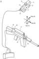
- FIG. 1illustrates a system 10 , according to at least some embodiments, that provides an information-enhanced heads-up display (HUD) for an infantryman or other armed tactical operator.
- HUDhead-up display
- System 10includes a set of goggles 11 that are configured for wear by the user. Goggles 11 may be worn directly, may be attached to a helmet or other headgear (not shown), or worn in some other manner. The front side of goggles 11 faces outward (i.e., away from the user) when worn, and includes eyepieces 12 and other apertures (not shown) for receiving light or other (e.g., IR) input from the user's field of view.
- eyepieces 12 and other aperturesnot shown
- goggles 11faces the user when worn such that the user looks outward through eyepieces 12 and sees external objects within the goggles field of view.
- goggles 11includes an image generator and a projector and creates a user display that combines video images and graphical indicia with what a user sees as a result of light passing from the external environment through eyepieces 12 .
- a sensor 13is attached to goggles 11 or otherwise physically coupled so as to move as a single unit with goggles 11 .
- Sensor 13includes an inertial measurement unit (IMU) and magnetometer.
- IMUinertial measurement unit
- sensor 13is an IM 3 TM sensor (available from Archangel Systems, Inc.
- Control unit 16includes a computer, radio receiver and other elements, as is also described below.
- System 10further includes a video source (or “scope”) 17 and a sensor 18 configured to move as a single unit with scope 17 .
- scope 17is affixed to a rifle 19 and is used to target rifle 19 .
- scope 17is aligned with the barrel of rifle 19 such that a reticle corresponding to the optical centerline of scope 17 generally follows the path of a bullet fired from rifle 19 .
- Scope 17may include a visible-light video camera, a thermal imaging (i.e., IR sensitive) video camera, a night-vision video camera, or some combination thereof.
- scope 17is a Light Weapon Thermal Sight (available from DRS Optronics of Melbourne, Florida).
- Sensor 18is also an IMU (such as the aforementioned IM 3 TM sensor) in at least some embodiments. Sensor 18 and scope 17 communicate with control unit 16 via cables 20 and 21 .
- control unit 16receives video feeds from scope 17 and goggles 11 .
- the video feedsmay be delivered using any standard video format, for example analog formats like NTSC or PAL, digital formats like MPEG, or a non-standard format.
- Sensors 13 and 18communicate angular pitch, yaw, and roll information to control unit 16 .
- a computer within control unit 16determines orientation of the line of sight for goggles 11 relative to the line of sight for scope 17 . As described in more detail below, this permits superimposition of an image from scope 17 onto a display corresponding to a field of view of goggles 11 .
- sensors 13 and 18communicate via Universal Asynchronous Receiver/Transmitter (UART) protocol on cables 14 and 21 . These cables, along with video cables 15 and 20 , may be sewn into a soldier's clothing, rifle sling, equipment harness, etc. to prevent entanglement.
- control unit 16communicates wirelessly with sensors 13 and 18 , goggles 11 and/or scope 17 in other embodiments.
- ultra-wideband (UWB) transceiversmay transmit video and sensor data from rifle 19 , as well as video and sensor data from goggles 11 .
- UWBmay be used to transmit video from the control unit to goggles 11 .
- UWB radiossuch as Time Domain's PulsON® radio, are particularly desirable for their high bandwidth, low power consumption and for being virtually undetectable, any wireless standard may be used, including both Bluetooth and IEEE 802.11.
- UWB radiosmay be used for more than transmission of video and sensor data. Multiple radios may be placed on rifle 19 and on goggles 11 (or on a helmet, to which the goggles may be affixed), each of which can relay their precise position. In this fashion, control unit 16 is able to calculate the alignment of the rifle and goggles based on the relative location of radios rather than using separate orientation sensors.
- FIG. 2is a block diagram of control unit 16 .
- Control unit 16includes a computer 30 , global positioning system (GPS) chipset 31 and data communication chip set 32 .
- GPS chip set 31receives signals from GPS satellites via antenna 33 and outputs GPS data to computer 30 . Based on that GPS data, computer 30 determines the location of system 10 (and thus of the user) to within the accuracy limits of the particular GPS chip set. For differential GPS systems intended for military use, the horizontal position information is typically accurate to less than three meters.
- RF data communication chip set 32provides two-way data communication (using antenna 34 ) between system 10 and other elements in a tactical network. Those other elements may include additional systems 10 (e.g., worn by other soldiers in a squad), a remotely located commander, etc.
- the communication link(s) serviced by chip set 32may include a Land Warrior radio local net, single channel ground and airborne radio system (SINCGARS), Force XXI Battle Command Brigade-and-Below (FBCB2) tracking system, etc
- Computer 30includes a bus 35 connected to GPS chip set 31 and local communication chip set 32 via GPS interface 36 and communication interface 37 , respectively.
- a processor 38communicates with interfaces 36 and 37 and with memory 40 via bus 35 .
- Memory 40includes a combination of volatile (e.g., random access memory, or RAM) and non-volatile memory (e.g., removable and/or non-removable FLASH, EEPROM, hard drive, etc.). Stored in memory 40 are instructions for performing operations of system 10 as described herein and a tactical database (described below). Additional components communicating with processor 38 via bus 35 include a video input interface 41 , video output interface 42 and sensor interfaces 43 - 45 . Video input interface 41 receives video input from scope 17 and goggles 11 and makes that input available to processor 38 .
- sensor interfaces 43 and 44receive input from sensors 13 and 18 and make sensor data available to processor 38 .
- Other sensorse.g., barometric sensors
- Processor 38provides video output, via interface 42 , to goggles 11 for presentation in a display generated within goggles 11 .
- FIG. 2is merely one example of a control unit.
- the components and/or functions shownmay be combined and/or divided in various ways.
- a single input interfacecould receive all sensor and video feed data.
- some or all of the operations performed by processor 38 and other elements of control unit 16could be performed by one or more application specific integrated circuits (ASICs), field-programmable gate arrays (FPGAs), etc.
- ASICsapplication specific integrated circuits
- FPGAsfield-programmable gate arrays
- some or all of the operations described herein as being performed by processor 38are hardwired into one or more ASICs as gates and other logic dedicated to the calculations and other operations described herein.
- FIG. 3is a block diagram showing data flows in system 10 .
- Scope 17receives electromagnetic input (e.g., visible light, infrared) from within its field of view.
- the field of view for scope 17is shown schematically in FIG. 3 with dotted lines and labeled “scope FOV.”
- the scope FOVis 18°.
- an optical centerline (or “line of sight”) for scope 17also referred to herein as the “scope FOV centerline”.
- the scope FOVis a cone symmetrically centered on the scope optical centerline.
- Scope 17outputs a video feed corresponding to an image of external objects within the scope FOV.
- a video image output from scope 17will be referred to as a “scope image.”
- Sensor 18is coupled to scope 17 (because of both components being attached to rifle 19 ) and outputs data (P S , R S , Y S ) reflecting the rotational orientation of scope 17 about pitch (P), roll (R) and yaw (Y) axes (as shown in FIG.
- sensor 13 coupled to goggles 11outputs data (P G , R G , Y G ) reflecting the rotational orientation of goggles 11 about pitch (P), roll (R) and yaw (Y) axes.
- Ppitch
- Rroll
- Yyaw
- sensors 13 and 18output data at predetermined sampling intervals (e.g. 100 Hz).
- sensor 13also includes a magnetometer. The magnetometer senses the earth's magnetic field and provides a signal (MagNorth) indicative of magnetic north.
- control unit 16In addition to sensor data and a scope 17 video signal, control unit 16 also receives periodic position data updates via antenna 33 and tactical data via antenna 34 .
- position data via antenna 33includes data from GPS satellites.
- Tactical dataincludes data providing positions and descriptions of various elements (e.g., friendly or hostile forces) in the environment in which system 10 is operating.
- Other types of datamay be received from one or more additional sensors 55 .
- sensor 55is a barometer providing data indicating changes in the elevation of system 10 , which data can be used to confirm and/or adjust GPS-based elevation data.
- Goggles 11includes an array 56 of electromagnetic receptors (e.g., charge-coupled devices, photodiodes or other photo-sensitive elements, microbolometers) that receive electromagnetic radiation (e.g., visible light, IR) from within the receptor array field of view (“goggles FOV”).
- electromagnetic receptorse.g., charge-coupled devices, photodiodes or other photo-sensitive elements, microbolometers
- the goggles FOVis a cone symmetrically centered about an optical centerline/line of sight (also referred to herein as the “goggles FOV centerline”) extending from goggles 11 . This configuration is not required, however.
- An example of an image from a goggles array with a non-conical FOVis described below in connection with FIG. 13 A .
- Visible light from the goggles FOValso passes through eyepiece 12 and can be seen by the user.
- eyepiece 12 and array 56are offset slightly from one another, the eyepiece FOV (not indicated in FIG. 3 ) is the same or larger than the array field of view (i.e., the goggles FOV in FIG. 3 ) and generally has the same center line.
- Array 56generates image data (e.g., a night vision view of the environment within the goggles FOV). This image data is then provided to an image generator 57 that processes the image data into an image of objects in the goggles FOV.
- an image corresponding to the data from array 56will be referred to as a “goggles image.”
- the goggles imagemay be modified by computer 30 prior to being displayed to a user. Accordingly, the goggles image is also output via line 58 to computer 30 .
- a video feed from computer 30(which may contain the goggles image modified to include the scope image and other graphics) is received by projector 59 via line 61 .
- Projector 59through beam splitter 60 , combines the goggles image with the visible light passing directly through eyepiece 12 .
- the goggles imagecan also be provided directly to projector 59 from image generator 57 (e.g., if computer 30 or scope 17 becomes inoperative but night vision capability is still desired).
- a heads-up display (HUD) field of view (HUD FOV)is also shown in FIG. 3 , and is further discussed below.
- FIG. 3only shows one array, one eyepiece, one projector and one beam splitter. In at least some embodiments, there is a separate arrangement of array, eyepiece, projector and beam splitter for each eye.
- Goggles 11 in some embodimentsis a modified version of the AN/PVS-21 low-profile night vision goggles with M-2755 Enhanced Heads Up Display available from Sensor Technology Systems, Inc. of Beavercreek, Ohio. The modifications to a standard AN/PVS-21 (or other night vision goggles or enhanced vision system) required to implement various embodiments of the invention will be apparent to persons of skill in the art once such persons are provided with the information included herein.
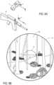
- FIG. 4shows an example of a user display 70 provided by goggles 11 .
- “user display”is used to refer to the image projected by projector 59 ( FIG. 3 ) through beam splitter 60 into eyepiece 12 , and which is visible by a wearer of goggles 11 .
- a user displaymay include the goggles image (or a portion thereof), the scope image (or a portion thereof) and other graphical objects.
- FIG. 4assumes system 10 is being used in a forest setting, though such a setting is merely for purposes of illustration.
- goggles FOVLocated within the goggles FOV (and thus in goggles image 82 ) are numerous trees and bushes such as might be present in a forest environment, as well as soldiers 71 (partially behind a tree in the lower left) and 72 (partially covered by foliage in the upper right).
- User display 70is also slightly shaded so as to indicate that the goggles image is a night vision display.
- the outer circle of FIG. 4generally corresponds to the limit of the goggles FOV.
- the HUD portion of user display 70is shown as a rectangular region 73 in the center portion of the goggles FOV. As explained in further detail below, various graphical indicia are overlaid within HUD 73 .
- HUD 73Also overlaid on HUD 73 is a weapon view 74 corresponding to (and generated from) the scope image.
- the weapon viewis the same size as the scope image. This is not a requirement, however.
- the scope imagemay be cropped to provide a weapon view that is actually smaller than the scope image (or that corresponds to reduced scope FOV).
- HUD 73is shown as a rectangle and weapon view 74 is shown as a circle in FIG. 4 , other shapes could be used.
- weapon view 74is rectangular. Portions of the scope image at the outer edges of the scope FOV may similarly be cropped so as to give a weapon view a desired shape.
- the location and rotation of weapon view 74 within user display 70is determined by computer 30 based on output from sensors 13 and 18 and based on comparison of the scope image with the goggles image.
- scope imagesor portions thereof are dynamically positioned within user display 70 so as to indicate where scope 17 (and thus rifle 19 ) is pointing.
- a user of system 10is able to simultaneously survey a setting, acquire a target and point a weapon at the target without having to remove his or her goggles and adjust to a weapon sight.
- An aiming reticle 76is located at the center of weapon view 74 , and corresponds to the rifle aim point (as zeroed to the rifle at a specified range) and lies near the scope FOV centerline.
- Various other graphical objectsare also included in the HUD.
- “friendly” icons 77 and 78are positioned upon soldiers 71 and 72 . In this manner, the user of system 10 is aware that soldiers 71 and 72 should not be fired upon.
- an icon 79indicating the location of (or direction to) a rally point (i.e., a position determined in advance of a tactical operation and at which persons involved in the operation may regroup).
- Icon 80shows a reported location of an enemy machine gun position.
- Colored path 81indicates a preplanned route. Additional details of generating the graphical objects in display 70 , as well as examples of other graphical objects that could be included in display 70 , are provided below.
- FIGS. 5 A and 5 Bare a flow chart explaining the operation of system 10 .
- the steps shown in FIGS. 5 A and 5 Bcan be reordered, combined, split, replaced, etc.
- FIGS. 5 A and 5 Bare not intended to indicate a requirement that all steps be performed as part of a single algorithm.
- Many aspects of system 10 operationcould be accommodated on multiple independently-running parallel program threads or as processes running in parallel on an ASIC, an FPGA, multiple processors, etc.
- all of the operations shown in the flow charts of FIGS. 5 A through 5 Bwould not necessarily be performed the same number of times as is suggested by the flow chart.
- refreshing and/or updating of iconsmight occur at a different rate than updating and/or repositioning of weapon view 74 .
- a useractivates system 10 , and goggles 11 , control unit 16 and scope 17 are energized. Sensors 13 and 18 are also energized. The system is then calibrated (block 103 ).
- a user of system 10remains motionless for a period of time so as to allow rate sensors and accelerometers in sensors 13 and 18 to stabilize, determine a down vector, etc.
- IMU sensors 13 and 18can both determine a common down vector based on the earth's gravitational field. The sensors thus require no further initial calibration as to the pitch and roll axes. However, each sensor randomly chooses a zero-yaw orientation.
- sensors 13 and 18must be further calibrated so that a baseline difference between the zero-yaw orientation can be determined.
- sensor 18 on rifle 19might arbitrarily choose a zero-yaw position that corresponds to rifle 19 pointing along a 37 degree compass heading
- sensor 13 on goggles 11might arbitrarily choose a zero-yaw position that corresponds to the optical centerline of the goggles FOV pointing along a 246 degree compass heading.
- this difference in zero-yaw orientationsis determined by the user looking at a distant (e.g., over 300 meters away) object through goggles. A calibration reticle corresponding to the goggles FOV centerline is shown in the goggles display. The user then moves rifle 19 so that a reticle corresponding to the centerline of scope 17 is aligned with the goggles reticle and presses a “calibration” button.
- computer 30receives position data for system 10 from GPS chipset 31 ( FIG. 2 ) and/or from data communication chipset 32 in block 105 .
- computer 30receives data for a video frame (i.e., a scope image) from scope 17 and data for a goggles image from image generator 57 .
- Operationthen proceeds to block 109 , where computer 30 receives angular pitch (P G ), roll (R G ) and yaw (Y G ) orientation data for goggles 11 from sensor 13 .
- Computer 30also receives pitch (P S ), roll (R S ) and yaw (Y S ) data from sensor 18 .
- Data values from sensors 13 and 18indicate the angle of vertical rise (pitch), the angle of horizontal rotation (yaw), and the angle of rotation around the line of sight (roll), for both goggles 11 and scope 17 , which because of calibration share the same coordinate system.
- the pitch, roll and yaw angle values from (goggles) IMU 13 and the pitch, roll and yaw angle values from (scope) IMU 18are used to create an IMU-based rotation matrix.
- the IMU-based rotation matrixis then used in block 113 to calculate a location (i.e., horizontal and vertical position) and an image rotation for the scope image within the goggles image (and thus, the correct placement of weapon view 74 in user display 70 ).
- Rotation matrices and the use of same to place and orient one image within anotherare known in the art and/or would be readily apparent to persons of ordinary skill in the art once such persons are provided with the information contained herein.
- computer 30adjusts for differences between scope 17 (and a scope image) and array 56 (and a goggles image).
- the goggles FOV in some embodimentsis 40° and the scope FOV is 18°.
- array 56 and a similar sensor array in scope 17may have different numbers of pixels and/or different pixel pitches. Adjusting for these and other differences between scope 17 and goggles 11 so as to determine a linear distance up or down on user display 70 (and an image rotation) is within the ability of persons skilled in the art once such persons are supplied with information provided herein.
- FIGS. 6 A through 6 Hpositioning and rotating a weapon view 74 within display 70 based on data from sensors 13 and 18 is generally illustrated.
- FIGS. 6 A through 6 Hassume data from sensors 13 and 18 is accurate (e.g., not significantly affected by bias drift) and that weapon view 74 is generated based on the IMU sensor data only.
- HUD 73 and various icons and other indicia included in FIG. 4are omitted from FIGS. 6 B, 6 D, 6 F and 6 H .
- goggles 11are looking in exactly the same direction that rifle 19 is pointed. This results in a centered weapon view 74 ( FIG. 6 B ), and computer 30 places an image from scope 17 directly over the center of goggles display 82 .
- FIG. 6 Crifle 19 has yawed eight degrees to the left.
- FIG. 6 Ddepicts the subsequent change in user display 70 .
- the pitch and roll values detected by sensors 13 and 18remain unchanged, but the yaw value detected by sensor 18 will change by minus eight degrees (or positive eight degrees, depending on the chosen convention).
- the proper location for the scope imagewill be ⁇ 8 degrees from the HUD centerline. Accordingly, the placement of weapon view 74 in the heads up display is shifted to the left as shown (the same result would have been obtained if rifle 19 was held still and goggles 11 yawed eight degrees to the right).
- weapon view 74remains at the edge of HUD 73 .
- computer 30gives weapon view 74 a distinctive border to indicate to the user that rifle 19 is pointing outside the visual field of goggles 11 .
- Weapon view 74remains visible in such embodiments so as to provide the user a view of where the weapon is pointing (e.g., allowing a user to aim and shoot around a corner).
- rifle 19has been pitched upward six degrees.
- the yaw and roll values detected by sensors 13 and 18remain unchanged, but the pitch values from sensor 13 and from sensor 18 differ by six degrees. This results in weapon view 74 being shifted upward within display 70 as shown in FIG. 6 F .
- parallaxis in many applications a non-issue. At least some implementations of system 10 are predominantly intended for use against targets at distances greater than 10 meters. Moreover, when targeting a weapon using system 10 , weapon view 74 will ultimately be the source of assurance that the weapon is pointed at a proper target. Even if weapon view 74 is slightly misaligned with the surrounding portions of the goggles view, the soldier will be primarily concerned that the weapon is pointed at the correct target, and weapon view 74 will still accurately show the intended target.
- FIGS. 6 G and 6 Hshow rotation of weapon view 74 in display 70 .
- computer 30calculates an amount by which weapon view 74 should be rotated within display 70 so as to be properly registered with the remainder of display 70 .
- Various algorithms for rotating an image by a desired amountare known in the art. In the example of FIGS. 6 G and 6 H the image rotation of weapon view 74 is ten degrees.
- block 117the IMU-based calculation for position and rotation of weapon view 74 within display 70 is checked using an image-based method. This permits computer 30 to adjust the manner in which IMU-based positions and rotations are calculated, thereby correcting for bias drift and helping to maintain proper registration of the scope image within the goggles image.
- registrationrefers to positioning of a scope image (or a portion of that scope image) within a goggles image so that the two images are properly aligned and positioned, and one image coincides with the other.
- IMU-based orientation determinationis relatively simple from a computational standpoint and is generally quite robust over short periods of time, IMUs can have certain disadvantages.
- IMUshave bias drift rates and may be susceptible to significant overshoot if moved rapidly.
- the relative orientation of goggles 11 and scope 17can be independently deduced by processing image data from image generator 57 and scope 17 if there is sufficient image content and contrast and if similar imaging technologies (e.g., microbolometers, CCD, etc.) are used.
- image data from image generator 57 and scope 17e.g., microbolometers, CCD, etc.
- the image from scope 17can be considered a dilated, translated and rotated distortion of the image generated from image generator 57 .
- the angle between the viewing vector of array 56 (i.e., the goggles FOV centerline) and the viewing vector of scope 17 (the scope FOV centerline)should not be too great (i.e., so the image from scope 17 is contained within the goggles image). If the angle is too great as determined by IMU readings (such as when an operator looks away from where the weapon is pointed), the image comparison algorithm is (in some embodiments) not invoked until the IMU data indicates that the angle is within acceptable limits for image comparison.
- the distance between goggles 11 and scope 17should also be small compared to the distance from goggles 11 and scope 17 to objects being viewed. This ensures that parallax effects do not disrupt a simplifying assumption that the goggles FOV centerline and the scope FOV centerline are co-located.
- the location of the fixed pointconstrains the solution of the proper orientation of the scope image relative to the goggles image up to a twist rotation.
- the twist rotationis about an axis corresponding to a line defined by the center of projection of the scope camera and the point u′,v′ (i.e., the fixed point) on the scope camera focal plane. If the Brouwer fixed point for the goggles and scope images is at the center of the scope image, the twist rotation corresponds to the difference between the roll axis orientations of goggles 11 and scope 17 .
- the Brouwer fixed pointcan be found by scanning and comparing a goggles image and a scope image and determining a location where a rotationally invariant similarity metric is maximized.
- One such metricis the peak to sidelobe ratio (PSR) of a cross correlation of two linear signals.
- PSRpeak to sidelobe ratio
- One of those signalsis from a small annular region centered about a location in a goggles image and the other is from an annular region (of the same angular size) centered about a location in the scope image. If the PSR for those two annular regions is the maximum, the centers of those annular regions represent the Brouwer fixed point.
- PSRcan be defined as (PEAK ⁇ mean)/ ⁇ , where PEAK is a peak cross correlation value for the centers of the two annular regions, and where mean and ⁇ are the respective mean and standard deviations of cross correlation values for the annular regions.
- the twist rotation about the fixed pointcan be deduced from the phase shift of the two signals.
- the phase shiftis proportional to the displacement of the cross correlation peak used in the PSR calculation between the two signals. That is, starting from the zero point of each annulus (as defined by image orientation) and taking signal values around the annulus, determine the angular displacement from zero for each peak. The difference between these two angles is the phase shift.
- FIG. 7is a flow chart providing additional details about the operations performed within block 117 of FIG. 5 B in some embodiments.
- computer 30performs an image-based check on a point of interest in the portion of the goggles image identified (using IMU data from sensors 13 and 18 ) as corresponding to the center of the scope image.
- Point of interestrefers to a point in an image (a center of a portion of the goggles image in the current example) that is being evaluated as possibly corresponding to a point on the other image (the center of the scope image in the current example).
- the image-based checkpasses, the values for the IMU-based rotation matrix (and thus, the center for weapon view 74 predicted by that IMU-based rotation matrix) are verified, and computer 30 proceeds to block 204 on the “yes” branch. If the image-based check fails, computer 30 proceeds on the “no” branch to block 206 . As described in more detail below, computer 30 will in block 206 and in subsequent blocks expand the search (primarily in the global yaw plane) to perform image-based checks on additional points of interest in the goggles image.
- FIGS. 8 A through 8 Gconceptually illustrate a case in which the image-based check verifies the position for the scope image calculated with IMU data from sensors 13 and 18 .
- FIGS. 6 B, 6 D, 6 F and 6 HHUD 73 and other elements shown in FIG. 4 have been omitted from FIGS. 8 A through 8 G .
- FIG. 8 Ashows a goggles image 82
- FIG. 8 Bshows a scope image 302 .
- the useris holding his head level but has tilted rifle 19 twenty degrees (20°) to the left. Shown in FIG.
- FIG. 8 A(with broken lines) is the portion 303 of goggles image 82 where computer 30 intends (relying on the IMU-based rotation matrix) to place scope image 302 .
- the center 304 of portion 303is also indicated; so as to avoid confusion with the aiming reticle of the weapon view, the center is shown as a “+” inside of a circle.
- the broken line 303 in FIG. 8 Aonly shows the portion of goggles image 82 over which scope image 302 of FIG. 8 B would be overlaid.
- the intended rotation of scope image 302 within goggles image 82(according to the IMU-based rotation matrix) is shown in FIG. 8 A as the arcuate dimension “20°.”
- computer 30performs an image-based check of point 304 so as to evaluate the validity of point 304 as the center of a weapon view. Stated differently, computer 30 initially assumes that points 304 and 305 are the Brouwer fixed point. As part of the image-based check of point 304 , several PSRs are calculated using a region of goggles image portion 303 and regions of scope image 302 . As seen in FIG. 8 C , a first PSR calculation is based on a cross correlation using the pixel intensity values of the equally-sized annular regions 308 and 309 respectively centered on the center points 304 and 305 of goggles image portion 303 and scope image 302 .
- the PSR value from this calculation(PSR[ 304 : 305 ]) is then compared to PSRs calculated for annular regions centered on locations around center 305 of scope image 302 .
- another PSR(PSR[ 304 : 305 - 1 ]) is calculated based on a cross correlation using the pixel intensity values of the equally-sized annular regions 308 and 309 - 1 respectively centered on points 304 and 305 - 1 of goggles image portion 303 and scope image 302 .
- PSR[ 304 : 305 - 2 ], PSR[ 304 : 305 - 3 ] and PSR[ 304 : 305 - 4 ]are calculated based on cross correlations using the pixel intensity values of equally-sized annular regions 308 and 309 - 2 (centered on point 305 - 2 , as shown in FIG. 8 E ), equally-sized annular regions 308 and 309 - 3 (centered on point 305 - 3 , as shown in FIG. 8 F ) and equally-sized annular regions 308 and 309 - 4 (centered on point 305 - 4 , as shown in FIG. 8 G ).
- Point 304passes the image-based check (i.e., the assumption that points 304 and 305 are the Brouwer fixed point is validated) when computer 30 determines that PSR[ 304 : 305 ], PSR[ 304 : 305 - 1 ], PSR[ 304 : 305 - 2 ], PSR[ 304 : 305 - 3 ] and PSR[ 304 : 305 - 4 ] are within an acceptable range of one another.
- An acceptable PSR rangewill depend on the characteristic performance of the sensor technology (microbolometer, etc.) being used in the imaging sources (scope 17 and array 56 in the present example), as well as on peculiarities of a given manufacturer's implementation of a particular class of sensor.
- the acceptable PSR range for a given combination of a goggles sensor type and a scope sensor typecan be determined by comparing a series of exemplar images obtained using samples of those two sensor types. Determining an acceptable range is within the routine ability of a person of ordinary skill in the art once such a person is provided with the information contained herein.
- an image-based check of a point of interestcalculates PSR values using regions centered on more or fewer points around the center 305 of scope image 302 . Those points around center 305 could also have locations (relative to center 305 ) other than as shown for points 305 - 1 through 305 - 4 .
- PSRs for an image-based check of a goggles image point of interestare based on annular regions centered on points around that goggles image point of interest instead of annular regions centered on points surrounding the scope image.
- computer 30moves to block 204 from the “yes” branch of block 202 if the image-based check for the IMU-based center of the weapon view passes.
- computer 30determines if there is a roll difference between the two images. In particular, computer 30 calculates the phase shift of the scope image and goggles image and deduces a twist rotation from the phase shift. If the difference between the twist rotation and the IMU-based roll difference is within acceptable limits (e.g., less than five degrees), the IMU-based value (and thus, the rotation of the scope image within the goggles image predicted by IMU data) is verified, and operation proceeds to block 119 of FIG. 5 B . If the difference between the twist rotation and IMU-based rotation is not within acceptable limits, computer 30 proceeds on the “no” branch from block 204 to block 218 . Block 218 is discussed below.
- a failed image-based check in block 202indicates that the IMU-based location for scope image 302 within goggles image 82 may be incorrect.
- the scope image and the part of the goggles image over which computer 30 intends (based on IMU data) to overlay the scope imagedo not sufficiently represent the same part of the external environment.
- computer 30proceeds on the “no” branch from block 202 to block 206 .
- block 206computer 30 attempts to find the proper location for scope image center 305 within goggles image 82 by comparing scope image 302 with different parts of goggles image 82 .
- computer 30performs image-based checks for points of interest in goggles image 82 that are slightly offset from a center calculated from IMU data. This is illustrated conceptually in the example of FIGS. 8 H through 8 K , which assumes the same goggles image 82 and scope image 302 of FIGS. 8 A and 8 B , but in which the IMU-based position and image rotation are not correct.
- FIG. 8 Hshows goggles image 82 and a portion 311 of goggles image 82 where computer 30 now intends (relying on inaccurate IMU-based information) to place scope image 302 .
- the center 313 of portion 311 and the IMU-based image rotation angle (17°)are also shown.
- the correct position of scope image 302 within goggles image 82is shown with a different type of broken line.
- FIG. 8 Ishows an enlarged area of goggles image 82 around center 313 .
- computer 30performs image-based checks for each of points 315 a through 315 h . As seen in FIG. 8 I , these points are slightly offset from center 313 .
- the image-based check of point 315 gis based on cross correlations of the pixel intensity values for annular region 316 (centered on point 315 g , as seen in FIG. 8 J ) and each of equally-sized annular regions 309 through 309 - 4 shown in FIGS. 8 C through 8 G . Similar image-based checks are performed for the points 315 a - 315 f and 315 h.
- computer 30determines if any of the image-based checks of block 206 passed. If so, computer 30 proceeds to block 216 , which block is explained below. If not, computer 30 proceeds on the “no” branch to block 210 .
- computer 30expands its search and performs image-based checks on points in the goggles image that are even further offset from IMU-based center 313 . This is shown in FIG. 8 K , where further offset locations 315 i through 315 hh are indicated. In at least some embodiments, the expanded search is biased in the global yaw plane. As shown in FIG.
- computer 30proceeds to block 212 and determines if any of the image-based checks of block 210 passed. If so, computer 30 selects the location (e.g., one of points 315 i through 315 hh ) for which the highest PSR was obtained (e.g., the highest PSR for a point of interest that passed) and proceeds to block 216 along the “yes” branch. If none of the image-based checks in block 210 resulted in a pass, computer 30 proceeds on the “no” branch to block 214 . In block 214 , computer 30 determines if there are additional regions of goggles image 82 with which a portion of scope image 302 can be compared.
- computer 30returns on the “yes” branch to block 210 and further expands its search to include locations that are farther away from center 313 . If computer 30 determines in block 214 that there are no more regions of goggles image 82 with which scope image 302 can be compared, computer 30 proceeds on the “no” branch to block 119 ( FIG. 5 B ). In at least some embodiments, computer 30 treats a failure of all points of interest to pass an image-based check as evidence that there is temporarily insufficient contrast and/or content in the scope or goggles image to perform a PSR calculation, or that the scope FOV is not within the goggles FOV.
- any adjustment of IMU-based position calculation using image comparison resultswill wait until a better set of scope and goggles images are available.
- calibrationcan be performed manually (typically in less than ten seconds). Adjustment of IMU-based position calculation is described in more detail below.
- computer 30When computer 30 does determine that a point of interest in the goggles image has passed an image-based check, computer 30 proceeds to block 216 of FIG. 7 (either from the “yes” branch of block 208 or from the “yes” branch of block 212 ). In block 216 , computer 30 identifies a portion of the goggles image centered on the point for which the highest PSR was found. Computer 30 then proceeds to block 218 and calculates the twist rotation of scope image 302 . The calculations of blocks 206 through 216 determine the amount by which the scope image is translated relative to the goggles image. The relative rotation of the two images (if any) is calculated separately in block 218 . As indicated above, this calculation is in some embodiments based on the phase shift of scope image 302 and the portion of goggles image 82 identified in block 216 .
- Computer 30then proceeds to block 219 , where the IMU-based goggles portion ( 311 in the example of FIG. 8 H ) and rotation matrix are replaced with the portion identified in block 216 and with the twist rotation (from block 218 ). If block 219 is reached from the “no” branch of block 204 , only the (IMU-based) roll is replaced. Computer 30 also adjusts the manner of IMU-based position calculation. This is illustrated conceptually in FIGS. 9 A through 9 C .
- FIG. 9 Ashows a goggles image 350 , the center point 351 for an IMU-based location for a scope image and the center point 352 for an image-comparison-based location for the scope image.
- IMUis the horizontal location of the scope image in the goggles image calculated with data from IMU sensors 13 and 18 .
- Imageis the horizontal location of the scope image in the goggles image calculated using the image comparison technique described above.
- IMUis the vertical location of the scope image in the goggles image calculated with data from IMU sensors 13 and 18 ;
- Imageis the vertical location of the scope image in the goggles image calculated using the image comparison technique described above.
- FIGS. 9 A and 9 Bthe difference between H
- FIG. 9 Cshows values R
- Imageare used (in a manner readily appreciable by persons of ordinary skill in the art) to correct IMU-based roll calculations until a new correction is available.
- corrections to pitch and rollare much smaller than those to yaw due to the presence of three-axis accelerometers in both IMUs that yield a consistent gravity vector, thus correcting much of the drift in these directions.
- pitch and roll corrections from image registrationwill not be applied until they exceed a pre-determined threshold because this effect due to gravity usually will keep these axes in control.
- computer 30proceeds to block 119 of FIG. 5 B .
- the scope imageis cropped, resized and/or rotated.
- the resulting imageis then overlaid on the goggles image as the weapon view (block 121 ).
- a reticle(which corresponds to the scope FOV centerline) may be generated, but in some embodiments an integral scope image reticle will be displayed as part of the image.
- the weapon viewmay be given a desired shape (e.g., rectangular or circular) and angular dimension(s), and portions of the scope view outside of the desired shape may be cropped.
- Computer 30proceeds from block 121 to block 123 , where a tactical object database is updated.
- a tactical object databaseis updated.
- user display 70graphically indicates locations of various real-world objects of interest to the user. Data for such objects is stored in a database, accessible by computer 30 , located in memory 40 (see FIG. 2 ), and periodically updated by messages received from other friendly units by means of the communications chip set 32 .
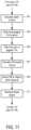
- FIG. 10shows an example of a database 401 , according to at least some embodiments, storing information about real-world objects.
- the real-world objectsare items of tactical interest to a soldier; accordingly, such items may also be referred to herein as “tactical objects.”
- Database 401in tabular form for purposes of explanation.
- Database 401need not be stored or organized as a table, however, and need not have other features shown in FIG. 10 .
- a database such as database 401could be stored in numerous other formats, could include information other than that shown in FIG. 10 , and/or could be stored as multiple separate databases.
- the first column in FIG. 10contains an identifier for an object of interest. For convenience, relatively simple identifiers are shown in FIG. 10 . The identifiers could take any form, however. In some cases, an identifier may be a name (e.g., of another soldier) or other characters that a human user would recognize, and that might be displayed in user display 70 under some circumstances.
- the second column of FIG. 10indicates an object type. Although only four object types are shown in database 401 , numerous other types of objects could be included. For example, mission objectives, friendly outposts or emplacements, obstacles, contaminated areas, magnetic headings, stadia marks and other items can be included within database 401 and shown in a user display with an icon or other indicator.
- the third column of database 401gives location information for each object.
- the location informationprovides the three-dimensional location of an object within a particular tactical region.
- the tactical regionmay be relatively small (e.g., several square miles that a military unit will patrol). In other cases, the tactical region may be much larger.
- the location data in FIG. 10is represented generically as ⁇ x coord>, ⁇ y coord> (with a lower-case “y” in this case referring to a linear distance axis and not yaw) and ⁇ z coord>.
- actual location informationmay be in the form geographical coordinates, military grid reference system coordinates, or in any other desired format.
- the fourth column of FIG. 10shows the type of icon or other graphical object used to mark or otherwise indicate a tactical object in user display 70 . Although the icon type is shown graphically in FIG. 10 for convenience, an actual database may contain a pointer or other data object corresponding to a particular icon.
- terrain and other geographic informationis also stored in database 401 .
- This geographic informationincludes elevations of points in the tactical region, true north corrections for magnetic north values obtained from a magnetometer in sensor 13 , magnetic dip angle to determine if there is interference to the compass, etc.
- Datacan be input into database 401 in various ways. Some data might be downloaded into database 401 (e.g., via an RS232 or USB port on computer 30 ) from a laptop computer as part of planning for a mission. Examples of such data could include planned routes, known enemy positions, etc. Other data is added to database 401 , while system 10 is in use, based on periodic updates over the radio communications link. Block 123 of FIG. 5 B represents such updating of database 401 via radio communications. For example, changing locations of friendly personnel can be relayed from other systems 10 used by such personnel. As another example, an enemy unit location may be reported by a soldier using system 10 , and that enemy unit location is then broadcast to other soldiers (each of whom is also equipped with a system 10 ). Radio updates may also come from sources other than (or in addition to) soldiers equipped with systems 10 . As but one example, a remotely located commander or an airborne observation unit may provide tactical information about enemy units, changed mission objectives, etc.
- FIG. 11is a flow chart providing additional details about the operations performed within block 125 of FIG. 5 B .
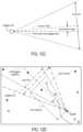
- FIGS. 12 A through 12 Dare used to conceptually explain various operations of FIG. 11 .
- Computer 30would not necessarily generate the diagrams shown in FIGS. 12 A through 12 D as part of the operations described in connection with FIG. 11 .
- computer 30first determines the location of system 10 based on GPS coordinates and/or other data received in block 105 of FIG. 5 A .
- FIG. 12 Aa plan view of a portion of the tactical region for which information is stored in database 401 .
- Various friendly soldiers, enemy positions and other tactical objectsare shown using the same types of icons shown in FIGS. 4 and 10 .
- Each of the tactical objectshas one or more entries in database 401 .
- the position of system 10(and thus of goggles 11 ) is also indicated.
- block 503FIG.
- computer 30uses magnetometer output from sensor 13 , or (in case of magnetic interference) the yaw Euler angle calculated from the IMU movements subsequent to the last acceptable magnetic fix, to determine the direction of the goggles FOV (i.e., the direction in which the user is looking).
- the value of MagNorthis corrected (using geographically-specific magnetic deviation and true-north correction data in database 401 ) so as to determine the direction in which goggles 11 are pointed.
- FIG. 12 BAlso shown in FIG. 12 B is the goggles FOV and HUD FOV.
- Flow then proceeds to block 505 of FIG. 11where pitch axis data from goggles sensor 13 is used to determine the degree to which the user is looking up or down. This is shown in FIG. 12 C .
- Computer 30then proceeds to block 507 .
- computer 30calculates a spatial volume corresponding to the boundary of HUD 73 in user display 70 .
- This HUD volumeis a pyramid centered on the goggles FOV centerline and extending outward.
- the HUD FOVe.g., 32°
- the HUD pyramidis bounded by a plane located at a range (d) from goggles 11 . This is shown in FIG. 12 D .
- Computer 30searches database 401 for all objects within the just-calculated HUD pyramid.
- the range (d)is in some embodiments selected by the user. For example, a user might be more concerned about objects that are relatively close (e.g., within 500 meters) than about those that are further away. Moreover, providing icons or other display indicia for distant objects may unnecessarily clutter user display 70 . In certain embodiments, range (d) may be changed while system 10 is operating and the user display can be de-cluttered in other ways. As but one example, route information, control measures, etc. may be removed at the push of a button during a firefight so as to minimize potential distracters to the soldier, while friendly icons would be retained to help limit fratricide. Removed information could be restored by the operator when again needed.
- computer 30then generates icons or other indicia in user display 70 corresponding to the objects, identified in the database search of block 509 , within the HUD pyramid.
- the size of the icons or other indiciais logarithmically scaled so that icons or other indicia for more distant objects are smaller.
- Computer 30then returns to block 127 ( FIG. 5 B ). If more video frames from goggles 11 and scope 17 are received (i.e., goggles 11 and scope 17 remain ON), then computer 30 returns to block 105 of FIG. 5 A . Otherwise, operation of system 10 terminates.
- the weapon viewcan be a magnified version of the scope view (either at all times or selectively at the request of the user).
- the image-based comparison techniques described abovecan first be performed using an unmagnified scope image. Once the proper location and orientation for the scope image are deduced, the scope image can be magnified and cropped prior to overlay as the weapon view.
- Other types of informatione.g., a battery life indicator, navigational headings, etc.
- a usercan be provided with a great deal of flexibility in selecting the types of information to be shown on the display.
- Such selectioncan take place during set-up or while the system is in use. For example, a soldier on patrol may choose to see display indicators for routes, rally points, indirect fire targets, preplanned control measures, etc. When the soldier is attacked or is about to enter a firelight, he or she might then place the weapon in a close-combat mode (e.g., by pressing a mode control button located on a weapon). In such a close-combat mode, the user could avoid information overload by suppressing all information except icons for friendly forces. In some cases, the soldier might even choose to suppress “friendly” icons and opt for an audible warning if the weapon is pointed at friendly personnel.
- a soldiermight configure his system to display icons for friendly forces within a first range (e.g., 300 meters) and for enemy positions within a second range (e.g., 1000 meters), to display graphics for patrol routes within a third range (e.g., 500 meters), to plot control measures with routes, etc.
- a first rangee.g. 300 meters
- a second rangee.g. 1000 meters
- a third rangee.g. 500 meters
- location informationcan be provided via GPS transmissions.
- Location datacan also be augmented by local information such as timing and ranges from nearby soldiers also equipped with a system such as described herein.
- Other types of navigational datae.g., WAAS, or wide area augmentation system
- Barometric pressurecan be used to provide a relative elevation error and used as a check against a GPS-based elevation, as well as during system initialization.
- a terrain databasee.g., within a database such as database 401
- Data from various sourcescan be updated at various rates (e.g., video frames at 30 Hz, IMU data at 100 Hz, GPS or other navigational updates at 1 Hz, range data from other soldiers at 8 Hz).
- IMU accelerometerscan have bandwidths greater than 1000 Hz, resolution of 1.25 milligrams, and 2% sensitivity.
- a magnetometercan provide outputs at 200 Hz and have a sensitivity of 1 mGauss (1 part in 300-600 Earth field).
- Rate sensorscan have a 2% error and 100 Hz bandwidth, and barometric pressure data provided at 100 Hz and within 1-2 meters of resolution. Range data from other soldiers may be within 1.3 meters of error.
- all of these valuesare only examples, and the invention is not limited to systems having specific values for any of these quantities.
- FIG. 7Other embodiments also include numerous variations on the above-described methods for using a comparison of a scope image and a goggles image to check an IMU-based location and rotation for that scope image within that goggles image.
- the operations described in connection with FIG. 7initially assume that the center for a scope image within a goggles image calculated from IMU data is correct. If the image comparison suggests that the IMU-based calculation is not correct, a search of other possible center locations moves outward from the IMU-based center. Assuming an IMU drift rate of approximately 1°/hour, a procedure such as that of FIG. 7 works well (and minimizes computational load on a processor) if the scope and goggles point in the same direction at least once every 10 to 15 minutes.
- a systemcould be configured so that a user can manually initiate a search (e.g., beginning at the goggles image center) across the entire goggles image for a scope image location. This could be used for initially calibrating the IMUs, or as a re-calibration if the user has not pointed his weapon forward for an extended period (e.g., if the weapon was slung over a shoulder).
- the search patterns shown in FIGS. 8 J and 8 Kare only examples. Numerous other search patterns could be implemented.
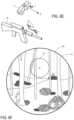
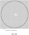
- FIGS. 13 A and 13 Bshow a goggles images and scope image, respectively, that will be used to describe this alternate algorithm. Unlike the previous discussion, which assumed the fields of view for both goggles array 56 and scope 17 were conical, the images of FIGS. 13 A and 13 B instead assume that array 56 and a similar array inside of scope 17 are rectangular.
- FIG. 13 Ais a goggles image 601 generated when array 56 ( FIG.
- FIG. 13 Bis a scope image 603 generated when an array inside scope 17 ( FIG. 3 ) is also 320 ⁇ 240 pixel microbolometer array (8-12 micron range) having a 14.4° horizontal FOV, a 10.8° vertical FOV, and an 18° diagonal FOV.
- the data from the scope arrayis also converted into a 640 ⁇ 480 pixel NTSC format image for transmission to control unit 16 and digitized for processing.
- the horizontal, vertical and diagonal goggles fields of vieware the same as the horizontal, vertical and diagonal scope fields of view.
- the below-described alternative image comparison algorithmcan also be used in connection with a goggles and/or scope image created from different arrays having different fields of view (including the conical fields of view described previously), as well as in circumstances when the fields of view for the goggles and the scope are different in horizontal, vertical and/or diagonal planes. Adaptation of the below described alternative algorithm to such other array configurations is within the routine ability of persons of ordinary skill in the art once such persons are provided with the information contained herein.
- each pixelcorresponds to approximately 0.0225° of the FOV in each of the horizontal, vertical and diagonal planes.
- each of images 601 and 603is based on data from a 320 ⁇ 240 pixel array.
- Each array pixelwould thus correspond to approximately 0.045° of the FOV in each of the horizontal, vertical and diagonal planes.
- gray-scale values from the 320 ⁇ 240 pixel arraysare duplicated so as to create images 601 and 603 .
- a pixel in 320 ⁇ 240 array 56 outputting a gray-scale value of Gcorresponds to a 2 ⁇ 2 pixel block in image 601 , with all four pixels in that 2 ⁇ 2 block also having a gray-scale value of G. The significance of this will be apparent below.
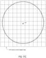
- a center 604is also indicated. Surrounding center 604 is a circle 605 having a diameter corresponding to 4° of the FOV. The region within circle 604 will be overlaid on goggles image 601 as a weapon view (similar to weapon view 74 of FIG. 4 ).
- FIG. 14is a flow chart for an alternate image comparison algorithm according to at least some embodiments. Various blocks in the FIG. 14 flow chart will be further explained using diagrams and plots in FIGS. 15 - 22 .
- the alternative image comparison algorithm of FIG. 14assumes that current IMU data is available from sensors 13 and 18 ( FIG. 3 ), that IMU drift since the last calibration (or image registration) has not been significant, and that IMU data is thus usable as a starting point in the algorithm (as described below).
- random noise in IMU outputrarely exceeds 1 degree in yaw or 1 ⁇ 2 degree in pitch or roll.
- center area 605is wholly contained within goggles image 601 (i.e., that the portion of the external environment corresponding to center area 605 is also represented by a region wholly contained in goggles image 601 ) at time intervals such that the bias drift will be less than 2 degrees.
- the image comparison algorithm of FIG. 14is entered from block 115 of FIG. 5 B .
- the algorithm of FIG. 14is also performed by computer 30 ( FIG. 2 ).
- computer 30resets a counter (N).
- the counter Nis used to prevent excessive looping through the algorithm.
- computer 30proceeds to block 703 and locates a region of high contrast, within scope image 603 , that is relatively near center 604 . This is shown in more detail by FIG. 15 .
- FIG. 15is a partially schematic diagram in which the various image elements (e.g., trees, foliage, etc.) have been omitted for simplicity, but in which the boundary of scope image 603 and center 604 are shown.
- computer 30searches image 603 for a square region 610 in which the pixels inside of region 610 have a high degree of contrast.
- computer 30searches for the square region 610 in which the standard deviation of pixel gray-scale values is maximized.
- image 603comprises numerous 2 ⁇ 2 pixel blocks in which all pixels in a 2 ⁇ 2 block have the same gray-scale value. Accordingly, when calculating a standard deviation for a region of image 603 , only every other pixel in the horizontal and vertical directions need be used.
- region 610corresponds to a 3° horizontal FOV by 3° vertical FOV portion of image 603 .
- region 610is approximately 133 pixels by 133 pixels.
- the center 606 of region 610should also be within 2° of center 604 in the horizontal plane and within 1° of center 604 in the vertical plane.
- computer 30thus searches for a 133 ⁇ 133 pixel region contained within a 311 ⁇ 222 pixel region of image 603 that is centered about center 604 .
- computer 30proceeds from block 703 to block 705 and determines if the region 610 identified in block 703 is of sufficiently high contrast. If, for example, the maximum standard deviation for gray-scale values within any 133 ⁇ 133 pixel block is not sufficiently high, there may be insufficient contrast to continue with an image comparison. A sufficiently high standard deviation value could be determined for a given combination of goggles and scope imaging array types based on a series of test images. If the standard deviation for gray scale values in the region 610 identified in block 703 is not sufficiently high, computer 30 returns to block 119 of FIG. 5 B via the “yes” branch. If the standard deviation of gray-scale values for the region 610 identified in block 703 is sufficiently high, computer continues with the image comparison and proceeds on the “no” branch to block 707 .
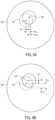
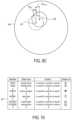
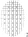
- FIG. 16is a partially schematic diagram in which the various image elements (e.g., trees, foliage, etc.) have been omitted for simplicity, but in which the boundary of goggles image 601 is shown.
- Point 607is the point which IMU data indicates corresponds to point 606 in the scope image. Also shown in FIG. 601 is a 1° by 1° (e.g., 44 pixels by 44 pixels) region 613 centered on point 607 . The significance of region 613 is explained below.
- computer 30proceeds from block 707 to block 709 .
- computer 30obtains pixel gray-scale values from 128 locations on a circle around center 606 of region 610 ( FIG. 15 ). This is shown in more detail in FIG. 17 A , a schematic diagram of pixels surrounding center 606 in a portion of scope image 603 . Each of the squares in FIG. 17 A represents one pixel of scope image 603 . Surrounding center 606 are 128 locations (shown as diamonds) that are equally spaced on a circle having a diameter of approximately 1°. For each of the diamonds in FIG. 17 A , computer 30 obtains the gray-scale value for the pixel in which the diamond's center is located.
- valuesare not limited to those for every other pixel.
- gray-scale valuesmay be obtained for multiple pixels within a 2 ⁇ 2 pixel block corresponding to a single pixel of the microbolometer array in scope 17 . Indeed, there might be instances in which two of the points on the circle are located within the same pixel of image 603 .
- computer 30proceeds from block 709 to block 711 .
- computer 30performs an operation similar to that of block 709 , but instead using goggles image 601 .
- computer 30obtains pixel gray-scale values from 128 locations on a circle around point 607 in goggles image 601 ( FIG. 16 ). This is shown in more detail in FIG. 17 B , a schematic diagram of pixels surrounding point 607 in a portion of goggles image 601 .
- gray-scale valuesmay be obtained for multiple pixels within a 2 ⁇ 2 pixel block corresponding to a single pixel of the microbolometer array 56 in goggles 11 .
- goggles image 601 and scope image 603have the same horizontal, vertical and diagonal fields of view and are of the same pixel dimensions. This need not be the case, however. If one of images 601 or 603 was of a different pixel dimension or had a different field of view, the procedures of blocks 709 and 711 would be similar. In particular, gray-scale values would be obtained from pixels corresponding to the same number of points distributed on similarly-dimensioned circles in each image. If, for example, a goggles image has a 32° horizontal FOV, a 24° vertical FOV and a 40° diagonal FOV, each pixel in that image represents approximately 0.1°. An even distribution of 128 points on a 1° circle would be generally as shown in FIG. 17 C . In FIG.
- point 607 ′is a point (determined using IMU data) corresponding to the center of a high contrast region found in block 703 ( FIG. 14 ).
- Each square in FIG. 17 Crepresents one pixel of a goggles image having the larger FOV values.
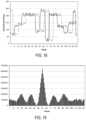
- FIG. 18is a plot showing an example of raw data that might be obtained in blocks 709 and 711 .
- the plots of FIG. 18 and of subsequent FIGS. 19 and 20are provided for purposes of explanation, and would not necessarily be generated by computer 30 .
- the solid line plotrepresents the 128 gray-scale values obtained in one of blocks 709 and 711
- the broken line plotrepresents the 128 values obtained in the other of blocks 709 and 711 .
- a 10% noise factor and a 22.5 degree phase shift(representing a rotation of one image relative to the other) have been added.
- computer 30first performs a discrete Fast Fourier Transform (FFT) on each data set (i.e., a discrete FFT on the 128 scope image values and a discrete FFT on the 128 goggles image values).
- FFTFast Fourier Transform
- Computer 30then multiplies the complex conjugate of one of those discrete FFTs by the other of the discrete FFTs.
- Computer 30next obtains an inverse FFT of the product.
- Computer 30subtracts the DC component of the inverse FFT and obtains data that allows peak-to-sidelobe ratio (PSR) comparisons.
- PSRpeak-to-sidelobe ratio
- FIG. 19is a plot of the results of a calculation in block 713 ( FIG. 14 ) when the center points do coincide.
- the sidelobes in FIG. 19can be seen as three regions (on either side of the peak) that are higher than their surroundings. The location of the peak can also be used to determine the rotation of one image relative to the other. In the example of FIG.
- FIG. 20is an example of a plot resulting from the calculations of block 713 using random data.
- block 715If the result of the evaluation in FIG. 14 block 715 is favorable (e.g., if the PSR ⁇ 3), computer 30 proceeds to block 717 via the “Fav.” branch and stores the PSR, rotation and the pixel coordinates of the point in the goggles image 601 that was used in block 711 (e.g., point 607 ) as the circle center. Computer 30 then continues to block 719 . If the result in block 715 is not favorable (e.g., PSR ⁇ 3), computer 30 proceeds on the “Unfav.” branch to block 719 without storing a PSR, center location or rotation.
- FIGS. 21 and 22show a pattern by which additional points in region 613 are selected in at least some embodiments.
- FIG. 21schematically shows region 613 and location 607 (found in FIG. 14 block 707 ), with each of the squares representing a single pixel.
- FIG. 22is an enlargement of the portion of region 613 indicated in FIG. 21 .
- computer 30selects the pixel at position ⁇ circle around (2) ⁇ .
- Computer 30then returns to block 711 and repeats block 711 using pixel position ⁇ circle around (2) ⁇ instead of point 607 , and then repeats blocks 713 through 719 (possibly omitting block 715 ).
- pixel position ⁇ circle around (3) ⁇is selected. This continues until some stop condition is reached.
- a stop conditionis reached when the pattern shown generally in FIG. 22 reaches the sides of region 613 along the horizontal plane.
- the pattern of FIG. 22weights the search based on a higher probability that any random noise or bias drift will be greater along the yaw axis than along the pitch or roll axes.
- the stop conditionis reached after every other point in both the horizontal and vertical directions has been checked.
- computer 30proceeds to block 723 and determines if any of the data sets (with each set containing a PSR, rotation and center point location) stored in block 717 is unambiguously the best.
- the “best” data setis one in which the PSR is a predetermined percentage above the other stored PSRs. The percentage by which a “best” point should exceed others depends on the characteristics of the imaging technology involved, but one example value is an excess of 10%.
- computer 30proceeds to block 725 .
- block 725(which is substantially similar block 219 of FIG. 7 )
- computer 30updates the IMU-based position for weapon view 74 based on the position and rotation of scope image region 605 within goggles image 601 resulting from the unambiguously best data set.
- Computer 30also uses that data set to adjust the manner in which subsequent IMU-based position and image rotation calculations are made. This adjustment is performed as previously explained in connection with FIGS. 9 A- 9 C .
- computer 30proceeds to block 119 of FIG. 5 B .
- computer 30proceeds to block 727 . If counter N has reached a maximum vale (N MAX ), computer 30 returns (via the “yes” branch) to block 119 of FIG. 5 B . Appropriate values of Nit would depend of various design preferences (e.g., processor speed, acceptable latency, etc.). If counter N has not reached N MAX , computer 30 proceeds on the “no” branch to block 729 and increments counter N, and then proceeds to block 731 . In block 731 a new high contrast region is selected in the scope image.
- N MAXa maximum vale
- the selection of block 731identifies the 3° ⁇ 3° pixel block having the next highest gray-scale value standard deviation, and which does not overlap a previously selected 3° ⁇ 3° pixel block in image 603 by more than a predetermined amount.
- Computer 30then returns to block 707 .
- the search pattern of block 721the sizes of image regions evaluated, and various other parameters can be varied.
- the above-described algorithmemploys center 604 as one reference point and point 607 as a corresponding reference point.
- a point other than the center of the scope imagecan be used as the initial reference point.
- individual pixel gray-scale valuesare the image element data points used in the FFT analyses. Other image element data points could be used (e.g., an average of gray-scale values for several pixels clustered around a point, wavelength (color) information if sensors provide color information).
- 17 A through 17 Chave a particular dimensioned arrangement relative to the reference point (center 604 ) and the corresponding reference point (point 607 ).
- different arrangementse.g., oval, square, concentric rings, etc.
- different dimensionse.g., closer to or farther from the reference point and corresponding reference point
- data setsare stored in block 717 for only the five highest (or some other predetermined number of highest) PSR values.
- the scope imagehas a small number of possible FOVs (e.g., 9° diagonal or 18° diagonal).
- driftmay become obvious to the user. In such a case, the user can manually recalibrate the system.
- a heads up displayneed not be associated with a pair of goggles.
- the heads up displaycould appear before a windshield in a vehicle.
- a weapon mounted on the vehicleincludes a video gun sight producing images processed and projected onto the heads up display.
- an orientation sensormay be placed to sense the orientation of the vehicle rather than a pair of goggles worn by the observer. This embodiment may be particularly useful for remotely controlled weapon systems, for example a robot carrying a weapon.
- controllergenerically refers to any of one or more FPGAs, microprocessors, ASICs, other types of computational devices, or combinations thereof. It is to be understood that the subject matter defined in the appended claims is not necessarily limited to the specific features or acts described above. Rather, the specific features and acts described above are disclosed as example forms of implementing the claims. In the claims, various portions are prefaced with letter or number references for convenience. However, use of such references does not imply a temporal relationship not otherwise required by the language of the claims.
Landscapes
- Engineering & Computer Science (AREA)
- Physics & Mathematics (AREA)
- General Physics & Mathematics (AREA)
- Theoretical Computer Science (AREA)
- Optics & Photonics (AREA)
- Computer Vision & Pattern Recognition (AREA)
- Multimedia (AREA)
- General Engineering & Computer Science (AREA)
- Software Systems (AREA)
- Signal Processing (AREA)
- Computer Hardware Design (AREA)
- Computer Graphics (AREA)
- Health & Medical Sciences (AREA)
- Artificial Intelligence (AREA)
- Computing Systems (AREA)
- Databases & Information Systems (AREA)
- Evolutionary Computation (AREA)
- General Health & Medical Sciences (AREA)
- Medical Informatics (AREA)
- Controls And Circuits For Display Device (AREA)
- Aiming, Guidance, Guns With A Light Source, Armor, Camouflage, And Targets (AREA)
- Processing Or Creating Images (AREA)
Abstract
Description
Claims (35)
Priority Applications (2)
| Application Number | Priority Date | Filing Date | Title |
|---|---|---|---|
| US17/723,730US11965714B2 (en) | 2007-02-28 | 2022-04-19 | System and method for video image registration and/or providing supplemental data in a heads up display |
| US18/612,519US20240230279A1 (en) | 2007-02-28 | 2024-03-21 | System and Method for Video Image Registration and/or Providing Supplemental Data in a Heads Up Display |
Applications Claiming Priority (5)
| Application Number | Priority Date | Filing Date | Title |
|---|---|---|---|
| US11/680,207US9229230B2 (en) | 2007-02-28 | 2007-02-28 | System and method for video image registration and/or providing supplemental data in a heads up display |
| US14/950,643US9618752B2 (en) | 2007-02-28 | 2015-11-24 | System and method for video image registration and/or providing supplemental data in a heads up display |
| US15/483,086US10139629B2 (en) | 2007-02-28 | 2017-04-10 | System and method for video image registration and/or providing supplemental data in a heads up display |
| US16/165,210US20190049734A1 (en) | 2007-02-28 | 2018-10-19 | System and Method for Video Image Registration and/or Providing Supplemental Data in a Heads Up Display |
| US17/723,730US11965714B2 (en) | 2007-02-28 | 2022-04-19 | System and method for video image registration and/or providing supplemental data in a heads up display |
Related Parent Applications (1)
| Application Number | Title | Priority Date | Filing Date |
|---|---|---|---|
| US16/165,210ContinuationUS20190049734A1 (en) | 2007-02-28 | 2018-10-19 | System and Method for Video Image Registration and/or Providing Supplemental Data in a Heads Up Display |
Related Child Applications (1)
| Application Number | Title | Priority Date | Filing Date |
|---|---|---|---|
| US18/612,519ContinuationUS20240230279A1 (en) | 2007-02-28 | 2024-03-21 | System and Method for Video Image Registration and/or Providing Supplemental Data in a Heads Up Display |
Publications (2)
| Publication Number | Publication Date |
|---|---|
| US20230042217A1 US20230042217A1 (en) | 2023-02-09 |
| US11965714B2true US11965714B2 (en) | 2024-04-23 |
Family
ID=39715307
Family Applications (6)
| Application Number | Title | Priority Date | Filing Date |
|---|---|---|---|
| US11/680,207Active2034-11-06US9229230B2 (en) | 2007-02-28 | 2007-02-28 | System and method for video image registration and/or providing supplemental data in a heads up display |
| US14/950,643ActiveUS9618752B2 (en) | 2007-02-28 | 2015-11-24 | System and method for video image registration and/or providing supplemental data in a heads up display |
| US15/483,086ActiveUS10139629B2 (en) | 2007-02-28 | 2017-04-10 | System and method for video image registration and/or providing supplemental data in a heads up display |
| US16/165,210AbandonedUS20190049734A1 (en) | 2007-02-28 | 2018-10-19 | System and Method for Video Image Registration and/or Providing Supplemental Data in a Heads Up Display |
| US17/723,730ActiveUS11965714B2 (en) | 2007-02-28 | 2022-04-19 | System and method for video image registration and/or providing supplemental data in a heads up display |
| US18/612,519PendingUS20240230279A1 (en) | 2007-02-28 | 2024-03-21 | System and Method for Video Image Registration and/or Providing Supplemental Data in a Heads Up Display |
Family Applications Before (4)
| Application Number | Title | Priority Date | Filing Date |
|---|---|---|---|
| US11/680,207Active2034-11-06US9229230B2 (en) | 2007-02-28 | 2007-02-28 | System and method for video image registration and/or providing supplemental data in a heads up display |
| US14/950,643ActiveUS9618752B2 (en) | 2007-02-28 | 2015-11-24 | System and method for video image registration and/or providing supplemental data in a heads up display |
| US15/483,086ActiveUS10139629B2 (en) | 2007-02-28 | 2017-04-10 | System and method for video image registration and/or providing supplemental data in a heads up display |
| US16/165,210AbandonedUS20190049734A1 (en) | 2007-02-28 | 2018-10-19 | System and Method for Video Image Registration and/or Providing Supplemental Data in a Heads Up Display |
Family Applications After (1)
| Application Number | Title | Priority Date | Filing Date |
|---|---|---|---|
| US18/612,519PendingUS20240230279A1 (en) | 2007-02-28 | 2024-03-21 | System and Method for Video Image Registration and/or Providing Supplemental Data in a Heads Up Display |
Country Status (1)
| Country | Link |
|---|---|
| US (6) | US9229230B2 (en) |
Cited By (1)
| Publication number | Priority date | Publication date | Assignee | Title |
|---|---|---|---|---|
| US20230419460A1 (en)* | 2018-11-05 | 2023-12-28 | Ultrahaptics IP Two Limited | Method and apparatus for calibrating augmented reality headsets |
Families Citing this family (66)
| Publication number | Priority date | Publication date | Assignee | Title |
|---|---|---|---|---|
| US9323055B2 (en)* | 2006-05-26 | 2016-04-26 | Exelis, Inc. | System and method to display maintenance and operational instructions of an apparatus using augmented reality |
| JP5119636B2 (en)* | 2006-09-27 | 2013-01-16 | ソニー株式会社 | Display device and display method |
| US9229230B2 (en) | 2007-02-28 | 2016-01-05 | Science Applications International Corporation | System and method for video image registration and/or providing supplemental data in a heads up display |
| US20080218331A1 (en)* | 2007-03-08 | 2008-09-11 | Itt Manufacturing Enterprises, Inc. | Augmented reality-based system and method to show the location of personnel and sensors inside occluded structures and provide increased situation awareness |
| US20090214436A1 (en) | 2008-02-18 | 2009-08-27 | Washington University | Dichromic fluorescent compounds |
| JP2010033367A (en)* | 2008-07-29 | 2010-02-12 | Canon Inc | Information processor and information processing method |
| CA2747544C (en)* | 2008-12-19 | 2016-06-21 | Saab Ab | System and method for mixing a scene with a virtual scenario |
| US8336777B1 (en)* | 2008-12-22 | 2012-12-25 | Pantuso Francis P | Covert aiming and imaging devices |
| US20100196859A1 (en)* | 2009-02-01 | 2010-08-05 | John David Saugen | Combat Information System |
| TWI400467B (en)* | 2009-05-11 | 2013-07-01 | Acer Inc | Electronic device with object guidance function and its object guidance method |
| EP2502410B1 (en)* | 2009-11-19 | 2019-05-01 | eSight Corporation | A method for augmenting sight |
| US10470010B2 (en) | 2010-01-15 | 2019-11-05 | Colt Canada Ip Holding Partnership | Networked battle system or firearm |
| US10477618B2 (en) | 2010-01-15 | 2019-11-12 | Colt Canada Ip Holding Partnership | Networked battle system or firearm |
| US10477619B2 (en) | 2010-01-15 | 2019-11-12 | Colt Canada Ip Holding Partnership | Networked battle system or firearm |
| US10337834B2 (en) | 2010-01-15 | 2019-07-02 | Colt Canada Ip Holding Partnership | Networked battle system or firearm |
| US20110250962A1 (en)* | 2010-04-09 | 2011-10-13 | Feiner Steven K | System and method for a 3d computer game with true vector of gravity |
| US9615147B2 (en)* | 2010-05-17 | 2017-04-04 | Flir Systems, Inc. | Multisensory meter system |
| US20110301813A1 (en)* | 2010-06-07 | 2011-12-08 | Denso International America, Inc. | Customizable virtual lane mark display |
| US8854220B1 (en)* | 2010-08-30 | 2014-10-07 | Exelis, Inc. | Indicating desiccant in night vision goggles |
| US20120157204A1 (en)* | 2010-12-20 | 2012-06-21 | Lai Games Australia Pty Ltd. | User-controlled projector-based games |
| GB2499776A (en)* | 2011-11-17 | 2013-09-04 | Thermoteknix Systems Ltd | Projecting secondary information into an optical system |
| ITFI20110266A1 (en) | 2011-12-09 | 2013-06-10 | Selex Galileo Spa | "MIRA SYSTEM" |
| US9829715B2 (en)* | 2012-01-23 | 2017-11-28 | Nvidia Corporation | Eyewear device for transmitting signal and communication method thereof |
| US10230943B2 (en)* | 2012-01-23 | 2019-03-12 | Washington University | Goggle imaging systems and methods |
| US9625720B2 (en)* | 2012-01-24 | 2017-04-18 | Accipiter Radar Technologies Inc. | Personal electronic target vision system, device and method |
| US9132342B2 (en)* | 2012-10-31 | 2015-09-15 | Sulon Technologies Inc. | Dynamic environment and location based augmented reality (AR) systems |
| US20140125870A1 (en)* | 2012-11-05 | 2014-05-08 | Exelis Inc. | Image Display Utilizing Programmable and Multipurpose Processors |
| WO2014085605A2 (en)* | 2012-11-28 | 2014-06-05 | Intrepid Networks, Llc | Integrated systems and methods providing situational awareness of operations in an organization |
| JP6123365B2 (en)* | 2013-03-11 | 2017-05-10 | セイコーエプソン株式会社 | Image display system and head-mounted display device |
| KR102098277B1 (en)* | 2013-06-11 | 2020-04-07 | 삼성전자주식회사 | Visibility improvement method based on eye tracking, machine-readable storage medium and electronic device |
| US10228242B2 (en) | 2013-07-12 | 2019-03-12 | Magic Leap, Inc. | Method and system for determining user input based on gesture |
| US9816785B2 (en)* | 2013-10-31 | 2017-11-14 | Aerovironment, Inc. | Interactive weapon targeting system displaying remote sensed image of target area |
| US10104241B2 (en)* | 2013-11-14 | 2018-10-16 | Drs Network & Imaging Systems, Llc | Method for integrated optical systems |
| US10338776B2 (en) | 2013-12-06 | 2019-07-02 | Telefonaktiebolaget Lm Ericsson (Publ) | Optical head mounted display, television portal module and methods for controlling graphical user interface |
| US20160091282A1 (en)* | 2014-04-01 | 2016-03-31 | Joe D. Baker | Mobile ballistics processing and targeting display system |
| EP2950035A1 (en)* | 2014-05-28 | 2015-12-02 | Patents Factory Ltd. Sp. z o.o. | Method and system for a tactical visualization |
| US10330440B2 (en)* | 2014-11-26 | 2019-06-25 | Philip Lyren | Target analysis and recommendation |
| US9852547B2 (en)* | 2015-03-23 | 2017-12-26 | International Business Machines Corporation | Path visualization for augmented reality display device based on received data and probabilistic analysis |
| WO2016179350A1 (en) | 2015-05-06 | 2016-11-10 | Washington University | Compounds having rd targeting motifs and methods of use thereof |
| EP3304941A4 (en)* | 2015-05-26 | 2019-01-09 | Colt Canada Ip Holding Partnership | NETWORK BATTLE SYSTEM COMPRISING HIGH HEAD DISPLAY DEVICES |
| JP6555804B2 (en)* | 2015-06-22 | 2019-08-07 | 株式会社日立国際電気 | Shooting training system |
| US10378858B2 (en)* | 2016-01-21 | 2019-08-13 | Kai W. Gull | Systems, devices and methods for visualizing a target |
| CA3093803A1 (en)* | 2016-02-03 | 2017-10-26 | VK Integrated Systems, Inc. | Firearm electronic system |
| DE102017101118A1 (en)* | 2017-01-20 | 2018-07-26 | Steiner-Optik Gmbh | Communication system for transmitting captured object information between at least two communication partners |
| CN108346398A (en)* | 2017-01-24 | 2018-07-31 | 上海珏芯光电科技有限公司 | Its driving method of display driving board device |
| WO2019050495A2 (en)* | 2017-09-06 | 2019-03-14 | Guzeldere Mehmet Ali | Wireless vision equipment for weapons |
| SG11202002344XA (en)* | 2017-09-15 | 2020-04-29 | Tactacam LLC | Weapon sighted camera system |
| CN107886487B (en)* | 2017-12-03 | 2021-04-27 | 南京理工大学 | Real-time implementation method of low-light video inter-frame accumulation noise reduction algorithm based on FPGA |
| DE102018112779A1 (en)* | 2018-04-16 | 2019-10-17 | Indivi Optics Gmbh | Night vision sighting system of a handgun, especially a hunting rifle |
| US20200296316A1 (en) | 2019-03-11 | 2020-09-17 | Quibi Holdings, LLC | Media content presentation |
| US20200296462A1 (en) | 2019-03-11 | 2020-09-17 | Wci One, Llc | Media content presentation |
| IT201900005110A1 (en)* | 2019-04-04 | 2020-10-04 | Eye Tech Lab S R L | MONOCULAR DIGITAL MAGNIFIER AND RELATED GLASSES. |
| US11961294B2 (en) | 2019-09-09 | 2024-04-16 | Techinvest Company Limited | Augmented, virtual and mixed-reality content selection and display |
| US10997418B2 (en)* | 2019-09-09 | 2021-05-04 | Ar, Llc | Augmented, virtual and mixed-reality content selection and display |
| WO2021119423A1 (en) | 2019-12-13 | 2021-06-17 | Washington University | Near infrared fluorescent dyes, formulations and related methods |
| US11409360B1 (en)* | 2020-01-28 | 2022-08-09 | Meta Platforms Technologies, Llc | Biologically-constrained drift correction of an inertial measurement unit |
| US11410270B2 (en) | 2020-06-03 | 2022-08-09 | University Of Central Florida Research Foundation, Inc. | Intelligent object magnification for augmented reality displays |
| US11651502B2 (en)* | 2020-07-22 | 2023-05-16 | Microsoft Technology Licensing, Llc | Systems and methods for updating continuous image alignment of separate cameras |
| US12026235B2 (en)* | 2021-06-04 | 2024-07-02 | Morphix, Inc. | Target classification system |
| US12014514B2 (en) | 2021-06-04 | 2024-06-18 | Morphix, Inc. | Target classification system |
| US11644277B2 (en)* | 2021-07-01 | 2023-05-09 | Raytheon Canada Limited | Digital booster for sights |
| WO2023281488A1 (en) | 2021-07-04 | 2023-01-12 | Elbit Systems Ltd. | A conformal display system and a method thereof |
| GB2614032A (en)* | 2021-10-08 | 2023-06-28 | Uab Yukon Advanced Optics Worldwide | Observation device |
| US11460270B1 (en)* | 2021-11-23 | 2022-10-04 | George Carter | System and method utilizing a smart camera to locate enemy and friendly forces |
| US12429749B2 (en)* | 2022-04-18 | 2025-09-30 | Thales Defense & Security, Inc. | Methods and systems for automatic parallax compensation for helmet mounted imaging sensors used for augmented or extended reality displays |
| US20240080911A1 (en)* | 2022-09-06 | 2024-03-07 | Science Applications International Corporation | Systems and Methods for Communicating Data in an Operational Environment |
Citations (99)
| Publication number | Priority date | Publication date | Assignee | Title |
|---|---|---|---|---|
| US3674925A (en) | 1970-12-03 | 1972-07-04 | Us Navy | Cable-less television system |
| US3798795A (en) | 1972-07-03 | 1974-03-26 | Rmc Res Corp | Weapon aim evaluation system |
| US3798796A (en) | 1972-06-28 | 1974-03-26 | Aerospatiale | Method and equipment for training personnel in the optical tracking of a moving target |
| US3843969A (en) | 1973-11-05 | 1974-10-29 | Us Air Force | Personnel armor suspension system |
| DE2436169A1 (en) | 1974-07-26 | 1976-02-05 | Precitronic | Directed electromagnetic radiation beam transmitter - has helmet mounted aiming device beam projector for communication or firing |
| US3964178A (en) | 1975-07-03 | 1976-06-22 | The United States Of America As Represented By The Secretary Of The Navy | Universal infantry weapons trainer |
| US4020324A (en) | 1974-08-26 | 1977-04-26 | Lear Siegler, Inc. | Weapon delivery system |
| US4028725A (en) | 1976-04-21 | 1977-06-07 | Grumman Aerospace Corporation | High-resolution vision system |
| US4081716A (en) | 1976-03-01 | 1978-03-28 | Ise Electronics Corporation | Fluorescent display elements |
| US4091412A (en) | 1967-12-01 | 1978-05-23 | The United States Of America As Represented By The Secretary Of The Army | Target designation system |
| US4222880A (en) | 1977-09-23 | 1980-09-16 | Siemens Aktiengesellschaft | Arrangement for optical transmission of communications |
| US4280125A (en) | 1979-07-27 | 1981-07-21 | Xerox Corporation | Thin vacuum panel display device |
| US4290757A (en) | 1980-06-09 | 1981-09-22 | The United States Of America As Represented By The Secretary Of The Navy | Burst on target simulation device for training with rockets |
| US4302191A (en) | 1979-03-28 | 1981-11-24 | Weibull John L | Aiming and gunnery training apparatus |
| US4398799A (en) | 1980-03-04 | 1983-08-16 | Pilkington P.E. Limited | Head-up displays |
| US4470817A (en) | 1980-06-27 | 1984-09-11 | Fried. Krupp Gesellschaft mit beschr/a/ nkter Haftung | Apparatus for limiting the firing field of a weapon, particularly an armored cannon, during practice firing |
| US4516157A (en) | 1982-11-23 | 1985-05-07 | Campbell Malcolm G | Portable electronic camera |
| US4597740A (en) | 1981-08-27 | 1986-07-01 | Honeywell Gmbh | Method for simulation of a visual field of view |
| US4605959A (en) | 1984-08-23 | 1986-08-12 | Westinghouse Electric Corp. | Portable communications terminal |
| US4703879A (en) | 1985-12-12 | 1987-11-03 | Varo, Inc. | Night vision goggle headgear |
| WO1988002841A1 (en) | 1986-10-17 | 1988-04-21 | Hughes Aircraft Company | Weapon automatic alerting and cueing system |
| US4752824A (en) | 1986-03-20 | 1988-06-21 | Rank Pullin Control Limited | Parallax correction apparatus for a head-up display |
| US4786966A (en) | 1986-07-10 | 1988-11-22 | Varo, Inc. | Head mounted video display and remote camera system |
| US4884137A (en) | 1986-07-10 | 1989-11-28 | Varo, Inc. | Head mounted video display and remote camera system |
| US4923401A (en) | 1988-11-25 | 1990-05-08 | The United States Of America As Represented By The Secretary Of The Navy | Long range light pen |
| US4963006A (en) | 1986-12-26 | 1990-10-16 | Nikon Corporation | Zoom lens with inner or rear focusing system |
| WO1990012330A2 (en) | 1989-04-13 | 1990-10-18 | Measurement Devices Limited | Hand-held laser rangefinder |
| US4970589A (en) | 1986-07-10 | 1990-11-13 | Varo, Inc. | Head mounted video display and remote camera system |
| US5005213A (en) | 1986-07-10 | 1991-04-02 | Varo, Inc. | Head mounted video display and remote camera system |
| US5059781A (en) | 1989-09-20 | 1991-10-22 | Gec-Marconi Limited | Orientation monitoring apparatus |
| US5200827A (en) | 1986-07-10 | 1993-04-06 | Varo, Inc. | Head mounted video display and remote camera system |
| WO1993019414A1 (en) | 1992-03-24 | 1993-09-30 | Hughes Training, Inc. | Portable exploitation and control system |
| US5274236A (en) | 1992-12-16 | 1993-12-28 | Westinghouse Electric Corp. | Method and apparatus for registering two images from different sensors |
| US5281142A (en) | 1991-05-15 | 1994-01-25 | Zaenglein Jr William | Shooting simulating process and training device |
| US5325449A (en) | 1992-05-15 | 1994-06-28 | David Sarnoff Research Center, Inc. | Method for fusing images and apparatus therefor |
| US5353134A (en) | 1991-11-19 | 1994-10-04 | Thomson-Csf | Weapon aiming device |
| WO1995016948A1 (en) | 1993-12-13 | 1995-06-22 | Carroll David W | Wearable personal computer system |
| EP0545527B1 (en) | 1991-12-06 | 1996-09-04 | Litton Systems, Inc. | Weapon aiming system |
| US5555324A (en) | 1994-11-01 | 1996-09-10 | Massachusetts Institute Of Technology | Method and apparatus for generating a synthetic image by the fusion of signals representative of different views of the same scene |
| US5625765A (en) | 1993-09-03 | 1997-04-29 | Criticom Corp. | Vision systems including devices and methods for combining images for extended magnification schemes |
| EP0777100A2 (en) | 1995-12-09 | 1997-06-04 | Daimler-Benz Aerospace Aktiengesellschaft | Missile weapon system |
| WO1997025583A1 (en) | 1996-01-08 | 1997-07-17 | Tommy Andersson Data Ab | Impact position marker for ordinary or simulated shooting |
| WO1997027527A1 (en) | 1996-01-22 | 1997-07-31 | He Holdings, Inc., Doing Business As Hughes Electronics | Integrated, reconfigurable man-portable modular system |
| US5675112A (en) | 1994-04-12 | 1997-10-07 | Thomson-Csf | Aiming device for weapon and fitted-out weapon |
| US5701202A (en) | 1995-05-18 | 1997-12-23 | Olympus Optical Co., Ltd. | Head or face mounted image display apparatus |
| US5711104A (en) | 1996-12-19 | 1998-01-27 | Schmitz; Geoffrey W. | Small arms visual aiming system, a method for aiming a firearm, and headgear for use therewith |
| US5806229A (en) | 1997-06-24 | 1998-09-15 | Raytheon Ti Systems, Inc. | Aiming aid for use with electronic weapon sights |
| US5834676A (en) | 1996-08-12 | 1998-11-10 | Sight Unseen | Weapon-mounted location-monitoring apparatus |
| WO1998051986A1 (en) | 1997-05-16 | 1998-11-19 | Yair David | Aiming apparatus |
| WO2000037875A1 (en) | 1998-12-18 | 2000-06-29 | Thomson-Csf Sextant | Aiming aid method and system for a light weapon |
| US6123006A (en) | 1998-07-13 | 2000-09-26 | Recon/Optical, Inc. | Retrofit extended vision module for weapon system optical sight |
| US6181302B1 (en) | 1996-04-24 | 2001-01-30 | C. Macgill Lynde | Marine navigation binoculars with virtual display superimposing real world image |
| US6237462B1 (en) | 1998-05-21 | 2001-05-29 | Tactical Telepresent Technolgies, Inc. | Portable telepresent aiming system |
| US6292593B1 (en) | 1996-09-18 | 2001-09-18 | Sharp Kabushiki Kaisha | Image synthesizing device and method |
| US20020015536A1 (en) | 2000-04-24 | 2002-02-07 | Warren Penny G. | Apparatus and method for color image fusion |
| US6449419B1 (en) | 2000-09-05 | 2002-09-10 | Richard Brough | Optical viewing system and clamping device therefor |
| US6560029B1 (en) | 2001-12-21 | 2003-05-06 | Itt Manufacturing Enterprises, Inc. | Video enhanced night vision goggle |
| US20030210228A1 (en) | 2000-02-25 | 2003-11-13 | Ebersole John Franklin | Augmented reality situational awareness system and method |
| US6707761B2 (en) | 2001-09-17 | 2004-03-16 | Bae Systems Information & Electronic Systems Integration Inc | Co-registered acoustical and optical cameras for underwater imaging |
| US20040051680A1 (en) | 2002-09-25 | 2004-03-18 | Azuma Ronald T. | Optical see-through augmented reality modified-scale display |
| US20040056870A1 (en) | 2001-03-13 | 2004-03-25 | Canon Kabushiki Kaisha | Image composition apparatus and method |
| US6765569B2 (en) | 2001-03-07 | 2004-07-20 | University Of Southern California | Augmented-reality tool employing scene-feature autocalibration during camera motion |
| WO2004068212A1 (en) | 2003-01-27 | 2004-08-12 | Energy Laser S.R.L. | Helmet for displaying environmental images in critical environments |
| US6781127B1 (en) | 2000-06-08 | 2004-08-24 | Equinox Corporation | Common aperture fused reflective/thermal emitted sensor and system |
| US6785404B1 (en) | 1999-10-19 | 2004-08-31 | Kabushiki Kaisha Toyoda Jidoshokki Seisakusho | Image positional relation correction apparatus, steering supporting apparatus provided with the image positional relation correction apparatus, and image positional relation correction method |
| KR20040091992A (en) | 2003-04-23 | 2004-11-03 | 싸이트라스텔레콤(주) | Cyber pointer system |
| US6826295B2 (en) | 2000-06-03 | 2004-11-30 | Robert Bosch Gmbh | Method and apparatus for determining reference points in a fingerprint |
| US20040257441A1 (en) | 2001-08-29 | 2004-12-23 | Geovantage, Inc. | Digital imaging system for airborne applications |
| US6836320B2 (en) | 2002-10-23 | 2004-12-28 | Ae Systems Information And Electronic Systems Integration Inc. | Method and apparatus for active boresight correction |
| US20050073531A1 (en) | 2003-10-01 | 2005-04-07 | Canon Kabushiki Kaisha | Image processing apparatus and method, and calibration device for position and orientation sensor |
| US6899539B1 (en) | 2000-02-17 | 2005-05-31 | Exponent, Inc. | Infantry wearable information and weapon system |
| CN1624414A (en) | 2003-12-02 | 2005-06-08 | 郑忠田 | gun electronic sighting device |
| US20050179799A1 (en) | 2004-02-14 | 2005-08-18 | Umanskiy Yuriy K. | Firearm mounted video camera |
| US20050207651A1 (en) | 2004-03-16 | 2005-09-22 | Sony Corporation | System and method for efficiently performing a pattern matching procedure |
| US6963800B1 (en) | 2002-05-10 | 2005-11-08 | Solider Vision | Routing soldiers around enemy attacks and battlefield obstructions |
| CN1727836A (en) | 2004-07-29 | 2006-02-01 | 白世忠 | Tactical operation platform for handgum aiming fire with line changed |
| US20060055786A1 (en) | 2004-03-09 | 2006-03-16 | Viosport | Portable camera and wiring harness |
| US7037258B2 (en) | 1999-09-24 | 2006-05-02 | Karl Storz Imaging, Inc. | Image orientation for endoscopic video displays |
| US7050078B2 (en) | 2002-12-19 | 2006-05-23 | Accenture Global Services Gmbh | Arbitrary object tracking augmented reality applications |
| US20060116814A1 (en) | 2003-04-09 | 2006-06-01 | Milbert Randy L | Method and system for generating and presenting off-road travel routes |
| US20060121993A1 (en) | 2004-12-02 | 2006-06-08 | Science Applications International Corporation | System and method for video image registration in a heads up display |
| US20070001874A1 (en) | 2005-06-29 | 2007-01-04 | Honeywell International Inc. | Perspective view conformal traffic targets display |
| WO2007107975A1 (en) | 2006-03-20 | 2007-09-27 | Itl Optronics Ltd. | Optical distance viewing device having positioning and/or map display facilities |
| US7277118B2 (en) | 1999-08-09 | 2007-10-02 | Fuji Xerox Co., Ltd. | Method and system for compensating for parallax in multiple camera systems |
| WO2007133620A2 (en) | 2006-05-10 | 2007-11-22 | The Boeing Company | System and architecture for automatic image registration |
| US20080025640A1 (en) | 2006-07-25 | 2008-01-31 | Itt Manufacturing Enterprises, Inc. | Motion compensated image registration for overlaid/fused video |
| US20080048931A1 (en) | 2003-11-26 | 2008-02-28 | Rafael - Armament Development Authority Ltd. | Helmet System for Information or Weapon Systems |
| US7369174B2 (en) | 2001-12-27 | 2008-05-06 | Sage Technologies Ltd. | Helmet-mounted thermal imaging system |
| US7401920B1 (en) | 2003-05-20 | 2008-07-22 | Elbit Systems Ltd. | Head mounted eye tracking and display system |
| US20090040308A1 (en) | 2007-01-15 | 2009-02-12 | Igor Temovskiy | Image orientation correction method and system |
| US7580185B2 (en) | 2002-08-28 | 2009-08-25 | Carl Zeiss Surgical Gmbh | Microscopy system, microscopy method and a method of treating an aneurysm |
| US20090235570A1 (en) | 1997-12-08 | 2009-09-24 | Horus Vision | Apparatus and method for calculating aiming point information |
| US7620265B1 (en) | 2004-04-12 | 2009-11-17 | Equinox Corporation | Color invariant image fusion of visible and thermal infrared video |
| US7786424B2 (en) | 2005-05-30 | 2010-08-31 | Andreas Durner | Electronic day and night vision goggles having dual camera |
| US20100254572A1 (en) | 2005-05-09 | 2010-10-07 | Lockheed Martin Corporation | Continuous extended range image processing |
| US7810273B2 (en) | 2005-03-18 | 2010-10-12 | Rudolf Koch | Firearm sight having two parallel video cameras |
| US20100258000A1 (en) | 2005-05-05 | 2010-10-14 | Matthew Charles Hagerty | Wireless, waterproof remote video weapon mounted sighting system, SmartSight |
| US8587659B1 (en) | 2007-05-07 | 2013-11-19 | Equinox Corporation | Method and apparatus for dynamic image registration |
| US9229230B2 (en) | 2007-02-28 | 2016-01-05 | Science Applications International Corporation | System and method for video image registration and/or providing supplemental data in a heads up display |
- 2007
- 2007-02-28USUS11/680,207patent/US9229230B2/enactiveActive
- 2015
- 2015-11-24USUS14/950,643patent/US9618752B2/enactiveActive
- 2017
- 2017-04-10USUS15/483,086patent/US10139629B2/enactiveActive
- 2018
- 2018-10-19USUS16/165,210patent/US20190049734A1/ennot_activeAbandoned
- 2022
- 2022-04-19USUS17/723,730patent/US11965714B2/enactiveActive
- 2024
- 2024-03-21USUS18/612,519patent/US20240230279A1/enactivePending
Patent Citations (110)
| Publication number | Priority date | Publication date | Assignee | Title |
|---|---|---|---|---|
| US4091412A (en) | 1967-12-01 | 1978-05-23 | The United States Of America As Represented By The Secretary Of The Army | Target designation system |
| US3674925A (en) | 1970-12-03 | 1972-07-04 | Us Navy | Cable-less television system |
| US3798796A (en) | 1972-06-28 | 1974-03-26 | Aerospatiale | Method and equipment for training personnel in the optical tracking of a moving target |
| US3798795A (en) | 1972-07-03 | 1974-03-26 | Rmc Res Corp | Weapon aim evaluation system |
| US3843969A (en) | 1973-11-05 | 1974-10-29 | Us Air Force | Personnel armor suspension system |
| DE2436169A1 (en) | 1974-07-26 | 1976-02-05 | Precitronic | Directed electromagnetic radiation beam transmitter - has helmet mounted aiming device beam projector for communication or firing |
| US4020324A (en) | 1974-08-26 | 1977-04-26 | Lear Siegler, Inc. | Weapon delivery system |
| US3964178A (en) | 1975-07-03 | 1976-06-22 | The United States Of America As Represented By The Secretary Of The Navy | Universal infantry weapons trainer |
| US4081716A (en) | 1976-03-01 | 1978-03-28 | Ise Electronics Corporation | Fluorescent display elements |
| US4028725A (en) | 1976-04-21 | 1977-06-07 | Grumman Aerospace Corporation | High-resolution vision system |
| US4222880A (en) | 1977-09-23 | 1980-09-16 | Siemens Aktiengesellschaft | Arrangement for optical transmission of communications |
| US4302191A (en) | 1979-03-28 | 1981-11-24 | Weibull John L | Aiming and gunnery training apparatus |
| US4280125A (en) | 1979-07-27 | 1981-07-21 | Xerox Corporation | Thin vacuum panel display device |
| US4398799A (en) | 1980-03-04 | 1983-08-16 | Pilkington P.E. Limited | Head-up displays |
| US4290757A (en) | 1980-06-09 | 1981-09-22 | The United States Of America As Represented By The Secretary Of The Navy | Burst on target simulation device for training with rockets |
| US4470817A (en) | 1980-06-27 | 1984-09-11 | Fried. Krupp Gesellschaft mit beschr/a/ nkter Haftung | Apparatus for limiting the firing field of a weapon, particularly an armored cannon, during practice firing |
| US4597740A (en) | 1981-08-27 | 1986-07-01 | Honeywell Gmbh | Method for simulation of a visual field of view |
| US4516157A (en) | 1982-11-23 | 1985-05-07 | Campbell Malcolm G | Portable electronic camera |
| US4605959A (en) | 1984-08-23 | 1986-08-12 | Westinghouse Electric Corp. | Portable communications terminal |
| US4703879A (en) | 1985-12-12 | 1987-11-03 | Varo, Inc. | Night vision goggle headgear |
| US4752824A (en) | 1986-03-20 | 1988-06-21 | Rank Pullin Control Limited | Parallax correction apparatus for a head-up display |
| US5005213A (en) | 1986-07-10 | 1991-04-02 | Varo, Inc. | Head mounted video display and remote camera system |
| US4970589A (en) | 1986-07-10 | 1990-11-13 | Varo, Inc. | Head mounted video display and remote camera system |
| US4884137A (en) | 1986-07-10 | 1989-11-28 | Varo, Inc. | Head mounted video display and remote camera system |
| US4786966A (en) | 1986-07-10 | 1988-11-22 | Varo, Inc. | Head mounted video display and remote camera system |
| US5200827A (en) | 1986-07-10 | 1993-04-06 | Varo, Inc. | Head mounted video display and remote camera system |
| WO1988002841A1 (en) | 1986-10-17 | 1988-04-21 | Hughes Aircraft Company | Weapon automatic alerting and cueing system |
| US4963006A (en) | 1986-12-26 | 1990-10-16 | Nikon Corporation | Zoom lens with inner or rear focusing system |
| US4923401A (en) | 1988-11-25 | 1990-05-08 | The United States Of America As Represented By The Secretary Of The Navy | Long range light pen |
| WO1990012330A3 (en) | 1989-04-13 | 1990-12-13 | Measurement Devices Ltd | Hand-held laser rangefinder |
| WO1990012330A2 (en) | 1989-04-13 | 1990-10-18 | Measurement Devices Limited | Hand-held laser rangefinder |
| US5059781A (en) | 1989-09-20 | 1991-10-22 | Gec-Marconi Limited | Orientation monitoring apparatus |
| US5281142A (en) | 1991-05-15 | 1994-01-25 | Zaenglein Jr William | Shooting simulating process and training device |
| US5353134A (en) | 1991-11-19 | 1994-10-04 | Thomson-Csf | Weapon aiming device |
| EP0545527B1 (en) | 1991-12-06 | 1996-09-04 | Litton Systems, Inc. | Weapon aiming system |
| WO1993019414A1 (en) | 1992-03-24 | 1993-09-30 | Hughes Training, Inc. | Portable exploitation and control system |
| US5325449A (en) | 1992-05-15 | 1994-06-28 | David Sarnoff Research Center, Inc. | Method for fusing images and apparatus therefor |
| US5488674A (en) | 1992-05-15 | 1996-01-30 | David Sarnoff Research Center, Inc. | Method for fusing images and apparatus therefor |
| US5274236A (en) | 1992-12-16 | 1993-12-28 | Westinghouse Electric Corp. | Method and apparatus for registering two images from different sensors |
| US5625765A (en) | 1993-09-03 | 1997-04-29 | Criticom Corp. | Vision systems including devices and methods for combining images for extended magnification schemes |
| WO1995016948A1 (en) | 1993-12-13 | 1995-06-22 | Carroll David W | Wearable personal computer system |
| US5675112A (en) | 1994-04-12 | 1997-10-07 | Thomson-Csf | Aiming device for weapon and fitted-out weapon |
| US5555324A (en) | 1994-11-01 | 1996-09-10 | Massachusetts Institute Of Technology | Method and apparatus for generating a synthetic image by the fusion of signals representative of different views of the same scene |
| US5701202A (en) | 1995-05-18 | 1997-12-23 | Olympus Optical Co., Ltd. | Head or face mounted image display apparatus |
| EP0777100A2 (en) | 1995-12-09 | 1997-06-04 | Daimler-Benz Aerospace Aktiengesellschaft | Missile weapon system |
| US5991043A (en) | 1996-01-08 | 1999-11-23 | Tommy Anderson | Impact position marker for ordinary or simulated shooting |
| WO1997025583A1 (en) | 1996-01-08 | 1997-07-17 | Tommy Andersson Data Ab | Impact position marker for ordinary or simulated shooting |
| WO1997027527A1 (en) | 1996-01-22 | 1997-07-31 | He Holdings, Inc., Doing Business As Hughes Electronics | Integrated, reconfigurable man-portable modular system |
| US5864481A (en) | 1996-01-22 | 1999-01-26 | Raytheon Company | Integrated, reconfigurable man-portable modular system |
| US6181302B1 (en) | 1996-04-24 | 2001-01-30 | C. Macgill Lynde | Marine navigation binoculars with virtual display superimposing real world image |
| US5834676A (en) | 1996-08-12 | 1998-11-10 | Sight Unseen | Weapon-mounted location-monitoring apparatus |
| US6292593B1 (en) | 1996-09-18 | 2001-09-18 | Sharp Kabushiki Kaisha | Image synthesizing device and method |
| US5711104A (en) | 1996-12-19 | 1998-01-27 | Schmitz; Geoffrey W. | Small arms visual aiming system, a method for aiming a firearm, and headgear for use therewith |
| WO1998051986A1 (en) | 1997-05-16 | 1998-11-19 | Yair David | Aiming apparatus |
| US5806229A (en) | 1997-06-24 | 1998-09-15 | Raytheon Ti Systems, Inc. | Aiming aid for use with electronic weapon sights |
| US7832137B2 (en) | 1997-12-08 | 2010-11-16 | Horus Vision, Llc | Apparatus and method for calculating aiming point information |
| US20090235570A1 (en) | 1997-12-08 | 2009-09-24 | Horus Vision | Apparatus and method for calculating aiming point information |
| US6237462B1 (en) | 1998-05-21 | 2001-05-29 | Tactical Telepresent Technolgies, Inc. | Portable telepresent aiming system |
| US6123006A (en) | 1998-07-13 | 2000-09-26 | Recon/Optical, Inc. | Retrofit extended vision module for weapon system optical sight |
| WO2000037875A1 (en) | 1998-12-18 | 2000-06-29 | Thomson-Csf Sextant | Aiming aid method and system for a light weapon |
| US7277118B2 (en) | 1999-08-09 | 2007-10-02 | Fuji Xerox Co., Ltd. | Method and system for compensating for parallax in multiple camera systems |
| US7037258B2 (en) | 1999-09-24 | 2006-05-02 | Karl Storz Imaging, Inc. | Image orientation for endoscopic video displays |
| US6785404B1 (en) | 1999-10-19 | 2004-08-31 | Kabushiki Kaisha Toyoda Jidoshokki Seisakusho | Image positional relation correction apparatus, steering supporting apparatus provided with the image positional relation correction apparatus, and image positional relation correction method |
| US6899539B1 (en) | 2000-02-17 | 2005-05-31 | Exponent, Inc. | Infantry wearable information and weapon system |
| US20030210228A1 (en) | 2000-02-25 | 2003-11-13 | Ebersole John Franklin | Augmented reality situational awareness system and method |
| US20020015536A1 (en) | 2000-04-24 | 2002-02-07 | Warren Penny G. | Apparatus and method for color image fusion |
| US6826295B2 (en) | 2000-06-03 | 2004-11-30 | Robert Bosch Gmbh | Method and apparatus for determining reference points in a fingerprint |
| US6781127B1 (en) | 2000-06-08 | 2004-08-24 | Equinox Corporation | Common aperture fused reflective/thermal emitted sensor and system |
| US6449419B1 (en) | 2000-09-05 | 2002-09-10 | Richard Brough | Optical viewing system and clamping device therefor |
| US6765569B2 (en) | 2001-03-07 | 2004-07-20 | University Of Southern California | Augmented-reality tool employing scene-feature autocalibration during camera motion |
| US20040056870A1 (en) | 2001-03-13 | 2004-03-25 | Canon Kabushiki Kaisha | Image composition apparatus and method |
| US7365706B2 (en) | 2001-03-13 | 2008-04-29 | Canon Kabushiki Kaisha | Image composition apparatus and method |
| US20040257441A1 (en) | 2001-08-29 | 2004-12-23 | Geovantage, Inc. | Digital imaging system for airborne applications |
| US6707761B2 (en) | 2001-09-17 | 2004-03-16 | Bae Systems Information & Electronic Systems Integration Inc | Co-registered acoustical and optical cameras for underwater imaging |
| US6560029B1 (en) | 2001-12-21 | 2003-05-06 | Itt Manufacturing Enterprises, Inc. | Video enhanced night vision goggle |
| US7369174B2 (en) | 2001-12-27 | 2008-05-06 | Sage Technologies Ltd. | Helmet-mounted thermal imaging system |
| US6963800B1 (en) | 2002-05-10 | 2005-11-08 | Solider Vision | Routing soldiers around enemy attacks and battlefield obstructions |
| US7580185B2 (en) | 2002-08-28 | 2009-08-25 | Carl Zeiss Surgical Gmbh | Microscopy system, microscopy method and a method of treating an aneurysm |
| US20040051680A1 (en) | 2002-09-25 | 2004-03-18 | Azuma Ronald T. | Optical see-through augmented reality modified-scale display |
| US7002551B2 (en) | 2002-09-25 | 2006-02-21 | Hrl Laboratories, Llc | Optical see-through augmented reality modified-scale display |
| US6836320B2 (en) | 2002-10-23 | 2004-12-28 | Ae Systems Information And Electronic Systems Integration Inc. | Method and apparatus for active boresight correction |
| US7050078B2 (en) | 2002-12-19 | 2006-05-23 | Accenture Global Services Gmbh | Arbitrary object tracking augmented reality applications |
| WO2004068212A1 (en) | 2003-01-27 | 2004-08-12 | Energy Laser S.R.L. | Helmet for displaying environmental images in critical environments |
| US20060116814A1 (en) | 2003-04-09 | 2006-06-01 | Milbert Randy L | Method and system for generating and presenting off-road travel routes |
| KR20040091992A (en) | 2003-04-23 | 2004-11-03 | 싸이트라스텔레콤(주) | Cyber pointer system |
| US7401920B1 (en) | 2003-05-20 | 2008-07-22 | Elbit Systems Ltd. | Head mounted eye tracking and display system |
| US20050073531A1 (en) | 2003-10-01 | 2005-04-07 | Canon Kabushiki Kaisha | Image processing apparatus and method, and calibration device for position and orientation sensor |
| US20080048931A1 (en) | 2003-11-26 | 2008-02-28 | Rafael - Armament Development Authority Ltd. | Helmet System for Information or Weapon Systems |
| CN1624414A (en) | 2003-12-02 | 2005-06-08 | 郑忠田 | gun electronic sighting device |
| US20050179799A1 (en) | 2004-02-14 | 2005-08-18 | Umanskiy Yuriy K. | Firearm mounted video camera |
| US20060055786A1 (en) | 2004-03-09 | 2006-03-16 | Viosport | Portable camera and wiring harness |
| US20050207651A1 (en) | 2004-03-16 | 2005-09-22 | Sony Corporation | System and method for efficiently performing a pattern matching procedure |
| US7620265B1 (en) | 2004-04-12 | 2009-11-17 | Equinox Corporation | Color invariant image fusion of visible and thermal infrared video |
| CN1727836A (en) | 2004-07-29 | 2006-02-01 | 白世忠 | Tactical operation platform for handgum aiming fire with line changed |
| US7787012B2 (en) | 2004-12-02 | 2010-08-31 | Science Applications International Corporation | System and method for video image registration in a heads up display |
| US8817103B2 (en) | 2004-12-02 | 2014-08-26 | Science Applications International Corporation | System and method for video image registration in a heads up display |
| US20060121993A1 (en) | 2004-12-02 | 2006-06-08 | Science Applications International Corporation | System and method for video image registration in a heads up display |
| US7810273B2 (en) | 2005-03-18 | 2010-10-12 | Rudolf Koch | Firearm sight having two parallel video cameras |
| US20100258000A1 (en) | 2005-05-05 | 2010-10-14 | Matthew Charles Hagerty | Wireless, waterproof remote video weapon mounted sighting system, SmartSight |
| US20100254572A1 (en) | 2005-05-09 | 2010-10-07 | Lockheed Martin Corporation | Continuous extended range image processing |
| US7786424B2 (en) | 2005-05-30 | 2010-08-31 | Andreas Durner | Electronic day and night vision goggles having dual camera |
| US20070001874A1 (en) | 2005-06-29 | 2007-01-04 | Honeywell International Inc. | Perspective view conformal traffic targets display |
| WO2007107975A1 (en) | 2006-03-20 | 2007-09-27 | Itl Optronics Ltd. | Optical distance viewing device having positioning and/or map display facilities |
| WO2007133620A2 (en) | 2006-05-10 | 2007-11-22 | The Boeing Company | System and architecture for automatic image registration |
| US20080025640A1 (en) | 2006-07-25 | 2008-01-31 | Itt Manufacturing Enterprises, Inc. | Motion compensated image registration for overlaid/fused video |
| US7805020B2 (en) | 2006-07-25 | 2010-09-28 | Itt Manufacturing Enterprises, Inc. | Motion compensated image registration for overlaid/fused video |
| US20090040308A1 (en) | 2007-01-15 | 2009-02-12 | Igor Temovskiy | Image orientation correction method and system |
| US9229230B2 (en) | 2007-02-28 | 2016-01-05 | Science Applications International Corporation | System and method for video image registration and/or providing supplemental data in a heads up display |
| US9618752B2 (en) | 2007-02-28 | 2017-04-11 | Science Applications International Corporation | System and method for video image registration and/or providing supplemental data in a heads up display |
| US8587659B1 (en) | 2007-05-07 | 2013-11-19 | Equinox Corporation | Method and apparatus for dynamic image registration |
Non-Patent Citations (235)
| Title |
|---|
| "Commander's Digital Assistance (CDA)", General Dynamics C4, downloaded from <http://www.defense-update.com> on Dec. 11, 2006, 3 pages. |
| "Competitive Analysis: Ground Guidance", downloaded from <http://www.primoridal.com> on Dec. 11, 2006, 9 pages. |
| "Competitive Analysis: Unit Detection, Differentiating friend from foe and assessing threats in a soldier's head-mounted display", downloaded from <http://www.primordial.com> on Dec. 11, 2006, 8 pages. |
| "Microsoft Initial Invalidity Contentions for Asserted Patents" (redacted) (May 26, 2020), including claim chart 230-05. |
| "Primordial Solder User Manual", downloaded from <http://www.primordial.com> on Dec. 11, 2006, 28 pages. |
| "Primordial Soldier, Vision system software for soldiers", downloaded from <http://www.primordial.com> on Dec. 11, 2006, 6 pages. |
| "Primordial Soldier: Vision System for Soldiers", Product Sheet, downloaded from <http://www.primordial.com> on Dec. 11, 2006, 2 pages. |
| "Raytheon delivers radios for Land Warrior," Military & Aerospace Electronics, McKenney, TX, <https://www.militaryaerospace.com/articles/2005/07/raytheon-delivers-radios-for-land-warrior.html>, Jul. 27, 2005. |
| "Raytheon to Produce a New Lightweight Thermal Weapon Sight for the U.S. Army," Photonics Online, <https://www.photonocisonline.com/doc/raytheon-to-produce-a-new-lightweight-thermal-0001>, Mar. 4, 1999. |
| "Whitepaper: Ground Guidance", downloaded from <http://www.primordial.com> on Dec. 11, 2006, 15 pages. |
| "Whitepaper: Unit Detection, Differentiating friend from foe and assess threats in a soldier's head-mounted display", downloaded from <http://www.primordial.com> on Dec. 11, 2006, 16 pages. |
| 21 Century Land Warrior (CLW) Generation II (GEN II) Soldier System ATD System/Design Trade Study Report and associated documentation, prototypes and simulations/assessments, (1994-95) (Jan. 6, 1995) (96 pages) (MSFT 00017031-MSFT0007126). |
| Ackerman, J., Application of Augmented Reality to Laparoscopic Surgery, Doctorate Dissertation submitted to the faculty of The University of North Carolina at Chapel Hill, 2002. |
| Anderson, J., "Integrated Imaging Sensors," SPIE 2001, vol. 4369, pp. 14-24 (11 pages). |
| Azuma, et al., "Improving Static and Dynamic Registration in an Optical See-through HMD," Proceedings of SIGGRAPH '94, Computer Graphics, Annual Conference Series, pp. 197-204, Orlando, FL, Jul. 24-29, 1994. |
| Azuma, R., "A Survey of Augmented Reality," Presence: Teleoperators and Virtual Environments, vol. 6, No. 4, pp. 355-385, Aug. 1997. |
| Azuma, R., "Predictive Tracking for Augmented Reality," Dissertation for degree of Doctor of Philosophy, Department of Computer Science, CB#3175, Sitterson Hall, UNC-Chapel Hill, Chapel Hill, NC 27599-3175, Feb. 1995. |
| Bajura, M., "Merging Virtual Objects with the Real World: Seeing Ultrasound Imagery within the Patient," Computer Graphics, Proceedings of SIGGRAPH, vol. 26, No. 2, pp. 203-210, Jul. 1992. |
| Beal, C., et al., "A New Vision: Helmet-Mounted Displays Take Multi-Track Approach," Jane's International Defense Review, pp. 41-44, Aug. 1997. |
| Beal, C., et al., "Helmet-Mounted Displays: Are we Jumping the Gun?," International Defense Reivew, pp. 69-75, Sep. 1994. |
| Behar, I., et al., Visual Survey of Apache Aviators (VISAA), U.S. Army Aeromedical Research Laboratory, Ft. Rucker, Alabama, USAARL Report 9015, Sep. 1990. |
| Bell, B.W., et al., "Error Analysis of Image Matching Using a Non-Planar Object Model," Proceedings of SPIE 4741, Battelspace Digitization and Network-Centric Warfare II, vol. 4741, doi: 10.1117/12.478726, Aug. 2002. |
| Belt, R., et al., "Evolution of Helmet Mounted Display Requirements and Honeywell HMD/HMS Systems," Proceedings of SPIE, vol. 3362, Part of the SPIE Conference on Helmet and Head-Mounted Displays III, doi: 10.1117/12.317451, Apr. 1998. |
| Belt, Ronald A., Combat vehicle visualization system, Proc. SPIE 4021, Helmet- and Head-Mounted Displays V, (Jun. 23, 2000) ("Belt"), 28 pages. |
| Bigwood, C., Thermal Imager for dismounted infantry, /www.spiedigitallibrary.org/conference-proceedings-of-spie/5612/0000/Thermal-image-for-dismounted-infantry/10.1117/12.578489, (2004), 3 pages. |
| Bimber, O., et al., "Spatial Augmented Reality, Merging Real and Virtual Worlds," AK Peters, Ltd., 2004-2005. |
| Braybrook, R., "Looks Can Kill," Armada International, SciTech Premium Collection, vol. 22, No. 4, p. 44, Aug./Sep. 1998. |
| Brown, Lisa, G., "A Survey of Image Registration Techniques," ACM Computing Surveys (CSUR), vol. 24, No. 4, pp. 325-376, Dec. 1992. |
| Bull, G., "Helmet Displays Options—A Routemap," SPIE vol. 1290, Helmet-Mounted Displays II, 1990. |
| Burt, P., et al., "Enhanced Image Capture Through Fusion," Proceedings of IEEE 4th International Conference on Computer Vision, pp. 173-182, 1993. |
| Caldwell, J., "JCF-AWE to test digitizing light forces," Army News Service, <https://fas.org/man/dod-101/sys/land/docs/man-la-land_warrior-000828.htm>, Aug. 28, 2000, 3 pages. |
| Cameron, A., et al., "The Viper HMD—from Design Conept to Flight Test," SPIE, vol. 2218, Helmets Group, Display Systems (Rochester), Displays Division, 1994. |
| Casey, C., "Helmet Mounted Displays on the Modern Battlefield," Proceedings of SPIE, vol. 3689, Helmet- and Head-Mounted Displays IV, doi: 10.1117/12.352839, Jul. 12, 1999. |
| Casey, C., et al., "Part-Task Training with a Helmet Integrated Display Simulator System," Proceedings of SPIE, vol. 1456, Large Screen Projection, Avionic, and Helmet-Mounted Displays, Aug. 1991. |
| Centric, et al., Observations of Infantry Courses: Implications for Land Warrior (LW) Training, U.S. Army Research Institute for the Behavioral and Social Sciences, Jan. 2000, 104 pages. |
| Chapman, F.W. et al., "The Advent of Helmet-Mounted Devices in the Combat Aircraft Cockpit—An Operator Viewpoint." Proceedings of SPIR, 1695, 26-37, (1992), 12 pages. |
| Chisholm, P., "21st Century Helicopter Training," Military Training Technology (Online Ed.). 11(1), 2006, 5 pages. |
| Chung, J., et al., "Exploring Virtual Worlds with Head-Mounted Displays," TR89-009, appeared in Non-Holograhic True 3-Dimensional Display Technologies, SPIE Proceedings, vol. 1083, Jan. 15-20, 1989. |
| Cochran, William T., et al., "What Is the Fast Fourier Transform?", Proceedings of the IEEE, vol. 55, No. 10, Oct. 1967, 1664-1674, 11 pages. |
| Complaint for Patent Infringement, Case No. 1:17-cv-00825-MCW (Fed. CI. Jun. 19, 2017), Document 1, filed Jun. 19, 2017, 47 pages. |
| Curriculum Vitae of Matthew A. Turk, PHD, 22 pages. |
| Davis, L., et al., "Application of Augmented Reality to Visualizing Anatomical Airways," Helmet- and Head-Mounted Displays VII, Proceedings of SPIE, vol. 4711, pp. 400-405, 2002. |
| De Vos, G. et al., "Use of Holographic Optical Elements in HMDs." Helmet Mounted Displays II, Proceedings of SPIE, 1290, 70-80, (1990), 12 pages. |
| Declaration of Dr. Matthew Turk PHD Regarding U.S. Pat. No. 8,817,103—IPR2019-01312, Jul. 11, 2019, 87 pages. |
| Declaration of Dr. Matthew Turk PHD Regarding U.S. Pat. No. 9,618,752, IPR2019-01361, Jul. 19, 2019, 129 pages. |
| Declaration of Dr. Matthew Turk PHD, Regarding U.S. Pat. No. 9,229,230—IPR2019-01359, -01360, Jul. 19, 2019, 180 pages. |
| Declaration of Ingrid Hsieh-Yee, Ph.D. Jul. 10, 2019, 94 pages. |
| Declaration of Ingrid Hsieh-Yee, Ph.D., Jul. 15, 2019, 139 pages. |
| Declaration of Matthew Turk PHD Regarding U.S. Pat. No. 7,787,012—IPR2019-01311 (Jul. 11, 2019) 87 pages. |
| Defendant Motion to Dismiss in Court of Federal Claims case 1:17-cv-00825-EGB (filed Oct. 16, 2017). |
| Defendant Reply to Plaintiff Opposition to Motion to Dismiss in Court of Federal Claims case 1:17-cv-00825-EGB (filed Nov. 27, 2017). |
| Defendant-Intervenor Microsoft Corporation's Amended Invalidity Contentions for the 230 Patent, Science Applications International Corporation v. U.S. and Mircosoft Corporation, Case No. 17-cv-00825, (193 pages) (Feb. 11, 2022). |
| Defendant-Intervenor Microsoft Corporation's Motion for Summary Judgment of Invalidity Based on Indefiniteness, Science Applications International Corporation v. U.S., Microsoft Corporation and L3 Technologies, Inc., Case No. 17-cv-00825, Document 345 (redacted) (38 pages) (Mar. 6, 2023). |
| Defendant's Assertions from Science Applications International Corporation v. U.S., Case No. 17-cv-00825 (Ct. CI.) ("Exhibit 230-02A2: U.S. Pat. No. 9,229,230 (Amended) Invalidity Chart Based on The Roberts Publications") (76 pages). |
| Defendant's assertions from Science Applications International Corporation v. U.S., Case No. 17-cv-00825 (Ct. Cl.) ("Defendant-Intervenor Microsoft Corporation's Initial Invalidity Contentions for the Asserted Patents") (redacted) (May 26, 2020) (223 pages). |
| Defendant's assertions from Science Applications International Corporation v. U.S., Case No. 17-cv-00825 (Ct. Cl.) ("Defendant's Revised Disclosure of Prior Art and Initial Invalidity Claim Chart") (Oct. 27, 2018) (27 pages). |
| Defendant's assertions from Science Applications International Corporation v. U.S., Case No. 17-cv-00825 (Ct. Cl.) ("Exhibit 012-01: U.S. Pat. No. 7,787,012 . . . Based on U.S. Pat. No. 5,200,827 to Hanson et al. . . .") (36 pages). |
| Defendant's assertions from Science Applications International Corporation v. U.S., Case No. 17-cv-00825 (Ct. Cl.) ("Exhibit 012-06: U.S. Pat. No. 7,787,012 . . . Based on Valery") (31 pages). |
| Defendant's assertions from Science Applications International Corporation v. U.S., Case No. 17-cv-00825 (Ct. Cl.) ("Exhibit 012-11: U.S. Pat. No. 7,787,012 . . . Based on Equinox Phase I") (32 pages). |
| Defendant's assertions from Science Applications International Corporation v. U.S., Case No. 17-cv-00825 (Ct. Cl.) ("Exhibit 103-06: U.S. Pat. No. 8,817,103 . . . Based on Valery") (26 pages). |
| Defendant's assertions from Science Applications International Corporation v. U.S., Case No. 17-cv-00825 (Ct. Cl.) ("Exhibit 103-07: U.S. Pat. No. 8,817,103 . . . Based on Equinox Phase I") (25 pages). |
| Defendant's assertions from Science Applications International Corporation v. U.S., Case No. 17-cv-00825 (Ct. Cl.) ("Exhibit 230-01A2: U.S. Pat. No. 9,229,230 (Amended) Invalidity Chart Based on U.S. Pat. No. 6,560,029 to Dobbie, et al. . . .") (77 pages). |
| Defendant's assertions from Science Applications International Corporation v. U.S., Case No. 17-cv-00825 (Ct. Cl.) ("Exhibit 230-06: U.S. Pat. No. 9,229,230 . . . Based on Valery") (85 pages). |
| Defendant's assertions from Science Applications International Corporation v. U.S., Case No. 17-cv-00825 (Ct. Cl.) ("Exhibit 230-07: U.S. Pat. No. 9,229,230 . . . Based on Equinox SBIR") (82 pages). |
| Defendant's assertions from Science Applications International Corporation v. U.S., Case No. 17-cv-00825 (Ct. Cl.) ("Exhibit 752-06: U.S. Pat. No. 9,618,752 . . . Based on Valery") (50 pages). |
| Defendant's assertions from Science Applications International Corporation v. U.S., Case No. 17-cv-00825 (Ct. Cl.) (untitled), Oct. 13, 2018, 279 pages. |
| Defendant's assertions from Science Applications International Corporation v. U.S., Case No. 17-cv-00825 (Ct. Cl.) "Exhibit 230-01: U.S. Pat. No. 9,229,230 . . . Based on U.S. Pat. No. 6,560,029 to Dobbie, et al. . . .") (108 pages). |
| Defendant's assertions from Science Applications International Corporation v. U.S., Case No. 17-cv-00825 (Ct. Cl.) "Exhibit 230-01A: U.S. Pat. No. 9,229,230 (Amended) Invalidity Chart Based on U.S. Pat. No. 6,560,029 to Dobbie, et al. . . .") (65 pages). |
| Defendant's assertions from Science Applications International Corporation v. U.S., Case No. 17-cv-00825 (Ct. Cl.) "Exhibit 230-02A: U.S. Pat. No. 9,229,230 (Amended) Invalidity Chart Based on The Roberts Publications") (72 pages). |
| Defendant's Assertions from Science Applications International Corporation v. U.S., Case No. 17-cv-00825 (Ct. Cl.) "Exhibit 230-03A2: U.S. Pat. No. 9,229,230 (Amended) Invalidity Chart Based on Land Warrior Soldier System") (53 pages). |
| Defendant's Assertions from Science Applications International Corporation v. U.S., Case No. 17-cv-00825 (Ct. Cl.) "Exhibit 230-04A: U.S. Pat. No. 9,229,230 (Amended) Invalidity Chart Based on The Land Warrior Report") (48 pages). |
| Defendant's Assertions from Science Applications International Corporation v. U.S., Case No. 17-cv-00825 (Ct. Cl.) "Exhibit 230-04A2: U.S. Pat. No. 9,229,230 (Amended) Invalidity Chart Based on The Land Warrior Report") (54 pages). |
| Defendant's Assertions from Science Applications International Corporation v. U.S., Case No. 17-cv-00825 (Ct. Cl.) "Exhibit 230-05: U.S. Pat. No. 9,229,230 Invalidity Chart Based on The Desert's Edge Report and System") (76 pages). |
| Defendant's Assertions from Science Applications International Corporation v. U.S., Case No. 17-cv-00825 (Ct. Cl.) "Exhibit 230-05A2: U.S. Pat. No. 9,229,230 (Amended) Invalidity Chart Based on The Desert's Edge Report and System") (45 pages). |
| Defendant's Assertions from Science Applications International Corporation v. U.S., Case No. 17-cv-00825 (Ct. Cl.) "Exhibit 230-06A: U.S. Pat. No. 9,229,230 (Amended) Invalidity Chart Based on Valery") (52 pages). |
| Defendant's Assertions from Science Applications International Corporation v. U.S., Case No. 17-cv-00825 (Ct. Cl.) "Exhibit 230-06A2: U.S. Pat. No. 9,229,230 (Amended) Invalidity Chart Based on Valery") (65 pages). |
| Defendant's Assertions from Science Applications International Corporation v. U.S., Case No. 17-cv-00825 (Ct. Cl.) "Exhibit 230-07A: U.S. Pat. No. 9,229,230 (Amended) Invalidity Chart Based on Equinox SBIR System") (51 pages). |
| Defendant's Assertions from Science Applications International Corporation v. U.S., Case No. 17-cv-00825 (Ct. Cl.) "Exhibit 230-07A2: U.S. Pat. No. 9,229,230 (Amended) Invalidity Chart Based on Equinox SBIR System") (55 pages). |
| Defendant's assertions from Science Applications International Corporation v. U.S., Case No. 17-cv-00825 (Ct. Cl.) "Exhibit 752-01: U.S. Pat. No. 9,618,752 . . . Based on U.S. Pat. No. 6,560,029 to Dobbie, et al. . . .") (69 pages). |
| Defendant's assertions from Science Applications International Corporation v. U.S., Case No. 17-cv-00825 (Ct. Cl.) "Exhibit 752-07: U.S. Pat. No. 9,618,752 . . . Based on Equinox SBIR") (56 pages). |
| Defendant's assertions from Science Applications International Corporation v. U.S., Case No. 17-cv-00825 (Ct. Cl.) Exhibit 103-01: U.S. Pat. No. 8,817,103 . . . Based on U.S. Pat. No. 5,200,827 to Hanson et al. . . . ) (37 pages). |
| Defendant's assertions from Science Applications International Corporation v. U.S., Case No. 17-cv-00825 (Fed. Cl.) (untitled), Oct. 12, 2018, 192 pages. |
| Defendant's Assertions from Science Applications International Corporation v. U.S., Case No. 17-cv-00825, (Ct. Cl.) "Exhibit 230-05A: U.S. Pat. No. 9,229,230 (Amended) Invalidity Chart Based on The Desert's Edge Report and System") (41 pages). |
| Defendant's Assetions from Science Applications International Corporation v. U.S., Case No. 17-cv-00825 (Ct. Cl.) "Exhibit 230-03A: U.S. Pat. No. 9,229,230 (Amended) Invalidity Chart Based on Land Warrior Soldier System") (48 pages). |
| Defendants' Combined Opposition to SAIC's Motions for Patial Summary Judgement of Infringement by the Government and Prior Art Status of Desert's Edge (ECF 340), Science Applications International Corporation v. U.S., Microsoft Corporation and L3 Technologies, Inc. Document 368 (redacted) (48 pages) (Apr. 12, 2023). |
| Defendants' Jun. 30, 2022, Amended Invalidity Contentions for the 230 Patent, Science Applications International Corporation v. U.S., Microsoft Corporation and L3 Technologies, Inc., Case No. 17-cv-00825, (197 pages) (Jun. 20, 2022). |
| Defendants' Response in Opposition to SAIC's Rule 59 Motion for Reconsideration (Dkt. 236), Science Applications International Corporation v. U.S., Microsoft Corporation and L3 Technologies, Inc., Document 251 (redacted) (28 pages) (Jan. 19, 2022). |
| Desert's Edge Research Laboratory, Final Report: Contract#DAAA21-93-M-1651 (Apr. 20, 1993), 54 pages. |
| Dictionary.com, "calibrate" definition, Jul. 16, 2019, 6 pages. |
| Dictionary.com, "goggle" definition, Jul. 12, 2019, 7 pages. |
| Dorheim, M., "VTAS Sight Fielded, Shelved in the 1970s." Aviation Week and Space Technology, October, 23, 51, (1995) (3 pages). |
| Drascic, D., et al., "Perceptual Issues in Augmented Reality," Proceedings of SPIE, vol. 2653: Stereoscopic Displays and Virtual Reality Systems III< pp. 123-134, Feb. 1996. |
| Duchowski, A., et al., "Binocular Eye Tracking in Virtual Reality for Inspection Training," Proceedings of the Eye Tracking Research and Applications Symposium, Palm Beach Gardens, FL, pp. 89-96, Nov. 6-8, 2000. |
| Dupont Corporation, "Case Study: Cadillac XLR has a New Generation Head-Up Display (HUD)," <http://www.2.dupont.com/Automotive/en_US/applications/caseStudies/case178.html>, Apr. 20, 2006. |
| Ehlers M., "Spectral Characteristics Preserving Image Fusion Based on Fourier Domain Filtering," Proceedings of the SPIE, 5574, Remote Sensing for Environmental Monitoring, GIS Applications, and geology IV, doi: 10.1117/12.565160, Maspalomas, Canary Islands, Spain, (2004) (13 pages). |
| Elbit Systems, "MiDASH Modular Integrated Display and Sight System for Helicopter Pilots," (2004), 1 page. |
| Eric Foxlin, Chapter 7: Motion Tracking Requirements and Technologies, Handbook of Virtual Environment Technology, InterSense Inc., downloaded from <http://www.intersense.com> prior to Feb. 28, 2007, 54 pages. |
| Feb. 13, 2007 web page titled "Land Warrior Integrated Modular Fighting System, USA," http://www.army-technology.com/projects/land_warrior (downloaded from The Wayback Machine) (3 pages). |
| Ferrin, "Headgear System Development for the Dismounted Soldier," Proceedings of SPIE, vol. 2735, Head-Mounted Displays, Event: Aerospace/Defense Sensing and Controls, Jun. 7, 1996, doi: 10.1117/12.241905. |
| File history for U.S. Appl. No. 12/116,843 (U.S. Pat. No. 8,587,659), 183 pages. |
| Foley, J.D., et al., "Computer Graphics: Principles and Practice," 2nd Ed., Addison-Wesley, (1990), 1239 pages. |
| Foyle, D., et al., "Attentional Effects with Superimposed Symbology: Implications for Head-Up Displays (HUD)," Proceedings of the Human Factors and Ergonomics Socity 37th Meeting, pp. 1340-1344, 1993. |
| Garamone, J., "Army Tests Land Warrior for 21st Century Soldiers," DoD News, American Forces Press Service, http://archive.defense.gov/news/newsarticle.aspx?id=42267, (Sep. 11, 1998), 2 pages. |
| Geiselman, E.E., "Utility of Off-boresight Helmet-Mounted Symbology During a High Angle Airborne Target Acquisition Task." Helmet- and Head-Mounted Displays and Symbology Design Requirements, Proceedings of SPIE, 2218, 328-338, (1994), 12 pages. |
| Girolamo, H.J., "Advanced Information Displays for the 21st Century Warrior." Information Display, 13(3), 10-17, (1997), 8 pages. |
| Gizmag.com, "Trimersion HMD Takes First Person Shooter Games to a New Level of Reality," http://www.gizmag.com/go/6410, (2007), 7 pages. |
| Graves, W., "‘Land Warrior’ night live-fire sheds light on future," Army News Service, Ft. Polk, Louisiana, <https://fas.org/man/dod-101/sys/land/docs/man-la-land_warrior-000918.htm>, Sep. 18, 2000. |
| Haar, R., "Virtual Reality in the Military: Present and Future," Faculty of Electrical Engineering, Mathematics and Computer Science, University of Twente, Jun. 2006. |
| Hale, S. et al., "Pilot Assessment of the AH-64 Helmet-Mounted Display System." Proceedings of the 5th International Symposium on Aviation Psychology, 1, 307-312, (1989) (8 pages). |
| Harding, T., et al., "Optical and Biodynamic Evaluation of the Helmet Integrated Display Sight System (HIDSS) for the RAH-66 Comanche Development and Validation Program Phase," USAARL Report No. 98-22, U.S. Army Aeromedical Research Laboratory, Ft. Rucker, AL, Mar. 1998. |
| Harding, T., et al., Evaluation of the Microvision Helmet-Mounted Display Technology for Synthetic Vision Application Engineering Prototype for the Virtual Cockpit Optimization Program, USAARL Report No. 2004-02, U.S. Army Aeromedical Research Laboratory, Ft. Rucker, AL, Nov. 2003. |
| Heads-up display definition—Dictionary.com (accessed Jun. 19, 2019), 3 pages. |
| Hiatt, K., et al., "Apache Aviator Visual Experiences with the IHADSS Helmet-Mounted Display in Operation Iraqi Freedom," USAARL Report No. 2004-20, U.S. Army Aeromedical Research Laboratory, Aug. 2004. |
| Hicks, J. et al., Eyekon: Distributed Augmented Reality for Soldier Teams, 21st Century Systems, Inc., Jun. 2003, 30 pages. |
| Hopper, D., "Reality and Surreality of 3-D Displays: Holodeck and Beyond*," Invited Keynote Paper in the Electronic Information Display Conference of Society for Information Display, ExCel Conference and Exhibition Centre, Central London, England UK, Nov. 21-23, 2000. |
| Horn et al., "Fused Reflected/Emitted Light Sensors," Proceedings of the SPIE Infrared Technology and Applications XXVII, vol. 4369, p. 1-13, (2001) (13 pages). |
| Identification of Proposed Claim Constructions and Supporting Evidence, No. 1:17-cv-00825-MCW, (Jun. 13, 2019), 28 pages. |
| Internet Archive version of Feb. 24, 2007, web page titled "FELIN (Fantassin à Équipements et Liaisons Intégrés)—Future Infantry Soldier System, France". |
| InterSense InertiaCube3 and IC3 Processor, Intersense, downloaded from <http://www.intersense.com> prior to Feb. 28, 2007,1 page. |
| Intersense, Inc., Intersense InertiaCube2, <http://www.isense.com/products/prec/ic2/inertiaCube2.pdf>, 2004. |
| Janin, A.L. et al., "Calibration of Head-Mounted Displays for Augmented Reality Applications," Proceedings of IEEE Virtual Reality Annual International Symposium, doi: 10.1109/VRAIS.1993,380772, (Sep. 18-22, 1993) (10 pages). |
| Jennings, S., "An In-Flight Evaluation of Stereoscopic Imagery in Helicopter Cockpits," SPIE Aerosense, Proceedings of SPIE, 3057, 108-117, (1997) (10 pages). |
| Johnston, R.S. et al., "Development of Commercial Retinal Scanning Display." Helmet- and Head-Mounted Displays and Symbology Design Requirements II, Proceedings of SPIE, 2465, 2-13 (1995) (12 pages). |
| Jontz, S., "Exercises will help determine whether ‘light’ is right for Army," Washington Bureau, Stars and Strips, <https://fas.org/man/dod-101/sys/land/docs/man-la-land_warrior-000824.htm>, Aug. 24, 2000. |
| Kalich, M.E. et al., "A Limited Flight Study for Investigating Hyperstereo Vision." Head- and Helmet-Mounted Displays XII: Design and Applications. In: Brown, R.W. et al. (Eds.), Proceedings of SPIE, 6557, 655701, (2007), (14 pages). |
| Kauchak, M., "AVCATT-A Enters Low-Rate Initial Production." T&S 2001, An Armed Forces Journal Global Publication, Winter, 56-57, (2001) (4 pages). |
| Keller, K., et al., "Perception in HMDs, What is it in Head Mounted Displays (HMDs) that really make them all so terrible?," Proceedings of SPIE, vol. 3362, 46-53, 1998. |
| Klass, P.J., "Navy Pilots to use Helmet Sight." Aviation Week and Space Technology, Jan. 31, 37-40 (1972), (6 pages). |
| Kozaitis, S., "Image Preprocessing for Phase-Only Filtering," Proceedings of SPIE, Optical Information Processing Systems and Architecture, vol. 1151, pp. 154-164, Aug. 1989. |
| Kumar, et al., "Correlation Pattern Recognition", published 2005, pp. 149-150. |
| Kutulakos, K., et al., "Calibration-Free Augmented Reality," IEEE Transactions on Visualization and Computer Graphics, vol. 4, No. 1, doi: 10.1109/2945.675647, Jan.-Mar. 1998. |
| Laliberté, F., et al., "Registration and Fusion of Retinal Images—An Evaluation Study," IEEE Transactions on Medical Imaging, vol. 22, No. 5, May 2003. |
| Land Warrior Review—1—Force XXI, In-Process Review Apr. 21-23, 1998, Motorola Space and Systems Technology Group, 126 pages. |
| Livingston, Mark A., et al., "Evaluating System Capabilities and User Performance in the Battlefield Augmented Reality System", published in Proc. NIST/DARPA Workshop on Performance Metrics for Intelligent Systems, Gaithersburg, MD, Aug. 24-26, 2004. |
| Lobo, J., et al., "Vision and Inertial Sensor Cooperation Using Gravity as a Vertical Reference," IEEE Transactions on Pattern Analysis and Machine Ingelligence, vol. 25, No. 12, Dec. 2003. |
| Lucas, T., "Advances in Helmet-Mounted Displays." Avionics, June, pp. 20-27, (1994) (8 pages). |
| Manning, S., et al., "A Moveable View, Head-up displays are paving the way for head-worn displays designed to provide information and flight guidance.," Flight Safety Foundation, AeroSafetyWorld, pp. 41-44, Aug. 2007. |
| Marine Corp SBIR Topic N04-155 "Sensor for Simultaneous Movement and Directed Weapons Fire in Day/Low/no-light" (GOV-0002224). |
| Marshall, G.F., "Back from the Past. Helmet-Mounted Display," Proceedings of SPIE, 1116, 2-11, (1989) (13 pages). |
| Marty Whitford, "Friend or Foe?, FBCB2 Enhances Battle Planning, Reduces ‘Friendly Fire’", GPS World, Feb. 1, 2005, downloaded from <http://www.gpsworld.com/gpsworld> on Dec. 11, 2006, 10 pages. |
| McCann, R., et al., "Attentional Limitations With Head-Up Displays," In R.S. Jensen (Ed.), Proceedings of the Seventh International Symposium on Aviation Psychology, 70-75, Columbus: Ohio State University, 1993. |
| McCann, R., et al., "Scene-linked Symbology to Improve Situation Awareness," AGARD Conference Proceedings, No. 555, Aerospace Medical Panel Conference on Situation Awareness, 16:1-16:11, 1995. |
| McLean, W., et al., "A Performance History of AN/PVS-5 and ANVIS Image Intensification Systems in U.S. Army Aviation (Reprint)," USAARL Report No. 98-28, U.S. Army Aeromedical Research Laboratory, Ft. Rucker, AL, May 1998. |
| Melzer, J., et al., "An integrated approach to helmet display system design," Optical and Helmet Systems Department, Kaiser Electronics, SPIE, vol. 778, Display System Optics, pp. 83-87, 1987. |
| Melzer, J.E., et al., "Head-Mounted Displays: Designing for the User." New York: McGraw-Hill, (1997) (445 pages). |
| Memorandum Order, Science Applications International Corporation v. U.S., Microsoft Corporation and L3 Technologies, Inc., Case No. 17-cv-825, Document 299, (23 pages) (Aug. 5, 2022). |
| Merryman, R.K., "Vista Sabre II: Integration of Helmet-Mounted Tracker/Display and High Boresight Missile Seeker Into F-15 Aircraft." Proceedings of SPIE, 2218, 173-184, (1994) (14 pages). |
| Microsoft Press Computer Dictionary (3rd ed. 1997), 43 pages. |
| Milgrani, P., et al., "Augmented Reality: A class of displays on the reality-virtuality continuum," ATR Communication Systems Research Laboratories, SPIE, vol. 2351, Telemanipulator and Telepresence Technologies, 1994. |
| Moore, J., et al., "The Use of Simulation and Modeling for Acquisition, Requirements, and Training (Smart) in the Virtual Cockpit Optimization Program (VCOP)," The Interservice/Industry Training, Simulation and Education Conference (I/ITSEC), 1999. |
| National Defense Magazine, Can the Army Make Objective Force Warrior Work?, <http://www.nationaldefenesemagazine.org/articl.cfm?id=1173>, Aug. 2003. |
| Naval SBIR-28, FY04.2 Proposal Submission, 41 pages. |
| Navy SBIR FY04.2 Proposal Submission, N04-155, Sensor for Simultaneous Movement and Directed Weapons Fire in Day/Low/No-light, on or before Apr. 2004. |
| Nelson, A.S. et al., "High Resolution Color Flat Panel Head-Mounted Display Design for the Advanced Flat Panel Program." Proceedings of SPIE, 2218, 7-16, (1996) (10 pages). |
| Nelson, S., "Combat Vehicle Crew Helmet-Mounted Display: Next Generation High-Resolution Head-Mounted Display." In: Lewandowski, R. et al. (Ed.), Helmet- and Head-Mounted Displays and Symbology Design Requirements, Proceedings of SPIE, 2218, 7-16 (1996) (10 pages). |
| Nelson, S., et al., "Arthroscopic knee surgery using the advanced flat panel high-resolution color head-mounted display," Proc. SPIE, vol. 3058, Head-Mounted Displays II, doi: 10.1117/12.276640, pp. 170-177, Jun. 18, 1997. |
| Néñez, J., et al., "Multiresolution-Based Image Fusion with Additive Wavelet Decomposition," IEEE Transactions on Geoscience and Remote Sensing, vol. 37, No. 3, pp. 1204-1211, doi: 10.1109/36.763274, May 1999. |
| New Oxford American Dictionary (2nd ed. 2005), 56 pages. |
| New Oxford American Dictionary (2nd ed. 2005), Parts 1 and 2, 134 pages. |
| Order Denying Motion to Dismiss in Court of Federal Claims case 1:17-cv-00825-EGB (entered Jan. 19, 2018). |
| Order, Science Applications International Corp. v. U.S., Microsoft Corporation and L3 Technologies, Inc., Case No. 17-cv-00825 C, Document 195, (2 pages) (Aug. 11, 2021). |
| Palmer, B., "The Wired Warrior: The Army and Partner Raytheon Reinvent the Foot Soldier for the Digital Battlefield," Fortune, vol. 138, Issue 12, Dec. 21, 1998. |
| Petition for Inter Partes Review of U.S. Pat. No. 7,787,012, IPR2019-01311, Jul. 11, 2019, 75 pages. |
| Petition for Inter Partes Review of U.S. Pat. No. 9,229,230, IPR2019-01359, Jul. 22, 2019, 94 pages. |
| Petition for Inter Partes Review of U.S. Pat. No. 9,229,230, IPR2019-01360, Jul. 23, 2019, 91 pages. |
| Petition for Inter Partes Review of U.S. Pat. No. 9,618,752, IPR2019-01361, Jul. 23, 2019, 89 pages. |
| Petition for Inter Partes Review of U.S. Patent No. 8,817,103, IPR2019-01312, Jul. 11, 2019, 81 pages. |
| Pike, J. and Sherman R., "Land Warrior," FAS Military Analysis Network, <https://fas.org/man/dod-101/sys/land/land-warror.htm>, Aug. 7, 1999. |
| Plaintiff Opposition to Motion to Dismiss in Court of Federal Claims case 1:17-cv-00825-EGB (filed Nov. 13, 2017). |
| Plaintiff's Motion for Reconsideration with Exhibits A, B and C, Science Applications International Corp. v. U.S., Microsoft Corporation and L3 Technologies, Inc., Case No. 17-cv-00825, Document 254 (redacted) (Jan. 27, 2022) (41 pages). |
| Plaintiff's Motion for Reconsideration, Science Applications International Corp., v. U.S. Microsoft Corporation and L3 Technologies, Inc., Case No. 17-cv-00825, Document 245 (redacted) (19 pages) (Dec. 22, 2021). |
| Plaintiff's Reply in Support of Its Motion for Reconsideration with Exhibit A, Science Applications International Corp., v. U.S., Microsoft Corporation and L3 Technologies, Inc., Case No. 17-cv-00825, Document 256 (redacted) (Jan. 27, 2022) (21 pages). |
| Primeau, G., "Wide-field-of-view SVGA sequential color HMD for use in anthromorphic telepresence applications," Proceedings of SPIE, vol. 4021, Helmet- and Head-Mounted Displays V., doi: 10.1117/12.389147, pp. 11-19, Jun. 23, 2000. |
| Primordial Soldier: Geographically-Enabled Augmented Reality System for Dismounted Soldiers (A05-119), Presentation, downloaded from <http://www.primordial.com> on Dec. 11, 2006, 35 pages. |
| Proctor, P., "Retinal Displays Portend Synthetic Vision, HUD Advances." Aviation Week and Space Technology, 15, 58, (1996) (3 pages). |
| ProView XL35 & XL50, Dec. 8, 2007 web page for <http://www.rockwellcollins.com/optronics/ProductsAndServices/VisionSystems/HeadMountedDisplays/ProViewXL50/page738.html>, downloaded from The Wayback Machine (1 page). |
| Qt Auto News, "HUD Technology Keeps Your Eye on the Road." Auto News, http://www.qtautonews.com/2006/04/25/hud-technology-keeps-your-eye-on-the-road/, (2006) (downloaded from The Wayback Machine) (3 pages). |
| Quantum3d, Inc., Daggers: Embedded Training for Dismounted Soldiers Science and Technology Objective (STO), <http://www.quantum3d.com/PDF/sstories/SStories_Daggers.pdf>, 2004. |
| Randello, J.S., et al., "The Integrated Sight: Future Improvement for Land Warroior," Proceedings of SPIE 3394, Sensor Technology for Soldier Systems, doi: 10.1117/12.321043, (Event: Aerospace/Defense Sensing and Controls, Orlando, FL, United States), Apr. 1998. |
| Rash, C., "Shutting Out the Noise," Flight Safety Foundation, AviationSafetyWorld, pp. 42-45, Nov. 2006. |
| Rash, C.E. (Editor), "Helmet-Mounted Displays: Design Issues for the Rotary-Wing Environment." Bellingham, WA: SPIE Press, (2000), 312 pages. |
| Reinhart, W., "Depth Cueing for Visual Search an Positioning." Proceedings of SPIE, 1457, 221-232, (1992), 13 pages. |
| Roberts, "A Helmet Integration Case Study: Head Orientation Sensor Integration Into Land Warrior, The Design & Integration of Helmet Systems: Proc.," Dec. 2-5, 1997, 18 pages. |
| Roberts, B., et al., "Electronic Compass and Vertical-Angle Measurement Sensor: Applications and Benefits to the Soldier System," Proceedings of SPIE, vol. 3394, Event: Aerospace/Defense Sensing and Controls, 1998, doi: 10.1117/12.321038. |
| Rolland, J., et al., "Head-Mounted Projective Displays for Creating Collaborative Environments," Proceedings of SPIE, vol. 4711, pp. 395-399, 2002. |
| Science Applications International Corporation's Memorandum in Support of Its Motion for Partial Summary Judgment of Infringement by the Government and for Summay Judgment Regarding the Desert's Edge Prior Art Status, Science Applications International Corporation v. U.S., Microsoft Corporation and L3 Technologies, Inc., Case No. 17-cv-00825, Document 351 (redacted) (50 pages) (Mar. 13, 2023). |
| Science Applications International Corporation's Opposition to Defendant-Intervenor Microsoft Corporation's and the United States' and Third Party Defendant L3 Technologies, Inc.'s Motions for Summary Judgment of Invalidity Based on Indefiniteness, Science Applications International Corporation v. U.S., Microsoft Corporation and L3 Technologies, Inc., Document 371 (redacted) (49 pages) (Apr. 12, 2023). |
| Science Applications International Corporation's Reply to Defendants' Combined Opposition to SAIC's Motion for Partial Summary Judgment of Infringement by the Government and Prior Art Status of Desert's Edge, Science Applications International Corporation v. U.S., Microsoft Corporation and L3 Technologies, Inc., Case No. 17-cv-00825, Document 387 (redacted) (27 pages) (Apr. 26, 2023). |
| Science Applications International Corporation's Response to Microsoft's Invalidity Contentions Exhibit 012-01 (Hanson) U.S. Pat. No. 7,787,012 in Science Applications International Corporation v. U.S., Case No. 17-cv-00825 (19 pages). |
| Science Applications International Corporation's Response to Microsoft's Invalidity Contentions Exhibit 012-02 (Roberts References) U.S. Pat. No. 7,787,012, in Science Applications International Corporations v. U.S., Case No. 17-cv-00825 (18 pages). |
| Science Applications International Corporation's Response to Microsoft's Invalidity Contentions Exhibit 012-06 (Valery) U.S. Pat. No. 7,786,012, in Science Applications International Corporation v. U.S., Case No. 17-cv-00825 (15 pages). |
| Science Applications International Corporation's Response to Microsoft's Invalidity Contentions Exhibit 103-02 (Roberts References) U.S. Pat. No. 8,817, 103, in Science Applications International Corporation v. U.S., Case No. 17-cv-00825 (12 pages). |
| Science Applications International Corporation's Response to Microsoft's Invalidity Contentions Exhibit 103-06 (Valery) U.S. Pat. No. 8,817, 103, in Science Applications International Corporation v. U.S., Case No. 17-cv-00825 (15 pages). |
| Science Applications International Corporation's Response to Microsoft's Invalidity Contentions Exhibit 230-01 (Dobbie) U.S. Pat. No. 9,229,230, in Science Applications International Corporation v. U.S., Case No. 17-cv-00825 (58 pages). |
| Science Applications International Corporation's Response to Microsoft's Invalidity Contentions Exhibit 230-02 (Roberts References) U.S. Pat. No. 9,229,230 in Science Applications International Corporation v. U.S., Case No. 17-cv-00825 (47 pages). |
| Science Applications International Corporation's Response to Microsoft's Invalidity Contentions Exhibit 230-06 (Valery) U.S. Pat. No. 9,229,230 in Science Applications International Corporation v. U.S., Case No. 17-cv-00825 (40 pages). |
| Science Applications International Corporation's Response to Microsoft's Invalidity Contentions Exhibit 752-01 (Dobbie) U.S. Pat. No. 9,618,752 in Science Applications International Corporation v. U.S., Case No. 17-cv-00825 (35 pages). |
| Science Applications International Corporation's Response to Microsoft's Invalidity Contentions Exhibit 752-02 (Roberts References) U.S. Pat. No. 9,617,752 in Science Applications International Corporation v. U.S., Case No. 17-cv-0025 (30 pages). |
| Science Applications International Corporation's Response to Microsoft's Invalidity Contentions Exhibit 752-06 (Valery) U.S. Pat. No. 9,618,752 in Science Applications International Corporation v. U.S., Case No. 17-cv-0025 (25 pages). |
| Scribner, D., et al., "Infrared Color Vision: An Approach to Sensor Fusion," Optics and Photonics News, pp. 27-32, Aug. 1998. |
| Seeman, J. et al., "Advanced Helicopter Pilotage Visual Requirements." Proceedings of the American Helicopter Society, 48, 233-252, (1992) (22 pages). |
| Sensor Technology Systems, Inc., Model 2733 Low Profile/Night Vision Goggle: AN/PVS-21: Operational Summary, 2004. |
| Simons, R., et al., "Visualization Solutions for AVCATT-A Reconfigurable Cockpits," The Interservice/Industry Training, Simulation and Education Conference (I/ITSEC), Orlando, FL, 2002. |
| Socolinsky, D., et al., "Brain Imaging Registration by Correlation of First-Order Geometry," Proceedings of SPIE, vol. 3661, Event: Medical Imaging, 1999, Part of the SPIE Conference on Image Processing, Feb. 1999. |
| Socolinsky, D., et al., "Multipsectral Image Visualization Through First-Order Fusion," IEEE Transactions on Image Processing, vol. 11, No. 8, pp. 923-931, Aug. 2002. |
| Spitzer, Cary R., Digital Avionics Systems and Principles and Practices (2000), 10 pages. |
| State, A., et al., "Superior Augmented Reality Registration by Integrating Landmark Tracking and Magnetic Tracking," SIGGRAPH '96 Proceedings of the 23rd Annual Conference on Computer Graphics and Interactive Techniques, pp. 429-438, doi: 10.1145/237170.237282, 1996. |
| Steding, T., et al., "Optimum Filters for Image Registration," IEEE Transactions on Aerospace and Electronic Systems, vol. AES-15, No. 6, Nov. 1979. |
| Strine, J., "Final JCF-AWE attack shows equipment works," Army News Service, Ft. Polk, Louisiana, <https://fas.org/man/dod-101/sys/land/docs/man-la-land_warrior-000920.htm>, Sep. 20, 2000. |
| Stuart, G.W. et al., "Head-up displays and visual attention: Integrating data and theory," in "Contemporary Issues in Human Factors and Aviation Safety." Burlington, Vermont: Ashgate Publishing, (2005) (25 pages). |
| Sutherland, I., "The Ultimate Display," Proceedings of the IFIP Congress 2, pp. 506-508, 1965. |
| The New Oxford American Dictionary, Second Edition, (2005), 11 pages. |
| Thurman, S., et al., "Image Registration for Fizeau Fourier Transform Imaging Spectroscopy," The Institute of Optics, University of Rochester, Algorithms and Technologies for Multispectral, Hyperspectral, and Ultraspectral Imagery XII, Proceedings of SPIE, vol. 6233, doi: 10.1117/12.665593, 2006. |
| Toet, A., et al., "Merging Thermal and Visual Images by a Contrast Pyramid," Optical Engineering, vol. 28, No. 7, pp. 789-792, Jul. 1989. |
| Toet, A., et al., "New False Color Mapping for Image Fusion," Optical Engineering, vol. 35, No. 3, pp. 650-658, Mar. 1996. |
| U.S. Appl. No. 60/560,968, filed Apr. 12, 2004, 62 pages. |
| U.S. Appl. No. 60/924,264, filed May 7, 2007, 268 pages. |
| Wahlde, R.V., Application of an Inertial Reticle System to an Objective Personal Weapon, Army Research Laboratory, Feb. 1996, 30 pages. |
| Walrath, James D., "Information Technology for the Soldier: The Human Factor," Army Research Laboratory (ARL-TR-3525), May 2005, 18 pages. |
| Waxman, A., et al., "Color Night Vision: Opponent Processing in the Fusion of Visible and IR Imagery," Neural Networks, vol. 10, No. 1, pp. 1-6, 1997. |
| Weapon Systems 2002, United States Army (2002), 66 pages. |
| Web pages regarding AN/PVS-21, STS Sensor Technology Systems, downloaded from <http://www.sts-eo.com> on Jan. 11, 2007, 9 pages. |
| White, J., "Knighthelm 24-hour HMD: from development to production," Proceedings of SPIE, vol. 4361, Helmet- and Head-Mounted Displays VI, doi: 10.1117/12.437991, pp. 164-175, Aug. 22, 2001. |
| Wickens, C., et al., "Conformal Symbology, Attention Shifts, and the Head-Up Display," Proceedings of the Human Factors and Ergonomics Society 38th Annual Meeting, pp. 6-10, 1994. |
| Wolff, "Sensor for Simultaneous Movement and Directed Weapons Fire in Day/Night Conditions," May 2007, 268 pages. |
| Wood, R., "Holographic Head-Up Displays," Electro-Optical Displays, in: Karim, M., (Ed.), New York: Marcel Dekker, pp. 337-415, 1992. |
| Xue, Z., et al., "Concealed Weapon Detection Using Color Image Fusion," pp. 622-627, IEEE 2003. |
| Yeh, Michelle, et al., "Effects of Frame of Reference and Viewing Condition on Attentional Issues with Helmet Mounted Displays", Technical Report, Jan. 1998, pp. 1-75. |
| Yocky, D., "Image Merging and Data Fusion by Means of the Discrete Two-Dimensional Wavelet Transform," J. Opt. Soc. Am. A, vol. 12, No. 9, pp. 1834-1841, Sep. 1995. |
| Yona, Z., et al., "Day/night ANVIS/HUD-24 (day HUD) flight test and pilot evaluations," Proceedings of SPIE, vol. 5442, Helmet- and Head-Mounted Displays IX: Technologies and Applications, doi: 10.1117/12.543440, Sep. 8, 2004. |
| You, S., et al., "Hybrid Inertial and Vision Tracking for Augmented Reality Registration," IEEE Virtual Reality '99 Conference, pp. 260-267, Mar. 13-17, 1999. |
| You, S., et al., Orientation Tracking for Outdoor Augmented Reality Registration, IEEE Computer Graphics and Applications, Virtual Reality, pp. 36-42, Nov./Dec. 1992. |
| Zhang, E., Pixel-by-pixel VIS/NIR and LIR sensor fusion system, /www.spiedigitallibrary.org/conference-proceedings-of-spie/4820/0000/Pixel-by-pixel-VISNIR-and-LIR-sensor-fusion-system/10.1117/12.450540 (15 pages). |
| Zintsmaster, L.R., "Wide-Eye Helmet Mounted Display System for Rotorcraft Applications." IEEE Aerospace and Electronic Systems Magazine. 9(3), 6-11, (1994), 5 pages. |
| Zitova, B., et al., "Image Registration Methods: A Survey," Image and Vision Computing, 21, 977-1000, Received Nov. 2001, Accepted Jun. 2003. |
Cited By (2)
| Publication number | Priority date | Publication date | Assignee | Title |
|---|---|---|---|---|
| US20230419460A1 (en)* | 2018-11-05 | 2023-12-28 | Ultrahaptics IP Two Limited | Method and apparatus for calibrating augmented reality headsets |
| US12169918B2 (en)* | 2018-11-05 | 2024-12-17 | Ultrahaptics IP Two Limited | Method and apparatus for calibrating augmented reality headsets |
Also Published As
| Publication number | Publication date |
|---|---|
| US20170212353A1 (en) | 2017-07-27 |
| US20080204361A1 (en) | 2008-08-28 |
| US20160077343A1 (en) | 2016-03-17 |
| US20240230279A1 (en) | 2024-07-11 |
| US9618752B2 (en) | 2017-04-11 |
| US10139629B2 (en) | 2018-11-27 |
| US20190049734A1 (en) | 2019-02-14 |
| US9229230B2 (en) | 2016-01-05 |
| US20230042217A1 (en) | 2023-02-09 |
Similar Documents
| Publication | Publication Date | Title |
|---|---|---|
| US11965714B2 (en) | System and method for video image registration and/or providing supplemental data in a heads up display | |
| US8817103B2 (en) | System and method for video image registration in a heads up display | |
| US11226175B2 (en) | Devices with network-connected scopes for allowing a target to be simultaneously tracked by multiple devices | |
| US9891705B1 (en) | Automatic boresighting of head-worn display | |
| US8209140B2 (en) | Cooperative calibration of heading sensors | |
| US12050084B2 (en) | Method for tracking a single presumed target by a plurality of scopes located remotely from one another and amalgamating current target position data from scopes that located the presumed target | |
| US10425540B2 (en) | Method and system for integrated optical systems | |
| JP2008061224A (en) | Passive optical locator | |
| KR102853492B1 (en) | A vehicle-mounted device with networked scopes that allows simultaneous tracking of targets from multiple different devices. | |
| US11893298B2 (en) | Multi-platform integrated display | |
| US20220042769A1 (en) | Autonomous optronic module for geolocated target pointing for a portable system, and corresponding system | |
| US20210081037A1 (en) | Large Area Tracker with Milliwave Boresight Capability |
Legal Events
| Date | Code | Title | Description |
|---|---|---|---|
| AS | Assignment | Owner name:SCIENCE APPLICATIONS INTERNATIONAL CORPORATION, VIRGINIA Free format text:CHANGE OF NAME;ASSIGNOR:SAIC GEMINI, INC.;REEL/FRAME:059727/0711 Effective date:20130927 Owner name:SAIC GEMINI, INC., VIRGINIA Free format text:ASSIGNMENT OF ASSIGNORS INTEREST;ASSIGNOR:SCIENCE APPLICATIONS INTERNATIONAL CORPORATION;REEL/FRAME:059638/0426 Effective date:20130927 Owner name:SCIENCE APPLICATIONS INTERNATIONAL CORPORATION, VIRGINIA Free format text:ASSIGNMENT OF ASSIGNORS INTEREST;ASSIGNORS:SCALES, JOHN RICHARD;RODGERS, MICHAEL HARRIS;SIGNING DATES FROM 20070219 TO 20070228;REEL/FRAME:059638/0422 | |
| FEPP | Fee payment procedure | Free format text:ENTITY STATUS SET TO UNDISCOUNTED (ORIGINAL EVENT CODE: BIG.); ENTITY STATUS OF PATENT OWNER: LARGE ENTITY | |
| AS | Assignment | Owner name:SCIENCE APPLICATIONS INTERNATIONAL CORPORATION, VIRGINIA Free format text:ASSIGNMENT OF ASSIGNORS INTEREST;ASSIGNOR:HOSE, MARK D.;REEL/FRAME:059826/0626 Effective date:20220504 | |
| STPP | Information on status: patent application and granting procedure in general | Free format text:NON FINAL ACTION MAILED | |
| STPP | Information on status: patent application and granting procedure in general | Free format text:RESPONSE TO NON-FINAL OFFICE ACTION ENTERED AND FORWARDED TO EXAMINER | |
| STPP | Information on status: patent application and granting procedure in general | Free format text:FINAL REJECTION MAILED | |
| STPP | Information on status: patent application and granting procedure in general | Free format text:RESPONSE AFTER FINAL ACTION FORWARDED TO EXAMINER | |
| STPP | Information on status: patent application and granting procedure in general | Free format text:NOTICE OF ALLOWANCE MAILED -- APPLICATION RECEIVED IN OFFICE OF PUBLICATIONS | |
| ZAAB | Notice of allowance mailed | Free format text:ORIGINAL CODE: MN/=. | |
| STPP | Information on status: patent application and granting procedure in general | Free format text:PUBLICATIONS -- ISSUE FEE PAYMENT VERIFIED | |
| STCF | Information on status: patent grant | Free format text:PATENTED CASE | |
| CC | Certificate of correction |