US11964808B2 - Method of forming a pad - Google Patents
Method of forming a padDownload PDFInfo
- Publication number
- US11964808B2 US11964808B2US17/233,629US202117233629AUS11964808B2US 11964808 B2US11964808 B2US 11964808B2US 202117233629 AUS202117233629 AUS 202117233629AUS 11964808 B2US11964808 B2US 11964808B2
- Authority
- US
- United States
- Prior art keywords
- mould
- region
- pad
- space
- sheet
- Prior art date
- Legal status (The legal status is an assumption and is not a legal conclusion. Google has not performed a legal analysis and makes no representation as to the accuracy of the status listed.)
- Active, expires
Links
Images


Classifications
- B—PERFORMING OPERATIONS; TRANSPORTING
- B65—CONVEYING; PACKING; STORING; HANDLING THIN OR FILAMENTARY MATERIAL
- B65D—CONTAINERS FOR STORAGE OR TRANSPORT OF ARTICLES OR MATERIALS, e.g. BAGS, BARRELS, BOTTLES, BOXES, CANS, CARTONS, CRATES, DRUMS, JARS, TANKS, HOPPERS, FORWARDING CONTAINERS; ACCESSORIES, CLOSURES, OR FITTINGS THEREFOR; PACKAGING ELEMENTS; PACKAGES
- B65D71/00—Bundles of articles held together by packaging elements for convenience of storage or transport, e.g. portable segregating carrier for plural receptacles such as beer cans or pop bottles; Bales of material
- B65D71/0088—Palletisable loads, i.e. loads intended to be transported by means of a fork-lift truck
- B65D71/0092—Palletisable loads, i.e. loads intended to be transported by means of a fork-lift truck provided with one or more rigid supports, at least one dimension of the supports corresponding to a dimension of the load, e.g. skids
- B65D71/0096—Palletisable loads, i.e. loads intended to be transported by means of a fork-lift truck provided with one or more rigid supports, at least one dimension of the supports corresponding to a dimension of the load, e.g. skids the dimensions of the supports corresponding to the periphery of the load, e.g. pallets
- B—PERFORMING OPERATIONS; TRANSPORTING
- B65—CONVEYING; PACKING; STORING; HANDLING THIN OR FILAMENTARY MATERIAL
- B65D—CONTAINERS FOR STORAGE OR TRANSPORT OF ARTICLES OR MATERIALS, e.g. BAGS, BARRELS, BOTTLES, BOXES, CANS, CARTONS, CRATES, DRUMS, JARS, TANKS, HOPPERS, FORWARDING CONTAINERS; ACCESSORIES, CLOSURES, OR FITTINGS THEREFOR; PACKAGING ELEMENTS; PACKAGES
- B65D19/00—Pallets or like platforms, with or without side walls, for supporting loads to be lifted or lowered
- B65D19/38—Details or accessories
- B—PERFORMING OPERATIONS; TRANSPORTING
- B65—CONVEYING; PACKING; STORING; HANDLING THIN OR FILAMENTARY MATERIAL
- B65D—CONTAINERS FOR STORAGE OR TRANSPORT OF ARTICLES OR MATERIALS, e.g. BAGS, BARRELS, BOTTLES, BOXES, CANS, CARTONS, CRATES, DRUMS, JARS, TANKS, HOPPERS, FORWARDING CONTAINERS; ACCESSORIES, CLOSURES, OR FITTINGS THEREFOR; PACKAGING ELEMENTS; PACKAGES
- B65D57/00—Internal frames or supports for flexible articles, e.g. stiffeners; Separators for articles packaged in stacks or groups, e.g. for preventing adhesion of sticky articles
- B65D57/002—Separators for articles packaged in stacks or groups, e.g. stacked or nested
- B65D57/003—Separators for articles packaged in stacks or groups, e.g. stacked or nested for horizontally placed articles, i.e. for stacked or nested articles
- B—PERFORMING OPERATIONS; TRANSPORTING
- B29—WORKING OF PLASTICS; WORKING OF SUBSTANCES IN A PLASTIC STATE IN GENERAL
- B29C—SHAPING OR JOINING OF PLASTICS; SHAPING OF MATERIAL IN A PLASTIC STATE, NOT OTHERWISE PROVIDED FOR; AFTER-TREATMENT OF THE SHAPED PRODUCTS, e.g. REPAIRING
- B29C45/00—Injection moulding, i.e. forcing the required volume of moulding material through a nozzle into a closed mould; Apparatus therefor
- B29C45/0046—Details relating to the filling pattern or flow paths or flow characteristics of moulding material in the mould cavity
- B—PERFORMING OPERATIONS; TRANSPORTING
- B29—WORKING OF PLASTICS; WORKING OF SUBSTANCES IN A PLASTIC STATE IN GENERAL
- B29C—SHAPING OR JOINING OF PLASTICS; SHAPING OF MATERIAL IN A PLASTIC STATE, NOT OTHERWISE PROVIDED FOR; AFTER-TREATMENT OF THE SHAPED PRODUCTS, e.g. REPAIRING
- B29C45/00—Injection moulding, i.e. forcing the required volume of moulding material through a nozzle into a closed mould; Apparatus therefor
- B29C45/17—Component parts, details or accessories; Auxiliary operations
- B29C45/26—Moulds
- B29C45/2602—Mould construction elements
- B—PERFORMING OPERATIONS; TRANSPORTING
- B29—WORKING OF PLASTICS; WORKING OF SUBSTANCES IN A PLASTIC STATE IN GENERAL
- B29L—INDEXING SCHEME ASSOCIATED WITH SUBCLASS B29C, RELATING TO PARTICULAR ARTICLES
- B29L2007/00—Flat articles, e.g. films or sheets
- B29L2007/002—Panels; Plates; Sheets
- B—PERFORMING OPERATIONS; TRANSPORTING
- B29—WORKING OF PLASTICS; WORKING OF SUBSTANCES IN A PLASTIC STATE IN GENERAL
- B29L—INDEXING SCHEME ASSOCIATED WITH SUBCLASS B29C, RELATING TO PARTICULAR ARTICLES
- B29L2031/00—Other particular articles
- B29L2031/712—Containers; Packaging elements or accessories, Packages
- B—PERFORMING OPERATIONS; TRANSPORTING
- B65—CONVEYING; PACKING; STORING; HANDLING THIN OR FILAMENTARY MATERIAL
- B65D—CONTAINERS FOR STORAGE OR TRANSPORT OF ARTICLES OR MATERIALS, e.g. BAGS, BARRELS, BOTTLES, BOXES, CANS, CARTONS, CRATES, DRUMS, JARS, TANKS, HOPPERS, FORWARDING CONTAINERS; ACCESSORIES, CLOSURES, OR FITTINGS THEREFOR; PACKAGING ELEMENTS; PACKAGES
- B65D2571/00—Bundles of articles held together by packaging elements for convenience of storage or transport, e.g. portable segregating carrier for plural receptacles such as beer cans, pop bottles; Bales of material
- B65D2571/00006—Palletisable loads, i.e. loads intended to be transported by means of a fork-lift truck
- B65D2571/00043—Intermediate plates or the like
- B—PERFORMING OPERATIONS; TRANSPORTING
- B65—CONVEYING; PACKING; STORING; HANDLING THIN OR FILAMENTARY MATERIAL
- B65D—CONTAINERS FOR STORAGE OR TRANSPORT OF ARTICLES OR MATERIALS, e.g. BAGS, BARRELS, BOTTLES, BOXES, CANS, CARTONS, CRATES, DRUMS, JARS, TANKS, HOPPERS, FORWARDING CONTAINERS; ACCESSORIES, CLOSURES, OR FITTINGS THEREFOR; PACKAGING ELEMENTS; PACKAGES
- B65D71/00—Bundles of articles held together by packaging elements for convenience of storage or transport, e.g. portable segregating carrier for plural receptacles such as beer cans or pop bottles; Bales of material
- B65D71/0088—Palletisable loads, i.e. loads intended to be transported by means of a fork-lift truck
- Y—GENERAL TAGGING OF NEW TECHNOLOGICAL DEVELOPMENTS; GENERAL TAGGING OF CROSS-SECTIONAL TECHNOLOGIES SPANNING OVER SEVERAL SECTIONS OF THE IPC; TECHNICAL SUBJECTS COVERED BY FORMER USPC CROSS-REFERENCE ART COLLECTIONS [XRACs] AND DIGESTS
- Y10—TECHNICAL SUBJECTS COVERED BY FORMER USPC
- Y10T—TECHNICAL SUBJECTS COVERED BY FORMER US CLASSIFICATION
- Y10T428/00—Stock material or miscellaneous articles
- Y10T428/24—Structurally defined web or sheet [e.g., overall dimension, etc.]
- Y10T428/24479—Structurally defined web or sheet [e.g., overall dimension, etc.] including variation in thickness
Definitions
- This inventionrelates to pads. More particularly, but not exclusively, this invention relates to layer pads for use on layers of a load. Embodiments of this invention relate to slip sheets for use between layers of a load.
- Layer padsare used between layers of loads on pallets to hold the lower layer in place and provide a base for the upper layer.
- One example of a layer padis disclosed in EP1833728A. It has been discovered, however, that some prior art layer pads have a tendency to warp after having been manufactured.
- a padcomprising a substantially flat sheet having first and second opposite substantially planar faces, wherein the pad further includes at least one raised formation on at least one of the faces.
- the padmay be in the form of a layer pad for use on a layer of articles forming a load.
- the padmay include a respective raised formation on each of the first and second faces.
- the padmay include a plurality of the raised formations on each of the first and second faces.
- The, or each, raised formationmay be conical or frustoconical in shape.
- the thickness of the pad at regions at which one of the raised formations is presentmay be substantially 30% thicker than regions of the pad devoid of the aforesaid raised formations.
- The, or each, raised formationmay have a main region extending from the first or second face.
- The, or each, raised formationmay further include an apex region spaced from the respective first or second face.
- the apex regionmay be substantially planar.
- Each of the main regionsmay taper inwardly from the respective face to the apex region.
- a plurality of rows of the raised formationsmay be provided on the, or each, face. Where the raised formations are provided on each of the first and second faces, the raised formations on the first face may be aligned with the raised formations on the second face. Each apex region may be substantially planar.
- Each raised formationmay have substantially the same height as the, or each, other raised formation.
- the apex regions of the raised formations on each facedefine a respective plane.
- the sheetmay be substantially rectangular.
- the padmay have marginal portions on the sheet. The marginal portions may extend around the sheet.
- the sheetmay have corner regions.
- the marginal portionsmay extend around the corner regions.
- the marginal portionsmay be curved around the corner regions.
- the marginal portionsmay have outer edges.
- the marginal portionsmay comprise corrugations, which may extend perpendicular from the outer edges. The corrugations may merge into the sheet.
- a method of forming a pad as described abovecomprising providing a mould having at least one injection port for a moulding material, said mould defining a mould space having a relatively narrow region and at least one relatively wide region, injecting the moulding material into the mould space to fill the relatively narrow region and the relatively wide region, allowing the moulding material to cure and thereafter releasing the so formed pad from the mould.
- the moulding materialmay comprise a molten plastics material.
- the mould spacemay have a plurality of relatively wide regions within the relatively narrow region.
- the mould spacemay have first and second opposite sides and a respective wide region on each side.
- the mould spacemay have first and second opposite sides and a plurality of respective wide regions on each side.
- the mould spacemay include first and second mould parts to provide the first and second opposite sides of the mould space respectively.
- the first mould partmay define a recess to provide the relatively wide region in the mould space.
- the first mould partmay define a plurality of the aforesaid recesses.
- the second mould partmay define a recess to provide the relatively wide region in the mould space.
- the second mould partmay define a plurality of the aforesaid recesses.
- Each of the first and second mould partsmay define a plurality of the recesses to provide a plurality of relatively wide regions on each side of the mould space.
- the first mould partmay comprise a substantially planar region.
- the second mould partmay comprise a substantially planar region
- Each of the first and second mould partsmay define a respective recess to provide the respective relatively wide regions on each side of the mould space.
- The, or each relatively wide regionmay be substantially frustoconical in shape.
- The, or each, recessmay be substantially frustoconical in shape.
- a plurality of rows of the relatively wide regionsmay be provided on the, or each, side of the mould space. Where the relatively wide regions are provided on each of the first and second sides of the mould space, the relatively wide regions on the first side may be aligned with the relatively wide regions on the second side.
- a plurality of rows of the recessesmay be defined in the, or each, mould part. Where the recesses are defined in each of the first and second mould parts, the recesses defined the first mould part may be aligned with the recesses defined in the second mould part.
- the mould spacemay be substantially rectangular.
- the padmay have one or more marginal portions on the sheet. The, or each, marginal portion may extend around the sheet.
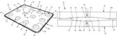
- FIG. 1is a perspective view from above of a pad
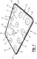
- FIG. 2is a perspective view from below of the pad shown in FIG. 1 ;
- FIG. 3is a view along the line II-II in FIG. 1 ;
- FIG. 4is a schematic sectional side view of a mould for forming the pad shown in FIGS. 1 , 2 and 3 .
- FIGS. 1 , 2 and 3show a pad in the form of a layer pad 10 , which is disposed between layers of a load (not shown), for example bottles.
- the loadmay be arranged in the layers on a pallet.
- the layer pad 10comprises a substantially flat sheet 12 having first and second opposite faces 14 , 16 , which are identical to each other.
- the faces 14 , 16are substantially planar.
- the layer pad 10is substantially rectangular.
- the layer pad 10further include a plurality of raised formations 18 on each of the first and second faces 14 , 16 .
- Each raised formation 18 on the first face 14is substantially aligned with a respective one of the raised formations 18 on the second face 16 .
- the raised formations 18are of a frustoconical shape comprising a shallow tapering main region 20 and a substantially planar apex region 22 .
- a planar region 14 A of the first face 14is provided between the raised formations 18 on the first face 14 .
- a planar region 16 A of the second face 16is provided between the raised formations of the second face 16 .
- the aligned raised formations 18increase the thickness of the sheet 12 by about 30% between the apex regions 22 compared to the thickness of the sheet 12 at the planar region 12 A.
- each raised formationextends outwardly from the respective first or second face 14 , 16 to the apex region 22 .
- Each main region 20tapers inwardly towards the apex region 22 .
- the apex region 22is substantially circular.
- Each of the raised formations 18may have substantially the same height as each of the other raised formations 18 .
- the apex regions 22 on each of the first and second faces 14 , 16define a respective plane.
- the raised formations 18 on the first face 14are the same as the raised formations on the second face 16 .
- the raised formations 20are arranged in substantially identical regular arrays, as shown in FIGS. 1 and 2 , on both of the first and second faces 14 , 16 .
- the layer pad 10has marginal portions 24 , which extend around the substantially flat sheet 12 .
- the sheet 12has corner regions 26 , and the marginal portions 24 extend around the corner regions 26 .
- the corner regions 26are curved and, as a result, the marginal portions 24 curve around the corner regions 26 .
- the marginal portions 24have an outer edge 25 and corrugations 28 which extend inwardly from the outer edge 25 to merge with the sheet 12 .
- FIG. 4shows a mould 30 for manufacturing the layer pad 10 .
- the mould 30comprises a first and second mould parts 32 , 33 , each having a planar region comprising a planar inner surface 34 and a plurality of recesses 36 .
- Each recess 36is of a substantially frustoconical shape having a main recess region 38 and an apex region 40 .
- the apex region 40is substantially circular.
- An injection port 42extends through the apex region 40 of the recess 36 in the first and second mould parts 32 , 33 .
- the first and second mould parts 32 , 33can be arranged in a moulding position shown in FIG. 4 to define a mould space 43 therebetween.
- the mould space 43has a relatively narrow region 43 A between the opposite planar surfaces 34 , and relatively wider regions 43 B between the opposite recesses 36 .
- a respective injection port 42may be provided in each of the apex regions 40 of all the recesses 36 of the first and second mould parts 32 , 33 .
- a respective conduit 44extends to each injection port 42 through which a moulding material, such as a molten plastics material, is injected into the mould space 43 .
- the mould parts 32 , 33are secured to each other by suitable means known in the art of injection moulding in the position shown FIG. 4 to define the mould space therebetween.
- a suitable moulding materialsuch as a molten plastics material, is then injected into the mould space via all the injection ports 42 in each of the mould parts 32 , 33 .
- the moulding materialis allowed to cure, and the layer pad 10 is then removed from the mould.
- the provision of the raised formations 18 on the planar surfaces 12 A of the substantially flat sheet 12provides the advantage of the embodiment described herein that it helps prevent warping of the sheet 12 when the layer pad 10 is removed from the mould.
- the injection of the moulding material into the mould 30 at the apex regions 40 of the recesses 36provides the advantage in the embodiment described herein that the moulding material enters the mould 30 in a condition that does not induce stress in the moulding. It is believed that the provision of the injection ports 42 at the recesses 36 reduces the pressure at the injection ports during the injection of the moulding material.
- the reduction in pressurehas the effect of reducing the stress experienced by the material, thereby allowing uniform crystallisation. As a result of this lack of stress, there is little or no tendency of the layer pad 10 to warp when it is removed from the mould 30 .
- the arrangement and amount of the raised formations 18 on the sheet 12can be different from the arrangement and amount shown in FIGS. 1 and 2 .
- the raised formations 18can be provided on only one of the faces 14 , 16 of the sheet 12 .
- the injection ports 42can be provided at only some of the recesses 36 . If desired, the injection ports 42 could be provided at some or all of the recesses 36 in only one of the first and second mould parts 32 , 33 .
Landscapes
- Engineering & Computer Science (AREA)
- Mechanical Engineering (AREA)
- Manufacturing & Machinery (AREA)
- Moulds For Moulding Plastics Or The Like (AREA)
- Buffer Packaging (AREA)
- Polishing Bodies And Polishing Tools (AREA)
- Corsets Or Brassieres (AREA)
- Materials For Medical Uses (AREA)
- Pallets (AREA)
- Insulating Bodies (AREA)
Abstract
Description
Claims (17)
Priority Applications (1)
| Application Number | Priority Date | Filing Date | Title |
|---|---|---|---|
| US17/233,629US11964808B2 (en) | 2015-10-09 | 2021-04-19 | Method of forming a pad |
Applications Claiming Priority (9)
| Application Number | Priority Date | Filing Date | Title |
|---|---|---|---|
| GB1517932 | 2015-10-09 | ||
| GBGB1517932.8AGB201517932D0 (en) | 2015-10-09 | 2015-10-09 | Pad |
| GB1517932.8 | 2015-10-09 | ||
| GB1616996 | 2016-10-06 | ||
| GB1616996.3 | 2016-10-06 | ||
| GB1616996.3AGB2545300B (en) | 2015-10-09 | 2016-10-06 | Layer Pad with Raised Formations |
| PCT/GB2016/000182WO2017060666A1 (en) | 2015-10-09 | 2016-10-07 | Layer pad |
| US201815765453A | 2018-04-02 | 2018-04-02 | |
| US17/233,629US11964808B2 (en) | 2015-10-09 | 2021-04-19 | Method of forming a pad |
Related Parent Applications (2)
| Application Number | Title | Priority Date | Filing Date |
|---|---|---|---|
| PCT/GB2016/000182DivisionWO2017060666A1 (en) | 2015-10-09 | 2016-10-07 | Layer pad |
| US15/765,453DivisionUS11014724B2 (en) | 2015-10-09 | 2016-10-07 | Layer pad |
Publications (2)
| Publication Number | Publication Date |
|---|---|
| US20210237948A1 US20210237948A1 (en) | 2021-08-05 |
| US11964808B2true US11964808B2 (en) | 2024-04-23 |
Family
ID=55130851
Family Applications (2)
| Application Number | Title | Priority Date | Filing Date |
|---|---|---|---|
| US15/765,453ActiveUS11014724B2 (en) | 2015-10-09 | 2016-10-07 | Layer pad |
| US17/233,629Active2037-09-05US11964808B2 (en) | 2015-10-09 | 2021-04-19 | Method of forming a pad |
Family Applications Before (1)
| Application Number | Title | Priority Date | Filing Date |
|---|---|---|---|
| US15/765,453ActiveUS11014724B2 (en) | 2015-10-09 | 2016-10-07 | Layer pad |
Country Status (10)
| Country | Link |
|---|---|
| US (2) | US11014724B2 (en) |
| EP (1) | EP3359463B1 (en) |
| CN (1) | CN106564680A (en) |
| AU (1) | AU2016333731B2 (en) |
| CA (1) | CA3000604A1 (en) |
| ES (1) | ES2919224T3 (en) |
| GB (2) | GB201517932D0 (en) |
| PL (1) | PL3359463T3 (en) |
| PT (1) | PT3359463T (en) |
| WO (1) | WO2017060666A1 (en) |
Families Citing this family (1)
| Publication number | Priority date | Publication date | Assignee | Title |
|---|---|---|---|---|
| USD1092972S1 (en)* | 2023-08-03 | 2025-09-16 | Athalon Sportsgear, Inc. | Dimpled hard material surface for golf travel cases |
Citations (25)
| Publication number | Priority date | Publication date | Assignee | Title |
|---|---|---|---|---|
| US3700205A (en)* | 1967-12-20 | 1972-10-24 | Craemer Press & Stanzwerk | Die for molding plastic pallets |
| FR2305363A1 (en) | 1975-03-26 | 1976-10-22 | Socar | INTERCAL PLATE FOR THE STORAGE OR PACKAGING OF BULK OBJECTS OF IRREGULAR SHAPES |
| FR2314040A1 (en) | 1975-06-10 | 1977-01-07 | Conlor Molding Systems Ltd | INJECTION MOLDED PLASTIC ARTICLE, CUP OR BASIN SHAPE |
| US4117950A (en) | 1977-10-19 | 1978-10-03 | Buckeye Molding Company | Plastic closure |
| US4580680A (en)* | 1981-01-28 | 1986-04-08 | Bigelow-Sanford, Inc. | Shipping pallet and container formed therefrom |
| US4617748A (en)* | 1984-03-01 | 1986-10-21 | I.S.A.P. Spa (Industrie Specializzate Articoli Plastici) | Label for egg trays and the like |
| FR2596025A1 (en) | 1986-03-18 | 1987-09-25 | Bsn Emballage | Thermoformed spacer tray with a stud for packaging bottles in superimposed layers |
| EP0362091A1 (en) | 1988-09-30 | 1990-04-04 | Société Anonyme : B.S.N. EMBALLAGE | Separator tray for pelletisable loads formed from stacked layers of containers |
| US5034258A (en) | 1990-01-22 | 1991-07-23 | Nifty Products, Inc. | Carpet mat with improved gripping surface |
| FR2674510A1 (en) | 1991-03-25 | 1992-10-02 | Lauragri Sa | Package for concave-bottomed bottles |
| US5258217A (en) | 1991-05-28 | 1993-11-02 | A/A Manufacturing, Inc. | Landfill liner |
| US6068124A (en) | 1998-08-27 | 2000-05-30 | Nanya Plastics | Plastic pallet and separator for packaging yarn spools |
| JP2003112771A (en) | 2001-10-02 | 2003-04-18 | Ngk Insulators Ltd | Package |
| US20030143374A1 (en) | 2002-01-28 | 2003-07-31 | Stitchick David M. | Non-skid surface for containers |
| US20050019531A1 (en) | 2003-07-24 | 2005-01-27 | John Bazbaz | Slipsheet, divider sheet and method for making the same |
| GB2420773A (en) | 2004-12-03 | 2006-06-07 | Loadhog Ltd | Slip sheets for palletised loads of containers |
| US20100288169A1 (en)* | 2007-07-12 | 2010-11-18 | Lomold Corporation Nv | Pallet |
| US20110179978A1 (en)* | 2010-01-28 | 2011-07-28 | Pieter Wouter Du Toit | Pallet for the handling of goods, process for manufacturing a pallet and method for providing pallets |
| CH703419A2 (en) | 2010-07-13 | 2012-01-13 | Texa Ag | Intermediate layer plate for pallet for stacking cases or tins, has frustum-shaped spigots formed along edges of intermediate layer plate, where spigots engage with outer rows of group of cases or tins stacked on pallet |
| US20120292221A1 (en) | 2011-05-19 | 2012-11-22 | Illinois Tool Works Inc. | Void board, package and method of packaging using a void board |
| US8367184B2 (en) | 2006-04-27 | 2013-02-05 | 3M Innovative Properties Company | Structured films having acoustical absorbance properties |
| US20130213841A1 (en) | 2010-06-07 | 2013-08-22 | Debco Pty Ltd | Stackable containers and associated method for the transport of plants |
| GB2529939A (en) | 2014-09-03 | 2016-03-09 | Loadhog Ltd | Load cap |
| USD760990S1 (en) | 2014-09-23 | 2016-07-05 | Loadhog Limited | Load cap |
| US20190127115A1 (en)* | 2017-05-12 | 2019-05-02 | Rehrig Pacific Company | Pallet and pallet cap |
Family Cites Families (2)
| Publication number | Priority date | Publication date | Assignee | Title |
|---|---|---|---|---|
| US3741411A (en)* | 1971-10-04 | 1973-06-26 | Ma Ind Inc | Molded cushion pad insertable between heavy panels |
| BE799082A (en)* | 1973-05-04 | 1973-08-31 | Synfina Sa | CONTAINER PALETTIZATION PROCESS. |
- 2015
- 2015-10-09GBGBGB1517932.8Apatent/GB201517932D0/ennot_activeCeased
- 2016
- 2016-05-25CNCN201610352721.8Apatent/CN106564680A/enactivePending
- 2016-10-06GBGB1616996.3Apatent/GB2545300B/enactiveActive
- 2016-10-07PLPL16795123.5Tpatent/PL3359463T3/enunknown
- 2016-10-07AUAU2016333731Apatent/AU2016333731B2/enactiveActive
- 2016-10-07EPEP16795123.5Apatent/EP3359463B1/enactiveActive
- 2016-10-07USUS15/765,453patent/US11014724B2/enactiveActive
- 2016-10-07PTPT167951235Tpatent/PT3359463T/enunknown
- 2016-10-07WOPCT/GB2016/000182patent/WO2017060666A1/ennot_activeCeased
- 2016-10-07ESES16795123Tpatent/ES2919224T3/enactiveActive
- 2016-10-07CACA3000604Apatent/CA3000604A1/ennot_activeAbandoned
- 2021
- 2021-04-19USUS17/233,629patent/US11964808B2/enactiveActive
Patent Citations (25)
| Publication number | Priority date | Publication date | Assignee | Title |
|---|---|---|---|---|
| US3700205A (en)* | 1967-12-20 | 1972-10-24 | Craemer Press & Stanzwerk | Die for molding plastic pallets |
| FR2305363A1 (en) | 1975-03-26 | 1976-10-22 | Socar | INTERCAL PLATE FOR THE STORAGE OR PACKAGING OF BULK OBJECTS OF IRREGULAR SHAPES |
| FR2314040A1 (en) | 1975-06-10 | 1977-01-07 | Conlor Molding Systems Ltd | INJECTION MOLDED PLASTIC ARTICLE, CUP OR BASIN SHAPE |
| US4117950A (en) | 1977-10-19 | 1978-10-03 | Buckeye Molding Company | Plastic closure |
| US4580680A (en)* | 1981-01-28 | 1986-04-08 | Bigelow-Sanford, Inc. | Shipping pallet and container formed therefrom |
| US4617748A (en)* | 1984-03-01 | 1986-10-21 | I.S.A.P. Spa (Industrie Specializzate Articoli Plastici) | Label for egg trays and the like |
| FR2596025A1 (en) | 1986-03-18 | 1987-09-25 | Bsn Emballage | Thermoformed spacer tray with a stud for packaging bottles in superimposed layers |
| EP0362091A1 (en) | 1988-09-30 | 1990-04-04 | Société Anonyme : B.S.N. EMBALLAGE | Separator tray for pelletisable loads formed from stacked layers of containers |
| US5034258A (en) | 1990-01-22 | 1991-07-23 | Nifty Products, Inc. | Carpet mat with improved gripping surface |
| FR2674510A1 (en) | 1991-03-25 | 1992-10-02 | Lauragri Sa | Package for concave-bottomed bottles |
| US5258217A (en) | 1991-05-28 | 1993-11-02 | A/A Manufacturing, Inc. | Landfill liner |
| US6068124A (en) | 1998-08-27 | 2000-05-30 | Nanya Plastics | Plastic pallet and separator for packaging yarn spools |
| JP2003112771A (en) | 2001-10-02 | 2003-04-18 | Ngk Insulators Ltd | Package |
| US20030143374A1 (en) | 2002-01-28 | 2003-07-31 | Stitchick David M. | Non-skid surface for containers |
| US20050019531A1 (en) | 2003-07-24 | 2005-01-27 | John Bazbaz | Slipsheet, divider sheet and method for making the same |
| GB2420773A (en) | 2004-12-03 | 2006-06-07 | Loadhog Ltd | Slip sheets for palletised loads of containers |
| US8367184B2 (en) | 2006-04-27 | 2013-02-05 | 3M Innovative Properties Company | Structured films having acoustical absorbance properties |
| US20100288169A1 (en)* | 2007-07-12 | 2010-11-18 | Lomold Corporation Nv | Pallet |
| US20110179978A1 (en)* | 2010-01-28 | 2011-07-28 | Pieter Wouter Du Toit | Pallet for the handling of goods, process for manufacturing a pallet and method for providing pallets |
| US20130213841A1 (en) | 2010-06-07 | 2013-08-22 | Debco Pty Ltd | Stackable containers and associated method for the transport of plants |
| CH703419A2 (en) | 2010-07-13 | 2012-01-13 | Texa Ag | Intermediate layer plate for pallet for stacking cases or tins, has frustum-shaped spigots formed along edges of intermediate layer plate, where spigots engage with outer rows of group of cases or tins stacked on pallet |
| US20120292221A1 (en) | 2011-05-19 | 2012-11-22 | Illinois Tool Works Inc. | Void board, package and method of packaging using a void board |
| GB2529939A (en) | 2014-09-03 | 2016-03-09 | Loadhog Ltd | Load cap |
| USD760990S1 (en) | 2014-09-23 | 2016-07-05 | Loadhog Limited | Load cap |
| US20190127115A1 (en)* | 2017-05-12 | 2019-05-02 | Rehrig Pacific Company | Pallet and pallet cap |
Also Published As
| Publication number | Publication date |
|---|---|
| PT3359463T (en) | 2022-06-27 |
| PL3359463T3 (en) | 2022-08-29 |
| EP3359463A1 (en) | 2018-08-15 |
| ES2919224T3 (en) | 2022-07-22 |
| US11014724B2 (en) | 2021-05-25 |
| CA3000604A1 (en) | 2017-04-13 |
| WO2017060666A8 (en) | 2018-04-19 |
| EP3359463B1 (en) | 2022-05-25 |
| AU2016333731B2 (en) | 2021-07-08 |
| GB201517932D0 (en) | 2015-11-25 |
| GB2545300B (en) | 2019-05-22 |
| CN106564680A (en) | 2017-04-19 |
| US20210237948A1 (en) | 2021-08-05 |
| AU2016333731A1 (en) | 2018-04-26 |
| GB2545300A (en) | 2017-06-14 |
| WO2017060666A1 (en) | 2017-04-13 |
| GB201616996D0 (en) | 2016-11-23 |
| US20180290802A1 (en) | 2018-10-11 |
Similar Documents
| Publication | Publication Date | Title |
|---|---|---|
| US20220081914A1 (en) | Uncoupling Mat | |
| US11964808B2 (en) | Method of forming a pad | |
| CN101212875A (en) | Plastic composite structure and manufacturing method thereof | |
| KR20190093045A (en) | method of manufacturing secondary battery pouch for secondary battery and pouch for secondary battery | |
| CN102395458A (en) | Method for producing composite material member and laminate of prepreg sheets | |
| CN103144829A (en) | Pallet | |
| JP3995177B2 (en) | Inorganic molded body and stacking method thereof | |
| JPS6143540A (en) | Manufacture of frp parts | |
| WO2016183846A1 (en) | Liquid crystal panel packaging box | |
| US10453760B2 (en) | Lid array panel, package with lid and method of making the same | |
| CN212896892U (en) | Fireproof heat-insulation board | |
| US20110318540A1 (en) | Method for obtaining a part made of a composite for the purpose of limiting the edge effects | |
| US20210299973A1 (en) | Mat and method to manufacture mat | |
| TWI889004B (en) | Semiconductor substrate carrying container and method of making the same | |
| KR102798117B1 (en) | Honeycomb panel manufacturing method and Honeycomb panel manufactured by the method and Mold for manufacturing honeycomb panel | |
| CN218202619U (en) | Anti-warping foam adhesive tape | |
| CN203961215U (en) | PVC floor tile | |
| KR102085227B1 (en) | Pallet manufacturing method | |
| CN108930743A (en) | The double arches overlapping variation rigidity leaf spring and production method being staggered using the perpendicular paving of horizontal paving | |
| JP6947586B2 (en) | Manufacturing method of plate-shaped resin molded product and plate-shaped resin molded product | |
| CN204056719U (en) | A kind of veneer sheet pier | |
| CN206672924U (en) | Heat block base island salient point device | |
| US20190126531A1 (en) | Mat and method to manufacture mat | |
| WO2014143365A1 (en) | Woven fabric with two interlocked sections | |
| JP6338090B2 (en) | Injection mold |
Legal Events
| Date | Code | Title | Description |
|---|---|---|---|
| FEPP | Fee payment procedure | Free format text:ENTITY STATUS SET TO UNDISCOUNTED (ORIGINAL EVENT CODE: BIG.); ENTITY STATUS OF PATENT OWNER: SMALL ENTITY | |
| AS | Assignment | Owner name:LOADHOG LIMITED, UNITED KINGDOM Free format text:ASSIGNMENT OF ASSIGNORS INTEREST;ASSIGNORS:JOWETT, LEIGH;BAKER, MARTIN LESLIE;DAVIS, LUKE;AND OTHERS;REEL/FRAME:055970/0096 Effective date:20180403 | |
| FEPP | Fee payment procedure | Free format text:ENTITY STATUS SET TO SMALL (ORIGINAL EVENT CODE: SMAL); ENTITY STATUS OF PATENT OWNER: SMALL ENTITY | |
| STPP | Information on status: patent application and granting procedure in general | Free format text:APPLICATION DISPATCHED FROM PREEXAM, NOT YET DOCKETED | |
| STPP | Information on status: patent application and granting procedure in general | Free format text:DOCKETED NEW CASE - READY FOR EXAMINATION | |
| STPP | Information on status: patent application and granting procedure in general | Free format text:NON FINAL ACTION MAILED | |
| STPP | Information on status: patent application and granting procedure in general | Free format text:RESPONSE TO NON-FINAL OFFICE ACTION ENTERED AND FORWARDED TO EXAMINER | |
| STPP | Information on status: patent application and granting procedure in general | Free format text:FINAL REJECTION MAILED | |
| STPP | Information on status: patent application and granting procedure in general | Free format text:ADVISORY ACTION MAILED | |
| STPP | Information on status: patent application and granting procedure in general | Free format text:DOCKETED NEW CASE - READY FOR EXAMINATION | |
| STPP | Information on status: patent application and granting procedure in general | Free format text:NOTICE OF ALLOWANCE MAILED -- APPLICATION RECEIVED IN OFFICE OF PUBLICATIONS | |
| ZAAB | Notice of allowance mailed | Free format text:ORIGINAL CODE: MN/=. | |
| STPP | Information on status: patent application and granting procedure in general | Free format text:PUBLICATIONS -- ISSUE FEE PAYMENT RECEIVED | |
| STPP | Information on status: patent application and granting procedure in general | Free format text:PUBLICATIONS -- ISSUE FEE PAYMENT VERIFIED | |
| STCF | Information on status: patent grant | Free format text:PATENTED CASE |