US11958666B2 - Child resistant double seam container lid - Google Patents
Child resistant double seam container lidDownload PDFInfo
- Publication number
- US11958666B2 US11958666B2US17/137,543US202017137543AUS11958666B2US 11958666 B2US11958666 B2US 11958666B2US 202017137543 AUS202017137543 AUS 202017137543AUS 11958666 B2US11958666 B2US 11958666B2
- Authority
- US
- United States
- Prior art keywords
- piece
- lid
- child resistant
- double seam
- lid portion
- Prior art date
- Legal status (The legal status is an assumption and is not a legal conclusion. Google has not performed a legal analysis and makes no representation as to the accuracy of the status listed.)
- Active, expires
Links
Images


Classifications
- B—PERFORMING OPERATIONS; TRANSPORTING
- B65—CONVEYING; PACKING; STORING; HANDLING THIN OR FILAMENTARY MATERIAL
- B65D—CONTAINERS FOR STORAGE OR TRANSPORT OF ARTICLES OR MATERIALS, e.g. BAGS, BARRELS, BOTTLES, BOXES, CANS, CARTONS, CRATES, DRUMS, JARS, TANKS, HOPPERS, FORWARDING CONTAINERS; ACCESSORIES, CLOSURES, OR FITTINGS THEREFOR; PACKAGING ELEMENTS; PACKAGES
- B65D50/00—Closures with means for discouraging unauthorised opening or removal thereof, with or without indicating means, e.g. child-proof closures
- B65D50/02—Closures with means for discouraging unauthorised opening or removal thereof, with or without indicating means, e.g. child-proof closures openable or removable by the combination of plural actions
- B65D50/04—Closures with means for discouraging unauthorised opening or removal thereof, with or without indicating means, e.g. child-proof closures openable or removable by the combination of plural actions requiring the combination of simultaneous actions, e.g. depressing and turning, lifting and turning, maintaining a part and turning another one
- B65D50/045—Closures with means for discouraging unauthorised opening or removal thereof, with or without indicating means, e.g. child-proof closures openable or removable by the combination of plural actions requiring the combination of simultaneous actions, e.g. depressing and turning, lifting and turning, maintaining a part and turning another one where one action elastically deforms or deflects at least part of the closure, the container or an intermediate element, e.g. a ring
- B65D50/046—Closures with means for discouraging unauthorised opening or removal thereof, with or without indicating means, e.g. child-proof closures openable or removable by the combination of plural actions requiring the combination of simultaneous actions, e.g. depressing and turning, lifting and turning, maintaining a part and turning another one where one action elastically deforms or deflects at least part of the closure, the container or an intermediate element, e.g. a ring and such deformation causes the disengagement of locking means, e.g. the release of a pawl-like element from a tooth or abutment, to allow removal of the closure by simultaneous rotation
- B—PERFORMING OPERATIONS; TRANSPORTING
- B65—CONVEYING; PACKING; STORING; HANDLING THIN OR FILAMENTARY MATERIAL
- B65D—CONTAINERS FOR STORAGE OR TRANSPORT OF ARTICLES OR MATERIALS, e.g. BAGS, BARRELS, BOTTLES, BOXES, CANS, CARTONS, CRATES, DRUMS, JARS, TANKS, HOPPERS, FORWARDING CONTAINERS; ACCESSORIES, CLOSURES, OR FITTINGS THEREFOR; PACKAGING ELEMENTS; PACKAGES
- B65D21/00—Nestable, stackable or joinable containers; Containers of variable capacity
- B65D21/02—Containers specially shaped, or provided with fittings or attachments, to facilitate nesting, stacking, or joining together
- B65D21/0209—Containers specially shaped, or provided with fittings or attachments, to facilitate nesting, stacking, or joining together stackable or joined together one-upon-the-other in the upright or upside-down position
- B65D21/0217—Containers with a closure presenting stacking elements
- B65D21/0219—Containers with a closure presenting stacking elements the closure presenting projecting peripheral elements receiving or surrounding the bottom or peripheral elements projecting from the bottom of a superimposed container
- B—PERFORMING OPERATIONS; TRANSPORTING
- B65—CONVEYING; PACKING; STORING; HANDLING THIN OR FILAMENTARY MATERIAL
- B65D—CONTAINERS FOR STORAGE OR TRANSPORT OF ARTICLES OR MATERIALS, e.g. BAGS, BARRELS, BOTTLES, BOXES, CANS, CARTONS, CRATES, DRUMS, JARS, TANKS, HOPPERS, FORWARDING CONTAINERS; ACCESSORIES, CLOSURES, OR FITTINGS THEREFOR; PACKAGING ELEMENTS; PACKAGES
- B65D41/00—Caps, e.g. crown caps or crown seals, i.e. members having parts arranged for engagement with the external periphery of a neck or wall defining a pouring opening or discharge aperture; Protective cap-like covers for closure members, e.g. decorative covers of metal foil or paper
- B65D41/02—Caps or cap-like covers without lines of weakness, tearing strips, tags, or like opening or removal devices
- B65D41/26—Caps or cap-like covers serving as, or incorporating, drinking or measuring vessels
- B—PERFORMING OPERATIONS; TRANSPORTING
- B65—CONVEYING; PACKING; STORING; HANDLING THIN OR FILAMENTARY MATERIAL
- B65D—CONTAINERS FOR STORAGE OR TRANSPORT OF ARTICLES OR MATERIALS, e.g. BAGS, BARRELS, BOTTLES, BOXES, CANS, CARTONS, CRATES, DRUMS, JARS, TANKS, HOPPERS, FORWARDING CONTAINERS; ACCESSORIES, CLOSURES, OR FITTINGS THEREFOR; PACKAGING ELEMENTS; PACKAGES
- B65D43/00—Lids or covers for rigid or semi-rigid containers
- B65D43/02—Removable lids or covers
- B65D43/0202—Removable lids or covers without integral tamper element
- B65D43/0204—Removable lids or covers without integral tamper element secured by snapping over beads or projections
- B65D43/0212—Removable lids or covers without integral tamper element secured by snapping over beads or projections only on the outside, or a part turned to the outside, of the mouth
- B—PERFORMING OPERATIONS; TRANSPORTING
- B65—CONVEYING; PACKING; STORING; HANDLING THIN OR FILAMENTARY MATERIAL
- B65D—CONTAINERS FOR STORAGE OR TRANSPORT OF ARTICLES OR MATERIALS, e.g. BAGS, BARRELS, BOTTLES, BOXES, CANS, CARTONS, CRATES, DRUMS, JARS, TANKS, HOPPERS, FORWARDING CONTAINERS; ACCESSORIES, CLOSURES, OR FITTINGS THEREFOR; PACKAGING ELEMENTS; PACKAGES
- B65D45/00—Clamping or other pressure-applying devices for securing or retaining closure members
- B65D45/02—Clamping or other pressure-applying devices for securing or retaining closure members for applying axial pressure to engage closure with sealing surface
- B65D45/30—Annular members, e.g. with snap-over action or screw-threaded
- B65D45/305—Screw-threaded or bayonet-type annular members cooperating with an intermediate ring
- B—PERFORMING OPERATIONS; TRANSPORTING
- B65—CONVEYING; PACKING; STORING; HANDLING THIN OR FILAMENTARY MATERIAL
- B65D—CONTAINERS FOR STORAGE OR TRANSPORT OF ARTICLES OR MATERIALS, e.g. BAGS, BARRELS, BOTTLES, BOXES, CANS, CARTONS, CRATES, DRUMS, JARS, TANKS, HOPPERS, FORWARDING CONTAINERS; ACCESSORIES, CLOSURES, OR FITTINGS THEREFOR; PACKAGING ELEMENTS; PACKAGES
- B65D50/00—Closures with means for discouraging unauthorised opening or removal thereof, with or without indicating means, e.g. child-proof closures
- B65D50/02—Closures with means for discouraging unauthorised opening or removal thereof, with or without indicating means, e.g. child-proof closures openable or removable by the combination of plural actions
- B65D50/06—Closures with means for discouraging unauthorised opening or removal thereof, with or without indicating means, e.g. child-proof closures openable or removable by the combination of plural actions requiring the combination of different actions in succession
- B65D50/061—Closures with means for discouraging unauthorised opening or removal thereof, with or without indicating means, e.g. child-proof closures openable or removable by the combination of plural actions requiring the combination of different actions in succession being disengageable from container only after rotational alignment of closure, or other means inhibiting removal of closure, with container, e.g. tortuous path type
- B—PERFORMING OPERATIONS; TRANSPORTING
- B65—CONVEYING; PACKING; STORING; HANDLING THIN OR FILAMENTARY MATERIAL
- B65D—CONTAINERS FOR STORAGE OR TRANSPORT OF ARTICLES OR MATERIALS, e.g. BAGS, BARRELS, BOTTLES, BOXES, CANS, CARTONS, CRATES, DRUMS, JARS, TANKS, HOPPERS, FORWARDING CONTAINERS; ACCESSORIES, CLOSURES, OR FITTINGS THEREFOR; PACKAGING ELEMENTS; PACKAGES
- B65D50/00—Closures with means for discouraging unauthorised opening or removal thereof, with or without indicating means, e.g. child-proof closures
- B65D50/02—Closures with means for discouraging unauthorised opening or removal thereof, with or without indicating means, e.g. child-proof closures openable or removable by the combination of plural actions
- B65D50/06—Closures with means for discouraging unauthorised opening or removal thereof, with or without indicating means, e.g. child-proof closures openable or removable by the combination of plural actions requiring the combination of different actions in succession
- B65D50/067—Closures with means for discouraging unauthorised opening or removal thereof, with or without indicating means, e.g. child-proof closures openable or removable by the combination of plural actions requiring the combination of different actions in succession using integral or non-integral accessories, e.g. tool, key
- B—PERFORMING OPERATIONS; TRANSPORTING
- B65—CONVEYING; PACKING; STORING; HANDLING THIN OR FILAMENTARY MATERIAL
- B65D—CONTAINERS FOR STORAGE OR TRANSPORT OF ARTICLES OR MATERIALS, e.g. BAGS, BARRELS, BOTTLES, BOXES, CANS, CARTONS, CRATES, DRUMS, JARS, TANKS, HOPPERS, FORWARDING CONTAINERS; ACCESSORIES, CLOSURES, OR FITTINGS THEREFOR; PACKAGING ELEMENTS; PACKAGES
- B65D51/00—Closures not otherwise provided for
- B65D51/18—Arrangements of closures with protective outer cap-like covers or of two or more co-operating closures
- B65D51/20—Caps, lids, or covers co-operating with an inner closure arranged to be opened by piercing, cutting, or tearing
- B—PERFORMING OPERATIONS; TRANSPORTING
- B65—CONVEYING; PACKING; STORING; HANDLING THIN OR FILAMENTARY MATERIAL
- B65D—CONTAINERS FOR STORAGE OR TRANSPORT OF ARTICLES OR MATERIALS, e.g. BAGS, BARRELS, BOTTLES, BOXES, CANS, CARTONS, CRATES, DRUMS, JARS, TANKS, HOPPERS, FORWARDING CONTAINERS; ACCESSORIES, CLOSURES, OR FITTINGS THEREFOR; PACKAGING ELEMENTS; PACKAGES
- B65D51/00—Closures not otherwise provided for
- B65D51/24—Closures not otherwise provided for combined or co-operating with auxiliary devices for non-closing purposes
- B65D51/242—Closures not otherwise provided for combined or co-operating with auxiliary devices for non-closing purposes provided with means for facilitating lifting or suspending of the container
- B—PERFORMING OPERATIONS; TRANSPORTING
- B65—CONVEYING; PACKING; STORING; HANDLING THIN OR FILAMENTARY MATERIAL
- B65D—CONTAINERS FOR STORAGE OR TRANSPORT OF ARTICLES OR MATERIALS, e.g. BAGS, BARRELS, BOTTLES, BOXES, CANS, CARTONS, CRATES, DRUMS, JARS, TANKS, HOPPERS, FORWARDING CONTAINERS; ACCESSORIES, CLOSURES, OR FITTINGS THEREFOR; PACKAGING ELEMENTS; PACKAGES
- B65D51/00—Closures not otherwise provided for
- B65D51/24—Closures not otherwise provided for combined or co-operating with auxiliary devices for non-closing purposes
- B65D51/245—Closures not otherwise provided for combined or co-operating with auxiliary devices for non-closing purposes provided with decoration, information or contents indicating devices, labels
- B—PERFORMING OPERATIONS; TRANSPORTING
- B65—CONVEYING; PACKING; STORING; HANDLING THIN OR FILAMENTARY MATERIAL
- B65D—CONTAINERS FOR STORAGE OR TRANSPORT OF ARTICLES OR MATERIALS, e.g. BAGS, BARRELS, BOTTLES, BOXES, CANS, CARTONS, CRATES, DRUMS, JARS, TANKS, HOPPERS, FORWARDING CONTAINERS; ACCESSORIES, CLOSURES, OR FITTINGS THEREFOR; PACKAGING ELEMENTS; PACKAGES
- B65D53/00—Sealing or packing elements; Sealings formed by liquid or plastics material
- B65D53/02—Collars or rings
- B—PERFORMING OPERATIONS; TRANSPORTING
- B65—CONVEYING; PACKING; STORING; HANDLING THIN OR FILAMENTARY MATERIAL
- B65D—CONTAINERS FOR STORAGE OR TRANSPORT OF ARTICLES OR MATERIALS, e.g. BAGS, BARRELS, BOTTLES, BOXES, CANS, CARTONS, CRATES, DRUMS, JARS, TANKS, HOPPERS, FORWARDING CONTAINERS; ACCESSORIES, CLOSURES, OR FITTINGS THEREFOR; PACKAGING ELEMENTS; PACKAGES
- B65D2205/00—Venting means
- B65D2205/02—Venting holes
- B—PERFORMING OPERATIONS; TRANSPORTING
- B65—CONVEYING; PACKING; STORING; HANDLING THIN OR FILAMENTARY MATERIAL
- B65D—CONTAINERS FOR STORAGE OR TRANSPORT OF ARTICLES OR MATERIALS, e.g. BAGS, BARRELS, BOTTLES, BOXES, CANS, CARTONS, CRATES, DRUMS, JARS, TANKS, HOPPERS, FORWARDING CONTAINERS; ACCESSORIES, CLOSURES, OR FITTINGS THEREFOR; PACKAGING ELEMENTS; PACKAGES
- B65D2543/00—Lids or covers essentially for box-like containers
- B65D2543/00009—Details of lids or covers for rigid or semi-rigid containers
- B65D2543/00018—Overall construction of the lid
- B65D2543/00046—Drinking-through lids
- B—PERFORMING OPERATIONS; TRANSPORTING
- B65—CONVEYING; PACKING; STORING; HANDLING THIN OR FILAMENTARY MATERIAL
- B65D—CONTAINERS FOR STORAGE OR TRANSPORT OF ARTICLES OR MATERIALS, e.g. BAGS, BARRELS, BOTTLES, BOXES, CANS, CARTONS, CRATES, DRUMS, JARS, TANKS, HOPPERS, FORWARDING CONTAINERS; ACCESSORIES, CLOSURES, OR FITTINGS THEREFOR; PACKAGING ELEMENTS; PACKAGES
- B65D2543/00—Lids or covers essentially for box-like containers
- B65D2543/00009—Details of lids or covers for rigid or semi-rigid containers
- B65D2543/00018—Overall construction of the lid
- B65D2543/00064—Shape of the outer periphery
- B65D2543/00074—Shape of the outer periphery curved
- B65D2543/00092—Shape of the outer periphery curved circular
- B—PERFORMING OPERATIONS; TRANSPORTING
- B65—CONVEYING; PACKING; STORING; HANDLING THIN OR FILAMENTARY MATERIAL
- B65D—CONTAINERS FOR STORAGE OR TRANSPORT OF ARTICLES OR MATERIALS, e.g. BAGS, BARRELS, BOTTLES, BOXES, CANS, CARTONS, CRATES, DRUMS, JARS, TANKS, HOPPERS, FORWARDING CONTAINERS; ACCESSORIES, CLOSURES, OR FITTINGS THEREFOR; PACKAGING ELEMENTS; PACKAGES
- B65D2543/00—Lids or covers essentially for box-like containers
- B65D2543/00009—Details of lids or covers for rigid or semi-rigid containers
- B65D2543/00018—Overall construction of the lid
- B65D2543/00231—Overall construction of the lid made of several pieces
- B65D2543/0024—Overall construction of the lid made of several pieces two pieces, one forming at least the whole skirt, the other forming at least the whole upper part
- B—PERFORMING OPERATIONS; TRANSPORTING
- B65—CONVEYING; PACKING; STORING; HANDLING THIN OR FILAMENTARY MATERIAL
- B65D—CONTAINERS FOR STORAGE OR TRANSPORT OF ARTICLES OR MATERIALS, e.g. BAGS, BARRELS, BOTTLES, BOXES, CANS, CARTONS, CRATES, DRUMS, JARS, TANKS, HOPPERS, FORWARDING CONTAINERS; ACCESSORIES, CLOSURES, OR FITTINGS THEREFOR; PACKAGING ELEMENTS; PACKAGES
- B65D2543/00—Lids or covers essentially for box-like containers
- B65D2543/00009—Details of lids or covers for rigid or semi-rigid containers
- B65D2543/00435—Lids secured to an intermediate ring or like annular member fixed to the container mouth
- B—PERFORMING OPERATIONS; TRANSPORTING
- B65—CONVEYING; PACKING; STORING; HANDLING THIN OR FILAMENTARY MATERIAL
- B65D—CONTAINERS FOR STORAGE OR TRANSPORT OF ARTICLES OR MATERIALS, e.g. BAGS, BARRELS, BOTTLES, BOXES, CANS, CARTONS, CRATES, DRUMS, JARS, TANKS, HOPPERS, FORWARDING CONTAINERS; ACCESSORIES, CLOSURES, OR FITTINGS THEREFOR; PACKAGING ELEMENTS; PACKAGES
- B65D2543/00—Lids or covers essentially for box-like containers
- B65D2543/00009—Details of lids or covers for rigid or semi-rigid containers
- B65D2543/00444—Contact between the container and the lid
- B65D2543/00481—Contact between the container and the lid on the inside or the outside of the container
- B65D2543/0049—Contact between the container and the lid on the inside or the outside of the container on the inside, or a part turned to the inside of the mouth of the container
- B65D2543/00527—NO contact
- B—PERFORMING OPERATIONS; TRANSPORTING
- B65—CONVEYING; PACKING; STORING; HANDLING THIN OR FILAMENTARY MATERIAL
- B65D—CONTAINERS FOR STORAGE OR TRANSPORT OF ARTICLES OR MATERIALS, e.g. BAGS, BARRELS, BOTTLES, BOXES, CANS, CARTONS, CRATES, DRUMS, JARS, TANKS, HOPPERS, FORWARDING CONTAINERS; ACCESSORIES, CLOSURES, OR FITTINGS THEREFOR; PACKAGING ELEMENTS; PACKAGES
- B65D2543/00—Lids or covers essentially for box-like containers
- B65D2543/00009—Details of lids or covers for rigid or semi-rigid containers
- B65D2543/00444—Contact between the container and the lid
- B65D2543/00481—Contact between the container and the lid on the inside or the outside of the container
- B65D2543/00537—Contact between the container and the lid on the inside or the outside of the container on the outside, or a part turned to the outside of the mouth of the container
- B—PERFORMING OPERATIONS; TRANSPORTING
- B65—CONVEYING; PACKING; STORING; HANDLING THIN OR FILAMENTARY MATERIAL
- B65D—CONTAINERS FOR STORAGE OR TRANSPORT OF ARTICLES OR MATERIALS, e.g. BAGS, BARRELS, BOTTLES, BOXES, CANS, CARTONS, CRATES, DRUMS, JARS, TANKS, HOPPERS, FORWARDING CONTAINERS; ACCESSORIES, CLOSURES, OR FITTINGS THEREFOR; PACKAGING ELEMENTS; PACKAGES
- B65D2543/00—Lids or covers essentially for box-like containers
- B65D2543/00009—Details of lids or covers for rigid or semi-rigid containers
- B65D2543/00444—Contact between the container and the lid
- B65D2543/00592—Snapping means
- B65D2543/00601—Snapping means on the container
- B65D2543/00611—Profiles
- B65D2543/00638—Rolled edge
- B—PERFORMING OPERATIONS; TRANSPORTING
- B65—CONVEYING; PACKING; STORING; HANDLING THIN OR FILAMENTARY MATERIAL
- B65D—CONTAINERS FOR STORAGE OR TRANSPORT OF ARTICLES OR MATERIALS, e.g. BAGS, BARRELS, BOTTLES, BOXES, CANS, CARTONS, CRATES, DRUMS, JARS, TANKS, HOPPERS, FORWARDING CONTAINERS; ACCESSORIES, CLOSURES, OR FITTINGS THEREFOR; PACKAGING ELEMENTS; PACKAGES
- B65D2543/00—Lids or covers essentially for box-like containers
- B65D2543/00009—Details of lids or covers for rigid or semi-rigid containers
- B65D2543/00444—Contact between the container and the lid
- B65D2543/00592—Snapping means
- B65D2543/00601—Snapping means on the container
- B65D2543/00675—Periphery concerned
- B65D2543/00685—Totality
- B—PERFORMING OPERATIONS; TRANSPORTING
- B65—CONVEYING; PACKING; STORING; HANDLING THIN OR FILAMENTARY MATERIAL
- B65D—CONTAINERS FOR STORAGE OR TRANSPORT OF ARTICLES OR MATERIALS, e.g. BAGS, BARRELS, BOTTLES, BOXES, CANS, CARTONS, CRATES, DRUMS, JARS, TANKS, HOPPERS, FORWARDING CONTAINERS; ACCESSORIES, CLOSURES, OR FITTINGS THEREFOR; PACKAGING ELEMENTS; PACKAGES
- B65D2543/00—Lids or covers essentially for box-like containers
- B65D2543/00009—Details of lids or covers for rigid or semi-rigid containers
- B65D2543/00444—Contact between the container and the lid
- B65D2543/00592—Snapping means
- B65D2543/00712—Snapping means on the lid
- B65D2543/00722—Profiles
- B65D2543/00731—Groove or hollow bead
- B—PERFORMING OPERATIONS; TRANSPORTING
- B65—CONVEYING; PACKING; STORING; HANDLING THIN OR FILAMENTARY MATERIAL
- B65D—CONTAINERS FOR STORAGE OR TRANSPORT OF ARTICLES OR MATERIALS, e.g. BAGS, BARRELS, BOTTLES, BOXES, CANS, CARTONS, CRATES, DRUMS, JARS, TANKS, HOPPERS, FORWARDING CONTAINERS; ACCESSORIES, CLOSURES, OR FITTINGS THEREFOR; PACKAGING ELEMENTS; PACKAGES
- B65D2543/00—Lids or covers essentially for box-like containers
- B65D2543/00009—Details of lids or covers for rigid or semi-rigid containers
- B65D2543/00444—Contact between the container and the lid
- B65D2543/00592—Snapping means
- B65D2543/00712—Snapping means on the lid
- B65D2543/00787—Periphery concerned
- B65D2543/00796—Totality
- B—PERFORMING OPERATIONS; TRANSPORTING
- B65—CONVEYING; PACKING; STORING; HANDLING THIN OR FILAMENTARY MATERIAL
- B65D—CONTAINERS FOR STORAGE OR TRANSPORT OF ARTICLES OR MATERIALS, e.g. BAGS, BARRELS, BOTTLES, BOXES, CANS, CARTONS, CRATES, DRUMS, JARS, TANKS, HOPPERS, FORWARDING CONTAINERS; ACCESSORIES, CLOSURES, OR FITTINGS THEREFOR; PACKAGING ELEMENTS; PACKAGES
- B65D2543/00—Lids or covers essentially for box-like containers
- B65D2543/00009—Details of lids or covers for rigid or semi-rigid containers
- B65D2543/00824—Means for facilitating removing of the closure
- B65D2543/00833—Integral tabs, tongues, handles or similar
- B65D2543/00842—Integral tabs, tongues, handles or similar outside of the lid
- B—PERFORMING OPERATIONS; TRANSPORTING
- B65—CONVEYING; PACKING; STORING; HANDLING THIN OR FILAMENTARY MATERIAL
- B65D—CONTAINERS FOR STORAGE OR TRANSPORT OF ARTICLES OR MATERIALS, e.g. BAGS, BARRELS, BOTTLES, BOXES, CANS, CARTONS, CRATES, DRUMS, JARS, TANKS, HOPPERS, FORWARDING CONTAINERS; ACCESSORIES, CLOSURES, OR FITTINGS THEREFOR; PACKAGING ELEMENTS; PACKAGES
- B65D2543/00—Lids or covers essentially for box-like containers
- B65D2543/00009—Details of lids or covers for rigid or semi-rigid containers
- B65D2543/00824—Means for facilitating removing of the closure
- B65D2543/00925—Means for facilitating removing of the closure by applying inwardly directed pressure at two horizontally opposed points
- B—PERFORMING OPERATIONS; TRANSPORTING
- B65—CONVEYING; PACKING; STORING; HANDLING THIN OR FILAMENTARY MATERIAL
- B65D—CONTAINERS FOR STORAGE OR TRANSPORT OF ARTICLES OR MATERIALS, e.g. BAGS, BARRELS, BOTTLES, BOXES, CANS, CARTONS, CRATES, DRUMS, JARS, TANKS, HOPPERS, FORWARDING CONTAINERS; ACCESSORIES, CLOSURES, OR FITTINGS THEREFOR; PACKAGING ELEMENTS; PACKAGES
- B65D2543/00—Lids or covers essentially for box-like containers
- B65D2543/00009—Details of lids or covers for rigid or semi-rigid containers
- B65D2543/00953—Sealing means
- B65D2543/00962—Sealing means inserted
- B65D2543/00972—Collars or rings
- B—PERFORMING OPERATIONS; TRANSPORTING
- B65—CONVEYING; PACKING; STORING; HANDLING THIN OR FILAMENTARY MATERIAL
- B65D—CONTAINERS FOR STORAGE OR TRANSPORT OF ARTICLES OR MATERIALS, e.g. BAGS, BARRELS, BOTTLES, BOXES, CANS, CARTONS, CRATES, DRUMS, JARS, TANKS, HOPPERS, FORWARDING CONTAINERS; ACCESSORIES, CLOSURES, OR FITTINGS THEREFOR; PACKAGING ELEMENTS; PACKAGES
- B65D81/00—Containers, packaging elements, or packages, for contents presenting particular transport or storage problems, or adapted to be used for non-packaging purposes after removal of contents
- B65D81/18—Containers, packaging elements, or packages, for contents presenting particular transport or storage problems, or adapted to be used for non-packaging purposes after removal of contents providing specific environment for contents, e.g. temperature above or below ambient
- B65D81/20—Containers, packaging elements, or packages, for contents presenting particular transport or storage problems, or adapted to be used for non-packaging purposes after removal of contents providing specific environment for contents, e.g. temperature above or below ambient under vacuum or superatmospheric pressure, or in a special atmosphere, e.g. of inert gas
- B65D81/2007—Containers, packaging elements, or packages, for contents presenting particular transport or storage problems, or adapted to be used for non-packaging purposes after removal of contents providing specific environment for contents, e.g. temperature above or below ambient under vacuum or superatmospheric pressure, or in a special atmosphere, e.g. of inert gas under vacuum
- B65D81/2015—Containers, packaging elements, or packages, for contents presenting particular transport or storage problems, or adapted to be used for non-packaging purposes after removal of contents providing specific environment for contents, e.g. temperature above or below ambient under vacuum or superatmospheric pressure, or in a special atmosphere, e.g. of inert gas under vacuum in an at least partially rigid container
Definitions
- a child resistant double seam container lidincluding an adapter ring for securely affixing to the double seam top rim of conventional double seamed containers that will be difficult for children to open, yet readily openable by adults.
- a one-piece, two-piece, and three-piece child resistant double seam affixable container lidis provided having a first piece lid portion first, a second piece adapter ring locking member second piece and optionally a third piece securing unit piece, with rotational alignment indicators, and optional additional integral features such as a liquid measuring cup feature, a liquid tight lid feature, a threaded lid portion, a replaceable double seam container lid portion and a double seam container lid locking member adapter ring securely affixable to the double seam container.
- Canningis the process of preserving a product by processing and sealing it in an airtight metal can.
- Cansare typically either two-piece or three-piece cans.
- a can bodyis formed by punching a metal plate to form a cylinder closed at one end. The can is then filled and the open end closed by seaming a lid to the can body during the canning process.
- a can bodyopen at both ends, is formed by rolling and seaming a metal plate. A first end is closed by seaming a lid to the can body. The can is then filled and the second end closed by seaming a lid to the can body during the canning process.
- This patentdescribes a resilient plastic container and lid but does not describe a lid for a can that is difficult for a child to attempt to remove and may be easily removed and securely put back on by an adult.
- This patentdescribes a process for closing a metal can body but does not deal with a removable and resealable metal child resistant can lid.
- Child Resistant Double Seam Container LidThe principle advantage of the preferred embodiment of the Child Resistant Double Seam Container Lid is that they cannot be easily opened in a conventional manner by a child, yet is readily openable by adults, especially senior adults.
- Child Resistant Double Seam Container Lidcan be configured in a one-piece, two-piece and three-piece lid, including an upper lid portion top piece and lower adapter ring locking member piece.
- Child Resistant Double Seam Container LidAnother advantage of the Child Resistant Double Seam Container Lid is that it can be constructed with features making it liquid tight.
- Child Resistant Double Seam Container Lidcan be configured to include a measuring cup integral with the lid top portion or it may include a measuring cup which is provided as a separate removeable piece.
- Another advantage of the Child Resistant Double Seam Container Lidis that an adapter ring locking member piece is provided which is capable of being secured to the double seam.
- the lid portion top piece and the adapter ring locking member pieceare round and may include rotational indicators which when aligned allow for the lid portion top piece to be removed.
- the one-piece lidsmay be provided with finger grips and container retaining guides to allow for stable container stacking.
- Child Resistant Double Seam Container LidAnother advantage of the Child Resistant Double Seam Container Lid is that it will provide for a child resistant lid portion top piece and adapter ring locking member piece affixable to a beverage container double seam.
- Child Resistant Double Seam Container Lidwill provide a locking member adapter ring piece which includes retaining teeth to secure the locking member adapter ring piece to a container double seam.
- Child Resistant Double Seam Container LidAnother advantage of the Child Resistant Double Seam Container Lid is that it will provide for a child resistant lid portion top piece and adapter ring locking member piece affixable to a conventional product can container double seam.
- Child Resistant Double Seam Container Lidmay provide a securing unit affixable to the locking member adapter ring piece to lock the locking member adapter ring piece in place on the double seam of the container.
- Child Resistant Double Seam Container Lidmay have a rubber sealant coating applied to the lid inner surface, with the vacuum sealing can locking member adapter ring piece having the rubber sealant applied on the inner surface, making the container liquid tight and vacuum sealable.
- Child Resistant Double Seam Container Lidmay incorporate a threaded attachment between the lid portion top piece and the vacuum sealable can locking member adapter ring piece.
- the preferred embodiment of the Child Resistant Double Seam Container Lidwill be comprised of two parts, with those two pieces being a lid portion top piece and an adapter ring can locking member piece, both of which will be round in shape.
- the adapter ring can locking member piecehas an external locking trough around its round circumference with a narrow relief area therein.
- the lid portion top piecehas a mating locking inner portion that engages within the external locking trough in the adapter ring can locking member with a locking nib that when located next to the relief area in the can be pressed upward to remove the lid.
- An upper portion of a rotational alignment indicatoris located on the can lid portion top piece and an opposing rotational alignment indicator is located on the adapter ring can locking member piece.
- the lid portion top pieceis round, and can be rotated about the adapter ring can locking member, which is also round, so that the locking nib does not align with the relief area and the can will remain locked until the lid portion top piece is again rotated until the two parts of the rotational alignment indicator sections come together.
- fourteen (14) retaining teeth on the inner lower edge of the adapter ring can locking memberwill be forced over the double seam and will engage under the double seam can top rim to lock the Child Resistant Double Seam Container Lid to the can.
- the number of retaining teethcan be varied from about 14 to 25 teeth.
- the preferred embodiment of the Child Resistant Double Seam Container Lidwill have a lid portion top piece which is tapered, with smooth sides to make the lid portion top piece difficult for a child to grasp, and a sealing ledge on the cap inside surface to grab the seam roll of the upper edge of the can.
- the lid sealing ledgeis relieved in two areas ninety degrees apart leaving a ridge to maintain a seal when the lid is attached to a can.
- the lidwill flex when it is pushed up where the indicia “PUSH UP” and the lifting protrusion are located with a small tab located below to make it easier for adults to remove the cap.
- Child Resistant Double Seam Container Lidwill be comprised of three parts, with those three pieces being the lid portion top piece, the can locking member adapter ring piece and the adapter ring securing unit piece.
- the lid portion top piecehas a mating locking inner portion that engages within the trough in the can locking member adapter ring piece with a locking nib that when located next to the relief area in the can be pressed upward to remove the lid portion top piece.
- the securing unit adapter ring piecehas a plurality of wedge shaped teeth that are pressed between the can locking member adapter ring piece and the lid portion top piece of the can double seam to further secure Child Resistant Double Seam Container Lid to the can double seam.
- Child Resistant Double Seam Container Lidwill have a rubber sealant coating applied to the lid inner surface, with the vacuum sealing can locking member having the rubber sealant applied on the inner surface of the edges of both the lid portion piece and the adapter ring locking member piece.
- An alternate embodiment of the Child Resistant Double Seam Container Lidwill incorporate a threaded attachment between the lid and the Vacuum sealing can locking member.
- the vacuum sealing can locking memberputs pressure on the rubber sealing coating on the side and top of the can rim when the retaining teeth are locked under the can rim.
- the lidhas a bulbous area on the outer edge with a plurality gripping ribs around the perimeter to aid in tightening down the lid.
- a second set of gripping ribsare on the perimeter of the Vacuum sealing can locking member helps in tightening the lid.
- a flexible locking tabis located on one of the gripping ribs to engage with one of the gripping ribs that can be bent upward to release the lid to rotate and open the can. By pressing down on the lid, a partial vacuum will be achieved within the can.
- Child Resistant Double Seam Container Lidwill provide an adapter ring locking member piece capable of receiving a measuring cup therein.
- Child Resistant Double Seam Container Lidwill provide an adapter ring locking member piece capable of being combined and attached together with a frangible attachment point, and configured in 3-pack, 4-pack, 6-pack, 8-pack and more beverage or food container combinations.
- Child Resistant Double Seam Container Lidwill provide an adapter ring locking member piece which will have a retractable and extendable push tab to increase the leverage in opening or removing the lid portion top piece.
- An alternate embodiment of the Child Resistant Double Seam Container Lidwill provide an adapter ring locking member piece secured to a double seam can top rim which can be configured to accept a varying number of different lid portion top pieces which have been specifically configured to be child resistant in differing ways, and openable and closable when the rotational alignment indicators are properly aligned for removal.
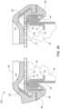
- FIG. 1depicts a cross-section of the preferred embodiment of the assembled Child Resistant Double Seam Container Lid over a conventional can double seam, in accordance with the present invention.
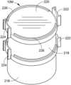
- FIG. 2depicts a side elevation view of two cans with the Child Resistant Double Seam Container Lid stacked one on top of the other having the upper can with the two parts of the indicator section in the can opening position and the lower can with the indicator section separated in the can locked position, in accordance with the present invention.
- FIG. 3depicts a top view of the can locking member of the preferred embodiment of the Child Resistant Double Seam Container Lid illustrating the plurality of retaining teeth and the relief area, in accordance with the present invention.
- FIG. 4depicts a cross-section through the lid portion top piece of the preferred embodiment of the Child Resistant Double Seam Container Lid illustrating the locking nib, in accordance with the present invention.
- FIG. 5depicts a cross-section through the preferred embodiment of the adapter ring can locking member piece illustrating the external locking trough, the retaining teeth and the relief area therein, in accordance with the present invention.
- FIG. 6depicts the first alternate embodiment Child Resistant Double Seam Container Lid illustrating a side view of a conventional can incorporating the Child Resistant Double Seam Container Lid, in accordance with the present invention.
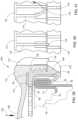
- FIG. 7depicts a cross-section through an assembled alternate embodiment of the Child Resistant Double Seam Container Lid illustrating the conventional can lid portion top piece with the locking nib section and the adapter ring can locking member piece with the addition of a securing unit third piece, in accordance with the present invention.
- FIG. 8depicts a cross-section through an assembled alternate embodiment of the Child Resistant Double Seam Container Lid, illustrating the adapter ring can locking member piece with external locking trough and retaining teeth along with wedge teeth on the securing unit third piece, in accordance with the present invention.
- FIG. 9depicts an exploded cross-section through separate alternate embodiments of the Child Resistant Double Seam Container Lid, illustrating the adapter ring can locking member piece with retaining teeth and wedge teeth on the securing unit third piece, in accordance with the present invention.
- FIG. 10is an enlarged partial cross-section through an assembled alternate embodiment of the Child Resistant Double Seam Container Lid illustrating a lid portion top first piece, the adapter ring can locking member second piece with an external locking trough and a relief area for the locking nib, wherein the retaining teeth on the adapter ring can locking member will have a flexible a configuration, in accordance with the present invention.
- FIG. 11is an enlarged partial cross-section through the assembled alternate embodiment of the Child Resistant Double Seam Container Lid illustrating a conventional lid portion top piece with an internal locking inner protrusion, the adapter ring can locking member piece with an external locking trough for accepting the locking nib and having a different configuration of the retaining teeth and the securing unit piece, in accordance with the present invention.
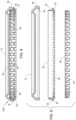
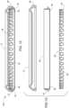
- FIG. 12is a cross-section of the assembled alternate embodiment of the Child Resistant Double Seam Container Lid illustrating a lid portion top piece, and the adapter ring can locking member second piece with the segments of the retaining teeth flat, prior to being bent up when inserted over a conventional can double seam top rim, in accordance with the present invention.
- FIG. 13depicts separate cross-sections views of an alternate embodiment of the Child Resistant Double Seam Container Lid illustrating the lid portion top piece, the adapter ring can locking member second piece and the securing unit third piece, in accordance with the present invention.
- FIG. 14depicts a perspective bottom view of the lid portion top first piece removed from the adapter ring can locking member second piece as shown in FIG. 15 , in accordance with the present invention.
- FIG. 15depicts a perspective top and side elevation view of a pop-top opener removable conventional can top illustrating the Child Resistant Double Seam Container Lid adapter ring can locking member piece and the securing unit piece in place secured on the double seam, in accordance with the present invention.
- FIG. 16depicts a top view of an alternate embodiment Child Resistant Double Seam Container Lid having a flexible lid portion top piece including a tab for leveraging open the flexible lid portion top piece, in accordance with the present invention.
- FIG. 17depicts a side elevation view of the alternate embodiment Child Resistant Double Seam Container Lid shown in FIG. 16 , having a flexible lid with the PUSH UP indicia and a lifting leverage tab, in accordance with the present invention.
- FIG. 18depicts a bottom view of the alternate embodiment Child Resistant Double Seam Container Lid shown in FIG. 16 , having a flexible lid with a lifting leverage tab, in accordance with the present invention.
- FIG. 19depicts a cross-section of the alternate embodiment Child Resistant Double Seam Container Lid shown in FIG. 18 , having a flexible lid with a lifting leverage tab, in accordance with the present invention.
- FIG. 20depicts a perspective view of an alternate embodiment Child Resistant Double Seam Container Lid having a flexible one-piece lid portion piece illustrating a hand with a strap tool exerting pressure to manually bend the lid portion piece to open a container, in accordance with the present invention.
- FIG. 21depicts a cross-section of the Child Resistant Double Seam Container Lid having a flexible one-piece lid portion piece shown in FIG. 20 , with the opening tool in place on the lid portion piece, in accordance with the present invention.
- FIG. 22depicts a cross-section of the Child Resistant Double Seam Container Lid having a flexible one-piece lid portion piece with a thin section therein to aide in the flexibility of the lid, in accordance with the present invention.
- FIG. 23depicts a cross-section of the Child Resistant Double Seam Container Lid having a flexible one-piece lid portion piece with a slotted section to aid in the flexibility of the lid, in accordance with the present invention.
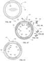
- FIG. 24depicts a top perspective view of another alternate embodiment of the Child Resistant Double Seam Container Lid having the round lid portion first piece placed on a conventional round can, in accordance with the present invention.
- FIG. 25depicts a top perspective view of the alternate embodiment of the Child Resistant Double Seam Container Lid shown in FIG. 24 illustrating the top of a conventional round can with pop top opener having the adapter ring can locking member in place secured to the double seam of the can, in accordance with the present invention.
- FIG. 26depicts a bottom perspective view of the alternate embodiment of the Child Resistant Double Seam Container Lid shown in FIG. 25 having the round adapter ring can locking member apart from the conventional can double seam, illustrating the retaining teeth along the circumference of the round adapter ring, in accordance with the present invention.
- FIG. 27depicts a bottom view of the alternate embodiment of the Child Resistant Double Seam Container Lid shown in FIG. 26 illustrating the pattern of a plurality of retaining teeth, in accordance with the present invention.
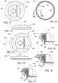
- FIG. 28depicts a cross-section of the assembled alternate embodiment of the Child Resistant Double Seam Container Lid shown in FIG. 24 , in accordance with the present invention.
- FIG. 29depicts a cross section of the assembled alternate embodiment of the Child Resistant Double Seam Container Lid shown in FIG. 24 illustrating the location of the indicator section on the left side, in accordance with the present invention.
- FIG. 30depicts a side view of a conventional can incorporating the assembled alternate embodiment of the Child Resistant Double Seam Container Lid shown in FIG. 24 illustrating the indicator sections aligned for opening or closing the lip portion piece, in accordance with the present invention.
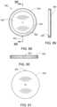
- FIG. 31depicts a top view of an alternate embodiment of the Child Resistant Double Seam Container Lid, in accordance with the present invention.
- FIG. 32depicts a bottom perspective view of the underside of an assembled alternate embodiment of the Child Resistant Double Seam Container Lid illustrating the connected lid portion top piece and the adapter ring can locking member piece having a vacuum sealing gasket feature, in accordance with the present invention.
- FIG. 33depicts a top perspective view of the top surface of the alternate embodiment of the Child Resistant Double Seam Container Lid shown in FIG. 32 in place on a conventional round can, in accordance with the present invention.
- FIG. 34depicts a bottom view of the underside of an alternate embodiment of the Child Resistant Double Seam Container Lid with a vacuum sealing can lid configuration incorporating the vacuum sealing lid portion top piece and the adapter ring can locking member piece, in accordance with the present invention.
- FIG. 35depicts a cross-section of the alternate embodiment of the Child Resistant Double Seam Container Lid shown in FIG. 34 in place on a conventional round can secured to the double seam with the vacuum sealing lid portion piece and incorporating the vacuum sealing adapter ring can locking member piece, in accordance with the present invention.
- FIG. 36depicts a cross-section of two conventional round cans with the alternate embodiment of the Child Resistant Double Seam Container Lid shown in FIG. 35 in place on the lower can secured to the double seam, illustrating the contoured surface of the lid portion top piece for facilitating stacking of the cans so equipped, in accordance with the present invention.
- FIG. 37depicts a side elevation view of the alternate embodiment of the Child Resistant Double Seam Container Lid shown in FIG. 35 in place on a conventional round can double seam, in accordance with the present invention.
- FIG. 38depicts an enlarged cross-section of the alternate embodiment of the Child Resistant Double Seam Container Lid shown in FIG. 35 in place on a conventional round can double seam illustrating the vacuum sealing lid having an adapter ring can locking member with a rubber seal coating and lid portion top piece having a rubber sealing coating, in accordance with the present invention.
- FIG. 39depicts an enlarged cross-section of another alternate embodiment of the Child Resistant Double Seam Container Lid incorporating a vacuum sealing threaded lid portion top piece attached to a vacuum sealing threaded adapter ring can locking member piece, in accordance with the present invention.
- FIG. 40depicts a partial side view of the alternate embodiment of the Child Resistant Double Seam Container Lid illustrating the vacuum sealing lid portion top piece in the locked position, in accordance with the present invention.
- FIG. 41depicts a partial side view of the alternate embodiment of the Child Resistant Double Seam Container Lid illustrating the vacuum sealing lid portion top piece in the unlocked position, in accordance with the present invention.
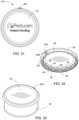
- FIG. 42depicts an exploded top and side perspective view of a three-piece Child Resistant Double Seam Container Lid incorporating a first piece round lid portion top piece, a second piece adapter ring can locking member piece, and a third piece divided measuring cup.
- FIG. 43depicts a partial cross-sectional view of the lid portion top piece of the three-piece Child Resistant Double Seam Container Lid incorporating a divided measuring cup shown in FIG. 42 .
- FIG. 44depicts a cross-sectional view of the middle piece measuring cup portion of the three-piece Child Resistant Double Seam Container Lid incorporating a divided measuring cup shown in FIG. 42 .
- FIG. 45depicts an enlarged cross-sectional view of the double seam on a can rim top portion of the container which accepts the second piece round adapter ring can locking member piece of the three-piece Child Resistant Double Seam Container Lid incorporating a divided measuring cup shown in FIG. 42 .
- FIG. 46depicts a bottom plan view of the lid portion top piece of the three-piece Child Resistant Double Seam Container Lid incorporating a divided measuring cup shown in FIG. 42 .
- FIG. 47depicts a top plan view of the adapter ring portion of the three-piece Child Resistant Double Seam Container Lid incorporating a divided measuring cup shown in FIG. 42 .
- FIG. 48depicts a cross-sectional view of the adapter ring portion of the three-piece Child Resistant Double Seam Container Lid incorporating a divided measuring cup shown in FIG. 47 .
- FIG. 49depicts another cross-sectional view of the adapter ring portion of the three-piece Child Resistant Double Seam Container Lid incorporating a divided measuring cup shown in FIG. 47 .
- FIG. 50depicts yet another cross-sectional view of the adapter ring portion of the three-piece Child Resistant Double Seam Container Lid incorporating a divided measuring cup shown in FIG. 47 .
- FIG. 51depicts a bottom plan view of the adapter ring portion of the three-piece Child Resistant Double Seam Container Lid incorporating a divided measuring cup shown in FIG. 47 .
- FIG. 52depicts a top perspective view of three adapter rings connected together by a frangible connection point configured to hold three containers, showing one container below the adapter ring 3-pack and not connected thereto.
- FIG. 53depicts a top perspective view of an alternate embodiment of the Child Resistant Double Seam Container Lid illustrating a round lid portion top piece having drinking, dispensing and venting holes therein.
- FIG. 54depicts a bottom perspective view of the alternate embodiment of the Child Resistant Double Seam Container Lid illustrating a round lid portion top piece having drinking, dispensing and venting holes therein shown in FIG. 53 .
- FIG. 55depicts a partial cross-sectional view of the alternate embodiment of the Child Resistant Double Seam Container Lid illustrating a round lid portion top piece having drinking, dispensing and venting holes therein shown in FIG. 54 .
- FIG. 56depicts a top perspective view of an alternate embodiment of the Child Resistant Double Seam Container Lid illustrating incorporated integral finger grips and container retaining guides for facilitating stacking of containers so equipped.
- FIG. 57depicts a cross-sectional view of the alternate embodiment of the Child Resistant Double Seam Container Lid shown in FIG. 56 illustrating the position of an O-ring within the lid portion enabling a liquid tight one-piece child resistant lid with finger grips and container retaining guides.
- FIG. 58depicts a top perspective view of an alternate embodiment of the Child Resistant Double Seam Container Lid illustrating two stacked containers having a one-piece child resistant lid with integral extended finger grips and incorporating larger container retaining guides located around the circumference of the one-piece lid.
- FIG. 59depicts a top plan view of the alternate embodiment of the Child Resistant Double Seam Container Lid shown in FIG. 58 .
- FIG. 60depicts a front elevational view of the alternate embodiment of the Child Resistant Double Seam Container Lid shown in FIG. 59 .
- FIG. 61depicts a cross-sectional view of the alternate embodiment of the Child Resistant Double Seam Container Lid shown in FIG. 63 .
- FIG. 62depicts an enlarged cross-sectional partial view of a portion of the alternate embodiment of the Child Resistant Double Seam Container Lid one-piece lid with extended finger grips and larger container retaining guides shown in FIG. 61 illustrating the location of the O-ring.
- FIG. 63depicts a bottom plan view of the alternate embodiment of the Child Resistant Double Seam Container Lid showing the one-piece child resistant lid with extended finger grips and larger container retaining guides shown in FIG. 59 .
- FIG. 64depicts a side elevational view of the alternate embodiment of the Child Resistant Double Seam Container Lid illustrating the one-piece child resistant lid with extended finger grips and larger container retaining guides shown in FIG. 60 .
- FIG. 65depicts a top plan view of an alternate embodiment of the Child Resistant Double Seam Container Lid illustrating a one-piece child resistant lid with finger grips and an integrated 1 Tablespoon Measuring Cup located on the lid top surface.
- FIG. 66depicts a bottom plan view of the alternate embodiment of the Child Resistant Double Seam Container Lid shown in FIG. 65 illustrating a one-piece child resistant lid with finger grips and an integrated 1 Tablespoon Measuring Cup located on the lid top surface.
- FIG. 67depicts a cross-sectional view of the alternate embodiment of the Child Resistant Double Seam Container Lid shown in FIG. 66 illustrating a one-piece child resistant lid with finger grips and an integrated 1 Tablespoon Measuring Cup located on the lid top surface.
- FIG. 68depicts a top plan view of an alternate embodiment of the Child Resistant Double Seam Container Lid illustrating a one-piece child resistant lid with finger grips and an integrated 2 Tablespoon Measuring Cup located on the lid top surface.
- FIG. 69depicts a bottom plan view of the alternate embodiment of the Child Resistant Double Seam Container Lid shown in FIG. 68 illustrating a one-piece child resistant lid with finger grips and an integrated 2 Tablespoon Measuring Cup located on the lid top surface.
- FIG. 70depicts a bottom plan view of the one-piece Child Resistant Double Seam Container Lid with finger grips and an integrated 2 Tablespoon Measuring Cup shown in FIG. 69 .
- FIG. 71depicts a top plan view of an alternate embodiment of a Child Resistant Double Seam Container Lid illustrating a two-piece child resistant lid with an integrated push out leverage tab.
- FIG. 72depicts a bottom plan view of the alternate embodiment of the Child Resistant Double Seam Container Lid shown in FIG. 71 illustrating detail of a two-piece child resistant lid with an integrated push out leverage tab adapter ring piece.
- FIG. 73depicts a side elevational view of the alternate embodiment of the Child Resistant Double Seam Container Lid shown in FIG. 71 having an integrated push out leverage tab on the lid portion piece of the two-piece child resistant lid with a push out leverage tab.
- FIG. 74depicts a top plan view of an alternate embodiment of the Child Resistant Double Seam Container Lid illustrating a two-piece child resistant lid with an integrated push out leverage tab, showing the push out leverage tab pushed out and extended for increased leverage during the removal of the lid portion.
- FIG. 75depicts a side elevational view of the alternate embodiment of the Child Resistant Double Seam Container Lid shown in FIG. 74 illustrating a two-piece child resistant lid with an integrated push out leverage tab, showing the push out leverage tab pushed out and extended for increased leverage during the removal of the lid portion.
- FIG. 76depicts an enlarged partial cross-sectional view of the alternate embodiment of the Child Resistant Double Seam Container Lid shown in FIG. 74 illustrating detail of the adapter ring piece of the two-piece child resistant lid with a push out leverage tab shown in FIG. 72 .
- FIG. 77depicts a cross-sectional view of the alternate embodiment of the Child Resistant Double Seam Container Lid shown in FIG. 74 illustrating the assembled adapter ring piece and lid portion piece of the two-piece child resistant lid with a push out leverage tab, showing the push out leverage tab pushed out and extended for increased leverage in removing the lid portion shown in FIG. 74 and FIG. 75 .
- FIG. 78depicts a cross-sectional view of the alternate embodiment of the Child Resistant Double Seam Container Lid shown in FIG. 74 illustrating the assembled adapter ring piece and lid portion piece of the two-piece child resistant lid with a push out leverage tab, showing the push out leverage tab in place as shown in FIG. 71 and FIG. 73 .
- FIG. 79depicts a side elevational view of an alternate embodiment of the Child Resistant Double Seam Container Lid illustrating a two-piece child resistant lid affixed to a beer can beverage container showing the rotational alignment indicators in alignment together allowing the removal of the lid portion piece.
- FIG. 80depicts an enlarged partial cross-sectional view of the alternate embodiment of the Child Resistant Double Seam Container Lid as shown in FIG. 79 illustrating a two-piece child resistant lid affixed to a beer can beverage container showing the rotational alignment indicators in alignment together.
- FIG. 81depicts a side elevational view of an alternate embodiment of the Child Resistant Double Seam Container Lid illustrating a two-piece child resistant lid affixed to a soda can beverage container showing the rotational alignment indicators out of alignment and apart preventing the removal of the lid.
- FIG. 82depicts an enlarged partial cross-sectional view of the alternate embodiment of the Child Resistant Double Seam Container Lid as shown in FIG. 81 illustrating a two-piece child resistant lid affixed to a soda can beverage container showing the rotational alignment indicators out of alignment and apart preventing the removal of the lid.
- FIG. 83depicts a top plan view of the round adapter ring piece of the two-piece Child Resistant Double Seam Container Lid as shown in FIG. 79 illustrating the retaining teeth which secure the round adapter ring piece to the beverage can.
- FIG. 84depicts a bottom plan view of the round adapter ring piece of the two-piece Child Resistant Double Seam Container Lid as shown in FIG. 79 illustrating the retaining teeth which secure the round adapter ring piece to the beverage can.
- FIG. 85depicts an enlarged partial cross-sectional view of the adapter ring piece of the two-piece Child Resistant Double Seam Container Lid as shown in FIG. 83 illustrating the small retaining nib thereon.
- FIG. 86depicts an enlarged partial cross-sectional view of the adapter ring piece of the two-piece Child Resistant Double Seam Container Lid as shown in FIG. 84 illustrating the large locking nib thereon.
- FIG. 87depicts an enlarged detailed partial view of the top plan view of the adapter ring piece of the two-piece Child Resistant Double Seam Container Lid as shown in FIG. 83 illustrating the rotational alignment indicator area.
- FIG. 88depicts a bottom plan view of the lid portion of the Child Resistant Double Seam Container Lid as shown in FIG. 79 to FIG. 82 illustrating the retaining tab position relative to the rotational alignment indicators.
- FIG. 89depicts a cross-sectional view of the lid portion piece of the Child Resistant Double Seam Container Lid as shown in FIG. 88 illustrating the retaining tab located on the lid portion piece of the two-piece child resistant lid.
- FIG. 90depicts a side elevational view of the lid portion of the Child Resistant Double Seam Container Lid as shown in FIG. 88 and FIG. 89 illustrating the position of the rotational alignment indicator thereon.
- FIG. 91depicts a top plan view of the lid portion of the Child Resistant Double Seam Container Lid as shown in FIG. 88 and FIG. 90 illustrating the position of the rotational alignment indicator thereon.
- FIG. 1depicts a cross-section of the preferred embodiment of the assembled two-piece Child Resistant Double Seam Container Lid 10 A snapped on to a conventional can 32 double seamed container seam roll 30 top rim, made up of the container 32 wall and the container lid portion 33 , in accordance with the present invention.
- the preferred embodiment of the two-piece Child Resistant Double Seam Container Lid 10 A disclosed hereinis comprised of two separate pieces, the first piece lid portion 12 and the second piece adapter ring can locking member 20 .
- the adapter ringcan locking member 20 snaps on to the container double seam 30 and cannot be removed following affixation.
- the first piece lid portion 12is configured to be accepted by the adapter ring can locking member 20 second piece in a way that makes the lid portion adapter ring combination assembled two-piece Child Resistant Double Seam Container Lid 10 A child resistant.
- all of the first piece lid portions disclosed throughout this application specificationare round in shape, and all of the second piece adapter ring can locking members are round in shape, as they would not properly function to rotate about each other if either of the two pieces were not round or somehow became out of round. Therefore, all pieces shown are round circular disk shaped or round ring shaped.
- FIG. 1depicting a cross section view of the preferred embodiment of the two-piece Child Resistant Double Seam Container Lid 10 A indicating the first piece lid portion 12 with a contoured surface 14 to secure additional cans for stacking.
- a locking inner ring 16 of the lid portion 12engages within the external locking trough 18 in the circumference of the second piece adapter ring can locking member 20 with a relief area 22 to access the nib section 24 of the lid portion 12 for the removal of the lid portion 12 when an upward pressure is applied at the lifting indicator section 26 .
- the top surface 28 of the can locking member 20rests on the rim 30 of the can 32 and is held in place by the upper surface 34 of the external locking trough 18 .
- a series of retaining teeth 36 around the lower inner surface of the can locking member 20are bent up when the locking member 20 is forced over the top rim 30 of the can 32 to engage under the lip of the can 30 .
- FIG. 2depicts a side elevation view of two stacked round cans 32 with the two-piece Child Resistant Double Seam Container Lid 10 A thereon, stacked one on top of the other having the upper can 32 first piece lid portion 12 with the two parts of the rotational alignment indicator section 26 , namely, rotational alignment indicator 26 A and rotational alignment indicator 26 B aligned in the child resistant can lid opening position, in accordance with the present invention.
- the lower canhas the lid 12 rotated so that indicator section 26 A is moved to the right putting the lid 12 in the locking position.
- the cansare stable when stacked, as the top can rests within the contoured portion 14 (see FIG. 1 ) of the first piece lid portion 12 , and will not slide.
- FIG. 3depicts a top view of the second piece adapter ring can locking member 20 of the preferred embodiment of the two-piece Child Resistant Double Seam Container Lid 10 A illustrating the plurality of retaining teeth 36 and the relief area 22 , in accordance with the present invention.
- the plurality of retaining teeth 36snap on to the can double seam and are thereby securely affixed to the can double seam.
- the relief area 22will allow the nib 24 to lift upwardly and the first piece lid portion 12 can be removed from the second piece adapter ring can locking member 20 .
- FIG. 4depicts a cross-section through the lid portion top piece 12 of the preferred embodiment of the two-piece Child Resistant Double Seam Container Lid 10 A illustrating the locking nib section 24 , and the inner locking ring 16 , in accordance with the present invention.
- the inner locking ring 16runs around the entire circumference of the lid portion 12 except for the rotational indicator 26 area, where the locking nib section 24 is located.
- FIG. 5depicts a cross-section through the preferred embodiment of the two-piece Child Resistant Double Seam Container Lid 10 A showing detail of the adapter ring can locking member piece 20 illustrating the external locking trough 18 where the locking inner ring 16 is securely held in place.
- the top surface 28 of the can locking member 20rests on the rim 30 of the can 32 (see FIG. 1 ), the fourteen (14) retaining teeth 36 are shown on the lower surface with the single relief area 22 for the nib section 24 on the left side.
- FIG. 6depicts the first alternate embodiment three-piece Child Resistant Double Seam Container Lid 10 B, illustrating a side view of a conventional can 32 incorporating the Child Resistant Double Seam Container Lid 10 B lid portion 12 and adapter ring 20 , having the rotational alignment indicators within rotational indicator section 26 in alignment.
- FIG. 7depicts a cross-section through an assembled alternate embodiment of the three-piece Child Resistant Double Seam Container Lid 10 B illustrating the conventional can lid portion first piece 12 with the locking nib section 24 and the adapter ring can locking member second piece 20 with the addition of a securing unit third piece 38 .
- the securing unit third piece 38secures the adapter ring can locking member second piece 20 to the double seam of the can 30 , such that, when in place, the adapter ring 20 and securing unit 38 combination prevents the adapter ring 20 from being removed from the double seam 30 after affixation.
- FIG. 8depicts a cross-section through an assembled alternate embodiment of the three-piece Child Resistant Double Seam Container Lid 10 B, illustrating greater detail of the lid portion first piece 20 , the adapter ring can locking member second piece 20 with external locking trough 18 and a plurality of retaining teeth 36 along with a plurality of wedge teeth 40 on the securing unit 38 third piece.
- FIG. 9depicts an exploded cross-section through separate alternate embodiments of the three-piece Child Resistant Double Seam Container Lid 10 B, illustrating the lid portion first piece 12 , the adapter ring can locking member second piece 20 with a plurality of retaining teeth 36 and the location of a plurality of wedge teeth 40 on the securing unit third piece 38 , in accordance with the present invention.
- FIG. 10is an enlarged partial cross-section through an assembled alternate embodiment of a three-piece Child Resistant Double Seam Container Lid 10 C illustrating a lid portion top first piece 12 , the adapter ring can locking member second piece 20 with an external locking trough 18 and a relief area 22 for the locking nib 24 to lift out when opening the lid portion first piece 12 .
- the plurality of retaining teeth 36 on the adapter ring can locking member 20will have a flexible curved configuration in this embodiment, in accordance with the present invention.
- the twenty four (24) retaining teeth 36 on the can locking member 20will be curved in shape not straight, and have a thinner cross-section for a more flexible configuration.
- the rotational indicators 26are aligned to allow the locking nib 24 to be lifted thereby removing the child resistant lid portion 12 .
- FIG. 11is an enlarged partial cross-section through the assembled alternate embodiment of the three-piece Child Resistant Double Seam Container Lid 10 C illustrating a conventional lid portion top first piece 12 with an internal locking inner protrusion 16 , the adapter ring can locking member second piece 20 with an external locking trough 18 for accepting the locking nib 24 and having a different configuration of the retaining teeth 36 and the securing unit third piece 38 , in accordance with the present invention.
- the retaining teethare curved, thinner and more flexible.
- FIG. 12is a cross-section of the assembled alternate embodiment of the three-piece Child Resistant Double Seam Container Lid 10 C illustrating a lid portion top first piece 12 , and the adapter ring can locking member second piece 20 with the segments of the thinner flexible retaining teeth 36 flat, prior to being bent up when inserted over a conventional can double seam top rim, and the securing unit third piece 38 having a plurality of retaining teeth 40 , in accordance with the present invention.
- FIG. 13depicts an exploded separate piece cross-sectional views of an alternate embodiment of the three-piece Child Resistant Double Seam Container Lid 10 C illustrating the lid portion top first piece 12 and the lid portion rotational alignment indicator section 26 , the adapter ring can locking member second piece 20 with the thinner flexible retaining teeth 36 flat, prior to being bent up when inserted over a conventional can double seam top rim and the securing unit third piece 38 with a plurality of retaining teeth 40 , in accordance with the present invention.
- FIG. 14depicts a perspective bottom view of the lid portion top first piece 12 alone removed from the adapter ring can locking member second piece 20 , as shown in FIG. 15 below, illustrating the rotational indicator section 26 of the alternate embodiment of the three-piece Child Resistant Double Seam Container Lid 10 C.
- FIG. 15depicts a perspective top and side elevation view of a pop-top opener 42 removable conventional can 32 top surface, illustrating the Child Resistant Double Seam Container Lid 10 C adapter ring can locking member piece 20 with a plurality of retaining teeth (not shown) and the securing unit third piece 38 in place secured on the double seam with a plurality of retaining teeth 40 .
- FIG. 16depicts a top view of another alternate embodiment of a one-piece Child Resistant Double Seam Container Lid 10 D having a flexible lid portion top piece 12 only, including a protruding leverage tab (not shown, see FIG. 17 , FIG. 18 and FIG. 19 ) for leveraging open the flexible lid portion top piece, making it easier to open.
- FIG. 17depicts a side elevation view of the alternate embodiment one-piece Child Resistant Double Seam Container Lid 10 D shown in FIG. 16 , having a flexible malleable lid 12 with a lift up protrusion 48 , a “PUSH UP” indicia 50 and a lifting leverage tab 52 to assist in the removal of the lid 12 .
- the outer perimeter 54has a smooth angled surface 56 making it difficult to grip by children.
- FIG. 18depicts a bottom view of the alternate embodiment one-piece Child Resistant Double Seam Container Lid 10 D shown in FIG. 17 , having a flexible lid 12 with a lifting leverage tab 52 .
- the inner edge surface 62 that is relieved 64 on two areas leaving a ridge 66 to the lid sealing ledge 62maintain the sealing capability when the Child Resistant Double Seam Container Lid 10 D is placed or replaced on a conventional can 32 .
- FIG. 19depicts a cross-section of the alternate embodiment Child Resistant Double Seam Container Lid 10 D as shown in FIG. 18 , having a flexible lid portion 12 with a lifting leverage tab 52 further illustrating the tab 52 location, and the inner edge surface 62 is relieved areas 64 on two areas leaving a lid sealing ledge 66 .
- the Child Resistant Double Seam Container Lid flexible lid portion 12can be rotated upward for removal by stretching the material in the relieved areas 64 .
- FIG. 20depicts a perspective view of an alternate embodiment one-piece Child Resistant Double Seam Container Lid 10 E having a flexible one-piece lid portion piece 12 illustrating a user's hand 74 with a manual strap tool 68 with end 70 fitted into a slot 70 on the lid 12 exerting pressure to manually bend the lid portion piece 12 to open a container 32 .
- a person's hand 74uses a specialized manual tool 68 for exerting pressure to manually bend the lid 12 at a relieved area 76 to readily open the lid portion 12 on the can 32 .
- FIG. 21depicts a cross-section of the Child Resistant Double Seam Container Lid 10 E having a flexible one-piece lid portion piece 12 as shown in FIG. 20 , with the opening tool 68 in place on the lid portion piece 12 , showing where pressure can be exerted to bend the lid 12 at the relieved area 76 to open the conventional can 32 .
- FIG. 22depicts a cross-section of the Child Resistant Double Seam Container Lid 10 E having a flexible one-piece lid portion piece 12 , further illustrating the location of the thin section slots 72 and the relieved area 76 therein to aide in the flexibility of the lid 12 .
- FIG. 23depicts a cross-section of the Child Resistant Double Seam Container Lid 10 E having a flexible one-piece lid portion piece 12 with a slotted section having a plurality of slots 78 one hundred and eighty degrees apart in the relieved area 76 of the lid so it will flex upward to release from the conventional can 32 when pressure is applied, to aid in the flexibility of the lid.
- FIG. 24depicts a top perspective view of another alternate embodiment of the three-piece Child Resistant Double Seam Container Lid 10 F having the assembled round lid portion first piece 12 and round adapter ring can locking member second piece in place on a conventional round can 32 , in accordance with the present invention.
- FIG. 25depicts a top perspective view of the alternate embodiment of the three-piece Child Resistant Double Seam Container Lid 10 F shown in FIG. 24 illustrating the top of a conventional round can 32 with pop top opener 42 having the adapter ring can locking member second piece 20 and securing member third piece 38 in place secured to the double seam of the conventional can 32 .
- Retaining teeth 40 on the securing member third piece 38are visible, but the retaining teeth 36 on the adapter ring 20 are not visible in this view.
- FIG. 26depicts a bottom perspective view of the alternate embodiment of the three-piece Child Resistant Double Seam Container Lid 10 F shown in FIG. 25 having the assembled round adapter ring can locking member 20 and securing unit 38 apart from the conventional can double seam, illustrating the retaining teeth 36 along the circumference of the round adapter ring 20 and the retaining teeth 40 along the circumference of the securing unit 38 .
- FIG. 27depicts a bottom view of the alternate embodiment of the three-piece Child Resistant Double Seam Container Lid 10 F shown in FIG. 26 illustrating the pattern of a plurality of retaining teeth 36 on the adapter ring can locking member 20 and the retaining teeth 40 on the securing unit 38 .
- FIG. 28depicts a cross-section of the assembled alternate embodiment of the three-piece Child Resistant Double Seam Container Lid 10 F shown in FIG. 27 , illustrating here the assembled three pieces of the child resistant lid configuration, namely, the lid portion first piece 12 on the adapter ring can locking member second piece 20 , and the securing unit third piece 38 .
- This viewalso shows the retaining teeth 36 on the adapter ring 20 and the retaining teeth 40 on the securing unit 38 .
- FIG. 29depicts another cross-section of the assembled alternate embodiment of the three-piece Child Resistant Double Seam Container Lid 10 F shown in FIG. 27 illustrating the location of the rotational alignment indicator section 26 on the left side of the lid portion first piece 12 .
- FIG. 30depicts a side view of a conventional can incorporating the assembled alternate embodiment of the three-piece Child Resistant Double Seam Container Lid 10 F shown in FIG. 24 illustrating the rotational alignment indicator sections 26 aligned for opening or closing the lip portion piece 12 , in accordance with the present invention.
- FIG. 31depicts a top view of an alternate embodiment of a two-piece Child Resistant Double Seam Container Lid 10 G having a liquid tight vacuum sealing lid 82 showing the rotational alignment indicator 26 A on the lid portion first piece 82 .
- FIG. 32depicts a bottom perspective view of the underside of an assembled alternate embodiment of the two-piece Child Resistant Double Seam Container Lid 10 G illustrating the connected lid portion top piece 82 with the rubber sealant coating 84 applied to the lid inner surface 86 , with the vacuum sealing adapter ring can locking member 88 having the rubber sealant 90 applied on the inner surface of the edge 92 .
- the inner surface of the vacuum sealing can locking member 88has a plurality of retaining teeth 36 on the lower edge 92 and a plurality of upper supporting teeth 94 on the upper edge 96 .
- rubber sealing coating 84 on lid portion 82 and the rubber sealing coating 90 on adapter ring 88make the overall lid 82 liquid tight and capable of being vacuum sealed.
- the rotational alignment indicators 26 A on lid portion 82 and 26 B on the adapter ring 88here being in alignment for opening and removing the lid 82 up and off of the adapter ring 88 .
- FIG. 33depicts a top perspective view of the top surface of the alternate embodiment of the two-piece Child Resistant Double Seam Container Lid 10 G shown in FIG. 32 in place on a conventional round conventional can 32 , and showing the lid rotational indicator 26 A.
- FIG. 34depicts a bottom view of the underside of an alternate embodiment of the two-piece Child Resistant Double Seam Container Lid 10 G with a vacuum sealing can lid 82 configuration incorporating the vacuum sealing lid portion top piece 82 and the adapter ring can locking member piece 88 showing the location of retaining teeth 36 around the circumference of the adapter ring 88 . Also seen here is the rubber sealing coating 84 located on the lid inner surface 86 and a plurality of upper supporting teeth 94 .
- FIG. 35depicts a cross-section of the alternate embodiment of the two-piece Child Resistant Double Seam Container Lid 10 G shown in FIG. 34 in place on a conventional round can 32 secured to the double seam 31 with the vacuum sealing lid portion piece 82 and incorporating the vacuum sealing adapter ring can locking member piece 88 .
- FIG. 36depicts a cross-section of two conventional round stacked cans 32 with the alternate embodiment of the two-piece Child Resistant Double Seam Container Lid 10 G shown in FIG. 35 in place on the lower can 32 with the adapter ring 88 secured to the double seam 31 , illustrating the contoured surface of the lid portion top piece 82 configured specifically for facilitating stacking of the cans so equipped.
- FIG. 37depicts a side elevation view of the alternate embodiment of the assembled two-piece Child Resistant Double Seam Container Lid 10 G shown in FIG. 35 in place on a conventional round can 32 double seam, and showing the location of the rotational alignment indicator section 26 .
- FIG. 38depicts an enlarged partial cross-section of the alternate embodiment of the two-piece Child Resistant Double Seam Container Lid 10 G shown in FIG. 35 in place on a conventional round can 32 double seam 31 illustrating the vacuum sealing lid portion 82 having an adapter ring can locking member 88 with a rubber seal coating 90 and lid portion top piece 82 having a rubber sealing coating 84 .
- the lid 30 and the can wall 32are folded to create a closed double seam 31 having five layers. All of the adapter rings as disclosed herein are configured to be secured to this double seam.
- the adapter ring 88snaps on to the double seam 31 and is secured by upper retaining teeth 94 and retaining teeth 36 .
- rubber sealing coating 84 on lid portion 82 and the rubber sealing coating 90 on adapter ring 88make the overall assembled lid 82 and adapter ring 88 liquid tight and capable of being vacuum sealed.
- FIG. 39depicts an enlarged cross-section of another alternate embodiment of the two-piece Child Resistant Double Seam Container Lid 1011 incorporating a vacuum sealing threaded lid portion top piece 112 having threads 104 attached to a vacuum sealing threaded adapter ring can locking member piece 108 including mating threads to lid threads 104 .
- the vacuum sealing can locking member 108puts pressure on the rubber sealing coating 90 on the side and top of the can rim 30 when the retaining teeth are locked under the can rim 30 .
- the lid 106is tightened down it puts pressure on the rubber sealing coating 110 on the lid 106 and the vacuum sealing can locking member 108 .
- the adapter ring 88snaps on to the double seam 31 and is secured by upper retaining teeth 94 and retaining teeth 36 .
- the lid 106has a bulbous area 112 on the outer edge with a plurality gripping ribs 114 around the perimeter to aide in tightening down the lid 106 .
- a second set of gripping ribs 116are on the perimeter of the vacuum sealing can locking member 108 .
- a flexible locking tab 118is located on one of the gripping ribs 114 to engage with one of the gripping ribs 116 that can be bent upward to release the lid 106 to rotate and open the can 32 .
- FIG. 40depicts a partial side view of the alternate embodiment of the two-piece threaded Child Resistant Double Seam Container Lid 1011 illustrating the vacuum sealing lid portion top piece 112 gripping ribs 114 on the lid 106 and the gripping ribs 116 on the vacuum sealing can locking member 108 with the flexible locking tab 118 straight down in the locked position.
- FIG. 41depicts a partial side view of the alternate embodiment of the two-piece threaded Child Resistant Double Seam Container Lid 1011 illustrating the vacuum sealing lid portion top piece 112 in the unlocked position, illustrating detail of the gripping ribs 114 on the lid 106 and the gripping ribs 116 on the vacuum sealing can locking member 108 with a flexible locking tab 118 straight down in the locked position.
- FIG. 42depicts an exploded top and side perspective view of a two-piece Child Resistant Double Seam Container Lid 10 J incorporating a measuring cup, having a first round lid portion top piece 130 , a second adapter ring can locking member piece 150 , configured to accommodate a divided measuring cup 140 .
- the measuring cup 140is divided by a handle 142 having an optional orifice 144 .
- a rotational alignment indicator 132is also shown on the first round lid portion top piece 130 .
- the adapter ring 150has an inner surface 152 and an outer surface 154 and is configured to accept the measuring cup 140 when nested within the inner surface 152 .
- the adapter ring lower surface 154includes locking slots 158 and locking ring lid locking tab accepting openings 160 (see FIGS.
- a rotational alignment indicator 156is also shown on the second adapter ring can locking member piece 150 .
- FIG. 43depicts a partial cross-sectional view of the lid portion top piece 130 of the two-piece Child Resistant Double Seam Container Lid 10 J incorporating a divided measuring cup shown in FIG. 42 .
- the lid portion top piece 130has an outer surface 134 and an inner surface 136 with a nib 138 extending around the lower circumference of the inner surface 136 .
- FIG. 44depicts a cross-sectional view of the middle piece measuring cup portion 140 of the two-piece Child Resistant Double Seam Container Lid 10 J incorporating a divided measuring cup shown in FIG. 42 .
- the measuring cup 140is divided by a handle 142 having an optional orifice 144 as seen in FIG. 42 .
- the measuring cup 140also includes a rim 146 and an inner nib 148 extending around the entire circumference of the measuring cup 140 to allow the measuring cup to rest on the adapter ring 150 when nested therein.
- FIG. 45depicts an enlarged cross-sectional view of the double seam 31 on a can rim top portion 30 of the container which accepts the second piece round adapter ring can locking member piece 150 of the two-piece Child Resistant Double Seam Container Lid 10 J incorporating a divided measuring cup shown in FIG. 42 .
- the double seam 31is made up of five layers (three layers of the can lid 33 and two layers of the can wall 35 ) after the can lid 33 and the can wall 35 are folded into a double seam 31 . This forms the can rim top portion 30 for which all adapter rings disclosed herein are configured to be secured to by various means.
- FIG. 46depicts a bottom plan view of the lid portion top piece 130 of the two-piece Child Resistant Double Seam Container Lid 10 J incorporating a divided measuring cup shown in FIG. 42 .
- the inner surface of the lid 130has a plurality of spaced apart lid locking tabs 162 . These lid locking tabs 162 are configured to be accepted by the adapter ring locking and unlocking slots 158 .
- FIG. 47depicts a top plan view of the adapter ring portion 150 of the two-piece Child Resistant Double Seam Container Lid 10 J incorporating a divided measuring cup shown in FIG. 42 .
- the adapter ring locking member 150has an inner surface 152 and an outer surface 154 as well as a rotational alignment indicator section 156 (not seen here, see FIG. 42 ). Also seen in this top plan view is a plurality of locking ring locking tab sections 164 and a locking ring locking nib section 166 .
- FIG. 48depicts a cross-sectional view of the adapter ring portion 150 of the two-piece Child Resistant Double Seam Container Lid 10 J incorporating a divided measuring cup shown in FIG. 47 .
- This cross-sectionshows the locking/unlocking slot 158 as well as the locking ring lid locking nib section 166 .
- FIG. 49depicts another cross-sectional view through a different section of the adapter ring portion 150 of the two-piece Child Resistant Double Seam Container Lid 10 J incorporating a divided measuring cup shown in FIG. 47 .
- This cross-sectionalso shows the locking/unlocking slot 158 and the locking ring lid locking nib section 166 as well as a locking ring double seam container locking nib section 168 .
- FIG. 50depicts yet another cross-sectional view through yet a different section of the adapter ring portion 150 of the two-piece Child Resistant Double Seam Container Lid 10 J incorporating a divided measuring cup shown in FIG. 47 , illustrating the position of the locking ring lid locking nib section 166 .
- FIG. 51depicts a bottom plan view of the adapter ring portion of the two-piece Child Resistant Double Seam Container Lid 10 J incorporating a divided measuring cup shown in FIG. 47 .
- the adapter ring locking member 150has an inner surface 152 and a rotational alignment indicator section 156 . Also seen in this bottom plan view is a plurality of locking ring locking tab sections 164 and a plurality of locking ring locking tab accepting openings 160 .
- FIG. 52depicts a top perspective view of three adapter rings 150 connected together by a frangible plastic bridge connection point 170 configured to hold three containers together here, showing one container 30 below the adapter ring 3-pack and not connected thereto by its double seam 31 .
- 2-packs, 3-packs, 4-packs, 6-packs, 8-packs, etc. of connected containerscan be configured by using the frangible plastic bridge connection 170 between a plurality of adapter rings 150 to form food and beverage packs having containers that are easily separated by pulling the frangible plastic bridge connection 170 apart.
- FIG. 53depicts a top perspective view of an alternate embodiment of the two-piece Child Resistant Double Seam Container Lid 10 K illustrating a round lid portion top piece 180 having drinking, dispensing and venting holes 184 and 186 therein. As shown here in FIG. 53 and FIG. 54 , there is a larger hole 184 for dispensing liquids and a smaller hole 186 for venting the container while dispensing liquids.
- FIG. 54depicts a bottom perspective view of the alternate embodiment of the two-piece Child Resistant Double Seam Container Lid 10 K shown in FIG. 53 .
- a rubber gasket or O-ring 190extending around the circumference of the upper inner area of lid portion 180 making the lid liquid tight when in place on adapter ring 150 , as disclosed in FIG. 47 through FIG. 52 .
- Detail of the location of this rubber gasket or O-ring 190can be seen in FIG. 55 below.
- a plurality of lid locking tabs 188are located on the edge of lid portion 180 which mate with the locking ring lid locking tab accepting openings 160 (see FIG. 51 ).
- FIG. 55depicts a partial cross-sectional view of the alternate embodiment of the two-piece Child Resistant Double Seam Container Lid 10 K illustrating a round lid portion top piece 180 having drinking, dispensing and venting holes 184 and 186 therein, as shown in FIG. 54 .
- the rubber gasket or O-ring 190is located in the upper inner surface of the lid portion 180 .
- FIG. 56depicts a top perspective view of an alternate embodiment of a one-piece Child Resistant Double Seam Container Lid 10 L illustrating a lid portion 200 having incorporated integral finger grips 202 and 204 and container retaining guides 206 and 208 for facilitating stacking of containers so equipped.
- FIG. 57depicts a cross-sectional view of the alternate embodiment of the one-piece Child Resistant Double Seam Container Lid 10 L shown in FIG. 56 illustrating the position of an O-ring 210 within the lid portion 200 enabling a liquid tight one-piece child resistant lid with finger grips and container retaining guides.
- FIG. 58depicts a top perspective view of another alternate embodiment of the one-piece Child Resistant Double Seam Container Lid 10 M illustrating two stacked containers 218 having a one-piece child resistant lid portion 220 with integral extended finger grips 222 and 224 and incorporating larger container retaining guides 226 located partially around the circumference of the one-piece lid portion 220 .
- the larger retaining guides 226secure the stacked containers 218 from sliding when stacked.
- FIG. 59depicts a top plan view of the alternate embodiment of the one-piece Child Resistant Double Seam Container Lid 10 M as shown in FIG. 58 , further illustrating the finger grips 222 and the retaining guides 226 .
- FIG. 60depicts a front elevational view of the alternate embodiment of the one-piece Child Resistant Double Seam Container Lid 10 M shown in FIG. 59 , further illustrating the finger grips 224 and the retaining guides 226 .
- FIG. 61depicts a cross-sectional view of the alternate embodiment of the one-piece Child Resistant Double Seam Container Lid 10 M shown in FIG. 63 .
- This viewshows the bottom surface 240 of the lid portion 220 , and the plurality of retaining teeth 238 located on the inner surface of lid portion 220 .
- a rubber gasket or O-ring 232on the upper inner surface of the lid portion 220 .
- FIG. 62depicts an enlarged cross-sectional partial view of a portion of the alternate embodiment of the one-piece Child Resistant Double Seam Container Lid 10 M one-piece lid portion 220 with extended finger grip 222 and larger container retaining guides (not shown here) as shown in FIG. 61 illustrating the location of the rubber gasket or O-ring 232 and the retaining teeth 238 .
- the direction arrow 230indicates the movement of the finger grip 222 when opening the container and removing the lid.
- FIG. 63depicts a bottom plan view of the alternate embodiment of the one-piece Child Resistant Double Seam Container Lid 10 M showing the one-piece child resistant lid portion 220 with extended finger grips 224 as shown in FIG. 59 . This view also shows the location of a plurality of retaining teeth 238 along the entire circumference of the lid portion 220 inner surface.
- FIG. 64depicts a side elevational view of the alternate embodiment of the one-piece Child Resistant Double Seam Container Lid 10 M illustrating the one-piece child resistant lid portion 220 with extended finger grips 222 and 224 and one of the two larger container retaining guides 226 as shown in FIG. 60 .
- FIG. 65depicts a top plan view of an alternate embodiment of a one-piece Child Resistant Double Seam Container Lid 10 N illustrating a one-piece child resistant lid portion 242 with finger grips 246 and 248 , two semi-circular container stacking retaining guides 250 and 252 and an integrated 1 Tablespoon Measuring Cup 244 located on the upper surface of lid portion 242 .
- FIG. 66depicts a bottom plan view of the alternate embodiment of the one-piece Child Resistant Double Seam Container Lid 10 N shown in FIG. 65 illustrating a one-piece child resistant lid 242 with finger grips 246 and 248 and an integrated 1 Tablespoon Measuring Cup located on the lid top surface, also showing a plurality of lid retaining teeth 256 located around the entire circumference of the lid inner surface 254 .
- FIG. 67depicts a cross-sectional view of the alternate embodiment of the one-piece Child Resistant Double Seam Container Lid 10 N shown in FIG. 66 illustrating a one-piece child resistant lid 242 with finger grips and an integrated 1 Tablespoon Measuring Cup 244 integrally molded in to the lid top surface. Also seen are several of the plurality of retaining teeth 256 located around the circumference of the inner surface 254 of the lid portion 242 .
- FIG. 68depicts a top plan view of an alternate embodiment of a one-piece Child Resistant Double Seam Container Lid 10 P illustrating a one-piece child resistant lid portion 260 with finger grips 264 and 266 , one circular container stacking retaining guide 268 and an integrated 2 Tablespoon Measuring Cup 262 located on the upper surface of lid portion 260 .
- FIG. 69depicts a bottom plan view of the alternate embodiment of the one-piece Child Resistant Double Seam Container Lid 10 P shown in FIG. 68 illustrating a one-piece child resistant lid 260 with finger grips 264 and 266 and container stacking retaining guide 268 along with an integrated 2 Tablespoon Measuring Cup located on the lid top surface, also showing a plurality of lid retaining teeth 272 located around the entire circumference of the lid inner surface 270 .
- FIG. 70depicts a cross-sectional view of the alternate embodiment of the one-piece Child Resistant Double Seam Container Lid 10 P shown in FIG. 69 illustrating a one-piece child resistant lid 260 with finger grips and an integrated 2 Tablespoon Measuring Cup 262 integrally molded in to the lid top surface. Also seen in this view is several of the plurality of retaining teeth 272 located around the circumference of the inner surface 270 of the lid portion 260 .
- FIG. 71depicts a top plan view of an alternate embodiment of a two-piece Child Resistant Double Seam Container Lid 10 Q illustrating the top piece of a two-piece child resistant lid portion 280 with an integrated push out leverage tab 282 located within the lid portion 280 .
- the lid portion 280has a direction arrow 283 molded in to the top surface to indicate which direction a user should push the push out leverage tab 282 .
- FIG. 72depicts a bottom plan view of the alternate embodiment of the two-piece Child Resistant Double Seam Container Lid 10 Q illustrating detail of the adapter ring can locking member 284 of the two-piece child resistant lid with an integrated push out leverage tab 10 Q.
- the adapter ring piece 284includes a plurality of retaining teeth 286 along the circumference of the inner wall 288 of the adapter ring piece 284 .
- FIG. 73depicts a side elevational view of the alternate embodiment of the two-piece Child Resistant Double Seam Container Lid 10 Q lid portion 280 as shown in FIG. 71 having an integrated push out leverage tab 282 on the lid portion piece of the two-piece child resistant lid portion 280 with a push out leverage tab.
- FIG. 74depicts a top plan view of the alternate embodiment of the two-piece Child Resistant Double Seam Container Lid 10 Q illustrating a two-piece child resistant lid portion 280 with an integrated push out leverage tab 282 , showing the push out leverage tab 282 pushed out in the direction of direction arrow 283 and extended for increased leverage during the removal of the lid portion 280 .
- FIG. 75depicts a side elevational view of the alternate embodiment of the two-piece Child Resistant Double Seam Container Lid 10 Q shown in FIG. 74 illustrating a two-piece child resistant lid portion 280 with an integrated push out leverage tab 282 , showing the push out leverage tab 282 pushed out in the direction of direction arrow 283 and extended for increased leverage during the removal of the lid portion 280 .
- FIG. 76depicts an enlarged partial cross-sectional view of the alternate embodiment of the two-piece Child Resistant Double Seam Container Lid 10 Q as shown in FIG. 72 illustrating detail of the adapter ring piece 284 and showing the location of retaining teeth 286 , a locking trough 290 and a locking nib 292 .
- This viewalso shows the way the adapter ring 284 snaps on to the double seam of a container, which double seam is made from roll folding the container wall 294 and the container lid 296 .
- FIG. 77depicts a cross-sectional view of the alternate embodiment of the two-piece Child Resistant Double Seam Container Lid 10 Q shown in FIG. 74 illustrating the assembled adapter ring piece 284 and lid portion piece 280 of the two-piece child resistant lid with a push out leverage tab 282 , showing the push out leverage tab 282 pushed out and extended for increased leverage in removing the lid portion 280 as shown extended out in the top plan view of FIG. 74 and the side elevation view of FIG. 75 .
- FIG. 78depicts a cross-sectional view of the alternate embodiment of the two-piece Child Resistant Double Seam Container Lid 10 Q shown in FIG. 74 illustrating the assembled adapter ring piece 284 and lid portion piece 280 of the two-piece child resistant lid with a push out leverage tab 282 , showing the push out leverage tab 282 in place, tucked in and not extended out for leverage as shown in top plan view FIG. 71 and side elevation view FIG. 73 .
- FIG. 79depicts a side elevational view of an alternate embodiment of a two-piece Child Resistant Double Seam Container Lid 10 R for a beverage container, illustrating a two-piece child resistant lid portion 300 and an adapter ring piece 304 affixed to a beer can beverage container 308 showing the rotational alignment indicators 302 and 306 in alignment together allowing the removal of the lid portion piece 300 .
- FIG. 80depicts an enlarged partial cross-sectional view of the alternate embodiment of the Child Resistant Double Seam Container Lid 10 R as shown in FIG. 79 illustrating a two-piece child resistant lid portion 300 and an adapter ring piece 304 affixed to a beer can beverage container 308 showing the rotational alignment indicators 302 and 306 in alignment together allowing the removal of the lid portion piece 300 .
- This viewalso shows the adapter ring 304 snapped on to the double seam 320 made up of the container wall 322 and container lid 324 .
- the adapter ring 304is held securely in place within adapter ring cavity 321 by retaining teeth 314 . Since rotational alignment indicators 302 and 306 are in alignment here, there is shown a small locking nib 330 which allows removal of the lid portion 300 by easily and readily lifting lid portion retaining tab 326 over the small locking nib 330 .
- FIG. 81depicts a side elevational view of the alternate embodiment of the two-piece Child Resistant Double Seam Container Lid 10 R illustrating a two-piece child resistant lid portion 300 and adapter ring piece 304 affixed to a soda can beverage container 310 showing the rotational alignment indicators 302 and 306 out of alignment and rotated apart preventing the removal of the lid portion 300 off of the adapter ring piece 304 .
- FIG. 82depicts an enlarged partial cross-sectional view of the alternate embodiment of the two-piece Child Resistant Double Seam Container Lid 10 R as shown in FIG. 81 illustrating a two-piece child resistant lid portion 300 and an adapter ring piece 304 affixed to a soda can beverage container 308 showing the rotational alignment indicators 302 and 306 out of alignment apart preventing the easy removal of the lid portion piece 300 .
- This viewalso shows the adapter ring 304 snapped on to the double seam 320 made up of the container wall 322 and container lid 324 .
- the adapter ring 304is held securely in place within adapter ring cavity 321 by retaining teeth 314 . Since rotational alignment indicators 302 and 306 are out of alignment here, there is shown a large locking nib 338 which prevents removal of the lid portion 300 by making it difficult to lift lid portion retaining tab 326 over the large locking nib 328 .
- FIG. 83depicts a top plan view of the round adapter ring locking piece 304 of the two-piece Child Resistant Double Seam Container Lid 10 R for beverage containers as shown in FIG. 79 , illustrating the retaining teeth 314 which secure the round adapter ring locking piece 304 to the beverage can double seam top rim.
- the adapter ring locking piece 304has an inner wall 332 and an outer wall 334 , with the retaining teeth 314 located around the entire circumference of the inner wall 332 .
- FIG. 84depicts a bottom plan view of the round adapter ring locking piece 304 of the two-piece Child Resistant Double Seam Container Lid 10 R as shown in FIG. 79 illustrating the retaining teeth 314 which secure the round adapter ring locking piece 304 to the beverage can double seam top rim.
- the adapter ring locking piece 304has an inner wall 332 and an outer wall 334 , with the retaining teeth 314 located around the entire circumference of the inner wall 332 .
- FIG. 85depicts an enlarged partial cross-sectional view of the alternate embodiment of the Child Resistant Double Seam Container Lid 10 R as shown in FIG. 83 illustrating an adapter ring piece 304 affixed to a beverage container double seam top rim 320 .
- This viewalso shows the adapter ring 304 snapped on to the double seam 320 made up of the container wall 322 and container lid 324 .
- the adapter ring 304is held securely in place within adapter ring cavity 321 by retaining teeth 314 .
- FIG. 86depicts an enlarged partial cross-sectional view of the alternate embodiment of the two-piece Child Resistant Double Seam Container Lid 10 R as shown in FIG. 84 illustrating a two-piece child resistant lid portion 300 and an adapter ring piece 304 affixed to a soda can beverage container.
- This viewalso shows the adapter ring 304 snapped on to the double seam 320 made up of the container wall 322 and container lid 324 .
- the adapter ring 304is held securely in place within adapter ring cavity 321 by retaining teeth 314 .
- There is also shown a large locking nib 338which prevents removal of the lid portion 300 by making it difficult to lift lid portion retaining tab 326 over the large locking nib 328 .
- FIG. 87depicts an enlarged detailed partial view of the top plan view of the adapter ring piece 304 of the two-piece Child Resistant Double Seam Container Lid 10 R as shown in FIG. 83 illustrating the rotational alignment indicator 306 area.
- This viewalso reveals the inner wall 332 , the outer wall 334 and the retaining teeth 314 , along with locking slots 305 and 307 .
- the recessed area between locking slots 305 and 307allow the retaining tab 326 (see FIG. 88 ) to be easily lifted out, and the lid portion removed.
- FIG. 88depicts a bottom plan view of the lid portion 300 of the Child Resistant Double Seam Container Lid 10 R as shown in FIG. 79 through FIG. 82 illustrating the retaining tab 326 position relative to the rotational alignment indicator 302 .
- the lid portion 300has an outer wall 336 and an inner wall 338 , with the locking tab 326 positioned along the inner wall 338 .
- FIG. 89depicts a cross-sectional view of the lid portion piece of the two-piece Child Resistant Double Seam Container Lid 10 R as shown in FIG. 88 illustrating the position of the retaining tab 326 located on the lid portion piece 300 .
- FIG. 90depicts a side elevational view of the lid portion 300 of the two-piece Child Resistant Double Seam Container Lid 10 R as shown in FIG. 88 and FIG. 89 illustrating the position of the rotational alignment indicator 302 thereon.
- the rotational alignment indicator 302is located in proximity to the retaining tab 326 located on the lid portion piece 300 .
- FIG. 91depicts a top plan view of the lid portion 300 of the two-piece Child Resistant Double Seam Container Lid 10 R as shown in FIG. 88 and FIG. 90 illustrating the position of the rotational alignment indicator 302 thereon.
- the Child Resistant Double Seam Container Lid 10 A, 10 B, 10 C, 10 D, 10 E, 10 F, 10 G, 10 H, 10 J, 10 K, 10 L, 10 M, 10 N, 10 P, 10 Q, and 10 R shown in the drawings and described in detail hereindisclose arrangements of elements of particular construction and configuration for illustrating preferred embodiments of structure and method of operation of the present application.
- Conditional languagesuch as “can,” “could,” “might,” or “may,” unless specifically stated otherwise, or otherwise understood within the context as used, is generally intended to convey that certain embodiments include, while other embodiments do not include, certain features, elements, and/or steps. Thus, such conditional language is not generally intended to imply that features, elements, and/or steps are in any way required for one or more embodiments or that one or more embodiments necessarily include logic for deciding, with or without user input or prompting, whether these features, elements, and/or steps are included or are to be performed in any particular embodiment.
- the terms “generally parallel” and “substantially parallel”refer to a value, amount, or characteristic that departs from exactly parallel by less than or equal to 15 degrees, 10 degrees, 5 degrees, 3 degrees, 1 degree, or 0.1 degree.
Landscapes
- Engineering & Computer Science (AREA)
- Mechanical Engineering (AREA)
- Closures For Containers (AREA)
- Rigid Containers With Two Or More Constituent Elements (AREA)
Abstract
Description
Claims (11)
Priority Applications (5)
| Application Number | Priority Date | Filing Date | Title |
|---|---|---|---|
| US17/137,543US11958666B2 (en) | 2017-06-07 | 2020-12-30 | Child resistant double seam container lid |
| EP21916099.1AEP4271623A4 (en) | 2020-12-30 | 2021-04-28 | Child resistant double seam container lid |
| AU2021411333AAU2021411333A1 (en) | 2020-12-30 | 2021-04-28 | Child resistant double seam container lid |
| PCT/US2021/029627WO2022146479A1 (en) | 2020-12-30 | 2021-04-28 | Child resistant double seam container lid |
| CA3205838ACA3205838A1 (en) | 2020-12-30 | 2021-04-28 | Child resistant double seam container lid |
Applications Claiming Priority (2)
| Application Number | Priority Date | Filing Date | Title |
|---|---|---|---|
| US15/616,483US20170355495A1 (en) | 2016-06-08 | 2017-06-07 | Child resistant and senior friendly can lid |
| US17/137,543US11958666B2 (en) | 2017-06-07 | 2020-12-30 | Child resistant double seam container lid |
Related Parent Applications (1)
| Application Number | Title | Priority Date | Filing Date |
|---|---|---|---|
| US15/616,483Continuation-In-PartUS20170355495A1 (en) | 2016-06-08 | 2017-06-07 | Child resistant and senior friendly can lid |
Publications (2)
| Publication Number | Publication Date |
|---|---|
| US20210114783A1 US20210114783A1 (en) | 2021-04-22 |
| US11958666B2true US11958666B2 (en) | 2024-04-16 |
Family
ID=75492076
Family Applications (1)
| Application Number | Title | Priority Date | Filing Date |
|---|---|---|---|
| US17/137,543Active2038-01-12US11958666B2 (en) | 2017-06-07 | 2020-12-30 | Child resistant double seam container lid |
Country Status (5)
| Country | Link |
|---|---|
| US (1) | US11958666B2 (en) |
| EP (1) | EP4271623A4 (en) |
| AU (1) | AU2021411333A1 (en) |
| CA (1) | CA3205838A1 (en) |
| WO (1) | WO2022146479A1 (en) |
Families Citing this family (12)
| Publication number | Priority date | Publication date | Assignee | Title |
|---|---|---|---|---|
| US20170355495A1 (en) | 2016-06-08 | 2017-12-14 | N2 Packaging Systems, Llc | Child resistant and senior friendly can lid |
| US11834237B2 (en) | 2017-06-07 | 2023-12-05 | N2 Packaging Systems, Llc | Child resistant double seam container lid adapter ring |
| USD964167S1 (en)* | 2018-08-09 | 2022-09-20 | Henkel Ag & Co. Kgaa | Closure |
| USD1010454S1 (en) | 2021-09-03 | 2024-01-09 | Graham Packaging Company, L.P. | Container |
| USD1003725S1 (en) | 2021-09-03 | 2023-11-07 | Graham Packaging Company, L.P. | Container |
| USD981234S1 (en)* | 2021-09-15 | 2023-03-21 | Closure Systems International Inc. | Closure |
| USD1053010S1 (en) | 2022-11-10 | 2024-12-03 | Closure Systems International Inc. | Hinged overcap |
| USD1045606S1 (en) | 2022-11-18 | 2024-10-08 | Closure Systems International Inc. | Hinged overcap |
| US12195247B2 (en) | 2022-11-30 | 2025-01-14 | Altria Client Services Llc | Child-resistant container |
| WO2024163790A1 (en)* | 2023-02-01 | 2024-08-08 | Randy Scott Martin | Child resistant container lids |
| US12397976B2 (en) | 2023-03-28 | 2025-08-26 | Closure Systems International Inc. | Flip-top closure and a package |
| US12031364B2 (en)* | 2023-09-19 | 2024-07-09 | Wenfeng Peng | Child lock structure, hook structure, handle structure and heating barrel |
Citations (201)
| Publication number | Priority date | Publication date | Assignee | Title |
|---|---|---|---|---|
| US1381831A (en) | 1921-06-14 | Snuff-box opener | ||
| US1410515A (en) | 1920-10-01 | 1922-03-21 | Saddlemire Robert Luther | Receptacle |
| US1463856A (en) | 1921-07-14 | 1923-08-07 | Allmen Christian Von | Jar closure |
| US2857083A (en) | 1955-12-12 | 1958-10-21 | Robert N Masterson | Combination jar lid and measuring cup |
| US2859786A (en) | 1956-02-21 | 1958-11-11 | Tupper Corp | Coupling means for tubular vessels |
| US3173574A (en)* | 1963-08-08 | 1965-03-16 | Gen Am Transport | Container stacking and covering devices |
| US3281008A (en) | 1964-04-20 | 1966-10-25 | D Andrea Angelo Ralph | Cans and method for canning |
| US3419181A (en) | 1967-11-07 | 1968-12-31 | Continental Can Co | Score guard overcap for full open ends |
| US3565295A (en)* | 1968-11-20 | 1971-02-23 | Sterling Drug Inc | Overcap with two-surface cup seal |
| US3642161A (en)* | 1970-07-29 | 1972-02-15 | Ray D Stroud | Safety lid |
| US3703975A (en)* | 1970-06-19 | 1972-11-28 | William C Wittemer | Safety closure |
| US3811589A (en) | 1972-05-30 | 1974-05-21 | T Thornton | Child-resistant container assembly and components thereof |
| US3831820A (en) | 1972-04-17 | 1974-08-27 | Precision Valve Corp | Childproof safety cap for a pressurized dispenser |
| US3964634A (en)* | 1975-09-02 | 1976-06-22 | Knight Engineering And Molding Co. | Child resistant safety cap |
| US4119239A (en) | 1976-05-24 | 1978-10-10 | Cities Service Company | Container lock device |
| US4129687A (en) | 1972-03-18 | 1978-12-12 | Accumulatorenwerk Hoppecke | Reaction catalyst for the elimination of oxyhydrogen gas in lead-acid storage batteries |
| USRE30531E (en) | 1978-01-18 | 1981-03-03 | Inflatable terrarium assembly | |
| US4279353A (en) | 1977-04-23 | 1981-07-21 | Zensho Honma | Plastic bottle cap |
| US4359166A (en) | 1979-11-07 | 1982-11-16 | Createchnic Patent Ag | Container closure cap |
| US4429800A (en) | 1982-06-01 | 1984-02-07 | Greenspan Donald J | Child safe container-closure unit |
| US4480762A (en)* | 1982-06-11 | 1984-11-06 | Ryder International Corporation | Reuseable vial cap |
| US4625890A (en) | 1985-10-09 | 1986-12-02 | Galer Herbert W | Safety closure for open head containers |
| USD292324S (en) | 1985-03-15 | 1987-10-13 | Decker Deceased Mark R | Holder for cigarettes or cigars |
| US4790444A (en) | 1986-11-27 | 1988-12-13 | Terzi Stampi S.n.c.di Dario Terzi & C. | Cup-cap combination for soft drink cans |
| US4807768A (en) | 1988-04-22 | 1989-02-28 | Sunbeam Plastics Corporation | Child resistant dispensing closure |
| US4809874A (en) | 1988-02-26 | 1989-03-07 | Pehr Harold T | Hinged closure for containers |
| US4852757A (en) | 1988-04-21 | 1989-08-01 | Milton Gold | Adapter for expanding the volume of a container |
| US4883198A (en) | 1987-10-06 | 1989-11-28 | Manska Wayne E | Container and method for dispensing semi-solid substances |
| USD309109S (en) | 1986-11-03 | 1990-07-10 | Allen Tool Company, Inc. | Combined lid and seal for containers |
| US4960206A (en) | 1986-04-28 | 1990-10-02 | Vac-Puff Corporation | System for packaging a product and forewarning consumers if the package has been tampered with |
| US5011009A (en) | 1988-08-12 | 1991-04-30 | Davidoff Of Geneva, Inc. | Cigar storage and transportation container |
| US5040691A (en) | 1989-12-13 | 1991-08-20 | Anchor Hocking Packaging Company | Child-resistant, easy opening package |
| US5050621A (en) | 1988-08-12 | 1991-09-24 | British-American Tobacco Company Limited | Smoking articles |
| US5092477A (en) | 1991-06-14 | 1992-03-03 | Johnson Jr John C | Container closure |
| US5135144A (en) | 1990-08-29 | 1992-08-04 | Eli Lilly And Company | Insulated drug supply pouch |
| US5137260A (en) | 1988-02-26 | 1992-08-11 | Pehr Harold T | Child resistant container with flush latched closure |
| US5292017A (en) | 1993-01-26 | 1994-03-08 | Calmar Inc. | Child-resistant closure with easy opening feature |
| US5310081A (en) | 1990-10-22 | 1994-05-10 | Mccabe Brad M | Integral beverage container closure |
| US5402906A (en) | 1992-07-16 | 1995-04-04 | Brown; Richard S. | Fresh produce container system |
| US5443174A (en) | 1994-04-12 | 1995-08-22 | Bauer; Richard G. | Zip-top can with spoon |
| US5449077A (en)* | 1994-09-13 | 1995-09-12 | Seidler; David | Bottle with child resistant cap |
| USD362389S (en) | 1994-04-15 | 1995-09-19 | Proex, Incorporated | Side vented lid for glass liquid receptacle |
| USD374822S (en) | 1995-03-07 | 1996-10-22 | Bennett Industries, Inc. | Container closure |
| USD385793S (en) | 1996-08-05 | 1997-11-04 | Revlon Consumer Products Corporation | Combined container and cap |
| US5779093A (en) | 1996-09-20 | 1998-07-14 | Poole; Trent A. | Paint can guard |
| US5836474A (en) | 1993-11-26 | 1998-11-17 | Novatelligence Ab | Storage means specially intended for medicaments |
| US5866219A (en) | 1996-10-30 | 1999-02-02 | Product Engineering, Inc. | Product information label system |
| USD413485S (en) | 1998-07-20 | 1999-09-07 | Muetal, Inc. | Canteen lid |
| US5961000A (en) | 1996-11-14 | 1999-10-05 | Sanfilippo; James J. | System and method for filling and sealing containers in controlled environments |
| USD414650S (en) | 1998-08-07 | 1999-10-05 | Dart Industries Inc. | Container seal |
| US5979680A (en) | 1997-10-10 | 1999-11-09 | Kerr Group, Inc. | Push tab cap and locking tab vial assembly |
| USD421909S (en) | 1999-04-07 | 2000-03-28 | Weatherchem Corporation | Child-resistant screw-on cap |
| US6053347A (en) | 1998-12-15 | 2000-04-25 | Fullin; Joe | Sealing device for metallic containers |
| US6152751A (en) | 1999-04-30 | 2000-11-28 | Pace Medical Inc. | Shielded pin connector and shield |
| USD437776S1 (en) | 1999-08-06 | 2001-02-20 | Pullan Patricia A | Decorative container |
| US6237818B1 (en) | 2000-01-19 | 2001-05-29 | Rieke Corporation | Tamper evident pouring spout |
| US6276853B1 (en) | 1999-04-14 | 2001-08-21 | Fragrance Systems International Inc. | Axially aligned, commonly joined dual dispensers |
| USD448995S1 (en) | 2000-12-29 | 2001-10-09 | Mcdonald Robert | Combined lid and handle for a can |
| US6439409B1 (en)* | 2001-01-03 | 2002-08-27 | Mark W. Dressel | Child-resistant and elder-friendly vial closure system |
| US20020148833A1 (en) | 1998-04-29 | 2002-10-17 | Jean Simon | Metal packaging with safety cap |
| US20020169635A1 (en) | 2001-05-11 | 2002-11-14 | Shillingburg Craig P. | Process and system for prescribing, administering, and monitoring a treatment regimen for a patient |
| US6532965B1 (en) | 2001-10-24 | 2003-03-18 | Brown & Williamson Tobacco Corporation | Smoking article using steam as an aerosol-generating source |
| US6596328B1 (en) | 2000-03-30 | 2003-07-22 | Recot, Inc. | Consumables container with multi-functional cap |
| US6793081B1 (en) | 2003-07-03 | 2004-09-21 | Jay S Derman | Locking neck ring |
| US6874649B2 (en) | 2001-12-20 | 2005-04-05 | Solo Cup Company | Lid |
| US20050092751A1 (en) | 2002-03-07 | 2005-05-05 | Brasilata S/A Embalagens Metalicas | Plastic lid for a can |
| US20050145627A1 (en)* | 2003-04-03 | 2005-07-07 | Stull Technologies, Inc. | Removable and reusable container closure with vent |
| US6923333B2 (en) | 2002-12-23 | 2005-08-02 | Alfonso N. Arciniegas | Tamper resistant plastic industrial container with pail, cover and pour spout closure |
| US20050173272A1 (en) | 2004-02-05 | 2005-08-11 | Lemmons Robert W.Iv | Compartmented smokeless tobacco can |
| US20060060578A1 (en) | 2004-09-03 | 2006-03-23 | Church John R | Secure locking container |
| US7040487B2 (en) | 2001-07-14 | 2006-05-09 | Entegris, Inc. | Protective shipper |
| US20060144726A1 (en) | 2004-12-30 | 2006-07-06 | Foust Kevin D | Container assembly |
| US7093710B2 (en) | 2002-10-31 | 2006-08-22 | Brother Kogyo Kabushiki Kaisha | Ink-package assembly, and method of producing the same |
| US7111746B2 (en) | 2003-01-08 | 2006-09-26 | Tri State Distribution, Inc. | Shellable child resistant closure container with positive lock mechanism |
| US20060231447A1 (en) | 2003-08-11 | 2006-10-19 | Fensham Noel C | Blister pack for smoking articles |
| US20070034595A1 (en) | 2005-08-10 | 2007-02-15 | Continental Afa Dispensing Company | Bottle and cap closure apparatus with torque feature |
| US20070062952A1 (en)* | 2003-06-27 | 2007-03-22 | Toyo Seikan Kaisha., Ltd. | Container opening structure, container provide with the opening structure and method of manufacturing the opening structure |
| USD540169S1 (en) | 2005-09-14 | 2007-04-10 | Crown Packaging Technology, Inc. | Container |
| US7231923B2 (en) | 2004-07-13 | 2007-06-19 | R.J. Reynolds Tobacco Company | Smoking article including a catalytic smoke reformer |
| US20080052044A1 (en) | 2007-01-16 | 2008-02-28 | S&S X-Ray Products, Inc. | Temperature and Humidity Monitoring for Pharmacy Shipping Crate |
| US20080149584A1 (en) | 2006-12-21 | 2008-06-26 | Martinelli Lawrence G | Secure product packaging |
| US20080202956A1 (en) | 2007-02-28 | 2008-08-28 | J.L. Clark, Inc. | Lid For Tobacco Can |
| US20080283527A1 (en)* | 2007-05-16 | 2008-11-20 | Allen Tool Company, Inc. | Container and closure assembly |
| US20080314916A1 (en) | 2007-06-22 | 2008-12-25 | John Louis Dimartino | Snap overcap closure for a container |
| US7475787B2 (en) | 2005-10-28 | 2009-01-13 | Pepsico, Inc. And Silgan Plastics, Inc. | Induction heatable container with protective end caps |
| USD585489S1 (en) | 2007-09-20 | 2009-01-27 | Bongkeun Han | Marker |
| US20090212004A1 (en) | 2008-02-27 | 2009-08-27 | Silgan Containers Corporation | Vacuum container with protective features |
| US7581899B2 (en) | 2004-11-30 | 2009-09-01 | James Alexander Corporation | Dispenser and process |
| US20090266736A1 (en) | 2008-04-25 | 2009-10-29 | Drug Plastics & Glass Company, Inc. | Container having an identification device molded therein and method of making same |
| USD604942S1 (en) | 2008-04-02 | 2009-12-01 | Surefire, Llc | Flask |
| US20090314299A1 (en) | 2008-06-18 | 2009-12-24 | Kilpatrick Penny K | Cigarette and cigar container and disposal receptacle |
| US20100031968A1 (en) | 2008-07-25 | 2010-02-11 | Gamucci Limited | Method and apparatus relating to electronic smoking-substitute devices |
| USD610006S1 (en) | 2008-12-11 | 2010-02-16 | Denise Ortell | Cap for cylindrical container |
| US20100083959A1 (en) | 2006-10-06 | 2010-04-08 | Friedrich Siller | Inhalation device and heating unit therefor |
| US20100101186A1 (en) | 2008-10-28 | 2010-04-29 | J.L. Clark, Inc. | Container With Compactor |
| US20100175639A1 (en) | 2005-03-01 | 2010-07-15 | Saudi Arabian Oil Company | Method for on board decarbonization of hydrocarbon fuels in a vehicle |
| US7798319B1 (en) | 2008-03-11 | 2010-09-21 | U.S. Smokeless Tobacco Company | Container device for tobacco articles |
| US7845505B2 (en) | 2003-06-03 | 2010-12-07 | Taisei Kako Co., Ltd. | Container cap |
| US20110023895A1 (en) | 2009-07-31 | 2011-02-03 | Ying-Hsiu Wang | Length-adjustable cigar tube |
| USD639337S1 (en) | 2010-06-01 | 2011-06-07 | Fulon Development Limited | Marker |
| USD639338S1 (en) | 2010-06-01 | 2011-06-07 | Fulon Development Limited | Marker |
| USD641628S1 (en) | 2010-11-17 | 2011-07-19 | Rieke Corporation | Closure for a container |
| US20110174639A1 (en) | 2010-01-20 | 2011-07-21 | Ready Reserve Ammo, Inc. | Ammunition preservation packaging and storage system |
| US20110277764A1 (en) | 2010-05-15 | 2011-11-17 | Nathan Andrew Terry | Data logging personal vaporizing inhaler |
| US20110303566A1 (en) | 2008-12-12 | 2011-12-15 | Paul Gibson | Container for Snus |
| US20110308986A1 (en) | 2009-02-27 | 2011-12-22 | Sam Hwa Dang P And T Co., Ltd | Packaging box with a radio frequency identification tag |
| USD653281S1 (en) | 2010-09-16 | 2012-01-31 | Sun Same Enterprises Co., Ltd. | Cap for a stamp |
| US20120037654A1 (en) | 2008-05-23 | 2012-02-16 | Helen Of Troy Limited | Container lid |
| US20120064468A1 (en) | 2010-09-15 | 2012-03-15 | Sibley David P | Container for candle with matches |
| USD656192S1 (en) | 2010-08-04 | 2012-03-20 | Beifa Group Co., Ltd. | Marker |
| USD656545S1 (en) | 2011-01-19 | 2012-03-27 | Fulon Development Limited | Marker |
| USD664035S1 (en) | 2010-07-21 | 2012-07-24 | Apex Biotechnology Corp. | Cap for waterproof container |
| US8240492B2 (en) | 2008-04-23 | 2012-08-14 | RFR Design LLC | Snap closure |
| USD667876S1 (en) | 2010-10-14 | 2012-09-25 | Beifa Group Co., Ltd. | Pen |
| USD669124S1 (en) | 2011-01-17 | 2012-10-16 | Beifa Group Co., Ltd. | Marker |
| USD669123S1 (en) | 2011-01-17 | 2012-10-16 | Beifa Group Co., Ltd. | Marker |
| US20120318882A1 (en) | 2011-06-16 | 2012-12-20 | Vapor Corp. | Vapor delivery devices |
| US20120318283A1 (en) | 2010-02-24 | 2012-12-20 | Tomoichi Watanabe | Flavor inhalation pipe |
| US20130008809A1 (en) | 2011-07-06 | 2013-01-10 | Charles Cortez | Seal can |
| US20130015215A1 (en) | 2010-01-13 | 2013-01-17 | John Coote | Hanger |
| US20130105482A1 (en) | 2010-12-07 | 2013-05-02 | Letica Corporation | Child resistant, tamper evident container |
| USD689735S1 (en) | 2010-10-22 | 2013-09-17 | Tracy Redfern | Hot beverage cup lid |
| US8573426B2 (en) | 2010-04-27 | 2013-11-05 | Cactus, Llc | Pharmaceutical waste disposal assembly |
| USD698652S1 (en) | 2011-12-20 | 2014-02-04 | Stout Brands, LLC | Beverage container |
| US20140096781A1 (en) | 2012-10-08 | 2014-04-10 | R. J. Reynolds Tobacco Company | Electronic smoking article and associated method |
| USD704066S1 (en) | 2011-01-14 | 2014-05-06 | Natura Cosmeticos S.A. | Container |
| US8746240B2 (en) | 2010-05-15 | 2014-06-10 | Nate Terry & Michael Edward Breede | Activation trigger for a personal vaporizing inhaler |
| WO2014128428A1 (en) | 2013-02-25 | 2014-08-28 | Compagnie Plastic Omnium | Sealed drum for transporting a powder chemical product |
| US20140283859A1 (en) | 2010-05-15 | 2014-09-25 | Minusa Holdings Llc | Assembly directed airflow |
| US20140283858A1 (en) | 2013-03-22 | 2014-09-25 | Qiuming Liu | Electronic cigarette |
| US8863947B2 (en) | 2010-09-15 | 2014-10-21 | N2 Packaging Systems, Llc | Storage preservation and transport for a controlled substance |
| US8910640B2 (en) | 2013-01-30 | 2014-12-16 | R.J. Reynolds Tobacco Company | Wick suitable for use in an electronic smoking article |
| USD721202S1 (en) | 2013-07-25 | 2015-01-13 | Kimree Hi-Tech Inc | Electronic cigarette |
| US20150034104A1 (en) | 2011-11-25 | 2015-02-05 | Shenzhen Bauway Technology Limited | Anion electronic cigarette |
| US20150048169A1 (en) | 2013-08-13 | 2015-02-19 | Fotovio Gmbh | Carrier element with a qr code |
| USD725310S1 (en) | 2013-06-29 | 2015-03-24 | Vahan Eksouzian | Vaporizer |
| USD727172S1 (en) | 2013-06-13 | 2015-04-21 | Soremartec S.A. | Container for confectionery products |
| US20150136618A1 (en) | 2013-11-20 | 2015-05-21 | R.J. Reynolds Tobacco Company | Container for Smokeless Tobacco Product |
| USD732733S1 (en) | 2013-06-20 | 2015-06-23 | Smart Evolution Trading S.r.l. | Electronic cigarette |
| US20150253055A1 (en) | 2014-03-10 | 2015-09-10 | Sam Tung Tsui | Collapsible Multi-Purpose Containers |
| USD739598S1 (en) | 2012-02-13 | 2015-09-22 | Philip Morris Products S.A. | Smoking accessory |
| USD739597S1 (en) | 2012-02-13 | 2015-09-22 | Philip Morris Products S.A. | Smoking accessory |
| US20150290699A1 (en) | 2011-09-30 | 2015-10-15 | Crown Packaging Technology, Inc. | Process for closing metal cans |
| US20150320114A1 (en) | 2014-05-12 | 2015-11-12 | Hao Wu | Touch control electronic cigarette |
| US20150374036A1 (en) | 2013-03-08 | 2015-12-31 | Japan Tobacco Inc. | Non-burning type flavor inhaler |
| US20160016700A1 (en) | 2014-06-10 | 2016-01-21 | Wells Enterprises, Inc. | Container lid |
| US20160016715A1 (en) | 2004-02-05 | 2016-01-21 | N.V. Nutricia | Packaging for pulverulent material |
| US20160031627A1 (en) | 2014-08-04 | 2016-02-04 | Huan-Fu Yeh | Moisture Proof Container |
| US9259035B2 (en) | 2010-05-15 | 2016-02-16 | R. J. Reynolds Tobacco Company | Solderless personal vaporizing inhaler |
| US20160046415A1 (en) | 2014-08-15 | 2016-02-18 | Top-That! Llc | Container lid system with tamper indicator |
| US9265287B2 (en) | 2013-03-15 | 2016-02-23 | Crown Packaging Technology, Inc. | Tobacco container with plastic insert |
| USD751902S1 (en) | 2014-07-10 | 2016-03-22 | Apc Products Limited | Vent closure with cap, inner baffle and body for pails |
| US9352288B2 (en) | 2010-05-15 | 2016-05-31 | Rai Strategic Holdings, Inc. | Vaporizer assembly and cartridge |
| US20160167845A1 (en) | 2014-12-15 | 2016-06-16 | Eric Harvey | Child Resistant Lid and Packaging |
| US20160273789A1 (en)* | 2015-03-21 | 2016-09-22 | Core Pacific, Llc | Dehumidifier container |
| USD770677S1 (en) | 2014-11-11 | 2016-11-01 | Xikar, Inc. | Lighter |
| US20160331912A1 (en) | 2015-05-13 | 2016-11-17 | Michael Alexander Trzecieski | Device for Vaporization of Phyto Material |
| US20160360782A1 (en) | 2015-06-09 | 2016-12-15 | Fabian A Barrantes | Cigar Protective Enclosure with Liquid Retention and Dispensing Apparatus, Method and System |
| USD774887S1 (en) | 2015-01-26 | 2016-12-27 | G3 Enterprises, Inc. | Carbonated beverage cap liner |
| USD775279S1 (en) | 2015-07-29 | 2016-12-27 | Kami Shen | Marker |
| USD777034S1 (en) | 2014-08-07 | 2017-01-24 | Inno-Pak, Llc | Container lid |
| US20170113851A1 (en)* | 2015-10-21 | 2017-04-27 | Berry Plastics Corporation | Child-resistant canister |
| USD788697S1 (en) | 2014-03-04 | 2017-06-06 | VMR Products, LLC | Battery portion for a vaporizer |
| US9696949B2 (en) | 2015-06-11 | 2017-07-04 | Kyocera Document Solutions Inc. | Information processing apparatus that has function of multi-up printing of different printing jobs |
| US20170215478A1 (en) | 2016-01-28 | 2017-08-03 | Stratos Product Development Llc | Vapor delivery systems and methods |
| US9743691B2 (en) | 2010-05-15 | 2017-08-29 | Rai Strategic Holdings, Inc. | Vaporizer configuration, control, and reporting |
| US20170253408A1 (en) | 2016-03-07 | 2017-09-07 | B&G Plastics, Inc. | Jewelry display hanger with security tag |
| US20170258142A1 (en) | 2016-03-10 | 2017-09-14 | Pax Labs, Inc. | Vaporization device with lip sensing |
| USD800566S1 (en) | 2016-07-27 | 2017-10-24 | ILNP Cosmetics Inc. | Bottle |
| US20170305615A1 (en) | 2014-10-07 | 2017-10-26 | Stanpac Inc. | Tamper Evident Lid and Method of Making Same |
| USD804306S1 (en) | 2015-08-26 | 2017-12-05 | Michael Simons | Electronic lid device for a beverage |
| US20170355495A1 (en) | 2016-06-08 | 2017-12-14 | N2 Packaging Systems, Llc | Child resistant and senior friendly can lid |
| USD808580S1 (en) | 2016-10-18 | 2018-01-23 | Sparq Life, Inc. | Electronic vaping device |
| US9878821B2 (en) | 2014-10-20 | 2018-01-30 | IDN2 Holdings, LLC | Container for the storage, preservation, identification, tracking and transport of a federally controlled substance |
| US20180042302A1 (en) | 2014-12-29 | 2018-02-15 | British American Tobacco (Investments) Limited | Cartridge for use with apparatus for heating smokable material |
| US9913490B2 (en) | 2013-12-26 | 2018-03-13 | Altria Client Services Llc | Thin wall product display tube |
| USD812428S1 (en) | 2016-08-18 | 2018-03-13 | Arthur Wu | Bottle |
| US9936729B2 (en) | 2014-10-16 | 2018-04-10 | R.J. Reynolds Tobacco Company | Package for a tobacco-containing material and related packaging method |
| US20180098571A1 (en) | 2016-10-07 | 2018-04-12 | James Matthew Watson | Vaporizer |
| US9950844B2 (en) | 2013-03-15 | 2018-04-24 | Taptango, Llc | Child-resistant closure systems for containers |
| US20180117268A1 (en) | 2015-04-29 | 2018-05-03 | Poda Technologies Ltd. | Vaporizer, apparatus, device, and methods |
| US9968127B2 (en) | 2015-02-18 | 2018-05-15 | Tyger Manufacturing Llc | Smoking device |
| US20180153221A1 (en) | 2016-12-02 | 2018-06-07 | Vmr Products Llc | Combination vaporizer |
| US9999250B2 (en) | 2010-05-15 | 2018-06-19 | Rai Strategic Holdings, Inc. | Vaporizer related systems, methods, and apparatus |
| US20180177234A1 (en) | 2015-07-07 | 2018-06-28 | Kt & G Corporation | Electronic cigarette |
| USD826470S1 (en) | 2017-05-03 | 2018-08-21 | Cloudious9 Inc. | Smoking article |
| USD828158S1 (en) | 2016-11-17 | 2018-09-11 | Leslie D. Manis | Lid with scoop retainer |
| US20180319556A1 (en) | 2016-01-18 | 2018-11-08 | Swedish Match North Europe Ab | Child resistant snuff container |
| USD859143S1 (en) | 2016-07-11 | 2019-09-10 | Csp Technologies, Inc. | Container for storage |
| US20190276202A1 (en) | 2017-11-29 | 2019-09-12 | Cory J. Wilson | Child-resistant cap |
| USD861979S1 (en) | 2017-10-10 | 2019-10-01 | N2 Packaging Systems, Llc | Snap-open preservation tube for tobacco and tobacco-like products |
| US20190315532A1 (en) | 2018-04-13 | 2019-10-17 | Palmetto Distilleries, LLC | Pour spout |
| US10463075B2 (en) | 2018-02-08 | 2019-11-05 | Swedish Match North Europe Ab | Snuff container |
| USD865439S1 (en) | 2017-12-19 | 2019-11-05 | Helen Of Troy Limited | Sugar storage device |
| USD876232S1 (en) | 2018-08-04 | 2020-02-25 | N2 Packaging Systems, Llc | One-piece child resistant lid |
| US10597205B2 (en) | 2018-01-29 | 2020-03-24 | N2 Packaging Systems, Llc | Container for a government regulated product having a child resistant lid |
| US20200140156A1 (en) | 2018-11-06 | 2020-05-07 | International Service And Rebuilding, Inc. | System and kit for a child resistant sealing can lid |
| USD891175S1 (en) | 2014-10-20 | 2020-07-28 | N2 Packaging Systems, Llc | Child resistant lid for beverage container |
| US10954042B2 (en)* | 2018-03-07 | 2021-03-23 | Berry Global, Inc. | Package |
| US20210102829A1 (en) | 2019-10-08 | 2021-04-08 | Verdant Ventures | Tamper-resistant lid assembly for dispensing a premeasured amount of liquid |
| US20210122539A1 (en) | 2017-06-07 | 2021-04-29 | N2 Packaging Systems, Llc | Child resistant double seam container lid adapter ring |
Family Cites Families (1)
| Publication number | Priority date | Publication date | Assignee | Title |
|---|---|---|---|---|
| US8038026B2 (en)* | 2006-10-03 | 2011-10-18 | Stull Technologies, Inc. | Removable locking container cover with slotted outer skirt |
- 2020
- 2020-12-30USUS17/137,543patent/US11958666B2/enactiveActive
- 2021
- 2021-04-28WOPCT/US2021/029627patent/WO2022146479A1/ennot_activeCeased
- 2021-04-28AUAU2021411333Apatent/AU2021411333A1/ennot_activeAbandoned
- 2021-04-28EPEP21916099.1Apatent/EP4271623A4/enactivePending
- 2021-04-28CACA3205838Apatent/CA3205838A1/enactivePending
Patent Citations (206)
| Publication number | Priority date | Publication date | Assignee | Title |
|---|---|---|---|---|
| US1381831A (en) | 1921-06-14 | Snuff-box opener | ||
| US1410515A (en) | 1920-10-01 | 1922-03-21 | Saddlemire Robert Luther | Receptacle |
| US1463856A (en) | 1921-07-14 | 1923-08-07 | Allmen Christian Von | Jar closure |
| US2857083A (en) | 1955-12-12 | 1958-10-21 | Robert N Masterson | Combination jar lid and measuring cup |
| US2859786A (en) | 1956-02-21 | 1958-11-11 | Tupper Corp | Coupling means for tubular vessels |
| US3173574A (en)* | 1963-08-08 | 1965-03-16 | Gen Am Transport | Container stacking and covering devices |
| US3281008A (en) | 1964-04-20 | 1966-10-25 | D Andrea Angelo Ralph | Cans and method for canning |
| US3419181A (en) | 1967-11-07 | 1968-12-31 | Continental Can Co | Score guard overcap for full open ends |
| US3565295A (en)* | 1968-11-20 | 1971-02-23 | Sterling Drug Inc | Overcap with two-surface cup seal |
| US3703975A (en)* | 1970-06-19 | 1972-11-28 | William C Wittemer | Safety closure |
| US3642161A (en)* | 1970-07-29 | 1972-02-15 | Ray D Stroud | Safety lid |
| US4129687A (en) | 1972-03-18 | 1978-12-12 | Accumulatorenwerk Hoppecke | Reaction catalyst for the elimination of oxyhydrogen gas in lead-acid storage batteries |
| US3831820A (en) | 1972-04-17 | 1974-08-27 | Precision Valve Corp | Childproof safety cap for a pressurized dispenser |
| US3811589A (en) | 1972-05-30 | 1974-05-21 | T Thornton | Child-resistant container assembly and components thereof |
| US3964634A (en)* | 1975-09-02 | 1976-06-22 | Knight Engineering And Molding Co. | Child resistant safety cap |
| US4119239A (en) | 1976-05-24 | 1978-10-10 | Cities Service Company | Container lock device |
| US4279353A (en) | 1977-04-23 | 1981-07-21 | Zensho Honma | Plastic bottle cap |
| USRE30531E (en) | 1978-01-18 | 1981-03-03 | Inflatable terrarium assembly | |
| US4359166A (en) | 1979-11-07 | 1982-11-16 | Createchnic Patent Ag | Container closure cap |
| US4429800A (en) | 1982-06-01 | 1984-02-07 | Greenspan Donald J | Child safe container-closure unit |
| US4480762A (en)* | 1982-06-11 | 1984-11-06 | Ryder International Corporation | Reuseable vial cap |
| USD292324S (en) | 1985-03-15 | 1987-10-13 | Decker Deceased Mark R | Holder for cigarettes or cigars |
| US4625890A (en) | 1985-10-09 | 1986-12-02 | Galer Herbert W | Safety closure for open head containers |
| US4960206A (en) | 1986-04-28 | 1990-10-02 | Vac-Puff Corporation | System for packaging a product and forewarning consumers if the package has been tampered with |
| USD309109S (en) | 1986-11-03 | 1990-07-10 | Allen Tool Company, Inc. | Combined lid and seal for containers |
| US4790444A (en) | 1986-11-27 | 1988-12-13 | Terzi Stampi S.n.c.di Dario Terzi & C. | Cup-cap combination for soft drink cans |
| US4883198A (en) | 1987-10-06 | 1989-11-28 | Manska Wayne E | Container and method for dispensing semi-solid substances |
| US5137260A (en) | 1988-02-26 | 1992-08-11 | Pehr Harold T | Child resistant container with flush latched closure |
| US4809874A (en) | 1988-02-26 | 1989-03-07 | Pehr Harold T | Hinged closure for containers |
| US4852757A (en) | 1988-04-21 | 1989-08-01 | Milton Gold | Adapter for expanding the volume of a container |
| US4807768A (en) | 1988-04-22 | 1989-02-28 | Sunbeam Plastics Corporation | Child resistant dispensing closure |
| US5011009A (en) | 1988-08-12 | 1991-04-30 | Davidoff Of Geneva, Inc. | Cigar storage and transportation container |
| US5050621A (en) | 1988-08-12 | 1991-09-24 | British-American Tobacco Company Limited | Smoking articles |
| US5040691A (en) | 1989-12-13 | 1991-08-20 | Anchor Hocking Packaging Company | Child-resistant, easy opening package |
| US5135144A (en) | 1990-08-29 | 1992-08-04 | Eli Lilly And Company | Insulated drug supply pouch |
| US5310081A (en) | 1990-10-22 | 1994-05-10 | Mccabe Brad M | Integral beverage container closure |
| US5092477A (en) | 1991-06-14 | 1992-03-03 | Johnson Jr John C | Container closure |
| US5402906A (en) | 1992-07-16 | 1995-04-04 | Brown; Richard S. | Fresh produce container system |
| US5292017A (en) | 1993-01-26 | 1994-03-08 | Calmar Inc. | Child-resistant closure with easy opening feature |
| US5836474A (en) | 1993-11-26 | 1998-11-17 | Novatelligence Ab | Storage means specially intended for medicaments |
| US5443174A (en) | 1994-04-12 | 1995-08-22 | Bauer; Richard G. | Zip-top can with spoon |
| USD362389S (en) | 1994-04-15 | 1995-09-19 | Proex, Incorporated | Side vented lid for glass liquid receptacle |
| US5449077A (en)* | 1994-09-13 | 1995-09-12 | Seidler; David | Bottle with child resistant cap |
| USD374822S (en) | 1995-03-07 | 1996-10-22 | Bennett Industries, Inc. | Container closure |
| USD385793S (en) | 1996-08-05 | 1997-11-04 | Revlon Consumer Products Corporation | Combined container and cap |
| US5779093A (en) | 1996-09-20 | 1998-07-14 | Poole; Trent A. | Paint can guard |
| US5866219A (en) | 1996-10-30 | 1999-02-02 | Product Engineering, Inc. | Product information label system |
| US5961000A (en) | 1996-11-14 | 1999-10-05 | Sanfilippo; James J. | System and method for filling and sealing containers in controlled environments |
| US5979680A (en) | 1997-10-10 | 1999-11-09 | Kerr Group, Inc. | Push tab cap and locking tab vial assembly |
| US20020148833A1 (en) | 1998-04-29 | 2002-10-17 | Jean Simon | Metal packaging with safety cap |
| USD413485S (en) | 1998-07-20 | 1999-09-07 | Muetal, Inc. | Canteen lid |
| USD414650S (en) | 1998-08-07 | 1999-10-05 | Dart Industries Inc. | Container seal |
| US6053347A (en) | 1998-12-15 | 2000-04-25 | Fullin; Joe | Sealing device for metallic containers |
| USD421909S (en) | 1999-04-07 | 2000-03-28 | Weatherchem Corporation | Child-resistant screw-on cap |
| US6276853B1 (en) | 1999-04-14 | 2001-08-21 | Fragrance Systems International Inc. | Axially aligned, commonly joined dual dispensers |
| US6152751A (en) | 1999-04-30 | 2000-11-28 | Pace Medical Inc. | Shielded pin connector and shield |
| USD437776S1 (en) | 1999-08-06 | 2001-02-20 | Pullan Patricia A | Decorative container |
| US6237818B1 (en) | 2000-01-19 | 2001-05-29 | Rieke Corporation | Tamper evident pouring spout |
| US6596328B1 (en) | 2000-03-30 | 2003-07-22 | Recot, Inc. | Consumables container with multi-functional cap |
| USD448995S1 (en) | 2000-12-29 | 2001-10-09 | Mcdonald Robert | Combined lid and handle for a can |
| US6439409B1 (en)* | 2001-01-03 | 2002-08-27 | Mark W. Dressel | Child-resistant and elder-friendly vial closure system |
| US20020169635A1 (en) | 2001-05-11 | 2002-11-14 | Shillingburg Craig P. | Process and system for prescribing, administering, and monitoring a treatment regimen for a patient |
| US7040487B2 (en) | 2001-07-14 | 2006-05-09 | Entegris, Inc. | Protective shipper |
| US6532965B1 (en) | 2001-10-24 | 2003-03-18 | Brown & Williamson Tobacco Corporation | Smoking article using steam as an aerosol-generating source |
| US6874649B2 (en) | 2001-12-20 | 2005-04-05 | Solo Cup Company | Lid |
| US20050092751A1 (en) | 2002-03-07 | 2005-05-05 | Brasilata S/A Embalagens Metalicas | Plastic lid for a can |
| US7093710B2 (en) | 2002-10-31 | 2006-08-22 | Brother Kogyo Kabushiki Kaisha | Ink-package assembly, and method of producing the same |
| US6923333B2 (en) | 2002-12-23 | 2005-08-02 | Alfonso N. Arciniegas | Tamper resistant plastic industrial container with pail, cover and pour spout closure |
| US7111746B2 (en) | 2003-01-08 | 2006-09-26 | Tri State Distribution, Inc. | Shellable child resistant closure container with positive lock mechanism |
| US20050145627A1 (en)* | 2003-04-03 | 2005-07-07 | Stull Technologies, Inc. | Removable and reusable container closure with vent |
| US7845505B2 (en) | 2003-06-03 | 2010-12-07 | Taisei Kako Co., Ltd. | Container cap |
| US20070062952A1 (en)* | 2003-06-27 | 2007-03-22 | Toyo Seikan Kaisha., Ltd. | Container opening structure, container provide with the opening structure and method of manufacturing the opening structure |
| US6793081B1 (en) | 2003-07-03 | 2004-09-21 | Jay S Derman | Locking neck ring |
| US20060231447A1 (en) | 2003-08-11 | 2006-10-19 | Fensham Noel C | Blister pack for smoking articles |
| US20050173272A1 (en) | 2004-02-05 | 2005-08-11 | Lemmons Robert W.Iv | Compartmented smokeless tobacco can |
| US20160016715A1 (en) | 2004-02-05 | 2016-01-21 | N.V. Nutricia | Packaging for pulverulent material |
| US7231923B2 (en) | 2004-07-13 | 2007-06-19 | R.J. Reynolds Tobacco Company | Smoking article including a catalytic smoke reformer |
| US20060060578A1 (en) | 2004-09-03 | 2006-03-23 | Church John R | Secure locking container |
| US7581899B2 (en) | 2004-11-30 | 2009-09-01 | James Alexander Corporation | Dispenser and process |
| US20060144726A1 (en) | 2004-12-30 | 2006-07-06 | Foust Kevin D | Container assembly |
| US20100175639A1 (en) | 2005-03-01 | 2010-07-15 | Saudi Arabian Oil Company | Method for on board decarbonization of hydrocarbon fuels in a vehicle |
| US20070034595A1 (en) | 2005-08-10 | 2007-02-15 | Continental Afa Dispensing Company | Bottle and cap closure apparatus with torque feature |
| USD540169S1 (en) | 2005-09-14 | 2007-04-10 | Crown Packaging Technology, Inc. | Container |
| US7475787B2 (en) | 2005-10-28 | 2009-01-13 | Pepsico, Inc. And Silgan Plastics, Inc. | Induction heatable container with protective end caps |
| US20100083959A1 (en) | 2006-10-06 | 2010-04-08 | Friedrich Siller | Inhalation device and heating unit therefor |
| US20080149584A1 (en) | 2006-12-21 | 2008-06-26 | Martinelli Lawrence G | Secure product packaging |
| US20080052044A1 (en) | 2007-01-16 | 2008-02-28 | S&S X-Ray Products, Inc. | Temperature and Humidity Monitoring for Pharmacy Shipping Crate |
| US20080202956A1 (en) | 2007-02-28 | 2008-08-28 | J.L. Clark, Inc. | Lid For Tobacco Can |
| US20080283527A1 (en)* | 2007-05-16 | 2008-11-20 | Allen Tool Company, Inc. | Container and closure assembly |
| US20080314916A1 (en) | 2007-06-22 | 2008-12-25 | John Louis Dimartino | Snap overcap closure for a container |
| USD585489S1 (en) | 2007-09-20 | 2009-01-27 | Bongkeun Han | Marker |
| US20090212004A1 (en) | 2008-02-27 | 2009-08-27 | Silgan Containers Corporation | Vacuum container with protective features |
| US20100307113A1 (en) | 2008-03-11 | 2010-12-09 | U.S. Smokeless Tobacco Company | Container Device for Tobacco Articles |
| US7798319B1 (en) | 2008-03-11 | 2010-09-21 | U.S. Smokeless Tobacco Company | Container device for tobacco articles |
| USD604942S1 (en) | 2008-04-02 | 2009-12-01 | Surefire, Llc | Flask |
| US8240492B2 (en) | 2008-04-23 | 2012-08-14 | RFR Design LLC | Snap closure |
| US20090266736A1 (en) | 2008-04-25 | 2009-10-29 | Drug Plastics & Glass Company, Inc. | Container having an identification device molded therein and method of making same |
| US20120037654A1 (en) | 2008-05-23 | 2012-02-16 | Helen Of Troy Limited | Container lid |
| US20090314299A1 (en) | 2008-06-18 | 2009-12-24 | Kilpatrick Penny K | Cigarette and cigar container and disposal receptacle |
| US20100031968A1 (en) | 2008-07-25 | 2010-02-11 | Gamucci Limited | Method and apparatus relating to electronic smoking-substitute devices |
| US20100101186A1 (en) | 2008-10-28 | 2010-04-29 | J.L. Clark, Inc. | Container With Compactor |
| USD610006S1 (en) | 2008-12-11 | 2010-02-16 | Denise Ortell | Cap for cylindrical container |
| US20110303566A1 (en) | 2008-12-12 | 2011-12-15 | Paul Gibson | Container for Snus |
| US20110308986A1 (en) | 2009-02-27 | 2011-12-22 | Sam Hwa Dang P And T Co., Ltd | Packaging box with a radio frequency identification tag |
| US20110023895A1 (en) | 2009-07-31 | 2011-02-03 | Ying-Hsiu Wang | Length-adjustable cigar tube |
| US20130015215A1 (en) | 2010-01-13 | 2013-01-17 | John Coote | Hanger |
| US20110174639A1 (en) | 2010-01-20 | 2011-07-21 | Ready Reserve Ammo, Inc. | Ammunition preservation packaging and storage system |
| US20120318283A1 (en) | 2010-02-24 | 2012-12-20 | Tomoichi Watanabe | Flavor inhalation pipe |
| US8573426B2 (en) | 2010-04-27 | 2013-11-05 | Cactus, Llc | Pharmaceutical waste disposal assembly |
| US9259035B2 (en) | 2010-05-15 | 2016-02-16 | R. J. Reynolds Tobacco Company | Solderless personal vaporizing inhaler |
| US9999250B2 (en) | 2010-05-15 | 2018-06-19 | Rai Strategic Holdings, Inc. | Vaporizer related systems, methods, and apparatus |
| US20140283859A1 (en) | 2010-05-15 | 2014-09-25 | Minusa Holdings Llc | Assembly directed airflow |
| US8746240B2 (en) | 2010-05-15 | 2014-06-10 | Nate Terry & Michael Edward Breede | Activation trigger for a personal vaporizing inhaler |
| US9352288B2 (en) | 2010-05-15 | 2016-05-31 | Rai Strategic Holdings, Inc. | Vaporizer assembly and cartridge |
| US9743691B2 (en) | 2010-05-15 | 2017-08-29 | Rai Strategic Holdings, Inc. | Vaporizer configuration, control, and reporting |
| US20110277764A1 (en) | 2010-05-15 | 2011-11-17 | Nathan Andrew Terry | Data logging personal vaporizing inhaler |
| USD639338S1 (en) | 2010-06-01 | 2011-06-07 | Fulon Development Limited | Marker |
| USD639337S1 (en) | 2010-06-01 | 2011-06-07 | Fulon Development Limited | Marker |
| USD664035S1 (en) | 2010-07-21 | 2012-07-24 | Apex Biotechnology Corp. | Cap for waterproof container |
| USD656192S1 (en) | 2010-08-04 | 2012-03-20 | Beifa Group Co., Ltd. | Marker |
| US20120064468A1 (en) | 2010-09-15 | 2012-03-15 | Sibley David P | Container for candle with matches |
| US8863947B2 (en) | 2010-09-15 | 2014-10-21 | N2 Packaging Systems, Llc | Storage preservation and transport for a controlled substance |
| USD653281S1 (en) | 2010-09-16 | 2012-01-31 | Sun Same Enterprises Co., Ltd. | Cap for a stamp |
| USD667876S1 (en) | 2010-10-14 | 2012-09-25 | Beifa Group Co., Ltd. | Pen |
| USD689735S1 (en) | 2010-10-22 | 2013-09-17 | Tracy Redfern | Hot beverage cup lid |
| USD717104S1 (en) | 2010-10-22 | 2014-11-11 | Tracy Redfern | Hot beverage cup lid |
| USD641628S1 (en) | 2010-11-17 | 2011-07-19 | Rieke Corporation | Closure for a container |
| USD655605S1 (en) | 2010-11-17 | 2012-03-13 | Rieke Corporation | Container lid with a closure |
| US20130105482A1 (en) | 2010-12-07 | 2013-05-02 | Letica Corporation | Child resistant, tamper evident container |
| USD704066S1 (en) | 2011-01-14 | 2014-05-06 | Natura Cosmeticos S.A. | Container |
| USD669123S1 (en) | 2011-01-17 | 2012-10-16 | Beifa Group Co., Ltd. | Marker |
| USD669124S1 (en) | 2011-01-17 | 2012-10-16 | Beifa Group Co., Ltd. | Marker |
| USD656545S1 (en) | 2011-01-19 | 2012-03-27 | Fulon Development Limited | Marker |
| US20120318882A1 (en) | 2011-06-16 | 2012-12-20 | Vapor Corp. | Vapor delivery devices |
| US20130008809A1 (en) | 2011-07-06 | 2013-01-10 | Charles Cortez | Seal can |
| US20150290699A1 (en) | 2011-09-30 | 2015-10-15 | Crown Packaging Technology, Inc. | Process for closing metal cans |
| US20150034104A1 (en) | 2011-11-25 | 2015-02-05 | Shenzhen Bauway Technology Limited | Anion electronic cigarette |
| USD698652S1 (en) | 2011-12-20 | 2014-02-04 | Stout Brands, LLC | Beverage container |
| USD739598S1 (en) | 2012-02-13 | 2015-09-22 | Philip Morris Products S.A. | Smoking accessory |
| USD739597S1 (en) | 2012-02-13 | 2015-09-22 | Philip Morris Products S.A. | Smoking accessory |
| US20140096781A1 (en) | 2012-10-08 | 2014-04-10 | R. J. Reynolds Tobacco Company | Electronic smoking article and associated method |
| US8910640B2 (en) | 2013-01-30 | 2014-12-16 | R.J. Reynolds Tobacco Company | Wick suitable for use in an electronic smoking article |
| WO2014128428A1 (en) | 2013-02-25 | 2014-08-28 | Compagnie Plastic Omnium | Sealed drum for transporting a powder chemical product |
| US20150374036A1 (en) | 2013-03-08 | 2015-12-31 | Japan Tobacco Inc. | Non-burning type flavor inhaler |
| US9950844B2 (en) | 2013-03-15 | 2018-04-24 | Taptango, Llc | Child-resistant closure systems for containers |
| US9265287B2 (en) | 2013-03-15 | 2016-02-23 | Crown Packaging Technology, Inc. | Tobacco container with plastic insert |
| US20140283858A1 (en) | 2013-03-22 | 2014-09-25 | Qiuming Liu | Electronic cigarette |
| USD727172S1 (en) | 2013-06-13 | 2015-04-21 | Soremartec S.A. | Container for confectionery products |
| USD732733S1 (en) | 2013-06-20 | 2015-06-23 | Smart Evolution Trading S.r.l. | Electronic cigarette |
| USD725310S1 (en) | 2013-06-29 | 2015-03-24 | Vahan Eksouzian | Vaporizer |
| USD721202S1 (en) | 2013-07-25 | 2015-01-13 | Kimree Hi-Tech Inc | Electronic cigarette |
| US20150048169A1 (en) | 2013-08-13 | 2015-02-19 | Fotovio Gmbh | Carrier element with a qr code |
| US20150136618A1 (en) | 2013-11-20 | 2015-05-21 | R.J. Reynolds Tobacco Company | Container for Smokeless Tobacco Product |
| US9913490B2 (en) | 2013-12-26 | 2018-03-13 | Altria Client Services Llc | Thin wall product display tube |
| USD788697S1 (en) | 2014-03-04 | 2017-06-06 | VMR Products, LLC | Battery portion for a vaporizer |
| US20150253055A1 (en) | 2014-03-10 | 2015-09-10 | Sam Tung Tsui | Collapsible Multi-Purpose Containers |
| US20150320114A1 (en) | 2014-05-12 | 2015-11-12 | Hao Wu | Touch control electronic cigarette |
| US20160016700A1 (en) | 2014-06-10 | 2016-01-21 | Wells Enterprises, Inc. | Container lid |
| USD751902S1 (en) | 2014-07-10 | 2016-03-22 | Apc Products Limited | Vent closure with cap, inner baffle and body for pails |
| US20160031627A1 (en) | 2014-08-04 | 2016-02-04 | Huan-Fu Yeh | Moisture Proof Container |
| USD777034S1 (en) | 2014-08-07 | 2017-01-24 | Inno-Pak, Llc | Container lid |
| US20160046415A1 (en) | 2014-08-15 | 2016-02-18 | Top-That! Llc | Container lid system with tamper indicator |
| US20170305615A1 (en) | 2014-10-07 | 2017-10-26 | Stanpac Inc. | Tamper Evident Lid and Method of Making Same |
| US9936729B2 (en) | 2014-10-16 | 2018-04-10 | R.J. Reynolds Tobacco Company | Package for a tobacco-containing material and related packaging method |
| US10124941B2 (en) | 2014-10-20 | 2018-11-13 | N2 Packaging Systems, Llc | Re-sealable container for a controlled substance having a child resistant lid |
| USD891175S1 (en) | 2014-10-20 | 2020-07-28 | N2 Packaging Systems, Llc | Child resistant lid for beverage container |
| US9878821B2 (en) | 2014-10-20 | 2018-01-30 | IDN2 Holdings, LLC | Container for the storage, preservation, identification, tracking and transport of a federally controlled substance |
| USD770677S1 (en) | 2014-11-11 | 2016-11-01 | Xikar, Inc. | Lighter |
| US20160167845A1 (en) | 2014-12-15 | 2016-06-16 | Eric Harvey | Child Resistant Lid and Packaging |
| US20180042302A1 (en) | 2014-12-29 | 2018-02-15 | British American Tobacco (Investments) Limited | Cartridge for use with apparatus for heating smokable material |
| USD774887S1 (en) | 2015-01-26 | 2016-12-27 | G3 Enterprises, Inc. | Carbonated beverage cap liner |
| US9968127B2 (en) | 2015-02-18 | 2018-05-15 | Tyger Manufacturing Llc | Smoking device |
| US20160273789A1 (en)* | 2015-03-21 | 2016-09-22 | Core Pacific, Llc | Dehumidifier container |
| US20180117268A1 (en) | 2015-04-29 | 2018-05-03 | Poda Technologies Ltd. | Vaporizer, apparatus, device, and methods |
| US20160331912A1 (en) | 2015-05-13 | 2016-11-17 | Michael Alexander Trzecieski | Device for Vaporization of Phyto Material |
| US20160360782A1 (en) | 2015-06-09 | 2016-12-15 | Fabian A Barrantes | Cigar Protective Enclosure with Liquid Retention and Dispensing Apparatus, Method and System |
| US9696949B2 (en) | 2015-06-11 | 2017-07-04 | Kyocera Document Solutions Inc. | Information processing apparatus that has function of multi-up printing of different printing jobs |
| US20180177234A1 (en) | 2015-07-07 | 2018-06-28 | Kt & G Corporation | Electronic cigarette |
| USD775279S1 (en) | 2015-07-29 | 2016-12-27 | Kami Shen | Marker |
| USD804306S1 (en) | 2015-08-26 | 2017-12-05 | Michael Simons | Electronic lid device for a beverage |
| US20170113851A1 (en)* | 2015-10-21 | 2017-04-27 | Berry Plastics Corporation | Child-resistant canister |
| US20180319556A1 (en) | 2016-01-18 | 2018-11-08 | Swedish Match North Europe Ab | Child resistant snuff container |
| US20170215478A1 (en) | 2016-01-28 | 2017-08-03 | Stratos Product Development Llc | Vapor delivery systems and methods |
| US20170253408A1 (en) | 2016-03-07 | 2017-09-07 | B&G Plastics, Inc. | Jewelry display hanger with security tag |
| US20170258142A1 (en) | 2016-03-10 | 2017-09-14 | Pax Labs, Inc. | Vaporization device with lip sensing |
| US20170355495A1 (en) | 2016-06-08 | 2017-12-14 | N2 Packaging Systems, Llc | Child resistant and senior friendly can lid |
| US20220234796A1 (en) | 2016-06-08 | 2022-07-28 | N2 Packaging Systems, Llc | Child resistant and senior friendly can lid |
| USD859143S1 (en) | 2016-07-11 | 2019-09-10 | Csp Technologies, Inc. | Container for storage |
| USD800566S1 (en) | 2016-07-27 | 2017-10-24 | ILNP Cosmetics Inc. | Bottle |
| USD812428S1 (en) | 2016-08-18 | 2018-03-13 | Arthur Wu | Bottle |
| US20180098571A1 (en) | 2016-10-07 | 2018-04-12 | James Matthew Watson | Vaporizer |
| USD808580S1 (en) | 2016-10-18 | 2018-01-23 | Sparq Life, Inc. | Electronic vaping device |
| USD828158S1 (en) | 2016-11-17 | 2018-09-11 | Leslie D. Manis | Lid with scoop retainer |
| US20180153221A1 (en) | 2016-12-02 | 2018-06-07 | Vmr Products Llc | Combination vaporizer |
| USD826470S1 (en) | 2017-05-03 | 2018-08-21 | Cloudious9 Inc. | Smoking article |
| US20210122539A1 (en) | 2017-06-07 | 2021-04-29 | N2 Packaging Systems, Llc | Child resistant double seam container lid adapter ring |
| USD861979S1 (en) | 2017-10-10 | 2019-10-01 | N2 Packaging Systems, Llc | Snap-open preservation tube for tobacco and tobacco-like products |
| US20190276202A1 (en) | 2017-11-29 | 2019-09-12 | Cory J. Wilson | Child-resistant cap |
| USD865439S1 (en) | 2017-12-19 | 2019-11-05 | Helen Of Troy Limited | Sugar storage device |
| US10597205B2 (en) | 2018-01-29 | 2020-03-24 | N2 Packaging Systems, Llc | Container for a government regulated product having a child resistant lid |
| US10463075B2 (en) | 2018-02-08 | 2019-11-05 | Swedish Match North Europe Ab | Snuff container |
| US10954042B2 (en)* | 2018-03-07 | 2021-03-23 | Berry Global, Inc. | Package |
| US20190315532A1 (en) | 2018-04-13 | 2019-10-17 | Palmetto Distilleries, LLC | Pour spout |
| USD876232S1 (en) | 2018-08-04 | 2020-02-25 | N2 Packaging Systems, Llc | One-piece child resistant lid |
| US20200140156A1 (en) | 2018-11-06 | 2020-05-07 | International Service And Rebuilding, Inc. | System and kit for a child resistant sealing can lid |
| US20210102829A1 (en) | 2019-10-08 | 2021-04-08 | Verdant Ventures | Tamper-resistant lid assembly for dispensing a premeasured amount of liquid |
Non-Patent Citations (32)
| Title |
|---|
| Ex Parte Quayle Action mailed Oct. 1, 2019 in U.S. Appl. No. 29/659,000, 7 pages. |
| Examination report No. 1 dated Feb. 7, 2018 in Australian Patent Application No. 2015339764, 6 pages. |
| Final Office Action dated Dec. 9, 2019 in U.S. Appl. No. 16/186,880, 5 pages. |
| Final Office Action dated Jun. 13, 2014 in U.S. Appl. No. 13/233,931, 10 pages. |
| Final Office Action dated Mar. 4, 2022 in U.S. Appl. No. 15/616,483, 13 pages. |
| International Search Report and Written Opinion dated Aug. 24, 2018 in International Application No. PCT/US18/33561, 11 pages. |
| International Search Report and Written Opinion dated Feb. 3, 2020 in International Application No. PCT/US19/60661, 7 pages. |
| International Search Report and Written Opinion dated Jan. 8, 2016 in International Application No. PCT/US15/56158, 9 pages. |
| International Search Report and Written Opinion dated Sep. 29, 2021 in International Application No. PCT/US21/29627, 15 pages. |
| Non-Final Office Action dated Apr. 6, 2020 in U.S. Appl. No. 29/667,732, 11 pages. |
| Non-Final Office Action dated Aug. 31, 2023 in U.S. Appl. No. 17/724,383, 5 pages. |
| Non-Final Office Action dated Feb. 9, 2017 in U.S. Appl. No. 14/519,031, 8 pages. |
| Non-Final Office Action dated May 15, 2023 in U.S. Appl. No. 17/140,565, 8 pages. |
| Non-Final Office Action dated Oct. 8, 2013 in U.S. Appl. No. 13/233,931, 10 pages. |
| Non-Final Office Action dated Sep. 12, 2017 in U.S. Appl. No. 14/519,031, 7 pages. |
| Non-Final Office Action dated Sep. 18, 2019 in U.S. Appl. No. 16/186,880, 7 pages. |
| Non-Final Office Action dated Sep. 4, 2018 in U.S. Appl. No. 29/621,608, 10 pages. |
| Notice of Allowance dated Aug. 21, 2014 in U.S. Appl. No. 13/233,931, 810 pages. |
| Notice of Allowance dated Dec. 18, 2019 in U.S. Appl. No. 29/659,000, 3 pages. |
| Notice of Allowance dated Jan. 27, 2020 in U.S. Appl. No. 16/186,880, 5 pages. |
| Notice of Allowance dated Jun. 1, 2020 in U.S. Appl. No. 29/667,732, 7 pages. |
| Notice of Allowance dated May 13, 2019 in U.S. Appl. No. 29/621,608, 3 pages. |
| Notice of Allowance dated Nov. 1, 2023 in U.S. Appl. No. 17/724,383, 7 pages. |
| Notice of Allowance dated Nov. 21, 2017 in U.S. Appl. No. 14/519,031, 8 pages. |
| Notice of Allowance dated Sep. 18, 2018 in U.S. Appl. No. 15/882,962, 6 pages. |
| Notice of Allowance dated Sep. 18, 2023 in U.S. Appl. No. 17/140,565, 7 pages. |
| Office Action dated Jan. 13, 2020 in European Patent Application No. 15854441.1, 3 pages. |
| Office Action dated Jan. 17, 2022 in Colombian Patent Application No. NC2021/0007365, 19 pages. |
| Office Action dated Mar. 13, 2019 in European Patent Application No. 15854441.1, 3 pages. |
| Supplementary European Search Report dated Jul. 5, 2022 in European Patent Application No. 19885694.0, 8 pages. |
| Supplementary European Search Report dated Mar. 23, 2018 in European Patent Application No. 15854441.1, 7 pages. |
| You Tube. N2Packagaing Systems LLC, Check the Boxes, May 7, 2019. Available at www.youtube.com/watch?v=b6zqSmkWX5I. |
Also Published As
| Publication number | Publication date |
|---|---|
| AU2021411333A9 (en) | 2025-01-09 |
| EP4271623A4 (en) | 2024-12-11 |
| CA3205838A1 (en) | 2022-07-07 |
| WO2022146479A1 (en) | 2022-07-07 |
| EP4271623A1 (en) | 2023-11-08 |
| AU2021411333A1 (en) | 2023-07-06 |
| US20210114783A1 (en) | 2021-04-22 |
Similar Documents
| Publication | Publication Date | Title |
|---|---|---|
| US11958666B2 (en) | Child resistant double seam container lid | |
| US11834237B2 (en) | Child resistant double seam container lid adapter ring | |
| US11858701B2 (en) | Child resistant and senior friendly can lid | |
| US3868041A (en) | Can or container with resealable lid | |
| KR0168470B1 (en) | Vent seal | |
| CN106163938B (en) | Resealable container with lasso and lid | |
| US11589695B2 (en) | Insulated drinking vessel with multifunction lid | |
| US8047398B2 (en) | Snap overcap closure for a container | |
| US4562937A (en) | Internally-seating container closure | |
| US9254929B2 (en) | Reusable food container with re-sealable cap | |
| US5799813A (en) | Plug closure with integral pull ring | |
| US20050194390A1 (en) | Stackable container lid | |
| US6360909B1 (en) | Container closure having a frangible seal | |
| US20060163106A1 (en) | Container | |
| US4790448A (en) | Container and lid with tamper evident closure | |
| WO2006083606A2 (en) | Easy open container closure | |
| ZA200207065B (en) | Can lid. | |
| US3680731A (en) | Container closure | |
| US20180155096A1 (en) | Lid with removable bottle opener and beverage container including the lid | |
| US10435210B1 (en) | Scoop dock and use methods | |
| EP1900645A1 (en) | Stackable Lid | |
| US9321563B1 (en) | Coffee cup lid holder | |
| US3049264A (en) | Sanitary removable covers for containers | |
| US20240270444A1 (en) | Expandable and Collapsible Lid System and Method | |
| US20150368013A1 (en) | Container assembly |
Legal Events
| Date | Code | Title | Description |
|---|---|---|---|
| FEPP | Fee payment procedure | Free format text:ENTITY STATUS SET TO UNDISCOUNTED (ORIGINAL EVENT CODE: BIG.); ENTITY STATUS OF PATENT OWNER: SMALL ENTITY | |
| FEPP | Fee payment procedure | Free format text:ENTITY STATUS SET TO SMALL (ORIGINAL EVENT CODE: SMAL); ENTITY STATUS OF PATENT OWNER: SMALL ENTITY | |
| STPP | Information on status: patent application and granting procedure in general | Free format text:APPLICATION DISPATCHED FROM PREEXAM, NOT YET DOCKETED | |
| STPP | Information on status: patent application and granting procedure in general | Free format text:DOCKETED NEW CASE - READY FOR EXAMINATION | |
| AS | Assignment | Owner name:N2 PACKAGING SYSTEMS, LLC, IDAHO Free format text:ASSIGNMENT OF ASSIGNORS INTEREST;ASSIGNORS:SIBLEY, DAVID P.;MARTIN, RANDY S.;STANDLEE, MICHAEL G.;SIGNING DATES FROM 20220801 TO 20220804;REEL/FRAME:060731/0708 | |
| STPP | Information on status: patent application and granting procedure in general | Free format text:NON FINAL ACTION MAILED | |
| STPP | Information on status: patent application and granting procedure in general | Free format text:NON FINAL ACTION MAILED | |
| STPP | Information on status: patent application and granting procedure in general | Free format text:RESPONSE TO NON-FINAL OFFICE ACTION ENTERED AND FORWARDED TO EXAMINER | |
| STPP | Information on status: patent application and granting procedure in general | Free format text:NOTICE OF ALLOWANCE MAILED -- APPLICATION RECEIVED IN OFFICE OF PUBLICATIONS | |
| STPP | Information on status: patent application and granting procedure in general | Free format text:AWAITING TC RESP., ISSUE FEE NOT PAID | |
| STPP | Information on status: patent application and granting procedure in general | Free format text:NOTICE OF ALLOWANCE MAILED -- APPLICATION RECEIVED IN OFFICE OF PUBLICATIONS | |
| STPP | Information on status: patent application and granting procedure in general | Free format text:PUBLICATIONS -- ISSUE FEE PAYMENT VERIFIED | |
| STCF | Information on status: patent grant | Free format text:PATENTED CASE |