US11958328B2 - Methods and apparatus for suspension set up - Google Patents
Methods and apparatus for suspension set upDownload PDFInfo
- Publication number
- US11958328B2 US11958328B2US17/003,746US202017003746AUS11958328B2US 11958328 B2US11958328 B2US 11958328B2US 202017003746 AUS202017003746 AUS 202017003746AUS 11958328 B2US11958328 B2US 11958328B2
- Authority
- US
- United States
- Prior art keywords
- suspension
- user
- suspension component
- vehicle
- program
- Prior art date
- Legal status (The legal status is an assumption and is not a legal conclusion. Google has not performed a legal analysis and makes no representation as to the accuracy of the status listed.)
- Active, expires
Links
Images


Classifications
- B—PERFORMING OPERATIONS; TRANSPORTING
- B60—VEHICLES IN GENERAL
- B60G—VEHICLE SUSPENSION ARRANGEMENTS
- B60G17/00—Resilient suspensions having means for adjusting the spring or vibration-damper characteristics, for regulating the distance between a supporting surface and a sprung part of vehicle or for locking suspension during use to meet varying vehicular or surface conditions, e.g. due to speed or load
- B60G17/015—Resilient suspensions having means for adjusting the spring or vibration-damper characteristics, for regulating the distance between a supporting surface and a sprung part of vehicle or for locking suspension during use to meet varying vehicular or surface conditions, e.g. due to speed or load the regulating means comprising electric or electronic elements
- B60G17/018—Resilient suspensions having means for adjusting the spring or vibration-damper characteristics, for regulating the distance between a supporting surface and a sprung part of vehicle or for locking suspension during use to meet varying vehicular or surface conditions, e.g. due to speed or load the regulating means comprising electric or electronic elements characterised by the use of a specific signal treatment or control method
- B—PERFORMING OPERATIONS; TRANSPORTING
- B60—VEHICLES IN GENERAL
- B60G—VEHICLE SUSPENSION ARRANGEMENTS
- B60G17/00—Resilient suspensions having means for adjusting the spring or vibration-damper characteristics, for regulating the distance between a supporting surface and a sprung part of vehicle or for locking suspension during use to meet varying vehicular or surface conditions, e.g. due to speed or load
- B60G17/015—Resilient suspensions having means for adjusting the spring or vibration-damper characteristics, for regulating the distance between a supporting surface and a sprung part of vehicle or for locking suspension during use to meet varying vehicular or surface conditions, e.g. due to speed or load the regulating means comprising electric or electronic elements
- B60G17/017—Resilient suspensions having means for adjusting the spring or vibration-damper characteristics, for regulating the distance between a supporting surface and a sprung part of vehicle or for locking suspension during use to meet varying vehicular or surface conditions, e.g. due to speed or load the regulating means comprising electric or electronic elements characterised by their use when the vehicle is stationary, e.g. during loading, engine start-up or switch-off
- B—PERFORMING OPERATIONS; TRANSPORTING
- B60—VEHICLES IN GENERAL
- B60G—VEHICLE SUSPENSION ARRANGEMENTS
- B60G17/00—Resilient suspensions having means for adjusting the spring or vibration-damper characteristics, for regulating the distance between a supporting surface and a sprung part of vehicle or for locking suspension during use to meet varying vehicular or surface conditions, e.g. due to speed or load
- B60G17/015—Resilient suspensions having means for adjusting the spring or vibration-damper characteristics, for regulating the distance between a supporting surface and a sprung part of vehicle or for locking suspension during use to meet varying vehicular or surface conditions, e.g. due to speed or load the regulating means comprising electric or electronic elements
- B60G17/019—Resilient suspensions having means for adjusting the spring or vibration-damper characteristics, for regulating the distance between a supporting surface and a sprung part of vehicle or for locking suspension during use to meet varying vehicular or surface conditions, e.g. due to speed or load the regulating means comprising electric or electronic elements characterised by the type of sensor or the arrangement thereof
- B—PERFORMING OPERATIONS; TRANSPORTING
- B60—VEHICLES IN GENERAL
- B60G—VEHICLE SUSPENSION ARRANGEMENTS
- B60G17/00—Resilient suspensions having means for adjusting the spring or vibration-damper characteristics, for regulating the distance between a supporting surface and a sprung part of vehicle or for locking suspension during use to meet varying vehicular or surface conditions, e.g. due to speed or load
- B60G17/02—Spring characteristics, e.g. mechanical springs and mechanical adjusting means
- B60G17/04—Spring characteristics, e.g. mechanical springs and mechanical adjusting means fluid spring characteristics
- B60G17/0416—Spring characteristics, e.g. mechanical springs and mechanical adjusting means fluid spring characteristics regulated by varying the resiliency of hydropneumatic suspensions
- B60G17/0424—Spring characteristics, e.g. mechanical springs and mechanical adjusting means fluid spring characteristics regulated by varying the resiliency of hydropneumatic suspensions by varying the air pressure of the accumulator
- B—PERFORMING OPERATIONS; TRANSPORTING
- B60—VEHICLES IN GENERAL
- B60G—VEHICLE SUSPENSION ARRANGEMENTS
- B60G17/00—Resilient suspensions having means for adjusting the spring or vibration-damper characteristics, for regulating the distance between a supporting surface and a sprung part of vehicle or for locking suspension during use to meet varying vehicular or surface conditions, e.g. due to speed or load
- B60G17/06—Characteristics of dampers, e.g. mechanical dampers
- B—PERFORMING OPERATIONS; TRANSPORTING
- B62—LAND VEHICLES FOR TRAVELLING OTHERWISE THAN ON RAILS
- B62J—CYCLE SADDLES OR SEATS; AUXILIARY DEVICES OR ACCESSORIES SPECIALLY ADAPTED TO CYCLES AND NOT OTHERWISE PROVIDED FOR, e.g. ARTICLE CARRIERS OR CYCLE PROTECTORS
- B62J45/00—Electrical equipment arrangements specially adapted for use as accessories on cycles, not otherwise provided for
- B62J45/40—Sensor arrangements; Mounting thereof
- B62J45/41—Sensor arrangements; Mounting thereof characterised by the type of sensor
- B—PERFORMING OPERATIONS; TRANSPORTING
- B62—LAND VEHICLES FOR TRAVELLING OTHERWISE THAN ON RAILS
- B62J—CYCLE SADDLES OR SEATS; AUXILIARY DEVICES OR ACCESSORIES SPECIALLY ADAPTED TO CYCLES AND NOT OTHERWISE PROVIDED FOR, e.g. ARTICLE CARRIERS OR CYCLE PROTECTORS
- B62J45/00—Electrical equipment arrangements specially adapted for use as accessories on cycles, not otherwise provided for
- B62J45/40—Sensor arrangements; Mounting thereof
- B62J45/42—Sensor arrangements; Mounting thereof characterised by mounting
- B—PERFORMING OPERATIONS; TRANSPORTING
- B62—LAND VEHICLES FOR TRAVELLING OTHERWISE THAN ON RAILS
- B62K—CYCLES; CYCLE FRAMES; CYCLE STEERING DEVICES; RIDER-OPERATED TERMINAL CONTROLS SPECIALLY ADAPTED FOR CYCLES; CYCLE AXLE SUSPENSIONS; CYCLE SIDE-CARS, FORECARS, OR THE LIKE
- B62K25/00—Axle suspensions
- B62K25/04—Axle suspensions for mounting axles resiliently on cycle frame or fork
- B62K25/28—Axle suspensions for mounting axles resiliently on cycle frame or fork with pivoted chain-stay
- B62K25/286—Axle suspensions for mounting axles resiliently on cycle frame or fork with pivoted chain-stay the shock absorber being connected to the chain-stay via a linkage mechanism
- B—PERFORMING OPERATIONS; TRANSPORTING
- B60—VEHICLES IN GENERAL
- B60G—VEHICLE SUSPENSION ARRANGEMENTS
- B60G2204/00—Indexing codes related to suspensions per se or to auxiliary parts
- B60G2204/61—Adjustable during maintenance
- B—PERFORMING OPERATIONS; TRANSPORTING
- B60—VEHICLES IN GENERAL
- B60G—VEHICLE SUSPENSION ARRANGEMENTS
- B60G2206/00—Indexing codes related to the manufacturing of suspensions: constructional features, the materials used, procedures or tools
- B60G2206/01—Constructional features of suspension elements, e.g. arms, dampers, springs
- B60G2206/90—Maintenance
- B60G2206/99—Suspension element selection procedure depending on loading or performance requirements, e.g. selection of damper, spring or bush
- B—PERFORMING OPERATIONS; TRANSPORTING
- B60—VEHICLES IN GENERAL
- B60G—VEHICLE SUSPENSION ARRANGEMENTS
- B60G2300/00—Indexing codes relating to the type of vehicle
- B60G2300/12—Cycles; Motorcycles
- B—PERFORMING OPERATIONS; TRANSPORTING
- B60—VEHICLES IN GENERAL
- B60G—VEHICLE SUSPENSION ARRANGEMENTS
- B60G2401/00—Indexing codes relating to the type of sensors based on the principle of their operation
- B60G2401/14—Photo or light sensitive means, e.g. Infrared
- B—PERFORMING OPERATIONS; TRANSPORTING
- B60—VEHICLES IN GENERAL
- B60G—VEHICLE SUSPENSION ARRANGEMENTS
- B60G2401/00—Indexing codes relating to the type of sensors based on the principle of their operation
- B60G2401/14—Photo or light sensitive means, e.g. Infrared
- B60G2401/142—Visual Display Camera, e.g. LCD
- B—PERFORMING OPERATIONS; TRANSPORTING
- B60—VEHICLES IN GENERAL
- B60G—VEHICLE SUSPENSION ARRANGEMENTS
- B60G2500/00—Indexing codes relating to the regulated action or device
- B60G2500/10—Damping action or damper
- B60G2500/102—Damping action or damper stepwise
- B—PERFORMING OPERATIONS; TRANSPORTING
- B60—VEHICLES IN GENERAL
- B60G—VEHICLE SUSPENSION ARRANGEMENTS
- B60G2500/00—Indexing codes relating to the regulated action or device
- B60G2500/30—Height or ground clearance
- B—PERFORMING OPERATIONS; TRANSPORTING
- B60—VEHICLES IN GENERAL
- B60G—VEHICLE SUSPENSION ARRANGEMENTS
- B60G2600/00—Indexing codes relating to particular elements, systems or processes used on suspension systems or suspension control systems
- B60G2600/04—Means for informing, instructing or displaying
- B—PERFORMING OPERATIONS; TRANSPORTING
- B60—VEHICLES IN GENERAL
- B60G—VEHICLE SUSPENSION ARRANGEMENTS
- B60G2600/00—Indexing codes relating to particular elements, systems or processes used on suspension systems or suspension control systems
- B60G2600/18—Automatic control means
- B60G2600/182—Active control means
- B—PERFORMING OPERATIONS; TRANSPORTING
- B60—VEHICLES IN GENERAL
- B60G—VEHICLE SUSPENSION ARRANGEMENTS
- B60G2600/00—Indexing codes relating to particular elements, systems or processes used on suspension systems or suspension control systems
- B60G2600/20—Manual control or setting means
- B—PERFORMING OPERATIONS; TRANSPORTING
- B60—VEHICLES IN GENERAL
- B60G—VEHICLE SUSPENSION ARRANGEMENTS
- B60G2600/00—Indexing codes relating to particular elements, systems or processes used on suspension systems or suspension control systems
- B60G2600/70—Computer memory; Data storage, e.g. maps for adaptive control
- B60G2600/704—Electronic tags containing data, e.g. identification number of a component; Gain values for the control of the unit, etc.
- B—PERFORMING OPERATIONS; TRANSPORTING
- B62—LAND VEHICLES FOR TRAVELLING OTHERWISE THAN ON RAILS
- B62K—CYCLES; CYCLE FRAMES; CYCLE STEERING DEVICES; RIDER-OPERATED TERMINAL CONTROLS SPECIALLY ADAPTED FOR CYCLES; CYCLE AXLE SUSPENSIONS; CYCLE SIDE-CARS, FORECARS, OR THE LIKE
- B62K25/00—Axle suspensions
- B62K25/04—Axle suspensions for mounting axles resiliently on cycle frame or fork
- B62K2025/044—Suspensions with automatic adjustment
- B—PERFORMING OPERATIONS; TRANSPORTING
- B62—LAND VEHICLES FOR TRAVELLING OTHERWISE THAN ON RAILS
- B62K—CYCLES; CYCLE FRAMES; CYCLE STEERING DEVICES; RIDER-OPERATED TERMINAL CONTROLS SPECIALLY ADAPTED FOR CYCLES; CYCLE AXLE SUSPENSIONS; CYCLE SIDE-CARS, FORECARS, OR THE LIKE
- B62K25/00—Axle suspensions
- B62K25/04—Axle suspensions for mounting axles resiliently on cycle frame or fork
- B62K2025/047—Axle suspensions for mounting axles resiliently on cycle frame or fork with suspension locking means
- B—PERFORMING OPERATIONS; TRANSPORTING
- B62—LAND VEHICLES FOR TRAVELLING OTHERWISE THAN ON RAILS
- B62K—CYCLES; CYCLE FRAMES; CYCLE STEERING DEVICES; RIDER-OPERATED TERMINAL CONTROLS SPECIALLY ADAPTED FOR CYCLES; CYCLE AXLE SUSPENSIONS; CYCLE SIDE-CARS, FORECARS, OR THE LIKE
- B62K25/00—Axle suspensions
- B62K25/04—Axle suspensions for mounting axles resiliently on cycle frame or fork
- B62K2025/048—Axle suspensions for mounting axles resiliently on cycle frame or fork with suspension manual adjustment details
- G—PHYSICS
- G06—COMPUTING OR CALCULATING; COUNTING
- G06T—IMAGE DATA PROCESSING OR GENERATION, IN GENERAL
- G06T2207/00—Indexing scheme for image analysis or image enhancement
- G06T2207/20—Special algorithmic details
- G06T2207/20021—Dividing image into blocks, subimages or windows
- G—PHYSICS
- G06—COMPUTING OR CALCULATING; COUNTING
- G06T—IMAGE DATA PROCESSING OR GENERATION, IN GENERAL
- G06T2207/00—Indexing scheme for image analysis or image enhancement
- G06T2207/30—Subject of image; Context of image processing
- G06T2207/30248—Vehicle exterior or interior
- G—PHYSICS
- G06—COMPUTING OR CALCULATING; COUNTING
- G06T—IMAGE DATA PROCESSING OR GENERATION, IN GENERAL
- G06T2207/00—Indexing scheme for image analysis or image enhancement
- G06T2207/30—Subject of image; Context of image processing
- G06T2207/30248—Vehicle exterior or interior
- G06T2207/30252—Vehicle exterior; Vicinity of vehicle
- G—PHYSICS
- G06—COMPUTING OR CALCULATING; COUNTING
- G06T—IMAGE DATA PROCESSING OR GENERATION, IN GENERAL
- G06T2210/00—Indexing scheme for image generation or computer graphics
- G06T2210/22—Cropping
Definitions
- the inventionrelates generally to vehicle suspensions and, more specifically, to a system for adjusting operational characteristics of a vehicle suspension system.
- Vehicle suspension systemstypically include a spring component or components and a damping component or components.
- mechanical springslike helical springs, are used with some type of viscous fluid-based damping mechanism, the spring and damper being mounted functionally in parallel.
- a springmay comprise pressurized gas and features of the damper or spring are user-adjustable, such as by adjusting the air pressure in a gas spring.
- a dampermay be constructed by placing a damping piston in a fluid-filled cylinder (e.g., liquid such as oil). As the damping piston is moved in the cylinder, fluid is compressed and passes from one side of the piston to the other side.
- the pistonincludes vents there-through which may be covered by shim stacks to provide for different operational characteristics in compression or extension.
- suspension sagalso applies to all-terrain vehicles (ATVs), trucks, and other vehicles equipped with a suspension.
- Rebound dampingdissipates stored system spring energy after a suspension compression event and results in a controlled rate of return of the suspension to a more extended condition. Preventing the suspension from rebounding too quickly is an important aspect of the quality of vehicle suspension setup.
- an improper amount of rebound dampingcan result in the rear of the vehicle “kicking” off the ground and pitching the rider forward after encountering a bump or sharp compression obstacle, also known as “bucking.”
- buckingsharp compression obstacle
- an improper amount of rebound dampingcan cause impact to the rider's hands as the front suspension kicks back directly toward the rider.
- One embodiment of the present disclosuresets forth a computer-readable storage medium including instructions that, when executed by a processor, cause the processor to perform a plurality of steps.
- the stepsinclude receiving a weight value that indicates a load to be carried by the vehicle, receiving a digital image of the suspension component, and cropping the digital image to generate a portion of the digital image, where the portion of the digital image comprises a plurality of pixels associated with a shaft of the suspension component and an o-ring positioned to indicate a level of sag of the suspension component under the load.
- the stepsfurther include analyzing, via an object recognition algorithm executed by a processor, the portion of the digital image to determine a location of the o-ring on the shaft of the suspension component, and determining an adjustment to the suspension component based on the location of the o-ring.
- the present disclosuresets forth a system for adjusting a suspension component on a vehicle.
- the systemincludes an image sensor, a display, a memory storing an application, and a processor coupled to the memory, the image sensor, and the display.
- the processoris configured to receive a weight value that indicates a load to be carried by the vehicle, receive a digital image of the suspension component, and crop the digital image to generate a portion of the digital image, where the portion of the digital image comprises a plurality of pixels associated with a shaft of the suspension component and an o-ring positioned to indicate a level of sag of the suspension component under the load.
- the processoris further configured to analyze, via an object recognition algorithm, the portion of the digital image to determine a location of the o-ring on the shaft of the suspension component, and determine an adjustment to the suspension component based on the location of the o-ring.
- Yet another embodiment of the present disclosuresets forth a system for adjusting a suspension component on a vehicle.
- the systemincludes a display, a memory storing an application, and a processor coupled to the memory, and the display.
- the processoris configured to receive a weight value that indicates a load to be carried by the vehicle, determine a target pressure for an air spring of the suspension component based on the weight value, measure a loaded position of the suspension component, and determine an adjustment to the suspension component based on the loaded position.
- a vehicle dampercomprising a piston and shaft telescopically mounted within a cylinder, wherein a portion of the shaft is visible when the damper is mounted on a vehicle and the vehicle is not in use, the vehicle damper further comprising a code for identifying the vehicle damper within an electronic database of vehicle dampers, and a member mounted on the visible portion of the shaft.
- the memberadapted to be movable along the shaft by the cylinder during a compression of the damper, but which member retains a position on the shaft indicating the furthest movement of the cylinder during compression of the damper.
- a systemthat includes a shock absorber having a first member and a second member mounted movably relative thereto such that the shock absorber is positioned at or between an extended position and a compressed position.
- the systemfurther includes a sensor configured to measure the position of the shock absorber, a memory for storing a plurality of sensor readings (e.g., digitally), a processor executing a program for calculating a force applied to the shock absorber based on a difference between a first position and a second position and a spring setting (i.e., target pressure) such that the force applied to the shock absorber causes the shock absorber to be compressed to a third position (i.e., proper sag position), and a user interface for displaying the spring setting to a user.
- the programcalculates a rebound damping setting (and/or a compression damping setting) for the shock absorber based on the spring setting.
- the devicemay use the physical characteristics of the suspension component and an intended load entered by the rider to automatically calculate target values for various settings of the suspension component that should result in a properly setup vehicle suspension.
- the devicemay also receive feedback, such as using images captured by the device, to determine whether the suspension should be adjusted from the target values in order to provide the correct result. Proper setup of a vehicle suspension helps create a more enjoyable experience for the rider.
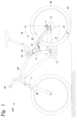
- FIG. 1shows a vehicle used to perform a setup routine, according to one example embodiment
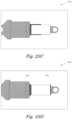
- FIGS. 2 A and 2 Bshow a suspension component assembly, according to one example embodiment
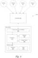
- FIG. 3illustrates a suspension setup system that assists a user in proper setup of the vehicle suspension, according to one example embodiment
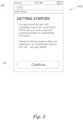
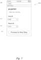
- FIGS. 4 - 22set forth a graphical user interface displayed by the suspension setup system, according to one example embodiment
- FIGS. 23 A- 23 Fillustrate a technique for aligning a device with a suspension component, according to one example embodiment
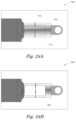
- FIGS. 24 A and 24 Billustrate an object detection algorithm for determining the location of o-ring relative to the suspension component, according to one embodiment
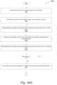
- FIGS. 25 A and 25 Bset forth flow diagrams of method steps for assisting a user in performing a setup routine, according to one embodiment.
- FIGS. 26 A and 26 Bset forth flow diagrams of method steps for an object detection algorithm implemented by program, according to one embodiment.
- Integrated damper/spring vehicle shock absorbersoften include a damper body surrounded by a mechanical spring or constructed in conjunction with an air spring.
- the damperoften consists of a piston and shaft telescopically mounted in a fluid filled cylinder.
- a mechanical springmay be a helically wound spring that surrounds the damper body.
- shock absorbersutilize gas as a spring medium in place of, or in addition to, mechanical springs.
- Gas spring type shock absorberssuch as gas spring shock absorbers having integral dampers, are described in U.S. Pat. Nos. 6,135,434; 6,360,857; and 6,311,962, each of which is herein incorporated by reference in its entirety.
- U.S. Pat. No. 6,360,857which is incorporated herein by reference in its entirety, shows a shock absorber having selectively adjustable damping characteristics.
- U.S. Pat. No. 7,163,222which is incorporated herein by reference in its entirety, describes a gas sprung front shock absorber for a bicycle (i.e., a bicycle fork) having a selective “lock out” and adjustable “blow off” function.
- shock absorbergas or mechanical
- the spring mechanism (gas or mechanical) of some shock absorbersis adjustable so that it can be preset to varying initial states of compression.
- the shock springmay comprise different stages having varying spring rates, thereby giving the overall shock absorber a compound spring rate varying through the stroke length. In that way, the shock absorber can be adjusted to accommodate heavier or lighter carried weight, or greater or lesser anticipated impact loads.
- shock absorbersshould be pre-adjusted to account for varying terrain and anticipated speeds and jumps. Shocks may also be adjusted according to certain rider preferences (e.g., soft to firm).
- FIG. 28 of U.S. Pat. No. 7,374,028(hereinafter “028 patent”), which is incorporated by reference herein in its entirety.
- the shock absorber of FIG. 28also includes an “adjustable intensifier assembly 510 .”
- the intensifier or reservoiraccepts damping fluid from chamber 170 as the fluid is displaced from that chamber by the incursion of rod 620 into chamber 170 during a compression stroke of the shock.
- the intensifier valve assemblyregulates flow of damping fluid into and out of the reservoir, and an embodiment of the valve assembly is shown in FIG. 17 of the '028 patent.
- a vehiclesuch as a bicycle, generally identified by reference numeral 100 , comprises a frame 40 and front forks 80 .
- the frame 40has a suspension system comprising a swing arm assembly 10 that, in use, is able to move relative to the rest of the frame; this movement is permitted by, inter alia, a rear shock absorber and/or damping assembly 25 .
- the front forks 80also provide a suspension function via a damping assembly in at least one fork leg.
- the bicycle 100 shown in FIG. 1is a full suspension bicycle (such as an ATB or mountain bike), although the embodiments described herein are not limited to use on full suspension bicycles.
- the term “suspension system”is intended to include vehicles having either a front suspension or a rear suspension (or both), and other systems wherein motion damping is included (such as for example vehicle steering dampeners or machine part motion dampeners).
- a sensor 5may be positioned proximate a rear axle 15 of the bicycle 100 for sensing changes in terrain. As shown in FIG. 1 , the sensor 5 is mounted on swing arm assembly 10 proximate the rear axle 15 of the bicycle 100 . In one embodiment, the angular orientation of a sensor 5 sensing axis is movable through a range or angle 20 (and is shown in each of two positions of many possible positions), thereby allowing alteration of a force component sensed by the sensor 5 in relation to a force (vector) input into the rear swing arm 10 . It is understood that the sensor 5 may be moved or mounted in any suitable configuration and allowing for any suitable range of adjustment as may be desirable.
- the sensor 5may include one, two, three or more sensing axes, which is useful for adjusting the sensitivity of the sensor 5 to various anticipated terrain and bicycle speed conditions.
- the bicycle speedaffects the vector direction of a force input to the bicycle wheel for a constant amplitude terrain disparity 55 or “bump/dip.” Varying size bumps and dips also affect the vector input angle to the wheel for constant bicycle speed.
- the movement of the swing arm 10is however limited to a mechanically determined trajectory.
- a second sensor 5 b(also illustrated in FIG. 2 A ) may be coupled to the rear suspension, such as shock absorber and/or damper assembly 25 , for measuring the operational characteristics of the rear suspension.
- a third sensor 5 cmay be coupled to the front suspension, such as front forks 80 , for measuring the operational characteristics of the front suspension.
- the operational characteristicsmay include at least one of position, velocity, acceleration, stroke, sag, compression, rebound, pressure, and temperature of the vehicle suspension.
- the sensorsmay be any suitable force or acceleration transducer (e.g. strain gage, wheatstone bridge, accelerometer, hydraulic cylinder, interferometer based, optical, thermal, acoustic or any suitable combination thereof).
- the sensorsmay utilize solid state electronics, electro-mechanical principles, or any other suitable mechanisms for monitoring the operational characteristics.
- sensor 5comprises a single-axis, self-powered accelerometer, such as for example ENDEVCO Model 2229C.
- the 2229Cis a comparatively small device with overall dimensions of about 15 mm height by 10 mm diameter, and weighs about 4.9 g.
- sensor 5comprises the ENDEVCO 12M1A, which is of the surface-mount type.
- the 12M1Ais a single-axis accelerometer comprising a bimorph sensing element which operates in the bender mode. This accelerometer is particularly small and light, measuring about 4.5 mm by 3.8 mm by 0.85 mm, and weighs about 0.12 g.
- sensor 5may be a tri-axial accelerometer, such as the ENDEVCO 67-100, which has overall dimensions of about 23 mm length and 15 mm width, and weighs about 14 g. Other sensors known in the art may be used with the embodiments described herein.
- the senor 5may be attached to the swing arm 10 directly, to any link thereof, to an intermediate mounting member or to any other portion or portions of the bicycle 100 as may be useful for purposes disclosed herein.
- the sensor 5may be attached to an un-sprung portion of the bicycle 100 , such as for example the swing arm 10
- another sensor 35such as an accelerometer as described above
- a sprung portion of the bicycle 100such as for example the frame 40 .
- Data from each sensorcan be registered relative to a common time datum, and suspension damping and/or spring effectiveness can be evaluated by comparing the data from the sensors on either “side” of the suspension unit.
- Sensorsmay be integrated with the vehicle structure and data processing system as described in U.S. Pat. Nos.
- Sensors and valve actuatorse.g., electric solenoid, linear motor type, or rotary motor type
- Sensors and valve actuatorsmay be integrated herein utilizing principles outlined in SP-861-Vehicle Dynamics and Electronic Controlled Suspensions SAE Technical Paper Series no. 910661 by Shiozaki et al. for the International Congress and Exposition, Detroit, Mich., Feb. 25-Mar. 1, 1991, which is incorporated herein by reference in its entirety.
- sensors and valves, or principles, of patents and other documents incorporated herein by referencemay be integrated into embodiments hereof, individually or in combination, as disclosed herein.
- the shock absorber 25is operatively mounted between an unsprung portion of the bicycle 100 , such as the swing arm 10 and rear axle 15 , and a sprung portion of the bicycle 100 , such as the frame 40 .
- a representative example embodiment of the shock absorber 25derives from a modification, as disclosed herein, of the shock absorber shown in FIG. 28 of the '028 patent.
- an intensifier assembly 510is shown in conjunction with a damper assembly 630 , which may be implemented as part of damping assembly 25 in vehicle 100 .
- the damper assembly 630is disclosed in FIG. 28 of the '028 patent and includes similar reference numerals.
- FIG. 2 Bshows an embodiment of a valve assembly 511 , such as an intensifier valve, for use with the embodiments disclosed herein.
- the valve assembly 511 of FIG. 2 Breplaces, or may be used with, the “adjustable intensifier assembly” 510 , as shown in FIGS. 16, 17, 28 and elsewhere in the '028 patent.
- the valve assembly 511is operable in response to electric current and is capable of being modulated or throttled for selective full opening, closing and intermediate opening or “throttle” positions.
- the valve assembly 511comprises a valve portion 110 and an actuator portion 120 .
- the valve portion 110may include a cylinder 112 with one or more variable orifices 114 and a member (e.g. piston) 116 that moves within the cylinder 112 to control the opening of the orifice(s) 114 .
- the valve assembly 511is in a closed position when the piston 116 is covering the orifice(s) 114 .
- the valve assembly 511is in an open position when the piston 116 moves away from the orifice(s) 114 such that at least a portion of the orifice(s) 114 is opened. In the open position, fluid may flow into the valve portion 110 and may flow out of the valve portion 110 . The position of the piston 116 relative to the orifice(s) 114 varies the orifice opening and the flow through the valve portion 110 . The valve assembly 511 may thus provide an output pressure in response to an input flow.
- the valve portion 110may also include a spring 118 that applies a force against the piston 116 to bias the piston 116 toward the closed position. Fluid pressure against the piston 116 may result in a force that exceeds the spring force causing the piston 116 to move and open the orifice(s) 114 .
- the actuator portion 120may also apply a force to the piston 116 .
- the actuator portion 120may advantageously be back drivable to permit the pressure term to push open the valve, for example, during the onset of a high shock event.
- One embodiment of the actuator portion 120is a voice coil type linear actuator including a voice coil 122 , a magnet 124 , and a back iron 126 .
- the back iron 126is coupled to the piston 116 such that linear movement of the back iron 126 causes linear movement of the piston 116 .
- the actuator portion 120may be controlled using a command such as a voltage command, for example, provided by drive electronics.
- a voltage command or signal to the actuator portion 120causes current to flow through the coil 122 , creating a magnetic field that applies a force to the magnet 124 and back iron 126 .
- Different voltage commandsmay thus correspond to different amounts of force applied to the piston 116 in the valve assembly 511 .
- the signals and actuatorare configured to move the valve completely between a full open (“unlocked”) and a full closed position (“locked”) thereby allowing the damper to move or substantially locking it; i.e., adjusting the damping rate of the damping assembly 630 between minimum and maximum respectively.
- the exemplary actuator 120is a voice coil type linear actuator, those skilled in the art will recognize that other types of actuator technologies may be used.
- the sensors, switches, controllers, actuators and other operative elements hereofmay comprise optical circuitry and as such the power source may comprises an optical (or other electromagnetic) generator such as a “LASER” and wiring and circuits used herein may comprises fiber optic and optic circuitry including Bragg grating technology and other suitable “electrical equivalents.”
- the elements hereofmay be operable in whole or in part based on sonic wave or microwave transmission and suitable waveguide technology may be employed.
- An operation of an intensifier valvethat may be used with the embodiments described herein is disclosed in U.S. Pat. No. 7,299,112; which is incorporated herein by reference in its entirety.
- voice coil 122 and magnet 124are interchangeable such that the voice coil may be either 122 or 124 and the magnet may be the other of 122 and 124 , respectively.
- the voice coil 122 or 124responds to input current from the power circuit (e.g. position control circuit or other suitable electrical input as described herein) and, therefore, input wiring is desirable.
- the input wiring and terminals for the 122 version of the voice coilis shown at 150 .
- the input wiring and terminals for the 124 version of the voice coilis shown at 151 and includes windings 152 to accommodate extension and contraction of the throughput wires 152 during operation of the valve assembly 511 .
- the valve assembly 511is shown in a closed or downward 156 , position. As such, piston 116 fully obstructs orifices 114 thereby preventing fluid from flowing from damper assembly 630 , through channel 636 , into upper chamber 153 , through orifice 114 , through valve outlet 157 and into floating piston compensator chamber 154 .
- the magnet electromagnet combination of 122 and 124causes the back iron 126 , and correspondingly the valve piston 116 , to move upward 155 in an amount proportional to the voice coil input.
- Such upward 155 movementis against spring 118 , which biases the valve piston 116 downward 156 (i.e. toward closed) and, therefore, when the voice coil input balances with the force of spring 118 , movement of the piston 116 will stop and the valve assembly 511 will be correspondingly throttled.
- the senor 5puts out a voltage corresponding to an input force.
- the outputs from sensors 5 , 5 b , 5 c , 35may be reconciled in a controller or processor 65 (described in greater detail below) that implements an algorithm for weighting their respective inputs and generating a resulting singular command or signal based on a predetermined logic.
- the sensor 5senses an input force along the prescribed range or axis 20 .
- a bump in the terrain 45typically exerts a force on a tire/wheel 60 of the bicycle 100 .
- the angle of the resolved force relative to the tire/wheel 60is typically normal (substantially) to the tire/wheel 60 at the point of impact.
- That forcethen imparts a component of the impact to the axle 15 as dictated by the trajectory of the swing arm linkage 10 .
- That componentcan be sensed by the sensor 5 at a magnitude corresponding to the orientation of the sensor range or angle 20 .
- the sensor axis 20 orientationcan be adjusted to make the sensor 5 more or less sensitive (by imparting more or less of the impact to the sensor range or axis 20 ) to bumps and dips in the terrain 45 .
- remote lock/unlock function of the rear shock absorber 25 and/or front shock absorber 80may be provided on the bicycle 100 .
- remote lock/unlockmay be entirely automatically controlled by a controller 65 in response to the input from the sensors 5 , 5 b , 5 c and/or 35 when the bicycle 100 is in use.
- the usermay be able to override and/or adjust this automatic control using a device 50 .
- the remote lock/unlock of the rear shock absorber 25 and/or front shock absorber in fork 80may be entirely controlled at the user's discretion using the device 50 ; in such an embodiment, the sensors 5 , 5 b , 5 c and/or 35 need not be provided on the bicycle 100 and the user locks and unlocks the suspension system according to his or her own preferences at the time.
- device 50comprises a digital user interface device provided with buttons and/or a touch screen that enables the user to adjust the damper assembly 630 at will.
- the device 50may comprise a suitable GPS (global positioning system) unit, bicycle computer, heart rate monitor, smart phone, personal computer, or cloud-connected computer, and may further comprise connectivity to a network such as the Internet.
- the device 50may send and receive data via cell phone bands, satellite bands, or other suitable electromagnetic frequencies to connect with other computer networks for the sending and or receiving of data, wherein the data may be received by and transformed by an outside computing machine and transmitted to the device 50 in an altered form or in a new form corresponding to the result of the outside machine transformation.
- the functionality of the device 50may be incorporated into performance recording devices and/or digital user interfaces such as, but not limited to, the Garmin® EDGE series of devices and smart phones such as the Apple® iPhone or Motorola® phones including the Android® Operating System.
- Some or all components of embodiments described herein, including sensors, switches, processors, controllers, shock absorbers, intensifier assembly, and/or valve assembly,may be interconnected or connected by wired or wireless communication.
- the componentsmay be connected to a network, such as a wide area network (WAN), local area network (LAN), or the Internet, and configured to implement communications via Bluetooth, Wi-Fi, ANT (i.e., Garmin low power usage protocol), or any other suitable power or signal transmitting protocol.
- the componentsshould ideally communicate wirelessly with controller 65 .
- the controller 65receives the input signals from sensors 5 (as well as 5 b , 5 c , 35 , etc.) the controller 65 responds to those signals by adjusting the damping rate of the damper assembly 630 .
- the controller 65takes a derivative (i.e., differentiation) of the suspension compression and/or extension acceleration to determine the rate of change of acceleration for forecasting and implementing adjustment of the valve assembly 511 or for determining a data rate or sample density required to adequately represent current suspension behavior. For example, if a bump 55 is encountered, followed immediately by a dip, it may be desirable to have the rebound of the tire into the dip occur very rapidly. If the valve assembly 511 were opened to an intermediate state as determined by the controller 65 and the controller determines that a bump has been followed by a large magnitude reversal of the derivative of the acceleration (i.e., indicated by the sensor 5 ), then the controller 65 may direct the power source to fully open the valve assembly 511 to allow the maximum rebound velocity.
- a derivativei.e., differentiation
- shock absorber/damping assembly 630and related systems are equally applicable to vehicle front forks. Further, it is contemplated that the vehicle may include both shock absorbers and front forks, both of which having some or all of the features disclosed herein.
- FIG. 3illustrates a suspension setup system 300 that assists a user in proper setup of the vehicle suspension, according to one example embodiment.
- the system 300enables a user to set up a vehicle 100 (such as vehicle 100 described above) equipped with one or more sensors (such as sensors 5 , 5 b , 5 c , 35 described above), a processor or controller 65 , and a device 50 .
- An operator or user, such as a rider of the vehicle 100may use the system 300 according to the embodiments described herein.
- the vehicle 100such as a bicycle, is equipped with the device 50 comprising at least a memory 320 storing a program 325 that implements an algorithm for setting up the suspension of the vehicle 100 , and a processor 310 for executing the program 325 .
- the device 50includes a communication interface 330 to communicate with controller 65 .
- Communication interface 330may be a wireless network interface, a near-field communication interface, or any other technically feasible communication interface.
- Device 50may also include a display 350 used to display a graphical user interface to a user and an image sensor 380 that enables live video or images to be captured by the device 50 and stored in memory 320 .
- display 350comprises a touch-sensitive LCD screen that may be used both for display of the user interface and for receiving input from the user.
- the device 50captures data 335 from the sensors in the memory 320 for processing by program 325 .
- the data 335may include suspension component relative position data (e.g., inches of compression or full extension or full compression or any suitable combination of such data) and/or other operational characteristics/features of the vehicle 100 that are measured by the sensors.
- the raw sensor datamay be communicated to the controller 65 via wired and/or wireless communication, and the controller 65 may process the raw sensor data and communicate the processed data 335 to device 50 via, for example, an industry standard low power wireless protocol.
- the program 325instructs the user on what adjustments to make to improve the vehicle suspension setup and/or to describe the current performance of the vehicle suspension system.
- the usermay use the device 50 to adjust one or more components of the vehicle 100 , automatically, manually and/or remotely, wired and/or wirelessly, directly, manually and/or indirectly (such as via the controller 65 ) during and/or after operation of the vehicle 100 .
- the sensorsare mounted to vehicle suspension components, such as the front forks 80 of bicycle 100 illustrated in FIG. 1 .
- the sensormay be coupled to the vehicle 100 and may be operable to measure an operational characteristic of a vehicle component.
- the sensorsmay be directly coupled to the vehicle components for direct measurement of each component's operational characteristics.
- the sensorsmay be coupled to portions of the vehicle 100 apart from the vehicle components and may be operable for indirect measurement of each component's operational characteristics.
- the sensorsmay be positioned at any location relative to the vehicle 100 and may be operable to measure an operational characteristic of the vehicle 100 directly or indirectly (e.g.
- the sensorsare used to determine the position, velocity, and/or acceleration of the suspension components (raw sensor data is used to calculate such parameters within the controller 65 ).
- the sensorsmay be linear potentiometers, string potentiometers, contact or non-contact membrane potentiometers, rotary potentiometers (such as if used on a linkage fork or a rear suspension linkage), accelerometers, 3D global position sensors (“GPS”), pressure sensors (for measuring the air spring or coil spring compression), and/or other type of sensors.
- GPSglobal position sensors
- pressure sensorsfor measuring the air spring or coil spring compression
- the data sampling rate for the sensorsis about 500 Hz to allow sufficient sampling and resolution of the vehicle suspension movement during operation.
- the controller 65is relatively small (about 2′′.times.3-3.5′′.times.0.5-0.625′′) and lightweight so as to not negatively impact the user of the vehicle 100 .
- the controller 65need not literally “control” anything but rather may cull data and send the result to the device 50 for processing.
- the controller 65may contain one or more of the following major components: a low power microprocessor, a wireless communication chip (such as ANT+, Bluetooth, and/or Wi-Fi 802.11n), a battery, and flash memory.
- the controller 65may also have other sensors on board such as a GPS, a compass, an accelerometer, an altimeter, and/or an air temperature sensor.
- the controller 65may also have one or more external features such as multi-color LED's to communicate basic state of operation and battery charge to the user and buttons to toggle power and start/stop data logging.
- the controller 65may also have an external mini USB connector to connect to a computer or other external device for uploading of data and charging the battery as well as external connectors to connect to any wired sensors.
- the controller 65may record and evaluate the vehicle suspension data in real time.
- the controller 65may analyze parameters like sag (static ride height), rebound and compression speed, top out and bottom out events. Then, after analysis is complete, the controller 65 may communicate the results of the analysis with the device 50 .
- sagstatic ride height
- rebound and compression speedtop out and bottom out events.
- the controller 65may communicate the results of the analysis with the device 50 .
- the controller 65may record and evaluate the vehicle suspension data in real time.
- the controller 65may analyze parameters like sag (static ride height), rebound and compression speed, top out and bottom out events. Then, after analysis is complete, the controller 65 may communicate the results of the analysis with the device 50 . Because there are many user interface devices that already have ANT+ and/or Bluetooth built-in (e.g. Garmin® GPS, power meters, Apple® iPhone, etc.) it is contemplated that certain embodiments will be compatible with these protocols. These 3rd party user interface devices generally have large displays with a developed GUI and
- the built-in wireless capabilitiesare ideal for low density data transmittal, but are not well suited for high speed data acquisition (because low power wireless data rates are generally limited).
- the applicability of the systemis increased.
- the device 50is programmed with a data template or templates suitable for filling with data and/or calculations/suggestions from the controller 65 .
- the device 50is programmed with input templates for facilitating user input of suspension model, user weight, vehicle type, etc. as may be useful in aiding the controller 65 to look up corresponding parameters.
- the controller 65will communicate to the device 50 selected data or calculations (e.g.
- graphical, tabular, textual or other suitable formatto display to the user, such as suggestions for adjusting spring preload, air spring pressure (to adjust sag), rebound damping setting, compression damping setting, bottom out damper setting, etc.
- Communicationwill also work in reverse to allow the user to enter data, such as model of suspension, rider weight, etc., in the device 50 which will relay the information to the controller 65 . From such model information the controller 65 will look up model relevant parameters and use those to aid in calculating suggestions or for processing raw sensor data.
- the controller 65functions as a data receiver, processor, memory and data filter.
- the controller 65receives high frequency (high sampling rate) data from the suspension sensor(s). Because current user interface devices, particularly those using wireless protocols, may not be capable of high enough data rates to directly monitor the suspension sensors, the controller 65 may act as a high data rate intermediary between the suspension sensors and the device 50 .
- the controller 65is configured to prompt and accept high sampling rate data from the suspension sensors.
- the controller 65then stores the data and processes selected data at selected intervals for transmission to a user interface of the device 50 . In other words the controller 65 pares the effective data rate and makes that pared data transmission to the user interface in real time. Additionally, the controller 65 stores all un-transmitted data for later analysis if desired.
- the controller 65can later be plugged into a computer system, such as a home computing device or laptop via a USB pigtail or dongle device.
- the controller 65may also preprocess data and generate user friendly viewing formats for transmission to the user interface of the device 50 .
- the controller 65may calculate data trends of other useful data derivatives for periodic “real time” (effectively real time although not exact) display on the user interface of the device 50 .
- each vehicle 100 suspension componentis equipped with a position sensor for indicating the magnitude (or state) of extension or compression existing in the vehicle 100 suspension at any given moment.
- a position sensorfor indicating the magnitude (or state) of extension or compression existing in the vehicle 100 suspension at any given moment.
- a sensorwill generate a tremendous amount of data. Relatively high sampling rates are needed to capture meaningful information in devices operating at such high frequencies.
- a suitable telescopic tube of the vehicle 100 suspensionmay be equipped or fitted with two piezoelectric sensors.
- One of the piezoelectric sensorsis a high frequency exciter which is configured on the tube such that it (substantially) continuously induces impacts to a wall of the tube. In lay terms, the sensor thumps or pings the tube wall on a continual basis.
- the second piezoelectric sensoris an accelerometer fixed or configured with the tube wall so as to monitor vibration of the tube wall.
- the frequency of the exciteris intentionally set well outside any resonant mode of the suspension tube as it travels through its operational suspension stroke.
- a sensing frequency of the monitoris selected to coincide (substantially) with at least one resonant mode range of the tube as it travels through its operational stroke.
- the aforementioned exciter and monitorare calibrated, in conjunction with the controller 65 , so that values for resonant frequencies (in a selected mode or modes) of the suspension tube (or other suitable and variably “ringing” suspension component) are correlated with axial extension/compression of the suspension containing or including the tube.
- Such correlation datais stored with the controller 65 for use in real time calculation of axial suspension position based on real time input from the suspension resonant frequency monitor.
- the tubewill tend to resonate regardless of the exciter frequency so by monitoring the change in resonant frequency or tube “ringing”, with the monitor, the axial position of the suspension can be derived within the controller 65 .
- the exciter and monitoract on and measure resonance with a cavity of the vehicle 100 suspension wherein cavity resonance versus axial suspension displacement is calibrated and correlated for use in the controller 65 .
- magnetic flux leakage of a suspension component, or magnetic imposition of current in a surrounding conductive structureis correlated with axial suspension displacement.
- opticsmay be used (e.g. Doppler effect) to measure displacement.
- a magnetis affixed to one portion of the suspension and a conductor is affixed to a relatively movable portion of the suspension so that when the suspension moves axially the relative movement between the magnet and the conductor generates a changing current of flux in the arrangement (and that can be correlated with axial movement).
- sonic or ultrasonic wavesare used to excite a portion of the suspension and the changing reflective sonic signals are monitored to determine axial disposition of the suspension.
- vehicle suspension componentsinclude scan compatible identification codes (e.g., bar codes or QR codes) specifying at least model type and possibly including details including performance specifications.
- the scan compatible identification codesmay also specify other manufacture details such as lot, factory source, build date, inventory numbers, invoice or tracking numbers, subassembly/assembly numbers, etc.
- the codes and/or dataare included on a chip embedded in the suspension, such as an active or passive radio frequency identification (“RFID”) tag.
- RFIDradio frequency identification
- the controller 65which may include an RFID tag reader, detects the chip and, based on the data received there from, proceeds to configure, or suggest configuration for, the vehicle suspension.
- the controller 65 and/or device 50operates in a setup mode where rider input weight and suspension product data are used to suggest initial spring preload and damper settings for the vehicle suspension components.
- the controller 65 and/or device 50may also operate in a ride mode wherein suspension movement (e.g. average travel used versus available, portion or range of travel used, number and severity of bottom out or top out events) is monitored and used in conjunction with the rider and suspension data to suggest changes to the suspension setup that better utilize or maximize usage of the suspension capabilities.
- the controller 65 and/or device 50monitors compression range of the suspension to determine whether or not the suspension is setup for optimal use of its range over a given terrain 45 .
- a GPS unittransmits real time GPS data to the controller 65 and such data is overlayed or paired with corresponding suspension data along an elapsed (or relative sequence) time synchronous data marker (or other suitable common data marker or “datum” type).
- a rebound settingcan be automatically achieved by utilizing the air spring pressure or coil spring preload needed to achieve proper sag. The rebound setting is then achieved via feeding the air spring pressure for an air shock, or an oil pressure signal for a coil shock, down the damper shaft to a pressure sensitive damping valve at the damper shaft piston. Rebound damping requirements will vary depending on the stiffness of the suspension spring. A stiffer (or softer) spring normally indicates more (or less) rebound damping as a requirement.
- a rebound damper settingis calculated from the sag calculation spring setting recommendation.
- there is an external rebound adjustorto make incremental changes from the predetermined setting to account for varied terrain/conditions, and/or riding style and preference.
- an initial sag settingcan be automatically set and facilitated by having a position valve within the shock for a given length bleed off air pressure until a specific sag level is achieved.
- Each shock strokewould have a specific length of sag/position valve.
- the userwould pressurize their shock to a maximum shock pressure of, for example, 300 psi or so. The actual max number is not important at this point. The idea is to over pressurize the shock beyond any reasonable properly set sag pressure.
- the userthen switches the shock to be in setup or sag mode and sits on the bike. The shock will bleed air from the air spring until the position valve encounters a shut off abutment which thereby shuts the bleed valve.
- the device 50 or controller 65“knows” a vehicle suspension component is extended beyond a proper sag level and a an electrically actuated valve (or other type of remote actuated valve) is opened to bleed air pressure from the air spring in a controlled manner until the proper predetermined sag level is reached, at which point the valve automatically closes and the shock opts itself out of sag mode.
- the usercan switch the sag set up mode off upon reaching a proper sag setting. When in a normal riding mode, more pressure can be added to the air spring or pressure can be reduced from the air spring to accommodate different rider styles and or terrain 45 .
- This auto sag featurecan be achieved electronically as well, by having a position sensor in the shock, and the shock model data allowing the controller 65 to adjust spring preload (e.g. air pressure) appropriately for the given model (as determined by the controller 65 in a query).
- spring preloade.g. air pressure
- An electronically controlled pressure relief valveis utilized to bleed off air spring pressure until the sensor determines the shock is at its' proper sag. The pressure relief valve is then directed to close and proper sag level is achieved.
- the system 300can be utilized by integrating certain data collection sensors to both assist in the initial setup of the vehicle and to provide hints on how to tweak the vehicle 100 suspension system beyond an initial setup.
- the sensorscommunicate with the controller 65 .
- Datae.g. model, specifications
- the controller 65would know lengths, travels, external adjustment features etc.
- the controller 65(or device 50 ) would then walk the user through a proper setup routine, starting with sag for example, using the user interface provided by device 50 .
- the userwould sit on the bike and the rider sag measurement for the fork and shock would be displayed on the device 50 for example.
- the controller 65will know what product it is trying to get adjusted properly and will make pressure recommendations for the user to input to the shock or fork.
- the userthen sits on the bike again and, in this iterative and interactive process, will arrive at initial sag setting for the fork and shock product being used.
- the controller 65will “know” what pressure is in the fork and shock, and will make rebound recommendations based on those settings. In a simpler form, the controller 65 will ask the user to input their final sag attaining pressures and will then make rebound recommendations based on the product and pressures. The controller 65 will also make compression damping setting recommendations based on the product connected to the controller 65 . The user then goes out and rides the vehicle. The controller 65 will transfer to data logging mode once the bike is being ridden or in a simpler form when the user puts the system into ride mode. The controller 65 will log and save bottom out events, average travel used, identify too quick or too slow rebound events, etc.
- the controller 65will make recommendations on settings to have the system respond better in the stroke. If the average travel used in less than a specified amount the controller 65 will make recommendations on settings to utilize more travel. Full travel events will be evaluated versus the average travel used data and make recommendations on how to reduce or increase the amount of full travel events.
- Computer (PC/laptop) softwaremay be utilized so the data logged can be downloaded to a computer system for further evaluation.
- a websitesuch as the FOX RACING SHOX website, can be utilized as a place for riders to go to check out settings other riders are using and why, and to provide a way to spend time in a community, such as a FOX RACING SHOX community.
- the controller 65will log ridden hours and will prompt the user to perform certain maintenance operations, and when data is downloaded to the computer system, such as a desktop/laptop machine, a link to the service procedure for the particular recommended service will pop up.
- the linkwill be to a video guild on how to perform the service, tools needed etc., if a user is at the max of a particular adjustment feature on the closed or open side, the controller 65 will make a recommendation to have a service provider, such as FOX RACING SHOX, re-valve their system to get that particular adjustment feature into the middle of its' range again, and will make recommendations to a service technician, such as a FOX RACING SHOX service tech, on what direction to make the valving changes, etc.
- a more elaborate system 300can incorporate accelerometers, pressure sensors, etc.
- FIGS. 4 through 22illustrate templates for a program 325 executed on device 50 , according to one embodiment.
- Program 325may be implemented to assist a user in performing an initial setup of the vehicle 100 suspension.
- Program 325is configured to run on a smartphone, tablet, iPod®, or other Internet enabled mobile device. Portions of program 325 may be supported and enabled for devices that include an image sensor 380 or video camera.
- program 325may be configured to be executed on a laptop or desktop computer.
- Program 325may be installed on device 50 from an online repository containing applications compatible with device 50 .
- device 50may be a smart phone such as Apple® iPhone and program 325 may be an application downloadable from the iTunes® store.
- Program 325may be updated periodically via the Internet, may transmit saved settings to remote storage, and may download current suspension product information and physical characteristics.
- Product informationwhich may be used automatically in some calculations performed by program 325 , may be stored in a database on device 50 or stored remotely on a location accessible through the device's network connection (e.g., wireless connection to the Internet).
- program 325is used to manually setup front fork 80 and shock absorber 25 of vehicle 100 .
- vehicle 100does not include sensors ( 5 , 5 b , 5 c , etc.) for measuring the position of the vehicle suspension components.
- the vehicle suspension componentsmay not include actuators, such as valve assembly 511 , configured to adjust the damping rate remotely.
- program 325assists the user in manually adjusting the pressure in the air spring and the damping rate of the damping components in the shock absorbers.
- device 50may be “dumb” in that device 50 does not communicate with a controller 65 to receive information about the operational characteristics of the vehicle suspension components.
- the usermay connect to the online repository (e.g., iTunes) for downloading like programs 325 and either download the program 325 directly to device 50 or download the program 325 to a computer that is then synched to device 50 to transfer the program 325 to the device 50 .
- the online repositorye.g., iTunes
- the usercan open the program 325 to begin the setup routine.
- the programdisplays a set of templates that allow the user to read instructions on how to setup the various components of the vehicle suspension, prompt the user for input such as the component IDs of the various suspension components or the user's weight with full riding gear, and display pictures or videos that show the user how to properly setup the vehicle suspension.
- the various screen shots of one embodiment of program 325are described in more detail below.
- GUI 400when executed by processor 310 , is configured to display a graphical user interface (GUI) 400 that includes a plurality of templates such as the first screen shot 400 a .
- GUI 400includes a status bar at the top of the display that includes information such as a time, cellular connectivity information, and battery status. It will be appreciated that other types of information may be included in the status bar.
- the status barmay be controlled by an operating system executed by device 50 and not directly configured by program 325 .
- the first screen shot 400 aalso displays a logo and description of the program 325 .
- the first screen shot 400 aincludes user interface elements such as button 402 and button 404 .
- display 350may comprise a touch sensitive LCD panel that enables a user to touch the screen proximate to buttons 402 and 404 to provide input to program 325 .
- a useris given the option to create a new setup routine by selecting button 402 or to load a previously saved setup routine by selecting button 404 .
- program 325displays a second screen shot 400 b that includes a button 406 to go back to the first screen shot 400 a .
- the second screen shot 400 bincludes information for a user that instructs the user that further information may be available from a source such as a vehicle suspension component supplier.
- the second screen shot 400 balso includes a button 408 that, when selected, begins the setup routine.
- a third screen shot 400 cshows a user how to locate product identification information on vehicle forks 80 and shocks 25 .
- product labelsmay include labels that provide a component ID (i.e., a unique code that specifies the particular suspension component installed on the vehicle 100 ).
- the component IDcomprises a 4-digit alpha-numeric code that uniquely identifies each suspension component type.
- the labelsmay include bar codes or QR codes that can be scanned using an image sensor 380 included in device 50 .
- a usermay use an image sensor 380 to capture an image of the bar code on each of the fork 80 and shock absorber 25 .
- Program 325may then decipher the bar codes to automatically retrieve the component ID for the various vehicle suspension components.
- the third screen shot 400 cincludes button 406 to go to the previous screen (e.g., 400 b ) and includes a button 410 to proceed to the next screen (e.g., 400 d ).
- a fourth screen shot 400 denables a user to manually input component IDs for both the fork 80 and the shock 25 for vehicle 100 .
- the fourth screen shot 400 dmay include user interface elements that enable a user to automatically scan the labels to retrieve the component IDs.
- the fourth screen shot 400 dincludes a first user interface element 412 and a second user interface element 414 that enable a user to manually enter component IDs for both the front fork 80 and the shock absorber 25 , respectively.
- the fourth screen shot 400 dalso includes a button 406 to go to the previous screen (e.g., 400 c ) and a button 410 to proceed to the next screen (e.g., 400 e ).
- User input entered in the fourth screen shot 400 dmay control the order that subsequent screen shots are displayed while performing the setup routine. For example, if a user only enters the component ID for the front fork 80 , then only those screen shots associated with proper setup of the front fork 80 will be displayed. Similarly, if a user only enters the component ID for the shock absorber 25 , then only those screen shots associated with proper setup of the shock absorber 25 will be displayed.
- the component IDenables program 325 to query a database to retrieve product information related to the specific vehicle suspension component.
- the product informationmay include, but is not limited to, product name/model, the available external adjustments available for the component, the length of travel of the component, a preferred sag setting for the component, the range of adjustment for each of the external adjustors available for the component, and physical characteristics of the component such as air spring piston area, air volume compression ratio, composite spring curve shape, upper tube outside diameter for a fork, and shock body outside diameter for a shock.
- program 325may display an error message when a match is not found for the entered component ID.
- Program 325may display text or a graphic next to the user interface elements 412 and 414 when a match is found that indicates to a user that product information associated with the component ID was located. For example, a thumbnail image of the component may be displayed next to the user interface element 412 or 414 .
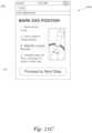
- a fifth screen shot 400 einstructs a user to prepare the fork 80 and shock 25 for proper setup.
- the fifth screen shot 400 edepicts how the fork compression damping adjusters and the fork rebound adjusters look on the product as well as how to set the adjusters at the beginning of the setup routine.
- the fifth screen shot 400 ealso includes a button 406 to go to the previous screen (e.g., 400 d ) and a button 410 to proceed to the next screen (e.g., 400 f ).
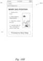
- a sixth screen shot 400 finstructs a user to remove the air valve caps for the fork 80 and the shock absorber 25 .
- the air pumpmay include an integrated air pressure gauge used to determine the current air pressure in the fork 80 or shock absorber 25 .
- the air pumpmay include an integrated pressure transducer that instructs the air pump how much pressure is in the fork 80 or the shock absorber 25 .
- the usermay set the air pump to pressurize the fork 80 or shock absorber 25 to a specific pressure and the air pump may automatically add air to the fork 80 or shock absorber 25 to the specific pressure.
- the air pumpmay communicate directly with the device 50 such that the program 325 automatically configures the set points (i.e., suggested pressure) for pressurizing the fork 80 or shock absorber 25 .
- the sixth screen shot 400 falso includes a button 406 to go to the previous screen (e.g., 400 e ) and a button 410 to proceed to the next screen (e.g., 400 g ).
- FIGS. 10 through 14illustrate the fork adjustment specific screens displayed by program 325 .
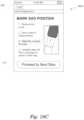
- a seventh screen shot 400 genables a user to determine an initial pressure setting for the fork 80 depending on a fully-loaded weight of the user.
- the seventh screen shot 400 gincludes a first user interface element 416 that enables a user to enter the fully-loaded weight for the intended riding conditions.
- the first user interface element 416may be a selector wheel that can be moved up or down to select the desired fully-loaded weight.
- the first user interface element 416may be similar to user interface elements 412 or 414 that enable a user to enter the weight using a keyboard.
- device 50may be in communication with a scale or other sensor that measures the fully-loaded weight of the user.
- a scale or other sensorthat measures the fully-loaded weight of the user.
- a sensorsuch as a strain gauge and wheatstone bridge, may be used to measure the fully-loaded weight of the user.
- the seventh screen shot 400 gincludes a second interface element 418 that indicates a target pressure at which the air spring in the fork should be set and a third interface element 420 that lets a user toggle between imperial units and metric units. For example, as shown, imperial units (i.e., pounds and pounds per square inch) are displayed in user interface element 416 and 418 . Although not shown, the user may be instructed in how to attach and use the shock pump with the fork 80 via a description or graphical or video depiction. The target pressure is derived via a calculation based on the fully-loaded weight of the rider and the physical parameters of the suspension component retrieved in the product information.
- the air spring compression ratio, the air spring piston area, the negative spring length, the negative spring rate, and the top-out spring ratecan be used to calculate a more exact starting pressure.
- the program 325may be configured to calculate a starting pressure corresponding to a particular sag setting (e.g., 25%). Given the retrieved product information, the program 325 can determine a starting pressure that would result in the shock absorber 25 being compressed to 25% under a load equal to the selected fully-loaded weight.
- the target pressureis calculated dynamically based on the product information.
- the target pressureis pre-calculated for each possible fully-loaded weight and stored in an array that may be accessed by program 325 .
- the seventh screen shot 400 galso includes a button 406 to go to the previous screen (e.g., 400 f ) and a button 410 to proceed to the next screen (e.g., 400 h ).
- FIGS. 11 A through 11 Dillustrate an eighth screen shot 400 h that provides a graphical depiction of how to set an indicator member located on a tube of the fork 80 to indicate a position of the fork 80 when fully-loaded.
- the indicator membercomprises an o-ring, but it is intended that similar or equivalent functionality can be provided by other structures, as described herein.
- other structuresmay include a plastic member that fits tightly over the shaft of the suspension component (i.e., fork 80 or shock absorber 25 ) and is movable relative thereto.
- the useris instructed to remove the pump from the valve of the air spring of the fork 80 .
- a second stepas graphically depicted in FIG. 11 B , the user is instructed to get on the vehicle in a riding position. The user should be equipped with the proper riding gear to approximately match the fully-loaded weight entered by the user in the seventh screen shot 400 g .
- a third stepas graphically depicted in FIG. 11 C , the user is instructed to slide the o-ring to the seal on the top of the lower tube on the fork 80 .
- a fourth stepas graphically depicted in FIG. 11 D , the user is instructed to dismount the vehicle 100 .
- the eighth screen shot 400 halso includes a button 406 to go to the previous screen (e.g., 400 g ) and a button 410 to proceed to the next screen (e.g., 400 i ).
- the inventionis not limited to the use of an o-ring as the indicator member.
- the indicator membercan be any suitable e.g. a full or part ring of plastics material. When in the form of a part-ring, the user could clip the indicator member to the shaft for the purposes of sag adjustment and then remove the part-ring when finished.
- a full or part-ringis fitted to the suspension component at point of manufacture.
- the indicator membercan be any colour or combination of colours that enables it to be identified by an object recognition algorithm when mounted on the suspension component.
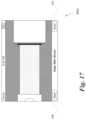
- a ninth screen shot 400 ishows a graphical overlay to be used in conjunction with a camera mode of the device 50 .
- the graphical overlayis a depiction of the air spring leg of the front fork 80 and is selected from one or more graphical overlays corresponding to the various vehicle suspension components.
- the particular graphical overlay displayed in the ninth screen shot 400 iis selected based on the front fork component ID entered on the fourth screen shot 400 d .
- the graphical overlayincludes portions 422 and 424 that correspond to the approximate shape of the upper portion of the lower tube and the cap for the upper tube, respectively.
- the graphical overlayalso includes a partially transparent portion 426 that corresponds to the shaft for the upper tube of the air spring leg of the fork 80 .
- program 325may activate a camera mode of device 50 .
- program 325may display an image captured using an image sensor 380 under the graphical overlay of the front fork.
- the imagemay be updated periodically such as in a video mode where a new image is captured every 33 ms (i.e., 30 frames per second).
- Periodically updating the image in a video modeenables the user to align the scene with the fork 80 with the graphical overlay portions 422 , 424 .
- the usermoves the device 50 such that the seal 428 on the top edge of the lower tube of the fork 80 is approximately aligned with the portion 422 of the graphical overlay corresponding to the upper portion of the lower tube.
- the useralso moves the device 50 such that the scale of the lower tube is approximately equal to a scale of the graphical overlay such as by matching the captured diameter of the lower tube of the fork to the width of the portion 422 of the graphical overlay.
- the usermay select the scan user interface element 432 to capture an image of the fork 80 .
- the program 325can measure the width of the lower tube, in pixels, of the fork captured by the image sensor 380 and compare that to the distance, in pixels, between the seal 428 of the lower tube and the position of the o-ring 430 .
- the ratio of the distance to width, in pixels,may be multiplied by the known diameter of the lower tube to determine an amount of compression of the fork 80 based on the fully-loaded weight of the rider (i.e., amount of sag).
- the fork 80 or shock 25may include markings, such as index marks or dots, on the component that enable program 325 to register a scale of the component.
- the markingsmay be of high contrast with the surface of the shock component and equally spaced such that object recognition is easily performed.
- the program 325may assume that the user has captured the image of the fork 80 at the same scale as the graphical overlay.
- program 325may only measure the position of the o-ring 430 in the image relative to pixels corresponding to the edge of the portion 422 of the graphical overlay.
- the program 325may implement an image processing algorithm, described more fully below in connection with FIGS. 24 A- 26 B , to determine the location of the o-ring 430 in relation to the graphical overlay.
- the graphical overlaymay include indicators that provide the user with feedback as to whether the proper sag setting has been achieved.
- the graphical overlaymay include a line or other indicator that indicates the approximate location of the o-ring corresponding to a preferred sag setting (e.g., 1.5 inches of travel for a fork with 6 inches of total travel corresponding to 25% sag).
- the graphical overlaymay also include gradient indicators in combination with pressure delta recommendations indicating whether the user should refine the pressure in the air spring. For example, if the sag setting is off by more than 5%, the color gradient may change from green to yellow indicating that further adjustment of the pressure in the air spring is appropriate.
- the ninth screen shot 400 ialso includes a button 406 to go to the previous screen (e.g., 400 h ) and, although not shown explicitly, a button 410 to proceed to the next screen (e.g., 400 j ).
- the scan user interface button 432once pressed, may be replaced with button 410 . In other embodiments, the scan user interface button 432 as well as buttons 406 and 410 may be displayed simultaneously.
- a tenth screen shot 400 jinstructs a user to make an adjustment to the air pressure in the air spring of the fork 80 .
- the tenth screen shot 400 jincludes a user interface element 434 that specifies the new adjusted pressure for the air spring based on the measured o-ring 430 position.
- the tenth screen shot 400 jalso includes a button 406 to go to the previous screen (e.g., 400 i ) and a button 410 to proceed to the next screen (e.g., 400 k ).
- an eleventh screen shot 400 kinstructs a user to make an adjustment to the rebound damping setting for the fork 80 .
- the rebound damping settingis calculated based on the adjusted air pressure setting of the air spring of the fork 80 .
- the fork 80includes an external adjuster for adjusting the amount of rebound damping in the damping leg of the fork 80 . The rebound damping is adjusted by turning the knob counter-clockwise to increase the damping, thereby slowing how quickly the fork 80 extends after being compressed by terrain.
- the eleventh screen shot 400 kincludes a user interface element 436 that specifies the setting for the external rebound adjuster.
- a usermay turn the external rebound adjuster fully clockwise, corresponding to the minimum amount of rebound damping. Then, the user turns the external rebound adjuster clockwise by the specified number of clicks, each click corresponding to a discrete adjustment point.
- fork 80may include other means for adjusting the amount of damping implemented in the damping leg of the fork 80 .
- the rebound dampingmay be adjusted by a level, a dial, a cam, an electrically or pneumatically controlled actuator, or any other technically feasible mechanism for adjusting the rebound damping.
- the instructions and user interface element 436may reflect instructions and settings for these alternative mechanisms.
- the eleventh screen shot 400 kinstructs a user to make an adjustment to the compression damping setting for the fork 80 .
- the compression damping settingmay also be calculated based on the adjusted air pressure setting of the air spring of the fork 80 .
- the fork 80is properly setup. As long as the user has entered a valid component ID for a shock absorber 25 into user interface element 414 of FIG. 7 , the setup routine continues by displaying the set of templates associated with the setup of a shock absorber 25 .
- the eleventh screen shot 400 kincludes a button 406 to go to the previous screen (e.g., 400 j ) and a button 410 to proceed to the next screen (e.g., 400 l ).
- FIGS. 15 through 19illustrate screen shots 400 l through 400 p displayed to assist the user in performing proper setup of a shock absorber 25 .
- Screen shots 400 l through 400 pare similar to screen shots 400 g through 400 k of FIGS. 10 through 14 , except displaying information and graphical overlays related to the shock absorber 25 identified by the component ID entered into user interface element 414 rather than the fork 80 identified by the component ID entered into user interface element 412 .
- each screen shot 400 l through 400 pincludes a button 406 to go to the previous screen and a button 410 to proceed to the next screen. Some of the graphical depictions may be changed to show the location of controls or adjusters associated with shock absorber 25 instead of fork 80 .
- a usermay select button 410 of sixteenth screen shot 400 p to proceed to the next screen (e.g., 400 q ).
- a seventeenth screen shot 400 qdisplays a summary of the setup parameters to the user.
- Setup parameters for the fork 80include a target air pressure for the air spring of the fork 80 and a rebound damping setting for the damper of the fork 80 .
- Setup parameters for the shock absorber 25include a target air pressure for the air spring of the shock absorber 25 and a rebound damping setting for the damper of the shock absorber 25 .
- the seventeenth screen shot 400 qincludes a first button 438 that enables a user to save the setup parameters associated with the just completed setup routine.
- An user interface element 440enables a user to type a name for the saved setup routine. If the user so chooses, a button 442 enables the user to discard the setup parameters and return to the home screen 400 a .
- the seventeenth screen shot 400 qalso includes button 406 to go back to the previous screen (e.g., 400 p ).
- an eighteenth screen shot 400 rdisplays a list of saved setup routines.
- the eighteenth screen shot 400 rincludes a button 444 that enables a user to edit each of the saved setup routines.
- selecting the button 444lets a user delete any of the saved setup routines.
- selecting the button 44lets a user change any of the saved parameters in the setup routine.
- the eighteenth screen shot 400 ralso includes a button 406 to go back to the previous screen (e.g., 400 a ).
- Selecting any of the saved setup routines listed in the eighteenth screen shot 400 rcauses program 325 to display the nineteenth screen shot 400 s , as shown in FIG. 22 .
- the nineteenth screen shot 400 sdisplays the setup parameters for the selected setup routine.
- the nineteenth screen shot 400 salso includes a button 406 to go back to the previous screen (e.g., 400 r ).
- the image overlay view of the ninth screen shot 400 i or the fourteenth screen shot 400 nhelps the user measure and properly set a vehicle suspensions sag.
- the viewcomprises a graphical overlay on top of a live view as seen from an image sensor 380 .
- This technique for viewing a live image with a graphical overlaymay sometimes be referred to as a heads-up display or HUD.
- the usermay move and orient the device 50 via 6 degrees of freedom (i.e., translation in x, y, and z coordinates as well as rotation around each of the three axes).
- the usercan line up the live view of the suspension component with the static overlay of the graphical representation of the component.
- the usermay align two or more indicators in the graphical overlay with corresponding points on the suspension component. For example, the user may align one indicator with a left edge of the lower tube of the fork 80 in the view and a second indicator with a right edge of the lower tube of the fork 80 in the view. Aligning these two indicators with the corresponding opposite edges of the lower tube will ensure that the live view is correctly scaled to the graphical overlay. Aligning the top edge of the lower tube (i.e., a seal) with a third indicator will then ensure that the graphical overlay is correctly positioned.
- the size and scale of the graphical overlaycorresponds to the physical dimensions of the suspension component.
- FIGS. 23 A-Fillustrate one technique for aligning a live view 710 captured by an image sensor 380 with a graphical overlay 720 shown on the display 350 of the device 50 , according to one embodiment.
- a live view 710 captured from the image sensor 380is shown in FIG. 23 A .
- the live view 710includes an image of a shock absorber captured by the image sensor 380 .
- FIG. 23 Bshows a graphical overlay 720 displayed on the display 350 and superimposed on top of the live view 710 captured by the image sensor 380 .
- the graphical overlay 720includes three indicators 722 , 724 , and 726 (e.g., lines) used to align and orient the live view 710 of the shock absorber with the device 50 .
- FIG. 23 Cshows a composite image 730 of the live view 710 aligned with the graphical overlay 720 .
- FIG. 23 Dshows another composite image 740 of the live view 710 aligned with a second graphical overlay having two indicators; a first indicator 742 aligned with the sealed end of the shaft of the shock absorber and a second indicator 744 aligned with a bushing end of the shaft of the shock absorber.
- FIG. 23 Eshows a third graphical overlay 750 that includes graphical representations for one or more portions of the shock absorber. In the example shown in FIG. 23 E , a portion of the sealed end of the main cylinder body of the shock absorber is shown along with a bushing at the other end of the shaft.
- FIG. 23 Fshows yet another composite image 760 of the live view 710 aligned with a third graphical overlay 750 .
- FIGS. 24 A and 24 Billustrate an object detection algorithm for determining the location of o-ring 430 relative to the suspension component, according to one embodiment.
- frame 800comprises a digital image of the suspension component captured by the image sensor 380 .
- the format of frame 800may be in any technically feasible digital image format (e.g., a bitmap or JPEG (Joint Pictures Expert Group)), that stores digital image data for a plurality of pixels.
- JPEGJoint Pictures Expert Group
- each pixelis associated with 4 channels of color data (i.e., red, green, blue, and alpha) at 8 bits per channel (i.e., each color is stored as an intensity value that ranges between 0-255).
- Program 325analyzes each of the one or more frames 800 to determine a location of the o-ring 430 on the shaft.
- program 325analyzes a portion 810 of the frame 800 that, if the live image 510 was properly aligned with device 50 , corresponds to the shaft of the suspension component.
- Program 325crops the frame 800 so that the analysis is only performed on the smaller portion 810 comprising a subset of pixels of frame 800 , which should correspond to pixels associated with the surface of the shaft and a portion of the o-ring 430 .
- Program 325also converts the portion 810 from a color format to a grayscale format (i.e., 8 bits per pixel that represents an intensity level between white (255) and black (0)).
- CMOS sensor or CCD sensorwith an integrated color filter array that captures color images.
- the object detection algorithm implemented by the program 325does not detect objects, or edges of objects, based on color. Therefore, converting the image data to grayscale may reduce the complexity of calculations during image processing.
- the shaft of the suspension componentsis typically a tube of machined aluminum or some other type of curved surface of various metallic materials.
- the curved surface of the shaftresults in specular highlights reflected off the surface such that the intensity values associated with the surface of the shaft as captured by the image sensor 380 have a wide range in values.
- specular reflectiondepends largely on the orientation of the surface from the light source. In other words, across the width of the shaft, the intensity of the pixel may vary wildly across the shaft, but along the length of the shaft (i.e., parallel to the longitudinal axis), the intensity of the pixels should be relatively similar except at discontinuities in the surface such as located at the edges of the o-ring 430 .
- program 325creates slices 820 of the portion 810 of the frame 800 and analyzes each slice 820 independently, as described below. In one embodiment, each slice 820 is equivalent to one row of pixels from the portion 810 of the frame 800 .
- program 325normalizes the intensity levels for each of the pixels included in the slice 820 .
- 0represents black and 255 represents white with shades of gray represented between 0 and 255. Normalizing the intensity value for the pixels increases the contrast of that particular slice 820 . For example, if the range of intensity values for all pixels in the slice 820 is between 53 and 112, normalizing the intensity values of the pixels comprises setting each pixel's intensity value to between 0 and 255 based on the relative position of the old intensity value to the range between 53 and 112.
- program 325clips the intensity values for all pixels in the normalized slice 820 above a threshold intensity level to be equal to the threshold intensity level. For example, any pixels having an intensity value above 50 are clipped such that all pixels have a maximum intensity value of 50.
- the resulting clipped slice 820includes black pixels and pixels at various dark shades of grey.
- Program 325then normalizes the intensity levels again, setting all pixels having an intensity value of 50 to equal 255 and the intensity levels for all other pixels between 0 and 254, where at least one pixel (i.e., the pixels in the original, unprocessed slice 820 with the lowest intensity value) has an intensity level of 0 (i.e., fully black).
- Program 325then combines the normalized slices 820 to form a high contrast image that is then filtered to generate a filtered image 850 , as shown in FIG. 24 B , of the portion 810 of the frame 800 .
- the normalized slices 820are combined into a new image and filtered to remove stray pixels and other noise that may be captured by the image sensor 380 . For example, multiple lights and/or shadows may create low intensity pixels at locations on the surface of the shaft that are not at the location of the o-ring 430 . As shown in FIG.
- the resulting filtered image 850includes a large area of white (high intensity) that corresponds to the surface of the shaft of the suspension component as well as a plurality of black pixels that should correspond to the edges of the o-ring 430 .
- Program 325analyzes the filtered image 850 to find the edges for any objects in the filtered image 850 . At least some of these edges should correspond to the edges seen at the perimeter of the o-ring 430 .
- Program 325then analyzes the detected edges to find all substantially vertical lines formed by the edges and selects the median vertical line position as the likely location of the o-ring 430 .
- the above described technique for finding the likely location of the o-ring 430includes a number of processing steps that may take time in some simple devices 50 . In some embodiments, processing may be reduced by relying on a simpler technique that doesn't attempt to filter out noise and irregularities in the captured portion 810 of the frame 800 . Although not as reliable as the technique described above, this alternative technique is less computationally intensive.
- program 325sums the intensity values for pixels in each column of pixels for the portion 810 of the original captured frame 800 to generate a single row of intensity sums for each column. The column of pixels associated with the lowest total intensity sum is then selected as the likely location of the o-ring 430 . In other words, the column of pixels in portion 810 having the lowest average intensity value is selected as the likely location of the o-ring 430 .
- FIGS. 25 A and 25 Bset forth flow diagrams of method steps for assisting a user in performing a setup routine, according to one embodiment. Although the method steps are described in conjunction with the systems of FIGS. 1 - 24 B , persons of ordinary skill in the art will understand that any system configured to perform the method steps, in any order, is within the scope of the present invention.
- a method 900begins at step 902 , where processor 310 executes program 325 on device 50 .
- Program 325displays a GUI 400 on display 350 .
- program 325prompts a user to enter one or more component IDs that identify the suspension components installed on the vehicle 100 .
- Component IDsmay be typed into a user interface element in GUI 400 or scanned in automatically using an image sensor 380 .
- Program 325may check a database, stored locally or remotely, to determine whether the component IDs match a particular suspension product stored in the database. Program 325 may then retrieve product information associated with the suspension product specified by the component IDs.
- program 325prompts a user to set external adjusters for the air spring and rebound settings of the suspension component, as applicable.
- program 325may display instructions as text in a GUI 400 , as shown in screen shot 400 e
- program 325prompts a user to enter a fully-loaded riding weight.
- program 325displays user interface elements as part of GUI 400 that enable a user to enter a fully-loaded riding weight, as shown in screen shots 400 g and 400 l .
- program 325may automatically read a fully-loaded riding weight by querying a load sensor on vehicle 100 when the user indicates that the vehicle has been fully-loaded.
- program 325prompts a user to set a pressure of the air spring in the suspension component based on the fully-loaded riding weight.
- program 325calculates a target air pressure for the air spring based on the fully-loaded riding weight entered in step 908 and one or more physical characteristic values associated with the suspension component that are retrieved from a database based on the component ID.
- Program 325may display the target air pressure in a user interface element of GUI 400 , as shown in screen shots 400 g and 400 l .
- program 325prompts a user to sit on the vehicle 100 and adjust an o-ring 430 to mark a compression level of the suspension component.
- program 325displays instructions through a series of textual and graphical elements in GUI 400 , as shown in screen shots 400 h and 400 m . Once the o-ring 430 is adjusted, the user may dismount the vehicle 100 such that the o-ring remains at a location on the shaft of the suspension component and indicates the amount of compression of the suspension component when compressed by the fully-loaded riding weight.
- program 325captures a digital image of the suspension component in an unloaded state (e.g., fully extended).
- a usermay use an image sensor 380 to capture an image of the suspension component that is properly aligned and oriented relative to the device 50 .
- program 325displays a graphical overlay on top of a live view captured by the image sensor 380 on display 350 , as shown in screen shots 400 i and 400 n .
- program 325analyzes the digital image to determine a location of the o-ring 430 .
- program 325analyzes the digital image using an object detection algorithm described below in conjunction with FIGS. 26 A and 26 B .
- program 325prompts the user to adjust the pressure of the air spring based on the detected o-ring 430 location.
- program 325prompts the user to adjust the rebound damping setting to a suggested rebound setting. The rebound damping setting is calculated based on the adjusted pressure of the air spring. In one embodiment, program 325 may also prompt the user to adjust the compression damping setting to a suggested compression setting based on the adjusted pressure of the air spring.
- program 325prompts the user to save the recommended setup parameters generated by the setup routine. After the user is allowed to save the setup parameters, method 900 terminates.
- FIGS. 26 A and 26 Bset forth flow diagrams of method steps for an object detection algorithm implemented by program 325 , according to one embodiment. Although the method steps are described in conjunction with the systems of FIGS. 1 - 24 B , persons of ordinary skill in the art will understand that any system configured to perform the method steps, in any order, is within the scope of the present invention.
- a method 1000begins at step 1002 , where program 325 receives a portion 810 of a digital image 800 to be analyzed.
- program 325crops an image captured with image sensor 380 to generate a cropped image that should correspond to an image of the shaft of the suspension component and an o-ring 430 .
- the extents of the portion 810may be determined based on product information retrieved from the database using the component ID and specified in conjunction with the graphical overlay for the suspension component.
- program 325divides the portion 810 of the digital image into a plurality of slices 820 .
- each slice 820represents a row of pixels from the portion 810 of the digital image 800 .
- program 325For each slice, at step 1006 , program 325 normalizes the intensity value associated with each pixel of the slice 820 during a first pass. At step 1008 , program 325 clips the intensity value for any pixels having an intensity value above a threshold value. At step 1010 , program 325 normalizes the intensity value associated with each pixel in the slice 820 during a second pass. At step 1012 , program 325 determines whether more slices 820 need to be processed. If more slices 820 need to be processed, then method 1000 repeats steps 1006 , 1008 , and 1010 for the next slice 820 . If all the slices 820 in the portion 810 of the digital image 800 have been processed, then, at step 1014 , program 325 generates a processed image by combining the plurality of normalized slices 820 into a composite image corresponding to portion 810 .
- program 325filters the processed image.
- program 325may implement any technically feasible filtering algorithm to remove excess noise from the processed image such as by adjusting a pixels intensity value based on the intensity values of two or more proximate pixels.
- program 325processes the filtered image using an edge detection algorithm to find one or more substantially vertical lines in the processed image, which may be any technically feasible edge detection algorithm commonly known to those of skill in the art.
- Program 325uses the edge detection algorithm to determine the locations of one or more substantially vertical edges in the portion 810 .
- program 325selects the location of the median substantially vertical line in the processed image as the location of the o-ring 430 .
- Program 325may sort the plurality of substantially vertical edges by location and then select the median location associated with a substantially vertical edge.
- a usermay utilize a mobile device equipped with an image sensor, such as a smart-phone, tablet computer, or laptop, to assist the user in proper setup of a vehicle suspension.
- the deviceexecutes an application that prompts the user for input and instructs the user to perform a series of steps for adjusting the suspension components.
- the applicationmay not communicate with sensors on the vehicle, or the application may communicate with various sensors located on the vehicle to provide feedback to the device during the setup routine.
- the systemanalyzes a digital image of the suspension component to provide feedback to the application about a physical characteristic of the component, such as the amount of sag of the vehicle suspension when loaded. The application may use this feedback information to assist the user in further adjustment to the vehicle suspension
- aspects of the present inventionmay be implemented in hardware or software or in a combination of hardware and software.
- One embodiment of the inventionmay be implemented as a program product for use with a computer system.
- the program(s) of the program productdefine functions of the embodiments (including the methods described herein) and can be contained on a variety of computer-readable storage media.
- Illustrative computer-readable storage mediainclude, but are not limited to: (i) non-writable storage media (e.g., read-only memory devices within a computer such as CD-ROM disks readable by a CD-ROM drive, flash memory, ROM chips or any type of solid-state non-volatile semiconductor memory) on which information is permanently stored; and (ii) writable storage media (e.g., floppy disks within a diskette drive or hard-disk drive or any type of solid-state random-access semiconductor memory) on which alterable information is stored.
- non-writable storage mediae.g., read-only memory devices within a computer such as CD-ROM disks readable by a CD-ROM drive, flash memory, ROM chips or any type of solid-state non-volatile semiconductor memory
- writable storage mediae.g., floppy disks within a diskette drive or hard-disk drive or any type of solid-state random-access semiconductor memory
Landscapes
- Engineering & Computer Science (AREA)
- Mechanical Engineering (AREA)
- Vehicle Body Suspensions (AREA)
- Axle Suspensions And Sidecars For Cycles (AREA)
Abstract
Description
Claims (10)
Priority Applications (2)
| Application Number | Priority Date | Filing Date | Title |
|---|---|---|---|
| US17/003,746US11958328B2 (en) | 2011-09-12 | 2020-08-26 | Methods and apparatus for suspension set up |
| US18/636,068US20240375473A1 (en) | 2011-09-12 | 2024-04-15 | Methods and apparatus for suspension set up |
Applications Claiming Priority (7)
| Application Number | Priority Date | Filing Date | Title |
|---|---|---|---|
| US201161533712P | 2011-09-12 | 2011-09-12 | |
| US201261624895P | 2012-04-16 | 2012-04-16 | |
| US13/612,679US8838335B2 (en) | 2011-09-12 | 2012-09-12 | Methods and apparatus for suspension set up |
| US14/446,179US9278598B2 (en) | 2009-03-19 | 2014-07-29 | Methods and apparatus for suspension set up |
| US15/061,735US10086670B2 (en) | 2009-03-19 | 2016-03-04 | Methods and apparatus for suspension set up |
| US16/147,200US10759247B2 (en) | 2011-09-12 | 2018-09-28 | Methods and apparatus for suspension set up |
| US17/003,746US11958328B2 (en) | 2011-09-12 | 2020-08-26 | Methods and apparatus for suspension set up |
Related Parent Applications (1)
| Application Number | Title | Priority Date | Filing Date |
|---|---|---|---|
| US16/147,200ContinuationUS10759247B2 (en) | 2011-09-12 | 2018-09-28 | Methods and apparatus for suspension set up |
Related Child Applications (1)
| Application Number | Title | Priority Date | Filing Date |
|---|---|---|---|
| US18/636,068ContinuationUS20240375473A1 (en) | 2011-09-12 | 2024-04-15 | Methods and apparatus for suspension set up |
Publications (2)
| Publication Number | Publication Date |
|---|---|
| US20210023901A1 US20210023901A1 (en) | 2021-01-28 |
| US11958328B2true US11958328B2 (en) | 2024-04-16 |
Family
ID=46826371
Family Applications (6)
| Application Number | Title | Priority Date | Filing Date |
|---|---|---|---|
| US13/612,679ActiveUS8838335B2 (en) | 2009-03-19 | 2012-09-12 | Methods and apparatus for suspension set up |
| US14/446,179ActiveUS9278598B2 (en) | 2009-03-19 | 2014-07-29 | Methods and apparatus for suspension set up |
| US15/061,735ActiveUS10086670B2 (en) | 2009-03-19 | 2016-03-04 | Methods and apparatus for suspension set up |
| US16/147,200ActiveUS10759247B2 (en) | 2011-09-12 | 2018-09-28 | Methods and apparatus for suspension set up |
| US17/003,746Active2033-05-20US11958328B2 (en) | 2011-09-12 | 2020-08-26 | Methods and apparatus for suspension set up |
| US18/636,068PendingUS20240375473A1 (en) | 2011-09-12 | 2024-04-15 | Methods and apparatus for suspension set up |
Family Applications Before (4)
| Application Number | Title | Priority Date | Filing Date |
|---|---|---|---|
| US13/612,679ActiveUS8838335B2 (en) | 2009-03-19 | 2012-09-12 | Methods and apparatus for suspension set up |
| US14/446,179ActiveUS9278598B2 (en) | 2009-03-19 | 2014-07-29 | Methods and apparatus for suspension set up |
| US15/061,735ActiveUS10086670B2 (en) | 2009-03-19 | 2016-03-04 | Methods and apparatus for suspension set up |
| US16/147,200ActiveUS10759247B2 (en) | 2011-09-12 | 2018-09-28 | Methods and apparatus for suspension set up |
Family Applications After (1)
| Application Number | Title | Priority Date | Filing Date |
|---|---|---|---|
| US18/636,068PendingUS20240375473A1 (en) | 2011-09-12 | 2024-04-15 | Methods and apparatus for suspension set up |
Country Status (2)
| Country | Link |
|---|---|
| US (6) | US8838335B2 (en) |
| EP (3) | EP3929459A1 (en) |
Cited By (3)
| Publication number | Priority date | Publication date | Assignee | Title |
|---|---|---|---|---|
| US20240375473A1 (en)* | 2011-09-12 | 2024-11-14 | Fox Factory, Inc. | Methods and apparatus for suspension set up |
| US12371122B2 (en) | 2009-01-07 | 2025-07-29 | Fox Factory, Inc. | Method and apparatus for an adjustable damper |
| US12377699B2 (en) | 2009-01-07 | 2025-08-05 | Fox Factory, Inc. | Method and apparatus for an adjustable damper |
Families Citing this family (132)
| Publication number | Priority date | Publication date | Assignee | Title |
|---|---|---|---|---|
| JP2003524754A (en) | 1998-05-16 | 2003-08-19 | ピーイー コーポレイション (エヌワイ) | Apparatus for monitoring the polymerase chain reaction of DNA |
| US8627932B2 (en) | 2009-01-07 | 2014-01-14 | Fox Factory, Inc. | Bypass for a suspension damper |
| US20120305350A1 (en) | 2011-05-31 | 2012-12-06 | Ericksen Everet O | Methods and apparatus for position sensitive suspension damping |
| US10047817B2 (en) | 2009-01-07 | 2018-08-14 | Fox Factory, Inc. | Method and apparatus for an adjustable damper |
| US20100170760A1 (en) | 2009-01-07 | 2010-07-08 | John Marking | Remotely Operated Bypass for a Suspension Damper |
| US8857580B2 (en) | 2009-01-07 | 2014-10-14 | Fox Factory, Inc. | Remotely operated bypass for a suspension damper |
| US10060499B2 (en) | 2009-01-07 | 2018-08-28 | Fox Factory, Inc. | Method and apparatus for an adjustable damper |
| US11306798B2 (en) | 2008-05-09 | 2022-04-19 | Fox Factory, Inc. | Position sensitive suspension damping with an active valve |
| US9033122B2 (en) | 2009-01-07 | 2015-05-19 | Fox Factory, Inc. | Method and apparatus for an adjustable damper |
| US8393446B2 (en) | 2008-08-25 | 2013-03-12 | David M Haugen | Methods and apparatus for suspension lock out and signal generation |
| EP3666347B1 (en) | 2008-11-25 | 2021-10-20 | Fox Factory, Inc. | Computer usable storage medium for virtual competition |
| US10036443B2 (en) | 2009-03-19 | 2018-07-31 | Fox Factory, Inc. | Methods and apparatus for suspension adjustment |
| US9422018B2 (en) | 2008-11-25 | 2016-08-23 | Fox Factory, Inc. | Seat post |
| US9140325B2 (en) | 2009-03-19 | 2015-09-22 | Fox Factory, Inc. | Methods and apparatus for selective spring pre-load adjustment |
| US10821795B2 (en) | 2009-01-07 | 2020-11-03 | Fox Factory, Inc. | Method and apparatus for an adjustable damper |
| US9038791B2 (en) | 2009-01-07 | 2015-05-26 | Fox Factory, Inc. | Compression isolator for a suspension damper |
| US12122205B2 (en) | 2009-01-07 | 2024-10-22 | Fox Factory, Inc. | Active valve for an internal bypass |
| US8936139B2 (en) | 2009-03-19 | 2015-01-20 | Fox Factory, Inc. | Methods and apparatus for suspension adjustment |
| US8672106B2 (en) | 2009-10-13 | 2014-03-18 | Fox Factory, Inc. | Self-regulating suspension |
| EP2312180B1 (en) | 2009-10-13 | 2019-09-18 | Fox Factory, Inc. | Apparatus for controlling a fluid damper |
| US10697514B2 (en) | 2010-01-20 | 2020-06-30 | Fox Factory, Inc. | Remotely operated bypass for a suspension damper |
| EP2402239B1 (en) | 2010-07-02 | 2020-09-02 | Fox Factory, Inc. | Adjustable seat post |
| US8465025B2 (en)* | 2010-08-31 | 2013-06-18 | Oshkosh Corporation | Gas spring assembly for a vehicle suspension |
| US11279199B2 (en) | 2012-01-25 | 2022-03-22 | Fox Factory, Inc. | Suspension damper with by-pass valves |
| US8770592B2 (en) | 2012-02-03 | 2014-07-08 | Fox Factory, Inc. | Suspension with hydraulic preload adjust |
| US10330171B2 (en) | 2012-05-10 | 2019-06-25 | Fox Factory, Inc. | Method and apparatus for an adjustable damper |
| US8843273B2 (en)* | 2012-09-24 | 2014-09-23 | Sram, Llc | Bicycle suspension |
| ITPD20130040A1 (en)* | 2013-02-22 | 2014-08-23 | Piaggio & C Spa | MOTORCYCLE SUSPENSION WITH AUTOMATIC ADJUSTMENT OF THE PRE-LOAD AND DAMPING AND ITS AUTOMATIC ADJUSTMENT METHOD OF A MOTORCYCLE SUSPENSION |
| US20140358298A1 (en)* | 2013-05-31 | 2014-12-04 | DWFritz Automation, Inc. | Alignment tool |
| UA120914C2 (en)* | 2013-09-30 | 2020-03-10 | Пресіжн Плентінг Елелсі | METHODS AND SYSTEMS OF SEED VARIETY SELECTION |
| US9428242B2 (en)* | 2014-02-24 | 2016-08-30 | Harley-Davidson Motor Company Group, LLC | Variable ride height systems and methods |
| US20150243019A1 (en)* | 2014-02-26 | 2015-08-27 | DWFritz Automation, Inc. | Alignment system architecture |
| JP6408828B2 (en)* | 2014-08-11 | 2018-10-17 | Kyb株式会社 | Suspension device |
| US20160153515A1 (en)* | 2014-12-02 | 2016-06-02 | Cycling Sports Group, Inc. | Valve Assembly For Bicycle Suspension System |
| DE102015103464A1 (en)* | 2015-03-10 | 2016-09-15 | Thyssenkrupp Ag | Vibration damper with electronic marking |
| JP6404763B2 (en)* | 2015-03-31 | 2018-10-17 | 株式会社ショーワ | Reaction force adjustment support device, program, and reaction force adjustment support method |
| FR3035029B1 (en)* | 2015-04-16 | 2018-09-07 | Performance Suspension | METHOD AND SYSTEM FOR ASSISTING THE ADJUSTMENT OF VEHICLE SHOCK ABSORBERS |
| DE102015107707A1 (en)* | 2015-05-18 | 2016-11-24 | Dt Swiss Ag | Suspension control for a muscle-operated two-wheeler |
| DE102016207789A1 (en) | 2015-05-22 | 2016-11-24 | Ford Global Technologies, Llc | Estimation of the wear amount of a suspension system |
| JP2017003017A (en)* | 2015-06-11 | 2017-01-05 | Kybモーターサイクルサスペンション株式会社 | Buffer |
| US10871423B2 (en)* | 2016-03-30 | 2020-12-22 | Intel Corporation | Internet of things device for monitoring the motion of oscillating equipment |
| US10737546B2 (en) | 2016-04-08 | 2020-08-11 | Fox Factory, Inc. | Electronic compression and rebound control |
| KR102517175B1 (en)* | 2016-10-18 | 2023-04-03 | 현대모비스 주식회사 | Electric type damper for vehicle |
| US11491841B2 (en)* | 2017-05-05 | 2022-11-08 | Fox Factory, Inc. | System for minimizing data transmission latency between a sensor and a suspension controller of a vehicle |
| US11105390B2 (en) | 2017-08-28 | 2021-08-31 | Qa1 Precision Products, Inc. | Shock absorber with dry valving |
| USD869259S1 (en) | 2017-08-28 | 2019-12-10 | Qa1 Precision Products, Inc. | Valve component |
| USD872837S1 (en) | 2017-08-28 | 2020-01-14 | Qa1 Precision Products, Inc. | Bleed needle |
| USD866408S1 (en) | 2017-08-28 | 2019-11-12 | Qa1 Precision Products, Inc. | Shock absorber |
| US11085502B2 (en) | 2017-08-28 | 2021-08-10 | Qa1 Precision Products, Inc. | Bleed needle for a hydraulic system |
| US20200325509A1 (en) | 2017-09-08 | 2020-10-15 | Intrexon Corporation | Microorganisms and Methods in the Fermentation of Benzylisoquinoline Alkaloids |
| US10981429B2 (en) | 2017-09-29 | 2021-04-20 | Fox Factory, Inc. | Electronically controlled sway bar damping link |
| EP3687841A1 (en)* | 2017-09-28 | 2020-08-05 | Saint-Gobain Performance Plastics Pampus GmbH | Suspension assembly and method of making and using the same |
| TWI847427B (en)* | 2017-09-28 | 2024-07-01 | 美商速聯有限責任公司 | Controllable cycle suspension |
| US10933710B2 (en) | 2017-09-29 | 2021-03-02 | Fox Factory, Inc. | Modular electronic damping control |
| US11009093B2 (en)* | 2017-10-16 | 2021-05-18 | Suspension Direct, Inc. | Electronically adjustable shock absorber |
| US10933709B2 (en)* | 2017-12-19 | 2021-03-02 | Ronald D. Shaw | Off-road vehicle suspension monitoring and adjustment system |
| CN111954601B (en)* | 2018-04-06 | 2024-03-19 | 沃尔沃卡车集团 | Method for determining a desired speed of a vehicle |
| DE102018110073B3 (en)* | 2018-04-26 | 2019-05-09 | Fibro Gmbh | Monitoring sensor with safety function for evacuating the gas spring by radio |
| EP3597496B1 (en)* | 2018-07-16 | 2020-09-02 | Safran Landing Systems UK Limited | Aircraft landing gear assembly |
| US20200079463A1 (en) | 2018-09-07 | 2020-03-12 | Trvstper, Inc. | Dual sided suspension assembly for a cycle wheel |
| US11230346B2 (en) | 2018-09-25 | 2022-01-25 | Specialized Bicycle Components Inc. | Cycle wheel suspension assembly having gas pistons with unequal gas piston areas |
| US11230347B2 (en) | 2018-09-25 | 2022-01-25 | Specialized Bicycle Components, Inc. | Cycle wheel suspension assembly having gas pistons with unequal gas piston areas |
| US11230348B2 (en) | 2018-09-25 | 2022-01-25 | Specialized Bicycle Components, Inc. | Trailing link cycle wheel suspension assembly having gas pistons with unequal gas piston areas |
| US12319381B2 (en) | 2018-09-25 | 2025-06-03 | Specialized Bicycle Components, Inc. | Trailing link cycle wheel suspension assembly having gas pistons with unequal gas piston areas |
| US11117635B2 (en) | 2018-10-03 | 2021-09-14 | Motion Instruments Inc. | System for balancing dampening forces on a suspension system |
| US11208172B2 (en) | 2018-10-05 | 2021-12-28 | Specialized Bicycle Components, Inc. | Suspension pivot assemblies having a retention feature |
| KR102448779B1 (en)* | 2018-10-12 | 2022-09-28 | 히다치 아스테모 가부시키가이샤 | suspension control unit |
| US11345432B2 (en) | 2018-10-12 | 2022-05-31 | Specialized Bicycle Components, Inc. | Suspension assembly for a cycle having a fork arm with dual opposing tapers |
| US11273887B2 (en) | 2018-10-16 | 2022-03-15 | Specialized Bicycle Components, Inc. | Cycle suspension with travel indicator |
| FR3094056B1 (en)* | 2019-03-22 | 2022-05-06 | Decathlon Sa | Adjustable suspension comprising a fluid distribution device |
| JP7285118B2 (en) | 2019-04-01 | 2023-06-01 | ヤマハ発動機株式会社 | Suspension system and vehicle |
| JP2020168898A (en)* | 2019-04-01 | 2020-10-15 | ヤマハ発動機株式会社 | Suspension system and vehicle |
| US11524744B2 (en) | 2019-04-09 | 2022-12-13 | Specialized Bicycle Components, Inc. | Cycle suspension with rotation sensor |
| JP6901516B2 (en)* | 2019-04-15 | 2021-07-14 | 本田技研工業株式会社 | Vehicle suspension |
| JP7378881B2 (en)* | 2019-08-05 | 2023-11-14 | カヤバモーターサイクルサスペンション株式会社 | Front fork |
| US11713093B2 (en)* | 2019-08-29 | 2023-08-01 | Fox Factory, Inc. | Smart device application with customizable tunes for active valve control |
| EP4025487A4 (en)* | 2019-09-03 | 2023-08-23 | Fox Factory, Inc. | CONNECTED COMPONENT PLATFORM |
| US11459050B2 (en)* | 2019-09-03 | 2022-10-04 | Fox Factory, Inc. | Connected component platform |
| WO2021066819A1 (en)* | 2019-10-02 | 2021-04-08 | Motion Instruments Inc. | System for balancing dampening forces on a suspension system |
| US11505024B2 (en) | 2019-10-08 | 2022-11-22 | Off-Road Research LLC | Electronically controlled external damper reservoir |
| US20210131520A1 (en)* | 2019-11-01 | 2021-05-06 | Suspension Direct Inc. | Integrated electronic valving control for shock absorber |
| US11975792B2 (en)* | 2019-11-26 | 2024-05-07 | Fox Factory, Inc. | Selecting different suspension tunes via a manually operated switch |
| CN110861462B (en)* | 2019-12-02 | 2022-10-04 | 西安科技大学 | A vehicle intelligent hybrid suspension coordination control system based on image recognition |
| US11951792B2 (en)* | 2020-02-24 | 2024-04-09 | Ford Global Technologies, Llc | Suspension component damage detection with marker |
| US20210309063A1 (en) | 2020-04-02 | 2021-10-07 | Fox Factory, Inc. | Vehicle suspension management via an in-vehicle infotainment (ivi) system |
| US12234879B2 (en) | 2020-04-09 | 2025-02-25 | Fox Factory, Inc. | User accessible shock travel spacer |
| EP3939813A1 (en) | 2020-07-15 | 2022-01-19 | Fox Factory, Inc. | Active valve customizable tune application |
| US11833876B2 (en) | 2020-07-15 | 2023-12-05 | Fox Factory, Inc. | Rough road detection |
| US11796027B2 (en) | 2020-07-21 | 2023-10-24 | Fox Factory, Inc. | Damping adjuster |
| PT3943374T (en)* | 2020-07-24 | 2022-12-26 | Sanchez Soler Francisco | Rear suspension device, system and method for a bicycle |
| US12070981B2 (en) | 2020-10-27 | 2024-08-27 | Fox Factory, Inc. | Internal stroke sensor for an IFP shock assembly |
| US20220134830A1 (en) | 2020-11-04 | 2022-05-05 | Fox Factory, Inc. | Self-contained airshock assembly |
| US12138977B2 (en) | 2020-11-19 | 2024-11-12 | Fox Factory, Inc. | Energy harvesting switch |
| US12168379B2 (en) | 2020-11-19 | 2024-12-17 | Fox Factory, Inc. | Shock absorber with a bearing housing bypass assembly |
| CA3139485A1 (en)* | 2020-11-26 | 2022-05-26 | Bombardier Recreational Product Inc. | Shock absorber for a vehicle |
| US11634003B2 (en) | 2020-12-17 | 2023-04-25 | Fox Factory, Inc. | Automated control system for an electronically controlled sway bar link |
| US12065214B2 (en) | 2020-12-28 | 2024-08-20 | Fox Factory, Inc. | Wireless active suspension system |
| US20220210650A1 (en) | 2020-12-28 | 2022-06-30 | Fox Factory, Inc. | Wireless switch for an active component |
| US20220234679A1 (en) | 2021-01-28 | 2022-07-28 | Fox Factory, Inc. | Damper with an annular base valve flow system |
| US12330459B2 (en) | 2021-02-01 | 2025-06-17 | Fox Factory, Inc. | Three-port adjuster |
| US12410868B2 (en) | 2021-02-05 | 2025-09-09 | Fox Factory, Inc. | Rotary flow control valve that requires no linear motion |
| US20220266939A1 (en)* | 2021-02-23 | 2022-08-25 | Fox Factory, Inc. | Orientationally flexible bump sensor |
| CN112896401B (en)* | 2021-03-17 | 2022-07-26 | 浙江春风动力股份有限公司 | Motorcycle steering system |
| US12305733B2 (en) | 2021-06-16 | 2025-05-20 | Fox Factory, Inc. | Adjustable shock assembly |
| EP4108557B1 (en) | 2021-06-24 | 2025-05-14 | Fox Factory, Inc. | Electronically actuated dropper seatpost |
| US12379011B2 (en) | 2021-06-28 | 2025-08-05 | Fox Factory, Inc. | Electronic modal base valve |
| US20230025376A1 (en) | 2021-07-14 | 2023-01-26 | Fox Factory, Inc. | Timely component movement measuring system |
| EP4125068A1 (en) | 2021-07-29 | 2023-02-01 | Fox Factory, Inc. | Connected component platform |
| US12429106B2 (en) | 2021-09-14 | 2025-09-30 | Fox Factory, Inc. | Wireless active suspension system with at least one wireless sensor coupled with at least one unsprung mass |
| US20230082373A1 (en) | 2021-09-14 | 2023-03-16 | Fox Factory, Inc. | Bypass port piston |
| US12350991B2 (en) | 2021-11-18 | 2025-07-08 | Fox Factory, Inc. | Plug and play suspension |
| US12083850B2 (en) | 2021-12-20 | 2024-09-10 | Fox Factory, Inc. | Electronically controlled sway bar damping link |
| US20230249702A1 (en) | 2022-02-04 | 2023-08-10 | Fox Factory, Inc. | Range sharing of vehicle setup iformation |
| EP4253106A1 (en) | 2022-02-23 | 2023-10-04 | Fox Factory, Inc. | Hydraulic cross-linked suspension |
| US12311720B2 (en) | 2022-02-23 | 2025-05-27 | Fox Factory, Inc. | Hydraulic cross-linked suspension |
| US12330734B2 (en) | 2022-04-15 | 2025-06-17 | Fox Factory, Inc. | Active suspension and body wearable device integration |
| EP4269137B1 (en) | 2022-04-26 | 2025-10-15 | Fox Factory, Inc. | System and method |
| CN114919364A (en)* | 2022-04-29 | 2022-08-19 | 的卢技术有限公司 | Suspension adjustment method, device, electronic device, and readable storage medium |
| EP4272983A1 (en) | 2022-05-06 | 2023-11-08 | Fox Factory, Inc. | Spring preload system |
| US20230400080A1 (en) | 2022-06-10 | 2023-12-14 | Fox Factory, Inc. | Integrated bearing hardware for shock assembly |
| CN115263958B (en)* | 2022-06-24 | 2024-05-07 | 中国电子科技集团公司第十研究所 | Dot matrix structure with heat transfer and energy absorption vibration reduction characteristics |
| CN115111302B (en)* | 2022-07-28 | 2024-03-01 | 安徽工程大学 | Damping device for electric drive axle controller |
| US20240084871A1 (en) | 2022-09-08 | 2024-03-14 | Fox Factory, Inc. | Device for controlling fluid flow in a shock assembly |
| US11738619B1 (en)* | 2022-09-28 | 2023-08-29 | Liquidspring Technologies, Inc. | Variable rate liquid spring suspension system exhibiting low variance in suspension frequency |
| US20240227978A9 (en) | 2022-10-19 | 2024-07-11 | Fox Factory, Inc. | Fork arch |
| US12391085B2 (en) | 2022-12-09 | 2025-08-19 | Fox Factory, Inc. | Motorized adjustment of a damper bleed |
| US20240229889A1 (en) | 2022-12-13 | 2024-07-11 | Fox Factory, Inc. | Air spring assembly |
| TW202430788A (en) | 2022-12-14 | 2024-08-01 | 美商福克斯制造有限公司 | Reduced friction valve assembly |
| US20240309932A1 (en) | 2023-01-24 | 2024-09-19 | Fox Factory, Inc. | Live valve poppet |
| US20240410440A1 (en) | 2023-06-07 | 2024-12-12 | Fox Factory, Inc. | Piston fluid flow dynamics, temperature stability, and noise mitigation |
| US12384213B2 (en) | 2023-08-25 | 2025-08-12 | Fox Factory, Inc. | Hot-start suspension tune |
| US11904978B1 (en)* | 2023-09-07 | 2024-02-20 | Manoj Apte | Hybridized mountain bike suspension |
Citations (813)
| Publication number | Priority date | Publication date | Assignee | Title |
|---|---|---|---|---|
| US435995A (en) | 1890-09-09 | John boyd dunlop | ||
| US1078060A (en) | 1912-09-14 | 1913-11-11 | Edmund W Newman | Shock-absorber. |
| US1307502A (en) | 1919-06-24 | Spuing control and shock-absorber for automobiles | ||
| US1313763A (en) | 1919-08-19 | Shock-ajsojbes | ||
| US1409849A (en) | 1922-03-14 | Check valve fob dashpots and the like | ||
| US1468652A (en) | 1918-10-11 | 1923-09-25 | William J Storey | Shock absorber |
| US1492731A (en) | 1922-12-14 | 1924-05-06 | Kerr Benjamin | Shock absorber |
| US1560477A (en) | 1923-06-23 | 1925-11-03 | John W Kessler | Shock absorber |
| US1571788A (en) | 1925-04-23 | 1926-02-02 | J C Craig | Shock absorber |
| US1575973A (en) | 1926-03-09 | Shock absorber | ||
| US1655786A (en) | 1924-07-09 | 1928-01-10 | Guerritore Orazio | Vehicle spring suspension |
| US1923011A (en) | 1928-07-05 | 1933-08-15 | Rollin H Moulton | Shock absorber |
| US1948600A (en) | 1931-08-15 | 1934-02-27 | Walter B Templeton | Adjustable dance floor support |
| US1970239A (en) | 1931-01-21 | 1934-08-14 | Landeweer Klaas | Shock absorber for motor vehicles and the like |
| US2018312A (en) | 1930-08-20 | 1935-10-22 | Rollin H Moulton | Shock absorber |
| US2098119A (en) | 1936-10-19 | 1937-11-02 | Southern Steel Co | Combination fitting for gas dispensing systems |
| US2115072A (en) | 1937-01-25 | 1938-04-26 | Gen Motors Corp | Pneumatic suspension device |
| US2122407A (en) | 1937-03-15 | 1938-07-05 | Houde Eng Corp | Hydraulic shock absorber |
| US2186266A (en) | 1936-08-20 | 1940-01-09 | Onions John Henry | Shock absorber for aircraft |
| US2259437A (en) | 1939-03-01 | 1941-10-21 | Peter P Dean | Control apparatus |
| US2354340A (en) | 1943-05-07 | 1944-07-25 | Gustaf E Utter | Loom picker check |
| US2363867A (en) | 1944-02-08 | 1944-11-28 | Malcolm D Isely | Hydraulic snubber |
| US2492331A (en) | 1947-03-27 | 1949-12-27 | Spring Russell Mason | Shock absorber valve regulator |
| US2518553A (en) | 1945-10-18 | 1950-08-15 | Gabriel Co | Closure plate and valve assembly for shock absorbers |
| US2540525A (en) | 1947-05-09 | 1951-02-06 | Grinnell Corp | Spring support |
| US2559633A (en) | 1947-12-31 | 1951-07-10 | Katz Maurice | Hydraulic device for damping oscillations for spring suspensions of vehicles and the like |
| US2588520A (en) | 1946-10-12 | 1952-03-11 | Minneapolis Moline Co | Hydraulically operated check valve mechanism |
| US2697600A (en) | 1949-07-20 | 1954-12-21 | Jean A Gregoire | Suspension means for vehicles |
| US2705119A (en) | 1949-12-06 | 1955-03-29 | Ridge Tool Co | Pipe support stand |
| US2725076A (en) | 1953-07-03 | 1955-11-29 | Crane Co | Guided closure unit for check valves and the like |
| US2729308A (en) | 1952-01-05 | 1956-01-03 | Gabriel Co | Multiple stage shock absorber |
| US2778378A (en) | 1952-07-28 | 1957-01-22 | Bendix Aviat Corp | Combination sequence and locking valve |
| US2784962A (en) | 1954-05-04 | 1957-03-12 | Grinnell Corp | Adjustment scales for spring devices |
| US2809722A (en) | 1953-09-09 | 1957-10-15 | Pullman Standard Car Mfg Co | Pneumatic shock absorber with rebound control |
| US2838140A (en) | 1955-11-03 | 1958-06-10 | Marlin B Rasmusson | Hydraulic dash-pot controller for an actuator |
| US2846028A (en) | 1955-03-30 | 1958-08-05 | Gunther Roland Eric | Magnetic fluid damping device |
| US2853974A (en) | 1955-10-31 | 1958-09-30 | Westinghouse Air Brake Co | Piston cushioning arrangement for cylinders |
| GB806307A (en) | 1955-06-02 | 1958-12-23 | William Kenneth Wasdell | Improvements in or relating to hydraulic shock absorbers |
| US2879971A (en) | 1954-10-20 | 1959-03-31 | Honeywell Regulator Co | Valve apparatus |
| US2883181A (en) | 1955-11-14 | 1959-04-21 | Cleveland Pneumatic Ind Inc | Landing gear construction |
| US2897613A (en) | 1956-04-25 | 1959-08-04 | Int Harvester Co | Hydraulic carrying-lock for earth-working scrapers |
| US2924304A (en) | 1957-05-23 | 1960-02-09 | Gabriel Co | Shock absorber with recoil cushion |
| US2941629A (en) | 1954-12-06 | 1960-06-21 | Rohacs Etienne | Valves |
| US2967065A (en) | 1957-12-09 | 1961-01-03 | Ford Motor Co | Vehicle air suspension system control valve means |
| US2973744A (en) | 1960-03-09 | 1961-03-07 | W E Hennells Company | Cushioning structure for fluid actuated cylinder |
| US2991804A (en) | 1959-05-27 | 1961-07-11 | Gen Motors Corp | Air suspension and control apparatus therefor |
| US3003595A (en) | 1959-03-06 | 1961-10-10 | Gabriel Co | Shock absorbers |
| US3056598A (en) | 1958-04-18 | 1962-10-02 | Short Brothers & Harland Ltd | Under-carriage shock absorbers for aircraft |
| US3071394A (en) | 1960-10-21 | 1963-01-01 | Weatherhead Co | Control valve for vehicle suspension |
| US3073586A (en) | 1959-09-03 | 1963-01-15 | Cleveland Pneumatic Ind Inc | Aircraft landing gear |
| US3074709A (en) | 1959-08-28 | 1963-01-22 | Clayton Deuandre Company Ltd | Air suspension systems for vehicles |
| US3085530A (en) | 1958-10-22 | 1963-04-16 | Floyd M Williamson | Hydraulic press ram cushion |
| US3087583A (en) | 1959-10-07 | 1963-04-30 | Otis Elevator Co | Extended roller guide for elevators |
| US3107753A (en) | 1961-02-24 | 1963-10-22 | Georgette Daniel | Pneumatic motion regulator |
| FR1343760A (en) | 1962-10-13 | 1963-11-22 | Cie Parisienne Outil Air Compr | Damping cylinders |
| US3127958A (en) | 1961-06-30 | 1964-04-07 | Ford Motor Co | Shock absorber with improved relief valve structure |
| US3175645A (en) | 1962-09-13 | 1965-03-30 | Stabilus Ind Handels Gmbh | Shock absorber with primary and secondary damping chambers |
| US3202413A (en) | 1962-04-13 | 1965-08-24 | Hoesch Ag | Fluid-pressure devices for vehicle suspensions or the like |
| US3206153A (en) | 1963-02-25 | 1965-09-14 | Bjorgensen Designs Ltd | Tilt swivel mechanism for chairs |
| US3207270A (en) | 1964-08-31 | 1965-09-21 | Ellis Fluid Dynamics Corp | Shock absorber including adjustable metering orifices |
| US3216535A (en) | 1963-08-19 | 1965-11-09 | Gen Motors Corp | Shock absorber of the rod metered type |
| US3284076A (en) | 1964-07-20 | 1966-11-08 | Thomas & Betts Corp | Adjustable tensioning means for tools |
| US3286797A (en) | 1964-06-29 | 1966-11-22 | Parker Hannifin Corp | Hydraulic control unit |
| US3405625A (en) | 1966-04-28 | 1968-10-15 | Speed O Print Business Machine | Photocopy machine with fluid bath and liquid reservoir package elevator |
| US3419849A (en) | 1962-11-30 | 1968-12-31 | Burroughs Corp | Modular computer system |
| US3420493A (en) | 1965-12-13 | 1969-01-07 | Wilbur P Kraft | Combination metering,check and shut-off valve |
| US3447644A (en) | 1966-03-17 | 1969-06-03 | Woodhead Mfg Co Ltd | Two stage shock absorber |
| US3494606A (en) | 1966-03-30 | 1970-02-10 | Siegfried Hanchen | Hydraulic bumper |
| GB1185074A (en) | 1966-04-16 | 1970-03-18 | Fichtel & Sachs Ag | Improvements in or relating to Oscillation Dampers |
| US3528700A (en) | 1968-03-27 | 1970-09-15 | Albert Kamin | Adjustable clamp and spring arrangement for seat support |
| US3537722A (en) | 1967-06-22 | 1970-11-03 | Moulton Development Ltd | Suspension systems |
| US3556137A (en) | 1969-05-15 | 1971-01-19 | Sloan Valve Co | Control valves |
| US3559027A (en) | 1967-09-27 | 1971-01-26 | Harold B Arsem | Electric shock absorber |
| US3560033A (en) | 1969-02-25 | 1971-02-02 | Homer A Barkus | Telescopic positive lock strut |
| US3575442A (en) | 1969-07-14 | 1971-04-20 | Gen Motors Corp | Semiautomatic door actuated vehicle leveling system |
| US3584331A (en) | 1969-06-13 | 1971-06-15 | Rixson Inc | Hydraulic door checking mechanism |
| US3603575A (en) | 1969-07-07 | 1971-09-07 | Chapman Performance Products I | Adjustable vehicle-stabilizing unit |
| US3605960A (en) | 1969-05-27 | 1971-09-20 | Jerome R Singer | Automatically adjustable shock absorbers |
| US3618972A (en) | 1970-03-05 | 1971-11-09 | Walter T Buhl | Valve for a pneumatic leveling system |
| US3621950A (en) | 1968-08-08 | 1971-11-23 | Fichtel & Sachs Ag | Shock absorber including valved bypass |
| US3650033A (en) | 1968-10-26 | 1972-03-21 | Siemens Ag | Dental treatment units |
| US3701544A (en) | 1970-10-13 | 1972-10-31 | Frank M Stankovich | Motorcycle front end assembly |
| US3714953A (en) | 1971-10-20 | 1973-02-06 | Nat Water Blast Inc | Pressure relief valve |
| US3750856A (en) | 1971-12-09 | 1973-08-07 | G Kenworthy | Adjustable, pressure compensating shock absorber/buffer |
| US3784228A (en) | 1971-10-22 | 1974-01-08 | Hoesch Ag | Regulating apparatus for a fluid controlled car suspension |
| US3791408A (en) | 1972-05-31 | 1974-02-12 | Yuken Kogyo Co Ltd | Electromagnetic pressure-telecontrolling valve |
| US3792644A (en) | 1973-05-14 | 1974-02-19 | Stanley Works | Hydraulic operator and circuit therefor |
| US3795291A (en) | 1971-09-17 | 1974-03-05 | Yamaha Motor Co Ltd | Hydraulic shock-absorbing device |
| US3830482A (en) | 1972-10-17 | 1974-08-20 | K Norris | Adjustable coil spring lifter |
| US3842753A (en) | 1973-08-03 | 1974-10-22 | Rohr Industries Inc | Suspension dampening for a surface support vehicle by magnetic means |
| US3861487A (en) | 1973-05-16 | 1975-01-21 | Walter L Gill | Electric power means for vehicles |
| US3903613A (en) | 1974-02-07 | 1975-09-09 | Aaron M Bisberg | Bicycle training device for simulating the movement of a bicycle equipped with gears |
| US3941402A (en) | 1975-03-03 | 1976-03-02 | Yankowski Anthony P | Electromagnetic shock absorber |
| US3981479A (en) | 1974-06-14 | 1976-09-21 | Snap-Tite, Inc. | Check valve |
| US3981204A (en) | 1975-01-06 | 1976-09-21 | Starbard Raymond Edward | Shock absorber drive unit |
| US3986118A (en) | 1975-05-02 | 1976-10-12 | Goodyear Aerospace Corporation | Simplified wheel speed transducer |
| US3995883A (en) | 1973-11-21 | 1976-12-07 | Lucas Aerospace Limited | Land vehicle wheel suspension arrangements |
| US4022113A (en) | 1975-12-10 | 1977-05-10 | Blatt Leland F | Flow control valve |
| US4032829A (en) | 1975-08-22 | 1977-06-28 | Schenavar Harold E | Road shock energy converter for charging vehicle batteries |
| US4036335A (en) | 1971-09-13 | 1977-07-19 | Arnold A. Cowan | Adjustable shock absorber |
| US4045008A (en) | 1975-04-15 | 1977-08-30 | Suspa Federungstechnik Fritz Bauer & Sohne Ohg | Gas spring |
| US4072087A (en) | 1975-09-17 | 1978-02-07 | Caterpillar Tractor Co. | Digital positioner for remote actuation of a control valve |
| US4103881A (en) | 1976-09-13 | 1978-08-01 | Simich Irene C | Load regulator |
| US4106522A (en) | 1976-03-05 | 1978-08-15 | Poclain, Societe Anonyme | Pressure relief valve |
| US4114735A (en) | 1976-03-15 | 1978-09-19 | Tokico Ltd. | Hydraulic damper and valve structure |
| US4121610A (en) | 1976-02-02 | 1978-10-24 | Ambac Industries Incorporated | Electrically operated proportional flow control hydraulic valve and manually operable remote control device therefor |
| US4131657A (en) | 1977-03-10 | 1978-12-26 | Gte Sylvania Incorporated | Electric automotive choke |
| US4139186A (en) | 1976-11-26 | 1979-02-13 | Itt Industries, Inc. | Retractable shock absorber |
| US4153237A (en) | 1976-11-01 | 1979-05-08 | Supalla Steven A | Hydrapneumatic suspension unit and valving structure |
| US4159106A (en) | 1977-11-10 | 1979-06-26 | Nyman Bengt E | Vehicular suspension unit |
| US4166612A (en) | 1976-04-30 | 1979-09-04 | Stabilus Gmbh | Gas spring with means for impeding piston movement away from one terminal position |
| US4174098A (en) | 1978-07-03 | 1979-11-13 | Ace Controls, Inc. | Shock absorber and mounting means therefor |
| US4183509A (en) | 1977-03-22 | 1980-01-15 | Honda Giken Kogyo Kabushiki Kaisha | Shock absorber for vehicle use |
| FR2432424A1 (en) | 1978-08-02 | 1980-02-29 | Micmo | Lock for bicycle saddle post - has eccentric spindle working in transverse bore in pull rod which has locking member at one end |
| FR2449236A1 (en) | 1979-02-16 | 1980-09-12 | Brochot Maurice | Hydraulic two=way ram shock absorber for car - has remote controlled pneumatic bellows to vary resistance valves to transfer feed |
| US4236613A (en) | 1977-05-09 | 1980-12-02 | Lely Cornelis V D | Coupling member |
| US4287812A (en) | 1976-08-25 | 1981-09-08 | Shoketsu Kinzoku Kogyo Kabushiki Kaisha | Control valve |
| US4291850A (en) | 1979-03-19 | 1981-09-29 | Lockheed Corporation | Contractable shock absorber strut |
| US4305566A (en) | 1979-10-31 | 1981-12-15 | Fluid Controls, Inc. | Fluid control valve |
| US4311302A (en) | 1978-12-22 | 1982-01-19 | Fichtel & Sachs Ag | Shock absorber device |
| US4333668A (en) | 1979-12-17 | 1982-06-08 | The Bendix Corporation | Electronic adaptive ride control system |
| US4334711A (en) | 1980-10-27 | 1982-06-15 | American Standard Inc. | System for automatically delaying application of a snow brake for a railway vehicle |
| US4337850A (en) | 1978-02-06 | 1982-07-06 | Tokico Ltd. | Hydraulic damper |
| US4348016A (en) | 1978-09-06 | 1982-09-07 | Lucien Milly | Process and device for suspension of vehicle wheels |
| US4351515A (en) | 1979-07-02 | 1982-09-28 | Toyota Jidosha Kogyo Kabushiki Kaisha | Feedback control type shock absorbing suspension system |
| JPS57173632A (en) | 1981-04-21 | 1982-10-26 | Kayaba Ind Co Ltd | Hydraulic buffer |
| JPS57182506A (en) | 1981-05-01 | 1982-11-10 | Kayaba Ind Co Ltd | Damping force controller of hydraulic pressure buffer |
| US4366969A (en) | 1981-07-21 | 1983-01-04 | Moog Automotive, Inc. | Adjustable leveling suspension unit for vehicles |
| GB2104183A (en) | 1981-06-18 | 1983-03-02 | Tokico Ltd | Shock absorber with metering rod or tube |
| US4387781A (en) | 1981-02-02 | 1983-06-14 | Ezell Harry E | Electrical generating system for vehicles |
| FR2529002A2 (en) | 1979-10-10 | 1983-12-23 | Laporte Yves | Autonomous multi-facet road sign with remote control - uses photo-voltaic cell array to provide energy for rechargeable battery driving motor which can act directly or pressurise fluid |
| US4437548A (en) | 1980-03-12 | 1984-03-20 | Tokico Ltd. | Shock absorber |
| US4465299A (en) | 1982-11-30 | 1984-08-14 | Paccar Inc. | Vehicle suspension with load-controlled damping and load-controlled damper |
| US4474363A (en) | 1982-03-20 | 1984-10-02 | Toyota Jidosha Kabushiki Kaisha | Suspension for automobile |
| US4491207A (en) | 1983-07-15 | 1985-01-01 | Lord Corporation | Fluid control means for vehicle suspension system |
| US4500827A (en) | 1984-06-11 | 1985-02-19 | Merritt Thomas D | Linear reciprocating electrical generator |
| US4502673A (en) | 1982-02-11 | 1985-03-05 | Applied Power Inc. | Integral shock absorber and spring assembly |
| US4529180A (en) | 1984-01-30 | 1985-07-16 | Menasco Inc. | Thermally efficient shock absorber |
| US4546959A (en) | 1980-07-10 | 1985-10-15 | Showa Manufacturing Co., Ltd. | Shock absorber having adjustable damping means including an auxiliary oil tank |
| US4548233A (en) | 1983-04-27 | 1985-10-22 | Mannesmann Rexroth Gmbh | Electrically controlled pressure relief valve including a hydraulic bias |
| US4550899A (en) | 1980-08-21 | 1985-11-05 | Power Components Inc. | Pneumatic spring |
| GB2159234A (en) | 1984-05-17 | 1985-11-27 | Boge Gmbh | Hydraulic damper with adjustable bypass |
| GB2159604A (en) | 1984-05-28 | 1985-12-04 | Boge Gmbh | An adjustable hydraulic damper |
| US4570851A (en) | 1984-05-07 | 1986-02-18 | Cirillo John R | Temperature regulating, pressure relief flow valves employing shaped memory alloys |
| US4572317A (en) | 1982-11-01 | 1986-02-25 | Honda Giken Kogyo K.K. | Position control system for the body of a vehicle |
| US4616810A (en) | 1985-03-28 | 1986-10-14 | Richardson Wayne U | Liquid cooled shock absorber |
| DE3613386A1 (en) | 1985-04-20 | 1986-10-30 | Tokico Ltd., Kawasaki, Kanagawa | Hydraulic damper |
| US4620619A (en) | 1982-05-20 | 1986-11-04 | Atsugi Motor Parts Co., Ltd. | Variable-damping-force shock absorber |
| US4624346A (en) | 1983-07-20 | 1986-11-25 | Creusot-Loire | Multi-ratio hydraulic energy dissipater |
| US4630818A (en) | 1985-06-27 | 1986-12-23 | Tunturipyora Oy | Torque metering device for a bicycle-type ergometer |
| US4634142A (en) | 1983-08-15 | 1987-01-06 | C & K Venture Income I-Coast | Computer optimized adaptive suspension system |
| EP0207409A2 (en) | 1985-07-02 | 1987-01-07 | Bayerische Motoren Werke Aktiengesellschaft, Patentabteilung AJ-3 | Valve system for an adjustable hydraulic damper |
| US4647068A (en) | 1985-01-16 | 1987-03-03 | Toyota Jidosha Kabushiki Kaisha | Rear suspension controller |
| DE3532292A1 (en) | 1985-09-11 | 1987-03-19 | Fichtel & Sachs Ag | Vibration damper having an adjustable damping force |
| GB2180320A (en) | 1985-09-11 | 1987-03-25 | Fichtel & Sachs Ag | Vibration damper with variable damping force |
| US4655440A (en) | 1984-04-14 | 1987-04-07 | Robert Bosch Gmbh | Apparatus for controlling vehicle spring firmness |
| US4657280A (en) | 1983-10-27 | 1987-04-14 | Honda Giken Kogyo Kabushiki Kaisha | System for controlling the damping rate of a vehicle suspension |
| DE3536655A1 (en) | 1985-10-15 | 1987-04-16 | Festo Kg | Pneumatic or hydraulic shock absorber |
| US4659104A (en) | 1984-12-20 | 1987-04-21 | Nissan Motor Company, Limited | Automatic level control system for automotive vehicle with fail-safe system therefor |
| US4660689A (en) | 1985-03-22 | 1987-04-28 | Toyota Jidosha Kabushiki Kaisha | Hydraulic buffer |
| US4662616A (en) | 1985-07-23 | 1987-05-05 | Rantom, Inc. | Combined check and exhaust valve for high pressure gas spring |
| US4673194A (en) | 1985-06-14 | 1987-06-16 | Nissan Motor Company, Limited | Automotive suspension control system with self-adjustment feature |
| US4696489A (en) | 1985-01-14 | 1987-09-29 | Nissan Motor Company, Limited | Automotive suspension system with variable damping characteristics |
| US4709779A (en) | 1985-02-20 | 1987-12-01 | Nissan Motor Co., Ltd. | Vibration damping system for power unit |
| US4723753A (en) | 1985-11-19 | 1988-02-09 | Mitsubishi Renki K.K. | Flow rate control valve system |
| US4729459A (en) | 1984-10-01 | 1988-03-08 | Nippon Soken, Inc. | Adjustable damping force type shock absorber |
| US4732244A (en) | 1986-01-30 | 1988-03-22 | White Power Production B.V. | Hydraulic shock damper assembly for use in vehicles |
| US4743000A (en) | 1985-04-12 | 1988-05-10 | Robert Bosch Gmbh | Method and apparatus for controlling spring stiffness, in particular in vehicles |
| US4744444A (en) | 1978-04-12 | 1988-05-17 | Craig L. Gillingham | Shock absorber |
| US4750735A (en) | 1986-10-09 | 1988-06-14 | M & R Industries, Inc. | Adjustable hydraulic load-resisting mechanisms for exercise machines |
| US4765648A (en) | 1986-05-02 | 1988-08-23 | Gaydon Technology Limited | Suspension system for a motor vehicle |
| US4773671A (en) | 1986-02-21 | 1988-09-27 | Honda Giken Kogyo Kabushiki Kaisha | Method of controlling damping force of damper |
| DE3709447A1 (en) | 1987-03-23 | 1988-10-13 | Bilstein August Gmbh Co Kg | ADJUSTABLE SHOCK ABSORBER, ESPECIALLY FOR MOTOR VEHICLES |
| DE3711442A1 (en) | 1987-04-04 | 1988-10-20 | Boge Ag | Hydraulic, adjustable vibration damper |
| US4786034A (en) | 1986-04-02 | 1988-11-22 | Robert Bosch Gmbh | Apparatus for damping courses of movement |
| FR2617928A1 (en) | 1986-12-09 | 1989-01-13 | Renault | Shock absorber including materials with shape memory |
| US4802561A (en) | 1986-03-22 | 1989-02-07 | Boge Ag | Adjustable shock absorber |
| US4806082A (en) | 1987-11-09 | 1989-02-21 | Pennwalt Corporation | Fluid actuated pump with improved flow-limiting fluid refill valve |
| EP0304801A2 (en) | 1987-08-25 | 1989-03-01 | Trw Inc. | Strut with controlled variable damping rate |
| EP0306819A2 (en) | 1987-09-03 | 1989-03-15 | Toyota Jidosha Kabushiki Kaisha | Electronic controlled fluid suspension system with an advance control and a feedback control of a vehicle attitude |
| US4815575A (en) | 1988-04-04 | 1989-03-28 | General Motors Corporation | Electric, variable damping vehicle suspension |
| JPH0193637A (en) | 1987-10-05 | 1989-04-12 | Nhk Spring Co Ltd | Suspension for vehicle |
| US4821852A (en) | 1986-07-25 | 1989-04-18 | Toyota Jidosha Kabushiki Kaisha | Shock absorber |
| JPH01106721A (en) | 1987-10-20 | 1989-04-24 | Tokico Ltd | Shock absorber |
| US4826207A (en) | 1987-01-16 | 1989-05-02 | Honda Giken Kogyo Kabushiki Kaisha | Compound suspension system |
| US4830395A (en) | 1988-02-22 | 1989-05-16 | Foley Jimmy D | Stabilizer system for racing cars |
| DE3738048A1 (en) | 1987-11-09 | 1989-05-18 | Rexroth Mannesmann Gmbh | Device for damping the self-movements of the masses of a linear two-mass oscillator |
| US4836578A (en) | 1987-12-28 | 1989-06-06 | Ford Motor Company | High resolution digital suspension position sensor for automotive vehicle |
| US4838306A (en) | 1987-08-10 | 1989-06-13 | Aladdin Engineering & Mfg., Inc. | Pneumatic locking valve with manual override |
| US4838394A (en) | 1988-09-06 | 1989-06-13 | Lemme Charles D | Adjustable shock absorber and system |
| US4838527A (en) | 1987-03-03 | 1989-06-13 | Power Components, Inc. | Convertible gas spring |
| US4858733A (en) | 1986-12-29 | 1989-08-22 | Bridgestone Corporation | Electroviscous liquid-filled suspension device and control damping device therefor |
| US4892328A (en) | 1988-05-27 | 1990-01-09 | Aura Systems, Inc. | Electromagnetic strut assembly |
| US4919166A (en) | 1988-07-05 | 1990-04-24 | Sims Anthony M | Two-way flow valve |
| US4936423A (en) | 1985-04-12 | 1990-06-26 | Robert Bosch Gmbh | Apparatus for damping courses of motion |
| US4936424A (en) | 1989-05-09 | 1990-06-26 | Costa Vince F | Hydraulic shock absorber with pressure sensitive external valving |
| JPH02168038A (en) | 1988-09-30 | 1990-06-28 | Tokico Ltd | Hydraulic shock absorber |
| US4938228A (en) | 1989-02-15 | 1990-07-03 | Righter William H | Wrist worn heart rate monitor |
| US4949989A (en) | 1988-04-19 | 1990-08-21 | Atsugi Motor Parts Co., Ltd. | Automotive suspension system with variable suspension characteristics and variable damping force shock absorber therefor |
| US4958706A (en) | 1988-11-14 | 1990-09-25 | Richardson Donald G | Adjustable shock absorbers |
| US4972928A (en) | 1987-07-21 | 1990-11-27 | Sirven Jacques M M | Hydraulic damper with variable operating characteristics |
| US4975849A (en) | 1986-06-20 | 1990-12-04 | Tokico Ltd. | Suspension controller for vehicle |
| EP0403803A1 (en) | 1989-06-20 | 1990-12-27 | AUGUST BILSTEIN GMBH & CO. KG | Semi-active suspension |
| US4984819A (en) | 1988-04-14 | 1991-01-15 | Atsugi Motor Parts Company, Limited | Automotive suspension system and shock absorber therefor |
| US4986393A (en) | 1988-02-09 | 1991-01-22 | Boge Ag | Adjustable vibration dampers for motor vehicles |
| DE3924166C1 (en) | 1989-07-21 | 1991-02-28 | Boge Ag, 5208 Eitorf, De | Hydraulic vibration damper with valved piston - has changeover control rod with several surface recesses with different widths |
| JPH03113139A (en) | 1989-09-25 | 1991-05-14 | Tokico Ltd | Hydraulic buffer |
| US5027303A (en) | 1989-07-17 | 1991-06-25 | Witte Don C | Measuring apparatus for pedal-crank assembly |
| US5031455A (en) | 1989-09-05 | 1991-07-16 | Cline David J | Bicycle power meter |
| US5036934A (en) | 1989-03-30 | 1991-08-06 | Nishina Edward T | Electro motor car |
| US5040381A (en) | 1990-04-19 | 1991-08-20 | Prime Computer, Inc. | Apparatus for cooling circuits |
| US5044614A (en) | 1990-02-22 | 1991-09-03 | Rau John A | Shock absorber spring adjuster |
| US5060959A (en) | 1988-10-05 | 1991-10-29 | Ford Motor Company | Electrically powered active suspension for a vehicle |
| US5060910A (en) | 1990-03-15 | 1991-10-29 | Aisan Kogyo Kabushiki Kaisha | Flow control device |
| DE4022099C1 (en) | 1990-07-11 | 1991-12-12 | Boge Ag, 5208 Eitorf, De | Adjustable hydraulic car shock absorber - uses atmos pressure as low one, and has seal between low pressure side and valve plug |
| US5072812A (en) | 1989-01-10 | 1991-12-17 | Tokico Ltd. | Hydraulic shock absorber |
| US5074624A (en) | 1988-10-05 | 1991-12-24 | Knorr-Bremse Ag | Bogie vehicle with electrohydraulic brakes and hydropneumatic suspension |
| US5076404A (en) | 1989-06-02 | 1991-12-31 | Stromsholmens Mekaniska Verkstad Ab | Time delay device for a gas spring |
| US5080392A (en) | 1990-04-26 | 1992-01-14 | Cb Auto Design Inc. | Suspension unit |
| US5094325A (en) | 1990-06-21 | 1992-03-10 | Smith J Marlow | Vehicle shock absorber assembly |
| DE4029090A1 (en) | 1990-09-13 | 1992-03-19 | Hilti Ag | Sound damping pipe-clip insert - has portion on protrusion towards pipe allowing slide movement |
| US5105918A (en) | 1989-10-23 | 1992-04-21 | Nippondenso Co., Ltd. | Detection of damping force for shock absorber control |
| US5113980A (en) | 1990-09-11 | 1992-05-19 | Hyrad Corporation | Quick response adjustable shock absorber and system |
| US5127634A (en) | 1988-09-14 | 1992-07-07 | Automobiles Peugeot | Hydropneumatic vehicle suspension strut |
| JPH04203540A (en) | 1990-11-29 | 1992-07-24 | Mazda Motor Corp | Damping force adjusting type hydraulic buffer |
| US5152547A (en) | 1990-11-02 | 1992-10-06 | Davis Leo W | Dual piston strut |
| US5161817A (en) | 1990-10-16 | 1992-11-10 | Imo Industries Inc. | Fluid-operated leveling valve systems |
| US5161653A (en) | 1989-04-18 | 1992-11-10 | Hare Sr Nicholas S | Electro-rheological shock absorber |
| US5163742A (en) | 1990-03-08 | 1992-11-17 | Mercedes-Benz Ag | Method of distributing brake pressure to the axles of a motor vehicle with an abs pressure-medium brake |
| US5178242A (en) | 1990-11-19 | 1993-01-12 | Atsugi Unisia Corporation | Hydraulic damper |
| US5186481A (en) | 1991-04-03 | 1993-02-16 | Rockshox, Inc. | Bicycle with improved front fork wheel suspension |
| US5203584A (en) | 1990-04-17 | 1993-04-20 | Mazada Motor Corporation | Suspension system for a vehicle |
| US5207774A (en) | 1991-11-27 | 1993-05-04 | Lord Corporation | Valving for a controllable shock absorber |
| JPH05149364A (en) | 1991-11-30 | 1993-06-15 | Tokico Ltd | Damping force adjustable hydraulic shock absorber |
| US5231583A (en) | 1990-06-08 | 1993-07-27 | Monroe Auto Equipment Company | Method and apparatus for dynamic leveling of a vehicle using an active suspension system |
| US5230364A (en) | 1991-04-06 | 1993-07-27 | Vickers, Incorporated | Pressure relief valve |
| EP0552568A1 (en) | 1991-12-27 | 1993-07-28 | Bridgestone Corporation | A process and an apparatus for controlling vibration damping force in a vibration damping device |
| US5236169A (en) | 1991-08-12 | 1993-08-17 | T.J.S.W. Inc. | Adjustable height shock absorbing bicycle seat mounting post assembly |
| US5246247A (en) | 1989-10-28 | 1993-09-21 | Hermann Hemscheidt Maschinenfabrik Gmbh & Co. | Hydropneumatic suspension system |
| US5248014A (en) | 1990-10-19 | 1993-09-28 | Tokico Ltd. | Hydraulic shock absorber |
| US5259487A (en) | 1992-07-14 | 1993-11-09 | The Lubrizol Corporation | Adjustable dampers using electrorheological fluids |
| US5263559A (en) | 1989-09-23 | 1993-11-23 | Robert Bosch Gmbh | Damping system for a shock absorber having a one-way check valve |
| US5265902A (en) | 1992-02-25 | 1993-11-30 | Lewis Roy A | Vehicle suspension member |
| JPH05319054A (en) | 1992-05-15 | 1993-12-03 | Nissan Motor Co Ltd | Suspension control device |
| US5275086A (en) | 1992-08-27 | 1994-01-04 | Unlimited Solutions, Inc. | Fluid actuator with internal pressure relief valve |
| US5277283A (en) | 1988-09-19 | 1994-01-11 | Atsugi Unisia Corporation | Variable damping-characteristics shock absorber with adjustable orifice construction variable of fluid flow restriction depending upon fluid pressure difference |
| US5283733A (en) | 1992-03-24 | 1994-02-01 | Colley Russell H | Computer on-line golf scoring device |
| US5284330A (en) | 1992-06-18 | 1994-02-08 | Lord Corporation | Magnetorheological fluid devices |
| US5295074A (en) | 1989-05-05 | 1994-03-15 | Group Lotus Plc | Vehicle suspension control system |
| US5293971A (en) | 1988-08-02 | 1994-03-15 | Atsugi Unisia Corporation | Shock absorber with damping valve structure having wide range variable damping characteristics |
| US5297045A (en) | 1989-04-21 | 1994-03-22 | Group Lotus Plc | Vehicle suspension system |
| US5295563A (en) | 1993-03-01 | 1994-03-22 | General Motors Corporation | Active suspension actuator with control flow through the piston rod |
| US5301776A (en) | 1991-11-16 | 1994-04-12 | Boge Ag | Hydraulic adjustable vibration damper |
| JPH06101735A (en) | 1992-09-17 | 1994-04-12 | Tokico Ltd | Hydraulic shock absorber |
| US5307907A (en) | 1991-06-11 | 1994-05-03 | Atsugi Unisia Corporation | Hydraulic damper |
| US5310203A (en) | 1992-12-03 | 1994-05-10 | Chen Tsai L | Bicycle shock-absorbing apparatus |
| US5311709A (en) | 1991-12-25 | 1994-05-17 | Kajima Corporation | Variable damping device for seismic response controlled structure |
| US5318066A (en) | 1990-09-07 | 1994-06-07 | Alfred Teves Gmbh | Solenoid valve for hydraulic brake units with slip control |
| JPH06185562A (en) | 1992-12-18 | 1994-07-05 | Tokico Ltd | Hydraulic shock absorber |
| US5328004A (en) | 1992-08-21 | 1994-07-12 | General Motors Corporation | Bypass valve assembly for a hydraulic damper |
| US5347186A (en) | 1992-05-26 | 1994-09-13 | Mcq Associates, Inc. | Linear motion electric power generator |
| US5346242A (en) | 1986-12-09 | 1994-09-13 | Robert Bosch Gmbh | Apparatus for active motor vehicle suspensions |
| US5348112A (en) | 1993-02-19 | 1994-09-20 | Works Performance Products, Inc. | Motorcycle height adjuster |
| DE4406918A1 (en) | 1993-03-18 | 1994-09-22 | Fichtel & Sachs Ag | Damping valve device |
| US5372223A (en) | 1990-12-27 | 1994-12-13 | Koni B.V. | Twin-pipe shock absorber |
| US5372224A (en) | 1992-02-07 | 1994-12-13 | Fichtel & Sachs Ag | Oscillation damper |
| US5381952A (en) | 1993-10-15 | 1995-01-17 | Standard-Thomson Corporation | Fail-safe thermostat |
| US5390121A (en) | 1993-08-19 | 1995-02-14 | Lord Corporation | Banded on-off control method for semi-active dampers |
| US5390949A (en) | 1993-03-08 | 1995-02-21 | The University Of Toledo | Active suspension systems and components using piezoelectric sensing and actuation devices |
| US5392885A (en) | 1991-02-23 | 1995-02-28 | Fichtel & Sachs Ag | Adjustable hydraulic vibration damper for motor vehicles |
| US5392886A (en) | 1990-11-30 | 1995-02-28 | Drummond; Jameson M. | Liquid cooled shock absorber |
| US5396973A (en) | 1991-11-15 | 1995-03-14 | Lord Corporation | Variable shock absorber with integrated controller, actuator and sensors |
| US5398787A (en) | 1991-02-11 | 1995-03-21 | Fichtel & Sachs Ag | Damping pilot valve having vibration damper-related characteristic curves |
| GB2282864A (en) | 1993-10-15 | 1995-04-19 | Fichtel & Sachs Ag | Hydraulic shock absorber |
| US5413196A (en) | 1992-03-19 | 1995-05-09 | Fichtel & Sachs Ag | Oscillation damper |
| US5445366A (en) | 1994-06-08 | 1995-08-29 | Industrial Technology Research Corporation | Hydraulic shock absorbing device for a bicycle front fork |
| GB2289111A (en) | 1994-05-02 | 1995-11-08 | Fichtel & Sachs Ag | Vehicle suspension damper control system with a single acceleration sensor |
| US5467280A (en) | 1992-08-04 | 1995-11-14 | Unisia Jecs Corporation | Vehicular suspension system utilizing variable damping force shock absorber |
| US5475593A (en) | 1991-04-23 | 1995-12-12 | Trw Inc. | Distributed active vehicle suspension system |
| US5480011A (en) | 1992-09-29 | 1996-01-02 | Showa Corp. | Hydraulic damper |
| JPH084818A (en) | 1994-06-15 | 1996-01-12 | Tokico Ltd | Damping force adjustable hydraulic shock absorber |
| US5485417A (en) | 1991-01-31 | 1996-01-16 | Fichtel & Sachs Ag | Process and arrangement for controlling a vibration damper |
| US5487006A (en) | 1988-11-14 | 1996-01-23 | Atsugi Unisia Corporation | System for detecting road roughness for suspension control and automotive suspension control system utilizing thus detected road roughness as control parameter |
| US5503258A (en) | 1994-08-16 | 1996-04-02 | Ford Motor Co. | Hydraulic shock absorber |
| US5517898A (en) | 1995-03-29 | 1996-05-21 | Korea Institute Of Machinery & Materials | Pneumatic cylinder utilizing cushioning sleeves, quick exhaust valves and quick supply valves |
| US5542150A (en) | 1994-08-30 | 1996-08-06 | Tu; A-Shih | Simple push button type link control structure |
| US5551674A (en) | 1994-07-06 | 1996-09-03 | Johnsen; Thore K. | Adjustable resilient support device |
| US5553836A (en) | 1995-05-11 | 1996-09-10 | Patentials Incorporated | Adjustable suspension system |
| US5558190A (en) | 1995-10-06 | 1996-09-24 | Chang; John | Damping device adapted for use in exercise apparatus |
| US5566794A (en) | 1994-09-02 | 1996-10-22 | Ace Controls, Inc. | Shock absorber having nonadjustable metering |
| US5578877A (en) | 1994-06-13 | 1996-11-26 | General Electric Company | Apparatus for converting vibratory motion to electrical energy |
| US5586637A (en) | 1994-02-22 | 1996-12-24 | Aidlin; Samuel S. | Variable angle conveyor assembly with stepped cleat |
| US5588510A (en) | 1995-09-25 | 1996-12-31 | Husco International, Inc. | Variable damping force shock absorber |
| US5592401A (en) | 1995-02-28 | 1997-01-07 | Virtual Technologies, Inc. | Accurate, rapid, reliable position sensing using multiple sensing technologies |
| US5597180A (en) | 1994-08-15 | 1997-01-28 | Ganzel; Blaise J. | Vehicle roll control apparatus |
| US5598337A (en) | 1992-09-30 | 1997-01-28 | Mazda Motor Corporation | Suspension apparatus with driving state feedback for vehicles |
| US5601164A (en) | 1993-11-11 | 1997-02-11 | Bridgestone Corporation | Device using electrorheological fluid |
| US5611413A (en) | 1991-09-06 | 1997-03-18 | Itt Automotive Europe Gmbh | Controllable valve arrangement for controllable two-tube vibration absorbers |
| US5634563A (en) | 1995-11-28 | 1997-06-03 | Peng; Jung-Ching | CD storage rack |
| US5651433A (en) | 1992-07-15 | 1997-07-29 | Fichtel & Sachs Ag | Fluid operated oscillation damper |
| US5657840A (en) | 1986-06-05 | 1997-08-19 | Lizell; Magnus B. | Method and apparatus for absorbing mechanical shock |
| EP0806587A1 (en) | 1996-05-06 | 1997-11-12 | FICHTEL & SACHS AG | Piston-cylinder unit with path-dependent damping characteristics |
| US5687575A (en) | 1996-04-29 | 1997-11-18 | Regents Of The University Of California | Miniature thermo-electric cooled cryogenic pump |
| US5697477A (en) | 1994-10-07 | 1997-12-16 | Nifco Inc. | Air damper |
| US5699885A (en) | 1993-03-18 | 1997-12-23 | Fichtel & Sachs Ag | Vibration damper with adjustable damping force |
| US5722645A (en) | 1995-06-16 | 1998-03-03 | Dr. Ing. H. C. F. Porsche Ag | Arrangement for influencing coil spring travel |
| US5735372A (en) | 1994-07-08 | 1998-04-07 | Aimrite Systems International, Inc. | Variable constant force hydraulic components and systems |
| US5803443A (en) | 1997-09-24 | 1998-09-08 | Chang; Wu-Sung | Shock absorber for motor vehicles |
| US5806159A (en) | 1994-07-26 | 1998-09-15 | Nec Corporation | Piezoelectric ceramic transformer |
| WO1998040231A2 (en) | 1997-03-13 | 1998-09-17 | Cannondale Corporation | Electronic suspension system for a wheeled vehicle |
| US5810384A (en) | 1993-12-21 | 1998-09-22 | Unisia Jecs Corporation | Apparatus and method for controlling damping force characteristic of vehicular shock absorber |
| US5810128A (en) | 1995-05-18 | 1998-09-22 | Yamaha Hatsudoki Kabushiki Kaisha | Shock absorber |
| US5813731A (en) | 1996-06-17 | 1998-09-29 | Hhb Limited, L.L.C. | Hydraulic parking brake system for railway vehicles |
| US5813456A (en) | 1996-11-12 | 1998-09-29 | Milner; John E. | Retrievable bridge plug and retrieving tool |
| US5818132A (en) | 1997-01-13 | 1998-10-06 | Konotchick; John A. | Linear motion electric power generator |
| US5816281A (en) | 1997-02-21 | 1998-10-06 | Mixon; Charles S. | Brake bleeding tool |
| US5826935A (en) | 1997-11-19 | 1998-10-27 | Defreitas; Renato J. | Automatic bicycle seat adjuster |
| US5828843A (en) | 1996-03-21 | 1998-10-27 | Mpath Interactive, Inc. | Object-oriented method for matching clients together with servers according to attributes included in join request |
| US5829733A (en) | 1996-11-29 | 1998-11-03 | Becker; William R. | Adjustable height shock absorbing bicycle seat mounting assembly |
| US5833036A (en) | 1996-03-20 | 1998-11-10 | Pro-Formance Shocks, Inc. | Rebound adjustable shock absorber |
| US5850352A (en) | 1995-03-31 | 1998-12-15 | The Regents Of The University Of California | Immersive video, including video hypermosaicing to generate from multiple video views of a scene a three-dimensional video mosaic from which diverse virtual video scene images are synthesized, including panoramic, scene interactive and stereoscopic images |
| US5850896A (en) | 1994-10-21 | 1998-12-22 | Yamaha Hatsudoki Kabushiki Kaisha | Shock absorber |
| US5853071A (en) | 1997-07-10 | 1998-12-29 | Mcdonnell Douglas Corporation | Bleed valve for bleeding fluid from a hydraulic circuit |
| WO1999006231A1 (en) | 1997-07-31 | 1999-02-11 | Outback Bicycles, Inc. | Continuosly compensating bicycle suspension system |
| US5872418A (en) | 1994-10-31 | 1999-02-16 | Pi Ceramic Gmbh | Piezoelectric motor |
| US5884921A (en) | 1996-08-29 | 1999-03-23 | Toyota Jidosha Kabushiki Kaisha | Electric control apparatus for damper device in suspension system of automotive vehicle |
| US5937975A (en) | 1996-06-21 | 1999-08-17 | Fichtel & Sachs Ag | Vibration damper for a motor vehicle and a vibration damper having a damping valve with adjustable damping force for a motor vehicle |
| US5947238A (en) | 1997-03-05 | 1999-09-07 | Lord Corporation | Passive magnetorheological fluid device with excursion dependent characteristic |
| US5952823A (en) | 1996-03-22 | 1999-09-14 | Mts Systems Corporation | Magnetostrictive linear displacement transducer for a shock absorber |
| US5954318A (en) | 1997-05-01 | 1999-09-21 | Kluhsman Machine, Inc. | Suspension assembly having detent nut adjustment |
| US5957252A (en) | 1996-08-02 | 1999-09-28 | Berthold; Brian D. | Hydraulic suspension unit |
| US5956951A (en) | 1996-09-20 | 1999-09-28 | Mr Technologies | Adjustable magneto-rheological fluid device |
| US5987368A (en) | 1996-05-22 | 1999-11-16 | Toyota Jidosha Kabushiki Kaisha | Sprung- and unsprung-structure relative-velocity computing apparatus for vehicle |
| US5988655A (en) | 1996-11-08 | 1999-11-23 | Kayaba Kogyo Kabushiki Kaisha | Vehicular height adjusting device |
| US5988330A (en) | 1997-07-03 | 1999-11-23 | Morris; Jay | Adjustable shock absorber |
| US5992450A (en) | 1998-06-30 | 1999-11-30 | Eaton Corporation | Cartridge valve having solenoid bypass and integral relief valve |
| US5996746A (en) | 1997-07-03 | 1999-12-07 | Rockshox, Inc. | Adjustable twin tube shock absorber |
| US5999868A (en) | 1996-02-26 | 1999-12-07 | Board Of Regents The University Of Texas System | Constant force suspension, near constant force suspension, and associated control algorithms |
| US5996745A (en) | 1997-05-15 | 1999-12-07 | K-2 Corporation | Piezoelectric shock absorber valve |
| US6000702A (en) | 1996-04-20 | 1999-12-14 | Daimlerchrysler Ag | Active vehicle suspension system |
| US6013007A (en) | 1998-03-26 | 2000-01-11 | Liquid Spark, Llc | Athlete's GPS-based performance monitor |
| US6017047A (en) | 1997-04-28 | 2000-01-25 | Hoose; Howard | Vehicle suspension |
| US6029958A (en) | 1996-06-25 | 2000-02-29 | Ohlins Racing Ab | Shock absorber |
| US6035979A (en) | 1996-06-21 | 2000-03-14 | Fichtel & Sachs Ag | Vibration damper and a vibration damper with a damping valve having an adjustable damping force |
| US6050583A (en) | 1997-01-13 | 2000-04-18 | Bohn; David D. | Electronically controlled bicycle suspension apparatus |
| US6058340A (en) | 1993-12-28 | 2000-05-02 | Tokico Ltd. | Suspension control apparatus |
| WO2000027658A1 (en) | 1998-11-11 | 2000-05-18 | Kenmar Company Trust | Suspension control unit and control valve |
| US6067490A (en) | 1997-03-18 | 2000-05-23 | Tokico, Ltd. | Suspension control apparatus utilizing a PWM type proportional solenoid valve |
| US6073536A (en) | 1998-03-02 | 2000-06-13 | Campbell; A. Keith | Automotive hydraulic system and method for driving a hydraulic accessory in parallel with a power steering unit |
| US6073700A (en) | 1997-07-25 | 2000-06-13 | Hochiki Kabushiki Kaisha | Sprinkler head |
| US6092011A (en) | 1997-04-08 | 2000-07-18 | Unisia Jecs Corporation | Apparatus and method for controlling damping force characteristic of vehicular shock absorber |
| US6092816A (en) | 1997-04-11 | 2000-07-25 | Tokico Ltd | Vehicle height adjusting apparatus and cylinder system used therefor |
| US6105988A (en) | 1997-07-16 | 2000-08-22 | Rockshox, Inc. | Adjustable suspension system having positive and negative springs |
| US6112868A (en) | 1994-10-31 | 2000-09-05 | Gabriel Ride Control Products, Inc. | Externally adjustable dampening control for a shock absorber |
| US6120049A (en) | 1998-10-29 | 2000-09-19 | Answer Products, Inc. | Bicycle shock absorber including lockout means |
| US6131709A (en) | 1997-11-25 | 2000-10-17 | Lord Corporation | Adjustable valve and vibration damper utilizing same |
| US6135434A (en) | 1998-02-03 | 2000-10-24 | Fox Factory, Inc. | Shock absorber with positive and negative gas spring chambers |
| US6141969A (en) | 1998-03-10 | 2000-11-07 | Rover Group Limited | Beverage vessel holder |
| EP1050696A2 (en) | 1999-05-04 | 2000-11-08 | PAIOLI S.p.A. | Twin-piston shock absorber particularly for vehicle suspensions |
| US6151930A (en) | 1997-10-29 | 2000-11-28 | Lord Corporation | Washing machine having a controllable field responsive damper |
| US6152856A (en) | 1996-05-08 | 2000-11-28 | Real Vision Corporation | Real time simulation using position sensing |
| US6157103A (en) | 1998-02-27 | 2000-12-05 | Mitsubishi Denki Kabushiki Kaisha | Step motor |
| US6179098B1 (en) | 1998-04-24 | 2001-01-30 | Honda Giken Kogyo Kabushiki Kaisha | Vehicular damper with vehicle height adjusting function having an internal heat source |
| US6196555B1 (en) | 1998-01-27 | 2001-03-06 | Atlas Copco Wagner, Inc. | Roll-resistant hydraulic suspension system, kit and method for load handling vehicles |
| US6199669B1 (en) | 1999-06-02 | 2001-03-13 | Bill Huang | Brake caliper for a bicycle disk brake |
| US6203026B1 (en) | 1999-09-22 | 2001-03-20 | Marcus Jones | Air suspension override system |
| US6215217B1 (en) | 1999-01-06 | 2001-04-10 | Kabushiki Kaisha Sankyo Seiki Seisakusho | Dynamic pressure bearing motor |
| US6213263B1 (en) | 1996-07-24 | 2001-04-10 | Donerre Amortisseur | Oil damper system |
| US6219045B1 (en) | 1995-11-13 | 2001-04-17 | Worlds, Inc. | Scalable virtual world chat client-server system |
| US6217049B1 (en) | 1997-07-03 | 2001-04-17 | Rockshox, Inc. | Bicycle suspension system with spring preload adjuster and hydraulic lockout device |
| US6244398B1 (en) | 1997-05-15 | 2001-06-12 | K2 Bike Inc. | Shock absorber with variable bypass damping |
| US6254067B1 (en) | 1999-08-02 | 2001-07-03 | Giant Manufacturing Co., Ltd. | Fluid regulating device for use with a hydraulic cylinder to obtain a variable shock absorbing effect |
| US6279702B1 (en) | 2001-01-05 | 2001-08-28 | Mando Corporation | Shock absorber using a hydraulic fluid and a magnetorheological fluid |
| US20010017334A1 (en) | 2000-02-29 | 2001-08-30 | Vincent Alan Henry | Vibration damping apparatus |
| US6290034B1 (en) | 1996-10-04 | 2001-09-18 | Tokico Ltd. | Suspension control system |
| US20010022621A1 (en) | 2000-03-20 | 2001-09-20 | Squibbs Robert Francis | Camera with user identity data |
| US6293530B1 (en) | 1995-01-10 | 2001-09-25 | Liquidspring Technologies, Inc. | Compressible liquid vibration control system |
| US6296092B1 (en) | 1998-10-28 | 2001-10-02 | Fox Factory, Inc. | Position-sensitive shock absorber |
| EP1138530A2 (en) | 2000-03-27 | 2001-10-04 | Bose Corporation | Surface vehicle vertical trajectory planning |
| US20010030408A1 (en) | 2000-01-13 | 2001-10-18 | Hiroyuki Miyoshi | Bicycle suspension |
| US6311962B1 (en) | 1998-02-03 | 2001-11-06 | Fox Factory, Inc. | Shock absorber with external air cylinder spring |
| US6318525B1 (en) | 1999-05-07 | 2001-11-20 | Marzocchi, S.P.A. | Shock absorber with improved damping |
| US6322468B1 (en) | 1999-11-17 | 2001-11-27 | Borgwarner Inc. | Pressure relief valve and dual path vent disc for hydraulic tensioner |
| US6321888B1 (en) | 1999-05-25 | 2001-11-27 | Tenneco Automotive Inc. | Damper with externally mounted semi-active system |
| US20010055373A1 (en) | 2000-06-14 | 2001-12-27 | Kabushiki Kaisha Toshiba | Information processing system, information device and information processing device |
| US20020000352A1 (en) | 2000-05-31 | 2002-01-03 | Takuya Matsumoto | Damping force control type hydraulic shock absorber |
| US6336648B1 (en) | 1997-12-15 | 2002-01-08 | David D. Bohn | Electronically controlled anti-dive suspension apparatus for two-wheeled vehicles |
| US6343807B1 (en) | 2001-01-19 | 2002-02-05 | Answer Products, Inc. | Multi-travel suspension fork for cycles |
| US20020032508A1 (en) | 2000-07-31 | 2002-03-14 | Toru Uchino | Suspension control system |
| US6359837B1 (en) | 1999-06-30 | 2002-03-19 | Casio Computer Co., Ltd. | Camera, camera system, information recording system, timepiece, and link system for camera and timepiece |
| EP1188661A2 (en) | 2000-09-13 | 2002-03-20 | Shimano Inc. | Automatic shifting control device for a bicycle |
| US6360857B1 (en) | 1999-03-19 | 2002-03-26 | Fox Factory, Inc. | Damping adjuster for shock absorber |
| US6371267B1 (en) | 2000-11-06 | 2002-04-16 | General Motors Corporation | Liquid cooled magnetorheological fluid clutch for automotive transmissions |
| US6371262B1 (en) | 1999-04-28 | 2002-04-16 | Tokico Ltd. | Damping force control type hydraulic shock absorber |
| US20020045987A1 (en) | 2000-07-13 | 2002-04-18 | Tadahiro Ohata | Digital broadcast signal processing apparatus and digital broadcast signal processing method |
| US6378816B1 (en) | 1999-06-04 | 2002-04-30 | Joel W. Pfister | Linear motion table leg |
| US6378885B1 (en) | 1998-03-02 | 2002-04-30 | Anthony S. Ellsworth | Bicycle suspension apparatus and related method |
| US20020050518A1 (en) | 1997-12-08 | 2002-05-02 | Roustaei Alexander R. | Sensor array |
| US20020050112A1 (en) | 2000-11-02 | 2002-05-02 | Okin Gesselschaft Fur Antriebstechnik Mbh & Co. Kg | Telescopic column |
| US6382370B1 (en) | 1999-09-01 | 2002-05-07 | K2 Bike, Inc. | Shock absorber with an adjustable lock-out value and two-stage flow restriction |
| US20020055422A1 (en) | 1995-05-18 | 2002-05-09 | Matthew Airmet | Stationary exercise apparatus adaptable for use with video games and including springed tilting features |
| US20020053493A1 (en) | 1998-12-02 | 2002-05-09 | Connolly Bove Lodge & Hutz Llp | Shock absorber |
| US6389341B1 (en) | 2001-01-12 | 2002-05-14 | Davis Family Irrevocable Trust | Control system for a vehicle suspension |
| US6390747B1 (en) | 1999-09-24 | 2002-05-21 | Alfred Commins | Shrinkage compensator for building tiedowns |
| US6394238B1 (en) | 2000-05-25 | 2002-05-28 | Husco International, Inc. | Regenerative suspension for an off-road vehicle |
| US20020063469A1 (en) | 2000-11-17 | 2002-05-30 | Akitaka Nishio | Vehicle motion control device |
| US6401883B1 (en) | 1999-09-22 | 2002-06-11 | Mts Systems Corporation | Vehicle suspension strut having a continuous position sensor |
| US6412788B1 (en) | 1999-03-31 | 2002-07-02 | Tokico Ltd. | Suspension control system |
| US6418360B1 (en) | 1999-01-08 | 2002-07-09 | Shockware | Sensor structure for measuring vehicle suspension related information |
| US20020089107A1 (en) | 2000-12-29 | 2002-07-11 | You-Seok Koh | Motor controlled suspension system for adjusting the height of a vehicle body and a damping force |
| US20020095979A1 (en) | 1999-01-22 | 2002-07-25 | Soichiro Shirato | Apparatus for measuring dynamic load characteristics of wheels |
| US6427812B2 (en) | 1997-07-08 | 2002-08-06 | Active Control Experts, Inc. | Damper and valve |
| US20020113347A1 (en) | 2000-05-08 | 2002-08-22 | Lorin Robbins | Adjustable shock absorber |
| US20020121416A1 (en) | 2001-02-19 | 2002-09-05 | Yohei Katayama | Hydraulic cylinder apparatus |
| EP1241087A1 (en) | 2001-03-13 | 2002-09-18 | Shimano Inc. | Bicycle suspension |
| US20020130003A1 (en) | 2001-03-16 | 2002-09-19 | Delphi Technologies, Inc. | Magnetorheological dampers with improved wear resistance |
| US20020130000A1 (en) | 2001-03-14 | 2002-09-19 | Delphi Technologies, Inc. | Magneto-rheological damper with ferromagnetic housing insert |
| US6458060B1 (en) | 1999-07-08 | 2002-10-01 | Icon Ip, Inc. | Systems and methods for interaction with exercise device |
| US6460567B1 (en) | 1999-11-24 | 2002-10-08 | Hansen Technologies Corpporation | Sealed motor driven valve |
| US6467593B1 (en) | 1999-09-30 | 2002-10-22 | Mauro Corradini | Hydraulic shock absorber with progressive braking effect |
| US6474753B1 (en) | 1996-08-21 | 2002-11-05 | Continental Teves Ag & Co., Ohg | Automatically actuated braking system |
| US20020187867A1 (en) | 2001-06-07 | 2002-12-12 | Shimano Inc. | Hydraulic gear shift mechanism |
| US20020185581A1 (en) | 2001-06-11 | 2002-12-12 | Trask Brian C. | Bicycle seat elevation adjuster |
| US6501554B1 (en) | 2000-06-20 | 2002-12-31 | Ppt Vision, Inc. | 3D scanner and method for measuring heights and angles of manufactured parts |
| US20030001358A1 (en) | 2001-07-02 | 2003-01-02 | Becker William M. | Bicycle fork cartridge assembly |
| US6510929B1 (en) | 1999-11-29 | 2003-01-28 | The Board Of Regents Of The University And Community College System Of Nevada | Controllable magneto-rheological fluid damper |
| US6520297B1 (en) | 2000-04-06 | 2003-02-18 | Avid, L.L.C. | Cable feed for a mechanical ball bearing disc brake |
| US20030034697A1 (en) | 2001-05-07 | 2003-02-20 | Goldner Ronald B. | Electromagnetic linear generator and shock absorber |
| US20030040348A1 (en) | 2001-08-21 | 2003-02-27 | Martens Mark Hugo | Graphical workout feedback system |
| US6527093B2 (en) | 2001-02-09 | 2003-03-04 | Delphi Technologies, Inc. | Pressure controlled suspension damper |
| US20030051954A1 (en) | 2001-09-18 | 2003-03-20 | Darryl Sendrea | Temperature compensating shock absorber |
| US20030054327A1 (en) | 2001-09-20 | 2003-03-20 | Evensen Mark H. | Repetitive motion feedback system and method of practicing a repetitive motion |
| US20030065430A1 (en) | 2001-10-01 | 2003-04-03 | Jianbo Lu | Attitude sensing system for an automotive vehicle |
| US20030075403A1 (en) | 1999-08-10 | 2003-04-24 | Lars Dernebo | Arrangement for a piston and cylinder device |
| US20030103651A1 (en) | 2001-12-03 | 2003-06-05 | Kurt Novak | Photogrammetric apparatus |
| US20030128275A1 (en) | 2001-12-03 | 2003-07-10 | Maguire James F. | Mobile traffic camera system |
| US6604751B2 (en) | 2001-08-30 | 2003-08-12 | Fox Factory, Inc. | Inertia valve shock absorber |
| US6609686B2 (en) | 2002-01-18 | 2003-08-26 | Tam Srl | Adjustable support apparatus |
| WO2003070546A1 (en) | 2002-02-22 | 2003-08-28 | Noboru Iwayama | Elevating mechanism of saddle and bicycle having that mechanism |
| US20030160369A1 (en) | 2002-01-11 | 2003-08-28 | Laplante John A. | Semi-active shock absorber control system |
| US6619615B1 (en) | 1999-02-06 | 2003-09-16 | Zf Friedrichshafen Ag | Propotional control pressure valve |
| US6623389B1 (en) | 1999-11-23 | 2003-09-23 | Valentino Campagnolo | Gear shift device for bicycles |
| US20030191567A1 (en) | 2002-04-05 | 2003-10-09 | Gentilcore Michael Leonard | Bicycle data acquisition |
| EP1355209A1 (en) | 2002-04-18 | 2003-10-22 | Ford Global Technologies, LLC | Vehicle control system |
| US6648109B2 (en) | 2001-09-13 | 2003-11-18 | Meritor Heavy Vehicle Technology, Llc | Adjustable shock absorber |
| US20030216845A1 (en) | 2002-05-15 | 2003-11-20 | Williston Scott Lawton | Automatic tire inflation based on vehicle loading conditions |
| US6651788B1 (en) | 1998-11-23 | 2003-11-25 | Klaus Wohlfarth | Bottom valve for twin-tube shock absorbers for motor vehicles |
| US6659241B2 (en) | 2001-08-22 | 2003-12-09 | Meritor Heavy Vehicle Technology, Llc | Shock absorber compression damping adjustment |
| US20040004659A1 (en) | 2002-07-02 | 2004-01-08 | Foote Jonathan T. | Intersection detection in panoramic video |
| US20040017455A1 (en) | 2002-07-05 | 2004-01-29 | Kremers Martinus Antonius | Method of printing a receiving material with hot melt ink and an inkjet printer suitable for applying such a method |
| US20040021754A1 (en) | 2002-07-05 | 2004-02-05 | Kremers Martinus Antonius | Meltable ink for an inkjet printer and a method of selecting such an ink |
| US6701234B1 (en) | 2001-10-18 | 2004-03-02 | Andrew John Vogelsang | Portable motion recording device for motor vehicles |
| EP1394439A1 (en) | 2002-08-29 | 2004-03-03 | Fludicon GmbH | Shock absorbing system for cycles |
| US6722678B2 (en) | 1999-04-06 | 2004-04-20 | Specialized Bicycle Components, Inc. | Bicycle damping enhancement system |
| US20040075350A1 (en) | 2002-08-13 | 2004-04-22 | Zf Sachs Ag | Spring support having a height-adjustable spring plate |
| US20040091111A1 (en) | 2002-07-16 | 2004-05-13 | Levy Kenneth L. | Digital watermarking and fingerprinting applications |
| US20040099312A1 (en) | 2002-11-22 | 2004-05-27 | Victor Equipment Company | Gas pressure regulator |
| US20040103146A1 (en) | 2002-11-26 | 2004-05-27 | Seung-Hun Park | Method and system for physically exercising with plurality of participants using network |
| US6755113B2 (en) | 2002-07-30 | 2004-06-29 | Ha Wse Company Limited | Accumulated semi-active hydraulic damper |
| DE202004005229U1 (en) | 2003-04-02 | 2004-07-01 | Gustav Magenwirth Gmbh & Co. Kg | Stroke-dependent damping system |
| EP1449688A2 (en) | 2003-02-18 | 2004-08-25 | Bose Corporation | Surface vehicle vertical trajectory planning |
| US6782980B2 (en) | 2001-11-29 | 2004-08-31 | Tokico Ltd. | Controllable damping force hydraulic shock absorber |
| US20040172178A1 (en) | 2003-02-27 | 2004-09-02 | Shimano, Inc. | Bicycle display apparatus with distributed processing |
| US20040208687A1 (en) | 2003-04-18 | 2004-10-21 | Wayne Sicz | Adjustable bicycle seat post assembly |
| US20040220712A1 (en) | 2003-03-27 | 2004-11-04 | Shimano, Inc. | Bicycle information processing apparatus with memory protection |
| US20040222056A1 (en) | 2001-08-30 | 2004-11-11 | Fox Robert C. | Inertia valve shock absorber |
| US6817454B2 (en) | 2001-12-12 | 2004-11-16 | Tokico Ltd. | Damping force control type hydraulic shock absorber |
| US20040256778A1 (en) | 2003-06-17 | 2004-12-23 | Frank Verriet | ATV coil spring preload equalizing adjuster |
| DE10326675A1 (en) | 2003-06-13 | 2004-12-30 | Zf Friedrichshafen Ag | Control device for a motor vehicle's chassis has an electronic control device, a vibration generator, an electronic module and a sensor and/or actuator |
| US6837827B1 (en) | 2003-06-17 | 2005-01-04 | Garmin Ltd. | Personal training device using GPS data |
| US6840257B2 (en) | 2001-05-08 | 2005-01-11 | Alberto Arena | Proportional valve with shape memory alloy actuator |
| US6853955B1 (en) | 2002-12-13 | 2005-02-08 | Garmin Ltd. | Portable apparatus with performance monitoring and audio entertainment features |
| US6857625B2 (en) | 2001-01-15 | 2005-02-22 | Thyssenkrupp Automotive Ag | Spring carrier |
| US20050055156A1 (en) | 2003-08-18 | 2005-03-10 | Koplar Interactive Systems International, L.L.C. | Method and system for embedding device positional data in video signals |
| US20050056507A1 (en) | 2003-09-15 | 2005-03-17 | Molina Simon Anne De | Shock absorber staged valving system |
| US20050077131A1 (en) | 2003-10-08 | 2005-04-14 | Peter Russell | Shock absorber apparatus |
| US6883650B2 (en) | 2002-11-15 | 2005-04-26 | Arvinmeritor Technology, Llc. | Adjustable shock absorber |
| JP2005119548A (en) | 2003-10-17 | 2005-05-12 | Nissan Motor Co Ltd | Electric vehicle suspension system |
| JP2005119549A (en) | 2003-10-17 | 2005-05-12 | Suzuki Motor Corp | Information exchange system, motorcycle, and device, method and computer program for providing information |
| US20050104320A1 (en) | 2003-11-19 | 2005-05-19 | Sram Corporation | Lockout mechanism for a suspension system |
| US20050110229A1 (en) | 2003-10-16 | 2005-05-26 | Ryoji Kimura | Vehicle height adjusting apparatus |
| US6902513B1 (en) | 2002-04-02 | 2005-06-07 | Mcclure Daniel R. | Interactive fitness equipment |
| US20050121269A1 (en) | 2003-12-08 | 2005-06-09 | Namuduri Chandra S. | Fluid damper having continuously variable damping response |
| US6921351B1 (en) | 2001-10-19 | 2005-07-26 | Cybergym, Inc. | Method and apparatus for remote interactive exercise and health equipment |
| US6920951B2 (en) | 2003-04-17 | 2005-07-26 | Visteon Global Technologies, Inc. | Regenerative damping method and apparatus |
| US20050173849A1 (en) | 2004-02-10 | 2005-08-11 | Bart Vandewal | Electronically controlled frequency dependent damping |
| US6935157B2 (en) | 2002-10-11 | 2005-08-30 | Larry D. Miller | Anti-bob system for cycles |
| US20050195094A1 (en) | 2004-03-05 | 2005-09-08 | White Russell W. | System and method for utilizing a bicycle computer to monitor athletic performance |
| US20050199455A1 (en) | 2004-03-12 | 2005-09-15 | Browne Alan L. | Customizable strut assemblies and articles that employ the same |
| US20050216186A1 (en) | 2004-03-24 | 2005-09-29 | Dorfman Barnaby M | System and method for displaying images in an online directory |
| US20050227798A1 (en) | 2004-04-08 | 2005-10-13 | Shimano, Inc. | Apparatus for adjusting a position of a bicycle derailleur |
| US20050239601A1 (en) | 2003-08-14 | 2005-10-27 | Tom Thomas | Virtual exercise system and method |
| US6959906B2 (en) | 2003-02-11 | 2005-11-01 | Thyssenkrupp Bilstein Gmbh | Blow-off valve for a hydraulic dashpot |
| US6959921B2 (en) | 2003-01-13 | 2005-11-01 | Arvinmeritor Technology, Llc | Temperature responsive valve assembly for a pneumatic spring |
| US6966412B2 (en) | 2003-02-24 | 2005-11-22 | Arctic Cat Inc. | Position-sensitive shock absorber |
| US6978871B2 (en) | 2003-09-17 | 2005-12-27 | Tenneco Automotive Operating Company Inc. | Adjustable damper with control valve, mounted in an external collar |
| US6978872B2 (en) | 2002-05-29 | 2005-12-27 | Progressive Suspension Inc. | Hydraulic dampers with pressure regulated control valve |
| EP1623856A2 (en) | 2004-08-06 | 2006-02-08 | Honda Motor Co., Ltd. | Suspension control system |
| US20060040793A1 (en) | 2001-08-21 | 2006-02-23 | Martens Mark H | Exercise system with graphical feedback and method of gauging fitness progress |
| US20060064223A1 (en) | 2004-09-20 | 2006-03-23 | Darrell Voss | Vehicle systems and method |
| US20060066074A1 (en) | 2004-09-29 | 2006-03-30 | Maverick American Llc | Adjustable bicycle seat assemblies and methods of use |
| US20060065496A1 (en) | 2001-08-30 | 2006-03-30 | Fox Factory, Inc. | Inertia valve shock absorber |
| US7025367B2 (en) | 2002-10-08 | 2006-04-11 | Mckinnon Paul G | Adjustable air cushion bicycle seat |
| US20060076757A1 (en) | 2004-10-07 | 2006-04-13 | Arvinmeritor Technology, Llc | Ride height control system for walking beam suspension |
| US20060081431A1 (en) | 2004-10-14 | 2006-04-20 | Tenneco Automotive Operating Company, Inc. | Amplitude controlled orifice valving |
| US20060096817A1 (en) | 2004-11-08 | 2006-05-11 | Norgaard Bret M | Fluid flow regulation of a vehicle shock absorber/damper |
| EP1662167A1 (en) | 2004-11-30 | 2006-05-31 | Jean-Joseph Willé | Pneumatic spring and damper with pneumatic spring |
| US20060113834A1 (en) | 2004-11-30 | 2006-06-01 | Nobumichi Hanawa | Damping valve and shock absorber using same |
| US20060120080A1 (en) | 2004-02-03 | 2006-06-08 | Gene Sipinski | Control and an integrated circuit for a multisensory apparatus |
| US20060124414A1 (en) | 2004-12-09 | 2006-06-15 | Nobumichi Hanawa | Front fork |
| US20060136173A1 (en) | 2004-12-17 | 2006-06-22 | Nike, Inc. | Multi-sensor monitoring of athletic performance |
| WO2006065235A2 (en) | 2004-12-10 | 2006-06-22 | Fox Factory, Inc. (Dba Fox Racing Shox) | Shock absorber with pressure-controlled damping |
| US20060137934A1 (en) | 2004-12-23 | 2006-06-29 | Phonak Ag | Hearing protection earplug and use of the same |
| US20060163551A1 (en) | 2005-01-27 | 2006-07-27 | Duane Coenen | Hydraulic vehicle jack system |
| US20060163787A1 (en) | 2005-01-14 | 2006-07-27 | Zf Friedrichshafen Ag | Spring carrier with adjustable spring collar |
| US20060175792A1 (en) | 2004-04-13 | 2006-08-10 | Kimir Seatpost | Adjustable Bicycle Seat Post Assembly |
| US20060176216A1 (en) | 2004-11-17 | 2006-08-10 | Hipskind Jason C | Tracking and timing system |
| US20060185951A1 (en) | 2003-10-20 | 2006-08-24 | Akira Tanaka | Hydraulic shock absorber system for a vehicle |
| US20060213082A1 (en) | 2005-03-23 | 2006-09-28 | Meschan David F | Athletic shoe with removable resilient element |
| US20060219503A1 (en) | 2005-03-29 | 2006-10-05 | Mando Corporation | Air suspension and electronically controlled suspension system |
| US20060225976A1 (en) | 2005-04-12 | 2006-10-12 | Takao Nakadate | Controllable damping force hydraulic shock absorber |
| US20060231359A1 (en) | 2003-02-05 | 2006-10-19 | Yoshinori Matsunaga | Damping coefficient switching-type hydraulic damper |
| US20060237272A1 (en) | 2004-06-04 | 2006-10-26 | Tan-Cheng Huang | Shock absorber |
| US7128693B2 (en) | 2000-04-28 | 2006-10-31 | International Business Machines Corporation | Program and system for managing fitness activity across diverse exercise machines utilizing a portable computer system |
| US20060253210A1 (en) | 2005-03-26 | 2006-11-09 | Outland Research, Llc | Intelligent Pace-Setting Portable Media Player |
| US20060254365A1 (en) | 2005-05-10 | 2006-11-16 | Hamel Michael J | Wireless vibrating strain gauge for smart civil structures |
| US20060265144A1 (en)* | 2005-04-29 | 2006-11-23 | University Of Vermont And State Agricultural College | Method of making a decision on the status of a mechanical system using input and response data acquired in situ |
| DE102005025811A1 (en) | 2005-06-02 | 2006-12-07 | Kamm, Thomas, Dipl.-Wirtsch.-Ing. (FH) | Electronically controlled/regulated chassis for e.g. bicycle, has sensors measuring front wheel oscillating systems acceleration and chassis`s body acceleration, and adjusting damping coefficients of wheel damping unit or rear damper |
| US7147207B2 (en) | 2004-11-04 | 2006-12-12 | Sram Corporation | Actuator apparatus for controlling a valve mechanism of a suspension system |
| US20060289258A1 (en) | 2003-07-08 | 2006-12-28 | Fox Robert C | Damper with pressure-sensitive compression damping |
| US20070008096A1 (en) | 2005-05-14 | 2007-01-11 | Tracy Randy L | Reversibly mountable acceleration/de-acceleration warning light |
| US20070006489A1 (en) | 2005-07-11 | 2007-01-11 | Nike, Inc. | Control systems and foot-receiving device products containing such systems |
| US7166064B2 (en) | 1999-07-08 | 2007-01-23 | Icon Ip, Inc. | Systems and methods for enabling two-way communication between one or more exercise devices and computer devices and for enabling users of the one or more exercise devices to competitively exercise |
| US7166062B1 (en) | 1999-07-08 | 2007-01-23 | Icon Ip, Inc. | System for interaction with exercise device |
| US20070021885A1 (en) | 2005-07-25 | 2007-01-25 | Honeywell International Inc. | System and method for personalizing motor vehicle ride or handling characteristics |
| US20070032981A1 (en) | 2005-08-01 | 2007-02-08 | Merkel Carolyn M | Wearable fitness device and fitness device interchangeable with plural wearable articles |
| WO2007017739A2 (en) | 2005-08-08 | 2007-02-15 | Dayton Technologies Limited | Performance monitoring apparatus |
| US20070034464A1 (en) | 2005-08-11 | 2007-02-15 | Barefoot Darek C | Magnetic valve for shock absorbers |
| US20070039790A1 (en) | 2005-08-22 | 2007-02-22 | Technology Investments Limited | Vehicle suspension spring system |
| US20070051573A1 (en) | 2004-11-08 | 2007-03-08 | Norgaard Bret M | Fluid flow regulation of a vehicle shock absorber/damper |
| US20070070069A1 (en) | 2005-09-26 | 2007-03-29 | Supun Samarasekera | System and method for enhanced situation awareness and visualization of environments |
| US20070080515A1 (en) | 2005-08-18 | 2007-04-12 | Mcandrews Michael | Position sensitive shock absorber |
| US7204466B2 (en) | 2005-03-11 | 2007-04-17 | Wu-Hong Hsieh | Quick-acting telescopic tube |
| US20070088475A1 (en) | 2005-10-17 | 2007-04-19 | John Nordgren | Method and apparatus for controlling damping of a vehicle suspension |
| US7208845B2 (en) | 2004-04-15 | 2007-04-24 | Halliburton Energy Services, Inc. | Vibration based power generator |
| US20070090518A1 (en) | 2005-10-20 | 2007-04-26 | Ioan Sauciuc | Microelectronic cooling apparatus and associated method |
| US20070119669A1 (en) | 2003-04-04 | 2007-05-31 | Anderfaas Eric N | Magnetorheological damper system |
| US7234680B2 (en) | 2001-05-31 | 2007-06-26 | Wendell Hull | Combination valve and regulator with vented seat for use with pressurized gas cylinders, particularly oxygen cylinders |
| US7243763B2 (en) | 2000-03-29 | 2007-07-17 | Lord Corporation | System comprising magnetically actuated motion control device |
| KR20070076226A (en) | 2006-01-18 | 2007-07-24 | 주식회사 만도 | Electronically controlled suspension device and anti-squat control method using the same |
| US20070170688A1 (en) | 2006-01-25 | 2007-07-26 | Watson Edward M | Real-Time Bicycle-Mounted Pedal Stroke Power Analysis System |
| US7255210B2 (en) | 2004-03-24 | 2007-08-14 | Ohlins Racing Ab | Telescopic fork leg for a vehicle, preferably a motorcycle |
| US20070199401A1 (en) | 2006-02-16 | 2007-08-30 | Shimano Inc. | Bicycle shifter |
| US20070213126A1 (en) | 2003-07-14 | 2007-09-13 | Fusion Sport International Pty Ltd | Sports Training And Testing Methods, Appartaus And System |
| US7270222B1 (en) | 2004-03-23 | 2007-09-18 | Brandon Aymar | Externally adjustable internal bypass shock absorber |
| US20070239479A1 (en) | 2006-03-29 | 2007-10-11 | Juha Arrasvuori | System and method for gaming |
| US7287760B1 (en) | 2006-08-21 | 2007-10-30 | Bfs Diversified Products, Llc | Vehicle suspension system and method |
| US7292867B2 (en) | 2003-01-16 | 2007-11-06 | Bones In Motion, Inc. | Location-aware fitness training device, methods, and program products that support real-time interactive communication and automated route generation |
| US20070260372A1 (en)* | 2006-05-08 | 2007-11-08 | Langer William J | Dynamic vehicle suspension system testing and simulation |
| US7293764B2 (en) | 2006-02-03 | 2007-11-13 | Neotek Co., Ltd. | Adjusting mechanism with a helical spring of large diameter |
| US7299112B2 (en) | 2004-11-03 | 2007-11-20 | Activeshock, Inc. | Electrically controlled pressure relief valve and system and method for controlling same |
| JP2007302211A (en) | 2006-05-15 | 2007-11-22 | Toyota Motor Corp | Suspension system |
| US20070272458A1 (en) | 2004-12-09 | 2007-11-29 | Kabushikikaisha Equos Research | Wheel Supporting and Driving Device |
| US7302961B2 (en) | 2004-09-01 | 2007-12-04 | Flow-Safe, Inc. | Surge relief valve |
| US20080009992A1 (en) | 2006-06-07 | 2008-01-10 | Honda Motor Co., Ltd. | Control device of variable damping force damper |
| US20080015089A1 (en) | 2006-07-06 | 2008-01-17 | Elisa Hurwitz | Method and apparatus for measuring exercise performance |
| US20080018065A1 (en) | 2004-04-28 | 2008-01-24 | Isuzu Motors Limited | Vehicle Height Adjustment Device And Vehicle Height Adjustment Method |
| US20080029730A1 (en) | 2006-08-07 | 2008-02-07 | Kayaba Industry Co., Ltd. | Rotary valve |
| US20080041677A1 (en) | 2004-12-09 | 2008-02-21 | Namuduri Chandra S | Magnetorheological device and system and method for using the same |
| US20080059025A1 (en) | 2006-08-29 | 2008-03-06 | Honda Motor Co., Ltd. | Vehicle state estimation system |
| US20080067019A1 (en) | 2006-09-19 | 2008-03-20 | Delphi Technologies, Inc. | Magnetorheological damper |
| US7363129B1 (en) | 2007-01-05 | 2008-04-22 | Moon Valley Software | Apparatus, system and method that interfaces with an automobile engine control unit |
| US20080096726A1 (en) | 2006-09-07 | 2008-04-24 | Nike, Inc. | Athletic Performance Sensing and/or Tracking Systems and Methods |
| US20080099968A1 (en) | 2006-10-27 | 2008-05-01 | Answer Products, Inc. | Adjustable and progressive coil spring system for two wheeled vehicles |
| US20080109158A1 (en) | 2006-11-02 | 2008-05-08 | Yka Huhtala | Real time performance comparison |
| US20080116622A1 (en) | 2006-11-16 | 2008-05-22 | Fox Factory, Inc. | Gas spring curve control in an adjustable-volume gas-pressurized device |
| US20080119330A1 (en) | 2006-11-22 | 2008-05-22 | Boson Technology Co., Ltd. | Intelligent vehicle meter |
| US20080163718A1 (en) | 2007-01-05 | 2008-07-10 | Chiang Cheng Hsun | Ergonomic Road Bicycle Handlebar |
| WO2008086605A1 (en) | 2007-01-16 | 2008-07-24 | Denis Boivin | Position sensitive damper |
| US20080185244A1 (en) | 2007-02-07 | 2008-08-07 | Atsushi Maeda | Hydraulic shock absorber |
| US7415336B1 (en) | 2002-12-23 | 2008-08-19 | Garmin Ltd. | Methods, devices, and systems for automatic flight logs |
| US7413063B1 (en) | 2003-02-24 | 2008-08-19 | Davis Family Irrevocable Trust | Compressible fluid magnetorheological suspension strut |
| US20080200310A1 (en) | 2007-02-16 | 2008-08-21 | Nike, Inc. | Real-Time Comparison of Athletic Information |
| US7422092B2 (en) | 2003-07-07 | 2008-09-09 | Gregory Hitchcock | Controllable compressible fluid damper |
| WO2008114445A1 (en) | 2007-03-20 | 2008-09-25 | Pioneer Corporation | Training device, training method, training program, and recording medium |
| JP2008238921A (en) | 2007-03-27 | 2008-10-09 | Honda Motor Co Ltd | Control device for damping force variable damper |
| US20080250844A1 (en) | 2007-04-02 | 2008-10-16 | Gartner Bill J | Methods and Apparatus for Developing a Vehicle Suspension |
| US20080254944A1 (en) | 2007-04-14 | 2008-10-16 | Muri John I | Monitoring of a Wearable Athletic Device |
| US20080303320A1 (en) | 2007-06-06 | 2008-12-11 | Paul Steven Schranz | Adjustable seat support |
| US20080312799A1 (en) | 2007-06-12 | 2008-12-18 | Campagnolo S.R.L. | Method for electronically controlling a bicycle gearshift and bicycle electronic system |
| US20080314706A1 (en) | 2007-06-20 | 2008-12-25 | Saiman Lun | Gas cup assembly and damper having same |
| US20090000885A1 (en) | 2006-08-07 | 2009-01-01 | Mcandrews Michael | Bicycle damper |
| US20090001684A1 (en) | 2007-06-29 | 2009-01-01 | Specialized Bicycle Components, Inc. | Bicycle suspension assembly |
| US20090020382A1 (en) | 2007-07-19 | 2009-01-22 | Van Weelden Curtis L | Piston With An Integral Electrically Operated Adjustment Valve For A Hydraulic Vibration Damper |
| US20090038897A1 (en) | 2007-06-29 | 2009-02-12 | Hitachi, Ltd. | Shock absorber |
| US20090048070A1 (en) | 2007-08-17 | 2009-02-19 | Adidas International Marketing B.V. | Sports electronic training system with electronic gaming features, and applications thereof |
| US20090070037A1 (en) | 2007-09-07 | 2009-03-12 | Maritz Inc. | Automated narration and recording for drive events |
| US20090069972A1 (en) | 2007-09-07 | 2009-03-12 | Maritz Inc. | Gps triggered narration and recording for drive events |
| US20090071772A1 (en) | 2007-09-17 | 2009-03-19 | S & T Daewoo Co.,Ltd | Sensor module comprising acceleration sensor and relative displacement sensor, damper and electronically controllable suspension system comprising the same, and method of controlling vehicle movement using the same |
| US20090071773A1 (en) | 2007-09-13 | 2009-03-19 | Saiman Lun | Magnetorheological (MR) piston, MR piston assembly, and MR damper system |
| US7513490B2 (en) | 2003-08-12 | 2009-04-07 | Graeme Kershaw Robertson | Shock absorber assembly |
| US20090098981A1 (en) | 2007-10-11 | 2009-04-16 | Del Giorno Ralph J | Virtual Trainer |
| US7523617B2 (en) | 2004-10-22 | 2009-04-28 | Nextreme Thermal Solutions, Inc. | Thin film thermoelectric devices for hot-spot thermal management in microprocessors and other electronics |
| US20090118100A1 (en) | 2007-11-02 | 2009-05-07 | Microsoft Corporation | Mobile exercise enhancement with virtual competition |
| US20090121398A1 (en) | 2005-10-07 | 2009-05-14 | Toyota Jidosha Kabushiki Kaisha | Electromagnetic shock absorber for vehicle |
| DE102007056313A1 (en) | 2007-11-22 | 2009-05-28 | Canyon Bicycles Gmbh | Valve device for bicycle suspension strut for removing excess pressure, comprises closing element, which is arranged in valve outlet channel, where closing element seals outlet channel up to threshold pressure |
| US20090138157A1 (en) | 2007-11-09 | 2009-05-28 | Bae Systems Hagglunds Aktiebolag | Suspension device and method for use with a vehicle |
| US20090140501A1 (en) | 2005-03-01 | 2009-06-04 | Kinetic Pty Ltd. | Hydraulic System for a Vehicle Suspension |
| CN101468587A (en) | 2007-11-24 | 2009-07-01 | 格拉默股份有限公司 | Device with a suspension system and method for setting a suspension system |
| DE102007063365A1 (en) | 2007-12-29 | 2009-07-02 | Marzell Maier | Device for adjusting the height of a seat post |
| US20090171532A1 (en) | 2007-12-31 | 2009-07-02 | Jri Development Group, Llc | Method, system, and device for optimizing a vehicle's suspension |
| US7558574B2 (en) | 2005-08-03 | 2009-07-07 | Kamilo Feher | Video, voice and location finder wireless communication system |
| US7558313B2 (en) | 1998-08-10 | 2009-07-07 | Kamilo Feher | Cross-correlated TDMA, spread spectrum, CDMA and OFDM systems |
| US20090192673A1 (en)* | 2008-01-24 | 2009-07-30 | Cannondale Bicycle Corporation | Bicycle user interface system and method of operation thereof |
| US7569952B1 (en) | 2003-04-18 | 2009-08-04 | Ferro Solutions, Inc. | High efficiency, inductive vibration energy harvester |
| US20090200760A1 (en) | 2008-01-11 | 2009-08-13 | Gartner Bill J | Dual rate gas spring shock absorber |
| US20090200126A1 (en) | 2008-02-12 | 2009-08-13 | Honda Motor Co., Ltd. | Variable damping-force damper and manufacturing method of the same |
| US7581743B2 (en) | 2005-11-14 | 2009-09-01 | Santa Cruz Bicycles, Inc. | Bicycle rear wheel suspension system with controlled variable shock rate |
| US20090236807A1 (en) | 2008-03-19 | 2009-09-24 | Wootten Dennis K | Methods and apparatus for suspending vehicles |
| US20090258710A1 (en) | 2008-04-09 | 2009-10-15 | Nike, Inc. | System and method for athletic performance race |
| US20090261542A1 (en) | 2008-03-19 | 2009-10-22 | Mcintyre Kevin Joseph | Suspension height adjustment mechanism |
| EP2116739A2 (en) | 2008-05-09 | 2009-11-11 | Fox Factory, Inc. | Methods and apparatus for position sensitive suspension dampening |
| US20090277736A1 (en) | 2008-05-09 | 2009-11-12 | Specialized Bicycle Components, Inc. | Bicycle damper |
| US20090288924A1 (en) | 2008-05-20 | 2009-11-26 | Todd Michael Murray | Hydraulic vibration damper piston with an integral electrically operated adjustment valve |
| US20090294231A1 (en) | 2008-06-02 | 2009-12-03 | Lord Corporation | Magneto-rheological fluid damper having enhanced on-state yield strength |
| US7628414B2 (en) | 2004-08-06 | 2009-12-08 | Illinois Tool Works Inc. | Vehicle roll stabilizing damper system |
| US20090302558A1 (en) | 2008-06-06 | 2009-12-10 | Shimano Inc. | Bicycle suspension system |
| US20090314592A1 (en) | 2006-03-20 | 2009-12-24 | Ohlins Racing Ab | Damper device and manufacture of such a damper device |
| US20090324327A1 (en) | 2008-06-30 | 2009-12-31 | Specialized Bicycle Components, Inc. | Vertically adjustable bicycle assembly |
| US20100004097A1 (en) | 2008-07-03 | 2010-01-07 | D Eredita Michael | Online Sporting System |
| US20100010709A1 (en)* | 2008-01-24 | 2010-01-14 | Cannondale Bicycle Corporation | Bicycle distributed computing arrangement and method of operation |
| US20100025946A1 (en)* | 2006-09-12 | 2010-02-04 | Toyota Jidosha Kabushiki Kaisha | Suspension system for vehicle |
| US20100044975A1 (en) | 2008-07-24 | 2010-02-25 | Joshua Benjamin Yablon | Vehicle suspension damper |
| US7673936B2 (en) | 2007-10-25 | 2010-03-09 | Jung Yu Hsu | Adjustable bicycle seat assembly |
| US20100059964A1 (en) | 2008-09-05 | 2010-03-11 | Sram Corporation | Bicycle Suspension System |
| US20100066051A1 (en) | 2008-08-25 | 2010-03-18 | Haugen David M | Methods and apparatus for suspension lock out and signal generation |
| US7684911B2 (en) | 2005-06-20 | 2010-03-23 | Gm Global Technology Operations, Inc. | Suspension control calibration integrity |
| US7699753B2 (en) | 2004-01-30 | 2010-04-20 | Carl Daikeler | Method and apparatus for creating a virtual workout community |
| KR20100041679A (en) | 2008-10-14 | 2010-04-22 | 로베르트 보쉬 게엠베하 | Damper |
| US7703585B2 (en) | 2002-06-25 | 2010-04-27 | Fox Factory, Inc. | Integrated and self-contained suspension assembly having an on-the-fly adjustable air spring |
| DE202008015968U1 (en) | 2008-12-03 | 2010-04-29 | Rose Versand Gmbh | Retractable seat post |
| US20100109277A1 (en) | 2008-11-06 | 2010-05-06 | Furrer Fredrick J | Adjustable Monotube Shock Absorber |
| US7722056B2 (en) | 2005-04-15 | 2010-05-25 | Toyota Jidosha Kabushiki Kaisha | Damping force generation system and vehicle suspension system constructed by including the same |
| EP2189191A2 (en) | 2008-11-25 | 2010-05-26 | Fox Factory, Inc. | Methods and Apparatus for Virtual Competition |
| US20100133764A1 (en) | 2008-12-02 | 2010-06-03 | Watson & Chalin Manufacturing, Inc. | Suspension system run height adjustment |
| US7730906B2 (en) | 2005-06-15 | 2010-06-08 | Dipl.-Ing. Wolfgang E. Schultz | Solenoid with path converter |
| US20100139442A1 (en) | 2008-12-09 | 2010-06-10 | Shimano Inc. | Bicycle operating device |
| US20100147640A1 (en) | 2008-12-15 | 2010-06-17 | Caterpillar Inc. | Machine Configurations Employing Passive And Controllable Cab Mounts |
| US20100164705A1 (en) | 2008-12-31 | 2010-07-01 | Stmicroelectronics, Inc. | Self-powered sensor system for monitoring tire pressure |
| US20100170760A1 (en) | 2009-01-07 | 2010-07-08 | John Marking | Remotely Operated Bypass for a Suspension Damper |
| US7764990B2 (en) | 2004-07-01 | 2010-07-27 | Suunto Oy | Method and device for measuring exercise level during exercise and for measuring fatigue |
| US20100186836A1 (en) | 2007-07-26 | 2010-07-29 | Toyo Seikan Kaisha Ltd. | Coupler |
| US20100198453A1 (en) | 2009-02-02 | 2010-08-05 | Apple Inc. | Systems and Methods for Integrating a Portable Electronic Device with a Bicycle |
| US7775128B2 (en) | 2008-09-04 | 2010-08-17 | Saris Cycling Group, Inc. | Cassette-based power meter |
| US20100207351A1 (en) | 2009-02-19 | 2010-08-19 | Jochen Klieber | Adjustable-Length Seat Post |
| US20100224454A1 (en) | 2009-03-03 | 2010-09-09 | Chen-Hsieh Chen | Stepless pressure-varying shock absorber |
| US20100244340A1 (en) | 2008-03-19 | 2010-09-30 | Wootten Dennis K | Methods and apparatus for combined variable damping and variable spring rate suspension |
| US20100252972A1 (en) | 2009-03-19 | 2010-10-07 | Christopher Paul Cox | Methods and apparatus for selective spring pre-load adjustment |
| US20100276238A1 (en) | 2007-10-09 | 2010-11-04 | Dominique Crasset | Device for controlling a hydraulic suspension shock-absorbing device |
| US20100276906A1 (en) | 2009-05-04 | 2010-11-04 | Mario Galasso | Suspension system for a vehicle |
| US7828125B2 (en) | 2006-09-11 | 2010-11-09 | Honda Motor Co., Ltd. | System for controlling electric device |
| US7837213B2 (en) | 2007-04-16 | 2010-11-23 | Trek Bicycle Corporation | Bicycle rear wheel suspension system |
| DE202010012738U1 (en) | 2009-09-21 | 2010-11-25 | Shimano Inc., Sakai | Electronic control device for a height-adjustable seat post assembly of a bicycle |
| US7841258B2 (en) | 2005-12-01 | 2010-11-30 | Shimano Inc. | Bicycle shift controller |
| US7845602B1 (en) | 2006-02-09 | 2010-12-07 | Primos, Inc. | Telescoping support stand apparatus |
| US20100308628A1 (en) | 2009-06-05 | 2010-12-09 | Jung Yu Hsu | Adjustment device for bicycle seat |
| US20100314917A1 (en) | 2009-06-16 | 2010-12-16 | Hsieh Shu-Erh | Saddle Adjusting Device |
| US20100324781A1 (en) | 2009-06-18 | 2010-12-23 | Gagliano Charles J | Adaptive active suspension and aware vehicle network system and method |
| US7857325B2 (en) | 2005-12-16 | 2010-12-28 | Srats, Inc. | Adjustable-height suspension system |
| US20100327542A1 (en) | 2009-06-29 | 2010-12-30 | Shimano, Inc. | Apparatus for controlling a bicycle suspension element |
| US20100326780A1 (en) | 2009-06-30 | 2010-12-30 | Showa Corporation | Hydraulic Shock Absorber |
| US7872764B2 (en) | 2007-10-16 | 2011-01-18 | Magna Electronics Inc. | Machine vision for predictive suspension |
| US7874567B2 (en) | 2009-03-02 | 2011-01-25 | Shimano Inc. | Bicycle shifting control apparatus |
| US20110022266A1 (en) | 2008-03-05 | 2011-01-27 | Luigi Piero Ippolito | Vehicle-suspension system with remote control |
| US7901292B1 (en) | 2004-04-15 | 2011-03-08 | Navteq North America, Llc | Method for comparing performances on remotely located courses |
| US20110067965A1 (en) | 2009-09-18 | 2011-03-24 | Specialized Bicycle Components, Inc. | Bicycle shock absorber with slidable inertia mass |
| US20110086686A1 (en) | 2009-10-08 | 2011-04-14 | Jason Avent | Interactive computer game |
| US7931132B2 (en) | 2006-04-26 | 2011-04-26 | Robert Bosch Gmbh | Damper |
| US7931563B2 (en) | 2007-03-08 | 2011-04-26 | Health Hero Network, Inc. | Virtual trainer system and method |
| US20110095507A1 (en) | 2008-04-02 | 2011-04-28 | Pierre-Geoffroy Plantet | Bicycle suspension system |
| US20110097139A1 (en) | 2009-10-22 | 2011-04-28 | Jung-Yu Hsu | Longitudinally adjustable assembly for a bicycle seat |
| FR2952031A1 (en) | 2009-10-29 | 2011-05-06 | Michel Georges Isnard | Device for rapidly changing height of saddle of all-terrain bicycle, has movable tube supporting saddle of bicycle by support, ring rigidly fixed inside fixed tube, and pins assembled in holes to assure upper and lower limitation of course |
| US20110109060A1 (en) | 2009-08-31 | 2011-05-12 | Praxis Works LLC | Active shock-damping system |
| US20110127706A1 (en) | 2008-07-16 | 2011-06-02 | The University Of Sheffield | Dampers for mountain bikes |
| US7975814B2 (en) | 2005-08-19 | 2011-07-12 | Ohlins Racing Ab | Method for arranging a separating piston in a cavity and a device with such a separating piston |
| US20110174582A1 (en) | 2010-01-20 | 2011-07-21 | Wootten Dennis K | Methods and apparatus for variable damping adjuster |
| EP2357098A2 (en) | 2010-02-05 | 2011-08-17 | Fox Factory, Inc. | Method and apparatus for suspension adjustment |
| US20110202236A1 (en)* | 2009-03-19 | 2011-08-18 | Mario Galasso | Methods and apparatus for suspension adjustment |
| US20110204201A1 (en) | 2010-02-23 | 2011-08-25 | Shimano Inc. | Height adjustable seatpost assembly |
| US20110214956A1 (en) | 2009-01-07 | 2011-09-08 | John Marking | Remotely operated bypass for a suspension damper |
| US8016349B2 (en) | 2009-08-28 | 2011-09-13 | Shimano Inc. | Motorized bicycle seatpost assembly |
| US20110257848A1 (en) | 2010-04-16 | 2011-10-20 | Shimano Inc. | Bicycle seat height adjustment method |
| US20110284333A1 (en) | 2010-05-20 | 2011-11-24 | Suspa Gmbh | Damper |
| US8069964B2 (en) | 2007-06-21 | 2011-12-06 | Tenneco Automotive Operating Company Inc. | Junction bleed |
| US20110315494A1 (en) | 2009-01-07 | 2011-12-29 | John Marking | Bypass for a suspension damper |
| US20120006949A1 (en) | 2010-07-02 | 2012-01-12 | Andrew Laird | Positive lock adjustable seat post |
| US20120007327A1 (en) | 2010-07-09 | 2012-01-12 | Specialized Bicycle Components, Inc. | Bicycle with suspension |
| EP2410203A2 (en) | 2010-07-22 | 2012-01-25 | Fox Factory, Inc. | Suspension Damper with Remotely-Operable Valve |
| US20120018264A1 (en) | 2010-07-21 | 2012-01-26 | King Shock Technology, Inc. | Adjustable internal bypass shock absorber featuring a fluid flow regulator |
| US20120018263A1 (en) | 2009-01-07 | 2012-01-26 | John Marking | Suspension damper with remotely-operable valve |
| US8121785B2 (en) | 2007-08-28 | 2012-02-21 | Garmin Switzerland Gmbh | Bicycle computer having position-determining functionality |
| US20120048665A1 (en) | 2009-01-07 | 2012-03-01 | John Marking | Compression isolator for a suspension damper |
| US8136877B2 (en) | 2010-02-03 | 2012-03-20 | Austin A. Walsh | Bicycle seat height adjusting assembly |
| US20120074660A1 (en) | 2010-09-28 | 2012-03-29 | Georges Thomas | Vehicle height adjustment suspension device |
| US20120080279A1 (en) | 2009-03-19 | 2012-04-05 | Fox Factory, Inc. | Methods and apparatus for sag adjustment |
| US8151952B2 (en) | 2006-11-02 | 2012-04-10 | Continental Teves Ag & Co. Ohg | Proportional control valve |
| US8157629B2 (en) | 2008-03-14 | 2012-04-17 | Deere & Company | Concave suspension for a threshing section in a harvesting machine |
| US20120136537A1 (en) | 2009-03-19 | 2012-05-31 | Mario Galasso | Methods and Apparatus for Suspension Adjustment |
| US20120166044A1 (en) | 2010-12-23 | 2012-06-28 | Dt Swiss, Inc. | Suspension system for a bicycle and method of controlling a suspension system |
| US8210106B2 (en) | 2008-02-26 | 2012-07-03 | Electro-Motive Diesel, Inc. | Adjustable cab isolator bracket |
| US20120181126A1 (en) | 2009-09-29 | 2012-07-19 | Koni B.V. | Adjustable shock absorber |
| EP2479095A2 (en) | 2011-01-25 | 2012-07-25 | DT Swiss AG | Shock absorber for a bicycle |
| US8246065B1 (en) | 2011-07-05 | 2012-08-21 | Shimano Inc. | Height adjustable seatpost assembly |
| US20120221228A1 (en) | 2009-08-18 | 2012-08-30 | Toyota Jidosha Kabushiki Kaisha | Vehicle control system |
| US8256732B1 (en) | 2006-02-09 | 2012-09-04 | Primos, Inc. | Telescoping support stand apparatus |
| US8256587B2 (en) | 2007-07-18 | 2012-09-04 | Eab Engineering As | Shock absorber |
| EP2495472A2 (en) | 2011-03-03 | 2012-09-05 | Fox Factory, Inc. | Cooler for a suspension damper |
| US8262058B2 (en) | 2008-08-28 | 2012-09-11 | Kot Norbert J | Balanced pilot operated check valve |
| US8265825B2 (en) | 2007-11-29 | 2012-09-11 | Toyota Jidosha Kabushiki Kaisha | Suspension system |
| US20120228906A1 (en) | 2011-03-11 | 2012-09-13 | Specialized Bicycle Components, Inc. | Adjustable assembly for a bicycle |
| US20120253600A1 (en) | 2011-03-31 | 2012-10-04 | Shimano Inc. | Bicycle component control apparatus |
| US20120253599A1 (en) | 2011-03-30 | 2012-10-04 | Shimano Inc. | Bicycle suspension control apparatus |
| US8285447B2 (en) | 2007-03-20 | 2012-10-09 | Enpulz, L.L.C. | Look ahead vehicle suspension system |
| US8291889B2 (en) | 2009-05-07 | 2012-10-23 | Caterpillar Inc. | Pressure control in low static leak fuel system |
| US8292274B2 (en) | 2003-01-10 | 2012-10-23 | Barnes Group Inc. | Dampened compression spring rod |
| US20120274043A1 (en) | 2009-11-26 | 2012-11-01 | Lee Chang-Yong | Apparatus for adjusting the height of a saddle for a bicycle |
| US8308124B2 (en) | 2010-10-28 | 2012-11-13 | Jung Yu Hsu | Control device for adjustable bicycle seat |
| US8307965B2 (en) | 2005-10-13 | 2012-11-13 | Zf Friedrichshafen Ag | Vibration damper with adjustable damping force |
| US8317261B2 (en) | 2010-11-03 | 2012-11-27 | Austin A. Walsh | Bicycle seat height adjusting assembly |
| US8322497B2 (en) | 2006-05-01 | 2012-12-04 | Lord Corporation | Magneto-rheological dampers for semi-active suspension systems |
| US20120305350A1 (en) | 2011-05-31 | 2012-12-06 | Ericksen Everet O | Methods and apparatus for position sensitive suspension damping |
| RU2469224C1 (en) | 2011-06-10 | 2012-12-10 | Государственное образовательное учреждение высшего профессионального образования "Южно-Уральский государственный университет" | Automotive suspension adaptive damper |
| US20120312648A1 (en) | 2011-06-09 | 2012-12-13 | Mando Corporation | Valve structure of shock absorber having variable flow channel |
| US20130001030A1 (en) | 2009-11-23 | 2013-01-03 | Beijingwest Industries Co., Ltd | Bi-stable shock absorber assembly |
| US20130037361A1 (en) | 2011-08-11 | 2013-02-14 | Mando Corporation | Piston assembly of shock absorber |
| US20130090195A1 (en) | 2011-10-05 | 2013-04-11 | Shimano, Inc. | Apparatus for controlling multiple bicycle operating characteristics |
| US8423244B2 (en) | 2009-05-16 | 2013-04-16 | Bayerische Motoren Werke Aktiengesellschaft | Device and method for controlled damping of a vehicle |
| US8430770B2 (en) | 2006-10-07 | 2013-04-30 | Brian M. Dugan | Systems and methods for measuring and/or analyzing swing information |
| WO2013066159A1 (en) | 2011-11-06 | 2013-05-10 | Tractive Suspension B.V. | Adjustable telescopic fork for a motorcycle with built in electric motor externally adjustable fork tube assembly, suspension system and motorcycle comprising the same |
| US20130119634A1 (en) | 2011-08-24 | 2013-05-16 | Trek Bicycle Corp. | Automatic drop seatpost |
| US20130144489A1 (en) | 2011-09-12 | 2013-06-06 | Fox Factory, Inc. | Methods and apparatus for suspension set up |
| US8459619B2 (en) | 2010-10-24 | 2013-06-11 | Oshkosh Corporation | Gas spring control system and method |
| US20130168195A1 (en) | 2011-12-30 | 2013-07-04 | Mando Corporation | Piston assembly of shock absorber |
| US8495947B2 (en) | 2009-06-30 | 2013-07-30 | Hitachi Automotive Systems, Ltd. | Hydraulic cylinder |
| US20130221713A1 (en) | 2008-11-25 | 2013-08-29 | Fox Factory, Inc. | Seat post |
| US20130220110A1 (en) | 2010-06-13 | 2013-08-29 | Zoomlion Heavy Industry Science And Technology Co., Ltd. | Vehicle body inclination-angle regulating uint, hydropneumatic suspension mechanism and mobile crane |
| US8556049B2 (en) | 2010-11-08 | 2013-10-15 | Mando Corporation | Damping force controlling valve assembly for shock absorber |
| US20130292218A1 (en) | 2009-01-07 | 2013-11-07 | Fox Factory, Inc. | Method and apparatus for an adjustable damper |
| US8596663B2 (en) | 2011-03-29 | 2013-12-03 | Shimano Inc. | Fluid flow control structure |
| US20130333993A1 (en) | 2012-06-13 | 2013-12-19 | Mando Corporation | Piston assembly of shock absorber |
| US8616351B2 (en) | 2009-10-06 | 2013-12-31 | Tenneco Automotive Operating Company Inc. | Damper with digital valve |
| US8651251B2 (en) | 2000-12-16 | 2014-02-18 | Thyssenkrupp Bilstein Suspension Gmbh | Regulated dashpot with shock-absorption force controls |
| US20140048365A1 (en) | 2012-08-14 | 2014-02-20 | Mando Corporation | Valve assembly of shock absorber |
| US20140061419A1 (en) | 2012-08-30 | 2014-03-06 | Tien Hsin Industries Co., Ltd. | Multi-position adjustable height seat post |
| US8781690B2 (en) | 2011-11-28 | 2014-07-15 | Shimano Inc. | Bicycle seat position indicator |
| US8781680B2 (en) | 2011-02-28 | 2014-07-15 | Shimano Inc. | Bicycle suspension control setting device |
| US8868253B2 (en) | 2011-07-29 | 2014-10-21 | Shimano Inc. | Bicycle communication adapter |
| US8888115B2 (en) | 2010-04-07 | 2014-11-18 | Specialized Bicycle Components, Inc. | Bicycle seat tube |
| US8935036B1 (en) | 2013-09-06 | 2015-01-13 | State Farm Mutual Automobile Insurance Company | Systems and methods for updating a driving tip model using telematics data |
| US8950771B2 (en) | 2010-06-05 | 2015-02-10 | B-Labs Ag | Bicycle frame having a height-adjustable saddle pillar |
| US8955653B2 (en) | 2009-10-13 | 2015-02-17 | Fox Factory, Incorporated | Methods and apparatus for controlling a fluid damper |
| US20150073656A1 (en) | 2013-09-10 | 2015-03-12 | Shimano Inc. | Bicycle component control apparatus |
| EP2848582A1 (en) | 2013-09-12 | 2015-03-18 | Micro Matic A/S | A safety relief valve |
| US20150081171A1 (en) | 2009-01-07 | 2015-03-19 | Fox Factory, Inc. | Method and apparatus for an adjustable damper |
| US8985594B2 (en) | 2012-01-11 | 2015-03-24 | Toyota Jidosha Kabushiki Kaisha | Vehicle |
| US8991571B2 (en) | 2011-03-30 | 2015-03-31 | Showa Corporation | Hydraulic shock absorber |
| US9033122B2 (en) | 2009-01-07 | 2015-05-19 | Fox Factory, Inc. | Method and apparatus for an adjustable damper |
| US20150141056A1 (en) | 2013-11-21 | 2015-05-21 | Here Global B.V. | Apparatus and Method to Update Geographic Database |
| US9047778B1 (en) | 2010-06-25 | 2015-06-02 | Cellco Partnership | Collision avoidance system using telematics unit |
| US20150175236A1 (en) | 2013-12-23 | 2015-06-25 | Dt Swiss Inc. | Suspension control system for a bicycle, bicycle, and suspension control method |
| US20150179062A1 (en) | 2013-12-19 | 2015-06-25 | Feeney Wireless, LLC | Dynamic routing intelligent vehicle enhancement system |
| US9073592B2 (en) | 2011-10-12 | 2015-07-07 | Jung Yu Hsu | Height adjustable seat tube with oil storage unit |
| US20150191069A1 (en) | 2013-03-14 | 2015-07-09 | Oshkosh Corporation | Load dependent damper for a vehicle suspension system |
| US20150197308A1 (en) | 2012-08-21 | 2015-07-16 | Befra Electronic, S.R.O | Electronically Controlled Suspension System, Method for Controlling a Suspension System and Computer Program |
| US9103400B2 (en) | 2012-05-09 | 2015-08-11 | Fox Factory, Inc. | Method and apparatus for an adjustable damper |
| US20150233442A1 (en) | 2012-10-09 | 2015-08-20 | Kayaba Industry Co., Ltd. | Suspension device |
| US9126647B2 (en) | 2013-01-30 | 2015-09-08 | Taiwan Hodaka Industrial Co., Ltd. | Bicycle seat post structure |
| US9157523B2 (en) | 2013-05-27 | 2015-10-13 | Shimano Inc. | Bicycle component actuation apparatus |
| US20150291248A1 (en) | 2014-04-09 | 2015-10-15 | Shimano Inc. | Bicycle operating device |
| US9194456B2 (en) | 2009-10-13 | 2015-11-24 | Fox Factory, Inc. | Suspension system |
| US9199690B2 (en) | 2013-12-27 | 2015-12-01 | Shimano Inc. | Bicycle suspension system |
| US20160003320A1 (en) | 2013-02-15 | 2016-01-07 | Kayaba Industry Co., Ltd. | Solenoid valve |
| US20160025178A1 (en) | 2013-03-13 | 2016-01-28 | Kayaba Industry Co., Ltd. | Damping valve |
| US20160031506A1 (en) | 2014-08-01 | 2016-02-04 | Ford Global Technologies, Llc | Electric bicycle |
| US20160076617A1 (en) | 2014-09-16 | 2016-03-17 | Fox Factory, Inc. | Adjustable internal bypass |
| US20160153515A1 (en) | 2014-12-02 | 2016-06-02 | Cycling Sports Group, Inc. | Valve Assembly For Bicycle Suspension System |
| US20160200163A1 (en) | 2013-09-30 | 2016-07-14 | Showa Corporation | Pressure damper and damping force generation mechanism |
| US20160200164A1 (en) | 2015-01-13 | 2016-07-14 | Toyota Jidosha Kabushiki Kaisha | Stabilizer |
| US9415659B2 (en) | 2012-01-25 | 2016-08-16 | Nissan Motor Co., Ltd. | Vehicle control device and vehicle control method |
| US9422025B2 (en) | 2012-11-08 | 2016-08-23 | Vrm S.P.A. | Fork assembly with electrovalve |
| US20160364989A1 (en) | 2015-06-15 | 2016-12-15 | ImageKeeper LLC | Unmanned aerial vehicle management |
| US9556925B2 (en) | 2009-01-07 | 2017-01-31 | Fox Factory, Inc. | Suspension damper with by-pass valves |
| US20170268595A1 (en) | 2014-11-25 | 2017-09-21 | Kyb Corporation | Damping valve and damper |
| US20170291466A1 (en) | 2016-04-08 | 2017-10-12 | Fox Factory, Inc. | Electronic compression and rebound control |
| US20180010666A1 (en) | 2010-01-20 | 2018-01-11 | Fox Factory, Inc. | Remotely operated bypass for a suspension damper |
| US9975598B2 (en) | 2014-03-04 | 2018-05-22 | Zf Friedrichshafen Ag | Vibration damper with level control |
| US20180150764A1 (en) | 2016-11-28 | 2018-05-31 | Here Global B.V. | Method and apparatus for providing automated generation of parking restriction data using machine learning |
| US20180156300A1 (en) | 2016-12-02 | 2018-06-07 | Aisin Seiki Kabushiki Kaisha | Damping force adjustment mechanism |
| US20180174446A1 (en) | 2015-02-09 | 2018-06-21 | Kevin Sunlin Wang | System and method for traffic violation avoidance |
| US20180208011A1 (en) | 2017-01-23 | 2018-07-26 | Caterpillar Underground Mining Pty Ltd. | Vehicle suspension control system |
| US20180222541A1 (en) | 2015-10-19 | 2018-08-09 | Fox Factory, Inc. | Infinite adjust seat post with pressure relief valve |
| US10089868B1 (en) | 2015-01-20 | 2018-10-02 | State Farm Mutual Automobile Insurance Company | Determining abnormal traffic conditions from a broadcast of telematics data originating from another vehicle |
| US20180339566A1 (en) | 2009-01-07 | 2018-11-29 | Fox Factory, Inc. | Method and apparatus for an adjustable damper |
| US20180355946A1 (en) | 2009-01-07 | 2018-12-13 | Fox Factory, Inc. | Method and apparatus for an adjustable damper |
| US20190092116A1 (en) | 2017-09-28 | 2019-03-28 | Saint-Gobain Performance Plastics Pampus Gmbh | Suspension assembly and method of making and using the same |
| US20190154100A1 (en) | 2017-01-30 | 2019-05-23 | Fox Factory, Inc. | Twin tube shock with adjustable pressure regulation |
| US20190176557A1 (en) | 2009-01-07 | 2019-06-13 | Fox Factory, Inc. | Active valve for an internal bypass |
| US20190184782A1 (en) | 2017-12-19 | 2019-06-20 | Ronald D. Shaw | Off-road vehicle suspension monitoring and adjustment system |
| US10330171B2 (en) | 2012-05-10 | 2019-06-25 | Fox Factory, Inc. | Method and apparatus for an adjustable damper |
| US20190203798A1 (en) | 2008-05-09 | 2019-07-04 | Fox Factory, Inc. | Position sensitive suspension damping with an active valve |
| US10473179B2 (en) | 2013-11-19 | 2019-11-12 | Thomas Ripa | Movement stage for a hydraulic shock absorber and shock absorber with the movement stage |
| US20200191227A1 (en) | 2017-04-26 | 2020-06-18 | Fox Factory, Inc. | Multi-mode air shock |
| WO2021066819A1 (en) | 2019-10-02 | 2021-04-08 | Motion Instruments Inc. | System for balancing dampening forces on a suspension system |
Family Cites Families (7)
| Publication number | Priority date | Publication date | Assignee | Title |
|---|---|---|---|---|
| JPS597889Y2 (en) | 1981-04-28 | 1984-03-10 | 株式会社遠藤製作所 | Tempura scooper |
| US10039813B2 (en)* | 2012-02-07 | 2018-08-07 | Massachusetts Institute Of Technology | Use of antagonists of ghrelin or ghrelin receptor to prevent or treat stress-sensitive psychiatric illness |
| WO2015018104A1 (en)* | 2013-08-08 | 2015-02-12 | 东莞市洁都电子科技有限公司 | Multi-colored light bulb |
| US9563814B1 (en)* | 2014-06-27 | 2017-02-07 | Blinker, Inc. | Method and apparatus for recovering a vehicle identification number from an image |
| US9589201B1 (en)* | 2014-06-27 | 2017-03-07 | Blinker, Inc. | Method and apparatus for recovering a vehicle value from an image |
| US9558419B1 (en)* | 2014-06-27 | 2017-01-31 | Blinker, Inc. | Method and apparatus for receiving a location of a vehicle service center from an image |
| CN105395348B (en)* | 2014-09-11 | 2018-12-07 | 喜来健株式会社 | Two column ceramic structure of self |
- 2012
- 2012-09-12EPEP21171148.6Apatent/EP3929459A1/enactivePending
- 2012-09-12EPEP19157767.5Apatent/EP3567272B1/enactiveActive
- 2012-09-12EPEP12184150.6Apatent/EP2567839B1/enactiveActive
- 2012-09-12USUS13/612,679patent/US8838335B2/enactiveActive
- 2014
- 2014-07-29USUS14/446,179patent/US9278598B2/enactiveActive
- 2016
- 2016-03-04USUS15/061,735patent/US10086670B2/enactiveActive
- 2018
- 2018-09-28USUS16/147,200patent/US10759247B2/enactiveActive
- 2020
- 2020-08-26USUS17/003,746patent/US11958328B2/enactiveActive
- 2024
- 2024-04-15USUS18/636,068patent/US20240375473A1/enactivePending
Patent Citations (1016)
| Publication number | Priority date | Publication date | Assignee | Title |
|---|---|---|---|---|
| US1307502A (en) | 1919-06-24 | Spuing control and shock-absorber for automobiles | ||
| US1313763A (en) | 1919-08-19 | Shock-ajsojbes | ||
| US1409849A (en) | 1922-03-14 | Check valve fob dashpots and the like | ||
| US435995A (en) | 1890-09-09 | John boyd dunlop | ||
| US1575973A (en) | 1926-03-09 | Shock absorber | ||
| US1078060A (en) | 1912-09-14 | 1913-11-11 | Edmund W Newman | Shock-absorber. |
| US1468652A (en) | 1918-10-11 | 1923-09-25 | William J Storey | Shock absorber |
| US1492731A (en) | 1922-12-14 | 1924-05-06 | Kerr Benjamin | Shock absorber |
| US1560477A (en) | 1923-06-23 | 1925-11-03 | John W Kessler | Shock absorber |
| US1655786A (en) | 1924-07-09 | 1928-01-10 | Guerritore Orazio | Vehicle spring suspension |
| US1571788A (en) | 1925-04-23 | 1926-02-02 | J C Craig | Shock absorber |
| US1923011A (en) | 1928-07-05 | 1933-08-15 | Rollin H Moulton | Shock absorber |
| US2018312A (en) | 1930-08-20 | 1935-10-22 | Rollin H Moulton | Shock absorber |
| US1970239A (en) | 1931-01-21 | 1934-08-14 | Landeweer Klaas | Shock absorber for motor vehicles and the like |
| US1948600A (en) | 1931-08-15 | 1934-02-27 | Walter B Templeton | Adjustable dance floor support |
| US2186266A (en) | 1936-08-20 | 1940-01-09 | Onions John Henry | Shock absorber for aircraft |
| US2098119A (en) | 1936-10-19 | 1937-11-02 | Southern Steel Co | Combination fitting for gas dispensing systems |
| US2115072A (en) | 1937-01-25 | 1938-04-26 | Gen Motors Corp | Pneumatic suspension device |
| US2122407A (en) | 1937-03-15 | 1938-07-05 | Houde Eng Corp | Hydraulic shock absorber |
| US2259437A (en) | 1939-03-01 | 1941-10-21 | Peter P Dean | Control apparatus |
| US2354340A (en) | 1943-05-07 | 1944-07-25 | Gustaf E Utter | Loom picker check |
| US2363867A (en) | 1944-02-08 | 1944-11-28 | Malcolm D Isely | Hydraulic snubber |
| US2518553A (en) | 1945-10-18 | 1950-08-15 | Gabriel Co | Closure plate and valve assembly for shock absorbers |
| US2588520A (en) | 1946-10-12 | 1952-03-11 | Minneapolis Moline Co | Hydraulically operated check valve mechanism |
| US2492331A (en) | 1947-03-27 | 1949-12-27 | Spring Russell Mason | Shock absorber valve regulator |
| US2540525A (en) | 1947-05-09 | 1951-02-06 | Grinnell Corp | Spring support |
| US2559633A (en) | 1947-12-31 | 1951-07-10 | Katz Maurice | Hydraulic device for damping oscillations for spring suspensions of vehicles and the like |
| US2697600A (en) | 1949-07-20 | 1954-12-21 | Jean A Gregoire | Suspension means for vehicles |
| US2705119A (en) | 1949-12-06 | 1955-03-29 | Ridge Tool Co | Pipe support stand |
| US2729308A (en) | 1952-01-05 | 1956-01-03 | Gabriel Co | Multiple stage shock absorber |
| US2778378A (en) | 1952-07-28 | 1957-01-22 | Bendix Aviat Corp | Combination sequence and locking valve |
| US2725076A (en) | 1953-07-03 | 1955-11-29 | Crane Co | Guided closure unit for check valves and the like |
| US2809722A (en) | 1953-09-09 | 1957-10-15 | Pullman Standard Car Mfg Co | Pneumatic shock absorber with rebound control |
| US2784962A (en) | 1954-05-04 | 1957-03-12 | Grinnell Corp | Adjustment scales for spring devices |
| US2879971A (en) | 1954-10-20 | 1959-03-31 | Honeywell Regulator Co | Valve apparatus |
| US2941629A (en) | 1954-12-06 | 1960-06-21 | Rohacs Etienne | Valves |
| US2846028A (en) | 1955-03-30 | 1958-08-05 | Gunther Roland Eric | Magnetic fluid damping device |
| GB806307A (en) | 1955-06-02 | 1958-12-23 | William Kenneth Wasdell | Improvements in or relating to hydraulic shock absorbers |
| US2853974A (en) | 1955-10-31 | 1958-09-30 | Westinghouse Air Brake Co | Piston cushioning arrangement for cylinders |
| US2838140A (en) | 1955-11-03 | 1958-06-10 | Marlin B Rasmusson | Hydraulic dash-pot controller for an actuator |
| US2883181A (en) | 1955-11-14 | 1959-04-21 | Cleveland Pneumatic Ind Inc | Landing gear construction |
| US2897613A (en) | 1956-04-25 | 1959-08-04 | Int Harvester Co | Hydraulic carrying-lock for earth-working scrapers |
| US2924304A (en) | 1957-05-23 | 1960-02-09 | Gabriel Co | Shock absorber with recoil cushion |
| US2967065A (en) | 1957-12-09 | 1961-01-03 | Ford Motor Co | Vehicle air suspension system control valve means |
| US3056598A (en) | 1958-04-18 | 1962-10-02 | Short Brothers & Harland Ltd | Under-carriage shock absorbers for aircraft |
| US3085530A (en) | 1958-10-22 | 1963-04-16 | Floyd M Williamson | Hydraulic press ram cushion |
| US3003595A (en) | 1959-03-06 | 1961-10-10 | Gabriel Co | Shock absorbers |
| US2991804A (en) | 1959-05-27 | 1961-07-11 | Gen Motors Corp | Air suspension and control apparatus therefor |
| US3074709A (en) | 1959-08-28 | 1963-01-22 | Clayton Deuandre Company Ltd | Air suspension systems for vehicles |
| US3073586A (en) | 1959-09-03 | 1963-01-15 | Cleveland Pneumatic Ind Inc | Aircraft landing gear |
| US3087583A (en) | 1959-10-07 | 1963-04-30 | Otis Elevator Co | Extended roller guide for elevators |
| US2973744A (en) | 1960-03-09 | 1961-03-07 | W E Hennells Company | Cushioning structure for fluid actuated cylinder |
| US3071394A (en) | 1960-10-21 | 1963-01-01 | Weatherhead Co | Control valve for vehicle suspension |
| US3107753A (en) | 1961-02-24 | 1963-10-22 | Georgette Daniel | Pneumatic motion regulator |
| US3127958A (en) | 1961-06-30 | 1964-04-07 | Ford Motor Co | Shock absorber with improved relief valve structure |
| US3202413A (en) | 1962-04-13 | 1965-08-24 | Hoesch Ag | Fluid-pressure devices for vehicle suspensions or the like |
| US3175645A (en) | 1962-09-13 | 1965-03-30 | Stabilus Ind Handels Gmbh | Shock absorber with primary and secondary damping chambers |
| US3238850A (en) | 1962-10-13 | 1966-03-08 | Cie Parisienne Outil Air Compr | Jacks with damping means |
| FR1343760A (en) | 1962-10-13 | 1963-11-22 | Cie Parisienne Outil Air Compr | Damping cylinders |
| US3419849A (en) | 1962-11-30 | 1968-12-31 | Burroughs Corp | Modular computer system |
| US3206153A (en) | 1963-02-25 | 1965-09-14 | Bjorgensen Designs Ltd | Tilt swivel mechanism for chairs |
| US3216535A (en) | 1963-08-19 | 1965-11-09 | Gen Motors Corp | Shock absorber of the rod metered type |
| US3286797A (en) | 1964-06-29 | 1966-11-22 | Parker Hannifin Corp | Hydraulic control unit |
| US3284076A (en) | 1964-07-20 | 1966-11-08 | Thomas & Betts Corp | Adjustable tensioning means for tools |
| US3207270A (en) | 1964-08-31 | 1965-09-21 | Ellis Fluid Dynamics Corp | Shock absorber including adjustable metering orifices |
| US3420493A (en) | 1965-12-13 | 1969-01-07 | Wilbur P Kraft | Combination metering,check and shut-off valve |
| US3447644A (en) | 1966-03-17 | 1969-06-03 | Woodhead Mfg Co Ltd | Two stage shock absorber |
| US3494606A (en) | 1966-03-30 | 1970-02-10 | Siegfried Hanchen | Hydraulic bumper |
| GB1185074A (en) | 1966-04-16 | 1970-03-18 | Fichtel & Sachs Ag | Improvements in or relating to Oscillation Dampers |
| DE1555311A1 (en) | 1966-04-16 | 1970-08-20 | Fichtel & Sachs Ag | Vibration damper that is automatically adjustable depending on the spring load |
| US3405625A (en) | 1966-04-28 | 1968-10-15 | Speed O Print Business Machine | Photocopy machine with fluid bath and liquid reservoir package elevator |
| US3537722A (en) | 1967-06-22 | 1970-11-03 | Moulton Development Ltd | Suspension systems |
| US3559027A (en) | 1967-09-27 | 1971-01-26 | Harold B Arsem | Electric shock absorber |
| US3528700A (en) | 1968-03-27 | 1970-09-15 | Albert Kamin | Adjustable clamp and spring arrangement for seat support |
| US3621950A (en) | 1968-08-08 | 1971-11-23 | Fichtel & Sachs Ag | Shock absorber including valved bypass |
| US3650033A (en) | 1968-10-26 | 1972-03-21 | Siemens Ag | Dental treatment units |
| US3560033A (en) | 1969-02-25 | 1971-02-02 | Homer A Barkus | Telescopic positive lock strut |
| US3556137A (en) | 1969-05-15 | 1971-01-19 | Sloan Valve Co | Control valves |
| US3605960A (en) | 1969-05-27 | 1971-09-20 | Jerome R Singer | Automatically adjustable shock absorbers |
| US3584331A (en) | 1969-06-13 | 1971-06-15 | Rixson Inc | Hydraulic door checking mechanism |
| US3603575A (en) | 1969-07-07 | 1971-09-07 | Chapman Performance Products I | Adjustable vehicle-stabilizing unit |
| US3575442A (en) | 1969-07-14 | 1971-04-20 | Gen Motors Corp | Semiautomatic door actuated vehicle leveling system |
| US3618972A (en) | 1970-03-05 | 1971-11-09 | Walter T Buhl | Valve for a pneumatic leveling system |
| US3701544A (en) | 1970-10-13 | 1972-10-31 | Frank M Stankovich | Motorcycle front end assembly |
| US4036335A (en) | 1971-09-13 | 1977-07-19 | Arnold A. Cowan | Adjustable shock absorber |
| US3795291A (en) | 1971-09-17 | 1974-03-05 | Yamaha Motor Co Ltd | Hydraulic shock-absorbing device |
| US3714953A (en) | 1971-10-20 | 1973-02-06 | Nat Water Blast Inc | Pressure relief valve |
| US3784228A (en) | 1971-10-22 | 1974-01-08 | Hoesch Ag | Regulating apparatus for a fluid controlled car suspension |
| US3750856A (en) | 1971-12-09 | 1973-08-07 | G Kenworthy | Adjustable, pressure compensating shock absorber/buffer |
| US3791408A (en) | 1972-05-31 | 1974-02-12 | Yuken Kogyo Co Ltd | Electromagnetic pressure-telecontrolling valve |
| US3830482A (en) | 1972-10-17 | 1974-08-20 | K Norris | Adjustable coil spring lifter |
| US3792644A (en) | 1973-05-14 | 1974-02-19 | Stanley Works | Hydraulic operator and circuit therefor |
| US3861487A (en) | 1973-05-16 | 1975-01-21 | Walter L Gill | Electric power means for vehicles |
| US3842753A (en) | 1973-08-03 | 1974-10-22 | Rohr Industries Inc | Suspension dampening for a surface support vehicle by magnetic means |
| US3995883A (en) | 1973-11-21 | 1976-12-07 | Lucas Aerospace Limited | Land vehicle wheel suspension arrangements |
| US3903613A (en) | 1974-02-07 | 1975-09-09 | Aaron M Bisberg | Bicycle training device for simulating the movement of a bicycle equipped with gears |
| US3981479A (en) | 1974-06-14 | 1976-09-21 | Snap-Tite, Inc. | Check valve |
| US3981204A (en) | 1975-01-06 | 1976-09-21 | Starbard Raymond Edward | Shock absorber drive unit |
| US3941402A (en) | 1975-03-03 | 1976-03-02 | Yankowski Anthony P | Electromagnetic shock absorber |
| US4045008A (en) | 1975-04-15 | 1977-08-30 | Suspa Federungstechnik Fritz Bauer & Sohne Ohg | Gas spring |
| US3986118A (en) | 1975-05-02 | 1976-10-12 | Goodyear Aerospace Corporation | Simplified wheel speed transducer |
| US4032829A (en) | 1975-08-22 | 1977-06-28 | Schenavar Harold E | Road shock energy converter for charging vehicle batteries |
| US4072087A (en) | 1975-09-17 | 1978-02-07 | Caterpillar Tractor Co. | Digital positioner for remote actuation of a control valve |
| US4022113A (en) | 1975-12-10 | 1977-05-10 | Blatt Leland F | Flow control valve |
| US4121610A (en) | 1976-02-02 | 1978-10-24 | Ambac Industries Incorporated | Electrically operated proportional flow control hydraulic valve and manually operable remote control device therefor |
| US4106522A (en) | 1976-03-05 | 1978-08-15 | Poclain, Societe Anonyme | Pressure relief valve |
| US4114735A (en) | 1976-03-15 | 1978-09-19 | Tokico Ltd. | Hydraulic damper and valve structure |
| US4166612A (en) | 1976-04-30 | 1979-09-04 | Stabilus Gmbh | Gas spring with means for impeding piston movement away from one terminal position |
| US4287812A (en) | 1976-08-25 | 1981-09-08 | Shoketsu Kinzoku Kogyo Kabushiki Kaisha | Control valve |
| US4103881A (en) | 1976-09-13 | 1978-08-01 | Simich Irene C | Load regulator |
| US4153237A (en) | 1976-11-01 | 1979-05-08 | Supalla Steven A | Hydrapneumatic suspension unit and valving structure |
| US4139186A (en) | 1976-11-26 | 1979-02-13 | Itt Industries, Inc. | Retractable shock absorber |
| US4131657A (en) | 1977-03-10 | 1978-12-26 | Gte Sylvania Incorporated | Electric automotive choke |
| US4183509A (en) | 1977-03-22 | 1980-01-15 | Honda Giken Kogyo Kabushiki Kaisha | Shock absorber for vehicle use |
| US4236613A (en) | 1977-05-09 | 1980-12-02 | Lely Cornelis V D | Coupling member |
| US4159106A (en) | 1977-11-10 | 1979-06-26 | Nyman Bengt E | Vehicular suspension unit |
| US4337850A (en) | 1978-02-06 | 1982-07-06 | Tokico Ltd. | Hydraulic damper |
| US4744444A (en) | 1978-04-12 | 1988-05-17 | Craig L. Gillingham | Shock absorber |
| US4174098A (en) | 1978-07-03 | 1979-11-13 | Ace Controls, Inc. | Shock absorber and mounting means therefor |
| FR2432424A1 (en) | 1978-08-02 | 1980-02-29 | Micmo | Lock for bicycle saddle post - has eccentric spindle working in transverse bore in pull rod which has locking member at one end |
| US4348016A (en) | 1978-09-06 | 1982-09-07 | Lucien Milly | Process and device for suspension of vehicle wheels |
| US4311302A (en) | 1978-12-22 | 1982-01-19 | Fichtel & Sachs Ag | Shock absorber device |
| FR2449236A1 (en) | 1979-02-16 | 1980-09-12 | Brochot Maurice | Hydraulic two=way ram shock absorber for car - has remote controlled pneumatic bellows to vary resistance valves to transfer feed |
| US4291850A (en) | 1979-03-19 | 1981-09-29 | Lockheed Corporation | Contractable shock absorber strut |
| US4351515A (en) | 1979-07-02 | 1982-09-28 | Toyota Jidosha Kogyo Kabushiki Kaisha | Feedback control type shock absorbing suspension system |
| FR2529002A2 (en) | 1979-10-10 | 1983-12-23 | Laporte Yves | Autonomous multi-facet road sign with remote control - uses photo-voltaic cell array to provide energy for rechargeable battery driving motor which can act directly or pressurise fluid |
| US4305566A (en) | 1979-10-31 | 1981-12-15 | Fluid Controls, Inc. | Fluid control valve |
| US4333668A (en) | 1979-12-17 | 1982-06-08 | The Bendix Corporation | Electronic adaptive ride control system |
| US4437548A (en) | 1980-03-12 | 1984-03-20 | Tokico Ltd. | Shock absorber |
| US4546959A (en) | 1980-07-10 | 1985-10-15 | Showa Manufacturing Co., Ltd. | Shock absorber having adjustable damping means including an auxiliary oil tank |
| US4550899A (en) | 1980-08-21 | 1985-11-05 | Power Components Inc. | Pneumatic spring |
| US4334711A (en) | 1980-10-27 | 1982-06-15 | American Standard Inc. | System for automatically delaying application of a snow brake for a railway vehicle |
| US4387781A (en) | 1981-02-02 | 1983-06-14 | Ezell Harry E | Electrical generating system for vehicles |
| JPS57173632A (en) | 1981-04-21 | 1982-10-26 | Kayaba Ind Co Ltd | Hydraulic buffer |
| JPS57182506A (en) | 1981-05-01 | 1982-11-10 | Kayaba Ind Co Ltd | Damping force controller of hydraulic pressure buffer |
| GB2104183A (en) | 1981-06-18 | 1983-03-02 | Tokico Ltd | Shock absorber with metering rod or tube |
| US4366969A (en) | 1981-07-21 | 1983-01-04 | Moog Automotive, Inc. | Adjustable leveling suspension unit for vehicles |
| US4502673A (en) | 1982-02-11 | 1985-03-05 | Applied Power Inc. | Integral shock absorber and spring assembly |
| US4474363A (en) | 1982-03-20 | 1984-10-02 | Toyota Jidosha Kabushiki Kaisha | Suspension for automobile |
| US4620619A (en) | 1982-05-20 | 1986-11-04 | Atsugi Motor Parts Co., Ltd. | Variable-damping-force shock absorber |
| US4572317A (en) | 1982-11-01 | 1986-02-25 | Honda Giken Kogyo K.K. | Position control system for the body of a vehicle |
| US4465299A (en) | 1982-11-30 | 1984-08-14 | Paccar Inc. | Vehicle suspension with load-controlled damping and load-controlled damper |
| US4548233A (en) | 1983-04-27 | 1985-10-22 | Mannesmann Rexroth Gmbh | Electrically controlled pressure relief valve including a hydraulic bias |
| US4491207A (en) | 1983-07-15 | 1985-01-01 | Lord Corporation | Fluid control means for vehicle suspension system |
| US4624346A (en) | 1983-07-20 | 1986-11-25 | Creusot-Loire | Multi-ratio hydraulic energy dissipater |
| US4634142A (en) | 1983-08-15 | 1987-01-06 | C & K Venture Income I-Coast | Computer optimized adaptive suspension system |
| US4657280A (en) | 1983-10-27 | 1987-04-14 | Honda Giken Kogyo Kabushiki Kaisha | System for controlling the damping rate of a vehicle suspension |
| US4529180A (en) | 1984-01-30 | 1985-07-16 | Menasco Inc. | Thermally efficient shock absorber |
| US4655440A (en) | 1984-04-14 | 1987-04-07 | Robert Bosch Gmbh | Apparatus for controlling vehicle spring firmness |
| US4570851A (en) | 1984-05-07 | 1986-02-18 | Cirillo John R | Temperature regulating, pressure relief flow valves employing shaped memory alloys |
| GB2159234A (en) | 1984-05-17 | 1985-11-27 | Boge Gmbh | Hydraulic damper with adjustable bypass |
| GB2159604A (en) | 1984-05-28 | 1985-12-04 | Boge Gmbh | An adjustable hydraulic damper |
| US4500827A (en) | 1984-06-11 | 1985-02-19 | Merritt Thomas D | Linear reciprocating electrical generator |
| US4729459A (en) | 1984-10-01 | 1988-03-08 | Nippon Soken, Inc. | Adjustable damping force type shock absorber |
| US4659104A (en) | 1984-12-20 | 1987-04-21 | Nissan Motor Company, Limited | Automatic level control system for automotive vehicle with fail-safe system therefor |
| US4696489A (en) | 1985-01-14 | 1987-09-29 | Nissan Motor Company, Limited | Automotive suspension system with variable damping characteristics |
| US4647068A (en) | 1985-01-16 | 1987-03-03 | Toyota Jidosha Kabushiki Kaisha | Rear suspension controller |
| US4709779A (en) | 1985-02-20 | 1987-12-01 | Nissan Motor Co., Ltd. | Vibration damping system for power unit |
| US4660689A (en) | 1985-03-22 | 1987-04-28 | Toyota Jidosha Kabushiki Kaisha | Hydraulic buffer |
| US4616810A (en) | 1985-03-28 | 1986-10-14 | Richardson Wayne U | Liquid cooled shock absorber |
| US4743000A (en) | 1985-04-12 | 1988-05-10 | Robert Bosch Gmbh | Method and apparatus for controlling spring stiffness, in particular in vehicles |
| US4936423A (en) | 1985-04-12 | 1990-06-26 | Robert Bosch Gmbh | Apparatus for damping courses of motion |
| DE3613386A1 (en) | 1985-04-20 | 1986-10-30 | Tokico Ltd., Kawasaki, Kanagawa | Hydraulic damper |
| US4673194A (en) | 1985-06-14 | 1987-06-16 | Nissan Motor Company, Limited | Automotive suspension control system with self-adjustment feature |
| US4630818A (en) | 1985-06-27 | 1986-12-23 | Tunturipyora Oy | Torque metering device for a bicycle-type ergometer |
| EP0207409A2 (en) | 1985-07-02 | 1987-01-07 | Bayerische Motoren Werke Aktiengesellschaft, Patentabteilung AJ-3 | Valve system for an adjustable hydraulic damper |
| US4662616A (en) | 1985-07-23 | 1987-05-05 | Rantom, Inc. | Combined check and exhaust valve for high pressure gas spring |
| GB2180320A (en) | 1985-09-11 | 1987-03-25 | Fichtel & Sachs Ag | Vibration damper with variable damping force |
| DE3532292A1 (en) | 1985-09-11 | 1987-03-19 | Fichtel & Sachs Ag | Vibration damper having an adjustable damping force |
| DE3536655A1 (en) | 1985-10-15 | 1987-04-16 | Festo Kg | Pneumatic or hydraulic shock absorber |
| US4723753A (en) | 1985-11-19 | 1988-02-09 | Mitsubishi Renki K.K. | Flow rate control valve system |
| US4732244A (en) | 1986-01-30 | 1988-03-22 | White Power Production B.V. | Hydraulic shock damper assembly for use in vehicles |
| US4773671A (en) | 1986-02-21 | 1988-09-27 | Honda Giken Kogyo Kabushiki Kaisha | Method of controlling damping force of damper |
| US4802561A (en) | 1986-03-22 | 1989-02-07 | Boge Ag | Adjustable shock absorber |
| US4786034A (en) | 1986-04-02 | 1988-11-22 | Robert Bosch Gmbh | Apparatus for damping courses of movement |
| US4765648A (en) | 1986-05-02 | 1988-08-23 | Gaydon Technology Limited | Suspension system for a motor vehicle |
| US5657840A (en) | 1986-06-05 | 1997-08-19 | Lizell; Magnus B. | Method and apparatus for absorbing mechanical shock |
| US4975849A (en) | 1986-06-20 | 1990-12-04 | Tokico Ltd. | Suspension controller for vehicle |
| US4821852A (en) | 1986-07-25 | 1989-04-18 | Toyota Jidosha Kabushiki Kaisha | Shock absorber |
| US4750735A (en) | 1986-10-09 | 1988-06-14 | M & R Industries, Inc. | Adjustable hydraulic load-resisting mechanisms for exercise machines |
| FR2617928A1 (en) | 1986-12-09 | 1989-01-13 | Renault | Shock absorber including materials with shape memory |
| US5346242A (en) | 1986-12-09 | 1994-09-13 | Robert Bosch Gmbh | Apparatus for active motor vehicle suspensions |
| US4858733A (en) | 1986-12-29 | 1989-08-22 | Bridgestone Corporation | Electroviscous liquid-filled suspension device and control damping device therefor |
| US4826207A (en) | 1987-01-16 | 1989-05-02 | Honda Giken Kogyo Kabushiki Kaisha | Compound suspension system |
| US4838527A (en) | 1987-03-03 | 1989-06-13 | Power Components, Inc. | Convertible gas spring |
| DE3709447A1 (en) | 1987-03-23 | 1988-10-13 | Bilstein August Gmbh Co Kg | ADJUSTABLE SHOCK ABSORBER, ESPECIALLY FOR MOTOR VEHICLES |
| DE3711442A1 (en) | 1987-04-04 | 1988-10-20 | Boge Ag | Hydraulic, adjustable vibration damper |
| US4972928A (en) | 1987-07-21 | 1990-11-27 | Sirven Jacques M M | Hydraulic damper with variable operating characteristics |
| US4838306A (en) | 1987-08-10 | 1989-06-13 | Aladdin Engineering & Mfg., Inc. | Pneumatic locking valve with manual override |
| US4846317A (en) | 1987-08-25 | 1989-07-11 | Trw Inc. | Strut with controlled variable damping rate |
| EP0304801A2 (en) | 1987-08-25 | 1989-03-01 | Trw Inc. | Strut with controlled variable damping rate |
| EP0306819A2 (en) | 1987-09-03 | 1989-03-15 | Toyota Jidosha Kabushiki Kaisha | Electronic controlled fluid suspension system with an advance control and a feedback control of a vehicle attitude |
| US4949262A (en) | 1987-09-03 | 1990-08-14 | Kabushiki Kaisha Toyota Chuo Kenkyusho | Electronic controlled fluid suspension system with an advance control and a feedback control of a vehicle attitude |
| JPH0193637A (en) | 1987-10-05 | 1989-04-12 | Nhk Spring Co Ltd | Suspension for vehicle |
| JPH01106721A (en) | 1987-10-20 | 1989-04-24 | Tokico Ltd | Shock absorber |
| DE3738048A1 (en) | 1987-11-09 | 1989-05-18 | Rexroth Mannesmann Gmbh | Device for damping the self-movements of the masses of a linear two-mass oscillator |
| US4806082A (en) | 1987-11-09 | 1989-02-21 | Pennwalt Corporation | Fluid actuated pump with improved flow-limiting fluid refill valve |
| US4836578A (en) | 1987-12-28 | 1989-06-06 | Ford Motor Company | High resolution digital suspension position sensor for automotive vehicle |
| US4986393A (en) | 1988-02-09 | 1991-01-22 | Boge Ag | Adjustable vibration dampers for motor vehicles |
| US4830395A (en) | 1988-02-22 | 1989-05-16 | Foley Jimmy D | Stabilizer system for racing cars |
| US4815575A (en) | 1988-04-04 | 1989-03-28 | General Motors Corporation | Electric, variable damping vehicle suspension |
| US4984819A (en) | 1988-04-14 | 1991-01-15 | Atsugi Motor Parts Company, Limited | Automotive suspension system and shock absorber therefor |
| US4949989A (en) | 1988-04-19 | 1990-08-21 | Atsugi Motor Parts Co., Ltd. | Automotive suspension system with variable suspension characteristics and variable damping force shock absorber therefor |
| US4892328A (en) | 1988-05-27 | 1990-01-09 | Aura Systems, Inc. | Electromagnetic strut assembly |
| US4919166A (en) | 1988-07-05 | 1990-04-24 | Sims Anthony M | Two-way flow valve |
| US5293971A (en) | 1988-08-02 | 1994-03-15 | Atsugi Unisia Corporation | Shock absorber with damping valve structure having wide range variable damping characteristics |
| US4838394A (en) | 1988-09-06 | 1989-06-13 | Lemme Charles D | Adjustable shock absorber and system |
| US4838394B1 (en) | 1988-09-06 | 1992-12-01 | D Lemme Charles | |
| US5127634A (en) | 1988-09-14 | 1992-07-07 | Automobiles Peugeot | Hydropneumatic vehicle suspension strut |
| US5277283A (en) | 1988-09-19 | 1994-01-11 | Atsugi Unisia Corporation | Variable damping-characteristics shock absorber with adjustable orifice construction variable of fluid flow restriction depending upon fluid pressure difference |
| JPH02168038A (en) | 1988-09-30 | 1990-06-28 | Tokico Ltd | Hydraulic shock absorber |
| US5060959A (en) | 1988-10-05 | 1991-10-29 | Ford Motor Company | Electrically powered active suspension for a vehicle |
| US5074624A (en) | 1988-10-05 | 1991-12-24 | Knorr-Bremse Ag | Bogie vehicle with electrohydraulic brakes and hydropneumatic suspension |
| US5487006A (en) | 1988-11-14 | 1996-01-23 | Atsugi Unisia Corporation | System for detecting road roughness for suspension control and automotive suspension control system utilizing thus detected road roughness as control parameter |
| US4958706A (en) | 1988-11-14 | 1990-09-25 | Richardson Donald G | Adjustable shock absorbers |
| US5072812A (en) | 1989-01-10 | 1991-12-17 | Tokico Ltd. | Hydraulic shock absorber |
| US4938228A (en) | 1989-02-15 | 1990-07-03 | Righter William H | Wrist worn heart rate monitor |
| US5036934A (en) | 1989-03-30 | 1991-08-06 | Nishina Edward T | Electro motor car |
| US5161653A (en) | 1989-04-18 | 1992-11-10 | Hare Sr Nicholas S | Electro-rheological shock absorber |
| US5297045A (en) | 1989-04-21 | 1994-03-22 | Group Lotus Plc | Vehicle suspension system |
| US5295074A (en) | 1989-05-05 | 1994-03-15 | Group Lotus Plc | Vehicle suspension control system |
| US4936424A (en) | 1989-05-09 | 1990-06-26 | Costa Vince F | Hydraulic shock absorber with pressure sensitive external valving |
| US5076404A (en) | 1989-06-02 | 1991-12-31 | Stromsholmens Mekaniska Verkstad Ab | Time delay device for a gas spring |
| EP0403803A1 (en) | 1989-06-20 | 1990-12-27 | AUGUST BILSTEIN GMBH & CO. KG | Semi-active suspension |
| US5027303A (en) | 1989-07-17 | 1991-06-25 | Witte Don C | Measuring apparatus for pedal-crank assembly |
| DE3924166C1 (en) | 1989-07-21 | 1991-02-28 | Boge Ag, 5208 Eitorf, De | Hydraulic vibration damper with valved piston - has changeover control rod with several surface recesses with different widths |
| US5031455A (en) | 1989-09-05 | 1991-07-16 | Cline David J | Bicycle power meter |
| US5263559A (en) | 1989-09-23 | 1993-11-23 | Robert Bosch Gmbh | Damping system for a shock absorber having a one-way check valve |
| JPH03113139A (en) | 1989-09-25 | 1991-05-14 | Tokico Ltd | Hydraulic buffer |
| US5105918A (en) | 1989-10-23 | 1992-04-21 | Nippondenso Co., Ltd. | Detection of damping force for shock absorber control |
| US5246247A (en) | 1989-10-28 | 1993-09-21 | Hermann Hemscheidt Maschinenfabrik Gmbh & Co. | Hydropneumatic suspension system |
| US5044614A (en) | 1990-02-22 | 1991-09-03 | Rau John A | Shock absorber spring adjuster |
| US5163742A (en) | 1990-03-08 | 1992-11-17 | Mercedes-Benz Ag | Method of distributing brake pressure to the axles of a motor vehicle with an abs pressure-medium brake |
| US5060910A (en) | 1990-03-15 | 1991-10-29 | Aisan Kogyo Kabushiki Kaisha | Flow control device |
| US5203584A (en) | 1990-04-17 | 1993-04-20 | Mazada Motor Corporation | Suspension system for a vehicle |
| US5040381A (en) | 1990-04-19 | 1991-08-20 | Prime Computer, Inc. | Apparatus for cooling circuits |
| US5080392A (en) | 1990-04-26 | 1992-01-14 | Cb Auto Design Inc. | Suspension unit |
| US5231583A (en) | 1990-06-08 | 1993-07-27 | Monroe Auto Equipment Company | Method and apparatus for dynamic leveling of a vehicle using an active suspension system |
| US5094325A (en) | 1990-06-21 | 1992-03-10 | Smith J Marlow | Vehicle shock absorber assembly |
| DE4022099C1 (en) | 1990-07-11 | 1991-12-12 | Boge Ag, 5208 Eitorf, De | Adjustable hydraulic car shock absorber - uses atmos pressure as low one, and has seal between low pressure side and valve plug |
| US5318066A (en) | 1990-09-07 | 1994-06-07 | Alfred Teves Gmbh | Solenoid valve for hydraulic brake units with slip control |
| US5113980A (en) | 1990-09-11 | 1992-05-19 | Hyrad Corporation | Quick response adjustable shock absorber and system |
| DE4029090A1 (en) | 1990-09-13 | 1992-03-19 | Hilti Ag | Sound damping pipe-clip insert - has portion on protrusion towards pipe allowing slide movement |
| US5161817A (en) | 1990-10-16 | 1992-11-10 | Imo Industries Inc. | Fluid-operated leveling valve systems |
| US5248014A (en) | 1990-10-19 | 1993-09-28 | Tokico Ltd. | Hydraulic shock absorber |
| US5152547A (en) | 1990-11-02 | 1992-10-06 | Davis Leo W | Dual piston strut |
| US5178242A (en) | 1990-11-19 | 1993-01-12 | Atsugi Unisia Corporation | Hydraulic damper |
| JPH04203540A (en) | 1990-11-29 | 1992-07-24 | Mazda Motor Corp | Damping force adjusting type hydraulic buffer |
| US5392886A (en) | 1990-11-30 | 1995-02-28 | Drummond; Jameson M. | Liquid cooled shock absorber |
| US5372223A (en) | 1990-12-27 | 1994-12-13 | Koni B.V. | Twin-pipe shock absorber |
| US5485417A (en) | 1991-01-31 | 1996-01-16 | Fichtel & Sachs Ag | Process and arrangement for controlling a vibration damper |
| US5398787A (en) | 1991-02-11 | 1995-03-21 | Fichtel & Sachs Ag | Damping pilot valve having vibration damper-related characteristic curves |
| US5392885A (en) | 1991-02-23 | 1995-02-28 | Fichtel & Sachs Ag | Adjustable hydraulic vibration damper for motor vehicles |
| US5186481A (en) | 1991-04-03 | 1993-02-16 | Rockshox, Inc. | Bicycle with improved front fork wheel suspension |
| US5230364A (en) | 1991-04-06 | 1993-07-27 | Vickers, Incorporated | Pressure relief valve |
| US5475593A (en) | 1991-04-23 | 1995-12-12 | Trw Inc. | Distributed active vehicle suspension system |
| US5307907A (en) | 1991-06-11 | 1994-05-03 | Atsugi Unisia Corporation | Hydraulic damper |
| US5236169A (en) | 1991-08-12 | 1993-08-17 | T.J.S.W. Inc. | Adjustable height shock absorbing bicycle seat mounting post assembly |
| US5611413A (en) | 1991-09-06 | 1997-03-18 | Itt Automotive Europe Gmbh | Controllable valve arrangement for controllable two-tube vibration absorbers |
| US5396973A (en) | 1991-11-15 | 1995-03-14 | Lord Corporation | Variable shock absorber with integrated controller, actuator and sensors |
| US5301776A (en) | 1991-11-16 | 1994-04-12 | Boge Ag | Hydraulic adjustable vibration damper |
| US5207774A (en) | 1991-11-27 | 1993-05-04 | Lord Corporation | Valving for a controllable shock absorber |
| JPH05149364A (en) | 1991-11-30 | 1993-06-15 | Tokico Ltd | Damping force adjustable hydraulic shock absorber |
| US5311709A (en) | 1991-12-25 | 1994-05-17 | Kajima Corporation | Variable damping device for seismic response controlled structure |
| EP0552568A1 (en) | 1991-12-27 | 1993-07-28 | Bridgestone Corporation | A process and an apparatus for controlling vibration damping force in a vibration damping device |
| US5372224A (en) | 1992-02-07 | 1994-12-13 | Fichtel & Sachs Ag | Oscillation damper |
| US5265902A (en) | 1992-02-25 | 1993-11-30 | Lewis Roy A | Vehicle suspension member |
| US5413196A (en) | 1992-03-19 | 1995-05-09 | Fichtel & Sachs Ag | Oscillation damper |
| US5283733A (en) | 1992-03-24 | 1994-02-01 | Colley Russell H | Computer on-line golf scoring device |
| JPH05319054A (en) | 1992-05-15 | 1993-12-03 | Nissan Motor Co Ltd | Suspension control device |
| US5347186A (en) | 1992-05-26 | 1994-09-13 | Mcq Associates, Inc. | Linear motion electric power generator |
| US5284330A (en) | 1992-06-18 | 1994-02-08 | Lord Corporation | Magnetorheological fluid devices |
| US5259487A (en) | 1992-07-14 | 1993-11-09 | The Lubrizol Corporation | Adjustable dampers using electrorheological fluids |
| US5651433A (en) | 1992-07-15 | 1997-07-29 | Fichtel & Sachs Ag | Fluid operated oscillation damper |
| US5467280A (en) | 1992-08-04 | 1995-11-14 | Unisia Jecs Corporation | Vehicular suspension system utilizing variable damping force shock absorber |
| US5328004A (en) | 1992-08-21 | 1994-07-12 | General Motors Corporation | Bypass valve assembly for a hydraulic damper |
| US5275086A (en) | 1992-08-27 | 1994-01-04 | Unlimited Solutions, Inc. | Fluid actuator with internal pressure relief valve |
| JPH06101735A (en) | 1992-09-17 | 1994-04-12 | Tokico Ltd | Hydraulic shock absorber |
| US5480011A (en) | 1992-09-29 | 1996-01-02 | Showa Corp. | Hydraulic damper |
| US5598337A (en) | 1992-09-30 | 1997-01-28 | Mazda Motor Corporation | Suspension apparatus with driving state feedback for vehicles |
| US5310203A (en) | 1992-12-03 | 1994-05-10 | Chen Tsai L | Bicycle shock-absorbing apparatus |
| JPH06185562A (en) | 1992-12-18 | 1994-07-05 | Tokico Ltd | Hydraulic shock absorber |
| US5348112A (en) | 1993-02-19 | 1994-09-20 | Works Performance Products, Inc. | Motorcycle height adjuster |
| US5295563A (en) | 1993-03-01 | 1994-03-22 | General Motors Corporation | Active suspension actuator with control flow through the piston rod |
| US5390949A (en) | 1993-03-08 | 1995-02-21 | The University Of Toledo | Active suspension systems and components using piezoelectric sensing and actuation devices |
| US5699885A (en) | 1993-03-18 | 1997-12-23 | Fichtel & Sachs Ag | Vibration damper with adjustable damping force |
| DE4406918A1 (en) | 1993-03-18 | 1994-09-22 | Fichtel & Sachs Ag | Damping valve device |
| US5390121A (en) | 1993-08-19 | 1995-02-14 | Lord Corporation | Banded on-off control method for semi-active dampers |
| US5381952A (en) | 1993-10-15 | 1995-01-17 | Standard-Thomson Corporation | Fail-safe thermostat |
| GB2282864A (en) | 1993-10-15 | 1995-04-19 | Fichtel & Sachs Ag | Hydraulic shock absorber |
| US5601164A (en) | 1993-11-11 | 1997-02-11 | Bridgestone Corporation | Device using electrorheological fluid |
| US5810384A (en) | 1993-12-21 | 1998-09-22 | Unisia Jecs Corporation | Apparatus and method for controlling damping force characteristic of vehicular shock absorber |
| US6058340A (en) | 1993-12-28 | 2000-05-02 | Tokico Ltd. | Suspension control apparatus |
| US5586637A (en) | 1994-02-22 | 1996-12-24 | Aidlin; Samuel S. | Variable angle conveyor assembly with stepped cleat |
| GB2289111A (en) | 1994-05-02 | 1995-11-08 | Fichtel & Sachs Ag | Vehicle suspension damper control system with a single acceleration sensor |
| US5445366A (en) | 1994-06-08 | 1995-08-29 | Industrial Technology Research Corporation | Hydraulic shock absorbing device for a bicycle front fork |
| US5578877A (en) | 1994-06-13 | 1996-11-26 | General Electric Company | Apparatus for converting vibratory motion to electrical energy |
| JPH084818A (en) | 1994-06-15 | 1996-01-12 | Tokico Ltd | Damping force adjustable hydraulic shock absorber |
| US5551674A (en) | 1994-07-06 | 1996-09-03 | Johnsen; Thore K. | Adjustable resilient support device |
| US5735372A (en) | 1994-07-08 | 1998-04-07 | Aimrite Systems International, Inc. | Variable constant force hydraulic components and systems |
| US5806159A (en) | 1994-07-26 | 1998-09-15 | Nec Corporation | Piezoelectric ceramic transformer |
| US5597180A (en) | 1994-08-15 | 1997-01-28 | Ganzel; Blaise J. | Vehicle roll control apparatus |
| US5503258A (en) | 1994-08-16 | 1996-04-02 | Ford Motor Co. | Hydraulic shock absorber |
| US5542150A (en) | 1994-08-30 | 1996-08-06 | Tu; A-Shih | Simple push button type link control structure |
| US5566794A (en) | 1994-09-02 | 1996-10-22 | Ace Controls, Inc. | Shock absorber having nonadjustable metering |
| US5697477A (en) | 1994-10-07 | 1997-12-16 | Nifco Inc. | Air damper |
| US5850896A (en) | 1994-10-21 | 1998-12-22 | Yamaha Hatsudoki Kabushiki Kaisha | Shock absorber |
| US6112868A (en) | 1994-10-31 | 2000-09-05 | Gabriel Ride Control Products, Inc. | Externally adjustable dampening control for a shock absorber |
| US5872418A (en) | 1994-10-31 | 1999-02-16 | Pi Ceramic Gmbh | Piezoelectric motor |
| US6293530B1 (en) | 1995-01-10 | 2001-09-25 | Liquidspring Technologies, Inc. | Compressible liquid vibration control system |
| US5592401A (en) | 1995-02-28 | 1997-01-07 | Virtual Technologies, Inc. | Accurate, rapid, reliable position sensing using multiple sensing technologies |
| EP0735280A2 (en) | 1995-03-29 | 1996-10-02 | KOREA INSTITUTE OF MACHINERY & METALS | Pneumatic cylinder |
| US5517898A (en) | 1995-03-29 | 1996-05-21 | Korea Institute Of Machinery & Materials | Pneumatic cylinder utilizing cushioning sleeves, quick exhaust valves and quick supply valves |
| US5850352A (en) | 1995-03-31 | 1998-12-15 | The Regents Of The University Of California | Immersive video, including video hypermosaicing to generate from multiple video views of a scene a three-dimensional video mosaic from which diverse virtual video scene images are synthesized, including panoramic, scene interactive and stereoscopic images |
| US5553836A (en) | 1995-05-11 | 1996-09-10 | Patentials Incorporated | Adjustable suspension system |
| US20020055422A1 (en) | 1995-05-18 | 2002-05-09 | Matthew Airmet | Stationary exercise apparatus adaptable for use with video games and including springed tilting features |
| US5810128A (en) | 1995-05-18 | 1998-09-22 | Yamaha Hatsudoki Kabushiki Kaisha | Shock absorber |
| US5722645A (en) | 1995-06-16 | 1998-03-03 | Dr. Ing. H. C. F. Porsche Ag | Arrangement for influencing coil spring travel |
| US5588510A (en) | 1995-09-25 | 1996-12-31 | Husco International, Inc. | Variable damping force shock absorber |
| US5558190A (en) | 1995-10-06 | 1996-09-24 | Chang; John | Damping device adapted for use in exercise apparatus |
| US6219045B1 (en) | 1995-11-13 | 2001-04-17 | Worlds, Inc. | Scalable virtual world chat client-server system |
| US5634563A (en) | 1995-11-28 | 1997-06-03 | Peng; Jung-Ching | CD storage rack |
| US5999868A (en) | 1996-02-26 | 1999-12-07 | Board Of Regents The University Of Texas System | Constant force suspension, near constant force suspension, and associated control algorithms |
| US5833036A (en) | 1996-03-20 | 1998-11-10 | Pro-Formance Shocks, Inc. | Rebound adjustable shock absorber |
| US5828843A (en) | 1996-03-21 | 1998-10-27 | Mpath Interactive, Inc. | Object-oriented method for matching clients together with servers according to attributes included in join request |
| US5952823A (en) | 1996-03-22 | 1999-09-14 | Mts Systems Corporation | Magnetostrictive linear displacement transducer for a shock absorber |
| US6000702A (en) | 1996-04-20 | 1999-12-14 | Daimlerchrysler Ag | Active vehicle suspension system |
| US5687575A (en) | 1996-04-29 | 1997-11-18 | Regents Of The University Of California | Miniature thermo-electric cooled cryogenic pump |
| EP0806587A1 (en) | 1996-05-06 | 1997-11-12 | FICHTEL & SACHS AG | Piston-cylinder unit with path-dependent damping characteristics |
| US6152856A (en) | 1996-05-08 | 2000-11-28 | Real Vision Corporation | Real time simulation using position sensing |
| US5987368A (en) | 1996-05-22 | 1999-11-16 | Toyota Jidosha Kabushiki Kaisha | Sprung- and unsprung-structure relative-velocity computing apparatus for vehicle |
| US5813731A (en) | 1996-06-17 | 1998-09-29 | Hhb Limited, L.L.C. | Hydraulic parking brake system for railway vehicles |
| US6035979A (en) | 1996-06-21 | 2000-03-14 | Fichtel & Sachs Ag | Vibration damper and a vibration damper with a damping valve having an adjustable damping force |
| US5937975A (en) | 1996-06-21 | 1999-08-17 | Fichtel & Sachs Ag | Vibration damper for a motor vehicle and a vibration damper having a damping valve with adjustable damping force for a motor vehicle |
| US6029958A (en) | 1996-06-25 | 2000-02-29 | Ohlins Racing Ab | Shock absorber |
| US6213263B1 (en) | 1996-07-24 | 2001-04-10 | Donerre Amortisseur | Oil damper system |
| US5957252A (en) | 1996-08-02 | 1999-09-28 | Berthold; Brian D. | Hydraulic suspension unit |
| US6474753B1 (en) | 1996-08-21 | 2002-11-05 | Continental Teves Ag & Co., Ohg | Automatically actuated braking system |
| US5884921A (en) | 1996-08-29 | 1999-03-23 | Toyota Jidosha Kabushiki Kaisha | Electric control apparatus for damper device in suspension system of automotive vehicle |
| US5956951A (en) | 1996-09-20 | 1999-09-28 | Mr Technologies | Adjustable magneto-rheological fluid device |
| US6290034B1 (en) | 1996-10-04 | 2001-09-18 | Tokico Ltd. | Suspension control system |
| US5988655A (en) | 1996-11-08 | 1999-11-23 | Kayaba Kogyo Kabushiki Kaisha | Vehicular height adjusting device |
| US5813456A (en) | 1996-11-12 | 1998-09-29 | Milner; John E. | Retrievable bridge plug and retrieving tool |
| US5829733A (en) | 1996-11-29 | 1998-11-03 | Becker; William R. | Adjustable height shock absorbing bicycle seat mounting assembly |
| US6050583A (en) | 1997-01-13 | 2000-04-18 | Bohn; David D. | Electronically controlled bicycle suspension apparatus |
| US5818132A (en) | 1997-01-13 | 1998-10-06 | Konotchick; John A. | Linear motion electric power generator |
| US5816281A (en) | 1997-02-21 | 1998-10-06 | Mixon; Charles S. | Brake bleeding tool |
| US5947238A (en) | 1997-03-05 | 1999-09-07 | Lord Corporation | Passive magnetorheological fluid device with excursion dependent characteristic |
| US6073736A (en) | 1997-03-13 | 2000-06-13 | Cannondale Corporation | Valve assembly for a suspension system for a wheeled vehicle |
| WO1998040231A2 (en) | 1997-03-13 | 1998-09-17 | Cannondale Corporation | Electronic suspension system for a wheeled vehicle |
| US5971116A (en) | 1997-03-13 | 1999-10-26 | Cannondale Corporation | Electronic suspension system for a wheeled vehicle |
| US6067490A (en) | 1997-03-18 | 2000-05-23 | Tokico, Ltd. | Suspension control apparatus utilizing a PWM type proportional solenoid valve |
| US6092011A (en) | 1997-04-08 | 2000-07-18 | Unisia Jecs Corporation | Apparatus and method for controlling damping force characteristic of vehicular shock absorber |
| US6092816A (en) | 1997-04-11 | 2000-07-25 | Tokico Ltd | Vehicle height adjusting apparatus and cylinder system used therefor |
| US6017047A (en) | 1997-04-28 | 2000-01-25 | Hoose; Howard | Vehicle suspension |
| US5954318A (en) | 1997-05-01 | 1999-09-21 | Kluhsman Machine, Inc. | Suspension assembly having detent nut adjustment |
| US6244398B1 (en) | 1997-05-15 | 2001-06-12 | K2 Bike Inc. | Shock absorber with variable bypass damping |
| US5996745A (en) | 1997-05-15 | 1999-12-07 | K-2 Corporation | Piezoelectric shock absorber valve |
| US6217049B1 (en) | 1997-07-03 | 2001-04-17 | Rockshox, Inc. | Bicycle suspension system with spring preload adjuster and hydraulic lockout device |
| US5988330A (en) | 1997-07-03 | 1999-11-23 | Morris; Jay | Adjustable shock absorber |
| US5996746A (en) | 1997-07-03 | 1999-12-07 | Rockshox, Inc. | Adjustable twin tube shock absorber |
| US6427812B2 (en) | 1997-07-08 | 2002-08-06 | Active Control Experts, Inc. | Damper and valve |
| US5853071A (en) | 1997-07-10 | 1998-12-29 | Mcdonnell Douglas Corporation | Bleed valve for bleeding fluid from a hydraulic circuit |
| US6105988A (en) | 1997-07-16 | 2000-08-22 | Rockshox, Inc. | Adjustable suspension system having positive and negative springs |
| US6073700A (en) | 1997-07-25 | 2000-06-13 | Hochiki Kabushiki Kaisha | Sprinkler head |
| WO1999006231A1 (en) | 1997-07-31 | 1999-02-11 | Outback Bicycles, Inc. | Continuosly compensating bicycle suspension system |
| US5803443A (en) | 1997-09-24 | 1998-09-08 | Chang; Wu-Sung | Shock absorber for motor vehicles |
| US6151930A (en) | 1997-10-29 | 2000-11-28 | Lord Corporation | Washing machine having a controllable field responsive damper |
| US5826935A (en) | 1997-11-19 | 1998-10-27 | Defreitas; Renato J. | Automatic bicycle seat adjuster |
| US6131709A (en) | 1997-11-25 | 2000-10-17 | Lord Corporation | Adjustable valve and vibration damper utilizing same |
| US20020050518A1 (en) | 1997-12-08 | 2002-05-02 | Roustaei Alexander R. | Sensor array |
| US6336648B1 (en) | 1997-12-15 | 2002-01-08 | David D. Bohn | Electronically controlled anti-dive suspension apparatus for two-wheeled vehicles |
| US6196555B1 (en) | 1998-01-27 | 2001-03-06 | Atlas Copco Wagner, Inc. | Roll-resistant hydraulic suspension system, kit and method for load handling vehicles |
| US6135434A (en) | 1998-02-03 | 2000-10-24 | Fox Factory, Inc. | Shock absorber with positive and negative gas spring chambers |
| US6311962B1 (en) | 1998-02-03 | 2001-11-06 | Fox Factory, Inc. | Shock absorber with external air cylinder spring |
| US6157103A (en) | 1998-02-27 | 2000-12-05 | Mitsubishi Denki Kabushiki Kaisha | Step motor |
| US6378885B1 (en) | 1998-03-02 | 2002-04-30 | Anthony S. Ellsworth | Bicycle suspension apparatus and related method |
| US6073536A (en) | 1998-03-02 | 2000-06-13 | Campbell; A. Keith | Automotive hydraulic system and method for driving a hydraulic accessory in parallel with a power steering unit |
| US6141969A (en) | 1998-03-10 | 2000-11-07 | Rover Group Limited | Beverage vessel holder |
| US6013007A (en) | 1998-03-26 | 2000-01-11 | Liquid Spark, Llc | Athlete's GPS-based performance monitor |
| US6179098B1 (en) | 1998-04-24 | 2001-01-30 | Honda Giken Kogyo Kabushiki Kaisha | Vehicular damper with vehicle height adjusting function having an internal heat source |
| US5992450A (en) | 1998-06-30 | 1999-11-30 | Eaton Corporation | Cartridge valve having solenoid bypass and integral relief valve |
| US7558313B2 (en) | 1998-08-10 | 2009-07-07 | Kamilo Feher | Cross-correlated TDMA, spread spectrum, CDMA and OFDM systems |
| US6296092B1 (en) | 1998-10-28 | 2001-10-02 | Fox Factory, Inc. | Position-sensitive shock absorber |
| US20010042663A1 (en) | 1998-10-28 | 2001-11-22 | Fox Factory, Inc. | Position-sensitive shock absorber |
| US6415895B2 (en) | 1998-10-28 | 2002-07-09 | Fox Factory, Inc. | Position-sensitive shock absorber |
| US6120049A (en) | 1998-10-29 | 2000-09-19 | Answer Products, Inc. | Bicycle shock absorber including lockout means |
| US7076351B2 (en) | 1998-11-11 | 2006-07-11 | Great Northern Technologies, Llc | Enhanced computer optimized adaptive suspension system and method |
| US6502837B1 (en) | 1998-11-11 | 2003-01-07 | Kenmar Company Trust | Enhanced computer optimized adaptive suspension system and method |
| US20050098401A1 (en) | 1998-11-11 | 2005-05-12 | Hamilton James M. | Enhanced computer optimized adaptive suspension system and method |
| US20030001346A1 (en) | 1998-11-11 | 2003-01-02 | Hamilton James M. | Enhanced computer optimized adaptive suspension system and method |
| WO2000027658A1 (en) | 1998-11-11 | 2000-05-18 | Kenmar Company Trust | Suspension control unit and control valve |
| US6651788B1 (en) | 1998-11-23 | 2003-11-25 | Klaus Wohlfarth | Bottom valve for twin-tube shock absorbers for motor vehicles |
| US20020053493A1 (en) | 1998-12-02 | 2002-05-09 | Connolly Bove Lodge & Hutz Llp | Shock absorber |
| US6446771B1 (en) | 1998-12-02 | 2002-09-10 | öHLINS RACING AB | Shock absorber |
| US6215217B1 (en) | 1999-01-06 | 2001-04-10 | Kabushiki Kaisha Sankyo Seiki Seisakusho | Dynamic pressure bearing motor |
| US20040220708A1 (en) | 1999-01-08 | 2004-11-04 | Owen Donald M. | Vehicle-mountable, suspension monitoring system |
| US6418360B1 (en) | 1999-01-08 | 2002-07-09 | Shockware | Sensor structure for measuring vehicle suspension related information |
| US20020095979A1 (en) | 1999-01-22 | 2002-07-25 | Soichiro Shirato | Apparatus for measuring dynamic load characteristics of wheels |
| US6619615B1 (en) | 1999-02-06 | 2003-09-16 | Zf Friedrichshafen Ag | Propotional control pressure valve |
| US6360857B1 (en) | 1999-03-19 | 2002-03-26 | Fox Factory, Inc. | Damping adjuster for shock absorber |
| US6412788B1 (en) | 1999-03-31 | 2002-07-02 | Tokico Ltd. | Suspension control system |
| US7270221B2 (en) | 1999-04-06 | 2007-09-18 | Specialized Bicycle Components, Inc. | Bicycle damping enhancement system |
| US7694987B2 (en) | 1999-04-06 | 2010-04-13 | Specialized Bicycle Components, Inc. | Bicycle damping enhancement system |
| US20080093820A1 (en) | 1999-04-06 | 2008-04-24 | Specialized Bicycle Components, Inc. | Bicycle damping enhancement system |
| US6991076B2 (en) | 1999-04-06 | 2006-01-31 | Specialized Bicycle Components, Inc. | Bicycle damping enhancement system |
| US6722678B2 (en) | 1999-04-06 | 2004-04-20 | Specialized Bicycle Components, Inc. | Bicycle damping enhancement system |
| US6371262B1 (en) | 1999-04-28 | 2002-04-16 | Tokico Ltd. | Damping force control type hydraulic shock absorber |
| EP1050696A2 (en) | 1999-05-04 | 2000-11-08 | PAIOLI S.p.A. | Twin-piston shock absorber particularly for vehicle suspensions |
| US6318525B1 (en) | 1999-05-07 | 2001-11-20 | Marzocchi, S.P.A. | Shock absorber with improved damping |
| US6321888B1 (en) | 1999-05-25 | 2001-11-27 | Tenneco Automotive Inc. | Damper with externally mounted semi-active system |
| US6199669B1 (en) | 1999-06-02 | 2001-03-13 | Bill Huang | Brake caliper for a bicycle disk brake |
| US6378816B1 (en) | 1999-06-04 | 2002-04-30 | Joel W. Pfister | Linear motion table leg |
| US6359837B1 (en) | 1999-06-30 | 2002-03-19 | Casio Computer Co., Ltd. | Camera, camera system, information recording system, timepiece, and link system for camera and timepiece |
| US6458060B1 (en) | 1999-07-08 | 2002-10-01 | Icon Ip, Inc. | Systems and methods for interaction with exercise device |
| US7166064B2 (en) | 1999-07-08 | 2007-01-23 | Icon Ip, Inc. | Systems and methods for enabling two-way communication between one or more exercise devices and computer devices and for enabling users of the one or more exercise devices to competitively exercise |
| US7166062B1 (en) | 1999-07-08 | 2007-01-23 | Icon Ip, Inc. | System for interaction with exercise device |
| US6254067B1 (en) | 1999-08-02 | 2001-07-03 | Giant Manufacturing Co., Ltd. | Fluid regulating device for use with a hydraulic cylinder to obtain a variable shock absorbing effect |
| US20030075403A1 (en) | 1999-08-10 | 2003-04-24 | Lars Dernebo | Arrangement for a piston and cylinder device |
| US6659240B2 (en) | 1999-08-10 | 2003-12-09 | Lars Dernebo | Arrangement for a piston and cylinder device |
| US6382370B1 (en) | 1999-09-01 | 2002-05-07 | K2 Bike, Inc. | Shock absorber with an adjustable lock-out value and two-stage flow restriction |
| US6203026B1 (en) | 1999-09-22 | 2001-03-20 | Marcus Jones | Air suspension override system |
| US6401883B1 (en) | 1999-09-22 | 2002-06-11 | Mts Systems Corporation | Vehicle suspension strut having a continuous position sensor |
| US6390747B1 (en) | 1999-09-24 | 2002-05-21 | Alfred Commins | Shrinkage compensator for building tiedowns |
| US6467593B1 (en) | 1999-09-30 | 2002-10-22 | Mauro Corradini | Hydraulic shock absorber with progressive braking effect |
| US6322468B1 (en) | 1999-11-17 | 2001-11-27 | Borgwarner Inc. | Pressure relief valve and dual path vent disc for hydraulic tensioner |
| US6623389B1 (en) | 1999-11-23 | 2003-09-23 | Valentino Campagnolo | Gear shift device for bicycles |
| US6460567B1 (en) | 1999-11-24 | 2002-10-08 | Hansen Technologies Corpporation | Sealed motor driven valve |
| US6510929B1 (en) | 1999-11-29 | 2003-01-28 | The Board Of Regents Of The University And Community College System Of Nevada | Controllable magneto-rheological fluid damper |
| US20010030408A1 (en) | 2000-01-13 | 2001-10-18 | Hiroyuki Miyoshi | Bicycle suspension |
| US6863291B2 (en) | 2000-01-13 | 2005-03-08 | Shimano, Inc. | Bicycle suspension |
| US20010017334A1 (en) | 2000-02-29 | 2001-08-30 | Vincent Alan Henry | Vibration damping apparatus |
| US20010022621A1 (en) | 2000-03-20 | 2001-09-20 | Squibbs Robert Francis | Camera with user identity data |
| EP1138530A2 (en) | 2000-03-27 | 2001-10-04 | Bose Corporation | Surface vehicle vertical trajectory planning |
| US7243763B2 (en) | 2000-03-29 | 2007-07-17 | Lord Corporation | System comprising magnetically actuated motion control device |
| US6520297B1 (en) | 2000-04-06 | 2003-02-18 | Avid, L.L.C. | Cable feed for a mechanical ball bearing disc brake |
| US7128693B2 (en) | 2000-04-28 | 2006-10-31 | International Business Machines Corporation | Program and system for managing fitness activity across diverse exercise machines utilizing a portable computer system |
| US20020113347A1 (en) | 2000-05-08 | 2002-08-22 | Lorin Robbins | Adjustable shock absorber |
| US6394238B1 (en) | 2000-05-25 | 2002-05-28 | Husco International, Inc. | Regenerative suspension for an off-road vehicle |
| US6474454B2 (en) | 2000-05-31 | 2002-11-05 | Tokico Ltd. | Damping force control type hydraulic shock absorber |
| US20020000352A1 (en) | 2000-05-31 | 2002-01-03 | Takuya Matsumoto | Damping force control type hydraulic shock absorber |
| US20010055373A1 (en) | 2000-06-14 | 2001-12-27 | Kabushiki Kaisha Toshiba | Information processing system, information device and information processing device |
| US6501554B1 (en) | 2000-06-20 | 2002-12-31 | Ppt Vision, Inc. | 3D scanner and method for measuring heights and angles of manufactured parts |
| US20020045987A1 (en) | 2000-07-13 | 2002-04-18 | Tadahiro Ohata | Digital broadcast signal processing apparatus and digital broadcast signal processing method |
| US20020032508A1 (en) | 2000-07-31 | 2002-03-14 | Toru Uchino | Suspension control system |
| US6434460B1 (en) | 2000-07-31 | 2002-08-13 | Tokico Ltd. | Suspension control system |
| EP1188661A2 (en) | 2000-09-13 | 2002-03-20 | Shimano Inc. | Automatic shifting control device for a bicycle |
| US20020050112A1 (en) | 2000-11-02 | 2002-05-02 | Okin Gesselschaft Fur Antriebstechnik Mbh & Co. Kg | Telescopic column |
| US6371267B1 (en) | 2000-11-06 | 2002-04-16 | General Motors Corporation | Liquid cooled magnetorheological fluid clutch for automotive transmissions |
| US6672687B2 (en) | 2000-11-17 | 2004-01-06 | Aisin Seiki Kabushiki Kaisha | Vehicle motion control device |
| US20020063469A1 (en) | 2000-11-17 | 2002-05-30 | Akitaka Nishio | Vehicle motion control device |
| US8651251B2 (en) | 2000-12-16 | 2014-02-18 | Thyssenkrupp Bilstein Suspension Gmbh | Regulated dashpot with shock-absorption force controls |
| US20020089107A1 (en) | 2000-12-29 | 2002-07-11 | You-Seok Koh | Motor controlled suspension system for adjusting the height of a vehicle body and a damping force |
| US6279702B1 (en) | 2001-01-05 | 2001-08-28 | Mando Corporation | Shock absorber using a hydraulic fluid and a magnetorheological fluid |
| US6389341B1 (en) | 2001-01-12 | 2002-05-14 | Davis Family Irrevocable Trust | Control system for a vehicle suspension |
| US6857625B2 (en) | 2001-01-15 | 2005-02-22 | Thyssenkrupp Automotive Ag | Spring carrier |
| US6343807B1 (en) | 2001-01-19 | 2002-02-05 | Answer Products, Inc. | Multi-travel suspension fork for cycles |
| US6527093B2 (en) | 2001-02-09 | 2003-03-04 | Delphi Technologies, Inc. | Pressure controlled suspension damper |
| US20020121416A1 (en) | 2001-02-19 | 2002-09-05 | Yohei Katayama | Hydraulic cylinder apparatus |
| EP1241087A1 (en) | 2001-03-13 | 2002-09-18 | Shimano Inc. | Bicycle suspension |
| US20020130000A1 (en) | 2001-03-14 | 2002-09-19 | Delphi Technologies, Inc. | Magneto-rheological damper with ferromagnetic housing insert |
| US20020130003A1 (en) | 2001-03-16 | 2002-09-19 | Delphi Technologies, Inc. | Magnetorheological dampers with improved wear resistance |
| US20030034697A1 (en) | 2001-05-07 | 2003-02-20 | Goldner Ronald B. | Electromagnetic linear generator and shock absorber |
| US6952060B2 (en) | 2001-05-07 | 2005-10-04 | Trustees Of Tufts College | Electromagnetic linear generator and shock absorber |
| US6840257B2 (en) | 2001-05-08 | 2005-01-11 | Alberto Arena | Proportional valve with shape memory alloy actuator |
| US7234680B2 (en) | 2001-05-31 | 2007-06-26 | Wendell Hull | Combination valve and regulator with vented seat for use with pressurized gas cylinders, particularly oxygen cylinders |
| US20020187867A1 (en) | 2001-06-07 | 2002-12-12 | Shimano Inc. | Hydraulic gear shift mechanism |
| US20020185581A1 (en) | 2001-06-11 | 2002-12-12 | Trask Brian C. | Bicycle seat elevation adjuster |
| US7163222B2 (en) | 2001-07-02 | 2007-01-16 | Fox Factory, Inc. | Bicycle fork having lock-out, blow-off, and adjustable blow-off threshold |
| US20070007743A1 (en) | 2001-07-02 | 2007-01-11 | Fox Factory, Inc. | Bicycle Fork Having Lock-out, Blow-off, and Adjustable Blow-off Threshold |
| US6592136B2 (en) | 2001-07-02 | 2003-07-15 | Fox Factory, Inc. | Bicycle fork cartridge assembly |
| US20030001358A1 (en) | 2001-07-02 | 2003-01-02 | Becker William M. | Bicycle fork cartridge assembly |
| US20030040348A1 (en) | 2001-08-21 | 2003-02-27 | Martens Mark Hugo | Graphical workout feedback system |
| US7736272B2 (en) | 2001-08-21 | 2010-06-15 | Pantometrics, Ltd. | Exercise system with graphical feedback and method of gauging fitness progress |
| US20060040793A1 (en) | 2001-08-21 | 2006-02-23 | Martens Mark H | Exercise system with graphical feedback and method of gauging fitness progress |
| US6659241B2 (en) | 2001-08-22 | 2003-12-09 | Meritor Heavy Vehicle Technology, Llc | Shock absorber compression damping adjustment |
| US6604751B2 (en) | 2001-08-30 | 2003-08-12 | Fox Factory, Inc. | Inertia valve shock absorber |
| US7490705B2 (en) | 2001-08-30 | 2009-02-17 | Fox Factory, Inc. | Bicycle suspension assembly including inertia valve and gas spring |
| US7484603B2 (en) | 2001-08-30 | 2009-02-03 | Fox Factory, Inc. | Shock absorber with electronic control |
| US20060065496A1 (en) | 2001-08-30 | 2006-03-30 | Fox Factory, Inc. | Inertia valve shock absorber |
| US7128192B2 (en) | 2001-08-30 | 2006-10-31 | Fox Factory, Inc. | Inertia valve shock absorber |
| US20040222056A1 (en) | 2001-08-30 | 2004-11-11 | Fox Robert C. | Inertia valve shock absorber |
| US6648109B2 (en) | 2001-09-13 | 2003-11-18 | Meritor Heavy Vehicle Technology, Llc | Adjustable shock absorber |
| US20030051954A1 (en) | 2001-09-18 | 2003-03-20 | Darryl Sendrea | Temperature compensating shock absorber |
| US20030054327A1 (en) | 2001-09-20 | 2003-03-20 | Evensen Mark H. | Repetitive motion feedback system and method of practicing a repetitive motion |
| US20030065430A1 (en) | 2001-10-01 | 2003-04-03 | Jianbo Lu | Attitude sensing system for an automotive vehicle |
| US6701234B1 (en) | 2001-10-18 | 2004-03-02 | Andrew John Vogelsang | Portable motion recording device for motor vehicles |
| US6921351B1 (en) | 2001-10-19 | 2005-07-26 | Cybergym, Inc. | Method and apparatus for remote interactive exercise and health equipment |
| US6782980B2 (en) | 2001-11-29 | 2004-08-31 | Tokico Ltd. | Controllable damping force hydraulic shock absorber |
| US20030128275A1 (en) | 2001-12-03 | 2003-07-10 | Maguire James F. | Mobile traffic camera system |
| US20030103651A1 (en) | 2001-12-03 | 2003-06-05 | Kurt Novak | Photogrammetric apparatus |
| US6817454B2 (en) | 2001-12-12 | 2004-11-16 | Tokico Ltd. | Damping force control type hydraulic shock absorber |
| US20030160369A1 (en) | 2002-01-11 | 2003-08-28 | Laplante John A. | Semi-active shock absorber control system |
| US6732033B2 (en) | 2002-01-11 | 2004-05-04 | Active Shock, Inc. | Semi-active shock absorber control system |
| US6609686B2 (en) | 2002-01-18 | 2003-08-26 | Tam Srl | Adjustable support apparatus |
| WO2003070546A1 (en) | 2002-02-22 | 2003-08-28 | Noboru Iwayama | Elevating mechanism of saddle and bicycle having that mechanism |
| US6902513B1 (en) | 2002-04-02 | 2005-06-07 | Mcclure Daniel R. | Interactive fitness equipment |
| US20030191567A1 (en) | 2002-04-05 | 2003-10-09 | Gentilcore Michael Leonard | Bicycle data acquisition |
| EP1355209A1 (en) | 2002-04-18 | 2003-10-22 | Ford Global Technologies, LLC | Vehicle control system |
| US20030216845A1 (en) | 2002-05-15 | 2003-11-20 | Williston Scott Lawton | Automatic tire inflation based on vehicle loading conditions |
| US6978872B2 (en) | 2002-05-29 | 2005-12-27 | Progressive Suspension Inc. | Hydraulic dampers with pressure regulated control valve |
| US7703585B2 (en) | 2002-06-25 | 2010-04-27 | Fox Factory, Inc. | Integrated and self-contained suspension assembly having an on-the-fly adjustable air spring |
| US20040004659A1 (en) | 2002-07-02 | 2004-01-08 | Foote Jonathan T. | Intersection detection in panoramic video |
| US7289138B2 (en) | 2002-07-02 | 2007-10-30 | Fuji Xerox Co., Ltd. | Intersection detection in panoramic video |
| US6923853B2 (en) | 2002-07-05 | 2005-08-02 | Oce Technologies, B.V. | Meltable ink for an inkjet printer and a method of selecting such an ink |
| US20040017455A1 (en) | 2002-07-05 | 2004-01-29 | Kremers Martinus Antonius | Method of printing a receiving material with hot melt ink and an inkjet printer suitable for applying such a method |
| US6905203B2 (en) | 2002-07-05 | 2005-06-14 | Océ-Technologies B.V. | Method of printing a receiving material with hot melt ink and an inkjet printer suitable for applying such a method |
| US20040021754A1 (en) | 2002-07-05 | 2004-02-05 | Kremers Martinus Antonius | Meltable ink for an inkjet printer and a method of selecting such an ink |
| US20040091111A1 (en) | 2002-07-16 | 2004-05-13 | Levy Kenneth L. | Digital watermarking and fingerprinting applications |
| US6755113B2 (en) | 2002-07-30 | 2004-06-29 | Ha Wse Company Limited | Accumulated semi-active hydraulic damper |
| US20040075350A1 (en) | 2002-08-13 | 2004-04-22 | Zf Sachs Ag | Spring support having a height-adjustable spring plate |
| US7135794B2 (en) | 2002-08-13 | 2006-11-14 | Zf Sachs Ag | Spring support having a height-adjustable spring plate |
| EP1394439A1 (en) | 2002-08-29 | 2004-03-03 | Fludicon GmbH | Shock absorbing system for cycles |
| US7025367B2 (en) | 2002-10-08 | 2006-04-11 | Mckinnon Paul G | Adjustable air cushion bicycle seat |
| US6935157B2 (en) | 2002-10-11 | 2005-08-30 | Larry D. Miller | Anti-bob system for cycles |
| US6883650B2 (en) | 2002-11-15 | 2005-04-26 | Arvinmeritor Technology, Llc. | Adjustable shock absorber |
| US20040099312A1 (en) | 2002-11-22 | 2004-05-27 | Victor Equipment Company | Gas pressure regulator |
| US20040103146A1 (en) | 2002-11-26 | 2004-05-27 | Seung-Hun Park | Method and system for physically exercising with plurality of participants using network |
| US6853955B1 (en) | 2002-12-13 | 2005-02-08 | Garmin Ltd. | Portable apparatus with performance monitoring and audio entertainment features |
| US7415336B1 (en) | 2002-12-23 | 2008-08-19 | Garmin Ltd. | Methods, devices, and systems for automatic flight logs |
| US8292274B2 (en) | 2003-01-10 | 2012-10-23 | Barnes Group Inc. | Dampened compression spring rod |
| US6959921B2 (en) | 2003-01-13 | 2005-11-01 | Arvinmeritor Technology, Llc | Temperature responsive valve assembly for a pneumatic spring |
| US7292867B2 (en) | 2003-01-16 | 2007-11-06 | Bones In Motion, Inc. | Location-aware fitness training device, methods, and program products that support real-time interactive communication and automated route generation |
| US20060231359A1 (en) | 2003-02-05 | 2006-10-19 | Yoshinori Matsunaga | Damping coefficient switching-type hydraulic damper |
| US7234574B2 (en) | 2003-02-05 | 2007-06-26 | Kajima Corporation | Damping coefficient switching-type hydraulic damper |
| US6959906B2 (en) | 2003-02-11 | 2005-11-01 | Thyssenkrupp Bilstein Gmbh | Blow-off valve for a hydraulic dashpot |
| EP1449688A2 (en) | 2003-02-18 | 2004-08-25 | Bose Corporation | Surface vehicle vertical trajectory planning |
| US6966412B2 (en) | 2003-02-24 | 2005-11-22 | Arctic Cat Inc. | Position-sensitive shock absorber |
| US7413063B1 (en) | 2003-02-24 | 2008-08-19 | Davis Family Irrevocable Trust | Compressible fluid magnetorheological suspension strut |
| US7770701B1 (en) | 2003-02-24 | 2010-08-10 | Horstman, Inc. | Suspension strut for use with a compressible magnetorheological fluid |
| US20040172178A1 (en) | 2003-02-27 | 2004-09-02 | Shimano, Inc. | Bicycle display apparatus with distributed processing |
| US20040220712A1 (en) | 2003-03-27 | 2004-11-04 | Shimano, Inc. | Bicycle information processing apparatus with memory protection |
| DE202004005229U1 (en) | 2003-04-02 | 2004-07-01 | Gustav Magenwirth Gmbh & Co. Kg | Stroke-dependent damping system |
| US7234575B2 (en) | 2003-04-04 | 2007-06-26 | Millenworks | Magnetorheological damper system |
| US8413773B2 (en) | 2003-04-04 | 2013-04-09 | Millenworks | Magnetorheological damper system |
| US20070119669A1 (en) | 2003-04-04 | 2007-05-31 | Anderfaas Eric N | Magnetorheological damper system |
| US7600616B2 (en) | 2003-04-04 | 2009-10-13 | Millenworks | Magnetorheological damper system |
| US20100032254A1 (en) | 2003-04-04 | 2010-02-11 | Anderfaas Eric N | Magnetorheological Damper System |
| US6920951B2 (en) | 2003-04-17 | 2005-07-26 | Visteon Global Technologies, Inc. | Regenerative damping method and apparatus |
| US7569952B1 (en) | 2003-04-18 | 2009-08-04 | Ferro Solutions, Inc. | High efficiency, inductive vibration energy harvester |
| US20040208687A1 (en) | 2003-04-18 | 2004-10-21 | Wayne Sicz | Adjustable bicycle seat post assembly |
| DE10326675A1 (en) | 2003-06-13 | 2004-12-30 | Zf Friedrichshafen Ag | Control device for a motor vehicle's chassis has an electronic control device, a vibration generator, an electronic module and a sensor and/or actuator |
| US20050288154A1 (en) | 2003-06-17 | 2005-12-29 | Garmin Ltd., A Cayman Islands Corporation | Personal training device using GPS data |
| US6837827B1 (en) | 2003-06-17 | 2005-01-04 | Garmin Ltd. | Personal training device using GPS data |
| US20050107216A1 (en) | 2003-06-17 | 2005-05-19 | Garmin Ltd., A Cayman Islands Corporation | Personal training device using GPS data |
| US20040256778A1 (en) | 2003-06-17 | 2004-12-23 | Frank Verriet | ATV coil spring preload equalizing adjuster |
| US7566290B2 (en) | 2003-06-17 | 2009-07-28 | Garmin Ltd. | Personal training device using GPS data |
| US7422092B2 (en) | 2003-07-07 | 2008-09-09 | Gregory Hitchcock | Controllable compressible fluid damper |
| US20060289258A1 (en) | 2003-07-08 | 2006-12-28 | Fox Robert C | Damper with pressure-sensitive compression damping |
| US7374028B2 (en) | 2003-07-08 | 2008-05-20 | Fox Factory, Inc. | Damper with pressure-sensitive compression damping |
| US20070213126A1 (en) | 2003-07-14 | 2007-09-13 | Fusion Sport International Pty Ltd | Sports Training And Testing Methods, Appartaus And System |
| US7513490B2 (en) | 2003-08-12 | 2009-04-07 | Graeme Kershaw Robertson | Shock absorber assembly |
| US20050239601A1 (en) | 2003-08-14 | 2005-10-27 | Tom Thomas | Virtual exercise system and method |
| US7217224B2 (en) | 2003-08-14 | 2007-05-15 | Tom Thomas | Virtual exercise system and method |
| US20050055156A1 (en) | 2003-08-18 | 2005-03-10 | Koplar Interactive Systems International, L.L.C. | Method and system for embedding device positional data in video signals |
| US20050056507A1 (en) | 2003-09-15 | 2005-03-17 | Molina Simon Anne De | Shock absorber staged valving system |
| US6978871B2 (en) | 2003-09-17 | 2005-12-27 | Tenneco Automotive Operating Company Inc. | Adjustable damper with control valve, mounted in an external collar |
| US20050077131A1 (en) | 2003-10-08 | 2005-04-14 | Peter Russell | Shock absorber apparatus |
| US20050110229A1 (en) | 2003-10-16 | 2005-05-26 | Ryoji Kimura | Vehicle height adjusting apparatus |
| US7316406B2 (en) | 2003-10-16 | 2008-01-08 | Mitsubishi Fuso Truck And Bus Corporation | Vehicle height adjusting apparatus |
| JP2005119549A (en) | 2003-10-17 | 2005-05-12 | Suzuki Motor Corp | Information exchange system, motorcycle, and device, method and computer program for providing information |
| JP2005119548A (en) | 2003-10-17 | 2005-05-12 | Nissan Motor Co Ltd | Electric vehicle suspension system |
| US20060185951A1 (en) | 2003-10-20 | 2006-08-24 | Akira Tanaka | Hydraulic shock absorber system for a vehicle |
| US20050104320A1 (en) | 2003-11-19 | 2005-05-19 | Sram Corporation | Lockout mechanism for a suspension system |
| US20050121269A1 (en) | 2003-12-08 | 2005-06-09 | Namuduri Chandra S. | Fluid damper having continuously variable damping response |
| US7699753B2 (en) | 2004-01-30 | 2010-04-20 | Carl Daikeler | Method and apparatus for creating a virtual workout community |
| US20060120080A1 (en) | 2004-02-03 | 2006-06-08 | Gene Sipinski | Control and an integrated circuit for a multisensory apparatus |
| US8210330B2 (en) | 2004-02-10 | 2012-07-03 | Tenneco Automotive Operating Company Inc. | Electronically controlled frequency dependent damping |
| US20050173849A1 (en) | 2004-02-10 | 2005-08-11 | Bart Vandewal | Electronically controlled frequency dependent damping |
| US7413062B2 (en) | 2004-02-10 | 2008-08-19 | Tenneco Automotive Operating Company Inc. | Electronically controlled frequency dependent damping |
| US20080006494A1 (en) | 2004-02-10 | 2008-01-10 | Bart Vandewal | Electronically controlled frequency dependent damping |
| US20050195094A1 (en) | 2004-03-05 | 2005-09-08 | White Russell W. | System and method for utilizing a bicycle computer to monitor athletic performance |
| US20050199455A1 (en) | 2004-03-12 | 2005-09-15 | Browne Alan L. | Customizable strut assemblies and articles that employ the same |
| US7270222B1 (en) | 2004-03-23 | 2007-09-18 | Brandon Aymar | Externally adjustable internal bypass shock absorber |
| US7255210B2 (en) | 2004-03-24 | 2007-08-14 | Ohlins Racing Ab | Telescopic fork leg for a vehicle, preferably a motorcycle |
| US20050216186A1 (en) | 2004-03-24 | 2005-09-29 | Dorfman Barnaby M | System and method for displaying images in an online directory |
| US20050227798A1 (en) | 2004-04-08 | 2005-10-13 | Shimano, Inc. | Apparatus for adjusting a position of a bicycle derailleur |
| US20060175792A1 (en) | 2004-04-13 | 2006-08-10 | Kimir Seatpost | Adjustable Bicycle Seat Post Assembly |
| US7208845B2 (en) | 2004-04-15 | 2007-04-24 | Halliburton Energy Services, Inc. | Vibration based power generator |
| US7901292B1 (en) | 2004-04-15 | 2011-03-08 | Navteq North America, Llc | Method for comparing performances on remotely located courses |
| US7631882B2 (en) | 2004-04-28 | 2009-12-15 | Isuzu Motors Limited | Vehicle height adjustment device and vehicle height adjustment method |
| US20080018065A1 (en) | 2004-04-28 | 2008-01-24 | Isuzu Motors Limited | Vehicle Height Adjustment Device And Vehicle Height Adjustment Method |
| US20060237272A1 (en) | 2004-06-04 | 2006-10-26 | Tan-Cheng Huang | Shock absorber |
| US7764990B2 (en) | 2004-07-01 | 2010-07-27 | Suunto Oy | Method and device for measuring exercise level during exercise and for measuring fatigue |
| EP1623856A2 (en) | 2004-08-06 | 2006-02-08 | Honda Motor Co., Ltd. | Suspension control system |
| US7628414B2 (en) | 2004-08-06 | 2009-12-08 | Illinois Tool Works Inc. | Vehicle roll stabilizing damper system |
| US7302961B2 (en) | 2004-09-01 | 2007-12-04 | Flow-Safe, Inc. | Surge relief valve |
| US20060064223A1 (en) | 2004-09-20 | 2006-03-23 | Darrell Voss | Vehicle systems and method |
| US20060066074A1 (en) | 2004-09-29 | 2006-03-30 | Maverick American Llc | Adjustable bicycle seat assemblies and methods of use |
| US7306206B2 (en) | 2004-09-29 | 2007-12-11 | Maverick American Llc | Adjustable bicycle seat assemblies and methods of use |
| US20060076757A1 (en) | 2004-10-07 | 2006-04-13 | Arvinmeritor Technology, Llc | Ride height control system for walking beam suspension |
| US20060081431A1 (en) | 2004-10-14 | 2006-04-20 | Tenneco Automotive Operating Company, Inc. | Amplitude controlled orifice valving |
| US7523617B2 (en) | 2004-10-22 | 2009-04-28 | Nextreme Thermal Solutions, Inc. | Thin film thermoelectric devices for hot-spot thermal management in microprocessors and other electronics |
| US7299112B2 (en) | 2004-11-03 | 2007-11-20 | Activeshock, Inc. | Electrically controlled pressure relief valve and system and method for controlling same |
| US7147207B2 (en) | 2004-11-04 | 2006-12-12 | Sram Corporation | Actuator apparatus for controlling a valve mechanism of a suspension system |
| US20060096817A1 (en) | 2004-11-08 | 2006-05-11 | Norgaard Bret M | Fluid flow regulation of a vehicle shock absorber/damper |
| US7628259B2 (en) | 2004-11-08 | 2009-12-08 | Thyssenkrupp Bilstein Of America, Inc. | Fluid flow regulation of a vehicle shock absorber/damper |
| US7325660B2 (en) | 2004-11-08 | 2008-02-05 | Thyssenkrupp Bilstein Of America, Inc. | Fluid flow regulation of a vehicle shock absorber/damper |
| US20070051573A1 (en) | 2004-11-08 | 2007-03-08 | Norgaard Bret M | Fluid flow regulation of a vehicle shock absorber/damper |
| US20060176216A1 (en) | 2004-11-17 | 2006-08-10 | Hipskind Jason C | Tracking and timing system |
| US20060113834A1 (en) | 2004-11-30 | 2006-06-01 | Nobumichi Hanawa | Damping valve and shock absorber using same |
| EP1662167A1 (en) | 2004-11-30 | 2006-05-31 | Jean-Joseph Willé | Pneumatic spring and damper with pneumatic spring |
| US7591352B2 (en) | 2004-11-30 | 2009-09-22 | Kayaba Industry Co., Ltd. | Damping valve and shock absorber using same |
| US20080041677A1 (en) | 2004-12-09 | 2008-02-21 | Namuduri Chandra S | Magnetorheological device and system and method for using the same |
| US20070272458A1 (en) | 2004-12-09 | 2007-11-29 | Kabushikikaisha Equos Research | Wheel Supporting and Driving Device |
| US20060124414A1 (en) | 2004-12-09 | 2006-06-15 | Nobumichi Hanawa | Front fork |
| US7441638B2 (en) | 2004-12-09 | 2008-10-28 | Kayaba Industry Co., Ltd. | Front fork |
| WO2006065235A2 (en) | 2004-12-10 | 2006-06-22 | Fox Factory, Inc. (Dba Fox Racing Shox) | Shock absorber with pressure-controlled damping |
| US20060136173A1 (en) | 2004-12-17 | 2006-06-22 | Nike, Inc. | Multi-sensor monitoring of athletic performance |
| EP1825220A2 (en) | 2004-12-17 | 2007-08-29 | NIKE International Ltd. | Multi-sensor montoring of athletic performance |
| US20060137934A1 (en) | 2004-12-23 | 2006-06-29 | Phonak Ag | Hearing protection earplug and use of the same |
| US7469910B2 (en) | 2005-01-14 | 2008-12-30 | Zf Friedrichshafen Ag | Spring carrier with adustable spring collar |
| US20060163787A1 (en) | 2005-01-14 | 2006-07-27 | Zf Friedrichshafen Ag | Spring carrier with adjustable spring collar |
| US20060163551A1 (en) | 2005-01-27 | 2006-07-27 | Duane Coenen | Hydraulic vehicle jack system |
| US20090140501A1 (en) | 2005-03-01 | 2009-06-04 | Kinetic Pty Ltd. | Hydraulic System for a Vehicle Suspension |
| US7204466B2 (en) | 2005-03-11 | 2007-04-17 | Wu-Hong Hsieh | Quick-acting telescopic tube |
| US20060213082A1 (en) | 2005-03-23 | 2006-09-28 | Meschan David F | Athletic shoe with removable resilient element |
| US7726042B2 (en) | 2005-03-23 | 2010-06-01 | Meschan David F | Athletic shoe with removable resilient element |
| US20060253210A1 (en) | 2005-03-26 | 2006-11-09 | Outland Research, Llc | Intelligent Pace-Setting Portable Media Player |
| US20060219503A1 (en) | 2005-03-29 | 2006-10-05 | Mando Corporation | Air suspension and electronically controlled suspension system |
| US7694785B2 (en) | 2005-04-12 | 2010-04-13 | Hitachi, Ltd. | Controllable damping force hydraulic shock absorber |
| US20060225976A1 (en) | 2005-04-12 | 2006-10-12 | Takao Nakadate | Controllable damping force hydraulic shock absorber |
| US7722056B2 (en) | 2005-04-15 | 2010-05-25 | Toyota Jidosha Kabushiki Kaisha | Damping force generation system and vehicle suspension system constructed by including the same |
| US20060265144A1 (en)* | 2005-04-29 | 2006-11-23 | University Of Vermont And State Agricultural College | Method of making a decision on the status of a mechanical system using input and response data acquired in situ |
| US20060254365A1 (en) | 2005-05-10 | 2006-11-16 | Hamel Michael J | Wireless vibrating strain gauge for smart civil structures |
| US7397355B2 (en) | 2005-05-14 | 2008-07-08 | Randy Lee Tracy | Reversibly mountable acceleration/de-acceleration warning light |
| US20070008096A1 (en) | 2005-05-14 | 2007-01-11 | Tracy Randy L | Reversibly mountable acceleration/de-acceleration warning light |
| DE102005025811A1 (en) | 2005-06-02 | 2006-12-07 | Kamm, Thomas, Dipl.-Wirtsch.-Ing. (FH) | Electronically controlled/regulated chassis for e.g. bicycle, has sensors measuring front wheel oscillating systems acceleration and chassis`s body acceleration, and adjusting damping coefficients of wheel damping unit or rear damper |
| US7730906B2 (en) | 2005-06-15 | 2010-06-08 | Dipl.-Ing. Wolfgang E. Schultz | Solenoid with path converter |
| US7684911B2 (en) | 2005-06-20 | 2010-03-23 | Gm Global Technology Operations, Inc. | Suspension control calibration integrity |
| US20070006489A1 (en) | 2005-07-11 | 2007-01-11 | Nike, Inc. | Control systems and foot-receiving device products containing such systems |
| US20070021885A1 (en) | 2005-07-25 | 2007-01-25 | Honeywell International Inc. | System and method for personalizing motor vehicle ride or handling characteristics |
| US20070032981A1 (en) | 2005-08-01 | 2007-02-08 | Merkel Carolyn M | Wearable fitness device and fitness device interchangeable with plural wearable articles |
| US7558574B2 (en) | 2005-08-03 | 2009-07-07 | Kamilo Feher | Video, voice and location finder wireless communication system |
| WO2007017739A2 (en) | 2005-08-08 | 2007-02-15 | Dayton Technologies Limited | Performance monitoring apparatus |
| US20090131224A1 (en) | 2005-08-08 | 2009-05-21 | Dayton Technologies Limited | Performance Monitoring Apparatus |
| US8104591B2 (en) | 2005-08-11 | 2012-01-31 | Eko Sport, Inc. | Magnetic valve for shock absorbers |
| US20070034464A1 (en) | 2005-08-11 | 2007-02-15 | Barefoot Darek C | Magnetic valve for shock absorbers |
| US20070080515A1 (en) | 2005-08-18 | 2007-04-12 | Mcandrews Michael | Position sensitive shock absorber |
| US7975814B2 (en) | 2005-08-19 | 2011-07-12 | Ohlins Racing Ab | Method for arranging a separating piston in a cavity and a device with such a separating piston |
| US20070039790A1 (en) | 2005-08-22 | 2007-02-22 | Technology Investments Limited | Vehicle suspension spring system |
| EP1757473A2 (en) | 2005-08-22 | 2007-02-28 | Technology Investments Limited | Vehicle suspension spring system |
| US7779974B2 (en) | 2005-08-22 | 2010-08-24 | Technology Investments Limited | Vehicle suspension spring system |
| US20070070069A1 (en) | 2005-09-26 | 2007-03-29 | Supun Samarasekera | System and method for enhanced situation awareness and visualization of environments |
| US8127900B2 (en) | 2005-10-07 | 2012-03-06 | Toyota Jidosha Kabushiki Kaisha | Electromagnetic shock absorber for vehicle |
| US20090121398A1 (en) | 2005-10-07 | 2009-05-14 | Toyota Jidosha Kabushiki Kaisha | Electromagnetic shock absorber for vehicle |
| US8307965B2 (en) | 2005-10-13 | 2012-11-13 | Zf Friedrichshafen Ag | Vibration damper with adjustable damping force |
| US20070088475A1 (en) | 2005-10-17 | 2007-04-19 | John Nordgren | Method and apparatus for controlling damping of a vehicle suspension |
| US20070090518A1 (en) | 2005-10-20 | 2007-04-26 | Ioan Sauciuc | Microelectronic cooling apparatus and associated method |
| US7795711B2 (en) | 2005-10-20 | 2010-09-14 | Intel Corporation | Microelectronic cooling apparatus and associated method |
| US7581743B2 (en) | 2005-11-14 | 2009-09-01 | Santa Cruz Bicycles, Inc. | Bicycle rear wheel suspension system with controlled variable shock rate |
| US7841258B2 (en) | 2005-12-01 | 2010-11-30 | Shimano Inc. | Bicycle shift controller |
| US7857325B2 (en) | 2005-12-16 | 2010-12-28 | Srats, Inc. | Adjustable-height suspension system |
| KR20070076226A (en) | 2006-01-18 | 2007-07-24 | 주식회사 만도 | Electronically controlled suspension device and anti-squat control method using the same |
| US20070170688A1 (en) | 2006-01-25 | 2007-07-26 | Watson Edward M | Real-Time Bicycle-Mounted Pedal Stroke Power Analysis System |
| US7293764B2 (en) | 2006-02-03 | 2007-11-13 | Neotek Co., Ltd. | Adjusting mechanism with a helical spring of large diameter |
| US8256732B1 (en) | 2006-02-09 | 2012-09-04 | Primos, Inc. | Telescoping support stand apparatus |
| US7845602B1 (en) | 2006-02-09 | 2010-12-07 | Primos, Inc. | Telescoping support stand apparatus |
| US20070199401A1 (en) | 2006-02-16 | 2007-08-30 | Shimano Inc. | Bicycle shifter |
| US8042427B2 (en) | 2006-02-16 | 2011-10-25 | Shimano Inc. | Bicycle shifter |
| US20090314592A1 (en) | 2006-03-20 | 2009-12-24 | Ohlins Racing Ab | Damper device and manufacture of such a damper device |
| US8845496B2 (en) | 2006-03-29 | 2014-09-30 | Nokia Corporation | System and method for gaming |
| US20070239479A1 (en) | 2006-03-29 | 2007-10-11 | Juha Arrasvuori | System and method for gaming |
| WO2007117884A2 (en) | 2006-04-07 | 2007-10-18 | Kimir Seatpost | Adjustable bicycle seat post |
| US7931132B2 (en) | 2006-04-26 | 2011-04-26 | Robert Bosch Gmbh | Damper |
| US8322497B2 (en) | 2006-05-01 | 2012-12-04 | Lord Corporation | Magneto-rheological dampers for semi-active suspension systems |
| US20070260372A1 (en)* | 2006-05-08 | 2007-11-08 | Langer William J | Dynamic vehicle suspension system testing and simulation |
| JP2007302211A (en) | 2006-05-15 | 2007-11-22 | Toyota Motor Corp | Suspension system |
| US20080009992A1 (en) | 2006-06-07 | 2008-01-10 | Honda Motor Co., Ltd. | Control device of variable damping force damper |
| US20080015089A1 (en) | 2006-07-06 | 2008-01-17 | Elisa Hurwitz | Method and apparatus for measuring exercise performance |
| US20080029730A1 (en) | 2006-08-07 | 2008-02-07 | Kayaba Industry Co., Ltd. | Rotary valve |
| US8262062B2 (en) | 2006-08-07 | 2012-09-11 | Kayaba Industry Co., Ltd. | Rotary valve |
| US20090000885A1 (en) | 2006-08-07 | 2009-01-01 | Mcandrews Michael | Bicycle damper |
| US7287760B1 (en) | 2006-08-21 | 2007-10-30 | Bfs Diversified Products, Llc | Vehicle suspension system and method |
| US20080059025A1 (en) | 2006-08-29 | 2008-03-06 | Honda Motor Co., Ltd. | Vehicle state estimation system |
| US20080096726A1 (en) | 2006-09-07 | 2008-04-24 | Nike, Inc. | Athletic Performance Sensing and/or Tracking Systems and Methods |
| US7828125B2 (en) | 2006-09-11 | 2010-11-09 | Honda Motor Co., Ltd. | System for controlling electric device |
| US20100025946A1 (en)* | 2006-09-12 | 2010-02-04 | Toyota Jidosha Kabushiki Kaisha | Suspension system for vehicle |
| US20080067019A1 (en) | 2006-09-19 | 2008-03-20 | Delphi Technologies, Inc. | Magnetorheological damper |
| US8430770B2 (en) | 2006-10-07 | 2013-04-30 | Brian M. Dugan | Systems and methods for measuring and/or analyzing swing information |
| US20080099968A1 (en) | 2006-10-27 | 2008-05-01 | Answer Products, Inc. | Adjustable and progressive coil spring system for two wheeled vehicles |
| US8151952B2 (en) | 2006-11-02 | 2012-04-10 | Continental Teves Ag & Co. Ohg | Proportional control valve |
| US7840346B2 (en) | 2006-11-02 | 2010-11-23 | Nokia Corporation | Real time performance comparison |
| US20080109158A1 (en) | 2006-11-02 | 2008-05-08 | Yka Huhtala | Real time performance comparison |
| US20080116622A1 (en) | 2006-11-16 | 2008-05-22 | Fox Factory, Inc. | Gas spring curve control in an adjustable-volume gas-pressurized device |
| US20080119330A1 (en) | 2006-11-22 | 2008-05-22 | Boson Technology Co., Ltd. | Intelligent vehicle meter |
| US7363129B1 (en) | 2007-01-05 | 2008-04-22 | Moon Valley Software | Apparatus, system and method that interfaces with an automobile engine control unit |
| US20080163718A1 (en) | 2007-01-05 | 2008-07-10 | Chiang Cheng Hsun | Ergonomic Road Bicycle Handlebar |
| WO2008086605A1 (en) | 2007-01-16 | 2008-07-24 | Denis Boivin | Position sensitive damper |
| US20080185244A1 (en) | 2007-02-07 | 2008-08-07 | Atsushi Maeda | Hydraulic shock absorber |
| US8556048B2 (en) | 2007-02-07 | 2013-10-15 | Hitachi, Ltd. | Hydraulic shock absorber |
| US20080200310A1 (en) | 2007-02-16 | 2008-08-21 | Nike, Inc. | Real-Time Comparison of Athletic Information |
| US8727947B2 (en) | 2007-02-16 | 2014-05-20 | Nike, Inc. | Real-time comparison of athletic information |
| US7931563B2 (en) | 2007-03-08 | 2011-04-26 | Health Hero Network, Inc. | Virtual trainer system and method |
| US8285447B2 (en) | 2007-03-20 | 2012-10-09 | Enpulz, L.L.C. | Look ahead vehicle suspension system |
| WO2008114445A1 (en) | 2007-03-20 | 2008-09-25 | Pioneer Corporation | Training device, training method, training program, and recording medium |
| JP2008238921A (en) | 2007-03-27 | 2008-10-09 | Honda Motor Co Ltd | Control device for damping force variable damper |
| US20080250844A1 (en) | 2007-04-02 | 2008-10-16 | Gartner Bill J | Methods and Apparatus for Developing a Vehicle Suspension |
| US7946163B2 (en) | 2007-04-02 | 2011-05-24 | Penske Racing Shocks | Methods and apparatus for developing a vehicle suspension |
| US20080254944A1 (en) | 2007-04-14 | 2008-10-16 | Muri John I | Monitoring of a Wearable Athletic Device |
| US7837213B2 (en) | 2007-04-16 | 2010-11-23 | Trek Bicycle Corporation | Bicycle rear wheel suspension system |
| US20080303320A1 (en) | 2007-06-06 | 2008-12-11 | Paul Steven Schranz | Adjustable seat support |
| US20080312799A1 (en) | 2007-06-12 | 2008-12-18 | Campagnolo S.R.L. | Method for electronically controlling a bicycle gearshift and bicycle electronic system |
| US20080314706A1 (en) | 2007-06-20 | 2008-12-25 | Saiman Lun | Gas cup assembly and damper having same |
| US8069964B2 (en) | 2007-06-21 | 2011-12-06 | Tenneco Automotive Operating Company Inc. | Junction bleed |
| US20090001684A1 (en) | 2007-06-29 | 2009-01-01 | Specialized Bicycle Components, Inc. | Bicycle suspension assembly |
| US20090038897A1 (en) | 2007-06-29 | 2009-02-12 | Hitachi, Ltd. | Shock absorber |
| US8256587B2 (en) | 2007-07-18 | 2012-09-04 | Eab Engineering As | Shock absorber |
| US20090020382A1 (en) | 2007-07-19 | 2009-01-22 | Van Weelden Curtis L | Piston With An Integral Electrically Operated Adjustment Valve For A Hydraulic Vibration Damper |
| US20100186836A1 (en) | 2007-07-26 | 2010-07-29 | Toyo Seikan Kaisha Ltd. | Coupler |
| US7927253B2 (en) | 2007-08-17 | 2011-04-19 | Adidas International Marketing B.V. | Sports electronic training system with electronic gaming features, and applications thereof |
| US20090048070A1 (en) | 2007-08-17 | 2009-02-19 | Adidas International Marketing B.V. | Sports electronic training system with electronic gaming features, and applications thereof |
| US8121785B2 (en) | 2007-08-28 | 2012-02-21 | Garmin Switzerland Gmbh | Bicycle computer having position-determining functionality |
| US20090070037A1 (en) | 2007-09-07 | 2009-03-12 | Maritz Inc. | Automated narration and recording for drive events |
| US20090069972A1 (en) | 2007-09-07 | 2009-03-12 | Maritz Inc. | Gps triggered narration and recording for drive events |
| US7828126B2 (en) | 2007-09-13 | 2010-11-09 | Bwi Company Limited S.A. | Magnetorheological (MR) piston, MR piston assembly, and MR damper system |
| US20090071773A1 (en) | 2007-09-13 | 2009-03-19 | Saiman Lun | Magnetorheological (MR) piston, MR piston assembly, and MR damper system |
| US20090071772A1 (en) | 2007-09-17 | 2009-03-19 | S & T Daewoo Co.,Ltd | Sensor module comprising acceleration sensor and relative displacement sensor, damper and electronically controllable suspension system comprising the same, and method of controlling vehicle movement using the same |
| US20100276238A1 (en) | 2007-10-09 | 2010-11-04 | Dominique Crasset | Device for controlling a hydraulic suspension shock-absorbing device |
| US20090098981A1 (en) | 2007-10-11 | 2009-04-16 | Del Giorno Ralph J | Virtual Trainer |
| US7872764B2 (en) | 2007-10-16 | 2011-01-18 | Magna Electronics Inc. | Machine vision for predictive suspension |
| US7673936B2 (en) | 2007-10-25 | 2010-03-09 | Jung Yu Hsu | Adjustable bicycle seat assembly |
| US7766794B2 (en) | 2007-11-02 | 2010-08-03 | Microsoft Corporation | Mobile exercise enhancement with virtual competition |
| US20090118100A1 (en) | 2007-11-02 | 2009-05-07 | Microsoft Corporation | Mobile exercise enhancement with virtual competition |
| US20090138157A1 (en) | 2007-11-09 | 2009-05-28 | Bae Systems Hagglunds Aktiebolag | Suspension device and method for use with a vehicle |
| DE102007056313A1 (en) | 2007-11-22 | 2009-05-28 | Canyon Bicycles Gmbh | Valve device for bicycle suspension strut for removing excess pressure, comprises closing element, which is arranged in valve outlet channel, where closing element seals outlet channel up to threshold pressure |
| CN101468587A (en) | 2007-11-24 | 2009-07-01 | 格拉默股份有限公司 | Device with a suspension system and method for setting a suspension system |
| US8265825B2 (en) | 2007-11-29 | 2012-09-11 | Toyota Jidosha Kabushiki Kaisha | Suspension system |
| DE102007063365A1 (en) | 2007-12-29 | 2009-07-02 | Marzell Maier | Device for adjusting the height of a seat post |
| US8056392B2 (en) | 2007-12-31 | 2011-11-15 | Jri Development Group, Llc | Method, system, and device for optimizing a vehicle's suspension |
| US20090171532A1 (en) | 2007-12-31 | 2009-07-02 | Jri Development Group, Llc | Method, system, and device for optimizing a vehicle's suspension |
| US20090200760A1 (en) | 2008-01-11 | 2009-08-13 | Gartner Bill J | Dual rate gas spring shock absorber |
| US20090192673A1 (en)* | 2008-01-24 | 2009-07-30 | Cannondale Bicycle Corporation | Bicycle user interface system and method of operation thereof |
| EP2103512A2 (en) | 2008-01-24 | 2009-09-23 | Cannondale Bicycle Corporation | Bicycle user interface system and method of operation thereof |
| US8121757B2 (en) | 2008-01-24 | 2012-02-21 | Cannondale Bicycle Corporation | Bicycle user interface system and method of operation thereof |
| US20100010709A1 (en)* | 2008-01-24 | 2010-01-14 | Cannondale Bicycle Corporation | Bicycle distributed computing arrangement and method of operation |
| US20090200126A1 (en) | 2008-02-12 | 2009-08-13 | Honda Motor Co., Ltd. | Variable damping-force damper and manufacturing method of the same |
| US8210106B2 (en) | 2008-02-26 | 2012-07-03 | Electro-Motive Diesel, Inc. | Adjustable cab isolator bracket |
| US20110022266A1 (en) | 2008-03-05 | 2011-01-27 | Luigi Piero Ippolito | Vehicle-suspension system with remote control |
| US8157629B2 (en) | 2008-03-14 | 2012-04-17 | Deere & Company | Concave suspension for a threshing section in a harvesting machine |
| US20090261542A1 (en) | 2008-03-19 | 2009-10-22 | Mcintyre Kevin Joseph | Suspension height adjustment mechanism |
| US8087676B2 (en) | 2008-03-19 | 2012-01-03 | Mcintyre Kevin Joseph | Suspension height adjustment mechanism |
| US20090236807A1 (en) | 2008-03-19 | 2009-09-24 | Wootten Dennis K | Methods and apparatus for suspending vehicles |
| US20100244340A1 (en) | 2008-03-19 | 2010-09-30 | Wootten Dennis K | Methods and apparatus for combined variable damping and variable spring rate suspension |
| US20110095507A1 (en) | 2008-04-02 | 2011-04-28 | Pierre-Geoffroy Plantet | Bicycle suspension system |
| US8286982B2 (en) | 2008-04-02 | 2012-10-16 | Cycles Lapierre | Bicycle suspension system |
| US20090258710A1 (en) | 2008-04-09 | 2009-10-15 | Nike, Inc. | System and method for athletic performance race |
| US8336683B2 (en) | 2008-05-09 | 2012-12-25 | Specialized Bicycle Components, Inc. | Bicycle damper |
| US10054185B2 (en) | 2008-05-09 | 2018-08-21 | Fox Factory, Inc. | Methods and apparatus for position sensitive suspension damping |
| US20090277736A1 (en) | 2008-05-09 | 2009-11-12 | Specialized Bicycle Components, Inc. | Bicycle damper |
| US20180355943A1 (en) | 2008-05-09 | 2018-12-13 | Fox Factory, Inc. | Methods and apparatus for position sensitive suspension damping |
| US8550223B2 (en) | 2008-05-09 | 2013-10-08 | Fox Factory, Inc. | Methods and apparatus for position sensitive suspension dampening |
| US20190203798A1 (en) | 2008-05-09 | 2019-07-04 | Fox Factory, Inc. | Position sensitive suspension damping with an active valve |
| EP2116739A2 (en) | 2008-05-09 | 2009-11-11 | Fox Factory, Inc. | Methods and apparatus for position sensitive suspension dampening |
| US9303712B2 (en) | 2008-05-09 | 2016-04-05 | Fox Factory, Inc. | Methods and apparatus for position sensitive suspension damping |
| US20090288924A1 (en) | 2008-05-20 | 2009-11-26 | Todd Michael Murray | Hydraulic vibration damper piston with an integral electrically operated adjustment valve |
| US7654369B2 (en) | 2008-05-20 | 2010-02-02 | Husco International, Inc. | Hydraulic vibration damper piston with an integral electrically operated adjustment valve |
| US20090294231A1 (en) | 2008-06-02 | 2009-12-03 | Lord Corporation | Magneto-rheological fluid damper having enhanced on-state yield strength |
| US7722069B2 (en) | 2008-06-06 | 2010-05-25 | Shimano Inc. | Bicycle suspension system |
| US20090302558A1 (en) | 2008-06-06 | 2009-12-10 | Shimano Inc. | Bicycle suspension system |
| US20090324327A1 (en) | 2008-06-30 | 2009-12-31 | Specialized Bicycle Components, Inc. | Vertically adjustable bicycle assembly |
| US8328454B2 (en) | 2008-06-30 | 2012-12-11 | Specialized Bicycle Components, Inc. | Vertically adjustable bicycle assembly |
| US20100004097A1 (en) | 2008-07-03 | 2010-01-07 | D Eredita Michael | Online Sporting System |
| US8021270B2 (en) | 2008-07-03 | 2011-09-20 | D Eredita Michael | Online sporting system |
| US20110127706A1 (en) | 2008-07-16 | 2011-06-02 | The University Of Sheffield | Dampers for mountain bikes |
| US8770357B2 (en) | 2008-07-16 | 2014-07-08 | University Of Sheffield | Dampers for mountain bikes |
| US20100044975A1 (en) | 2008-07-24 | 2010-02-25 | Joshua Benjamin Yablon | Vehicle suspension damper |
| US20150090547A1 (en) | 2008-08-25 | 2015-04-02 | Fox Factory, Inc. | Methods and apparatus for suspension lock out and signal generation |
| US20180335102A1 (en) | 2008-08-25 | 2018-11-22 | Fox Factory, Inc. | Methods and apparatus for suspension lock out and signal generation |
| US20220252129A1 (en) | 2008-08-25 | 2022-08-11 | Fox Factory, Inc. | Methods and apparatus for suspension lock out and signal generation |
| US20100066051A1 (en) | 2008-08-25 | 2010-03-18 | Haugen David M | Methods and apparatus for suspension lock out and signal generation |
| US10072724B2 (en) | 2008-08-25 | 2018-09-11 | Fox Factory, Inc. | Methods and apparatus for suspension lock out and signal generation |
| US8393446B2 (en) | 2008-08-25 | 2013-03-12 | David M Haugen | Methods and apparatus for suspension lock out and signal generation |
| US10550909B2 (en) | 2008-08-25 | 2020-02-04 | Fox Factory, Inc. | Methods and apparatus for suspension lock out and signal generation |
| US8684367B2 (en) | 2008-08-25 | 2014-04-01 | Fox Factory, Incorporated | Methods and apparatus for suspension lock out and signal generation |
| US11162555B2 (en) | 2008-08-25 | 2021-11-02 | Fox Factory, Inc. | Methods and apparatus for suspension lock out and signal generation |
| US8262058B2 (en) | 2008-08-28 | 2012-09-11 | Kot Norbert J | Balanced pilot operated check valve |
| US8141438B2 (en) | 2008-09-04 | 2012-03-27 | Saris Cycling Group, Inc. | Cassette-based power meter |
| US7775128B2 (en) | 2008-09-04 | 2010-08-17 | Saris Cycling Group, Inc. | Cassette-based power meter |
| US20100059964A1 (en) | 2008-09-05 | 2010-03-11 | Sram Corporation | Bicycle Suspension System |
| KR20100041679A (en) | 2008-10-14 | 2010-04-22 | 로베르트 보쉬 게엠베하 | Damper |
| US20100109277A1 (en) | 2008-11-06 | 2010-05-06 | Furrer Fredrick J | Adjustable Monotube Shock Absorber |
| US10029172B2 (en) | 2008-11-25 | 2018-07-24 | Fox Factory, Inc. | Methods and apparatus for virtual competition |
| US20160355226A1 (en) | 2008-11-25 | 2016-12-08 | Fox Factory, Inc. | Seat post |
| US20180304149A1 (en) | 2008-11-25 | 2018-10-25 | Fox Factory, Inc. | Methods and apparatus for virtual competition |
| US9108098B2 (en) | 2008-11-25 | 2015-08-18 | Fox Factory, Inc. | Methods and apparatus for virtual competition |
| EP2189191A2 (en) | 2008-11-25 | 2010-05-26 | Fox Factory, Inc. | Methods and Apparatus for Virtual Competition |
| US20130221713A1 (en) | 2008-11-25 | 2013-08-29 | Fox Factory, Inc. | Seat post |
| US20190247744A1 (en) | 2008-11-25 | 2019-08-15 | Fox Factory, Inc. | Methods and apparatus for virtual competition |
| US9422018B2 (en) | 2008-11-25 | 2016-08-23 | Fox Factory, Inc. | Seat post |
| US20100160014A1 (en) | 2008-11-25 | 2010-06-24 | Mario Galasso | Methods and apparatus for virtual competition |
| US20100133764A1 (en) | 2008-12-02 | 2010-06-03 | Watson & Chalin Manufacturing, Inc. | Suspension system run height adjustment |
| DE202008015968U1 (en) | 2008-12-03 | 2010-04-29 | Rose Versand Gmbh | Retractable seat post |
| US20100139442A1 (en) | 2008-12-09 | 2010-06-10 | Shimano Inc. | Bicycle operating device |
| US8201476B2 (en) | 2008-12-09 | 2012-06-19 | Shimano Inc. | Bicycle operating device |
| US20100147640A1 (en) | 2008-12-15 | 2010-06-17 | Caterpillar Inc. | Machine Configurations Employing Passive And Controllable Cab Mounts |
| US20100164705A1 (en) | 2008-12-31 | 2010-07-01 | Stmicroelectronics, Inc. | Self-powered sensor system for monitoring tire pressure |
| US20160265615A1 (en) | 2009-01-07 | 2016-09-15 | Fox Factory, Inc. | Remotely operated bypass for a suspension damper |
| US20140027219A1 (en) | 2009-01-07 | 2014-01-30 | Fox Factory, Inc. | Remotely operated bypass for a suspension damper |
| US20150081171A1 (en) | 2009-01-07 | 2015-03-19 | Fox Factory, Inc. | Method and apparatus for an adjustable damper |
| US20180339566A1 (en) | 2009-01-07 | 2018-11-29 | Fox Factory, Inc. | Method and apparatus for an adjustable damper |
| US20180334007A1 (en) | 2009-01-07 | 2018-11-22 | Fox Factory, Inc. | Method and apparatus for an adjustable damper |
| US20110214956A1 (en) | 2009-01-07 | 2011-09-08 | John Marking | Remotely operated bypass for a suspension damper |
| US9033122B2 (en) | 2009-01-07 | 2015-05-19 | Fox Factory, Inc. | Method and apparatus for an adjustable damper |
| US9038791B2 (en) | 2009-01-07 | 2015-05-26 | Fox Factory, Inc. | Compression isolator for a suspension damper |
| US20180339565A1 (en) | 2009-01-07 | 2018-11-29 | Fox Factory, Inc. | Method and apparatus for an adjustable damper |
| US20180334008A1 (en) | 2009-01-07 | 2018-11-22 | Fox Factory, Inc. | Method and apparatus for an adjustable damper |
| US8857580B2 (en) | 2009-01-07 | 2014-10-14 | Fox Factory, Inc. | Remotely operated bypass for a suspension damper |
| US10415662B2 (en) | 2009-01-07 | 2019-09-17 | Fox Factory, Inc. | Remotely operated bypass for a suspension damper |
| US10443671B2 (en) | 2009-01-07 | 2019-10-15 | Fox Factory, Inc. | Remotely operated bypass for a suspension damper |
| US20180355946A1 (en) | 2009-01-07 | 2018-12-13 | Fox Factory, Inc. | Method and apparatus for an adjustable damper |
| US20180328446A1 (en) | 2009-01-07 | 2018-11-15 | Fox Factory, Inc. | Method and apparatus for an adjustable damper |
| US20180326808A1 (en) | 2009-01-07 | 2018-11-15 | Fox Factory, Inc. | Method and apparatus for an adjustable damper |
| US20190032745A1 (en) | 2009-01-07 | 2019-01-31 | Fox Factory, Inc. | Bypass for a suspension damper |
| US10094443B2 (en) | 2009-01-07 | 2018-10-09 | Fox Factory, Inc. | Bypass for a suspension damper |
| US9120362B2 (en) | 2009-01-07 | 2015-09-01 | Fox Factory, Inc. | Bypass for a suspension damper |
| US9239090B2 (en) | 2009-01-07 | 2016-01-19 | Fox Factory, Inc. | Suspension damper with remotely-operable valve |
| US20120048665A1 (en) | 2009-01-07 | 2012-03-01 | John Marking | Compression isolator for a suspension damper |
| US20190176557A1 (en) | 2009-01-07 | 2019-06-13 | Fox Factory, Inc. | Active valve for an internal bypass |
| US9353818B2 (en) | 2009-01-07 | 2016-05-31 | Fox Factory, Inc. | Remotely operated bypass for a suspension damper |
| US20160153516A1 (en) | 2009-01-07 | 2016-06-02 | Fox Factory, Inc. | Suspension damper with remotely-operable valve |
| US9366307B2 (en) | 2009-01-07 | 2016-06-14 | Fox Factory, Inc. | Compression isolator for a suspension damper |
| US20180339567A1 (en) | 2009-01-07 | 2018-11-29 | Fox Factory, Inc. | Method and apparatus for an adjustable damper |
| US10336149B2 (en) | 2009-01-07 | 2019-07-02 | Fox Factory, Inc. | Method and apparatus for an adjustable damper |
| US10040329B2 (en) | 2009-01-07 | 2018-08-07 | Fox Factory, Inc. | Method and apparatus for an adjustable damper |
| US8627932B2 (en) | 2009-01-07 | 2014-01-14 | Fox Factory, Inc. | Bypass for a suspension damper |
| US20140008160A1 (en) | 2009-01-07 | 2014-01-09 | Fox Factory, Inc. | Remotely operated bypass for a suspension damper |
| US20120018263A1 (en) | 2009-01-07 | 2012-01-26 | John Marking | Suspension damper with remotely-operable valve |
| US9452654B2 (en) | 2009-01-07 | 2016-09-27 | Fox Factory, Inc. | Method and apparatus for an adjustable damper |
| US20180031071A1 (en) | 2009-01-07 | 2018-02-01 | Fox Factory, Inc. | Compression isolator for a suspension damper |
| US20160290431A1 (en) | 2009-01-07 | 2016-10-06 | Fox Factory, Inc. | Compression isolator for a suspension damper |
| US9784333B2 (en) | 2009-01-07 | 2017-10-10 | Fox Factory, Inc. | Compression isolator for a suspension damper |
| US20130292218A1 (en) | 2009-01-07 | 2013-11-07 | Fox Factory, Inc. | Method and apparatus for an adjustable damper |
| US20110315494A1 (en) | 2009-01-07 | 2011-12-29 | John Marking | Bypass for a suspension damper |
| US10336148B2 (en) | 2009-01-07 | 2019-07-02 | Fox Factory, Inc. | Method and apparatus for an adjustable damper |
| US20100170760A1 (en) | 2009-01-07 | 2010-07-08 | John Marking | Remotely Operated Bypass for a Suspension Damper |
| US20170008363A1 (en) | 2009-01-07 | 2017-01-12 | Fox Factory, Inc. | Method and apparatus for an adjustable damper |
| US20170259876A1 (en) | 2009-01-07 | 2017-09-14 | Fox Factory, Inc. | Method and apparatus for an adjustable damper |
| US20170184174A1 (en) | 2009-01-07 | 2017-06-29 | Fox Factory, Inc. | Bypass for a suspension damper |
| US9556925B2 (en) | 2009-01-07 | 2017-01-31 | Fox Factory, Inc. | Suspension damper with by-pass valves |
| US9663181B2 (en) | 2009-01-07 | 2017-05-30 | Fox Factory, Inc. | Method and apparatus for an adjustable damper |
| US20170136843A1 (en) | 2009-01-07 | 2017-05-18 | Fox Factory, Inc. | Suspension damper with by-pass valves |
| US9616728B2 (en) | 2009-01-07 | 2017-04-11 | Fox Factory, Inc. | Bypass for a suspension damper |
| US20100198453A1 (en) | 2009-02-02 | 2010-08-05 | Apple Inc. | Systems and Methods for Integrating a Portable Electronic Device with a Bicycle |
| US8364389B2 (en) | 2009-02-02 | 2013-01-29 | Apple Inc. | Systems and methods for integrating a portable electronic device with a bicycle |
| US20100207351A1 (en) | 2009-02-19 | 2010-08-19 | Jochen Klieber | Adjustable-Length Seat Post |
| US7909348B2 (en) | 2009-02-19 | 2011-03-22 | Jochen Klieber | Adjustable-length seat post |
| US7874567B2 (en) | 2009-03-02 | 2011-01-25 | Shimano Inc. | Bicycle shifting control apparatus |
| US20100224454A1 (en) | 2009-03-03 | 2010-09-09 | Chen-Hsieh Chen | Stepless pressure-varying shock absorber |
| US20160319899A1 (en) | 2009-03-19 | 2016-11-03 | Fox Factory, Inc. | Methods and apparatus for suspension adjustment |
| US9186949B2 (en) | 2009-03-19 | 2015-11-17 | Fox Factory, Inc. | Methods and apparatus for suspension adjustment |
| US8936139B2 (en) | 2009-03-19 | 2015-01-20 | Fox Factory, Inc. | Methods and apparatus for suspension adjustment |
| US9682604B2 (en) | 2009-03-19 | 2017-06-20 | Fox Factory, Inc. | Methods and apparatus for selective spring pre-load adjustment |
| US9523406B2 (en) | 2009-03-19 | 2016-12-20 | Fox Factory, Inc. | Methods and apparatus for suspension adjustment |
| US20100252972A1 (en) | 2009-03-19 | 2010-10-07 | Christopher Paul Cox | Methods and apparatus for selective spring pre-load adjustment |
| US20110202236A1 (en)* | 2009-03-19 | 2011-08-18 | Mario Galasso | Methods and apparatus for suspension adjustment |
| US20180328442A1 (en) | 2009-03-19 | 2018-11-15 | Fox Factory, Inc. | Methods and apparatus for suspension adjustment |
| US10036443B2 (en)* | 2009-03-19 | 2018-07-31 | Fox Factory, Inc. | Methods and apparatus for suspension adjustment |
| US10591015B2 (en) | 2009-03-19 | 2020-03-17 | Fox Factory, Inc. | Methods and apparatus for suspension adjustment |
| US20120080279A1 (en) | 2009-03-19 | 2012-04-05 | Fox Factory, Inc. | Methods and apparatus for sag adjustment |
| US9140325B2 (en) | 2009-03-19 | 2015-09-22 | Fox Factory, Inc. | Methods and apparatus for selective spring pre-load adjustment |
| US20160185178A1 (en) | 2009-03-19 | 2016-06-30 | Fox Factory, Inc. | Methods and apparatus for suspension set up |
| US20170282669A1 (en) | 2009-03-19 | 2017-10-05 | Fox Factory, Inc. | Methods and apparatus for selective spring pre-load adjustment |
| US20120136537A1 (en) | 2009-03-19 | 2012-05-31 | Mario Galasso | Methods and Apparatus for Suspension Adjustment |
| US9278598B2 (en) | 2009-03-19 | 2016-03-08 | Fox Factory, Inc. | Methods and apparatus for suspension set up |
| US10145435B2 (en)* | 2009-03-19 | 2018-12-04 | Fox Factory, Inc. | Methods and apparatus for suspension adjustment |
| US10086670B2 (en) | 2009-03-19 | 2018-10-02 | Fox Factory, Inc. | Methods and apparatus for suspension set up |
| US20100276906A1 (en) | 2009-05-04 | 2010-11-04 | Mario Galasso | Suspension system for a vehicle |
| EP2248691A1 (en) | 2009-05-04 | 2010-11-10 | Fox Factory, Inc. | Suspension system for a vehicle |
| US8291889B2 (en) | 2009-05-07 | 2012-10-23 | Caterpillar Inc. | Pressure control in low static leak fuel system |
| US8423244B2 (en) | 2009-05-16 | 2013-04-16 | Bayerische Motoren Werke Aktiengesellschaft | Device and method for controlled damping of a vehicle |
| US20100308628A1 (en) | 2009-06-05 | 2010-12-09 | Jung Yu Hsu | Adjustment device for bicycle seat |
| US8191964B2 (en) | 2009-06-05 | 2012-06-05 | Jung Yu Hsu | Adjustment device for bicycle seat |
| US20100314917A1 (en) | 2009-06-16 | 2010-12-16 | Hsieh Shu-Erh | Saddle Adjusting Device |
| US20100324781A1 (en) | 2009-06-18 | 2010-12-23 | Gagliano Charles J | Adaptive active suspension and aware vehicle network system and method |
| US20100327542A1 (en) | 2009-06-29 | 2010-12-30 | Shimano, Inc. | Apparatus for controlling a bicycle suspension element |
| US8091910B2 (en) | 2009-06-29 | 2012-01-10 | Shimano, Inc. | Apparatus for controlling a bicycle suspension element |
| US8495947B2 (en) | 2009-06-30 | 2013-07-30 | Hitachi Automotive Systems, Ltd. | Hydraulic cylinder |
| US20100326780A1 (en) | 2009-06-30 | 2010-12-30 | Showa Corporation | Hydraulic Shock Absorber |
| US20120221228A1 (en) | 2009-08-18 | 2012-08-30 | Toyota Jidosha Kabushiki Kaisha | Vehicle control system |
| US8016349B2 (en) | 2009-08-28 | 2011-09-13 | Shimano Inc. | Motorized bicycle seatpost assembly |
| US20110109060A1 (en) | 2009-08-31 | 2011-05-12 | Praxis Works LLC | Active shock-damping system |
| US20110067965A1 (en) | 2009-09-18 | 2011-03-24 | Specialized Bicycle Components, Inc. | Bicycle shock absorber with slidable inertia mass |
| DE202010012738U1 (en) | 2009-09-21 | 2010-11-25 | Shimano Inc., Sakai | Electronic control device for a height-adjustable seat post assembly of a bicycle |
| US20120181126A1 (en) | 2009-09-29 | 2012-07-19 | Koni B.V. | Adjustable shock absorber |
| US9810282B2 (en) | 2009-10-06 | 2017-11-07 | Tenneco Automotive Operating Company Inc. | Damper with digital valve |
| US8616351B2 (en) | 2009-10-06 | 2013-12-31 | Tenneco Automotive Operating Company Inc. | Damper with digital valve |
| US20110086686A1 (en) | 2009-10-08 | 2011-04-14 | Jason Avent | Interactive computer game |
| US9194456B2 (en) | 2009-10-13 | 2015-11-24 | Fox Factory, Inc. | Suspension system |
| US8955653B2 (en) | 2009-10-13 | 2015-02-17 | Fox Factory, Incorporated | Methods and apparatus for controlling a fluid damper |
| US10180171B2 (en) | 2009-10-13 | 2019-01-15 | Fox Factory, Inc. | Suspension system |
| US11279198B2 (en) | 2009-10-13 | 2022-03-22 | Fox Factory, Inc. | Methods and apparatus for controlling a fluid damper |
| US9550405B2 (en) | 2009-10-13 | 2017-01-24 | Fox Factory, Inc. | Methods and apparatus for controlling a fluid damper |
| US10406883B2 (en) | 2009-10-13 | 2019-09-10 | Fox Factory, Inc. | Methods and apparatus for controlling a fluid damper |
| US20110097139A1 (en) | 2009-10-22 | 2011-04-28 | Jung-Yu Hsu | Longitudinally adjustable assembly for a bicycle seat |
| FR2952031A1 (en) | 2009-10-29 | 2011-05-06 | Michel Georges Isnard | Device for rapidly changing height of saddle of all-terrain bicycle, has movable tube supporting saddle of bicycle by support, ring rigidly fixed inside fixed tube, and pins assembled in holes to assure upper and lower limitation of course |
| US20130001030A1 (en) | 2009-11-23 | 2013-01-03 | Beijingwest Industries Co., Ltd | Bi-stable shock absorber assembly |
| US8641073B2 (en) | 2009-11-26 | 2014-02-04 | Chang-yong Lee | Apparatus for adjusting the height of a saddle for a bicycle |
| US20120274043A1 (en) | 2009-11-26 | 2012-11-01 | Lee Chang-Yong | Apparatus for adjusting the height of a saddle for a bicycle |
| US20110174582A1 (en) | 2010-01-20 | 2011-07-21 | Wootten Dennis K | Methods and apparatus for variable damping adjuster |
| US20180010666A1 (en) | 2010-01-20 | 2018-01-11 | Fox Factory, Inc. | Remotely operated bypass for a suspension damper |
| US8622180B2 (en) | 2010-01-20 | 2014-01-07 | Fox Factory, Inc. | Methods and apparatus for variable damping adjuster |
| US10697514B2 (en) | 2010-01-20 | 2020-06-30 | Fox Factory, Inc. | Remotely operated bypass for a suspension damper |
| US8136877B2 (en) | 2010-02-03 | 2012-03-20 | Austin A. Walsh | Bicycle seat height adjusting assembly |
| EP2357098A2 (en) | 2010-02-05 | 2011-08-17 | Fox Factory, Inc. | Method and apparatus for suspension adjustment |
| US20110204201A1 (en) | 2010-02-23 | 2011-08-25 | Shimano Inc. | Height adjustable seatpost assembly |
| US8888115B2 (en) | 2010-04-07 | 2014-11-18 | Specialized Bicycle Components, Inc. | Bicycle seat tube |
| US20110257848A1 (en) | 2010-04-16 | 2011-10-20 | Shimano Inc. | Bicycle seat height adjustment method |
| US8550551B2 (en) | 2010-04-16 | 2013-10-08 | Shimano Inc. | Bicycle seat height adjustment method |
| US20110284333A1 (en) | 2010-05-20 | 2011-11-24 | Suspa Gmbh | Damper |
| US8950771B2 (en) | 2010-06-05 | 2015-02-10 | B-Labs Ag | Bicycle frame having a height-adjustable saddle pillar |
| US20130220110A1 (en) | 2010-06-13 | 2013-08-29 | Zoomlion Heavy Industry Science And Technology Co., Ltd. | Vehicle body inclination-angle regulating uint, hydropneumatic suspension mechanism and mobile crane |
| US9047778B1 (en) | 2010-06-25 | 2015-06-02 | Cellco Partnership | Collision avoidance system using telematics unit |
| US8814109B2 (en) | 2010-07-02 | 2014-08-26 | Fox Factory, Inc. | Positive lock adjustable seat post |
| US20190031264A1 (en) | 2010-07-02 | 2019-01-31 | Fox Factory, Inc | Lever assembly for positive lock adjustable seat post |
| US20120006949A1 (en) | 2010-07-02 | 2012-01-12 | Andrew Laird | Positive lock adjustable seat post |
| US9650094B2 (en) | 2010-07-02 | 2017-05-16 | Fox Factory, Inc. | Lever assembly for positive lock adjustable seatpost |
| US20170247072A1 (en) | 2010-07-02 | 2017-08-31 | Fox Factory, Inc | Positive lock adjustable seat post |
| US8480064B2 (en) | 2010-07-09 | 2013-07-09 | Specialized Bicycle Components, Inc. | Bicycle with suspension |
| US9057416B2 (en) | 2010-07-09 | 2015-06-16 | Specialized Bicycle Components, Inc. | Bicycle with suspension |
| US20120007327A1 (en) | 2010-07-09 | 2012-01-12 | Specialized Bicycle Components, Inc. | Bicycle with suspension |
| US20120018264A1 (en) | 2010-07-21 | 2012-01-26 | King Shock Technology, Inc. | Adjustable internal bypass shock absorber featuring a fluid flow regulator |
| EP2410203A2 (en) | 2010-07-22 | 2012-01-25 | Fox Factory, Inc. | Suspension Damper with Remotely-Operable Valve |
| US20120074660A1 (en) | 2010-09-28 | 2012-03-29 | Georges Thomas | Vehicle height adjustment suspension device |
| US8262100B2 (en) | 2010-09-28 | 2012-09-11 | Georges Thomas | Vehicle height adjustment suspension device |
| US8459619B2 (en) | 2010-10-24 | 2013-06-11 | Oshkosh Corporation | Gas spring control system and method |
| US8308124B2 (en) | 2010-10-28 | 2012-11-13 | Jung Yu Hsu | Control device for adjustable bicycle seat |
| US8317261B2 (en) | 2010-11-03 | 2012-11-27 | Austin A. Walsh | Bicycle seat height adjusting assembly |
| US8556049B2 (en) | 2010-11-08 | 2013-10-15 | Mando Corporation | Damping force controlling valve assembly for shock absorber |
| US20120166044A1 (en) | 2010-12-23 | 2012-06-28 | Dt Swiss, Inc. | Suspension system for a bicycle and method of controlling a suspension system |
| US8967343B2 (en) | 2011-01-25 | 2015-03-03 | Dt Swiss Inc. | Shock absorber for a bicycle |
| EP2479095A2 (en) | 2011-01-25 | 2012-07-25 | DT Swiss AG | Shock absorber for a bicycle |
| US8781680B2 (en) | 2011-02-28 | 2014-07-15 | Shimano Inc. | Bicycle suspension control setting device |
| US8763770B2 (en) | 2011-03-03 | 2014-07-01 | Fox Factory, Inc. | Cooler for a suspension damper |
| EP2495472A2 (en) | 2011-03-03 | 2012-09-05 | Fox Factory, Inc. | Cooler for a suspension damper |
| US20120222927A1 (en) | 2011-03-03 | 2012-09-06 | John Marking | Cooler for a suspension damper |
| US10718397B2 (en) | 2011-03-03 | 2020-07-21 | Fox Factory, Inc. | Cooler for a suspension damper |
| US20120228906A1 (en) | 2011-03-11 | 2012-09-13 | Specialized Bicycle Components, Inc. | Adjustable assembly for a bicycle |
| US8596663B2 (en) | 2011-03-29 | 2013-12-03 | Shimano Inc. | Fluid flow control structure |
| US20120253599A1 (en) | 2011-03-30 | 2012-10-04 | Shimano Inc. | Bicycle suspension control apparatus |
| US8991571B2 (en) | 2011-03-30 | 2015-03-31 | Showa Corporation | Hydraulic shock absorber |
| US8458080B2 (en) | 2011-03-30 | 2013-06-04 | Shimano Inc. | Bicycle suspension control apparatus |
| US8655548B2 (en) | 2011-03-31 | 2014-02-18 | Shimano Inc. | Bicycle component control apparatus |
| US20120253600A1 (en) | 2011-03-31 | 2012-10-04 | Shimano Inc. | Bicycle component control apparatus |
| US20120305350A1 (en) | 2011-05-31 | 2012-12-06 | Ericksen Everet O | Methods and apparatus for position sensitive suspension damping |
| US20120312648A1 (en) | 2011-06-09 | 2012-12-13 | Mando Corporation | Valve structure of shock absorber having variable flow channel |
| RU2469224C1 (en) | 2011-06-10 | 2012-12-10 | Государственное образовательное учреждение высшего профессионального образования "Южно-Уральский государственный университет" | Automotive suspension adaptive damper |
| US8246065B1 (en) | 2011-07-05 | 2012-08-21 | Shimano Inc. | Height adjustable seatpost assembly |
| US8868253B2 (en) | 2011-07-29 | 2014-10-21 | Shimano Inc. | Bicycle communication adapter |
| US8752682B2 (en) | 2011-08-11 | 2014-06-17 | Mando Corporation | Piston assembly of shock absorber |
| US20130037361A1 (en) | 2011-08-11 | 2013-02-14 | Mando Corporation | Piston assembly of shock absorber |
| US20130119634A1 (en) | 2011-08-24 | 2013-05-16 | Trek Bicycle Corp. | Automatic drop seatpost |
| US8833786B2 (en) | 2011-08-24 | 2014-09-16 | Trek Bicycle Corporation | Automatic drop seatpost |
| US20190030975A1 (en) | 2011-09-12 | 2019-01-31 | Fox Factory, Inc. | Methods and apparatus for suspension set up |
| US20130144489A1 (en) | 2011-09-12 | 2013-06-06 | Fox Factory, Inc. | Methods and apparatus for suspension set up |
| US8838335B2 (en) | 2011-09-12 | 2014-09-16 | Fox Factory, Inc. | Methods and apparatus for suspension set up |
| EP2567839B1 (en) | 2011-09-12 | 2019-03-13 | Fox Factory, Inc. | Methods and apparatus for suspension set up |
| US20130090195A1 (en) | 2011-10-05 | 2013-04-11 | Shimano, Inc. | Apparatus for controlling multiple bicycle operating characteristics |
| US8744699B2 (en) | 2011-10-05 | 2014-06-03 | Shimano, Inc. | Apparatus for controlling multiple bicycle operating characteristics |
| US9073592B2 (en) | 2011-10-12 | 2015-07-07 | Jung Yu Hsu | Height adjustable seat tube with oil storage unit |
| WO2013066159A1 (en) | 2011-11-06 | 2013-05-10 | Tractive Suspension B.V. | Adjustable telescopic fork for a motorcycle with built in electric motor externally adjustable fork tube assembly, suspension system and motorcycle comprising the same |
| US8781690B2 (en) | 2011-11-28 | 2014-07-15 | Shimano Inc. | Bicycle seat position indicator |
| US20130168195A1 (en) | 2011-12-30 | 2013-07-04 | Mando Corporation | Piston assembly of shock absorber |
| US8985594B2 (en) | 2012-01-11 | 2015-03-24 | Toyota Jidosha Kabushiki Kaisha | Vehicle |
| US9415659B2 (en) | 2012-01-25 | 2016-08-16 | Nissan Motor Co., Ltd. | Vehicle control device and vehicle control method |
| US9103400B2 (en) | 2012-05-09 | 2015-08-11 | Fox Factory, Inc. | Method and apparatus for an adjustable damper |
| US10330171B2 (en) | 2012-05-10 | 2019-06-25 | Fox Factory, Inc. | Method and apparatus for an adjustable damper |
| US20130333993A1 (en) | 2012-06-13 | 2013-12-19 | Mando Corporation | Piston assembly of shock absorber |
| EP3786049A1 (en) | 2012-07-02 | 2021-03-03 | Fox Factory, Inc. | System for controlling a vehicle's motion |
| US20140048365A1 (en) | 2012-08-14 | 2014-02-20 | Mando Corporation | Valve assembly of shock absorber |
| US20150197308A1 (en) | 2012-08-21 | 2015-07-16 | Befra Electronic, S.R.O | Electronically Controlled Suspension System, Method for Controlling a Suspension System and Computer Program |
| US20140061419A1 (en) | 2012-08-30 | 2014-03-06 | Tien Hsin Industries Co., Ltd. | Multi-position adjustable height seat post |
| US20150233442A1 (en) | 2012-10-09 | 2015-08-20 | Kayaba Industry Co., Ltd. | Suspension device |
| US9422025B2 (en) | 2012-11-08 | 2016-08-23 | Vrm S.P.A. | Fork assembly with electrovalve |
| US9126647B2 (en) | 2013-01-30 | 2015-09-08 | Taiwan Hodaka Industrial Co., Ltd. | Bicycle seat post structure |
| US20160003320A1 (en) | 2013-02-15 | 2016-01-07 | Kayaba Industry Co., Ltd. | Solenoid valve |
| US20160025178A1 (en) | 2013-03-13 | 2016-01-28 | Kayaba Industry Co., Ltd. | Damping valve |
| US20150191069A1 (en) | 2013-03-14 | 2015-07-09 | Oshkosh Corporation | Load dependent damper for a vehicle suspension system |
| US9157523B2 (en) | 2013-05-27 | 2015-10-13 | Shimano Inc. | Bicycle component actuation apparatus |
| US8935036B1 (en) | 2013-09-06 | 2015-01-13 | State Farm Mutual Automobile Insurance Company | Systems and methods for updating a driving tip model using telematics data |
| US9229712B2 (en) | 2013-09-10 | 2016-01-05 | Shimano Inc. | Bicycle component control apparatus |
| US20150073656A1 (en) | 2013-09-10 | 2015-03-12 | Shimano Inc. | Bicycle component control apparatus |
| EP2848582A1 (en) | 2013-09-12 | 2015-03-18 | Micro Matic A/S | A safety relief valve |
| US20160200163A1 (en) | 2013-09-30 | 2016-07-14 | Showa Corporation | Pressure damper and damping force generation mechanism |
| US10473179B2 (en) | 2013-11-19 | 2019-11-12 | Thomas Ripa | Movement stage for a hydraulic shock absorber and shock absorber with the movement stage |
| US20150141056A1 (en) | 2013-11-21 | 2015-05-21 | Here Global B.V. | Apparatus and Method to Update Geographic Database |
| US20150179062A1 (en) | 2013-12-19 | 2015-06-25 | Feeney Wireless, LLC | Dynamic routing intelligent vehicle enhancement system |
| US20150175236A1 (en) | 2013-12-23 | 2015-06-25 | Dt Swiss Inc. | Suspension control system for a bicycle, bicycle, and suspension control method |
| US9199690B2 (en) | 2013-12-27 | 2015-12-01 | Shimano Inc. | Bicycle suspension system |
| US9975598B2 (en) | 2014-03-04 | 2018-05-22 | Zf Friedrichshafen Ag | Vibration damper with level control |
| US20150291248A1 (en) | 2014-04-09 | 2015-10-15 | Shimano Inc. | Bicycle operating device |
| US20180118302A1 (en) | 2014-04-09 | 2018-05-03 | Shimano Inc. | Bicycle operating device |
| US20160031506A1 (en) | 2014-08-01 | 2016-02-04 | Ford Global Technologies, Llc | Electric bicycle |
| US20180326805A1 (en) | 2014-09-16 | 2018-11-15 | Fox Factory, Inc. | Adjustable internal bypass |
| US9528565B2 (en) | 2014-09-16 | 2016-12-27 | Fox Factory, Inc. | Adjustable internal bypass |
| US20160076617A1 (en) | 2014-09-16 | 2016-03-17 | Fox Factory, Inc. | Adjustable internal bypass |
| US10040328B2 (en) | 2014-09-16 | 2018-08-07 | Fox Factory, Inc. | Adjustable internal bypass |
| US20170268595A1 (en) | 2014-11-25 | 2017-09-21 | Kyb Corporation | Damping valve and damper |
| US20160153515A1 (en) | 2014-12-02 | 2016-06-02 | Cycling Sports Group, Inc. | Valve Assembly For Bicycle Suspension System |
| US20160200164A1 (en) | 2015-01-13 | 2016-07-14 | Toyota Jidosha Kabushiki Kaisha | Stabilizer |
| US10089868B1 (en) | 2015-01-20 | 2018-10-02 | State Farm Mutual Automobile Insurance Company | Determining abnormal traffic conditions from a broadcast of telematics data originating from another vehicle |
| US20180174446A1 (en) | 2015-02-09 | 2018-06-21 | Kevin Sunlin Wang | System and method for traffic violation avoidance |
| US20160364989A1 (en) | 2015-06-15 | 2016-12-15 | ImageKeeper LLC | Unmanned aerial vehicle management |
| US20180222541A1 (en) | 2015-10-19 | 2018-08-09 | Fox Factory, Inc. | Infinite adjust seat post with pressure relief valve |
| US10737546B2 (en) | 2016-04-08 | 2020-08-11 | Fox Factory, Inc. | Electronic compression and rebound control |
| US20170291466A1 (en) | 2016-04-08 | 2017-10-12 | Fox Factory, Inc. | Electronic compression and rebound control |
| US11472252B2 (en) | 2016-04-08 | 2022-10-18 | Fox Factory, Inc. | Electronic compression and rebound control |
| US20180150764A1 (en) | 2016-11-28 | 2018-05-31 | Here Global B.V. | Method and apparatus for providing automated generation of parking restriction data using machine learning |
| US20180156300A1 (en) | 2016-12-02 | 2018-06-07 | Aisin Seiki Kabushiki Kaisha | Damping force adjustment mechanism |
| US20180208011A1 (en) | 2017-01-23 | 2018-07-26 | Caterpillar Underground Mining Pty Ltd. | Vehicle suspension control system |
| US20190154100A1 (en) | 2017-01-30 | 2019-05-23 | Fox Factory, Inc. | Twin tube shock with adjustable pressure regulation |
| US20200191227A1 (en) | 2017-04-26 | 2020-06-18 | Fox Factory, Inc. | Multi-mode air shock |
| US20190092116A1 (en) | 2017-09-28 | 2019-03-28 | Saint-Gobain Performance Plastics Pampus Gmbh | Suspension assembly and method of making and using the same |
| US10933709B2 (en) | 2017-12-19 | 2021-03-02 | Ronald D. Shaw | Off-road vehicle suspension monitoring and adjustment system |
| US20190184782A1 (en) | 2017-12-19 | 2019-06-20 | Ronald D. Shaw | Off-road vehicle suspension monitoring and adjustment system |
| WO2021066819A1 (en) | 2019-10-02 | 2021-04-08 | Motion Instruments Inc. | System for balancing dampening forces on a suspension system |
Non-Patent Citations (60)
Cited By (3)
| Publication number | Priority date | Publication date | Assignee | Title |
|---|---|---|---|---|
| US12371122B2 (en) | 2009-01-07 | 2025-07-29 | Fox Factory, Inc. | Method and apparatus for an adjustable damper |
| US12377699B2 (en) | 2009-01-07 | 2025-08-05 | Fox Factory, Inc. | Method and apparatus for an adjustable damper |
| US20240375473A1 (en)* | 2011-09-12 | 2024-11-14 | Fox Factory, Inc. | Methods and apparatus for suspension set up |
Also Published As
| Publication number | Publication date |
|---|---|
| EP2567839A3 (en) | 2018-01-10 |
| US20150073657A1 (en) | 2015-03-12 |
| EP2567839B1 (en) | 2019-03-13 |
| US20240375473A1 (en) | 2024-11-14 |
| EP3567272A1 (en) | 2019-11-13 |
| US20130144489A1 (en) | 2013-06-06 |
| US20190030975A1 (en) | 2019-01-31 |
| US10759247B2 (en) | 2020-09-01 |
| US8838335B2 (en) | 2014-09-16 |
| EP3929459A1 (en) | 2021-12-29 |
| US10086670B2 (en) | 2018-10-02 |
| US20210023901A1 (en) | 2021-01-28 |
| EP2567839A2 (en) | 2013-03-13 |
| EP3567272B1 (en) | 2021-05-26 |
| US20160185178A1 (en) | 2016-06-30 |
| US9278598B2 (en) | 2016-03-08 |
Similar Documents
| Publication | Publication Date | Title |
|---|---|---|
| US11958328B2 (en) | Methods and apparatus for suspension set up | |
| US12163569B2 (en) | Methods and apparatus for suspension adjustment | |
| EP2357098B1 (en) | Method and apparatus for suspension adjustment | |
| US12115823B2 (en) | Off-road vehicle suspension monitoring and adjustment system | |
| US12151771B2 (en) | Smart device application with customizable tunes for active valve control | |
| US20250014393A1 (en) | Connected component platform | |
| US11459050B2 (en) | Connected component platform | |
| EP4563451A1 (en) | Method, control system and computer program for event-based active suspension control |
Legal Events
| Date | Code | Title | Description |
|---|---|---|---|
| FEPP | Fee payment procedure | Free format text:ENTITY STATUS SET TO UNDISCOUNTED (ORIGINAL EVENT CODE: BIG.); ENTITY STATUS OF PATENT OWNER: LARGE ENTITY | |
| STPP | Information on status: patent application and granting procedure in general | Free format text:APPLICATION DISPATCHED FROM PREEXAM, NOT YET DOCKETED | |
| AS | Assignment | Owner name:FOX FACTORY, INC., GEORGIA Free format text:ASSIGNMENT OF ASSIGNORS INTEREST;ASSIGNORS:GALASSO, MARIO;FRANKLIN, JOSEPH;LAIRD, ANDREW;AND OTHERS;SIGNING DATES FROM 20120923 TO 20130124;REEL/FRAME:054329/0393 | |
| STPP | Information on status: patent application and granting procedure in general | Free format text:DOCKETED NEW CASE - READY FOR EXAMINATION | |
| AS | Assignment | Owner name:WELLS FARGO BANK, NATIONAL ASSOCIATION, NORTH CAROLINA Free format text:SECURITY INTEREST;ASSIGNOR:FOX FACTORY, INC.;REEL/FRAME:059616/0435 Effective date:20220405 | |
| STPP | Information on status: patent application and granting procedure in general | Free format text:NON FINAL ACTION MAILED | |
| STPP | Information on status: patent application and granting procedure in general | Free format text:RESPONSE TO NON-FINAL OFFICE ACTION ENTERED AND FORWARDED TO EXAMINER | |
| STPP | Information on status: patent application and granting procedure in general | Free format text:NOTICE OF ALLOWANCE MAILED -- APPLICATION RECEIVED IN OFFICE OF PUBLICATIONS | |
| STPP | Information on status: patent application and granting procedure in general | Free format text:AWAITING TC RESP., ISSUE FEE NOT PAID | |
| STPP | Information on status: patent application and granting procedure in general | Free format text:NOTICE OF ALLOWANCE MAILED -- APPLICATION RECEIVED IN OFFICE OF PUBLICATIONS | |
| STPP | Information on status: patent application and granting procedure in general | Free format text:PUBLICATIONS -- ISSUE FEE PAYMENT VERIFIED | |
| STPP | Information on status: patent application and granting procedure in general | Free format text:PUBLICATIONS -- ISSUE FEE PAYMENT VERIFIED | |
| STCF | Information on status: patent grant | Free format text:PATENTED CASE |