US11957404B2 - Two-stage electrosurgical device for vessel sealing - Google Patents
Two-stage electrosurgical device for vessel sealingDownload PDFInfo
- Publication number
- US11957404B2 US11957404B2US17/929,430US202217929430AUS11957404B2US 11957404 B2US11957404 B2US 11957404B2US 202217929430 AUS202217929430 AUS 202217929430AUS 11957404 B2US11957404 B2US 11957404B2
- Authority
- US
- United States
- Prior art keywords
- jaw
- end effector
- medial plane
- offset distance
- spaced apart
- Prior art date
- Legal status (The legal status is an assumption and is not a legal conclusion. Google has not performed a legal analysis and makes no representation as to the accuracy of the status listed.)
- Active
Links
Images


Classifications
- A—HUMAN NECESSITIES
- A61—MEDICAL OR VETERINARY SCIENCE; HYGIENE
- A61B—DIAGNOSIS; SURGERY; IDENTIFICATION
- A61B18/00—Surgical instruments, devices or methods for transferring non-mechanical forms of energy to or from the body
- A61B18/04—Surgical instruments, devices or methods for transferring non-mechanical forms of energy to or from the body by heating
- A61B18/12—Surgical instruments, devices or methods for transferring non-mechanical forms of energy to or from the body by heating by passing a current through the tissue to be heated, e.g. high-frequency current
- A61B18/14—Probes or electrodes therefor
- A61B18/1442—Probes having pivoting end effectors, e.g. forceps
- A61B18/1445—Probes having pivoting end effectors, e.g. forceps at the distal end of a shaft, e.g. forceps or scissors at the end of a rigid rod
- A—HUMAN NECESSITIES
- A61—MEDICAL OR VETERINARY SCIENCE; HYGIENE
- A61B—DIAGNOSIS; SURGERY; IDENTIFICATION
- A61B17/00—Surgical instruments, devices or methods
- A61B17/28—Surgical forceps
- A61B17/285—Surgical forceps combined with cutting implements
- A—HUMAN NECESSITIES
- A61—MEDICAL OR VETERINARY SCIENCE; HYGIENE
- A61B—DIAGNOSIS; SURGERY; IDENTIFICATION
- A61B17/00—Surgical instruments, devices or methods
- A61B17/28—Surgical forceps
- A61B17/29—Forceps for use in minimally invasive surgery
- A—HUMAN NECESSITIES
- A61—MEDICAL OR VETERINARY SCIENCE; HYGIENE
- A61B—DIAGNOSIS; SURGERY; IDENTIFICATION
- A61B17/00—Surgical instruments, devices or methods
- A61B17/28—Surgical forceps
- A61B17/29—Forceps for use in minimally invasive surgery
- A61B17/295—Forceps for use in minimally invasive surgery combined with cutting implements
- A—HUMAN NECESSITIES
- A61—MEDICAL OR VETERINARY SCIENCE; HYGIENE
- A61B—DIAGNOSIS; SURGERY; IDENTIFICATION
- A61B17/00—Surgical instruments, devices or methods
- A61B17/28—Surgical forceps
- A61B17/2812—Surgical forceps with a single pivotal connection
- A61B17/282—Jaws
- A61B2017/2825—Inserts of different material in jaws
- A—HUMAN NECESSITIES
- A61—MEDICAL OR VETERINARY SCIENCE; HYGIENE
- A61B—DIAGNOSIS; SURGERY; IDENTIFICATION
- A61B17/00—Surgical instruments, devices or methods
- A61B17/28—Surgical forceps
- A61B17/29—Forceps for use in minimally invasive surgery
- A61B2017/2926—Details of heads or jaws
- A—HUMAN NECESSITIES
- A61—MEDICAL OR VETERINARY SCIENCE; HYGIENE
- A61B—DIAGNOSIS; SURGERY; IDENTIFICATION
- A61B18/00—Surgical instruments, devices or methods for transferring non-mechanical forms of energy to or from the body
- A61B2018/00053—Mechanical features of the instrument of device
- A61B2018/00184—Moving parts
- A—HUMAN NECESSITIES
- A61—MEDICAL OR VETERINARY SCIENCE; HYGIENE
- A61B—DIAGNOSIS; SURGERY; IDENTIFICATION
- A61B18/00—Surgical instruments, devices or methods for transferring non-mechanical forms of energy to or from the body
- A61B2018/00571—Surgical instruments, devices or methods for transferring non-mechanical forms of energy to or from the body for achieving a particular surgical effect
- A61B2018/00589—Coagulation
- A—HUMAN NECESSITIES
- A61—MEDICAL OR VETERINARY SCIENCE; HYGIENE
- A61B—DIAGNOSIS; SURGERY; IDENTIFICATION
- A61B18/00—Surgical instruments, devices or methods for transferring non-mechanical forms of energy to or from the body
- A61B2018/00571—Surgical instruments, devices or methods for transferring non-mechanical forms of energy to or from the body for achieving a particular surgical effect
- A61B2018/00601—Cutting
- A—HUMAN NECESSITIES
- A61—MEDICAL OR VETERINARY SCIENCE; HYGIENE
- A61B—DIAGNOSIS; SURGERY; IDENTIFICATION
- A61B18/00—Surgical instruments, devices or methods for transferring non-mechanical forms of energy to or from the body
- A61B2018/00571—Surgical instruments, devices or methods for transferring non-mechanical forms of energy to or from the body for achieving a particular surgical effect
- A61B2018/0063—Sealing
- A—HUMAN NECESSITIES
- A61—MEDICAL OR VETERINARY SCIENCE; HYGIENE
- A61B—DIAGNOSIS; SURGERY; IDENTIFICATION
- A61B18/00—Surgical instruments, devices or methods for transferring non-mechanical forms of energy to or from the body
- A61B18/04—Surgical instruments, devices or methods for transferring non-mechanical forms of energy to or from the body by heating
- A61B18/12—Surgical instruments, devices or methods for transferring non-mechanical forms of energy to or from the body by heating by passing a current through the tissue to be heated, e.g. high-frequency current
- A61B18/14—Probes or electrodes therefor
- A61B18/1442—Probes having pivoting end effectors, e.g. forceps
- A61B2018/1452—Probes having pivoting end effectors, e.g. forceps including means for cutting
- A61B2018/1455—Probes having pivoting end effectors, e.g. forceps including means for cutting having a moving blade for cutting tissue grasped by the jaws
- A—HUMAN NECESSITIES
- A61—MEDICAL OR VETERINARY SCIENCE; HYGIENE
- A61B—DIAGNOSIS; SURGERY; IDENTIFICATION
- A61B18/00—Surgical instruments, devices or methods for transferring non-mechanical forms of energy to or from the body
- A61B18/04—Surgical instruments, devices or methods for transferring non-mechanical forms of energy to or from the body by heating
- A61B18/12—Surgical instruments, devices or methods for transferring non-mechanical forms of energy to or from the body by heating by passing a current through the tissue to be heated, e.g. high-frequency current
- A61B18/14—Probes or electrodes therefor
- A61B2018/1465—Deformable electrodes
- A—HUMAN NECESSITIES
- A61—MEDICAL OR VETERINARY SCIENCE; HYGIENE
- A61B—DIAGNOSIS; SURGERY; IDENTIFICATION
- A61B90/00—Instruments, implements or accessories specially adapted for surgery or diagnosis and not covered by any of the groups A61B1/00 - A61B50/00, e.g. for luxation treatment or for protecting wound edges
- A61B90/03—Automatic limiting or abutting means, e.g. for safety
- A61B2090/033—Abutting means, stops, e.g. abutting on tissue or skin
- A61B2090/034—Abutting means, stops, e.g. abutting on tissue or skin abutting on parts of the device itself
Definitions
- the present disclosurerelates to an electrosurgical device. More specifically, the present disclosure relates to an electrosurgical device for vessel sealing.
- forcepsmay be utilized for laparoscopic surgery.
- the forcepsmay be employed to control delicate movements inside a patient and may include a gripping assembly or a cutting assembly. Further, the forceps may utilize electrical energy in the gripping assembly.
- the forcepshave a pair of opposed resilient jaws that are closed against each other by pulling the jaws into a distal end of a shaft that captures a portion of the jaws that is wider than the distal end opening of the shaft so that the jaws are moved together.
- the shaftmay be pushed over the jaws so that the jaws are moved together to create a gripping force. In both of these arrangements, the shaft captures the jaws and acts as a cam that forces the jaws together to create the gripping force.
- the present disclosureprovides an end effector assembly with a two-stage configuration that optimally seals both small and large vessels.
- an end effector assembly of a forcepsincludes a first jaw with a tissue sealing surface and an electrode on the sealing surface, and a second jaw with a tissue sealing surface and an electrode on the sealing surface.
- the first jaw and the second jawmove between an open position and a closed position.
- the sealing surface of at least one of the first jaw and the second jawhas a rigid medial section and flexible lateral sections.
- each of the first jaw and the second jawhas a rigid medial section and flexible lateral sections; each lateral section has a cavity such that the lateral sections are cantilevered; the cavities are filled with a polymer; the medial section and the lateral sections are coplanar; each of the first jaw and the second jaw includes a jaw body and a sealing plate, the exterior surface of the sealing plate being the sealing surface of each of the first jaw and the second jaw; the jaw body of at least one of the first jaw and the second jaw includes a support member; a layer of pliable material is disposed between the support member and the sealing plate, the layer of pliable material being made of separate cells placed side by side with different stiffnesses, the center cells being more rigid than the lateral cells; the sealing plate of at least one of the first jaw and the second jaw has a central section connected to a central section of the respective jaw body, the lateral sections being cantile
- a method of using forcepsincludes one or more of the following steps: opening a first jaw and a second jaw of the forceps, the first jaw having a tissue sealing surface and an electrode on the sealing surface and the second jaw having a tissue sealing surface and an electrode on the sealing surface, the sealing surface of at least one of the first jaw and the second jaw has a rigid section and a flexible lateral; closing the first jaw and the second jaw to grasp tissue therebetween; applying electrosurgical energy to coagulate tissue grasped between the first jaw and the second jaw; and pressing the first jaw and the second jaw together to cut the tissue.
- the method of using the forcepsmay be further characterized by one or any combination of the following features: the sealing surfaces of at least one of the first jaw and the second jaw has a rigid medial section and flexible lateral sections; the medial section is a first plate and the lateral sections are a second plate that is coplanar with the first plate; non-conductive stops are disposed on the second plate that deflects the second plate prior to the first jaw and the second jaw closing; each of the first jaw and the second jaw has a first plate and a second plate; the non-conductive stops on one of the second plates deflects the second plates prior to the first jaw and the second jaw closing such that the medial plates contact each other; non-conductive stops are disposed on the first plate, the non-conductive stops of the second plate being longer than the non-conductive stops of the first plate such that the non-conductive stops of the second plate make contact before the non-conductive stops of the first plate make contact; at least one of the first jaw and the second jaw has a longitudinal slot in which a blade reciprocates; and the method further includes
- an end effector of a forcepsincludes a first jaw with a tissue sealing surface and an electrode on the sealing surface, a second jaw with a tissue sealing surface and an electrode on the sealing surface, and a blade that reciprocates within a longitudinal slot, the first jaw and the second jaw moving between an open position and a closed position.
- the sealing surfaces of at least one of the first jaw and the second jawhas a first section on a first side of the slot and a second section on a second side of the slot, the first section being a first plate and the second section being a second plate that is coplanar with the first plate, the first section being a rigid section and the second section being a flexible section.
- each of the first jaw and the second jawincludes a jaw body and a sealing plate, the exterior surface of the sealing plate being the sealing surface of each of the first jaw and the second jaw; and the jaw body of at least one of the first jaw and the second jaw includes a support member, a layer of pliable material being disposed between the support member and the sealing plate, the layer of pliable material being made of separate cells placed side by side with different stiffnesses, the center cells being more rigid than the lateral cells.
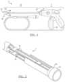
- FIG. 1illustrates an electrosurgical forceps in accordance with the principles of the present invention
- FIG. 2an example of a set of jaws for the forceps shown in FIG. 1 ;
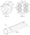
- FIG. 3illustrates an end of a tubular member and/or a camming shaft for the forceps
- FIG. 4illustrates an end view of a tubular member and/or a camming shaft
- FIG. 5illustrates a perspective view of a camming shaft
- FIG. 6illustrates a perspective view of the forceps shown in FIG. 1 ;
- FIG. 7illustrates a cross-sectional view of the jaws
- FIG. 8illustrates a cross-sectional view of another set of jaws in accordance with the principles of the present invention.
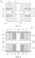
- FIG. 9illustrates a cross-sectional view of yet another set of jaws in accordance with the principles of the present invention.
- FIG. 10illustrates a cross-sectional view of yet another set of jaws in accordance with the principles of the present invention
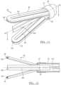
- FIG. 11illustrates a perspective view of the jaws shown in FIG. 6 with a cutting blade
- FIG. 12illustrates a side view of the jaws shown in FIG. 6 with the cutting blade
- FIG. 13illustrates a lower jaw of yet another set of jaws in accordance with the principles of the present invention
- FIGS. 14 A and 14 Billustrate the jaws of FIG. 13 clamping onto a large vessel
- FIGS. 15 A and 15 Billustrate the jaws of FIG. 13 clamping onto a small vessel
- FIG. 16illustrates a cross-sectional view of yet another set of jaws in accordance with the principles of the present invention.
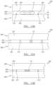
- a forcepssuch as, for example, a laparoscopic forceps, embodying the principles of the present invention is illustrated therein and designated at 2 .
- the forceps 2may function to grip an object.
- the forceps 2may be used during surgery to grip a feature of interest including: a part of a body, an anatomical feature, tissue, veins, arteries, or a combination thereof.
- the forceps 2may function to be used in surgery, for example, laparoscopic surgery.
- the forceps 2may be used with or without power. Current may be passed through the forceps 2 so that the forceps are used for electrosurgery.
- a therapy currentmay be passed from one jaw to a second jaw when tissue is located within the jaw and the therapy current may coagulate blood, cauterize, cut, or a combination thereof.
- the forceps 2may generally include one or more working assemblies and sufficient controls to work the one or more assemblies.
- the forceps 2may include parts employed to perform the recited functions and may include generally, a stylet (e.g., a tubular member, a hollow tube, or an assembly of tubes), a hand piece, one or more operable mechanisms used to actuate the stylet, or a combination thereof.
- the hand piecemay be an assembly of parts or housing structures capable of forming a hand piece structure with a cavity. Note that the present invention is not limited to laparoscopic procedures. That is, the below described jaws can be employed with any type of medical device that clamps onto tissue.
- the forceps 2include a handpiece 4 having a distal end 6 and a proximal end 8 .
- the handpiece 4also includes at least one operable mechanism 50 .
- a tubular member 20has a proximal end 24 that is connected to the distal end 6 of the handpiece 4 .
- the tubular member 20includes a distal end 22 that includes jaws 40 extending therefrom.
- the jaws 40have members 92 and 94 that open and close when the tubular member 20 is moved forward along the longitudinal axis 26 of the tubular member into contact with the members 92 and 94 or the jaws 40 are moved backwards along the longitudinal axis 26 into contact with the tubular member 20 .
- a camming shaft 70is located on the forceps 2 with the jaws 40 extending therefrom.
- the members 92 and 94are biased by the camming shaft 70 so that the jaws 40 are opened and closed.
- the members 92 and 94include inserts 104 and 106 and a pair of slots 96 and 98 that extend through the members 92 and 94 , respectively.
- the inserts 104 and 106are made of any suitable pliable material, such as, an elastic polymer.
- a sealing surface 100 of the member 92includes a first sealing surface 110 on lateral cantilevered portions or sections of the member 92 , that is, on both sides of the slot 96 , and a second sealing surface 112 on medial portions or sections on both sides of the slot 96 .
- the member 94includes a first sealing surface 114 on lateral cantilevered portions or sections of the member 94 , that is, on both sides of the slot 98 , and a second sealing surface 116 on medial portions or sections on both sides of the slot 98 . Note that the use of the inserts 104 and 106 is optional.
- cavitieswould exist below the lateral cantilevered portions that define the first sealing surfaces 110 and 114 .
- the inserts 104 and 106 and/or the cavitiescan extend along a portion of or all of the jaw members 92 and 94 .
- FIG. 3illustrates the end of the tubular member 20 or a camming shaft showing a pair of internal flat portions 30 along the top surfaces and the bottom surfaces.
- a blade recess 34extends between the pair of internal flat portions 30 so that a blade 400 ( FIGS. 11 and 12 ) extends out of the tubular member 20 .
- FIG. 4illustrates a cross-sectional view of a tubular member 20 .
- the internal flat portions 30include at least a portion that has a complementary shape to that of the legs of the jaws 44 . Accordingly, as the tubular member 20 or the legs 44 axially move, the internal flat portions 30 control the orientation and movement of the jaws.
- FIG. 5illustrates a perspective view of one example of a camming shaft 70 that is inserted into the tubular member 20 .
- the camming shaft 70includes a molded flare 74 with a pair of protrusions 72 extending therefrom.
- FIG. 6illustrates the jaws 40 including a pin 90 located between the jaws.
- the pin 90holds the jaw members 92 and 94 together and provide a pivot point for the jaw members 92 and 94 such that the members 92 and 94 close when the tubular member 20 is slid over the opposing members 92 and 94 .
- the first sealing surfaces 110 and 114form a first compression zone above the inserts 104 and 106
- the second sealing surfaces 112 and 116form a second compression zone when the jaw members 92 and 94 are clamped together on a vessel.
- the jaws 40is a two-stage end-effector with the first compression zones produced by the compression surfaces 110 and 114 being more flexible than the second compression zones produced by the compression surfaces 112 and 116 .
- the jaw members 92 and 94can be electrical connected to a generator that provides a source of electrosurgical energy so that a RF voltage with different potentials can be applied to the electrically connected sections of the jaw members 92 and 94 .
- the RF voltageproduces a current that passes from one jaw member to the other jaw member electrode through tissue, thereby heating the tissue to coagulate or cut the tissue.
- the jaws 240include a first jaw member 292 and a second jaw member 294 .
- the first jaw member 292includes a jaw body or support member 295 and a sealing plate 293 disposed on both sides of a slot 296 .
- the exterior surface of the sealing plate 293defines a sealing surface 200 .
- a layer of pliable material 204 , 208 and 212is disposed between the jaw body 295 and the sealing plate 293 .
- the layer of pliable materis made of separate cells placed side by side with different stiffnesses, the medial or center cells 208 being stiffer than the lateral cells 204 .
- the layer of pliable materialincludes the medial cells 208 positioned adjacent to the lateral cells 204 , while in other arrangements the intermediate cells 212 are positioned between the medial cells 208 and the lateral cells 204 to provide an additional transition from the stiffer medial cells 208 to the more flexible lateral cells 204 .
- the second jaw member 294includes a jaw body 297 and a sealing plate 299 disposed on both sides of a slot 298 .
- the exterior surface of the sealing plate 299defines a sealing surface 202 .
- a layer of pliable material 206 , 210 and 214is disposed between the jaw body 297 and the sealing plate 299 .
- the layer of pliable materis made of separate cells placed side by side with different stiffnesses, the medial or center cells 210 being stiffer than the lateral cells 204 .
- the layer of pliable materialincludes the medial cells 210 positioned adjacent to the lateral cells 206 , while in other arrangements the intermediate cells 214 are positioned between the medial cells 210 and the lateral cells 206 to provide an additional transition from the stiffer medial cells 210 to the more flexible lateral cells 206 .
- the layers of pliable material 204 , 208 , 212 and 206 , 210 , 214can extend along a portion of or all of the jaw members 292 and 294 .
- the sealing surfaces above the lateral cells 204 and 206form a first compression zone and the sealing surfaces above the medial cells 208 and 210 form a second compression zone when the jaw members 292 and 294 are closed and clamped together on a vessel, the first compression zone being more flexible than the second compression zone.
- the jaw members 292 and 294include the intermediate cells 212 and 214 , the stiffness of the cells 212 and 214 can be selected to provide a desired transition from the first compression zone to the second compression zone.
- the cells 204 , 206 , 208 , 210 , 212 , 214can be made from any suitable compliant materials such as elastomers. In some arrangements, none of the cells 204 , 206 , 208 , 210 , 212 , 214 are electrically conductive. In other arrangements, some or all of the cells 204 , 206 , 208 , 210 , 212 , 214 can be electrically conductive.
- a voltage with different potentialscan be applied to the electrically conductive cells such that a current passes from one jaw member to the other jaw member through tissue clamped between the jaw members to coagulate or cut the tissue.
- FIG. 9Shown in FIG. 9 is another set of jaws 340 with a first jaw member 392 and a second jaw member 394 in accordance with the principles of the present invention.
- the first jaw member 392includes a jaw body 304 and cantilever members 308 attached to the jaw body 304 on both sides of a slot 396 with a layer of material 312 .
- the arrangement of the cantilever members 308 with respect to the jaw body 304defines a cavity such as a gap 316 on each side of the slot 396 to enable the cantilever member 308 to flex with respect to the jaw body 304 .
- the first jaw member 392includes lateral first sealing surfaces 320 and medial second sealing surfaces 324 .
- the first sealing surface 320defines a more flexible region of the cantilever member 308 than the second sealing surface 324 .
- the stiffness of the layer of material 312can be also be selected to adjust the stiffnesses of the first sealing surface 320 and the second sealing surface 324 .
- the second jaw member 394includes a jaw body 306 and cantilever members 310 attached to the jaw body 306 on both sides of a slot 398 with a layer of material 314 .
- the arrangement of the cantilever members 310 with respect to the jaw body 306defines a cavity such as a gap 318 on each side of the slot 398 to enable the cantilever member 310 to flex with respect to the jaw body 306 .
- the second jaw member 394includes lateral first sealing surfaces 325 and medial second sealing surfaces 326 . Since the unattached region of the cantilever member 310 is able to flex into the gap 318 , the first sealing surface 325 defines a more flexible region of the cantilever member 310 than the second sealing surface 326 .
- the stiffness of the layer of material 314can be also be selected to adjust the stiffnesses of the first sealing surface 325 and the second sealing surface 326 .
- the cantilevered members 308 and 310can extend along a portion of or all of the jaw members 392 and 394 .
- the sealing surfaces 320 and 325form a first compression zone and the sealing surfaces 324 and 326 form a second compression zone when the jaw members 392 and 394 are clamped together on a vessel, the first compression zone being more flexible than the second compression zone.
- the jaw body 304 or cantilever members 308 or both the jaw body 304 and cantilever members 308can be electrically conductive
- the jaw body 306 or cantilever members 310 or both the jaw body 306 and cantilever members 310can be electrically conductive.
- a voltage with different potentialscan be applied to the electrically conductive portions of the jaw members 392 and 394 such that a current passes from one jaw member to the other jaw member through tissue clamped between the jaw members to coagulate or cut the tissue.
- the jaws 440includes a first jaw member 492 and a second jaw member 494 .
- the first jaw member 492includes a jaw body 408 and wedges of pliable material 404 , such as, for example, any compliant material including elastomers, attached to chamfered outer portions of the jaw body 408 on both sides of a slot 496 .
- the jaw member 492includes a first sealing surface 412 on lateral portions or sections of the member 492 , that is, on both sides of the slot 496 , and a second sealing surface 412 on medial portions or sections on both sides of the slot 496 .
- the second jaw member 492includes a jaw body 410 and wedges of pliable material 406 , such as, for example, any compliant material including elastomers, attached to chamfered outer portions of the jaw body 410 on both sides of a slot 498 .
- the jaw member 494includes a first sealing surface 414 on lateral portions or sections of the member 494 , that is, on both sides of the slot 498 , and a second sealing surface 418 on medial portions or sections on both sides of the slot 498 .
- the wedges of pliable material 404 and 406can extend along a portion of or all of the jaw members 492 and 494 .
- first sealing surfaces 412 and 414form a first compression zone above the pliable material 404 and 406
- second sealing surfaces 416 and 418form a second compression zone when the jaw members 492 and 494 are clamped together on a vessel. Because of the pliable or compliant nature of the material 404 and 406 , the first compression zones produced by the compression surfaces 412 and 414 are more flexible than the second compression zones produced by the compression surfaces 416 and 418 .
- the jaw body 408 or pliable material 404 or both the jaw body 408 and pliable material 404can be electrically conductive
- the jaw body 410 or pliable material 406 or both the jaw body 410 and pliable material 406can be electrically conductive.
- any of the jaw arrangements 40 , 240 , 340 and 440 described previouslycan include a cutting blade.
- the jaws 40are shown with a blade 400 .
- the blade 400includes a slot 402 that engages with the pin 90 to allow the blade 400 to reciprocate along the pin 90 .
- the blade 400is connected to a blade shaft 412 .
- axial movement of the blade shaft 412results in reciprocating axial movement of the blade 400 along the slots 96 and 98 of the jaw members 92 and 94 to cut tissue clamped between the jaw members 92 and 94 .
- a similar blade arrangementcan be added to the jaws 240 , 340 and 440 .
- the jaws 540includes a first jaw member 592 and a second jaw member 594 .
- the first jaw member 592includes a lateral portion 502 and a medial or center portion 504 separated from the lateral portion 502 by a gap 508 to enable the lateral portion 502 to flex relative to the medial portion 504 .
- the lateral portion 502has a first sealing surface 506 and the medial portion 504 has a sealing surface 510 .
- the second jaw memberalso has a lateral portion 521 with a first sealing surface 522 and a medial or center portion 526 with a second sealing surface 528 .
- the lateral portions 502 and 521are made of a first material 516 and the medial portions 504 and 526 are made of a second material 518 that is stiffer than the first material 516 .
- the lateral portion 502 of the first jaw memberincludes a first set of non-conductive stops 512 and the medial portion 504 includes a second set of non-conductive stops 514 .
- the first set of non-conductive stops 512has a height of h 1 and the second set of non-conductive stops 512 has a height of h 2 that is less than the height h 1 .
- the stops 512deflect the lateral portions 502 and 521 prior to the first jaw member 592 and the second jaw member 594 fully closing such that the medial plates portions 504 and 526 contact each other if the medial portions 504 and 526 do not include the stops 514 . If the medial portions 504 and 526 include the stops 514 , the stops 512 of the lateral portion 502 make contact with the lateral portion 521 before the stops 514 of the medial portion 504 makes contact with the medial portion 526 .
- the lateral portion 502 or the medial portion 504 or both the lateral portion 502 and the medial portion 504can be electrically conductive
- lateral portion 521 or the medial portion 526 or both the lateral portion 521 and the medial portion 526can be electrically conductive.
- the jaws 600include a first jaw member 692 and a second jaw member 694 .
- the first jaw member 692includes a jaw body or support member 695 and a sealing plate 693 disposed on both sides of a slot 696 .
- the exterior surface of the sealing plate 693defines a sealing surface 601 .
- a layer of pliable material 604 and 608is disposed between the jaw body 695 and the sealing plate 693 .
- the layer of pliable materis made of separate cells with different stiffnesses, the cells 608 being stiffer than the cells 604 .
- the second jaw member 694includes a jaw body 697 and a sealing plate 699 disposed on both sides of a slot 698 .
- the exterior surface of the sealing plate 699defines a sealing surface 603 .
- a layer of pliable material 606 and 610is disposed between the jaw body 697 and the sealing plate 699 .
- the layer of pliable materis made of separate cells with different stiffnesses, the cells 610 being stiffer than the cells 604 .
- the layers of pliable material 604 , 608 and 606 , 610can extend along a portion of or all of the jaw members 292 and 294 .
- the sealing surfaces above the cells 604 and 606form a first compression zone and the sealing surfaces above the cells 608 and 610 form a second compression zone when the jaw members 692 and 694 are closed and clamped together on a vessel, the first compression zone being more flexible than the second compression zone.
- the cells 604 , 606 , 608 and 610can be made from any suitable compliant materials such as elastomers. In some arrangements, none of the cells 604 , 606 , 608 and 610 are electrically conductive. In other arrangements, some or all of the cells 604 , 606 , 608 and 610 can be electrically conductive. Hence, when the jaw members 692 and 694 are connected to a generator that provides a source of electrical energy, a voltage with different potentials can be applied to the electrically conductive cells such that a current passes from one jaw member to the other jaw member through tissue clamped between the jaw members to coagulate or cut the tissue.
- the jaw arrangement 600can include the cutting blade 400 shown previously in FIGS. 11 and 12 .
- the blade 400includes the slot 402 that engages with the pin 90 to allow the blade 400 to reciprocate along the pin 90 .
- the blade 400is connected to the blade shaft 412 .
- axial movement of the blade shaft 412results in reciprocating axial movement of the blade 400 along the slots 696 and 698 of the jaw members 692 and 694 to cut tissue clamped between the jaw members 692 and 694 .
- the present inventioncontemplates any type of jaw member that clamps onto tissue with another jaw member.
- the jaw memberscan clamp onto tissue as the jaw members move toward each other in any suitable manner including translational and rotational movement.
- various components of the any of the above-described jaw memberscan be electrically conductive.
- the components themselvescan be electrically conductive electrodes or electrically conductive material can be added to the component to form an electrode on the component.
Landscapes
- Health & Medical Sciences (AREA)
- Life Sciences & Earth Sciences (AREA)
- Surgery (AREA)
- Engineering & Computer Science (AREA)
- Medical Informatics (AREA)
- Veterinary Medicine (AREA)
- Biomedical Technology (AREA)
- Heart & Thoracic Surgery (AREA)
- Nuclear Medicine, Radiotherapy & Molecular Imaging (AREA)
- Molecular Biology (AREA)
- Animal Behavior & Ethology (AREA)
- General Health & Medical Sciences (AREA)
- Public Health (AREA)
- Ophthalmology & Optometry (AREA)
- Physics & Mathematics (AREA)
- Plasma & Fusion (AREA)
- Otolaryngology (AREA)
- Surgical Instruments (AREA)
Abstract
Description
Claims (20)
Priority Applications (1)
| Application Number | Priority Date | Filing Date | Title |
|---|---|---|---|
| US17/929,430US11957404B2 (en) | 2016-06-02 | 2022-09-02 | Two-stage electrosurgical device for vessel sealing |
Applications Claiming Priority (3)
| Application Number | Priority Date | Filing Date | Title |
|---|---|---|---|
| US201662344751P | 2016-06-02 | 2016-06-02 | |
| US15/602,607US11464561B2 (en) | 2016-06-02 | 2017-05-23 | Two-stage electrosurgical device for vessel sealing |
| US17/929,430US11957404B2 (en) | 2016-06-02 | 2022-09-02 | Two-stage electrosurgical device for vessel sealing |
Related Parent Applications (1)
| Application Number | Title | Priority Date | Filing Date |
|---|---|---|---|
| US15/602,607ContinuationUS11464561B2 (en) | 2016-06-02 | 2017-05-23 | Two-stage electrosurgical device for vessel sealing |
Publications (2)
| Publication Number | Publication Date |
|---|---|
| US20230044200A1 US20230044200A1 (en) | 2023-02-09 |
| US11957404B2true US11957404B2 (en) | 2024-04-16 |
Family
ID=59021326
Family Applications (2)
| Application Number | Title | Priority Date | Filing Date |
|---|---|---|---|
| US15/602,607Active2038-11-22US11464561B2 (en) | 2016-06-02 | 2017-05-23 | Two-stage electrosurgical device for vessel sealing |
| US17/929,430ActiveUS11957404B2 (en) | 2016-06-02 | 2022-09-02 | Two-stage electrosurgical device for vessel sealing |
Family Applications Before (1)
| Application Number | Title | Priority Date | Filing Date |
|---|---|---|---|
| US15/602,607Active2038-11-22US11464561B2 (en) | 2016-06-02 | 2017-05-23 | Two-stage electrosurgical device for vessel sealing |
Country Status (2)
| Country | Link |
|---|---|
| US (2) | US11464561B2 (en) |
| EP (2) | EP3251623B1 (en) |
Families Citing this family (41)
| Publication number | Priority date | Publication date | Assignee | Title |
|---|---|---|---|---|
| US8663220B2 (en) | 2009-07-15 | 2014-03-04 | Ethicon Endo-Surgery, Inc. | Ultrasonic surgical instruments |
| US11090104B2 (en) | 2009-10-09 | 2021-08-17 | Cilag Gmbh International | Surgical generator for ultrasonic and electrosurgical devices |
| US9439668B2 (en) | 2012-04-09 | 2016-09-13 | Ethicon Endo-Surgery, Llc | Switch arrangements for ultrasonic surgical instruments |
| US9408622B2 (en) | 2012-06-29 | 2016-08-09 | Ethicon Endo-Surgery, Llc | Surgical instruments with articulating shafts |
| US10194973B2 (en) | 2015-09-30 | 2019-02-05 | Ethicon Llc | Generator for digitally generating electrical signal waveforms for electrosurgical and ultrasonic surgical instruments |
| US10595930B2 (en) | 2015-10-16 | 2020-03-24 | Ethicon Llc | Electrode wiping surgical device |
| US11051840B2 (en) | 2016-01-15 | 2021-07-06 | Ethicon Llc | Modular battery powered handheld surgical instrument with reusable asymmetric handle housing |
| US12193698B2 (en) | 2016-01-15 | 2025-01-14 | Cilag Gmbh International | Method for self-diagnosing operation of a control switch in a surgical instrument system |
| US11229471B2 (en) | 2016-01-15 | 2022-01-25 | Cilag Gmbh International | Modular battery powered handheld surgical instrument with selective application of energy based on tissue characterization |
| US11129670B2 (en) | 2016-01-15 | 2021-09-28 | Cilag Gmbh International | Modular battery powered handheld surgical instrument with selective application of energy based on button displacement, intensity, or local tissue characterization |
| US10456193B2 (en) | 2016-05-03 | 2019-10-29 | Ethicon Llc | Medical device with a bilateral jaw configuration for nerve stimulation |
| US11464561B2 (en) | 2016-06-02 | 2022-10-11 | Gyrus Acmi, Inc. | Two-stage electrosurgical device for vessel sealing |
| US11266430B2 (en) | 2016-11-29 | 2022-03-08 | Cilag Gmbh International | End effector control and calibration |
| GB2567654B (en)* | 2017-10-18 | 2022-10-05 | Gyrus Medical Ltd | Electrosurgical instrument |
| IT201800002432A1 (en)* | 2018-02-06 | 2019-08-06 | Fondazione St Italiano Tecnologia | ADAPTATIVELY MORPHING SURGICAL GRASPER |
| US11324544B2 (en) | 2018-07-25 | 2022-05-10 | Gyrus Acmi, Inc. | Medical instrument |
| US11950797B2 (en) | 2019-12-30 | 2024-04-09 | Cilag Gmbh International | Deflectable electrode with higher distal bias relative to proximal bias |
| US11779387B2 (en)* | 2019-12-30 | 2023-10-10 | Cilag Gmbh International | Clamp arm jaw to minimize tissue sticking and improve tissue control |
| US12262937B2 (en) | 2019-12-30 | 2025-04-01 | Cilag Gmbh International | User interface for surgical instrument with combination energy modality end-effector |
| US12114912B2 (en) | 2019-12-30 | 2024-10-15 | Cilag Gmbh International | Non-biased deflectable electrode to minimize contact between ultrasonic blade and electrode |
| US11986201B2 (en) | 2019-12-30 | 2024-05-21 | Cilag Gmbh International | Method for operating a surgical instrument |
| US11660089B2 (en) | 2019-12-30 | 2023-05-30 | Cilag Gmbh International | Surgical instrument comprising a sensing system |
| US11779329B2 (en) | 2019-12-30 | 2023-10-10 | Cilag Gmbh International | Surgical instrument comprising a flex circuit including a sensor system |
| US11944366B2 (en)* | 2019-12-30 | 2024-04-02 | Cilag Gmbh International | Asymmetric segmented ultrasonic support pad for cooperative engagement with a movable RF electrode |
| US11786294B2 (en) | 2019-12-30 | 2023-10-17 | Cilag Gmbh International | Control program for modular combination energy device |
| US12082808B2 (en) | 2019-12-30 | 2024-09-10 | Cilag Gmbh International | Surgical instrument comprising a control system responsive to software configurations |
| US11812957B2 (en) | 2019-12-30 | 2023-11-14 | Cilag Gmbh International | Surgical instrument comprising a signal interference resolution system |
| US20210196357A1 (en) | 2019-12-30 | 2021-07-01 | Ethicon Llc | Electrosurgical instrument with asynchronous energizing electrodes |
| US12076006B2 (en) | 2019-12-30 | 2024-09-03 | Cilag Gmbh International | Surgical instrument comprising an orientation detection system |
| US12336747B2 (en) | 2019-12-30 | 2025-06-24 | Cilag Gmbh International | Method of operating a combination ultrasonic / bipolar RF surgical device with a combination energy modality end-effector |
| US20210196362A1 (en) | 2019-12-30 | 2021-07-01 | Ethicon Llc | Electrosurgical end effectors with thermally insulative and thermally conductive portions |
| US11786291B2 (en) | 2019-12-30 | 2023-10-17 | Cilag Gmbh International | Deflectable support of RF energy electrode with respect to opposing ultrasonic blade |
| US11696776B2 (en) | 2019-12-30 | 2023-07-11 | Cilag Gmbh International | Articulatable surgical instrument |
| US12343063B2 (en) | 2019-12-30 | 2025-07-01 | Cilag Gmbh International | Multi-layer clamp arm pad for enhanced versatility and performance of a surgical device |
| US12023086B2 (en) | 2019-12-30 | 2024-07-02 | Cilag Gmbh International | Electrosurgical instrument for delivering blended energy modalities to tissue |
| US11937866B2 (en) | 2019-12-30 | 2024-03-26 | Cilag Gmbh International | Method for an electrosurgical procedure |
| US11684412B2 (en) | 2019-12-30 | 2023-06-27 | Cilag Gmbh International | Surgical instrument with rotatable and articulatable surgical end effector |
| US12053224B2 (en) | 2019-12-30 | 2024-08-06 | Cilag Gmbh International | Variation in electrode parameters and deflectable electrode to modify energy density and tissue interaction |
| US11937863B2 (en) | 2019-12-30 | 2024-03-26 | Cilag Gmbh International | Deflectable electrode with variable compression bias along the length of the deflectable electrode |
| US11857213B2 (en) | 2020-08-28 | 2024-01-02 | Gyrus Acmi, Inc. | Forceps with hinged jaws and force distribution |
| WO2024184194A1 (en)* | 2023-03-03 | 2024-09-12 | Creo Medical Limited | Electrosurgical instrument and electrosurgical apparatus |
Citations (45)
| Publication number | Priority date | Publication date | Assignee | Title |
|---|---|---|---|---|
| US763226A (en) | 1903-09-10 | 1904-06-21 | Frederic Tudor | Vise or the like. |
| US2092905A (en) | 1936-05-06 | 1937-09-14 | Welcome E Brumbelow | Game apparatus |
| US3503396A (en) | 1967-09-21 | 1970-03-31 | American Hospital Supply Corp | Atraumatic surgical clamp |
| US5693051A (en)* | 1993-07-22 | 1997-12-02 | Ethicon Endo-Surgery, Inc. | Electrosurgical hemostatic device with adaptive electrodes |
| US5728121A (en) | 1996-04-17 | 1998-03-17 | Teleflex Medical, Inc. | Surgical grasper devices |
| US5754928A (en) | 1995-09-29 | 1998-05-19 | Minnesota Mining And Manufacturing Company | Squeegee apparatus and method for removing developer liquid from an imaging substrate |
| US5752973A (en) | 1994-10-18 | 1998-05-19 | Archimedes Surgical, Inc. | Endoscopic surgical gripping instrument with universal joint jaw coupler |
| WO1999040861A1 (en) | 1998-02-17 | 1999-08-19 | Baker James A | Radiofrequency medical instrument for vessel welding |
| US6086586A (en) | 1998-09-14 | 2000-07-11 | Enable Medical Corporation | Bipolar tissue grasping apparatus and tissue welding method |
| US6123701A (en) | 1997-10-09 | 2000-09-26 | Perfect Surgical Techniques, Inc. | Methods and systems for organ resection |
| US6406485B1 (en) | 1999-10-08 | 2002-06-18 | Pilling Weck Incorporated | Surgical grasping device and components thereof |
| US20020188294A1 (en) | 2001-04-06 | 2002-12-12 | Couture Gary M. | Vessel sealer and divider |
| US20030171748A1 (en) | 2001-10-22 | 2003-09-11 | Sciogen Llc | Electrosurgical instrument and method of use |
| US20040143263A1 (en) | 2002-11-14 | 2004-07-22 | Schechter David A. | Compressible jaw configuration with bipolar RF output electrodes for soft tissue fusion |
| US6926716B2 (en) | 2001-11-09 | 2005-08-09 | Surgrx Inc. | Electrosurgical instrument |
| US6942676B2 (en) | 2002-03-21 | 2005-09-13 | Novare Surgical Systems, Inc. | Surgical clamp pads with deflecting elements |
| US20050203507A1 (en) | 2004-03-12 | 2005-09-15 | Surgrx, Inc. | Electrosurgical instrument and method of use |
| US7041102B2 (en) | 2001-10-22 | 2006-05-09 | Surgrx, Inc. | Electrosurgical working end with replaceable cartridges |
| US20060217709A1 (en)* | 2003-05-01 | 2006-09-28 | Sherwood Services Ag | Electrosurgical instrument that directs energy delivery and protects adjacent tissue |
| US7182775B2 (en) | 2003-02-27 | 2007-02-27 | Microline Pentax, Inc. | Super atraumatic grasper apparatus |
| WO2007103986A2 (en) | 2006-03-08 | 2007-09-13 | Aragon Surgical, Inc. | Method and apparatus for surgical electrocautery |
| US7276068B2 (en) | 2002-10-04 | 2007-10-02 | Sherwood Services Ag | Vessel sealing instrument with electrical cutting mechanism |
| US20070255279A1 (en) | 1997-11-12 | 2007-11-01 | Buysse Steven P | Electrosurgical instrument which reduces collateral damage to adjacent tissue |
| US20090054894A1 (en) | 2007-08-24 | 2009-02-26 | Chie Yachi | Surgical operating apparatus |
| US20090149853A1 (en) | 2003-05-15 | 2009-06-11 | Chelsea Shields | Tissue Sealer with Non-Conductive Variable Stop Members and Method of Sealing Tissue |
| EP2092905A1 (en) | 2008-02-22 | 2009-08-26 | Tyco Healthcare Group, LP | Monocoque jaw design |
| US20100057083A1 (en) | 2008-08-28 | 2010-03-04 | Tyco Healthcare Group Lp | Tissue Fusion Jaw Angle Improvement |
| US20100057084A1 (en) | 2008-08-28 | 2010-03-04 | TYCO Healthcare Group L.P | Tissue Fusion Jaw Angle Improvement |
| US20110118736A1 (en) | 2009-11-16 | 2011-05-19 | Tyco Healthcare Group Lp | Surgical Forceps Capable of Adjusting Sealing Pressure Based on Vessel Size |
| US20110190765A1 (en) | 2010-01-29 | 2011-08-04 | Tyco Healthcare Group Lp | Dielectric Jaw Insert For Electrosurgical End Effector |
| US20110319886A1 (en)* | 2010-06-23 | 2011-12-29 | Tyco Healthcare Group Lp | Surgical Forceps for Sealing and Dividing Tissue |
| US8192433B2 (en) | 2002-10-04 | 2012-06-05 | Covidien Ag | Vessel sealing instrument with electrical cutting mechanism |
| US8262655B2 (en) | 2007-11-21 | 2012-09-11 | Ethicon Endo-Surgery, Inc. | Bipolar forceps |
| US8298232B2 (en) | 2006-01-24 | 2012-10-30 | Tyco Healthcare Group Lp | Endoscopic vessel sealer and divider for large tissue structures |
| US20130014375A1 (en) | 2011-07-11 | 2013-01-17 | Tyco Healthcare Group Lp | Surgical Forceps and Method of Manufacturing Thereof |
| US8382754B2 (en) | 2005-03-31 | 2013-02-26 | Covidien Ag | Electrosurgical forceps with slow closure sealing plates and method of sealing tissue |
| US8556929B2 (en) | 2010-01-29 | 2013-10-15 | Covidien Lp | Surgical forceps capable of adjusting seal plate width based on vessel size |
| US8597297B2 (en) | 2006-08-29 | 2013-12-03 | Covidien Ag | Vessel sealing instrument with multiple electrode configurations |
| US20140257277A1 (en) | 2013-03-07 | 2014-09-11 | Arthocare Corporation | Methods and systems related to electrosurgical wands |
| US20140276731A1 (en) | 2013-03-14 | 2014-09-18 | Ethicon Endo-Surgery, Inc. | Electrosurgical instrument end effector with compliant electrode |
| US8968308B2 (en) | 2011-10-20 | 2015-03-03 | Covidien Lp | Multi-circuit seal plates |
| US20150305796A1 (en) | 2014-04-24 | 2015-10-29 | Gyrus Acmi, Inc., D.B.A. Olympus Surgical Technologies America | Partially covered jaw electrodes |
| US20160066980A1 (en)* | 2014-09-08 | 2016-03-10 | Erbe Elektromedizin Gmbh | System for Simultaneous Tissue Coagulation and Tissue Dissection |
| US20160346035A1 (en) | 2014-02-12 | 2016-12-01 | Olympus Corporation | Treatment instrument |
| EP3251623A1 (en) | 2016-06-02 | 2017-12-06 | Gyrus ACMI, Inc. (D.B.A. Olympus Surgical Technologies America) | Two-stage electrosurgical device for vessel sealing |
- 2017
- 2017-05-23USUS15/602,607patent/US11464561B2/enactiveActive
- 2017-06-01EPEP17173962.6Apatent/EP3251623B1/enactiveActive
- 2017-06-01EPEP21168117.6Apatent/EP3875050B1/enactiveActive
- 2022
- 2022-09-02USUS17/929,430patent/US11957404B2/enactiveActive
Patent Citations (59)
| Publication number | Priority date | Publication date | Assignee | Title |
|---|---|---|---|---|
| US763226A (en) | 1903-09-10 | 1904-06-21 | Frederic Tudor | Vise or the like. |
| US2092905A (en) | 1936-05-06 | 1937-09-14 | Welcome E Brumbelow | Game apparatus |
| US3503396A (en) | 1967-09-21 | 1970-03-31 | American Hospital Supply Corp | Atraumatic surgical clamp |
| US5693051A (en)* | 1993-07-22 | 1997-12-02 | Ethicon Endo-Surgery, Inc. | Electrosurgical hemostatic device with adaptive electrodes |
| US5752973A (en) | 1994-10-18 | 1998-05-19 | Archimedes Surgical, Inc. | Endoscopic surgical gripping instrument with universal joint jaw coupler |
| US5754928A (en) | 1995-09-29 | 1998-05-19 | Minnesota Mining And Manufacturing Company | Squeegee apparatus and method for removing developer liquid from an imaging substrate |
| US5728121A (en) | 1996-04-17 | 1998-03-17 | Teleflex Medical, Inc. | Surgical grasper devices |
| US6123701A (en) | 1997-10-09 | 2000-09-26 | Perfect Surgical Techniques, Inc. | Methods and systems for organ resection |
| US20070255279A1 (en) | 1997-11-12 | 2007-11-01 | Buysse Steven P | Electrosurgical instrument which reduces collateral damage to adjacent tissue |
| WO1999040861A1 (en) | 1998-02-17 | 1999-08-19 | Baker James A | Radiofrequency medical instrument for vessel welding |
| US6113598A (en)* | 1998-02-17 | 2000-09-05 | Baker; James A. | Radiofrequency medical instrument and methods for vessel welding |
| US6086586A (en) | 1998-09-14 | 2000-07-11 | Enable Medical Corporation | Bipolar tissue grasping apparatus and tissue welding method |
| US6406485B1 (en) | 1999-10-08 | 2002-06-18 | Pilling Weck Incorporated | Surgical grasping device and components thereof |
| US20020188294A1 (en) | 2001-04-06 | 2002-12-12 | Couture Gary M. | Vessel sealer and divider |
| US20030171748A1 (en) | 2001-10-22 | 2003-09-11 | Sciogen Llc | Electrosurgical instrument and method of use |
| US7041102B2 (en) | 2001-10-22 | 2006-05-09 | Surgrx, Inc. | Electrosurgical working end with replaceable cartridges |
| US6926716B2 (en) | 2001-11-09 | 2005-08-09 | Surgrx Inc. | Electrosurgical instrument |
| US6942676B2 (en) | 2002-03-21 | 2005-09-13 | Novare Surgical Systems, Inc. | Surgical clamp pads with deflecting elements |
| US7276068B2 (en) | 2002-10-04 | 2007-10-02 | Sherwood Services Ag | Vessel sealing instrument with electrical cutting mechanism |
| US8192433B2 (en) | 2002-10-04 | 2012-06-05 | Covidien Ag | Vessel sealing instrument with electrical cutting mechanism |
| US20040143263A1 (en) | 2002-11-14 | 2004-07-22 | Schechter David A. | Compressible jaw configuration with bipolar RF output electrodes for soft tissue fusion |
| US8945125B2 (en) | 2002-11-14 | 2015-02-03 | Covidien Ag | Compressible jaw configuration with bipolar RF output electrodes for soft tissue fusion |
| US7182775B2 (en) | 2003-02-27 | 2007-02-27 | Microline Pentax, Inc. | Super atraumatic grasper apparatus |
| US20060217709A1 (en)* | 2003-05-01 | 2006-09-28 | Sherwood Services Ag | Electrosurgical instrument that directs energy delivery and protects adjacent tissue |
| US20090149853A1 (en) | 2003-05-15 | 2009-06-11 | Chelsea Shields | Tissue Sealer with Non-Conductive Variable Stop Members and Method of Sealing Tissue |
| US20050203507A1 (en) | 2004-03-12 | 2005-09-15 | Surgrx, Inc. | Electrosurgical instrument and method of use |
| US8382754B2 (en) | 2005-03-31 | 2013-02-26 | Covidien Ag | Electrosurgical forceps with slow closure sealing plates and method of sealing tissue |
| US8298232B2 (en) | 2006-01-24 | 2012-10-30 | Tyco Healthcare Group Lp | Endoscopic vessel sealer and divider for large tissue structures |
| US20090182333A1 (en) | 2006-03-08 | 2009-07-16 | Joseph Eder | Method and Apparatus for Surgical Electrocautery |
| WO2007103986A3 (en) | 2006-03-08 | 2008-04-10 | Aragon Surgical Inc | Method and apparatus for surgical electrocautery |
| WO2007103986A2 (en) | 2006-03-08 | 2007-09-13 | Aragon Surgical, Inc. | Method and apparatus for surgical electrocautery |
| US8597297B2 (en) | 2006-08-29 | 2013-12-03 | Covidien Ag | Vessel sealing instrument with multiple electrode configurations |
| US20090054894A1 (en) | 2007-08-24 | 2009-02-26 | Chie Yachi | Surgical operating apparatus |
| US8262655B2 (en) | 2007-11-21 | 2012-09-11 | Ethicon Endo-Surgery, Inc. | Bipolar forceps |
| EP2092905A1 (en) | 2008-02-22 | 2009-08-26 | Tyco Healthcare Group, LP | Monocoque jaw design |
| US20090216229A1 (en) | 2008-02-22 | 2009-08-27 | Tyco Healthcare Group Lp | Monocoque Jaw Design |
| US8795274B2 (en) | 2008-08-28 | 2014-08-05 | Covidien Lp | Tissue fusion jaw angle improvement |
| US20100057083A1 (en) | 2008-08-28 | 2010-03-04 | Tyco Healthcare Group Lp | Tissue Fusion Jaw Angle Improvement |
| US20100057084A1 (en) | 2008-08-28 | 2010-03-04 | TYCO Healthcare Group L.P | Tissue Fusion Jaw Angle Improvement |
| US8317787B2 (en) | 2008-08-28 | 2012-11-27 | Covidien Lp | Tissue fusion jaw angle improvement |
| EP2554135A1 (en) | 2008-08-28 | 2013-02-06 | Tyco Healthcare Group, LP | Tissue fusion jaw angle improvement |
| US20110118736A1 (en) | 2009-11-16 | 2011-05-19 | Tyco Healthcare Group Lp | Surgical Forceps Capable of Adjusting Sealing Pressure Based on Vessel Size |
| US8556929B2 (en) | 2010-01-29 | 2013-10-15 | Covidien Lp | Surgical forceps capable of adjusting seal plate width based on vessel size |
| EP2353535A1 (en) | 2010-01-29 | 2011-08-10 | Tyco Healthcare Group, LP | Dielectric jaw insert for electrosurgical end effector |
| US20110190765A1 (en) | 2010-01-29 | 2011-08-04 | Tyco Healthcare Group Lp | Dielectric Jaw Insert For Electrosurgical End Effector |
| US8647343B2 (en) | 2010-06-23 | 2014-02-11 | Covidien Lp | Surgical forceps for sealing and dividing tissue |
| US20140155893A1 (en) | 2010-06-23 | 2014-06-05 | Covidien Lp | Surgical forceps for sealing and dividing tissue |
| US20110319886A1 (en)* | 2010-06-23 | 2011-12-29 | Tyco Healthcare Group Lp | Surgical Forceps for Sealing and Dividing Tissue |
| US20130014375A1 (en) | 2011-07-11 | 2013-01-17 | Tyco Healthcare Group Lp | Surgical Forceps and Method of Manufacturing Thereof |
| US8968308B2 (en) | 2011-10-20 | 2015-03-03 | Covidien Lp | Multi-circuit seal plates |
| US20140257277A1 (en) | 2013-03-07 | 2014-09-11 | Arthocare Corporation | Methods and systems related to electrosurgical wands |
| US20140276731A1 (en) | 2013-03-14 | 2014-09-18 | Ethicon Endo-Surgery, Inc. | Electrosurgical instrument end effector with compliant electrode |
| US20160346035A1 (en) | 2014-02-12 | 2016-12-01 | Olympus Corporation | Treatment instrument |
| US20150305796A1 (en) | 2014-04-24 | 2015-10-29 | Gyrus Acmi, Inc., D.B.A. Olympus Surgical Technologies America | Partially covered jaw electrodes |
| US20160066980A1 (en)* | 2014-09-08 | 2016-03-10 | Erbe Elektromedizin Gmbh | System for Simultaneous Tissue Coagulation and Tissue Dissection |
| EP3251623A1 (en) | 2016-06-02 | 2017-12-06 | Gyrus ACMI, Inc. (D.B.A. Olympus Surgical Technologies America) | Two-stage electrosurgical device for vessel sealing |
| US20170348044A1 (en) | 2016-06-02 | 2017-12-07 | Gyrus Acmi, Inc., D.B.A. Olympus Surgical Technologies America | Two-stage electrosurgical device for vessel sealing |
| EP3251623B1 (en) | 2016-06-02 | 2021-04-14 | Gyrus ACMI, Inc. d.b.a. Olympus Surgical Technologies America | Two-stage electrosurgical device for vessel sealing |
| US11464561B2 (en) | 2016-06-02 | 2022-10-11 | Gyrus Acmi, Inc. | Two-stage electrosurgical device for vessel sealing |
Non-Patent Citations (27)
Also Published As
| Publication number | Publication date |
|---|---|
| EP3875050B1 (en) | 2025-08-27 |
| US20230044200A1 (en) | 2023-02-09 |
| EP3251623B1 (en) | 2021-04-14 |
| EP3251623A1 (en) | 2017-12-06 |
| US11464561B2 (en) | 2022-10-11 |
| EP3875050A1 (en) | 2021-09-08 |
| US20170348044A1 (en) | 2017-12-07 |
Similar Documents
| Publication | Publication Date | Title |
|---|---|---|
| US11957404B2 (en) | Two-stage electrosurgical device for vessel sealing | |
| US12329441B2 (en) | Two-stage electrosurgical device for vessel sealing | |
| US12213720B2 (en) | Jaw assemblies for electrosurgical instruments and methods of manufacturing jaw assemblies | |
| JP6467463B2 (en) | Surgical device with jaw force limiter | |
| US10820940B2 (en) | Methods of manufacturing a pair of jaw members of an end-effector assembly for a surgical instrument | |
| CN106491203B (en) | Instrument for grasping, dissecting and/or coagulating biological tissue | |
| CN108430350B (en) | Clamps with Tissue Stops | |
| US9265566B2 (en) | Surgical instrument | |
| AU2001249932B8 (en) | Electrosurgical instrument which reduces collateral damage to adjacent tissue | |
| US7160298B2 (en) | Electrosurgical instrument which reduces effects to adjacent tissue structures | |
| JP4546424B2 (en) | Endoscopic treatment tool | |
| JP2016007542A (en) | Surgical instrument | |
| US10987153B2 (en) | Forceps with active jaw entrapment of tissue | |
| US11490953B2 (en) | Electrosurgical instrument and passively cooled jaw members thereof | |
| US10292759B2 (en) | Electrosurgical device for vessel sealing | |
| US11065049B2 (en) | Electrosurgical device with asymmetric seal compression | |
| US20170281264A1 (en) | Electrosurgical device for vessel sealing | |
| US20200337760A1 (en) | Single-use surgical instrument | |
| AU2001249912B9 (en) | Electrosurgical instrument reducing thermal spread | |
| GB2565135A (en) | Bipolar surgical instruments |
Legal Events
| Date | Code | Title | Description |
|---|---|---|---|
| FEPP | Fee payment procedure | Free format text:ENTITY STATUS SET TO UNDISCOUNTED (ORIGINAL EVENT CODE: BIG.); ENTITY STATUS OF PATENT OWNER: LARGE ENTITY | |
| AS | Assignment | Owner name:GYRUS ACMI, INC. D/B/A OLYMPUS SURGICAL TECHNOLOGIES AMERICA, MASSACHUSETTS Free format text:ASSIGNMENT OF ASSIGNORS INTEREST;ASSIGNORS:WANG, HUISUN;BATCHELOR, KESTER JULIAN;BUTLER, BILL;REEL/FRAME:061014/0812 Effective date:20170524 | |
| STPP | Information on status: patent application and granting procedure in general | Free format text:DOCKETED NEW CASE - READY FOR EXAMINATION | |
| AS | Assignment | Owner name:GYRUS ACMI, INC. D/B/A OLYMPUS SURGICAL TECHNOLOGIES AMERICA, MASSACHUSETTS Free format text:CORRECTIVE ASSIGNMENT TO CORRECT THE FIRST NAME OF THE 3RD INVENTOR PREVIOUSLY RECORDED AT REEL: 061014 FRAME: 0812. ASSIGNOR(S) HEREBY CONFIRMS THE ASSIGNMENT;ASSIGNORS:WANG, HUISUN;BATCHELOR, KESTER JULIAN;BUTLER, WILLIAM;REEL/FRAME:061899/0006 Effective date:20170524 | |
| STPP | Information on status: patent application and granting procedure in general | Free format text:NON FINAL ACTION MAILED | |
| STPP | Information on status: patent application and granting procedure in general | Free format text:RESPONSE TO NON-FINAL OFFICE ACTION ENTERED AND FORWARDED TO EXAMINER | |
| STPP | Information on status: patent application and granting procedure in general | Free format text:NOTICE OF ALLOWANCE MAILED -- APPLICATION RECEIVED IN OFFICE OF PUBLICATIONS | |
| STPP | Information on status: patent application and granting procedure in general | Free format text:PUBLICATIONS -- ISSUE FEE PAYMENT VERIFIED | |
| STCF | Information on status: patent grant | Free format text:PATENTED CASE |