US11957178B2 - Aerosol actuator - Google Patents
Aerosol actuatorDownload PDFInfo
- Publication number
- US11957178B2 US11957178B2US18/055,122US202218055122AUS11957178B2US 11957178 B2US11957178 B2US 11957178B2US 202218055122 AUS202218055122 AUS 202218055122AUS 11957178 B2US11957178 B2US 11957178B2
- Authority
- US
- United States
- Prior art keywords
- cap
- aerosol
- operating cap
- fins
- operating
- Prior art date
- Legal status (The legal status is an assumption and is not a legal conclusion. Google has not performed a legal analysis and makes no representation as to the accuracy of the status listed.)
- Active
Links
Images


Classifications
- B—PERFORMING OPERATIONS; TRANSPORTING
- B65—CONVEYING; PACKING; STORING; HANDLING THIN OR FILAMENTARY MATERIAL
- B65D—CONTAINERS FOR STORAGE OR TRANSPORT OF ARTICLES OR MATERIALS, e.g. BAGS, BARRELS, BOTTLES, BOXES, CANS, CARTONS, CRATES, DRUMS, JARS, TANKS, HOPPERS, FORWARDING CONTAINERS; ACCESSORIES, CLOSURES, OR FITTINGS THEREFOR; PACKAGING ELEMENTS; PACKAGES
- B65D83/00—Containers or packages with special means for dispensing contents
- B65D83/14—Containers for dispensing liquid or semi-liquid contents by internal gaseous pressure, i.e. aerosol containers comprising propellant
- B65D83/16—Actuating means
- B65D83/20—Actuator caps
- B65D83/206—Actuator caps comprising cantilevered actuating elements, e.g. levers pivoting about living hinges
- A—HUMAN NECESSITIES
- A24—TOBACCO; CIGARS; CIGARETTES; SIMULATED SMOKING DEVICES; SMOKERS' REQUISITES
- A24F—SMOKERS' REQUISITES; MATCH BOXES; SIMULATED SMOKING DEVICES
- A24F40/00—Electrically operated smoking devices; Component parts thereof; Manufacture thereof; Maintenance or testing thereof; Charging means specially adapted therefor
- A24F40/40—Constructional details, e.g. connection of cartridges and battery parts
- A24F40/48—Fluid transfer means, e.g. pumps
- A24F40/485—Valves; Apertures
- A—HUMAN NECESSITIES
- A24—TOBACCO; CIGARS; CIGARETTES; SIMULATED SMOKING DEVICES; SMOKERS' REQUISITES
- A24F—SMOKERS' REQUISITES; MATCH BOXES; SIMULATED SMOKING DEVICES
- A24F40/00—Electrically operated smoking devices; Component parts thereof; Manufacture thereof; Maintenance or testing thereof; Charging means specially adapted therefor
- A24F40/50—Control or monitoring
- B—PERFORMING OPERATIONS; TRANSPORTING
- B05—SPRAYING OR ATOMISING IN GENERAL; APPLYING FLUENT MATERIALS TO SURFACES, IN GENERAL
- B05B—SPRAYING APPARATUS; ATOMISING APPARATUS; NOZZLES
- B05B11/00—Single-unit hand-held apparatus in which flow of contents is produced by the muscular force of the operator at the moment of use
- B—PERFORMING OPERATIONS; TRANSPORTING
- B65—CONVEYING; PACKING; STORING; HANDLING THIN OR FILAMENTARY MATERIAL
- B65D—CONTAINERS FOR STORAGE OR TRANSPORT OF ARTICLES OR MATERIALS, e.g. BAGS, BARRELS, BOTTLES, BOXES, CANS, CARTONS, CRATES, DRUMS, JARS, TANKS, HOPPERS, FORWARDING CONTAINERS; ACCESSORIES, CLOSURES, OR FITTINGS THEREFOR; PACKAGING ELEMENTS; PACKAGES
- B65D83/00—Containers or packages with special means for dispensing contents
- B65D83/14—Containers for dispensing liquid or semi-liquid contents by internal gaseous pressure, i.e. aerosol containers comprising propellant
- B65D83/16—Actuating means
- B65D83/22—Actuating means with means to disable actuation
- B—PERFORMING OPERATIONS; TRANSPORTING
- B65—CONVEYING; PACKING; STORING; HANDLING THIN OR FILAMENTARY MATERIAL
- B65D—CONTAINERS FOR STORAGE OR TRANSPORT OF ARTICLES OR MATERIALS, e.g. BAGS, BARRELS, BOTTLES, BOXES, CANS, CARTONS, CRATES, DRUMS, JARS, TANKS, HOPPERS, FORWARDING CONTAINERS; ACCESSORIES, CLOSURES, OR FITTINGS THEREFOR; PACKAGING ELEMENTS; PACKAGES
- B65D83/00—Containers or packages with special means for dispensing contents
- B65D83/14—Containers for dispensing liquid or semi-liquid contents by internal gaseous pressure, i.e. aerosol containers comprising propellant
- B65D83/32—Dip-tubes
- B—PERFORMING OPERATIONS; TRANSPORTING
- B65—CONVEYING; PACKING; STORING; HANDLING THIN OR FILAMENTARY MATERIAL
- B65D—CONTAINERS FOR STORAGE OR TRANSPORT OF ARTICLES OR MATERIALS, e.g. BAGS, BARRELS, BOTTLES, BOXES, CANS, CARTONS, CRATES, DRUMS, JARS, TANKS, HOPPERS, FORWARDING CONTAINERS; ACCESSORIES, CLOSURES, OR FITTINGS THEREFOR; PACKAGING ELEMENTS; PACKAGES
- B65D83/00—Containers or packages with special means for dispensing contents
- B65D83/14—Containers for dispensing liquid or semi-liquid contents by internal gaseous pressure, i.e. aerosol containers comprising propellant
- B65D83/44—Valves specially adapted for the discharge of contents; Regulating devices
- B65D83/46—Tilt valves
Definitions
- the inventionrelates to dispensing of an aerosol product and more particularly to an improved tilt-type aerosol actuator assembly having a cap rotatable relative to a base for enabling and disabling dispensing of an aerosol product from an aerosol container.
- An aerosol dispensercomprises an aerosol container filled with an aerosol product and an aerosol propellent.
- the aerosol containeris equipped with a tilt-valve to control the discharge of the aerosol product and propellant.
- An aerosol actuator assemblyis an interface device typically comprising an operating cap and a base that attaches to the container and can be actuated by a user to control the flow of an aerosol product through the aerosol valve.
- the aerosol valveincludes a biasing spring which biases the valve into a closed position.
- a valve stemcooperates with the aerosol valve for opening the valve.
- An operating capengages with the valve stem and via tilting action of the actuator, opens and closes the valve.
- the operating capwill typically include a spray nozzle for directing the dispensed aerosol product.
- tilt-type aerosol dispensersOne problem commonly associated with tilt-type aerosol dispensers is that of accidental discharge of the contents of the container because of inadvertent tilting of the valve stem. Frequently, after the purchase of an aerosol dispenser, a protective cap that prevents inadvertent operation is thrown away and the aerosol actuator left unprotected. Subsequently, if the dispenser is packed into luggage or otherwise packed with other articles, sufficient force may be applied to the operating cap to tilt the cap and cause operation of the aerosol dispenser valve.
- the present inventionsolves the problems of the prior art by providing an aerosol actuator having an operating cap and a base cap, where the operating cap interfaces with the aerosol valve of an aerosol dispenser and is rotatable between a locked position which prohibits dispensing of the aerosol product and an unlocked position that allows dispensing of the aerosol product via tilting action of the operating cap, which causes tilting or opening of the aerosol valve.
- the operating capincludes a plurality of fins that are rotatable over a plurality of slots and blocking surfaces disposed in the base cap.
- the operating capin the locked position, is rotated clockwise such that the fins are positioned over the blocking surfaces which thereby prevent depression or operation of the cap.
- the unlocked positionthe operating cap is rotated counterclockwise such that the fins are disposed above the slots in the base cap, thereby allowing downward depression of the cap.
- the fins and slotsare configured such that downward depression of an operating surface on one side of the operating cap causes tilting of the cap, which thereby causes tilting of the aerosol valve to which the operating cap is attached.
- the operating cap and base capmay be configured such that the direction of rotation for unlocking and locking of the operating cap may be reversed from that of the exemplary embodiment.
- the base capis configured so as to be attachable via a press fit to either a lip of an aerosol container or to the lip of an aerosol valve cup.
- the aerosol actuator of the present inventionmay be manufactured from plastic materials at relatively low cost and in high volume. Being fabricated entirely from plastic materials, the aerosol actuator of the present invention is well-suited for recycling.
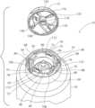
- FIG. 1is a perspective view of an aerosol actuator of the present invention.
- FIG. 1 Ais a cross-sectional view of the aerosol actuator of FIG. 1 mounted on an aerosol container.
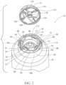
- FIG. 2is an exploded perspective view of the aerosol actuator of FIG. 1 .
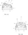
- FIG. 3 Ais a cross-sectional view, taken along the line A-A of FIG. 1 , of the aerosol actuator of FIG. 1 , showing the front and rear fins of the operating cap positioned above the corresponding blocking surfaces of the base cap when the operating cap is rotated to the locked position.
- FIG. 3 Bis a cross-sectional view, taken along the line B-B of FIG. 1 , of the aerosol actuator of FIG. 1 , showing the side fins of the operating cap positioned above the corresponding blocking surfaces of the base cap when the operating cap is rotated to the locked position.
- FIG. 4 Ais a cross-sectional view, taken along the line A-A of FIG. 1 , of the aerosol actuator of FIG. 1 , showing the front and rear fins of the operating cap positioned above the corresponding slots of the base cap when the operating cap is rotated to the unlocked position.
- FIG. 4 Bis a cross-sectional view, taken along the line B-B of FIG. 1 , of the aerosol actuator of FIG. 1 , showing the side fins of the operating cap positioned above the corresponding slots of the base cap when the operating cap is rotated to the unlocked position.
- FIG. 5is a cross-sectional view, taken along the line A-A of FIG. 1 , showing the operating cap of the aerosol actuator of FIG. 1 in the depressed position.
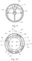
- FIG. 6is a top view, partially cut away, showing the fins of the operating cap of the aerosol actuator of FIG. 1 , over the blocking portions of the base cap, when the operating cap is in the locked position.
- FIG. 7is a top view, partially cutaway, showing the fins of the operating cap of the aerosol actuator of FIG. 1 over the slots of the base when the operating cap is in the unlocked position.
- FIG. 8 Ais a cross section of the operating cap of FIG. 1 taken along the line A-A of FIG. 1 .
- FIG. 8 Bis a cross section of the operating cap of FIG. 1 taken along the line B-B of FIG. 1 .
- FIG. 9is a bottom view of the operating cap of the aerosol actuator assembly of FIG. 1 .
- FIG. 10is a top view of the base cap of the aerosol actuator assembly of FIG. 1 .
- FIG. 11is a side view of the base cap of the aerosol actuator assembly of FIG. 1 .
- the aerosol actuator assembly 10comprises an operating cap 12 and a base cap 14 .
- the operating cap 12is rotatably attached to the base cap 14 .
- the base cap 14is secured to an aerosol container 18 .
- the aerosol container 18has a longitudinal axis of symmetry 8 .
- the aerosol container 18is equipped with an aerosol valve 20 having a valve stem 22 .
- the aerosol valve 20controls the flow of the aerosol product 50 through the valve stem 22 .
- the aerosol product 50 and the aerosol propellant(not shown) are stored within the aerosol container 18 .
- a downwards directionrefers to a direction along the longitudinal axis of symmetry 8 towards a closed or bottom end 26 of the aerosol container 18 and an upwards direction refers to a direction along the longitudinal axis of symmetry 8 towards the aerosol valve 20 installed in the aerosol container 18 .
- the aerosol container 18has a top end 24 and the bottom end 26 with a cylindrical sidewall 28 therebetween.
- the bottom end 26is closed out by an end-wall 30 .
- the top end 24tapers radially inwardly to form a neck 32 terminating in a bead 34 .
- the bead 34defines an opening 36 in the aerosol container 18 for receiving a mounting cup 38 .
- the mounting cup 38includes a peripheral rim 40 for sealing to the bead 34 of the aerosol container 18 .
- the mounting cup 38includes a turret 42 for receiving the aerosol valve 20 .
- the aerosol valve 20includes a valve body 44 secured to the turret 42 of the mounting cup 38 .
- the valve body 44defines an internal valve cavity 46 in fluid communication with the aerosol container 18 through a dip tube 48 .
- the aerosol valve 20includes a valve element 52 positioned within the internal valve cavity 46 .
- a biasing spring 54biases the valve element 52 into a normally closed position to inhibit the flow of the aerosol product 50 through the valve stem 22 .
- the aerosol valve 20is configured such that tilting of the valve stem 22 by an external force applied to the valve stem 22 causes a gap to open between the valve stem 22 and the valve element 52 , which thereby allows aerosol product 50 to exit the aerosol container 18 through a flow passage 56 in the valve stem 22 .
- the biasing spring 54causes the valve element 52 to seal against the valve stem 22 , thereby preventing the aerosol product 50 from exiting the aerosol container 18 .
- the aerosol actuator assembly 10comprises the operating cap 12 and the base cap 14 , which are configured such that the operating cap 12 is rotatable relative to the base cap 14 between an unlocked position (see FIGS. 4 A, 4 B and 7 ) and a locked position (see FIGS. 3 A, 3 B and 6 ).
- the operating cap 12is rotated to the unlocked position, the operating cap 12 is tiltable relative to the base cap 14 for actuating the aerosol valve 20 to dispense the aerosol product 50 from the aerosol container 18 . (See FIG.
- Tilting of the operating cap 12occurs when a user presses downwardly on an actuation surface 58 of the operating cap 12 , when the operating cap is in the unlocked position. (See FIGS. 4 A, 4 B and 7 .) When the operating cap 12 is rotated to the locked position (see FIGS. 3 A, 3 B and 6 ), tilting of the operating cap 12 is blocked.
- the base cap 14includes an outer cylindrical sidewall 60 , a middle cylindrical sidewall 62 and an inner cylindrical sidewall 64 .
- the outer cylindrical sidewall 60 , the middle cylindrical sidewall 62 , and the inner cylindrical sidewall 64are coaxial with the longitudinal axis of symmetry 8 of the aerosol container 18 .
- Disposed between the middle cylindrical sidewall 62 and the inner cylindrical sidewall 64are a plurality of buttresses 66 which are connected to the side walls and serve to stiffen the sidewalls.
- gusset portions 98Formed between the outer cylindrical sidewall 60 and the middle cylindrical sidewall 62 are a plurality of gusset portions 98 , which function to interconnect the outer cylindrical sidewall 60 with the middle cylindrical sidewall 62 .
- a top surface of the middle cylindrical side wall 62 between a clockwise stop surface 92 and a counterclockwise stop surface 94is defined as the forward shelf 68 .
- Formed in the inner cylindrical sidewall 64is a rear slot 70 and side slots 72 .
- Each of the side slots 72has a bottom surface 112 .
- the rear slot 70has a bottom surface 114 .
- the depth of bottom surfaces 112 of the side slots 72 and the bottom surface 114 of the rear slot 70are the same.
- the depth of bottom surfaces 112 of the side slots 72 and the bottom surface 114 of the rear slot 70 and the depth of the forward shelf 68is defined the vertical distance, downwardly, from a plane 142 defined as being coplaner with the upper circumference of the inner cylindrical wall 64 of the base cap 12 .
- the depth of the forward shelf 68is less than that of the bottom surface 112 of the side slots 72 of the bottom surface 114 of the rear slot 70 .
- Adjacent to the side slots 72are side blocking portions 74 .
- a clockwise stop surface 84Formed at an end of each side blocking portion 74 is a clockwise stop surface 84 , where the clockwise stop surface 84 limits clockwise rotation of the operating cap 12 .
- a counter-clockwise stop surface 86Formed at one of the walls defining each of the side slots 72 is a counter-clockwise stop surface 86 , where the counter-clockwise stop surface 86 limits counterclockwise rotation of the operating cap 12 .
- a rear blocking portion 76formed adjacent to the rear slot 70 is a rear blocking portion 76 .
- a clockwise stop surface 88Formed at an end wall of the rear blocking portion 76 is a clockwise stop surface 88 , where the clockwise stop surface 88 functions to limit clockwise rotation of the operating cap 12 .
- a counterclockwise stop surface 90Formed at one of the walls defining rear slot 70 is a counterclockwise stop surface 90 , where the counterclockwise stop surface 90 serves to limit counterclockwise rotation of the operating cap 12 .
- the forward shelf 68 of the base cap 14also includes a clockwise stop surface 92 and a counterclockwise stop surface 94 , where the counterclockwise stop surface 94 serves to limit counterclockwise rotation on the operating cap 12 and the clockwise stop surface 92 serves to limit clockwise rotation of the operating cap 12 .
- the base cap 14includes an annular projection 71 formed on an inner surface of outer cylindrical sidewall 60 and adjacent a lower edge and which extends radially inwardly. (See FIGS. 3 A, 3 B, 4 A, 4 B and 5 .)
- the annular projection 71snaps over the peripheral rim 40 (see FIG. 1 A ) of the mounting cup 38 and thereby secures the base cap 14 to the aerosol container 18 .
- the annular projection 71may engage with the bead 34 of the aerosol container 18 .
- the base cap 14further includes a plurality of annular protrusions 106 spaced about an exterior surface of the middle cylindrical sidewall 62 . (See FIG. 2 .) The plurality of annular protrusions 106 of the base cap 14 engage via a snap fit relationship with a plurality of mating angular protrusions 108 formed on an inner surface of the operating cap 12 . (See FIG. 2 .)
- the operating cap 12includes a generally hollow, hemispherical body 116 , a tubular portion 118 that is coaxial with the axis of symmetry 8 of the aerosol container 18 , and four equally spaced fins, i.e. front fin 120 , rear or rear fin 122 and side fins 124 , extending radially outwardly from the tubular portion 118 .
- each of the finsextends downwardly from the interior of the operating cap 12 to a specific height above a plane 146 , the plane 146 being coplanar with a bottom circumference 148 of the operating cap 12 .
- the front fin 120has a height 130 .
- the rear fin 122has a height 128 and the side fins 124 have a height 126 . (See FIG. 3 B .)
- the height 128 of the rear fin 122is greater than the height 130 of the front fin 120 and the height 126 of the side fins 124 .
- the height 126 of the side fins 124is greater than the height 130 of the front fin 120 , but less than the height 128 of the rear fin 122 .
- the operating cap 12further includes a nozzle flow passage 134 which has an exit orifice 136 at one end and connects to a flow passage 138 of the tubular portion 118 at another end. (See FIG. 8 A .)
- the tubular portion 118is configured at an open end 140 to engage with an outlet end of the aerosol valve 20 .
- the plurality of angular protrusions 108 formed on the inner surface of the operating cap 12snap over the plurality of annular protrusions 106 of the base cap 14 .
- the operating cap 12is snapped into place on the base cap 14 , the operating cap 12 is prevented from translating relative to the base cap 14 , but it's free to rotate relative to the base cap 14 about a longitudinal axis coincident with the longitudinal axis 8 of the aerosol container 18 .
- the operating cap 12is biased in an upwards direction.
- the operating cap 12With the operating cap 12 engaged with the base cap 14 , in the exemplary embodiment, the operating cap 12 is rotatable, relative to the base, clockwise to a locked position or counterclockwise to an unlocked position.
- the locking protrusions 78 on the top surfaces 80 of side blocking portions 74 and the top surface 82 of rear blocking portion 76 , respectively,provide tactile feedback to a user as the operating cap 12 rotates.
- the locking protrusions 78also function to prevent the side fins 124 and the rear fin 122 from inadvertently rotating counterclockwise and allowing the operating cap 12 to inadvertently move into the unlocked position.
- downward pressure on the actuation surface 58 of the operating cap 12causes the front fin 120 to contact the forward shelf 68 and the rear fin 122 to depress until it contacts the bottom surface 114 of the rear slot 70 .
- the height 128 of the rear fin 122is greater than the height 130 of the front fin 120 and the height 126 of the side fins 124 , this results in the operating cap 12 tilting upon depression of actuation surface 58 . Consequently, the tubular portion 118 of the operating cap 12 causes tilting of the valve stem 22 of the aerosol valve 20 .
- the side fins 124 of the operating cap 12are disposed above the side slots 72 .
- the height of the side fins 124are configured such that when the operating cap 12 is depressed, the side fins 124 will not contact the bottom surfaces 112 of the side slots 72 when the rear fin 122 abuts the bottom surface 114 of the rear slot 70 .
- the height of the side fins 124may be configured such that upon downward depression of the operating cap 12 , the side fins 124 contact the bottom surface 112 of the side slots 72 before the rear fin 122 contacts the bottom surface 114 of the rear slot 70 . Upon the continued application of downward force, the operating cap 12 will rock about the side fins 124 until the rear fin 122 contacts the bottom surface 114 of the rear slot 70 . This rocking action may create a more positive “feel” or “feedback” to a user of the aerosol actuator 10 .
- the operating cap and the base cap of the present inventionmay be injection molded from a wide variety of plastic materials of which polyethylene and polypropylene are two such materials. These materials are well-suited for low cost, high volume production. Other materials and methods of manufacture may also be suitable.
Landscapes
- Chemical & Material Sciences (AREA)
- Dispersion Chemistry (AREA)
- Engineering & Computer Science (AREA)
- Mechanical Engineering (AREA)
- Containers And Packaging Bodies Having A Special Means To Remove Contents (AREA)
- Nozzles (AREA)
Abstract
Description
Claims (9)
Priority Applications (4)
| Application Number | Priority Date | Filing Date | Title |
|---|---|---|---|
| US18/055,122US11957178B2 (en) | 2021-11-15 | 2022-11-14 | Aerosol actuator |
| PCT/US2022/079893WO2023087026A1 (en) | 2021-11-15 | 2022-11-15 | Aerosol actuator |
| CA3232262ACA3232262A1 (en) | 2021-11-15 | 2022-11-15 | Aerosol actuator |
| EP22893934.4AEP4392342A4 (en) | 2021-11-15 | 2022-11-15 | AEROSOL ACTUATOR |
Applications Claiming Priority (2)
| Application Number | Priority Date | Filing Date | Title |
|---|---|---|---|
| US202163279533P | 2021-11-15 | 2021-11-15 | |
| US18/055,122US11957178B2 (en) | 2021-11-15 | 2022-11-14 | Aerosol actuator |
Publications (2)
| Publication Number | Publication Date |
|---|---|
| US20230148674A1 US20230148674A1 (en) | 2023-05-18 |
| US11957178B2true US11957178B2 (en) | 2024-04-16 |
Family
ID=86325345
Family Applications (1)
| Application Number | Title | Priority Date | Filing Date |
|---|---|---|---|
| US18/055,122ActiveUS11957178B2 (en) | 2021-11-15 | 2022-11-14 | Aerosol actuator |
Country Status (4)
| Country | Link |
|---|---|
| US (1) | US11957178B2 (en) |
| EP (1) | EP4392342A4 (en) |
| CA (1) | CA3232262A1 (en) |
| WO (1) | WO2023087026A1 (en) |
Citations (33)
| Publication number | Priority date | Publication date | Assignee | Title |
|---|---|---|---|---|
| US3874562A (en) | 1972-11-10 | 1975-04-01 | Polytop Corp | Dispensing closure with pump parts and container using the same |
| US3907174A (en) | 1971-04-13 | 1975-09-23 | Vca Corp | Dispensing pump construction with foldable discharge nozzle |
| JPS6095678U (en) | 1983-12-02 | 1985-06-29 | オムロン株式会社 | Coin passage jam release device |
| US4607765A (en) | 1984-04-19 | 1986-08-26 | S.A.R. S.P.A. | Manually operated pump for the delivery under pressure of liquid substances |
| US4875604A (en) | 1986-01-17 | 1989-10-24 | Joachim Czech | Dispenser for paste-like products |
| US5388730A (en) | 1993-11-10 | 1995-02-14 | Enviro Pac International L.L.C. | Lockable actuator for a dispensing canister |
| US5673821A (en) | 1991-08-31 | 1997-10-07 | Smithkline Beecham Plc | Dispensing device for two fluid materials |
| US20030116588A1 (en) | 2000-04-13 | 2003-06-26 | Stefano Santagiuliana | Multidose delivery pump |
| EP1389491A1 (en) | 2002-08-13 | 2004-02-18 | Yon Woo Corporation | Airless dispenser pump |
| US20060043117A1 (en) | 2004-08-30 | 2006-03-02 | Rieke Corporation | Airless dispensing pump with tamper evidence features |
| US7014127B2 (en) | 2003-01-24 | 2006-03-21 | S.C. Johnson & Son, Inc. | Aerosol dispenser assembly having low volatile organic compound (VOC) content |
| US20080179347A1 (en) | 2003-03-03 | 2008-07-31 | Patrick Timothy Yerby | Aerosol actuator |
| US20090008413A1 (en) | 2007-04-17 | 2009-01-08 | Choi Hee Jin | Airless dispensing pump container with an airtight push down type nozzle head |
| USD594747S1 (en) | 2007-07-16 | 2009-06-23 | Lumson, S.p.A. | Aerosol dispenser cap |
| USD595570S1 (en) | 2007-07-16 | 2009-07-07 | Lumson, S.p.A. | Aerosol dispenser cap |
| US7601681B2 (en) | 1999-12-22 | 2009-10-13 | The Procter & Gamble Company | Laundry and cleaning and/or fabric care composition |
| US7611032B2 (en)* | 2004-01-27 | 2009-11-03 | L'oreal | Lockable dispensing head |
| US7757905B2 (en)* | 2005-08-18 | 2010-07-20 | Summit Packaging Systems, Inc. | Spray actuator |
| US8100298B2 (en)* | 2003-03-03 | 2012-01-24 | Aptargroup, Inc. | Aerosol actuator |
| US20120104048A1 (en) | 2010-10-27 | 2012-05-03 | Hsih Tung Tooling Co.,Ltd. | Foam dispensing device |
| US20130277397A1 (en) | 2012-04-24 | 2013-10-24 | Aptar Group Inc | Trigger operated aerosol dispenser |
| CN103612823A (en) | 2013-11-13 | 2014-03-05 | 黄建艺 | External spring emulsion pump and application method thereof |
| CN103708093A (en) | 2013-12-13 | 2014-04-09 | 中山市美捷时包装制品有限公司 | Double-spring lotion pump |
| US20140144429A1 (en) | 2012-11-28 | 2014-05-29 | E-Nicotine Technology, Inc. | Methods and devices for compound delivery |
| US20140239021A1 (en) | 2012-08-30 | 2014-08-28 | Zhejiang Jm Industry Co., Ltd. | Powder Dispenser |
| EP2925395A1 (en) | 2012-11-28 | 2015-10-07 | E-Nicotine Technology, Inc. | Methods and devices for compound delivery |
| EP2970974A2 (en) | 2013-03-14 | 2016-01-20 | Alnylam Pharmaceuticals, Inc. | Complement component c5 irna compositions and methods of use thereof |
| JP6095678B2 (en) | 2011-11-11 | 2017-03-15 | エスアイオーツー・メディカル・プロダクツ・インコーポレイテッド | Passivation, pH protection or slippery coatings for pharmaceutical packages, coating processes and equipment |
| US20180118444A1 (en) | 2015-04-24 | 2018-05-03 | Lindal France Sas | Dispensing head for aerosol container provided with blocking means |
| US10335816B1 (en) | 2018-08-29 | 2019-07-02 | Armin Arminak | All plastic water resistant pump |
| US10544418B2 (en) | 2007-06-15 | 2020-01-28 | Arrowhead Pharmaceuticals, Inc. | RNAi inhibition of alpha-ENaC expression |
| US10577169B2 (en)* | 2015-10-21 | 2020-03-03 | Lindal France Sas | Dispensing head for aerosol container |
| KR102292287B1 (en) | 2021-03-31 | 2021-08-20 | 김종성 | Liquid pressure pump |
Family Cites Families (2)
| Publication number | Priority date | Publication date | Assignee | Title |
|---|---|---|---|---|
| US3306252A (en)* | 1963-12-03 | 1967-02-28 | Johnson & Johnson | Shielded aerosol medicament dispenser |
| US7861894B2 (en)* | 2007-08-22 | 2011-01-04 | Seaquistperfect Dispensing L.L.C. | Lockable dispenser |
- 2022
- 2022-11-14USUS18/055,122patent/US11957178B2/enactiveActive
- 2022-11-15CACA3232262Apatent/CA3232262A1/enactivePending
- 2022-11-15WOPCT/US2022/079893patent/WO2023087026A1/ennot_activeCeased
- 2022-11-15EPEP22893934.4Apatent/EP4392342A4/enactivePending
Patent Citations (35)
| Publication number | Priority date | Publication date | Assignee | Title |
|---|---|---|---|---|
| US3907174A (en) | 1971-04-13 | 1975-09-23 | Vca Corp | Dispensing pump construction with foldable discharge nozzle |
| US3874562A (en) | 1972-11-10 | 1975-04-01 | Polytop Corp | Dispensing closure with pump parts and container using the same |
| JPS6095678U (en) | 1983-12-02 | 1985-06-29 | オムロン株式会社 | Coin passage jam release device |
| US4607765A (en) | 1984-04-19 | 1986-08-26 | S.A.R. S.P.A. | Manually operated pump for the delivery under pressure of liquid substances |
| US4875604A (en) | 1986-01-17 | 1989-10-24 | Joachim Czech | Dispenser for paste-like products |
| US5673821A (en) | 1991-08-31 | 1997-10-07 | Smithkline Beecham Plc | Dispensing device for two fluid materials |
| US5388730A (en) | 1993-11-10 | 1995-02-14 | Enviro Pac International L.L.C. | Lockable actuator for a dispensing canister |
| US7601681B2 (en) | 1999-12-22 | 2009-10-13 | The Procter & Gamble Company | Laundry and cleaning and/or fabric care composition |
| US20030116588A1 (en) | 2000-04-13 | 2003-06-26 | Stefano Santagiuliana | Multidose delivery pump |
| EP1389491A1 (en) | 2002-08-13 | 2004-02-18 | Yon Woo Corporation | Airless dispenser pump |
| US7014127B2 (en) | 2003-01-24 | 2006-03-21 | S.C. Johnson & Son, Inc. | Aerosol dispenser assembly having low volatile organic compound (VOC) content |
| US8100298B2 (en)* | 2003-03-03 | 2012-01-24 | Aptargroup, Inc. | Aerosol actuator |
| US7487891B2 (en) | 2003-03-03 | 2009-02-10 | Seaquist Perfect Dispensing Foreign | Aerosol actuator |
| US8127968B2 (en) | 2003-03-03 | 2012-03-06 | Aptar Group, Inc. | Aerosol actuator |
| US20080179347A1 (en) | 2003-03-03 | 2008-07-31 | Patrick Timothy Yerby | Aerosol actuator |
| US7611032B2 (en)* | 2004-01-27 | 2009-11-03 | L'oreal | Lockable dispensing head |
| US20060043117A1 (en) | 2004-08-30 | 2006-03-02 | Rieke Corporation | Airless dispensing pump with tamper evidence features |
| US7757905B2 (en)* | 2005-08-18 | 2010-07-20 | Summit Packaging Systems, Inc. | Spray actuator |
| US20090008413A1 (en) | 2007-04-17 | 2009-01-08 | Choi Hee Jin | Airless dispensing pump container with an airtight push down type nozzle head |
| US10544418B2 (en) | 2007-06-15 | 2020-01-28 | Arrowhead Pharmaceuticals, Inc. | RNAi inhibition of alpha-ENaC expression |
| USD594747S1 (en) | 2007-07-16 | 2009-06-23 | Lumson, S.p.A. | Aerosol dispenser cap |
| USD595570S1 (en) | 2007-07-16 | 2009-07-07 | Lumson, S.p.A. | Aerosol dispenser cap |
| US20120104048A1 (en) | 2010-10-27 | 2012-05-03 | Hsih Tung Tooling Co.,Ltd. | Foam dispensing device |
| JP6095678B2 (en) | 2011-11-11 | 2017-03-15 | エスアイオーツー・メディカル・プロダクツ・インコーポレイテッド | Passivation, pH protection or slippery coatings for pharmaceutical packages, coating processes and equipment |
| US20130277397A1 (en) | 2012-04-24 | 2013-10-24 | Aptar Group Inc | Trigger operated aerosol dispenser |
| US20140239021A1 (en) | 2012-08-30 | 2014-08-28 | Zhejiang Jm Industry Co., Ltd. | Powder Dispenser |
| US20140144429A1 (en) | 2012-11-28 | 2014-05-29 | E-Nicotine Technology, Inc. | Methods and devices for compound delivery |
| EP2925395A1 (en) | 2012-11-28 | 2015-10-07 | E-Nicotine Technology, Inc. | Methods and devices for compound delivery |
| EP2970974A2 (en) | 2013-03-14 | 2016-01-20 | Alnylam Pharmaceuticals, Inc. | Complement component c5 irna compositions and methods of use thereof |
| CN103612823A (en) | 2013-11-13 | 2014-03-05 | 黄建艺 | External spring emulsion pump and application method thereof |
| CN103708093A (en) | 2013-12-13 | 2014-04-09 | 中山市美捷时包装制品有限公司 | Double-spring lotion pump |
| US20180118444A1 (en) | 2015-04-24 | 2018-05-03 | Lindal France Sas | Dispensing head for aerosol container provided with blocking means |
| US10577169B2 (en)* | 2015-10-21 | 2020-03-03 | Lindal France Sas | Dispensing head for aerosol container |
| US10335816B1 (en) | 2018-08-29 | 2019-07-02 | Armin Arminak | All plastic water resistant pump |
| KR102292287B1 (en) | 2021-03-31 | 2021-08-20 | 김종성 | Liquid pressure pump |
Also Published As
| Publication number | Publication date |
|---|---|
| US20230148674A1 (en) | 2023-05-18 |
| EP4392342A4 (en) | 2025-01-15 |
| CA3232262A1 (en) | 2023-05-19 |
| EP4392342A1 (en) | 2024-07-03 |
| WO2023087026A1 (en) | 2023-05-19 |
Similar Documents
| Publication | Publication Date | Title |
|---|---|---|
| CN101575039B (en) | Aerosol actuator | |
| EP0625075B1 (en) | Spray pump package employing multiple orifices for dispensing liquid in different spray patterns with automatically adjusted optimized pump stroke for each pattern | |
| JP4679142B2 (en) | Lockable dispensing head | |
| EP1915299B1 (en) | Spray actuator | |
| US8100298B2 (en) | Aerosol actuator | |
| EP1912879B1 (en) | Spray actuating mechanism for a dispensing canister | |
| US7249692B2 (en) | Dispenser with lock | |
| EP0952892B1 (en) | Combined lock and anti-clog feature for spray package | |
| EP1917205B1 (en) | Dispenser with lock | |
| US20060113329A1 (en) | Dispenser with lock | |
| EP2718020B1 (en) | Fluid dispensing device for discharging fluid simultaneously in multiple directions | |
| US11957178B2 (en) | Aerosol actuator | |
| US3223332A (en) | Dispensing cap for aerosol containers | |
| JP2025060078A (en) | Aerosol container dispenser | |
| JP2003137375A (en) | Liquid-discharging container |
Legal Events
| Date | Code | Title | Description |
|---|---|---|---|
| AS | Assignment | Owner name:APACKAGING GROUP LLC, CALIFORNIA Free format text:ASSIGNMENT OF ASSIGNORS INTEREST;ASSIGNOR:ARMINAK, ARMIN;REEL/FRAME:061763/0900 Effective date:20221110 | |
| FEPP | Fee payment procedure | Free format text:ENTITY STATUS SET TO UNDISCOUNTED (ORIGINAL EVENT CODE: BIG.); ENTITY STATUS OF PATENT OWNER: SMALL ENTITY | |
| FEPP | Fee payment procedure | Free format text:ENTITY STATUS SET TO SMALL (ORIGINAL EVENT CODE: SMAL); ENTITY STATUS OF PATENT OWNER: SMALL ENTITY | |
| STPP | Information on status: patent application and granting procedure in general | Free format text:RESPONSE TO NON-FINAL OFFICE ACTION ENTERED AND FORWARDED TO EXAMINER | |
| STPP | Information on status: patent application and granting procedure in general | Free format text:FINAL REJECTION MAILED | |
| STPP | Information on status: patent application and granting procedure in general | Free format text:DOCKETED NEW CASE - READY FOR EXAMINATION | |
| STPP | Information on status: patent application and granting procedure in general | Free format text:NON FINAL ACTION MAILED | |
| STPP | Information on status: patent application and granting procedure in general | Free format text:RESPONSE TO NON-FINAL OFFICE ACTION ENTERED AND FORWARDED TO EXAMINER | |
| STPP | Information on status: patent application and granting procedure in general | Free format text:NOTICE OF ALLOWANCE MAILED -- APPLICATION RECEIVED IN OFFICE OF PUBLICATIONS | |
| STPP | Information on status: patent application and granting procedure in general | Free format text:PUBLICATIONS -- ISSUE FEE PAYMENT VERIFIED | |
| STCF | Information on status: patent grant | Free format text:PATENTED CASE |