US11956600B2 - Device and method to reduce ear wax clogging of acoustic ports, hearing aid sealing system, and feedback reduction system - Google Patents
Device and method to reduce ear wax clogging of acoustic ports, hearing aid sealing system, and feedback reduction systemDownload PDFInfo
- Publication number
- US11956600B2 US11956600B2US18/197,246US202318197246AUS11956600B2US 11956600 B2US11956600 B2US 11956600B2US 202318197246 AUS202318197246 AUS 202318197246AUS 11956600 B2US11956600 B2US 11956600B2
- Authority
- US
- United States
- Prior art keywords
- membrane
- acoustic
- hearing aid
- earphone
- channel
- Prior art date
- Legal status (The legal status is an assumption and is not a legal conclusion. Google has not performed a legal analysis and makes no representation as to the accuracy of the status listed.)
- Active
Links
- 210000002939cerumenAnatomy0.000titleabstractdescription71
- 238000000034methodMethods0.000titleabstractdescription32
- 206010050337Cerumen impactionDiseases0.000titleabstractdescription31
- 230000009467reductionEffects0.000titleabstractdescription12
- 238000007789sealingMethods0.000titledescription18
- 239000012528membraneSubstances0.000claimsdescription113
- 239000000463materialSubstances0.000claimsdescription93
- 210000000613ear canalAnatomy0.000claimsdescription50
- 230000035699permeabilityEffects0.000claimsdescription15
- 229920001296polysiloxanePolymers0.000claimsdescription10
- 229920001971elastomerPolymers0.000claimsdescription6
- 239000004033plasticSubstances0.000claimsdescription5
- 229920003023plasticPolymers0.000claimsdescription5
- 239000004809TeflonSubstances0.000claimsdescription3
- 229920006362Teflon®Polymers0.000claimsdescription3
- 230000001419dependent effectEffects0.000claimsdescription3
- 210000003454tympanic membraneAnatomy0.000abstractdescription7
- 239000007789gasSubstances0.000description27
- 238000003780insertionMethods0.000description24
- 230000037431insertionEffects0.000description24
- 230000033001locomotionEffects0.000description13
- 229920000642polymerPolymers0.000description12
- 230000008859changeEffects0.000description11
- 230000006870functionEffects0.000description11
- 230000008901benefitEffects0.000description10
- 230000000694effectsEffects0.000description10
- 238000005094computer simulationMethods0.000description8
- 239000000565sealantSubstances0.000description8
- 230000000116mitigating effectEffects0.000description7
- QTBSBXVTEAMEQO-UHFFFAOYSA-NAcetic acidChemical compoundCC(O)=OQTBSBXVTEAMEQO-UHFFFAOYSA-N0.000description6
- 239000013065commercial productSubstances0.000description6
- 238000013461designMethods0.000description6
- 230000001965increasing effectEffects0.000description6
- 238000004519manufacturing processMethods0.000description6
- 230000005540biological transmissionEffects0.000description5
- 239000007788liquidSubstances0.000description5
- 239000000126substanceSubstances0.000description5
- -1PolyethylenePolymers0.000description4
- XUIMIQQOPSSXEZ-UHFFFAOYSA-NSiliconChemical compound[Si]XUIMIQQOPSSXEZ-UHFFFAOYSA-N0.000description4
- QVGXLLKOCUKJST-UHFFFAOYSA-Natomic oxygenChemical compound[O]QVGXLLKOCUKJST-UHFFFAOYSA-N0.000description4
- 238000004364calculation methodMethods0.000description4
- 238000005868electrolysis reactionMethods0.000description4
- 239000001301oxygenSubstances0.000description4
- 229910052760oxygenInorganic materials0.000description4
- 230000008569processEffects0.000description4
- 229910052710siliconInorganic materials0.000description4
- 239000010703siliconSubstances0.000description4
- 238000001228spectrumMethods0.000description4
- 206010011878DeafnessDiseases0.000description3
- 239000000853adhesiveSubstances0.000description3
- 230000001070adhesive effectEffects0.000description3
- 238000004140cleaningMethods0.000description3
- 230000007423decreaseEffects0.000description3
- 230000003247decreasing effectEffects0.000description3
- 239000000499gelSubstances0.000description3
- 210000003128headAnatomy0.000description3
- 208000016354hearing loss diseaseDiseases0.000description3
- 230000007246mechanismEffects0.000description3
- 239000000047productSubstances0.000description3
- 238000004088simulationMethods0.000description3
- 239000007787solidSubstances0.000description3
- 238000010408sweepingMethods0.000description3
- 238000009966trimmingMethods0.000description3
- 229920002292Nylon 6Polymers0.000description2
- 239000004698PolyethyleneSubstances0.000description2
- 239000004793PolystyreneSubstances0.000description2
- 238000009825accumulationMethods0.000description2
- 210000000436anusAnatomy0.000description2
- 210000001367arteryAnatomy0.000description2
- 230000036760body temperatureEffects0.000description2
- 230000001055chewing effectEffects0.000description2
- 239000004020conductorSubstances0.000description2
- 230000002708enhancing effectEffects0.000description2
- 238000002474experimental methodMethods0.000description2
- 239000006260foamSubstances0.000description2
- 239000003292glueSubstances0.000description2
- 231100000888hearing lossToxicity0.000description2
- 230000010370hearing lossEffects0.000description2
- 238000002955isolationMethods0.000description2
- 239000000203mixtureSubstances0.000description2
- 210000001331noseAnatomy0.000description2
- 229920000573polyethylenePolymers0.000description2
- 229920000139polyethylene terephthalatePolymers0.000description2
- 239000005020polyethylene terephthalateSubstances0.000description2
- 229920002223polystyrenePolymers0.000description2
- 238000005086pumpingMethods0.000description2
- 210000003462veinAnatomy0.000description2
- XLYOFNOQVPJJNP-UHFFFAOYSA-NwaterChemical compoundOXLYOFNOQVPJJNP-UHFFFAOYSA-N0.000description2
- 229920000858CyclodextrinPolymers0.000description1
- 241001282135Poromitra oscitansSpecies0.000description1
- 206010048232YawningDiseases0.000description1
- 125000003668acetyloxy groupChemical group[H]C([H])([H])C(=O)O[*]0.000description1
- 230000003044adaptive effectEffects0.000description1
- 239000002390adhesive tapeSubstances0.000description1
- 230000003321amplificationEffects0.000description1
- 238000004458analytical methodMethods0.000description1
- 210000003484anatomyAnatomy0.000description1
- 230000000844anti-bacterial effectEffects0.000description1
- 210000000040apocrine glandAnatomy0.000description1
- 238000006243chemical reactionMethods0.000description1
- 238000004891communicationMethods0.000description1
- 208000030251communication diseaseDiseases0.000description1
- 230000008867communication pathwayEffects0.000description1
- 238000009833condensationMethods0.000description1
- 230000005494condensationEffects0.000description1
- 229920001940conductive polymerPolymers0.000description1
- 230000008602contractionEffects0.000description1
- 230000008878couplingEffects0.000description1
- 238000010168coupling processMethods0.000description1
- 238000005859coupling reactionMethods0.000description1
- 238000005336crackingMethods0.000description1
- 229920006037cross link polymerPolymers0.000description1
- 238000013016dampingMethods0.000description1
- 231100000895deafnessToxicity0.000description1
- 238000001514detection methodMethods0.000description1
- 238000006073displacement reactionMethods0.000description1
- 210000005069earsAnatomy0.000description1
- 239000000806elastomerSubstances0.000description1
- 238000005516engineering processMethods0.000description1
- 230000007613environmental effectEffects0.000description1
- 239000004744fabricSubstances0.000description1
- 230000001815facial effectEffects0.000description1
- 239000000945fillerSubstances0.000description1
- 239000012530fluidSubstances0.000description1
- 239000004519greaseSubstances0.000description1
- 230000036541healthEffects0.000description1
- 238000007373indentationMethods0.000description1
- 208000014674injuryDiseases0.000description1
- 239000002184metalSubstances0.000description1
- 239000007769metal materialSubstances0.000description1
- 238000012986modificationMethods0.000description1
- 230000004048modificationEffects0.000description1
- 238000000465mouldingMethods0.000description1
- 210000000214mouthAnatomy0.000description1
- 239000012811non-conductive materialSubstances0.000description1
- 238000003199nucleic acid amplification methodMethods0.000description1
- 239000003921oilSubstances0.000description1
- 230000001590oxidative effectEffects0.000description1
- 230000037361pathwayEffects0.000description1
- 230000000737periodic effectEffects0.000description1
- 229920001690polydopaminePolymers0.000description1
- 239000002861polymer materialSubstances0.000description1
- 230000005855radiationEffects0.000description1
- 230000008439repair processEffects0.000description1
- 238000012827research and developmentMethods0.000description1
- 230000004044responseEffects0.000description1
- 229920006395saturated elastomerPolymers0.000description1
- HFHDHCJBZVLPGP-UHFFFAOYSA-Nschardinger α-dextrinChemical compoundO1C(C(C2O)O)C(CO)OC2OC(C(C2O)O)C(CO)OC2OC(C(C2O)O)C(CO)OC2OC(C(O)C2O)C(CO)OC2OC(C(C2O)O)C(CO)OC2OC2C(O)C(O)C1OC2COHFHDHCJBZVLPGP-UHFFFAOYSA-N0.000description1
- 210000001732sebaceous glandAnatomy0.000description1
- 230000035945sensitivityEffects0.000description1
- 238000000926separation methodMethods0.000description1
- 230000035939shockEffects0.000description1
- 239000002904solventSubstances0.000description1
- 230000008733traumaEffects0.000description1
- 125000000391vinyl groupChemical group[H]C([*])=C([H])[H]0.000description1
- 229920002554vinyl polymerPolymers0.000description1
- 230000000007visual effectEffects0.000description1
- 230000004580weight lossEffects0.000description1
Images


Classifications
- H—ELECTRICITY
- H04—ELECTRIC COMMUNICATION TECHNIQUE
- H04R—LOUDSPEAKERS, MICROPHONES, GRAMOPHONE PICK-UPS OR LIKE ACOUSTIC ELECTROMECHANICAL TRANSDUCERS; DEAF-AID SETS; PUBLIC ADDRESS SYSTEMS
- H04R25/00—Deaf-aid sets, i.e. electro-acoustic or electro-mechanical hearing aids; Electric tinnitus maskers providing an auditory perception
- H04R25/65—Housing parts, e.g. shells, tips or moulds, or their manufacture
- H04R25/652—Ear tips; Ear moulds
- H04R25/654—Ear wax retarders
- B—PERFORMING OPERATIONS; TRANSPORTING
- B33—ADDITIVE MANUFACTURING TECHNOLOGY
- B33Y—ADDITIVE MANUFACTURING, i.e. MANUFACTURING OF THREE-DIMENSIONAL [3-D] OBJECTS BY ADDITIVE DEPOSITION, ADDITIVE AGGLOMERATION OR ADDITIVE LAYERING, e.g. BY 3-D PRINTING, STEREOLITHOGRAPHY OR SELECTIVE LASER SINTERING
- B33Y50/00—Data acquisition or data processing for additive manufacturing
- B—PERFORMING OPERATIONS; TRANSPORTING
- B33—ADDITIVE MANUFACTURING TECHNOLOGY
- B33Y—ADDITIVE MANUFACTURING, i.e. MANUFACTURING OF THREE-DIMENSIONAL [3-D] OBJECTS BY ADDITIVE DEPOSITION, ADDITIVE AGGLOMERATION OR ADDITIVE LAYERING, e.g. BY 3-D PRINTING, STEREOLITHOGRAPHY OR SELECTIVE LASER SINTERING
- B33Y80/00—Products made by additive manufacturing
- Y—GENERAL TAGGING OF NEW TECHNOLOGICAL DEVELOPMENTS; GENERAL TAGGING OF CROSS-SECTIONAL TECHNOLOGIES SPANNING OVER SEVERAL SECTIONS OF THE IPC; TECHNICAL SUBJECTS COVERED BY FORMER USPC CROSS-REFERENCE ART COLLECTIONS [XRACs] AND DIGESTS
- Y10—TECHNICAL SUBJECTS COVERED BY FORMER USPC
- Y10T—TECHNICAL SUBJECTS COVERED BY FORMER US CLASSIFICATION
- Y10T29/00—Metal working
- Y10T29/49—Method of mechanical manufacture
- Y10T29/49002—Electrical device making
- Y10T29/49005—Acoustic transducer
Definitions
- the present inventionrelates to devices and methods for membrane earpieces, ear wax mitigation, hearing aids, and feedback reduction.
- Various devicese.g. headphones, earbuds, behind the ear devices, hearing aids, and other devices that direct acoustic energy into an acoustic measuring device (e.g., ear)
- Many conventional systemshave difficulty sealing in the ear canal.
- Other orifice (e.g., ear, mouth, anus, nose, artery, vein, pipe, indentation) insertion devicesadditionally have sealing issues.
- Various methods of sealingcan impact the orifice walls. The amount of impact is important for designing comfortable orifice sealing devices.
- a sample market with associated issuesis the hearing aid market. It is estimated that more than 20 million people in the United States experience some form of hearing loss. However, according to the 1990-91 National Health Survey, only 18% of those who identified themselves as having hearing problems use hearing aids (over the age of three and non-institutionalized).
- Many hearing aidsstart with a silicon mold of the ear canal, then are scanned and placed into a computer model.
- the computer modelserves as an ear canal.
- a hearing aidis fabricated by trimming the model to form an earmold shell smaller than the ear canal, into which electronics are placed for a hearing aid.
- the earmold shellprovides several basic functions. First, it couples the hearing aid with the user's ear. It channels the sound from the hearing aid, through the ear canal, to the eardrum.
- the earmold shellalso helps to secure the electronics of the hearing aid in place.
- the challengeis to provide the user with a secure fit (i.e., a small distance between the earmold shell and the ear canal).
- Earmold shellsare required for most hearing aids that fit within the ear canal, and since the anatomical structure of the ear varies from person to person, the majority (80%) of all earmold shells are custom-made.
- Feedbackis an issue with hearing aids. Feedback is experienced by 6.4 million hearing aid users. There are two types of acoustic feedback: (1) produced internally from the hearing aid, indicating a need for repair; and (2) the more common cause, externally produced feedback due to leakage of amplified sound, that radiates from the speaker and then is picked up by the microphone and re-amplified. In many cases, the feedback can be addressed by either repositioning the hearing aid or by reshaping the earmold so that its fit conforms more closely to the shape of the ear canal (Smedley & Schow, 1998; Sweetow, 1998).
- Feedbackoccurs when the hearing aid does not fit properly and the output signal leaks around the earmold, is received by the hearing aid microphone, and is amplified.
- Other causes of feedbackinclude the vents that are drilled into them. Vents are used to reduce the “plugged up” feeling experienced when the user speaks. However, the vent also provides an opening for the sound to create feedback within the hearing aid. At high amplification the output signal can again be picked up by the hearing aid microphone and be amplified. Users who experience significant feedback will adjust the hearing instrument's gain, or will turn it off completely. In the worst-case situation, the hearing aid user will stop wearing the device altogether.
- At least one exemplary embodimentis directed to a method of conforming a hearing aid to fit most users comprising: attaching an expandable element to a hearing aid body; and attaching an inflation management system to the expandable element, where the expandable element includes an inflatable bladder, and the inflation management system is configured to provide a medium to the bladder.
- At least one exemplary embodimentis directed to a conformal hearing aid comprising: a hearing aid body, where the hearing aid body houses a microphone and a receiver, where the microphone is positioned within the hearing aid body to measure acoustic signals from an ambient environment, and where the receiver is positioned within the hearing aid body to emit acoustic signals toward a tympanic membrane of a user; an expandable element, where the expandable element is operatively connected to the hearing aid body, and where the expandable element is configured to encompass a circumferential portion of the hearing aid body when expanded; and an inflation management system, where the inflation management system is configured to expand the expandable element when actuated.
- At least one exemplary embodimentis directed to a method of distributing force to increase comfort in a hearing aid comprising: attaching an inflatable system to a hearing aid; and attaching an inflation management system to the hearing aid, where the inflation management system is configured to be actuated, where the inflatable system is configured to expand to contact a portion of an ear canal when the inflation management system is actuated, and configured so that the pressure of the contact can be adjusted.
- At least one exemplary embodimentis directed to a method of distributing force to increase comfort in a hearing aid comprising: actuating an inflation management system operatively attached to a hearing aid, where the actuation of the inflation management system inflates an bladder; and adjusting the pressure in the bladder to a user's comfort.
- At least one exemplary embodimentis directed to an adjustable hearing aid comprising: an inflatable system operatively attached to a hearing aid; and an inflation management system operatively attached to the hearing aid, where the inflation management system is configured to be actuated, where the inflatable system is configured to expand to contact a portion of an ear canal when the inflation management system is actuated, and configured so that the pressure of the contact can be adjusted.
- At least one exemplary embodimentis directed to a method of hearing aid fabrication comprising: scanning an ear mold and representing the ear mold as an ear mold computer simulation; trimming the ear mold computer simulation using software tools to generate a hearing aid simulated body; identifying at least one inflation groove on the hearing aid simulated body using software tools; and generating a modified hearing aid body simulation with the groove.
- At least one exemplary embodimentis directed to a method of reducing earwax accumulation in acoustic cannels comprising: inserting an offset volume from at least one acoustic channel, where the offset volume has at least one dimension larger than the diameter of the acoustic channel; enclosing the offset volume in an enclosure, where the enclosure has an opening to the at least one acoustic channel; and making at least a portion of the enclosure from a flexible material.
- At least one exemplary embodimentis directed to a wax shield comprising: a body; a stressed flexible membrane; and where the membrane is attached to the body forming a wax shield, and where the wax shield is configured to be attached to a device with an acoustic channel, where the device is configured to be inserted into an ear canal.
- At least one exemplary embodimentis directed to an ear wax mitigation system comprising: a hearing aid with an acoustic channel, where one end of the acoustic channel is connected to a transducer and the opposite end is open; and a pump system, where the pump system is pneumatically connected to the acoustic channel between both ends, and where the pump system is configured to be actuated to force air into the acoustic channel to force loose ear wax out of the open end of the acoustic channel.
- At least one exemplary embodimentis directed to an ear wax mitigation system comprising: a hearing aid with an acoustic channel, where one end of the acoustic channel is connected to a transducer and the opposite end is open; and a condensing portion, where the condensing portion is operatively attached to the hearing aid, where the condensing strip is selected so that cerumen gas condenses on the condensing strip before it condenses on the material of the hearing aid.
- At least one exemplary embodimentis directed to a hearing aid with reduced feedback comprising: a microphone; a receiver; an inflation tube; and an inflation management system, where the microphone is configured to measure an ambient environment, where at least a portion of the ambient environment is replayed by the receiver, where the inflation tube is configured to expand to seal a channel the hearing aid is inserted into, where any feedback between the microphone and receiver is reduced as a result of the sealing of the channel by the inflation tube.
- At least one exemplary embodimentis directed to a method of reducing processor power usage in hearing aids comprising: attaching at least one inflatable member to a hearing aid circumferentially; and inflating the inflatable member when the hearing aid is inserted into an ear canal, whereby the inflatable member is pressurized to a level where the acoustic path between a speaker and a microphone are reduced resulting in a reduced feedback level compared to an identical hearing aid without an inflatable member attached, where the reduced feedback reduces the amount of processor power usage needed for software treatment of feedback.
- At least one exemplary embodimentis directed to a reduced power usage hearing aid comprising: an inflatable member operatively attached to a hearing aid circumferentially; and an inflation management system, where the inflation management system is configured to be actuated to pressurize the inflatable member, where when the inflatable member is pressurized the channel in which the hearing aid is inserted is sealed, where the sealing reduces the acoustic path between a speaker and a microphone in the hearing aid resulting in a reduced feedback level compared to an identical hearing aid without an inflatable member attached, where the reduced feedback reduces the amount of processor power usage needed for software treatment of feedback.
- At least one exemplary embodimentis directed to a method of increasing the headroom in hearing aids comprising: attaching at least one inflatable member to a hearing aid circumferentially; and inflating the inflatable member when the hearing aid is inserted into an ear canal, whereby the inflatable member is pressurized to a level where the acoustic path between a first side of the hearing aid exposed to the ambient environment and a second side of the hearing aid inserted into a channel is reduced, where the reduced acoustic path reduces ambient environment leakage into the channel, where the reduced leakage reduces the gain to which a receiver must emit acoustic signals to a tympanic membrane of a user to achieve the threshold level of hearing for the user at a 1 kHz signal.
- At least one exemplary embodimentis directed to a hearing aid that increases the receiver headroom comprising: an inflatable member operatively attached to a hearing aid circumferentially; and an inflation management system, where the inflation management system is configured to be actuated to pressurize the inflatable member, where when the inflatable member is pressurized when the hearing aid is inserted into an ear canal the acoustic path between a first side of the hearing aid exposed to the ambient environment and a second side of the hearing aid inserted into a channel is reduced, where the reduced acoustic path reduces ambient environment leakage into the channel, where the reduced leakage reduces the gain to which a receiver must emit acoustic signals to a tympanic membrane of a user to achieve the threshold level of hearing for the user at a 1 kHz signal.
- At least one exemplary embodimentis directed to a wax shield comprising: a body; a stressed flexible membrane; where the membrane is attached to the body forming a wax shield, and where the wax shield is configured to be attached to a device with an acoustic channel, where the device is configured to be inserted into an ear canal.
- FIGS. 1 and 2illustrate an inflation system in accordance with at least one exemplary embodiment
- FIGS. 3 , 4 , and 5illustrate various cross sections of a catheter in accordance with at least one exemplary embodiment
- FIG. 6illustrates the material calculation based upon elongation values
- FIG. 7illustrates an insertion device with at least one inflation tube to seal a channel that the insertion device is inserted in accordance with at least one exemplary embodiment
- FIG. 8illustrates an insertion device with at least one inflation tube to seal a channel that the insertion device is inserted in accordance with at least one exemplary embodiment
- FIGS. 9 A- 9 Lillustrate a method for designing a hearing aid configured to accommodate an inflation tube
- FIG. 10illustrates the effect of insertion depth on insertion loss for a first commercial product versus an inflation system in accordance with at least one exemplary embodiment
- FIG. 11illustrates the effect of insertion depth on insertion loss for a second commercial product versus an inflation system in accordance with at least one exemplary embodiment
- FIG. 12illustrates a wax shield in accordance with at least one exemplary embodiment
- FIG. 13illustrates the attachment of a wax shield to an acoustic device in accordance with at least one exemplary embodiment
- FIG. 14illustrates a method of stressing a membrane before attachment to a wax shield in accordance with at least one exemplary embodiment
- FIG. 15illustrates acoustic transparency of a wax shield in accordance with the stressed state of a membrane built into a wax shield
- FIG. 16illustrates acoustic transparency of various materials
- FIG. 17illustrates acoustic transparency of various stressed materials
- FIG. 18illustrates acoustic transparency of various stressed materials
- FIG. 19illustrates acoustic transparency of various stressed materials
- FIGS. 20 - 23illustrate an earpiece in accordance with at least one exemplary embodiment
- FIG. 24illustrates at least one exemplary embodiment using a forced pressure to remove earwax from the acoustic channel
- FIG. 25illustrates at least one exemplary embodiment using an offset filament to keep earwax from the acoustic channel
- FIG. 26illustrates at least one exemplary embodiment using a forced pressure to remove earwax from the acoustic channel
- FIG. 27illustrates at least one exemplary embodiment using a condensing strip to condense earwax out of the environment onto the strip.
- a multitude of materialscan be used for exemplary embodiments, and the use of material depends upon the use the exemplary embodiment is to be used.
- a wax shieldcan have a lower permeability value to cerumen, but a higher permeability to air, whereas an inflation system can have a lower permeability to air than the wax shield.
- the permeability used as a design factoris dependent upon the objective. For example if a level of pressure loss in an inflation system is allowable over a period of time, an acceptable permeability can be determined and a material for the inflation system chosen based upon permeability. Additionally the form function of the balloon in the inflated state and the uninflated state can determine the elongation value needed.
- the elongation valuecan be used to further refine the material that can be used for the inflation system. For example some material that can satisfy permeability if the goal is to lose a few % of atm in a few hours is Polystyrene, Polyethylene, Nylon 6, Polyethylene terephthalate, TeflonTM, and EvopreneTM. Then selection can be made based upon elongation, for example expanding from an initial 3 mm Inner Diameter (ID1) expanding to a tube 10 mm expanded Inner Diameter (ID2), which results in a linear elongation of [2*pi*(5 mm)]/[2*pi*(1.5 mm)] of about 333%.
- ID1initial 3 mm Inner Diameter
- ID23 mm expanded Inner Diameter
- a further determinationcan be made based upon the hysteresis of a material of the stress strain curve.
- a materialcan be chosen that has a hysteresis curve that is less during the operational ranges of temperature, and elongation %.
- Exemplary embodimentsare directed to or can be operatively used on various wired or wireless devices (e.g., earbuds, headphones, ear terminals, behind the ear devices or other acoustic devices as known by one of ordinary skill, and equivalents) or other devices that can be part of a user interface or inserted into an orifice (e.g., ear canal, nose, artery, vein, cavity, recess, anus, throat, pipe, chamber).
- wired or wireless devicese.g., earbuds, headphones, ear terminals, behind the ear devices or other acoustic devices as known by one of ordinary skill, and equivalents
- an orificee.g., ear canal, nose, artery, vein, cavity, recess, anus, throat, pipe, chamber.
- exemplary embodimentsare not limited to ear devices, for example some functionality can be implemented on other systems with speakers and/or microphones for example computer systems, PDAs, BlackBerry® smart phones, cell and mobile phones, and any other device that emits or measures acoustic energy but also for common items such as cups, utensils, medical inserts and devices, and pipe inserts. Additionally, exemplary embodiments can be used with digital and non-digital acoustic systems. Additionally various receivers and microphones can be used, for example MEMs transducers, diaphragm transducers, for example Knowles' FG and EG series transducers.
- any inflatable systemcan include fluid (gas or liquid) as well as include a soft, flexible/expandable section to manage mandibular movement.
- a soft expandable mediumcan be used to maintain contact with the ear canal wall when the jaw moves (mandibular movement).
- a heat expansive material, light expandable, or other materialsthat would maintain a comfortable level of pressure, for example one that expands about 1 mm beyond the not stretch ear canal wall.
- the fillable material referred to hereincan be viscous and can include silicone, non or low permeable-based polymers, gels, vinyl elastomers, or any other material of sufficient properties to allow the deformation of a membrane cavity from user contact. Materials can also be used to provide a slow reformation of the original membrane cavity shape after it has been deformed and released. In this regard, a silicone, non or low permeable gel or other non-cross-linked polymer or uncatalyzed materials may be used. It should be appreciated that the composition of the fillable material could be altered for applications in which varied membrane characteristics are desired (i.e. more stiffness, durability, more or less deformability and/or longer-lasting deformation).
- the fillable materialmay be elastically deformed or it may be deformed by displacement, which is the actual movement or flow of the fillable material in response to pressure, such as that from a user's fingertips.
- the fillable materialcould be altered for applications in which varied temperature or light conditions would be encountered during the use of particular products on which the membrane cavity is mounted.
- the portion of a membrane (e.g., used for the flexible membrane) connected to a structure (base membrane)can be made of any material, rigid or elastic, including various plastic or metal materials, or it can be made of a membrane formed of thin rubber-based material, deformable plastic or silicone, non or low permeable-based materials or other elastomeric materials suitable for a given application.
- various low permeable (to the filler medium, such as air) flexible mediumcan be used for balloon material.
- the permeabilitycan be defined such that a pressure of 0.1 bar gauge can leak from the balloon in 8 hours.
- the pressure valuecan change and the time value can change.
- the pressure valuecan be 0.01 bar in 16 hours.
- the baseis configured as a flexible membrane, the cavity can more easily conform to a product's surface, thereby increasing the ease with which the cavity can be installed, removed, and replaced.
- the outer membranealso can be made of a thin rubber-based material, deformable plastic, low permeability materials, Teflon materials, silicone, non or low permeable polymer materials, or other elastomeric materials suitable for a given application. If the base membrane and outer membrane are made of silicone, non or low permeable material, both should be from 0.50 mm to 2.5 mm in thickness.
- the basemay be a membrane instead of a piece of rigid material. The edges of the outer membrane and the base membrane can be mechanically fastened or clamped forming the membrane cavity. Additionally, at least a portion of the base membrane can be adhesively attached (e.g., adhesive tape, glue) or mechanically fastened to the support structure.
- a silicone cushioncan be used in components that contact the skin, where a membrane contains a silicone filing.
- the silicone, non or low permeable sealantcan be of an acetoxy cure type. In particular, upon exposure to moisture, the silicone, non or low permeable sealant will give off small amounts of acetic acid while the sealant cures. It is not recommended that the acetic acid vapors be inhaled.
- the sealantwill cure in 24 hours and has a tack free time of 10-20 minutes at 77.degree. F. (25.degree. C.) with 50% relative humidity.
- the sealant's tensile strengthis approximately 350 psi, its elongation property is 450%, and its hardness is approximately 25-30 Shore A.
- the sealanthas temperature stability from ⁇ 85.degree. F. to 450.degree. F. ( ⁇ 65.degree. C. to 232.degree. C.) and can withstand intermittent exposure to temperatures as high as 500.degree. F. (280.degree. C.).
- the sealantis believed to have good resistance to various weathering conditions, including UV radiation, rain, snow, etc., without hardening, cracking, or shrinking.
- the support structure and the lower surface of the base membraneshould be clean, dry, and free from oil, grease or other foreign material. If necessary, metal surfaces should be wiped with a non-oily solvent. Rubber surfaces should be abraded to promote adhesion. Depending on environmental conditions, the base and product surface should be joined within minutes, before the tack-free time of the sealant passes.
- An earpiece systemcan include a sealing section.
- At least one exemplary embodiment of the sealing sectioncan be made disposable for performance, hygienic, and utility reasons. To minimize cerumen build up, it can be removed as much as possible before it builds up in areas of the ear canal or in the acoustic channels. This is achieved by removing cerumen while it is in a vapor stage (in the air).
- the sealing section of the earpiececan include material for absorbing cerumen thereby preventing buildup.
- the sealing sectionis a balloon filled with a gas, liquid, or gel. In this particular exemplary embodiment the balloon material is designed to attract and absorb the cerumen in vapor form.
- the materialcan prevent the cerumen from oxidizing by absorbing oxygen into the membrane or by allowing oxygen to enter the balloon but not cerumen, thus decreasing the amount of oxygen in the ear canal.
- Cerumenturns yellow when in contact with oxygen over an extended period of time. Non-oxidized cerumen is clear thus keeping it in the transparent state will be less noticeable on the sealing section of the earpiece when it is from the ear.
- the materialwould be of one or more parts or layers, such that the low-viscosity, flowing cerumen type from the apocrine glands is trapped, and such that the high-viscosity, waxy cerumen type from the sebaceous glands is trapped, precluding either from migrating down the sound tube into the receiver electronics.
- the materialcan be located in any of the following locations, or combination thereof: over the tip of the sound port, along any portion of the inside wall of the sound port, along the exterior wall of the insertable eartip.
- the mechanism for trapping either or both varieties of cerumenmay be any of the following: 1) to collect and harbor the cerumen on the surface of the material; 2) to act as a permeable membrane with porosity to trap the cerumen within its structure, 3) to act as a mesh filter to allow certain substances of sufficiently small unit size to flow through, put to block other substances of larger unit size (such as cerumen) by trapping it in the fabric of the mesh.
- the cerumen trap materialprovides its function via its own reaction, and thus change of state, upon insertion or soon thereafter to one of more of the ambient conditions within the ear canal, inclusive of high humidity, temperature that is near to the body core temperature (approx. 98.6 degrees F.), or TMJ movement.
- the materialhas a chemical and/or structural composition that exhibits an affinity for one or both types of cerumen.
- the sealing sectioncan be replaced periodically to maintain hygiene and performance of the system.
- the materialcan be attached to the earpiece via adhesive bond, friction-fit, interlocking means, elastic means, and/or as an integral part of the earpiece that is molded into the structural material of the earpiece. Periodic replacement is one method of maintaining a clean acoustic channel Notification is provided for the end-user to know when the cerumen trap should be replaced, there is provision for the material to change color, shade, or other obvious visual attribute.
- the materialcan be affixed to the earpiece, such that it can be replaced by an end-user with no special tools or chemicals. Reducing concentration of cerumen in the ear canal area.
- the gas in the ear canal when sealed by the earpiecewill increase in concentration of cerumen as the body excretes the material.
- the cerumeneventually reaches a level of concentration where it comes out of the vapor and forms a solid in the ear canal.
- Circulating air into and out of the ear canalcan minimize the build up of solid cerumen by reducing the vapor concentration of cerumen when replaced with gas having no cerumen.
- Air from the ambientcan be brought into the ear canal periodically.
- gas from a system for increasing/decreasing pressure in a ballooncan be ported to the ear canal and a path provided out of the ear canal opened to remove gas from the ear canal thereby reducing the concentration of vaporous cerumen.
- a material that is permeable to cerumen gas but not to or less than aircan be used to allow the escape of cerumen, mimicking an open ear.
- the sealing section of the earpiececan comprise an electrolysis unit for generating gas to pressurize a sealing balloon.
- a manual pumpcan be implemented to pump up the balloon to seal the ear canal.
- Gas from the pressurized balloon, manual pumping, or a separate pressurized cleaning bladdercan be used to blow out debris in the acoustic channels.
- a valvecan be opened to the acoustic channels coupled to a pressurized source of gas. The force generated by the pressurized gas traversing the acoustic channel will move the debris from the opening clearing the channel.
- the processcan be controlled by a microprocessor of the system.
- a voltage/current controlled polymercan be used to cover the opening of the acoustic channels when the microphone or the receiver is not being used.
- the coverprevents debris from accumulating in the acoustic channel when the device is not being used.
- a control signal provided by the processopens the cover when either the microphone or receiver is being used.
- the covercan have small opening for allowing acoustic signals to pass into the acoustic channel at all times under conditions of low activity.
- a pressurized gascan be used to clear the openings.
- the covercan be opened exposing the acoustic ports to ensure coupling to the ear canal under control of the microprocessor.
- the material mounted over the sound portcan be of either an impervious (imperforate) membrane which will preclude any passage of earwax but will be excited by incident sound waves and pass them, in the same manner as a drum head, or a porous membrane whose passages are smaller than the smallest unit of cerumen so that the cerumen will be held in the membrane, but which allows air molecules to pass through, thus passing sound wave energy.
- the former (impervious membrane) solutionwill also preclude the passage of ear canal perspiration and other liquids.
- the covercan also be a trap for the cerumen to be contained in the cover. The cover does not pass sound in this example and is opened to expose the acoustic channel when the earpiece is operational.
- a voltage/current controlled polymercan be used to clean debris from the acoustic channel.
- the polymercan be designed to physically move from one position to another position.
- the polymercan reside in the acoustic channel in one state and extend out of the acoustic channel in a second state thereby pushing debris out of the tube.
- the polymercan sweep the ports of the acoustic channel similar to a windshield wiper.
- the polymer in a first stateresides on one side of the stent port and sweeps across the openings to a second side of the stent ports.
- the polymercan be designed to create a sweeping motion internal to the acoustic channel where multiple polymer fingers are used in sequence to make the sweeping motion moving debris from internal to the channel towards the port and then out of the port.
- protrusions on the stent through which the acoustic channels travel to create areas away from the ports as collection points for cerumenFor example, multiple protrusions at the tip where the ports are located. Cerumen is likely to be collected on these extensions. The extensions do not affect receiving or providing an acoustic signal. Forced gas through the acoustic tube can clean off the extensions. Tip or port shape of the acoustic channel can impact how the gas is concentrated to remove debris.
- At least one exemplary embodimentis directed to at least one of: 1.) a pressurized sealing section that blows out debris in or around an acoustic channel; 2.) electrolysis to generate a gas; 3.) a manual pump to inflate a sealing section, a restoring force balloon, an extra reservoir for cleaning; 4.) an elastic or inelastic balloon; 5.) a current/voltage controlled polymer; 6.) an acoustic channel cover; 7.) a polymer acoustic channel cleaner (sweeping movement inside tubes); 8.) a perforated cover to let sound in; 9.) valving to blow out an acoustic channel; 10.) detection methodology of a blockage possible using a high frequency signal (could go to a frequency above human hearing if a transducer will allow); 11.) a material of a balloon or somewhere on the earpiece that attracts or is permeable to cerumen (can be a one way membrane); or 12.) if a balloon is liquid filled it could contain a substance that dissolves
- the IMSinflation management system
- the IMSmitigates repeated need to take new impressions for poor fitting. The same is true for weight loss (change) of the wearer.
- AFCadaptive feedback control
- An IMScan enhance comfort.
- An IMScan be used for stability in the ear, thus the reduction of loss of instruments as the ear is moved. 5.) The IMS has been tested and reduces the occlusion effect. 6.) An IMS can produce better comfort, stability, and acoustical satisfaction, which governs overall enhancement of user compliancy.
- An IMScan reduce total power of the processor since AFC has been reduced. This can extend battery life.
- sealing sectionse.g., hoop balloons used for the circumference in hearing aid fabrication
- the minimal compressed dimensione.g. 8 mm diameter
- an expanded dimensione.g., 14 mm
- FIGS. 1 and 2illustrate multiple balloons in at least one inflation system in accordance with at least one exemplary embodiment.
- the exemplary embodiment of the inflation system illustratedcan include a catheter 200 of length L1 (e.g., 10-40 mm), and outside diameter OD.
- a balloone.g., multi-chamber
- the ballooncan be inflated via inflation holes 100 to inflate separate multi-chambers of the balloon.
- the balloonscan be inflated separately or simultaneously.
- the ballooncan expand to an outer radii L5 (e.g., 3-8 mm), with an axial extent along the axis per chamber, L6 (e.g., 1-15 mm), with the chambers separated by a gap of L2 with midline separations of L3 (e.g., 1-20 mm).
- L5e.g., 3-8 mm
- L6e.g., 1-15 mm
- L3e.g., 1-20 mm
- the thickness of the balloon dtcan be varied (e.g., 0.005-2.0 mm).
- the ballooncan be made of various materials.
- a ballooncan be made of a material that has low permeability to the medium that is within the balloon.
- the medium in the balloonis air, and the design criteria is that the balloon retains pressure for a period of time, such design criteria will guide which flexible material to use.
- some material that can satisfy permeability if the goal is to lose a few % of atm in a few hoursis Polystyrene, Polyethylene, Nylon 6, Polyethylene terephthalate, TeflonTM, and EvopreneTM.
- FIGS. 3 , 4 , and 5illustrate various cross sections of a catheter/stent in accordance with at least one exemplary embodiment.
- the catheter/stentscan be made of the same material as the balloons.
- the catheterse.g., 400 , 500
- the cathetersare attached to the single or multiple balloons 410 , where multiple channels (e.g., 330 , 510 , 520 ) can be embedded in the catheter 500 .
- the multiple channelscan be chosen so that each channel can inflate a separate balloon to different pressures.
- pressurescan be chosen for comfort levels and/or sound isolation levels.
- gauge pressure values inside the balloonscan be between 0.001 bar and 2.0 bar.
- the multiple channelscan be used as various use channels, for example acoustic channels or pneumatic channels.
- the catheter 500can be flexible along its long axis so that it can bend around several corners (e.g., traversing an ear canal) but be firm enough to facilitate insertion (e.g., Shore Durometer 30-70).
- FIG. 6illustrates the material calculation based upon elongation values for another exemplary embodiment of an inflation system 600 .
- an extra amount of material 610can be used to facilitate the reduction of permanent deformation of the multiple chambers (e.g., 620 , 630 ) of the balloon.
- a simple linear elongation % calculationis illustrated and can be used to calculate a rough extent of any extra material needed (L0 minus bonding distance).
- the linear calculationis a non-limiting example and more detailed analysis can be used to determine an ideal length. For example an area and volume of the material can be used, and the critical elongation before permanent deformation occurs can be used to design the L0 value.
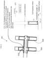
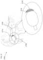
- FIG. 7illustrates an insertion device 700 with at least one inflation tube (e.g., 740 , 750 ) to seal a channel (e.g., 730 ) that the insertion device is inserted in accordance with at least one exemplary embodiment.
- a body 770can have grooves for inflation tube inserts.
- An optional wax shield 710can be operatively attached (glued, bonded, thermal bonded, ultrasonic bonding, molded) to the body 770 .
- the wax shield 710can have a portion 720 that is a flexible membrane that is acoustically transparent (for example the acoustic energy 780 A to 780 B, via acoustic port 760 ).
- the flexible membrane 720can be a material that has a low permeability to cerumen gas and is acoustically transparent. Although it can be impermeable to cerumen gas and then stressed to a design % to facilitate acoustic transparency but serve as a shield to prevent cerumen gas from entering the acoustic channel.
- FIG. 8illustrates an insertion device 800 with at least one inflation tube (e.g., 820 , 830 ) to seal (e.g., reduction of acoustic energy 880 to energy 890 to energy 870 ) a channel (e.g., 810 ) that the insertion device 800 is inserted in accordance with at least one exemplary embodiment.
- one side of the insertion device 800can be partially acoustically isolated from the opposite side.
- the insertion body 840can have one side in an ear canal where a receiver emits acoustic energy toward the ear canal, where the receiver (e.g., due to the inflation tubes 820 , 830 ) can be acoustically isolated by a microphone on the side of the insertion device 800 on the ear aperture side of the insertion device 800 .
- acoustic isolationaids the reduction of feedback between the microphone and the receiver, for example in a hearing aid.
- an acoustic signal from the aperture sideproximate to energy 880
- can be acoustically reduced to energy 890 and to energy 870while passing the inflation tubes 820 and 830 which press against the channel 810 , at positions 850 and 860 respectively.
- FIGS. 9 A- 9 Hillustrate a method for designing a hearing aid configured to accommodate an inflation tube.
- any type of hearing aide.g., Completely In Canal, CIC
- FIG. 9 Aillustrates an ear mold 900 , which can be 3-D scanned and placed into a computer model as a virtual representation 910 of the ear mold ( FIG. 9 B ).
- the ear moldcan be via a silicon impression material or optically scanned.
- the virtual representation 910can be further reduced using software tools (e.g., a person (e.g., designer) can utilize a mouse to click on portions of the virtual representation 910 in a software CAD system) to create a reduced version 920 ( FIG. 9 C ) inside the virtual representation 910 , where the virtual representation can be used as a virtual ear canal.
- a software toolcan be constructed so that a given distance normal to the virtual representation can be constructed forming the reduced version 920 .
- the reduced version 920can form the basis of a body of an earpiece such as a hearing aid.
- a designercan select (e.g., via clicking the button on a mouse) portions of the reduced version 920 that are further removed to accommodate further structures (e.g., male connecting portion 930 to a wax shield 940 ( FIG. 9 E ), acoustic channels 931 to a receiver 932 ) in a modified version 925 ( FIG. 9 D ).
- the designercan further select inflation grooves (e.g., 950 , 960 ) and support inflation channels (e.g., 970 ), which can then be removed (e.g., manually indicating the section to remove or programmed to remove a set amount for standardized inflation tubes) (e.g., grooves removed 955 , 965 and 975 from the computer model) from the modified version 925 forming a grooved model 927 .
- the grooved model 927can then be fabricated (e.g., molded, CNC, SLA) to form the body of the hearing aid and inflation tubes and inflation lines attached onto the body of the hearing aid.
- a pumping mechanism 987e.g., manual, electrolysis
- FIGS. 9 I through 9 Killustrate several versions of earpieces that can use the inflation management system whose fabrication is illustrated in FIGS. 9 A- 9 H .
- a receiveri.e., a speaker
- a microphone 951coupled to acoustic channel 937
- Both the receiver 932 and the microphone 951can be operatively attached to a circuit 941 .
- the circuit 941can include a processor chip or can be a circuit that is configured to modify (e.g., amplify) the acoustic signal measured by the microphone 951 and emit the modified acoustic signal from the receiver 932 .
- the microphone 951can pick up the ambient environment and emit it via the receiver 932 amplified, enhancing a user's hearing.
- many microphones and receiverscan be used herein in the exemplary embodiments described (e.g., Knowles TWFK receivers, FG microphones) and the discussion herein is not meant to limit which microphone or receiver is used in the exemplary embodiments.
- FIG. 9 Jillustrates the use of a microphone 952 to pick up acoustic signals from the same region that receiver 932 emits them.
- an earpiececan be configured to use a microphone 952 to pick up voice through the head, and operatively connected to a circuit 941 , transmit the picked up voice remotely.
- An inflation systemcan enhance the quality of the voice pickup by reducing the occlusion effect, resulting in a clearer voice quality (e.g., one with reduced resonance in the closed region near the ear drum).
- FIG. 9 Killustrates the use of two microphones (e.g., microphones 952 and 951 ), where one microphone ( 951 ) monitors the ambient environment and the second microphone ( 952 ) the environment in the ear.
- Such a configurationcan be used for communication in noisy environments, where the inflation system provides mitigation of the occlusion effect, enhancing voice pickup by microphone 952 , which can then be sent via communication pathways (e.g., CDMA, RF) to another party.
- communication pathwayse.g., CDMA, RF
- circuit 941can be a DSP chip, a simple circuit board with preamps, or other earpiece related circuit that can modify any received acoustic signal.
- FIG. 9 Lillustrates an example of a shell 971 that can be CAD reduced from virtual representation 910 .
- the shellcan contain the contents of a hearing aid.
- the shellcan be sent to an SLA machine for fabrication or other manufacturing system that can generate the shell from the CAD drawing.
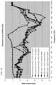
- FIGS. 10 and 11illustrate the effect of insertion depth on insertion loss for a commercial product versus an inflation system in accordance with at least one exemplary embodiment.
- a commercial hearing protection device's effectivenessis strongly determinant upon the insertion depth.
- Many devicese.g., foam plugs
- IMS, balloon, catheterinflation management system
- FIG. 11illustrates a commercial foam plug (Commercial Product 2), compared to an inflation management system (IMS) type 1, note the much smaller spread as a function of frequency of the IMS system as a function of insertion depth compared with the commercial product.
- IMSinflation management system
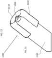
- FIG. 12illustrates a cut away of a wax shield 1200 in accordance with at least one exemplary embodiment.
- a catheter 1240 with channels 1230e.g. acoustic channel
- channels 1230e.g. acoustic channel
- a mediume.g., earwax
- a shielde.g., waxshield
- the waxshieldcan include a body 1220 and a membrane portion 1210 . If acoustic signals are played from the acoustic channel 1230 , they can be damped by the membrane portion 1210 .
- the acoustic transparency of the membranecan be modified based upon material, thickness, and stress of the membrane.
- the membraneis made to have a low permeability to ear wax both in its liquid, solid, and gaseous form.
- the diameter of the membraneis larger than the cross sectional diameter of the channel 1230 .
- the waxshieldcan be operatively attached to the catheter 1240 (e.g., bonded, molded, glued, adhered, thermal bonded, ultrasonic welded).
- the waxshieldis stressed to a design elongation, where the elongation is chosen to maximize acoustic transmission through the membrane.
- a highly stressed membranee.g., 100% or more
- the membranecan become more acoustically transparent than even a nonstressed membrane.
- the membranecan be fabricated from materials similar to the balloons, or even air permeable materials like silicon, or rubber.
- FIG. 13illustrates the attachment of the waxshield to an acoustic device in accordance with at least one exemplary embodiment.
- a stop 1325is built into the waxshield so that an offset volume of V1 is created when the waxshield is attached.
- a catheter 1300 having an acoustic channel 1340can be attached (A) to the waxshield, for example via bonding (e.g., glue, adhesive, UV cured, molded together).
- the waxshieldcan have a sleeve 1310 , a stop 1325 , and a stressed membrane 1320 .
- the stressed membraneis placed directly over the port of the acoustic channel 1340 , without an offset volume V1.
- FIG. 14illustrates a method of stressing a membrane 1320 before attachment to a waxshield in accordance with at least one exemplary embodiment.
- an initial membrane 1400can be elongated 1410 prior to attachment to the waxshield body.
- the optimum elongation %is dependent on membrane material, membrane unstressed thickness, and area extent. Note that for a given thickness the flexibility of the membrane or the ability to propagate acoustical signals can vary as the stress is increased since as the membrane is stressed the thickness decreases. Thus if the thickness effects are larger than the damping effect due to membrane stress, the membrane can be more flexible and transmit acoustical signals better than when unstressed.
- the unstressed membranehas a volume V.
- the % of strain increase(referred here as elongation) can be expressed as the change in a dimension (e.g., length, thickness), area change (e.g., A1/A), and volume change in the effective region (the areal portion used across an acoustic port, e.g., the area covering 1320 ).
- FIG. 15illustrates acoustic transparency of a waxshield in accordance with the stressed state of a membrane built into a waxshield. Note that features in the initial acoustic source 1510 are repeated in some of the stressed membrane plots (e.g., 1560 ). What is illustrated in FIG. 15 as the initial acoustic source 1510 is the spectrum of the initial source as measured by a microphone at a given location without a membrane in place. Then various membranes that have been stressed to various values are inserted between the source signal (e.g., receiver) and the measuring microphone. 1540 illustrates the spectrum passing an unstressed membrane. Note that an unstressed membrane 1540 can have a larger gap (i.e.
- a wax shield membrane 1200can be placed above an acoustic port. There can also be an offset distance between the acoustic port.
- the membrane areato be larger than the acoustic port exit area and thus facilitates acoustic sensitivity by allowing the membrane surface to vibrate more freely if the acoustic exit area is small. For example since the vibration stroke of the membrane communicates acoustic pressure a smaller confined area limits the modes of vibration's amplitudes, effecting the amplitude that can be communicated as a function of frequency.
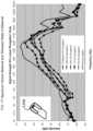
- FIG. 16illustrates acoustic transparency of various unstressed materials ( 1610 , 1620 , 1630 , 1640 , and 1650 ) that can be used for the membrane in the waxshield.
- the material showing little deviation from 1600is the material with the best acoustical transparency.
- FIG. 17illustrates acoustic transparency of various stressed materials that can be used for the membrane in the waxshield.
- FIG. 17illustrates the same material as illustrated in FIG. 16 for a particular elongation % (X).
- FIG. 17illustrates a method of choosing between a series of materials, by choosing the material whose frequency spectrum is closest to the source signal. For example one can choose the spectrum with best least squares fit to the source signal.
- FIG. 18illustrates acoustic transparency of one material at various stresses for a closed cavity experiment, illustrating that various stresses can be acoustically more transparent than other stress values. Note that the stress can have an elongation value from 0% up to 2000%. As clearly illustrated various levels of elongation have higher values of acoustic transmission than an unstressed state. Thus once a material is selected, FIG. 18 illustrates a method of choosing the optimum stress for the material. For example an elongation X % would be chosen over (100+X) % since an elongation of X % provides more acoustical energy transmission than in the unstressed state or (100+X) % state.
- FIG. 19illustrates acoustic transparency of one material at various stresses for an open cavity experiment, illustrating that various stresses can be acoustically more transparent than other stress values. Note that the stress can have an elongation value from 0% up to 2000%. As clearly illustrated various levels of elongation have higher values of acoustic transmission than an unstressed state. Thus once a material is selected, FIG. 19 illustrates a method of choosing the optimum stress for the material. For example an elongation X % would be chosen over (100+X) % since an elongation of X % provides more acoustical energy transmission than in the unstressed state or (100+X) % state.
- FIGS. 20 - 23illustrate non-limiting examples of earpieces 2000 in accordance with at least one exemplary embodiment.
- a housing 2050e.g., housing electrical components such as Knowles FG, TO microphones 2110 and TWFK receivers 2120 (for example coupled to circuit board 2140 )
- a grip 2040which interfaces, for example via body portion 2030 , the electrical components to a multilumen stent 2010 that can have multiple acoustic channels (e.g., 2220 and 2230 ).
- the stent 2010can have attached an inflatable element 2020 .
- an additional ambient environment microphone 2130e.g., a MEMs microphone
- FIG. 23illustrates another exemplary embodiment, where an elastic membrane 2310 can provide a restoring force B2, which causes expansion B1 of the inflatable element.
- the earpieces illustrated in FIGS. 20 - 23can have wax shields at the end of the stent 2010 as described previously.
- FIGS. 24 - 27illustrate further non-limiting examples of ear wax mitigation.
- FIGS. 24 and 26illustrate a forced air method of clearing the acoustic channels
- FIG. 25illustrates filaments to keep ear wax away from acoustic channels
- FIG. 27illustrates a condensing strip to condense the ear wax at a controlled location away from the acoustic ports.
- FIGS. 24 and 26illustrate a forced air method of clearing acoustic channels.
- a user controlled push button bladdercan be connected to an earpiece so that forced air 2460 travels down a pneumatic channel which can be made a one way flow via one-way pressure valves (e.g., 2450 , 2450 A, 24508 , 2450 C, and 2450 D).
- the pressure of the forced flow 2460can push air through acoustic channels 2430 and 2440 , which can be respectively coupled to transducers 2410 and 2420 .
- Ear wax 2470 that has entered one of the acoustic channels(e.g., 2430 ) can be removed 2490 via the forced air.
- 26illustrates a configuration where two one way valves (e.g., 2450 C and 2450 D) allow a built up of pressure in the acoustic channels (e.g., 2430 and 2440 ) forcing the ear wax 2470 from the obstructed channel when the pressure builds up to the point where the force on the ear wax 2470 is such to dislodge it from the acoustic channel (e.g., 2430 ).
- 2400can be a stent with the multilumen channels acting as acoustic channels 2430 and 2440 .
- valves 2450 , 2450 A, 24508 , 2450 C, and 2450 Dcan be different types of valves, for example 2450 , 2450 C and 2450 D can be duckbill valves, while 2450 A and 24508 can be unique membrane one way valves.
- FIG. 25illustrates a multilumen stent 2500 , where two of the lumens are acoustic channels 2430 and 2440 .
- Optional one way valvese.g., 2450 A, 24508
- Valves 2450 A and 24508can be very thin membrane valves that essentially allow a pressure wave to pass the valve in essentially one direction.
- a one way membrane acoustic valvecan be a membrane composed of tiny (e.g., ⁇ 1 mm OD) conical structures with openings that are closed with no pressure difference between the sides of the cone.
- the filaments 2580can be used independent of any valves in at least one exemplary embodiment and can be composed of any material that will offset earwax 2470 away from the acoustic channel opening (e.g., Teflon, silicon, low durometer plastics and polymers).
- FIG. 27illustrates at least one further ear wax mitigation device 2700 in accordance with at least one exemplary embodiment.
- the device 2700can include in general an inflation element 2730 , a low ear wax gas condensing portion 2720 (e.g., stent, portion of tip) and a larger ear wax condensing portion 2710 (i.e., higher condensing when compared to 2720 ).
- the air at the interfacedecreases in temperature condensing the water as droplets until the new saturation level for the new temperature is reached.
- removing the ear wax gas from the environmentfacilitates keeping it out of acoustic channels.
- the acoustic channelscan be kept near or higher than body temperatures (e.g., material made of a good heat conductive material so that the earpiece low condensing regions achieve body temperature quickly), then isolated regions of cooler temperatures can condense out a portion of the ear wax gas in the closed region between an occluding earpiece and the tympanic membrane.
- the balloon and stentare made of a good thermal conductive polymer
- a light colore.g., to keep the temperature of the strip down, the light color reflects most incident light
- the ear wax gaswill have a tendency to condense on the light strip of non conductive material, removing the ear wax gas concentration from the air. If the light colored strip is made to be easily cleanable then a user can clean the earpiece themselves.
- At least one exemplary embodimentis directed to a method of reducing earwax accumulation of acoustic cannels comprising: inserting an offset volume from at least one acoustic channel, where the offset volume has at least one dimension larger than the diameter of the acoustic channel (e.g., if the acoustic channel has an inner diameter of 1 mm the offset volume has an inner diameter of about 2.5 mm); enclosing the offset volume in an enclosure (e.g., molding the waxshield as one piece with an offset ridge and membrane, where the waxshield can be attached), where the enclosure has an opening to the at least one acoustic channel (e.g., opening in the waxshield can be fit over an acoustic channel to allow acoustic energy into the offset volume); and making at least a portion of the enclosure from a flexible, low air permeable material.
- an enclosuree.g., molding the waxshield as one piece with an offset ridge and membrane, where
- At least one exemplary embodimentis directed to designing a hearing aid that has an inflation system attached as illustrated and discussed with respect to FIGS. 9 A- 9 H .
- At least one exemplary embodimentis directed to a method of hearing aid fabrication comprising: scanning an ear mold and representing the ear mold as an ear mold computer simulation; trimming the ear mold computer simulation using software tools to generate a hearing aid simulated body; identifying at least one inflation groove on the hearing aid simulated body using software tools; and generating a modified hearing aid body simulation with the groove; identifying at least one inflation channel on the hearing aid simulated body using software tools; sending the modified hearing aid body simulation to an SLA machine and fabricating a hearing aid body from the SLA machine; attaching an inflation system into the at least one inflation groove; attaching an inflation line into the inflation channel, and attaching an inflation pump to an end of the inflation line.
- At least one exemplary embodimentis directed to a hearing aid comprising: a microphone (e.g., Knowles TO series), a receiver (e.g., Knowles TWFK version); an inflation tube (e.g., inflation hoops); and an inflating device (e.g., manual and/or electrolysis), where the microphone samples an ambient environment and replays at least a portion of the ambient environment by the receiver, where the inflation tube is configured to expand to seal a channel in which the hearing aid is inserted, where any feedback is reduced by the expanding.
- a microphonee.g., Knowles TO series
- a receivere.g., Knowles TWFK version
- an inflation tubee.g., inflation hoops
- an inflating devicee.g., manual and/or electrolysis
- At least one exemplary embodimentis directed to a wax shield comprising: a body; a stressed flexible membrane; and where the membrane is attached to the body forming a wax shield, and where the wax shield is configured to be attached to a device with an acoustic channel, where the device is configured to be inserted into an ear canal; and additionally where the wax shield includes a membrane that has a reduced permeability to cerumen gas.
- At least one exemplary embodimentis directed to a feedback reduction system comprising: an acoustic device (e.g., earpiece, hearing aid), which includes a receiver (speaker) and a microphone; and an inflation system attached to the acoustic device, where when inflated the inflation system acoustically isolates the microphone from the speaker reducing feedback from the microphone to the speaker.
- an acoustic devicee.g., earpiece, hearing aid
- an inflation systemattached to the acoustic device, where when inflated the inflation system acoustically isolates the microphone from the speaker reducing feedback from the microphone to the speaker.
- At least one exemplary embodimentis directed to an increased stability mechanism comprising: an inflation system attached to an in-ear device (e.g., earpiece).
- an in-ear devicee.g., earpiece
- the inflation systemWhen the inflation system is inflated the earpiece becomes more stable (e.g., more resistant to torque, and/or pull). Additionally during jaw motion the inflation system can react by compressing or expanding when the ear canal dimension changes.
Landscapes
- Engineering & Computer Science (AREA)
- Manufacturing & Machinery (AREA)
- Chemical & Material Sciences (AREA)
- Materials Engineering (AREA)
- General Health & Medical Sciences (AREA)
- Otolaryngology (AREA)
- Physics & Mathematics (AREA)
- Acoustics & Sound (AREA)
- Signal Processing (AREA)
- Neurosurgery (AREA)
- Health & Medical Sciences (AREA)
- Headphones And Earphones (AREA)
- Prostheses (AREA)
Abstract
Description
Claims (11)
Priority Applications (2)
| Application Number | Priority Date | Filing Date | Title |
|---|---|---|---|
| US18/197,246US11956600B2 (en) | 2008-10-15 | 2023-05-15 | Device and method to reduce ear wax clogging of acoustic ports, hearing aid sealing system, and feedback reduction system |
| US18/397,365US12212936B2 (en) | 2008-10-15 | 2023-12-27 | Device and method to reduce ear wax clogging of acoustic ports, hearing aid sealing system, and feedback reduction system |
Applications Claiming Priority (10)
| Application Number | Priority Date | Filing Date | Title |
|---|---|---|---|
| US10576108P | 2008-10-15 | 2008-10-15 | |
| US17601309P | 2009-05-06 | 2009-05-06 | |
| US12/579,673US8554350B2 (en) | 2008-10-15 | 2009-10-15 | Device and method to reduce ear wax clogging of acoustic ports, hearing aid sealing system, and feedback reduction system |
| US14/017,711US10715940B2 (en) | 2008-10-15 | 2013-09-04 | Device and method to reduce ear wax clogging of acoustic ports, hearing aid sealing sytem, and feedback reduction system |
| US16/874,844US10897678B2 (en) | 2008-10-15 | 2020-05-15 | Device and method to reduce ear wax clogging of acoustic ports, hearing aid sealing system, and feedback reduction system |
| US16/945,798US10979831B2 (en) | 2008-10-15 | 2020-07-31 | Device and method to reduce ear wax clogging of acoustic ports, hearing aid sealing system, and feedback reduction system |
| US17/092,221US11223918B2 (en) | 2008-10-15 | 2020-11-07 | Device and method to reduce ear wax clogging of acoustic ports, hearing aid sealing system, and feedback reduction system |
| US17/492,793US11638109B2 (en) | 2008-10-15 | 2021-10-04 | Device and method to reduce ear wax clogging of acoustic ports, hearing aid sealing system, and feedback reduction system |
| US17/989,677US11700495B2 (en) | 2008-10-15 | 2022-11-17 | Device and method to reduce ear wax clogging of acoustic ports, hearing aid sealing system, and feedback reduction system |
| US18/197,246US11956600B2 (en) | 2008-10-15 | 2023-05-15 | Device and method to reduce ear wax clogging of acoustic ports, hearing aid sealing system, and feedback reduction system |
Related Parent Applications (1)
| Application Number | Title | Priority Date | Filing Date |
|---|---|---|---|
| US17/989,677ContinuationUS11700495B2 (en) | 2008-10-15 | 2022-11-17 | Device and method to reduce ear wax clogging of acoustic ports, hearing aid sealing system, and feedback reduction system |
Related Child Applications (1)
| Application Number | Title | Priority Date | Filing Date |
|---|---|---|---|
| US18/397,365ContinuationUS12212936B2 (en) | 2008-10-15 | 2023-12-27 | Device and method to reduce ear wax clogging of acoustic ports, hearing aid sealing system, and feedback reduction system |
Publications (2)
| Publication Number | Publication Date |
|---|---|
| US20230292067A1 US20230292067A1 (en) | 2023-09-14 |
| US11956600B2true US11956600B2 (en) | 2024-04-09 |
Family
ID=42319119
Family Applications (9)
| Application Number | Title | Priority Date | Filing Date |
|---|---|---|---|
| US12/579,673Active2032-04-11US8554350B2 (en) | 2008-10-15 | 2009-10-15 | Device and method to reduce ear wax clogging of acoustic ports, hearing aid sealing system, and feedback reduction system |
| US14/017,711Active2030-07-03US10715940B2 (en) | 2008-10-15 | 2013-09-04 | Device and method to reduce ear wax clogging of acoustic ports, hearing aid sealing sytem, and feedback reduction system |
| US16/874,844ActiveUS10897678B2 (en) | 2008-10-15 | 2020-05-15 | Device and method to reduce ear wax clogging of acoustic ports, hearing aid sealing system, and feedback reduction system |
| US16/945,798ActiveUS10979831B2 (en) | 2008-10-15 | 2020-07-31 | Device and method to reduce ear wax clogging of acoustic ports, hearing aid sealing system, and feedback reduction system |
| US17/092,221ActiveUS11223918B2 (en) | 2008-10-15 | 2020-11-07 | Device and method to reduce ear wax clogging of acoustic ports, hearing aid sealing system, and feedback reduction system |
| US17/492,793ActiveUS11638109B2 (en) | 2008-10-15 | 2021-10-04 | Device and method to reduce ear wax clogging of acoustic ports, hearing aid sealing system, and feedback reduction system |
| US17/989,677ActiveUS11700495B2 (en) | 2008-10-15 | 2022-11-17 | Device and method to reduce ear wax clogging of acoustic ports, hearing aid sealing system, and feedback reduction system |
| US18/197,246ActiveUS11956600B2 (en) | 2008-10-15 | 2023-05-15 | Device and method to reduce ear wax clogging of acoustic ports, hearing aid sealing system, and feedback reduction system |
| US18/397,365ActiveUS12212936B2 (en) | 2008-10-15 | 2023-12-27 | Device and method to reduce ear wax clogging of acoustic ports, hearing aid sealing system, and feedback reduction system |
Family Applications Before (7)
| Application Number | Title | Priority Date | Filing Date |
|---|---|---|---|
| US12/579,673Active2032-04-11US8554350B2 (en) | 2008-10-15 | 2009-10-15 | Device and method to reduce ear wax clogging of acoustic ports, hearing aid sealing system, and feedback reduction system |
| US14/017,711Active2030-07-03US10715940B2 (en) | 2008-10-15 | 2013-09-04 | Device and method to reduce ear wax clogging of acoustic ports, hearing aid sealing sytem, and feedback reduction system |
| US16/874,844ActiveUS10897678B2 (en) | 2008-10-15 | 2020-05-15 | Device and method to reduce ear wax clogging of acoustic ports, hearing aid sealing system, and feedback reduction system |
| US16/945,798ActiveUS10979831B2 (en) | 2008-10-15 | 2020-07-31 | Device and method to reduce ear wax clogging of acoustic ports, hearing aid sealing system, and feedback reduction system |
| US17/092,221ActiveUS11223918B2 (en) | 2008-10-15 | 2020-11-07 | Device and method to reduce ear wax clogging of acoustic ports, hearing aid sealing system, and feedback reduction system |
| US17/492,793ActiveUS11638109B2 (en) | 2008-10-15 | 2021-10-04 | Device and method to reduce ear wax clogging of acoustic ports, hearing aid sealing system, and feedback reduction system |
| US17/989,677ActiveUS11700495B2 (en) | 2008-10-15 | 2022-11-17 | Device and method to reduce ear wax clogging of acoustic ports, hearing aid sealing system, and feedback reduction system |
Family Applications After (1)
| Application Number | Title | Priority Date | Filing Date |
|---|---|---|---|
| US18/397,365ActiveUS12212936B2 (en) | 2008-10-15 | 2023-12-27 | Device and method to reduce ear wax clogging of acoustic ports, hearing aid sealing system, and feedback reduction system |
Country Status (1)
| Country | Link |
|---|---|
| US (9) | US8554350B2 (en) |
Families Citing this family (58)
| Publication number | Priority date | Publication date | Assignee | Title |
|---|---|---|---|---|
| US8401212B2 (en) | 2007-10-12 | 2013-03-19 | Earlens Corporation | Multifunction system and method for integrated hearing and communication with noise cancellation and feedback management |
| US7668325B2 (en) | 2005-05-03 | 2010-02-23 | Earlens Corporation | Hearing system having an open chamber for housing components and reducing the occlusion effect |
| US11217237B2 (en) | 2008-04-14 | 2022-01-04 | Staton Techiya, Llc | Method and device for voice operated control |
| US10009677B2 (en) | 2007-07-09 | 2018-06-26 | Staton Techiya, Llc | Methods and mechanisms for inflation |
| US11291456B2 (en) | 2007-07-12 | 2022-04-05 | Staton Techiya, Llc | Expandable sealing devices and methods |
| WO2009155358A1 (en) | 2008-06-17 | 2009-12-23 | Earlens Corporation | Optical electro-mechanical hearing devices with separate power and signal components |
| BRPI0919266A2 (en) | 2008-09-22 | 2017-05-30 | SoundBeam LLC | device and method for transmitting an audio signal to a user, methods for manufacturing a device for transmitting an audio signal to the user, and for providing an audio device for a user, and device and method for transmitting a sound for a user. user having a tympanic membrane |
| US9129291B2 (en) | 2008-09-22 | 2015-09-08 | Personics Holdings, Llc | Personalized sound management and method |
| US8992710B2 (en) | 2008-10-10 | 2015-03-31 | Personics Holdings, LLC. | Inverted balloon system and inflation management system |
| US8554350B2 (en) | 2008-10-15 | 2013-10-08 | Personics Holdings Inc. | Device and method to reduce ear wax clogging of acoustic ports, hearing aid sealing system, and feedback reduction system |
| US8550206B2 (en) | 2011-05-31 | 2013-10-08 | Virginia Tech Intellectual Properties, Inc. | Method and structure for achieving spectrum-tunable and uniform attenuation |
| EP2586216A1 (en) | 2010-06-26 | 2013-05-01 | Personics Holdings, Inc. | Method and devices for occluding an ear canal having a predetermined filter characteristic |
| WO2012019636A1 (en)* | 2010-08-09 | 2012-02-16 | Siemens Medical Instruments Pte. Ltd. | Method for operating a hearing aid and corresponding hearing aid |
| EP2656639B1 (en) | 2010-12-20 | 2020-05-13 | Earlens Corporation | Anatomically customized ear canal hearing apparatus |
| CA2831678A1 (en) | 2011-03-28 | 2012-10-04 | Ambientz | Methods and systems for searching utilizing acoustical context |
| US10362381B2 (en) | 2011-06-01 | 2019-07-23 | Staton Techiya, Llc | Methods and devices for radio frequency (RF) mitigation proximate the ear |
| WO2013016589A1 (en)* | 2011-07-26 | 2013-01-31 | Neukermans Armand P | Hearing aid for non-contact eardrum pressure activation |
| WO2014039026A1 (en) | 2012-09-04 | 2014-03-13 | Personics Holdings, Inc. | Occlusion device capable of occluding an ear canal |
| US10043535B2 (en) | 2013-01-15 | 2018-08-07 | Staton Techiya, Llc | Method and device for spectral expansion for an audio signal |
| US10045133B2 (en) | 2013-03-15 | 2018-08-07 | Natan Bauman | Variable sound attenuator with hearing aid |
| US9333116B2 (en) | 2013-03-15 | 2016-05-10 | Natan Bauman | Variable sound attenuator |
| US9521480B2 (en) | 2013-07-31 | 2016-12-13 | Natan Bauman | Variable noise attenuator with adjustable attenuation |
| US10043534B2 (en) | 2013-12-23 | 2018-08-07 | Staton Techiya, Llc | Method and device for spectral expansion for an audio signal |
| US10034103B2 (en) | 2014-03-18 | 2018-07-24 | Earlens Corporation | High fidelity and reduced feedback contact hearing apparatus and methods |
| WO2015183725A1 (en)* | 2014-05-27 | 2015-12-03 | Sophono, Inc. | Systems, devices, components and methods for reducing feedback between microphones and baseplates in bone conduction magnetic hearing devices |
| CA2933318C (en) | 2014-05-30 | 2017-03-21 | Revol Technologies Inc. | A customizable ear insert |
| DK3169396T3 (en) | 2014-07-14 | 2021-06-28 | Earlens Corp | Sliding bias and peak limitation for optical hearing aids |
| US10163453B2 (en) | 2014-10-24 | 2018-12-25 | Staton Techiya, Llc | Robust voice activity detector system for use with an earphone |
| US9924276B2 (en) | 2014-11-26 | 2018-03-20 | Earlens Corporation | Adjustable venting for hearing instruments |
| US20210322223A1 (en)* | 2014-12-01 | 2021-10-21 | Staton Techiya Llc | Fixation methods for devices in tubular structures |
| US10413240B2 (en) | 2014-12-10 | 2019-09-17 | Staton Techiya, Llc | Membrane and balloon systems and designs for conduits |
| US10709388B2 (en) | 2015-05-08 | 2020-07-14 | Staton Techiya, Llc | Biometric, physiological or environmental monitoring using a closed chamber |
| US10418016B2 (en) | 2015-05-29 | 2019-09-17 | Staton Techiya, Llc | Methods and devices for attenuating sound in a conduit or chamber |
| EP3139636B1 (en) | 2015-09-07 | 2019-10-16 | Oticon A/s | A hearing device comprising a feedback cancellation system based on signal energy relocation |
| US11477560B2 (en) | 2015-09-11 | 2022-10-18 | Hear Llc | Earplugs, earphones, and eartips |
| DK3888564T3 (en) | 2015-10-02 | 2025-07-14 | Earlens Corp | DEVICE FOR CUSTOMIZED DELIVERY OF MEDICINE IN THE EAR CANAL |
| US10937407B2 (en) | 2015-10-26 | 2021-03-02 | Staton Techiya, Llc | Biometric, physiological or environmental monitoring using a closed chamber |
| US11350226B2 (en) | 2015-12-30 | 2022-05-31 | Earlens Corporation | Charging protocol for rechargeable hearing systems |
| US10178483B2 (en) | 2015-12-30 | 2019-01-08 | Earlens Corporation | Light based hearing systems, apparatus, and methods |
| US10492010B2 (en) | 2015-12-30 | 2019-11-26 | Earlens Corporations | Damping in contact hearing systems |
| US10764226B2 (en) | 2016-01-15 | 2020-09-01 | Staton Techiya, Llc | Message delivery and presentation methods, systems and devices using receptivity |
| US10616693B2 (en) | 2016-01-22 | 2020-04-07 | Staton Techiya Llc | System and method for efficiency among devices |
| TWM526264U (en)* | 2016-03-21 | 2016-07-21 | Taiwan Microloops Corp | Liquid-cooled heat dissipation device and heat dissipation structure thereof |
| EP3510796A4 (en) | 2016-09-09 | 2020-04-29 | Earlens Corporation | Contact hearing systems, apparatus and methods |
| WO2018093733A1 (en) | 2016-11-15 | 2018-05-24 | Earlens Corporation | Improved impression procedure |
| US10250964B2 (en) | 2017-05-10 | 2019-04-02 | Logitech Europe S.A. | Apparatus and method of forming a custom earpiece |
| US20180338195A1 (en)* | 2017-05-16 | 2018-11-22 | The Charles Stark Draper Laboratory, Inc. | Jamming Grip For Earbud Retention |
| WO2018227125A2 (en)* | 2017-06-09 | 2018-12-13 | Zipline Health, Inc. | Stabilization of ear devices |
| WO2019135184A1 (en) | 2018-01-03 | 2019-07-11 | Logitech Europe S.A. | Apparatus and method of forming a custom earpiece |
| WO2019173470A1 (en) | 2018-03-07 | 2019-09-12 | Earlens Corporation | Contact hearing device and retention structure materials |
| WO2019199680A1 (en) | 2018-04-09 | 2019-10-17 | Earlens Corporation | Dynamic filter |
| US12267651B2 (en)* | 2020-03-02 | 2025-04-01 | Widex A/S | Handling tool for hearing aid |
| US20220054318A1 (en)* | 2020-08-21 | 2022-02-24 | Giner Life Sciences, Inc. | Wearable system and method for modification of fluid environment of an ear |
| US11422392B2 (en)* | 2020-10-05 | 2022-08-23 | Meta Platforms Technologies, Llc | Ultraminiature dynamic speaker for a fully in-ear monitor |
| US11425515B1 (en) | 2021-03-16 | 2022-08-23 | Iyo Inc. | Ear-mount able listening device with baffled seal |
| US12233264B2 (en) | 2021-12-07 | 2025-02-25 | Starkey Laboratories, Inc. | Hearing device and method of using same |
| KR102553394B1 (en) | 2022-11-29 | 2023-07-10 | 주식회사 아즈라 | Dual Structure TPE Eartips Having Wax Guard |
| CN116744210A (en)* | 2023-05-22 | 2023-09-12 | 宝德(东莞)科技有限公司 | Method for making acoustic shell with shielding effect |
Citations (48)
| Publication number | Priority date | Publication date | Assignee | Title |
|---|---|---|---|---|
| US2803308A (en) | 1955-08-11 | 1957-08-20 | Dictaphone Corp | Ear-tip for stethoscope type headset |
| FR2560520A1 (en) | 1984-03-02 | 1985-09-06 | Beltone Electronics Corp | ANTI-CERUMEN BARRIER SYSTEM FOR INDIVIDUAL EARPHONES |
| US6094494A (en) | 1998-08-13 | 2000-07-25 | Haroldson; Olaf | Hearing aid device and method for providing an improved fit and reduced feedback |
| US6513621B1 (en) | 2000-06-13 | 2003-02-04 | Doctors Research Group | Method of producing and making use of ear tips having a filled airtight chamber |
| US6671381B1 (en)* | 1993-11-23 | 2003-12-30 | Gabriele Lux-Wellenhof | Sleeve for hearing aids, and a method and apparatus for testing hearing |
| US20040258263A1 (en) | 2003-04-03 | 2004-12-23 | Sonic Innovations, Inc., A Delaware Corporation | Balloon-expandable hearing device fitting system and self-expanding hearing device |
| EP1519625A2 (en)* | 2003-09-11 | 2005-03-30 | Starkey Laboratories, Inc. | External ear canal voice detection |
| WO2006037156A1 (en)* | 2004-10-01 | 2006-04-13 | Hear Works Pty Ltd | Acoustically transparent occlusion reduction system and method |
| US7130437B2 (en) | 2000-06-29 | 2006-10-31 | Beltone Electronics Corporation | Compressible hearing aid |
| US7227968B2 (en)* | 2001-06-25 | 2007-06-05 | Sonion Roskilde A/S | Expandsible Receiver Module |
| EP1841283A2 (en) | 2006-02-21 | 2007-10-03 | Siemens Audiologische Technik GmbH | In the ear hearing aid with a ventilation duct worn |
| US20110079227A1 (en) | 2009-10-05 | 2011-04-07 | Turcot Michael C | Pressure regulation mechanism for inflatable in-ear device |
| US8047207B2 (en) | 2007-08-22 | 2011-11-01 | Personics Holdings Inc. | Orifice insertion devices and methods |
| US8186478B1 (en) | 2011-01-18 | 2012-05-29 | Rufus Leroy Grason | Multi-functional dual filtered hearing protector |
| US8229128B2 (en) | 2008-02-20 | 2012-07-24 | Personics Holdings Inc. | Device for acoustic sealing |
| US8251925B2 (en) | 2007-12-31 | 2012-08-28 | Personics Holdings Inc. | Device and method for radial pressure determination |
| US8391534B2 (en) | 2008-07-23 | 2013-03-05 | Asius Technologies, Llc | Inflatable ear device |
| US20130136285A1 (en) | 2010-07-13 | 2013-05-30 | Siemens Medical Instruments Pte. Ltd. | Inflatable ear piece with pressure relief valve |
| US8522916B2 (en) | 2008-06-26 | 2013-09-03 | Personics Holdings Inc. | Occlusion effect mitigation and sound isolation device for orifice inserted systems |
| US20130251172A1 (en) | 2012-03-21 | 2013-09-26 | Jack Mosseri | Inflatable Ear Buds |
| US8548181B2 (en) | 2010-07-13 | 2013-10-01 | Siemens Medical Instruments Pte. Ltd. | Inflatable ear mold connection system |
| US8631801B2 (en) | 2008-07-06 | 2014-01-21 | Personics Holdings, Inc | Pressure regulating systems for expandable insertion devices |
| US8649540B2 (en) | 2009-10-30 | 2014-02-11 | Etymotic Research, Inc. | Electronic earplug |
| DE102012221233A1 (en) | 2012-09-12 | 2014-03-13 | Siemens Medical Instruments Pte. Ltd. | Coupling hearing device for a hearing device |
| US8678011B2 (en) | 2007-07-12 | 2014-03-25 | Personics Holdings, Inc. | Expandable earpiece sealing devices and methods |
| DE102013203334B3 (en) | 2013-02-28 | 2014-05-22 | Siemens Medical Instruments Pte. Ltd. | Valve device, hearing aid and method |
| EP2749043A1 (en) | 2011-08-25 | 2014-07-02 | Magnatone Hearing Aid Corporation | Ear tip piece for attenuating sound |
| US8774435B2 (en) | 2008-07-23 | 2014-07-08 | Asius Technologies, Llc | Audio device, system and method |
| US20140205123A1 (en) | 2013-01-23 | 2014-07-24 | Sonion Nederland B.V. | Balloon connector for a hearing aid assembly |
| US8792669B2 (en) | 2008-05-21 | 2014-07-29 | Phonak Ag | Earphone system and use of an earphone system |
| US8942405B2 (en) | 2007-10-31 | 2015-01-27 | Thx, Ltd | Earphone device |
| US20160050483A1 (en) | 2014-08-15 | 2016-02-18 | Voyetra Turtle Beach, Inc. | Earphones with motion sensitive inflation |
| EP2991381A1 (en) | 2014-08-25 | 2016-03-02 | Sidney A. Higgins | Enhanced comfort eartip |
| US9288592B2 (en) | 2012-02-02 | 2016-03-15 | Conversion Sound Inc. | Custom ear adaptor system with balloon-style or elastomeric dome earpiece |
| US20160127818A1 (en) | 2014-11-04 | 2016-05-05 | Asius Technologies, Llc. | In-ear hearing device and broadcast streaming system |
| US9338568B2 (en) | 2012-10-25 | 2016-05-10 | Sonion Nederland B.V. | Inflatable ear piece and a method of its manufacture |
| EP3068142A1 (en) | 2015-03-09 | 2016-09-14 | Conversion Sound Inc. | Comfort and high retention vibration and sound damping ear tips |
| US9462100B2 (en) | 2008-01-10 | 2016-10-04 | Personics Holdings, Llc | Method and earpiece for visual operational status indication |
| US20160295311A1 (en) | 2010-06-04 | 2016-10-06 | Hear Llc | Earplugs, earphones, panels, inserts and safety methods |
| US20180220239A1 (en) | 2010-06-04 | 2018-08-02 | Hear Llc | Earplugs, earphones, and eartips |
| US10045107B2 (en) | 2015-07-21 | 2018-08-07 | Harman International Industries, Incorporated | Eartip that conforms to a user's ear canal |
| US10506320B1 (en) | 2019-01-10 | 2019-12-10 | Phillip Dale Lott | Dynamic earphone tip |
| US20190387305A1 (en) | 2008-10-10 | 2019-12-19 | Staton Techiya LLC | Inverted balloon system and inflation management system |
| US10917711B2 (en) | 2017-06-29 | 2021-02-09 | Starkey Laboratories, Inc. | Flanged earbud and hearing device including same |
| US11012770B2 (en) | 2019-03-25 | 2021-05-18 | Apple Inc. | Eartips for in-ear listening devices |
| US20210152924A1 (en) | 2018-03-09 | 2021-05-20 | Staton Techiya, Llc | Eartips And Earphone Devices, And Systems And Methods Therefor |
| US20220061767A1 (en) | 2015-05-08 | 2022-03-03 | Staton Techiya Llc | Biometric, physiological or environmental monitoring using a closed chamber |
| US11294619B2 (en) | 2018-03-10 | 2022-04-05 | Staton Techiya, Llc | Earphone software and hardware |
Family Cites Families (130)
| Publication number | Priority date | Publication date | Assignee | Title |
|---|---|---|---|---|
| US2535258A (en)* | 1947-12-05 | 1950-12-26 | Reginald B Bland | Earpiece with inflatable sealing means |
| US3602654A (en)* | 1968-10-04 | 1971-08-31 | John A Victoreen | Hydraulically expandable earpiece |
| US3876843A (en) | 1973-01-02 | 1975-04-08 | Textron Inc | Directional hearing aid with variable directivity |
| US4088849A (en) | 1975-09-30 | 1978-05-09 | Victor Company Of Japan, Limited | Headphone unit incorporating microphones for binaural recording |
| JPS5944639B2 (en) | 1975-12-02 | 1984-10-31 | フジゼロツクス カブシキガイシヤ | Standard pattern update method in voice recognition method |
| US4741344A (en)* | 1982-09-27 | 1988-05-03 | Nicolet Instrument Corporation | Ear canal electrode |
| DE8712957U1 (en)* | 1987-09-25 | 1989-01-19 | Siemens AG, 1000 Berlin und 8000 München | In-the-ear hearing aid |
| US4834211A (en)* | 1988-02-02 | 1989-05-30 | Kenneth Bibby | Anchoring element for in-the-ear devices |
| US4947440A (en) | 1988-10-27 | 1990-08-07 | The Grass Valley Group, Inc. | Shaping of automatic audio crossfade |
| US4896679A (en)* | 1989-05-22 | 1990-01-30 | St Pierre Carol L | Method and apparatus for the exclusion of sound and water from the auditory canal |
| US5260126A (en)* | 1990-01-10 | 1993-11-09 | Kimberly-Clark Corporation | Low stress relaxation elastomeric nonwoven webs and fibers |
| US5208867A (en) | 1990-04-05 | 1993-05-04 | Intelex, Inc. | Voice transmission system and method for high ambient noise conditions |
| US5333622A (en)* | 1990-08-20 | 1994-08-02 | The Center For Innovative Technology | Earplug and hearing devices formed in-situ |
| US5267321A (en) | 1991-11-19 | 1993-11-30 | Edwin Langberg | Active sound absorber |
| US5887070A (en) | 1992-05-08 | 1999-03-23 | Etymotic Research, Inc. | High fidelity insert earphones and methods of making same |
| US5524056A (en) | 1993-04-13 | 1996-06-04 | Etymotic Research, Inc. | Hearing aid having plural microphones and a microphone switching system |
| US6553130B1 (en) | 1993-08-11 | 2003-04-22 | Jerome H. Lemelson | Motor vehicle warning and control system and method |
| US5483027A (en)* | 1994-08-24 | 1996-01-09 | Krause; Ward B. | Earplug with form-fitting fluid chambers |
| US6256396B1 (en)* | 1995-05-26 | 2001-07-03 | William Bradford Cushman | Self-fitting hearing protection earplug with facile insertion mechanism |
| US5903868A (en) | 1995-11-22 | 1999-05-11 | Yuen; Henry C. | Audio recorder with retroactive storage |
| DE19630109A1 (en) | 1996-07-25 | 1998-01-29 | Siemens Ag | Method for speaker verification using at least one speech signal spoken by a speaker, by a computer |
| FI108909B (en) | 1996-08-13 | 2002-04-15 | Nokia Corp | Earphone element and terminal |
| US5934310A (en)* | 1996-12-31 | 1999-08-10 | Littlehorn; Michael J. | Balloon valve and method of producing |
| US6021325A (en) | 1997-03-10 | 2000-02-01 | Ericsson Inc. | Mobile telephone having continuous recording capability |
| US6021207A (en) | 1997-04-03 | 2000-02-01 | Resound Corporation | Wireless open ear canal earpiece |
| US6163338A (en) | 1997-12-11 | 2000-12-19 | Johnson; Dan | Apparatus and method for recapture of realtime events |
| US6393130B1 (en)* | 1998-10-26 | 2002-05-21 | Beltone Electronics Corporation | Deformable, multi-material hearing aid housing |
| US6400652B1 (en) | 1998-12-04 | 2002-06-04 | At&T Corp. | Recording system having pattern recognition |
| US6359993B2 (en) | 1999-01-15 | 2002-03-19 | Sonic Innovations | Conformal tip for a hearing aid with integrated vent and retrieval cord |
| GB9907050D0 (en)* | 1999-03-26 | 1999-05-19 | Sonomax Sft Inc | System for fitting a hearing device in the ear |
| US6724902B1 (en)* | 1999-04-29 | 2004-04-20 | Insound Medical, Inc. | Canal hearing device with tubular insert |
| US6804638B2 (en) | 1999-04-30 | 2004-10-12 | Recent Memory Incorporated | Device and method for selective recall and preservation of events prior to decision to record the events |
| US6920229B2 (en) | 1999-05-10 | 2005-07-19 | Peter V. Boesen | Earpiece with an inertial sensor |
| US6163508A (en) | 1999-05-13 | 2000-12-19 | Ericsson Inc. | Recording method having temporary buffering |
| FI19992351L (en) | 1999-10-29 | 2001-04-30 | Nokia Mobile Phones Ltd | Voice recognition |
| FR2805072B1 (en) | 2000-02-16 | 2002-04-05 | Touchtunes Music Corp | METHOD FOR ADJUSTING THE SOUND VOLUME OF A DIGITAL SOUND RECORDING |
| US7050592B1 (en) | 2000-03-02 | 2006-05-23 | Etymotic Research, Inc. | Hearing test apparatus and method having automatic starting functionality |
| US20010046304A1 (en) | 2000-04-24 | 2001-11-29 | Rast Rodger H. | System and method for selective control of acoustic isolation in headsets |
| US6567524B1 (en) | 2000-09-01 | 2003-05-20 | Nacre As | Noise protection verification device |
| US6754359B1 (en) | 2000-09-01 | 2004-06-22 | Nacre As | Ear terminal with microphone for voice pickup |
| US6661901B1 (en) | 2000-09-01 | 2003-12-09 | Nacre As | Ear terminal with microphone for natural voice rendition |
| US6484842B1 (en)* | 2000-09-25 | 2002-11-26 | Phonak Ag | Custom-molded ear-plug, and process for producing a custom-molded ear-plug device |
| US6748238B1 (en) | 2000-09-25 | 2004-06-08 | Sharper Image Corporation | Hands-free digital recorder system for cellular telephones |
| US7050876B1 (en)* | 2000-10-06 | 2006-05-23 | Phonak Ltd. | Manufacturing methods and systems for rapid production of hearing-aid shells |
| IL149968A0 (en) | 2002-05-31 | 2002-11-10 | Yaron Mayer | System and method for improved retroactive recording or replay |
| US20020106091A1 (en) | 2001-02-02 | 2002-08-08 | Furst Claus Erdmann | Microphone unit with internal A/D converter |
| US20020118798A1 (en) | 2001-02-27 | 2002-08-29 | Christopher Langhart | System and method for recording telephone conversations |
| US6728385B2 (en) | 2002-02-28 | 2004-04-27 | Nacre As | Voice detection and discrimination apparatus and method |
| US7035091B2 (en) | 2002-02-28 | 2006-04-25 | Accenture Global Services Gmbh | Wearable computer system and modes of operating the system |
| US20040203351A1 (en) | 2002-05-15 | 2004-10-14 | Koninklijke Philips Electronics N.V. | Bluetooth control device for mobile communication apparatus |
| US7072482B2 (en) | 2002-09-06 | 2006-07-04 | Sonion Nederland B.V. | Microphone with improved sound inlet port |
| AU2003269187A1 (en)* | 2002-09-19 | 2004-04-08 | Exstent Limited | External stent |
| US8246673B2 (en)* | 2002-09-19 | 2012-08-21 | Exstent Limited | External support for a blood vessel |
| US8086093B2 (en) | 2002-12-05 | 2011-12-27 | At&T Ip I, Lp | DSL video service with memory manager |
| ATE394020T1 (en)* | 2002-12-23 | 2008-05-15 | Sonion Roskilde As | ENCAPSULATED HANDSET WITH AN EXPANDABLE MEANS SUCH AS A BALLOON |
| US20040125965A1 (en) | 2002-12-27 | 2004-07-01 | William Alberth | Method and apparatus for providing background audio during a communication session |
| US20040190737A1 (en) | 2003-03-25 | 2004-09-30 | Volker Kuhnel | Method for recording information in a hearing device as well as a hearing device |
| US7406179B2 (en) | 2003-04-01 | 2008-07-29 | Sound Design Technologies, Ltd. | System and method for detecting the insertion or removal of a hearing instrument from the ear canal |
| US7430299B2 (en) | 2003-04-10 | 2008-09-30 | Sound Design Technologies, Ltd. | System and method for transmitting audio via a serial data port in a hearing instrument |
| US7433714B2 (en) | 2003-06-30 | 2008-10-07 | Microsoft Corporation | Alert mechanism interface |
| US7190795B2 (en) | 2003-10-08 | 2007-03-13 | Henry Simon | Hearing adjustment appliance for electronic audio equipment |
| US8050440B2 (en)* | 2003-11-13 | 2011-11-01 | Rafferty Richard A | Hearing aid that facilitates removal of earwax and trapping of moisture |
| US7164775B2 (en)* | 2003-12-01 | 2007-01-16 | Meyer John A | In the ear hearing aid utilizing annular ring acoustic seals |
| US7688983B2 (en) | 2003-12-05 | 2010-03-30 | 3M Innovative Properties Company | Method and apparatus for objective assessment of in-ear device acoustical performance |
| US7899194B2 (en) | 2005-10-14 | 2011-03-01 | Boesen Peter V | Dual ear voice communication device |
| US7778434B2 (en) | 2004-05-28 | 2010-08-17 | General Hearing Instrument, Inc. | Self forming in-the-ear hearing aid with conical stent |
| US7317932B2 (en) | 2004-06-23 | 2008-01-08 | Inventec Appliances Corporation | Portable phone capable of being switched into hearing aid function |
| US7602933B2 (en) | 2004-09-28 | 2009-10-13 | Westone Laboratories, Inc. | Conformable ear piece and method of using and making same |
| US7715577B2 (en) | 2004-10-15 | 2010-05-11 | Mimosa Acoustics, Inc. | System and method for automatically adjusting hearing aid based on acoustic reflectance |
| US7348895B2 (en) | 2004-11-03 | 2008-03-25 | Lagassey Paul J | Advanced automobile accident detection, data recordation and reporting system |
| US7450730B2 (en) | 2004-12-23 | 2008-11-11 | Phonak Ag | Personal monitoring system for a user and method for monitoring a user |
| US7844065B2 (en)* | 2005-01-14 | 2010-11-30 | Phonak Ag | Hearing instrument |
| US20070189544A1 (en) | 2005-01-15 | 2007-08-16 | Outland Research, Llc | Ambient sound responsive media player |
| US20060195322A1 (en) | 2005-02-17 | 2006-08-31 | Broussard Scott J | System and method for detecting and storing important information |
| US7962340B2 (en) | 2005-08-22 | 2011-06-14 | Nuance Communications, Inc. | Methods and apparatus for buffering data for use in accordance with a speech recognition system |
| US7801708B2 (en)* | 2005-09-13 | 2010-09-21 | Siemens Corporation | Method and apparatus for the rigid and non-rigid registration of 3D shapes |
| US7639831B2 (en)* | 2005-11-21 | 2009-12-29 | Sony Ericsson Mobile Communications Ab | Sound emitting device with an expandable earpiece |
| US7756285B2 (en) | 2006-01-30 | 2010-07-13 | Songbird Hearing, Inc. | Hearing aid with tuned microphone cavity |
| US7477756B2 (en) | 2006-03-02 | 2009-01-13 | Knowles Electronics, Llc | Isolating deep canal fitting earphone |
| US7467022B2 (en)* | 2006-04-06 | 2008-12-16 | Siemens Aktiengesellschaft | Method for fabricating a hearing aid shell and mold incorporating test fitting by the user |
| ATE495522T1 (en) | 2006-04-27 | 2011-01-15 | Mobiter Dicta Oy | METHOD, SYSTEM AND DEVICE FOR IMPLEMENTING LANGUAGE |
| US7756281B2 (en) | 2006-05-20 | 2010-07-13 | Personics Holdings Inc. | Method of modifying audio content |
| WO2007137232A2 (en) | 2006-05-20 | 2007-11-29 | Personics Holdings Inc. | Method of modifying audio content |
| US8208644B2 (en) | 2006-06-01 | 2012-06-26 | Personics Holdings Inc. | Earhealth monitoring system and method III |
| US8199919B2 (en) | 2006-06-01 | 2012-06-12 | Personics Holdings Inc. | Earhealth monitoring system and method II |
| US8194864B2 (en) | 2006-06-01 | 2012-06-05 | Personics Holdings Inc. | Earhealth monitoring system and method I |
| US7502484B2 (en) | 2006-06-14 | 2009-03-10 | Think-A-Move, Ltd. | Ear sensor assembly for speech processing |
| US7773759B2 (en) | 2006-08-10 | 2010-08-10 | Cambridge Silicon Radio, Ltd. | Dual microphone noise reduction for headset application |
| US7672823B2 (en)* | 2006-09-05 | 2010-03-02 | Siemens Aktiengesellschaft | Computerized method for adherence to physical restriction in the construction of an ITE hearing aid |
| US8014553B2 (en) | 2006-11-07 | 2011-09-06 | Nokia Corporation | Ear-mounted transducer and ear-device |
| US7779844B2 (en)* | 2006-12-15 | 2010-08-24 | Kimberly-Clark Worldwide, Inc. | Self-fitting device for location in an ear canal |
| US7605812B2 (en)* | 2006-12-19 | 2009-10-20 | Siemens Aktiengesellschaft | Intelligent modeling method and system for earmold shell and hearing aid design |
| WO2008079112A1 (en) | 2006-12-20 | 2008-07-03 | Thomson Licensing | Embedded audio routing switcher |
| US9135797B2 (en) | 2006-12-28 | 2015-09-15 | International Business Machines Corporation | Audio detection using distributed mobile computing |
| US20080165988A1 (en) | 2007-01-05 | 2008-07-10 | Terlizzi Jeffrey J | Audio blending |
| GB2441835B (en) | 2007-02-07 | 2008-08-20 | Sonaptic Ltd | Ambient noise reduction system |
| US7920557B2 (en) | 2007-02-15 | 2011-04-05 | Harris Corporation | Apparatus and method for soft media processing within a routing switcher |
| US8625819B2 (en) | 2007-04-13 | 2014-01-07 | Personics Holdings, Inc | Method and device for voice operated control |
| US8221861B2 (en) | 2007-05-04 | 2012-07-17 | Personics Holdings Inc. | Earguard sealing system II: single-chamber systems |
| WO2008157557A1 (en) | 2007-06-17 | 2008-12-24 | Personics Holdings Inc. | Earpiece sealing system |
| US10009677B2 (en)* | 2007-07-09 | 2018-06-26 | Staton Techiya, Llc | Methods and mechanisms for inflation |
| US20090024234A1 (en) | 2007-07-19 | 2009-01-22 | Archibald Fitzgerald J | Apparatus and method for coupling two independent audio streams |
| US8340310B2 (en) | 2007-07-23 | 2012-12-25 | Asius Technologies, Llc | Diaphonic acoustic transduction coupler and ear bud |
| WO2009036344A1 (en) | 2007-09-12 | 2009-03-19 | Personics Holdings Inc. | Sealing devices |
| US8065118B2 (en)* | 2007-10-16 | 2011-11-22 | Siemens Hearing Instruments Inc. | Method for anatomically aware automatic faceplate placement for hearing instrument design |
| WO2009062167A1 (en) | 2007-11-09 | 2009-05-14 | Personics Holdings Inc. | Electroactive polymer systems |
| US20090173353A1 (en)* | 2007-12-14 | 2009-07-09 | Kimberly-Clark Worldwide, Inc. | Self-fitting device for location in an ear canal |
| US9757069B2 (en) | 2008-01-11 | 2017-09-12 | Staton Techiya, Llc | SPL dose data logger system |
| US8208652B2 (en) | 2008-01-25 | 2012-06-26 | Personics Holdings Inc. | Method and device for acoustic sealing |
| US7913696B2 (en)* | 2008-06-30 | 2011-03-29 | Kimberly-Clark Worldwide Inc. | Self-fitting device for location in an ear canal |
| US7886745B2 (en)* | 2008-06-30 | 2011-02-15 | Kimberly-Clark Worldwide, Inc. | Self-fitting device for location in an ear canal |
| US8600067B2 (en) | 2008-09-19 | 2013-12-03 | Personics Holdings Inc. | Acoustic sealing analysis system |
| US8554350B2 (en) | 2008-10-15 | 2013-10-08 | Personics Holdings Inc. | Device and method to reduce ear wax clogging of acoustic ports, hearing aid sealing system, and feedback reduction system |
| US9539147B2 (en) | 2009-02-13 | 2017-01-10 | Personics Holdings, Llc | Method and device for acoustic sealing and occlusion effect mitigation |
| WO2010094033A2 (en) | 2009-02-13 | 2010-08-19 | Personics Holdings Inc. | Earplug and pumping systems |
| US9202456B2 (en) | 2009-04-23 | 2015-12-01 | Qualcomm Incorporated | Systems, methods, apparatus, and computer-readable media for automatic control of active noise cancellation |
| US20140026665A1 (en) | 2009-07-31 | 2014-01-30 | John Keady | Acoustic Sensor II |
| JP5499633B2 (en) | 2009-10-28 | 2014-05-21 | ソニー株式会社 | REPRODUCTION DEVICE, HEADPHONE, AND REPRODUCTION METHOD |
| US8437492B2 (en) | 2010-03-18 | 2013-05-07 | Personics Holdings, Inc. | Earpiece and method for forming an earpiece |
| KR20140026229A (en) | 2010-04-22 | 2014-03-05 | 퀄컴 인코포레이티드 | Voice activity detection |
| US9053697B2 (en) | 2010-06-01 | 2015-06-09 | Qualcomm Incorporated | Systems, methods, devices, apparatus, and computer program products for audio equalization |
| US20140373854A1 (en) | 2011-05-31 | 2014-12-25 | John P. Keady | Method and structure for achieveing acoustically spectrum tunable earpieces, panels, and inserts |
| US9123323B2 (en) | 2010-06-04 | 2015-09-01 | John P. Keady | Method and structure for inducing acoustic signals and attenuating acoustic signals |
| US20130149192A1 (en) | 2011-09-08 | 2013-06-13 | John P. Keady | Method and structure for generating and receiving acoustic signals and eradicating viral infections |
| US8550206B2 (en) | 2011-05-31 | 2013-10-08 | Virginia Tech Intellectual Properties, Inc. | Method and structure for achieving spectrum-tunable and uniform attenuation |
| US9037458B2 (en) | 2011-02-23 | 2015-05-19 | Qualcomm Incorporated | Systems, methods, apparatus, and computer-readable media for spatially selective audio augmentation |
| US10356532B2 (en) | 2011-03-18 | 2019-07-16 | Staton Techiya, Llc | Earpiece and method for forming an earpiece |
| US8183997B1 (en) | 2011-11-14 | 2012-05-22 | Google Inc. | Displaying sound indications on a wearable computing system |
| US20150150728A1 (en) | 2012-11-30 | 2015-06-04 | Gideon Williams Duvall | Orifice Occluding Inflated Device |
| CA2913218C (en) | 2013-05-24 | 2022-09-27 | Awe Company Limited | Systems and methods for a shared mixed reality experience |
- 2009
- 2009-10-15USUS12/579,673patent/US8554350B2/enactiveActive
- 2013
- 2013-09-04USUS14/017,711patent/US10715940B2/enactiveActive
- 2020
- 2020-05-15USUS16/874,844patent/US10897678B2/enactiveActive
- 2020-07-31USUS16/945,798patent/US10979831B2/enactiveActive
- 2020-11-07USUS17/092,221patent/US11223918B2/enactiveActive
- 2021
- 2021-10-04USUS17/492,793patent/US11638109B2/enactiveActive
- 2022
- 2022-11-17USUS17/989,677patent/US11700495B2/enactiveActive
- 2023
- 2023-05-15USUS18/197,246patent/US11956600B2/enactiveActive
- 2023-12-27USUS18/397,365patent/US12212936B2/enactiveActive
Patent Citations (50)
| Publication number | Priority date | Publication date | Assignee | Title |
|---|---|---|---|---|
| US2803308A (en) | 1955-08-11 | 1957-08-20 | Dictaphone Corp | Ear-tip for stethoscope type headset |
| FR2560520A1 (en) | 1984-03-02 | 1985-09-06 | Beltone Electronics Corp | ANTI-CERUMEN BARRIER SYSTEM FOR INDIVIDUAL EARPHONES |
| US6671381B1 (en)* | 1993-11-23 | 2003-12-30 | Gabriele Lux-Wellenhof | Sleeve for hearing aids, and a method and apparatus for testing hearing |
| US6094494A (en) | 1998-08-13 | 2000-07-25 | Haroldson; Olaf | Hearing aid device and method for providing an improved fit and reduced feedback |
| US6513621B1 (en) | 2000-06-13 | 2003-02-04 | Doctors Research Group | Method of producing and making use of ear tips having a filled airtight chamber |
| US7130437B2 (en) | 2000-06-29 | 2006-10-31 | Beltone Electronics Corporation | Compressible hearing aid |
| US7227968B2 (en)* | 2001-06-25 | 2007-06-05 | Sonion Roskilde A/S | Expandsible Receiver Module |
| US20040258263A1 (en) | 2003-04-03 | 2004-12-23 | Sonic Innovations, Inc., A Delaware Corporation | Balloon-expandable hearing device fitting system and self-expanding hearing device |
| EP1519625A2 (en)* | 2003-09-11 | 2005-03-30 | Starkey Laboratories, Inc. | External ear canal voice detection |
| WO2006037156A1 (en)* | 2004-10-01 | 2006-04-13 | Hear Works Pty Ltd | Acoustically transparent occlusion reduction system and method |
| EP1841283A2 (en) | 2006-02-21 | 2007-10-03 | Siemens Audiologische Technik GmbH | In the ear hearing aid with a ventilation duct worn |
| US8678011B2 (en) | 2007-07-12 | 2014-03-25 | Personics Holdings, Inc. | Expandable earpiece sealing devices and methods |
| US8047207B2 (en) | 2007-08-22 | 2011-11-01 | Personics Holdings Inc. | Orifice insertion devices and methods |
| US8942405B2 (en) | 2007-10-31 | 2015-01-27 | Thx, Ltd | Earphone device |
| US8251925B2 (en) | 2007-12-31 | 2012-08-28 | Personics Holdings Inc. | Device and method for radial pressure determination |
| US9462100B2 (en) | 2008-01-10 | 2016-10-04 | Personics Holdings, Llc | Method and earpiece for visual operational status indication |
| US8229128B2 (en) | 2008-02-20 | 2012-07-24 | Personics Holdings Inc. | Device for acoustic sealing |
| US8792669B2 (en) | 2008-05-21 | 2014-07-29 | Phonak Ag | Earphone system and use of an earphone system |
| US8522916B2 (en) | 2008-06-26 | 2013-09-03 | Personics Holdings Inc. | Occlusion effect mitigation and sound isolation device for orifice inserted systems |
| US8631801B2 (en) | 2008-07-06 | 2014-01-21 | Personics Holdings, Inc | Pressure regulating systems for expandable insertion devices |
| US8391534B2 (en) | 2008-07-23 | 2013-03-05 | Asius Technologies, Llc | Inflatable ear device |
| US8774435B2 (en) | 2008-07-23 | 2014-07-08 | Asius Technologies, Llc | Audio device, system and method |
| US20190387305A1 (en) | 2008-10-10 | 2019-12-19 | Staton Techiya LLC | Inverted balloon system and inflation management system |
| US20110079227A1 (en) | 2009-10-05 | 2011-04-07 | Turcot Michael C | Pressure regulation mechanism for inflatable in-ear device |
| US8649540B2 (en) | 2009-10-30 | 2014-02-11 | Etymotic Research, Inc. | Electronic earplug |
| US20180220239A1 (en) | 2010-06-04 | 2018-08-02 | Hear Llc | Earplugs, earphones, and eartips |
| US20160295311A1 (en) | 2010-06-04 | 2016-10-06 | Hear Llc | Earplugs, earphones, panels, inserts and safety methods |
| US8548181B2 (en) | 2010-07-13 | 2013-10-01 | Siemens Medical Instruments Pte. Ltd. | Inflatable ear mold connection system |
| US8903113B2 (en) | 2010-07-13 | 2014-12-02 | Siemens Medical Instruments Pte. Ltd. | Inflatable ear mold with protected inflation air inlet |
| US20130136285A1 (en) | 2010-07-13 | 2013-05-30 | Siemens Medical Instruments Pte. Ltd. | Inflatable ear piece with pressure relief valve |
| US8186478B1 (en) | 2011-01-18 | 2012-05-29 | Rufus Leroy Grason | Multi-functional dual filtered hearing protector |
| EP2749043A1 (en) | 2011-08-25 | 2014-07-02 | Magnatone Hearing Aid Corporation | Ear tip piece for attenuating sound |
| US9288592B2 (en) | 2012-02-02 | 2016-03-15 | Conversion Sound Inc. | Custom ear adaptor system with balloon-style or elastomeric dome earpiece |
| US20130251172A1 (en) | 2012-03-21 | 2013-09-26 | Jack Mosseri | Inflatable Ear Buds |
| DE102012221233A1 (en) | 2012-09-12 | 2014-03-13 | Siemens Medical Instruments Pte. Ltd. | Coupling hearing device for a hearing device |
| US9338568B2 (en) | 2012-10-25 | 2016-05-10 | Sonion Nederland B.V. | Inflatable ear piece and a method of its manufacture |
| US20140205123A1 (en) | 2013-01-23 | 2014-07-24 | Sonion Nederland B.V. | Balloon connector for a hearing aid assembly |
| DE102013203334B3 (en) | 2013-02-28 | 2014-05-22 | Siemens Medical Instruments Pte. Ltd. | Valve device, hearing aid and method |
| US20160050483A1 (en) | 2014-08-15 | 2016-02-18 | Voyetra Turtle Beach, Inc. | Earphones with motion sensitive inflation |
| EP2991381A1 (en) | 2014-08-25 | 2016-03-02 | Sidney A. Higgins | Enhanced comfort eartip |
| US20160127818A1 (en) | 2014-11-04 | 2016-05-05 | Asius Technologies, Llc. | In-ear hearing device and broadcast streaming system |
| EP3068142A1 (en) | 2015-03-09 | 2016-09-14 | Conversion Sound Inc. | Comfort and high retention vibration and sound damping ear tips |
| US20220061767A1 (en) | 2015-05-08 | 2022-03-03 | Staton Techiya Llc | Biometric, physiological or environmental monitoring using a closed chamber |
| US10045107B2 (en) | 2015-07-21 | 2018-08-07 | Harman International Industries, Incorporated | Eartip that conforms to a user's ear canal |
| US10917711B2 (en) | 2017-06-29 | 2021-02-09 | Starkey Laboratories, Inc. | Flanged earbud and hearing device including same |
| US20210152924A1 (en) | 2018-03-09 | 2021-05-20 | Staton Techiya, Llc | Eartips And Earphone Devices, And Systems And Methods Therefor |
| US11294619B2 (en) | 2018-03-10 | 2022-04-05 | Staton Techiya, Llc | Earphone software and hardware |
| US11006198B2 (en) | 2019-01-10 | 2021-05-11 | Phillip Dale Lott | Dynamic earphone tip |
| US10506320B1 (en) | 2019-01-10 | 2019-12-10 | Phillip Dale Lott | Dynamic earphone tip |
| US11012770B2 (en) | 2019-03-25 | 2021-05-18 | Apple Inc. | Eartips for in-ear listening devices |
Also Published As
| Publication number | Publication date |
|---|---|
| US10897678B2 (en) | 2021-01-19 |
| US11638109B2 (en) | 2023-04-25 |
| US10715940B2 (en) | 2020-07-14 |
| US20100177918A1 (en) | 2010-07-15 |
| US20200280811A1 (en) | 2020-09-03 |
| US20210168543A1 (en) | 2021-06-03 |
| US20230292067A1 (en) | 2023-09-14 |
| US8554350B2 (en) | 2013-10-08 |
| US20140003644A1 (en) | 2014-01-02 |
| US20220030365A1 (en) | 2022-01-27 |
| US11223918B2 (en) | 2022-01-11 |
| US11700495B2 (en) | 2023-07-11 |
| US12212936B2 (en) | 2025-01-28 |
| US20240223976A1 (en) | 2024-07-04 |
| US20230082717A1 (en) | 2023-03-16 |
| US20200367001A1 (en) | 2020-11-19 |
| US10979831B2 (en) | 2021-04-13 |
Similar Documents
| Publication | Publication Date | Title |
|---|---|---|
| US11956600B2 (en) | Device and method to reduce ear wax clogging of acoustic ports, hearing aid sealing system, and feedback reduction system | |
| US10757496B2 (en) | Methods and devices for occluding an ear canal having a predetermined filter characteristic | |
| US10034105B2 (en) | Article with internal light source for fitting in-situ and related devices and methods | |
| US8229128B2 (en) | Device for acoustic sealing | |
| US8678011B2 (en) | Expandable earpiece sealing devices and methods | |
| US5113967A (en) | Audibility earplug | |
| US8657064B2 (en) | Earpiece sealing system | |
| US8550206B2 (en) | Method and structure for achieving spectrum-tunable and uniform attenuation | |
| US20110235843A1 (en) | Method and device for acoustic sealing and occlusion effect mitigation | |
| KR20100037151A (en) | Diaphonic acoustic transduction coupler and ear bud | |
| KR20120068767A (en) | Inflatable ear device | |
| JP5894322B1 (en) | Simple hearing aid | |
| US20250071458A1 (en) | Expandable sealing devices and methods | |
| CN205987277U (en) | An ear -worn earphone |
Legal Events
| Date | Code | Title | Description |
|---|---|---|---|
| FEPP | Fee payment procedure | Free format text:ENTITY STATUS SET TO UNDISCOUNTED (ORIGINAL EVENT CODE: BIG.); ENTITY STATUS OF PATENT OWNER: LARGE ENTITY | |
| FEPP | Fee payment procedure | Free format text:ENTITY STATUS SET TO SMALL (ORIGINAL EVENT CODE: SMAL); ENTITY STATUS OF PATENT OWNER: LARGE ENTITY | |
| STPP | Information on status: patent application and granting procedure in general | Free format text:DOCKETED NEW CASE - READY FOR EXAMINATION | |
| STPP | Information on status: patent application and granting procedure in general | Free format text:NOTICE OF ALLOWANCE MAILED -- APPLICATION RECEIVED IN OFFICE OF PUBLICATIONS | |
| AS | Assignment | Owner name:STATON TECHIYA, LLC, FLORIDA Free format text:ASSIGNMENT OF ASSIGNORS INTEREST;ASSIGNOR:DM STATON FAMILY LIMITED PARTNERSHIP;REEL/FRAME:065825/0563 Effective date:20181008 Owner name:DM STATON FAMILY LIMITED PARTNERSHIP, FLORIDA Free format text:ASSIGNMENT OF ASSIGNORS INTEREST;ASSIGNORS:PERSONICS HOLDINGS, INC.;PERSONICS HOLDINGS, LLC;REEL/FRAME:065825/0504 Effective date:20181008 Owner name:PERSONICS HOLDINGS, LLC, FLORIDA Free format text:ASSIGNMENT OF ASSIGNORS INTEREST;ASSIGNOR:KEADY, JOHN P.;REEL/FRAME:065825/0356 Effective date:20180716 | |
| AS | Assignment | Owner name:THE DIABLO CANYON COLLECTIVE LLC, DELAWARE Free format text:ASSIGNMENT OF ASSIGNORS INTEREST;ASSIGNOR:STATON TECHIYA, LLC;REEL/FRAME:066660/0563 Effective date:20240124 | |
| FEPP | Fee payment procedure | Free format text:ENTITY STATUS SET TO UNDISCOUNTED (ORIGINAL EVENT CODE: BIG.); ENTITY STATUS OF PATENT OWNER: LARGE ENTITY | |
| STPP | Information on status: patent application and granting procedure in general | Free format text:PUBLICATIONS -- ISSUE FEE PAYMENT RECEIVED | |
| STCF | Information on status: patent grant | Free format text:PATENTED CASE |