US11953764B2 - Tunable lenses with enhanced performance features - Google Patents
Tunable lenses with enhanced performance featuresDownload PDFInfo
- Publication number
- US11953764B2 US11953764B2US17/255,452US201917255452AUS11953764B2US 11953764 B2US11953764 B2US 11953764B2US 201917255452 AUS201917255452 AUS 201917255452AUS 11953764 B2US11953764 B2US 11953764B2
- Authority
- US
- United States
- Prior art keywords
- phase modulation
- electro
- optical layer
- fresnel lens
- optical
- Prior art date
- Legal status (The legal status is an assumption and is not a legal conclusion. Google has not performed a legal analysis and makes no representation as to the accuracy of the status listed.)
- Active, expires
Links
- 230000003287optical effectEffects0.000claimsabstractdescription72
- 230000005284excitationEffects0.000claimsabstractdescription37
- 230000007704transitionEffects0.000claimsabstractdescription24
- 238000012937correctionMethods0.000claimsdescription31
- 238000000034methodMethods0.000claimsdescription21
- 239000004973liquid crystal related substanceSubstances0.000claimsdescription20
- 230000008859changeEffects0.000claimsdescription10
- 230000010287polarizationEffects0.000description23
- 230000003190augmentative effectEffects0.000description11
- 239000000463materialSubstances0.000description9
- 230000004438eyesightEffects0.000description7
- 230000004044responseEffects0.000description6
- 239000000758substrateSubstances0.000description5
- 230000008901benefitEffects0.000description4
- 230000004308accommodationEffects0.000description3
- 230000000694effectsEffects0.000description3
- 230000003068static effectEffects0.000description3
- 230000000007visual effectEffects0.000description3
- 230000003044adaptive effectEffects0.000description2
- 208000003464asthenopiaDiseases0.000description2
- 230000009286beneficial effectEffects0.000description2
- 238000013461designMethods0.000description2
- 230000010363phase shiftEffects0.000description2
- 206010002945AphakiaDiseases0.000description1
- 239000004642PolyimideSubstances0.000description1
- 238000003491arrayMethods0.000description1
- 230000000295complement effectEffects0.000description1
- 150000001875compoundsChemical class0.000description1
- 239000004020conductorSubstances0.000description1
- 230000001419dependent effectEffects0.000description1
- 238000001514detection methodMethods0.000description1
- 238000011161developmentMethods0.000description1
- 238000005538encapsulationMethods0.000description1
- -1for exampleSubstances0.000description1
- 239000000499gelSubstances0.000description1
- 239000011521glassSubstances0.000description1
- AMGQUBHHOARCQH-UHFFFAOYSA-Nindium;oxotinChemical compound[In].[Sn]=OAMGQUBHHOARCQH-UHFFFAOYSA-N0.000description1
- 238000012986modificationMethods0.000description1
- 230000004048modificationEffects0.000description1
- 230000002093peripheral effectEffects0.000description1
- 229920001721polyimidePolymers0.000description1
- 229920000642polymerPolymers0.000description1
- 201000010041presbyopiaDiseases0.000description1
- 230000005855radiationEffects0.000description1
- 239000000126substanceSubstances0.000description1
- 239000012780transparent materialSubstances0.000description1
Images


Classifications
- G—PHYSICS
- G02—OPTICS
- G02F—OPTICAL DEVICES OR ARRANGEMENTS FOR THE CONTROL OF LIGHT BY MODIFICATION OF THE OPTICAL PROPERTIES OF THE MEDIA OF THE ELEMENTS INVOLVED THEREIN; NON-LINEAR OPTICS; FREQUENCY-CHANGING OF LIGHT; OPTICAL LOGIC ELEMENTS; OPTICAL ANALOGUE/DIGITAL CONVERTERS
- G02F1/00—Devices or arrangements for the control of the intensity, colour, phase, polarisation or direction of light arriving from an independent light source, e.g. switching, gating or modulating; Non-linear optics
- G02F1/29—Devices or arrangements for the control of the intensity, colour, phase, polarisation or direction of light arriving from an independent light source, e.g. switching, gating or modulating; Non-linear optics for the control of the position or the direction of light beams, i.e. deflection
- G—PHYSICS
- G02—OPTICS
- G02F—OPTICAL DEVICES OR ARRANGEMENTS FOR THE CONTROL OF LIGHT BY MODIFICATION OF THE OPTICAL PROPERTIES OF THE MEDIA OF THE ELEMENTS INVOLVED THEREIN; NON-LINEAR OPTICS; FREQUENCY-CHANGING OF LIGHT; OPTICAL LOGIC ELEMENTS; OPTICAL ANALOGUE/DIGITAL CONVERTERS
- G02F1/00—Devices or arrangements for the control of the intensity, colour, phase, polarisation or direction of light arriving from an independent light source, e.g. switching, gating or modulating; Non-linear optics
- G02F1/0009—Materials therefor
- G02F1/0018—Electro-optical materials
- G—PHYSICS
- G02—OPTICS
- G02B—OPTICAL ELEMENTS, SYSTEMS OR APPARATUS
- G02B27/00—Optical systems or apparatus not provided for by any of the groups G02B1/00 - G02B26/00, G02B30/00
- G02B27/01—Head-up displays
- G02B27/017—Head mounted
- G02B27/0172—Head mounted characterised by optical features
- G—PHYSICS
- G02—OPTICS
- G02C—SPECTACLES; SUNGLASSES OR GOGGLES INSOFAR AS THEY HAVE THE SAME FEATURES AS SPECTACLES; CONTACT LENSES
- G02C7/00—Optical parts
- G02C7/02—Lenses; Lens systems ; Methods of designing lenses
- G02C7/08—Auxiliary lenses; Arrangements for varying focal length
- G02C7/081—Ophthalmic lenses with variable focal length
- G02C7/083—Electrooptic lenses
- G—PHYSICS
- G02—OPTICS
- G02F—OPTICAL DEVICES OR ARRANGEMENTS FOR THE CONTROL OF LIGHT BY MODIFICATION OF THE OPTICAL PROPERTIES OF THE MEDIA OF THE ELEMENTS INVOLVED THEREIN; NON-LINEAR OPTICS; FREQUENCY-CHANGING OF LIGHT; OPTICAL LOGIC ELEMENTS; OPTICAL ANALOGUE/DIGITAL CONVERTERS
- G02F1/00—Devices or arrangements for the control of the intensity, colour, phase, polarisation or direction of light arriving from an independent light source, e.g. switching, gating or modulating; Non-linear optics
- G02F1/01—Devices or arrangements for the control of the intensity, colour, phase, polarisation or direction of light arriving from an independent light source, e.g. switching, gating or modulating; Non-linear optics for the control of the intensity, phase, polarisation or colour
- G02F1/0121—Operation of devices; Circuit arrangements, not otherwise provided for in this subclass
- G—PHYSICS
- G02—OPTICS
- G02F—OPTICAL DEVICES OR ARRANGEMENTS FOR THE CONTROL OF LIGHT BY MODIFICATION OF THE OPTICAL PROPERTIES OF THE MEDIA OF THE ELEMENTS INVOLVED THEREIN; NON-LINEAR OPTICS; FREQUENCY-CHANGING OF LIGHT; OPTICAL LOGIC ELEMENTS; OPTICAL ANALOGUE/DIGITAL CONVERTERS
- G02F1/00—Devices or arrangements for the control of the intensity, colour, phase, polarisation or direction of light arriving from an independent light source, e.g. switching, gating or modulating; Non-linear optics
- G02F1/01—Devices or arrangements for the control of the intensity, colour, phase, polarisation or direction of light arriving from an independent light source, e.g. switching, gating or modulating; Non-linear optics for the control of the intensity, phase, polarisation or colour
- G02F1/03—Devices or arrangements for the control of the intensity, colour, phase, polarisation or direction of light arriving from an independent light source, e.g. switching, gating or modulating; Non-linear optics for the control of the intensity, phase, polarisation or colour based on ceramics or electro-optical crystals, e.g. exhibiting Pockels effect or Kerr effect
- G02F1/0305—Constructional arrangements
- G02F1/0316—Electrodes
- G—PHYSICS
- G02—OPTICS
- G02F—OPTICAL DEVICES OR ARRANGEMENTS FOR THE CONTROL OF LIGHT BY MODIFICATION OF THE OPTICAL PROPERTIES OF THE MEDIA OF THE ELEMENTS INVOLVED THEREIN; NON-LINEAR OPTICS; FREQUENCY-CHANGING OF LIGHT; OPTICAL LOGIC ELEMENTS; OPTICAL ANALOGUE/DIGITAL CONVERTERS
- G02F1/00—Devices or arrangements for the control of the intensity, colour, phase, polarisation or direction of light arriving from an independent light source, e.g. switching, gating or modulating; Non-linear optics
- G02F1/01—Devices or arrangements for the control of the intensity, colour, phase, polarisation or direction of light arriving from an independent light source, e.g. switching, gating or modulating; Non-linear optics for the control of the intensity, phase, polarisation or colour
- G02F1/13—Devices or arrangements for the control of the intensity, colour, phase, polarisation or direction of light arriving from an independent light source, e.g. switching, gating or modulating; Non-linear optics for the control of the intensity, phase, polarisation or colour based on liquid crystals, e.g. single liquid crystal display cells
- G02F1/133—Constructional arrangements; Operation of liquid crystal cells; Circuit arrangements
- G02F1/1333—Constructional arrangements; Manufacturing methods
- G02F1/1335—Structural association of cells with optical devices, e.g. polarisers or reflectors
- G02F1/133526—Lenses, e.g. microlenses or Fresnel lenses
- G—PHYSICS
- G02—OPTICS
- G02F—OPTICAL DEVICES OR ARRANGEMENTS FOR THE CONTROL OF LIGHT BY MODIFICATION OF THE OPTICAL PROPERTIES OF THE MEDIA OF THE ELEMENTS INVOLVED THEREIN; NON-LINEAR OPTICS; FREQUENCY-CHANGING OF LIGHT; OPTICAL LOGIC ELEMENTS; OPTICAL ANALOGUE/DIGITAL CONVERTERS
- G02F1/00—Devices or arrangements for the control of the intensity, colour, phase, polarisation or direction of light arriving from an independent light source, e.g. switching, gating or modulating; Non-linear optics
- G02F1/01—Devices or arrangements for the control of the intensity, colour, phase, polarisation or direction of light arriving from an independent light source, e.g. switching, gating or modulating; Non-linear optics for the control of the intensity, phase, polarisation or colour
- G02F1/19—Devices or arrangements for the control of the intensity, colour, phase, polarisation or direction of light arriving from an independent light source, e.g. switching, gating or modulating; Non-linear optics for the control of the intensity, phase, polarisation or colour based on variable-reflection or variable-refraction elements not provided for in groups G02F1/015 - G02F1/169
- G—PHYSICS
- G02—OPTICS
- G02B—OPTICAL ELEMENTS, SYSTEMS OR APPARATUS
- G02B27/00—Optical systems or apparatus not provided for by any of the groups G02B1/00 - G02B26/00, G02B30/00
- G02B27/01—Head-up displays
- G02B27/017—Head mounted
- G02B2027/0178—Eyeglass type
- G—PHYSICS
- G02—OPTICS
- G02B—OPTICAL ELEMENTS, SYSTEMS OR APPARATUS
- G02B27/00—Optical systems or apparatus not provided for by any of the groups G02B1/00 - G02B26/00, G02B30/00
- G02B27/01—Head-up displays
- G02B27/0179—Display position adjusting means not related to the information to be displayed
- G02B2027/0185—Displaying image at variable distance
- G—PHYSICS
- G02—OPTICS
- G02C—SPECTACLES; SUNGLASSES OR GOGGLES INSOFAR AS THEY HAVE THE SAME FEATURES AS SPECTACLES; CONTACT LENSES
- G02C2202/00—Generic optical aspects applicable to one or more of the subgroups of G02C7/00
- G02C2202/20—Diffractive and Fresnel lenses or lens portions
- G—PHYSICS
- G02—OPTICS
- G02F—OPTICAL DEVICES OR ARRANGEMENTS FOR THE CONTROL OF LIGHT BY MODIFICATION OF THE OPTICAL PROPERTIES OF THE MEDIA OF THE ELEMENTS INVOLVED THEREIN; NON-LINEAR OPTICS; FREQUENCY-CHANGING OF LIGHT; OPTICAL LOGIC ELEMENTS; OPTICAL ANALOGUE/DIGITAL CONVERTERS
- G02F1/00—Devices or arrangements for the control of the intensity, colour, phase, polarisation or direction of light arriving from an independent light source, e.g. switching, gating or modulating; Non-linear optics
- G02F1/01—Devices or arrangements for the control of the intensity, colour, phase, polarisation or direction of light arriving from an independent light source, e.g. switching, gating or modulating; Non-linear optics for the control of the intensity, phase, polarisation or colour
- G02F1/13—Devices or arrangements for the control of the intensity, colour, phase, polarisation or direction of light arriving from an independent light source, e.g. switching, gating or modulating; Non-linear optics for the control of the intensity, phase, polarisation or colour based on liquid crystals, e.g. single liquid crystal display cells
- G02F1/1313—Devices or arrangements for the control of the intensity, colour, phase, polarisation or direction of light arriving from an independent light source, e.g. switching, gating or modulating; Non-linear optics for the control of the intensity, phase, polarisation or colour based on liquid crystals, e.g. single liquid crystal display cells specially adapted for a particular application
Definitions
- the present inventionrelates generally to optical devices, and particularly to electrically-tunable lenses.
- Tunable lensesare optical elements whose optical characteristics, such as the focal length and/or the location of the optical axis, can be adjusted during use, typically under electronic control. Such lenses may be used in a wide variety of applications, such as in spectacles for vision correction and for augmented and virtual reality.
- Electrically-tunable lensestypically contain a thin layer of a suitable electro-optical material, i.e., a material whose local effective index of refraction changes as a function of the voltage applied across the material.
- An electrode or array of electrodesis used to apply the desired voltages in order to locally adjust the refractive index to the desired value.
- Liquid crystalsare the electro-optical material that is most commonly used for this purpose (wherein the applied voltage rotates the molecules, which changes the axis of birefringence and thus changes the effective refractive index), but other materials, such as polymer gels, with similar electro-optical properties can alternatively be used for this purpose.
- phase modulation profileis used in the present description and in the claims to mean the distribution of the local phase shifts that are applied to light passing through the layer as the result of the locally-variable effective refractive index over the area of the electro-optical layer of the tunable lens, relative to the phase shift that is applied to light passing through the layer when no electrical power is applied.
- Lenses using grid arrays of this sortare described, for example, in U.S. Pat. No. 7,475,985.
- PCT International Publication WO 2014/049577whose disclosure is incorporated herein by reference, describes an optical device comprising an electro-optical layer, having an effective local index of refraction at any given location within an active area of the electro-optical layer that is determined by a voltage waveform applied across the electro-optical layer at the location.
- An array of excitation electrodesincluding parallel conductive stripes extending over the active area, is disposed over one or both sides of the electro-optical layer.
- Control circuitryapplies respective control voltage waveforms to the excitation electrodes and is configured to concurrently modify the respective control voltage waveforms applied to excitation electrodes so as to generate a specified phase modulation profile in the electro-optical layer.
- PCT International Publication WO 2015/186010whose disclosure is incorporated herein by reference, describes adaptive spectacles, which include a spectacle frame and first and second electrically-tunable lenses, mounted in the spectacle frame.
- control circuitryis configured to receive an input indicative of a distance from an eye of a person wearing the spectacles to an object viewed by the person, and to tune the first and second lenses in response to the input.
- Other types of electrically tunable lenses and aspects of their operationare described in PCT International Publication WO 2017/216716, whose disclosure is likewise incorporated herein by reference.
- an electrically-tunable lensbe capable of rapid switching of its phase modulation profile, for example in response to movements and changes in focal distance of the eye.
- PCT International Publication WO 2017/182906describes the application of overshoot and undershoot voltages in switching between different sets of control voltage waveforms, corresponding to two different focal powers. The higher voltage differences promote faster switching of the phase modulation profile in the liquid crystal in the lens.
- Virtual reality systemsshow a user a virtual scene, typically using a near-eye display with collimating optics to enable sharp vision from a close distance.
- Augmented reality systemsshow a user virtual content over a real-world scene, typically using a transparent (or semi-transparent) light guide that enables viewing of the real world through it, and projects the virtual content into the user's eyes.
- U.S. Pat. No. 9,304,319describes an augmented reality system with a see-through display device that includes a variable focus lens a user looks through.
- a focal region adjustment unitautomatically focuses the variable focus lens in a current user focal region.
- a microdisplay assembly attached to the see-through display devicegenerates a virtual object for display in the user's current focal region by adjusting its focal region.
- Embodiments of the present inventionthat are described hereinbelow provide improved electrically-tunable optical devices, as well as systems based on such devices and methods for their control.
- optical apparatusincluding a transparent envelope and an electro-optical layer, contained within the envelope and having an effective local index of refraction at any given location that is determined by a voltage waveform applied across the electro-optical layer at the location.
- An array of excitation electrodesis disposed over a surface of the transparent envelope.
- Control circuitryis configured to apply voltage waveforms to the excitation electrodes so as to generate across at least a part of the active area of the electro-optical layer a phase modulation profile including spatially alternating peaks and troughs separated by phase transitions chosen so as to emulate a Fresnel lens, while the troughs have respective phase modulation depths that vary by at least one quarter wavelength at a nominal wavelength of 500 nm across at least the part of the active area of the electro-optical layer that emulates the Fresnel lens.
- the respective phase modulation depths of the troughsvary by at least one half wavelength at the nominal wavelength across the part of the active area of the electro-optical layer that emulates the Fresnel lens.
- the phase transitionshave respective amplitudes that increase monotonically from a central zone of the Fresnel lens outward toward a periphery of the part of the active area of the electro-optical layer that emulates the Fresnel lens.
- the phase modulation depths at the troughs in at least a central zone of the Fresnel lensare at least four wavelengths of light at the nominal wavelength.
- the peakshave respective peak phase modulations that vary across the part of the active area of the electro-optical layer that emulates the Fresnel lens by at least one quarter wavelength at the nominal wavelength.
- the array of excitation electrodeshas an average pitch, and the peaks in the phase modulation profile are spaced apart by integer multiples of a value that is at least three times the average pitch.
- the excitation electrodesinclude parallel conductive stripes extending across a first surface of the transparent envelope
- the apparatusincludes a transparent common electrode on a second surface of the transparent envelope, opposite the first surface, and wherein the control circuitry is configured to apply the voltage waveforms to the excitation electrodes so that the phase modulation profile emulates a cylindrical Fresnel lens.
- control circuitryis configured to modify the voltage waveforms so as to change a focal power of the Fresnel lens and/or to shift and optical center of the Fresnel lens emulated by the phase modulation profile.
- control circuitryis configured to apply the voltage waveforms so that outside the part of the active area that is in proximity to the optical center of the Fresnel lens, the electro-optical layer applies a constant phase modulation to light that is incident on the apparatus.
- the electro-optical layerincludes a liquid crystal.
- an augmented reality (AR) systemincluding an AR display configured to project an image with a given linear polarization toward an eye of a viewer while allowing the viewer to view a scene through the display.
- An electrically-tunable lensincluding an optical phase modulator configured to focus light only of the given linear polarization, is positioned between the display and the eye.
- a controlleris coupled to identify a location of an item of interest in the projected image, and to drive the optical phase modulator to apply a refractive correction within an area of the electrically-tunable lens surrounding an axis running from the eye to the identified location, while applying no refractive correction by the optical phase modulator outside the area.
- the controlleris configured to adjust the refractive correction responsively to a virtual distance to the location of the item of interest in the image that is projected toward the eye. Additionally or alternatively, the controller is configured to identify a change in the location or in the item of interest, and to shift the area within which the refractive correction is applied responsively to the identified change.
- the systemincludes an eye tracker, which is configured to identify a direction of gaze of the eye, wherein the controller is configured to identify the location of the item of interest responsively to the direction of gaze.
- the area over which the refractive correction is applied by the optical phase modulatorhas an angular width, relative to the eye, that is no greater than 20°, or even no greater than 5°.
- the area over which the refractive correction is applieddefines a viewing aperture of the electrically-tunable lens
- the controlleris configured to drive the display to blur a part of the image that is projected outside the viewing aperture.
- a method for optical correctionwhich includes providing an electro-optical modulator including a transparent envelope containing an electro-optical layer having an effective local index of refraction at any given location that is determined by a voltage waveform applied across the electro-optical layer at the location, with an array of excitation electrodes disposed over a surface of the transparent envelope.
- Voltage waveformsare applied to the excitation electrodes so as to generate across at least a part of the active area of the electro-optical layer a phase modulation profile including spatially alternating peaks and troughs separated by phase transitions chosen so as to emulate a Fresnel lens, while the troughs have respective phase modulation depths that vary by at least one quarter wavelength at a nominal wavelength of 500 nm across at least the part of the active area of the electro-optical layer that emulates the Fresnel lens.
- a method for vision correctionwhich includes projecting an image with a given linear polarization from an augmented reality (AR) display toward an eye of a viewer while allowing the viewer to view a scene through the display.
- An electrically-tunable lensincluding an optical phase modulator configured to focus light only of the given linear polarization, is positioned between the display and the eye. A location of an item of interest in the projected image is identified, and the optical phase modulator is driven to apply a refractive correction within an area of the electrically-tunable lens surrounding an axis running from the eye to the identified location, while applying no refractive correction by the optical phase modulator outside the area.
- optical apparatusincluding a transparent envelope and an electro-optical layer, contained within the envelope and having an effective local index of refraction at any given location that is determined by a voltage waveform applied across the electro-optical layer at the location, having an available dynamic phase modulation range determined by a thickness and a range of effective local index of refraction of the electro-optical layer.
- An array of excitation electrodesis disposed over a surface of the transparent envelope.
- Control circuitryis configured to apply voltage waveforms to the excitation electrodes so as to generate across at least a part of the active area of the electro-optical layer a phase modulation profile including spatially alternating peaks and troughs separated by phase transitions chosen so as to emulate a Fresnel lens, while applying a phase modulation over at least 90% of the part of the active area emulating the Fresnel lens that is less than 70% of the available dynamic phase modulation range of the electro-optical layer.
- the phase modulation applied over at least 90% of the part of the active area emulating the Fresnel lensis less than 50% of the dynamic phase modulation range of the electro-optical layer.
- the voltage waveformsare chosen so that an unused lower part of the available dynamic phase modulation range below the troughs has an extent that is larger than an unused upper part of the available dynamic phase modulation range above the peaks.
- the extent of the unused lower part of the available dynamic phase modulation range below the troughsis larger than twice the unused upper part of the available dynamic phase modulation range above the peaks.
- a method for optical correctionwhich includes providing an electro-optical modulator including a transparent envelope containing an electro-optical layer having an effective local index of refraction at any given location that is determined by a voltage waveform applied across the electro-optical layer at the location, with an array of excitation electrodes disposed over a surface of the transparent envelope, the electro-optical modulator having an available dynamic phase modulation range determined by a thickness and a range of effective local index of refraction of the electro-optical layer.
- Voltage waveformsare applied to the excitation electrodes so as to generate across at least a part of the active area of the electro-optical layer a phase modulation profile including spatially alternating peaks and troughs separated by phase transitions chosen so as to emulate a Fresnel lens, while applying a phase modulation over at least 90% of the part of the active area emulating the Fresnel lens that is less than 70% of the available dynamic phase modulation range of the electro-optical layer.
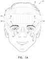
- FIGS. 1 A and 1 Bare schematic front and sectional views, respectively, of an augmented reality system that incorporates electrically-tunable lenses, in accordance with an embodiment of the invention
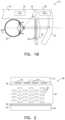
- FIG. 2is a schematic sectional view of an electrically-tunable optical phase modulator, in accordance with an embodiment of the invention
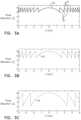
- FIGS. 3 A, 3 B and 3 Care plots that schematically illustrate phase modulation profiles applied by an electrically-tunable lens, in accordance with an embodiment of the invention.
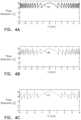
- FIGS. 4 A, 4 B and 4 Care plots that schematically illustrate phase modulation profiles applied by an electrically-tunable lens, in accordance with another embodiment of the invention.
- FIG. 5is a plot that schematically illustrate a phase modulation profile applied by an electrically-tunable lens, in accordance with another embodiment of the invention.
- FIG. 6is a schematic pictorial illustration of the operation of an augmented reality system incorporating an electrically-tunable lens, in accordance with an embodiment of the invention.
- Tunable lensesoffer major advantages over conventional static lenses in ophthalmic use. For example, tunable spectacle lenses can dynamically adjust their focal lengths for different object distances, as an aid to individuals who have lost their natural ability to accommodate for distance due to presbyopia or aphakia. Tunable spectacle lenses can also adjust their optical power to compensate for eye fatigue and different lighting conditions and can even be shared by different people with different prescriptions.
- PCT International Publications WO 2014/049577 and WO 2015/186010describe technological means that can be applied in producing such lenses and in controlling their focal properties.
- PCT Patent Application PCT/IB2018/054957(published as WO 2019/012385) describes the use of electrically-tunable lenses for dynamic vision correction, particularly in virtual reality and augmented reality systems.
- augmented reality (AR) systemsone or more electrically-tunable lenses are positioned in line with an AR projection display.
- a controllerreceives information on the direction and the distance to an item of interest projected by the AR system (based on the virtual content, eye tracking information or other methods), as well as information on the distance-accommodation capability of the viewer's eyes. Based on this information, the controller sets and varies the refractive power and optical center of the dynamic lens or lenses. The viewer is thus able to view comfortably both the projected AR display and the real-world scene on which it is superimposed, with minimal eye strain.
- Electrically-tunable lenses that use a liquid crystal (LC) as their electro-optical mediumare generally polarization-dependent, meaning that the lens will refract light of one linear polarization but will have no effect on the orthogonal polarization.
- PCT/IB2018/054957describes various solutions to this limitation, such as using a pair of electrically-tunable lenses with orthogonal polarizations, or using a polarizer with the same polarization as the electrically-tunable lens, in line with the display, to filter out light of the orthogonal polarization.
- a pair of electrically-tunable lenses with the same polarization and complementary refractive powersmay be used, with one lens between the display and the eye and the other lens between the display and the real-world scene that is viewed through the display.
- an AR displayprojects an image with a given linear polarization toward the eye of a viewer while allowing the viewer to view a scene through the display.
- An electrically-tunable lensconfigured to focus light only of the same linear polarization as the display is positioned between the display and the eye. (In a binocular AR system, electrically-tunable lenses of this sort can be placed in front of both eyes.)
- a controlleridentifies the location of an item of interest in the projected image and thus defines an axis running from the eye to this location.
- the controllerthen drives the electrically-tunable lens to apply a refractive correction within an area of the electrically-tunable lens surrounding this axis, while applying no refractive correction outside the area.
- the area over which the refractive correction is appliedis typically narrow, and thus defines a viewing aperture with a narrow angular width relative to the field of view of the eye, for example no greater than 20°, or even less, for example only in the foveal are of vision, which is typically no more than 5° wide. Therefore, the item of interest will appear to the viewer to be in focus, while light passing through the display and lens outside the area of the item will be unaffected by the refractive correction, regardless of polarization.
- the controllerdrives the display to blur parts of the AR image that are projected outside the viewing aperture of the electrically-tunable lens. Because these areas are, in any case, outside the viewer's area of sharp foveal vision, the viewer will not be aware that they are blurred.
- the controller in the AR systemdetects these changes and adjusts the area of refractive correction accordingly.
- the detectionmay be based on eye tracking, for example, and/or on the content of the image projected by the AR display.
- the electrically-tunable lensbe capable of changing its phase modulation profile rapidly (as noted in the above-mentioned PCT International Publication WO 2017/182906).
- This sort of fast responsecan be facilitated by using a thin liquid crystal layer as the electro-optical layer.
- a thin liquid crystal layerlimits the dynamic range of the phase modulation that can be achieved by the lens.
- the dynamic phase modulation rangeor equivalently, the phase modulation depth, expressed in wavelengths of light at a nominal wavelength, such as 500 nm, is proportional to the birefringence and the thickness of the liquid crystal.
- the control circuitry of the electrically-tunable lensmay advantageously drive the electro-optical medium to emulate a Fresnel lens, taking greater advantage of the limited modulation range.
- control circuitryapplies voltage waveforms to the excitation electrodes so as to generate, across at least a part of the active area of the electro-optical layer (i.e., the area excited by the electrodes), a phase modulation profile comprising spatially alternating peaks and troughs separated by phase transitions of appropriate amplitudes.
- the control circuitryapply the voltage waveforms to the excitation electrodes in a narrow range of relatively high voltages.
- the minimum voltages of the waveformsare sufficiently high, at least in the central zone of the Fresnel lens, so that even in the troughs, the electro-optical layer gives rise to a substantial phase modulation, relative to the dynamic range of phase modulation.
- the phase modulation applied over at least 90% of the active area of the Fresnel lensmay be less than 70% of the available dynamic phase modulation range of the electro-optical layer, or even less than 50% of the available dynamic phase modulation range. Because of these limitations, the phase transitions in the phase modulation profile of the Fresnel lens may be only one or two wavelengths, while the phase modulation depth in the troughs is at least four wavelengths.
- the control circuitry of the electrically-tunable lensapplies waveforms of different voltages to the excitation electrodes, so that at least the respective phase modulation depths of the troughs vary by at least one quarter wavelength, and possibly one half wavelength or more, at a nominal wavelength of 500 nm across at least the part of the active area of the electro-optical layer that emulates the Fresnel lens. Additionally or alternatively, the peak modulation depths may vary in a similar fashion.
- This arrangementenables operation of the electrically-tunable lens as a Fresnel lens with both good optical quality and fast response, for example when changes are needed in the focal power or optical center of the Fresnel lens.
- the locations of the peaks and troughscan be designed so that the distances between the peaks are integer multiples of a given minimal distance, so that when the lens is shifted laterally by multiples of the minimal distance, the locations of the peaks and troughs do not change much.
- This minimal distancemay advantageously be at least three times the average pitch of the array of excitation electrodes that is used to create the phase modulation profile.
- FIGS. 1 A and 1 Bare schematic front and sectional views, respectively, of an AR system 20 that incorporates electrically-tunable lenses 32 , in accordance with an embodiment of the invention.
- System 20comprises an AR display 22 , which projects AR images toward one or both eyes 30 of a viewer 26 , while allowing the viewer to view a scene through the display.
- display 22is mounted on a frame 24 , which contains or otherwise supports one or more miniature image projectors 28 (typically one for each eye). Each projector 28 projects images of a given linear polarization toward display 22 , which reflects the image beams toward eyes 30 without changing the polarization. (Alternatively or additionally, display 22 may have a polarizing effect.)
- Display 22typically comprises a transparent waveguide, into which the image projected by projector 28 is coupled by suitable optics.
- the surface of the waveguide facing viewer 26comprises a structure, such as a hologram, a diffraction grating, or a beamsplitter with partially reflecting facets, to deflect the image toward the viewer.
- Displays of this sortinclude, for example, HoloLens, available from Microsoft Corporation (Redmond, Washington), and the DK-Vision development kit available from Lumus (Ness Ziona, Israel).
- lenses 32are positioned between display 22 and eyes 30 .
- lenses 32may comprise compound lenses, including a static lens 40 and one or more optical phase modulators 38 , which are chosen and configured to provide the corrections necessary for the ocular refraction and accommodation capabilities of viewer 26 .
- Optical phase modulators 38which are described in greater detail hereinbelow with reference to FIG. 2 , are configured to focus light of the same linear polarization as is projected by projector 28 . Details of the design and operation of such lenses are described in the above-mentioned PCT Patent Application PCT/IB2018/054957. In the present embodiment, however, in system 20 there is no polarizer interposed between the eyes 30 and the scene that can be viewed through display 22 , nor is there any further electrically-tunable lens interposed between display 22 and the scene.
- a controller 42identifies the location of an item of interest in the projected image and drives optical phase modulators 38 in lenses 32 to apply an appropriate refractive correction, but only within an area of each lens surrounding an axis running from the eye to the identified location.
- the optical phase modulatorsapply no refractive correction outside the area (although static lens 40 may apply a fixed refractive correction over the entire field of view).
- the refractive correction applied by optical phase modulators 38is chosen so as to adjust for the virtual distance from eyes 30 to the location of the identified item of interest.
- controller 42When controller 42 identifies a change in the location of the current item of interest, or a change in the item of interest itself (for example, because the viewer's attention has shifted to a different item in the display), controller 42 will drive optical phase modulators 38 to shift the areas within which they apply a refractive correction in response to the identified change. Further details of the operation of controller 42 and lenses 32 in applying these refractive corrections are described hereinbelow with reference to FIG. 6 .
- Controller 42may identify the direction to the item of interest, as well as the accommodation distance, based on a variety of possible inputs.
- one or more eye trackers 34 built into or supported by frame 24may detect the gaze angles of eyes 30 .
- Controller 42may then identify the location of the item of interest and the area in which to apply the refractive correction on this basis.
- the gaze angles of the two eyesmay differ in viewing nearby objects, and controller 42 may detect and apply the convergence of the gaze angles in determining and accommodating for the distance at which eyes 30 are attempting to focus.
- controller 42may receive an input, for example from projector 28 , indicating the location of an item of interest in the images projected by display 22 and may use this information independently or in conjunction with the gaze angles indicated by eye trackers 34 .
- Controller 42typically comprises a programmable processor, which is programmed in software and/or firmware to carry out the functions that are described herein. Alternatively or additionally, controller 42 comprises hard-wired and/or programmable hardware logic circuits, which carry out at least some of the functions of the controller. Although controller 42 is shown in the figures, for the sake of simplicity, as a single, monolithic functional block, in practice the controller may comprise a single chip or a set of two or more chips, with suitable interfaces for receiving and outputting the signals that are illustrated in the figures and are described in the text.
- FIG. 2is a schematic sectional view of optical phase modulator 38 , in accordance with an embodiment of the invention.
- Optical phase modulator 38comprises an electro-optical layer 46 , contained in an envelope comprising an upper substrate 43 and a lower substrate 44 , which comprise a transparent material, for example, glass.
- Layer 46comprises a liquid crystal material, which is typically contained by suitable encapsulation, as is known in the art.
- Substrates 43 and 44can be coated on their insides with a polyimide alignment layer 54 (for example PI-2555, produced by Nissan Chemical Industries Ltd., Japan), which contains linear alignment structures in contact with layer 46 , which cause liquid crystal molecules 48 to line up in a desired parallel orientation.
- the linear alignment structurescan comprise actual physical grooves in alignment layer 54 , for example, or alternatively molecular structures in the alignment layer that exert electrical aligning forces on the liquid crystal molecules.
- Electrodes 50 and 52are disposed over opposing first and second sides of electro-optical layer 46 .
- Electrodes 50 and 52comprise a transparent, conductive material, such as indium tin oxide (ITO), as is known in the art, which is deposited on the surfaces of substrates 43 and 44 , respectively.
- ITOindium tin oxide
- non-transparent excitation electrodesmay be used, as long as they are thin enough so that they do not cause disturbing optical effects.
- optical phase modulator 38will typically comprise at least 100 stripe electrodes for excitation, and possibly even 400 or more.
- Electrodes 50 in the pictured embodimentare arranged as an array of parallel stripes.
- electrodes 52may comprise stripes perpendicular to electrodes 50 , which enable control circuitry (such as controller 42 , together with suitable analog drive circuits) to apply two-dimensional voltage patterns across layer 46 .
- electrode 52may comprise a uniform layer on substrate 44 , defining a common electrode capable of serving as an electrical ground plane. In this latter case, only one-dimensional voltage patterns can be applied across layer 46 , which can be used to create phase modulation profiles that emulate cylindrical lenses (such as a cylindrical Fresnel lens in the embodiments of FIGS. 3 A-C , 4 A-C and 5 ). As shown in FIG.
- optical phase modulators 38in series, with electrodes 50 oriented orthogonally one to the other, can be used in lens 32 to generate two-dimensional optical modulation patterns. Both optical phase modulators in this case are configured to focus light of the same linear polarization.
- electro-optical layer 46Due to the behavior of liquid crystal molecules 48 , electro-optical layer 46 has an effective local index of refraction at any given location within the active area of the layer that is determined by the voltage waveform that is applied across the electro-optical layer at that location. Controller 42 applies the appropriate control voltage waveforms to electrodes 50 and 52 so as to modify the optical phase modulation profile of electro-optical layer 46 .
- the phase modulation profileis chosen to cause rays of optical radiation that are incident on optical phase modulator 40 to converge or diverge with a desired focal power.
- the phase modulation profilemay comprise a Fresnel profile, with sharp peaks and troughs alternating spatially across at least a part of the active area of electro-optical layer 46 .
- the control voltage waveformsmay be chosen so as to give rise to a smooth refractive phase modulation profile.
- FIGS. 3 A, 3 B and 3 Care plots that schematically illustrate Fresnel-type phase modulation profiles 60 , 63 and 64 , respectively, that are applied by an electrically-tunable lens, in accordance with an embodiment of the invention.
- Profiles 60 , 63 and 64may be applied, for example, by optical phase modulator 38 , as shown and described above.
- controller 42may modify the voltage waveforms applied to electrodes 50 so as to change the focal power and to shift the optical center of the lens.
- Profiles 60 , 63 and 64are chosen so as to emulate a Fresnel lens, meaning that they comprise spatially alternating peaks 61 and troughs 62 of phase modulation, separated by phase transitions, which emulate the thickness variations of a conventional Fresnel lens.
- the phase modulationrefers to the phase retardation of light at the nominal wavelength passing through the electro-optical layer when voltage is applied, relative to the phase retardation of light passing through the layer when zero voltage is applied.
- the maximal modulation of the electro-active layer(when maximal voltage is applied) is nine wavelengths.
- the driving voltagesare chosen so that only a part of the dynamic range of phase modulation is used.
- profile 60uses a range of 6-8 wavelengths; profile 63 uses a range of 5-8 wavelengths; and profile 64 uses a range of 2-8 wavelengths.
- the phase modulation applied by electro-optical layer 46is less than 70% of the available dynamic phase modulation range of the electro-optical layer over at least 90% of the part of the active area emulating the Fresnel lens; and in profiles 60 and 62 the phase modulation applied by electro-optical layer 46 is less than 50% of the available dynamic phase modulation range of the electro-optical layer over at least 90% of the part of the active area emulating the Fresnel lens.
- the figuresthus show low and high unused modulation ranges that correspond respectively to driving voltages lower than the minimal voltage at troughs 62 and higher than the maximal voltage that is used in driving the excitation electrodes at peaks 61 to achieve the desired phase modulation profiles.
- the extent of the low unused phase modulation rangebe larger than that of the high unused modulation range, or even more than twice the extent.
- the extent of the unused low range in FIG. 3 Ais six wavelengths, while the extent of the high unused range is one wavelength.
- FIGS. 4 A, 4 B and 4 Care plots that schematically illustrate phase modulation profiles 65 , 66 and 67 applied by an electrically-tunable lens, in accordance with another embodiment of the invention. These profiles may be generated and modified in a similar fashion to the profiles shown in FIGS. 3 A- 3 C .
- the troughs in at least the central zone of the Fresnel lensgive rise to a phase modulation of at least four wavelengths, although the troughs may alternatively have larger or smaller modulation depths (for example as shown in FIG. 3 C ).
- the phase transition between each peak and the succeeding trough in profiles 65 and 66is two wavelengths.
- liquid crystals with other ranges of layer thickness and refractive characteristicsmay be used (with appropriate adjustment of the driving voltages), as well as other types of electro-optical materials.
- phase transitions in profile 65are all of equal amplitude, optical artifacts could arise due to consistent inaccuracies in the implementation of the phase modulation profile by the electrically-tunable lens.
- One way of overcoming these artifactsis to vary the phase modulation depths of the troughs, and possible the peaks, as well, as illustrated by profile 66 .
- the depth of phase modulation at the troughs(as well as the peaks) varies across the part of the active area of the electro-optical layer that emulates the Fresnel lens by at least one quarter wavelength of light at a wavelength of 500 nm, or even a half wavelength or more.
- each segment of the Fresnel profileuses a different range of phase modulation.
- the voltage waveformsare chosen such that the distances between the peaks are integer multiples of a given minimal distance, 200 ⁇ m in this example.
- the lensis shifted laterally in multiples of this distance, i.e., in steps of 200 ⁇ m in the present example, more peaks and troughs remain at the same locations compared to implementation that do not use this feature. It can therefore be advantageous to limit shifts of the Fresnel profile to such steps. As a result, the lens can be shifted more smoothly.
- FIG. 5is a plot that schematically illustrates a phase modulation profile 70 applied by an electrically-tunable lens, such as by optical phase modulator 38 , in accordance with another embodiment of the invention.
- controller 42applies the voltage waveforms to electrodes 50 so that the respective amplitudes of the phase transitions between peaks 72 and successive troughs 74 increase monotonically from the central zone of the Fresnel lens outward toward the periphery of the lens area.
- the use of relatively high voltages in the central region of the lensfacilitates rapid adjustment of the lens power, as in the preceding embodiment.
- the larger phase transitions in the peripheral area of the lensspread the peaks and troughs farther apart, and thus improve the optical quality of the lens.
- FIG. 6is a schematic pictorial illustration of the operation of an augmented reality system incorporating an electrically-tunable lens, in accordance with an embodiment of the invention.
- This figureshows elements of system 20 ( FIG. 1 ) in an exploded arrangement that is useful in understanding how optical phase modulators 38 in lens 32 operate in conjunction with display 22 so as to enable the viewer to observe an item 84 of interest in the image projected by display 22 while viewing a scene 90 through the display.
- modulators 38provide this functionality without the addition of a polarizer or additional electrically-tunable lens interposed in the path between the viewer's eye 30 and scene 90 .
- modulators 38focus light only of a certain, predefined linear polarization, for example a vertical polarization, as illustrated by an arrow 80 .
- Projector 28projects light of this same polarization toward display 22 , as illustrated by an arrow 82 .
- controller 42drives optical phase modulators 38 to generate a lens profile 86 (such as a Fresnel profile in the present example) only in a small area surrounding an axis 88 running from eye 30 to item 84 .
- controller 42determines the angle of axis 88 and the refractive correction to be applied by lens profile 86 based on the content projected by display and/or the gaze direction indicated by eye tracker 34 .
- optical phase modulator 38applies a constant phase modulation to the incident light, meaning that the optical phase modulator exerts no optical power over most of its area.
- Optical phase modulator 38has no effect at all on light of the polarization orthogonal to that indicated by arrow 80 . Even light of the same polarization as that indicated by arrow 80 will be largely unaffected outside the area of lens profile 86 . It is therefore desirable that the area of the lens profile be kept small, encompassing item 84 but extending only minimally beyond the bounds of the item of interest. For example, the area over which the refractive correction is applied may have an angular width, relative to the eye, that is no greater than 5°. Thus, when the viewer looks at item 84 , he or she will see it in good focus, thanks to lens profile 86 ; whereas the viewer will see scene 90 clearly over all the remaining field of view.
- controller 34instructs projector 28 to digitally blur parts of the projected image, such as item 92 , that are projected outside the viewing aperture of profile 86 . Because item 92 falls outside the area of sharp foveal vision of eye 30 , the viewer will not be disturbed by the blur.
Landscapes
- Physics & Mathematics (AREA)
- Nonlinear Science (AREA)
- General Physics & Mathematics (AREA)
- Optics & Photonics (AREA)
- Health & Medical Sciences (AREA)
- Ophthalmology & Optometry (AREA)
- Chemical & Material Sciences (AREA)
- Crystallography & Structural Chemistry (AREA)
- General Health & Medical Sciences (AREA)
- Engineering & Computer Science (AREA)
- Ceramic Engineering (AREA)
- Mathematical Physics (AREA)
- Liquid Crystal (AREA)
Abstract
Description
Claims (32)
Priority Applications (1)
| Application Number | Priority Date | Filing Date | Title |
|---|---|---|---|
| US17/255,452US11953764B2 (en) | 2017-07-10 | 2019-07-22 | Tunable lenses with enhanced performance features |
Applications Claiming Priority (6)
| Application Number | Priority Date | Filing Date | Title |
|---|---|---|---|
| US201762530306P | 2017-07-10 | 2017-07-10 | |
| US201762586909P | 2017-11-16 | 2017-11-16 | |
| PCT/IB2018/054957WO2019012385A1 (en) | 2017-07-10 | 2018-07-05 | Virtual reality and augmented reality systems with dynamic vision correction |
| US201862701857P | 2018-07-23 | 2018-07-23 | |
| US17/255,452US11953764B2 (en) | 2017-07-10 | 2019-07-22 | Tunable lenses with enhanced performance features |
| PCT/IB2019/056243WO2020021431A1 (en) | 2018-07-23 | 2019-07-22 | Tunable lenses with enhanced performance features |
Related Parent Applications (1)
| Application Number | Title | Priority Date | Filing Date |
|---|---|---|---|
| PCT/IB2018/054957Continuation-In-PartWO2019012385A1 (en) | 2017-07-10 | 2018-07-05 | Virtual reality and augmented reality systems with dynamic vision correction |
Publications (2)
| Publication Number | Publication Date |
|---|---|
| US20210311356A1 US20210311356A1 (en) | 2021-10-07 |
| US11953764B2true US11953764B2 (en) | 2024-04-09 |
Family
ID=77920852
Family Applications (1)
| Application Number | Title | Priority Date | Filing Date |
|---|---|---|---|
| US17/255,452Active2039-07-09US11953764B2 (en) | 2017-07-10 | 2019-07-22 | Tunable lenses with enhanced performance features |
Country Status (1)
| Country | Link |
|---|---|
| US (1) | US11953764B2 (en) |
Families Citing this family (5)
| Publication number | Priority date | Publication date | Assignee | Title |
|---|---|---|---|---|
| EP3844949B1 (en)* | 2018-08-29 | 2025-05-07 | InterDigital Madison Patent Holdings, SAS | Device and method for displaying voxels |
| EP3977199A4 (en) | 2019-06-02 | 2023-06-14 | Optica Amuka (A.A.) Ltd. | Electrically-tunable vision aid for treatment of myopia |
| EP4314944A4 (en)* | 2021-03-29 | 2025-04-02 | Optica Amuka (A.A.) Ltd. | SUNGLASSES WITH NEAR VISION ADJUSTMENT |
| US20240295751A1 (en)* | 2023-03-01 | 2024-09-05 | Meta Platforms Technologies, Llc | Wearable device with a corrective lens having a diffractive surface |
| DE102023111103A1 (en)* | 2023-04-28 | 2024-10-31 | Carl Zeiss Ag | OPTICAL SYSTEM WITH FRESNEL LENS ADAPTED FOR AUGMENTED REALITY APPLICATIONS |
Citations (145)
| Publication number | Priority date | Publication date | Assignee | Title |
|---|---|---|---|---|
| US3580661A (en) | 1969-04-10 | 1971-05-25 | Bell & Howell Co | Rear projection viewing screen for close viewing |
| US3881921A (en) | 1971-10-01 | 1975-05-06 | Eastman Kodak Co | Electrophotographic process employing image and control grid means |
| US4190330A (en) | 1977-12-27 | 1980-02-26 | Bell Telephone Laboratories, Incorporated | Variable focus liquid crystal lens system |
| WO1981002795A1 (en) | 1980-03-25 | 1981-10-01 | B Belgorod | Spectacle lens having continuously variable controlled density and fast response time |
| US4300818A (en) | 1978-03-13 | 1981-11-17 | Schachar Ronald A | Multifocal ophthalmic lens |
| US4584592A (en) | 1984-08-13 | 1986-04-22 | Xerox Corporation | Marking head for fluid jet assisted ion projection imaging systems |
| JPS62209412A (en) | 1986-03-10 | 1987-09-14 | Jiesu:Kk | Variable focal length liquid crystal lens for correcting astigmatism |
| US4853764A (en) | 1988-09-16 | 1989-08-01 | Pedalo, Inc. | Method and apparatus for screenless panoramic stereo TV system |
| JPH0289017A (en) | 1988-09-26 | 1990-03-29 | Olympus Optical Co Ltd | Image pickup system |
| JPH036518A (en) | 1989-06-02 | 1991-01-14 | Canon Inc | lcd lens |
| US5073021A (en) | 1989-03-17 | 1991-12-17 | Environmental Research Institute Of Michigan | Bifocal ophthalmic lens constructed from birefringent material |
| US5212583A (en) | 1992-01-08 | 1993-05-18 | Hughes Aircraft Company | Adaptive optics using the electrooptic effect |
| EP0595705A1 (en) | 1992-10-28 | 1994-05-04 | Sony Corporation | Head-mounted image display apparatus |
| US5359444A (en) | 1992-12-24 | 1994-10-25 | Motorola, Inc. | Auto-focusing optical apparatus |
| US5757546A (en) | 1993-12-03 | 1998-05-26 | Stereographics Corporation | Electronic stereoscopic viewer |
| US5815233A (en) | 1993-03-31 | 1998-09-29 | Citizen Watch Co., Ltd. | Optical device containing a liquid crystal element for changing optical characteristics of a lens element |
| US5861936A (en) | 1996-07-26 | 1999-01-19 | Gillan Holdings Limited | Regulating focus in accordance with relationship of features of a person's eyes |
| US5861940A (en) | 1996-08-01 | 1999-01-19 | Sharp Kabushiki Kaisha | Eye detection system for providing eye gaze tracking |
| WO1999041639A1 (en) | 1998-02-13 | 1999-08-19 | The Technology Partnership Plc | Liquid crystal light modulator |
| EP1050775A1 (en) | 1999-04-22 | 2000-11-08 | Thomas Swan And Co., Ltd. | Optical phase modulator |
| US6152563A (en) | 1998-02-20 | 2000-11-28 | Hutchinson; Thomas E. | Eye gaze direction tracker |
| US6243063B1 (en) | 1997-06-12 | 2001-06-05 | Sharp Kabushiki Kaisha | Diffractive spatial light modulator and display |
| US6369933B1 (en)* | 1999-01-28 | 2002-04-09 | Display Tech, Inc | Optical correlator having multiple active components formed on a single integrated circuit |
| US20020044125A1 (en) | 1996-09-27 | 2002-04-18 | Paolo Maltese | Low voltage control method for a ferroelectric liquid crystal matrix display panel |
| US6491394B1 (en) | 1999-07-02 | 2002-12-10 | E-Vision, Llc | Method for refracting and dispensing electro-active spectacles |
| US6501443B1 (en) | 1992-05-29 | 2002-12-31 | Crystalens Limited | Method of controlling liquid crystal lens in solar powered spectacles using light sensors |
| US6517203B1 (en) | 1999-07-02 | 2003-02-11 | E-Vision, Llc | System, apparatus, and method for correcting vision using electro-active spectacles |
| US20030058406A1 (en) | 1999-07-02 | 2003-03-27 | Blum Ronald D. | Method for refracting and dispensing electro-active spectacles |
| JP2003091013A (en) | 2001-09-18 | 2003-03-28 | Ricoh Co Ltd | Liquid crystal element, light deflecting element, image display device using the light deflecting element, method for manufacturing light deflecting element, and method for driving light deflecting element |
| US6553504B1 (en) | 1997-03-09 | 2003-04-22 | Jacob Katzenelson | Clock synchronization of multiprocessor systems |
| US20030128416A1 (en) | 2001-12-20 | 2003-07-10 | Caracci Lisa A. | Spatial light modulators with improved inter-pixel performance |
| WO2003077012A2 (en) | 2002-03-13 | 2003-09-18 | E-Vision, L.L.C. | Electro-optic lens with integrated components |
| US20030210377A1 (en) | 2001-10-05 | 2003-11-13 | Blum Ronald D. | Hybrid electro-active lens |
| US20030231293A1 (en) | 2000-06-23 | 2003-12-18 | E-Vision L.L.C. | Electro-optic lens with integrated components |
| US20040041745A1 (en) | 2002-08-02 | 2004-03-04 | Li-Yi Chen | Method and appartus for frame processing in a liquid crystal display |
| US20040160389A1 (en) | 1996-01-17 | 2004-08-19 | Nippon Telegraph And Telephone Corporation | Optical device and three-dimensional display device |
| US20040169630A1 (en) | 2003-02-28 | 2004-09-02 | Citizen Watch Co., Ltd. | Liquid crystal optical modulator and drive method |
| US6857741B2 (en) | 2002-01-16 | 2005-02-22 | E-Vision, Llc | Electro-active multi-focal spectacle lens |
| US6888661B1 (en)* | 2002-06-13 | 2005-05-03 | Cheetah Omni, Llc | Square filter function tunable optical devices |
| US20050146495A1 (en) | 2003-12-05 | 2005-07-07 | Genesis Microchip Inc. | LCD overdrive table triangular interpolation |
| US20050162367A1 (en) | 2004-01-27 | 2005-07-28 | Genesis Microchip Inc. | Dynamically selecting either frame rate conversion (FRC) or pixel overdrive in an LCD panel based display |
| US20050168430A1 (en) | 2004-02-04 | 2005-08-04 | Nishimura Ken A. | Method and apparatus to enhance contrast in electro-optical display devices |
| US6986579B2 (en) | 1999-07-02 | 2006-01-17 | E-Vision, Llc | Method of manufacturing an electro-active lens |
| US20060034003A1 (en) | 2004-08-16 | 2006-02-16 | Xceed Imaging Ltd. | Optical method and system for extended depth of focus |
| US20060066808A1 (en) | 2004-09-27 | 2006-03-30 | Blum Ronald D | Ophthalmic lenses incorporating a diffractive element |
| WO2006034652A1 (en) | 2004-09-30 | 2006-04-06 | The Hong Kong Polytechnic University | Method of optical treatment |
| US20060092340A1 (en) | 2004-11-02 | 2006-05-04 | Blum Ronald D | Electro-active spectacles and method of fabricating same |
| US20060164687A1 (en) | 2005-01-21 | 2006-07-27 | Chung-Hsun Huang | Apparatus for overdrive computation and method therefor |
| US20060164593A1 (en) | 2005-01-21 | 2006-07-27 | Nasser Peyghambarian | Adaptive electro-active lens with variable focal length |
| EP1760515A2 (en) | 2003-10-03 | 2007-03-07 | Invisia Ltd. | Multifocal ophthalmic lens |
| US20070052876A1 (en) | 2003-10-03 | 2007-03-08 | Invisia Ltd. | Multifocal lens |
| WO2007041796A1 (en) | 2005-10-12 | 2007-04-19 | Carl Zeiss Vision Australia Holdings Limited | Ophthalmic lens element for myopia correction |
| US20070146873A1 (en) | 2005-12-09 | 2007-06-28 | Amnis Corporation | Extended depth of field imaging for high speed object analysis |
| US20070236769A1 (en) | 2004-08-16 | 2007-10-11 | Xceed Imaging Ltd. | Optical method and system for extended depth of focus |
| US20070236800A1 (en) | 2006-03-03 | 2007-10-11 | Ozan Cakmakci | Imaging systems for eyeglass-based display devices |
| US20070280626A1 (en) | 2006-05-24 | 2007-12-06 | Haddock Joshua N | Optical rangefinder for an electro-active lens |
| US20070290972A1 (en) | 2006-06-12 | 2007-12-20 | Gerald Meredith | Method to Reduce Power Consumption with Electro-Optic Lenses |
| WO2008032061A2 (en) | 2006-09-12 | 2008-03-20 | Ucl Business Plc | Imaging apparatus and methods |
| US20080239420A1 (en) | 2007-04-02 | 2008-10-02 | Vuzix Corporation | Agile holographic optical phased array device and applications |
| US7475984B2 (en) | 2000-06-23 | 2009-01-13 | Pixeloptics Inc. | Electro-optic lens with integrated components |
| US7475985B2 (en) | 1999-07-02 | 2009-01-13 | Pixeloptics Inc. | System, apparatus, and method for correcting vision using an electro-active lens |
| US7497121B2 (en) | 2005-12-22 | 2009-03-03 | Denso Corporation | Ultrasonic sensor |
| US20090096981A1 (en) | 2007-10-11 | 2009-04-16 | Roger Clarke | Alignment of liquid crystalline materials to surface relief diffractive structures |
| US20090103044A1 (en) | 1999-07-02 | 2009-04-23 | Duston Dwight P | Spectacle frame bridge housing electronics for electro-active spectacle lenses |
| US20090237575A1 (en) | 2008-03-18 | 2009-09-24 | David Tsi-Shi | Adaptive focusing using liquid crystal zone plates in electro-optical readers |
| US7600872B2 (en) | 2004-12-23 | 2009-10-13 | Rodenstock Gmbh | Spectacle lens device comprising an electrically adaptive area, spectacles, use and method for operating said spectacle lens device |
| US20090279050A1 (en) | 2008-03-25 | 2009-11-12 | Mcginn Joseph Thomas | Electro-optic lenses for correction of higher order aberrations |
| US20100007804A1 (en) | 2008-07-09 | 2010-01-14 | Ostendo Technologies, Inc. | Image Construction Based Video Display System |
| US20100026920A1 (en) | 2008-07-30 | 2010-02-04 | Samsung Electronics Co., Ltd. | Electro-optic unit, driving method of the electro-optic unit, and display apparatus having the same |
| US7728949B2 (en) | 2007-01-22 | 2010-06-01 | Pixeloptics, Inc. | Electro-active lens |
| US20100149444A1 (en) | 2007-04-17 | 2010-06-17 | Koninklijke Philips Electronics N.V. | Beam-shaping device |
| US20100157181A1 (en) | 2008-12-22 | 2010-06-24 | Sony Corporation | Lens array device and image display |
| US20110018903A1 (en) | 2004-08-03 | 2011-01-27 | Silverbrook Research Pty Ltd | Augmented reality device for presenting virtual imagery registered to a viewed surface |
| US20110037837A1 (en) | 2009-08-12 | 2011-02-17 | Sony Corporation | Shutter glasses and shutter control method |
| CN201752480U (en) | 2009-10-27 | 2011-03-02 | 谢刚 | Eye caring instrument |
| EP2309310A1 (en) | 2009-10-01 | 2011-04-13 | Koninklijke Philips Electronics N.V. | 3D spectacles |
| WO2011075834A1 (en) | 2009-12-23 | 2011-06-30 | Lensvector Inc. | Image stabilization and shifting in a liquid crystal lens |
| US20110228181A1 (en) | 2010-03-17 | 2011-09-22 | Samsung Electronics Co., Ltd. | Image display device using diffractive lens |
| US20110234934A1 (en) | 2010-03-26 | 2011-09-29 | Silicon Touch Technology Inc. | Double-layer liquid crystal lens apparatus |
| US8028473B2 (en) | 2008-06-21 | 2011-10-04 | Lensvector Inc. | Electro-optical devices using dynamic reconfiguration of effective electrode structures |
| JP2011203457A (en) | 2010-03-25 | 2011-10-13 | Konica Minolta Business Technologies Inc | Image forming apparatus |
| US8052278B2 (en) | 2005-07-20 | 2011-11-08 | Essilor International (Compagnie Generale D'optique | Randomly pixellated optical component, its fabrication method and its use in the fabrication of a transparent optical element |
| CN102253563A (en) | 2011-08-15 | 2011-11-23 | 南京中电熊猫液晶显示科技有限公司 | Electrically driven liquid crystal lens with optimized visual angle and stereoscopic display device thereof |
| US20110317128A1 (en) | 2009-03-05 | 2011-12-29 | Essilor International (Compagnie Generale D'optique) | Spectacle eyeglass for myopic child |
| US20120098875A1 (en) | 2010-10-20 | 2012-04-26 | Sony Corporation | Illumination device and display device |
| US20120099040A1 (en) | 2010-10-22 | 2012-04-26 | Reald Inc. | Split segmented liquid crystal modulator |
| US20120120333A1 (en) | 2010-11-16 | 2012-05-17 | Shenzhen Super Perfect Optics Ltd. | Liquid crystal lens, controlling method thereof and 3d display using the same |
| US20120133891A1 (en) | 2010-05-29 | 2012-05-31 | Wenyu Jiang | Systems, methods and apparatus for making and using eyeglasses with adaptive lens driven by gaze distance and low power gaze tracking |
| US20120147038A1 (en) | 2010-12-08 | 2012-06-14 | Microsoft Corporation | Sympathetic optic adaptation for see-through display |
| JP2012141552A (en) | 2011-01-06 | 2012-07-26 | Akita Prefecture | Liquid crystal cylindrical lens array and display device |
| US20120194781A1 (en) | 2011-01-28 | 2012-08-02 | Light Prescriptions Innovators, Llc | Autofocusing eyewear, especially for presbyopia correction |
| US20120212696A1 (en) | 2011-01-27 | 2012-08-23 | Pixeloptics, Inc. | Variable optical element comprising a liquid crystal alignment layer |
| WO2012120470A1 (en) | 2011-03-10 | 2012-09-13 | Optika Amuka (A.A.) Ltd. | Stereographic viewing with extended depth of field |
| EP2503787A1 (en) | 2011-03-22 | 2012-09-26 | Hitachi Displays, Ltd. | 2D/3D liquid crystal display device |
| US20120300171A1 (en) | 2011-05-27 | 2012-11-29 | Pixeloptics, Inc. | Programmable Ophthalmic Lenses |
| US20130010256A1 (en) | 2010-07-02 | 2013-01-10 | Pixel Optics, Inc. | Electro-active spectacle frames |
| US20130027655A1 (en) | 2011-06-02 | 2013-01-31 | Pixeloptics, Inc. | Electro-Active Lenses Including Thin Glass Substrates |
| US20130128229A1 (en) | 2011-11-21 | 2013-05-23 | Icheck Health Connection, Inc. | Video game to monitor retinal diseases |
| US20130208224A1 (en) | 2010-02-17 | 2013-08-15 | Yuko Kizu | Liquid crystal display apparatus |
| US20130215374A1 (en) | 2005-10-28 | 2013-08-22 | Pixeloptics, Inc. | Eyewear docking station and electronic module |
| US20130250223A1 (en) | 2012-03-22 | 2013-09-26 | Ayako Takagi | Liquid crystal optical apparatus and image display device |
| US20130250193A1 (en) | 2012-03-23 | 2013-09-26 | Samsung Display Co., Ltd. | Display device |
| EP2682810A1 (en) | 2012-07-06 | 2014-01-08 | Kabushiki Kaisha Toshiba | Liquid crystal Fresnel lens and image display apparatus |
| US20140036172A1 (en) | 2012-08-03 | 2014-02-06 | Pixeloptics, Inc. | Electro-Active Ophthalmic Lenses Comprising Low Viscosity Liquid Crystalline Mixtures |
| US20140036183A1 (en) | 2008-06-06 | 2014-02-06 | Lensvector Inc. | Tunable liquid crystal optical device |
| US8675148B2 (en) | 2010-12-27 | 2014-03-18 | Kabushiki Kaisha Toshiba | Gradient refractive index liquid crystal optical apparatus and image display apparatus |
| US8690321B2 (en) | 2012-04-21 | 2014-04-08 | Paul Lapstun | Fixation-based control of electroactive spectacles |
| WO2014063432A1 (en) | 2012-10-25 | 2014-05-01 | Au Optronics Corporation | Liquid crystal lens and display device having the same |
| US8773629B2 (en) | 2012-04-13 | 2014-07-08 | Kabushiki Kaisha Toshiba | Liquid crystal optical apparatus and image display device having particular electrodes |
| US8896772B2 (en) | 2010-03-19 | 2014-11-25 | Evosens | Optical variation device, optical assembly and method for manufacturing such a device |
| US20140347405A1 (en) | 2013-05-22 | 2014-11-27 | Samsung Display Co., Ltd. | Pixel circuit and method for driving the same |
| US8922902B2 (en) | 2010-03-24 | 2014-12-30 | Mitsui Chemicals, Inc. | Dynamic lens |
| RU2541819C2 (en) | 2013-05-24 | 2015-02-20 | Рашид Адыгамович Ибатулин | Method for training accommodation, preventing and/or treating progressive myopia and device for implementing it |
| US20150116304A1 (en) | 2013-10-30 | 2015-04-30 | Samsung Display Co., Ltd. | Three dimensional image display and liquid crystal lens thereof |
| US9052514B2 (en) | 2012-03-08 | 2015-06-09 | Japan Display Inc. | Liquid-crystal lens, display apparatus and electronic equipment |
| US20150185503A1 (en) | 2013-12-27 | 2015-07-02 | Larry R. Tate | Automatic focus prescription lens eyeglasses |
| US20150219893A1 (en) | 2013-02-07 | 2015-08-06 | Liqxtal Technology Inc. | Optical system and its display system |
| US20150378240A1 (en) | 2014-06-24 | 2015-12-31 | Superd Co. Ltd. | 2d/3d switchable stereoscopic display apparatus |
| US20160004128A1 (en) | 2014-01-17 | 2016-01-07 | Boe Technology Group Co., Ltd. | Liquid crystal lens and three-dimensional display device |
| US9241669B2 (en) | 2012-07-18 | 2016-01-26 | Johnson & Johnson Vision Care, Inc. | Neuromuscular sensing for variable-optic electronic ophthalmic lens |
| US9304319B2 (en) | 2010-11-18 | 2016-04-05 | Microsoft Technology Licensing, Llc | Automatic focus improvement for augmented reality displays |
| US20160161767A1 (en) | 2014-12-06 | 2016-06-09 | Winthrop Childers | Device Interaction for Correcting Presbyopia |
| US20160209647A1 (en) | 2015-01-19 | 2016-07-21 | Magna Electronics Inc. | Vehicle vision system with light field monitor |
| US20160370605A1 (en) | 2013-12-17 | 2016-12-22 | Liron Ain-Kedem | Controlling vision correction using eye tracking and depth detection |
| US20170003519A1 (en) | 2015-06-30 | 2017-01-05 | Telefonaktiebolaget L M Ericsson (Publ) | Controlling a lens for adjustable vision correction |
| US9541774B2 (en) | 2011-12-16 | 2017-01-10 | Mitsui Chemicals, Inc. | Control device for variable focus lenses, control method for variable focus lenses, and electronic glasses |
| US20170068134A1 (en) | 2012-09-30 | 2017-03-09 | Optica Amuka (A.A.) Ltd. | Electrically-tunable lenses and lens systems |
| WO2017049072A1 (en) | 2015-09-16 | 2017-03-23 | Blum Ronald D | Systems, apparatus, and methods for ophthalmic lenses with wireless charging |
| US20170160518A1 (en) | 2015-12-08 | 2017-06-08 | Oculus Vr, Llc | Focus adjusting virtual reality headset |
| US20170184848A1 (en) | 2015-12-29 | 2017-06-29 | Tuomas Vallius | Augmented reality display system with variable focus |
| US20170219828A1 (en) | 2016-01-28 | 2017-08-03 | Coretronic Corporation | Head-mounted display |
| US20170269453A1 (en) | 2014-11-24 | 2017-09-21 | Lensvector Inc. | Liquid crystal beam control device with improved zone transition and method of manufacture thereof |
| WO2017158486A1 (en) | 2016-03-16 | 2017-09-21 | Optica Amuka (A.A.) Ltd. | Polarization-insensitive phase modulator |
| US20170276963A1 (en) | 2016-03-22 | 2017-09-28 | Johnson & Johnson Vision Care, Inc. | Pulsed plus lens designs for myopia control, enhanced depth of focus and presbyopia correction |
| US9958703B2 (en) | 2012-03-30 | 2018-05-01 | Johnson & Johnson Vision Care, Inc. | Method and apparatus for a variable power opthalmic lens |
| US20180136486A1 (en) | 2016-07-25 | 2018-05-17 | Magic Leap, Inc. | Light field processor system |
| CN207380380U (en) | 2017-11-09 | 2018-05-18 | 孙正国 | A kind of smart myopia prevents glasses |
| US10036901B2 (en) | 2012-09-30 | 2018-07-31 | Optica Amuka (A.A.) Ltd. | Lenses with electrically-tunable power and alignment |
| CN108845433A (en) | 2018-07-19 | 2018-11-20 | 三星电子(中国)研发中心 | Intelligent glasses and its control method |
| US20180356652A1 (en) | 2017-06-13 | 2018-12-13 | Giichi Shibuya | Glasses |
| US20190113772A1 (en) | 2016-06-16 | 2019-04-18 | Optica Amuka (A.A.) Ltd. | Tunable Lenses for Spectacles |
| US10268050B2 (en) | 2015-11-06 | 2019-04-23 | Hoya Lens Thailand Ltd. | Spectacle lens |
| US10466391B2 (en) | 2014-06-05 | 2019-11-05 | Optica Amuka (A.A.) Ltd. | Control of dynamic lenses |
| US20200285062A1 (en) | 2017-10-16 | 2020-09-10 | Optica Amuka (A.A.) Ltd. | Spectacles with electrically-tunable lenses controllable by an external system |
| US20200292848A1 (en) | 2016-04-17 | 2020-09-17 | Optica Amuka (A.A.) Ltd. | Liquid crystal lens with enhanced electrical drive |
- 2019
- 2019-07-22USUS17/255,452patent/US11953764B2/enactiveActive
Patent Citations (152)
| Publication number | Priority date | Publication date | Assignee | Title |
|---|---|---|---|---|
| US3580661A (en) | 1969-04-10 | 1971-05-25 | Bell & Howell Co | Rear projection viewing screen for close viewing |
| US3881921A (en) | 1971-10-01 | 1975-05-06 | Eastman Kodak Co | Electrophotographic process employing image and control grid means |
| US4190330A (en) | 1977-12-27 | 1980-02-26 | Bell Telephone Laboratories, Incorporated | Variable focus liquid crystal lens system |
| US4300818A (en) | 1978-03-13 | 1981-11-17 | Schachar Ronald A | Multifocal ophthalmic lens |
| WO1981002795A1 (en) | 1980-03-25 | 1981-10-01 | B Belgorod | Spectacle lens having continuously variable controlled density and fast response time |
| US4584592A (en) | 1984-08-13 | 1986-04-22 | Xerox Corporation | Marking head for fluid jet assisted ion projection imaging systems |
| JPS62209412A (en) | 1986-03-10 | 1987-09-14 | Jiesu:Kk | Variable focal length liquid crystal lens for correcting astigmatism |
| US4853764A (en) | 1988-09-16 | 1989-08-01 | Pedalo, Inc. | Method and apparatus for screenless panoramic stereo TV system |
| JPH0289017A (en) | 1988-09-26 | 1990-03-29 | Olympus Optical Co Ltd | Image pickup system |
| US5073021A (en) | 1989-03-17 | 1991-12-17 | Environmental Research Institute Of Michigan | Bifocal ophthalmic lens constructed from birefringent material |
| JPH036518A (en) | 1989-06-02 | 1991-01-14 | Canon Inc | lcd lens |
| US5212583A (en) | 1992-01-08 | 1993-05-18 | Hughes Aircraft Company | Adaptive optics using the electrooptic effect |
| US6501443B1 (en) | 1992-05-29 | 2002-12-31 | Crystalens Limited | Method of controlling liquid crystal lens in solar powered spectacles using light sensors |
| EP0595705A1 (en) | 1992-10-28 | 1994-05-04 | Sony Corporation | Head-mounted image display apparatus |
| US5359444A (en) | 1992-12-24 | 1994-10-25 | Motorola, Inc. | Auto-focusing optical apparatus |
| US5815233A (en) | 1993-03-31 | 1998-09-29 | Citizen Watch Co., Ltd. | Optical device containing a liquid crystal element for changing optical characteristics of a lens element |
| US5757546A (en) | 1993-12-03 | 1998-05-26 | Stereographics Corporation | Electronic stereoscopic viewer |
| US20040160389A1 (en) | 1996-01-17 | 2004-08-19 | Nippon Telegraph And Telephone Corporation | Optical device and three-dimensional display device |
| US5861936A (en) | 1996-07-26 | 1999-01-19 | Gillan Holdings Limited | Regulating focus in accordance with relationship of features of a person's eyes |
| US5861940A (en) | 1996-08-01 | 1999-01-19 | Sharp Kabushiki Kaisha | Eye detection system for providing eye gaze tracking |
| US20020044125A1 (en) | 1996-09-27 | 2002-04-18 | Paolo Maltese | Low voltage control method for a ferroelectric liquid crystal matrix display panel |
| US6553504B1 (en) | 1997-03-09 | 2003-04-22 | Jacob Katzenelson | Clock synchronization of multiprocessor systems |
| US6243063B1 (en) | 1997-06-12 | 2001-06-05 | Sharp Kabushiki Kaisha | Diffractive spatial light modulator and display |
| WO1999041639A1 (en) | 1998-02-13 | 1999-08-19 | The Technology Partnership Plc | Liquid crystal light modulator |
| US6152563A (en) | 1998-02-20 | 2000-11-28 | Hutchinson; Thomas E. | Eye gaze direction tracker |
| US6369933B1 (en)* | 1999-01-28 | 2002-04-09 | Display Tech, Inc | Optical correlator having multiple active components formed on a single integrated circuit |
| EP1050775A1 (en) | 1999-04-22 | 2000-11-08 | Thomas Swan And Co., Ltd. | Optical phase modulator |
| US20060126698A1 (en) | 1999-06-11 | 2006-06-15 | E-Vision, Llc | Method of manufacturing an electro-active lens |
| US20030058406A1 (en) | 1999-07-02 | 2003-03-27 | Blum Ronald D. | Method for refracting and dispensing electro-active spectacles |
| US6517203B1 (en) | 1999-07-02 | 2003-02-11 | E-Vision, Llc | System, apparatus, and method for correcting vision using electro-active spectacles |
| US20090103044A1 (en) | 1999-07-02 | 2009-04-23 | Duston Dwight P | Spectacle frame bridge housing electronics for electro-active spectacle lenses |
| US7517083B2 (en) | 1999-07-02 | 2009-04-14 | E-Vision, Llc | Electro-optic lens with integrated components for varying refractive properties |
| US7475985B2 (en) | 1999-07-02 | 2009-01-13 | Pixeloptics Inc. | System, apparatus, and method for correcting vision using an electro-active lens |
| US6491394B1 (en) | 1999-07-02 | 2002-12-10 | E-Vision, Llc | Method for refracting and dispensing electro-active spectacles |
| US6986579B2 (en) | 1999-07-02 | 2006-01-17 | E-Vision, Llc | Method of manufacturing an electro-active lens |
| US7475984B2 (en) | 2000-06-23 | 2009-01-13 | Pixeloptics Inc. | Electro-optic lens with integrated components |
| US20030231293A1 (en) | 2000-06-23 | 2003-12-18 | E-Vision L.L.C. | Electro-optic lens with integrated components |
| JP2003091013A (en) | 2001-09-18 | 2003-03-28 | Ricoh Co Ltd | Liquid crystal element, light deflecting element, image display device using the light deflecting element, method for manufacturing light deflecting element, and method for driving light deflecting element |
| US20030210377A1 (en) | 2001-10-05 | 2003-11-13 | Blum Ronald D. | Hybrid electro-active lens |
| US20030128416A1 (en) | 2001-12-20 | 2003-07-10 | Caracci Lisa A. | Spatial light modulators with improved inter-pixel performance |
| US6857741B2 (en) | 2002-01-16 | 2005-02-22 | E-Vision, Llc | Electro-active multi-focal spectacle lens |
| WO2003077012A2 (en) | 2002-03-13 | 2003-09-18 | E-Vision, L.L.C. | Electro-optic lens with integrated components |
| US6888661B1 (en)* | 2002-06-13 | 2005-05-03 | Cheetah Omni, Llc | Square filter function tunable optical devices |
| US20040041745A1 (en) | 2002-08-02 | 2004-03-04 | Li-Yi Chen | Method and appartus for frame processing in a liquid crystal display |
| US20040169630A1 (en) | 2003-02-28 | 2004-09-02 | Citizen Watch Co., Ltd. | Liquid crystal optical modulator and drive method |
| US20070052876A1 (en) | 2003-10-03 | 2007-03-08 | Invisia Ltd. | Multifocal lens |
| EP1760515A2 (en) | 2003-10-03 | 2007-03-07 | Invisia Ltd. | Multifocal ophthalmic lens |
| US20050146495A1 (en) | 2003-12-05 | 2005-07-07 | Genesis Microchip Inc. | LCD overdrive table triangular interpolation |
| US20050162367A1 (en) | 2004-01-27 | 2005-07-28 | Genesis Microchip Inc. | Dynamically selecting either frame rate conversion (FRC) or pixel overdrive in an LCD panel based display |
| US20050168430A1 (en) | 2004-02-04 | 2005-08-04 | Nishimura Ken A. | Method and apparatus to enhance contrast in electro-optical display devices |
| US20110018903A1 (en) | 2004-08-03 | 2011-01-27 | Silverbrook Research Pty Ltd | Augmented reality device for presenting virtual imagery registered to a viewed surface |
| US20060034003A1 (en) | 2004-08-16 | 2006-02-16 | Xceed Imaging Ltd. | Optical method and system for extended depth of focus |
| US20070236769A1 (en) | 2004-08-16 | 2007-10-11 | Xceed Imaging Ltd. | Optical method and system for extended depth of focus |
| US20060066808A1 (en) | 2004-09-27 | 2006-03-30 | Blum Ronald D | Ophthalmic lenses incorporating a diffractive element |
| WO2006034652A1 (en) | 2004-09-30 | 2006-04-06 | The Hong Kong Polytechnic University | Method of optical treatment |
| US20060092340A1 (en) | 2004-11-02 | 2006-05-04 | Blum Ronald D | Electro-active spectacles and method of fabricating same |
| US7600872B2 (en) | 2004-12-23 | 2009-10-13 | Rodenstock Gmbh | Spectacle lens device comprising an electrically adaptive area, spectacles, use and method for operating said spectacle lens device |
| US20060164687A1 (en) | 2005-01-21 | 2006-07-27 | Chung-Hsun Huang | Apparatus for overdrive computation and method therefor |
| US20060164593A1 (en) | 2005-01-21 | 2006-07-27 | Nasser Peyghambarian | Adaptive electro-active lens with variable focal length |
| US8052278B2 (en) | 2005-07-20 | 2011-11-08 | Essilor International (Compagnie Generale D'optique | Randomly pixellated optical component, its fabrication method and its use in the fabrication of a transparent optical element |
| WO2007041796A1 (en) | 2005-10-12 | 2007-04-19 | Carl Zeiss Vision Australia Holdings Limited | Ophthalmic lens element for myopia correction |
| US20130215374A1 (en) | 2005-10-28 | 2013-08-22 | Pixeloptics, Inc. | Eyewear docking station and electronic module |
| US20070146873A1 (en) | 2005-12-09 | 2007-06-28 | Amnis Corporation | Extended depth of field imaging for high speed object analysis |
| US7497121B2 (en) | 2005-12-22 | 2009-03-03 | Denso Corporation | Ultrasonic sensor |
| US20070236800A1 (en) | 2006-03-03 | 2007-10-11 | Ozan Cakmakci | Imaging systems for eyeglass-based display devices |
| US20070280626A1 (en) | 2006-05-24 | 2007-12-06 | Haddock Joshua N | Optical rangefinder for an electro-active lens |
| US20070290972A1 (en) | 2006-06-12 | 2007-12-20 | Gerald Meredith | Method to Reduce Power Consumption with Electro-Optic Lenses |
| WO2008032061A2 (en) | 2006-09-12 | 2008-03-20 | Ucl Business Plc | Imaging apparatus and methods |
| US7728949B2 (en) | 2007-01-22 | 2010-06-01 | Pixeloptics, Inc. | Electro-active lens |
| US20080239420A1 (en) | 2007-04-02 | 2008-10-02 | Vuzix Corporation | Agile holographic optical phased array device and applications |
| US20100149444A1 (en) | 2007-04-17 | 2010-06-17 | Koninklijke Philips Electronics N.V. | Beam-shaping device |
| US20090096981A1 (en) | 2007-10-11 | 2009-04-16 | Roger Clarke | Alignment of liquid crystalline materials to surface relief diffractive structures |
| US20090237575A1 (en) | 2008-03-18 | 2009-09-24 | David Tsi-Shi | Adaptive focusing using liquid crystal zone plates in electro-optical readers |
| US20090279050A1 (en) | 2008-03-25 | 2009-11-12 | Mcginn Joseph Thomas | Electro-optic lenses for correction of higher order aberrations |
| US20140036183A1 (en) | 2008-06-06 | 2014-02-06 | Lensvector Inc. | Tunable liquid crystal optical device |
| US8028473B2 (en) | 2008-06-21 | 2011-10-04 | Lensvector Inc. | Electro-optical devices using dynamic reconfiguration of effective electrode structures |
| US20100007804A1 (en) | 2008-07-09 | 2010-01-14 | Ostendo Technologies, Inc. | Image Construction Based Video Display System |
| US20100026920A1 (en) | 2008-07-30 | 2010-02-04 | Samsung Electronics Co., Ltd. | Electro-optic unit, driving method of the electro-optic unit, and display apparatus having the same |
| US20100157181A1 (en) | 2008-12-22 | 2010-06-24 | Sony Corporation | Lens array device and image display |
| US20110317128A1 (en) | 2009-03-05 | 2011-12-29 | Essilor International (Compagnie Generale D'optique) | Spectacle eyeglass for myopic child |
| US20110037837A1 (en) | 2009-08-12 | 2011-02-17 | Sony Corporation | Shutter glasses and shutter control method |
| EP2309310A1 (en) | 2009-10-01 | 2011-04-13 | Koninklijke Philips Electronics N.V. | 3D spectacles |
| CN201752480U (en) | 2009-10-27 | 2011-03-02 | 谢刚 | Eye caring instrument |
| US20120257131A1 (en) | 2009-12-23 | 2012-10-11 | Lensvector Inc. | Image stabilization and shifting in a liquid crystal lens |
| WO2011075834A1 (en) | 2009-12-23 | 2011-06-30 | Lensvector Inc. | Image stabilization and shifting in a liquid crystal lens |
| US20130208224A1 (en) | 2010-02-17 | 2013-08-15 | Yuko Kizu | Liquid crystal display apparatus |
| US20110228181A1 (en) | 2010-03-17 | 2011-09-22 | Samsung Electronics Co., Ltd. | Image display device using diffractive lens |
| US8896772B2 (en) | 2010-03-19 | 2014-11-25 | Evosens | Optical variation device, optical assembly and method for manufacturing such a device |
| US8922902B2 (en) | 2010-03-24 | 2014-12-30 | Mitsui Chemicals, Inc. | Dynamic lens |
| JP2011203457A (en) | 2010-03-25 | 2011-10-13 | Konica Minolta Business Technologies Inc | Image forming apparatus |
| US20110234934A1 (en) | 2010-03-26 | 2011-09-29 | Silicon Touch Technology Inc. | Double-layer liquid crystal lens apparatus |
| US20120133891A1 (en) | 2010-05-29 | 2012-05-31 | Wenyu Jiang | Systems, methods and apparatus for making and using eyeglasses with adaptive lens driven by gaze distance and low power gaze tracking |
| US20130010256A1 (en) | 2010-07-02 | 2013-01-10 | Pixel Optics, Inc. | Electro-active spectacle frames |
| US20120098875A1 (en) | 2010-10-20 | 2012-04-26 | Sony Corporation | Illumination device and display device |
| US20120099040A1 (en) | 2010-10-22 | 2012-04-26 | Reald Inc. | Split segmented liquid crystal modulator |
| US20120120333A1 (en) | 2010-11-16 | 2012-05-17 | Shenzhen Super Perfect Optics Ltd. | Liquid crystal lens, controlling method thereof and 3d display using the same |
| US9304319B2 (en) | 2010-11-18 | 2016-04-05 | Microsoft Technology Licensing, Llc | Automatic focus improvement for augmented reality displays |
| US20120147038A1 (en) | 2010-12-08 | 2012-06-14 | Microsoft Corporation | Sympathetic optic adaptation for see-through display |
| US8675148B2 (en) | 2010-12-27 | 2014-03-18 | Kabushiki Kaisha Toshiba | Gradient refractive index liquid crystal optical apparatus and image display apparatus |
| JP2012141552A (en) | 2011-01-06 | 2012-07-26 | Akita Prefecture | Liquid crystal cylindrical lens array and display device |
| US20120212696A1 (en) | 2011-01-27 | 2012-08-23 | Pixeloptics, Inc. | Variable optical element comprising a liquid crystal alignment layer |
| US20120194781A1 (en) | 2011-01-28 | 2012-08-02 | Light Prescriptions Innovators, Llc | Autofocusing eyewear, especially for presbyopia correction |
| WO2012120470A1 (en) | 2011-03-10 | 2012-09-13 | Optika Amuka (A.A.) Ltd. | Stereographic viewing with extended depth of field |
| EP2503787A1 (en) | 2011-03-22 | 2012-09-26 | Hitachi Displays, Ltd. | 2D/3D liquid crystal display device |
| US20120300171A1 (en) | 2011-05-27 | 2012-11-29 | Pixeloptics, Inc. | Programmable Ophthalmic Lenses |
| US20130027655A1 (en) | 2011-06-02 | 2013-01-31 | Pixeloptics, Inc. | Electro-Active Lenses Including Thin Glass Substrates |
| CN102253563A (en) | 2011-08-15 | 2011-11-23 | 南京中电熊猫液晶显示科技有限公司 | Electrically driven liquid crystal lens with optimized visual angle and stereoscopic display device thereof |
| US20130128229A1 (en) | 2011-11-21 | 2013-05-23 | Icheck Health Connection, Inc. | Video game to monitor retinal diseases |
| US9541774B2 (en) | 2011-12-16 | 2017-01-10 | Mitsui Chemicals, Inc. | Control device for variable focus lenses, control method for variable focus lenses, and electronic glasses |
| US9052514B2 (en) | 2012-03-08 | 2015-06-09 | Japan Display Inc. | Liquid-crystal lens, display apparatus and electronic equipment |
| US20130250223A1 (en) | 2012-03-22 | 2013-09-26 | Ayako Takagi | Liquid crystal optical apparatus and image display device |
| US20130250193A1 (en) | 2012-03-23 | 2013-09-26 | Samsung Display Co., Ltd. | Display device |
| US9958703B2 (en) | 2012-03-30 | 2018-05-01 | Johnson & Johnson Vision Care, Inc. | Method and apparatus for a variable power opthalmic lens |
| US8773629B2 (en) | 2012-04-13 | 2014-07-08 | Kabushiki Kaisha Toshiba | Liquid crystal optical apparatus and image display device having particular electrodes |
| US8690321B2 (en) | 2012-04-21 | 2014-04-08 | Paul Lapstun | Fixation-based control of electroactive spectacles |
| EP2682810A1 (en) | 2012-07-06 | 2014-01-08 | Kabushiki Kaisha Toshiba | Liquid crystal Fresnel lens and image display apparatus |
| US9241669B2 (en) | 2012-07-18 | 2016-01-26 | Johnson & Johnson Vision Care, Inc. | Neuromuscular sensing for variable-optic electronic ophthalmic lens |
| US20140036172A1 (en) | 2012-08-03 | 2014-02-06 | Pixeloptics, Inc. | Electro-Active Ophthalmic Lenses Comprising Low Viscosity Liquid Crystalline Mixtures |
| US10288904B2 (en) | 2012-09-30 | 2019-05-14 | Optica Amuka (A.A.) Ltd. | Lenses with electrically-tunable power and alignment |
| US10036901B2 (en) | 2012-09-30 | 2018-07-31 | Optica Amuka (A.A.) Ltd. | Lenses with electrically-tunable power and alignment |
| US20170068134A1 (en) | 2012-09-30 | 2017-03-09 | Optica Amuka (A.A.) Ltd. | Electrically-tunable lenses and lens systems |
| US20140118644A1 (en) | 2012-10-25 | 2014-05-01 | Au Optronics Corporation | Liquid crystal lens and display device having the same |
| WO2014063432A1 (en) | 2012-10-25 | 2014-05-01 | Au Optronics Corporation | Liquid crystal lens and display device having the same |
| US20150219893A1 (en) | 2013-02-07 | 2015-08-06 | Liqxtal Technology Inc. | Optical system and its display system |
| US20140347405A1 (en) | 2013-05-22 | 2014-11-27 | Samsung Display Co., Ltd. | Pixel circuit and method for driving the same |
| RU2541819C2 (en) | 2013-05-24 | 2015-02-20 | Рашид Адыгамович Ибатулин | Method for training accommodation, preventing and/or treating progressive myopia and device for implementing it |
| US20150116304A1 (en) | 2013-10-30 | 2015-04-30 | Samsung Display Co., Ltd. | Three dimensional image display and liquid crystal lens thereof |
| US20160370605A1 (en) | 2013-12-17 | 2016-12-22 | Liron Ain-Kedem | Controlling vision correction using eye tracking and depth detection |
| US20150185503A1 (en) | 2013-12-27 | 2015-07-02 | Larry R. Tate | Automatic focus prescription lens eyeglasses |
| US20160004128A1 (en) | 2014-01-17 | 2016-01-07 | Boe Technology Group Co., Ltd. | Liquid crystal lens and three-dimensional display device |
| US10466391B2 (en) | 2014-06-05 | 2019-11-05 | Optica Amuka (A.A.) Ltd. | Control of dynamic lenses |
| US20200003933A1 (en) | 2014-06-05 | 2020-01-02 | Optica Amuka (A.A.) Ltd. | Control of dynamic lenses |
| US20150378240A1 (en) | 2014-06-24 | 2015-12-31 | Superd Co. Ltd. | 2d/3d switchable stereoscopic display apparatus |
| US20170269453A1 (en) | 2014-11-24 | 2017-09-21 | Lensvector Inc. | Liquid crystal beam control device with improved zone transition and method of manufacture thereof |
| US20160161767A1 (en) | 2014-12-06 | 2016-06-09 | Winthrop Childers | Device Interaction for Correcting Presbyopia |
| US20160209647A1 (en) | 2015-01-19 | 2016-07-21 | Magna Electronics Inc. | Vehicle vision system with light field monitor |
| WO2017003330A1 (en) | 2015-06-30 | 2017-01-05 | Telefonaktiebolaget Lm Ericsson (Publ) | Controlling a lens for adjustable vision correction |
| US20170003519A1 (en) | 2015-06-30 | 2017-01-05 | Telefonaktiebolaget L M Ericsson (Publ) | Controlling a lens for adjustable vision correction |
| WO2017049072A1 (en) | 2015-09-16 | 2017-03-23 | Blum Ronald D | Systems, apparatus, and methods for ophthalmic lenses with wireless charging |
| US10268050B2 (en) | 2015-11-06 | 2019-04-23 | Hoya Lens Thailand Ltd. | Spectacle lens |
| US20170160518A1 (en) | 2015-12-08 | 2017-06-08 | Oculus Vr, Llc | Focus adjusting virtual reality headset |
| US20170184848A1 (en) | 2015-12-29 | 2017-06-29 | Tuomas Vallius | Augmented reality display system with variable focus |
| US20170219828A1 (en) | 2016-01-28 | 2017-08-03 | Coretronic Corporation | Head-mounted display |
| WO2017158486A1 (en) | 2016-03-16 | 2017-09-21 | Optica Amuka (A.A.) Ltd. | Polarization-insensitive phase modulator |
| US20170276963A1 (en) | 2016-03-22 | 2017-09-28 | Johnson & Johnson Vision Care, Inc. | Pulsed plus lens designs for myopia control, enhanced depth of focus and presbyopia correction |
| US20200292848A1 (en) | 2016-04-17 | 2020-09-17 | Optica Amuka (A.A.) Ltd. | Liquid crystal lens with enhanced electrical drive |
| US20190113772A1 (en) | 2016-06-16 | 2019-04-18 | Optica Amuka (A.A.) Ltd. | Tunable Lenses for Spectacles |
| US20180136486A1 (en) | 2016-07-25 | 2018-05-17 | Magic Leap, Inc. | Light field processor system |
| US20180356652A1 (en) | 2017-06-13 | 2018-12-13 | Giichi Shibuya | Glasses |
| US20200285062A1 (en) | 2017-10-16 | 2020-09-10 | Optica Amuka (A.A.) Ltd. | Spectacles with electrically-tunable lenses controllable by an external system |
| CN207380380U (en) | 2017-11-09 | 2018-05-18 | 孙正国 | A kind of smart myopia prevents glasses |
| CN108845433A (en) | 2018-07-19 | 2018-11-20 | 三星电子(中国)研发中心 | Intelligent glasses and its control method |
Non-Patent Citations (36)
| Title |
|---|
| Bagwell et al., "Liquid crystal based active optics", SPIE Proceedings Novel Optical Systems Design and Optimization IX, vol. 6289, pp. 1-12, Sep. 5, 2006. |
| Baluja et al., "Non-Intrusive Gaze Tracking Using Artificial Neural Networks", CMU Technical Report, CMU-CS-94-102; pp. 1-14, Jan. 5, 1994. |
| Boulder Nonlinear Systems, "Spatial Light Modulators—XY Phase Series", 1 page, 2007. |
| Boulder Nonlinear Systems, "Spatial Light Modulators—XY Phase Series—draft Specifications", 1 page, 2007. |
| Brunosan., "Headaches in 3D", Saepe cadendo, pp. 1-4, Jan. 29, 2011. |
| CA Application # 2,939,664 Office Action dated Apr. 20, 2021. |
| CA Application # 2,947,809 Office Action dated Apr. 19, 2021. |
| EP Application # 18869416 Search Report dated Jun. 16, 2021. |
| EP Application # 18869416.0 Office Action dated May 26, 2023. |
| EP Application # 19841482.3 Search Report dated May 13, 2022. |
| EP Application # 20819033.0 Search Report dated May 17, 2023. |
| EP Application # 21202537.3 Search Report dated Nov. 4, 2021. |
| Goodman, "Introduction to Fourier Optics", 3rd edition, published by Roberts & Company, pp. 1-98, year 2005. |
| Heinzmann et al., "3-D Facial Pose And Gaze Point Estimation Using a Robust Real-Time Tracking Paradigm", Proceedings of the Third International Conference on Automatic Face and Gesture Recognition, pp. 142-147, Apr. 14-16, 1998. |
| Holmarc Opto-Mechantronics Pvt. Ltd., "Lab Equipment for Research and Manufacturing", pp. 1-24 (relevant p. 18 "Bench Top Rubbing Machine"), Jan. 23, 2015. |
| Holoeye Photonics AG, "LC 2002: Translucent Spatial Light Modulator", pp. 1-2, May 12, 2012. |
| International Application # PCT/IB2019/056243 Search Report dated Nov. 3, 2020. |
| International Application # PCT/IB2022/052812 Search Report dated Jun. 30, 2022. |
| Jacob, R., "The Use of Eye Movements in Human-Computer Interaction Techniques: What You Look at Is What You Get", ACM Transactions on Information Systems, vol. 9, No. 3, pp. 152-169, Apr. 1991. |
| JP Application # 2021568848 Office Action dated Oct. 3, 2023. |
| Lensvector, "Breakthrough Autofocus Technology", 1 page, 2010. |
| Loktev et al., "Wave front control systems based on modal liquid crystal lenses", Review of Scientific Instruments, vol. 71, No. 9, pp. 3290-3297, Sep. 1, 2000. |
| Longtech Optics Co Ltd., "LCD Multiplex Ratio", 1 page, year 2008. |
| Naumov et al., "Liquid-crystal adaptive lenses with modal control", Optics Letters, vol. 23, No. 13, pp. 992-994, Jul. 1, 1998. |
| Pixeloptics Inc., "The Evolution of Technology—emPower!—The world's First Electronic Focusing Eyewear", 1 page, 2009. |
| Sensomotoric Instruments Gmbh, "SMI Eye Tracking Glasses-Discover What is Seen", pp. 1-2, 2011. |
| Stiefelhagen et al., "A Model-Based Gaze Tracking System", International Journal of Artificial Intelligence Tools, vol. 6, No. 2, pp. 193-209, year 1997. |
| U.S. Appl. No. 16/085,581 Office Action dated May 7, 2021. |
| U.S. Appl. No. 16/085,581 Office Action dated Sep. 20, 2021. |
| U.S. Appl. No. 16/566,910 Office Action dated Jun. 24, 2021. |
| U.S. Appl. No. 16/648,695 Office Action dated Jun. 9, 2022. |
| U.S. Appl. No. 17/340,138 Office Action dated Feb. 24, 2023. |
| U.S. Appl. No. 17/521,887 Office Action dated Mar. 23, 2023. |
| Varioptic SA, "Liquid Lens for Auto Focus (AF)", pp. 1-3, Jul. 31, 2012. |
| Varioptic SA, "The Liquid Lens Technology", pp. 1-2, Dec. 2, 2010. |
| Wang et al., "Liquid crystal blazed grating beam deflector", Part of the SPIE Conference on Advanced OpticalMemories and Interfaces to Comouter Storage, San Diego, USA, vol. 3468, pp. 43-54, Jul. 1998. |
Also Published As
| Publication number | Publication date |
|---|---|
| US20210311356A1 (en) | 2021-10-07 |
Similar Documents
| Publication | Publication Date | Title |
|---|---|---|
| US11953764B2 (en) | Tunable lenses with enhanced performance features | |
| US20230341693A1 (en) | Virtual reality and augmented reality systems with dynamic vision correction | |
| US11774782B2 (en) | Liquid crystal lens with enhanced electrical drive | |
| US11747708B2 (en) | Polarization-insensitive phase modulator | |
| US11852949B1 (en) | Hybrid varifocal lens | |
| Kumar et al. | Compact vari-focal augmented reality display based on ultrathin, polarization-insensitive, and adaptive liquid crystal lens | |
| US12189216B2 (en) | Tunable and foveated lens systems | |
| WO2021076243A1 (en) | Pitch variable optical devices and systems containing the same | |
| US20230176380A1 (en) | Pupil-replicating lightguide with switchable out-coupling efficiency distribution and display based thereon | |
| US11221488B1 (en) | Tunable and foveated lens systems | |
| WO2021163296A1 (en) | Resonant liquid crystal devices | |
| US20230176378A1 (en) | Lightguides with tunable gratings for dynamically variable field-of-view | |
| US20220057691A1 (en) | Tunable optical lens and electronic apparatus employing the same | |
| US11262638B2 (en) | Liquid crystal mixtures for pitch variable optical elements | |
| EP3086167A1 (en) | Optical modulation element | |
| US20240427123A1 (en) | Anamorphic directional illumination device | |
| EP3827308B1 (en) | Tunable lenses with enhanced performance features | |
| US20230418034A1 (en) | Anamorphic directional illumination device | |
| RU2757072C1 (en) | Multi-zone adjustable lens | |
| WO2023107309A1 (en) | Pupil-replicating lightguide with switchable out-coupling efficiency distribution and display based thereon | |
| RU2725680C1 (en) | Method of producing a tunable achromatic lens | |
| US12259616B1 (en) | Heliconical liquid crystal polarization hologram and device including the same | |
| US20250060588A1 (en) | Display system for providing high contrast ratio and reducing rainbow effect | |
| US20250244613A1 (en) | Foveated Lenses | |
| US20240319503A1 (en) | Liquid crystal for vision correction |
Legal Events
| Date | Code | Title | Description |
|---|---|---|---|
| FEPP | Fee payment procedure | Free format text:ENTITY STATUS SET TO UNDISCOUNTED (ORIGINAL EVENT CODE: BIG.); ENTITY STATUS OF PATENT OWNER: SMALL ENTITY | |
| AS | Assignment | Owner name:OPTICA AMUKA (A.A.) LTD., ISRAEL Free format text:ASSIGNMENT OF ASSIGNORS INTEREST;ASSIGNORS:HADDAD, YARIV;VARDY, YUVAL;ALON, ALEX;AND OTHERS;SIGNING DATES FROM 20201213 TO 20201220;REEL/FRAME:054845/0901 | |
| FEPP | Fee payment procedure | Free format text:ENTITY STATUS SET TO SMALL (ORIGINAL EVENT CODE: SMAL); ENTITY STATUS OF PATENT OWNER: SMALL ENTITY | |
| STPP | Information on status: patent application and granting procedure in general | Free format text:DOCKETED NEW CASE - READY FOR EXAMINATION | |
| STPP | Information on status: patent application and granting procedure in general | Free format text:RESPONSE TO NON-FINAL OFFICE ACTION ENTERED AND FORWARDED TO EXAMINER | |
| STPP | Information on status: patent application and granting procedure in general | Free format text:NOTICE OF ALLOWANCE MAILED -- APPLICATION RECEIVED IN OFFICE OF PUBLICATIONS | |
| STPP | Information on status: patent application and granting procedure in general | Free format text:AWAITING TC RESP., ISSUE FEE NOT PAID | |
| STPP | Information on status: patent application and granting procedure in general | Free format text:AWAITING TC RESP., ISSUE FEE NOT PAID | |
| STPP | Information on status: patent application and granting procedure in general | Free format text:PUBLICATIONS -- ISSUE FEE PAYMENT VERIFIED | |
| STPP | Information on status: patent application and granting procedure in general | Free format text:AWAITING TC RESP, ISSUE FEE PAYMENT VERIFIED | |
| STPP | Information on status: patent application and granting procedure in general | Free format text:PUBLICATIONS -- ISSUE FEE PAYMENT VERIFIED | |
| STCF | Information on status: patent grant | Free format text:PATENTED CASE |