US11950872B2 - Dynamic pulley system - Google Patents
Dynamic pulley systemDownload PDFInfo
- Publication number
- US11950872B2 US11950872B2US17/130,496US202017130496AUS11950872B2US 11950872 B2US11950872 B2US 11950872B2US 202017130496 AUS202017130496 AUS 202017130496AUS 11950872 B2US11950872 B2US 11950872B2
- Authority
- US
- United States
- Prior art keywords
- pulley
- wire
- series
- tab
- instrument
- Prior art date
- Legal status (The legal status is an assumption and is not a legal conclusion. Google has not performed a legal analysis and makes no representation as to the accuracy of the status listed.)
- Active, expires
Links
- 238000000034methodMethods0.000claimsabstractdescription71
- 238000003780insertionMethods0.000claimsabstractdescription18
- 230000037431insertionEffects0.000claimsabstractdescription18
- 230000004807localizationEffects0.000description21
- 210000003484anatomyAnatomy0.000description20
- 230000007246mechanismEffects0.000description19
- 210000002435tendonAnatomy0.000description16
- 238000013519translationMethods0.000description16
- 210000000707wristAnatomy0.000description13
- 230000033001locomotionEffects0.000description12
- 239000012636effectorSubstances0.000description10
- 238000005452bendingMethods0.000description9
- 238000013276bronchoscopyMethods0.000description9
- 230000004044responseEffects0.000description9
- 230000003287optical effectEffects0.000description8
- 238000003860storageMethods0.000description8
- 210000001015abdomenAnatomy0.000description7
- 238000001839endoscopyMethods0.000description7
- 210000001503jointAnatomy0.000description7
- 230000001225therapeutic effectEffects0.000description7
- 238000003384imaging methodMethods0.000description6
- 210000003708urethraAnatomy0.000description6
- 230000009471actionEffects0.000description5
- 230000007423decreaseEffects0.000description5
- 238000012545processingMethods0.000description5
- 238000012546transferMethods0.000description5
- 238000013461designMethods0.000description4
- 238000003973irrigationMethods0.000description4
- 230000002262irrigationEffects0.000description4
- 210000003734kidneyAnatomy0.000description4
- 210000004072lungAnatomy0.000description4
- 238000013507mappingMethods0.000description4
- 239000013307optical fiberSubstances0.000description4
- 230000005855radiationEffects0.000description4
- 210000000626ureterAnatomy0.000description4
- 230000002792vascularEffects0.000description4
- 210000000683abdominal cavityAnatomy0.000description3
- 230000003187abdominal effectEffects0.000description3
- 230000008901benefitEffects0.000description3
- 230000008859changeEffects0.000description3
- 238000002591computed tomographyMethods0.000description3
- 230000008878couplingEffects0.000description3
- 238000010168coupling processMethods0.000description3
- 238000005859coupling reactionMethods0.000description3
- 210000001105femoral arteryAnatomy0.000description3
- 239000012530fluidSubstances0.000description3
- 230000006870functionEffects0.000description3
- 230000002496gastric effectEffects0.000description3
- 238000002357laparoscopic surgeryMethods0.000description3
- 210000002414legAnatomy0.000description3
- 210000000056organAnatomy0.000description3
- 230000001954sterilising effectEffects0.000description3
- 238000004659sterilization and disinfectionMethods0.000description3
- 238000011282treatmentMethods0.000description3
- 238000001574biopsyMethods0.000description2
- 238000004364calculation methodMethods0.000description2
- 230000006835compressionEffects0.000description2
- 238000007906compressionMethods0.000description2
- 238000004590computer programMethods0.000description2
- 238000001514detection methodMethods0.000description2
- 238000010586diagramMethods0.000description2
- 238000005516engineering processMethods0.000description2
- 238000002575gastroscopyMethods0.000description2
- 210000004013groinAnatomy0.000description2
- 239000000463materialSubstances0.000description2
- 238000005259measurementMethods0.000description2
- 230000005693optoelectronicsEffects0.000description2
- 230000007170pathologyEffects0.000description2
- 230000002085persistent effectEffects0.000description2
- 230000002028prematureEffects0.000description2
- 230000008569processEffects0.000description2
- 239000007787solidSubstances0.000description2
- 230000003068static effectEffects0.000description2
- 238000001356surgical procedureMethods0.000description2
- 206010073306Exposure to radiationDiseases0.000description1
- 208000000913Kidney CalculiDiseases0.000description1
- 206010029148NephrolithiasisDiseases0.000description1
- 238000012084abdominal surgeryMethods0.000description1
- 210000003815abdominal wallAnatomy0.000description1
- 239000000853adhesiveSubstances0.000description1
- 230000001070adhesive effectEffects0.000description1
- 238000013459approachMethods0.000description1
- 210000001367arteryAnatomy0.000description1
- 230000000712assemblyEffects0.000description1
- 238000000429assemblyMethods0.000description1
- 210000002302brachial arteryAnatomy0.000description1
- 210000000621bronchiAnatomy0.000description1
- 210000003123bronchioleAnatomy0.000description1
- 210000001715carotid arteryAnatomy0.000description1
- 230000003247decreasing effectEffects0.000description1
- 238000003745diagnosisMethods0.000description1
- 238000006073displacement reactionMethods0.000description1
- 210000002310elbow jointAnatomy0.000description1
- 239000000835fiberSubstances0.000description1
- 238000002594fluoroscopyMethods0.000description1
- 239000012634fragmentSubstances0.000description1
- 210000001035gastrointestinal tractAnatomy0.000description1
- 230000005484gravityEffects0.000description1
- 230000036541healthEffects0.000description1
- 210000001624hipAnatomy0.000description1
- 238000010348incorporationMethods0.000description1
- 230000036512infertilityEffects0.000description1
- 230000003993interactionEffects0.000description1
- 230000003902lesionEffects0.000description1
- 230000003211malignant effectEffects0.000description1
- 239000012528membraneSubstances0.000description1
- 238000012986modificationMethods0.000description1
- 230000004048modificationEffects0.000description1
- 238000012544monitoring processMethods0.000description1
- 238000011471prostatectomyMethods0.000description1
- 230000001012protectorEffects0.000description1
- 230000029058respiratory gaseous exchangeEffects0.000description1
- 238000005096rolling processMethods0.000description1
- 230000011218segmentationEffects0.000description1
- 238000000926separation methodMethods0.000description1
- 238000001228spectrumMethods0.000description1
- 230000000087stabilizing effectEffects0.000description1
- 239000004575stoneSubstances0.000description1
- 238000002560therapeutic procedureMethods0.000description1
- 238000003325tomographyMethods0.000description1
- 210000003437tracheaAnatomy0.000description1
- 230000009466transformationEffects0.000description1
- 238000009211ultrasonic lithotripsyMethods0.000description1
- 210000000689upper legAnatomy0.000description1
- 210000001835visceraAnatomy0.000description1
Images


Classifications
- A—HUMAN NECESSITIES
- A61—MEDICAL OR VETERINARY SCIENCE; HYGIENE
- A61B—DIAGNOSIS; SURGERY; IDENTIFICATION
- A61B34/00—Computer-aided surgery; Manipulators or robots specially adapted for use in surgery
- A61B34/70—Manipulators specially adapted for use in surgery
- A61B34/71—Manipulators operated by drive cable mechanisms
- A—HUMAN NECESSITIES
- A61—MEDICAL OR VETERINARY SCIENCE; HYGIENE
- A61B—DIAGNOSIS; SURGERY; IDENTIFICATION
- A61B17/00—Surgical instruments, devices or methods
- A61B2017/00477—Coupling
- A—HUMAN NECESSITIES
- A61—MEDICAL OR VETERINARY SCIENCE; HYGIENE
- A61B—DIAGNOSIS; SURGERY; IDENTIFICATION
- A61B34/00—Computer-aided surgery; Manipulators or robots specially adapted for use in surgery
- A61B34/20—Surgical navigation systems; Devices for tracking or guiding surgical instruments, e.g. for frameless stereotaxis
- A61B2034/2046—Tracking techniques
- A61B2034/2051—Electromagnetic tracking systems
- A—HUMAN NECESSITIES
- A61—MEDICAL OR VETERINARY SCIENCE; HYGIENE
- A61B—DIAGNOSIS; SURGERY; IDENTIFICATION
- A61B34/00—Computer-aided surgery; Manipulators or robots specially adapted for use in surgery
- A61B34/30—Surgical robots
- A61B2034/301—Surgical robots for introducing or steering flexible instruments inserted into the body, e.g. catheters or endoscopes
- A—HUMAN NECESSITIES
- A61—MEDICAL OR VETERINARY SCIENCE; HYGIENE
- A61B—DIAGNOSIS; SURGERY; IDENTIFICATION
- A61B34/00—Computer-aided surgery; Manipulators or robots specially adapted for use in surgery
- A61B34/70—Manipulators specially adapted for use in surgery
- A61B34/71—Manipulators operated by drive cable mechanisms
- A61B2034/715—Cable tensioning mechanisms for removing slack
- A—HUMAN NECESSITIES
- A61—MEDICAL OR VETERINARY SCIENCE; HYGIENE
- A61B—DIAGNOSIS; SURGERY; IDENTIFICATION
- A61B34/00—Computer-aided surgery; Manipulators or robots specially adapted for use in surgery
- A61B34/30—Surgical robots
- A61B34/37—Leader-follower robots
- B—PERFORMING OPERATIONS; TRANSPORTING
- B25—HAND TOOLS; PORTABLE POWER-DRIVEN TOOLS; MANIPULATORS
- B25J—MANIPULATORS; CHAMBERS PROVIDED WITH MANIPULATION DEVICES
- B25J18/00—Arms
- B25J18/02—Arms extensible
- B25J18/04—Arms extensible rotatable
- Y—GENERAL TAGGING OF NEW TECHNOLOGICAL DEVELOPMENTS; GENERAL TAGGING OF CROSS-SECTIONAL TECHNOLOGIES SPANNING OVER SEVERAL SECTIONS OF THE IPC; TECHNICAL SUBJECTS COVERED BY FORMER USPC CROSS-REFERENCE ART COLLECTIONS [XRACs] AND DIGESTS
- Y10—TECHNICAL SUBJECTS COVERED BY FORMER USPC
- Y10T—TECHNICAL SUBJECTS COVERED BY FORMER US CLASSIFICATION
- Y10T74/00—Machine element or mechanism
- Y10T74/19—Gearing
- Y10T74/19642—Directly cooperating gears
- Y10T74/19698—Spiral
- Y10T74/19819—Driven rack or shaft
Definitions
- Systems and methods disclosed hereinare directed to medical instrument systems, and more particularly, to a dynamic pulley system for robotic medical procedures.
- Medical proceduresmay involve accessing and visualizing the inside of a patient's anatomy for diagnostic and/or therapeutic purposes.
- gastroenterology, urology, and bronchologyinvolve medical procedures that allow a physician to examine patient lumens, such as the ureter, gastrointestinal tract, and airways (bronchi and bronchioles).
- a thin, flexible tubular tool or instrumentsuch as an endoscope or catheter, is inserted into the patient through an orifice (such as a natural orifice) and advanced towards a tissue site identified for subsequent diagnosis and/or treatment.
- the medical instrumentcan be controllable and articulable to facilitate navigation through the anatomy.
- FIG. 1illustrates an embodiment of a cart-based robotic system arranged for diagnostic and/or therapeutic bronchoscopy.
- FIG. 2depicts further aspects of the robotic system of FIG. 1 .
- FIG. 3illustrates an embodiment of the robotic system of FIG. 1 arranged for ureteroscopy.
- FIG. 4illustrates an embodiment of the robotic system of FIG. 1 arranged for a vascular procedure.
- FIG. 5illustrates an embodiment of a table-based robotic system arranged for a bronchoscopic procedure.
- FIG. 6provides an alternative view of the robotic system of FIG. 5 .
- FIG. 7illustrates an example system configured to stow robotic arm(s).
- FIG. 8illustrates an embodiment of a table-based robotic system configured for a ureteroscopic procedure.
- FIG. 9illustrates an embodiment of a table-based robotic system configured for a laparoscopic procedure.
- FIG. 10illustrates an embodiment of the table-based robotic system of FIGS. 5 - 9 with pitch or tilt adjustment.
- FIG. 11provides a detailed illustration of the interface between the table and the column of the table-based robotic system of FIGS. 5 - 10 .
- FIG. 12illustrates an alternative embodiment of a table-based robotic system.
- FIG. 13illustrates an end view of the table-based robotic system of FIG. 12 .
- FIG. 14illustrates an end view of a table-based robotic system with robotic arms attached thereto.
- FIG. 15illustrates an exemplary instrument driver.
- FIG. 16illustrates an exemplary medical instrument with a paired instrument driver.
- FIG. 17illustrates an alternative design for an instrument driver and instrument where the axes of the drive units are parallel to the axis of the elongated shaft of the instrument.
- FIG. 18illustrates an instrument having an instrument-based insertion architecture.
- FIG. 19illustrates an exemplary controller.
- FIG. 20depicts a block diagram illustrating a localization system that estimates a location of one or more elements of the robotic systems of FIGS. 1 - 10 , such as the location of the instrument of FIGS. 16 - 18 , in accordance to an example embodiment.
- FIG. 21 Aillustrates a dynamic pulley system with two pulleys coupled together in a first configuration.
- FIG. 21 Billustrates the two pulleys of the dynamic pulley system of FIG. 21 A positioned side by side in the first configuration.
- FIG. 22 Aillustrates two expandable pulleys of the dynamic pulley system of FIG. 21 A coupled together in a second configuration.
- FIG. 22 Billustrates the dynamic pulley system of FIGS. 21 A- 22 A positioned side by side in the second configuration.
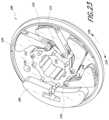
- FIG. 23illustrates a perspective front view of a dynamic pulley system.
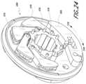
- FIG. 24illustrates a perspective back view of the dynamic pulley system of FIG. 23 .
- FIG. 25illustrates a front view of the dynamic pulley system of FIGS. 23 - 24 .
- FIG. 26illustrates a back view of the dynamic pulley system of FIGS. 23 - 25 .
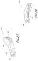
- FIG. 27illustrates a perspective top view of a leaf of the dynamic pulley system of FIGS. 23 - 26 .
- FIG. 28illustrate a perspective side view of the leaf of FIG. 27 .
- FIG. 29illustrates a perspective front view of the dynamic pulley system of FIG. 23 with a wire extended over the leaves and the leaves in an expanded configuration.
- FIG. 30illustrates a perspective front view of the dynamic pulley system of FIG. 29 with the wire extended over the leaves and the leaves in a collapsed configuration.
- FIG. 31illustrates a perspective side view of the dynamic pulley system of FIG. 23 with a pair of wires extending over the leaves.
- FIG. 32illustrates a medical instrument with a dynamic pulley system with four pulleys.
- aspects of the present disclosuremay be integrated into a robotically-enabled medical system capable of performing a variety of medical procedures, including both minimally invasive, such as laparoscopy, and non-invasive, such as endoscopy, procedures.
- the systemmay be capable of performing bronchoscopy, ureteroscopy, gastroscopy, etc.
- the systemmay provide additional benefits, such as enhanced imaging and guidance to assist the physician. Additionally, the system may provide the physician with the ability to perform the procedure from an ergonomic position without the need for awkward arm motions and positions. Still further, the system may provide the physician with the ability to perform the procedure with improved ease of use such that one or more of the instruments of the system can be controlled by a single user.
- FIG. 1illustrates an embodiment of a cart-based robotically-enabled system 10 arranged for a diagnostic and/or therapeutic bronchoscopy.
- the system 10may comprise a cart 11 having one or more robotic arms 12 to deliver a medical instrument, such as a steerable endoscope 13 , which may be a procedure-specific bronchoscope for bronchoscopy, to a natural orifice access point (i.e., the mouth of the patient positioned on a table in the present example) to deliver diagnostic and/or therapeutic tools.
- a medical instrumentsuch as a steerable endoscope 13
- a natural orifice access pointi.e., the mouth of the patient positioned on a table in the present example
- the cart 11may be positioned proximate to the patient's upper torso in order to provide access to the access point.
- the robotic arms 12may be actuated to position the bronchoscope relative to the access point.
- the arrangement in FIG. 1may also be utilized when performing a gastro-intestinal (GI) procedure with a gastroscope, a specialized endoscope for GI procedures.
- FIG. 2depicts an example embodiment of the cart in greater detail.
- the robotic arms 12may insert the steerable endoscope 13 into the patient robotically, manually, or a combination thereof.
- the steerable endoscope 13may comprise at least two telescoping parts, such as an inner leader portion and an outer sheath portion, each portion coupled to a separate instrument driver from the set of instrument drivers 28 , each instrument driver coupled to the distal end of an individual robotic arm.
- This linear arrangement of the instrument drivers 28which facilitates coaxially aligning the leader portion with the sheath portion, creates a “virtual rail” 29 that may be repositioned in space by manipulating the one or more robotic arms 12 into different angles and/or positions.
- the virtual rails described hereinare depicted in the Figures using dashed lines, and accordingly the dashed lines do not depict any physical structure of the system.
- Translation of the instrument drivers 28 along the virtual rail 29telescopes the inner leader portion relative to the outer sheath portion or advances or retracts the endoscope 13 from the patient.
- the angle of the virtual rail 29may be adjusted, translated, and pivoted based on clinical application or physician preference. For example, in bronchoscopy, the angle and position of the virtual rail 29 as shown represents a compromise between providing physician access to the endoscope 13 while minimizing friction that results from bending the endoscope 13 into the patient's mouth.
- the endoscope 13may be directed down the patient's trachea and lungs after insertion using precise commands from the robotic system until reaching the target destination or operative site. In order to enhance navigation through the patient's lung network and/or reach the desired target, the endoscope 13 may be manipulated to telescopically extend the inner leader portion from the outer sheath portion to obtain enhanced articulation and greater bend radius.
- the use of separate instrument drivers 28also allows the leader portion and sheath portion to be driven independently of each other.
- the endoscope 13may be directed to deliver a biopsy needle to a target, such as, for example, a lesion or nodule within the lungs of a patient.
- the needlemay be deployed down a working channel that runs the length of the endoscope to obtain a tissue sample to be analyzed by a pathologist.
- additional toolsmay be deployed down the working channel of the endoscope for additional biopsies.
- the endoscope 13may endoscopically deliver tools to resect the potentially cancerous tissue.
- diagnostic and therapeutic treatmentscan be delivered in separate procedures.
- the endoscope 13may also be used to deliver a fiducial to “mark” the location of the target nodule as well. In other instances, diagnostic and therapeutic treatments may be delivered during the same procedure.
- the system 10may also include a movable tower 30 , which may be connected via support cables to the cart 11 to provide support for controls, electronics, fluidics, optics, sensors, and/or power to the cart 11 . Placing such functionality in the tower 30 allows for a smaller form factor cart 11 that may be more easily adjusted and/or re-positioned by an operating physician and his/her staff. Additionally, the division of functionality between the cart/table and the support tower 30 reduces operating room clutter and facilitates improving clinical workflow. While the cart 11 may be positioned close to the patient, the tower 30 may be stowed in a remote location to stay out of the way during a procedure.
- the tower 30may include component(s) of a computer-based control system that stores computer program instructions, for example, within a non-transitory computer-readable storage medium such as a persistent magnetic storage drive, solid state drive, etc.
- the execution of those instructionsmay control the entire system or sub-system(s) thereof.
- the instructionswhen executed by a processor of the computer system, the instructions may cause the components of the robotics system to actuate the relevant carriages and arm mounts, actuate the robotics arms, and control the medical instruments.
- the motors in the joints of the robotics armsmay position the arms into a certain posture.
- the tower 30may also include a pump, flow meter, valve control, and/or fluid access in order to provide controlled irrigation and aspiration capabilities to the system that may be deployed through the endoscope 13 . These components may also be controlled using the computer system of the tower 30 . In some embodiments, irrigation and aspiration capabilities may be delivered directly to the endoscope 13 through separate cable(s).
- the tower 30may include a voltage and surge protector designed to provide filtered and protected electrical power to the cart 11 , thereby avoiding placement of a power transformer and other auxiliary power components in the cart 11 , resulting in a smaller, more moveable cart 11 .
- the tower 30may also include support equipment for the sensors deployed throughout the robotic system 10 .
- the tower 30may include optoelectronics equipment for detecting, receiving, and processing data received from the optical sensors or cameras throughout the robotic system 10 . In combination with the control system, such optoelectronics equipment may be used to generate real-time images for display in any number of consoles deployed throughout the system, including in the tower 30 .
- the tower 30may also include an electronic subsystem for receiving and processing signals received from deployed electromagnetic (EM) sensors.
- EMelectromagnetic
- the tower 30may also be used to house and position an EM field generator for detection by EM sensors in or on the medical instrument.
- the tower 30may also include a console 31 in addition to other consoles available in the rest of the system, e.g., console mounted on top of the cart.
- the console 31may include a user interface and a display screen, such as a touchscreen, for the physician operator.
- Consoles in the system 10are generally designed to provide both robotic controls as well as preoperative and real-time information of the procedure, such as navigational and localization information of the endoscope 13 .
- the console 31is not the only console available to the physician, it may be used by a second operator, such as a nurse, to monitor the health or vitals of the patient and the operation of the system 10 , as well as to provide procedure-specific data, such as navigational and localization information.
- the console 30is housed in a body that is separate from the tower 30 .
- the tower 30may be coupled to the cart 11 and endoscope 13 through one or more cables or connections (not shown).
- the support functionality from the tower 30may be provided through a single cable to the cart 11 , simplifying and de-cluttering the operating room.
- specific functionalitymay be coupled in separate cabling and connections. For example, while power may be provided through a single power cable to the cart 11 , the support for controls, optics, fluidics, and/or navigation may be provided through a separate cable.
- FIG. 2provides a detailed illustration of an embodiment of the cart 11 from the cart-based robotically-enabled system shown in FIG. 1 .
- the cart 11generally includes an elongated support structure 14 (often referred to as a “column”), a cart base 15 , and a console 16 at the top of the column 14 .
- the column 14may include one or more carriages, such as a carriage 17 (alternatively “arm support”) for supporting the deployment of one or more robotic arms 12 (three shown in FIG. 2 ).
- the carriage 17may include individually configurable arm mounts that rotate along a perpendicular axis to adjust the base of the robotic arms 12 for better positioning relative to the patient.
- the carriage 17also includes a carriage interface 19 that allows the carriage 17 to vertically translate along the column 14 .
- the carriage interface 19is connected to the column 14 through slots, such as slot 20 , that are positioned on opposite sides of the column 14 to guide the vertical translation of the carriage 17 .
- the slot 20contains a vertical translation interface to position and hold the carriage 17 at various vertical heights relative to the cart base 15 .
- Vertical translation of the carriage 17allows the cart 11 to adjust the reach of the robotic arms 12 to meet a variety of table heights, patient sizes, and physician preferences.
- the individually configurable arm mounts on the carriage 17allow the robotic arm base 21 of the robotic arms 12 to be angled in a variety of configurations.
- the slot 20may be supplemented with slot covers that are flush and parallel to the slot surface to prevent dirt and fluid ingress into the internal chambers of the column 14 and the vertical translation interface as the carriage 17 vertically translates.
- the slot coversmay be deployed through pairs of spring spools positioned near the vertical top and bottom of the slot 20 .
- the coversare coiled within the spools until deployed to extend and retract from their coiled state as the carriage 17 vertically translates up and down.
- the spring-loading of the spoolsprovides force to retract the cover into a spool when the carriage 17 translates towards the spool, while also maintaining a tight seal when the carriage 17 translates away from the spool.
- the coversmay be connected to the carriage 17 using, for example, brackets in the carriage interface 19 to ensure proper extension and retraction of the cover as the carriage 17 translates.
- the column 14may internally comprise mechanisms, such as gears and motors, that are designed to use a vertically aligned lead screw to translate the carriage 17 in a mechanized fashion in response to control signals generated in response to user inputs, e.g., inputs from the console 16 .
- the robotic arms 12may generally comprise robotic arm bases 21 and end effectors 22 , separated by a series of linkages 23 that are connected by a series of joints 24 , each joint comprising an independent actuator, each actuator comprising an independently controllable motor.
- Each independently controllable jointrepresents an independent degree of freedom available to the robotic arm 12 .
- Each of the robotic arms 12may have seven joints, and thus provide seven degrees of freedom. A multitude of joints result in a multitude of degrees of freedom, allowing for “redundant” degrees of freedom. Having redundant degrees of freedom allows the robotic arms 12 to position their respective end effectors 22 at a specific position, orientation, and trajectory in space using different linkage positions and joint angles. This allows for the system to position and direct a medical instrument from a desired point in space while allowing the physician to move the arm joints into a clinically advantageous position away from the patient to create greater access, while avoiding arm collisions.
- the cart base 15balances the weight of the column 14 , carriage 17 , and robotic arms 12 over the floor. Accordingly, the cart base 15 houses heavier components, such as electronics, motors, power supply, as well as components that either enable movement and/or immobilize the cart 11 .
- the cart base 15includes rollable wheel-shaped casters 25 that allow for the cart 11 to easily move around the room prior to a procedure. After reaching the appropriate position, the casters 25 may be immobilized using wheel locks to hold the cart 11 in place during the procedure.
- the console 16allows for both a user interface for receiving user input and a display screen (or a dual-purpose device such as, for example, a touchscreen 26 ) to provide the physician user with both preoperative and intraoperative data.
- Potential preoperative data on the touchscreen 26may include preoperative plans, navigation and mapping data derived from preoperative computerized tomography (CT) scans, and/or notes from preoperative patient interviews.
- Intraoperative data on displaymay include optical information provided from the tool, sensor and coordinate information from sensors, as well as vital patient statistics, such as respiration, heart rate, and/or pulse.
- the console 16may be positioned and tilted to allow a physician to access the console 16 from the side of the column 14 opposite the carriage 17 . From this position, the physician may view the console 16 , robotic arms 12 , and patient while operating the console 16 from behind the cart 11 .
- the console 16also includes a handle 27 to assist with maneuvering and stabilizing the cart 11 .
- FIG. 3illustrates an embodiment of a robotically-enabled system 10 arranged for ureteroscopy.
- the cart 11may be positioned to deliver a ureteroscope 32 , a procedure-specific endoscope designed to traverse a patient's urethra and ureter, to the lower abdominal area of the patient.
- the ureteroscope 32may be directly aligned with the patient's urethra to reduce friction and forces on the sensitive anatomy in the area.
- the cart 11may be aligned at the foot of the table to allow the robotic arms 12 to position the ureteroscope 32 for direct linear access to the patient's urethra. From the foot of the table, the robotic arms 12 may insert the ureteroscope 32 along the virtual rail 33 directly into the patient's lower abdomen through the urethra.
- the ureteroscope 32may be navigated into the bladder, ureters, and/or kidneys for diagnostic and/or therapeutic applications.
- the ureteroscope 32may be directed into the ureter and kidneys to break up kidney stone build up using a laser or ultrasonic lithotripsy device deployed down the working channel of the ureteroscope 32 .
- the resulting stone fragmentsmay be removed using baskets deployed down the ureteroscope 32 .
- FIG. 4illustrates an embodiment of a robotically-enabled system 10 similarly arranged for a vascular procedure.
- the system 10may be configured such that the cart 11 may deliver a medical instrument 34 , such as a steerable catheter, to an access point in the femoral artery in the patient's leg.
- the femoral arterypresents both a larger diameter for navigation as well as a relatively less circuitous and tortuous path to the patient's heart, which simplifies navigation.
- the cart 11may be positioned towards the patient's legs and lower abdomen to allow the robotic arms 12 to provide a virtual rail 35 with direct linear access to the femoral artery access point in the patient's thigh/hip region.
- the medical instrument 34may be directed and inserted by translating the instrument drivers 28 .
- the cartmay be positioned around the patient's upper abdomen in order to reach alternative vascular access points, such as, for example, the carotid and brachial arteries near the shoulder and wrist.
- Embodiments of the robotically-enabled medical systemmay also incorporate the patient's table. Incorporation of the table reduces the amount of capital equipment within the operating room by removing the cart, which allows greater access to the patient.
- FIG. 5illustrates an embodiment of such a robotically-enabled system arranged for a bronchoscopic procedure.
- System 36includes a support structure or column 37 for supporting platform 38 (shown as a “table” or “bed”) over the floor.
- the end effectors of the robotic arms 39 of the system 36comprise instrument drivers 42 that are designed to manipulate an elongated medical instrument, such as a bronchoscope 40 in FIG. 5 , through or along a virtual rail 41 formed from the linear alignment of the instrument drivers 42 .
- a C-arm for providing fluoroscopic imagingmay be positioned over the patient's upper abdominal area by placing the emitter and detector around the table 38 .
- FIG. 6provides an alternative view of the system 36 without the patient and medical instrument for discussion purposes.
- the column 37may include one or more carriages 43 shown as ring-shaped in the system 36 , from which the one or more robotic arms 39 may be based.
- the carriages 43may translate along a vertical column interface 44 that runs the length of the column 37 to provide different vantage points from which the robotic arms 39 may be positioned to reach the patient.
- the carriage(s) 43may rotate around the column 37 using a mechanical motor positioned within the column 37 to allow the robotic arms 39 to have access to multiples sides of the table 38 , such as, for example, both sides of the patient.
- the carriagesmay be individually positioned on the column and may translate and/or rotate independently of the other carriages.
- the system 36can include a patient table or bed with adjustable arm supports in the form of bars or rails extending alongside it.
- One or more robotic arms 39e.g., via a shoulder with an elbow joint
- the robotic arms 39are advantageously capable of being stowed compactly beneath the patient table or bed, and subsequently raised during a procedure.
- the robotic arms 39may be mounted on the carriages 43 through a set of arm mounts 45 comprising a series of joints that may individually rotate and/or telescopically extend to provide additional configurability to the robotic arms 39 .
- the arm mounts 45may be positioned on the carriages 43 such that, when the carriages 43 are appropriately rotated, the arm mounts 45 may be positioned on either the same side of the table 38 (as shown in FIG. 6 ), on opposite sides of the table 38 (as shown in FIG. 9 ), or on adjacent sides of the table 38 (not shown).
- the column 37structurally provides support for the table 38 , and a path for vertical translation of the carriages 43 . Internally, the column 37 may be equipped with lead screws for guiding vertical translation of the carriages, and motors to mechanize the translation of the carriages 43 based the lead screws. The column 37 may also convey power and control signals to the carriages 43 and the robotic arms 39 mounted thereon.
- the table base 46serves a similar function as the cart base 15 in the cart 11 shown in FIG. 2 , housing heavier components to balance the table/bed 38 , the column 37 , the carriages 43 , and the robotic arms 39 .
- the table base 46may also incorporate rigid casters to provide stability during procedures. Deployed from the bottom of the table base 46 , the casters may extend in opposite directions on both sides of the base 46 and retract when the system 36 needs to be moved.
- the system 36may also include a tower (not shown) that divides the functionality of the system 36 between the table and the tower to reduce the form factor and bulk of the table.
- the towermay provide a variety of support functionalities to the table, such as processing, computing, and control capabilities, power, fluidics, and/or optical and sensor processing.
- the towermay also be movable to be positioned away from the patient to improve physician access and de-clutter the operating room. Additionally, placing components in the tower allows for more storage space in the table base 46 for potential stowage of the robotic arms 39 .
- the towermay also include a master controller or console that provides both a user interface for user input, such as keyboard and/or pendant, as well as a display screen (or touchscreen) for preoperative and intraoperative information, such as real-time imaging, navigation, and tracking information.
- a master controller or consolethat provides both a user interface for user input, such as keyboard and/or pendant, as well as a display screen (or touchscreen) for preoperative and intraoperative information, such as real-time imaging, navigation, and tracking information.
- the towermay also contain holders for gas tanks to be used for insufflation.
- a table basemay stow and store the robotic arms when not in use.
- FIG. 7illustrates a system 47 that stows robotic arms in an embodiment of the table-based system.
- carriages 48may be vertically translated into base 49 to stow robotic arms 50 , arm mounts 51 , and the carriages 48 within the base 49 .
- Base covers 52may be translated and retracted open to deploy the carriages 48 , arm mounts 51 , and robotic arms 50 around column 53 , and closed to stow to protect them when not in use.
- the base covers 52may be sealed with a membrane 54 along the edges of its opening to prevent dirt and fluid ingress when closed.
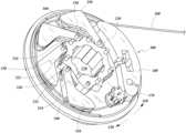
- FIG. 8illustrates an embodiment of a robotically-enabled table-based system configured for a ureteroscopic procedure.
- the table 38may include a swivel portion 55 for positioning a patient off-angle from the column 37 and table base 46 .
- the swivel portion 55may rotate or pivot around a pivot point (e.g., located below the patient's head) in order to position the bottom portion of the swivel portion 55 away from the column 37 .
- the pivoting of the swivel portion 55allows a C-arm (not shown) to be positioned over the patient's lower abdomen without competing for space with the column (not shown) below table 38 .
- the robotic arms 39may directly insert a ureteroscope 56 along a virtual rail 57 into the patient's groin area to reach the urethra.
- stirrups 58may also be fixed to the swivel portion 55 of the table 38 to support the position of the patient's legs during the procedure and allow clear access to the patient's groin area.
- minimally invasive instrumentsmay be inserted into the patient's anatomy.
- the minimally invasive instrumentscomprise an elongated rigid member, such as a shaft, which is used to access anatomy within the patient. After inflation of the patient's abdominal cavity, the instruments may be directed to perform surgical or medical tasks, such as grasping, cutting, ablating, suturing, etc.
- the instrumentscan comprise a scope, such as a laparoscope.
- FIG. 9illustrates an embodiment of a robotically-enabled table-based system configured for a laparoscopic procedure. As shown in FIG.
- the carriages 43 of the system 36may be rotated and vertically adjusted to position pairs of the robotic arms 39 on opposite sides of the table 38 , such that instrument 59 may be positioned using the arm mounts 45 to be passed through minimal incisions on both sides of the patient to reach his/her abdominal cavity.
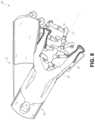
- FIG. 10illustrates an embodiment of the robotically-enabled medical system with pitch or tilt adjustment.
- the system 36may accommodate tilt of the table 38 to position one portion of the table at a greater distance from the floor than the other.
- the arm mounts 45may rotate to match the tilt such that the robotic arms 39 maintain the same planar relationship with the table 38 .
- the column 37may also include telescoping portions 60 that allow vertical extension of the column 37 to keep the table 38 from touching the floor or colliding with the table base 46 .
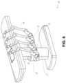
- FIG. 11provides a detailed illustration of the interface between the table 38 and the column 37 .
- Pitch rotation mechanism 61may be configured to alter the pitch angle of the table 38 relative to the column 37 in multiple degrees of freedom.
- the pitch rotation mechanism 61may be enabled by the positioning of orthogonal axes 1 , 2 at the column-table interface, each axis actuated by a separate motor 3 , 4 responsive to an electrical pitch angle command. Rotation along one screw 5 would enable tilt adjustments in one axis 1 , while rotation along the other screw 6 would enable tilt adjustments along the other axis 2 .
- a ball jointcan be used to alter the pitch angle of the table 38 relative to the column 37 in multiple degrees of freedom.
- pitch adjustmentsare particularly useful when trying to position the table in a Trendelenburg position, i.e., position the patient's lower abdomen at a higher position from the floor than the patient's upper abdomen, for lower abdominal surgery.
- the Trendelenburg positioncauses the patient's internal organs to slide towards his/her upper abdomen through the force of gravity, clearing out the abdominal cavity for minimally invasive tools to enter and perform lower abdominal surgical or medical procedures, such as laparoscopic prostatectomy.
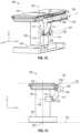
- FIGS. 12 and 13illustrate isometric and end views of an alternative embodiment of a table-based surgical robotics system 100 .
- the surgical robotics system 100includes one or more adjustable arm supports 105 that can be configured to support one or more robotic arms (see, for example, FIG. 14 ) relative to a table 101 .
- a single adjustable arm support 105is shown, though an additional arm support can be provided on an opposite side of the table 101 .
- the adjustable arm support 105can be configured so that it can move relative to the table 101 to adjust and/or vary the position of the adjustable arm support 105 and/or any robotic arms mounted thereto relative to the table 101 .
- the adjustable arm support 105may be adjusted one or more degrees of freedom relative to the table 101 .
- the adjustable arm support 105provides high versatility to the system 100 , including the ability to easily stow the one or more adjustable arm supports 105 and any robotics arms attached thereto beneath the table 101 .
- the adjustable arm support 105can be elevated from the stowed position to a position below an upper surface of the table 101 . In other embodiments, the adjustable arm support 105 can be elevated from the stowed position to a position above an upper surface of the table 101 .
- the adjustable arm support 105can provide several degrees of freedom, including lift, lateral translation, tilt, etc.
- the arm support 105is configured with four degrees of freedom, which are illustrated with arrows in FIG. 12 .
- a first degree of freedomallows for adjustment of the adjustable arm support 105 in the z-direction (“Z-lift”).
- the adjustable arm support 105can include a carriage 109 configured to move up or down along or relative to a column 102 supporting the table 101 .
- a second degree of freedomcan allow the adjustable arm support 105 to tilt.
- the adjustable arm support 105can include a rotary joint, which can allow the adjustable arm support 105 to be aligned with the bed in a Trendelenburg position.
- a third degree of freedomcan allow the adjustable arm support 105 to “pivot up,” which can be used to adjust a distance between a side of the table 101 and the adjustable arm support 105 .
- a fourth degree of freedomcan permit translation of the adjustable arm support 105 along a longitudinal length of the table.
- the surgical robotics system 100 in FIGS. 12 and 13can comprise a table supported by a column 102 that is mounted to a base 103 .
- the base 103 and the column 102support the table 101 relative to a support surface.
- a floor axis 131 and a support axis 133are shown in FIG. 13 .
- the adjustable arm support 105can be mounted to the column 102 . In other embodiments, the arm support 105 can be mounted to the table 101 or base 103 .
- the adjustable arm support 105can include a carriage 109 , a bar or rail connector 111 and a bar or rail 107 . In some embodiments, one or more robotic arms mounted to the rail 107 can translate and move relative to one another.
- the carriage 109can be attached to the column 102 by a first joint 113 , which allows the carriage 109 to move relative to the column 102 (e.g., such as up and down a first or vertical axis 123 ).
- the first joint 113can provide the first degree of freedom (“Z-lift”) to the adjustable arm support 105 .
- the adjustable arm support 105can include a second joint 115 , which provides the second degree of freedom (tilt) for the adjustable arm support 105 .
- the adjustable arm support 105can include a third joint 117 , which can provide the third degree of freedom (“pivot up”) for the adjustable arm support 105 .
- An additional joint 119(shown in FIG.
- the adjustable arm support 105can include a fourth joint 121 , which can provide a fourth degree of freedom (translation) for the adjustable arm support 105 along a fourth axis 129 .
- FIG. 14illustrates an end view of the surgical robotics system 140 A with two adjustable arm supports 105 A, 105 B mounted on opposite sides of a table 101 .
- a first robotic arm 142 Ais attached to the bar or rail 107 A of the first adjustable arm support 105 B.
- the first robotic arm 142 Aincludes a base 144 A attached to the rail 107 A.
- the distal end of the first robotic arm 142 Aincludes an instrument drive mechanism 146 A that can attach to one or more robotic medical instruments or tools.
- the second robotic arm 142 Bincludes a base 144 B attached to the rail 107 B.
- the distal end of the second robotic arm 142 Bincludes an instrument drive mechanism 146 B.
- the instrument drive mechanism 146 Bcan be configured to attach to one or more robotic medical instruments or tools.
- one or more of the robotic arms 142 A, 142 Bcomprises an arm with seven or more degrees of freedom.
- one or more of the robotic arms 142 A, 142 Bcan include eight degrees of freedom, including an insertion axis (1-degree of freedom including insertion), a wrist (3-degrees of freedom including wrist pitch, yaw and roll), an elbow (1-degree of freedom including elbow pitch), a shoulder (2-degrees of freedom including shoulder pitch and yaw), and base 144 A, 144 B (1-degree of freedom including translation).
- the insertion degree of freedomcan be provided by the robotic arm 142 A, 142 B, while in other embodiments, the instrument itself provides insertion via an instrument-based insertion architecture.
- the end effectors of the system's robotic armsmay comprise (i) an instrument driver (alternatively referred to as “instrument drive mechanism” or “instrument device manipulator”) that incorporates electro-mechanical means for actuating the medical instrument and (ii) a removable or detachable medical instrument, which may be devoid of any electro-mechanical components, such as motors.
- instrument driveralternatively referred to as “instrument drive mechanism” or “instrument device manipulator”
- instrument device manipulatora removable or detachable medical instrument, which may be devoid of any electro-mechanical components, such as motors.
- This dichotomymay be driven by the need to sterilize medical instruments used in medical procedures, and the inability to adequately sterilize expensive capital equipment due to their intricate mechanical assemblies and sensitive electronics. Accordingly, the medical instruments may be designed to be detached, removed, and interchanged from the instrument driver (and thus the system) for individual sterilization or disposal by the physician or the physician's staff. In contrast, the instrument drivers need not be changed or sterilized, and may be draped for protection
- FIG. 15illustrates an example instrument driver.
- instrument driver 62Positioned at the distal end of a robotic arm, instrument driver 62 comprises one or more drive units 63 arranged with parallel axes to provide controlled torque to a medical instrument via drive shafts 64 .
- Each drive unit 63comprises an individual drive shaft 64 for interacting with the instrument, a gear head 65 for converting the motor shaft rotation to a desired torque, a motor 66 for generating the drive torque, an encoder 67 to measure the speed of the motor shaft and provide feedback to the control circuitry, and control circuity 68 for receiving control signals and actuating the drive unit.
- Each drive unit 63being independently controlled and motorized, the instrument driver 62 may provide multiple (e.g., four as shown in FIG. 15 ) independent drive outputs to the medical instrument.
- the control circuitry 68would receive a control signal, transmit a motor signal to the motor 66 , compare the resulting motor speed as measured by the encoder 67 with the desired speed, and modulate the motor signal to
- the robotic systemmay incorporate a drive interface, such as a sterile adapter connected to a sterile drape, that sits between the instrument driver and the medical instrument.
- a drive interfacesuch as a sterile adapter connected to a sterile drape
- the chief purpose of the sterile adapteris to transfer angular motion from the drive shafts of the instrument driver to the drive inputs of the instrument while maintaining physical separation, and thus sterility, between the drive shafts and drive inputs.
- an example sterile adaptermay comprise a series of rotational inputs and outputs intended to be mated with the drive shafts of the instrument driver and drive inputs on the instrument.
- the sterile drapecomprised of a thin, flexible material such as transparent or translucent plastic, is designed to cover the capital equipment, such as the instrument driver, robotic arm, and cart (in a cart-based system) or table (in a table-based system).
- the capital equipmentsuch as the instrument driver, robotic arm, and cart (in a cart-based system) or table (in a table-based system).
- Use of the drapewould allow the capital equipment to be positioned proximate to the patient while still being located in an area not requiring sterilization (i.e., non-sterile field).
- the medical instrumentmay interface with the patient in an area requiring sterilization (i.e., sterile field).
- FIG. 16illustrates an example medical instrument with a paired instrument driver.
- medical instrument 70comprises an elongated shaft 71 (or elongate body) and an instrument base 72 .
- the instrument base 72also referred to as an “instrument handle” due to its intended design for manual interaction by the physician, may generally comprise rotatable drive inputs 73 , e.g., receptacles, pulleys or spools, that are designed to be mated with drive outputs 74 that extend through a drive interface on instrument driver 75 at the distal end of robotic arm 76 .
- the mated drive inputs 73 of the instrument base 72may share axes of rotation with the drive outputs 74 in the instrument driver 75 to allow the transfer of torque from the drive outputs 74 to the drive inputs 73 .
- the drive outputs 74may comprise splines that are designed to mate with receptacles on the drive inputs 73 .
- the elongated shaft 71is designed to be delivered through either an anatomical opening or lumen, e.g., as in endoscopy, or a minimally invasive incision, e.g., as in laparoscopy.
- the elongated shaft 71may be either flexible (e.g., having properties similar to an endoscope) or rigid (e.g., having properties similar to a laparoscope) or contain a customized combination of both flexible and rigid portions.
- the distal end of a rigid elongated shaftmay be connected to an end effector extending from a jointed wrist formed from a clevis with at least one degree of freedom and a surgical tool or medical instrument, such as, for example, a grasper or scissors, that may be actuated based on force from the tendons as the drive inputs rotate in response to torque received from the drive outputs 74 of the instrument driver 75 .
- a surgical tool or medical instrumentsuch as, for example, a grasper or scissors
- the distal end of a flexible elongated shaftmay include a steerable or controllable bending section that may be articulated and bent based on torque received from the drive outputs 74 of the instrument driver 75 .
- Torque from the instrument driver 75is transmitted down the elongated shaft 71 using tendons along the elongated shaft 71 .
- These individual tendonssuch as pull wires, may be individually anchored to individual drive inputs 73 within the instrument handle 72 .
- the tendonsare directed down one or more pull lumens along the elongated shaft 71 and anchored at the distal portion of the elongated shaft 71 , or in the wrist at the distal portion of the elongated shaft.
- these tendonsmay be coupled to a distally mounted end effector, such as a wrist, grasper, or scissor.
- the tendonmay cause a joint to rotate about an axis, thereby causing the end effector to move in one direction or another.
- the tendonmay be connected to one or more jaws of a grasper at the distal end of the elongated shaft 71 , where tension from the tendon causes the grasper to close.
- the tendonsmay be coupled to a bending or articulating section positioned along the elongated shaft 71 (e.g., at the distal end) via adhesive, control ring, or other mechanical fixation.
- a bending or articulating sectionpositioned along the elongated shaft 71 (e.g., at the distal end) via adhesive, control ring, or other mechanical fixation.
- torque exerted on the drive inputs 73would be transmitted down the tendons, causing the softer, bending section (sometimes referred to as the articulable section or region) to bend or articulate.
- the angle of the spiraling and/or spacing therebetweenmay be altered or engineered for specific purposes, wherein tighter spiraling exhibits lesser shaft compression under load forces, while lower amounts of spiraling results in greater shaft compression under load forces, but limits bending.
- the pull lumensmay be directed parallel to the longitudinal axis of the elongated shaft 71 to allow for controlled articulation in the desired bending or articulable sections.
- the elongated shaft 71houses a number of components to assist with the robotic procedure.
- the shaft 71may comprise a working channel for deploying surgical tools (or medical instruments), irrigation, and/or aspiration to the operative region at the distal end of the shaft 71 .
- the shaft 71may also accommodate wires and/or optical fibers to transfer signals to/from an optical assembly at the distal tip, which may include an optical camera.
- the shaft 71may also accommodate optical fibers to carry light from proximally-located light sources, such as light emitting diodes, to the distal end of the shaft 71 .
- the distal tipmay also comprise the opening of a working channel for delivering tools for diagnostic and/or therapy, irrigation, and aspiration to an operative site.
- the distal tipmay also include a port for a camera, such as a fiberscope or a digital camera, to capture images of an internal anatomical space.
- the distal tipmay also include ports for light sources for illuminating the anatomical space when using the camera.
- the drive shaft axesand thus the drive input axes, are orthogonal to the axis of the elongated shaft 71 .
- This arrangementcomplicates roll capabilities for the elongated shaft 71 .
- Rolling the elongated shaft 71 along its axis while keeping the drive inputs 73 staticresults in undesirable tangling of the tendons as they extend off the drive inputs 73 and enter pull lumens within the elongated shaft 71 .
- the resulting entanglement of such tendonsmay disrupt any control algorithms intended to predict movement of the flexible elongated shaft 71 during an endoscopic procedure.
- FIG. 17illustrates an alternative design for an instrument driver and instrument where the axes of the drive units are parallel to the axis of the elongated shaft of the instrument.
- a circular instrument driver 80comprises four drive units with their drive outputs 81 aligned in parallel at the end of a robotic arm 82 .
- the drive units, and their respective drive outputs 81are housed in a rotational assembly 83 of the instrument driver 80 that is driven by one of the drive units within the assembly 83 .
- the rotational assembly 83rotates along a circular bearing that connects the rotational assembly 83 to the non-rotational portion 84 of the instrument driver 80 .
- Power and controls signalsmay be communicated from the non-rotational portion 84 of the instrument driver 80 to the rotational assembly 83 through electrical contacts that may be maintained through rotation by a brushed slip ring connection (not shown).
- the rotational assembly 83may be responsive to a separate drive unit that is integrated into the non-rotatable portion 84 , and thus not in parallel to the other drive units.
- the rotational mechanism 83allows the instrument driver 80 to rotate the drive units, and their respective drive outputs 81 , as a single unit around an instrument driver axis 85 .
- an instrument 86may comprise an elongated shaft portion 88 and an instrument base 87 (shown with a transparent external skin for discussion purposes) comprising a plurality of drive inputs 89 (such as receptacles, pulleys, and spools) that are configured to receive the drive outputs 81 in the instrument driver 80 .
- the instrument shaft 88extends from the center of the instrument base 87 with an axis substantially parallel to the axes of the drive inputs 89 , rather than orthogonal as in the design of FIG. 16 .
- the medical instrument 86When coupled to the rotational assembly 83 of the instrument driver 80 , the medical instrument 86 , comprising instrument base 87 and instrument shaft 88 , rotates in combination with the rotational assembly 83 about the instrument driver axis 85 . Since the instrument shaft 88 is positioned at the center of instrument base 87 , the instrument shaft 88 is coaxial with instrument driver axis 85 when attached. Thus, rotation of the rotational assembly 83 causes the instrument shaft 88 to rotate about its own longitudinal axis. Moreover, as the instrument base 87 rotates with the instrument shaft 88 , any tendons connected to the drive inputs 89 in the instrument base 87 are not tangled during rotation. Accordingly, the parallelism of the axes of the drive outputs 81 , drive inputs 89 , and instrument shaft 88 allows for the shaft rotation without tangling any control tendons.
- FIG. 18illustrates an instrument having an instrument based insertion architecture in accordance with some embodiments.
- the instrument 150can be coupled to any of the instrument drivers discussed above.
- the instrument 150comprises an elongated shaft 152 , an end effector 162 connected to the shaft 152 , and a handle 170 coupled to the shaft 152 .
- the elongated shaft 152comprises a tubular member having a proximal portion 154 and a distal portion 156 .
- the elongated shaft 152comprises one or more channels or grooves 158 along its outer surface.
- the grooves 158are configured to receive one or more wires or cables 180 therethrough.
- One or more cables 180thus run along an outer surface of the elongated shaft 152 .
- cables 180can also run through the elongated shaft 152 .
- Manipulation of the one or more cables 180results in actuation of the end effector 162 .
- the instrument handle 170which may also be referred to as an instrument base, may generally comprise an attachment interface 172 having one or more mechanical inputs 174 , e.g., receptacles, pulleys or spools, that are designed to be reciprocally mated with one or more torque couplers on an attachment surface of an instrument driver.
- mechanical inputs 174e.g., receptacles, pulleys or spools, that are designed to be reciprocally mated with one or more torque couplers on an attachment surface of an instrument driver.
- the instrument 150comprises a series of pulleys or cables that enable the elongated shaft 152 to translate relative to the handle 170 .
- the instrument 150itself comprises an instrument-based insertion architecture that accommodates insertion of the instrument, thereby minimizing the reliance on a robot arm to provide insertion of the instrument 150 .
- a robotic armcan be largely responsible for instrument insertion.
- any of the robotic systems described hereincan include an input device or controller for manipulating an instrument attached to a robotic arm.
- the controllercan be coupled (e.g., communicatively, electronically, electrically, wirelessly and/or mechanically) with an instrument such that manipulation of the controller causes a corresponding manipulation of the instrument e.g., via master slave control.
- FIG. 19is a perspective view of an embodiment of a controller 182 .
- the controller 182comprises a hybrid controller that can have both impedance and admittance control.
- the controller 182can utilize just impedance or passive control.
- the controller 182can utilize just admittance control.
- the controller 182advantageously can have a lower perceived inertia while in use.
- the controller 182is configured to allow manipulation of two medical instruments, and includes two handles 184 .
- Each of the handles 184is connected to a gimbal 186 .
- Each gimbal 186is connected to a positioning platform 188 .
- each positioning platform 188includes a SCARA arm (selective compliance assembly robot arm) 198 coupled to a column 194 by a prismatic joint 196 .
- the prismatic joints 196are configured to translate along the column 194 (e.g., along rails 197 ) to allow each of the handles 184 to be translated in the z-direction, providing a first degree of freedom.
- the SCARA arm 198is configured to allow motion of the handle 184 in an x-y plane, providing two additional degrees of freedom.
- one or more load cellsare positioned in the controller.
- a load cell(not shown) is positioned in the body of each of the gimbals 186 .
- portions of the controller 182are capable of operating under admittance control, thereby advantageously reducing the perceived inertia of the controller while in use.
- the positioning platform 188is configured for admittance control, while the gimbal 186 is configured for impedance control.
- the gimbal 186is configured for admittance control, while the positioning platform 188 is configured for impedance control. Accordingly, for some embodiments, the translational or positional degrees of freedom of the positioning platform 188 can rely on admittance control, while the rotational degrees of freedom of the gimbal 186 rely on impedance control.
- the robotic systems contemplated by this disclosurecan provide for non-radiation-based navigational and localization means to reduce physician exposure to radiation and reduce the amount of equipment within the operating room.
- the term “localization”may refer to determining and/or monitoring the position of objects in a reference coordinate system. Technologies such as preoperative mapping, computer vision, real-time EM tracking, and robot command data may be used individually or in combination to achieve a radiation-free operating environment. In other cases, where radiation-based imaging modalities are still used, the preoperative mapping, computer vision, real-time EM tracking, and robot command data may be used individually or in combination to improve upon the information obtained solely through radiation-based imaging modalities.
- FIG. 20is a block diagram illustrating a localization system 90 that estimates a location of one or more elements of the robotic system, such as the location of the instrument, in accordance to an example embodiment.
- the localization system 90may be a set of one or more computer devices configured to execute one or more instructions.
- the computer devicesmay be embodied by a processor (or processors) and computer-readable memory in one or more components discussed above.
- the computer devicesmay be in the tower 30 shown in FIG. 1 , the cart 11 shown in FIGS. 1 - 4 , the beds shown in FIGS. 5 - 14 , etc.
- the localization system 90may include a localization module 95 that processes input data 91 - 94 to generate location data 96 for the distal tip of a medical instrument.
- the location data 96may be data or logic that represents a location and/or orientation of the distal end of the instrument relative to a frame of reference.
- the frame of referencecan be a frame of reference relative to the anatomy of the patient or to a known object, such as an EM field generator (see discussion below for the EM field generator).
- Preoperative mappingmay be accomplished through the use of the collection of low dose CT scans.
- Preoperative CT scansare reconstructed into three-dimensional images, which are visualized, e.g. as “slices” of a cutaway view of the patient's internal anatomy.
- image-based models for anatomical cavities, spaces and structures of the patient's anatomy, such as a patient lung networkmay be generated.
- Techniquessuch as center-line geometry may be determined and approximated from the CT images to develop a three-dimensional volume of the patient's anatomy, referred to as model data 91 (also referred to as “preoperative model data” when generated using only preoperative CT scans).
- Network topological modelsmay also be derived from the CT-images, and are particularly appropriate for bronchoscopy.
- the instrumentmay be equipped with a camera to provide vision data (or image data) 92 .
- the localization module 95may process the vision data 92 to enable one or more vision-based (or image-based) location tracking modules or features.
- the preoperative model data 91may be used in conjunction with the vision data 92 to enable computer vision-based tracking of the medical instrument (e.g., an endoscope or an instrument advance through a working channel of the endoscope).
- the robotic systemmay generate a library of expected endoscopic images from the model based on the expected path of travel of the endoscope, each image linked to a location within the model. Intraoperatively, this library may be referenced by the robotic system in order to compare real-time images captured at the camera (e.g., a camera at a distal end of the endoscope) to those in the image library to assist localization.
- Some features of the localization module 95may identify circular geometries in the preoperative model data 91 that correspond to anatomical lumens and track the change of those geometries to determine which anatomical lumen was selected, as well as the relative rotational and/or translational motion of the camera. Use of a topological map may further enhance vision-based algorithms or techniques.
- Optical flowanother computer vision-based technique, may analyze the displacement and translation of image pixels in a video sequence in the vision data 92 to infer camera movement.
- optical flow techniquesmay include motion detection, object segmentation calculations, luminance, motion compensated encoding, stereo disparity measurement, etc. Through the comparison of multiple frames over multiple iterations, movement and location of the camera (and thus the endoscope) may be determined.
- the localization module 95may use real-time EM tracking to generate a real-time location of the endoscope in a global coordinate system that may be registered to the patient's anatomy, represented by the preoperative model.
- EM trackingan EM sensor (or tracker) comprising one or more sensor coils embedded in one or more locations and orientations in a medical instrument (e.g., an endoscopic tool) measures the variation in the EM field created by one or more static EM field generators positioned at a known location.
- the location information detected by the EM sensorsis stored as EM data 93 .
- the EM field generator(or transmitter), may be placed close to the patient to create a low intensity magnetic field that the embedded sensor may detect.
- the magnetic fieldinduces small currents in the sensor coils of the EM sensor, which may be analyzed to determine the distance and angle between the EM sensor and the EM field generator.
- These distances and orientationsmay be intraoperatively “registered” to the patient anatomy (e.g., the preoperative model) in order to determine the geometric transformation that aligns a single location in the coordinate system with a position in the preoperative model of the patient's anatomy.
- an embedded EM tracker in one or more positions of the medical instrumente.g., the distal tip of an endoscope
- Robotic command and kinematics data 94may also be used by the localization module 95 to provide localization data 96 for the robotic system.
- Device pitch and yaw resulting from articulation commandsmay be determined during preoperative calibration. Intraoperatively, these calibration measurements may be used in combination with known insertion depth information to estimate the position of the instrument. Alternatively, these calculations may be analyzed in combination with EM, vision, and/or topological modeling to estimate the position of the medical instrument within the network.
- a number of other input datacan be used by the localization module 95 .
- an instrument utilizing shape-sensing fibercan provide shape data that the localization module 95 can use to determine the location and shape of the instrument.
- the localization module 95may use the input data 91 - 94 in combination(s). In some cases, such a combination may use a probabilistic approach where the localization module 95 assigns a confidence weight to the location determined from each of the input data 91 - 94 . Thus, where the EM data may not be reliable (as may be the case where there is EM interference) the confidence of the location determined by the EM data 93 can be decrease and the localization module 95 may rely more heavily on the vision data 92 and/or the robotic command and kinematics data 94 .
- the robotic systems discussed hereinmay be designed to incorporate a combination of one or more of the technologies above.
- the robotic system's computer-based control systembased in the tower, bed and/or cart, may store computer program instructions, for example, within a non-transitory computer-readable storage medium such as a persistent magnetic storage drive, solid state drive, or the like, that, upon execution, cause the system to receive and analyze sensor data and user commands, generate control signals throughout the system, and display the navigational and localization data, such as the position of the instrument within the global coordinate system, anatomical map, etc.
- the robotic medical instrumentscan be used, in some aspects, with robotically-enabled medical systems, such as those described above with reference to FIGS. 1 - 20 .
- medical instrumentscan include an instrument configured to be controlled by a robotic arm, such as a flexible endoscope or catheter.
- the medical instrumentcan include a medical tool actuated with a wrist, a camera (e.g., with an optical fiber), a gripper tool, a basketing tool, a blade tool, a laser tool (e.g., with an optical fiber), and/or other instruments described herein.
- the medical instrumentscan be configured for endoscopic procedures.
- the medical instrumentscan be configured for ureteroscopy, gastroscopy, bronchoscopy, or other endoscopic procedures.
- the medical instrumentscan be configured for laparoscopic procedures or other types of medical procedures (e.g., open procedures).
- the medical instrumentmay be articulated to navigate through the patient's anatomy to access, visualize, and diagnose and/or treat pathologies in various organs via orifices and lumens of various organs, such as a kidney for ureteroscopy.
- the medical instrumentshould be flexible and deflectable in one or more directions.
- the medical instrumentcan also be elongate such that it can reach the desired target area in the patient's anatomy.
- the medical instrumentcan be attached to an instrument drive mechanism that is positioned on the end of a robotic arm or other instrument positioning device.
- the instrument drive mechanismcan include one or more robotic drive outputs that engage one or more robotic drive inputs or drive shafts to robotically control the medical instrument.
- the physicianmay use a controller (for example, as shown in FIG. 19 ) to control the robotically-enabled system.
- the medical instrumentcan include a tool with a wrist and the wrist can be actuated to control and manipulate the tool.
- the medical instrumentcan include an instrument handle, which can include one or more rotational drive inputs or drive shafts.
- the drive shaftsmay actuate one or more pullwires with one or more expanding pulleys.
- the one or more pullwiresmay be actuated to articulate an elongated shaft or the wrist of the tool.
- the medical instrumentscan include an elongated shaft and an instrument handle (or instrument base).
- the elongated shaftcan be configured for insertion into a patient's anatomy during a medical procedure.
- the elongated shaftis inserted into the patient's anatomy through a natural orifice.
- the elongated shaftis inserted into the patient's anatomy through an incision or other surgical opening.
- the elongated shaftcan be flexible.
- the elongated shaftcan be articulable and controllable. This can allow an operator, such as a physician, to control the articulation of the elongated shaft so as to navigate and steer the medical instrument through the patient's anatomy. Controlling the articulation of the elongated shaft can include deflecting or bending an articulable portion of the elongated shaft and in certain embodiments the roll or rotation of the elongated shaft about a longitudinal axis of the shaft.
- the articulable portioncan be a distal portion of the elongated shaft.
- the articulable portionmay be articulable in one or more degrees of freedom. Degrees of freedom may be linear or rotational. For example, a first degree of freedom may be translation along a first axis, a second degree of freedom may be translation along a second axis perpendicular to the first axis, and a third degree of freedom may be along a third axis perpendicular to both the first and second axes. Additional or alternative degrees of freedom may exist, such as rotation about one or more of the first, second, and/or third axes, and/or swiveling within first, second, and/or third planes. Actuation of the elongated shaft may be controlled at the instrument base.
- An instrument base or handlecan be connected to the elongate shaft, such as at the proximal portion or distal portion of the shaft.
- the instrument basecan include one or more rotational drive inputs or drive shafts.
- the elongate shaftcan be coupled to the drive input to control articulation of one or more portions of the elongate shaft.
- the elongated shaftcan include one or more pull wires which extend along the length of the elongate shaft.
- the one or more pull wirescan be actuatable to articulate the elongated shaft.
- the one or more drive inputs, coupled to one or more pull wires with one or more expandable pulleyscan be configured to bend the shaft, such as at the distal end, in various directions.
- the medical instrumentcan include drive inputs, which may also be called rotational drive inputs, inputs, drive shafts, rotational drive shafts, or shafts.
- the drive inputsmay be located in a handle of the medical instrument.
- one of the drive inputsis configured to provide two-way deflection control for the elongated shaft of the medical instrument.
- Two-way deflection controlcan allow deflection of the elongated shaft in two directions.
- the two directionscan be opposite directions, such as up and down or left and right. This can also referred to as two-way deflection control in a single plane, such as an up-down plane or a left-right plane.
- Directional termse.g., up, down, left, right, etc. are used broadly to indicate different directions relative to an orientation of the medical instrument. Because the medical instrument can be constantly repositioned in a wide variety of orientations, the directional terms should not be interpreted as limiting.
- the directions referred to as up, down, left, and rightcan change depending on the orientation of the instrument.
- controlling or operating the manual or robotic drive input in a first directioncauses deflection of the elongated shaft in a first direction (e.g., up) and manipulating the manual or robotic drive input in a second direction causes deflection of the elongated shaft in a second direction (e.g., down).
- the medical instrumentmay include an additional drive input configured to allow an additional two-way deflection control.
- the first drive inputcan allow two-way deflection control in opposing directions such as up and down directions
- the second drive inputcan allow two-way deflection control in left and right directions.
- the first drive inputcan allow two-way deflection in any two directions, such as up and left
- the second drive inputcan allow two-way deflection in the other two directions, such as down and right. This would permit four-way deflection control for the elongated shaft using two drive inputs.
- the drive inputsare configured to allow four-way deflection control.
- four-way deflection controlallows articulation of the elongated shaft in four different directions.
- the directionscan be four orthogonal directions, such as up, down, left, and right.
- the drive inputs configured for four-way deflection controlcan include two robotic drive inputs.
- the two drive inputscan be configured to engage to with two corresponding drive outputs on the instrument drive mechanism.
- Each drive inputcan be rotatable in two opposite directions, for example, clockwise and counterclockwise. Rotation of a first of the two drive inputs in one direction (e.g., the clockwise direction) can allow articulation in one of the four direction (e.g., up).
- Rotation of the first of the two drive inputs in the opposite directioncan allow articulation in another of the four directions (e.g., down).
- Rotation of a second of the two drive inputs in one directioncan allow articulation in another of the four directions (e.g., right).
- rotation of the second of the two drive inputs in the opposite directione.g., the counterclockwise direction
- four-way deflection controlcan be achieved using two drive inputs.
- the drive inputsare configured to provide other numbers of directional deflection control, such as two-way deflection control, three-way deflection control, etc.
- the medical instrumentcan include one or more pull wires extending along the elongated shaft (e.g., extending on or through at least a portion of the elongated shaft).
- the pull wirescan be attached to actuation mechanisms, such as one or more expandable pulleys, within the instrument handle.
- the actuation mechanismcan, in turn, be connected to the drive inputs such that actuation of the drive inputs operates the actuation mechanisms to pull on the pull wires to cause articulation of the elongated shaft.
- one or more of the drive inputsare each connected to the same actuation mechanism (e.g., pulley, capstan, and/or pulley assembly) within the instrument handle such that the drive input can be used to actuate the same actuation mechanism.
- actuation mechanisme.g., pulley, capstan, and/or pulley assembly
- the physicianmay control the medical instrument by controlling or operating drive inputs or drive shafts of the medical device. It can be advantageous to route and control two wires or cables on a single drive shaft, which can then drive bi-directional control. This can be advantageous as it is more efficient and frees up other drive shafts for other purposes (e.g., to control other types of articulation or functions).
- One of the challenges with articulating a medical instrumentis the management of slack in the pull wires or control wires about the pulley or capstan.
- Each of the two pull wirescan each be attached to a pulley.
- the two pulleyscan each couple to the same single drive shaft.
- the two pulleyscan be driven by the single drive shaft, allowing the single drive shaft to control two directions of articulation or deflection.
- the challenge with two wires routed on a single drive shaft (via two pulleys)can lead to excessive slack which can lead to excessive articulation response lag that creates a subpar robotic driving experience as a user attempts to navigate internal anatomical structures. For example, as a pulley is rotated one of the wires is placed in tension while the other un-tensioned wire becomes slack. When rotation of the pulley is reversed, the slack in the un-tensioned wire can create the undesirable lag described above.
- the control wirescan be used for instruments or for articulating an elongate shaft (such as a catheter). In either of these uses, it is desirable to use a single pulley to control two control wires on a single drive shaft, but this can lead to undesirable lag. Therefore, it is even more desirable to drive two pulleys on a single drive shaft, each pulley coupled to one of two control wires, that can reduce slack and minimize response lag.
- FIGS. 21 A- 21 B and 22 A- 22 Billustrate an example embodiment of a dynamic pulley system 200 with two expandable pulleys 210 , 220 .
- FIG. 21 Aillustrates the dynamic pulley system 200 with two expandable pulleys 210 , 220 coupled together in a first configuration.
- FIG. 21 Billustrates the two expandable pulleys 210 , 220 of the dynamic pulley system 200 separated and positioned side by side in the first configuration.
- FIG. 22 Aillustrates two expandable pulleys 210 , 220 of the dynamic pulley system 200 of FIGS. 22 A- 22 B coupled together in a second configuration.
- FIG. 21 Aillustrates the dynamic pulley system 200 with two expandable pulleys 210 , 220 coupled together in a first configuration.
- FIG. 21 Billustrates the two expandable pulleys 210 , 220 of the dynamic pulley system 200 separated and positioned side by side in the first configuration.
- FIG. 22 Aillustrate
- the dynamic pulley system 200can also be considered a single pulley with two sides 210 , 220 with each side of the pulley engaging a separate pull wire 212 , 222 , respectively.
- the dynamic pulley system 200 of FIGS. 21 A- 22 Bcan be used to control the pull wires 212 , 222 which can be connected to and actuate a catheter or tool, as described above.
- the two expandable pulleys 210 , 220 of the dynamic pulley system 200 of FIGS. 21 A- 22 Bcan actuate pull wires 212 , 222 connected to a catheter or tool.
- each attached pulley 210 , 220can expand and contract to maintain a minimum tension on each of the pullwires 212 , 222 , thereby managing and preventing any excessive slack along the path along each pulley 210 , 220 .
- the first and second pulleys 210 , 220are configured to expand or collapse to address the issue of response lag which can occur with multiple wires driven by a single drive shaft.
- the first and second pulleys 210 , 220can expand to dynamically tension and maintain minimum tension on each respective pull wire 212 , 222 and take up any slack, such as when the drive shaft changes directions.
- the first expanding pulley 210may include a first pull wire 212 wrapped around the first expanding pulley 210 in one direction, such as the counterclockwise direction 240 .
- the second expanding pulley 220may include a second pull wire 222 wrapped around the second expanding pulley 220 in another direction, such as the clockwise direction 230 .
- the first expanding pulley 210is configured to expand when the first expanding pulley 210 is rotated in the first direction (e.g. counterclockwise 240 ) and to collapse when the first expanding pulley 210 is rotated in the second direction (e.g. clockwise 230 ).
- the second expanding pulley 220is configured to collapse when the second expanding pulley 220 is rotated in the first direction (e.g. counterclockwise 240 ) and to expand when the second expanding pulley 220 is rotated in the second direction (e.g. clockwise 230 ).
- the first directioncorresponds to a direction at which the first expanding pulley 210 pushes on or releases tension on the first pull wire 212
- the second directioncorresponds to a direction at which the first expanding pulley 210 pulls on or increases tension on the first pull wire 212
- the first directioncorresponds to a direction at which the second expanding pulley 220 pulls on or increases tension on the second pull wire 222
- the second directioncorresponds to a direction at which the second expanding pulley 220 pushes on or releases tension on the second pull wire 222 .
- the first expanding pulley 210can, from the expanded configuration, rotate in the second direction (e.g., clockwise 230 ) to increase tension in the first pull wire 212 .
- the first expanding pulley 210collapses.
- the second expanding pulley 220can, from the collapsed configuration, decrease tension in the second pull wire 222 .
- the second expanding pulley 220can expand to take up slack in the second pull wire 222 .
- FIG. 21 A- 21 Billustrate the dynamic pulley system 200 rotated in the first direction, such as the counterclockwise direction 240 .
- FIG. 22 A- 22 Billustrate the dynamic pulley system 200 rotated in the second direction, such as the clockwise direction 230 .
- the second directione.g. clockwise 230
- the first directione.g. counterclockwise 240 ).
- the first and second pulleys 210 , 220can be positioned with the center of the pulleys aligned, through the center of the pulleys.
- a drive shaft 260(as shown in FIGS. 21 A and 22 A ) may be coupled to the first and second pulleys 210 , 220 .
- the drive shaft 260can be similar to the one or more drive shafts 64 as shown in FIG. 15 .
- the drive unit 63can include one or more drive shafts 64 , which can be arranged with parallel axes.
- the one or more drive shafts 64can be connected to the one or more pulleys to provide controlled torque to a medical instrument via the drive shafts 64 .
- the drive shaft 64can then simultaneously rotate the first and second pulley 210 , 220 .
- the first pulley 210expands and the second pulley 220 collapses.
- the first pulley 210collapses and the second pulley 220 expands.
- FIG. 21 A- 21 Billustrate the pulley system 200 in a first configuration, with the first pulley 210 in an expanded configuration 210 A, where the diameter of the expanded first pulley (“D 1 ”) is expanded or extended.
- the first pulley 210is configured to expand when the first pulley 210 is rotated in the first direction, such as counterclockwise 240 .
- FIG. 21 A- 21 Billustrate the pulley system 200 in the first configuration, with the second pulley 220 in a collapsed configuration 220 A, where the diameter of the collapsed second pulley (“D 2 ”) is contracted or collapsed.
- the second pulley 220is configured to contract when the second pulley 220 is rotated in the first direction, such as counterclockwise 240 .
- the first expanding pulley 210can, from the expanded configuration 210 A as shown in FIG. 21 A , increase or apply tension in the first pull wire 212 by rotating in the second direction 230 .
- the first expanding pulley 210collapses as shown in FIG. 22 A- 22 B .
- the second expanding pulley 220can, from the collapsed configuration 220 A as shown in FIG. 21 A , decrease or release tension in the second pull wire 222 by rotating in the second direction 230 .
- the second expanding pulley 220can expand as shown in FIG. 22 A- 22 B to take up slack in the second pull wire 222 .
- FIG. 22 A- 22 Billustrate the pulley system 200 in a second configuration, with the first pulley 210 in the collapsed configuration 210 B, where the diameter of the collapsed first pulley (“D 1 ”) is collapsed or contracted.
- the first pulley 210is configured to collapse when the first pulley 210 is rotated in the second direction, such as clockwise 230 .
- FIG. 22 A- 22 Billustrate the pulley system 200 in the second configuration, with the second pulley 220 in an expanded configuration 220 B, where the diameter of the expanded second pulley 220 B (“D 2 ”) is expanded.
- the second pulley 220is configured to expand when the second pulley 220 is rotated in the second direction, such as clockwise 230 .
- the first expanding pulley 210from the collapsed configuration 210 B as shown in FIG. 22 A- 22 B , can decrease or release tension in the first pull wire 212 by rotating in the first direction 240 .
- the second expanding pulley 220from the expanded configuration 220 B as shown in 22 A- 22 B, can increase or apply tension in the second pull wire 222 by rotating in the first direction 240 .
- first pull wire 212 and second pull wire 222can extend along the elongate shaft (not shown), such as from a distal end to a proximal end of the elongate shaft.
- the first and second pull wires 212 , 222can be configured to bend the shaft in two opposing directions.
- the two opposing directionscan be left and right or anterior and posterior.
- the two opposing directionscan also be up and down or inferior and superior.
- the first and second pull wires 212 , 222can bend the shaft in any two directions, such as up and right or down and left.
- the one or more drive inputscan also be configured to rotate the elongate shaft about its longitudinal axis or linearly translate.
- the instrument basecan include two drive inputs.
- Each drive inputcan receive a dynamic tension pulley system including two expanding pulleys.
- Each dynamic pulleycan be coupled to a pull wire.
- Each of the drive inputscan control and articulate the elongate shaft in two directions. Therefore, two drive inputs can control four pull wires, thereby controlling four-way articulation of the elongate shaft.
- a first and second pulleycan be coupled to a first drive input, while a third and fourth pulley can be coupled to the second drive input.
- the first pull wire 212 and second pull wire 222can also be actuated in other environments, such as tools coupled to a wrist (e.g. jaws, grippers, cutter, or any other tool).
- the dynamic pulley systemcan include one or more pulleys that are configured to expand or contract.
- Various mechanismscan be used to expand and contract the diameters of the pulleys.
- the one or more pulleyscan be made of compressible or deformable material.
- the outer surface of the pulleyis supported by one or more springs.
- FIG. 23illustrates an example of the dynamic pulley system that utilizes deformable leaves to change the diameter of at least a portion of the dynamic pulley system.
- the dynamic pulleycan dynamically tension one or more pull wires as the dynamic pulley is configured to collapse or expand against the pull wires.
- the dynamic tensioning of the expanding pulleycan be created by deformable leaves, which may also be called wings or tabs, radially positioned about the expanding pulley.
- FIG. 23illustrates a perspective front view of a dynamic pulley system.
- FIG. 25illustrates a front view of the dynamic pulley system of FIG. 23 .
- the front side of the dynamic pulley systemmay be considered a first pulley 300 .
- the front side of the dynamic pulley systemmay be considered a first side 300 of a single pulley.
- the first pulley or first side 300includes a central hub 320 with a central or center hole 310 .
- the central hole 310may be shaped and configured to receive the drive shaft (not shown).
- the central hole 310may include a series of grooves or recesses that correspond to the shape of the drive shaft, such that the drive shaft can actuate rotation of the first pulley 300 when placed in the central hole 310 .
- the first pulley 300includes a series of leaves 350 , which may also be called tabs or wings. Each leaf 350 can extend outward from the hub 320 . Although the first pulley 300 includes four leaves 350 as shown in FIGS. 23 and 25 , the first pulley 300 includes any number of leaves 350 , such as 1, 2, 3, 4, 5, 6, or more. Each of the series of leaves 350 can attach to various points of the hub 320 or to points immediately adjacent to the hub 320 .
- the hub 320may include a series of projecting surfaces 322 , 324 that act as a stop to limit the range of rotation for each tab 350 .
- the first projecting surface 322acts to stop to limit rotation for the tab 350 in a first direction 240
- the second projecting surface 324acts to stop limit rotation for the tab 350 in a second direction 230 .
- FIGS. 23 and 25illustrate the series of leaves 350 positioned on one side of the first pulley 300
- the leaves 350may be positioned anywhere on the first pulley 300 , such as on the opposite side of the first pulley 300 than shown or positioned all around the first pulley 300 .
- the first pulley 300can also include a fixed portion 380 .
- the outer or distal surface of the fixed portion 380may be curved to match the outer circumference of the first pulley 300 and to engage with a wire wrapped around the first pulley 300 .
- the attachment 326 where the leaf 350 attaches to or adjacent the hub 320defines an axis of rotation or pivot point of the leaf 350 .
- the leaf 350may attach to the hub 320 or adjacent to the hub 320 a variety of ways, such as with a pin.
- the leaf 350rotates about this axis of rotation or pivot point defined by the point of attachment 326 .
- Each leaf 350has a length from the point 326 where the leaf 350 attaches to the hub 320 to an outermost portion of the leaf 350 .
- Each leaf 350can move between an expanded position and a collapsed position.
- the leaf 350can form a hinge with the hub 320 .
- the leaf 350can rotate as a hinge as the leaf 350 rotates about the point of attachment 326 .
- the leaf 350can receive a spring 330 to bias the leaf 350 in the expanded position.
- the spring 330may be a torsion spring 330 .
- One portion of the spring 330can be positioned against the first projecting surface 322 .
- the other portion of the spring 330can be received within a recess of the leaf 350 .
- FIG. 24illustrates a perspective back view of the dynamic tension pulley system.
- FIG. 26illustrates a back view of the dynamic pulley system.
- the back side of the dynamic pulley systemmay be considered a second pulley 400 .
- the second pulley 400may be fixed or coupled to the first pulley 300 .
- the second pulley 400may be integral with the first pulley 300 .
- the first pulley 300 and the second pulley 400may be positioned back to back.
- the first pulley 300 and the second pulley 400may be positioned back to back and positioned on the same drive input.
- the back side of the dynamic pulley systemmay be considered a second side 400 of a single pulley, positioned opposite from the first side 300 of a single pulley.
- the second pulley 400similar to the first pulley 300 , includes a central hub 420 with a central hole 410 .
- the second pulley 400includes a series of leaves 450 extending outward from the hub 420 .
- the second pulley 400can include a fixed portion 480 , similar to the first pulley 300 .
- the leaves 450may form a hinge with the central hub 420 .
- the leaf 450can receive a spring 430 to bias the leaf 450 in the expanded position.
- the second pulley 400may be a substantial mirror of the first pulley 300 , as described herein.
- the central hole 410 of the second pulley 400may be aligned with the central hole 310 of the first pulley 300 when the first and second pulleys 300 , 400 are positioned back to back.
- FIGS. 27 - 28illustrate the leaf 350 of the first pulley 300 .
- the leaf 350can include a proximal portion or radially inner portion 354 and a distal portion or radially outer portion 356 .
- the leaf 350can increase in diameter from the proximal portion 354 to the distal portion 356 .
- the proximal portion 354can be considered an innermost portion and the distal portion 356 can be considered the outermost portion.
- the proximal portion 354can be narrow and the distal portion 356 can be wide.
- the distal portion 356can extend on one side, such that the leaf 350 is asymmetrical and has an overall “L” shape.
- the distal portion 356can include a sloped or inclined exterior edge.
- the distal exterior of the leaf 350may be sloped radially inward in a first direction, such as a first rotational direction 240 .
- the sloped exterior edgecan include a distal recess or groove 360 , which can receive a portion of a pull wire (which may also be called a wire or a cable). In this manner, the wire can be engaged with the outermost portion 356 of the leaf 350 .
- the proximal portion 354can include a hole 352 to attach or anchor the leaf 350 to the pulley 300 at the point of attachment 326 , such as adjacent to the central hub 320 (as shown in FIGS. 23 and 25 ).
- the proximal portion 354can include a proximal recess or groove 358 , which can receive at least a portion of the spring 330 (as shown in FIGS. 23 and 25 ).
- the proximal groove 358can be on a first side of the leaf 350 .
- the distal groove 360can be positioned on a second side of the leaf 350 , opposite from the first side.
- the distal groove 360can extend from the second side of the leaf 350 (as shown in FIG. 27 ) to a distal end of the leaf 350 (as shown in FIG. 28 ).
- the second pulley 400may be a mirror of the first pulley 300 .
- the leaves 450 of the second pulley 400(as shown in FIGS. 24 and 26 ) can be substantially similar but mirror images of the leaves 350 (as shown in FIGS. 23 , 25 , 27 , and 28 ).
- the exterior of the leaves 450may be sloped radially inward in a second direction, such as a second rotational direction 230 of the pulley 300 .
- FIG. 29illustrates a perspective front view of a dynamic pulley system with a wire 500 coupled to the leaves 350 in an expanded configuration.
- FIG. 30illustrates a perspective front view of the dynamic pulley system with the wire 500 coupled to the leaves 350 in a collapsed configuration.
- the dynamic pulley systemis rotated and the pulley increases tension on the wire, the leaves 350 will then collapse.
- the pulleydecreases tension on the wire 500 and the leaves 350 will then expand to take up slack in the wire 500 .
- a wire 500can be coupled to the pulley 300 and extend around the one or more leaves 350 .
- One end of the wire 500can be attached to the pulley 300 at a termination point.
- the pulley 300can further include a ratchet 370 , which can be configured to pretension the wire 500 .
- the ratchet 370can receive one end of the wire 500 .
- the one end of the wire 500can terminate at the ratchet 370 , such that the ratchet 370 can be considered the termination point.
- the wire 500extends from the termination point around outermost portions 356 of the series of leaves 350 .
- the wire 500can then extend along an elongated shaft or wrist coupled to a tool of a medical instrument, as described previously.
- the wire 500can then be actuatable to articulate the elongated shaft or wrist of a tool of the medical instrument.
- the series of leaves 350can each have the distal groove 360 to receive the wire 500 .
- the wire 500is configured to press an edge of the leaf 350 to collapse the leaf 350 .
- the leafwill collapse under tension of the wire 500 , where the tension is increased as the pulley 300 is rotated.
- the leaf 350can be biased in an expanded configuration (e.g. with a spring) such that as tension is decreased or released as the pulley 300 is rotated, the leaf 350 will expand.
- the directionality of the extended portion of the distal portions 356can be aligned with one another and may each point in one rotational direction, such as the counterclockwise direction 240 .
- the wire 500 can be wrappedcan be around the series of leaves 350 in a second rotational direction, such as a clockwise direction 230 .
- the drive unit 63can include one or more drive shafts 64 , which can be arranged with parallel axes.
- the one or more drive shafts 64can be connected to the one or more pulleys to provide controlled torque to a medical instrument via the drive shafts 64 .
- the drive shaft 64can be inserted into the central hole 310 of the first pulley 300 .
- the drive shaft 64can then drive the rotation of the pulley 300 to rotate in the first and second directions, such as counterclockwise 240 and clockwise 230 .
- a gear train or any other mechanical couplingcan be used between the drive shaft 64 and the pulley so that the drive shaft can drive rotation of the pulley.
- each leaf 350can extend outward from the hub 320 and can be moveable from an expanded position and a collapsed position.
- the leaf 350can be rotatable between the expanded position and the collapsed position.
- the leaf 350can pivot about an attachment point 326 of where the leaf 350 attaches to the pulley 300 .
- the series of leaves 350are configured to collapse during rotation in a first direction and to expand during rotation in a second direction, the second direction opposite from the first direction.
- the first directioncan be counterclockwise 240 and the second direction can be clockwise 230 .
- the outermost portion 356 of the leaf 350is positioned farthest from the central hub 320 .
- the outermost position 356 of the leaf 350is positioned closest to the central hub 320 .
- the leaf 350can be configured to expand radially outward towards the expanded position as the pulley is rotated.
- the leaf 350can be configured to collapse radially inward towards the collapsed position as the pulley is rotated in a different direction. Where the leaf 350 connects to the point 326 on the hub 320 , the leaf 350 rotates as the hinge as the leaf 350 rotates about the point 326 on the hub 320 between the expanded and collapsed positions. In this manner, as the series of leaves 350 can be positioned around the pulley 300 and the series of leaves 350 are moveable between the expanded and collapsed position, the pulley 300 can be considered expanding and collapsing.
- the leaf 350As the leaf 350 is coupled to the wire 500 , the leaf 350 is configured to expand against the wire 500 as the pulley 300 is rotated. Each of the series of leaves 350 are configured to expand against the wire 500 as the pulley 300 is rotated. Each leaf 350 is configured to expand to push the wire away from the hub 320 to take up slack in the wire 500 .
- the leaves 350 of the pulley 300may be biased in the expanded configuration (such as with the spring 330 ). As the pulley 300 rotates, one or more leaves 350 can come into contact with the wire 500 . The leaves 350 will subsequently and sequentially collapse as the pulley 300 is rotated to pull and actuate the wire 500 . Therefore, while one or more of the leaves 350 are in an expanded position, one or more of the leaves 350 may be in a fully or partially collapsed position. In some embodiments, the pulley may be configured to “handoff” the wire 500 to one or more of the leaves. In such embodiments, at a given time at least one leaf 350 is in contact with the wire 500 and at least one leaf 350 is not in contact with the wire 500 .
- the pulleycan bring the non-contacting leaf into contact with the wire as the already contacting leaf rotates further with the pulley and may begin to collapse.
- Such a handoff sequencemay be useful to provide a smooth response in the actuation of the wire 500 as the pulley is rotated.
- the pulley 300rotates in a direction (e.g. counterclockwise 240 ) that pulls on the wire 500 , at least one of the series of leaves 350 collapses and at least another one of the series of leaves 350 is brought into contact with the wire 500 .
- the fixed portion 380can be considered a fixed leaf or a crescent shaped contour.
- the fixed portion 380can increase the diameter of the first pulley 300 . The increased diameter can cause less slack generation and reduce the required rotation of the pulley 300 .
- the fixed portion 380can come in contact with the wire 500 when the series of leaves 350 have collapsed.
- the leaves 350can then handoff or transfer the wire 500 to the fixed portion 380 of the pulley 300 , as the pulley 300 continues to rotate, such that the outer edge of the fixed portion 380 now comes into contact with the wire 500 .
- the pulley 300can be configured such that the handoff from the leaves 350 to the fixed portion 380 occurs when the leaves 350 are not fully collapsed.
- the handoff of the wire 500 from the series of leaves 350 to the fixed portion 380mitigates premature collapsing of the leaves 350 under higher tension under the wire 500 .
- the remaining leaves 350 that remain expanded and that are in contact with the wire 500experience an increase in tension under the wire 500 .
- tension from the wire 500can then be distributed to the fixed portion 380 and reduce or mitigate premature collapsing of the leaves 350 .
- the handoff of the wire 500can occur between the leaves 350 and the fixed portion 380 as described. In other embodiments, during rotation of the pulley 300 , the handoff of the wire 500 can also occur between leaves 350 , as some leaves 350 come in contact with the wire 500 and some leaves 350 do not contact the wire 500 .
- the wire 500can be passed from one leaf 350 to another leaf 350 as each leaf 350 collapses under tension from the wire 500 and the next leaf 350 in the biased expanded configuration comes into contact with the wire 500 .
- the pulley 300is rotated in the direction that pulls on the wire 500 , the expanded leaves 350 will be brought into contact with the wire 500 as the other leaves 350 start to collapse. In some embodiments, there is no handoff of the wire 500 .
- the second pulley 400may be a mirror of the first pulley 300 .
- the second pulley 400can be configured to operate in a similar manner as the pulley 300 , but in opposite directions.
- FIG. 31illustrates a perspective side view of the dynamic pulley system with certain components being shown as transparent, to show the first series of leaves 350 and the second series of leaves 450 .
- the first pulley 300can be coupled to or stacked on top of the second pulley 400 .
- the first pulley 300can be back to back with the second pulley 400 .
- the respective central holes 310 , 410can be aligned.
- a single rotational drive input(such as the same drive shaft 64 as described above) can pass through the aligned central holes 310 , 410 of the first and second pulley 300 , 400 .
- the rotational drive inputcan be coupled to the pulley 300 and second 400 to simultaneously drive the first pulley 300 and the second pulley 400 together.
- the rotational drive inputcan drive the first pulley 300 and second pulley 400 in the first and second directions 240 , 230 .
- the systemmay also be considered a single pulley with two sides 300 , 400 .
- the first series of leaves 350are attached to a first side 300 of the pulley, further comprising a second series of leaves 450 fixed to a second side 400 of the pulley.
- the exterior of each of the first series of leaves 350is sloped in a first rotational direction 240 .
- the wire 500can terminate on the pulley 300 and wrap around the outermost portions 356 of the leaves 350 in a second rotational direction 230 .
- the exterior of each of the second series of tabs 450is sloped in a second rotational direction 230 , opposite from the first rotational direction 240 .
- the second wire 600can terminate on the second pulley 400 and wrap around the outermost portions 456 of the second series of leaves 450 in a first rotational direction 240 .
- the first pulley 300can be rotated in a first rotational direction 240 to pull on a first wire 500 coupled to the first pulley 300 .
- the first pulley 300can be rotated in a second rotational direction 230 opposite the first rotational direction. While the first pulley 300 is rotated in the second rotational direction 230 , the first pulley 300 can expand. The expansion of the first pulley 300 takes up slack in the wire 500 as the first pulley 300 is rotated in the second 230 .
- the first pulley 300can include a first series of leaves or wings 350 .
- the first series of wings 350can move in the expanded position when the first pulley 300 is expanding.
- the first series of wings 350can move in the collapsed position when the pulley 300 is rotated in the first rotational direction 240 .
- the second pulley 400can be coupled to the first pulley 300 . Since the second pulley 400 is a mirror image of the first pulley 300 , the second pulley 400 can operate in a similar manner in expanding and collapsing but in opposite directions from the first pulley 300 .
- the second pulley 400can be rotated in the second rotational direction 230 to pull on a second wire 600 coupled to the second pulley 400 .
- the second pulley 400can be rotated in the first rotational direction 240 , opposite the second rotational direction. While the second pulley 400 is rotated in the first direction 240 , the second pulley 400 can expand. The expansion of the second pulley 400 takes up slack in the second wire 600 as the second pulley 400 is rotated in the first direction 240 .
- the second pulley 400can include a second series of leaves or wings 450 .
- the second series of wings 450can move in the expanded position when the second pulley 400 is expanding.
- the second series of wings 450can move in the collapsed position when the pulley 400 is rotated in the second rotational direction 230 .
- FIG. 32illustrates multiple dynamic pulleys connected to pull wires connected to an instrument or an articulating member 1100 .
- the instrument or articulating member 1100can be actuated by four pull wires 500 , 600 , 900 , 1000 .
- the four pull wires 500 , 600 , 900 , 1000can be actuated to articulate the instrument 1100 .
- Two pull wires 500 , 600can be controlled and actuated by the first pulley 300 and second pulley 400 as described and shown in FIG. 31 .
- the other two pull wires 900 , 1000can be controlled and actuated by a third pulley 700 and fourth pulley 800 .
- the third and fourth pulleys 700 , 800can have a the same structure as the first and second pulleys 300 , 400 and operate in the same way. Although not necessarily depicted in the schematic illustration of FIG. 32 , each pair of pull wires coupled to a common pulley stack may exit the pulley stack from opposing sides of the pulley stack in a similar manner to that shown in FIG. 31 .
- the pair of pull wires 500 , 600may exit the first pulley 300 and the second pulley 400 from opposing sides or opposing directions of the first and second pulleys (e.g., one pull wire exiting clockwise and the other pull wire exiting counter clockwise), while the pair of pull wires 900 , 1000 may exit third pulley 700 and the fourth pulley 800 from opposing sides or opposing directions of the third and fourth pulleys (e.g., one pull wire exiting clockwise and the other pull wire exiting counter clockwise).
- the drive unit 63can include multiple drive shafts 64 which are arranged in parallel. While one drive shaft 64 can drive the first and second pulleys 300 , 400 as described above, the third and fourth pulleys 700 , 800 can be rotated by a second drive shaft 64 parallel to the first drive shaft 64 .
- Implementations disclosed hereinprovide systems, methods and apparatus for related to dynamic pulleys for robotically controllable medical instruments.
- Couplemay indicate either an indirect connection or a direct connection.
- first componentmay be either indirectly connected to the second component via another component or directly connected to the second component.
- the specific computer-implemented functions described hereinmay be stored as one or more instructions on a processor-readable or computer-readable medium.
- the term “computer-readable medium”refers to any available medium that can be accessed by a computer or processor.
- such a mediummay comprise random access memory (RAM), read-only memory (ROM), electrically erasable programmable read-only memory (EEPROM), flash memory, compact disc read-only memory (CD-ROM) or other optical disk storage, magnetic disk storage or other magnetic storage devices, or any other medium that can be used to store desired program code in the form of instructions or data structures and that can be accessed by a computer.
- a computer-readable mediummay be tangible and non-transitory.
- the term “code”may refer to software, instructions, code or data that is/are executable by a computing device or processor.
- the methods disclosed hereincomprise one or more steps or actions for achieving the described method.
- the method steps and/or actionsmay be interchanged with one another without departing from the scope of the claims.
- the order and/or use of specific steps and/or actionsmay be modified without departing from the scope of the claims.
- the term “plurality”denotes two or more. For example, a plurality of components indicates two or more components.
- the term “determining”encompasses a wide variety of actions and, therefore, “determining” can include calculating, computing, processing, deriving, investigating, looking up (e.g., looking up in a table, a database or another data structure), ascertaining and the like. Also, “determining” can include receiving (e.g., receiving information), accessing (e.g., accessing data in a memory) and the like. Also, “determining” can include resolving, selecting, choosing, establishing and the like.
Landscapes
- Health & Medical Sciences (AREA)
- Life Sciences & Earth Sciences (AREA)
- Surgery (AREA)
- Engineering & Computer Science (AREA)
- Animal Behavior & Ethology (AREA)
- General Health & Medical Sciences (AREA)
- Biomedical Technology (AREA)
- Heart & Thoracic Surgery (AREA)
- Medical Informatics (AREA)
- Molecular Biology (AREA)
- Nuclear Medicine, Radiotherapy & Molecular Imaging (AREA)
- Veterinary Medicine (AREA)
- Public Health (AREA)
- Robotics (AREA)
- Manipulator (AREA)
- Physics & Mathematics (AREA)
- Biophysics (AREA)
- Optics & Photonics (AREA)
- Pathology (AREA)
- Radiology & Medical Imaging (AREA)
Abstract
Description
Claims (21)
Priority Applications (1)
| Application Number | Priority Date | Filing Date | Title |
|---|---|---|---|
| US17/130,496US11950872B2 (en) | 2019-12-31 | 2020-12-22 | Dynamic pulley system |
Applications Claiming Priority (2)
| Application Number | Priority Date | Filing Date | Title |
|---|---|---|---|
| US201962956001P | 2019-12-31 | 2019-12-31 | |
| US17/130,496US11950872B2 (en) | 2019-12-31 | 2020-12-22 | Dynamic pulley system |
Publications (2)
| Publication Number | Publication Date |
|---|---|
| US20210196415A1 US20210196415A1 (en) | 2021-07-01 |
| US11950872B2true US11950872B2 (en) | 2024-04-09 |
Family
ID=76547350
Family Applications (1)
| Application Number | Title | Priority Date | Filing Date |
|---|---|---|---|
| US17/130,496Active2042-01-12US11950872B2 (en) | 2019-12-31 | 2020-12-22 | Dynamic pulley system |
Country Status (4)
| Country | Link |
|---|---|
| US (1) | US11950872B2 (en) |
| EP (1) | EP4084717A4 (en) |
| CN (1) | CN114901188A (en) |
| WO (1) | WO2021137104A1 (en) |
Families Citing this family (1)
| Publication number | Priority date | Publication date | Assignee | Title |
|---|---|---|---|---|
| WO2024157183A1 (en)* | 2023-01-25 | 2024-08-02 | Auris Health, Inc. | Relaxation tension monitoring and homing of medical instruments |
Citations (909)
| Publication number | Priority date | Publication date | Assignee | Title |
|---|---|---|---|---|
| US2556601A (en) | 1947-02-10 | 1951-06-12 | Niles Bement Pond Co | Multiple tapping head |
| US2566183A (en) | 1947-05-29 | 1951-08-28 | Skilsaw Inc | Portable power-driven tool |
| US2623175A (en) | 1949-03-25 | 1952-12-23 | Radiart Corp | Reel antenna |
| US2730699A (en) | 1952-02-01 | 1956-01-10 | Gen Dynamics Corp | Telemetering system |
| US2884808A (en) | 1957-10-23 | 1959-05-05 | Mueller Co | Drive for drilling machine |
| US3294183A (en) | 1964-09-30 | 1966-12-27 | Black & Decker Mfg Co | Power driven tools |
| US3472083A (en) | 1967-10-25 | 1969-10-14 | Lawrence S Schnepel | Torque wrench |
| US3513724A (en) | 1968-07-17 | 1970-05-26 | Monogram Ind Inc | Speed reduction mechanism |
| US3572325A (en) | 1968-10-25 | 1971-03-23 | Us Health Education & Welfare | Flexible endoscope having fluid conduits and control |
| US3595074A (en) | 1968-10-30 | 1971-07-27 | Clarence Johnson | Torque transducer |
| US3734207A (en) | 1971-12-27 | 1973-05-22 | M Fishbein | Battery powered orthopedic cutting tool |
| US3739923A (en) | 1970-02-20 | 1973-06-19 | Tokyo Shibaura Electric Co | Manipulator |
| US3763860A (en) | 1971-08-26 | 1973-10-09 | H Clarke | Laparoscopy instruments and method for suturing and ligation |
| US3784031A (en) | 1970-08-21 | 1974-01-08 | Tokyo Shibaura Electric Co | Machine for performing work |
| US3790002A (en) | 1971-10-11 | 1974-02-05 | Commissariat Energie Atomique | Manipulator with drive motors |
| US3913565A (en) | 1973-05-18 | 1975-10-21 | Olympus Optical Co | Guide tube for a treating instrument to be inserted into body cavity |
| US3921536A (en) | 1975-01-30 | 1975-11-25 | Hall Ski Lift Company Inc | Cable grip tester |
| US3926386A (en) | 1974-07-09 | 1975-12-16 | Us Air Force | Spool for wire deployment |
| US4040413A (en) | 1974-07-18 | 1977-08-09 | Fuji Photo Optical Co. Ltd. | Endoscope |
| US4141245A (en) | 1975-06-03 | 1979-02-27 | Brandstetter Heinz P | Device for the measurement of mechanical work and power |
| US4198960A (en) | 1977-01-31 | 1980-04-22 | Olympus Optical Co., Ltd. | Apparatus for removing a foreign matter having individually operable trapping and flexing wires, a central channel for illumination, suction and injection and a laterally disposed bore for feeding fluids |
| US4241884A (en) | 1979-03-20 | 1980-12-30 | George Lynch | Powered device for controlling the rotation of a reel |
| US4243034A (en) | 1978-10-17 | 1981-01-06 | Viggo Ab | Cannula or catheter assembly |
| US4294234A (en) | 1979-06-22 | 1981-10-13 | Olympus Optical Co., Ltd. | Endoscope |
| US4351493A (en) | 1979-09-20 | 1982-09-28 | U.S. Philips Corporation | Tape tension control for a tape recorder |
| US4357843A (en) | 1980-10-31 | 1982-11-09 | Peck-O-Matic, Inc. | Tong apparatus for threadedly connecting and disconnecting elongated members |
| US4384493A (en) | 1980-02-18 | 1983-05-24 | Gruenbaum Heinrich | Torque measuring device |
| US4392485A (en) | 1981-02-17 | 1983-07-12 | Richard Wolf Gmbh | Endoscope |
| US4470407A (en) | 1982-03-11 | 1984-09-11 | Laserscope, Inc. | Endoscopic device |
| US4483326A (en) | 1981-04-21 | 1984-11-20 | Kabushiki Kaisha Medos Kenkyusho | Curvature control mechanism in endoscopes |
| US4507026A (en) | 1982-09-29 | 1985-03-26 | Boeing Aerospace Company | Depth control assembly |
| US4530471A (en) | 1981-03-05 | 1985-07-23 | Inoue-Japax Research Incorporated | Method of and apparatus for dispensing wire from a wire storage spool |
| US4532935A (en) | 1982-11-01 | 1985-08-06 | Wang Ko P | Bronchoscopic needle assembly |
| US4555960A (en) | 1983-03-23 | 1985-12-03 | Cae Electronics, Ltd. | Six degree of freedom hand controller |
| US4607619A (en) | 1984-02-28 | 1986-08-26 | Snow Brand Milk Products, Co., Ltd. | Locking mechanism for an endoscope |
| US4608034A (en)* | 1984-03-27 | 1986-08-26 | Reswick James B | Variable speed ratio drive |
| US4685458A (en) | 1984-03-01 | 1987-08-11 | Vaser, Inc. | Angioplasty catheter and method for use thereof |
| US4688555A (en) | 1986-04-25 | 1987-08-25 | Circon Corporation | Endoscope with cable compensating mechanism |
| US4690175A (en) | 1981-11-17 | 1987-09-01 | Kabushiki Kaisha Medos Kenkyusho | Flexible tube for endoscope |
| US4706656A (en) | 1985-05-15 | 1987-11-17 | Olympus Optical Co., Ltd. | Endoscope device with tool channel |
| US4741326A (en) | 1986-10-01 | 1988-05-03 | Fujinon, Inc. | Endoscope disposable sheath |
| US4745908A (en) | 1987-05-08 | 1988-05-24 | Circon Corporation | Inspection instrument fexible shaft having deflection compensation means |
| US4747405A (en) | 1984-03-01 | 1988-05-31 | Vaser, Inc. | Angioplasty catheter |
| US4748969A (en) | 1987-05-07 | 1988-06-07 | Circon Corporation | Multi-lumen core deflecting endoscope |
| US4750475A (en) | 1985-08-14 | 1988-06-14 | Kabushiki Kaisha Machida Seisakusho | Operating instrument guide mechanism for endoscope apparatus |
| US4771766A (en) | 1986-07-08 | 1988-09-20 | Kabushiki Kaisha Machida Seisakusho | Guide tube assembly of endoscope |
| US4784150A (en) | 1986-11-04 | 1988-11-15 | Research Corporation | Surgical retractor and blood flow monitor |
| US4846791A (en) | 1988-09-02 | 1989-07-11 | Advanced Medical Technology & Development Corp. | Multi-lumen catheter |
| US4854301A (en) | 1986-11-13 | 1989-08-08 | Olympus Optical Co., Ltd. | Endoscope apparatus having a chair with a switch |
| US4857058A (en) | 1988-07-11 | 1989-08-15 | Payton Hugh W | Support patch for intravenous catheter |
| US4869238A (en) | 1988-04-22 | 1989-09-26 | Opielab, Inc. | Endoscope for use with a disposable sheath |
| US4898574A (en) | 1986-05-08 | 1990-02-06 | Olympus Optical Co., Ltd. | Lithotomic apparatus |
| US4907168A (en) | 1988-01-11 | 1990-03-06 | Adolph Coors Company | Torque monitoring apparatus |
| US4906496A (en) | 1986-10-15 | 1990-03-06 | Sms Corporation | Double-walled tube assembly |
| US4945790A (en) | 1989-08-07 | 1990-08-07 | Arthur Golden | Multi-purpose hand tool |
| US4967732A (en) | 1989-05-01 | 1990-11-06 | Kabushiki Kaisha Machida Seisakusho | Endoscope |
| US4983165A (en) | 1990-01-23 | 1991-01-08 | Loiterman David A | Guidance system for vascular catheter or the like |
| US5029574A (en) | 1988-04-14 | 1991-07-09 | Okamoto Industries, Inc. | Endoscopic balloon with a protective film thereon |
| US5050585A (en) | 1988-03-28 | 1991-09-24 | Asahi Kogaku Kogyo Kabushiki Kaisha | Sheathed endoscope |
| US5083549A (en) | 1989-02-06 | 1992-01-28 | Candela Laser Corporation | Endoscope with tapered shaft |
| US5085659A (en) | 1990-11-21 | 1992-02-04 | Everest Medical Corporation | Biopsy device with bipolar coagulation capability |
| US5106387A (en) | 1985-03-22 | 1992-04-21 | Massachusetts Institute Of Technology | Method for spectroscopic diagnosis of tissue |
| US5108800A (en) | 1990-05-17 | 1992-04-28 | United Chinese Plastics Products Co., Ltd. | Artificial flower |
| US5125909A (en) | 1989-06-14 | 1992-06-30 | Richard Wolf Gmbh | Flexible tubular channel with external supporting ridges |
| US5150452A (en) | 1989-07-28 | 1992-09-22 | Megamation Incorporated | Method and apparatus for anti-collision and collision protection for multiple robot system |
| US5168864A (en) | 1991-09-26 | 1992-12-08 | Clarus Medical Systems, Inc. | Deflectable endoscope |
| US5196023A (en) | 1990-02-05 | 1993-03-23 | Werner Martin | Surgical needle holder and cutter for an endo-suture, endo-ligature or the like |
| US5207128A (en) | 1992-03-23 | 1993-05-04 | Weatherford-Petco, Inc. | Tong with floating jaws |
| EP0543539A1 (en) | 1991-11-18 | 1993-05-26 | Intelliwire, Inc. | Steerable flexible elongate device and method for use therewith |
| US5217002A (en) | 1990-05-14 | 1993-06-08 | Asahi Kogaku Kogyo Kabushiki Kaisha | Flexible tube of endoscope and method of producing the same |
| US5217465A (en) | 1992-02-28 | 1993-06-08 | Alcon Surgical, Inc. | Flexible and steerable aspiration tip for microsurgery |
| US5234428A (en) | 1991-06-11 | 1993-08-10 | Kaufman David I | Disposable electrocautery/cutting instrument with integral continuous smoke evacuation |
| US5251611A (en) | 1991-05-07 | 1993-10-12 | Zehel Wendell E | Method and apparatus for conducting exploratory procedures |
| US5256150A (en) | 1991-12-13 | 1993-10-26 | Endovascular Technologies, Inc. | Large-diameter expandable sheath and method |
| US5257617A (en) | 1989-12-25 | 1993-11-02 | Asahi Kogaku Kogyo Kabushiki Kaisha | Sheathed endoscope and sheath therefor |
| US5261391A (en) | 1991-08-23 | 1993-11-16 | Kabushiki Kaisha Machida Seisakusho | Threaded flexible guide tube for endoscope |
| US5277085A (en) | 1991-11-26 | 1994-01-11 | Bridgestone Corporation | Multi-shaft electrically-operated automatic nut runner |
| US5287861A (en) | 1992-10-30 | 1994-02-22 | Wilk Peter J | Coronary artery by-pass method and associated catheter |
| US5308323A (en) | 1988-06-06 | 1994-05-03 | Sumitomo Electric Industries. Ltd. | Multiple compartment balloon catheter |
| US5313934A (en) | 1992-09-10 | 1994-05-24 | Deumed Group Inc. | Lens cleaning means for invasive viewing medical instruments |
| US5318589A (en) | 1992-04-15 | 1994-06-07 | Microsurge, Inc. | Surgical instrument for endoscopic surgery |
| US5325848A (en) | 1992-09-10 | 1994-07-05 | Ethicon, Inc. | Endoscopic tissue manipulator with expandable frame |
| WO1994014494A2 (en) | 1992-12-23 | 1994-07-07 | Angeion Corp. | Steerable catheter |
| US5342381A (en) | 1993-02-11 | 1994-08-30 | Everest Medical Corporation | Combination bipolar scissors and forceps instrument |
| US5344395A (en) | 1989-11-13 | 1994-09-06 | Scimed Life Systems, Inc. | Apparatus for intravascular cavitation or delivery of low frequency mechanical energy |
| US5350101A (en) | 1990-11-20 | 1994-09-27 | Interventional Technologies Inc. | Device for advancing a rotatable tube |
| US5353783A (en) | 1991-12-09 | 1994-10-11 | Nakao Naomi L | Endoscopic method using sheath |
| US5370609A (en) | 1990-08-06 | 1994-12-06 | Possis Medical, Inc. | Thrombectomy device |
| US5372124A (en) | 1991-04-10 | 1994-12-13 | Olympus Optical Co., Ltd. | Treating instrument |
| US5386818A (en) | 1993-05-10 | 1995-02-07 | Schneebaum; Cary W. | Laparoscopic and endoscopic instrument guiding method and apparatus |
| US5411016A (en) | 1994-02-22 | 1995-05-02 | Scimed Life Systems, Inc. | Intravascular balloon catheter for use in combination with an angioscope |
| JPH07136173A (en) | 1993-11-15 | 1995-05-30 | Olympus Optical Co Ltd | Manipulator for operation |
| US5426687A (en) | 1992-07-07 | 1995-06-20 | Innovative Care Ltd. | Laser targeting device for use with image intensifiers in surgery |
| US5431649A (en) | 1993-08-27 | 1995-07-11 | Medtronic, Inc. | Method and apparatus for R-F ablation |
| US5441485A (en) | 1994-02-24 | 1995-08-15 | Peters; Michael J. | Bladder catheter |
| US5448988A (en) | 1992-12-02 | 1995-09-12 | Kabushiki Kaisha Toshiba | Endoscope |
| US5449356A (en) | 1991-10-18 | 1995-09-12 | Birtcher Medical Systems, Inc. | Multifunctional probe for minimally invasive surgery |
| US5450843A (en) | 1991-05-29 | 1995-09-19 | Origin Medsystems, Inc. | Retraction apparatus and methods for endoscopic surgery |
| US5472426A (en) | 1991-09-12 | 1995-12-05 | B.E.I. Medical | Cervical discectomy instruments |
| US5478330A (en) | 1992-12-01 | 1995-12-26 | Cardiac Pathways Corporation | Steerable catheter with adjustable bend location and/or radius and method |
| US5482029A (en) | 1992-06-26 | 1996-01-09 | Kabushiki Kaisha Toshiba | Variable flexibility endoscope system |
| US5489270A (en) | 1993-06-11 | 1996-02-06 | Cordis Corporation | Controlled flexible catheter |
| US5496267A (en) | 1990-11-08 | 1996-03-05 | Possis Medical, Inc. | Asymmetric water jet atherectomy |
| US5501667A (en) | 1994-03-15 | 1996-03-26 | Cordis Corporation | Perfusion balloon and method of use and manufacture |
| US5520684A (en) | 1993-06-10 | 1996-05-28 | Imran; Mir A. | Transurethral radio frequency apparatus for ablation of the prostate gland and method |
| US5524180A (en) | 1992-08-10 | 1996-06-04 | Computer Motion, Inc. | Automated endoscope system for optimal positioning |
| US5533985A (en) | 1994-04-20 | 1996-07-09 | Wang; James C. | Tubing |
| US5545170A (en) | 1992-10-09 | 1996-08-13 | Innovasive Devices, Inc. | Surgical instrument |
| US5559294A (en) | 1994-09-15 | 1996-09-24 | Condux International, Inc. | Torque measuring device |
| US5562648A (en) | 1995-03-31 | 1996-10-08 | E. I. Du Pont De Nemours And Company | Adult incontinent absorbent undergarment |
| US5562239A (en) | 1994-04-28 | 1996-10-08 | Ethicon Endo-Surgery, Inc. | Identification device for surgical instrument |
| US5562678A (en) | 1995-06-02 | 1996-10-08 | Cook Pacemaker Corporation | Needle's eye snare |
| US5573535A (en) | 1994-09-23 | 1996-11-12 | United States Surgical Corporation | Bipolar surgical instrument for coagulation and cutting |
| US5572999A (en) | 1992-05-27 | 1996-11-12 | International Business Machines Corporation | Robotic system for positioning a surgical instrument relative to a patient's body |
| US5580200A (en) | 1993-04-16 | 1996-12-03 | Fullerton; Robert L. | Method and apparatus for rapidly engaging and disengaging threaded coupling members |
| US5613973A (en) | 1995-03-10 | 1997-03-25 | Wilson Greatbatch Ltd. | Laraposcopic surgical grasper having an attachable strap |
| EP0776739A2 (en) | 1992-01-21 | 1997-06-04 | Sri International | Surgical System |
| US5645083A (en) | 1994-02-10 | 1997-07-08 | Essig; Mitchell N. | Peritoneal surgical method |
| US5658311A (en) | 1996-07-05 | 1997-08-19 | Schneider (Usa) Inc. | High pressure expander bundle for large diameter stent deployment |
| US5681296A (en) | 1994-07-11 | 1997-10-28 | Terumo Kabushiki Kaisha | Catheter tube and a method of processing the inner surface of a tube |
| US5695500A (en) | 1991-06-13 | 1997-12-09 | International Business Machines Corporation | System for manipulating movement of a surgical instrument with computer controlled brake |
| US5697949A (en) | 1995-05-18 | 1997-12-16 | Symbiosis Corporation | Small diameter endoscopic instruments |
| US5704534A (en) | 1994-12-19 | 1998-01-06 | Ethicon Endo-Surgery, Inc. | Articulation assembly for surgical instruments |
| DE19649082C1 (en) | 1996-11-27 | 1998-01-08 | Fraunhofer Ges Forschung | Remote control unit for implement with holder and two hexapods |
| US5710870A (en) | 1995-09-07 | 1998-01-20 | California Institute Of Technology | Decoupled six degree-of-freedom robot manipulator |
| US5709661A (en) | 1992-04-14 | 1998-01-20 | Endo Sonics Europe B.V. | Electronic catheter displacement sensor |
| US5716325A (en) | 1990-03-02 | 1998-02-10 | General Surgical Innovations, Inc. | Arthroscopic retractors and method of using the same |
| US5720775A (en) | 1996-07-31 | 1998-02-24 | Cordis Corporation | Percutaneous atrial line ablation catheter |
| US5737500A (en) | 1992-03-11 | 1998-04-07 | California Institute Of Technology | Mobile dexterous siren degree of freedom robot arm with real-time control system |
| US5741429A (en) | 1991-09-05 | 1998-04-21 | Cardia Catheter Company | Flexible tubular device for use in medical applications |
| US5749889A (en) | 1996-02-13 | 1998-05-12 | Imagyn Medical, Inc. | Method and apparatus for performing biopsy |
| US5767840A (en) | 1996-06-28 | 1998-06-16 | International Business Machines Corporation | Six-degrees-of-freedom movement sensor having strain gauge mechanical supports |
| US5779623A (en) | 1993-10-08 | 1998-07-14 | Leonard Medical, Inc. | Positioner for medical instruments |
| US5788667A (en) | 1996-07-19 | 1998-08-04 | Stoller; Glenn | Fluid jet vitrectomy device and method for use |
| US5792165A (en) | 1993-07-21 | 1998-08-11 | Charles H. Klieman | Endoscopic instrument with detachable end effector |
| US5792135A (en) | 1996-05-20 | 1998-08-11 | Intuitive Surgical, Inc. | Articulated surgical instrument for performing minimally invasive surgery with enhanced dexterity and sensitivity |
| US5797900A (en) | 1996-05-20 | 1998-08-25 | Intuitive Surgical, Inc. | Wrist mechanism for surgical instrument for performing minimally invasive surgery with enhanced dexterity and sensitivity |
| US5798627A (en) | 1995-01-04 | 1998-08-25 | Gilliland; Malcolm T. | Method for simultaneous operation of robot welders |
| US5810770A (en) | 1996-12-13 | 1998-09-22 | Stryker Corporation | Fluid management pump system for surgical procedures |
| US5842390A (en) | 1996-02-28 | 1998-12-01 | Frank's Casing Crew And Rental Tools Inc. | Dual string backup tong |
| US5855583A (en) | 1996-02-20 | 1999-01-05 | Computer Motion, Inc. | Method and apparatus for performing minimally invasive cardiac procedures |
| US5873817A (en) | 1997-05-12 | 1999-02-23 | Circon Corporation | Endoscope with resilient deflectable section |
| US5876325A (en) | 1993-11-02 | 1999-03-02 | Olympus Optical Co., Ltd. | Surgical manipulation system |
| US5882347A (en) | 1996-09-09 | 1999-03-16 | Cordis Europa, N.V. | Catheter with internal stiffening ridges |
| US5888191A (en) | 1997-02-14 | 1999-03-30 | Fuji Photo Optical Co., Ltd. | Conduit-separated endoscope system |
| EP0904796A2 (en) | 1997-09-05 | 1999-03-31 | Cordis Webster, Inc. | Omni-directional steerable catheter |
| US5893869A (en) | 1997-02-19 | 1999-04-13 | University Of Iowa Research Foundation | Retrievable inferior vena cava filter system and method for use thereof |
| US5897491A (en) | 1995-08-30 | 1999-04-27 | Explorent Chirurgische Instruments Gmbh | Device for endoscopic examinations |
| US5910129A (en) | 1996-12-19 | 1999-06-08 | Ep Technologies, Inc. | Catheter distal assembly with pull wires |
| US5921968A (en) | 1997-11-25 | 1999-07-13 | Merit Medical Systems, Inc. | Valve apparatus with adjustable quick-release mechanism |
| US5924175A (en) | 1997-04-29 | 1999-07-20 | Lippitt; Robert G. | Annularly expanding and retracting gripping and releasing mechanism |
| US5938587A (en) | 1996-04-25 | 1999-08-17 | Modified Polymer Components, Inc. | Flexible inner liner for the working channel of an endoscope |
| US5938586A (en) | 1996-05-16 | 1999-08-17 | Wilk & Nakao Medical Technology, Incorporated | Endoscope biopsy channel liner and associated method |
| US5943056A (en) | 1995-07-11 | 1999-08-24 | Fujitsu Ltd. | Interference checking method |
| US5967934A (en) | 1995-06-27 | 1999-10-19 | Matsushita Electric Works, Ltd. | Planetary transmission with releaseable one way clutch |
| US5989230A (en) | 1996-01-11 | 1999-11-23 | Essex Technology, Inc. | Rotate to advance catheterization system |
| US6012494A (en) | 1995-03-16 | 2000-01-11 | Deutsche Forschungsanstalt Fur Luft- Und Raumfahrt E.V. | Flexible structure |
| US6071281A (en) | 1998-05-05 | 2000-06-06 | Ep Technologies, Inc. | Surgical method and apparatus for positioning a diagnostic or therapeutic element within the body and remote power control unit for use with same |
| US6077219A (en) | 1997-04-23 | 2000-06-20 | Stm Medizintechnik Starnberg Gmbh | Roll-back tube system |
| US6084371A (en) | 1999-02-19 | 2000-07-04 | Lockheed Martin Energy Research Corporation | Apparatus and methods for a human de-amplifier system |
| US6093157A (en) | 1997-10-22 | 2000-07-25 | Scimed Life Systems, Inc. | Radiopaque guide wire |
| US6110171A (en) | 1999-03-09 | 2000-08-29 | Everest Medical Corporation | Electrosurgical cutting and coagulating instrument for open surgery |
| US6120498A (en) | 1998-03-05 | 2000-09-19 | Jani; Mahendra G. | Aspirating handpieces for laser surgical operations |
| US6120476A (en) | 1997-12-01 | 2000-09-19 | Cordis Webster, Inc. | Irrigated tip catheter |
| US6143013A (en) | 1995-04-28 | 2000-11-07 | Target Therapeutics, Inc. | High performance braided catheter |
| WO2000067640A2 (en) | 1999-05-10 | 2000-11-16 | Brock Rogers Surgical Inc. | Surgical instrument |
| US6154000A (en) | 1994-09-07 | 2000-11-28 | Omnitek Research & Development, Inc. | Apparatus for providing a controlled deflection and/or actuator apparatus |
| US6157853A (en) | 1997-11-12 | 2000-12-05 | Stereotaxis, Inc. | Method and apparatus using shaped field of repositionable magnet to guide implant |
| US6156030A (en) | 1997-06-04 | 2000-12-05 | Y-Beam Technologies, Inc. | Method and apparatus for high precision variable rate material removal and modification |
| US6171234B1 (en) | 1998-09-25 | 2001-01-09 | Scimed Life Systems, Inc. | Imaging gore loading tool |
| US6174280B1 (en) | 1998-11-19 | 2001-01-16 | Vision Sciences, Inc. | Sheath for protecting and altering the bending characteristics of a flexible endoscope |
| US6174318B1 (en) | 1998-04-23 | 2001-01-16 | Scimed Life Systems, Inc. | Basket with one or more moveable legs |
| US6185478B1 (en) | 1997-05-29 | 2001-02-06 | Seiko Epson Corporation | Printing apparatus, control method for a printing apparatus, and recording medium for recording a control program for a printing apparatus |
| US6183435B1 (en) | 1999-03-22 | 2001-02-06 | Cordis Webster, Inc. | Multi-directional steerable catheters and control handles |
| US6197015B1 (en) | 1998-12-09 | 2001-03-06 | Medi-Dyne Inc. | Angiography catheter with sections having different mechanical properties |
| US6198974B1 (en) | 1998-08-14 | 2001-03-06 | Cordis Webster, Inc. | Bi-directional steerable catheter |
| US6206903B1 (en) | 1999-10-08 | 2001-03-27 | Intuitive Surgical, Inc. | Surgical tool with mechanical advantage |
| US6234958B1 (en) | 1998-11-30 | 2001-05-22 | Medical Access Systems, Llc | Medical device introduction system including medical introducer having a plurality of access ports and methods of performing medical procedures with same |
| US6236906B1 (en) | 1998-03-26 | 2001-05-22 | Carl-Zeiss-Stiftung | Process and apparatus for hand-controlled guiding of an instrument in a predetermined movement region |
| US20010004676A1 (en) | 1999-12-14 | 2001-06-21 | Asahi Kogaku Kogyo Kabushiki Kaisha | Manipulating section for an endoscopic treatment instrument |
| US6272371B1 (en) | 1997-01-03 | 2001-08-07 | Biosense Inc. | Bend-responsive catheter |
| US6289579B1 (en) | 1999-03-23 | 2001-09-18 | Motorola, Inc. | Component alignment and transfer apparatus |
| US20010042643A1 (en) | 2000-01-12 | 2001-11-22 | Volker Krueger | Steerable modular drilling assembly |
| US6322557B1 (en) | 1997-12-10 | 2001-11-27 | Fedorov Svyatoslav Nikolaevich | Device for removing cataracts |
| US20020019644A1 (en) | 1999-07-12 | 2002-02-14 | Hastings Roger N. | Magnetically guided atherectomy |
| US20020045905A1 (en) | 1998-12-08 | 2002-04-18 | Gerbi Craig Richard | Tool guide and method for introducing an end effector to a surgical site in minimally invasive surgery |
| US6375635B1 (en) | 1999-05-18 | 2002-04-23 | Hydrocision, Inc. | Fluid jet surgical instruments |
| US6394998B1 (en) | 1999-01-22 | 2002-05-28 | Intuitive Surgical, Inc. | Surgical tools for use in minimally invasive telesurgical applications |
| US6405078B1 (en) | 1999-01-15 | 2002-06-11 | Biosense Webster, Inc. | Porous irrigated tip electrode catheter |
| US6404497B1 (en) | 1999-01-25 | 2002-06-11 | Massachusetts Institute Of Technology | Polarized light scattering spectroscopy of tissue |
| US6401572B1 (en) | 2001-06-29 | 2002-06-11 | Dan Provost | Torque tool |
| US20020098938A1 (en) | 2001-01-23 | 2002-07-25 | Rodney Milbourne | First stage clutch |
| US20020100254A1 (en) | 2000-10-12 | 2002-08-01 | Dsd Communications, Inc. | System and method for targeted advertising and marketing |
| US20020107573A1 (en) | 1999-03-07 | 2002-08-08 | Discure Ltd. | Method and apparatus for computerized surgery |
| US20020111608A1 (en) | 2001-01-18 | 2002-08-15 | George Baerveldt | Minimally invasive glaucoma surgical instrument and method |
| US6436107B1 (en) | 1996-02-20 | 2002-08-20 | Computer Motion, Inc. | Method and apparatus for performing minimally invasive surgical procedures |
| US6440061B1 (en) | 2000-03-24 | 2002-08-27 | Donald E. Wenner | Laparoscopic instrument system for real-time biliary exploration and stone removal |
| US20020117017A1 (en) | 2000-10-20 | 2002-08-29 | Gerd Bernhardt | Control Lever |
| WO2002074178A2 (en) | 2001-02-15 | 2002-09-26 | Endovia Medical, Inc. | Flexible surgical instrument |
| US6464632B1 (en) | 1999-02-13 | 2002-10-15 | James M. Taylor | Flexible inner liner for the working channel of an endoscope |
| US20020161426A1 (en) | 2001-04-26 | 2002-10-31 | Octavian Iancea | Collapsing machine and procedure for tubular nitinol stents |
| US20020161355A1 (en) | 1999-08-27 | 2002-10-31 | Helmut Wollschlager | Device for handling a catheter |
| US6485411B1 (en) | 2000-04-12 | 2002-11-26 | Circon Corporation | Endoscope shaft with superelastic alloy spiral frame and braid |
| US20020177789A1 (en) | 2001-05-06 | 2002-11-28 | Ferry Steven J. | System and methods for advancing a catheter |
| US6487940B2 (en) | 2001-01-23 | 2002-12-03 | Associated Toolmakers Incorporated | Nut driver |
| US6491701B2 (en) | 1998-12-08 | 2002-12-10 | Intuitive Surgical, Inc. | Mechanical actuator interface system for robotic surgical tools |
| US6491626B1 (en) | 1999-04-16 | 2002-12-10 | Nuvasive | Articulation systems for positioning minimally invasive surgical tools |
| US20030004455A1 (en) | 2001-06-28 | 2003-01-02 | Kadziauskas Kenneth E. | Bi-manual phaco needle |
| US6508823B1 (en) | 1998-06-17 | 2003-01-21 | Saphir Medical | Pneumatic control handpiece for surgical and medical use |
| US6522906B1 (en) | 1998-12-08 | 2003-02-18 | Intuitive Surgical, Inc. | Devices and methods for presenting and regulating auxiliary information on an image display of a telesurgical system to assist an operator in performing a surgical procedure |
| US20030036748A1 (en) | 2001-06-29 | 2003-02-20 | Intuitive Surgical, Inc. | Surgical tool having positively positionable tendon-actuated multi-disk wrist joint |
| US20030040681A1 (en) | 1999-03-09 | 2003-02-27 | Advance Sentry Corporation | Biopsy apparatus and method of obtaining biopsy sample |
| US6537205B1 (en) | 1999-10-14 | 2003-03-25 | Scimed Life Systems, Inc. | Endoscopic instrument system having reduced backlash control wire action |
| US20030056561A1 (en) | 2001-04-13 | 2003-03-27 | Werner Butscher | Robot and method for bending orthodontic archwires and other medical devices |
| US20030065358A1 (en) | 2001-08-06 | 2003-04-03 | Frecker Mary I. | Multifunctional tool and method for minimally invasive surgery |
| US6554793B1 (en) | 1998-04-07 | 2003-04-29 | Stm Medizintechnik Starnberg Gmbh | Flexible trocar with an upturning tube system |
| US20030100892A1 (en) | 2000-07-27 | 2003-05-29 | Intuitive Surgical, Inc. | Roll-pitch-roll surgical tool |
| US6577891B1 (en) | 1998-12-22 | 2003-06-10 | Bruker Optik Gmbh | IR spectroscopic endoscope with inflatable balloon |
| US20030109780A1 (en) | 2001-06-07 | 2003-06-12 | Inria Roquencourt | Methods and apparatus for surgical planning |
| US20030109889A1 (en) | 2001-12-12 | 2003-06-12 | Steve Mercereau | Articulating stone basket |
| US20030109877A1 (en) | 1999-10-08 | 2003-06-12 | Intuitive Surgical, Inc. | Minimally invasive surgical hook apparatus and method for using same |
| EP1321106A1 (en) | 1996-02-08 | 2003-06-25 | Symbiosis Corporation | Endoscopic robotic surgical tools and methods |
| US20030130564A1 (en) | 2002-01-04 | 2003-07-10 | Stephen Martone | Endoscope assemblies having working channels with reduced bending and stretching resistance |
| US20030158545A1 (en) | 2000-09-28 | 2003-08-21 | Arthrocare Corporation | Methods and apparatus for treating back pain |
| US20030163199A1 (en) | 2000-03-31 | 2003-08-28 | Heinrich Boehm | Variable height vertebral implant |
| US20030167623A1 (en) | 1998-02-14 | 2003-09-11 | Weatherford/Lamb, Inc. | Apparatus and method for handling of tubulars |
| US20030195664A1 (en) | 1999-04-07 | 2003-10-16 | Intuitive Surgical, Inc. | Grip strength with tactile feedback for robotic surgery |
| US20030208189A1 (en) | 2001-10-19 | 2003-11-06 | Payman Gholam A. | Integrated system for correction of vision of the human eye |
| US20030212308A1 (en) | 2002-05-13 | 2003-11-13 | Everest Vit | Tube gripper integral with controller for endoscope or borescope |
| US6653374B1 (en) | 1999-07-14 | 2003-11-25 | Cheil Industries Inc. | Method of preparing flameproof thermoplastic resin composition |
| US6676668B2 (en) | 2001-12-12 | 2004-01-13 | C.R. Baed | Articulating stone basket |
| US20040015053A1 (en) | 2000-05-22 | 2004-01-22 | Johannes Bieger | Fully-automatic, robot-assisted camera guidance susing positions sensors for laparoscopic interventions |
| US20040015122A1 (en) | 1998-06-29 | 2004-01-22 | John Zhang | Sheath for use with an ultrasound element |
| US6706050B1 (en) | 1996-05-10 | 2004-03-16 | Emmanuil Giannadakis | System of laparoscopic-endoscopic surgery |
| US20040054322A1 (en) | 2002-09-12 | 2004-03-18 | Vargas Jaime Salvador | Shape-transferring cannula system and method of use |
| US6716178B1 (en) | 2001-05-31 | 2004-04-06 | Advanced Cardiovascular Systems, Inc. | Apparatus and method for performing thermal and laser doppler velocimetry measurements |
| US20040072066A1 (en) | 2002-10-12 | 2004-04-15 | Samsung Sdi Co., Ltd. | Lithium metal anode for lithium battery |
| US6726675B1 (en) | 1998-03-11 | 2004-04-27 | Navicath Ltd. | Remote control catheterization |
| WO2004039273A2 (en) | 2002-10-31 | 2004-05-13 | C.R. Bard, Inc. | Electrophysiology catheter with biased tip |
| US6746422B1 (en) | 2000-08-23 | 2004-06-08 | Norborn Medical, Inc. | Steerable support system with external ribs/slots that taper |
| US6749560B1 (en) | 1999-10-26 | 2004-06-15 | Circon Corporation | Endoscope shaft with slotted tube |
| US20040138525A1 (en) | 2003-01-15 | 2004-07-15 | Usgi Medical Corp. | Endoluminal tool deployment system |
| US20040143253A1 (en) | 2003-01-17 | 2004-07-22 | Vanney Guy P. | Ablation catheter assembly having a virtual electrode comprising portholes |
| EP1442720A1 (en) | 2003-01-31 | 2004-08-04 | Tre Esse Progettazione Biomedica S.r.l | Apparatus for the maneuvering of flexible catheters in the human cardiovascular system |
| US20040153093A1 (en) | 2003-01-31 | 2004-08-05 | Advanced Medical Optics, Inc. | Bi-manual phacoemulsification apparatus and method |
| US20040152972A1 (en) | 2003-01-30 | 2004-08-05 | Mark Hunter | Method and apparatus for post-operative tuning of a spinal implant |
| US20040158261A1 (en) | 2002-05-15 | 2004-08-12 | Vu Dinh Q. | Endoscopic device for spill-proof laparoscopic ovarian cystectomy |
| US6786896B1 (en) | 1997-09-19 | 2004-09-07 | Massachusetts Institute Of Technology | Robotic apparatus |
| US6790173B2 (en) | 2002-06-13 | 2004-09-14 | Usgi Medical, Inc. | Shape lockable apparatus and method for advancing an instrument through unsupported anatomy |
| US20040186349A1 (en) | 2002-12-24 | 2004-09-23 | Usgi Medical Corp. | Apparatus and methods for achieving endoluminal access |
| US20040193013A1 (en) | 2000-05-08 | 2004-09-30 | Pentax Corporation | Flexible tube for an endoscope |
| US20040193146A1 (en) | 2001-02-15 | 2004-09-30 | Endo Via Medical, Inc. | Robotically controlled surgical instruments |
| US20040210116A1 (en) | 2003-04-16 | 2004-10-21 | Granit Medical Innovation, Inc. | Endoscopic retractor instrument and associated method |
| WO2004096015A2 (en) | 2003-04-25 | 2004-11-11 | Applied Medical Resources Corporation | Steerable kink-resistant sheath |
| WO2004103430A2 (en) | 2003-05-19 | 2004-12-02 | Usgi Medical Inc. | Endoluminal tool deployment system |
| US20040243147A1 (en) | 2001-07-03 | 2004-12-02 | Lipow Kenneth I. | Surgical robot and robotic controller |
| US6827710B1 (en) | 1996-11-26 | 2004-12-07 | Edwards Lifesciences Corporation | Multiple lumen access device |
| US6827712B2 (en) | 1997-06-18 | 2004-12-07 | United States Surgical Corporation | Robotic arm DLUs for performing surgical tasks |
| WO2004105849A1 (en) | 2003-05-29 | 2004-12-09 | Japan Science And Technology Agency | Bendable tube and method of manufacturing the same |
| US20040249246A1 (en) | 2003-04-22 | 2004-12-09 | Campos Jorge A. | System, apparatus, and method for viewing a visually obscured portion of a cavity |
| US20040253079A1 (en) | 2003-06-11 | 2004-12-16 | Dan Sanchez | Surgical instrument with a universal wrist |
| WO2004114037A2 (en) | 2003-06-20 | 2004-12-29 | Fanuc Robotics America, Inc. | Multiple robot arm tracking and mirror jog |
| US6837846B2 (en) | 2000-04-03 | 2005-01-04 | Neo Guide Systems, Inc. | Endoscope having a guide tube |
| US20050004515A1 (en) | 2002-11-15 | 2005-01-06 | Hart Charles C. | Steerable kink resistant sheath |
| US20050004579A1 (en) | 2003-06-27 | 2005-01-06 | Schneider M. Bret | Computer-assisted manipulation of catheters and guide wires |
| US20050033270A1 (en) | 1998-11-20 | 2005-02-10 | Intuitive Surgical, Inc. | Stabilizer for robotic beating-heart surgery |
| US20050054900A1 (en) | 2003-07-21 | 2005-03-10 | Vanderbilt University | Ophthalmic orbital surgery apparatus and method and image-guided navigation system |
| US6879287B2 (en) | 2003-05-24 | 2005-04-12 | Agency For Science, Technology And Research | Packaged integrated antenna for circular and linear polarizations |
| WO2005032637A2 (en) | 2003-09-30 | 2005-04-14 | Advanced Cardiovascular Systems, Inc. | Deflectable catheter assembly and method of making same |
| US20050125005A1 (en) | 2003-12-08 | 2005-06-09 | Tetsuya Fujikura | Balloon attaching jig of endoscope |
| US20050131279A1 (en) | 2003-04-01 | 2005-06-16 | Boston Scientific Scimed, Inc. | Articulation joint for video endoscope |
| US6908428B2 (en) | 2003-09-04 | 2005-06-21 | Sightline Technologies Ltd. | Sleeve for endoscopic tools |
| US20050154262A1 (en) | 2003-04-01 | 2005-07-14 | Banik Michael S. | Imaging system for video endoscope |
| US20050159646A1 (en) | 1997-01-13 | 2005-07-21 | Medispectra, Inc. | Optical probe accessory device for use in in vivo diagnostic procedures |
| US20050159645A1 (en) | 2003-11-12 | 2005-07-21 | Bertolero Arthur A. | Balloon catheter sheath |
| US6921362B2 (en) | 2002-10-10 | 2005-07-26 | Pentax Corporation | Outer sheathed endoscope |
| US20050165366A1 (en) | 2004-01-28 | 2005-07-28 | Brustad John R. | Medical tubing having variable characteristics and method of making same |
| US20050177026A1 (en) | 2004-02-09 | 2005-08-11 | Hoeg Hans D. | Endoscope with variable direction of view module |
| US20050183532A1 (en) | 2004-02-25 | 2005-08-25 | University Of Manitoba | Hand controller and wrist device |
| WO2005081202A1 (en) | 2004-02-17 | 2005-09-01 | Acumen Medical, Inc. | Variable steerable catheters and methods for using them |
| DE102004020465B3 (en) | 2004-04-26 | 2005-09-01 | Aumann Gmbh | Wire tension regulator for winding machine has braking wheel which may be driven by electric motor and braked by disk brake applied by moving coil actuator |
| US20050222581A1 (en) | 2004-03-30 | 2005-10-06 | Vance Products Incorporated, D/B/A | Multiple lumen access sheath |
| JP2005270464A (en) | 2004-03-25 | 2005-10-06 | Terumo Corp | Catheter for removing and sucking foreign matter inside blood vessel |
| US20050222554A1 (en) | 2004-03-05 | 2005-10-06 | Wallace Daniel T | Robotic catheter system |
| US20050234293A1 (en) | 2004-03-31 | 2005-10-20 | Hironori Yamamoto | Holding device, endoscopic device, and operating method of endoscopic device |
| US6958035B2 (en) | 2002-10-15 | 2005-10-25 | Dusa Pharmaceuticals, Inc | Medical device sheath apparatus and method of making and using same |
| US20050240178A1 (en) | 2000-12-29 | 2005-10-27 | Intuitive Surgical, Inc. | Bipolar cauterizing instrument |
| US20050256452A1 (en) | 2002-11-15 | 2005-11-17 | Demarchi Thomas | Steerable vascular sheath |
| US20050261705A1 (en) | 2004-05-21 | 2005-11-24 | Gist Christopher W | Device to remove kidney stones |
| US20050273085A1 (en) | 2004-06-07 | 2005-12-08 | Novare Surgical Systems, Inc. | Articulating mechanism with flex-hinged links |
| US20050272975A1 (en) | 2004-03-23 | 2005-12-08 | Mcweeney John O | In-vivo visualization system |
| US20050288549A1 (en) | 2004-06-14 | 2005-12-29 | Pneumrx, Inc. | Guided access to lung tissues |
| US20060015133A1 (en) | 2000-07-24 | 2006-01-19 | Jeffrey Grayzel | Stiffened balloon catheter for dilatation and stenting |
| US20060041188A1 (en) | 2003-03-25 | 2006-02-23 | Dirusso Carlo A | Flexible endoscope |
| US20060041245A1 (en) | 2001-05-06 | 2006-02-23 | Ferry Steven J | Systems and methods for medical device a dvancement and rotation |
| US7008401B2 (en) | 1990-02-02 | 2006-03-07 | Boston Scientific Scimed, Inc. | Assemblies for creating compound curves in distal catheter regions |
| US20060058813A1 (en) | 2004-09-15 | 2006-03-16 | Scimed Life Systems | Atraumatic medical device |
| US7044936B2 (en) | 2002-08-21 | 2006-05-16 | Arrow International Inc. | Catheter connector with pivot lever spring latch |
| US20060111692A1 (en) | 2004-07-19 | 2006-05-25 | Hlavka Edwin J | Robotically controlled intravascular tissue injection system |
| US20060116693A1 (en) | 2004-12-01 | 2006-06-01 | Weisenburgh William B Ii | Apparatus and method for stone capture and removal |
| US20060135963A1 (en) | 2004-09-09 | 2006-06-22 | Kick George F | Expandable gastrointestinal sheath |
| US20060142657A1 (en) | 2002-03-06 | 2006-06-29 | Mako Surgical Corporation | Haptic guidance system and method |
| US20060156875A1 (en) | 2005-01-19 | 2006-07-20 | Depuy Mitek, Inc. | Fluid cutting device and method of use |
| US20060161137A1 (en) | 1997-11-21 | 2006-07-20 | Intuitive Surgical Inc. | Sterile surgical drape |
| US20060189891A1 (en) | 2004-12-15 | 2006-08-24 | Irving Waxman | Flexible elongate surgical needle device having a tissue engaging section being of greater flexibility than an intermediate section, and methods of using the device |
| US20060201688A1 (en) | 2005-02-24 | 2006-09-14 | Cheryl Jenner | Hammer drill with a mode changeover mechanism |
| US20060229587A1 (en) | 2004-06-03 | 2006-10-12 | Rafael Beyar | Transmission for a remote catheterization system |
| US20060241368A1 (en) | 2002-04-22 | 2006-10-26 | Gabor Fichtinger | Apparatus for insertion of a medical device during a medical imaging process |
| US20060237205A1 (en) | 2005-04-21 | 2006-10-26 | Eastway Fair Company Limited | Mode selector mechanism for an impact driver |
| US7130700B2 (en) | 2002-11-19 | 2006-10-31 | Medtronic, Inc. | Multilumen body for an implantable medical device |
| CN1857877A (en) | 2005-05-06 | 2006-11-08 | 美国发那科机器人有限公司 | Roboter-mehrarm-steuerungssystem |
| US20060264708A1 (en) | 2005-05-20 | 2006-11-23 | Karl Storz Endovision | Liner for endoscope working channel |
| US20060276827A1 (en) | 2005-06-02 | 2006-12-07 | Vladimir Mitelberg | Stretch resistant embolic coil delivery system with mechanical release mechanism |
| US20070000498A1 (en) | 2005-06-23 | 2007-01-04 | Glynn Timothy K | Pleated bag for interventional pullback systems |
| US20070013336A1 (en) | 2005-05-19 | 2007-01-18 | Intuitive Surgical Inc. | Software center and highly configurable robotic systems for surgery and other uses |
| US20070016164A1 (en) | 2005-06-28 | 2007-01-18 | Dudney Joshua L | Actuation handle for a catheter |
| US20070027534A1 (en) | 2005-07-27 | 2007-02-01 | Bjarne Bergheim | Methods and systems for cardiac valve delivery |
| US20070027443A1 (en) | 2005-06-29 | 2007-02-01 | Ondine International, Ltd. | Hand piece for the delivery of light and system employing the hand piece |
| US7172580B2 (en) | 2003-12-11 | 2007-02-06 | Cook Incorporated | Hemostatic valve assembly |
| US20070032906A1 (en) | 2002-08-13 | 2007-02-08 | Sutherland Garnette R | Microsurgical robot system |
| US20070054766A1 (en) | 2005-09-02 | 2007-03-08 | Shamis Dmitry A | Variable drive apparatus and system |
| US20070060879A1 (en) | 2001-02-15 | 2007-03-15 | Hansen Medical, Inc. | Coaxial catheter system |
| US20070100201A1 (en) | 2005-11-02 | 2007-05-03 | Olympus Medical Systems Corporation | Endoscope system equipped with manipulating unit for commanding medical therapy to endoscope and medical instrument attached thereto |
| US20070100254A1 (en) | 2005-10-27 | 2007-05-03 | Olympus Medical Systems Corporation | Apparatus for assisting operations of medical instrument attached to endoscope |
| US20070106304A1 (en) | 2005-11-03 | 2007-05-10 | Vance Products Incorporated D/B/A Cook Urological Incorporated | Articulating basket with simultaneous basket extension or basket retraction |
| US20070112355A1 (en) | 2005-11-14 | 2007-05-17 | Amr Salahieh | Medical implant deployment tool |
| US20070117655A1 (en) | 2005-11-22 | 2007-05-24 | Bridgestone Sports Co., Ltd. | Golf ball |
| US20070119274A1 (en) | 1996-12-12 | 2007-05-31 | Devengenzo Roman L | Instrument interface of a robotic surgical system |
| US20070135803A1 (en) | 2005-09-14 | 2007-06-14 | Amir Belson | Methods and apparatus for performing transluminal and other procedures |
| US20070135733A1 (en) | 2005-12-09 | 2007-06-14 | Soukup Thomas M | Handle and articulator system and method |
| US20070135763A1 (en) | 2005-12-12 | 2007-06-14 | Musbach Frank A | Micromachined medical devices |
| US20070149946A1 (en) | 2005-12-07 | 2007-06-28 | Viswanathan Raju R | Advancer system for coaxial medical devices |
| US20070156019A1 (en) | 2005-12-30 | 2007-07-05 | Larkin David Q | Robotic surgery system including position sensors using fiber bragg gratings |
| US7248944B2 (en) | 1992-01-21 | 2007-07-24 | Institute Surgical, Inc | Roll-pitch-roll wrist methods for minimally invasive robotic surgery |
| US20070185485A1 (en) | 2004-05-28 | 2007-08-09 | Hauck John A | Robotic surgical system and method for automated creation of ablation lesions |
| US20070191177A1 (en) | 2006-02-16 | 2007-08-16 | Smc Kabushiki Kaisha | Automatic Speed Reducing Ratio-Switching Apparatus |
| US20070208375A1 (en) | 2006-02-23 | 2007-09-06 | Kouji Nishizawa | Surgical device |
| US20070213668A1 (en) | 2006-03-07 | 2007-09-13 | Aaron Spitz | Foot Operated Irrigation Control Apparatus for Medical Procedures |
| US20070239178A1 (en) | 2002-08-14 | 2007-10-11 | Hansen Medical, Inc. | Robotic medical instrument system |
| US20070239028A1 (en) | 2006-03-29 | 2007-10-11 | Ethicon Endo-Surgery, Inc. | Ultrasonic surgical system and method |
| US7282055B2 (en) | 2001-03-13 | 2007-10-16 | Olympus Corporation | Medical retrieval instrument |
| US20070245175A1 (en) | 2003-02-28 | 2007-10-18 | Jianyu Zheng | Method of, apparatus and graphical user interface for automatic diagnostics |
| US20070250111A1 (en) | 2006-04-25 | 2007-10-25 | Ifung Lu | Medical instrument having an articulatable end effector |
| EP1849423A2 (en) | 2006-04-24 | 2007-10-31 | Ethicon Endo-Surgery, Inc. | Medical instrument having a medical snare |
| US20070270645A1 (en) | 2006-05-17 | 2007-11-22 | Fujinon Corporation | Endoscope |
| US20070270679A1 (en) | 2006-05-17 | 2007-11-22 | Duy Nguyen | Deflectable variable radius catheters |
| WO2007136984A2 (en) | 2006-05-17 | 2007-11-29 | St. Jude Medical, Atrial Fibrillation Division, Inc. | Auto lock for catheter handle |
| US20070282167A1 (en) | 2006-05-19 | 2007-12-06 | Michael Barenboym | Control mechanism for steerable medical device |
| US20070287886A1 (en) | 2005-02-02 | 2007-12-13 | Voyage Medical Inc. | Tissue visualization and manipulation systems |
| WO2007146987A2 (en) | 2006-06-13 | 2007-12-21 | Intuitive Surgical, Inc. | Minimally invasive surgical system |
| US20070299427A1 (en) | 2006-06-14 | 2007-12-27 | Yeung Benny H B | Surgical manipulator |
| US20080015566A1 (en) | 2006-07-13 | 2008-01-17 | Steve Livneh | Surgical sealing and cutting apparatus |
| US20080021440A1 (en) | 2004-09-30 | 2008-01-24 | Solomon Todd R | Electro-mechancial strap stack in robotic arms |
| US20080033467A1 (en) | 2006-06-08 | 2008-02-07 | Olympus Medical Systems Corp. | Calculus crushing apparatus and medical procedure using endoscope |
| US20080039255A1 (en) | 2006-08-08 | 2008-02-14 | Terumo Kabushiki Kaisha | Working mechanism and manipulator |
| US20080045981A1 (en) | 2005-04-22 | 2008-02-21 | Ilya Margolin | Ligating clip and ligating clip applicator |
| US20080046122A1 (en) | 2003-06-30 | 2008-02-21 | Intuitive Surgical, Inc. | Maximum torque driving of robotic surgical tools in robotic surgical systems |
| US20080051629A1 (en) | 2003-07-29 | 2008-02-28 | Akira Sugiyama | Internal Treatment Apparatus for a Patient and an Internal Treatment System for a Patient |
| US20080065111A1 (en) | 2005-12-30 | 2008-03-13 | Blumenkranz Stephen J | Force sensing for surgical instruments |
| CN101161426A (en) | 2007-10-19 | 2008-04-16 | 哈尔滨工业大学 | Flexible connecting line structure between integrated circuit board in the finger of robot delicacy hand |
| US20080097293A1 (en) | 2006-09-11 | 2008-04-24 | Boston Scientific Scimed, Inc. | Steerable catheter with rapid exchange lumen |
| US20080108869A1 (en) | 2006-10-20 | 2008-05-08 | Femsuite Llc | Optical surgical device and methods of use |
| US20080125698A1 (en) | 2006-09-08 | 2008-05-29 | Advanced Medical Optics, Inc. | Systems and methods for power and flow rate control |
| US20080139887A1 (en) | 2006-12-07 | 2008-06-12 | International Polymer Engineering, Inc. | Endoscopic working channel and method of making same |
| US20080147011A1 (en) | 2006-12-14 | 2008-06-19 | Urmey William F | Catheter positioning system |
| US20080146874A1 (en) | 2006-12-13 | 2008-06-19 | Chieh-Hsiao Chen | Guiding stylet apparatus |
| US20080147089A1 (en) | 2005-12-20 | 2008-06-19 | Intuitive Surgical, Inc. | Wireless communication in a robotic surgical system |
| US20080177285A1 (en) | 1998-02-24 | 2008-07-24 | Hansen Medical, Inc. | Surgical instrument |
| US20080187101A1 (en) | 2006-10-16 | 2008-08-07 | Oraya Therapeutics, Inc. | Orthovoltage radiotherapy |
| WO2008097540A2 (en) | 2007-02-02 | 2008-08-14 | Hansen Medical, Inc. | Robotic surgical instrument and methods using bragg fiber sensors |
| US20080196533A1 (en) | 2003-11-14 | 2008-08-21 | Massimo Bergamasco | Remotely Actuated Robotic Wrist |
| US20080208001A1 (en) | 2007-02-26 | 2008-08-28 | Ron Hadani | Conforming endoscope |
| US20080212082A1 (en) | 2004-07-16 | 2008-09-04 | Luna Innovations Incorporated | Fiber optic position and/or shape sensing based on rayleigh scatter |
| US20080214925A1 (en) | 2007-03-01 | 2008-09-04 | Civco Medical Instruments Co., Inc. | Device for precision positioning of instruments at a mri scanner |
| US20080228104A1 (en) | 2004-03-11 | 2008-09-18 | Uber Arthur E | Energy Assisted Medical Devices, Systems and Methods |
| US20080243064A1 (en) | 2007-02-15 | 2008-10-02 | Hansen Medical, Inc. | Support structure for robotic medical instrument |
| US20080253108A1 (en) | 2007-04-05 | 2008-10-16 | Dpm Associates, Llc | Illuminating Footwear Accessory |
| US20080262301A1 (en) | 2007-04-20 | 2008-10-23 | Wilson-Cook Medical Inc. | Steerable overtube |
| US20080287963A1 (en) | 2005-12-30 | 2008-11-20 | Rogers Theodore W | Methods and apparatus to shape flexible entry guides for minimally invasive surgery |
| US20080302200A1 (en) | 2007-06-06 | 2008-12-11 | Tobey Wayland E | Modular hybrid snake arm |
| US20090005768A1 (en) | 2006-05-02 | 2009-01-01 | Shiva Sharareh | Catheter with omni-directional optical lesion evaluation |
| US20090012507A1 (en) | 2007-03-13 | 2009-01-08 | William Culbertson | Method for patterned plasma-mediated modification of the crystalline lens |
| US20090030446A1 (en) | 2007-07-25 | 2009-01-29 | Measamer John P | Tissue Manipulator |
| US20090043305A1 (en) | 2004-08-24 | 2009-02-12 | Erbe Elektromedizin Gmbh | Surgical instrument |
| US20090082634A1 (en) | 2007-09-25 | 2009-03-26 | Biten Kishore Kathrani | Surgical method |
| US20090082722A1 (en) | 2007-08-21 | 2009-03-26 | Munger Gareth T | Remote navigation advancer devices and methods of use |
| US20090088774A1 (en) | 2007-09-30 | 2009-04-02 | Nitish Swarup | Apparatus and method of user interface with alternate tool mode for robotic surgical tools |
| US20090099420A1 (en) | 2007-10-11 | 2009-04-16 | Neoguide Systems, Inc. | System for managing bowden cables in articulating instruments |
| US20090098971A1 (en) | 2006-08-01 | 2009-04-16 | Chi Hong Ho | Automatic transmission for a power tool |
| US20090105723A1 (en) | 2007-10-22 | 2009-04-23 | Boston Scientific Scimed, Inc. | Steerable stone basket |
| US20090105645A1 (en) | 2007-08-21 | 2009-04-23 | Brian Kidd | Apparatus for selectively rotating and/or advancing an elongate device |
| US20090131885A1 (en) | 2006-11-08 | 2009-05-21 | Takayuki Akahoshi | Curved Irrigation/Aspiration Needle |
| US20090137353A1 (en) | 2007-11-26 | 2009-05-28 | Alexander Serkh | Expandable pulley |
| US20090163948A1 (en) | 2007-12-21 | 2009-06-25 | Kabushiki Kaisha Toshiba | Manipulator system and method of controlling manipulator |
| JP2009139187A (en) | 2007-12-05 | 2009-06-25 | Sumitomo Heavy Ind Ltd | Torque measuring device |
| US20090163851A1 (en) | 2007-12-19 | 2009-06-25 | Holloway Kenneth A | Occlusive material removal device having selectively variable stiffness |
| US20090161827A1 (en) | 2007-12-23 | 2009-06-25 | Oraya Therapeutics, Inc. | Methods and devices for detecting, controlling, and predicting radiation delivery |
| US20090171371A1 (en) | 2007-12-26 | 2009-07-02 | Intuitive Surgical, Inc. | Medical robotic system with functionality to determine and display a distance indicated by movement of a tool robotically manipulated by an operator |
| US7559934B2 (en) | 2003-04-07 | 2009-07-14 | Scimed Life Systems, Inc. | Beaded basket retrieval device |
| CN100515347C (en) | 2002-03-19 | 2009-07-22 | 巴德都柏林Itc有限公司 | Biopsy device and biopsy needle module insertable therein |
| WO2009092059A2 (en) | 2008-01-16 | 2009-07-23 | Catheter Robotics, Inc. | Remotely controlled catheter insertion system |
| US20090192524A1 (en) | 2006-06-29 | 2009-07-30 | Intuitive Surgical, Inc. | Synthetic representation of a surgical robot |
| WO2009097461A1 (en) | 2008-01-29 | 2009-08-06 | Neoguide Systems Inc. | Apparatus and methods for automatically controlling an endoscope |
| US20090227998A1 (en) | 2008-03-06 | 2009-09-10 | Aquabeam Llc | Tissue ablation and cautery with optical energy carried in fluid stream |
| US7594903B2 (en) | 2002-09-25 | 2009-09-29 | Abbott Cardiovascular Systems Inc. | Controlling shaft bending moment and whipping in a tendon deflection or other tendon system |
| US20090248041A1 (en) | 2008-03-31 | 2009-10-01 | Intuitive Surgical, Inc. | Robotic surgical tools for laser marking and laser cutting |
| US20090248039A1 (en) | 2008-03-31 | 2009-10-01 | Intuitive Surgical, Inc. | Sterile Drape Interface for Robotic Surgical Instrument |
| US20090247880A1 (en) | 2008-03-28 | 2009-10-01 | Mutsumi Naruse | Ultrasonic diagnosis system and pump apparatus |
| US20090247944A1 (en) | 2008-03-27 | 2009-10-01 | Kirschenman Mark B | Robotic catheter rotatable device cartridge |
| US20090254083A1 (en) | 2008-03-10 | 2009-10-08 | Hansen Medical, Inc. | Robotic ablation catheter |
| US20090264878A1 (en) | 2008-04-21 | 2009-10-22 | Electro Medical Associates, Llc | Devices and methods for ablating and removing a tissue mass |
| US20090270760A1 (en) | 2008-04-23 | 2009-10-29 | Leimbach Jessica P | Biopsy Devices |
| US20090287188A1 (en) | 2008-05-13 | 2009-11-19 | Boston Scientific Scimed, Inc. | Steering system with locking mechanism |
| US20090299344A1 (en) | 2005-07-20 | 2009-12-03 | Woojin Lee | Surgical instrument guide device |
| US20090299352A1 (en) | 2007-12-21 | 2009-12-03 | Boston Scientific Scimed, Inc. | Steerable laser-energy delivery device |
| US20090306587A1 (en) | 2005-06-20 | 2009-12-10 | Zoran Milijasevic | Sleeve Steering and Reinforcement |
| US20090312773A1 (en) | 2008-06-13 | 2009-12-17 | Ramiro Cabrera | Endoscopic stitching devices |
| US20100004642A1 (en) | 2008-07-02 | 2010-01-07 | Lumpkin Christopher F | Selectively bendable laser fiber for surgical laser probe |
| US7645230B2 (en) | 2003-02-11 | 2010-01-12 | Olympus Corporation | Over-tube, method of manufacturing over-tube, method of disposing over-tube, and method of treatment in abdominal cavity |
| US7645231B2 (en) | 2003-03-28 | 2010-01-12 | Fujinon Corporation | Endoscopic fluid supply conduit system |
| US20100010504A1 (en) | 2006-09-19 | 2010-01-14 | The Trustees Of Columbia University In The City Of New York | Systems, devices, and methods for surgery on a hollow anatomically suspended organ |
| US20100016852A1 (en) | 2008-07-16 | 2010-01-21 | Intuitive Surgical, Inc. | Medical instrument electronically energized using drive cables |
| US20100011900A1 (en) | 2008-07-16 | 2010-01-21 | Intuitive Surgical, Inc. | Backend mechanism for four-cable wrist |
| US20100016853A1 (en) | 2008-07-16 | 2010-01-21 | Intuitive Surgical, Inc. | Bipolar cautery instrument |
| US20100011901A1 (en) | 2008-07-16 | 2010-01-21 | Intuitive Surgical, Inc. | Four-cable wrist with solid surface cable channels |
| US20100030023A1 (en) | 2008-08-04 | 2010-02-04 | Olympus Medical Systems Corp. | Active drive type medical apparatus and drive control method |
| WO2009109532A9 (en) | 2008-03-07 | 2010-03-04 | Novozymes Adenium Biotech A/S | Use of defensins against tuberculosis |
| JP2010046384A (en) | 2008-08-25 | 2010-03-04 | Terumo Corp | Medical manipulator and experimental device |
| US20100069833A1 (en) | 2008-05-06 | 2010-03-18 | Corindus Ltd. | Catheter system |
| US20100073150A1 (en) | 2008-09-24 | 2010-03-25 | Olson Eric S | Robotic catheter system including haptic feedback |
| US20100082017A1 (en) | 2008-09-26 | 2010-04-01 | Advanced Medical Optics, Inc. | Laser modification of intraocular lens |
| US20100081965A1 (en) | 2008-10-01 | 2010-04-01 | John Mugan | Needle biopsy device |
| US20100082041A1 (en) | 2008-09-30 | 2010-04-01 | Intuitive Surgical, Inc. | Passive preload and capstan drive for surgical instruments |
| US20100114115A1 (en) | 2006-03-22 | 2010-05-06 | Hansen Medical, Inc. | Fiber optic instrument sensing system |
| US20100130823A1 (en) | 2008-11-25 | 2010-05-27 | Fujifilm Corporation | Endoscope |
| US20100130923A1 (en) | 2008-11-26 | 2010-05-27 | B. Braun Medical Inc. | Apparatus and method for inserting a catheter |
| US20100168918A1 (en) | 2008-12-31 | 2010-07-01 | Intuitive Surgical, Inc. | Obtaining force information in a minimally invasive surgical procedure |
| US20100175701A1 (en) | 2009-01-12 | 2010-07-15 | Hansen Medical, Inc. | Modular interfaces and drive actuation through barrier |
| US20100179632A1 (en) | 2009-01-12 | 2010-07-15 | Medtronic Vascular, Inc. | Robotic Fenestration Device Having Impedance Measurement |
| WO2010081187A1 (en) | 2009-01-15 | 2010-07-22 | Cathrx Ltd | Steerable stylet |
| US7766856B2 (en) | 2001-05-06 | 2010-08-03 | Stereotaxis, Inc. | System and methods for advancing a catheter |
| US20100204646A1 (en) | 2009-02-11 | 2010-08-12 | Gianni Plicchi | Robotic manipulator for the remote maneuvering of catheters |
| US20100204605A1 (en) | 2009-02-12 | 2010-08-12 | Keimar, Inc. | Physiological parameter sensors |
| WO2010093153A2 (en) | 2009-02-12 | 2010-08-19 | 주식회사 래보 | Surgical navigation apparatus and method for same |
| US20100210923A1 (en) | 2009-02-13 | 2010-08-19 | Dan Li | Deployable sensor platform on the lead system of an implantable device |
| US7781724B2 (en) | 2004-07-16 | 2010-08-24 | Luna Innovations Incorporated | Fiber optic position and shape sensing device and method relating thereto |
| US20100217184A1 (en) | 2009-02-20 | 2010-08-26 | Boston Scientific Scimed, Inc. | Steerable catheter having intermediate stiffness transition zone |
| US20100217235A1 (en) | 2007-02-15 | 2010-08-26 | Thorstenson Chad A | Catheter and method of manufacture |
| US7789827B2 (en) | 2006-08-21 | 2010-09-07 | Karl Storz Endovision, Inc. | Variable shaft flexibility in endoscope |
| US20100225209A1 (en) | 2009-03-09 | 2010-09-09 | Intuitive Surgical, Inc. | Ergonomic surgeon control console in robotic surgical systems |
| US20100228249A1 (en) | 2009-03-09 | 2010-09-09 | Intuitive Surgical, Inc. | User interfaces for electrosurgical tools in robotic surgical systems |
| US20100248177A1 (en) | 2009-03-26 | 2010-09-30 | W&H Dentalwerk Bürmoos GmbH | Medical or dental handpiece with inductive coupling |
| US20100249497A1 (en) | 2009-03-30 | 2010-09-30 | Peine William J | Surgical instrument |
| US20100249506A1 (en) | 2009-03-26 | 2010-09-30 | Intuitive Surgical, Inc. | Method and system for assisting an operator in endoscopic navigation |
| US20100268211A1 (en) | 2009-04-17 | 2010-10-21 | Kim Manwaring | Inductively Heated Multi-Mode Bipolar Surgical Tool |
| US20100274078A1 (en) | 2009-04-27 | 2010-10-28 | Kwang-Gi Kim | Endoscope manipulator for minimally invasive surgery |
| WO2010133733A1 (en) | 2009-05-22 | 2010-11-25 | Universitat Politècnica De Catalunya | Robotic system for laparoscopic surgery |
| WO2010133982A2 (en) | 2009-05-18 | 2010-11-25 | Koninklijke Philips Electronics, N.V. | Marker-free tracking registration and calibration for em-tracked endoscopic system |
| US20100312141A1 (en) | 2009-05-08 | 2010-12-09 | Broncus Technologies, Inc. | Tissue sampling devices, systems and methods |
| US20100332033A1 (en) | 2009-06-30 | 2010-12-30 | Intuitive Surgical, Inc. | Control of medical robotic system manipulator about kinematic singularities |
| US20100331858A1 (en) | 2008-01-30 | 2010-12-30 | The Trustees Of Columbia University In The City Of New York | Systems, devices, and methods for robot-assisted micro-surgical stenting |
| US20110009863A1 (en) | 2009-07-10 | 2011-01-13 | Tyco Healthcare Group Lp | Shaft Constructions for Medical Devices with an Articulating Tip |
| US20110015648A1 (en) | 2009-07-16 | 2011-01-20 | Hansen Medical, Inc. | Endoscopic robotic catheter system |
| US20110015483A1 (en) | 2009-07-16 | 2011-01-20 | Federico Barbagli | Endoscopic robotic catheter system |
| US20110015484A1 (en) | 2009-07-16 | 2011-01-20 | Alvarez Jeffrey B | Endoscopic robotic catheter system |
| US20110015650A1 (en) | 2008-06-11 | 2011-01-20 | Seung Wook Choi | Instrument of robot arm for surgery |
| JP2011015992A (en) | 2002-11-25 | 2011-01-27 | Edwards Lifesciences Ag | Method and device for remodeling extravascular tissue structure |
| US20110028991A1 (en) | 2001-06-29 | 2011-02-03 | Intuitive Surgical Operations, Inc. | Cardiac Tissue Ablation Instrument with Flexible Wrist |
| US20110028790A1 (en) | 2004-09-24 | 2011-02-03 | Vivid Medical, Inc. | Disposable endoscopic access device and portable display |
| US7882841B2 (en) | 2007-01-02 | 2011-02-08 | Procept Corporation | Minimally invasive methods and devices for the treatment of prostate diseases |
| US20110071543A1 (en) | 2009-09-23 | 2011-03-24 | Intuitive Surgical, Inc. | Curved cannula surgical system control |
| US20110071541A1 (en) | 2009-09-23 | 2011-03-24 | Intuitive Surgical, Inc. | Curved cannula |
| US20110077681A1 (en) | 2008-05-29 | 2011-03-31 | Yoshitaka Nagano | Insertion device and insertion method of coil |
| US20110098533A1 (en) | 2008-10-28 | 2011-04-28 | Olympus Medical Systems Corp. | Medical instrument |
| US20110106146A1 (en) | 2008-05-30 | 2011-05-05 | Chang Wook Jeong | Tool for minimally invasive surgery |
| US7938809B2 (en) | 2008-04-14 | 2011-05-10 | Merit Medical Systems, Inc. | Quick release hemostasis valve |
| WO2011058530A1 (en) | 2009-11-16 | 2011-05-19 | Koninklijke Philips Electronics, N.V. | Human-robot shared control for endoscopic assistant robot |
| US20110125165A1 (en) | 2008-05-16 | 2011-05-26 | The Johns Hopkins University | System and method for macro-micro distal dexterity enhancement in micro-surgery of the eye |
| US20110130718A1 (en) | 2009-05-25 | 2011-06-02 | Kidd Brian L | Remote Manipulator Device |
| US7963911B2 (en) | 2004-02-09 | 2011-06-21 | Smart Medical Systems Ltd. | Locomotive endoscope assembly for fluid supply |
| US20110152880A1 (en) | 2009-12-23 | 2011-06-23 | Hansen Medical, Inc. | Flexible and steerable elongate instruments with torsion control |
| US20110148442A1 (en) | 2009-12-21 | 2011-06-23 | Oliver Berner | Monitoring a suspension and traction means of an elevator system |
| US20110147030A1 (en) | 2009-12-18 | 2011-06-23 | Jens Blum | Handheld machine tool |
| CN201884596U (en) | 2010-11-02 | 2011-06-29 | 李国铭 | Differential |
| US20110160713A1 (en) | 2009-09-24 | 2011-06-30 | Ceramoptec Industries Inc. | Twister fiber optic systems and their use in medical applications |
| US20110160745A1 (en) | 2007-04-16 | 2011-06-30 | Tim Fielding | Frame Mapping and Force Feedback Methods, Devices and Systems |
| US7974674B2 (en) | 2004-05-28 | 2011-07-05 | St. Jude Medical, Atrial Fibrillation Division, Inc. | Robotic surgical system and method for surface modeling |
| US20110167611A1 (en) | 2006-11-16 | 2011-07-14 | Intuitive Surgical Operations, Inc. | Methods for Two-Piece End-Effectors of Robotic Surgical Tools |
| US7987046B1 (en) | 2007-04-04 | 2011-07-26 | Garmin Switzerland Gmbh | Navigation device with improved user interface and mounting features |
| US20110184391A1 (en) | 2007-01-02 | 2011-07-28 | Procept Corporation | Multi fluid tissue resection methods and devices |
| JP2011143029A (en) | 2010-01-13 | 2011-07-28 | Olympus Corp | Endoscope-bending operation apparatus |
| WO2011100110A1 (en) | 2010-02-11 | 2011-08-18 | Intuitive Surgical Operations, Inc. | Method and system for automatically maintaining an operator selected roll orientation at a distal tip of a robotic endoscope |
| US8002713B2 (en) | 2002-03-19 | 2011-08-23 | C. R. Bard, Inc. | Biopsy device and insertable biopsy needle module |
| US20110208211A1 (en) | 2010-02-25 | 2011-08-25 | Tyco Healthcare Group Lp | Articulating endoscopic surgical clip applier |
| US20110213362A1 (en) | 2010-02-26 | 2011-09-01 | Tyco Healthcare Group Lp | Drive Mechanism for Articulation of a Surgical Instrument |
| US20110224660A1 (en) | 2008-12-02 | 2011-09-15 | Ceramoptec Industries Inc. | Diode Laser Induced Vapor/Plasma Mediated Medical Procedures and Device |
| US20110238083A1 (en) | 2005-07-01 | 2011-09-29 | Hansen Medical, Inc. | Robotic catheter system and methods |
| US20110245844A1 (en) | 2010-03-30 | 2011-10-06 | Terumo Kabushiki Kaisha | Medical robot system |
| US8038598B2 (en) | 2006-05-15 | 2011-10-18 | Baystate Health, Inc. | Balloon endoscope device |
| US20110257641A1 (en) | 2010-04-14 | 2011-10-20 | Roger Hastings | Phototherapy for renal denervation |
| US8046049B2 (en) | 2004-02-23 | 2011-10-25 | Biosense Webster, Inc. | Robotically guided catheter |
| US20110261183A1 (en) | 2010-03-16 | 2011-10-27 | Tyco Healthcare Group Lp | Wireless laparoscopic camera |
| US8052636B2 (en) | 2004-03-05 | 2011-11-08 | Hansen Medical, Inc. | Robotic catheter system and methods |
| US20110276085A1 (en) | 2010-05-04 | 2011-11-10 | Jacek Krzyzanowski | End effector assembly with increased clamping force for a surgical instrument |
| US20110277775A1 (en) | 2007-06-13 | 2011-11-17 | Intuitive Surgical Operations, Inc. | Surgical system instrument sterile adapter |
| US20110288573A1 (en) | 2008-02-14 | 2011-11-24 | Ethicon Endo-Surgery, Inc. | Robotically-controlled motorized surgical cutting and fastening instrument |
| US20110306836A1 (en) | 2000-04-03 | 2011-12-15 | Intuitive Surgical Operations, Inc. | Tendon-driven endoscope and methods of use |
| US20110313343A1 (en) | 2010-06-18 | 2011-12-22 | Alcon Research, Ltd. | Phacoemulsification Fluidics System Having a Single Pump Head |
| WO2011161218A1 (en) | 2010-06-23 | 2011-12-29 | Renzo Marco Giovanni Brun Del Re | Hand-held biopsy support tool |
| US20120004576A1 (en) | 2010-06-30 | 2012-01-05 | Assaf Govari | Pressure sensing for a multi-arm catheter |
| US8092397B2 (en) | 2006-02-22 | 2012-01-10 | Hansen Medical, Inc. | Apparatus for measuring distal forces on a working instrument |
| WO2012018816A2 (en) | 2010-08-02 | 2012-02-09 | The Johns Hopkins University | Tool exchange interface and control algorithm for cooperative surgical robots |
| US20120048759A1 (en) | 2009-04-24 | 2012-03-01 | Aesculap Ag | Cartridge with a plurality of c-shaped ligature clips |
| WO2012037506A2 (en) | 2010-09-17 | 2012-03-22 | Hansen Medical, Inc. | Robotically controlled steerable catheters |
| WO2012035923A1 (en) | 2010-09-14 | 2012-03-22 | オリンパスメディカルシステムズ株式会社 | Endoscope system and poor visibility determination method |
| WO2012040233A2 (en) | 2010-09-20 | 2012-03-29 | Entourage Medical Technologies, Llc | System for providing surgical access |
| US8157308B2 (en) | 2007-08-28 | 2012-04-17 | Scanvaegt International A/S | Gripping device for a robot |
| US20120123327A1 (en) | 2010-11-03 | 2012-05-17 | Biocardia, Inc. | Steerable endoluminal devices and methods |
| US8187173B2 (en) | 2007-08-28 | 2012-05-29 | Olympus Medical Systems Corp. | Apparatus for advancing an endoscope and method for manipulating the apparatus for advancing an endoscope |
| US20120136419A1 (en) | 2010-11-29 | 2012-05-31 | Zarembo Paul E | Implantable medical leads with spiral lumens |
| US20120132018A1 (en) | 2009-05-15 | 2012-05-31 | Hsiao-Wei Tang | Remote centre of motion positioner |
| US20120138660A1 (en) | 2005-08-31 | 2012-06-07 | Ethicon Endo-Surgery, Inc. | Robotically-controlled cable-based surgical end effectors |
| JP2012105793A (en) | 2010-11-17 | 2012-06-07 | Hoya Corp | Treatment tool with one direction bending function for endoscope |
| US20120138586A1 (en) | 2010-09-25 | 2012-06-07 | Queen's University At Kingston | Methods and systems for coherent imaging and feedback control for modification of materials |
| US20120143226A1 (en) | 2009-03-14 | 2012-06-07 | Vasostitch, Inc. | Vessel access and closure device |
| US20120150154A1 (en) | 2010-11-15 | 2012-06-14 | Intuitive Surgical Operations, Inc. | Decoupling instrument shaft roll and end effector actuation in a surgical instrument |
| US20120190976A1 (en) | 2009-07-28 | 2012-07-26 | Clement Kleinstreuer | Methods and devices for targeted injection of microspheres |
| US20120186194A1 (en) | 2011-01-25 | 2012-07-26 | Krones Ag | Closing means |
| US20120209315A1 (en) | 2009-10-27 | 2012-08-16 | Universitat Politecnica De Catalunya | Minimally invasive laparoscopic surgical pliers |
| US8246536B2 (en) | 2006-04-26 | 2012-08-21 | Hoya Corporation | Treatment tool insertion channel of endoscope |
| US20120232342A1 (en) | 2009-10-15 | 2012-09-13 | Boris Reydel | Disposable and reusable comlex shaped see-through endoscope |
| US20120232476A1 (en) | 2009-11-12 | 2012-09-13 | Koninklijke Philips Electronics N.V. | Steering system and a catcher system |
| US20120239012A1 (en) | 2009-12-24 | 2012-09-20 | Ethicon Endo-Surgery, Inc. | Motor-driven surgical cutting instrument with electric actuator directional control assembly |
| US8277417B2 (en) | 2009-09-23 | 2012-10-02 | James J. Fedinec | Central venous catheter kit with line gripping and needle localizing devices |
| US20120253277A1 (en) | 2008-03-17 | 2012-10-04 | Boston Scientific Scimed, Inc. | Steering mechanism |
| US20120259320A1 (en) | 2011-04-07 | 2012-10-11 | Frieder Loesel | System and Method for Performing Lens Fragmentation |
| US20120259244A1 (en) | 2011-04-08 | 2012-10-11 | Salient Surgical Technologies, Inc. | Catheter Systems and Methods of Use |
| US8291791B2 (en) | 2008-05-12 | 2012-10-23 | Longyear Tm, Inc. | Open-faced rod spinning device |
| US20120277730A1 (en) | 2009-06-24 | 2012-11-01 | Amr Salahieh | Steerable Delivery Sheaths |
| US20120289777A1 (en) | 2011-05-13 | 2012-11-15 | Intuitive Surgical Operations, Inc. | Medical system providing dynamic registration of a model of an anatomical structure for image-guided surgery |
| US20120296318A1 (en) | 2011-05-16 | 2012-11-22 | Wellhoefer Armin | System and process for surgical treatment of an eye as well as process for calibrating a system of such a type |
| US20130006144A1 (en) | 2011-06-28 | 2013-01-03 | Michael Clancy | Biopsy needle with flexible length |
| US20130018400A1 (en) | 2011-07-11 | 2013-01-17 | Sven Milton | Status control for electrically powered surgical tool systems |
| US20130030519A1 (en) | 2011-07-27 | 2013-01-31 | Edwards Lifesciences Corporation | Delivery systems for prosthetic heart valve |
| US20130035537A1 (en) | 2011-08-05 | 2013-02-07 | Wallace Daniel T | Robotic systems and methods for treating tissue |
| US20130053877A1 (en) | 2010-02-05 | 2013-02-28 | Imds Corporation | Multiple Function Surgical Instrument |
| EP2567670A1 (en) | 2011-09-07 | 2013-03-13 | Robocath | Module and method for driving elongate flexible medical instruments and associated robotic system |
| US20130066335A1 (en) | 2010-05-25 | 2013-03-14 | Ronny Bärwinkel | Method for moving an instrument arm of a laparoscopy robot into a predeterminable relative position with respect to a trocar |
| US20130066136A1 (en) | 2010-11-24 | 2013-03-14 | Mount Sinai School Of Medicine | Magnetic based device for retrieving a misplaced article |
| CN102973317A (en) | 2011-09-05 | 2013-03-20 | 周宁新 | Arrangement structure for mechanical arm of minimally invasive surgery robot |
| US20130085486A1 (en) | 2011-10-03 | 2013-04-04 | Biolase, Inc. | Surgical Laser Cutting Device |
| US20130085442A1 (en) | 2010-06-13 | 2013-04-04 | Motus Gi Medical Technologies Ltd. | Systems and methods for cleaning body cavities |
| US8414505B1 (en) | 2001-02-15 | 2013-04-09 | Hansen Medical, Inc. | Catheter driver system |
| US20130090552A1 (en) | 2007-08-14 | 2013-04-11 | Koninklijke Philips Electronics N.V. | System and method for sensing shape of elongated instrument |
| US20130096422A1 (en) | 2010-02-15 | 2013-04-18 | The University Of Texas At Austin | Interventional photoacoustic imaging system |
| US20130096574A1 (en) | 2011-10-18 | 2013-04-18 | Hyosig Kang | System and method for robotic surgery |
| US8425465B2 (en) | 2008-03-25 | 2013-04-23 | Ntn Corporation | Drive device for linear body |
| US20130110042A1 (en) | 2008-05-12 | 2013-05-02 | Mayo Foundation For Medical Education And Research | Hemostatic Devices and Methods for Use Thereof |
| US20130110107A1 (en) | 2011-10-31 | 2013-05-02 | Paul Smith | Endoscopic instrument having a deflectable distal tool |
| US20130109957A1 (en) | 2010-01-14 | 2013-05-02 | Koninklijke Philips Electronics N.V. | Flexible instrument channel insert for scope with real-time position tracking |
| US20130116716A1 (en) | 2010-11-16 | 2013-05-09 | Deutsches Zentrum Fuer Luft-Und Raumfahrt E.V. | Liquid-jet scalpel |
| WO2013071071A1 (en) | 2011-11-09 | 2013-05-16 | Intuitive Surgical Operations, Inc. | Application of force feedback on an input device to urge its operator to command an articulated instrument to a preferred pose |
| US8444637B2 (en) | 2006-12-29 | 2013-05-21 | St. Jude Medical, Atrial Filbrillation Division, Inc. | Steerable ablation device |
| US20130144395A1 (en) | 2011-12-02 | 2013-06-06 | Ethicon Endo-Surgery, Inc. | Elbow assembly for surgical devices |
| US20130144274A1 (en) | 2011-12-02 | 2013-06-06 | Ethicon Endo-Surgery, Inc. | Surgical methods using a surgical device having a fixed angular orientation |
| US8460236B2 (en) | 2010-06-24 | 2013-06-11 | Hansen Medical, Inc. | Fiber optic instrument sensing system |
| US20130165908A1 (en) | 2011-12-02 | 2013-06-27 | Barosense, Inc. | Positioning device and articulation assembly for remote positioning of a tool |
| US20130165854A1 (en) | 2011-12-22 | 2013-06-27 | Kulbir Sandhu | Multi-user touch-based control of a remote catheter guidance system (rcgs) |
| US8480595B2 (en) | 2006-12-13 | 2013-07-09 | Devicor Medical Products, Inc. | Biopsy device with motorized needle cocking |
| WO2013107468A1 (en) | 2012-01-18 | 2013-07-25 | Wavelight Gmbh | Adjusting laser energy in accordace with optical density |
| US20130190796A1 (en) | 2010-07-13 | 2013-07-25 | Loma Vista Medical, Inc. | "inflatable medical devices" |
| US8498691B2 (en) | 2005-12-09 | 2013-07-30 | Hansen Medical, Inc. | Robotic catheter system and methods |
| US20130204124A1 (en) | 2012-02-03 | 2013-08-08 | Intuitive Surgical Operations, Inc. | Steerable flexible needle with embedded shape sensing |
| US8515215B2 (en) | 2007-04-20 | 2013-08-20 | Koninklijke Philips Electronics N.V. | Optical fiber shape sensing systems |
| US20130226151A1 (en) | 2012-02-28 | 2013-08-29 | Terumo Kabushiki Kaisha | Flexible tube for medical instrument and medical instrument |
| US20130226161A1 (en) | 2012-02-25 | 2013-08-29 | Adam L. Hickenbotham | Devices and Methods for Improving Vision Using Laser Photomiosis |
| US20130225997A1 (en) | 2012-02-28 | 2013-08-29 | Spiration, Inc. | Lung biopsy needle |
| US8523762B2 (en) | 2005-11-04 | 2013-09-03 | Olympus Medical Systems Corp. | Endoscope system, endoscope, supporting member, and method of using endoscope system |
| US20130231678A1 (en) | 2010-03-02 | 2013-09-05 | Corindus, Inc. | Robotic catheter system with variable drive mechanism |
| US20130233908A1 (en) | 2011-04-19 | 2013-09-12 | Cardica, Inc. | Active wedge and i-beam for surgical stapler |
| US8540748B2 (en) | 2008-07-07 | 2013-09-24 | Intuitive Surgical Operations, Inc. | Surgical instrument wrist |
| US20130253267A1 (en) | 2011-09-07 | 2013-09-26 | Ashford & St Peter's Hospital | Laparoscopic surgery |
| WO2013154708A1 (en) | 2012-04-12 | 2013-10-17 | Ams Research Corporation | Surgical laser systems and laser lithotripsy techniques |
| US20130304091A1 (en) | 2012-05-11 | 2013-11-14 | Ethicon, Inc. | Applicator instruments having distal end caps for facilitating the accurate placement of surgical fasteners during open repair procedures |
| US20130303876A1 (en) | 2012-03-28 | 2013-11-14 | Mark Gelfand | Carotid body modulation planning and assessment |
| US20130303892A1 (en) | 2012-05-14 | 2013-11-14 | Intuitive Surgical Operations, Inc. | Systems and Methods for Navigation Based on Ordered Sensor Records |
| US20130304084A1 (en) | 2010-10-11 | 2013-11-14 | Ecole Polytechnique Federale De Lausanne (Epfl) | Mechanical manipulator for surgical instruments |
| US20130317276A1 (en) | 2012-05-23 | 2013-11-28 | Mark A. D'Andrea | Brachytherapy tandem and ovoid implantation devices and methods |
| US20130317519A1 (en) | 2012-05-25 | 2013-11-28 | Hansen Medical, Inc. | Low friction instrument driver interface for robotic systems |
| WO2013179600A1 (en) | 2012-05-31 | 2013-12-05 | Canon Kabushiki Kaisha | Medical instrument |
| US20130334281A1 (en) | 2012-06-19 | 2013-12-19 | Covidien Lp | Apparatus for endoscopic procedures |
| US20130345519A1 (en) | 2012-06-22 | 2013-12-26 | Gregory Piskun | Floating, multi-lumen-catheter retractor system for a minimally-invasive, operative gastrointestinal treatment |
| US20130345686A1 (en) | 2011-12-01 | 2013-12-26 | Joe Denton Brown | End Fire Fiber Arrangements with Improved Erosion Resistance |
| US20140005681A1 (en) | 2012-06-29 | 2014-01-02 | Ethicon Endo-Surgery, Inc. | Ultrasonic surgical instruments with control mechanisms |
| US20140000411A1 (en) | 2012-06-28 | 2014-01-02 | Ethicon Endo-Surgery, Inc. | Differential locking arrangements for rotary powered surgical instruments |
| US20140012288A1 (en) | 2010-11-11 | 2014-01-09 | Medrobotics Corporation | Introduction devices for highly articulated robotic probes and methods of production and use of such probes |
| US20140039681A1 (en) | 2012-08-03 | 2014-02-06 | Stryker Corporation | Surgical Manipulator Capable of Controlling a Surgical Instrument in Multiple Modes |
| US20140039517A1 (en) | 2012-08-03 | 2014-02-06 | Stryker Corporation | Navigation System for use with a Surgical Manipulator Operable in Manual or Semi-Autonomous Modes |
| US20140046313A1 (en) | 2012-01-30 | 2014-02-13 | Vytronus, Inc. | Tissue necrosis methods and apparatus |
| US20140046308A1 (en) | 2011-05-12 | 2014-02-13 | Carl Zeiss Meditec Ag | Laser instrument for eye therapy |
| US8652030B2 (en) | 2010-05-21 | 2014-02-18 | Olympus Medical Systems Corp. | Two-part bending endoscope |
| US20140051985A1 (en) | 2012-08-17 | 2014-02-20 | Tailin Fan | Percutaneous nephrolithotomy target finding system |
| US20140058428A1 (en) | 2012-08-27 | 2014-02-27 | Facet Technologies, Llc | Twist-to-charge mechanism of lancing device |
| US20140058365A1 (en) | 2007-12-17 | 2014-02-27 | Josef F. Bille | System and Method for Using Compensating Incisions in Intrastromal Refractive Surgery |
| US8671817B1 (en) | 2012-11-28 | 2014-03-18 | Hansen Medical, Inc. | Braiding device for catheter having acuately varying pullwires |
| US20140100445A1 (en) | 2011-12-15 | 2014-04-10 | Imricor Medical Systems, Inc. | Mri compatible handle and steerable sheath |
| CN103735313A (en) | 2013-12-11 | 2014-04-23 | 中国科学院深圳先进技术研究院 | Surgical robot and condition monitoring method thereof |
| CN103767659A (en) | 2014-01-02 | 2014-05-07 | 中国人民解放军总医院 | Digestive Endoscopy Robot |
| US8720448B2 (en) | 2008-11-07 | 2014-05-13 | Hansen Medical, Inc. | Sterile interface apparatus |
| US20140142591A1 (en) | 2012-04-24 | 2014-05-22 | Auris Surgical Robotics, Inc. | Method, apparatus and a system for robotic assisted surgery |
| US20140163736A1 (en) | 2012-12-10 | 2014-06-12 | Intuitive Surgical Operations, Inc. | Collision avoidance during controlled movement of image capturing device and manipulatable device movable arms |
| US20140163318A1 (en) | 2012-12-12 | 2014-06-12 | Boston Scientific Scimed, Inc. | Method and system for transhiatal esophagectomy |
| US20140166023A1 (en) | 2011-08-04 | 2014-06-19 | Olympus Corporation | Operation support device and assembly method thereof |
| US20140171778A1 (en) | 2012-12-14 | 2014-06-19 | Panasonic Corporation | Force measurement apparatus, force measurement method, force measurement program, force measurement integrated electronic circuit, and master-slave device |
| US8758231B2 (en) | 2009-05-14 | 2014-06-24 | Cook Medical Technologies Llc | Access sheath with active deflection |
| US20140180063A1 (en) | 2012-10-12 | 2014-06-26 | Intuitive Surgical Operations, Inc. | Determining position of medical device in branched anatomical structure |
| US20140194905A1 (en) | 2013-01-08 | 2014-07-10 | Boston Scientific Scimed, Inc. | Low profile medical device and related methods of use |
| US20140194859A1 (en) | 2013-01-10 | 2014-07-10 | Pravoslava IANCHULEV | System and method of performing femtosecond laser accomodative capsulotomy |
| US20140200402A1 (en) | 2013-01-16 | 2014-07-17 | Phillip Jack Snoke | Medical Device Introduction Systems and Methods |
| US20140222019A1 (en) | 2011-02-17 | 2014-08-07 | Sven Brudniok | Surgical Instrument |
| US20140222207A1 (en) | 2012-08-03 | 2014-08-07 | Stryker Corporation | Surgical Manipulator Capable of Controlling a Surgical Instrument in Multiple Modes |
| US20140235943A1 (en) | 2013-02-15 | 2014-08-21 | Intuitive Surgical Operations, Inc. | Vision Probe with Access Port |
| US20140243849A1 (en) | 2013-02-26 | 2014-08-28 | Remzi Saglam | Remotely-operated robotic control system for use with a medical instrument and associated use thereof |
| US8820603B2 (en) | 2006-01-31 | 2014-09-02 | Ethicon Endo-Surgery, Inc. | Accessing data stored in a memory of a surgical instrument |
| US20140246473A1 (en) | 2013-03-01 | 2014-09-04 | Ethicon Endo-Surgery, Inc. | Rotary powered surgical instruments with multiple degrees of freedom |
| JP2014159071A (en) | 2014-01-10 | 2014-09-04 | Karl Stortz Gmbh & Co Kg | Medical manipulator |
| US8827947B2 (en) | 2010-07-27 | 2014-09-09 | Koninklijke Philips N.V. | Breast pump |
| US20140257333A1 (en) | 2013-03-07 | 2014-09-11 | Intuitive Surgical Operations, Inc. | Hybrid manual and robotic interventional instruments and methods of use |
| US20140276389A1 (en) | 2013-03-13 | 2014-09-18 | Sean Walker | Selective grip device for drive mechanism |
| US20140276394A1 (en) | 2013-03-15 | 2014-09-18 | Hansen Medical, Inc. | Input device for controlling a catheter |
| US20140276936A1 (en) | 2013-03-15 | 2014-09-18 | Hansen Medical, Inc. | Active drive mechanism for simultaneous rotation and translation |
| US20140276935A1 (en) | 2013-03-15 | 2014-09-18 | Hansen Medical, Inc. | Rotational support for an elongate member |
| US20140277334A1 (en) | 2013-03-14 | 2014-09-18 | Hansen Medical, Inc. | Active drives for robotic catheter manipulators |
| US20140275956A1 (en) | 2013-03-14 | 2014-09-18 | Tailin Fan | Surgical positioning circuit |
| US20140276233A1 (en) | 2011-09-20 | 2014-09-18 | Corindus, Inc. | Catheter force measurement apparatus and method |
| US20140276956A1 (en) | 2011-11-04 | 2014-09-18 | Titan Medical Inc. | Apparatus and method for controlling an end-effector assembly |
| US20140276594A1 (en) | 2013-03-14 | 2014-09-18 | Hansen Medical, Inc. | Catheter tension sensing |
| US20140276723A1 (en) | 2013-03-13 | 2014-09-18 | Ethicon Endo-Surgery, Inc. | Electrosurgical device with disposable shaft having rack and pinion drive |
| US20140309655A1 (en) | 2013-04-16 | 2014-10-16 | Calcula Technologies, Inc. | Device for removing kidney stones |
| US20140316397A1 (en) | 2013-03-15 | 2014-10-23 | Joe Denton Brown | Protective Sheath for Surgical Laser Fiber |
| US20140316203A1 (en) | 2013-04-22 | 2014-10-23 | Gyrus Acmi, Inc. | Surgeon Controlled Endoscope Device and Method |
| US8882660B2 (en) | 2009-05-29 | 2014-11-11 | Nanyang Technological University | Robotic system for flexible endoscopy |
| US20140343416A1 (en) | 2013-05-16 | 2014-11-20 | Intuitive Surgical Operations, Inc. | Systems and methods for robotic medical system integration with external imaging |
| US20140357984A1 (en) | 2013-05-30 | 2014-12-04 | Translucent Medical, Inc. | System and method for displaying anatomy and devices on a movable display |
| US20140375784A1 (en) | 2013-06-21 | 2014-12-25 | Omnivision Technologies, Inc. | Image Sensor With Integrated Orientation Indicator |
| US20150012134A1 (en) | 2009-03-09 | 2015-01-08 | Intuitive Surgical Operations, Inc. | Adaptable integrated energy control system for electrosurgical tools in robotic surgical systems |
| US20150031950A1 (en) | 2009-09-23 | 2015-01-29 | Entellus Medical, Inc. | Endoscope system for treatment of sinusitis |
| US8945163B2 (en) | 2009-04-01 | 2015-02-03 | Ethicon Endo-Surgery, Inc. | Methods and devices for cutting and fastening tissue |
| WO2015016499A1 (en)* | 2013-07-29 | 2015-02-05 | Byun Hwan Young | Continuously variable transmission for vehicles |
| US8956280B2 (en) | 2002-05-30 | 2015-02-17 | Intuitive Surgical Operations, Inc. | Apparatus and methods for placing leads using direct visualization |
| US8968333B2 (en) | 2005-05-03 | 2015-03-03 | Hansen Medical, Inc. | Support assembly for robotic catheter system |
| US20150073439A1 (en) | 2013-09-06 | 2015-03-12 | Ethicon Endo-Surgery, Inc. | Surgical clip applier with articulation section |
| US20150080879A1 (en) | 2013-09-16 | 2015-03-19 | Ethicon Endo-Surgery, Inc. | Integrated systems for electrosurgical steam or smoke control |
| US8992542B2 (en) | 2009-10-01 | 2015-03-31 | Mako Surgical Corp. | Surgical system for positioning prosthetic component and/or for constraining movement of surgical tool |
| US20150090063A1 (en) | 2012-04-27 | 2015-04-02 | Deutsches Zentrum Fur Luft-Und Raumfahrt E.V. | Robotic arrangement for use in medical fields |
| US20150127045A1 (en) | 2012-07-17 | 2015-05-07 | Richard Wolf Gmbh | Endoscopic instrument |
| US20150133960A1 (en) | 2012-04-27 | 2015-05-14 | Kuka Laboratories Gmbh | Robotic Surgery System |
| US20150133963A1 (en) | 2006-05-17 | 2015-05-14 | Hansen Medical, Inc. | Robotic instrument system |
| US20150144514A1 (en) | 2013-11-28 | 2015-05-28 | Xcelerator Labs, Llc | Ophthalmic surgical systems, methods, and devices |
| US20150150635A1 (en) | 2013-03-14 | 2015-06-04 | Sri International | Compact robotic wrist |
| US20150164522A1 (en) | 2013-12-12 | 2015-06-18 | Boston Scientific Scimed, Inc. | Adjustable medical retrieval devices and related methods of use |
| WO2015093602A1 (en) | 2013-12-20 | 2015-06-25 | オリンパス株式会社 | Guide member for flexible manipulator, and flexible manipulator |
| US20150182250A1 (en) | 2013-12-27 | 2015-07-02 | Ethicon Endo-Surgery, Inc | Coupling features for ultrasonic surgical instrument |
| US20150190204A1 (en) | 2012-06-28 | 2015-07-09 | Koninklijke Philips N.V. | C-arm trajectory planning for optimal image acquisition in endoscopic surgery |
| US20150201917A1 (en) | 2014-01-17 | 2015-07-23 | Merit Medical Systems, Inc. | Flush cut biopsy needle assembly and method of use |
| US20150231364A1 (en) | 2010-05-14 | 2015-08-20 | C. R. Bard, Inc. | Catheter Placement Device Including Guidewire and Catheter Control Elements |
| WO2015127231A1 (en) | 2014-02-21 | 2015-08-27 | Intuitive Surgical Operations, Inc. | Mechanical joints, and related systems and methods |
| US20150255782A1 (en) | 2014-03-04 | 2015-09-10 | Hyundai Motor Company | Separation membrane for lithium sulfur batteries |
| WO2015153174A1 (en) | 2014-04-02 | 2015-10-08 | Intuitive Surgical Operations, Inc. | Devices, systems, and methods using a steerable stylet and flexible needle |
| JP2015181495A (en) | 2014-03-20 | 2015-10-22 | オリンパス株式会社 | Insertion shape detection device |
| US9173713B2 (en) | 2013-03-14 | 2015-11-03 | Hansen Medical, Inc. | Torque-based catheter articulation |
| US20150314110A1 (en) | 2014-05-05 | 2015-11-05 | Hansen Medical, Inc. | Balloon visualization for traversing a vessel |
| CN105147393A (en) | 2015-08-19 | 2015-12-16 | 哈尔滨工业大学 | Minimally invasive robot mirror-holding mechanical arm |
| US20150374446A1 (en) | 2012-08-03 | 2015-12-31 | Stryker Corporation | System and Method for Controlling a Surgical Manipulator Based on Implant Parameters |
| US20150374445A1 (en) | 2013-02-19 | 2015-12-31 | gomtec GmbH | Holding device having at least one clamping jaw for a robotic surgical system |
| WO2016003052A1 (en) | 2014-06-30 | 2016-01-07 | 최대명 | System and method for managing endoscopic scope |
| US20160000512A1 (en) | 2013-02-19 | 2016-01-07 | gomtec GmbH | Holding device for a surgical instrument and a sheath and method and control device for operating a robot with such a holding device |
| US20160000414A1 (en) | 2014-07-02 | 2016-01-07 | Covidien Lp | Methods for marking biopsy location |
| US20160007881A1 (en) | 2011-07-29 | 2016-01-14 | Hansen Medical, Inc. | Apparatus and methods for fiber integration and registration |
| US20160022289A1 (en) | 2014-07-28 | 2016-01-28 | Shaw P. Wan | Suction evacuation device |
| US20160022466A1 (en) | 2014-07-24 | 2016-01-28 | Lim Innovations, Inc. | Sequential series of orthopedic devices that include incremental changes in form |
| US20160030073A1 (en) | 2013-03-14 | 2016-02-04 | Brigham And Women's Hospital, Inc. | System and method for laparoscopic morcellator |
| US20160030014A1 (en) | 2014-07-30 | 2016-02-04 | Covidien Lp | Exchangeable core biopsy needle |
| US9259280B2 (en) | 1999-09-17 | 2016-02-16 | Intuitive Surgical Operations, Inc. | Phantom degrees of freedom in joint estimation and control |
| US9259281B2 (en) | 2012-08-15 | 2016-02-16 | Intuitive Surgical Operations, Inc. | Movable surgical mounting platform controlled by manual motion of robotic arms |
| US20160045208A1 (en) | 2014-08-14 | 2016-02-18 | Boston Scientific Scimed, Inc. | Kidney stone suction device |
| US20160067450A1 (en) | 2014-09-10 | 2016-03-10 | Intuitive Surgical Operations, Inc. | Flexible instrument with nested conduits |
| US20160066935A1 (en) | 2014-09-08 | 2016-03-10 | Boston Scientific Scimed, Inc. | Retrieval devices and related methods of use |
| US9296104B2 (en) | 1999-09-17 | 2016-03-29 | Intuitive Surgical Operations, Inc. | Systems and methods for tracking a path using the null-space |
| US9314953B2 (en) | 2007-11-16 | 2016-04-19 | Nomacorc, Llc | Multi-component synthetic closure and method of manufacture |
| US9326822B2 (en) | 2013-03-14 | 2016-05-03 | Hansen Medical, Inc. | Active drives for robotic catheter manipulators |
| CN105559886A (en) | 2014-10-31 | 2016-05-11 | 西门子公司 | Method for automatically monitoring the penetration behavior of a trocar and monitoring system |
| CN105559850A (en) | 2015-12-17 | 2016-05-11 | 天津工业大学 | Robot-assisted surgery surgical drill instrument with force sensing function |
| US9345456B2 (en) | 2004-03-24 | 2016-05-24 | Devicor Medical Products, Inc. | Biopsy device |
| US9345544B2 (en) | 1999-09-17 | 2016-05-24 | Intuitive Surgical Operations, Inc. | Systems and methods for avoiding collisions between manipulator arms using a null-space |
| EP3025630A1 (en) | 2013-07-26 | 2016-06-01 | Olympus Corporation | Manipulator system |
| US20160158490A1 (en) | 2014-11-05 | 2016-06-09 | Clph, Llc | Catheter devices and methods for making them |
| US20160166234A1 (en) | 2014-12-16 | 2016-06-16 | General Electric Company | Breast imaging method and system |
| US9375284B2 (en) | 1999-09-17 | 2016-06-28 | Intuitive Surgical Operations, Inc. | Systems and methods for facilitating access to edges of cartesian-coordinate space using the null space |
| US20160183841A1 (en) | 2013-08-15 | 2016-06-30 | Intuitive Surgical Operations Inc. | Graphical User Interface For Catheter Positioning And Insertion |
| US20160192860A1 (en) | 2013-08-15 | 2016-07-07 | Intuitive Surgical Operations Inc. | Systems and methods for medical procedure confirmation |
| US20160199984A1 (en) | 2015-01-14 | 2016-07-14 | Kuka Roboter Gmbh | Method for the Alignment of a Multiaxial Manipulator with an Input Device |
| US20160206389A1 (en) | 2005-12-27 | 2016-07-21 | Intuitive Surgical Operations, Inc. | Constraint based control in a minimally invasive surgical apparatus |
| US20160213435A1 (en) | 1999-09-17 | 2016-07-28 | Intuitive Surgical Operations, Inc. | Phantom degrees of freedom for manipulating the movement of mechanical bodies |
| US9408669B2 (en) | 2013-03-15 | 2016-08-09 | Hansen Medical, Inc. | Active drive mechanism with finite range of motion |
| US20160227982A1 (en) | 2015-02-05 | 2016-08-11 | Fujifilm Corporation | Endoscope system |
| US9415510B2 (en) | 1999-09-17 | 2016-08-16 | Intuitive Surgical Operations, Inc. | System and methods for positioning a manipulator arm by clutching within a null-perpendicular space concurrent with null-space movement |
| US20160242858A1 (en) | 2015-02-25 | 2016-08-25 | Mako Surgical Corp. | Navigation Systems And Methods For Reducing Tracking Interruptions During A Surgical Procedure |
| US9427551B2 (en) | 2013-03-16 | 2016-08-30 | Clph, Llc | Steerable catheters and methods for making them |
| US20160249932A1 (en) | 2013-10-26 | 2016-09-01 | The United States Of America,As Represented By The Secretary,Department Of Health And Human Services | Atrial appendage ligation |
| WO2016137612A1 (en) | 2015-02-26 | 2016-09-01 | Covidien Lp | Robotically controlling remote center of motion with software and guide tube |
| US9446177B2 (en) | 2005-06-30 | 2016-09-20 | Intuitive Surgical Operations, Inc. | Surgical instrument with robotic and manual actuation features |
| US20160270865A1 (en) | 2014-07-01 | 2016-09-22 | Auris Surgical Robotics, Inc. | Reusable catheter with disposable balloon attachment and tapered tip |
| US9460536B2 (en) | 2013-03-06 | 2016-10-04 | Olympus Corporation | Endoscope system and method for operating endoscope system that display an organ model image to which an endoscopic image is pasted |
| US20160287279A1 (en) | 2015-04-01 | 2016-10-06 | Auris Surgical Robotics, Inc. | Microsurgical tool for robotic applications |
| WO2016161449A1 (en) | 2015-04-03 | 2016-10-06 | The Regents Of The University Of Michigan | Tension management apparatus for cable-driven transmission |
| US9462931B2 (en)* | 2013-03-05 | 2016-10-11 | Boston Scientific Scimed, Inc. | Control system for medical devices and related methods of use |
| US20160302871A1 (en) | 2015-04-15 | 2016-10-20 | Mobius Imaging, Llc | Integrated medical imaging and surgical robotic system |
| US20160303743A1 (en) | 2013-12-11 | 2016-10-20 | Covidien Lp | Wrist and jaw assemblies for robotic surgical systems |
| US20160310146A1 (en) | 2015-04-23 | 2016-10-27 | Via Surgical Ltd. | Surgical fastener delivery and locking mechanism |
| US20160331358A1 (en) | 2013-12-13 | 2016-11-17 | Intuitive Surgical Operations, Inc. | Telescoping biopsy needle |
| US9504604B2 (en) | 2011-12-16 | 2016-11-29 | Auris Surgical Robotics, Inc. | Lithotripsy eye treatment |
| US20160346049A1 (en) | 2014-02-07 | 2016-12-01 | Covidien Lp | Input device assemblies for robotic surgical systems |
| US9510911B2 (en) | 1999-09-17 | 2016-12-06 | Intuitive Surgical Operations, Inc. | System and methods for managing multiple null-space objectives and SLI behaviors |
| US9517106B2 (en) | 1999-09-17 | 2016-12-13 | Intuitive Surgical Operations, Inc. | Systems and methods for commanded reconfiguration of a surgical manipulator using the null-space |
| US20160372743A1 (en) | 2015-06-19 | 2016-12-22 | SolidEnergy Systems | Multi-layer polymer coated li anode for high density li metal battery |
| US20170007337A1 (en) | 2014-07-01 | 2017-01-12 | Auris Surgical Robotics, Inc. | Driver-mounted torque sensing mechanism |
| US20170020615A1 (en) | 2015-07-23 | 2017-01-26 | Sri International | Robotic arm and robotic surgical system |
| US9561083B2 (en) | 2014-07-01 | 2017-02-07 | Auris Surgical Robotics, Inc. | Articulating flexible endoscopic tool with roll capabilities |
| US20170049471A1 (en) | 2015-08-20 | 2017-02-23 | Boston Scientific Scimed, Inc. | Medical device and related methods |
| US20170055995A1 (en) | 2013-01-14 | 2017-03-02 | Intuitive Surgical Operations, Inc. | Clamping instrument |
| US20170065227A1 (en) | 2014-05-06 | 2017-03-09 | St. Jude Medical, Cardiology Division, Inc. | Electrode support structure assembly |
| US9591990B2 (en) | 2007-03-09 | 2017-03-14 | St. Jude Medical, Atrial Fibrillation Division, Inc. | Automated catalog and system for correction of inhomogeneous fields |
| US9592042B2 (en) | 2010-04-13 | 2017-03-14 | Central Manchester University Hospitals Nhs Foundation Trust | Surgical device and methods |
| US20170071584A1 (en) | 2014-06-04 | 2017-03-16 | Olympus Corporation | Joining structure and biopsy needle |
| US9597152B2 (en) | 2011-09-10 | 2017-03-21 | Cook Medical Technologies Llc | Control handles for medical devices |
| US20170086934A1 (en) | 2014-03-17 | 2017-03-30 | Intuitive Surgical Operations, Inc. | Surgical drape and systems including surgical drape and attachment sensor |
| WO2017059412A1 (en) | 2015-10-02 | 2017-04-06 | Vanderbilt University | Concentric tube robot |
| US20170095295A1 (en) | 2015-10-02 | 2017-04-06 | Ethicon Endo-Surgery, Llc | System and method of converting user input into motion of a surgical instrument via a robotic surgical system |
| US9622827B2 (en) | 2015-05-15 | 2017-04-18 | Auris Surgical Robotics, Inc. | Surgical robotics system |
| US20170135706A1 (en) | 2010-06-29 | 2017-05-18 | Mighty Oak Medical, Inc. | Patient-matched apparatus and methods for performing surgical procedures |
| US20170151028A1 (en) | 2015-06-01 | 2017-06-01 | Olympus Corporation | Medical manipulator system |
| US20170151416A1 (en) | 2015-12-01 | 2017-06-01 | Invivo Therapeutics Corporation | Methods and Systems for Delivery of a Trail of a Therapeutic Substance into an Anatomical Space |
| US9668814B2 (en) | 2013-03-07 | 2017-06-06 | Hansen Medical, Inc. | Infinitely rotatable tool with finite rotating drive shafts |
| US20170165009A1 (en) | 2015-12-10 | 2017-06-15 | Cambridge Medical Robotics Limited | Driving a surgical instrument articulation |
| US20170172553A1 (en) | 2015-12-10 | 2017-06-22 | Cambridge Medical Robotics Limited | Pulley arrangement for articulating a surgical instrument |
| WO2017114855A1 (en) | 2015-12-29 | 2017-07-06 | Koninklijke Philips N.V. | System, control unit and method for control of a surgical robot |
| US20170202627A1 (en) | 2016-01-14 | 2017-07-20 | Auris Surgical Robotics, Inc. | Electromagnetic tracking surgical system and method of controlling the same |
| US9713509B2 (en) | 2013-10-24 | 2017-07-25 | Auris Surgical Robotics, Inc. | Instrument device manipulator with back-mounted tool attachment mechanism |
| US20170209073A1 (en) | 2016-01-26 | 2017-07-27 | Auris Surgical Robotics, Inc. | Surgical tools having electromagnetic tracking components |
| US9727963B2 (en) | 2015-09-18 | 2017-08-08 | Auris Surgical Robotics, Inc. | Navigation of tubular networks |
| US9737371B2 (en) | 2014-09-30 | 2017-08-22 | Auris Surgical Robotics, Inc. | Configurable robotic surgical system with virtual rail and flexible endoscope |
| US9744335B2 (en)* | 2014-07-01 | 2017-08-29 | Auris Surgical Robotics, Inc. | Apparatuses and methods for monitoring tendons of steerable catheters |
| US20170252096A1 (en) | 2016-03-07 | 2017-09-07 | Ethicon Llc | Robotic Bi-Polar Instruments |
| WO2017151993A1 (en) | 2016-03-04 | 2017-09-08 | Covidien Lp | Electromechanical surgical systems and robotic surgical instruments thereof |
| US9763741B2 (en) | 2013-10-24 | 2017-09-19 | Auris Surgical Robotics, Inc. | System for robotic-assisted endolumenal surgery and related methods |
| US20170265923A1 (en) | 2010-11-01 | 2017-09-21 | Atricure, Inc. | Robotic toolkit |
| US20170265954A1 (en) | 2016-03-17 | 2017-09-21 | Intuitive Surgical Operations, Inc. | Stapler with cable-driven advanceable clamping element and dual distal pulleys |
| US20170281049A1 (en) | 2014-12-19 | 2017-10-05 | Olympus Corporation | Insertion/removal supporting apparatus and insertion/removal supporting method |
| US20170281218A1 (en) | 2016-04-04 | 2017-10-05 | Ethicon Endo-Surgery, Llc | Surgical instrument with motorized articulation drive in shaft rotation knob |
| US20170290631A1 (en) | 2016-04-08 | 2017-10-12 | Auris Surgical Robotics, Inc. | Floating electromagnetic field generator system and method of controlling the same |
| US9788910B2 (en) | 2014-07-01 | 2017-10-17 | Auris Surgical Robotics, Inc. | Instrument-mounted tension sensing mechanism for robotically-driven medical instruments |
| US20170319289A1 (en) | 2014-12-17 | 2017-11-09 | Kuka Roboter Gmbh | System for robot-assisted medical treatment |
| US20170325932A1 (en) | 2016-05-12 | 2017-11-16 | University Of Notre Dame Du Lac | Additive manufacturing device for biomaterials |
| US20170333147A1 (en) | 2016-05-20 | 2017-11-23 | Intuitive Surgical Operations, Inc. | Instrument drape |
| US9844353B2 (en) | 2013-03-13 | 2017-12-19 | Hansen Medical, Inc. | Reducing incremental measurement sensor error |
| US20180000563A1 (en) | 2016-06-17 | 2018-01-04 | Yaser Shanjani | Intraoral appliances with sensing |
| US9867635B2 (en) | 2013-03-08 | 2018-01-16 | Auris Surgical Robotics, Inc. | Method, apparatus and system for a water jet |
| US20180025666A1 (en) | 2016-07-21 | 2018-01-25 | Auris Surgical Robotics, Inc. | System with emulator movement tracking for controlling medical devices |
| US20180042464A1 (en) | 2015-03-25 | 2018-02-15 | Sony Corporation | Medical support arm apparatus |
| US20180049792A1 (en) | 2016-08-16 | 2018-02-22 | Ethicon Endo-Surgery, Llc | Surgical Tool Positioning Based on Sensed Parameters |
| US20180049824A1 (en) | 2016-08-16 | 2018-02-22 | Ethicon Endo-Surgery, Llc | Robotics Tool Exchange |
| US20180056044A1 (en) | 2016-08-29 | 2018-03-01 | Hansen Medical, Inc. | Active drive for guidewire manipulation |
| US9918659B2 (en) | 2013-03-15 | 2018-03-20 | Intuitive Surgical Operations, Inc. | Shape sensor systems for tracking interventional instruments and mehods of use |
| US9918681B2 (en) | 2011-09-16 | 2018-03-20 | Auris Surgical Robotics, Inc. | System and method for virtually tracking a surgical tool on a movable display |
| US20180079090A1 (en) | 2016-09-16 | 2018-03-22 | Verb Surgical Inc. | Robotic arms |
| US20180080841A1 (en) | 2016-09-16 | 2018-03-22 | Verb Surgical Inc. | Multi-degree of freedom sensor |
| US9931025B1 (en) | 2016-09-30 | 2018-04-03 | Auris Surgical Robotics, Inc. | Automated calibration of endoscopes with pull wires |
| US9943962B2 (en) | 2015-01-02 | 2018-04-17 | Siemens Aktiengesellschaft | Robotic medical apparatus with collision detection and method for collision detection in a robotic medical apparatus |
| WO2018069679A1 (en) | 2016-10-14 | 2018-04-19 | Cambridge Medical Robotics Limited | Driving arrangement for articulating a surgical instrument |
| US20180104820A1 (en) | 2016-10-16 | 2018-04-19 | The Boeing Company | Method and Apparatus for Compliant Robotic End-Effector |
| US9949749B2 (en) | 2015-10-30 | 2018-04-24 | Auris Surgical Robotics, Inc. | Object capture with a basket |
| US9955986B2 (en) | 2015-10-30 | 2018-05-01 | Auris Surgical Robotics, Inc. | Basket apparatus |
| US9962228B2 (en) | 2016-08-31 | 2018-05-08 | Auris Surgical Robotics, Inc. | Length conservative surgical instrument |
| US20180140371A1 (en) | 2015-05-07 | 2018-05-24 | Cambridge Medical Robotics Ltd | A surgical drape for transferring drive |
| US9993614B2 (en) | 2013-08-27 | 2018-06-12 | Catheter Precision, Inc. | Components for multiple axis control of a catheter in a catheter positioning system |
| US10016900B1 (en) | 2017-10-10 | 2018-07-10 | Auris Health, Inc. | Surgical robotic arm admittance control |
| US20180193049A1 (en) | 2017-01-10 | 2018-07-12 | Sandy Lawrence Heck | Multifunction surgical instrument for use in laparoscopic surgery |
| US10022192B1 (en) | 2017-06-23 | 2018-07-17 | Auris Health, Inc. | Automatically-initialized robotic systems for navigation of luminal networks |
| US10024401B2 (en)* | 2014-12-24 | 2018-07-17 | Tsubakimoto Chain Co. | Chain tensioner |
| US10029367B2 (en) | 1999-09-17 | 2018-07-24 | Intuitive Surgical Operations, Inc. | System and method for managing multiple null-space objectives and constraints |
| US20180206931A1 (en) | 2016-12-20 | 2018-07-26 | Verb Surgical Inc. | Drape attachment to sterile adapters for use in a robotic surgical system |
| US10046140B2 (en) | 2014-04-21 | 2018-08-14 | Hansen Medical, Inc. | Devices, systems, and methods for controlling active drive systems |
| US20180243048A1 (en) | 2015-08-27 | 2018-08-30 | Focal Healthcare Inc. | Moveable interface between a stepper and a stabilizer |
| US20180250085A1 (en) | 2015-10-16 | 2018-09-06 | Medical Microinstruments S.p.A. | Surgical tool |
| US10080576B2 (en) | 2013-03-08 | 2018-09-25 | Auris Health, Inc. | Method, apparatus, and a system for facilitating bending of an instrument in a surgical or medical robotic environment |
| US20180279852A1 (en) | 2017-03-31 | 2018-10-04 | Auris Health, Inc. | Robotic systems for navigation of luminal networks that compensate for physiological noise |
| US20180289431A1 (en) | 2017-04-07 | 2018-10-11 | Auris Health, Inc. | Patient introducer alignment |
| US20180296299A1 (en) | 2015-11-12 | 2018-10-18 | Covidien Lp | Robotic surgical systems and methods for monitoring applied forces |
| WO2018189722A1 (en) | 2017-04-14 | 2018-10-18 | Medical Microinstruments S.p.A. | Robotic microsurgical assembly |
| US20180296285A1 (en) | 2015-10-16 | 2018-10-18 | Medical Microinstruments S.p.A. | Surgical tool for robotic surgery and robotic surgical assembly |
| US20180303566A1 (en) | 2017-03-14 | 2018-10-25 | Verb Surgical Inc. | Techniques for damping vibration in a robotic surgical system |
| US10117713B2 (en) | 2015-07-01 | 2018-11-06 | Mako Surgical Corp. | Robotic systems and methods for controlling a tool removing material from a workpiece |
| US20180325499A1 (en) | 2017-05-12 | 2018-11-15 | Auris Health, Inc. | Biopsy apparatus and system |
| US10130429B1 (en) | 2016-01-06 | 2018-11-20 | Ethicon Llc | Methods, systems, and devices for controlling movement of a robotic surgical system |
| US10136949B2 (en) | 2015-08-17 | 2018-11-27 | Ethicon Llc | Gathering and analyzing data for robotic surgical systems |
| US10136959B2 (en) | 2016-12-28 | 2018-11-27 | Auris Health, Inc. | Endolumenal object sizing |
| US10143360B2 (en) | 2010-06-24 | 2018-12-04 | Auris Health, Inc. | Methods and devices for controlling a shapeable medical device |
| US10145747B1 (en) | 2017-10-10 | 2018-12-04 | Auris Health, Inc. | Detection of undesirable forces on a surgical robotic arm |
| US10149720B2 (en) | 2013-03-08 | 2018-12-11 | Auris Health, Inc. | Method, apparatus, and a system for facilitating bending of an instrument in a surgical or medical robotic environment |
| US10154822B2 (en) | 2007-09-13 | 2018-12-18 | Toby D. Henderson | Patient positioner system |
| US10159533B2 (en) | 2014-07-01 | 2018-12-25 | Auris Health, Inc. | Surgical system with configurable rail-mounted mechanical arms |
| US20190000560A1 (en) | 2017-06-28 | 2019-01-03 | Auris Health, Inc. | Electromagnetic distortion detection |
| US20190000576A1 (en) | 2017-06-28 | 2019-01-03 | Auris Health, Inc. | Medical robotics systems implementing axis constraints during actuation of one or more motorized joints |
| US20190000559A1 (en) | 2017-06-28 | 2019-01-03 | Auris Health, Inc. | Electromagnetic field generator alignment |
| US20190015166A1 (en) | 2016-01-06 | 2019-01-17 | Vanderbilt University | Snare tool manipulator system |
| US10219868B2 (en) | 2016-01-06 | 2019-03-05 | Ethicon Llc | Methods, systems, and devices for controlling movement of a robotic surgical system |
| US20190069962A1 (en) | 2016-02-26 | 2019-03-07 | Think Surgical, Inc. | Method and system for guiding user positioning of a robot |
| US10231867B2 (en) | 2013-01-18 | 2019-03-19 | Auris Health, Inc. | Method, apparatus and system for a water jet |
| US10231793B2 (en) | 2015-10-30 | 2019-03-19 | Auris Health, Inc. | Object removal through a percutaneous suction tube |
| US10244926B2 (en) | 2016-12-28 | 2019-04-02 | Auris Health, Inc. | Detecting endolumenal buckling of flexible instruments |
| US20190099231A1 (en) | 2017-09-29 | 2019-04-04 | Ethicon Llc | Power axle wrist for robotic surgical tool |
| US20190099232A1 (en) | 2017-10-04 | 2019-04-04 | Mako Surgical Corp. | Sterile Drape Assembly For Surgical Robot |
| US20190110839A1 (en) | 2017-10-13 | 2019-04-18 | Auris Health, Inc. | Robotic system configured for navigation path tracing |
| US20190117324A1 (en) | 2017-10-23 | 2019-04-25 | Ethicon Llc | Distally replaceable cable systems in surgical tools |
| US20190117320A1 (en) | 2016-01-11 | 2019-04-25 | Mazor Robotics Ltd. | Surgical robotic system |
| US10285574B2 (en) | 2017-04-07 | 2019-05-14 | Auris Health, Inc. | Superelastic medical instrument |
| US20190142537A1 (en) | 2013-03-14 | 2019-05-16 | Auris Health, Inc. | Catheter tension sensing |
| US10299870B2 (en) | 2017-06-28 | 2019-05-28 | Auris Health, Inc. | Instrument insertion compensation |
| US20190167366A1 (en) | 2017-12-06 | 2019-06-06 | Auris Health, Inc. | Systems and methods to correct for uncommanded instrument roll |
| US10314463B2 (en) | 2014-10-24 | 2019-06-11 | Auris Health, Inc. | Automated endoscope calibration |
| US20190183587A1 (en) | 2017-12-18 | 2019-06-20 | Auris Health, Inc. | Methods and systems for instrument tracking and navigation within luminal networks |
| US20190183585A1 (en) | 2017-12-14 | 2019-06-20 | Auris Health, Inc. | System and method for estimating instrument location |
| US10327855B2 (en) | 2014-09-17 | 2019-06-25 | Intuitive Surgical Operations, Inc. | Systems and methods for utilizing augmented Jacobian to control manipulator joint movement |
| US10350390B2 (en) | 2011-01-20 | 2019-07-16 | Auris Health, Inc. | System and method for endoluminal and translumenal therapy |
| US20190216576A1 (en) | 2018-01-17 | 2019-07-18 | Auris Health, Inc. | Surgical platform with adjustable arm supports |
| US20190223967A1 (en) | 2016-10-04 | 2019-07-25 | Intuitive Surgical Operations, Inc. | Computer-assisted teleoperated surgery systems and methods |
| US10363103B2 (en) | 2009-04-29 | 2019-07-30 | Auris Health, Inc. | Flexible and steerable elongate instruments with shape control and support elements |
| US20190231460A1 (en) | 2016-09-19 | 2019-08-01 | Intuitive Surgical Operations, Inc. | Positioning indicator system for a remotely controllable arm and related methods |
| US20190231458A1 (en) | 2016-07-01 | 2019-08-01 | Intuitive Surgical Operations, Inc. | Computer-assisted medical systems and methods |
| US20190239890A1 (en) | 2018-02-08 | 2019-08-08 | Ethicon Llc | Surgical clip applier with parallel closure jaws |
| US10376672B2 (en) | 2013-03-15 | 2019-08-13 | Auris Health, Inc. | Catheter insertion system and method of fabrication |
| US10383765B2 (en) | 2012-04-24 | 2019-08-20 | Auris Health, Inc. | Apparatus and method for a global coordinate system for use in robotic surgery |
| US20190269468A1 (en) | 2018-03-01 | 2019-09-05 | Auris Health, Inc. | Methods and systems for mapping and navigation |
| US10405908B2 (en) | 2014-12-18 | 2019-09-10 | Warsaw Orthopedic, Inc. | Apparatus and method for forming support device for effecting orthopedic stabilization |
| US10426661B2 (en) | 2013-08-13 | 2019-10-01 | Auris Health, Inc. | Method and apparatus for laser assisted cataract surgery |
| US10426559B2 (en) | 2017-06-30 | 2019-10-01 | Auris Health, Inc. | Systems and methods for medical instrument compression compensation |
| US20190298469A1 (en) | 2016-07-14 | 2019-10-03 | Intuitive Surgical Operations, Inc. | Mechanism for managing and retaining a surgical drape |
| US20190298465A1 (en) | 2018-03-29 | 2019-10-03 | Auris Health, Inc. | Robotically-enabled medical systems with multifunction end effectors having rotational offsets |
| US20190298464A1 (en) | 2018-03-29 | 2019-10-03 | Intuitive Surgical Operations, Inc. | Teleoperated surgical instruments |
| US20190298460A1 (en) | 2018-03-28 | 2019-10-03 | Auris Health, Inc. | Medical instruments with variable bending stiffness profiles |
| US10454347B2 (en) | 2016-04-29 | 2019-10-22 | Auris Health, Inc. | Compact height torque sensing articulation axis assembly |
| US10463439B2 (en) | 2016-08-26 | 2019-11-05 | Auris Health, Inc. | Steerable catheter with shaft load distributions |
| US10464209B2 (en) | 2017-10-05 | 2019-11-05 | Auris Health, Inc. | Robotic system with indication of boundary for robotic arm |
| US10470830B2 (en) | 2017-12-11 | 2019-11-12 | Auris Health, Inc. | Systems and methods for instrument based insertion architectures |
| US20190365486A1 (en) | 2018-05-31 | 2019-12-05 | Auris Health, Inc. | Path-based navigation of tubular networks |
| US20190365209A1 (en) | 2018-05-31 | 2019-12-05 | Auris Health, Inc. | Robotic systems and methods for navigation of luminal network that detect physiological noise |
| US20190365479A1 (en) | 2018-05-30 | 2019-12-05 | Auris Health, Inc. | Systems and methods for location sensor-based branch prediction |
| US20190375383A1 (en) | 2018-06-06 | 2019-12-12 | Sensata Technologies, Inc. | Electromechanical braking connector |
| US20190380787A1 (en) | 2018-05-31 | 2019-12-19 | Auris Health, Inc. | Image-based airway analysis and mapping |
| US20200000533A1 (en) | 2018-06-28 | 2020-01-02 | Auris Health, Inc. | Medical systems incorporating pulley sharing |
| US10524866B2 (en) | 2018-03-28 | 2020-01-07 | Auris Health, Inc. | Systems and methods for registration of location sensors |
| US20200008874A1 (en) | 2017-03-22 | 2020-01-09 | Intuitive Surgical Operations, Inc. | Systems and methods for intelligently seeding registration |
| US10543048B2 (en) | 2016-12-28 | 2020-01-28 | Auris Health, Inc. | Flexible instrument insertion using an adaptive insertion force threshold |
| US10543047B2 (en) | 2013-03-15 | 2020-01-28 | Auris Health, Inc. | Remote catheter manipulator |
| US10555778B2 (en) | 2017-10-13 | 2020-02-11 | Auris Health, Inc. | Image-based branch detection and mapping for navigation |
| US20200046434A1 (en) | 2018-08-07 | 2020-02-13 | Auris Health, Inc. | Combining strain-based shape sensing with catheter control |
| US10569052B2 (en) | 2014-05-15 | 2020-02-25 | Auris Health, Inc. | Anti-buckling mechanisms for catheters |
| US20200085516A1 (en) | 2018-09-17 | 2020-03-19 | Auris Health, Inc. | Systems and methods for concomitant medical procedures |
| US20200093549A1 (en) | 2018-09-26 | 2020-03-26 | Auris Health, Inc. | Systems and instruments for suction and irrigation |
| US20200093554A1 (en) | 2018-09-26 | 2020-03-26 | Auris Health, Inc. | Articulating medical instruments |
| US20200100855A1 (en) | 2018-09-28 | 2020-04-02 | Auris Health, Inc. | Robotic systems and methods for concomitant endoscopic and percutaneous medical procedures |
| US20200107894A1 (en) | 2018-10-08 | 2020-04-09 | Auris Health, Inc. | Systems and instruments for tissue sealing |
| US10631949B2 (en) | 2015-09-09 | 2020-04-28 | Auris Health, Inc. | Instrument device manipulator with back-mounted tool attachment mechanism |
| US10639114B2 (en) | 2018-08-17 | 2020-05-05 | Auris Health, Inc. | Bipolar medical instrument |
| US20200138531A1 (en) | 2017-06-06 | 2020-05-07 | Cmr Surgical Limited | Pulley arrangement and pulley guard for articulating a surgical instrument |
| US10667875B2 (en) | 2018-06-27 | 2020-06-02 | Auris Health, Inc. | Systems and techniques for providing multiple perspectives during medical procedures |
| US20200197109A1 (en) | 2017-06-06 | 2020-06-25 | Cmr Surgical Limited | Instrument interface for robotic surgical instrument |
| US20200197112A1 (en) | 2018-12-20 | 2020-06-25 | Auris Health, Inc. | Shielding for wristed instruments |
| US20200206472A1 (en) | 2018-12-28 | 2020-07-02 | Auris Health, Inc. | Percutaneous sheath for robotic medical systems and methods |
| US10702348B2 (en) | 2015-04-09 | 2020-07-07 | Auris Health, Inc. | Surgical system with configurable rail-mounted mechanical arms |
| US10716461B2 (en) | 2017-05-17 | 2020-07-21 | Auris Health, Inc. | Exchangeable working channel |
| US10744035B2 (en) | 2013-06-11 | 2020-08-18 | Auris Health, Inc. | Methods for robotic assisted cataract surgery |
| US10751140B2 (en) | 2018-06-07 | 2020-08-25 | Auris Health, Inc. | Robotic medical systems with high force instruments |
| US20200268460A1 (en) | 2019-02-22 | 2020-08-27 | Auris Health, Inc. | Surgical platform with motorized arms for adjustable arm supports |
| US10765303B2 (en) | 2018-02-13 | 2020-09-08 | Auris Health, Inc. | System and method for driving medical instrument |
| US10765487B2 (en) | 2018-09-28 | 2020-09-08 | Auris Health, Inc. | Systems and methods for docking medical instruments |
| US20200281787A1 (en) | 2019-03-08 | 2020-09-10 | Auris Health, Inc. | Tilt mechanisms for medical systems and applications |
| US20200297444A1 (en) | 2019-03-21 | 2020-09-24 | The Board Of Trustees Of The Leland Stanford Junior University | Systems and methods for localization based on machine learning |
| US20200297437A1 (en) | 2019-03-22 | 2020-09-24 | Auris Health, Inc. | Systems and methods for aligning inputs on medical instruments |
| US10786432B2 (en) | 2011-04-12 | 2020-09-29 | Sartorius Stedim Biotech Gmbh | Use of a device and a method for preparing mixtures of pharmaceutical substances |
| US20200305983A1 (en) | 2019-03-29 | 2020-10-01 | Auris Health, Inc. | Systems and methods for optical strain sensing in medical instruments |
| US20200305989A1 (en) | 2019-03-25 | 2020-10-01 | Auris Health, Inc. | Systems and methods for medical stapling |
| US10792466B2 (en) | 2017-03-28 | 2020-10-06 | Auris Health, Inc. | Shaft actuating handle |
| US10792464B2 (en) | 2014-07-01 | 2020-10-06 | Auris Health, Inc. | Tool and method for using surgical endoscope with spiral lumens |
| US20200315723A1 (en) | 2019-04-08 | 2020-10-08 | Auris Health, Inc. | Systems, methods, and workflows for concomitant procedures |
| US10820947B2 (en) | 2018-09-28 | 2020-11-03 | Auris Health, Inc. | Devices, systems, and methods for manually and robotically driving medical instruments |
| US10820954B2 (en) | 2018-06-27 | 2020-11-03 | Auris Health, Inc. | Alignment and attachment systems for medical instruments |
| US10828118B2 (en) | 2018-08-15 | 2020-11-10 | Auris Health, Inc. | Medical instruments for tissue cauterization |
| US10827913B2 (en) | 2018-03-28 | 2020-11-10 | Auris Health, Inc. | Systems and methods for displaying estimated location of instrument |
| US10835153B2 (en) | 2017-12-08 | 2020-11-17 | Auris Health, Inc. | System and method for medical instrument navigation and targeting |
| US10850013B2 (en) | 2017-12-08 | 2020-12-01 | Auris Health, Inc. | Directed fluidics |
| US20200405424A1 (en) | 2019-06-28 | 2020-12-31 | Auris Health, Inc. | Medical instruments including wrists with hybrid redirect surfaces |
| US20200405423A1 (en) | 2019-06-25 | 2020-12-31 | Auris Health, Inc. | Medical instruments including wrists with hybrid redirect surfaces |
| US20200405420A1 (en) | 2019-06-28 | 2020-12-31 | Auris Health, Inc. | Console overlay and methods of using same |
| US20200405411A1 (en) | 2019-06-28 | 2020-12-31 | Auris Health, Inc. | Patient introducer for a robotic system |
| US20200405317A1 (en) | 2019-06-27 | 2020-12-31 | Auris Health, Inc. | Systems and methods for a medical clip applier |
| US20200405419A1 (en) | 2019-06-26 | 2020-12-31 | Auris Health, Inc. | Systems and methods for robotic arm alignment and docking |
| US10881280B2 (en) | 2018-08-24 | 2021-01-05 | Auris Health, Inc. | Manually and robotically controllable medical instruments |
Family Cites Families (2)
| Publication number | Priority date | Publication date | Assignee | Title |
|---|---|---|---|---|
| US4938732A (en)* | 1989-06-13 | 1990-07-03 | Gkn Automotive, Inc. | Continuously variable transmission system having variable diameter pulley assemblies responsive to axially directed forces |
| US10473195B2 (en)* | 2017-06-06 | 2019-11-12 | GM Global Technology Operations LLC | Continuously-variable transmission |
- 2020
- 2020-12-22CNCN202080091055.1Apatent/CN114901188A/enactivePending
- 2020-12-22USUS17/130,496patent/US11950872B2/enactiveActive
- 2020-12-22WOPCT/IB2020/062353patent/WO2021137104A1/ennot_activeCeased
- 2020-12-22EPEP20909838.3Apatent/EP4084717A4/ennot_activeWithdrawn
Patent Citations (1107)
| Publication number | Priority date | Publication date | Assignee | Title |
|---|---|---|---|---|
| US2556601A (en) | 1947-02-10 | 1951-06-12 | Niles Bement Pond Co | Multiple tapping head |
| US2566183A (en) | 1947-05-29 | 1951-08-28 | Skilsaw Inc | Portable power-driven tool |
| US2623175A (en) | 1949-03-25 | 1952-12-23 | Radiart Corp | Reel antenna |
| US2730699A (en) | 1952-02-01 | 1956-01-10 | Gen Dynamics Corp | Telemetering system |
| US2884808A (en) | 1957-10-23 | 1959-05-05 | Mueller Co | Drive for drilling machine |
| US3294183A (en) | 1964-09-30 | 1966-12-27 | Black & Decker Mfg Co | Power driven tools |
| US3472083A (en) | 1967-10-25 | 1969-10-14 | Lawrence S Schnepel | Torque wrench |
| US3513724A (en) | 1968-07-17 | 1970-05-26 | Monogram Ind Inc | Speed reduction mechanism |
| US3572325A (en) | 1968-10-25 | 1971-03-23 | Us Health Education & Welfare | Flexible endoscope having fluid conduits and control |
| US3595074A (en) | 1968-10-30 | 1971-07-27 | Clarence Johnson | Torque transducer |
| US3739923A (en) | 1970-02-20 | 1973-06-19 | Tokyo Shibaura Electric Co | Manipulator |
| US3784031A (en) | 1970-08-21 | 1974-01-08 | Tokyo Shibaura Electric Co | Machine for performing work |
| US3763860A (en) | 1971-08-26 | 1973-10-09 | H Clarke | Laparoscopy instruments and method for suturing and ligation |
| US3790002A (en) | 1971-10-11 | 1974-02-05 | Commissariat Energie Atomique | Manipulator with drive motors |
| US3734207A (en) | 1971-12-27 | 1973-05-22 | M Fishbein | Battery powered orthopedic cutting tool |
| US3913565A (en) | 1973-05-18 | 1975-10-21 | Olympus Optical Co | Guide tube for a treating instrument to be inserted into body cavity |
| US3926386A (en) | 1974-07-09 | 1975-12-16 | Us Air Force | Spool for wire deployment |
| US4040413A (en) | 1974-07-18 | 1977-08-09 | Fuji Photo Optical Co. Ltd. | Endoscope |
| US3921536A (en) | 1975-01-30 | 1975-11-25 | Hall Ski Lift Company Inc | Cable grip tester |
| US4141245A (en) | 1975-06-03 | 1979-02-27 | Brandstetter Heinz P | Device for the measurement of mechanical work and power |
| US4198960A (en) | 1977-01-31 | 1980-04-22 | Olympus Optical Co., Ltd. | Apparatus for removing a foreign matter having individually operable trapping and flexing wires, a central channel for illumination, suction and injection and a laterally disposed bore for feeding fluids |
| US4243034A (en) | 1978-10-17 | 1981-01-06 | Viggo Ab | Cannula or catheter assembly |
| US4241884A (en) | 1979-03-20 | 1980-12-30 | George Lynch | Powered device for controlling the rotation of a reel |
| US4294234A (en) | 1979-06-22 | 1981-10-13 | Olympus Optical Co., Ltd. | Endoscope |
| US4351493A (en) | 1979-09-20 | 1982-09-28 | U.S. Philips Corporation | Tape tension control for a tape recorder |
| US4384493A (en) | 1980-02-18 | 1983-05-24 | Gruenbaum Heinrich | Torque measuring device |
| US4357843A (en) | 1980-10-31 | 1982-11-09 | Peck-O-Matic, Inc. | Tong apparatus for threadedly connecting and disconnecting elongated members |
| US4392485A (en) | 1981-02-17 | 1983-07-12 | Richard Wolf Gmbh | Endoscope |
| US4530471A (en) | 1981-03-05 | 1985-07-23 | Inoue-Japax Research Incorporated | Method of and apparatus for dispensing wire from a wire storage spool |
| US4483326A (en) | 1981-04-21 | 1984-11-20 | Kabushiki Kaisha Medos Kenkyusho | Curvature control mechanism in endoscopes |
| US4690175A (en) | 1981-11-17 | 1987-09-01 | Kabushiki Kaisha Medos Kenkyusho | Flexible tube for endoscope |
| US4470407A (en) | 1982-03-11 | 1984-09-11 | Laserscope, Inc. | Endoscopic device |
| US4507026A (en) | 1982-09-29 | 1985-03-26 | Boeing Aerospace Company | Depth control assembly |
| US4532935A (en) | 1982-11-01 | 1985-08-06 | Wang Ko P | Bronchoscopic needle assembly |
| US4555960A (en) | 1983-03-23 | 1985-12-03 | Cae Electronics, Ltd. | Six degree of freedom hand controller |
| US4607619A (en) | 1984-02-28 | 1986-08-26 | Snow Brand Milk Products, Co., Ltd. | Locking mechanism for an endoscope |
| US4747405A (en) | 1984-03-01 | 1988-05-31 | Vaser, Inc. | Angioplasty catheter |
| US4685458A (en) | 1984-03-01 | 1987-08-11 | Vaser, Inc. | Angioplasty catheter and method for use thereof |
| US4608034A (en)* | 1984-03-27 | 1986-08-26 | Reswick James B | Variable speed ratio drive |
| US5106387A (en) | 1985-03-22 | 1992-04-21 | Massachusetts Institute Of Technology | Method for spectroscopic diagnosis of tissue |
| US4706656A (en) | 1985-05-15 | 1987-11-17 | Olympus Optical Co., Ltd. | Endoscope device with tool channel |
| US4750475A (en) | 1985-08-14 | 1988-06-14 | Kabushiki Kaisha Machida Seisakusho | Operating instrument guide mechanism for endoscope apparatus |
| US4688555A (en) | 1986-04-25 | 1987-08-25 | Circon Corporation | Endoscope with cable compensating mechanism |
| US4898574A (en) | 1986-05-08 | 1990-02-06 | Olympus Optical Co., Ltd. | Lithotomic apparatus |
| US4771766A (en) | 1986-07-08 | 1988-09-20 | Kabushiki Kaisha Machida Seisakusho | Guide tube assembly of endoscope |
| US4741326A (en) | 1986-10-01 | 1988-05-03 | Fujinon, Inc. | Endoscope disposable sheath |
| US4906496A (en) | 1986-10-15 | 1990-03-06 | Sms Corporation | Double-walled tube assembly |
| US4784150A (en) | 1986-11-04 | 1988-11-15 | Research Corporation | Surgical retractor and blood flow monitor |
| US4854301A (en) | 1986-11-13 | 1989-08-08 | Olympus Optical Co., Ltd. | Endoscope apparatus having a chair with a switch |
| US4748969A (en) | 1987-05-07 | 1988-06-07 | Circon Corporation | Multi-lumen core deflecting endoscope |
| US4745908A (en) | 1987-05-08 | 1988-05-24 | Circon Corporation | Inspection instrument fexible shaft having deflection compensation means |
| US4907168A (en) | 1988-01-11 | 1990-03-06 | Adolph Coors Company | Torque monitoring apparatus |
| US5050585A (en) | 1988-03-28 | 1991-09-24 | Asahi Kogaku Kogyo Kabushiki Kaisha | Sheathed endoscope |
| US5029574A (en) | 1988-04-14 | 1991-07-09 | Okamoto Industries, Inc. | Endoscopic balloon with a protective film thereon |
| US4869238A (en) | 1988-04-22 | 1989-09-26 | Opielab, Inc. | Endoscope for use with a disposable sheath |
| US5308323A (en) | 1988-06-06 | 1994-05-03 | Sumitomo Electric Industries. Ltd. | Multiple compartment balloon catheter |
| US4857058A (en) | 1988-07-11 | 1989-08-15 | Payton Hugh W | Support patch for intravenous catheter |
| US4846791A (en) | 1988-09-02 | 1989-07-11 | Advanced Medical Technology & Development Corp. | Multi-lumen catheter |
| US5083549A (en) | 1989-02-06 | 1992-01-28 | Candela Laser Corporation | Endoscope with tapered shaft |
| US4967732A (en) | 1989-05-01 | 1990-11-06 | Kabushiki Kaisha Machida Seisakusho | Endoscope |
| US5125909A (en) | 1989-06-14 | 1992-06-30 | Richard Wolf Gmbh | Flexible tubular channel with external supporting ridges |
| US5150452A (en) | 1989-07-28 | 1992-09-22 | Megamation Incorporated | Method and apparatus for anti-collision and collision protection for multiple robot system |
| US4945790A (en) | 1989-08-07 | 1990-08-07 | Arthur Golden | Multi-purpose hand tool |
| US5344395A (en) | 1989-11-13 | 1994-09-06 | Scimed Life Systems, Inc. | Apparatus for intravascular cavitation or delivery of low frequency mechanical energy |
| US5257617A (en) | 1989-12-25 | 1993-11-02 | Asahi Kogaku Kogyo Kabushiki Kaisha | Sheathed endoscope and sheath therefor |
| US4983165A (en) | 1990-01-23 | 1991-01-08 | Loiterman David A | Guidance system for vascular catheter or the like |
| US7008401B2 (en) | 1990-02-02 | 2006-03-07 | Boston Scientific Scimed, Inc. | Assemblies for creating compound curves in distal catheter regions |
| US5196023A (en) | 1990-02-05 | 1993-03-23 | Werner Martin | Surgical needle holder and cutter for an endo-suture, endo-ligature or the like |
| US5716325A (en) | 1990-03-02 | 1998-02-10 | General Surgical Innovations, Inc. | Arthroscopic retractors and method of using the same |
| US5217002A (en) | 1990-05-14 | 1993-06-08 | Asahi Kogaku Kogyo Kabushiki Kaisha | Flexible tube of endoscope and method of producing the same |
| US5108800A (en) | 1990-05-17 | 1992-04-28 | United Chinese Plastics Products Co., Ltd. | Artificial flower |
| US5370609A (en) | 1990-08-06 | 1994-12-06 | Possis Medical, Inc. | Thrombectomy device |
| US5496267A (en) | 1990-11-08 | 1996-03-05 | Possis Medical, Inc. | Asymmetric water jet atherectomy |
| US5350101A (en) | 1990-11-20 | 1994-09-27 | Interventional Technologies Inc. | Device for advancing a rotatable tube |
| US5085659A (en) | 1990-11-21 | 1992-02-04 | Everest Medical Corporation | Biopsy device with bipolar coagulation capability |
| US5372124A (en) | 1991-04-10 | 1994-12-13 | Olympus Optical Co., Ltd. | Treating instrument |
| US5251611A (en) | 1991-05-07 | 1993-10-12 | Zehel Wendell E | Method and apparatus for conducting exploratory procedures |
| US5450843A (en) | 1991-05-29 | 1995-09-19 | Origin Medsystems, Inc. | Retraction apparatus and methods for endoscopic surgery |
| US5234428A (en) | 1991-06-11 | 1993-08-10 | Kaufman David I | Disposable electrocautery/cutting instrument with integral continuous smoke evacuation |
| US5695500A (en) | 1991-06-13 | 1997-12-09 | International Business Machines Corporation | System for manipulating movement of a surgical instrument with computer controlled brake |
| US5261391A (en) | 1991-08-23 | 1993-11-16 | Kabushiki Kaisha Machida Seisakusho | Threaded flexible guide tube for endoscope |
| US5741429A (en) | 1991-09-05 | 1998-04-21 | Cardia Catheter Company | Flexible tubular device for use in medical applications |
| US5472426A (en) | 1991-09-12 | 1995-12-05 | B.E.I. Medical | Cervical discectomy instruments |
| US5168864A (en) | 1991-09-26 | 1992-12-08 | Clarus Medical Systems, Inc. | Deflectable endoscope |
| US5449356A (en) | 1991-10-18 | 1995-09-12 | Birtcher Medical Systems, Inc. | Multifunctional probe for minimally invasive surgery |
| EP0543539A1 (en) | 1991-11-18 | 1993-05-26 | Intelliwire, Inc. | Steerable flexible elongate device and method for use therewith |
| US5277085A (en) | 1991-11-26 | 1994-01-11 | Bridgestone Corporation | Multi-shaft electrically-operated automatic nut runner |
| US5353783A (en) | 1991-12-09 | 1994-10-11 | Nakao Naomi L | Endoscopic method using sheath |
| US5256150A (en) | 1991-12-13 | 1993-10-26 | Endovascular Technologies, Inc. | Large-diameter expandable sheath and method |
| EP0776739A2 (en) | 1992-01-21 | 1997-06-04 | Sri International | Surgical System |
| US7248944B2 (en) | 1992-01-21 | 2007-07-24 | Institute Surgical, Inc | Roll-pitch-roll wrist methods for minimally invasive robotic surgery |
| US5217465A (en) | 1992-02-28 | 1993-06-08 | Alcon Surgical, Inc. | Flexible and steerable aspiration tip for microsurgery |
| US5737500A (en) | 1992-03-11 | 1998-04-07 | California Institute Of Technology | Mobile dexterous siren degree of freedom robot arm with real-time control system |
| US5207128A (en) | 1992-03-23 | 1993-05-04 | Weatherford-Petco, Inc. | Tong with floating jaws |
| US5709661A (en) | 1992-04-14 | 1998-01-20 | Endo Sonics Europe B.V. | Electronic catheter displacement sensor |
| US5318589A (en) | 1992-04-15 | 1994-06-07 | Microsurge, Inc. | Surgical instrument for endoscopic surgery |
| US5572999A (en) | 1992-05-27 | 1996-11-12 | International Business Machines Corporation | Robotic system for positioning a surgical instrument relative to a patient's body |
| US5482029A (en) | 1992-06-26 | 1996-01-09 | Kabushiki Kaisha Toshiba | Variable flexibility endoscope system |
| US5426687A (en) | 1992-07-07 | 1995-06-20 | Innovative Care Ltd. | Laser targeting device for use with image intensifiers in surgery |
| US5524180A (en) | 1992-08-10 | 1996-06-04 | Computer Motion, Inc. | Automated endoscope system for optimal positioning |
| US5325848A (en) | 1992-09-10 | 1994-07-05 | Ethicon, Inc. | Endoscopic tissue manipulator with expandable frame |
| US5313934A (en) | 1992-09-10 | 1994-05-24 | Deumed Group Inc. | Lens cleaning means for invasive viewing medical instruments |
| US5545170A (en) | 1992-10-09 | 1996-08-13 | Innovasive Devices, Inc. | Surgical instrument |
| US5287861A (en) | 1992-10-30 | 1994-02-22 | Wilk Peter J | Coronary artery by-pass method and associated catheter |
| US5478330A (en) | 1992-12-01 | 1995-12-26 | Cardiac Pathways Corporation | Steerable catheter with adjustable bend location and/or radius and method |
| US5448988A (en) | 1992-12-02 | 1995-09-12 | Kabushiki Kaisha Toshiba | Endoscope |
| US5507725A (en) | 1992-12-23 | 1996-04-16 | Angeion Corporation | Steerable catheter |
| WO1994014494A2 (en) | 1992-12-23 | 1994-07-07 | Angeion Corp. | Steerable catheter |
| US5342381A (en) | 1993-02-11 | 1994-08-30 | Everest Medical Corporation | Combination bipolar scissors and forceps instrument |
| US5580200A (en) | 1993-04-16 | 1996-12-03 | Fullerton; Robert L. | Method and apparatus for rapidly engaging and disengaging threaded coupling members |
| US5386818A (en) | 1993-05-10 | 1995-02-07 | Schneebaum; Cary W. | Laparoscopic and endoscopic instrument guiding method and apparatus |
| US5520684A (en) | 1993-06-10 | 1996-05-28 | Imran; Mir A. | Transurethral radio frequency apparatus for ablation of the prostate gland and method |
| US5489270A (en) | 1993-06-11 | 1996-02-06 | Cordis Corporation | Controlled flexible catheter |
| US5792165A (en) | 1993-07-21 | 1998-08-11 | Charles H. Klieman | Endoscopic instrument with detachable end effector |
| US5431649A (en) | 1993-08-27 | 1995-07-11 | Medtronic, Inc. | Method and apparatus for R-F ablation |
| US5779623A (en) | 1993-10-08 | 1998-07-14 | Leonard Medical, Inc. | Positioner for medical instruments |
| US5876325A (en) | 1993-11-02 | 1999-03-02 | Olympus Optical Co., Ltd. | Surgical manipulation system |
| JPH07136173A (en) | 1993-11-15 | 1995-05-30 | Olympus Optical Co Ltd | Manipulator for operation |
| US5645083A (en) | 1994-02-10 | 1997-07-08 | Essig; Mitchell N. | Peritoneal surgical method |
| US5411016A (en) | 1994-02-22 | 1995-05-02 | Scimed Life Systems, Inc. | Intravascular balloon catheter for use in combination with an angioscope |
| US5441485A (en) | 1994-02-24 | 1995-08-15 | Peters; Michael J. | Bladder catheter |
| US5501667A (en) | 1994-03-15 | 1996-03-26 | Cordis Corporation | Perfusion balloon and method of use and manufacture |
| US5533985A (en) | 1994-04-20 | 1996-07-09 | Wang; James C. | Tubing |
| US5562239A (en) | 1994-04-28 | 1996-10-08 | Ethicon Endo-Surgery, Inc. | Identification device for surgical instrument |
| US5681296A (en) | 1994-07-11 | 1997-10-28 | Terumo Kabushiki Kaisha | Catheter tube and a method of processing the inner surface of a tube |
| US6154000A (en) | 1994-09-07 | 2000-11-28 | Omnitek Research & Development, Inc. | Apparatus for providing a controlled deflection and/or actuator apparatus |
| US5559294A (en) | 1994-09-15 | 1996-09-24 | Condux International, Inc. | Torque measuring device |
| US5573535A (en) | 1994-09-23 | 1996-11-12 | United States Surgical Corporation | Bipolar surgical instrument for coagulation and cutting |
| US5704534A (en) | 1994-12-19 | 1998-01-06 | Ethicon Endo-Surgery, Inc. | Articulation assembly for surgical instruments |
| US5798627A (en) | 1995-01-04 | 1998-08-25 | Gilliland; Malcolm T. | Method for simultaneous operation of robot welders |
| US5613973A (en) | 1995-03-10 | 1997-03-25 | Wilson Greatbatch Ltd. | Laraposcopic surgical grasper having an attachable strap |
| US6012494A (en) | 1995-03-16 | 2000-01-11 | Deutsche Forschungsanstalt Fur Luft- Und Raumfahrt E.V. | Flexible structure |
| US5562648A (en) | 1995-03-31 | 1996-10-08 | E. I. Du Pont De Nemours And Company | Adult incontinent absorbent undergarment |
| US6143013A (en) | 1995-04-28 | 2000-11-07 | Target Therapeutics, Inc. | High performance braided catheter |
| US5697949A (en) | 1995-05-18 | 1997-12-16 | Symbiosis Corporation | Small diameter endoscopic instruments |
| US5562678A (en) | 1995-06-02 | 1996-10-08 | Cook Pacemaker Corporation | Needle's eye snare |
| US5967934A (en) | 1995-06-27 | 1999-10-19 | Matsushita Electric Works, Ltd. | Planetary transmission with releaseable one way clutch |
| US5943056A (en) | 1995-07-11 | 1999-08-24 | Fujitsu Ltd. | Interference checking method |
| US5897491A (en) | 1995-08-30 | 1999-04-27 | Explorent Chirurgische Instruments Gmbh | Device for endoscopic examinations |
| US5710870A (en) | 1995-09-07 | 1998-01-20 | California Institute Of Technology | Decoupled six degree-of-freedom robot manipulator |
| US5989230A (en) | 1996-01-11 | 1999-11-23 | Essex Technology, Inc. | Rotate to advance catheterization system |
| EP1321106A1 (en) | 1996-02-08 | 2003-06-25 | Symbiosis Corporation | Endoscopic robotic surgical tools and methods |
| US5749889A (en) | 1996-02-13 | 1998-05-12 | Imagyn Medical, Inc. | Method and apparatus for performing biopsy |
| US5855583A (en) | 1996-02-20 | 1999-01-05 | Computer Motion, Inc. | Method and apparatus for performing minimally invasive cardiac procedures |
| US6436107B1 (en) | 1996-02-20 | 2002-08-20 | Computer Motion, Inc. | Method and apparatus for performing minimally invasive surgical procedures |
| US5842390A (en) | 1996-02-28 | 1998-12-01 | Frank's Casing Crew And Rental Tools Inc. | Dual string backup tong |
| US5938587A (en) | 1996-04-25 | 1999-08-17 | Modified Polymer Components, Inc. | Flexible inner liner for the working channel of an endoscope |
| US6315715B1 (en) | 1996-04-25 | 2001-11-13 | Modified Polymer Components, Inc. | Flexible inner liner for the working channel of an endoscope |
| US6706050B1 (en) | 1996-05-10 | 2004-03-16 | Emmanuil Giannadakis | System of laparoscopic-endoscopic surgery |
| US5938586A (en) | 1996-05-16 | 1999-08-17 | Wilk & Nakao Medical Technology, Incorporated | Endoscope biopsy channel liner and associated method |
| US20160157945A1 (en) | 1996-05-20 | 2016-06-09 | Intuitive Surgical Operations, Inc. | Articulated Surgical Instrument for Performing Minimally Invasive Surgery with Enhanced Dexterity and Sensitivity |
| US5797900A (en) | 1996-05-20 | 1998-08-25 | Intuitive Surgical, Inc. | Wrist mechanism for surgical instrument for performing minimally invasive surgery with enhanced dexterity and sensitivity |
| US5792135A (en) | 1996-05-20 | 1998-08-11 | Intuitive Surgical, Inc. | Articulated surgical instrument for performing minimally invasive surgery with enhanced dexterity and sensitivity |
| US5767840A (en) | 1996-06-28 | 1998-06-16 | International Business Machines Corporation | Six-degrees-of-freedom movement sensor having strain gauge mechanical supports |
| US5658311A (en) | 1996-07-05 | 1997-08-19 | Schneider (Usa) Inc. | High pressure expander bundle for large diameter stent deployment |
| US5788667A (en) | 1996-07-19 | 1998-08-04 | Stoller; Glenn | Fluid jet vitrectomy device and method for use |
| US5720775A (en) | 1996-07-31 | 1998-02-24 | Cordis Corporation | Percutaneous atrial line ablation catheter |
| US5882347A (en) | 1996-09-09 | 1999-03-16 | Cordis Europa, N.V. | Catheter with internal stiffening ridges |
| US6827710B1 (en) | 1996-11-26 | 2004-12-07 | Edwards Lifesciences Corporation | Multiple lumen access device |
| DE19649082C1 (en) | 1996-11-27 | 1998-01-08 | Fraunhofer Ges Forschung | Remote control unit for implement with holder and two hexapods |
| WO1998023216A1 (en) | 1996-11-27 | 1998-06-04 | Fraunhofer-Gesellschaft zur Förderung der angewandten Forschung e.V. | Device for remote control of a tool |
| US20070119274A1 (en) | 1996-12-12 | 2007-05-31 | Devengenzo Roman L | Instrument interface of a robotic surgical system |
| US20180116735A1 (en) | 1996-12-12 | 2018-05-03 | Intuitive Surgical Operations, Inc. | Surgical robotic tools, data architecture, and use |
| US5810770A (en) | 1996-12-13 | 1998-09-22 | Stryker Corporation | Fluid management pump system for surgical procedures |
| US5910129A (en) | 1996-12-19 | 1999-06-08 | Ep Technologies, Inc. | Catheter distal assembly with pull wires |
| US6272371B1 (en) | 1997-01-03 | 2001-08-07 | Biosense Inc. | Bend-responsive catheter |
| US20050159646A1 (en) | 1997-01-13 | 2005-07-21 | Medispectra, Inc. | Optical probe accessory device for use in in vivo diagnostic procedures |
| US5888191A (en) | 1997-02-14 | 1999-03-30 | Fuji Photo Optical Co., Ltd. | Conduit-separated endoscope system |
| US5893869A (en) | 1997-02-19 | 1999-04-13 | University Of Iowa Research Foundation | Retrievable inferior vena cava filter system and method for use thereof |
| US6077219A (en) | 1997-04-23 | 2000-06-20 | Stm Medizintechnik Starnberg Gmbh | Roll-back tube system |
| US5924175A (en) | 1997-04-29 | 1999-07-20 | Lippitt; Robert G. | Annularly expanding and retracting gripping and releasing mechanism |
| US5873817A (en) | 1997-05-12 | 1999-02-23 | Circon Corporation | Endoscope with resilient deflectable section |
| US6185478B1 (en) | 1997-05-29 | 2001-02-06 | Seiko Epson Corporation | Printing apparatus, control method for a printing apparatus, and recording medium for recording a control program for a printing apparatus |
| US6156030A (en) | 1997-06-04 | 2000-12-05 | Y-Beam Technologies, Inc. | Method and apparatus for high precision variable rate material removal and modification |
| US20080065112A1 (en) | 1997-06-18 | 2008-03-13 | United States Surgical Corporation | ROBOTIC ARMS DLUs FOR PERFORMING SURGICAL TASKS |
| US6827712B2 (en) | 1997-06-18 | 2004-12-07 | United States Surgical Corporation | Robotic arm DLUs for performing surgical tasks |
| EP0904796A2 (en) | 1997-09-05 | 1999-03-31 | Cordis Webster, Inc. | Omni-directional steerable catheter |
| US6786896B1 (en) | 1997-09-19 | 2004-09-07 | Massachusetts Institute Of Technology | Robotic apparatus |
| US6093157A (en) | 1997-10-22 | 2000-07-25 | Scimed Life Systems, Inc. | Radiopaque guide wire |
| US6157853A (en) | 1997-11-12 | 2000-12-05 | Stereotaxis, Inc. | Method and apparatus using shaped field of repositionable magnet to guide implant |
| US20060161137A1 (en) | 1997-11-21 | 2006-07-20 | Intuitive Surgical Inc. | Sterile surgical drape |
| US5921968A (en) | 1997-11-25 | 1999-07-13 | Merit Medical Systems, Inc. | Valve apparatus with adjustable quick-release mechanism |
| US6120476A (en) | 1997-12-01 | 2000-09-19 | Cordis Webster, Inc. | Irrigated tip catheter |
| US6322557B1 (en) | 1997-12-10 | 2001-11-27 | Fedorov Svyatoslav Nikolaevich | Device for removing cataracts |
| US20030167623A1 (en) | 1998-02-14 | 2003-09-11 | Weatherford/Lamb, Inc. | Apparatus and method for handling of tubulars |
| US20080177285A1 (en) | 1998-02-24 | 2008-07-24 | Hansen Medical, Inc. | Surgical instrument |
| US6120498A (en) | 1998-03-05 | 2000-09-19 | Jani; Mahendra G. | Aspirating handpieces for laser surgical operations |
| US6726675B1 (en) | 1998-03-11 | 2004-04-27 | Navicath Ltd. | Remote control catheterization |
| US6236906B1 (en) | 1998-03-26 | 2001-05-22 | Carl-Zeiss-Stiftung | Process and apparatus for hand-controlled guiding of an instrument in a predetermined movement region |
| US6554793B1 (en) | 1998-04-07 | 2003-04-29 | Stm Medizintechnik Starnberg Gmbh | Flexible trocar with an upturning tube system |
| US6174318B1 (en) | 1998-04-23 | 2001-01-16 | Scimed Life Systems, Inc. | Basket with one or more moveable legs |
| US6071281A (en) | 1998-05-05 | 2000-06-06 | Ep Technologies, Inc. | Surgical method and apparatus for positioning a diagnostic or therapeutic element within the body and remote power control unit for use with same |
| US6508823B1 (en) | 1998-06-17 | 2003-01-21 | Saphir Medical | Pneumatic control handpiece for surgical and medical use |
| US20040015122A1 (en) | 1998-06-29 | 2004-01-22 | John Zhang | Sheath for use with an ultrasound element |
| US6198974B1 (en) | 1998-08-14 | 2001-03-06 | Cordis Webster, Inc. | Bi-directional steerable catheter |
| US6171234B1 (en) | 1998-09-25 | 2001-01-09 | Scimed Life Systems, Inc. | Imaging gore loading tool |
| US6174280B1 (en) | 1998-11-19 | 2001-01-16 | Vision Sciences, Inc. | Sheath for protecting and altering the bending characteristics of a flexible endoscope |
| US20050033270A1 (en) | 1998-11-20 | 2005-02-10 | Intuitive Surgical, Inc. | Stabilizer for robotic beating-heart surgery |
| US6234958B1 (en) | 1998-11-30 | 2001-05-22 | Medical Access Systems, Llc | Medical device introduction system including medical introducer having a plurality of access ports and methods of performing medical procedures with same |
| US6491701B2 (en) | 1998-12-08 | 2002-12-10 | Intuitive Surgical, Inc. | Mechanical actuator interface system for robotic surgical tools |
| US20020045905A1 (en) | 1998-12-08 | 2002-04-18 | Gerbi Craig Richard | Tool guide and method for introducing an end effector to a surgical site in minimally invasive surgery |
| US6522906B1 (en) | 1998-12-08 | 2003-02-18 | Intuitive Surgical, Inc. | Devices and methods for presenting and regulating auxiliary information on an image display of a telesurgical system to assist an operator in performing a surgical procedure |
| US20090248043A1 (en) | 1998-12-08 | 2009-10-01 | Intuitive Surgical, Inc. | Mechanical actuator interface system for robotic surgical tools |
| US6197015B1 (en) | 1998-12-09 | 2001-03-06 | Medi-Dyne Inc. | Angiography catheter with sections having different mechanical properties |
| US6577891B1 (en) | 1998-12-22 | 2003-06-10 | Bruker Optik Gmbh | IR spectroscopic endoscope with inflatable balloon |
| US6405078B1 (en) | 1999-01-15 | 2002-06-11 | Biosense Webster, Inc. | Porous irrigated tip electrode catheter |
| US20020111621A1 (en) | 1999-01-22 | 2002-08-15 | Intuitive Surgical, Inc. | Surgical tools for use in minimally invasive telesurgical applications |
| US6394998B1 (en) | 1999-01-22 | 2002-05-28 | Intuitive Surgical, Inc. | Surgical tools for use in minimally invasive telesurgical applications |
| US6404497B1 (en) | 1999-01-25 | 2002-06-11 | Massachusetts Institute Of Technology | Polarized light scattering spectroscopy of tissue |
| US6464632B1 (en) | 1999-02-13 | 2002-10-15 | James M. Taylor | Flexible inner liner for the working channel of an endoscope |
| US6084371A (en) | 1999-02-19 | 2000-07-04 | Lockheed Martin Energy Research Corporation | Apparatus and methods for a human de-amplifier system |
| US20020107573A1 (en) | 1999-03-07 | 2002-08-08 | Discure Ltd. | Method and apparatus for computerized surgery |
| US6110171A (en) | 1999-03-09 | 2000-08-29 | Everest Medical Corporation | Electrosurgical cutting and coagulating instrument for open surgery |
| US20030040681A1 (en) | 1999-03-09 | 2003-02-27 | Advance Sentry Corporation | Biopsy apparatus and method of obtaining biopsy sample |
| US6183435B1 (en) | 1999-03-22 | 2001-02-06 | Cordis Webster, Inc. | Multi-directional steerable catheters and control handles |
| US6289579B1 (en) | 1999-03-23 | 2001-09-18 | Motorola, Inc. | Component alignment and transfer apparatus |
| US20030195664A1 (en) | 1999-04-07 | 2003-10-16 | Intuitive Surgical, Inc. | Grip strength with tactile feedback for robotic surgery |
| US6491626B1 (en) | 1999-04-16 | 2002-12-10 | Nuvasive | Articulation systems for positioning minimally invasive surgical tools |
| WO2000067640A2 (en) | 1999-05-10 | 2000-11-16 | Brock Rogers Surgical Inc. | Surgical instrument |
| US6375635B1 (en) | 1999-05-18 | 2002-04-23 | Hydrocision, Inc. | Fluid jet surgical instruments |
| US20020019644A1 (en) | 1999-07-12 | 2002-02-14 | Hastings Roger N. | Magnetically guided atherectomy |
| US6653374B1 (en) | 1999-07-14 | 2003-11-25 | Cheil Industries Inc. | Method of preparing flameproof thermoplastic resin composition |
| US6695818B2 (en) | 1999-08-27 | 2004-02-24 | Wollschlaeger Helmut | Device for handling a catheter |
| US20020161355A1 (en) | 1999-08-27 | 2002-10-31 | Helmut Wollschlager | Device for handling a catheter |
| US9517106B2 (en) | 1999-09-17 | 2016-12-13 | Intuitive Surgical Operations, Inc. | Systems and methods for commanded reconfiguration of a surgical manipulator using the null-space |
| US9296104B2 (en) | 1999-09-17 | 2016-03-29 | Intuitive Surgical Operations, Inc. | Systems and methods for tracking a path using the null-space |
| US9345544B2 (en) | 1999-09-17 | 2016-05-24 | Intuitive Surgical Operations, Inc. | Systems and methods for avoiding collisions between manipulator arms using a null-space |
| US9375284B2 (en) | 1999-09-17 | 2016-06-28 | Intuitive Surgical Operations, Inc. | Systems and methods for facilitating access to edges of cartesian-coordinate space using the null space |
| US20160213435A1 (en) | 1999-09-17 | 2016-07-28 | Intuitive Surgical Operations, Inc. | Phantom degrees of freedom for manipulating the movement of mechanical bodies |
| US9415510B2 (en) | 1999-09-17 | 2016-08-16 | Intuitive Surgical Operations, Inc. | System and methods for positioning a manipulator arm by clutching within a null-perpendicular space concurrent with null-space movement |
| US10029367B2 (en) | 1999-09-17 | 2018-07-24 | Intuitive Surgical Operations, Inc. | System and method for managing multiple null-space objectives and constraints |
| US9259280B2 (en) | 1999-09-17 | 2016-02-16 | Intuitive Surgical Operations, Inc. | Phantom degrees of freedom in joint estimation and control |
| US9510911B2 (en) | 1999-09-17 | 2016-12-06 | Intuitive Surgical Operations, Inc. | System and methods for managing multiple null-space objectives and SLI behaviors |
| US9675422B2 (en) | 1999-09-17 | 2017-06-13 | Intuitive Surgical Operations, Inc. | Systems and methods for avoiding collisions between manipulator arms using a null-space |
| US20030109877A1 (en) | 1999-10-08 | 2003-06-12 | Intuitive Surgical, Inc. | Minimally invasive surgical hook apparatus and method for using same |
| US6206903B1 (en) | 1999-10-08 | 2001-03-27 | Intuitive Surgical, Inc. | Surgical tool with mechanical advantage |
| US6537205B1 (en) | 1999-10-14 | 2003-03-25 | Scimed Life Systems, Inc. | Endoscopic instrument system having reduced backlash control wire action |
| US6749560B1 (en) | 1999-10-26 | 2004-06-15 | Circon Corporation | Endoscope shaft with slotted tube |
| US20010004676A1 (en) | 1999-12-14 | 2001-06-21 | Asahi Kogaku Kogyo Kabushiki Kaisha | Manipulating section for an endoscopic treatment instrument |
| US20010042643A1 (en) | 2000-01-12 | 2001-11-22 | Volker Krueger | Steerable modular drilling assembly |
| US6440061B1 (en) | 2000-03-24 | 2002-08-27 | Donald E. Wenner | Laparoscopic instrument system for real-time biliary exploration and stone removal |
| US20030163199A1 (en) | 2000-03-31 | 2003-08-28 | Heinrich Boehm | Variable height vertebral implant |
| US20110306836A1 (en) | 2000-04-03 | 2011-12-15 | Intuitive Surgical Operations, Inc. | Tendon-driven endoscope and methods of use |
| US6837846B2 (en) | 2000-04-03 | 2005-01-04 | Neo Guide Systems, Inc. | Endoscope having a guide tube |
| US6485411B1 (en) | 2000-04-12 | 2002-11-26 | Circon Corporation | Endoscope shaft with superelastic alloy spiral frame and braid |
| US20040193013A1 (en) | 2000-05-08 | 2004-09-30 | Pentax Corporation | Flexible tube for an endoscope |
| US20040015053A1 (en) | 2000-05-22 | 2004-01-22 | Johannes Bieger | Fully-automatic, robot-assisted camera guidance susing positions sensors for laparoscopic interventions |
| US20060015133A1 (en) | 2000-07-24 | 2006-01-19 | Jeffrey Grayzel | Stiffened balloon catheter for dilatation and stenting |
| US6685698B2 (en) | 2000-07-27 | 2004-02-03 | Intuitive Surgical, Inc. | Roll-pitch-roll surgical tool |
| US20030100892A1 (en) | 2000-07-27 | 2003-05-29 | Intuitive Surgical, Inc. | Roll-pitch-roll surgical tool |
| US6746422B1 (en) | 2000-08-23 | 2004-06-08 | Norborn Medical, Inc. | Steerable support system with external ribs/slots that taper |
| US20030158545A1 (en) | 2000-09-28 | 2003-08-21 | Arthrocare Corporation | Methods and apparatus for treating back pain |
| US20020100254A1 (en) | 2000-10-12 | 2002-08-01 | Dsd Communications, Inc. | System and method for targeted advertising and marketing |
| US20020117017A1 (en) | 2000-10-20 | 2002-08-29 | Gerd Bernhardt | Control Lever |
| US20070123855A1 (en) | 2000-12-29 | 2007-05-31 | Intuitive Surgical Inc. | Bipolar cauterizing instrument |
| US20050240178A1 (en) | 2000-12-29 | 2005-10-27 | Intuitive Surgical, Inc. | Bipolar cauterizing instrument |
| US20020111608A1 (en) | 2001-01-18 | 2002-08-15 | George Baerveldt | Minimally invasive glaucoma surgical instrument and method |
| US6487940B2 (en) | 2001-01-23 | 2002-12-03 | Associated Toolmakers Incorporated | Nut driver |
| US20020098938A1 (en) | 2001-01-23 | 2002-07-25 | Rodney Milbourne | First stage clutch |
| US20070060879A1 (en) | 2001-02-15 | 2007-03-15 | Hansen Medical, Inc. | Coaxial catheter system |
| US10695536B2 (en) | 2001-02-15 | 2020-06-30 | Auris Health, Inc. | Catheter driver system |
| WO2002074178A2 (en) | 2001-02-15 | 2002-09-26 | Endovia Medical, Inc. | Flexible surgical instrument |
| US20040193146A1 (en) | 2001-02-15 | 2004-09-30 | Endo Via Medical, Inc. | Robotically controlled surgical instruments |
| US8414505B1 (en) | 2001-02-15 | 2013-04-09 | Hansen Medical, Inc. | Catheter driver system |
| US7282055B2 (en) | 2001-03-13 | 2007-10-16 | Olympus Corporation | Medical retrieval instrument |
| US20030056561A1 (en) | 2001-04-13 | 2003-03-27 | Werner Butscher | Robot and method for bending orthodontic archwires and other medical devices |
| US20020161426A1 (en) | 2001-04-26 | 2002-10-31 | Octavian Iancea | Collapsing machine and procedure for tubular nitinol stents |
| US20060041245A1 (en) | 2001-05-06 | 2006-02-23 | Ferry Steven J | Systems and methods for medical device a dvancement and rotation |
| US7635342B2 (en) | 2001-05-06 | 2009-12-22 | Stereotaxis, Inc. | System and methods for medical device advancement and rotation |
| US7276044B2 (en) | 2001-05-06 | 2007-10-02 | Stereotaxis, Inc. | System and methods for advancing a catheter |
| US7766856B2 (en) | 2001-05-06 | 2010-08-03 | Stereotaxis, Inc. | System and methods for advancing a catheter |
| US20020177789A1 (en) | 2001-05-06 | 2002-11-28 | Ferry Steven J. | System and methods for advancing a catheter |
| US6716178B1 (en) | 2001-05-31 | 2004-04-06 | Advanced Cardiovascular Systems, Inc. | Apparatus and method for performing thermal and laser doppler velocimetry measurements |
| US20030109780A1 (en) | 2001-06-07 | 2003-06-12 | Inria Roquencourt | Methods and apparatus for surgical planning |
| US20030004455A1 (en) | 2001-06-28 | 2003-01-02 | Kadziauskas Kenneth E. | Bi-manual phaco needle |
| US6401572B1 (en) | 2001-06-29 | 2002-06-11 | Dan Provost | Torque tool |
| US20110028991A1 (en) | 2001-06-29 | 2011-02-03 | Intuitive Surgical Operations, Inc. | Cardiac Tissue Ablation Instrument with Flexible Wrist |
| US20030036748A1 (en) | 2001-06-29 | 2003-02-20 | Intuitive Surgical, Inc. | Surgical tool having positively positionable tendon-actuated multi-disk wrist joint |
| US7736356B2 (en) | 2001-06-29 | 2010-06-15 | Intutive Surgical Operations, Inc. | Surgical tool having positively positionable tendon-actuated multi-disk wrist joint |
| US20040243147A1 (en) | 2001-07-03 | 2004-12-02 | Lipow Kenneth I. | Surgical robot and robotic controller |
| US20030065358A1 (en) | 2001-08-06 | 2003-04-03 | Frecker Mary I. | Multifunctional tool and method for minimally invasive surgery |
| US20030208189A1 (en) | 2001-10-19 | 2003-11-06 | Payman Gholam A. | Integrated system for correction of vision of the human eye |
| US6676668B2 (en) | 2001-12-12 | 2004-01-13 | C.R. Baed | Articulating stone basket |
| US20030109889A1 (en) | 2001-12-12 | 2003-06-12 | Steve Mercereau | Articulating stone basket |
| US20030130564A1 (en) | 2002-01-04 | 2003-07-10 | Stephen Martone | Endoscope assemblies having working channels with reduced bending and stretching resistance |
| US20060142657A1 (en) | 2002-03-06 | 2006-06-29 | Mako Surgical Corporation | Haptic guidance system and method |
| US8002713B2 (en) | 2002-03-19 | 2011-08-23 | C. R. Bard, Inc. | Biopsy device and insertable biopsy needle module |
| CN100515347C (en) | 2002-03-19 | 2009-07-22 | 巴德都柏林Itc有限公司 | Biopsy device and biopsy needle module insertable therein |
| US20060241368A1 (en) | 2002-04-22 | 2006-10-26 | Gabor Fichtinger | Apparatus for insertion of a medical device during a medical imaging process |
| US20030212308A1 (en) | 2002-05-13 | 2003-11-13 | Everest Vit | Tube gripper integral with controller for endoscope or borescope |
| US20040158261A1 (en) | 2002-05-15 | 2004-08-12 | Vu Dinh Q. | Endoscopic device for spill-proof laparoscopic ovarian cystectomy |
| US8956280B2 (en) | 2002-05-30 | 2015-02-17 | Intuitive Surgical Operations, Inc. | Apparatus and methods for placing leads using direct visualization |
| US6790173B2 (en) | 2002-06-13 | 2004-09-14 | Usgi Medical, Inc. | Shape lockable apparatus and method for advancing an instrument through unsupported anatomy |
| US20070032906A1 (en) | 2002-08-13 | 2007-02-08 | Sutherland Garnette R | Microsurgical robot system |
| US20070239178A1 (en) | 2002-08-14 | 2007-10-11 | Hansen Medical, Inc. | Robotic medical instrument system |
| US7044936B2 (en) | 2002-08-21 | 2006-05-16 | Arrow International Inc. | Catheter connector with pivot lever spring latch |
| US20040054322A1 (en) | 2002-09-12 | 2004-03-18 | Vargas Jaime Salvador | Shape-transferring cannula system and method of use |
| US7594903B2 (en) | 2002-09-25 | 2009-09-29 | Abbott Cardiovascular Systems Inc. | Controlling shaft bending moment and whipping in a tendon deflection or other tendon system |
| US6921362B2 (en) | 2002-10-10 | 2005-07-26 | Pentax Corporation | Outer sheathed endoscope |
| US20040072066A1 (en) | 2002-10-12 | 2004-04-15 | Samsung Sdi Co., Ltd. | Lithium metal anode for lithium battery |
| US6958035B2 (en) | 2002-10-15 | 2005-10-25 | Dusa Pharmaceuticals, Inc | Medical device sheath apparatus and method of making and using same |
| WO2004039273A2 (en) | 2002-10-31 | 2004-05-13 | C.R. Bard, Inc. | Electrophysiology catheter with biased tip |
| US20050004515A1 (en) | 2002-11-15 | 2005-01-06 | Hart Charles C. | Steerable kink resistant sheath |
| US20050256452A1 (en) | 2002-11-15 | 2005-11-17 | Demarchi Thomas | Steerable vascular sheath |
| US7130700B2 (en) | 2002-11-19 | 2006-10-31 | Medtronic, Inc. | Multilumen body for an implantable medical device |
| JP2011015992A (en) | 2002-11-25 | 2011-01-27 | Edwards Lifesciences Ag | Method and device for remodeling extravascular tissue structure |
| US20040186349A1 (en) | 2002-12-24 | 2004-09-23 | Usgi Medical Corp. | Apparatus and methods for achieving endoluminal access |
| US20040138525A1 (en) | 2003-01-15 | 2004-07-15 | Usgi Medical Corp. | Endoluminal tool deployment system |
| US20110046441A1 (en) | 2003-01-15 | 2011-02-24 | Usgi Medical, Inc. | Endoluminal tool deployment system |
| US20040143253A1 (en) | 2003-01-17 | 2004-07-22 | Vanney Guy P. | Ablation catheter assembly having a virtual electrode comprising portholes |
| US20040152972A1 (en) | 2003-01-30 | 2004-08-05 | Mark Hunter | Method and apparatus for post-operative tuning of a spinal implant |
| EP1442720A1 (en) | 2003-01-31 | 2004-08-04 | Tre Esse Progettazione Biomedica S.r.l | Apparatus for the maneuvering of flexible catheters in the human cardiovascular system |
| US20040254566A1 (en) | 2003-01-31 | 2004-12-16 | Gianni Plicchi | Apparatus for the maneuvering of flexible catheters in the human cardiovascular system |
| US20040153093A1 (en) | 2003-01-31 | 2004-08-05 | Advanced Medical Optics, Inc. | Bi-manual phacoemulsification apparatus and method |
| US7645230B2 (en) | 2003-02-11 | 2010-01-12 | Olympus Corporation | Over-tube, method of manufacturing over-tube, method of disposing over-tube, and method of treatment in abdominal cavity |
| US20070245175A1 (en) | 2003-02-28 | 2007-10-18 | Jianyu Zheng | Method of, apparatus and graphical user interface for automatic diagnostics |
| US20060041188A1 (en) | 2003-03-25 | 2006-02-23 | Dirusso Carlo A | Flexible endoscope |
| US7645231B2 (en) | 2003-03-28 | 2010-01-12 | Fujinon Corporation | Endoscopic fluid supply conduit system |
| US20050131279A1 (en) | 2003-04-01 | 2005-06-16 | Boston Scientific Scimed, Inc. | Articulation joint for video endoscope |
| US20050154262A1 (en) | 2003-04-01 | 2005-07-14 | Banik Michael S. | Imaging system for video endoscope |
| US7559934B2 (en) | 2003-04-07 | 2009-07-14 | Scimed Life Systems, Inc. | Beaded basket retrieval device |
| US20040210116A1 (en) | 2003-04-16 | 2004-10-21 | Granit Medical Innovation, Inc. | Endoscopic retractor instrument and associated method |
| US20040249246A1 (en) | 2003-04-22 | 2004-12-09 | Campos Jorge A. | System, apparatus, and method for viewing a visually obscured portion of a cavity |
| WO2004096015A2 (en) | 2003-04-25 | 2004-11-11 | Applied Medical Resources Corporation | Steerable kink-resistant sheath |
| JP2006525087A (en) | 2003-04-25 | 2006-11-09 | アプライド メディカル リソーシーズ コーポレイション | Steerable torsion-proof sheath member |
| WO2004103430A2 (en) | 2003-05-19 | 2004-12-02 | Usgi Medical Inc. | Endoluminal tool deployment system |
| JP2007511247A (en) | 2003-05-19 | 2007-05-10 | ユーエスジーアイ メディカル, インコーポレイテッド | Lumen tool deployment system |
| US6879287B2 (en) | 2003-05-24 | 2005-04-12 | Agency For Science, Technology And Research | Packaged integrated antenna for circular and linear polarizations |
| WO2004105849A1 (en) | 2003-05-29 | 2004-12-09 | Japan Science And Technology Agency | Bendable tube and method of manufacturing the same |
| US20040253079A1 (en) | 2003-06-11 | 2004-12-16 | Dan Sanchez | Surgical instrument with a universal wrist |
| WO2004114037A2 (en) | 2003-06-20 | 2004-12-29 | Fanuc Robotics America, Inc. | Multiple robot arm tracking and mirror jog |
| CN1846181A (en) | 2003-06-20 | 2006-10-11 | 美国发那科机器人有限公司 | Multiple robot arm tracking and mirror jog |
| US20060146010A1 (en) | 2003-06-27 | 2006-07-06 | Schneider M Bret | Computer assisted manipulation of catheters and guide wires |
| US20050004579A1 (en) | 2003-06-27 | 2005-01-06 | Schneider M. Bret | Computer-assisted manipulation of catheters and guide wires |
| US20080046122A1 (en) | 2003-06-30 | 2008-02-21 | Intuitive Surgical, Inc. | Maximum torque driving of robotic surgical tools in robotic surgical systems |
| US20050054900A1 (en) | 2003-07-21 | 2005-03-10 | Vanderbilt University | Ophthalmic orbital surgery apparatus and method and image-guided navigation system |
| US20080051629A1 (en) | 2003-07-29 | 2008-02-28 | Akira Sugiyama | Internal Treatment Apparatus for a Patient and an Internal Treatment System for a Patient |
| US6908428B2 (en) | 2003-09-04 | 2005-06-21 | Sightline Technologies Ltd. | Sleeve for endoscopic tools |
| WO2005032637A2 (en) | 2003-09-30 | 2005-04-14 | Advanced Cardiovascular Systems, Inc. | Deflectable catheter assembly and method of making same |
| US20050159645A1 (en) | 2003-11-12 | 2005-07-21 | Bertolero Arthur A. | Balloon catheter sheath |
| US20080196533A1 (en) | 2003-11-14 | 2008-08-21 | Massimo Bergamasco | Remotely Actuated Robotic Wrist |
| US20050125005A1 (en) | 2003-12-08 | 2005-06-09 | Tetsuya Fujikura | Balloon attaching jig of endoscope |
| US7172580B2 (en) | 2003-12-11 | 2007-02-06 | Cook Incorporated | Hemostatic valve assembly |
| US20050165366A1 (en) | 2004-01-28 | 2005-07-28 | Brustad John R. | Medical tubing having variable characteristics and method of making same |
| US20050177026A1 (en) | 2004-02-09 | 2005-08-11 | Hoeg Hans D. | Endoscope with variable direction of view module |
| US7963911B2 (en) | 2004-02-09 | 2011-06-21 | Smart Medical Systems Ltd. | Locomotive endoscope assembly for fluid supply |
| WO2005081202A1 (en) | 2004-02-17 | 2005-09-01 | Acumen Medical, Inc. | Variable steerable catheters and methods for using them |
| US8046049B2 (en) | 2004-02-23 | 2011-10-25 | Biosense Webster, Inc. | Robotically guided catheter |
| US20050183532A1 (en) | 2004-02-25 | 2005-08-25 | University Of Manitoba | Hand controller and wrist device |
| US20050222554A1 (en) | 2004-03-05 | 2005-10-06 | Wallace Daniel T | Robotic catheter system |
| US7972298B2 (en) | 2004-03-05 | 2011-07-05 | Hansen Medical, Inc. | Robotic catheter system |
| US8052636B2 (en) | 2004-03-05 | 2011-11-08 | Hansen Medical, Inc. | Robotic catheter system and methods |
| US20080228104A1 (en) | 2004-03-11 | 2008-09-18 | Uber Arthur E | Energy Assisted Medical Devices, Systems and Methods |
| US20050272975A1 (en) | 2004-03-23 | 2005-12-08 | Mcweeney John O | In-vivo visualization system |
| US9345456B2 (en) | 2004-03-24 | 2016-05-24 | Devicor Medical Products, Inc. | Biopsy device |
| JP2005270464A (en) | 2004-03-25 | 2005-10-06 | Terumo Corp | Catheter for removing and sucking foreign matter inside blood vessel |
| US20050222581A1 (en) | 2004-03-30 | 2005-10-06 | Vance Products Incorporated, D/B/A | Multiple lumen access sheath |
| US20050234293A1 (en) | 2004-03-31 | 2005-10-20 | Hironori Yamamoto | Holding device, endoscopic device, and operating method of endoscopic device |
| DE102004020465B3 (en) | 2004-04-26 | 2005-09-01 | Aumann Gmbh | Wire tension regulator for winding machine has braking wheel which may be driven by electric motor and braked by disk brake applied by moving coil actuator |
| US20050261705A1 (en) | 2004-05-21 | 2005-11-24 | Gist Christopher W | Device to remove kidney stones |
| US7974674B2 (en) | 2004-05-28 | 2011-07-05 | St. Jude Medical, Atrial Fibrillation Division, Inc. | Robotic surgical system and method for surface modeling |
| US10258285B2 (en) | 2004-05-28 | 2019-04-16 | St. Jude Medical, Atrial Fibrillation Division, Inc. | Robotic surgical system and method for automated creation of ablation lesions |
| US20070185485A1 (en) | 2004-05-28 | 2007-08-09 | Hauck John A | Robotic surgical system and method for automated creation of ablation lesions |
| US7615042B2 (en) | 2004-06-03 | 2009-11-10 | Corindus Ltd. | Transmission for a remote catheterization system |
| US20060229587A1 (en) | 2004-06-03 | 2006-10-12 | Rafael Beyar | Transmission for a remote catheterization system |
| US20050273085A1 (en) | 2004-06-07 | 2005-12-08 | Novare Surgical Systems, Inc. | Articulating mechanism with flex-hinged links |
| US20100234831A1 (en) | 2004-06-07 | 2010-09-16 | Hinman Cameron D | Articulating mechanism with flex-hinged links |
| US20050288549A1 (en) | 2004-06-14 | 2005-12-29 | Pneumrx, Inc. | Guided access to lung tissues |
| US20080212082A1 (en) | 2004-07-16 | 2008-09-04 | Luna Innovations Incorporated | Fiber optic position and/or shape sensing based on rayleigh scatter |
| US7781724B2 (en) | 2004-07-16 | 2010-08-24 | Luna Innovations Incorporated | Fiber optic position and shape sensing device and method relating thereto |
| US20060111692A1 (en) | 2004-07-19 | 2006-05-25 | Hlavka Edwin J | Robotically controlled intravascular tissue injection system |
| US20090043305A1 (en) | 2004-08-24 | 2009-02-12 | Erbe Elektromedizin Gmbh | Surgical instrument |
| US20060135963A1 (en) | 2004-09-09 | 2006-06-22 | Kick George F | Expandable gastrointestinal sheath |
| US20060058813A1 (en) | 2004-09-15 | 2006-03-16 | Scimed Life Systems | Atraumatic medical device |
| US20110028790A1 (en) | 2004-09-24 | 2011-02-03 | Vivid Medical, Inc. | Disposable endoscopic access device and portable display |
| US20080021440A1 (en) | 2004-09-30 | 2008-01-24 | Solomon Todd R | Electro-mechancial strap stack in robotic arms |
| US20060116693A1 (en) | 2004-12-01 | 2006-06-01 | Weisenburgh William B Ii | Apparatus and method for stone capture and removal |
| US20060189891A1 (en) | 2004-12-15 | 2006-08-24 | Irving Waxman | Flexible elongate surgical needle device having a tissue engaging section being of greater flexibility than an intermediate section, and methods of using the device |
| US20060156875A1 (en) | 2005-01-19 | 2006-07-20 | Depuy Mitek, Inc. | Fluid cutting device and method of use |
| US20070287886A1 (en) | 2005-02-02 | 2007-12-13 | Voyage Medical Inc. | Tissue visualization and manipulation systems |
| US20060201688A1 (en) | 2005-02-24 | 2006-09-14 | Cheryl Jenner | Hammer drill with a mode changeover mechanism |
| US20060237205A1 (en) | 2005-04-21 | 2006-10-26 | Eastway Fair Company Limited | Mode selector mechanism for an impact driver |
| US20080045981A1 (en) | 2005-04-22 | 2008-02-21 | Ilya Margolin | Ligating clip and ligating clip applicator |
| US8968333B2 (en) | 2005-05-03 | 2015-03-03 | Hansen Medical, Inc. | Support assembly for robotic catheter system |
| CN1857877A (en) | 2005-05-06 | 2006-11-08 | 美国发那科机器人有限公司 | Roboter-mehrarm-steuerungssystem |
| US20060287769A1 (en) | 2005-05-06 | 2006-12-21 | Fanuc Robotics America, Inc. | Robot multi-arm control system |
| US9687310B2 (en) | 2005-05-19 | 2017-06-27 | Intuitive Surgical Operations, Inc. | Software center and highly configurable robotic systems for surgery and other uses |
| US8541970B2 (en) | 2005-05-19 | 2013-09-24 | Intuitive Surgical Operations, Inc. | Software center and highly configurable robotic systems for surgery and other uses |
| US8004229B2 (en) | 2005-05-19 | 2011-08-23 | Intuitive Surgical Operations, Inc. | Software center and highly configurable robotic systems for surgery and other uses |
| US20070013336A1 (en) | 2005-05-19 | 2007-01-18 | Intuitive Surgical Inc. | Software center and highly configurable robotic systems for surgery and other uses |
| US8749190B2 (en) | 2005-05-19 | 2014-06-10 | Intuitive Surgical Operations, Inc. | Software center and highly configurable robotic systems for surgery and other uses |
| US8786241B2 (en) | 2005-05-19 | 2014-07-22 | Intuitive Surgical Operations, Inc. | Software center and highly configurable robotic systems for surgery and other uses |
| US20060264708A1 (en) | 2005-05-20 | 2006-11-23 | Karl Storz Endovision | Liner for endoscope working channel |
| US20060276827A1 (en) | 2005-06-02 | 2006-12-07 | Vladimir Mitelberg | Stretch resistant embolic coil delivery system with mechanical release mechanism |
| US20090306587A1 (en) | 2005-06-20 | 2009-12-10 | Zoran Milijasevic | Sleeve Steering and Reinforcement |
| US20070000498A1 (en) | 2005-06-23 | 2007-01-04 | Glynn Timothy K | Pleated bag for interventional pullback systems |
| US20070016164A1 (en) | 2005-06-28 | 2007-01-18 | Dudney Joshua L | Actuation handle for a catheter |
| US20070027443A1 (en) | 2005-06-29 | 2007-02-01 | Ondine International, Ltd. | Hand piece for the delivery of light and system employing the hand piece |
| US9446177B2 (en) | 2005-06-30 | 2016-09-20 | Intuitive Surgical Operations, Inc. | Surgical instrument with robotic and manual actuation features |
| US8257303B2 (en) | 2005-07-01 | 2012-09-04 | Hansen Medical, Inc. | Robotic catheter system and methods |
| US9457168B2 (en) | 2005-07-01 | 2016-10-04 | Hansen Medical, Inc. | Robotic catheter system and methods |
| US20110238083A1 (en) | 2005-07-01 | 2011-09-29 | Hansen Medical, Inc. | Robotic catheter system and methods |
| US20090299344A1 (en) | 2005-07-20 | 2009-12-03 | Woojin Lee | Surgical instrument guide device |
| US20070027534A1 (en) | 2005-07-27 | 2007-02-01 | Bjarne Bergheim | Methods and systems for cardiac valve delivery |
| US20120138660A1 (en) | 2005-08-31 | 2012-06-07 | Ethicon Endo-Surgery, Inc. | Robotically-controlled cable-based surgical end effectors |
| US20070054766A1 (en) | 2005-09-02 | 2007-03-08 | Shamis Dmitry A | Variable drive apparatus and system |
| US20070135803A1 (en) | 2005-09-14 | 2007-06-14 | Amir Belson | Methods and apparatus for performing transluminal and other procedures |
| US20070100254A1 (en) | 2005-10-27 | 2007-05-03 | Olympus Medical Systems Corporation | Apparatus for assisting operations of medical instrument attached to endoscope |
| US20070100201A1 (en) | 2005-11-02 | 2007-05-03 | Olympus Medical Systems Corporation | Endoscope system equipped with manipulating unit for commanding medical therapy to endoscope and medical instrument attached thereto |
| US20070106304A1 (en) | 2005-11-03 | 2007-05-10 | Vance Products Incorporated D/B/A Cook Urological Incorporated | Articulating basket with simultaneous basket extension or basket retraction |
| US20140058404A1 (en) | 2005-11-03 | 2014-02-27 | Cook Medical Technologies Llc | Articulating basket with simultaneous basket extension or basket retraction |
| US8523762B2 (en) | 2005-11-04 | 2013-09-03 | Olympus Medical Systems Corp. | Endoscope system, endoscope, supporting member, and method of using endoscope system |
| US20070112355A1 (en) | 2005-11-14 | 2007-05-17 | Amr Salahieh | Medical implant deployment tool |
| US20070117655A1 (en) | 2005-11-22 | 2007-05-24 | Bridgestone Sports Co., Ltd. | Golf ball |
| US20070149946A1 (en) | 2005-12-07 | 2007-06-28 | Viswanathan Raju R | Advancer system for coaxial medical devices |
| US8498691B2 (en) | 2005-12-09 | 2013-07-30 | Hansen Medical, Inc. | Robotic catheter system and methods |
| US20070135733A1 (en) | 2005-12-09 | 2007-06-14 | Soukup Thomas M | Handle and articulator system and method |
| US20070135763A1 (en) | 2005-12-12 | 2007-06-14 | Musbach Frank A | Micromachined medical devices |
| US20080147089A1 (en) | 2005-12-20 | 2008-06-19 | Intuitive Surgical, Inc. | Wireless communication in a robotic surgical system |
| US20160206389A1 (en) | 2005-12-27 | 2016-07-21 | Intuitive Surgical Operations, Inc. | Constraint based control in a minimally invasive surgical apparatus |
| US20080287963A1 (en) | 2005-12-30 | 2008-11-20 | Rogers Theodore W | Methods and apparatus to shape flexible entry guides for minimally invasive surgery |
| US20070156019A1 (en) | 2005-12-30 | 2007-07-05 | Larkin David Q | Robotic surgery system including position sensors using fiber bragg gratings |
| US7930065B2 (en) | 2005-12-30 | 2011-04-19 | Intuitive Surgical Operations, Inc. | Robotic surgery system including position sensors using fiber bragg gratings |
| US20080065111A1 (en) | 2005-12-30 | 2008-03-13 | Blumenkranz Stephen J | Force sensing for surgical instruments |
| US8820603B2 (en) | 2006-01-31 | 2014-09-02 | Ethicon Endo-Surgery, Inc. | Accessing data stored in a memory of a surgical instrument |
| US20070191177A1 (en) | 2006-02-16 | 2007-08-16 | Smc Kabushiki Kaisha | Automatic Speed Reducing Ratio-Switching Apparatus |
| US8092397B2 (en) | 2006-02-22 | 2012-01-10 | Hansen Medical, Inc. | Apparatus for measuring distal forces on a working instrument |
| US20070208375A1 (en) | 2006-02-23 | 2007-09-06 | Kouji Nishizawa | Surgical device |
| US20070213668A1 (en) | 2006-03-07 | 2007-09-13 | Aaron Spitz | Foot Operated Irrigation Control Apparatus for Medical Procedures |
| US20100114115A1 (en) | 2006-03-22 | 2010-05-06 | Hansen Medical, Inc. | Fiber optic instrument sensing system |
| US20070239028A1 (en) | 2006-03-29 | 2007-10-11 | Ethicon Endo-Surgery, Inc. | Ultrasonic surgical system and method |
| EP1849423A2 (en) | 2006-04-24 | 2007-10-31 | Ethicon Endo-Surgery, Inc. | Medical instrument having a medical snare |
| US20070250111A1 (en) | 2006-04-25 | 2007-10-25 | Ifung Lu | Medical instrument having an articulatable end effector |
| US8246536B2 (en) | 2006-04-26 | 2012-08-21 | Hoya Corporation | Treatment tool insertion channel of endoscope |
| US20090005768A1 (en) | 2006-05-02 | 2009-01-01 | Shiva Sharareh | Catheter with omni-directional optical lesion evaluation |
| US8038598B2 (en) | 2006-05-15 | 2011-10-18 | Baystate Health, Inc. | Balloon endoscope device |
| US20150133963A1 (en) | 2006-05-17 | 2015-05-14 | Hansen Medical, Inc. | Robotic instrument system |
| US20070270645A1 (en) | 2006-05-17 | 2007-11-22 | Fujinon Corporation | Endoscope |
| US20070270679A1 (en) | 2006-05-17 | 2007-11-22 | Duy Nguyen | Deflectable variable radius catheters |
| CN101443069A (en) | 2006-05-17 | 2009-05-27 | 圣朱德医疗有限公司房颤分公司 | Auto lock for catheter handle |
| WO2007136984A2 (en) | 2006-05-17 | 2007-11-29 | St. Jude Medical, Atrial Fibrillation Division, Inc. | Auto lock for catheter handle |
| US20070282167A1 (en) | 2006-05-19 | 2007-12-06 | Michael Barenboym | Control mechanism for steerable medical device |
| US20080033467A1 (en) | 2006-06-08 | 2008-02-07 | Olympus Medical Systems Corp. | Calculus crushing apparatus and medical procedure using endoscope |
| WO2007146987A2 (en) | 2006-06-13 | 2007-12-21 | Intuitive Surgical, Inc. | Minimally invasive surgical system |
| US20080065103A1 (en) | 2006-06-13 | 2008-03-13 | Intuitive Surgical, Inc. | Surgical instrument control and actuation |
| US20130144116A1 (en) | 2006-06-13 | 2013-06-06 | Intuitive Surgical Operations, Inc. | Surgical instrument control and actuation |
| US8182415B2 (en) | 2006-06-13 | 2012-05-22 | Intuitive Surgical Operations, Inc. | Minimally invasive surgical system |
| US20070299427A1 (en) | 2006-06-14 | 2007-12-27 | Yeung Benny H B | Surgical manipulator |
| US20090192524A1 (en) | 2006-06-29 | 2009-07-30 | Intuitive Surgical, Inc. | Synthetic representation of a surgical robot |
| US20080015566A1 (en) | 2006-07-13 | 2008-01-17 | Steve Livneh | Surgical sealing and cutting apparatus |
| US20090098971A1 (en) | 2006-08-01 | 2009-04-16 | Chi Hong Ho | Automatic transmission for a power tool |
| US20080039255A1 (en) | 2006-08-08 | 2008-02-14 | Terumo Kabushiki Kaisha | Working mechanism and manipulator |
| US7789827B2 (en) | 2006-08-21 | 2010-09-07 | Karl Storz Endovision, Inc. | Variable shaft flexibility in endoscope |
| US20080125698A1 (en) | 2006-09-08 | 2008-05-29 | Advanced Medical Optics, Inc. | Systems and methods for power and flow rate control |
| US20080097293A1 (en) | 2006-09-11 | 2008-04-24 | Boston Scientific Scimed, Inc. | Steerable catheter with rapid exchange lumen |
| US20100010504A1 (en) | 2006-09-19 | 2010-01-14 | The Trustees Of Columbia University In The City Of New York | Systems, devices, and methods for surgery on a hollow anatomically suspended organ |
| US20080187101A1 (en) | 2006-10-16 | 2008-08-07 | Oraya Therapeutics, Inc. | Orthovoltage radiotherapy |
| US20080108869A1 (en) | 2006-10-20 | 2008-05-08 | Femsuite Llc | Optical surgical device and methods of use |
| US20090131885A1 (en) | 2006-11-08 | 2009-05-21 | Takayuki Akahoshi | Curved Irrigation/Aspiration Needle |
| US20110238064A1 (en) | 2006-11-16 | 2011-09-29 | Intuitive Surgical Operations, Inc. | Apparatus with Two-Piece End-Effectors for Robotic Surgical Tools |
| US20110167611A1 (en) | 2006-11-16 | 2011-07-14 | Intuitive Surgical Operations, Inc. | Methods for Two-Piece End-Effectors of Robotic Surgical Tools |
| US20080139887A1 (en) | 2006-12-07 | 2008-06-12 | International Polymer Engineering, Inc. | Endoscopic working channel and method of making same |
| US8480595B2 (en) | 2006-12-13 | 2013-07-09 | Devicor Medical Products, Inc. | Biopsy device with motorized needle cocking |
| US20080146874A1 (en) | 2006-12-13 | 2008-06-19 | Chieh-Hsiao Chen | Guiding stylet apparatus |
| US20080147011A1 (en) | 2006-12-14 | 2008-06-19 | Urmey William F | Catheter positioning system |
| US8444637B2 (en) | 2006-12-29 | 2013-05-21 | St. Jude Medical, Atrial Filbrillation Division, Inc. | Steerable ablation device |
| US20110184391A1 (en) | 2007-01-02 | 2011-07-28 | Procept Corporation | Multi fluid tissue resection methods and devices |
| US7882841B2 (en) | 2007-01-02 | 2011-02-08 | Procept Corporation | Minimally invasive methods and devices for the treatment of prostate diseases |
| US20080218770A1 (en) | 2007-02-02 | 2008-09-11 | Hansen Medical, Inc. | Robotic surgical instrument and methods using bragg fiber sensors |
| US20120253332A1 (en) | 2007-02-02 | 2012-10-04 | Hansen Medical, Inc. | Surgery methods using a robotic instrument system |
| WO2008097540A2 (en) | 2007-02-02 | 2008-08-14 | Hansen Medical, Inc. | Robotic surgical instrument and methods using bragg fiber sensors |
| US20090036900A1 (en) | 2007-02-02 | 2009-02-05 | Hansen Medical, Inc. | Surgery methods using a robotic instrument system |
| US20080249536A1 (en) | 2007-02-15 | 2008-10-09 | Hansen Medical, Inc. | Interface assembly for controlling orientation of robotically controlled medical instrument |
| US20100217235A1 (en) | 2007-02-15 | 2010-08-26 | Thorstenson Chad A | Catheter and method of manufacture |
| US20080243064A1 (en) | 2007-02-15 | 2008-10-02 | Hansen Medical, Inc. | Support structure for robotic medical instrument |
| US20080208001A1 (en) | 2007-02-26 | 2008-08-28 | Ron Hadani | Conforming endoscope |
| US20080214925A1 (en) | 2007-03-01 | 2008-09-04 | Civco Medical Instruments Co., Inc. | Device for precision positioning of instruments at a mri scanner |
| US9591990B2 (en) | 2007-03-09 | 2017-03-14 | St. Jude Medical, Atrial Fibrillation Division, Inc. | Automated catalog and system for correction of inhomogeneous fields |
| US20090012507A1 (en) | 2007-03-13 | 2009-01-08 | William Culbertson | Method for patterned plasma-mediated modification of the crystalline lens |
| US7987046B1 (en) | 2007-04-04 | 2011-07-26 | Garmin Switzerland Gmbh | Navigation device with improved user interface and mounting features |
| US20080253108A1 (en) | 2007-04-05 | 2008-10-16 | Dpm Associates, Llc | Illuminating Footwear Accessory |
| US20110160745A1 (en) | 2007-04-16 | 2011-06-30 | Tim Fielding | Frame Mapping and Force Feedback Methods, Devices and Systems |
| US8515215B2 (en) | 2007-04-20 | 2013-08-20 | Koninklijke Philips Electronics N.V. | Optical fiber shape sensing systems |
| US20080262301A1 (en) | 2007-04-20 | 2008-10-23 | Wilson-Cook Medical Inc. | Steerable overtube |
| US20080302200A1 (en) | 2007-06-06 | 2008-12-11 | Tobey Wayland E | Modular hybrid snake arm |
| US20110277775A1 (en) | 2007-06-13 | 2011-11-17 | Intuitive Surgical Operations, Inc. | Surgical system instrument sterile adapter |
| US20090030446A1 (en) | 2007-07-25 | 2009-01-29 | Measamer John P | Tissue Manipulator |
| US20130090552A1 (en) | 2007-08-14 | 2013-04-11 | Koninklijke Philips Electronics N.V. | System and method for sensing shape of elongated instrument |
| US9726476B2 (en) | 2007-08-14 | 2017-08-08 | Koninklijke Philips Electronics N.V. | Fiber optic instrument orientation sensing system and method |
| US9186046B2 (en) | 2007-08-14 | 2015-11-17 | Koninklijke Philips Electronics N.V. | Robotic instrument systems and methods utilizing optical fiber sensor |
| US7998020B2 (en) | 2007-08-21 | 2011-08-16 | Stereotaxis, Inc. | Apparatus for selectively rotating and/or advancing an elongate device |
| US20090105645A1 (en) | 2007-08-21 | 2009-04-23 | Brian Kidd | Apparatus for selectively rotating and/or advancing an elongate device |
| US20090082722A1 (en) | 2007-08-21 | 2009-03-26 | Munger Gareth T | Remote navigation advancer devices and methods of use |
| US8157308B2 (en) | 2007-08-28 | 2012-04-17 | Scanvaegt International A/S | Gripping device for a robot |
| US8187173B2 (en) | 2007-08-28 | 2012-05-29 | Olympus Medical Systems Corp. | Apparatus for advancing an endoscope and method for manipulating the apparatus for advancing an endoscope |
| US10154822B2 (en) | 2007-09-13 | 2018-12-18 | Toby D. Henderson | Patient positioner system |
| US20090082634A1 (en) | 2007-09-25 | 2009-03-26 | Biten Kishore Kathrani | Surgical method |
| US20090088774A1 (en) | 2007-09-30 | 2009-04-02 | Nitish Swarup | Apparatus and method of user interface with alternate tool mode for robotic surgical tools |
| US20090099420A1 (en) | 2007-10-11 | 2009-04-16 | Neoguide Systems, Inc. | System for managing bowden cables in articulating instruments |
| CN101161426A (en) | 2007-10-19 | 2008-04-16 | 哈尔滨工业大学 | Flexible connecting line structure between integrated circuit board in the finger of robot delicacy hand |
| US20090105723A1 (en) | 2007-10-22 | 2009-04-23 | Boston Scientific Scimed, Inc. | Steerable stone basket |
| US9314953B2 (en) | 2007-11-16 | 2016-04-19 | Nomacorc, Llc | Multi-component synthetic closure and method of manufacture |
| US20090137353A1 (en) | 2007-11-26 | 2009-05-28 | Alexander Serkh | Expandable pulley |
| JP2009139187A (en) | 2007-12-05 | 2009-06-25 | Sumitomo Heavy Ind Ltd | Torque measuring device |
| US20140058365A1 (en) | 2007-12-17 | 2014-02-27 | Josef F. Bille | System and Method for Using Compensating Incisions in Intrastromal Refractive Surgery |
| US20090163851A1 (en) | 2007-12-19 | 2009-06-25 | Holloway Kenneth A | Occlusive material removal device having selectively variable stiffness |
| US20090163948A1 (en) | 2007-12-21 | 2009-06-25 | Kabushiki Kaisha Toshiba | Manipulator system and method of controlling manipulator |
| US20090299352A1 (en) | 2007-12-21 | 2009-12-03 | Boston Scientific Scimed, Inc. | Steerable laser-energy delivery device |
| US20090161827A1 (en) | 2007-12-23 | 2009-06-25 | Oraya Therapeutics, Inc. | Methods and devices for detecting, controlling, and predicting radiation delivery |
| US20090171371A1 (en) | 2007-12-26 | 2009-07-02 | Intuitive Surgical, Inc. | Medical robotic system with functionality to determine and display a distance indicated by movement of a tool robotically manipulated by an operator |
| WO2009092059A2 (en) | 2008-01-16 | 2009-07-23 | Catheter Robotics, Inc. | Remotely controlled catheter insertion system |
| WO2009097461A1 (en) | 2008-01-29 | 2009-08-06 | Neoguide Systems Inc. | Apparatus and methods for automatically controlling an endoscope |
| US20100331858A1 (en) | 2008-01-30 | 2010-12-30 | The Trustees Of Columbia University In The City Of New York | Systems, devices, and methods for robot-assisted micro-surgical stenting |
| US20110288573A1 (en) | 2008-02-14 | 2011-11-24 | Ethicon Endo-Surgery, Inc. | Robotically-controlled motorized surgical cutting and fastening instrument |
| US20090227998A1 (en) | 2008-03-06 | 2009-09-10 | Aquabeam Llc | Tissue ablation and cautery with optical energy carried in fluid stream |
| CN102015759A (en) | 2008-03-07 | 2011-04-13 | 诺维信阿德宁生物技术公司 | Use of defensins against tuberculosis |
| WO2009109532A9 (en) | 2008-03-07 | 2010-03-04 | Novozymes Adenium Biotech A/S | Use of defensins against tuberculosis |
| US20160235495A1 (en) | 2008-03-10 | 2016-08-18 | Hansen Medical, Inc. | Robotic ablation catheter |
| US20090254083A1 (en) | 2008-03-10 | 2009-10-08 | Hansen Medical, Inc. | Robotic ablation catheter |
| US20120253277A1 (en) | 2008-03-17 | 2012-10-04 | Boston Scientific Scimed, Inc. | Steering mechanism |
| US8425465B2 (en) | 2008-03-25 | 2013-04-23 | Ntn Corporation | Drive device for linear body |
| US20090247944A1 (en) | 2008-03-27 | 2009-10-01 | Kirschenman Mark B | Robotic catheter rotatable device cartridge |
| US20090247880A1 (en) | 2008-03-28 | 2009-10-01 | Mutsumi Naruse | Ultrasonic diagnosis system and pump apparatus |
| US20090248041A1 (en) | 2008-03-31 | 2009-10-01 | Intuitive Surgical, Inc. | Robotic surgical tools for laser marking and laser cutting |
| US20090248039A1 (en) | 2008-03-31 | 2009-10-01 | Intuitive Surgical, Inc. | Sterile Drape Interface for Robotic Surgical Instrument |
| US7938809B2 (en) | 2008-04-14 | 2011-05-10 | Merit Medical Systems, Inc. | Quick release hemostasis valve |
| US20090264878A1 (en) | 2008-04-21 | 2009-10-22 | Electro Medical Associates, Llc | Devices and methods for ablating and removing a tissue mass |
| US20090270760A1 (en) | 2008-04-23 | 2009-10-29 | Leimbach Jessica P | Biopsy Devices |
| US20100130987A1 (en) | 2008-05-06 | 2010-05-27 | Corindus Ltd. | Catheter system |
| US20100069833A1 (en) | 2008-05-06 | 2010-03-18 | Corindus Ltd. | Catheter system |
| US20130110042A1 (en) | 2008-05-12 | 2013-05-02 | Mayo Foundation For Medical Education And Research | Hemostatic Devices and Methods for Use Thereof |
| US8291791B2 (en) | 2008-05-12 | 2012-10-23 | Longyear Tm, Inc. | Open-faced rod spinning device |
| US20090287188A1 (en) | 2008-05-13 | 2009-11-19 | Boston Scientific Scimed, Inc. | Steering system with locking mechanism |
| US20110125165A1 (en) | 2008-05-16 | 2011-05-26 | The Johns Hopkins University | System and method for macro-micro distal dexterity enhancement in micro-surgery of the eye |
| US20110077681A1 (en) | 2008-05-29 | 2011-03-31 | Yoshitaka Nagano | Insertion device and insertion method of coil |
| US20110106146A1 (en) | 2008-05-30 | 2011-05-05 | Chang Wook Jeong | Tool for minimally invasive surgery |
| US20110015650A1 (en) | 2008-06-11 | 2011-01-20 | Seung Wook Choi | Instrument of robot arm for surgery |
| US20090312773A1 (en) | 2008-06-13 | 2009-12-17 | Ramiro Cabrera | Endoscopic stitching devices |
| US20100004642A1 (en) | 2008-07-02 | 2010-01-07 | Lumpkin Christopher F | Selectively bendable laser fiber for surgical laser probe |
| US8540748B2 (en) | 2008-07-07 | 2013-09-24 | Intuitive Surgical Operations, Inc. | Surgical instrument wrist |
| US20100016852A1 (en) | 2008-07-16 | 2010-01-21 | Intuitive Surgical, Inc. | Medical instrument electronically energized using drive cables |
| US20100011901A1 (en) | 2008-07-16 | 2010-01-21 | Intuitive Surgical, Inc. | Four-cable wrist with solid surface cable channels |
| US20100016853A1 (en) | 2008-07-16 | 2010-01-21 | Intuitive Surgical, Inc. | Bipolar cautery instrument |
| US20100011900A1 (en) | 2008-07-16 | 2010-01-21 | Intuitive Surgical, Inc. | Backend mechanism for four-cable wrist |
| US8821480B2 (en) | 2008-07-16 | 2014-09-02 | Intuitive Surgical Operations, Inc. | Four-cable wrist with solid surface cable channels |
| US20160051318A1 (en) | 2008-07-16 | 2016-02-25 | Intuitive Surgical Operations, Inc. | Medical instrument electrically energized using drive cables |
| US20100030023A1 (en) | 2008-08-04 | 2010-02-04 | Olympus Medical Systems Corp. | Active drive type medical apparatus and drive control method |
| JP2010046384A (en) | 2008-08-25 | 2010-03-04 | Terumo Corp | Medical manipulator and experimental device |
| US20100073150A1 (en) | 2008-09-24 | 2010-03-25 | Olson Eric S | Robotic catheter system including haptic feedback |
| US20100082017A1 (en) | 2008-09-26 | 2010-04-01 | Advanced Medical Optics, Inc. | Laser modification of intraocular lens |
| US20100082041A1 (en) | 2008-09-30 | 2010-04-01 | Intuitive Surgical, Inc. | Passive preload and capstan drive for surgical instruments |
| US20100081965A1 (en) | 2008-10-01 | 2010-04-01 | John Mugan | Needle biopsy device |
| US20110098533A1 (en) | 2008-10-28 | 2011-04-28 | Olympus Medical Systems Corp. | Medical instrument |
| US8720448B2 (en) | 2008-11-07 | 2014-05-13 | Hansen Medical, Inc. | Sterile interface apparatus |
| US20100130823A1 (en) | 2008-11-25 | 2010-05-27 | Fujifilm Corporation | Endoscope |
| US20100130923A1 (en) | 2008-11-26 | 2010-05-27 | B. Braun Medical Inc. | Apparatus and method for inserting a catheter |
| US20110224660A1 (en) | 2008-12-02 | 2011-09-15 | Ceramoptec Industries Inc. | Diode Laser Induced Vapor/Plasma Mediated Medical Procedures and Device |
| US20130310819A1 (en) | 2008-12-02 | 2013-11-21 | Biolitec Pharma Marketing Ltd. | Laser plasma modulator system for endoscopy and endocavitary surgery |
| US20100168918A1 (en) | 2008-12-31 | 2010-07-01 | Intuitive Surgical, Inc. | Obtaining force information in a minimally invasive surgical procedure |
| US20140069437A1 (en) | 2009-01-12 | 2014-03-13 | Hansen Medical, Inc. | Modular interfaces and drive actuation through barrier |
| US20100175701A1 (en) | 2009-01-12 | 2010-07-15 | Hansen Medical, Inc. | Modular interfaces and drive actuation through barrier |
| US9204933B2 (en) | 2009-01-12 | 2015-12-08 | Hansen Medical, Inc. | Modular interfaces and drive actuation through barrier |
| US20100179632A1 (en) | 2009-01-12 | 2010-07-15 | Medtronic Vascular, Inc. | Robotic Fenestration Device Having Impedance Measurement |
| WO2010081187A1 (en) | 2009-01-15 | 2010-07-22 | Cathrx Ltd | Steerable stylet |
| US20100204646A1 (en) | 2009-02-11 | 2010-08-12 | Gianni Plicchi | Robotic manipulator for the remote maneuvering of catheters |
| CN102316817A (en) | 2009-02-12 | 2012-01-11 | 伊顿株式会社 | Surgical navigation apparatus and method for same |
| WO2010093153A2 (en) | 2009-02-12 | 2010-08-19 | 주식회사 래보 | Surgical navigation apparatus and method for same |
| US20100204605A1 (en) | 2009-02-12 | 2010-08-12 | Keimar, Inc. | Physiological parameter sensors |
| US20100210923A1 (en) | 2009-02-13 | 2010-08-19 | Dan Li | Deployable sensor platform on the lead system of an implantable device |
| US20100217184A1 (en) | 2009-02-20 | 2010-08-26 | Boston Scientific Scimed, Inc. | Steerable catheter having intermediate stiffness transition zone |
| US20150012134A1 (en) | 2009-03-09 | 2015-01-08 | Intuitive Surgical Operations, Inc. | Adaptable integrated energy control system for electrosurgical tools in robotic surgical systems |
| US20100228249A1 (en) | 2009-03-09 | 2010-09-09 | Intuitive Surgical, Inc. | User interfaces for electrosurgical tools in robotic surgical systems |
| US20100225209A1 (en) | 2009-03-09 | 2010-09-09 | Intuitive Surgical, Inc. | Ergonomic surgeon control console in robotic surgical systems |
| US20120143226A1 (en) | 2009-03-14 | 2012-06-07 | Vasostitch, Inc. | Vessel access and closure device |
| US20100248177A1 (en) | 2009-03-26 | 2010-09-30 | W&H Dentalwerk Bürmoos GmbH | Medical or dental handpiece with inductive coupling |
| US20100249506A1 (en) | 2009-03-26 | 2010-09-30 | Intuitive Surgical, Inc. | Method and system for assisting an operator in endoscopic navigation |
| US20100249497A1 (en) | 2009-03-30 | 2010-09-30 | Peine William J | Surgical instrument |
| US8945163B2 (en) | 2009-04-01 | 2015-02-03 | Ethicon Endo-Surgery, Inc. | Methods and devices for cutting and fastening tissue |
| US20100268211A1 (en) | 2009-04-17 | 2010-10-21 | Kim Manwaring | Inductively Heated Multi-Mode Bipolar Surgical Tool |
| US20120048759A1 (en) | 2009-04-24 | 2012-03-01 | Aesculap Ag | Cartridge with a plurality of c-shaped ligature clips |
| US20100274078A1 (en) | 2009-04-27 | 2010-10-28 | Kwang-Gi Kim | Endoscope manipulator for minimally invasive surgery |
| US10363103B2 (en) | 2009-04-29 | 2019-07-30 | Auris Health, Inc. | Flexible and steerable elongate instruments with shape control and support elements |
| US20200046942A1 (en) | 2009-04-29 | 2020-02-13 | Auris Health, Inc. | Flexible and steerable elongate instruments with shape control and support elements |
| US20100312141A1 (en) | 2009-05-08 | 2010-12-09 | Broncus Technologies, Inc. | Tissue sampling devices, systems and methods |
| US8758231B2 (en) | 2009-05-14 | 2014-06-24 | Cook Medical Technologies Llc | Access sheath with active deflection |
| US20120132018A1 (en) | 2009-05-15 | 2012-05-31 | Hsiao-Wei Tang | Remote centre of motion positioner |
| US20120069167A1 (en) | 2009-05-18 | 2012-03-22 | Koninklijke Philips Electronics N.V. | Marker-free tracking registration and calibration for em-tracked endoscopic system |
| WO2010133982A2 (en) | 2009-05-18 | 2010-11-25 | Koninklijke Philips Electronics, N.V. | Marker-free tracking registration and calibration for em-tracked endoscopic system |
| WO2010133733A1 (en) | 2009-05-22 | 2010-11-25 | Universitat Politècnica De Catalunya | Robotic system for laparoscopic surgery |
| CN102458295A (en) | 2009-05-22 | 2012-05-16 | 加泰罗尼亚理工大学 | Robotic system for laparoscopic surgery |
| US20110130718A1 (en) | 2009-05-25 | 2011-06-02 | Kidd Brian L | Remote Manipulator Device |
| US8882660B2 (en) | 2009-05-29 | 2014-11-11 | Nanyang Technological University | Robotic system for flexible endoscopy |
| US20120277730A1 (en) | 2009-06-24 | 2012-11-01 | Amr Salahieh | Steerable Delivery Sheaths |
| US20100332033A1 (en) | 2009-06-30 | 2010-12-30 | Intuitive Surgical, Inc. | Control of medical robotic system manipulator about kinematic singularities |
| US20110009863A1 (en) | 2009-07-10 | 2011-01-13 | Tyco Healthcare Group Lp | Shaft Constructions for Medical Devices with an Articulating Tip |
| WO2011005335A1 (en) | 2009-07-10 | 2011-01-13 | Tyco Healthcare Group Lp | Shaft constructions for medical devices with an articulating tip |
| US20110015484A1 (en) | 2009-07-16 | 2011-01-20 | Alvarez Jeffrey B | Endoscopic robotic catheter system |
| US20110015483A1 (en) | 2009-07-16 | 2011-01-20 | Federico Barbagli | Endoscopic robotic catheter system |
| US20110015648A1 (en) | 2009-07-16 | 2011-01-20 | Hansen Medical, Inc. | Endoscopic robotic catheter system |
| US20120190976A1 (en) | 2009-07-28 | 2012-07-26 | Clement Kleinstreuer | Methods and devices for targeted injection of microspheres |
| US8277417B2 (en) | 2009-09-23 | 2012-10-02 | James J. Fedinec | Central venous catheter kit with line gripping and needle localizing devices |
| US20150031950A1 (en) | 2009-09-23 | 2015-01-29 | Entellus Medical, Inc. | Endoscope system for treatment of sinusitis |
| US20110071543A1 (en) | 2009-09-23 | 2011-03-24 | Intuitive Surgical, Inc. | Curved cannula surgical system control |
| US20110071541A1 (en) | 2009-09-23 | 2011-03-24 | Intuitive Surgical, Inc. | Curved cannula |
| US20180206927A1 (en) | 2009-09-23 | 2018-07-26 | Intuitive Surgical Operations, Inc. | Curved cannula surgical system |
| US20110160713A1 (en) | 2009-09-24 | 2011-06-30 | Ceramoptec Industries Inc. | Twister fiber optic systems and their use in medical applications |
| US8992542B2 (en) | 2009-10-01 | 2015-03-31 | Mako Surgical Corp. | Surgical system for positioning prosthetic component and/or for constraining movement of surgical tool |
| US20120232342A1 (en) | 2009-10-15 | 2012-09-13 | Boris Reydel | Disposable and reusable comlex shaped see-through endoscope |
| US20120209315A1 (en) | 2009-10-27 | 2012-08-16 | Universitat Politecnica De Catalunya | Minimally invasive laparoscopic surgical pliers |
| US20120232476A1 (en) | 2009-11-12 | 2012-09-13 | Koninklijke Philips Electronics N.V. | Steering system and a catcher system |
| US8870815B2 (en) | 2009-11-12 | 2014-10-28 | Koninklijke Philips N.V. | Steering system and a catcher system |
| US20120283747A1 (en) | 2009-11-16 | 2012-11-08 | Koninklijke Philips Electronics N.V. | Human-robot shared control for endoscopic assistant robot |
| CN102665590A (en) | 2009-11-16 | 2012-09-12 | 皇家飞利浦电子股份有限公司 | Human-robot shared control for endoscopic assistant robot |
| WO2011058530A1 (en) | 2009-11-16 | 2011-05-19 | Koninklijke Philips Electronics, N.V. | Human-robot shared control for endoscopic assistant robot |
| US20110147030A1 (en) | 2009-12-18 | 2011-06-23 | Jens Blum | Handheld machine tool |
| US20110148442A1 (en) | 2009-12-21 | 2011-06-23 | Oliver Berner | Monitoring a suspension and traction means of an elevator system |
| US8686747B2 (en) | 2009-12-21 | 2014-04-01 | Inventio Ag | Monitoring a suspension and traction means of an elevator system |
| US20110152880A1 (en) | 2009-12-23 | 2011-06-23 | Hansen Medical, Inc. | Flexible and steerable elongate instruments with torsion control |
| US20120239012A1 (en) | 2009-12-24 | 2012-09-20 | Ethicon Endo-Surgery, Inc. | Motor-driven surgical cutting instrument with electric actuator directional control assembly |
| US20120220832A1 (en) | 2010-01-13 | 2012-08-30 | Olympus Medical Systems Corp. | Endoscope bending device |
| JP2011143029A (en) | 2010-01-13 | 2011-07-28 | Olympus Corp | Endoscope-bending operation apparatus |
| US20130109957A1 (en) | 2010-01-14 | 2013-05-02 | Koninklijke Philips Electronics N.V. | Flexible instrument channel insert for scope with real-time position tracking |
| US20130053877A1 (en) | 2010-02-05 | 2013-02-28 | Imds Corporation | Multiple Function Surgical Instrument |
| WO2011100110A1 (en) | 2010-02-11 | 2011-08-18 | Intuitive Surgical Operations, Inc. | Method and system for automatically maintaining an operator selected roll orientation at a distal tip of a robotic endoscope |
| CN102711586A (en) | 2010-02-11 | 2012-10-03 | 直观外科手术操作公司 | Method and system for automatically maintaining an operator selected roll orientation at a distal tip of a robotic endoscope |
| US20130096422A1 (en) | 2010-02-15 | 2013-04-18 | The University Of Texas At Austin | Interventional photoacoustic imaging system |
| US20110208211A1 (en) | 2010-02-25 | 2011-08-25 | Tyco Healthcare Group Lp | Articulating endoscopic surgical clip applier |
| US20110213362A1 (en) | 2010-02-26 | 2011-09-01 | Tyco Healthcare Group Lp | Drive Mechanism for Articulation of a Surgical Instrument |
| US20130231678A1 (en) | 2010-03-02 | 2013-09-05 | Corindus, Inc. | Robotic catheter system with variable drive mechanism |
| US20110261183A1 (en) | 2010-03-16 | 2011-10-27 | Tyco Healthcare Group Lp | Wireless laparoscopic camera |
| US9179979B2 (en) | 2010-03-30 | 2015-11-10 | Karl Storz Gmbh & Co. Kg | Medical robot system |
| US20110245844A1 (en) | 2010-03-30 | 2011-10-06 | Terumo Kabushiki Kaisha | Medical robot system |
| US9592042B2 (en) | 2010-04-13 | 2017-03-14 | Central Manchester University Hospitals Nhs Foundation Trust | Surgical device and methods |
| US20110257641A1 (en) | 2010-04-14 | 2011-10-20 | Roger Hastings | Phototherapy for renal denervation |
| US20110276085A1 (en) | 2010-05-04 | 2011-11-10 | Jacek Krzyzanowski | End effector assembly with increased clamping force for a surgical instrument |
| US20150231364A1 (en) | 2010-05-14 | 2015-08-20 | C. R. Bard, Inc. | Catheter Placement Device Including Guidewire and Catheter Control Elements |
| US8746252B2 (en) | 2010-05-14 | 2014-06-10 | Intuitive Surgical Operations, Inc. | Surgical system sterile drape |
| US8652030B2 (en) | 2010-05-21 | 2014-02-18 | Olympus Medical Systems Corp. | Two-part bending endoscope |
| US20130066335A1 (en) | 2010-05-25 | 2013-03-14 | Ronny Bärwinkel | Method for moving an instrument arm of a laparoscopy robot into a predeterminable relative position with respect to a trocar |
| US20130085442A1 (en) | 2010-06-13 | 2013-04-04 | Motus Gi Medical Technologies Ltd. | Systems and methods for cleaning body cavities |
| US20110313343A1 (en) | 2010-06-18 | 2011-12-22 | Alcon Research, Ltd. | Phacoemulsification Fluidics System Having a Single Pump Head |
| WO2011161218A1 (en) | 2010-06-23 | 2011-12-29 | Renzo Marco Giovanni Brun Del Re | Hand-held biopsy support tool |
| US10143360B2 (en) | 2010-06-24 | 2018-12-04 | Auris Health, Inc. | Methods and devices for controlling a shapeable medical device |
| US8460236B2 (en) | 2010-06-24 | 2013-06-11 | Hansen Medical, Inc. | Fiber optic instrument sensing system |
| US20170135706A1 (en) | 2010-06-29 | 2017-05-18 | Mighty Oak Medical, Inc. | Patient-matched apparatus and methods for performing surgical procedures |
| US20120004576A1 (en) | 2010-06-30 | 2012-01-05 | Assaf Govari | Pressure sensing for a multi-arm catheter |
| CN102327118A (en) | 2010-06-30 | 2012-01-25 | 韦伯斯特生物官能(以色列)有限公司 | Pressure sensing for a multi-arm catheter |
| US20130190796A1 (en) | 2010-07-13 | 2013-07-25 | Loma Vista Medical, Inc. | "inflatable medical devices" |
| US8827947B2 (en) | 2010-07-27 | 2014-09-09 | Koninklijke Philips N.V. | Breast pump |
| CN103037799A (en) | 2010-08-02 | 2013-04-10 | 约翰霍普金斯大学 | Tool exchange interface and control algorithm for cooperative surgical robots |
| US20140066944A1 (en) | 2010-08-02 | 2014-03-06 | The Johns Hopkins University | Tool exchange interface and control algorithm for cooperative surgical robots |
| WO2012018816A2 (en) | 2010-08-02 | 2012-02-09 | The Johns Hopkins University | Tool exchange interface and control algorithm for cooperative surgical robots |
| WO2012035923A1 (en) | 2010-09-14 | 2012-03-22 | オリンパスメディカルシステムズ株式会社 | Endoscope system and poor visibility determination method |
| CN102834043A (en) | 2010-09-14 | 2012-12-19 | 奥林巴斯医疗株式会社 | Endoscope system and poor visibility determination method |
| US8961533B2 (en) | 2010-09-17 | 2015-02-24 | Hansen Medical, Inc. | Anti-buckling mechanisms and methods |
| US10555780B2 (en) | 2010-09-17 | 2020-02-11 | Auris Health, Inc. | Systems and methods for positioning an elongate member inside a body |
| WO2012037506A2 (en) | 2010-09-17 | 2012-03-22 | Hansen Medical, Inc. | Robotically controlled steerable catheters |
| US20200163726A1 (en) | 2010-09-17 | 2020-05-28 | Auris Health, Inc. | Systems and methods for positioning an elongate member inside a body |
| US20120071895A1 (en) | 2010-09-17 | 2012-03-22 | Stahler Gregory J | Anti-buckling mechanisms and methods |
| US20120191107A1 (en) | 2010-09-17 | 2012-07-26 | Tanner Neal A | Systems and methods for positioning an elongate member inside a body |
| US20150142013A1 (en) | 2010-09-17 | 2015-05-21 | Hansen Medical, Inc. | Systems and methods for positioning an elongate member inside a body |
| US10130427B2 (en) | 2010-09-17 | 2018-11-20 | Auris Health, Inc. | Systems and methods for positioning an elongate member inside a body |
| US20120071894A1 (en) | 2010-09-17 | 2012-03-22 | Tanner Neal A | Robotic medical systems and methods |
| US20120071821A1 (en) | 2010-09-17 | 2012-03-22 | Yu Alan L | Systems and methods for manipulating an elongate member |
| CN103298414A (en) | 2010-09-20 | 2013-09-11 | 随行医疗技术公司 | System for providing surgical access |
| WO2012040233A2 (en) | 2010-09-20 | 2012-03-29 | Entourage Medical Technologies, Llc | System for providing surgical access |
| US20120138586A1 (en) | 2010-09-25 | 2012-06-07 | Queen's University At Kingston | Methods and systems for coherent imaging and feedback control for modification of materials |
| US20130304084A1 (en) | 2010-10-11 | 2013-11-14 | Ecole Polytechnique Federale De Lausanne (Epfl) | Mechanical manipulator for surgical instruments |
| US20170265923A1 (en) | 2010-11-01 | 2017-09-21 | Atricure, Inc. | Robotic toolkit |
| CN201884596U (en) | 2010-11-02 | 2011-06-29 | 李国铭 | Differential |
| US20120123327A1 (en) | 2010-11-03 | 2012-05-17 | Biocardia, Inc. | Steerable endoluminal devices and methods |
| US20140012288A1 (en) | 2010-11-11 | 2014-01-09 | Medrobotics Corporation | Introduction devices for highly articulated robotic probes and methods of production and use of such probes |
| US20120150154A1 (en) | 2010-11-15 | 2012-06-14 | Intuitive Surgical Operations, Inc. | Decoupling instrument shaft roll and end effector actuation in a surgical instrument |
| US20130116716A1 (en) | 2010-11-16 | 2013-05-09 | Deutsches Zentrum Fuer Luft-Und Raumfahrt E.V. | Liquid-jet scalpel |
| JP2012105793A (en) | 2010-11-17 | 2012-06-07 | Hoya Corp | Treatment tool with one direction bending function for endoscope |
| US20130066136A1 (en) | 2010-11-24 | 2013-03-14 | Mount Sinai School Of Medicine | Magnetic based device for retrieving a misplaced article |
| US20120136419A1 (en) | 2010-11-29 | 2012-05-31 | Zarembo Paul E | Implantable medical leads with spiral lumens |
| US20190314616A1 (en) | 2011-01-20 | 2019-10-17 | Auris Health, Inc. | System and method for endoluminal and translumenal therapy |
| US10350390B2 (en) | 2011-01-20 | 2019-07-16 | Auris Health, Inc. | System and method for endoluminal and translumenal therapy |
| US20120186194A1 (en) | 2011-01-25 | 2012-07-26 | Krones Ag | Closing means |
| US9730757B2 (en) | 2011-02-17 | 2017-08-15 | Kuka Roboter Gmbh | Surgical instrument |
| US20140222019A1 (en) | 2011-02-17 | 2014-08-07 | Sven Brudniok | Surgical Instrument |
| US20120259320A1 (en) | 2011-04-07 | 2012-10-11 | Frieder Loesel | System and Method for Performing Lens Fragmentation |
| US20120259244A1 (en) | 2011-04-08 | 2012-10-11 | Salient Surgical Technologies, Inc. | Catheter Systems and Methods of Use |
| US10786432B2 (en) | 2011-04-12 | 2020-09-29 | Sartorius Stedim Biotech Gmbh | Use of a device and a method for preparing mixtures of pharmaceutical substances |
| US20130233908A1 (en) | 2011-04-19 | 2013-09-12 | Cardica, Inc. | Active wedge and i-beam for surgical stapler |
| US20140046308A1 (en) | 2011-05-12 | 2014-02-13 | Carl Zeiss Meditec Ag | Laser instrument for eye therapy |
| US20120289777A1 (en) | 2011-05-13 | 2012-11-15 | Intuitive Surgical Operations, Inc. | Medical system providing dynamic registration of a model of an anatomical structure for image-guided surgery |
| US20120296318A1 (en) | 2011-05-16 | 2012-11-22 | Wellhoefer Armin | System and process for surgical treatment of an eye as well as process for calibrating a system of such a type |
| US20130006144A1 (en) | 2011-06-28 | 2013-01-03 | Michael Clancy | Biopsy needle with flexible length |
| US20130018400A1 (en) | 2011-07-11 | 2013-01-17 | Sven Milton | Status control for electrically powered surgical tool systems |
| US20130030519A1 (en) | 2011-07-27 | 2013-01-31 | Edwards Lifesciences Corporation | Delivery systems for prosthetic heart valve |
| US20200337593A1 (en) | 2011-07-29 | 2020-10-29 | Auris Health, Inc. | Apparatus and methods for fiber integration and registration |
| US20160007881A1 (en) | 2011-07-29 | 2016-01-14 | Hansen Medical, Inc. | Apparatus and methods for fiber integration and registration |
| US10667720B2 (en) | 2011-07-29 | 2020-06-02 | Auris Health, Inc. | Apparatus and methods for fiber integration and registration |
| US20140166023A1 (en) | 2011-08-04 | 2014-06-19 | Olympus Corporation | Operation support device and assembly method thereof |
| US20130035537A1 (en) | 2011-08-05 | 2013-02-07 | Wallace Daniel T | Robotic systems and methods for treating tissue |
| CN102973317A (en) | 2011-09-05 | 2013-03-20 | 周宁新 | Arrangement structure for mechanical arm of minimally invasive surgery robot |
| US20130253267A1 (en) | 2011-09-07 | 2013-09-26 | Ashford & St Peter's Hospital | Laparoscopic surgery |
| EP2567670A1 (en) | 2011-09-07 | 2013-03-13 | Robocath | Module and method for driving elongate flexible medical instruments and associated robotic system |
| US9597152B2 (en) | 2011-09-10 | 2017-03-21 | Cook Medical Technologies Llc | Control handles for medical devices |
| US9918681B2 (en) | 2011-09-16 | 2018-03-20 | Auris Surgical Robotics, Inc. | System and method for virtually tracking a surgical tool on a movable display |
| US20140276233A1 (en) | 2011-09-20 | 2014-09-18 | Corindus, Inc. | Catheter force measurement apparatus and method |
| US20130085486A1 (en) | 2011-10-03 | 2013-04-04 | Biolase, Inc. | Surgical Laser Cutting Device |
| US20130096574A1 (en) | 2011-10-18 | 2013-04-18 | Hyosig Kang | System and method for robotic surgery |
| US20130110107A1 (en) | 2011-10-31 | 2013-05-02 | Paul Smith | Endoscopic instrument having a deflectable distal tool |
| US20140276956A1 (en) | 2011-11-04 | 2014-09-18 | Titan Medical Inc. | Apparatus and method for controlling an end-effector assembly |
| CN103930063A (en) | 2011-11-09 | 2014-07-16 | 直观外科手术操作公司 | Application of force feedback on an input device prompts its operator to command an articulated instrument into a preferred pose |
| WO2013071071A1 (en) | 2011-11-09 | 2013-05-16 | Intuitive Surgical Operations, Inc. | Application of force feedback on an input device to urge its operator to command an articulated instrument to a preferred pose |
| US20130345686A1 (en) | 2011-12-01 | 2013-12-26 | Joe Denton Brown | End Fire Fiber Arrangements with Improved Erosion Resistance |
| US20130144395A1 (en) | 2011-12-02 | 2013-06-06 | Ethicon Endo-Surgery, Inc. | Elbow assembly for surgical devices |
| US20130165908A1 (en) | 2011-12-02 | 2013-06-27 | Barosense, Inc. | Positioning device and articulation assembly for remote positioning of a tool |
| US20130144274A1 (en) | 2011-12-02 | 2013-06-06 | Ethicon Endo-Surgery, Inc. | Surgical methods using a surgical device having a fixed angular orientation |
| US20140100445A1 (en) | 2011-12-15 | 2014-04-10 | Imricor Medical Systems, Inc. | Mri compatible handle and steerable sheath |
| US9504604B2 (en) | 2011-12-16 | 2016-11-29 | Auris Surgical Robotics, Inc. | Lithotripsy eye treatment |
| US20130165854A1 (en) | 2011-12-22 | 2013-06-27 | Kulbir Sandhu | Multi-user touch-based control of a remote catheter guidance system (rcgs) |
| US20150202085A1 (en) | 2012-01-18 | 2015-07-23 | Wavelight Gmbh | Adjusting laser energy in accordance with optical density |
| WO2013107468A1 (en) | 2012-01-18 | 2013-07-25 | Wavelight Gmbh | Adjusting laser energy in accordace with optical density |
| US20140046313A1 (en) | 2012-01-30 | 2014-02-13 | Vytronus, Inc. | Tissue necrosis methods and apparatus |
| US20130204124A1 (en) | 2012-02-03 | 2013-08-08 | Intuitive Surgical Operations, Inc. | Steerable flexible needle with embedded shape sensing |
| US20130226161A1 (en) | 2012-02-25 | 2013-08-29 | Adam L. Hickenbotham | Devices and Methods for Improving Vision Using Laser Photomiosis |
| US20130226151A1 (en) | 2012-02-28 | 2013-08-29 | Terumo Kabushiki Kaisha | Flexible tube for medical instrument and medical instrument |
| US20130225997A1 (en) | 2012-02-28 | 2013-08-29 | Spiration, Inc. | Lung biopsy needle |
| US20130303876A1 (en) | 2012-03-28 | 2013-11-14 | Mark Gelfand | Carotid body modulation planning and assessment |
| CN104619281A (en) | 2012-04-12 | 2015-05-13 | Ams研究公司 | Surgical laser systems and laser lithotripsy techniques |
| WO2013154708A1 (en) | 2012-04-12 | 2013-10-17 | Ams Research Corporation | Surgical laser systems and laser lithotripsy techniques |
| US20140142591A1 (en) | 2012-04-24 | 2014-05-22 | Auris Surgical Robotics, Inc. | Method, apparatus and a system for robotic assisted surgery |
| US10383765B2 (en) | 2012-04-24 | 2019-08-20 | Auris Health, Inc. | Apparatus and method for a global coordinate system for use in robotic surgery |
| US20150090063A1 (en) | 2012-04-27 | 2015-04-02 | Deutsches Zentrum Fur Luft-Und Raumfahrt E.V. | Robotic arrangement for use in medical fields |
| US20150133960A1 (en) | 2012-04-27 | 2015-05-14 | Kuka Laboratories Gmbh | Robotic Surgery System |
| US20130304091A1 (en) | 2012-05-11 | 2013-11-14 | Ethicon, Inc. | Applicator instruments having distal end caps for facilitating the accurate placement of surgical fasteners during open repair procedures |
| US20130303892A1 (en) | 2012-05-14 | 2013-11-14 | Intuitive Surgical Operations, Inc. | Systems and Methods for Navigation Based on Ordered Sensor Records |
| US20130317276A1 (en) | 2012-05-23 | 2013-11-28 | Mark A. D'Andrea | Brachytherapy tandem and ovoid implantation devices and methods |
| US20130317519A1 (en) | 2012-05-25 | 2013-11-28 | Hansen Medical, Inc. | Low friction instrument driver interface for robotic systems |
| US20160338783A1 (en) | 2012-05-25 | 2016-11-24 | Hansen Medical, Inc. | Low friction instrument driver interface for robotic systems |
| US20150148600A1 (en) | 2012-05-31 | 2015-05-28 | Canon Kabushiki Kaisha | Medical instrument |
| WO2013179600A1 (en) | 2012-05-31 | 2013-12-05 | Canon Kabushiki Kaisha | Medical instrument |
| US20170258534A1 (en) | 2012-06-01 | 2017-09-14 | Intuitive Surgical Operations, Inc. | Systems and methods for avoiding collisions between manipulator arms using a null-space |
| US20130334281A1 (en) | 2012-06-19 | 2013-12-19 | Covidien Lp | Apparatus for endoscopic procedures |
| US20130345519A1 (en) | 2012-06-22 | 2013-12-26 | Gregory Piskun | Floating, multi-lumen-catheter retractor system for a minimally-invasive, operative gastrointestinal treatment |
| US20140000411A1 (en) | 2012-06-28 | 2014-01-02 | Ethicon Endo-Surgery, Inc. | Differential locking arrangements for rotary powered surgical instruments |
| US20150190204A1 (en) | 2012-06-28 | 2015-07-09 | Koninklijke Philips N.V. | C-arm trajectory planning for optimal image acquisition in endoscopic surgery |
| US20140005681A1 (en) | 2012-06-29 | 2014-01-02 | Ethicon Endo-Surgery, Inc. | Ultrasonic surgical instruments with control mechanisms |
| US20150127045A1 (en) | 2012-07-17 | 2015-05-07 | Richard Wolf Gmbh | Endoscopic instrument |
| US10314661B2 (en) | 2012-08-03 | 2019-06-11 | Stryker Corporation | Surgical robotic system and method for controlling an instrument feed rate |
| US20190192249A1 (en) | 2012-08-03 | 2019-06-27 | Stryker Corporation | Surgical Manipulator And Method For Resuming Semi-Autonomous Tool Path Position |
| US20150366629A1 (en) | 2012-08-03 | 2015-12-24 | Stryker Corporation | Surgical Manipulator Having a Feed Rate Calculator |
| US20150374446A1 (en) | 2012-08-03 | 2015-12-31 | Stryker Corporation | System and Method for Controlling a Surgical Manipulator Based on Implant Parameters |
| US20140039681A1 (en) | 2012-08-03 | 2014-02-06 | Stryker Corporation | Surgical Manipulator Capable of Controlling a Surgical Instrument in Multiple Modes |
| US10463440B2 (en) | 2012-08-03 | 2019-11-05 | Stryker Corporation | Surgical manipulator and method for resuming semi-autonomous tool path position |
| US20170172680A1 (en) | 2012-08-03 | 2017-06-22 | Stryker Corporation | Surgical Robotic System and Method For Controlling an Instrument Feed Rate |
| US10350017B2 (en) | 2012-08-03 | 2019-07-16 | Stryker Corporation | Manipulator and method for controlling the manipulator based on joint limits |
| US20170000577A1 (en) | 2012-08-03 | 2017-01-05 | Stryker Corporation | Manipulator and Method for Controlling the Manipulator Based on Joint Limits |
| US20200030046A1 (en) | 2012-08-03 | 2020-01-30 | Stryker Corporation | Surgical system and method utilizing impulse modeling for controlling an instrument |
| US20140222207A1 (en) | 2012-08-03 | 2014-08-07 | Stryker Corporation | Surgical Manipulator Capable of Controlling a Surgical Instrument in Multiple Modes |
| US9566125B2 (en) | 2012-08-03 | 2017-02-14 | Stryker Corporation | Surgical manipulator having a feed rate calculator |
| US20140039517A1 (en) | 2012-08-03 | 2014-02-06 | Stryker Corporation | Navigation System for use with a Surgical Manipulator Operable in Manual or Semi-Autonomous Modes |
| US9480534B2 (en) | 2012-08-03 | 2016-11-01 | Stryker Corporation | Navigation system and method for removing a volume of tissue from a patient |
| US9259281B2 (en) | 2012-08-15 | 2016-02-16 | Intuitive Surgical Operations, Inc. | Movable surgical mounting platform controlled by manual motion of robotic arms |
| US20140051985A1 (en) | 2012-08-17 | 2014-02-20 | Tailin Fan | Percutaneous nephrolithotomy target finding system |
| US20140058428A1 (en) | 2012-08-27 | 2014-02-27 | Facet Technologies, Llc | Twist-to-charge mechanism of lancing device |
| US20140180063A1 (en) | 2012-10-12 | 2014-06-26 | Intuitive Surgical Operations, Inc. | Determining position of medical device in branched anatomical structure |
| US8671817B1 (en) | 2012-11-28 | 2014-03-18 | Hansen Medical, Inc. | Braiding device for catheter having acuately varying pullwires |
| US9259282B2 (en) | 2012-12-10 | 2016-02-16 | Intuitive Surgical Operations, Inc. | Collision avoidance during controlled movement of image capturing device and manipulatable device movable arms |
| US20140163736A1 (en) | 2012-12-10 | 2014-06-12 | Intuitive Surgical Operations, Inc. | Collision avoidance during controlled movement of image capturing device and manipulatable device movable arms |
| US20140163318A1 (en) | 2012-12-12 | 2014-06-12 | Boston Scientific Scimed, Inc. | Method and system for transhiatal esophagectomy |
| US20140171778A1 (en) | 2012-12-14 | 2014-06-19 | Panasonic Corporation | Force measurement apparatus, force measurement method, force measurement program, force measurement integrated electronic circuit, and master-slave device |
| US20140194905A1 (en) | 2013-01-08 | 2014-07-10 | Boston Scientific Scimed, Inc. | Low profile medical device and related methods of use |
| US20140194859A1 (en) | 2013-01-10 | 2014-07-10 | Pravoslava IANCHULEV | System and method of performing femtosecond laser accomodative capsulotomy |
| US20170055995A1 (en) | 2013-01-14 | 2017-03-02 | Intuitive Surgical Operations, Inc. | Clamping instrument |
| US20140200402A1 (en) | 2013-01-16 | 2014-07-17 | Phillip Jack Snoke | Medical Device Introduction Systems and Methods |
| US10231867B2 (en) | 2013-01-18 | 2019-03-19 | Auris Health, Inc. | Method, apparatus and system for a water jet |
| US20190151148A1 (en) | 2013-01-18 | 2019-05-23 | Auris Health, Inc. | Method, apparatus and system for a water jet |
| US20140235943A1 (en) | 2013-02-15 | 2014-08-21 | Intuitive Surgical Operations, Inc. | Vision Probe with Access Port |
| US20150374445A1 (en) | 2013-02-19 | 2015-12-31 | gomtec GmbH | Holding device having at least one clamping jaw for a robotic surgical system |
| US20160000512A1 (en) | 2013-02-19 | 2016-01-07 | gomtec GmbH | Holding device for a surgical instrument and a sheath and method and control device for operating a robot with such a holding device |
| US20140243849A1 (en) | 2013-02-26 | 2014-08-28 | Remzi Saglam | Remotely-operated robotic control system for use with a medical instrument and associated use thereof |
| US20140246473A1 (en) | 2013-03-01 | 2014-09-04 | Ethicon Endo-Surgery, Inc. | Rotary powered surgical instruments with multiple degrees of freedom |
| US9462931B2 (en)* | 2013-03-05 | 2016-10-11 | Boston Scientific Scimed, Inc. | Control system for medical devices and related methods of use |
| US9460536B2 (en) | 2013-03-06 | 2016-10-04 | Olympus Corporation | Endoscope system and method for operating endoscope system that display an organ model image to which an endoscopic image is pasted |
| US20140257333A1 (en) | 2013-03-07 | 2014-09-11 | Intuitive Surgical Operations, Inc. | Hybrid manual and robotic interventional instruments and methods of use |
| US10478595B2 (en) | 2013-03-07 | 2019-11-19 | Auris Health, Inc. | Infinitely rotatable tool with finite rotating drive shafts |
| US9668814B2 (en) | 2013-03-07 | 2017-06-06 | Hansen Medical, Inc. | Infinitely rotatable tool with finite rotating drive shafts |
| US9867635B2 (en) | 2013-03-08 | 2018-01-16 | Auris Surgical Robotics, Inc. | Method, apparatus and system for a water jet |
| US10080576B2 (en) | 2013-03-08 | 2018-09-25 | Auris Health, Inc. | Method, apparatus, and a system for facilitating bending of an instrument in a surgical or medical robotic environment |
| US10149720B2 (en) | 2013-03-08 | 2018-12-11 | Auris Health, Inc. | Method, apparatus, and a system for facilitating bending of an instrument in a surgical or medical robotic environment |
| US20180360435A1 (en) | 2013-03-08 | 2018-12-20 | Auris Health, Inc. | Method, apparatus, and system for facilitating bending of an instrument in a surgical or medical robotic environment |
| US20140276723A1 (en) | 2013-03-13 | 2014-09-18 | Ethicon Endo-Surgery, Inc. | Electrosurgical device with disposable shaft having rack and pinion drive |
| US9844353B2 (en) | 2013-03-13 | 2017-12-19 | Hansen Medical, Inc. | Reducing incremental measurement sensor error |
| US20140276389A1 (en) | 2013-03-13 | 2014-09-18 | Sean Walker | Selective grip device for drive mechanism |
| US10493239B2 (en) | 2013-03-14 | 2019-12-03 | Auris Health, Inc. | Torque-based catheter articulation |
| US20140277334A1 (en) | 2013-03-14 | 2014-09-18 | Hansen Medical, Inc. | Active drives for robotic catheter manipulators |
| US9636483B2 (en) | 2013-03-14 | 2017-05-02 | Hansen Medical, Inc. | Torque-based catheter articulation |
| US10687903B2 (en) | 2013-03-14 | 2020-06-23 | Auris Health, Inc. | Active drive for robotic catheter manipulators |
| US9173713B2 (en) | 2013-03-14 | 2015-11-03 | Hansen Medical, Inc. | Torque-based catheter articulation |
| US9326822B2 (en) | 2013-03-14 | 2016-05-03 | Hansen Medical, Inc. | Active drives for robotic catheter manipulators |
| US20200383735A1 (en) | 2013-03-14 | 2020-12-10 | Auris Health, Inc. | Active drive for robotic catheter manipulators |
| US10213264B2 (en) | 2013-03-14 | 2019-02-26 | Auris Health, Inc. | Catheter tension sensing |
| US20200086087A1 (en) | 2013-03-14 | 2020-03-19 | Auris Health, Inc. | Torque-based catheter articulation |
| US20150150635A1 (en) | 2013-03-14 | 2015-06-04 | Sri International | Compact robotic wrist |
| US20190142537A1 (en) | 2013-03-14 | 2019-05-16 | Auris Health, Inc. | Catheter tension sensing |
| US10556092B2 (en) | 2013-03-14 | 2020-02-11 | Auris Health, Inc. | Active drives for robotic catheter manipulators |
| US20200230360A1 (en) | 2013-03-14 | 2020-07-23 | Auris Health, Inc. | Active drives for robotic catheter manipulators |
| US20140275956A1 (en) | 2013-03-14 | 2014-09-18 | Tailin Fan | Surgical positioning circuit |
| US9498601B2 (en) | 2013-03-14 | 2016-11-22 | Hansen Medical, Inc. | Catheter tension sensing |
| US20160030073A1 (en) | 2013-03-14 | 2016-02-04 | Brigham And Women's Hospital, Inc. | System and method for laparoscopic morcellator |
| US20140276594A1 (en) | 2013-03-14 | 2014-09-18 | Hansen Medical, Inc. | Catheter tension sensing |
| US9918659B2 (en) | 2013-03-15 | 2018-03-20 | Intuitive Surgical Operations, Inc. | Shape sensor systems for tracking interventional instruments and mehods of use |
| US20140276936A1 (en) | 2013-03-15 | 2014-09-18 | Hansen Medical, Inc. | Active drive mechanism for simultaneous rotation and translation |
| US20140276394A1 (en) | 2013-03-15 | 2014-09-18 | Hansen Medical, Inc. | Input device for controlling a catheter |
| US20140316397A1 (en) | 2013-03-15 | 2014-10-23 | Joe Denton Brown | Protective Sheath for Surgical Laser Fiber |
| US9452018B2 (en) | 2013-03-15 | 2016-09-27 | Hansen Medical, Inc. | Rotational support for an elongate member |
| US10792112B2 (en) | 2013-03-15 | 2020-10-06 | Auris Health, Inc. | Active drive mechanism with finite range of motion |
| US9408669B2 (en) | 2013-03-15 | 2016-08-09 | Hansen Medical, Inc. | Active drive mechanism with finite range of motion |
| US10524867B2 (en) | 2013-03-15 | 2020-01-07 | Auris Health, Inc. | Active drive mechanism for simultaneous rotation and translation |
| US10543047B2 (en) | 2013-03-15 | 2020-01-28 | Auris Health, Inc. | Remote catheter manipulator |
| US20200155245A1 (en) | 2013-03-15 | 2020-05-21 | Auris Health, Inc. | Remote catheter manipulator |
| US20190307987A1 (en) | 2013-03-15 | 2019-10-10 | Auris Health, Inc. | Catheter insertion system and method of fabrication |
| US20200129252A1 (en) | 2013-03-15 | 2020-04-30 | Auris Health, Inc. | Active drive mechanism for simultaneous rotation and translation |
| US10376672B2 (en) | 2013-03-15 | 2019-08-13 | Auris Health, Inc. | Catheter insertion system and method of fabrication |
| US10820952B2 (en) | 2013-03-15 | 2020-11-03 | Auris Heath, Inc. | Rotational support for an elongate member |
| US20140276935A1 (en) | 2013-03-15 | 2014-09-18 | Hansen Medical, Inc. | Rotational support for an elongate member |
| US10071479B2 (en) | 2013-03-15 | 2018-09-11 | Intuitive Surgical Operations, Inc. | Systems and methods for tracking a path using the null-space |
| US20200405413A1 (en) | 2013-03-15 | 2020-12-31 | Auris Health, Inc. | Active drive mechanism with finite range of motion |
| US9427551B2 (en) | 2013-03-16 | 2016-08-30 | Clph, Llc | Steerable catheters and methods for making them |
| US20140309655A1 (en) | 2013-04-16 | 2014-10-16 | Calcula Technologies, Inc. | Device for removing kidney stones |
| US20140316203A1 (en) | 2013-04-22 | 2014-10-23 | Gyrus Acmi, Inc. | Surgeon Controlled Endoscope Device and Method |
| US20140343416A1 (en) | 2013-05-16 | 2014-11-20 | Intuitive Surgical Operations, Inc. | Systems and methods for robotic medical system integration with external imaging |
| US20140357984A1 (en) | 2013-05-30 | 2014-12-04 | Translucent Medical, Inc. | System and method for displaying anatomy and devices on a movable display |
| US10744035B2 (en) | 2013-06-11 | 2020-08-18 | Auris Health, Inc. | Methods for robotic assisted cataract surgery |
| US20200360183A1 (en) | 2013-06-11 | 2020-11-19 | Auris Health, Inc. | Method, apparatus, and a system for robotic assisted surgery |
| US20140375784A1 (en) | 2013-06-21 | 2014-12-25 | Omnivision Technologies, Inc. | Image Sensor With Integrated Orientation Indicator |
| EP3025630A1 (en) | 2013-07-26 | 2016-06-01 | Olympus Corporation | Manipulator system |
| WO2015016499A1 (en)* | 2013-07-29 | 2015-02-05 | Byun Hwan Young | Continuously variable transmission for vehicles |
| US10426661B2 (en) | 2013-08-13 | 2019-10-01 | Auris Health, Inc. | Method and apparatus for laser assisted cataract surgery |
| US20200121502A1 (en) | 2013-08-13 | 2020-04-23 | Auris Health, Inc. | Method and apparatus for laser assisted cataract surgery |
| US20160192860A1 (en) | 2013-08-15 | 2016-07-07 | Intuitive Surgical Operations Inc. | Systems and methods for medical procedure confirmation |
| US20160183841A1 (en) | 2013-08-15 | 2016-06-30 | Intuitive Surgical Operations Inc. | Graphical User Interface For Catheter Positioning And Insertion |
| US9993614B2 (en) | 2013-08-27 | 2018-06-12 | Catheter Precision, Inc. | Components for multiple axis control of a catheter in a catheter positioning system |
| US20150073439A1 (en) | 2013-09-06 | 2015-03-12 | Ethicon Endo-Surgery, Inc. | Surgical clip applier with articulation section |
| US20150080879A1 (en) | 2013-09-16 | 2015-03-19 | Ethicon Endo-Surgery, Inc. | Integrated systems for electrosurgical steam or smoke control |
| US9763741B2 (en) | 2013-10-24 | 2017-09-19 | Auris Surgical Robotics, Inc. | System for robotic-assisted endolumenal surgery and related methods |
| US10405939B2 (en) | 2013-10-24 | 2019-09-10 | Auris Health, Inc. | Endoscopic device with helical lumen design |
| US9713509B2 (en) | 2013-10-24 | 2017-07-25 | Auris Surgical Robotics, Inc. | Instrument device manipulator with back-mounted tool attachment mechanism |
| US9980785B2 (en) | 2013-10-24 | 2018-05-29 | Auris Health, Inc. | Instrument device manipulator with surgical tool de-articulation |
| US20190223974A1 (en) | 2013-10-24 | 2019-07-25 | Auris Health, Inc. | Endoscopic device with helical lumen design |
| US9844412B2 (en) | 2013-10-24 | 2017-12-19 | Auris Surgical Robotics, Inc. | Methods and apparatus for constructing endoscopic device with helical lumen design |
| US10405940B2 (en) | 2013-10-24 | 2019-09-10 | Auris Health, Inc. | Endoscopic device with double-helical lumen design |
| US10219874B2 (en) | 2013-10-24 | 2019-03-05 | Auris Health, Inc. | Instrument device manipulator with tension sensing apparatus |
| US9737373B2 (en) | 2013-10-24 | 2017-08-22 | Auris Surgical Robotics, Inc. | Instrument device manipulator and surgical drape |
| US20190336238A1 (en) | 2013-10-24 | 2019-11-07 | Auris Health, Inc. | Instrument device manipulator with tension sensing apparatus |
| US9993313B2 (en) | 2013-10-24 | 2018-06-12 | Auris Health, Inc. | Instrument device manipulator with roll mechanism |
| US20160249932A1 (en) | 2013-10-26 | 2016-09-01 | The United States Of America,As Represented By The Secretary,Department Of Health And Human Services | Atrial appendage ligation |
| US20150144514A1 (en) | 2013-11-28 | 2015-05-28 | Xcelerator Labs, Llc | Ophthalmic surgical systems, methods, and devices |
| US20160303743A1 (en) | 2013-12-11 | 2016-10-20 | Covidien Lp | Wrist and jaw assemblies for robotic surgical systems |
| CN103735313A (en) | 2013-12-11 | 2014-04-23 | 中国科学院深圳先进技术研究院 | Surgical robot and condition monitoring method thereof |
| US20150164522A1 (en) | 2013-12-12 | 2015-06-18 | Boston Scientific Scimed, Inc. | Adjustable medical retrieval devices and related methods of use |
| US20160331358A1 (en) | 2013-12-13 | 2016-11-17 | Intuitive Surgical Operations, Inc. | Telescoping biopsy needle |
| WO2015093602A1 (en) | 2013-12-20 | 2015-06-25 | オリンパス株式会社 | Guide member for flexible manipulator, and flexible manipulator |
| US20160287346A1 (en) | 2013-12-20 | 2016-10-06 | Olympus Corporation | Flexible-manipulator guide member and flexible manipulator |
| US20150182250A1 (en) | 2013-12-27 | 2015-07-02 | Ethicon Endo-Surgery, Inc | Coupling features for ultrasonic surgical instrument |
| CN103767659A (en) | 2014-01-02 | 2014-05-07 | 中国人民解放军总医院 | Digestive Endoscopy Robot |
| JP2014159071A (en) | 2014-01-10 | 2014-09-04 | Karl Stortz Gmbh & Co Kg | Medical manipulator |
| US20150201917A1 (en) | 2014-01-17 | 2015-07-23 | Merit Medical Systems, Inc. | Flush cut biopsy needle assembly and method of use |
| US20160346049A1 (en) | 2014-02-07 | 2016-12-01 | Covidien Lp | Input device assemblies for robotic surgical systems |
| WO2015127231A1 (en) | 2014-02-21 | 2015-08-27 | Intuitive Surgical Operations, Inc. | Mechanical joints, and related systems and methods |
| US20150255782A1 (en) | 2014-03-04 | 2015-09-10 | Hyundai Motor Company | Separation membrane for lithium sulfur batteries |
| US20170086934A1 (en) | 2014-03-17 | 2017-03-30 | Intuitive Surgical Operations, Inc. | Surgical drape and systems including surgical drape and attachment sensor |
| US20160367324A1 (en) | 2014-03-20 | 2016-12-22 | Olympus Corporation | Insertion shape detection apparatus |
| JP2015181495A (en) | 2014-03-20 | 2015-10-22 | オリンパス株式会社 | Insertion shape detection device |
| US20170095234A1 (en) | 2014-04-02 | 2017-04-06 | Intuitive Surgical Operations, Inc. | Devices, Systems, and Methods Using a Steerable Stylet and Flexible Needle |
| WO2015153174A1 (en) | 2014-04-02 | 2015-10-08 | Intuitive Surgical Operations, Inc. | Devices, systems, and methods using a steerable stylet and flexible needle |
| US10046140B2 (en) | 2014-04-21 | 2018-08-14 | Hansen Medical, Inc. | Devices, systems, and methods for controlling active drive systems |
| US20180326181A1 (en) | 2014-04-21 | 2018-11-15 | Hansen Medical, Inc. | Devices, systems, and methods for controlling active drive systems |
| US20150314110A1 (en) | 2014-05-05 | 2015-11-05 | Hansen Medical, Inc. | Balloon visualization for traversing a vessel |
| US20170065227A1 (en) | 2014-05-06 | 2017-03-09 | St. Jude Medical, Cardiology Division, Inc. | Electrode support structure assembly |
| US20200155801A1 (en) | 2014-05-15 | 2020-05-21 | Auris Health, Inc. | Anti-buckling mechanisms for catheters |
| US10569052B2 (en) | 2014-05-15 | 2020-02-25 | Auris Health, Inc. | Anti-buckling mechanisms for catheters |
| US20170071584A1 (en) | 2014-06-04 | 2017-03-16 | Olympus Corporation | Joining structure and biopsy needle |
| WO2016003052A1 (en) | 2014-06-30 | 2016-01-07 | 최대명 | System and method for managing endoscopic scope |
| US9561083B2 (en) | 2014-07-01 | 2017-02-07 | Auris Surgical Robotics, Inc. | Articulating flexible endoscopic tool with roll capabilities |
| US9744335B2 (en)* | 2014-07-01 | 2017-08-29 | Auris Surgical Robotics, Inc. | Apparatuses and methods for monitoring tendons of steerable catheters |
| US20160270865A1 (en) | 2014-07-01 | 2016-09-22 | Auris Surgical Robotics, Inc. | Reusable catheter with disposable balloon attachment and tapered tip |
| US10159533B2 (en) | 2014-07-01 | 2018-12-25 | Auris Health, Inc. | Surgical system with configurable rail-mounted mechanical arms |
| US20200406002A1 (en) | 2014-07-01 | 2020-12-31 | Auris Health, Inc. | Tool and method for using surgical endoscope with spiral lumens |
| US10398518B2 (en) | 2014-07-01 | 2019-09-03 | Auris Health, Inc. | Articulating flexible endoscopic tool with roll capabilities |
| US10792464B2 (en) | 2014-07-01 | 2020-10-06 | Auris Health, Inc. | Tool and method for using surgical endoscope with spiral lumens |
| US20190380797A1 (en) | 2014-07-01 | 2019-12-19 | Auris Health, Inc. | Medical instrument having translatable spool |
| US20170007337A1 (en) | 2014-07-01 | 2017-01-12 | Auris Surgical Robotics, Inc. | Driver-mounted torque sensing mechanism |
| US10814101B2 (en) | 2014-07-01 | 2020-10-27 | Auris Health, Inc. | Apparatuses and methods for monitoring tendons of steerable catheters |
| US10493241B2 (en) | 2014-07-01 | 2019-12-03 | Auris Health, Inc. | Apparatuses and methods for monitoring tendons of steerable catheters |
| US9788910B2 (en) | 2014-07-01 | 2017-10-17 | Auris Surgical Robotics, Inc. | Instrument-mounted tension sensing mechanism for robotically-driven medical instruments |
| US20160000414A1 (en) | 2014-07-02 | 2016-01-07 | Covidien Lp | Methods for marking biopsy location |
| US20160022466A1 (en) | 2014-07-24 | 2016-01-28 | Lim Innovations, Inc. | Sequential series of orthopedic devices that include incremental changes in form |
| US20160022289A1 (en) | 2014-07-28 | 2016-01-28 | Shaw P. Wan | Suction evacuation device |
| US20160030014A1 (en) | 2014-07-30 | 2016-02-04 | Covidien Lp | Exchangeable core biopsy needle |
| CN205729413U (en) | 2014-07-30 | 2016-11-30 | 柯惠有限合伙公司 | Device for aspiration biopsy |
| US20160045208A1 (en) | 2014-08-14 | 2016-02-18 | Boston Scientific Scimed, Inc. | Kidney stone suction device |
| US20160066935A1 (en) | 2014-09-08 | 2016-03-10 | Boston Scientific Scimed, Inc. | Retrieval devices and related methods of use |
| US20160067450A1 (en) | 2014-09-10 | 2016-03-10 | Intuitive Surgical Operations, Inc. | Flexible instrument with nested conduits |
| US10327855B2 (en) | 2014-09-17 | 2019-06-25 | Intuitive Surgical Operations, Inc. | Systems and methods for utilizing augmented Jacobian to control manipulator joint movement |
| US9737371B2 (en) | 2014-09-30 | 2017-08-22 | Auris Surgical Robotics, Inc. | Configurable robotic surgical system with virtual rail and flexible endoscope |
| US20200261172A1 (en) | 2014-09-30 | 2020-08-20 | Auris Health, Inc. | Configurable robotic surgical system with virtual rail and flexible endoscope |
| US10667871B2 (en) | 2014-09-30 | 2020-06-02 | Auris Health, Inc. | Configurable robotic surgical system with virtual rail and flexible endoscope |
| US10314463B2 (en) | 2014-10-24 | 2019-06-11 | Auris Health, Inc. | Automated endoscope calibration |
| CN105559886A (en) | 2014-10-31 | 2016-05-11 | 西门子公司 | Method for automatically monitoring the penetration behavior of a trocar and monitoring system |
| US20160128781A1 (en) | 2014-10-31 | 2016-05-12 | Lutz Blohm | Method of automatically monitoring the penetration behavior of a trocar held by a robotic arm and monitoring system |
| US20160158490A1 (en) | 2014-11-05 | 2016-06-09 | Clph, Llc | Catheter devices and methods for making them |
| US20160166234A1 (en) | 2014-12-16 | 2016-06-16 | General Electric Company | Breast imaging method and system |
| US20170319289A1 (en) | 2014-12-17 | 2017-11-09 | Kuka Roboter Gmbh | System for robot-assisted medical treatment |
| US10405908B2 (en) | 2014-12-18 | 2019-09-10 | Warsaw Orthopedic, Inc. | Apparatus and method for forming support device for effecting orthopedic stabilization |
| US20170281049A1 (en) | 2014-12-19 | 2017-10-05 | Olympus Corporation | Insertion/removal supporting apparatus and insertion/removal supporting method |
| US10024401B2 (en)* | 2014-12-24 | 2018-07-17 | Tsubakimoto Chain Co. | Chain tensioner |
| US9943962B2 (en) | 2015-01-02 | 2018-04-17 | Siemens Aktiengesellschaft | Robotic medical apparatus with collision detection and method for collision detection in a robotic medical apparatus |
| US20160199984A1 (en) | 2015-01-14 | 2016-07-14 | Kuka Roboter Gmbh | Method for the Alignment of a Multiaxial Manipulator with an Input Device |
| US20160227982A1 (en) | 2015-02-05 | 2016-08-11 | Fujifilm Corporation | Endoscope system |
| US20160242858A1 (en) | 2015-02-25 | 2016-08-25 | Mako Surgical Corp. | Navigation Systems And Methods For Reducing Tracking Interruptions During A Surgical Procedure |
| US20180042686A1 (en) | 2015-02-26 | 2018-02-15 | Covidien Lp | Robotically controlling remote center of motion with software and guide tube |
| WO2016137612A1 (en) | 2015-02-26 | 2016-09-01 | Covidien Lp | Robotically controlling remote center of motion with software and guide tube |
| US20180042464A1 (en) | 2015-03-25 | 2018-02-15 | Sony Corporation | Medical support arm apparatus |
| US20200315717A1 (en) | 2015-04-01 | 2020-10-08 | Auris Health, Inc. | Microsurgical tool for robotic applications |
| US10639109B2 (en) | 2015-04-01 | 2020-05-05 | Auris Health, Inc. | Microsurgical tool for robotic applications |
| US20160287279A1 (en) | 2015-04-01 | 2016-10-06 | Auris Surgical Robotics, Inc. | Microsurgical tool for robotic applications |
| WO2016161449A1 (en) | 2015-04-03 | 2016-10-06 | The Regents Of The University Of Michigan | Tension management apparatus for cable-driven transmission |
| JP2018515299A (en) | 2015-04-03 | 2018-06-14 | ザ リージェンツ オブ ザ ユニヴァシティ オブ ミシガン | Tension management device for cable drive transmission |
| US10702348B2 (en) | 2015-04-09 | 2020-07-07 | Auris Health, Inc. | Surgical system with configurable rail-mounted mechanical arms |
| US20200323596A1 (en) | 2015-04-09 | 2020-10-15 | Auris Health, Inc. | Surgical system with configurable rail-mounted mechanical arms |
| US20160302871A1 (en) | 2015-04-15 | 2016-10-20 | Mobius Imaging, Llc | Integrated medical imaging and surgical robotic system |
| US20160310146A1 (en) | 2015-04-23 | 2016-10-27 | Via Surgical Ltd. | Surgical fastener delivery and locking mechanism |
| US20180140371A1 (en) | 2015-05-07 | 2018-05-24 | Cambridge Medical Robotics Ltd | A surgical drape for transferring drive |
| US10500001B2 (en) | 2015-05-15 | 2019-12-10 | Auris Health, Inc. | Surgical robotics system |
| US9622827B2 (en) | 2015-05-15 | 2017-04-18 | Auris Surgical Robotics, Inc. | Surgical robotics system |
| US20200188043A1 (en) | 2015-05-15 | 2020-06-18 | Auris Health, Inc. | Surgical robotics system |
| US9636184B2 (en) | 2015-05-15 | 2017-05-02 | Auris Surgical Robotics, Inc. | Swivel bed for a surgical robotics system |
| US20170151028A1 (en) | 2015-06-01 | 2017-06-01 | Olympus Corporation | Medical manipulator system |
| US20160372743A1 (en) | 2015-06-19 | 2016-12-22 | SolidEnergy Systems | Multi-layer polymer coated li anode for high density li metal battery |
| US20190290109A1 (en) | 2015-06-26 | 2019-09-26 | Auris Health, Inc. | Automated endoscope calibration |
| US10117713B2 (en) | 2015-07-01 | 2018-11-06 | Mako Surgical Corp. | Robotic systems and methods for controlling a tool removing material from a workpiece |
| US20170020615A1 (en) | 2015-07-23 | 2017-01-26 | Sri International | Robotic arm and robotic surgical system |
| US10136949B2 (en) | 2015-08-17 | 2018-11-27 | Ethicon Llc | Gathering and analyzing data for robotic surgical systems |
| CN105147393A (en) | 2015-08-19 | 2015-12-16 | 哈尔滨工业大学 | Minimally invasive robot mirror-holding mechanical arm |
| US20170049471A1 (en) | 2015-08-20 | 2017-02-23 | Boston Scientific Scimed, Inc. | Medical device and related methods |
| US20180243048A1 (en) | 2015-08-27 | 2018-08-30 | Focal Healthcare Inc. | Moveable interface between a stepper and a stabilizer |
| US10786329B2 (en) | 2015-09-09 | 2020-09-29 | Auris Health, Inc. | Instrument device manipulator with roll mechanism |
| US20200405434A1 (en) | 2015-09-09 | 2020-12-31 | Auris Health, Inc. | Instrument device manipulator with roll mechanism |
| US10631949B2 (en) | 2015-09-09 | 2020-04-28 | Auris Health, Inc. | Instrument device manipulator with back-mounted tool attachment mechanism |
| US10169875B2 (en) | 2015-09-18 | 2019-01-01 | Auris Health, Inc. | Navigation of tubular networks |
| US9727963B2 (en) | 2015-09-18 | 2017-08-08 | Auris Surgical Robotics, Inc. | Navigation of tubular networks |
| US10482599B2 (en) | 2015-09-18 | 2019-11-19 | Auris Health, Inc. | Navigation of tubular networks |
| US20170095295A1 (en) | 2015-10-02 | 2017-04-06 | Ethicon Endo-Surgery, Llc | System and method of converting user input into motion of a surgical instrument via a robotic surgical system |
| WO2017059412A1 (en) | 2015-10-02 | 2017-04-06 | Vanderbilt University | Concentric tube robot |
| US20180250085A1 (en) | 2015-10-16 | 2018-09-06 | Medical Microinstruments S.p.A. | Surgical tool |
| US20180296285A1 (en) | 2015-10-16 | 2018-10-18 | Medical Microinstruments S.p.A. | Surgical tool for robotic surgery and robotic surgical assembly |
| US10639108B2 (en) | 2015-10-30 | 2020-05-05 | Auris Health, Inc. | Process for percutaneous operations |
| US20180221038A1 (en) | 2015-10-30 | 2018-08-09 | Auris Health, Inc. | Object capture with a basket |
| US20180221039A1 (en) | 2015-10-30 | 2018-08-09 | Auris Health, Inc. | Basket apparatus |
| US20200330167A1 (en) | 2015-10-30 | 2020-10-22 | Auris Health, Inc. | Process for percutaneous operations |
| US20190274764A1 (en) | 2015-10-30 | 2019-09-12 | Auris Health, Inc. | Object removal through a percutaneous suction tube |
| US9949749B2 (en) | 2015-10-30 | 2018-04-24 | Auris Surgical Robotics, Inc. | Object capture with a basket |
| US10231793B2 (en) | 2015-10-30 | 2019-03-19 | Auris Health, Inc. | Object removal through a percutaneous suction tube |
| US9955986B2 (en) | 2015-10-30 | 2018-05-01 | Auris Surgical Robotics, Inc. | Basket apparatus |
| US20180296299A1 (en) | 2015-11-12 | 2018-10-18 | Covidien Lp | Robotic surgical systems and methods for monitoring applied forces |
| US20170151416A1 (en) | 2015-12-01 | 2017-06-01 | Invivo Therapeutics Corporation | Methods and Systems for Delivery of a Trail of a Therapeutic Substance into an Anatomical Space |
| US20170172553A1 (en) | 2015-12-10 | 2017-06-22 | Cambridge Medical Robotics Limited | Pulley arrangement for articulating a surgical instrument |
| US20170165009A1 (en) | 2015-12-10 | 2017-06-15 | Cambridge Medical Robotics Limited | Driving a surgical instrument articulation |
| CN105559850A (en) | 2015-12-17 | 2016-05-11 | 天津工业大学 | Robot-assisted surgery surgical drill instrument with force sensing function |
| WO2017114855A1 (en) | 2015-12-29 | 2017-07-06 | Koninklijke Philips N.V. | System, control unit and method for control of a surgical robot |
| US10219868B2 (en) | 2016-01-06 | 2019-03-05 | Ethicon Llc | Methods, systems, and devices for controlling movement of a robotic surgical system |
| US20190015166A1 (en) | 2016-01-06 | 2019-01-17 | Vanderbilt University | Snare tool manipulator system |
| US10130429B1 (en) | 2016-01-06 | 2018-11-20 | Ethicon Llc | Methods, systems, and devices for controlling movement of a robotic surgical system |
| US20190117320A1 (en) | 2016-01-11 | 2019-04-25 | Mazor Robotics Ltd. | Surgical robotic system |
| US20170202627A1 (en) | 2016-01-14 | 2017-07-20 | Auris Surgical Robotics, Inc. | Electromagnetic tracking surgical system and method of controlling the same |
| US20170209073A1 (en) | 2016-01-26 | 2017-07-27 | Auris Surgical Robotics, Inc. | Surgical tools having electromagnetic tracking components |
| US20190069962A1 (en) | 2016-02-26 | 2019-03-07 | Think Surgical, Inc. | Method and system for guiding user positioning of a robot |
| WO2017151993A1 (en) | 2016-03-04 | 2017-09-08 | Covidien Lp | Electromechanical surgical systems and robotic surgical instruments thereof |
| US20170252096A1 (en) | 2016-03-07 | 2017-09-07 | Ethicon Llc | Robotic Bi-Polar Instruments |
| US20170265954A1 (en) | 2016-03-17 | 2017-09-21 | Intuitive Surgical Operations, Inc. | Stapler with cable-driven advanceable clamping element and dual distal pulleys |
| US20170281218A1 (en) | 2016-04-04 | 2017-10-05 | Ethicon Endo-Surgery, Llc | Surgical instrument with motorized articulation drive in shaft rotation knob |
| US20170290631A1 (en) | 2016-04-08 | 2017-10-12 | Auris Surgical Robotics, Inc. | Floating electromagnetic field generator system and method of controlling the same |
| US20200091799A1 (en) | 2016-04-29 | 2020-03-19 | Auris Health, Inc. | Compact height torque sensing articulation axis assembly |
| US10454347B2 (en) | 2016-04-29 | 2019-10-22 | Auris Health, Inc. | Compact height torque sensing articulation axis assembly |
| US20170325932A1 (en) | 2016-05-12 | 2017-11-16 | University Of Notre Dame Du Lac | Additive manufacturing device for biomaterials |
| US20170333147A1 (en) | 2016-05-20 | 2017-11-23 | Intuitive Surgical Operations, Inc. | Instrument drape |
| US20180000563A1 (en) | 2016-06-17 | 2018-01-04 | Yaser Shanjani | Intraoral appliances with sensing |
| US20190231458A1 (en) | 2016-07-01 | 2019-08-01 | Intuitive Surgical Operations, Inc. | Computer-assisted medical systems and methods |
| US20190298469A1 (en) | 2016-07-14 | 2019-10-03 | Intuitive Surgical Operations, Inc. | Mechanism for managing and retaining a surgical drape |
| US20180025666A1 (en) | 2016-07-21 | 2018-01-25 | Auris Surgical Robotics, Inc. | System with emulator movement tracking for controlling medical devices |
| US20180049792A1 (en) | 2016-08-16 | 2018-02-22 | Ethicon Endo-Surgery, Llc | Surgical Tool Positioning Based on Sensed Parameters |
| US20180049824A1 (en) | 2016-08-16 | 2018-02-22 | Ethicon Endo-Surgery, Llc | Robotics Tool Exchange |
| US20200038128A1 (en) | 2016-08-26 | 2020-02-06 | Auris Health, Inc. | Steerable catheter with shaft load distributions |
| US10463439B2 (en) | 2016-08-26 | 2019-11-05 | Auris Health, Inc. | Steerable catheter with shaft load distributions |
| US20180056044A1 (en) | 2016-08-29 | 2018-03-01 | Hansen Medical, Inc. | Active drive for guidewire manipulation |
| US20200305992A1 (en) | 2016-08-31 | 2020-10-01 | Auris Health, Inc. | Length conservative surgical instrument |
| US10682189B2 (en) | 2016-08-31 | 2020-06-16 | Auris Health, Inc. | Length conservative surgical instrument |
| US9962228B2 (en) | 2016-08-31 | 2018-05-08 | Auris Surgical Robotics, Inc. | Length conservative surgical instrument |
| US20180080841A1 (en) | 2016-09-16 | 2018-03-22 | Verb Surgical Inc. | Multi-degree of freedom sensor |
| US20180079090A1 (en) | 2016-09-16 | 2018-03-22 | Verb Surgical Inc. | Robotic arms |
| US20190231460A1 (en) | 2016-09-19 | 2019-08-01 | Intuitive Surgical Operations, Inc. | Positioning indicator system for a remotely controllable arm and related methods |
| US10813539B2 (en) | 2016-09-30 | 2020-10-27 | Auris Health, Inc. | Automated calibration of surgical instruments with pull wires |
| US9931025B1 (en) | 2016-09-30 | 2018-04-03 | Auris Surgical Robotics, Inc. | Automated calibration of endoscopes with pull wires |
| US20190223967A1 (en) | 2016-10-04 | 2019-07-25 | Intuitive Surgical Operations, Inc. | Computer-assisted teleoperated surgery systems and methods |
| WO2018069679A1 (en) | 2016-10-14 | 2018-04-19 | Cambridge Medical Robotics Limited | Driving arrangement for articulating a surgical instrument |
| US20180104820A1 (en) | 2016-10-16 | 2018-04-19 | The Boeing Company | Method and Apparatus for Compliant Robotic End-Effector |
| US20180206931A1 (en) | 2016-12-20 | 2018-07-26 | Verb Surgical Inc. | Drape attachment to sterile adapters for use in a robotic surgical system |
| US20190365201A1 (en) | 2016-12-28 | 2019-12-05 | Auris Health, Inc. | Detecting endolumenal buckling of flexible instruments |
| US10136959B2 (en) | 2016-12-28 | 2018-11-27 | Auris Health, Inc. | Endolumenal object sizing |
| US10543048B2 (en) | 2016-12-28 | 2020-01-28 | Auris Health, Inc. | Flexible instrument insertion using an adaptive insertion force threshold |
| US20190175009A1 (en) | 2016-12-28 | 2019-06-13 | Auris Health, Inc. | Endolumenal object sizing |
| US20200268459A1 (en) | 2016-12-28 | 2020-08-27 | Auris Health, Inc. | Flexible instrument insertion using an adaptive insertion force threshold |
| US10244926B2 (en) | 2016-12-28 | 2019-04-02 | Auris Health, Inc. | Detecting endolumenal buckling of flexible instruments |
| US20180193049A1 (en) | 2017-01-10 | 2018-07-12 | Sandy Lawrence Heck | Multifunction surgical instrument for use in laparoscopic surgery |
| US20180303566A1 (en) | 2017-03-14 | 2018-10-25 | Verb Surgical Inc. | Techniques for damping vibration in a robotic surgical system |
| US20200008874A1 (en) | 2017-03-22 | 2020-01-09 | Intuitive Surgical Operations, Inc. | Systems and methods for intelligently seeding registration |
| US10792466B2 (en) | 2017-03-28 | 2020-10-06 | Auris Health, Inc. | Shaft actuating handle |
| US20180279852A1 (en) | 2017-03-31 | 2018-10-04 | Auris Health, Inc. | Robotic systems for navigation of luminal networks that compensate for physiological noise |
| US10743751B2 (en) | 2017-04-07 | 2020-08-18 | Auris Health, Inc. | Superelastic medical instrument |
| US20180289431A1 (en) | 2017-04-07 | 2018-10-11 | Auris Health, Inc. | Patient introducer alignment |
| US20200367726A1 (en) | 2017-04-07 | 2020-11-26 | Auris Health, Inc. | Superelastic medical instrument |
| US10285574B2 (en) | 2017-04-07 | 2019-05-14 | Auris Health, Inc. | Superelastic medical instrument |
| WO2018189722A1 (en) | 2017-04-14 | 2018-10-18 | Medical Microinstruments S.p.A. | Robotic microsurgical assembly |
| US20180325499A1 (en) | 2017-05-12 | 2018-11-15 | Auris Health, Inc. | Biopsy apparatus and system |
| US20200345216A1 (en) | 2017-05-17 | 2020-11-05 | Auris Health, Inc. | Exchangeable working channel |
| US10716461B2 (en) | 2017-05-17 | 2020-07-21 | Auris Health, Inc. | Exchangeable working channel |
| US20200197109A1 (en) | 2017-06-06 | 2020-06-25 | Cmr Surgical Limited | Instrument interface for robotic surgical instrument |
| US20200138531A1 (en) | 2017-06-06 | 2020-05-07 | Cmr Surgical Limited | Pulley arrangement and pulley guard for articulating a surgical instrument |
| US10022192B1 (en) | 2017-06-23 | 2018-07-17 | Auris Health, Inc. | Automatically-initialized robotic systems for navigation of luminal networks |
| US20190216548A1 (en) | 2017-06-23 | 2019-07-18 | Auris Health, Inc. | Robotic systems for determining a roll of a medical device in luminal networks |
| US10159532B1 (en) | 2017-06-23 | 2018-12-25 | Auris Health, Inc. | Robotic systems for determining a roll of a medical device in luminal networks |
| US20190000576A1 (en) | 2017-06-28 | 2019-01-03 | Auris Health, Inc. | Medical robotics systems implementing axis constraints during actuation of one or more motorized joints |
| US20190262086A1 (en) | 2017-06-28 | 2019-08-29 | Auris Health, Inc. | Instrument insertion compensation |
| US10299870B2 (en) | 2017-06-28 | 2019-05-28 | Auris Health, Inc. | Instrument insertion compensation |
| US20190000560A1 (en) | 2017-06-28 | 2019-01-03 | Auris Health, Inc. | Electromagnetic distortion detection |
| US20190000559A1 (en) | 2017-06-28 | 2019-01-03 | Auris Health, Inc. | Electromagnetic field generator alignment |
| US10426559B2 (en) | 2017-06-30 | 2019-10-01 | Auris Health, Inc. | Systems and methods for medical instrument compression compensation |
| US20200038123A1 (en) | 2017-06-30 | 2020-02-06 | Auris Health, Inc. | Systems and methods for medical instrument compression compensation |
| US20190099231A1 (en) | 2017-09-29 | 2019-04-04 | Ethicon Llc | Power axle wrist for robotic surgical tool |
| US20190099232A1 (en) | 2017-10-04 | 2019-04-04 | Mako Surgical Corp. | Sterile Drape Assembly For Surgical Robot |
| US10464209B2 (en) | 2017-10-05 | 2019-11-05 | Auris Health, Inc. | Robotic system with indication of boundary for robotic arm |
| US20200171660A1 (en) | 2017-10-05 | 2020-06-04 | Auris Health, Inc. | Robotic system with indication of boundary for robotic arm |
| US20200217733A1 (en) | 2017-10-10 | 2020-07-09 | Auris Health, Inc. | Detection of undesirable forces on a robotic manipulator |
| US10434660B2 (en) | 2017-10-10 | 2019-10-08 | Auris Health, Inc. | Surgical robotic arm admittance control |
| US20200039086A1 (en) | 2017-10-10 | 2020-02-06 | Auris Health, Inc. | Surgical robotic arm admittance control |
| US10145747B1 (en) | 2017-10-10 | 2018-12-04 | Auris Health, Inc. | Detection of undesirable forces on a surgical robotic arm |
| US10016900B1 (en) | 2017-10-10 | 2018-07-10 | Auris Health, Inc. | Surgical robotic arm admittance control |
| US10539478B2 (en) | 2017-10-10 | 2020-01-21 | Auris Health, Inc. | Detection of misalignment of robotic arms |
| US20200170720A1 (en) | 2017-10-13 | 2020-06-04 | Auris Health, Inc. | Image-based branch detection and mapping for navigation |
| US10555778B2 (en) | 2017-10-13 | 2020-02-11 | Auris Health, Inc. | Image-based branch detection and mapping for navigation |
| US20190110839A1 (en) | 2017-10-13 | 2019-04-18 | Auris Health, Inc. | Robotic system configured for navigation path tracing |
| US20190117324A1 (en) | 2017-10-23 | 2019-04-25 | Ethicon Llc | Distally replaceable cable systems in surgical tools |
| US20190167366A1 (en) | 2017-12-06 | 2019-06-06 | Auris Health, Inc. | Systems and methods to correct for uncommanded instrument roll |
| US10835153B2 (en) | 2017-12-08 | 2020-11-17 | Auris Health, Inc. | System and method for medical instrument navigation and targeting |
| US10850013B2 (en) | 2017-12-08 | 2020-12-01 | Auris Health, Inc. | Directed fluidics |
| US10470830B2 (en) | 2017-12-11 | 2019-11-12 | Auris Health, Inc. | Systems and methods for instrument based insertion architectures |
| US10779898B2 (en) | 2017-12-11 | 2020-09-22 | Auris Health, Inc. | Systems and methods for instrument based insertion architectures |
| US20190183585A1 (en) | 2017-12-14 | 2019-06-20 | Auris Health, Inc. | System and method for estimating instrument location |
| US20190183587A1 (en) | 2017-12-18 | 2019-06-20 | Auris Health, Inc. | Methods and systems for instrument tracking and navigation within luminal networks |
| US10517692B2 (en) | 2018-01-17 | 2019-12-31 | Auris Health, Inc. | Surgical platform with adjustable arm supports |
| US20200146769A1 (en) | 2018-01-17 | 2020-05-14 | Auris Health, Inc. | Surgical platform with adjustable arm supports |
| US20190216576A1 (en) | 2018-01-17 | 2019-07-18 | Auris Health, Inc. | Surgical platform with adjustable arm supports |
| US20190239890A1 (en) | 2018-02-08 | 2019-08-08 | Ethicon Llc | Surgical clip applier with parallel closure jaws |
| US20200352420A1 (en) | 2018-02-13 | 2020-11-12 | Auris Health, Inc. | System and method for driving medical instrument |
| US10765303B2 (en) | 2018-02-13 | 2020-09-08 | Auris Health, Inc. | System and method for driving medical instrument |
| US20190269468A1 (en) | 2018-03-01 | 2019-09-05 | Auris Health, Inc. | Methods and systems for mapping and navigation |
| US10524866B2 (en) | 2018-03-28 | 2020-01-07 | Auris Health, Inc. | Systems and methods for registration of location sensors |
| US10827913B2 (en) | 2018-03-28 | 2020-11-10 | Auris Health, Inc. | Systems and methods for displaying estimated location of instrument |
| US20190298460A1 (en) | 2018-03-28 | 2019-10-03 | Auris Health, Inc. | Medical instruments with variable bending stiffness profiles |
| US20190298464A1 (en) | 2018-03-29 | 2019-10-03 | Intuitive Surgical Operations, Inc. | Teleoperated surgical instruments |
| US20190298465A1 (en) | 2018-03-29 | 2019-10-03 | Auris Health, Inc. | Robotically-enabled medical systems with multifunction end effectors having rotational offsets |
| US20190365479A1 (en) | 2018-05-30 | 2019-12-05 | Auris Health, Inc. | Systems and methods for location sensor-based branch prediction |
| US20190365209A1 (en) | 2018-05-31 | 2019-12-05 | Auris Health, Inc. | Robotic systems and methods for navigation of luminal network that detect physiological noise |
| US20190380787A1 (en) | 2018-05-31 | 2019-12-19 | Auris Health, Inc. | Image-based airway analysis and mapping |
| US20190365486A1 (en) | 2018-05-31 | 2019-12-05 | Auris Health, Inc. | Path-based navigation of tubular networks |
| US20190375383A1 (en) | 2018-06-06 | 2019-12-12 | Sensata Technologies, Inc. | Electromechanical braking connector |
| US10751140B2 (en) | 2018-06-07 | 2020-08-25 | Auris Health, Inc. | Robotic medical systems with high force instruments |
| US20200375678A1 (en) | 2018-06-07 | 2020-12-03 | Auris Health, Inc. | Robotic medical systems with high force instruments |
| US20200237458A1 (en) | 2018-06-27 | 2020-07-30 | Auris Health, Inc. | Systems and techniques for providing multiple perspectives during medical procedures |
| US10667875B2 (en) | 2018-06-27 | 2020-06-02 | Auris Health, Inc. | Systems and techniques for providing multiple perspectives during medical procedures |
| US10820954B2 (en) | 2018-06-27 | 2020-11-03 | Auris Health, Inc. | Alignment and attachment systems for medical instruments |
| US20200000533A1 (en) | 2018-06-28 | 2020-01-02 | Auris Health, Inc. | Medical systems incorporating pulley sharing |
| US20200046434A1 (en) | 2018-08-07 | 2020-02-13 | Auris Health, Inc. | Combining strain-based shape sensing with catheter control |
| US10828118B2 (en) | 2018-08-15 | 2020-11-10 | Auris Health, Inc. | Medical instruments for tissue cauterization |
| US10639114B2 (en) | 2018-08-17 | 2020-05-05 | Auris Health, Inc. | Bipolar medical instrument |
| US20200222134A1 (en) | 2018-08-17 | 2020-07-16 | Auris Health, Inc. | Medical instrument with mechanical interlock |
| US10881280B2 (en) | 2018-08-24 | 2021-01-05 | Auris Health, Inc. | Manually and robotically controllable medical instruments |
| US20200085516A1 (en) | 2018-09-17 | 2020-03-19 | Auris Health, Inc. | Systems and methods for concomitant medical procedures |
| US20200093554A1 (en) | 2018-09-26 | 2020-03-26 | Auris Health, Inc. | Articulating medical instruments |
| US20200093549A1 (en) | 2018-09-26 | 2020-03-26 | Auris Health, Inc. | Systems and instruments for suction and irrigation |
| US10765487B2 (en) | 2018-09-28 | 2020-09-08 | Auris Health, Inc. | Systems and methods for docking medical instruments |
| US20200100855A1 (en) | 2018-09-28 | 2020-04-02 | Auris Health, Inc. | Robotic systems and methods for concomitant endoscopic and percutaneous medical procedures |
| US10820947B2 (en) | 2018-09-28 | 2020-11-03 | Auris Health, Inc. | Devices, systems, and methods for manually and robotically driving medical instruments |
| US20200367981A1 (en) | 2018-09-28 | 2020-11-26 | Auris Health, Inc. | Systems and methods for docking medical instruments |
| US20200107894A1 (en) | 2018-10-08 | 2020-04-09 | Auris Health, Inc. | Systems and instruments for tissue sealing |
| US20200197112A1 (en) | 2018-12-20 | 2020-06-25 | Auris Health, Inc. | Shielding for wristed instruments |
| US20200206472A1 (en) | 2018-12-28 | 2020-07-02 | Auris Health, Inc. | Percutaneous sheath for robotic medical systems and methods |
| US20200268460A1 (en) | 2019-02-22 | 2020-08-27 | Auris Health, Inc. | Surgical platform with motorized arms for adjustable arm supports |
| US20200281787A1 (en) | 2019-03-08 | 2020-09-10 | Auris Health, Inc. | Tilt mechanisms for medical systems and applications |
| US20200297444A1 (en) | 2019-03-21 | 2020-09-24 | The Board Of Trustees Of The Leland Stanford Junior University | Systems and methods for localization based on machine learning |
| US20200297437A1 (en) | 2019-03-22 | 2020-09-24 | Auris Health, Inc. | Systems and methods for aligning inputs on medical instruments |
| US20200305989A1 (en) | 2019-03-25 | 2020-10-01 | Auris Health, Inc. | Systems and methods for medical stapling |
| US20200305983A1 (en) | 2019-03-29 | 2020-10-01 | Auris Health, Inc. | Systems and methods for optical strain sensing in medical instruments |
| US20200315723A1 (en) | 2019-04-08 | 2020-10-08 | Auris Health, Inc. | Systems, methods, and workflows for concomitant procedures |
| US20200405423A1 (en) | 2019-06-25 | 2020-12-31 | Auris Health, Inc. | Medical instruments including wrists with hybrid redirect surfaces |
| US20200405419A1 (en) | 2019-06-26 | 2020-12-31 | Auris Health, Inc. | Systems and methods for robotic arm alignment and docking |
| US20200405317A1 (en) | 2019-06-27 | 2020-12-31 | Auris Health, Inc. | Systems and methods for a medical clip applier |
| US20200405424A1 (en) | 2019-06-28 | 2020-12-31 | Auris Health, Inc. | Medical instruments including wrists with hybrid redirect surfaces |
| US20200405411A1 (en) | 2019-06-28 | 2020-12-31 | Auris Health, Inc. | Patient introducer for a robotic system |
| US20200405420A1 (en) | 2019-06-28 | 2020-12-31 | Auris Health, Inc. | Console overlay and methods of using same |
Non-Patent Citations (7)
| Title |
|---|
| Hernansanz et al, 2015, A multi-robot cooperation strategy for dexterous task oriented teleoperation, 2015, Elsevier, Robotics and Autonomous Systems, 68(205):156-172. |
| International Preliminary Report on Patentability and Written Opinion for Appl. No. PCT/IB2020/062353, dated Jul. 5, 2022, 7 pages. |
| International search report for PCT/IB2020/062353, dated Apr. 5, 2021, 4 pages. |
| Mayo Clinic, Robotic Surgery, https://www.mayoclinic.org/tests-procedures/robotic-surgery/about/pac-20394974?p=1, downloaded from the internet on Jul. 12. 2018, 2 pp. |
| Ramezanifard et al, 2007, A Novel Modeling Approach for Collision Avoidance in Robotic Surgery, 2007 Science Publications, American Journal of Applied Sciences 4(9):693-699. |
| Search Report and Written Opinion for Appl. No. 20909838.3, dated Jan. 12, 2024, 10 pages. |
| Written opinion of the International Search Report for PCT/IB2020/062353, dated Apr. 5, 2021, 6 pages. |
Also Published As
| Publication number | Publication date |
|---|---|
| CN114901188A (en) | 2022-08-12 |
| US20210196415A1 (en) | 2021-07-01 |
| EP4084717A1 (en) | 2022-11-09 |
| EP4084717A4 (en) | 2024-02-14 |
| WO2021137104A1 (en) | 2021-07-08 |
Similar Documents
| Publication | Publication Date | Title |
|---|---|---|
| US12285229B2 (en) | Medical systems incorporating pulley sharing | |
| US11957428B2 (en) | Medical instruments including wrists with hybrid redirect surfaces | |
| US12226175B2 (en) | Systems and methods for docking medical instruments | |
| US12157238B2 (en) | Systems and methods for robotic arm alignment and docking | |
| US12138003B2 (en) | Medical instruments including wrists with hybrid redirect surfaces | |
| US12114838B2 (en) | Manually and robotically controllable medical instruments | |
| US11896330B2 (en) | Robotic medical system having multiple medical instruments | |
| US11638618B2 (en) | Systems and methods for aligning inputs on medical instruments | |
| US20230121364A1 (en) | Systems and methods for medical stapling | |
| US11986257B2 (en) | Medical instrument with articulable segment | |
| US12357405B2 (en) | Systems and methods for kinematic optimization with shared robotic degrees-of-freedom | |
| US20210030501A1 (en) | Systems and methods for adjusting remote center distances in medical procedures | |
| US11737845B2 (en) | Medical instrument with a capstan | |
| US20250010464A1 (en) | High stiffness bar with internal actuators and internal cabling | |
| US11950872B2 (en) | Dynamic pulley system | |
| US20230270513A1 (en) | Systems and methods for improving external workspace in robotic surgical systems |
Legal Events
| Date | Code | Title | Description |
|---|---|---|---|
| FEPP | Fee payment procedure | Free format text:ENTITY STATUS SET TO UNDISCOUNTED (ORIGINAL EVENT CODE: BIG.); ENTITY STATUS OF PATENT OWNER: LARGE ENTITY | |
| STPP | Information on status: patent application and granting procedure in general | Free format text:APPLICATION DISPATCHED FROM PREEXAM, NOT YET DOCKETED | |
| AS | Assignment | Owner name:AURIS HEALTH, INC., CALIFORNIA Free format text:ASSIGNMENT OF ASSIGNORS INTEREST;ASSIGNORS:CASTILLO, ANDRE J.;UEDA, AKIRA BRYAN;SIGNING DATES FROM 20210111 TO 20210318;REEL/FRAME:055676/0372 | |
| STPP | Information on status: patent application and granting procedure in general | Free format text:DOCKETED NEW CASE - READY FOR EXAMINATION | |
| STPP | Information on status: patent application and granting procedure in general | Free format text:NON FINAL ACTION MAILED | |
| STPP | Information on status: patent application and granting procedure in general | Free format text:RESPONSE TO NON-FINAL OFFICE ACTION ENTERED AND FORWARDED TO EXAMINER | |
| STPP | Information on status: patent application and granting procedure in general | Free format text:NOTICE OF ALLOWANCE MAILED -- APPLICATION RECEIVED IN OFFICE OF PUBLICATIONS | |
| STPP | Information on status: patent application and granting procedure in general | Free format text:PUBLICATIONS -- ISSUE FEE PAYMENT RECEIVED | |
| STPP | Information on status: patent application and granting procedure in general | Free format text:PUBLICATIONS -- ISSUE FEE PAYMENT VERIFIED | |
| STCF | Information on status: patent grant | Free format text:PATENTED CASE | |
| STCF | Information on status: patent grant | Free format text:PATENTED CASE |