US11950545B2 - Precision irrigation system - Google Patents
Precision irrigation systemDownload PDFInfo
- Publication number
- US11950545B2 US11950545B2US16/496,764US201816496764AUS11950545B2US 11950545 B2US11950545 B2US 11950545B2US 201816496764 AUS201816496764 AUS 201816496764AUS 11950545 B2US11950545 B2US 11950545B2
- Authority
- US
- United States
- Prior art keywords
- drone
- valves
- irrigation
- valve
- lines
- Prior art date
- Legal status (The legal status is an assumption and is not a legal conclusion. Google has not performed a legal analysis and makes no representation as to the accuracy of the status listed.)
- Active, expires
Links
- 230000002262irrigationEffects0.000titleclaimsabstractdescription40
- 238000003973irrigationMethods0.000titleclaimsabstractdescription40
- 239000012530fluidSubstances0.000claimsabstractdescription7
- 230000004913activationEffects0.000claimsdescription20
- IJGRMHOSHXDMSA-UHFFFAOYSA-NAtomic nitrogenChemical compoundN#NIJGRMHOSHXDMSA-UHFFFAOYSA-N0.000claimsdescription6
- 229910052757nitrogenInorganic materials0.000claimsdescription3
- 238000010521absorption reactionMethods0.000claimsdescription2
- XLYOFNOQVPJJNP-UHFFFAOYSA-NwaterSubstancesOXLYOFNOQVPJJNP-UHFFFAOYSA-N0.000claimsdescription2
- 230000003213activating effectEffects0.000claims1
- 238000000034methodMethods0.000description3
- 238000013507mappingMethods0.000description2
- 230000000712assemblyEffects0.000description1
- 238000000429assemblyMethods0.000description1
- 230000000903blocking effectEffects0.000description1
- 235000015097nutrientsNutrition0.000description1
Images

Classifications
- A—HUMAN NECESSITIES
- A01—AGRICULTURE; FORESTRY; ANIMAL HUSBANDRY; HUNTING; TRAPPING; FISHING
- A01G—HORTICULTURE; CULTIVATION OF VEGETABLES, FLOWERS, RICE, FRUIT, VINES, HOPS OR SEAWEED; FORESTRY; WATERING
- A01G25/00—Watering gardens, fields, sports grounds or the like
- A01G25/02—Watering arrangements located above the soil which make use of perforated pipe-lines or pipe-lines with dispensing fittings, e.g. for drip irrigation
- A—HUMAN NECESSITIES
- A01—AGRICULTURE; FORESTRY; ANIMAL HUSBANDRY; HUNTING; TRAPPING; FISHING
- A01G—HORTICULTURE; CULTIVATION OF VEGETABLES, FLOWERS, RICE, FRUIT, VINES, HOPS OR SEAWEED; FORESTRY; WATERING
- A01G25/00—Watering gardens, fields, sports grounds or the like
- A01G25/16—Control of watering
- B—PERFORMING OPERATIONS; TRANSPORTING
- B64—AIRCRAFT; AVIATION; COSMONAUTICS
- B64U—UNMANNED AERIAL VEHICLES [UAV]; EQUIPMENT THEREFOR
- B64U50/00—Propulsion; Power supply
- B64U50/30—Supply or distribution of electrical power
- B64U50/31—Supply or distribution of electrical power generated by photovoltaics
- B—PERFORMING OPERATIONS; TRANSPORTING
- B64—AIRCRAFT; AVIATION; COSMONAUTICS
- B64U—UNMANNED AERIAL VEHICLES [UAV]; EQUIPMENT THEREFOR
- B64U2101/00—UAVs specially adapted for particular uses or applications
- B—PERFORMING OPERATIONS; TRANSPORTING
- B64—AIRCRAFT; AVIATION; COSMONAUTICS
- B64U—UNMANNED AERIAL VEHICLES [UAV]; EQUIPMENT THEREFOR
- B64U2101/00—UAVs specially adapted for particular uses or applications
- B64U2101/40—UAVs specially adapted for particular uses or applications for agriculture or forestry operations
- B—PERFORMING OPERATIONS; TRANSPORTING
- B64—AIRCRAFT; AVIATION; COSMONAUTICS
- B64U—UNMANNED AERIAL VEHICLES [UAV]; EQUIPMENT THEREFOR
- B64U2201/00—UAVs characterised by their flight controls
- B64U2201/10—UAVs characterised by their flight controls autonomous, i.e. by navigating independently from ground or air stations, e.g. by using inertial navigation systems [INS]
Definitions
- the present disclosure described hereinin general, relates to a large-scale irrigation system more particularly to a precision large-scale irrigation using a drone to irrigate the field.
- This inventiondescribes a precision irrigation system for linear irrigation lines commonly referred to as row or row crop applications. These systems have multiple parallel lines that irrigate the rows with the same flow rate and spacing for the entire block to be irrigated.
- a system for precision irrigationcomprises a main line.
- a plurality of sub main lineswherein the plurality of sub main lines are configured to receive fluid from the main line.
- the systemcomprises a plurality of emitters lines emerging from at least one of the plurality of the sub main lines; wherein each emitter lines from the plurality lines has a length of at least 150 ft.
- a plurality of valveswherein each valve is configured to connect at least one emitter line, from the plurality of emitter lines, with the at least one sub main line, from the plurality of sub main lines.
- the systemfurther comprises a drone configured to communicably connect with the plurality of valves, wherein the drone is configured to receive a set of pre-defined instructions from a remote server and control the plurality of valves based on the instructions.
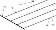
- FIG. 1illustrates a common line irrigation system with sub main irrigation line and emitter line, in accordance with the present disclosure.
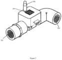
- FIG. 2illustrates a valve in accordance with an exemplary embodiment of the present disclosure.
- irrigation systemmay comprise a valve that is inserted into the main line of the individual row, these valves either has a small solar cell similar to one manufactured by Sol Chip or a piezoelectric device, wherein they have a receiving circuit attached to them.
- the segments described abovehave a valve that is inserted into the main line of the individual row and forms a secondary shorter parallel line to the main line of the individual row.
- These valve assemblieseither a small solar cell similar to one manufactured by Sol Chip or a piezoelectric device with a blocking valve for the correct action. These devices generate enough power to activate a small valve.
- the secondary segmentmay be spaced at 150 ft between each of the secondary segment.
- the secondary segmentmay further comprise a row of emitters appropriately spaced and serviced by these valves on each individual segment. These valves are on off valves. They have a receiving circuit attached to them that is activated by a signal from the drone.
- the field requirementsare determined by mapping the field for a number of requirements. There may be several maps for water absorption, nitrogen requirements or other plant requirements.
- Each series of flyovers and activation by the dronecan be changed by simply changing the pattern in the drone. There would be a series of flyover/activation for each pattern requirement. The first flyover/activation would activate the highest requirement and have a specific time for that activation.
- next activationwould be the next highest requirement for the appropriate time and then so on until the entire field is satisfied.
- An entirely different set of activation patternscould be programmed for different requirements (different maps) for nitrogen or other plant needs.
- the pattern and signal activationcan be programmed into the drone based on GPS location.
- the present disclosurediscloses a method for precise irrigation.
- the methodmay comprise steps of mapping a plurality of valves using a global positioning system. Further automatically assigning a unique value to the plurality of valves and controlling the plurality of valves by a drone.
- the irrigation systemmay comprise a main line 102 . Further the main line 102 may branch into a plurality of sub main line 104 . The main line 102 and sub main line 104 may be configured to hold and provide continues fluid for irrigation. Further each sub line 104 from the plurality sub main line 104 may further be split into a plurality of emitter lines 108 . Further each emitter line 108 from the plurality of emitter lines 108 may be connected to the sub main line 104 via a valve 106 .
- the valve 106may be activated and de-activated using a drone 110 , wherein the drone 110 may pre-programed with a schedule to do the same.
- the main line 102may be connected to the plurality of sub main lines 104 .
- the plurality of sub main linesmay further be configured to receive fluid or other nutrients from the main line 102 .
- a plurality of emitters lines 108may emerge from the at least one of the plurality of the sub main lines. Each emitter lines from the plurality lines 108 may have a length of at least 150 ft.
- the main lines, the plurality of sub main lines, and the plurality of emitter linesform a liner topology for irrigation area
- the embodimentmay comprise of a plurality of valves 106 .
- Each valvecan be configured to connect with at least one emitter line, from the plurality of emitter lines 108 , with the at least one sub main line, from the plurality of sub main lines 104 .
- the plurality of valves 106may further be communicably connected to a drone 110 .
- the plurality of valves 108may comprise a solar panel to generate power on-board, in order to supply power to a piezoelectric device or solenoid actuators to control opening of the plurality of valves by the drone 110 .
- the drone 110may be configured to receive a set of pre-defined instructions from a remote server (Not shown) and control the plurality of valves 108 based on the instructions.
- the set of pre-defined instructionsmay comprise task associated with the drone 108 .
- the taskcan be performed dynamically based on priority setting.
- the set of pre-defined instructionscould be stored on board the drone 110 or communicated dynamically to the drone 110 via a communication channel from the remote server.
- FIG. 2illustrates a valve in accordance with an exemplary embodiment of the present disclosure.
- the valve 200may be configured to operate in only on or off state and may comprise a first opening 202 and a second opening 204 . Either the first opening 202 or the second opening 204 may be connected with a sub main line in row irrigation system. Subsequently the remaining opening would provide the fluid to an emitter line.
- the valve 200may further comprise a solar panel 206 .
- the solar panel 206may be mounted directly onto the valve to provide power to the valve 200 .
- the valve 200may have a solenoid switch 208 .
- the valvemay be operated into or toggled between On mode and Off mode via a piezoelectric device or solenoid actuators.
- each of the plurality of valves 200are mapped using a global positing system, with each of the plurality of valves having a unique location.
Landscapes
- Engineering & Computer Science (AREA)
- Life Sciences & Earth Sciences (AREA)
- Water Supply & Treatment (AREA)
- Environmental Sciences (AREA)
- Aviation & Aerospace Engineering (AREA)
- Chemical & Material Sciences (AREA)
- Combustion & Propulsion (AREA)
- Soil Sciences (AREA)
- Spray Control Apparatus (AREA)
- Catching Or Destruction (AREA)
- Coating Apparatus (AREA)
Abstract
Description
Claims (8)
Applications Claiming Priority (3)
| Application Number | Priority Date | Filing Date | Title |
|---|---|---|---|
| IN201721009879 | 2017-03-21 | ||
| IN201721009879 | 2017-03-21 | ||
| PCT/IN2018/050159WO2018173072A2 (en) | 2017-03-21 | 2018-03-21 | A precision irrigation system |
Publications (2)
| Publication Number | Publication Date |
|---|---|
| US20200029517A1 US20200029517A1 (en) | 2020-01-30 |
| US11950545B2true US11950545B2 (en) | 2024-04-09 |
Family
ID=63585120
Family Applications (1)
| Application Number | Title | Priority Date | Filing Date |
|---|---|---|---|
| US16/496,764Active2039-10-12US11950545B2 (en) | 2017-03-21 | 2018-03-21 | Precision irrigation system |
Country Status (3)
| Country | Link |
|---|---|
| US (1) | US11950545B2 (en) |
| EP (1) | EP3599826A4 (en) |
| WO (1) | WO2018173072A2 (en) |
Citations (13)
| Publication number | Priority date | Publication date | Assignee | Title |
|---|---|---|---|---|
| US20020002425A1 (en)* | 1999-11-30 | 2002-01-03 | Dossey James F. | Computer controlled irrigation and environment management system |
| US20040117070A1 (en)* | 2002-11-21 | 2004-06-17 | Reinke Manufacturing Co., Inc. | GPS-based control system and method for controlling mechanized irrigation systems |
| US20060027677A1 (en)* | 2004-08-05 | 2006-02-09 | Pivotrac.Com, Llc | Remote current sensor monitoring system and GPS tracking system and method for mechanized irrigation systems |
| US20120254784A1 (en) | 2011-03-29 | 2012-10-04 | Loren Vander Griend | Method and apparatus for irrigation system design registration and on-site sprinkler package configuration verification |
| US20140129039A1 (en)* | 2012-11-07 | 2014-05-08 | Rain Bird Corporation | Irrigation Control Systems and Methods |
| US20150319941A1 (en) | 2014-05-06 | 2015-11-12 | Rachio | System and method for an improved sprinkler control system |
| US20160100533A1 (en) | 2014-10-14 | 2016-04-14 | Nelson Irrigation Corporation | Proximity programmed, globally synchronized irrigation controller and system |
| US20170020087A1 (en) | 2011-12-19 | 2017-01-26 | Younis Technologies, Inc. | Robotic irrigation system |
| US20170172077A1 (en)* | 2015-12-17 | 2017-06-22 | Intel Corporation | Property landscape management apparatus and method |
| US10084868B2 (en)* | 2016-09-03 | 2018-09-25 | Microsoft Technology Licensing, Llc | IoT gateway for weakly connected settings |
| US10660279B2 (en)* | 2012-05-21 | 2020-05-26 | Smart Rain Systems, LLC | Irrigation management |
| US10728336B2 (en)* | 2016-03-04 | 2020-07-28 | Sabrina Akhtar | Integrated IoT (Internet of Things) system solution for smart agriculture management |
| US11014668B2 (en)* | 2016-11-24 | 2021-05-25 | SZ DJI Technology Co., Ltd. | Agricultural unmanned aerial vehicle |
Family Cites Families (3)
| Publication number | Priority date | Publication date | Assignee | Title |
|---|---|---|---|---|
| US7930069B2 (en) | 2008-04-24 | 2011-04-19 | Telsco Industries, Inc. | Irrigation flow converter, monitoring system and intelligent water management system |
| EP3044771A4 (en) | 2013-09-09 | 2017-05-03 | Soil IQ, Inc. | Monitoring device and method of use |
| US10028425B2 (en)* | 2015-03-02 | 2018-07-24 | James Canyon | System, apparatus, and method for remote soil moisture measurement and control |
- 2018
- 2018-03-21USUS16/496,764patent/US11950545B2/enactiveActive
- 2018-03-21WOPCT/IN2018/050159patent/WO2018173072A2/ennot_activeCeased
- 2018-03-21EPEP18772629.4Apatent/EP3599826A4/enactivePending
Patent Citations (13)
| Publication number | Priority date | Publication date | Assignee | Title |
|---|---|---|---|---|
| US20020002425A1 (en)* | 1999-11-30 | 2002-01-03 | Dossey James F. | Computer controlled irrigation and environment management system |
| US20040117070A1 (en)* | 2002-11-21 | 2004-06-17 | Reinke Manufacturing Co., Inc. | GPS-based control system and method for controlling mechanized irrigation systems |
| US20060027677A1 (en)* | 2004-08-05 | 2006-02-09 | Pivotrac.Com, Llc | Remote current sensor monitoring system and GPS tracking system and method for mechanized irrigation systems |
| US20120254784A1 (en) | 2011-03-29 | 2012-10-04 | Loren Vander Griend | Method and apparatus for irrigation system design registration and on-site sprinkler package configuration verification |
| US20170020087A1 (en) | 2011-12-19 | 2017-01-26 | Younis Technologies, Inc. | Robotic irrigation system |
| US10660279B2 (en)* | 2012-05-21 | 2020-05-26 | Smart Rain Systems, LLC | Irrigation management |
| US20140129039A1 (en)* | 2012-11-07 | 2014-05-08 | Rain Bird Corporation | Irrigation Control Systems and Methods |
| US20150319941A1 (en) | 2014-05-06 | 2015-11-12 | Rachio | System and method for an improved sprinkler control system |
| US20160100533A1 (en) | 2014-10-14 | 2016-04-14 | Nelson Irrigation Corporation | Proximity programmed, globally synchronized irrigation controller and system |
| US20170172077A1 (en)* | 2015-12-17 | 2017-06-22 | Intel Corporation | Property landscape management apparatus and method |
| US10728336B2 (en)* | 2016-03-04 | 2020-07-28 | Sabrina Akhtar | Integrated IoT (Internet of Things) system solution for smart agriculture management |
| US10084868B2 (en)* | 2016-09-03 | 2018-09-25 | Microsoft Technology Licensing, Llc | IoT gateway for weakly connected settings |
| US11014668B2 (en)* | 2016-11-24 | 2021-05-25 | SZ DJI Technology Co., Ltd. | Agricultural unmanned aerial vehicle |
Non-Patent Citations (1)
| Title |
|---|
| International Search Report and Written Opinion issued in PCT/IN2018/050159, dated Sep. 25, 2018; ISA/US. |
Also Published As
| Publication number | Publication date |
|---|---|
| WO2018173072A2 (en) | 2018-09-27 |
| WO2018173072A3 (en) | 2018-11-08 |
| US20200029517A1 (en) | 2020-01-30 |
| EP3599826A4 (en) | 2020-12-16 |
| EP3599826A2 (en) | 2020-02-05 |
Similar Documents
| Publication | Publication Date | Title |
|---|---|---|
| EP3661352B1 (en) | System and method for variable rate irrigation wind control and compensation | |
| US6928339B2 (en) | GPS-based control system and method for controlling mechanized irrigation systems | |
| EP4426043A3 (en) | Multiple zone configuration | |
| EP3354128B1 (en) | Irrigation system | |
| WO2002096189A3 (en) | System for automated monitoring and maintenance of crops including computer control of irrigation and chemical delivery using multiple channel conduit | |
| WO2019016684A3 (en) | Irrigation system and method | |
| WO2020190967A8 (en) | Valve system and methods | |
| GB2612189B (en) | Integrated smart irrigation management control system for water, fertilizer, gas, pesticide and heat, and irrigation method | |
| US11950545B2 (en) | Precision irrigation system | |
| US11559014B2 (en) | Method and system for in row variable rate precision irrigation | |
| GB2551345A (en) | Agricultural sprayer | |
| MX2021013171A (en) | System, method and apparatus for providing variable rate application of applicants to discrete field locations. | |
| CN206773530U (en) | A kind of Control management system of intelligent plant protection unmanned plane | |
| EP3277076B1 (en) | Irrigation system and method | |
| CN112672828B (en) | System and method for cascading alignment of independent drive systems | |
| PH12019501522A1 (en) | Devices, systems, and methods for providing and using one or more valves in an assembly line grow pod | |
| US20070290067A1 (en) | Individually controlled sprinkler and lighting system | |
| CN108733077A (en) | A kind of agricultural unmanned machine operation Intelligentized regulating and controlling system | |
| CN103718929A (en) | Automatic garden plant watering system | |
| RO133935A2 (en) | Intelligent system for variable zonal irrigation | |
| WO2013098845A3 (en) | Modulated cyclic flow (mcf) drip irrigation systems | |
| KR20160112829A (en) | System of automatic watering for afforestation | |
| RU2682919C1 (en) | Drip irrigation tier system | |
| Duke | Potential for variable water and chemical application | |
| KR20230100923A (en) | Sprinkler system and method for operating sprinkler system |
Legal Events
| Date | Code | Title | Description |
|---|---|---|---|
| FEPP | Fee payment procedure | Free format text:ENTITY STATUS SET TO UNDISCOUNTED (ORIGINAL EVENT CODE: BIG.); ENTITY STATUS OF PATENT OWNER: LARGE ENTITY | |
| AS | Assignment | Owner name:JAIN IRRIGATION SYSTEMS LIMITED, INDIA Free format text:ASSIGNMENT OF ASSIGNORS INTEREST;ASSIGNORS:DEFRANK, MICHAEL PATRICK;JAIN, AJIT BHAVARLAL;SIGNING DATES FROM 20191111 TO 20191125;REEL/FRAME:051219/0802 | |
| STPP | Information on status: patent application and granting procedure in general | Free format text:NON FINAL ACTION MAILED | |
| STPP | Information on status: patent application and granting procedure in general | Free format text:RESPONSE TO NON-FINAL OFFICE ACTION ENTERED AND FORWARDED TO EXAMINER | |
| STPP | Information on status: patent application and granting procedure in general | Free format text:FINAL REJECTION MAILED | |
| STPP | Information on status: patent application and granting procedure in general | Free format text:DOCKETED NEW CASE - READY FOR EXAMINATION | |
| STPP | Information on status: patent application and granting procedure in general | Free format text:NOTICE OF ALLOWANCE MAILED -- APPLICATION RECEIVED IN OFFICE OF PUBLICATIONS | |
| STCF | Information on status: patent grant | Free format text:PATENTED CASE |