US11950287B2 - Resource configuration of beam failure recovery request transmission - Google Patents
Resource configuration of beam failure recovery request transmissionDownload PDFInfo
- Publication number
- US11950287B2 US11950287B2US16/101,239US201816101239AUS11950287B2US 11950287 B2US11950287 B2US 11950287B2US 201816101239 AUS201816101239 AUS 201816101239AUS 11950287 B2US11950287 B2US 11950287B2
- Authority
- US
- United States
- Prior art keywords
- reference signals
- wireless device
- base station
- resource
- preamble
- Prior art date
- Legal status (The legal status is an assumption and is not a legal conclusion. Google has not performed a legal analysis and makes no representation as to the accuracy of the status listed.)
- Active
Links
Images


Classifications
- H—ELECTRICITY
- H04—ELECTRIC COMMUNICATION TECHNIQUE
- H04W—WIRELESS COMMUNICATION NETWORKS
- H04W74/00—Wireless channel access
- H04W74/002—Transmission of channel access control information
- H04W74/006—Transmission of channel access control information in the downlink, i.e. towards the terminal
- H—ELECTRICITY
- H04—ELECTRIC COMMUNICATION TECHNIQUE
- H04B—TRANSMISSION
- H04B17/00—Monitoring; Testing
- H04B17/30—Monitoring; Testing of propagation channels
- H04B17/309—Measuring or estimating channel quality parameters
- H—ELECTRICITY
- H04—ELECTRIC COMMUNICATION TECHNIQUE
- H04B—TRANSMISSION
- H04B7/00—Radio transmission systems, i.e. using radiation field
- H04B7/02—Diversity systems; Multi-antenna system, i.e. transmission or reception using multiple antennas
- H04B7/04—Diversity systems; Multi-antenna system, i.e. transmission or reception using multiple antennas using two or more spaced independent antennas
- H04B7/06—Diversity systems; Multi-antenna system, i.e. transmission or reception using multiple antennas using two or more spaced independent antennas at the transmitting station
- H04B7/0613—Diversity systems; Multi-antenna system, i.e. transmission or reception using multiple antennas using two or more spaced independent antennas at the transmitting station using simultaneous transmission
- H04B7/0615—Diversity systems; Multi-antenna system, i.e. transmission or reception using multiple antennas using two or more spaced independent antennas at the transmitting station using simultaneous transmission of weighted versions of same signal
- H04B7/0619—Diversity systems; Multi-antenna system, i.e. transmission or reception using multiple antennas using two or more spaced independent antennas at the transmitting station using simultaneous transmission of weighted versions of same signal using feedback from receiving side
- H04B7/0621—Feedback content
- H04B7/0626—Channel coefficients, e.g. channel state information [CSI]
- H—ELECTRICITY
- H04—ELECTRIC COMMUNICATION TECHNIQUE
- H04B—TRANSMISSION
- H04B7/00—Radio transmission systems, i.e. using radiation field
- H04B7/02—Diversity systems; Multi-antenna system, i.e. transmission or reception using multiple antennas
- H04B7/04—Diversity systems; Multi-antenna system, i.e. transmission or reception using multiple antennas using two or more spaced independent antennas
- H04B7/06—Diversity systems; Multi-antenna system, i.e. transmission or reception using multiple antennas using two or more spaced independent antennas at the transmitting station
- H04B7/0686—Hybrid systems, i.e. switching and simultaneous transmission
- H04B7/0695—Hybrid systems, i.e. switching and simultaneous transmission using beam selection
- H04B7/06952—Selecting one or more beams from a plurality of beams, e.g. beam training, management or sweeping
- H04B7/06964—Re-selection of one or more beams after beam failure
- H—ELECTRICITY
- H04—ELECTRIC COMMUNICATION TECHNIQUE
- H04L—TRANSMISSION OF DIGITAL INFORMATION, e.g. TELEGRAPHIC COMMUNICATION
- H04L27/00—Modulated-carrier systems
- H04L27/26—Systems using multi-frequency codes
- H04L27/2601—Multicarrier modulation systems
- H04L27/2647—Arrangements specific to the receiver only
- H04L27/2655—Synchronisation arrangements
- H04L27/2689—Link with other circuits, i.e. special connections between synchronisation arrangements and other circuits for achieving synchronisation
- H04L27/2692—Link with other circuits, i.e. special connections between synchronisation arrangements and other circuits for achieving synchronisation with preamble design, i.e. with negotiation of the synchronisation sequence with transmitter or sequence linked to the algorithm used at the receiver
- H—ELECTRICITY
- H04—ELECTRIC COMMUNICATION TECHNIQUE
- H04L—TRANSMISSION OF DIGITAL INFORMATION, e.g. TELEGRAPHIC COMMUNICATION
- H04L5/00—Arrangements affording multiple use of the transmission path
- H04L5/0091—Signalling for the administration of the divided path, e.g. signalling of configuration information
- H—ELECTRICITY
- H04—ELECTRIC COMMUNICATION TECHNIQUE
- H04W—WIRELESS COMMUNICATION NETWORKS
- H04W24/00—Supervisory, monitoring or testing arrangements
- H04W24/08—Testing, supervising or monitoring using real traffic
- H—ELECTRICITY
- H04—ELECTRIC COMMUNICATION TECHNIQUE
- H04W—WIRELESS COMMUNICATION NETWORKS
- H04W74/00—Wireless channel access
- H04W74/08—Non-scheduled access, e.g. ALOHA
- H04W74/0833—Random access procedures, e.g. with 4-step access
- H—ELECTRICITY
- H04—ELECTRIC COMMUNICATION TECHNIQUE
- H04W—WIRELESS COMMUNICATION NETWORKS
- H04W76/00—Connection management
- H04W76/10—Connection setup
- H04W76/19—Connection re-establishment
- H—ELECTRICITY
- H04—ELECTRIC COMMUNICATION TECHNIQUE
- H04W—WIRELESS COMMUNICATION NETWORKS
- H04W76/00—Connection management
- H04W76/20—Manipulation of established connections
- H04W76/27—Transitions between radio resource control [RRC] states
- H—ELECTRICITY
- H04—ELECTRIC COMMUNICATION TECHNIQUE
- H04B—TRANSMISSION
- H04B17/00—Monitoring; Testing
- H04B17/10—Monitoring; Testing of transmitters
- H04B17/15—Performance testing
- H04B17/17—Detection of non-compliance or faulty performance, e.g. response deviations
- H—ELECTRICITY
- H04—ELECTRIC COMMUNICATION TECHNIQUE
- H04W—WIRELESS COMMUNICATION NETWORKS
- H04W74/00—Wireless channel access
- H04W74/08—Non-scheduled access, e.g. ALOHA
- H04W74/0833—Random access procedures, e.g. with 4-step access
- H04W74/0838—Random access procedures, e.g. with 4-step access using contention-free random access [CFRA]
Definitions
- beam failure recoverymay be used for recovering a beam pair link between a base station and a wireless device. If a beam failure is detected, difficulties may arise in performing beam failure recovery in a timely and efficient manner.
- a base stationmay transmit, to a wireless device, one or more messages comprising configuration parameters for beam failure recovery.
- the configuration parametersmay comprise an indication of reference signals and/or channel resources to be used in beam failure recovery.
- the configuration parametersmay be transmitted using a medium access control (MAC) control element (CE).
- the wireless devicemay detect a beam failure.
- the wireless device and/or the base stationmay utilize the reference signals and/or channel resources in performing a beam failure recovery procedure.
- FIG. 1shows example sets of orthogonal frequency division multiplexing (OFDM) subcarriers.
- FIG. 2shows example transmission time and reception time for two carriers in a carrier group.
- FIG. 3shows example OFDM radio resources.
- FIG. 4shows hardware elements of a base station and a wireless device.
- FIG. 5 A , FIG. 5 B , FIG. 5 C and FIG. 5 Dshow examples for uplink and downlink signal transmission.
- FIG. 6shows an example protocol structure with multi-connectivity.
- FIG. 7shows an example protocol structure with carrier aggregation (CA) and dual connectivity (DC).
- CAcarrier aggregation
- DCdual connectivity
- FIG. 8shows example timing advance group (TAG) configurations.
- FIG. 9shows example message flow in a random access process in a secondary TAG.
- FIG. 10 A and FIG. 10 Bshow examples for interfaces between a 5G core network and base stations.
- FIG. 11 A , FIG. 11 B , FIG. 11 C , FIG. 11 D , FIG. 11 E , and FIG. 11 Fshow examples for architectures of tight interworking between a 5G RAN and a long term evolution (LTE) radio access network (RAN).
- LTElong term evolution
- FIG. 12 A , FIG. 12 B , and FIG. 12 Cshow examples for radio protocol structures of tight interworking bearers.
- FIG. 13 A and FIG. 13 Bshow examples for gNodeB (gNB) deployment.
- gNBgNodeB
- FIG. 14shows functional split option examples of a centralized gNB deployment.
- FIG. 15shows an example of a synchronization signal burst set.
- FIG. 16shows an example of a random access procedure.
- FIG. 17shows an example of transmitting channel state information reference signals periodically for a beam.
- FIG. 18shows an example of a channel state information reference signal mapping.
- FIG. 19shows an example of a beam failure event involving a single transmission and receiving point.
- FIG. 20shows an example of a beam failure event involving multiple transmission and receiving points.
- FIG. 21shows an example of a beam failure recovery request utilizing a PRACH channel.
- FIG. 22shows an example of a multi-beam BFR-PRACH configuration.
- FIG. 23shows an example of a multi-beam BFR-PRACH configuration.
- FIG. 24shows an example of a PRACH configuration for a beam failure recovery request transmission.
- FIG. 25shows an example of MAC signaling activating a subset of a configured CSI-RS associated with a BFR-PRACH resource.
- FIG. 26shows an example of PRACH configuration and activation for a beam failure recovery request transmission.
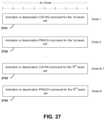
- FIG. 27shows an example MAC CE structure for CSI-RS and/or BFR-PRACH activation or deactivation.
- FIG. 28shows an example of PRACH configuration and activation for BFR request transmission.
- FIG. 29shows an example MAC CE for CSI-RS activation and/or deactivation, and/or BFR-PRACH configuration.
- FIG. 30shows an example of processes for a wireless device for beam failure recovery requests.
- FIG. 31shows an example of processes for a base station for beam failure recovery requests.
- FIG. 32shows example elements of a computing device that may be used to implement any of the various devices described herein.
- Examplesmay enable operation of carrier aggregation and may be employed in the technical field of multicarrier communication systems. Examples may relate to beam management in a multicarrier communication system.
- Example transmission mechanismsmay include, but are not limited to: CDMA, OFDM, TDMA, Wavelet technologies, and/or the like. Hybrid transmission mechanisms such as TDMA/CDMA, and OFDM/CDMA may also be employed.
- Various modulation schemesmay be used for signal transmission in the physical layer. Examples of modulation schemes include, but are not limited to: phase, amplitude, code, a combination of these, and/or the like.
- An example radio transmission methodmay implement QAM using BPSK, QPSK, 16-QAM, 64-QAM, 256-QAM, and/or the like.
- Physical radio transmissionmay be enhanced by dynamically or semi-dynamically changing the modulation and coding scheme depending on transmission requirements and radio conditions.
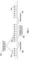
- FIG. 1shows example sets of OFDM subcarriers.
- arrow(s) in the diagrammay depict a subcarrier in a multicarrier OFDM system.
- the OFDM systemmay use technology such as OFDM technology, DFTS-OFDM, SC-OFDM technology, or the like.
- arrow 101shows a subcarrier transmitting information symbols.
- FIG. 1is shown as an example, and a typical multicarrier OFDM system may include more subcarriers in a carrier.
- the number of subcarriers in a carriermay be in the range of 10 to 10,000 subcarriers.
- FIG. 1shows two guard bands 106 and 107 in a transmission band. As shown in FIG.
- guard band 106is between subcarriers 103 and subcarriers 104 .
- the example set of subcarriers A 102includes subcarriers 103 and subcarriers 104 .
- FIG. 1also shows an example set of subcarriers B 105 . As shown, there is no guard band between any two subcarriers in the example set of subcarriers B 105 .
- Carriers in a multicarrier OFDM communication systemmay be contiguous carriers, non-contiguous carriers, or a combination of both contiguous and non-contiguous carriers.
- FIG. 2shows an example timing arrangement with transmission time and reception time for two carriers.
- a multicarrier OFDM communication systemmay include one or more carriers, for example, ranging from 1 to 10 carriers.
- Carrier A 204 and carrier B 205may have the same or different timing structures.
- FIG. 2shows two synchronized carriers, carrier A 204 and carrier B 205 may or may not be synchronized with each other.
- Different radio frame structuresmay be supported for FDD and TDD duplex mechanisms.
- FIG. 2shows an example FDD frame timing. Downlink and uplink transmissions may be organized into radio frames 201 .
- radio frame durationis 10 milliseconds (msec). Other frame durations, for example, in the range of 1 to 100 msec may also be supported.
- each 10 msec radio frame 201may be divided into ten equally sized subframes 202 .
- Other subframe durationssuch as including 0.5 msec, 1 msec, 2 msec, and 5 msec may also be supported.
- Subframe(s)may consist of two or more slots (e.g., slots 206 and 207 ).
- 10 subframesmay be available for downlink transmission and 10 subframes may be available for uplink transmissions in each 10 msec interval. Uplink and downlink transmissions may be separated in the frequency domain.
- a slotmay be 7 or 14 OFDM symbols for the same subcarrier spacing of up to 60 kHz with normal CP.
- a slotmay be 14 OFDM symbols for the same subcarrier spacing higher than 60 kHz with normal CP.
- a slotmay include all downlink, all uplink, or a downlink part and an uplink part, and/or alike.
- Slot aggregationmay be supported, e.g., data transmission may be scheduled to span one or multiple slots.
- a mini-slotmay start at an OFDM symbol in a subframe.
- a mini-slotmay have a duration of one or more OFDM symbols.
- Slot(s)may include a plurality of OFDM symbols 203 . The number of OFDM symbols 203 in a slot 206 may depend on the cyclic prefix length and subcarrier spacing.
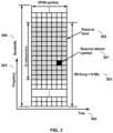
- FIG. 3shows an example of OFDM radio resources, including a resource grid structure in time 304 and frequency 305 .
- the quantity of downlink subcarriers or RBsmay depend, at least in part, on the downlink transmission bandwidth 306 configured in the cell.
- the smallest radio resource unitmay be called a resource element (e.g., 301 ).
- Resource elementsmay be grouped into resource blocks (e.g., 302 ).
- Resource blocksmay be grouped into larger radio resources called Resource Block Groups (RBG) (e.g., 303 ).
- the transmitted signal in slot 206may be described by one or several resource grids of a plurality of subcarriers and a plurality of OFDM symbols. Resource blocks may be used to describe the mapping of certain physical channels to resource elements.
- a resource blockmay correspond to one slot in the time domain and 180 kHz in the frequency domain (for 15 kHz subcarrier bandwidth and 12 subcarriers).
- a numerologymay be derived by scaling a basic subcarrier spacing by an integer N.
- Scalable numerologymay allow at least from 15 kHz to 480 kHz subcarrier spacing.
- the numerology with 15 kHz and scaled numerology with different subcarrier spacing with the same CP overheadmay align at a symbol boundary every 1 msec in a NR carrier.
- FIG. 4shows hardware elements of a base station 401 and a wireless device 406 .
- a communication network 400may include at least one base station 401 and at least one wireless device 406 .
- the base station 401may include at least one communication interface 402 , one or more processors 403 , and at least one set of program code instructions 405 stored in non-transitory memory 404 and executable by the one or more processors 403 .
- the wireless device 406may include at least one communication interface 407 , one or more processors 408 , and at least one set of program code instructions 410 stored in non-transitory memory 409 and executable by the one or more processors 408 .
- a communication interface 402 in the base station 401may be configured to engage in communication with a communication interface 407 in the wireless device 406 , such as via a communication path that includes at least one wireless link 411 .
- the wireless link 411may be a bi-directional link.
- the communication interface 407 in the wireless device 406may also be configured to engage in communication with the communication interface 402 in the base station 401 .
- the base station 401 and the wireless device 406may be configured to send and receive data over the wireless link 411 using multiple frequency carriers.
- Base stations, wireless devices, and other communication devicesmay include structure and operations of transceiver(s).
- a transceiveris a device that includes both a transmitter and receiver.
- Transceiversmay be employed in devices such as wireless devices, base stations, relay nodes, and/or the like. Examples for radio technology implemented in the communication interfaces 402 , 407 and the wireless link 411 are shown in FIG. 1 , FIG. 2 , FIG. 3 , FIG. 5 , and associated text.
- the communication network 400may comprise any number and/or type of devices, such as, for example, computing devices, wireless devices, mobile devices, handsets, tablets, laptops, internet of things (IoT) devices, hotspots, cellular repeaters, computing devices, and/or, more generally, user equipment (e.g., UE).
- IoTinternet of things
- any device hereinmay comprise any one or more of the above types of devices or similar devices.
- the communication network 400may comprise an LTE network, a 5G network, or any other network for wireless communications.
- Apparatuses, systems, and/or methods described hereinmay generally be described as implemented on one or more devices (e.g., wireless device, base station, eNB, gNB, computing device, etc.), in one or more networks, but it will be understood that one or more features and steps may be implemented on any device and/or in any network.
- the term “base station”may comprise one or more of: a base station, a node, a Node B, a gNB, an eNB, an ng-eNB, a relay node (e.g., an integrated access and backhaul (IAB) node), a donor node (e.g., a donor eNB, a donor gNB, etc.), an access point (e.g., a WiFi access point), a computing device, a device capable of wirelessly communicating, or any other device capable of sending and/or receiving signals.
- a base stationmay comprise one or more of: a base station, a node, a Node B, a gNB, an eNB, an ng-eNB, a relay node (e.g., an integrated access and backhaul (IAB) node), a donor node (e.g., a donor eNB, a donor gNB, etc.), an access point (e.g., a WiFi
- wireless devicemay comprise one or more of: a UE, a handset, a mobile device, a computing device, a node, a device capable of wirelessly communicating, or any other device capable of sending and/or receiving signals. Any reference to one or more of these terms/devices also considers use of any other term/device mentioned above.
- the communications network 400may comprise Radio Access Network (RAN) architecture.
- the RAN architecturemay comprise one or more RAN nodes that may be a next generation Node B (gNB) (e.g., 401 ) providing New Radio (NR) user plane and control plane protocol terminations towards a first wireless device (e.g. 406 ).
- a RAN nodemay be a next generation evolved Node B (ng-eNB), providing Evolved UMTS Terrestrial Radio Access (E-UTRA) user plane and control plane protocol terminations towards a second wireless device.
- the first wireless devicemay communicate with a gNB over a Uu interface.
- the second wireless devicemay communicate with a ng-eNB over a Uu interface.
- Base station 401may comprise one or more of a gNB, ng-eNB, and/or the like.
- a gNB or an ng-eNBmay host functions such as: radio resource management and scheduling, IP header compression, encryption and integrity protection of data, selection of Access and Mobility Management Function (AMF) at User Equipment (UE) attachment, routing of user plane and control plane data, connection setup and release, scheduling and transmission of paging messages (originated from the AMF), scheduling and transmission of system broadcast information (originated from the AMF or Operation and Maintenance (O&M)), measurement and measurement reporting configuration, transport level packet marking in the uplink, session management, support of network slicing, Quality of Service (QoS) flow management and mapping to data radio bearers, support of wireless devices in RRC_INACTIVE state, distribution function for Non-Access Stratum (NAS) messages, RAN sharing, and dual connectivity or tight interworking between NR and E-UTRA.
- AMFAccess and Mobility Management Function
- UEUser Equipment
- O&MOperation and Maintenance
- One or more gNBs and/or one or more ng-eNBsmay be interconnected with each other by means of Xn interface.
- a gNB or an ng-eNBmay be connected by means of NG interfaces to 5G Core Network (5GC).
- 5GCmay comprise one or more AMF/User Plane Function (UPF) functions.
- a gNB or an ng-eNBmay be connected to a UPF by means of an NG-User plane (NG-U) interface.
- the NG-U interfacemay provide delivery (e.g., non-guaranteed delivery) of user plane Protocol Data Units (PDUs) between a RAN node and the UPF.
- PDUsProtocol Data Units
- a gNB or an ng-eNBmay be connected to an AMF by means of an NG-Control plane (e.g., NG-C) interface.
- the NG-C interfacemay provide functions such as NG interface management, UE context management, UE mobility management, transport of NAS messages, paging, PDU session management, configuration transfer or warning message transmission.
- a UPFmay host functions such as anchor point for intra-/inter-Radio Access Technology (RAT) mobility (if applicable), external PDU session point of interconnect to data network, packet routing and forwarding, packet inspection and user plane part of policy rule enforcement, traffic usage reporting, uplink classifier to support routing traffic flows to a data network, branching point to support multi-homed PDU session, QoS handling for user plane, e.g. packet filtering, gating, Uplink (UL)/Downlink (DL) rate enforcement, uplink traffic verification (e.g. Service Data Flow (SDF) to QoS flow mapping), downlink packet buffering and/or downlink data notification triggering.
- RATRadio Access Technology
- An AMFmay host functions such as NAS signaling termination, NAS signaling security, Access Stratum (AS) security control, inter Core Network (CN) node signaling for mobility between 3 rd Generation Partnership Project (3GPP) access networks, idle mode UE reachability (e.g., control and execution of paging retransmission), registration area management, support of intra-system and inter-system mobility, access authentication, access authorization including check of roaming rights, mobility management control (subscription and policies), support of network slicing and/or Session Management Function (SMF) selection
- SMFSession Management Function
- An interfacemay be a hardware interface, a firmware interface, a software interface, and/or a combination thereof.
- the hardware interfacemay include connectors, wires, electronic devices such as drivers, amplifiers, and/or the like.
- a software interfacemay include code stored in a memory device to implement protocol(s), protocol layers, communication drivers, device drivers, combinations thereof, and/or the like.
- a firmware interfacemay include a combination of embedded hardware and code stored in and/or in communication with a memory device to implement connections, electronic device operations, protocol(s), protocol layers, communication drivers, device drivers, hardware operations, combinations thereof, and/or the like.
- the term configuredmay relate to the capacity of a device whether the device is in an operational or a non-operational state. Configured may also refer to specific settings in a device that effect the operational characteristics of the device whether the device is in an operational or a non-operational state. In other words, the hardware, software, firmware, registers, memory values, and/or the like may be “configured” within a device, whether the device is in an operational or a nonoperational state, to provide the device with specific characteristics. Terms such as “a control message to cause in a device” may mean that a control message has parameters that may be used to configure specific characteristics in the device, whether the device is in an operational or a non-operational state.
- a 5G networkmay include a multitude of base stations, providing a user plane NR PDCP/NR RLC/NR MAC/NR PHY and control plane (NR RRC) protocol terminations towards the wireless device.
- the base station(s)may be interconnected with other base station(s) (e.g., employing an Xn interface).
- the base stationsmay also be connected employing, for example, an NG interface to an NGC.
- FIG. 10 A and FIG. 10 Bshow examples for interfaces between a 5G core network (e.g., NGC) and base stations (e.g., gNB and eLTE eNB).
- the base stationsmay be interconnected to the NGC control plane (e.g., NG CP) employing the NG-C interface and to the NGC user plane (e.g., UPGW) employing the NG-U interface.
- the NG interfacemay support a many-to-many relation between 5G core networks and base stations.
- a base stationmay include many sectors, for example: 1, 2, 3, 4, or 6 sectors.
- a base stationmay include many cells, for example, ranging from 1 to 50 cells or more.
- a cellmay be categorized, for example, as a primary cell or secondary cell.
- one serving cellmay provide the NAS (non-access stratum) mobility information (e.g., TAI), and at RRC connection re-establishment/handover, one serving cell may provide the security input. This cell may be referred to as the Primary Cell (PCell).
- PCellPrimary Cell
- the carrier corresponding to the PCellmay be the Downlink Primary Component Carrier (DL PCC); in the uplink, the carrier corresponding to the PCell may be the Uplink Primary Component Carrier (UL PCC).
- SCellsmay be configured to form together with the PCell a set of serving cells.
- the carrier corresponding to an SCellmay be a Downlink Secondary Component Carrier (DL SCC); in the uplink, the carrier corresponding to an SCell may be an Uplink Secondary Component Carrier (UL SCC).
- An SCellmay or may not have an uplink carrier.
- a cellcomprising a downlink carrier and optionally an uplink carrier, may be assigned a physical cell ID and a cell index.
- a carrierdownlink or uplink
- the cell ID or cell indexmay also identify the downlink carrier or uplink carrier of the cell (depending on the context in which it is used).
- the cell IDmay be equally referred to a carrier ID, and cell index may be referred to carrier index.
- the physical cell ID or cell indexmay be assigned to a cell.
- a cell IDmay be determined using a synchronization signal transmitted on a downlink carrier.
- a cell indexmay be determined using RRC messages.
- reference to a first physical cell ID for a first downlink carriermay indicate that the first physical cell ID is for a cell comprising the first downlink carrier.
- the same conceptmay apply to, for example, carrier activation.
- Reference to a first carrier that is activatedmay indicate that the cell comprising the first carrier is activated.
- a devicemay be configured to operate as needed by freely combining any of the examples.
- the disclosed mechanismsmay be performed if certain criteria are met, for example, in a wireless device, a base station, a radio environment, a network, a combination of the above, and/or the like.
- Example criteriamay be based, at least in part, on for example, traffic load, initial system set up, packet sizes, traffic characteristics, a combination of the above, and/or the like. One or more criteria may be satisfied. It may be possible to implement examples that selectively implement disclosed protocols.
- a base stationmay communicate with a variety of wireless devices.
- Wireless devicesmay support multiple technologies, and/or multiple releases of the same technology. Wireless devices may have some specific capability(ies) depending on its wireless device category and/or capability(ies).
- a base stationmay comprise multiple sectors. Reference to a base station communicating with a plurality of wireless devices may indicate that a base station may communicate with a subset of the total wireless devices in a coverage area.
- a plurality of wireless devices of a given LTE or 5G release, with a given capability and in a given sector of the base station,may be used.
- the plurality of wireless devicesmay refer to a selected plurality of wireless devices, and/or a subset of total wireless devices in a coverage area which perform according to disclosed methods, and/or the like. There may be a plurality of wireless devices in a coverage area that may not comply with the disclosed methods, for example, because those wireless devices perform based on older releases of LTE or 5G technology.
- a base stationmay transmit (e.g., to a wireless device) one or more messages (e.g. RRC messages) that may comprise a plurality of configuration parameters for one or more cells.
- One or more cellsmay comprise at least one primary cell and at least one secondary cell.
- An RRC messagemay be broadcasted or unicasted to the wireless device.
- Configuration parametersmay comprise common parameters and dedicated parameters.
- Services and/or functions of an RRC sublayermay comprise at least one of: broadcast of system information related to AS and NAS; paging initiated by 5GC and/or NG-RAN; establishment, maintenance, and/or release of an RRC connection between a wireless device and NG-RAN, which may comprise at least one of addition, modification and release of carrier aggregation; or addition, modification, and/or release of dual connectivity in NR or between E-UTRA and NR.
- Services and/or functions of an RRC sublayermay further comprise at least one of security functions comprising key management; establishment, configuration, maintenance, and/or release of Signaling Radio Bearers (SRBs) and/or Data Radio Bearers (DRBs); mobility functions which may comprise at least one of a handover (e.g.
- Services and/or functions of an RRC sublayermay further comprise at least one of QoS management functions; a wireless device measurement configuration/reporting; detection of and/or recovery from radio link failure; or NAS message transfer to/from a core network entity (e.g. AMF, Mobility Management Entity (MME)) from/to the wireless device.
- a core network entitye.g. AMF, Mobility Management Entity (MME)
- An RRC sublayermay support an RRC_Idle state, an RRC_Inactive state and/or an RRC_Connected state for a wireless device.
- a wireless devicemay perform at least one of: Public Land Mobile Network (PLMN) selection; receiving broadcasted system information; cell selection/re-selection; monitoring/receiving a paging for mobile terminated data initiated by 5GC; paging for mobile terminated data area managed by 5GC; or DRX for CN paging configured via NAS.
- PLMNPublic Land Mobile Network
- a wireless devicemay perform at least one of: receiving broadcasted system information; cell selection/re-selection; monitoring/receiving a RAN/CN paging initiated by NG-RAN/5GC; RAN-based notification area (RNA) managed by NG-RAN; or DRX for RAN/CN paging configured by NG-RAN/NAS.
- a base statione.g. NG-RAN
- a base statione.g.
- NG-RANmay perform at least one of: establishment of 5GC-NG-RAN connection (both C/U-planes) for the wireless device; storing a UE AS context for the wireless device; transmit/receive of unicast data to/from the wireless device; or network-controlled mobility based on measurement results received from the wireless device.
- an NG-RANmay know a cell that the wireless device belongs to.
- SISystem information
- the minimum SImay be periodically broadcast.
- the minimum SImay comprise basic information required for initial access and information for acquiring any other SI broadcast periodically or provisioned on-demand, i.e. scheduling information.
- the other SImay either be broadcast, or be provisioned in a dedicated manner, either triggered by a network or upon request from a wireless device.
- a minimum SImay be transmitted via two different downlink channels using different messages (e.g. MasterInformationBlock and SystemInformationBlockType 1 ).
- the other SImay be transmitted via SystemInformationBlockType 2 .
- dedicated RRC signalingmay be employed for the request and delivery of the other SI.
- the requestmay trigger a random-access procedure.
- a wireless devicemay send its radio access capability information which may be static.
- a base stationmay request what capabilities for a wireless device to report based on band information. If allowed by a network, a temporary capability restriction request may be sent by the wireless device to signal the limited availability of some capabilities (e.g. due to hardware sharing, interference or overheating) to the base station. The base station may confirm or reject the request.
- the temporary capability restrictionmay be transparent to 5GC (e.g., static capabilities may be stored in 5GC).
- a wireless devicemay have an RRC connection with a network.
- one serving cellmay provide NAS mobility information, and at RRC connection re-establishment/handover, one serving cell may provide a security input.
- This cellmay be referred to as the PCell.
- SCellsmay be configured to form together with the PCell a set of serving cells.
- the configured set of serving cells for the wireless devicemay comprise one PCell and one or more SCells.
- RRCmay also add, remove, or reconfigure SCells for usage with the target PCell. If adding a new SCell, dedicated RRC signaling may be employed to send all required system information of the SCell. In connected mode, wireless devices may not need to acquire broadcasted system information directly from the SCells.
- An RRC connection reconfiguration proceduremay be used to modify an RRC connection, (e.g. to establish, modify and/or release RBs, to perform handover, to setup, modify, and/or release measurements, to add, modify, and/or release SCells and cell groups).
- NAS dedicated informationmay be transferred from the network to the wireless device.
- the RRCConnectionReconfiguration messagemay be a command to modify an RRC connection. It may convey information for measurement configuration, mobility control, radio resource configuration (e.g. RBs, MAC main configuration and physical channel configuration) comprising any associated dedicated NAS information and security configuration. If the received RRC Connection Reconfiguration message includes the sCellToReleaseList, the wireless device may perform an SCell release. If the received RRC Connection Reconfiguration message includes the sCellToAddModList, the wireless device may perform SCell additions or modification.
- An RRC connection establishment (or reestablishment, resume) proceduremay be used to establish (or reestablish, resume) an RRC connection.
- An RRC connection establishment proceduremay comprise SRB 1 establishment.
- the RRC connection establishment proceduremay be used to transfer the initial NAS dedicated information message from a wireless device to E-UTRAN.
- the RRCConnectionReestablishment messagemay be used to re-establish SRB 1 .
- a measurement report proceduremay be to transfer measurement results from a wireless device to NG-RAN.
- the wireless devicemay initiate a measurement report procedure, e.g., after successful security activation.
- a measurement report messagemay be employed to transmit measurement results.
- FIG. 5 A , FIG. 5 B , FIG. 5 C , and FIG. 5 Dshow examples of architecture for uplink and downlink signal transmission.
- FIG. 5 Ashows an example for an uplink physical channel.
- the baseband signal representing the physical uplink shared channelmay be processed according to the following processes, which may be performed by structures described below. These structures and corresponding functions are shown as examples, however, it is anticipated that other structures and/or functions may be implemented in various examples.
- the structures and corresponding functionsmay comprise, e.g., one or more scrambling devices 501 A and 501 B configured to perform scrambling of coded bits in each of the codewords to be transmitted on a physical channel; one or more modulation mappers 502 A and 502 B configured to perform modulation of scrambled bits to generate complex-valued symbols; a layer mapper 503 configured to perform mapping of the complex-valued modulation symbols onto one or several transmission layers; one or more transform precoders 504 A and 504 B to generate complex-valued symbols; a precoding device 505 configured to perform precoding of the complex-valued symbols; one or more resource element mappers 506 A and 506 B configured to perform mapping of precoded complex-valued symbols to resource elements; one or more signal generators 507 A and 507 B configured to perform the generation of a complex-valued time-domain DFTS-OFDM/SC-FDMA signal for each antenna port; and/or the like.
- FIG. 5 Bshows an example for performing modulation and up-conversion to the carrier frequency of the complex-valued DFTS-OFDM/SC-FDMA baseband signal, e.g., for each antenna port and/or for the complex-valued physical random access channel (PRACH) baseband signal.
- the baseband signalrepresented as s 1 (t)
- the real componentmay be modulated by a modulator 511 A
- the imaginary componentmay be modulated by a modulator 511 B.
- the output signal of the modulator 511 A and the output signal of the modulator 511 Bmay be mixed by a mixer 512 .
- the output signal of the mixer 512may be input to a filtering device 513 , and filtering may be employed by the filtering device 513 prior to transmission.
- FIG. 5 Cshows an example structure for downlink transmissions.
- the baseband signal representing a downlink physical channelmay be processed by the following processes, which may be performed by structures described below. These structures and corresponding functions are shown as examples, however, it is anticipated that other structures and/or functions may be implemented in various examples.
- the structures and corresponding functionsmay comprise, e.g., one or more scrambling devices 531 A and 531 B configured to perform scrambling of coded bits in each of the codewords to be transmitted on a physical channel; one or more modulation mappers 532 A and 532 B configured to perform modulation of scrambled bits to generate complex-valued modulation symbols; a layer mapper 533 configured to perform mapping of the complex-valued modulation symbols onto one or several transmission layers; a precoding device 534 configured to perform precoding of the complex-valued modulation symbols on each layer for transmission on the antenna ports; one or more resource element mappers 535 A and 535 B configured to perform mapping of complex-valued modulation symbols for each antenna port to resource elements; one or more OFDM signal generators 536 A and 536 B configured to perform the generation of complex-valued time-domain OFDM signal for each antenna port; and/or the like.
- one or more scrambling devices 531 A and 531 Bconfigured to perform scrambling of coded bits in each of the
- FIG. 5 Dshows an example structure for modulation and up-conversion to the carrier frequency of the complex-valued OFDM baseband signal for each antenna port.
- the baseband signalrepresented as s 1 (p) (t)
- the baseband signalmay be split, by a signal splitter 520 , into real and imaginary components, Re ⁇ s 1 (p) (t) ⁇ and Im ⁇ s 1 (p) (t) ⁇ , respectively.
- the real componentmay be modulated by a modulator 521 A
- the imaginary componentmay be modulated by a modulator 521 B.
- the output signal of the modulator 521 A and the output signal of the modulator 521 Bmay be mixed by a mixer 522 .
- the output signal of the mixer 522may be input to a filtering device 523 , and filtering may be employed by the filtering device 523 prior to transmission.
- FIG. 6 and FIG. 7show examples for protocol structures with CA and multi-connectivity.
- NRmay support multi-connectivity operation, whereby a multiple receiver/transmitter (RX/TX) wireless device in RRC_CONNECTED may be configured to utilize radio resources provided by multiple schedulers located in multiple gNBs connected via a non-ideal or ideal backhaul over the Xn interface.
- gNBs involved in multi-connectivity for a certain wireless devicemay assume two different roles: a gNB may either act as a master gNB (e.g., 600 ) or as a secondary gNB (e.g., 610 or 620 ).
- a wireless devicemay be connected to one master gNB (e.g., 600 ) and one or more secondary gNBs (e.g., 610 and/or 620 ). Any one or more of the Master gNB 600 and/or the secondary gNBs 610 and 620 may be a Next Generation (NG) NodeB.
- the master gNB 600may comprise protocol layers NR MAC 601 , NR RLC 602 and 603 , and NR PDCP 604 and 605 .
- the secondary gNBmay comprise protocol layers NR MAC 611 , NR RLC 612 and 613 , and NR PDCP 614 .
- the secondary gNBmay comprise protocol layers NR MAC 621 , NR RLC 622 and 623 , and NR PDCP 624 .
- the master gNB 600may communicate via an interface 606 and/or via an interface 607 , the secondary gNB 610 may communicate via an interface 615 , and the secondary gNB 620 may communicate via an interface 625 .
- the master gNB 600may also communicate with the secondary gNB 610 and the secondary gNB 621 via interfaces 608 and 609 , respectively, which may include Xn interfaces.
- the master gNB 600may communicate via the interface 608 , at layer NR PDCP 605 , and with the secondary gNB 610 at layer NR RLC 612 .
- the master gNB 600may communicate via the interface 609 , at layer NR PDCP 605 , and with the secondary gNB 620 at layer NR RLC 622 .
- FIG. 7shows an example structure for the UE side MAC entities, e.g., if a Master Cell Group (MCG) and a Secondary Cell Group (SCG) are configured.
- MCGMaster Cell Group
- SCGSecondary Cell Group
- MBMSMedia Broadcast Multicast Service
- the radio protocol architecture that a particular bearer usesmay depend on how the bearer is set up. As an example, three alternatives may exist, an MCG bearer, an SCG bearer, and a split bearer, such as shown in FIG. 6 .
- NR RRCmay be located in a master gNB and SRBs may be configured as a MCG bearer type and may use the radio resources of the master gNB.
- Multi-connectivitymay have at least one bearer configured to use radio resources provided by the secondary gNB. Multi-connectivity may or may not be configured or implemented.
- the wireless devicemay be configured with multiple NR MAC entities: e.g., one NR MAC entity for a master gNB, and other NR MAC entities for secondary gNBs.
- the configured set of serving cells for a wireless devicemay comprise two subsets: e.g., the Master Cell Group (MCG) including the serving cells of the master gNB, and the Secondary Cell Groups (SCGs) including the serving cells of the secondary gNBs.
- MCGMaster Cell Group
- SCGsSecondary Cell Groups
- At least one cell in a SCGmay have a configured UL component carrier (CC) and one of the UL CCs, e.g., named PSCell (or PCell of SCG, or sometimes called PCell), may be configured with PUCCH resources. If the SCG is configured, there may be at least one SCG bearer or one split bearer.
- CCUL component carrier
- PSCellPCell of SCG, or sometimes called PCell
- NR RLC Acknowledge Mode (AM) bearermay be configured for the split bearer.
- a PSCellmay not be de-activated.
- the PSCellmay be changed with an SCG change (e.g., with a security key change and a RACH procedure).
- a direct bearer typemay change between a split bearer and an SCG bearer, or a simultaneous configuration of an SCG and a split bearer may or may not be supported.
- a master gNB and secondary gNBsmay interact for multi-connectivity.
- the master gNBmay maintain the RRM measurement configuration of the wireless device, and the master gNB may, (e.g., based on received measurement reports, and/or based on traffic conditions and/or bearer types), decide to ask a secondary gNB to provide additional resources (e.g., serving cells) for a wireless device. If a request from the master gNB is received, a secondary gNB may create a container that may result in the configuration of additional serving cells for the wireless device (or the secondary gNB decide that it has no resource available to do so). For wireless device capability coordination, the master gNB may provide some or all of the Active Set (AS) configuration and the wireless device capabilities to the secondary gNB.
- ASActive Set
- the master gNB and the secondary gNBmay exchange information about a wireless device configuration, such as by employing NR RRC containers (e.g., inter-node messages) carried in Xn messages.
- the secondary gNBmay initiate a reconfiguration of its existing serving cells (e.g., PUCCH towards the secondary gNB).
- the secondary gNBmay decide which cell is the PSCell within the SCG.
- the master gNBmay or may not change the content of the NR RRC configuration provided by the secondary gNB.
- the master gNBmay provide the latest measurement results for the SCG cell(s).
- Both a master gNB and a secondary gNBsmay know the system frame number (SFN) and subframe offset of each other by operations, administration, and maintenance (OAM) (e.g., for the purpose of discontinuous reception (DRX) alignment and identification of a measurement gap).
- SFNsystem frame number
- OFAMoperations, administration, and maintenance
- dedicated NR RRC signalingmay be used for sending required system information of the cell for CA, except, e.g., for the SFN acquired from an MIB of the PSCell of an SCG.
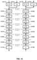
- FIG. 7shows an example of dual-connectivity (DC) for two MAC entities at a wireless device side.
- a first MAC entitymay comprise a lower layer of an MCG 700 , an upper layer of an MCG 718 , and one or more intermediate layers of an MCG 719 .
- the lower layer of the MCG 700may comprise, e.g., a paging channel (PCH) 701 , a broadcast channel (BCH) 702 , a downlink shared channel (DL-SCH) 703 , an uplink shared channel (UL-SCH) 704 , and a random access channel (RACH) 705 .
- PCHpaging channel
- BCHbroadcast channel
- DL-SCHdownlink shared channel
- UL-SCHuplink shared channel
- RACHrandom access channel
- the one or more intermediate layers of the MCG 719may comprise, e.g., one or more hybrid automatic repeat request (HARQ) processes 706 , one or more random access control processes 707 , multiplexing and/or de-multiplexing processes 709 , logical channel prioritization on the uplink processes 710 , and a control processes 708 providing control for the above processes in the one or more intermediate layers of the MCG 719 .
- HARQhybrid automatic repeat request
- the upper layer of the MCG 718may comprise, e.g., a paging control channel (PCCH) 711 , a broadcast control channel (BCCH) 712 , a common control channel (CCCH) 713 , a dedicated control channel (DCCH) 714 , a dedicated traffic channel (DTCH) 715 , and a MAC control 716 .
- PCCHpaging control channel
- BCCHbroadcast control channel
- CCCHcommon control channel
- DCCHdedicated control channel
- DTCHdedicated traffic channel
- MAC control 716e.g., a paging control channel (PCCH) 711 , a broadcast control channel (BCCH) 712 , a common control channel (CCCH) 713 , a dedicated control channel (DCCH) 714 , a dedicated traffic channel (DTCH) 715 , and a MAC control 716 .
- PCCHpaging control channel
- BCCHbroadcast control channel
- CCCHcommon control channel
- DCCHdedicated control
- a second MAC entitymay comprise a lower layer of an SCG 720 , an upper layer of an SCG 738 , and one or more intermediate layers of an SCG 739 .
- the lower layer of the SCG 720may comprise, e.g., a BCH 722 , a DL-SCH 723 , an UL-SCH 724 , and a RACH 725 .
- the one or more intermediate layers of the SCG 739may comprise, e.g., one or more HARQ processes 726 , one or more random access control processes 727 , multiplexing and/or de-multiplexing processes 729 , logical channel prioritization on the uplink processes 730 , and a control processes 728 providing control for the above processes in the one or more intermediate layers of the SCG 739 .
- the upper layer of the SCG 738may comprise, e.g., a BCCH 732 , a DCCH 714 , a DTCH 735 , and a MAC control 736 .
- Serving cellsmay be grouped in a TA group (TAG). Serving cells in one TAG may use the same timing reference. For a given TAG, a wireless device may use at least one downlink carrier as a timing reference. For a given TAG, a wireless device may synchronize uplink subframe and frame transmission timing of uplink carriers belonging to the same TAG. Serving cells having an uplink to which the same TA applies may correspond to serving cells hosted by the same receiver.
- a wireless device supporting multiple TAsmay support two or more TA groups. One TA group may include the PCell and may be called a primary TAG (pTAG). In a multiple TAG configuration, at least one TA group may not include the PCell and may be called a secondary TAG (sTAG).
- pTAGprimary TAG
- sTAGsecondary TAG
- Carriers within the same TA groupmay use the same TA value and/or the same timing reference. If DC is configured, cells belonging to a cell group (e.g., MCG or SCG) may be grouped into multiple TAGs including a pTAG and one or more sTAGs.
- a cell groupe.g., MCG or SCG
- TAGsincluding a pTAG and one or more sTAGs.
- FIG. 8shows example TAG configurations.
- a pTAGcomprises a PCell
- an sTAGcomprises an SCell 1 .
- a pTAGcomprises a PCell and an SCell 1
- an sTAGcomprises an SCell 2 and an SCell 3 .
- a pTAGcomprises a PCell and an SCell 1
- an sTAG 1comprises an SCell 2 and an SCell 3
- an sTAG 2comprises a SCell 4 .
- Up to four TAGsmay be supported in a cell group (MCG or SCG), and other example TAG configurations may also be provided.
- structures and operationsare described for use with a pTAG and an sTAG. Some of the examples may be used for configurations with multiple sTAGs.
- An eNBmay initiate an RA procedure, via a PDCCH order, for an activated SCell.
- the PDCCH ordermay be sent on a scheduling cell of this SCell. If cross carrier scheduling is configured for a cell, the scheduling cell may be different than the cell that is employed for preamble transmission, and the PDCCH order may include an SCell index. At least a non-contention based RA procedure may be supported for SCell(s) assigned to sTAG(s).
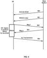
- FIG. 9shows an example of random access processes, and a corresponding message flow, in a secondary TAG.
- a base stationsuch as an eNB, may transmit an activation command 900 to a wireless device, such as a UE.
- the activation command 900may be transmitted to activate an SCell.
- the base stationmay also transmit a PDDCH order 901 to the wireless device, which may be transmitted, e.g., after the activation command 900 .
- the wireless devicemay begin to perform a RACH process for the SCell, which may be initiated, e.g., after receiving the PDDCH order 901 .
- a wireless devicemay transmit to the base station (e.g., as part of a RACH process) a preamble 902 (e.g., Msg 1 ), such as a random access preamble (RAP).
- the preamble 902may be transmitted in response to the PDCCH order 901 .
- the wireless devicemay transmit the preamble 902 via an SCell belonging to an sTAG. Preamble transmission for SCells may be controlled by a network using PDCCH format 1 A.
- the base stationmay send a random access response (RAR) 903 (e.g., Msg 2 message) to the wireless device.
- the RAR 903may be in response to the preamble 902 transmission via the SCell.
- the RAR 903may be addressed to a random access radio network temporary identifier (RA-RNTI) in a PCell common search space (CSS). If the wireless device receives the RAR 903 , the RACH process may conclude. The RACH process may conclude, e.g., after or in response to the wireless device receiving the RAR 903 from the base station. After the RACH process, the wireless device may transmit an uplink transmission 904 .
- the uplink transmission 904may comprise uplink packets transmitted via the same SCell used for the preamble 902 transmission.
- Initial timing alignment for communications between the wireless device and the base stationmay be performed through a random access procedure, such as described above regarding FIG. 9 .
- the random access proceduremay involve a wireless device, such as a UE, transmitting a random access preamble and a base station, such as an eNB, responding with an initial TA command NTA (amount of timing advance) within a random access response window.
- NTAamount of timing advance
- the eNBmay estimate the uplink timing from the random access preamble transmitted by the wireless device.
- the TA commandmay be derived by the eNB based on the estimation of the difference between the desired UL timing and the actual UL timing.
- the wireless devicemay determine the initial uplink transmission timing relative to the corresponding downlink of the sTAG on which the preamble is transmitted.
- the mapping of a serving cell to a TAGmay be configured by a serving eNB with RRC signaling.
- the mechanism for TAG configuration and reconfigurationmay be based on RRC signaling. If an eNB performs an SCell addition configuration, the related TAG configuration may be configured for the SCell.
- An eNBmay modify the TAG configuration of an SCell by removing (e.g., releasing) the SCell and adding (e.g., configuring) a new SCell (with the same physical cell ID and frequency) with an updated TAG ID.
- the new SCell with the updated TAG IDmay initially be inactive subsequent to being assigned the updated TAG ID.
- the eNBmay activate the updated new SCell and start scheduling packets on the activated SCell.
- the SCellmay need to be removed and a new SCell may need to be added with another TAG.
- at least one RRC messagesuch as at least one RRC reconfiguration message
- the at least one RRC messagemay be sent to the wireless device to reconfigure TAG configurations, e.g., by releasing the SCell and configuring the SCell as a part of the pTAG.
- the SCellmay be explicitly assigned to the pTAG.
- the PCellmay not change its TA group and may be a member of the pTAG.
- a PUCCH transmissionis only transmitted on a PCell (e.g., a PSCell) to an eNB.
- a wireless devicemay transmit PUCCH information on one cell (e.g., a PCell or a PSCell) to a given eNB.
- the number of CA capable wireless devicesincrease, and as the number of aggregated carriers increase, the number of PUCCHs and the PUCCH payload size may increase.
- Accommodating the PUCCH transmissions on the PCellmay lead to a high PUCCH load on the PCell.
- a PUCCH on an SCellmay be used to offload the PUCCH resource from the PCell. More than one PUCCH may be configured.
- a PUCCH on a PCellmay be configured and another PUCCH on an SCell may be configured.
- One, two, or more cellsmay be configured with PUCCH resources for transmitting CSI, acknowledgment (ACK), and/or non-acknowledgment (NACK) to a base station.
- Cellsmay be grouped into multiple PUCCH groups, and one or more cell within a group may be configured with a PUCCH.
- one SCellmay belong to one PUCCH group.
- SCells with a configured PUCCH transmitted to a base stationmay be called a PUCCH SCell, and a cell group with a common PUCCH resource transmitted to the same base station may be called a PUCCH group.
- a MAC entitymay have a configurable timer, e.g., timeAlignmentTimer, per TAG.
- the timeAlignmentTimermay be used to control how long the MAC entity considers the serving cells belonging to the associated TAG to be uplink time aligned. If a Timing Advance Command MAC control element is received, the MAC entity may apply the Timing Advance Command for the indicated TAG; and/or the MAC entity may start or restart the timeAlignmentTimer associated with a TAG that may be indicated by the Timing Advance Command MAC control element.
- the MAC entitymay apply the Timing Advance Command for this TAG and/or start or restart the timeAlignmentTimer associated with this TAG. Additionally or alternatively, if the Random Access Preamble is not selected by the MAC entity, the MAC entity may apply the Timing Advance Command for this TAG and/or start or restart the timeAlignmentTimer associated with this TAG. If the timeAlignmentTimer associated with this TAG is not running, the Timing Advance Command for this TAG may be applied, and the timeAlignmentTimer associated with this TAG may be started.
- a timeAlignmentTimer associated with this TAGmay be stopped. If the contention resolution is successful, the MAC entity may ignore the received Timing Advance Command. The MAC entity may determine whether the contention resolution is successful or whether the contention resolution is not successful.
- FIG. 10 A and FIG. 10 Bshow examples for interfaces between a 5G core network (e.g., NGC) and base stations (e.g., gNB and eLTE eNB).
- a base stationsuch as a gNB 1020 , may be interconnected to an NGC 1010 control plane employing an NG-C interface.
- the base statione.g., the gNB 1020
- a base station, such as an eLTE eNB 1040may be interconnected to an NGC 1030 control plane employing an NG-C interface.
- the base statione.g., the eLTE eNB 1040
- An NG interfacemay support a many-to-many relation between 5G core networks and base stations.
- FIG. 11 A , FIG. 11 B , FIG. 11 C , FIG. 11 D , FIG. 11 E , and FIG. 11 Fare examples for architectures of tight interworking between a 5G RAN and an LTE RAN.
- the tight interworkingmay enable a multiple receiver/transmitter (RX/TX) wireless device in an RRC_CONNECTED state to be configured to utilize radio resources provided by two schedulers located in two base stations (e.g., an eLTE eNB and a gNB).
- the two base stationsmay be connected via a non-ideal or ideal backhaul over the Xx interface between an LTE eNB and a gNB, or over the Xn interface between an eLTE eNB and a gNB.
- Base stations involved in tight interworking for a certain wireless devicemay assume different roles.
- a base stationmay act as a master base station or a base station may act as a secondary base station.
- a wireless devicemay be connected to both a master base station and a secondary base station.
- Mechanisms implemented in tight interworkingmay be extended to cover more than two base stations.
- a master base stationmay be an LTE eNB 1102 A or an LTE eNB 1102 B, which may be connected to EPC nodes 1101 A or 1101 B, respectively. This connection to EPC nodes may be, e.g., to an MME via the S1-C interface and/or to an S-GW via the S1-U interface.
- a secondary base stationmay be a gNB 1103 A or a gNB 1103 B, either or both of which may be a non-standalone node having a control plane connection via an Xx-C interface to an LTE eNB (e.g., the LTE eNB 1102 A or the LTE eNB 1102 B).
- LTE eNBe.g., the LTE eNB 1102 A or the LTE eNB 1102 B.
- a user plane for a gNBmay be connected to an S-GW (e.g., the EPC 1101 A) through an LTE eNB (e.g., the LTE eNB 1102 A), via an Xx-U interface between the LTE eNB and the gNB, and via an S1-U interface between the LTE eNB and the S-GW.
- S-GWe.g., the EPC 1101 A
- LTE eNBe.g., the LTE eNB 1102 A
- S-GWe.g., the EPC 1101 A
- a master base stationmay be a gNB 1103 C or a gNB 1103 D, which may be connected to NGC nodes 1101 C or 1101 D, respectively. This connection to NGC nodes may be, e.g., to a control plane core node via the NG-C interface and/or to a user plane core node via the NG-U interface.
- a secondary base stationmay be an eLTE eNB 1102 C or an eLTE eNB 1102 D, either or both of which may be a non-standalone node having a control plane connection via an Xn-C interface to a gNB (e.g., the gNB 1103 C or the gNB 1103 D).
- a gNBe.g., the gNB 1103 C or the gNB 1103 D.
- a user plane for an eLTE eNBmay be connected to a user plane core node (e.g., the NGC 1101 C) through a gNB (e.g., the gNB 1103 C), via an Xn-U interface between the eLTE eNB and the gNB, and via an NG-U interface between the gNB and the user plane core node.
- a user plane core nodee.g., the NGC 1101 C
- a gNBe.g., the gNB 1103 C
- a user plane for an eLTE eNBmay be connected directly to a user plane core node (e.g., the NGC 1101 D) via an NG-U interface between the eLTE eNB and the user plane core node.
- a user plane core nodee.g., the NGC 1101 D
- a master base stationmay be an eLTE eNB 1102 E or an eLTE eNB 1102 F, which may be connected to NGC nodes 1101 E or 1101 F, respectively.
- This connection to NGC nodesmay be, e.g., to a control plane core node via the NG-C interface and/or to a user plane core node via the NG-U interface.
- a secondary base stationmay be a gNB 1103 E or a gNB 1103 F, either or both of which may be a non-standalone node having a control plane connection via an Xn-C interface to an eLTE eNB (e.g., the eLTE eNB 1102 E or the eLTE eNB 1102 F).
- a user plane for a gNBmay be connected to a user plane core node (e.g., the NGC 1101 E) through an eLTE eNB (e.g., the eLTE eNB 1102 E), via an Xn-U interface between the eLTE eNB and the gNB, and via an NG-U interface between the eLTE eNB and the user plane core node.
- a user plane core nodee.g., the NGC 1101 E
- an eLTE eNBe.g., the eLTE eNB 1102 E
- a user plane for a gNBmay be connected directly to a user plane core node (e.g., the NGC 1101 F) via an NG-U interface between the gNB and the user plane core node.
- a user plane core nodee.g., the NGC 1101 F
- FIG. 12 A , FIG. 12 B , and FIG. 12 Care examples for radio protocol structures of tight interworking bearers.
- An LTE eNB 1201 Amay be an S1 master base station, and a gNB 1210 A may be an S1 secondary base station. An example for a radio protocol architecture for a split bearer and an SCG bearer is shown.
- the LTE eNB 1201 Amay be connected to an EPC with a non-standalone gNB 1210 A, via an Xx interface between the PDCP 1206 A and an NR RLC 1212 A.
- the LTE eNB 1201 Amay include protocol layers MAC 1202 A, RLC 1203 A and RLC 1204 A, and PDCP 1205 A and PDCP 1206 A.
- An MCG bearer typemay interface with the PDCP 1205 A, and a split bearer type may interface with the PDCP 1206 A.
- the gNB 1210 Amay include protocol layers NR MAC 1211 A, NR RLC 1212 A and NR RLC 1213 A, and NR PDCP 1214 A.
- An SCG bearer typemay interface with the NR PDCP 1214 A.
- a gNB 1201 Bmay be an NG master base station, and an eLTE eNB 1210 B may be an NG secondary base station.
- An example for a radio protocol architecture for a split bearer and an SCG beareris shown.
- the gNB 1201 Bmay be connected to an NGC with a non-standalone eLTE eNB 1210 B, via an Xn interface between the NR PDCP 1206 B and an RLC 1212 B.
- the gNB 1201 Bmay include protocol layers NR MAC 1202 B, NR RLC 1203 B and NR RLC 1204 B, and NR PDCP 1205 B and NR PDCP 1206 B.
- An MCG bearer typemay interface with the NR PDCP 1205 B, and a split bearer type may interface with the NR PDCP 1206 B.
- the eLTE eNB 1210 Bmay include protocol layers MAC 1211 B, RLC 1212 B and RLC 1213 B, and PDCP 1214 B.
- An SCG bearer typemay interface with the PDCP 1214 B.
- An eLTE eNB 1201 Cmay be an NG master base station, and a gNB 1210 C may be an NG secondary base station.
- An example for a radio protocol architecture for a split bearer and an SCG beareris shown.
- the eLTE eNB 1201 Cmay be connected to an NGC with a non-standalone gNB 1210 C, via an Xn interface between the PDCP 1206 C and an NR RLC 1212 C.
- the eLTE eNB 1201 Cmay include protocol layers MAC 1202 C, RLC 1203 C and RLC 1204 C, and PDCP 1205 C and PDCP 1206 C.
- An MCG bearer typemay interface with the PDCP 1205 C, and a split bearer type may interface with the PDCP 1206 C.
- the gNB 1210 Cmay include protocol layers NR MAC 1211 C, NR RLC 1212 C and NR RLC 1213 C, and NR PDCP 1214 C.
- An SCG bearer typemay interface with the NR PDCP 1214 C.
- the radio protocol architecture that a particular bearer usesmay depend on how the bearer is setup. At least three alternatives may exist, e.g., an MCG bearer, an SCG bearer, and a split bearer, such as shown in FIG. 12 A , FIG. 12 B , and FIG. 12 C .
- the NR RRCmay be located in a master base station, and the SRBs may be configured as an MCG bearer type and may use the radio resources of the master base station.
- Tight interworkingmay have at least one bearer configured to use radio resources provided by the secondary base station. Tight interworking may or may not be configured or implemented.
- the wireless devicemay be configured with two MAC entities: e.g., one MAC entity for a master base station, and one MAC entity for a secondary base station.
- the configured set of serving cells for a wireless devicemay comprise of two subsets: e.g., the Master Cell Group (MCG) including the serving cells of the master base station, and the Secondary Cell Group (SCG) including the serving cells of the secondary base station.
- MCGMaster Cell Group
- SCGSecondary Cell Group
- At least one cell in a SCGmay have a configured UL CC and one of them, e.g., a PSCell (or the PCell of the SCG, which may also be called a PCell), is configured with PUCCH resources. If the SCG is configured, there may be at least one SCG bearer or one split bearer.
- a PSCellIf one or more of a physical layer problem or a random access problem is detected on a PSCell, if the maximum number of (NR) RLC retransmissions associated with the SCG has been reached, and/or if an access problem on a PSCell during an SCG addition or during an SCG change is detected, then: an RRC connection re-establishment procedure may not be triggered, UL transmissions towards cells of the SCG may be stopped, a master base station may be informed by the wireless device of a SCG failure type, and/or for a split bearer the DL data transfer over the master base station may be maintained.
- the RLC AM bearermay be configured for the split bearer.
- a PSCellmay not be de-activated.
- a PSCellmay be changed with an SCG change, e.g., with security key change and a RACH procedure.
- SCG changee.g., with security key change and a RACH procedure.
- a direct bearer type change, between a split bearer and an SCG bearer,may not be supported.
- Simultaneous configuration of an SCG and a split bearermay not be supported.
- a master base station and a secondary base stationmay interact.
- the master base stationmay maintain the RRM measurement configuration of the wireless device.
- the master base stationmay determine to ask a secondary base station to provide additional resources (e.g., serving cells) for a wireless device. This determination may be based on, e.g., received measurement reports, traffic conditions, and/or bearer types. If a request from the master base station is received, a secondary base station may create a container that may result in the configuration of additional serving cells for the wireless device, or the secondary base station may determine that it has no resource available to do so.
- the master base stationmay provide at least part of the AS configuration and the wireless device capabilities to the secondary base station, e.g., for wireless device capability coordination.
- the master base station and the secondary base stationmay exchange information about a wireless device configuration such as by using RRC containers (e.g., inter-node messages) carried in Xn or Xx messages.
- the secondary base stationmay initiate a reconfiguration of its existing serving cells (e.g., PUCCH towards the secondary base station).
- the secondary base stationmay determine which cell is the PSCell within the SCG.
- the master base stationmay not change the content of the RRC configuration provided by the secondary base station. If an SCG is added and/or an SCG SCell is added, the master base station may provide the latest measurement results for the SCG cell(s).
- Either or both of a master base station and a secondary base stationmay know the SFN and subframe offset of each other by OAM, (e.g., for the purpose of DRX alignment and identification of a measurement gap). If a new SCG SCell is added, dedicated RRC signaling may be used for sending required system information of the cell, such as for CA, except, e.g., for the SFN acquired from an MIB of the PSCell of an SCG.
- FIG. 13 A and FIG. 13 Bshow examples for gNB deployment.
- a core 1301 and a core 1310may interface with other nodes via RAN-CN interfaces.
- the full protocol stacke.g., NR RRC, NR PDCP, NR RLC, NR MAC, and NR PHY
- a gNB 1302e.g., a gNB 1302 , a gNB 1303 , and/or an eLTE eNB or LTE eNB 1304 .
- These nodesmay interface with one of more of each other via a respective inter-BS interface.
- upper layers of a gNBmay be located in a Central Unit (CU) 1311
- lower layers of the gNBmay be located in Distributed Units (DU) 1312 , 1313 , and 1314 .
- the CU-DU interfacee.g., Fs interface
- connecting CU 1311 and DUs 1312 , 1312 , and 1314may be ideal or non-ideal.
- the Fs-Cmay provide a control plane connection over the Fs interface
- the Fs-Umay provide a user plane connection over the Fs interface.
- different functional split options between the CU 1311 and the DUs 1312 , 1313 , and 1314may be possible by locating different protocol layers (e.g., RAN functions) in the CU 1311 and in the DU 1312 , 1313 , and 1314 .
- the functional splitmay support flexibility to move the RAN functions between the CU 1311 and the DUs 1312 , 1313 , and 1314 depending on service requirements and/or network environments.
- the functional split optionmay change during operation (e.g., after the Fs interface setup procedure), or the functional split option may change only in the Fs setup procedure (e.g., the functional split option may be static during operation after Fs setup procedure).
- FIG. 14shows examples for different functional split options of a centralized gNB deployment.
- Element numerals that are followed by “A” or “B” designations in FIG. 14may represent the same elements in different traffic flows, e.g., either receiving data (e.g., data 1402 A) or sending data (e.g., 1402 B).
- an NR RRC 1401may be in a CU, and an NR PDCP 1403 , an NR RLC (e.g., comprising a High NR RLC 1404 and/or a Low NR RLC 1405 ), an NR MAC (e.g., comprising a High NR MAC 1406 and/or a Low NR MAC 1407 ), an NR PHY (e.g., comprising a High NR PHY 1408 and/or a LOW NR PHY 1409 ), and an RF 1410 may be in a DU.
- an NR RLCe.g., comprising a High NR RLC 1404 and/or a Low NR RLC 1405
- an NR MACe.g., comprising a High NR MAC 1406 and/or a Low NR MAC 1407
- an NR PHYe.g., comprising a High NR PHY 1408 and/or a LOW NR
- the NR RRC 1401 and the NR PDCP 1403may be in a CU, and the NR RLC, the NR MAC, the NR PHY, and the RF 1410 may be in a DU.
- the NR RRC 1401 , the NR PDCP 1403 , and a partial function of the NR RLCe.g., the High NR RLC 1404
- the other partial function of the NR RLCe.g., the Low NR RLC 1405
- the NR MAC, the NR PHY, and the RF 1410may be in a DU.
- the NR RRC 1401 , the NR PDCP 1403 , and the NR RLCmay be in a CU, and the NR MAC, the NR PHY, and the RF 1410 may be in a DU.
- the NR RRC 1401 , the NR PDCP 1403 , the NR RLC, and a partial function of the NR MACe.g., the High NR MAC 1406
- the other partial function of the NR MACe.g., the Low NR MAC 1407
- the NR PHY, and the RF 1410may be in a DU.
- the NR RRC 1401 , the NR PDCP 1403 , the NR RLC, and the NR MACmay be in CU, and the NR PHY and the RF 1410 may be in a DU.
- the NR RRC 1401 , the NR PDCP 1403 , the NR RLC, the NR MAC, and a partial function of the NR PHYe.g., the High NR PHY 1408
- the other partial function of the NR PHYe.g., the Low NR PHY 1409
- the RF 1410may be in a DU.
- the NR RRC 1401 , the NR PDCP 1403 , the NR RLC, the NR MAC, and the NR PHYmay be in a CU, and the RF 1410 may be in a DU.
- the functional splitmay be configured per CU, per DU, per wireless device, per bearer, per slice, and/or with other granularities.
- a CUmay have a fixed split, and DUs may be configured to match the split option of the CU.
- each DUmay be configured with a different split, and a CU may provide different split options for different DUs.
- a gNBe.g., a CU and a DU
- a per bearer splitdifferent split options may be utilized for different bearer types.
- different split optionsmay be applied for different slices.
- a new radio access networkmay support different network slices, which may allow differentiated treatment customized to support different service requirements with end to end scope.
- the new RANmay provide a differentiated handling of traffic for different network slices that may be pre-configured, and the new RAN may allow a single RAN node to support multiple slices.
- the new RANmay support selection of a RAN part for a given network slice, e.g., by one or more slice ID(s) or NSSAI(s) provided by a wireless device or provided by an NGC (e.g., an NG CP).
- the slice ID(s) or NSSAI(s)may identify one or more of pre-configured network slices in a PLMN.
- a wireless devicemay provide a slice ID and/or an NSSAI, and a RAN node (e.g., a gNB) may use the slice ID or the NSSAI for routing an initial NAS signaling to an NGC control plane function (e.g., an NG CP).
- an NGC control plane functione.g., an NG CP.
- a RAN nodemay send a NAS signaling to a default NGC control plane function.
- the wireless devicemay provide a temporary ID for a slice identification, which may be assigned by the NGC control plane function, to enable a RAN node to route the NAS message to a relevant NGC control plane function.
- the new RANmay support resource isolation between slices. If the RAN resource isolation is implemented, shortage of shared resources in one slice does not cause a break in a service level agreement for another slice.
- the amount of data traffic carried over networksis expected to increase for many years to come.
- the number of users and/or devicesis increasing and each user/device accesses an increasing number and variety of services, e.g., video delivery, large files, and images.
- Thisrequires not only high capacity in the network, but also provisioning very high data rates to meet customers' expectations on interactivity and responsiveness.
- More spectrummay be required for network operators to meet the increasing demand.
- Considering user expectations of high data rates along with seamless mobilityit is beneficial that more spectrum be made available for deploying macro cells as well as small cells for communication systems.
- LAALicensed Assisted Access
- Listen-before-talkmay be implemented for transmission in an LAA cell.
- equipmentmay apply a clear channel assessment (CCA) check before using the channel.
- CCAclear channel assessment
- the CCAmay utilize at least energy detection to determine the presence or absence of other signals on a channel to determine if a channel is occupied or clear, respectively.
- European and Japanese regulationsmandate the usage of LBT in the unlicensed bands.
- carrier sensing via LBTmay be one way for fair sharing of the unlicensed spectrum.
- Discontinuous transmission on an unlicensed carrier with limited maximum transmission durationmay be enabled. Some of these functions may be supported by one or more signals to be transmitted from the beginning of a discontinuous LAA downlink transmission.
- Channel reservationmay be enabled by the transmission of signals, by an LAA node, after gaining channel access, e.g., via a successful LBT operation, so that other nodes that receive the transmitted signal with energy above a certain threshold sense the channel to be occupied.
- Functions that may need to be supported by one or more signals for LAA operation with discontinuous downlink transmissionmay include one or more of the following: detection of the LAA downlink transmission (including cell identification) by wireless devices, time synchronization of wireless devices, and frequency synchronization of wireless devices.
- LAA designmay employ subframe boundary alignment according to LTE-A carrier aggregation timing relationships across serving cells aggregated by CA. This may not indicate that the eNB transmissions may start only at the subframe boundary.
- LAAmay support transmitting PDSCH if not all OFDM symbols are available for transmission in a subframe according to LBT. Delivery of necessary control information for the PDSCH may also be supported.
- LBT proceduresmay be employed for fair and friendly coexistence of LAA with other operators and technologies operating in unlicensed spectrum.
- LBT procedures on a node attempting to transmit on a carrier in unlicensed spectrummay require the node to perform a clear channel assessment to determine if the channel is free for use.
- An LBT proceduremay involve at least energy detection to determine if the channel is being used. For example, regulatory requirements in some regions, e.g., in Europe, specify an energy detection threshold such that if a node receives energy greater than this threshold, the node assumes that the channel is not free. Nodes may follow such regulatory requirements.
- a nodemay optionally use a lower threshold for energy detection than that specified by regulatory requirements.
- LAAmay employ a mechanism to adaptively change the energy detection threshold, e.g., LAA may employ a mechanism to adaptively lower the energy detection threshold from an upper bound. Adaptation mechanism may not preclude static or semi-static setting of the threshold. A Category 4 LBT mechanism or other type of LBT mechanisms may be implemented.
- no LBT proceduremay be implemented.
- no LBT proceduremay be performed by the transmitting entity.
- Category 2e.g., LBT without random back-off
- the duration of time that the channel is sensed to be idle before the transmitting entity transmitsmay be deterministic.
- Category 3e.g., LBT with random back-off with a contention window of fixed size
- the LBT proceduremay have the following procedure as one of its components.
- the transmitting entitymay draw a random number N within a contention window.
- the size of the contention windowmay be specified by the minimum and maximum value of N.
- the size of the contention windowmay be fixed.
- the random number Nmay be employed in the LBT procedure to determine the duration of time that the channel is sensed to be idle, e.g., before the transmitting entity transmits on the channel.
- Category 4e.g., LBT with random back-off with a contention window of variable size
- the transmitting entitymay draw a random number N within a contention window.
- the size of contention windowmay be specified by the minimum and maximum value of N.
- the transmitting entitymay vary the size of the contention window if drawing the random number N.
- the random number Nmay be used in the LBT procedure to determine the duration of time that the channel is sensed to be idle, e.g., before the transmitting entity transmits on the channel.
- LAAmay employ uplink LBT at the wireless device.
- the UL LBT schememay be different from the DL LBT scheme, e.g., by using different LBT mechanisms or parameters. These differences in schemes may be due to the LAA UL being based on scheduled access, which may affect a wireless device's channel contention opportunities. Other considerations motivating a different UL LBT scheme may include, but are not limited to, multiplexing of multiple wireless devices in a single subframe.
- a DL transmission burstmay be a continuous transmission from a DL transmitting node, e.g., with no transmission immediately before or after from the same node on the same CC.
- An UL transmission burst from a wireless device perspectivemay be a continuous transmission from a wireless device, e.g., with no transmission immediately before or after from the same wireless device on the same CC.
- a UL transmission burstmay be defined from a wireless device perspective or from an eNB perspective. If an eNB is operating DL and UL LAA over the same unlicensed carrier, DL transmission burst(s) and UL transmission burst(s) on LAA may be scheduled in a TDM manner over the same unlicensed carrier. An instant in time may be part of a DL transmission burst or part of an UL transmission burst.
- a base stationmay transmit a plurality of beams to a wireless device.
- a serving beammay be determined, from the plurality of beams, for the wireless communications between the base station and the wireless device.
- One or more candidate beamsmay also be determined, from the plurality of beams, for providing the wireless communications if a beam failure event occurs, e.g., such that the serving beam becomes unable to provide the desired communications.
- One or more candidate beamsmay be determined by a wireless device and/or by a base station. By determining and configuring a candidate beam, the wireless device and base station may continue wireless communications if the serving beam experiences a beam failure event.
- a base statione.g., a gNB in NR
- Wireless devicesmay perform uplink beam sweeps for UL direction to access a cell.
- a base stationmay configure time-repetition within one synchronization signal (SS) block. This time-repetition may comprise, e.g., one or more of a primary synchronization signal (PSS), a secondary synchronization signal (SSS), and a physical broadcast channel (PBCH).
- PSSprimary synchronization signal
- SSSsecondary synchronization signal
- PBCHphysical broadcast channel
- a base stationmay configure one or more of these signals and physical channels, such as an SS Block, in multiple beams.
- a wireless devicemay identify, e.g., from an SS block, an OFDM symbol index, a slot index in a radio frame, and a radio frame number.
- a wireless devicemay assume that SS blocks form an SS burst and an SS burst set.
- An SS burst setmay have a given periodicity.
- SS blocksmay be transmitted together in multiple beams (e.g., in multiple beam examples) to form an SS burst.
- One or more SS blocksmay be transmitted via one beam.
- a beammay have a steering direction. If multiple SS bursts transmit beams, these SS bursts together may form an SS burst set, such as shown in FIG. 15 .
- a base station 1501may transmit SS bursts 1502 A to 1502 H during time periods 1503 .
- a plurality of these SS burstsmay comprise an SS burst set, such as an SS burst set 1504 (e.g., SS bursts 1502 A and 1502 E).
- An SS burst setmay comprise any number of a plurality of SS bursts 1502 A to 1502 H.
- Each SS burst within an SS burst setmay transmitted at a fixed or variable periodicity during time periods 1503 .
- one or more of PSS, SSS, or PBCH signalsmay be repeated for a cell, e.g., to support cell selection, cell reselection, and/or initial access procedures.
- an associated PBCH or a physical downlink shared channel (PDSCH) scheduling system informationmay be broadcasted by a base station to multiple wireless devices.
- the PDSCHmay be indicated by a physical downlink control channel (PDCCH) in a common search space.
- the system informationmay comprise system information block type 2 (SIB 2 ).
- SIB 2may carry a physical random access channel (PRACH) configuration for a beam.
- a base stationmay have a RACH configuration which may include a PRACH preamble pool, time and/or frequency radio resources, and other power related parameters.
- a wireless devicemay use a PRACH preamble from a RACH configuration to initiate a contention-based RACH procedure or a contention-free RACH procedure.
- a wireless devicemay perform a 4-step RACH procedure, which may be a contention-based RACH procedure or a contention-free RACH procedure.
- the wireless devicemay select a beam associated with an SS block that may have the best receiving signal quality.
- the wireless devicemay successfully detect a cell identifier that may be associated with the cell and decode system information with a RACH configuration.
- the wireless devicemay use one PRACH preamble and select one PRACH resource from RACH resources indicated by the system information associated with the selected beam.
- a PRACH resourcemay comprise at least one of: a PRACH index indicating a PRACH preamble, a PRACH format, a PRACH numerology, time and/or frequency radio resource allocation, power setting of a PRACH transmission, and/or other radio resource parameters.
- the PRACH preamble and resourcemay be indicated in a DCI or other high layer signaling.
- FIG. 16shows an example of a random access procedure (e.g., via a RACH) that may include sending, by a base station, one or more SS blocks.
- a wireless device 1620e.g., a UE
- a base station 1621e.g., a gNB in NR
- Each preamble transmission by the wireless devicemay be associated with a separate random access procedure, such as shown in FIG. 16 .
- the random access proceduremay begin at step 1601 with a base station 1621 (e.g., a gNB in NR) sending a first SS block to a wireless device 1621 (e.g., a UE).
- any of the SS blocksmay comprise one or more of a PSS, SSS, tertiary synchronization signal (TSS), or PBCH signal.
- the first SS block in step 1601may be associated with a first PRACH configuration.
- the base station 1621may send to the wireless device 1620 a second SS block that may be associated with a second PRACH configuration.
- the base station 1621may send to the wireless device 1620 a third SS block that may be associated with a third PRACH configuration.
- the base station 1621may send to the wireless device 1620 a fourth SS block that may be associated with a fourth PRACH configuration.
- SS blocksmay be sent in the same manner in addition to, or replacing, steps 1603 and 1604 .
- An SS burstmay comprise any number of SS blocks.
- SS burst 1610comprises the three SS blocks sent during steps 1602 - 1604 .
- the wireless device 1620may send to the base station 1621 a preamble, at step 1605 , e.g., after or in response to receiving one or more SS blocks or SS bursts.
- the preamblemay comprise a PRACH preamble, and may be referred to as RA Msg 1 .
- the PRACH preamblemay be transmitted in step 1605 according to or based on a PRACH configuration that may be received in an SS block (e.g., one of the SS blocks from steps 1601 - 1604 ) that may be determined to be the best SS block beam.
- the wireless device 1620may determine a best SS block beam from among SS blocks it may receive prior to sending the PRACH preamble.
- the base station 1621may send a random access response (RAR), which may be referred to as RA Msg 2 , at step 1606 , e.g., after or in response to receiving the PRACH preamble.
- RARrandom access response
- the RARmay be transmitted in step 1606 via a DL beam that corresponds to the SS block beam associated with the PRACH configuration.
- the base station 1621may determine the best SS block beam from among SS blocks it previously sent prior to receiving the PRACH preamble.
- the base station 1621may receive the PRACH preamble according to or based on the PRACH configuration associated with the best SS block beam.
- the wireless device 1620may send to the base station 1621 an RRCConnectionRequest and/or RRCConnectionResumeRequest message, which may be referred to as RA Msg 3 , at step 1607 , e.g., after or in response to receiving the RAR.
- the base station 1621may send to the wireless device 1620 an RRCConnectionSetup and/or RRCConnectionResume message, which may be referred to as RA Msg 4 , at step 1608 , e.g., after or in response to receiving the RRCConnectionRequest and/or RRCConnectionResumeRequest message.
- the wireless device 1620may send to the base station 1621 an RRCConnectionSetupComplete and/or RRCConnectionResumeComplete message, which may be referred to as RA Msg 5 , at step 1609 , e.g., after or in response to receiving the RRCConnectionSetup and/or RRCConnectionResume.
- An RRC connectionmay be established between the wireless device 1620 and the base station 1621 , and the random access procedure may end, e.g., after or in response to receiving the RRCConnectionSetupComplete and/or RRCConnectionResumeComplete message.
- a best beamincluding but not limited to a best SS block beam, may be determined based on a channel state information reference signal (CSI-RS).
- CSI-RSchannel state information reference signal
- a wireless devicemay use a CSI-RS in a multi-beam system for estimating the beam quality of the links between the wireless device and a base station. For example, based on a measurement of a CSI-RS, a wireless device may report CSI for downlink channel adaption.
- a CSI parametermay include a precoding matrix index (PMI), a channel quality index (CQI) value, and/or a rank indicator (RI).
- PMIprecoding matrix index
- CQIchannel quality index
- RIrank indicator
- a wireless devicemay report a beam index based on a reference signal received power (RSRP) measurement on a CSI-RS.
- RSRPreference signal received power
- the wireless devicemay report the beam index in a CSI resource indication (CRI) for downlink beam selection.
- a base stationmay transmit a CSI-RS via a CSI-RS resource, such as via one or more antenna ports, or via one or more time and/or frequency radio resources.
- a beammay be associated with a CSI-RS.
- a CSI-RSmay comprise an indication of a beam direction.
- Each of a plurality of beamsmay be associated with one of a plurality of CSI-RSs.
- a CSI-RS resourcemay be configured in a cell-specific way, e.g., via common RRC signaling.
- a CSI-RS resourcemay be configured in a wireless device-specific way, e.g., via dedicated RRC signaling and/or layer 1 and/or layer 2 (L1/L2) signaling.
- Multiple wireless devices in or served by a cellmay measure a cell-specific CSI-RS resource.
- a dedicated subset of wireless devices in or served by a cellmay measure a wireless device-specific CSI-RS resource.
- a base stationmay transmit a CSI-RS resource periodically, using aperiodic transmission, or using a multi-shot or semi-persistent transmission. In a periodic transmission, a base station may transmit the configured CSI-RS resource using a configured periodicity in the time domain.
- a base stationmay transmit the configured CSI-RS resource in a dedicated time slot.
- a base stationmay transmit the configured CSI-RS resource in a configured period.
- a base stationmay configure different CSI-RS resources in different terms for different purposes. Different terms may include, e.g., cell-specific, device-specific, periodic, aperiodic, multi-shot, or other terms. Different purposes may include, e.g., beam management, CQI reporting, or other purposes.
- FIG. 17shows an example of transmitting CSI-RSs periodically for a beam.
- a base station 1701may transmit a beam in a predefined order in the time domain, such as during time periods 1703 .
- Beams used for a CSI-RS transmissionsuch as for CSI-RS 1704 in transmissions 1702 C and/or 1703 E, may have a different beam width relative to a beam width for SS-blocks transmission, such as for SS blocks 1702 A, 1702 B, 1702 D, and 1702 F- 1702 H.
- a beam width of a beam used for a CSI-RS transmissionmay have the same value as a beam width for an SS block.
- An SS blockmay occupy a number of OFDM symbols (e.g., 4), and a number of subcarriers (e.g., 240), carrying a synchronization sequence signal.
- the synchronization sequence signalmay identify a cell.
- FIG. 18shows an example of a CSI-RS that may be mapped in time and frequency domains.
- Each square shown in FIG. 18may represent a resource block within a bandwidth of a cell.
- Each resource blockmay comprise a number of subcarriers.
- a cellmay have a bandwidth comprising a number of resource blocks.
- a base statione.g., a gNB in NR
- CSI-RS parameters for a CSI-RSmay comprise, e.g., time and OFDM frequency parameters, port numbers, CSI-RS index, and/or CSI-RSsequence parameters.
- Time and frequency parametersmay indicate, e.g., periodicity, subframes, symbol numbers, OFDM subcarriers, and/or other radio resource parameters.
- CSI-RSmay be configured using common parameters, e.g., when a plurality of wireless devices receive the same CSI-RSsignal.
- CSI-RSmay be configured using wireless device dedicated parameters, e.g., when a CSI-RS is configured for a specific wireless device.
- three beamsmay be configured for a wireless device, e.g., in a wireless device-specific configuration. Any number of additional beams (e.g., represented by the column of blank squares) or fewer beams may be included.
- Beam 1may be allocated with CSI-RS 1 that may be transmitted in some subcarriers in a resource block (RB) of a first symbol.
- Beam 2may be allocated with CSI-RS 2 that may be transmitted in some subcarriers in a RB of a second symbol.
- Beam 3may be allocated with CSI-RS 3 that may be transmitted in some subcarriers in a RB of a third symbol.
- All subcarriers in a RBmay not necessarily be used for transmitting a particular CSI-RS (e.g., CSI-RS 1 ) on an associated beam (e.g., beam 1 ) for that CSI-RS.
- CSI-RSCSI-RS 1
- beam 1CSI-RS 1
- beam 2CSI-RS 2
- beam 3time domain multiplexing
- Beam managementmay use a device-specific configured CSI-RS.
- a wireless devicemay monitor a channel quality of a beam pair link comprising a transmitting beam by a base station (e.g., a gNB in NR) and a receiving beam by the wireless device (e.g., a UE).
- a base statione.g., a gNB in NR
- a receiving beame.g., a UE
- a wireless devicemay monitor multiple beam pair links between the base station and the wireless device.
- a wireless devicemay transmit one or more beam management reports to a base station.
- a beam management reportmay indicate one or more beam pair quality parameters, comprising, e.g., one or more beam identifications, RSRP, PMI, CQI, and/or RI, of a subset of configured beams.
- a base station and/or a wireless devicemay perform a downlink L1/L2 beam management procedure.
- One or more downlink L1/L2 beam management proceduresmay be performed within one or multiple transmission and receiving points (TRPs).
- Procedure P- 1may be used to enable a wireless device measurement on different TRP transmit (Tx) beams, e.g., to support a selection of TRP Tx beams and/or wireless device receive (Rx) beam(s).
- Beamforming at a TRPmay include, e.g., an intra-TRP and/or inter-TRP Tx beam sweep from a set of different beams.
- Beamforming at a wireless devicemay include, e.g., a wireless device Rx beam sweep from a set of different beams.
- Procedure P- 2may be used to enable a wireless device measurement on different TRP Tx beams, e.g., which may change inter-TRP and/or intra-TRP Tx beam(s).
- Procedure P- 2may be performed, e.g., on a smaller set of beams for beam refinement than in procedure P- 1 .
- P- 2may be a particular example of P- 1 .
- P- 3may be used to enable a wireless device measurement on the same TRP Tx beam, e.g., to change a wireless device Rx beam if a wireless device uses beamforming.
- a base stationmay transmit, to the wireless device, a signal indicating that one or more beam pair links are the one or more serving beams.
- the base stationmay transmit PDCCH and/or PDSCH for the wireless device using the one or more serving beams.
- a wireless devicee.g., a UE and/or a base station (e.g., a gNB) may trigger a beam failure recovery mechanism.
- a wireless devicemay trigger a beam failure recovery (BFR) request transmission, e.g., when a beam failure event occurs.
- BFRbeam failure recovery
- a beam failure eventmay include, e.g., a determination that a quality of beam pair link(s) of an associated control channel is unsatisfactory.
- a determination of an unsatisfactory quality of beam pair link(s) of an associated channelmay be based on the quality falling below a threshold and/or an expiration of a timer.
- a wireless devicemay measure a quality of beam pair link(s) using one or more reference signals (RS).
- RSreference signals
- One or more SS blocks, one or more CSI-RS resources, and/or one or more demodulation reference signals (DM-RSs) of a PBCHmay be used as a RS for measuring a quality of a beam pair link.
- a quality of a beam pair linkmay be based on one or more of an RSRP value, reference signal received quality (RSRQ) value, and/or CSI value measured on RS resources.
- RSRQreference signal received quality
- a base stationmay indicate that an RS resource, e.g., that may be used for measuring a beam pair link quality, is quasi-co-located (QCLed) with one or more DM-RSs of a control channel.
- QLedquasi-co-located
- the RS resource and the DM-RSs of the control channelmay be QCLed when the channel characteristics from a transmission via an RS to a wireless device, and the channel characteristics from a transmission via a control channel to the wireless device, are similar or the same under a configured criterion.
- FIG. 19shows an example of a beam failure event involving a single TRP.
- a single TRPsuch as at a base station 1901 may transmit, to a wireless device 1902 , a first beam 1903 and a second beam 1904 .
- a beam failure eventmay occur if, e.g., a serving beam, such as the second beam 1904 , is blocked by a moving vehicle 1905 or other obstruction (e.g., building, tree, land, or any object) and configured beams (e.g., the first beam 1903 and the second beam 1904 ), including the serving beam, are received from the single TRP.
- the wireless device 1902may trigger a mechanism to recover from beam failure when a beam failure occurs.
- FIG. 20shows an example of a beam failure event involving multiple TRPs.
- Multiple TRPssuch as at a first base station 2001 and at a second base station 2006 , may transmit, to a wireless device 2002 , a first beam 2003 (e.g., from the first base station 2001 ) and a second beam 2004 (e.g., from the second base station 2006 ).
- a beam failure eventmay occur when, e.g., a serving beam, such as the second beam 2004 , is blocked by a moving vehicle 2005 or other obstruction (e.g., building, tree, land, or any object) and configured beams (e.g., the first beam 2003 and the second beam 2004 ) are received from multiple TRPs.
- the wireless device 2002may trigger a mechanism to recover from beam failure when a beam failure occurs.
- a wireless devicemay monitor a PDCCH, such as a New Radio PDCCH (NR-PDCCH), on M beam pair links simultaneously, where M ⁇ 1 and the maximum value of M may depend at least on the wireless device capability. Such monitoring may increase robustness against beam pair link blocking.
- a base stationmay transmit, and the wireless device may receive, one or more messages configured to cause the wireless device to monitor NR-PDCCH on different beam pair link(s) and/or in different NR-PDCCH OFDM symbols.
- a base stationmay transmit higher layer signaling, and/or a MAC control element (MAC CE), that may comprise parameters related to a wireless device Rx beam setting for monitoring NR-PDCCH on multiple beam pair links.
- a base stationmay transmit one or more indications of a spatial QCL assumption between a first DL RS antenna port(s) and a second DL RS antenna port(s).
- the first DL RS antenna port(s)may be for one or more of a cell-specific CSI-RS, device-specific CSI-RS, SS block, PBCH with DM-RSs of PBCH, and/or PBCH without DM-RSs of PBCH.
- the second DL RS antenna port(s)may be for demodulation of a DL control channel.
- Signaling for a beam indication for a NR-PDCCHmay be via MAC CE signaling, RRC signaling, DCI signaling, or specification-transparent and/or an implicit method, and any combination thereof.
- a base stationmay indicate spatial QCL parameters between DL RS antenna port(s) and DM-RS antenna port(s) of DL data channel.
- a base stationmay transmit DCI (e.g., downlink grants) comprising information indicating the RS antenna port(s).
- the informationmay indicate the RS antenna port(s) which may be QCLed with DM-RS antenna port(s).
- a different set of DM-RS antenna port(s) for the DL data channelmay be indicated as a QCL with a different set of RS antenna port(s).
- a wireless devicemay use CSI-RSs QCLed with DM-RS for a PDCCH to monitor beam pair link quality. If a beam failure event occurs, the wireless device may transmit a beam failure recovery request, such as by a determined configuration.
- a base stationmay detect that there is a beam failure event, for the wireless device, by monitoring the uplink physical channel or signal.
- the base stationmay initiate a beam recovery mechanism to recover the beam pair link for transmitting PDCCH between the base station and the wireless device.
- the base stationmay transmit one or more control signals, to the wireless device, e.g., after or in response to receiving the beam failure recovery request.
- a beam recovery mechanismmay be, e.g., an L1 scheme, or a higher layer scheme.
- a base stationmay transmit one or more messages comprising, e.g., configuration parameters of an uplink physical channel and/or a signal for transmitting a beam failure recovery request.
- the uplink physical channel and/or signalmay be based on at least one of the following: a non-contention based PRACH (e.g., a beam failure recovery PRACH or BFR-PRACH), which may use a resource orthogonal to resources of other PRACH transmissions; a PUCCH (e.g., beam failure recovery PUCCH or BFR-PUCCH); and/or a contention-based PRACH resource. Combinations of these candidate signal and/or channels may be configured by a base station.
- a wireless devicemay receive, and a base station may transmit, one or more radio resource control messages comprising configuration parameters of a cell.
- the configuration parametersmay comprise one or more: parameters of a plurality of reference signals (RSs); parameters of a plurality of random access channel (RACH) resources, or thresholds.
- the one or more parameters of the plurality of RSsmay comprise a channel state information reference signal resource.
- the wireless devicemay receive, and the base station may transmit, one or more medium access control (MAC) control elements (CEs).
- the one or more MAC CEsmay comprise one or more of a first RS of the plurality of RSs, or a first RACH resource of the plurality of RACH resources.
- the wireless device and/or the base stationmay monitor a plurality of second RSs, and the first RACH resource may be associated with one or more of the plurality of second RSs.
- the plurality of second RSsmay be indicated by the at least one MAC CE.
- the first RACH resourcemay be associated with a first candidate beam in a first set of the plurality of sets of second RSs.
- the base stationmay determine the plurality of second RSs.
- the base stationmay transmit, and the wireless device may receive, tone or more indications of the plurality of sets of second RSs.
- the wireless device and/or the base stationmay detect one or more beam failures.
- a beam failuremay be detected, e.g., by measuring a channel state information reference signal resource associated with the plurality of RSs, and/or by determining that a channel quality of the first RS is below a first threshold of the one or more thresholds.
- the wireless device and/or the base stationmay select a preamble associated with the first RACH resources, e.g., after or in response to detecting the at least one beam failure.
- the wireless devicemay transmit, and the base station may receive, via the first RACH resource, the selected preamble.
- the selected preamblemay be based on a channel quality of the first RS.
- a beam failure recovery requestmay be transmitted with the selected preamble.
- a systemmay comprise the wireless device and the base station.
- FIG. 21shows an example of a beam failure recovery request utilizing a PRACH channel.
- a wireless device 2102may transmit a BFR request on a non-contention based channel, e.g., based on PRACH (e.g., BFR-PRACH). The wireless device 2102 may detect a beam failure based on measurements on a specific CSI-RS resource.
- a base station 2101may provide a wireless device with a BFR-PRACH resource for a BFR request transmission.
- a BFR-PRACH resourcemay comprise one or more of: a PRACH preamble, a PRACH numerology, a PRACH format, a time allocation relative to a RS associated to a beam, or a frequency allocation.
- the base station 2101may configure the wireless device 2102 with a single beam (e.g., beam 2115 ), associated with one or both of a CSI-RS resource 2103 and a BFR-PRACH resource 2104 . If a wireless device 2102 detects a beam failure event on the beam 2115 , the wireless device 2102 may transmit a BFR request on the BFR-PRACH resource (e.g., the resource 2104 ), associated with CSI-RS 1 .
- a single beame.g., beam 2115
- the wireless device 2102may transmit a BFR request on the BFR-PRACH resource (e.g., the resource 2104 ), associated with CSI-RS 1 .
- the base station 2101may transmit, e.g., via RRC signaling, one or more messages comprising configuration parameters for periodic CSI-RS resources.
- the base station 2101may transmit, e.g., via RRC signaling, one or more messages comprising configuration parameters for resources (e.g., multi-shot or aperiodic CSI-RS resources).
- the base station 2101may transmit, via a medium access control (MAC) control element (CE) one or more messages comprising activation or deactivation of resources (e.g., multi-shot or aperiodic CSI-RS resources).
- the base station 2101may transmit, via system information block type 2 (SIB 2 ), one or more messages comprising configuration parameters of a PRACH resource used for initial access.
- SIB 2system information block type 2
- the base station 2101may transmit messages for configuring CSI-RS resources and/or for configuring PRACH resources independent from one another.
- the base station 2101may transmit, via RRC signaling, one or more messages comprising configuration parameters for CSI-RS resources, configuration parameters for BFR-PRACH resources, and/or configuration resources for a mapping from CSI-RS resources to BFR-PRACH resources.
- FIG. 22shows an example of a multi-beam BFR-PRACH configuration.
- a wireless device 2202may monitor multiple transmission beams (e.g., a beam 2211 , a beam 2213 , a beam 2215 , a beam 2217 , and/or a beam 2219 ).
- a base station 2201may configure multiple beams (e.g., the beam 2211 , the beam 2215 , and/or the beam 2219 ) for the wireless device 2202 .
- One or more of the beams configured for the wireless device 2202may be associated with a specific CSI-RS (e.g., the beam 2211 may be associated with a CSI-RS 2203 , the beam 2215 may be associated with a CSI-RS 2205 , and/or the beam 2219 may be associated with a CSI-RS 2207 ).
- the base station 2201may configure the wireless device 2202 with the beam 2211 associated with a CSI-RS 2203 , the beam 2215 associated with a CSI-RS 2205 , and/or the beam 2219 associated with a CSI-RS 2207 .
- the wireless device 2202may monitor multiple beams, with a serving beam on one or more beams (e.g., on the beam 2211 ).
- the wireless device 2202may use the BFR-PRACH on a second CSI-RS (e.g., the CSI-RS 2205 ), to transmit a BFR request, indicating the new candidate beam (e.g., the beam 2215 ) as a candidate beam.
- the wireless device 2202may determine a beam failure event based on a measurement regarding one or more of a CSI-RS, SS blocks, or DM-RSs of a PBCH.
- FIG. 23shows an example of a multi-beam BFR-PRACH configuration.
- a base station 2301may transmit, via multiple beams 2305 , one or more messages comprising configuration parameters for at least one of multiple CSI-RSs associated with multiple beams.
- the base station 2301may associate, via RRC signaling, BFR-PRACH resources with the multiple CSI-RSs.
- the base station 2301may transmit one or more messages comprising configuration parameters of uplink signals and/or channels (e.g., a scheduling request (SR) signal, a PUCCH signal, or a PUSCH signal) for a BFR request transmission.
- the base station 2301may transmit one or more messages comprising configuration parameters for BFR PRACH resources shared by multiple wireless devices for BFR request transmissions.
- SRscheduling request
- the base station 2301may transmit messages to one or more wireless devices using narrow transmission beams of the transmission beams 2305 (e.g., beams TxB 1 , TxB 2 , TxB 3 , TxB 4 , TxB 5 , TxB 6 , TxB 7 , TxB 8 , and/or TxB 9 ).
- the base station 2301may receive messages from one or more wireless devices using wide receiving beams of the transmission beams 2305 (e.g., the beams RxB 1 , RxB 2 , and/or RxB 3 ).
- the base stationmay steer a receiving beam (e.g., the beam RxB 1 ) to receive an uplink transmission corresponding to one or more transmission beams (e.g., the beams TxB 1 , TxB 2 , and/or TxB 3 ).
- the base stationmay steer a receiving beam (e.g., the beam RxB 2 ) to receive an uplink transmission corresponding to one or more transmission beams (e.g., the beams TxB 4 , TxB 5 , and/or TxB 6 ).
- the base stationmay steer a receiving beam (e.g., the beam RxB 3 ) to receive an uplink transmission corresponding to one or more transmission beams (e.g., the beams TxB 7 , TxB 8 , and/or TxB 9 ).
- a receiving beame.g., the beam RxB 3
- TxB 7 , TxB 8 , and/or TxB 9e.g., the beams TxB 7 , TxB 8 , and/or TxB 9 .
- a beam failure recovery mechanismmay utilize a one-to-one association of a RACH resource and a CSI-RS resource (such as may be shown in FIG. 22 and as described above). This may enable selection of a candidate beam for a beam failure recovery procedure.
- the one-to-one associationmay associate a RACH resource with a CSI-RS resource (e.g., for a candidate beam). If there are multiple CSI-RS resources configured for candidate beam selection, a base station may allocate multiple RACH resources for one or more of the multiple CSI-RS resources. Multiple wireless devices may be served by a base station.
- a beam failure recovery mechanismmay lead a to large number of RACH resources reserved for beam failure recovery, which may result in a capacity issue for other random access procedures utilizing the RACH resources. If a base station has different beam widths for a transmission beam and a receiving beam, a beam failure recovery mechanism may result in an excess allocation of RACH resources for beam failure recovery (such as may be shown in FIG. 23 and as described above). Methods and systems described herein may resolve the issue of RACH resource excess allocation and may solve the problem of capacity issue of RACH resources for other random access procedures.
- a base stationmay transmit (e.g., via RRC signaling) one or more messages comprising configuration parameters for CSI-RS resources associated with PRACH resources.
- the configuration parametersmay comprise a CSI-RS resource set comprising one or more CSI-RS resources, and/or a CSI-RS resource set (which may be associated with a PRACH resource).
- a CSI-RS resource setmay be associated with a resource set index.
- a CSI-RS resource(e.g., of a CSI-RS resource set) may be associated with a CSI-RS resource index or a CSI-RS resource index indicating a CSI-RS resource.
- a PRACH resource associated with the CSI-RS resource setmay be associated with a PRACH resource index indicating a PRACH resource.
- a CSI-RS resourcewhich may be associated with a beam, may comprise one or more CSI-RS ports.
- a CSI-RS resourcemay comprise one or more time or frequency radio resources.
- a PRACH resourcemay comprise one or more of: a PRACH preamble, a PRACH format, a PRACH numerology, a time resource allocation, or a frequency resource allocation.
- a base stationmay transmit, via device-specific RRC signaling, one or more messages comprising configuration parameters for a CSI-RS resource set and/or an associated PRACH. Additionally or alternatively, a base station may transmit, by cell-specific RRC signaling, one or more messages comprising configuration parameters for a CSI-RS and/or an associated PRACH.
- a base stationmay transmit (e.g., by RRC signaling) one or more messages comprising configuration parameters for a CSI-RS resource set and/or an associated PRACH, wherein the configuration parameters may indicate one or more of: a periodic transmission of a CSI-RS, an aperiodic transmission of a CSI-RS, a multiple-shot transmission of a CSI-RS, or a semi-persistent transmission of a CSI-RS.
- a periodic transmissiona configured CSI-RS resource may be transmitted using a configured periodicity in the time domain.
- a configured CSI-RS resourcemay be transmitted in a dedicated time slot.
- a configured CSI-RS resourcemay be transmitted in a configured period.
- a wireless devicemay transmit, based on one or more received messages comprising configuration parameters of CSI-RS resources associated with PRACH resources, a BFR request on a PRACH resource.
- FIG. 24shows an example of a PRACH configuration for beam failure recovery request transmission.
- a base station 2401may configure a wireless device 2402 with one or more beam sets.
- a beam set 2410may comprise beams TxB 1 and TxB 2 .
- the beam TxB 1may be associated with a CSI-RS 1
- the beam TxB 2may be associated with a CSI-RS 2 .
- a PRACH resource R 1may be associated with the beam set 2410 .
- a beam set 2415may comprise beams TxB 4 and TxB 5 .
- the beam TxB 4may be associated with a CSI-RS 3
- the beam TxB 5may be associated with a CSI-RS 4 .
- a PRACH resource R 2may be associated with the beam set 2415 .
- a beam set 2420may comprise the beams TxB 8 and TxB 9 .
- the beam TxB 8may be associated with a CSI-RS 5
- the beam TxB 9may be associated with a CSI-RS 6 .
- a PRACH resource R 3may be associated with the beam set 2420 .
- the wireless device 2402may be configured with a CSI-RS configuration associated with a BFR-PRACH configuration.
- the wireless device 2402may trigger a BFR request (e.g., based on the CSI-RS configuration and/or the BFR-PRACH configuration).
- the wireless device 2402may monitor one or more beams of a set (e.g., the beams TxB 1 and TxB 2 of the beam set 2410 ).
- a beam failure eventmay be triggered, e.g., based on a threshold beam link quality associated with one or more beams (e.g., the beams TxB 1 and TxB 2 ). If a beam failure event is triggered, the wireless device 2402 may transmit a BFR request on the BFR-PRACH resource R 1 .
- the wireless device 2402may transmit a BFR request on a BFR-PRACH resource corresponding to the candidate beam (e.g., the resource R 2 for the beam set 2415 or the resource R 3 for the beam set 2420 ).
- a PRACH resource used for a BFR request transmissionmay be different from other PRACH resources, e.g., by having a different PRACH preamble, time or frequency location, PRACH format, and/or PRACH numerology.
- the base station 2401may transmit, e.g., via RRC signaling, one or more messages comprising configuration parameters for CSI-RS resources associated with PRACH resources.
- the configuration parametersmay comprise one or more sets of CSI-RS resources, a CSI-RS resource set comprising one or more CSI-RS resources, and/or a CSI-RS resource set associated with a PRACH resource.
- the base station 2401may transmit, e.g., via MAC signaling, one or more messages comprising activation or deactivation parameters for CSI-RS resources.
- the base station 2401may activate or deactivate one or more sets of CSI-RS resources for a wireless device.
- the base station 2401may activate or deactivate, e.g., via MAC signaling, a CSI-RSset with a PRACH resource.
- Activation or deactivation, e.g., by MAC signaling, of one or more sets of CSI-RS resourcesmay enable the base station 2401 to dynamically or adaptively configure CSI-RS resources based on one or more channels associated with a wireless device.
- the base station 2401may transmit, e.g., using L1 downlink control information, one or more messages comprising activation or deactivation parameters for CSI-RS resources.
- the base station 2401may activate or deactivate one or more sets of CSI-RS resources for a wireless device.
- the base station 2401may activate or deactivate, e.g., using L1 downlink control information, a CSI-RSset with a PRACH resource.
- Activation or deactivation, e.g., using L1 downlink control information, of one or more sets of CSI-RS resourcesmay enable the base station 2401 to dynamically or adaptively configure CSI-RS resources based on one or more channels associated with a wireless device.
- a wireless device 2402may transmit a BFR request using a PRACH resource.
- the wireless device 2402may transmit the BFR request, e.g., based on one or more received messages comprising activation or deactivation configuration parameters of CSI-RS resources associated with the PRACH resource.
- FIG. 25is an example of MAC signaling activating a subset of a configured CSI-RS resource associated with a BFR-PRACH resource.
- a base station 2501may transmit configuration parameters to configure a wireless device 2502 .
- a beam set 2510may comprise beams TxB 1 and TxB 2 .
- the beam TxB 1may be associated with a CSI-RS 1
- the beam TxB 2may be associated with a CSI-RS 2 .
- a PRACH resource R 1may be associated with the beam set 2510 .
- a beam set 2515may comprise beams TxB 4 and TxB 5 .
- the beam TxB 4may be associated with a CSI-RS 3
- the beam TxB 5may be associated with a CSI-RS 4 .
- a PRACH resource R 2may be associated with the beam set 2515 .
- a beam set 2520may comprise beams TxB 8 and TxB 9 .
- the beam TxB 8may be associated with a CSI-RSS
- the beam TxB 9may be associated with a CSI-RS 6 .
- a PRACH resource R 3may be associated with the beam set 2520 .
- the base station 2501may activate, e.g., via MAC signaling, the beam set 2515 .
- the base station 2501may instruct the wireless device 2502 to monitor the beams TxB 4 and TxB 5 .
- the wireless device 2502may detect a beam failure event, trigger a BFR request, and transmit a BFR request using the PRACH resource R 2 .
- the base station 2501may transmit, e.g., via RRC signaling, one or more messages comprising configuration parameters of CSI-RS resources associated with PRACH resources.
- the parametersmay comprise one or more sets of CSI-RS resources, a CSI-RS resource set comprising one or more CSI-RS resources, and/or a CSI-RS resource set associated with one or more PRACH resources.
- the base station 2501may transmit, e.g., via MAC signaling, one or more messages comprising activation parameters and/or deactivation parameters for CSI-RS resources and associated PRACH resources.
- the base station 2501may activate or deactivate, e.g., via the MAC signaling, one or more sets of CSI-RS resources for the wireless device 2502 .
- the base station 2501may activate or deactivate, e.g., via the MAC signaling, a CSI-RSset activated or deactivated with a PRACH resource.
- the base station 2501may transmit, e.g., via L1 downlink control information, one or more messages comprising activation parameters and/or deactivation parameters for CSI-RS resources and associated PRACH resources.
- the base station 2501may activate or deactivate, e.g., via L1 downlink control information, one or more sets of CSI-RS resources for the wireless device 2502 .
- the base station 2501may activate or deactivate a CSI-RSset activated or deactivated with a PRACH resource (e.g., by using L1 downlink control information).
- a BFR-PRACH resourcemay be different from other PRACH resources regarding radio resources for a cell.
- the radio resources for the cellmay comprise a PRACH resource for a contention-based RACH procedure or a contention-free RACH procedure.
- the wireless device 2502may transmit, based on one or more received messages comprising activation parameters and/or deactivation parameters of CSI-RS resources associated with PRACH resources, a BFR request on a PRACH resource.
- FIG. 26shows an example of PRACH configuration and activation for a beam failure recovery request transmission.
- a base station 2601may transmit configuration parameters to configure a wireless device 2602 .
- a beam set 2610may comprise beams TxB 1 and TxB 2 .
- the beam TxB 1may be associated with a CSI-RS 1 and a BFR-PRACH resource R 1 .
- the beam TxB 2may be associated with a CSI-RS 2 and a BFR-PRACH resource R 2 .
- a beam set 2615may comprise beams TxB 4 and TxB 5 .
- the beam TxB 4may be associated with a CSI-RS 3 and a BFR-PRACH resource R 3 .
- the beam TxB 5may be associated with a CSI-RS 4 and a BFR-PRACH resource R 4 .
- a beam set 2620may comprise beams TxB 8 and TxB 9 .
- a beam TxB 8may be associated with a CSI-RS 5 and a BFR-PRACH resource R 5 .
- the beam TxB 9may be associated with a CSI-RS 6 and a BFR-PRACH resource R 6 .
- the base station 2601may activate, e.g., via MAC signaling, one or more beam sets.
- the base station 2601may activate the beam sets 2615 and 2620 by transmitting a MAC CE.
- the MAC CEmay indicate an association between CSI-RS resources and/or RACH resources.
- a MAC CEmay indicate that the beams TxB 4 and TxB 5 are associated with the CSI-RS 3 and the CSI-RS 4 , and/or that the beams TxB 4 and TxB 5 are associated with the BFR-PRACH resource R 3 .
- the MAC CEmay indicate that the beam TxB 8 is associated with the CSI-RS 5 and the BFR-PRACH resource R 5
- the base station 2601may transmit a MAC CE to a wireless device 2602 to activate and/or deactivate CSI-RS resources and associated PRACH resources.
- the MAC CEmay be associated with a logic channel ID (LCID) in a corresponding MAC header.
- the LCIDmay indicate that the MAC CE is to activate or deactivate CSI-RS resources and associated PRACH resources.
- FIG. 27shows an example MAC CE structure for CSI-RS and/or BFR-PRACH activation and/or deactivation.
- a MAC CEmay comprise activation and/or deactivation CSI-RS commands, and/or PRACH commands, for a configured beam set.
- a bit in the first octet 2701associated with the first beam set, may indicate an activating or deactivating command for a CSI-RS resource (e.g., “1” as activating, “0” as deactivating).
- a bit in the second octet 2702may indicate an activating or deactivating command for a BFR-PRACH resource (e.g., “1” as activating, “0” as deactivating).
- an additional activation or deactivation CSI-RS command at octet N ⁇ 1may be followed by an additional activation or deactivation PRACH command at octet N (e.g., the octet 2704 ).
- the wireless device 2602may be configured with CSI-RS configuration associated with PRACH configuration.
- the wireless device 2602may transmit a BFR request based on receiving a MAC CE activating a subset of CSI-RS resources associated with a subset of BFR-PRACH resources.
- the wireless device 2602may monitor the beams TxB 4 and TxB 5 of the beam set 2615 , as well as the beam TxB 8 of the beam set 2620 . If a beam failure event is detected (e.g., based on beam link quality regarding the beams TxB 4 and TxB 5 ), the wireless device may use the BFR-PRACH resource R 3 to transmit a BFR request. If the wireless device 2602 discovers a beam failure event on the beam set 2615 , it may identify a candidate beam from a different beam set (e.g., the beam TxB 8 from the beam set 2620 ). The wireless device 2602 may transmit a BFR request on the BFR-PRACH resource R 5 associated with the beam TxB 8 .
- the base station 2601may transmit, e.g., via RRC signaling, one or more messages comprising configuration parameters for CSI-RS resources.
- the parametersmay comprise one or more sets of CSI-RS resources or a CSI-RS resource set comprising one or more CSI-RS resources.
- the base station 2601may transmit MAC signaling for CSI-RS activation or deactivation, and/or PRACH configuration, to the wireless device 2602 .
- the MAC signalingmay provide activating commands and/or deactivating commands for one or more CSI-RS resource sets.
- the MAC signalingmay provide a PRACH resource associated with a CSI-RS resource set.
- the base station 2601may transmit L1 downlink control information for CSI-RS activation or deactivation, and/or PRACH configuration, to the wireless device 2602 .
- the L1 downlink control informationmay comprise activating commands and/or deactivating commands for one or more CSI-RS resource sets.
- the L1 downlink control informationmay comprise a PRACH resource associated to a CSI-RS resource set.
- the wireless device 2602may transmit a BFR request on a PRACH resource.
- the PRACH resourcemay comprise one or more of: a PRACH preamble, a PRACH format, a PRACH numerology, a time resource allocation, and/or a frequency resource allocation.
- a PRACH resource for a BFR request transmissionmay be different from other PRACH resources (e.g., a PRACH resource for contention-based RACH procedure, or contention-free RACH procedure).
- FIG. 28shows an example of PRACH configuration and activation for a BFR request transmission.
- a base station 2801may transmit configuration parameters to configure a wireless device 2802 .
- a beam set 2810may comprise beams TxB 1 and TxB 2 .
- the beam TxB 1may be associated with a CSI-RS 1 .
- the beam TxB 2may be associated with a CSI-RS 2 .
- a beam set 2815may comprise beams TxB 4 and TxB 5 .
- the beam TxB 4may be associated with a CSI-RS 3 .
- the beam TxB 5may be associated with a CSI-RS 4 .
- a beam set 2820may comprise beams TxB 8 and TxB 9 .
- the beam TxB 8may be associated with a CSI-RS 5 .
- the beam TxB 9may be associated with a CSI-RS 6 .
- the base station 2801may activate one or more beam sets, e.g., by transmitting MAC signaling to the wireless device 2802 .
- the base station 2801may activate the beam set 2815 and/or the beam set 2820 by transmitting a MAC CE.
- the MAC CEmay indicate an association between CSI-RS resources and RACH resources.
- a MAC CEmay indicate that the beam set 2815 is associated with the PRACH resource R 1 , and/or that the beam set 2820 is associated with the BFR-PRACH resource R 2 .
- the base station 2801may transmit, to the wireless device 2802 , a MAC CE indicating an activation and/or deactivation of CSI-RS resources, and/or a configuration of PRACH resources.
- the MAC CEmay be associated with an LCID in a corresponding MAC header.
- the LCIDmay indicate the MAC CE is to activate or deactivate CSI-RS resources and/or configure PRACH resources.
- FIG. 29shows an example MAC CE for activation and/or deactivation, and/or BFR-PRACH configuration.
- a MAC CEmay comprise activation or deactivation CSI-RS commands, and/or a BFR-PRACH configuration, for beam sets.
- a bit in the first octet 2901associated with the first CSI-RS resource set, may indicate an activating or deactivating command for a CSI-RS resource (e.g., “1” as activating, “0” as deactivating).
- Multiple bits in the second octet 2902may correspond to configuration information for a BFR-PRACH resource. Additional commands may be sent for additional beam sets.
- an additional activation or deactivation CSI-RS command at octet N ⁇ 1may be followed by an additional activation or deactivation PRACH command at octet N (e.g., the octet 2904 ).
- the wireless device 2802may receive an RRC message comprising configuration parameters of a cell.
- the configuration parametersmay comprise one or more CSI-RS resource parameters of a plurality of CSI-RSs.
- the configuration parametersmay comprise one or more RACH resource parameters.
- the plurality of CSI-RSmay be grouped into a plurality of CSI-RS groups (e.g., sets).
- the one or more RACH resource parameters of a RACHmay be associated with a CSI-RS group in the plurality of CSI-RS groups.
- the one or more RACH resource parametersmay comprise one or more: PRACH preambles, a PRACH format, a PRACH numerology, a time resource allocation, and/or a frequency resource allocation.
- the wireless device 2802may receive a MAC command indicating activation of a first preamble associated with a first RACH.
- the wireless device 2802may receive L1 downlink control information indicating activation of a first preamble associated with a first RACH.
- the wireless device 2802may detect that a beam, of at least one first beam associated with at least one CSI-RS of a CSI-RS group, meets one or more first criteria based on the one or more first criteria being met.
- the criteriamay comprise an indication that a beam failure is detected.
- the criteriamay comprise an indication that a signal measurement associated with the beam is below a threshold, above a threshold, or satisfies a threshold.
- the wireless device 2802may transmit a first preamble associated with a RACH of the CSI-RS group based on detecting a beam failure.
- a MAC commandmay comprise an index of the first preamble.
- the MAC commandmay comprise an index of the CSI-RS group.
- at least one RRC messagemay comprise a CSI group index for a CSI group of the plurality of CSI groups.
- FIG. 30shows an example of processes for a wireless device for beam failure recovery requests.
- a base stationmay transmit one or more messages comprising configuration parameters indicating one or more PRACH resources to a wireless device.
- the base stationmay transmit one or more messages via RRC messaging.
- the configuration parametersmay indicate one or more serving cells.
- the configuration parametersmay indicate one or more RACH resources and/or one or more PRACH resources for BFR requests.
- the configuration parametersmay comprise one or more preambles and/or RSs.
- RS resourcesmay comprise one or more of: CSI-RSs, SS blocks, and/or DMRSs of a PBCH.
- the configuration parametersmay comprise one or more TRPs.
- the configuration parametersmay comprise one or more first preambles and/or PRACHs associated with first RSs, one or more second preambles and/or PRACHs associated with second RSs, and/or one or more third (or other number) preambles and/or PRACHs associated with third (or other number) RSs.
- a wireless devicemay receive, from the base station, the configuration parameters.
- the configuration parametersmay be used to configure the wireless device with parameters of multiple beams.
- the configuration parametersmay configure the wireless device with configured and/or activated transmit beams.
- the configuration parametersmay indicate a first threshold for RSs, which may be used to detect a beam failure such as in step 3004 .
- the base stationmay use the serving beam to transmit, and the wireless device may use a receiving beam corresponding to the serving beam to receive, PDCCH signals and associated PDSCH signals for the wireless device.
- the wireless devicemay receive, from the base station, a MAC CE indicating activation of a first set of one or more: RSs, preambles, or RACH resources.
- a MAC CEmay have the advantage of being a faster transmission than other types of transmissions, such as an RRC message.
- the MAC CEmay indicate RSs and or RACH resources that may be used in the event of that beam failure recovery is triggered.
- the MAC CEmay indicate CSI-RSs and BFR-PRACH resources, such as described above regarding FIG. 26 .
- Resourcesmay be associated with one or more beams in a variety of ways. One or more examples described herein (e.g., FIGS. 26 , 27 , and/or 28 ) may show different resource assignments for transmission beams that may be assigned using a MAC CE.
- the wireless devicemay monitor reference signals for a potential beam failure at step 3003 , e.g., after receiving configuration parameters and/or a MAC CE.
- the wireless devicemay monitor a first set of RSs based on the first threshold.
- the first set of RSsmay correspond to CSI-RSs of a serving beam.
- the first thresholdmay be determined and/or modified based on measurements from one or more previous beam failure events.
- the first thresholdmay be set to a value at or near an average of previous beam failure events, or to a value above some or all previous beam failure events.
- the wireless devicemay monitor periodically for a duration of time (e.g., until an expiration of a timer) or until the first RSs fall below the first threshold.
- the wireless devicemay detect a beam failure event.
- a detection of a beam failure eventmay comprise the wireless device determining that a channel quality of the first RSs fall below the first threshold. Additionally or alternatively, a detection of a beam failure event may comprise one or more measurements of a channel quality falling below the first threshold.
- the beam failure eventmay be on a serving beam. If a beam failure event occurs on the serving beam, the wireless device may monitor configured and/or activated beams.
- the wireless devicemay select a preamble and/or a RACH resource.
- the preamble and/or a RACH resourcemay correspond to the one or more: RSs, preambles, or RACH resources indicated by the MAC CE command received at step 3002 .
- the preamble and/or RACH resourcemay be selected for use in beam failure recovery, e.g., after detection of the beam failure event.
- the wireless devicemay transmit the selected preamble via the selected RACH resource for the BFR procedure.
- the wireless devicemay use the RSs and/or RACH resources indicated by the MAC CE in performing BFR procedures, according to one or more methods as described herein.
- a wireless device and/or a base stationmay, after the wireless device and/or the base station successfully finish the beam failure recovery procedure, automatically deactivate the one or more RSs and/or the one or more RACH resources activated by the MAC CE.
- the base stationmay deactivate the one or more RSs and/or the one or more RACH resources by transmitting a second MAC CE indicating the one or more RSs and/or the one or more RACH resources.
- the second MAC CEmay indicate a deactivation of the one or more RSs and/or the one or more RACH resources.
- the wireless devicemay deactivate the one or more RS and/or the one or more RACH resources based on receiving the second MAC CE.
- FIG. 31shows an example of processes for a base station for beam failure recovery requests. These processes may be complementary of the processes for a wireless device for beam failure recovery requests depicted in FIG. 30 .
- a base stationmay, at step 3101 , transmit a message comprising one or more configuration parameters. For example, the base station may transmit configuration parameters such as those received by a wireless device in FIG. 30 .
- the configuration parametersmay indicate a first threshold for RSs, which may be used to detect a beam failure.
- the base stationmay select one or more RSs and/or one or more RACH resources at step 3102 .
- the base stationmay select one or more RSs and/or one or more RACH resources for use in a beam failure recovery procedure.
- the RSs and/or one or more RACH resourcesmay be transmitted via a MAC CE.
- the MAC CEmay indicate CSI-RSs and BFR-PRACH resources, such as described above regarding FIG. 26 or FIG. 30 .
- Resourcesmay be associated with one or more beams in a variety of ways. One or more examples described herein (e.g., FIG. 26 , FIG. 27 , and/or FIG. 28 ) may show different resource assignments for transmission beams that may be assigned using a MAC CE.
- the base stationmay determine the best RSs and RACH resources for use by the wireless device based on various factors (e.g., the base station's understanding of the network topography, wireless environment, and/or RACH resources in use by wireless devices connected to the base station). This may have the advantage of reducing power consumption (e.g., by reducing the number of RSs to be monitored), as well as allowing the wireless device to transmit beam-forming requests faster (e.g., because fewer resources are being monitored).
- factorse.g., the base station's understanding of the network topography, wireless environment, and/or RACH resources in use by wireless devices connected to the base station. This may have the advantage of reducing power consumption (e.g., by reducing the number of RSs to be monitored), as well as allowing the wireless device to transmit beam-forming requests faster (e.g., because fewer resources are being monitored).
- RSs and/or RACH resourcesmay be selected according to multiple factors.
- a first factormay be the cell state for a RACH resource.
- a second factormay be the physical location of a wireless device relative to a base station.
- a third factormay be the relative transmission quality for a RACH resource.
- the cell statemay be prioritized above the location, and the location may be prioritized above the relative transmission quality.
- the cell state and the locationmay be specific to a given wireless device.
- the base stationmay transmit, to the wireless device, a MAC CE indicating activation of a first set of one or more: RSs, preambles, or RACH resources.
- a MAC CEmay have the advantage of being a faster transmission than other types of transmissions, such as an RRC message.
- the MAC CEmay indicate RSs and or RACH resources that may be used in the event of that beam failure recovery is triggered.
- the base stationmay begin monitoring RACH resources at step 3104 .
- the base stationmay monitor RACH resources associated with a cell.
- the base stationmay monitor the first RACH resources, as well as the second RACH resources.
- the base stationmay detect a first preamble (e.g., a RAP) transmitted from a wireless device via the first RACH resources.
- the base stationmay detect, at step 3106 , a beam failure related to the first RACH resources.
- the base stationmay continue to perform a BFR procedure according to the systems and methods described above.
- the BFR procedure performed in step 3107may comprise, or be in addition to, BFR procedures that may have been performed in step 3101 to step 3106 , or as otherwise described herein.
- Any wireless device and/or base stationmay perform any combination of one or more of the above steps of FIG. 30 and/or FIG. 31 .
- a wireless device, a base station, a core network device, or any other devicemay perform any combination of a step, or a complementary step, of one or more of the above steps. Some or all of these steps may be performed, and the order of these steps may be adjusted.
- step 3002 and/or step 3003may be performed before step 3001
- step 3005may be performed before step 3004 .
- step 3104 and/or step 3105may be performed before step 3102 and/or step 3103 .
- Any base station described hereinmay be a current base station, a serving base station, a source base station, a target base station, or any other base station.
- FIG. 32shows general hardware elements that may be used to implement any of the various computing devices discussed herein, including, e.g., the base station 401 , the first base station 1502 , the second base station 1503 , the wireless device 406 , the wireless device 1501 , or any other base station, wireless device, or computing device.
- the computing device 3200may include one or more processors 3201 , which may execute instructions stored in the random access memory (RAM) 3203 , the removable media 3204 (such as a Universal Serial Bus (USB) drive, compact disk (CD) or digital versatile disk (DVD), or floppy disk drive), or any other desired storage medium. Instructions may also be stored in an attached (or internal) hard drive 3205 .
- RAMrandom access memory
- the removable media 3204such as a Universal Serial Bus (USB) drive, compact disk (CD) or digital versatile disk (DVD), or floppy disk drive
- Instructionsmay also be stored in an attached (or internal) hard drive 3205 .
- the computing device 3200may also include a security processor (not shown), which may execute instructions of one or more computer programs to monitor the processes executing on the processor 3201 and any process that requests access to any hardware and/or software components of the computing device 3200 (e.g., ROM 3202 , RAM 3203 , the removable media 3204 , the hard drive 3205 , the device controller 3207 , a network interface 3209 , a GPS 3211 , a Bluetooth interface 3212 , a WiFi interface 3213 , etc.).
- a security processornot shown
- the computing device 3200may include one or more output devices, such as the display 3206 (e.g., a screen, a display device, a monitor, a television, etc.), and may include one or more output device controllers 3207 , such as a video processor. There may also be one or more user input devices 3208 , such as a remote control, keyboard, mouse, touch screen, microphone, etc.
- the computing device 3200may also include one or more network interfaces, such as a network interface 3209 , which may be a wired interface, a wireless interface, or a combination of the two.
- the network interface 3209may provide an interface for the computing device 3200 to communicate with a network 3210 (e.g., a RAN, or any other network).
- the network interface 3209may include a modem (e.g., a cable modem), and the external network 3210 may include communication links, an external network, an in-home network, a provider's wireless, coaxial, fiber, or hybrid fiber/coaxial distribution system (e.g., a DOCSIS network), or any other desired network.
- the computing device 3200may include a location-detecting device, such as a global positioning system (GPS) microprocessor 3211 , which may be configured to receive and process global positioning signals and determine, with possible assistance from an external server and antenna, a geographic position of the computing device 3200 .
- GPSglobal positioning system
- FIG. 32is a hardware configuration, although the components shown may be implemented as software as well. Modifications may be made to add, remove, combine, divide, etc. components of the computing device 3200 as desired. Additionally, the components may be implemented using basic computing devices and components, and the same components (e.g., processor 3201 , ROM storage 3202 , display 3206 , etc.) may be used to implement any of the other computing devices and components described herein. For example, the various components described herein may be implemented using computing devices having components such as a processor executing computer-executable instructions stored on a computer-readable medium, as shown in FIG. 32 .
- Some or all of the entities described hereinmay be software based, and may co-exist in a common physical platform (e.g., a requesting entity may be a separate software process and program from a dependent entity, both of which may be executed as software on a common computing device).
- One or more features of the disclosuremay be implemented in a computer-usable data and/or computer-executable instructions, such as in one or more program modules, executed by one or more computers or other devices.
- program modulesinclude routines, programs, objects, components, data structures, etc. that perform particular tasks or implement particular abstract data types when executed by a processor in a computer or other data processing device.
- the computer executable instructionsmay be stored on one or more computer readable media such as a hard disk, optical disk, removable storage media, solid state memory, RAM, etc.
- the functionality of the program modulesmay be combined or distributed as desired.
- the functionalitymay be implemented in whole or in part in firmware or hardware equivalents such as integrated circuits, field programmable gate arrays (FPGA), and the like.
- Particular data structuresmay be used to more effectively implement one or more features of the disclosure, and such data structures are contemplated within the scope of computer executable instructions and computer-usable data described herein.
- modulesmay be an isolatable element that performs a defined function and has a defined interface to other elements.
- the modulesmay be implemented in hardware, software in combination with hardware, firmware, wetware (i.e., hardware with a biological element) or a combination thereof, all of which may be behaviorally equivalent.
- modulesmay be implemented as a software routine written in a computer language configured to be executed by a hardware machine (such as C, C++, Fortran, Java, Basic, Matlab or the like) or a modeling/simulation program such as Simulink, Stateflow, GNU Script, or LabVIEWMathScript.
- modulesmay comprise physical hardware that incorporates discrete or programmable analog, digital and/or quantum hardware.
- programmable hardwaremay comprise: computers, microcontrollers, microprocessors, application-specific integrated circuits (ASICs); field programmable gate arrays (FPGAs); and complex programmable logic devices (CPLDs).
- Computers, microcontrollers, and microprocessorsmay be programmed using languages such as assembly, C, C++ or the like.
- FPGAs, ASICs, and CPLDsmay be programmed using hardware description languages (HDL), such as VHSIC hardware description language (VHDL) or Verilog, which may configure connections between internal hardware modules with lesser functionality on a programmable device.
- HDLhardware description languages
- VHDLVHSIC hardware description language
- VerilogVerilog
- a non-transitory tangible computer readable mediamay comprise instructions executable by one or more processors configured to cause operations of multi-carrier communications described herein.
- An article of manufacturemay comprise a non-transitory tangible computer readable machine-accessible medium having instructions encoded thereon for enabling programmable hardware to cause a device (e.g., a wireless device, wireless communicator, a UE, a base station, and the like) to enable operation of multi-carrier communications described herein.
- the device, or one or more devices such as in a systemmay include one or more processors, memory, interfaces, and/or the like.
- Other examplesmay comprise communication networks comprising devices such as base stations, wireless devices or user equipment (UE), servers, switches, antennas, and/or the like. Any device (e.g., a wireless device, a base station, or any other device) or combination of devices may be used to perform any combination of one or more of steps described herein, including, e.g., any complementary step or steps of one or more of the above steps.
- UEuser equipment
Landscapes
- Engineering & Computer Science (AREA)
- Signal Processing (AREA)
- Computer Networks & Wireless Communication (AREA)
- Quality & Reliability (AREA)
- Physics & Mathematics (AREA)
- Electromagnetism (AREA)
- Mobile Radio Communication Systems (AREA)
Abstract
Description
- 3GPP 3rd Generation Partnership Project
- 5G 5th generation wireless systems
- 5GC 5G Core Network
- ACK Acknowledgement
- AMF Access and Mobility Management Function
- ASIC application-specific integrated circuit
- BFR beam failure recovery
- BPSK binary phase shift keying
- CA carrier aggregation
- CC component carrier
- CDMA code division multiple access
- CP cyclic prefix
- CPLD complex programmable logic devices
- CSI channel state information
- CSS common search space
- CU central unit
- DC dual connectivity
- DCI downlink control information
- DFTS-OFDM discrete fourier transform spreading OFDM
- DL downlink
- DU distributed unit
- eLTE enhanced LTE
- eMBB enhanced mobile broadband
- eNB evolved Node B
- EPC evolved packet core
- E-UTRAN evolved-universal terrestrial radio access network
- FDD frequency division multiplexing
- FPGA field programmable gate arrays
- Fs-C Fs-control plane
- Fs-U Fs-user plane
- gNB next generation node B
- HARQ hybrid automatic repeat request
- HDL hardware description languages
- ID identifier
- IE information element
- LTE long term evolution
- MAC media access control
- MCG master cell group
- MeNB master evolved node B
- MIB master information block
- MME mobility management entity
- mMTC massive machine type communications
- NACK Negative Acknowledgement
- NAS non-access stratum
- NG CP next generation control plane core
- NGC next generation core
- NG-C NG-control plane
- NG-U NG-user plane
- NR MAC new radio MAC
- NR PDCP new radio PDCP
- NR PHY new radio physical
- NR RLC new radio RLC
- NR RRC new radio RRC
- NR new radio
- NSSAI network slice selection assistance information
- OFDM orthogonal frequency division multiplexing
- PCC primary component carrier
- PCell primary cell
- PDCCH physical downlink control channel
- PDCP packet data convergence protocol
- PDU packet data unit
- PHICH physical HARQ indicator channel
- PHY physical
- PLMN public land mobile network
- PSCell primary secondary cell
- pTAG primary timing advance group
- PUCCH physical uplink control channel
- PUSCH physical uplink shared channel
- QAM quadrature amplitude modulation
- QPSK quadrature phase shift keying
- RA random access
- RACH random access channel
- RAN radio access network
- RAP random access preamble
- RAR random access response
- RB resource blocks
- RBG resource block groups
- RLC radio link control
- RRC radio resource control
- RRM radio resource management
- RV redundancy version
- SCC secondary component carrier
- SCell secondary cell
- SCG secondary cell group
- SC-OFDM single carrier-OFDM
- SDU service data unit
- SeNB secondary evolved node B
- SFN system frame number
- S-GW serving gateway
- SIB system information block
- SC-OFDM single carrier orthogonal frequency division multiplexing
- SRB signaling radio bearer
- sTAG(s) secondary timing advance group(s)
- TA timing advance
- TAG timing advance group
- TAI tracking area identifier
- TAT time alignment timer
- TDD time division duplexing
- TDMA time division multiple access
- TTI transmission time interval
- TB transport block
- UE user equipment
- UL uplink
- UPGW user plane gateway
- URLLC ultra-reliable low-latency communications
- VHDL VHSIC hardware description language
- Xn-C Xn-control plane
- Xn-U Xn-user plane
- Xx-C Xx-control plane
- Xx-U Xx-user plane
Claims (38)
Priority Applications (2)
| Application Number | Priority Date | Filing Date | Title |
|---|---|---|---|
| US16/101,239US11950287B2 (en) | 2017-08-10 | 2018-08-10 | Resource configuration of beam failure recovery request transmission |
| US18/436,218US20240260091A1 (en) | 2017-08-10 | 2024-02-08 | Resource Configuration of Beam Failure Recovery Request Transmission |
Applications Claiming Priority (2)
| Application Number | Priority Date | Filing Date | Title |
|---|---|---|---|
| US201762543820P | 2017-08-10 | 2017-08-10 | |
| US16/101,239US11950287B2 (en) | 2017-08-10 | 2018-08-10 | Resource configuration of beam failure recovery request transmission |
Related Child Applications (1)
| Application Number | Title | Priority Date | Filing Date |
|---|---|---|---|
| US18/436,218ContinuationUS20240260091A1 (en) | 2017-08-10 | 2024-02-08 | Resource Configuration of Beam Failure Recovery Request Transmission |
Publications (2)
| Publication Number | Publication Date |
|---|---|
| US20190053288A1 US20190053288A1 (en) | 2019-02-14 |
| US11950287B2true US11950287B2 (en) | 2024-04-02 |
Family
ID=65274328
Family Applications (2)
| Application Number | Title | Priority Date | Filing Date |
|---|---|---|---|
| US16/101,239ActiveUS11950287B2 (en) | 2017-08-10 | 2018-08-10 | Resource configuration of beam failure recovery request transmission |
| US18/436,218PendingUS20240260091A1 (en) | 2017-08-10 | 2024-02-08 | Resource Configuration of Beam Failure Recovery Request Transmission |
Family Applications After (1)
| Application Number | Title | Priority Date | Filing Date |
|---|---|---|---|
| US18/436,218PendingUS20240260091A1 (en) | 2017-08-10 | 2024-02-08 | Resource Configuration of Beam Failure Recovery Request Transmission |
Country Status (1)
| Country | Link |
|---|---|
| US (2) | US11950287B2 (en) |
Cited By (4)
| Publication number | Priority date | Publication date | Assignee | Title |
|---|---|---|---|---|
| US20220006689A1 (en)* | 2020-07-03 | 2022-01-06 | Qualcomm Incorporated | Beam failure detection and recovery with carrier aggregation |
| US20220217549A1 (en)* | 2019-09-30 | 2022-07-07 | Huawei Technologies Co., Ltd. | Communication Method, Apparatus, and System |
| US20220232627A1 (en)* | 2021-01-18 | 2022-07-21 | Lg Electronics Inc. | Method and apparatus for enhancing resource allocation in NR V2X |
| US20240251332A1 (en)* | 2023-01-25 | 2024-07-25 | Qualcomm Incorporated | Primary synchronization signal burst that is separate from a secondary synchronization signal burst |
Families Citing this family (59)
| Publication number | Priority date | Publication date | Assignee | Title |
|---|---|---|---|---|
| US11469940B2 (en)* | 2016-10-03 | 2022-10-11 | Qualcomm Incorporated | Fast beam recovery using beam information in the measurement report |
| WO2018174803A1 (en) | 2017-03-24 | 2018-09-27 | Telefonaktiebolaget Lm Ericsson (Publ) | Systems and methods for determining transmitter and receiver configurations for a wireless device |
| US11223967B2 (en)* | 2017-04-18 | 2022-01-11 | Qualcomm Incorporated | Techniques to provide energy efficient radio resource management |
| EP3629614A4 (en)* | 2017-06-29 | 2020-04-29 | Huawei International Pte. Ltd. | NETWORK SLICE ASSIGNMENT METHOD, DEVICE AND SYSTEM |
| US10673685B2 (en)* | 2017-08-18 | 2020-06-02 | At&T Intellectual Property I, L.P. | Facilitating beam recovery request for 5G or other next generation network |
| US10374683B2 (en)* | 2017-09-07 | 2019-08-06 | Futurewei Technologies, Inc. | Apparatus and method for beam failure recovery |
| JP2020535719A (en)* | 2017-09-27 | 2020-12-03 | 日本電気株式会社 | Terminal devices, network devices, and methods |
| US11064518B2 (en)* | 2017-09-29 | 2021-07-13 | Qualcomm Incorporated | Asynchronous single beam directional listen-before-talk |
| EP4236460B1 (en) | 2017-10-06 | 2024-12-18 | Sharp Kabushiki Kaisha | Random access channel resource selection in multi-beam environment |
| US11457493B2 (en)* | 2017-11-02 | 2022-09-27 | Ntt Docomo, Inc. | User terminal and radio communication method |
| US11917687B2 (en)* | 2017-11-16 | 2024-02-27 | Telefonaktiebolaget Lm Ericsson (Publ) | Random access procedure |
| US11153800B2 (en)* | 2017-11-17 | 2021-10-19 | Asustek Computer Inc. | Method and apparatus for User Equipment (UE) monitoring behavior for beam recovery in a wireless communication system |
| KR20200088416A (en)* | 2017-11-17 | 2020-07-22 | 지티이 코포레이션 | Reference signal configuration |
| CN109842472B (en)* | 2017-11-25 | 2024-01-09 | 华为技术有限公司 | Method and device for configuring reference signals |
| JP7156380B2 (en)* | 2018-01-04 | 2022-10-19 | 富士通株式会社 | Method, apparatus and communication system for configuring beam failure recovery |
| US10784944B2 (en)* | 2018-01-09 | 2020-09-22 | Ofinno, Llc | Timing advance in beam failure recovery request transmission |
| EP3509373B1 (en) | 2018-01-09 | 2023-03-08 | Comcast Cable Communications LLC | Beam selection in beam failure recovery request retransmission |
| US10966183B2 (en)* | 2018-01-12 | 2021-03-30 | Apple Inc. | Beam indication considering beam failure recovery in new radio |
| WO2019154418A1 (en)* | 2018-02-11 | 2019-08-15 | Telefonaktiebolaget Lm Ericsson (Publ) | Methods and devices for beam failure recovery |
| WO2019159024A1 (en) | 2018-02-15 | 2019-08-22 | Telefonaktiebolaget Lm Ericsson (Publ) | Efficient mac ce indication of spatial relation for semi-persistent srs |
| WO2019166016A1 (en)* | 2018-03-02 | 2019-09-06 | FG Innovation Company Limited | Scell selection for beam failure recovry |
| US11601181B2 (en)* | 2018-03-16 | 2023-03-07 | Lenovo (Beijing) Limited | Beam failure recovery |
| US20190327714A1 (en)* | 2018-04-18 | 2019-10-24 | Google Llc | Dedicated User Equipment Beam Search for Fifth Generation New Radio |
| US11277868B2 (en)* | 2018-07-13 | 2022-03-15 | Lg Electronics Inc. | Method and device for performing random access procedure |
| WO2020040572A1 (en)* | 2018-08-22 | 2020-02-27 | 엘지전자 주식회사 | Method for uplink transmission in wireless communication system and apparatus therefor |
| SG11202102430XA (en)* | 2018-09-10 | 2021-04-29 | Beijing Xiaomi Mobile Software Co Ltd | Method and device for reporting beam failure of secondary serving cell, and storage medium |
| CN112740744B (en)* | 2018-09-20 | 2024-06-11 | 夏普株式会社 | System, device and method for handling radio link failure in a wireless relay network |
| KR20200047401A (en)* | 2018-10-25 | 2020-05-07 | 한국전자통신연구원 | Method for managing radio links in multi-carrier environment, and apparatus for the same |
| KR102832861B1 (en)* | 2018-11-23 | 2025-07-11 | 삼성전자주식회사 | Electronic device for determining radio link failure in wireless network and method thereof |
| US11337225B2 (en)* | 2018-12-27 | 2022-05-17 | Qualcomm Incorporated | Beam recovery procedure for full duplex operation |
| US11018750B2 (en)* | 2019-01-03 | 2021-05-25 | Qualcomm Incorporated | Recovery mechanism for secondary cell |
| EP3925266B1 (en) | 2019-02-15 | 2023-10-18 | FG Innovation Company Limited | Method and apparatus for acknowledging scell beam failure recovery request |
| CN111586803B (en)* | 2019-02-15 | 2021-09-07 | 华为技术有限公司 | Communication method and related equipment |
| EP3930209A4 (en) | 2019-02-22 | 2022-11-09 | LG Electronics Inc. | Method for performing beam management by ue in wireless communication system, and ue and base station supporting same |
| WO2020168572A1 (en)* | 2019-02-22 | 2020-08-27 | Oppo广东移动通信有限公司 | Information determining method, apparatus, system and device, and storage medium |
| BR112021013928A2 (en)* | 2019-02-26 | 2021-09-21 | Ntt Docomo, Inc. | TERMINAL AND METHOD OF COMMUNICATION |
| CN113574807B (en)* | 2019-03-11 | 2023-12-22 | Lg电子株式会社 | Method for transmitting beam information by user equipment in wireless communication system, and user equipment and base station supporting the same |
| CN111918324B (en)* | 2019-05-10 | 2024-04-19 | 英特尔公司 | Method for SCell beam fault detection and beam fault recovery request transmission in NR |
| US11349548B2 (en)* | 2019-05-31 | 2022-05-31 | Center Of Excellence In Wireless Technology | Method for detecting beam failure event by base station in wireless network |
| KR102495755B1 (en) | 2019-06-28 | 2023-02-06 | 엘지전자 주식회사 | Method and apparatus for transmitting and receiving physical uplink control channel in wireless communication system |
| US20210036757A1 (en)* | 2019-08-01 | 2021-02-04 | FG Innovation Company Limited | Method of transmitting secondary cell beam failure recovery request information and related device |
| CN112351403B (en) | 2019-08-07 | 2023-10-20 | 华为技术有限公司 | Communication method, SLRB establishment method and communication device |
| CN114642072A (en) | 2019-08-15 | 2022-06-17 | 北京小米移动软件有限公司 | Reception of random access response |
| US11245465B2 (en)* | 2019-10-30 | 2022-02-08 | Qualcomm Incorporated | Control channel for beam failure recovery prioritization |
| US20240022929A1 (en)* | 2019-11-04 | 2024-01-18 | Apple Inc. | Failure Handling for Secondary Cell |
| CN114616885B (en)* | 2019-11-04 | 2023-11-03 | 苹果公司 | Fault handling for secondary cells |
| BR112022008521A2 (en)* | 2019-11-05 | 2022-07-26 | Beijing Xiaomi Mobile Software Co Ltd | METHOD TO ALLOCATE BEAM FAILURE REQUEST RESOURCES, AND, TERMINAL |
| CN114982275B (en)* | 2020-01-21 | 2024-11-29 | 华为技术有限公司 | Communication method and device |
| JP2023056057A (en)* | 2020-03-06 | 2023-04-19 | シャープ株式会社 | TERMINAL DEVICE, BASE STATION DEVICE, AND COMMUNICATION METHOD |
| US11791888B2 (en)* | 2020-06-24 | 2023-10-17 | FG Innovation Company Limited | Method and user equipment for wireless communication in wireless communication system |
| US11832198B2 (en) | 2020-07-02 | 2023-11-28 | Qualcomm Incorporated | Cell synchronization in physical (PHY) layer and medium access control (MAC) layer mobility |
| US20220132517A1 (en)* | 2020-10-23 | 2022-04-28 | Samsung Electronics Co., Ltd. | Method and apparatus for partial beam failure recovery in a wireless communications system |
| WO2022126407A1 (en)* | 2020-12-16 | 2022-06-23 | Qualcomm Incorporated | New beam indication reporting for multi-beam operation |
| US20240088973A1 (en)* | 2020-12-28 | 2024-03-14 | Ntt Docomo, Inc. | Beam selection method and network element |
| CN116762386A (en)* | 2021-01-12 | 2023-09-15 | 苹果公司 | Secondary cell activation and change process |
| CA3213793A1 (en)* | 2021-04-02 | 2022-10-06 | Bo Fan | Beam failure recovery method and apparatus |
| US11791966B2 (en)* | 2021-09-10 | 2023-10-17 | Qualcomm Incorporated | Techniques for reporting channel state information periodicity |
| WO2024229796A1 (en)* | 2023-05-11 | 2024-11-14 | Apple Inc. | Methods and apparatus for enabling two timing advances in wireless communication |
| CN119997207A (en)* | 2023-11-09 | 2025-05-13 | 华为技术有限公司 | A communication method and device |
Citations (122)
| Publication number | Priority date | Publication date | Assignee | Title |
|---|---|---|---|---|
| US6490261B1 (en) | 1999-10-28 | 2002-12-03 | Ericsson Inc. | Overlapping slot transmission using phased arrays |
| US20100279700A1 (en) | 2009-04-29 | 2010-11-04 | Samsung Electronics Co. Ltd. | Resource allocation and power control method |
| US20130039345A1 (en) | 2011-08-12 | 2013-02-14 | Samsung Electronics Co. Ltd. | Apparatus and method for adaptive beam-forming in wireless communication system |
| WO2013025142A1 (en) | 2011-08-15 | 2013-02-21 | Telefonaktiebolaget L M Ericsson (Publ) | Controlling random access in secondary cells |
| US20130188580A1 (en) | 2012-01-25 | 2013-07-25 | Esmael Hejazi Dinan | Power Scaling in Multicarrier Wireless Device |
| US20130250828A1 (en) | 2012-03-23 | 2013-09-26 | Mediatek, Inc. | Method and Apparatus of Allocating Scheduling Request Resources In Mobile Communication Networks |
| US20150189574A1 (en) | 2013-12-26 | 2015-07-02 | Samsung Electronics Co., Ltd. | Methods for dormant cell signaling for advanced cellular network |
| US20150208462A1 (en) | 2012-08-10 | 2015-07-23 | Lg Electronics Inc. | Method and apparatus for configuring a discontinuous reception (drx) operation in a wireless communication system |
| US9125218B2 (en) | 2011-09-16 | 2015-09-01 | Htc Corporation | Method of handling random access procedure on primary cell when random access procedure on secondary cell is ongoing or about to start |
| US20150271796A1 (en)* | 2011-04-05 | 2015-09-24 | Samsung Electronics Co., Ltd. | Method and apparatus of configuring downlink timing and transmitting random access response in mobile communication system using carrier aggregation |
| US20150365921A1 (en) | 2014-06-12 | 2015-12-17 | Htc Corporation | Device of Handling Subframe Allocation |
| US20160205631A1 (en) | 2015-01-12 | 2016-07-14 | Qualcomm Incorporated | Uplink power control techniques for ultra low latency in lte devices |
| EP3099118A1 (en) | 2014-01-22 | 2016-11-30 | LG Electronics Inc. | Method for performing power control, and user equipment |
| WO2017024516A1 (en) | 2015-08-11 | 2017-02-16 | Telefonaktiebolaget Lm Ericsson (Publ) | Recovery from beam failure |
| US20170099126A1 (en) | 2015-10-05 | 2017-04-06 | Qualcomm Incorporated | Enhanced component carrier discovery reference signals |
| US20170195998A1 (en) | 2014-09-23 | 2017-07-06 | Huawei Technologies Co., Ltd. | Beam configuration method, base station, and user equipment |
| US20170207843A1 (en) | 2016-01-14 | 2017-07-20 | Samsung Electronics Co., Ltd. | System, method, and apparatus of beam-tracking and beam feedback operation in a beam-forming based system |
| WO2017135803A1 (en) | 2016-02-04 | 2017-08-10 | Samsung Electronics Co., Ltd. | Method and apparatus for ue signal transmission in 5g cellular communications |
| US9736795B2 (en) | 2012-04-16 | 2017-08-15 | Comcast Cable Communications, Llc | Signal transmission power adjustment in a wireless device |
| WO2017151876A1 (en) | 2016-03-03 | 2017-09-08 | Idac Holdings, Inc. | Methods and apparatus for beam control in beamformed systems |
| US9814076B2 (en) | 2013-01-28 | 2017-11-07 | Lg Electronics Inc. | Method for performing high-speed initial access process in wireless access system supporting ultrahigh frequency band, and device supporting same |
| US20170332406A1 (en) | 2016-05-16 | 2017-11-16 | Qualcomm Incorporated | Beam and symbol selection to transmit rach |
| WO2017196612A1 (en) | 2016-05-11 | 2017-11-16 | Idac Holdings, Inc. | Systems and methods for beamformed uplink transmission |
| US20170339662A1 (en) | 2016-05-20 | 2017-11-23 | National Taiwan University | Mobility management method in macro-assisted system and related apparatuses using the same |
| US20170346545A1 (en)* | 2016-05-26 | 2017-11-30 | Qualcomm Incorporated | System and method for beam switching and reporting |
| WO2017217898A1 (en) | 2016-06-15 | 2017-12-21 | Telefonaktiebolaget Lm Ericsson (Publ) | Spatial separation as beam reporting condition |
| US20170373731A1 (en) | 2016-06-24 | 2017-12-28 | Asustek Computer Inc. | Method and apparatus for performing ue beamforming in a wireless communication system |
| US20180006770A1 (en) | 2016-07-01 | 2018-01-04 | Asustek Computer Inc. | Method and apparatus for managing communication when a serving beam becomes invalid in a wireless communication system |
| WO2018017840A1 (en) | 2016-07-20 | 2018-01-25 | Convida Wireless, Llc | Mobility for radio devices using beamforming and selection |
| US20180034611A1 (en)* | 2016-07-28 | 2018-02-01 | Qualcomm Incorporated | Semi-persistent measurement reference signal (mrs) configuration |
| WO2018031799A1 (en) | 2016-08-10 | 2018-02-15 | Idac Holdings, Inc. | Connectivity supervision and recovery |
| WO2018031327A1 (en) | 2016-08-10 | 2018-02-15 | Idac Holdings, Inc. | Methods and apparatus for efficient power saving in wireless networks |
| US20180054382A1 (en) | 2016-08-22 | 2018-02-22 | Qualcomm Incorporated | Channel sensing for independent links |
| US20180083753A1 (en) | 2016-09-16 | 2018-03-22 | Qualcomm Incorporated | Beam switching and recovery |
| US20180083751A1 (en)* | 2015-04-06 | 2018-03-22 | Lg Electronics Inc. | Method for transmitting and receiving signal based on shared resource in wireless communication system, and apparatus therefor |
| US9936516B2 (en) | 2014-10-08 | 2018-04-03 | Qualcomm Incorporated | Transmission coordination for collocated radios |
| US20180098334A1 (en) | 2015-05-26 | 2018-04-05 | Huawei Technologies Co., Ltd. | Machine Type Communication Scheduling Method, Base Station, and User Equipment |
| US9949298B1 (en) | 2017-05-04 | 2018-04-17 | At&T Intellectual Property I, L.P. | Facilitating signaling and transmission protocols for enhanced beam management for initial access |
| US20180110066A1 (en) | 2016-10-18 | 2018-04-19 | Qualcomm Incorporated | Scheduling request transmission for directional beam access |
| US20180115940A1 (en) | 2016-10-21 | 2018-04-26 | Qualcomm Incorporated | Multiplexing initial access and data transmissions in assisted millimeter wave systems |
| US20180124687A1 (en) | 2016-11-03 | 2018-05-03 | Samsung Electronics Co., Ltd. | Apparatus and method to support ultra-wide bandwidth in fifth generation (5g) new radio |
| US20180132266A1 (en) | 2016-11-04 | 2018-05-10 | Asustek Computer Inc. | Method and apparatus for transmitting control information in a wireless communication system |
| WO2018084544A1 (en) | 2016-11-03 | 2018-05-11 | Samsung Electronics Co., Ltd. | Apparatus and method to support ultra-wide bandwidth in fifth generation (5g) new radio |
| US20180138962A1 (en) | 2016-04-13 | 2018-05-17 | Qualcomm Incorporated | System and method for beam adjustment request |
| US20180145807A1 (en)* | 2015-08-13 | 2018-05-24 | Ntt Docomo, Inc. | Information transmission method, information processing method, base station, and mobile station |
| US20180176958A1 (en) | 2016-12-19 | 2018-06-21 | Qualcomm Incorporated | Random access channel (rach) timing adjustment |
| US20180191422A1 (en) | 2017-01-05 | 2018-07-05 | Futurewei Technologies, Inc. | Device/UE-Oriented Beam Recovery and Maintenance Mechanisms |
| WO2018128426A1 (en) | 2017-01-04 | 2018-07-12 | Lg Electronics Inc. | Method and apparatus for sharing spectrum between 3gpp lte and nr in wireless communication system |
| WO2018129300A1 (en) | 2017-01-06 | 2018-07-12 | Idac Holdings, Inc. | Beam failure recovery |
| WO2018136300A1 (en) | 2017-01-17 | 2018-07-26 | Qualcomm Incorporated | System and method for beam adjustment request |
| US20180220448A1 (en) | 2017-02-01 | 2018-08-02 | Qualcomm Incorporated | Data transmissions during base station beamsweep |
| WO2018141303A1 (en) | 2017-02-06 | 2018-08-09 | Mediatek Inc. | Beam failure recovery mechanism for multi-beam operation |
| US20180234960A1 (en) | 2017-02-10 | 2018-08-16 | Qualcomm Incorporated | Uplink resources for beam recovery |
| US20180241452A1 (en) | 2017-02-23 | 2018-08-23 | Qualcomm Incorporated | Beam sweeping for control and data transmissions |
| US20180249453A1 (en) | 2017-02-24 | 2018-08-30 | Qualcomm Incorporated | Restricted set indication in multi-beam operation |
| WO2018156696A1 (en) | 2017-02-27 | 2018-08-30 | Intel IP Corporation | Exit conditions for conditional handovers and beam based mobility state estimation |
| WO2018170481A1 (en) | 2017-03-16 | 2018-09-20 | Ofinno Technologies, Llc | Truncated buffer status reporting |
| US20180270699A1 (en) | 2017-03-16 | 2018-09-20 | Ofinno Technologies, Llc | Buffer Status Reporting Procedure in a Wireless Device and Wireless Network |
| WO2018169848A1 (en) | 2017-03-14 | 2018-09-20 | Qualcomm Incorporated | Techniques and apparatuses for beam management |
| US20180270700A1 (en) | 2017-03-16 | 2018-09-20 | Ofinno Technologies, Llc | Buffer Status Report Control |
| WO2018171476A1 (en) | 2017-03-22 | 2018-09-27 | 华为技术有限公司 | Method for transmitting data, and terminal device |
| US20180279150A1 (en) | 2017-03-24 | 2018-09-27 | Qualcomm Incorporated | Techniques for buffer status report and scheduling request in new radio |
| US20180279229A1 (en) | 2017-03-23 | 2018-09-27 | Ofinno Technologies, Llc | Uplink Transmission Power Adjustment |
| US20180278310A1 (en) | 2017-03-23 | 2018-09-27 | Samsung Electronics Co., Ltd | Method and apparatus for beam recovery of single/multi-beam pair link (bpl) in multi-beam based system |
| WO2018174800A1 (en) | 2017-03-24 | 2018-09-27 | Telefonaktiebolaget Lm Ericsson (Publ) | Method and system for beam tracking failure recovery |
| US20180279193A1 (en) | 2017-03-22 | 2018-09-27 | Ofinno Technologies, Llc | Conditional Handover Execution |
| US20180287860A1 (en) | 2017-03-31 | 2018-10-04 | Futurewei Technologies, Inc. | System and Method for Communications Beam Recovery |
| US20180302889A1 (en) | 2017-04-12 | 2018-10-18 | Samsung Electronics Co., Ltd. | Method and apparatus for beam recovery in next generation wireless systems |
| US20180310321A1 (en) | 2017-04-24 | 2018-10-25 | Motorola Mobility Llc | Mapping an access attempt type to a network configuration |
| EP3397015A1 (en) | 2017-04-26 | 2018-10-31 | ASUSTek Computer Inc. | Method and apparatus for requesting resource for control element transmission in a wireless communication system |
| WO2018199162A1 (en) | 2017-04-27 | 2018-11-01 | シャープ株式会社 | Base station device, terminal device, communication method, and integrated circuit |
| WO2018199243A1 (en) | 2017-04-27 | 2018-11-01 | シャープ株式会社 | Base station device, terminal device, communication method, and integrated circuit |
| WO2018199079A1 (en) | 2017-04-27 | 2018-11-01 | シャープ株式会社 | Terminal device, base station device, communication method, and integrated circuit |
| WO2018196520A1 (en) | 2017-04-28 | 2018-11-01 | 华为技术有限公司 | Beam management method, terminal device, and network device |
| WO2018199100A1 (en) | 2017-04-27 | 2018-11-01 | シャープ株式会社 | Base station device, terminal device, communication method, and integrated circuit |
| WO2018199074A1 (en) | 2017-04-27 | 2018-11-01 | シャープ株式会社 | Base station device, terminal device, communication method, and integrated circuit |
| WO2018195975A1 (en) | 2017-04-28 | 2018-11-01 | Nec Corporation | Methods, terminal devices, network elements and apparatuses for random access process |
| WO2018203785A1 (en) | 2017-05-05 | 2018-11-08 | Telefonaktiebolaget Lm Ericsson (Publ) | User equipment, base station and methods in a radio communications network |
| WO2018204922A1 (en) | 2017-05-05 | 2018-11-08 | Motorola Mobility Llc | Transmitting sr prior to completing rach |
| US20180324723A1 (en) | 2017-05-05 | 2018-11-08 | Qualcomm Incorporated | Uplink transmissions without timing synchronization in wireless communication |
| WO2018201990A1 (en) | 2017-05-03 | 2018-11-08 | 华为技术有限公司 | Communication method, terminal and base station |
| WO2018203719A1 (en) | 2017-05-05 | 2018-11-08 | Samsung Electronics Co., Ltd. | Methods for transmitting uplink signal and downlink signal, ue and base station |
| WO2018201450A1 (en) | 2017-05-05 | 2018-11-08 | Motorola Mobility Llc | Indicating a beam switch request |
| WO2018204255A1 (en) | 2017-05-03 | 2018-11-08 | Idac Holdings, Inc. | Beam recovery mechanism |
| US20180343653A1 (en)* | 2017-05-26 | 2018-11-29 | Samsung Electronics Co., Ltd. | Method and apparatus for beam indication in next generation wireless systems |
| WO2018222276A1 (en) | 2017-06-01 | 2018-12-06 | Qualcomm Incorporated | Conditional reference signal transmission and measurement |
| US20180359790A1 (en)* | 2015-08-03 | 2018-12-13 | Samsung Electronics Co., Ltd | Method and apparatus for initial access in wireless communication system |
| US20180367374A1 (en) | 2017-06-16 | 2018-12-20 | Futurewei Technologies, Inc. | Method for response to beam failure recovery request |
| WO2018227464A1 (en) | 2017-06-15 | 2018-12-20 | Motorola Mobility Llc | Transmitting a beam recovery request |
| WO2018231655A1 (en) | 2017-06-14 | 2018-12-20 | Qualcomm Incorporated | System and method for transmitting beam failure recovery request |
| WO2018232259A1 (en) | 2017-06-15 | 2018-12-20 | Convida Wireless, Llc | Scheduling requests, status reports, and logical channel prioritization |
| WO2018232090A1 (en) | 2017-06-14 | 2018-12-20 | Idac Holdings, Inc. | Unified beam management in a wireless network |
| WO2018227551A1 (en) | 2017-06-16 | 2018-12-20 | Zte Corporation | Apparatus and method for allocating resources |
| US20180368142A1 (en) | 2017-06-16 | 2018-12-20 | Asustek Computer Inc. | Method and apparatus for beam management in unlicensed spectrum in a wireless communication system |
| WO2018230862A1 (en) | 2017-06-16 | 2018-12-20 | Lg Electronics Inc. | Method for performing beam failure recovery in wireless communication system and apparatus for the same |
| WO2018237400A1 (en) | 2017-06-23 | 2018-12-27 | Huawei Technologies Co., Ltd. | UNIFIED RLF DETECTION, MULTI-BEAM RLM AND BFR MECHANISMS WITH FULL DIVERSITY |
| US20180375560A1 (en)* | 2016-01-28 | 2018-12-27 | Chao Wei | Energy efficient csi measurement for fd-mimo |
| WO2019004694A1 (en) | 2017-06-26 | 2019-01-03 | Samsung Electronics Co., Ltd. | Method for generating preamble, method for configuring preamble and equipment thereof, random access method, device, user equipment and base station |
| US20190028174A1 (en) | 2017-07-24 | 2019-01-24 | Qualcomm Incorporated | Parameter adjustment for radio link failure (rlf) procedure enhanced by aperiodic beam failure recovery (bfr) triggers |
| US20190037423A1 (en) | 2017-07-25 | 2019-01-31 | Mediatek Inc. | Channels and Procedures for Beam Failure Recovery |
| US20190037498A1 (en) | 2017-07-25 | 2019-01-31 | Fg Innovation Ip Company Limited | Method and apparatus of power saving for discontinuous reception |
| US20190044792A1 (en) | 2017-08-07 | 2019-02-07 | Futurewei Technologies, Inc. | System and Method for Transmit Power Control |
| US20190052339A1 (en) | 2017-08-10 | 2019-02-14 | Comcast Cable Communications, Llc | Priority of Beam Failure Recovery Request and Uplink Channels |
| US20190053294A1 (en) | 2017-08-10 | 2019-02-14 | Futurewei Technologies, Inc. | Beam failure recovery request |
| WO2019032882A1 (en) | 2017-08-09 | 2019-02-14 | Idac Holdings, Inc. | Methods and systems for beam recovery and management |
| US20190059129A1 (en) | 2017-08-21 | 2019-02-21 | Qualcomm Incorporated | Beam management for connected discontinuous reception with advanced grant indicator |
| US20190075600A1 (en) | 2017-09-07 | 2019-03-07 | Futurewei Technologies, Inc. | System and Method for Random Access Communications |
| US20190074882A1 (en) | 2017-09-07 | 2019-03-07 | Hua Zhou | Uplink Beam Failure Recovery |
| US20190090143A1 (en) | 2017-09-16 | 2019-03-21 | Qualcomm Incorporated | Systems and methods for communication beam loss recovery |
| US20190104549A1 (en) | 2014-11-26 | 2019-04-04 | Idac Holdings, Inc. | Initial access in high frequency wireless systems |
| US10278160B2 (en)* | 2016-02-26 | 2019-04-30 | Samsung Electronics Co., Ltd. | Apparatus and method for performing random access in beam-formed system |
| US20190141555A1 (en)* | 2016-03-30 | 2019-05-09 | Idac Holdings, Inc. | Systems and Methods for Reference Signal Measurements in Wireless Systems |
| US20190159234A1 (en)* | 2016-07-07 | 2019-05-23 | Lg Electronics Inc. | Method and user equipment for receiving downlink signal |
| US10313216B2 (en) | 2014-12-30 | 2019-06-04 | Huawei Technologies Co., Ltd. | Bit-forwarding ingress router, bit-forwarding router, and operation, administration and maintenance test method |
| US20190173740A1 (en) | 2018-02-06 | 2019-06-06 | Intel Corporation | Control signaling of beam failure detection |
| US20190268893A1 (en) | 2018-02-23 | 2019-08-29 | Mediatek Inc. | Default Beam for Uplink Transmission after Beam Failure Recovery |
| US10541741B2 (en)* | 2016-05-26 | 2020-01-21 | Qualcomm Incorporated | System and method for beam switching and reporting |
| US10555359B2 (en) | 2017-08-11 | 2020-02-04 | Futurewei Technologies, Inc. | System and method for beam failure recovery |
| US20200059285A1 (en) | 2017-05-05 | 2020-02-20 | Mediatek Singapore Pte. Ltd. | Methods and apparatus supporting beam failure recovery in system with multiple-beam operation |
| US20200059898A1 (en)* | 2017-05-01 | 2020-02-20 | Ntt Docomo, Inc. | User terminal and radio communication method |
| US20200068416A1 (en) | 2017-05-04 | 2020-02-27 | Lg Electronics Inc. | Method for performing beam recovery in wireless communication system and apparatus therefor |
| US20200092785A1 (en) | 2017-04-28 | 2020-03-19 | Vivo Mobile Communication Co., Ltd. | Beam failure recovery method and terminal |
- 2018
- 2018-08-10USUS16/101,239patent/US11950287B2/enactiveActive
- 2024
- 2024-02-08USUS18/436,218patent/US20240260091A1/enactivePending
Patent Citations (162)
| Publication number | Priority date | Publication date | Assignee | Title |
|---|---|---|---|---|
| US6490261B1 (en) | 1999-10-28 | 2002-12-03 | Ericsson Inc. | Overlapping slot transmission using phased arrays |
| US20100279700A1 (en) | 2009-04-29 | 2010-11-04 | Samsung Electronics Co. Ltd. | Resource allocation and power control method |
| US20150271796A1 (en)* | 2011-04-05 | 2015-09-24 | Samsung Electronics Co., Ltd. | Method and apparatus of configuring downlink timing and transmitting random access response in mobile communication system using carrier aggregation |
| US9585188B2 (en)* | 2011-04-05 | 2017-02-28 | Samsung Electronics Co., Ltd. | Method and apparatus of configuring downlink timing and transmitting random access response in mobile communication system using carrier aggregation |
| US20130039345A1 (en) | 2011-08-12 | 2013-02-14 | Samsung Electronics Co. Ltd. | Apparatus and method for adaptive beam-forming in wireless communication system |
| WO2013025142A1 (en) | 2011-08-15 | 2013-02-21 | Telefonaktiebolaget L M Ericsson (Publ) | Controlling random access in secondary cells |
| US9125218B2 (en) | 2011-09-16 | 2015-09-01 | Htc Corporation | Method of handling random access procedure on primary cell when random access procedure on secondary cell is ongoing or about to start |
| US20130188580A1 (en) | 2012-01-25 | 2013-07-25 | Esmael Hejazi Dinan | Power Scaling in Multicarrier Wireless Device |
| US20130250828A1 (en) | 2012-03-23 | 2013-09-26 | Mediatek, Inc. | Method and Apparatus of Allocating Scheduling Request Resources In Mobile Communication Networks |
| US9736795B2 (en) | 2012-04-16 | 2017-08-15 | Comcast Cable Communications, Llc | Signal transmission power adjustment in a wireless device |
| US20150208462A1 (en) | 2012-08-10 | 2015-07-23 | Lg Electronics Inc. | Method and apparatus for configuring a discontinuous reception (drx) operation in a wireless communication system |
| US9814076B2 (en) | 2013-01-28 | 2017-11-07 | Lg Electronics Inc. | Method for performing high-speed initial access process in wireless access system supporting ultrahigh frequency band, and device supporting same |
| US20150189574A1 (en) | 2013-12-26 | 2015-07-02 | Samsung Electronics Co., Ltd. | Methods for dormant cell signaling for advanced cellular network |
| EP3099118A1 (en) | 2014-01-22 | 2016-11-30 | LG Electronics Inc. | Method for performing power control, and user equipment |
| US20150365921A1 (en) | 2014-06-12 | 2015-12-17 | Htc Corporation | Device of Handling Subframe Allocation |
| US20170195998A1 (en) | 2014-09-23 | 2017-07-06 | Huawei Technologies Co., Ltd. | Beam configuration method, base station, and user equipment |
| US9936516B2 (en) | 2014-10-08 | 2018-04-03 | Qualcomm Incorporated | Transmission coordination for collocated radios |
| US20190104549A1 (en) | 2014-11-26 | 2019-04-04 | Idac Holdings, Inc. | Initial access in high frequency wireless systems |
| US10965568B2 (en) | 2014-12-30 | 2021-03-30 | Huawei Technologies Co., Ltd. | Bit-forwarding ingress router, bit-forwarding router, and operation, administration and maintenance test method |
| US10313216B2 (en) | 2014-12-30 | 2019-06-04 | Huawei Technologies Co., Ltd. | Bit-forwarding ingress router, bit-forwarding router, and operation, administration and maintenance test method |
| US20160205631A1 (en) | 2015-01-12 | 2016-07-14 | Qualcomm Incorporated | Uplink power control techniques for ultra low latency in lte devices |
| US20180083751A1 (en)* | 2015-04-06 | 2018-03-22 | Lg Electronics Inc. | Method for transmitting and receiving signal based on shared resource in wireless communication system, and apparatus therefor |
| US20180098334A1 (en) | 2015-05-26 | 2018-04-05 | Huawei Technologies Co., Ltd. | Machine Type Communication Scheduling Method, Base Station, and User Equipment |
| US20180359790A1 (en)* | 2015-08-03 | 2018-12-13 | Samsung Electronics Co., Ltd | Method and apparatus for initial access in wireless communication system |
| WO2017024516A1 (en) | 2015-08-11 | 2017-02-16 | Telefonaktiebolaget Lm Ericsson (Publ) | Recovery from beam failure |
| US20180219604A1 (en) | 2015-08-11 | 2018-08-02 | Telefonaktiebolaget Lm Ericsson (Publ) | Recovery from Beam Failure |
| US20180145807A1 (en)* | 2015-08-13 | 2018-05-24 | Ntt Docomo, Inc. | Information transmission method, information processing method, base station, and mobile station |
| US20170099126A1 (en) | 2015-10-05 | 2017-04-06 | Qualcomm Incorporated | Enhanced component carrier discovery reference signals |
| WO2017123060A1 (en) | 2016-01-14 | 2017-07-20 | Samsung Electronics Co., Ltd. | System, method, and apparatus of beam-tracking and beam feedback operation in a beam-forming based system |
| US20170207843A1 (en) | 2016-01-14 | 2017-07-20 | Samsung Electronics Co., Ltd. | System, method, and apparatus of beam-tracking and beam feedback operation in a beam-forming based system |
| US20180375560A1 (en)* | 2016-01-28 | 2018-12-27 | Chao Wei | Energy efficient csi measurement for fd-mimo |
| WO2017135803A1 (en) | 2016-02-04 | 2017-08-10 | Samsung Electronics Co., Ltd. | Method and apparatus for ue signal transmission in 5g cellular communications |
| US10278160B2 (en)* | 2016-02-26 | 2019-04-30 | Samsung Electronics Co., Ltd. | Apparatus and method for performing random access in beam-formed system |
| WO2017151876A1 (en) | 2016-03-03 | 2017-09-08 | Idac Holdings, Inc. | Methods and apparatus for beam control in beamformed systems |
| EP3424152A1 (en) | 2016-03-03 | 2019-01-09 | IDAC Holdings, Inc. | Methods and apparatus for beam control in beamformed systems |
| US20190141555A1 (en)* | 2016-03-30 | 2019-05-09 | Idac Holdings, Inc. | Systems and Methods for Reference Signal Measurements in Wireless Systems |
| US20180138962A1 (en) | 2016-04-13 | 2018-05-17 | Qualcomm Incorporated | System and method for beam adjustment request |
| WO2017196612A1 (en) | 2016-05-11 | 2017-11-16 | Idac Holdings, Inc. | Systems and methods for beamformed uplink transmission |
| US20170332406A1 (en) | 2016-05-16 | 2017-11-16 | Qualcomm Incorporated | Beam and symbol selection to transmit rach |
| US20170339662A1 (en) | 2016-05-20 | 2017-11-23 | National Taiwan University | Mobility management method in macro-assisted system and related apparatuses using the same |
| US10541741B2 (en)* | 2016-05-26 | 2020-01-21 | Qualcomm Incorporated | System and method for beam switching and reporting |
| US20170346545A1 (en)* | 2016-05-26 | 2017-11-30 | Qualcomm Incorporated | System and method for beam switching and reporting |
| WO2017217898A1 (en) | 2016-06-15 | 2017-12-21 | Telefonaktiebolaget Lm Ericsson (Publ) | Spatial separation as beam reporting condition |
| US20170373731A1 (en) | 2016-06-24 | 2017-12-28 | Asustek Computer Inc. | Method and apparatus for performing ue beamforming in a wireless communication system |
| US20180006770A1 (en) | 2016-07-01 | 2018-01-04 | Asustek Computer Inc. | Method and apparatus for managing communication when a serving beam becomes invalid in a wireless communication system |
| US20190159234A1 (en)* | 2016-07-07 | 2019-05-23 | Lg Electronics Inc. | Method and user equipment for receiving downlink signal |
| WO2018017840A1 (en) | 2016-07-20 | 2018-01-25 | Convida Wireless, Llc | Mobility for radio devices using beamforming and selection |
| US10333672B2 (en)* | 2016-07-28 | 2019-06-25 | Qualcomm Incorporated | Semi-persistent measurement reference signal (MRS) configuration |
| US20180034611A1 (en)* | 2016-07-28 | 2018-02-01 | Qualcomm Incorporated | Semi-persistent measurement reference signal (mrs) configuration |
| WO2018031327A1 (en) | 2016-08-10 | 2018-02-15 | Idac Holdings, Inc. | Methods and apparatus for efficient power saving in wireless networks |
| WO2018031799A1 (en) | 2016-08-10 | 2018-02-15 | Idac Holdings, Inc. | Connectivity supervision and recovery |
| WO2018038862A1 (en) | 2016-08-22 | 2018-03-01 | Qualcomm Incorporated | Feedback for independent links |
| US20180054783A1 (en) | 2016-08-22 | 2018-02-22 | Qualcomm Incorporated | Power control for independent links |
| WO2018038859A1 (en) | 2016-08-22 | 2018-03-01 | Qualcomm Incorporated | Methods and apparatuses for communicating control information for independent links |
| WO2018038864A1 (en) | 2016-08-22 | 2018-03-01 | Qualcomm Incorporated | Event trigger for independent links |
| WO2018038860A1 (en) | 2016-08-22 | 2018-03-01 | Qualcomm Incorporated | Methods and apparatuses for controlling allocations for independent links |
| US20180054348A1 (en) | 2016-08-22 | 2018-02-22 | Qualcomm Incorporated | Beam information for independent links |
| WO2018038861A1 (en) | 2016-08-22 | 2018-03-01 | Qualcomm Incorporated | Methods and apparatuses for power control for independent links |
| US20180054811A1 (en) | 2016-08-22 | 2018-02-22 | Qualcomm Incorporated | Communicating control information for independent links |
| US20180054812A1 (en) | 2016-08-22 | 2018-02-22 | Qualcomm Incorporated | Controlling allocations for independent links |
| US20180054832A1 (en) | 2016-08-22 | 2018-02-22 | Qualcomm Incorporated | Feedback for independent links |
| US20180054382A1 (en) | 2016-08-22 | 2018-02-22 | Qualcomm Incorporated | Channel sensing for independent links |
| US20180083753A1 (en) | 2016-09-16 | 2018-03-22 | Qualcomm Incorporated | Beam switching and recovery |
| US20180110066A1 (en) | 2016-10-18 | 2018-04-19 | Qualcomm Incorporated | Scheduling request transmission for directional beam access |
| US20180115990A1 (en) | 2016-10-21 | 2018-04-26 | Qualcomm Incorporated | Directional synchronization in assisted millimeter wave systems |
| US20180115940A1 (en) | 2016-10-21 | 2018-04-26 | Qualcomm Incorporated | Multiplexing initial access and data transmissions in assisted millimeter wave systems |
| WO2018075985A1 (en) | 2016-10-21 | 2018-04-26 | Qualcomm Incorporated | Directional synchronization in assisted millimeter wave systems |
| WO2018084544A1 (en) | 2016-11-03 | 2018-05-11 | Samsung Electronics Co., Ltd. | Apparatus and method to support ultra-wide bandwidth in fifth generation (5g) new radio |
| US20180124687A1 (en) | 2016-11-03 | 2018-05-03 | Samsung Electronics Co., Ltd. | Apparatus and method to support ultra-wide bandwidth in fifth generation (5g) new radio |
| US20180132266A1 (en) | 2016-11-04 | 2018-05-10 | Asustek Computer Inc. | Method and apparatus for transmitting control information in a wireless communication system |
| US20180176958A1 (en) | 2016-12-19 | 2018-06-21 | Qualcomm Incorporated | Random access channel (rach) timing adjustment |
| WO2018128426A1 (en) | 2017-01-04 | 2018-07-12 | Lg Electronics Inc. | Method and apparatus for sharing spectrum between 3gpp lte and nr in wireless communication system |
| US20180191422A1 (en) | 2017-01-05 | 2018-07-05 | Futurewei Technologies, Inc. | Device/UE-Oriented Beam Recovery and Maintenance Mechanisms |
| WO2018129300A1 (en) | 2017-01-06 | 2018-07-12 | Idac Holdings, Inc. | Beam failure recovery |
| WO2018136300A1 (en) | 2017-01-17 | 2018-07-26 | Qualcomm Incorporated | System and method for beam adjustment request |
| US20180220448A1 (en) | 2017-02-01 | 2018-08-02 | Qualcomm Incorporated | Data transmissions during base station beamsweep |
| WO2018144592A1 (en) | 2017-02-01 | 2018-08-09 | Qualcomm Incorporated | Data transmissions during base station beamsweep |
| US20180227899A1 (en) | 2017-02-06 | 2018-08-09 | Mediatek Inc. | Beam Failure Recovery Mechanism for Multi-Beam Operation |
| WO2018141303A1 (en) | 2017-02-06 | 2018-08-09 | Mediatek Inc. | Beam failure recovery mechanism for multi-beam operation |
| US20180234960A1 (en) | 2017-02-10 | 2018-08-16 | Qualcomm Incorporated | Uplink resources for beam recovery |
| WO2018148552A1 (en) | 2017-02-10 | 2018-08-16 | Qualcomm Incorporated | Uplink resources for beam recovery |
| US20180241452A1 (en) | 2017-02-23 | 2018-08-23 | Qualcomm Incorporated | Beam sweeping for control and data transmissions |
| WO2018156299A1 (en) | 2017-02-24 | 2018-08-30 | Qualcomm Incorporated | Restricted set indication in multi-beam operation |
| US20180249453A1 (en) | 2017-02-24 | 2018-08-30 | Qualcomm Incorporated | Restricted set indication in multi-beam operation |
| WO2018156696A1 (en) | 2017-02-27 | 2018-08-30 | Intel IP Corporation | Exit conditions for conditional handovers and beam based mobility state estimation |
| US20180270689A1 (en) | 2017-03-14 | 2018-09-20 | Qualcomm Incorporated | Techniques and apparatuses for beam management |
| WO2018169848A1 (en) | 2017-03-14 | 2018-09-20 | Qualcomm Incorporated | Techniques and apparatuses for beam management |
| US20180270700A1 (en) | 2017-03-16 | 2018-09-20 | Ofinno Technologies, Llc | Buffer Status Report Control |
| WO2018170481A1 (en) | 2017-03-16 | 2018-09-20 | Ofinno Technologies, Llc | Truncated buffer status reporting |
| US20180270699A1 (en) | 2017-03-16 | 2018-09-20 | Ofinno Technologies, Llc | Buffer Status Reporting Procedure in a Wireless Device and Wireless Network |
| US20180270698A1 (en) | 2017-03-16 | 2018-09-20 | Ofinno Technologies, Llc | Truncated Buffer Status Reporting |
| WO2018171476A1 (en) | 2017-03-22 | 2018-09-27 | 华为技术有限公司 | Method for transmitting data, and terminal device |
| US20180279193A1 (en) | 2017-03-22 | 2018-09-27 | Ofinno Technologies, Llc | Conditional Handover Execution |
| US20180278310A1 (en) | 2017-03-23 | 2018-09-27 | Samsung Electronics Co., Ltd | Method and apparatus for beam recovery of single/multi-beam pair link (bpl) in multi-beam based system |
| US20180279229A1 (en) | 2017-03-23 | 2018-09-27 | Ofinno Technologies, Llc | Uplink Transmission Power Adjustment |
| WO2018174667A1 (en) | 2017-03-23 | 2018-09-27 | Samsung Electronics Co., Ltd. | Method and apparatus for beam recovery of single/multi-beam pair link (bpl) in multi-beam based system |
| WO2018175303A1 (en) | 2017-03-24 | 2018-09-27 | Qualcomm Incorporated | Techniques for buffer status report and scheduling request in new radio |
| WO2018174800A1 (en) | 2017-03-24 | 2018-09-27 | Telefonaktiebolaget Lm Ericsson (Publ) | Method and system for beam tracking failure recovery |
| US20180279150A1 (en) | 2017-03-24 | 2018-09-27 | Qualcomm Incorporated | Techniques for buffer status report and scheduling request in new radio |
| US20180287860A1 (en) | 2017-03-31 | 2018-10-04 | Futurewei Technologies, Inc. | System and Method for Communications Beam Recovery |
| US20180288756A1 (en)* | 2017-03-31 | 2018-10-04 | Futurewet Technologies, Inc. | System and Method for Communications Beam Recovery |
| US20180302889A1 (en) | 2017-04-12 | 2018-10-18 | Samsung Electronics Co., Ltd. | Method and apparatus for beam recovery in next generation wireless systems |
| WO2018190617A1 (en) | 2017-04-12 | 2018-10-18 | Samsung Electronics Co., Ltd. | Method and apparatus for beam recovery in wireless communication system |
| US20180310321A1 (en) | 2017-04-24 | 2018-10-25 | Motorola Mobility Llc | Mapping an access attempt type to a network configuration |
| WO2018200579A1 (en) | 2017-04-24 | 2018-11-01 | Motorola Mobility Llc | Mapping an access attempt type to a network configuration |
| US20180317123A1 (en) | 2017-04-26 | 2018-11-01 | Asustek Computer Inc. | Method and apparatus for requesting resource for control element transmission in a wireless communication system |
| EP3397015A1 (en) | 2017-04-26 | 2018-10-31 | ASUSTek Computer Inc. | Method and apparatus for requesting resource for control element transmission in a wireless communication system |
| WO2018199100A1 (en) | 2017-04-27 | 2018-11-01 | シャープ株式会社 | Base station device, terminal device, communication method, and integrated circuit |
| WO2018199074A1 (en) | 2017-04-27 | 2018-11-01 | シャープ株式会社 | Base station device, terminal device, communication method, and integrated circuit |
| WO2018199162A1 (en) | 2017-04-27 | 2018-11-01 | シャープ株式会社 | Base station device, terminal device, communication method, and integrated circuit |
| WO2018199243A1 (en) | 2017-04-27 | 2018-11-01 | シャープ株式会社 | Base station device, terminal device, communication method, and integrated circuit |
| WO2018199079A1 (en) | 2017-04-27 | 2018-11-01 | シャープ株式会社 | Terminal device, base station device, communication method, and integrated circuit |
| US20200092785A1 (en) | 2017-04-28 | 2020-03-19 | Vivo Mobile Communication Co., Ltd. | Beam failure recovery method and terminal |
| WO2018195975A1 (en) | 2017-04-28 | 2018-11-01 | Nec Corporation | Methods, terminal devices, network elements and apparatuses for random access process |
| WO2018196520A1 (en) | 2017-04-28 | 2018-11-01 | 华为技术有限公司 | Beam management method, terminal device, and network device |
| US20200120714A1 (en) | 2017-04-28 | 2020-04-16 | Nec Corporation | Methods, terminal devices, network elements and apparatuses for random access process |
| US20200059898A1 (en)* | 2017-05-01 | 2020-02-20 | Ntt Docomo, Inc. | User terminal and radio communication method |
| WO2018204255A1 (en) | 2017-05-03 | 2018-11-08 | Idac Holdings, Inc. | Beam recovery mechanism |
| WO2018201990A1 (en) | 2017-05-03 | 2018-11-08 | 华为技术有限公司 | Communication method, terminal and base station |
| US20200068416A1 (en) | 2017-05-04 | 2020-02-27 | Lg Electronics Inc. | Method for performing beam recovery in wireless communication system and apparatus therefor |
| US9949298B1 (en) | 2017-05-04 | 2018-04-17 | At&T Intellectual Property I, L.P. | Facilitating signaling and transmission protocols for enhanced beam management for initial access |
| WO2018204718A1 (en) | 2017-05-05 | 2018-11-08 | Qualcomm Incorporated | Uplink transmissions without timing synchronization in wireless communication |
| US20180323856A1 (en) | 2017-05-05 | 2018-11-08 | Samsung Electronics Co., Ltd | Methods for transmitting uplink signal and downlink signal, ue and base station |
| WO2018203785A1 (en) | 2017-05-05 | 2018-11-08 | Telefonaktiebolaget Lm Ericsson (Publ) | User equipment, base station and methods in a radio communications network |
| WO2018204922A1 (en) | 2017-05-05 | 2018-11-08 | Motorola Mobility Llc | Transmitting sr prior to completing rach |
| US20180324723A1 (en) | 2017-05-05 | 2018-11-08 | Qualcomm Incorporated | Uplink transmissions without timing synchronization in wireless communication |
| WO2018203719A1 (en) | 2017-05-05 | 2018-11-08 | Samsung Electronics Co., Ltd. | Methods for transmitting uplink signal and downlink signal, ue and base station |
| WO2018201450A1 (en) | 2017-05-05 | 2018-11-08 | Motorola Mobility Llc | Indicating a beam switch request |
| US20200059285A1 (en) | 2017-05-05 | 2020-02-20 | Mediatek Singapore Pte. Ltd. | Methods and apparatus supporting beam failure recovery in system with multiple-beam operation |
| CN108809580A (en) | 2017-05-05 | 2018-11-13 | 北京三星通信技术研究有限公司 | Method for transmitting uplink signal, user equipment and base station |
| US20180324867A1 (en) | 2017-05-05 | 2018-11-08 | Motorola Mobility Llc | Transmitting sr prior to completing rach |
| US20180343653A1 (en)* | 2017-05-26 | 2018-11-29 | Samsung Electronics Co., Ltd. | Method and apparatus for beam indication in next generation wireless systems |
| WO2018222276A1 (en) | 2017-06-01 | 2018-12-06 | Qualcomm Incorporated | Conditional reference signal transmission and measurement |
| US20180351611A1 (en) | 2017-06-01 | 2018-12-06 | Qualcomm Incorporated | Conditional reference signal transmission and measurement |
| US20180368126A1 (en) | 2017-06-14 | 2018-12-20 | Qualcomm Incorporated | System and method for transmitting beam failure recovery request |
| WO2018232090A1 (en) | 2017-06-14 | 2018-12-20 | Idac Holdings, Inc. | Unified beam management in a wireless network |
| WO2018231655A1 (en) | 2017-06-14 | 2018-12-20 | Qualcomm Incorporated | System and method for transmitting beam failure recovery request |
| WO2018232259A1 (en) | 2017-06-15 | 2018-12-20 | Convida Wireless, Llc | Scheduling requests, status reports, and logical channel prioritization |
| WO2018227464A1 (en) | 2017-06-15 | 2018-12-20 | Motorola Mobility Llc | Transmitting a beam recovery request |
| US10461994B2 (en) | 2017-06-16 | 2019-10-29 | Futurewei Technologies, Inc. | Method for response to beam failure recovery request |
| US20180367374A1 (en) | 2017-06-16 | 2018-12-20 | Futurewei Technologies, Inc. | Method for response to beam failure recovery request |
| US20200178338A1 (en) | 2017-06-16 | 2020-06-04 | Lg Electronics Inc. | Method for performing beam failure recovery in wireless communication system and apparatus for the same |
| WO2018228187A1 (en) | 2017-06-16 | 2018-12-20 | Huawei Technologies Co., Ltd. | Method for Response to Beam Failure Recovery Request |
| WO2018227551A1 (en) | 2017-06-16 | 2018-12-20 | Zte Corporation | Apparatus and method for allocating resources |
| US20180368142A1 (en) | 2017-06-16 | 2018-12-20 | Asustek Computer Inc. | Method and apparatus for beam management in unlicensed spectrum in a wireless communication system |
| WO2018230862A1 (en) | 2017-06-16 | 2018-12-20 | Lg Electronics Inc. | Method for performing beam failure recovery in wireless communication system and apparatus for the same |
| WO2018237400A1 (en) | 2017-06-23 | 2018-12-27 | Huawei Technologies Co., Ltd. | UNIFIED RLF DETECTION, MULTI-BEAM RLM AND BFR MECHANISMS WITH FULL DIVERSITY |
| WO2019004694A1 (en) | 2017-06-26 | 2019-01-03 | Samsung Electronics Co., Ltd. | Method for generating preamble, method for configuring preamble and equipment thereof, random access method, device, user equipment and base station |
| US20190028174A1 (en) | 2017-07-24 | 2019-01-24 | Qualcomm Incorporated | Parameter adjustment for radio link failure (rlf) procedure enhanced by aperiodic beam failure recovery (bfr) triggers |
| US20190037423A1 (en) | 2017-07-25 | 2019-01-31 | Mediatek Inc. | Channels and Procedures for Beam Failure Recovery |
| US20190037498A1 (en) | 2017-07-25 | 2019-01-31 | Fg Innovation Ip Company Limited | Method and apparatus of power saving for discontinuous reception |
| US20190044792A1 (en) | 2017-08-07 | 2019-02-07 | Futurewei Technologies, Inc. | System and Method for Transmit Power Control |
| WO2019032882A1 (en) | 2017-08-09 | 2019-02-14 | Idac Holdings, Inc. | Methods and systems for beam recovery and management |
| US20190053294A1 (en) | 2017-08-10 | 2019-02-14 | Futurewei Technologies, Inc. | Beam failure recovery request |
| US20190052339A1 (en) | 2017-08-10 | 2019-02-14 | Comcast Cable Communications, Llc | Priority of Beam Failure Recovery Request and Uplink Channels |
| US10555359B2 (en) | 2017-08-11 | 2020-02-04 | Futurewei Technologies, Inc. | System and method for beam failure recovery |
| US20190059129A1 (en) | 2017-08-21 | 2019-02-21 | Qualcomm Incorporated | Beam management for connected discontinuous reception with advanced grant indicator |
| US20190075600A1 (en) | 2017-09-07 | 2019-03-07 | Futurewei Technologies, Inc. | System and Method for Random Access Communications |
| US20190074882A1 (en) | 2017-09-07 | 2019-03-07 | Hua Zhou | Uplink Beam Failure Recovery |
| US20190090143A1 (en) | 2017-09-16 | 2019-03-21 | Qualcomm Incorporated | Systems and methods for communication beam loss recovery |
| US20190173740A1 (en) | 2018-02-06 | 2019-06-06 | Intel Corporation | Control signaling of beam failure detection |
| US20190268893A1 (en) | 2018-02-23 | 2019-08-29 | Mediatek Inc. | Default Beam for Uplink Transmission after Beam Failure Recovery |
Non-Patent Citations (345)
| Title |
|---|
| 3GPP TR 38.802 V14.1.0 (Jun. 2017), Technical Report, 3rd Generation Partnership Project; Technical Specification Group Radio Access Network; Study on New Radio Access Technology Physical Layer Aspects (Release 14). |
| 3GPP TR 38.912 V14.0.0 (Mar. 2017), Technical Report, 3rd Generation Partnership Project; Technical Specification Group Radio Access Network; Study on New Radio (NR) Access Technology (Release 14). |
| 3GPP TS 36.211 V14.3.0 (Jun. 2017); Technical Specification; 3rd Generation Partnership Project; Technical Specification Group Radio Access Network; Evolved Universal Terrestrial Radio Access (E-UTRA); Physical channels and modulation (Release 14). |
| 3GPP TS 36.212 V14.3.0 (Jun. 2017); Technical Specification; 3rd Generation Partnership Project; Technical Specification Group Radio Access Network; Evolved Universal Terrestrial Radio Access (E-UTRA); Multiplexing and channel coding (Release 14). |
| 3GPP TS 36.213 V14.3.0 (Jun. 2017); Technical Specification; 3rd Generation Partnership Project; Technical Specification Group Radio Access Network; Evolved Universal Terrestrial Radio Access (E-UTRA); Physical layer procedures (Release 14). |
| 3GPP TS 36.321 V.14.3.0 (Jun. 2017); Technical Specification; 3rd Generation Partnership Project; Technical Specification Group Radio Access Network; Evolved Universal Terrestrial Radio Access (E-UTRA); Medium Access Control (MAC) protocol specification (Release 14). |
| 3GPP TS 36.331 V.14.3.0 (Jun. 2017); Technical Specification; 3rd Generation Partnership Project; Technical Specification Group Radio Access Network; Evolved Universal Terrestrial Radio Access (E-UTRA); Radio Resource Control (RRC); Protocol specification (Release 14). |
| 3GPP TS 38.213 V15.0.0 (Dec. 2017); Technical Specification; 3rd Generation Partnership Project; Technical Specification Group Radio Access Network; NR; Physical layer procedures for control (Release 15). |
| 3GPP TS 38.213 V15.0.1 (Feb. 2018); Technical Specification; 3rd Generation Partnership Project; Technical Specification Group Radio Access Network; NR; Physical layer procedures for control (Release 15). |
| 3GPP TS 38.213 V15.1.0 (Mar. 2018); Technical Specification; 3rd Generation Partnership Project; Technical Specification Group Radio Access Network; NR; Physical layer procedures for control (Release 15). |
| 3GPP TS 38.213 V15.2.0 (Jun. 2018), Technical Specification, 3rd Generation Partnership Project; Technical Specification Group Radio Access Network; NR; Physical layer procedures for control (Release 15). |
| 3GPP TS 38.321 V15.0.0 (Dec. 2017); Technical Specification; 3rd Generation Partnership Project; Technical Specification Group Radio Access Network; NR; Medium Access Control (MAC) protocol specification (Release 15). |
| 3GPP TS 38.321 V15.1.0 (Mar. 2018); Technical Specification; 3rd Generation Partnership Project; Technical Specification Group Radio Access Network; NR; Medium Access Control (MAC) protocol specification (Release 15). |
| 3GPP TS 38.321 V15.2.0 (Jun. 2018), Technical Specification, 3rd Generation Partnership Project; Technical Specification Group Radio Access Network; NR; Medium Access Control (MAC) protocol specification (Release 15). |
| 3GPP TS 38.331 V15.1.0 (Mar. 2018); Technical Specification; 3rd Generation Partnership Project; Technical Specification Group Radio Access Network; NR; Radio Resource Control (RRC) protocol specification (Release 15). |
| 3GPP TS 38.331 V15.2.1 (Jun. 2018), Technical Specification, 3rd Generation Partnership Project; Technical Specification Group Radio Access Network; NR; Radio Resource Control (RRC) protocol specification (Release 15). |
| 3GPP TSG RAN WG1 Meeting #90, Prague, Czech Republic, Aug. 21-25, 2017, Title: RAN1 Chairman's Notes. |
| 3GPP TSG RAN WG1 Meeting NR#3, Nagoya, Japan, Sep. 18-21, 2017, Title: RAN1 Chairman's Notes. |
| 3GPP TSG-RAN WG1 #89: "Beam failure recovery mechanism", May 15, 2017. |
| 3GPP TSG-RAN WG2 Meeting#AH: "Random access procedure for beam recovery request", Jun. 27, 2017. |
| 3GPP TSG-RAN WG2 NR Ad Hoc, Qingdao, China, Jun. 27-29, 2017, Source: RAN2 Chairman (Intel), Object: Chairman Notes. |
| Apr. 15, 2019—Extented European Search Report—EP 19150964.5. |
| Aug. 27, 2019—European Extended Search Report—EP 19173892.1. |
| Dec. 16, 2019—European Extended Search Report—EP 19191018.1. |
| Dec. 20, 2019—European Extended Search Report—EP 19199208.0. |
| International Search Report and Written Opinion for PCT/US2018/046368 dated Dec. 13, 2018. |
| Jul. 15, 2022—EP Search Report—EP App. No. 22161347.4. |
| Jul. 16, 2019—European Extended Search Report—EP 19166184.2. |
| May 14, 2019—European Extended Search Report—19157460.7. |
| May 22, 2019—Extended European Search Report—19156175.2. |
| May 31, 2022—European Search Report—22161363.1. |
| PRACH—Preamble Detection and Timing Advance Estimation for multi-UE in 3GPP LTE, 3GPP LTE Solutions, from www.mymowireless.com. |
| R1-1702078 3GPP TSG RAN WG1 Meeting #88, Athens, Greece, Feb. 13-17, 2017, Source: CATT, Title: Considerations on beam recovery mechanism. |
| R1-1704230 3GPP TSG RAN WG1 Meeting #88b, Spokane, USA, Apr. 3-7, 2017, Source: Huawei, HiSilicon, Title: Link recovery procedure for beam failure. |
| R1-1704400 3GPP TSG RAN WG1 Meeting #88bis, Spokane, USA, Apr. 3-7, 2017, Source: ZTE, ZTE Microelectronics, Title: Discussion on beam recovery mechanism. |
| R1-1704465 3GPP TSG RAN WG1 Meeting #88bis, Spokane, USA, Apr. 3-7, 2017, Source: MediaTek, Inc., Title: Discussion on beam recovery mechanism. |
| R1-1704478 3GPP TSG RAN WG1 Meeting #88bis, Spokane, USA, Apr. 3-7, 2017, Source: Fujitsu, Title: Discussion on beam failure recovery procedure. |
| R1-1704723 3GPP TSG RAN WG1 Meeting #88bis, Spokane, USA, Apr. 3-7, 2017, Source: Intel Corporation, Title: Details for UL Beam Management. |
| R1-1704725 3GPP TSG RAN WG1 Meeting #88bis, Spokane, USA, Apr. 3-7, 2017, Source: Intel Corporation, Title: On UE Initiated Beam Recovery. |
| R1-1705582 3GPP TSG RAN WG1 Meeting #88bis, Spokane, USA, Apr. 3-7, 2017, Source: Qualcomm Incorporated, Title: Beam recovery procedures. |
| R1-1705719 3GPP TSG RAN WG1 Meeting #88bis, Spokane, USA, Apr. 3-7, 2017, Source: NTT DOCOMO, Inc., Title: Further views on mechanism to recover from beam failure. |
| R1-1705893 3GPP TSG RAN WG1 Meeting #88bis, Spokane, USA, Apr. 3-7, 2017, Source: Ericsson, Title: Beam failure detection and beam recovery actions. |
| R1-1705961 3GPP TSG RAN WG1 Meeting #88bis, Spokane, USA, Apr. 3-7, 2017, Source: Nokia, Alcatel-Lucent Shanghai Bell, Title: Beam Recovery in NR. |
| R1-1706928 3GPP TSG RAN WG1 Meeting #89, Hangzhou, China, May 15-19, 2017, Source: Huawei, HiSilicon, Title: Beam management across multiple carriers. |
| R1-1707121 3GPP TSG RAN WG1 Meeting #89, Hangzhou, China, May 15-19, 2017, Source: ZTE, Title: Discussion on beam recovery mechanism. |
| R1-1707255 3GPP TSG RAN WG1 Meeting #89, Hangzhou, China, May 15-19, 2017, Source: Fujitsu, Title: Discussion on beam failure recovery procedure. |
| R1-1707356 3GPP TSG RAN WG1 Meeting #89, Hangzhou, China, May 15-19, 2017, Source: Intel Corporation, Title: Discussion for Mechanism to Recover from Beam Failure. |
| R1-1707477 3GPP TSG RAN WG1 Meeting #89, Hangzhou, China, May 15-19, 2017, Source: CATT, Title: Discussion on DL beam recovery. |
| R1-1707698 3GPP TSG RAN WG1 Meeting #89, Hangzhou, China, May 15-19, 2017, Source: Guangdong OPPO Mobile Telecom, Title: On Beam Recovery Mechanism. |
| R1-1707782 3GPP TSG RAN WG1 Meeting #89, Hangzhou, China, May 15-19, 2017, Source: Spreadtrum Communications, Title: Discussion on UE initiated recovery from beam failure. |
| R1-1707814 3GPP TSG RAN WG1 Meeting #89, Hangzhou, China, May 15-19, 2017, Source: NEC, Title: Low latency beam failure recovery by PRACH/PRACH-like. |
| R1-1707954 3GPP TSG RAN WG1 Meeting #89, Hangzhou, China, May 15-19, 2017, Source: Samsung, Title: Discussion on beam recovery procedure. |
| R1-1708380 3GPP TSG RAN WG1 Meeting #89 Hangzhou, P.R. China, May 15-19, 2017; Source: CHTTL, Title: Discussion on Beam Failure Recovery. |
| R1-1708678 3GPP TSG RAN WG1 Meeting #89, Hangzhou, China, May 15-19, 2017, Source: Ericsson, Title: Beam failure recovery mechanism. |
| R1-1708678 3GPP TSG-RAN WG1 #89, Hangzhou, China, May 15-19, 2017, Source: Ericsson, Title: Beam failure recovery mechanism. |
| R1-1708890 3GPP TSG RAN WG1 Meeting #89, Hangzhou, China, May 15-19, 2017, Source: MCC Support, Title: Final Report of 3GPP TSG RAN WG1 #88bis v1.0.0 (Spokane, Washington, Apr. 3-7, 2017). |
| R1-1708905 3GPP TSG RAN WG1 Meeting #89, Hangzhou, China, May 15-19, 2017, Source: Nokia, Alcatel-Lucent Shanghai Bell, Title: Beam Recovery. |
| R1-1709907 3GPP TSG RAN WG1 NR Ad-Hoc#2, Qingdao, China, Jun. 27-30, 2017, Source: Xinwei, Title: Discussion on Beam Failure Recovery. |
| R1-1709929 3GPP TSG RAN WG1 NR Ad Hoc Meeting, Qingdao, China, Jun. 27-30, 2017, Source: Huawei, HiSilicon, Title: General views on beam failure recovery. |
| R1-170xxxx 3GPP TSG RAN WG1 Meeting #88b, Spokane, USA, Apr. 3-7, 2017, Source: Huawei, HiSilicon, Title: WF on Beam Failure Recovery. |
| R1-1710058 3GPP TSG RAN WG1 NR Ad-Hoc#2, Qingdao, China, Jun. 27-30, 2017, Source: CATT, Title: Considerations on DL beam failure and recovery. |
| R1-1710144 3GPP TSG RAN WG1 NR Ad-Hoc #2, Qingdao, China, Jun. 27-30, 2017, Source: Guangdong OPPO Mobile Telecom, Title: On Beam Recovery Mechanism. |
| R1-1710185 3GPP TSG RAN WG1 NR Ad-Hoc #2, Qingdao, China, Jun. 27-30, 2017, Source: ZTE, Title: Discussion on beam recovery mechanism. |
| R1-1710283 3GPP TSG RAN WG1 NR Ad-Hoc#2, Qingdao, China, Jun. 27-30, 2017, Source: LG Electronics, Title: Discussion on beam failure recovery. |
| R1-1710400 3GPP TSG RAN WG1 NR Ad-Hoc#2, Qingdao, China, Jun. 27-30, 2017, Source: Vivo, Title: Beam failure recovery procedure. |
| R1-1710527 3GPP TSG RAN WG1 NR Ad-Hoc #2, Qingdao, China, Jun. 27-30, 2017, Source: Intel Corporation, Title: Discussion for mechanism to recover from beam failure. |
| R1-1710596 3GPP TSG RAN WG1 NR Ad-Hoc#2, Qingdao, China, Jun. 27-30, 2017, Source: Lenovo, Motorola Mobility, Title: Discussion of beam recovery procedure. |
| R1-1710655 3GPP TSG RAN WG1 NR Ad-Hoc #2, Qingdao, China, Jun. 27-30, 2017, Source: Samsung, Title: Beam failure recovery. |
| R1-1710810 3GPP TSG RAN WG1 AH_NR Meeting, Qingdao, China, Jun. 27-30, 2017, Source: MediaTek Inc., Title: Mechanism for flexible beam failure recovery. |
| R1-1710926 3GPP TSG RAN WG1 NR Ad-Hoc#2, Qingdao, China, Jun. 27-30, 2017, Source: InterDigital, Inc., Title: On Remaining Details of Beam Failure Recovery. |
| R1-1711016 3GPP TSG RAN WG1 #89AH-NR, Qingdao, China, Jun. 27-30, 2017, Source: Ericsson, Title: UL beam management details. |
| R1-1711017 3GPP TSG RAN WG1 #89ah-NR, Qingdao, China, Jun. 27-30, 2017, Source: Ericsson, Title: Mechanism to recover from beam failure. |
| R1-1711161 3GPP TSG RAN WG1 NR#2, Qingdao, China, Jun. 27-30, 2017, Source: Qualcomm Incorporated, Title: Beam recovery procedures. |
| R1-1711161 3GPP TSG-RAN WG1 NR#2 Jun. 27-30, 2017 Qingdao, P.R. China; Source: Qualcomm Incorporated, Title: Bean Recovery Procedures. |
| R1-17111617 3GPP TSG RAN WG1 NR AH#2, Qingdao, China, Jun. 27-30, 2017, Source: CATT, Title: RACH power control and power ramping procedure (revision of R1-1710034). |
| R1-1711291 3GPP TSG RAN WG1 NR Ad-Hoc#2, Qingdao, China, Jun. 27-30, 2017, Source: Nokia, Alcatel-Lucent Shanghai Bell, Title: Beam Recovery. |
| R1-1712153 3GPP TSG RAN WG1 Meeting #90, Prague, Czech Republic, Aug. 21-25, 2017, Source: Huawei, HiSilicon, Title: Overview of bandwidth part. |
| R1-1712223 3GPP TSG RAN WG1 Meeting #90, Prague, Czech Republic, Aug. 21-25, 2017, Source: Huawei, HiSilicon, Title: UL beam management. |
| R1-1712224 3GPP TSG RAN WG1 Meeting #90, Prague, Czech Republic, Aug. 21-25, 2017, Source: Huawei, HiSilicon, Title: Procedure details for beam failure recovery. |
| R1-1712268 3GPP TSG RAN WG1 Meeting #90, Prague, Czech Republic, Aug. 21-25, 2017, Source: Xinwei, Title: Discussion on beam failure recovery. |
| R1-1712299 3GPP TSG RAN WG1 Meeting #90, Prague, Czech Republic, Aug. 21-25, 2017, Source: ZTE, Title: UL beam management for NR MIMO. |
| R1-1712378 3GPP TSG RAN WG1 Meeting #90, Prague, Czech Republic, Aug. 21-25, 2017, Source: CATT, Title: Considerations on UL beam management. |
| R1-1712379 3GPP TSG RAN WG1 Meeting #90, Prague, Czech Republic, Aug. 21-25, 2017, Source: CATT, Title: Beam failure detection and recovery. |
| R1-1712551 3GPP TSG RAN WG1 Meeting #90, Prague, Czech Republic, Aug. 21-25, 2017, Source: Intel Corporation, Title: Details for UL beam management. |
| R1-1712552 3GPP TSG RAN WG1 Meeting #90, Prague, Czech Republic, Aug. 21-25, 2017, Source: Intel Corporation, Title: Discussion for mechanism to recover from beam failure. |
| R1-1712713 3GPP TSG RAN WG1 Meeting #90, Prague, Czech Republic, Aug. 21-25, 2017, Source: AT&T, Title: Mechanisms to recover from beam failure. |
| R1-1712838 3GPP TSG RAN WG1 Meeting #90, Prague, Czech Republic, Aug. 21-25, 2017, Source: Vivo, Title: Discussion on uplink beam management. |
| R1-1712966 3GPP TSG RAN WG1 Meeting #90, Prague, Czech Republic, Aug. 21-25, 2017, Source: Sony, Title: Considerations on UL beam management. |
| R1-1713204 3GPP TSG RAN WG1 Meeting #90, Prague, Czech Republic, Aug. 21-25, 2017, Source: LG Electronics, Title: Further remaining details on wider bandwidth operation. |
| R1-1713287 3GPP TSG RAN WG1 Meeting #90, Prague, Czech Republic, Aug. 21-25, 2017, Source: Guangdong OPPO Mobile Telecom, Title: Discussion on the UL beam management. |
| R1-1713596 3GPP TSG RAN WG1 Meeting #90, Prague, Czech Republic, Aug. 21-25, 2017, Source: Samsung, Title: Discussion on UL beam management. |
| R1-1713978 3GPP TSG RAN WG1 Meeting #90, Prague, Czech Republic, Aug. 21-25, 2017, Source: MediaTek Inc., Title: Further Details on Bandwidth Part Operation in NR. |
| R1-1714143 3GPP TSG RAN WG1 Meeting #90, Prague, Czech Republic, Aug. 21-25, 2017, Source: InterDigital, Inc., Title: On efficient UL beam management. |
| R1-1714250 3GPP TSG RAN WG1 Meeting #90, Prague, Czech Republic, Aug. 21-25, 2017, Source: Nokia, Nokia Shanghai Bell, Title: SRS transmission for beam management. |
| R1-1714251 3GPP TSG RAN WG1 Meeting #90, Prague, Czech Republic, Aug. 21-25, 2017, Source: Nokia, Nokia Shanghai Bell, Title: Beam recovery in NR. |
| R1-1714292 3GPP TSG RAN WG1 Meeting #90, Prague, Czech Republic, Aug. 21-25, 2017, Source: Ericsson, Title: On UL beam management. |
| R1-1714383 3GPP TSG RAN WG1 Meeting #90, Prague, Czech Republic, Aug. 21-25, 2017, Source: ASUSTeK, Title: Considerations on UE Beamforming Management. |
| R1-1715441 3GPP TSG RAN WG1 Meeting NR#3, Nagoya, Japan, Sep. 18-21, 2017, Source: ZTE, Sanechips, Title: Discussion on beam recovery. |
| R1-1715468 3GPP TSG RAN WG1 Meeting NR#3, Nagoya, Japan, Sep. 18-21, 2017, Source: Huawei, HiSilicon, Title: Beam Failure Recovery Design Details. |
| R1-1715620 3GPP TSG RAN WG1 Meeting NR#3, Nagoya, Japan, Sep. 18-21, 2017, Source: Vivo, Title: Discussion on beam failure recovery procedure. |
| R1-1715802 3GPP TSG RAN WG1 Meeting NR#3, Nagoya, Japan, Sep. 18-21, 2017, Source: CATT, Title: Beam failure detection and recovery. |
| R1-1715860 3GPP TSG RAN WG1 Meeting NR#3, Nagoya, Japan, Sep. 18-21, 2017, Source: LG Electronics, Title: Discussion on beam failure recovery. |
| R1-1715941 3GPP TSG RAN WG1 Meeting NR#3, Nagoya Japan, Sep. 18-21, 2017, Source: Samsung, Title: Beam Failure recovery. |
| R1-1716295 3GPP TSG RAN WG1 Meeting NR#3, Nagoya, Japan, Sep. 18-21, 2017, Source: Intel Corporation, Title: Remaining Issues on Beam Failure Recovery. |
| R1-1716397 3GPP TSG RAN WG1 Meeting NR#3, Nagoya, Japan, Sep. 18-21, 2017, Source: Qualcomm Incorporated, Title: Beam recovery procedure. |
| R1-1716469 3GPP TSG RAN WG1 Meeting NR#3, Nagoya, Japan, Sep. 18-21, 2017: Source: InterDigital, Inc., Title: Remaining issues on beam recovery. |
| R1-1716500 3GPP TSG RAN WG1 Meeting NR#3, Nagoya, Japan, Sep. 18-21, 2017, Source: Nokia, Nokia Shanghai Bell, Title Beam Recovery in NR. |
| R1-1717302 3GPP TSG RAN WG1 Meeting #90bis, Prague, Czech Republic, Oct. 9-13, 2017, Source: Huawei, HiSilicon Title: Beam failure recovery design details. |
| R1-1717369 3GPP TSG RAN WG1 Meeting #90bis, Prague, Czech Republic, Oct. 9-13, 2017, Source: Intel Corporation, Title: Remaining Issues on Beam Failure Recovery. |
| R1-1717473 3GPP TSG RAN WG1 Meeting #90bis, Prague, Czech Republic, Oct. 9-13, 2017, Source: vivo, Title: Discussion on beam failure recovery. |
| R1-1717606 3GPP TSG RAN WG1 Meeting #90bis, Prague, Czech Republic, Oct. 9-13, 2017, Source: Samsung, Title: Beam failure recovery. |
| R1-1717942 3GPP TSG RAN WG1 Meeting #90bis, Prague, Czech Republic, Oct. 9-13, 2017, Source: LG Electronics, Title: Discussion on beam failure recovery. |
| R1-1718010 3GPP TSG RAN WG1 Meeting #90bis, Prague, Czech Republic, Oct. 9-13, 2017, Source: NEC, Title: Discussion on Beam Failure Recovery. |
| R1-1718055 3GPP TSG RAN WG1 Meeting #90bis, Prague, Czech Republic, Oct. 9-13, 2017, Source: OPPO, Title: Discussion on Beam Recovery Mechanism. |
| R1-1718193 3GPP TSG RAN WG1 Meeting #90bis, Prague, Czech Republic, Oct. 9-13, 2017, Source: NTT DOCOMO, Title: Views on beam recovery. |
| R1-1718389 3GPP TSG RAN WG1 Meeting #90bis, Prague, Czech Republic, Oct. 9-13, 2017, Source: AT&T, Title: Beam Recovery for Full and Partial Control Channel Failure. |
| R1-1718512 3GPP TSG RAN WG1 Meeting #90bis, Prague, Czech Republic, Oct. 9-13, 2017, Source: Nokia, Nokia Shanghai Bell, Title: Beam Recovery in NR. |
| R1-1718542 3GPP TSG RAN WG1 Meeting #90bis, Prague Czech Republic, Oct. 9-13, 2017, Source: Qualcomm Incorpated, Title: Beam recovery procedure. |
| R1-1719423 3GPP TSG RAN WG1 Meeting #91, Reno, USA, Nov. 27-Dec. 1, 2017, Source: Huawei, HiSilicon, Title: Remaining details on beam failure recovery. |
| R1-1719619 3GPP TSG RAN WG1 Meeting #91, Reno, USA, Nov. 27-Dec. 1, 2017, Source: Fujitsu, Title: Discussion on beam failure recovery. |
| R1-1719633 3GPP TSG RAN WG1 Meeting #91, Reno, USA, Nov. 27-Dec. 1, 2017, Source: AT&T, Title: Remaining Details on Mechanisms to Recover from Beam Failure. |
| R1-1719650 3GPP TSG RAN WG1 Meeting #91, Reno, USA, Nov. 27-Dec. 1, 2017, Source: AT&T, Title: Remaining details on bandwidth parts. |
| R1-1719651 3GPP TSG RAN WG1 Meeting #91, Reno, USA, Nov. 27-Dec. 1, 2017, Source: AT&T, Title: Remaining details on carrier aggregation. |
| R1-1719695 3GPP TSG RAN WG1 Meeting #91, Reno, USA, Nov. 27-Dec. 1, 2017, Source: Spreadtrum Communications, Title: Remaining issues on beam failure recovery mechanism. |
| R1-1719770 3GPP TSG RAN WG1 Meeting #91, Reno, USA, Nov. 27-Dec. 1, 2017, Source: vivo, Title: Remaining details on mechanism to recover from beam failure. |
| R1-1719809 3GPP TSG RAN WG1 Meeting #91, Reno, USA, Nov. 27-Dec. 1, 2017, Source: Huawei, HiSilicon, Title: Design of PUCCH-based Beam Failure Recovery. |
| R1-1719908 3GPP TSG RAN WG1 Meeting #91, Reno, USA, Nov. 27-Dec. 1, 2017, Source: LG Electronics, Title: Discussion on beam failure recovery. |
| R1-1719988 3GPP TSG RAN WG1 Meeting #91, Reno, USA, Nov. 27-Dec. 1, 2017, Source: Discussion on Beam Recovery Mechanism. |
| R1-171xxxx 3GPP TSG RAN WG1 Meeting #90, Prague, Czech Republic, Aug. 21-25, 2017, Source: MCC Support, Title: Draft Report of 3GPP TSG RAN WG1 #89 v0.2.0 (Hangzhou, China, May 15-19, 2017). |
| R1-171xxxx 3GPP TSG RAN WG1 Meeting #90, Prague, Czech Republic, Aug. 21-25, 2017, Source: MCC Support, Title: Draft Report of 3GPP TSG RAN WG1 #AH NR2 v0.1.0 (Qingdao, China, Jun. 27-30, 2017). |
| R1-171xxxx 3GPP TSG RAN WG1 Meeting #90, Prague, Czech Republic, Aug. 21-25, 2017, Source: MediaTek Inc. Title: Offline Discussion on Beam Recovery Mechanism. |
| R1-1720072 3GPP TSG RAN WG1 Meeting #91, Reno, USA, Nov. 27-Dec. 1, 2017, Source: Intel Corporation, Title: Remaining Issues on Beam Failure Recovery. |
| R1-1720291 3GPP TSG RAN WG1 Meeting #91, Reno, USA, Nov. 27-Dec. 1, 2017, Source Samsung, Title: Beam failure recovery. |
| R1-1720305 3GPP TSG RAN WG1 Meeting #91, Reno, USA, Nov. 27-Dec. 1, 2017, Source: Samsung, Title: Discussion on cross-carrier beam management. |
| R1-1720574 3GPP TSG RAN WG1 Meeting #91, Reno, USA, Nov. 27-Dec. 1, 2017, Source: NEC, Title: On Partial Beam Failure Recovery. |
| R1-1720631 3GPP TSG RAN WG1 Meeting #91, Reno, USA, Nov. 27-Dec. 1, 2017, Source: InterDigital, Inc., Title: Remaining issues on beam recovery. |
| R1-1720804 3GPP TSG RAN WG1 Meeting #91, Reno, USA, Nov. 27-Dec. 1, 2017, Source: NTT DOCOMO, Title: Remaining issue on beam recovery. |
| R1-1720891 3GPP TSG RAN WG1 Meeting #91, Reno, USA, Nov. 27-Dec. 1, 2017, Source: Nokia, Nokia Shanghai Bell, Title: Beam Recovery in NR. |
| R1-1721027 3GPP TSG RAN WG1 Meeting #91, Reno, USA, Nov. 27-Dec. 1, 2017, Source: Ericsson, Title: On Carrier aggregation related aspects. |
| R1-1721523 3GPP TSG RAN WG1 Meeting #91, Reno, USA, Nov. 27-Dec. 1, 2017, Source: NTT DOCOMO, Samsung, Mediatek, AT&T, ZTE, Intel, Huawei, CATT, Qualcomm, Fujitsu, Spreadtrum, Title: WF for handling partial beam failure. |
| R1-1721672 3GPP TSG RAN WG1 Meeting #90, Prague, Czech Republic, Aug. 21-25, 2017, Source: Lenovo, Motorola Mobility, Title: Discussion of beam failure recovery. |
| R1-1721673 3GPP TSG RAN WG1 Meeting #91, Reno, USA, Nov. 27-Dec. 1, 2017, Source: NTT DOCOMO, Intel, Huawei, NEC, Spreadtrum, Mediatek, China Telecom, AT&T, Samsung, ZTE, CATT, Qualcomm, Fujitsu, Nokia, Title: WF for handling partial beam failure. |
| R1-1800100 3GPP TSG RAN WG1 Meeting Ad Hoc, Vancouver, Canada, Jan. 22-26, 2018, Source: Huawei, HiSilicon, Title: Summary of remaining issues of beam measurement, reporting and indication. |
| R1-1800101 3GPP TSG RAN WG1 Meeting Ad Hoc, Vancouver, Canada, Jan. 22-26, 2018, Source: Huawei, HiSilicon, Title: Summary of remaining issues on beam failure recovery. |
| R1-1800110 3GPP TSG RAN WG1 Meeting Ad Hoc, Vancouver, Canada, Jan. 22-26, 2018, Source: ZTE, Sanechips, Title: Remaining details on bean management. |
| R1-1800111 3GPP TSG RAN WG1 Meeting Ad Hoc, Vancouver, Canada, Jan. 22-26, 2018, Source: ZTE, Sanechips, Title: Remaining details on mean management. |
| R1-1800312 3GPP TSG RAN WG1 Meeting Ad Hoc, Vancouver, Canada, Jan. 22-26, 2018, Source: Intel Corporation, Title: Remaining Issues on Beam Failure Recovery. |
| R1-1800362 3GPP TSG RAN WG1 Meeting AH 1801, Vancouver, Canada, Jan. 22-26, 2018, Source: LG Electronics, Title: Clarification on PDCCH beam indication by higher-layers. |
| R1-1800363 3GPP TSG RAN WG1 Meeting AH 1801, Vancouver, Canada, Jan. 22-26, 2018, Source: LG Electronics, Title: Text proposals on UL beam management. |
| R1-1800364 3GPP TSG RAN WG1 Meeting AH 1801, Vancouver, Canada, Jan. 22-26, 2018, Source: LG Electronics, Title: Discussion on PHY and MAC operation for beam failure recovery. |
| R1-1800401 3GPP TSG RAN WG1 Meeting AH 1801, Vancouver, Canada, Jan. 22-26, 2018, Source: Lenovo, Motorola Mobility, Title: Corrections on beam management. |
| R1-1800402 3GPP TSG RAN WG1 Meeting AH 1801, Vancouver, Canada, Jan. 22-26, 2018, Source: Lenovo, Motorola Mobility, Title: Corrections on beam failure recovery. |
| R1-1800432 3GPP TSG RAN WG1 Meeting AH 1801, Vancouver, Canada, Jan. 22-26, 2018, Source: Samsung, Title: Issues on beam management. |
| R1-1800433 3GPP TSG RAN WG1 Meeting AH 1801, Vancouver, Canada, Jan. 22-26, 2018, Source: Samsung, Title: Aperiodic beam reporting. |
| R1-1800434 3GPP TSG RAN WG1 Meeting AH 1801, Vancouver, Canada, Jan. 22-26, 2018, Source: Samsung, Title: Issues on beam failure recovery. |
| R1-1800472 3GPP TSG RAN WG1 Meeting AH 1801, Vancouver, Canada, Jan. 22-26, 2018, Source: Samsung, Title: PHR for CA. |
| R1-1800498 3GPP TSG RAN WG1 Meeting AH 1801, Vancouver, Canada, Jan. 22-26, 2018, Source: OPPO, Title: Text Proposal for Beam Management. |
| R1-1800499 3GPP TSG RAN WG1 Meeting AH 1801, Vancouver, Canada, Jan. 22-26, 2018, Source: OPPO, Title: Text Proposal for Beam Failure Recovery. |
| R1-1800526 3GPP TSG RAN WG1 Meeting Ad Hoc, Vancouver, Canada, Jan. 22-26, 2018, Source: Huawei, HiSilicon, Title: Remaining details of PHR. |
| R1-1800542 3GPP TSG RAN WG1 Meeting Ad Hoc, Vancouver, Canada, Jan. 22-26, 2018, Source: CMCC, Title: Discussion on remaining issues for beam indication. |
| R1-1800543 3GPP TSG RAN WG1 Meeting Ad Hoc, Vancouver, Canada, Jan. 22-26, 2018, Source: CMCC, Title: Discussion on beam recovery mechanism. |
| R1-1800582 3GPP TSG RAN WG1 Meeting Ad Hoc, Vancouver, Canada, Jan. 22-26, 2018, Source: AT&T, Title: TCI states configuration design to support dynamic BWP switching. |
| R1-1800583 3GPP TSG RAN WG1 Meeting Ad Hoc, Vancouver, Canada, Jan. 22-26, 2018, Source: AT&T, Title: In support of partial beam failure. |
| R1-1800622 3GPP TSG RAN WG1 Meeting Ad Hoc, Vancouver, Canada, Jan. 22-26, 2018, Source: ASUSTeK, Title: Remaining Issues for Beam Failure Recovery Procedure. |
| R1-1800629 3GPP TSG RAN WG1 Meeting Ad Hoc, Vancouver, Canada, Jan. 22-26, 2018, Source: InterDigital, Inc., Title: Remaining details on beam failure recovery. |
| R1-1800642 3GPP TSG RAN WG1 Meeting Ad Hoc, Vancouver, Canada, Jan. 22-26, 2018, Source: ITRI, Title: Discussion on timer for beam failure recovery. |
| R1-1800660 3GPP TSG RAN WG1 Meeting Ad Hoc, Vancouver, Canada, Jan. 22-26, 2018, Source: NTT DOCOMO, Title: Remaining Issue on Beam Indication. |
| R1-1800661 3GPP TSG RAN WG1 Meeting Ad Hoc, Vancouver, Canada, Jan. 22-26, 2018, Source: NTT DOCOMO, Title: Remaining issue on beam recovery. |
| R1-1800682 3GPP TSG RAN WG1 Meeting Ad Hoc, Vancouver, Canada, Jan. 22-26, 2018, Source: NTT DOCOMO, Inc., Title: Remaining issues on PHR. |
| R1-1800699 3GPP TSG RAN WG1 Meeting Ad Hoc, Vancouver, Canada, Jan. 22-26, 2018, Source: Ericsson, Title: Remaining details on beam management. |
| R1-1800700 3GPP TSG RAN WG1 Meeting Ad Hoc, Vancouver, Canada, Jan. 22-26, 2018, Source: Ericsson, Title: Remaining details and corrections for beam recovery. |
| R1-1800734 3GPP TSG RAN WG1 Meeting Ad Hoc, Vancouver, Canada, Jan. 22-26, 2018, Source: InterDigital, Inc., Title: Remaining issues on beam management. |
| R1-1800751 3GPP TSG RAN WG1 Meeting Ad Hoc, Vancouver, Canada, Jan. 22-26, 2018, Source: Nokia, Nokia Shanghai Bell, Title: Remaining details on beam indication, measurement and reporting. |
| R1-1800752 3GPP TSG RAN WG1 Meeting Ad Hoc, Vancouver, Canada, Jan. 22-26, 2018, Source: Nokia, Nokia Shanghai Bell, Title: Remaining Details on Beam Recovery. |
| R1-1800859 3GPP TSG RAN WG1 Meeting Ad Hoc, Vancouver, Canada, Jan. 22-26, 2018, Source: Qualcomm, Title: Beam management for NR. |
| R1-1800860 3GPP TSG RAN WG1 Meeting Ad Hoc, Vancouver, Canada, Jan. 22-26, 2018, Source: Qualcomm Incorporated, Title: Remaining details on beam recovery procedure. |
| R1-1800879 3GPP TSG RAN WG1 NR Ad Hoc, Vancouver, Canada, Jan. 22-26, 2018, Source: Qualcomm Incorporated, Title: Remaining Issues on BWP. |
| R1-1801006 3GPP TSG RAN WG1 Meeting Ad Hoc, Vancouver, Canada, Jan. 22-26, 2018, Source: Ericsson, Title; Feature lead summary 1 of beam measurement and reporting. |
| R1-1801089 3GPP TSG RAN WG1 Meeting Ad Hoc, Vancouver, Canada, Jan. 22-26, 2018, Source: Media Tec Inc., Title: Summary for Remaining issue on Beam Failure Recovery. |
| R1-1801143 3GPP TSG RAN WG1 Meeting Ad Hoc, Vancouver, Canada, Jan. 22-26, 2018, Source: Ericsson, Title: Feature lead summary 2 of beam measurement and reporting. |
| R1-1801160 3GPP TSG RAN WG1 Meeting Ad Hoc, Vancouver, Canada, Jan. 22-26, 2018, Source: NTT DOCOMO, Qualcomm, Huawei, HiSilicon, ZTE, Sanechips, Fujitsu, Title: Updated offline proposal on PHR. |
| R1-1801187 3GPP TSG RAN WG1 Meeting Ad Hoc, Vancouver, Canada, Jan. 22-26, 2018, Source: Ericsson, Title: Feature lead summary 3 of beam measurement and reporting. |
| R1-1801197 3GPP TSG RAN WG1 Meeting Ad Hoc, Vancouver, Canada, Jan. 22-26, 2018, Source: MediaTek Inc., Title: Offline Summary for Remaining issues on Beam Failure Recovery. |
| R1-1801223 3GPP TSG RAN WG1 Meeting Ad Hoc, Vancouver, Canada, Jan. 22-26, 2018, Source: MediaTek Inc., Title: Offline Discussion Summary for Beam Failure Recovery. |
| R1-1801228 3GPP TSG RAN WG1 Meeting Ad Hoc, Vancouver, Canada, Jan. 22-26, 2018, Source: Ericsson, Title: Text proposal on source QCL for semi-persistent CSI-RS. |
| R1-1801229 3GPP TSG RAN WG1 Meeting Ad Hoc, Vancouver, Canada, Jan. 22-26, 2018, Source: Ericsson, Title: Text proposal for source spatial relation for semi-persistent SRS. |
| R1-1801230 3GPP TSG RAN WG1 Meeting Ad Hoc, Vancouver, Canada, Jan. 22-26, 2018, Source: Ericsson, Title: Text proposal on priority rules for PUCCH carrying RSRP reports and SRS. |
| R1-1801454 3GPP TSG RAN WG1 Meeting #92, Athens, Greece, Feb. 26-Mar. 2, 2018, Source: Huawei, HiSilicon, Title: Remaining issues on beam failure recovery. |
| R1-1801722 3GPP TSG RAN WG1 Meeting #92, Athens, Greece, Feb. 26-Mar. 2, 2018, Source: CATT, Title: Remaining issues on DL beam failure recovery. |
| R1-1802393 3GPP TSG RAN WG1 Meeting #92, Athens, Greece, Feb. 26-Mar. 2, 2018, Source: Intel Corporation, Title: On beam management issues for mutli-CC operation. |
| R1-1802397 3GPP TSG RAN WG1 Meeting #92, Athens, Greece, Feb. 26-Mar. 2, 2018, Source: Intel Corporation, Title: Remaining Issues on Beam Failure Recovery. |
| R1-1802472 3GPP TSG RAN WG1 Meeting #92, Athens, Greece, Feb. 26-Mar. 2, 2018, Source: NTT DOCOMO, Title: Remaining issues on beam recovery. |
| R1-1802557 3GPP TSG RAN WG1 Meeting #92, Athens, Greece, Feb. 26-Mar. 2, 2018, Source: Nokia, Nokia Shanghai Bell, Title: Remaining Details on Beam Recovery. |
| R1-1802593 3GPP TSG RAN WG1 Meeting #92, Athens, Greece, Feb. 26-Mar. 2, 2018, Source: AT&T, Title: In support of partial beam failure. |
| R1-1802744 3GPP TSG RAN WG1 Meeting #92, Athens, Greece, Feb. 26-Mar. 2, 2018, Source: Ericsson, Title: Remaining details on beam recovery. |
| R1-1802824 3GPP TSG RAN WG1 Meeting #92, Athens, Greece, Feb. 26-Mar. 2, 2018, Source: Qualcomm Incorporated, Title: Beam recovery procedures. |
| R1-1803362 3GPP TSG RAN WG1 Meeting #92, Athens, Greece, Feb. 26-Mar. 2, 2018, Source: MediaTek Inc., Title: Summary on Remaining issues on Beam Failure Recovery. |
| R1-1803368 3GPP TSG RAN WG1 Meeting #92, Athens, Greece, Feb. 26-Mar. 2, 2018, Source: [RAN1], Title: Draft LS reply to RAN2 on beam failure recovery. |
| R1-1803397 3GPP TSG RAN WG1 Meeting #92, Athens, Greece, Feb. 26-Mar. 2, 2018, Source: CATT, Title: Summary of Email Discussion on Beam Failure Recovery on Scell. |
| R1-1803441 3GPP TSG RAN WG1 Meeting #92, Athens, Greece, Feb. 26-Mar. 2, 2018, Source: MediaTek Inc., Title: Summary 2 on Remaing issues on Beam Failure Recovery. |
| R1-1803622 3GPP TSG RAN WG1 Meeting #92, Sanya, China, Apr. 16-20, 2018, Source: NEC, Title: Remaining issues on beam failure recovery. |
| R1-1803745 3GPP TSG-RAN WG1 Meeting #92bis, Sanya, China, Apr. 16-20, 2018, Source: CATT, Title: Remaining Details on Beam Failure Recovery. |
| R1-1804210 3GPP TSG-RAN WG1 Meeting #92bis, Sanya, China, Apr. 16-20, 2018, Source: Lenovo, Motorola Mobility, Title: Discussion of Beam Measurement for Carrier Aggregation. |
| R1-1804211 3GPP TSG-RAN WG1 Meeting #92bis, Sanya, China, Apr. 16-20, 2018, Source: Lenovo, Motorola Mobility, Title: Discussion of beam failure recovery for Carrier Aggregation. |
| R1-1804363 3GPP TSG-RAN WG1 Meeting #92bis, Sanya, China, Apr. 16-20, 2018, Source: Samsung, Title: Simultaneous Reception of Physical Channels and Reference Signals. |
| R1-1804789 3GPP TSG-RAN WG1 Meeting #92bis, Sanya, China, Apr. 16-20, 2018, Source: Qualcomm Incorporated, Title: Details on Simultaneous Reception/Transmission of PHY Channels and RS in FR2. |
| R1-1804975 3GPP TSG-RAN WG1 Meeting #92bis, Sanya, China, Apr. 16-20, 2018, Source: Ericsson, Title: Remaining Issues on Beam Recovery. |
| R1-1804977 3GPP TSG-RAN WG1 Meeting #92bis, Sanya, China, Apr. 16-20, 2018, Source: Ericsson, Title: On Simultaneous Reception of Physical and Reference Signals Across CCs. |
| R1-1805538 3GPP TSG-RAN WG1 Meeting #92bis, Sanya, China, Apr. 16-20, 2018, Source: NTT DOCOMO, Inc., Title: Offline Summary for AI 7.1.3.1.2 Search Space. |
| R1-1806281 3GPP TSG-RAN WG1 #93, Busan, Korea, May 21-25, 2018, Source: CATT, Title: Remaining issues on beam failure recovery. |
| R1-1806508 3GPP TSG-RAN WG1 #93, Busan, Korea, May 21-25, 2018, Source: Intel Corporation, Title: Remaining issues on beam failure recovery. |
| R1-1806616 3GPP TSG-RAN WG1 #93, Busan, Korea, May 21-25, 2018, Source: LG Electronics, Title: Remaining issues on Search Space. |
| R1-1806729 3GPP TSG-RAN WG1 #93, Busan, Korea, May 21-25, 2018, Source: Samsung, Title: Corrections on Search Space Design. |
| R1-1806789 3GPP TSG-RAN WG1 #93, Busan, Korea, May 21-25, 2018, Source: MediaTek Inc., Title: Remaining issues on beam failure recovery. |
| R1-1807796 3GPP TSG-RAN WG1 #93, Busan, Korea, May 21-25, 2018, Source: MediaTek Inc., Title: Summary 2 on Remaining issues on beam failure recovery. |
| R1-1808720 3GPP TSG-RAN WG1 Meeting #94, Gothenburg, Sweden, Aug. 20-24, 2018, Source: Intel Corporation, Title: On SCell Beam Failure Recovery. |
| R1-180xxxx 3GPP TSG RAN WG1 Meeting #92bis, Sanya, China, Apr. 16-20, 2018, Source: MediaTek, Inc., Title: Summary 1 on Remaining issues on Beam Failure Recovery. |
| R1-180xxxx 3GPP TSG RAN WG1 Meeting #93 Busan, South Korea, May 21-25, 2018, Source: Ericsson, Title: Feature lead summary for beam measurement and reporting. |
| R1-180xxxx 3GPP TSG RAN WG1 Meeting #93 Busan, South Korea, May 21-25, 2018, Source: MediaTek Inc., Title: Summary on Remaining issues on Beam Failure Recovery. |
| R1-180XXXX 3GPP TSG-RAN WG1 Meeting #94, Gothenburg, Sweden, Aug. 20-24, 2018, Source: Ericsson, Title: Feature lead summary beam management v2. |
| R1-180XXXX 3GPP TSG-RAN WG1 Meeting #94, Gothenburg, Sweden, Aug. 20-24, 2018, Source: MediaTek Inc., Title: Summary #1 on Remaining Issues on Beam Failure Recovery. |
| R1-180XXXX 3GPP TSG-RAN WG1 Meeting #94, Gothenburg, Sweden, Aug. 20-24, 2018, Source: NTT DOCOMO, Inc., Title: Offline summary for PDCCH structure and search space. |
| R1-1810020 3GPP TSG-RAN WG1 Meeting #94, Gothenburg, Sweden, Aug. 20-24, 2018, Source: Samsung, Title: CR to 38.213 capturing the RAN1#94 meeting agreements. |
| R2-1703712 3GPP TSG-RAN WG2 2017 RAN2 #97bis Meeting, Spokane, USA, Apr. 3-7, 2017; Source: Samsung, Title: NR Beam Recovery Procedure. |
| R2-1706680 3GPP TSG-RAN WG2 NR-Adhoc, Qingdao, China, Jun. 27-29, 2017, Source: AT&T, Title: Beam Failure Recovery Mechanism and RLF. |
| R2-1707001 3GPP TSG-RAN WG2 Meeing #AH Qingdao, China Jun. 27-29, 2017; Source: Lenovo, Motorola Mobility, Title: Random Access Procedure for Beam Recovery Request. |
| R2-1707001 3GPP TSG-RAN WG2 Meeting #AH, Qingdao, China, Jun. 27-29, 2017, Source: Lenovo, Motorola Mobility, Title: Random access procedure for beam recovery request. |
| R2-1707999 3GPP TSG-RAN WG2 #99, Berlin, Germany, Aug. 21-25, 2017, Source: MediaTek Inc., Title: Beam Management and Beam Recovery in MAC. |
| R2-1708677 3GPP TSG RAN WG2 #99, Berlin, Germany, Aug. 21-25, 2017, Source: Nokia, Nokia Shanghai Bell, Title: Beam Recovery in NR. |
| R2-1708696 3GPP TSG RAN WG2 #99, Berlin, Germany, Aug. 21-25, 2017, Source: Huawei, HiSilicon, Title: Consideration on DRX with beam management. |
| R2-1708697 3GPP TSG RAN WG2 #99, Berlin, Germany, Aug. 21-25, 2017, Source: Huawei, HiSilicon, Title: Handling of Resources for Beam Failure Recovery. |
| R2-1708755 3GPP TSG RAN WG2 #99, Berlin, Germany, Aug. 21-25, 2017, Source: LG Electronics, Title: DRX related timers in NR (Revision of R2-1706750). |
| R2-1708791 3GPP TSG RAN WG2 #99, Berlin, Germany, Aug. 21-25, 2017, Source: Intel Corporation, Title: C-DRX enhancement in NR (Revision of R2-1707026). |
| R2-1709085 3GPP TSG-RAN WG2 #99, Berlin, Germany, Aug. 21-25, 2017, Source: Qualcomm Incorporated, Title: Beam Recovery Request. |
| R2-1709223 3GPP TSG RAN WG2 #99, Berlin, Germany, Aug. 21-25, 2017, Source: Qualcomm Incorporated, Title: Beam management in C-DRX. |
| R2-1709320 3GPP TSG-RAN WG2 #99, Berlin, Germany, Aug. 21-25, 2017, Source: ASUSTeK, Title: Discussion on Beam Recover Request in NR. |
| R2-1709588 3GPP TSG RAN WG2 #99, Berlin, Germany, Aug. 21-25, 2017, Source: Samsung, Title: NR beamformed C-DRX operation (updated resubmission of R2-1705734). |
| R2-1709652 3GPP TSG RAN WG2 #99, Berlin, Germany, Aug. 21-25, 2017, Source: Qualcomm Incorporated, Apple, OPPO, Title: Wake-Up Signaling for C-DRX Mode. |
| R2-1709916 3GPP TSG RAN WG2 #99, Berlin, Germany, Aug. 21-25, 2017, Source: Ericsson, Title: Reply LS to SA2 on 5Qls for URLLC. |
| R2-1710562 3GPP TSG-RAN WG2 #99bis, Prague, Czech Republic, Oct. 9-13, 2017, Source: Huawei, HiSilicon, Title: RAN2 aspects of DL beam management (revision of R2-1708695). |
| R2-1713170 3GPP TSG RAN WG2 Meeting #100, Reno, USA, Nov. 27-Dec. 1, 2017, Source: Nokia (rapporteur), Title: Report of [99bis#32][LTE/euCA] Faster activation for Scells (Nokia). |
| R2-1714289 3GPP TSG RAN WG2 Meeting #100, Reno, USA, Nov. 27-Dec. 1, 2017, Source: Nokia, Nokia Shanghai Bell, Title: Running CR for euCA Stage-2. |
| R2-1800042 3GPP TSG-RAN WG2 AH, Vancouver, Canada, Jan. 22-26, 2018, Source: ASUSTeK, Title: Discussion on Beam Failure Recovery Request in NR. |
| R2-1800049 3GPP TSG-RAN WG2 AH, Vancouver, Canada, Jan. 22-26, 2018, Source: ASUSTeK, Title: UE Behaviours Upon Beam Failure and Recovery. |
| R2-1800168 3GPP TSG-RAN WG2 AH, Vancouver, Canada, Jan. 22-26, 2018, Source: CATT, Title: Solution for PH Type Inconsistency Between RAN1 and RAN2. |
| R2-1800169 3GPP TSG-RAN WG2 AH, Vancouver, Canada, Jan. 22-26, 2018, Source: CATT, Title: PHR MAC CE for EN-DC. |
| R2-1800231 3GPP TSG-RAN WG2 #100, Reno, USA, Nov. 27-Dec. 1, 2017, Source: Xiaomi, Title: Consideration on PHR Trigger Condition for Supporting SUL. |
| R2-1800253 3GPP TSG-RAN WG2 AH, Vancouver, Canada, Jan. 22-26, 2018, Source: ASUSTeK, Title: Pathloss Change for Triggering PHR. |
| R2-1800254 3GPP TSG-RAN WG2 AH, Vancouver, Canada, Jan. 22-26, 2018, Source: CATT, Title: RA Procedure and Parameters for BFR. |
| R2-1800343 3GPP TSG-RAN WG2 AH, Vancouver, Canada, Jan. 22-26, 2018, Source: Ericsson, Title: PHR Format for SUL. |
| R2-1800560 3GPP TSG-RAN WG2 NR, Vancouver, Canada, Jan. 22-26, 2018, Source: Sharp, Title: Remaining Issues on beam failure recovery. |
| R2-1800614 3GPP TSG-RAN WG2 AH, Vancouver, Canada, Jan. 22-26, 2018, Source: Samsung, Title: Support for Type 2 PH in NR. |
| R2-18006164 3GPP TSG-RAN WG2 Meeting #101bis, Sanya, China, Apr. 16-20, 2018, Source: Media Tek Inc., Title: On Parallel SR and RACH Procedure in NR. |
| R2-1800619 3GPP TSG-RAN WG2 AH, Vancouver, Canada, Jan. 22-26, 2018, Source: Samsung, Title: SUL and PHR. |
| R2-1800632 3GPP TSG-RAN WG2 AH, Vancouver, Canada, Jan. 22-26, 2018, Source: Huawei, HiSilicon, Title: Remaining issue for beam failure recovery. |
| R2-1800642 3GPP TSG-RAN WG2 AH, Vancouver, Canada, Jan. 22-26, 2018, Source: Huawei, HiSilicon, Title: PHR Alignment Between RAN1 and RAN2. |
| R2-1800680 3GPP TSG-RAN WG2 AH, Vancouver, Canada, Jan. 22-26, 2018, Source: Lenovo, Motorola Mobility, Title: PHR for NR CA. |
| R2-1800822 3GPP TSG-RAN WG2 AH, Vancouver, Canada, Jan. 22-26, 2018, Source: Spreadtrum Communications, Title: Beam Failure Recovery Clarification. |
| R2-1800866 3GPP TSG-RAN WG2 AH, Vancouver, Canada, Jan. 22-26, 2018, Source: vivo, Title: RACH configuration for beam recovery. |
| R2-1800895 3GPP TSG-RAN WG2 AH, Vancouver, Canada, Jan. 22-26, 2018, Source: vivo, Title: Discussion on the impact on beam failure recovery. |
| R2-1801008 3GPP TSG-RAN WG2 AH, Vancouver, Canada, Jan. 22-26, 2018, Source: Huawei, HiSilicon, Title: Discussion on Power Sharing and its Impact on PHR for EN-DC. |
| R2-1801009 3GPP TSG-RAN WG2 AH, Vancouver, Canada, Jan. 22-26, 2018, Source: Huawei, HiSilicon, Title: General Consideration on RA Procedure for Beam Failure Recovery. |
| R2-1801041 3GPP TSG-RAN WG2 AH, Vancouver, Canada, Jan. 22-26, 2018, Source: Huawei, HiSilicon, Title: Remaining Issue of Power Management in NR. |
| R2-1801043 3GPP TSG-RAN WG2 AH, Vancouver, Canada, Jan. 22-26, 2018, Source: Huawei, HiSilicon, Title: Consideration of PHR with Multi-Beam Operation. |
| R2-1801049 3GPP TSG-RAN WG2 AH, Vancouver, Canada, Jan. 22-26, 2018, Source: Huawei, HiSilicon, Title: Non-contention based random access for beam failure recovery in CA. |
| R2-1801404 3GPP TSG-RAN WG2 AH, Vancouver, Canada, Jan. 22-26, 2018, Source: NTT DOCOMO, Inc., Title: Discussion on Beam Failure Recovery. |
| R2-1801406 3GPP TSG-RAN WG2 AH, Vancouver, Canada, Jan. 22-26, 2018, Source: NTT DOCOMO, Inc., Title: Remaining Issue on PHR. |
| R2-1801432 3GPP TSG RAN WG2 NR Ad Hoc, Vancouver, Canada, Jan. 22-26, 2018, Source: Qualcomm Incorporated, Title: Dormant BWP for fast SCell activation. |
| R2-1801539 3GPP TSG-RAN WG2 AH, Vancouver, Canada, Jan. 22-26, 2018, Source: CATT, Title: PHR MAC CE for EN-DC. |
| R2-1801540 3GPP TSG-RAN WG2 AH, Vancouver, Canada, Jan. 22-26, 2018, Source: CATT, Title: Correction on PHR MAC CE in EN-DC in TS38.321. |
| R2-1801564 3GPP TSG-RAN WG2 AH, Vancouver, Canada, Jan. 22-26, 2018, Source: NTT DOCOMO, Inc., Title: LS on PHR. |
| R2-1801568 3GPP TSG-RAN WG2 AH, Vancouver, Canada, Jan. 22-26, 2018, Source: RAN WG2, Title: LS on PHR. |
| R2-1801814 3GPP TSG-RAN WG2 #101, Athens, Greece, Feb. 26-Mar. 2, 2018, Source: Huawei, HiSilicon, Title: Beam Failure Recovery on SCell. |
| R2-1801926 3GPP TSG-RAN WG2 #101, Athens, Greece, Feb. 26-Mar. 2, 2018, Source: ZTE, Sanechips, Title: Remaining considerations on RACH procedure for BFR. |
| R2-1802143 3GPP TSG-RAN WG2 #101, Athens, Greece, Feb. 26-Mar. 2, 2018, Source: CATT, Title: RACH reattempt considering beam selection. |
| R2-1802151 3GPP TSG-RAN WG2 #101, Athens, Greece, Feb. 26-Mar. 2, 2018, Source: CATT, Title: Beam failure recovery. |
| R2-1802490 3GPP TSG-RAN WG2 #101, Athens, Greece, Feb. 26-Mar. 2, 2018, Source: CATT, Huawei, HiSilicon, Title: Discussion on Beam Failure Recovery for CA. |
| R2-1802554 3GPP TSG-RAN WG2 #101, Athens, Greece, Feb. 26-Mar. 2, 2018, Source: ASUSTeK, Title: Discussion on Beam Failure Recovery Request in NR. |
| R2-1802756 3GPP TSG RAN WG2 Meeting #101, Athens, Greece, Feb. 26-Mar. 2, 2018, Source: Nokia, Nokia Shanghai Bell, Title: Remaining details on temporary CQI reporting during activation. |
| R2-1803195 3GPP TSG-RAN WG2 #101, Athens, Greece, Feb. 26-Mar. 2, 2018, Source: Ericsson, Title: Beam Failure Recovery in Scell. |
| R2-1803229 3GPP TSG-RAN WG2 #101, Athens, Greece, Feb. 26-Mar. 2, 2018, Source: Nokia, Nokia Shanghai Bell, Title: BWP switch interaction with contention free BFR preamble. |
| R2-1803564 3GPP TSG RAN WG2 Meeting #101, Athens, Greece, Feb. 26-Mar. 2, 2018, Source: Qualcomm Incorporated, Title: Dormant BWP for fast SCell activation. |
| R2-1804279 3GPP TSG-RAN WG2 Meeting #101, Sanya, China, Apr. 16-20, 2018, Source: ASUSTeK, Title: UE behaviours upon beam failure and recovery. |
| R2-1804303 3GPP TSG-RAN WG2 Meeting #101, Sanya, China, Apr. 16-20, 2018, Source: Samsung, Title: MAC Impacts: Beam Failure Recovery for SCell. |
| R2-1804407 3GPP TSG-RAN WG2 Meeting #101, Sanya, China, Apr. 16-20, 2018, Source: ZTE, Sanechips, Title: Consideration on beam failure recovery for SCell. |
| R2-1804410 3GPP TSG-RAN WG2 Meeting #101, Sanya, China, Apr. 16-20, 2018, Source: Huawei, HiSilicon, Title: Beam failure recovery using MAC CE. |
| R2-1804411 3GPP TSG-RAN WG2 Meeting #101, Sanya, China, Apr. 16-20, 2018, Source: Huawei, HiSilicon, Title: BWP issues for BFR. |
| R2-1804434 3GPP TSG-RAN WG2 Meeting #101, Sanya, China, Apr. 16-20, 2018, Source: OPPO, Title: Issues on supporting SCell BFR RACH. |
| R2-1804475 3GPP TSG-RAN WG2 Meeting #101bis, Sanya, China, Apr. 16-20, 2018, Source: Spreadtrum Communications, Title: Beam Failure recovery on SCell. |
| R2-1804481 3GPP TSG-RAN WG2 Meeting #101, Sanya, China, Apr. 16-20, 2018, Source: CATT, Title: Leftover issues for BFR. |
| R2-1804482 3GPP TSG-RAN WG2 Meeting #101, Sanya, China, Apr. 16-20, 2018, Source: CATT, Title: BFR configurations and fallback options. |
| R2-1804483 3GPP TSG-RAN WG2 Meeting #101, Sanya, China, Apr. 16-20, 2018, Source: CATT, Title: BFR on SCell. |
| R2-1804696 3GPP TSG-RAN WG2 Meeting #101, Sanya, China, Apr. 16-20, 2018, Source: vivo, Title: Discussion on the SCell BFR. |
| R2-1804763 3GPP TSG-RAN WG2 Meeting #101bis, Sanya, China, Apr. 16-20, 2018, Source: Nokia, Nokia Shanghai Bell, Title: Running MAC CR for euCA. |
| R2-1804877 3GPP TSG-RAN WG2 Meeting #101bis, Sanya, China, Apr. 16-20, 2018, Source: Xiaomi, Title: Consideration on SR Transmission Occasion Overlap with a UL-SCH Resource. |
| R2-1805204 3GPP TSG-RAN WG2 Meeting #101, Sanya, China, Apr. 16-20, 2018, Source: Lenovo, Motorola Mobility, Title: Dedicated PRACH resource for beam failure recovery. |
| R2-1805414 3GPP TSG-RAN WG2 Meeting #101, Sanya, China, Apr. 16-20, 2018, Source: Ericsson, Title: Beam Failure Recovery in SCell and contention-based BFR on SpCell. |
| R2-1805896 3GPP TSG-RAN WG2 Meeting #101, Sanya, China, Apr. 16-20, 2018, Source: Huawei, HiSilicon, Title: ASN.1 for Beam Failure Recovery. |
| R2-1805905 3GPP TSG-RAN WG2 Meeting #101, Sanya, China, Apr. 16-20, 2018, Source: Huawei, HiSilicon, Title: Discussions on RA for SCells BFR. |
| R2-1806120 3GPP TSG-RAN WG2 Meeting #101, Sanya, China, Apr. 16-20, 2018, Source: ITL, Title: Beam Failure Recovery on SCell. |
| R2-1806166 3GPP TSG-RAN WG2 Meeting #101, Sanya, China, Apr. 16-20, 2018, Source: MediaTek, Inc., Title: On switching between CFRA and CBRA. |
| R2-1806229 3GPP TSG-RAN WG2 Meeting #101bis, Sanya, China, Apr. 16-20, 2018, Source: Samsung, Title: Miscellaneous corrections. |
| R2-1806774 3GPP TSG-RAN WG2 Meeting #102, Sanya, China, Apr. 16-20, 2018, Source: Nokia, Nokia Shanghai Bell, Title: Finalization of dormant SCell state. |
| R2-1806819 3GPP TSG-RAN WG2 Meeting #102, Busan, Korea, May 21-25, 2018, Source: Samsung, Title: MAC Impacts: Beam Failure Recovery for SCell. |
| R2-1806924 3GPP TSG-RAN WG2 Meeting #102, Busan, Korea, May 21-25, 2018, Source: Qualcomm, Inc., Title: SCell Dormant State Transitions based on New Timers & MAC-CEs. |
| R2-1806998 3GPP TSG-RAN WG2 Meeting #102, Busan, Korea, May 21-25, 2018, Source: CATT, Title: The validity of CFRA resources for BFR. |
| R2-1807160 3GPP TSG-RAN WG2 Meeting #102, Busan, Korea, May 21-25, 2018, Source: Panasonic, Title: Timer associated with the dedicated BFR PRACH resource. |
| R2-1807405 3GPP TSG-RAN WG2 Meeting #102, Busan, Korea, May 21-25, 2018, Source: ZTE, Title: Discussion on the beam failure recovery timer. |
| R2-1807415 3GPP TSG-RAN WG2 Meeting #102, Busan, Korea, May 21-25, 2018, Source: OPPO, Title: MAC impacts on supporting BFR procedure on SCell. |
| R2-1807444 3GPP TSG-RAN WG2 Meeting #102, Busan, Korea, May 21-25, 2018, Source: Huawei, HiSilicon, Title: BWP switch for BFR. |
| R2-1807481 3GPP TSG RAN WG2 Meeting #102, Busan, Korea, May 21-25, 2018, Source: Huawei, HiSilicon, Title: Remaining issues of temporary CQI reporting. |
| R2-1807584 3GPP TSG RAN WG2 Meeting #102, Busan, Korea, May 21-25, 2018, Source: vivo, Title: Discussion on the SCell BFR. |
| R2-1807961 3GPP TSG RAN WG2 Meeting #102, Busan, Korea, May 21-25, 2018, Source: Huawei, HiSilicon, Title: Discussion on BFR-config for SCell BFR. |
| R2-1807975 3GPP TSG RAN WG2 Meeting #102, Busan, Korea, May 21-25, 2018, Source: Huawei, HiSilicon, Title: Discussion on beam failure recovery for SCell. |
| R2-1808024 3GPP TSG RAN WG2 Meeting #102, Busan, Korea, May 21-25, 2018, Source: Nokia, Nokia Shanghai Bell, Title: SCell Beam Failure Recovery. |
| R2-1808570 3GPP TSG RAN WG2 Meeting #102, Busan, Korea, May 21-25, 2018, Source: Qualcomm Incorporated, Title: Dormant BWP for fast SCell activation. |
| R2-1808658 3GPP TSG RAN WG2 Meeting #102, Busan, Korea, May 21-25, 2018, Source: ITL, Title: Beam failure recovery on SCell. |
| R2-1808809 3GPP TSG RAN WG2 Meeting #102, Busan, Korea, May 21-25, 2018, Source: Ericsson, Title: CR on Dormat SCell state transition MAC CE. |
| R2-1809515 3GPP TSG RAN WG2 AH-1807, Montreal, Canada, Jul. 2-6, 2018, Source: CATT, Title: Further issues with DL BWP switching for CFRA. |
| R2-1809523 3GPP TSG RAN WG2 AH-1807, Montreal, Canada, Jul. 2-6, 2018, Source: CATT, Title: Further discussion on BFR termination criterion. |
| R2-1809721 3GPP TSG RAN WG2 AH-1807, Montreal, Canada, Jul. 2-6, 2018, Source: InterDigital, Title: BWP switching for RA-BFR. |
| R2-1809872 3GPP TSG RAN WG2 AH-1807, Montreal, Canada, Jul. 2-6, 2018, Source: vivo, Title: Remaining configuration issues for BFR. |
| R2-1809894 3GPP TSG RAN WG2 AH-1807, Montreal, Canada, Jul. 2-6, 2018, Source: vivo, Title: Preamble Selection when CFRA Resource Available. |
| R2-1809925 3GPP TSG RAN WG2 AH-1807, Montreal, Canada, Jul. 2-6, 2018, Source: OPPO, Title: The issue of BWP switching for BFR RACH. |
| R2-1810008 3GPP TSG RAN WG2 AH-1807, Montreal, Canada, Jul. 2-6, 2018, Source: Sharp, Title: Remaining issues on DL BWP switching upon RACH procedure initiation. |
| R2-1810063 3GPP TSG RAN WG2 AH-1807, Montreal, Canada, Jul. 2-6, 2018, Source: Ericsson, Title: Dormant SCell state in NR. |
| R2-1810091 3GPP TSG RAN WG2 AH-1807, Montreal, Canada, Jul. 2-6, 2018, Source: Huawei, HiSilicon, Title: BWP switch for BFR. |
| R2-1810424 3GPP TSG RAN WG2 AH-1807, Montreal, Canada, Jul. 2-6, 2018, Source: Qualcomm Inc., Title: BFD procedure in DRX mode. |
| R2-1810513 3GPP TSG RAN WG2 AH-1807, Montreal, Canada, Jul. 2-6, 2018, Source: Huawei, HiSilicon, Title: Clarification on RA procedure for BFR on BWPs without CBRA occasions. |
| R2-1810641 3GPP TSG RAN WG2 AH-1807, Montreal, Canada, Jul. 2-6, 2018, Source: Huawei, HiSilicon, Title: Issues on BWP switch and search space configuration for BFR. |
| R2-1810643 3GPP TSG RAN WG2 AH-1807, Montreal, Canada, Jul. 2-6, 2018, Source: Huawei, HiSilicon, Title: RACH configuration on BWPs. |
| R2-1810797 3GPP TSG RAN WG2 AH-1807, Montreal, Canada, Jul. 2-6, 2018, Source: CATT, Title: Offline discussion #100 on DL-UL linking for CFRA. |
| R2-1811149 3GPP TSG-RAN WG2 Meeting #103, Gothenburg, Sweden, Aug. 20-24, 2018, Source: OPPO, Title: CR on beam failure recovery configuration. |
| R2-1811208 3GPP TSG-RAN WG2 Meeting #103, Gothenburg, Sweden, Aug. 20-24, 2018, Source: CATT, Title: UL/DL BWP linkage for PDCCH order initiated CFRA. |
| R2-1811325 3GPP TSG-RAN WG2 Meeting #103, Gothenburg, Sweden, Aug. 20-24, 2018, Source: Samsung Electronics, Title: Handling Beam Failure Recovery Configuration Update. |
| R2-1811482 3GPP TSG-RAN WG2 Meeting #103, Gothenburg, Sweden, Aug. 20-24, 2018, Source: ZTE, Sanechips, Title: Consideration on implicit configuration of RS for BFD. |
| R2-1811483 3GPP TSG-RAN WG2 Meeting #103, Gothenburg, Sweden, Aug. 20-24, 2018, Source: ZTE, Sanechips, Title: CR for the reset of BFD in 38.321. |
| R2-1811593 3GPP TSG-RAN WG2 Meeting #103, Gothenburg, Sweden, Aug. 20-24, 2018, Source: ZTE Corporation, Sanechips, Title: CR for the configuration of BeamFailureRecoveryConfig. |
| R2-1811896 3GPP TSG-RAN WG2 Meeting #103, Gothenburg, Sweden, Aug. 20-24, 2018, Source: Huawei, HiSilicon, Title: BWP switch for BFR. |
| R2-1812108 3GPP TSG-RAN WG2 Meeting #103, Gothenburg, Sweden, Aug. 20-24, 2018, Source: Nokia, Nokia Shanghai Bell, Title: Reset of BFD. |
| R2-1812639 3GPP TSG-RAN WG2 Meeting #103, Gothenburg, Sweden, Aug. 20-24, 2018, Source: LG Electronics Inc., Title: BWP operation for BFR RA. |
| R2-1814198 3GPP TSG-RAN WG2 Meeting #103bis, Chengdu, China, Oct. 8-12, 2018, Source: vivo, Title: Clarification on the beam change during BFR. |
| R2-1815644 3GPP TSG-RAN WG2 Meeting #103bis, Chengdu, PR China, Oct. 8-12, 2018, Source: Ericsson, Samsung, Title: Correction for Reconfiguration of CFRA during ongoing RA. |
| RP-181344 3GPP TSG RAN Meeting #80, La Jolla, USA, Jun. 11-14, 2018, Source: Ericsson, Nokia, Nokia Shanghai Bell, Huawei, Title: New WID on MR-DC enhancements (NR_MRDC_Enh). |
| Sep. 25, 2019—European Extended Search Report—EP 19166863.1. |
Cited By (7)
| Publication number | Priority date | Publication date | Assignee | Title |
|---|---|---|---|---|
| US20220217549A1 (en)* | 2019-09-30 | 2022-07-07 | Huawei Technologies Co., Ltd. | Communication Method, Apparatus, and System |
| US12317100B2 (en)* | 2019-09-30 | 2025-05-27 | Huawei Technologies Co., Ltd. | Communication method, apparatus, and system |
| US20220006689A1 (en)* | 2020-07-03 | 2022-01-06 | Qualcomm Incorporated | Beam failure detection and recovery with carrier aggregation |
| US12040937B2 (en)* | 2020-07-03 | 2024-07-16 | Qualcomm Incorporated | Beam failure detection and recovery with carrier aggregation |
| US20220232627A1 (en)* | 2021-01-18 | 2022-07-21 | Lg Electronics Inc. | Method and apparatus for enhancing resource allocation in NR V2X |
| US12232168B2 (en)* | 2021-01-18 | 2025-02-18 | Lg Electronics Inc. | Method and apparatus for enhancing resource allocation in NR V2X |
| US20240251332A1 (en)* | 2023-01-25 | 2024-07-25 | Qualcomm Incorporated | Primary synchronization signal burst that is separate from a secondary synchronization signal burst |
Also Published As
| Publication number | Publication date |
|---|---|
| US20190053288A1 (en) | 2019-02-14 |
| US20240260091A1 (en) | 2024-08-01 |
Similar Documents
| Publication | Publication Date | Title |
|---|---|---|
| US12341719B2 (en) | Beam failure recovery request transmission | |
| US20240260091A1 (en) | Resource Configuration of Beam Failure Recovery Request Transmission | |
| US11950309B2 (en) | Transmission power control for beam failure recovery requests | |
| US11165485B2 (en) | Priority of beam failure recovery request and uplink channels | |
| US11871286B2 (en) | Connection failure information for packet duplication | |
| US20220158891A1 (en) | Downlink Control Information For Multiple Beam Procedure Types | |
| US20240414628A1 (en) | Connection Failure Reporting | |
| US20230362883A1 (en) | Beam paging assistance | |
| US10772008B2 (en) | Cell configuration for packet duplication | |
| US11678246B2 (en) | Contention free random access failure | |
| US11611468B2 (en) | Beam management with DRX configuration | |
| US20190053319A1 (en) | Activation of Grant-Free Transmission | |
| EP3665971A1 (en) | Beam failure recovery request transmission |
Legal Events
| Date | Code | Title | Description |
|---|---|---|---|
| FEPP | Fee payment procedure | Free format text:ENTITY STATUS SET TO UNDISCOUNTED (ORIGINAL EVENT CODE: BIG.); ENTITY STATUS OF PATENT OWNER: LARGE ENTITY | |
| STPP | Information on status: patent application and granting procedure in general | Free format text:DOCKETED NEW CASE - READY FOR EXAMINATION | |
| AS | Assignment | Owner name:COMCAST CABLE COMMUNICATIONS, LLC, PENNSYLVANIA Free format text:ASSIGNMENT OF ASSIGNORS INTEREST;ASSIGNORS:ZHOU, HUA;DINAN, ESMAEL;JEON, HYOUNGSUK;AND OTHERS;REEL/FRAME:048844/0080 Effective date:20190409 | |
| STPP | Information on status: patent application and granting procedure in general | Free format text:NON FINAL ACTION MAILED | |
| STPP | Information on status: patent application and granting procedure in general | Free format text:RESPONSE TO NON-FINAL OFFICE ACTION ENTERED AND FORWARDED TO EXAMINER | |
| ZAAA | Notice of allowance and fees due | Free format text:ORIGINAL CODE: NOA | |
| ZAAB | Notice of allowance mailed | Free format text:ORIGINAL CODE: MN/=. | |
| AS | Assignment | Owner name:COMCAST CABLE COMMUNICATIONS, LLC, PENNSYLVANIA Free format text:ASSIGNMENT OF ASSIGNORS INTEREST;ASSIGNORS:ZHOU, HUA;DINAN, ESMAEL HEJAZI;PARK, KYUNGMIN;AND OTHERS;SIGNING DATES FROM 20200304 TO 20200423;REEL/FRAME:052809/0973 | |
| STPP | Information on status: patent application and granting procedure in general | Free format text:NON FINAL ACTION MAILED | |
| STPP | Information on status: patent application and granting procedure in general | Free format text:RESPONSE TO NON-FINAL OFFICE ACTION ENTERED AND FORWARDED TO EXAMINER | |
| STPP | Information on status: patent application and granting procedure in general | Free format text:NON FINAL ACTION MAILED | |
| FEPP | Fee payment procedure | Free format text:PETITION RELATED TO MAINTENANCE FEES GRANTED (ORIGINAL EVENT CODE: PTGR); ENTITY STATUS OF PATENT OWNER: LARGE ENTITY | |
| STPP | Information on status: patent application and granting procedure in general | Free format text:RESPONSE TO NON-FINAL OFFICE ACTION ENTERED AND FORWARDED TO EXAMINER | |
| STPP | Information on status: patent application and granting procedure in general | Free format text:NON FINAL ACTION MAILED | |
| STPP | Information on status: patent application and granting procedure in general | Free format text:RESPONSE TO NON-FINAL OFFICE ACTION ENTERED AND FORWARDED TO EXAMINER | |
| STPP | Information on status: patent application and granting procedure in general | Free format text:FINAL REJECTION MAILED | |
| STPP | Information on status: patent application and granting procedure in general | Free format text:DOCKETED NEW CASE - READY FOR EXAMINATION | |
| STPP | Information on status: patent application and granting procedure in general | Free format text:NON FINAL ACTION MAILED | |
| STPP | Information on status: patent application and granting procedure in general | Free format text:RESPONSE TO NON-FINAL OFFICE ACTION ENTERED AND FORWARDED TO EXAMINER | |
| STPP | Information on status: patent application and granting procedure in general | Free format text:NOTICE OF ALLOWANCE MAILED -- APPLICATION RECEIVED IN OFFICE OF PUBLICATIONS | |
| ZAAB | Notice of allowance mailed | Free format text:ORIGINAL CODE: MN/=. | |
| STPP | Information on status: patent application and granting procedure in general | Free format text:PUBLICATIONS -- ISSUE FEE PAYMENT RECEIVED | |
| STPP | Information on status: patent application and granting procedure in general | Free format text:AWAITING TC RESP, ISSUE FEE PAYMENT VERIFIED | |
| STPP | Information on status: patent application and granting procedure in general | Free format text:PUBLICATIONS -- ISSUE FEE PAYMENT VERIFIED | |
| STCF | Information on status: patent grant | Free format text:PATENTED CASE | |
| CC | Certificate of correction |