US11945539B2 - Dual sided suspension assembly for a cycle wheel - Google Patents
Dual sided suspension assembly for a cycle wheelDownload PDFInfo
- Publication number
- US11945539B2 US11945539B2US17/109,029US202017109029AUS11945539B2US 11945539 B2US11945539 B2US 11945539B2US 202017109029 AUS202017109029 AUS 202017109029AUS 11945539 B2US11945539 B2US 11945539B2
- Authority
- US
- United States
- Prior art keywords
- spring
- pivot
- shock
- arm
- wheel
- Prior art date
- Legal status (The legal status is an assumption and is not a legal conclusion. Google has not performed a legal analysis and makes no representation as to the accuracy of the status listed.)
- Active, expires
Links
Images


Classifications
- B—PERFORMING OPERATIONS; TRANSPORTING
- B62—LAND VEHICLES FOR TRAVELLING OTHERWISE THAN ON RAILS
- B62K—CYCLES; CYCLE FRAMES; CYCLE STEERING DEVICES; RIDER-OPERATED TERMINAL CONTROLS SPECIALLY ADAPTED FOR CYCLES; CYCLE AXLE SUSPENSIONS; CYCLE SIDE-CARS, FORECARS, OR THE LIKE
- B62K25/00—Axle suspensions
- B62K25/04—Axle suspensions for mounting axles resiliently on cycle frame or fork
- B62K25/06—Axle suspensions for mounting axles resiliently on cycle frame or fork with telescopic fork, e.g. including auxiliary rocking arms
- B62K25/08—Axle suspensions for mounting axles resiliently on cycle frame or fork with telescopic fork, e.g. including auxiliary rocking arms for front wheel
- B—PERFORMING OPERATIONS; TRANSPORTING
- B62—LAND VEHICLES FOR TRAVELLING OTHERWISE THAN ON RAILS
- B62K—CYCLES; CYCLE FRAMES; CYCLE STEERING DEVICES; RIDER-OPERATED TERMINAL CONTROLS SPECIALLY ADAPTED FOR CYCLES; CYCLE AXLE SUSPENSIONS; CYCLE SIDE-CARS, FORECARS, OR THE LIKE
- B62K21/00—Steering devices
- B62K21/02—Front wheel forks or equivalent, e.g. single tine
- B—PERFORMING OPERATIONS; TRANSPORTING
- B62—LAND VEHICLES FOR TRAVELLING OTHERWISE THAN ON RAILS
- B62K—CYCLES; CYCLE FRAMES; CYCLE STEERING DEVICES; RIDER-OPERATED TERMINAL CONTROLS SPECIALLY ADAPTED FOR CYCLES; CYCLE AXLE SUSPENSIONS; CYCLE SIDE-CARS, FORECARS, OR THE LIKE
- B62K25/00—Axle suspensions
- B62K25/04—Axle suspensions for mounting axles resiliently on cycle frame or fork
- B62K25/12—Axle suspensions for mounting axles resiliently on cycle frame or fork with rocking arm pivoted on each fork leg
- B62K25/22—Axle suspensions for mounting axles resiliently on cycle frame or fork with rocking arm pivoted on each fork leg with more than one arm on each fork leg
- B62K25/24—Axle suspensions for mounting axles resiliently on cycle frame or fork with rocking arm pivoted on each fork leg with more than one arm on each fork leg for front wheel
- B—PERFORMING OPERATIONS; TRANSPORTING
- B60—VEHICLES IN GENERAL
- B60G—VEHICLE SUSPENSION ARRANGEMENTS
- B60G2300/00—Indexing codes relating to the type of vehicle
- B60G2300/12—Cycles; Motorcycles
- B—PERFORMING OPERATIONS; TRANSPORTING
- B62—LAND VEHICLES FOR TRAVELLING OTHERWISE THAN ON RAILS
- B62K—CYCLES; CYCLE FRAMES; CYCLE STEERING DEVICES; RIDER-OPERATED TERMINAL CONTROLS SPECIALLY ADAPTED FOR CYCLES; CYCLE AXLE SUSPENSIONS; CYCLE SIDE-CARS, FORECARS, OR THE LIKE
- B62K19/00—Cycle frames
- B62K19/30—Frame parts shaped to receive other cycle parts or accessories
- B—PERFORMING OPERATIONS; TRANSPORTING
- B62—LAND VEHICLES FOR TRAVELLING OTHERWISE THAN ON RAILS
- B62K—CYCLES; CYCLE FRAMES; CYCLE STEERING DEVICES; RIDER-OPERATED TERMINAL CONTROLS SPECIALLY ADAPTED FOR CYCLES; CYCLE AXLE SUSPENSIONS; CYCLE SIDE-CARS, FORECARS, OR THE LIKE
- B62K2201/00—Springs used in cycle frames or parts thereof
- B62K2201/08—Fluid springs
Definitions
- the disclosureis generally directed to wheel suspension assemblies for cycles, and more specifically directed to wheel suspension assemblies for cycles that improve stability and that have a shock absorber with an inline configuration on a first arm of a steering fork, and a spring unit on a second arm of the steering fork.
- a telescopic forkincludes sliding stantions connected in a steerable manner to a cycle frame, the sliding stanchions forming a telescoping mechanism for shock absorption during riding over rough terrain.
- Sliding stantionsrequire very tight manufacturing tolerances, so expensive round centerless ground stantions are almost always used in high performance telescopic forks.
- Outer surfaces of the stantiontypically slide against bushings to allow for compliance, and in many designs, the inner surfaces of the stantions slide against a damper or air spring piston to absorb shocks.
- Front suspension for a cycleis subject to large bending forces fore and aft and less significant lateral forces.
- the round stantions in a telescopic forkmust be sized to support the greatest loads, in the fore/aft direction. This requires the use of large diameter stantions.
- stictionlarge breakaway friction in the system (known as stiction) is generated by these components. Stiction resists compression of the suspension in reaction to bumps, which is a drawback in a suspension product where the goal is to react to road or terrain conditions, for example by deflecting in response to ground conditions, and/or absorbing impact from bumps. Additionally, as the telescopic fork is loaded in the fore/aft direction (usually on impact or braking), the bushings bind, resulting in even greater stiction at the exact moment when a rider needs the most compliance.
- Telescopic forkscompress in a linear fashion in response to bumps.
- the wheel, spring, and/or damperall move together at the same rate because they are directly attached to each other. Because the fork compresses linearly, and because the spring and damper are connected directly to the wheel, the leverage ratio of wheel to damper and spring travel is a constant 1:1.
- angle of attack stability and stictionincrease and oppose one another.
- stictionalso increases, which is undesirable.
- This problemis caused by the rearward angle of the fork stantions. The less steeply (slacker) the fork stantions are angled, the better the angle of attack is in relation to oncoming bumps.
- the fork angleis largely governed by the steering axis (head tube) angle of the cycle's frame the sliding stantions develop increased bushing load, and greater bending, resulting in increased stiction when slacker fork angles are used.
- a further drawback of telescopic forksis called front suspension dive.
- front brakeWhen a rider applies the front brake, deceleration begins and the rider's weight transfers towards the front wheel, increasing load on the fork.
- the suspensionstiffens, and traction reduces.
- This same load transfer phenomenonhappens in most automobiles as well, but there is a distinction with a cycle telescopic fork in that the undesirable braking reaction in a cycle telescopic fork is made up of two components, load transfer and braking squat.
- Load transferoccurs when the rider's weight transfers forward during deceleration. That weight transfer causes an increased load on the front wheel, which compresses the front suspension.
- Braking squatis measured in the front suspension kinematics, and can have a positive, negative, or zero value. This value is independent of load transfer, and can have an additive or subtractive effect to the amount of fork dive present during braking.
- a positive value(known as pro-dive) forcibly compresses the front suspension when the brakes are applied, cumulative to the already present force from load transfer.
- a zero valuehas no braking reaction at all; the front suspension is free to respond naturally to the effects of load transfer (for better or worse).
- a negative value(known as anti-dive) counteracts the front suspension's tendency to dive by balancing out the force of load transfer with a counteracting force.
- Angular wheel displacement relative to the ground during vertical suspension compressionis an important characteristic to limit in a front suspension.
- a front wheel planeis constrained perpendicularly to the front axle, and symmetric to the front wheel when measured in an unladen state.
- the front wheelcan exhibit a transient steering response or provide vague steering feedback for the rider, causing difficulty in control of the steering.
- Telescopic forksare usually available in one of two layouts, called conventional and inverted.
- a conventional layouttypically has two fixed inner stantions attached to a steering head, and an outer unitized lower leg assembly with a brace sometimes called an arch that connects two sliding members together and maintains relative common displacement between the two sliding members as the suspension compresses and extends.
- the archis a structural member connecting the two sliding members and that the arch typically extends around the outer circumference of the wheel.
- the conventional telescopic forkcan use conventional and universal hubs, along with quick release style axles, which are less costly and more convenient for the user than custom designs or clamped axles.
- Inverted telescopic fork layoutshave the inner stantions connected to the wheel axle, and two outer sliding members connected to a steering assembly. Because the two sliding stantions are only connected to each other by a wheel axle, this axle and the hub connection is used to maintain relative common displacement between the two sliding members as the suspension compresses and extends.
- the axleneeds to be oversized in diameter and requires a secure connection to the stantions so that the axle is limited in both rotation and bending, to provide the stiffness required to limit angular wheel displacement.
- This oversized axle and clampingin turn requires oversized and heavy hearings and huh parts and requires the user to spend more time during assembly and disassembly of the front wheel from the inverted fork.
- the custom hubs required to work with the oversized axlesare not typically universally mountable, are more costly than conventional hubs.
- Linkage front suspensionshave been attempted in the past as an alternative to telescopic forks, yet they have failed to overcome the inherent disadvantages of telescopic forks.
- Past linkage front suspensionshave also failed to achieve prolonged market acceptance due to issues including difficult fitment to frames, limited access to adjustments, the exposure of critical parts to the weather, accelerated wear characteristics, difficulty of maintenance, undesirable ride and handling characteristics, and undesirable aesthetics.
- shock absorbersincluding dampers and springs.
- shock absorber designs using a gas springnormal practice is to attach a gas spring piston to the damper body, such that the gas spring is situated outboard and concentric to the damper.
- This outboard and concentric arrangement of the gas spring with relation to the damperis referred to as a concentric shock absorber or shock absorber having a concentric configuration, and forces compromises in suspension design.
- These compromisescan include a necessarily large overall diameter of the shock absorber which results in a large size and difficult fitment, or can require extremely small diameter damper pistons which impart detrimental damper performance, or can require extremely small area gas spring pistons which impart detrimental gas spring performance.
- Linkage front suspensionshave the challenge of controlling angular wheel displacement relative to the fixed portions of the frame.
- Linkage front suspensions having linkage assemblies that are located on opposite sides of a wheelalso have used a structural member otherwise known as an arch that connects the linkage assemblies by extending around a circumference of the wheel. This connection helps to maintain relative common displacement between the linkage members as the suspension compresses and extends.
- this type of arch designrequires the linkages to be placed close to the outside diameter of the wheel to use a shorter and stiffer arch, or alternatively use a very long, flexible, and heavy arch to connect all the way around the wheel.
- Locating linkage members as close to the wheel contact pointis desirable because this helps to give the links a mechanical advantage in controlling internal chassis forces with as lightweight of a structure as possible. Moving the linkages far away from the contact point is undesirable because presents an issue where angular wheel displacement and lateral wheel displacement can be magnified due to the amplification of unwanted linkage movement or flex.
- a suspension assembly for a cycleincludes a steering fork having a first arm and a second arm.
- One or both of the first arm and the second armmay include a first end and a second end, and one or both of the first arm and the second arm further may include a fixed pivot and a shock pivot, the space between first arm and second arm defining a wheel opening.
- the suspension assemblyalso includes a shock link having a shock link fixed pivot and a shock link floating pivot spaced apart from one another.
- the shock linkis operatively connected to the first arm fixed pivot at the shock link fixed pivot such that the shock link is rotatable, pivotable, or bendable about the shock link fixed pivot and the shock link fixed pivot remains in a fixed location relative to the first arm while the shock link floating pivot is movable relative to the first arm.
- the suspension assemblyalso includes a shock absorber having an inline configuration, a gas spring, a first shock mount, and a second shock mount, the shock absorber being located substantially on one of the first arm or second arm, the first shock mount being operatively connected to the first arm shock pivot and the second shock mount being operatively connected to a shock connection pivot located between the shock link fixed pivot and the shock link floating pivot along a length of the shock link.
- the suspension assemblyalso includes a spring unit having a gas spring, a first spring mount, and a second spring mount, the spring unit being substantially located on the other of the first arm or second arm, opposite the shock absorber.
- the suspension assemblyalso includes a wheel carrier having a wheel carrier first pivot and a wheel carrier second pivot spaced apart from one another along a length of the wheel carrier.
- a wheel mount on the wheel carrieris adapted to be connected to a front wheel and the wheel carrier first pivot is operatively connected to the shock link floating pivot so that the wheel carrier second pivot is rotatable, pivotable, flexible or bendable about the wheel carrier first pivot relative to the shock link floating pivot.
- the suspension assemblyalso includes a control link having a control link floating pivot and a control link fixed pivot.
- the control link floating pivotis operatively connected to the wheel carrier second pivot, and the control link fixed pivot is operatively connected to the first arm control pivot such that the control link floating pivot is rotatable, pivotable, flexible, or bendable about the control link fixed pivot, which remains in a fixed location relative to the first arm control pivot.
- the fixed pivots and the floating pivotsare arranged in a trailing configuration where each of the fixed pivots is forward of the corresponding floating pivot in the forward direction of travel.
- a wheel suspension assembly for a cycleincludes a steering fork having a first arm and a second arm.
- the steering forkis rotatable about a steering axis.
- the first armis angled relative to the steering axis and the first arm has a first end and a second end.
- At least one of the first arm and the second armincludes a fixed pivot and a shock pivot, the space between the first arm and second arm defining a wheel opening.
- the suspension assemblyalso includes a shock link having a shock link fixed pivot and a shock link floating pivot spaced apart from one another.
- the shock linkis operatively connected to the first arm fixed pivot at the shock link fixed pivot such that the shock link is rotatable, pivotable, flexible or bendable about the shock link fixed pivot and the shock link fixed pivot remains in a fixed location relative to the first arm while the shock link floating pivot is movable relative to the first arm.
- the suspension assemblyalso includes a shock absorber having an inline configuration, a gas spring, a first shock mount, and a second shock mount, the shock absorber being located substantially on one of the first side or second side.
- the first shock mountis operatively connected to the first arm shock pivot
- the second shock mountis operatively connected to a shock connection pivot located between the shock link fixed pivot and the shock link floating pivot along a length of the shock link.
- the suspension assemblyalso includes a spring unit having a gas spring, a first spring mount, and a second spring mount, the spring unit being located substantially on the other of the first arm or second arm, opposite the shock absorber.
- the suspension assemblyalso includes a wheel carrier having a wheel carrier first pivot and a wheel carrier second pivot spaced apart from one another along a length of the wheel carrier.
- the wheel carrieralso includes a wheel mount.
- the wheel carrier first pivotis operatively connected to the shock link floating pivot so that the wheel carrier second pivot is rotatable, pivotable, flexible, or bendable about the wheel carrier first pivot relative to the shock link floating pivot.
- the suspension assemblyalso includes a control link having a control link floating pivot and a control link fixed pivot.
- the control link floating pivotis operatively connected to the wheel carrier second pivot, and the control link fixed pivot is operatively connected to the first arm control pivot such that the control link floating pivot is rotatable, pivotable, flexible, or bendable about the control link fixed pivot, which remains in a fixed location relative to the first arm control pivot.
- a wheelis rotatably attached to the wheel carrier at the wheel mount.
- the fixed pivots and the floating pivotsare arranged in a trailing configuration where each of the fixed pivots is forward of the corresponding floating pivot in the forward direction of travel.
- the front wheelmoves within an envelope during suspension compression and extension.
- the wheel openingallows clearance for the front wheel so that the front wheel does not contact the first arm during suspension compression and extension.
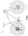
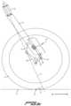
- FIG. 1 Ais a side view of a cycle including a front wheel suspension assembly constructed according to the teachings of the disclosure.
- FIG. 1 Bis a side view of an alternate embodiment of a cycle including a front wheel suspension assembly constructed according to the teachings of the disclosure, the cycle of FIG. 1 B including a rear wheel suspension assembly.
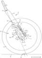
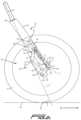
- FIG. 2 Ais a close up side view of a first arm of the front wheel suspension assembly of FIG. 1 .
- FIG. 2 Bis a close up side view of a second arm of the front wheel suspension assembly of FIG. 1 .
- FIG. 3 Ais a side exploded view of the front wheel suspension assembly of FIG. 2 A .
- FIG. 3 Bis a side exploded view of the front wheel suspension assembly of FIG. 2 B .
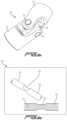
- FIG. 4 Ais a side cut-away view of a first embodiment of a shock absorber of the wheel suspension assembly of FIG. 2 A .
- FIG. 4 Bis a side cut-away view of a second embodiment of a shock absorber of the wheel suspension assembly of FIG. 2 A .
- FIG. 4 Cis a side cut-away view of a third embodiment of a shock absorber of the wheel suspension assembly of FIG. 2 A .
- FIG. 4 Dis a side cut-away view of a fourth embodiment of a shock absorber of the wheel suspension assembly of FIG. 2 A .
- FIG. 4 Eis a side cut-away view of a first embodiment of a gas spring of the wheel suspension assembly of FIG. 2 B .
- FIG. 5 Ais a side schematic view of the embodiment of a wheel suspension assembly of FIG. 2 A , having the shock absorber of FIG. 4 A or 4 B .
- FIG. 5 Bis a side schematic view of the embodiment of a wheel suspension assembly of FIG. 2 A , having the shock absorber of FIG. 4 C or 4 D .
- FIG. 5 Cis a side schematic view of the embodiment of a wheel suspension assembly of FIG. 2 B , having the gas spring of FIG. 4 E .
- FIG. 6 Ais a perspective view of a first embodiment of a pivot of the wheel suspension assembly of FIG. 2 A .
- FIG. 6 Bis a side view of a second embodiment of a pivot of the wheel suspension assembly of FIG. 2 A .
- FIG. 6 Cis an exploded view of a third embodiment of a pivot of the wheel suspension assembly of FIG. 2 A .
- FIG. 6 Dis a side view of a fourth embodiment of a pivot of the wheel suspension assembly of FIG. 2 A .
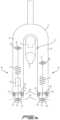
- FIG. 7 Ais a front cut-away view of the embodiment of the wheel suspension assembly of FIGS. 2 A and 2 B .
- FIG. 7 Bis a front cut-away schematic view of the embodiment of the wheel suspension assembly of FIGS. 2 A and 2 B .
- FIG. 8is a side schematic view showing certain embodiments of wheel carriers of the suspension assembly.
- a cycle 10includes a frame 12 , a front wheel 14 , which in certain embodiments can include a rim and a tire, rotatably connected to a fork 30 , and a rear wheel 16 rotatably connected to the frame 12 .
- the rear wheel 16is drivable by a drive mechanism, such as a chain 18 connected to a wheel sprocket 20 and to a chainring 22 , so that driving force may be imparted to the rear wheel 16 .
- the fork 30allows the front wheel 14 to deflect relative to the frame 12 in response to ground conditions as a rider rides the cycle and to improve handling and control during riding.
- the fork 30 and the front wheel 14may be operatively connected to a suspension assembly or linkage 46 .
- the frame 12may optionally include a rear wheel suspension assembly (not shown in FIG. 1 A ), which may allow the rear wheel 16 to deflect in response to ground conditions as a rider rides the cycle and to improve handling and control during riding.
- a cycle 10includes a frame 12 , a front wheel 14 , which in certain embodiments can include a rim and a tire, rotatably connected to a fork 30 , and a rear wheel 16 rotatably connected to the frame 12 .
- the fork 30 and the front wheel 14may be operatively connected to a suspension assembly or linkage 46 .
- the rear wheel 16is drivable by a drive mechanism, such as a chain 18 connected to a wheel sprocket 20 and to a chainring 22 , so that driving force may be imparted to the rear wheel 16 .
- the fork 30allows the front wheel 14 to deflect relative to the frame 12 in response to ground conditions as a rider rides the cycle and to improve handling and control during riding.
- the frame 12may optionally include a rear wheel suspension assembly 24 , which may allow the rear wheel 16 relative to the frame 12 to deflect in response to ground conditions as a rider rides the cycle and to improve handling and control during riding.
- the fork 30includes a first arm 32 and a second arm 33 , each of which are operatively connected to a steering shaft 34 .
- the steering shaft 34includes a steering axis S that is formed by a central axis of the steering shaft 34 .
- the first arm 32has a first end 36 a second end 38 , the first arm 32 including a first arm fixed pivot 40 and a first arm shock pivot 42 .
- the second arm 33has a first end 37 and a second end 39 , the second arm 33 including a second arm fixed pivot 140 and a second arm spring pivot 142 .
- the first arm shock pivot 42operably connects a suspension device, such as a shock absorber 44 to the first arm 32 .
- a suspension devicesuch as a shock absorber 44
- the first arm shock pivot 42allows relative motion, in this case rotation, between the shock absorber 44 and the first arm 32 .
- other types of relative motionsuch as flexure or translation, between the shock absorber 44 and the first arm 32 may be employed.
- the first arm fixed pivot 40pivotably connects one element of the linkage 46 , as discussed further below, to the first arm 32 .
- the second arm spring pivot 142operably connects a suspension device, such as a spring unit 48 to the second arm 33 .
- a suspension devicesuch as a spring unit 48
- the second arm spring pivot 142allows relative motion, in this case rotation, between the spring unit 48 and the second arm 33 .
- other types of relative motionsuch as flexure or translation, between the spring unit 48 and the second arm 33 may be employed.
- the second arm fixed pivot 140pivotably connects one element of the linkage 46 , as discussed further below, to the second arm 33 .
- a shock link 50is pivotably connected to the first arm fixed pivot 40 .
- the shock link 50includes a shock link fixed pivot 52 and a shock link floating pivot 54 spaced apart from one another along a length of the shock link 50 .
- the shock link 50is pivotably connected to the first arm fixed pivot 40 at the shock link fixed pivot 52 such that the shock link 50 is rotatable about the shock link fixed pivot 52 and the shock link fixed pivot 52 remains in a fixed location relative to the first arm 32 , while the shock link floating pivot 54 is movable relative to the first arm 32 .
- a spring link 150is pivotably connected to the second arm fixed pivot 140 .
- the spring link 150includes a spring link fixed pivot 152 and a spring link floating pivot 154 spaced apart from one another along a length of the spring link 150 .
- the spring link 150is pivotably connected to the second arm fixed pivot 140 at the spring link fixed pivot 152 such that the spring link 150 is rotatable about the spring link fixed pivot 152 and the spring link fixed pivot 152 remains in a fixed location relative to the second arm 33 , while the spring link floating pivot 154 is movable relative to the second arm 33 .
- a pivotincludes any connection structure that may be used to operatively connect one element to another element.
- An operative connectionmay allow for one component to move in relation to another while constraining movement in one or more degrees of freedom.
- the one degree of freedommay be pivoting about an axis.
- a pivotmay be formed from a journal or through hole in one component and an axle in another component.
- pivotsmay include ball and socket joints.
- Yet other examples of pivotsinclude, but are not limited to singular embodiments and combinations of, compliant mounts, sandwich style mounts, post mounts, bushings, bearings, ball bearings, plain bearings, flexible couplings, flexure pivots, journals, holes, pins, bolts, and other fasteners.
- a fixed pivotis defined as a pivotable structure that does not change position relative the first arm 32 .
- a floating pivotis defined as a pivot that is movable (or changes position) relative to another element, and in this case, is movable relative to first arm 32 .
- the suspension assembly or linkage 46 , 146is configured in a trailing orientation.
- a trailing orientationis defined herein as a linkage that includes a fixed pivot that is forward of the corresponding floating pivot when the cycle is traveling in the forward direction of travel as represented by arrow A in FIGS. 1 A and 1 B .
- the floating pivottrails the fixed pivot when the cycle is traveling in the forward direction of travel.
- the shock link fixed pivot 52is forward of the shock link floating pivot 54 .
- the disclosed suspension assembly or linkage 46is also characterized as a multi-bar linkage.
- a multi-bar linkageis defined herein as a linkage in which any part of the front wheel 14 is directly connected a link that is not directly connected to an arm of the fork 30 .
- the shock absorber 44includes a first shock mount 56 and a second shock mount 58 , the first shock mount 56 being pivotably connected to the first arm shock pivot 42 , the second shock mount 58 being pivotably connected to a shock connection pivot 60 located between the shock link fixed pivot 52 and the shock link floating pivot 54 along a length of the shock link 50 .
- the shock absorber 44can also include a gas spring 92 having a spring body 88 , a damper 94 having a damper body 89 , an inshaft 80 , and outshaft 90 , a damper piston 83 , a gas piston 81 , and a shaft seal 85 .
- a dampermay also be referred to as a dashpot and a gas spring may also be referred to as a mechanical spring.
- the first shock mount 56can be located at any point along the length of the spring body 88 or damper body 89 .
- the first shock mount 56can be located closer to the inshaft 80 than a first end 87 of the spring body 88 .
- the first shock mount 56can comprise various types of pivot designs and layouts, such as through bolt pivots, trunnion mounts, clevises, or other types of pivots.
- the second shock mount 58can be located at any point along the length of the inshaft 80 .
- the second shock mount 58can be located closer to the damper 94 than a second end 97 of the inshaft 80 .
- the second shock mount 58can comprise various types of pivot designs and layouts, such as through bolt pivots, trunnion mounts, clevises, or other types of pivots.
- the shock absorber 44can be mounted with the first shock mount 56 attached to either the first arm 32 or the shock link 50 and/or with the second shock mount 58 attached to either the first arm 32 or the shock link 50 .
- Shock absorber 44 mountingis not limited to the first shock mount 56 being attached to the first arm 32 and the second shock mount 58 being attached to the shock link 50 as illustrated in the accompanying figures.
- the spring unit 48includes a first spring mount 57 and a second spring mount 59 , the first spring mount 57 being pivotably connected to the second arm spring pivot 142 , the second spring mount 59 being pivotably connected to a spring connection pivot 160 located between the spring link fixed pivot 152 and the spring link floating pivot 154 along a length of the spring link 150 .
- the spring unit 48can also include a gas spring 192 having a spring body 188 , an inshaft 180 , a gas piston 181 , a gas piston seal 191 , and a shaft seal 185 .
- a gas springmay also be referred to as a mechanical spring.
- the first spring mount 57can be located at any point along the length of the spring body 188 .
- the first spring mount 57can he located closer to the inshaft 180 than a first end 187 of the spring body 188 .
- the first spring mount 57can comprise various types of pivot designs and layouts, such as through bolt pivots, trunnion mounts, devises, or other types of pivots.
- the second spring mount 59can be located at any point along the length of the inshaft 180 .
- the second spring mount 59can be located closer to the spring body 188 than a second end 197 of the inshaft 180 .
- the second spring mount 59can comprise various types of pivot designs and layouts, such as through bolt pivots, trunnion mounts, clevises, or other types of pivots.
- the spring unit 48can be mounted with the first spring mount 57 attached to either the second arm 33 or the spring link 150 and/or with the second spring mount 59 attached to either the second arm 33 or the spring link 150 .
- the spring unit 48 mountingis not limited to the first spring mount 57 being attached to the second arm 33 and the second spring mount 59 being attached to the spring link 150 as illustrated in the accompanying figures.
- the inshafts 80 , 180 and the outshaft 90can comprise a singular component or plurality of components, and may be combined with other components.
- the damper piston 83may be connected to or include a portion or the entirety of the inshaft 80 or outshaft 90 .
- the damper piston 83has a greater radial cross-sectional area than the inshaft 80 or the outshaft 90 .
- the inshafts 80 , 180 and the outshaft 90can extend between and through a shaft seal 85 , 185 to operably connect a gas spring 92 with a damper and/or to provide concurrent movement of any combination of the inshafts 80 , 180 , the outshaft 90 , the gas pistons 81 , 181 , and the damper piston 83 during suspension compression and extension.
- the damper pistonmates to or includes a damper piston seal 93 .
- the damper piston seal 93may comprise; multiple, or combinations of glide ring, wear band, o-ring. X-ring, Q ring, quad ring, Teflon seal, cap seal, piston ring, solid piston, T seal, V ring, U cup, urethane seal, PSQ seal, preloaded piston band, or other type of band or seal.
- the damper piston seal 93is intended to seal damping fluid between each side of the damper piston 83 , while allowing axial movement of the damper piston 83 and therefore axial movement of the inshaft 80 and/or outshaft 90 .
- the gas spring 92has certain advantages over other types of springs.
- the gas spring 92uses a pressurized gas such as air, nitrogen, or other gases to act on the area of a gas piston 81 , which outputs a force at the gas piston 81 .
- a usercan change the gas pressure and therefore the force output at the gas piston 81 . This allows the user to tailor output force based on their preference or to meet the requirements of varying road conditions.
- a gas spring 92may comprise pressures that can act on both sides of the gas piston 81 .
- the gas piston 81 , 181can be connected to or include a portion or the entirety of the inshaft 80 , 180 or the outshaft 90 .
- the gas piston 81 , 181has a greater radial cross-sectional area than the inshaft 80 , 180 or the outshaft 90 .
- the gas piston 81has a greater radial cross-sectional area than the damper piston 83 .
- the gas piston 81 , 181mates to or includes a gas piston seal 91 , 191 .
- the gas piston seal 91 , 191may comprise; singular, multiple, or combinations of glide ring, wear band, o-ring.
- the gas piston seal 91 , 191is intended to seal gas between each side of the gas piston 81 , 181 , while allowing axial movement of the gas piston 81 , 181 and therefore axial movement of the inshaft 80 , 180 and/or outshaft 90 .
- the shock absorber 44includes a shaft seal 85 .
- the shaft seal 45is used to seal damping fluid or gas inside the damper body 89 or spring body 88 while allowing axial movement of an inshaft 80 and/or outshaft 90 .
- the shaft seal 85can be located at one end of a spring body 88 , while sealing gas inside the spring body 88 and allowing axial movement of an inshaft 80 or outshaft 90 .
- a shaft seal 45can be located at one or more ends of a damper body 89 , while sealing damping fluid inside the damper body 89 and allowing axial movement of an inshaft 80 or outshaft 90 .
- the spring unit 48includes a shaft seal 185 .
- the shaft seal 185is used to seal fluid or gas inside the spring body 188 while allowing axial movement of the inshaft 180 .
- the shaft seal 185can be located at one end of a spring body 188 , while scaling gas inside the spring body 188 and allowing axial movement of an inshaft 180 .
- the shaft seal 185can be located at one or more ends of the spring body 188 , while sealing damping fluid inside the spring body 188 and allowing axial movement of the inshaft 180 .
- a first wheel carrier 62includes a wheel carrier first pivot 64 and a wheel carrier second pivot 66 spaced apart from one another along a length of the wheel carrier 62 . Both the wheel carrier first pivot 64 and the wheel carrier second pivot 66 arc floating pivots, as they both move relative to the first arm 32 .
- a wheel mount 68is adapted to be connected to a center of a wheel, for example the front wheel 14 . In the disclosed embodiment, a center of the front wheel 14 is rotatably connected to the wheel mount 68 .
- the wheel carrier first pivot 64is pivotably connected to the shock link floating pivot 54 so that the wheel carrier second pivot 66 is pivotable about the wheel carrier first pivot 64 relative to the shock link floating pivot 54 .
- a wheel carrierin some embodiments, can include one or more brake mounts.
- a second wheel carrier 162includes a wheel carrier first pivot 164 and a wheel carrier second pivot 166 spaced apart from one another along a length of the wheel carrier 162 .
- Both the wheel carrier first pivot 164 and the wheel carrier second pivot 166are floating pivots, as they both move relative to the first arm 32 .
- a wheel mount 168is adapted to be connected to a center of a wheel, for example the front wheel 14 . In the disclosed embodiment, a center of the front wheel 14 is rotatably connected to the wheel mount 168 .
- the wheel carrier first pivot 164is pivotably connected to the spring link floating pivot 154 so that the wheel carrier second pivot 166 is pivotable about the wheel carrier first pivot 164 relative to the spring link floating pivot 154 .
- a wheel carrierin some embodiments, can include one or more brake mounts 163 .
- a first control link 70includes a control link floating pivot 72 and a control link fixed pivot 74 .
- the control link floating pivot 72is pivotably connected to the wheel carrier second pivot 66
- the control link fixed pivot 74is pivotably connected to a first arm control pivot 76 located on the first arm 32 such that the control link floating pivot 72 is pivotable about the control link fixed pivot 74 , which remains in a fixed location relative to the first arm control pivot 76 .
- a second control link 170includes a control link floating pivot 172 and a control link fixed pivot 174 .
- the control link floating pivot 172is pivotably connected to the wheel carrier second pivot 166
- the control link fixed pivot 174is pivotably connected to a second arm control pivot 176 located on the second arm 33 such that the control link floating pivot 172 is pivotable about the control link fixed pivot 174 , which remains in a fixed location relative to the second arm control pivot 176 .
- the shock connection pivot 60is closer to the shock link fixed pivot 52 than to the shock link floating pivot 54 , as illustrated in FIG. 2 A .
- a perpendicular distance D between a central axis I of an inshaft 80 of the shock absorber 44 or spring unit 48 and a center of the shock link fixed pivot 52varies as the shock absorber 44 is compressed and extended, as the shock absorber pivots about the first shock mount 56 .
- This pivoting and varying of the perpendicular distance Dallows the leverage ratio and motion ratio to vary as the shock absorber 44 compresses and extends.
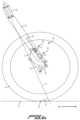
- a mechanical trail distance Tvaries as the shock absorber 44 compresses and extends.
- the mechanical trail distance Tis defined as the perpendicular distance between the steering axis S and the contact point 82 of the front wheel 14 with the ground 84 . More specifically, as the suspension compresses, beginning at a state of full extension, the mechanical trail distance T increases, thus increasing stability during compression. Compression is usually experienced during braking, cornering, and shock absorbing, all of which benefit from increased stability that results from the mechanical trail distance increase.
- Mechanical trail(or “trail”, or “caster”) is an important metric relating to handling characteristics of two-wheeled cycles.
- Mechanical trailis a configuration in which the wheel is rotatably attached to a fork, which has a steering axis that is offset from the contact point of the wheel with the ground.
- the steering axisis forward of the contact point, as in the case of a shopping cart, this configuration allows the caster wheel to follow the direction of cart travel. If the contact point moves forward of the steering axis (for example when reversing direction of a shopping cart), the directional control becomes unstable and the wheel spins around to the original position in which the contact point trails the steering axis.
- the friction between the ground and the wheelcauses a self-righting torque that tends to force the wheel to trail the steering axis.
- the greater the distance between the contact point and perpendicular to the steering axisthe more torque is generated, and the greater the stability of the system.
- the longer the distance between the cycle wheel contact point and perpendicular to the steering axisthe more torque is generated, and the greater the stability of the system.
- the shorter the distance between the cycle wheel contact point and perpendicular to the steering axisthe less torque is generated, and the lower the stability of the system.
- This caster effectis an important design characteristic in cycles. Generally, the caster effect describes the cycle rider's perception of stability resulting from the mechanical trail distance described above. If the wheel gets out of line, a self-aligning torque automatically causes the wheel to follow the steering axis again due to the orientation of the wheel ground contact point being behind the steering axis of the fork. As the contact point of the wheel with the ground is moved further behind the steering axis, self aligning torque increases. This increase in stability is referred to herein as the caster effect.
- the steering axis of the fork 30projects ahead of the contact point 82 .
- the steering axis Sprojects farther ahead of the contact point 82 , which results in the stability increasing. This increased stability stands in contrast to known telescopic fork cycles, which experience reduced trail and thus reduced stability during compression.
- a shock absorbercan be compressed at a constant or variable rate as the suspension moves at a constant rate towards a state of full compression.
- incremental suspension compression distance measurementsare taken. Incremental suspension compression distance is measured from the center of the wheel at the wheel rotation axis and parallel with the steering axis, starting from a state of full suspension extension, and moving towards a state of full suspension compression. These incremental measurements are called the incremental suspension compression distance.
- a shock absorber lengthcan be changed by wheel link, and/or brake link, and/or control link movements as the suspension compresses. At each incremental suspension compression distance measurement, a shock absorber length measurement is taken.
- leverage ratioThe relationship between incremental suspension compression distance change and shock absorber length change for correlating measurements of the suspension's compression is called leverage ratio or motion ratio.
- Leverage ratio and motion ratioare effectively equivalent but mathematically different methods of quantifying the effects of variable suspension compression distance versus shock compression distance.
- Overall leverage ratiois the average leverage ratio across the entire range of compression.
- Overall leverage ratiocan be calculated by dividing the total suspension compression distance by the total shock absorber compression distance.
- Overall motion ratiois the average motion ratio across the entire range of compression.
- Overall motion ratiocan be calculated by dividing the total shock absorber compression distance by the total suspension compression distance.
- a suspended wheelhas a compressible wheel suspension travel distance that features a beginning travel state where the suspension is completely uncompressed to a state where no further suspension extension can take place, and an end travel state where a suspension is completely compressed to a state where no further suspension compression can take place.
- the shock absorberis in a state of least compression, and the suspension is easily compressed.
- a leverage ratiois defined as the ratio of compressive wheel travel change divided by shock absorber measured length change over an identical and correlating given wheel travel distance.
- a motion ratiois defined as the ratio of shock absorber measured length change divided by compressive wheel travel change over an identical and correlating given wheel travel distance.
- a leverage ratio curveis a graphed quantifiable representation of leverage ratio versus wheel compression distance or percentage of full compression distance. Wheel compression distance, suspension compression, or wheel travel is measured from the center of the wheel at the wheel rotation axis and parallel with the steering axis, with the initial 0 percent measurement taken at full suspension extension with the vehicle unladen. As a suspension is compressed from a state of full extension to a state of full compression at a constant rate, measurements of shock absorber length are taken as the shortest distance between a first shock pivot and a second shock pivot at equal increments of suspension compression.
- leverage ratiois shown on the Y axis escalating from the x axis in a positive direction
- vertical wheel travelis shown on the X axis escalating from the Y axis in a positive direction.
- a motion ratio curveis a graphed quantifiable representation of motion ratio versus wheel compression distance or percentage of full compression distance.
- Wheel compression distance, suspension compression, or wheel travelis measured from the center of the wheel at the wheel rotation axis and parallel with the steering axis, with the initial 0 percent measurement taken at full suspension extension with the vehicle unladen.
- measurements of shock absorber lengthare taken as the shortest distance between a first shock pivot and a second shock pivot at equal increments of suspension compression.
- motion ratiois shown on the Y axis escalating from the x axis in a positive direction
- vertical wheel travelis shown on the X axis escalating from the Y axis in a positive direction.
- a leverage ratio or motion ratio curvecan be broken down into three equal parts in relation to wheel compression distance or vertical wheel travel, a beginning 1 ⁇ 3 (third), a middle 1 ⁇ 3, and an end 1 ⁇ 3.
- a beginning 1 ⁇ 3can comprise a positive slope, zero slope, and or a negative slope.
- a middle 1 ⁇ 3can comprise a positive slope, zero slope, and or a negative slope.
- an end 1 ⁇ 3can comprise a positive slope, zero slope, and or a negative slope.
- Certain preferred leverage ratio embodimentscan comprise a beginning 1 ⁇ 3 with a positive slope, a middle 1 ⁇ 3 with a less positive slope, and an end 1 ⁇ 3 with a more positive slope.
- Certain preferred leverage ratio embodimentscan comprise a beginning 1 ⁇ 3 with a negative slope, a middle 1 ⁇ 3 with negative and zero slope, and an end 1 ⁇ 3 with a positive slope. Certain preferred leverage ratio embodiments can comprise a beginning 1 ⁇ 3 with a positive and negative slope, a middle 1 ⁇ 3 with negative and zero slope, and an end 1 ⁇ 3 with a positive slope. Certain preferred leverage ratio embodiments can comprise a beginning 1 ⁇ 3 with a positive and negative slope, a middle 1 ⁇ 3 with negative and zero slope, and an end 1 ⁇ 3 with a more negative slope. Certain preferred motion ratio embodiments can comprise a beginning 1 ⁇ 3 with a negative slope, a middle 1 ⁇ 3 with a less negative slope, and an end 1 ⁇ 3 with a more negative slope.
- Certain preferred motion ratio embodimentscan comprise a beginning 1 ⁇ 3 with a positive slope, a middle 1 ⁇ 3 with positive and zero slope, and an end 1 ⁇ 3 with a negative slope. Certain preferred motion ratio embodiments can comprise a beginning 1 ⁇ 3 with a negative and positive slope, a middle 1 ⁇ 3 with positive and zero slope, and an end 1 ⁇ 3 with a negative slope. Certain preferred motion ratio embodiments can comprise a beginning 1 ⁇ 3 with a negative and positive slope, a middle 1 ⁇ 3 with positive and zero slope, and an end 1 ⁇ 3 with a more positive slope.
- the disclosed wheel suspension assemblyprovides a greater than 1:1 overall leverage ratio between the shock absorber 44 and the shock link 50 , due to the indirect coupling (through the linkage 46 ) of the wheel 14 and the shock absorber 44 .
- the disclosed wheel suspension assemblyprovides a less than 1:1 overall motion ratio between the shock absorber 44 and the shock link 50 , due to the indirect coupling (through the linkage 46 ) of the wheel 14 and the shock absorber 44 .
- instantaneous leverage ratio and motion ratiocan vary non-linearly.
- the central axis I of the inshaft 80 of the shock absorber 44is arranged to form an angle B of between 0° and 20° relative to a central axis F of the first arm 32 , the central axis F of the first arm 32 being defined by a line formed between the first arm shock pivot 42 and the first arm fixed pivot 40 .
- the central axis I of the inshaft 80 of the shock absorber 44forms an angle with the central axis F of the first arm 32 of between 0° and 15°.
- the central axis I of the inshaft 80 of the shock absorber 44forms an angle with the central axis F of the first arm 32 of between 0° and 30°.
- the angle Bmay vary within these ranges during compression and extension.
- the first arm 32includes a hollow portion 86 and the shock absorber 44 is located at least partially within the hollow portion 86 of the first arm 32 .
- the shock link fixed pivot 52is offset forward of the central axis I of the inshaft 80 of the shock absorber 44 .
- the central axis I of the inshaft 80 of the shock absorber 44is positioned between the shock link fixed pivot 52 and the shock link floating pivot 54 in a plane defined by the central axis I of the inshaft 80 , the shock link fixed pivot 52 and the shock link floating pivot 54 (i.e., the plane defined by the view of FIGS. 2 A and 2 B ).
- a line between the wheel carrier first pivot 64 and the wheel carrier second pivot 66defines a wheel carrier axis WC
- the wheel mount 68is offset from the wheel carrier axis WC in a plane defined by the wheel carrier axis WC and the wheel mount 68 (i.e., the plane defined by the views of FIG. 3 A and 3 B ).
- the wheel mount 68is offset from the wheel carrier axis WC towards the first arm 32 , for example the embodiment illustrated in FIGS. 2 and 3 .
- the wheel mount 68may be offset from the wheel carrier axis WC away from the first arm 32 .
- the wheel mount 68 , 168is located aft of the shock link fixed pivot 52 , or of the spring link fixed pivot 152 , such that the central axis I of the inshaft 80 , 180 of the shock absorber 44 or of the spring unit 48 is located between the wheel mount 68 , 168 and the shock link fixed pivot 52 , or the spring link fixed pivot 152 in a plane defined by the central axis I of the inshaft 80 , 188 , the wheel mount 68 , 168 and the shock link fixed pivot 52 , or the spring link fixed pivot 152 (i.e., the plane defined by the views of FIGS. 2 A and 2 B ).
- the shock absorber 44may include an inline shock absorber having a damper body 89 and a spring body 88 that are sequentially arranged along a substantially common central axis.
- the damper body 89 and the spring body 88shall be considered to be inline and arranged sequentially along a substantially common central axis when a central axis of the spring body 88 and a central axis of the damper body 89 are offset from one another by a maximum of 100% of the outside diameter of an inshaft 80 . In other embodiments, the damper body 89 and the spring body 88 are offset from one another by a maximum of 50% of the outside diameter of the inshaft 80 . In other embodiments, the damper body 89 and the spring body 88 are offset from one another by a maximum of 33% of the outside diameter of the inshaft 80 .
- the damper body 89 and the spring body 88are offset from one another by a maximum of 25% of the outside diameter of the inshaft 80 . In a preferred embodiment, the damper body 89 and the spring body 88 share a common central axis.
- the inshaft 80extends from the damper body 89 , and an outshaft 90 extends into the damper body 89 and into the spring body 88 .
- the second shock mount 58is formed at one end of the inshaft 80 , and the inshaft 80 is pivotably connected to the shock connection pivot 60 by the second shock mount 58 such that the inshaft 80 and the outshaft 90 are compressible and extendable relative to the damper body 89 as the shock link 50 pivots about the shock link fixed pivot 52 .
- the damper body 89is located between the spring body 88 and the second shock mount 58 .
- the shock absorber 44includes a gas piston 81 with a larger radial cross-sectional area than a damper piston 83 .
- the shock absorber 44includes a shaft seal 85 .
- the shaft seal 85is used to seal damping fluid or gas inside the damper body 89 and/or inside the spring body 88 while allowing axial movement of an inshaft 80 and/or outshaft 90 .
- the shaft seal 85can be located at one end of a spring body 88 , while sealing gas inside the spring body 88 and allowing axial movement of an outshaft 90 .
- the shaft seal 85can be located at one end of a damper body 89 , while sealing damping fluid inside the damper body 89 and allowing axial movement of an outshaft 90 .
- the shaft seal 85can be located at one end of a damper body 89 , while sealing damping fluid inside the damper body 89 and allowing axial movement of an inshaft 80 .
- the shock absorber 44may include one or any combination of shaft seals 85 at the locations described above.
- the shock absorber 44may include an inline shock absorber having a damper body 89 and a spring body 88 that are sequentially arranged along a substantially common central axis.
- the shock absorbermay further include an inshaft 80 that extends from the damper body 89 , and an outshaft 90 that extends into the damper body 89 and into the spring body 88 .
- the second shock mount 58is formed at one end of the inshaft 80 , and the inshaft 80 is pivotably connected to the shock connection pivot 60 by the second shock mount 58 such that the inshaft 80 and the outshaft 90 are compressible and extendable relative to the damper body 89 as the shock link 50 pivots about the shock link fixed pivot 52 .
- the damper body 89is located between the spring body 88 and the second shock mount 58 .
- the shock absorber 44includes a gas piston 81 with a larger radial cross-sectional area than a damper piston 83 .
- the shock absorber 44includes a shaft seal 85 .
- the shaft seal 85is used to seal damping fluid or gas inside the damper body 89 and/or the spring body 88 while allowing axial movement of an inshaft 80 and/or outshaft 90 .
- the shaft seal 85can be located at one end of a spring body 88 , while sealing gas inside the spring body 88 and allowing axial movement of an outshaft 90 .
- the shaft seal 85can be located at one end of a spring body 88 , while sealing gas inside the spring body 88 , and additionally sealing damping fluid inside the damper body 89 , and allowing axial movement of an outshaft 90 .
- the shaft seal 85can be located at one end of a damper body 89 , while sealing damping fluid inside damper body 89 and allowing axial movement of an inshaft 80 .
- the shock absorber 44may include one or any combination of shaft seals 85 at the locations described above.
- the shock absorber 44may include an inline shock absorber having a spring body 88 and a damper body 89 that are sequentially arranged along a substantially common central axis.
- the shock absorbermay further include an inshaft 80 that extends from the spring body 88 , and an outshaft 90 that extends into the damper body 89 and into the spring body 88 .
- the second shock mount 58is formed at one end of the inshaft 80 , and the inshaft 80 is pivotably connected to the shock connection pivot 60 by the second shock mount 58 such that the inshaft 80 and the outshaft 90 are compressible and extendable relative to the spring body 88 as the shock link 50 pivots about the shock link fixed pivot 52 .
- FIG. 4 Cdiffers from the embodiment of FIG. 4 A in that the spring body 88 is between the damper body 89 and the second shock mount 58 .
- the damper body 89was located between the spring body 88 and the second shock mount 58 .
- the shock absorber 44includes a gas piston 81 with a larger radial cross-sectional area than a damper piston 83 .
- the shock absorber 44includes a shaft seal 85 .
- the shaft seal 85is used to seal damping fluid or gas inside the spring body 88 and/or the damper body 89 while allowing axial movement of an inshaft 80 and/or outshaft 90 .
- the shaft seal 85can be located at one end of a damper body 89 , while sealing damping fluid or gas inside the damper body 89 and allowing axial movement of an outshaft 90 .
- the shaft seal 85can be located at one end of a spring body 88 , while sealing gas inside the spring body 88 and allowing axial movement of an outshaft 90 .
- the shaft seal 85can be located at one end of a spring body 88 , while sealing gas inside the spring body 88 and allowing axial movement of an inshaft 80 .
- the shock absorber 44may include an inline shock absorber having a spring body 88 and a damper body 89 that are sequentially arranged along a substantially common central axis.
- the shock absorbermay further include the inshaft 80 that extends from the spring body 88 , and an outshaft 90 that extends into the damper body 89 and into the spring body 88 .
- the second shock mount 58is formed at one end of the inshaft 80 , and the inshaft 80 is pivotably connected to the shock connection pivot 60 by the second shock mount 58 such that the inshaft 80 and the outshaft 90 are compressible and extendable relative to the spring body 88 as the shock link 50 pivots about the shock link fixed pivot 52 .
- FIG. 4 Ddiffers from the embodiments of FIG. 4 B in that the spring body 88 is between the damper body 89 and the second shock mount 58 .
- the damper body 89was located between the spring body 88 and the second shock mount 58 .
- the shock absorber 44includes a shaft seal 85 .
- the shaft seal 85is used to seal damping fluid or gas inside the spring body 88 and/or damper body 89 while allowing axial movement of an inshaft 80 and/or outshaft 90 .
- the shaft seal 85can be located at one end of a damper body 89 , while sealing damping fluid or gas inside the damper body 89 and allowing axial movement of an outshaft 90 .
- the shaft seal 85can be located at one end of a damper body 89 , while sealing damping fluid or gas inside the damper body 89 , and additionally sealing gas inside the spring body 88 , and allowing axial movement of an outshaft 90 .
- the shaft seal 85can be located at one end of a spring body 88 , while sealing gas inside spring body 88 and allowing axial movement of an inshaft 80 .
- the spring unit 48may include an inshaft 180 that extends from the spring body 188 .
- the first spring mount 57is located in close proximity to the spring body 188 .
- the second spring mount 59is located in close proximity to one end of the inshaft 180 , and the inshaft 180 is pivotably connected to the spring connection pivot 160 by the second spring mount 59 such that the inshaft 180 is compressible and extendable relative to the spring body 188 as the spring link 150 pivots about the spring link fixed pivot 152 .
- the embodiment of FIG. 4 Ediffers from the embodiments of FIGS. 4 A , B, C, and D in that there is no outshaft 90 or damper 94 .
- the spring unit 48includes the shaft seal 185 .
- the shaft seal 185is used to seal gas inside the spring body 188 while allowing axial movement of the inshaft 180 .
- the shaft seal 185can be located at one end of a spring body 188 , while sealing gas inside spring body 188 and allowing axial movement of an inshaft 180 .
- FIG. 5 Aillustrates the wheel suspension assembly of FIG. 2 A , with the shock absorber of FIG. 4 A or 4 B , in engineering symbols that distinguish a mechanical spring 47 (in this case a gas spring) and dashpot 49 (or damper) of the shock absorber 44 .
- the body of the dashpot 49 and one end of the mechanical spring 47are connected to the first shock mount 56 to operably connect a gas spring with a damper to provide concurrent movement of spring and damper components during suspension compression and extension.
- the mechanical spring 47is located above the dashpot 49 in an inline configuration in this embodiment.
- FIG. 5 Billustrates the wheel suspension assembly of FIG. 2 A , with the shock absorber of FIG. 4 C or 4 D , in engineering symbols that distinguish a mechanical spring 47 and dashpot 49 of the shock absorber 44 .
- the body of the dashpot 49 and one end of the mechanical spring 47are connected to the first shock mount 56 to operably connect a gas spring with a damper to provide concurrent movement of spring and damper components during suspension compression and extension.
- the dashpot 49is located above the mechanical spring 47 in an inline configuration in this embodiment.
- FIG. 5 Cillustrates the wheel suspension assembly of FIG. 2 B , with the spring unit 48 of FIG. 4 E , in engineering symbols that distinguish a mechanical spring 47 of the spring unit 48 .
- the body of the mechanical spring 47is connected to the first spring mount 57 to operably provide movement of spring components during suspension compression and extension.
- control link 70is pivotably mounted to the first arm 32 at the first arm control pivot 76 that is located between the first arm fixed pivot 40 and the first arm shock pivot 42 , along a length of the first arm 32 .
- FIGS. 6 A- 6 Dseveral embodiments of structures are illustrated that may be used as the pivots (fixed and/or floating) described herein.
- FIG. 6 Aillustrates a cardan pivot 100 .
- the cardan pivotincludes a first member 101 and a second member 102 that are pivotably connected to one another by yoke 105 which comprises a first pin 103 and a second pin 104 .
- yoke 105which comprises a first pin 103 and a second pin 104 .
- the first member 101 and the second member 102may move relative to one another about an axis of the first pin 103 and/or about an axis of the second pin 104 .
- FIG. 6 Billustrates a flexure pivot 200 .
- the flexure pivot 200includes a flexible portion 203 disposed between a first member 201 and a second member 202 .
- the first member 201 , the second member 202 , and the flexible portion 203may be integrally formed.
- the first member 201 , the second member 202 , and the flexible portion 203may be separate elements that are connected to one another.
- the flexible portion 203allows relative motion between the first member 201 and the second member 202 about the flexible portion 203 .
- the flexible portion 203is more flexible than the members 201 and 202 , permitting localized flexure at the flexible portion 203 .
- the flexible portion 203is formed by a thinner portion of the overall structure.
- the flexible portion 203is thinned sufficiently to allow flexibility in the overall structure.
- the flexible portion 203is shorter than 100 mm.
- the flexible portion 203is shorter than 70 mm.
- the flexible portion 203is shorter than 50 mm.
- the flexible portion 203is shorter than 40 mm.
- the flexible portion 203is shorter than 30 mm. In certain other preferred embodiments, the flexible portion 203 is shorter than 25 mm.
- FIG. 6 Cillustrates a bar pin pivot 300 .
- the bar pin pivotincludes a first bar arm 301 and a second bar arm 302 that are rotatably connected to a central hub 303 .
- the central hub 303allows the first bar arm 301 and the second bar arm 302 to rotate around a common axis.
- FIG. 6 Dillustrates a post mount pivot 400 .
- the post mount pivot 400includes a mounting stem 401 that extends from a first shock member 402 .
- the mounting stem 401is connected to a structure 407 by a nut 404 , one or more retainers 405 , and one or more grommets 406 .
- the first shock member 402is allowed relative movement by displacement of the grommets 406 , which allows the mounting stem 401 to move relative to a structure 407 in at least one degree of freedom.
- FIG. 7 Aillustrates a certain embodiment of the wheel suspension assembly in a front view, where a space between the first arm 32 and the second arm 33 of the steering fork 30 , in part, defines a wheel opening 61 .
- the front wheel 14moves within an envelope 15 , during suspension compression and extension.
- the wheel opening 61allows clearance for the front wheel 14 so that the front wheel 14 does not contact the steering fork 30 during suspension compression and extension.
- the shock absorber 44is shown positioned on the first arm 32
- the spring unit 48is shown positioned on the second arm 33 .
- the shock link 50(or the spring link 150 ) is pivotably connected to the first arm fixed pivot 40 or to the second arm fixed pivot 140 at the shock link fixed pivot 52 , or at the spring link fixed pivot 152 such that the shock link 50 (or the spring link 150 ) is rotatable about a first pivot axis 53 a of the shock link fixed pivot 52 (or of the spring link fixed pivot 152 ) and the shock link fixed pivot 52 (or the spring link fixed pivot 152 ) remains in a fixed location relative to the first arm 32 , or to the second arm 33 , while the shock link 50 (or the spring link 150 ) is movable relative to the first arm 32 , or to the second arm 33 .
- the shock absorber 44includes the first shock mount 56 and the second shock mount 58 , the first shock mount 56 being pivotably connected to the first arm 32 about a pivot axis 53 c.
- the second shock mount 58is formed at one end of the inshaft 80 , and the inshaft 80 is pivotably connected about the pivot axis 53 a to the shock connection pivot 60 by the second shock mount 58 such that the inshaft 80 is compressible and extendable relative to the damper body 89 and spring body 88 as the shock link 50 pivots about the shock link fixed pivot 52 .
- the spring unit 48includes the first spring mount 57 and the second spring mount 59 , the first spring mount 57 being pivotably connected to the second arm 33 about a pivot axis 53 b.
- the second the second spring mount 59is formed at one end of the inshaft 180 , and the inshaft 180 is pivotably connected about the pivot axis 53 a to the shock connection pivot 60 by the second spring mount 59 such that the inshaft 180 is compressible and extendable relative to the spring body 188 as the shock link 150 pivots about the spring link fixed pivot 152 .
- FIG. 7 Billustrates the wheel suspension assembly of FIG. 7 A , in a front view, with the shock absorber of FIGS. A-D, in engineering symbols that distinguish a mechanical spring 47 and dashpot 49 of the shock absorber 44 .
- the body of the dashpot 49 and one end of the mechanical spring 47are connected to the first shock mount 56 to operably connect a gas spring with a damper to provide concurrent movement of spring and damper components during suspension compression and extension.
- the dashpot 49is located below the mechanical spring 47 in an inline configuration in this embodiment, but the dashpot 49 could be located above or concentric to the mechanical spring 47 in other configurations.
- a space between the first arm 32 and the second arm 33 of the steering fork 30defines the wheel opening 61 .
- the front wheel 14moves within the envelope 15 , during suspension compression and extension.
- the wheel opening 61allows clearance for the front wheel 14 so that the front wheel 14 does not contact the steering fork 30 during suspension compression and extension.
- the shock absorber 44includes the mechanical spring 47 and the dashpot 49 is shown positioned on the first arm 32 , and the spring unit 48 including a mechanical spring 47 is shown positioned on the second arm 33 .
- the shock absorber 44could be positioned on the second arm 33 , and a spring unit 48 could be positioned on the first arm 32 .
- the shock link 50is pivotably connected to the first arm fixed pivot 40 at the shock link fixed pivot 52 such that the shock link 50 is rotatable about pivot axis 53 d of the shock link fixed pivot 52 and the shock link fixed pivot 52 remains in a fixed location relative to the first arm 32 , while the shock link 50 is movable relative to the first arm 32 .
- FIG. 8illustrates in a side schematic view certain embodiments of wheel carriers of the suspension assembly.
- a first wheel carrier 62is illustrated, and it should be understood that the features of the first wheel carrier 62 can be similar or equivalent to the features of a second wheel carrier 162 as illustrated in other figures herein.
- the wheel mount 68can be located at any point attached to the first wheel carrier 62 .
- the wheel mount 68can be located on either side of, or in-line with a line wheel carrier axis WC.
- the wheel mount 68can be located between a wheel carrier first pivot 64 and a wheel carrier second pivot 66 or the wheel mount 68 can be located not between a wheel carrier first pivot 64 and a wheel carrier second pivot 66 .
- the disclosed wheel suspension assembliescan be designed to be lighter in weight, lower in friction, more compliant, safer, and perform better than traditional wheel suspension assemblies.
- the disclosed wheel suspension assembliesalso reduce stiction and increase stability during braking, cornering, and shock absorption, when compared to traditional wheel suspension assemblies.
- the disclosed wheel suspension assembliesare particularly well suited to E-bikes.
- E-bikesare heavier and faster than typical mountain bikes. They are usually piloted by less skilled and less fit riders, and require a stronger front suspension to handle normal riding conditions.
- E-bikesare difficult to build, requiring the challenging integration of motors and batteries into frame designs. In many cases, the electric parts are large and unsightly.
- E-bikesare typically cost prohibitive to build as well, requiring special fittings to adapt motors and batteries.
- the additional cost to the manufactureris about double the price of a common bicycle frame. That cost is multiplied and passed onto the consumer.
- the beneficial caster effect described above with respect to the disclosed wheel suspension assembliesis an important improvement over traditional wheel suspension assemblies and reduces some of the drawbacks of E-bikes.
- the disclosed wheel suspension assembliesare not constrained by round stantions, the oval fork legs balance fore-aft and side to side compliance for ultimate traction. Combining superior chassis stiffness while eliminating stiction gives the disclosed wheel suspension assemblies a performance advantage over traditional wheel suspension assemblies.
- wheel suspension assembliesare easily retrofittable to traditional cycles.
Landscapes
- Engineering & Computer Science (AREA)
- Mechanical Engineering (AREA)
- Vehicle Body Suspensions (AREA)
Abstract
Description
Claims (17)
Priority Applications (2)
| Application Number | Priority Date | Filing Date | Title |
|---|---|---|---|
| US17/109,029US11945539B2 (en) | 2018-09-07 | 2020-12-01 | Dual sided suspension assembly for a cycle wheel |
| US18/581,901US20240270343A1 (en) | 2018-09-07 | 2024-02-20 | Dual sided suspension assembly for a cycle wheel |
Applications Claiming Priority (2)
| Application Number | Priority Date | Filing Date | Title |
|---|---|---|---|
| US16/125,085US20200079463A1 (en) | 2018-09-07 | 2018-09-07 | Dual sided suspension assembly for a cycle wheel |
| US17/109,029US11945539B2 (en) | 2018-09-07 | 2020-12-01 | Dual sided suspension assembly for a cycle wheel |
Related Parent Applications (1)
| Application Number | Title | Priority Date | Filing Date |
|---|---|---|---|
| US16/125,085ContinuationUS20200079463A1 (en) | 2018-09-07 | 2018-09-07 | Dual sided suspension assembly for a cycle wheel |
Related Child Applications (1)
| Application Number | Title | Priority Date | Filing Date |
|---|---|---|---|
| US18/581,901ContinuationUS20240270343A1 (en) | 2018-09-07 | 2024-02-20 | Dual sided suspension assembly for a cycle wheel |
Publications (2)
| Publication Number | Publication Date |
|---|---|
| US20210323633A1 US20210323633A1 (en) | 2021-10-21 |
| US11945539B2true US11945539B2 (en) | 2024-04-02 |
Family
ID=69591703
Family Applications (3)
| Application Number | Title | Priority Date | Filing Date |
|---|---|---|---|
| US16/125,085AbandonedUS20200079463A1 (en) | 2018-09-07 | 2018-09-07 | Dual sided suspension assembly for a cycle wheel |
| US17/109,029Active2039-08-16US11945539B2 (en) | 2018-09-07 | 2020-12-01 | Dual sided suspension assembly for a cycle wheel |
| US18/581,901PendingUS20240270343A1 (en) | 2018-09-07 | 2024-02-20 | Dual sided suspension assembly for a cycle wheel |
Family Applications Before (1)
| Application Number | Title | Priority Date | Filing Date |
|---|---|---|---|
| US16/125,085AbandonedUS20200079463A1 (en) | 2018-09-07 | 2018-09-07 | Dual sided suspension assembly for a cycle wheel |
Family Applications After (1)
| Application Number | Title | Priority Date | Filing Date |
|---|---|---|---|
| US18/581,901PendingUS20240270343A1 (en) | 2018-09-07 | 2024-02-20 | Dual sided suspension assembly for a cycle wheel |
Country Status (3)
| Country | Link |
|---|---|
| US (3) | US20200079463A1 (en) |
| EP (1) | EP3847089A2 (en) |
| WO (1) | WO2020086157A2 (en) |
Cited By (2)
| Publication number | Priority date | Publication date | Assignee | Title |
|---|---|---|---|---|
| US12258095B2 (en) | 2019-04-09 | 2025-03-25 | Specialized Bicycle Components, Inc. | Cycle suspension with rotation sensor |
| US12344346B2 (en) | 2018-10-16 | 2025-07-01 | Specialized Bicycle Components, Inc. | Cycle suspension with travel indicator |
Families Citing this family (9)
| Publication number | Priority date | Publication date | Assignee | Title |
|---|---|---|---|---|
| US20200079463A1 (en) | 2018-09-07 | 2020-03-12 | Trvstper, Inc. | Dual sided suspension assembly for a cycle wheel |
| US11230348B2 (en) | 2018-09-25 | 2022-01-25 | Specialized Bicycle Components, Inc. | Trailing link cycle wheel suspension assembly having gas pistons with unequal gas piston areas |
| US11230346B2 (en) | 2018-09-25 | 2022-01-25 | Specialized Bicycle Components Inc. | Cycle wheel suspension assembly having gas pistons with unequal gas piston areas |
| US11230347B2 (en) | 2018-09-25 | 2022-01-25 | Specialized Bicycle Components, Inc. | Cycle wheel suspension assembly having gas pistons with unequal gas piston areas |
| US12319381B2 (en) | 2018-09-25 | 2025-06-03 | Specialized Bicycle Components, Inc. | Trailing link cycle wheel suspension assembly having gas pistons with unequal gas piston areas |
| US11084552B2 (en) | 2018-09-25 | 2021-08-10 | Specialized Bicycle Components, Inc. | Simplified gas spring setup for a trailing link cycle wheel suspension |
| US11208172B2 (en) | 2018-10-05 | 2021-12-28 | Specialized Bicycle Components, Inc. | Suspension pivot assemblies having a retention feature |
| US11345432B2 (en) | 2018-10-12 | 2022-05-31 | Specialized Bicycle Components, Inc. | Suspension assembly for a cycle having a fork arm with dual opposing tapers |
| US20250187698A1 (en)* | 2023-12-12 | 2025-06-12 | Kangaroo Design Inc. | Front Suspension System |
Citations (493)
| Publication number | Priority date | Publication date | Assignee | Title |
|---|---|---|---|---|
| US389200A (en) | 1888-09-11 | cleg-a | ||
| US393387A (en) | 1888-11-27 | Velocipede | ||
| US400727A (en) | 1889-04-02 | Spring-fork for bicycles | ||
| US412322A (en) | 1889-10-08 | Velocipede | ||
| US414048A (en) | 1889-10-29 | Velociped | ||
| US423471A (en) | 1890-03-18 | Petehg | ||
| US426402A (en) | 1890-04-22 | Bicycle | ||
| US435477A (en) | 1890-09-02 | Half to henry t | ||
| US441649A (en) | 1890-12-02 | John boyd dunlop | ||
| US443266A (en) | 1890-12-23 | Velocipede-fork | ||
| US444639A (en) | 1891-01-13 | Bicycle | ||
| US447234A (en) | 1891-02-24 | Bicycle | ||
| US467794A (en) | 1892-01-26 | Bicycle | ||
| US468643A (en) | 1892-02-09 | clement | ||
| US524389A (en) | 1894-08-14 | Bicycle | ||
| US602354A (en) | 1898-04-12 | Bicycle | ||
| US638723A (en) | 1898-04-14 | 1899-12-12 | Thomas Getchell Kelly | Bicycle. |
| US739476A (en) | 1902-12-26 | 1903-09-22 | E R Thomas Motor Company | Cushion-truss for cycles. |
| US783236A (en) | 1903-11-20 | 1905-02-21 | Thomas Ashburn | Bicycle or tricycle. |
| FR347724A (en) | 1904-11-11 | 1905-03-21 | Alberic De La Celle | Anti-vibration fork for motorcycles and bicycles |
| FR353990A (en) | 1905-05-05 | 1905-09-25 | Friedrich Sprung | Shock-resistant elastic suspension for bicycles and other vehicles |
| FR350269A (en) | 1904-10-27 | 1905-12-18 | Paul Joseph Jorat | Suspension for bicycles, tricycles, motorcycles, instantly adapting |
| US848324A (en) | 1906-11-10 | 1907-03-26 | James H Sager | Bicycle attachment. |
| FR376759A (en) | 1907-04-13 | 1907-08-20 | Albert Keller Dorian | Elastic fork for bicycles and motorcycles |
| US913961A (en) | 1907-12-30 | 1909-03-02 | Aurora Automatic Machinery Co | Bicycle-frame. |
| US927989A (en) | 1909-07-13 | Excelsior Supply Company | Bicycle. | |
| US940245A (en) | 1908-08-11 | 1909-11-16 | John W Gates | Spring-fork for wheeled vehicles. |
| US946143A (en) | 1908-06-01 | 1910-01-11 | Aurora Automatic Machinery Co | Bicycle-frame. |
| US953697A (en) | 1909-09-04 | 1910-04-05 | Daniel Pierce Haven | Wheeled vehicle. |
| US973071A (en) | 1909-05-03 | 1910-10-18 | Charles A Redmond | Shock-absorbing attachment for bicycles. |
| US979674A (en) | 1910-03-28 | 1910-12-27 | R K Holmes | Spring-fork for wheeled vehicles. |
| US980999A (en) | 1910-09-08 | 1911-01-10 | Fred H Pommer | Spring-cushion fork structure for motor-cycles. |
| US989638A (en) | 1910-03-09 | 1911-04-18 | Henry E Pilgrim | Cushion-fork. |
| US1000115A (en) | 1910-08-19 | 1911-08-08 | Louis M Schmidt | Bicycle shock-absorber. |
| US1036263A (en) | 1912-05-20 | 1912-08-20 | Charles R Kittle | Spring-fork for wheeled vehicles. |
| US1042480A (en) | 1912-01-05 | 1912-10-29 | Samuel Robinson Ridgway | Spring-fork for cycles and motor-cycles. |
| US1077105A (en) | 1912-07-13 | 1913-10-28 | Archibald H Stewart | Bicycle wheel suspension. |
| CH63758A (en) | 1912-03-23 | 1914-02-16 | Walther Schmied | Spring suspension device on vehicles |
| US1096417A (en) | 1913-11-08 | 1914-05-12 | Martin Ekstrom | Spring-fork. |
| FR467213A (en) | 1914-01-12 | 1914-06-06 | Hendee Mfg Company | Improvements to motorcycles |
| US1101614A (en) | 1913-08-09 | 1914-06-30 | Wilfred Bramham | Shock-absorber. |
| US1132829A (en) | 1913-01-29 | 1915-03-23 | Mary Elizabeth Johnson | Cycle-frame. |
| US1144753A (en) | 1914-08-08 | 1915-06-29 | Davis Sewing Machine Company | Fork for bicycles and the like. |
| US1166156A (en) | 1914-01-12 | 1915-12-28 | George Featherstone Shimmin | Spring-fork for cycles, motor-cycles, and the like. |
| US1189874A (en) | 1912-12-18 | 1916-07-04 | Norbert H Schickel | Mounting for vehicle-wheels. |
| US1203927A (en) | 1914-05-01 | 1916-11-07 | Giuseppe Stagni | Motor fore-carriage for bicycles and similar vehicles. |
| US1213995A (en) | 1916-03-29 | 1917-01-30 | Aurora Automatic Machinery Co | Spring-fork for motor-cycles. |
| US1223572A (en) | 1914-08-31 | 1917-04-24 | William Holder Osborne | Spring-fork for cycles, motor-cycles, and the like. |
| US1227634A (en) | 1915-08-14 | 1917-05-29 | Andrew S Grant | Vehicle. |
| US1251992A (en) | 1916-05-27 | 1918-01-01 | William Holder Osborne | Spring-fork for cycles, motor-cycles, and the like. |
| US1254798A (en) | 1917-06-29 | 1918-01-29 | Harley Davidson Motor Co Inc | Spring motor-cycle fork. |
| US1273179A (en) | 1917-02-02 | 1918-07-23 | Orin F Perry | Mounting for maching-guns and the like. |
| US1298958A (en) | 1917-10-11 | 1919-04-01 | William Johnston | Bicycle-frame. |
| US1333449A (en) | 1917-04-30 | 1920-03-09 | Russell Henry Horton | Shock-absorber |
| US1365524A (en) | 1919-10-13 | 1921-01-11 | Paul C Mellantine | Motorcycle fork extension |
| GB166065A (en) | 1920-09-27 | 1921-07-14 | Armes De Guerre Fab Nat | Improvements in spring forks for cycles and the like |
| US1397850A (en) | 1920-09-30 | 1921-11-22 | Brampton Brothers Ltd | Spring-fork for motorcycles |
| US1432376A (en) | 1921-12-02 | 1922-10-17 | Wolff Louis | Resilient attachment for bicycles |
| FR547006A (en) | 1921-11-15 | 1922-11-29 | Front elastic fork for bicycles | |
| US1452436A (en) | 1920-07-20 | 1923-04-17 | Pullin Cyril George | Front fork for velocipedes |
| FR559088A (en) | 1922-11-24 | 1923-09-08 | Cyclette | Elastic fork for motor bicycles and motorcycles |
| US1475044A (en) | 1923-11-20 | Shock absobbeb | ||
| GB223638A (en) | 1923-07-21 | 1924-10-21 | Harry Markham | Improved spring fork for motor cycles, cycles & the like |
| US1517146A (en) | 1924-02-04 | 1924-11-25 | Ottis G Bloom | Bicycle shock absorber |
| FR28240E (en) | 1923-09-29 | 1925-01-26 | Elastic fork | |
| US1527133A (en) | 1920-12-04 | 1925-02-17 | Harley Davidson Motor Co Inc | Shock absorber |
| GB238069A (en) | 1924-07-24 | 1925-08-13 | John Percy Maclean | Improvements in spring forks for motor cycles and other cycles |
| GB239848A (en) | 1924-09-11 | 1925-12-24 | Koeln Lindenthaler Metallwerke | Shock absorber for vehicles |
| GB258141A (en) | 1926-01-06 | 1926-09-16 | Narazo Shimazu | Improvements in or relating to the heads and spring forks of cycles, motor cycles and the like |
| US1605680A (en) | 1924-11-03 | 1926-11-02 | G R S Products Company Inc | Frame for motor cycles |
| GB264003A (en) | 1925-12-15 | 1927-01-13 | Bowden Wire Ltd | Improvements in or connected with shock absorbers or vibration dampers for use with vehicles, machinery, shafting, or other apparatus having a part movable relatively to another part |
| GB279630A (en) | 1926-10-23 | 1927-11-03 | Frederick Henry Grubb | Improvements in and relating to forks for the front or steering wheels of cycles, motor cycles, tricycles and the like |
| FR636211A (en) | 1928-04-04 | |||
| GB302026A (en) | 1927-11-10 | 1928-12-13 | William Holder Osborne | An improved shock or rebound absorbing means for the forks of motor cycles and the like |
| GB322370A (en) | 1928-10-26 | 1929-12-05 | Zundapp Ges Fuer Den Dau Von S | Improvements in or relating to motor cycle frames |
| US1834308A (en) | 1929-07-10 | 1931-12-01 | Harley Davidson Motor Co Inc | Motor cycle front fork and front fork assembly |
| US1924586A (en) | 1932-04-12 | 1933-08-29 | Oscar U Zerk | Shaft and spindle bearing |
| US1924363A (en) | 1932-03-12 | 1933-08-29 | Kanai Kunzo | Front wheel drive motorcycle |
| DK49600C (en) | 1933-04-08 | 1934-12-03 | Fisker & Nielsen As | Front fork device for Bicycles, in particular Motorcycles. |
| US1999394A (en) | 1932-11-19 | 1935-04-30 | Chrysler Corp | Front axle construction |
| US2038011A (en) | 1935-03-18 | 1936-04-21 | Spiegler Earl Charles | Mounting for vehicle wheels |
| US2063704A (en) | 1933-12-13 | 1936-12-08 | Gen Motors Corp | Automobile suspension system |
| US2073736A (en) | 1935-07-23 | 1937-03-16 | Westfield Mfg Company | Resilient mounting for bicycle wheels |
| US2087299A (en) | 1935-07-22 | 1937-07-20 | Alexis R Pribil | Trailer |
| GB469697A (en) | 1936-05-16 | 1937-07-30 | Reginald Roberts | Improvements relating to spring forks for cycles and like vehicles |
| US2160034A (en) | 1938-03-03 | 1939-05-30 | Frank W Schwinn | Bicycle spring fork mechanism |
| US2170565A (en) | 1937-05-26 | 1939-08-22 | Macbeth Colin | Spring suspension for fork-mounted wheels |
| US2203342A (en) | 1937-09-30 | 1940-06-04 | Briggs Mfg Co | Spring device |
| US2233313A (en) | 1939-12-12 | 1941-02-25 | Kenneth M Hazelroth | Bicycle shock absorber |
| US2271304A (en) | 1940-01-08 | 1942-01-27 | George K Mulholland | Trailer unit |
| US2303568A (en) | 1940-12-10 | 1942-12-01 | Ohio Rubber Co | Resilient wheel mounting |
| US2376788A (en) | 1940-03-23 | 1945-05-22 | Latscher-Latka Eric | Motorcycle springing |
| FR902973A (en) | 1943-10-29 | 1945-09-18 | Elastic cycle fork | |
| GB585122A (en) | 1945-02-06 | 1947-01-30 | Sydney William Hardy | Improvements in shock absorbing means for motorbicycle and tricycle wheels |
| GB585904A (en) | 1944-12-18 | 1947-02-27 | Frank Talbot Robson | Improvements in cycle forks |
| GB586372A (en) | 1944-11-07 | 1947-03-17 | Enfield Cycle Co Ltd | Improvements in or relating to telescopic spring forks for motor-cycles |
| US2462711A (en) | 1946-08-02 | 1949-02-22 | Willard W Barnett | Front wheel bicycle knee action |
| US2463310A (en) | 1944-02-07 | 1949-03-01 | Henry J Kaiser Company | Independently suspended motor vehicle characterized by a low center of gravity |
| US2464326A (en) | 1947-06-13 | 1949-03-15 | Robert A Macgregor | Shock absorber |
| US2475774A (en) | 1948-01-06 | 1949-07-12 | Benson Ben | Fork for motorcycles |
| US2485484A (en) | 1946-03-20 | 1949-10-18 | Cullen H Dean | Bicycle shock absorber |
| US2486430A (en) | 1947-04-22 | 1949-11-01 | John W Moore | Motor bike frame |
| US2489821A (en) | 1945-05-14 | 1949-11-29 | Ryder Elmer | Bicycle attachment |
| US2504452A (en) | 1945-07-05 | 1950-04-18 | Rostan Theodore | Motor bicycle construction |
| US2525171A (en) | 1949-04-29 | 1950-10-10 | Ralph E Franks | Front wheel suspension |
| US2537679A (en) | 1947-07-26 | 1951-01-09 | Murray Ohio Mfg Co | Front wheel suspension for bicycles |
| FR972653A (en) | 1948-08-27 | 1951-02-01 | Elastic fork for cycles | |
| US2540585A (en) | 1948-01-17 | 1951-02-06 | Cleveland Welding Co | Fork assemblage for bicycles |
| US2543991A (en) | 1948-06-05 | 1951-03-06 | Whizzer Motor Company | Spring fork mechanism |
| US2550876A (en) | 1948-06-11 | 1951-05-01 | William G Spencer | Bicycle fork mechanism |
| CA474575A (en) | 1951-06-19 | Frederic Halliday George | Forked wheel mountings for cycles | |
| US2561156A (en) | 1946-01-11 | 1951-07-17 | Lars O Thorkildsen | Bicycle fork |
| BE507753A (en) | 1950-12-23 | 1951-12-31 | ||
| US2588889A (en) | 1948-07-22 | 1952-03-11 | Adrienne M Sherwood | Motor wheel and mounting strut |
| US2596411A (en) | 1947-12-26 | 1952-05-13 | Eugene H Jordan | Motorcycle and its front steering fork |
| US2636567A (en) | 1950-03-27 | 1953-04-28 | Landrum Porter | Motorcycle frame, spring suspension, and shock absorbing mechanism therefor |
| GB691551A (en) | 1950-11-08 | 1953-05-13 | Invacar Ltd | Improvements in or relating to spring mountings for vehicle wheels |
| FR1030006A (en) | 1950-12-21 | 1953-06-09 | Improvements to the suspension of bicycles | |
| FR1032268A (en) | 1951-02-09 | 1953-06-30 | Telescopic suspension fork, adaptable, for motorcycles and mopeds | |
| US2649312A (en) | 1951-01-18 | 1953-08-18 | Benjamin J Miller | Fork attachment for springing bicycle wheels |
| US2660455A (en) | 1951-03-09 | 1953-11-24 | Murray Ohio Mfg Co | Guided suspension means for bicycle steering wheels |
| US2664644A (en) | 1952-01-26 | 1954-01-05 | David J Tyerman | Toe-in change indicator for automobiles |
| FR1059922A (en) | 1952-04-08 | 1954-03-29 | Elastic suspension and steering device for cycles, motorcycles and other similar vehicles | |
| FR1064265A (en) | 1952-10-10 | 1954-05-12 | Improvement in suspensions | |
| FR1067221A (en) | 1951-11-30 | 1954-06-14 | Innocenti | Improvements to suspension devices for the wheels of motorcycles and other similar vehicles |
| GB717259A (en) | 1952-02-22 | 1954-10-27 | Norton Motors Ltd | Improvements in or relating to forked wheel suspension systems for motor cycles |
| GB720093A (en) | 1950-08-08 | 1954-12-15 | Mecanique Et Pieces Detachees | Improvements relating to shock absorbers for the forks of cycles or like vehicles |
| FR1082316A (en) | 1953-08-19 | 1954-12-28 | P Besset Ets | Elastic fork for bicycles with auxiliary motor, mopeds, motorcycles or the like |
| US2708112A (en) | 1951-10-16 | 1955-05-10 | Dunlop Rubber Co | Shock absorbers |
| US2729465A (en) | 1951-11-17 | 1956-01-03 | Torre Pier Luigi | Springing system for a motorcycle wheel |
| US2751991A (en) | 1952-10-01 | 1956-06-26 | App De Controle Et D Equipment | Mounting of bicycle front wheel and auxiliary drive engine therefor |
| US2752167A (en) | 1952-11-22 | 1956-06-26 | Monark Silver King Inc | Spring fork structure for bicycles |
| US2756070A (en) | 1950-04-14 | 1956-07-24 | Torre Pier Luigi | Spring suspension system for motorcycle front wheels |
| US2756832A (en) | 1950-09-05 | 1956-07-31 | Adrienne M Sherwood | Steerable strut with mountings for drive motor and wheel |
| US2855212A (en) | 1956-11-05 | 1958-10-07 | Flxible Company | Independent front wheel torsion suspension for vehicles |
| GB824866A (en) | 1956-02-10 | 1959-12-09 | N S U Werke A G | A swinging-lever, sprung-fork suspension, in particular but not exclusively for the front wheel of motor-cycles or motor-scooters |
| US2918306A (en) | 1958-06-30 | 1959-12-22 | Edward P Lewandoski | Hydraulic vehicle suspension system |
| DE1084599B (en) | 1954-11-18 | 1960-06-30 | Josef Mindrup | Spring-loaded front fork for bicycles, mopeds, motorcycles or the like. |
| GB841523A (en) | 1955-10-27 | 1960-07-20 | Armstrong Patents Co Ltd | Improvements in or relating to spring forks for motorcycles or the like |
| US2953395A (en) | 1958-01-08 | 1960-09-20 | Triumph Engineering Company Lt | Motorcycle front wheel suspension |
| US2969992A (en) | 1959-05-18 | 1961-01-31 | Murray Ohio Mfg Co | Spring suspension for bicycle wheel |
| US2976056A (en) | 1958-06-04 | 1961-03-21 | John D Henry | Bicycle suspension system |
| DE1122392B (en) | 1958-06-28 | 1962-01-18 | Nuernberger Hercules Werke G M | One-armed swing arm to cushion a wheel on a two-wheeled vehicle |
| US3083038A (en) | 1962-01-26 | 1963-03-26 | Moulton Consultants Ltd | Telescopic spring suspension systems for the front wheels of bicycles, mopeds, motor scooters and motor cycles |
| US3133748A (en) | 1962-08-31 | 1964-05-19 | John E Gunnerson | Resilient mounting for bicycle rear wheel |
| US3188072A (en)* | 1962-06-19 | 1965-06-08 | Stabilus Ind Handels Gmbh | Spring or damping device |
| US3433318A (en) | 1967-03-16 | 1969-03-18 | Theodore A Packard | Powered steerable wheel and suspension means for vehicles |
| US3673608A (en) | 1970-08-25 | 1972-06-27 | Wagner Electric Corp | Information recorder |
| US3694004A (en) | 1970-11-18 | 1972-09-26 | Aloysius F Siebers | Front wheel mounting for bicycles |
| US3701544A (en) | 1970-10-13 | 1972-10-31 | Frank M Stankovich | Motorcycle front end assembly |
| US3730553A (en) | 1971-11-17 | 1973-05-01 | J Harman | Front fork assembly for two wheel vehicles |
| US3774935A (en) | 1972-06-08 | 1973-11-27 | Gen Motors Corp | Pitch suppressing system |
| JPS5069875U (en) | 1973-10-30 | 1975-06-20 | ||
| US3942821A (en) | 1973-09-29 | 1976-03-09 | Rolf Bock | Bicycle suspension |
| US3944254A (en) | 1974-10-25 | 1976-03-16 | Takao Inui | Shock-absorbing device |
| US3954284A (en) | 1975-02-28 | 1976-05-04 | Phillips Ronald F | Bicycle wheel suspension means |
| US3989261A (en) | 1975-07-24 | 1976-11-02 | Honda Giken Kogyo Kabushiki Kaisha | Motorcycle front-wheel suspension with means for restraint of compression of a telescopic front upon braking |
| US4030641A (en) | 1974-08-07 | 1977-06-21 | Massey-Ferguson Services N.V. | Implements for delivering particulate material to the ground |
| US4057264A (en) | 1975-07-25 | 1977-11-08 | Kensei Suzuki | Front fork for suspending a front wheel of a motorcycle |
| US4058903A (en) | 1976-01-15 | 1977-11-22 | Wilkerson Edward D | Wheel base, tracking and frame analyzer |
| GB1540824A (en) | 1974-10-19 | 1979-02-14 | Bothwell P | Two-wheeled vehicles |
| US4147371A (en) | 1976-05-14 | 1979-04-03 | Honda Giken Kogyo Kabushiki Kaisha | Telescopic front fork construction for motorcycle |
| US4153237A (en) | 1976-11-01 | 1979-05-08 | Supalla Steven A | Hydrapneumatic suspension unit and valving structure |
| GB1545403A (en) | 1977-06-04 | 1979-05-10 | Univ Manchester | Motorcycle front fork assembly |
| US4159123A (en) | 1977-08-18 | 1979-06-26 | Petty Preston L | Motorcycle braking mechanism including means for controlling telescoping action of the front fork means |
| US4162797A (en) | 1977-10-03 | 1979-07-31 | Mcbride Thomas W | Exercise tricycle |
| FR2418742A1 (en) | 1978-03-01 | 1979-09-28 | Guichard Michel | Motorcycle front suspension - has pivoted cranks and ball joints forming deformable quadrilateral linkage which resists change of shape |
| US4170369A (en) | 1978-01-23 | 1979-10-09 | Lauren Strutman | Bicycle wheel suspension, driving and braking assembly |
| US4179135A (en) | 1978-01-13 | 1979-12-18 | John Slater | Motorcycle front wheel suspension system |
| US4180280A (en) | 1977-02-10 | 1979-12-25 | Piaggio & C. S.P.A. | Front-wheel suspension for two- or three-wheeled vehicles |
| US4186936A (en) | 1976-04-26 | 1980-02-05 | Michel Houze | Front suspension, in particular for a vehicle having two wheels and vehicle provided with said suspension |
| US4189168A (en) | 1978-04-28 | 1980-02-19 | Courtney Orley R | Wheel suspension system for a vehicle |
| US4212481A (en) | 1977-09-21 | 1980-07-15 | Diafil International S.A. | Suspension system for vehicle wheels |
| GB2038736A (en) | 1979-01-09 | 1980-07-30 | Lew Ways Ltd | Resilient suspension of cycle wheels |
| US4242481A (en) | 1979-05-07 | 1980-12-30 | Texas Alkyls, Inc. | Aluminum oligomers as polymerization catalysts |
| GB2052407A (en) | 1979-06-27 | 1981-01-28 | Brown G | Vehicle anti-drive braking arrangement |
| US4265329A (en) | 1978-02-24 | 1981-05-05 | Cortanze Andre | Frameless motorcycle |
| US4268055A (en) | 1976-03-05 | 1981-05-19 | Bell Theodore F | Bicycle fork assembly |
| EP0030306A2 (en) | 1979-12-07 | 1981-06-17 | Diafil International S.A. | A front suspension system for a motorcycle wheel |
| EP0032170A2 (en) | 1979-11-22 | 1981-07-22 | Diafil International S.A. | A front suspension system for a motorcycle |
| US4295658A (en) | 1978-04-17 | 1981-10-20 | Kayaba Kogyo Kabushiki Kaisha | Front end shock absorbing apparatus for wheeled vehicle |
| GB2073680A (en) | 1980-02-25 | 1981-10-21 | Brown G C | Vehicle anti-dive braking arrangement |
| WO1982000445A1 (en) | 1980-08-06 | 1982-02-18 | B Schultz | Vehicular suspension |
| FR2494208A2 (en) | 1977-05-17 | 1982-05-21 | Jillet Didier | Motor cycle front suspension - has leading link suspension with steering via sliding rods from handlebars |
| US4367882A (en) | 1980-04-11 | 1983-01-11 | Battelle Memorial Institute | Suspension apparatus |
| GB2106843A (en) | 1981-07-17 | 1983-04-20 | Yamaha Motor Nv | Motor cycle suspension |
| DE3133576A1 (en) | 1981-08-25 | 1983-05-19 | Hubertus 4500 Osnabrück Fischer | Anti-dive control for telescopic forks in single-track vehicles |
| US4388978A (en) | 1981-01-30 | 1983-06-21 | Claude Fior | Suspension system for cycles and in particular for motorcycles |
| US4401316A (en) | 1980-03-17 | 1983-08-30 | Honda Giken Kogyo Kabushiki Kaisha | Front suspension for motocycle |
| US4406475A (en) | 1980-03-17 | 1983-09-27 | Honda Giken Kogyo Kabushiki Kaisha | Front wheel suspension system for motorcycles |
| US4408399A (en) | 1980-11-22 | 1983-10-11 | V. L. Churchill Limited | Wheel alignment gauge |
| US4421337A (en) | 1982-01-08 | 1983-12-20 | Pratt Thomas A | Bicycle with resiliently yieldable wheel supports |
| US4422662A (en) | 1979-07-20 | 1983-12-27 | Honda Giken Kogyo Kabushiki Kaisha | Front fork construction for motorcycle |
| DE3223728A1 (en) | 1982-06-25 | 1983-12-29 | Ekkehard 7566 Weisenbach Au Alschweig | Device for extending the front wheel fork of single-track motor vehicles |
| WO1984000526A1 (en) | 1982-07-26 | 1984-02-16 | Terence Anthony Haynes | A motorcycle front fork assembly |
| US4433851A (en) | 1981-08-17 | 1984-02-28 | Honda Giken Kogyo Kabushiki Kaisha | Front suspension system for motorcycles |
| US4433850A (en) | 1981-03-10 | 1984-02-28 | Honda Giken Kogyo Kabushiki Kaisha | Front wheel suspension system for motorcycles |
| US4438909A (en) | 1980-09-16 | 1984-03-27 | Showa Manufacturing Co., Ltd. | Vehicle front fork |
| US4444406A (en) | 1980-12-25 | 1984-04-24 | Honda Giken Kogyo Kabushiki Kaisha | Front wheel suspension for motorcycles |
| US4455032A (en) | 1981-03-09 | 1984-06-19 | Honda Giken Kogyo Kabushiki Kaisha | Front wheel suspension for a motor tricycle and associated method |
| US4480711A (en) | 1981-10-29 | 1984-11-06 | Honda Giken Kogyo Kabushiki Kaisha | Front suspension of light vehicle |
| US4482264A (en) | 1982-04-30 | 1984-11-13 | Kabushiki-Kaisha Kodera Seisakusho | Universal joint for fishing lines |
| US4520892A (en) | 1982-02-17 | 1985-06-04 | Honda Giken Kogyo Kabushiki Kaisha | Two-wheeled vehicle with offset wheel |
| JPS60110588A (en) | 1983-11-22 | 1985-06-17 | ヤマハ発動機株式会社 | Suspension system for front wheel of motorcycle |
| US4526249A (en) | 1983-05-25 | 1985-07-02 | Parker James G | Front suspension system for a motorcycle |
| US4531755A (en) | 1980-10-09 | 1985-07-30 | Honda Giken Kogyo Kabushiki Kaisha | Suspension system for a front road wheel of a motorcycle |
| US4533153A (en) | 1981-09-07 | 1985-08-06 | Honda Giken Kogyo Kabushiki Kaisha | Front brake system for motorcycles |
| US4540190A (en) | 1982-12-01 | 1985-09-10 | Alex Moulton Limited | Bicycle frame |
| US4542910A (en) | 1982-01-25 | 1985-09-24 | Yamaha Hatsudoki Kabushiki Kaisha | Motorcycle suspension system |
| US4561669A (en) | 1982-12-30 | 1985-12-31 | Simons Stephen W | Motorcycle fork |
| US4570963A (en) | 1982-12-15 | 1986-02-18 | Honda Giken Kogyo Kabushiki Kaisha | Front wheel shock absorbing system for motorcycles |
| US4572534A (en) | 1982-10-09 | 1986-02-25 | Bayerische Motoren Werke Aktiengesellschaft | Front wheel suspension for motorcycles |
| US4576393A (en) | 1982-12-01 | 1986-03-18 | Alex Moulton Limited | Bicycle suspension |
| US4585245A (en) | 1984-07-20 | 1986-04-29 | Richard Rose | Front fork shock slider for motorcycles and the like |
| JPS61124683A (en) | 1984-11-21 | 1986-06-12 | 伊藤 孝雄 | Sizing for yarn weaving |
| JPS61160380A (en) | 1984-12-29 | 1986-07-21 | 本田技研工業株式会社 | Bottom link trailing suspension device |
| US4616810A (en) | 1985-03-28 | 1986-10-14 | Richardson Wayne U | Liquid cooled shock absorber |
| US4625985A (en) | 1985-04-15 | 1986-12-02 | Honda Giken Kogyo Kabushiki Kaisha | Anti dive devices for motorcycles |
| US4650027A (en) | 1984-06-08 | 1987-03-17 | Elf France | Coupling device between a front suspension and a rear suspension of a vehicle |
| WO1987001670A1 (en) | 1985-09-17 | 1987-03-26 | Terence Anthony Haynes | Improvements to motorcycle front suspension |
| US4660683A (en) | 1984-05-22 | 1987-04-28 | Honda Giken Kogyo Kabushiki Kaisha | Brake device for vehicles |
| US4685694A (en) | 1984-08-07 | 1987-08-11 | Honda Giken Kogyo Kabushiki Kaisha | Steering apparatus of vehicles |
| JPS62187608A (en) | 1986-02-13 | 1987-08-17 | Honda Motor Co Ltd | vehicle wheel suspension system |
| US4702338A (en) | 1985-06-28 | 1987-10-27 | Elf France | Suspension device for a vehicle wheel support arm and front-rear coupling system for said suspension |
| US4703839A (en) | 1982-12-14 | 1987-11-03 | Honda Giken Kogyo Kabushiki Kaisha | Brake device for motor vehicles |
| US4723621A (en) | 1985-10-30 | 1988-02-09 | Honda Giken Kogyo Kabushiki Kaisha | Motorcycle |
| US4732241A (en) | 1985-06-14 | 1988-03-22 | Honda Giken Kogyo Kabushiki Kaisha | Disc brake apparatus |
| US4738468A (en) | 1985-04-18 | 1988-04-19 | Bayerische Motoren Werke, Ag | Front wheel suspension for a motorcycle |
| US4741545A (en) | 1986-02-24 | 1988-05-03 | Honda Giken Kogyo Kabushiki Kaisha | Front wheel steering device for motor vehicles |
| US4742884A (en) | 1985-07-30 | 1988-05-10 | Honda Giken Kogyo Kabushiki Kaisha | Brake device for a motorcycle |
| US4744434A (en) | 1981-05-26 | 1988-05-17 | Honda Giken Kogyo Kabushiki Kaisha | Wheel suspension system for motorcycles |
| JPS63112191U (en) | 1987-01-16 | 1988-07-19 | ||
| US4770434A (en) | 1985-07-24 | 1988-09-13 | Zen Pietro | Vehicle consisting of two distinct and detachable sections |
| US4775163A (en) | 1987-07-27 | 1988-10-04 | Harley-Davidson, Inc. | Motorcycle |
| US4776609A (en) | 1987-07-13 | 1988-10-11 | Industrial Technology Research Institute | Linkage type of anti-dive suspension system |
| US4789174A (en) | 1987-04-27 | 1988-12-06 | Mert Lawwill | Suspension bicycle |
| JPS649887U (en) | 1987-07-07 | 1989-01-19 | ||
| US4807898A (en) | 1987-06-22 | 1989-02-28 | Huntly Robert B | Motorcycle front suspension and steering system |
| US4809802A (en) | 1986-03-07 | 1989-03-07 | Honda Giken Kogyo Kabushiki Kaisha | Structure for two-wheeled vehicle |
| US4815763A (en) | 1988-06-13 | 1989-03-28 | Hartmann Dirck T | Shock absorber for mountain bicycles |
| US4828069A (en) | 1986-02-18 | 1989-05-09 | Honda Giken Kogyo Kabushiki Kaisha | Motorcycle |
| US4834412A (en) | 1986-07-17 | 1989-05-30 | Elf France | Motorcycle front wheel suspension device |
| JPH01204884A (en) | 1988-02-10 | 1989-08-17 | Kawasaki Heavy Ind Ltd | Motorcycle front wheel steering device |
| EP0336891A1 (en) | 1988-03-25 | 1989-10-11 | Siegfried Willa | Angle measuring instrument |
| US4878558A (en) | 1987-10-28 | 1989-11-07 | Honda Giken Kogyo Kabushiki Kaisha | Front fork of a motorcycle |
| US4881750A (en) | 1989-02-06 | 1989-11-21 | Hartmann Dirck T | ATB shock absorber |
| DE8906328U1 (en) | 1989-05-22 | 1989-11-23 | Beinhauer, Uwe, 6380 Bad Homburg | Motorcycle front fork |
| US4890857A (en) | 1987-01-12 | 1990-01-02 | Elf France | Steerable wheels of land vehicles |
| DE3833880A1 (en) | 1988-10-05 | 1990-04-12 | Peter Mickenbecker | System for preventing or reducing brake-diving of front-wheel suspension systems (anti-dive system) |
| US4971344A (en) | 1989-01-04 | 1990-11-20 | Rockshox, Inc. | Bicycle with a front fork wheel suspension |
| EP0399615A2 (en) | 1989-05-25 | 1990-11-28 | Marinus Johannes Meijers | Improved bicycle |
| US4993734A (en) | 1988-03-14 | 1991-02-19 | Elf France | Coupling device between a steerable wheel and a steering control member |
| US4997197A (en) | 1989-05-08 | 1991-03-05 | Shultz G Merle | Soft suspension bicycle |
| EP0420610A1 (en) | 1989-09-28 | 1991-04-03 | Cannondale Corporation | Bicycle suspension system |
| US5009451A (en) | 1988-07-19 | 1991-04-23 | Kabushiki Kaisha Showa Seisakusho | Shock absorber for use in a vehicle |
| US5042608A (en) | 1988-09-05 | 1991-08-27 | Honda Giken Kogyo Kabushiki Kaisha | Front-wheel-drive motorcycle |
| US5050699A (en) | 1988-06-13 | 1991-09-24 | Franck Savard | Transmission for a vehicle having at least one driving wheel |
| US5064212A (en) | 1990-12-27 | 1991-11-12 | Jae Shin Yun | Bicycle utilizing the vector system |
| US5069467A (en) | 1989-05-24 | 1991-12-03 | De Bei Claudio | Front shock absorbing unit for motorcycles |
| US5069303A (en) | 1989-06-29 | 1991-12-03 | Fuller Robert B | High performance motorcycle steering mechanism |
| DE4119339A1 (en) | 1991-06-12 | 1992-01-16 | Heinrich Griesel | Spring mechanism for bicycle - fits in or partly outside slot of fork arm |
| US5088705A (en) | 1991-04-05 | 1992-02-18 | Dan Ken Industrial Co., Ltd. | Bicycle shock-absorbing apparatus |
| US5133223A (en) | 1989-11-08 | 1992-07-28 | Bimota S.P.A. | Device for steering the front wheel of a motor vehicle |
| US5156231A (en) | 1988-12-27 | 1992-10-20 | Elf France | Suspension-corrective device designed especially for a motorcycle |
| JPH0520635A (en) | 1991-07-11 | 1993-01-29 | Fujitsu Ltd | Magnetic head and magnetic disk device |
| US5186481A (en) | 1991-04-03 | 1993-02-16 | Rockshox, Inc. | Bicycle with improved front fork wheel suspension |
| US5193833A (en) | 1990-08-24 | 1993-03-16 | Robert Reisinger | Bicycle front suspension, steering & braking system |
| US5193832A (en) | 1991-09-19 | 1993-03-16 | Wilson Stephen R | Suspension for bicyles |
| US5195766A (en) | 1990-06-05 | 1993-03-23 | Boge Ag | Bicycle with front fork suspension |
| US5219211A (en) | 1990-03-20 | 1993-06-15 | Honda Giken Kogyo Kabushiki Kaisha | Braking system for motorcycle having apportioning control |
| FR2687976A1 (en) | 1992-02-27 | 1993-09-03 | Mazoue Gerard | Vehicle, particularly bicycle, including trailing-arm suspensions |
| US5248159A (en) | 1992-02-18 | 1993-09-28 | Moore James D | Lightweight self-adjusting semihydraulic suspension system |
| US5249650A (en) | 1990-11-30 | 1993-10-05 | Yamaha Hatsudoki Kabushiki Kaisha | Motorcycle front wheel disc brake arrangement |
| US5269549A (en) | 1991-09-19 | 1993-12-14 | Wilson Stephen R | Suspension for bicycles |
| US5284352A (en) | 1992-12-03 | 1994-02-08 | Chen Tsai L | Compression-adjustable bicycle shock-absorbing apparatus |
| US5299820A (en) | 1991-09-19 | 1994-04-05 | Mert Lawwill | Bicycle front suspension |
| US5310203A (en) | 1992-12-03 | 1994-05-10 | Chen Tsai L | Bicycle shock-absorbing apparatus |
| DE9404873U1 (en) | 1994-03-22 | 1994-05-19 | Scheffer, Lutz, 79211 Denzlingen | Vehicle, especially bicycle or motorcycle |
| US5320374A (en) | 1991-06-11 | 1994-06-14 | Cannondale Corporation | Suspension fork |
| DE9403640U1 (en) | 1994-03-04 | 1994-06-30 | Düwel, Norbert, 32683 Barntrup | Wheel guidance on one or both sides for vehicles with brake pitch compensation |
| US5328196A (en) | 1991-03-20 | 1994-07-12 | Showa Manufacturing Co., Ltd. | Wheel suspension system for bicycle |
| US5350185A (en) | 1990-03-09 | 1994-09-27 | Russell Robinson | Bicycle shock absorber |
| US5354085A (en) | 1990-12-21 | 1994-10-11 | Otto Gally | Sprung bicycle |
| US5359910A (en) | 1993-12-28 | 1994-11-01 | Bettis Corporation | Bicycle front fork shock absorbing mechanism |
| US5361864A (en) | 1990-11-30 | 1994-11-08 | Yamaha Hatsudoki Kabushiki Kaisha | Front wheel suspension for motorcycle |
| DE9414705U1 (en) | 1994-09-10 | 1995-02-23 | Pertsch, René, 33615 Bielefeld | Front swing arm for motorcycles |
| US5403028A (en) | 1993-05-04 | 1995-04-04 | Trimble; Richard H. | Drive wheel suspension system for human powered vehicle |
| US5405159A (en) | 1992-09-18 | 1995-04-11 | Klein Bicycle Corporation | High efficiency bicycle suspension |
| US5409248A (en) | 1991-08-12 | 1995-04-25 | Williams; Richard L. | Bicycle suspension |
| US5413368A (en) | 1993-09-16 | 1995-05-09 | Cannondale Corporation | Bicycle with trailing arm wheel suspensions |
| US5417446A (en) | 1994-09-08 | 1995-05-23 | Halson Designs, Inc. | Air damping for bicycle shock absorbing fork |
| US5427397A (en) | 1993-03-11 | 1995-06-27 | Sr Suntour Inc. | Wheel suspension type front fork |
| US5427208A (en) | 1992-03-13 | 1995-06-27 | Hirotetsu Motobu | Bicycle front wheel control mechanism |
| US5429380A (en) | 1991-09-19 | 1995-07-04 | Lawwill; Mert | Bicycle front suspension |
| US5431426A (en) | 1993-09-16 | 1995-07-11 | Ijams; Dav | Anti-dive apparatus for bicycles |
| US5441291A (en) | 1993-09-20 | 1995-08-15 | Girvin, Inc. | Bicycle front fork suspension |
| US5449155A (en) | 1993-08-09 | 1995-09-12 | Cannondale Corporation | Suspension skock absorber for bicycles |
| US5456480A (en) | 1994-06-06 | 1995-10-10 | Rockshox, Inc. | Fork suspension with variable hydraulic damping |
| US5462302A (en) | 1991-10-25 | 1995-10-31 | Leitner; Horst | Double swingarm front suspension for bicycles and motorcycles |
| US5474318A (en) | 1993-09-15 | 1995-12-12 | Castellano; John P. | Long-travel rear suspension system for bicycles |
| US5487223A (en) | 1994-10-12 | 1996-01-30 | Krane; Anthony E. | Linear scale |
| US5498013A (en) | 1994-12-12 | 1996-03-12 | Hwang; Chiuon T. | Bicycle frame having shock absorbing device |
| USD368054S (en) | 1995-04-17 | 1996-03-19 | Answer Products, Inc. | Bicycle suspension fork |
| US5509676A (en) | 1994-01-26 | 1996-04-23 | Kabushiki Kaisha Daikin Seisakusho | Shock absorber for a bicycle front fork |
| DE19503047A1 (en) | 1995-02-01 | 1996-08-08 | Gnieser Gmbh Auto Technik | Front wheel suspension for motorcycles |
| EP0726198A2 (en) | 1995-02-13 | 1996-08-14 | Peugeot Motocycles | Suspension for a vehicle with steered front wheel and vehicle comprising this suspension |
| EP0728093A1 (en) | 1993-11-09 | 1996-08-28 | HS Products AG Systemtechnik und Produktmanagement | Device for spring-loaded wheel control in the frame of a bicycle |
| EP0731017A1 (en) | 1995-03-09 | 1996-09-11 | Bayerische Motoren Werke Aktiengesellschaft, Patentabteilung AJ-3 | Telescopic front suspension for a motorcycle |
| US5564534A (en) | 1993-05-10 | 1996-10-15 | Honda Giken Kogyo Kabushiki Kaisha | Link between a motorcycle brake caliper and a master cylinder |
| EP0744562A1 (en) | 1995-05-23 | 1996-11-27 | Jay Keith Tullis | Tunable air spring |
| US5599034A (en) | 1994-02-24 | 1997-02-04 | Brigden; Paul H. | Single arm bicycle suspension fork |
| US5615756A (en) | 1994-03-30 | 1997-04-01 | Fichtel & Sachs Ag | Shock absorber for a motor vehicle, which shock absorber has a piston valve |
| DE19635939A1 (en) | 1995-12-05 | 1997-06-12 | Klaus Kramer | Suspension for front wheel of bicycle |
| WO1997046443A1 (en) | 1996-06-05 | 1997-12-11 | Cato Hals | A springy fork assembly for a two-wheeled vehicle |
| US5709399A (en) | 1996-06-05 | 1998-01-20 | Smith, Jr.; Joseph E. | Motor vehicle steering assembly |
| US5720473A (en) | 1996-03-26 | 1998-02-24 | Thomas; James Gregory | Shock absorber |
| DE19633692A1 (en) | 1996-08-21 | 1998-02-26 | Michael Schaefer | Front wheel suspension for motorcycle |
| US5743574A (en) | 1996-12-06 | 1998-04-28 | Pci-Products Company International, Inc. | One-piece pierce-lock double-engagement cable-seal |
| US5743547A (en) | 1994-04-06 | 1998-04-28 | Voss; Darrell W. | High efficiency, high performance leading link fork design for bicycle front wheel suspensions |
| US5749590A (en) | 1995-07-13 | 1998-05-12 | Roerig; Scott | Suspension fork assembly |
| US5782313A (en) | 1991-11-01 | 1998-07-21 | Yamaha Hatsudoki Kabushiki Kaisha | Double swing arm motorcycle front suspension |
| US5810102A (en) | 1996-08-23 | 1998-09-22 | Stewart; Gary L. | Reversible bit assembly |
| US5813684A (en) | 1995-02-24 | 1998-09-29 | Bayersiche Motoren Werke Aktiengesellschaft | Front wheel suspension for a motorcycle |
| US5829773A (en) | 1996-01-19 | 1998-11-03 | Tenneco Automotive Inc. | Modular telescopic front fork assembly |
| US5855388A (en) | 1996-01-18 | 1999-01-05 | Bastin-Logan Water Services, Inc. | Floating gauge mount for motorcycle |
| WO1999010224A1 (en) | 1997-08-29 | 1999-03-04 | Schwinn Cycling & Fitness Inc. | Rear suspension for a bicycle |
| JPH1191671A (en) | 1997-09-23 | 1999-04-06 | Honda Motor Co Ltd | Link type front suspension support structure |
| US5899478A (en) | 1996-09-30 | 1999-05-04 | Woodside; Terence D. | Stability maintaining shock absorbing bicycle front fork and trailing arm assembly |
| US5908200A (en) | 1995-10-19 | 1999-06-01 | Answer Products, Inc. | Two wheeled vehicle fork with reinforced leg |
| US5927741A (en) | 1998-12-15 | 1999-07-27 | Chi; Yi-Chen | Cushion device for a bicycle |
| US5931489A (en) | 1997-05-21 | 1999-08-03 | General Motors Corporation | Air bag module with extruded housing |
| US5951033A (en) | 1997-07-03 | 1999-09-14 | Rockshox, Inc. | Friction damper system for bicycle suspension system |
| EP0941916A1 (en) | 1998-03-12 | 1999-09-15 | Eric Offenstadt | Telescopic fork suspension |
| US6017047A (en) | 1997-04-28 | 2000-01-25 | Hoose; Howard | Vehicle suspension |
| US6036211A (en) | 1996-04-25 | 2000-03-14 | Nohr; Mark W. | Bicycle front suspension |
| WO2000013961A1 (en) | 1998-09-09 | 2000-03-16 | Ultimate Sports Engineering Ltd. | Anti-dive front suspension |
| US6047981A (en) | 1998-02-20 | 2000-04-11 | Giant Manufacturing Co., Ltd. | Supporting device for a bicycle wheel |
| EP0992374A1 (en) | 1998-10-05 | 2000-04-12 | Leonardo Enrique Maximo Aparicio | Dual input suspension system using a common spring/shock-absorber device |
| JP2000159178A (en) | 1998-11-30 | 2000-06-13 | Honda Motor Co Ltd | Front wheel suspension for motorcycles |
| JP2000159170A (en) | 1998-11-30 | 2000-06-13 | Honda Motor Co Ltd | Front fender mounting structure for motorcycles |
| JP2000159171A (en) | 1998-11-30 | 2000-06-13 | Honda Motor Co Ltd | Front structure of motorcycle |
| JP2000159177A (en) | 1998-11-30 | 2000-06-13 | Honda Motor Co Ltd | Bottom link type front wheel suspension for motorcycles |
| JP2000168666A (en) | 1998-12-04 | 2000-06-20 | Honda Motor Co Ltd | Front wheel suspension for motorcycles |
| US6089585A (en) | 1996-12-19 | 2000-07-18 | Bayerische Motoren Werke Aktiengesellschaft | Telescopically compressible wheel suspension |
| EP1049618A1 (en) | 1998-01-30 | 2000-11-08 | Hervé Lansac | Suspended front fork for mountain bike and motorcycle |
| US6149173A (en) | 1998-10-26 | 2000-11-21 | Bynoe; Wayne | Bicycle having jumping capability |
| US6152472A (en) | 1996-09-30 | 2000-11-28 | Engineered Progression Inc. | Stability maintaining and shock absorbing front fork assembly for bicycles |
| US6155370A (en) | 1997-09-23 | 2000-12-05 | Honda Giken Kogyo Kabushiki Kaisha | Front suspension device |
| US6161858A (en) | 1999-06-14 | 2000-12-19 | Merida Industry Co., Ltd. | Mountain bike frame |
| US6164424A (en) | 1997-05-15 | 2000-12-26 | K2 Bike Inc. | Shock absorber with bypass damping |
| US6164675A (en) | 1997-04-18 | 2000-12-26 | Pickering; Gregory Lee | Front suspension for a motorized trike |
| US6199885B1 (en) | 1998-05-20 | 2001-03-13 | Bayerische Motoren Werke Aktiengesellschaft | Suspension system for the front wheel of a motorcycle |
| US6241391B1 (en) | 1997-04-28 | 2001-06-05 | Howard Hoose | Vehicle suspension and bearing therefor |
| US6244609B1 (en) | 1998-07-28 | 2001-06-12 | Jeff Wilson | Front wheel suspension fork for two wheeled vehicles and method |
| US6260869B1 (en) | 1997-07-31 | 2001-07-17 | Excelsior-Henderson Motorcyle Co. | Motorcycle front suspension system |
| US6260870B1 (en) | 2000-02-08 | 2001-07-17 | Jeeng-Neng Fan | Structure telescopic-type front fork cushion for bicycles |
| US6263994B1 (en) | 1997-10-03 | 2001-07-24 | Frederick G. Eitel | Advanced motorcycle chassis steering and suspension system |
| CN1309053A (en) | 2000-02-15 | 2001-08-22 | 本田技研工业株式会社 | Front suspension structure of motor bicycle |
| US20010019197A1 (en) | 2000-02-15 | 2001-09-06 | Shinji Ito | Front suspension structure |
| US6311961B1 (en) | 1996-03-22 | 2001-11-06 | Silvestre Edigio Julia | Hydro-pneumatic suspension unit for land-vehicles |
| US20020005066A1 (en) | 1995-12-19 | 2002-01-17 | Tanner Leanne M. | Glow-in-the-dark tire pressure gauge |
| US6357775B1 (en) | 1998-11-30 | 2002-03-19 | Honda Giken Kogyo Kabushiki Kaisha | Bottom link type front wheel suspension for motorcycle |
| US6371263B1 (en) | 1997-04-28 | 2002-04-16 | Howard Hoose | Vehicle and vehicle suspension |
| US6382374B1 (en) | 1998-11-30 | 2002-05-07 | Honda Giken Kogyo Kabushiki Kaisha | Brake system for a motorcycle |
| US6386567B1 (en) | 1998-03-27 | 2002-05-14 | Carl W. Schonfeld | Bicycle with shock absorber |
| WO2002038437A1 (en) | 2000-11-09 | 2002-05-16 | Kendall Torry Peter | Suspension system |
| US6402175B1 (en) | 1999-06-07 | 2002-06-11 | öHLINS RACING AB | Front wheel suspension for preferably a motorcycle |
| US20020079670A1 (en) | 2000-12-22 | 2002-06-27 | Johnson Yih | Shock absorbing device used in a bicycle to reduce shock transmitted to a handlebar |
| US20020084619A1 (en) | 2000-08-14 | 2002-07-04 | Odom Harold Paul | Vehicle front suspension system |
| US6488300B2 (en) | 2000-02-15 | 2002-12-03 | Honda Giken Kogyo Kabushiki Kaisha | Link type front suspension structure |
| US6533305B1 (en) | 2000-11-27 | 2003-03-18 | Randall G. Falk | Motorcycle front wheel suspension system having pneumatic springs and a dedicated pressure air source |
| TW568054U (en) | 2003-04-24 | 2003-12-21 | Shen Shye Metal Mfg Co Ltd | Improved shock absorbing structure for front fork of bicycle |
| US20040036250A1 (en) | 2002-08-26 | 2004-02-26 | Kenji Kofuji | Link-type front suspension device in motorcycle |
| US6783140B1 (en) | 2003-08-12 | 2004-08-31 | Bill Huang | Bicycle front fork vibration-proof structure |
| US6789810B2 (en) | 2001-06-15 | 2004-09-14 | Russell W. Strong | Integrated wheel suspension system |
| US6908092B2 (en) | 2002-08-26 | 2005-06-21 | Honda Giken Kogyo Kabushiki Kaisha | Link type suspension for vehicle such as motorcycle |
| US6910702B1 (en) | 1999-06-04 | 2005-06-28 | Cato Hals | All-suspension bicycle frame with isolated drive gear |
| US6918605B2 (en) | 2003-06-10 | 2005-07-19 | Showa Corporation | Inverted type front fork in two-wheeled vehicle or the like |
| US20050248119A1 (en) | 2004-05-05 | 2005-11-10 | Specialized Bicycle Components, Inc. | Bicycle fork with tensioned damping member |
| US7011325B2 (en) | 2003-05-15 | 2006-03-14 | Kinzler Frederick W | Adjustable length suspension fork for a bicycle |
| US7047831B2 (en) | 1997-10-10 | 2006-05-23 | Michigan State University | Design template |
| US7140627B2 (en) | 2002-07-29 | 2006-11-28 | Wimmer Martin F | Front wheel suspension system for vehicles having a single front wheel |
| CN2846274Y (en) | 2005-10-09 | 2006-12-13 | 郑良义 | Bicycle with shock-proof hooster |
| US7159883B2 (en) | 2003-10-20 | 2007-01-09 | Delphi Technologies, Inc. | Front suspension for vehicles with front steerable wheel |
| US7210695B2 (en) | 2002-11-21 | 2007-05-01 | Adrian Michael Griffiths | Suspension systems |
| US20080023934A1 (en) | 2006-07-26 | 2008-01-31 | Van Houweling Erik | Bicycle light system |
| US7331594B2 (en) | 2003-07-28 | 2008-02-19 | Wimmer Martin F | Front wheel suspension system for vehicles having a single front wheel |
| US20080041681A1 (en) | 2006-08-18 | 2008-02-21 | Sram Corporation | Bicycle suspension system |
| US20080060863A1 (en) | 2006-08-31 | 2008-03-13 | Yamaha Hatsudoki Kabushiki Kaisha | Shock absorber, straddle type vehicle and manufacturing method for shock absorber |
| US7350787B2 (en) | 2001-04-03 | 2008-04-01 | Voss Darrell W | Vehicles and methods using center of gravity and mass shift control system |
| TWM335458U (en) | 2007-11-02 | 2008-07-01 | Shen Shye Metal Mfg Co Ltd | Replaceable turning structure of hydraulic shock-absorption front fork |
| US7425008B2 (en) | 2006-03-06 | 2008-09-16 | David Frank Pokrywka | Steerable leveraged suspension system suitable for use on a bicycle |
| US7425009B2 (en) | 2004-12-27 | 2008-09-16 | Showa Corporation | Front fork apparatus in two-wheeled vehicle or the like |
| US7434823B2 (en) | 2002-05-23 | 2008-10-14 | Edwin Robinson | Suspension system for vehicles |
| US20080258424A1 (en) | 2007-04-18 | 2008-10-23 | John Paul | Unitary vehicular front end and method of use thereof |
| US7441622B2 (en) | 2005-05-26 | 2008-10-28 | Costa Vincenzo F | Springer type suspension |
| US20080277848A1 (en) | 2007-05-08 | 2008-11-13 | Terry Davis | Shock absorber fork damper |
| US20080296863A1 (en) | 2006-04-06 | 2008-12-04 | Bayerische Motoren Werke Aktiengesellschaft | Motorcycle having a Front Wheel Suspension |
| EP2000398A2 (en) | 2007-06-07 | 2008-12-10 | Rocky Mountain Bicycles, A Division of Procycle Group Inc. | Bicycle rear suspension system |
| US20090001684A1 (en) | 2007-06-29 | 2009-01-01 | Specialized Bicycle Components, Inc. | Bicycle suspension assembly |
| US20090033009A1 (en) | 2007-08-01 | 2009-02-05 | Zf Friedrichshafen Ag | Self-pumping hydropneumatic spring-damper unit |
| CN201198348Y (en) | 2008-03-27 | 2009-02-25 | 胜捷复材科技股份有限公司 | Vehicle frame gluing structure |
| TWM354565U (en) | 2008-05-01 | 2009-04-11 | Hl Corp Shenzhen Co Ltd | Positioning structure for the roller of front fork of bicycle |
| EP2096024A1 (en) | 2008-02-28 | 2009-09-02 | Hsueh-Yi Chen | Shock-absorbing suspension device for wheeled vehicle |
| EP2100807A1 (en) | 2008-03-12 | 2009-09-16 | Hsueh-Yi Chen | Shock-absorbing suspension device for a wheeled vehicle |
| US20090266656A1 (en) | 2008-04-28 | 2009-10-29 | Showa Corporation | Hydraulic shock absorber |
| KR20090117921A (en) | 2007-01-15 | 2009-11-16 | 테네코 오토모티브 오퍼레이팅 컴파니 인코포레이티드 | Device for monitoring damage to car suspension |
| US20100010709A1 (en) | 2008-01-24 | 2010-01-14 | Cannondale Bicycle Corporation | Bicycle distributed computing arrangement and method of operation |
| US7699330B2 (en) | 2008-02-28 | 2010-04-20 | Hsueh-Yi Chen | Four-bar linkage suspension device for a wheeled vehicle |
| US7708296B2 (en) | 2001-07-02 | 2010-05-04 | Fox Factory, Inc. | Bicycle fork having lock-out, blow-off, and adjustable blow-off threshold |
| US7744107B2 (en) | 2008-02-28 | 2010-06-29 | Hsueh-Yi Chen | Four-bar linkage suspension device for a wheeled vehicle |
| US20100244340A1 (en) | 2008-03-19 | 2010-09-30 | Wootten Dennis K | Methods and apparatus for combined variable damping and variable spring rate suspension |
| US20110012321A1 (en) | 2009-07-16 | 2011-01-20 | Hsueh-Yi Chen | Shock-absorbing suspension device for a wheeled vehicle |
| US7887077B2 (en) | 2007-02-23 | 2011-02-15 | Jean-Michel Thiers | Motorcycle steering |
| US7896379B2 (en) | 2008-10-21 | 2011-03-01 | Honda Motor Company, Ltd. | Motorcycles having upper and lower arms coupled with fork and frame |
| US20110083930A1 (en) | 2009-10-13 | 2011-04-14 | Andrew Laird | Self-regulating suspension |
| US20110093930A1 (en) | 2008-04-25 | 2011-04-21 | Birgit Bartel-Kurz | Concept of Efficiently Distributing Access Authorization Information |
| US20110156728A1 (en) | 2009-12-25 | 2011-06-30 | Honda Motor Co., Ltd. | Rotation angle sensing assembly including attaching structure, variable valve mechanism for internal combustion engine using the attaching structure, and vehicle incorporating the same |
| EP2357098A2 (en) | 2010-02-05 | 2011-08-17 | Fox Factory, Inc. | Method and apparatus for suspension adjustment |
| EP2483141A1 (en) | 2009-10-02 | 2012-08-08 | Martin Trebichavsky | Front wheel suspension for a single-track vehicle |
| US20120228850A1 (en) | 2011-03-10 | 2012-09-13 | Kinesis Industry Co., Ltd. | Rear suspension system for bicycles |
| US20120248666A1 (en) | 2011-03-30 | 2012-10-04 | Firestone Industrial Products Company, Llc | Gas spring and damper assembly and suspension system including same |
| TWD149623S (en) | 2010-09-15 | 2012-10-11 | 菲力工業股份有限公司 | Wheel fork, bicycle frame |
| JP5069875B2 (en) | 2006-06-26 | 2012-11-07 | 富士フイルム株式会社 | Laser apparatus and optical amplification apparatus |
| US8333528B2 (en) | 2009-02-16 | 2012-12-18 | Caterpillar Inc. | Lateral pin retention system and method |
| US8448970B1 (en) | 2011-06-30 | 2013-05-28 | Douglas L. Vardon | Suspension system for steerable front wheel of vehicle |
| DE102013004788A1 (en) | 2012-03-23 | 2013-09-26 | Specialized Bicycle Components, Inc. | Bicycle damping system |
| US20140061987A1 (en) | 2012-08-31 | 2014-03-06 | Firestone Industrial Products Company, Llc | Jounce bumpers and spring assemblies including same |
| US20140202809A1 (en) | 2011-11-01 | 2014-07-24 | Kayaba Industry Co., Ltd. | Sealing device and shock absorber with the sealing device |
| FR3004415A1 (en) | 2013-04-15 | 2014-10-17 | Matthieu Carmel Alfano | CYCLE DEFORMABLE QUADRILATERE FRONT SUSPENSION, THE PRINCIPLE OF WHICH ENABLES ANTI-DIVING BEHAVIOR AND THE INTEGRATION OF AN INDEPENDENT SHOCK ABSORBER |
| US20140316652A1 (en) | 2009-01-07 | 2014-10-23 | Fox Factory, Inc. | Method and apparatus for an adjustable damper |
| US8939458B2 (en) | 2013-06-12 | 2015-01-27 | American Design and Master-Craft Initiative, LLC | Suspension system |
| US20150183440A1 (en) | 2012-01-31 | 2015-07-02 | Google Inc. | Systems and methods for monitoring and reporting road quality |
| EP2913257A1 (en) | 2012-10-25 | 2015-09-02 | Yamaha Hatsudoki Kabushiki Kaisha | Suspension device |
| US20150317065A1 (en) | 2014-04-30 | 2015-11-05 | MBTE Holdings Sweden AB | Visual searching and navigation |
| US20150375823A1 (en) | 2013-02-22 | 2015-12-31 | Piaggio & C. S.P.A. | Apparatus and method for adjusting the pre-load of a motorbike suspension spring |
| US9248883B2 (en) | 2013-03-13 | 2016-02-02 | Specialized Bicycle Components, Inc. | Bicycle fork with compliant tip |
| US9278598B2 (en) | 2009-03-19 | 2016-03-08 | Fox Factory, Inc. | Methods and apparatus for suspension set up |
| US20160288867A1 (en) | 2015-03-31 | 2016-10-06 | Showa Corporation | Front fork |
| US20160339989A1 (en) | 2015-05-18 | 2016-11-24 | Dt Swiss Inc | Chassis controller for a human-powered two-wheeled vehicle |
| US20160339987A1 (en) | 2012-06-26 | 2016-11-24 | Dt Swiss Inc | Suspension Control For A Human-Powered Two-Wheeled Vehicle and Method |
| US9592838B1 (en) | 2016-07-05 | 2017-03-14 | Chiprle Mae Mecklenburg | Tandem rail rider and method of use thereof |
| US20170087932A1 (en) | 2011-05-11 | 2017-03-30 | Softwheel Ltd. | Wheel with suspension system |
| TW201722777A (en) | 2008-05-09 | 2017-07-01 | 史比塞自行車組件公司 | Bicycle damper |
| US20170198779A1 (en) | 2016-01-08 | 2017-07-13 | Hendrickson Usa, L.L.C. | Armored Air Spring Assembly |
| US9707817B1 (en) | 2015-12-11 | 2017-07-18 | Arnott T&P Holding, Llc | Shock apparatus, method and system for all vehicles |
| US20170219041A1 (en) | 2014-08-04 | 2017-08-03 | Firestone Industrial Products Company, Llc | Support and carrier assemblies as well as end member assemblies and gas spring and damper assemblies including same |
| US9724701B2 (en) | 2013-03-12 | 2017-08-08 | Joy Mm Delaware, Inc. | Tapered pick holder |
| US20170284493A1 (en) | 2016-04-01 | 2017-10-05 | Firestone Industrial Products Company, Llc | Gas spring end member as well as gas spring and damper assembly and suspension system including same |
| US20180281878A1 (en) | 2015-09-28 | 2018-10-04 | Yanmar Co., Ltd. | Passenger vehicle |
| US10094683B1 (en) | 2017-05-15 | 2018-10-09 | Motion Instruments, Inc. | Magnetically actuated pressure sensitive suspension position sensor |
| US10099743B2 (en) | 2013-12-23 | 2018-10-16 | Dt Swiss Inc. | Suspension control system for a bicycle, bicycle, and suspension control method |
| US20180297435A1 (en) | 2012-11-07 | 2018-10-18 | Polaris Industries Inc. | Vehicle having suspension with continuous damping control |
| US20180304952A1 (en) | 2017-04-21 | 2018-10-25 | Sram, Llc | Bicycle suspension component and analysis device |
| US20180334219A1 (en) | 2017-05-18 | 2018-11-22 | Dt Swiss Inc. | Shock device in particular for bicycles |
| US20190031277A1 (en) | 2017-07-27 | 2019-01-31 | Trvstper, Inc. | Suspension assembly for a bicycle |
| US20190031275A1 (en) | 2017-07-27 | 2019-01-31 | Trvstper, Inc. | Suspension assembly for a cycle |
| US20190031276A1 (en) | 2017-07-27 | 2019-01-31 | Trvstper, Inc. | Suspension assembly for a cycle |
| US20190047658A1 (en) | 2017-07-27 | 2019-02-14 | Trv Tper, Inc. | Suspension assembly for a cycle |
| US20190047657A1 (en) | 2017-07-27 | 2019-02-14 | Trvstper, Inc. | Suspension assembly for a cycle |
| US20190061865A1 (en) | 2017-08-28 | 2019-02-28 | Trvstper, Inc. | Inline shock absorber with gas spring for a cycle wheel suspension assembly |
| US20190061866A1 (en) | 2017-08-29 | 2019-02-28 | Trvstper, Inc. | Inline shock absorber with coil spring for a cycle wheel suspension assembly |
| US20190061867A1 (en) | 2017-08-28 | 2019-02-28 | Trvstper, Inc. | Inline Shock Absorber with Gas Spring for a Cycle Wheel Suspension Assembly |
| US20190061868A1 (en) | 2017-08-29 | 2019-02-28 | Trvstper, Inc. | Inline shock absorber with coil spring for a cycle wheel suspension assembly |
| US20190092116A1 (en) | 2017-09-28 | 2019-03-28 | Saint-Gobain Performance Plastics Pampus Gmbh | Suspension assembly and method of making and using the same |
| USD859125S1 (en) | 2018-02-08 | 2019-09-10 | Trvstper, Inc. | Cycle suspension rebound knob |
| USD860062S1 (en) | 2018-02-08 | 2019-09-17 | Trvstper, Inc. | Cycle suspension assembly |
| USD860061S1 (en) | 2018-02-08 | 2019-09-17 | Trvstper, Inc. | Cycle suspension assembly |
| USD861542S1 (en) | 2018-02-08 | 2019-10-01 | Trvstper, Inc. | Cycle suspension assembly |
| US10537790B2 (en) | 2008-11-25 | 2020-01-21 | Fox Factory, Inc. | Methods and apparatus for virtual competition |
| US20200079463A1 (en) | 2018-09-07 | 2020-03-12 | Trvstper, Inc. | Dual sided suspension assembly for a cycle wheel |
| US20200079462A1 (en) | 2018-09-07 | 2020-03-12 | Trvstper, Inc. | Dual sided suspension assembly for a cycle wheel |
| US20200094908A1 (en) | 2018-09-25 | 2020-03-26 | Trvstper, Inc. | Simplified gas spring setup for a cycle wheel suspension |
| US20200094910A1 (en) | 2018-09-25 | 2020-03-26 | Trvstper, Inc. | Simplified gas spring setup for a cycle wheel suspension |
| USD880369S1 (en) | 2018-02-08 | 2020-04-07 | Trvstper, Inc. | Cycle suspension assembly |
| USD880372S1 (en) | 2018-02-08 | 2020-04-07 | Trvstper, Inc. | Cycle suspension assembly |
| USD880371S1 (en) | 2018-02-08 | 2020-04-07 | Trvstper, Inc. | Cycle suspension assembly |
| USD880370S1 (en) | 2018-02-08 | 2020-04-07 | Trvstper, Inc. | Cycle suspension assembly |
| TWM596028U (en) | 2020-01-13 | 2020-06-01 | 拿手創意行銷有限公司 | Improved double-layer inner pot structure of air fryer |
| US20200354012A1 (en) | 2011-02-25 | 2020-11-12 | Fox Factory, Inc. | Compression sensitive suspension dampening |
| US10894572B2 (en) | 2018-09-07 | 2021-01-19 | Motion Instruments, Inc. | Sensor assembly for pivoting suspension of bicycle |
| WO2021066819A1 (en) | 2019-10-02 | 2021-04-08 | Motion Instruments Inc. | System for balancing dampening forces on a suspension system |
| US11084552B2 (en) | 2018-09-25 | 2021-08-10 | Specialized Bicycle Components, Inc. | Simplified gas spring setup for a trailing link cycle wheel suspension |
| US11117635B2 (en) | 2018-10-03 | 2021-09-14 | Motion Instruments Inc. | System for balancing dampening forces on a suspension system |
| US11208172B2 (en) | 2018-10-05 | 2021-12-28 | Specialized Bicycle Components, Inc. | Suspension pivot assemblies having a retention feature |
| US11230347B2 (en) | 2018-09-25 | 2022-01-25 | Specialized Bicycle Components, Inc. | Cycle wheel suspension assembly having gas pistons with unequal gas piston areas |
| US11230348B2 (en) | 2018-09-25 | 2022-01-25 | Specialized Bicycle Components, Inc. | Trailing link cycle wheel suspension assembly having gas pistons with unequal gas piston areas |
| US11230346B2 (en) | 2018-09-25 | 2022-01-25 | Specialized Bicycle Components Inc. | Cycle wheel suspension assembly having gas pistons with unequal gas piston areas |
| US11273887B2 (en) | 2018-10-16 | 2022-03-15 | Specialized Bicycle Components, Inc. | Cycle suspension with travel indicator |
| US20220153381A1 (en) | 2020-11-18 | 2022-05-19 | Yeti Cycling, Llc | Integrated motor mount and suspension pivot |
| US11345432B2 (en) | 2018-10-12 | 2022-05-31 | Specialized Bicycle Components, Inc. | Suspension assembly for a cycle having a fork arm with dual opposing tapers |
| US20220204123A1 (en) | 2018-09-25 | 2022-06-30 | Specialized Bicycle Components, Inc. | Trailing link cycle wheel suspension assembly having gas pistons with unequal gas piston areas |
| US11524744B2 (en) | 2019-04-09 | 2022-12-13 | Specialized Bicycle Components, Inc. | Cycle suspension with rotation sensor |
Family Cites Families (2)
| Publication number | Priority date | Publication date | Assignee | Title |
|---|---|---|---|---|
| US20010030404A1 (en)* | 2000-04-18 | 2001-10-18 | Chieh-I Liu | Shock absorber for a scooter |
| US20250187698A1 (en)* | 2023-12-12 | 2025-06-12 | Kangaroo Design Inc. | Front Suspension System |
- 2018
- 2018-09-07USUS16/125,085patent/US20200079463A1/ennot_activeAbandoned
- 2019
- 2019-09-04EPEP19850826.9Apatent/EP3847089A2/enactivePending
- 2019-09-04WOPCT/US2019/049427patent/WO2020086157A2/ennot_activeCeased
- 2020
- 2020-12-01USUS17/109,029patent/US11945539B2/enactiveActive
- 2024
- 2024-02-20USUS18/581,901patent/US20240270343A1/enactivePending
Patent Citations (545)
| Publication number | Priority date | Publication date | Assignee | Title |
|---|---|---|---|---|
| US444639A (en) | 1891-01-13 | Bicycle | ||
| US447234A (en) | 1891-02-24 | Bicycle | ||
| US400727A (en) | 1889-04-02 | Spring-fork for bicycles | ||
| US412322A (en) | 1889-10-08 | Velocipede | ||
| US414048A (en) | 1889-10-29 | Velociped | ||
| US423471A (en) | 1890-03-18 | Petehg | ||
| US426402A (en) | 1890-04-22 | Bicycle | ||
| US435477A (en) | 1890-09-02 | Half to henry t | ||
| US441649A (en) | 1890-12-02 | John boyd dunlop | ||
| US467794A (en) | 1892-01-26 | Bicycle | ||
| US393387A (en) | 1888-11-27 | Velocipede | ||
| US927989A (en) | 1909-07-13 | Excelsior Supply Company | Bicycle. | |
| US443266A (en) | 1890-12-23 | Velocipede-fork | ||
| US468643A (en) | 1892-02-09 | clement | ||
| US524389A (en) | 1894-08-14 | Bicycle | ||
| US602354A (en) | 1898-04-12 | Bicycle | ||
| CA474575A (en) | 1951-06-19 | Frederic Halliday George | Forked wheel mountings for cycles | |
| FR636211A (en) | 1928-04-04 | |||
| US1475044A (en) | 1923-11-20 | Shock absobbeb | ||
| US389200A (en) | 1888-09-11 | cleg-a | ||
| US638723A (en) | 1898-04-14 | 1899-12-12 | Thomas Getchell Kelly | Bicycle. |
| US739476A (en) | 1902-12-26 | 1903-09-22 | E R Thomas Motor Company | Cushion-truss for cycles. |
| US783236A (en) | 1903-11-20 | 1905-02-21 | Thomas Ashburn | Bicycle or tricycle. |
| FR350269A (en) | 1904-10-27 | 1905-12-18 | Paul Joseph Jorat | Suspension for bicycles, tricycles, motorcycles, instantly adapting |
| FR347724A (en) | 1904-11-11 | 1905-03-21 | Alberic De La Celle | Anti-vibration fork for motorcycles and bicycles |
| FR353990A (en) | 1905-05-05 | 1905-09-25 | Friedrich Sprung | Shock-resistant elastic suspension for bicycles and other vehicles |
| US848324A (en) | 1906-11-10 | 1907-03-26 | James H Sager | Bicycle attachment. |
| FR376759A (en) | 1907-04-13 | 1907-08-20 | Albert Keller Dorian | Elastic fork for bicycles and motorcycles |
| US913961A (en) | 1907-12-30 | 1909-03-02 | Aurora Automatic Machinery Co | Bicycle-frame. |
| US946143A (en) | 1908-06-01 | 1910-01-11 | Aurora Automatic Machinery Co | Bicycle-frame. |
| US940245A (en) | 1908-08-11 | 1909-11-16 | John W Gates | Spring-fork for wheeled vehicles. |
| US973071A (en) | 1909-05-03 | 1910-10-18 | Charles A Redmond | Shock-absorbing attachment for bicycles. |
| US953697A (en) | 1909-09-04 | 1910-04-05 | Daniel Pierce Haven | Wheeled vehicle. |
| US989638A (en) | 1910-03-09 | 1911-04-18 | Henry E Pilgrim | Cushion-fork. |
| US979674A (en) | 1910-03-28 | 1910-12-27 | R K Holmes | Spring-fork for wheeled vehicles. |
| US1000115A (en) | 1910-08-19 | 1911-08-08 | Louis M Schmidt | Bicycle shock-absorber. |
| US980999A (en) | 1910-09-08 | 1911-01-10 | Fred H Pommer | Spring-cushion fork structure for motor-cycles. |
| US1042480A (en) | 1912-01-05 | 1912-10-29 | Samuel Robinson Ridgway | Spring-fork for cycles and motor-cycles. |
| CH63758A (en) | 1912-03-23 | 1914-02-16 | Walther Schmied | Spring suspension device on vehicles |
| US1036263A (en) | 1912-05-20 | 1912-08-20 | Charles R Kittle | Spring-fork for wheeled vehicles. |
| US1077105A (en) | 1912-07-13 | 1913-10-28 | Archibald H Stewart | Bicycle wheel suspension. |
| US1189874A (en) | 1912-12-18 | 1916-07-04 | Norbert H Schickel | Mounting for vehicle-wheels. |
| US1132829A (en) | 1913-01-29 | 1915-03-23 | Mary Elizabeth Johnson | Cycle-frame. |
| US1101614A (en) | 1913-08-09 | 1914-06-30 | Wilfred Bramham | Shock-absorber. |
| US1096417A (en) | 1913-11-08 | 1914-05-12 | Martin Ekstrom | Spring-fork. |
| US1166156A (en) | 1914-01-12 | 1915-12-28 | George Featherstone Shimmin | Spring-fork for cycles, motor-cycles, and the like. |
| FR467213A (en) | 1914-01-12 | 1914-06-06 | Hendee Mfg Company | Improvements to motorcycles |
| US1203927A (en) | 1914-05-01 | 1916-11-07 | Giuseppe Stagni | Motor fore-carriage for bicycles and similar vehicles. |
| US1144753A (en) | 1914-08-08 | 1915-06-29 | Davis Sewing Machine Company | Fork for bicycles and the like. |
| US1223572A (en) | 1914-08-31 | 1917-04-24 | William Holder Osborne | Spring-fork for cycles, motor-cycles, and the like. |
| US1227634A (en) | 1915-08-14 | 1917-05-29 | Andrew S Grant | Vehicle. |
| US1213995A (en) | 1916-03-29 | 1917-01-30 | Aurora Automatic Machinery Co | Spring-fork for motor-cycles. |
| US1251992A (en) | 1916-05-27 | 1918-01-01 | William Holder Osborne | Spring-fork for cycles, motor-cycles, and the like. |
| US1273179A (en) | 1917-02-02 | 1918-07-23 | Orin F Perry | Mounting for maching-guns and the like. |
| US1333449A (en) | 1917-04-30 | 1920-03-09 | Russell Henry Horton | Shock-absorber |
| US1254798A (en) | 1917-06-29 | 1918-01-29 | Harley Davidson Motor Co Inc | Spring motor-cycle fork. |
| US1298958A (en) | 1917-10-11 | 1919-04-01 | William Johnston | Bicycle-frame. |
| US1365524A (en) | 1919-10-13 | 1921-01-11 | Paul C Mellantine | Motorcycle fork extension |
| US1452436A (en) | 1920-07-20 | 1923-04-17 | Pullin Cyril George | Front fork for velocipedes |
| GB166065A (en) | 1920-09-27 | 1921-07-14 | Armes De Guerre Fab Nat | Improvements in spring forks for cycles and the like |
| US1397850A (en) | 1920-09-30 | 1921-11-22 | Brampton Brothers Ltd | Spring-fork for motorcycles |
| US1527133A (en) | 1920-12-04 | 1925-02-17 | Harley Davidson Motor Co Inc | Shock absorber |
| FR547006A (en) | 1921-11-15 | 1922-11-29 | Front elastic fork for bicycles | |
| US1432376A (en) | 1921-12-02 | 1922-10-17 | Wolff Louis | Resilient attachment for bicycles |
| FR559088A (en) | 1922-11-24 | 1923-09-08 | Cyclette | Elastic fork for motor bicycles and motorcycles |
| GB223638A (en) | 1923-07-21 | 1924-10-21 | Harry Markham | Improved spring fork for motor cycles, cycles & the like |
| FR28240E (en) | 1923-09-29 | 1925-01-26 | Elastic fork | |
| US1517146A (en) | 1924-02-04 | 1924-11-25 | Ottis G Bloom | Bicycle shock absorber |
| GB238069A (en) | 1924-07-24 | 1925-08-13 | John Percy Maclean | Improvements in spring forks for motor cycles and other cycles |
| GB239848A (en) | 1924-09-11 | 1925-12-24 | Koeln Lindenthaler Metallwerke | Shock absorber for vehicles |
| US1605680A (en) | 1924-11-03 | 1926-11-02 | G R S Products Company Inc | Frame for motor cycles |
| GB264003A (en) | 1925-12-15 | 1927-01-13 | Bowden Wire Ltd | Improvements in or connected with shock absorbers or vibration dampers for use with vehicles, machinery, shafting, or other apparatus having a part movable relatively to another part |
| GB258141A (en) | 1926-01-06 | 1926-09-16 | Narazo Shimazu | Improvements in or relating to the heads and spring forks of cycles, motor cycles and the like |
| GB279630A (en) | 1926-10-23 | 1927-11-03 | Frederick Henry Grubb | Improvements in and relating to forks for the front or steering wheels of cycles, motor cycles, tricycles and the like |
| GB302026A (en) | 1927-11-10 | 1928-12-13 | William Holder Osborne | An improved shock or rebound absorbing means for the forks of motor cycles and the like |
| GB322370A (en) | 1928-10-26 | 1929-12-05 | Zundapp Ges Fuer Den Dau Von S | Improvements in or relating to motor cycle frames |
| US1834308A (en) | 1929-07-10 | 1931-12-01 | Harley Davidson Motor Co Inc | Motor cycle front fork and front fork assembly |
| US1924363A (en) | 1932-03-12 | 1933-08-29 | Kanai Kunzo | Front wheel drive motorcycle |
| US1924586A (en) | 1932-04-12 | 1933-08-29 | Oscar U Zerk | Shaft and spindle bearing |
| US1999394A (en) | 1932-11-19 | 1935-04-30 | Chrysler Corp | Front axle construction |
| DK49600C (en) | 1933-04-08 | 1934-12-03 | Fisker & Nielsen As | Front fork device for Bicycles, in particular Motorcycles. |
| US2063704A (en) | 1933-12-13 | 1936-12-08 | Gen Motors Corp | Automobile suspension system |
| US2038011A (en) | 1935-03-18 | 1936-04-21 | Spiegler Earl Charles | Mounting for vehicle wheels |
| US2087299A (en) | 1935-07-22 | 1937-07-20 | Alexis R Pribil | Trailer |
| US2073736A (en) | 1935-07-23 | 1937-03-16 | Westfield Mfg Company | Resilient mounting for bicycle wheels |
| GB469697A (en) | 1936-05-16 | 1937-07-30 | Reginald Roberts | Improvements relating to spring forks for cycles and like vehicles |
| US2170565A (en) | 1937-05-26 | 1939-08-22 | Macbeth Colin | Spring suspension for fork-mounted wheels |
| US2203342A (en) | 1937-09-30 | 1940-06-04 | Briggs Mfg Co | Spring device |
| US2160034A (en) | 1938-03-03 | 1939-05-30 | Frank W Schwinn | Bicycle spring fork mechanism |
| US2233313A (en) | 1939-12-12 | 1941-02-25 | Kenneth M Hazelroth | Bicycle shock absorber |
| US2271304A (en) | 1940-01-08 | 1942-01-27 | George K Mulholland | Trailer unit |
| US2376788A (en) | 1940-03-23 | 1945-05-22 | Latscher-Latka Eric | Motorcycle springing |
| US2303568A (en) | 1940-12-10 | 1942-12-01 | Ohio Rubber Co | Resilient wheel mounting |
| FR902973A (en) | 1943-10-29 | 1945-09-18 | Elastic cycle fork | |
| US2463310A (en) | 1944-02-07 | 1949-03-01 | Henry J Kaiser Company | Independently suspended motor vehicle characterized by a low center of gravity |
| GB586372A (en) | 1944-11-07 | 1947-03-17 | Enfield Cycle Co Ltd | Improvements in or relating to telescopic spring forks for motor-cycles |
| GB585904A (en) | 1944-12-18 | 1947-02-27 | Frank Talbot Robson | Improvements in cycle forks |
| GB585122A (en) | 1945-02-06 | 1947-01-30 | Sydney William Hardy | Improvements in shock absorbing means for motorbicycle and tricycle wheels |
| US2489821A (en) | 1945-05-14 | 1949-11-29 | Ryder Elmer | Bicycle attachment |
| US2504452A (en) | 1945-07-05 | 1950-04-18 | Rostan Theodore | Motor bicycle construction |
| US2561156A (en) | 1946-01-11 | 1951-07-17 | Lars O Thorkildsen | Bicycle fork |
| US2485484A (en) | 1946-03-20 | 1949-10-18 | Cullen H Dean | Bicycle shock absorber |
| US2462711A (en) | 1946-08-02 | 1949-02-22 | Willard W Barnett | Front wheel bicycle knee action |
| US2486430A (en) | 1947-04-22 | 1949-11-01 | John W Moore | Motor bike frame |
| US2464326A (en) | 1947-06-13 | 1949-03-15 | Robert A Macgregor | Shock absorber |
| US2537679A (en) | 1947-07-26 | 1951-01-09 | Murray Ohio Mfg Co | Front wheel suspension for bicycles |
| US2596411A (en) | 1947-12-26 | 1952-05-13 | Eugene H Jordan | Motorcycle and its front steering fork |
| US2475774A (en) | 1948-01-06 | 1949-07-12 | Benson Ben | Fork for motorcycles |
| US2540585A (en) | 1948-01-17 | 1951-02-06 | Cleveland Welding Co | Fork assemblage for bicycles |
| US2543991A (en) | 1948-06-05 | 1951-03-06 | Whizzer Motor Company | Spring fork mechanism |
| US2550876A (en) | 1948-06-11 | 1951-05-01 | William G Spencer | Bicycle fork mechanism |
| US2588889A (en) | 1948-07-22 | 1952-03-11 | Adrienne M Sherwood | Motor wheel and mounting strut |
| FR972653A (en) | 1948-08-27 | 1951-02-01 | Elastic fork for cycles | |
| US2525171A (en) | 1949-04-29 | 1950-10-10 | Ralph E Franks | Front wheel suspension |
| US2636567A (en) | 1950-03-27 | 1953-04-28 | Landrum Porter | Motorcycle frame, spring suspension, and shock absorbing mechanism therefor |
| US2756070A (en) | 1950-04-14 | 1956-07-24 | Torre Pier Luigi | Spring suspension system for motorcycle front wheels |
| GB720093A (en) | 1950-08-08 | 1954-12-15 | Mecanique Et Pieces Detachees | Improvements relating to shock absorbers for the forks of cycles or like vehicles |
| US2756832A (en) | 1950-09-05 | 1956-07-31 | Adrienne M Sherwood | Steerable strut with mountings for drive motor and wheel |
| GB691551A (en) | 1950-11-08 | 1953-05-13 | Invacar Ltd | Improvements in or relating to spring mountings for vehicle wheels |
| FR1030006A (en) | 1950-12-21 | 1953-06-09 | Improvements to the suspension of bicycles | |
| BE507753A (en) | 1950-12-23 | 1951-12-31 | ||
| US2649312A (en) | 1951-01-18 | 1953-08-18 | Benjamin J Miller | Fork attachment for springing bicycle wheels |
| FR1032268A (en) | 1951-02-09 | 1953-06-30 | Telescopic suspension fork, adaptable, for motorcycles and mopeds | |
| US2660455A (en) | 1951-03-09 | 1953-11-24 | Murray Ohio Mfg Co | Guided suspension means for bicycle steering wheels |
| US2708112A (en) | 1951-10-16 | 1955-05-10 | Dunlop Rubber Co | Shock absorbers |
| US2729465A (en) | 1951-11-17 | 1956-01-03 | Torre Pier Luigi | Springing system for a motorcycle wheel |
| FR1067221A (en) | 1951-11-30 | 1954-06-14 | Innocenti | Improvements to suspension devices for the wheels of motorcycles and other similar vehicles |
| US2664644A (en) | 1952-01-26 | 1954-01-05 | David J Tyerman | Toe-in change indicator for automobiles |
| GB717259A (en) | 1952-02-22 | 1954-10-27 | Norton Motors Ltd | Improvements in or relating to forked wheel suspension systems for motor cycles |
| FR1059922A (en) | 1952-04-08 | 1954-03-29 | Elastic suspension and steering device for cycles, motorcycles and other similar vehicles | |
| US2751991A (en) | 1952-10-01 | 1956-06-26 | App De Controle Et D Equipment | Mounting of bicycle front wheel and auxiliary drive engine therefor |
| FR1064265A (en) | 1952-10-10 | 1954-05-12 | Improvement in suspensions | |
| US2752167A (en) | 1952-11-22 | 1956-06-26 | Monark Silver King Inc | Spring fork structure for bicycles |
| FR1082316A (en) | 1953-08-19 | 1954-12-28 | P Besset Ets | Elastic fork for bicycles with auxiliary motor, mopeds, motorcycles or the like |
| DE1084599B (en) | 1954-11-18 | 1960-06-30 | Josef Mindrup | Spring-loaded front fork for bicycles, mopeds, motorcycles or the like. |
| GB841523A (en) | 1955-10-27 | 1960-07-20 | Armstrong Patents Co Ltd | Improvements in or relating to spring forks for motorcycles or the like |
| GB824866A (en) | 1956-02-10 | 1959-12-09 | N S U Werke A G | A swinging-lever, sprung-fork suspension, in particular but not exclusively for the front wheel of motor-cycles or motor-scooters |
| US2855212A (en) | 1956-11-05 | 1958-10-07 | Flxible Company | Independent front wheel torsion suspension for vehicles |
| US2953395A (en) | 1958-01-08 | 1960-09-20 | Triumph Engineering Company Lt | Motorcycle front wheel suspension |
| US2976056A (en) | 1958-06-04 | 1961-03-21 | John D Henry | Bicycle suspension system |
| DE1122392B (en) | 1958-06-28 | 1962-01-18 | Nuernberger Hercules Werke G M | One-armed swing arm to cushion a wheel on a two-wheeled vehicle |
| US2918306A (en) | 1958-06-30 | 1959-12-22 | Edward P Lewandoski | Hydraulic vehicle suspension system |
| US2969992A (en) | 1959-05-18 | 1961-01-31 | Murray Ohio Mfg Co | Spring suspension for bicycle wheel |
| US3083038A (en) | 1962-01-26 | 1963-03-26 | Moulton Consultants Ltd | Telescopic spring suspension systems for the front wheels of bicycles, mopeds, motor scooters and motor cycles |
| US3188072A (en)* | 1962-06-19 | 1965-06-08 | Stabilus Ind Handels Gmbh | Spring or damping device |
| US3133748A (en) | 1962-08-31 | 1964-05-19 | John E Gunnerson | Resilient mounting for bicycle rear wheel |
| US3433318A (en) | 1967-03-16 | 1969-03-18 | Theodore A Packard | Powered steerable wheel and suspension means for vehicles |
| US3673608A (en) | 1970-08-25 | 1972-06-27 | Wagner Electric Corp | Information recorder |
| US3701544A (en) | 1970-10-13 | 1972-10-31 | Frank M Stankovich | Motorcycle front end assembly |
| US3694004A (en) | 1970-11-18 | 1972-09-26 | Aloysius F Siebers | Front wheel mounting for bicycles |
| US3730553A (en) | 1971-11-17 | 1973-05-01 | J Harman | Front fork assembly for two wheel vehicles |
| US3774935A (en) | 1972-06-08 | 1973-11-27 | Gen Motors Corp | Pitch suppressing system |
| US3942821A (en) | 1973-09-29 | 1976-03-09 | Rolf Bock | Bicycle suspension |
| JPS5069875U (en) | 1973-10-30 | 1975-06-20 | ||
| US4030641A (en) | 1974-08-07 | 1977-06-21 | Massey-Ferguson Services N.V. | Implements for delivering particulate material to the ground |
| GB1540824A (en) | 1974-10-19 | 1979-02-14 | Bothwell P | Two-wheeled vehicles |
| US3944254A (en) | 1974-10-25 | 1976-03-16 | Takao Inui | Shock-absorbing device |
| US3954284A (en) | 1975-02-28 | 1976-05-04 | Phillips Ronald F | Bicycle wheel suspension means |
| US3989261A (en) | 1975-07-24 | 1976-11-02 | Honda Giken Kogyo Kabushiki Kaisha | Motorcycle front-wheel suspension with means for restraint of compression of a telescopic front upon braking |
| US4057264A (en) | 1975-07-25 | 1977-11-08 | Kensei Suzuki | Front fork for suspending a front wheel of a motorcycle |
| US4058903A (en) | 1976-01-15 | 1977-11-22 | Wilkerson Edward D | Wheel base, tracking and frame analyzer |
| US4268055A (en) | 1976-03-05 | 1981-05-19 | Bell Theodore F | Bicycle fork assembly |
| US4186936A (en) | 1976-04-26 | 1980-02-05 | Michel Houze | Front suspension, in particular for a vehicle having two wheels and vehicle provided with said suspension |
| US4147371A (en) | 1976-05-14 | 1979-04-03 | Honda Giken Kogyo Kabushiki Kaisha | Telescopic front fork construction for motorcycle |
| US4153237A (en) | 1976-11-01 | 1979-05-08 | Supalla Steven A | Hydrapneumatic suspension unit and valving structure |
| US4180280A (en) | 1977-02-10 | 1979-12-25 | Piaggio & C. S.P.A. | Front-wheel suspension for two- or three-wheeled vehicles |
| FR2494208A2 (en) | 1977-05-17 | 1982-05-21 | Jillet Didier | Motor cycle front suspension - has leading link suspension with steering via sliding rods from handlebars |
| US4184695A (en) | 1977-06-04 | 1980-01-22 | Victoria University Of Manchester | Motorcycle front fork assembly |
| GB1545403A (en) | 1977-06-04 | 1979-05-10 | Univ Manchester | Motorcycle front fork assembly |
| US4159123A (en) | 1977-08-18 | 1979-06-26 | Petty Preston L | Motorcycle braking mechanism including means for controlling telescoping action of the front fork means |
| US4212481A (en) | 1977-09-21 | 1980-07-15 | Diafil International S.A. | Suspension system for vehicle wheels |
| US4162797A (en) | 1977-10-03 | 1979-07-31 | Mcbride Thomas W | Exercise tricycle |
| US4179135A (en) | 1978-01-13 | 1979-12-18 | John Slater | Motorcycle front wheel suspension system |
| US4170369A (en) | 1978-01-23 | 1979-10-09 | Lauren Strutman | Bicycle wheel suspension, driving and braking assembly |
| US4265329A (en) | 1978-02-24 | 1981-05-05 | Cortanze Andre | Frameless motorcycle |
| FR2418742A1 (en) | 1978-03-01 | 1979-09-28 | Guichard Michel | Motorcycle front suspension - has pivoted cranks and ball joints forming deformable quadrilateral linkage which resists change of shape |
| US4295658A (en) | 1978-04-17 | 1981-10-20 | Kayaba Kogyo Kabushiki Kaisha | Front end shock absorbing apparatus for wheeled vehicle |
| US4189168A (en) | 1978-04-28 | 1980-02-19 | Courtney Orley R | Wheel suspension system for a vehicle |
| GB2038736A (en) | 1979-01-09 | 1980-07-30 | Lew Ways Ltd | Resilient suspension of cycle wheels |
| US4242481A (en) | 1979-05-07 | 1980-12-30 | Texas Alkyls, Inc. | Aluminum oligomers as polymerization catalysts |
| GB2052407A (en) | 1979-06-27 | 1981-01-28 | Brown G | Vehicle anti-drive braking arrangement |
| US4422662A (en) | 1979-07-20 | 1983-12-27 | Honda Giken Kogyo Kabushiki Kaisha | Front fork construction for motorcycle |
| EP0032170A2 (en) | 1979-11-22 | 1981-07-22 | Diafil International S.A. | A front suspension system for a motorcycle |
| EP0030306A2 (en) | 1979-12-07 | 1981-06-17 | Diafil International S.A. | A front suspension system for a motorcycle wheel |
| US4410196A (en) | 1979-12-07 | 1983-10-18 | Honda Giken Kogyo Kabushiki Kaisha | Suspension system for a motorvehicle wheel, particularly for a motorcycle wheel |
| GB2073680A (en) | 1980-02-25 | 1981-10-21 | Brown G C | Vehicle anti-dive braking arrangement |
| US4401316A (en) | 1980-03-17 | 1983-08-30 | Honda Giken Kogyo Kabushiki Kaisha | Front suspension for motocycle |
| US4406475A (en) | 1980-03-17 | 1983-09-27 | Honda Giken Kogyo Kabushiki Kaisha | Front wheel suspension system for motorcycles |
| US4367882A (en) | 1980-04-11 | 1983-01-11 | Battelle Memorial Institute | Suspension apparatus |
| US4437678A (en) | 1980-08-06 | 1984-03-20 | Schultz Barry J | Vehicular suspension |
| WO1982000445A1 (en) | 1980-08-06 | 1982-02-18 | B Schultz | Vehicular suspension |
| US4438909A (en) | 1980-09-16 | 1984-03-27 | Showa Manufacturing Co., Ltd. | Vehicle front fork |
| US4531755A (en) | 1980-10-09 | 1985-07-30 | Honda Giken Kogyo Kabushiki Kaisha | Suspension system for a front road wheel of a motorcycle |
| US4408399A (en) | 1980-11-22 | 1983-10-11 | V. L. Churchill Limited | Wheel alignment gauge |
| US4444406A (en) | 1980-12-25 | 1984-04-24 | Honda Giken Kogyo Kabushiki Kaisha | Front wheel suspension for motorcycles |
| US4388978A (en) | 1981-01-30 | 1983-06-21 | Claude Fior | Suspension system for cycles and in particular for motorcycles |
| US4455032A (en) | 1981-03-09 | 1984-06-19 | Honda Giken Kogyo Kabushiki Kaisha | Front wheel suspension for a motor tricycle and associated method |
| US4433850A (en) | 1981-03-10 | 1984-02-28 | Honda Giken Kogyo Kabushiki Kaisha | Front wheel suspension system for motorcycles |
| US4744434A (en) | 1981-05-26 | 1988-05-17 | Honda Giken Kogyo Kabushiki Kaisha | Wheel suspension system for motorcycles |
| GB2106843A (en) | 1981-07-17 | 1983-04-20 | Yamaha Motor Nv | Motor cycle suspension |
| US4433851A (en) | 1981-08-17 | 1984-02-28 | Honda Giken Kogyo Kabushiki Kaisha | Front suspension system for motorcycles |
| DE3133576A1 (en) | 1981-08-25 | 1983-05-19 | Hubertus 4500 Osnabrück Fischer | Anti-dive control for telescopic forks in single-track vehicles |
| US4533153A (en) | 1981-09-07 | 1985-08-06 | Honda Giken Kogyo Kabushiki Kaisha | Front brake system for motorcycles |
| US4480711A (en) | 1981-10-29 | 1984-11-06 | Honda Giken Kogyo Kabushiki Kaisha | Front suspension of light vehicle |
| US4421337A (en) | 1982-01-08 | 1983-12-20 | Pratt Thomas A | Bicycle with resiliently yieldable wheel supports |
| US4542910A (en) | 1982-01-25 | 1985-09-24 | Yamaha Hatsudoki Kabushiki Kaisha | Motorcycle suspension system |
| US4520892A (en) | 1982-02-17 | 1985-06-04 | Honda Giken Kogyo Kabushiki Kaisha | Two-wheeled vehicle with offset wheel |
| US4482264A (en) | 1982-04-30 | 1984-11-13 | Kabushiki-Kaisha Kodera Seisakusho | Universal joint for fishing lines |
| DE3223728A1 (en) | 1982-06-25 | 1983-12-29 | Ekkehard 7566 Weisenbach Au Alschweig | Device for extending the front wheel fork of single-track motor vehicles |
| EP0125244A1 (en) | 1982-07-26 | 1984-11-21 | Terence Anthony Haynes | A motorcycle front fork assembly. |
| WO1984000526A1 (en) | 1982-07-26 | 1984-02-16 | Terence Anthony Haynes | A motorcycle front fork assembly |
| US4629205A (en) | 1982-07-26 | 1986-12-16 | Haynes Terence A | Motorcycle front fork assembly |
| US4572534A (en) | 1982-10-09 | 1986-02-25 | Bayerische Motoren Werke Aktiengesellschaft | Front wheel suspension for motorcycles |
| US4576393A (en) | 1982-12-01 | 1986-03-18 | Alex Moulton Limited | Bicycle suspension |
| US4540190A (en) | 1982-12-01 | 1985-09-10 | Alex Moulton Limited | Bicycle frame |
| US4703839A (en) | 1982-12-14 | 1987-11-03 | Honda Giken Kogyo Kabushiki Kaisha | Brake device for motor vehicles |
| US4570963A (en) | 1982-12-15 | 1986-02-18 | Honda Giken Kogyo Kabushiki Kaisha | Front wheel shock absorbing system for motorcycles |
| US4561669A (en) | 1982-12-30 | 1985-12-31 | Simons Stephen W | Motorcycle fork |
| US4526249A (en) | 1983-05-25 | 1985-07-02 | Parker James G | Front suspension system for a motorcycle |
| JPS60110588A (en) | 1983-11-22 | 1985-06-17 | ヤマハ発動機株式会社 | Suspension system for front wheel of motorcycle |
| US4660683A (en) | 1984-05-22 | 1987-04-28 | Honda Giken Kogyo Kabushiki Kaisha | Brake device for vehicles |
| US4650027A (en) | 1984-06-08 | 1987-03-17 | Elf France | Coupling device between a front suspension and a rear suspension of a vehicle |
| US4585245A (en) | 1984-07-20 | 1986-04-29 | Richard Rose | Front fork shock slider for motorcycles and the like |
| US4685694A (en) | 1984-08-07 | 1987-08-11 | Honda Giken Kogyo Kabushiki Kaisha | Steering apparatus of vehicles |
| JPS61124683A (en) | 1984-11-21 | 1986-06-12 | 伊藤 孝雄 | Sizing for yarn weaving |
| JPS61160380A (en) | 1984-12-29 | 1986-07-21 | 本田技研工業株式会社 | Bottom link trailing suspension device |
| US4616810A (en) | 1985-03-28 | 1986-10-14 | Richardson Wayne U | Liquid cooled shock absorber |
| US4625985A (en) | 1985-04-15 | 1986-12-02 | Honda Giken Kogyo Kabushiki Kaisha | Anti dive devices for motorcycles |
| US4738468A (en) | 1985-04-18 | 1988-04-19 | Bayerische Motoren Werke, Ag | Front wheel suspension for a motorcycle |
| US4732241A (en) | 1985-06-14 | 1988-03-22 | Honda Giken Kogyo Kabushiki Kaisha | Disc brake apparatus |
| US4702338A (en) | 1985-06-28 | 1987-10-27 | Elf France | Suspension device for a vehicle wheel support arm and front-rear coupling system for said suspension |
| US4770434A (en) | 1985-07-24 | 1988-09-13 | Zen Pietro | Vehicle consisting of two distinct and detachable sections |
| US4742884A (en) | 1985-07-30 | 1988-05-10 | Honda Giken Kogyo Kabushiki Kaisha | Brake device for a motorcycle |
| WO1987001670A1 (en) | 1985-09-17 | 1987-03-26 | Terence Anthony Haynes | Improvements to motorcycle front suspension |
| US4723621A (en) | 1985-10-30 | 1988-02-09 | Honda Giken Kogyo Kabushiki Kaisha | Motorcycle |
| JPS62187608A (en) | 1986-02-13 | 1987-08-17 | Honda Motor Co Ltd | vehicle wheel suspension system |
| US4828069A (en) | 1986-02-18 | 1989-05-09 | Honda Giken Kogyo Kabushiki Kaisha | Motorcycle |
| US4741545A (en) | 1986-02-24 | 1988-05-03 | Honda Giken Kogyo Kabushiki Kaisha | Front wheel steering device for motor vehicles |
| US4809802A (en) | 1986-03-07 | 1989-03-07 | Honda Giken Kogyo Kabushiki Kaisha | Structure for two-wheeled vehicle |
| US4834412A (en) | 1986-07-17 | 1989-05-30 | Elf France | Motorcycle front wheel suspension device |
| US4890857A (en) | 1987-01-12 | 1990-01-02 | Elf France | Steerable wheels of land vehicles |
| JPS63112191U (en) | 1987-01-16 | 1988-07-19 | ||
| US4789174A (en) | 1987-04-27 | 1988-12-06 | Mert Lawwill | Suspension bicycle |
| US4807898A (en) | 1987-06-22 | 1989-02-28 | Huntly Robert B | Motorcycle front suspension and steering system |
| JPS649887U (en) | 1987-07-07 | 1989-01-19 | ||
| US4776609A (en) | 1987-07-13 | 1988-10-11 | Industrial Technology Research Institute | Linkage type of anti-dive suspension system |
| US4775163A (en) | 1987-07-27 | 1988-10-04 | Harley-Davidson, Inc. | Motorcycle |
| US4878558A (en) | 1987-10-28 | 1989-11-07 | Honda Giken Kogyo Kabushiki Kaisha | Front fork of a motorcycle |
| JPH01204884A (en) | 1988-02-10 | 1989-08-17 | Kawasaki Heavy Ind Ltd | Motorcycle front wheel steering device |
| US4993734A (en) | 1988-03-14 | 1991-02-19 | Elf France | Coupling device between a steerable wheel and a steering control member |
| EP0336891A1 (en) | 1988-03-25 | 1989-10-11 | Siegfried Willa | Angle measuring instrument |
| US4815763A (en) | 1988-06-13 | 1989-03-28 | Hartmann Dirck T | Shock absorber for mountain bicycles |
| US5050699A (en) | 1988-06-13 | 1991-09-24 | Franck Savard | Transmission for a vehicle having at least one driving wheel |
| US5009451A (en) | 1988-07-19 | 1991-04-23 | Kabushiki Kaisha Showa Seisakusho | Shock absorber for use in a vehicle |
| US5042608A (en) | 1988-09-05 | 1991-08-27 | Honda Giken Kogyo Kabushiki Kaisha | Front-wheel-drive motorcycle |
| DE3833880A1 (en) | 1988-10-05 | 1990-04-12 | Peter Mickenbecker | System for preventing or reducing brake-diving of front-wheel suspension systems (anti-dive system) |
| US5156231A (en) | 1988-12-27 | 1992-10-20 | Elf France | Suspension-corrective device designed especially for a motorcycle |
| US4971344B1 (en) | 1989-01-04 | 1992-03-24 | Rockshox Inc | |
| US4971344A (en) | 1989-01-04 | 1990-11-20 | Rockshox, Inc. | Bicycle with a front fork wheel suspension |
| US4881750A (en) | 1989-02-06 | 1989-11-21 | Hartmann Dirck T | ATB shock absorber |
| US4997197A (en) | 1989-05-08 | 1991-03-05 | Shultz G Merle | Soft suspension bicycle |
| DE8906328U1 (en) | 1989-05-22 | 1989-11-23 | Beinhauer, Uwe, 6380 Bad Homburg | Motorcycle front fork |
| US5069467A (en) | 1989-05-24 | 1991-12-03 | De Bei Claudio | Front shock absorbing unit for motorcycles |
| EP0399615A2 (en) | 1989-05-25 | 1990-11-28 | Marinus Johannes Meijers | Improved bicycle |
| US5069303A (en) | 1989-06-29 | 1991-12-03 | Fuller Robert B | High performance motorcycle steering mechanism |
| US5308099A (en) | 1989-09-26 | 1994-05-03 | Browning Michael R S | Bicycle suspension system |
| US5509674A (en) | 1989-09-26 | 1996-04-23 | Cannondale Corporation | Bicycle suspension system |
| EP0420610A1 (en) | 1989-09-28 | 1991-04-03 | Cannondale Corporation | Bicycle suspension system |
| US5133223A (en) | 1989-11-08 | 1992-07-28 | Bimota S.P.A. | Device for steering the front wheel of a motor vehicle |
| US5380026A (en) | 1990-03-09 | 1995-01-10 | Robinson; Russell | Bicycle shock absorber |
| US5350185A (en) | 1990-03-09 | 1994-09-27 | Russell Robinson | Bicycle shock absorber |
| US5219211A (en) | 1990-03-20 | 1993-06-15 | Honda Giken Kogyo Kabushiki Kaisha | Braking system for motorcycle having apportioning control |
| US5195766A (en) | 1990-06-05 | 1993-03-23 | Boge Ag | Bicycle with front fork suspension |
| US5193833A (en) | 1990-08-24 | 1993-03-16 | Robert Reisinger | Bicycle front suspension, steering & braking system |
| US5361864A (en) | 1990-11-30 | 1994-11-08 | Yamaha Hatsudoki Kabushiki Kaisha | Front wheel suspension for motorcycle |
| US5249650A (en) | 1990-11-30 | 1993-10-05 | Yamaha Hatsudoki Kabushiki Kaisha | Motorcycle front wheel disc brake arrangement |
| US5354085A (en) | 1990-12-21 | 1994-10-11 | Otto Gally | Sprung bicycle |
| US5064212A (en) | 1990-12-27 | 1991-11-12 | Jae Shin Yun | Bicycle utilizing the vector system |
| US5328196A (en) | 1991-03-20 | 1994-07-12 | Showa Manufacturing Co., Ltd. | Wheel suspension system for bicycle |
| US5186481A (en) | 1991-04-03 | 1993-02-16 | Rockshox, Inc. | Bicycle with improved front fork wheel suspension |
| US5088705A (en) | 1991-04-05 | 1992-02-18 | Dan Ken Industrial Co., Ltd. | Bicycle shock-absorbing apparatus |
| US5320374A (en) | 1991-06-11 | 1994-06-14 | Cannondale Corporation | Suspension fork |
| DE4119339A1 (en) | 1991-06-12 | 1992-01-16 | Heinrich Griesel | Spring mechanism for bicycle - fits in or partly outside slot of fork arm |
| JPH0520635A (en) | 1991-07-11 | 1993-01-29 | Fujitsu Ltd | Magnetic head and magnetic disk device |
| US5409248A (en) | 1991-08-12 | 1995-04-25 | Williams; Richard L. | Bicycle suspension |
| US5193832A (en) | 1991-09-19 | 1993-03-16 | Wilson Stephen R | Suspension for bicyles |
| US5429380A (en) | 1991-09-19 | 1995-07-04 | Lawwill; Mert | Bicycle front suspension |
| US5269549A (en) | 1991-09-19 | 1993-12-14 | Wilson Stephen R | Suspension for bicycles |
| US5299820A (en) | 1991-09-19 | 1994-04-05 | Mert Lawwill | Bicycle front suspension |
| US5462302A (en) | 1991-10-25 | 1995-10-31 | Leitner; Horst | Double swingarm front suspension for bicycles and motorcycles |
| US5782313A (en) | 1991-11-01 | 1998-07-21 | Yamaha Hatsudoki Kabushiki Kaisha | Double swing arm motorcycle front suspension |
| US5248159A (en) | 1992-02-18 | 1993-09-28 | Moore James D | Lightweight self-adjusting semihydraulic suspension system |
| FR2687976A1 (en) | 1992-02-27 | 1993-09-03 | Mazoue Gerard | Vehicle, particularly bicycle, including trailing-arm suspensions |
| US5427208A (en) | 1992-03-13 | 1995-06-27 | Hirotetsu Motobu | Bicycle front wheel control mechanism |
| US5405159A (en) | 1992-09-18 | 1995-04-11 | Klein Bicycle Corporation | High efficiency bicycle suspension |
| US5284352A (en) | 1992-12-03 | 1994-02-08 | Chen Tsai L | Compression-adjustable bicycle shock-absorbing apparatus |
| US5310203A (en) | 1992-12-03 | 1994-05-10 | Chen Tsai L | Bicycle shock-absorbing apparatus |
| US5427397A (en) | 1993-03-11 | 1995-06-27 | Sr Suntour Inc. | Wheel suspension type front fork |
| US5403028A (en) | 1993-05-04 | 1995-04-04 | Trimble; Richard H. | Drive wheel suspension system for human powered vehicle |
| US5564534A (en) | 1993-05-10 | 1996-10-15 | Honda Giken Kogyo Kabushiki Kaisha | Link between a motorcycle brake caliper and a master cylinder |
| US5449155A (en) | 1993-08-09 | 1995-09-12 | Cannondale Corporation | Suspension skock absorber for bicycles |
| US5474318B1 (en) | 1993-09-15 | 1997-12-30 | John P Castellano | Long-travel rear suspension system for bicycles |
| US5474318A (en) | 1993-09-15 | 1995-12-12 | Castellano; John P. | Long-travel rear suspension system for bicycles |
| US5413368A (en) | 1993-09-16 | 1995-05-09 | Cannondale Corporation | Bicycle with trailing arm wheel suspensions |
| US5431426A (en) | 1993-09-16 | 1995-07-11 | Ijams; Dav | Anti-dive apparatus for bicycles |
| US5441291A (en) | 1993-09-20 | 1995-08-15 | Girvin, Inc. | Bicycle front fork suspension |
| EP0728093A1 (en) | 1993-11-09 | 1996-08-28 | HS Products AG Systemtechnik und Produktmanagement | Device for spring-loaded wheel control in the frame of a bicycle |
| US5359910A (en) | 1993-12-28 | 1994-11-01 | Bettis Corporation | Bicycle front fork shock absorbing mechanism |
| US5509676A (en) | 1994-01-26 | 1996-04-23 | Kabushiki Kaisha Daikin Seisakusho | Shock absorber for a bicycle front fork |
| US5599034A (en) | 1994-02-24 | 1997-02-04 | Brigden; Paul H. | Single arm bicycle suspension fork |
| US5931487A (en)* | 1994-03-04 | 1999-08-03 | Koppelberg; Guenter | Brake dive compensator |
| WO1995023728A1 (en) | 1994-03-04 | 1995-09-08 | Koppelberg Guenter | Braking dive compensator |
| DE9403640U1 (en) | 1994-03-04 | 1994-06-30 | Düwel, Norbert, 32683 Barntrup | Wheel guidance on one or both sides for vehicles with brake pitch compensation |
| DE9404873U1 (en) | 1994-03-22 | 1994-05-19 | Scheffer, Lutz, 79211 Denzlingen | Vehicle, especially bicycle or motorcycle |
| US5615756A (en) | 1994-03-30 | 1997-04-01 | Fichtel & Sachs Ag | Shock absorber for a motor vehicle, which shock absorber has a piston valve |
| US5743547A (en) | 1994-04-06 | 1998-04-28 | Voss; Darrell W. | High efficiency, high performance leading link fork design for bicycle front wheel suspensions |
| US5456480A (en) | 1994-06-06 | 1995-10-10 | Rockshox, Inc. | Fork suspension with variable hydraulic damping |
| US5417446A (en) | 1994-09-08 | 1995-05-23 | Halson Designs, Inc. | Air damping for bicycle shock absorbing fork |
| DE9414705U1 (en) | 1994-09-10 | 1995-02-23 | Pertsch, René, 33615 Bielefeld | Front swing arm for motorcycles |
| US5487223A (en) | 1994-10-12 | 1996-01-30 | Krane; Anthony E. | Linear scale |
| US5498013A (en) | 1994-12-12 | 1996-03-12 | Hwang; Chiuon T. | Bicycle frame having shock absorbing device |
| DE19503047A1 (en) | 1995-02-01 | 1996-08-08 | Gnieser Gmbh Auto Technik | Front wheel suspension for motorcycles |
| EP0726198A2 (en) | 1995-02-13 | 1996-08-14 | Peugeot Motocycles | Suspension for a vehicle with steered front wheel and vehicle comprising this suspension |
| US5813684A (en) | 1995-02-24 | 1998-09-29 | Bayersiche Motoren Werke Aktiengesellschaft | Front wheel suspension for a motorcycle |
| EP0731017A1 (en) | 1995-03-09 | 1996-09-11 | Bayerische Motoren Werke Aktiengesellschaft, Patentabteilung AJ-3 | Telescopic front suspension for a motorcycle |
| US5799963A (en) | 1995-03-09 | 1998-09-01 | Bayerische Motoren Werke Aktiengesellschaft | Telescopic front wheel suspension for a motorcycle |
| USD368054S (en) | 1995-04-17 | 1996-03-19 | Answer Products, Inc. | Bicycle suspension fork |
| EP0744562A1 (en) | 1995-05-23 | 1996-11-27 | Jay Keith Tullis | Tunable air spring |
| US5749590A (en) | 1995-07-13 | 1998-05-12 | Roerig; Scott | Suspension fork assembly |
| US5908200A (en) | 1995-10-19 | 1999-06-01 | Answer Products, Inc. | Two wheeled vehicle fork with reinforced leg |
| DE19635939A1 (en) | 1995-12-05 | 1997-06-12 | Klaus Kramer | Suspension for front wheel of bicycle |
| US20020005066A1 (en) | 1995-12-19 | 2002-01-17 | Tanner Leanne M. | Glow-in-the-dark tire pressure gauge |
| US5855388A (en) | 1996-01-18 | 1999-01-05 | Bastin-Logan Water Services, Inc. | Floating gauge mount for motorcycle |
| US5829773A (en) | 1996-01-19 | 1998-11-03 | Tenneco Automotive Inc. | Modular telescopic front fork assembly |
| US6311961B1 (en) | 1996-03-22 | 2001-11-06 | Silvestre Edigio Julia | Hydro-pneumatic suspension unit for land-vehicles |
| US5720473A (en) | 1996-03-26 | 1998-02-24 | Thomas; James Gregory | Shock absorber |
| US6036211A (en) | 1996-04-25 | 2000-03-14 | Nohr; Mark W. | Bicycle front suspension |
| WO1997046443A1 (en) | 1996-06-05 | 1997-12-11 | Cato Hals | A springy fork assembly for a two-wheeled vehicle |
| US5709399A (en) | 1996-06-05 | 1998-01-20 | Smith, Jr.; Joseph E. | Motor vehicle steering assembly |
| DE19633692A1 (en) | 1996-08-21 | 1998-02-26 | Michael Schaefer | Front wheel suspension for motorcycle |
| US5810102A (en) | 1996-08-23 | 1998-09-22 | Stewart; Gary L. | Reversible bit assembly |
| US5899478A (en) | 1996-09-30 | 1999-05-04 | Woodside; Terence D. | Stability maintaining shock absorbing bicycle front fork and trailing arm assembly |
| US6152472A (en) | 1996-09-30 | 2000-11-28 | Engineered Progression Inc. | Stability maintaining and shock absorbing front fork assembly for bicycles |
| US5743574A (en) | 1996-12-06 | 1998-04-28 | Pci-Products Company International, Inc. | One-piece pierce-lock double-engagement cable-seal |
| US6089585A (en) | 1996-12-19 | 2000-07-18 | Bayerische Motoren Werke Aktiengesellschaft | Telescopically compressible wheel suspension |
| US6164675A (en) | 1997-04-18 | 2000-12-26 | Pickering; Gregory Lee | Front suspension for a motorized trike |
| US6371263B1 (en) | 1997-04-28 | 2002-04-16 | Howard Hoose | Vehicle and vehicle suspension |
| US6017047A (en) | 1997-04-28 | 2000-01-25 | Hoose; Howard | Vehicle suspension |
| US6241391B1 (en) | 1997-04-28 | 2001-06-05 | Howard Hoose | Vehicle suspension and bearing therefor |
| US6164424A (en) | 1997-05-15 | 2000-12-26 | K2 Bike Inc. | Shock absorber with bypass damping |
| US5931489A (en) | 1997-05-21 | 1999-08-03 | General Motors Corporation | Air bag module with extruded housing |
| TW416920B (en) | 1997-07-03 | 2001-01-01 | Rock Shox Inc | Damping system, bicycle suspension fork and method of damping a suspension system |
| US5951033A (en) | 1997-07-03 | 1999-09-14 | Rockshox, Inc. | Friction damper system for bicycle suspension system |
| US6260869B1 (en) | 1997-07-31 | 2001-07-17 | Excelsior-Henderson Motorcyle Co. | Motorcycle front suspension system |
| WO1999010224A1 (en) | 1997-08-29 | 1999-03-04 | Schwinn Cycling & Fitness Inc. | Rear suspension for a bicycle |
| JPH1191671A (en) | 1997-09-23 | 1999-04-06 | Honda Motor Co Ltd | Link type front suspension support structure |
| US6155370A (en) | 1997-09-23 | 2000-12-05 | Honda Giken Kogyo Kabushiki Kaisha | Front suspension device |
| US6263994B1 (en) | 1997-10-03 | 2001-07-24 | Frederick G. Eitel | Advanced motorcycle chassis steering and suspension system |
| US7047831B2 (en) | 1997-10-10 | 2006-05-23 | Michigan State University | Design template |
| US6517095B1 (en) | 1998-01-30 | 2003-02-11 | Lansac Hervi | Suspended front fork for mountain bike and motorcycle |
| EP1049618A1 (en) | 1998-01-30 | 2000-11-08 | Hervé Lansac | Suspended front fork for mountain bike and motorcycle |
| US6047981A (en) | 1998-02-20 | 2000-04-11 | Giant Manufacturing Co., Ltd. | Supporting device for a bicycle wheel |
| EP0941916A1 (en) | 1998-03-12 | 1999-09-15 | Eric Offenstadt | Telescopic fork suspension |
| US6386567B1 (en) | 1998-03-27 | 2002-05-14 | Carl W. Schonfeld | Bicycle with shock absorber |
| US6199885B1 (en) | 1998-05-20 | 2001-03-13 | Bayerische Motoren Werke Aktiengesellschaft | Suspension system for the front wheel of a motorcycle |
| US6244609B1 (en) | 1998-07-28 | 2001-06-12 | Jeff Wilson | Front wheel suspension fork for two wheeled vehicles and method |
| WO2000013961A1 (en) | 1998-09-09 | 2000-03-16 | Ultimate Sports Engineering Ltd. | Anti-dive front suspension |
| US6896276B1 (en) | 1998-09-09 | 2005-05-24 | Ultimate Sports Engineering Limited | Anti-dive front suspension |
| EP0992374A1 (en) | 1998-10-05 | 2000-04-12 | Leonardo Enrique Maximo Aparicio | Dual input suspension system using a common spring/shock-absorber device |
| US6149173A (en) | 1998-10-26 | 2000-11-21 | Bynoe; Wayne | Bicycle having jumping capability |
| US6357775B1 (en) | 1998-11-30 | 2002-03-19 | Honda Giken Kogyo Kabushiki Kaisha | Bottom link type front wheel suspension for motorcycle |
| JP2000159177A (en) | 1998-11-30 | 2000-06-13 | Honda Motor Co Ltd | Bottom link type front wheel suspension for motorcycles |
| JP2000159170A (en) | 1998-11-30 | 2000-06-13 | Honda Motor Co Ltd | Front fender mounting structure for motorcycles |
| JP2000159171A (en) | 1998-11-30 | 2000-06-13 | Honda Motor Co Ltd | Front structure of motorcycle |
| US6382374B1 (en) | 1998-11-30 | 2002-05-07 | Honda Giken Kogyo Kabushiki Kaisha | Brake system for a motorcycle |
| JP2000159178A (en) | 1998-11-30 | 2000-06-13 | Honda Motor Co Ltd | Front wheel suspension for motorcycles |
| JP2000168666A (en) | 1998-12-04 | 2000-06-20 | Honda Motor Co Ltd | Front wheel suspension for motorcycles |
| US6336647B1 (en) | 1998-12-04 | 2002-01-08 | Honda Giken Kogyo Kabushiki Kaisha | Front wheel suspension in a two-wheeled vehicle |
| US5927741A (en) | 1998-12-15 | 1999-07-27 | Chi; Yi-Chen | Cushion device for a bicycle |
| US6910702B1 (en) | 1999-06-04 | 2005-06-28 | Cato Hals | All-suspension bicycle frame with isolated drive gear |
| US6402175B1 (en) | 1999-06-07 | 2002-06-11 | öHLINS RACING AB | Front wheel suspension for preferably a motorcycle |
| US6161858A (en) | 1999-06-14 | 2000-12-19 | Merida Industry Co., Ltd. | Mountain bike frame |
| US6260870B1 (en) | 2000-02-08 | 2001-07-17 | Jeeng-Neng Fan | Structure telescopic-type front fork cushion for bicycles |
| CN1309053A (en) | 2000-02-15 | 2001-08-22 | 本田技研工业株式会社 | Front suspension structure of motor bicycle |
| US20010019197A1 (en) | 2000-02-15 | 2001-09-06 | Shinji Ito | Front suspension structure |
| US6457732B2 (en) | 2000-02-15 | 2002-10-01 | Honda Giken Kogyo Kabushiki Kaisha | Front suspension structure |
| US6485043B2 (en) | 2000-02-15 | 2002-11-26 | Honda Giken Kogyo Kabushiki Kaisha | Front suspension structure for motorcycle |
| US6488300B2 (en) | 2000-02-15 | 2002-12-03 | Honda Giken Kogyo Kabushiki Kaisha | Link type front suspension structure |
| TW484570U (en) | 2000-02-15 | 2002-04-21 | Honda Motor Co Ltd | Front suspension structure for motorcycle |
| US20020084619A1 (en) | 2000-08-14 | 2002-07-04 | Odom Harold Paul | Vehicle front suspension system |
| WO2002038437A1 (en) | 2000-11-09 | 2002-05-16 | Kendall Torry Peter | Suspension system |
| US6533305B1 (en) | 2000-11-27 | 2003-03-18 | Randall G. Falk | Motorcycle front wheel suspension system having pneumatic springs and a dedicated pressure air source |
| US20020079670A1 (en) | 2000-12-22 | 2002-06-27 | Johnson Yih | Shock absorbing device used in a bicycle to reduce shock transmitted to a handlebar |
| US6517096B2 (en) | 2000-12-22 | 2003-02-11 | Giant Manufacturing Co., Ltd. | Shock absorbing device used in a bicycle to reduce shock transmitted to a handlebar |
| US7350787B2 (en) | 2001-04-03 | 2008-04-01 | Voss Darrell W | Vehicles and methods using center of gravity and mass shift control system |
| US6789810B2 (en) | 2001-06-15 | 2004-09-14 | Russell W. Strong | Integrated wheel suspension system |
| US7708296B2 (en) | 2001-07-02 | 2010-05-04 | Fox Factory, Inc. | Bicycle fork having lock-out, blow-off, and adjustable blow-off threshold |
| US7434823B2 (en) | 2002-05-23 | 2008-10-14 | Edwin Robinson | Suspension system for vehicles |
| US7140627B2 (en) | 2002-07-29 | 2006-11-28 | Wimmer Martin F | Front wheel suspension system for vehicles having a single front wheel |
| US6908092B2 (en) | 2002-08-26 | 2005-06-21 | Honda Giken Kogyo Kabushiki Kaisha | Link type suspension for vehicle such as motorcycle |
| US6994365B2 (en) | 2002-08-26 | 2006-02-07 | Honda Giken Kogyo Kabushiki Kaisha | Link-type front suspension device in motorcycle |
| US20040036250A1 (en) | 2002-08-26 | 2004-02-26 | Kenji Kofuji | Link-type front suspension device in motorcycle |
| US7210695B2 (en) | 2002-11-21 | 2007-05-01 | Adrian Michael Griffiths | Suspension systems |
| TW568054U (en) | 2003-04-24 | 2003-12-21 | Shen Shye Metal Mfg Co Ltd | Improved shock absorbing structure for front fork of bicycle |
| US7011325B2 (en) | 2003-05-15 | 2006-03-14 | Kinzler Frederick W | Adjustable length suspension fork for a bicycle |
| US6918605B2 (en) | 2003-06-10 | 2005-07-19 | Showa Corporation | Inverted type front fork in two-wheeled vehicle or the like |
| US7364178B2 (en) | 2003-07-28 | 2008-04-29 | Wimmer Martin F | Front wheel suspension system for vehicles having a single front wheel |
| US7331594B2 (en) | 2003-07-28 | 2008-02-19 | Wimmer Martin F | Front wheel suspension system for vehicles having a single front wheel |
| US6783140B1 (en) | 2003-08-12 | 2004-08-31 | Bill Huang | Bicycle front fork vibration-proof structure |
| US7159883B2 (en) | 2003-10-20 | 2007-01-09 | Delphi Technologies, Inc. | Front suspension for vehicles with front steerable wheel |
| US20050248119A1 (en) | 2004-05-05 | 2005-11-10 | Specialized Bicycle Components, Inc. | Bicycle fork with tensioned damping member |
| US7425009B2 (en) | 2004-12-27 | 2008-09-16 | Showa Corporation | Front fork apparatus in two-wheeled vehicle or the like |
| US7441622B2 (en) | 2005-05-26 | 2008-10-28 | Costa Vincenzo F | Springer type suspension |
| CN2846274Y (en) | 2005-10-09 | 2006-12-13 | 郑良义 | Bicycle with shock-proof hooster |
| US7425008B2 (en) | 2006-03-06 | 2008-09-16 | David Frank Pokrywka | Steerable leveraged suspension system suitable for use on a bicycle |
| EP2001733B1 (en) | 2006-04-06 | 2012-12-26 | Bayerische Motoren Werke Aktiengesellschaft | Motor cycle with front wheel suspension |
| US20080296863A1 (en) | 2006-04-06 | 2008-12-04 | Bayerische Motoren Werke Aktiengesellschaft | Motorcycle having a Front Wheel Suspension |
| JP5069875B2 (en) | 2006-06-26 | 2012-11-07 | 富士フイルム株式会社 | Laser apparatus and optical amplification apparatus |
| US20080023934A1 (en) | 2006-07-26 | 2008-01-31 | Van Houweling Erik | Bicycle light system |
| EP1884455B1 (en) | 2006-07-26 | 2009-04-22 | Trek Bicycle Corporation | Bicycle light system |
| US20080041681A1 (en) | 2006-08-18 | 2008-02-21 | Sram Corporation | Bicycle suspension system |
| US20080060863A1 (en) | 2006-08-31 | 2008-03-13 | Yamaha Hatsudoki Kabushiki Kaisha | Shock absorber, straddle type vehicle and manufacturing method for shock absorber |
| KR20090117921A (en) | 2007-01-15 | 2009-11-16 | 테네코 오토모티브 오퍼레이팅 컴파니 인코포레이티드 | Device for monitoring damage to car suspension |
| US7887077B2 (en) | 2007-02-23 | 2011-02-15 | Jean-Michel Thiers | Motorcycle steering |
| US20080258424A1 (en) | 2007-04-18 | 2008-10-23 | John Paul | Unitary vehicular front end and method of use thereof |
| US20080277848A1 (en) | 2007-05-08 | 2008-11-13 | Terry Davis | Shock absorber fork damper |
| EP2000398A2 (en) | 2007-06-07 | 2008-12-10 | Rocky Mountain Bicycles, A Division of Procycle Group Inc. | Bicycle rear suspension system |
| US20080303242A1 (en) | 2007-06-07 | 2008-12-11 | O'connor D Arcy | Bicycle rear suspension system |
| US7635141B2 (en) | 2007-06-07 | 2009-12-22 | Rocky Mountain Bicycles - A Division Of Procycle Group Inc. | Bicycle rear suspension system |
| US20090001684A1 (en) | 2007-06-29 | 2009-01-01 | Specialized Bicycle Components, Inc. | Bicycle suspension assembly |
| US20090033009A1 (en) | 2007-08-01 | 2009-02-05 | Zf Friedrichshafen Ag | Self-pumping hydropneumatic spring-damper unit |
| TWM335458U (en) | 2007-11-02 | 2008-07-01 | Shen Shye Metal Mfg Co Ltd | Replaceable turning structure of hydraulic shock-absorption front fork |
| US20100010709A1 (en) | 2008-01-24 | 2010-01-14 | Cannondale Bicycle Corporation | Bicycle distributed computing arrangement and method of operation |
| EP2096024A1 (en) | 2008-02-28 | 2009-09-02 | Hsueh-Yi Chen | Shock-absorbing suspension device for wheeled vehicle |
| US7744107B2 (en) | 2008-02-28 | 2010-06-29 | Hsueh-Yi Chen | Four-bar linkage suspension device for a wheeled vehicle |
| US7699330B2 (en) | 2008-02-28 | 2010-04-20 | Hsueh-Yi Chen | Four-bar linkage suspension device for a wheeled vehicle |
| EP2100807A1 (en) | 2008-03-12 | 2009-09-16 | Hsueh-Yi Chen | Shock-absorbing suspension device for a wheeled vehicle |
| US20100244340A1 (en) | 2008-03-19 | 2010-09-30 | Wootten Dennis K | Methods and apparatus for combined variable damping and variable spring rate suspension |
| CN201198348Y (en) | 2008-03-27 | 2009-02-25 | 胜捷复材科技股份有限公司 | Vehicle frame gluing structure |
| US20110093930A1 (en) | 2008-04-25 | 2011-04-21 | Birgit Bartel-Kurz | Concept of Efficiently Distributing Access Authorization Information |
| US20090266656A1 (en) | 2008-04-28 | 2009-10-29 | Showa Corporation | Hydraulic shock absorber |
| TWM354565U (en) | 2008-05-01 | 2009-04-11 | Hl Corp Shenzhen Co Ltd | Positioning structure for the roller of front fork of bicycle |
| TW201722777A (en) | 2008-05-09 | 2017-07-01 | 史比塞自行車組件公司 | Bicycle damper |
| US7896379B2 (en) | 2008-10-21 | 2011-03-01 | Honda Motor Company, Ltd. | Motorcycles having upper and lower arms coupled with fork and frame |
| US10537790B2 (en) | 2008-11-25 | 2020-01-21 | Fox Factory, Inc. | Methods and apparatus for virtual competition |
| US20140316652A1 (en) | 2009-01-07 | 2014-10-23 | Fox Factory, Inc. | Method and apparatus for an adjustable damper |
| US8333528B2 (en) | 2009-02-16 | 2012-12-18 | Caterpillar Inc. | Lateral pin retention system and method |
| US9278598B2 (en) | 2009-03-19 | 2016-03-08 | Fox Factory, Inc. | Methods and apparatus for suspension set up |
| US20110012321A1 (en) | 2009-07-16 | 2011-01-20 | Hsueh-Yi Chen | Shock-absorbing suspension device for a wheeled vehicle |
| EP2483141A1 (en) | 2009-10-02 | 2012-08-08 | Martin Trebichavsky | Front wheel suspension for a single-track vehicle |
| US8534692B2 (en) | 2009-10-02 | 2013-09-17 | Martin Trebichavsky | Front wheel suspension for a single-track vehicle |
| US9194456B2 (en) | 2009-10-13 | 2015-11-24 | Fox Factory, Inc. | Suspension system |
| US20110083930A1 (en) | 2009-10-13 | 2011-04-14 | Andrew Laird | Self-regulating suspension |
| US20110156728A1 (en) | 2009-12-25 | 2011-06-30 | Honda Motor Co., Ltd. | Rotation angle sensing assembly including attaching structure, variable valve mechanism for internal combustion engine using the attaching structure, and vehicle incorporating the same |
| EP2357098A2 (en) | 2010-02-05 | 2011-08-17 | Fox Factory, Inc. | Method and apparatus for suspension adjustment |
| TWD149623S (en) | 2010-09-15 | 2012-10-11 | 菲力工業股份有限公司 | Wheel fork, bicycle frame |
| US20200354012A1 (en) | 2011-02-25 | 2020-11-12 | Fox Factory, Inc. | Compression sensitive suspension dampening |
| US20120228850A1 (en) | 2011-03-10 | 2012-09-13 | Kinesis Industry Co., Ltd. | Rear suspension system for bicycles |
| US20120248666A1 (en) | 2011-03-30 | 2012-10-04 | Firestone Industrial Products Company, Llc | Gas spring and damper assembly and suspension system including same |
| US20170087932A1 (en) | 2011-05-11 | 2017-03-30 | Softwheel Ltd. | Wheel with suspension system |
| US8448970B1 (en) | 2011-06-30 | 2013-05-28 | Douglas L. Vardon | Suspension system for steerable front wheel of vehicle |
| US20140202809A1 (en) | 2011-11-01 | 2014-07-24 | Kayaba Industry Co., Ltd. | Sealing device and shock absorber with the sealing device |
| US20150183440A1 (en) | 2012-01-31 | 2015-07-02 | Google Inc. | Systems and methods for monitoring and reporting road quality |
| DE102013004788A1 (en) | 2012-03-23 | 2013-09-26 | Specialized Bicycle Components, Inc. | Bicycle damping system |
| US20160339987A1 (en) | 2012-06-26 | 2016-11-24 | Dt Swiss Inc | Suspension Control For A Human-Powered Two-Wheeled Vehicle and Method |
| US20140061987A1 (en) | 2012-08-31 | 2014-03-06 | Firestone Industrial Products Company, Llc | Jounce bumpers and spring assemblies including same |
| EP2913257A1 (en) | 2012-10-25 | 2015-09-02 | Yamaha Hatsudoki Kabushiki Kaisha | Suspension device |
| US20180297435A1 (en) | 2012-11-07 | 2018-10-18 | Polaris Industries Inc. | Vehicle having suspension with continuous damping control |
| US20150375823A1 (en) | 2013-02-22 | 2015-12-31 | Piaggio & C. S.P.A. | Apparatus and method for adjusting the pre-load of a motorbike suspension spring |
| US9682741B2 (en) | 2013-02-22 | 2017-06-20 | Piaggio & C. S.P.A. | Apparatus and method for adjusting the pre-load of a motorbike suspension spring |
| US9724701B2 (en) | 2013-03-12 | 2017-08-08 | Joy Mm Delaware, Inc. | Tapered pick holder |
| US9248883B2 (en) | 2013-03-13 | 2016-02-02 | Specialized Bicycle Components, Inc. | Bicycle fork with compliant tip |
| FR3004415A1 (en) | 2013-04-15 | 2014-10-17 | Matthieu Carmel Alfano | CYCLE DEFORMABLE QUADRILATERE FRONT SUSPENSION, THE PRINCIPLE OF WHICH ENABLES ANTI-DIVING BEHAVIOR AND THE INTEGRATION OF AN INDEPENDENT SHOCK ABSORBER |
| US8939458B2 (en) | 2013-06-12 | 2015-01-27 | American Design and Master-Craft Initiative, LLC | Suspension system |
| US10099743B2 (en) | 2013-12-23 | 2018-10-16 | Dt Swiss Inc. | Suspension control system for a bicycle, bicycle, and suspension control method |
| US20150317065A1 (en) | 2014-04-30 | 2015-11-05 | MBTE Holdings Sweden AB | Visual searching and navigation |
| US20170219041A1 (en) | 2014-08-04 | 2017-08-03 | Firestone Industrial Products Company, Llc | Support and carrier assemblies as well as end member assemblies and gas spring and damper assemblies including same |
| US20160288867A1 (en) | 2015-03-31 | 2016-10-06 | Showa Corporation | Front fork |
| US20160339989A1 (en) | 2015-05-18 | 2016-11-24 | Dt Swiss Inc | Chassis controller for a human-powered two-wheeled vehicle |
| US10906601B2 (en) | 2015-09-28 | 2021-02-02 | Yanmar Power Technology Co., Ltd. | Passenger vehicle |
| US20180281878A1 (en) | 2015-09-28 | 2018-10-04 | Yanmar Co., Ltd. | Passenger vehicle |
| US9707817B1 (en) | 2015-12-11 | 2017-07-18 | Arnott T&P Holding, Llc | Shock apparatus, method and system for all vehicles |
| US20170198779A1 (en) | 2016-01-08 | 2017-07-13 | Hendrickson Usa, L.L.C. | Armored Air Spring Assembly |
| US20170284493A1 (en) | 2016-04-01 | 2017-10-05 | Firestone Industrial Products Company, Llc | Gas spring end member as well as gas spring and damper assembly and suspension system including same |
| US9592838B1 (en) | 2016-07-05 | 2017-03-14 | Chiprle Mae Mecklenburg | Tandem rail rider and method of use thereof |
| US20180304952A1 (en) | 2017-04-21 | 2018-10-25 | Sram, Llc | Bicycle suspension component and analysis device |
| US10094683B1 (en) | 2017-05-15 | 2018-10-09 | Motion Instruments, Inc. | Magnetically actuated pressure sensitive suspension position sensor |
| US20180334219A1 (en) | 2017-05-18 | 2018-11-22 | Dt Swiss Inc. | Shock device in particular for bicycles |
| US10308312B2 (en) | 2017-07-27 | 2019-06-04 | Trvstper, Inc. | Suspension assembly for a cycle |
| US20190168838A1 (en) | 2017-07-27 | 2019-06-06 | Trvstper, Inc. | Suspension assembly for a cycle |
| US20190047658A1 (en) | 2017-07-27 | 2019-02-14 | Trv Tper, Inc. | Suspension assembly for a cycle |
| US20190047657A1 (en) | 2017-07-27 | 2019-02-14 | Trvstper, Inc. | Suspension assembly for a cycle |
| US10518836B2 (en) | 2017-07-27 | 2019-12-31 | Trvstper, Inc. | Suspension assembly for a cycle |
| US10196106B1 (en) | 2017-07-27 | 2019-02-05 | Trvstper, Inc. | Suspension assembly for a cycle |
| US20190031277A1 (en) | 2017-07-27 | 2019-01-31 | Trvstper, Inc. | Suspension assembly for a bicycle |
| US20190031276A1 (en) | 2017-07-27 | 2019-01-31 | Trvstper, Inc. | Suspension assembly for a cycle |
| US20190031275A1 (en) | 2017-07-27 | 2019-01-31 | Trvstper, Inc. | Suspension assembly for a cycle |
| US10549815B2 (en) | 2017-07-27 | 2020-02-04 | Trvstper, Inc. | Suspension assembly for a bicycle |
| US10689061B2 (en) | 2017-07-27 | 2020-06-23 | Trvstper, Inc. | Suspension assembly for a cycle |
| US10300979B2 (en) | 2017-07-27 | 2019-05-28 | Trvstper, Inc. | Suspension assembly for a bicycle |
| US10526039B2 (en) | 2017-07-27 | 2020-01-07 | Trvstper, Inc. | Suspension assembly for a cycle |
| US20190039681A1 (en) | 2017-07-27 | 2019-02-07 | Trvstper, Inc. | Suspension assembly for a bicycle |
| US10549812B2 (en) | 2017-08-28 | 2020-02-04 | Trvstper, Inc. | Inline shock absorber with gas spring for a cycle wheel suspension assembly |
| WO2019046039A1 (en) | 2017-08-28 | 2019-03-07 | Trvstper, Inc. | Inline shock absorber with gas spring for a cycle wheel suspension assembly |
| US20190061867A1 (en) | 2017-08-28 | 2019-02-28 | Trvstper, Inc. | Inline Shock Absorber with Gas Spring for a Cycle Wheel Suspension Assembly |
| US10526040B2 (en) | 2017-08-28 | 2020-01-07 | Trvstper, Inc. | Inline shock absorber with gas spring for a cycle wheel suspension assembly |
| US20190061865A1 (en) | 2017-08-28 | 2019-02-28 | Trvstper, Inc. | Inline shock absorber with gas spring for a cycle wheel suspension assembly |
| WO2019046040A1 (en) | 2017-08-29 | 2019-03-07 | Trvstper, Inc | Inline shock absorber with coil spring for a cycle wheel suspension assembly |
| US10549813B2 (en) | 2017-08-29 | 2020-02-04 | Trvstper, Inc. | Inline shock absorber with coil spring for a cycle wheel suspension assembly |
| US20190061868A1 (en) | 2017-08-29 | 2019-02-28 | Trvstper, Inc. | Inline shock absorber with coil spring for a cycle wheel suspension assembly |
| US20190061866A1 (en) | 2017-08-29 | 2019-02-28 | Trvstper, Inc. | Inline shock absorber with coil spring for a cycle wheel suspension assembly |
| US10518839B2 (en) | 2017-08-29 | 2019-12-31 | Trvstper, Inc. | Inline shock absorber with coil spring for a cycle wheel suspension assembly |
| US20190092116A1 (en) | 2017-09-28 | 2019-03-28 | Saint-Gobain Performance Plastics Pampus Gmbh | Suspension assembly and method of making and using the same |
| USD880371S1 (en) | 2018-02-08 | 2020-04-07 | Trvstper, Inc. | Cycle suspension assembly |
| USD859125S1 (en) | 2018-02-08 | 2019-09-10 | Trvstper, Inc. | Cycle suspension rebound knob |
| USD880369S1 (en) | 2018-02-08 | 2020-04-07 | Trvstper, Inc. | Cycle suspension assembly |
| USD880372S1 (en) | 2018-02-08 | 2020-04-07 | Trvstper, Inc. | Cycle suspension assembly |
| USD880370S1 (en) | 2018-02-08 | 2020-04-07 | Trvstper, Inc. | Cycle suspension assembly |
| USD860062S1 (en) | 2018-02-08 | 2019-09-17 | Trvstper, Inc. | Cycle suspension assembly |
| USD860061S1 (en) | 2018-02-08 | 2019-09-17 | Trvstper, Inc. | Cycle suspension assembly |
| USD861542S1 (en) | 2018-02-08 | 2019-10-01 | Trvstper, Inc. | Cycle suspension assembly |
| US20200079463A1 (en) | 2018-09-07 | 2020-03-12 | Trvstper, Inc. | Dual sided suspension assembly for a cycle wheel |
| US20200079462A1 (en) | 2018-09-07 | 2020-03-12 | Trvstper, Inc. | Dual sided suspension assembly for a cycle wheel |
| US20210323632A1 (en) | 2018-09-07 | 2021-10-21 | Specialized Bicycle Components, Inc. | Dual sided suspension assembly for a cycle wheel |
| US10894572B2 (en) | 2018-09-07 | 2021-01-19 | Motion Instruments, Inc. | Sensor assembly for pivoting suspension of bicycle |
| US20200094910A1 (en) | 2018-09-25 | 2020-03-26 | Trvstper, Inc. | Simplified gas spring setup for a cycle wheel suspension |
| US11230346B2 (en) | 2018-09-25 | 2022-01-25 | Specialized Bicycle Components Inc. | Cycle wheel suspension assembly having gas pistons with unequal gas piston areas |
| US20220204123A1 (en) | 2018-09-25 | 2022-06-30 | Specialized Bicycle Components, Inc. | Trailing link cycle wheel suspension assembly having gas pistons with unequal gas piston areas |
| US11084552B2 (en) | 2018-09-25 | 2021-08-10 | Specialized Bicycle Components, Inc. | Simplified gas spring setup for a trailing link cycle wheel suspension |
| US11230348B2 (en) | 2018-09-25 | 2022-01-25 | Specialized Bicycle Components, Inc. | Trailing link cycle wheel suspension assembly having gas pistons with unequal gas piston areas |
| US20200094908A1 (en) | 2018-09-25 | 2020-03-26 | Trvstper, Inc. | Simplified gas spring setup for a cycle wheel suspension |
| US11230347B2 (en) | 2018-09-25 | 2022-01-25 | Specialized Bicycle Components, Inc. | Cycle wheel suspension assembly having gas pistons with unequal gas piston areas |
| US20220097792A1 (en) | 2018-10-03 | 2022-03-31 | Motion Instruments Inc. | System for balancing dampening forces on a suspension system |
| US11117635B2 (en) | 2018-10-03 | 2021-09-14 | Motion Instruments Inc. | System for balancing dampening forces on a suspension system |
| US11208172B2 (en) | 2018-10-05 | 2021-12-28 | Specialized Bicycle Components, Inc. | Suspension pivot assemblies having a retention feature |
| US20220363335A1 (en) | 2018-10-05 | 2022-11-17 | Specialized Bicycle Components, Inc. | Suspension pivot assemblies having a retention feature |
| US20220363336A1 (en) | 2018-10-12 | 2022-11-17 | Specialized Bicycle Components Holding Company, Inc. | Suspension assembly for a cycle having a fork arm with dual opposing tapers |
| US11345432B2 (en) | 2018-10-12 | 2022-05-31 | Specialized Bicycle Components, Inc. | Suspension assembly for a cycle having a fork arm with dual opposing tapers |
| US11273887B2 (en) | 2018-10-16 | 2022-03-15 | Specialized Bicycle Components, Inc. | Cycle suspension with travel indicator |
| US20230023390A1 (en) | 2018-10-16 | 2023-01-26 | Specialized Bicycle Components, Inc. | Cycle suspension with travel indicator |
| US11524744B2 (en) | 2019-04-09 | 2022-12-13 | Specialized Bicycle Components, Inc. | Cycle suspension with rotation sensor |
| US20230271670A1 (en) | 2019-04-09 | 2023-08-31 | Specialized Bicycle Components, Inc. | Cycle suspension with rotation sensor |
| WO2021066819A1 (en) | 2019-10-02 | 2021-04-08 | Motion Instruments Inc. | System for balancing dampening forces on a suspension system |
| TWM596028U (en) | 2020-01-13 | 2020-06-01 | 拿手創意行銷有限公司 | Improved double-layer inner pot structure of air fryer |
| US20220153381A1 (en) | 2020-11-18 | 2022-05-19 | Yeti Cycling, Llc | Integrated motor mount and suspension pivot |
Non-Patent Citations (11)
| Title |
|---|
| Anubi et al., "Variable stiffness suspension system", Mechanical Sciences, vol. 4:139-151 (2013), www.mech-sci-net/4/139/2013. |
| Black and white photograph of Greeves trials machine, Applicant Admitted Prior Art, Applicant's internal files. |
| Black and white photograph of Scorpion motorcycle, Applicant Admitted Prior Art, Applicant's internal files. |
| Black and white photograph of Silencer motorcycle, Applicant Admitted Prior Art, Applicant's internal files. |
| Color photograph of a cotton TC-70 motorcycle, Applicant Admitted Prior Art, Applicant's internal files. |
| Color photograph of Armstrong bicycle, Applicant Admitted Prior Art, Applicant's Internal Files. |
| Color photograph of Armstrong motorcycle, Applicant Admitted Prior Art, Applicant's internal files. |
| International Preliminary Report on Patentability for application No. PCT/US2019/049427, dated Mar. 9, 2021, in 7 pages. |
| International Preliminary Report on Patentability for application No. PCT/US2019/055915, dated Apr. 8, 2021, in 9 pages. |
| International Search Report and Written Opinion for application No. PCT/US2019/049427, dated May 27, 2020, in 9 pages. |
| International Search Report for application No. PCT/US2019/055915, dated Dec. 6, 2019, in 13 pages. |
Cited By (2)
| Publication number | Priority date | Publication date | Assignee | Title |
|---|---|---|---|---|
| US12344346B2 (en) | 2018-10-16 | 2025-07-01 | Specialized Bicycle Components, Inc. | Cycle suspension with travel indicator |
| US12258095B2 (en) | 2019-04-09 | 2025-03-25 | Specialized Bicycle Components, Inc. | Cycle suspension with rotation sensor |
Also Published As
| Publication number | Publication date |
|---|---|
| US20200079463A1 (en) | 2020-03-12 |
| US20210323633A1 (en) | 2021-10-21 |
| WO2020086157A2 (en) | 2020-04-30 |
| US20240270343A1 (en) | 2024-08-15 |
| EP3847089A2 (en) | 2021-07-14 |
| WO2020086157A3 (en) | 2020-06-25 |
Similar Documents
| Publication | Publication Date | Title |
|---|---|---|
| US10526040B2 (en) | Inline shock absorber with gas spring for a cycle wheel suspension assembly | |
| US11945539B2 (en) | Dual sided suspension assembly for a cycle wheel | |
| US10549812B2 (en) | Inline shock absorber with gas spring for a cycle wheel suspension assembly | |
| US10518839B2 (en) | Inline shock absorber with coil spring for a cycle wheel suspension assembly | |
| US10689061B2 (en) | Suspension assembly for a cycle | |
| US10549813B2 (en) | Inline shock absorber with coil spring for a cycle wheel suspension assembly | |
| US11230347B2 (en) | Cycle wheel suspension assembly having gas pistons with unequal gas piston areas | |
| US10308312B2 (en) | Suspension assembly for a cycle | |
| US10549815B2 (en) | Suspension assembly for a bicycle | |
| US10526039B2 (en) | Suspension assembly for a cycle | |
| US11230346B2 (en) | Cycle wheel suspension assembly having gas pistons with unequal gas piston areas | |
| US11230348B2 (en) | Trailing link cycle wheel suspension assembly having gas pistons with unequal gas piston areas | |
| US20210323632A1 (en) | Dual sided suspension assembly for a cycle wheel | |
| US20190047657A1 (en) | Suspension assembly for a cycle | |
| US11084552B2 (en) | Simplified gas spring setup for a trailing link cycle wheel suspension | |
| US20200094910A1 (en) | Simplified gas spring setup for a cycle wheel suspension | |
| US12319381B2 (en) | Trailing link cycle wheel suspension assembly having gas pistons with unequal gas piston areas | |
| US20200094908A1 (en) | Simplified gas spring setup for a cycle wheel suspension | |
| WO2020077248A1 (en) | Dual sided suspension assembly for a cycle wheel | |
| WO2020077253A1 (en) | Inline shock absorber with gas spring for a cycle wheel suspension assembly |
Legal Events
| Date | Code | Title | Description |
|---|---|---|---|
| FEPP | Fee payment procedure | Free format text:ENTITY STATUS SET TO UNDISCOUNTED (ORIGINAL EVENT CODE: BIG.); ENTITY STATUS OF PATENT OWNER: LARGE ENTITY | |
| STPP | Information on status: patent application and granting procedure in general | Free format text:DOCKETED NEW CASE - READY FOR EXAMINATION | |
| STPP | Information on status: patent application and granting procedure in general | Free format text:NON FINAL ACTION MAILED | |
| STPP | Information on status: patent application and granting procedure in general | Free format text:RESPONSE TO NON-FINAL OFFICE ACTION ENTERED AND FORWARDED TO EXAMINER | |
| STPP | Information on status: patent application and granting procedure in general | Free format text:NOTICE OF ALLOWANCE MAILED -- APPLICATION RECEIVED IN OFFICE OF PUBLICATIONS | |
| STPP | Information on status: patent application and granting procedure in general | Free format text:AWAITING TC RESP., ISSUE FEE NOT PAID | |
| STPP | Information on status: patent application and granting procedure in general | Free format text:NOTICE OF ALLOWANCE MAILED -- APPLICATION RECEIVED IN OFFICE OF PUBLICATIONS | |
| AS | Assignment | Owner name:SPECIALIZED BICYCLE COMPONENTS, INC., CALIFORNIA Free format text:CHANGE OF NAME;ASSIGNOR:EIC SPECIAL HOLDING CO.;REEL/FRAME:066370/0520 Effective date:20220428 Owner name:EIC SPECIAL HOLDING CO., CALIFORNIA Free format text:ASSIGNMENT OF ASSIGNORS INTEREST;ASSIGNOR:SPECIALIZED BICYCLE COMPONENTS, INC.;REEL/FRAME:066370/0208 Effective date:20220421 Owner name:TRVSTPER, INC., UTAH Free format text:ASSIGNMENT OF ASSIGNORS INTEREST;ASSIGNOR:WEAGLE, DAVID;REEL/FRAME:066244/0781 Effective date:20190420 Owner name:SPECIALIZED BICYCLE COMPONENTS, INC., CALIFORNIA Free format text:ASSIGNMENT OF ASSIGNORS INTEREST;ASSIGNOR:TRVSTPER, INC.;REEL/FRAME:066244/0864 Effective date:20201110 | |
| STCF | Information on status: patent grant | Free format text:PATENTED CASE |