US11945128B2 - Razor handle with a pivoting portion - Google Patents
Razor handle with a pivoting portionDownload PDFInfo
- Publication number
- US11945128B2 US11945128B2US16/365,825US201916365825AUS11945128B2US 11945128 B2US11945128 B2US 11945128B2US 201916365825 AUS201916365825 AUS 201916365825AUS 11945128 B2US11945128 B2US 11945128B2
- Authority
- US
- United States
- Prior art keywords
- axis
- coil
- pivot
- pivoting head
- handle
- Prior art date
- Legal status (The legal status is an assumption and is not a legal conclusion. Google has not performed a legal analysis and makes no representation as to the accuracy of the status listed.)
- Active
Links
Images


Classifications
- B—PERFORMING OPERATIONS; TRANSPORTING
- B26—HAND CUTTING TOOLS; CUTTING; SEVERING
- B26B—HAND-HELD CUTTING TOOLS NOT OTHERWISE PROVIDED FOR
- B26B21/00—Razors of the open or knife type; Safety razors or other shaving implements of the planing type; Hair-trimming devices involving a razor-blade; Equipment therefor
- B26B21/08—Razors of the open or knife type; Safety razors or other shaving implements of the planing type; Hair-trimming devices involving a razor-blade; Equipment therefor involving changeable blades
- B26B21/14—Safety razors with one or more blades arranged transversely to the handle
- B26B21/22—Safety razors with one or more blades arranged transversely to the handle involving several blades to be used simultaneously
- B26B21/222—Safety razors with one or more blades arranged transversely to the handle involving several blades to be used simultaneously with the blades moulded into, or attached to, a changeable unit
- B26B21/225—Safety razors with one or more blades arranged transversely to the handle involving several blades to be used simultaneously with the blades moulded into, or attached to, a changeable unit the changeable unit being resiliently mounted on the handle
- B—PERFORMING OPERATIONS; TRANSPORTING
- B26—HAND CUTTING TOOLS; CUTTING; SEVERING
- B26B—HAND-HELD CUTTING TOOLS NOT OTHERWISE PROVIDED FOR
- B26B21/00—Razors of the open or knife type; Safety razors or other shaving implements of the planing type; Hair-trimming devices involving a razor-blade; Equipment therefor
- B26B21/40—Details or accessories
- B26B21/52—Handles, e.g. tiltable, flexible
- B26B21/521—Connection details, e.g. connection to razor heads
Definitions
- the inventiongenerally relates to handles for razors, more particularly to handles with a pivoting portion.
- Recent advances in shaving razorsmay provide for closer, finer, and more comfortable shaving.
- One factor that may affect the closeness of the shaveis the amount of contact for blades on a shaving surface. The larger the surface area that the blades contact then the closer the shave becomes.
- Current approaches to shavinglargely comprise of razors with a pivoting axis of rotation, for example, about an axis substantially parallel to the blades and substantially perpendicular to the handle (i.e., front-and-back pivoting motion).
- One factor that may affect the comfort of the shaveis provision for a skin benefit, such as fluid or heat, to be delivered at the skin surface.
- a skin benefitsuch as fluid or heat
- the razorincluding powered and manual razors, is preferably simpler, cost-effective, reliable, compact, durable, easier and/or faster to manufacture, and easier and/or faster to assemble with more precision.
- a handlecan include a body and a pivoting head pivotally coupled with the main body at a pivot axis.
- the pivoting headcan include at least two mating parts defining an interior channel.
- a pivot springcan include a first coil spring and a second coil spring and a main bar portion that is at least partially disposed in the interior channel and interacts with the pivoting head to bias the pivoting head into a rest position.
- the main bar portionalso can couple the first and second coil springs together in a spaced.
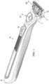
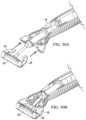
- FIG. 1is a schematic perspective view of a shaving razor in accordance with an embodiment of the invention
- FIG. 2is a schematic perspective view of the underside of the shaving razor of FIG. 1 ;
- FIG. 3is a schematic perspective view of a portion of the shaving razor of FIG. 2 ;
- FIG. 4is a schematic perspective view of a shaving razor in accordance with an embodiment of the invention.
- FIG. 5is a schematic perspective view of the underside of the shaving razor of FIG. 4 ;
- FIG. 6is a schematic perspective view of a portion of the shaving razor of FIG. 5 ;
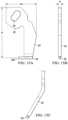
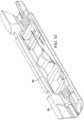
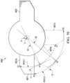
- FIG. 7is a schematic side view of a razor handle in accordance with an embodiment of the invention.
- FIG. 8is a schematic perspective representation of a trapezoidal prism shaped object
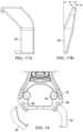
- FIG. 9is a schematic side view of a portion of a pivoting head in accordance with an embodiment of a handle of the invention.
- FIG. 10is a schematic perspective view of a portion of a pivoting head in accordance with an embodiment of a handle of the invention.
- FIG. 11is a schematic perspective view of a portion of a pivoting head in accordance with an embodiment of a handle of the invention.
- FIG. 12is a schematic perspective view of a portion of a pivoting head in accordance with an embodiment of a handle of the invention.
- FIG. 13is a schematic perspective view of a portion of a pivoting head in accordance with an embodiment of a handle of the invention.
- FIG. 14is a schematic perspective assembly view a portion of a pivoting head in accordance with an embodiment of a handle of the invention.
- FIG. 15 A-Cis a schematic representation of an embodiment of an arm
- FIG. 16 A-Cis a schematic representation of an embodiment of an arm
- FIG. 17 A-Bis a schematic representation of an embodiment of an arm
- FIG. 18is a schematic representation of an embodiment of arms mounting to a handle in accordance with an embodiment of the invention.
- FIG. 19 A-Bis a schematic representation of an embodiment of an arm
- FIG. 20is a schematic representation of an embodiment of arms mounting to a handle in accordance with an embodiment of the invention.
- FIG. 21is a schematic perspective view of an embodiment of a pivot spring in accordance with an embodiment of the invention.
- FIG. 22is a schematic perspective view of an embodiment of a pivot spring and a portion of a pivoting head in accordance with an embodiment of the invention.
- FIG. 23is a schematic perspective view of an embodiment of a pivot spring and a portion of a pivoting head in accordance with an embodiment of the invention.
- FIG. 24is a schematic perspective assembly view of an embodiment of a pivot spring and a portion of a pivoting head in accordance with an embodiment of the invention.
- FIG. 25is a schematic perspective view of a portion of a pivoting head in accordance with an embodiment of the invention.
- FIG. 26is a schematic perspective view of a portion of a pivoting head in accordance with an embodiment of the invention.
- FIG. 27 A-Bis schematic view of a portion of a pivoting head in accordance with an embodiment of the invention.
- FIG. 28is schematic perspective assembly view of a portion of a pivoting head in accordance with an embodiment of the invention.
- FIG. 29is schematic perspective view of a portion of a pivoting head in accordance with an embodiment of the invention.
- FIG. 30 A-Bis schematic perspective assembly view of a portion of a handle in accordance with an embodiment of the invention.
- FIG. 31is schematic perspective view of a portion of a handle in accordance with an embodiment of the invention.
- FIG. 32is schematic perspective assembly view of a portion of a handle in accordance with an embodiment of the invention.
- FIG. 33is schematic perspective assembly view of a portion of a handle in accordance with an embodiment of the invention.
- FIG. 34is schematic perspective view of a pivoting head in accordance with an embodiment of the invention.
- FIG. 35is schematic perspective view of a pivoting head in accordance with an embodiment of the invention.
- FIG. 36is schematic perspective assembly view of a pivoting head in accordance with an embodiment of the invention.
- FIG. 37 A-Bis schematic perspective assembly view of a portion of a pivoting head in accordance with an embodiment of the invention.
- FIG. 38 A-Bis schematic perspective assembly view of a portion of a pivoting head in accordance with an embodiment of the invention.
- FIG. 39 A-Bis schematic perspective assembly view of a portion of a pivoting head in accordance with an embodiment of the invention.
- FIG. 40 A-Bis schematic perspective assembly view of a portion of a pivoting head in accordance with an embodiment of the invention.
- FIG. 41 A-Dis schematic perspective assembly view of a portion of a pivoting head showing steps of assembly in accordance with an embodiment of the invention
- FIG. 42is schematic perspective view of a portion of a pivoting head in accordance with an embodiment of the invention.
- FIG. 43 A-Fis schematic perspective assembly view of a portion of a pivoting head showing steps of assembly in accordance with an embodiment of the invention
- FIG. 44is schematic perspective assembly view of a portion of a pivoting head in accordance with an embodiment of the invention.
- FIG. 45is schematic perspective assembly view of a portion of a pivoting head in accordance with an embodiment of the invention.
- FIG. 46is schematic perspective assembly view of a portion of a pivoting head in accordance with an embodiment of the invention.
- FIG. 47is schematic perspective cut away view of a portion of a pivoting head in accordance with an embodiment of the invention.
- FIG. 48is schematic perspective view of a portion of a pivoting head in accordance with an embodiment of the invention.
- FIG. 49is schematic perspective assembly view of a portion of a pivoting head in accordance with an embodiment of the invention.
- FIG. 50is a perspective view of a razor handle in accordance with an embodiment of the invention.
- FIG. 51is a partial side view of a razor handle in accordance with an embodiment of the invention.
- FIG. 52is a perspective view of a portion of a fluid benefit delivery member in accordance with an embodiment of the invention.
- FIG. 53is a cut away view of a portion of a razor handle showing a fillet radius in accordance with an embodiment of the invention.
- FIG. 54is a cut away view of a portion of a razor handle showing a chamfer in accordance with an embodiment of the invention
- FIG. 54 A-Cis a schematic perspective view of the geometry of a chamfer as shown in FIG. 54 ;
- FIG. 55is a plan view of a portion of a razor handle showing a slot in accordance with an embodiment of the invention.
- FIG. 56is a perspective view of a fluid benefit delivery member attached to a portion of a pivoting head in accordance with an embodiment of the invention.
- FIG. 57is a perspective assembly view of a fluid benefit delivery member being attached to a portion of a pivoting head in accordance with an embodiment of the invention
- FIG. 58is a perspective view of a portion of a fluid benefit delivery member in accordance with an embodiment of the invention.
- FIG. 59is a cross sectional view of a portion of a fluid benefit delivery member in accordance with an embodiment of the invention.
- FIG. 60is a perspective view of a portion of a fluid benefit delivery member in accordance with an embodiment of the invention.
- FIG. 61is a perspective view of a portion of a pivoting head with a connection for a fluid benefit delivery member in accordance with an embodiment of the invention.
- FIG. 62is a perspective view of a fluid benefit delivery member and a portion of a pivoting head in accordance with an embodiment of the invention.
- FIG. 63is a perspective view of a fluid benefit delivery member and a portion of a pivoting head in accordance with an embodiment of the invention.
- FIG. 64is a perspective view of a fluid benefit delivery member and a portion of a pivoting head in accordance with an embodiment of the invention.
- FIG. 65is a perspective view of a portion of a fluid benefit delivery member and a portion of a pivoting head in accordance with an embodiment of the invention.
- FIGS. 66 A and 66 Bshows cut away views of a pivoting head and show a fluid distribution member
- FIG. 67 A-Bis a schematic representation of a portion of an apparatus associated with a test method described herein in accordance with an embodiment of the invention.
- FIG. 68is a graph showing a representative torque curve for an embodiment in accordance with an embodiment of the invention.
- FIG. 69is a graph showing a representative torque curve for an embodiment in accordance with an embodiment of the invention.
- FIG. 70is a schematic representation of a portion of an apparatus associated with a test method described herein in accordance with an embodiment of the invention.
- FIG. 71is a schematic representation of a portion of an apparatus associated with a test method described herein in accordance with an embodiment of the invention.
- the shaving razorcan have a handle 12 and a blade cartridge unit 15 which can releasably attach to the handle 12 and can contain one or more blades 17 .
- the description hereinrelates primarily to the handle 12 , and features associated with the handle 12 that facilitate pivoting of the blade cartridge unit 15 relative to the handle 12 , and provision of skin benefit delivery components to the skin of a user of the razor 10 .
- the skin benefit delivery componentsextend from handle 12 through an opening in the cartridge unit 15 and can, therefore, be in close proximity to the skin of a user during shaving.
- the benefitswill be delivered through a pivoting head as will be described herein.
- the mechanism to pivot the pivoting head relative to a handlecomprises a benefit pivot delivery connection, a spring member, and one or more bearings.
- the benefit pivot delivery connectionfunctions to deliver a benefit (such as heat or fluid) from the handle to a user's skin.
- FIG. 1Two non-limiting embodiments of razors providing for a skin benefit are disclosed herein.
- the first, shown in FIG. 1can deliver a fluid to the skin of the user.
- FIG. 2which shows the underside of the razor depicted in FIG. 1
- a portion of the handle 12can extend through blade cartridge unit 15 and be exposed as face 80 .
- Face 80can be a skin interfacing surface, intended to be contacting or proximate the skin of a user using the shaver, discussed more fully below.
- face 80is a surface of a pivoting head 22 and can have openings 78 through which a fluid can be dispensed for skin benefit during and after shaving.
- Pivoting head 22can pivot about a pivot axis, referred to herein as a pivot axis or a first axis of rotation 26 with respect to handle 12 , as well as a secondary axis of rotation 27 that is generally perpendicular to the first axis of rotation 26 .
- Fluid flow from the reservoir in handle 12can be achieved by pressing the skin benefit actuator 14 , which can be a depressible button, and which presses on a fluid reservoir inside handle 12 to urge fluid flow toward and through the pivoting head 22 , as described more fully below.
- the reservoirmay be of any type.
- One exampleis described in co-owned, co-pending U.S. patent application Ser. No. 15/499,307, which is hereby incorporated herein by reference.
- FIG. 4shows another embodiment of a shaving razor that can have a handle 12 and a blade cartridge unit 15 which can releasably attach to the handle 12 and can contain one or more blades 17 .
- the pivoting head 22can comprise a heat delivery element which can deliver a heat benefit to the skin or a heat skin benefit.
- pivoting head 22can pivot about the first axis of rotation 26 with respect to handle 12 , as well as a secondary axis of rotation 27 that is generally perpendicular to the first axis of rotation 26 .
- FIG. 5which shows the underside of the razor depicted in FIG.
- heating surface 82is a surface of a pivoting head 22 and can be heated to deliver a heat skin benefit during or after shaving. Heating can be achieved by pressing the skin benefit actuator 14 , which can be a depressible button, and which closes a powered circuit inside handle 12 to a flexible circuit to the pivoting head 22 , as described more fully below.
- the handle 12may hold a power source, such as one or more batteries (not shown) that supply power to a heat delivery element, as discussed below.
- the heat delivery elementmay comprise a metal, such as aluminum or steel.
- the razor handle disclosed hereincan include the heat delivery element disclosed co-owned, co-pending US Application, which is hereby incorporated herein by reference.
- FIG. 7an embodiment of a handle for a razor providing a fluid skin benefit will be described in more detail. It should be noted that many of the components described in relation to the razor 10 providing a fluid skin benefit can also be incorporated into a razor 10 providing for heat skin benefit, particularly as they relate to the handle and pivoting head described herein, including the shape of the pivoting head, and the spring mechanism that urges the pivoting head into a rest position, and the limit members that limit the range of rotation of the pivoting head, all as described more fully below.
- the handle 12can comprise a main body 16 that can include a main frame 18 and a secondary frame 20 .
- the main body 16 including its component main frame 18 and secondary frame 20 memberscan comprise a durable material such as metal, cast metal, plastic, impact-resistant plastic, and composite materials.
- the main frame 18can be made of metal and can provide a significant portion of the structural integrity of the handle.
- the main frame 18is comprised of zinc.
- the main frame 18is comprised of die cast zinc.
- the secondary frame 20can be made of a plastic material and can overlie most of the main frame 18 and provide for a significant portion of the size and comfort of the handle 12 .
- a pivoting head 22can be connected to the main body 16 by one or more arms 24 . Pivoting head 22 can pivot about the first axis of rotation 26 that is defined by the connection of the pivoting head 22 to pins 30 disposed at distal portions 58 of arms 24 , as described more fully below. As discussed above, blade cartridge unit 15 attaches to the pivoting head 22 such that the blade cartridge unit 15 can pivot on handle 12 to provide more skin contact area on the skin of a user during shaving.
- the pivoting head 22can have a shape beneficially conducive to both attaching to the blade cartridge unit 15 and facilitating the delivery of a skin benefit from the handle 12 to and through the blade cartridge unit 15 attached to the handle 12 .
- the shape of the pivoting head 22can alternatively be described as a “funnel,” or as “tapered,” or a “trapezoidal prism-shaped.” As understood from the description herein, the description “trapezoidal prism” is general with respect to an overall visual impression the pivoting head. For example, a schematic representation of a trapezoidal prism-shaped element is shown in FIG. 8 and shows a shape having a relatively wide upper face (or opening) 32 , a relatively narrow lower face 34 , two long major faces 36 , and two end faces 38 that are generally trapezoidal-shaped.
- trapezoidal prismis used herein as the best description for the overall visual appearance of the pivoting head 22 , but the description does not imply any particular geometric or dimensional requirements beyond what is described herein. That is, the pivoting head 22 , including the cover member 40 , need not have complete edges or surfaces. Further, edges need not be unbroken and straight, and sides need not be unbroken and flat.
- Pivoting head 22 and the various parts as described hereincan be made of thermoplastic resins, which can be injection molded.
- the thermoplastic resincan preferably be of a relatively high impact strength with a Charpy notched strength impact value higher than 2 kJ/m 2 (as measured by ISO 179/1).
- the thermoplastic resincan have a relatively high tensile modulus above 500 MPa as measured using ISO 527-2/1-A (1 mm/min).
- resins of the polyoxymethylenecan be utilized for the pivoting head parts, and copolymer forms can be more readily injection molded due to improved heat stability over homopolymer versions.
- Acetal copolymer with Charpy notched strength impact values higher than 6 kJ/m 2 (as measured by ISO 179/1), including with values equal to or greater than 13 kJ/m 2 , and including values greater than 85 kJ/m 2can be utilized.
- the thermoplastic materialis relatively stiff having a tensile modulus above 900 MPa as measured using ISO 527-2/1-A (1 mm/min). Examples include HOSTAFORM® XT20 and HOSTAFORM® 59363.
- FIGS. 9 - 13shows a pivoting head in side profile in which corresponding faces 32 , 34 , 36 , and 38 of the trapezoidal prism shape in FIG. 8 are shown, the trapezoidal prism shape schematically representing the general shape impression of the pivoting head 22 .
- FIG. 9shows a portion of pivoting head 22 that includes a cover member 40 , a base member 42 connected to cover member 40 , and arms 24 connected handle 12 and to pivoting head 22 at pivot axis, i.e., first axis of rotation 26 .
- a fluid skin benefitcan be delivered via a benefit delivery member in the form of a fluid benefit delivery member 76 operatively coupled to base member 42 to permit fluid flow from the fluid delivery member into the pivoting head 22 .
- fluid benefit delivery member 76can include a flexible plastic benefit pivot delivery connection, such as a flexible silicone plastic tube, operatively coupled to a fluid reservoir in the handle 12 and to base member 42 such that upon depressing the skin benefit actuator 14 on handle 12 , a fluid, including a lubricating lotion, can be transmitted from inside handle 12 through pivoting head 22 , and out of openings 78 on face 80 as shown in FIG. 10 .
- the materials chosen for fluid benefit delivery member 76can have good chemical resistance to a variety of chemicals found in a consumer environment for durability along with a low modulus of elasticity for providing low resistance to angular deflection about a pivot.
- the materials for fluid benefit delivery member 76can include thermoplastic elastomers (TPE).
- TPE materialscan include styrenic block copolymers, including, for example, Poly(styrene-block-ethylenebutylene-block-styrene) (SEBS), Poly(styrene-block-butadiene-block-styrene) (SBS), or Poly(styrene-block-isoprene-block-styrene) (SIS).
- SEBSPoly(styrene-block-ethylenebutylene-block-styrene)
- SBSPoly(styrene-block-butadiene-block-styrene)
- SISPoly(styrene-block-isoprene-block-styrene)
- the materials for fluid benefit delivery member 76can include thermoplastic vulcanized (TPV) systems.
- the fluid delivery membercan be injection molded as an overmold, e.g., in a two-shot injection molding operation, on base member 42 which can be a different material, including a relatively harder plastic.
- base member 42which can be a different material, including a relatively harder plastic.
- fluid benefit delivery member 76can also be formed separately and joined to base member 42 .
- Suitable TPV systemscan include TPV systems based on polypropylene (PP) and ethylene propylene diene terpolymer (EPDM), TPV systems based on polypropylene and nitrile rubber, TPV systems based on polypropylene and butyl rubber, TPV systems based on polypropylene and halogenated butyl rubber, TPV systems based on polypropylene and natural rubber, or TPV systems based on polyurethane and silicone rubber.
- a TPV system based on polypropylenecan have the greater chemical resistance against chemicals commonly used in shaving applications.
- materials for the fluid benefit delivery member 76can include creep resistant materials having an increase in tensile strain of less than about 3% from an initial tensile strain when measured using ISO 89901 carried out at 1000 hours at 73 Fahrenheit.
- materials for the fluid benefit delivery member 76can include materials having a hardness of about 10 on a Shore A durometer scale and about 60 on a Shore A durometer scale.
- the materials for any benefit delivery member, such as the fluid benefit delivery member 76 or heat delivery member 96can be below 60 A, including values below 50 A.
- materials for the fluid benefit delivery member 76can include elastomers having compression sets less than about 25% as measured by ASTM D-395.
- benefit delivery memberhas a moment of inertia from about 6 mm 4 to about 40 mm 4 .
- TPUthermoplastic polyurethane
- MPRmelt processable rubber
- PVCplasticized polyvinyl chloride
- OBColefinic block copolymers
- ionomersthermoplastic elastomers based on styrenic block copolymers.
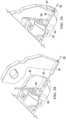
- One or both ends 44 (corresponding to the end faces 38 of the schematic shape shown in FIG. 8 ) of the pivoting head 22can have a limit member 46 that limits the extent of rotation of pivoting head 22 about first axis of rotation 26 .
- limit members 46limit rotation by providing a surface of the pivoting head 22 that can come into contact with arms 24 to stop rotation.
- the limit memberscan include first and second surfaces 48 , 50 that can come into contacting relationship with arms 24 to stop rotation of the pivoting head about first axis of rotation 26 .
- surfaces 48 , 50can be diverging surfaces that diverge relative to each other from a closest position near the pivoting axis 26 a distance substantially the extent of the portion of pivoting head 22 corresponding to the short dimension of the major faces 36 of the trapezoidal prism shape.
- first diverging surface 48can limit movement of the pivoting head to a first position and the second diverging surface 50 can limit the movement of the pivoting head to a second position. Pivoting of the pivoting head 22 is thus limited by the interaction of the diverging surfaces and the arms 24 .
- First and second diverging surfaces 48 , 50can be flat, partially flat, or have non-flat portions, with the only requirement being that a portion of the diverging surfaces contact arm 24 to limit rotation as desired.
- first diverging surface 48 of limit member 46can be substantially flat and can be disposed in contacting relationship adjacent arm 24 to limit the pivoting head 22 from further pivoting in a counter-clockwise direction (as viewed in FIG. 9 ).
- the included angle 43 between the diverging surfaces (e.g., an angle of divergence) for the angularly diverging surfaces 48 and 50can determine the angular rotation of pivoting head 22 about first axis of rotation 26 .
- the angle of divergence for the angularly diverging surfaces 48 and 50can be up to 50 degrees or more.
- pivoting head 22can rotate from a first position at 0 degrees to a second position at about 50 degrees relative to the first position, and any position therebetween.
- a spring member 64can apply a biasing force at a location corresponding to a main bar portion axis 86 , as described more fully below, to urge pivoting head 22 toward the first, at rest, position.
- the position shown in FIG. 9can be considered a rest position, as this is the position of the pivoting head 22 when no biasing force is applied against spring member 64 (shown in FIG. 13 ) to rotate the pivoting head clockwise (as viewed in FIG. 9 ).
- the rest position of the pivoting headcan be at any angle within the included angle 43 .
- pivoting head 22is shown connected to the main frame 18 of the main body 16 by arms 24 , referred to individually as first arm 24 A and second arm 24 B.
- the nomenclature of “A” and “B”is used herein to denote individual pairs of elements.
- Fluid benefit delivery member 76extends from main body 16 and connects to base member 42 , which is joined to cover member 40 to provide for controlled fluid transport from a reservoir inside handle 12 to one or more openings 78 on the face 80 of pivoting head 22 .
- face 80can extend through an opening on an attached blade cartridge unit 15 such that face 80 can be disposed very near, or even on, the skin of a user when razor 10 is used for shaving.
- Fluid flowcan be provided, for example, by pressure applied to a flexible fluid reservoir inside handle 12 . Pressure can be applied, for example, by the user pressing on a skin benefit actuator 14 on handle 12 .
- a proximal portion 52 of arms 24can be connected to the main frame 18 at a mounting location 60 .
- Arms 24can be made of metal and the main frame can be made of metal such that a relatively strong connection can be facilitated by the fixation of metal arms on a metal main frame.
- Proximal portion 52 of arm 24can define an opening 54 (shown in more detail in FIG. 12 ) in arm 24 which can engage a protuberance 56 on main frame 18 for connection to main body 16 of handle 12 .
- Arms 24likewise have a distal portion 58 which can engage a bearing recess 62 in pivoting head 22 (described more fully below) for connecting the pivoting head 22 to the main body 16 of handle 12 .
- a first arm 24 Acan have a first proximal portion 52 A that can define an opening 54 A that can connect to a first protuberance 56 A at a first location 60 A on main frame 18
- a second arm 24 Bcan have a second proximal portion 52 B that can define an opening 54 B that can connect to a second protuberance 56 B at a second location 60 B on main frame 18
- a first arm 24 Acan have a first distal portion 58 A that can connect to a first bearing recess in pivoting head 22
- a second arm 24 Bcan have a second distal portion 58 B that can connect to a second bearing recess in pivoting head 22 .
- Pivoting head 22can have mating portions that when connected together form a spring-loaded compartment 84 therebetween, the compartment facilitating the delivery of a skin benefit to a user during shaving.
- pivoting head 22can have a cover member 40 , a base member 42 connected to cover member 40 , and arms 24 connecting the pivoting head 22 to main body 16 .
- arms 24can have pins 30 disposed at distal portions 58 thereof.
- cylindrical pins 30can be welded to distal portions 58 of arms 24 .
- Each pin 30can be operatively disposed in a bearing recess 62 on pivoting head 22 .
- the bearing recess 62can be a cylindrical opening on cover member 40 having an inside diameter slightly greater than the outside diameter of pins 30 , such that cover member 40 , and therefore pivoting head 22 , can freely pivot upon the first axis of rotation 26 .
- a spring member 64is partially disposed between the mating faces of the cover member 40 and base member 42 and acts to bias the pivoting head 22 in relation to arms 24 into the first position as shown in FIG. 4 , in which first diverging surface 48 of limit member 46 rests in contacting relationship with arm 24 .
- Spring member 64can be any spring member facilitating biasing of the pivoting head to the first rest position.
- Spring membercan be, for example, any of torsion coil springs, coil spring, leaf spring, helical compression spring, and disc spring.
- spring member 64comprises torsion springs, and can have at least one coil spring 68 .
- two coil springs 68 A and 68 Bare coupled together in a spaced relationship by a main bar portion 70 as shown in FIG. 14 .
- coil springs 68can each define a longitudinal coil axis 74 .
- the axis of rotationwhich can be called a pivot axis or a first pivot axis, can be parallel to and offset from one of the longitudinal coil axes.
- spring member 64can be can be made of plastic, impact-resistant plastic, metal, and composite materials.
- the spring member 64can be made from materials that are resistant to stress relaxation such as metal, polyetheretherketone, and some grades of silicone rubber.
- Such an embodiment of spring member 64comprised of stress relaxation resistant materials, can prevent the pivot head from undesirably taking a “set,” a permanent deformation of the spring member that prevents the pivot head from returning to its rest position when unloaded.
- spring member 64can be made of 200 Series or 300 Series stainless steel at spring temper per ASTM A313.
- spring member 64can be comprised of stainless steel wire (e.g., 302 stainless steel wire) having an ultimate tensile strength metal greater than 1800 MPa or an engineering yield stress between about 800 MPa and about 2000 MPa.
- First arm 24 A and second arm 24 Bcan each be generally flat members having generally parallel planar opposite sides.
- Arms 24can define an imaginary plane 66 , as shown in FIG. 9 , and the imaginary plane 66 A of arm 24 A can be coplanar with the imaginary plane 66 B of arm 24 B.
- Pins 30can each have an imaginary longitudinal pin axis 68 disposed centrally in relation to each pin, and imaginary longitudinal pin axis 68 A of pin 30 A on arm 24 A can be coaxial with longitudinal pin axis 68 B of pin 30 B on arm 24 B, as indicated in FIG. 14 .
- Arms 24can have various shapes and features beneficially adapted to the pivoting head 22 . Additionally, arms can be made of plastic, impact-resistant plastic, metal, and composite materials. In an embodiment, arms 24 can be comprised of metal. Arms 24 and can be made of a 200 or 300 Series stainless steel having an engineering yield stress measured by ASTM standard E8 greater than about 200 MPa, and preferably greater than 500 MPa and a tensile strength again measured by ASTM standard E8 greater than 1000 MPa.
- arms 24can be sized and shaped appropriately to the size of the pivoting head 22 and handle 12 to which pivoting head 22 is attached.
- arm 24can be considered in plan view having an arm length, Al, of from about 10 mm to about 25 mm, and can be about 17 mm.
- arm 24can have an arm width, Aw, of from about 5 mm to about 20 mm, and can be about 10 mm.
- arm 24can be a substantially uniform thickness plate having an arm thickness, At, of from about 0.5 mm to about 4 mm, and can be about 1 mm.
- arm 24can be substantially flat in side profile, as shown in FIGS. 15 A and 15 B .
- arm 24can have at least one bend as shown in side profile in FIGS. 15 B and 15 C .
- a pin 30can be integral with arm 24 , or attached, such as by welding, to arm 24 such that a portion 30 C of pin 30 extends laterally to engage the bearing recess 62 of the pivoting head 22 .
- Pin 30can be a circular cross section cylindrical shape having a length of from about 2 mm to about 15 mm and can be about 4 mm Pin 30 can have a largest cross-sectional dimension, such as a diameter, of from about 0.6 mm to about 2.5 mm, and can be about 1.0 mm Perimeter of holes in arm can be from about 5 mm to about 25 mm and can be about 10 mm.
- the armshave a minimum cross-sectional moment of inertia multiplied by the elastic modulus of the arm material greater than 65 N-cm 2 . In an embodiment, this minimum cross-sectional moment of inertia multiplied by the elastic modulus of the arm material can be about 400 N-cm 2 to about 20000 N-cm 2 .
- arm 24can have portions at a proximal portion 52 defining an opening 54 . Openings can be used to engage and attach arms 24 to the main body 16 .
- arm 24 shown in FIG. 15corresponds to arm 24 shown in FIGS. 10 and 11 , in which opening 54 engages a protuberance 56 on main frame 18 of main body 16 .
- FIGS. 17 - 20show alternative embodiments of arms 24 .
- arms 24can have a variable thickness At, and can have a thicker portion generally central to arm 24 and thinner portions near the ends of arm 24 . Such a configuration can permit optimization of strength and weight of arms 24 .
- FIGS. 18 and 20show alternative connection embodiments in which a hook member on the proximal portion 52 of arm 24 can engage a mating portion of main body 16 .
- Pivoting head 22can be rotated about first axis of rotation 26 by a biasing force applied to the pivoting head to rotate the pivoting head 22 about the first axis of rotation 26 to a second position such that second diverging surface 50 rests in contacting relationship with arm 24 .
- spring member 64can act to rotate pivoting head back to the first position.
- pivoting head 22can be rotated about the first axis of rotation 26 , which can be considered a first pivot axis, from the first position through an angle of rotation of between about 0 degrees and about 50 degrees and when rotated the pivot spring applies a biasing torque about the first axis of rotation 26 of less than about 30 N-mm at an angle of rotation of about 50 degrees.
- pivoting head 22can be rotated about the first axis of rotation 26 , which can be considered a first pivot axis, from the first position through an angle of rotation of between about 0 degrees and about 50 degrees and when rotated the pivot spring applies a biasing torque about the first axis of rotation 26 of between about 2 N-mm and about 12 N-mm.
- the fluid benefit delivery member 76being flexibly coupled can provide a portion of the restorative, biasing torque as well.
- the fluid delivery membercan contribute about 30% of the restorative, biasing torque about the first axis of rotation 26 .
- the restorative, biasing torque about the first axis of rotation 26can be about less than about 10 N-mm and can be about 6 N-mm with about 4.5 N-mm contributed by spring member 64 and about 1.5 N-mm contributed by the fluid benefit delivery member 76 .
- the pivoting torque supplied by the spring membercan be considered a first pivoting torque.
- the pivoting torque supplied by the benefit delivery membercan be considered a second pivoting torque.
- the benefit delivery membercan be severable, that is, cut, removed, or otherwise uncoupled from its ability to supply a pivoting torque to the pivoting head.
- a ratio of the sum of said first and second pivoting torques divided by said angular deflection in radians to said second pivoting torque divided by said angular deflection in radians of said pivoting head with said pivot benefit delivery connection severedis greater than 2 and can be greater than 4.
- Torquecan be measured according to the Static Torque Stiffness Method described below in the Test Methods section.
- spring member 64can be a torsion spring and can include a first coil spring 69 A and a second coil spring 69 B coupled by a main bar portion 70 .
- a leg extension 72can extend from each coil spring 69 a sufficient length to operatively engage arms 24 to provide the biasing force necessary to cause pivoting head 22 to be urged toward the first, rest, position.
- spring member 64applies a resisting, restorative force to urge the pivoting head back to the first position.
- Coil springs 69 A and 69 Bcan each define a longitudinal coil axis 74 .
- Longitudinal coil axis 74 A of first coil spring 68 Acan be coaxial with longitudinal coil axis 74 B of second coil axis 68 B.
- One or both of longitudinal axes 74can be substantially parallel to and offset from the first axis of rotation 26 , which can be referred to as a pivot axis.
- Spring member 64can be made of metal, including steel, and can be stainless steel having an engineering yield stress greater than about 600 MPa.
- coil springs 69are operatively disposed on each end of pivoting head 22 and a portion of the main bar portion 70 resides between the cover member 40 and base member 42 to provide direct engagement to bias the pivoting head toward a rest position.
- the first axis of rotation 26can be parallel to and offset from both of the longitudinal coil axes 74 A, 74 B, and can, as well, be parallel to and offset from the main bar portion axis 86 .
- the first axis of rotation 26can be parallel to and offset from both of the longitudinal coil axes 74 A, 74 B a distance of from about 1 mm to about 5 mm.
- the first axis of rotation 26can be parallel to and offset from both of the longitudinal coil axes 74 A, 74 B a distance of about 2 mm.
- spring membercan be made of materials including amorphous polymers with glass transition temperatures above 80 Celsius, metals, elastomers having compression sets less than 25% as measured by ASTM D-395 and combinations thereof.
- spring membercomprises creep resistant materials having an increase in tensile strain of less than about 3% from an initial tensile strain when measured using ISO 89901 carried out at 1000 hours at 73 Fahrenheit.
- FIGS. 22 - 24illustrate an embodiment of a base member 42 having at least one channel 87 disposed on a face thereof.
- base member 42includes a channel 87 for housing a portion of spring member 64 .
- the embodiment illustrated in FIGS. 22 - 24includes a fluid benefit delivery member 76 , but with respect to the channel 87 the base member 42 need not be coupled to the fluid benefit delivery member 76 , but could, instead, house components related to a heating surface 82 , as described in more detail below.
- Base member 42can be molded plastic, and channel 87 can be a molded channel.
- fluid deliver member 76can be molded flexible plastic and can be molded integrally with base member 42 .
- Channel 87can have a size and shape conformed to receive the main bar portion 70 of spring member 64 , as shown in FIGS. 21 - 24 .
- FIG. 22shows spring member 64 prior to being inserted into channel 87 ;
- FIG. 23shows spring member 64 placed into channel 87 with first and second coil springs 68 A and 68 B disposed at an exterior portion of base member 42 .
- cover member 40also made of molded plastic and made to have mating surfaces with base member 42 can be joined by translating onto and connecting to the base member in the direction indicated by arrows in FIG. 24 .
- cover member 40Once cover member 40 is in mating relationship with base member 42 , cover member and base member can be joined, such as by adhesive, press fit, or welding.
- staking pins 89can be driven into openings 90 in a cold press fit as shown in FIGS. 25 and 26 to cause the base member 42 and cover member 40 to remain in operatively stable mating relationship.
- a compartment 84is defined between the parts, which compartment 84 has a volume into which fluid can flow from the handle 12 and from which fluid can flow to openings 90 on the skin interfacing face 80 of pivoting head 22 .
- Fluid containment in compartment 84can be achieved by a sealing relationship between cover member 40 and base member 42 .
- FIG. 27 Ashows the mating surface of a cover member 40 and
- FIG. 27 Bshows the first mating surface 88 of a base member 42 .
- sealingcan be achieved by the first mating face 88 of cover member 40 that, when operatively connected to base member 42 can mate in a juxtaposed, contacting relationship with a second mating face 90 of base member 42 .
- a gasket member 92can extend outwardly from first mating face 88 and can sealingly fit in a corresponding gasket groove 94 on base member 42 .
- FIGS. 28 - 33An embodiment of a pivoting head 22 can be assembled onto handle 12 in a manner illustrated in FIGS. 28 - 33 .
- pins 30 of arms 24can be inserted into bearing recess 62 of cover member 40 by translating in the direction of the arrow of FIG. 28 , which direction aligns with the longitudinal pin axis 67 (as shown in FIG. 14 ) and first axis of rotation 26 .
- spring member 64is disposed in operative relationship between cover member 40 and base member 42 .
- Arms 24can be held in place in any suitable manner while they are slid in the direction of the arrows in FIG. 30 , which shows before (A) and after (B) depictions of the arm securement in slots 103 of main body 16 .
- openings 54 of arms 24can be exposed through a corresponding access opening 106 in main body 16 .
- one or more extensions 107 on or in slot 103can provide for an interference fit to hold arms in place for the next step.
- FIG. 33there is shown certain handle 12 elements being assembled to secure pivoting head 22 to handle 12 .
- An embodiment of main frame 18is shown translating in the direction of the arrows in FIG. 33 from a first position (A) to join secondary frame 20 (B).
- Main frame 18can be joined to secondary frame 20 by adhesive applied at adhesive grooves 120 on secondary frame 20 which can mate with corresponding adhesive bosses on main frame 18 .
- Main frame 18can be disposed on a portion of secondary frame 20 in a mating relationship such that protuberances 56 are inserted through access openings 106 of main body 16 and openings 54 of arms 24 .
- Protuberances 56can provide positive metal-to-metal coupling of arms 24 to handle 12 .
- adhesivecan be applied at the connection of protuberances 56 and openings 54 to provide for additional securement of arms (and, therefore, pivoting head 12 ) to main frame 18 (and, therefore, handle 12 ).
- Pivoting head 22 for delivering heatcan have components common to those described above for delivering fluid, such as one or more arms 24 , one or more spring members 64 , a cover member 40 and a base member 42 , and these common components can be configured as described above, or in a similar manner.
- the pivoting head 22 for delivering a heat benefitcan also have a heat delivery member 96 comprised of heat delivery components, including a flexible conductive strip 98 for conducting electricity from a first proximal portion 98 A operatively attached in handle 12 to a second distal portion 98 B operatively disposed in pivoting head 22 and delivering heat to the skin at a heating surface 82 .
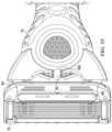
- FIG. 35shows an embodiment of a pivoting head 22 for a razor delivering a heat skin benefit.
- the pivoting headcan include a cover member 40 connected to a base member 42 and a spring member 64 partially disposed between the cover member 40 and the base member 42 .
- the pivoting head 22 shown in FIG. 35can include components shown in the assembly view of FIG. 36 .
- spring member 64 as described abovecan be disposed between the cover member 40 and the base member 42 , substantially as described above.
- Other componentscan be disposed on the outside of cover member 40 and can be attached in a layered relationship having sizes that correspond to the narrow lower face of the cover member 40 .
- the heat delivery member 96may include a face plate 102 for delivering heat to or proximal to the skin's surface during a shaving stroke for an improved shaving experience.
- the face plate 102may have an outer skin contacting heating surface 82 comprising a relatively hard coating (that is harder than the material of the face plate 102 ), such as titanium nitride to improve durability and scratch resistance of the face plate 102 .
- the face plate 102may go through an anodizing process.
- the hard coating of the skin contact surfacemay also be used to change or enhance the color of the skin application surface 82 of the face plate 102 .
- the heat delivery element 96may be in electrical communication with a portion of the handle 12 .
- the heat delivery element 16may be mounted to the pivoting head 22 and in communication with the power source (not shown).
- the face plate 102may be as thin as possible, but stable mechanically.
- the face plate 102may have a wall thickness of about 100 micrometers to about 200 micrometers.
- the face plate 102may comprise a material having a thermal conductivity of about 10 to 30 W/mK, such as steel.
- the face plate 102can be manufactured from a thin piece of steel that results in the face plate 102 having a low thermal conductivity thus helping minimize heat loss through a perimeter wall 110 and maximizes heat flow towards the skin interfacing surface 80 .
- the face plate 102may be constructed from a thicker piece of aluminum having a thermal conductivity ranging from about 160 to 200 W/mK.
- the heat delivery element 96may include a heater (not shown), e.g., a resistive heat element portion of flexible conductive strip 98 , that is in electrical contact with a micro-controller and a power source (not shown), e.g. a rechargeable battery, positioned within the handle 12 .
- the heat delivery member 96may include the face plate 102 , the flexible conductive strip 98 heater, a heat dispersion layer 100 , a compressible thermal insulation layer 99 , and a portion of cover member 40 .
- the face plate 102may have a recessed inner surface 122 opposite the skin application surface 82 configured to receive the heater 98 , the heat dispersion layer 100 and the compressible thermal insulation layer 99 .
- the perimeter wall 110may define the inner surface 122 .
- the perimeter wall 110may have one or more tabs 108 extending from the perimeter wall 110 , transverse to and away from the inner surface 122 . For example, FIG. 36 illustrates four extending from the perimeter wall 110 .
- the heat dispersion layer 100may be positioned on and in direct contact with the inner surface 122 of the face plate 102 .
- the heat dispersion layer 100may have a lower surface 124 directly contacting the inner surface 122 of the face plate 102 and an upper surface 126 (opposite lower surface 37 ) directly contacting the heater 98 .
- the heat dispersion layer 100can be defined as a layer of material having a high thermal conductivity and can be compressible.
- the heat dispersion layer 100may comprise graphite foil.
- the heat dispersion layer 100may have an anisotropic coefficient of thermal conductivity in the plane parallel to the face plate 102 of about 200 to about 1700 W/mK (preferably 400 to 700 W/mK) and vertical to the face plate 102 of about 10 to 50 W/mK and preferably 15 to 25 W/mK to facilitate sufficient heat conduction or transfer.
- the compressibility of the heat dispersion layer 100allows the heat dispersion layer 100 adapt to non-uniform surfaces of the inner surface 122 of the face plate 102 and non-uniform surfaces of the heater 98 , thus providing better contact and heat transfer.
- the compressibility of the heat dispersion layer 100also minimizes stray particulates from pushing into the heater 98 (because the heat dispersion layer 100 may be softer than the heater), thus preventing damage to the heater 98 .
- the heat dispersion layer 100may comprise a graphite foil that is compressed by about 20% to about 50% of its original thickness.
- the heat dispersion layer 100may have a compressed thickness of about 50 micrometers to about 300 micrometers more preferably 80 to 200 micrometers.
- the heater 98may be positioned between two compressible layers.
- the heater 98may be positioned between the heat dispersion layer 100 and the compressible thermal insulation layer 99 .
- the two compressible layersmay facilitate clamping the heater 98 in place without damaging the heater 98 , thus improving securement and assembly of the heat delivery element 96 .
- the compressible thermal insulation layer 99may help direct the heat flow toward the face plate 102 and away from the cover member 40 . Accordingly, less heat is wasted, and more heat may be able to reach the skin during shaving.
- the compressible thermal insulation layer 99may have low thermal conductivity, for example, less than 0.30 W/mK and preferably less than 0.1 W/mK.
- the compressible thermal insulation layer 38may comprise an open cell or closed cellular compressible foam.
- the compressible thermal insulation layer 99may be compressed 20-50% from its original thickness.
- the compressible thermal insulation layer 99may have a compressed thickness of about 400 ⁇ m to about 800 ⁇ m.
- the cover member 40may be mounted on top of the compressible thermal insulation layer 99 and secured to the face plate 102 . Accordingly, the heater 98 , the heat dispersion layer 100 and the compressible thermal insulation layer 99 may be pressed together between the face plate 102 and the cover member 40 and assembled as described more fully below.
- the heat dispersion layer 100 , the heater 98 , and the compressible thermal insulation layer 99may fit snugly within the perimeter wall 110 .
- the pressing of the various layers togethermay result in more efficient heat transfer across the interfaces of the different layers in the heat delivery element 96 . In absence of this compression force the thermal transfer across the interfaces can be insufficient. Furthermore, the pressing of the layers together may also eliminate secondary assembly processes, such as the use of adhesives between the various layers.
- the compressible thermal insulation layer 99may fit snugly within the perimeter wall 110 .
- the first layer in contacting relationship with cover member 40can be a compressible thermal insulation layer 99 such as a foam member.
- a portion of the heater in the form of a flexible conductive strip 98can be sandwiched between a foam thermal insulation layer 99 and a graphite foil strip heat dispersion layer 100 .
- the layers of foam thermal insulation layer 99 , flexible conductive strip 98 and graphite foil stripcan be connected in layered, contacting relationship to the narrow lower face of the cover member 40 by a faceplate 102 .
- Faceplate 102can have a smooth outer surface that corresponds to heating surface 82 , and tabs 108 that can be used to connect the heat delivery components to the pivoting head 22 .
- a graphite foil strip heat dispersion layer 100can be placed onto a trough 104 of faceplate 102 , such as onto the recessed inner surface 122 of faceplate 102 .
- distal portion 98 B of flexible conductive strip 98can be shaped and fit into the trough 104 of faceplate 102 .
- a compressible thermal insulation layer 99 membercan be placed into trough 104 of faceplate 102 .
- foam thermal insulation layer 99can be sized and shaped accordingly to fit in trough 104 .
- cover member 40can be placed on top of the other layered components in and faceplate 102 .
- cover member 40can be secured to the cover member 40 via tabs 108 as shown in the assembly view of FIG. 41 A-D .
- tabs 108including a pair of tabs labeled 1 and 2 in FIGS. 41 A and 3 and 4 in FIG. 41 B , can be folded into receiving openings 111 on cover member 40 , as shown in the cross-sectional perspective assembly view of FIGS. 41 C and 41 D .
- spring member 64as described above, can be placed in cover member 40 and seated in corresponding form-fitting recesses, including a channel 87 , of cover member 40 .
- base member 42can be connected to cover member in a sequence described with respect to the assembly view of FIG. 43 A-F.
- one or more first latching members 112 on base member 42can be placed into and hooked into one or more first latch receiving portions 114 of cover member 40 , and, as shown in FIG. 43 C-F, base member 42 can be rotated and pressed onto cover member 40 such that one or more second latching members 116 can be snapped into cooperating second latch receiving portions 118 .
- pivoting head 22is ready to be coupled to handle 12 .
- arms 24can be inserted in the direction of the arrows into the bearing recess 62 of cover member 40 by sliding pins 30 into the bearing recesses 62 , as described above.
- arms 24can then be inserted in the direction of arrows into slots 103 of main body 16 .
- a slot 103is shown having disposed therein the proximal portion of arm 24 as well as a leg extension 72 of spring member 64 .
- portions of main body 16can be cold stamped in the direction of the arrows to secure arms 24 to main body 16 of handle 12 .
- portions of the main body 16 corresponding to openings 54 of arms 24can be permanently plastically deformed by pressing into the openings 54 . This operation, known as cold stamping or cold staking, permits secure coupling of arms 24 , and therefore, pivoting head 22 , to main body 16 (and, therefore, handle 12 ).
- pivoting head 22can be pivoted about a pivot axis, i.e., axis of rotation 26 under the biasing force of a spring member 64 .
- pivoting head 22can be in pivotal relation to the handle 12 via, for example, a spring, a joint, a hinge, a bearing, or any other suitable connection that enables the pivoting head to be in pivotal relation to the handle.
- the pivoting headmay be in pivotal relation to the handle 12 via mechanisms that contain one or more springs and one or more sliding contact bearings, such as a pin pivot, a shell bearing, a linkage, a revolute joint, a revolute hinge, a prismatic slider, a prismatic joint, a cylindrical joint, a spherical joint, a ball-and-socket joint, a planar joint, a slot joint, a reduced slot joint, or any other suitable joint, or one or more springs and one or more rolling element bearings, such as a ball bearing, a cylindrical pin bearing, or rolling element thrust bearing.
- Sliding contact bearingscan typically have friction levels of 0.1 to 0.3.
- Rolling element bearingscan typically have friction of 0.001 to 0.01. Lower friction bearings are preferred the further a pivot mechanism is offset from its axis of rotation to assure smooth motion and prevent the bearing from sticking.
- pivot mechanisms about first axis of rotation 26allow rotational motions ranging from about 0 degrees from the cartridge rest position to about 50 degrees.
- a rotational stiffness for a pivot mechanism about first axis of rotation 26may be measured by deflecting the pivot 25 degrees about the first axis of rotation 26 and measuring the required torque about this first axis of rotation 26 to maintain this position.
- the torque levels at 50 degrees of rotationcan be generally less than 20 N-mm.
- the rotational stiffness (torque measured about the axis of rotation divided by degrees of angular rotation) associated with the first axis of rotation 26can be generally less than 0.3 N-mm per degree of rotation and preferably between 0.05 N-mm per degree of rotation and 0.18 N-m per degree of rotation.
- additional pivot mechanisms about secondary axis of rotation 27allow rotational motions ranging from ⁇ 12.5 degrees to +12.5 degrees.
- a rotational stiffness for a pivot mechanism about secondary axis of rotationmay be measured by deflecting the pivot ⁇ 5 degrees and +5 degrees about secondary axis of rotation 27 and measuring the required torques about the secondary axis of rotation to maintain this position. The rotational stiffness may be calculated by dividing the absolute value of the difference in these measured torques by the 10 degrees difference in angular motion.
- the rotational stiffness associated with pivot mechanisms about secondary axis of rotation 27generally range from about 0.8 to about 2.5 N-mm per degree of rotation.
- the handle 12was connected to the pivoting head 22 by a pair of arms 24 , a spring member 26 , and a benefit pivot delivery connection.
- the spring membercan be comprised of a metal.
- the spring member 64can also be comprised of a stress-relaxation resistant material such as a metal, polyetheretherketone, or silicone rubber, all of which can prevent the razor 10 or razor handle 12 from taking a “set,” or permanently deforming at deflected angle when the razor 10 or razor handle 12 is stored improperly due to the stress relaxation of the components that connect the pivoting head 22 to the proximal end of the handle.
- a stress-relaxation resistant materialsuch as a metal, polyetheretherketone, or silicone rubber
- the benefit pivot delivery connectioncan be a connection through which a skin deliver benefit component passes from the handle 12 to the pivoting head 22 to deliver a skin benefit through the cartridge 15 to the skin interfacing face 80 .
- a fluid benefit delivery member 76 and a heat delivery member 96can be configured so as to facilitate proper pivoting of the pivoting head about first axis of rotation 26 and secondary axis of rotation 27 .
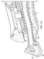
- a razor 10is shown in which the flexible conductive strip 98 of heat delivery member 96 bridges a gap between the handle 12 and the pivoting head onto which is attached a blade cartridge 15 .
- the flexible conductive strip 98is longer than the distance to be traversed between the handle 12 and the pivoting head 22 , resulting in a loop 150 of the flexible conductive strip 98 .
- This loop 150which can be generally U-shaped or S-shaped, can minimize the effect of the flexible conductive strip 98 on the biasing torque force required to pivot the pivoting head 22 about the first axis of rotation 26 .
- this loop 150 of the benefit delivery membercontributes to a ratio of biasing torque provided by the sum of the benefit member and the spring member 64 , and the biasing torque provided by the spring member alone, which torque ration is discussed in more detail below.
- a fluid delivery benefit membersuch as a flexible plastic tube
- a fluid delivery benefit membercan also have a loop 150 portion such that excess length of the flexible tube allows for minimizing the effect of the fluid benefit delivery member 76 on the biasing torque force required to pivot the pivoting head 22 about the first axis of rotation 26 .
- the installed length of fluid benefit delivery member 76as shown in FIG. 53 can be from 1 mm to 3 mm less than the free length of the fluid benefit delivery member 76 . This forced compression contributes to the loop 150 portion and has been found to aid in further minimizing the effect of the fluid benefit delivery member 76 on the biasing torque force required to pivot the pivoting head 22 about the first axis of rotation 26 .
- FIGS. 53 - 61Additional features found to further minimizing the effect of the fluid benefit delivery member 76 on the biasing torque force required to pivot the pivoting head 22 about the first axis of rotation 26 can be understood with reference to FIGS. 53 - 61 .
- the radius of curvaturecan be understood to reduce the stress applied to the surface of the fluid delivery member at the point of bending due to the pivoting of pivoting head 22 during use.
- a chamfer 154is provided, as shown.
- the chamfercan have a chamfer angle of about 5 degrees to about 30 degrees at the proximal end of the handle, and can have a chamfer length of about 3 mm to about 15 mm
- the chamfer 154is believed to reduce the stress applied to the surface of the fluid delivery member at the point of bending due to the pivoting of pivoting head 22 during use.
- a chamfercan be defined as shown in the view of FIG. 54 A-C .
- a block 201is shown with an edge 205 to be chamfered and a front face 206 .
- block 201is shown after edge 205 has been chamfered creating chamfer 202 .
- chamfer 202is shown having a chamfer length 204 and a chamfer angle 203 .
- the torque associated with a pivot benefit delivery membercan be reduced by cutout in the surrounding structure of the pivoting benefit delivery member that is a chamfer with a chamber angle between about 5 degrees and 30 degrees and chamfer length from 3 mm to 15 mm.
- an additional feature found to minimize the effect of the fluid benefit delivery member 76 on the biasing torque force required to pivot the pivoting head 22 about the first axis of rotation 26can be understood from FIG. 55 as a slot 156 on the handle 12 at the location of the exit of the fluid benefit delivery member 76 .
- the slotcan have a width measured generally parallel to the axis of rotation 26 of about 3 mm to about 10 mm, and a length measured perpendicular to the width of from about 2 mm to about 15 mm.
- fluid benefit delivery member 76which can be a flexible molded plastic tube, can be configured such that a distal portion 160 has a thinner wall diameter than a proximal portion 162 .
- the proximal portion 162which can be connected in fluid communication with other components in the handle 12 (not shown), can have a diameter and/or wall thickness that provides for durability and greater physical integrity during manufacture and use.
- distal portion 160which connects to the cover member 42 of the pivoting head, can comprise a relatively smaller diameter or a relatively thinner wall thickness, thereby providing for greater flexibility and less effect on the biasing torque force required to pivot the pivoting head 22 about the first axis of rotation 26 .
- fluid benefit delivery member 76is shown in which the tube wall of the fluid benefit delivery member 76 is ribbed or corrugated. It is believed that such a design, by permitting much of the wall to be relatively thinner, can, when joined to the base member 42 provide for greater flexibility and less effect on the biasing torque force required to pivot the pivoting head 22 about the first axis of rotation 26 .
- FIGS. 58 - 60Alternative embodiments of fluid benefit delivery member 76 utilizing coil springs to reinforce strength and provide for flexibility are depicted in FIGS. 58 - 60 .
- a coil spring 164which can be made of plastic or metal, can configured about the outside of fluid benefit delivery member 76 .
- a coil spring 164which can be made of plastic or metal, can configured about the inside of fluid benefit delivery member 76 .
- a coil spring 164which can be made of plastic or metal, can configured to be molded into the walls of fluid benefit delivery member 76 .
- FIG. 61depicts one embodiment of a feature to join fluid deliver member 76 to the base member 42 .
- a ball and socket joint component 166can be present on the base member 42 .
- the distal end of a tubular fluid delivery membercan be joined by pressing or gluing onto the receiving end of the ball and socket joint component 166 .
- the joining of the fluid benefit delivery member 76 to the pivoting head 22can be a two-component embodiment, as shown in FIG. 62 .
- the fluid benefit delivery member 76can be molded with an integral pivoting head connection member 170 that can attach to the mating portion of the pivoting head 22 in any suitable manner, such as snap fit, friction fit, adhesive joining, or the like.
- a spring member 64(not shown) can be added externally to the pivoting head 22 to provide for a biasing force on pivoting head.
- the fluid benefit delivery member 76 and the base member 42 of the pivoting head 22can be overmolded in a two-shot injection mold to form a three-component assembly that can form pivoting head 22 .
- the base membercan be a relatively hard material and the fluid benefit delivery member 76 can be a relatively soft material.
- a portion of the polymer injection molded for the fluid delivery memberforms the gasket member 92 of the base member 42 , as described above. Referring to FIG. 63 , the base member 42 and fluid benefit delivery member 76 are shown as they would appear if they were injection molded separately.
- the fluid benefit delivery member 76 and the base member 42can be overmolded in a two-shot injection mold process to manufacture an integral member as shown in FIG.
- FIG. 65shows another perspective view of the first mating surface 88 of the cover member 42 having exposed and extended therefrom a gasket member 92 which is integral with fluid benefit delivery member 76 .
- the base membercan be joined to the third component, i.e., the cover member 40 , such that their respective first and second mating faces 88 , 90 are joined, and gasket member 92 lodges in and forms a gasket in gasket groove 94 of cover member 40 .
- the fluid flow path of the pivoting head 22can be configured to provide for relatively unobstructed, smooth, continuous fluid flow from the fluid benefit delivery member 76 to openings 78 in face 80 of pivoting head 22 , which can be a skin interfacing face.
- FIGS. 66 A and 66 Bwhich depict partial cross-sectional views of a pivoting head 22 having joined thereto a fluid benefit delivery member 76 that enters at a location having an area approximating the cross-sectional area of the fluid benefit delivery member 76 tube, a flow distributor 171 which directs and distributes fluid flow can be present. It is believed that having the flow distributor begin distribution relatively close to the entry point of the tube of the fluid benefit delivery member 76 .
- the fluid flow distributor 171is located about 0.5 mm to about 2 mm from a junction of the connection of the fluid benefit delivery member 76 to the pivoting head 22 .
- the fluid reservoir in the pivoting head 22can have a small cross section closer to the connection of the fluid benefit delivery member 76 to the pivoting head 22 .
- the internal fluid conduit associated with fluid benefit delivery member 76can have an internal hydraulic diameter from about 1 mm to about 3 mm.
- the fluid benefit delivery membercan have a minimum hydraulic diameter along the exterior of the fluid benefit delivery member from about 1.5 mm to about 3.5 mm
- the materials used for the fluid benefit delivery member 76can be elastomers with compression set of about less than 25%, and preferably about less than 10% measured by ASTM D-395.
- silicone elastomerhas been found to be suitable for the fluid benefit delivery member 76 .
- thermoplastics or thermosetswith relatively high creep resistance, e.g., increase in tensile strain less than about 3%, and preferably less than about 1%, from initial tensile strain when measured using ISO 899-1 carried out at 1000 hours @ 73 F.
- first and second pivoting torquescan be referred to as relating to rotational stiffness.
- the benefit delivery membersuch as the flexible conductive strip 98 of heat delivery member 96 and fluid benefit delivery member 76
- the rotational stiffness of the pivoting head 22is greater than twice, or more preferably greater than 5 times, the rotational stiffness of the pivoting head 22 with the benefit delivery member removed.
- the rotational stiffness of the pivoting head 22 without the benefit delivery membercan be measured by severing, e.g., cutting out, the benefit delivery member such that it exerts no biasing force between the pivoting head 22 and the handle 12 .
- the rotational stiffness of the pivot mechanismis desirably greater than twice the rotational stiffness of the pivot mechanism with the benefit pivot delivery connection disconnected at the proximal end of the handle and at the pivoting head 22 .
- This latter configurationgreatly reduces the probability and conditions under which the razor 10 or razor handle 12 can take a “set.”
- the rotational stiffness of a pivot mechanism(with or without benefit pivot delivery connection) can be measured by the Static Torque Stiffness Method described below.
- Every maximum numerical limitation given throughout this specificationincludes every lower numerical limitation, as if such lower numerical limitations were expressly written herein. Every minimum numerical limitation given throughout this specification includes every higher numerical limitation, as if such higher numerical limitations were expressly written herein. Every numerical range given throughout this specification includes every narrower numerical range that falls within such broader numerical range, as if such narrower numerical ranges were all expressly written herein.
- the static torque stiffness methodcan be used to measure torque stiffness.
- different sections of the test componentare rotated relative to each other about an axis of rotation (such as axis of rotation 26 , for example) of the pivot mechanism and torques versus angles of rotation between sections are measured.
- the pivot mechanism 400can be understood to rotate a first section 401 of the test component located on one side of the pivot mechanism relative to a second section 402 of the test component located on the far side of the pivot mechanism about an axis of rotation AA.
- These first and second sectionsmay include parts of the pivot mechanism.
- torque stiffnesscan be understood to be a measurement of proportionality between measurement of torque and rotation angle. More specifically, torque stiffness, K, is the proportionality constant for the least squares best fit line 407 for measurements 408 of torque versus rotation angle over the middle 50% 404 of the full range 405 of angular motion of the pivot mechanism 400 unless otherwise specified.
- An individual torque measurementcan be understood to be the measurement of torque and angle while holding the relative angle between the first section 401 , which can rotate, and the second section 402 , which is held fixed, constant.
- the static torque stiffness methodconsists of (1) identifying the instant center of rotation over the full angular range of the motion of the pivot mechanisms, (2) clamping the test component into an appropriate test fixture that has the torque sensor centered about axis of rotation, (3) making the individual measurement of torque and rotation, and (4) calculating the torque stiffness.
- the environmental testing conditions for the static torque stiffness methodcomprise of making measurements at a room temperature of 23 Celsius and relative humidity of 35% to 50% and using test components that are in a dry, “as-made” condition.
- Step 1Identify the instant center of rotation over the full angular range of motion of the pivot of mechanism.
- the instant center of rotationis the location of the axis of rotation of the pivot mechanism at an individual angle of rotation.
- the identification of the axis of rotation for an individual torque versus angle measurementcan be important because many pivot mechanisms have virtual pivots where the axis of rotation is offset or even outside the pivot mechanism, many pivot mechanisms have no obvious features such as a pin or a shaft that indicate the location of the axis of rotation, and some more complex pivot mechanisms have an axis of rotation that changes location during the motion.
- the instant center of rotation C of a pivot mechanism undergoing a planar rotationcan be determined by tracing the path, PATH1 and PATH2, of two points, P1, and P2, on the rotating first section 401 .
- FIG. 7shows Section 401 at 3 positions 401 a , 401 b , and 401 c , and it calculates the instant center of rotation C at position 401 b .
- two lines, T 1 and T 2can be drawn tangent to PATH1 and PATH2 respectively.
- Two additional lines, R 1 and R 2can be drawn perpendicular to T 1 and T 2 respectively.
- the instant centercan be located at the intersection of R 1 and R 2 . In general, the instant center can be considered fixed for the full range of angular motion of the pivot mechanism if all pivot centers are in a region R, which has an area of 0.25 mm 2 .
- Step 2Clamp the test component in appropriate test fixture with torque sensor centered on axis of rotation
- an appropriate test measurement system 420can be configured to make the torque versus angle measurements needed to calculate the torque stiffness.
- Representative components of a torque testersuch as Instron's MT1 MicroTorsion tester are shown as a tester base 421 , tester torque cell 422 , and torque tester rotational member 423 .
- Instron's MT1 MicroTorsion testerhas a full-scale torque cell of 225 N-mm, with a torque accuracy of +1-0.5%, a torque repeatability of +1-0.5%, and an angle resolution of 0.003 degrees.
- the tester base 421is fixed and attached to a torque cell 422 while the tester rotational member 423 rotates about an axis of rotation, TT.
- the fixed second section 402is fastened to the torque cell side 422 of the tester using a first clamping mechanism 424 .
- the rotating first section 401is fastened to the tester rotational member 423 using a second clamping mechanism 425 .
- Both clamping mechanismsare designed to allow the pivot to freely rotate through its full range of motion with little to no lateral loading on the pivot mechanism. They are also designed to make the tester axis of rotation, TT, colinear to the pivot mechanism's axis of rotation, AA. For pivot mechanisms whose instant center of rotation changes, multiple clamps should be used to ensure that these axes are colinear.
- the angles of rotation measured in accordance with the static torque stiffness methodare the angles of deflection of the moving first section 401 of the test component that rotate relative to the at rest position of said first section.
- the angle that is being measuredis defined as the relative angle of the first section from the at rest position of the first section.
- the zero angle position of the first sectionis defined to be the rest position of the first section relative to the handle when (1) the test component is fixed in space, (2) the first section is free to rotate about its axis of rotation relative to the fixed test component, (3) the axis of rotation of the first section is oriented colinear to the axis of rotation of the torque tester for range of angles being measured and (4) no external forces or torques other than those transmitted from the second section and gravity act on the first section.
- Step 3Make the individual measurement of torque versus angle.
- the followingis the sequence for measurement of the torque-angle data of a safety razor.
- test componentFor each of the angles, fasten the test component into the appropriate clamps ( 424 and 425 ) to ensure the instant center of rotation for the angle being measured is coincident to the axis of rotation of the tester, TT.
- Step 4.Calculate the measured data from the torque stiffness.
- a handlecomprising:
- pivot springcomprises stainless steel having a yield stress of between about 800 MPa and about 2300 MPa.
- a handlecomprising:
- a handlecomprising:
- first coil axis and the second coil axisis substantially parallel to and offset from the pivot axis a distance of about 2 mm.
- a handlecomprising:
- pivot springcomprises a first coil spring and a second coil spring and a main bar portion that couples the first and second coil springs together in a spaced relationship.
- pivot springis selected from the group consisting of coil spring, leaf spring, helical compression spring, and disc spring.
- a handlecomprising:
- a handlecomprising:
- the handle of any of paragraphs AAA-CCCwherein the first coil spring defines a first coil axis and the second coil spring defines a second coil axis, and wherein the first coil axis is generally coaxial with the second coil axis and wherein the pivoting head is rotatable about a first pivot axis, the first pivot axis being generally parallel to one of the first and second coil axes and offset from one of the first and second coil axes a distance of from about 1 mm to about 5 mm.
- EEEThe handle of any of paragraphs AAA-DDD, wherein the first coil spring defines a first coil axis and the second coil spring defines a second coil axis, and wherein the first coil axis is generally coaxial with the second coil axis and wherein the pivoting head is rotatable about a first pivot axis, the first pivot axis being generally parallel to one of the first and second coil axes and offset from one of the first and second coil axes a distance of from about 2 mm.
- a handlecomprising:
- a handlecomprising:
- the pivot springcomprises at least one coil spring defining a longitudinal coil axis that is parallel to and is offset from the pivot axis a distance of from about 1 mm to about 5 mm.
- pivot springcomprises at least one coil spring defining a longitudinal coil axis that is parallel to and is offset from the pivot axis a distance of about 2 mm.
- pivot springis selected from the group consisting of coil spring, leaf spring, helical compression spring, and disc spring.
- AAAAAAAA.
- a handlecomprising:
- first coil springdefines a first longitudinal coil axis and the second coil spring defines a second longitudinal coil axis, and wherein the first longitudinal coil axis is generally coaxial with the second longitudinal coil axis.
- first coil springdefines a first longitudinal coil axis and the second coil spring defines a second longitudinal coil axis, and wherein the first longitudinal coil axis is generally coaxial with the second longitudinal coil axis and wherein the pivot axis is generally parallel to one of the first and second longitudinal coil axes.
- HHHHThe handle of any of paragraphs DDDD-GGGG, wherein the first coil spring defines a first longitudinal coil axis and the second coil spring defines a second longitudinal coil axis, and wherein the first longitudinal coil axis is generally coaxial with the second longitudinal coil axis and wherein the pivot axis is generally parallel to and offset from one of the first and second longitudinal coil axes a distance of about 2 mm.
Landscapes
- Life Sciences & Earth Sciences (AREA)
- Forests & Forestry (AREA)
- Engineering & Computer Science (AREA)
- Mechanical Engineering (AREA)
- Dry Shavers And Clippers (AREA)
Abstract
Description
- a main body;
- a pivoting head being pivotally coupled with the main body at a pivot axis, the pivoting head being comprised of at least two mating parts defining an interior channel;
- a pivot spring comprising a first coil spring and a second coil spring and a main bar portion that couples the first and second coil springs together in a spaced relationship; and
- wherein the main bar portion is at least partially disposed in the interior channel and interacts with the pivoting head to bias the pivoting head into a rest position.
- a main body;
- a pivoting head being pivotally coupled with the main body at a pivot axis, the pivoting head being comprised of at least two mating parts defining an interior channel; and
- a pivot spring comprising at least one coil spring coupled to a main bar portion; and
- wherein the main bar portion is at least partially disposed in the interior channel and defines a main bar axis that is parallel to and offset from the pivot axis.
- a main body;
- a first arm having a first proximal portion rigidly coupled to the main body at a first location and a first distal end that is pivotally coupled with a first end of a pivoting head;
- a second arm having a second proximal portion rigidly coupled to the main body at a second location and a second distal end that is pivotally coupled with a second end of the pivoting head;
- a pivot spring comprising a first coil spring and a second coil spring and a main bar portion that couples the first and second coil springs together in a spaced relationship; and
- wherein the pivot spring is coupled with the pivoting head and interacts with the pivoting head to bias the pivoting head into a first position relative to the first arm and the second arm.
- a main body;
- a pivoting head being substantially trapezoidal prism shaped and pivotally coupled with the main body about a pivot axis, the pivoting head having a first end comprising a first limit member and a second end comprising a second limit member, each of the first and second limit members comprising first and second surfaces, the first surface limiting movement of the pivoting head to a first position and the second surface limiting movement of the pivoting head to a second position; and
- a pivot spring that interacts with the main body to bias the pivoting head into the first position.
- a main body;
- a pivoting head pivotally coupled with the main body about a first pivot axis, the pivoting head having a first end comprising a first limit member and a second end comprising a second limit member, each of the first and second limit members comprising first and second angularly diverging surfaces; and
- a pivot spring comprising at least one coil spring defining a longitudinal coil axis that is parallel to and offset from the pivot axis.
- a main body;
- a pivoting head pivotally coupled with the main body about a pivot axis, the pivoting head having a trapezoidal prism shape, a first end comprising a first limit member and a second end comprising a second limit member, each of the first and second limit members comprising first and second angularly diverging surfaces
- a first arm having a first proximal portion rigidly coupled to the main body at a first location (32A) and a first distal end that is pivotally coupled with the pivoting head;
- a second arm having a second proximal portion rigidly coupled to the main body at a second location (34A) and a second distal end that is pivotally coupled with the pivoting head opposite the first distal end of the first arm; and
- a pivot spring comprising a first coil spring and a second coil spring and a main bar portion that couples the first and second coil springs together, wherein the pivot spring interacts with the pivoting head to bias the pivoting head into a first position with the first angularly diverging surface of the pivoting head in contacting relationship the first arm and the second angularly diverging surface of the pivoting head in contacting relationship with the second arm.
- A main body;
- a pivoting head being pivotally coupled with the main body about a pivot axis, and
- a pivot spring comprising a first coil spring and a second coil spring and a main bar portion that couples the first and second coil springs together in a spaced relationship, wherein one of the first and second coil springs defines a longitudinal coil axis that is parallel to and offset from the pivot axis and interacts with the main body to bias the pivoting head into a first position.
- a main body;
- a pivoting head pivotally coupled with the main body about a pivot axis, the pivoting head having a trapezoidal prism shape; and
- a pivot spring that is offset from the pivot axis.
- a main body;
- a first arm having a first proximal portion rigidly coupled to the main body at a first location and a first distal end that is pivotally coupled with a pivoting head about a pivot axis;
- a second arm having a second proximal portion rigidly coupled to the main body at a second location and a second distal end that is pivotally coupled with the pivoting head opposite the first distal end of the first arm; and
- a pivot spring comprising a first coil spring and a second coil spring and a main bar portion that couples the first and second coil springs together in a spaced relationship, wherein the pivot spring interacts with the main body to bias the pivoting head about the pivot axis into a first position relative to the first arm and the second arm.
Claims (23)
Priority Applications (1)
| Application Number | Priority Date | Filing Date | Title |
|---|---|---|---|
| US16/365,825US11945128B2 (en) | 2018-03-30 | 2019-03-27 | Razor handle with a pivoting portion |
Applications Claiming Priority (2)
| Application Number | Priority Date | Filing Date | Title |
|---|---|---|---|
| US201862650295P | 2018-03-30 | 2018-03-30 | |
| US16/365,825US11945128B2 (en) | 2018-03-30 | 2019-03-27 | Razor handle with a pivoting portion |
Publications (2)
| Publication Number | Publication Date |
|---|---|
| US20190299440A1 US20190299440A1 (en) | 2019-10-03 |
| US11945128B2true US11945128B2 (en) | 2024-04-02 |
Family
ID=66041814
Family Applications (1)
| Application Number | Title | Priority Date | Filing Date |
|---|---|---|---|
| US16/365,825ActiveUS11945128B2 (en) | 2018-03-30 | 2019-03-27 | Razor handle with a pivoting portion |
Country Status (8)
| Country | Link |
|---|---|
| US (1) | US11945128B2 (en) |
| EP (1) | EP3774215B1 (en) |
| JP (1) | JP2021516102A (en) |
| CN (1) | CN111867795B (en) |
| AU (2) | AU2019242568A1 (en) |
| BR (1) | BR112020020123A2 (en) |
| CA (1) | CA3091275A1 (en) |
| WO (1) | WO2019190961A1 (en) |
Cited By (2)
| Publication number | Priority date | Publication date | Assignee | Title |
|---|---|---|---|---|
| USD1077355S1 (en)* | 2024-11-18 | 2025-05-27 | Jiangxi Xirui Manufacturing Co., Ltd | Razor |
| USD1079126S1 (en)* | 2023-06-27 | 2025-06-10 | Zhejiang Yanyang Technology Co., Ltd. | Razor |
Families Citing this family (12)
| Publication number | Priority date | Publication date | Assignee | Title |
|---|---|---|---|---|
| CA3091481C (en)* | 2018-03-30 | 2022-11-29 | The Gillette Company Llc | Shaving razor system including skin interconnect member |
| US11607820B2 (en) | 2018-03-30 | 2023-03-21 | The Gillette Company Llc | Razor handle with movable members |
| EP3546156B1 (en)* | 2018-03-30 | 2021-03-10 | The Gillette Company LLC | Razor handle with a pivoting portion |
| US10773408B2 (en) | 2018-03-30 | 2020-09-15 | The Gillette Company Llc | Shaving razor cartridge |
| CA3092879A1 (en) | 2018-03-30 | 2019-10-03 | The Gillette Company Llc | Razor handle with movable members |
| EP3774227A1 (en) | 2018-03-30 | 2021-02-17 | The Gillette Company LLC | Razor handle with movable members |
| USD874061S1 (en) | 2018-03-30 | 2020-01-28 | The Gillette Company Llc | Shaving razor cartridge |
| BR112020020132A2 (en) | 2018-03-30 | 2021-01-05 | The Gillette Company Llc | HANDLE OF SHAVING OR DEVILING APPLIANCE WITH MOBILE LIMBS |
| WO2019191158A1 (en) | 2018-03-30 | 2019-10-03 | The Gillette Company Llc | Shaving razor system including skin interconnect member |
| JP2021515672A (en) | 2018-03-30 | 2021-06-24 | ザ ジレット カンパニー リミテッド ライアビリティ カンパニーThe Gillette Company Llc | Razor system for shaving |
| USD928404S1 (en)* | 2019-04-09 | 2021-08-17 | Dorco Co., Ltd. | Razor handle |
| CN114043536A (en)* | 2021-12-14 | 2022-02-15 | 广州威的科技有限公司 | Cold and hot shaver |
Citations (605)
| Publication number | Priority date | Publication date | Assignee | Title |
|---|---|---|---|---|
| FR520234A (en) | 1919-07-19 | 1921-06-22 | Axel Edward Astrand | Improvements to razors and similar utensils |
| US1505578A (en) | 1923-03-26 | 1924-08-19 | Barra Charles | Razor |
| US1552026A (en) | 1923-07-12 | 1925-09-01 | Barra Charles | Safety razor |
| US1675128A (en) | 1925-09-24 | 1928-06-26 | Ostrovsky Harry | Safety razor |
| US1821574A (en) | 1928-05-16 | 1931-09-01 | Peters Peter Nicholas | Razor |
| US1892836A (en) | 1932-04-29 | 1933-01-03 | George R Harvey | Combination razor and shaving brush |
| DE575523C (en) | 1932-02-01 | 1933-04-28 | Emil Pirwitz | Heatable razor |
| FR749861A (en) | 1932-02-01 | 1933-08-01 | Aeg | Heated razor |
| US2018147A (en) | 1932-02-01 | 1935-10-22 | Pirwitz Emil | Safety razor |
| US2063808A (en) | 1935-08-16 | 1936-12-08 | Thomas J Henderson | Electrically heated safety razor |
| US2134973A (en)* | 1938-01-29 | 1938-11-01 | Wilbur F Harwell | Knife |
| FR840502A (en) | 1938-02-10 | 1939-04-27 | Advanced safety razor with recordable heated blade | |
| US2164581A (en) | 1937-12-31 | 1939-07-04 | George R Ewald | Thermoelectric rotary razor |
| US2225257A (en) | 1936-07-21 | 1940-12-17 | Fernan O Conill | Razor |
| US2231219A (en) | 1938-10-31 | 1941-02-11 | Peterson Payson | Razor |
| GB541723A (en) | 1940-06-06 | 1941-12-09 | Hans Otto Hoffmann | Improvements in shaving apparatus |
| US2324148A (en) | 1942-01-30 | 1943-07-13 | Moses M Gravin | Electrically heated safety razor |
| US2327192A (en) | 1943-05-26 | 1943-08-17 | Arthur E Keene | Soap-containing safety razor |
| US2414482A (en) | 1943-10-18 | 1947-01-21 | Norman Kelso | Electric soldering iron |
| US2536844A (en) | 1949-08-25 | 1951-01-02 | Frederick Carlton | Thermal scraper |
| FR985030A (en) | 1949-02-16 | 1951-07-13 | Razor enhancements | |
| US2622319A (en) | 1948-12-14 | 1952-12-23 | Hunt James Russell | Electric heat shaver |
| US2714651A (en) | 1951-05-25 | 1955-08-02 | Wotton Charles Sydney Richard | Electrically heated soldering irons |
| GB875618A (en)* | 1959-04-04 | 1961-08-23 | Harry Arthur Easton | Spring tensioned attachment for heavy duty sweeping brushes |
| GB1056038A (en) | 1963-11-06 | 1967-01-25 | Philips Electronic Associated | Improvements in or relating to methods of manufacturing curved metal bodies provided with apertures |
| US3325627A (en) | 1964-09-30 | 1967-06-13 | Adler | Electrically heated mixing spatula |
| GB1075139A (en) | 1964-05-29 | 1967-07-12 | Philips Electronic Associated | Improvements in or relating to portable electrical apparatus |
| US3364568A (en) | 1965-12-09 | 1968-01-23 | Lowy Nathaniel | Shaver having selectively operable heating and cooling means |
| US3454745A (en) | 1967-09-25 | 1969-07-08 | Knapp Monarch | Heater for shaving lather containers |
| US3591923A (en) | 1968-07-31 | 1971-07-13 | Turner & Seymour Mfg Co The | Handle attachment |
| US3593416A (en) | 1968-10-10 | 1971-07-20 | Roger C Edson | Safety razor |
| US3600804A (en) | 1967-06-19 | 1971-08-24 | Gillette Co | Safety razors |
| US3611568A (en) | 1969-08-20 | 1971-10-12 | Gillette Co | Vibratory safety razor |
| US3644992A (en)* | 1970-04-07 | 1972-02-29 | Sylvania Electric Prod | Razor assembly |
| US3648368A (en) | 1970-03-23 | 1972-03-14 | Gillette Co | Safety razor |
| US3713184A (en) | 1971-09-24 | 1973-01-30 | R Leland | Mop with interchangeable heads |
| US3748730A (en)* | 1971-08-18 | 1973-07-31 | Schick Inc | Electric razor end cap arrangement |
| US3768162A (en) | 1971-12-13 | 1973-10-30 | Gillette Co | Razor handle |
| US3786563A (en) | 1971-08-31 | 1974-01-22 | Gillette Co | Shaving system |
| US3795979A (en) | 1972-04-27 | 1974-03-12 | Gillette Co | Handle |
| US3876858A (en) | 1973-02-09 | 1975-04-08 | French Co R T | Shrink-film hole-burning device |
| US3878605A (en) | 1972-12-11 | 1975-04-22 | Philip Morris Inc | Handle construction |
| US3896364A (en) | 1973-08-15 | 1975-07-22 | Richard A Reister | Electric razor adapter |
| US3934115A (en) | 1973-09-25 | 1976-01-20 | Peterson Gerald H | Method and apparatus for electric singe cutting |
| US3935639A (en) | 1973-03-01 | 1976-02-03 | The Gillette Company | Safety razor |
| US3950848A (en) | 1974-03-18 | 1976-04-20 | Michael Goldstein | Safety razor |
| DE2520959A1 (en)* | 1975-05-10 | 1976-12-09 | Robert Henrich | Removable handle attachment system for brooms - has twin fork system with spring type retention devices which protrude through holes in plastics clamp |
| US4026016A (en) | 1975-05-12 | 1977-05-31 | The Gillette Company | Razor blade assembly |
| US4077119A (en) | 1977-02-16 | 1978-03-07 | Jose Manuel Sellera | Shaving device |
| US4083104A (en) | 1975-05-12 | 1978-04-11 | The Gillette Company | Razor handle |
| US4094063A (en) | 1976-12-15 | 1978-06-13 | The Gillette Company | Razor assembly with pivotally mounted cartridge |
| JPS5416091U (en) | 1977-06-30 | 1979-02-01 | ||
| US4148236A (en) | 1976-12-21 | 1979-04-10 | Norsk Treteknisk Institutt | Method and a device for controlling thermal stresses in a power saw blade |
| DE2801845A1 (en) | 1978-01-13 | 1979-07-19 | Joerg Munder | Wet razor with replaceable blade - has heating element fitted in region of blade support |
| GB2030909A (en) | 1978-08-15 | 1980-04-16 | Wilkinson Sword Ltd | Razors |
| JPS5566396U (en) | 1978-10-31 | 1980-05-07 | ||
| EP0020816A1 (en) | 1979-06-19 | 1981-01-07 | The Gillette Company | Shaving razor assembly |
| US4253013A (en) | 1977-09-05 | 1981-02-24 | Mabuchi Motor Co., Ltd. | Electric heating device for warming the shaving head of an electric shaver |
| US4253235A (en) | 1979-06-19 | 1981-03-03 | The Gillette Company | Shaving system |
| US4258471A (en) | 1979-06-19 | 1981-03-31 | The Gillette Company | Razor handle |
| US4266340A (en) | 1979-06-11 | 1981-05-12 | Warner-Lambert Company | Razor handle for mounting pivotable razor blade cartridges |
| US4281456A (en) | 1979-11-13 | 1981-08-04 | The Gillette Company | Razor handle with a pivotal connection means for an element of a blade cartridge mounted thereon |
| US4281455A (en) | 1978-10-20 | 1981-08-04 | Wilkinson Sword Limited | Razor with removably mounted pivotal cartridge |
| JPS56128188A (en) | 1980-03-10 | 1981-10-07 | Hideo Ishii | Razor with heating tool |
| GB2078589A (en) | 1980-06-26 | 1982-01-13 | Gillette Co | Razor Handles |
| GB2093750A (en) | 1981-03-02 | 1982-09-08 | Warner Lambert Co | Support for releasably retaining a blade cartridge |
| JPS5838581A (en) | 1981-08-31 | 1983-03-07 | 松下電工株式会社 | Electric razor |
| US4377034A (en) | 1980-11-10 | 1983-03-22 | Druash Alex F | Safety razor kit |
| US4403414A (en) | 1981-04-09 | 1983-09-13 | Warner-Lambert Company | Socket device for a pivotal razor |
| GB2116470A (en) | 1982-03-12 | 1983-09-28 | Gillette Co | Safety razors |
| US4413411A (en) | 1982-02-25 | 1983-11-08 | The Gillette Company | Razor handle |
| US4422237A (en) | 1982-02-25 | 1983-12-27 | The Gillette Company | Razor handle |
| US4475286A (en) | 1980-10-20 | 1984-10-09 | Kabushiki Kaisha Kaijirushi Hamono Center | Safety razor |
| US4502216A (en) | 1981-07-21 | 1985-03-05 | Tonal S.A.S. Di Furnari Giuseppe & C. | Safety razor provided with an articulated head |
| US4514904A (en) | 1983-09-21 | 1985-05-07 | The Gillette Company | Razor handle |
| JPS60194333U (en) | 1984-06-05 | 1985-12-24 | キヤノン株式会社 | temperature control device |
| US4561526A (en)* | 1983-01-03 | 1985-12-31 | Samsonite Corporation | Steering and support handle for wheeled luggage |
| US4562644A (en) | 1984-08-10 | 1986-01-07 | Hitchens Peter B | Lubricant-applying safety razor |
| US4587968A (en) | 1984-03-19 | 1986-05-13 | Price David R | Electric emasculator and method for castrating |
| US4598192A (en) | 1984-03-02 | 1986-07-01 | Garrett John E | Electrically heated handle for fishing rods |
| US4658505A (en) | 1985-03-15 | 1987-04-21 | Wilkinson Sword Limited | Razor handle for supporting a detachable shaving unit |
| US4716652A (en) | 1983-10-05 | 1988-01-05 | John Cataudella | Disposable shaver |
| US4791724A (en) | 1987-06-04 | 1988-12-20 | Jack Dumas | Wedge shaped razor apparatus |
| US4797998A (en) | 1986-12-08 | 1989-01-17 | Warner-Lambert Company | Lockable pivotable razor |
| US4809432A (en) | 1986-11-24 | 1989-03-07 | Shaverd Corp. | Disposable razor and emollient dispensing device |
| US4833779A (en) | 1987-06-30 | 1989-05-30 | American Safety Razor Company | Platform, handle and shield for safety razor |
| US4837930A (en) | 1987-01-30 | 1989-06-13 | Eurafrica S.R.L. | Safety razor |
| US4864735A (en) | 1988-02-18 | 1989-09-12 | Chung Chang L | Multi-purpose presence grooming implement |
| US4879811A (en)* | 1987-10-01 | 1989-11-14 | Cooney Daniel J | Safety razor |
| US4888868A (en) | 1988-01-21 | 1989-12-26 | Pritchard Kevin M | Disposable razor assembly with detachable packet containing shaving-associated material |
| US4918818A (en) | 1988-09-22 | 1990-04-24 | Hsieh Yin Fei | Multi-purpose massage shaver |
| US4944090A (en) | 1989-04-03 | 1990-07-31 | Stanley Sumnall | Razor head with yieldable shaving aid |
| US4970784A (en)* | 1988-09-08 | 1990-11-20 | Wilkinson Sword Gesellschaft Mit Beschrankter Haftung | Razor with a pivoted detachable blade unit |
| US4985995A (en) | 1988-09-08 | 1991-01-22 | Wilkinson Sword Gesellschaft Mit Beschrankter Haftung | Razor head, especially a razor blade unit |
| US5010905A (en) | 1989-10-20 | 1991-04-30 | Snyder Marilyn J | Water-vapor hair treatment apparatus |
| US5016352A (en) | 1990-03-22 | 1991-05-21 | The Gillette Company | Single button razor |
| US5029391A (en) | 1989-03-15 | 1991-07-09 | Wilkinson Sword Gesellschaft Mit Beschrankter Haftung | Pivot-head razor |
| US5031319A (en) | 1989-09-22 | 1991-07-16 | Wilkinson Sword Gesellschaft Mit Beschrankter Haftung | Wet razor |
| US5033152A (en) | 1989-05-22 | 1991-07-23 | Wilkinson Sword Gesellschaft Mit Beschrankter Haftung | Wet razor |
| US5038472A (en) | 1989-11-17 | 1991-08-13 | Warner-Lambert Company | Pivoting safety razor assembly |
| US5044077A (en) | 1990-04-10 | 1991-09-03 | Warner-Lambert Company | Razor mechanism |
| US5046249A (en) | 1989-08-19 | 1991-09-10 | Matsushita Electric Works, Ltd. | Motor driven oscillating razor |
| US5065515A (en) | 1991-01-24 | 1991-11-19 | Warner-Lambert Company | Thermally assisted shaving system |
| KR920000490Y1 (en) | 1989-12-04 | 1992-01-15 | 한일공업 주식회사 | Razor |
| US5092041A (en) | 1991-06-10 | 1992-03-03 | Grigory Podolsky | Universal shaving device |
| US5098414A (en) | 1990-01-17 | 1992-03-24 | Walker Cedric T M | Steaming device for cosmetic skin treatment |
| US5113585A (en) | 1990-09-28 | 1992-05-19 | The Gillette Company | Shaving system |
| US5121541A (en) | 1991-11-12 | 1992-06-16 | Patrakis Strati G | Electric razor with built-in mister |
| WO1992013684A2 (en) | 1991-01-24 | 1992-08-20 | Warner-Lambert Company | Thermally assisted shaving system |
| US5157834A (en) | 1990-04-10 | 1992-10-27 | Warner-Lambert Company | Razor mechanism with slidable cartridge support |
| US5168628A (en) | 1990-06-22 | 1992-12-08 | Kai Industries Co., Ltd. | Razor |
| US5182858A (en) | 1989-06-05 | 1993-02-02 | Warner-Lambert Company | Razor mechanism |
| US5191172A (en) | 1991-11-07 | 1993-03-02 | Garganese Richard S | Cable terminal protector |
| US5191712A (en) | 1988-10-28 | 1993-03-09 | The Gillette Company | Safety razors and guards |
| US5270493A (en) | 1990-11-26 | 1993-12-14 | Matsushita Electric Industrial Co., Ltd. | Printed circuit board having electromagnetic wave shield layer and self-contained printed resistor |
| WO1994004106A1 (en) | 1992-08-17 | 1994-03-03 | Mehl, Thomas, L. | Hand-held, portable steam razor |
| US5299354A (en) | 1990-10-11 | 1994-04-05 | The Gillette Company | Oscillating shaver |
| US5307564A (en) | 1992-12-01 | 1994-05-03 | Schoenberg Frederic D | Safety razor |
| US5309640A (en) | 1990-07-10 | 1994-05-10 | S.E.R.P.A.T. S.R.L. | Instrument for cutting hair and simultaneously cauterize the cut hair ends |
| JPH06137960A (en) | 1992-10-29 | 1994-05-20 | Kyocera Corp | Temperature sensor |
| US5319822A (en) | 1991-07-15 | 1994-06-14 | Barry Hirsch | Broom head holder for attaching to a broom head |
| US5331740A (en) | 1992-10-08 | 1994-07-26 | The Gillette Company | Shaving system |
| US5333383A (en) | 1990-04-10 | 1994-08-02 | Warner-Lambert Company | Razor handle mechanism with convex-concave slidable cartridge support |
| US5333382A (en) | 1992-03-02 | 1994-08-02 | Ligaya Corporation | Brow shaver |
| JPH06216532A (en) | 1993-01-18 | 1994-08-05 | Toshiba Corp | Multilayer board with built-in element |
| US5337478A (en) | 1993-05-03 | 1994-08-16 | Zaki Cohen | Automatic shaving apparatus |
| US5347717A (en) | 1993-11-05 | 1994-09-20 | Ts Ai Tse Jen | Chuck assembly for a disposable razor |
| FR2703290A1 (en) | 1993-04-02 | 1994-10-07 | Mendola Claude | Heating device improving the comfort of mechanical shaving of the epidermis |
| US5394777A (en) | 1991-09-26 | 1995-03-07 | Warner-Lambert Company | Thermally enhanced shaving system |
| US5402573A (en) | 1993-05-20 | 1995-04-04 | Aurora Dawn Ltd. | Twin blade spray razor |
| JPH0720172U (en) | 1993-09-10 | 1995-04-11 | フェザー安全剃刀株式会社 | Safety razor |
| US5438759A (en)* | 1994-05-24 | 1995-08-08 | Dieringer; Janice A. | Button removal device |
| FR2716402A1 (en) | 1994-02-23 | 1995-08-25 | Des Garets Christian | Razor shaving head incorporating heating element |
| US5454164A (en) | 1994-03-17 | 1995-10-03 | The Gillette Company | Wet shaving system with a lubricating device |
| US5497551A (en) | 1994-10-13 | 1996-03-12 | The Gillette Company | Razor handle assembly |
| US5533263A (en) | 1991-11-27 | 1996-07-09 | The Gillette Company | Razors |
| JPH08202459A (en) | 1995-01-24 | 1996-08-09 | Chino Corp | Control device |
| US5560106A (en) | 1993-11-09 | 1996-10-01 | Armbruster; Joseph M. | Resilient floating head razor |
| US5575068A (en) | 1992-04-27 | 1996-11-19 | Warner-Lambert Company | Safety razor |
| US5600887A (en) | 1995-05-26 | 1997-02-11 | Olson; Brad | Flexible easy-rinsing razor |
| WO1997008804A1 (en) | 1995-08-22 | 1997-03-06 | Philips Electronics N.V. | Combination of an electrical appliance and an associated stand |
| US5626154A (en) | 1993-09-13 | 1997-05-06 | The Gillette Company | Method and system for shaving including a lubricant and a water-swellable polymer |
| US5636442A (en) | 1992-10-08 | 1997-06-10 | The Gillette Company | Shaving systems with blade holder |
| US5653025A (en) | 1993-05-07 | 1997-08-05 | Warner-Lambert Company | Thermally assisted shaving system |
| US5661907A (en) | 1996-04-10 | 1997-09-02 | The Gillette Company | Razor blade assembly |
| US5673485A (en) | 1992-05-12 | 1997-10-07 | Hill; John | Safety razors |
| WO1997037819A2 (en) | 1996-04-10 | 1997-10-16 | The Gillette Company | Shaving system and method |
| US5687485A (en) | 1996-05-15 | 1997-11-18 | The Gillette Company | Razor handle |
| US5743017A (en) | 1995-04-12 | 1998-04-28 | Theracut-Hair-Technik Gmbh | Device for heating the blades of scissors, knives and the like |
| US5761814A (en) | 1994-10-03 | 1998-06-09 | The Gillette Company | Razor construction |
| JPH10165521A (en) | 1996-12-06 | 1998-06-23 | Kobayashi Sangyo Kk | Therapeutic and beauty heaters |
| US5780819A (en) | 1995-07-07 | 1998-07-14 | Fabrikant; Marvin | Heater for shaving cream containers with dome-shaped support and heating surface |
| US5782346A (en) | 1997-02-19 | 1998-07-21 | The Gillette Company | Tray for a wet shaving razor |
| US5786573A (en) | 1995-07-07 | 1998-07-28 | Fabrikant; Marvin | Heater for shaving cream containers enabling vertical adjustment of the heater relative to the container |
| US5784790A (en) | 1996-04-10 | 1998-07-28 | The Gillette Company | Shaving razor and method |
| US5787594A (en) | 1995-02-10 | 1998-08-04 | Estrada; Juan Jose Hugo Ceja | Detailed shaving device |
| US5787593A (en) | 1995-11-29 | 1998-08-04 | Warner-Lambert Company | Pivoting shaving system |
| JPH10207288A (en) | 1997-01-23 | 1998-08-07 | Canon Inc | Heater, fixing device, and image forming device |
| US5794342A (en) | 1996-08-09 | 1998-08-18 | Davey; Melville G. | Oscillating blade razor |
| US5794343A (en) | 1997-05-12 | 1998-08-18 | The Gillette Company | Razor blade assembly |
| GB2323224A (en) | 1997-03-13 | 1998-09-16 | Emerson Electric Co | Safe control system |
| EP0885697A1 (en) | 1997-06-16 | 1998-12-23 | Warner-Lambert Company | Razor providing pivoting and swivelling razor head support |
| EP0903205A1 (en) | 1997-09-23 | 1999-03-24 | Warner-Lambert Company | Razors providing pivoting and swivelling razor head support |
| US5911480A (en) | 1997-11-21 | 1999-06-15 | The Morgan Family Ministries, Inc. | Razor having extendable handle with adjustable positions |
| US5933960A (en) | 1995-03-23 | 1999-08-10 | Avidor; Joseph | Shaving apparatus and method of shaving |
| US5953825A (en) | 1996-01-16 | 1999-09-21 | The Gillette Company | Safety razors |
| US5956851A (en) | 1996-04-10 | 1999-09-28 | The Gillette Company | Shaving system including handle and replaceable cartridges |
| CA2261421A1 (en) | 1998-04-22 | 1999-10-22 | David C. Coffin | Disposable cartridge holder for single direction pivoting cartridge |
| US5989085A (en) | 1997-08-25 | 1999-11-23 | Sanshin Kogyo Kabushiki Kaisha | Tilt and trim control for marine propulsion system |
| US6026577A (en) | 1993-10-15 | 2000-02-22 | Warner-Lambert Company | Disposable razor with removable razor head |
| US6035537A (en) | 1997-09-30 | 2000-03-14 | The Gillette Company | Razor cartridge with metal clip retaining blades |
| EP0987088A1 (en) | 1998-09-14 | 2000-03-22 | Warner-Lambert Company | Razor frame with integral weight |
| US6052903A (en) | 1996-04-10 | 2000-04-25 | The Gillette Company | Dispensing razor blade cartridges used with a handle |
| US6061912A (en) | 1997-10-30 | 2000-05-16 | Gazaway; Eileen L. | Instrument for cutting multi-strand plastic fiber materials |
| JP3066524B2 (en) | 1996-08-23 | 2000-07-17 | 株式会社デベロ | Remote control method and remote control device for hot water supply temperature |
| US6115924A (en) | 1992-04-13 | 2000-09-12 | The Gillette Company | Razor with a movable cartridge |
| US6138361A (en) | 1999-04-21 | 2000-10-31 | Warner-Lambert Company | Pivotable razor assembly and cartridge |
| US6141875A (en) | 1993-02-22 | 2000-11-07 | Andrews; Edward A. | In-line shaving razors with twin pivoting heads |
| AU1135700A (en) | 1999-04-28 | 2000-11-16 | Xinjiang Australia United Machinery Pty Ltd | Shearing handpiece |
| US6158125A (en) | 1999-02-22 | 2000-12-12 | Dolev; Moshe | Cutter assemblies for electric shavers |
| US6161288A (en) | 1993-02-22 | 2000-12-19 | Andrews; Edward A. | Four blade bi-directional razor structure with flexible guard system |
| US6161287A (en) | 1998-04-24 | 2000-12-19 | The Gillette Company | Razor blade system |
| US20010003869A1 (en) | 1998-12-28 | 2001-06-21 | Manual Antonio Rocha | Four sided dual blade shaver |
| JP2001510720A (en) | 1997-07-22 | 2001-08-07 | ザ ジレット カンパニー | Safety razor |
| USD446884S1 (en) | 2000-06-07 | 2001-08-21 | The Gillette Company | Razor handle |
| US6276061B1 (en) | 1999-03-29 | 2001-08-21 | Menachem Rozenkranc | Multi-blade shaving apparatus |
| US6276062B1 (en) | 1998-04-01 | 2001-08-21 | American Safety Razor Corporation | Triple blade safety razor |
| US20010023538A1 (en) | 2000-02-23 | 2001-09-27 | Katsumi Muraguchi | Electric shaver |
| US6301792B1 (en) | 2000-01-25 | 2001-10-16 | Roger D. Speer | Rechargeable shaving apparatus for vehicle |
| US6308415B1 (en)* | 1997-04-24 | 2001-10-30 | U.S. Philips Corporation | Hair-cutting apparatus having a toothed cutting device, and toothed cutting device for a hair-cutting apparatus |
| US20020000040A1 (en) | 1998-12-21 | 2002-01-03 | The Gillette Company | Safety razors |
| JP2002023805A (en) | 2000-07-12 | 2002-01-25 | Yamatake Corp | Control system |
| US20020014010A1 (en) | 1998-12-21 | 2002-02-07 | Braun Gmbh | Power driven hair clipper |
| US20020023351A1 (en) | 1999-02-15 | 2002-02-28 | Simms Graham John | Razors |
| JP2002066172A (en) | 2000-08-28 | 2002-03-05 | Marumiya:Kk | Shaver |
| US20020029478A1 (en) | 1998-08-19 | 2002-03-14 | The Gillette Company | Applying fluid preparations to the skin, e.g. in connection with shaving |
| US20020035786A1 (en) | 1997-09-18 | 2002-03-28 | Bernard Gilder | Safety razors |
| US6421918B1 (en) | 1997-06-16 | 2002-07-23 | Warner-Lambert Company | High frequency wet/dry shaving system |
| US20020096512A1 (en) | 2000-11-29 | 2002-07-25 | Abbott Richard C. | Resistive heaters and uses thereof |
| US6434839B1 (en) | 2000-06-24 | 2002-08-20 | Dorco Co., Ltd. | Safety razor |
| US20020116822A1 (en) | 2001-02-28 | 2002-08-29 | Coffin David C. | Shaving razor using blade cartridge and blade cartridge therefor |
| US20020120278A1 (en) | 2001-02-23 | 2002-08-29 | Cense Abraham Josephus | Hair removing device comprising a heating member |
| US20020138992A1 (en) | 2001-03-28 | 2002-10-03 | Paul Richard | Safety razor with pivot point shift from center to guard-bar under applied load |
| US20020144404A1 (en) | 1999-09-27 | 2002-10-10 | Bernard Gilder | Safety razors |
| US6481104B1 (en) | 2000-09-22 | 2002-11-19 | Sharper Image Corporation | Vibrating shaving systems |
| US20020189102A1 (en) | 1998-03-25 | 2002-12-19 | Orloff Glennis J. | Razor system with worn blade indicator |
| US6526660B1 (en) | 1999-07-02 | 2003-03-04 | Macneil Stephen | Device for trimming and shaping a beard or moustache |
| US20030046816A1 (en) | 2001-03-01 | 2003-03-13 | Steve Kanzer | Shaving razor having a heat sink razor head |
| US20030070309A1 (en) | 2001-10-15 | 2003-04-17 | Brown William R. | Handles for personal care products |
| US20030074798A1 (en) | 2001-10-22 | 2003-04-24 | Follo Thomas A. | Shaving device |
| US20030079348A1 (en) | 2001-11-01 | 2003-05-01 | Follo Thomas A. | Razor assembly with replaceable cartridge |
| US20030088984A1 (en) | 2001-11-15 | 2003-05-15 | Klaus Brandt | Shaving razors and razor cartridges |
| US20030101589A1 (en) | 1999-05-17 | 2003-06-05 | Barish Benjamin J. | Attachments for electrical shaver and auxiliary cleaning device useful for electrical shaver |
| US6574866B2 (en) | 2000-06-21 | 2003-06-10 | Koninklijke Philips Electronics N.V. | Hair removing apparatus comprising plate-shaped carriers which care positioned and movable with respect to each other |
| US20030115762A1 (en) | 2001-12-21 | 2003-06-26 | Follo Thomas A. | Razor assembly with replaceable cartridge |
| US6598303B2 (en) | 1998-12-31 | 2003-07-29 | The Gillette Company | Surface conforming shaving razor and handle therefor |
| US20030154832A1 (en) | 2002-01-30 | 2003-08-21 | Warner-Lambert Company | Razor having thermo-electric shaving aid ejection system and method of ejecting shaving aid |
| US20030155887A1 (en) | 2002-02-15 | 2003-08-21 | Bourilkov Jordan T. | Hybrid power supply |
| US6615498B1 (en) | 2000-03-13 | 2003-09-09 | Warner-Lambert Company | Flexible member for a shaving razor |
| US20030204954A1 (en) | 2000-10-16 | 2003-11-06 | The Gillette Company | Safety razors |
| US6655028B2 (en) | 2001-04-27 | 2003-12-02 | Warner-Lambert Company | Wet shaving device with guard/transfer roller and replaceable shaving aid |
| US20030226258A1 (en) | 2002-06-06 | 2003-12-11 | John Patrick | Heated razor and electric shaver |
| CN1462103A (en) | 2002-05-28 | 2003-12-17 | 华尔刀剪公司 | vibration motor |
| US20030231001A1 (en) | 2002-06-12 | 2003-12-18 | Koninklijke Philips Electronics N.V. | Wireless battery charging |
| US6675479B1 (en) | 2000-02-29 | 2004-01-13 | The Gillette Company | Shaving razor and blade unit with improved guard |
| US20040045948A1 (en) | 2002-02-05 | 2004-03-11 | Pinchas Shalev | Pulsed electric shaver |
| US20040074097A1 (en) | 2002-10-21 | 2004-04-22 | Warner-Lambert Company | Razor assembly having a clutch controlled shaving aid delivery system |
| US6736997B2 (en) | 2001-03-09 | 2004-05-18 | Datec Coating Corporation | Sol-gel derived resistive and conductive coating |
| US20040098863A1 (en) | 2001-07-23 | 2004-05-27 | Pinchas Shalev | Real electric shaver |
| JP2004186072A (en) | 2002-12-05 | 2004-07-02 | Shinwa Sokutei Kk | Method for manufacturing planar heating device having temperature detection function |
| US20040216311A1 (en) | 2003-03-28 | 2004-11-04 | Eveready Battery Company, Inc. | Razor handle assembly |
| US6817101B1 (en) | 1999-04-28 | 2004-11-16 | Display Matrix Corporation | Hot blade razor |
| US20040226126A1 (en) | 2003-05-15 | 2004-11-18 | Grant Cox | Spring-biased pivoting squeegee |
| US20050000100A1 (en) | 2003-06-25 | 2005-01-06 | Eveready Battery Company, Inc. | Razor having a multi-position shaving head |
| US6880253B1 (en) | 2000-06-23 | 2005-04-19 | Bic Violex S.A. | Razor with a movable shaving head |
| EP1535708A1 (en) | 2003-11-26 | 2005-06-01 | WAHL GmbH | Cutting tool for electric hair clippers |
| US6910274B1 (en) | 2003-12-16 | 2005-06-28 | Eveready Battery Company, Inc. | Shaving apparatus |
| US20050189338A1 (en) | 2004-02-26 | 2005-09-01 | Sukeforth Carl J. | Heat apparatus for extending the life of blade cutting edges |
| JP2005246044A (en) | 2004-02-02 | 2005-09-15 | Shima Riken:Kk | Hairdressing razor |
| US20050198840A1 (en) | 2004-03-11 | 2005-09-15 | Worrick Charles B.Iii | Shaving razor with button |
| US20050198841A1 (en) | 2004-03-11 | 2005-09-15 | Worrick Charles B.Iii | Shaving system |
| US6946624B1 (en) | 2004-12-03 | 2005-09-20 | Tomassetti Louis D | Heated tray for razor |
| US20050218513A1 (en) | 2004-03-30 | 2005-10-06 | Toshiharu Seko | Semiconductor apparatus, manufacturing method thereof, semiconductor module apparatus using semiconductor apparatus, and wire substrate for semiconductor apparatus |
| US20050223568A1 (en) | 2004-03-11 | 2005-10-13 | Walker Vincent P | Razors and shaving cartridges with guard |
| US6966400B1 (en)* | 2002-06-27 | 2005-11-22 | Aaron Rollins | Method and device for utilization of a stethoscope as a neurological diagnostic tool and percussion tool |
| US20050268472A1 (en) | 2004-06-07 | 2005-12-08 | Bourilkov Jordan T | Shaving systems |
| US6973730B2 (en) | 2003-03-14 | 2005-12-13 | Tomassetti Louis D | Flexible razor and dispenser with pivoting head |
| US20060026841A1 (en) | 2004-08-09 | 2006-02-09 | Dirk Freund | Razors |
| US20060032055A1 (en) | 2003-02-19 | 2006-02-16 | Simms Graham J | Safety razors |
| US20060032053A1 (en) | 2003-02-19 | 2006-02-16 | Ian Saker | Safety razors |
| US20060032054A1 (en) | 2003-02-19 | 2006-02-16 | Simms Graham J | Safety razors |
| US20060037197A1 (en) | 2003-02-19 | 2006-02-23 | Hawes Christopher M | Hand held appliances |
| US20060070242A1 (en) | 2004-10-01 | 2006-04-06 | Szczepanowski Andrew A | Shaving razors and razor cartridges |
| US20060080838A1 (en) | 2004-10-20 | 2006-04-20 | Robert Johnson | Shaving razors and cartridges |
| US20060080839A1 (en) | 2004-10-14 | 2006-04-20 | Hesketh Mark R | Shaving device having multiple razor blades |
| US20060080837A1 (en) | 2004-10-20 | 2006-04-20 | Robert Johnson | Shaving razors and cartridges |
| US20060112563A1 (en) | 2000-10-16 | 2006-06-01 | The Gillette Company, A Delaware Corporation | Safety razors |
| US20060117568A1 (en) | 2004-12-03 | 2006-06-08 | Tomassetti Louis D | Heated razor cartridge |
| US20060123631A1 (en) | 2004-12-15 | 2006-06-15 | Andrew Szczepanowski | Shaving razors and razor cartridges |
| EP1671761A1 (en) | 2004-12-17 | 2006-06-21 | Feintechnik GmbH Eisfeld | Shaving razor for supporting a detachable shaving unit |
| US20060138121A1 (en) | 2002-11-22 | 2006-06-29 | Werkman Pieter J | Sol-gel based heating element |
| USD524482S1 (en) | 2004-10-05 | 2006-07-04 | Eveready Battery Company, Inc. | Guard bar |
| USD524483S1 (en) | 2005-04-04 | 2006-07-04 | Eveready Battery Company, Inc. | Guard bar |
| US20060179661A1 (en) | 2004-03-11 | 2006-08-17 | The Gillette Company, A Delaware Corporation | Shaving cartridges and razors |
| US7093363B1 (en) | 2005-07-12 | 2006-08-22 | Kuo Jack C | Foldable razor assembly |
| US7137203B2 (en) | 2003-12-30 | 2006-11-21 | Eveready Battery Company, Inc. | Shaving apparatus |
| US20060260142A1 (en) | 2005-04-05 | 2006-11-23 | Eveready Battery Company, Inc. | Razor handle and method for making same |
| USD533684S1 (en) | 2005-02-24 | 2006-12-12 | The Gillette Company | Razor cartridge |
| CN2848496Y (en) | 2005-12-19 | 2006-12-20 | 林镇榕 | Shaver holder |
| US20070028449A1 (en) | 2003-11-17 | 2007-02-08 | King William A | Shaving product |
| US20070044313A1 (en) | 2005-08-29 | 2007-03-01 | Menachem Rozenkranc | Automatic shaving apparatus system |
| US20070056167A1 (en) | 2005-09-14 | 2007-03-15 | Eveready Battery Company, Inc. | Blade mounting members for a razor cartridge |
| JP2007068922A (en) | 2005-09-09 | 2007-03-22 | Kai R & D Center Co Ltd | Head-swinging razor |
| US20070068010A1 (en) | 2005-09-26 | 2007-03-29 | Fuji Photo Film Co., Ltd. | Cutting blade |
| US7200938B2 (en) | 2003-02-19 | 2007-04-10 | Eveready Battery Company, Inc. | Multiple blade razor cartridge |
| US20070084058A1 (en) | 2005-10-11 | 2007-04-19 | Andrew Szczepanowski | Heated shaving razors |
| US7219430B2 (en) | 2005-03-08 | 2007-05-22 | The Gillette Company | Oscillating razors |
| JP2007512928A (en) | 2003-12-08 | 2007-05-24 | エヴァレディ バッテリー カンパニー インク | Shaving device with pivot actuated valve for delivering shaving aid material |
| US20070145031A1 (en) | 2003-03-13 | 2007-06-28 | Radiancy, Inc. | Electric shaver with removable head cutting by heat |
| US20070168302A1 (en) | 2006-01-19 | 2007-07-19 | 401(K) Advisors, Inc. | Retirement plan advisory system |
| US20070163123A1 (en) | 2003-12-12 | 2007-07-19 | Societe Bic | Process for the making of a wet shaving system with a guard bar |
| US20070169302A1 (en) | 2006-01-23 | 2007-07-26 | Gali Madhala | Shortenable squeegee |
| US20070180699A1 (en) | 2004-03-15 | 2007-08-09 | Psimadas Yiannis M | Razor having two slideable shaving heads |
| KR20070089345A (en) | 2006-02-28 | 2007-08-31 | 조중범 | Razors with heating means |
| US20070220752A1 (en) | 2004-07-22 | 2007-09-27 | Yiannis Psimadas | Razor Head Having Two Shaving Heds |
| US20070256276A1 (en) | 2004-12-23 | 2007-11-08 | Felo-Werkzeugfabrik Holland-Letz Gmbh | Handle |
| CN200977659Y (en) | 2006-09-14 | 2007-11-21 | 吕仁裕 | Magnetic suspension motor electric clipper |
| US20070271714A1 (en) | 2006-03-17 | 2007-11-29 | Light Dimensions, Inc. | Light-based enhancing apparatuses and methods of use |
| US20070283565A1 (en) | 2006-06-08 | 2007-12-13 | Tae-Jun Ho | Multi type head moving shaver |
| US20080016692A1 (en) | 2006-07-24 | 2008-01-24 | Eveready Battery Company, Inc. | Shaving system having an umbilical |
| US20080034591A1 (en) | 2006-08-08 | 2008-02-14 | Kam Fai Fung | Shaver with swivel head |
| JP2008059842A (en) | 2006-08-30 | 2008-03-13 | Fuji Koki Corp | Connector, conduction connection structure, and conduction connecting method |
| JP2008063187A (en) | 2006-09-07 | 2008-03-21 | Ngk Spark Plug Co Ltd | Silicon nitride sintered compact, ceramic substrate for heat dissipation and insulation, circuit board for heat dissipation and insulation and module for heat dissipation and insulation |
| US20080086887A1 (en) | 2006-05-05 | 2008-04-17 | Park Sung K | Modular grooming tool |
| US7367126B2 (en) | 2005-09-06 | 2008-05-06 | The Gillette Company | Powered wet-shaving razor |
| JP2008515510A (en) | 2004-10-18 | 2008-05-15 | ザ ジレット カンパニー | Razor |
| US20080148579A1 (en) | 2005-02-03 | 2008-06-26 | Bic-Violex Sa | Razor Handling Having an Air Cushion Finger Rest Area |
| US20080189953A1 (en) | 2007-02-14 | 2008-08-14 | The Gillette Company | Safety razor |
| CN101306537A (en) | 2008-06-26 | 2008-11-19 | 孙晓松 | Method and products thereof capable of heating blade on shaver |
| US20080289185A1 (en) | 2004-08-13 | 2008-11-27 | Sean Peter Clarke | Razors |
| US20080307660A1 (en) | 2007-06-12 | 2008-12-18 | Sean Peter Clarke | Pivotally Actuated Pump Driven Liquid Dispensing Shaving Razor |
| US20090007432A1 (en) | 2007-07-06 | 2009-01-08 | I-Chiun Precision Industry Co., Ltd. | Holder for razor head |
| US20090056140A1 (en) | 2007-08-30 | 2009-03-05 | Michael Hal Bruno | Razor with blade unit biasing member |
| US20090071010A1 (en) | 2007-09-17 | 2009-03-19 | Robert Anthony Hart | Cartridge Life Indicator |
| US20090070947A1 (en) | 2006-03-17 | 2009-03-19 | Trisa Holding Ag | Electrically Operated, Continuously Adjustable Personal Hygiene Device |
| US20090083982A1 (en) | 2007-09-28 | 2009-04-02 | The Gillette Company | Decreasing blade spans |
| US7520408B1 (en) | 2005-10-13 | 2009-04-21 | Anthony Smith | Dripless hot glue gun |
| US20090119923A1 (en) | 2007-09-17 | 2009-05-14 | Robert Anthony Hart | Sensor For A Razor |
| DE202009003889U1 (en) | 2009-03-19 | 2009-05-28 | Rational Ag | Cooking appliance |
| CN201253863Y (en) | 2008-07-17 | 2009-06-10 | 孙晓松 | Electroheat shaver |
| US20090178281A1 (en) | 2008-01-14 | 2009-07-16 | Moore Milton D | Multi-blade fan razor |
| US20090183371A1 (en) | 2008-01-23 | 2009-07-23 | Mileti Robert J | Razor With Integrated Dispensing of Shaving Treatments |
| JP2009178400A (en) | 2008-01-31 | 2009-08-13 | Kai R & D Center Co Ltd | Razor |
| US20090217531A1 (en) | 2008-02-28 | 2009-09-03 | Katsumi Muraguchi | Electric shaver |
| US20090235539A1 (en) | 2008-02-27 | 2009-09-24 | Wonderley Jeffrey W | Shaving system |
| US20090255123A1 (en) | 2008-04-15 | 2009-10-15 | Tomassetti Louis D | Razor with blade heating system |
| US20090293281A1 (en) | 2008-05-30 | 2009-12-03 | Michael Hal Bruno | Blade support for multi-blade razor cartridges |
| US20090313837A1 (en) | 2008-06-19 | 2009-12-24 | John Joseph Winter | Safety Razor Having Pivotable Blade Unit |
| CN101612740A (en) | 2009-07-15 | 2009-12-30 | 宁波市开利刀片制造有限公司 | A kind of safety razor |
| US20100000093A1 (en) | 2008-07-07 | 2010-01-07 | Kingdom International Co., Ltd. | Hair clipper blade assembly |
| DE102008032389A1 (en) | 2008-07-09 | 2010-01-14 | Richard Seidenbusch | Disposable electric razor, has hand part comprising energy source and pole contact for head part, superior double track skin contact strip forming bridge field and pole, and blades forming antipole |
| US20100024615A1 (en) | 2006-09-21 | 2010-02-04 | Societe Bic | Blade shaving device and method |
| US20100031510A1 (en) | 2008-08-06 | 2010-02-11 | Matthias Gester | Heated shaving razor |
| US20100043242A1 (en) | 2008-08-20 | 2010-02-25 | Christopher John Stevens | Safety Razor Having Pivotable Blade Unit |
| US20100077622A1 (en) | 2008-09-26 | 2010-04-01 | Schulz Kristopher W | Handle for shaving razors having improved grip |
| US20100095530A1 (en) | 2007-04-25 | 2010-04-22 | John Christopher De Klerk | Razor |
| US20100107416A1 (en) | 2008-05-01 | 2010-05-06 | Eveready Battery Company, Inc. | Separable lubrication |
| GB2452411B (en) | 2007-08-31 | 2010-05-19 | Knowledge & Merchandising Inc | Shaving system comprising a razor handle |
| US20100122464A1 (en) | 2008-11-14 | 2010-05-20 | Thilivhali Tshikovhi Ndou | Razor Cartridge with Skin Engaging Member |
| US20100132204A1 (en) | 2008-12-03 | 2010-06-03 | Threshold Capital, Inc. | Razor with independent suspension |
| JP2010124875A (en) | 2008-11-25 | 2010-06-10 | Panasonic Electric Works Co Ltd | Hair clipper |
| WO2010068070A2 (en) | 2008-12-11 | 2010-06-17 | Cho Won-Sang | Two-sided razor |
| WO2010078564A2 (en) | 2009-01-05 | 2010-07-08 | The Gillette Company | Docking mechanisms for shaving razors and cartridges |
| US20100198134A1 (en) | 2008-01-17 | 2010-08-05 | Shimon Eckhouse | Hair removal apparatus for personal use and the method of using same |
| US20100212939A1 (en) | 2007-10-03 | 2010-08-26 | Fujikura Ltd. | Module, circuit board, and module manufacturing method |
| JP2010193758A (en) | 2009-02-24 | 2010-09-09 | Kobashi Kogyo Co Ltd | Pricking machine |
| US20100236071A1 (en) | 2009-03-23 | 2010-09-23 | Andrew Anthony Szczepanowski | Manually Actuable Liquid Dispensing Razor |
| US20100236072A1 (en) | 2009-03-23 | 2010-09-23 | Andrew Anthony Szczepanowski | Manually Actuable Liquid Dispensing Razor |
| JP2010532220A (en) | 2007-06-29 | 2010-10-07 | エバレデイ バツテリ カンパニー インコーポレーテツド | Grooming tool assembly |
| KR20100108753A (en) | 2009-03-30 | 2010-10-08 | 씨앤디아이(주) | Shaver having the heating function |
| US20100269352A1 (en) | 2009-04-28 | 2010-10-28 | Progressive International Corporation | Y peeler |
| US20100287784A1 (en) | 2009-05-12 | 2010-11-18 | Yuanlin Qiu | Electric shaver with a swing head portion |
| US20100292546A1 (en) | 2009-05-14 | 2010-11-18 | Oleg Gonopolskiy | Breathable physiological sensor |
| US20100319204A1 (en) | 2009-06-22 | 2010-12-23 | Mark Peterson | Method of forming a functional razor cartridge and a functional razor cartridge |
| US20110005082A1 (en) | 2007-02-01 | 2011-01-13 | Braun Gmbh | Hair Removal Apparatus |
| US20110016721A1 (en) | 2009-07-27 | 2011-01-27 | Fred Schnak | Illuminated Button Assembly |
| US7877879B2 (en) | 2005-09-09 | 2011-02-01 | Kai R&D Center Co., Ltd. | Razor |
| JP2011019558A (en) | 2009-07-13 | 2011-02-03 | Kai R & D Center Co Ltd | Handle of razor |
| US20110023310A1 (en) | 2008-04-11 | 2011-02-03 | Bic-Violex Sa | Razor handle for a retractable shaving cartridge and a razor comprising such a razor handle |
| US20110035950A1 (en) | 2009-08-12 | 2011-02-17 | Terence Gordon Royle | Safety razor with rotational movement and locking button |
| US20110041340A1 (en) | 2008-05-23 | 2011-02-24 | Faiz Fiesal Sherman | Razor Comprising A Three Dimensional, Microstructured Abrasion Material |
| US7913399B2 (en) | 2007-01-14 | 2011-03-29 | Specialife Industries Limited | Blade set for hair clipper |
| US20110088269A1 (en) | 2009-10-21 | 2011-04-21 | Walker Jr Vincent Paul | Docking Mechanisms for Shaving Razors and Cartridges |
| US20110126413A1 (en) | 2009-12-02 | 2011-06-02 | Andrew Anthony Szczepanowski | Razor cartridge components with indicia |
| US20110138637A1 (en) | 2010-08-11 | 2011-06-16 | Bucco Thomas J | Razor with three-axis multi-position capability |
| US20110146015A1 (en) | 2009-12-18 | 2011-06-23 | Colgate-Palmolive Company | Oral Care Implement Having Multi-Component Handle |
| US20110146080A1 (en) | 2009-12-23 | 2011-06-23 | Pauw Jacobus Cornelis | Razor |
| EP2338652A1 (en) | 2009-12-23 | 2011-06-29 | Jacobus Cornelis Pauw | A razor |
| US20110167640A1 (en) | 2010-01-08 | 2011-07-14 | Lion Flyash | Skin-heating shaving apparatus and method |
| US20110167653A1 (en) | 2008-09-18 | 2011-07-14 | Bic-Violex Sa | Razor with a retractable shaving cartridge and razor handle for such a handle |
| US20110174328A1 (en) | 2008-10-10 | 2011-07-21 | Avon Products, Inc. | Ergonomic Mascara Applicator |
| JP2011152345A (en) | 2010-01-28 | 2011-08-11 | Kai R & D Center Co Ltd | Oscillating razor |
| US20110197450A1 (en) | 2010-02-16 | 2011-08-18 | Taub Stew L | Shaving razor adapter attaching a shaving razor cartridge to a shaving razor handle |
| USD643977S1 (en) | 2010-10-19 | 2011-08-23 | American Safety Razor | Razor cartridge |
| US20110203124A1 (en) | 2010-02-19 | 2011-08-25 | Kelly Daniel Bridges | Protective Covers for Wet Shaving Razors |
| US20110219624A1 (en) | 2010-03-15 | 2011-09-15 | Barry Keith Rockell | Liquid Dispensing Device Comprising A Peristaltic Pump |
| US20110239475A1 (en) | 2008-10-01 | 2011-10-06 | Bic-Violex Sa | Razor handles to be releasably connected to shaving cartridges and razors including such handles |
| US20110252646A1 (en) | 2008-10-29 | 2011-10-20 | Bic-Violex Sa | Razor handle having a pivotable retractable shaving head carrier and razor having such a handle |
| US20110289776A1 (en) | 2010-04-15 | 2011-12-01 | Christopher Martin Hawes | Fluid Dispensing Hair Removal Device |
| US20110308089A1 (en) | 2010-06-17 | 2011-12-22 | Kelly Daniel Bridges | Shaving razor cartridge |
| US20110314677A1 (en) | 2009-02-13 | 2011-12-29 | Eveready Battery Company Inc. | Body care device |
| US8104184B2 (en) | 2004-03-11 | 2012-01-31 | The Gillette Company | Shaving cartridges and razors |
| US20120030945A1 (en) | 2010-03-15 | 2012-02-09 | Sean Peter Clarke | Razor cartridge |
| US20120060382A1 (en) | 2009-05-28 | 2012-03-15 | Koninklijke Philips Electronics N.V. | Pivoting arrangement |
| US20120096718A1 (en) | 2010-10-20 | 2012-04-26 | Daren Mark Howell | Shaving razor providing enhanced control during shaving |
| US20120102761A1 (en) | 2010-10-28 | 2012-05-03 | Paul Michael Jessemey | Hair removal cartridge with elongated recess |
| US20120102745A1 (en) | 2010-10-28 | 2012-05-03 | Paul Michael Jessemey | Hair removal device with cartridge retention cover |
| US8183940B2 (en) | 2008-08-29 | 2012-05-22 | Fujitsu Limited | Temperature control device |
| US20120125489A1 (en) | 2009-07-09 | 2012-05-24 | Masayuki Hashimura | High strength steel wire for spring |
| US20120124840A1 (en) | 2009-07-31 | 2012-05-24 | Bic Violex Sa | Wet shaver |
| US20120151775A1 (en) | 2009-08-06 | 2012-06-21 | Xiangrong Ren | Razor head and outer frame thereof |
| US20120167392A1 (en) | 2010-12-30 | 2012-07-05 | Stmicroelectronics Pte. Ltd. | Razor with chemical and biological sensor |
| US20120187261A1 (en) | 2011-01-21 | 2012-07-26 | Cicero Salvatore G | Spring loaded device that opens up when force is applied and closes when released |
| US20120205362A1 (en) | 2011-02-16 | 2012-08-16 | Hans-Peter Etzkorn | Electric Heater and Assembly Therefor |
| US20120210586A1 (en) | 2009-11-12 | 2012-08-23 | Koninklijke Philips Electronics N.V. | Hair cutting device with pivoting mechanism |
| US20120227554A1 (en) | 2011-03-07 | 2012-09-13 | Jack Beech | Grooming device with leveling indicators |
| US20120246947A1 (en) | 2011-03-28 | 2012-10-04 | Dong Fang | Hand Held Device Having A Rotational Axis |
| US20120255185A1 (en) | 2011-04-05 | 2012-10-11 | Ashok Bakul Patel | Razor handle with a rotatable portion |
| US20120255942A1 (en) | 2011-04-06 | 2012-10-11 | Hankscraft Inc. | Traffic Light Heater |
| US20120260509A1 (en) | 2011-04-15 | 2012-10-18 | Dong Fang | Hand held device having a rotational axis |
| US20120266465A1 (en) | 2007-09-17 | 2012-10-25 | Robert Anthony Hart | Cartridge detachment sensor |
| US20120279073A1 (en) | 2011-05-02 | 2012-11-08 | Gary Lee Snow | Snap-on grip attachment for hair clipper |
| US20120279070A1 (en) | 2009-12-30 | 2012-11-08 | Dorco Co., Ltd. | Razor comprising a temperature-sensitive capsule |
| US20120279075A1 (en) | 2011-05-02 | 2012-11-08 | Amsel Klaus Guenter | Improved battery housing for battery-powered device |
| US20120291295A1 (en) | 2011-05-19 | 2012-11-22 | Richard Thomas Braun | Razor with rotating and locking head |
| US20120291288A1 (en) | 2011-05-18 | 2012-11-22 | William Bohmer | Razor with blade heating system |
| US20120297625A1 (en) | 2011-05-26 | 2012-11-29 | Peter Charles Madden | Universal Shaving Instrument |
| US20120311865A1 (en) | 2011-06-08 | 2012-12-13 | Zafirro, Llc | Mineral blade and razor for use with same |
| US20120330234A1 (en) | 2010-03-16 | 2012-12-27 | Barkey Gmbh & Co. Kg | Device for heating flowing fluids and production method |
| US20130081290A1 (en) | 2011-10-03 | 2013-04-04 | Matthew Frank Murgida | Razor handle with a rotatable portion |
| US20130081289A1 (en) | 2011-09-30 | 2013-04-04 | Kevin James Wain | Shaving razor handle for biasing a shaving cartridge |
| US20130081276A1 (en) | 2011-09-30 | 2013-04-04 | Kevin James Wain | Biasing shaving razors |
| US20130097868A1 (en) | 2011-10-21 | 2013-04-25 | Paul Michael Jessemey | Hair Removal Cartridge with Elongated Recess Region |
| US8429826B2 (en) | 2008-10-02 | 2013-04-30 | The Gillette Company | Shaving razors and cartridges |
| US8434189B2 (en) | 2009-11-24 | 2013-05-07 | Huo-Pia Wang | Brush having a resiliently articulated handgrip |
| WO2013070995A1 (en) | 2011-11-10 | 2013-05-16 | The Gillette Company | Razor cartridge with lubrication and moisturizing strips |
| US20130144280A1 (en) | 2009-12-06 | 2013-06-06 | Shimon Eckhouse | Method and apparatus for personal skin treatment |
| US20130145626A1 (en) | 2011-12-09 | 2013-06-13 | Xiaolan Xu | Replaceable fluid dispensing cartridge |
| US20130145625A1 (en) | 2011-12-09 | 2013-06-13 | Xiaolan Xu | Fluid dispensing shaving razor |
| US20130145623A1 (en) | 2011-12-09 | 2013-06-13 | Kevin James Wain | Fluid Applicator for a Personal-Care Appliance |
| US20130145624A1 (en) | 2011-12-09 | 2013-06-13 | Paul Michael Jessemey | Personal-care appliance having pivoting fluid connector |
| US20130160306A1 (en) | 2011-12-22 | 2013-06-27 | Daren Mark Howell | Linkage mechanism producing a virtual pivot axis for a razor |
| CN203031634U (en) | 2013-01-11 | 2013-07-03 | 吴海翔 | Charging po razor |
| US8481898B2 (en) | 2010-06-04 | 2013-07-09 | Robert Parker | Self regulating electric heaters |
| CN103208780A (en) | 2013-04-12 | 2013-07-17 | 苏州欧泰克电子科技有限公司 | Direct current motor control circuit with heat protection function |
| CN103235614A (en) | 2013-05-13 | 2013-08-07 | 上海富士施乐有限公司 | Safety control circuit of thermal fixer |
| US20130199346A1 (en) | 2010-08-30 | 2013-08-08 | Yiannis Marios Psimadas | Protective cover for a shaving cartridge, a shaving assembly, a razor, a method of shaving with such a razor and a method of manufacturing a protective cover |
| US20130199348A1 (en) | 2012-02-06 | 2013-08-08 | David Aberizk | Pilomotor effect stimulating device and method |
| US20130205959A1 (en) | 2011-08-16 | 2013-08-15 | Neil John Jones | Composition Dispensing Device Comprising A Moisturizing Composition |
| CN203210412U (en) | 2013-04-27 | 2013-09-25 | 上海晟事美安实业股份有限公司 | Razor holder |
| US20130291391A1 (en) | 2012-05-01 | 2013-11-07 | The Gillette Company | Razor handle with a rotatable portion |
| US20130291390A1 (en) | 2012-05-01 | 2013-11-07 | The Gillette Company | Handle for a shaving razor |
| US8590162B2 (en) | 2007-05-31 | 2013-11-26 | Dorco Co., Ltd. | Shaver |
| US20130312272A1 (en) | 2012-05-25 | 2013-11-28 | Shavelogic, Inc. | Magnetic Attachment for Shaving Cartridge |
| US20130326881A1 (en) | 2012-06-06 | 2013-12-12 | Eveready Battery Company Inc. | Cartridge Restoring Device With Fluid Delivery |
| US8615886B1 (en) | 2004-05-06 | 2013-12-31 | Winthrop D. Childers | Shaving system with energy imparting device |
| US8621758B2 (en) | 2007-02-01 | 2014-01-07 | Robert Quintiliani | Razor handle |
| US20140026726A1 (en) | 2012-07-26 | 2014-01-30 | Shavelogic, Inc. | Pivoting razors |
| US20140026423A1 (en) | 2005-09-06 | 2014-01-30 | The Gillette Company | Razors |
| US20140048310A1 (en) | 2012-08-16 | 2014-02-20 | Apple Inc. | Printed Circuit Solder Connections |
| US8661688B2 (en) | 2009-01-15 | 2014-03-04 | Panasonic Corporation | Electric shaver |
| US20140083265A1 (en) | 2012-09-27 | 2014-03-27 | Shavelogic, Inc. | Shaving systems |
| KR20140040880A (en) | 2012-09-26 | 2014-04-04 | 주식회사 도루코 | Handle assembly and the razor using the same |
| KR20140042230A (en) | 2012-09-28 | 2014-04-07 | 주식회사 도루코 | Heating shaving cartridge |
| US20140096402A1 (en) | 2011-05-18 | 2014-04-10 | Kai R&D Center Co., Ltd. | Pivoting razor |
| US20140114301A1 (en) | 2011-06-22 | 2014-04-24 | Radiancy Inc. | Hair Removal and Re-Growth Suppression Apparatus |
| US20140109735A1 (en) | 2012-10-19 | 2014-04-24 | Ian Raymond Shepperson | Shaving razors |
| US20140116211A1 (en) | 2012-10-25 | 2014-05-01 | Shavelogic, Inc. | Dedicated Attachment Systems for Consumer Products |
| US20140116737A1 (en) | 2012-10-31 | 2014-05-01 | Hitachi Koki Co., Ltd. | Portable tool |
| US8732955B2 (en) | 2010-10-20 | 2014-05-27 | The Gillette Company | Shaving razor including a biasing member producing a progressively increasing cartridge return torque |
| US8745883B2 (en) | 2010-09-29 | 2014-06-10 | The Gillette Company | Razor handle with a rotatable portion |
| KR20140069811A (en) | 2012-11-30 | 2014-06-10 | 주식회사 도루코 | Double pivoting razor |
| US20140165800A1 (en) | 2012-12-18 | 2014-06-19 | Shavelogic, Inc. | Shaving Systems |
| USD707885S1 (en) | 2013-02-28 | 2014-06-24 | The Gillette Company | Shaving razor cartridge |
| US8772679B2 (en) | 2009-03-19 | 2014-07-08 | Weiss Controls, Inc. | Method and system for controlling a heating element with temperature sensitive conductive layer |
| US8769825B2 (en) | 2010-10-20 | 2014-07-08 | The Gillette Company | Shaving razor including a biasing member producing a progressively increasing cartridge return torque and handle geometry enhancing control during shaving |
| CN103909531A (en) | 2012-12-29 | 2014-07-09 | 广州海天塑胶有限公司 | Foam razor |
| US8793879B2 (en) | 2010-10-28 | 2014-08-05 | The Gillette Company | Cartridge biasing applicator for a hair removal device |
| US20140216210A1 (en) | 2013-02-05 | 2014-08-07 | Timothy J. NEAR | Striking device with sliding weight for increasing impact force |
| KR200473990Y1 (en) | 2012-09-28 | 2014-08-13 | (주) 에스문 | Shaver |
| CN103998190A (en) | 2011-12-22 | 2014-08-20 | 吉列公司 | Razor cartridge that rotates about a virtual pivot axis |
| US20140230258A1 (en) | 2013-02-20 | 2014-08-21 | The Gillette Company | Compact hand held device |
| US20140245611A1 (en) | 2011-05-18 | 2014-09-04 | L.P.I. Consumer Products, Inc. | Razor with blade heating system |
| CN203818169U (en) | 2014-04-29 | 2014-09-10 | 任向荣 | Shaver |
| US8887369B2 (en) | 2011-12-09 | 2014-11-18 | The Gillette Company | Personal-care appliance and method of assembly |
| US20150032128A1 (en) | 2012-01-26 | 2015-01-29 | Slender Medical Ltd. | Ultrasonic skin treatment device with hair removal capability |
| US20150122899A1 (en) | 2011-10-12 | 2015-05-07 | Sanden Corporation | Apparatus For Controlling In-Vehicle Heater |
| US20150135538A1 (en) | 2013-11-15 | 2015-05-21 | Display Matrix Corporation | Method and system for regulating electric current flow from a power source to a blade cartridge in a wet shave razor |
| US20150174775A1 (en) | 2013-12-20 | 2015-06-25 | The Gillette Company | Pivoting shaving razor handle |
| US20150174773A1 (en) | 2013-12-20 | 2015-06-25 | The Gillette Company | Heated shaving razor |
| US20150174774A1 (en) | 2013-12-20 | 2015-06-25 | The Gillette Company | Heated shaving razor handle |
| US20150174776A1 (en) | 2013-12-20 | 2015-06-25 | The Gillette Company | Removable razor cartridge having magnetic elements |
| US9071073B2 (en) | 2007-10-04 | 2015-06-30 | The Gillette Company | Household device continuous battery charger utilizing a constant voltage regulator |
| US20150190935A1 (en) | 2012-09-27 | 2015-07-09 | Shavelogic, Inc. | Shaving systems |
| US20150190936A1 (en) | 2012-09-28 | 2015-07-09 | Shavelogic, Inc. | Shaving systems |
| US20150197020A1 (en) | 2014-01-14 | 2015-07-16 | The Gillette Company | Heated shaving razors |
| US20150197018A1 (en) | 2014-01-14 | 2015-07-16 | The Gillette Company | Shaving cartridges having thermal sensors |
| JP5753310B1 (en) | 2014-12-03 | 2015-07-22 | 坂口電熱株式会社 | Fluorine resin film sheet heater |
| US20150266191A1 (en) | 2014-03-24 | 2015-09-24 | Michael J. MAIMONE | Razor with handle having articulable joint |
| US20150266190A1 (en) | 2014-03-21 | 2015-09-24 | L.P.I. Consumer Products, Inc. | Blade heating system for a razor |
| US20150273708A1 (en) | 2012-11-06 | 2015-10-01 | Kai R&D Center Co., Ltd. | Razor |
| US9149945B2 (en) | 2008-04-15 | 2015-10-06 | L.P.I. Consumer Products, Inc. | Razor with blade heating system |
| US20150283716A1 (en) | 2012-10-18 | 2015-10-08 | S-Moon | Rotating type razor |
| USD741010S1 (en) | 2013-08-26 | 2015-10-13 | The Gillette Company | Razor cartridge |
| USD741008S1 (en) | 2013-08-26 | 2015-10-13 | The Gillette Company | Razor cartridge |
| US20150296622A1 (en) | 2014-04-11 | 2015-10-15 | Apple Inc. | Flexible Printed Circuit With Semiconductor Strain Gauge |
| US20150290819A1 (en) | 2012-12-21 | 2015-10-15 | Bic-Violex Sa | Shaver |
| US20150298326A1 (en) | 2014-04-16 | 2015-10-22 | Display Matrix Corporation | Razor with heaters behind blades |
| US20150298327A1 (en) | 2014-04-21 | 2015-10-22 | Display Matrix Corporation | Razor cartridge with unitary heated blade arrangement |
| US20150306777A1 (en) | 2012-12-21 | 2015-10-29 | Bic-Violex Sa | Shaver |
| US20150314466A1 (en) | 2012-12-21 | 2015-11-05 | Bic-Violex Sa | Shaver with interchangeable cartridge, cartridge and head and handle assembly for such shaver |
| JP2015195869A (en) | 2014-03-31 | 2015-11-09 | パナソニックIpマネジメント株式会社 | Clippers |
| US20150321366A1 (en) | 2012-12-21 | 2015-11-12 | Bic-Violex Sa | Shaver |
| US20150328788A1 (en) | 2012-12-11 | 2015-11-19 | Xiangrong Ren | Handle for shaver, and shaver |
| US20160001455A1 (en) | 2014-07-02 | 2016-01-07 | The Gillette Company | Shaving razor pivot lock |
| US9259846B1 (en) | 2014-10-07 | 2016-02-16 | Ruairidh Robertson | Shaving device |
| US20160046029A1 (en) | 2012-10-17 | 2016-02-18 | Pedro A. Samuels | Adjustably Positionable Razor Assembly |
| US20160101531A1 (en) | 2014-10-10 | 2016-04-14 | Edgewell Personal Care Brands, Llc. | Universal Razor Cartridge Handle |
| US20160107324A1 (en) | 2014-10-07 | 2016-04-21 | Ruairidh Robertson | Shaving Device |
| US20160121495A1 (en) | 2014-10-30 | 2016-05-05 | The Gillette Company | Shaving razor system including at least one magnetic element |
| US20160121496A1 (en) | 2014-10-30 | 2016-05-05 | The Gillette Company | Shaving razor system including at least one magnetic element |
| US20160121497A1 (en) | 2014-10-30 | 2016-05-05 | The Gillette Company | Shaving razor system including at least one magnetic element |
| US20160144519A1 (en) | 2014-11-21 | 2016-05-26 | Leaf Shave Company Llc | Razor with Pivoting Head |
| US20160144520A1 (en) | 2014-11-26 | 2016-05-26 | Tsung Shih LEE | Razor module |
| US20160250765A1 (en) | 2014-02-28 | 2016-09-01 | Bic-Violex Sa | A Razor Handle Comprising Inserts Within Holes And Razor Comprising Such A Razor Handle |
| US20160250764A1 (en) | 2013-10-15 | 2016-09-01 | Kai R&D Center Co., Ltd. | Razor with detachable replacement blade |
| US20160250766A1 (en) | 2014-08-07 | 2016-09-01 | Bic-Violex Sa | A Razor Handle Comprising an Element Within a Hole and Razor Comprising Such a Razor Handle |
| US9434080B2 (en) | 2013-06-19 | 2016-09-06 | Bic-Violex Sa | Shaving blade assembly with a blade unit and a skin contact member |
| US9440367B2 (en) | 2011-08-31 | 2016-09-13 | Oak Novations, Ltd. | Device for wet shaving |
| JP2016168276A (en) | 2015-03-13 | 2016-09-23 | 日立マクセル株式会社 | Electric razor |
| US20160288348A1 (en) | 2013-11-22 | 2016-10-06 | Koninklijke Philips N.V. | Linkage unit and hair cutting appliance |
| USD772484S1 (en) | 2014-12-15 | 2016-11-22 | Kai R&D Center Co., Ltd. | Safety razor blade cartridge |
| US9511501B2 (en) | 2013-08-12 | 2016-12-06 | The Gillette Company Llc | Shaving cartridges having lubrication members |
| US9517570B2 (en) | 2007-04-20 | 2016-12-13 | The Gillette Company | Razor cartridge |
| US20160375596A1 (en) | 2015-06-25 | 2016-12-29 | The Gillette Company | Method of assembling a personal care product |
| US20160375597A1 (en) | 2015-06-25 | 2016-12-29 | The Gillette Company | Heating element for a shaving razor |
| US20170001323A1 (en) | 2013-11-27 | 2017-01-05 | Kai R&D Center Co., Ltd. | Razor |
| US9539734B1 (en) | 2015-12-01 | 2017-01-10 | Bic-Violex Sa | Shaving razors and shaving cartridges |
| US9545729B2 (en) | 2015-03-26 | 2017-01-17 | Wahl Clipper Corporation | Hair trimmer blade set with adjustable blades |
| US20170021513A1 (en) | 2014-03-05 | 2017-01-26 | Mack-Ray Inc. | Dual sided razor |
| US20170036363A1 (en) | 2014-04-16 | 2017-02-09 | Bic-Violex Sa | Handles for shavers to be releasably connected to shaving cartridges |
| US20170043492A1 (en) | 2014-10-07 | 2017-02-16 | Ruairidh Robertson | Shaving Device |
| US20170080585A1 (en) | 2014-03-21 | 2017-03-23 | Shavelogic, Inc. | Metal spring return |
| US20170112002A1 (en) | 2015-10-15 | 2017-04-20 | The Gillette Company Llc | Electronic subassembly for a personal care product |
| USD785248S1 (en) | 2015-04-27 | 2017-04-25 | The Gillette Company | Razor cartridge |
| JP2017086606A (en) | 2015-11-12 | 2017-05-25 | 株式会社貝印刃物開発センター | Support structure of oscillatable razor |
| US20170173809A1 (en) | 2014-08-04 | 2017-06-22 | Bic-Violex Sa | A razor handle comprising an insert within a hole and razor comprising such a razor handle |
| US20170173806A1 (en) | 2015-12-16 | 2017-06-22 | Tsung-Shih Lee | Biaxial razor |
| US20170259440A1 (en) | 2016-03-14 | 2017-09-14 | The Gillette Company Llc | Method of assembling an electronic subassembly for a personal care product |
| US20170266825A1 (en) | 2014-12-10 | 2017-09-21 | Bic-Violex S.A. | A shaving blade assembly comprising a blade unit and a skin contact member and a razor comprising a razor handle and such a shaving blade assembly |
| US20170282392A1 (en) | 2014-03-24 | 2017-10-05 | Flexhandle, L.L..C. | Razor with handle having articulable joint |
| US20170282391A1 (en) | 2014-09-12 | 2017-10-05 | Shavelogic, Inc. | Shaving razor accessory |
| US9789620B2 (en) | 2010-10-28 | 2017-10-17 | The Gillette Company | Pump for a liquid dispensing hair removal device |
| US20170319310A1 (en) | 2014-11-11 | 2017-11-09 | Sunstar Suisse S.A. | Method for manufacturing interdental cleaning device |
| US20170326744A1 (en) | 2014-03-05 | 2017-11-16 | Mack-Ray Inc. | Dual sided razor |
| US20170326741A1 (en) | 2015-02-01 | 2017-11-16 | Mack-Ray Inc. | Dual sided razor |
| US20170334083A1 (en) | 2014-12-05 | 2017-11-23 | Bic-Violex S.A. | A shaver's handle with a lock and release mechanism for engaging and disengaging a razor cartridge |
| US20170341249A1 (en) | 2016-05-31 | 2017-11-30 | The Gillette Company | Adapter For A Handle And A Cartridge Of Different Razor Systems |
| US20170341248A1 (en) | 2016-05-31 | 2017-11-30 | The Gillette Company | Adapter For A Handle And A Cartridge Of Different Razor Systems |
| CN206795896U (en) | 2017-05-16 | 2017-12-26 | 上海晟事美安实业股份有限公司 | A kind of handle being easily assembled to |
| US9868220B2 (en) | 2016-03-01 | 2018-01-16 | Brian Lee Moffat | Shaving cartridge with enhanced rinsing |
| US20180043553A1 (en) | 2016-08-11 | 2018-02-15 | The Gillette Company | Handle for a razor |
| US9902077B2 (en) | 2006-06-29 | 2018-02-27 | Dorco Co., Ltd. | Shaver |
| US20180079095A1 (en) | 2014-10-07 | 2018-03-22 | Ruairidh Robertson | Shaving Device |
| EP3166760B1 (en) | 2014-07-07 | 2018-03-28 | Koninklijke Philips N.V. | Hair clipping device |
| US9975262B2 (en) | 2015-02-15 | 2018-05-22 | Samir Hanna Safar | Fingertip mountable shaving device |
| US20180141225A1 (en) | 2016-11-23 | 2018-05-24 | Personal Care Marketing And Research, Inc. | Razor docking and pivot |
| US20180200899A1 (en) | 2017-01-17 | 2018-07-19 | The Gillette Company Llc | Liquid dispensing shaving razor and method of manufacture |
| US20180272549A1 (en) | 2015-11-20 | 2018-09-27 | Dorco Co,. Ltd. | Handle assembly and cartridge, and razor including same |
| USD829991S1 (en) | 2016-09-23 | 2018-10-02 | Personal Care Marketing And Research, Inc. | Razor cartridge |
| US20180297222A1 (en) | 2017-04-18 | 2018-10-18 | The Gillette Company Llc | Shaving razor system |
| US20180297224A1 (en) | 2017-04-14 | 2018-10-18 | Bic-Violex Sa | Head converter |
| US10220532B2 (en) | 2011-10-06 | 2019-03-05 | Bic Violex Sa | Razor blade, razor head, and method of manufacture |
| USD843059S1 (en) | 2016-12-21 | 2019-03-12 | The Gillette Company Llc | Shaving razor |
| US20190117356A1 (en) | 2015-05-04 | 2019-04-25 | Trisa Holding Ag | Electrical appliance for personal care |
| US20190152079A1 (en) | 2017-11-21 | 2019-05-23 | Dorco Co., Ltd. | Razor assembly |
| US20190152077A1 (en) | 2017-11-21 | 2019-05-23 | Dorco Co., Ltd. | Razor assembly |
| US20190176355A1 (en) | 2016-07-08 | 2019-06-13 | Bic Violex S.A. | Reconfigurable shaving razors |
| US20190224874A1 (en) | 2016-09-14 | 2019-07-25 | Edgewell Personal Care Brands, Llc | Bidirectional Shaving Device |
| US20190255721A1 (en) | 2016-07-08 | 2019-08-22 | Bic-Violex Sa | Reconfigurable shaving razors with articulating head |
| US10406704B2 (en) | 2014-10-06 | 2019-09-10 | OneBlade, Inc. | Razor apparatus and shaving system |
| US20190299450A1 (en) | 2018-03-30 | 2019-10-03 | The Gillette Company Llc | Shaving razor cartridge |
| WO2019191231A1 (en) | 2018-03-30 | 2019-10-03 | The Gillette Company Llc | Razor handle with a pivoting portion |
| US20190299453A1 (en) | 2018-03-30 | 2019-10-03 | The Gillette Company Llc | Razor handle with movable members |
| US20190299477A1 (en) | 2018-03-30 | 2019-10-03 | The Gillette Company Llc | Razor handle with movable members |
| US20190299465A1 (en) | 2018-03-30 | 2019-10-03 | The Gillette Company Llc | Heated shaving razor |
| US20190299463A1 (en) | 2018-03-30 | 2019-10-03 | The Gillette Company Llc | Shaving razor cartridge and method of manufacture |
| US20190299455A1 (en) | 2018-03-30 | 2019-10-03 | The Gillette Company Llc | Shaving razor system including skin interconnect member |
| US20190299473A1 (en) | 2018-03-30 | 2019-10-03 | The Gillette Company Llc | Razor handle with movable members |
| US20190299474A1 (en) | 2018-03-30 | 2019-10-03 | The Gillette Company Llc | Razor handle with movable members |
| US20190337174A1 (en) | 2017-01-17 | 2019-11-07 | Bic-Violex Sa | Shaving cartridges pivotable about two axes |
| USD867661S1 (en) | 2018-04-11 | 2019-11-19 | Societe Bic | Shaver cartridge with lubricating strip |
| US20190358836A1 (en) | 2014-03-24 | 2019-11-28 | Flexhandle, L.L.C. | Razor with handle having articulable joint |
| US20190358837A1 (en) | 2018-03-30 | 2019-11-28 | The Gillette Company Llc | Shaving razor system |
| US20190366570A1 (en) | 2017-01-17 | 2019-12-05 | Bic-Violex Sa | Shaving handle system for holding a cartridge pivotable about two axes |
| US10500747B2 (en) | 2013-12-09 | 2019-12-10 | Shavelogic, Inc. | Multi-material pivot return for shaving systems |
| US10538006B2 (en) | 2009-09-21 | 2020-01-21 | The Gillette Company Llc | Shaving razors and cartridges |
| US20200023531A1 (en) | 2017-04-11 | 2020-01-23 | Edgewell Personal Care Brands, Llc | Removable razor cartridge with magnetic attachment |
| USD874061S1 (en) | 2018-03-30 | 2020-01-28 | The Gillette Company Llc | Shaving razor cartridge |
| US20200039098A1 (en) | 2017-01-17 | 2020-02-06 | Bic-Violex Sa | A handle for a shaver enabling rotational movement of a cartridge |
| USD877983S1 (en) | 2016-09-09 | 2020-03-10 | The Gillette Company Llc | Shaving razor cartridge |
| US20200130209A1 (en) | 2017-07-17 | 2020-04-30 | Beiersdorf Ag | Safety razor |
| US20200130208A1 (en) | 2017-05-27 | 2020-04-30 | Samar Anjum | Multifunctional wet shaving razor |
| US10652956B2 (en) | 2016-06-22 | 2020-05-12 | The Gillette Company Llc | Personal consumer product with thermal control circuitry and methods thereof |
| US20200180178A1 (en) | 2018-12-11 | 2020-06-11 | Dorco Co., Ltd. | Razor assembly |
| US20200223080A1 (en) | 2017-07-20 | 2020-07-16 | Shavelogic, Inc. | Shaving systems |
| US10766155B2 (en) | 2017-01-20 | 2020-09-08 | The Gillette Company Llc | Heating delivery element for a shaving razor |
| US10773403B2 (en) | 2018-03-30 | 2020-09-15 | The Gillette Company Llc | Shaving razor handle |
| US10773406B2 (en) | 2017-01-20 | 2020-09-15 | The Gillette Company Llc | Heating member for a shaving razor |
| US10786917B1 (en) | 2019-03-28 | 2020-09-29 | Cam Michael Walton | Handheld razor cutter apparatus |
| US20200361105A1 (en) | 2019-05-14 | 2020-11-19 | Dorco Co., Ltd. | Razor cartridge and razor assembly using the same |
| US10843357B2 (en) | 2017-11-21 | 2020-11-24 | Dorco Co., Ltd. | Razor assembly |
| US20200368927A1 (en) | 2015-05-13 | 2020-11-26 | The Gillette Company | Shaving razor cartridge |
| USD905339S1 (en) | 2019-04-24 | 2020-12-15 | Edgewell Personal Care Brands, Llc | Safety razor blade assembly |
| US20200398449A1 (en) | 2019-06-21 | 2020-12-24 | The Gillette Company Llc | Razor cartridge with one or more skin support elements |
| US10894330B2 (en) | 2018-03-30 | 2021-01-19 | The Gillette Company Llc | Shaving razor system |
| US20210016458A1 (en) | 2019-07-15 | 2021-01-21 | The Gillette Company Llc | Shaving razor cartridge |
| USD912326S1 (en) | 2018-03-30 | 2021-03-02 | The Gillette Company Llc | Handle for a shaving razor |
| US10940597B2 (en) | 2018-01-02 | 2021-03-09 | Dorco Co., Ltd. | Razor cartridge having a blade housing with slits receiving clips for securing razor blades |
| USD913591S1 (en) | 2018-06-04 | 2021-03-16 | The Gillette Company Llc | Shaving razor cartridge |
| US10946540B2 (en) | 2015-12-01 | 2021-03-16 | Bic-Violex Sa | Shaving razors and shaving cartridges |
| USD921984S1 (en) | 2019-03-19 | 2021-06-08 | The Gillette Company Llc | Shaving razor cartridge |
| US11117278B2 (en) | 2017-06-06 | 2021-09-14 | The Gillette Company Llc | Shaving razor cartridge |
| USD933295S1 (en) | 2019-07-15 | 2021-10-12 | The Gillette Company Llc | Shaving razor cartridge |
| US20210323180A1 (en) | 2020-04-16 | 2021-10-21 | The Gillette Company Llc | Razor cartridge |
| US20210323181A1 (en) | 2020-04-16 | 2021-10-21 | The Gillette Company Llc | Razor blade |
| USD936287S1 (en) | 2019-09-24 | 2021-11-16 | Guangzhou Weidi Technology Co., Ltd. | Razor |
| US20220152855A1 (en) | 2014-08-25 | 2022-05-19 | Dorco Co., Ltd. | Razor blade and razor cartridge using the same |
| US20220241994A1 (en) | 2021-01-29 | 2022-08-04 | The Gillette Company Llc | Method for retaining a shaving razor component in a razor cartridge |
| US20220258366A1 (en) | 2018-03-30 | 2022-08-18 | The Gillette Company Llc | Razor handle with movable members |
| USD965887S1 (en) | 2020-05-20 | 2022-10-04 | The Gillette Company Llc | Shaving razor guard bar |
| US20220329246A1 (en) | 2021-04-07 | 2022-10-13 | The Gillette Company Llc | Method of resetting a digital counter for a personal care appliance |
| USD967529S1 (en) | 2018-03-30 | 2022-10-18 | The Gillette Company Llc | Handle for a shaving razor |
| US20220347875A1 (en) | 2021-05-03 | 2022-11-03 | The Gillette Company Llc | Methods of forming a razor blade assembly |
| USD972776S1 (en) | 2020-12-25 | 2022-12-13 | Foshan Yingjili Electrical Equipment Co., Ltd. | Razor head |
Family Cites Families (1)
| Publication number | Priority date | Publication date | Assignee | Title |
|---|---|---|---|---|
| EP1633229A4 (en)* | 2003-05-15 | 2009-03-25 | Ettore Prod Co | Spring-biased pivoting squeegee |
- 2019
- 2019-03-25EPEP19715792.8Apatent/EP3774215B1/enactiveActive
- 2019-03-25AUAU2019242568Apatent/AU2019242568A1/ennot_activeAbandoned
- 2019-03-25CNCN201980016902.5Apatent/CN111867795B/enactiveActive
- 2019-03-25BRBR112020020123-5Apatent/BR112020020123A2/ennot_activeApplication Discontinuation
- 2019-03-25WOPCT/US2019/023835patent/WO2019190961A1/ennot_activeCeased
- 2019-03-25CACA3091275Apatent/CA3091275A1/ennot_activeAbandoned
- 2019-03-25JPJP2020546152Apatent/JP2021516102A/enactivePending
- 2019-03-27USUS16/365,825patent/US11945128B2/enactiveActive
- 2022
- 2022-03-16AUAU2022201824Apatent/AU2022201824A1/ennot_activeAbandoned
Patent Citations (720)
| Publication number | Priority date | Publication date | Assignee | Title |
|---|---|---|---|---|
| FR520234A (en) | 1919-07-19 | 1921-06-22 | Axel Edward Astrand | Improvements to razors and similar utensils |
| US1505578A (en) | 1923-03-26 | 1924-08-19 | Barra Charles | Razor |
| US1552026A (en) | 1923-07-12 | 1925-09-01 | Barra Charles | Safety razor |
| US1675128A (en) | 1925-09-24 | 1928-06-26 | Ostrovsky Harry | Safety razor |
| US1821574A (en) | 1928-05-16 | 1931-09-01 | Peters Peter Nicholas | Razor |
| DE575523C (en) | 1932-02-01 | 1933-04-28 | Emil Pirwitz | Heatable razor |
| FR749861A (en) | 1932-02-01 | 1933-08-01 | Aeg | Heated razor |
| US2018147A (en) | 1932-02-01 | 1935-10-22 | Pirwitz Emil | Safety razor |
| US1892836A (en) | 1932-04-29 | 1933-01-03 | George R Harvey | Combination razor and shaving brush |
| US2063808A (en) | 1935-08-16 | 1936-12-08 | Thomas J Henderson | Electrically heated safety razor |
| US2225257A (en) | 1936-07-21 | 1940-12-17 | Fernan O Conill | Razor |
| US2164581A (en) | 1937-12-31 | 1939-07-04 | George R Ewald | Thermoelectric rotary razor |
| US2134973A (en)* | 1938-01-29 | 1938-11-01 | Wilbur F Harwell | Knife |
| FR840502A (en) | 1938-02-10 | 1939-04-27 | Advanced safety razor with recordable heated blade | |
| US2231219A (en) | 1938-10-31 | 1941-02-11 | Peterson Payson | Razor |
| GB541723A (en) | 1940-06-06 | 1941-12-09 | Hans Otto Hoffmann | Improvements in shaving apparatus |
| US2324148A (en) | 1942-01-30 | 1943-07-13 | Moses M Gravin | Electrically heated safety razor |
| US2327192A (en) | 1943-05-26 | 1943-08-17 | Arthur E Keene | Soap-containing safety razor |
| US2414482A (en) | 1943-10-18 | 1947-01-21 | Norman Kelso | Electric soldering iron |
| US2622319A (en) | 1948-12-14 | 1952-12-23 | Hunt James Russell | Electric heat shaver |
| FR985030A (en) | 1949-02-16 | 1951-07-13 | Razor enhancements | |
| US2536844A (en) | 1949-08-25 | 1951-01-02 | Frederick Carlton | Thermal scraper |
| US2714651A (en) | 1951-05-25 | 1955-08-02 | Wotton Charles Sydney Richard | Electrically heated soldering irons |
| GB875618A (en)* | 1959-04-04 | 1961-08-23 | Harry Arthur Easton | Spring tensioned attachment for heavy duty sweeping brushes |
| GB1056038A (en) | 1963-11-06 | 1967-01-25 | Philips Electronic Associated | Improvements in or relating to methods of manufacturing curved metal bodies provided with apertures |
| GB1075139A (en) | 1964-05-29 | 1967-07-12 | Philips Electronic Associated | Improvements in or relating to portable electrical apparatus |
| US3325627A (en) | 1964-09-30 | 1967-06-13 | Adler | Electrically heated mixing spatula |
| US3364568A (en) | 1965-12-09 | 1968-01-23 | Lowy Nathaniel | Shaver having selectively operable heating and cooling means |
| US3600804A (en) | 1967-06-19 | 1971-08-24 | Gillette Co | Safety razors |
| US3454745A (en) | 1967-09-25 | 1969-07-08 | Knapp Monarch | Heater for shaving lather containers |
| US3591923A (en) | 1968-07-31 | 1971-07-13 | Turner & Seymour Mfg Co The | Handle attachment |
| US3593416A (en) | 1968-10-10 | 1971-07-20 | Roger C Edson | Safety razor |
| US3611568A (en) | 1969-08-20 | 1971-10-12 | Gillette Co | Vibratory safety razor |
| US3648368A (en) | 1970-03-23 | 1972-03-14 | Gillette Co | Safety razor |
| US3644992A (en)* | 1970-04-07 | 1972-02-29 | Sylvania Electric Prod | Razor assembly |
| US3748730A (en)* | 1971-08-18 | 1973-07-31 | Schick Inc | Electric razor end cap arrangement |
| US3786563A (en) | 1971-08-31 | 1974-01-22 | Gillette Co | Shaving system |
| US3713184A (en) | 1971-09-24 | 1973-01-30 | R Leland | Mop with interchangeable heads |
| US3768162A (en) | 1971-12-13 | 1973-10-30 | Gillette Co | Razor handle |
| US3795979A (en) | 1972-04-27 | 1974-03-12 | Gillette Co | Handle |
| US3878605A (en) | 1972-12-11 | 1975-04-22 | Philip Morris Inc | Handle construction |
| US3876858A (en) | 1973-02-09 | 1975-04-08 | French Co R T | Shrink-film hole-burning device |
| US3935639A (en) | 1973-03-01 | 1976-02-03 | The Gillette Company | Safety razor |
| US3896364A (en) | 1973-08-15 | 1975-07-22 | Richard A Reister | Electric razor adapter |
| US3934115A (en) | 1973-09-25 | 1976-01-20 | Peterson Gerald H | Method and apparatus for electric singe cutting |
| US3950848A (en) | 1974-03-18 | 1976-04-20 | Michael Goldstein | Safety razor |
| DE2520959A1 (en)* | 1975-05-10 | 1976-12-09 | Robert Henrich | Removable handle attachment system for brooms - has twin fork system with spring type retention devices which protrude through holes in plastics clamp |
| US4083104A (en) | 1975-05-12 | 1978-04-11 | The Gillette Company | Razor handle |
| US4026016A (en) | 1975-05-12 | 1977-05-31 | The Gillette Company | Razor blade assembly |
| US4094063A (en) | 1976-12-15 | 1978-06-13 | The Gillette Company | Razor assembly with pivotally mounted cartridge |
| US4148236A (en) | 1976-12-21 | 1979-04-10 | Norsk Treteknisk Institutt | Method and a device for controlling thermal stresses in a power saw blade |
| US4077119A (en) | 1977-02-16 | 1978-03-07 | Jose Manuel Sellera | Shaving device |
| JPS5416091U (en) | 1977-06-30 | 1979-02-01 | ||
| US4253013A (en) | 1977-09-05 | 1981-02-24 | Mabuchi Motor Co., Ltd. | Electric heating device for warming the shaving head of an electric shaver |
| DE2801845A1 (en) | 1978-01-13 | 1979-07-19 | Joerg Munder | Wet razor with replaceable blade - has heating element fitted in region of blade support |
| GB2030909A (en) | 1978-08-15 | 1980-04-16 | Wilkinson Sword Ltd | Razors |
| US4281455A (en) | 1978-10-20 | 1981-08-04 | Wilkinson Sword Limited | Razor with removably mounted pivotal cartridge |
| JPS5566396U (en) | 1978-10-31 | 1980-05-07 | ||
| US4266340A (en) | 1979-06-11 | 1981-05-12 | Warner-Lambert Company | Razor handle for mounting pivotable razor blade cartridges |
| US4253235A (en) | 1979-06-19 | 1981-03-03 | The Gillette Company | Shaving system |
| US4258471A (en) | 1979-06-19 | 1981-03-31 | The Gillette Company | Razor handle |
| EP0020816A1 (en) | 1979-06-19 | 1981-01-07 | The Gillette Company | Shaving razor assembly |
| US4281456A (en) | 1979-11-13 | 1981-08-04 | The Gillette Company | Razor handle with a pivotal connection means for an element of a blade cartridge mounted thereon |
| JPS56128188A (en) | 1980-03-10 | 1981-10-07 | Hideo Ishii | Razor with heating tool |
| GB2078589A (en) | 1980-06-26 | 1982-01-13 | Gillette Co | Razor Handles |
| US4475286A (en) | 1980-10-20 | 1984-10-09 | Kabushiki Kaisha Kaijirushi Hamono Center | Safety razor |
| US4377034A (en) | 1980-11-10 | 1983-03-22 | Druash Alex F | Safety razor kit |
| GB2093750A (en) | 1981-03-02 | 1982-09-08 | Warner Lambert Co | Support for releasably retaining a blade cartridge |
| US4403414A (en) | 1981-04-09 | 1983-09-13 | Warner-Lambert Company | Socket device for a pivotal razor |
| US4502216A (en) | 1981-07-21 | 1985-03-05 | Tonal S.A.S. Di Furnari Giuseppe & C. | Safety razor provided with an articulated head |
| JPS5838581A (en) | 1981-08-31 | 1983-03-07 | 松下電工株式会社 | Electric razor |
| US4413411A (en) | 1982-02-25 | 1983-11-08 | The Gillette Company | Razor handle |
| US4422237A (en) | 1982-02-25 | 1983-12-27 | The Gillette Company | Razor handle |
| GB2116470A (en) | 1982-03-12 | 1983-09-28 | Gillette Co | Safety razors |
| US4561526A (en)* | 1983-01-03 | 1985-12-31 | Samsonite Corporation | Steering and support handle for wheeled luggage |
| US4514904A (en) | 1983-09-21 | 1985-05-07 | The Gillette Company | Razor handle |
| US4716652A (en) | 1983-10-05 | 1988-01-05 | John Cataudella | Disposable shaver |
| US4598192A (en) | 1984-03-02 | 1986-07-01 | Garrett John E | Electrically heated handle for fishing rods |
| US4587968A (en) | 1984-03-19 | 1986-05-13 | Price David R | Electric emasculator and method for castrating |
| JPS60194333U (en) | 1984-06-05 | 1985-12-24 | キヤノン株式会社 | temperature control device |
| US4562644A (en) | 1984-08-10 | 1986-01-07 | Hitchens Peter B | Lubricant-applying safety razor |
| US4658505A (en) | 1985-03-15 | 1987-04-21 | Wilkinson Sword Limited | Razor handle for supporting a detachable shaving unit |
| US4809432A (en) | 1986-11-24 | 1989-03-07 | Shaverd Corp. | Disposable razor and emollient dispensing device |
| US4797998A (en) | 1986-12-08 | 1989-01-17 | Warner-Lambert Company | Lockable pivotable razor |
| US4837930A (en) | 1987-01-30 | 1989-06-13 | Eurafrica S.R.L. | Safety razor |
| US4791724A (en) | 1987-06-04 | 1988-12-20 | Jack Dumas | Wedge shaped razor apparatus |
| US4833779A (en) | 1987-06-30 | 1989-05-30 | American Safety Razor Company | Platform, handle and shield for safety razor |
| US4879811A (en)* | 1987-10-01 | 1989-11-14 | Cooney Daniel J | Safety razor |
| US4888868A (en) | 1988-01-21 | 1989-12-26 | Pritchard Kevin M | Disposable razor assembly with detachable packet containing shaving-associated material |
| US4864735A (en) | 1988-02-18 | 1989-09-12 | Chung Chang L | Multi-purpose presence grooming implement |
| US4985995A (en) | 1988-09-08 | 1991-01-22 | Wilkinson Sword Gesellschaft Mit Beschrankter Haftung | Razor head, especially a razor blade unit |
| US4970784A (en)* | 1988-09-08 | 1990-11-20 | Wilkinson Sword Gesellschaft Mit Beschrankter Haftung | Razor with a pivoted detachable blade unit |
| US4918818A (en) | 1988-09-22 | 1990-04-24 | Hsieh Yin Fei | Multi-purpose massage shaver |
| US5191712A (en) | 1988-10-28 | 1993-03-09 | The Gillette Company | Safety razors and guards |
| US5029391A (en) | 1989-03-15 | 1991-07-09 | Wilkinson Sword Gesellschaft Mit Beschrankter Haftung | Pivot-head razor |
| US4944090A (en) | 1989-04-03 | 1990-07-31 | Stanley Sumnall | Razor head with yieldable shaving aid |
| US5033152A (en) | 1989-05-22 | 1991-07-23 | Wilkinson Sword Gesellschaft Mit Beschrankter Haftung | Wet razor |
| US5182858A (en) | 1989-06-05 | 1993-02-02 | Warner-Lambert Company | Razor mechanism |
| US5046249A (en) | 1989-08-19 | 1991-09-10 | Matsushita Electric Works, Ltd. | Motor driven oscillating razor |
| US5031319A (en) | 1989-09-22 | 1991-07-16 | Wilkinson Sword Gesellschaft Mit Beschrankter Haftung | Wet razor |
| US5010905A (en) | 1989-10-20 | 1991-04-30 | Snyder Marilyn J | Water-vapor hair treatment apparatus |
| US5038472A (en) | 1989-11-17 | 1991-08-13 | Warner-Lambert Company | Pivoting safety razor assembly |
| KR920000490Y1 (en) | 1989-12-04 | 1992-01-15 | 한일공업 주식회사 | Razor |
| US5098414A (en) | 1990-01-17 | 1992-03-24 | Walker Cedric T M | Steaming device for cosmetic skin treatment |
| US5016352A (en) | 1990-03-22 | 1991-05-21 | The Gillette Company | Single button razor |
| US5157834A (en) | 1990-04-10 | 1992-10-27 | Warner-Lambert Company | Razor mechanism with slidable cartridge support |
| US5333383A (en) | 1990-04-10 | 1994-08-02 | Warner-Lambert Company | Razor handle mechanism with convex-concave slidable cartridge support |
| US5044077A (en) | 1990-04-10 | 1991-09-03 | Warner-Lambert Company | Razor mechanism |
| US5168628A (en) | 1990-06-22 | 1992-12-08 | Kai Industries Co., Ltd. | Razor |
| US5309640A (en) | 1990-07-10 | 1994-05-10 | S.E.R.P.A.T. S.R.L. | Instrument for cutting hair and simultaneously cauterize the cut hair ends |
| US5113585A (en) | 1990-09-28 | 1992-05-19 | The Gillette Company | Shaving system |
| US5299354A (en) | 1990-10-11 | 1994-04-05 | The Gillette Company | Oscillating shaver |
| US5270493A (en) | 1990-11-26 | 1993-12-14 | Matsushita Electric Industrial Co., Ltd. | Printed circuit board having electromagnetic wave shield layer and self-contained printed resistor |
| WO1992013684A2 (en) | 1991-01-24 | 1992-08-20 | Warner-Lambert Company | Thermally assisted shaving system |
| US5065515A (en) | 1991-01-24 | 1991-11-19 | Warner-Lambert Company | Thermally assisted shaving system |
| US5092041A (en) | 1991-06-10 | 1992-03-03 | Grigory Podolsky | Universal shaving device |
| US5319822A (en) | 1991-07-15 | 1994-06-14 | Barry Hirsch | Broom head holder for attaching to a broom head |
| US5394777A (en) | 1991-09-26 | 1995-03-07 | Warner-Lambert Company | Thermally enhanced shaving system |
| US5191172A (en) | 1991-11-07 | 1993-03-02 | Garganese Richard S | Cable terminal protector |
| US5121541A (en) | 1991-11-12 | 1992-06-16 | Patrakis Strati G | Electric razor with built-in mister |
| US5533263A (en) | 1991-11-27 | 1996-07-09 | The Gillette Company | Razors |
| US5333382A (en) | 1992-03-02 | 1994-08-02 | Ligaya Corporation | Brow shaver |
| US6115924A (en) | 1992-04-13 | 2000-09-12 | The Gillette Company | Razor with a movable cartridge |
| US5575068A (en) | 1992-04-27 | 1996-11-19 | Warner-Lambert Company | Safety razor |
| US5673485A (en) | 1992-05-12 | 1997-10-07 | Hill; John | Safety razors |
| WO1994004106A1 (en) | 1992-08-17 | 1994-03-03 | Mehl, Thomas, L. | Hand-held, portable steam razor |
| US5331740A (en) | 1992-10-08 | 1994-07-26 | The Gillette Company | Shaving system |
| US5636442A (en) | 1992-10-08 | 1997-06-10 | The Gillette Company | Shaving systems with blade holder |
| JPH06137960A (en) | 1992-10-29 | 1994-05-20 | Kyocera Corp | Temperature sensor |
| US5307564A (en) | 1992-12-01 | 1994-05-03 | Schoenberg Frederic D | Safety razor |
| JPH06216532A (en) | 1993-01-18 | 1994-08-05 | Toshiba Corp | Multilayer board with built-in element |
| US6141875A (en) | 1993-02-22 | 2000-11-07 | Andrews; Edward A. | In-line shaving razors with twin pivoting heads |
| US6161288A (en) | 1993-02-22 | 2000-12-19 | Andrews; Edward A. | Four blade bi-directional razor structure with flexible guard system |
| FR2703290A1 (en) | 1993-04-02 | 1994-10-07 | Mendola Claude | Heating device improving the comfort of mechanical shaving of the epidermis |
| US5337478A (en) | 1993-05-03 | 1994-08-16 | Zaki Cohen | Automatic shaving apparatus |
| US5653025A (en) | 1993-05-07 | 1997-08-05 | Warner-Lambert Company | Thermally assisted shaving system |
| US5402573A (en) | 1993-05-20 | 1995-04-04 | Aurora Dawn Ltd. | Twin blade spray razor |
| JPH0720172U (en) | 1993-09-10 | 1995-04-11 | フェザー安全剃刀株式会社 | Safety razor |
| US5626154A (en) | 1993-09-13 | 1997-05-06 | The Gillette Company | Method and system for shaving including a lubricant and a water-swellable polymer |
| US6026577A (en) | 1993-10-15 | 2000-02-22 | Warner-Lambert Company | Disposable razor with removable razor head |
| US5347717A (en) | 1993-11-05 | 1994-09-20 | Ts Ai Tse Jen | Chuck assembly for a disposable razor |
| US5560106A (en) | 1993-11-09 | 1996-10-01 | Armbruster; Joseph M. | Resilient floating head razor |
| FR2716402A1 (en) | 1994-02-23 | 1995-08-25 | Des Garets Christian | Razor shaving head incorporating heating element |
| US5454164A (en) | 1994-03-17 | 1995-10-03 | The Gillette Company | Wet shaving system with a lubricating device |
| US5438759A (en)* | 1994-05-24 | 1995-08-08 | Dieringer; Janice A. | Button removal device |
| US5761814A (en) | 1994-10-03 | 1998-06-09 | The Gillette Company | Razor construction |
| US5497551A (en) | 1994-10-13 | 1996-03-12 | The Gillette Company | Razor handle assembly |
| JPH08202459A (en) | 1995-01-24 | 1996-08-09 | Chino Corp | Control device |
| US5787594A (en) | 1995-02-10 | 1998-08-04 | Estrada; Juan Jose Hugo Ceja | Detailed shaving device |
| US5933960A (en) | 1995-03-23 | 1999-08-10 | Avidor; Joseph | Shaving apparatus and method of shaving |
| US5743017A (en) | 1995-04-12 | 1998-04-28 | Theracut-Hair-Technik Gmbh | Device for heating the blades of scissors, knives and the like |
| US5600887A (en) | 1995-05-26 | 1997-02-11 | Olson; Brad | Flexible easy-rinsing razor |
| US5786573A (en) | 1995-07-07 | 1998-07-28 | Fabrikant; Marvin | Heater for shaving cream containers enabling vertical adjustment of the heater relative to the container |
| US5780819A (en) | 1995-07-07 | 1998-07-14 | Fabrikant; Marvin | Heater for shaving cream containers with dome-shaped support and heating surface |
| WO1997008804A1 (en) | 1995-08-22 | 1997-03-06 | Philips Electronics N.V. | Combination of an electrical appliance and an associated stand |
| US5787593A (en) | 1995-11-29 | 1998-08-04 | Warner-Lambert Company | Pivoting shaving system |
| US5953825A (en) | 1996-01-16 | 1999-09-21 | The Gillette Company | Safety razors |
| US6052903A (en) | 1996-04-10 | 2000-04-25 | The Gillette Company | Dispensing razor blade cartridges used with a handle |
| US5661907A (en) | 1996-04-10 | 1997-09-02 | The Gillette Company | Razor blade assembly |
| US5822869A (en) | 1996-04-10 | 1998-10-20 | The Gillette Company | Razor handle |
| US5787586A (en) | 1996-04-10 | 1998-08-04 | The Gillette Company | Shaving system and method |
| US5784790A (en) | 1996-04-10 | 1998-07-28 | The Gillette Company | Shaving razor and method |
| WO1997037819A2 (en) | 1996-04-10 | 1997-10-16 | The Gillette Company | Shaving system and method |
| US5956851A (en) | 1996-04-10 | 1999-09-28 | The Gillette Company | Shaving system including handle and replaceable cartridges |
| US5687485A (en) | 1996-05-15 | 1997-11-18 | The Gillette Company | Razor handle |
| US5794342A (en) | 1996-08-09 | 1998-08-18 | Davey; Melville G. | Oscillating blade razor |
| JP3066524B2 (en) | 1996-08-23 | 2000-07-17 | 株式会社デベロ | Remote control method and remote control device for hot water supply temperature |
| JPH10165521A (en) | 1996-12-06 | 1998-06-23 | Kobayashi Sangyo Kk | Therapeutic and beauty heaters |
| JPH10207288A (en) | 1997-01-23 | 1998-08-07 | Canon Inc | Heater, fixing device, and image forming device |
| US5782346A (en) | 1997-02-19 | 1998-07-21 | The Gillette Company | Tray for a wet shaving razor |
| GB2323224A (en) | 1997-03-13 | 1998-09-16 | Emerson Electric Co | Safe control system |
| US6308415B1 (en)* | 1997-04-24 | 2001-10-30 | U.S. Philips Corporation | Hair-cutting apparatus having a toothed cutting device, and toothed cutting device for a hair-cutting apparatus |
| US5794343A (en) | 1997-05-12 | 1998-08-18 | The Gillette Company | Razor blade assembly |
| US6421918B1 (en) | 1997-06-16 | 2002-07-23 | Warner-Lambert Company | High frequency wet/dry shaving system |
| EP0885697A1 (en) | 1997-06-16 | 1998-12-23 | Warner-Lambert Company | Razor providing pivoting and swivelling razor head support |
| JP2001510720A (en) | 1997-07-22 | 2001-08-07 | ザ ジレット カンパニー | Safety razor |
| US5989085A (en) | 1997-08-25 | 1999-11-23 | Sanshin Kogyo Kabushiki Kaisha | Tilt and trim control for marine propulsion system |
| US20020035786A1 (en) | 1997-09-18 | 2002-03-28 | Bernard Gilder | Safety razors |
| US5953824A (en) | 1997-09-23 | 1999-09-21 | Warner-Lambert Company | Razors providing pivoting and swivelling razor head support |
| EP0903205A1 (en) | 1997-09-23 | 1999-03-24 | Warner-Lambert Company | Razors providing pivoting and swivelling razor head support |
| US6035537A (en) | 1997-09-30 | 2000-03-14 | The Gillette Company | Razor cartridge with metal clip retaining blades |
| US6061912A (en) | 1997-10-30 | 2000-05-16 | Gazaway; Eileen L. | Instrument for cutting multi-strand plastic fiber materials |
| US5911480A (en) | 1997-11-21 | 1999-06-15 | The Morgan Family Ministries, Inc. | Razor having extendable handle with adjustable positions |
| US20020189102A1 (en) | 1998-03-25 | 2002-12-19 | Orloff Glennis J. | Razor system with worn blade indicator |
| US6276062B1 (en) | 1998-04-01 | 2001-08-21 | American Safety Razor Corporation | Triple blade safety razor |
| US6122826A (en) | 1998-04-22 | 2000-09-26 | Warner-Lambert Company | Disposable cartridge holder for single direction pivoting cartridge |
| CA2261421A1 (en) | 1998-04-22 | 1999-10-22 | David C. Coffin | Disposable cartridge holder for single direction pivoting cartridge |
| US6161287A (en) | 1998-04-24 | 2000-12-19 | The Gillette Company | Razor blade system |
| US6754958B2 (en) | 1998-08-19 | 2004-06-29 | The Gillette Company | Applying fluid preparations to the skin, e.g. in connection with shaving |
| US20020029478A1 (en) | 1998-08-19 | 2002-03-14 | The Gillette Company | Applying fluid preparations to the skin, e.g. in connection with shaving |
| EP0987088A1 (en) | 1998-09-14 | 2000-03-22 | Warner-Lambert Company | Razor frame with integral weight |
| US20020014010A1 (en) | 1998-12-21 | 2002-02-07 | Braun Gmbh | Power driven hair clipper |
| US6941659B2 (en) | 1998-12-21 | 2005-09-13 | The Gillette Company | Safety razors |
| US20020000040A1 (en) | 1998-12-21 | 2002-01-03 | The Gillette Company | Safety razors |
| US20010003869A1 (en) | 1998-12-28 | 2001-06-21 | Manual Antonio Rocha | Four sided dual blade shaver |
| US6598303B2 (en) | 1998-12-31 | 2003-07-29 | The Gillette Company | Surface conforming shaving razor and handle therefor |
| US20020023351A1 (en) | 1999-02-15 | 2002-02-28 | Simms Graham John | Razors |
| US6789321B2 (en) | 1999-02-15 | 2004-09-14 | The Gillette Company | Razors |
| US6158125A (en) | 1999-02-22 | 2000-12-12 | Dolev; Moshe | Cutter assemblies for electric shavers |
| US6276061B1 (en) | 1999-03-29 | 2001-08-21 | Menachem Rozenkranc | Multi-blade shaving apparatus |
| US6138361A (en) | 1999-04-21 | 2000-10-31 | Warner-Lambert Company | Pivotable razor assembly and cartridge |
| AU1135700A (en) | 1999-04-28 | 2000-11-16 | Xinjiang Australia United Machinery Pty Ltd | Shearing handpiece |
| US6817101B1 (en) | 1999-04-28 | 2004-11-16 | Display Matrix Corporation | Hot blade razor |
| US20030101589A1 (en) | 1999-05-17 | 2003-06-05 | Barish Benjamin J. | Attachments for electrical shaver and auxiliary cleaning device useful for electrical shaver |
| US6526660B1 (en) | 1999-07-02 | 2003-03-04 | Macneil Stephen | Device for trimming and shaping a beard or moustache |
| US20020144404A1 (en) | 1999-09-27 | 2002-10-10 | Bernard Gilder | Safety razors |
| US6301792B1 (en) | 2000-01-25 | 2001-10-16 | Roger D. Speer | Rechargeable shaving apparatus for vehicle |
| US6430813B2 (en) | 2000-02-23 | 2002-08-13 | Sanyo Electric Co., Ltd. | Electric shaver |
| US20010023538A1 (en) | 2000-02-23 | 2001-09-27 | Katsumi Muraguchi | Electric shaver |
| US6675479B1 (en) | 2000-02-29 | 2004-01-13 | The Gillette Company | Shaving razor and blade unit with improved guard |
| US6615498B1 (en) | 2000-03-13 | 2003-09-09 | Warner-Lambert Company | Flexible member for a shaving razor |
| USD446884S1 (en) | 2000-06-07 | 2001-08-21 | The Gillette Company | Razor handle |
| US6574866B2 (en) | 2000-06-21 | 2003-06-10 | Koninklijke Philips Electronics N.V. | Hair removing apparatus comprising plate-shaped carriers which care positioned and movable with respect to each other |
| US6880253B1 (en) | 2000-06-23 | 2005-04-19 | Bic Violex S.A. | Razor with a movable shaving head |
| US6434839B1 (en) | 2000-06-24 | 2002-08-20 | Dorco Co., Ltd. | Safety razor |
| JP2002023805A (en) | 2000-07-12 | 2002-01-25 | Yamatake Corp | Control system |
| JP2002066172A (en) | 2000-08-28 | 2002-03-05 | Marumiya:Kk | Shaver |
| US6481104B1 (en) | 2000-09-22 | 2002-11-19 | Sharper Image Corporation | Vibrating shaving systems |
| US20030204954A1 (en) | 2000-10-16 | 2003-11-06 | The Gillette Company | Safety razors |
| US20060112563A1 (en) | 2000-10-16 | 2006-06-01 | The Gillette Company, A Delaware Corporation | Safety razors |
| US20020096512A1 (en) | 2000-11-29 | 2002-07-25 | Abbott Richard C. | Resistive heaters and uses thereof |
| EP1363517B1 (en) | 2001-02-23 | 2008-02-27 | Koninklijke Philips Electronics N.V. | Hair removing device comprising a heating member |
| US20020120278A1 (en) | 2001-02-23 | 2002-08-29 | Cense Abraham Josephus | Hair removing device comprising a heating member |
| US6442850B1 (en) | 2001-02-28 | 2002-09-03 | Pfizer Inc. | Shaving razor using blade cartridge and blade cartridge therefor |
| US20020116822A1 (en) | 2001-02-28 | 2002-08-29 | Coffin David C. | Shaving razor using blade cartridge and blade cartridge therefor |
| US20030046816A1 (en) | 2001-03-01 | 2003-03-13 | Steve Kanzer | Shaving razor having a heat sink razor head |
| US6736997B2 (en) | 2001-03-09 | 2004-05-18 | Datec Coating Corporation | Sol-gel derived resistive and conductive coating |
| US20020138992A1 (en) | 2001-03-28 | 2002-10-03 | Paul Richard | Safety razor with pivot point shift from center to guard-bar under applied load |
| US6655028B2 (en) | 2001-04-27 | 2003-12-02 | Warner-Lambert Company | Wet shaving device with guard/transfer roller and replaceable shaving aid |
| US20040098863A1 (en) | 2001-07-23 | 2004-05-27 | Pinchas Shalev | Real electric shaver |
| US20030070309A1 (en) | 2001-10-15 | 2003-04-17 | Brown William R. | Handles for personal care products |
| US6807739B2 (en) | 2001-10-22 | 2004-10-26 | Eveready Battery Company, Inc. | Shaving device |
| US20030074798A1 (en) | 2001-10-22 | 2003-04-24 | Follo Thomas A. | Shaving device |
| US20030079348A1 (en) | 2001-11-01 | 2003-05-01 | Follo Thomas A. | Razor assembly with replaceable cartridge |
| US6868610B2 (en) | 2001-11-15 | 2005-03-22 | The Gillette Company | Shaving razors and razor cartridges |
| US20030088984A1 (en) | 2001-11-15 | 2003-05-15 | Klaus Brandt | Shaving razors and razor cartridges |
| US20030115762A1 (en) | 2001-12-21 | 2003-06-26 | Follo Thomas A. | Razor assembly with replaceable cartridge |
| US7111400B2 (en) | 2002-01-30 | 2006-09-26 | Eveready Battery Company, Inc. | Razor having thermo-electric shaving aid ejection system and method of ejecting shaving aid |
| US20030154832A1 (en) | 2002-01-30 | 2003-08-21 | Warner-Lambert Company | Razor having thermo-electric shaving aid ejection system and method of ejecting shaving aid |
| US20040045948A1 (en) | 2002-02-05 | 2004-03-11 | Pinchas Shalev | Pulsed electric shaver |
| US20030155887A1 (en) | 2002-02-15 | 2003-08-21 | Bourilkov Jordan T. | Hybrid power supply |
| CN1462103A (en) | 2002-05-28 | 2003-12-17 | 华尔刀剪公司 | vibration motor |
| US20030226258A1 (en) | 2002-06-06 | 2003-12-11 | John Patrick | Heated razor and electric shaver |
| US6836966B2 (en) | 2002-06-06 | 2005-01-04 | SLE Limited Partnership | Heated razor and electric shaver |
| US20030231001A1 (en) | 2002-06-12 | 2003-12-18 | Koninklijke Philips Electronics N.V. | Wireless battery charging |
| US6966400B1 (en)* | 2002-06-27 | 2005-11-22 | Aaron Rollins | Method and device for utilization of a stethoscope as a neurological diagnostic tool and percussion tool |
| US6763590B2 (en) | 2002-10-21 | 2004-07-20 | Eveready Battery Company, Inc. | Razor assembly having a clutch controlled shaving aid delivery system |
| US20040074097A1 (en) | 2002-10-21 | 2004-04-22 | Warner-Lambert Company | Razor assembly having a clutch controlled shaving aid delivery system |
| US20060138121A1 (en) | 2002-11-22 | 2006-06-29 | Werkman Pieter J | Sol-gel based heating element |
| JP2004186072A (en) | 2002-12-05 | 2004-07-02 | Shinwa Sokutei Kk | Method for manufacturing planar heating device having temperature detection function |
| US20080271319A1 (en) | 2003-02-19 | 2008-11-06 | Ian Saker | Safety razors |
| US7200938B2 (en) | 2003-02-19 | 2007-04-10 | Eveready Battery Company, Inc. | Multiple blade razor cartridge |
| US20060037197A1 (en) | 2003-02-19 | 2006-02-23 | Hawes Christopher M | Hand held appliances |
| US20060032054A1 (en) | 2003-02-19 | 2006-02-16 | Simms Graham J | Safety razors |
| US20060032053A1 (en) | 2003-02-19 | 2006-02-16 | Ian Saker | Safety razors |
| US20060032055A1 (en) | 2003-02-19 | 2006-02-16 | Simms Graham J | Safety razors |
| US20070145031A1 (en) | 2003-03-13 | 2007-06-28 | Radiancy, Inc. | Electric shaver with removable head cutting by heat |
| US6973730B2 (en) | 2003-03-14 | 2005-12-13 | Tomassetti Louis D | Flexible razor and dispenser with pivoting head |
| US20040216311A1 (en) | 2003-03-28 | 2004-11-04 | Eveready Battery Company, Inc. | Razor handle assembly |
| US20040226126A1 (en) | 2003-05-15 | 2004-11-18 | Grant Cox | Spring-biased pivoting squeegee |
| US7000282B2 (en)* | 2003-05-15 | 2006-02-21 | Ettore Products Co. | Spring-biased pivoting squeegee |
| US20050000100A1 (en) | 2003-06-25 | 2005-01-06 | Eveready Battery Company, Inc. | Razor having a multi-position shaving head |
| US20070028449A1 (en) | 2003-11-17 | 2007-02-08 | King William A | Shaving product |
| EP1535708A1 (en) | 2003-11-26 | 2005-06-01 | WAHL GmbH | Cutting tool for electric hair clippers |
| JP2007512928A (en) | 2003-12-08 | 2007-05-24 | エヴァレディ バッテリー カンパニー インク | Shaving device with pivot actuated valve for delivering shaving aid material |
| US20070163123A1 (en) | 2003-12-12 | 2007-07-19 | Societe Bic | Process for the making of a wet shaving system with a guard bar |
| US6910274B1 (en) | 2003-12-16 | 2005-06-28 | Eveready Battery Company, Inc. | Shaving apparatus |
| US7137203B2 (en) | 2003-12-30 | 2006-11-21 | Eveready Battery Company, Inc. | Shaving apparatus |
| JP2005246044A (en) | 2004-02-02 | 2005-09-15 | Shima Riken:Kk | Hairdressing razor |
| US20050189338A1 (en) | 2004-02-26 | 2005-09-01 | Sukeforth Carl J. | Heat apparatus for extending the life of blade cutting edges |
| US9193077B2 (en) | 2004-03-11 | 2015-11-24 | The Gillette Company | Shaving razor cartridge having connecting member |
| US8104184B2 (en) | 2004-03-11 | 2012-01-31 | The Gillette Company | Shaving cartridges and razors |
| US7197825B2 (en) | 2004-03-11 | 2007-04-03 | The Gillette Company | Razors and shaving cartridges with guard |
| US20050198840A1 (en) | 2004-03-11 | 2005-09-15 | Worrick Charles B.Iii | Shaving razor with button |
| US20050198841A1 (en) | 2004-03-11 | 2005-09-15 | Worrick Charles B.Iii | Shaving system |
| US20060179661A1 (en) | 2004-03-11 | 2006-08-17 | The Gillette Company, A Delaware Corporation | Shaving cartridges and razors |
| US20050223568A1 (en) | 2004-03-11 | 2005-10-13 | Walker Vincent P | Razors and shaving cartridges with guard |
| US20070180699A1 (en) | 2004-03-15 | 2007-08-09 | Psimadas Yiannis M | Razor having two slideable shaving heads |
| US8015711B2 (en) | 2004-03-15 | 2011-09-13 | Bic-Violex Sa | Razor having two slideable shaving heads |
| US20050218513A1 (en) | 2004-03-30 | 2005-10-06 | Toshiharu Seko | Semiconductor apparatus, manufacturing method thereof, semiconductor module apparatus using semiconductor apparatus, and wire substrate for semiconductor apparatus |
| US8615886B1 (en) | 2004-05-06 | 2013-12-31 | Winthrop D. Childers | Shaving system with energy imparting device |
| US20050268472A1 (en) | 2004-06-07 | 2005-12-08 | Bourilkov Jordan T | Shaving systems |
| US20070220752A1 (en) | 2004-07-22 | 2007-09-27 | Yiannis Psimadas | Razor Head Having Two Shaving Heds |
| US20060026841A1 (en) | 2004-08-09 | 2006-02-09 | Dirk Freund | Razors |
| US8186063B2 (en) | 2004-08-13 | 2012-05-29 | The Gillette Company | Razors |
| US20080289185A1 (en) | 2004-08-13 | 2008-11-27 | Sean Peter Clarke | Razors |
| US20060070242A1 (en) | 2004-10-01 | 2006-04-06 | Szczepanowski Andrew A | Shaving razors and razor cartridges |
| USD524482S1 (en) | 2004-10-05 | 2006-07-04 | Eveready Battery Company, Inc. | Guard bar |
| US20060080839A1 (en) | 2004-10-14 | 2006-04-20 | Hesketh Mark R | Shaving device having multiple razor blades |
| US20080155831A1 (en) | 2004-10-18 | 2008-07-03 | Terence Gordon Royle | Razors |
| JP2008515510A (en) | 2004-10-18 | 2008-05-15 | ザ ジレット カンパニー | Razor |
| US20060080838A1 (en) | 2004-10-20 | 2006-04-20 | Robert Johnson | Shaving razors and cartridges |
| US8033023B2 (en) | 2004-10-20 | 2011-10-11 | The Gillette Company | Shaving razors and cartridges |
| US20060080837A1 (en) | 2004-10-20 | 2006-04-20 | Robert Johnson | Shaving razors and cartridges |
| US6946624B1 (en) | 2004-12-03 | 2005-09-20 | Tomassetti Louis D | Heated tray for razor |
| US20060117568A1 (en) | 2004-12-03 | 2006-06-08 | Tomassetti Louis D | Heated razor cartridge |
| US7681320B2 (en) | 2004-12-15 | 2010-03-23 | The Gillette Company | Shaving razors and razor cartridges |
| US20060123631A1 (en) | 2004-12-15 | 2006-06-15 | Andrew Szczepanowski | Shaving razors and razor cartridges |
| EP1671761A1 (en) | 2004-12-17 | 2006-06-21 | Feintechnik GmbH Eisfeld | Shaving razor for supporting a detachable shaving unit |
| US20070256276A1 (en) | 2004-12-23 | 2007-11-08 | Felo-Werkzeugfabrik Holland-Letz Gmbh | Handle |
| US20080148579A1 (en) | 2005-02-03 | 2008-06-26 | Bic-Violex Sa | Razor Handling Having an Air Cushion Finger Rest Area |
| USD533684S1 (en) | 2005-02-24 | 2006-12-12 | The Gillette Company | Razor cartridge |
| US7219430B2 (en) | 2005-03-08 | 2007-05-22 | The Gillette Company | Oscillating razors |
| USD524483S1 (en) | 2005-04-04 | 2006-07-04 | Eveready Battery Company, Inc. | Guard bar |
| US20060260142A1 (en) | 2005-04-05 | 2006-11-23 | Eveready Battery Company, Inc. | Razor handle and method for making same |
| US7093363B1 (en) | 2005-07-12 | 2006-08-22 | Kuo Jack C | Foldable razor assembly |
| US20070044313A1 (en) | 2005-08-29 | 2007-03-01 | Menachem Rozenkranc | Automatic shaving apparatus system |
| US7367126B2 (en) | 2005-09-06 | 2008-05-06 | The Gillette Company | Powered wet-shaving razor |
| US20140026423A1 (en) | 2005-09-06 | 2014-01-30 | The Gillette Company | Razors |
| JP2007068922A (en) | 2005-09-09 | 2007-03-22 | Kai R & D Center Co Ltd | Head-swinging razor |
| US7877879B2 (en) | 2005-09-09 | 2011-02-01 | Kai R&D Center Co., Ltd. | Razor |
| US20070056167A1 (en) | 2005-09-14 | 2007-03-15 | Eveready Battery Company, Inc. | Blade mounting members for a razor cartridge |
| US20070068010A1 (en) | 2005-09-26 | 2007-03-29 | Fuji Photo Film Co., Ltd. | Cutting blade |
| US20070084058A1 (en) | 2005-10-11 | 2007-04-19 | Andrew Szczepanowski | Heated shaving razors |
| US20130247395A1 (en) | 2005-10-11 | 2013-09-26 | The Gillette Company | Heated shaving razors |
| US7743506B2 (en) | 2005-10-11 | 2010-06-29 | The Gillette Company | Heated shaving razors |
| US7520408B1 (en) | 2005-10-13 | 2009-04-21 | Anthony Smith | Dripless hot glue gun |
| CN2848496Y (en) | 2005-12-19 | 2006-12-20 | 林镇榕 | Shaver holder |
| US20070168302A1 (en) | 2006-01-19 | 2007-07-19 | 401(K) Advisors, Inc. | Retirement plan advisory system |
| US20070169302A1 (en) | 2006-01-23 | 2007-07-26 | Gali Madhala | Shortenable squeegee |
| KR20070089345A (en) | 2006-02-28 | 2007-08-31 | 조중범 | Razors with heating means |
| US20070271714A1 (en) | 2006-03-17 | 2007-11-29 | Light Dimensions, Inc. | Light-based enhancing apparatuses and methods of use |
| US20090070947A1 (en) | 2006-03-17 | 2009-03-19 | Trisa Holding Ag | Electrically Operated, Continuously Adjustable Personal Hygiene Device |
| US20080086887A1 (en) | 2006-05-05 | 2008-04-17 | Park Sung K | Modular grooming tool |
| US20070283565A1 (en) | 2006-06-08 | 2007-12-13 | Tae-Jun Ho | Multi type head moving shaver |
| US9902077B2 (en) | 2006-06-29 | 2018-02-27 | Dorco Co., Ltd. | Shaver |
| US20080016692A1 (en) | 2006-07-24 | 2008-01-24 | Eveready Battery Company, Inc. | Shaving system having an umbilical |
| US20080034591A1 (en) | 2006-08-08 | 2008-02-14 | Kam Fai Fung | Shaver with swivel head |
| JP2008059842A (en) | 2006-08-30 | 2008-03-13 | Fuji Koki Corp | Connector, conduction connection structure, and conduction connecting method |
| JP2008063187A (en) | 2006-09-07 | 2008-03-21 | Ngk Spark Plug Co Ltd | Silicon nitride sintered compact, ceramic substrate for heat dissipation and insulation, circuit board for heat dissipation and insulation and module for heat dissipation and insulation |
| CN200977659Y (en) | 2006-09-14 | 2007-11-21 | 吕仁裕 | Magnetic suspension motor electric clipper |
| US20100024615A1 (en) | 2006-09-21 | 2010-02-04 | Societe Bic | Blade shaving device and method |
| US7913399B2 (en) | 2007-01-14 | 2011-03-29 | Specialife Industries Limited | Blade set for hair clipper |
| US20110005082A1 (en) | 2007-02-01 | 2011-01-13 | Braun Gmbh | Hair Removal Apparatus |
| US8621758B2 (en) | 2007-02-01 | 2014-01-07 | Robert Quintiliani | Razor handle |
| US20080189953A1 (en) | 2007-02-14 | 2008-08-14 | The Gillette Company | Safety razor |
| US9517570B2 (en) | 2007-04-20 | 2016-12-13 | The Gillette Company | Razor cartridge |
| US20100095530A1 (en) | 2007-04-25 | 2010-04-22 | John Christopher De Klerk | Razor |
| US8438735B2 (en) | 2007-04-26 | 2013-05-14 | Valeo Trade And Invest 3 (Pty) Ltd. | Razor |
| US20100115774A1 (en) | 2007-04-26 | 2010-05-13 | John Christopher De Klerk | Razor |
| US8590162B2 (en) | 2007-05-31 | 2013-11-26 | Dorco Co., Ltd. | Shaver |
| US20080307660A1 (en) | 2007-06-12 | 2008-12-18 | Sean Peter Clarke | Pivotally Actuated Pump Driven Liquid Dispensing Shaving Razor |
| JP2010532220A (en) | 2007-06-29 | 2010-10-07 | エバレデイ バツテリ カンパニー インコーポレーテツド | Grooming tool assembly |
| US20090007432A1 (en) | 2007-07-06 | 2009-01-08 | I-Chiun Precision Industry Co., Ltd. | Holder for razor head |
| US7770294B2 (en) | 2007-08-30 | 2010-08-10 | The Gillette Company | Razor with blade unit biasing member |
| US20090056140A1 (en) | 2007-08-30 | 2009-03-05 | Michael Hal Bruno | Razor with blade unit biasing member |
| GB2452411B (en) | 2007-08-31 | 2010-05-19 | Knowledge & Merchandising Inc | Shaving system comprising a razor handle |
| US20100281698A1 (en) | 2007-08-31 | 2010-11-11 | Knowledge & Merchandising Inc. Limited | Shaving system comprising a razor handle |
| US20100205808A1 (en) | 2007-08-31 | 2010-08-19 | William Ashley King | Shaving system comprising a razor handle |
| US20090071010A1 (en) | 2007-09-17 | 2009-03-19 | Robert Anthony Hart | Cartridge Life Indicator |
| US20090119923A1 (en) | 2007-09-17 | 2009-05-14 | Robert Anthony Hart | Sensor For A Razor |
| US20120266465A1 (en) | 2007-09-17 | 2012-10-25 | Robert Anthony Hart | Cartridge detachment sensor |
| US8510958B2 (en) | 2007-09-17 | 2013-08-20 | The Gillette Company | Cartridge detachment sensor |
| US20090083982A1 (en) | 2007-09-28 | 2009-04-02 | The Gillette Company | Decreasing blade spans |
| US20100212939A1 (en) | 2007-10-03 | 2010-08-26 | Fujikura Ltd. | Module, circuit board, and module manufacturing method |
| US9071073B2 (en) | 2007-10-04 | 2015-06-30 | The Gillette Company | Household device continuous battery charger utilizing a constant voltage regulator |
| US20090178281A1 (en) | 2008-01-14 | 2009-07-16 | Moore Milton D | Multi-blade fan razor |
| US20100198134A1 (en) | 2008-01-17 | 2010-08-05 | Shimon Eckhouse | Hair removal apparatus for personal use and the method of using same |
| US20090183371A1 (en) | 2008-01-23 | 2009-07-23 | Mileti Robert J | Razor With Integrated Dispensing of Shaving Treatments |
| JP2009178400A (en) | 2008-01-31 | 2009-08-13 | Kai R & D Center Co Ltd | Razor |
| US20090235539A1 (en) | 2008-02-27 | 2009-09-24 | Wonderley Jeffrey W | Shaving system |
| US20090217531A1 (en) | 2008-02-28 | 2009-09-03 | Katsumi Muraguchi | Electric shaver |
| US20110023310A1 (en) | 2008-04-11 | 2011-02-03 | Bic-Violex Sa | Razor handle for a retractable shaving cartridge and a razor comprising such a razor handle |
| US20090255123A1 (en) | 2008-04-15 | 2009-10-15 | Tomassetti Louis D | Razor with blade heating system |
| US9149945B2 (en) | 2008-04-15 | 2015-10-06 | L.P.I. Consumer Products, Inc. | Razor with blade heating system |
| US20100107416A1 (en) | 2008-05-01 | 2010-05-06 | Eveready Battery Company, Inc. | Separable lubrication |
| US8191263B2 (en) | 2008-05-01 | 2012-06-05 | Eveready Battery Company, Inc. | Separable lubrication |
| US20110041340A1 (en) | 2008-05-23 | 2011-02-24 | Faiz Fiesal Sherman | Razor Comprising A Three Dimensional, Microstructured Abrasion Material |
| US20090293281A1 (en) | 2008-05-30 | 2009-12-03 | Michael Hal Bruno | Blade support for multi-blade razor cartridges |
| US20090313837A1 (en) | 2008-06-19 | 2009-12-24 | John Joseph Winter | Safety Razor Having Pivotable Blade Unit |
| CN101306537A (en) | 2008-06-26 | 2008-11-19 | 孙晓松 | Method and products thereof capable of heating blade on shaver |
| US20100000093A1 (en) | 2008-07-07 | 2010-01-07 | Kingdom International Co., Ltd. | Hair clipper blade assembly |
| DE102008032389A1 (en) | 2008-07-09 | 2010-01-14 | Richard Seidenbusch | Disposable electric razor, has hand part comprising energy source and pole contact for head part, superior double track skin contact strip forming bridge field and pole, and blades forming antipole |
| CN201253863Y (en) | 2008-07-17 | 2009-06-10 | 孙晓松 | Electroheat shaver |
| US10099393B2 (en) | 2008-08-06 | 2018-10-16 | The Procter & Gamble Company | Heated shaving razor |
| US20150068043A1 (en) | 2008-08-06 | 2015-03-12 | The Gillette Company | Heated shaving razor |
| US20100031510A1 (en) | 2008-08-06 | 2010-02-11 | Matthias Gester | Heated shaving razor |
| US20100043242A1 (en) | 2008-08-20 | 2010-02-25 | Christopher John Stevens | Safety Razor Having Pivotable Blade Unit |
| US8205344B2 (en) | 2008-08-20 | 2012-06-26 | The Gillette Company | Safety razor having pivotable blade unit |
| US8183940B2 (en) | 2008-08-29 | 2012-05-22 | Fujitsu Limited | Temperature control device |
| US8615891B2 (en) | 2008-09-18 | 2013-12-31 | Bic-Violex Sa | Razor with a retractable shaving cartridge and razor handle for such a handle |
| US20110167653A1 (en) | 2008-09-18 | 2011-07-14 | Bic-Violex Sa | Razor with a retractable shaving cartridge and razor handle for such a handle |
| US20100077622A1 (en) | 2008-09-26 | 2010-04-01 | Schulz Kristopher W | Handle for shaving razors having improved grip |
| US20110239475A1 (en) | 2008-10-01 | 2011-10-06 | Bic-Violex Sa | Razor handles to be releasably connected to shaving cartridges and razors including such handles |
| US8429826B2 (en) | 2008-10-02 | 2013-04-30 | The Gillette Company | Shaving razors and cartridges |
| US20110174328A1 (en) | 2008-10-10 | 2011-07-21 | Avon Products, Inc. | Ergonomic Mascara Applicator |
| US20110252646A1 (en) | 2008-10-29 | 2011-10-20 | Bic-Violex Sa | Razor handle having a pivotable retractable shaving head carrier and razor having such a handle |
| US20100122464A1 (en) | 2008-11-14 | 2010-05-20 | Thilivhali Tshikovhi Ndou | Razor Cartridge with Skin Engaging Member |
| JP2010124875A (en) | 2008-11-25 | 2010-06-10 | Panasonic Electric Works Co Ltd | Hair clipper |
| US20100132204A1 (en) | 2008-12-03 | 2010-06-03 | Threshold Capital, Inc. | Razor with independent suspension |
| WO2010068070A2 (en) | 2008-12-11 | 2010-06-17 | Cho Won-Sang | Two-sided razor |
| WO2010078564A2 (en) | 2009-01-05 | 2010-07-08 | The Gillette Company | Docking mechanisms for shaving razors and cartridges |
| US8661688B2 (en) | 2009-01-15 | 2014-03-04 | Panasonic Corporation | Electric shaver |
| US20160046028A1 (en) | 2009-02-13 | 2016-02-18 | Trisa Holding Ag | Body care device |
| US20110314677A1 (en) | 2009-02-13 | 2011-12-29 | Eveready Battery Company Inc. | Body care device |
| JP2010193758A (en) | 2009-02-24 | 2010-09-09 | Kobashi Kogyo Co Ltd | Pricking machine |
| DE202009003889U1 (en) | 2009-03-19 | 2009-05-28 | Rational Ag | Cooking appliance |
| US8772679B2 (en) | 2009-03-19 | 2014-07-08 | Weiss Controls, Inc. | Method and system for controlling a heating element with temperature sensitive conductive layer |
| US20100236071A1 (en) | 2009-03-23 | 2010-09-23 | Andrew Anthony Szczepanowski | Manually Actuable Liquid Dispensing Razor |
| US8745877B2 (en) | 2009-03-23 | 2014-06-10 | The Gillette Company | Manually actuable liquid dispensing razor |
| US8826543B2 (en) | 2009-03-23 | 2014-09-09 | The Gillette Company | Manually actuable liquid dispensing razor |
| US20100236072A1 (en) | 2009-03-23 | 2010-09-23 | Andrew Anthony Szczepanowski | Manually Actuable Liquid Dispensing Razor |
| KR20100108753A (en) | 2009-03-30 | 2010-10-08 | 씨앤디아이(주) | Shaver having the heating function |
| US20100269352A1 (en) | 2009-04-28 | 2010-10-28 | Progressive International Corporation | Y peeler |
| US20100287784A1 (en) | 2009-05-12 | 2010-11-18 | Yuanlin Qiu | Electric shaver with a swing head portion |
| US20100292546A1 (en) | 2009-05-14 | 2010-11-18 | Oleg Gonopolskiy | Breathable physiological sensor |
| US20120060382A1 (en) | 2009-05-28 | 2012-03-15 | Koninklijke Philips Electronics N.V. | Pivoting arrangement |
| US20100319204A1 (en) | 2009-06-22 | 2010-12-23 | Mark Peterson | Method of forming a functional razor cartridge and a functional razor cartridge |
| US20120125489A1 (en) | 2009-07-09 | 2012-05-24 | Masayuki Hashimura | High strength steel wire for spring |
| JP2011019558A (en) | 2009-07-13 | 2011-02-03 | Kai R & D Center Co Ltd | Handle of razor |
| CN101612740A (en) | 2009-07-15 | 2009-12-30 | 宁波市开利刀片制造有限公司 | A kind of safety razor |
| US20120234658A1 (en) | 2009-07-27 | 2012-09-20 | Fred Schnak | Button assembly for displaying an illuminated symbol |
| US20110016721A1 (en) | 2009-07-27 | 2011-01-27 | Fred Schnak | Illuminated Button Assembly |
| US9469038B2 (en) | 2009-07-31 | 2016-10-18 | Bic-Violex Sa | Wet shaver |
| US20120124840A1 (en) | 2009-07-31 | 2012-05-24 | Bic Violex Sa | Wet shaver |
| US20120151775A1 (en) | 2009-08-06 | 2012-06-21 | Xiangrong Ren | Razor head and outer frame thereof |
| US8474144B2 (en) | 2009-08-12 | 2013-07-02 | The Gillette Company | Safety razor with rotational movement and locking button |
| US20110035950A1 (en) | 2009-08-12 | 2011-02-17 | Terence Gordon Royle | Safety razor with rotational movement and locking button |
| US10538006B2 (en) | 2009-09-21 | 2020-01-21 | The Gillette Company Llc | Shaving razors and cartridges |
| US20110088269A1 (en) | 2009-10-21 | 2011-04-21 | Walker Jr Vincent Paul | Docking Mechanisms for Shaving Razors and Cartridges |
| US20120210586A1 (en) | 2009-11-12 | 2012-08-23 | Koninklijke Philips Electronics N.V. | Hair cutting device with pivoting mechanism |
| US8434189B2 (en) | 2009-11-24 | 2013-05-07 | Huo-Pia Wang | Brush having a resiliently articulated handgrip |
| US20110126413A1 (en) | 2009-12-02 | 2011-06-02 | Andrew Anthony Szczepanowski | Razor cartridge components with indicia |
| US20130144280A1 (en) | 2009-12-06 | 2013-06-06 | Shimon Eckhouse | Method and apparatus for personal skin treatment |
| US20110146015A1 (en) | 2009-12-18 | 2011-06-23 | Colgate-Palmolive Company | Oral Care Implement Having Multi-Component Handle |
| EP2338652A1 (en) | 2009-12-23 | 2011-06-29 | Jacobus Cornelis Pauw | A razor |
| US20140096396A1 (en) | 2009-12-23 | 2014-04-10 | Jacobus Cornelis PAUW | Razor |
| US20110146080A1 (en) | 2009-12-23 | 2011-06-23 | Pauw Jacobus Cornelis | Razor |
| US20120279070A1 (en) | 2009-12-30 | 2012-11-08 | Dorco Co., Ltd. | Razor comprising a temperature-sensitive capsule |
| US20110167640A1 (en) | 2010-01-08 | 2011-07-14 | Lion Flyash | Skin-heating shaving apparatus and method |
| US20120233864A1 (en) | 2010-01-08 | 2012-09-20 | Lion Flyash | Skin-heating shaving apparatus and method |
| US8516706B2 (en) | 2010-01-08 | 2013-08-27 | Syneron Medical Ltd | Skin-heating shaving apparatus and method |
| US8479624B2 (en) | 2010-01-08 | 2013-07-09 | Syneron Medical Ltd | Skin-heating shaving apparatus and method |
| JP2011152345A (en) | 2010-01-28 | 2011-08-11 | Kai R & D Center Co Ltd | Oscillating razor |
| US20110197450A1 (en) | 2010-02-16 | 2011-08-18 | Taub Stew L | Shaving razor adapter attaching a shaving razor cartridge to a shaving razor handle |
| US20110203124A1 (en) | 2010-02-19 | 2011-08-25 | Kelly Daniel Bridges | Protective Covers for Wet Shaving Razors |
| US20120030945A1 (en) | 2010-03-15 | 2012-02-09 | Sean Peter Clarke | Razor cartridge |
| US20110219624A1 (en) | 2010-03-15 | 2011-09-15 | Barry Keith Rockell | Liquid Dispensing Device Comprising A Peristaltic Pump |
| US20120330234A1 (en) | 2010-03-16 | 2012-12-27 | Barkey Gmbh & Co. Kg | Device for heating flowing fluids and production method |
| US20110289776A1 (en) | 2010-04-15 | 2011-12-01 | Christopher Martin Hawes | Fluid Dispensing Hair Removal Device |
| US8481898B2 (en) | 2010-06-04 | 2013-07-09 | Robert Parker | Self regulating electric heaters |
| US20110308089A1 (en) | 2010-06-17 | 2011-12-22 | Kelly Daniel Bridges | Shaving razor cartridge |
| US20110138637A1 (en) | 2010-08-11 | 2011-06-16 | Bucco Thomas J | Razor with three-axis multi-position capability |
| US9889572B2 (en) | 2010-08-11 | 2018-02-13 | Thomas J. Bucco | Razor with cutting blade rotatable about multiple axes |
| US20130199346A1 (en) | 2010-08-30 | 2013-08-08 | Yiannis Marios Psimadas | Protective cover for a shaving cartridge, a shaving assembly, a razor, a method of shaving with such a razor and a method of manufacturing a protective cover |
| US8745883B2 (en) | 2010-09-29 | 2014-06-10 | The Gillette Company | Razor handle with a rotatable portion |
| USD643977S1 (en) | 2010-10-19 | 2011-08-23 | American Safety Razor | Razor cartridge |
| US8732955B2 (en) | 2010-10-20 | 2014-05-27 | The Gillette Company | Shaving razor including a biasing member producing a progressively increasing cartridge return torque |
| US8769825B2 (en) | 2010-10-20 | 2014-07-08 | The Gillette Company | Shaving razor including a biasing member producing a progressively increasing cartridge return torque and handle geometry enhancing control during shaving |
| US8650763B2 (en) | 2010-10-20 | 2014-02-18 | The Gillette Company | Shaving razor providing enhanced control during shaving |
| US20120096718A1 (en) | 2010-10-20 | 2012-04-26 | Daren Mark Howell | Shaving razor providing enhanced control during shaving |
| US20120102745A1 (en) | 2010-10-28 | 2012-05-03 | Paul Michael Jessemey | Hair removal device with cartridge retention cover |
| US9789620B2 (en) | 2010-10-28 | 2017-10-17 | The Gillette Company | Pump for a liquid dispensing hair removal device |
| US8793879B2 (en) | 2010-10-28 | 2014-08-05 | The Gillette Company | Cartridge biasing applicator for a hair removal device |
| US20120102761A1 (en) | 2010-10-28 | 2012-05-03 | Paul Michael Jessemey | Hair removal cartridge with elongated recess |
| US20120167392A1 (en) | 2010-12-30 | 2012-07-05 | Stmicroelectronics Pte. Ltd. | Razor with chemical and biological sensor |
| US20120187261A1 (en) | 2011-01-21 | 2012-07-26 | Cicero Salvatore G | Spring loaded device that opens up when force is applied and closes when released |
| US20120205362A1 (en) | 2011-02-16 | 2012-08-16 | Hans-Peter Etzkorn | Electric Heater and Assembly Therefor |
| US20120227554A1 (en) | 2011-03-07 | 2012-09-13 | Jack Beech | Grooming device with leveling indicators |
| US20120246947A1 (en) | 2011-03-28 | 2012-10-04 | Dong Fang | Hand Held Device Having A Rotational Axis |
| US20120255185A1 (en) | 2011-04-05 | 2012-10-11 | Ashok Bakul Patel | Razor handle with a rotatable portion |
| US8978258B2 (en) | 2011-04-05 | 2015-03-17 | The Gillette Company | Razor handle with a rotatable portion |
| US20120255942A1 (en) | 2011-04-06 | 2012-10-11 | Hankscraft Inc. | Traffic Light Heater |
| US20120260509A1 (en) | 2011-04-15 | 2012-10-18 | Dong Fang | Hand held device having a rotational axis |
| US20120279075A1 (en) | 2011-05-02 | 2012-11-08 | Amsel Klaus Guenter | Improved battery housing for battery-powered device |
| US20120279073A1 (en) | 2011-05-02 | 2012-11-08 | Gary Lee Snow | Snap-on grip attachment for hair clipper |
| US9498892B2 (en) | 2011-05-18 | 2016-11-22 | Kai R&D Center Co., Ltd. | Pivoting razor |
| US20140096402A1 (en) | 2011-05-18 | 2014-04-10 | Kai R&D Center Co., Ltd. | Pivoting razor |
| US20120291288A1 (en) | 2011-05-18 | 2012-11-22 | William Bohmer | Razor with blade heating system |
| US20140245611A1 (en) | 2011-05-18 | 2014-09-04 | L.P.I. Consumer Products, Inc. | Razor with blade heating system |
| US9604375B2 (en) | 2011-05-18 | 2017-03-28 | Heated Blades Holding Company, Llc | Razor with blade heating system |
| US8713801B2 (en) | 2011-05-18 | 2014-05-06 | L.P.I. Consumer Products, Inc. | Razor with blade heating system |
| US20120291295A1 (en) | 2011-05-19 | 2012-11-22 | Richard Thomas Braun | Razor with rotating and locking head |
| US20120297625A1 (en) | 2011-05-26 | 2012-11-29 | Peter Charles Madden | Universal Shaving Instrument |
| US20120311865A1 (en) | 2011-06-08 | 2012-12-13 | Zafirro, Llc | Mineral blade and razor for use with same |
| US20140114301A1 (en) | 2011-06-22 | 2014-04-24 | Radiancy Inc. | Hair Removal and Re-Growth Suppression Apparatus |
| US20130205959A1 (en) | 2011-08-16 | 2013-08-15 | Neil John Jones | Composition Dispensing Device Comprising A Moisturizing Composition |
| US9440367B2 (en) | 2011-08-31 | 2016-09-13 | Oak Novations, Ltd. | Device for wet shaving |
| US20130081276A1 (en) | 2011-09-30 | 2013-04-04 | Kevin James Wain | Biasing shaving razors |
| US20130081289A1 (en) | 2011-09-30 | 2013-04-04 | Kevin James Wain | Shaving razor handle for biasing a shaving cartridge |
| US20130081290A1 (en) | 2011-10-03 | 2013-04-04 | Matthew Frank Murgida | Razor handle with a rotatable portion |
| US10220532B2 (en) | 2011-10-06 | 2019-03-05 | Bic Violex Sa | Razor blade, razor head, and method of manufacture |
| US20150122899A1 (en) | 2011-10-12 | 2015-05-07 | Sanden Corporation | Apparatus For Controlling In-Vehicle Heater |
| US20130097868A1 (en) | 2011-10-21 | 2013-04-25 | Paul Michael Jessemey | Hair Removal Cartridge with Elongated Recess Region |
| WO2013070995A1 (en) | 2011-11-10 | 2013-05-16 | The Gillette Company | Razor cartridge with lubrication and moisturizing strips |
| US20170225345A1 (en) | 2011-12-09 | 2017-08-10 | The Gillette Company Llc | Personal-care appliance and method of assembly |
| US20130145625A1 (en) | 2011-12-09 | 2013-06-13 | Xiaolan Xu | Fluid dispensing shaving razor |
| US20130145626A1 (en) | 2011-12-09 | 2013-06-13 | Xiaolan Xu | Replaceable fluid dispensing cartridge |
| US8887369B2 (en) | 2011-12-09 | 2014-11-18 | The Gillette Company | Personal-care appliance and method of assembly |
| US20130145623A1 (en) | 2011-12-09 | 2013-06-13 | Kevin James Wain | Fluid Applicator for a Personal-Care Appliance |
| US20130145624A1 (en) | 2011-12-09 | 2013-06-13 | Paul Michael Jessemey | Personal-care appliance having pivoting fluid connector |
| US9381657B2 (en) | 2011-12-09 | 2016-07-05 | The Gillette Company | Replaceable fluid dispensing cartridge |
| US20130160306A1 (en) | 2011-12-22 | 2013-06-27 | Daren Mark Howell | Linkage mechanism producing a virtual pivot axis for a razor |
| CN103998190A (en) | 2011-12-22 | 2014-08-20 | 吉列公司 | Razor cartridge that rotates about a virtual pivot axis |
| US20150032128A1 (en) | 2012-01-26 | 2015-01-29 | Slender Medical Ltd. | Ultrasonic skin treatment device with hair removal capability |
| US20130199348A1 (en) | 2012-02-06 | 2013-08-08 | David Aberizk | Pilomotor effect stimulating device and method |
| US20130291390A1 (en) | 2012-05-01 | 2013-11-07 | The Gillette Company | Handle for a shaving razor |
| US8938885B2 (en) | 2012-05-01 | 2015-01-27 | The Gillette Company | Razor handle with a rotatable portion |
| US20130291391A1 (en) | 2012-05-01 | 2013-11-07 | The Gillette Company | Razor handle with a rotatable portion |
| US20130312272A1 (en) | 2012-05-25 | 2013-11-28 | Shavelogic, Inc. | Magnetic Attachment for Shaving Cartridge |
| US20130326881A1 (en) | 2012-06-06 | 2013-12-12 | Eveready Battery Company Inc. | Cartridge Restoring Device With Fluid Delivery |
| US20140026726A1 (en) | 2012-07-26 | 2014-01-30 | Shavelogic, Inc. | Pivoting razors |
| US9283685B2 (en) | 2012-07-26 | 2016-03-15 | Shavelogic, Inc. | Pivoting razors |
| US20140048310A1 (en) | 2012-08-16 | 2014-02-20 | Apple Inc. | Printed Circuit Solder Connections |
| KR20140040880A (en) | 2012-09-26 | 2014-04-04 | 주식회사 도루코 | Handle assembly and the razor using the same |
| US20150190935A1 (en) | 2012-09-27 | 2015-07-09 | Shavelogic, Inc. | Shaving systems |
| US9486930B2 (en) | 2012-09-27 | 2016-11-08 | Shavelogic, Inc. | Shaving systems |
| US9475202B2 (en) | 2012-09-27 | 2016-10-25 | Shavelogic, Inc. | Shaving systems |
| US20140083265A1 (en) | 2012-09-27 | 2014-03-27 | Shavelogic, Inc. | Shaving systems |
| KR20140042230A (en) | 2012-09-28 | 2014-04-07 | 주식회사 도루코 | Heating shaving cartridge |
| US20150190936A1 (en) | 2012-09-28 | 2015-07-09 | Shavelogic, Inc. | Shaving systems |
| US10328587B2 (en) | 2012-09-28 | 2019-06-25 | Shavelogic, Inc. | Shaving systems |
| KR200473990Y1 (en) | 2012-09-28 | 2014-08-13 | (주) 에스문 | Shaver |
| US20160046029A1 (en) | 2012-10-17 | 2016-02-18 | Pedro A. Samuels | Adjustably Positionable Razor Assembly |
| US20150283716A1 (en) | 2012-10-18 | 2015-10-08 | S-Moon | Rotating type razor |
| US20140109735A1 (en) | 2012-10-19 | 2014-04-24 | Ian Raymond Shepperson | Shaving razors |
| US20140116211A1 (en) | 2012-10-25 | 2014-05-01 | Shavelogic, Inc. | Dedicated Attachment Systems for Consumer Products |
| US9669555B2 (en) | 2012-10-25 | 2017-06-06 | Shavelogic, Inc. | Dedicated attachment systems for consumer products |
| US20140116737A1 (en) | 2012-10-31 | 2014-05-01 | Hitachi Koki Co., Ltd. | Portable tool |
| US20150273708A1 (en) | 2012-11-06 | 2015-10-01 | Kai R&D Center Co., Ltd. | Razor |
| KR20140069811A (en) | 2012-11-30 | 2014-06-10 | 주식회사 도루코 | Double pivoting razor |
| US20150328788A1 (en) | 2012-12-11 | 2015-11-19 | Xiangrong Ren | Handle for shaver, and shaver |
| US20140165800A1 (en) | 2012-12-18 | 2014-06-19 | Shavelogic, Inc. | Shaving Systems |
| US9623575B2 (en) | 2012-12-18 | 2017-04-18 | Shavelogic, Inc. | Shaving systems |
| US20150321366A1 (en) | 2012-12-21 | 2015-11-12 | Bic-Violex Sa | Shaver |
| US20150290819A1 (en) | 2012-12-21 | 2015-10-15 | Bic-Violex Sa | Shaver |
| US20150314466A1 (en) | 2012-12-21 | 2015-11-05 | Bic-Violex Sa | Shaver with interchangeable cartridge, cartridge and head and handle assembly for such shaver |
| US20150306777A1 (en) | 2012-12-21 | 2015-10-29 | Bic-Violex Sa | Shaver |
| US9694503B2 (en) | 2012-12-21 | 2017-07-04 | Bic Violex S.A. | Shaver with interchangeable cartridge, cartridge and head and handle assembly for such shaver |
| CN103909531A (en) | 2012-12-29 | 2014-07-09 | 广州海天塑胶有限公司 | Foam razor |
| CN203031634U (en) | 2013-01-11 | 2013-07-03 | 吴海翔 | Charging po razor |
| US20140216210A1 (en) | 2013-02-05 | 2014-08-07 | Timothy J. NEAR | Striking device with sliding weight for increasing impact force |
| US20140230258A1 (en) | 2013-02-20 | 2014-08-21 | The Gillette Company | Compact hand held device |
| USD707885S1 (en) | 2013-02-28 | 2014-06-24 | The Gillette Company | Shaving razor cartridge |
| USD764101S1 (en) | 2013-02-28 | 2016-08-16 | The Gillette Company | Shaving razor cartridge |
| USD908285S1 (en) | 2013-02-28 | 2021-01-19 | The Gillette Company Llc | Shaving razor cartridge |
| USD811658S1 (en) | 2013-02-28 | 2018-02-27 | The Gillette Company Llc | Strip for a shaving razor cartridge |
| USD749265S1 (en) | 2013-02-28 | 2016-02-09 | The Gillette Company | Shaving razor cartridge |
| CN103208780A (en) | 2013-04-12 | 2013-07-17 | 苏州欧泰克电子科技有限公司 | Direct current motor control circuit with heat protection function |
| CN203210412U (en) | 2013-04-27 | 2013-09-25 | 上海晟事美安实业股份有限公司 | Razor holder |
| CN103235614A (en) | 2013-05-13 | 2013-08-07 | 上海富士施乐有限公司 | Safety control circuit of thermal fixer |
| US9434080B2 (en) | 2013-06-19 | 2016-09-06 | Bic-Violex Sa | Shaving blade assembly with a blade unit and a skin contact member |
| US9511501B2 (en) | 2013-08-12 | 2016-12-06 | The Gillette Company Llc | Shaving cartridges having lubrication members |
| USD741008S1 (en) | 2013-08-26 | 2015-10-13 | The Gillette Company | Razor cartridge |
| USD741010S1 (en) | 2013-08-26 | 2015-10-13 | The Gillette Company | Razor cartridge |
| US20160250764A1 (en) | 2013-10-15 | 2016-09-01 | Kai R&D Center Co., Ltd. | Razor with detachable replacement blade |
| US20150135538A1 (en) | 2013-11-15 | 2015-05-21 | Display Matrix Corporation | Method and system for regulating electric current flow from a power source to a blade cartridge in a wet shave razor |
| US20160288348A1 (en) | 2013-11-22 | 2016-10-06 | Koninklijke Philips N.V. | Linkage unit and hair cutting appliance |
| US20170001323A1 (en) | 2013-11-27 | 2017-01-05 | Kai R&D Center Co., Ltd. | Razor |
| US10500747B2 (en) | 2013-12-09 | 2019-12-10 | Shavelogic, Inc. | Multi-material pivot return for shaving systems |
| US20150174773A1 (en) | 2013-12-20 | 2015-06-25 | The Gillette Company | Heated shaving razor |
| US20150174775A1 (en) | 2013-12-20 | 2015-06-25 | The Gillette Company | Pivoting shaving razor handle |
| US20150174774A1 (en) | 2013-12-20 | 2015-06-25 | The Gillette Company | Heated shaving razor handle |
| US20150174776A1 (en) | 2013-12-20 | 2015-06-25 | The Gillette Company | Removable razor cartridge having magnetic elements |
| US20170326743A1 (en) | 2013-12-20 | 2017-11-16 | The Gillette Company Llc | Heated shaving razor |
| US20170282390A1 (en) | 2013-12-20 | 2017-10-05 | The Gillette Company Llc | Heated shaving razor handle |
| US9751229B2 (en) | 2013-12-20 | 2017-09-05 | The Gillette Company Llc | Heated shaving razor |
| US9707690B2 (en) | 2013-12-20 | 2017-07-18 | The Gillette Company Llc | Heated shaving razor handle |
| JP2017501852A (en) | 2013-12-20 | 2017-01-19 | ザ ジレット カンパニー リミテッド ライアビリティ カンパニーThe Gillette Company Llc | Removable razor cartridge with magnet element |
| US20150197020A1 (en) | 2014-01-14 | 2015-07-16 | The Gillette Company | Heated shaving razors |
| US9636830B2 (en) | 2014-01-14 | 2017-05-02 | The Gillette Company Llc | Heated shaving razors |
| US20170203453A1 (en) | 2014-01-14 | 2017-07-20 | The Gillette Company Llc | Heated shaving razors |
| US9469039B2 (en) | 2014-01-14 | 2016-10-18 | The Gillette Company | Heated shaving razors |
| WO2015108806A1 (en) | 2014-01-14 | 2015-07-23 | The Gillette Company | Heated shaving razors |
| US20150197021A1 (en) | 2014-01-14 | 2015-07-16 | The Gillette Company | Heated shaving razors |
| WO2015108801A1 (en) | 2014-01-14 | 2015-07-23 | The Gillette Company | Heated shaving razors |
| US20170066149A1 (en) | 2014-01-14 | 2017-03-09 | The Gillette Company Llc | Heated shaving razors |
| WO2015108801A4 (en) | 2014-01-14 | 2015-09-11 | The Gillette Company | Heated shaving razors |
| US20170066148A1 (en) | 2014-01-14 | 2017-03-09 | The Gillette Company Llc | Heated shaving razors |
| US20150197019A1 (en) | 2014-01-14 | 2015-07-16 | The Gillette Company | Heated shaving razors |
| US9833917B2 (en) | 2014-01-14 | 2017-12-05 | The Gillette Company Llc | Heated shaving razors |
| WO2015108805A1 (en) | 2014-01-14 | 2015-07-23 | The Gillette Company | Heated shaving razors |
| US20150197018A1 (en) | 2014-01-14 | 2015-07-16 | The Gillette Company | Shaving cartridges having thermal sensors |
| US20160250765A1 (en) | 2014-02-28 | 2016-09-01 | Bic-Violex Sa | A Razor Handle Comprising Inserts Within Holes And Razor Comprising Such A Razor Handle |
| US20170326744A1 (en) | 2014-03-05 | 2017-11-16 | Mack-Ray Inc. | Dual sided razor |
| US20170021513A1 (en) | 2014-03-05 | 2017-01-26 | Mack-Ray Inc. | Dual sided razor |
| US11325270B2 (en) | 2014-03-21 | 2022-05-10 | Sl Ip Company Llc | Metal spring return and method |
| US20150266190A1 (en) | 2014-03-21 | 2015-09-24 | L.P.I. Consumer Products, Inc. | Blade heating system for a razor |
| US20170080585A1 (en) | 2014-03-21 | 2017-03-23 | Shavelogic, Inc. | Metal spring return |
| US20150266191A1 (en) | 2014-03-24 | 2015-09-24 | Michael J. MAIMONE | Razor with handle having articulable joint |
| US20190358836A1 (en) | 2014-03-24 | 2019-11-28 | Flexhandle, L.L.C. | Razor with handle having articulable joint |
| US20170282392A1 (en) | 2014-03-24 | 2017-10-05 | Flexhandle, L.L..C. | Razor with handle having articulable joint |
| US11148310B2 (en) | 2014-03-24 | 2021-10-19 | Flexhandle, L.L.C. | Razor with handle having articulable joint |
| JP2015195869A (en) | 2014-03-31 | 2015-11-09 | パナソニックIpマネジメント株式会社 | Clippers |
| US20150296622A1 (en) | 2014-04-11 | 2015-10-15 | Apple Inc. | Flexible Printed Circuit With Semiconductor Strain Gauge |
| US20150298326A1 (en) | 2014-04-16 | 2015-10-22 | Display Matrix Corporation | Razor with heaters behind blades |
| US20170036363A1 (en) | 2014-04-16 | 2017-02-09 | Bic-Violex Sa | Handles for shavers to be releasably connected to shaving cartridges |
| US20150298327A1 (en) | 2014-04-21 | 2015-10-22 | Display Matrix Corporation | Razor cartridge with unitary heated blade arrangement |
| CN203818169U (en) | 2014-04-29 | 2014-09-10 | 任向荣 | Shaver |
| US20160001455A1 (en) | 2014-07-02 | 2016-01-07 | The Gillette Company | Shaving razor pivot lock |
| EP3166760B1 (en) | 2014-07-07 | 2018-03-28 | Koninklijke Philips N.V. | Hair clipping device |
| US20170173809A1 (en) | 2014-08-04 | 2017-06-22 | Bic-Violex Sa | A razor handle comprising an insert within a hole and razor comprising such a razor handle |
| US20160250766A1 (en) | 2014-08-07 | 2016-09-01 | Bic-Violex Sa | A Razor Handle Comprising an Element Within a Hole and Razor Comprising Such a Razor Handle |
| US20220152855A1 (en) | 2014-08-25 | 2022-05-19 | Dorco Co., Ltd. | Razor blade and razor cartridge using the same |
| US20170282391A1 (en) | 2014-09-12 | 2017-10-05 | Shavelogic, Inc. | Shaving razor accessory |
| US10406704B2 (en) | 2014-10-06 | 2019-09-10 | OneBlade, Inc. | Razor apparatus and shaving system |
| US20170043492A1 (en) | 2014-10-07 | 2017-02-16 | Ruairidh Robertson | Shaving Device |
| US20160096280A1 (en) | 2014-10-07 | 2016-04-07 | Ruairidh Robertson | Shaving Device |
| US20160107324A1 (en) | 2014-10-07 | 2016-04-21 | Ruairidh Robertson | Shaving Device |
| US9259846B1 (en) | 2014-10-07 | 2016-02-16 | Ruairidh Robertson | Shaving device |
| US20180079095A1 (en) | 2014-10-07 | 2018-03-22 | Ruairidh Robertson | Shaving Device |
| US20160101531A1 (en) | 2014-10-10 | 2016-04-14 | Edgewell Personal Care Brands, Llc. | Universal Razor Cartridge Handle |
| US20160121497A1 (en) | 2014-10-30 | 2016-05-05 | The Gillette Company | Shaving razor system including at least one magnetic element |
| JP2017531513A (en) | 2014-10-30 | 2017-10-26 | ザ ジレット カンパニー リミテッド ライアビリティ カンパニーThe Gillette Company Llc | Shaving razor system including at least one magnetic element |
| US20160121495A1 (en) | 2014-10-30 | 2016-05-05 | The Gillette Company | Shaving razor system including at least one magnetic element |
| US20160121496A1 (en) | 2014-10-30 | 2016-05-05 | The Gillette Company | Shaving razor system including at least one magnetic element |
| US20170319310A1 (en) | 2014-11-11 | 2017-11-09 | Sunstar Suisse S.A. | Method for manufacturing interdental cleaning device |
| US20160144519A1 (en) | 2014-11-21 | 2016-05-26 | Leaf Shave Company Llc | Razor with Pivoting Head |
| US20160144520A1 (en) | 2014-11-26 | 2016-05-26 | Tsung Shih LEE | Razor module |
| JP5753310B1 (en) | 2014-12-03 | 2015-07-22 | 坂口電熱株式会社 | Fluorine resin film sheet heater |
| US20170334083A1 (en) | 2014-12-05 | 2017-11-23 | Bic-Violex S.A. | A shaver's handle with a lock and release mechanism for engaging and disengaging a razor cartridge |
| US10427312B2 (en) | 2014-12-05 | 2019-10-01 | Bic-Violex S.A. | Shaver's handle with a lock and release mechanism for engaging and disengaging a razor cartridge |
| US20170266825A1 (en) | 2014-12-10 | 2017-09-21 | Bic-Violex S.A. | A shaving blade assembly comprising a blade unit and a skin contact member and a razor comprising a razor handle and such a shaving blade assembly |
| USD772484S1 (en) | 2014-12-15 | 2016-11-22 | Kai R&D Center Co., Ltd. | Safety razor blade cartridge |
| US20170326741A1 (en) | 2015-02-01 | 2017-11-16 | Mack-Ray Inc. | Dual sided razor |
| US9975262B2 (en) | 2015-02-15 | 2018-05-22 | Samir Hanna Safar | Fingertip mountable shaving device |
| JP2016168276A (en) | 2015-03-13 | 2016-09-23 | 日立マクセル株式会社 | Electric razor |
| US9545729B2 (en) | 2015-03-26 | 2017-01-17 | Wahl Clipper Corporation | Hair trimmer blade set with adjustable blades |
| USD785248S1 (en) | 2015-04-27 | 2017-04-25 | The Gillette Company | Razor cartridge |
| US20190117356A1 (en) | 2015-05-04 | 2019-04-25 | Trisa Holding Ag | Electrical appliance for personal care |
| US10667892B2 (en) | 2015-05-04 | 2020-06-02 | Trisa Holding Ag | Electrical appliance for personal care |
| US20200368927A1 (en) | 2015-05-13 | 2020-11-26 | The Gillette Company | Shaving razor cartridge |
| US20160375596A1 (en) | 2015-06-25 | 2016-12-29 | The Gillette Company | Method of assembling a personal care product |
| US10583576B2 (en) | 2015-06-25 | 2020-03-10 | The Gillette Company Llc | Heating element for a shaving razor |
| US20160375597A1 (en) | 2015-06-25 | 2016-12-29 | The Gillette Company | Heating element for a shaving razor |
| US20170112002A1 (en) | 2015-10-15 | 2017-04-20 | The Gillette Company Llc | Electronic subassembly for a personal care product |
| JP2017086606A (en) | 2015-11-12 | 2017-05-25 | 株式会社貝印刃物開発センター | Support structure of oscillatable razor |
| US20180272549A1 (en) | 2015-11-20 | 2018-09-27 | Dorco Co,. Ltd. | Handle assembly and cartridge, and razor including same |
| US9539734B1 (en) | 2015-12-01 | 2017-01-10 | Bic-Violex Sa | Shaving razors and shaving cartridges |
| US10946540B2 (en) | 2015-12-01 | 2021-03-16 | Bic-Violex Sa | Shaving razors and shaving cartridges |
| US20170173806A1 (en) | 2015-12-16 | 2017-06-22 | Tsung-Shih Lee | Biaxial razor |
| US9868220B2 (en) | 2016-03-01 | 2018-01-16 | Brian Lee Moffat | Shaving cartridge with enhanced rinsing |
| US20180093384A1 (en) | 2016-03-01 | 2018-04-05 | Brian Lee Moffat | Shaving cartridge with enhanced rinsing |
| US20170259440A1 (en) | 2016-03-14 | 2017-09-14 | The Gillette Company Llc | Method of assembling an electronic subassembly for a personal care product |
| US10137584B2 (en) | 2016-05-31 | 2018-11-27 | The Gillette Company Llc | Adapter for a handle and a cartridge of different razor systems |
| US20170341248A1 (en) | 2016-05-31 | 2017-11-30 | The Gillette Company | Adapter For A Handle And A Cartridge Of Different Razor Systems |
| US20170341249A1 (en) | 2016-05-31 | 2017-11-30 | The Gillette Company | Adapter For A Handle And A Cartridge Of Different Razor Systems |
| US10652956B2 (en) | 2016-06-22 | 2020-05-12 | The Gillette Company Llc | Personal consumer product with thermal control circuitry and methods thereof |
| US20200236738A1 (en) | 2016-06-22 | 2020-07-23 | The Gillette Company Llc | Personal consumer product with thermal control circuitry |
| US20190176355A1 (en) | 2016-07-08 | 2019-06-13 | Bic Violex S.A. | Reconfigurable shaving razors |
| US20190255721A1 (en) | 2016-07-08 | 2019-08-22 | Bic-Violex Sa | Reconfigurable shaving razors with articulating head |
| US20180043553A1 (en) | 2016-08-11 | 2018-02-15 | The Gillette Company | Handle for a razor |
| USD961847S1 (en) | 2016-09-09 | 2022-08-23 | The Gillette Company Llc | Shaving razor cartridge |
| USD877983S1 (en) | 2016-09-09 | 2020-03-10 | The Gillette Company Llc | Shaving razor cartridge |
| US20190224874A1 (en) | 2016-09-14 | 2019-07-25 | Edgewell Personal Care Brands, Llc | Bidirectional Shaving Device |
| USD829991S1 (en) | 2016-09-23 | 2018-10-02 | Personal Care Marketing And Research, Inc. | Razor cartridge |
| US9993931B1 (en) | 2016-11-23 | 2018-06-12 | Personal Care Marketing And Research, Inc. | Razor docking and pivot |
| US20180141225A1 (en) | 2016-11-23 | 2018-05-24 | Personal Care Marketing And Research, Inc. | Razor docking and pivot |
| USD843059S1 (en) | 2016-12-21 | 2019-03-12 | The Gillette Company Llc | Shaving razor |
| US20190337174A1 (en) | 2017-01-17 | 2019-11-07 | Bic-Violex Sa | Shaving cartridges pivotable about two axes |
| US20180200899A1 (en) | 2017-01-17 | 2018-07-19 | The Gillette Company Llc | Liquid dispensing shaving razor and method of manufacture |
| US20200039098A1 (en) | 2017-01-17 | 2020-02-06 | Bic-Violex Sa | A handle for a shaver enabling rotational movement of a cartridge |
| US20190366570A1 (en) | 2017-01-17 | 2019-12-05 | Bic-Violex Sa | Shaving handle system for holding a cartridge pivotable about two axes |
| US10766155B2 (en) | 2017-01-20 | 2020-09-08 | The Gillette Company Llc | Heating delivery element for a shaving razor |
| US10773406B2 (en) | 2017-01-20 | 2020-09-15 | The Gillette Company Llc | Heating member for a shaving razor |
| US20200361106A1 (en) | 2017-01-20 | 2020-11-19 | The Gillette Company Llc | Heating delivery element for a shaving razor |
| US20200023531A1 (en) | 2017-04-11 | 2020-01-23 | Edgewell Personal Care Brands, Llc | Removable razor cartridge with magnetic attachment |
| US20180297224A1 (en) | 2017-04-14 | 2018-10-18 | Bic-Violex Sa | Head converter |
| US10543611B2 (en) | 2017-04-14 | 2020-01-28 | Bic-Violex Sa | Head converter |
| US20180297222A1 (en) | 2017-04-18 | 2018-10-18 | The Gillette Company Llc | Shaving razor system |
| CN206795896U (en) | 2017-05-16 | 2017-12-26 | 上海晟事美安实业股份有限公司 | A kind of handle being easily assembled to |
| US20200130208A1 (en) | 2017-05-27 | 2020-04-30 | Samar Anjum | Multifunctional wet shaving razor |
| US11117278B2 (en) | 2017-06-06 | 2021-09-14 | The Gillette Company Llc | Shaving razor cartridge |
| US20200130209A1 (en) | 2017-07-17 | 2020-04-30 | Beiersdorf Ag | Safety razor |
| US20200223080A1 (en) | 2017-07-20 | 2020-07-16 | Shavelogic, Inc. | Shaving systems |
| US10974403B2 (en) | 2017-11-21 | 2021-04-13 | Dorco Co., Ltd. | Razor assembly |
| US20190152077A1 (en) | 2017-11-21 | 2019-05-23 | Dorco Co., Ltd. | Razor assembly |
| US10843357B2 (en) | 2017-11-21 | 2020-11-24 | Dorco Co., Ltd. | Razor assembly |
| US20190152079A1 (en) | 2017-11-21 | 2019-05-23 | Dorco Co., Ltd. | Razor assembly |
| US10940597B2 (en) | 2018-01-02 | 2021-03-09 | Dorco Co., Ltd. | Razor cartridge having a blade housing with slits receiving clips for securing razor blades |
| US20190299452A1 (en) | 2018-03-30 | 2019-10-03 | The Gillette Company Llc | Shaving razor cartridge |
| US20190299474A1 (en) | 2018-03-30 | 2019-10-03 | The Gillette Company Llc | Razor handle with movable members |
| US20190299464A1 (en) | 2018-03-30 | 2019-10-03 | The Gillette Company Llc | Shaving razor cartridge |
| USD967529S1 (en) | 2018-03-30 | 2022-10-18 | The Gillette Company Llc | Handle for a shaving razor |
| US20190299473A1 (en) | 2018-03-30 | 2019-10-03 | The Gillette Company Llc | Razor handle with movable members |
| US20190299462A1 (en) | 2018-03-30 | 2019-10-03 | The Gillette Company Llc | Shaving razor cartridge |
| US10759069B2 (en) | 2018-03-30 | 2020-09-01 | The Gillette Company Llc | Shaving razor cartridge |
| US20190299463A1 (en) | 2018-03-30 | 2019-10-03 | The Gillette Company Llc | Shaving razor cartridge and method of manufacture |
| US10773403B2 (en) | 2018-03-30 | 2020-09-15 | The Gillette Company Llc | Shaving razor handle |
| US10773407B2 (en) | 2018-03-30 | 2020-09-15 | The Gillette Company Llc | Shaving razor cartridge |
| US10773408B2 (en) | 2018-03-30 | 2020-09-15 | The Gillette Company Llc | Shaving razor cartridge |
| US20190299461A1 (en) | 2018-03-30 | 2019-10-03 | The Gillette Company Llc | Shaving razor cartridge |
| USD965221S1 (en) | 2018-03-30 | 2022-09-27 | The Gillette Company Llc | Shaving razor cartridge |
| US20190299451A1 (en) | 2018-03-30 | 2019-10-03 | The Gillette Company Llc | Shaving razor cartridge |
| US20190299465A1 (en) | 2018-03-30 | 2019-10-03 | The Gillette Company Llc | Heated shaving razor |
| US11154999B2 (en) | 2018-03-30 | 2021-10-26 | The Gillette Company Llc | Shaving razor cartridge |
| US20190299477A1 (en) | 2018-03-30 | 2019-10-03 | The Gillette Company Llc | Razor handle with movable members |
| US20220258366A1 (en) | 2018-03-30 | 2022-08-18 | The Gillette Company Llc | Razor handle with movable members |
| US10864646B2 (en) | 2018-03-30 | 2020-12-15 | The Gillette Company Llc | Shaving razor cartridge |
| US20220258367A1 (en) | 2018-03-30 | 2022-08-18 | The Gillette Company Llc | Razor handle with movable members |
| US10894330B2 (en) | 2018-03-30 | 2021-01-19 | The Gillette Company Llc | Shaving razor system |
| US20190299472A1 (en) | 2018-03-30 | 2019-10-03 | The Gillette Company Llc | Shaving razor cartridge |
| US11358294B2 (en) | 2018-03-30 | 2022-06-14 | The Gillette Company Llc | Razor handle with movable members |
| USD912326S1 (en) | 2018-03-30 | 2021-03-02 | The Gillette Company Llc | Handle for a shaving razor |
| USD874061S1 (en) | 2018-03-30 | 2020-01-28 | The Gillette Company Llc | Shaving razor cartridge |
| US20190299455A1 (en) | 2018-03-30 | 2019-10-03 | The Gillette Company Llc | Shaving razor system including skin interconnect member |
| US20190299453A1 (en) | 2018-03-30 | 2019-10-03 | The Gillette Company Llc | Razor handle with movable members |
| US20190358837A1 (en) | 2018-03-30 | 2019-11-28 | The Gillette Company Llc | Shaving razor system |
| WO2019191231A1 (en) | 2018-03-30 | 2019-10-03 | The Gillette Company Llc | Razor handle with a pivoting portion |
| US20190299450A1 (en) | 2018-03-30 | 2019-10-03 | The Gillette Company Llc | Shaving razor cartridge |
| US20190299447A1 (en) | 2018-03-30 | 2019-10-03 | The Gillette Company Llc | Shaving razor cartridge |
| USD867661S1 (en) | 2018-04-11 | 2019-11-19 | Societe Bic | Shaver cartridge with lubricating strip |
| USD913591S1 (en) | 2018-06-04 | 2021-03-16 | The Gillette Company Llc | Shaving razor cartridge |
| US20200180178A1 (en) | 2018-12-11 | 2020-06-11 | Dorco Co., Ltd. | Razor assembly |
| USD921984S1 (en) | 2019-03-19 | 2021-06-08 | The Gillette Company Llc | Shaving razor cartridge |
| USD961849S1 (en) | 2019-03-19 | 2022-08-23 | The Gillette Company Llc | Shaving razor cartridge |
| US10786917B1 (en) | 2019-03-28 | 2020-09-29 | Cam Michael Walton | Handheld razor cutter apparatus |
| USD905339S1 (en) | 2019-04-24 | 2020-12-15 | Edgewell Personal Care Brands, Llc | Safety razor blade assembly |
| US20200361105A1 (en) | 2019-05-14 | 2020-11-19 | Dorco Co., Ltd. | Razor cartridge and razor assembly using the same |
| US20200398449A1 (en) | 2019-06-21 | 2020-12-24 | The Gillette Company Llc | Razor cartridge with one or more skin support elements |
| US20210016458A1 (en) | 2019-07-15 | 2021-01-21 | The Gillette Company Llc | Shaving razor cartridge |
| USD933295S1 (en) | 2019-07-15 | 2021-10-12 | The Gillette Company Llc | Shaving razor cartridge |
| USD936287S1 (en) | 2019-09-24 | 2021-11-16 | Guangzhou Weidi Technology Co., Ltd. | Razor |
| US20210323181A1 (en) | 2020-04-16 | 2021-10-21 | The Gillette Company Llc | Razor blade |
| US20210323180A1 (en) | 2020-04-16 | 2021-10-21 | The Gillette Company Llc | Razor cartridge |
| USD965887S1 (en) | 2020-05-20 | 2022-10-04 | The Gillette Company Llc | Shaving razor guard bar |
| USD972776S1 (en) | 2020-12-25 | 2022-12-13 | Foshan Yingjili Electrical Equipment Co., Ltd. | Razor head |
| US20220241994A1 (en) | 2021-01-29 | 2022-08-04 | The Gillette Company Llc | Method for retaining a shaving razor component in a razor cartridge |
| US20220329246A1 (en) | 2021-04-07 | 2022-10-13 | The Gillette Company Llc | Method of resetting a digital counter for a personal care appliance |
| US20220347875A1 (en) | 2021-05-03 | 2022-11-03 | The Gillette Company Llc | Methods of forming a razor blade assembly |
Non-Patent Citations (21)
| Title |
|---|
| "Practical Design Guidelines for Flex", dated 2016, pp. 75-116, available on Sep. 12, 2023 at: https://fliphtmls.com/izxs/irex/basic. |
| 3B Certified Silicones in 50, 60, and 70 Durometer, Testa, Dominic, available on Sep. 25, 2020 at https://v www .sspi nc.com/si li cones that_ work/88/3 B-Certi fied-Si I icones-i n-50-60-and-70-Du rometer/? vsrefdom =adwords&gcl id=EAlalQobChMIOYrO_oyF7AIVk-DICh08_QaFEAAYAiAAEgKAnvD_Bw, dated Feb. 27, 2017,1- 6 pages. |
| All Office Actions, U.S. Appl. No. 16/365,879. |
| All Office Actions, U.S. Appl. No. 16/366,189. |
| All Office Actions, U.S. Appl. No. 16/366,209. |
| All Office Actions, U.S. Appl. No. 16/366,230. |
| All Office Actions, U.S. Appl. No. 16/366,246. |
| All Office Actions, U.S. Appl. No. 16/366,271. |
| All Office Actions, U.S. Appl. No. 16/366,288. |
| All Office Actions, U.S. Appl. No. 16/366,306. |
| All Office Actions, U.S. Appl. No. 16/367,396. |
| All Office Actions, U.S. Appl. No. 16/367,402. |
| All Office Actions, U.S. Appl. No. 16/367,412. |
| All Office Actions, U.S. Appl. No. 16/367,427. |
| All Office Actions; U.S. Appl. No. 17/406,457. |
| Amazon product review, Shaving razor handle dated Mar. 23, 2016,2 pages. |
| https://en.wikipedia.org/wiki/Yield_(engineering)#:-:text=The%20yield%20strength%20or%20yield,material%20begins%20to%20deform%20plastically., dated 2020 ; 1 page. |
| https://www.merriam-webster.com/dictionary/handle; dated 2020; 2 pages. |
| International Search Report and Written Opinion; Application Ser. No. PCT/US2019/023835; dated Jun. 7, 2019, 12 pages. |
| Low Compression Set Gaskets—Silicone, Urethane Foam, New England Die Cutting, available on Sep. 25, 2020 athttps://www.nedc.com/low-compression-set-gaskets-silicone-urethane-foam/ dated Mar. 22, 2020, 1-5 pages. |
| U.S. Unpublished U.S. Appl. No. 17/406,457, filed Aug. 19, 2021, to Ashok Bakul Patel et al. |
Cited By (2)
| Publication number | Priority date | Publication date | Assignee | Title |
|---|---|---|---|---|
| USD1079126S1 (en)* | 2023-06-27 | 2025-06-10 | Zhejiang Yanyang Technology Co., Ltd. | Razor |
| USD1077355S1 (en)* | 2024-11-18 | 2025-05-27 | Jiangxi Xirui Manufacturing Co., Ltd | Razor |
Also Published As
| Publication number | Publication date |
|---|---|
| EP3774215B1 (en) | 2024-03-13 |
| BR112020020123A2 (en) | 2021-01-26 |
| WO2019190961A1 (en) | 2019-10-03 |
| AU2019242568A1 (en) | 2020-09-03 |
| AU2022201824A1 (en) | 2022-04-07 |
| US20190299440A1 (en) | 2019-10-03 |
| JP2021516102A (en) | 2021-07-01 |
| CA3091275A1 (en) | 2019-10-03 |
| CN111867795B (en) | 2022-03-18 |
| CN111867795A (en) | 2020-10-30 |
| EP3774215A1 (en) | 2021-02-17 |
Similar Documents
| Publication | Publication Date | Title |
|---|---|---|
| US11780105B2 (en) | Razor handle with a pivoting portion | |
| US11945128B2 (en) | Razor handle with a pivoting portion | |
| US11577417B2 (en) | Razor handle with a pivoting portion | |
| US20250144831A1 (en) | Razor handle with a pivoting portion | |
| US11766795B2 (en) | Razor handle with a pivoting portion | |
| US20250153379A1 (en) | Razor handle with a pivoting portion | |
| US11691307B2 (en) | Razor handle with a pivoting portion | |
| US11453138B2 (en) | Razor handle with a pivoting portion | |
| US10899030B2 (en) | Razor handle with a pivoting portion | |
| EP4484093A2 (en) | Razor handle with a pivoting portion | |
| US20190299445A1 (en) | Razor handle with a pivoting portion | |
| US20190299442A1 (en) | Razor handle with a pivoting portion | |
| US20190299468A1 (en) | Razor handle with a pivoting portion |
Legal Events
| Date | Code | Title | Description |
|---|---|---|---|
| FEPP | Fee payment procedure | Free format text:ENTITY STATUS SET TO UNDISCOUNTED (ORIGINAL EVENT CODE: BIG.); ENTITY STATUS OF PATENT OWNER: LARGE ENTITY | |
| AS | Assignment | Owner name:THE GILLETTE COMPANY LLC, MASSACHUSETTS Free format text:ASSIGNMENT OF ASSIGNORS INTEREST;ASSIGNORS:FONTECCHIO, MARCO;MCNALLY, PATRICK FRANCIS;VEUGEN, ZACHARY OLIVER;AND OTHERS;SIGNING DATES FROM 20190509 TO 20190528;REEL/FRAME:049657/0852 | |
| STPP | Information on status: patent application and granting procedure in general | Free format text:DOCKETED NEW CASE - READY FOR EXAMINATION | |
| STPP | Information on status: patent application and granting procedure in general | Free format text:NON FINAL ACTION MAILED | |
| STPP | Information on status: patent application and granting procedure in general | Free format text:RESPONSE TO NON-FINAL OFFICE ACTION ENTERED AND FORWARDED TO EXAMINER | |
| STPP | Information on status: patent application and granting procedure in general | Free format text:FINAL REJECTION MAILED | |
| STPP | Information on status: patent application and granting procedure in general | Free format text:FINAL REJECTION MAILED | |
| STCV | Information on status: appeal procedure | Free format text:NOTICE OF APPEAL FILED | |
| STPP | Information on status: patent application and granting procedure in general | Free format text:AMENDMENT AFTER NOTICE OF APPEAL | |
| STCV | Information on status: appeal procedure | Free format text:NOTICE OF APPEAL FILED | |
| STPP | Information on status: patent application and granting procedure in general | Free format text:DOCKETED NEW CASE - READY FOR EXAMINATION | |
| STPP | Information on status: patent application and granting procedure in general | Free format text:NON FINAL ACTION MAILED | |
| STPP | Information on status: patent application and granting procedure in general | Free format text:RESPONSE TO NON-FINAL OFFICE ACTION ENTERED AND FORWARDED TO EXAMINER | |
| STPP | Information on status: patent application and granting procedure in general | Free format text:NOTICE OF ALLOWANCE MAILED -- APPLICATION RECEIVED IN OFFICE OF PUBLICATIONS | |
| STPP | Information on status: patent application and granting procedure in general | Free format text:PUBLICATIONS -- ISSUE FEE PAYMENT RECEIVED | |
| STPP | Information on status: patent application and granting procedure in general | Free format text:PUBLICATIONS -- ISSUE FEE PAYMENT VERIFIED | |
| STCF | Information on status: patent grant | Free format text:PATENTED CASE |