US11944531B2 - Devices, systems, and methods for repairing soft tissue and attaching soft tissue to bone - Google Patents
Devices, systems, and methods for repairing soft tissue and attaching soft tissue to boneDownload PDFInfo
- Publication number
- US11944531B2 US11944531B2US15/870,447US201815870447AUS11944531B2US 11944531 B2US11944531 B2US 11944531B2US 201815870447 AUS201815870447 AUS 201815870447AUS 11944531 B2US11944531 B2US 11944531B2
- Authority
- US
- United States
- Prior art keywords
- anvil
- anchor
- repair device
- legs
- capture
- Prior art date
- Legal status (The legal status is an assumption and is not a legal conclusion. Google has not performed a legal analysis and makes no representation as to the accuracy of the status listed.)
- Active, expires
Links
Images


Classifications
- A—HUMAN NECESSITIES
- A61—MEDICAL OR VETERINARY SCIENCE; HYGIENE
- A61F—FILTERS IMPLANTABLE INTO BLOOD VESSELS; PROSTHESES; DEVICES PROVIDING PATENCY TO, OR PREVENTING COLLAPSING OF, TUBULAR STRUCTURES OF THE BODY, e.g. STENTS; ORTHOPAEDIC, NURSING OR CONTRACEPTIVE DEVICES; FOMENTATION; TREATMENT OR PROTECTION OF EYES OR EARS; BANDAGES, DRESSINGS OR ABSORBENT PADS; FIRST-AID KITS
- A61F2/00—Filters implantable into blood vessels; Prostheses, i.e. artificial substitutes or replacements for parts of the body; Appliances for connecting them with the body; Devices providing patency to, or preventing collapsing of, tubular structures of the body, e.g. stents
- A61F2/02—Prostheses implantable into the body
- A61F2/08—Muscles; Tendons; Ligaments
- A61F2/0811—Fixation devices for tendons or ligaments
- A—HUMAN NECESSITIES
- A61—MEDICAL OR VETERINARY SCIENCE; HYGIENE
- A61B—DIAGNOSIS; SURGERY; IDENTIFICATION
- A61B17/00—Surgical instruments, devices or methods
- A61B17/04—Surgical instruments, devices or methods for suturing wounds; Holders or packages for needles or suture materials
- A61B17/0401—Suture anchors, buttons or pledgets, i.e. means for attaching sutures to bone, cartilage or soft tissue; Instruments for applying or removing suture anchors
- A—HUMAN NECESSITIES
- A61—MEDICAL OR VETERINARY SCIENCE; HYGIENE
- A61B—DIAGNOSIS; SURGERY; IDENTIFICATION
- A61B17/00—Surgical instruments, devices or methods
- A61B17/064—Surgical staples, i.e. penetrating the tissue
- A—HUMAN NECESSITIES
- A61—MEDICAL OR VETERINARY SCIENCE; HYGIENE
- A61B—DIAGNOSIS; SURGERY; IDENTIFICATION
- A61B17/00—Surgical instruments, devices or methods
- A61B17/068—Surgical staplers, e.g. containing multiple staples or clamps
- A61B17/0682—Surgical staplers, e.g. containing multiple staples or clamps for applying U-shaped staples or clamps, e.g. without a forming anvil
- A61B17/0686—Surgical staplers, e.g. containing multiple staples or clamps for applying U-shaped staples or clamps, e.g. without a forming anvil having a forming anvil staying below the tissue during stapling
- A—HUMAN NECESSITIES
- A61—MEDICAL OR VETERINARY SCIENCE; HYGIENE
- A61B—DIAGNOSIS; SURGERY; IDENTIFICATION
- A61B17/00—Surgical instruments, devices or methods
- A61B17/068—Surgical staplers, e.g. containing multiple staples or clamps
- A61B17/072—Surgical staplers, e.g. containing multiple staples or clamps for applying a row of staples in a single action, e.g. the staples being applied simultaneously
- A—HUMAN NECESSITIES
- A61—MEDICAL OR VETERINARY SCIENCE; HYGIENE
- A61B—DIAGNOSIS; SURGERY; IDENTIFICATION
- A61B17/00—Surgical instruments, devices or methods
- A61B17/10—Surgical instruments, devices or methods for applying or removing wound clamps, e.g. containing only one clamp or staple; Wound clamp magazines
- A61B17/105—Wound clamp magazines
- A—HUMAN NECESSITIES
- A61—MEDICAL OR VETERINARY SCIENCE; HYGIENE
- A61B—DIAGNOSIS; SURGERY; IDENTIFICATION
- A61B17/00—Surgical instruments, devices or methods
- A61B17/11—Surgical instruments, devices or methods for performing anastomosis; Buttons for anastomosis
- A61B17/1146—Surgical instruments, devices or methods for performing anastomosis; Buttons for anastomosis of tendons
- A—HUMAN NECESSITIES
- A61—MEDICAL OR VETERINARY SCIENCE; HYGIENE
- A61B—DIAGNOSIS; SURGERY; IDENTIFICATION
- A61B17/00—Surgical instruments, devices or methods
- A61B17/11—Surgical instruments, devices or methods for performing anastomosis; Buttons for anastomosis
- A61B17/115—Staplers for performing anastomosis, e.g. in a single operation
- A—HUMAN NECESSITIES
- A61—MEDICAL OR VETERINARY SCIENCE; HYGIENE
- A61F—FILTERS IMPLANTABLE INTO BLOOD VESSELS; PROSTHESES; DEVICES PROVIDING PATENCY TO, OR PREVENTING COLLAPSING OF, TUBULAR STRUCTURES OF THE BODY, e.g. STENTS; ORTHOPAEDIC, NURSING OR CONTRACEPTIVE DEVICES; FOMENTATION; TREATMENT OR PROTECTION OF EYES OR EARS; BANDAGES, DRESSINGS OR ABSORBENT PADS; FIRST-AID KITS
- A61F2/00—Filters implantable into blood vessels; Prostheses, i.e. artificial substitutes or replacements for parts of the body; Appliances for connecting them with the body; Devices providing patency to, or preventing collapsing of, tubular structures of the body, e.g. stents
- A61F2/02—Prostheses implantable into the body
- A61F2/08—Muscles; Tendons; Ligaments
- A61F2/0805—Implements for inserting tendons or ligaments
- A—HUMAN NECESSITIES
- A61—MEDICAL OR VETERINARY SCIENCE; HYGIENE
- A61B—DIAGNOSIS; SURGERY; IDENTIFICATION
- A61B17/00—Surgical instruments, devices or methods
- A61B17/04—Surgical instruments, devices or methods for suturing wounds; Holders or packages for needles or suture materials
- A61B17/0466—Suture bridges
- A—HUMAN NECESSITIES
- A61—MEDICAL OR VETERINARY SCIENCE; HYGIENE
- A61B—DIAGNOSIS; SURGERY; IDENTIFICATION
- A61B17/00—Surgical instruments, devices or methods
- A61B17/04—Surgical instruments, devices or methods for suturing wounds; Holders or packages for needles or suture materials
- A61B17/0487—Suture clamps, clips or locks, e.g. for replacing suture knots; Instruments for applying or removing suture clamps, clips or locks
- A—HUMAN NECESSITIES
- A61—MEDICAL OR VETERINARY SCIENCE; HYGIENE
- A61B—DIAGNOSIS; SURGERY; IDENTIFICATION
- A61B17/00—Surgical instruments, devices or methods
- A61B17/064—Surgical staples, i.e. penetrating the tissue
- A61B17/0643—Surgical staples, i.e. penetrating the tissue with separate closing member, e.g. for interlocking with staple
- A—HUMAN NECESSITIES
- A61—MEDICAL OR VETERINARY SCIENCE; HYGIENE
- A61B—DIAGNOSIS; SURGERY; IDENTIFICATION
- A61B17/00—Surgical instruments, devices or methods
- A61B17/064—Surgical staples, i.e. penetrating the tissue
- A61B17/0644—Surgical staples, i.e. penetrating the tissue penetrating the tissue, deformable to closed position
- A—HUMAN NECESSITIES
- A61—MEDICAL OR VETERINARY SCIENCE; HYGIENE
- A61B—DIAGNOSIS; SURGERY; IDENTIFICATION
- A61B17/00—Surgical instruments, devices or methods
- A61B2017/00831—Material properties
- A61B2017/00867—Material properties shape memory effect
- A—HUMAN NECESSITIES
- A61—MEDICAL OR VETERINARY SCIENCE; HYGIENE
- A61B—DIAGNOSIS; SURGERY; IDENTIFICATION
- A61B17/00—Surgical instruments, devices or methods
- A61B17/04—Surgical instruments, devices or methods for suturing wounds; Holders or packages for needles or suture materials
- A61B17/0401—Suture anchors, buttons or pledgets, i.e. means for attaching sutures to bone, cartilage or soft tissue; Instruments for applying or removing suture anchors
- A61B2017/0414—Suture anchors, buttons or pledgets, i.e. means for attaching sutures to bone, cartilage or soft tissue; Instruments for applying or removing suture anchors having a suture-receiving opening, e.g. lateral opening
- A—HUMAN NECESSITIES
- A61—MEDICAL OR VETERINARY SCIENCE; HYGIENE
- A61B—DIAGNOSIS; SURGERY; IDENTIFICATION
- A61B17/00—Surgical instruments, devices or methods
- A61B17/04—Surgical instruments, devices or methods for suturing wounds; Holders or packages for needles or suture materials
- A61B17/0401—Suture anchors, buttons or pledgets, i.e. means for attaching sutures to bone, cartilage or soft tissue; Instruments for applying or removing suture anchors
- A61B2017/0464—Suture anchors, buttons or pledgets, i.e. means for attaching sutures to bone, cartilage or soft tissue; Instruments for applying or removing suture anchors for soft tissue
- A—HUMAN NECESSITIES
- A61—MEDICAL OR VETERINARY SCIENCE; HYGIENE
- A61B—DIAGNOSIS; SURGERY; IDENTIFICATION
- A61B17/00—Surgical instruments, devices or methods
- A61B17/064—Surgical staples, i.e. penetrating the tissue
- A61B2017/0641—Surgical staples, i.e. penetrating the tissue having at least three legs as part of one single body
- A—HUMAN NECESSITIES
- A61—MEDICAL OR VETERINARY SCIENCE; HYGIENE
- A61B—DIAGNOSIS; SURGERY; IDENTIFICATION
- A61B17/00—Surgical instruments, devices or methods
- A61B17/064—Surgical staples, i.e. penetrating the tissue
- A61B2017/0645—Surgical staples, i.e. penetrating the tissue being elastically deformed for insertion
- A—HUMAN NECESSITIES
- A61—MEDICAL OR VETERINARY SCIENCE; HYGIENE
- A61B—DIAGNOSIS; SURGERY; IDENTIFICATION
- A61B17/00—Surgical instruments, devices or methods
- A61B17/11—Surgical instruments, devices or methods for performing anastomosis; Buttons for anastomosis
- A61B2017/1103—Approximator
- A—HUMAN NECESSITIES
- A61—MEDICAL OR VETERINARY SCIENCE; HYGIENE
- A61B—DIAGNOSIS; SURGERY; IDENTIFICATION
- A61B17/00—Surgical instruments, devices or methods
- A61B17/11—Surgical instruments, devices or methods for performing anastomosis; Buttons for anastomosis
- A61B2017/1132—End-to-end connections
- A—HUMAN NECESSITIES
- A61—MEDICAL OR VETERINARY SCIENCE; HYGIENE
- A61F—FILTERS IMPLANTABLE INTO BLOOD VESSELS; PROSTHESES; DEVICES PROVIDING PATENCY TO, OR PREVENTING COLLAPSING OF, TUBULAR STRUCTURES OF THE BODY, e.g. STENTS; ORTHOPAEDIC, NURSING OR CONTRACEPTIVE DEVICES; FOMENTATION; TREATMENT OR PROTECTION OF EYES OR EARS; BANDAGES, DRESSINGS OR ABSORBENT PADS; FIRST-AID KITS
- A61F2/00—Filters implantable into blood vessels; Prostheses, i.e. artificial substitutes or replacements for parts of the body; Appliances for connecting them with the body; Devices providing patency to, or preventing collapsing of, tubular structures of the body, e.g. stents
- A61F2/02—Prostheses implantable into the body
- A61F2/08—Muscles; Tendons; Ligaments
- A61F2/0811—Fixation devices for tendons or ligaments
- A61F2002/0817—Structure of the anchor
- A61F2002/0823—Modular anchors comprising a plurality of separate parts
- A61F2002/0835—Modular anchors comprising a plurality of separate parts with deformation of anchor parts, e.g. expansion of dowel by set screw
- A—HUMAN NECESSITIES
- A61—MEDICAL OR VETERINARY SCIENCE; HYGIENE
- A61F—FILTERS IMPLANTABLE INTO BLOOD VESSELS; PROSTHESES; DEVICES PROVIDING PATENCY TO, OR PREVENTING COLLAPSING OF, TUBULAR STRUCTURES OF THE BODY, e.g. STENTS; ORTHOPAEDIC, NURSING OR CONTRACEPTIVE DEVICES; FOMENTATION; TREATMENT OR PROTECTION OF EYES OR EARS; BANDAGES, DRESSINGS OR ABSORBENT PADS; FIRST-AID KITS
- A61F2/00—Filters implantable into blood vessels; Prostheses, i.e. artificial substitutes or replacements for parts of the body; Appliances for connecting them with the body; Devices providing patency to, or preventing collapsing of, tubular structures of the body, e.g. stents
- A61F2/02—Prostheses implantable into the body
- A61F2/08—Muscles; Tendons; Ligaments
- A61F2/0811—Fixation devices for tendons or ligaments
- A61F2002/0847—Mode of fixation of anchor to tendon or ligament
- A61F2002/0852—Fixation of a loop or U-turn, e.g. eyelets, anchor having multiple holes
Definitions
- the present inventionrelates generally to soft tissue repair sites. More particularly, the present invention relates to devices, systems, and methods for repairing soft tissue and attaching soft tissue to bone.
- Lacerated flexor tendon repairis a procedure performed tens-of-thousands of times a year in the United States alone.
- early post-operative mobilizationis beneficial to restoring maximal tendon function following injury and repair.
- Adhesion formationis a common complication following tendon repair, but can be reduced through motion rehabilitation programs as soon as possible following a surgery. By preventing adhesion formation and gliding resistance, tendon healing may be enhanced.
- the failure rate of tendon repairsis close to 30 percent, primarily because of overloading at the repair site.
- an objective of tendon repairis to provide adequate strength for passive and active motion during rehabilitation, it is important to maintain a delicate balance between rehabilitative motion protocols and fatiguing the repair site.
- Typical procedures for lacerated tendon repairuse one or more sutures to mend the two ends of a tendon together using complex suture patterns. While this can provide a good initial repair, the strength and quality of the repair may quickly degrade with subsequent loading and mobilization. Although postoperative therapy may be utilized to reduce adhesion, the resulting tension can induce gap formation or tendon rupture at the repair site, seriously impairing the outcome of the repair. Gapping at the repair site has many negative effects, such as reduced repair strength, tendon rupture, and an increased probability for adhesion. Further, complex suture patterns are also used for fixating soft tissue, such as tendon and ligaments, to bone, resulting in similar negative effects to the patient and often result in subsequent procedures depending on the activity level of the patient. Furthermore, such complex suturing procedures are time consuming and typically require specialized surgeons to perform such procedures.
- a repair device system for coupling to soft tissueincluding a delivery device, an implant delivery member, and a repair device.
- the delivery deviceincluding a handle and a push rod defining a longitudinal axis such that the push rod is configured to linearly actuate along the longitudinal axis.
- the implant delivery memberis configured to be removably coupled to the delivery device.
- the implant delivery memberincluding a cartridge and an anvil, the cartridge linearly moveable relative to the anvil.
- the repair deviceis configured to be held within the cartridge.
- the repair deviceincluding an anchor with a base having at least four legs extending from the base. Upon actuating the push rod with the delivery device, the push rod is configured to move the anchor from the cartridge to move the at least four legs against the anvil to move the at least four legs from a linear position to a formed position.
- the repair deviceincludes a capture member configured to be coupled to the anchor, the repair device configured to couple to soft tissue with the anchor and the capture member on opposing sides of the soft tissue.
- the repair deviceincludes a capture member, the capture member configured to be coupled to the anchor with the at least four legs in the formed position such that the at least four legs are formed around structure of the capture member.
- the base of the anchorincludes an elongated structure defining a base axis and the anvil being elongated to define an anvil axis, the base axis extending substantially parallel relative to the anvil axis.
- the anvilis elongated to define an anvil axis, the anvil axis extending substantially perpendicular relative to the longitudinal axis of the push rod.
- the formed position of the legsincludes a curled position of the legs.
- the push rodis configured to couple to the cartridge.
- the delivery deviceincludes a worm drive configured to be rotated by a thumb wheel, the worm drive configured to couple to a base portion of the implant delivery member.
- the at least four legs of the anchor held in the cartridgeextend substantially parallel with the longitudinal axis of the push rod.
- a repair device systemconfigured to couple to soft tissue.
- the repair device systemincluding an anvil and at least one anchor.
- the anvilincluding an upper surface defining anvil buckets therein.
- the at least one anchoris operatively coupled to the anvil.
- the at least one anchorhaving a base with at least four legs extending from the base, the at least four legs configured to be compressed against the anvil buckets to move the at least four legs to a formed position.
- the at least one anchorincludes a first anchor and a second anchor, the first anchor coupled to the second anchor with a flexible member.
- the flexible memberincludes one or more filaments.
- the repair device systemfurther includes at least one capture member, the at least one capture member configured to be positioned over the upper surface of the anvil, the at least one capture member configured to be coupled to the at least one anchor with the at least four legs in the formed position such that the at least four legs are formed around structure of the at least one capture member.
- the repair device systemfurther includes at least one capture member configured to be positioned on the upper surface of the anvil so that some of the at least four legs couple to the at least one capture member, upon the at least four legs being compressed against the anvil buckets.
- the repair device systemfurther includes a bone anchor configured to be coupled to the at least one anchor with a flexible member.
- At least one of the anvil bucketsis sized and configured to correspond with two legs of the at least four legs.
- the upper surface of the anvilincludes a first surface and a second surface each with the anvil buckets defined therein, the first surface being elevated higher than the second surface.
- the anvil buckets defined in the upper surface of the anvildefine at least two depths in the upper surface.
- a repair deviceconfigured to couple to soft tissue.
- the repair deviceincludes a capture portion and an anchor portion.
- the capture portionis configured to extend with radial portions.
- the anchor portionincludes a base with multiple legs extending therefrom, the multiple legs configured to move from a linear position to a formed position such that, in the formed position, the multiple legs couple to structure of the capture portion.
- the repair devicefurther includes a flexible member coupled to at least one of the capture portion and the anchor portion, the flexible member configured to be coupled to a bone anchor.
- the anchor portionincludes a first anchor and a second anchor with a flexible member coupled therebetween.
- the capture portionextends with multiple apertures therein. In another embodiment, the capture portion extends with a substantially flat structure. In still another embodiment, the capture portion and the anchor portion extends with elongated structures. In another embodiment, the multiple legs of the anchor portion are sized and configured to couple to the radial portions of the capture portion.
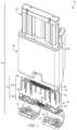
- FIG. 1is an exploded perspective view of various components of a distal portion of a delivery device configured to deliver a repair device, according to an embodiment of the present invention
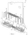
- FIG. 2is a perspective view of the repair device and a cradle portion, depicting first and second anchors in a pre-deployed state as positioned within the cartridge (not shown) and positioned above first and second capture members in the cradle portion, according to another embodiment of the present invention;
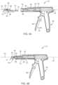
- FIG. 3is a perspective view of the delivery device, depicting the delivery device with an implant delivery member in a non-engaged position, according to another embodiment of the present invention
- FIG. 4is a top view of the delivery device of FIG. 3 , according to another embodiment of the present invention.
- FIG. 5 Ais a cross-sectional view of the delivery device taken along section line 5 A of FIG. 4 , depicting the implant delivery member disengaged relative to a pusher member portion of the delivery device, according to another embodiment of the present invention
- FIG. 5 Bis a cross-sectional view of the delivery device, depicting the implant delivery member engaged with the pusher member portion of the delivery device, according to another embodiment of the present invention
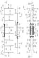
- FIG. 6is a perspective view of the repair device, depicting the first and second anchors with legs aligned for engagement relative to the respective first and second capture members, according to another embodiment of the present invention
- FIG. 7is a perspective view of the repair device, depicting the repair device in a deployed state, according to another embodiment of the present invention.
- FIG. 8is a top view of the repair device of FIG. 7 , according to another embodiment of the present invention.
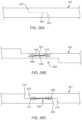
- FIG. 9is a side view of the repair device, depicting the repair device deployed within soft tissue at a soft tissue repair site, according to another embodiment of the present invention.
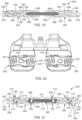
- FIG. 10 Ais a top perspective view of the repair device deployed in the soft tissue of FIG. 9 , according to another embodiment of the present invention.
- FIG. 10 Bis a bottom perspective view of the repair device deployed in soft tissue of FIG. 9 , according to another embodiment of the present invention.
- FIG. 11 Ais a top view of one or more repair devices, depicting first anchors of the one or more repair devices fixating soft tissue to bone with a bone anchor, according to another embodiment of the present invention
- FIG. 11 Bis a bottom view of the one or more repair devices, depicting first capture members coupled to arms of the first anchors of the one or more repair devices fixating soft tissue to bone with the bone anchor, according to another embodiment of the present invention
- FIG. 12is a perspective view of another embodiment of a repair device, depicting first and second anchors with legs aligned for engagement relative to the respective first and second capture members, according to the present invention
- FIG. 13is a top view of an anvil of a delivery device, depicting anvil buckets defined in the anvil sized for the repair device of FIG. 12 , according to another embodiment of the present invention
- FIG. 13 Ais a partial cross-sectional view of the anvil taken along section A-A of FIG. 13 , depicting depths of the anvil buckets defined in the anvil, according to another embodiment of the present invention
- FIG. 14is a partial perspective view of the anvil of FIG. 13 , according to another embodiment of the present invention.
- FIG. 15is a side view of the repair device of FIG. 12 , depicting a side profile of the first and second anchors in a disengaged position relative to the respective first and second capture members, according to another embodiment of the present invention
- FIG. 16is a top view of the repair device of FIG. 12 , depicting a top profile of the first and second anchors relative to the respective first and second capture members, according to another embodiment of the present invention
- FIG. 17is a perspective view of another embodiment of a repair device, depicting first and second anchors configured to engage with respective first and second capture members, according to the present invention
- FIG. 18is a side view of the repair device of FIG. 17 , according to another embodiment of the present invention.
- FIG. 19is a top view of the repair device of FIG. 17 , according to another embodiment of the present invention.
- FIG. 20is a top view of an anvil, depicting anvil buckets defined in the anvil sized for the repair device of FIG. 17 , according to another embodiment of the present invention.
- FIG. 21is a bottom view of the repair device of FIG. 17 , according to another embodiment of the present invention.
- FIG. 22is a perspective view of another embodiment of a repair device, according to the present invention.
- FIG. 23is a side view of the repair device of FIG. 22 , according to another embodiment of the present invention.
- FIG. 24is a top view of the repair device of FIG. 22 , according to another embodiment of the present invention.
- FIG. 25is a perspective view of the repair device of FIG. 22 , depicting the repair device with the legs in a formed position exhibiting a curled configuration, according to another embodiment of the present invention.
- FIG. 26 Ais a top view of a tendon, depicting the tendon with dashed lines that indicate an incision to be made in a tendon lengthening procedure, according to another embodiment of the present invention.
- FIG. 26 Bis a top view of the repair device of FIG. 25 , depicting the repair device coupling tendon ends of a tendon in a tendon lengthening procedure, according to another embodiment of the present invention.
- FIG. 26 Cis a top view of the repair device of FIG. 25 , depicting the repair device coupling lateral sides of a tendon in a tendon lengthening procedure, according to another embodiment of the present invention.
- FIG. 27is a bottom view of exposed portions of the repair device coupled to a tendon, according to another embodiment of the present invention.
- FIG. 28is a perspective view of another embodiment of a repair device for fixating tendon portions or ends in a tendon lengthening procedure, according to the present invention.
- a soft tissue repair devicethat may be employed to fixate severed or ruptured soft tissue together or for coupling soft tissue to bone.
- the various embodiments of a repair devicemay provide structure that maintains two ends or end portions of a lacerated or ruptured tendon in an abutting relationship, without gapping, to facilitate the appropriate healing required for fusing ends or end portions of soft tissue.
- the structural characteristics of the repair devicemay allow the tendon adjacent the tendon ends and along the length of the repair device to provide controlled elongation of the tendon.
- a repair device 10may be deployed into soft tissue 11 , such as tendon or ligament, and delivered with a delivery device 12 ( FIG. 3 ) with an anvil 14 at an end portion 16 of the delivery device 12 .
- the end portion 16 of the delivery device 12may include a cradle 18 , a cartridge 20 and a pusher member 22 , each of which may be sized and configured to cooperate with the repair device 10 .
- the cartridge 20may be linearly slidable and coupled to a rail portion or tract of an elongated extension 24 of the cradle 18 with a c-arm or channel extending along an underside of the cartridge 20 .
- the cartridge 20may be hollow or define a hollow portion so as to define an opening 26 extending through opposite sides of the cartridge 20 with the pusher member 22 positionable within a proximal side of the opening 26 of the cartridge 20 and a portion of the repair device 10 positionable within a distal side of the opening 26 of the cartridge 20 .
- the repair device 10may include a first anchor 28 coupled to a second anchor 30 with a first flexible member 32 therebetween.
- the before-mentioned portion of the repair device 10 positioned within the distal side of the cartridge 20may be such first and second anchors 28 , 30 with the first flexible member 32 therebetween.
- the repair device 10may also include a first capture member 34 and a second capture member 36 with a second flexible member 38 coupling the first capture member 34 to the second capture member 36 .
- Such first and second capture members 34 , 36may be positioned over an upper surface 40 of the anvil 14 .
- Such anvil 14may include anvil buckets 42 defined in the upper surface such that the anvil buckets 42 may be sized, oriented, and configured to manipulate legs 44 of the first and second anchors 28 , 30 . Further, the anvil 14 may define elongated structure to define a longitudinal anvil axis 25 extending along the elongated structure.
- first and second anchors 28 , 30can be temporarily housed within the cartridge 20 and effectively deployed from the cartridge 20 with the pusher member 22 so that the legs 44 of the first and second anchors 28 , 30 compress into the anvil buckets 42 to bend or move the legs 42 of the first and second anchors 28 , 30 to a formed position, such as a curled position, to be coupled to the first and second capture members 34 , 36 , as depicted in FIG. 7 , discussed in further detail herein.
- the delivery device 12may include a trigger gun 46 with a trigger 48 .
- the trigger gun 46may be manually actuatable in a physician's hand by manually gripping or actuating the trigger 48 , as shown with arrow 50 .
- the delivery device 12may also include a barrel housing 52 defining an axis 54 .
- the barrel housing 52may house a worm drive 56 and a push rod 58 co-axial with the worm drive 56 and extending longitudinally through the worm drive 56 .
- Such push rod 58may be configured to cooperate with the trigger 48 so as to distally actuate upon actuating the trigger 48 .
- the barrel housing 52may also include one or more openings 60 or opposing openings defined therein such that a thumb wheel 62 may be positioned and accessible for manually rotating therein.
- the delivery device 12includes a replaceable and removable implant delivery member 64 such that the implant delivery member 64 may be removable relative to the barrel housing 52 .
- the implant delivery member 64may include a base portion 66 , the cartridge 20 and the cradle 18 , the implant delivery member 64 extending between a proximal end 68 and a distal end 70 .
- the base portion 66may be coupled to the elongated extension 24 of the cradle 18 so as to extend proximally from the cradle 18 to define a tongue 72 .
- Such tongue 72may include threads 74 along an upper side 76 of the tongue 72 of the implant delivery member 64 .
- the base portion 66may also include a track or other structural characteristics that facilitate the cartridge 20 to be linearly moveable or slidable between the anvil 14 and the tongue 72 along the upper side 76 of the implant delivery member 64 .
- the cradle 18may include the anvil 14 with the upper surface 40 with the anvil buckets 42 defined therein.
- the thumb wheel 62 of the delivery device 12may be manually rotatable to cooperate with the worm drive 56 .
- the physicianmay position the tongue 72 within an end opening 78 or within a bore of the barrel housing 52 and, for example, position the tongue 72 within a space below the push rod 58 .
- the physicianmay rotate the thumb wheel 62 so that the worm drive 56 may engage the threads 74 of the tongue 72 and linearly move and pull the base portion 66 within the barrel housing 52 .
- the physicianmay continue to rotate the thumb wheel 62 so that the base portion 66 continues proximally so that the push rod 58 moves and slides the cartridge 20 distally until the cartridge 20 abuts and stops against the anvil 14 of the cradle 18 .
- the push rod 58may include a recess 80 at a distal end portion of the push rod 58 .
- further movement of the thumb wheel 62may move the push rod 58 over a lip 82 adjacent a proximal side of the cartridge 20 so that the recess 80 in the push rod 58 engages and may be captured by the lip 82 .
- the physicianmay hear, for example, a click as an assurance that the cartridge 20 is engaged with the push rod 58 .
- the push rod 58may be engaged with the cartridge 20 such that reverse movement of the thumb wheel 62 may move the push rod 58 and the cartridge 20 proximally.
- the physicianmay then move the cartridge 20 proximally a desired distance to then position soft tissue (not shown) in the cradle 18 .
- the trigger 48 of the delivery device 12may be actuated to move the push rod 58 distally, extending along the axis 54 , to push against the pusher member 22 to then push the repair device 10 from the cartridge 20 and into the soft tissue.
- the legs 44 of the first and second anchors 28 , 30compress against the anvil buckets 42 , the legs 44 move to a formed or curled position to wrap around portions of the first and second capture members 34 , 36 (see FIGS. 2 and 7 ).
- the physicianmay then rotate the thumb wheel 62 to move the base portion 66 and cradle 18 distally so that the cartridge 20 is backed-off from the cradle 18 and so that the user may then readily remove the soft tissue with the deployed repair device 10 therein and from the cradle 18 .
- the usermay then continue to rotate the thumb wheel 62 to continue to move the implant delivery member 64 distally until the worm drive 56 is disengaged from the threads 74 of the tongue 72 of the implant delivery member 64 .
- the physicianmay take a second one of the implant delivery member 64 and position it within the barrel housing 52 for engaging with the delivery device 12 as described above to then position a second repair device in the soft tissue, if desired.
- the implant delivery member 64is removable and replaceable relative to the delivery device 12 so that the delivery device 12 may be repeatably employed with multiple implant delivery members 64 .
- the components of the delivery device 12may be formed and made with medical grade materials, such as stainless steel, titanium, Nitinol, and/or alloys thereof or any other suitable metallic material or polymeric materials, such as liquid crystal polymers or acrylonitrile butadiene styrene (“ABS”) or any other suitable polymeric materials known to one of ordinary skill in the art.
- medical grade materialssuch as stainless steel, titanium, Nitinol, and/or alloys thereof or any other suitable metallic material or polymeric materials, such as liquid crystal polymers or acrylonitrile butadiene styrene (“ABS”) or any other suitable polymeric materials known to one of ordinary skill in the art.
- ABSacrylonitrile butadiene styrene
- Such delivery device 12 componentsmay be formed by employing molding and/or machining techniques, or any other suitable techniques and processes known to one of ordinary skill in the art.
- first and second anchors 28 , 30may be cut from sheet material such that each of the first and second anchors 28 , 30 may be a seamless unitary and monolithically formed structure.
- the legs 44 of the first and second anchors 28 , 30may be bent and oriented in a generally common predetermined direction, as depicted in FIG. 6 , from a single side of the first and second anchors 28 , 30 .
- first and second capture members 34 , 36may each be formed from sheet material such that the first and second capture members 34 , 36 may be a seamless unitary or monolithically formed structure, which may include portions bent and oriented as depicted in FIG. 6 .
- the first and second anchors 28 , 30 and the first and second capture members 34 , 36may be formed from, for example, a medical grade sheet material, such as stainless steel, titanium, Nitinol, and/or alloys thereof or any other suitable medical grade material, and be cut from the sheet material by laser cutting or any other suitable cutting technique known by one of ordinary skill in the art.
- the sheet materialmay be a bioresorbable material such as zinc, polylactic-co-glycolic acid (“PLGA”) or any other suitable bioresorbable material described herein or known by one of ordinary skill in the art.
- PLGApolylactic-co-glycolic acid
- the repair device 10is depicted with the legs 44 of the first and second anchors 28 , 30 positioned and oriented relative to the first and second capture members 34 , 36 just before the legs 44 are being compressed into the anvil buckets 42 of the anvil 14 (see FIG. 2 ).
- the first and second anchors 28 , 30may each include a base that may define elongated structure with legs 44 extending therefrom.
- the base 84 of the first and second anchors 28 , 30may be longitudinally aligned and oriented relative to each other and coupled together with the first flexible member 32 so as to define an anchor axis 86 .
- first and second capture members 34 , 36may define elongated structure with tines 88 extending therefrom such that the first and second capture members 34 , 36 may be longitudinally aligned and oriented with the second flexible member 38 extending therebetween so as to define a capture member axis 90 .
- first and second anchors 28 , 30may be longitudinally aligned and oriented relative to the first and second capture members 34 , 36 so that the anchor axis 86 extends substantially parallel relative to the capture member axis 90 .
- each of the anchor axis 86 and the capture member axis 90may be extend substantially parallel with the anvil axis 25 ( FIG. 2 ). Even further, the anchor axis 86 and the capture member axis 90 may extend substantially perpendicular relative to the axis 54 of the delivery device 12 ( FIG. 3 ).
- the first and second anchors 28 , 30may each include a base 84 with legs 44 extending from the base 84 .
- the base 84 of each of the first and second anchors 28 , 30may extend generally within a plane. Subsequent to the first and second anchors 28 , 30 being cut from sheet material, the legs 44 may be bent at their respective base to a bent position as depicted.
- the base 84 of each of the first and second anchors 28 , 30may include a first elongate portion 92 and a second elongate portion 94 .
- the first and second elongate portions 92 , 94may be interconnected by a laterally extending portion 96 therebetween. Such laterally extending portion 96 may be employed for coupling the first flexible member 32 thereto for each of the first and second anchors 28 , 30 .
- each of the first and second anchors 28 , 30include multiple legs 44 extending from a single side of the base 84 .
- each of the first and second anchors 28 , 30may include six legs 44 or more.
- each of the first and second anchors 28 , 30may include at least five legs 44 .
- each of the first and second anchors 28 , 30may include at least four legs 44 .
- each of the first and second anchors 28 , 30may include at least three legs 44 .
- the number of legs 44 for a given anchormay correspond with structural portions (i.e., apertures, struts, curved portions, etc.) of the first and second capture members 34 , 36 , the structural portions sized and configured to be captured or coupled to the legs 44 , discussed in further detail herein.
- Each of the legs 44may extend generally or substantially perpendicular relative to a plane defined by the base 84 of each of the first and second anchors 28 , 30 .
- the first and second anchors 28 , 30may be coupled together with the first flexible member 32 .
- the first flexible member 32may include one or more filaments. Such one or more filaments of the first flexible member 32 may be wrapped over the laterally extending portion 96 of each base 84 or a neck portion or any other suitable portion of the first and second anchors 28 , 30 .
- the one or more filaments of the first flexible member 32may take multiple wrappings or windings to ensure the first and second anchors 28 , 30 are appropriately coupled together so as to substantially resist elongation.
- the first flexible member 32may be formed from any suitable medical grade filament, such as a biocompatible polymeric filament or the like, for example, ultra-high molecular weight polyethylene.
- the first flexible member 32may be a single flexible member or include multiple flexible members extending between the first and second anchors 28 , 30 .
- the first and second capture members 34 , 36may each define a width 108 and a length 110 . Further, the first and second capture members 34 , 36 may include the tines 88 extending transverse relative to the planar main body 102 and sized and configured to pierce and extend into soft tissue.
- the tines 88 of the first and second capture members 34 , 36may be canted toward the repair site. In another embodiment, the tines 88 may be canted away from the repair site. In still another embodiment, the tines 88 may extend substantially perpendicular relative to the main body 102 of the first and second capture members 34 , 36 . But for the tines 88 , the first and second capture members 34 , 36 may extend in a plane or be substantially flat since the capture members may be laser cut from sheet material and, as such, portions of the cut sheet material may be flat and plate like and may exhibit a square or rectangular cross-section. In another embodiment, the tines 88 may include a barb or the like extending therefrom.
- each of the first and second capture members 34 , 36may include first and second elongated portions 112 , 114 extending from an inner portion 116 .
- the second flexible member 38may be employed to couple the first capture member 34 to the second capture member 36 .
- the first and second elongated portions 112 , 114may each define one or more apertures 118 therein and/or the one or more curved portions 106 .
- the apertures 118 and/or the curved portions 106may be sized and configured to receive and be captured by the legs 44 of the first and second anchors 28 , 30 , described in further detail herein.
- the first and second capture members 34 , 36may be coupled together with the second flexible member 38 .
- the second flexible member 38may include one or more filaments.
- such one or more filaments of the second flexible member 38may be wrapped over and around the inner portion 116 of each main body 102 of the first and second capture members 34 , 36 .
- the one or more filaments of the second flexible member 38may take multiple wrappings or windings to ensure the first and second capture members 34 , 36 are appropriately coupled together.
- the second flexible member 38may be formed from any suitable medical grade filament, such as a biocompatible polymeric filament or the like, for example, ultra-high molecular weight polyethylene.
- the second flexible member 38may be a single flexible member or include multiple flexible members extending between the first and second capture members 34 , 36 .
- end portions 120 of legs 44 of the first and second anchors 28 , 30may be moved (forced and compressed) to a formed position. In this manner, such end portions 120 of the legs 44 of each of the first and second anchors 28 , 30 may be moved from a first position (generally linear position, depicted in FIG. 6 ) to a second position, as depicted in FIG. 7 .
- the second position of the legs 44may exhibit a formed position, such as a bent, curled or wrapped position, formed via being compressed into the anvil buckets 42 of the anvil 14 ( FIG. 2 ). In this manner, the end portions 120 of the legs 44 may be manipulated to bend or wrap around structural portions of the first and second capture members 34 , 36 , thereby, coupling the first and second anchors 28 , 30 to the respective first and second capture members 34 , 36 .
- first and second capture members 34 , 36may each extend to define one or more apertures 118 and/or curved portions 106 and/or any other suitable capturing structure or structural portions, such as notches or peripheral recesses.
- Such capturing structure, such as apertures 118 , notches, or curved portions 106 , of the first and second capture members 34 , 36may be sized and configured to correspond with the legs 44 of the respective first and second anchors 28 , 30 to facilitate the legs 40 to wrap or curl around the structural portions of the first and second capture members 34 , 36 .
- the legs 44 of the first and second anchors 28 , 30extend into the soft tissue such that adjacent positions of initial entrance into the soft tissue by the legs 44 may not be longitudinally aligned with each other.
- middle legs 122may extend from the first and second anchors 28 , 30 a first distance 124 from the anchor axis 86 of the first and second anchors 28 , 30 , and other ones of the legs 44 on opposite ends of the first and second anchors 28 , 30 may extend relative to the anchor axis 86 of the first and second anchors 28 , 30 a second distance 126 , the first distance 124 being larger than the second distance 126 .
- the first distance 124may be smaller than the second distance 126 .
- the adjacent positions of entrance into the soft tissue at the second side or bottom side of the soft tissue of the end portions 120 of the legs 44 relative to the tines 88 of the first and second capture members 34 , 36may not be longitudinally aligned.
- the end portions 120 of the legs 44may be positioned at different distances than the tines 88 relative to the capture member axis 90 of the first and second capture members 34 , 36 .
- the lateral spacing between adjacent pairs of legs 44such as outer legs 128 relative to the middle legs 122 (see FIG. 7 ), may be different or longitudinally offset relative to each other.
- Such varying spacing or offset leg pairs 44 relative to adjacent leg pairs 44may result in the tips of, for example, the outer legs 128 and the middle legs 122 to enter the soft tissue at varying lateral positions relative to the anchor axis 86 or axis of the soft tissue (not shown) to gather varying longitudinal tissue bundles with the formed position of the legs 44 , upon deploying and fixating the repair device 10 to the soft tissue.
- the longitudinally extending tissue fibersmay be less apt to longitudinally tear along a common longitudinal line within the soft tissue and where adjacent arms 44 extend through the soft tissue.
- the legs 44 of the first and second anchors 28 , 30 extending from one lateral side of the base 84may be substantially longitudinally aligned relative to each other and the legs 44 of the first and second anchors 28 , 30 extending from the other lateral side of the base 84 may be substantially longitudinally aligned relative to each other.
- a force or load that may be placed on the soft tissuemay be maximized without the repair device 10 being pulled out of the soft tissue.
- the soft tissuemay fail before the low profile repair device 10 fails such that the repair device 10 may remain intact and coupled together.
- the repair device 10may include a first portion 130 and a second portion 132 , the first portion 130 and the second portion 132 coupled with the first flexible member 32 and the second flexible member 38 .
- the first portion 130may include the first anchor 28 and the first capture member 34 , the first anchor 28 sized to couple to the first capture member 34 via the legs 44 of the first anchor 28 .
- the second portion 132may include the second anchor 30 and the second capture member 36 , the second anchor 30 sized to couple to the second capture member 36 via the legs 40 of the second anchor 30 .
- first portion 130 or the second portion 132 of the repair device 10may be employed to be fixated to soft tissue with a flexible member coupled to, for example, a bone anchor, similar to that depicted in FIGS. 11 A and 11 B .
- a flexible membercoupled to, for example, a bone anchor, similar to that depicted in FIGS. 11 A and 11 B .
- Such first portion 130 and/or second portion 132may be appropriately sized relative to the soft tissue such that the repair device 10 may be employed for fixating to soft tissue.
- the repair device 10may be coupled together and fixated to soft tissue 11 .
- exposed portions of the repair device 10may exhibit a low profile relative to a first side 13 and second side 15 of the soft tissue 10 .
- the repair device 10may create a recess 17 or depressed portion (on both the first and second sides 13 , 15 ) in the soft tissue 11 such that exposed portions of the repair device 10 provide minimal structure extending beyond a height 19 or diameter of the soft tissue 11 .
- the repair device 10may be secured and maintained to the soft tissue 11 with the legs 44 and tines 88 at multiple locations in the soft tissue 11 .
- the legs 44 of the first and second anchors 26 , 30extend into the first side 13 and through the soft tissue 11 and back into the second side 15 of the soft tissue 11 .
- tines 88 extending from the first and second capture members 34 , 36may extend into the soft tissue 11 as well as end portions 120 of the legs 44 extending into the soft tissue 11 .
- the first flexible member 32extends over a tissue repair site 21 and couples the first anchor 28 to the second anchor 30 .
- first and second flexible members 32 , 38extends over the opposite side of the tissue repair site 21 and couples the first capture member 34 to the second capture member 36 .
- first and second flexible members 32 , 38may resist elongation along their respective longitudinal lengths to substantially prevent gapping at the soft tissue repair site 21 .
- first and second flexible members 32 , 38may assist the repair device 10 to move over a radius.
- first and second elongate portions 92 , 94 of each of the first and second anchors 28 , 30may each include a curved portion 138 along a length thereof.
- the curved portion 138may be sized and configured to facilitate the base 84 or the respective first and second elongate portions 92 , 34 to stretch or elongate relative to the first flexible member 32 or mid portion so as to move toward a more linear configuration upon a force or load being applied to the soft tissue 11 and, thus, to the repair device 10 .
- the curved portions 106 of the first and second capture members 34 , 36may be sized so as to facilitate the first and second capture members 34 , 36 to elongate or move to a more linear position so that the length of the first and second capture members 34 , 36 elongates so as to become longer.
- the repair device 10 along the first and second anchors 28 , 30 and the first and second capture members 34 , 36may elongate along their respective portions or lengths, upon a load being placed upon the repair device 10 , while the first and second flexible members 32 , 38 positioned over the soft tissue repair site 21 may resist elongation to maintain a substantially fixed position.
- the soft tissue 11may be somewhat exercised while maintaining the abutted soft tissue ends at the soft tissue repair site 21 in a substantially fixed position.
- FIGS. 11 A and 11 Ba top view and a bottom view, respectively, of another embodiment of one or more repair devices 140 for fixating soft tissue 11 , at a soft tissue repair site 21 , to bone 23 with a bone anchor 142 .
- the one or more repair devices 140being similar to a first portion 130 of the previously described repair device 10 (see FIG. 8 ).
- such one or more repair devices 140may employ, for example, an anchor 144 coupled to a capture member 146 such that legs 148 of the anchor 144 extend through the soft tissue 11 and the legs 148 are formed around or curl around portions of the capture member 146 , similar to previous described embodiments.
- the one or more repair devices 140may be coupled to the bone anchor 142 .
- a first flexible member 150 and a second flexible member 152 extending from the respective anchor 144 and the capture member 146may be coupled to the bone anchor 142 .
- Suchmay be employed by extending a bone anchor filament 154 through or around the first flexible member 150 and the second flexible member 152 and inserting and fixating the bone anchor 142 to bone 23 .
- one or more anchors 144may be coupled to one or more capture members 146 to fixate soft tissue 11 to bone 23 .
- the bone anchor filament 154may be coupled directly to one or both of the first anchors 684 as well as the bone anchor filament 694 being coupled to one or both of the capture members 146 , instead of employing the first and second flexible members 150 , 152 .
- FIGS. 12 - 16another embodiment of a repair device 220 for fixating soft tissue ends (not shown) together is provided.
- This embodimentmay include similar structural characteristics as the embodiment described and depicted in FIGS. 6 - 8 and may be employed with an anvil 222 associated with a similar delivery device to that described and depicted in FIGS. 3 , 4 , 5 A and 5 B , but the repair device 220 of this embodiment may be larger than previous embodiments and sized for fixating larger soft tissue portions.
- this embodiment of the repair device 220may be sized and configured to fixate to soft tissue, such as tendon in the biceps, or tendon of the posterior tibialis or anterior tibialis, or any other suitable sized tendon or soft tissue.
- the repair device 220 of this embodimentmay include opposing structures sized and configured to couple together with soft tissue fixated therebetween.
- the repair device 220may include a first anchor 224 and a second anchor 226 sized and configured to couple to a first capture member 228 and a second capture member 230 .
- the first and second anchors 224 , 226may be coupled together with a first flexible member 235 and the first and second capture members 228 , 230 may be coupled together with a second flexible member 234 .
- the first and second anchors 224 , 226may be aligned along an anchor longitudinal axis 236 so as to be oriented along their respective longitudinal lengths with the first flexible member 232 therebetween.
- first and second capture members 228 , 230may be aligned along a capture member longitudinal axis 238 so as to be oriented along their respective longitudinal lengths with the second flexible member 234 therebetween.
- the repair device 220may also define a center lateral axis 240 extending through a lateral center of the repair device 220 such that the center lateral axis 240 extends orthogonal relative to the anchor and capture longitudinal axes 236 , 238 and through both anchor and capture member longitudinal axes 236 , 238 .
- center lateral axis 240may extend along or adjacent to severed ends of the soft tissue (not shown) to be fixated within the repair device 220 .
- each of the first and second flexible members 232 , 234may be formed with one or more filaments 242 , similar to that described and depicted in previous embodiments.
- the first and second anchors 224 , 226may each include eight legs 244 extending from an anchor base 246 or base portion.
- the anchor base 246 of each of the first and second anchorsmay be elongated and may extend with a flat structure or planar structure defining an upper surface 248 and an underside surface 250 .
- the anchor base 246may extend between a first end 252 or outer end and a second end 254 or inner end. Further, the anchor base 246 may extend between opposite first and second lateral sides 256 , 258 .
- End portions (adjacent the first and second ends 252 , 254 ) of the anchor base 246may define a larger width than a width of a middle portion 272 of the anchor base 246 .
- Such end portionsmay include leg extensions 260 that may extend to leg pairs at the opposing first and second ends 252 , 254 .
- Such leg extensions 260 adjacent the second end 254 of the anchor base 246may define a shoulder portion 262 sized and configured to facilitate coupling the first flexible member 232 thereto.
- the middle portion 272 of the anchor base 246may include two leg pairs extending from the opposite first and second lateral sides 256 , 258 of the anchor base 246 .
- the first and second anchors 224 , 226may each include eight legs 244 extending from the anchor base 246 .
- first and second anchors 224 , 226may each include an outer leg pair 264 , an inner leg pair 266 , a first middle leg pair 268 , and a second middle leg pair 270 .
- the first and second middle leg pairs 268 , 270may extend from the middle portion 272 of the anchor base 246 of each of the first and second anchors 224 , 226 and may be sized and configured to couple to or capture the first and second capture members 228 , 230 by being formed or curling via the anvil 222 ( FIG. 13 ) around portions of the first and second capture members 228 , 230 .
- the outer and inner leg pairs 264 , 266 extending from the respective first and second ends 252 , 254 of the anchor base 246 of the first and second anchors 224 , 226may be sized and configured to curl via the anvil 222 without capturing the corresponding first and second capture members 228 , 230 positioned opposite the respective first and second anchors 224 , 226 .
- each of the first and second anchors 224 , 226may be formed to curl around the respective first and second capture members 228 , 230 and some of the legs 244 , such as four legs, of each of the first and second anchors 224 , 226 may be formed to curl without being coupled to the first and second capture members 228 , 230 .
- the first and second capture members 228 , 230may each include a base 274 or base portion with spikes 276 extending therefrom.
- the base 274 of the first and second capture members 228 , 230may be elongated and may extend with a flat structure or planar structure.
- the base 274may extend between a first end 278 or outer end and a second end 280 or inner end.
- the first end 278may include one or more spikes 276 extending therefrom, such as a single spike.
- the second end 280may extend with a neck 282 or shoulder portion and arms 284 that extend to one or more spikes 276 , such as two spikes.
- the neck 282 or narrow portion defined in the first and second capture members 228 , 230may facilitate coupling the first and second capture members 228 , 230 with the second flexible member 234 .
- the first and second capture members 228 , 230may include structure, such as strut structure 286 or radial portions, that may extend to define recesses 288 or apertures therein, so as to define a multi-cellular structure.
- Such recesses 288 or apertures defined by the strut structure 286 in each of the first and second capture members 228 , 230may at least partially act as structure for at least some of the legs 244 of the first and second anchors 224 , 226 to wrap or curl over as the first and second anchors 224 , 226 are being compressed against the anvil 222 ( FIG. 13 ) with tendon therebetween, similar to previous embodiments described and depicted herein.
- the anvil 222may be integrated with a cradle member 290 that may be coupled to a delivery device (not shown). Further, the anvil 222 may include a first anvil 292 and a second anvil 294 sized and configured to correspond with the respective first and second anchors 224 , 226 . Further, the first anvil 292 may include structural characteristics similar to the second anvil 294 such that the first anvil 292 may generally be a mirror image of the second anvil 294 . As such, description of the first anvil 292 may mirror the structure of the second anvil 294 .
- first anvil 292may be separated from the second anvil 294 with a gap 296 to assist, for example, the physician to manipulate the soft tissue being positioned within the cradle member 290 .
- first and second anvil 292 , 294may be elongated and aligned along an anvil longitudinal axis 298 , the anvil longitudinal axis 298 extending parallel with the anchor and capture member longitudinal axes 236 , 238 .
- the first and second anvil 292 , 294may include an anvil surface 300 with anvil buckets 302 defined therein, the anvil buckets 302 sized and configured to receive and manipulate the legs 1144 of the first and second anchors 1124 , 1126 compressed against and through the anvil buckets 302 .
- the anvil surface 300 of the first and second anvils 292 , 294may include a first anvil surface 304 and a second anvil surface 306 .
- the first anvil surface 304may be at an elevation higher than the second anvil surface 306 of the anvil 222 .
- the second anvil surface 306 of the first and second anvils 292 , 294may receive the respective first and second capture members 228 , 230 of the repair device 220 .
- the second anvil surface 306may include an upstanding wall 308 or island centrally located on the second anvil surface 306 that may correspond with structure of the first and second capture members 228 , 230 , such as a central aperture 310 of the first and second capture members 228 , 230 .
- such upstanding wall 308may extend to the same height as the first anvil surface 304 .
- the first and second anvils 292 , 294may each define outer anvil buckets 312 , inner anvil buckets 314 , a first middle anvil bucket 316 , and a second middle anvil bucket 318 .
- the outer anvil buckets 312may be laterally aligned (e.g., orthogonal) relative to the anvil longitudinal axis 298 .
- Such anvil buckets 302may define a generally rectangular periphery, as viewed from above the anvil 222 .
- the outer anvil buckets 312may extend to a lower most first bottom surface 320 and the first and second middle anvil buckets 316 , 318 may define a lower most second bottom surface 322 , the first bottom surface 320 being elevated higher than the second bottom surface 322 .
- a depth of the first and/or second middle anvil buckets 316 , 318may be greater than a depth of the outer anvil buckets 312 .
- the inner anvil buckets 314may include a lower most bottom surface similar to a depth of the first bottom surface 320 of the outer anvil buckets 312 .
- Each of the outer anvil buckets 312 defined in the anvil surface 300may extend with a radial surface 324 that at least partially defines a path, as indicated by arrow 326 , for compressing and forming or curling the outer leg pairs 264 to curl inward relative to each other, as shown by arrows 328 .
- Such radial surface 324 along the path of the outer anvil buckets 312may define a radial axis that extends parallel with the anvil longitudinal axis 298 .
- the inner anvil buckets 1214may be laterally aligned relative to the anvil longitudinal axis 1198 .
- the inner anvil buckets 314may be defined in the first anvil surface 304 .
- each of the inner anvil buckets 314 defined in the anvil surface 300may include a radial surface 330 (with downward and upward slopes) to at least partially extend along and define a path, as indicated by arrows 332 , for compressing and forming or curling the inner leg pairs 266 to curl inward relative to each other, as shown by arrows 334 .
- the radial surface 330 of the inner anvil buckets 314may define a radial axis that extends parallel with the anvil longitudinal axis 298 .
- the first and second middle anvil buckets 316 , 318 of each of the first and second anvils 292 , 294may each receive two legs 244 , such as the respective first middle leg pairs 268 and the second middle leg pairs 270 .
- the first and second middle anvil buckets 316 , 318may be defined in the second anvil surface 306 . Further, the first and second middle anvil buckets 316 , 318 may be aligned in the second anvil surface 306 along the anvil longitudinal axis 298 .
- the first middle anvil buckets 316 defined in the anvil surface 300may each include a radial surface 336 (with downward and upward slopes) to define a path, as indicated by arrows 338 .
- the radial surface 336may define a radial axis that may be perpendicular to the anvil longitudinal axis 298 .
- Such first middle anvil bucket 316 of the first and second anvil 292 , 294may be sized and configured to facilitate forming or curling two legs 244 therein, such as the first middle leg pair 268 of one of the first and second anchors 224 , 226 , so as to curl the first middle leg pair 268 in a first common direction, as shown by arrows 340 , to wrap around a portion or strut structure 286 of the corresponding first and second capture members 228 , 230 .
- the second middle anvil buckets 318 defined in the anvil surface 300may each include a radial surface 342 to define a path, as indicated by arrows 344 , the path proceeding with downward and upward slopes.
- the radial surface 342may define a radial axis that may extend perpendicular relative to the anvil longitudinal axis 298 .
- the second middle anvil bucket 318 of the first and second anvils 292 , 294may be sized and configured to facilitate forming or curling two legs 244 therein, such as the second middle leg pair 270 of one of the first and second anchors 224 , 226 , so as to curl the second middle leg pair 270 in a second common direction, as shown by arrows 346 , to curl and wrap around a portion or strut structure 286 of the corresponding first and second capture members 228 , 230 .
- the first common direction to which the first middle leg pair 268 is moved to curlmay be generally opposite relative to the second common direction to which the second middle leg pair 270 is moved to curl.
- the legs of the first middle leg pair 268 of the first and second anchors 224 , 226may curl in the first common direction, as indicated by arrows 340 , or an outward direction generally aligned with the anvil longitudinal axis 298 and the legs of the second middle leg pair 270 of the first and second anchors 224 , 226 may curl in the second common direction, as indicated by arrows 346 , or an inward direction generally aligned with the anvil longitudinal axis 298 .
- the anvil 222 with its anvil buckets 302 defined thereinmay be sized and configured to manipulate the curl of the outer and inner leg pairs 264 , 266 to curl in a generally orthogonal direction relative to the curl of the first and second middle leg pairs 268 , 270 .
- the anvil buckets 302 defined in the anvil 222may be sized and configured to curl the legs of the respective outer and inner leg pairs 264 , 266 inward toward each other (e.g., in a side-ways B-configuration) while the legs of the first middle leg pair 268 curl outward toward the outer leg pair 264 and the legs of the second middle leg pair 270 curl inward toward the inner leg pair 266 .
- one or more of the anvil buckets 302 defined in the anvil 222may receive two legs 244 of one of the first and second anchors 224 , 226 or may receive two legs 244 of both the first and second anchor 224 , 226 .
- the outer and inner anvil buckets 312 , 314may be sized and configured to each receive a single leg 244 of the first and second anchors 224 , 226 and the first and second middle anvil buckets 316 , 318 may be sized and configured to each receive two legs 244 of the first and second anchors 224 , 226 .
- two anvil buckets 302 defined in the anvil 222may be sized and configured to each receive two legs 244 of one of the first anchor 224 or the second anchor 226 such that the two legs 244 of one anvil bucket 302 curl in a general first direction and the two legs 244 of the other anvil bucket 302 curl in a general second direction, the first direction being generally opposite to the second direction.
- the one or more spikes 276 of the first and second capture members 228 , 230may extend in a canted manner.
- the one or more spikes 276 at the first and second ends 278 , 280 of the first capture member 228may extend upward or transverse relative to the first capture member 228 so as to be canted toward the center lateral axis 240 of the first and second capture members 228 , 230 or repair device 220 .
- the one or more spikes 276 at the first and second ends 278 , 280 of the second capture member 230may extend upward or transverse relative to the second capture member 226 so as to be canted toward the center lateral axis 240 of the first and second capture members 228 , 230 or repair device 220 .
- FIG. 16depicts a top view of the repair device 220 .
- the leg extensions 260extend laterally outward relative to the anchor longitudinal axis 236 such that the outer and inner leg pairs 264 , 266 extend from the leg extensions 260 a first lateral width 348 relative to the anchor longitudinal axis 236 .
- the first and second middle leg pairs 268 , 270 extending from the middle portion 272 of the anchor base 246may extend a second lateral width 350 relative to the anchor longitudinal axis 236 .
- the first lateral width 348may be larger than the second lateral width 350 .
- the legs 244 of the first and second anchors 224 , 226may extend through the soft tissue at different lateral distances relative to the anchor longitudinal axis 1136 or a longitudinal axis of the soft tissue (not shown).
- the repair device 360 of this embodimentmay be employed with an anvil 362 ( FIG. 20 ) associated with a delivery device (not shown), such as the delivery device 12 described and depicted in FIGS. 3 , 4 , 5 A, and 5 B .
- the repair device 360 of this embodimentmay include a narrower profile than previous embodiments, such as the repair device 360 described and depicted in FIGS. 6 - 8 , the repair device 360 sized and configured to fixate soft tissue (not shown) together.
- the repair device 360may be sized to fixate soft tissue or smaller zone two tendons, such as the small finger tendons, or extensors of the thumb or fingers, or extensor digitorum longus along the top of the foot, or any other suitable sized tendons that may correspond with the size of the repair device 360 .
- the repair device 360 of this embodimentmay include a first anchor 364 and a second anchor 366 positioned opposite of a first capture member 368 and a second capture member 370 , respectively.
- the first and second anchors 364 , 366may each include an anchor base 372 with legs extending therefrom.
- the anchor base 372 of each of the first and second anchors 364 , 366may be elongated such that the anchor base 372 of the first and second anchors 364 , 366 may be positioned/oriented and aligned along an anchor longitudinal axis 376 and coupled with a first flexible member 378 therebetween.
- Each anchor base 372may include four legs 374 or two leg pairs, namely, an outer leg pair 380 and an inner leg pair 382 .
- the repair device 360may include eight legs 374 for the first and second anchors 364 , 366 .
- each anchor base 372may extend with two elongate portions 388 each extending between an outer end 384 and an inner end 386 of the two elongate portions 388 .
- the inner leg pair 382extending from the inner ends 386 of the two elongate portions 388 and the outer leg pair 380 extending from the outer ends 384 of the two elongate portions 388 .
- the two elongate portions 388 of each anchor base 372may include an intermediate portion 390 extending transverse between the two elongate portions 388 , the intermediate portion 390 extending adjacent the inner ends 386 of the two elongate portions 388 .
- Such intermediate portion 390may provide coupling structure that may be employed to couple the first and second anchors 364 , 366 together with the first flexible member 378 .
- each of the two elongate portions 388 of the first and second anchors 364 , 366 of the repair device 360may extend off-set relative to each other.
- the two elongate portions 388may extend with one or more bends 392 .
- end portions or the outer and inner ends 384 , 386 of the two elongate portions 388may be a similar or common first distance 396 from each other and relative to the anchor longitudinal axis 376 with middle portions 394 of the two elongate portions 388 extending with the bends 392 or a curve to define a second distance 398 from each other and relative to the anchor longitudinal axis 376 , the second distance 398 being smaller than the first distance 396 .
- the first and second capture members 368 , 370 or capture plates of the repair device 360may be elongated and positioned along a capture member longitudinal axis 400 and may be coupled together with a second flexible member 402 therebetween.
- the first and second capture members 368 , 370 of this embodimentmay also extend with a narrower profile relative to previous embodiments so as to be sized and configured to couple to the legs 374 of the first and second anchors 364 , 366 .
- the first and second capture members 368 , 370may each include a base portion 404 and one or more spikes 406 extending upward therefrom.
- the base portion 404may extend between an outer end 408 and an inner end 410 and may extend generally flat and planar.
- the base portion 404may extend with strut structure 412 to define openings 414 or recesses therein.
- the base portion 404may extend with multiple struts so as to exhibit a multi-cellular structure.
- each base portion 404may include structure, such as strut structure 412 , for coupling the first and second capture members 368 , 370 together with one or more flexible filaments or the second flexible member 402 .
- the outer ends 408 of each base portion 404may extend to the one or more spikes 406 , such as two spikes, extending upward from each base portion 404 of the first and second capture members 368 , 370 .
- the one or more spikes 406may extend inward in a canted manner.
- the one or more spikes 406 of the first capture member 368may extend toward the first anchor 364 and be canted toward a center lateral axis 416 of the repair device 360 and the one or more spikes 406 of the second capture member 370 may extend toward the second anchor 366 and may be canted toward the center lateral axis 416 of the repair device 360 .
- the first and second capture members 368 , 370may be positioned on an anvil surface 420 of the anvil 362 of a delivery device (not shown), similar to the delivery device 12 described and depicted in FIGS. 3 , 4 , 5 A and 5 B .
- Such anvil 362may include the anvil surface 420 with anvil buckets 422 defined therein.
- the anvil 362may define eight anvil buckets 422 , each anvil bucket to correspond with one of the eight legs 374 of the first and second anchors 364 , 366 .
- each anvil bucket 422may be sized and configured to receive (in a compressive manner) a free end of one of the legs 374 so that the legs may be manipulated to be formed, such as in a curled configuration, to wrap around strut structure 412 of the first and second capture members 368 , 370 .
- the legs 374 of the outer leg pair 380 of the first and second anchors 364 , 366may correspond with outer anvil buckets 424 and the legs 374 of the inner leg pair 382 of the first and second anchors 364 , 366 may correspond with inner anvil buckets 426 .
- the legs 374 of the first and second anchors 364 , 366may be compressed and moved to a curled configuration to couple to the first and second capture members 368 , 370 , respectively, with soft tissue (not shown) positioned therebetween, similar to previous embodiments.
- the first and second capture members 368 , 370may include strut structure 412 sized and configured to receive the legs 374 of the first and second anchors 364 , 366 , respectively.
- the legs 374 of the outer leg pair 380 of the first and second anchors 364 , 366may curl around strut structure 412 of respective first and second capture members 368 , 370 , as indicated by arrows 428
- the legs 374 of the inner leg pair 382 of the first and second anchors 364 , 366may curl around strut structure 412 of the first and second capture members 368 , 370 , as indicated by arrows 430 .
- the repair device 500may be sized and configured as an anchor for fixating tendon ends together.
- the repair device 500may include similar structural characteristics made of similar materials and manufacturing techniques to that of previous embodiments, such as the repair device 10 of FIG. 6 , except the repair device 500 may be delivered independent of the capture members of the previous embodiments such that the repair device 500 may only fixate to a tendon by virtue of its one or more anchor portions.
- the repair device 500 of this embodimentmay include an intermediate portion 502 formed integrally with the repair device 500 , instead of the separately formed flexible member of previous embodiments.
- the intermediate portion 502may be structurally rigid and may be a similar rigidity as other portions of the repair device, such as the anchor.
- legs of the repair device 500may include a length that is shorter than legs of previous embodiments.
- the repair device 500may extend to define a first anchor portion 504 and a second anchor portion 506 with the intermediate portion 502 extending therebetween.
- the first anchor portion 504may extend with a first base 508 having first legs 510 extending therefrom.
- the second anchor portion 506may extend with a second base 512 having second legs 514 extending therefrom.
- the first base 508 and the second base 512may extend coplanar with the intermediate portion 502 of the repair device 500 .
- the first base 508 , the second base 512 , and the intermediate portion 502may be considered as a base or base portion of the repair device 500 .
- the repair device 500may define an elongated structure to define a longitudinal axis 516 along a length 522 of the repair device 500 , the repair device 500 defining a first lateral side 518 and an oppositely positioned second lateral side 520 relative to the longitudinal axis 516 .
- each of the first and second anchor portions 504 , 506may include five legs, of which the five legs may be defined by two outer legs 524 , two middle legs 526 and one inner leg 528 .
- the two outer and middle legs 524 , 526may extend from opposite first and second lateral sides 518 , 520 of each of the first and second anchor portions 504 , 506 .
- the one inner leg 528 of the first and second anchor portions 504 , 506may extend from opposite first and second lateral sides 518 , 520 of the repair device 500 .
- the first and second legs 510 , 514 of the first and second anchor portions 504 , 506may include similar structural characteristics as legs of previous embodiments described herein.
- first and second legs 510 , 514may each include one or more tapers 515 along a length of a given leg such that the one or more tapers 515 may be sized and configured to facilitate the legs to move to a curled configuration 538 (see FIG. 25 ). Further, along any one of the first and second lateral sides 518 , 520 , adjacent legs of the first and second legs 510 , 514 may extend downward from the corresponding first and second base 508 , 512 at different distances 513 from and relative to the longitudinal axis 516 .
- first and second anchor portions 504 , 506 of the repair device 500may each include six legs, similar to previously depicted embodiments, sized to be moved to a curled configuration for fixating to soft tissue.
- the repair device 500may include at least four legs extending from each of the first and second anchor portions 504 , 506 , sized to be moved to a curled configuration for fixating to soft tissue.
- the first and second anchor portions 504 , 506may each include four legs, each defined by two outer legs 524 and two middle legs 526 such that the one inner leg may not be included with the repair device.
- the repair device 500may define eight legs sized to be moved to a curled configuration for fixating to soft tissue.
- the repair device 500may define ten legs sized and configured to be moved to a curled configuration for fixating to soft tissue. In still another embodiment, the repair device 500 may define twelve legs sized and configured to be moved to a curled configuration for fixating to soft tissue.
- the repair device 500may define one or more apertures extending through portions of the repair device 500 .
- the first base 808 and the second base 512may each include a flat elongated structure 530 that may define an elongated aperture 532 therein, the flat elongated structure 530 having the before-described legs extending therefrom.
- Such flat elongated structure 530 of the first and second base 508 , 512may define undulations 534 along a periphery thereof.
- the intermediate portion 502may extend with one or more elongated openings 536 defined therein.
- the repair device 500may extend as a single seamless, monolithic structure.
- the first anchor portion 504 , the second anchor portion 506 , and the intermediate portion 502may each extend as the single seamless, monolithic structure.
- the intermediate portion 502may be a rigid member and a rigid coupling between the first and second anchor portions 504 , 506 .
- the intermediate portion 502may be a rigid coupling formed as a separate component, coupling the first and second anchor portions 504 , 506 together.
- the intermediate portion 502may be a flexible member formed as a separate component that may be sized and configured to couple the first and second anchor portions 504 , 506 together.
- the flexible membermay be made from one or more filaments, as set forth in previous embodiments herein.
- the repair device 500 of this embodimentmay be employed with the cartridge 20 and cradle 18 of the delivery device 12 in a similar manner to that described in previous embodiments.
- the repair device 500may be positioned in the cartridge 20 such that the cartridge 20 may be moved toward anvil buckets 42 of the anvil 14 for fixating to soft tissue or tendon ends.
- the legs of the repair device 500may be simultaneously moved to a second position upon engaging the anvil buckets 42 , moving the first and second legs 510 , 514 of the first and second anchor portions 504 , 506 in a curled configuration 538 , as depicted in FIG. 25 .
- the second position of the first and second legs 510 , 514 of the repair device 500may be an engaged position (being engaged with a tendon) or curled position.
- the legsdo not extend around portions of the capture members as described in previous embodiments, but rather, the first and second legs 510 , 514 may be configured to fixate to a tendon or soft tissue without the additional capture members.
- the repair device 500 of this embodimentmay be employed for fixating to a tendon 501 or soft tissue.
- the repair device 500may be utilized to facilitate a tendon lengthening procedure to treat, for example, hammer toe or any other case where tendon lengthening may be desired.
- a tendon 501 that may be desired for lengtheningmay be cut along dashed lines 503 to perform a “z tenotomy” technique, for example.
- the lateral portions of the dashed lines 503once cut, may become a first tendon end 505 and a second tendon end 507 .
- the first tendon end 505may be positioned to abut the second tendon end 507 . It may be desired to place a couple of sutures through the first and second tendon ends 505 , 507 to maintain contact therebetween.
- the first and second tendon ends 505 , 507may be positioned within an upper surface of an anvil 14 of a delivery device 12 , similar to that depicted and described in previous embodiments, such as in FIGS. 2 and 5 B .
- the repair device 500being positioned within a cartridge 20 , may then be deployed therefrom such that the first and second legs 510 , 514 ( FIG. 22 ) engage anvil buckets 42 so that the repair device 500 may be fixated to the tendon 501 with the intermediate portion 502 extending over the first and second tendon ends 505 , 507 .
- the first and second legs 510 , 514 of the repair device 500extend through the tendon 501 and may be formed to curl with the curled configuration 538 back into the tendon 501 .
- a portion of the first and second legs 510 , 514 in the curled configuration 538may be exposed to exhibit exposed portions 540 , as depicted in FIG. 27 , on one side of the tendon 501 or soft tissue.
- the first base 508 and second base 512 and intermediate portion 502 of the repair device 500may be exposed, as depicted in FIG. 26 B .
- the repair device 500may fixate to a tendon 501 for the purpose of tendon lengthening upon the repair device 500 being moved to the second position via the anvil 14 ( FIG. 2 ). It should be noted that the repair device 500 of this embodiment may be employed for approximating and fixating tendon ends together (in a non-tendon lengthening procedure), or may be employed for fixating soft tissue at a soft tissue repair site, such as tendon to ligament or ligament to ligament, or tendon/ligament to bone fixation, as set forth in previous embodiments herein.
- FIG. 26 Canother embodiment for tendon lengthening with the repair device 500 is provided.
- This embodimentemploys a slightly different technique for tendon lengthening, but may be employed with the repair device 500 in a similar manner as described in the previous embodiment.
- the tendon 501may be cut similarly along dashed lines 503 , as depicted in FIG. 26 A .
- first and second lateral sides 509 , 511that are adjacent the first and second tendon ends 505 , 507 are coupled together with the repair device 500 .
- This technique of tendon lengtheningmay leave first and second gaps 513 , 515 in the coupled tendon 801 .
- the repair device 500may be employed for treating and fixating a tendon in a tendon lengthening procedure with the delivery device 12 ( FIG. 3 ) as described herein.
- FIG. 28another embodiment of a repair device 550 is provided.
- the repair device 550 of this embodimentis similar to the previous embodiment, except anchor portions may be coupled with a flexible member.
- This embodimentmay also be similar to the anchor portions of the repair device depicted in FIGS. 6 - 7 .
- the description set forth herein relative to the anchor portions and intermediate portion or flexible member relative to FIGS. 6 - 7 as well as like anchor portion embodimentsmay be applicable relative to this embodiment of the repair device 550 .
- the repair device 550 of this embodimentmay be employed without capture members for fixating to a tendon.
- the repair device 550may include a first anchor portion 552 and a second anchor portion 554 with an intermediate portion 556 extending therebetween.
- the intermediate portion 556may be the flexible member 558 .
- the flexible member 558may be formed with one or more filaments wrapped around portions of the first and second anchor portions 552 , 554 .
- the first anchor portion 552may include a first base 560 with first legs 562 extending therefrom.
- the second anchor portion 554may include a second base 564 with second legs 566 extending therefrom.
- the first base 560may include a first elongate portion 568 and a second elongate portion 570 with a transverse portion 572 therebetween.
- the second base 564may include a third elongate portion 574 and a fourth elongate portion 576 with a transverse portion 578 therebetween.
- Each of first, second, third, and fourth elongate portions 568 , 570 , 574 , 576may include at least two legs extending therefrom and, in one embodiment, three legs extending from each elongate portion, as depicted.
- each of the first, second, third, and fourth elongate portions 568 , 570 , 574 , 576may extend in a wave configuration or with a radius so as to define undulations 580 along their respective length.
- the intermediate portion 556may extend from and between the transverse portions 572 , 578 of each of the first and second anchor portions 552 , 554 .
- first and second anchor portions 552 , 554may each include six legs, totaling twelve legs for the repair device 550 . In another embodiment, the first and second anchor portions 552 , 554 may each include four legs, totaling at least eight legs for the repair device 550 .
- the repair device 550 with its first and second anchor portions 552 , 554 and intermediate portion 556may be positioned within, for example, the cartridge 20 of the delivery device 12 with tendon ends positioned over the upper surface 40 of the anvil 14 for deploying the repair device 550 into the tendon so that anvil buckets 42 defined in the upper surface 40 may be shaped to cause the first and second legs 562 , 566 to be forced to move to a curled configuration to fixate tendon ends together, similar to that described in previous embodiments. In this manner, the repair device 550 may fixate tendon ends or soft tissue together.
- the various repair device embodiments or other embodiments disclosed hereinmay be applied to any one of various soft tissue to soft tissue repairs as well as soft tissue to bone repairs.
- the various repair device embodimentsmay be employed for flexor tendon repairs, patellar tendon repairs, Achilles tendon repairs, quadriceps tendon repairs, and/or bicep tendon repairs, or any other tendon, ligament, and tendon/ligament to bone repairs.
- the repair devicemay be appropriately sized for proper fixation to the different sized or types of soft tissue.
Landscapes
- Health & Medical Sciences (AREA)
- Life Sciences & Earth Sciences (AREA)
- Surgery (AREA)
- General Health & Medical Sciences (AREA)
- Public Health (AREA)
- Biomedical Technology (AREA)
- Heart & Thoracic Surgery (AREA)
- Veterinary Medicine (AREA)
- Engineering & Computer Science (AREA)
- Animal Behavior & Ethology (AREA)
- Molecular Biology (AREA)
- Nuclear Medicine, Radiotherapy & Molecular Imaging (AREA)
- Medical Informatics (AREA)
- Rheumatology (AREA)
- Orthopedic Medicine & Surgery (AREA)
- Rehabilitation Therapy (AREA)
- Cardiology (AREA)
- Oral & Maxillofacial Surgery (AREA)
- Transplantation (AREA)
- Vascular Medicine (AREA)
- Prostheses (AREA)
Abstract
Description
Claims (23)
Priority Applications (6)
| Application Number | Priority Date | Filing Date | Title |
|---|---|---|---|
| US15/870,447US11944531B2 (en) | 2012-07-30 | 2018-01-12 | Devices, systems, and methods for repairing soft tissue and attaching soft tissue to bone |
| US15/907,202US11583384B2 (en) | 2014-03-12 | 2018-02-27 | Devices, systems, and methods for repairing soft tissue and attaching soft tissue to bone |
| US16/226,573US11696822B2 (en) | 2016-09-28 | 2018-12-19 | Devices, systems, and methods for repairing soft tissue and attaching soft tissue to bone |
| US18/112,351US20230301770A1 (en) | 2014-03-12 | 2023-02-21 | Devices, systems, and methods for repairing soft tissue and attaching soft tissue to bone |
| US18/220,151US20230346539A1 (en) | 2016-09-28 | 2023-07-10 | Devices, systems, and methods for repairing soft tissue and attaching soft tissue to bone |
| US18/620,237US20240325138A1 (en) | 2012-07-30 | 2024-03-28 | Devices, systems, and methods for repairing soft tissue and attaching soft tissue to bone |
Applications Claiming Priority (19)
| Application Number | Priority Date | Filing Date | Title |
|---|---|---|---|
| US201261677239P | 2012-07-30 | 2012-07-30 | |
| US201361804570P | 2013-03-22 | 2013-03-22 | |
| US13/953,709US9427309B2 (en) | 2012-07-30 | 2013-07-29 | Soft tissue repair devices, systems, and methods |
| US201461952114P | 2014-03-12 | 2014-03-12 | |
| US201462007783P | 2014-06-04 | 2014-06-04 | |
| US201462040451P | 2014-08-22 | 2014-08-22 | |
| US201462053056P | 2014-09-19 | 2014-09-19 | |
| US201462064533P | 2014-10-16 | 2014-10-16 | |
| US201462094032P | 2014-12-18 | 2014-12-18 | |
| US201562129742P | 2015-03-06 | 2015-03-06 | |
| US14/645,924US9629632B2 (en) | 2012-07-30 | 2015-03-12 | Soft tissue repair devices, systems, and methods |
| US201562215739P | 2015-09-09 | 2015-09-09 | |
| US14/885,959US10219804B2 (en) | 2012-07-30 | 2015-10-16 | Devices, systems, and methods for repairing soft tissue and attaching soft tissue to bone |
| US201662401042P | 2016-09-28 | 2016-09-28 | |
| US201762445596P | 2017-01-12 | 2017-01-12 | |
| US201762464300P | 2017-02-27 | 2017-02-27 | |
| US15/719,346US10835241B2 (en) | 2012-07-30 | 2017-09-28 | Devices, systems, and methods for repairing soft tissue and attaching soft tissue to bone |
| US201762581031P | 2017-11-02 | 2017-11-02 | |
| US15/870,447US11944531B2 (en) | 2012-07-30 | 2018-01-12 | Devices, systems, and methods for repairing soft tissue and attaching soft tissue to bone |
Related Parent Applications (1)
| Application Number | Title | Priority Date | Filing Date |
|---|---|---|---|
| US15/719,346Continuation-In-PartUS10835241B2 (en) | 2012-07-30 | 2017-09-28 | Devices, systems, and methods for repairing soft tissue and attaching soft tissue to bone |
Related Child Applications (2)
| Application Number | Title | Priority Date | Filing Date |
|---|---|---|---|
| US15/907,202Continuation-In-PartUS11583384B2 (en) | 2014-03-12 | 2018-02-27 | Devices, systems, and methods for repairing soft tissue and attaching soft tissue to bone |
| US18/620,237ContinuationUS20240325138A1 (en) | 2012-07-30 | 2024-03-28 | Devices, systems, and methods for repairing soft tissue and attaching soft tissue to bone |
Publications (2)
| Publication Number | Publication Date |
|---|---|
| US20180200042A1 US20180200042A1 (en) | 2018-07-19 |
| US11944531B2true US11944531B2 (en) | 2024-04-02 |
Family
ID=62838380
Family Applications (1)
| Application Number | Title | Priority Date | Filing Date |
|---|---|---|---|
| US15/870,447Active2034-04-12US11944531B2 (en) | 2012-07-30 | 2018-01-12 | Devices, systems, and methods for repairing soft tissue and attaching soft tissue to bone |
Country Status (1)
| Country | Link |
|---|---|
| US (1) | US11944531B2 (en) |
Families Citing this family (17)
| Publication number | Priority date | Publication date | Assignee | Title |
|---|---|---|---|---|
| US10390935B2 (en) | 2012-07-30 | 2019-08-27 | Conextions, Inc. | Soft tissue to bone repair devices, systems, and methods |
| US11253252B2 (en) | 2012-07-30 | 2022-02-22 | Conextions, Inc. | Devices, systems, and methods for repairing soft tissue and attaching soft tissue to bone |
| US11957334B2 (en) | 2012-07-30 | 2024-04-16 | Conextions, Inc. | Devices, systems, and methods for repairing soft tissue and attaching soft tissue to bone |
| US10835241B2 (en) | 2012-07-30 | 2020-11-17 | Conextions, Inc. | Devices, systems, and methods for repairing soft tissue and attaching soft tissue to bone |
| US11944531B2 (en) | 2012-07-30 | 2024-04-02 | Conextions, Inc. | Devices, systems, and methods for repairing soft tissue and attaching soft tissue to bone |
| US9427309B2 (en)* | 2012-07-30 | 2016-08-30 | Conextions, Inc. | Soft tissue repair devices, systems, and methods |
| US10219804B2 (en) | 2012-07-30 | 2019-03-05 | Conextions, Inc. | Devices, systems, and methods for repairing soft tissue and attaching soft tissue to bone |
| US11583384B2 (en) | 2014-03-12 | 2023-02-21 | Conextions, Inc. | Devices, systems, and methods for repairing soft tissue and attaching soft tissue to bone |
| WO2015138760A1 (en) | 2014-03-12 | 2015-09-17 | Conextions, Inc. | Soft tissue repair devices, systems, and methods |
| US11696822B2 (en) | 2016-09-28 | 2023-07-11 | Conextions, Inc. | Devices, systems, and methods for repairing soft tissue and attaching soft tissue to bone |
| US20180271641A1 (en)* | 2017-02-15 | 2018-09-27 | Worcester Polytechnic Institute | Surgical fastening device |
| US10973509B2 (en) | 2017-12-20 | 2021-04-13 | Conextions, Inc. | Devices, systems, and methods for repairing soft tissue and attaching soft tissue to bone |
| US11547397B2 (en) | 2017-12-20 | 2023-01-10 | Conextions, Inc. | Devices, systems, and methods for repairing soft tissue and attaching soft tissue to bone |
| US11382610B2 (en)* | 2018-10-03 | 2022-07-12 | Absolutions Med, Inc. | Abdominal closure method and device variations |
| US11344398B2 (en)* | 2019-04-10 | 2022-05-31 | Absolutions Med, Inc. | Abdominal closure method and device variations for closing ventral hernias and reducing recurrence |
| WO2021146165A1 (en) | 2020-01-13 | 2021-07-22 | Absolutions Med, Inc. | Abdominal approximation device and method |
| WO2025008821A2 (en)* | 2023-07-03 | 2025-01-09 | Stfix Medical Ltd. | Soft tissue repair devices, systems, and methods |
Citations (325)
| Publication number | Priority date | Publication date | Assignee | Title |
|---|---|---|---|---|
| US3166072A (en) | 1962-10-22 | 1965-01-19 | Jr John T Sullivan | Barbed clips |
| US4388926A (en) | 1980-12-22 | 1983-06-21 | Ethicon, Inc. | High compliance monofilament surgical sutures comprising poly[alkylene terephthalate-co-(2-alkenyl or alkyl)succinate] |
| US4414967A (en) | 1981-06-22 | 1983-11-15 | Minnesota Mining And Manufacturing Company | Internal fixation of bone, tendon, and ligaments |
| US4454875A (en) | 1982-04-15 | 1984-06-19 | Techmedica, Inc. | Osteal medical staple |
| US4461298A (en) | 1982-07-26 | 1984-07-24 | Ethicon, Inc. | Composite sutures of silk and hydrophobic thermoplastic elastomers |
| US4469101A (en) | 1980-10-23 | 1984-09-04 | Battelle Memorial Institute | Suture device |
| US4489875A (en) | 1980-10-17 | 1984-12-25 | United States Surgical Corporation | Self-centering surgical staple and stapler for applying the same |
| US4532926A (en) | 1983-06-20 | 1985-08-06 | Ethicon, Inc. | Two-piece tissue fastener with ratchet leg staple and sealable latching receiver |
| US4534350A (en) | 1983-06-20 | 1985-08-13 | Ethicon, Inc. | Two-piece tissue fastener with compressible leg staple and retaining receiver |
| US4548202A (en) | 1983-06-20 | 1985-10-22 | Ethicon, Inc. | Mesh tissue fasteners |
| US4610250A (en)* | 1985-10-08 | 1986-09-09 | United States Surgical Corporation | Two-part surgical fastener for fascia wound approximation |
| US4655222A (en) | 1984-07-30 | 1987-04-07 | Ethicon, Inc. | Coated surgical staple |
| US4655980A (en) | 1984-12-24 | 1987-04-07 | Collagen Corporation | Process of making collagen membranes for medical use |
| US4741330A (en) | 1983-05-19 | 1988-05-03 | Hayhurst John O | Method and apparatus for anchoring and manipulating cartilage |
| US4776890A (en) | 1985-12-18 | 1988-10-11 | Collagen Corporation | Preparation of collagen hydroxyapatite matrix for bone repair |
| US4796612A (en) | 1986-08-06 | 1989-01-10 | Reese Hewitt W | Bone clamp and method |
| US4810549A (en) | 1987-08-24 | 1989-03-07 | High Voltage Graphics, Inc. | Plush textured multicolored flock transfer |
| US4873976A (en) | 1984-02-28 | 1989-10-17 | Schreiber Saul N | Surgical fasteners and method |
| US4942875A (en) | 1986-03-03 | 1990-07-24 | American Cyanamid Company | Surgical repair device having absorbable and nonabsorbable components |
| US4946467A (en) | 1988-03-14 | 1990-08-07 | Gunze Limited | Surgical suture |
| US4960420A (en) | 1988-08-23 | 1990-10-02 | Marlowe Goble E | Channel ligament clamp and system |
| US4983184A (en) | 1987-10-16 | 1991-01-08 | Institut Straumann Ag | Alloplastic material for producing an artificial soft tissue component and/or for reinforcing a natural soft tissue component |
| US5047103A (en) | 1987-08-24 | 1991-09-10 | High Voltage Graphics, Inc. | Method for making flock applique and transfers |
| US5061283A (en) | 1987-10-30 | 1991-10-29 | Pfizer Hospital Products Group, Inc. | Method for tendon and ligament repair |
| US5163956A (en) | 1990-11-06 | 1992-11-17 | General Electric Company | Methods and lenticules for modifying the cornea |
| US5207841A (en) | 1990-04-12 | 1993-05-04 | Tdk Corporation | Soft magnetic powder and magnetic shield composition |
| US5209756A (en)* | 1989-11-03 | 1993-05-11 | Bahaa Botros Seedhom | Ligament fixation staple |
| US5250049A (en) | 1992-01-10 | 1993-10-05 | Michael Roger H | Bone and tissue connectors |
| US5290552A (en) | 1988-05-02 | 1994-03-01 | Matrix Pharmaceutical, Inc./Project Hear | Surgical adhesive material |
| US5292334A (en) | 1993-03-31 | 1994-03-08 | United States Surgical Corporation | Surgical fastener |
| US5306290A (en) | 1993-02-12 | 1994-04-26 | Mitek Surgical Products, Inc. | Suture button |
| US5306500A (en) | 1988-11-21 | 1994-04-26 | Collagen Corporation | Method of augmenting tissue with collagen-polymer conjugates |
| US5312023A (en) | 1991-10-18 | 1994-05-17 | United States Surgical Corporation | Self contained gas powered surgical apparatus |
| US5326013A (en) | 1991-10-18 | 1994-07-05 | United States Surgical Corporation | Self contained gas powered surgical apparatus |
| US5329943A (en) | 1993-07-12 | 1994-07-19 | Jeffrey W. Johnson | Endoscopic assisted abdominoplasty |
| US5342376A (en) | 1993-05-03 | 1994-08-30 | Dermagraphics, Inc. | Inserting device for a barbed tissue connector |
| US5346746A (en) | 1991-03-28 | 1994-09-13 | High Voltage Graphics, Inc. | Transfers |
| US5370662A (en) | 1993-06-23 | 1994-12-06 | Kevin R. Stone | Suture anchor assembly |
| US5389098A (en) | 1992-05-19 | 1995-02-14 | Olympus Optical Co., Ltd. | Surgical device for stapling and/or fastening body tissues |
| US5413791A (en) | 1988-11-21 | 1995-05-09 | Collagen Corporation | Collagen-polymer conjugates |
| US5447265A (en) | 1993-04-30 | 1995-09-05 | Minnesota Mining And Manufacturing Company | Laparoscopic surgical instrument with a mechanism for preventing its entry into the abdominal cavity once it is depleted and removed from the abdominal cavity |
| US5458636A (en) | 1994-07-20 | 1995-10-17 | U.S. Biomaterials Corporation | Prosthetic device for repair and replacement of fibrous connective tissue |
| US5465894A (en) | 1993-12-06 | 1995-11-14 | Ethicon, Inc. | Surgical stapling instrument with articulated stapling head assembly on rotatable and flexible support shaft |
| US5480644A (en) | 1992-02-28 | 1996-01-02 | Jsf Consultants Ltd. | Use of injectable biomaterials for the repair and augmentation of the anal sphincters |
| US5510418A (en) | 1988-11-21 | 1996-04-23 | Collagen Corporation | Glycosaminoglycan-synthetic polymer conjugates |
| US5527341A (en) | 1991-05-24 | 1996-06-18 | Synthes (U.S.A) | Resorbable tendon and bone augmentation device |
| US5542594A (en) | 1993-10-06 | 1996-08-06 | United States Surgical Corporation | Surgical stapling apparatus with biocompatible surgical fabric |
| US5556428A (en) | 1993-09-29 | 1996-09-17 | Shah; Mrugesh K. | Apparatus and method for promoting growth and repair of soft tissue |
| US5575803A (en) | 1994-02-10 | 1996-11-19 | Bio-Vascular, Inc. | Soft tissue stapling buttress |
| US5580923A (en) | 1995-03-14 | 1996-12-03 | Collagen Corporation | Anti-adhesion films and compositions for medical use |
| US5597637A (en) | 1994-09-06 | 1997-01-28 | High Voltage Graphics, Inc. | Elastomeric backing for flock transfer |
| US5601557A (en) | 1982-05-20 | 1997-02-11 | Hayhurst; John O. | Anchoring and manipulating tissue |
| US5630842A (en) | 1992-07-27 | 1997-05-20 | Haemacure Biotech Inc. | Biocompatible surgical implant |
| US5630824A (en) | 1994-06-01 | 1997-05-20 | Innovasive Devices, Inc. | Suture attachment device |
| US5649937A (en) | 1992-06-04 | 1997-07-22 | Olympus Optical Co., Ltd. | Tissue-fixing surgical device, and method of fixing tissues |
| US5665112A (en) | 1995-06-06 | 1997-09-09 | Thal; Raymond | Knotless suture anchor assembly |
| US5667839A (en) | 1993-01-28 | 1997-09-16 | Collagen Corporation | Human recombinant collagen in the milk of transgenic animals |
| US5706997A (en) | 1991-10-18 | 1998-01-13 | United States Surgical Corporation | Apparatus for applying surgical fasteners |
| US5711472A (en) | 1991-10-18 | 1998-01-27 | United States Surgical Corporation | Self contained gas powered surgical apparatus |
| US5713903A (en) | 1991-03-22 | 1998-02-03 | United States Surgical Corporation | Orthopedic fastener |
| US5716981A (en) | 1993-07-19 | 1998-02-10 | Angiogenesis Technologies, Inc. | Anti-angiogenic compositions and methods of use |
| US5723008A (en) | 1995-07-20 | 1998-03-03 | Gordon; Leonard | Splint for repair of tendons or ligaments and method |
| US5756678A (en) | 1995-05-01 | 1998-05-26 | Cohesion Technologies, Inc. | Prion inactivation in connective tissue materials |
| US5766250A (en) | 1996-10-28 | 1998-06-16 | Medicinelodge, Inc. | Ligament fixator for a ligament anchor system |
| US5785713A (en) | 1995-04-25 | 1998-07-28 | Jobe; Richard P. | Surgical fixation apparatus |
| US5800544A (en) | 1994-12-02 | 1998-09-01 | Omeros Medical Systems, Inc. | Tendon and ligament repair system |
| US5807581A (en) | 1994-02-09 | 1998-09-15 | Collagen Corporation | Collagen-based injectable drug delivery system and its use |
| US5840078A (en) | 1995-03-01 | 1998-11-24 | Yerys; Paul | Method and apparatus for mechanical attachment of soft tissue to bone tissue |
| US5858156A (en) | 1998-02-17 | 1999-01-12 | High Voltage Graphics, Inc. | Diminishing bleed plush transfer |
| US5860229A (en) | 1994-02-24 | 1999-01-19 | Prodomo S.A. | Inlay sole with massaging knobs |
| US5865361A (en) | 1997-09-23 | 1999-02-02 | United States Surgical Corporation | Surgical stapling apparatus |
| US5916224A (en) | 1997-07-09 | 1999-06-29 | The United States Of America As Represented By The Secretary Of The Army | Tendon repair clip implant |
| US5947999A (en) | 1996-12-03 | 1999-09-07 | Groiso; Jorge A. | Surgical clip and method |
| US5961520A (en) | 1993-06-14 | 1999-10-05 | Beck, Jr.; Charles L. | Endosteal anchoring device for urging a ligament against a bone surface |
| US5980524A (en) | 1997-06-02 | 1999-11-09 | Innovasive Devices, Inc. | Device for repairing a meniscal tear in a knee and method |
| US5997811A (en) | 1997-07-02 | 1999-12-07 | Cohesion Technologies, Inc. | Method for sterile syringe packaging and handling |
| US6010764A (en) | 1998-03-28 | 2000-01-04 | High Voltage Graphics, Inc. | Transfer fabricated from non-compatible components |
| US6013083A (en) | 1997-05-02 | 2000-01-11 | Bennett; William F. | Arthroscopic rotator cuff repair apparatus and method |
| US6027523A (en) | 1997-10-06 | 2000-02-22 | Arthrex, Inc. | Suture anchor with attached disk |
| US6030410A (en) | 1998-05-18 | 2000-02-29 | Zurbruegg; Heinz Robert | Sternal closure technique and kit for performing same |
| US6083332A (en) | 1998-02-06 | 2000-07-04 | High Voltage Graphics, Inc. | Plush textured multicolored flock transfer |
| US6083242A (en) | 1999-02-17 | 2000-07-04 | Holobeam, Inc. | Surgical staples with deformation zones of non-uniform cross section |
| US6086547A (en) | 1995-11-27 | 2000-07-11 | Belden Wire And Cable B.V. | Wire for medical use coated with polyether sulphone and a copolymer |
| US6099538A (en) | 1999-02-02 | 2000-08-08 | T.A.G. Medical Products | Set of surgical tools and surgical method for connecting soft bone parts to one another or to connective tissue |
| US6106556A (en) | 1994-12-02 | 2000-08-22 | Omeros Medical Systems, Inc. | Tendon and ligament repair system |
| US6110560A (en) | 1998-02-17 | 2000-08-29 | High Voltage Graphics, Inc. | Mixed-media flock heat transfer with insert material |
| US6241747B1 (en) | 1993-05-03 | 2001-06-05 | Quill Medical, Inc. | Barbed Bodily tissue connector |
| US6250532B1 (en) | 1991-10-18 | 2001-06-26 | United States Surgical Corporation | Surgical stapling apparatus |
| US6277394B1 (en) | 1998-11-24 | 2001-08-21 | Cohesion Technologies, Inc. | Collagen-polymer matrices with differential biodegradability |
| US20010044637A1 (en) | 2000-05-19 | 2001-11-22 | Daniel Jacobs | Multi-point tension distribution device, a brow and face lift variation, and a method of tissue approximation using the device |
| US20010051815A1 (en) | 2000-03-15 | 2001-12-13 | Esplin Vermon S. | Soft tissue anchor |
| US6333347B1 (en) | 1999-01-29 | 2001-12-25 | Angiotech Pharmaceuticals & Advanced Research Tech | Intrapericardial delivery of anti-microtubule agents |
| US20020013298A1 (en) | 1996-12-02 | 2002-01-31 | William L. Hunter | Compositions and methods for treating or preventing inflammatory diseases |
| US6358557B1 (en) | 1999-09-10 | 2002-03-19 | Sts Biopolymers, Inc. | Graft polymerization of substrate surfaces |
| US6383199B2 (en) | 1993-08-25 | 2002-05-07 | Inlet Medical, Inc. | Devices for investing within ligaments for retracting and reinforcing the same |
| US20020055666A1 (en) | 1999-11-12 | 2002-05-09 | Hunter William L. | Compositions and methods for treating disease utilizing a combination of radioactive therapy and cell-cycle inhibitors |
| US20020077661A1 (en) | 2000-12-20 | 2002-06-20 | Vahid Saadat | Multi-barbed device for retaining tissue in apposition and methods of use |
| US6413742B1 (en) | 1998-05-08 | 2002-07-02 | Cohesion Technologies, Inc. | Recombinant gelatin and full-length triple helical collagen |
| US20020123750A1 (en) | 2001-02-28 | 2002-09-05 | Lukas Eisermann | Woven orthopedic implants |
| USD462766S1 (en) | 2001-02-16 | 2002-09-10 | Coapt Systems, Inc. | Brow lift device |
| US6464706B1 (en) | 1999-06-10 | 2002-10-15 | Thomas F. Winters | Tissue fixation device and method |
| US6472171B1 (en) | 1995-10-20 | 2002-10-29 | Cohesion Technologies, Inc. | Expression of procollagen in yeast |
| US20020173807A1 (en) | 2000-05-19 | 2002-11-21 | Daniel Jacobs | Multi-point tension distribution system device and method of tissue approximation using that device to improve wound healing |
| US6491714B1 (en) | 1996-05-03 | 2002-12-10 | William F. Bennett | Surgical tissue repair and attachment apparatus and method |
| US6495127B1 (en) | 1999-08-27 | 2002-12-17 | Cohesion Technologies, Inc. | Compositions and systems for forming high strength medical sealants, and associated methods of preparation and use |
| US20020192280A1 (en) | 2001-05-01 | 2002-12-19 | Angiotech Pharmaceuticals, Inc. | Compositions and methods for treating inflammatory conditions utilizing protein or polysaccharide containing anti-microtubule agents |
| US6515016B2 (en) | 1996-12-02 | 2003-02-04 | Angiotech Pharmaceuticals, Inc. | Composition and methods of paclitaxel for treating psoriasis |
| US6517579B1 (en) | 2000-09-06 | 2003-02-11 | Lonnie E. Paulos | Method and apparatus for securing a soft tissue graft to bone during an ACL reconstruction |
| US6533802B2 (en) | 2001-05-16 | 2003-03-18 | Smith & Nephew, Inc. | Endobutton continuous loop for bone-tendon-bone |
| US20030065360A1 (en) | 2000-05-19 | 2003-04-03 | Daniel Jacobs | Multi-point tension distribution system device and method of tissue approximation using that device to improve wound healing |
| US6544273B1 (en) | 1999-01-08 | 2003-04-08 | Ams Research Corporation | Tack device with shield |
| US6551315B2 (en) | 2000-12-06 | 2003-04-22 | Syntheon, Llc | Methods and apparatus for the treatment of gastric ulcers |
| US6569186B1 (en) | 2000-10-05 | 2003-05-27 | Biomet, Inc. | Soft tissue screw and fixation device |
| US20030105489A1 (en) | 2000-04-29 | 2003-06-05 | Aesculap Ag & Co. Kg | Suture anchor system for joining pieces of tissue and instrument for inserting an anchor implant |
| US6575976B2 (en) | 2000-06-12 | 2003-06-10 | Arthrex, Inc. | Expandable tissue anchor |
| US20030120309A1 (en) | 2001-11-08 | 2003-06-26 | Dennis Colleran | Reattachment of tissue to base tissue |
| US20030130735A1 (en) | 2002-01-09 | 2003-07-10 | Roger Rogalski | Graft device and methods of use |
| US20030130694A1 (en) | 1999-12-02 | 2003-07-10 | Ray Bojarski | Soft tissue attachment and repair |
| US20030153972A1 (en) | 2002-02-14 | 2003-08-14 | Michael Helmus | Biodegradable implantable or insertable medical devices with controlled change of physical properties leading to biomechanical compatibility |
| US20030157170A1 (en) | 2001-03-13 | 2003-08-21 | Richard Liggins | Micellar drug delivery vehicles and precursors thereto and uses thereof |
| US20030181371A1 (en) | 2001-12-28 | 2003-09-25 | Angiotech Pharmaceuticals, Inc. | Compositions and methods of using collajolie |
| US20030203976A1 (en) | 1993-07-19 | 2003-10-30 | William L. Hunter | Anti-angiogenic compositions and methods of use |
| US6648893B2 (en) | 2000-10-27 | 2003-11-18 | Blackstone Medical, Inc. | Facet fixation devices |
| US6652563B2 (en) | 2001-10-02 | 2003-11-25 | Arthrex, Inc. | Suture anchor with internal suture loop |
| US6656215B1 (en) | 2000-11-16 | 2003-12-02 | Cordis Corporation | Stent graft having an improved means for attaching a stent to a graft |
| US6656183B2 (en) | 2001-11-08 | 2003-12-02 | Smith & Nephew, Inc. | Tissue repair system |
| US6666873B1 (en) | 2002-08-08 | 2003-12-23 | Jack L. Cassell | Surgical coupler for joining tubular and hollow organs |
| US20040006352A1 (en) | 1995-08-24 | 2004-01-08 | Nobles Anthony A. | Suturing device and method |
| US20040010276A1 (en) | 2000-05-19 | 2004-01-15 | Daniel Jacobs | Multi-point tissue tension distribution device and method, a chin lift variation |
| US20040039404A1 (en) | 2002-08-26 | 2004-02-26 | Dreyfuss Peter J. | Suture anchor attached to tissue-fixation disk without top knot |
| US20040059336A1 (en) | 2002-09-25 | 2004-03-25 | Giuseppe Lombardo | Soft tissue anchor |
| US20040060410A1 (en) | 2002-09-30 | 2004-04-01 | Leung Jeffrey C. | Barbed sutures |
| US6716226B2 (en) | 2001-06-25 | 2004-04-06 | Inscope Development, Llc | Surgical clip |
| US20040076672A1 (en) | 1993-07-19 | 2004-04-22 | Angiotech Pharmaceuticals, Inc. | Anti-angiogenic compositions and methods of use |
| US20040088003A1 (en) | 2002-09-30 | 2004-05-06 | Leung Jeffrey C. | Barbed suture in combination with surgical needle |
| US6740100B2 (en) | 1999-12-23 | 2004-05-25 | Omeros Corporation | Tendon repair using adhesive |
| US6743233B1 (en) | 2000-08-02 | 2004-06-01 | Orthopaedic Biosystems, Ltd., Inc. | Medical screw and method of installation |
| US20040153153A1 (en) | 2001-05-31 | 2004-08-05 | Elson Robert J. | Anterior cruciate ligament reconstruction system and method of implementing same |
| US6773450B2 (en) | 2002-08-09 | 2004-08-10 | Quill Medical, Inc. | Suture anchor and method |
| US20040193217A1 (en) | 1996-09-13 | 2004-09-30 | Tendon Technology, Ltd. | Apparatus and methods for tendon or ligament repair |
| US20040199241A1 (en) | 2002-12-30 | 2004-10-07 | Angiotech International Ag | Silk stent grafts |
| US20040220616A1 (en) | 2000-03-13 | 2004-11-04 | Bonutti Peter M. | Method and device for securing body tissue |
| US20040220591A1 (en) | 2003-04-30 | 2004-11-04 | Bonutti Peter M. | Tissue fastener and methods for using same |
| US20040219214A1 (en) | 2002-12-30 | 2004-11-04 | Angiotech International Ag | Tissue reactive compounds and compositions and uses thereof |
| US20040224023A1 (en) | 1996-05-24 | 2004-11-11 | Angiotech Pharmaceuticals, Inc. | Compositions and methods for treating or preventing diseases of body passageways |
| US6830174B2 (en) | 2000-08-30 | 2004-12-14 | Cerebral Vascular Applications, Inc. | Medical instrument |
| US20040254609A1 (en)* | 2001-03-14 | 2004-12-16 | Esplin Vermon S. | Soft tissue anchor |
| US20040260340A1 (en) | 2000-05-19 | 2004-12-23 | Jacobs Daniel Irwin | Remotely anchored tissue fixation device and method |
| US20040267362A1 (en) | 2003-06-30 | 2004-12-30 | Julia Hwang | Scaffold for connective tissue repair |
| US20050090827A1 (en) | 2003-10-28 | 2005-04-28 | Tewodros Gedebou | Comprehensive tissue attachment system |
| US6905513B1 (en) | 2002-08-30 | 2005-06-14 | Biomet, Inc. | Knee prosthesis with graft ligaments |
| US20050152941A1 (en) | 2003-11-20 | 2005-07-14 | Angiotech International Ag | Soft tissue implants and anti-scarring agents |
| US20050175665A1 (en) | 2003-11-20 | 2005-08-11 | Angiotech International Ag | Polymer compositions and methods for their use |
| US20050186261A1 (en) | 2004-01-30 | 2005-08-25 | Angiotech International Ag | Compositions and methods for treating contracture |
| US20050192428A1 (en) | 1993-01-28 | 2005-09-01 | Berg Richard A. | Mutated recombinant collagens |
| US20050197699A1 (en) | 2004-02-10 | 2005-09-08 | Jacobs Daniel I. | Tissue repair apparatus and method |
| US6953138B1 (en) | 2004-02-18 | 2005-10-11 | Frank W. Dworak | Surgical stapler anvil with nested staple forming pockets |
| US6962594B1 (en) | 1998-04-29 | 2005-11-08 | Fabrice Thevenet | Reinforcement implants for tissue sutures |
| US7016194B1 (en) | 2004-08-26 | 2006-03-21 | Motorola, Inc. | Method and apparatus for cooling a module portion |
| US7056331B2 (en) | 2001-06-29 | 2006-06-06 | Quill Medical, Inc. | Suture method |
| US20060149349A1 (en) | 2002-10-10 | 2006-07-06 | Jean-Francois Garbe | Device for connection between a corporeal duct and a prosthesis |
| US20060147332A1 (en) | 2004-12-30 | 2006-07-06 | Howmedica Osteonics Corp. | Laser-produced porous structure |
| US7074203B1 (en) | 1990-09-25 | 2006-07-11 | Depuy Mitek, Inc. | Bone anchor and deployment device therefor |
| US7090685B2 (en) | 2001-06-25 | 2006-08-15 | Ethicon Endo-Surgery, Inc. | Surgical tool having a distal ratchet mechanism |
| US7121446B2 (en) | 2004-12-13 | 2006-10-17 | Niti Medical Technologies Ltd. | Palm-size surgical stapler for single hand operation |
| US20060240064A9 (en) | 2003-11-10 | 2006-10-26 | Angiotech International Ag | Medical implants and fibrosis-inducing agents |
| US7129209B2 (en) | 1995-03-14 | 2006-10-31 | Angiotech Pharmaceuticlas (Us), Inc. | Use of hydrophobic crosslinking agents to prepare crosslinked biomaterial compositions |
| US20060247641A1 (en) | 2004-11-15 | 2006-11-02 | Paul Re | Method and apparatus for the repair of a rotator cuff (RTC) tendon or ligament |
| US20070021779A1 (en) | 2003-06-27 | 2007-01-25 | Garvin Dennis D | Device for surgical repair, closure, and reconstruction |
| US20070027527A1 (en) | 2002-11-15 | 2007-02-01 | Michael Williams | Polymeric endoprosthesis and method of manufacture |
| US20070026043A1 (en) | 2003-11-20 | 2007-02-01 | Angiotech International Ag | Medical devices combined with diblock copolymer compositions |
| US7172615B2 (en) | 2000-05-19 | 2007-02-06 | Coapt Systems, Inc. | Remotely anchored tissue fixation device |
| US7176256B2 (en) | 1995-12-18 | 2007-02-13 | Angiotech Pharmaceuticals (Us), Inc. | Biocompatible crosslinked composition |
| US20070065663A1 (en) | 2003-05-13 | 2007-03-22 | Michael Trull | Apparatus for forming barbs on a suture |
| US20070123984A1 (en) | 2005-10-26 | 2007-05-31 | Zimmer Technology, Inc. | Ligament attachment and repair device |
| US7229413B2 (en) | 1996-11-06 | 2007-06-12 | Angiotech Biocoatings Corp. | Echogenic coatings with overcoat |
| US7232445B2 (en) | 2000-12-06 | 2007-06-19 | Id, Llc | Apparatus for the endoluminal treatment of gastroesophageal reflux disease (GERD) |
| US20070156158A1 (en) | 2005-12-29 | 2007-07-05 | Uri Herzberg | Device for treating carpal tunnel syndrome |
| US20070162022A1 (en) | 2005-12-23 | 2007-07-12 | Howmedica Osteonics Corp. | Porous tendon anchor |
| US20070196421A1 (en) | 2005-10-03 | 2007-08-23 | Hunter William L | Soft tissue implants and drug combination compositions, and use thereof |
| US7275674B2 (en)* | 2000-10-13 | 2007-10-02 | Tyco Healthcare Group Lp | Surgical stapling device |
| US7303577B1 (en) | 2003-02-05 | 2007-12-04 | Dean John C | Apparatus and method for use in repairs of injured soft tissue |
| US7309346B2 (en) | 2000-09-15 | 2007-12-18 | United States Surgical Corporation | Knotless tissue anchor |
| US20080003394A1 (en) | 2006-06-27 | 2008-01-03 | Travel Tags, Inc. | Card having a decorative fiber layer and process for making |
| US20080027443A1 (en) | 2006-07-26 | 2008-01-31 | Lambert Systms, L.L.C. | Biocompatible Anchoring Device For A Soft Tissue Graft, Method Of Making And Method Of Using |
| US20080027486A1 (en) | 2006-07-28 | 2008-01-31 | Angiotech Pharmaceuticals, Inc. | Minimally-invasive nipple-lift procedure and apparatus |
| US20080027445A1 (en) | 2000-03-16 | 2008-01-31 | Smith & Nephew, Inc. | Soft tissue sock enhancement devices |
| US20080027446A1 (en) | 2006-02-03 | 2008-01-31 | Biomet Sports Medicine, Inc. | Soft Tissue Repair and Conduit Device |
| US7328829B2 (en) | 2004-12-13 | 2008-02-12 | Niti Medical Technologies Ltd. | Palm size surgical stapler for single hand operation |
| US20080051888A1 (en) | 2005-02-18 | 2008-02-28 | Anthony Ratcliffe | Synthetic structure for soft tissue repair |
| US20080058579A1 (en) | 1999-11-12 | 2008-03-06 | Angiotech International Ag | Compositions and methods for treating disease utilizing a combination of radioactive therapy and cell-cycle inhibitors |
| US7343920B2 (en) | 2002-12-20 | 2008-03-18 | Toby E Bruce | Connective tissue repair system |
| US7354627B2 (en) | 2004-12-22 | 2008-04-08 | Depuy Products, Inc. | Method for organizing the assembly of collagen fibers and compositions formed therefrom |
| US20080124400A1 (en) | 2004-06-24 | 2008-05-29 | Angiotech International Ag | Microparticles With High Loadings Of A Bioactive Agent |
| US7398907B2 (en) | 2000-10-20 | 2008-07-15 | Tyco Healthcare Group Lp | Directionally biased staple and anvil assembly for forming the staple |
| US7401720B1 (en) | 2004-05-07 | 2008-07-22 | Ayaz Mahmud Durrani | Dual surgical stapler |
| US20080195204A1 (en) | 2007-02-12 | 2008-08-14 | Zhukauskas Arunas A | Progressive Grip Assembled Bone-Tendon-Bone Grafts, Methods of Making, and Methods of Use |
| US20080247987A1 (en) | 2005-08-04 | 2008-10-09 | Angiotech International Ag | Block Copolymer Compositions and Uses Thereof |
| US7438209B1 (en) | 2007-03-15 | 2008-10-21 | Ethicon Endo-Surgery, Inc. | Surgical stapling instruments having a releasable staple-forming pocket |
| US20080281325A1 (en) | 2007-05-07 | 2008-11-13 | Biomet Sports Medicine, Inc. | Fixation Device for Delivery of Biological Material Between Soft Tissue and Bone |
| US20080312315A1 (en) | 2004-09-17 | 2008-12-18 | Angiotech Pharmaceuticals(Us),Inc. | Multifunctional Compounds for Forming Crosslinked Biomaterials and Methods of Preparation and Use |
| US20090012560A1 (en) | 2007-04-13 | 2009-01-08 | Angiotech Pharmaceuticals, Inc. | Self-retaining systems for surgical procedures |
| US20090020584A1 (en) | 2007-07-11 | 2009-01-22 | Michael Soltz | Surgical staple with augmented compression area |
| US20090048616A1 (en) | 2007-08-14 | 2009-02-19 | Mgh Medesign, Llc | Device and method for assisting in flexor tendon repair and rehabilitation |
| US20090048537A1 (en) | 2006-01-31 | 2009-02-19 | Angiotech Biocoatings Corp. | Lubricious coatings |
| US20090060973A1 (en) | 2002-05-24 | 2009-03-05 | Angiotech International Ag | Compositions and methods for coating medical implants |
| US20090112259A1 (en) | 2007-10-31 | 2009-04-30 | Angiotech Pharmaceuticals, Inc. | Recombinant expressed bioadsorbable polyhydroxyalkonate monofilament and multi-filaments self-retaining sutures |
| US20090107965A1 (en) | 2007-10-31 | 2009-04-30 | Angiotech Pharmaceuticals, Inc. | Method of manufacturing and testing monofilament and multi-filaments self-retaining sutures |
| US20090117070A1 (en) | 2004-06-23 | 2009-05-07 | Angiotech Pharmaceuticals (Us), Inc. | Methods and Crosslinked Polymer Compositions for Cartilage Repair |
| US7530484B1 (en) | 2003-10-30 | 2009-05-12 | Ayaz Mahmud Durrani | Single cartridge surgical stapler |
| US20090125094A1 (en) | 2007-11-06 | 2009-05-14 | Angiotech Pharmaceuticals, Inc. | Sheath for intravascular inflatable structures, for example to expand stents |
| US20090143819A1 (en) | 2007-10-31 | 2009-06-04 | D Agostino William L | Coatings for modifying monofilament and multi-filaments self-retaining sutures |
| US20090149884A1 (en) | 2007-08-02 | 2009-06-11 | Redyns Medical, Llc | System and method for bridge anchor tendon attachment |
| US20090156980A1 (en) | 2005-04-04 | 2009-06-18 | Sinexus, Inc. | Device and methods for treating paranasal sinus conditions |
| US7568604B2 (en) | 2000-10-13 | 2009-08-04 | Tyco Healthcare Group Lp | Surgical fastener applying apparatus |
| US20090216326A1 (en) | 2008-02-27 | 2009-08-27 | Kieran Hirpara | Tendon repair apparatus and method |
| US20090222039A1 (en) | 2008-03-03 | 2009-09-03 | Arthrex, Inc. | Suture with biological material |
| US20090228021A1 (en) | 2008-03-06 | 2009-09-10 | Leung Jeffrey C | Matrix material |
| US20090226500A1 (en) | 2006-01-31 | 2009-09-10 | Angiotech Pharmaceuticals, Inc | Sutures and anti-scarring agents |
| US20090234386A1 (en) | 2008-03-11 | 2009-09-17 | Dean John C | Suture Cleat for Soft Tissue Injury Repair |
| US7600663B2 (en) | 2007-07-05 | 2009-10-13 | Green David T | Apparatus for stapling and incising tissue |
| US20090280153A1 (en) | 2005-05-10 | 2009-11-12 | Angiotech International Ag | electrical devices, anti-scarring agents, and therapeutic compositions |
| US20090299386A1 (en) | 2004-12-07 | 2009-12-03 | Biomet Sports Medicine, Llc | Soft Tissue Rivet and Method of Use |
| US7635074B2 (en) | 2005-10-04 | 2009-12-22 | Tyco Healthcare Group Lp | Staple drive assembly |
| US7635367B2 (en) | 2003-08-05 | 2009-12-22 | Medicrea International | Osteosynthesis clip and insertion tool for use with bone tissue fragments |
| US20090324720A1 (en) | 2008-04-22 | 2009-12-31 | Angiotech Pharmaceuticals, Inc. | Biocompatible crosslinked hydrogels, drug-loaded hydrogels and methods of using the same |
| US7641091B2 (en) | 2005-10-04 | 2010-01-05 | Tyco Healthcare Group Lp | Staple drive assembly |
| US7640617B2 (en) | 2007-03-09 | 2010-01-05 | Helen Of Troy Limited | Cleaning device including a pivot joint |
| US20100016872A1 (en) | 2008-06-27 | 2010-01-21 | Yves Bayon | Biosynthetic implant for soft tissue repair |
| US20100023052A1 (en) | 2008-07-23 | 2010-01-28 | Tyco Healthcare Group Lp | Staple for use in surgical procedures |
| US7665646B2 (en) | 2007-06-18 | 2010-02-23 | Tyco Healthcare Group Lp | Interlocking buttress material retention system |
| US7708759B2 (en) | 1996-09-13 | 2010-05-04 | Tendon Technology, Ltd. | Apparatus and methods for securing tendons or ligaments to bone |
| US7727246B2 (en) | 2000-12-06 | 2010-06-01 | Ethicon Endo-Surgery, Inc. | Methods for endoluminal treatment |
| US7727248B2 (en) | 2001-06-25 | 2010-06-01 | Ethicon Endo-Surgery, Inc. | Surgical clip |
| US7731718B2 (en) | 2003-04-01 | 2010-06-08 | Zimmer, Gmbh | Implant for the treatment of bone fractures |
| US20100160718A1 (en) | 2008-10-09 | 2010-06-24 | Villafana Manuel A | Apparatus and Method for Mounting an External Scaffold to a Vascular Graft |
| US20100198258A1 (en) | 2009-01-30 | 2010-08-05 | Kfx Medical Corporation | System and method for attaching soft tissue to bone |
| US20100193568A1 (en) | 2009-02-05 | 2010-08-05 | Ethicon Endo-Surgery, Inc. | Surgical stapling instrument comprising a magnetic element driver |
| US7771468B2 (en) | 2001-03-16 | 2010-08-10 | Angiotech Biocoatings Corp. | Medicated stent having multi-layer polymer coating |
| US20100217314A1 (en) | 2009-01-14 | 2010-08-26 | Holsten Henry E | Surgical stapling apparatus including staple with plate |
| US20100228078A1 (en) | 2001-12-19 | 2010-09-09 | Boston Scientific Scimed, Inc. | Sling assemblies for treating urinary incontinence and methods related thereto |
| US20100249802A1 (en) | 2009-03-27 | 2010-09-30 | May Thomas C | Soft Tissue Graft Preparation Devices and Methods |
| US7819896B2 (en) | 2002-10-04 | 2010-10-26 | Tyco Healthcare Group Lp | Tool assembly for a surgical stapling device |
| US7828189B2 (en) | 2005-08-15 | 2010-11-09 | Tyco Healthcare Group Lp | Surgical stapling instruments including a cartridge having multiple staple sizes |
| US7842097B2 (en) | 1995-10-16 | 2010-11-30 | Depuy Spine, Inc. | Tissue repair matrix |
| US7845533B2 (en) | 2007-06-22 | 2010-12-07 | Tyco Healthcare Group Lp | Detachable buttress material retention systems for use with a surgical stapling device |
| US20100324676A1 (en) | 2009-06-19 | 2010-12-23 | Ricardo Albertorio | Bone-tendon-bone suture button constructs and methods of tissue fixation |
| US7891531B1 (en) | 2006-01-31 | 2011-02-22 | Ward Gary L | Sub-miniature surgical staple cartridge |
| US20110106253A1 (en) | 2009-04-17 | 2011-05-05 | Shane Barwood | Tenodesis fixation method |
| US7942304B2 (en) | 2007-10-19 | 2011-05-17 | Tyco Healthcare Group Lp | Two piece anvil for surgical stapler |
| US20110125287A1 (en) | 2009-11-24 | 2011-05-26 | Tyco Healthcare Group LP, New Haven CT and Confluent Surgical, Inc. | Reinforced Tissue Patch |
| US20110124956A1 (en) | 2009-11-23 | 2011-05-26 | Ams Research Corporation | Patterned Sling Implant and Method |
| US7950561B2 (en) | 2007-06-18 | 2011-05-31 | Tyco Healthcare Group Lp | Structure for attachment of buttress material to anvils and cartridges of surgical staplers |
| US20110155787A1 (en) | 2008-09-19 | 2011-06-30 | Ethicon Endo-Surgery, Inc. | Staple cartridge |
| US8008598B2 (en) | 2005-07-27 | 2011-08-30 | Tyco Healthcare Group Lp | Method for forming staple pockets of a surgical stapler |
| US8006700B2 (en) | 2000-02-07 | 2011-08-30 | Demopulos Gregory A | Soft tissue repair system |
| US8011550B2 (en) | 2009-03-31 | 2011-09-06 | Tyco Healthcare Group Lp | Surgical stapling apparatus |
| US8016178B2 (en) | 2009-03-31 | 2011-09-13 | Tyco Healthcare Group Lp | Surgical stapling apparatus |
| US8016177B2 (en) | 2007-05-25 | 2011-09-13 | Tyco Healthcare Group Lp | Staple buttress retention system |
| US8029563B2 (en) | 2004-11-29 | 2011-10-04 | Gore Enterprise Holdings, Inc. | Implantable devices with reduced needle puncture site leakage |
| US8043328B2 (en) | 2001-08-29 | 2011-10-25 | Richard A. Hillstead, Inc. | Medical instrument |
| US8062330B2 (en) | 2007-06-27 | 2011-11-22 | Tyco Healthcare Group Lp | Buttress and surgical stapling apparatus |
| US8062314B2 (en) | 2000-12-06 | 2011-11-22 | Ethicon Endo-Surgery, Inc. | Methods for the endoluminal treatment of gastroesophageal reflux disease (GERD) |
| US20110288565A1 (en) | 2010-05-19 | 2011-11-24 | University Of Utah Research Foundation | Tissue fixation |
| US20110288566A1 (en) | 2010-05-19 | 2011-11-24 | University Of Utah Research Foundation | Tissue stabilization system |
| US20110301706A1 (en) | 2010-04-29 | 2011-12-08 | BioStruxs, LLC | Breast Reconstruction Device And Methods |
| US8083120B2 (en) | 2008-09-18 | 2011-12-27 | Ethicon Endo-Surgery, Inc. | End effector for use with a surgical cutting and stapling instrument |
| US8113409B2 (en) | 2009-03-31 | 2012-02-14 | Tyco Healthcare Group Lp | Surgical stapling apparatus with clamping assembly |
| US8118834B1 (en) | 2007-12-20 | 2012-02-21 | Angiotech Pharmaceuticals, Inc. | Composite self-retaining sutures and method |
| US8141762B2 (en) | 2009-10-09 | 2012-03-27 | Ethicon Endo-Surgery, Inc. | Surgical stapler comprising a staple pocket |
| US20120080336A1 (en)* | 2010-09-30 | 2012-04-05 | Ethicon Endo-Surgery, Inc. | Staple cartridge comprising staples positioned within a compressible portion thereof |
| US8157151B2 (en) | 2009-10-15 | 2012-04-17 | Tyco Healthcare Group Lp | Staple line reinforcement for anvil and cartridge |
| US20120130374A1 (en) | 2010-11-23 | 2012-05-24 | Nicolas Bouduban | Surgical implant |
| US20120203253A1 (en) | 2011-02-04 | 2012-08-09 | University Of Utah Research Foundation | System for tissue fixation to bone |
| US20120245629A1 (en) | 2011-03-23 | 2012-09-27 | Gross Jeffrey M | Self-retaining variable loop sutures |
| US8298286B2 (en) | 2006-12-19 | 2012-10-30 | Warsaw Orthopedic, Inc. | Non-linear vertebral mesh |
| US8308041B2 (en) | 2010-11-10 | 2012-11-13 | Tyco Healthcare Group Lp | Staple formed over the wire wound closure procedure |
| US8322455B2 (en) | 2006-06-27 | 2012-12-04 | Ethicon Endo-Surgery, Inc. | Manually driven surgical cutting and fastening instrument |
| US8328061B2 (en) | 2010-02-02 | 2012-12-11 | Covidien Lp | Surgical instrument for joining tissue |
| US8343186B2 (en) | 2004-04-06 | 2013-01-01 | Arthrex, Inc. | Fully threaded suture anchor with transverse anchor pin |
| US8439936B2 (en) | 2008-03-06 | 2013-05-14 | Zone 2 Surgical, Inc. | Device and method for tendon, ligament or soft tissue repair |
| US20130131781A1 (en) | 2008-10-09 | 2013-05-23 | Mimedx Group, Inc. | Biocomposite medical constructs including artificial tissues, vessels and patches |
| US8453905B2 (en) | 2009-01-26 | 2013-06-04 | Ethicon Endo-Surgery, Inc. | Surgical fastener for applying a large staple through a small delivery port |
| US20130144310A1 (en) | 2010-02-12 | 2013-06-06 | Core Essence Orthopaedics, Inc. | Method and apparatus for repairing a tendon or ligament |
| US8464925B2 (en) | 2010-05-11 | 2013-06-18 | Ethicon Endo-Surgery, Inc. | Methods and apparatus for delivering tissue treatment compositions to stapled tissue |
| US8469252B2 (en) | 2009-01-26 | 2013-06-25 | Ethicon Endo-Surgery, Inc. | Surgical stapler fastening device with adjustable anvil |
| US8485412B2 (en) | 2006-09-29 | 2013-07-16 | Ethicon Endo-Surgery, Inc. | Surgical staples having attached drivers and stapling instruments for deploying the same |
| US8491600B2 (en) | 1999-07-23 | 2013-07-23 | Depuy Mitek, Llc | System and method for attaching soft tissue to bone |
| US20130197580A1 (en) | 2012-02-01 | 2013-08-01 | Smith & Nephew, Inc. | Tissue graft anchoring |
| US8500776B2 (en) | 2010-02-08 | 2013-08-06 | Covidien Lp | Vacuum patch for rapid wound closure |
| US8540131B2 (en) | 2011-03-15 | 2013-09-24 | Ethicon Endo-Surgery, Inc. | Surgical staple cartridges with tissue tethers for manipulating divided tissue and methods of using same |
| US8585721B2 (en) | 2011-10-12 | 2013-11-19 | Covidien Lp | Mesh fixation system |
| US8602286B2 (en) | 2009-01-26 | 2013-12-10 | Ethicon Endo-Surgery, Inc. | Apparatus for feeding staples in a low profile surgical stapler |
| US8608765B1 (en) | 2009-10-15 | 2013-12-17 | SonicSurg Innovations, LLC | Device for minimally invasive tendon sheath release |
| US8613384B2 (en) | 2006-07-07 | 2013-12-24 | Ethicon Endo-Surgery, Inc. | Surgical stapling instrument and a staple cartridge and staple for such an instrument |
| US20140039551A1 (en) | 2012-08-03 | 2014-02-06 | Joseph P. Donahue | Suture Anchor Device and Methods of Use |
| US20140067061A1 (en) | 2012-07-30 | 2014-03-06 | Conextions, Inc. | Soft tissue repair devices, systems, and methods |
| US8740034B2 (en) | 2010-09-30 | 2014-06-03 | Ethicon Endo-Surgery, Inc. | Surgical stapling instrument with interchangeable staple cartridge arrangements |
| US20140214037A1 (en) | 2011-07-18 | 2014-07-31 | Woodwelding Ag | Method and implant for stabilizing separated bone portions relative to each other |
| US8801732B2 (en) | 2009-01-26 | 2014-08-12 | Ethicon Endo-Surgery, Inc. | Surgical stapler to secure a tissue fold |
| US8814904B2 (en) | 2010-10-26 | 2014-08-26 | Ziptek LLC. | Surgical suture system |
| CN104023649A (en) | 2011-06-06 | 2014-09-03 | 蓬蒂斯骨科有限责任公司 | Method and apparatus for repairing a tendon or ligament |
| US8834543B2 (en) | 2000-11-16 | 2014-09-16 | Depuy Mitek, Llc | Apparatus and method for attaching soft tissue to bone |
| US20150245841A1 (en) | 2012-07-30 | 2015-09-03 | Conextions, Inc. | Soft tissue repair devices, systems, and methods |
| US20150272567A1 (en) | 2012-08-03 | 2015-10-01 | Stabilynx, Inc. | Devices, systems, and methods for attaching soft tissue to bone tissue |
| US20150289866A1 (en) | 2014-04-10 | 2015-10-15 | Bowen Mark K | Locking Device and Method of Use |
| US9204960B2 (en) | 2010-11-17 | 2015-12-08 | Arthrex, Inc. | Adjustable suture-button constructs for ligament reconstruction |
| US9277909B2 (en) | 2007-10-27 | 2016-03-08 | Parcus Medical, Llc | Suture anchor |
| US20160066900A1 (en) | 2007-10-27 | 2016-03-10 | Parcus Medical Llc | Suture anchor |
| US20160066907A1 (en) | 2014-05-07 | 2016-03-10 | Biomedical Enterprises, Inc. | Method and apparatus for loading and implanting a shape memory implant |
| US9307979B1 (en) | 2010-10-26 | 2016-04-12 | Ziptek Llc | Surgical suture system, tissue restraints, and tissue anchors |
| US20160100933A1 (en) | 2012-07-30 | 2016-04-14 | Conextions, Inc. | Soft tissue to bone repair devices, systems, and methods |
| US20160100835A1 (en) | 2012-07-30 | 2016-04-14 | Conextions, Inc. | Devices, systems, and methods for repairing soft tissue and attaching soft tissue to bone |
| WO2016061530A1 (en) | 2014-10-16 | 2016-04-21 | Conextions, Inc. | Devices, systems, and methods for repairing soft tissue and attaching soft tissue to bone |
| US20160242771A1 (en) | 2015-02-24 | 2016-08-25 | Orthovestments, Llc | Orthopedic bone staple with polyaxial compression capability |
| US9486207B2 (en) | 2009-11-16 | 2016-11-08 | Arthrex, Inc. | Suture anchor eyelet with suture loader |
| US20170027578A1 (en) | 2012-10-15 | 2017-02-02 | Guy Friedman | Tendon repair apparatus |
| US20170056158A1 (en) | 2015-08-26 | 2017-03-02 | Albert Einstein Healthcare Network | Connector for attaching tissue to bone |
| US20170156847A1 (en) | 2015-12-07 | 2017-06-08 | Cable Fix LLC | Soft-tissue fixation device |
| US9700305B2 (en) | 2013-03-12 | 2017-07-11 | Ziptek LLC. | Method for securing tissue |
| US20180078253A1 (en) | 2012-07-30 | 2018-03-22 | Conextions, Inc. | Devices, systems, and methods for repairing soft tissue and attaching soft tissue to bone |
| US20180200042A1 (en) | 2012-07-30 | 2018-07-19 | Conextions, Inc. | Devices, systems, and methods for repairing soft tissue and attaching soft tissue to bone |
| US10299842B2 (en) | 2013-12-20 | 2019-05-28 | Crossroads Extremity Systems, Llc | Bone plates with dynamic elements |
| WO2019164853A1 (en) | 2018-02-20 | 2019-08-29 | Conextions, Inc. | Devices, systems, and methods for repairing soft tissue and attaching soft tissue to bone |
| US20210100545A1 (en) | 2019-10-07 | 2021-04-08 | Valeris Medical, Inc. | Suture anchor |
- 2018
- 2018-01-12USUS15/870,447patent/US11944531B2/enactiveActive
Patent Citations (438)
| Publication number | Priority date | Publication date | Assignee | Title |
|---|---|---|---|---|
| US3166072A (en) | 1962-10-22 | 1965-01-19 | Jr John T Sullivan | Barbed clips |
| US4489875A (en) | 1980-10-17 | 1984-12-25 | United States Surgical Corporation | Self-centering surgical staple and stapler for applying the same |
| US4469101A (en) | 1980-10-23 | 1984-09-04 | Battelle Memorial Institute | Suture device |
| US4388926A (en) | 1980-12-22 | 1983-06-21 | Ethicon, Inc. | High compliance monofilament surgical sutures comprising poly[alkylene terephthalate-co-(2-alkenyl or alkyl)succinate] |
| US4414967A (en) | 1981-06-22 | 1983-11-15 | Minnesota Mining And Manufacturing Company | Internal fixation of bone, tendon, and ligaments |
| US4454875A (en) | 1982-04-15 | 1984-06-19 | Techmedica, Inc. | Osteal medical staple |
| US5601557A (en) | 1982-05-20 | 1997-02-11 | Hayhurst; John O. | Anchoring and manipulating tissue |
| US4461298A (en) | 1982-07-26 | 1984-07-24 | Ethicon, Inc. | Composite sutures of silk and hydrophobic thermoplastic elastomers |
| US4741330A (en) | 1983-05-19 | 1988-05-03 | Hayhurst John O | Method and apparatus for anchoring and manipulating cartilage |
| US4532926A (en) | 1983-06-20 | 1985-08-06 | Ethicon, Inc. | Two-piece tissue fastener with ratchet leg staple and sealable latching receiver |
| US4534350A (en) | 1983-06-20 | 1985-08-13 | Ethicon, Inc. | Two-piece tissue fastener with compressible leg staple and retaining receiver |
| US4548202A (en) | 1983-06-20 | 1985-10-22 | Ethicon, Inc. | Mesh tissue fasteners |
| US4873976A (en) | 1984-02-28 | 1989-10-17 | Schreiber Saul N | Surgical fasteners and method |
| US4655222A (en) | 1984-07-30 | 1987-04-07 | Ethicon, Inc. | Coated surgical staple |
| US4655980A (en) | 1984-12-24 | 1987-04-07 | Collagen Corporation | Process of making collagen membranes for medical use |
| US4610250A (en)* | 1985-10-08 | 1986-09-09 | United States Surgical Corporation | Two-part surgical fastener for fascia wound approximation |
| US4776890A (en) | 1985-12-18 | 1988-10-11 | Collagen Corporation | Preparation of collagen hydroxyapatite matrix for bone repair |
| US4942875A (en) | 1986-03-03 | 1990-07-24 | American Cyanamid Company | Surgical repair device having absorbable and nonabsorbable components |
| US4796612A (en) | 1986-08-06 | 1989-01-10 | Reese Hewitt W | Bone clamp and method |
| US4810549A (en) | 1987-08-24 | 1989-03-07 | High Voltage Graphics, Inc. | Plush textured multicolored flock transfer |
| US5047103A (en) | 1987-08-24 | 1991-09-10 | High Voltage Graphics, Inc. | Method for making flock applique and transfers |
| US4983184A (en) | 1987-10-16 | 1991-01-08 | Institut Straumann Ag | Alloplastic material for producing an artificial soft tissue component and/or for reinforcing a natural soft tissue component |
| US5061283A (en) | 1987-10-30 | 1991-10-29 | Pfizer Hospital Products Group, Inc. | Method for tendon and ligament repair |
| US4946467A (en) | 1988-03-14 | 1990-08-07 | Gunze Limited | Surgical suture |
| US5290552A (en) | 1988-05-02 | 1994-03-01 | Matrix Pharmaceutical, Inc./Project Hear | Surgical adhesive material |
| US4960420A (en) | 1988-08-23 | 1990-10-02 | Marlowe Goble E | Channel ligament clamp and system |
| US5523348A (en) | 1988-11-21 | 1996-06-04 | Collagen Corporation | Method of preparing collagen-polymer conjugates |
| US5413791A (en) | 1988-11-21 | 1995-05-09 | Collagen Corporation | Collagen-polymer conjugates |
| US5510418A (en) | 1988-11-21 | 1996-04-23 | Collagen Corporation | Glycosaminoglycan-synthetic polymer conjugates |
| US5306500A (en) | 1988-11-21 | 1994-04-26 | Collagen Corporation | Method of augmenting tissue with collagen-polymer conjugates |
| US5446091A (en) | 1988-11-21 | 1995-08-29 | Collagen Corporation | Collagen-polymer conjugates containing an ether linkage |
| US5209756A (en)* | 1989-11-03 | 1993-05-11 | Bahaa Botros Seedhom | Ligament fixation staple |
| US5207841A (en) | 1990-04-12 | 1993-05-04 | Tdk Corporation | Soft magnetic powder and magnetic shield composition |
| US7074203B1 (en) | 1990-09-25 | 2006-07-11 | Depuy Mitek, Inc. | Bone anchor and deployment device therefor |
| US5163956A (en) | 1990-11-06 | 1992-11-17 | General Electric Company | Methods and lenticules for modifying the cornea |
| US5713903A (en) | 1991-03-22 | 1998-02-03 | United States Surgical Corporation | Orthopedic fastener |
| US5346746A (en) | 1991-03-28 | 1994-09-13 | High Voltage Graphics, Inc. | Transfers |
| US5527341A (en) | 1991-05-24 | 1996-06-18 | Synthes (U.S.A) | Resorbable tendon and bone augmentation device |
| US5312023A (en) | 1991-10-18 | 1994-05-17 | United States Surgical Corporation | Self contained gas powered surgical apparatus |
| US7464848B2 (en) | 1991-10-18 | 2008-12-16 | United States Surgical Corporation | Surgical stapling apparatus |
| US7296724B2 (en) | 1991-10-18 | 2007-11-20 | United States Surgical Corporation | Surgical stapling apparatus |
| US6877647B2 (en) | 1991-10-18 | 2005-04-12 | United States Surgical Corporation | Surgical stapling apparatus |
| US5326013A (en) | 1991-10-18 | 1994-07-05 | United States Surgical Corporation | Self contained gas powered surgical apparatus |
| US5711472A (en) | 1991-10-18 | 1998-01-27 | United States Surgical Corporation | Self contained gas powered surgical apparatus |
| US6644532B2 (en) | 1991-10-18 | 2003-11-11 | United States Surtical Corporation | Surgical stapling apparatus |
| US5706997A (en) | 1991-10-18 | 1998-01-13 | United States Surgical Corporation | Apparatus for applying surgical fasteners |
| US6250532B1 (en) | 1991-10-18 | 2001-06-26 | United States Surgical Corporation | Surgical stapling apparatus |
| US7861907B2 (en) | 1991-10-18 | 2011-01-04 | Tyco Healthcare Group Lp | Surgical stapling apparatus |
| US5250049A (en) | 1992-01-10 | 1993-10-05 | Michael Roger H | Bone and tissue connectors |
| US5480644A (en) | 1992-02-28 | 1996-01-02 | Jsf Consultants Ltd. | Use of injectable biomaterials for the repair and augmentation of the anal sphincters |
| US5389098A (en) | 1992-05-19 | 1995-02-14 | Olympus Optical Co., Ltd. | Surgical device for stapling and/or fastening body tissues |
| US5649937A (en) | 1992-06-04 | 1997-07-22 | Olympus Optical Co., Ltd. | Tissue-fixing surgical device, and method of fixing tissues |
| US5630842A (en) | 1992-07-27 | 1997-05-20 | Haemacure Biotech Inc. | Biocompatible surgical implant |
| US6111165A (en) | 1993-01-28 | 2000-08-29 | Cohesion Technologies, Inc. | Production of human recombinant collagen in the milk of transgenic animals |
| US20050192428A1 (en) | 1993-01-28 | 2005-09-01 | Berg Richard A. | Mutated recombinant collagens |
| US5667839A (en) | 1993-01-28 | 1997-09-16 | Collagen Corporation | Human recombinant collagen in the milk of transgenic animals |
| US5306290A (en) | 1993-02-12 | 1994-04-26 | Mitek Surgical Products, Inc. | Suture button |
| US5292334A (en) | 1993-03-31 | 1994-03-08 | United States Surgical Corporation | Surgical fastener |
| US5728110A (en) | 1993-04-30 | 1998-03-17 | United States Surgical Corporation | Procedure for use of laparoscopic surgical instruments |
| US5447265A (en) | 1993-04-30 | 1995-09-05 | Minnesota Mining And Manufacturing Company | Laparoscopic surgical instrument with a mechanism for preventing its entry into the abdominal cavity once it is depleted and removed from the abdominal cavity |
| US20090018577A1 (en) | 1993-05-03 | 2009-01-15 | Quill Medical, Inc. | Barbed sutures |
| US5342376A (en) | 1993-05-03 | 1994-08-30 | Dermagraphics, Inc. | Inserting device for a barbed tissue connector |
| US20070208355A1 (en) | 1993-05-03 | 2007-09-06 | Ruff Gregory L | Barbed tissue connector |
| US7226468B2 (en) | 1993-05-03 | 2007-06-05 | Quill Medical, Inc. | Barbed bodily tissue connector |
| US6241747B1 (en) | 1993-05-03 | 2001-06-05 | Quill Medical, Inc. | Barbed Bodily tissue connector |
| US5961520A (en) | 1993-06-14 | 1999-10-05 | Beck, Jr.; Charles L. | Endosteal anchoring device for urging a ligament against a bone surface |
| US5370662A (en) | 1993-06-23 | 1994-12-06 | Kevin R. Stone | Suture anchor assembly |
| US5329943A (en) | 1993-07-12 | 1994-07-19 | Jeffrey W. Johnson | Endoscopic assisted abdominoplasty |
| US20030203976A1 (en) | 1993-07-19 | 2003-10-30 | William L. Hunter | Anti-angiogenic compositions and methods of use |
| US20060240113A1 (en) | 1993-07-19 | 2006-10-26 | Angiotech Pharmaceuticals, Inc. | Anti-angiogenic compositions and methods of use |
| US20060127445A1 (en) | 1993-07-19 | 2006-06-15 | Angiotech Pharmaceuticals, Inc. | Anti-angiogenic compositions and methods of use |
| US5716981A (en) | 1993-07-19 | 1998-02-10 | Angiogenesis Technologies, Inc. | Anti-angiogenic compositions and methods of use |
| US20040076672A1 (en) | 1993-07-19 | 2004-04-22 | Angiotech Pharmaceuticals, Inc. | Anti-angiogenic compositions and methods of use |
| US6383199B2 (en) | 1993-08-25 | 2002-05-07 | Inlet Medical, Inc. | Devices for investing within ligaments for retracting and reinforcing the same |
| US5556428A (en) | 1993-09-29 | 1996-09-17 | Shah; Mrugesh K. | Apparatus and method for promoting growth and repair of soft tissue |
| US6045560A (en) | 1993-10-06 | 2000-04-04 | United States Surgical Corporation | Surgical stapling apparatus with biocompatible surgical fabric |
| US5542594A (en) | 1993-10-06 | 1996-08-06 | United States Surgical Corporation | Surgical stapling apparatus with biocompatible surgical fabric |
| US5908427A (en) | 1993-10-06 | 1999-06-01 | United States Surgical Corporation | Surgical stapling apparatus and method |
| US5964774A (en) | 1993-10-06 | 1999-10-12 | United States Surgical Corporation | Surgical stapling apparatus and method with surgical fabric |
| US5603443A (en) | 1993-12-06 | 1997-02-18 | Ethicon, Inc. | Surgical stapling instrument with articulated stapling head assembly on rotatable and flexible support shaft |
| US5732871A (en) | 1993-12-06 | 1998-03-31 | Ethicon, Inc. | Surgical stapling instrument with articulated stapling head assembly on rotatable and flexible support shaft |
| US5465894A (en) | 1993-12-06 | 1995-11-14 | Ethicon, Inc. | Surgical stapling instrument with articulated stapling head assembly on rotatable and flexible support shaft |
| US5607094A (en) | 1993-12-06 | 1997-03-04 | Ethicon, Inc. | Surgical stapling instrument with articulated stapling head assembly on rotatable and flexible support shaft |
| US5807581A (en) | 1994-02-09 | 1998-09-15 | Collagen Corporation | Collagen-based injectable drug delivery system and its use |
| US5575803A (en) | 1994-02-10 | 1996-11-19 | Bio-Vascular, Inc. | Soft tissue stapling buttress |
| US5860229A (en) | 1994-02-24 | 1999-01-19 | Prodomo S.A. | Inlay sole with massaging knobs |
| US5630824A (en) | 1994-06-01 | 1997-05-20 | Innovasive Devices, Inc. | Suture attachment device |
| US5458636A (en) | 1994-07-20 | 1995-10-17 | U.S. Biomaterials Corporation | Prosthetic device for repair and replacement of fibrous connective tissue |
| US5597637A (en) | 1994-09-06 | 1997-01-28 | High Voltage Graphics, Inc. | Elastomeric backing for flock transfer |
| US5800544A (en) | 1994-12-02 | 1998-09-01 | Omeros Medical Systems, Inc. | Tendon and ligament repair system |
| US6080192A (en) | 1994-12-02 | 2000-06-27 | Omeros Medical Systems, Inc. | Tendon and ligament repair system |
| US6106556A (en) | 1994-12-02 | 2000-08-22 | Omeros Medical Systems, Inc. | Tendon and ligament repair system |
| US5840078A (en) | 1995-03-01 | 1998-11-24 | Yerys; Paul | Method and apparatus for mechanical attachment of soft tissue to bone tissue |
| US7129209B2 (en) | 1995-03-14 | 2006-10-31 | Angiotech Pharmaceuticlas (Us), Inc. | Use of hydrophobic crosslinking agents to prepare crosslinked biomaterial compositions |
| US5580923A (en) | 1995-03-14 | 1996-12-03 | Collagen Corporation | Anti-adhesion films and compositions for medical use |
| US5785713A (en) | 1995-04-25 | 1998-07-28 | Jobe; Richard P. | Surgical fixation apparatus |
| US5756678A (en) | 1995-05-01 | 1998-05-26 | Cohesion Technologies, Inc. | Prion inactivation in connective tissue materials |
| US5665112A (en) | 1995-06-06 | 1997-09-09 | Thal; Raymond | Knotless suture anchor assembly |
| US5723008A (en) | 1995-07-20 | 1998-03-03 | Gordon; Leonard | Splint for repair of tendons or ligaments and method |
| US20040006352A1 (en) | 1995-08-24 | 2004-01-08 | Nobles Anthony A. | Suturing device and method |
| US7842097B2 (en) | 1995-10-16 | 2010-11-30 | Depuy Spine, Inc. | Tissue repair matrix |
| US6472171B1 (en) | 1995-10-20 | 2002-10-29 | Cohesion Technologies, Inc. | Expression of procollagen in yeast |
| US6086547A (en) | 1995-11-27 | 2000-07-11 | Belden Wire And Cable B.V. | Wire for medical use coated with polyether sulphone and a copolymer |
| US7176256B2 (en) | 1995-12-18 | 2007-02-13 | Angiotech Pharmaceuticals (Us), Inc. | Biocompatible crosslinked composition |
| US6491714B1 (en) | 1996-05-03 | 2002-12-10 | William F. Bennett | Surgical tissue repair and attachment apparatus and method |
| US6206886B1 (en) | 1996-05-03 | 2001-03-27 | William F. Bennett | Arthroscopic rotator cuff repair apparatus and method |
| US20040224023A1 (en) | 1996-05-24 | 2004-11-11 | Angiotech Pharmaceuticals, Inc. | Compositions and methods for treating or preventing diseases of body passageways |
| US7611521B2 (en) | 1996-09-13 | 2009-11-03 | Tendon Technology, Ltd. | Apparatus and methods for tendon or ligament repair |
| US8114129B2 (en) | 1996-09-13 | 2012-02-14 | Tendon Technology, Ltd. | Apparatus and methods for tendon or ligament repair |
| US7708759B2 (en) | 1996-09-13 | 2010-05-04 | Tendon Technology, Ltd. | Apparatus and methods for securing tendons or ligaments to bone |
| US20040193217A1 (en) | 1996-09-13 | 2004-09-30 | Tendon Technology, Ltd. | Apparatus and methods for tendon or ligament repair |
| US5766250A (en) | 1996-10-28 | 1998-06-16 | Medicinelodge, Inc. | Ligament fixator for a ligament anchor system |
| US7229413B2 (en) | 1996-11-06 | 2007-06-12 | Angiotech Biocoatings Corp. | Echogenic coatings with overcoat |
| US6515016B2 (en) | 1996-12-02 | 2003-02-04 | Angiotech Pharmaceuticals, Inc. | Composition and methods of paclitaxel for treating psoriasis |
| US20020013298A1 (en) | 1996-12-02 | 2002-01-31 | William L. Hunter | Compositions and methods for treating or preventing inflammatory diseases |
| US6689803B2 (en) | 1996-12-02 | 2004-02-10 | Angiotech Pharmaceuticals, Inc. | Compositions and methods for treating surgical adhesions |
| US5947999A (en) | 1996-12-03 | 1999-09-07 | Groiso; Jorge A. | Surgical clip and method |
| US6013083A (en) | 1997-05-02 | 2000-01-11 | Bennett; William F. | Arthroscopic rotator cuff repair apparatus and method |
| US5980524A (en) | 1997-06-02 | 1999-11-09 | Innovasive Devices, Inc. | Device for repairing a meniscal tear in a knee and method |
| US5997811A (en) | 1997-07-02 | 1999-12-07 | Cohesion Technologies, Inc. | Method for sterile syringe packaging and handling |
| US5916224A (en) | 1997-07-09 | 1999-06-29 | The United States Of America As Represented By The Secretary Of The Army | Tendon repair clip implant |
| US5865361A (en) | 1997-09-23 | 1999-02-02 | United States Surgical Corporation | Surgical stapling apparatus |
| US8070033B2 (en) | 1997-09-23 | 2011-12-06 | Tyco Healthcare Group Lp | Surgical stapling apparatus |
| US6241139B1 (en) | 1997-09-23 | 2001-06-05 | Keith L. Milliman | Surgical stapling apparatus |
| US8083118B2 (en) | 1997-09-23 | 2011-12-27 | Tyco Healthcare Group Lp | Surgical stapling apparatus |
| US8210416B2 (en) | 1997-09-23 | 2012-07-03 | Tyco Healthcare Group Lp | Surgical stapling apparatus |
| US8256656B2 (en) | 1997-09-23 | 2012-09-04 | Tyco Healthcare Group Lp | Surgical stapling apparatus |
| US6953139B2 (en) | 1997-09-23 | 2005-10-11 | United States Surgical Corporation | Surgical stapling apparatus |
| US6330965B1 (en) | 1997-09-23 | 2001-12-18 | United States Surgical Corporation | Surgical stapling apparatus |
| US8292152B2 (en) | 1997-09-23 | 2012-10-23 | Tyco Healthcare Group Lp | Surgical stapling apparatus |
| US8342377B2 (en) | 1997-09-23 | 2013-01-01 | Covidien Lp | Surgical stapling apparatus |
| US6669073B2 (en) | 1997-09-23 | 2003-12-30 | United States Surgical Corporation | Surgical stapling apparatus |
| US7565993B2 (en) | 1997-09-23 | 2009-07-28 | Milliman Keith L | Surgical stapling apparatus |
| US7303107B2 (en) | 1997-09-23 | 2007-12-04 | United States Surgical Corporation | Surgical stapling apparatus |
| US6079606A (en) | 1997-09-23 | 2000-06-27 | United States Surgical Corporation | Surgical stapling apparatus |
| US8087563B2 (en) | 1997-09-23 | 2012-01-03 | Tyco Healthcare Group Lp | Surgical stapling apparatus |
| US8636766B2 (en) | 1997-09-23 | 2014-01-28 | Covidien Lp | Surgical stapling apparatus including sensing mechanism |
| US6027523A (en) | 1997-10-06 | 2000-02-22 | Arthrex, Inc. | Suture anchor with attached disk |
| US6083332A (en) | 1998-02-06 | 2000-07-04 | High Voltage Graphics, Inc. | Plush textured multicolored flock transfer |
| US5858156A (en) | 1998-02-17 | 1999-01-12 | High Voltage Graphics, Inc. | Diminishing bleed plush transfer |
| US6110560A (en) | 1998-02-17 | 2000-08-29 | High Voltage Graphics, Inc. | Mixed-media flock heat transfer with insert material |
| US6010764A (en) | 1998-03-28 | 2000-01-04 | High Voltage Graphics, Inc. | Transfer fabricated from non-compatible components |
| US6962594B1 (en) | 1998-04-29 | 2005-11-08 | Fabrice Thevenet | Reinforcement implants for tissue sutures |
| US6413742B1 (en) | 1998-05-08 | 2002-07-02 | Cohesion Technologies, Inc. | Recombinant gelatin and full-length triple helical collagen |
| US6030410A (en) | 1998-05-18 | 2000-02-29 | Zurbruegg; Heinz Robert | Sternal closure technique and kit for performing same |
| US6277394B1 (en) | 1998-11-24 | 2001-08-21 | Cohesion Technologies, Inc. | Collagen-polymer matrices with differential biodegradability |
| US6544273B1 (en) | 1999-01-08 | 2003-04-08 | Ams Research Corporation | Tack device with shield |
| US6333347B1 (en) | 1999-01-29 | 2001-12-25 | Angiotech Pharmaceuticals & Advanced Research Tech | Intrapericardial delivery of anti-microtubule agents |
| US6099538A (en) | 1999-02-02 | 2000-08-08 | T.A.G. Medical Products | Set of surgical tools and surgical method for connecting soft bone parts to one another or to connective tissue |
| US6083242A (en) | 1999-02-17 | 2000-07-04 | Holobeam, Inc. | Surgical staples with deformation zones of non-uniform cross section |
| US6464706B1 (en) | 1999-06-10 | 2002-10-15 | Thomas F. Winters | Tissue fixation device and method |
| US8491600B2 (en) | 1999-07-23 | 2013-07-23 | Depuy Mitek, Llc | System and method for attaching soft tissue to bone |
| US8518091B2 (en) | 1999-07-23 | 2013-08-27 | Depuy Mitek, Llc | System and method for attaching soft tissue to bone |
| US6495127B1 (en) | 1999-08-27 | 2002-12-17 | Cohesion Technologies, Inc. | Compositions and systems for forming high strength medical sealants, and associated methods of preparation and use |
| US6358557B1 (en) | 1999-09-10 | 2002-03-19 | Sts Biopolymers, Inc. | Graft polymerization of substrate surfaces |
| US20080058579A1 (en) | 1999-11-12 | 2008-03-06 | Angiotech International Ag | Compositions and methods for treating disease utilizing a combination of radioactive therapy and cell-cycle inhibitors |
| US20020055666A1 (en) | 1999-11-12 | 2002-05-09 | Hunter William L. | Compositions and methods for treating disease utilizing a combination of radioactive therapy and cell-cycle inhibitors |
| US7887551B2 (en) | 1999-12-02 | 2011-02-15 | Smith & Nephew, Inc. | Soft tissue attachment and repair |
| US20030130694A1 (en) | 1999-12-02 | 2003-07-10 | Ray Bojarski | Soft tissue attachment and repair |
| US6740100B2 (en) | 1999-12-23 | 2004-05-25 | Omeros Corporation | Tendon repair using adhesive |
| US8006700B2 (en) | 2000-02-07 | 2011-08-30 | Demopulos Gregory A | Soft tissue repair system |
| US20040220616A1 (en) | 2000-03-13 | 2004-11-04 | Bonutti Peter M. | Method and device for securing body tissue |
| US20010051815A1 (en) | 2000-03-15 | 2001-12-13 | Esplin Vermon S. | Soft tissue anchor |
| US6712830B2 (en) | 2000-03-15 | 2004-03-30 | Esplin Medical Inventions, L.L.C. | Soft tissue anchor |
| US20080027445A1 (en) | 2000-03-16 | 2008-01-31 | Smith & Nephew, Inc. | Soft tissue sock enhancement devices |
| US20030105489A1 (en) | 2000-04-29 | 2003-06-05 | Aesculap Ag & Co. Kg | Suture anchor system for joining pieces of tissue and instrument for inserting an anchor implant |
| US6645226B1 (en) | 2000-05-19 | 2003-11-11 | Coapt Systems, Inc. | Multi-point tension distribution system device and method of tissue approximation using that device to improve wound healing |
| US20040260340A1 (en) | 2000-05-19 | 2004-12-23 | Jacobs Daniel Irwin | Remotely anchored tissue fixation device and method |
| US6485503B2 (en) | 2000-05-19 | 2002-11-26 | Coapt Systems, Inc. | Multi-point tissue tension distribution device, a brow and face lift variation, and a method of tissue approximation using the device |
| US20020173807A1 (en) | 2000-05-19 | 2002-11-21 | Daniel Jacobs | Multi-point tension distribution system device and method of tissue approximation using that device to improve wound healing |
| US7172615B2 (en) | 2000-05-19 | 2007-02-06 | Coapt Systems, Inc. | Remotely anchored tissue fixation device |
| US20030065360A1 (en) | 2000-05-19 | 2003-04-03 | Daniel Jacobs | Multi-point tension distribution system device and method of tissue approximation using that device to improve wound healing |
| US7156862B2 (en) | 2000-05-19 | 2007-01-02 | Coapt Systems, Inc. | Multi-point tension distribution system device and method of tissue approximation using that device to improve wound healing |
| US20010044637A1 (en) | 2000-05-19 | 2001-11-22 | Daniel Jacobs | Multi-point tension distribution device, a brow and face lift variation, and a method of tissue approximation using the device |
| US20040010276A1 (en) | 2000-05-19 | 2004-01-15 | Daniel Jacobs | Multi-point tissue tension distribution device and method, a chin lift variation |
| US20030069602A1 (en) | 2000-05-19 | 2003-04-10 | Daniel Jacobs | Multi-point tissue tension distribution device, a brow and face lift variation, and a method of tissue approximation using the device |
| US7510566B2 (en) | 2000-05-19 | 2009-03-31 | Coapt Systems, Inc. | Multi-point tissue tension distribution device and method, a chin lift variation |
| US20020022861A1 (en) | 2000-05-19 | 2002-02-21 | Daniel Jacobs | Multi-point tissue tension distribution device, a combined orbital rim repair and suspension variation, and a method of tissue approximation using the device |
| US6893452B2 (en) | 2000-05-19 | 2005-05-17 | Coapt Systems, Inc. | Multi-point tension distribution system device and method of tissue approximation using that device to improve wound healing |
| US6575976B2 (en) | 2000-06-12 | 2003-06-10 | Arthrex, Inc. | Expandable tissue anchor |
| US6743233B1 (en) | 2000-08-02 | 2004-06-01 | Orthopaedic Biosystems, Ltd., Inc. | Medical screw and method of installation |
| US6830174B2 (en) | 2000-08-30 | 2004-12-14 | Cerebral Vascular Applications, Inc. | Medical instrument |
| US6517579B1 (en) | 2000-09-06 | 2003-02-11 | Lonnie E. Paulos | Method and apparatus for securing a soft tissue graft to bone during an ACL reconstruction |
| US7309346B2 (en) | 2000-09-15 | 2007-12-18 | United States Surgical Corporation | Knotless tissue anchor |
| US6569186B1 (en) | 2000-10-05 | 2003-05-27 | Biomet, Inc. | Soft tissue screw and fixation device |
| US7275674B2 (en)* | 2000-10-13 | 2007-10-02 | Tyco Healthcare Group Lp | Surgical stapling device |
| US8033439B2 (en) | 2000-10-13 | 2011-10-11 | Tyco Healthcare Group Lp | Surgical stapling device |
| US7568604B2 (en) | 2000-10-13 | 2009-08-04 | Tyco Healthcare Group Lp | Surgical fastener applying apparatus |
| US8684249B2 (en) | 2000-10-20 | 2014-04-01 | Covidien Lp | Directionally biased staple and anvil assembly |
| US7824426B2 (en) | 2000-10-20 | 2010-11-02 | Tyco Healthcare Group, Lp | Directionally biased staples and cartridge having directionally biased staples |
| US7926692B2 (en) | 2000-10-20 | 2011-04-19 | Tyco Healthcare Group, L.P. | Directionally biased staple and anvil assembly |
| US8123101B2 (en) | 2000-10-20 | 2012-02-28 | Tyco Healthcare Group Lp | Directionally biased staple and anvil assembly for forming the staple |
| US7611038B2 (en) | 2000-10-20 | 2009-11-03 | Tyco Healthcare Group Lp | Directionally biased staple and anvil assembly for forming the staple |
| US7398907B2 (en) | 2000-10-20 | 2008-07-15 | Tyco Healthcare Group Lp | Directionally biased staple and anvil assembly for forming the staple |
| US8905287B2 (en) | 2000-10-20 | 2014-12-09 | Covidien Lp | Directionally biased staple and anvil assembly |
| US6648893B2 (en) | 2000-10-27 | 2003-11-18 | Blackstone Medical, Inc. | Facet fixation devices |
| US8834543B2 (en) | 2000-11-16 | 2014-09-16 | Depuy Mitek, Llc | Apparatus and method for attaching soft tissue to bone |
| US6656215B1 (en) | 2000-11-16 | 2003-12-02 | Cordis Corporation | Stent graft having an improved means for attaching a stent to a graft |
| US6551315B2 (en) | 2000-12-06 | 2003-04-22 | Syntheon, Llc | Methods and apparatus for the treatment of gastric ulcers |
| US7727246B2 (en) | 2000-12-06 | 2010-06-01 | Ethicon Endo-Surgery, Inc. | Methods for endoluminal treatment |
| US7232445B2 (en) | 2000-12-06 | 2007-06-19 | Id, Llc | Apparatus for the endoluminal treatment of gastroesophageal reflux disease (GERD) |
| US8066721B2 (en) | 2000-12-06 | 2011-11-29 | Ethicon Endo-Surgery, Inc. | Surgical clip application assembly |
| US8062314B2 (en) | 2000-12-06 | 2011-11-22 | Ethicon Endo-Surgery, Inc. | Methods for the endoluminal treatment of gastroesophageal reflux disease (GERD) |
| US6991643B2 (en) | 2000-12-20 | 2006-01-31 | Usgi Medical Inc. | Multi-barbed device for retaining tissue in apposition and methods of use |
| US20020077661A1 (en) | 2000-12-20 | 2002-06-20 | Vahid Saadat | Multi-barbed device for retaining tissue in apposition and methods of use |
| USD462766S1 (en) | 2001-02-16 | 2002-09-10 | Coapt Systems, Inc. | Brow lift device |
| US20020123750A1 (en) | 2001-02-28 | 2002-09-05 | Lukas Eisermann | Woven orthopedic implants |
| US20030157170A1 (en) | 2001-03-13 | 2003-08-21 | Richard Liggins | Micellar drug delivery vehicles and precursors thereto and uses thereof |
| US20040254609A1 (en)* | 2001-03-14 | 2004-12-16 | Esplin Vermon S. | Soft tissue anchor |
| US7771468B2 (en) | 2001-03-16 | 2010-08-10 | Angiotech Biocoatings Corp. | Medicated stent having multi-layer polymer coating |
| US20020192280A1 (en) | 2001-05-01 | 2002-12-19 | Angiotech Pharmaceuticals, Inc. | Compositions and methods for treating inflammatory conditions utilizing protein or polysaccharide containing anti-microtubule agents |
| US7530990B2 (en) | 2001-05-16 | 2009-05-12 | Smith & Nephew, Inc. | Endobutton continuous loop for bone tendon with double loop knot |
| US6533802B2 (en) | 2001-05-16 | 2003-03-18 | Smith & Nephew, Inc. | Endobutton continuous loop for bone-tendon-bone |
| US20040153153A1 (en) | 2001-05-31 | 2004-08-05 | Elson Robert J. | Anterior cruciate ligament reconstruction system and method of implementing same |
| US8021378B2 (en) | 2001-06-25 | 2011-09-20 | Ethicon Endo-Surgery, Inc. | Surgical clip |
| US7727248B2 (en) | 2001-06-25 | 2010-06-01 | Ethicon Endo-Surgery, Inc. | Surgical clip |
| US6743240B2 (en) | 2001-06-25 | 2004-06-01 | Ethicon Endo-Surgery, Inc. | Flexible surgical device having a rotatable end effector assembly |
| US7942885B2 (en) | 2001-06-25 | 2011-05-17 | Ethicon Endo-Surgery, Inc. | Surgical clip applier having clip chamber with clip chain |
| US6843794B2 (en) | 2001-06-25 | 2005-01-18 | Ethicon Endo-Surgery, Inc. | Surgical clip applier having jaws adapted to guide and deform a clip |
| US6716226B2 (en) | 2001-06-25 | 2004-04-06 | Inscope Development, Llc | Surgical clip |
| US7070602B2 (en) | 2001-06-25 | 2006-07-04 | Ethicon Endo-Surgery, Inc. | Method of applying surgical clips to tissue |
| US6945979B2 (en) | 2001-06-25 | 2005-09-20 | Ethicon Endo-Surgery, Inc. | Surgical device having a handle adapted to impart tensile and compressive forces to elements at a distal end of the device |
| US6824548B2 (en) | 2001-06-25 | 2004-11-30 | Ethicon Endo-Surgery, Inc. | Flexible surgical clip applier |
| US7615058B2 (en) | 2001-06-25 | 2009-11-10 | Ethicon Endo-Surgery, Inc | Surgical clip applier having jaws adapted to guide and deform a clip |
| US7090685B2 (en) | 2001-06-25 | 2006-08-15 | Ethicon Endo-Surgery, Inc. | Surgical tool having a distal ratchet mechanism |
| US20070208377A1 (en) | 2001-06-29 | 2007-09-06 | Andrew Kaplan | Suture Method |
| US7056331B2 (en) | 2001-06-29 | 2006-06-06 | Quill Medical, Inc. | Suture method |
| US8043328B2 (en) | 2001-08-29 | 2011-10-25 | Richard A. Hillstead, Inc. | Medical instrument |
| US6652563B2 (en) | 2001-10-02 | 2003-11-25 | Arthrex, Inc. | Suture anchor with internal suture loop |
| US20030120309A1 (en) | 2001-11-08 | 2003-06-26 | Dennis Colleran | Reattachment of tissue to base tissue |
| US6656183B2 (en) | 2001-11-08 | 2003-12-02 | Smith & Nephew, Inc. | Tissue repair system |
| US20100228078A1 (en) | 2001-12-19 | 2010-09-09 | Boston Scientific Scimed, Inc. | Sling assemblies for treating urinary incontinence and methods related thereto |
| US20030181371A1 (en) | 2001-12-28 | 2003-09-25 | Angiotech Pharmaceuticals, Inc. | Compositions and methods of using collajolie |
| US20030130735A1 (en) | 2002-01-09 | 2003-07-10 | Roger Rogalski | Graft device and methods of use |
| US20030153972A1 (en) | 2002-02-14 | 2003-08-14 | Michael Helmus | Biodegradable implantable or insertable medical devices with controlled change of physical properties leading to biomechanical compatibility |
| US20090060973A1 (en) | 2002-05-24 | 2009-03-05 | Angiotech International Ag | Compositions and methods for coating medical implants |
| US6666873B1 (en) | 2002-08-08 | 2003-12-23 | Jack L. Cassell | Surgical coupler for joining tubular and hollow organs |
| US20080234731A1 (en) | 2002-08-09 | 2008-09-25 | Quill Medical, Inc. | Suture anchor and method |
| US6773450B2 (en) | 2002-08-09 | 2004-08-10 | Quill Medical, Inc. | Suture anchor and method |
| US20040039404A1 (en) | 2002-08-26 | 2004-02-26 | Dreyfuss Peter J. | Suture anchor attached to tissue-fixation disk without top knot |
| US7442202B2 (en) | 2002-08-26 | 2008-10-28 | Arthrex, Inc. | Suture anchor attached to tissue-fixation disk without top knot |
| US6905513B1 (en) | 2002-08-30 | 2005-06-14 | Biomet, Inc. | Knee prosthesis with graft ligaments |
| US20040059336A1 (en) | 2002-09-25 | 2004-03-25 | Giuseppe Lombardo | Soft tissue anchor |
| US7189238B2 (en) | 2002-09-25 | 2007-03-13 | Linvatec Corporation | Soft tissue anchor |
| US20040060410A1 (en) | 2002-09-30 | 2004-04-01 | Leung Jeffrey C. | Barbed sutures |
| US20040088003A1 (en) | 2002-09-30 | 2004-05-06 | Leung Jeffrey C. | Barbed suture in combination with surgical needle |
| US20060135994A1 (en) | 2002-09-30 | 2006-06-22 | Gregory Ruff | Barbed Suture in Combination with Surgical Needle |
| US7819896B2 (en) | 2002-10-04 | 2010-10-26 | Tyco Healthcare Group Lp | Tool assembly for a surgical stapling device |
| US20060149349A1 (en) | 2002-10-10 | 2006-07-06 | Jean-Francois Garbe | Device for connection between a corporeal duct and a prosthesis |
| WO2004037094A2 (en) | 2002-10-23 | 2004-05-06 | Smith & Nephew, Inc. | Soft tissue attachment and repair |
| JP2006503655A (en) | 2002-10-23 | 2006-02-02 | スミス アンド ネフュー インコーポレーテッド | Soft tissue attachment and repair |
| US20070027527A1 (en) | 2002-11-15 | 2007-02-01 | Michael Williams | Polymeric endoprosthesis and method of manufacture |
| US7343920B2 (en) | 2002-12-20 | 2008-03-18 | Toby E Bruce | Connective tissue repair system |
| US20040199241A1 (en) | 2002-12-30 | 2004-10-07 | Angiotech International Ag | Silk stent grafts |
| US20040219214A1 (en) | 2002-12-30 | 2004-11-04 | Angiotech International Ag | Tissue reactive compounds and compositions and uses thereof |
| US7303577B1 (en) | 2003-02-05 | 2007-12-04 | Dean John C | Apparatus and method for use in repairs of injured soft tissue |
| US7731718B2 (en) | 2003-04-01 | 2010-06-08 | Zimmer, Gmbh | Implant for the treatment of bone fractures |
| US20040220591A1 (en) | 2003-04-30 | 2004-11-04 | Bonutti Peter M. | Tissue fastener and methods for using same |
| US20070065663A1 (en) | 2003-05-13 | 2007-03-22 | Michael Trull | Apparatus for forming barbs on a suture |
| US7624487B2 (en) | 2003-05-13 | 2009-12-01 | Quill Medical, Inc. | Apparatus and method for forming barbs on a suture |
| US20070021779A1 (en) | 2003-06-27 | 2007-01-25 | Garvin Dennis D | Device for surgical repair, closure, and reconstruction |
| US20040267362A1 (en) | 2003-06-30 | 2004-12-30 | Julia Hwang | Scaffold for connective tissue repair |
| US7635367B2 (en) | 2003-08-05 | 2009-12-22 | Medicrea International | Osteosynthesis clip and insertion tool for use with bone tissue fragments |
| US20050090827A1 (en) | 2003-10-28 | 2005-04-28 | Tewodros Gedebou | Comprehensive tissue attachment system |
| US7530484B1 (en) | 2003-10-30 | 2009-05-12 | Ayaz Mahmud Durrani | Single cartridge surgical stapler |
| US20060240064A9 (en) | 2003-11-10 | 2006-10-26 | Angiotech International Ag | Medical implants and fibrosis-inducing agents |
| US20050175665A1 (en) | 2003-11-20 | 2005-08-11 | Angiotech International Ag | Polymer compositions and methods for their use |
| US20050152941A1 (en) | 2003-11-20 | 2005-07-14 | Angiotech International Ag | Soft tissue implants and anti-scarring agents |
| US20070026043A1 (en) | 2003-11-20 | 2007-02-01 | Angiotech International Ag | Medical devices combined with diblock copolymer compositions |
| US20050186261A1 (en) | 2004-01-30 | 2005-08-25 | Angiotech International Ag | Compositions and methods for treating contracture |
| US20050197699A1 (en) | 2004-02-10 | 2005-09-08 | Jacobs Daniel I. | Tissue repair apparatus and method |
| US6953138B1 (en) | 2004-02-18 | 2005-10-11 | Frank W. Dworak | Surgical stapler anvil with nested staple forming pockets |
| US20170333026A1 (en) | 2004-04-06 | 2017-11-23 | Arthrex, Inc. | Suture anchor |
| US8801755B2 (en) | 2004-04-06 | 2014-08-12 | Arthrex, Inc. | Suture anchor |
| US8623052B2 (en) | 2004-04-06 | 2014-01-07 | Arthrex, Inc. | Suture anchor |
| US8343186B2 (en) | 2004-04-06 | 2013-01-01 | Arthrex, Inc. | Fully threaded suture anchor with transverse anchor pin |
| US7401720B1 (en) | 2004-05-07 | 2008-07-22 | Ayaz Mahmud Durrani | Dual surgical stapler |
| US20090117070A1 (en) | 2004-06-23 | 2009-05-07 | Angiotech Pharmaceuticals (Us), Inc. | Methods and Crosslinked Polymer Compositions for Cartilage Repair |
| US20080124400A1 (en) | 2004-06-24 | 2008-05-29 | Angiotech International Ag | Microparticles With High Loadings Of A Bioactive Agent |
| US7016194B1 (en) | 2004-08-26 | 2006-03-21 | Motorola, Inc. | Method and apparatus for cooling a module portion |
| US20080312315A1 (en) | 2004-09-17 | 2008-12-18 | Angiotech Pharmaceuticals(Us),Inc. | Multifunctional Compounds for Forming Crosslinked Biomaterials and Methods of Preparation and Use |
| US20060247641A1 (en) | 2004-11-15 | 2006-11-02 | Paul Re | Method and apparatus for the repair of a rotator cuff (RTC) tendon or ligament |
| US8029563B2 (en) | 2004-11-29 | 2011-10-04 | Gore Enterprise Holdings, Inc. | Implantable devices with reduced needle puncture site leakage |
| US8057524B2 (en) | 2004-12-07 | 2011-11-15 | Biomet Sports Medicine, Llc | Soft tissue rivet and method of use |
| US20090299386A1 (en) | 2004-12-07 | 2009-12-03 | Biomet Sports Medicine, Llc | Soft Tissue Rivet and Method of Use |
| US7121446B2 (en) | 2004-12-13 | 2006-10-17 | Niti Medical Technologies Ltd. | Palm-size surgical stapler for single hand operation |
| US7328829B2 (en) | 2004-12-13 | 2008-02-12 | Niti Medical Technologies Ltd. | Palm size surgical stapler for single hand operation |
| US7354627B2 (en) | 2004-12-22 | 2008-04-08 | Depuy Products, Inc. | Method for organizing the assembly of collagen fibers and compositions formed therefrom |
| US20060147332A1 (en) | 2004-12-30 | 2006-07-06 | Howmedica Osteonics Corp. | Laser-produced porous structure |
| US20080051888A1 (en) | 2005-02-18 | 2008-02-28 | Anthony Ratcliffe | Synthetic structure for soft tissue repair |
| US20090156980A1 (en) | 2005-04-04 | 2009-06-18 | Sinexus, Inc. | Device and methods for treating paranasal sinus conditions |
| US20090280153A1 (en) | 2005-05-10 | 2009-11-12 | Angiotech International Ag | electrical devices, anti-scarring agents, and therapeutic compositions |
| US8008598B2 (en) | 2005-07-27 | 2011-08-30 | Tyco Healthcare Group Lp | Method for forming staple pockets of a surgical stapler |
| US20080247987A1 (en) | 2005-08-04 | 2008-10-09 | Angiotech International Ag | Block Copolymer Compositions and Uses Thereof |
| US7828189B2 (en) | 2005-08-15 | 2010-11-09 | Tyco Healthcare Group Lp | Surgical stapling instruments including a cartridge having multiple staple sizes |
| US20070196421A1 (en) | 2005-10-03 | 2007-08-23 | Hunter William L | Soft tissue implants and drug combination compositions, and use thereof |
| US7635074B2 (en) | 2005-10-04 | 2009-12-22 | Tyco Healthcare Group Lp | Staple drive assembly |
| US7641091B2 (en) | 2005-10-04 | 2010-01-05 | Tyco Healthcare Group Lp | Staple drive assembly |
| US20070123984A1 (en) | 2005-10-26 | 2007-05-31 | Zimmer Technology, Inc. | Ligament attachment and repair device |
| US20070162022A1 (en) | 2005-12-23 | 2007-07-12 | Howmedica Osteonics Corp. | Porous tendon anchor |
| US20070156158A1 (en) | 2005-12-29 | 2007-07-05 | Uri Herzberg | Device for treating carpal tunnel syndrome |
| US20090226500A1 (en) | 2006-01-31 | 2009-09-10 | Angiotech Pharmaceuticals, Inc | Sutures and anti-scarring agents |
| US7891531B1 (en) | 2006-01-31 | 2011-02-22 | Ward Gary L | Sub-miniature surgical staple cartridge |
| US20090048537A1 (en) | 2006-01-31 | 2009-02-19 | Angiotech Biocoatings Corp. | Lubricious coatings |
| US20080027446A1 (en) | 2006-02-03 | 2008-01-31 | Biomet Sports Medicine, Inc. | Soft Tissue Repair and Conduit Device |
| US8322455B2 (en) | 2006-06-27 | 2012-12-04 | Ethicon Endo-Surgery, Inc. | Manually driven surgical cutting and fastening instrument |
| US20080003394A1 (en) | 2006-06-27 | 2008-01-03 | Travel Tags, Inc. | Card having a decorative fiber layer and process for making |
| US8613384B2 (en) | 2006-07-07 | 2013-12-24 | Ethicon Endo-Surgery, Inc. | Surgical stapling instrument and a staple cartridge and staple for such an instrument |
| US20080027443A1 (en) | 2006-07-26 | 2008-01-31 | Lambert Systms, L.L.C. | Biocompatible Anchoring Device For A Soft Tissue Graft, Method Of Making And Method Of Using |
| US20080027486A1 (en) | 2006-07-28 | 2008-01-31 | Angiotech Pharmaceuticals, Inc. | Minimally-invasive nipple-lift procedure and apparatus |
| US8485412B2 (en) | 2006-09-29 | 2013-07-16 | Ethicon Endo-Surgery, Inc. | Surgical staples having attached drivers and stapling instruments for deploying the same |
| US8720766B2 (en) | 2006-09-29 | 2014-05-13 | Ethicon Endo-Surgery, Inc. | Surgical stapling instruments and staples |
| US8298286B2 (en) | 2006-12-19 | 2012-10-30 | Warsaw Orthopedic, Inc. | Non-linear vertebral mesh |
| US20080195204A1 (en) | 2007-02-12 | 2008-08-14 | Zhukauskas Arunas A | Progressive Grip Assembled Bone-Tendon-Bone Grafts, Methods of Making, and Methods of Use |
| US7640617B2 (en) | 2007-03-09 | 2010-01-05 | Helen Of Troy Limited | Cleaning device including a pivot joint |
| US7604151B2 (en) | 2007-03-15 | 2009-10-20 | Ethicon Endo-Surgery, Inc. | Surgical stapling systems and staple cartridges for deploying surgical staples with tissue compression features |
| US7438209B1 (en) | 2007-03-15 | 2008-10-21 | Ethicon Endo-Surgery, Inc. | Surgical stapling instruments having a releasable staple-forming pocket |
| US8186560B2 (en) | 2007-03-15 | 2012-05-29 | Ethicon Endo-Surgery, Inc. | Surgical stapling systems and staple cartridges for deploying surgical staples with tissue compression features |
| US8668130B2 (en) | 2007-03-15 | 2014-03-11 | Ethicon Endo-Surgery, Inc. | Surgical stapling systems and staple cartridges for deploying surgical staples with tissue compression features |
| US20090012560A1 (en) | 2007-04-13 | 2009-01-08 | Angiotech Pharmaceuticals, Inc. | Self-retaining systems for surgical procedures |
| US8574275B2 (en) | 2007-05-07 | 2013-11-05 | Biomet Sports Medicine, Llc | Fixation device for delivery of biologic material between soft tissue and bone |
| US20080281325A1 (en) | 2007-05-07 | 2008-11-13 | Biomet Sports Medicine, Inc. | Fixation Device for Delivery of Biological Material Between Soft Tissue and Bone |
| US9439645B2 (en) | 2007-05-07 | 2016-09-13 | Biomet Sports Medicine, Llc | Fixation device for delivery of biologic material between soft tissue and bone |
| US8939983B2 (en) | 2007-05-07 | 2015-01-27 | Biomet Sports Medicine, Llc | Fixation device for delivery of biological material between soft tissue and bone |
| US7794484B2 (en) | 2007-05-07 | 2010-09-14 | Biomet Sports Medicine, Llc | Fixation device for delivery of biological material between soft tissue and bone |
| US8016177B2 (en) | 2007-05-25 | 2011-09-13 | Tyco Healthcare Group Lp | Staple buttress retention system |
| US8038045B2 (en) | 2007-05-25 | 2011-10-18 | Tyco Healthcare Group Lp | Staple buttress retention system |
| US8256654B2 (en) | 2007-05-25 | 2012-09-04 | Tyco Healthcare Group Lp | Staple buttress retention system |
| US8210414B2 (en) | 2007-05-25 | 2012-07-03 | Tyco Healthcare Group Lp | Staple buttress retention system |
| US8453910B2 (en) | 2007-05-25 | 2013-06-04 | Covidien Lp | Staple buttress retention system |
| US8308046B2 (en) | 2007-06-18 | 2012-11-13 | Tyco Healthcare Group Lp | Interlocking buttress material retention system |
| US7950561B2 (en) | 2007-06-18 | 2011-05-31 | Tyco Healthcare Group Lp | Structure for attachment of buttress material to anvils and cartridges of surgical staplers |
| US8308042B2 (en) | 2007-06-18 | 2012-11-13 | Tyco Healthcare Group Lp | Structure for attachment of buttress material to anvils and cartridges of surgical stapler |
| US7909224B2 (en) | 2007-06-18 | 2011-03-22 | Tyco Healthcare Group Lp | Interlocking buttress material retention system |
| US7665646B2 (en) | 2007-06-18 | 2010-02-23 | Tyco Healthcare Group Lp | Interlocking buttress material retention system |
| US8083119B2 (en) | 2007-06-18 | 2011-12-27 | Tyco Healthcare Group Lp | Interlocking buttress material retention system |
| US8616430B2 (en) | 2007-06-18 | 2013-12-31 | Covidien Lp | Interlocking buttress material retention system |
| US7845533B2 (en) | 2007-06-22 | 2010-12-07 | Tyco Healthcare Group Lp | Detachable buttress material retention systems for use with a surgical stapling device |
| US8062330B2 (en) | 2007-06-27 | 2011-11-22 | Tyco Healthcare Group Lp | Buttress and surgical stapling apparatus |
| US7600663B2 (en) | 2007-07-05 | 2009-10-13 | Green David T | Apparatus for stapling and incising tissue |
| US20090020584A1 (en) | 2007-07-11 | 2009-01-22 | Michael Soltz | Surgical staple with augmented compression area |
| US20090149884A1 (en) | 2007-08-02 | 2009-06-11 | Redyns Medical, Llc | System and method for bridge anchor tendon attachment |
| US20090048616A1 (en) | 2007-08-14 | 2009-02-19 | Mgh Medesign, Llc | Device and method for assisting in flexor tendon repair and rehabilitation |
| US8205620B2 (en) | 2007-10-19 | 2012-06-26 | Tyco Healthcare Group Lp | Two piece anvil for surgical stapler |
| US7942304B2 (en) | 2007-10-19 | 2011-05-17 | Tyco Healthcare Group Lp | Two piece anvil for surgical stapler |
| US20160066900A1 (en) | 2007-10-27 | 2016-03-10 | Parcus Medical Llc | Suture anchor |
| US20160174965A1 (en) | 2007-10-27 | 2016-06-23 | Parcus Medical Llc | Suture anchor |
| US9277909B2 (en) | 2007-10-27 | 2016-03-08 | Parcus Medical, Llc | Suture anchor |
| US20090143819A1 (en) | 2007-10-31 | 2009-06-04 | D Agostino William L | Coatings for modifying monofilament and multi-filaments self-retaining sutures |
| US20090107965A1 (en) | 2007-10-31 | 2009-04-30 | Angiotech Pharmaceuticals, Inc. | Method of manufacturing and testing monofilament and multi-filaments self-retaining sutures |
| US20090112259A1 (en) | 2007-10-31 | 2009-04-30 | Angiotech Pharmaceuticals, Inc. | Recombinant expressed bioadsorbable polyhydroxyalkonate monofilament and multi-filaments self-retaining sutures |
| US20090125094A1 (en) | 2007-11-06 | 2009-05-14 | Angiotech Pharmaceuticals, Inc. | Sheath for intravascular inflatable structures, for example to expand stents |
| US8118834B1 (en) | 2007-12-20 | 2012-02-21 | Angiotech Pharmaceuticals, Inc. | Composite self-retaining sutures and method |
| US20090216326A1 (en) | 2008-02-27 | 2009-08-27 | Kieran Hirpara | Tendon repair apparatus and method |
| US8062363B2 (en) | 2008-02-27 | 2011-11-22 | Xircon Limited | Tendon repair apparatus and method |
| US20090222039A1 (en) | 2008-03-03 | 2009-09-03 | Arthrex, Inc. | Suture with biological material |
| US20090228021A1 (en) | 2008-03-06 | 2009-09-10 | Leung Jeffrey C | Matrix material |
| US8480692B2 (en) | 2008-03-06 | 2013-07-09 | Zone 2 Surgical, Inc. | Device and method for tendon, ligament or soft tissue repair |
| US8439936B2 (en) | 2008-03-06 | 2013-05-14 | Zone 2 Surgical, Inc. | Device and method for tendon, ligament or soft tissue repair |
| US20090234386A1 (en) | 2008-03-11 | 2009-09-17 | Dean John C | Suture Cleat for Soft Tissue Injury Repair |
| US20090324720A1 (en) | 2008-04-22 | 2009-12-31 | Angiotech Pharmaceuticals, Inc. | Biocompatible crosslinked hydrogels, drug-loaded hydrogels and methods of using the same |
| US20100016872A1 (en) | 2008-06-27 | 2010-01-21 | Yves Bayon | Biosynthetic implant for soft tissue repair |
| US20100023052A1 (en) | 2008-07-23 | 2010-01-28 | Tyco Healthcare Group Lp | Staple for use in surgical procedures |
| US8083120B2 (en) | 2008-09-18 | 2011-12-27 | Ethicon Endo-Surgery, Inc. | End effector for use with a surgical cutting and stapling instrument |
| US20110155787A1 (en) | 2008-09-19 | 2011-06-30 | Ethicon Endo-Surgery, Inc. | Staple cartridge |
| US20100160718A1 (en) | 2008-10-09 | 2010-06-24 | Villafana Manuel A | Apparatus and Method for Mounting an External Scaffold to a Vascular Graft |
| US20130131781A1 (en) | 2008-10-09 | 2013-05-23 | Mimedx Group, Inc. | Biocomposite medical constructs including artificial tissues, vessels and patches |
| US20100217314A1 (en) | 2009-01-14 | 2010-08-26 | Holsten Henry E | Surgical stapling apparatus including staple with plate |
| US8469252B2 (en) | 2009-01-26 | 2013-06-25 | Ethicon Endo-Surgery, Inc. | Surgical stapler fastening device with adjustable anvil |
| US8602286B2 (en) | 2009-01-26 | 2013-12-10 | Ethicon Endo-Surgery, Inc. | Apparatus for feeding staples in a low profile surgical stapler |
| US8453905B2 (en) | 2009-01-26 | 2013-06-04 | Ethicon Endo-Surgery, Inc. | Surgical fastener for applying a large staple through a small delivery port |
| US8801732B2 (en) | 2009-01-26 | 2014-08-12 | Ethicon Endo-Surgery, Inc. | Surgical stapler to secure a tissue fold |
| US20100198258A1 (en) | 2009-01-30 | 2010-08-05 | Kfx Medical Corporation | System and method for attaching soft tissue to bone |
| US20100193568A1 (en) | 2009-02-05 | 2010-08-05 | Ethicon Endo-Surgery, Inc. | Surgical stapling instrument comprising a magnetic element driver |
| US20100249802A1 (en) | 2009-03-27 | 2010-09-30 | May Thomas C | Soft Tissue Graft Preparation Devices and Methods |
| US8550325B2 (en) | 2009-03-31 | 2013-10-08 | Covidien Lp | Surgical stapling apparatus with clamping assembly |
| US8011550B2 (en) | 2009-03-31 | 2011-09-06 | Tyco Healthcare Group Lp | Surgical stapling apparatus |
| US8113409B2 (en) | 2009-03-31 | 2012-02-14 | Tyco Healthcare Group Lp | Surgical stapling apparatus with clamping assembly |
| US8186557B2 (en) | 2009-03-31 | 2012-05-29 | Tyco Healthcare Group Lp | Surgical stapling apparatus with clamping assembly |
| US8016178B2 (en) | 2009-03-31 | 2011-09-13 | Tyco Healthcare Group Lp | Surgical stapling apparatus |
| US20110106253A1 (en) | 2009-04-17 | 2011-05-05 | Shane Barwood | Tenodesis fixation method |
| US20100324676A1 (en) | 2009-06-19 | 2010-12-23 | Ricardo Albertorio | Bone-tendon-bone suture button constructs and methods of tissue fixation |
| US8348129B2 (en) | 2009-10-09 | 2013-01-08 | Ethicon Endo-Surgery, Inc. | Surgical stapler having a closure mechanism |
| US8141762B2 (en) | 2009-10-09 | 2012-03-27 | Ethicon Endo-Surgery, Inc. | Surgical stapler comprising a staple pocket |
| US8157151B2 (en) | 2009-10-15 | 2012-04-17 | Tyco Healthcare Group Lp | Staple line reinforcement for anvil and cartridge |
| US8608765B1 (en) | 2009-10-15 | 2013-12-17 | SonicSurg Innovations, LLC | Device for minimally invasive tendon sheath release |
| US9486207B2 (en) | 2009-11-16 | 2016-11-08 | Arthrex, Inc. | Suture anchor eyelet with suture loader |
| US20110124956A1 (en) | 2009-11-23 | 2011-05-26 | Ams Research Corporation | Patterned Sling Implant and Method |
| US20110125287A1 (en) | 2009-11-24 | 2011-05-26 | Tyco Healthcare Group LP, New Haven CT and Confluent Surgical, Inc. | Reinforced Tissue Patch |
| US8328061B2 (en) | 2010-02-02 | 2012-12-11 | Covidien Lp | Surgical instrument for joining tissue |
| US8500776B2 (en) | 2010-02-08 | 2013-08-06 | Covidien Lp | Vacuum patch for rapid wound closure |
| US20130144310A1 (en) | 2010-02-12 | 2013-06-06 | Core Essence Orthopaedics, Inc. | Method and apparatus for repairing a tendon or ligament |
| US20110301706A1 (en) | 2010-04-29 | 2011-12-08 | BioStruxs, LLC | Breast Reconstruction Device And Methods |
| US8464925B2 (en) | 2010-05-11 | 2013-06-18 | Ethicon Endo-Surgery, Inc. | Methods and apparatus for delivering tissue treatment compositions to stapled tissue |
| US9451961B2 (en) | 2010-05-19 | 2016-09-27 | University Of Utah Research Foundation | Tissue stabilization system |
| US20110288566A1 (en) | 2010-05-19 | 2011-11-24 | University Of Utah Research Foundation | Tissue stabilization system |
| US20110288565A1 (en) | 2010-05-19 | 2011-11-24 | University Of Utah Research Foundation | Tissue fixation |
| US8740034B2 (en) | 2010-09-30 | 2014-06-03 | Ethicon Endo-Surgery, Inc. | Surgical stapling instrument with interchangeable staple cartridge arrangements |
| US20120080336A1 (en)* | 2010-09-30 | 2012-04-05 | Ethicon Endo-Surgery, Inc. | Staple cartridge comprising staples positioned within a compressible portion thereof |
| US8840003B2 (en) | 2010-09-30 | 2014-09-23 | Ethicon Endo-Surgery, Inc. | Surgical stapling instrument with compact articulation control arrangement |
| US8814904B2 (en) | 2010-10-26 | 2014-08-26 | Ziptek LLC. | Surgical suture system |
| US8845686B2 (en) | 2010-10-26 | 2014-09-30 | Ziptek LLC. | Surgical suture system |
| US9307979B1 (en) | 2010-10-26 | 2016-04-12 | Ziptek Llc | Surgical suture system, tissue restraints, and tissue anchors |
| US8308041B2 (en) | 2010-11-10 | 2012-11-13 | Tyco Healthcare Group Lp | Staple formed over the wire wound closure procedure |
| US9204960B2 (en) | 2010-11-17 | 2015-12-08 | Arthrex, Inc. | Adjustable suture-button constructs for ligament reconstruction |
| US9642610B2 (en) | 2010-11-17 | 2017-05-09 | Arthrex, Inc. | Adjustable suture-button constructs for ligament reconstruction |
| US20120130374A1 (en) | 2010-11-23 | 2012-05-24 | Nicolas Bouduban | Surgical implant |
| US20120203253A1 (en) | 2011-02-04 | 2012-08-09 | University Of Utah Research Foundation | System for tissue fixation to bone |
| US8540131B2 (en) | 2011-03-15 | 2013-09-24 | Ethicon Endo-Surgery, Inc. | Surgical staple cartridges with tissue tethers for manipulating divided tissue and methods of using same |
| US20120245629A1 (en) | 2011-03-23 | 2012-09-27 | Gross Jeffrey M | Self-retaining variable loop sutures |
| CN104023649A (en) | 2011-06-06 | 2014-09-03 | 蓬蒂斯骨科有限责任公司 | Method and apparatus for repairing a tendon or ligament |
| US20140214037A1 (en) | 2011-07-18 | 2014-07-31 | Woodwelding Ag | Method and implant for stabilizing separated bone portions relative to each other |
| US8585721B2 (en) | 2011-10-12 | 2013-11-19 | Covidien Lp | Mesh fixation system |
| US20130197580A1 (en) | 2012-02-01 | 2013-08-01 | Smith & Nephew, Inc. | Tissue graft anchoring |
| US20140067061A1 (en) | 2012-07-30 | 2014-03-06 | Conextions, Inc. | Soft tissue repair devices, systems, and methods |
| US9655625B2 (en) | 2012-07-30 | 2017-05-23 | Conextions, Inc. | Soft tissue repair devices, systems, and methods |
| US20180078253A1 (en) | 2012-07-30 | 2018-03-22 | Conextions, Inc. | Devices, systems, and methods for repairing soft tissue and attaching soft tissue to bone |
| US20160100933A1 (en) | 2012-07-30 | 2016-04-14 | Conextions, Inc. | Soft tissue to bone repair devices, systems, and methods |
| US10835241B2 (en) | 2012-07-30 | 2020-11-17 | Conextions, Inc. | Devices, systems, and methods for repairing soft tissue and attaching soft tissue to bone |
| US9427309B2 (en) | 2012-07-30 | 2016-08-30 | Conextions, Inc. | Soft tissue repair devices, systems, and methods |
| US20160100835A1 (en) | 2012-07-30 | 2016-04-14 | Conextions, Inc. | Devices, systems, and methods for repairing soft tissue and attaching soft tissue to bone |
| US10219804B2 (en) | 2012-07-30 | 2019-03-05 | Conextions, Inc. | Devices, systems, and methods for repairing soft tissue and attaching soft tissue to bone |
| US20180200042A1 (en) | 2012-07-30 | 2018-07-19 | Conextions, Inc. | Devices, systems, and methods for repairing soft tissue and attaching soft tissue to bone |
| US20150245841A1 (en) | 2012-07-30 | 2015-09-03 | Conextions, Inc. | Soft tissue repair devices, systems, and methods |
| US20150272567A1 (en) | 2012-08-03 | 2015-10-01 | Stabilynx, Inc. | Devices, systems, and methods for attaching soft tissue to bone tissue |
| US20140039551A1 (en) | 2012-08-03 | 2014-02-06 | Joseph P. Donahue | Suture Anchor Device and Methods of Use |
| US20170027578A1 (en) | 2012-10-15 | 2017-02-02 | Guy Friedman | Tendon repair apparatus |
| US9700305B2 (en) | 2013-03-12 | 2017-07-11 | Ziptek LLC. | Method for securing tissue |
| US10299842B2 (en) | 2013-12-20 | 2019-05-28 | Crossroads Extremity Systems, Llc | Bone plates with dynamic elements |
| US20150289866A1 (en) | 2014-04-10 | 2015-10-15 | Bowen Mark K | Locking Device and Method of Use |
| US20160066907A1 (en) | 2014-05-07 | 2016-03-10 | Biomedical Enterprises, Inc. | Method and apparatus for loading and implanting a shape memory implant |
| WO2016061530A1 (en) | 2014-10-16 | 2016-04-21 | Conextions, Inc. | Devices, systems, and methods for repairing soft tissue and attaching soft tissue to bone |
| WO2016138033A1 (en) | 2015-02-24 | 2016-09-01 | Orthovestments, Llc | Orthopedic bone staple with polyaxial compression capability |
| US20160242771A1 (en) | 2015-02-24 | 2016-08-25 | Orthovestments, Llc | Orthopedic bone staple with polyaxial compression capability |
| US20170056158A1 (en) | 2015-08-26 | 2017-03-02 | Albert Einstein Healthcare Network | Connector for attaching tissue to bone |
| US20170156847A1 (en) | 2015-12-07 | 2017-06-08 | Cable Fix LLC | Soft-tissue fixation device |
| WO2019164853A1 (en) | 2018-02-20 | 2019-08-29 | Conextions, Inc. | Devices, systems, and methods for repairing soft tissue and attaching soft tissue to bone |
| US20210100545A1 (en) | 2019-10-07 | 2021-04-08 | Valeris Medical, Inc. | Suture anchor |
Non-Patent Citations (16)
| Title |
|---|
| Burkhead et al., "Use of Graft Jacket as an Augmentation for Massive Rotator Cuff Tears," Semin Arthro, 2007, 18(1): 11-18. |
| Chunfeng et al., "Enhancing The Strength of the Tendon-Suture Interface Using 1-Ethyl-3-(3-dimethylaminoproply) Carbodimide Hydrochloride and Cyanoacrylate," Journal of Hand Surger, 2007, 32(5): 606-11. |
| Hirpara et al., "A Barbed Device for Digital Flexor Tendon Repair," http://proceedings.jbjs.org.uk/cgi/content/abstract/92-B/SUPP_II/291-d, Mar. 2010. |
| International Search Report dated Feb. 26, 2016 for International Application No. PCT/US2015/56059 (14 pages). |
| International Search Report dated Jul. 20, 2015 for International Application No. PCT/US2015/020231 (10 pages). |
| International Search Report dated May 8, 2019 for International Application No. PCT/US2019/018628 (14 pages). |
| International Search Report dated Oct. 10, 2013 for International Application No. PCT/US2013/052735 (7 pages). |
| Leung et al., "Barbed, Bi-Directional Medical Sutures: Biomechanical Properties and Wound Closure Efficacy Study," Society for Biomaterials 28ths Annual Meeting Transactions, 2002, p. 724. |
| McKenzie, "An Experimental Multiple Barbed Suture for the Long Flexor Tendons of The Palm and Fingers," Journal of Bone and Joint Surgery, Aug. 1967, pp. 440-447, vol. 49 B, No. 3. |
| Momose et al., "Suture Techniques With High Breaking Strength and Low Gliding Resistance: Experiments in the Dog Flexor Digitorum Pofundus Tendon," Acta Orthop Scand, 2001, 72(6):635-641. |
| Office Action in Chinese App. No. 201980014553.3 dated Feb. 10, 2023 (9 pages). |
| Office Action issued in EP 15850646.9 dated Sep. 19, 2019. |
| Office Action with English Translation in Japanese App. No. 2020-566536 dated Nov. 29, 2022 (7 pages). |
| Office Action with English Translation issued in CN 201580066314.4 dated Jun. 22, 2018. |
| Supplementary European Search Report dated Oct. 20, 2021 for European App. No. 19756761 (10 pages). |
| Supplementary European Search Report issued in EP 15850646.9 dated Jun. 25, 2018. |
Also Published As
| Publication number | Publication date |
|---|---|
| US20180200042A1 (en) | 2018-07-19 |
Similar Documents
| Publication | Publication Date | Title |
|---|---|---|
| US11944531B2 (en) | Devices, systems, and methods for repairing soft tissue and attaching soft tissue to bone | |
| US11446024B2 (en) | Devices, systems, and methods for repairing soft tissue and attaching soft tissue to bone | |
| US10835241B2 (en) | Devices, systems, and methods for repairing soft tissue and attaching soft tissue to bone | |
| US10660642B2 (en) | Soft tissue repair devices, systems, and methods | |
| CA2964626C (en) | Devices, systems, and methods for repairing soft tissue and attaching soft tissue to bone | |
| EP3531930B1 (en) | Tissue repair device | |
| US5702462A (en) | Method of meniscal repair | |
| JP4790285B2 (en) | Method and apparatus for repairing tears in triangular fibrocartilage complex | |
| AU2022259824B2 (en) | System for repairing soft tissue tears | |
| US11980360B2 (en) | Devices, systems, and methods for repairing soft tissue and attaching soft tissue to bone | |
| JP2024038484A (en) | Devices, systems, and methods for repairing soft tissue and attaching soft tissue to bone | |
| US20240325138A1 (en) | Devices, systems, and methods for repairing soft tissue and attaching soft tissue to bone | |
| US11583384B2 (en) | Devices, systems, and methods for repairing soft tissue and attaching soft tissue to bone | |
| US20220395273A1 (en) | Systems, devices and methods of repairing tendons and ligaments | |
| US11957334B2 (en) | Devices, systems, and methods for repairing soft tissue and attaching soft tissue to bone | |
| Miller et al. | Flexor Tendon Repair | |
| US20230301770A1 (en) | Devices, systems, and methods for repairing soft tissue and attaching soft tissue to bone |
Legal Events
| Date | Code | Title | Description |
|---|---|---|---|
| FEPP | Fee payment procedure | Free format text:ENTITY STATUS SET TO UNDISCOUNTED (ORIGINAL EVENT CODE: BIG.); ENTITY STATUS OF PATENT OWNER: SMALL ENTITY | |
| FEPP | Fee payment procedure | Free format text:ENTITY STATUS SET TO SMALL (ORIGINAL EVENT CODE: SMAL); ENTITY STATUS OF PATENT OWNER: SMALL ENTITY | |
| STPP | Information on status: patent application and granting procedure in general | Free format text:DOCKETED NEW CASE - READY FOR EXAMINATION | |
| AS | Assignment | Owner name:CONEXTIONS, INC., UTAH Free format text:ASSIGNMENT OF ASSIGNORS INTEREST;ASSIGNORS:KUBIAK, ERIK N.;TAYLOR, ROY M.;EVANS, ZACKERY K.;AND OTHERS;SIGNING DATES FROM 20181016 TO 20181022;REEL/FRAME:047391/0652 | |
| STPP | Information on status: patent application and granting procedure in general | Free format text:NON FINAL ACTION MAILED | |
| STPP | Information on status: patent application and granting procedure in general | Free format text:NON FINAL ACTION MAILED | |
| STPP | Information on status: patent application and granting procedure in general | Free format text:RESPONSE TO NON-FINAL OFFICE ACTION ENTERED AND FORWARDED TO EXAMINER | |
| STPP | Information on status: patent application and granting procedure in general | Free format text:FINAL REJECTION MAILED | |
| AS | Assignment | Owner name:AUCTUS FUND, LLC, MASSACHUSETTS Free format text:SECURITY INTEREST;ASSIGNOR:CONEXTION MEDICAL CORPORATION;REEL/FRAME:054327/0150 Effective date:20201109 | |
| STPP | Information on status: patent application and granting procedure in general | Free format text:DOCKETED NEW CASE - READY FOR EXAMINATION | |
| STPP | Information on status: patent application and granting procedure in general | Free format text:NON FINAL ACTION MAILED | |
| STPP | Information on status: patent application and granting procedure in general | Free format text:RESPONSE TO NON-FINAL OFFICE ACTION ENTERED AND FORWARDED TO EXAMINER | |
| STPP | Information on status: patent application and granting procedure in general | Free format text:NON FINAL ACTION MAILED | |
| STPP | Information on status: patent application and granting procedure in general | Free format text:FINAL REJECTION MAILED | |
| STPP | Information on status: patent application and granting procedure in general | Free format text:DOCKETED NEW CASE - READY FOR EXAMINATION | |
| STPP | Information on status: patent application and granting procedure in general | Free format text:NOTICE OF ALLOWANCE MAILED -- APPLICATION RECEIVED IN OFFICE OF PUBLICATIONS | |
| STPP | Information on status: patent application and granting procedure in general | Free format text:AWAITING TC RESP., ISSUE FEE NOT PAID | |
| STPP | Information on status: patent application and granting procedure in general | Free format text:NOTICE OF ALLOWANCE MAILED -- APPLICATION RECEIVED IN OFFICE OF PUBLICATIONS | |
| STPP | Information on status: patent application and granting procedure in general | Free format text:PUBLICATIONS -- ISSUE FEE PAYMENT RECEIVED | |
| STPP | Information on status: patent application and granting procedure in general | Free format text:PUBLICATIONS -- ISSUE FEE PAYMENT VERIFIED | |
| STPP | Information on status: patent application and granting procedure in general | Free format text:AWAITING TC RESP, ISSUE FEE PAYMENT VERIFIED | |
| STPP | Information on status: patent application and granting procedure in general | Free format text:AWAITING TC RESP, ISSUE FEE PAYMENT VERIFIED | |
| STPP | Information on status: patent application and granting procedure in general | Free format text:PUBLICATIONS -- ISSUE FEE PAYMENT VERIFIED | |
| STCF | Information on status: patent grant | Free format text:PATENTED CASE |