US11944280B2 - Adapter, surgical instrument set, and method for connecting surgical instrument - Google Patents
Adapter, surgical instrument set, and method for connecting surgical instrumentDownload PDFInfo
- Publication number
- US11944280B2 US11944280B2US16/542,264US201916542264AUS11944280B2US 11944280 B2US11944280 B2US 11944280B2US 201916542264 AUS201916542264 AUS 201916542264AUS 11944280 B2US11944280 B2US 11944280B2
- Authority
- US
- United States
- Prior art keywords
- engagement
- adapter
- robot arm
- surgical instrument
- engagement member
- Prior art date
- Legal status (The legal status is an assumption and is not a legal conclusion. Google has not performed a legal analysis and makes no representation as to the accuracy of the status listed.)
- Active, expires
Links
- 238000000034methodMethods0.000titleclaimsdescription8
- 230000005540biological transmissionEffects0.000claimsdescription32
- 230000007423decreaseEffects0.000claimsdescription3
- 238000010586diagramMethods0.000description14
- 239000012636effectorSubstances0.000description11
- 238000001356surgical procedureMethods0.000description9
- 238000005520cutting processMethods0.000description6
- 230000015271coagulationEffects0.000description4
- 238000005345coagulationMethods0.000description4
- 230000004044responseEffects0.000description4
- 238000004140cleaningMethods0.000description2
- 230000001112coagulating effectEffects0.000description2
- 230000006870functionEffects0.000description2
- 210000004247handAnatomy0.000description2
- 230000002093peripheral effectEffects0.000description2
- 239000011347resinSubstances0.000description2
- 229920005989resinPolymers0.000description2
- 230000000717retained effectEffects0.000description2
- 238000003860storageMethods0.000description2
- 244000052616bacterial pathogenSpecies0.000description1
- 230000008859changeEffects0.000description1
- 230000000994depressogenic effectEffects0.000description1
- 238000009963fullingMethods0.000description1
- 239000000463materialSubstances0.000description1
- 230000004048modificationEffects0.000description1
- 238000012986modificationMethods0.000description1
- 230000008569processEffects0.000description1
- 238000005096rolling processMethods0.000description1
- 239000000126substanceSubstances0.000description1
- 210000000707wristAnatomy0.000description1
Images


Classifications
- A—HUMAN NECESSITIES
- A61—MEDICAL OR VETERINARY SCIENCE; HYGIENE
- A61B—DIAGNOSIS; SURGERY; IDENTIFICATION
- A61B17/00—Surgical instruments, devices or methods
- A—HUMAN NECESSITIES
- A61—MEDICAL OR VETERINARY SCIENCE; HYGIENE
- A61B—DIAGNOSIS; SURGERY; IDENTIFICATION
- A61B34/00—Computer-aided surgery; Manipulators or robots specially adapted for use in surgery
- A61B34/30—Surgical robots
- A61B34/37—Leader-follower robots
- A—HUMAN NECESSITIES
- A61—MEDICAL OR VETERINARY SCIENCE; HYGIENE
- A61B—DIAGNOSIS; SURGERY; IDENTIFICATION
- A61B46/00—Surgical drapes
- A61B46/10—Surgical drapes specially adapted for instruments, e.g. microscopes
- A—HUMAN NECESSITIES
- A61—MEDICAL OR VETERINARY SCIENCE; HYGIENE
- A61B—DIAGNOSIS; SURGERY; IDENTIFICATION
- A61B17/00—Surgical instruments, devices or methods
- A61B2017/00017—Electrical control of surgical instruments
- A61B2017/00115—Electrical control of surgical instruments with audible or visual output
- A—HUMAN NECESSITIES
- A61—MEDICAL OR VETERINARY SCIENCE; HYGIENE
- A61B—DIAGNOSIS; SURGERY; IDENTIFICATION
- A61B17/00—Surgical instruments, devices or methods
- A61B2017/00477—Coupling
- A—HUMAN NECESSITIES
- A61—MEDICAL OR VETERINARY SCIENCE; HYGIENE
- A61B—DIAGNOSIS; SURGERY; IDENTIFICATION
- A61B17/00—Surgical instruments, devices or methods
- A61B2017/00477—Coupling
- A61B2017/00486—Adaptors for coupling parts with incompatible geometries
- A—HUMAN NECESSITIES
- A61—MEDICAL OR VETERINARY SCIENCE; HYGIENE
- A61B—DIAGNOSIS; SURGERY; IDENTIFICATION
- A61B17/00—Surgical instruments, devices or methods
- A61B2017/00973—Surgical instruments, devices or methods pedal-operated
- A—HUMAN NECESSITIES
- A61—MEDICAL OR VETERINARY SCIENCE; HYGIENE
- A61B—DIAGNOSIS; SURGERY; IDENTIFICATION
- A61B34/00—Computer-aided surgery; Manipulators or robots specially adapted for use in surgery
- A61B34/30—Surgical robots
- A61B2034/301—Surgical robots for introducing or steering flexible instruments inserted into the body, e.g. catheters or endoscopes
- A—HUMAN NECESSITIES
- A61—MEDICAL OR VETERINARY SCIENCE; HYGIENE
- A61B—DIAGNOSIS; SURGERY; IDENTIFICATION
- A61B46/00—Surgical drapes
- A61B46/40—Drape material, e.g. laminates; Manufacture thereof
Definitions
- One or more embodiments disclosed hereinrelate to an adapter, a surgical instrument set including the adapter, and a method for detachably connecting a surgical instrument to a robot arm.
- U.S. Pat. No. 8,142,447discloses an adapter including a latch by which the adapter is detachably fixed to an attachment portion of a robot arm, and an input section which transmits a driving force of the robot arm to the surgical instrument.
- the adapteris fixed to the robot arm by deforming the latch and hooking the latch on the attachment portion of the robot arm.
- One or more embodiments disclosed hereinare directed to an adapter for detachably connecting a surgical instrument to a robot arm of a robotic surgical system, in which the adapter is capable of being easily attached and detached to and from the robot arm, and stably fixed to the robot arm.
- An adapter for detachably connecting a surgical instrument to a robot arm of a robotic surgical systemmay include: a base including a first surface to be attached to an attachment portion of the robot arm, a second surface, and a plurality of recesses formed in the first surface; an engagement member disposed in the base and movable between an advanced position where the engagement member is advanced into the plurality of recesses and a retracted position where the engagement member is retracted from the plurality of recesses; a biasing member which biases the engagement member in a direction from the retracted position to the advanced position; and an operating member to be operated to move the engagement member to the retracted position against a biasing force of the biasing member.
- a surgical instrument setmay include: an adapter to be attached to a robot arm of a robotic surgical system; and a surgical instrument to be attached to the adapter.
- the adaptermay include: a base including a first surface to be attached to an attachment portion of the robot arm, a second surface different from the first surface, and a plurality of recesses formed in the first surface; an engagement member disposed in the base and movable between an advanced position where the engagement member is advanced into the plurality of recesses and a retracted position where the engagement member is retracted from the plurality of recesses; a biasing member which biases the engagement member in a direction from the retracted position to the advanced position; and an operating member to be operated to move the engagement member to the retracted position against a biasing force of the biasing member.
- the surgical instrumentmay have an attachment surface to be attached to the second surface of the adapter.
- One or more embodimentsis directed to a method for connecting a surgical instrument, in which the adapter may include: a base including a first surface to be attached attachment to an attachment portion of the robot arm, a second surface to which an attachment surface of the surgical instrument is attached, and a plurality of recesses formed in the first surface; an engagement member movable between an advanced position where the engagement member is advanced into the plurality of recesses and a retracted position where the engagement member is retracted from the plurality of recesses; a biasing member which biases the engagement member in a direction from the retracted position to the advanced position; and an operating member to be operated to move the engagement member to the retracted position against a biasing force of the biasing member.
- the methodmay include: moving the engagement member to the retracted position with the operating member; attaching the first surface of the adapter in which the engagement member has been moved to the retracted position, to the attachment portion of the robot arm; moving the engagement member to the advanced position by the biasing member; and attaching the attachment surface of the surgical instrument to the second surface of the adapter.
- FIG. 1is a diagram schematically illustrating a view of a robotic surgical system according to an embodiment.
- FIG. 2is a block diagram illustrating a view of a control configuration of the robotic surgical system according to an embodiment.
- FIG. 3is a diagram illustrating a perspective view of the state in which a surgical instrument is attached to a robot arm according to an embodiment via an adapter.
- FIG. 4is a diagram illustrating a perspective view of the state in which the surgical instrument and the adapter are detached from the robot arm according to an embodiment.
- FIG. 5is a diagram illustrating a perspective view of the adapter, the surgical instrument, and an attachment portion of the robot arm according to an embodiment as viewed from below.
- FIG. 6is a diagram illustrating a perspective view of the adapter according to an embodiment as viewed from above.
- FIG. 7is a diagram illustrating a perspective view of the state in which the adapter is detached from the attachment portion of the robot arm according to an embodiment.
- FIG. 8is a diagram illustrating a perspective view of the state in which the adapter is attached to the attachment portion of the robot arm according to an embodiment.
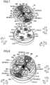
- FIG. 9is a diagram illustrating an exploded perspective view of a drive power transmission member of the adapter according to an embodiment.
- FIG. 10is a diagram illustrating a view of the state in which an engagement member of the adapter according to an embodiment is moved to a retracted position.
- FIG. 11is a diagram illustrating a view of the state in which the engagement member of the adapter according to an embodiment is moved to an advanced position.
- FIG. 12is a diagram illustrating a view for explaining the attachment of the adapter to the robot arm according to an embodiment.
- FIG. 13is a first diagram illustrating a view for explaining the attachment of the surgical instrument to the adapter according to an embodiment.
- FIG. 14is a second diagram illustrating a view for explaining the attachment of the surgical instrument to the adapter according to an embodiment.
- the robotic surgical system 100includes a remote control apparatus 10 and a patient-side apparatus 20 .
- the remote control apparatus 10is used to remotely operate medical equipment provided for the patient-side apparatus 20 .
- an operator Owho is a surgeon
- the remote control apparatus 10transmits the movement type instruction to the patient-side apparatus 20 via a controller 26 .
- the patient-side apparatus 20then handles the medical equipment, such as a surgical instrument 40 or an endoscope 50 attached to a robot arm 21 , in response to the movement type instruction transmitted from the remote control apparatus 10 .
- a minimally invasive operationis performed in this manner.
- the patient-side apparatus 20constitutes an interface through which a surgery is performed on a patient P.
- the patient-side apparatus 20is arranged beside a surgical table 30 on which the patient P lies.
- the patient-side apparatus 20has a plurality of robot arms 21 .
- An endoscope 50is attached to one of the robot arms 21 (i.e., the robot arm 21 ( 21 b )).
- Surgical instruments 40are attached to the other robot arms 21 ( 21 a ).
- the robot arms 21are supported by the same platform 23 .
- Each of the robot arms 21has a plurality of joints.
- a driving section including a servomotor and a position detector such as an encoderare provided for each joint.
- Each robot arm 21is configured to be controlled such that the medical equipment attached to the robot arm 21 make a desired movement in response to a driving signal given via the controller 26 .
- the platform 23is supported by a positioner 22 placed on the floor of the operating room.
- the positioner 22includes a column 24 having a lifting shaft adjustable in a vertical direction, and the lifting shaft is coupled to a base 25 having wheels and movable on the floor surface.
- the surgical instrument 40 as the medical equipmentis detachably attached to a distal end portion of the robot arm 21 a .
- the surgical instrument 40includes a housing 43 (see FIG. 4 ) attached to the robot arm 21 a , an elongated shaft 42 (see FIG. 4 ), and an end effector 41 (see FIG. 4 ) attached to a distal end portion of the shaft 42 .
- Examples of the end effector 41include, but are not limited to, a grasping forceps, scissors, a hook, a high-frequency knife, a snare wire, a clamp, and a stapler, and may include various types of treatment tools.
- each of the robot arms 21 aintroduces the surgical instrument 40 into the body of the patient P through a cannula (a trocar) retained on the body surface of the patient P.
- the end effector 41 of the surgical instrument 40is placed in the vicinity of the surgical site.
- the endoscope 50 as the medical equipmentis detachably attached to a distal end portion of the robot arm 21 b .
- the endoscope 50takes images in the body cavity of the patient P.
- the images takenare output to the remote control apparatus 10 .
- Examples of the endoscope 50include a 3D endoscope capable of taking three-dimensional images, and a 2D endoscope.
- the robot arm 21 bintroduces the endoscope 50 into the body of the patient P through a trocar retained on the body surface of the patient P.
- the endoscope 50is placed in the vicinity of the surgical site.
- the remote control apparatus 10constitutes an interface with the operator O.
- the remote control apparatus 10serves as a device through which the operator O operates the medical equipment attached to each robot arm 21 . That is, the remote control apparatus 10 is configured to be capable of transmitting, to the patient-side apparatus 20 , the movement type instruction that has been input by the operator O and that should be executed by the surgical instrument 40 and the endoscope 50 , via the controller 26 .
- the remote control apparatus 10is installed beside the surgical table 30 so that the operator can check the condition of the patient P while operating the master, for example.
- the remote control apparatus 10may be configured, for example, to wirelessly transmit the movement type instruction, and may be installed in a room different from the operating room where the surgical table 30 is placed.
- the term “movement type” to be performed by the surgical instrument 40may refer to the type of movement (a series of positions and orientations) of the surgical instrument 40 and the type of movement executed by the function of the respective surgical instruments 40 .
- the movement type to be performed by the surgical instrument 40includes positions of rolling and pitching of a wrist of the end effector 41 , and opening and closing the jaws.
- the movement type to be executed by the surgical instrument 40may include vibration of the high-frequency knife, specifically, a current supply to the high-frequency knife.
- the movement type to be performed by the surgical instrument 40may include tightening, and releasing from the tightening.
- the movement typemay include a movement of burning off a target site of the surgery, using a bipolar or a monopolar to which an electric current is supplied.
- Examples of the movement type to be performed by the endoscope 50include positioning, and determination of the orientation, of the tip end of the endoscope 50 , or setting of zoom magnification of the endoscope 50 .
- the remote control apparatus 10includes an operating handle 11 , an operation pedal unit 12 , a display unit 13 , and a control device 14 .
- the operating handle 11is intended to remotely operate the medical equipment attached to each robot arm 21 . Specifically, the operating handle 11 accepts the operation conducted by the operator O to control the medical equipment (i.e., the surgical instrument 40 and the endoscope 50 ).
- the operating handle 11includes two operating handles 11 arranged in the horizontal direction. Specifically, one of the two operating handles 11 is operated by the right hand of the operator O, and the other operating handle 11 is operated by the left hand of the operator O.
- the operating handle 11is arranged to extend from the back side to the front side of the remote control apparatus 10 .
- the operating handle 11is configured to be movable within a predetermined three-dimensional operation area A. Specifically, the operating handle 11 is configured to be movable up and down directions, the leftward and rightward directions, and the forward and backward directions.
- the remote control apparatus 10 and the patient-side apparatus 20constitute a master-slave system in controlling the movements of the robot arms 21 a and the robot arm 21 b .
- the operating handle 11serves as a master controlling element in the master-slave system
- the robot arms 21 a and the robot arm 21 b to which the medical equipment is attachedserve as slave moving elements.
- the movement of the robot arms 21 a or the robot arm 21 bis controlled so that the distal end portion of each robot arm 21 a (i.e., the end effector 41 of surgical instrument 40 ) or the distal end portion of the robot arm 21 b (i.e., the endoscope 50 ) will trace the movement of the operating handle 11 and shift accordingly.
- the patient-side apparatus 20is configured to control the movements of the respective robot arms 21 a according to a movement scale factor which has been set. For example, in a case in which the movement scale factor has been set to be 1 ⁇ 2, the end effector 41 of the surgical instrument 40 is controlled to shift by one half (1 ⁇ 2) of a distance by which the operating handle 11 has shifted. As a result, precise surgery can be accurately performed.
- the operation pedal unit 12includes a plurality of pedals for executing the function related to the medical equipment.
- the plurality of pedalsinclude a coagulation pedal, a cutting pedal, a camera pedal, and a clutch pedal.
- the plurality of pedalsare operated by the foot of the operator O.
- the coagulation pedalenables the operation of coagulating the surgical site using the surgical instrument 40 . Specifically, when the coagulation pedal is operated, a voltage for coagulation is applied to the surgical instrument 40 , thereby coagulating the surgical site.
- the cutting pedalenables the operation of cutting the surgical site using the surgical instrument 40 . Specifically, when the cutting pedal is operated, a voltage for the cutting is applied to the surgical instrument 40 , thereby cutting the surgical site.
- the camera pedalis used to change the position and orientation of the endoscope 50 taking images of the body cavity.
- the camera pedalvalidates the operation of the endoscope 50 through the operating handle 11 . That is, while the camera pedal is pressed down, the position and orientation of the endoscope 50 can be changed by using the operating handle 11 .
- the endoscope 50is operated using both of the left and right operating handles 11 .
- the endoscope 50rotates when the right and left operating handles 11 rotate about a midpoint between the left and right operating handles 11 .
- the endoscope 50moves forward when the left and right operating handles 11 are pushed forward.
- the endoscope 50moves backward when the left and right operating handles 11 are pulled backward.
- the endoscope 50moves up and down, and leftward and rightward when the left and right operating handles 11 are moved up and down, and leftward and rightward.
- the clutch pedalis used to temporarily block the connection for operation between the robot arm 21 and the operating handle 11 to stop the movement of the surgical instrument 40 .
- the robot arm 21 of the patient-side apparatus 20does not move even if the operating handle 11 is moved.
- the clutch pedalis pressed down to temporarily block the connection for operation so that the operating handle 11 can be returned to the center position.
- the clutch pedalis no longer pressed down, the robot arm 21 and the operating handle 11 are connected again, and the operating handle 11 can be operated again at around the center position.
- the display unit 13can display the images taken by the endoscope 50 .
- the display unit 13includes a scope type display unit or a non-scope type display unit.
- the scope type display unitis, for example, a display unit which an operator looks into.
- the non-scope type display unitrepresents a concept that includes an open display unit having a flat screen which an operator does not look into, just like a display of a common personal computer.
- a 3D image taken by the endoscope 50 attached to the robot arm 21 b of the patient-side apparatus 20is displayed.
- a 3D image taken by the endoscope 50 provided in the patient-side apparatus 20is displayed.
- a 2D image taken by the endoscope 50 provided in the patient-side apparatus 20may be displayed.
- the control device 14includes, for example, the control unit 141 including an arithmetic unit such as a CPU, a storage unit 142 including a memory such as a ROM and a RAM, and an image control unit 143 .
- the control device 14may be comprised of a single controller which provides centralized control, or may be configured as a plurality of controllers which work in cooperation with each other and provide distributed control.
- the control unit 141determines whether the movement type instruction input through the operating handle 11 is a movement type instruction to be executed by the robot arm 21 a , or a movement type instruction to be executed by the endoscope 50 , in accordance with the state of the operation pedal unit 12 .
- control unit 141determines that the movement type instruction input through the operating handle 11 is a movement type instruction to be executed by the surgical instrument 40 , the control unit 141 transmits this movement type instruction to the robot arm 21 a . In response, the robot arm 21 a is driven, as a result of which the operation of the surgical instrument 40 attached to the robot arm 21 a is controlled.
- control unit 141determines that the movement type instruction input through the operating handle 11 is a movement type instruction to be executed by the endoscope 50 , the control unit 141 transmits the movement type instruction to the robot arm 21 b . In response, the robot arm 21 b is driven, as a result of which the operation of the endoscope 50 attached to the robot arm 21 b is controlled.
- the storage unit 142stores, for example, control programs corresponding to the types of the surgical instrument 40 .
- the control unit 141reads the control program in accordance with the type of the surgical instrument 40 attached, thereby allowing the movement instruction entered through the operating handle 11 and/or operation pedal unit 12 of the remote control apparatus 10 to cause each surgical instrument 40 to perform a suitable operation.
- the image control unit 143transmits images taken by the endoscope 50 to the display unit 13 .
- the image control unit 143processes or corrects the image as needed.
- the robot arm 21is covered with a drape 70 because the robot arm 21 is used in a clean zone.
- a cleaning procedureis carried out to prevent surgery incisions and medical equipment from being infected and contaminated with pathogenic bacteria, foreign substances, or the like.
- a clean zone and a contaminated zonewhich is a zone other than the clean zone, are defined in this cleaning procedure.
- the surgical siteis positioned in the clean zone.
- Surgery team members, including the operator Otake good care so that only a disinfected object is placed in the clean zone during the surgery, and sterilize the object placed in the contaminated zone when it needs to be moved to the clean zone.
- the surgery team membersincluding the operator O, have put their hands in the contaminated zone, they sterilize their hands before they directly touch an object placed in the clean zone.
- the instrument to be used in the clean zoneis sterilized, or is covered with a sterilized drape 70 .
- the drape 70is positioned between the robotic arm 21 and the surgical instrument 40 .
- the drape 70is positioned between the adapter 60 and the robotic arm 21 .
- the adapter 60is attached to the attachment portion 211 of the robot arm 21 via the drape 70 . That is, the adapter 60 is a drape adapter for tucking the drape 70 between the adapter 60 and the robot arm 21 a .
- the surgical instrument 40is attached to the adapter 60 .
- the robot arm 21transmits power to the surgical instrument 40 via the adapter 60 in order to drive the end effector 41 of the surgical instrument 40 .
- the adapter 60includes a base 61 , a plurality of drive power transmission members 62 , guide rails 63 , a leading guide rail 64 , an electrode array 65 , and an arm engagement member 66 .
- the adapter 60includes a plurality of recesses 67 and a plurality of positioning holes 68 .
- a first surface 60 a of the adapter 60 toward the Z2 directionis attached to the robot arm 21 a .
- the surgical instrument 40is attached to a second surface 60 b of the adapter 60 toward the Z1 direction.
- the surgical instrument 40includes a plurality of driven sections 44 , two guide grooves 45 , two movable members 46 , a leading guide groove 47 , and an electrode array 48 .
- the drape 70has a main body 71 and an attachment portion 72 .
- the main body 71is formed to be like a film.
- the attachment portion 72is resin molded.
- the attachment portion 72has a through hole, through which the robot arm 21 a and the adapter 60 are engaged with each other.
- the through holemay be formed so as to correspond to each engaging portion.
- the through holemay be formed so as to correspond to a plurality of engaging portions.
- the adapter 60is attached to the attachment portion 211 of the robot arm 21 .
- the robot arm 21includes a driving member 212 , an engagement projecting portion 213 , and a boss 214 .
- the engagement projecting portion 213includes engagement projecting portions 213 a , 213 b , and 213 c . Two engagement projecting portions 213 b and two engagement projecting portions 213 c are provided.
- Each of the plurality of engagement projecting portions 213has a groove 2131 .
- the engagement projecting portions 213are intended for engagement with the adapter 60 .
- engagement portions 661 of an engagement member 66 of the adapter 60engages with the groove 2131 of a corresponding one of the engagement projecting portions 213 of the robot arm 21 .
- Each of the plurality of grooves 2131is open toward the Y2 direction.
- the plurality of driven sections 44 of the surgical instrument 40are driven to rotate, thereby actuating the end effector 41 .
- the driven sections 44 and the end effector 41are connected by one or more wires which pass through the shaft 42 .
- the one or more wiresare to be pulled by the rotation of the driven sections 44 .
- the end effector 41is actuated by pulling at least one of the one or more wires.
- the driven sections 44are connected to the shaft 42 by gears in the housing 43 .
- the rotation of the driven sections 44causes the shaft 42 to rotate.
- the rotation of one driven section 44causes the shaft 42 to rotate.
- the rotation of the other three driven sections 44actuates the end effector 41 .
- the four driven sections 44are arranged such that two driven sections are arranged toward the X direction, and the other two driven sections are arranged toward the Y direction.
- the guide groove 45extends along the Y direction. Two guide grooves 45 are provided so as to be opposed to each other in the X direction. The two guide grooves 45 are arranged approximately parallel to each other. The guide rails 63 of the adapter 60 are inserted into each of the guide grooves 45 , thereby guiding the attachment to the adapter 60 .
- the width of the guide groove 45changes as the movable member 46 moves in the X direction. That is, the width of the guide groove 45 increases as the movable member 46 moves toward the inside in the X direction. The width of the guide groove 45 decreases as the movable member 46 moves toward the outside in the X direction.
- the movable member 46is biased toward the direction (i.e., outward) which narrows the width of the guide groove 45 .
- the movable member 46is biased by a spring. Pushing of a button 461 by an operator causes the movable member 46 to move toward the direction (i.e., inward) which increases the width of the guide groove 45 .
- the leading guide groove 47extends along the Y direction.
- the leading guide groove 47is disposed between the two guide grooves 45 .
- the leading guide groove 47extends approximately parallel to the two guide grooves 45 .
- the leading guide groove 47is arranged approximately in the middle of the attachment surface 40 a in the X direction.
- the electrode array 48is connected to the robot arm 21 via the electrode array 65 of the adapter 60 .
- the electrode array 48is connected to a board provided in the housing 43 . That is, the board of the surgical instrument 40 and the robot arm 21 are connected to each other by the attachment of the surgical instrument 40 to the robot arm 21 via the adapter 60 .
- the board in the housing 43is used to manage the type of the surgical instrument 40 , the number of usage time of the surgical instrument 40 , and so on.
- the adapter 60is provided for detachably connecting the surgical instrument 40 to the robotic arm 21 a of the robotic surgical system 100 .
- the base 61includes a first surface 60 a for attachment to the robot arm 21 a , and a second surface 60 b to which the attachment surface 40 a of the surgical instrument 40 is attached.
- the drive power transmission members 62are rotatably disposed in the base 61 . Specifically, the drive power transmission members 62 are rotatable about a rotational axis extending in the Z direction. That is, the drive power transmission members 62 are rotatable about the rotational axis perpendicular to the first surface 60 a and the second surface 60 b .
- the drive power transmission members 62transmit the rotation of the plurality of driving members 212 , which are provided for the attachment portion 211 of the robot arm 21 a , to the plurality of driven sections 44 provided for the surgical instrument 40 .
- a multiple number of drive power transmission members 62are provided so as to correspond to the respective driving members 212 of the robot arm 21 a and the respective driven sections 44 of the surgical instrument 40 .
- the plurality of drive power transmission members 62are disposed at positions corresponding to the respective driving members 212 of the robot arm 21 a and the respective driven sections 44 of the surgical instrument 40 .
- the guide rails 63are formed on the second surface 60 b . Each of the guide rails 63 extends along the Y direction.
- the guide rails 63include two guide rails 63 provided so as to be opposed to each other in the X direction.
- the two guide rails 63are arranged approximately parallel to each other.
- the two guide rails 63are formed so as to correspond to the two guide grooves 45 arranged approximately parallel to each other in the attachment surface 40 a of the surgical instrument 40 .
- the guide grooves 45 in the attachment surface 40 aare brought to, and slid along, the respective guide rails 63 on the second surface 60 b , thereby guiding the surgical instrument 40 to a position where the plurality of drive power transmission members 62 correspond to the plurality of driven sections 44 provided in the attachment surface 40 a.
- the leading guide rail 64is formed on the second surface 60 b .
- the leading guide rail 64extends along the Y direction.
- the leading guide rail 64is disposed between the two guide rails 63 .
- the leading guide rail 64extends approximately parallel to the two guide rails 63 .
- the leading guide rail 64is arranged approximately in the middle of the second surface 60 b in the X direction.
- the leading guide rail 64is formed so as to correspond to the leading guide groove 47 formed in the attachment surface 40 a . That is, the leading guide rail 64 leads the two guide rails 63 in guiding the surgical instrument 40 .
- the electrode array 65is connected to the electrode array 48 of the surgical instrument 40 and the robot arm 21 .
- the arm engagement member 66engages with the engagement projecting portion 213 of the robot arm 21 . Specifically, the arm engagement member 66 engages with the engagement projecting portions 213 in the state where the engagement projecting portions 213 of the robot arm 21 are inserted, in the Z direction, in the recesses 67 formed in the first surface 60 a of the adaptor 60 . As illustrated in FIGS. 7 and 8 , the arm engagement member 66 includes an engagement member 661 , an operating member 662 , a bent portion 663 , a narrow width portion 664 , and a gripping portion 666 . The arm engagement member 66 is biased in the Y1 direction by a first biasing member 667 .
- the engagement member 661includes engagement portions 661 a , 661 b , and 661 c . Two engagement portions 661 b and two engagement portions 661 c are provided.
- the engagement member 661 of the arm engagement member 66is movable in the Y direction with respect to the base 61 of the adaptor 60 .
- the engagement member 661is moved by an operator or a user in the Y1 direction in the state where the engagement projecting portions 213 of the robot arm 21 are inserted in the recesses 67 of the adaptor 60 , the engagement member 661 is engaged with the engagement projecting portion 213 .
- the arm engagement member 66is moved in the Y2 direction, in the state where the engagement projecting portions 213 of the robot arm 21 are inserted in the recesses 67 of the adaptor 60 , the arm engagement member 66 is disengaged from the engagement projecting portion 213 .
- the engagement member 661 of the arm engagement member 66is movable between an advanced position (see FIG. 11 ), to which the engagement member 661 is advanced in the direction (i.e., the Y direction) intersecting with the direction (i.e., the Z direction) in which the first surface 60 a and the attachment portion 211 of the robot arm 21 a face each other, and a retracted position (see FIG. 10 ) where the engagement member 661 is retracted from the plurality of recesses 67 .
- the first biasing member 667provided between the base 61 and the engagement member 66 , biases the engagement member 661 in the direction from the retracted position to the advanced position (i.e., the Y1 direction).
- the operating member 662 of the arm engagement member 66is provided on the second surface 60 b of the base 61 , and is intended to move the engagement member 661 to the retracted position against the biasing force of the first biasing member 667 .
- the operating member 662is operated by being pushed in the Y2 direction by the operator.
- This configurationenables switching between the engaged state and the disengaged state of the engagement member 661 by moving the engagement member 661 along the direction intersecting with the direction in which the first surface 60 a and the attachment portion 211 of the robot arm 21 a face each other (i.e., along the first surface 60 a (i.e., in the Y direction) which is different from the engagement direction (i.e., the Z direction) of the adapter 60 and the robot arm 21 a ).
- the adapter 60can be stably fixed to the robot arm 21 a without the need to increase the biasing force of the first biasing member 667 with respect to the engagement member 661 .
- the adapter 60can be easily attached and detached to and from the robot arm 21 a . Consequently, the adapter 60 for detachably connecting the surgical instrument 40 to the robot arm 21 a of the robotic surgical system 100 can be easily attached and detached to and from the robot arm 21 a , and be stably fixed to the robot arm 21 a.
- the arm engagement member 66is configured such that the movement of the engagement member 661 by the operating member 662 is restricted in the state in which the first surface 60 a of the adapter 60 is attached to the attachment portion 211 of the robot arm 21 and the surgical instrument 40 is attached to the second surface 60 b .
- This configurationreduces the possibility that the robot arm 21 a and the adapter 60 are detached from each other in the state in which the surgical instrument 40 is attached. The surgical instrument 40 is therefore less likely to come off the robot arm 21 a together with the adapter 60 .
- the operating member 662protrudes toward the surgical instrument 40 from the second surface 60 b .
- the operating member 662is in contact with the surgical instrument 40 , and the movement of the operating member 662 is therefore restricted. That is, when the surgical instrument 40 is slid in the Y direction and attached to the adapter 60 , an edge portion, toward the Y1 direction, of the housing 43 of the surgical instrument 40 comes into contact with the operating member 662 .
- the surgical instrument 40once fixed to the adapter 60 , is no longer capable of moving in the Y direction, which restricts the movement of the operating member 662 in the Y direction, as well.
- the surgical instrument 40restricts the movement of the operating member 662 , which eliminates the need to provide another member for restricting the movement of the operating member 662 .
- the engagement member 661is configured to engage with the groove 2131 formed in each of the plurality of engagement projecting portions 213 of the robot arm 21 a .
- This configurationallows the engagement member 661 to be engaged with the grooves 2131 of the plurality of engagement projecting portions 213 in the state in which the plurality of engagement projecting portions 213 projecting from the attachment portion 211 of the robot arm 21 a are inserted in the plurality of recesses 67 of the adapter 60 .
- the adapter 60can thus be more stably fixed to the robot arm 21 a.
- the engagement projecting portion 213 a provided on the attachment portion 211 of the robot arm 21 a at a position near an edge portion toward the Y1 direction of the Y directionengages with the engagement portion 661 a of the arm engagement member 66 near an edge portion toward the Y1 direction of the Y direction.
- the two engagement projecting portions 213 b provided on the attachment portion 211 of the robot arm 21 a at positions near the middle in the Y directionrespectively engage with the two engagement portions 661 b of the arm engagement member 66 near the middle in the Y direction.
- the engagement member 661is configured such that the plurality of engagement portions 661 a to 661 c , which engage with the plurality of engagement projecting portions 213 of the robot arm 21 a , are integrally formed portions. This configuration contributes to reducing the number of parts, as compared to the case in which the plurality of engagement portions 661 a to 661 c which engage with the plurality of engagement projecting portions 213 are provided independently from one another.
- the operating member 662moves the plurality of engagement portions 661 a to 661 c in an integrated manner. This configuration enables switching between the engaged state and the disengaged state of the plurality of engagement portions 661 a to 661 c at once by operating the single operating member 662 .
- the adapter 60can thus be attached and detached to and from the robot arm 21 a more easily.
- the arm engagement member 66includes the engagement member 661 , the operating member 662 , the bent portion 663 , the narrow width portions 664 and 665 , and the gripping portion 666 , which are integrally formed to one another.
- the arm engagement member 66is made of a resin material, for example. The movement of the operating member 662 or the gripping portion 666 causes the plurality of engagement portions 661 a to 661 c to move in an integrated manner.
- the engagement member 661is at least partially deformable or bendable (for example, elastically or resiliently deformable) such that the engagement portions 661 a to 661 c are displaceable in the direction from the advanced position to the retracted position.
- the deformation of the engagement member 661can improve the dimensional accuracy of the engagement member 661 , which allows the engagement portions 661 a to 661 c to be engaged with reduced backlash.
- the bent portion 663is connected to a side of the engagement portion 661 a toward the Y2 direction.
- the bent portion 663is bent in the Z direction so as to be easily deformed (for example, elastically or resiliently deformed).
- the bent portion 663is bent in the Z direction to have two folds.
- the engagement portion 661 ais therefore easily displaceable in the Y direction.
- the bent portion 663may be referred to as a deformable portion (for example, an elastically or resiliently deformable portion) for the engagement portion 661 a.
- the narrow width portion 664is connected to a side of the engagement portion 661 b toward the middle in the X direction.
- the narrow width portion 664has a narrow width in the direction intersecting with the extension direction of the narrow width portion 664 .
- the engagement portion 661 bis therefore easily deformable in the Y direction.
- the narrow width portion 664may be referred to as a deformable portion (for example, an elastically or resiliently deformable portion) of the engagement portion 661 b .
- the narrow width portion 664is arranged at a position that avoids contact with the electrode array 65 .
- the narrow width portion 665is connected to a side of the engagement portion 661 c toward the middle in the X direction.
- the narrow width portion 665has a narrow width in the direction intersecting with the extension direction of the narrow width portion 665 .
- the engagement portion 661 cis therefore easily deformable in the Y direction.
- the narrow width portion 665may be referred to as a deformable portion (for example, an elastically or resiliently deformable portion) for the engagement portion 661 c .
- the narrow width portion 665is arranged at a position that avoids contact with the electrode array 65 .
- bent portion 663 and the narrow width portions 664 and 665contribute to easily deforming the engagement member 661 .
- the gripping portion 666is provided at an edge portion of the arm engagement member 66 toward the Y2 direction.
- the gripping portion 666when pulled in the Y2 direction by an operator, causes the engagement portions 661 a to 661 c to move in the Y2 direction.
- the gripping portion 666is therefore intended to release the engagement portions 661 a to 661 c from the engaged state.
- the gripping portion 666is arranged at a position that avoids contact with the electrode array 65 .
- the first biasing member 667is provided at approximately the center of the adapter 60 as viewed in the Z direction.
- the first biasing member 667biases the engagement member 66 in the Y1 direction.
- the first biasing member 667is comprised, for example, of a spring.
- a plurality of recesses 67are formed in the first surface 60 a of the base 61 . That is, the adapter 60 is fixed to the robot arm 21 a by the engagement at a plurality of positions. There are four or more recesses 67 provided. This configuration allows the adapter 60 to be attached to the robot arm 21 a at four or more engaging positions. The adapter 60 can thus be more stably fixed to the robot arm 21 a . For example, there are five recesses 67 provided.
- the plurality of recesses 67are arranged at substantially equal intervals on the outer peripheral side of the first surface 60 a .
- the engaging positions of the adapter 60 with respect to the robot arm 21 aare therefore well balanced on the first surface 60 a of the adapter 60 .
- the adapter 60can thus be more stably fixed to the robot arm 21 a.
- the positioning holes 68are formed in the first surface 60 a .
- the bosses 214 of the robot arm 21are fitted in the positioning holes 68 .
- a multiple number of positioning holes 68are formed.
- the positioning holes 68are provided in the vicinity of an edge of the first surface 60 a toward the Y1 direction.
- the drive power transmission member 62includes a first member 621 and a second member 622 movable with respect to the first member 621 via a second biasing member 623 .
- the first member 621has a recess 621 a in which the second member 622 is fitted, and an engaging portion 621 b which engages with the second member 622 .
- the second member 622has a recess 622 a which receives the second biasing member 623 , and an engaging portion 622 b which engages with the first member 621 .
- the first member 621 and the second member 622are fitted to each other in the Z direction with the second biasing member 623 interposed therebetween.
- the first member 621is disposed toward the second surface 60 b (toward the Z1 direction).
- the second member 622is disposed toward the first surface 60 a (toward the Z2 direction).
- the second biasing member 623biases the first member 621 in the Z1 direction with respect to the second member 622 .
- the second biasing member 623is comprised, for example, of a spring.
- the second member 622is flush with the first surface 60 a in the Z direction.
- the second member 622is disposed so as not to be movable in the Z direction with respect to the base 61 .
- the first member 621is disposed so as to be movable in the Z direction with respect to the base 61 .
- the first member 621can be depressed in the direction in which the rotational axis of the first member 621 extends (i.e., the Z direction) so as not to inhibit the movement of the surgical instrument 40 .
- the first member 621is configured to rotate together with the rotation of the second member 622 about the rotational axis in the Z direction. Specifically, the engaging portion 621 b formed on the inner peripheral portion of the first member 621 engages with the engaging portion 622 b formed on the outer periphery portion of the second member 622 . The engaging portion 621 b of the first member 621 protrudes inward from the recess 621 a . The engaging portion 622 b of the second member 622 is recessed inward from the outer periphery portion of the second member 622 .
- the engaging portion 621 b of the first member 621 and the engaging portion 622 b of the second member 622are kept engaged with each other even when the first member 621 moves in the Z direction with respect to the second member 622 . That is, the first member 621 is configured to rotate together with the second member 622 , irrespective of the position of the first member 621 in the Z direction with respect to the second member 622 . Thus, when the second member 622 is rotated by the rotation of the driving member 212 of the robot arm 21 , the first member 621 also rotates. The rotation of the driving member 212 of the robot arm 21 is transmitted in this manner to the driven section 44 of the surgical instrument 40 which engages with the first member 621 .
- the engagement member 661is configured such that each of the engagement portions 661 a to 661 c has a thickness which gradually decreases toward the distal end. This means that the distal end of each of the engagement portions 661 a to 661 c has an inclined surface. The inclined surfaces of the engagement portions 661 a to 661 c are inserted in the engagement positions. This configuration allows the engagement portions 661 a to 661 c to be engaged with reduced backlash without improving the dimensional accuracy of the engagement member 661 .
- the adapter 60is attached to the robot arm 21 a with the drape 70 covering the robot arm 21 a .
- the adapter 60is moved toward the robot arm 21 a in the Z direction and attached to the robot arm 21 a . That is, the adapter 60 is moved in the direction perpendicular to the first surface 60 a and the second surface 60 b (i.e., in the Z direction) to be attached to the attachment portion 211 of the robot arm 21 a .
- the above configurationreduces the possibility that the drape 70 tucked between the adapter 60 and the robot arm 21 a is dragged and the drape 70 is deviated from the right position.
- the surgical instrument 40is attached to the adapter 60 which has been attached to the robot arm 21 a .
- the surgical instrument 40is attached to the adapter 60 by moving the surgical instrument 40 in the Y direction along the leading guide rail 64 and the two guide rails 63 of the adapter 60 .
- the surgical instrument 40is attached to the robot arm 21 a via the adapter 60 in this manner.
- the surgical instrument 40In detaching the surgical instrument 40 from the robot arm 21 a , the surgical instrument 40 is slid in the Y2 direction while pushing the button 461 of the movable member 46 of the surgical instrument 40 , thereby detaching the surgical instrument 40 from the adapter 60 .
- the operating member 662is pushed in the Y2 direction in the state in which the surgical instrument 40 is detached from the adapter 60 , thereby causing the adapter 60 to be disengaged from the robot arm 21 a .
- the adapter 60is moved in the Z1 direction, so that the adapter 60 is removed from the robot arm 21 a.
- the adapter and the attachment portion of the robot armare engaged with each other by the engagement member at five engaging positions
- the adapter and the attachment portion of the robot armmay be engaged with each other by the engagement member at a plurality of engaging positions other than five.
- the shape of the adapter in plan viewmay not have to be approximately a circular shape.
- the adaptermay have a rectangular shape in plan view.
- the adapterhas four drive power transmission members has been described in the above embodiment, but this is a non-limiting example.
- the adaptermay have a plurality of drive power transmission members other than four.
- the surgical instrumentmay be attached and detached to and from the adapter by sliding the surgical instrument along the second surface of the adapter.
- the surgical instrumentmay be attached and detached to and from the adapter by moving the surgical instrument in a direction different from the direction along the second surface of the adapter.
- the surgical instrumentmay be attached and detached to and from the adapter by moving the surgical instrument in a direction perpendicular to the second surface of the adapter.
- the adapter and the drapeare independent from each other has been described in the above embodiment, but this is a non-limiting example.
- the adapter and the drapemay be an integrally formed member.
Landscapes
- Health & Medical Sciences (AREA)
- Surgery (AREA)
- Engineering & Computer Science (AREA)
- Life Sciences & Earth Sciences (AREA)
- Molecular Biology (AREA)
- Biomedical Technology (AREA)
- Heart & Thoracic Surgery (AREA)
- Medical Informatics (AREA)
- Robotics (AREA)
- Animal Behavior & Ethology (AREA)
- General Health & Medical Sciences (AREA)
- Public Health (AREA)
- Veterinary Medicine (AREA)
- Nuclear Medicine, Radiotherapy & Molecular Imaging (AREA)
- Manipulator (AREA)
Abstract
Description
Claims (16)
Applications Claiming Priority (2)
| Application Number | Priority Date | Filing Date | Title |
|---|---|---|---|
| JP2018159331AJP6745306B2 (en) | 2018-08-28 | 2018-08-28 | Adapter and connection method |
| JP2018-159331 | 2018-08-28 |
Publications (2)
| Publication Number | Publication Date |
|---|---|
| US20200069297A1 US20200069297A1 (en) | 2020-03-05 |
| US11944280B2true US11944280B2 (en) | 2024-04-02 |
Family
ID=69639276
Family Applications (1)
| Application Number | Title | Priority Date | Filing Date |
|---|---|---|---|
| US16/542,264Active2041-11-27US11944280B2 (en) | 2018-08-28 | 2019-08-15 | Adapter, surgical instrument set, and method for connecting surgical instrument |
Country Status (2)
| Country | Link |
|---|---|
| US (1) | US11944280B2 (en) |
| JP (1) | JP6745306B2 (en) |
Cited By (1)
| Publication number | Priority date | Publication date | Assignee | Title |
|---|---|---|---|---|
| US20240138831A1 (en)* | 2018-09-21 | 2024-05-02 | Covidien Lp | Hand-held surgical instruments |
Families Citing this family (5)
| Publication number | Priority date | Publication date | Assignee | Title |
|---|---|---|---|---|
| JP6745306B2 (en)* | 2018-08-28 | 2020-08-26 | 株式会社メディカロイド | Adapter and connection method |
| JP7350684B2 (en)* | 2020-03-25 | 2023-09-26 | 株式会社メディカロイド | electrosurgical instruments |
| CN116172707A (en)* | 2021-11-29 | 2023-05-30 | 深圳康诺思腾科技有限公司 | Connection structure of instrument driver and sliding arm and surgical robot |
| DE102022131663B4 (en)* | 2022-11-30 | 2025-08-14 | Karl Storz Se & Co. Kg | Interface for an electrosurgical instrument and surgical system |
| FR3154305A1 (en)* | 2023-10-24 | 2025-04-25 | Quantum Surgical | Tool changing system for minimally invasive robotic medical interventions |
Citations (79)
| Publication number | Priority date | Publication date | Assignee | Title |
|---|---|---|---|---|
| US3973179A (en)* | 1974-08-23 | 1976-08-03 | The Black And Decker Manufacturing Company | Modular cordless tools |
| US4976173A (en)* | 1987-02-24 | 1990-12-11 | Yang Tai Her | Manual electric tool |
| US5033552A (en)* | 1990-07-24 | 1991-07-23 | Hu Cheng Te | Multi-function electric tool |
| US5467911A (en)* | 1993-04-27 | 1995-11-21 | Olympus Optical Co., Ltd. | Surgical device for stapling and fastening body tissues |
| US5478351A (en)* | 1992-06-24 | 1995-12-26 | Microsurge, Inc. | Endoscopic surgical tool with handle and detachable tool assembly |
| US6331181B1 (en)* | 1998-12-08 | 2001-12-18 | Intuitive Surgical, Inc. | Surgical robotic tools, data architecture, and use |
| US20050021018A1 (en)* | 2001-04-19 | 2005-01-27 | Intuitive Surgical, Inc., A Delaware Corporation | Robotic surgical tool with ultrasound cauterizing and cutting instrument |
| US20050100867A1 (en)* | 2001-03-14 | 2005-05-12 | Alexander Hilscher | Method and device for cleaning teeth |
| US20060235436A1 (en)* | 1996-12-12 | 2006-10-19 | Intuitive Surgical Inc. | Sterile surgical adaptor |
| US20090182193A1 (en)* | 2008-01-10 | 2009-07-16 | Power Medical Interventions, Inc. | Imaging System For A Surgical Device |
| US20090312603A1 (en)* | 2008-06-17 | 2009-12-17 | Usgi Medical, Inc. | Endoscopic tissue anchor deployment |
| US7666191B2 (en) | 1996-12-12 | 2010-02-23 | Intuitive Surgical, Inc. | Robotic surgical system with sterile surgical adaptor |
| US20100069833A1 (en)* | 2008-05-06 | 2010-03-18 | Corindus Ltd. | Catheter system |
| US20100170519A1 (en)* | 2008-11-07 | 2010-07-08 | Hansen Medical, Inc. | Sterile interface apparatus |
| US20100198220A1 (en)* | 2009-02-05 | 2010-08-05 | Ethicon Endo-Surgery, Inc. | Surgical instruments and components for use in sterile environments |
| US20100274087A1 (en)* | 2007-06-13 | 2010-10-28 | Intuitive Surgical Operations, Inc. | Medical robotic system with coupled control modes |
| WO2011037394A2 (en)* | 2009-09-23 | 2011-03-31 | 주식회사 이턴 | Sterile adapter, fastening structure of wheels, and fastening structure of surgical instrument |
| US20110218551A1 (en)* | 1996-12-12 | 2011-09-08 | Intuitive Surgical Operations, Inc. | Instrument interface of a robotic surgical system |
| US20110290855A1 (en)* | 2008-02-14 | 2011-12-01 | Ethicon Endo-Surgery, Inc. | Robotically-controlled disposable motor-driven loading unit |
| US20120239060A1 (en)* | 2005-12-20 | 2012-09-20 | Intuitive Surgical Operations, Inc. | Disposable Sterile Surgical Adaptor |
| US8277473B2 (en)* | 2007-04-03 | 2012-10-02 | Terumo Kabushiki Kaisha | Manipulator system and control apparatus |
| US8353436B2 (en)* | 2009-05-06 | 2013-01-15 | Covidien Lp | Pin locking mechanism for a surgical instrument |
| US20130098968A1 (en)* | 2011-10-25 | 2013-04-25 | Tyco Healthcare Group Lp | Apparatus For Endoscopic Procedures |
| US20130274657A1 (en)* | 2010-09-17 | 2013-10-17 | Corindus, Inc. | Wheel for robotic catheter system drive mechanism |
| US20130296886A1 (en)* | 1995-06-07 | 2013-11-07 | Sri International | Surgical manipulator for a telerobotic system |
| US20140005679A1 (en)* | 2012-06-28 | 2014-01-02 | Ethicon Endo-Surgery, Inc. | Surgical instrument system including replaceable end effectors |
| US20140114334A1 (en)* | 2012-10-22 | 2014-04-24 | Ethicon Endo-Surgery, Inc. | Flexible harmonic waveguides/blades for surgical instruments |
| US20140249557A1 (en)* | 2013-03-01 | 2014-09-04 | Ethicon Endo-Surgery, Inc. | Thumbwheel switch arrangements for surgical instruments |
| US20140277334A1 (en)* | 2013-03-14 | 2014-09-18 | Hansen Medical, Inc. | Active drives for robotic catheter manipulators |
| US20140309666A1 (en)* | 2013-04-16 | 2014-10-16 | Ethicon Endo-Surgery, Inc. | Powered linear surgical stapler |
| US20150150547A1 (en)* | 2013-12-04 | 2015-06-04 | Covidien Lp | Adapter assembly for interconnecting surgical devices and surgical attachments, and surgical systems thereof |
| US20150257841A1 (en)* | 2014-03-17 | 2015-09-17 | Intuitive Surgical Operations, Inc. | Latch release for surgical instrument |
| US20160095585A1 (en)* | 2014-10-07 | 2016-04-07 | Covidien Lp | Handheld electromechanical surgical system |
| US20160118201A1 (en)* | 2014-10-22 | 2016-04-28 | Covidien Lp | Surgical instruments and switch assemblies thereof |
| US20160175062A1 (en)* | 2013-08-05 | 2016-06-23 | Intuitive Surgical Operations, Inc. | Devices, systems, and methods for surgical instrument reprocessing |
| US20170065365A1 (en)* | 2013-10-24 | 2017-03-09 | Auris Surgical Robotics, Inc. | Instrument Device Manipulator with Surgical Tool De-Articulation |
| US20170189020A1 (en)* | 2015-12-30 | 2017-07-06 | Ethicon Endo-Surgery, Llc | Surgical instruments with separable motors and motor control circuits |
| US20170196566A1 (en)* | 2016-01-13 | 2017-07-13 | Covidien Lp | Adapter assembly including a removable trocar assembly |
| US20170281218A1 (en)* | 2016-04-04 | 2017-10-05 | Ethicon Endo-Surgery, Llc | Surgical instrument with motorized articulation drive in shaft rotation knob |
| WO2017205333A1 (en)* | 2016-05-26 | 2017-11-30 | Covidien Lp | Robotic surgical assemblies |
| US20170367782A1 (en)* | 2015-09-09 | 2017-12-28 | Auris Surgical Robotics, Inc. | Instrument device manipulator with back-mounted tool attachment mechanism |
| US20180049836A1 (en)* | 2016-08-16 | 2018-02-22 | Ethicon Endo-Surgery, Llc | Robotics Tool Bailouts |
| US20180168753A1 (en)* | 2016-12-20 | 2018-06-21 | Verb Surgical Inc. | Sterile adapters with a tool seat for use in a robotic surgical system |
| US20180250002A1 (en)* | 2017-03-03 | 2018-09-06 | Covidien Lp | Powered surgical devices having tissue sensing function |
| US20180271604A1 (en)* | 2017-03-26 | 2018-09-27 | Verb Surgical Inc. | Coupler to attach robotic arm to surgical table |
| US20180304389A1 (en)* | 2015-10-16 | 2018-10-25 | Medical Microinstruments S.p.A. | Method of manufacturing for a medical instrument |
| US20190000577A1 (en)* | 2017-06-29 | 2019-01-03 | Ethicon Llc | System for controlling articulation forces |
| US10182816B2 (en)* | 2015-02-27 | 2019-01-22 | Ethicon Llc | Charging system that enables emergency resolutions for charging a battery |
| US20190038279A1 (en)* | 2017-08-03 | 2019-02-07 | Ethicon Llc | Surgical system shaft interconnection |
| US20190038281A1 (en)* | 2017-08-03 | 2019-02-07 | Ethicon Llc | Method for operating a surgical system bailout |
| US20190175287A1 (en)* | 2017-12-11 | 2019-06-13 | Auris Health, Inc. | Systems and methods for instrument based insertion architectures |
| US20190206565A1 (en)* | 2017-12-28 | 2019-07-04 | Ethicon Llc | Method for operating surgical instrument systems |
| US20190216554A1 (en)* | 2018-01-12 | 2019-07-18 | SS Innovations China Co. Ltd. | Sterile adapter assembly for a robotic surgical system |
| US20190261991A1 (en)* | 2015-02-27 | 2019-08-29 | Ethicon Llc | Modular stapling assembly |
| US10426468B2 (en)* | 2015-04-22 | 2019-10-01 | Covidien Lp | Handheld electromechanical surgical system |
| US20200061847A1 (en)* | 2016-12-13 | 2020-02-27 | Think Surgical, Inc. | Quick release coupler |
| US20200069385A1 (en)* | 2018-08-28 | 2020-03-05 | Medicaroid Corporation | Adaptor and method of attaching surgical instrument to robot arm through adaptor |
| US20200069381A1 (en)* | 2018-08-28 | 2020-03-05 | Medicaroid Corporation | Surgical instrument, robotic surgical system, and method of detaching surgical instrument attached to robot arm of robotic surgical system through adaptor |
| US20200069297A1 (en)* | 2018-08-28 | 2020-03-05 | Medicaroid Corporation | Adapter, surgical instrument set, and method for connecting surgical instrument |
| US20200069380A1 (en)* | 2018-08-28 | 2020-03-05 | Medicaroid Corporation | Robotic surgical instrument, method of assembling the same, and robotic surgical system |
| EP3232973B1 (en)* | 2014-12-19 | 2020-04-01 | DistalMotion SA | Sterile interface for articulated surgical instruments |
| US10779822B2 (en)* | 2008-02-14 | 2020-09-22 | Ethicon Llc | System including a surgical cutting and fastening instrument |
| US10780539B2 (en)* | 2011-05-27 | 2020-09-22 | Ethicon Llc | Stapling instrument for use with a robotic system |
| US20200305990A1 (en)* | 2019-03-28 | 2020-10-01 | Medicaroid Corporation | Adaptor and robotic surgical system |
| US20200305852A1 (en)* | 2019-03-28 | 2020-10-01 | Medicaroid Corporation | Adapter, robotic surgical system, and adapter attaching method |
| US20200305991A1 (en)* | 2019-03-28 | 2020-10-01 | Medicaroid Corporation | Method of fixing surgical instrument to robot arm |
| US10863983B2 (en)* | 2016-05-27 | 2020-12-15 | Olympus Corporation | Medical stapler |
| US20200405411A1 (en)* | 2019-06-28 | 2020-12-31 | Auris Health, Inc. | Patient introducer for a robotic system |
| US20210093398A1 (en)* | 2019-09-27 | 2021-04-01 | Medicaroid Corporation | Adapter set, adapter, and method of mounting surgical instrument on robot arm through adapter |
| US20210113283A1 (en)* | 2019-10-21 | 2021-04-22 | Medicaroid Corporation | Robotic surgical apparatus, surgical instrument, and method of attaching surgical instrument to robot arm |
| US20210220001A1 (en)* | 2020-01-22 | 2021-07-22 | Covidien Lp | Drive and articulation mechanisms for surgical instruments for use in robotic surgical systems |
| US20210401531A1 (en)* | 2018-08-28 | 2021-12-30 | Medicaroid Corporation | Sterile drape, instrument attachment set for attaching surgical instrument, and method for attaching surgical instrument to robot arm |
| US11369386B2 (en)* | 2019-06-27 | 2022-06-28 | Auris Health, Inc. | Systems and methods for a medical clip applier |
| US20220226057A1 (en)* | 2021-01-20 | 2022-07-21 | Ethicon Llc | Surgical tools with proximally mounted, cable based actuation systems |
| US20220233257A1 (en)* | 2017-12-19 | 2022-07-28 | Cilag Gmbh International | Method for determining the position of a rotatable jaw of a surgical instrument attachment assembly |
| US11490972B2 (en)* | 2018-08-28 | 2022-11-08 | Medicaroid Corporation | Driver interface, robotic surgical system, and method of detecting attachment of drape to driver interface |
| US11510669B2 (en)* | 2020-09-29 | 2022-11-29 | Covidien Lp | Hand-held surgical instruments |
| US11523509B2 (en)* | 2016-05-26 | 2022-12-06 | Covidien Lp | Instrument drive units |
| US20230277268A1 (en)* | 2022-03-07 | 2023-09-07 | Cilag Gmbh International | Arm drape assembly for robotic surgical system |
Family Cites Families (2)
| Publication number | Priority date | Publication date | Assignee | Title |
|---|---|---|---|---|
| JP5043414B2 (en)* | 2005-12-20 | 2012-10-10 | インテュイティブ サージカル インコーポレイテッド | Aseptic surgical adapter |
| DE102014117408A1 (en)* | 2014-11-27 | 2016-06-02 | avateramedical GmBH | Device for robotic surgery |
- 2018
- 2018-08-28JPJP2018159331Apatent/JP6745306B2/enactiveActive
- 2019
- 2019-08-15USUS16/542,264patent/US11944280B2/enactiveActive
Patent Citations (88)
| Publication number | Priority date | Publication date | Assignee | Title |
|---|---|---|---|---|
| US3973179A (en)* | 1974-08-23 | 1976-08-03 | The Black And Decker Manufacturing Company | Modular cordless tools |
| US4976173A (en)* | 1987-02-24 | 1990-12-11 | Yang Tai Her | Manual electric tool |
| US5033552A (en)* | 1990-07-24 | 1991-07-23 | Hu Cheng Te | Multi-function electric tool |
| US5478351A (en)* | 1992-06-24 | 1995-12-26 | Microsurge, Inc. | Endoscopic surgical tool with handle and detachable tool assembly |
| US5467911A (en)* | 1993-04-27 | 1995-11-21 | Olympus Optical Co., Ltd. | Surgical device for stapling and fastening body tissues |
| US20130296886A1 (en)* | 1995-06-07 | 2013-11-07 | Sri International | Surgical manipulator for a telerobotic system |
| US8998799B2 (en) | 1996-12-12 | 2015-04-07 | Intuitive Surgical Operations, Inc. | Sterile surgical adaptor |
| US20060235436A1 (en)* | 1996-12-12 | 2006-10-19 | Intuitive Surgical Inc. | Sterile surgical adaptor |
| US20110218551A1 (en)* | 1996-12-12 | 2011-09-08 | Intuitive Surgical Operations, Inc. | Instrument interface of a robotic surgical system |
| US8216250B2 (en) | 1996-12-12 | 2012-07-10 | Intuitive Surgical Operations, Inc. | Sterile surgical adaptor |
| US7666191B2 (en) | 1996-12-12 | 2010-02-23 | Intuitive Surgical, Inc. | Robotic surgical system with sterile surgical adaptor |
| US7699855B2 (en)* | 1996-12-12 | 2010-04-20 | Intuitive Surgical Operations, Inc. | Sterile surgical adaptor |
| US8105338B2 (en) | 1996-12-12 | 2012-01-31 | Intuitive Surgical Operations, Inc. | Sterile surgical adaptor |
| US6331181B1 (en)* | 1998-12-08 | 2001-12-18 | Intuitive Surgical, Inc. | Surgical robotic tools, data architecture, and use |
| US8142447B2 (en) | 1998-12-08 | 2012-03-27 | Intuitive Surgical Operations Inc. | Mechanical actuator interface system for robotic surgical tools |
| US20050100867A1 (en)* | 2001-03-14 | 2005-05-12 | Alexander Hilscher | Method and device for cleaning teeth |
| US20050021018A1 (en)* | 2001-04-19 | 2005-01-27 | Intuitive Surgical, Inc., A Delaware Corporation | Robotic surgical tool with ultrasound cauterizing and cutting instrument |
| US20120239060A1 (en)* | 2005-12-20 | 2012-09-20 | Intuitive Surgical Operations, Inc. | Disposable Sterile Surgical Adaptor |
| US8277473B2 (en)* | 2007-04-03 | 2012-10-02 | Terumo Kabushiki Kaisha | Manipulator system and control apparatus |
| US20100274087A1 (en)* | 2007-06-13 | 2010-10-28 | Intuitive Surgical Operations, Inc. | Medical robotic system with coupled control modes |
| US20090182193A1 (en)* | 2008-01-10 | 2009-07-16 | Power Medical Interventions, Inc. | Imaging System For A Surgical Device |
| US20110290855A1 (en)* | 2008-02-14 | 2011-12-01 | Ethicon Endo-Surgery, Inc. | Robotically-controlled disposable motor-driven loading unit |
| US10779822B2 (en)* | 2008-02-14 | 2020-09-22 | Ethicon Llc | System including a surgical cutting and fastening instrument |
| US20100069833A1 (en)* | 2008-05-06 | 2010-03-18 | Corindus Ltd. | Catheter system |
| US20090312603A1 (en)* | 2008-06-17 | 2009-12-17 | Usgi Medical, Inc. | Endoscopic tissue anchor deployment |
| US20100170519A1 (en)* | 2008-11-07 | 2010-07-08 | Hansen Medical, Inc. | Sterile interface apparatus |
| US20100198220A1 (en)* | 2009-02-05 | 2010-08-05 | Ethicon Endo-Surgery, Inc. | Surgical instruments and components for use in sterile environments |
| US8353436B2 (en)* | 2009-05-06 | 2013-01-15 | Covidien Lp | Pin locking mechanism for a surgical instrument |
| WO2011037394A2 (en)* | 2009-09-23 | 2011-03-31 | 주식회사 이턴 | Sterile adapter, fastening structure of wheels, and fastening structure of surgical instrument |
| US20130274657A1 (en)* | 2010-09-17 | 2013-10-17 | Corindus, Inc. | Wheel for robotic catheter system drive mechanism |
| US10780539B2 (en)* | 2011-05-27 | 2020-09-22 | Ethicon Llc | Stapling instrument for use with a robotic system |
| US20130098968A1 (en)* | 2011-10-25 | 2013-04-25 | Tyco Healthcare Group Lp | Apparatus For Endoscopic Procedures |
| US20140005679A1 (en)* | 2012-06-28 | 2014-01-02 | Ethicon Endo-Surgery, Inc. | Surgical instrument system including replaceable end effectors |
| US20140114334A1 (en)* | 2012-10-22 | 2014-04-24 | Ethicon Endo-Surgery, Inc. | Flexible harmonic waveguides/blades for surgical instruments |
| US20140249557A1 (en)* | 2013-03-01 | 2014-09-04 | Ethicon Endo-Surgery, Inc. | Thumbwheel switch arrangements for surgical instruments |
| US20140277334A1 (en)* | 2013-03-14 | 2014-09-18 | Hansen Medical, Inc. | Active drives for robotic catheter manipulators |
| US20140309666A1 (en)* | 2013-04-16 | 2014-10-16 | Ethicon Endo-Surgery, Inc. | Powered linear surgical stapler |
| US20140305992A1 (en)* | 2013-04-16 | 2014-10-16 | Ethicon Endo-Surgery, Inc. | Modular motor driven surgical instruments with status indication arrangements |
| US20160175062A1 (en)* | 2013-08-05 | 2016-06-23 | Intuitive Surgical Operations, Inc. | Devices, systems, and methods for surgical instrument reprocessing |
| US9713509B2 (en) | 2013-10-24 | 2017-07-25 | Auris Surgical Robotics, Inc. | Instrument device manipulator with back-mounted tool attachment mechanism |
| US20170065365A1 (en)* | 2013-10-24 | 2017-03-09 | Auris Surgical Robotics, Inc. | Instrument Device Manipulator with Surgical Tool De-Articulation |
| US20150150547A1 (en)* | 2013-12-04 | 2015-06-04 | Covidien Lp | Adapter assembly for interconnecting surgical devices and surgical attachments, and surgical systems thereof |
| US20160361131A1 (en)* | 2014-03-17 | 2016-12-15 | Intuitive Surgical Operations, Inc. | Coupler to Transfer Motion to Surgical Instrument From Teleoperated Actuator |
| US20150257841A1 (en)* | 2014-03-17 | 2015-09-17 | Intuitive Surgical Operations, Inc. | Latch release for surgical instrument |
| US20160095585A1 (en)* | 2014-10-07 | 2016-04-07 | Covidien Lp | Handheld electromechanical surgical system |
| US20160118201A1 (en)* | 2014-10-22 | 2016-04-28 | Covidien Lp | Surgical instruments and switch assemblies thereof |
| EP3232973B1 (en)* | 2014-12-19 | 2020-04-01 | DistalMotion SA | Sterile interface for articulated surgical instruments |
| US20190261991A1 (en)* | 2015-02-27 | 2019-08-29 | Ethicon Llc | Modular stapling assembly |
| US10182816B2 (en)* | 2015-02-27 | 2019-01-22 | Ethicon Llc | Charging system that enables emergency resolutions for charging a battery |
| US10426468B2 (en)* | 2015-04-22 | 2019-10-01 | Covidien Lp | Handheld electromechanical surgical system |
| US20170367782A1 (en)* | 2015-09-09 | 2017-12-28 | Auris Surgical Robotics, Inc. | Instrument device manipulator with back-mounted tool attachment mechanism |
| US20180304389A1 (en)* | 2015-10-16 | 2018-10-25 | Medical Microinstruments S.p.A. | Method of manufacturing for a medical instrument |
| US20170189020A1 (en)* | 2015-12-30 | 2017-07-06 | Ethicon Endo-Surgery, Llc | Surgical instruments with separable motors and motor control circuits |
| US20170196566A1 (en)* | 2016-01-13 | 2017-07-13 | Covidien Lp | Adapter assembly including a removable trocar assembly |
| US20170281218A1 (en)* | 2016-04-04 | 2017-10-05 | Ethicon Endo-Surgery, Llc | Surgical instrument with motorized articulation drive in shaft rotation knob |
| US11523509B2 (en)* | 2016-05-26 | 2022-12-06 | Covidien Lp | Instrument drive units |
| US20200315730A1 (en)* | 2016-05-26 | 2020-10-08 | Covidien Lp | Robotic surgical assemblies |
| WO2017205333A1 (en)* | 2016-05-26 | 2017-11-30 | Covidien Lp | Robotic surgical assemblies |
| US10863983B2 (en)* | 2016-05-27 | 2020-12-15 | Olympus Corporation | Medical stapler |
| US20180049836A1 (en)* | 2016-08-16 | 2018-02-22 | Ethicon Endo-Surgery, Llc | Robotics Tool Bailouts |
| US20200061847A1 (en)* | 2016-12-13 | 2020-02-27 | Think Surgical, Inc. | Quick release coupler |
| US20180168753A1 (en)* | 2016-12-20 | 2018-06-21 | Verb Surgical Inc. | Sterile adapters with a tool seat for use in a robotic surgical system |
| US20180250002A1 (en)* | 2017-03-03 | 2018-09-06 | Covidien Lp | Powered surgical devices having tissue sensing function |
| US20180271604A1 (en)* | 2017-03-26 | 2018-09-27 | Verb Surgical Inc. | Coupler to attach robotic arm to surgical table |
| US20190000577A1 (en)* | 2017-06-29 | 2019-01-03 | Ethicon Llc | System for controlling articulation forces |
| US20190038279A1 (en)* | 2017-08-03 | 2019-02-07 | Ethicon Llc | Surgical system shaft interconnection |
| US20190038281A1 (en)* | 2017-08-03 | 2019-02-07 | Ethicon Llc | Method for operating a surgical system bailout |
| US20190175287A1 (en)* | 2017-12-11 | 2019-06-13 | Auris Health, Inc. | Systems and methods for instrument based insertion architectures |
| US20220233257A1 (en)* | 2017-12-19 | 2022-07-28 | Cilag Gmbh International | Method for determining the position of a rotatable jaw of a surgical instrument attachment assembly |
| US20190206565A1 (en)* | 2017-12-28 | 2019-07-04 | Ethicon Llc | Method for operating surgical instrument systems |
| US20190216554A1 (en)* | 2018-01-12 | 2019-07-18 | SS Innovations China Co. Ltd. | Sterile adapter assembly for a robotic surgical system |
| US20200069380A1 (en)* | 2018-08-28 | 2020-03-05 | Medicaroid Corporation | Robotic surgical instrument, method of assembling the same, and robotic surgical system |
| US11490972B2 (en)* | 2018-08-28 | 2022-11-08 | Medicaroid Corporation | Driver interface, robotic surgical system, and method of detecting attachment of drape to driver interface |
| US20210401531A1 (en)* | 2018-08-28 | 2021-12-30 | Medicaroid Corporation | Sterile drape, instrument attachment set for attaching surgical instrument, and method for attaching surgical instrument to robot arm |
| US20200069385A1 (en)* | 2018-08-28 | 2020-03-05 | Medicaroid Corporation | Adaptor and method of attaching surgical instrument to robot arm through adaptor |
| US20200069297A1 (en)* | 2018-08-28 | 2020-03-05 | Medicaroid Corporation | Adapter, surgical instrument set, and method for connecting surgical instrument |
| US20200069381A1 (en)* | 2018-08-28 | 2020-03-05 | Medicaroid Corporation | Surgical instrument, robotic surgical system, and method of detaching surgical instrument attached to robot arm of robotic surgical system through adaptor |
| US20200305991A1 (en)* | 2019-03-28 | 2020-10-01 | Medicaroid Corporation | Method of fixing surgical instrument to robot arm |
| US20200305852A1 (en)* | 2019-03-28 | 2020-10-01 | Medicaroid Corporation | Adapter, robotic surgical system, and adapter attaching method |
| US20200305990A1 (en)* | 2019-03-28 | 2020-10-01 | Medicaroid Corporation | Adaptor and robotic surgical system |
| US11369386B2 (en)* | 2019-06-27 | 2022-06-28 | Auris Health, Inc. | Systems and methods for a medical clip applier |
| US20200405411A1 (en)* | 2019-06-28 | 2020-12-31 | Auris Health, Inc. | Patient introducer for a robotic system |
| US20210093398A1 (en)* | 2019-09-27 | 2021-04-01 | Medicaroid Corporation | Adapter set, adapter, and method of mounting surgical instrument on robot arm through adapter |
| US20210113283A1 (en)* | 2019-10-21 | 2021-04-22 | Medicaroid Corporation | Robotic surgical apparatus, surgical instrument, and method of attaching surgical instrument to robot arm |
| US20210220001A1 (en)* | 2020-01-22 | 2021-07-22 | Covidien Lp | Drive and articulation mechanisms for surgical instruments for use in robotic surgical systems |
| US11510669B2 (en)* | 2020-09-29 | 2022-11-29 | Covidien Lp | Hand-held surgical instruments |
| US20220226057A1 (en)* | 2021-01-20 | 2022-07-21 | Ethicon Llc | Surgical tools with proximally mounted, cable based actuation systems |
| US20230277268A1 (en)* | 2022-03-07 | 2023-09-07 | Cilag Gmbh International | Arm drape assembly for robotic surgical system |
Cited By (2)
| Publication number | Priority date | Publication date | Assignee | Title |
|---|---|---|---|---|
| US20240138831A1 (en)* | 2018-09-21 | 2024-05-02 | Covidien Lp | Hand-held surgical instruments |
| US12274439B2 (en)* | 2018-09-21 | 2025-04-15 | Covidien Lp | Hand-held surgical instruments |
Also Published As
| Publication number | Publication date |
|---|---|
| JP2020031769A (en) | 2020-03-05 |
| US20200069297A1 (en) | 2020-03-05 |
| JP6745306B2 (en) | 2020-08-26 |
Similar Documents
| Publication | Publication Date | Title |
|---|---|---|
| US11446100B2 (en) | Surgical instrument, robotic surgical system, and method of detaching surgical instrument attached to robot arm of robotic surgical system through adaptor | |
| US11583352B2 (en) | Endoscope adaptor, surgical system including the same, and method of attaching endoscope to robot arm through the same | |
| US11944280B2 (en) | Adapter, surgical instrument set, and method for connecting surgical instrument | |
| US11642186B2 (en) | Adaptor and method of attaching surgical instrument to robot arm through adaptor | |
| US12064206B2 (en) | Sterile drape, instrument attachment set for attaching surgical instrument, and method for attaching surgical instrument to robot arm | |
| US11723731B2 (en) | Adapter set, adapter, and method of mounting surgical instrument on robot arm through adapter | |
| US11234777B2 (en) | Adaptor and robotic surgical system | |
| US11490971B2 (en) | Driver interface, robotic surgical apparatus, and method of detecting attachment of surgical instrument to driver interface | |
| JP6821735B2 (en) | adapter | |
| US11642187B2 (en) | Surgical instrument, assembly including adaptor and surgical instrument, and robotic surgical system | |
| US11490972B2 (en) | Driver interface, robotic surgical system, and method of detecting attachment of drape to driver interface | |
| US12082891B2 (en) | Robotic surgical apparatus, surgical instrument, and method of attaching surgical instrument to robot arm | |
| US11266386B2 (en) | Adapter, robotic surgical system, and adapter attaching method | |
| US20220117691A1 (en) | Adaptor, method of detaching adaptor from robot arm, and robotic surgical system |
Legal Events
| Date | Code | Title | Description |
|---|---|---|---|
| AS | Assignment | Owner name:MEDICAROID CORPORATION, JAPAN Free format text:ASSIGNMENT OF ASSIGNORS INTEREST;ASSIGNORS:BETSUGI, SHOTA;USUKI, YU;AGO, KENJI;REEL/FRAME:050069/0133 Effective date:20190808 | |
| FEPP | Fee payment procedure | Free format text:ENTITY STATUS SET TO UNDISCOUNTED (ORIGINAL EVENT CODE: BIG.); ENTITY STATUS OF PATENT OWNER: LARGE ENTITY | |
| STPP | Information on status: patent application and granting procedure in general | Free format text:NON FINAL ACTION MAILED | |
| STPP | Information on status: patent application and granting procedure in general | Free format text:RESPONSE TO NON-FINAL OFFICE ACTION ENTERED AND FORWARDED TO EXAMINER | |
| STPP | Information on status: patent application and granting procedure in general | Free format text:FINAL REJECTION MAILED | |
| STPP | Information on status: patent application and granting procedure in general | Free format text:ADVISORY ACTION MAILED | |
| STPP | Information on status: patent application and granting procedure in general | Free format text:DOCKETED NEW CASE - READY FOR EXAMINATION | |
| STPP | Information on status: patent application and granting procedure in general | Free format text:FINAL REJECTION MAILED | |
| STPP | Information on status: patent application and granting procedure in general | Free format text:DOCKETED NEW CASE - READY FOR EXAMINATION | |
| STPP | Information on status: patent application and granting procedure in general | Free format text:NON FINAL ACTION MAILED | |
| STPP | Information on status: patent application and granting procedure in general | Free format text:NOTICE OF ALLOWANCE MAILED -- APPLICATION RECEIVED IN OFFICE OF PUBLICATIONS | |
| STPP | Information on status: patent application and granting procedure in general | Free format text:PUBLICATIONS -- ISSUE FEE PAYMENT VERIFIED | |
| STCF | Information on status: patent grant | Free format text:PATENTED CASE |