US11940705B2 - Control method for tintable windows - Google Patents
Control method for tintable windowsDownload PDFInfo
- Publication number
- US11940705B2 US11940705B2US17/305,132US202117305132AUS11940705B2US 11940705 B2US11940705 B2US 11940705B2US 202117305132 AUS202117305132 AUS 202117305132AUS 11940705 B2US11940705 B2US 11940705B2
- Authority
- US
- United States
- Prior art keywords
- window
- tintable window
- tint level
- electrochromic
- tint
- Prior art date
- Legal status (The legal status is an assumption and is not a legal conclusion. Google has not performed a legal analysis and makes no representation as to the accuracy of the status listed.)
- Active
Links
Images


Classifications
- E—FIXED CONSTRUCTIONS
- E06—DOORS, WINDOWS, SHUTTERS, OR ROLLER BLINDS IN GENERAL; LADDERS
- E06B—FIXED OR MOVABLE CLOSURES FOR OPENINGS IN BUILDINGS, VEHICLES, FENCES OR LIKE ENCLOSURES IN GENERAL, e.g. DOORS, WINDOWS, BLINDS, GATES
- E06B9/00—Screening or protective devices for wall or similar openings, with or without operating or securing mechanisms; Closures of similar construction
- E06B9/24—Screens or other constructions affording protection against light, especially against sunshine; Similar screens for privacy or appearance; Slat blinds
- G—PHYSICS
- G02—OPTICS
- G02F—OPTICAL DEVICES OR ARRANGEMENTS FOR THE CONTROL OF LIGHT BY MODIFICATION OF THE OPTICAL PROPERTIES OF THE MEDIA OF THE ELEMENTS INVOLVED THEREIN; NON-LINEAR OPTICS; FREQUENCY-CHANGING OF LIGHT; OPTICAL LOGIC ELEMENTS; OPTICAL ANALOGUE/DIGITAL CONVERTERS
- G02F1/00—Devices or arrangements for the control of the intensity, colour, phase, polarisation or direction of light arriving from an independent light source, e.g. switching, gating or modulating; Non-linear optics
- G02F1/01—Devices or arrangements for the control of the intensity, colour, phase, polarisation or direction of light arriving from an independent light source, e.g. switching, gating or modulating; Non-linear optics for the control of the intensity, phase, polarisation or colour
- G02F1/15—Devices or arrangements for the control of the intensity, colour, phase, polarisation or direction of light arriving from an independent light source, e.g. switching, gating or modulating; Non-linear optics for the control of the intensity, phase, polarisation or colour based on an electrochromic effect
- G02F1/163—Operation of electrochromic cells, e.g. electrodeposition cells; Circuit arrangements therefor
- G—PHYSICS
- G05—CONTROLLING; REGULATING
- G05B—CONTROL OR REGULATING SYSTEMS IN GENERAL; FUNCTIONAL ELEMENTS OF SUCH SYSTEMS; MONITORING OR TESTING ARRANGEMENTS FOR SUCH SYSTEMS OR ELEMENTS
- G05B15/00—Systems controlled by a computer
- G05B15/02—Systems controlled by a computer electric
- E—FIXED CONSTRUCTIONS
- E06—DOORS, WINDOWS, SHUTTERS, OR ROLLER BLINDS IN GENERAL; LADDERS
- E06B—FIXED OR MOVABLE CLOSURES FOR OPENINGS IN BUILDINGS, VEHICLES, FENCES OR LIKE ENCLOSURES IN GENERAL, e.g. DOORS, WINDOWS, BLINDS, GATES
- E06B9/00—Screening or protective devices for wall or similar openings, with or without operating or securing mechanisms; Closures of similar construction
- E06B9/24—Screens or other constructions affording protection against light, especially against sunshine; Similar screens for privacy or appearance; Slat blinds
- E06B2009/2417—Light path control; means to control reflection
- E—FIXED CONSTRUCTIONS
- E06—DOORS, WINDOWS, SHUTTERS, OR ROLLER BLINDS IN GENERAL; LADDERS
- E06B—FIXED OR MOVABLE CLOSURES FOR OPENINGS IN BUILDINGS, VEHICLES, FENCES OR LIKE ENCLOSURES IN GENERAL, e.g. DOORS, WINDOWS, BLINDS, GATES
- E06B9/00—Screening or protective devices for wall or similar openings, with or without operating or securing mechanisms; Closures of similar construction
- E06B9/24—Screens or other constructions affording protection against light, especially against sunshine; Similar screens for privacy or appearance; Slat blinds
- E06B2009/2464—Screens or other constructions affording protection against light, especially against sunshine; Similar screens for privacy or appearance; Slat blinds featuring transparency control by applying voltage, e.g. LCD, electrochromic panels
- Y—GENERAL TAGGING OF NEW TECHNOLOGICAL DEVELOPMENTS; GENERAL TAGGING OF CROSS-SECTIONAL TECHNOLOGIES SPANNING OVER SEVERAL SECTIONS OF THE IPC; TECHNICAL SUBJECTS COVERED BY FORMER USPC CROSS-REFERENCE ART COLLECTIONS [XRACs] AND DIGESTS
- Y02—TECHNOLOGIES OR APPLICATIONS FOR MITIGATION OR ADAPTATION AGAINST CLIMATE CHANGE
- Y02B—CLIMATE CHANGE MITIGATION TECHNOLOGIES RELATED TO BUILDINGS, e.g. HOUSING, HOUSE APPLIANCES OR RELATED END-USER APPLICATIONS
- Y02B80/00—Architectural or constructional elements improving the thermal performance of buildings
Definitions
- the embodiments disclosed hereinrelate generally to window controllers and related predictive control logic for implementing methods of controlling tint and other functions of tintable windows (e.g., electrochromic windows).
- Electrochromismis a phenomenon in which a material exhibits a reversible electrochemically-mediated change in an optical property when placed in a different electronic state, typically by being subjected to a voltage change.
- the optical propertyis typically one or more of color, transmittance, absorbance, and reflectance.
- One well known electrochromic materialis tungsten oxide (WO 3 ).
- Tungsten oxideis a cathodic electrochromic material in which a coloration transition, transparent to blue, occurs by electrochemical reduction.
- Electrochromic materialsmay be incorporated into, for example, windows for home, commercial and other uses.
- the color, transmittance, absorbance, and/or reflectance of such windowsmay be changed by inducing a change in the electrochromic material, that is, electrochromic windows are windows that can be darkened or lightened electronically.
- electrochromic windowsare windows that can be darkened or lightened electronically.
- a small voltage applied to an electrochromic device of the windowwill cause them to darken; reversing the voltage causes them to lighten. This capability allows control of the amount of light that passes through the windows, and presents an opportunity for electrochromic windows to be used as energy-saving devices.
- electrochromismwas discovered in the 1960s, electrochromic devices, and particularly electrochromic windows, still unfortunately suffer various problems and have not begun to realize their full commercial potential despite many recent advances in electrochromic technology, apparatus and related methods of making and/or using electrochromic devices.
- embodimentsinclude predictive control logic for implementing methods of controlling tint levels of electrochromic windows or other tintable windows.
- the control logiccan be used in a building having one or more electrochromic windows located between the interior and exterior of the building.
- the windowsmay have different configurations. For example, some may be vertical windows in offices or lobbies and others may be skylights in hallways.
- disclosed embodimentsinclude predictive control logic that provides a method of predicting and changing the tint level of one or more tintable windows to directly account for occupant comfort. The method can determined the tint level for a future time, for example, to allow for the predicted transition time of the tintable windows.
- control logicmay also make use of considerations for energy conservation.
- control logicmay include one or more modules with at least one of the modules being associated with occupant comfort considerations. One or more of the modules may be concerned with energy consumption as well.
- one or more modules of the control logicmay determine a tint level that is determined based on occupant comfort from direct sunlight or glare on the occupant or their activity area such as their desk. These modules may determine how far into the room the sunlight penetrates at a particular instant in time. The modules may then determine an appropriate tint level that will transmit the level of light that will be comfortable to the occupant.
- one or more modules of the control logicmay modify the tint level determined based on occupant comfort to also take into account energy considerations from predicted irradiance under clear sky conditions.
- the tint levelmay be darkened to make sure that it performs at least as well as a reference window required in the building as specified by the local municipality codes or standards.
- the modified tint levelwill provide at least as much energy savings in cooling as the reference window.
- the tint levelmay be lightened instead to provide energy savings in heating.
- one or more modules of the control logicmay modify the tint level determined based on occupant comfort and predicted clear sky irradiance to account for actual irradiance.
- the actual irradiancemay be different than the predicted irradiance due to obstructions and reflection of light.
- a photosensor or other sensor that can measure radiation levelscan be used to determine the actual irradiance.
- These one or more modulesdetermine the lightest tint level that transmits as much or less light into the room than the tint level determined based on occupant comfort and predicted clear sky irradiance.
- One embodimentis a method of controlling tint of a tintable window to account for occupant comfort in a room of a building.
- the tintable windowis located between the interior and exterior of the building.
- the methodpredicts an appropriate tint level for the tintable window at a future time based on a penetration depth of direct sunlight through the tintable window into the room at the future time and space type in the room.
- the methodprovides instructions over a network to transition tint of the tintable window to the tint level.
- Another embodimentis a controller for controlling tint of a tintable window to account for occupant comfort in a room of a building.
- the tintable windowis located between the interior and exterior of the building.
- the controllercomprises a processor configured to determine a tint level for the tintable window based on a penetration depth of direct sunlight through the tintable window into a room and space type in the room.
- the controlleralso comprises a power width modulator in communication with the processor and with the tintable window over a network.
- the power width modulatoris configured to receive the tint level from the processor and send a signal with tint instructions over the network to transition the tint of the tintable window to the determined tint level.
- Another embodimentis a master controller for controlling tint of a tintable window to account for occupant comfort in a building.
- the tintable windowis located between the interior and exterior of the building.
- the master controllercomprises a computer readable medium and a processor in communication with the computer readable medium and in communication with a local window controller for the tintable window.
- the computer readable mediumhas a configuration file with a space type associated with the tintable window.
- the processoris configured to receive the space type from the computer readable medium, determine a tint level for the tintable window based on a penetration depth of direct sunlight through the tintable window into a room and the space type, and send tint instructions over a network to the local window controller to transition tint of the tintable window to the determined tint level.
- Another embodimentis a method of controlling tint of one or more tintable windows in a zone of a building to account for occupant comfort.
- the methodcalculates a future time based on a current time and based on a predicted transition time of a representative window of the zone.
- the methodalso predicts a solar position at the future time and determines a program designated by a user in schedule.
- the programincludes logic for determining a tint level based on one or more independent variables.
- the methodalso employs the determined program to determining the tint level based on the predicted solar position at the future time and occupant comfort.
- the methodalso communicates instructions to the one or more tintable windows to transition tint to the determined tint level.
- the window controllerfor controlling tint of one or more tintable windows in a zone of a building to account for occupant comfort.
- the window controllercomprises a computer readable medium having predictive control logic, and site data and zone/group data associated with the zone.
- the window controllerfurther comprises a processor in communication with the computer readable medium and in communication with the tintable window.
- the processoris configured to calculate a future time based on a current time and a predicted transition time of a representative window of the zone.
- the processoris also configured to predict a solar position at the future time and determine a program designated by a user in a schedule.
- the programincludes logic for determining a tint level based on one or more independent variables.
- the processoris also configured to employ the determined program to determine a tint level using the predicted solar position at the future time and based on occupant comfort.
- the processoris also configured to communicate instructions to the one or more tintable windows in the zone to transition tint to the determined tint level.
- FIGS. 1 A- 1 Cshow schematic diagrams of electrochromic devices formed on glass substrates, i.e., electrochromic lites.
- FIGS. 2 A and 2 Bshow cross-sectional schematic diagrams of the electrochromic lites as described in relation to FIGS. 1 A- 1 C integrated into an IGU.
- FIG. 3 Adepicts a schematic cross-section of an electrochromic device.
- FIG. 3 Bdepicts a schematic cross-section of an electrochromic device in a bleached state (or transitioning to a bleached state).
- FIG. 3 Cdepicts a schematic cross-section of the electrochromic device shown in FIG. 3 B , but in a colored state (or transitioning to a colored state).
- FIG. 4depicts a simplified block diagram of components of a window controller.
- FIG. 5depicts a schematic diagram of a room including a tintable window and at least one sensor, according to disclosed embodiments.
- FIGS. 6 A- 6 Cinclude diagrams depicting some information collected by each of three Modules A, B, and C of an exemplary control logic, according to disclosed embodiments.
- FIG. 7is a flowchart showing some steps of predictive control logic for a method of controlling one or more electrochromic windows in a building, according to disclosed embodiments.
- FIG. 8is a flowchart showing a particular implementation of a portion of the control logic shown in FIG. 7 .
- FIG. 9is a flowchart showing details of Module A according to disclosed embodiments.
- FIG. 10is an example of an occupancy lookup table according to disclosed embodiments.
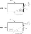
- FIG. 11 Adepicts a schematic diagram of a room including an electrochromic window with a space type based on the Desk 1 located near the window, according to disclosed embodiments.
- FIG. 11 Bdepicts a schematic diagram of a room including an electrochromic window with a space type based on the Desk 2 located further away from the window than in FIG. 11 A , according to disclosed embodiments.
- FIG. 12is a flowchart showing details of Module B according to disclosed embodiments.
- FIG. 13is a flowchart showing details of Module C according to disclosed embodiments.
- FIG. 14is a diagram showing another implementation of a portion of the control logic shown in FIG. 7 .
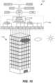
- FIG. 15depicts a schematic diagram of an embodiment of a building management system.
- FIG. 16depicts a block diagram of an embodiment of a building network.
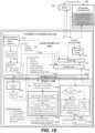
- FIG. 17is a block diagram of components of a system for controlling functions of one or more tintable windows of a building.
- FIG. 18is a block diagram depicting predictive control logic for a method of controlling the transitioning of tint levels of one or more tintable windows (e.g., electrochromic windows) in a building.
- tintable windowse.g., electrochromic windows
- FIG. 19is screenshot of a user interface used to enter schedule information to generate a schedule employed by a window controller, according to embodiments.
- FIG. 20is an example of an occupancy lookup table and a schematic diagram of a room with a desk and window showing the relationship between acceptance angle, sun angle, and penetration depth, according to embodiments.
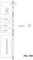
- FIGS. 21 A, 21 B, and 21 Care schematic drawings of the plan view of a portion of building having three different space types, according to an embodiment.
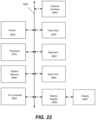
- FIG. 22is a block diagram of subsystems that may be present in window controllers used to control the tint level or more tintable windows, according to embodiments.
- electrochromic windowsalso referred to as smart windows
- the concepts disclosed hereinmay apply to other types of tintable windows.
- a tintable window incorporating a liquid crystal device or a suspended particle deviceinstead of an electrochromic device could be incorporated in any of the disclosed embodiments.
- electrochromic devicesIn order to orient the reader to the embodiments of systems, window controllers, and methods disclosed herein, a brief discussion of electrochromic devices is provided. This initial discussion of electrochromic devices is provided for context only, and the subsequently described embodiments of systems, window controllers, and methods are not limited to the specific features and fabrication processes of this initial discussion.
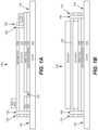
- FIG. 1 Ais a cross-sectional representation (see section cut X′-X′ of FIG. 1 C ) of an electrochromic lite 100 , which is fabricated starting with a glass sheet 105 .
- FIG. 1 Bshows an end view (see viewing perspective Y-Y′ of FIG. 1 C ) of electrochromic lite 100
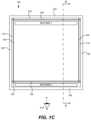
- FIG. 1 Cshows a top-down view of electrochromic lite 100 .
- FIG. 1 Ashows the electrochromic lite after fabrication on glass sheet 105 , edge deleted to produce area 140 , around the perimeter of the lite.
- the electrochromic litehas also been laser scribed and bus bars have been attached.
- the glass lite 105has a diffusion barrier 110 , and a first transparent conducting oxide layer (TCO) 115 , on the diffusion barrier.
- TCOtransparent conducting oxide layer
- the edge deletion processremoves both TCO 115 and diffusion barrier 110 , but in other embodiments only the TCO is removed, leaving the diffusion barrier intact.
- the TCO 115is the first of two conductive layers used to form the electrodes of the electrochromic device fabricated on the glass sheet.
- the glass sheetincludes underlying glass and the diffusion barrier layer.
- the diffusion barrieris formed, and then the first TCO, an electrochromic stack 125 , (e.g., having electrochromic, ion conductor, and counter electrode layers), and a second TCO 130 , are formed.
- the electrochromic deviceelectrochromic stack and second TCO
- the first TCO layeris also formed using the integrated deposition system where the glass sheet does not leave the integrated deposition system during deposition of the electrochromic stack and the (second) TCO layer.
- all of the layersare deposited in the integrated deposition system where the glass sheet does not leave the integrated deposition system during deposition.
- an isolation trench 120is cut through TCO 115 and diffusion barrier 110 .
- Trench 120is made in contemplation of electrically isolating an area of TCO 115 that will reside under bus bar 1 after fabrication is complete (see FIG. 1 A ). This is done to avoid charge buildup and coloration of the electrochromic device under the bus bar, which can be undesirable.
- FIG. 1 Adepicts areas 140 where the device has been removed, in this example, from a perimeter region surrounding laser scribe trenches 150 , 155 , 160 , and 165 .
- Trenches 150 , 160 and 165pass through the electrochromic stack and also through the first TCO and diffusion barrier.
- Trench 155passes through second TCO 130 and the electrochromic stack, but not the first TCO 115 .
- Laser scribe trenches 150 , 155 , 160 , and 165are made to isolate portions of the electrochromic device, 135 , 145 , 170 , and 175 , which were potentially damaged during edge deletion processes from the operable electrochromic device.
- laser scribe trenches 150 , 160 , and 165pass through the first TCO to aid in isolation of the device (laser scribe trench 155 does not pass through the first TCO, otherwise it would cut off bus bar 2's electrical communication with the first TCO and thus the electrochromic stack).
- the laser or lasers used for the laser scribe processesare typically, but not necessarily, pulse-type lasers, for example, diode-pumped solid state lasers.
- the laser scribe processescan be performed using a suitable laser from IPG Photonics (of Oxford, Mass.), or from Ekspla (of Vilnius, Lithuania). Scribing can also be performed mechanically, for example, by a diamond tipped scribe.
- the laser scribing processescan be performed at different depths and/or performed in a single process whereby the laser cutting depth is varied, or not, during a continuous path around the perimeter of the electrochromic device.
- the edge deletionis performed to the depth of the first TCO.
- Non-penetrating bus bar 1is applied to the second TCO.
- Non-penetrating bus bar 2is applied to an area where the device was not deposited (e.g., from a mask protecting the first TCO from device deposition), in contact with the first TCO or, in this example, where an edge deletion process (e.g., laser ablation using an apparatus having a XY or XYZ galvanometer) was used to remove material down to the first TCO.
- both bus bar 1 and bus bar 2are non-penetrating bus bars.
- a penetrating bus baris one that is typically pressed into and through the electrochromic stack to make contact with the TCO at the bottom of the stack.
- a non-penetrating bus baris one that does not penetrate into the electrochromic stack layers, but rather makes electrical and physical contact on the surface of a conductive layer, for example, a TCO.
- the TCO layerscan be electrically connected using a non-traditional bus bar, for example, a bus bar fabricated with screen and lithography patterning methods.
- electrical communicationis established with the device's transparent conducting layers via silk screening (or using another patterning method) a conductive ink followed by heat curing or sintering the ink.
- Advantages to using the above described device configurationinclude simpler manufacturing, for example, and less laser scribing than conventional techniques which use penetrating bus bars.
- the deviceis integrated into an insulated glass unit (IGU), which includes, for example, wiring the bus bars and the like.
- IGUinsulated glass unit
- one or both of the bus barsare inside the finished IGU, however in one embodiment one bus bar is outside the seal of the IGU and one bus bar is inside the IGU.
- area 140is used to make the seal with one face of the spacer used to form the IGU.
- the wires or other connection to the bus barsruns between the spacer and the glass.
- spacersare made of metal, e.g., stainless steel, which is conductive, it is desirable to take steps to avoid short circuiting due to electrical communication between the bus bar and connector thereto and the metal spacer.
- the electrochromic liteis integrated into an IGU, which includes, for example, wiring for the bus bars and the like.
- both of the bus barsare inside the primary seal of the finished IGU.
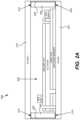
- FIG. 2 Ashows a cross-sectional schematic diagram of the electrochromic window as described in relation to FIGS. 1 A- 1 C integrated into an IGU 200 .
- a spacer 205is used to separate the electrochromic lite from a second lite 210 .
- Second lite 210 in IGU 200is a non-electrochromic lite, however, the embodiments disclosed herein are not so limited.
- lite 210can have an electrochromic device thereon and/or one or more coatings such as low-E coatings and the like.
- Lite 201can also be laminated glass, such as depicted in FIG. 2 B (lite 201 is laminated to reinforcing pane 230 , via resin 235 ).
- a primary seal material 215Between spacer 205 and the first TCO layer of the electrochromic lite is a primary seal material 215 .
- This primary seal materialis also between spacer 205 and second glass lite 210 .
- Around the perimeter of spacer 205is a secondary seal 220 .
- Bus bar wiring/leadstraverse the seals for connection to a controller.
- Secondary seal 220may be much thicker that depicted. These seals aid in keeping moisture out of an interior space 225 , of the IGU. They also serve to prevent argon or other gas in the interior of the IGU from escaping.
- FIG. 3 Aschematically depicts an electrochromic device 300 , in cross-section.
- Electrochromic device 300includes a substrate 302 , a first conductive layer (CL) 304 , an electrochromic layer (EC) 306 , an ion conducting layer (IC) 308 , a counter electrode layer (CE) 310 , and a second conductive layer (CL) 314 .
- Layers 304 , 306 , 308 , 310 , and 314are collectively referred to as an electrochromic stack 320 .
- a voltage source 316 operable to apply an electric potential across electrochromic stack 320effects the transition of the electrochromic device from, for example, a bleached state to a colored state (depicted). The order of layers can be reversed with respect to the substrate.
- Electrochromic devices having distinct layers as describedcan be fabricated as all solid state devices and/or all inorganic devices having low defectivity. Such devices and methods of fabricating them are described in more detail in U.S. patent application Ser. No. 12/645,111, entitled “Fabrication of Low-Defectivity Electrochromic Devices,” filed on Dec. 22, 2009, and naming Mark Kozlowski et al. as inventors, and in U.S. patent application Ser. No. 12/645,159, entitled, “Electrochromic Devices,” filed on Dec. 22, 2009 and naming Zhongchun Wang et al. as inventors, both of which are hereby incorporated by reference in their entireties.
- any one or more of the layers in the stackmay contain some amount of organic material.
- liquidsthat may be present in one or more layers in small amounts.
- solid state materialmay be deposited or otherwise formed by processes employing liquid components such as certain processes employing sol-gels or chemical vapor deposition.
- the reference to a transition between a bleached state and colored stateis non-limiting and suggests only one example, among many, of an electrochromic transition that may be implemented. Unless otherwise specified herein (including the foregoing discussion), whenever reference is made to a bleached-colored transition, the corresponding device or process encompasses other optical state transitions such as non-reflective-reflective, transparent-opaque, etc. Further, the term “bleached” refers to an optically neutral state, for example, uncolored, transparent, or translucent. Still further, unless specified otherwise herein, the “color” of an electrochromic transition is not limited to any particular wavelength or range of wavelengths. As understood by those of skill in the art, the choice of appropriate electrochromic and counter electrode materials governs the relevant optical transition.
- the electrochromic devicereversibly cycles between a bleached state and a colored state.
- a potentialis applied to the electrochromic stack 320 such that available ions in the stack reside primarily in the counter electrode 310 .
- the potential on the electrochromic stackis reversed, the ions are transported across the ion conducting layer 308 to the electrochromic material 306 and cause the material to transition to the colored state.
- the electrochromic device of embodiments described hereincan be reversibly cycled between different tint levels (e.g., bleached state, darkest colored state, and intermediate levels between the bleached state and the darkest colored state).
- voltage source 316may be configured to operate in conjunction with radiant and other environmental sensors. As described herein, voltage source 316 interfaces with a device controller (not shown in this figure). Additionally, voltage source 316 may interface with an energy management system that controls the electrochromic device according to various criteria such as the time of year, time of day, and measured environmental conditions. Such an energy management system, in conjunction with large area electrochromic devices (e.g., an electrochromic window), can dramatically lower the energy consumption of a building.
- substrate 302Any material having suitable optical, electrical, thermal, and mechanical properties may be used as substrate 302 .
- substratesinclude, for example, glass, plastic, and mirror materials.
- Suitable glassesinclude either clear or tinted soda lime glass, including soda lime float glass. The glass may be tempered or untempered.
- the substrateis a glass pane sized for residential window applications.
- the size of such glass panecan vary widely depending on the specific needs of the residence.
- the substrateis architectural glass.
- Architectural glassis typically used in commercial buildings, but may also be used in residential buildings, and typically, though not necessarily, separates an indoor environment from an outdoor environment.
- architectural glassis at least 20 inches by 20 inches, and can be much larger, for example, as large as about 80 inches by 120 inches.
- Architectural glassis typically at least about 2 mm thick, typically between about 3 mm and about 6 mm thick.
- electrochromic devicesare scalable to substrates smaller or larger than architectural glass. Further, the electrochromic device may be provided on a mirror of any size and shape.
- conductive layer 304On top of substrate 302 is conductive layer 304 .
- one or both of the conductive layers 304 and 314is inorganic and/or solid.
- Conductive layers 304 and 314may be made from a number of different materials, including conductive oxides, thin metallic coatings, conductive metal nitrides, and composite conductors.
- conductive layers 304 and 314are transparent at least in the range of wavelengths where electrochromism is exhibited by the electrochromic layer.
- Transparent conductive oxidesinclude metal oxides and metal oxides doped with one or more metals.
- metal oxides and doped metal oxidesexamples include indium oxide, indium tin oxide, doped indium oxide, tin oxide, doped tin oxide, zinc oxide, aluminum zinc oxide, doped zinc oxide, ruthenium oxide, doped ruthenium oxide and the like. Since oxides are often used for these layers, they are sometimes referred to as “transparent conductive oxide” (TCO) layers. Thin metallic coatings that are substantially transparent may also be used.
- the function of the conductive layersis to spread an electric potential provided by voltage source 316 over surfaces of the electrochromic stack 320 to interior regions of the stack, with relatively little ohmic potential drop.
- the electric potentialis transferred to the conductive layers though electrical connections to the conductive layers.
- bus barsone in contact with conductive layer 304 and one in contact with conductive layer 314 , provide the electric connection between the voltage source 316 and the conductive layers 304 and 314 .
- the conductive layers 304 and 314may also be connected to the voltage source 316 with other conventional means.
- electrochromic layer 306is inorganic and/or solid.
- the electrochromic layermay contain any one or more of a number of different electrochromic materials, including metal oxides.
- metal oxidesinclude tungsten oxide (WO3), molybdenum oxide (MoO3), niobium oxide (Nb2O5), titanium oxide (TiO2), copper oxide (CuO), iridium oxide (Ir2O3), chromium oxide (Cr2O3), manganese oxide (Mn2O3), vanadium oxide (V2O5), nickel oxide (Ni2O3), cobalt oxide (Co2O3) and the like.
- WO3tungsten oxide
- MoO3molybdenum oxide
- Nb2O5niobium oxide
- TiO2O5titanium oxide
- CuOcopper oxide
- Ir2O3iridium oxide
- Cr2O3chromium oxide
- manganese oxideMn2O3
- vanadium oxideV2
- the colorization (or change in any optical property—e.g., absorbance, reflectance, and transmittance) of the electrochromic materialis caused by reversible ion insertion into the material (e.g., intercalation) and a corresponding injection of a charge balancing electron.
- a charge balancing electrontypically some fraction of the ions responsible for the optical transition is irreversibly bound up in the electrochromic material. Some or all of the irreversibly bound ions are used to compensate “blind charge” in the material.
- suitable ionsinclude lithium ions (Li+) and hydrogen ions (H+) (that is, protons). In some cases, however, other ions will be suitable.
- lithium ionsare used to produce the electrochromic phenomena. Intercalation of lithium ions into tungsten oxide (WO3-y (0 ⁇ y ⁇ ⁇ 0.3)) causes the tungsten oxide to change from transparent (bleached state) to blue (colored state).
- counter electrode layer 310is inorganic and/or solid.
- the counter electrode layermay comprise one or more of a number of different materials that serve as a reservoir of ions when the electrochromic device is in the bleached state.
- the counter electrode layertransfers some or all of the ions it holds to the electrochromic layer, changing the electrochromic layer to the colored state.
- the counter electrode layercolors with the loss of ions.
- suitable materials for the counter electrode complementary to WO3include nickel oxide (NiO), nickel tungsten oxide (NiWO), nickel vanadium oxide, nickel chromium oxide, nickel aluminum oxide, nickel manganese oxide, nickel magnesium oxide, chromium oxide (Cr2O3), manganese oxide (MnO2), and Prussian blue.
- a counter electrode 310 made of nickel tungsten oxidethat is, ions are transported from counter electrode 310 to electrochromic layer 306
- the counter electrode layerwill transition from a transparent state to a colored state.
- Ion conducting layer 308serves as a medium through which ions are transported (in the manner of an electrolyte) when the electrochromic device transitions between the bleached state and the colored state.
- ion conducting layer 308is highly conductive to the relevant ions for the electrochromic and the counter electrode layers, but has sufficiently low electron conductivity that negligible electron transfer takes place during normal operation.
- a thin ion conducting layer with high ionic conductivitypermits fast ion conduction and hence fast switching for high performance electrochromic devices.
- the ion conducting layer 308is inorganic and/or solid.
- ion conducting layersfor electrochromic devices having a distinct IC layer
- suitable ion conducting layersinclude silicates, silicon oxides, tungsten oxides, tantalum oxides, niobium oxides, and borates. These materials may be doped with different dopants, including lithium. Lithium doped silicon oxides include lithium silicon-aluminum-oxide.
- the ion conducting layercomprises a silicate-based structure.
- a silicon-aluminum-oxide (SiAlO)is used for the ion conducting layer 308 .
- Electrochromic device 300may include one or more additional layers (not shown), such as one or more passive layers. Passive layers used to improve certain optical properties may be included in electrochromic device 300 . Passive layers for providing moisture or scratch resistance may also be included in electrochromic device 300 . For example, the conductive layers may be treated with anti-reflective or protective oxide or nitride layers. Other passive layers may serve to hermetically seal electrochromic device 300 .
- FIG. 3 Bis a schematic cross-section of an electrochromic device in a bleached state (or transitioning to a bleached state).
- an electrochromic device 400includes a tungsten oxide electrochromic layer (EC) 406 and a nickel-tungsten oxide counter electrode layer (CE) 410 .
- Electrochromic device 400also includes a substrate 402 , a conductive layer (CL) 404 , an ion conducting layer (IC) 408 , and conductive layer (CL) 414 .
- a power source 416is configured to apply a potential and/or current to an electrochromic stack 420 through suitable connections (e.g., bus bars) to the conductive layers 404 and 414 .
- the voltage sourceis configured to apply a potential of a few volts in order to drive a transition of the device from one optical state to another.
- the polarity of the potential as shown in FIG. 3 Ais such that the ions (lithium ions in this example) primarily reside (as indicated by the dashed arrow) in nickel-tungsten oxide counter electrode layer 410
- FIG. 3 Cis a schematic cross-section of electrochromic device 400 shown in FIG. 3 B but in a colored state (or transitioning to a colored state).
- the polarity of voltage source 416is reversed, so that the electrochromic layer is made more negative to accept additional lithium ions, and thereby transition to the colored state.
- lithium ionsare transported across ion conducting layer 408 to tungsten oxide electrochromic layer 406 .
- Tungsten oxide electrochromic layer 406is shown in the colored state.
- Nickel-tungsten oxide counter electrode 410is also shown in the colored state. As explained, nickel-tungsten oxide becomes progressively more opaque as it gives up (deintercalates) lithium ions.
- there is a synergistic effectwhere the transition to colored states for both layers 406 and 410 are additive toward reducing the amount of light transmitted through the stack and substrate.
- an electrochromic devicemay include an electrochromic (EC) electrode layer and a counter electrode (CE) layer separated by an ionically conductive (IC) layer that is highly conductive to ions and highly resistive to electrons.
- ECelectrochromic
- CEcounter electrode
- ICionically conductive
- the ionically conductive layerallows the electrochromic and counter electrodes to hold a charge and thereby maintain their bleached or colored states.
- the componentsform a stack which includes the ion conducting layer sandwiched between the electrochromic electrode layer and the counter electrode layer. The boundaries between these three stack components are defined by abrupt changes in composition and/or microstructure. Thus, the devices have three distinct layers with two abrupt interfaces.
- the counter electrode and electrochromic electrodesare formed immediately adjacent one another, sometimes in direct contact, without separately depositing an ionically conducting layer.
- electrochromic deviceshaving an interfacial region rather than a distinct IC layer are employed. Such devices, and methods of fabricating them, are described in U.S. Pat. No. 8,300,298 and U.S. patent application Ser. No. 12/772,075 filed on Apr. 30, 2010, and U.S. patent application Ser. Nos. 12/814,277 and 12/814,279, filed on Jun. 11, 2010—each of the three patent applications and patent is entitled “Electrochromic Devices,” each names Zhongchun Wang et al. as inventors, and each is incorporated by reference herein in its entirety.
- a window controlleris used to control the tint level of the electrochromic device of an electrochromic window.
- the window controlleris able to transition the electrochromic window between two tint states (levels), a bleached state and a colored state.
- the controllercan additionally transition the electrochromic window (e.g., having a single electrochromic device) to intermediate tint levels.
- the window controlleris able to transition the electrochromic window to four or more tint levels. Certain electrochromic windows allow intermediate tint levels by using two (or more) electrochromic lites in a single IGU, where each lite is a two-state lite. This is described in reference to FIGS. 2 A and 2 B in this section.
- an electrochromic windowcan include an electrochromic device 400 on one lite of an IGU 200 and another electrochromic device 400 on the other lite of the IGU 200 . If the window controller is able to transition each electrochromic device between two states, a bleached state and a colored state, the electrochromic window is able to attain four different states (tint levels), a colored state with both electrochromic devices being colored, a first intermediate state with one electrochromic device being colored, a second intermediate state with the other electrochromic device being colored, and a bleached state with both electrochromic devices being bleached.
- statessuch as described in U.S. Pat. No. 8,270,059, naming Robin Friedman et al. as inventors, titled “MULTI-PANE ELECTROCHROMIC WINDOWS,” which is hereby incorporated by reference in its entirety.
- the window controlleris able to transition an electrochromic window having an electrochromic device capable of transitioning between two or more tint levels.
- a window controllermay be able to transition the electrochromic window to a bleached state, one or more intermediate levels, and a colored state.
- the window controlleris able to transition an electrochromic window incorporating an electrochromic device between any number of tint levels between the bleached state and the colored state.
- a window controllercan power one or more electrochromic devices in an electrochromic window.
- this function of the window controlleris augmented with one or more other functions described in more detail below.
- Window controllers described hereinare not limited to those that have the function of powering an electrochromic device to which it is associated for the purposes of control. That is, the power source for the electrochromic window may be separate from the window controller, where the controller has its own power source and directs application of power from the window power source to the window. However, it is convenient to include a power source with the window controller and to configure the controller to power the window directly, because it obviates the need for separate wiring for powering the electrochromic window.
- window controllers described in this sectionare described as standalone controllers which may be configured to control the functions of a single window or a plurality of electrochromic windows, without integration of the window controller into a building control network or a building management system (BMS).
- Window controllersmay be integrated into a building control network or a BMS, as described further in the Building Management System section of this disclosure.
- FIG. 4depicts a block diagram of some components of a window controller 450 and other components of a window controller system of disclosed embodiments.
- FIG. 4is a simplified block diagram of a window controller, and more detail regarding window controllers can be found in U.S. patent application Ser. Nos. 13/449,248 and 13/449,251, both naming Stephen Brown as inventor, both titled “CONTROLLER FOR OPTICALLY-SWITCHABLE WINDOWS,” and both filed on Apr. 17, 2012, and in U.S. patent Ser. No. 13/449,235, titled “CONTROLLING TRANSITIONS IN OPTICALLY SWITCHABLE DEVICES,” naming Stephen Brown et al. as inventors and filed on Apr. 17, 2012, all of which are hereby incorporated by reference in their entireties.
- the illustrated components of the window controller 450include a window controller 450 having a microprocessor 455 or other processor, a power width modulator (PWM) 460 , a signal conditioning module 465 , and a computer readable medium (e.g., memory) having a configuration file 475 .
- Window controller 450is in electronic communication with one or more electrochromic devices 400 in an electrochromic window through network 480 (wired or wireless) to send instructions to the one or more electrochromic devices 400 .
- the window controller 450may be a local window controller in communication through a network (wired or wireless) to a master window controller.
- a buildingmay have at least one room having an electrochromic window between the exterior and interior of a building.
- One or more sensorsmay be located to the exterior of the building and/or inside the room.
- the output from the one or more sensorsmay be input to the signal conditioning module 465 of the window controller 450 .
- the output from the one or more sensorsmay be input to a BMS, as described further in the Building Management Systems section.
- the sensors of depicted embodimentsare shown as located on the outside vertical wall of the building, this is for the sake of simplicity, and the sensors may be in other locations, such as inside the room or on other surfaces to the exterior, as well.
- two or more sensorsmay be used to measure the same input, which can provide redundancy in case one sensor fails or has an otherwise erroneous reading.
- FIG. 5depicts a schematic diagram of a room 500 having an electrochromic window 505 with at least one electrochromic device.
- the electrochromic window 505is located between the exterior and the interior of a building, which includes the room 500 .
- the room 500also includes a window controller 450 connected to and configured to control the tint level of the electrochromic window 505 .
- An exterior sensor 510is located on a vertical surface in the exterior of the building.
- an interior sensormay also be used to measure the ambient light in room 500 .
- an occupant sensormay also be used to determine when an occupant is in the room 500 .
- Exterior sensor 510is a device, such as a photosensor, that is able to detect radiant light incident upon the device flowing from a light source such as the sun or from light reflected to the sensor from a surface, particles in the atmosphere, clouds, etc.
- the exterior sensor 510may generate a signal in the form of electrical current that results from the photoelectric effect and the signal may be a function of the light incident on the sensor 510 .
- the devicemay detect radiant light in terms of irradiance in units of watts/m 2 or other similar units.
- the devicemay detect light in the visible range of wavelengths in units of foot candles or similar units. In many cases, there is a linear relationship between these values of irradiance and visible light.
- Irradiance values from sunlightcan be predicted based on the time of day and time of year as the angle at which sunlight strikes the earth changes.
- Exterior sensor 510can detect radiant light in real-time, which accounts for reflected and obstructed light due to buildings, changes in weather (e.g., clouds), etc. For example, on cloudy days, sunlight would be blocked by the clouds and the radiant light detected by an exterior sensor 510 would be lower than on cloudless days.
- Output from the one or more exterior sensors 510could be compared to one another to determine, for example, if one of exterior sensors 510 is shaded by an object, such as by a bird that landed on exterior sensor 510 .
- a single sensor or a few sensorsmay be employed to determine the current level of radiant light from the sun impinging on the building or perhaps one side of the building.
- a cloudmay pass in front of the sun or a construction vehicle may park in front of the setting sun. These will result in deviations from the amount of radiant light from the sun calculated to normally impinge on the building.
- Exterior sensor 510may be a type of photosensor.
- exterior sensor 510may be a charge coupled device (CCD), photodiode, photoresistor, or photovoltaic cell.
- CCDcharge coupled device
- photodiodephotodiode
- photoresistorphotoresistor
- photovoltaic cellOne of ordinary skill in the art would appreciate that future developments in photosensor and other sensor technology would also work, as they measure light intensity and provide an electrical output representative of the light level.
- output from exterior sensor 510may be input to the signal conditioning module 465 .
- the inputmay be in the form of a voltage signal to signal conditioning module 465 .
- Signal conditioning module 465passes an output signal to the window controller 450 .
- Window controller 450determines a tint level of the electrochromic window 505 , based on various information from the configuration file 475 , output from the signal conditioning module 465 , override values. Window controller 450 and then instructs the PWM 460 , to apply a voltage and/or current to electrochromic window 505 to transition to the desired tint level.
- window controller 450can instruct the PWM 460 , to apply a voltage and/or current to electrochromic window 505 to transition it to any one of four or more different tint levels.
- electrochromic window 505can be transitioned to at least eight different tint levels described as: 0 (lightest), 5, 10, 15, 20, 25, 30, and 35 (darkest). The tint levels may linearly correspond to visual transmittance values and solar gain heat coefficient (SGHC) values of light transmitted through the electrochromic window 505 .
- SGHCsolar gain heat coefficient
- the lightest tint level of 0may correspond to an SGHC value of 0.80
- the tint level of 5may correspond to an SGHC value of 0.70
- the tint level of 10may correspond to an SGHC value of 0.60
- the tint level of 15may correspond to an SGHC value of 0.50
- the tint level of 20may correspond to an SGHC value of 0.40
- the tint level of 25may correspond to an SGHC value of 0.30
- the tint level of 30may correspond to an SGHC value of 0.20
- the tint level of 35 (darkest)may correspond to an SGHC value of 0.10.
- Window controller 450 or a master controller in communication with the window controller 450may employ any one or more predictive control logic components to determine a desired tint level based on signals from the exterior sensor 510 and/or other input.
- the window controller 450can instruct the PWM 460 to apply a voltage and/or current to electrochromic window 505 to transition it to the desired tint level.
- predictive control logicis used to implement methods of determining and controlling a desired tint level for the electrochromic window 505 or other tintable window that accounts for occupant comfort and/or energy conservation considerations.
- This predictive control logicmay employ one or more logic modules.
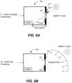
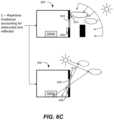
- FIGS. 6 A- 6 Cinclude diagrams depicting some information collected by each of three logic modules A, B, and C of an exemplary control logic of disclosed embodiments.
- FIG. 6 Ashows the penetration depth of direct sunlight into a room 500 through an electrochromic window 505 between the exterior and the interior of a building, which includes the room 500 .
- Penetration depthis a measure of how far direct sunlight will penetrate into the room 500 .
- penetration depthis measured in a horizontal direction away from the sill (bottom) of window.
- the windowdefines an aperture that provides an acceptance angle for direct sunlight.
- the penetration depthis calculated based upon the geometry of the window (e.g., window dimensions), its position and orientation in the room, any fins or other exterior shading outside of the window, and the position of the sun (e.g. angle of direct sunlight for a particular time of day and date).
- Exterior shading to an electrochromic window 505may be due to any type of structure that can shade the window such as an overhang, a fin, etc.
- FIG. 6 Athere is an overhang 520 above the electrochromic window 505 that blocks a portion of the direct sunlight entering the room 500 thus shortening the penetration depth.
- the room 500also includes a local window controller 450 connected to and configured to control the tint level of the electrochromic window 505 .
- An exterior sensor 510is located on a vertical surface in the exterior of the building.
- Module Acan be used to determine a tint level that considers occupant comfort from direct sunlight through the electrochromic window 505 onto an occupant or their activity area.
- the tint levelis determined based on a calculated penetration depth of direct sunlight into the room and the space type (e.g., desk near window, lobby, etc.) in the room at a particular instant in time. In some cases, the tint level may also be based on providing sufficient natural lighting into the room. In many cases, the penetration depth is the value calculated at a time in the future to account for glass transition time.
- the concern addressed in Module Ais that direct sunlight may penetrate so deep into the room 500 as to show directly on an occupant working at a desk or other work surface in a room. Publicly available programs can provide calculation of the sun's position and allow for easy calculation of penetration depth.
- FIG. 6 Aalso shows a desk in the room 500 as an example of a space type associated with an activity area (i.e. desk) and location of the activity area (i.e. location of desk).
- Each space typeis associated with different tint levels for occupant comfort. For example, if the activity is a critical activity such as work in an office being done at a desk or computer, and the desk is located near the window, the desired tint level may be higher than if the desk were further away from the window. As another example, if the activity is non-critical, such as the activity in a lobby, the desired tint level may be lower than for the same space having a desk.
- FIG. 6 Bshows direct sunlight and radiation under clear sky conditions entering the room 500 through the electrochromic window 505 .
- the radiationmay be from sunlight scattered by molecules and particles in the atmosphere.
- Module Bdetermines a tint level based on predicted values of irradiance under clear sky conditions flowing through the electrochromic window 505 under consideration.
- Various softwaresuch as open source RADIANCE program, can be used to predict clear sky irradiance at a certain latitude, longitude, time of year, and time of day, and for a given window orientation.
- FIG. 6 Cshows radiant light from the sky that is measured in real-time by an exterior sensor 510 to account for light that may be obstructed by or reflected from objects such as buildings or weather conditions (e.g., clouds) that are not accounted for in the clear sky predictions.
- the tint level determined by Module Cis based on the real-time irradiance based on measurements taken by the exterior sensor 510 .
- the predictive control logicmay implement one or more of the logic Modules A, B and C separately for each electrochromic window 505 in the building.
- Each electrochromic window 505can have a unique set of dimensions, orientation (e.g., vertical, horizontal, tilted at an angle), position, associated space type, etc.
- a configuration file with this information and other informationcan be maintained for each electrochromic window 505 .
- the configuration file 475may be stored in the computer readable medium 470 of the local window controller 450 of the electrochromic window 505 or in the BMS described later in this disclosure.
- the configuration file 475can include information such as a window configuration, an occupancy lookup table, information about an associated datum glass, and/or other data used by the predictive control logic.
- the window configurationmay include information such as the dimensions of the electrochromic window 505 , the orientation of the electrochromic window 505 , the position of the electrochromic window 505 , etc.
- a lookup tabledescribes tint levels that provide occupant comfort for certain space types and penetration depths. That is, the tint levels in the occupancy lookup table are designed to provide comfort to occupant(s) that may be in the room 500 from direct sunlight on the occupant(s) or their workspace.
- An example of an occupancy lookup tableis shown in FIG. 10 .
- the space typeis a measure to determine how much tinting will be required to address occupant comfort concerns for a given penetration depth and/or provide comfortable natural lighting in the room.
- the space type parametermay take into consideration many factors. Among these factors is the type of work or other activity being conducted in a particular room and the location of the activity. Close work associated with detailed study requiring great attention might be at one space type, while a lounge or a conference room might have a different space type. Additionally, the position of the desk or other work surface in the room with respect to the window is a consideration in defining the space type.
- the space typemay be associated with an office of a single occupant having a desk or other workspace located near the electrochromic window 505 . As another example, the space type may be a lobby.
- one or more modules of the predictive control logiccan determine desired tint levels while accounting for energy conservation in addition to occupant comfort. These modules may determine energy savings associated with a particular tint level by comparing the performance of the electrochromic window 505 at that tint level to a datum glass or other standard reference window. The purpose of using this reference window can be to ensure that the predictive control logic conforms to requirements of the municipal building code or other requirements for reference windows used in the locale of the building. Often municipalities define reference windows using conventional low emissivity glass to control the amount of air conditioning load in the building.
- the logicmay be designed so that the irradiance coming through a given electrochromic window 505 is never greater than the maximum irradiance coming through a reference window as specified by the respective municipality.
- predictive control logicmay use the solar heat gain coefficient (SHGC) value of the electrochromic window 505 at a particular tint level and the SHGC of the reference window to determine the energy savings of using the tint level.
- SHGCsolar heat gain coefficient
- the value of the SHGCis the fraction of incident light of all wavelengths transmitted through the window.
- a datum glassis described in many embodiments, other standard reference windows can be used.
- the SHGC of the reference windowe.g., datum glass
- the SHGC of the reference windowis a variable that can be different for different geographical locations and window orientations, and is based on code requirements specified by the respective municipality.
- buildingsare designed to have an HVAC with the capacity to fulfill the maximum expected heating and/or air-conditioning loads required at any given instance.
- the calculation of required capacitymay take into consideration the datum glass or reference window required in a building at the particular location where the building is being constructed. Therefore, it is important that the predictive control logic meet or exceed the functional requirements of the datum glass in order to allow building designers to confidently determine how much HVAC capacity to put into a particular building. Since the predictive control logic can be used to tint the window to provide additional energy savings over the datum glass, the predictive control logic could be useful in allowing building designers to have a lower HVAC capacity than would have been required using the datum glass specified by the codes and standards.
- the predictive control logichas only two independent variables that can be controlled by an occupant (end user), building designer, or building operator. These are the space types for a given window and the datum glass associated with the given window. Often the datum glass is specified when the predictive control logic is implemented for a given building.
- the space typecan vary, but is typically static.
- the space typemay be part of the configuration file maintained by the building or stored in the local window controller 450 . In some cases, the configuration file may be updated to account for various changes in the building.
- an updated configuration file with a modified occupancy lookup tablemay be stored in the computer readable medium 470 .
- the configuration filemay be updated to reflect the manual override.
- FIG. 7is a flowchart showing predictive control logic for a method of controlling one or more electrochromic windows 505 in a building, according to embodiments.
- the predictive control logicuses one or more of the Modules A, B, and C to calculate tint levels for the window(s) and sends instructions to transition the window(s).
- the calculations in the control logicare run 1 to n times at intervals timed by the timer at step 610 .
- nis the number of recalculations performed and n can be at least 1.
- the logic calculationscan be done at constant time intervals in some cases. In one cases, the logic calculations may be done every 2 to 5 minutes. However, tint transition for large pieces of electrochromic glass can take up to 30 minutes or more. For these large windows, calculations may be done on a less frequent basis such as every 30 minutes.
- logic Modules A, B, and Cperform calculations to determine a tint level for each electrochromic window 505 at a single instant in time t i . These calculations can be performed by the window controller 450 .
- the predictive control logicpredictively calculates how the window should transition in advance of the actual transition.
- the calculations in Modules A, B, and Ccan be based on a future time around or after transition is complete.
- the future time used in the calculationsmay be a time in the future that is sufficient to allow the transition to be completed after receiving the tint instructions.
- the controllercan send tint instructions in the present time in advance of the actual transition. By the completion of the transition, the window will have transitioned to a tint level that is desired for that time.
- the predictive control logicallows for certain types of overrides that disengage the algorithm at Modules A, B, and C and define override tint levels at step 640 based on some other consideration.
- One type of overrideis a manual override. This is an override implemented by an end user who is occupying a room and determines that a particular tint level (override value) is desirable. There may be situations where the user's manual override is itself overridden.
- An example of an overrideis a high demand (or peak load) override, which is associated with a requirement of a utility that energy consumption in the building be reduced.
- the buildingmay override the tint level from the predictive control logic described herein to ensure that all windows have a particularly high level of tinting.
- Another example of an overridemay be if there is no occupant in the room during a weekend in a commercial office building.
- the buildingmay disengage one or more Modules that relate to occupant comfort and all the windows may have a high level of tinting in cold weather and low level of tinting in warm weather.
- the tint levelsare transmitted over a network to electrochromic device(s) in one or more electrochromic windows 505 in the building.
- the transmission of tint levels to all windows of a buildingmay be implemented with efficiency in mind. For example, if the recalculation of tint level suggests that no change in tint from the current tint level is required, then there is no transmission of instructions with an updated tint level.
- the buildingmay be divided into zones based on window size. The predictive control logic may recalculate tint levels for zones with smaller windows more frequently than for zones with larger windows.
- the logic in FIG. 7 for implementing the control methods for multiple electrochromic windows 505 in an entire buildingcan be on a single device, for example, a single master window controller. This device can perform the calculations for each and every window in the building and also provide an interface for transmitting tint levels to one or more electrochromic devices in individual electrochromic windows 505 .
- the predictive control logicmay determine how an end user (e.g. occupant) tries to override the algorithm at particular times of day and makes use of this information in a more predictive manner to determine desired tint levels.
- the end usermay be using a wall switch to override the tint level provided by the predictive logic at a certain time each day to an override value.
- the predictive control logicmay receive information about these instances and change the predictive control logic to change the tint level to the override value at that time of day.
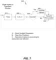
- FIG. 8is a diagram showing a particular implementation of block 620 from FIG. 7 .
- This diagramshows a method of performing all three Modules A, B, and C in sequence to calculate a final tint level of a particular electrochromic window 505 for a single instant in time t i .
- the final tint levelmay be the maximum permissible transmissivity of the window under consideration.
- FIG. 8also includes some exemplary inputs and outputs of Modules A, B, and C.
- the calculations in Modules A, B, and Care performed by window controller 450 in local window controller 450 in embodiments. In other embodiments, one or more of the modules can be performed by another processor.
- illustrated embodimentsshow all three Modules A, B, and C being used, other embodiments may use one or more of the Modules A, B, and C or may use additional modules.
- window controller 450uses Module A to determine a tint level for occupant comfort to prevent direct glare from sunlight penetrating the room 500 .
- Window controller 450uses Module A to calculate the penetration depth of direct sunlight into the room 500 based on the sun's position in the sky and the window configuration from the configuration file. The position of the sun is calculated based on the latitude and longitude of the building and the time of day and date. The occupancy lookup table and space type are input from a configuration file for the particular window.
- Module Aoutputs the Tint level from A to Module B.
- Module AThe goal of Module A is to ensure that direct sunlight or glare does not strike the occupant or his or her workspace.
- the tint level from Module Ais determined to accomplish this purpose. Subsequent calculations of tint level in Modules B and C can reduce energy consumption and may require even greater tint. However, if subsequent calculations of tint level based on energy consumption suggest less tinting than required to avoid interfering with the occupant, the predictive logic prevents the calculated greater level of transmissivity from being executed to assure occupant comfort.
- the tint level calculated in Module Ais input into Module B.
- a tint levelis calculated based on predictions of irradiance under clear sky conditions (clear sky irradiance).
- Window controller 450uses Module B to predict clear sky irradiance for the electrochromic window 505 based on window orientation from the configuration file and based on latitude and longitude of the building. These predictions are also based on a time of day and date.
- Publicly available softwaresuch as the RADIANCE program, which is an open-source program, can provide the calculations for predicting clear sky irradiance.
- the SHGC of the datum glassis also input into Module B from the configuration file.
- Window controller 450uses Module B to determine a tint level that is darker than the tint level in A and transmits less heat than the datum glass is predicted to transmit under maximum clear sky irradiance.
- Maximum clear sky irradianceis the highest level of irradiance for all times predicted for clear sky conditions.
- a tint level from B and predicted clear sky irradianceare input to Module C.
- Real-time irradiance valuesare input to Module C based on measurements from an exterior sensor 510 .
- Window controller 450uses Module C to calculate irradiance transmitted into the room if the window were tinted to the Tint level from Module B under clear sky conditions.
- Window controller 450uses Module C to find the appropriate tint level where the actual irradiance through the window with this tint level is less than or equal to the irradiance through the window with the Tint level from Module B.
- the tint level determined in Module Cis the final tint level.
- Much of the information input to the predictive control logicis determined from fixed information about the latitude and longitude, time and date. This information describes where the sun is with respect to the building, and more particularly with respect to the window for which the predictive control logic is being implemented.
- the position of the sun with respect to the windowprovides information such as the penetration depth of direct sunlight into the room assisted with the window. It also provides an indication of the maximum irradiance or solar radiant energy flux coming through the window.
- This calculated level of irradiancecan be modified by sensor input which might indicate that there is a reduction from the maximum amount of irradiance. Again, such reduction might be caused by a cloud or other obstruction between the window and the sun.
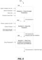
- FIG. 9is a flowchart showing details of step 700 of FIG. 8 .
- Module Abegins.
- the window controller 450uses Module A to calculate the position of the sun for the latitude and longitude coordinates of the building and the date and time of day of a particular instant in time, t i .
- the latitude and longitude coordinatesmay be input from the configuration file.
- the date and time of daymay be based on the current time provided by the timer.
- the sun positionis calculated at the particular instant in time, t i , which may be in the future in some cases. In other embodiments, the position of the sun is calculated in another component (e.g., module) of the predictive control logic.
- window controller 450uses Module A to calculate the penetration depth of direct sunlight into the room 500 at the particular instant in time used in step 710 .
- Module Acalculates the penetration depth based on the calculated position of the sun and window configuration information including the position of the window, dimensions of the window, orientation of the window (i.e. direction facing), and the details of any exterior shading.
- the window configuration informationis input from the configuration file associated with the electrochromic window 505 .
- Module Acan be used to calculate the penetration depth of the vertical window shown in FIG. 6 A by first calculating the angle ⁇ of the direct sunlight based on the position of the sun calculated at the particular instant in time. The penetration depth can be determined based on calculated angle ⁇ and the location of the lintel (top of the window).
- a tint levelis determined that will provide occupant comfort for the penetration depth calculated in step 720 .
- the occupancy lookup tableis used to find a desired tint level for the space type associated with the window, for the calculated penetration depth, and for the acceptance angle of the window.
- the space type and occupancy lookup tableare provided as input from the configuration file for the particular window.
- FIG. 10An example of an occupancy lookup table is provided in FIG. 10 .
- the values in the tableare in terms of a Tint level and associated SGHC values in parenthesis.
- FIG. 10shows the different tint levels (SGHC values) for different combinations of calculated penetration values and space types.
- the tableis based on eight tint levels including 0 (lightest), 5, 10, 15, 20, 25, 30, and 35 (lightest).
- the lightest tint level of 0corresponds to an SGHC value of 0.80
- the tint level of 5corresponds to an SGHC value of 0.70
- the tint level of 10corresponds to an SGHC value of 0.60
- the tint level of 15corresponds to an SGHC value of 0.50
- the tint level of 20corresponds to an SGHC value of 0.40
- the tint level of 25corresponds to an SGHC value of 0.30
- the tint level of 30corresponds to an SGHC value of 0.20
- the tint level of 35 (darkest)corresponds to an SGHC value of 0.10.
- the illustrated exampleincludes three space types: Desk 1 , Desk 2 , and Lobby and six penetration depths.
- FIG. 11 Ashows the location of Desk 1 in the room 500 .
- FIG. 11 Ashows the location of Desk 1 in the room 500 .
- FIG. 11 Ashows the location of Desk 1 in the room 500 .
- FIG. 11 Ashows the location of Desk 1 in the room 500 .
- 11 Bshows the location of Desk 2 in the room 500 .
- the tint levels for Desk 1 close to the windoware higher than the tint levels for Desk 2 far from window to prevent glare when the desk is closer to the window.
- Occupancy lookup tables with other valuesmay be used in other embodiments.
- one other occupancy lookup tablemay include only four tint levels associated with the penetration values.
- Another example of an occupancy table with four tint levels associated with four penetration depthsis shown in FIG. 20 .
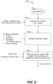
- FIG. 12is a diagram showing further detail of step 800 of FIG. 8 .
- Module Bbegins.
- Module Bcan be used to predict the irradiance at the window under clear sky conditions at t i .
- This clear sky irradiance at t iis predicted based on the latitude and longitude coordinates of the building and the window orientation (i.e. direction the window is facing).
- the Maximum Clear Sky Irradiance incident the window at all timesis predicted. These predicted values of clear sky irradiance can be calculated using open source software, such as Radiance.
- the window controller 450uses Module B to determine the maximum amount of irradiance that would be transmitted through a datum glass into the room 500 at that time (i.e. determines Maximum Datum Inside Irradiance).
- window controller 450uses Module B to determine inside irradiance into the room 500 having a window with the current tint level based on the equation.
- one or more the steps 705 , 810 and 820may be performed by a solar position calculator separate from Modules A and B.
- a solar position calculatorrefers to logic that determines the position of the sun at a particular future time and makes predictive determinations (e.g., predicts clear sky irradiance) based on the sun's position at that future time.
- the solar position calculatormay perform one or more steps of the methods disclosed herein.
- the solar position calculatormay be a portion of the predictive control logic performed by one or more of the components of the master window controller (e.g., master window controller 1402 depicted in FIG. 17 ).
- the solar position calculatormay be part of the predictive control logic shown in FIG. 18 implemented by the window controller 1410 (shown in FIG. 17 ).
- window controller 450uses Module B to determine whether the inside irradiance based on the current tint level is less than or equal to the maximum datum inside irradiance and the tint level is darker than the tint level from A. If the determination is NO, the current tint level is incrementally increased (darkened) at step 860 and the inside irradiance is recalculated at step 840 . If the determination is YES at step 850 , Module B ends.
- FIG. 13is a diagram showing further detail of step 900 of FIG. 8 .
- Module Cbegins.
- a tint level from B and predicted clear sky irradiance at the instant in time t iis input from Module B.
- Real-time irradiance valuesare input to Module C based on measurements from an exterior sensor 510 .
- window controller 450uses Module C to calculate irradiance transmitted into the room through an electrochromic window 505 tinted to the Tint level from B under clear sky conditions.
- the module logicstarts with the tint level from B and incrementally increases the tint level until the Actual Inside Irradiance ⁇ Calculated Inside Irradiance.
- the tint level determined in Module Cis the final tint level. This final tint level may be transmitted in tint instructions over the network to the electrochromic device(s) in the electrochromic window 505 .
- FIG. 14is a diagram includes another implementation of block 620 from FIG. 7 .
- This diagramshows a method of performing Modules A, B, and C of embodiments.
- the position of the sunis calculated based on the latitude and longitude coordinates of the building for a single instant in time t i .
- the penetration depthis calculated in Module A based on the window configuration including a position of the window, dimensions of the window, orientation of the window, and information about any external shading.
- Module Auses a lookup table to determine the tint level from A based on the calculated penetration and the space type. The tint level from A is then input into Module B.
- a program such as the open source program Radianceis used to determine clear sky irradiance based on window orientation and latitude and longitude coordinates of the building for both a single instant in time t i and a maximum value for all times.
- the datum glass SHGC and calculated maximum clear sky irradianceare input into Module B.
- Module Acalculates the maximum tint of the glass
- module Bdoesn't change the tint to make it lighter.
- the tint level calculated in Bis then input into Module C.
- the predicted clear sky irradianceis also input into Module C.
- a BMSis a computer-based control system installed in a building that monitors and controls the building's mechanical and electrical equipment such as ventilation, lighting, power systems, elevators, fire systems, and security systems.
- a BMSconsists of hardware, including interconnections by communication channels to a computer or computers, and associated software for maintaining conditions in the building according to preferences set by the occupants and/or by the building manager.
- a BMSmay be implemented using a local area network, such as Ethernet.
- the softwarecan be based on, for example, internet protocols and/or open standards.
- One example of softwareis software from Tridium, Inc. (of Richmond, Va.).
- One communications protocol commonly used with a BMSis BACnet (building automation and control networks).
- a BMSis most common in a large building, and typically functions at least to control the environment within the building.
- a BMSmay control temperature, carbon dioxide levels, and humidity within a building.
- mechanical devicesthat are controlled by a BMS such as heaters, air conditioners, blowers, vents, and the like.
- a BMSmay turn on and off these various devices under defined conditions.
- a core function of a typical modern BMSis to maintain a comfortable environment for the building's occupants while minimizing heating and cooling costs/demand.
- a modern BMSis used not only to monitor and control, but also to optimize the synergy between various systems, for example, to conserve energy and lower building operation costs.
- a window controlleris integrated with a BMS, where the window controller is configured to control one or more electrochromic windows 505 or other tintable windows.
- the one or more electrochromic windowsinclude at least one all solid state and inorganic electrochromic device.
- the one or more electrochromic windowsinclude only all solid state and inorganic windows.
- the electrochromic windowsare multistate electrochromic windows, as described in U.S. patent application Ser. No. 12/851,514, filed on Aug. 5, 2010, and entitled “Multipane Electrochromic Windows.”
- FIG. 15depicts a schematic diagram of an embodiment of a BMS 1100 , that manages a number of systems of a building 1101 , including security systems, heating/ventilation/air conditioning (HVAC), lighting of the building, power systems, elevators, fire systems, and the like.
- Security systemsmay include magnetic card access, turnstiles, solenoid driven door locks, surveillance cameras, burglar alarms, metal detectors, and the like.
- Fire systemsmay include fire alarms and fire suppression systems including a water plumbing control.
- Lighting systemsmay include interior lighting, exterior lighting, emergency warning lights, emergency exit signs, and emergency floor egress lighting.
- Power systemsmay include the main power, backup power generators, and uninterrupted power source (UPS) grids.
- UPSuninterrupted power source
- BMS 1100manages a master window controller 1102 .
- master window controller 1102is depicted as a distributed network of window controllers including a master network controller, 1103 , intermediate network controllers, 1105 a and 1105 b , and end or leaf controllers 1110 .
- End or leaf controllers 1110may be similar to window controller 450 described with respect to FIG. 4 .
- master network controller 1103may be in proximity to the BMS 1100 , and each floor of building 1101 may have one or more intermediate network controllers 1105 a and 1105 b , while each window of the building has its own end controller 1110 .
- each of controllers 1110controls a specific electrochromic window of building 1101 .
- Each of controllers 1110can be in a separate location from the electrochromic window that it controls, or be integrated into the electrochromic window. For simplicity, only ten electrochromic windows of building 1101 are depicted as controlled by master window controller 1102 . In a typical setting there may be a large number of electrochromic windows in a building controlled by master window controller 1102 . Master window controller 1102 need not be a distributed network of window controllers. For example, a single end controller which controls the functions of a single electrochromic window also falls within the scope of the embodiments disclosed herein, as described above. Advantages and features of incorporating electrochromic window controllers as described herein with BMSs are described below in more detail and in relation to FIG. 15 , where appropriate.
- a BMSincluding a multipurpose electrochromic window controller as described herein.
- a BMScan provide, for example, enhanced: 1) environmental control, 2) energy savings, 3) security, 4) flexibility in control options, 5) improved reliability and usable life of other systems due to less reliance thereon and therefore less maintenance thereof, 6) information availability and diagnostics, 7) effective use of staff, and various combinations of these, because the electrochromic windows can be automatically controlled.
- a BMSmay not be present or a BMS may be present but may not communicate with a master network controller or communicate at a high level with a master network controller.
- a master network controllercan provide, for example, enhanced: 1) environmental control, 2) energy savings, 3) flexibility in control options, 4) improved reliability and usable life of other systems due to less reliance thereon and therefore less maintenance thereof, 5) information availability and diagnostics, 6) effective use of staff, and various combinations of these, because the electrochromic windows can be automatically controlled. In these embodiments, maintenance on the BMS would not interrupt control of the electrochromic windows.
- FIG. 16depicts a block diagram of an embodiment of a building network 1200 for a building.
- network 1200may employ any number of different communication protocols, including BACnet.
- building network 1200includes a master network controller 1205 , a lighting control panel 1210 , a building management system (BMS) 1215 , a security control system, 1220 , and a user console, 1225 .
- BMSbuilding management system
- These different controllers and systems in the buildingmay be used to receive input from and/or control a HVAC system 1230 , lights 1235 , security sensors 1240 , door locks 1245 , cameras 1250 , and tintable windows 1255 , of the building.
- Master network controller 1205may function in a similar manner as master network controller 1103 described with respect to FIG. 15 .
- Lighting control panel 1210may include circuits to control the interior lighting, the exterior lighting, the emergency warning lights, the emergency exit signs, and the emergency floor egress lighting. Lighting control panel 1210 also may include occupancy sensors in the rooms of the building.
- BMS 1215may include a computer server that receives data from and issues commands to the other systems and controllers of network 1200 . For example, BMS 1215 may receive data from and issue commands to each of the master network controller 1205 , lighting control panel 1210 , and security control system 1220 .
- Security control system 1220may include magnetic card access, turnstiles, solenoid driven door locks, surveillance cameras, burglar alarms, metal detectors, and the like.
- User console 1225may be a computer terminal that can be used by the building manager to schedule operations of, control, monitor, optimize, and troubleshoot the different systems of the building.
- Software from Tridium, Inc.may generate visual representations of data from different systems for user console 1225 .
- Master network controller 1205controls windows 1255 .
- Lighting control panel 1210controls lights 1235 .
- BMS 1215may control HVAC 1230 .
- Security control system 1220controls security sensors 1240 , door locks 1245 , and cameras 1250 . Data may be exchanged and/or shared between all of the different devices/apparatus and controllers that are part of building network 1200 .
- the systems of BMS 1100 or building network 1200may run according to daily, monthly, quarterly, or yearly schedules.
- the lighting control system, the window control system, the HVAC, and the security systemmay operate on a 24 hour schedule accounting for when people are in the building during the work day.
- the buildingmay enter an energy savings mode, and during the day, the systems may operate in a manner that minimizes the energy consumption of the building while providing for occupant comfort.
- the systemsmay shut down or enter an energy savings mode over a holiday period.
- Geographical informationmay include the latitude and longitude of the building. Geographical information also may include information about the direction that each side of the building faces. Using such information, different rooms on different sides of the building may be controlled in different manners. For example, for east facing rooms of the building in the winter, the window controller may instruct the windows to have no tint in the morning so that the room warms up due to sunlight shining in the room and the lighting control panel may instruct the lights to be dim because of the lighting from the sunlight.
- the west facing windowsmay be controllable by the occupants of the room in the morning because the tint of the windows on the west side may have no impact on energy savings. However, the modes of operation of the east facing windows and the west facing windows may switch in the evening (e.g., when the sun is setting, the west facing windows are not tinted to allow sunlight in for both heat and lighting).
- a buildingfor example, like building 1101 in FIG. 15 , including a building network or a BMS, tintable windows for the exterior windows of the building (i.e., windows separating the interior of the building from the exterior of the building), and a number of different sensors.
- Light from exterior windows of a buildinggenerally has an effect on the interior lighting in the building about 20 feet or about 30 feet from the windows. That is, space in a building that is more that about 20 feet or about 30 feet from an exterior window receives little light from the exterior window. Such spaces away from exterior windows in a building are lit by lighting systems of the building.
- the temperature within a buildingmay be influenced by exterior light and/or the exterior temperature. For example, on a cold day and with the building being heated by a heating system, rooms closer to doors and/or windows will lose heat faster than the interior regions of the building and be cooler compared to the interior regions.
- the buildingmay include exterior sensors on the roof of the building.
- the buildingmay include an exterior sensor associated with each exterior window (e.g., as described in relation to FIG. 5 , room 500 ) or an exterior sensor on each side of the building.
- An exterior sensor on each side of the buildingcould track the irradiance on a side of the building as the sun changes position throughout the day.
- outputs from exterior sensors 510may be input to a network of BMS and provided as input to the local window controller 450 .
- output signals from any two or more sensorsare received.
- only one output signalis received, and in some other embodiments, three, four, five, or more outputs are received. These output signals may be received over a building network or a BMS.
- the output signals receivedinclude a signal indicating energy or power consumption by a heating system, a cooling system, and/or lighting within the building.
- the energy or power consumption of the heating system, the cooling system, and/or the lighting of the buildingmay be monitored to provide the signal indicating energy or power consumption.
- Devicesmay be interfaced with or attached to the circuits and/or wiring of the building to enable this monitoring.
- the power systems in the buildingmay be installed such that the power consumed by the heating system, a cooling system, and/or lighting for an individual room within the building or a group of rooms within the building can be monitored.
- Tint instructionscan be provided to change to tint of the tintable window to the determined level of tint.
- thismay include master network controller 1103 issuing commands to one or more intermediate network controllers 1105 a and 1105 b , which in turn issue commands to end controllers 1110 that control each window of the building.
- End controllers 1100may apply voltage and/or current to the window to drive the change in tint pursuant to the instructions.
- a building including electrochromic windows and a BMSmay be enrolled in or participate in a demand response program run by the utility or utilities providing power to the building.
- the programmay be a program in which the energy consumption of the building is reduced when a peak load occurrence is expected.
- the utilitymay send out a warning signal prior to an expected peak load occurrence. For example, the warning may be sent on the day before, the morning of, or about one hour before the expected peak load occurrence. A peak load occurrence may be expected to occur on a hot summer day when cooling systems/air conditioners are drawing a large amount of power from the utility, for example.
- the warning signalmay be received by the BMS of the building or by window controllers configured to control the electrochromic windows in the building.
- This warning signalcan be an override mechanism that disengages the Modules A, B, and C as shown in FIG. 7 .
- the BMScan then instruct the window controller(s) to transition the appropriate electrochromic device in the electrochromic windows 505 to a dark tint level aid in reducing the power draw of the cooling systems in the building at the time when the peak load is expected.
- tintable windows for the exterior windows of the buildingmay be grouped into zones, with tintable windows in a zone being instructed in a similar manner.
- groups of electrochromic windows on different floors of the building or different sides of the buildingmay be in different zones.
- all of the east facing electrochromic windowsmay be in zone 1
- all of the south facing electrochromic windowsmay be in zone 2
- all of the west facing electrochromic windowsmay be in zone 3
- all of the north facing electrochromic windowsmay be in zone 4 .
- all of the electrochromic windows on the first floor of the buildingmay be in zone 1
- all of the electrochromic windows on the second floormay be in zone 2
- all of the electrochromic windows on the third floormay be in zone 3 .
- all of the east facing electrochromic windowsmay be in zone 1
- all of the south facing electrochromic windowsmay be in zone 2
- all of the west facing electrochromic windowsmay be in zone 3
- all of the north facing electrochromic windowsmay be in zone 4 .
- east facing electrochromic windows on one floorcould be divided into different zones. Any number of tintable windows on the same side and/or different sides and/or different floors of the building may be assigned to a zone.
- electrochromic windows in a zonemay be controlled by the same window controller. In some other embodiments, electrochromic windows in a zone may be controlled by different window controllers, but the window controllers may all receive the same output signals from sensors and use the same function or lookup table to determine the level of tint for the windows in a zone.
- electrochromic windows in a zonemay be controlled by a window controller or controllers that receive an output signal from a transmissivity sensor.
- the transmissivity sensormay be mounted proximate the windows in a zone.
- the transmissivity sensormay be mounted in or on a frame containing an IGU (e.g., mounted in or on a mullion, the horizontal sash of a frame) included in the zone.
- electrochromic windows in a zone that includes the windows on a single side of the buildingmay be controlled by a window controller or controllers that receive an output signal from a transmissivity sensor.
- a sensormay provide an output signal to a window controller to control the electrochromic windows 505 of a first zone (e.g., a master control zone).
- the window controllermay also control the electrochromic windows 505 in a second zone (e.g., a slave control zone) in the same manner as the first zone.
- another window controllermay control the electrochromic windows 505 in the second zone in the same manner as the first zone.
- a building manager, occupants of rooms in the second zone, or other personmay manually instruct (using a tint or clear command or a command from a user console of a BMS, for example) the electrochromic windows in the second zone (i.e., the slave control zone) to enter a tint level such as a colored state (level) or a clear state.
- the electrochromic windows in the first zonei.e., the master control zone
- the electrochromic windows in the first zoneremain under control of the window controller receiving output from the transmissivity sensor.
- the second zonemay remain in a manual command mode for a period of time and then revert back to be under control of the window controller receiving output from the transmissivity sensor.
- the second zonemay stay in a manual mode for one hour after receiving an override command, and then may revert back to be under control of the window controller receiving output from the transmissivity sensor.
- a building manager, occupants of rooms in the first zone, or other personmay manually instruct (using a tint command or a command from a user console of a BMS, for example) the windows in the first zone (i.e., the master control zone) to enter a tint level such as a colored state or a clear state.
- the electrochromic windows in the second zonei.e., the slave control zone
- the first zonemay remain in a manual command mode for a period of time and then revert back to be under control of window controller receiving output from the transmissivity sensor.
- the first zonemay stay in a manual mode for one hour after receiving an override command, and then may revert back to be under control of the window controller receiving output from the transmissivity sensor.
- the electrochromic windows in the second zonemay remain in the tint level that they are in when the manual override for the first zone is received.
- the first zonemay remain in a manual command mode for a period of time and then both the first zone and the second zone may revert back to be under control of the window controller receiving output from the transmissivity sensor.
- any of the methods described herein of control of a tintable windowmay be used control the tint of a tintable window.
- window controllers described hereininclude components for wired or wireless communication between the window controller, sensors, and separate communication nodes. Wireless or wired communications may be accomplished with a communication interface that interfaces directly with the window controller. Such interface could be native to the microprocessor or provided via additional circuitry enabling these functions.
- a separate communication node for wireless communicationscan be, for example, another wireless window controller, an end, intermediate, or master window controller, a remote control device, or a BMS.
- Wireless communicationis used in the window controller for at least one of the following operations: programming and/or operating the electrochromic window 505 , collecting data from the EC window 505 from the various sensors and protocols described herein, and using the electrochromic window 505 as a relay point for wireless communication.
- Data collected from electrochromic windows 505also may include count data such as number of times an EC device has been activated, efficiency of the EC device over time, and the like.
- wireless communicationis used to operate the associated electrochromic windows 505 , for example, via an infrared (IR), and/or radio frequency (RF) signal.
- the controllerwill include a wireless protocol chip, such as Bluetooth, EnOcean, WiFi, Zigbee, and the like.
- Window controllersmay also have wireless communication via a network. Input to the window controller can be manually input by an end user at a wall switch, either directly or via wireless communication, or the input can be from a BMS of a building of which the electrochromic window is a component.
- wireless communicationis used to transfer data to and from each of a plurality of electrochromic windows via the distributed network of controllers, each having wireless communication components.
- master network controller 1103communicates wirelessly with each of intermediate network controllers 1105 a and 1105 b , which in turn communicate wirelessly with end controllers 1110 , each associated with an electrochromic window.
- Master network controller 1103may also communicate wirelessly with the BMS 1100 .
- at least one level of communication in the window controlleris performed wirelessly.
- more than one mode of wireless communicationis used in the window controller distributed network.
- a master window controllermay communicate wirelessly to intermediate controllers via WiFi or Zigbee, while the intermediate controllers communicate with end controllers via Bluetooth, Zigbee, EnOcean, or other protocol.
- window controllershave redundant wireless communication systems for flexibility in end user choices for wireless communication.
- Wireless communication between, for example, master and/or intermediate window controllers and end window controllersoffers the advantage of obviating the installation of hard communication lines. This is also true for wireless communication between window controllers and BMS.
- wireless communication in these rolesis useful for data transfer to and from electrochromic windows for operating the window and providing data to, for example, a BMS for optimizing the environment and energy savings in a building. Window location data as well as feedback from sensors are synergized for such optimization. For example, granular level (window-by-window) microclimate information is fed to a BMS in order to optimize the building's various environments.
- FIG. 17is a block diagram of components of a system 1400 for controlling functions (e.g., transitioning to different tint levels) of one or more tintable windows of a building (e.g., building 1101 shown in FIG. 15 ), according to embodiments.
- System 1400may be one of the systems managed by a BMS (e.g., BMS 1100 shown in FIG. 15 ) or may operate independently of a BMS.
- System 1400includes a master window controller 1402 that can send control signals to the tintable windows to control its functions.
- System 1400also includes a network 1410 in electronic communication with master window controller 1402 .
- the predictive control logic, other control logic and instructions for controlling functions of the tintable window(s), and/or sensor datamay be communicated to the master window controller 1402 through the network 1410 .
- Network 1410can be a wired or wireless network (e.g. cloud network).
- network 1410may be in communication with a BMS to allow the BMS to send instructions for controlling the tintable window(s) through network 1410 to the tintable window(s) in a building.
- System 1400also includes EC devices 400 of the tintable windows (not shown) and wall switches 1490 , which are both in electronic communication with master window controller 1402 .
- master window controller 1402can send control signals to EC device(s) 400 to control the tint level of the tintable windows having the EC device(s) 400 .
- Each wall switch 1490is also in communication with EC device(s) 400 and master window controller 1402 .
- An end usere.g., occupant of a room having the tintable window
- master window controller 1402is depicted as a distributed network of window controllers including a master network controller 1403 , a plurality of intermediate network controllers 1405 in communication with the master network controller 1403 , and multiple pluralities of end or leaf window controllers 1410 . Each plurality of end or leaf window controllers 1410 is in communication with a single intermediate network controller 1405 .
- master window controller 1402is illustrated as a distributed network of window controllers, master window controller 1402 could also be a single window controller controlling the functions of a single tintable window in other embodiments.
- the components of the system 1400 in FIG. 17may be similar in some respects to components described with respect to FIG. 15 .
- master network controller 1403may be similar to master network controller 1103 and intermediate network controllers 1405 may be similar to intermediate network controllers 1105 .
- Each of the window controllers in the distributed network of FIG. 17may include a processor (e.g., microprocessor) and a computer readable medium in electrical communication with the processor.
- each leaf or end window controller 1410is in communication with EC device(s) 400 of a single tintable window to control the tint level of that tintable window in the building.
- the leaf or end window controller 1410may be in communication with EC devices 400 on multiple lites of the IGU control the tint level of the IGU.
- each leaf or end window controller 1410may be in communication with a plurality of tintable windows.
- the leaf or end window controller 1410may be integrated into the tintable window or may be separate from the tintable window that it controls.
- Leaf and end window controllers 1410 in FIG. 17may be similar to the end or leaf controllers 1110 in FIG. 15 and/or may also be similar to window controller 450 described with respect to FIG. 4 .
- Each wall switch 1490can be operated by an end user (e.g., occupant of the room) to control the tint level and other functions of the tintable window in communication with the wall switch 1490 .
- the end usercan operate the wall switch 1490 to communicate control signals to the EC devices 400 in the associated tintable window.
- These signals from the wall switch 1490may override signals from master window controller 1402 in some cases. In other cases (e.g., high demand cases), control signals from the master window controller 1402 may override the control signals from wall switch 1490 .
- Each wall switch 1490is also in communication with the leaf or end window controller 1410 to send information about the control signals (e.g. time, date, tint level requested, etc.) sent from wall switch 1490 back to master window controller 1402 .
- wall switches 1490may be manually operated. In other cases, wall switches 1490 may be wirelessly controlled by the end user using a remote device (e.g., cell phone, tablet, etc.) sending wireless communications with the control signals, for example, using infrared (IR), and/or radio frequency (RF) signals. In some cases, wall switches 1490 may include a wireless protocol chip, such as Bluetooth, EnOcean, WiFi, Zigbee, and the like. Although wall switches 1490 depicted in FIG. 17 are located on the wall(s), other embodiments of system 1400 may have switches located elsewhere in the room.
- a wireless protocol chipsuch as Bluetooth, EnOcean, WiFi, Zigbee, and the like.
- FIG. 18is a block diagram depicting predictive control logic for a method of controlling the tint level of one or more tintable windows (e.g., electrochromic windows) in different zones of a building, according to embodiments.
- This logicmakes predictive determinations at a time in the future that accounts for the transition time of the EC devices 400 in the tintable windows.
- This predictive control logiccan be employed by components of system 1400 described with respect to FIG. 17 or by components of systems of other disclosed embodiments. In the illustrated example, a portion of the predictive control logic is performed by window controller 1410 , another portion is performed by network controller 1408 , and the logic in Module 1 1406 is performed by a separate component from the window controller 1410 and network controller 1408 . Alternatively, Module 1 1406 may be separate logic that may or may not be loaded onto the window controller 1410 .
- BMS 1407the portions of the predictive control logic employed by window controller 1410 and Module 1 1406 are managed by BMS 1407 .
- BMS 1407may be similar to BMS 1100 described with respect to FIG. 15 .
- BMS 1407is in electronic communication with window controller 1410 through a BACnet Interface 1408 . In other embodiments, other communications protocol may be used.
- Module 1 1406is also in communication with BMS 1407 through BACnet Interface 1408 .
- the predictive control logic depicted in FIG. 18may operate independently of a BMS.
- Network controller 1408receives sensor readings from one or more sensors (e.g., an outside light sensor) and may also convert the sensor reading into W/m 2 .
- the network controller 1408is in electronic communication with the window controller 1410 via either CANbus or CANOpen protocol.
- the network controller 1408communicates the converted sensor readings to the window controller 1410 .
- Network controller 1408may be similar to either the intermediate network controller 1405 or the master network controller 1403 of FIG. 17 .
- the portion of the predictive control logic employed by window controller 1410includes a master scheduler 1502 .
- the master scheduler 1502includes logic that allows a user (e.g., building administrator) to prepare a schedule that can use different types of control programs at different times of day and/or dates.
- Each of the control programsincludes logic for determining a tint level based on or more independent variables.
- One type of control programis simply a pure state.
- the building managermay specify that the windows are clear after 3 PM every day.
- building managermay specify a pure state for the time period between the hours of 8 PM to 6 AM every day.
- a different type of control programmay be employed, for example, one employing a much greater level of sophistication.
- One type of control program offering a high level of sophisticationincludes predictive control logic described in reference to FIG. 18 and may include the implementation of one or more of the logic Modules A, B, and C of Module 1 1406 .
- another highly sophisticated control program of this typeincludes predictive control logic described in reference to FIG. 18 and may include the implementation of one or more of the logic Modules A, B, and C of Module 1 1406 and Module D described later in this Section VII.
- another highly sophisticated control program of this typeis the predictive control logic described in reference to FIG.
- the predictive control logicuses sensor feedback in Module C and solar information in Modules A and B.
- Another example of a highly sophisticated control programis the predictive control logic described in reference to FIG. 7 with partial logic module implementation of one or two of the logic Modules A, B, and C described in reference to FIGS. 8 , 9 , and 12 .
- Another type of control programis a threshold control program that relies on feedback from one or more sensors (e.g., photosensors) and adjusts the tint level accordingly without regard to solar position.
- One of the technical advantages of using master scheduler 1502is that the user can select and schedule the control program (method) being used to determine the tint level.
- Master scheduler 1502runs the control programs in the schedule according to time in terms of the date and time of day based on a 24-hour day. Master scheduler 1502 may determine the date in terms of a calendar date and/or the day of the week based on a 7-day week with five weekdays (Monday through Friday) and two weekend days (Saturday and Sunday). Master scheduler 1502 may also determine whether certain days are holidays. Master scheduler 1502 may automatically adjust the time of day for daylight savings time based on the location of the tintable windows, which is determined by site data 1506 .
- master scheduler 1502may use a separate holiday schedule.
- the usermay have determined which control program(s) to use during the holiday schedule.
- the usermay determine which days will be included in the holiday schedule.
- Master scheduler 1502may copy the basic schedule set up by the user and allow the user to set up their modifications for the holidays in the holiday schedule.
- a zonemay be an area associated with a space type (e.g., offices having a desk at a particular position, conference rooms, etc.) or may be associated with multiple space types.
- a space typee.g., offices having a desk at a particular position, conference rooms, etc.
- the usermay select Zone 1 having offices to: 1) Monday through Friday: heat up at 8 am in morning to 70 degrees and turn on air conditioning to at 3 pm in afternoon to keep temperature in offices to 80 degrees, and then turn off all air conditioning, and heat at 5 pm during weekdays, and 2) (Saturday and Sunday) turn off heat and air conditioning.
- the usermay set Zone 2 having a conference room to run the predictive control logic of FIG. 18 including full-module implementation of Module 1 using all of the logic Module A, B, and C.
- the usermay select a Zone 1 having conference rooms to run Module 1 from 8 AM to 3 PM and a threshold program or pure state after 3 PM.
- a zonemay be the entire building or may be one or more windows in a building.
- the usermay also be able to select the sensor or sensors used in the programs. For example, the user may select a sensor located on the roof or a sensor located near or at the tintable window. As another example, the user may select an ID value of a particular sensor.
- the portion of the predictive control logic employed by window controller 1410also includes a user interface 1504 in electronic communication with master scheduler 1502 .
- User interface 1504is also in communication with site data 1506 , zone/group data 1508 , and sense logic 1516 .
- the usermay input their schedule information to prepare the schedule (generate a new schedule or modify an existing schedule) using user interface 1504 .
- User interface 1504may include an input device such as, for example, a keypad, touchpad, keyboard, etc.
- User interface 1504may also include a display to output information about the schedule and provide selectable options for setting up the schedule.
- User interface 1504is in electronic communication with a processor (e.g., microprocessor), which is in electronic communication with a computer readable medium (CRM). Both the processor and CRM are components of the window controller 1410 .
- the logic in master scheduler 1502 and other components of the predictive control logicmay be stored on the computer readable medium of window controller 1410 .
- Site data 1506includes the latitude, longitude, and GMT Offset for the location of the building.
- Zone/group dataincludes the position, dimension (e.g., window width, window height, sill width, etc.), orientation (e.g., window tilt), external shading (e.g., overhang depth, overhang location above window, left/right fin to side dimension, left/right fin depth, etc.), datum glass SHGC, and occupancy lookup table for the one or more tintable windows in each zone of the building.
- site data 1506 and zone/group data 1508is static information (i.e. information that is not changed by components of the predictive control logic). In other embodiments, this data may be generated on the fly.
- Site data 1506 and zone/group data 1508may be stored on a computer readable medium of the window controller 1410 .
- the userWhen preparing (or modifying) the schedule, the user selects the control program that master scheduler 1502 will run at different time periods in each of the zones of a building. In some cases, the user may be able to select from multiple control programs. In one such case, the user may prepare a schedule by selecting a control program from a list of all control programs (e.g., menu) displayed on user interface 1405 . In other cases, the user may have limited options available to them from a list of all control programs. For example, the user may have only paid for the use of two control programs. In this example, the user would only be able to select one of the two control programs paid for by the user.
- a list of all control programse.g., menu
- the usermay have limited options available to them from a list of all control programs. For example, the user may have only paid for the use of two control programs. In this example, the user would only be able to select one of the two control programs paid for by the user.
- FIG. 19An example of a user interface 1405 is shown in FIG. 19 .
- the user interface 1405is in the form of a table for entering schedule information used to generate or change a schedule employed by the master scheduler 1502 .
- the usercan enter the time period into the table by entering start and stop times.
- the usercan also select a sensor used by a program.
- the usercan also enter Site data 1506 and Zone/Group Data 1508 .
- the usercan also select an occupancy lookup table to be used by selecting “Sun Penetration Lookup.”
- the portion of the predictive control logic employed by window controller 1410also includes time of day (look ahead) logic 1510 .
- Time of day (look ahead) logic 1510determines a time in the future used by predictive control logic to make its predictive determinations. This time in the future accounts for time needed to transition the tint level of the EC devices 400 in the tintable windows. By using a time that accounts for transition time, the predictive control logic can predict a tint level appropriate for the future time at which time the EC devices 400 will have had the time to transition to the tint level after receiving the control signal.
- Time of day portion 1510may estimate the transition time of EC device(s) in a representative window based on information about the representative window (e.g., window dimension, etc.) from the Zone/Group Data. Time of day logic 1510 may then determine the future time based on the transition time and the current time. For example, the future time may be equal to or greater than the current time added to the transition time.
- the Zone/Group Dataincludes information about the representative window of each zone.
- the representative windowmay be one of the windows in the zone.
- the representative windowmay be a window having average properties (e.g., average dimensions) based on averaging all the properties from all the windows in that zone.
- the predictive control logic employed by window controller 1410also includes a solar position calculator 1512 .
- Solar position calculator 1512includes logic that determines the position of the sun, sun azimuth and sun altitude, at an instance in time. In FIG. 18 , solar position calculator 1512 makes its determinations based on a future instance in time received from time of day logic 1510 .
- Solar position calculator 1512is in communication with time of day portion 1510 and site data 1506 to receive the future time, latitude and longitude coordinates of the building, and other information that may be needed to make its calculation(s), such as the solar position calculation.
- Solar position calculator 1512may also perform one or more determinations based on the calculated solar position. In one embodiment, solar position calculator 1512 may calculate clear sky irradiance or make other determinations from Modules A, B, and C of Module 1 1406 .
- the control logic employed by window controller 1410also includes schedule logic 1518 , which is in communication with the sense logic 1516 , the user interface 1405 , the solar position calculator 1512 , and Module 1 1406 .
- the schedule logic 1518includes logic that determines whether to use the tint level passing through the intelligence logic 1520 from Module 1 1406 or use another tint level based on other considerations. For example, as sunrise and sunset times change throughout the year, the user may not want to reprogram the schedule to account for these changes.
- the schedule logic 1518may use the sunrise and sunset times from the solar position calculator 1512 to set an appropriate tint level before sunrise and after sunset without requiring the user to reprogram the schedule for these changing times.
- the schedule logic 1508may determine that according to the sunrise time received from the solar position calculator 1512 the sun has not risen and that a pre-sunrise tint level should be used instead of the tint level passed from Module 1 1406 .
- the tint level determined by the schedule logic 1518is passed to sense logic 1516 .
- Sense logic 1516is in communication with override logic 1514 , schedule logic 1518 , and user interface 1405 .
- Sense logic 1516includes logic that determines whether to use the tint level passed from schedule logic 1516 or use another tint level based on the sensor data received through the BACnet interface 1408 from one or more sensors. Using the example in the paragraph above, if schedule logic 1518 determines that it the sun has not risen and passed a pre-sunrise tint level and the sensor data shows that the sun has actually risen, then sense logic 1516 would use the tint level passed from Module 1 1406 through schedule logic 1518 . The tint level determined by sense logic 1516 is passed to override logic 1514 .
- BMS 1407 and network controller 1408are also in electronic communication with a demand response (e.g., utility company) to receive signals communicating the need for a high demand (or peak load) override.
- BMS 1407 and/or network controller 1408may send instructions through BACnet Interface 1408 to override logic 1514 that will process the override information from the demand response.
- Override logic 1514is in communication with BMS 1407 and network controller 1408 through the BACnet Interface 1408 , and also in communication with sense logic 1516 .
- Override logic 1514allows for certain types of overrides to disengage predictive control logic and use an override tint level based on another consideration.
- Some examples of types of overrides that may disengage predictive control logicinclude a high demand (or peak load) override, manual override, vacant room override, etc.
- a high demand (or peak load) overridedefines a tint level from the demand response.
- For a manual overridean end user may enter the override value at a wall switch 1490 (shown in FIG. 17 ) either manually or through a remote device.
- a vacant room overridedefines an override value based on a vacant room (i.e. no occupant in the room).
- the sense logic 1516may receive sensor data from a sensor (e.g., motion sensor) indicating that the room is vacant and sense logic 1516 may determine an override value and relay the override value to override logic 1514 .
- the override logic 1514can receive an override value and determine whether to use the override value or use another value, such as another override value received from a source having higher priority (i.e., demand response).
- the override logic 1514may operate by steps similar to the override steps 630 , 640 , and 650 described with respect to FIG. 7 .
- the control logic employed by window controller 1410also includes intelligence logic 1520 that can shut off one or more of Modules A 1550 , B 1558 and C 1560 .
- the intelligence logic 1520may be used to shut off one or more Modules where the user has not paid for those Modules.
- Intelligence logic 1520may prevent the use of certain more sophisticated features such as the penetration calculation made in Module A.
- a basic logicis used that “short-circuits” the solar calculator information and uses it to calculate tint levels, possibly with the assistance of one or more sensors. This tint level from the basic logic is communicated to schedule logic 1518 .
- Intelligence logic 1520can shut off one or more of the Modules (Module A 1550 , Module B 1558 and Module C 1560 ) by diverting certain communications between the window controller 1410 and Module 1 1406 .
- the communication between the solar position calculator 1512 and Module A 1550goes through intelligence logic 1520 and can be diverted to schedule logic 1518 by intelligence logic 1520 to shut off Module A 1550 , Module B 1558 and Module C 1560 .
- the communication of tint level from Module A at 1552 to the Clear Sky Irradiance calculations at 1554goes through intelligence logic 1520 and can be diverted instead to schedule logic 1518 to shut off Module B 1558 and Module C 1560 .
- the communication of tint level from Module B at 1558 to Module C 1560goes through intelligence logic 1520 and can be diverted to schedule logic 1518 to shut off Module C 1560 .
- Module 1 1406includes logic that determines and returns a tint level to the schedule logic 1518 of window controller 1410 .
- the logicpredicts a tint level that would be appropriate for the future time provided by the time of day portion 1510 .
- the tint levelis determined for a representative tintable window associated with each of the zones in the schedule.
- Module 1 1406includes Module A 1550 , Module B 1558 and Module C 1560 , which may have some steps that are similar in some respects to the steps performed in Modules A, B, and C as described with respect to FIGS. 8 , 9 , 12 and 13 .
- Module 1 1406may be comprised of Modules A, B, and C as described with respect to FIGS. 8 , 9 , 12 and 13 .
- Module 1 1406may be comprised of Modules A, B, and C described with respect to FIG. 14 .
- Module A 1550determines the penetration depth through the representative tintable window.
- the penetration depth predicted by Module A 1550is at the future time.
- Module A 1550calculates the penetration depth based on the determined position of the sun (i.e. sun azimuth and sun altitude) received from the solar position calculator 1512 and based on the position of the representative tintable window, acceptance angle, dimensions of the window, orientation of the window (i.e. direction facing), and the details of any exterior shading retrieved from the zone/group data 1508 .
- Module A 1550determines the tint level that will provide occupant comfort for the calculated penetration depth.
- Module A 1550uses the occupancy lookup table retrieved from the zone/group data 1508 to determine the desired tint level for the space type associated with the representative tintable window, for the calculated penetration depth, and for the acceptance angle of the window.
- Module A 1550outputs a tint level at step 1552 .
- the maximum clear sky irradiance incident on the representative tintable windowis predicted for all times in the logic 1554 .
- the clear sky irradiance at the future timeis also predicted based on the latitude and longitude coordinates of the building and the representative window orientation (i.e. direction the window is facing) from the site data 1506 and the zone/group data 1508 .
- These clear sky irradiance calculationscan be performed by the sun position calculator 1512 in other embodiments.
- Module C 1560makes a determination of whether a sensor reading of irradiance is less than the clear sky irradiance. If the determination result is YES, then the tint level being calculated is made incrementally lighter (clearer) until the value matches or is less than a tint level calculated as Sensor Reading ⁇ Tint Level SHGC, but not to exceed datum inside Irradiance from B. If the determination result is NO, then the tint level being calculated is made darker in incremental steps as done in Module B 1556 . Module C outputs the tint level. Logic 1562 determines that the tint level from Module C is the final tint level and returns this final tint level (Tint level from Module C) to the schedule logic 1518 of the window controller 1410 .
- Module 1 1406may also include a fourth Module D that can predict the effects of the surrounding environment on the intensity and direction of sunlight through the tintable windows in the zone.
- a neighboring building or other structuremay shade the building and block some light from passing through the windows.
- reflective surfacese.g., surfaces having snow, water, etc.
- a neighboring building or other surfaces in the environment surrounding the buildingmay reflect light into the tintable windows. This reflected light can increase the intensity of light into the tintable windows and cause glare in the occupant space.
- Module Dmay modify the tint level determined from Modules A, B, and C or may modify certain determinations from Modules A, B, and C such as, for example, the penetration depth calculation or the acceptance angle of the representative window in the Zone/Group data.
- a site studymay be conducted to determine the environment surrounding the building and/or one or more sensors may be used to determine the effects of the surrounding environment.
- Information from the site studymay be static information based on predicting the reflectance and shading (surrounding) effects for a time period (e.g., a year), or may be dynamic information that can be updated on a periodic basis or other timed basis.
- Module Dmay use the site study to modify the standard acceptance angle and associated ⁇ 1 and ⁇ 2 (shown in FIG. 20 ) of the representative window of each zone retrieved from the Zone/group data. Module D may communicate this modified information regarding the representative windows other modules of the predictive control logic.
- the one or more sensors employed by Module D to determine the effects of the surrounding environmentmay be the same sensors used by other modules (e.g., by Module C) or may be different sensors. These sensors may be specifically designed to determine the effects of the surrounding environment for Module D.
- the userfirst prepares a schedule with details of the times and dates, zones, sensors, and programs used.
- a default schedulemay be provided.
- the time of day portion 1510determines a future time of day based on the current time and the transition time of the EC device(s) 400 in the representative window or each zone in the schedule.
- the solar position calculator 1512uses the zone/group data 1508 and site data 1506 to determine the solar position at the future (look ahead) time for each representative window of each zone in the schedule.
- the intelligence logic 1520is used to determine which program to employ for each zone in the schedule. For each zone, the scheduled program is employed and predicts an appropriate tint level for that future time. If there is an override in place, an override value will be used. If there is no override in place, then the tint level determined by the program will be used. For each zone, the window controller 1410 will send control signals with the zone-specific tint level determined by the scheduled program to the associated EC device(s) 400 to transition the tint level of the tintable window(s) in that zone by the future time.
- FIG. 20is an illustration including an example of an occupancy lookup table.
- the tint level in the tableis in terms of T vis (visible transmission).
- the tableis based on four tint levels including 4% (lightest), 20%, 40%, and 63%.
- FIG. 20also shows a diagram of a desk near a window and the acceptance angle of the window to sunlight having an angle ⁇ sun between the angle of ⁇ 1 and ⁇ 2 . This diagram shows the relationship between the sun angle ⁇ sun and the location of the desk.
- FIGS. 21 A, 21 B, and 21 Care plan views of a portion of a building 2100 , according to embodiments.
- Building 2100may be similar in some respects to the building 1101 in FIG. 15 and the rooms in building 2100 may be similar in some respects to the room 500 described in FIGS. 5 , 6 A, 6 B, and 6 C .
- the portion of building 2100includes three different space types including: a desk in an office, a group of cubicles, and a conference room in the building 2100 .
- FIGS. 21 A, 21 B, and 21 Cshow the sun at different angles ⁇ sun . These figures also illustrate the different acceptance angles of the different types of windows in building 2100 .
- the conference room with the largest windowwill have the largest acceptance angle allowing the most light into the room.
- the T vis values in an associated occupancy lookup tablemay be relatively low (low transmissivity) for the conference room. If however, a similar window having the same acceptance angle was instead in a solarium, then the T vis values in an associated occupancy lookup table may be higher values (higher transmissivity) to allow for more sunlight to enter the room.
- FIG. 22is a block diagram of subsystems that may be present in window controllers used to control the tint level or more tintable windows, according to embodiments.
- window controllers depicted in FIG. 17may have a processor (e.g., microprocessor) and a computer readable medium in electronic communication with the processor.
- processore.g., microprocessor
- FIG. 22The various components previously described in the Figures may operate using one or more of the subsystems to facilitate the functions described herein. Any of the components in the Figures may use any suitable number of subsystems to facilitate the functions described herein. Examples of such subsystems and/or components are shown in a FIG. 22 .
- the subsystems shown in FIG. 22are interconnected via a system bus 2625 . Additional subsystems such as a printer 2630 , keyboard 2632 , fixed disk 2634 (or other memory comprising computer readable media), display 2430 , which is coupled to display adapter 2638 , and others are shown.
- Peripherals and input/output (I/O) deviceswhich couple to I/O controller 2640 , can be connected to the computer system by any number of means known in the art, such as serial port 2642 .
- serial port 2642 or external interface 2644can be used to connect the computer apparatus to a wide area network such as the Internet, a mouse input device, or a scanner.
- the interconnection via system busallows the processor 2410 to communicate with each subsystem and to control the execution of instructions from system memory 2646 or the fixed disk 2634 , as well as the exchange of information between subsystems.
- the system memory 2646 and/or the fixed disk 2634may embody a computer readable medium. Any of these elements may be present in the previously described features.
- an output devicesuch as the printer 2630 or display 2430 of one or more systems can output various forms of data.
- the system 1400may output schedule information on a display to a user.
- any of the software components or functions described in this applicationmay be implemented as software code to be executed by a processor using any suitable computer language such as, for example, Java, C++ or Perl using, for example, conventional or object-oriented techniques.
- the software codemay be stored as a series of instructions, or commands on a computer readable medium, such as a random access memory (RAM), a read only memory (ROM), a magnetic medium such as a hard-drive or a floppy disk, or an optical medium such as a CD-ROM.
- RAMrandom access memory
- ROMread only memory
- magnetic mediumsuch as a hard-drive or a floppy disk
- optical mediumsuch as a CD-ROM.
- Any such computer readable mediummay reside on or within a single computational apparatus, and may be present on or within different computational apparatuses within a system or network.
Landscapes
- Physics & Mathematics (AREA)
- Engineering & Computer Science (AREA)
- Nonlinear Science (AREA)
- Structural Engineering (AREA)
- General Physics & Mathematics (AREA)
- Optics & Photonics (AREA)
- Architecture (AREA)
- Civil Engineering (AREA)
- General Engineering & Computer Science (AREA)
- Automation & Control Theory (AREA)
- Electrochromic Elements, Electrophoresis, Or Variable Reflection Or Absorption Elements (AREA)
- Securing Of Glass Panes Or The Like (AREA)
- Operating, Guiding And Securing Of Roll- Type Closing Members (AREA)
- Power-Operated Mechanisms For Wings (AREA)
- Coloring (AREA)
- Blinds (AREA)
- Management, Administration, Business Operations System, And Electronic Commerce (AREA)
- Liquid Crystal (AREA)
- Air Conditioning Control Device (AREA)
- Circuit Arrangement For Electric Light Sources In General (AREA)
Abstract
Description
Claims (40)
Priority Applications (4)
| Application Number | Priority Date | Filing Date | Title |
|---|---|---|---|
| US17/760,474US12345568B2 (en) | 2012-04-13 | 2021-02-11 | Predictive modeling for tintable windows |
| US17/305,132US11940705B2 (en) | 2013-02-21 | 2021-06-30 | Control method for tintable windows |
| PCT/US2021/056103WO2022093629A1 (en) | 2020-10-27 | 2021-10-21 | Failure prediction of at least one tintable window |
| US18/429,181US20240168354A1 (en) | 2013-02-21 | 2024-01-31 | Control method for tintable windows |
Applications Claiming Priority (4)
| Application Number | Priority Date | Filing Date | Title |
|---|---|---|---|
| US13/772,969US9638978B2 (en) | 2013-02-21 | 2013-02-21 | Control method for tintable windows |
| US15/464,837US10539854B2 (en) | 2013-02-21 | 2017-03-21 | Control method for tintable windows |
| US16/695,004US11126057B2 (en) | 2013-02-21 | 2019-11-25 | Control method for tintable windows |
| US17/305,132US11940705B2 (en) | 2013-02-21 | 2021-06-30 | Control method for tintable windows |
Related Parent Applications (1)
| Application Number | Title | Priority Date | Filing Date |
|---|---|---|---|
| US16/695,004ContinuationUS11126057B2 (en) | 2012-04-13 | 2019-11-25 | Control method for tintable windows |
Related Child Applications (2)
| Application Number | Title | Priority Date | Filing Date |
|---|---|---|---|
| US17/760,474Continuation-In-PartUS12345568B2 (en) | 2012-04-13 | 2021-02-11 | Predictive modeling for tintable windows |
| US18/429,181ContinuationUS20240168354A1 (en) | 2013-02-21 | 2024-01-31 | Control method for tintable windows |
Publications (2)
| Publication Number | Publication Date |
|---|---|
| US20210325754A1 US20210325754A1 (en) | 2021-10-21 |
| US11940705B2true US11940705B2 (en) | 2024-03-26 |
Family
ID=51351806
Family Applications (5)
| Application Number | Title | Priority Date | Filing Date |
|---|---|---|---|
| US13/772,969Active2035-07-31US9638978B2 (en) | 2012-04-13 | 2013-02-21 | Control method for tintable windows |
| US15/464,837ActiveUS10539854B2 (en) | 2012-04-13 | 2017-03-21 | Control method for tintable windows |
| US16/695,004ActiveUS11126057B2 (en) | 2012-04-13 | 2019-11-25 | Control method for tintable windows |
| US17/305,132ActiveUS11940705B2 (en) | 2012-04-13 | 2021-06-30 | Control method for tintable windows |
| US18/429,181PendingUS20240168354A1 (en) | 2013-02-21 | 2024-01-31 | Control method for tintable windows |
Family Applications Before (3)
| Application Number | Title | Priority Date | Filing Date |
|---|---|---|---|
| US13/772,969Active2035-07-31US9638978B2 (en) | 2012-04-13 | 2013-02-21 | Control method for tintable windows |
| US15/464,837ActiveUS10539854B2 (en) | 2012-04-13 | 2017-03-21 | Control method for tintable windows |
| US16/695,004ActiveUS11126057B2 (en) | 2012-04-13 | 2019-11-25 | Control method for tintable windows |
Family Applications After (1)
| Application Number | Title | Priority Date | Filing Date |
|---|---|---|---|
| US18/429,181PendingUS20240168354A1 (en) | 2013-02-21 | 2024-01-31 | Control method for tintable windows |
Country Status (11)
| Country | Link |
|---|---|
| US (5) | US9638978B2 (en) |
| EP (3) | EP2959088B1 (en) |
| JP (4) | JP6541003B2 (en) |
| KR (3) | KR20210122310A (en) |
| CN (2) | CN109653669A (en) |
| AU (4) | AU2014219076B2 (en) |
| CA (1) | CA2902106C (en) |
| ES (1) | ES2718671T3 (en) |
| RU (2) | RU2657684C2 (en) |
| TW (4) | TWI621766B (en) |
| WO (1) | WO2014130471A1 (en) |
Cited By (5)
| Publication number | Priority date | Publication date | Assignee | Title |
|---|---|---|---|---|
| US12210261B2 (en) | 2013-02-21 | 2025-01-28 | View, Inc. | Control method for tintable windows |
| US12298644B2 (en) | 2011-03-16 | 2025-05-13 | View Operating Corporation | Controlling transitions in optically switchable devices |
| US12372846B2 (en) | 2013-02-21 | 2025-07-29 | View Operating Corporation | Control methods and systems using external 3D modeling and schedule-based computing |
| US12422725B2 (en) | 2013-02-21 | 2025-09-23 | View Operating Corporation | Control methods and systems using outside temperature as a driver for changing window tint states |
| US12429742B2 (en) | 2012-03-13 | 2025-09-30 | View Operating Corporation | Methods of controlling multi-zone tintable windows |
Families Citing this family (129)
| Publication number | Priority date | Publication date | Assignee | Title |
|---|---|---|---|---|
| US11137659B2 (en) | 2009-12-22 | 2021-10-05 | View, Inc. | Automated commissioning of controllers in a window network |
| US11592723B2 (en) | 2009-12-22 | 2023-02-28 | View, Inc. | Automated commissioning of controllers in a window network |
| US20210063836A1 (en) | 2017-04-26 | 2021-03-04 | View, Inc. | Building network |
| US20130271813A1 (en) | 2012-04-17 | 2013-10-17 | View, Inc. | Controller for optically-switchable windows |
| US8213074B1 (en) | 2011-03-16 | 2012-07-03 | Soladigm, Inc. | Onboard controller for multistate windows |
| US10747082B2 (en) | 2009-12-22 | 2020-08-18 | View, Inc. | Onboard controller for multistate windows |
| US10303035B2 (en) | 2009-12-22 | 2019-05-28 | View, Inc. | Self-contained EC IGU |
| US11314139B2 (en) | 2009-12-22 | 2022-04-26 | View, Inc. | Self-contained EC IGU |
| US10533892B2 (en) | 2015-10-06 | 2020-01-14 | View, Inc. | Multi-sensor device and system with a light diffusing element around a periphery of a ring of photosensors and an infrared sensor |
| US10690540B2 (en)* | 2015-10-06 | 2020-06-23 | View, Inc. | Multi-sensor having a light diffusing element around a periphery of a ring of photosensors |
| US10655386B2 (en)* | 2011-03-11 | 2020-05-19 | Lutron Technology Company Llc | Motorized window treatment |
| US9810020B2 (en)* | 2011-03-11 | 2017-11-07 | Lutron Electronics Co., Inc. | Motorized window treatment |
| US12105394B2 (en) | 2011-03-16 | 2024-10-01 | View, Inc. | Commissioning window networks |
| US10935865B2 (en) | 2011-03-16 | 2021-03-02 | View, Inc. | Driving thin film switchable optical devices |
| WO2013155467A1 (en) | 2012-04-13 | 2013-10-17 | View, Inc. | Applications for controlling optically switchable devices |
| US11630367B2 (en) | 2011-03-16 | 2023-04-18 | View, Inc. | Driving thin film switchable optical devices |
| US9030725B2 (en) | 2012-04-17 | 2015-05-12 | View, Inc. | Driving thin film switchable optical devices |
| US10989976B2 (en) | 2011-03-16 | 2021-04-27 | View, Inc. | Commissioning window networks |
| US9778532B2 (en) | 2011-03-16 | 2017-10-03 | View, Inc. | Controlling transitions in optically switchable devices |
| US11054792B2 (en) | 2012-04-13 | 2021-07-06 | View, Inc. | Monitoring sites containing switchable optical devices and controllers |
| US9412290B2 (en)* | 2013-06-28 | 2016-08-09 | View, Inc. | Controlling transitions in optically switchable devices |
| US8705162B2 (en) | 2012-04-17 | 2014-04-22 | View, Inc. | Controlling transitions in optically switchable devices |
| US10989977B2 (en) | 2011-03-16 | 2021-04-27 | View, Inc. | Onboard controller for multistate windows |
| US9645465B2 (en) | 2011-03-16 | 2017-05-09 | View, Inc. | Controlling transitions in optically switchable devices |
| US9454055B2 (en) | 2011-03-16 | 2016-09-27 | View, Inc. | Multipurpose controller for multistate windows |
| EP2769042B1 (en) | 2011-10-21 | 2018-02-21 | View, Inc. | Mitigating thermal shock in tintable windows |
| US11635666B2 (en) | 2012-03-13 | 2023-04-25 | View, Inc | Methods of controlling multi-zone tintable windows |
| US11950340B2 (en) | 2012-03-13 | 2024-04-02 | View, Inc. | Adjusting interior lighting based on dynamic glass tinting |
| US11300848B2 (en) | 2015-10-06 | 2022-04-12 | View, Inc. | Controllers for optically-switchable devices |
| US10503039B2 (en) | 2013-06-28 | 2019-12-10 | View, Inc. | Controlling transitions in optically switchable devices |
| US12345568B2 (en) | 2012-04-13 | 2025-07-01 | View Operating Corporation | Predictive modeling for tintable windows |
| WO2016004109A1 (en) | 2014-06-30 | 2016-01-07 | View, Inc. | Control methods and systems for networks of optically switchable windows during reduced power availability |
| US12124147B2 (en) | 2012-04-13 | 2024-10-22 | View, Inc. | Control methods and systems using external 3D modeling and neural networks |
| US9638978B2 (en)* | 2013-02-21 | 2017-05-02 | View, Inc. | Control method for tintable windows |
| US12400651B2 (en) | 2012-04-13 | 2025-08-26 | View Operating Corporation | Controlling optically-switchable devices |
| US10964320B2 (en) | 2012-04-13 | 2021-03-30 | View, Inc. | Controlling optically-switchable devices |
| US11674843B2 (en) | 2015-10-06 | 2023-06-13 | View, Inc. | Infrared cloud detector systems and methods |
| US11255120B2 (en) | 2012-05-25 | 2022-02-22 | View, Inc. | Tester and electrical connectors for insulated glass units |
| US11719990B2 (en) | 2013-02-21 | 2023-08-08 | View, Inc. | Control method for tintable windows |
| US11960190B2 (en) | 2013-02-21 | 2024-04-16 | View, Inc. | Control methods and systems using external 3D modeling and schedule-based computing |
| US11966142B2 (en) | 2013-02-21 | 2024-04-23 | View, Inc. | Control methods and systems using outside temperature as a driver for changing window tint states |
| US12061404B2 (en) | 2013-06-28 | 2024-08-13 | View, Inc. | Controlling transitions in optically switchable devices |
| US9885935B2 (en) | 2013-06-28 | 2018-02-06 | View, Inc. | Controlling transitions in optically switchable devices |
| US12353111B2 (en) | 2013-06-28 | 2025-07-08 | View Operating Corporation | Controlling transitions in optically switchable devices |
| EP3058421B1 (en)* | 2013-10-17 | 2019-04-03 | Merck Patent GmbH | Device for regulating entry of light |
| DE102014201652B4 (en)* | 2014-01-30 | 2023-07-27 | Zumtobel Lighting Gmbh | Self-adjusting sensor to capture daylight |
| US10221612B2 (en) | 2014-02-04 | 2019-03-05 | View, Inc. | Infill electrochromic windows |
| KR20150102180A (en) | 2014-02-27 | 2015-09-07 | 삼성디스플레이 주식회사 | Laser beam irradiation apparatus and manufacturing method of organic light emitting display apparatus using the same |
| SG10201807277UA (en)* | 2014-03-05 | 2018-09-27 | View Inc | Monitoring sites containing switchable optical devices and controllers |
| US11868103B2 (en) | 2014-03-05 | 2024-01-09 | View, Inc. | Site monitoring system |
| US11150616B2 (en) | 2014-03-05 | 2021-10-19 | View, Inc. | Site monitoring system |
| US11003041B2 (en) | 2014-06-30 | 2021-05-11 | View, Inc. | Power management for electrochromic window networks |
| US10253558B2 (en) | 2015-09-18 | 2019-04-09 | View, Inc. | Power distribution networks for electrochromic devices |
| US10859887B2 (en) | 2015-09-18 | 2020-12-08 | View, Inc. | Power distribution networks for electrochromic devices |
| US10365532B2 (en) | 2015-09-18 | 2019-07-30 | View, Inc. | Power distribution networks for electrochromic devices |
| US11743071B2 (en) | 2018-05-02 | 2023-08-29 | View, Inc. | Sensing and communications unit for optically switchable window systems |
| WO2020227702A2 (en) | 2019-05-09 | 2020-11-12 | View, Inc. | Antenna systems for controlled coverage in buildings |
| CN113608392A (en)* | 2014-09-17 | 2021-11-05 | 唯景公司 | Controlling transitions in optically switchable devices |
| TW202130977A (en) | 2014-09-29 | 2021-08-16 | 美商唯景公司 | Combi-sensor systems |
| US11566938B2 (en) | 2014-09-29 | 2023-01-31 | View, Inc. | Methods and systems for controlling tintable windows with cloud detection |
| CN106796305B (en)* | 2014-09-29 | 2021-11-23 | 唯景公司 | Daylight intensity or cloud detection with variable distance sensing |
| US11781903B2 (en) | 2014-09-29 | 2023-10-10 | View, Inc. | Methods and systems for controlling tintable windows with cloud detection |
| DE102014220818A1 (en) | 2014-10-14 | 2016-04-14 | Signum Bildtechnik GmbH | Apparatus and method for reducing glare |
| CA2970300A1 (en) | 2014-12-08 | 2016-06-16 | View, Inc. | Multiple interacting systems at a site |
| US11740948B2 (en) | 2014-12-08 | 2023-08-29 | View, Inc. | Multiple interacting systems at a site |
| US10316581B1 (en) | 2015-01-12 | 2019-06-11 | Kinestral Technologies, Inc. | Building model generation and intelligent light control for smart windows |
| US9470947B2 (en) | 2015-01-12 | 2016-10-18 | Kinestral Technologies, Inc. | Distributed device network-based control system with decoupled intelligence for smart windows |
| US10425376B2 (en)* | 2015-01-12 | 2019-09-24 | Kinestral Technologies, Inc. | Install mode and cloud learning for smart windows |
| US9658508B1 (en) | 2015-01-12 | 2017-05-23 | Kinestral Technologies, Inc. | Manufacturing methods for a transparent conductive oxide on a flexible substrate |
| EP3057067B1 (en)* | 2015-02-16 | 2017-08-23 | Thomson Licensing | Device and method for estimating a glossy part of radiation |
| US10484478B2 (en)* | 2015-05-04 | 2019-11-19 | Johnson Controls Technology Company | HVAC controller with integrated wireless network processor chip |
| WO2016182592A1 (en)* | 2015-05-11 | 2016-11-17 | Siemens Industry, Inc. | Energy-efficient integrated lighting, daylighting, and hvac with electrochromic glass |
| US10162785B2 (en)* | 2015-05-21 | 2018-12-25 | Acceltex Solutions | Wireless electronic device controller |
| US9951552B2 (en)* | 2015-05-26 | 2018-04-24 | Guardian Glass, LLC | Glazing with heat flux sensor and/or methods of making the same |
| TWI823168B (en) | 2015-07-07 | 2023-11-21 | 美商唯景公司 | Viewcontrol methods for tintable windows |
| KR101935980B1 (en)* | 2015-08-11 | 2019-01-08 | (주)엘지하우시스 | Smart window |
| US11384596B2 (en) | 2015-09-18 | 2022-07-12 | View, Inc. | Trunk line window controllers |
| US12366111B2 (en) | 2015-09-18 | 2025-07-22 | View Operating Corporation | Trunk line window controllers |
| US11255722B2 (en) | 2015-10-06 | 2022-02-22 | View, Inc. | Infrared cloud detector systems and methods |
| EP4435224A3 (en)* | 2015-10-09 | 2024-12-11 | View, Inc. | Controlling transitions in optically switchable devices |
| RU2018119490A (en)* | 2015-10-29 | 2019-12-02 | Вью, Инк. | CONTROLLERS FOR OPTICALLY SWITCHED DEVICES |
| CN105298344A (en)* | 2015-11-19 | 2016-02-03 | 安徽旺家源门业有限公司 | Photosensitive discoloring shower door |
| US11489483B2 (en)* | 2015-12-09 | 2022-11-01 | Brian Patrick Janowski | Solar window construction and methods |
| US10053911B2 (en)* | 2016-02-17 | 2018-08-21 | King Fahd University Of Petroleum And Minerals | System, device, and method for controlling smart windows |
| EP3426874B1 (en)* | 2016-03-09 | 2022-07-13 | View, Inc. | Method of commissioning electrochromic windows |
| WO2017189437A1 (en)* | 2016-04-28 | 2017-11-02 | The Regents Of The University Of California | A dynamic-shading system for a window/skylight |
| EP4130865A1 (en) | 2016-04-29 | 2023-02-08 | View, Inc. | Calibration of eletrical parameters in optically switchable windows |
| US10137764B2 (en) | 2016-05-20 | 2018-11-27 | Gentex Corporation | Electro-optic window control system |
| CN109416901A (en)* | 2016-05-31 | 2019-03-01 | 唯景公司 | Realize the control method of the pigmentable window of semi-tone state |
| US10243381B2 (en)* | 2016-08-02 | 2019-03-26 | Nio Usa, Inc. | Electrochromic vehicle window |
| EP3507450A4 (en)* | 2016-09-01 | 2020-09-23 | Cameron Technologies Limited | Systems and methods for optimizing the working environment in a drilling control room |
| CN113960844A (en)* | 2016-11-23 | 2022-01-21 | 唯景公司 | Automatic commissioning of controllers in a window network |
| US10705403B1 (en)* | 2016-12-13 | 2020-07-07 | Kinestral Technologies, Inc. | Charge sequestration methods for electrochromic devices |
| CN110214293A (en)* | 2016-12-15 | 2019-09-06 | 唯景公司 | Control method for tintable windows |
| EP3577300A4 (en)* | 2017-01-25 | 2020-06-24 | Sage Electrochromics, Inc. | Apparatus including a control device and a method of using the same |
| US11320713B2 (en) | 2017-02-16 | 2022-05-03 | View, Inc. | Solar power dynamic glass for heating and cooling buildings |
| US11714207B2 (en) | 2017-02-22 | 2023-08-01 | View, Inc. | Seismic event detection system |
| TWI800374B (en)* | 2017-02-27 | 2023-04-21 | 美商唯景公司 | Adjusting interior lighting based on dynamic glass tinting |
| US11091446B2 (en)* | 2017-03-24 | 2021-08-17 | R.J. Reynolds Tobacco Company | Methods of selectively forming substituted pyrazines |
| WO2018182676A1 (en)* | 2017-03-31 | 2018-10-04 | Ford Global Technologies, Llc | Vehicle window tinting |
| US11892738B2 (en) | 2017-04-26 | 2024-02-06 | View, Inc. | Tandem vision window and media display |
| US12339557B2 (en) | 2017-04-26 | 2025-06-24 | View, Inc. | Configuration associated with media display of a facility |
| US11747696B2 (en) | 2017-04-26 | 2023-09-05 | View, Inc. | Tandem vision window and media display |
| EP3616189A4 (en)* | 2017-04-26 | 2020-12-09 | View, Inc. | TONABLE WINDOW SYSTEM FOR BUILDING SERVICES |
| US11493819B2 (en) | 2017-04-26 | 2022-11-08 | View, Inc. | Displays for tintable windows |
| US12147142B2 (en)* | 2017-04-26 | 2024-11-19 | View, Inc. | Remote management of a facility |
| US11747698B2 (en) | 2017-04-26 | 2023-09-05 | View, Inc. | Tandem vision window and media display |
| CN111108720B (en) | 2017-09-22 | 2022-09-13 | Sage电致变色显示有限公司 | System including router, controller and non-emissive variable transmission device and method of use thereof |
| CN107783465A (en)* | 2017-10-13 | 2018-03-09 | 北京小米移动软件有限公司 | Glass display processing method, device and storage medium |
| US10562379B2 (en) | 2017-11-22 | 2020-02-18 | Ford Global Technologies, Llc | Controlling window tint levels to protect the interior cabin of an autonomous vehicle |
| CN116679500A (en)* | 2018-03-21 | 2023-09-01 | 唯景公司 | Method, apparatus and computer readable medium for determining hue level of tintable windows |
| CN110832828A (en)* | 2018-05-02 | 2020-02-21 | 唯景公司 | Edge network for building services |
| US10961774B2 (en)* | 2018-05-07 | 2021-03-30 | Johnson Controls Technology Company | Systems and methods for window setting adjustment |
| US10830479B2 (en) | 2018-05-18 | 2020-11-10 | Johnson Controls Technology Company | HVAC zone schedule management systems and methods |
| US12271868B2 (en) | 2018-08-15 | 2025-04-08 | View Operating Corporation | Failure prediction of at least one tintable window |
| WO2020162514A1 (en) | 2019-02-08 | 2020-08-13 | 日東電工株式会社 | Smart window control device, smart window control method, and smart window control program |
| JP7645193B2 (en) | 2019-04-29 | 2025-03-13 | カーディナル アイジー カンパニー | Staggered drive electrical control of multiple electrically controllable privacy glass structures |
| US11631493B2 (en) | 2020-05-27 | 2023-04-18 | View Operating Corporation | Systems and methods for managing building wellness |
| CA3142270A1 (en) | 2019-05-31 | 2020-12-03 | View, Inc. | Building antenna |
| RU2716361C1 (en)* | 2019-06-25 | 2020-03-11 | Алексей Владимирович Панченко | Method of orientation of solar energy receiving device on the sun and its conversion into other types of energy |
| US11860500B2 (en) | 2019-10-15 | 2024-01-02 | Sage Electrochromics, Inc. | Common database for supervisory control and on-site commissioning of an electrically switchable glass system |
| WO2021171726A1 (en)* | 2020-02-26 | 2021-09-02 | パナソニック液晶ディスプレイ株式会社 | Panel device and window material, method for installing panel device, and dimming control system |
| TW202206925A (en) | 2020-03-26 | 2022-02-16 | 美商視野公司 | Access and messaging in a multi client network |
| CN111474797B (en)* | 2020-05-08 | 2024-01-30 | 深圳市光羿科技有限公司 | Control method of electrochromic glass and electrochromic glass |
| KR102464589B1 (en)* | 2020-06-17 | 2022-11-09 | (주)구일엔지니어링 | Environmental environment control system using smart windows |
| AT524200B1 (en) | 2020-10-27 | 2022-03-15 | Hella Sonnen Und Wetterschutztechnik Gmbh | Shading and lighting system |
| CN114527608A (en)* | 2020-11-23 | 2022-05-24 | 合肥京东方显示技术有限公司 | Dimming panel, manufacturing method thereof, driving method thereof and dimming building glass |
| KR20230154556A (en)* | 2022-05-02 | 2023-11-09 | 에스케이씨 주식회사 | Method and apparatus for driving electrochromic device |
| CN119422192A (en)* | 2022-06-30 | 2025-02-11 | 唯景公司 | Applications for controlling optically switchable devices |
Citations (392)
| Publication number | Priority date | Publication date | Assignee | Title |
|---|---|---|---|---|
| US3963347A (en) | 1974-05-09 | 1976-06-15 | American Optical Corporation | Erbium laser ceilometer |
| US4355896A (en) | 1980-06-27 | 1982-10-26 | Nasa | Cloud cover sensor |
| JPS6122897U (en) | 1984-07-17 | 1986-02-10 | 鹿島建設株式会社 | window solar shading device |
| JPS6282194A (en) | 1985-10-04 | 1987-04-15 | 日立照明株式会社 | Window light control system for visual sensation display apparatus work |
| JPS63208830A (en) | 1987-02-25 | 1988-08-30 | Nikon Corp | How to drive an electrochromic device |
| JPH02132420A (en) | 1988-11-14 | 1990-05-21 | Nikon Corp | Electrochromic device control circuit |
| EP0445314A1 (en) | 1990-03-03 | 1991-09-11 | Youhichiro Aoyagi | Color changing transparent plate device |
| JPH0431833A (en) | 1990-05-29 | 1992-02-04 | Kajima Corp | solar control window |
| US5124833A (en) | 1989-07-11 | 1992-06-23 | Saint-Gobain Vitrage | Electrochromic system with less than 30 seconds switching time |
| US5170108A (en) | 1991-01-31 | 1992-12-08 | Daylighting, Inc. | Motion control method and apparatus for motorized window blinds and and the like |
| JPH04363495A (en) | 1991-06-11 | 1992-12-16 | Mitsui Constr Co Ltd | Blind opening and closing control device |
| US5204778A (en) | 1992-04-06 | 1993-04-20 | Gentex Corporation | Control system for automatic rearview mirrors |
| US5220317A (en) | 1990-12-11 | 1993-06-15 | Donnelly Corporation | Electrochromic device capable of prolonged coloration |
| JPH05178645A (en) | 1990-09-14 | 1993-07-20 | Saint Gobain Vitrage Internatl | Electrochromic windowpane |
| US5290986A (en) | 1991-10-22 | 1994-03-01 | International Business Machines Corporation | Thermally assisted shorts removal process for glass ceramic product using an RF field |
| US5353148A (en) | 1991-09-16 | 1994-10-04 | Corning Incorporated | Electrochromic device |
| JPH06282194A (en) | 1993-03-25 | 1994-10-07 | Toshiba Corp | Fixing device |
| US5365365A (en) | 1992-04-30 | 1994-11-15 | Saint Gobain Vitrage International | Electrochromic system with measurement of charge to be transferred |
| US5379215A (en) | 1991-02-25 | 1995-01-03 | Douglas P. Kruhoeffer | Method for creating a 3-D image of terrain and associated weather |
| US5379146A (en) | 1992-04-28 | 1995-01-03 | Saint-Gobain Vitrage International | Electrochromic pane |
| US5402144A (en) | 1992-08-12 | 1995-03-28 | Saint-Gobain Vitrage International | Electrical supply for an electrochromic cell |
| US5451822A (en) | 1991-03-15 | 1995-09-19 | Gentex Corporation | Electronic control system |
| WO1996032560A1 (en) | 1995-04-10 | 1996-10-17 | Paolo Wolters | Window assembly for screening and lighting inner rooms |
| US5583972A (en) | 1993-08-02 | 1996-12-10 | Miller; Richard L. | 3-D weather display and weathercast system |
| US5598000A (en) | 1996-02-22 | 1997-01-28 | Popat; Pradeep P. | Dual-mode automatic window covering system responsive to AC-induced flicker in ambient illumination |
| US5621526A (en) | 1994-05-30 | 1997-04-15 | Nec Corporation | Interferometer to eliminate the influence of clouds |
| US5663621A (en) | 1996-01-24 | 1997-09-02 | Popat; Pradeep P. | Autonomous, low-cost, automatic window covering system for daylighting applications |
| US5673028A (en) | 1993-01-07 | 1997-09-30 | Levy; Henry A. | Electronic component failure indicator |
| US5694144A (en) | 1994-05-16 | 1997-12-02 | Saint-Gobain Vitrage | Electrochromic system and its supply process |
| JPH1063216A (en) | 1996-08-23 | 1998-03-06 | Nikon Corp | Driving device for electrochromic device |
| WO1998016870A1 (en) | 1996-10-16 | 1998-04-23 | Sustainable Technologies Australia Limited | Control of electrochromic devices |
| US5760558A (en) | 1995-07-24 | 1998-06-02 | Popat; Pradeep P. | Solar-powered, wireless, retrofittable, automatic controller for venetian blinds and similar window converings |
| US5764402A (en) | 1994-04-29 | 1998-06-09 | Glaverbel | Optical cell control system |
| JPH10159465A (en) | 1996-11-29 | 1998-06-16 | Toshiba Lighting & Technol Corp | Shading device and lighting control device |
| JPH10249278A (en) | 1997-03-10 | 1998-09-22 | Mitsubishi Chem Corp | Electrostatic actuator device |
| EP0869032A2 (en) | 1997-04-02 | 1998-10-07 | Donnelly Corporation | Digital electrochromic mirror system |
| US5822107A (en) | 1994-12-23 | 1998-10-13 | Saint-Gobain Vitrage | Electrically drivable glazing |
| US5900720A (en) | 1993-09-10 | 1999-05-04 | Kallman; William R. | Micro-electronic power supply for electrochromic eyewear |
| EP0920210A1 (en) | 1997-11-21 | 1999-06-02 | Kazuya Deguchi | Remote monitoring and security system and method |
| US5956012A (en) | 1997-04-02 | 1999-09-21 | Gentex Corporation | Series drive circuit |
| US5973818A (en) | 1998-09-21 | 1999-10-26 | Ppg Industries Ohio, Inc. | Method and apparatus for controlling an electrochromic device |
| US5973819A (en) | 1998-09-21 | 1999-10-26 | Ppg Industries Ohio, Inc. | Method and apparatus for controlling an electrochromic device |
| US5978126A (en) | 1998-09-21 | 1999-11-02 | Ppg Industries Ohio, Inc. | Apparatus for controlling an electrochromic device |
| US6002511A (en) | 1993-02-26 | 1999-12-14 | Donnelly Corporation | Electrochromic polymeric solid films, manufacturing electrochromic devices using such solid films, and processes for making such solid films and devices |
| JP2000008476A (en) | 1998-06-26 | 2000-01-11 | Asahi Chem Ind Co Ltd | Sunshine simulation device |
| US6039850A (en) | 1995-12-05 | 2000-03-21 | Minnesota Mining And Manufacturing Company | Sputtering of lithium |
| US6039390A (en) | 1996-08-20 | 2000-03-21 | Donnelly Corporation | Chromogenic window assembly construction and other chromogenic devices |
| JP2000096956A (en) | 1998-09-22 | 2000-04-04 | Toso Co Ltd | Electric blind control device |
| US6055089A (en) | 1999-02-25 | 2000-04-25 | Minnesota Mining And Manufacturing Company | Photovoltaic powering and control system for electrochromic windows |
| US6064949A (en) | 1996-02-29 | 2000-05-16 | Zumtobel Licht Gmbh | Method and apparatus for controlling a screening device based on more than one set of factors |
| US6084700A (en) | 1998-04-29 | 2000-07-04 | Gentex Corporation | Reflectance control of an electrochromic element using a variable duty cycle drive |
| US6084231A (en) | 1997-12-22 | 2000-07-04 | Popat; Pradeep P. | Closed-loop, daylight-sensing, automatic window-covering system insensitive to radiant spectrum produced by gaseous-discharge lamps |
| US6125327A (en) | 1997-01-15 | 2000-09-26 | Harris Corporation | System for identifying and generating geographic map display of aircraft icing conditions |
| US6130448A (en) | 1998-08-21 | 2000-10-10 | Gentex Corporation | Optical sensor package and method of making same |
| US6130772A (en) | 1997-06-06 | 2000-10-10 | Cava; Frank James | Electrochromic device and method |
| US6163756A (en) | 1998-10-20 | 2000-12-19 | Baron Services, Inc. | System and method for detecting and displaying wind shear |
| EP1078818A2 (en) | 1999-08-25 | 2001-02-28 | Donnelly Corporation | Interior rearview mirror sound processing system |
| US6222177B1 (en) | 1999-01-19 | 2001-04-24 | Gentex Corporation | Electrochromic element driver with negative output resistance |
| US6262831B1 (en) | 1999-10-22 | 2001-07-17 | Gentex Corporation | Power supply for electrochromic mirrors in high voltage automotive power systems |
| US6266063B1 (en) | 1997-10-20 | 2001-07-24 | Baron Services, Inc. | Real-time three-dimensional weather display method and weathercast system |
| CN1333807A (en) | 1998-11-10 | 2002-01-30 | 聚同公司 | Daylight-nightglow colored phosphorescent plastic compositions and articles |
| WO2002009338A2 (en) | 2000-07-25 | 2002-01-31 | Gentex Corporation | System to control variable transmission windows |
| WO2002013052A2 (en) | 2000-08-03 | 2002-02-14 | Newerhome Technologies Canada, Inc. | Method of interactively profiling a structure |
| US6386713B1 (en) | 1997-09-16 | 2002-05-14 | Gentex Corporation | Individual mirror control system |
| JP2002148573A (en) | 2000-11-15 | 2002-05-22 | Nissan Motor Co Ltd | Light control glass with solar cell |
| US6398118B1 (en) | 1999-01-29 | 2002-06-04 | Howard B. Rosen | Thermostat incorporating thin film carbon dioxide sensor and environmental control system |
| US6407847B1 (en) | 2000-07-25 | 2002-06-18 | Gentex Corporation | Electrochromic medium having a color stability |
| US6407468B1 (en) | 2000-05-25 | 2002-06-18 | Gentex Corporation | Rearview mirror with buttons incorporating display |
| US20020075472A1 (en) | 2000-09-22 | 2002-06-20 | Holton Carvel E. | Optical fiber ceilometer for meteorological cloud altitude sensing |
| CN1359479A (en) | 1999-04-06 | 2002-07-17 | 里维奥公司 | Electro-optical glazing structures having scatthering and transparent modes of operation |
| US6449082B1 (en) | 1998-07-02 | 2002-09-10 | Donnelly Corporation | Busbars for electrically powered cells |
| US20020135881A1 (en) | 2000-08-03 | 2002-09-26 | Rukavina Thomas G. | Switchable electrochromic devices with uniform switching and preferential area shading |
| US20020144831A1 (en) | 2001-02-28 | 2002-10-10 | Kalt Charles G. | Environmentally green shelter structure for commercial and residential use |
| US20020152298A1 (en) | 2001-01-12 | 2002-10-17 | Christopher Kikta | Small building automation control system |
| CN1380482A (en) | 2001-04-06 | 2002-11-20 | 吴水森 | Light adjustable universal colour-changing glass door and window |
| DE10124673A1 (en) | 2001-05-18 | 2002-11-21 | Flabeg Gmbh & Co Kg | Varying at least one control variable influencing at least one optical property of switchable element involves limiting temperature gradient produced by absorption of electromagnetic radiation |
| CN1097760C (en) | 1994-11-02 | 2003-01-01 | 西门子公司 | Analysis methods for process data of technical plants |
| US6535126B2 (en) | 2000-12-15 | 2003-03-18 | Ppg Industries Ohio, Inc. | Electrochromic transparency incorporating security system |
| RU29501U1 (en) | 2002-04-01 | 2003-05-20 | Общество с ограниченной ответстенностью "Интерфейс" | Light shields on vehicle windows |
| US20030142140A1 (en) | 2002-01-28 | 2003-07-31 | International Business Machines Corporation | Adjusting the tint of a translucent window to convey status |
| US6614577B1 (en) | 2000-08-23 | 2003-09-02 | Ppg Industries Ohio, Inc. | Method and apparatus for controlling an electrochromic device |
| US20030210449A1 (en) | 2002-05-10 | 2003-11-13 | Ingalls James F. | Inferential temperature measurement of an electrochromic device |
| CN2590732Y (en) | 2002-12-31 | 2003-12-10 | 湖北省荆门市龙华实业有限公司 | Sandwich light modulating colour change glass |
| US20030227664A1 (en) | 2000-05-24 | 2003-12-11 | Anoop Agrawal | Electrochromic devices |
| US20030227663A1 (en) | 2000-05-04 | 2003-12-11 | Anoop Agrawal | Chromogenic glazing |
| US20040001056A1 (en) | 2002-06-28 | 2004-01-01 | Honeywell International Inc. | Electrochromic window driver |
| US20040108191A1 (en) | 2002-11-21 | 2004-06-10 | Exon Science Inc. | Automatic actuation of device according to UV intensity |
| JP2004170350A (en) | 2002-11-22 | 2004-06-17 | Horiba Ltd | Observation device and observation method for cloud or the like |
| US20040135989A1 (en) | 2003-01-09 | 2004-07-15 | Klebe Dimitri I | Cloud sensor |
| EP1441269A2 (en) | 2003-01-24 | 2004-07-28 | Somfy | Configuration method for an installation comprising solar protection and/or lighting device |
| US20040160322A1 (en) | 2003-02-03 | 2004-08-19 | Stilp Louis A. | RFID reader for a security system |
| EP0835475B1 (en) | 1995-06-26 | 2004-09-01 | Minnesota Mining And Manufacturing Company | Optical panel capable of switching between reflective and transmissive states |
| JP2004245985A (en) | 2003-02-13 | 2004-09-02 | Olympus Corp | Method for driving dimmer element, driving program, dimmer device, and camera using the dimmer device |
| US6819367B1 (en) | 2001-10-19 | 2004-11-16 | Frank James Cava | Shade-free light control system and method |
| EP1510854A1 (en) | 2002-05-31 | 2005-03-02 | Sony Corporation | Display device drive method |
| US20050046920A1 (en) | 2002-10-30 | 2005-03-03 | William Freeman | Control system for electrochromic devices |
| US20050046584A1 (en) | 1992-05-05 | 2005-03-03 | Breed David S. | Asset system control arrangement and method |
| JP2005054356A (en) | 2003-08-01 | 2005-03-03 | Cloud Nine:Kk | Electric blind remote control system |
| CN1659080A (en) | 2001-07-31 | 2005-08-24 | Ppg工业俄亥俄公司 | Switchable electrochromic devices for use in aircraft transparency windows |
| US20050200934A1 (en) | 2004-03-12 | 2005-09-15 | The Boeing Company | Dimming control system for an array of electrochromic devices |
| CN1672189A (en) | 2002-07-26 | 2005-09-21 | 皇家飞利浦电子股份有限公司 | Electrochromic color displays with different electrochromic materials |
| TW200532346A (en) | 2004-03-31 | 2005-10-01 | Exon Science Inc | A controlling system and method for controlling an electrochromic element |
| JP2005282106A (en) | 2004-03-29 | 2005-10-13 | Kyocera Corp | Dimmable glass window system |
| WO2005098811A1 (en) | 2004-03-17 | 2005-10-20 | Siemens Aktiengesellschaft | Control of electrochromic displays |
| WO2005103807A2 (en) | 2004-04-09 | 2005-11-03 | Saint-Gobain Glass France | Method of powering an electrically-controlled device with variable optical and/or energy properties |
| JP2005314870A (en) | 2004-04-26 | 2005-11-10 | Aisin Seiki Co Ltd | Natural light awakening device |
| US6965813B2 (en) | 2000-09-04 | 2005-11-15 | Forskarpatent I Uppsala Ab | Climate control system and method for controlling such |
| CN1704556A (en) | 2004-06-01 | 2005-12-07 | 乐金电子(沈阳)有限公司 | Adjustable staining device using liquid and control method thereof |
| US20050268629A1 (en) | 2004-03-25 | 2005-12-08 | Osman Ahmed | Method and apparatus for controlling building component characteristics |
| US20050270620A1 (en) | 2004-06-08 | 2005-12-08 | Bauer Frederick T | Rearview mirror element having a circuit mounted to the rear surface of the element |
| US20050278047A1 (en) | 2004-03-25 | 2005-12-15 | Siemens Building Technologies, Inc | Method and apparatus for generating a building system model |
| JP2006009281A (en) | 2004-06-22 | 2006-01-12 | Nichibei Co Ltd | Electric blind control device |
| EP1619546A2 (en) | 2004-07-23 | 2006-01-25 | Sage Electrochromics, Inc. | Control system for electrochromic devices |
| JP2006029027A (en) | 2004-07-21 | 2006-02-02 | Nichibei Co Ltd | Slat angle control device for electric blind |
| KR200412640Y1 (en) | 2006-01-16 | 2006-03-30 | 박기건 | Glass window with shading control |
| US20060107616A1 (en) | 2004-10-08 | 2006-05-25 | Carlo Ratti | Programmable window: a device for controlling the opacity of small-scale areas within a large scale transparent membrane |
| US20060170376A1 (en) | 2005-01-24 | 2006-08-03 | Color Kinetics Incorporated | Methods and apparatus for providing workspace lighting and facilitating workspace customization |
| CN1822951A (en) | 2003-07-16 | 2006-08-23 | 法国圣戈班玻璃厂 | Glazing with functional safety |
| US20060187608A1 (en) | 2002-03-22 | 2006-08-24 | Stark David H | Insulated glazing units |
| US20060207730A1 (en) | 2004-05-06 | 2006-09-21 | Joel Berman | Automated shade control method and system |
| US20060209007A1 (en) | 2005-03-16 | 2006-09-21 | Uksun Pyo | Method and apparatus for controlling electrochromic device |
| US7111952B2 (en) | 2003-03-24 | 2006-09-26 | Lutron Electronics Co., Inc. | System to control daylight and artificial illumination and sun glare in a space |
| US20070002007A1 (en) | 2005-07-04 | 2007-01-04 | Seiko Epson Corporation | Electro-optical arrangement |
| WO2007016546A2 (en) | 2005-07-29 | 2007-02-08 | Kestrel Wireless Inc. | Stable electro-chromic device |
| US20070055757A1 (en) | 2005-08-22 | 2007-03-08 | Mairs Susan M | Building automation system facilitating user customization |
| US7215318B2 (en) | 2002-06-24 | 2007-05-08 | Gentex Corporation | Electrochromic element drive control circuit |
| JP2007120090A (en) | 2005-10-26 | 2007-05-17 | Matsushita Electric Works Ltd | Solar radiation shielding control device |
| US20070162233A1 (en) | 2006-01-06 | 2007-07-12 | Robert Schwenke | Printable sensors for plastic glazing |
| KR100752041B1 (en) | 2004-03-16 | 2007-08-23 | 주식회사 엘지화학 | Drive circuit of electrochromic device |
| JP2007308971A (en) | 2006-05-18 | 2007-11-29 | Panahome Corp | Structure of opening |
| US7304787B2 (en) | 2004-07-27 | 2007-12-04 | E Ink Corporation | Electro-optic displays |
| US20070285759A1 (en) | 2006-06-09 | 2007-12-13 | Ash Kevin L | Variable Transmission Window System |
| WO2007146862A2 (en) | 2006-06-09 | 2007-12-21 | Gentex Corporation | Variable transmission window system |
| US20080012755A1 (en) | 2006-07-13 | 2008-01-17 | Colorado State University Research Foundation | Retrieval of Parameters in Networked Radar Environments |
| JP2008502949A (en) | 2004-06-10 | 2008-01-31 | メイゴールド,インコーポレーテッド | Structure image generation |
| US20080043316A2 (en) | 2005-09-08 | 2008-02-21 | Spd Control Systems Corporation | Building window control system |
| KR20080022319A (en) | 2006-09-06 | 2008-03-11 | 주식회사 엘지화학 | Electrochromic device driving device and control method thereof |
| WO2008048181A1 (en) | 2006-10-17 | 2008-04-24 | Chromogenics Ab | Indoor light balancing |
| JP2008531879A (en) | 2005-02-24 | 2008-08-14 | ローレンス ケーツ | Electric sunshade system |
| CN201104273Y (en) | 2007-07-13 | 2008-08-20 | 中国人民解放军理工大学气象学院 | Cloud-detection sensor based on infrared |
| US20080283621A1 (en)* | 2007-05-16 | 2008-11-20 | Inncom International, Inc. | Occupant controlled energy management system and method for managing energy consumption in a multi-unit building |
| WO2008147322A1 (en) | 2007-06-01 | 2008-12-04 | Chromogenics Sweden Ab | Control of electrochromic device |
| CN101322069A (en) | 2005-07-01 | 2008-12-10 | Ppg工业俄亥俄公司 | Transparent electrode for an electrochromic switchable cell |
| US20090020233A1 (en) | 2004-05-06 | 2009-01-22 | Mechoshade Systems, Inc. | Automated shade control method and system |
| US20090027759A1 (en) | 2007-07-23 | 2009-01-29 | University Of Kuwait | Electronic Window Shading System for Houses, Transport Vehicles and the Like |
| US20090066157A1 (en) | 2006-08-05 | 2009-03-12 | Min Ming Tarng | Green Technology: Green circuit and device designs of green chip |
| WO2009044330A1 (en) | 2007-10-02 | 2009-04-09 | Koninklijke Philips Electronics N.V. | Lighting system, and method and computer program for controlling the lighting system |
| CN101421558A (en) | 2003-03-24 | 2009-04-29 | 路创电子公司 | System for controlling sunlight and artificial lighting and sun glare in a space |
| TW200920987A (en) | 2007-09-26 | 2009-05-16 | Koninkl Philips Electronics Nv | Window system combining window and illumination functionalities |
| CN101438205A (en) | 2006-03-03 | 2009-05-20 | 金泰克斯公司 | Electro-optical element comprising an IMI coating |
| US20090139669A1 (en) | 2009-02-05 | 2009-06-04 | Les Jardins | Shadeline personal shade |
| US20090143141A1 (en) | 2002-08-06 | 2009-06-04 | Igt | Intelligent Multiplayer Gaming System With Multi-Touch Display |
| US7548833B2 (en) | 2004-03-25 | 2009-06-16 | Siemens Building Technologies, Inc. | Method and apparatus for graphical display of a condition in a building system with a mobile display unit |
| KR100904847B1 (en) | 2008-12-23 | 2009-06-25 | 박기건 | Shading Glass |
| US20090187287A1 (en) | 2008-01-21 | 2009-07-23 | Visiocorp Patents S.A.R.L. | Climate control system |
| US20090222137A1 (en) | 2004-05-06 | 2009-09-03 | Mechoshade Systems, Inc. | Automated shade control method and system |
| US20090231092A1 (en) | 2008-03-13 | 2009-09-17 | Kabushiki Kaisha Toshiba | Facility equipment cooperation system, equipment control method, and agent apparatus |
| US20090243732A1 (en) | 2006-08-05 | 2009-10-01 | Min Ming Tarng | SDOC with FPHA & FPXC: System Design On Chip with Field Programmable Hybrid Array of FPAA, FPGA, FPLA, FPMA, FPRA, FPTA and Frequency Programmable Xtaless ClockChip with Trimless/Trimfree Self-Adaptive Bandgap Reference Xtaless ClockChip |
| US20090243802A1 (en) | 2006-05-30 | 2009-10-01 | Andreas Wolf | Insulating Glass Unit With An Electronic Device and Process For Its Production |
| WO2009124647A1 (en) | 2008-04-10 | 2009-10-15 | Saint-Gobain Glass France | Control device for at least one electrochromic window, control system for one or more electrochromic windows, means of transport with at least one electrochromic window and with at least one control device, and method of |
| TWM368189U (en) | 2009-06-30 | 2009-11-01 | Univ Minghsin Sci & Tech | Power saving intelligent board having solar cells |
| US20090296188A1 (en) | 2008-05-30 | 2009-12-03 | The Board Of Trustees Of The University Of Illinois | Energy-Efficient Optoelectronic Smart Window |
| US20090323160A1 (en) | 2008-06-25 | 2009-12-31 | Peter Egerton | Multi-Pane Dynamic Window and Method For Making Same |
| WO2010007988A1 (en) | 2008-07-15 | 2010-01-21 | シャープ株式会社 | Data transmission device, method for transmitting data, audio-visual environment control device, audio-visual environment control system, and method for controlling audio-visual environment |
| CN101641618A (en) | 2007-01-24 | 2010-02-03 | 雷文布里克有限责任公司 | Thermally switched optical downconverting filter |
| US20100039410A1 (en) | 2006-10-12 | 2010-02-18 | Ntera, Inc. | Distributed display apparatus |
| GB2462754A (en) | 2004-05-06 | 2010-02-24 | Mechoshade Systems Inc | Automated shade control method and system |
| EP2161615A1 (en) | 2008-09-04 | 2010-03-10 | EControl-Glas GmbH & Co. KG | Process and apparatus for switching large-area electrochromic devices |
| US20100066484A1 (en) | 2008-09-15 | 2010-03-18 | Commtiva Technology Corporation | Remote monitor/control for billboard lighting or standby power system |
| CN101678209A (en) | 2007-05-31 | 2010-03-24 | 皇家飞利浦电子股份有限公司 | Method and system for providing illumination and physiological stimuli |
| US20100071856A1 (en) | 2008-09-25 | 2010-03-25 | Lutron Electronics Co., Inc. | Method of Automatically Controlling a Motorized Window Treatment While Minimizing Occupant Distractions |
| KR20100034361A (en) | 2008-09-23 | 2010-04-01 | 이종오 | A automatic sunshine filter control unit for a glass door and method thereof |
| US20100082081A1 (en) | 2006-12-19 | 2010-04-01 | Koninklijke Philips Electronics N.V. | Electrochromic device and photodynamic treatment device comprising such an electrochromic device |
| CN101702036A (en) | 2009-11-16 | 2010-05-05 | 中国科学院大气物理研究所 | Infrared celestial instrument |
| JP2010101151A (en) | 2008-09-26 | 2010-05-06 | Sekisui Chem Co Ltd | Light quantity control system |
| CN101762920A (en) | 2009-10-26 | 2010-06-30 | 杭州六易科技有限公司 | Controller of light-operated color-changing glass window |
| US20100172009A1 (en) | 2009-01-02 | 2010-07-08 | Econtrol-Glas Gmbh & Co. Kg | Process and apparatus for switching large-area electrochromic devices |
| WO2010079388A1 (en) | 2009-01-07 | 2010-07-15 | Koninklijke Philips Electronics N.V. | Intelligent controllable lighting networks and schemata therefore |
| US20100188057A1 (en) | 2006-08-05 | 2010-07-29 | Min Ming Tarng | Zilinx : the 11Less Green Technology for FPIC of Smart Window |
| TW201029838A (en) | 2008-12-12 | 2010-08-16 | Applied Materials Inc | Laminated electrically tintable windows |
| US20100235206A1 (en) | 2008-11-14 | 2010-09-16 | Project Frog, Inc. | Methods and Systems for Modular Buildings |
| US20100245972A1 (en) | 2009-03-30 | 2010-09-30 | Aaron Wright | Variable attenuated transmittance device control system |
| US20100243427A1 (en) | 2009-03-31 | 2010-09-30 | Soladigm, Inc. | Fabrication of low defectivity electrochromic devices |
| US7817326B1 (en) | 2009-04-08 | 2010-10-19 | Stmicroelectronics Design And Application Gmbh | Electrochrome element driver |
| WO2010120771A1 (en) | 2009-04-15 | 2010-10-21 | DiMi, Inc. | Remote building monitoring and controlling system and method |
| US20100294330A1 (en) | 2009-05-25 | 2010-11-25 | Industrial Technology Research Institute | Photovoltaic electrochromic device and method of manufacturing the same |
| US20100313476A1 (en) | 2009-06-15 | 2010-12-16 | Qualcomm Mems Technologies, Inc. | Periscoping vanes for smart windows |
| US20100315693A1 (en) | 2009-06-11 | 2010-12-16 | Switch Materials, Inc. | Variable transmittance optical filter and uses thereof |
| KR20110003698A (en) | 2009-07-06 | 2011-01-13 | 한국전자통신연구원 | Transparent Information Delivery Window |
| US7873490B2 (en) | 2005-12-28 | 2011-01-18 | Solmetric Corporation | Solar access measurement device |
| CN101969207A (en) | 2010-09-16 | 2011-02-09 | 国网电力科学研究院 | Photovoltaic ultra-short term power predicting method based on satellite remote sensing and meteorology telemetry technology |
| US20110035061A1 (en) | 2009-07-30 | 2011-02-10 | Lutron Electronics Co., Inc. | Load Control System Having An Energy Savings Mode |
| WO2011020478A1 (en) | 2009-08-17 | 2011-02-24 | Vkr Holding A/S | Method and apparatus for control of household devices |
| US20110066302A1 (en) | 2009-09-16 | 2011-03-17 | Mcewan John Arthur | Intelligent energy-saving system and method |
| US20110080629A1 (en) | 2006-03-03 | 2011-04-07 | Gentex Corporation | Electro-optical element including imi coatings |
| US7941245B1 (en) | 2007-05-22 | 2011-05-10 | Pradeep Pranjivan Popat | State-based system for automated shading |
| KR20110052721A (en) | 2008-08-25 | 2011-05-18 | 메코쉐이드 시스템즈, 인크. | Automated shade control |
| JP4694816B2 (en) | 2004-09-17 | 2011-06-08 | 政安 宮崎 | Multi-layer high airtight insulation member |
| US20110148218A1 (en) | 2009-12-22 | 2011-06-23 | Soladigm, Inc. | Wireless powered electrochromic windows |
| US7972021B2 (en) | 2005-08-23 | 2011-07-05 | Airbus Deutschland Gmbh | Transmission-controlled window glazing |
| US20110164304A1 (en) | 2009-07-07 | 2011-07-07 | Brown G Z | Weather-responsive shade control system |
| US20110167617A1 (en) | 2008-07-04 | 2011-07-14 | Saint-Gobain Glass France | Method for electrically securing an electrical power supply of an electrically controlled lighting system or system with variable optical properties and use of the electrically secured system |
| WO2011087684A1 (en) | 2010-01-13 | 2011-07-21 | Masco Corporation | Low voltage control systems and associated methods |
| WO2011087687A1 (en) | 2010-01-13 | 2011-07-21 | Masco Corporation | Low voltage control systems and associated methods |
| EP2357544A2 (en) | 2009-11-03 | 2011-08-17 | VKR Holding A/S | Shading means control |
| KR20110094672A (en) | 2010-02-17 | 2011-08-24 | 박기건 | High thermal efficiency window system |
| CN102183237A (en) | 2011-03-04 | 2011-09-14 | 中国气象局气象探测中心 | Device and method for measuring two-waveband cloud height of foundation |
| WO2011127015A1 (en) | 2010-04-05 | 2011-10-13 | Alphamicron Incorporated | Electronically switchable optical device with a multi-functional optical control apparatus and methods for operating the same |
| WO2011124720A2 (en) | 2010-04-09 | 2011-10-13 | Siemens Concentrated Solar Power Ltd. | Clouds managing system for a solar field, method for operating the clouds management system and solar field with the clouds managing system |
| US20110249313A1 (en) | 2008-12-20 | 2011-10-13 | Philippe Letocart | Optically active glazing with overvoltage protection |
| JP4799113B2 (en) | 2005-10-05 | 2011-10-26 | 株式会社村上開明堂 | Electrochromic device and driving method thereof |
| US20110260961A1 (en) | 2010-04-22 | 2011-10-27 | Sage Electrochromics, Inc. | Series connected electrochromic devices |
| US20110267674A1 (en) | 2010-04-30 | 2011-11-03 | Soladigm, Inc. | Electrochromic devices |
| US20110266138A1 (en) | 2010-04-30 | 2011-11-03 | Soladigm, Inc. | Electrochromic devices |
| US20110267675A1 (en) | 2010-04-30 | 2011-11-03 | Soladigm, Inc. | Electrochromic devices |
| US20110266419A1 (en) | 2010-05-03 | 2011-11-03 | Gm Global Technology Operations, Inc. | Methods and systems for controlling a reflectance of mirror in a vehicle |
| US20110266137A1 (en) | 2010-04-30 | 2011-11-03 | Soladigm, Inc. | Electrochromic devices |
| US20110295575A1 (en) | 2010-05-28 | 2011-12-01 | Levine David A | System and method for geomatic modeling of a diverse resource base across broad landscapes |
| US20110292488A1 (en) | 2010-06-01 | 2011-12-01 | RavenBrick LLC. | Multifunctional building component |
| US20110304898A1 (en) | 2008-12-10 | 2011-12-15 | Philippe Letocart | Assembly and method for adapting the polarity of a power source to an electrochromic device |
| CN202110359U (en) | 2011-05-25 | 2012-01-11 | 王麒 | Intelligent nanometer glass |
| US20120007507A1 (en) | 2010-07-08 | 2012-01-12 | Hella Kgaa Hueck & Co. | Method and sensor arrangement for detecting the visibility outside of a motor vehicle |
| CN102330530A (en) | 2011-06-20 | 2012-01-25 | 何凯 | Energy saving method using window and energy-saving window |
| US20120026573A1 (en) | 2010-11-08 | 2012-02-02 | Soladigm, Inc. | Electrochromic window fabrication methods |
| US20120033287A1 (en) | 2010-08-05 | 2012-02-09 | Soladigm, Inc. | Multi-pane electrochromic windows |
| US20120033288A1 (en) | 2010-08-05 | 2012-02-09 | Lee Mi-Hyun | Variable light transmittance window |
| US20120062975A1 (en) | 2011-03-16 | 2012-03-15 | Soladigm, Inc. | Controlling transitions in optically switchable devices |
| US20120069420A1 (en) | 2010-09-17 | 2012-03-22 | Alps Electric Co., Ltd. | Display device |
| US20120095601A1 (en) | 2009-07-30 | 2012-04-19 | Lutron Electronics Co., Inc. | Dynamic Keypad for Controlling Energy-Savings Modes of a Load Control System |
| CN202230346U (en) | 2011-08-16 | 2012-05-23 | 西安理工大学 | Rope-driving and air-actuating combinative control system used for shadow play performance |
| US20120133315A1 (en) | 2004-05-06 | 2012-05-31 | Mechoshade Systems, Inc. | Automated shade control in connection with electrochromic glass |
| US20120147449A1 (en) | 2010-12-08 | 2012-06-14 | Soladigm, Inc. | Spacers for insulated glass units |
| WO2012080589A1 (en) | 2010-12-16 | 2012-06-21 | Schneider Electric Industries Sas | Method for the individual and automated control of means for covering at least one window, control assembly for implementing said method and parameterizing tool for said assembly |
| WO2012080657A1 (en) | 2010-12-16 | 2012-06-21 | Saint-Gobain Glass France | System for controlling active glass panels including a glare sensor |
| WO2012080618A1 (en) | 2010-12-16 | 2012-06-21 | Saint-Gobain Glass France | System for controlling active glass panels in a building using glare, temperature, and luminosity |
| WO2012080656A1 (en) | 2010-12-16 | 2012-06-21 | Saint-Gobain Glass France | System for controlling active glazing units for managing the colour of light in a building |
| WO2012079159A1 (en) | 2010-12-15 | 2012-06-21 | Switch Materials Inc. | Variable transmittance optical devices |
| US8213074B1 (en) | 2011-03-16 | 2012-07-03 | Soladigm, Inc. | Onboard controller for multistate windows |
| US20120190386A1 (en) | 2008-02-05 | 2012-07-26 | Victor Thomas Anderson | Wireless location establishing device |
| US20120188627A1 (en) | 2011-01-21 | 2012-07-26 | E Ink Holdings Inc. | Smart window and smart window system using the same |
| US20120194895A1 (en) | 2011-01-24 | 2012-08-02 | Sage Electrochromics, Inc. | Control system for electrochromic device |
| US20120200908A1 (en) | 2011-02-09 | 2012-08-09 | Bergh Howard S | Electrochromic multi-layer devices with spatially coordinated switching |
| US20120239209A1 (en) | 2011-03-16 | 2012-09-20 | Soladigm, Inc. | Multipurpose controller for multistate windows |
| WO2012138074A2 (en) | 2011-04-06 | 2012-10-11 | Kim Hak Sun | Programmable logic controller for automatically controlling safe driving distance of vehicle |
| US20120261078A1 (en) | 2011-03-11 | 2012-10-18 | Adams Jason O | Motorized window treatment |
| US20120265350A1 (en) | 2011-04-14 | 2012-10-18 | Ian Ashdown | Predictive daylight harvesting system |
| US8292228B2 (en) | 2007-03-30 | 2012-10-23 | The Boeing Company | Control system for dimmable windows |
| US20120268803A1 (en) | 2011-04-20 | 2012-10-25 | Sage Electrochromics, Inc. | Electrochromic systems and controls comprising unique identifiers |
| US20120275008A1 (en) | 2010-04-30 | 2012-11-01 | Soladigm, Inc. | Electrochromic devices |
| US20130011315A1 (en) | 2011-07-05 | 2013-01-10 | Osman Ahmed | Environmentally Responsive Building and Control System Therefor |
| US20130038093A1 (en) | 2010-04-23 | 2013-02-14 | Magna Mirrors Of America, Inc. | Vehicle window with shade |
| US8380393B1 (en) | 2010-09-03 | 2013-02-19 | The Boeing Company | Variably dimmable window system and method |
| KR20130018527A (en) | 2011-08-01 | 2013-02-25 | 주식회사 동진쎄미켐 | Window system and method with dye-sensitized solar cell manufacturing method thereof |
| US20130057937A1 (en) | 2004-05-06 | 2013-03-07 | Mechoshade Systems, Inc. | Automated shade control in connection with electrochromic glass |
| US20130057157A1 (en) | 2011-09-02 | 2013-03-07 | Nxp B.V. | Lighting System |
| CN202794021U (en) | 2012-09-19 | 2013-03-13 | 上海新中佳精密仪器有限公司 | Spectroscopic analysis system of photochromic lens |
| US20130063065A1 (en) | 2004-05-06 | 2013-03-14 | Mechoshade Systems, Inc. | Automated shade control system utilizing brightness modeling |
| JP2013057975A (en) | 2008-04-14 | 2013-03-28 | E Ink Corp | Method for driving electro-optic display |
| WO2013059674A1 (en) | 2011-10-21 | 2013-04-25 | View, Inc. | Mitigating thermal shock in tintable windows |
| EP2590095A1 (en) | 2011-11-07 | 2013-05-08 | Somfy SAS | Method for configuring and operating a solar protection facility in a building |
| TWI395809B (en) | 2009-09-11 | 2013-05-11 | Ind Tech Res Inst | Multi-color solar photoelectric electrochromic device |
| US20130139804A1 (en) | 2011-12-01 | 2013-06-06 | Brightsource Industries (Israel) Ltd. | Systems and methods for control and calibration of a solar power tower system |
| US20130158790A1 (en) | 2011-12-16 | 2013-06-20 | Continental Automotive Systems, Inc. | Photo-electrochromic window tinter |
| US20130173926A1 (en) | 2011-08-03 | 2013-07-04 | Olea Systems, Inc. | Method, Apparatus and Applications for Biometric Identification, Authentication, Man-to-Machine Communications and Sensor Data Processing |
| WO2013102932A2 (en) | 2011-12-23 | 2013-07-11 | Mzaya Private Limited | System and method facilitating forecasting, optimization and visualization of energy data for an industry |
| WO2013105244A1 (en) | 2012-01-12 | 2013-07-18 | 株式会社日立製作所 | Shadow location predict system and shadow location predict method |
| WO2013109881A2 (en) | 2012-01-20 | 2013-07-25 | Sage Electrochromics, Inc. | Electrical connectivity within architectural glazing frame systems |
| WO2013130781A1 (en) | 2012-02-28 | 2013-09-06 | Sage Electrochromics, Inc. | Multi-zone electrochromic devices |
| US20130271812A1 (en) | 2012-04-17 | 2013-10-17 | View, Inc. | Controlling transitions in optically switchable devices |
| WO2013155467A1 (en) | 2012-04-13 | 2013-10-17 | View, Inc. | Applications for controlling optically switchable devices |
| US20130271814A1 (en) | 2012-04-17 | 2013-10-17 | View, Inc. | Controller for optically-switchable windows |
| US20130271813A1 (en) | 2012-04-17 | 2013-10-17 | View, Inc. | Controller for optically-switchable windows |
| US20130271815A1 (en) | 2012-04-17 | 2013-10-17 | View, Inc. | Driving thin film switchable optical devices |
| CN103370192A (en) | 2010-07-16 | 2013-10-23 | 赛捷电变色股份有限公司 | Electrochemical glass with electrically controllable optical and energy-related properties |
| CN203271490U (en) | 2013-04-22 | 2013-11-06 | 浙江工业大学 | Adjustable solar smart window |
| US20130321923A1 (en) | 2010-11-15 | 2013-12-05 | Massachusetts Institute Of Technology | Passive louver-based daylighting system |
| US20140043667A1 (en) | 2012-08-08 | 2014-02-13 | Kinestral Technologies, Inc. | Electrochromic multi-layer devices with composite electrically conductive layers |
| US20140067733A1 (en) | 2012-08-31 | 2014-03-06 | George Loisos | Expert system for prediction of changes to local environment |
| US20140083413A1 (en) | 2012-09-24 | 2014-03-27 | Brightsource Industries (Israel) Ltd. | Method and apparatus for mapping cloud shading on the ground in a large area |
| WO2014045163A2 (en) | 2012-09-21 | 2014-03-27 | Koninklijke Philips N.V. | A unified controller for integrated lighting, shading and thermostat control |
| US20140104667A1 (en) | 2012-10-12 | 2014-04-17 | Sage Electrochromics, Inc. | Partially tinted clear state for improved color and solar-heat gain control of electrochromic devices |
| WO2014078429A1 (en) | 2012-11-13 | 2014-05-22 | View, Inc. | Multi-zone ec windows |
| US20140145002A1 (en) | 2012-11-26 | 2014-05-29 | Elwha Llc | System for facilitating cloud formation and cloud precipitation |
| US20140177025A1 (en) | 2012-12-12 | 2014-06-26 | Lg Display Co., Ltd. | Light-controlling device and method of manufacturing the same |
| US20140177028A1 (en) | 2012-03-13 | 2014-06-26 | View, Inc. | Multi-zone ec windows |
| EP2764998A1 (en) | 2013-02-06 | 2014-08-13 | ISOCLIMA S.p.A. | Window construction |
| WO2014121863A1 (en) | 2013-02-05 | 2014-08-14 | Siemens Aktiengesellschaft | Method and device for controlling an energy-generating system which can be operated with a renewable energy source |
| US20140236323A1 (en) | 2013-02-21 | 2014-08-21 | View, Inc. | Control method for tintable windows |
| WO2014134451A2 (en) | 2013-03-01 | 2014-09-04 | New Energy Technologies, Inc. | Building intergrated photovoltaic devices as smart sensors for intelligent building energy management systems |
| US20140259931A1 (en) | 2013-03-15 | 2014-09-18 | Andersen Corporation | Glazing units with cartridge-based control units |
| US20140262057A1 (en) | 2013-03-15 | 2014-09-18 | Lutron Electronics Co., Inc. | Method of controlling a window treatment using a light sensor |
| US20140288715A1 (en) | 2011-11-07 | 2014-09-25 | Somfy Sas | Method for configuring and operating sun-protection equipment in a building |
| CN203870367U (en) | 2014-05-04 | 2014-10-08 | 浙江省松阳县职业中等专业学校 | Solar photochromic glass |
| US20140303788A1 (en) | 2013-04-04 | 2014-10-09 | Lutron Electronics Co., Inc. | Dynamic façade system consisting of controllable windows, automated shades and dimmable electric lights |
| WO2014165692A1 (en) | 2013-04-04 | 2014-10-09 | Circadian Management, Inc. | Lighting systems for protecting circadian neuroendocrine function |
| US8902486B1 (en) | 2013-11-20 | 2014-12-02 | Ashwin-Ushas Corporation, Inc. | Method and apparatus for control of electrochromic devices |
| CN104181612A (en) | 2014-08-13 | 2014-12-03 | 中国人民解放军理工大学 | Foundation cloud measuring method combining infrared and lasers |
| KR20140139894A (en) | 2013-05-28 | 2014-12-08 | 이기익 | Thermal blocking fabric of film for roll-up blind, and roll-up blind having the same |
| US20140371931A1 (en) | 2013-06-16 | 2014-12-18 | Mei-Jech Lin | W5RS: Anlinx & Milinx & Zilinx - the 23Less Green Technology for FSOC of Scalable iPindow of iPhome & Scalable Smart Window of Smart Home with Wire/Wireless/Solar/Battery Communication, Power Supplies & Conversions |
| WO2014209812A1 (en) | 2013-06-28 | 2014-12-31 | View, Inc. | Controlling transitions in optically switchable devices |
| US8934170B2 (en) | 2011-10-27 | 2015-01-13 | Fujifilm Corporation | Photochromic polarizing plate and shutter polarizing plate |
| US20150035440A1 (en) | 2003-07-14 | 2015-02-05 | Yechezkal Evan Spero | Detector controlled illuminating system |
| WO2015023842A2 (en) | 2013-08-15 | 2015-02-19 | Ethical Solutions, Llc | Viscosity reduction of heavy oils by cashew nut shell liquid formulations |
| US8976440B2 (en) | 2012-02-03 | 2015-03-10 | Itn Energy Systems, Inc. | Autonomous electrochromic assembly |
| US20150070745A1 (en) | 2011-03-16 | 2015-03-12 | View, Inc. | Controlling transitions in optically switchable devices |
| CN104429162A (en) | 2012-05-24 | 2015-03-18 | 皇家飞利浦有限公司 | Lighting system, particularly for delirium reduction in intensive care units |
| US20150092259A1 (en) | 2013-10-01 | 2015-04-02 | Sage Electrochromics, Inc. | Control System For Color Rendering Of Optical Glazings |
| US20150122474A1 (en) | 2012-04-27 | 2015-05-07 | Sl Holding, Kolding Aps | Temperature-controlled window and mehtod of controlling thereof |
| CN104685428A (en) | 2012-08-28 | 2015-06-03 | 戴尔斯生活有限责任公司 | Systems, methods, and articles of manufacture for improving well-being associated with liveable environments |
| US20150219975A1 (en) | 2012-08-23 | 2015-08-06 | Roger W. Phillips | Photonic-powered ec devices |
| US20150234945A1 (en) | 2014-02-18 | 2015-08-20 | Sefaira, Inc. | Real-time spatial daylighting analysis for a 3d geometric structure |
| WO2015171886A1 (en) | 2014-05-09 | 2015-11-12 | View, Inc. | Control method for tintable windows |
| US20150338713A1 (en) | 2012-11-26 | 2015-11-26 | View, Inc. | Multi-pane windows including electrochromic devices and electromechanical systems devices |
| US20150368967A1 (en) | 2014-06-23 | 2015-12-24 | Lutron Electronics Co., Inc. | Controlling motorized window treatments in response to multiple sensors |
| WO2016004109A1 (en) | 2014-06-30 | 2016-01-07 | View, Inc. | Control methods and systems for networks of optically switchable windows during reduced power availability |
| US20160040478A1 (en) | 2014-08-06 | 2016-02-11 | Lutron Electronics Co., Inc. | Motorized window treatment monitoring and control |
| WO2016029165A2 (en) | 2014-08-22 | 2016-02-25 | Lutron Electronics Co., Inc. | Load control system responsive to location of an occupant and mobile devices |
| WO2016029156A1 (en) | 2014-08-22 | 2016-02-25 | Lutron Electronics Co., Inc. | Load control system responsive to sensors and mobile devices |
| US20160054633A1 (en) | 2011-03-16 | 2016-02-25 | View Inc. | Controlling transitions in optically switchable devices |
| US20160062332A1 (en) | 2014-09-02 | 2016-03-03 | Vivint, Inc. | Smart hvac |
| US9298203B2 (en) | 2011-09-30 | 2016-03-29 | Johnson Controls Technology Company | Systems and methods for controlling energy use in a building management system using energy budgets |
| FR3026496A1 (en) | 2014-09-26 | 2016-04-01 | Reuniwatt | DETECTION ASSEMBLY AND METHOD FOR CLOUD IDENTIFICATION AND TRACKING IN AN AREA OF OBSERVED SKY |
| WO2016054112A1 (en) | 2014-09-29 | 2016-04-07 | View, Inc. | Sunlight intensity or cloud detection with variable distance sensing |
| WO2016053960A1 (en) | 2014-09-29 | 2016-04-07 | View, Inc. | Combi-sensor systems |
| DE102014220818A1 (en) | 2014-10-14 | 2016-04-14 | Signum Bildtechnik GmbH | Apparatus and method for reducing glare |
| CN105549293A (en) | 2016-03-08 | 2016-05-04 | 北京工业大学 | Designing and constructing method for human engineering smart window system |
| US20160154290A1 (en) | 2009-12-22 | 2016-06-02 | View, Inc. | Self-contained ec igu |
| WO2016085964A1 (en) | 2014-11-25 | 2016-06-02 | View, Inc. | Window antennas |
| WO2016094445A1 (en) | 2014-12-08 | 2016-06-16 | View, Inc. | Multiple interacting systems at a site |
| US20160203403A1 (en) | 2015-01-12 | 2016-07-14 | Kinestral Technologies, Inc. | Install mode and cloud learning for smart windows |
| US20160202589A1 (en) | 2015-01-12 | 2016-07-14 | Kinestral Technologies, Inc. | Distributed device network-based control system with decoupled intelligence for smart windows |
| US9404793B2 (en) | 2011-05-04 | 2016-08-02 | National Cheng Kung University | Method and system for adjusting brightness |
| US20160223878A1 (en) | 2013-09-19 | 2016-08-04 | Polyceed Inc | Chromatic Systems |
| US20160258209A1 (en) | 2015-03-03 | 2016-09-08 | Mechoshade Systems, Inc. | Shade adjustment notification system and method |
| CN106103191A (en) | 2014-02-28 | 2016-11-09 | 庞巴迪公司 | For controlling method, system and the executable program product of illumination |
| WO2016191406A1 (en) | 2015-05-26 | 2016-12-01 | Guardian Industries Corp. | Glazing with heat flux sensor and method of making the same |
| WO2017007942A1 (en) | 2015-07-07 | 2017-01-12 | View, Inc. | Control methods for tintable windows |
| US9546515B2 (en) | 2014-04-08 | 2017-01-17 | David R. Hall | Smart device position and orientation synchronization function |
| US9574934B2 (en) | 2012-10-16 | 2017-02-21 | Philips Lighting Holding B.V. | Illumination sensor for distinguishing between different contributions to a sensed light level |
| US20170053068A1 (en) | 2014-02-28 | 2017-02-23 | Delos Living Llc | Methods for enhancing wellness associated with habitable environments |
| US20170075183A1 (en) | 2013-02-21 | 2017-03-16 | View, Inc. | Control method for tintable windows |
| US20170097259A1 (en) | 2015-10-06 | 2017-04-06 | View, Inc. | Multi-sensor |
| WO2017059362A1 (en) | 2015-10-01 | 2017-04-06 | View, Inc. | Methods of controlling multi-zone tintable windows |
| WO2017075472A1 (en) | 2015-10-28 | 2017-05-04 | View, Inc. | Photovoltaic-electrochromic windows |
| US20170122802A1 (en) | 2015-10-06 | 2017-05-04 | View, Inc. | Multi-sensor |
| US9668315B2 (en) | 2013-04-19 | 2017-05-30 | Lutron Electronics Co., Inc. | Systems and methods for controlling color temperature |
| US9674924B2 (en) | 2011-10-25 | 2017-06-06 | Philips Lighting Holding B.V. | Methods and apparatus for control of illumination in an interior space |
| US9709869B2 (en) | 2010-08-09 | 2017-07-18 | Gentex Corporation | Electro-optic system configured to reduce a perceived color change |
| CN106971028A (en) | 2017-03-10 | 2017-07-21 | 福州众衡时代信息科技有限公司 | It is a kind of that virtual reality technology is used for the method for assembled architecture industry |
| US20170242315A1 (en) | 2016-02-22 | 2017-08-24 | Gentex Corporation | Electronically dimming window with improved performance |
| US20170279876A1 (en) | 2016-03-23 | 2017-09-28 | Lutron Electronics Co., Inc. | Configuring control devices operable for a load control environment |
| US9807857B2 (en) | 2013-03-22 | 2017-10-31 | International Mobile Iot Corp. | Illumination control system |
| WO2017189437A1 (en) | 2016-04-28 | 2017-11-02 | The Regents Of The University Of California | A dynamic-shading system for a window/skylight |
| US20170328121A1 (en) | 2014-02-04 | 2017-11-16 | View, Inc. | Infill electrochromic windows |
| KR101815919B1 (en) | 2015-11-30 | 2018-01-30 | 최은솔 | The Control method For Smart Glass And Home Appliances |
| WO2018034935A1 (en) | 2016-08-19 | 2018-02-22 | Pcms Holdings, Inc. | System and method for utilization of device-independent scenes in a smart home environment |
| WO2018038972A1 (en) | 2016-08-22 | 2018-03-01 | Pcms Holdings, Inc. | System and method for crowdsourcing generalized smart home automation scenes |
| WO2018039433A1 (en) | 2016-08-24 | 2018-03-01 | Delos Living Llc | Systems, methods and articles for enhancing wellness associated with habitable environments |
| US20180073712A1 (en) | 2014-12-16 | 2018-03-15 | Philips Lighting Holding B.V. | Lighting device, lighting system and use thereof |
| WO2018067996A1 (en) | 2016-10-06 | 2018-04-12 | View, Inc. | Infrared cloud detector systems and methods |
| US20180129172A1 (en) | 2012-04-13 | 2018-05-10 | View, Inc. | Monitoring sites containing switchable optical devices and controllers |
| US20180141414A1 (en) | 2016-11-22 | 2018-05-24 | Toyota Motor Engineering & Manufacturing North America, Inc. | Automatic Window Tinting Systems and Methods For A Vehicle |
| WO2018098089A1 (en) | 2016-11-23 | 2018-05-31 | View, Inc. | Automated commissioning of controllers in a window network |
| US20180162203A1 (en) | 2016-12-09 | 2018-06-14 | Gentex Corporation | Location based adjustable windows |
| WO2018112095A2 (en) | 2016-12-15 | 2018-06-21 | View, Inc. | Control method for tintable windows |
| US20180187484A1 (en) | 2004-05-06 | 2018-07-05 | Mechoshade Systems, Llc | Sky camera system for intelligent building control |
| WO2018140495A1 (en) | 2017-01-25 | 2018-08-02 | Sage Electrochromics, Inc. | Apparatus including a control device and a method of using the same |
| WO2018157063A1 (en) | 2017-02-27 | 2018-08-30 | View, Inc. | Adjusting interior lighting based on dynamic glass tinting |
| US20180284555A1 (en) | 2012-03-13 | 2018-10-04 | View, Inc. | Methods of controlling multi-zone tintable windows |
| US20190025661A9 (en) | 2015-10-06 | 2019-01-24 | View, Inc. | Controllers for optically-switchable devices |
| US20190171081A1 (en) | 2016-05-31 | 2019-06-06 | View, Inc. | Control methods for tintable windows implementing intermediate tint states |
| US10316581B1 (en) | 2015-01-12 | 2019-06-11 | Kinestral Technologies, Inc. | Building model generation and intelligent light control for smart windows |
| US20190230776A1 (en) | 2016-12-09 | 2019-07-25 | Lutron Technology Company Llc | Controlling lighting loads to achieve a desired lighting pattern |
| US20190250029A1 (en) | 2015-10-06 | 2019-08-15 | View, Inc. | Infrared cloud detector systems and methods |
| US20190257143A1 (en) | 2015-01-12 | 2019-08-22 | Kinestral Technologies, Inc. | Security focused system for smart windows |
| WO2019183289A1 (en) | 2018-03-21 | 2019-09-26 | View, Inc. | Control methods and systems using external 3d modeling and schedule-based computing |
| WO2019183232A1 (en) | 2018-03-21 | 2019-09-26 | View, Inc. | Methods and systems for controlling tintable windows with cloud detection |
| US20200007762A1 (en) | 2017-07-05 | 2020-01-02 | Dallmeier Electronic Gmbh & Co. Kg | Multi-sensor camera |
| US20200057346A1 (en) | 2013-02-21 | 2020-02-20 | View, Inc. | Control method for tintable windows |
| US20200063490A1 (en) | 2004-05-06 | 2020-02-27 | Mechoshade Systems, Llc | Sky Camera for Tracking Clouds |
| US20200072674A1 (en) | 2018-09-04 | 2020-03-05 | Lutron Technology Company Llc | Control of motorized window treatments and lighting color |
| US10605970B2 (en) | 2011-01-17 | 2020-03-31 | University Of Utah Research Foundation | Methods, systems, and apparatus for modulating circadian cycles |
| US20200260556A1 (en) | 2012-03-13 | 2020-08-13 | View, Inc. | Adjusting interior lighting based on dynamic glass tinting |
| US20210003899A1 (en) | 2013-02-21 | 2021-01-07 | View, Inc. | Control methods and systems using external 3d modeling and schedule-based computing |
| US10921675B2 (en) | 2019-02-13 | 2021-02-16 | Kinestral Technologies, Inc. | Cloud-based system for controlling electrochromic devices |
| US20210080319A1 (en) | 2014-09-29 | 2021-03-18 | View, Inc. | Methods and systems for controlling tintable windows with cloud detection |
| US10982487B2 (en) | 2019-08-23 | 2021-04-20 | Victor Ramirez | Systems and methods for tintable car windows having display capabilities |
| US20220113184A1 (en) | 2015-10-06 | 2022-04-14 | View, Inc. | Infrared cloud detector systems and methods |
| US20220214592A1 (en) | 2012-04-13 | 2022-07-07 | View, Inc. | Control method for tintable windows |
| US20220326584A1 (en) | 2013-02-21 | 2022-10-13 | View, Inc. | Control methods and systems using outside temperature as a driver for changing window tint states |
| US20230152654A1 (en) | 2012-03-13 | 2023-05-18 | View, Inc. | Methods of controlling multi-zone tintable windows |
| US20230408883A1 (en) | 2013-02-21 | 2023-12-21 | View, Inc. | Control method for tintable windows |
Family Cites Families (4)
| Publication number | Priority date | Publication date | Assignee | Title |
|---|---|---|---|---|
| JPH10184236A (en)* | 1996-12-20 | 1998-07-14 | Sony Corp | Sun-roof panel |
| KR20040012640A (en) | 2003-12-20 | 2004-02-11 | 주식회사 바이오프로테크 | A sensor unit of a instrument for measuring oxygen-saturation |
| US7450294B2 (en)* | 2004-03-12 | 2008-11-11 | Boeing Co | Multi-color electrochromic apparatus and methods |
| US20180046206A1 (en) | 2016-08-13 | 2018-02-15 | Applied Materials, Inc. | Method and apparatus for controlling gas flow to a process chamber |
- 2013
- 2013-02-21USUS13/772,969patent/US9638978B2/enactiveActive
- 2014
- 2014-02-18JPJP2015558909Apatent/JP6541003B2/enactiveActive
- 2014-02-18RURU2015139884Apatent/RU2657684C2/ennot_activeIP Right Cessation
- 2014-02-18RURU2018114264Apatent/RU2018114264A/ennot_activeApplication Discontinuation
- 2014-02-18CACA2902106Apatent/CA2902106C/enactiveActive
- 2014-02-18KRKR1020217030376Apatent/KR20210122310A/ennot_activeCeased
- 2014-02-18AUAU2014219076Apatent/AU2014219076B2/enactiveActive
- 2014-02-18WOPCT/US2014/016974patent/WO2014130471A1/enactiveApplication Filing
- 2014-02-18CNCN201811232377.4Apatent/CN109653669A/enactivePending
- 2014-02-18ESES14753897Tpatent/ES2718671T3/enactiveActive
- 2014-02-18CNCN201480022064.XApatent/CN105143586B/enactiveActive
- 2014-02-18EPEP14753897.9Apatent/EP2959088B1/enactiveActive
- 2014-02-18KRKR1020237009459Apatent/KR20230042541A/ennot_activeAbandoned
- 2014-02-18EPEP21163294.8Apatent/EP3869265A3/enactivePending
- 2014-02-18KRKR1020157026041Apatent/KR102306274B1/ennot_activeExpired - Fee Related
- 2014-02-18EPEP18208971.4Apatent/EP3470611B1/enactiveActive
- 2014-02-21TWTW103105957Apatent/TWI621766B/enactive
- 2014-02-21TWTW110146592Apatent/TW202229701A/enunknown
- 2014-02-21TWTW110106134Apatent/TWI752827B/enactive
- 2014-02-21TWTW107102210Apatent/TWI716664B/enactive
- 2017
- 2017-03-21USUS15/464,837patent/US10539854B2/enactiveActive
- 2018
- 2018-02-23AUAU2018201341Apatent/AU2018201341C1/enactiveActive
- 2019
- 2019-02-25JPJP2019031229Apatent/JP6818386B2/enactiveActive
- 2019-11-25USUS16/695,004patent/US11126057B2/enactiveActive
- 2020
- 2020-03-25AUAU2020202135Apatent/AU2020202135B9/enactiveActive
- 2020-12-24JPJP2020215729Apatent/JP7124048B2/enactiveActive
- 2021
- 2021-06-30USUS17/305,132patent/US11940705B2/enactiveActive
- 2022
- 2022-01-27AUAU2022200523Apatent/AU2022200523A1/ennot_activeAbandoned
- 2022-08-10JPJP2022127648Apatent/JP2022163157A/enactivePending
- 2024
- 2024-01-31USUS18/429,181patent/US20240168354A1/enactivePending
Patent Citations (574)
| Publication number | Priority date | Publication date | Assignee | Title |
|---|---|---|---|---|
| US3963347A (en) | 1974-05-09 | 1976-06-15 | American Optical Corporation | Erbium laser ceilometer |
| US4355896A (en) | 1980-06-27 | 1982-10-26 | Nasa | Cloud cover sensor |
| JPS6122897U (en) | 1984-07-17 | 1986-02-10 | 鹿島建設株式会社 | window solar shading device |
| JPS6282194A (en) | 1985-10-04 | 1987-04-15 | 日立照明株式会社 | Window light control system for visual sensation display apparatus work |
| JPS63208830A (en) | 1987-02-25 | 1988-08-30 | Nikon Corp | How to drive an electrochromic device |
| JPH02132420A (en) | 1988-11-14 | 1990-05-21 | Nikon Corp | Electrochromic device control circuit |
| US5124833A (en) | 1989-07-11 | 1992-06-23 | Saint-Gobain Vitrage | Electrochromic system with less than 30 seconds switching time |
| EP0445314A1 (en) | 1990-03-03 | 1991-09-11 | Youhichiro Aoyagi | Color changing transparent plate device |
| JPH0431833A (en) | 1990-05-29 | 1992-02-04 | Kajima Corp | solar control window |
| JPH05178645A (en) | 1990-09-14 | 1993-07-20 | Saint Gobain Vitrage Internatl | Electrochromic windowpane |
| US5220317A (en) | 1990-12-11 | 1993-06-15 | Donnelly Corporation | Electrochromic device capable of prolonged coloration |
| US5384578A (en) | 1990-12-11 | 1995-01-24 | Donnelly Corporation | Electrochromic device capable of prolonged coloration |
| US5170108A (en) | 1991-01-31 | 1992-12-08 | Daylighting, Inc. | Motion control method and apparatus for motorized window blinds and and the like |
| US5379215A (en) | 1991-02-25 | 1995-01-03 | Douglas P. Kruhoeffer | Method for creating a 3-D image of terrain and associated weather |
| US5451822A (en) | 1991-03-15 | 1995-09-19 | Gentex Corporation | Electronic control system |
| JPH04363495A (en) | 1991-06-11 | 1992-12-16 | Mitsui Constr Co Ltd | Blind opening and closing control device |
| US5353148A (en) | 1991-09-16 | 1994-10-04 | Corning Incorporated | Electrochromic device |
| US5290986A (en) | 1991-10-22 | 1994-03-01 | International Business Machines Corporation | Thermally assisted shorts removal process for glass ceramic product using an RF field |
| US5204778A (en) | 1992-04-06 | 1993-04-20 | Gentex Corporation | Control system for automatic rearview mirrors |
| US5379146A (en) | 1992-04-28 | 1995-01-03 | Saint-Gobain Vitrage International | Electrochromic pane |
| US5365365A (en) | 1992-04-30 | 1994-11-15 | Saint Gobain Vitrage International | Electrochromic system with measurement of charge to be transferred |
| US20050046584A1 (en) | 1992-05-05 | 2005-03-03 | Breed David S. | Asset system control arrangement and method |
| US5402144A (en) | 1992-08-12 | 1995-03-28 | Saint-Gobain Vitrage International | Electrical supply for an electrochromic cell |
| US5673028A (en) | 1993-01-07 | 1997-09-30 | Levy; Henry A. | Electronic component failure indicator |
| US6002511A (en) | 1993-02-26 | 1999-12-14 | Donnelly Corporation | Electrochromic polymeric solid films, manufacturing electrochromic devices using such solid films, and processes for making such solid films and devices |
| JPH06282194A (en) | 1993-03-25 | 1994-10-07 | Toshiba Corp | Fixing device |
| US5583972A (en) | 1993-08-02 | 1996-12-10 | Miller; Richard L. | 3-D weather display and weathercast system |
| US5900720A (en) | 1993-09-10 | 1999-05-04 | Kallman; William R. | Micro-electronic power supply for electrochromic eyewear |
| US5764402A (en) | 1994-04-29 | 1998-06-09 | Glaverbel | Optical cell control system |
| US5694144A (en) | 1994-05-16 | 1997-12-02 | Saint-Gobain Vitrage | Electrochromic system and its supply process |
| US5621526A (en) | 1994-05-30 | 1997-04-15 | Nec Corporation | Interferometer to eliminate the influence of clouds |
| CN1097760C (en) | 1994-11-02 | 2003-01-01 | 西门子公司 | Analysis methods for process data of technical plants |
| US5822107A (en) | 1994-12-23 | 1998-10-13 | Saint-Gobain Vitrage | Electrically drivable glazing |
| WO1996032560A1 (en) | 1995-04-10 | 1996-10-17 | Paolo Wolters | Window assembly for screening and lighting inner rooms |
| EP0835475B1 (en) | 1995-06-26 | 2004-09-01 | Minnesota Mining And Manufacturing Company | Optical panel capable of switching between reflective and transmissive states |
| US5760558A (en) | 1995-07-24 | 1998-06-02 | Popat; Pradeep P. | Solar-powered, wireless, retrofittable, automatic controller for venetian blinds and similar window converings |
| US6039850A (en) | 1995-12-05 | 2000-03-21 | Minnesota Mining And Manufacturing Company | Sputtering of lithium |
| US5663621A (en) | 1996-01-24 | 1997-09-02 | Popat; Pradeep P. | Autonomous, low-cost, automatic window covering system for daylighting applications |
| US5598000A (en) | 1996-02-22 | 1997-01-28 | Popat; Pradeep P. | Dual-mode automatic window covering system responsive to AC-induced flicker in ambient illumination |
| US6064949A (en) | 1996-02-29 | 2000-05-16 | Zumtobel Licht Gmbh | Method and apparatus for controlling a screening device based on more than one set of factors |
| US6493128B1 (en) | 1996-08-20 | 2002-12-10 | Donnelly Corporation | Chromogenic window assembly construction and other chromogenic devices |
| US6039390A (en) | 1996-08-20 | 2000-03-21 | Donnelly Corporation | Chromogenic window assembly construction and other chromogenic devices |
| JPH1063216A (en) | 1996-08-23 | 1998-03-06 | Nikon Corp | Driving device for electrochromic device |
| WO1998016870A1 (en) | 1996-10-16 | 1998-04-23 | Sustainable Technologies Australia Limited | Control of electrochromic devices |
| JPH10159465A (en) | 1996-11-29 | 1998-06-16 | Toshiba Lighting & Technol Corp | Shading device and lighting control device |
| US6125327A (en) | 1997-01-15 | 2000-09-26 | Harris Corporation | System for identifying and generating geographic map display of aircraft icing conditions |
| JPH10249278A (en) | 1997-03-10 | 1998-09-22 | Mitsubishi Chem Corp | Electrostatic actuator device |
| EP0869032A2 (en) | 1997-04-02 | 1998-10-07 | Donnelly Corporation | Digital electrochromic mirror system |
| US5956012A (en) | 1997-04-02 | 1999-09-21 | Gentex Corporation | Series drive circuit |
| US6130772A (en) | 1997-06-06 | 2000-10-10 | Cava; Frank James | Electrochromic device and method |
| US6386713B1 (en) | 1997-09-16 | 2002-05-14 | Gentex Corporation | Individual mirror control system |
| US6266063B1 (en) | 1997-10-20 | 2001-07-24 | Baron Services, Inc. | Real-time three-dimensional weather display method and weathercast system |
| EP0920210A1 (en) | 1997-11-21 | 1999-06-02 | Kazuya Deguchi | Remote monitoring and security system and method |
| US6084231A (en) | 1997-12-22 | 2000-07-04 | Popat; Pradeep P. | Closed-loop, daylight-sensing, automatic window-covering system insensitive to radiant spectrum produced by gaseous-discharge lamps |
| US6084700A (en) | 1998-04-29 | 2000-07-04 | Gentex Corporation | Reflectance control of an electrochromic element using a variable duty cycle drive |
| JP2000008476A (en) | 1998-06-26 | 2000-01-11 | Asahi Chem Ind Co Ltd | Sunshine simulation device |
| US6449082B1 (en) | 1998-07-02 | 2002-09-10 | Donnelly Corporation | Busbars for electrically powered cells |
| US6130448A (en) | 1998-08-21 | 2000-10-10 | Gentex Corporation | Optical sensor package and method of making same |
| US5973819A (en) | 1998-09-21 | 1999-10-26 | Ppg Industries Ohio, Inc. | Method and apparatus for controlling an electrochromic device |
| US5973818A (en) | 1998-09-21 | 1999-10-26 | Ppg Industries Ohio, Inc. | Method and apparatus for controlling an electrochromic device |
| US5978126A (en) | 1998-09-21 | 1999-11-02 | Ppg Industries Ohio, Inc. | Apparatus for controlling an electrochromic device |
| JP2000096956A (en) | 1998-09-22 | 2000-04-04 | Toso Co Ltd | Electric blind control device |
| US6163756A (en) | 1998-10-20 | 2000-12-19 | Baron Services, Inc. | System and method for detecting and displaying wind shear |
| CN1333807A (en) | 1998-11-10 | 2002-01-30 | 聚同公司 | Daylight-nightglow colored phosphorescent plastic compositions and articles |
| US6222177B1 (en) | 1999-01-19 | 2001-04-24 | Gentex Corporation | Electrochromic element driver with negative output resistance |
| US6398118B1 (en) | 1999-01-29 | 2002-06-04 | Howard B. Rosen | Thermostat incorporating thin film carbon dioxide sensor and environmental control system |
| US6055089A (en) | 1999-02-25 | 2000-04-25 | Minnesota Mining And Manufacturing Company | Photovoltaic powering and control system for electrochromic windows |
| US6897936B1 (en) | 1999-04-06 | 2005-05-24 | Inventqjaya Sdn. Bhd | Electro-optical glazing structures having scattering and transparent modes of operation |
| CN1359479A (en) | 1999-04-06 | 2002-07-17 | 里维奥公司 | Electro-optical glazing structures having scatthering and transparent modes of operation |
| EP1078818A2 (en) | 1999-08-25 | 2001-02-28 | Donnelly Corporation | Interior rearview mirror sound processing system |
| US6262831B1 (en) | 1999-10-22 | 2001-07-17 | Gentex Corporation | Power supply for electrochromic mirrors in high voltage automotive power systems |
| US6795226B2 (en) | 2000-05-04 | 2004-09-21 | Schott Corporation | Chromogenic glazing |
| US20030227663A1 (en) | 2000-05-04 | 2003-12-11 | Anoop Agrawal | Chromogenic glazing |
| US20030227664A1 (en) | 2000-05-24 | 2003-12-11 | Anoop Agrawal | Electrochromic devices |
| US6407468B1 (en) | 2000-05-25 | 2002-06-18 | Gentex Corporation | Rearview mirror with buttons incorporating display |
| WO2002009338A2 (en) | 2000-07-25 | 2002-01-31 | Gentex Corporation | System to control variable transmission windows |
| US6829511B2 (en) | 2000-07-25 | 2004-12-07 | Gentex Corporation | System to control variable transmission windows having a security system interface |
| US20110046810A1 (en) | 2000-07-25 | 2011-02-24 | Bechtel Jon H | Variable Transmission Window Constructions |
| US7085609B2 (en) | 2000-07-25 | 2006-08-01 | Gentex Corporation | Variable transmission window constructions |
| US20050063036A1 (en) | 2000-07-25 | 2005-03-24 | Bechtel Jon H. | Variable transmission window constructions |
| US7822490B2 (en) | 2000-07-25 | 2010-10-26 | Gentex Corporation | Variable transmission window constructions |
| US20090204269A1 (en) | 2000-07-25 | 2009-08-13 | Bechtel Jon H | Variable Transmission Window Constructions |
| US6567708B1 (en) | 2000-07-25 | 2003-05-20 | Gentex Corporation | System to interconnect, link, and control variable transmission windows and variable transmission window constructions |
| US6407847B1 (en) | 2000-07-25 | 2002-06-18 | Gentex Corporation | Electrochromic medium having a color stability |
| US7542809B2 (en) | 2000-07-25 | 2009-06-02 | Gentex Corporation | Variable transmission window constructions |
| US20030191546A1 (en) | 2000-07-25 | 2003-10-09 | Bechtel Jon H. | System to control variable transmission windows having a security system interface |
| US20070067048A1 (en) | 2000-07-25 | 2007-03-22 | Bechtel Jon H | Variable Transmission Window Constructions |
| US20020135881A1 (en) | 2000-08-03 | 2002-09-26 | Rukavina Thomas G. | Switchable electrochromic devices with uniform switching and preferential area shading |
| WO2002013052A2 (en) | 2000-08-03 | 2002-02-14 | Newerhome Technologies Canada, Inc. | Method of interactively profiling a structure |
| US6471360B2 (en) | 2000-08-03 | 2002-10-29 | Ppg Industries Ohio, Inc. | Switchable electrochromic devices with uniform switching and preferential area shading |
| US20030210450A1 (en) | 2000-08-23 | 2003-11-13 | Yu Phillip C. | Method and apparatus for controlling an electrochromic device |
| US6614577B1 (en) | 2000-08-23 | 2003-09-02 | Ppg Industries Ohio, Inc. | Method and apparatus for controlling an electrochromic device |
| US6965813B2 (en) | 2000-09-04 | 2005-11-15 | Forskarpatent I Uppsala Ab | Climate control system and method for controlling such |
| US20020075472A1 (en) | 2000-09-22 | 2002-06-20 | Holton Carvel E. | Optical fiber ceilometer for meteorological cloud altitude sensing |
| JP2002148573A (en) | 2000-11-15 | 2002-05-22 | Nissan Motor Co Ltd | Light control glass with solar cell |
| US6535126B2 (en) | 2000-12-15 | 2003-03-18 | Ppg Industries Ohio, Inc. | Electrochromic transparency incorporating security system |
| US20020152298A1 (en) | 2001-01-12 | 2002-10-17 | Christopher Kikta | Small building automation control system |
| US20020144831A1 (en) | 2001-02-28 | 2002-10-10 | Kalt Charles G. | Environmentally green shelter structure for commercial and residential use |
| CN1380482A (en) | 2001-04-06 | 2002-11-20 | 吴水森 | Light adjustable universal colour-changing glass door and window |
| DE10124673A1 (en) | 2001-05-18 | 2002-11-21 | Flabeg Gmbh & Co Kg | Varying at least one control variable influencing at least one optical property of switchable element involves limiting temperature gradient produced by absorption of electromagnetic radiation |
| CN1659080A (en) | 2001-07-31 | 2005-08-24 | Ppg工业俄亥俄公司 | Switchable electrochromic devices for use in aircraft transparency windows |
| EP1417535B1 (en) | 2001-07-31 | 2005-11-30 | PPG Industries Ohio, Inc. | Switchable electrochromic devices |
| US6819367B1 (en) | 2001-10-19 | 2004-11-16 | Frank James Cava | Shade-free light control system and method |
| US20030142140A1 (en) | 2002-01-28 | 2003-07-31 | International Business Machines Corporation | Adjusting the tint of a translucent window to convey status |
| US20060187608A1 (en) | 2002-03-22 | 2006-08-24 | Stark David H | Insulated glazing units |
| RU29501U1 (en) | 2002-04-01 | 2003-05-20 | Общество с ограниченной ответстенностью "Интерфейс" | Light shields on vehicle windows |
| US20030210449A1 (en) | 2002-05-10 | 2003-11-13 | Ingalls James F. | Inferential temperature measurement of an electrochromic device |
| US6856444B2 (en) | 2002-05-10 | 2005-02-15 | Sage Electrochromics, Inc. | Inferential temperature measurement of an electrochromic device |
| EP1510854A1 (en) | 2002-05-31 | 2005-03-02 | Sony Corporation | Display device drive method |
| US7215318B2 (en) | 2002-06-24 | 2007-05-08 | Gentex Corporation | Electrochromic element drive control circuit |
| WO2004003649A1 (en) | 2002-06-28 | 2004-01-08 | Sage Electrochromics, Inc. | Driving circuit for an electrochromic window |
| US20040001056A1 (en) | 2002-06-28 | 2004-01-01 | Honeywell International Inc. | Electrochromic window driver |
| CN1672189A (en) | 2002-07-26 | 2005-09-21 | 皇家飞利浦电子股份有限公司 | Electrochromic color displays with different electrochromic materials |
| US20090143141A1 (en) | 2002-08-06 | 2009-06-04 | Igt | Intelligent Multiplayer Gaming System With Multi-Touch Display |
| US6940627B2 (en) | 2002-10-30 | 2005-09-06 | Finisar Corporation | Control system for electrochromic devices |
| US20050046920A1 (en) | 2002-10-30 | 2005-03-03 | William Freeman | Control system for electrochromic devices |
| US20040108191A1 (en) | 2002-11-21 | 2004-06-10 | Exon Science Inc. | Automatic actuation of device according to UV intensity |
| JP2004170350A (en) | 2002-11-22 | 2004-06-17 | Horiba Ltd | Observation device and observation method for cloud or the like |
| CN2590732Y (en) | 2002-12-31 | 2003-12-10 | 湖北省荆门市龙华实业有限公司 | Sandwich light modulating colour change glass |
| US20040135989A1 (en) | 2003-01-09 | 2004-07-15 | Klebe Dimitri I | Cloud sensor |
| CN1534413A (en) | 2003-01-24 | 2004-10-06 | Somfy | Location method of equipment including sun protection and/or lighting device |
| EP1441269A2 (en) | 2003-01-24 | 2004-07-28 | Somfy | Configuration method for an installation comprising solar protection and/or lighting device |
| US20040160322A1 (en) | 2003-02-03 | 2004-08-19 | Stilp Louis A. | RFID reader for a security system |
| JP2004245985A (en) | 2003-02-13 | 2004-09-02 | Olympus Corp | Method for driving dimmer element, driving program, dimmer device, and camera using the dimmer device |
| US7963675B2 (en) | 2003-03-24 | 2011-06-21 | Lutron Electronics Co | Electrically controllable window treatment system to control sun glare in a space |
| CN102168517A (en) | 2003-03-24 | 2011-08-31 | 路创电子公司 | Electrically controllable window treatment system to control sun glare in a space |
| US7950827B2 (en) | 2003-03-24 | 2011-05-31 | Lutron Electronics Co., Inc. | Electrically controllable window treatment system to control sun glare in a space |
| US7111952B2 (en) | 2003-03-24 | 2006-09-26 | Lutron Electronics Co., Inc. | System to control daylight and artificial illumination and sun glare in a space |
| US7588067B2 (en) | 2003-03-24 | 2009-09-15 | Lutron Electronics Co., Inc. | Electrically controllable window treatment system to control sun glare in a space |
| CN101421558A (en) | 2003-03-24 | 2009-04-29 | 路创电子公司 | System for controlling sunlight and artificial lighting and sun glare in a space |
| US20150035440A1 (en) | 2003-07-14 | 2015-02-05 | Yechezkal Evan Spero | Detector controlled illuminating system |
| CN1822951A (en) | 2003-07-16 | 2006-08-23 | 法国圣戈班玻璃厂 | Glazing with functional safety |
| JP2005054356A (en) | 2003-08-01 | 2005-03-03 | Cloud Nine:Kk | Electric blind remote control system |
| US20050200934A1 (en) | 2004-03-12 | 2005-09-15 | The Boeing Company | Dimming control system for an array of electrochromic devices |
| KR100752041B1 (en) | 2004-03-16 | 2007-08-23 | 주식회사 엘지화학 | Drive circuit of electrochromic device |
| WO2005098811A1 (en) | 2004-03-17 | 2005-10-20 | Siemens Aktiengesellschaft | Control of electrochromic displays |
| US7548833B2 (en) | 2004-03-25 | 2009-06-16 | Siemens Building Technologies, Inc. | Method and apparatus for graphical display of a condition in a building system with a mobile display unit |
| US7610910B2 (en) | 2004-03-25 | 2009-11-03 | Siemens Building Technologies, Inc. | Method and apparatus for controlling building component characteristics |
| US20050268629A1 (en) | 2004-03-25 | 2005-12-08 | Osman Ahmed | Method and apparatus for controlling building component characteristics |
| US20050278047A1 (en) | 2004-03-25 | 2005-12-15 | Siemens Building Technologies, Inc | Method and apparatus for generating a building system model |
| JP2005282106A (en) | 2004-03-29 | 2005-10-13 | Kyocera Corp | Dimmable glass window system |
| US20050225830A1 (en) | 2004-03-31 | 2005-10-13 | Exon Science Inc. | Controlling system with fixed frequency driver for controlling an electrochromic element and method for the same |
| TW200532346A (en) | 2004-03-31 | 2005-10-01 | Exon Science Inc | A controlling system and method for controlling an electrochromic element |
| WO2005103807A2 (en) | 2004-04-09 | 2005-11-03 | Saint-Gobain Glass France | Method of powering an electrically-controlled device with variable optical and/or energy properties |
| US20080018979A1 (en) | 2004-04-09 | 2008-01-24 | Saint-Gobain Glass France | Method of Powering an Electrically-Controlled Device with Variable Optical and/or Energy Properties |
| JP2005314870A (en) | 2004-04-26 | 2005-11-10 | Aisin Seiki Co Ltd | Natural light awakening device |
| US20120133315A1 (en) | 2004-05-06 | 2012-05-31 | Mechoshade Systems, Inc. | Automated shade control in connection with electrochromic glass |
| US20130057937A1 (en) | 2004-05-06 | 2013-03-07 | Mechoshade Systems, Inc. | Automated shade control in connection with electrochromic glass |
| GB2462754A (en) | 2004-05-06 | 2010-02-24 | Mechoshade Systems Inc | Automated shade control method and system |
| US20090222137A1 (en) | 2004-05-06 | 2009-09-03 | Mechoshade Systems, Inc. | Automated shade control method and system |
| US8723467B2 (en) | 2004-05-06 | 2014-05-13 | Mechoshade Systems, Inc. | Automated shade control in connection with electrochromic glass |
| US20130063065A1 (en) | 2004-05-06 | 2013-03-14 | Mechoshade Systems, Inc. | Automated shade control system utilizing brightness modeling |
| US8836263B2 (en) | 2004-05-06 | 2014-09-16 | Mechoshade Systems, Inc. | Automated shade control in connection with electrochromic glass |
| US7417397B2 (en) | 2004-05-06 | 2008-08-26 | Mechoshade Systems, Inc. | Automated shade control method and system |
| US20180187484A1 (en) | 2004-05-06 | 2018-07-05 | Mechoshade Systems, Llc | Sky camera system for intelligent building control |
| US20200063490A1 (en) | 2004-05-06 | 2020-02-27 | Mechoshade Systems, Llc | Sky Camera for Tracking Clouds |
| US9938765B2 (en) | 2004-05-06 | 2018-04-10 | Mechoshade Systems, Llc | Automated shade control system interaction with building management system |
| US20060207730A1 (en) | 2004-05-06 | 2006-09-21 | Joel Berman | Automated shade control method and system |
| US20090020233A1 (en) | 2004-05-06 | 2009-01-22 | Mechoshade Systems, Inc. | Automated shade control method and system |
| US7977904B2 (en) | 2004-05-06 | 2011-07-12 | Mechoshade Systems, Inc. | Automated shade control method and system |
| CN1704556A (en) | 2004-06-01 | 2005-12-07 | 乐金电子(沈阳)有限公司 | Adjustable staining device using liquid and control method thereof |
| US20050270620A1 (en) | 2004-06-08 | 2005-12-08 | Bauer Frederick T | Rearview mirror element having a circuit mounted to the rear surface of the element |
| JP2008502949A (en) | 2004-06-10 | 2008-01-31 | メイゴールド,インコーポレーテッド | Structure image generation |
| JP2006009281A (en) | 2004-06-22 | 2006-01-12 | Nichibei Co Ltd | Electric blind control device |
| JP2006029027A (en) | 2004-07-21 | 2006-02-02 | Nichibei Co Ltd | Slat angle control device for electric blind |
| US7277215B2 (en) | 2004-07-23 | 2007-10-02 | Sage Electrochromics, Inc. | Control system for electrochromic devices |
| US20060018000A1 (en) | 2004-07-23 | 2006-01-26 | Greer Bryan D | Control system for electrochromic devices |
| US7133181B2 (en) | 2004-07-23 | 2006-11-07 | Sage Electrochromics, Inc. | Control system for electrochromic devices |
| EP1619546A2 (en) | 2004-07-23 | 2006-01-25 | Sage Electrochromics, Inc. | Control system for electrochromic devices |
| US20060245024A1 (en) | 2004-07-23 | 2006-11-02 | Sage Electrochromics, Inc. | Control system for electrochromic devices |
| US7304787B2 (en) | 2004-07-27 | 2007-12-04 | E Ink Corporation | Electro-optic displays |
| JP4694816B2 (en) | 2004-09-17 | 2011-06-08 | 政安 宮崎 | Multi-layer high airtight insulation member |
| US20060107616A1 (en) | 2004-10-08 | 2006-05-25 | Carlo Ratti | Programmable window: a device for controlling the opacity of small-scale areas within a large scale transparent membrane |
| US20060170376A1 (en) | 2005-01-24 | 2006-08-03 | Color Kinetics Incorporated | Methods and apparatus for providing workspace lighting and facilitating workspace customization |
| JP2008531879A (en) | 2005-02-24 | 2008-08-14 | ローレンス ケーツ | Electric sunshade system |
| US20060209007A1 (en) | 2005-03-16 | 2006-09-21 | Uksun Pyo | Method and apparatus for controlling electrochromic device |
| CN101322069A (en) | 2005-07-01 | 2008-12-10 | Ppg工业俄亥俄公司 | Transparent electrode for an electrochromic switchable cell |
| US20070002007A1 (en) | 2005-07-04 | 2007-01-04 | Seiko Epson Corporation | Electro-optical arrangement |
| WO2007016546A2 (en) | 2005-07-29 | 2007-02-08 | Kestrel Wireless Inc. | Stable electro-chromic device |
| US20070055757A1 (en) | 2005-08-22 | 2007-03-08 | Mairs Susan M | Building automation system facilitating user customization |
| US7972021B2 (en) | 2005-08-23 | 2011-07-05 | Airbus Deutschland Gmbh | Transmission-controlled window glazing |
| US7800812B2 (en) | 2005-09-08 | 2010-09-21 | SPD Control Systems Corp. | Intelligent SPD control apparatus with scalable networking capabilities for window and multimedia applications |
| US20120091315A1 (en) | 2005-09-08 | 2012-04-19 | Spd Control Systems Corporation | Electronic operations of a suspended particle device |
| JP2009508387A (en) | 2005-09-08 | 2009-02-26 | エスピーディー コントロール システムズ コーポレーション | Intelligent SPD controller with enhanced networking capable of adapting to windows and multimedia applications |
| US20080043316A2 (en) | 2005-09-08 | 2008-02-21 | Spd Control Systems Corporation | Building window control system |
| JP4799113B2 (en) | 2005-10-05 | 2011-10-26 | 株式会社村上開明堂 | Electrochromic device and driving method thereof |
| JP2007120090A (en) | 2005-10-26 | 2007-05-17 | Matsushita Electric Works Ltd | Solar radiation shielding control device |
| US7873490B2 (en) | 2005-12-28 | 2011-01-18 | Solmetric Corporation | Solar access measurement device |
| US7567183B2 (en) | 2006-01-06 | 2009-07-28 | Exatec Llc | Printable sensors for plastic glazing |
| CN101600604A (en) | 2006-01-06 | 2009-12-09 | 埃克阿泰克有限责任公司 | Printable sensor for window glass |
| US20070162233A1 (en) | 2006-01-06 | 2007-07-12 | Robert Schwenke | Printable sensors for plastic glazing |
| KR200412640Y1 (en) | 2006-01-16 | 2006-03-30 | 박기건 | Glass window with shading control |
| CN101438205A (en) | 2006-03-03 | 2009-05-20 | 金泰克斯公司 | Electro-optical element comprising an IMI coating |
| US20110080629A1 (en) | 2006-03-03 | 2011-04-07 | Gentex Corporation | Electro-optical element including imi coatings |
| JP2007308971A (en) | 2006-05-18 | 2007-11-29 | Panahome Corp | Structure of opening |
| US20090243802A1 (en) | 2006-05-30 | 2009-10-01 | Andreas Wolf | Insulating Glass Unit With An Electronic Device and Process For Its Production |
| US8547624B2 (en) | 2006-06-09 | 2013-10-01 | Gentex Corporation | Variable transmission window system |
| CN102749781A (en) | 2006-06-09 | 2012-10-24 | 金泰克斯公司 | Variable transmission window system |
| US20110255142A1 (en) | 2006-06-09 | 2011-10-20 | Ash Kevin L | Variable transmission window system |
| US20070285759A1 (en) | 2006-06-09 | 2007-12-13 | Ash Kevin L | Variable Transmission Window System |
| CN101501757A (en) | 2006-06-09 | 2009-08-05 | 金泰克斯公司 | Variable transmission window system |
| KR20090026181A (en) | 2006-06-09 | 2009-03-11 | 젠텍스 코포레이션 | Transmittance Window System for Vehicles |
| WO2007146862A2 (en) | 2006-06-09 | 2007-12-21 | Gentex Corporation | Variable transmission window system |
| US7990603B2 (en) | 2006-06-09 | 2011-08-02 | Gentex Corporation | Variable transmission window system |
| JP2009540376A (en) | 2006-06-09 | 2009-11-19 | ジェンテックス コーポレイション | Variable transmission window system |
| US20080012755A1 (en) | 2006-07-13 | 2008-01-17 | Colorado State University Research Foundation | Retrieval of Parameters in Networked Radar Environments |
| US20100188057A1 (en) | 2006-08-05 | 2010-07-29 | Min Ming Tarng | Zilinx : the 11Less Green Technology for FPIC of Smart Window |
| US20090243732A1 (en) | 2006-08-05 | 2009-10-01 | Min Ming Tarng | SDOC with FPHA & FPXC: System Design On Chip with Field Programmable Hybrid Array of FPAA, FPGA, FPLA, FPMA, FPRA, FPTA and Frequency Programmable Xtaless ClockChip with Trimless/Trimfree Self-Adaptive Bandgap Reference Xtaless ClockChip |
| US20090066157A1 (en) | 2006-08-05 | 2009-03-12 | Min Ming Tarng | Green Technology: Green circuit and device designs of green chip |
| WO2008030018A1 (en) | 2006-09-06 | 2008-03-13 | Lg Chem, Ltd. | Apparatus for driving electrochromic device and method thereof |
| KR20080022319A (en) | 2006-09-06 | 2008-03-11 | 주식회사 엘지화학 | Electrochromic device driving device and control method thereof |
| KR100931183B1 (en) | 2006-09-06 | 2009-12-10 | 주식회사 엘지화학 | Electrochromic device driving device and control method thereof |
| US20100039410A1 (en) | 2006-10-12 | 2010-02-18 | Ntera, Inc. | Distributed display apparatus |
| WO2008048181A1 (en) | 2006-10-17 | 2008-04-24 | Chromogenics Ab | Indoor light balancing |
| US20100296081A1 (en) | 2006-10-17 | 2010-11-25 | Chromogenics Ab | Indoor light balancing |
| US20100082081A1 (en) | 2006-12-19 | 2010-04-01 | Koninklijke Philips Electronics N.V. | Electrochromic device and photodynamic treatment device comprising such an electrochromic device |
| CN101641618A (en) | 2007-01-24 | 2010-02-03 | 雷文布里克有限责任公司 | Thermally switched optical downconverting filter |
| US9016630B2 (en) | 2007-03-30 | 2015-04-28 | The Boeing Company | Control system for dimmable windows |
| US8292228B2 (en) | 2007-03-30 | 2012-10-23 | The Boeing Company | Control system for dimmable windows |
| US20080283621A1 (en)* | 2007-05-16 | 2008-11-20 | Inncom International, Inc. | Occupant controlled energy management system and method for managing energy consumption in a multi-unit building |
| US7941245B1 (en) | 2007-05-22 | 2011-05-10 | Pradeep Pranjivan Popat | State-based system for automated shading |
| CN101678209A (en) | 2007-05-31 | 2010-03-24 | 皇家飞利浦电子股份有限公司 | Method and system for providing illumination and physiological stimuli |
| US20100172010A1 (en) | 2007-06-01 | 2010-07-08 | Chromogenics Sweden Ab | Control of electrochromic device |
| US8018644B2 (en) | 2007-06-01 | 2011-09-13 | Chromogenics Ab | Control of electrochromic device |
| JP2010529488A (en) | 2007-06-01 | 2010-08-26 | クロモゲニクス アクティエボラーグ | Control of electrochromic devices |
| WO2008147322A1 (en) | 2007-06-01 | 2008-12-04 | Chromogenics Sweden Ab | Control of electrochromic device |
| CN101707892A (en) | 2007-06-01 | 2010-05-12 | 显色公司 | Control of electrochromic device |
| CN201104273Y (en) | 2007-07-13 | 2008-08-20 | 中国人民解放军理工大学气象学院 | Cloud-detection sensor based on infrared |
| US8102586B2 (en) | 2007-07-23 | 2012-01-24 | Kuwait University | Electronic window shading system for houses, transport vehicles and the like |
| US20090027759A1 (en) | 2007-07-23 | 2009-01-29 | University Of Kuwait | Electronic Window Shading System for Houses, Transport Vehicles and the Like |
| TW200920987A (en) | 2007-09-26 | 2009-05-16 | Koninkl Philips Electronics Nv | Window system combining window and illumination functionalities |
| WO2009044330A1 (en) | 2007-10-02 | 2009-04-09 | Koninklijke Philips Electronics N.V. | Lighting system, and method and computer program for controlling the lighting system |
| US20090187287A1 (en) | 2008-01-21 | 2009-07-23 | Visiocorp Patents S.A.R.L. | Climate control system |
| US20120190386A1 (en) | 2008-02-05 | 2012-07-26 | Victor Thomas Anderson | Wireless location establishing device |
| US20090231092A1 (en) | 2008-03-13 | 2009-09-17 | Kabushiki Kaisha Toshiba | Facility equipment cooperation system, equipment control method, and agent apparatus |
| US20110235152A1 (en) | 2008-04-10 | 2011-09-29 | Philippe Letocart | Control device for at least one electrochromic window and method for activating the same |
| US8004739B2 (en) | 2008-04-10 | 2011-08-23 | Saint-Gobain Glass France | Control device for at least one electrochromic window and method for activating the same |
| WO2009124647A1 (en) | 2008-04-10 | 2009-10-15 | Saint-Gobain Glass France | Control device for at least one electrochromic window, control system for one or more electrochromic windows, means of transport with at least one electrochromic window and with at least one control device, and method of |
| US20110063708A1 (en) | 2008-04-10 | 2011-03-17 | Philippe Letocart | Control device for at least one electrochromic window, control system for one or more electrochromic windows, means of transport with at least one electrochromic window and with at least one control device, and method of |
| JP2013057975A (en) | 2008-04-14 | 2013-03-28 | E Ink Corp | Method for driving electro-optic display |
| US20090296188A1 (en) | 2008-05-30 | 2009-12-03 | The Board Of Trustees Of The University Of Illinois | Energy-Efficient Optoelectronic Smart Window |
| CN102203370A (en) | 2008-06-25 | 2011-09-28 | 索拉迪格姆公司 | Multi-pane dynamic window and method of making same |
| US20090323160A1 (en) | 2008-06-25 | 2009-12-31 | Peter Egerton | Multi-Pane Dynamic Window and Method For Making Same |
| US20110167617A1 (en) | 2008-07-04 | 2011-07-14 | Saint-Gobain Glass France | Method for electrically securing an electrical power supply of an electrically controlled lighting system or system with variable optical properties and use of the electrically secured system |
| WO2010007988A1 (en) | 2008-07-15 | 2010-01-21 | シャープ株式会社 | Data transmission device, method for transmitting data, audio-visual environment control device, audio-visual environment control system, and method for controlling audio-visual environment |
| KR20110052721A (en) | 2008-08-25 | 2011-05-18 | 메코쉐이드 시스템즈, 인크. | Automated shade control |
| EP2161615A1 (en) | 2008-09-04 | 2010-03-10 | EControl-Glas GmbH & Co. KG | Process and apparatus for switching large-area electrochromic devices |
| US20100066484A1 (en) | 2008-09-15 | 2010-03-18 | Commtiva Technology Corporation | Remote monitor/control for billboard lighting or standby power system |
| KR20100034361A (en) | 2008-09-23 | 2010-04-01 | 이종오 | A automatic sunshine filter control unit for a glass door and method thereof |
| US8288981B2 (en) | 2008-09-25 | 2012-10-16 | Lutron Electronics Co., Inc. | Method of automatically controlling a motorized window treatment while minimizing occupant distractions |
| US20100071856A1 (en) | 2008-09-25 | 2010-03-25 | Lutron Electronics Co., Inc. | Method of Automatically Controlling a Motorized Window Treatment While Minimizing Occupant Distractions |
| JP2010101151A (en) | 2008-09-26 | 2010-05-06 | Sekisui Chem Co Ltd | Light quantity control system |
| US20100235206A1 (en) | 2008-11-14 | 2010-09-16 | Project Frog, Inc. | Methods and Systems for Modular Buildings |
| US20110304898A1 (en) | 2008-12-10 | 2011-12-15 | Philippe Letocart | Assembly and method for adapting the polarity of a power source to an electrochromic device |
| US20110304899A1 (en) | 2008-12-12 | 2011-12-15 | Applied Materials, Inc. | Laminated electrically tintable windows |
| TW201029838A (en) | 2008-12-12 | 2010-08-16 | Applied Materials Inc | Laminated electrically tintable windows |
| US20110249313A1 (en) | 2008-12-20 | 2011-10-13 | Philippe Letocart | Optically active glazing with overvoltage protection |
| KR100904847B1 (en) | 2008-12-23 | 2009-06-25 | 박기건 | Shading Glass |
| US20100172009A1 (en) | 2009-01-02 | 2010-07-08 | Econtrol-Glas Gmbh & Co. Kg | Process and apparatus for switching large-area electrochromic devices |
| WO2010079388A1 (en) | 2009-01-07 | 2010-07-15 | Koninklijke Philips Electronics N.V. | Intelligent controllable lighting networks and schemata therefore |
| KR20110118783A (en) | 2009-01-07 | 2011-11-01 | 코닌클리케 필립스 일렉트로닉스 엔.브이. | Intelligent Controllable Lighting Networks and Schema for It |
| US20090139669A1 (en) | 2009-02-05 | 2009-06-04 | Les Jardins | Shadeline personal shade |
| US20100245972A1 (en) | 2009-03-30 | 2010-09-30 | Aaron Wright | Variable attenuated transmittance device control system |
| US20100245973A1 (en) | 2009-03-31 | 2010-09-30 | Soladigm, Inc. | Electrochromic devices |
| US9664974B2 (en) | 2009-03-31 | 2017-05-30 | View, Inc. | Fabrication of low defectivity electrochromic devices |
| US8432603B2 (en) | 2009-03-31 | 2013-04-30 | View, Inc. | Electrochromic devices |
| US20100243427A1 (en) | 2009-03-31 | 2010-09-30 | Soladigm, Inc. | Fabrication of low defectivity electrochromic devices |
| US7817326B1 (en) | 2009-04-08 | 2010-10-19 | Stmicroelectronics Design And Application Gmbh | Electrochrome element driver |
| WO2010120771A1 (en) | 2009-04-15 | 2010-10-21 | DiMi, Inc. | Remote building monitoring and controlling system and method |
| US20100294330A1 (en) | 2009-05-25 | 2010-11-25 | Industrial Technology Research Institute | Photovoltaic electrochromic device and method of manufacturing the same |
| US20100315693A1 (en) | 2009-06-11 | 2010-12-16 | Switch Materials, Inc. | Variable transmittance optical filter and uses thereof |
| US20100313476A1 (en) | 2009-06-15 | 2010-12-16 | Qualcomm Mems Technologies, Inc. | Periscoping vanes for smart windows |
| TWM368189U (en) | 2009-06-30 | 2009-11-01 | Univ Minghsin Sci & Tech | Power saving intelligent board having solar cells |
| KR20110003698A (en) | 2009-07-06 | 2011-01-13 | 한국전자통신연구원 | Transparent Information Delivery Window |
| US20110164304A1 (en) | 2009-07-07 | 2011-07-07 | Brown G Z | Weather-responsive shade control system |
| US8456729B2 (en) | 2009-07-07 | 2013-06-04 | The State Of Oregon Acting By And Through The State Board Of Higher Education On Behalf Of The University Of Oregon | Weather-responsive shade control system |
| US20110035061A1 (en) | 2009-07-30 | 2011-02-10 | Lutron Electronics Co., Inc. | Load Control System Having An Energy Savings Mode |
| US20120095601A1 (en) | 2009-07-30 | 2012-04-19 | Lutron Electronics Co., Inc. | Dynamic Keypad for Controlling Energy-Savings Modes of a Load Control System |
| WO2011020478A1 (en) | 2009-08-17 | 2011-02-24 | Vkr Holding A/S | Method and apparatus for control of household devices |
| TWI395809B (en) | 2009-09-11 | 2013-05-11 | Ind Tech Res Inst | Multi-color solar photoelectric electrochromic device |
| US20110066302A1 (en) | 2009-09-16 | 2011-03-17 | Mcewan John Arthur | Intelligent energy-saving system and method |
| CN101762920A (en) | 2009-10-26 | 2010-06-30 | 杭州六易科技有限公司 | Controller of light-operated color-changing glass window |
| EP2357544A2 (en) | 2009-11-03 | 2011-08-17 | VKR Holding A/S | Shading means control |
| CN101702036A (en) | 2009-11-16 | 2010-05-05 | 中国科学院大气物理研究所 | Infrared celestial instrument |
| US9128346B2 (en) | 2009-12-22 | 2015-09-08 | View, Inc. | Onboard controller for multistate windows |
| US20110148218A1 (en) | 2009-12-22 | 2011-06-23 | Soladigm, Inc. | Wireless powered electrochromic windows |
| US20150049378A1 (en) | 2009-12-22 | 2015-02-19 | View, Inc. | Onboard controller for multistate windows |
| US20120293855A1 (en) | 2009-12-22 | 2012-11-22 | Soladigm, Inc. | Onboard controller for multistate windows |
| US9081246B2 (en) | 2009-12-22 | 2015-07-14 | View, Inc. | Wireless powered electrochromic windows |
| US20160154290A1 (en) | 2009-12-22 | 2016-06-02 | View, Inc. | Self-contained ec igu |
| EP2517332B1 (en) | 2009-12-22 | 2018-09-26 | View, Inc. | Wireless powered electrochromic windows |
| WO2011087684A1 (en) | 2010-01-13 | 2011-07-21 | Masco Corporation | Low voltage control systems and associated methods |
| WO2011087687A1 (en) | 2010-01-13 | 2011-07-21 | Masco Corporation | Low voltage control systems and associated methods |
| WO2011087677A1 (en) | 2010-01-13 | 2011-07-21 | Masco Corporation | Low voltage control systems and associated methods |
| KR20110094672A (en) | 2010-02-17 | 2011-08-24 | 박기건 | High thermal efficiency window system |
| WO2011127015A1 (en) | 2010-04-05 | 2011-10-13 | Alphamicron Incorporated | Electronically switchable optical device with a multi-functional optical control apparatus and methods for operating the same |
| WO2011124720A2 (en) | 2010-04-09 | 2011-10-13 | Siemens Concentrated Solar Power Ltd. | Clouds managing system for a solar field, method for operating the clouds management system and solar field with the clouds managing system |
| US20110260961A1 (en) | 2010-04-22 | 2011-10-27 | Sage Electrochromics, Inc. | Series connected electrochromic devices |
| US20130038093A1 (en) | 2010-04-23 | 2013-02-14 | Magna Mirrors Of America, Inc. | Vehicle window with shade |
| US8764951B2 (en) | 2010-04-30 | 2014-07-01 | View, Inc. | Electrochromic devices |
| US20120275008A1 (en) | 2010-04-30 | 2012-11-01 | Soladigm, Inc. | Electrochromic devices |
| US20110267675A1 (en) | 2010-04-30 | 2011-11-03 | Soladigm, Inc. | Electrochromic devices |
| US8764950B2 (en) | 2010-04-30 | 2014-07-01 | View, Inc. | Electrochromic devices |
| US9261751B2 (en) | 2010-04-30 | 2016-02-16 | View, Inc. | Electrochromic devices |
| US20110266137A1 (en) | 2010-04-30 | 2011-11-03 | Soladigm, Inc. | Electrochromic devices |
| US8582193B2 (en) | 2010-04-30 | 2013-11-12 | View, Inc. | Electrochromic devices |
| US20110266138A1 (en) | 2010-04-30 | 2011-11-03 | Soladigm, Inc. | Electrochromic devices |
| US8300298B2 (en) | 2010-04-30 | 2012-10-30 | Soladigm, Inc. | Electrochromic devices |
| US20110267674A1 (en) | 2010-04-30 | 2011-11-03 | Soladigm, Inc. | Electrochromic devices |
| US20110266419A1 (en) | 2010-05-03 | 2011-11-03 | Gm Global Technology Operations, Inc. | Methods and systems for controlling a reflectance of mirror in a vehicle |
| US20110295575A1 (en) | 2010-05-28 | 2011-12-01 | Levine David A | System and method for geomatic modeling of a diverse resource base across broad landscapes |
| US20110292488A1 (en) | 2010-06-01 | 2011-12-01 | RavenBrick LLC. | Multifunctional building component |
| US20120007507A1 (en) | 2010-07-08 | 2012-01-12 | Hella Kgaa Hueck & Co. | Method and sensor arrangement for detecting the visibility outside of a motor vehicle |
| CN103370192A (en) | 2010-07-16 | 2013-10-23 | 赛捷电变色股份有限公司 | Electrochemical glass with electrically controllable optical and energy-related properties |
| CN103168269A (en) | 2010-08-05 | 2013-06-19 | 唯景公司 | Multi-pane electrochromic windows |
| US20120033287A1 (en) | 2010-08-05 | 2012-02-09 | Soladigm, Inc. | Multi-pane electrochromic windows |
| US20210214274A1 (en) | 2010-08-05 | 2021-07-15 | View, Inc. | Multi-pane electrochromic windows |
| US20120033288A1 (en) | 2010-08-05 | 2012-02-09 | Lee Mi-Hyun | Variable light transmittance window |
| US8270059B2 (en) | 2010-08-05 | 2012-09-18 | Soladigm, Inc. | Multi-pane electrochromic windows |
| TW201215981A (en) | 2010-08-05 | 2012-04-16 | Soladigm Inc | Multi-pane electrochromic windows |
| US20130021659A1 (en) | 2010-08-05 | 2013-01-24 | Soladigm, Inc. | Multi-pane electrochromic windows |
| US9709869B2 (en) | 2010-08-09 | 2017-07-18 | Gentex Corporation | Electro-optic system configured to reduce a perceived color change |
| US8380393B1 (en) | 2010-09-03 | 2013-02-19 | The Boeing Company | Variably dimmable window system and method |
| CN101969207A (en) | 2010-09-16 | 2011-02-09 | 国网电力科学研究院 | Photovoltaic ultra-short term power predicting method based on satellite remote sensing and meteorology telemetry technology |
| US20120069420A1 (en) | 2010-09-17 | 2012-03-22 | Alps Electric Co., Ltd. | Display device |
| US8164818B2 (en) | 2010-11-08 | 2012-04-24 | Soladigm, Inc. | Electrochromic window fabrication methods |
| US20120026573A1 (en) | 2010-11-08 | 2012-02-02 | Soladigm, Inc. | Electrochromic window fabrication methods |
| EP2638429B1 (en) | 2010-11-08 | 2021-02-24 | View, Inc. | Electrochromic window fabrication methods |
| US20130321923A1 (en) | 2010-11-15 | 2013-12-05 | Massachusetts Institute Of Technology | Passive louver-based daylighting system |
| US20120147449A1 (en) | 2010-12-08 | 2012-06-14 | Soladigm, Inc. | Spacers for insulated glass units |
| WO2012079159A1 (en) | 2010-12-15 | 2012-06-21 | Switch Materials Inc. | Variable transmittance optical devices |
| WO2012080589A1 (en) | 2010-12-16 | 2012-06-21 | Schneider Electric Industries Sas | Method for the individual and automated control of means for covering at least one window, control assembly for implementing said method and parameterizing tool for said assembly |
| US20130264948A1 (en) | 2010-12-16 | 2013-10-10 | Saint-Gobain Glass France | Control system for active window glass managing the colour of the light in a building |
| WO2012080657A1 (en) | 2010-12-16 | 2012-06-21 | Saint-Gobain Glass France | System for controlling active glass panels including a glare sensor |
| US9226366B2 (en) | 2010-12-16 | 2015-12-29 | Saint-Gobain Glass France | Control system for active window glass managing the colour of the light in a building |
| US20130263510A1 (en) | 2010-12-16 | 2013-10-10 | Romain Gassion | Method for the individualized and automated control of the means for closing off at least one window, control assembly for implementing said method, and parameter-setting tool for said assembly |
| WO2012080656A1 (en) | 2010-12-16 | 2012-06-21 | Saint-Gobain Glass France | System for controlling active glazing units for managing the colour of light in a building |
| WO2012080618A1 (en) | 2010-12-16 | 2012-06-21 | Saint-Gobain Glass France | System for controlling active glass panels in a building using glare, temperature, and luminosity |
| CN103370490A (en) | 2010-12-16 | 2013-10-23 | 施耐德电器工业公司 | Method for individualized and automated control of a device for closing at least one window, control assembly for implementing said method, and parameter setting tool for said assembly |
| CN103370986A (en) | 2010-12-16 | 2013-10-23 | 法国圣戈班玻璃厂 | System for controlling active glazing units for managing the colour of light in a building |
| US10605970B2 (en) | 2011-01-17 | 2020-03-31 | University Of Utah Research Foundation | Methods, systems, and apparatus for modulating circadian cycles |
| US20120188627A1 (en) | 2011-01-21 | 2012-07-26 | E Ink Holdings Inc. | Smart window and smart window system using the same |
| TW201231789A (en) | 2011-01-21 | 2012-08-01 | E Ink Holdings Inc | Smart window and smart window system using the same |
| US20120194895A1 (en) | 2011-01-24 | 2012-08-02 | Sage Electrochromics, Inc. | Control system for electrochromic device |
| US20120200908A1 (en) | 2011-02-09 | 2012-08-09 | Bergh Howard S | Electrochromic multi-layer devices with spatially coordinated switching |
| CN103370649A (en) | 2011-02-09 | 2013-10-23 | 基内斯托技术公司 | Electrochromic multi-layer devices with spatially coordinated switching |
| CN102183237B (en) | 2011-03-04 | 2012-08-22 | 中国气象局气象探测中心 | Device and method for measuring two-waveband cloud height of foundation |
| CN102183237A (en) | 2011-03-04 | 2011-09-14 | 中国气象局气象探测中心 | Device and method for measuring two-waveband cloud height of foundation |
| US20120261078A1 (en) | 2011-03-11 | 2012-10-18 | Adams Jason O | Motorized window treatment |
| US10908470B2 (en) | 2011-03-16 | 2021-02-02 | View, Inc. | Multipurpose controller for multistate windows |
| TW201248286A (en) | 2011-03-16 | 2012-12-01 | Soladigm Inc | Controlling transitions in optically switchable devices |
| US10712627B2 (en) | 2011-03-16 | 2020-07-14 | View, Inc. | Controlling transitions in optically switchable devices |
| US20160054634A1 (en) | 2011-03-16 | 2016-02-25 | View, Inc. | Multipurpose controller for multistate windows |
| US20160054633A1 (en) | 2011-03-16 | 2016-02-25 | View Inc. | Controlling transitions in optically switchable devices |
| US20200355977A1 (en) | 2011-03-16 | 2020-11-12 | View, Inc. | Controlling transitions in optically switchable devices |
| US8864321B2 (en) | 2011-03-16 | 2014-10-21 | View, Inc. | Controlling transitions in optically switchable devices |
| US8254013B2 (en) | 2011-03-16 | 2012-08-28 | Soladigm, Inc. | Controlling transitions in optically switchable devices |
| US20170168368A1 (en) | 2011-03-16 | 2017-06-15 | View, Inc. | Controlling transitions in optically switchable devices |
| US9645465B2 (en) | 2011-03-16 | 2017-05-09 | View, Inc. | Controlling transitions in optically switchable devices |
| US20120236386A1 (en) | 2011-03-16 | 2012-09-20 | Soladigm, Inc. | Controlling transitions in optically switchable devices |
| US20140160550A1 (en) | 2011-03-16 | 2014-06-12 | View, Inc. | Multipurpose controller for multistate windows |
| US20180157141A1 (en) | 2011-03-16 | 2018-06-07 | View, Inc. | Multipurpose controller for multistate windows |
| WO2012125332A2 (en) | 2011-03-16 | 2012-09-20 | Soladigm, Inc. | Multipurpose controller for multistate windows |
| CN103547965A (en) | 2011-03-16 | 2014-01-29 | 唯景公司 | Multipurpose controller for multiple state windows |
| US20120239209A1 (en) | 2011-03-16 | 2012-09-20 | Soladigm, Inc. | Multipurpose controller for multistate windows |
| US9927674B2 (en) | 2011-03-16 | 2018-03-27 | View, Inc. | Multipurpose controller for multistate windows |
| CN103649826A (en) | 2011-03-16 | 2014-03-19 | 唯景公司 | On-board controller for multiple status windows |
| US8213074B1 (en) | 2011-03-16 | 2012-07-03 | Soladigm, Inc. | Onboard controller for multistate windows |
| US11520207B2 (en) | 2011-03-16 | 2022-12-06 | View, Inc. | Controlling transitions in optically switchable devices |
| TW201243470A (en) | 2011-03-16 | 2012-11-01 | Soladigm Inc | Multipurpose controller for multistate windows |
| US9454055B2 (en) | 2011-03-16 | 2016-09-27 | View, Inc. | Multipurpose controller for multistate windows |
| US20150070745A1 (en) | 2011-03-16 | 2015-03-12 | View, Inc. | Controlling transitions in optically switchable devices |
| US20120062975A1 (en) | 2011-03-16 | 2012-03-15 | Soladigm, Inc. | Controlling transitions in optically switchable devices |
| WO2012138074A2 (en) | 2011-04-06 | 2012-10-11 | Kim Hak Sun | Programmable logic controller for automatically controlling safe driving distance of vehicle |
| US20120265350A1 (en) | 2011-04-14 | 2012-10-18 | Ian Ashdown | Predictive daylight harvesting system |
| US9078299B2 (en) | 2011-04-14 | 2015-07-07 | Suntracker Technologies Ltd | Predictive daylight harvesting system |
| WO2012145155A1 (en) | 2011-04-20 | 2012-10-26 | Sage Electrochromics, Inc. | System for controlling electrochromic glazings based on identifiers |
| US20120268803A1 (en) | 2011-04-20 | 2012-10-25 | Sage Electrochromics, Inc. | Electrochromic systems and controls comprising unique identifiers |
| US9404793B2 (en) | 2011-05-04 | 2016-08-02 | National Cheng Kung University | Method and system for adjusting brightness |
| US20130242370A1 (en) | 2011-05-25 | 2013-09-19 | Qi Wang | Nano smart glass system |
| CN202110359U (en) | 2011-05-25 | 2012-01-11 | 王麒 | Intelligent nanometer glass |
| CN102330530A (en) | 2011-06-20 | 2012-01-25 | 何凯 | Energy saving method using window and energy-saving window |
| US20130011315A1 (en) | 2011-07-05 | 2013-01-10 | Osman Ahmed | Environmentally Responsive Building and Control System Therefor |
| KR20130018527A (en) | 2011-08-01 | 2013-02-25 | 주식회사 동진쎄미켐 | Window system and method with dye-sensitized solar cell manufacturing method thereof |
| US20130173926A1 (en) | 2011-08-03 | 2013-07-04 | Olea Systems, Inc. | Method, Apparatus and Applications for Biometric Identification, Authentication, Man-to-Machine Communications and Sensor Data Processing |
| CN202230346U (en) | 2011-08-16 | 2012-05-23 | 西安理工大学 | Rope-driving and air-actuating combinative control system used for shadow play performance |
| US20130057157A1 (en) | 2011-09-02 | 2013-03-07 | Nxp B.V. | Lighting System |
| US9298203B2 (en) | 2011-09-30 | 2016-03-29 | Johnson Controls Technology Company | Systems and methods for controlling energy use in a building management system using energy budgets |
| US9523902B2 (en) | 2011-10-21 | 2016-12-20 | View, Inc. | Mitigating thermal shock in tintable windows |
| WO2013059674A1 (en) | 2011-10-21 | 2013-04-25 | View, Inc. | Mitigating thermal shock in tintable windows |
| CN103987909A (en) | 2011-10-21 | 2014-08-13 | 唯景公司 | Mitigating thermal shock in tintable windows |
| US20170123286A1 (en) | 2011-10-21 | 2017-05-04 | View, Inc. | Mitigating thermal shock in tintable windows |
| US20140300945A1 (en) | 2011-10-21 | 2014-10-09 | View, Inc. | Mitigating thermal shock in tintable windows |
| US10254618B2 (en) | 2011-10-21 | 2019-04-09 | View, Inc. | Mitigating thermal shock in tintable windows |
| US9674924B2 (en) | 2011-10-25 | 2017-06-06 | Philips Lighting Holding B.V. | Methods and apparatus for control of illumination in an interior space |
| US8934170B2 (en) | 2011-10-27 | 2015-01-13 | Fujifilm Corporation | Photochromic polarizing plate and shutter polarizing plate |
| US20140288715A1 (en) | 2011-11-07 | 2014-09-25 | Somfy Sas | Method for configuring and operating sun-protection equipment in a building |
| EP2590095A1 (en) | 2011-11-07 | 2013-05-08 | Somfy SAS | Method for configuring and operating a solar protection facility in a building |
| US20130139804A1 (en) | 2011-12-01 | 2013-06-06 | Brightsource Industries (Israel) Ltd. | Systems and methods for control and calibration of a solar power tower system |
| US20130158790A1 (en) | 2011-12-16 | 2013-06-20 | Continental Automotive Systems, Inc. | Photo-electrochromic window tinter |
| WO2013102932A2 (en) | 2011-12-23 | 2013-07-11 | Mzaya Private Limited | System and method facilitating forecasting, optimization and visualization of energy data for an industry |
| WO2013105244A1 (en) | 2012-01-12 | 2013-07-18 | 株式会社日立製作所 | Shadow location predict system and shadow location predict method |
| WO2013109881A2 (en) | 2012-01-20 | 2013-07-25 | Sage Electrochromics, Inc. | Electrical connectivity within architectural glazing frame systems |
| US8976440B2 (en) | 2012-02-03 | 2015-03-10 | Itn Energy Systems, Inc. | Autonomous electrochromic assembly |
| WO2013130781A1 (en) | 2012-02-28 | 2013-09-06 | Sage Electrochromics, Inc. | Multi-zone electrochromic devices |
| WO2015095615A1 (en) | 2012-03-13 | 2015-06-25 | View, Inc. | Multi-zone ec windows |
| US20170130523A1 (en) | 2012-03-13 | 2017-05-11 | View, Inc. | Multi-zone ec windows |
| US9341912B2 (en) | 2012-03-13 | 2016-05-17 | View, Inc. | Multi-zone EC windows |
| US20180284555A1 (en) | 2012-03-13 | 2018-10-04 | View, Inc. | Methods of controlling multi-zone tintable windows |
| US20230152654A1 (en) | 2012-03-13 | 2023-05-18 | View, Inc. | Methods of controlling multi-zone tintable windows |
| US20200260556A1 (en) | 2012-03-13 | 2020-08-13 | View, Inc. | Adjusting interior lighting based on dynamic glass tinting |
| US11635666B2 (en) | 2012-03-13 | 2023-04-25 | View, Inc | Methods of controlling multi-zone tintable windows |
| US20140177028A1 (en) | 2012-03-13 | 2014-06-26 | View, Inc. | Multi-zone ec windows |
| US20150116811A1 (en) | 2012-04-13 | 2015-04-30 | View, Inc. | Applications for controlling optically switchable devices |
| US20180129172A1 (en) | 2012-04-13 | 2018-05-10 | View, Inc. | Monitoring sites containing switchable optical devices and controllers |
| WO2013155467A1 (en) | 2012-04-13 | 2013-10-17 | View, Inc. | Applications for controlling optically switchable devices |
| US20220214592A1 (en) | 2012-04-13 | 2022-07-07 | View, Inc. | Control method for tintable windows |
| US8705162B2 (en) | 2012-04-17 | 2014-04-22 | View, Inc. | Controlling transitions in optically switchable devices |
| US9423664B2 (en) | 2012-04-17 | 2016-08-23 | View, Inc. | Controlling transitions in optically switchable devices |
| US20160124283A1 (en) | 2012-04-17 | 2016-05-05 | View, Inc. | Controlling transitions in optically switchable devices |
| CN104321497A (en) | 2012-04-17 | 2015-01-28 | 唯景公司 | Controlling the Switching of Optically Switchable Devices |
| US20150185581A1 (en) | 2012-04-17 | 2015-07-02 | View, Inc. | Driving thin film switchable optical devices |
| US20140268287A1 (en) | 2012-04-17 | 2014-09-18 | View, Inc. | Controlling transitions in optically switchable devices |
| US9030725B2 (en) | 2012-04-17 | 2015-05-12 | View, Inc. | Driving thin film switchable optical devices |
| US9081247B1 (en) | 2012-04-17 | 2015-07-14 | View, Inc. | Driving thin film switchable optical devices |
| US20130271812A1 (en) | 2012-04-17 | 2013-10-17 | View, Inc. | Controlling transitions in optically switchable devices |
| US20130271814A1 (en) | 2012-04-17 | 2013-10-17 | View, Inc. | Controller for optically-switchable windows |
| US10520784B2 (en) | 2012-04-17 | 2019-12-31 | View, Inc. | Controlling transitions in optically switchable devices |
| US9348192B2 (en) | 2012-04-17 | 2016-05-24 | View, Inc. | Controlling transitions in optically switchable devices |
| US20150293422A1 (en) | 2012-04-17 | 2015-10-15 | View, Inc. | Driving thin film switchable optical devices |
| US20150060648A1 (en) | 2012-04-17 | 2015-03-05 | View, Inc. | Controlling transitions in optically switchable devices |
| US20130271813A1 (en) | 2012-04-17 | 2013-10-17 | View, Inc. | Controller for optically-switchable windows |
| US20130271815A1 (en) | 2012-04-17 | 2013-10-17 | View, Inc. | Driving thin film switchable optical devices |
| US20150122474A1 (en) | 2012-04-27 | 2015-05-07 | Sl Holding, Kolding Aps | Temperature-controlled window and mehtod of controlling thereof |
| CN104429162A (en) | 2012-05-24 | 2015-03-18 | 皇家飞利浦有限公司 | Lighting system, particularly for delirium reduction in intensive care units |
| US20140043667A1 (en) | 2012-08-08 | 2014-02-13 | Kinestral Technologies, Inc. | Electrochromic multi-layer devices with composite electrically conductive layers |
| US20150219975A1 (en) | 2012-08-23 | 2015-08-06 | Roger W. Phillips | Photonic-powered ec devices |
| CN104685428A (en) | 2012-08-28 | 2015-06-03 | 戴尔斯生活有限责任公司 | Systems, methods, and articles of manufacture for improving well-being associated with liveable environments |
| US20140067733A1 (en) | 2012-08-31 | 2014-03-06 | George Loisos | Expert system for prediction of changes to local environment |
| US9406028B2 (en) | 2012-08-31 | 2016-08-02 | Christian Humann | Expert system for prediction of changes to local environment |
| CN202794021U (en) | 2012-09-19 | 2013-03-13 | 上海新中佳精密仪器有限公司 | Spectroscopic analysis system of photochromic lens |
| WO2014045163A2 (en) | 2012-09-21 | 2014-03-27 | Koninklijke Philips N.V. | A unified controller for integrated lighting, shading and thermostat control |
| US20140083413A1 (en) | 2012-09-24 | 2014-03-27 | Brightsource Industries (Israel) Ltd. | Method and apparatus for mapping cloud shading on the ground in a large area |
| US20140104667A1 (en) | 2012-10-12 | 2014-04-17 | Sage Electrochromics, Inc. | Partially tinted clear state for improved color and solar-heat gain control of electrochromic devices |
| US9574934B2 (en) | 2012-10-16 | 2017-02-21 | Philips Lighting Holding B.V. | Illumination sensor for distinguishing between different contributions to a sensed light level |
| WO2014078429A1 (en) | 2012-11-13 | 2014-05-22 | View, Inc. | Multi-zone ec windows |
| CN104781493A (en) | 2012-11-13 | 2015-07-15 | 唯景公司 | Multi-zone electrochromic windows |
| US20140145002A1 (en) | 2012-11-26 | 2014-05-29 | Elwha Llc | System for facilitating cloud formation and cloud precipitation |
| US20150338713A1 (en) | 2012-11-26 | 2015-11-26 | View, Inc. | Multi-pane windows including electrochromic devices and electromechanical systems devices |
| US20140177025A1 (en) | 2012-12-12 | 2014-06-26 | Lg Display Co., Ltd. | Light-controlling device and method of manufacturing the same |
| WO2014121863A1 (en) | 2013-02-05 | 2014-08-14 | Siemens Aktiengesellschaft | Method and device for controlling an energy-generating system which can be operated with a renewable energy source |
| EP2764998A1 (en) | 2013-02-06 | 2014-08-13 | ISOCLIMA S.p.A. | Window construction |
| WO2014130471A1 (en) | 2013-02-21 | 2014-08-28 | View, Inc. | Control method for tintable windows |
| US20170075183A1 (en) | 2013-02-21 | 2017-03-16 | View, Inc. | Control method for tintable windows |
| JP6541003B2 (en) | 2013-02-21 | 2019-07-10 | ビュー, インコーポレイテッド | Control method for tint adjustable windows |
| JP2016516921A (en) | 2013-02-21 | 2016-06-09 | ビュー, インコーポレイテッド | Control method for tint adjustable window |
| TW201447089A (en) | 2013-02-21 | 2014-12-16 | View Inc | Control method for tintable windows |
| US11719990B2 (en) | 2013-02-21 | 2023-08-08 | View, Inc. | Control method for tintable windows |
| US10539854B2 (en) | 2013-02-21 | 2020-01-21 | View, Inc. | Control method for tintable windows |
| CN105143586A (en) | 2013-02-21 | 2015-12-09 | 唯景公司 | Control method for tintable windows |
| US10048561B2 (en) | 2013-02-21 | 2018-08-14 | View, Inc. | Control method for tintable windows |
| US20140236323A1 (en) | 2013-02-21 | 2014-08-21 | View, Inc. | Control method for tintable windows |
| US20200057346A1 (en) | 2013-02-21 | 2020-02-20 | View, Inc. | Control method for tintable windows |
| US20220326584A1 (en) | 2013-02-21 | 2022-10-13 | View, Inc. | Control methods and systems using outside temperature as a driver for changing window tint states |
| JP6818386B2 (en) | 2013-02-21 | 2021-01-20 | ビュー, インコーポレイテッド | Control method for shade adjustable windows |
| US20170219907A1 (en) | 2013-02-21 | 2017-08-03 | View, Inc. | Control method for tintable windows |
| US20230408883A1 (en) | 2013-02-21 | 2023-12-21 | View, Inc. | Control method for tintable windows |
| US9638978B2 (en) | 2013-02-21 | 2017-05-02 | View, Inc. | Control method for tintable windows |
| US20200096831A1 (en) | 2013-02-21 | 2020-03-26 | View, Inc. | Control method for tintable windows |
| US11126057B2 (en) | 2013-02-21 | 2021-09-21 | View, Inc. | Control method for tintable windows |
| US20210003899A1 (en) | 2013-02-21 | 2021-01-07 | View, Inc. | Control methods and systems using external 3d modeling and schedule-based computing |
| US20200393733A1 (en) | 2013-02-21 | 2020-12-17 | View, Inc. | Control method for tintable windows |
| US10802372B2 (en) | 2013-02-21 | 2020-10-13 | View, Inc. | Control method for tintable windows |
| US20180373111A1 (en) | 2013-02-21 | 2018-12-27 | View, Inc. | Control method for tintable windows |
| WO2014134451A2 (en) | 2013-03-01 | 2014-09-04 | New Energy Technologies, Inc. | Building intergrated photovoltaic devices as smart sensors for intelligent building energy management systems |
| US20140330538A1 (en) | 2013-03-01 | 2014-11-06 | New Energy Technologies, Inc. | Building integrated photovoltaic devices as smart sensors for intelligent building energy management systems |
| WO2014150153A1 (en) | 2013-03-15 | 2014-09-25 | Lutron Electronics Co., Inc. | Method of controlling a window treatment using a light sensor |
| US20140262057A1 (en) | 2013-03-15 | 2014-09-18 | Lutron Electronics Co., Inc. | Method of controlling a window treatment using a light sensor |
| US20140259931A1 (en) | 2013-03-15 | 2014-09-18 | Andersen Corporation | Glazing units with cartridge-based control units |
| US9807857B2 (en) | 2013-03-22 | 2017-10-31 | International Mobile Iot Corp. | Illumination control system |
| US20140303788A1 (en) | 2013-04-04 | 2014-10-09 | Lutron Electronics Co., Inc. | Dynamic façade system consisting of controllable windows, automated shades and dimmable electric lights |
| WO2014165692A1 (en) | 2013-04-04 | 2014-10-09 | Circadian Management, Inc. | Lighting systems for protecting circadian neuroendocrine function |
| US9668315B2 (en) | 2013-04-19 | 2017-05-30 | Lutron Electronics Co., Inc. | Systems and methods for controlling color temperature |
| CN203271490U (en) | 2013-04-22 | 2013-11-06 | 浙江工业大学 | Adjustable solar smart window |
| KR20140139894A (en) | 2013-05-28 | 2014-12-08 | 이기익 | Thermal blocking fabric of film for roll-up blind, and roll-up blind having the same |
| US20140371931A1 (en) | 2013-06-16 | 2014-12-18 | Mei-Jech Lin | W5RS: Anlinx & Milinx & Zilinx - the 23Less Green Technology for FSOC of Scalable iPindow of iPhome & Scalable Smart Window of Smart Home with Wire/Wireless/Solar/Battery Communication, Power Supplies & Conversions |
| US20150002919A1 (en) | 2013-06-28 | 2015-01-01 | View, Inc. | Controlling transitions in optically switchable devices |
| WO2014209812A1 (en) | 2013-06-28 | 2014-12-31 | View, Inc. | Controlling transitions in optically switchable devices |
| WO2015023842A2 (en) | 2013-08-15 | 2015-02-19 | Ethical Solutions, Llc | Viscosity reduction of heavy oils by cashew nut shell liquid formulations |
| US20160223878A1 (en) | 2013-09-19 | 2016-08-04 | Polyceed Inc | Chromatic Systems |
| US20150092259A1 (en) | 2013-10-01 | 2015-04-02 | Sage Electrochromics, Inc. | Control System For Color Rendering Of Optical Glazings |
| US20230004059A1 (en) | 2013-11-13 | 2023-01-05 | View, Inc. | Methods of controlling multi-zone tintable windows |
| US8902486B1 (en) | 2013-11-20 | 2014-12-02 | Ashwin-Ushas Corporation, Inc. | Method and apparatus for control of electrochromic devices |
| WO2015077097A1 (en) | 2013-11-20 | 2015-05-28 | Ashwin-Ushas Corporation, Inc. | Method and apparatus for control of electrochromic devices |
| US20170328121A1 (en) | 2014-02-04 | 2017-11-16 | View, Inc. | Infill electrochromic windows |
| US20150234945A1 (en) | 2014-02-18 | 2015-08-20 | Sefaira, Inc. | Real-time spatial daylighting analysis for a 3d geometric structure |
| CN106103191A (en) | 2014-02-28 | 2016-11-09 | 庞巴迪公司 | For controlling method, system and the executable program product of illumination |
| US20170053068A1 (en) | 2014-02-28 | 2017-02-23 | Delos Living Llc | Methods for enhancing wellness associated with habitable environments |
| EP3114903A1 (en) | 2014-02-28 | 2017-01-11 | Bombardier Inc. | Method, system, and executable program product for controlling lighting |
| US9546515B2 (en) | 2014-04-08 | 2017-01-17 | David R. Hall | Smart device position and orientation synchronization function |
| CN203870367U (en) | 2014-05-04 | 2014-10-08 | 浙江省松阳县职业中等专业学校 | Solar photochromic glass |
| CN106462023A (en) | 2014-05-09 | 2017-02-22 | 唯景公司 | Control method for tintable windows |
| WO2015171886A1 (en) | 2014-05-09 | 2015-11-12 | View, Inc. | Control method for tintable windows |
| US20150368967A1 (en) | 2014-06-23 | 2015-12-24 | Lutron Electronics Co., Inc. | Controlling motorized window treatments in response to multiple sensors |
| WO2016004109A1 (en) | 2014-06-30 | 2016-01-07 | View, Inc. | Control methods and systems for networks of optically switchable windows during reduced power availability |
| US20160040478A1 (en) | 2014-08-06 | 2016-02-11 | Lutron Electronics Co., Inc. | Motorized window treatment monitoring and control |
| CN104181612A (en) | 2014-08-13 | 2014-12-03 | 中国人民解放军理工大学 | Foundation cloud measuring method combining infrared and lasers |
| WO2016029165A2 (en) | 2014-08-22 | 2016-02-25 | Lutron Electronics Co., Inc. | Load control system responsive to location of an occupant and mobile devices |
| WO2016029156A1 (en) | 2014-08-22 | 2016-02-25 | Lutron Electronics Co., Inc. | Load control system responsive to sensors and mobile devices |
| US20160062332A1 (en) | 2014-09-02 | 2016-03-03 | Vivint, Inc. | Smart hvac |
| FR3026496A1 (en) | 2014-09-26 | 2016-04-01 | Reuniwatt | DETECTION ASSEMBLY AND METHOD FOR CLOUD IDENTIFICATION AND TRACKING IN AN AREA OF OBSERVED SKY |
| WO2016053960A1 (en) | 2014-09-29 | 2016-04-07 | View, Inc. | Combi-sensor systems |
| CN106796305A (en) | 2014-09-29 | 2017-05-31 | 唯景公司 | Daylight intensity or cloud detection with variable distance sensing |
| US20210080319A1 (en) | 2014-09-29 | 2021-03-18 | View, Inc. | Methods and systems for controlling tintable windows with cloud detection |
| US20170276542A1 (en) | 2014-09-29 | 2017-09-28 | View, Inc. | Combi-sensor systems |
| US20210190991A1 (en) | 2014-09-29 | 2021-06-24 | View, Inc. | Sunlight intensity or cloud detection with variable distance sensing |
| US10234596B2 (en) | 2014-09-29 | 2019-03-19 | View, Inc. | Sunlight intensity or cloud detection with variable distance sensing |
| WO2016054112A1 (en) | 2014-09-29 | 2016-04-07 | View, Inc. | Sunlight intensity or cloud detection with variable distance sensing |
| WO2016058695A1 (en) | 2014-10-14 | 2016-04-21 | Signum Bildtechnik GmbH | Device and method for reducing the dazzle effect in a room of a building |
| DE102014220818A1 (en) | 2014-10-14 | 2016-04-14 | Signum Bildtechnik GmbH | Apparatus and method for reducing glare |
| WO2016085964A1 (en) | 2014-11-25 | 2016-06-02 | View, Inc. | Window antennas |
| US20170365908A1 (en) | 2014-11-25 | 2017-12-21 | View, Inc. | Window antennas |
| WO2016094445A1 (en) | 2014-12-08 | 2016-06-16 | View, Inc. | Multiple interacting systems at a site |
| US20180073712A1 (en) | 2014-12-16 | 2018-03-15 | Philips Lighting Holding B.V. | Lighting device, lighting system and use thereof |
| US20190257143A1 (en) | 2015-01-12 | 2019-08-22 | Kinestral Technologies, Inc. | Security focused system for smart windows |
| US20160203403A1 (en) | 2015-01-12 | 2016-07-14 | Kinestral Technologies, Inc. | Install mode and cloud learning for smart windows |
| US20160202589A1 (en) | 2015-01-12 | 2016-07-14 | Kinestral Technologies, Inc. | Distributed device network-based control system with decoupled intelligence for smart windows |
| US10316581B1 (en) | 2015-01-12 | 2019-06-11 | Kinestral Technologies, Inc. | Building model generation and intelligent light control for smart windows |
| US20160258209A1 (en) | 2015-03-03 | 2016-09-08 | Mechoshade Systems, Inc. | Shade adjustment notification system and method |
| WO2016191406A1 (en) | 2015-05-26 | 2016-12-01 | Guardian Industries Corp. | Glazing with heat flux sensor and method of making the same |
| WO2017007942A1 (en) | 2015-07-07 | 2017-01-12 | View, Inc. | Control methods for tintable windows |
| US11261654B2 (en) | 2015-07-07 | 2022-03-01 | View, Inc. | Control method for tintable windows |
| US20180307114A1 (en) | 2015-07-07 | 2018-10-25 | View, Inc. | Control method for tintable windows |
| CN108351471A (en) | 2015-10-01 | 2018-07-31 | 唯景公司 | The method for controlling multi-region pigmentable window |
| WO2017059362A1 (en) | 2015-10-01 | 2017-04-06 | View, Inc. | Methods of controlling multi-zone tintable windows |
| US20170097259A1 (en) | 2015-10-06 | 2017-04-06 | View, Inc. | Multi-sensor |
| US20220113184A1 (en) | 2015-10-06 | 2022-04-14 | View, Inc. | Infrared cloud detector systems and methods |
| US20230341259A1 (en) | 2015-10-06 | 2023-10-26 | View, Inc. | Infrared cloud detector systems and methods |
| US11674843B2 (en) | 2015-10-06 | 2023-06-13 | View, Inc. | Infrared cloud detector systems and methods |
| US20190025661A9 (en) | 2015-10-06 | 2019-01-24 | View, Inc. | Controllers for optically-switchable devices |
| US10495939B2 (en) | 2015-10-06 | 2019-12-03 | View, Inc. | Controllers for optically-switchable devices |
| US11255722B2 (en) | 2015-10-06 | 2022-02-22 | View, Inc. | Infrared cloud detector systems and methods |
| US20190250029A1 (en) | 2015-10-06 | 2019-08-15 | View, Inc. | Infrared cloud detector systems and methods |
| WO2017062592A1 (en) | 2015-10-06 | 2017-04-13 | View, Inc. | Multi-sensor |
| US20170122802A1 (en) | 2015-10-06 | 2017-05-04 | View, Inc. | Multi-sensor |
| US10690540B2 (en) | 2015-10-06 | 2020-06-23 | View, Inc. | Multi-sensor having a light diffusing element around a periphery of a ring of photosensors |
| WO2017075472A1 (en) | 2015-10-28 | 2017-05-04 | View, Inc. | Photovoltaic-electrochromic windows |
| KR101815919B1 (en) | 2015-11-30 | 2018-01-30 | 최은솔 | The Control method For Smart Glass And Home Appliances |
| US20170242315A1 (en) | 2016-02-22 | 2017-08-24 | Gentex Corporation | Electronically dimming window with improved performance |
| CN105549293A (en) | 2016-03-08 | 2016-05-04 | 北京工业大学 | Designing and constructing method for human engineering smart window system |
| US20170279876A1 (en) | 2016-03-23 | 2017-09-28 | Lutron Electronics Co., Inc. | Configuring control devices operable for a load control environment |
| WO2017189437A1 (en) | 2016-04-28 | 2017-11-02 | The Regents Of The University Of California | A dynamic-shading system for a window/skylight |
| US20190171081A1 (en) | 2016-05-31 | 2019-06-06 | View, Inc. | Control methods for tintable windows implementing intermediate tint states |
| WO2018034935A1 (en) | 2016-08-19 | 2018-02-22 | Pcms Holdings, Inc. | System and method for utilization of device-independent scenes in a smart home environment |
| WO2018038972A1 (en) | 2016-08-22 | 2018-03-01 | Pcms Holdings, Inc. | System and method for crowdsourcing generalized smart home automation scenes |
| WO2018039433A1 (en) | 2016-08-24 | 2018-03-01 | Delos Living Llc | Systems, methods and articles for enhancing wellness associated with habitable environments |
| WO2018067996A1 (en) | 2016-10-06 | 2018-04-12 | View, Inc. | Infrared cloud detector systems and methods |
| US20180141414A1 (en) | 2016-11-22 | 2018-05-24 | Toyota Motor Engineering & Manufacturing North America, Inc. | Automatic Window Tinting Systems and Methods For A Vehicle |
| WO2018098089A1 (en) | 2016-11-23 | 2018-05-31 | View, Inc. | Automated commissioning of controllers in a window network |
| US20190230776A1 (en) | 2016-12-09 | 2019-07-25 | Lutron Technology Company Llc | Controlling lighting loads to achieve a desired lighting pattern |
| US20180162203A1 (en) | 2016-12-09 | 2018-06-14 | Gentex Corporation | Location based adjustable windows |
| WO2018112095A3 (en) | 2016-12-15 | 2018-07-26 | View, Inc. | Control method for tintable windows |
| CN110214293A (en) | 2016-12-15 | 2019-09-06 | 唯景公司 | Control method for tintable windows |
| WO2018112095A2 (en) | 2016-12-15 | 2018-06-21 | View, Inc. | Control method for tintable windows |
| WO2018140495A1 (en) | 2017-01-25 | 2018-08-02 | Sage Electrochromics, Inc. | Apparatus including a control device and a method of using the same |
| US20180231860A1 (en) | 2017-01-25 | 2018-08-16 | Sage Electrochromics, Inc. | Apparatus including a control device and a method of using the same |
| WO2018157063A1 (en) | 2017-02-27 | 2018-08-30 | View, Inc. | Adjusting interior lighting based on dynamic glass tinting |
| CN106971028A (en) | 2017-03-10 | 2017-07-21 | 福州众衡时代信息科技有限公司 | It is a kind of that virtual reality technology is used for the method for assembled architecture industry |
| US20200007762A1 (en) | 2017-07-05 | 2020-01-02 | Dallmeier Electronic Gmbh & Co. Kg | Multi-sensor camera |
| WO2019183232A1 (en) | 2018-03-21 | 2019-09-26 | View, Inc. | Methods and systems for controlling tintable windows with cloud detection |
| WO2019183289A1 (en) | 2018-03-21 | 2019-09-26 | View, Inc. | Control methods and systems using external 3d modeling and schedule-based computing |
| US20200072674A1 (en) | 2018-09-04 | 2020-03-05 | Lutron Technology Company Llc | Control of motorized window treatments and lighting color |
| US10921675B2 (en) | 2019-02-13 | 2021-02-16 | Kinestral Technologies, Inc. | Cloud-based system for controlling electrochromic devices |
| US10982487B2 (en) | 2019-08-23 | 2021-04-20 | Victor Ramirez | Systems and methods for tintable car windows having display capabilities |
Non-Patent Citations (453)
| Title |
|---|
| "Halio Rooftop Sensor Kit (Model SR500)," Product Data Sheet, Kinestral Technologies, 2020, 4 pp. |
| "Halio Smart-Tinting Glass System," Product Data Sheet, Kinestral Technologies, www.kinestral.com, copyright 2017, 4 pp. |
| "How Cleantech wants to make a 2012 comeback" http://mountainview.patch.com/articles/how-cleantech-wants-to-make-a-2012-comeback, Jan. 23, 2012. |
| "New from Pella: Windows with Smartphone-run blinds", Pella Corp., http://www.desmoinesregister.com/article/20120114/BUSINESS/301140031/0/biggame/?odyssey=nav%7Chead, Jan. 13, 2012. |
| "Remote Sensing: Clouds," Department of Atmospheric and Ocean Science, University of Maryland, (known as of Sep. 3, 2014) [http://www.atmos.umd.edu/˜pinker/remote_sensing_clouds.htm]. |
| "SageGlass helps Solar Decathlon—and AIA award-winning home achieve net-zero energy efficiency" in MarketWatch.com, http://www.marketwatch.com/story/sageglass-helps-solar-decathlon-and-aia-award-winning-home-achieve-net-zero-energy-efficiency-2012-06-07, Jun. 7, 2012. |
| "Smart Glazing: Making smart-tinting glazing even smarter", Daylighting: Design & Technology for Better Buildings, Issue 20 (Jan./Feb. 2020), 5 pages. |
| "SPN1 Sunshine Pyranometer," Product Overview, Specification, Accessories and Product Resources, Delta-T Devices, May 5, 2016, 9 pp. https://www.delta-t.co.uk/product/spn1/(downloaded Apr. 28, 2020). |
| American Chemical Society, "Solar smart window could offer privacy and light control on demand (video)," EurakAlert! Pub Release, Nov. 16, 2016 [https://www.eurekalert.org/pub_releases/2016-11/acs-ssw111616.php]. |
| APC by Schneider Electric, Smart-UPS 120V Product Brochure, 2013, 8 pp. |
| AU Examination Report dated Aug. 28, 2021, in the AU Application No. 2020202011. |
| AU Office Action dated Feb. 15, 2023, in Application No. AU2021200070. |
| AU Office Action dated Feb. 21, 2023, in Application No. AU2021200070. |
| AU Office Action dated Feb. 22, 2022, in Application No. AU2021200070. |
| AU Office Action dated Jul. 3, 2023, in application No. AU20220200523. |
| AU Office action dated Nov. 28, 2022, in AU Application No. AU2021200070. |
| Australian Examination Report dated Dec. 19, 2018 in AU Application No. 2017270472. |
| Australian Examination Report dated Feb. 20, 2023, in Application No. AU2017376447. |
| Australian Examination Report dated Feb. 21, 2019 in AU Application No. 2018201341. |
| Australian Examination Report dated Feb. 28, 2022, in Application No. 2017376447. |
| Australian Examination Report dated Mar. 31, 2017 in AU Application No. 2014219076. |
| Australian Examination Report dated May 20, 2021 in AU Application No. 2020202135. |
| Australian Examination Report dated Sep. 9, 2016 in AU Application No. 2013249621. |
| Australian Examination Report No. 2 dated Feb. 12, 2020 in AU Application No. 2018201341. |
| Australian Notice of Acceptance for Patent Application, dated Sep. 29, 2020, for Australian Patent Application No. 2015255913. |
| Australian Office Action dated Jul. 1, 2019 in AU Application No. 2015255913. |
| Benson D. K. et al., "Design goals and challenges for a photovoltaic-powered electrochromic window covering", Solar Energy Materials and Solar Cells, vol. 39, No. 2/04, Dec. 1995, pp. 203-211. |
| Boltwood Cloud Sensor II by Diffraction Limited, 2016, [online], [retrieved Dec. 15, 2016]. Retrieved from the internet URL http://diffractionlimited.com/product/boltwood-cloud-sensor-ii/. |
| CA Office Action dated Apr. 11, 2023, in Application No. CA2991419. |
| CA Office Action dated Dec. 24, 2021, in Application No. CA2948668. |
| CA Office Action dated Feb. 11, 2022, in Application No. CA2902106. |
| CA Office Action dated Jun. 23, 2023, in Application No. CA3025827. |
| CA Office Action dated Nov. 2, 2023 in CA Application No. CA3047093. |
| CA Office Action dated Nov. 23, 2022, in Application No. CA2902106. |
| CA Office Action dated Oct. 4, 2022, in Application No. CA2991419. |
| Campbell-Burns, Peter, "Building a Cloud Sensor", Farnham Astronomical Society, (Apr. 15, 2013), Retrieved from the internet: URL: https://www.farnham-as.co.uk/2813/84/building-a-cloud-sensor/ [retrieved on 2828-84-24]. |
| Canadian Notice of Allowance dated Aug. 12, 2020 in Canadian Application No. 2,902,106. |
| Canadian Notice of Allowance dated Jan. 18, 2021 in Canadian Application No. 2,902,106. |
| Canadian Office Action dated Feb. 11, 2021 in CA Application No. 2,870,627. |
| Canadian Office Action dated Jan. 28, 2020 in Canadian Application No. 2,902,106. |
| Canadian Office Action dated Jun. 10, 2021 in CA Application No. 2,948,668. |
| Chinese Notice of Allowance & Search Report dated Sep. 12, 2019 in CN Application No. 201580035315.2. |
| Chinese Notice of Allowance dated Jun. 3, 2021 in CN Application No. 201680043725.6, No Translation. |
| Chinese Office Action dated Apr. 5, 2016 in Chinese Application No. 201280023631.4. |
| Chinese Office Action dated Aug. 19, 2019 in CN Application No. 201610645398.3. |
| Chinese Office Action dated Aug. 23, 2019 in CN Application No. 201680063892.7. |
| Chinese Office Action dated Dec. 1, 2016 in Chinese Application No. 201280023631.4. |
| Chinese Office Action dated Dec. 16, 2020 in CN Application No. 201680063892.7, with English Translation. |
| Chinese Office Action dated Dec. 19, 2018 in CN Application No. 201610645398.3. |
| Chinese Office Action dated Dec. 25, 2018 in CN Application No. 201710111979.3. |
| Chinese Office Action dated Feb. 2, 2021 in Chinese Application No. 201880022572.6, with English Translation. |
| Chinese Office Action dated Feb. 3, 2020 in Chinese Application No. 201710600395.2, with English Translation. |
| Chinese Office Action dated Feb. 9, 2018 in CN Application No. 201480022064.X. |
| Chinese Office Action dated Jan. 12, 2021 in CN Application No. 201780065447.9 with Translation. |
| Chinese Office Action dated Jan. 13, 2021 in Chinese Application No. 201811232377.4, with English Translation. |
| Chinese Office Action dated Jan. 14, 2019 in CN Application No. 201580035315.2. |
| Chinese Office Action dated Jan. 21, 2020 in Chinese Application No. 201811232377.4, with English Translation. |
| Chinese Office Action dated Jul. 14, 2020 in CN Application No. 201680063892.7, with English Translation. |
| Chinese Office Action dated Jul. 2, 2018 in Chinese Application No. 201710111979.3. |
| Chinese Office Action dated Jun. 23, 2021 in Chinese Application No. 201811232377.4, with English Translation. |
| Chinese Office Action dated Jun. 26, 2015 in Chinese Application No. 201280023631.4. |
| Chinese Office Action dated Jun. 27, 2016 in Chinese Application No. 201480022064.X. |
| Chinese Office Action dated Jun. 28, 2020 in CN Application No. 201680043725.6. |
| Chinese Office Action dated Mar. 10, 2020 in CN Application No. 201610645398.3, with English Translation. |
| Chinese Office Action dated Mar. 26, 2015 in CN Application No. 201280060910.8. |
| Chinese Office Action dated May 15, 2017 in Chinese Application No. 201480022064.X. |
| Chinese Office Action dated May 20, 2021 in Chinese Application No. 201710600395.2, with English Translation. |
| Chinese Office Action dated Nov. 27, 2015 in Chinese Application No. 2015032301101560. |
| Chinese Office Action dated Nov. 3, 2020 in Chinese Application No. 201710600395.2, with English Translation. |
| Chinese Office Action dated Oct. 10, 2015 in CN Application No. 201380026428.7. |
| CN Office Action dated Apr. 21, 2022 in Application No. CN201811232377.4 with English translation. |
| CN Office Action dated Apr. 25, 2022, in Application No. CN201980027469.5 with English translation. |
| CN Office Action dated Apr. 27, 2022, in Application No. CN201780039437.8 with English translation. |
| CN Office Action dated Aug. 10, 2022, in Application No. CN201911184096.0 with English translation. |
| CN Office Action dated Aug. 17, 2021 in CN Application No. 201680063892.7. |
| CN Office Action dated Aug. 4, 2021, in CN Application No. 201780039437.8 with English translation. |
| CN Office Action dated Feb. 14, 2023 in Application No. CN201780084583.2 with English translation. |
| CN Office Action dated Jan. 15, 2024 in CN Application No. 202080075246.9 with English Translation. |
| CN Office Action dated Jan. 5, 2023, in Application No. CN201980027469.5 with English translation. |
| CN Office Action dated Jul. 7, 2022 in Application No. CN201780084583.2 with English translation. |
| CN Office Action dated Mar. 8, 2022, in Application No. CN201680063892.7 with English translation. |
| CN Office Action dated Mar. 9, 2022, in Application No. CN201911184096.0 with English Translation. |
| CN Office Action dated May 31, 2022, in Application No. CN201880022572.6 With English Translation. |
| CN Office Action dated Nov. 10, 2021, in Application No. CN201811232377.4 with English Translation. |
| CN office action dated Nov. 24, 2021, in application No. 201780084583.2 with English Translation. |
| CN Office Action dated Nov. 3, 2021, in Application No. 201780065447.9 with English translation. |
| CN Office Action dated Nov. 8, 2021, in Application No. 201880022572.6 with English translation. |
| CN Office Action dated Oct. 14, 2022, in Application No. CN201880022572.6 With English Translation. |
| CN Office action dated Oct. 29, 2021 in CN Application No. CN201710600395.2 with English translation. |
| CN Office Action dated Sep. 1, 2023, in application No. CN20208072995.6 with English Translation. |
| CN Office Action dated Sep. 26, 2023, in Application No. CN202210751723.X. |
| CN Office Action dated Sep. 5, 2022, in Application No. CN201780039437.8 with English translation. |
| Communication re Third-Party Observation dated Dec. 4, 2014 and Third-Party Observation dated Dec. 3, 2014 in PCT/US2014/016974. |
| Decision to Grant, dated Oct. 27, 2020, for Japanese Patent Application No. JP 2019-031229, with partial translation. |
| Duchon, Claude E. et al., "Estimating Cloud Type from Pyranometer Observations," Journal of Applied Meteorology, vol. 38, Jan. 1999, pp. 132-141. |
| English translation of CN201104273 description form worldwide.espacenet.com. |
| English translation of JP2004170350 description form worldwide.espacenet.com. |
| EP Extended European Search report dated Jan. 2, 2024 in EP Application No. 23172663.9. |
| EP Extended European Search report dated Jun. 1, 2023, in Application No. EP23151011.6. |
| EP Extended European Search report dated May 15, 2023, in Application No. EP22201987.9. |
| EP Extended Search Report dated Apr. 29, 2020 in EP Application No. 17881918.1. |
| EP Extended Search Report dated Dec. 4, 2020 in EP Application No. 18756696.3. |
| EP Extended Search Report dated Mar. 23, 2020 in EP Application No. 17807428.2. |
| EP Extended Search Report dated May 12, 2020 in EP Application No. 17859286.1. |
| EP Extended Search Report dated May 16, 2019 in EP Application No. 16852784.4. |
| EP Invitation to Indicate Search dated Jun. 22, 2016 in EP Application No. 14753897.9. |
| EP office action dated Apr. 14, 2023, in application No. EP17859286.1. |
| EP office action dated Jun. 30, 2023, in application No. EP13777540.9. |
| EP office action dated Jun. 30, 2023, in application No. EP20768741.9. |
| EP Office Action dated Mar. 4, 2022, in Application No. EP17859286.1. |
| EP Office Action dated Nov. 9, 2023 in EP Application No. 21171305.2. |
| EP Office Action dated Oct. 1, 2021, in application No. EP17807428.2. |
| EP Partial Supplemental Search Report dated Apr. 12, 2019 in EP Application No. 16852784.4. |
| EP Search Report dated Nov. 25, 2021, in Application No. EP21171305.2. |
| EPO Communication dated Sep. 2, 2015 in EP Application No. 14753897.9 re Third-Party Observations. |
| European (Partial) Search Report dated Dec. 17, 2019 in EP Application No. 17807428.2. |
| European Extended Search Report dated Jan. 17, 2019 in EP Application No. 16821984.8. |
| European Extended Search Report dated Jan. 18, 2019 in EP Application No. 18208971.4. |
| European Extended Search Report dated Jun. 18, 2019 in EP Application No. 19165771.7. |
| European Extended Search Report dated Oct. 12, 2016 in EP Application No. 14753897.9. |
| European Intention to Grant, dated Jan. 18, 2021, in EP Application No. 18208971.4. |
| European Intention to Grant, dated Jul. 9, 2020, in EP Application No. 18208971.4. |
| European Intention to Grant, dated Mar. 23, 2021, in EP Application No. 18208971.4. |
| European Intention to Grant, dated Sep. 21, 2020, in EP Application No. 19165771.7. |
| European Office Action dated Apr. 5, 2023 in Application No. EP21163294.8. |
| European Office Action dated Dec. 12, 2017 in EP Application No. 14753897.9. |
| European Office Action dated Dec. 2, 2015 in EP Application No. 12841714.4. |
| European Office Action dated Feb. 22, 2023 for EP Application No. EP22197030.4. |
| European Office Action dated Feb. 23, 2023 in Application No. EP17807428.2. |
| European Office Action dated Jul. 15, 2019 in EP Application No. 13777540.9. |
| European Office Action dated Mar. 12, 2021 in EP Application No. 16852784.4. |
| European office action dated Mar. 18, 2022, in Application No. 13777540.9. |
| European Office Action dated Mar. 20, 2020 in EP Application No. 16852784.4. |
| European Office Action dated May 15, 2017 in EP Application No. EP 12841714.4. |
| European Office Action dated May 3, 2021 in EP Application No. 17881918.1. |
| European Office Action dated Oct. 2, 2020 in EP Application No. 13777540.9. |
| European Office Action dated Sep. 5, 2022 in Application No. EP18756696.3. |
| European Search Report dated Aug. 11, 2014 in European Application No. 12757877.1. |
| European Search Report dated Jul. 23, 2014 in European Application No. 12756917.6. |
| European Search Report dated Jul. 29, 2014 in European Application No. 12758250.0. |
| European Search Report dated Mar. 5, 2015 in European Application No. 12841714.4. |
| European Search Report dated May 11, 2016 in EP Application No. 13777540.9. |
| Ex Parte Quayle Action, dated Feb. 2, 2021, in U.S. Appl. No. 16/335,222. |
| Extended European Search Report dated Apr. 3, 2018 in EP Application No. 15789108.6. |
| Extended European search report dated Oct. 10, 2022, in Application No. EP22161794.7. |
| Extended European Search Report dated Oct. 13, 2021, for EP Application No. EP21163294.8. |
| Extended European Search Report dated Oct. 15, 2020 in EP Application No. 20182982.7. |
| Final Office Action dated Jun. 5, 2015 in U.S. Appl. No. 13/968,258. |
| Graham, Steve, "Clouds & Radiation," Mar. 1, 1999. [http://earthobservatory.nasa.gov/Features/Clouds/]. |
| Haby, Jeff, "Cloud Detection (IR v. VIS)," (known as of Sep. 3, 2014) [http://theweatherprediction.com/habyhints2/512/]. |
| Halio Automation Brochure, halioglass.com, dated Aug. 2019, 13 pages. |
| Hoosier Energy, "How do they do that? Measuring Real-Time Cloud Activity" Hoosier Energy Current Connections, (known as of Sep. 3, 2014). (http://members.questline.com/Article.aspx?articleID=8550&accountID=196000&nl=11774). |
| Humann, C., "HDR sky imaging for real time control of facades," presented Nov. 18, 2021 at Velux Build for Life conference. 21 pages of screenshots. Retrieved from internet: https://vimeo.com/647274396. |
| Idso, Sherwood B., "Humidity measurement by infrared thermometry," Remote Sensing of Environment, vol. 12, 1982, pp. 87-91. |
| IN First Examination Report dated Jul. 7, 2021 in Indian Patent Application No. 201917013204. |
| IN Office Action dated Dec. 17, 2021, in Application No. IN201917027304. |
| IN Office Action dated Dec. 18, 2019 in Application No. IN202038052140. |
| IN Office Action dated Feb. 25, 2022 in Application No. IN202138016166. |
| IN office action dated Mar. 4, 2022, in application No. 202038052140. |
| Indian Office Action dated Dec. 18, 2019 in IN Application No. 2371/KOLNP/2014. |
| Indian Office Action dated Jul. 7, 2021, in IN Application No. 201917013204. |
| Indian Office Action dated Jul. 9, 2020 in IN Application No. 201637038970. |
| Indian Office Action dated Jun. 10, 2021, in IN Application No. 202038025893. |
| Indian Office Action dated Sep. 3, 2019 in IN Application No. 3074/KOLNP/2015. |
| International Preliminary Report on Patentability dated Apr. 12, 2018 in PCT/US16/55005. |
| International Preliminary Report on Patentability dated Apr. 18, 2019 in PCT/US17/55631. |
| International Preliminary Report on Patentability dated Dec. 13, 2018 in PCT/US17/35290. |
| International Preliminary Report on Patentability dated Feb. 19, 2015 issued in PCT/US2013/053625. |
| International Preliminary Report on Patentability dated Jan. 18, 2018 in PCT/US2016/041344. |
| International Preliminary Report on Patentability dated Jun. 17, 2019 in PCT/US2017/066198. |
| International Preliminary Report on Patentability dated May 1, 2014 in PCT/US2012/061137. |
| International Preliminary Report on Patentability dated Nov. 24, 2016 in PCT/US2015/029675. |
| International Preliminary Report on Patentability dated Oct. 23, 2014 issued in PCT/US2013/036456. |
| International Preliminary Report on Patentability dated Oct. 30, 2014 issued in PCT/US2013/034998. |
| International Preliminary Report on Patentability dated Oct. 30, 2014 issued in PCT/US2013/036235. |
| International Preliminary Report on Patentability dated Sep. 22, 2020, issued in PCT/US2019/023268. |
| International Preliminary Report on Patentability dated Sep. 26, 2013, issued in PCT/US2012/027742. |
| International Preliminary Report on Patentability dated Sep. 26, 2013, issued in PCT/US2012/027828. |
| International Preliminary Report on Patentability dated Sep. 26, 2013, issued in PCT/US2012/027909. |
| International Preliminary Report on Patentability dated Sep. 3, 2015, issued in PCT/US2014/016974. |
| International Preliminary Report on Patentability dated Sep. 6, 2019 issued in PCT/US2018/019737. |
| International Search Report and Written Opinion (ISA: KIPO) dated Jun. 11, 2018 issued in PCT/US2018/019737. |
| International Search Report and Written Opinion dated Dec. 13, 2016 in PCT/US16/55005. |
| International Search Report and Written Opinion dated Dec. 26, 2013, issued in PCT/US2013/053625. |
| International Search Report and Written Opinion dated Jan. 25, 2018 in PCT/US17/55631. |
| International Search Report and Written Opinion dated Jul. 11, 2013, issued in PCT/US2013/034998. |
| International Search Report and Written Opinion dated Jul. 23, 2013, issued in PCT/US2013/036235. |
| International Search Report and Written Opinion dated Jul. 23, 2015 in PCT/US2015/029675. |
| International Search Report and Written Opinion dated Jul. 26, 2013, issued in PCT/US2013/036456. |
| International Search Report and Written Opinion dated Mar. 28, 2013 in PCT/US2012/061137. |
| International Search Report and Written Opinion dated Mar. 30, 2018 in PCT/US2017/066198. |
| International Search Report and Written Opinion dated May 26, 2014 in PCT/US2014/016974. |
| International Search Report and Written Opinion dated Nov. 25, 2020, in PCT Application No. PCT/US2020/047525. |
| International Search Report and Written Opinion dated Oct. 13, 2016, issued in PCT/US2016/041344. |
| International Search Report and Written Opinion dated Oct. 16, 2014, issued in PCT/US2014/043514. |
| International Search Report and Written Opinion dated Sep. 24, 2012, issued in PCT/US2012/027742. |
| International Search Report and Written Opinion dated Sep. 24, 2012, issued in PCT/US2012/027909. |
| International Search Report and Written Opinion dated Sep. 26, 2012, issued in PCT/US2012/027828. |
| International Search Report and Written Opinion dated Sep. 4, 2019, issued in PCT/US2019/023268. |
| International Search Report and Written Opinion dated Sep. 8, 2017, issued in PCT/US17/35290. |
| International Search Report and Written Opinion dated Sep. 8, 2023, in Application No. PCT/US2023/022140. |
| Invitation to Pay Fees and Communication Relating to the Result of the Partial International Search, dated Jul. 12, 2019, issued in PCT/US2019/023268. |
| Japanese Decision of Rejection dated Oct. 24, 2018 in JP Application No. JP 2015-558909. |
| Japanese Office Action dated Apr. 2, 2019 in JP Application No. 2016-567021. |
| Japanese Office Action dated Feb. 6, 2018 in JP Application No. 2015-558909. |
| Japanese Office Action dated Jan. 27, 2021 in JP Application No. 2019-232669. |
| Japanese Office Action dated Mar. 10, 2020 in JP Application No. 2019-031229. |
| JP Decision to Grant a Patent dated Jul. 29, 2021, in JP Application No. 2019-232669 withEnglish translation. |
| JP Decision to Grant a Patent dated Jul. 29, 2021, in JP Application No. 2019-232669. |
| JP Office Action dated Aug. 16, 2022 in Application No. JP2021-142788 with English translation. |
| JP Office Action dated Dec. 26, 2023 in JP Application No. 2022-127648 with English Translation. |
| JP Office Action dated Jan. 10, 2023 in Application No. JP2019-531271 with English translation. |
| JP Office Action dated Jan. 4, 2022, in Application No. JP2020-215729 with English Translation. |
| JP Office Action dated Jul. 12, 2022, in Application No. JP2019-531271 with English translation. |
| JP Office Action dated Jun. 6, 2023 in Application No. JP2022-127648 with English translation. |
| JP Office Action dated Mar. 7, 2023 in Application No. JP2021-142788 with English translation. |
| JP Office Action dated Oct. 12, 2021, in Application No. JP2019531271 with Machine Translation. |
| JP Office Action dated Sep. 12, 2023, in application No. JP2022-180244 with English Translation. |
| Kipp & Zonen, "Solar Radiation" (known as of Sep. 3, 2014) [http://www.kippzonen.com/Knowledge-Center/Theoretical-info/Solar-Radiation]. |
| Kleissl, Jan et al., "Recent Advances in Solar Variability Modeling and Solar Forecasting at UC San Diego," Proceedings, American Solar Energy Society, 2013 Solar Conference, Apr. 16-20, 2013, Baltimore, MD. |
| Korean Notice of Decision to Grant dated Jun. 22, 2021 in KR Application No. KR10-2015-7026041, with English Translation. |
| Korean Notice of First Refusal dated Feb. 18, 2021 in KR Application No. KR10-2015-7026041. |
| Korean Notification of Provisional Rejection dated Jun. 22, 2021 in KR Application No. KR10-2016-7032512. |
| Korean Office Action dated Mar. 30, 2020 in KR Application No. KR 10-2015-7026041, no translation. |
| Korean Office Action, dated Feb. 16, 2021, for Korean Patent Application No. 10-2020-7002032 with English Translation. |
| Korean Office Action, dated Jun. 15, 2020, for Korean Patent Application No. 10-2020-7002032 with English Translation. |
| Korean Office Action, dated Jun. 7, 2021, for Korean Patent Application No. 10-2020-7002032, with English Translation. |
| KR Office Action dated Apr. 27, 2022, in Application No. KR10-2016-7032512 with English Translation. |
| KR Office Action dated Dec. 23, 2021, in application No. 1020197011968 with English Translation. |
| KR Office Action dated Dec. 27, 2021, in Application No. KR1020217030376 with English translation. |
| KR Office Action dated Dec. 3, 2021, in Application No. KR1020217028534 with English translation. |
| KR Office Action dated Jul. 31, 2023, in Application No. KR10-2022-7039319 with English translation. |
| KR Office Action dated Mar. 6, 2023 in Application No. KR10-2022-7028868 with English translation. |
| KR Office Action dated Oct. 17, 2022 in Application No. KR10-2021-7030376 with English translation. |
| Letter dated Dec. 1, 2014 re Prior Art re U.S. Appl. No. 13/772,969 from Ryan D. Ricks representing MechoShade Systems, Inc. |
| Lim, Sunnie H.N. et al., "Modeling of optical and energy performance of tungsten-oxide-based electrochromic windows including their intermediate states," Solar Energy Materials & Solar Cells, vol. 108, Oct. 16, 2012, pp. 129-135. |
| Maghrabi, A., et al., "Design and development of a simple infrared monitor for cloud detection," Energy Conversion and Management, vol. 50, 2009, pp. 2732-2737. |
| Maghrabi, A., et al., "Precipitable water vapour estimation on the basis of sky temperatures measured by a single-pixel IR detector and screen temperatures under clear skies," Meteorological Applications, vol. 17, 2010, pp. 279-286. |
| Melexis "MLX90614 family Datasheet" (3901090614, Rev. 004), Jul. 30, 2008, 42 pp. |
| Mims III, Forrest M., et al., "Measuring total column water vapor by pointing an infrared thermometer at the sky," Bulletin of the American Meteorological Society, Oct. 2011, pp. 1311-1320. |
| Morris, V.R. et al., "Deployment of an infrared thermometer network at the atmospheric radiation measurement program southern great plains climate research facility," Sixteenth ARM Science Team Meeting Proceedings, Albuquerque, NM, Mar. 27-31, 2006, 11 pp. |
| National Aeronautics & Space Administration, "Cloud Radar System (CRS)," (known as of Sep. 3, 2014) [http://har.gsfc.nasa.gov/index.php?section=12]. |
| National Aeronautics & Space Administration, "Cloud Remote Sensing and Modeling," (known as of Sep. 3, 2014) [http://atmospheres.gsfc.nasa.gov/climate/index.php?section=134]. |
| Notice of Allowance dated Aug. 16, 2021 in U.S. Appl. No. 16/695,004. |
| Notice of Allowance dated Aug. 24, 2021 in U.S. Appl. No. 16/695,004. |
| Notice of Allowance dated Oct. 27, 2021 in U.S. Appl. No. 16/335,222. |
| Notice of Allowance, dated Jun. 18, 2020 in CN Application No. 201610645398.3, No Translation. |
| Office Action dated Oct. 6, 2014 in U.S. Appl. No. 13/968,258. |
| Partial EP Supplemental Search Report dated Nov. 29, 2017 in EP Application No. 15789108.6. |
| Partial European Search Report dated Jul. 6, 2021 for EP Application No. EP21163294.8. |
| PCT International Preliminary Report on Patentability and Written Opinion dated Mar. 3, 2022, issued in PCT/US2020/047525. |
| Preliminary Amendment dated Aug. 21, 2019 for U.S. Appl. No. 16/487,802. |
| Preliminary Amendment dated Jul. 10, 2020 for U.S. Appl. No. 15/929,958. |
| Preliminary Amendment dated Mar. 8, 2021, in U.S. Appl. No. 17/249,595. |
| Preliminary Amendment dated Nov. 9, 2020 for U.S. Appl. No. 17/008,342. |
| Preliminary Amendment No. 2, dated Dec. 9, 2020 for U.S. Appl. No. 16/695,004. |
| Reno. M, et al., "Global Horizontal Irradiance Clear Sky Models: Implementation and Analysis", Sandia Report, SAND2012-2389, 2012, pp. 1-67. |
| Russian Decision to Grant with Search Report dated Feb. 28, 2018 in RU Application No. 2015139884. |
| Russian Office Action dated Apr. 13, 2017 in RU Application No. 2014144632. |
| Russian Office Action dated Dec. 7, 2018 in RU Application No. 2016148196. |
| Russian Office Action dated Nov. 22, 2017 in RU Application No. 2014144632. |
| Science and Technology Facilities Council. "Cloud Radar: Predicting The Weather More Accurately." ScienceDaily, Oct. 1, 2008. [www.sciencedaily.com/releases/2008/09/080924085200.htm]. |
| Selkowitz, S. et al., "Dynamic, Integrated Façade Systems for Energy Efficiency and Comfort," Journal of Buiding Enclosure Design, Summer 2006, pp. 11-17. |
| Singapore Search Report dated May 29, 2020 in SG Application No. 10201608572S. |
| Singapore Supplementary Examination Report dated Dec. 7, 2016 in SG Application No. 11201406676Q. |
| Smith, et al. "Measuring Cloud Cover and Brightness Temperature with a Ground Based Thermal Infrared Camera", (Feb. 2008), American Meteorological Society, vol. 47, pp. 683-693. |
| Subramaniam, S., "Daylighting Simulations with Radiance using Matrix-based Methods", Lawrence Berkeley National Laboratory, Oct. 3, 2017, 145 pages. |
| Taiwan Office Action dated Jul. 30, 2020 in ROC (Taiwan) Pat. Appln. No. 105121480, with English Translation. |
| Taiwan Office Action dated May 13, 2021 in Taiwan Patent Application No. 106134521 with English Translation. |
| Taiwanese Office Action dated Apr. 17, 2020 in TW Application No. TW 107102210, no translation. |
| Taiwanese Office Action dated Aug. 22, 2017 in TW Application No. 103105957. |
| Taiwanese Office Action dated Jan. 11, 2016 in TW Application No. 101108958. |
| Taiwanese Office Action dated Jan. 30, 2019 in TW Application No. 104114812. |
| Taiwanese Office Action dated Jun. 21, 2021 in TW Application No. TW 107106439, no translation. |
| Taiwanese Office Action dated Jun. 21, 2021 in TW Application No. TW107106439 with English translation. |
| Taiwanese Office Action dated May 8, 2019 in TW Application No. 107122055. |
| Taiwanese Office Action dated Nov. 23, 2016 in TW Application No. 105129854. |
| Taiwanese Office Action dated Oct. 17, 2017 in TW Application No. 106115702. |
| Taiwanese Office Action dated Sep. 11, 2020 in TW Application No. 109103256, with English Translation. |
| Taiwanese Office Action dated Sep. 16, 2020 in TW Application No. 108143706, with English Translation. |
| Third-Party Submission dated Feb. 2, 2015 and Feb. 18, 2015 PTO Notice re Third-Party Submission for U.S. Appl. No. 13/772,969. |
| Thompson, Marcus, "Boltwood cloud sensor," Cloudynights.com, Nov. 25, 2005, 6 pp. [online], [retrieved Dec. 15, 2016]. Retrieved from the internet URL http://www.cloudynights.com/page/articles/cat/user-reviews/photography/photography-accessories/boltwood-cloud-sensor-r1222. |
| TW Notice of Allowance and Search Report dated Sep. 9, 2021, in application No. TW110106134 with English Translation. |
| TW Office Action dated Apr. 11, 2022, in Application No. TW106134521 with English Translation. |
| TW Office Action dated Dec. 19, 2022, in Application No. TW111117328 with English translation. |
| TW Office Action dated Dec. 29, 2021, in application No. TW110124070 with English Translation. |
| TW Office Action dated Jun. 29, 2022 In Application No. TW108109631 with English translation. |
| TW Office Action dated Mar. 16, 2022, in Application No. TW106143996 with English translation. |
| TW Office Action dated Mar. 23, 2023 in Application No. TW20210146592 with English translation. |
| TW Office Action dated Oct. 17, 2022, in Application No. TW111114527 with English Translation. |
| TW Office Action dated Oct. 24, 2023 in TW Application No. 111136120, with EnglishTranslation. |
| TW Office Action dated Oct. 26, 2021 in TW Application No. TW20170143996 with English translation. |
| TW Office Action dated Sep. 13, 2022, in Application No. TW106134521 with English Translation. |
| TW Office Action dated Sep. 15, 2022 In Application No. TW110140343 with English translation. |
| TW Reissued Office Action dated Jul. 8, 2021, in Taiwanese Application No. 107106439. |
| U.S Advisory Action dated Jun. 7, 2022 in U.S. Appl. No. 16/469,851. |
| U.S Notice of Allowance dated Dec. 20, 2021, in U.S. Appl. No. 15/742,015. |
| U.S. Appl. No. 17/249,595, inventors Frank et al., filed Mar. 5, 2021. |
| U.S. Appl. No. 18/150,146, Inventors Klawuhn et al., filed Jan. 4, 2023. |
| U.S. Appl. No. 18/308,658, inventors Zedlitz; Jason David., filed Apr. 27, 2023. |
| U.S. Appl. No. 18/404,661 inventor Brown S, filed Jan. 4, 2024. |
| U.S. Appl. No. 18/486,197, inventors Brown et al., filed Oct. 13, 2023. |
| U.S. Appl. No. 63/080,899, inventor Makker et al., filed Sep. 21, 2020. |
| U.S. Corrected Notice of Allowability dated Jan. 12, 2022, in U.S. Appl. No. 16/335,222. |
| U.S. Corrected Notice of Allowability dated Nov. 24, 2021, in U.S. Appl. No. 16/335,222. |
| U.S. Corrected Notice of Allowance dated Aug. 12, 2022 in U.S. Appl. No. 15/929,958. |
| U.S. Corrected Notice of Allowance dated Feb. 16, 2023 in U.S. Appl. No. 17/304,832. |
| U.S. Corrected Notice of Allowance dated Feb. 22, 2022 in U.S. Appl. No. 15/762,077. |
| U.S. Corrected Notice of Allowance dated Jan. 21, 2022 in U.S. Appl. No. 15/742,015. |
| U.S. Corrected Notice of Allowance dated Jun. 23, 2023, in U.S. Appl. No. 16/469,851. |
| U.S. Corrected Notice of Allowance dated May 18, 2022, in U.S. Appl. No. 16/303,384. |
| U.S. Corrected Notice of Allowance dated Nov. 1, 2023, in U.S. Appl. No. 16/487,802. |
| U.S. Corrected Notice of Allowance dated Nov. 3, 2022 in U.S. Appl. No. 15/929,958. |
| U.S. Final Office Action dated Apr. 30, 2012 in U.S. Appl. No. 13/049,750. |
| U.S. Final Office Action dated Apr. 30, 2020 in U.S. Appl. No. 15/891,866. |
| U.S. Final Office Action dated Aug. 19, 2013 in U.S. Appl. No. 13/049,756. |
| U.S. Final Office Action dated Dec. 18, 2023 in U.S. Appl. No. 17/931,014. |
| U.S. Final Office Action dated Feb. 26, 2015 in U.S. Appl. No. 13/479,137. |
| U.S. Final Office Action dated Jan. 11, 2019 in U.S. Appl. No. 15/891,866. |
| U.S. Final Office Action dated Jan. 27, 2014 in U.S. Appl. No. 13/479,137. |
| U.S. Final office Action dated Jan. 3, 2023 in U.S. Appl. No. 16/487,802. |
| U.S. Final office Action dated Jan. 4, 2023 in U.S. Appl. No. 17/249,595. |
| U.S. Final Office Action dated Jul. 2, 2015 in U.S. Appl. No. 13/049,756. |
| U.S. Final office Action dated Jul. 27, 2023 in U.S. Appl. No. 16/303,384. |
| U.S. Final Office Action dated Jul. 29, 2016 in U.S. Appl. No. 13/772,969. |
| U.S. Final Office Action dated Mar. 10, 2022, in U.S. Appl. No. 16/487,802. |
| U.S. Final Office Action dated May 15, 2014 in U.S. Appl. No. 13/449,251. |
| U.S. Final Office Action dated May 16, 2014 in U.S. Appl. No. 13/449,248. |
| U.S. Non Final Office Action dated Feb. 16, 2022 in U.S. Appl. No. 15/929,958. |
| U.S. Non Final Office Action dated Jan. 21, 2022, in U.S. Appl. No. 16/303,384. |
| U.S. Non-Final office Action dated Aug. 31, 2022 in U.S. Appl. No. 16/469,851. |
| U.S. Non-Final Office Action dated Dec. 6, 2022 in U.S. Appl. No. 16/303,384. |
| U.S. Non-Final office Action dated Jul. 14, 2022 in U.S. Appl. No. 16/487,802. |
| U.S. Non-Final Office Action dated Jul. 18, 2023, in U.S. Appl. No. 17/931,014. |
| U.S. Non-Final office Action dated Jul. 21, 2022 in U.S. Appl. No. 17/249,595. |
| U.S. Non-Final Office Action dated Mar. 14, 2023 in U.S. Appl. No. 17/008,342. |
| U.S. Non-Final Office Action dated May 11, 2023, in U.S. Appl. No. 16/982,535. |
| U.S. Non-Final Office Action dated May 15, 2023 in U.S. Appl. No. 16/487,802. |
| U.S. Non-Final Office Action dated May 9, 2023 in U.S. Appl. No. 17/753,098. |
| U.S. Non-Final Office Action dated Oct. 13, 2022, in U.S. Appl. No. 17/304,832. |
| U.S. Notice of Allowability (corrected) dated Jul. 28, 2016 in U.S. Appl. No. 14/163,026. |
| U.S. Notice of Allowance (corrected) dated Jun. 9, 2020 in U.S. Appl. No. 15/442,509. |
| U.S. Notice of Allowance (supplemental) dated Jun. 12, 2015 in U.S. Appl. No. 13/479,137. |
| U.S. Notice of Allowance dated Apr. 13, 2015 in U.S. Appl. No. 14/657,380. |
| U.S. Notice of Allowance dated Apr. 14, 2021 in U.S. Appl. No. 16/335,222. |
| U.S. Notice of Allowance dated Apr. 22, 2021 in U.S. Appl. No. 15/742,015. |
| U.S. Notice of Allowance dated Apr. 3, 2023 in U.S. Appl. No. 16/469,851. |
| U.S. Notice of Allowance dated Apr. 4, 2016 in U.S. Appl. No. 14/535,080. |
| U.S. Notice of Allowance dated Aug. 12, 2016 in U.S. Appl. No. 14/352,973. |
| U.S. Notice of Allowance dated Aug. 12, 2020 in U.S. Appl. No. 16/013,770. |
| U.S. Notice of Allowance dated Aug. 12, 2021 in U.S. Appl. No. 16/335,222. |
| U.S. Notice of Allowance dated Aug. 16, 2018 in U.S. Appl. No. 15/349,860. |
| U.S. Notice of Allowance dated Aug. 19, 2021 in U.S. Appl. No. 15/742,015. |
| U.S. Notice of Allowance dated Aug. 24, 2022 in U.S. Appl. No. 16/303,384. |
| U.S. Notice of Allowance dated Aug. 3, 2021 in U.S. Appl. No. 16/335,222. |
| U.S. Notice of Allowance dated Aug. 7, 2020 in U.S. Appl. No. 15/891,866. |
| U.S. Notice of Allowance dated Dec. 15, 2023 in U.S. Appl. No. 16/982,535. |
| U.S. Notice of Allowance dated Dec. 21, 2023 in U.S. Appl. No. 16/487,802. |
| U.S. Notice of Allowance dated Dec. 22, 2016 in U.S. Appl. No. 13/772,969. |
| U.S. Notice of Allowance dated Dec. 22, 2023 in U.S. Appl. No. 17/753,098. |
| U.S. Notice of Allowance dated Dec. 30, 2021, in U.S. Appl. No. 15/742,015. |
| U.S. Notice of Allowance dated Dec. 5, 2023 in U.S. Appl. No. 16/982,535. |
| U.S. Notice of Allowance dated Feb. 1, 2023 in U.S. Appl. No. 17/304,832. |
| U.S. Notice of Allowance dated Feb. 8, 2022 in U.S. Appl. No. 15/762,077. |
| U.S. Notice of Allowance dated Jan. 10, 2014 in U.S. Appl. No. 13/449,235. |
| U.S. Notice of Allowance dated Jan. 12, 2018 in U.S. Appl. No. 14/932,474. |
| U.S. Notice of Allowance dated Jan. 16, 2024 in U.S. Appl. No. 17/753,098 |
| U.S. Notice of Allowance dated Jan. 18, 2024 in U.S. Appl. No. 17/008,342. |
| U.S. Notice of Allowance dated Jan. 22, 2015 in U.S. Appl. No. 13/682,618. |
| U.S. Notice of Allowance dated Jan. 22, 2018 in U.S. Appl. No. 15/464,837. |
| U.S. Notice of Allowance dated Jan. 27, 2017 in U.S. Appl. No. 14/931,390. |
| U.S. Notice of Allowance dated Jan. 8, 2016 in U.S. Appl. No. 13/049,756. |
| U.S. Notice of Allowance dated Jul. 20, 2012 in U.S. Appl. No. 13/049,623. |
| U.S. Notice of Allowance dated Jul. 23, 2020 in U.S. Appl. No. 16/013,770. |
| U.S. Notice of Allowance dated Jul. 26, 2022, in U.S. Appl. No. 15/929,958. |
| U.S. Notice of Allowance dated Jun. 17, 2014 in U.S. Appl. No. 13/309,990. |
| U.S. Notice of Allowance dated Jun. 22, 2016 in U.S. Appl. No. 13/049,756. |
| U.S. Notice of Allowance dated Jun. 22, 2023, in U.S. Appl. No. 17/008,342. |
| U.S. Notice of Allowance dated Jun. 8, 2016 in U.S. Appl. No. 14/163,026. |
| U.S. Notice of Allowance dated Mar. 1, 2023 in U.S. Appl. No. 15/762,077. |
| U.S. Notice of Allowance dated Mar. 13, 2023 in U.S. Appl. No. 16/469,851. |
| U.S. Notice of Allowance dated Mar. 20, 2018 in U.S. Appl. No. 15/347,677. |
| U.S. Notice of Allowance dated Mar. 24, 2023 in U.S. Appl. No. 16/469,851. |
| U.S. Notice of Allowance dated Mar. 31, 2021 in U.S. Appl. No. 15/742,015. |
| U.S. Notice of Allowance dated May 12, 2021 for U.S. Appl. No. 15/762,077. |
| U.S. Notice of Allowance dated May 13, 2021 in U.S. Appl. No. 16/695,004. |
| U.S. Notice of Allowance dated May 14, 2015 in U.S. Appl. No. 13/479,137. |
| U.S. Notice of Allowance dated May 18, 2022, in U.S. Appl. No. 15/762,077. |
| U.S. Notice of Allowance dated May 27, 2020 in U.S. Appl. No. 15/442,509. |
| U.S. Notice of Allowance dated May 3, 2018 in U.S. Appl. No. 14/993,822. |
| U.S. Notice of Allowance dated May 4, 2022 in U.S. Appl. No. 16/303,384. |
| U.S. Notice of Allowance dated May 4, 2023 in U.S. Appl. No. 17/304,832. |
| U.S. Notice of Allowance dated May 8, 2012 in U.S. Appl. No. 13/049,750. |
| U.S. Notice of Allowance dated Nov. 16, 2018 in U.S. Appl. No. 15/349,860. |
| U.S. Notice of Allowance dated Oct. 18, 2023 in U.S. Appl. No. 16/487,802. |
| U.S. Notice of Allowance dated Oct. 2, 2019 in U.S. Appl. No. 15/464,837. |
| U.S. Notice of Allowance dated Sep. 22, 2022 in U.S. Appl. No. 15/762,077. |
| U.S. Notice of Allowance dated Sep. 25, 2018 in U.S. Appl. No. 15/442,509. |
| U.S. Notice of Allowance dated Sep. 29, 2023 in U.S. Appl. No. 17/008,342. |
| U.S. Notice of Allowance dated Sep. 3, 2019 in U.S. Appl. No. 15/442,509. |
| U.S. Notice of Allowance dated Sep. 5, 2023, in U.S. Appl. No. 17/249,595. |
| U.S. Notice of Allowance dated Sep. 6, 2019 in U.S. Appl. No. 14/993,822. |
| U.S. Office Action dated Apr. 1, 2022, in U.S. Appl. No. 16/469,851. |
| U.S. Office Action dated Apr. 14, 2016 in U.S. Appl. No. 14/163,026. |
| U.S. Office Action dated Aug. 28, 2017 in U.S. Appl. No. 14/932,474. |
| U.S. Office Action dated Dec. 10, 2020 in U.S. Appl. No. 16/695,004. |
| U.S. Office Action dated Dec. 24, 2013 in U.S. Appl. No. 13/309,990. |
| U.S. Office Action dated Feb. 22, 2016 in U.S. Appl. No. 14/535,080. |
| U.S. Office Action dated Feb. 24, 2015 in U.S. Appl. No. 14/163,026. |
| U.S. Office Action dated Feb. 3, 2012 in U.S. Appl. No. 13/049,750. |
| U.S. Office Action dated Jan. 16, 2015 in U.S. Appl. No. 14/468,778. |
| U.S. Office Action dated Jan. 18, 2013 in U.S. Appl. No. 13/049,756. |
| U.S. Office Action dated Jan. 2, 2020 in U.S. Appl. No. 15/442,509. |
| U.S. Office Action dated Jan. 23, 2020 in U.S. Appl. No. 15/762,077. |
| U.S. Office Action dated Jan. 5, 2016 in U.S. Appl. No. 13/772,969. |
| U.S. Office Action dated Jan. 5, 2018 in U.S. Appl. No. 15/442,509. |
| U.S. Office Action dated Jul. 3, 2014 in U.S. Appl. No. 13/479,137. |
| U.S. Office Action dated Jun. 11, 2020 in U.S. Appl. No. 16/303,384. |
| U.S. Office Action dated Jun. 23, 2020 in U.S. Appl. No. 15/742,015. |
| U.S. Office Action dated Jun. 3, 2015 in U.S. Appl. No. 13/449,251. |
| U.S. Office Action dated Jun. 6, 2017 in U.S. Appl. No. 15/442,509. |
| U.S. Office Action dated Mar. 12, 2019 in U.S. Appl. No. 15/464,837. |
| U.S. Office Action dated Mar. 18, 2020 in U.S. Appl. No. 16/013,770. |
| U.S. Office Action dated Mar. 27, 2012 in U.S. Appl. No. 13/049,623. |
| U.S. Office Action dated Mar. 27, 2019 in U.S. Appl. No. 14/993,822. |
| U.S. Office Action dated Mar. 3, 2021 in U.S. Appl. No. 16/303,384. |
| U.S. Office Action dated Mar. 5, 2019 in U.S. Appl. No. 15/442,509. |
| U.S. Office Action dated Mar. 8, 2017 in U.S. Appl. No. 14/993,822. |
| U.S. Office Action dated May 18, 2018 in U.S. Appl. No. 15/891,866. |
| U.S. Office Action dated May 30, 2018 in U.S. Appl. No. 15/464,837. |
| U.S. Office Action dated Nov. 19, 2015 in U.S. Appl. No. 14/535,080. |
| U.S. Office Action dated Nov. 2, 2017 in U.S. Appl. No. 15/349,860. |
| U.S. Office Action dated Nov. 27, 2015 in U.S. Appl. No. 14/163,026. |
| U.S. Office Action dated Nov. 27, 2015 in U.S. Appl. No. 14/352,973. |
| U.S. Office Action dated Nov. 29, 2013 in U.S. Appl. No. 13/449,248. |
| U.S. Office Action dated Nov. 29, 2013 in U.S. Appl. No. 13/449,251. |
| U.S. Office Action dated Oct. 11, 2013 in U.S. Appl. No. 13/449,235. |
| U.S. Office Action dated Oct. 11, 2017 in U.S. Appl. No. 14/993,822. |
| U.S. Office Action dated Oct. 21, 2019 in U.S. Appl. No. 15/742,015. |
| U.S. Office Action dated Oct. 27, 2020 in U.S. Appl. No. 15/762,077. |
| U.S. Office Action dated Oct. 28, 2014 in U.S. Appl. No. 13/449,251. |
| U.S. Office Action dated Oct. 6, 2014 in U.S. Appl. No. 13/049,756. |
| U.S. Office Action dated Sep. 14, 2018 in U.S. Appl. No. 14/993,822. |
| U.S. Office Action dated Sep. 15, 2014 in U.S. Appl. No. 13/682,618. |
| U.S. Office Action dated Sep. 16, 2021, in U.S. Appl. No. 16/469,851. |
| U.S. Office Action dated Sep. 19, 2019 in U.S. Appl. No. 15/891,866. |
| U.S. Office Action dated Sep. 21, 2021, in U.S. Appl. No. 16/487,802. |
| U.S. Office Action dated Sep. 23, 2013 in U.S. Appl. No. 13/479,137. |
| U.S. Office Action dated Sep. 29, 2014 in U.S. Appl. No. 13/449,248. |
| U.S. Preliminary Amendment dated Oct. 30, 2019 for U.S. Appl. No. 16/013,770. |
| U.S. Restriction Requirement dated Oct. 14, 2022, in U.S. Appl. No. 17/008,342. |
| Werner, Christian, "Automatic cloud cover indicator system," Journal of Applied Meteorology, vol. 12, Dec. 1973, pp. 1394-1400. |
| Zhu, H. et al., "Understanding Radiance (Brightness), Irradiance and Radiant Flux," Energetiq Technology, Inc., Technical Note #004-3-25-2011, 2018, 4 Pages. |
Cited By (5)
| Publication number | Priority date | Publication date | Assignee | Title |
|---|---|---|---|---|
| US12298644B2 (en) | 2011-03-16 | 2025-05-13 | View Operating Corporation | Controlling transitions in optically switchable devices |
| US12429742B2 (en) | 2012-03-13 | 2025-09-30 | View Operating Corporation | Methods of controlling multi-zone tintable windows |
| US12210261B2 (en) | 2013-02-21 | 2025-01-28 | View, Inc. | Control method for tintable windows |
| US12372846B2 (en) | 2013-02-21 | 2025-07-29 | View Operating Corporation | Control methods and systems using external 3D modeling and schedule-based computing |
| US12422725B2 (en) | 2013-02-21 | 2025-09-23 | View Operating Corporation | Control methods and systems using outside temperature as a driver for changing window tint states |
Also Published As
Similar Documents
| Publication | Publication Date | Title |
|---|---|---|
| US11940705B2 (en) | Control method for tintable windows | |
| US12210261B2 (en) | Control method for tintable windows | |
| EP3140694B1 (en) | Control method for tintable windows | |
| HK40043001A (en) | Control method for tintable windows | |
| HK40007647A (en) | Control method for tintable windows | |
| HK1214848B (en) | Control method for tintable windows | |
| HK1234499A1 (en) | Control method for tintable windows | |
| HK1234499B (en) | Control method for tintable windows |
Legal Events
| Date | Code | Title | Description |
|---|---|---|---|
| FEPP | Fee payment procedure | Free format text:ENTITY STATUS SET TO UNDISCOUNTED (ORIGINAL EVENT CODE: BIG.); ENTITY STATUS OF PATENT OWNER: SMALL ENTITY | |
| AS | Assignment | Owner name:VIEW, INC., CALIFORNIA Free format text:ASSIGNMENT OF ASSIGNORS INTEREST;ASSIGNORS:BROWN, STEPHEN C.;KHOWAL, DEEPIKA;VORA, NAMRATA;AND OTHERS;SIGNING DATES FROM 20130327 TO 20130926;REEL/FRAME:056827/0209 | |
| STPP | Information on status: patent application and granting procedure in general | Free format text:DOCKETED NEW CASE - READY FOR EXAMINATION | |
| STPP | Information on status: patent application and granting procedure in general | Free format text:NON FINAL ACTION MAILED | |
| STPP | Information on status: patent application and granting procedure in general | Free format text:DOCKETED NEW CASE - READY FOR EXAMINATION | |
| STPP | Information on status: patent application and granting procedure in general | Free format text:NON FINAL ACTION MAILED | |
| AS | Assignment | Owner name:CANTOR FITZGERALD SECURITIES, NEW YORK Free format text:SECURITY INTEREST;ASSIGNOR:VIEW, INC.;REEL/FRAME:065266/0810 Effective date:20231016 | |
| STPP | Information on status: patent application and granting procedure in general | Free format text:NON FINAL ACTION MAILED Free format text:RESPONSE TO NON-FINAL OFFICE ACTION ENTERED AND FORWARDED TO EXAMINER | |
| STPP | Information on status: patent application and granting procedure in general | Free format text:RESPONSE TO NON-FINAL OFFICE ACTION ENTERED AND FORWARDED TO EXAMINER | |
| FEPP | Fee payment procedure | Free format text:ENTITY STATUS SET TO SMALL (ORIGINAL EVENT CODE: SMAL); ENTITY STATUS OF PATENT OWNER: SMALL ENTITY | |
| STPP | Information on status: patent application and granting procedure in general | Free format text:AWAITING TC RESP., ISSUE FEE NOT PAID | |
| STPP | Information on status: patent application and granting procedure in general | Free format text:NOTICE OF ALLOWANCE MAILED -- APPLICATION RECEIVED IN OFFICE OF PUBLICATIONS | |
| STPP | Information on status: patent application and granting procedure in general | Free format text:AWAITING TC RESP, ISSUE FEE PAYMENT VERIFIED | |
| STCF | Information on status: patent grant | Free format text:PATENTED CASE | |
| FEPP | Fee payment procedure | Free format text:ENTITY STATUS SET TO UNDISCOUNTED (ORIGINAL EVENT CODE: BIG.); ENTITY STATUS OF PATENT OWNER: LARGE ENTITY | |
| AS | Assignment | Owner name:VIEW OPERATING CORPORATION, CALIFORNIA Free format text:MERGER AND CHANGE OF NAME;ASSIGNORS:VIEW, INC.;PVMS MERGER SUB, INC.;VIEW OPERATING CORPORATION;REEL/FRAME:069743/0586 Effective date:20210308 |