US11938277B2 - Catheterization system and methods for use thereof - Google Patents
Catheterization system and methods for use thereofDownload PDFInfo
- Publication number
- US11938277B2 US11938277B2US17/054,493US201917054493AUS11938277B2US 11938277 B2US11938277 B2US 11938277B2US 201917054493 AUS201917054493 AUS 201917054493AUS 11938277 B2US11938277 B2US 11938277B2
- Authority
- US
- United States
- Prior art keywords
- indicator
- catheter
- sensor
- patient
- catheterization system
- Prior art date
- Legal status (The legal status is an assumption and is not a legal conclusion. Google has not performed a legal analysis and makes no representation as to the accuracy of the status listed.)
- Active, expires
Links
Images


Classifications
- A—HUMAN NECESSITIES
- A61—MEDICAL OR VETERINARY SCIENCE; HYGIENE
- A61B—DIAGNOSIS; SURGERY; IDENTIFICATION
- A61B5/00—Measuring for diagnostic purposes; Identification of persons
- A61B5/68—Arrangements of detecting, measuring or recording means, e.g. sensors, in relation to patient
- A61B5/6846—Arrangements of detecting, measuring or recording means, e.g. sensors, in relation to patient specially adapted to be brought in contact with an internal body part, i.e. invasive
- A61B5/6847—Arrangements of detecting, measuring or recording means, e.g. sensors, in relation to patient specially adapted to be brought in contact with an internal body part, i.e. invasive mounted on an invasive device
- A61B5/6852—Catheters
- A—HUMAN NECESSITIES
- A61—MEDICAL OR VETERINARY SCIENCE; HYGIENE
- A61M—DEVICES FOR INTRODUCING MEDIA INTO, OR ONTO, THE BODY; DEVICES FOR TRANSDUCING BODY MEDIA OR FOR TAKING MEDIA FROM THE BODY; DEVICES FOR PRODUCING OR ENDING SLEEP OR STUPOR
- A61M25/00—Catheters; Hollow probes
- A61M25/0017—Catheters; Hollow probes specially adapted for long-term hygiene care, e.g. urethral or indwelling catheters to prevent infections
- A—HUMAN NECESSITIES
- A61—MEDICAL OR VETERINARY SCIENCE; HYGIENE
- A61B—DIAGNOSIS; SURGERY; IDENTIFICATION
- A61B5/00—Measuring for diagnostic purposes; Identification of persons
- A61B5/0002—Remote monitoring of patients using telemetry, e.g. transmission of vital signals via a communication network
- A—HUMAN NECESSITIES
- A61—MEDICAL OR VETERINARY SCIENCE; HYGIENE
- A61B—DIAGNOSIS; SURGERY; IDENTIFICATION
- A61B5/00—Measuring for diagnostic purposes; Identification of persons
- A61B5/20—Measuring for diagnostic purposes; Identification of persons for measuring urological functions restricted to the evaluation of the urinary system
- A—HUMAN NECESSITIES
- A61—MEDICAL OR VETERINARY SCIENCE; HYGIENE
- A61M—DEVICES FOR INTRODUCING MEDIA INTO, OR ONTO, THE BODY; DEVICES FOR TRANSDUCING BODY MEDIA OR FOR TAKING MEDIA FROM THE BODY; DEVICES FOR PRODUCING OR ENDING SLEEP OR STUPOR
- A61M25/00—Catheters; Hollow probes
- A61M25/10—Balloon catheters
- A—HUMAN NECESSITIES
- A61—MEDICAL OR VETERINARY SCIENCE; HYGIENE
- A61M—DEVICES FOR INTRODUCING MEDIA INTO, OR ONTO, THE BODY; DEVICES FOR TRANSDUCING BODY MEDIA OR FOR TAKING MEDIA FROM THE BODY; DEVICES FOR PRODUCING OR ENDING SLEEP OR STUPOR
- A61M27/00—Drainage appliance for wounds or the like, i.e. wound drains, implanted drains
- G—PHYSICS
- G16—INFORMATION AND COMMUNICATION TECHNOLOGY [ICT] SPECIALLY ADAPTED FOR SPECIFIC APPLICATION FIELDS
- G16H—HEALTHCARE INFORMATICS, i.e. INFORMATION AND COMMUNICATION TECHNOLOGY [ICT] SPECIALLY ADAPTED FOR THE HANDLING OR PROCESSING OF MEDICAL OR HEALTHCARE DATA
- G16H10/00—ICT specially adapted for the handling or processing of patient-related medical or healthcare data
- G16H10/60—ICT specially adapted for the handling or processing of patient-related medical or healthcare data for patient-specific data, e.g. for electronic patient records
- A—HUMAN NECESSITIES
- A61—MEDICAL OR VETERINARY SCIENCE; HYGIENE
- A61M—DEVICES FOR INTRODUCING MEDIA INTO, OR ONTO, THE BODY; DEVICES FOR TRANSDUCING BODY MEDIA OR FOR TAKING MEDIA FROM THE BODY; DEVICES FOR PRODUCING OR ENDING SLEEP OR STUPOR
- A61M25/00—Catheters; Hollow probes
- A61M2025/0001—Catheters; Hollow probes for pressure measurement
- A61M2025/0002—Catheters; Hollow probes for pressure measurement with a pressure sensor at the distal end
- A—HUMAN NECESSITIES
- A61—MEDICAL OR VETERINARY SCIENCE; HYGIENE
- A61M—DEVICES FOR INTRODUCING MEDIA INTO, OR ONTO, THE BODY; DEVICES FOR TRANSDUCING BODY MEDIA OR FOR TAKING MEDIA FROM THE BODY; DEVICES FOR PRODUCING OR ENDING SLEEP OR STUPOR
- A61M2205/00—General characteristics of the apparatus
- A61M2205/18—General characteristics of the apparatus with alarm
- A—HUMAN NECESSITIES
- A61—MEDICAL OR VETERINARY SCIENCE; HYGIENE
- A61M—DEVICES FOR INTRODUCING MEDIA INTO, OR ONTO, THE BODY; DEVICES FOR TRANSDUCING BODY MEDIA OR FOR TAKING MEDIA FROM THE BODY; DEVICES FOR PRODUCING OR ENDING SLEEP OR STUPOR
- A61M2205/00—General characteristics of the apparatus
- A61M2205/33—Controlling, regulating or measuring
- A—HUMAN NECESSITIES
- A61—MEDICAL OR VETERINARY SCIENCE; HYGIENE
- A61M—DEVICES FOR INTRODUCING MEDIA INTO, OR ONTO, THE BODY; DEVICES FOR TRANSDUCING BODY MEDIA OR FOR TAKING MEDIA FROM THE BODY; DEVICES FOR PRODUCING OR ENDING SLEEP OR STUPOR
- A61M2205/00—General characteristics of the apparatus
- A61M2205/35—Communication
- A61M2205/3546—Range
- A61M2205/3553—Range remote, e.g. between patient's home and doctor's office
- A—HUMAN NECESSITIES
- A61—MEDICAL OR VETERINARY SCIENCE; HYGIENE
- A61M—DEVICES FOR INTRODUCING MEDIA INTO, OR ONTO, THE BODY; DEVICES FOR TRANSDUCING BODY MEDIA OR FOR TAKING MEDIA FROM THE BODY; DEVICES FOR PRODUCING OR ENDING SLEEP OR STUPOR
- A61M25/00—Catheters; Hollow probes
- A61M25/01—Introducing, guiding, advancing, emplacing or holding catheters
- A61M25/02—Holding devices, e.g. on the body
- A61M25/04—Holding devices, e.g. on the body in the body, e.g. expansible
Definitions
- Foley catheterThe purpose of a Foley catheter is to drain urine from the bladder for a variety of medical reasons.
- CDCCenters for Disease Control and Prevention
- Hospitalsmay make every effort to comply with these recommendations, but monitoring nursing compliance can be difficult.
- Some facilitieshave implemented daily audits of their patients with Foley catheters, but this takes time away from the many other tasks required of hospital personnel.
- patients who typically use Foley catheter systemsare very sick and require constant and accurate monitoring of their vital signs, intakes and outputs, and other important bodily functions. Accordingly, there is a need to enhance the function of the Foley catheter system beyond simply draining urine.
- the apparatus and methods disclosed hereinaim to collect real time data on the usage of the Foley catheter systems to assist nurses with the care and maintenance thereof. This would streamline Foley catheter monitoring, facilitate guideline compliance, and reduce the risk of infection to the patient.
- the Foley catheterization systemcan include a catheter, tubing, a drainage bag, and an indicator.
- the indicatormay include at least one of a location indicator, a duration indicator, an elevation indicator, a tamper indicator, a dependent loop indicator, a floor contact indicator, and a patient securement indicator.
- the indicatormay include a sensor configured to measure an attribute relating to the use of the catheterization system.
- the indicatormay be communicatively coupled with a network.
- the indicatormay be disposed on at least a drainage bag, catheter, or tubing.
- the cathetermay include a sensor disposed adjacent a distal end of the catheter.
- the attributemay include at least one of a geographical location, a measure of catheter dwell time, an elevation of the drainage bag relative to a bladder of a patient, a fault in the electrical or fluid communication between the catheter, tubing, and drainage bag, a dependent loop in the tubing, a contact between a portion of the catheter system and a floor surface, and a detachment of a portion of the catheter system from the patient.
- a method of using a Foley catheterization systemwhich may include providing a catheterization system having a catheter, a drainage bag, and an indicator, inserting a distal end of the catheter within a bladder of the patient, inflating a balloon disposed adjacent a distal end of the catheter, fluidly connecting the catheter with the drainage bag, and automatically detecting and recording an attribute relating to the use of the catheterization system.
- the methodmay further include the attribute relating to the use of the catheterization system having at least one of: recording a geographic location of the catheterization system, recording a dwell time of the catheter, recording an elevation of the drainage bag relative to the bladder of the patient, recording a fault in the integrity of a connection within the catheterization system, recording the presence of a dependent loop between the catheter and the drainage bag, recording a contact between a portion of the catheter system and a floor surface, and recording a detachment between a portion of the catheter system and the patient.
- the methodmay further include the indicator communicatively coupled with a network to transmit information relating to the attribute to the network to be accessed by a medical professional.
- the methodmay further include the catheterization system being used until an end point is reached, the end point being determined by at least one of a predetermined date and time, a predetermined amount of time having expired, a predetermined amount of fluid having been collected, or a predetermined event or fault being detected.
- the methodmay further include the catheterization system providing an alert to the patient or a medical professional.
- a Foley catheterincluding a catheter body having a proximal end and a distal end, a balloon disposed adjacent a distal end, a drainage lumen extending from distal end to a proximal end, an inflation lumen extending from the balloon to a proximal end, and a sensor disposed adjacent a distal end and communicatively coupled with an indicator disposed adjacent a proximal end.
- the cathetermay further include the sensor and the indicator communicatively coupled by way of a wire disposed in a wall of the catheter body.
- the cathetermay further include the sensor and the indicator communicatively coupled by means of wireless communication.
- the cathetermay further include the sensor designed to detect at least one of temperature, moisture, pressure, or three-dimensional spatial location.
- the cathetermay further include the indicator designed to communicate with the sensor to detect an attribute relating to at least a spatial location, the presence of moisture, the inflation of the balloon, or internal body temperature.
- the cathetermay further include the indicator communicatively coupled with a network.
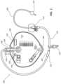
- FIG. 1provides an exemplary embodiment of a catheterization system including a catheter, tubing, and drainage bag in accordance with some embodiments.
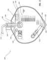
- FIG. 2provides an exemplary embodiment of a catheter in accordance with some embodiments.
- FIG. 3provides an exemplary embodiment of a drainage bag in accordance with some embodiments.
- any labelssuch as “left,” “right,” “front,” “back,” “top,” “bottom,” “forward,” “reverse,” “clockwise,” “counter clockwise,” “up,” “down,” or other similar terms such as “upper,” “lower,” “aft,” “fore,” “vertical,” “horizontal,” “proximal,” “distal,” and the like are used for convenience and are not intended to imply, for example, any particular fixed location, orientation, or direction. Instead, such labels are used to reflect, for example, relative location, orientation, or direction. It should also be understood that the singular forms of “a,” “an,” and “the” include plural references unless the context clearly dictates otherwise. Also, the words “including,” “has,” and “having,” as used herein, including the claims, shall have the same meaning as the word “comprising.”
- proximalrefers to a direction relatively closer to a medical professional
- distalrefers to a direction relatively further from the medical professional
- distalrefers to a direction relatively further from the medical professional.
- distalrefers to a direction relatively further from the medical professional.
- FIG. 1shows an indwelling Foley catheterization system 100 which includes a catheter 200 , and fluid collection or disposal equipment, such as a drainage bag 300 .
- a drainage bag 300is provided for illustrative purposes; however, it will be appreciated that other examples of fluid collection or disposal equipment, including various appropriate shapes, sizes, and materials, also fall within the scope of the present invention.
- the catheter 200may be fluidly connected to the drainage bag 300 by tubing 110 .
- the tubing 110may include various clips or attachment structures 120 which may conveniently attach excess tubing to adjacent clothing, equipment, bed rails, wheel chairs, or the like, to prevent the tubing from touching the ground or becoming entangled as the patient moves around.
- the catheterization system 100may further include a stabilization device 114 which may secure a proximal end of the catheter 200 to the patient.
- exemplary stabilization devicescan be found in: U.S. Pat. No. 8,900,196, filed Apr. 20, 2012, and titled, “Anchoring System”; U.S. Pat. No. 9,480,821, filed Jan. 30, 2012, and titled, “Anchoring System For A Medical Article”; U.S. Pat. No. 9,642,987, filed Feb. 7, 2008, and titled, “Anchoring System For A Catheter”; and U.S. Pat. No. 9,731,097, filed Jul. 3, 2012, and titled, “Stabilizing Device Having A Locking Collet”, each of which are incorporated by reference herein in their entirety.
- the catheterization system 100may further include additional equipment to facilitate the insertion and use of the indwelling catheter system.
- additional equipmentmay include lubrication, a sterile barrier, sterilization swabs, sterile gloves, instructions for use, and various other equipment for facilitating the insertion of the Foley catheter while minimizing the risk of introducing infection to the patient.
- the catheterization system 100may include one or more indicators configured to detect one or more given attributes.
- the indicatormay include sensors coupled with various other components necessary for the detecting, transmitting, displaying and recording of metrics which represent the one or more given attributes.
- the various other components necessary for the detecting, transmitting, displaying and recording of metricsmay include mechanical and/or electrical components. Exemplary components may include, but are not limited to, sensors, bimetallic strips, wires, capacitors, digital displays, power sources, and the like. It will be appreciated that the indicator will include the necessary components in order to detect and indicate the one or more given attributes and are considered to fall within the scope of the present invention.
- the catheterization system 100may include a location indicator 130 , a duration indicator 140 , an elevation indicator 150 , a tamper indicator 160 , a dependent loop indicator 170 , a floor contact indicator 180 , and a patient securement indicator 190 , each of which is described in detail below.
- a location indicator 130a duration indicator 140 , an elevation indicator 150 , a tamper indicator 160 , a dependent loop indicator 170 , a floor contact indicator 180 , and a patient securement indicator 190 , each of which is described in detail below.
- two or more of location indicator 130 , duration indicator 140 , elevation indicator 150 , tamper indicator 160 , dependent loop indicator 170 , floor contact indicator 180 , and patient securement indicator 190may be combined in a single indicator apparatus.
- a single indicator apparatusmay be configured to detect one or more of the given attributes detected by location indicator 130 , duration indicator 140 , elevation indicator 150 , tamper indicator 160 , dependent loop indicator 170 , floor contact indicator 180 , and patient securement indicator 190 .
- FIG. 2shows an exemplary catheter 200 which may be used as part of the catheterization system 100 .
- the catheter 200may include a catheter body 212 having a proximal end 214 and a distal end 216 .
- the distal end 216may include a catheter tip 252 with a rounded, atraumatic end.
- a balloon 232is located near the distal end 216 of the catheter adjacent the tip 252 of the catheter 200 .
- balloon 232may be inflated, using an inflation apparatus (not shown), to anchor the distal end 216 within the bladder.
- An exemplary inflation apparatusmay include a syringe that is fluidly connected with the balloon 232 by way of an inflation lumen 230 .
- a drainage lumen 240extends longitudinally within the catheter body 212 from proximal end 214 to drainage eye(s) 242 in the side wall(s) of tip 252 , and is in fluid communication with drainage eye(s) 242 .
- a single drainage eye 242is illustrated, it is contemplated that the tip 252 may include multiple drainage eyes 242 .
- Drainage eye(s) 242permit fluid to enter the drainage lumen 240 . Drainage eye(s) 242 may be burnished and polished for added smoothness to maximize patient comfort. Drainage eye(s) 242 may be relatively large holes to reduce clotting and maximize urine flow.
- the proximal end 214 of the drainage lumen 240is placed in fluid communication with fluid collection or disposal equipment, such as a drainage bag 300 .
- the proximal end 214 of catheter 200may include a drainage port 244 in fluid communication with the drainage lumen 240 .
- the proximal end 214 of catheter 200may include a one-way drainage valve 246 that only allows fluid to drain proximally from the catheter 200 , and prevents reflux of drained urine back into the catheter 200 .
- proximal end 214 of catheter 200may include or be attached to other communication valves, chambers, funnels, or other devices through which the drainage lumen 240 communicates and/or attaches to the fluid collection or disposal equipment.
- the inflation lumen 230is formed within the wall of the catheter body 212 and extends from an inflation eye 238 inside of the balloon 232 to the proximal end 214 of catheter body 212 .
- Catheter body 212may include a branching arm 218 in a proximal region of the catheter body 212 through which the inflation lumen 230 passes.
- balloon 232is inflated once the distal end 216 of catheter 200 is positioned within a bladder of the body of the patient, which serves to anchor the distal end 216 in the bladder.
- the proximal end 214 of catheter 200may include an inflation port 234 in fluid communication with the inflation lumen 230 of the catheter 200 .
- the proximal end 214 of catheter 200may also include an inflation valve 236 that prevents fluid flow in the inflation lumen 230 unless the proximal end 214 is connected to a syringe or other means for inflating or deflating the balloon 232 .
- catheter 200may include one or more of location indicator 130 , duration indicator 140 , elevation indicator 150 , tamper indicator 160 , dependent loop indicator 170 , floor contact indicator 180 , patient securement indicator 190 , and components thereof.
- catheter 200may include a sensor 220 located adjacent a distal end 216 .
- Sensor 220may be configured to detect one or more attributes, and may be communicatively coupled with one or more of location indicator 130 , duration indicator 140 , elevation indicator 150 , tamper indicator 160 , dependent loop indicator 170 , floor contact indicator 180 , and patient securement indicator 190 (hereinafter collectively termed “indicators 290 ”).
- One or more of indicators 290may be disposed on the catheter body 212 , adjacent a proximal end 214 .
- sensor 220 at a distal end 216may be communicatively coupled with one or more of indicators 290 at a proximal end 214 , either by way of a wire 250 disposed within a wall of the catheter body 212 , or by way of a wireless connection.
- wireless communicationsmay include Bluetooth, Wi-Fi, radio, ultrasound, or similar electro-magnetic or physical (acoustic) wireless communications modes, known in the art.
- sensor 220may be communicatively coupled, either by wired or wireless connection, with one or more indicators 290 disposed on tubing 110 , stabilization device 114 , drainage bag 300 , or combinations thereof. Although only a single sensor 220 is illustrated adjacent a distal end 216 , it is contemplated that catheter 200 may include multiple sensors 220 located adjacent a distal end 216 , a proximal end 214 , within a catheter body 212 , or combinations thereof.
- FIG. 3shows an exemplary fluid collection/disposal equipment, such as a drainage bag 300 .
- Drainage bag 300may include an inlet port 334 which may be fluidly connected to tubing 110 .
- inlet port 334 of drainage bag 300may include a one-way inlet valve 336 that only allows fluid to drain into drainage bag 300 , and prevents reflux of drained urine back into the tubing 110 .
- Drainage bag 300may further include a drainage port 344 .
- drainage port 344may also include a one-way drainage valve 346 that only allows fluid to drain out of drainage bag 300 , and prevents reflux of drained urine back into the drainage bag 300 .
- Drainage port 344may be fluidly connected to tubing 310 and associated connection structures (e.g. tap, spigot, or similar valve) that allows the drainage bag 300 to be emptied and reused if necessary.
- Drainage bag 300may include graded markings 350 , used to denote volume or similar indication of the amount of fluid collected in the drainage bag 300 .
- Drainage bag 300may include an attachment structure 320 , such as a clip, hook, or loop.
- the attachment structure 320may allow the drainage bag to be attached to, or suspended from, adjacent clothing or equipment such as a belt, bedrail, wheel chair, or the like.
- the attachment structure 320is configured to withstand both the weight of the drainage bag 300 as well as any fluid disposed therein.
- the catheterization system 100may include one or more of location indicator 130 , duration indicator 140 , elevation indicator 150 , tamper indicator 160 , dependent loop indicator 170 , floor contact indicator 180 , and patient securement indicator 190 , collectively termed “indicators” 290 .
- Each of the indicators 290may be communicatively coupled with a network.
- a networkmay include a Local Area Network (LAN), Wireless Local Area Network (WLAN), Virtual Private Network (VPN), intranet, internet, a ‘cloud’ based network, or a similar centralized or decentralized, wired or wireless network which falls within the scope of the present invention.
- each of the indicatorsmay detect one or more given attributes and associated metrics and transmits these attributes to the network, such as an Electronic Health Record (“EHR”) or Electronic Medical Record (“EMR”) system, or the like.
- EHRElectronic Health Record
- EMRElectronic Medical Record
- the networkmay then be configured to record and display these metrics.
- a location indicator 130may include an apparatus for detecting a physical or geographic location of the catheterization system.
- the location indicator 130may work in conjunction with various electromagnetic or magnetic fields to determine the relative position of the location indicator 130 , and therefore the associated catheterization system 100 , within a given area.
- the location indicator 130may further record the date and time associated with the location, as well.
- the location indicator 130may include a Global Positioning System (“GPS”) sensor configured to triangulate a relative location based off of GPS signals.
- GPSGlobal Positioning System
- the location indicator 130may use Wi-Fi 33 signals, GSM cellular phone signals, geomagnetic field, or similar natural or artificial, permanent or electro-magnetic fields, combinations thereof, or the like, to triangulate a location.
- the location indicator 130may record a location at set events (e.g. when the catheter 200 was inserted, when the catheter 200 was removed), or at set time intervals (e.g. every hour, minute, or second.)
- the location indicator 130may further include identification information detailing information specific to the individual device used and the patient with which it is used, or the like.
- Device informationmay include make, model, serial numbers, instructions for use, contraindications, or the like.
- Patient informationmay include, name, date of birth, medical record number (“MRN”), address, telephone number(s), specific directives, specific allergies, or the like.
- MRNmedical record number
- Such informationmay be communicated to the network with which the location indicator 130 is communicatively coupled.
- such informationmay already be stored on the network and the identification information may be linked to the device and/or patient by way of a key (e.g. serial number or MRN key) stored on the location indicator 130 .
- a keye.g. serial number or MRN key
- identifying informationmay also be included with each of the indicators 290 , associated with a catheterization system 100 .
- identifying informationmay be included as part of a separate identification indicator (not shown), distinct from that of the indicators 290 .
- a duration indicator 140may detect and record real-time duration of use of a catheterization system 100 .
- the duration indicator 140may detect and record the date and time that the catheter was inserted as well as the date and time that the catheter 200 should be replaced, in accordance with predetermined guidelines.
- the duration indicator 140may include a timer, clock, or similar indicator of real-time, which may be initiated automatically at a ‘start point’ of use of the catheterization system 100 , commonly termed ‘dwell time’.
- duration indicator 140may be communicatively coupled with one or more sensors that may detect when a distal end 216 is disposed within a bladder, when balloon 232 has been inflated, when catheter 200 is connected to the tubing 110 and/or drainage bag 300 , when urine has started to flow, or the like.
- sensorsmay detect when a distal end 216 is disposed within a bladder, when balloon 232 has been inflated, when catheter 200 is connected to the tubing 110 and/or drainage bag 300 , when urine has started to flow, or the like.
- One or more of these attributesmay be used to by the catheterization system 100 to automatically determine a ‘start point’ of dwell time. Similar attributes may also be used to automatically determine an ‘end point’ of use or dwell time.
- the duration indicator 140may include a ‘stopwatch’ which detects and records the amount of time elapsed since a start point of use.
- the duration indicator 140may include a ‘timer’ which measures the amount of time until an end point of use.
- different components of the catheterization system 100e.g. catheter 200 , tubing 110 , drainage bag 300 , may have to be replaced at different times. Stated differently, the components of the catheterization system 100 may have individual start/end points. Accordingly, the duration indicator may track separate start points, end points, and usage or dwell times for the various components of the catheterization system 100 .
- the duration indicator 140may include a display configured to show the patient or medical professional the attributes detected and recorded by the duration indicator 140 .
- the duration indicator 140may include various audio, visual, or tactile alerts, to alert a patient or medical professional of when the catheter 200 is due to be changed, or is needing to be changed immediately.
- the duration indicator 140may also alert a medical professional by way of the network, to which it is communicatively coupled as discussed herein.
- the duration indicator 140may include a percentage bar, progress bar, or similar graphical visual indicator of real-time.
- the automatic initiation of the duration indicator 140would both reduce the work load for the medical professional and remove the possibility of human error.
- a medical professionalmust record the date and time of when the catheter was inserted. From this, the date and time for replacing the catheter, in accordance with guidelines, may be calculated.
- a medical professionalfails to record the start date and time, or the information is lost, or communicated incorrectly, this may lead to complications.
- the cathetermay be left in place longer than is recommended, resulting in the potential malfunctions of the catheter system or an increased risk of infections due to prolonged use.
- the catheteris removed and discarded prematurely leading to an unnecessary patient discomfort from excessive exchanges of catheters, increased risk of infections during the exchange process, and increased costs for the patient due unnecessary use of equipment.
- an elevation indicator 150may detect and record the elevation of drainage bag 300 relative to the bladder.
- a catheterization system 100may rely on a passive, gravity fed, system to maintain a correct flow of urine from the bladder to the drainage bag 300 .
- An elevation indicator 150may determine if the drainage bag 300 is situated correctly, below the bladder of the patient.
- the elevation indicator 150may work in conjunction with one or more sensors either located on the drainage bag 300 , catheter 200 , tubing 110 , stabilization device 114 , or combinations thereof, or the like.
- a sensor 220located adjacent a distal end 216 of the catheter 200 may determine the location of the bladder and may be communicatively coupled with an elevation indicator 150 located adjacent an inlet port 334 of the drainage bag 300 .
- the relative positions of the elevation indicator 150 and sensor 220may be used to determine if the drainage bag 300 is situated correctly, below the bladder. Should the elevation indicator 150 determine that the drainage bag 300 is not correctly situated, the elevation indicator 150 may alert a patient by way of a suitable audio, visual, or tactile alerts, or may alert a medical professional by way of the network, to which it is communicatively coupled as discussed herein, or combinations thereof.
- the elevation indicator 150may work in conjunction with a location indicator 130 .
- the location indicator 130may include a GPS sensor, or similar sensor that is capable of determining elevation.
- the elevation indicator 150 , location indicator 130 , and associated sensors, (e.g. sensor 220 ), and the like,may determine the relative elevations of the bladder and drainage bag to ensure correct positioning of the drainage bag 300 .
- the elevation indicator 150may work in conjunction with a flow sensor (not shown) disposed on a catheter 200 , tubing 110 , or combinations thereof.
- the elevation indicator 150 and flow sensormay determine the correct direction of urine flow within the catheterization system 100 and therefore determine the correct position of the bag.
- a tamper indicator 160may monitor one or more of the connections within the catheterization system 100 to ensure integrity of the connections during set up and use of the catheterization system 100 .
- the catheterization system 100includes various fluid or electrical connections, for example, between the catheter drainage port 244 and tubing 110 , between inflation port 234 and inflation apparatus, between a distal end 216 and the bladder of a patient, between the catheter 200 and stabilization device 114 , between tubing 110 and inlet port 334 , between one or more of the indicators 290 and the catheterization system 100 , or the like.
- the integrity between these connectionsneeds to be verified to ensure correct set up of the catheterization system 100 .
- the integrity of these connectionsalso needs to be maintained during use of the catheterization system 100 . Should the connection integrity be disrupted, the system may fail to function as intended.
- the tamper indicator 160may be communicatively coupled with one or more sensors disposed at one or more of these connections of the catheterization system to ensure the integrity of the system.
- the sensors of the tamper indicator 160may use physical, electrical, magnetic, or similar modality to confirm the connection between the respective components is established correctly and maintained during use of the catheterization system 100 . Should the tamper indicator 160 determine that integrity of one or more of the connections has failed, or not correctly established, the tamper indicator 160 may alert a patient by way of a suitable audio, visual, or tactile alerts, or may alert a medical professional by way of the network, to which it is communicatively coupled as discussed herein, or combinations thereof.
- the tamper indicator 160may provide additional information as to the type of connection that has failed, the location of the particular failure, the particular connection within the catheterization system 100 that has failed, the individual catheterization system 100 unit that has experienced the failure, the identity of the patient with which the catheterization system 100 is associated, combinations thereof, or the like. In an embodiment the tamper indicator 160 may work in conjunction with the location indicator 130 to inform the medical professional where the patient, and associated catheterization system 100 with the failure, currently is, where the failure has occurred, or combinations thereof.
- the tamper indicator 160may automatically record and ensure the correct set up of the catheterization system 100 , this ensures the correct implementation of the catheterization system 100 according to predetermined guidelines. Further the tamper indicator 160 may endure integrity of electrical connections between the various components to ensure the indicators 290 are all functioning correctly. The tamper indicator 160 may also ensure integrity of the fluid connections between the catheter 200 , tubing 110 and drainage bag 300 which mitigates unhygienic spills and undue mess. Further, the tamper indicator 160 may allow a medical professional to monitor any patient non-compliance. For example, patients under chronic stress or having reduce mental capacity may intentionally or unintentionally interfere with the catheter system 100 .
- the tamper indicator 160may ensure the integrity of the information recorded by the catheterization system 100 , as a whole.
- a dependent loop indicator 170may monitor urine pooling, dependent loops, and other flow irregularities within the catheterization system 100 .
- a fundamental aspect of catheterization systemsis the monitoring of urine volume and flow rate for a patient. Complications may occur with the formation of ‘dependent loops’ within the catheterization system 100 .
- Dependent loopsoccur when there is excess tubing 110 between the catheter 200 and drainage bags 300 , creating loops of tubing. These tubing loops provide low points within a gravity fed system where urine pooling may occur.
- Such urine poolingmay affect the volume and flow rate data recorded by the catheterization system 100 . More importantly, however, such urine pooling may also lead to unhygienic conditions, and associated urinary tract infections.
- the dependent loop indicator 170may include one or more sensors associated with the catheter 200 , tubing 110 , drainage bag 300 , or combinations thereof.
- the dependent loop indicator 170may include flow rate sensors to ensure the correct direction and rate of flow of urine within the catheterization system 100 .
- the dependent loop indicator 170may include pressure sensors to detect the presence accumulations of static fluid within the catheterization system 100 .
- the dependent loop indicator 170may include suitable audio, visual, or tactile alerts, or may alert a medical professional by way of the network, to which it is communicatively coupled, or combinations thereof.
- the catheterization system 100may use a passive gravity feed system, or in an embodiment, the catheterization system 100 may use an active pump that moves fluid through the tubing 110 to the drainage bag. In an embodiment, the catheterization system 100 may use a combination of active and passive feed systems. Accordingly, the catheterization system 100 may predominantly rely on a gravity fed system. However, where the activity or body position of the patient is such that urine pooling occurs in tubing 110 , the dependent loop indicator 170 may detect such pooling and initiate a pump to move the urine through the tubing 110 to the drainage bag 300 . In this way, the catheterization system 100 may not only automatically detect the presence of a dependent loop and urine pooling, but may also rectify the problem automatically, without the need for intervention from a medical professional or patient.
- a floor contact indicator 180may monitor whether the catheterization system 100 , or components thereof, is touching or has touched a floor surface.
- the floor contact indicator 180may work in conjunction with one or more sensors disposed on the drainage bag 300 , tubing 110 , catheter 200 , or combinations thereof.
- the drainage bags of catheterization systemsare often attached to a waist belt on the patient, or to a bed rail, wheel chair, or similar piece of equipment adjacent the patient.
- the empty drainage bagmay seem securely attached to the belt or equipment.
- the attachmentmay become insufficient leading to the drainage bag slipping and touching or dragging along the floor. If such a situation goes unnoticed by the patient or busy medical professional, it can lead to various functional or hygienic problems, including for example, the wearing or rupturing of the drainage bag.
- a floor contact indicator 180may include a sensor disposed on a lower portion of the drainage bag 300 . Should the drainage bag 300 slip and make contact with a floor surface, the floor contact indicator 180 may alert a patient or medical professional either by way of suitable audio, visual, or tactile alerts, or may alert a medical professional by way of the network, to which it is communicatively coupled, or combinations thereof.
- a floor contact indicator 180may include sensors disposed at other key points within the catheterization system 100 which may indicate a portion of the catheterization system 100 is, or has touched, the floor. For example, a sensor may be located between the drainage bag 300 and attachment structure 320 . Accordingly, when any part of the drainage bag 300 makes contact with the floor, not just a lower most point substantially at floor contact indicator 180 , a sudden drop in pressure detected at attachment structure 320 may indicate the drainage bag is touching the floor.
- a floor contact indicator 180may include sensors disposed on tubing 110 .
- a collar 182may be slidably coupled with tubing 110 , such that the collar 182 will automatically align with a lower most point along the tubing 110 . Should the lower most point of the tubing 110 come into contact with the floor, a floor contact indicator 180 , or sensor communicatively coupled therewith, disposed on collar 182 may detect the contact and alert the patient or medical professional as discussed herein.
- collar 182may be part of the dependent loop indicator 170 .
- collar 182may be a separate structure from the dependent loop indicator 170 .
- a floor contact indicator 180may include sensors that detect various attributes in order to determine if a portion of the catheterization system 100 is, or has, made contact with the floor.
- sensorsmay detect pressure, three-dimensional (“3D”) spatial location, velocity or force (e.g. gyroscopic sensors, accelerometers), distance (e.g. using infrared, laser, or acoustic modalities), proximity (e.g. using radar, motion, magnetic force), combinations thereof, or the like.
- the floor contact indicator 180may work in conjunction with one or more of indicators, such as the location indicator 130 , elevation indicator 150 , or the like, to determine if a portion of the catheterization system 100 is, or has, made contact with the floor.
- the floor contact indicator 180may include sensors capable of determining if a portion of the catheterization system 100 is about make contact with the floor and provide a warning to the patient or medical professional, as described herein, so that contact between the floor and catheterization system 100 may be averted.
- a patient securement indicator 190may monitor whether the catheterization system 100 , or a component thereof, is attached to the patient, or has been detached therefrom.
- the catheterization system 100may be secured to a patient at various points; for example, drainage bag 300 may be secured to the patient using attachment structure 320 and a proximal end 214 of the catheter 200 may be secured to the skin of the patient using stabilization device 114 .
- various problemsmay occur if the catheterization system 100 , or a component thereof, becomes detached from the patient, either intentionally or unintentionally. For example, the detached portion may become disconnected from the catheterization system 100 , the portion may drag on the floor or become entangled. Such situations may result in damage to the catheterization system 100 or unsanitary conditions, leading to an increased risk of infection.
- a patient securement indicator 190may include one or more sensors that may detect if one or more portions of the catheterization system 100 is secured to the patient. As discussed herein, the sensors may use various modalities to determine if the catheterization system 100 , or a portions thereof, are secured to the patient. Such modalities may include, electromagnetic, magnetic, pressure, force, velocity, combinations thereof, or the like. Similarly, the patient securement indicator 190 may work in conjunction with other indicators, such as the location indicator 130 , floor contact indicator 180 , or the like, to determine if the catheterization system 100 , or portion thereof, has become detached from the patient.
- the patient securement indicator 190may provide suitable audio, visual, or tactile alerts to a patient, or may alert a medical professional by way of the network, to which it is communicatively coupled, or combinations thereof.
- a catheterization system 100may be provided including a catheter 200 , drainage bag 300 , tubing 110 , and one or more of location indicator 130 , duration indicator 140 , elevation indicator 150 , tamper indicator 160 , dependent loop indicator 170 , floor contact indicator 180 , and patient securement indicator 190 .
- the catheterization system 100may further include additional equipment to facilitate the insertion and use of the indwelling catheter system. Such equipment may include lubrication, a sterile barrier, sterilization swabs, sterile gloves, instructions for use, and various other equipment for facilitating the insertion of the Foley catheter while minimizing the risk of introducing infection to the patient.
- the catheter 200is introduced into the patient and is advanced into the patient's urethra until the distal end 216 of the catheter 200 , including the balloon 232 , resides within the bladder.
- the balloon 232is then inflated, typically by coupling a syringe to the proximal end 214 of the catheter 200 such that the syringe may communicate with the inflation lumen 230 , and actuating the syringe to discharge fluid from the syringe, through the inflation lumen 230 , and into the balloon 232 .
- the balloon 232which in one embodiment is made of an elastomeric material, is positioned around the catheter shaft.
- the balloon 232is preferably engineered to retain its shape once inflated without significantly deforming due to pressures arising while within the body.
- the balloon 232may include ribs (e.g., thicker polymer portions or added reinforcement) to ensure strength and symmetry of the material.
- a proximal end 214may be secured to the skin of the patient using a stabilization device 114 .
- Tubing 110may then fluidly connect the catheter 200 with the drainage bag 300 .
- the drainage bag 300may be secured at an appropriate position relative to the bladder of the patient.
- the one or more indicators 290may automatically detect when the catheterization system 100 is correctly deployed.
- the indicators 290may automatically detect and record: the individual patient with which the specific catheterization system 100 is being used; when the distal end 216 of the catheter is correctly located within the bladder; when the balloon is correctly inflated; when a proximal end 214 of the catheter 200 is secured to the patient; when a proximal end 214 of the catheter 200 is connected to the tubing 110 ; when the tubing 110 is connected to the drainage bag 300 ; when drainage bag 300 is secured to the patient; when urine flow commences; when drainage bag 300 is full; when catheterization system 100 , or components thereof, need to be replaced according to predetermined guidelines; and when catheterization system 100 is removed from the patient.
- the indicators 290 of the catheterization system 100may also detect and record the location of the catheterization system 100 when various events occur, as discussed above, or at various time intervals throughout the use of the catheterization system 100 , or combinations thereof.
- the indicators 290 of the catheterization systemmay also detect and record any faults that may occur during the usage of the catheterization system 100 , such as: a misalignment of the drainage bag 300 relative to the bladder of the patient; a connection integrity failure of within the catheterization system 100 ; a dependent loop or flow irregularity within the tubing 110 ; any contact between the catheterization system 100 and a floor surface; or any detachment of the catheterization system 100 , or portion thereof, from the patient during the use of the catheterization system 100 .
- the information detected and recorded by the catheterization system 100may be stored locally on a non-transitory storage device associated with the catheterization system 100 , or may be stored remotely to a network, as discussed herein.
- the catheterization system 100may continue to be used until a predetermined end point has been reached.
- the predetermined end pointmay determine by a specific date and time, by a specific amount of time that has elapsed, by a specific amount of fluid that has been collected, or when a specific event or fault has been detected, combinations thereof, or the like.
Landscapes
- Health & Medical Sciences (AREA)
- Life Sciences & Earth Sciences (AREA)
- Engineering & Computer Science (AREA)
- Heart & Thoracic Surgery (AREA)
- General Health & Medical Sciences (AREA)
- Public Health (AREA)
- Veterinary Medicine (AREA)
- Biomedical Technology (AREA)
- Animal Behavior & Ethology (AREA)
- Biophysics (AREA)
- Medical Informatics (AREA)
- Anesthesiology (AREA)
- Hematology (AREA)
- Molecular Biology (AREA)
- Pathology (AREA)
- Physics & Mathematics (AREA)
- Surgery (AREA)
- Pulmonology (AREA)
- Epidemiology (AREA)
- Urology & Nephrology (AREA)
- Primary Health Care (AREA)
- Child & Adolescent Psychology (AREA)
- Physiology (AREA)
- Computer Networks & Wireless Communication (AREA)
- Otolaryngology (AREA)
- External Artificial Organs (AREA)
- Media Introduction/Drainage Providing Device (AREA)
Abstract
Description
Claims (11)
Priority Applications (1)
| Application Number | Priority Date | Filing Date | Title |
|---|---|---|---|
| US17/054,493US11938277B2 (en) | 2018-05-22 | 2019-05-21 | Catheterization system and methods for use thereof |
Applications Claiming Priority (3)
| Application Number | Priority Date | Filing Date | Title |
|---|---|---|---|
| US201862675103P | 2018-05-22 | 2018-05-22 | |
| US17/054,493US11938277B2 (en) | 2018-05-22 | 2019-05-21 | Catheterization system and methods for use thereof |
| PCT/US2019/033389WO2019226697A1 (en) | 2018-05-22 | 2019-05-21 | Catheterization system and methods for use thereof |
Related Parent Applications (1)
| Application Number | Title | Priority Date | Filing Date |
|---|---|---|---|
| PCT/US2019/033389A-371-Of-InternationalWO2019226697A1 (en) | 2018-05-22 | 2019-05-21 | Catheterization system and methods for use thereof |
Related Child Applications (1)
| Application Number | Title | Priority Date | Filing Date |
|---|---|---|---|
| US18/612,745DivisionUS20240252783A1 (en) | 2018-05-22 | 2024-03-21 | Catheterization System and Methods for Use Thereof |
Publications (2)
| Publication Number | Publication Date |
|---|---|
| US20210187240A1 US20210187240A1 (en) | 2021-06-24 |
| US11938277B2true US11938277B2 (en) | 2024-03-26 |
Family
ID=68615818
Family Applications (2)
| Application Number | Title | Priority Date | Filing Date |
|---|---|---|---|
| US17/054,493Active2039-07-19US11938277B2 (en) | 2018-05-22 | 2019-05-21 | Catheterization system and methods for use thereof |
| US18/612,745PendingUS20240252783A1 (en) | 2018-05-22 | 2024-03-21 | Catheterization System and Methods for Use Thereof |
Family Applications After (1)
| Application Number | Title | Priority Date | Filing Date |
|---|---|---|---|
| US18/612,745PendingUS20240252783A1 (en) | 2018-05-22 | 2024-03-21 | Catheterization System and Methods for Use Thereof |
Country Status (6)
| Country | Link |
|---|---|
| US (2) | US11938277B2 (en) |
| EP (2) | EP4252816A3 (en) |
| JP (1) | JP2021524323A (en) |
| CN (1) | CN112165970A (en) |
| ES (1) | ES2964913T3 (en) |
| WO (1) | WO2019226697A1 (en) |
Families Citing this family (19)
| Publication number | Priority date | Publication date | Assignee | Title |
|---|---|---|---|---|
| US11045128B2 (en) | 2017-06-03 | 2021-06-29 | Sentinel Medical Technologies, LLC | Catheter for monitoring intra-abdominal pressure |
| JP2021524323A (en) | 2018-05-22 | 2021-09-13 | シー・アール・バード・インコーポレーテッドC R Bard Incorporated | Catheter insertion system and how to use it |
| EP4614117A2 (en) | 2018-08-10 | 2025-09-10 | C. R. Bard, Inc. | Automated urine-output-measurement systems and methods thereof |
| US11672457B2 (en) | 2018-11-24 | 2023-06-13 | Sentinel Medical Technologies, Llc. | Catheter for monitoring pressure |
| US11779263B2 (en) | 2019-02-08 | 2023-10-10 | Sentinel Medical Technologies, Llc. | Catheter for monitoring intra-abdominal pressure for assessing preeclampsia |
| US11730385B2 (en) | 2019-08-08 | 2023-08-22 | Sentinel Medical Technologies, LLC | Cable for use with pressure monitoring catheters |
| US11617543B2 (en)* | 2019-12-30 | 2023-04-04 | Sentinel Medical Technologies, Llc. | Catheter for monitoring pressure |
| US12083261B2 (en) | 2020-06-05 | 2024-09-10 | C. R. Bard, Inc. | Automated fluid output monitoring |
| US11703365B2 (en) | 2020-07-14 | 2023-07-18 | C. R. Bard, Inc. | Automatic fluid flow system with push-button connection |
| US12055249B2 (en) | 2020-07-21 | 2024-08-06 | C. R. Bard, Inc. | Automatic fluid flow system with retractable connection |
| EP4240458A4 (en)* | 2020-11-19 | 2024-05-29 | C. R. Bard, Inc. | DYNAMIC PRESSURE RESPONSE SYSTEM |
| US12408853B2 (en) | 2020-12-17 | 2025-09-09 | C. R. Bard, Inc. | Smart bag to measure urine output via catheter |
| US12364423B2 (en) | 2020-12-21 | 2025-07-22 | C. R. Bard, Inc. | Automated urinary output-measuring systems and methods |
| US11931151B2 (en) | 2020-12-22 | 2024-03-19 | C. R. Bard, Inc. | Automated urinary output measuring system |
| US12246146B2 (en) | 2020-12-23 | 2025-03-11 | C. R. Bard, Inc. | Automated weight based fluid output monitoring system |
| WO2023148435A1 (en)* | 2022-02-04 | 2023-08-10 | Sorbonne Universite | Device for monitoring the urinary voiding of a patient |
| TWI842198B (en) | 2022-11-14 | 2024-05-11 | 永磐科技股份有限公司 | Urine real-time monitoring system and method |
| US12311118B2 (en) | 2023-06-09 | 2025-05-27 | William Brubaker | Body fluid movement system |
| US12285570B1 (en)* | 2024-01-05 | 2025-04-29 | Wiiliam Brubaker | Body fluid movement system with one or more sensors coupled to a patient remote monitoring system |
Citations (214)
| Publication number | Priority date | Publication date | Assignee | Title |
|---|---|---|---|---|
| US3661143A (en) | 1969-06-23 | 1972-05-09 | Henkin Melvyn Lane | Medical apparatus for drainage, collection and monitoring of body fluids |
| US3781920A (en) | 1972-06-21 | 1974-01-01 | Brown Eng Corp | Waste discharge valve for toilet bowl |
| JPS4975171A (en) | 1972-10-20 | 1974-07-19 | ||
| US3851650A (en) | 1972-06-06 | 1974-12-03 | Kendall & Co | Closed drainage system with double lumen tube |
| US3919455A (en) | 1972-10-20 | 1975-11-11 | Hoffmann La Roche | Apparatus for the measurement of the volume and flow rate of liquids |
| JPS54147066A (en) | 1978-05-11 | 1979-11-16 | Shinko Electric Co Ltd | Level detector |
| US4276889A (en) | 1979-04-19 | 1981-07-07 | Shs Enterprises, Ltd. | Urine specimen collecting device |
| US4286590A (en) | 1978-07-24 | 1981-09-01 | Terumo Corporation | Stactometric apparatus |
| US4291692A (en) | 1979-10-09 | 1981-09-29 | University Of Utah | Closed-loop infusion system, both method and apparatus, based on real time urine measurement |
| US4296749A (en) | 1980-07-18 | 1981-10-27 | Louis B. Fine | Colostomy appliance |
| WO1981003427A1 (en) | 1980-05-29 | 1981-12-10 | H Scholander | Catheter device |
| US4305405A (en) | 1980-03-25 | 1981-12-15 | C. R. Bard, Inc. | Urine meter bag |
| US4312352A (en) | 1980-01-29 | 1982-01-26 | C. R. Bard, Inc. | Hanger, hook and handle assembly for urinary drainage bag |
| US4343316A (en) | 1980-05-16 | 1982-08-10 | C. R. Bard, Inc. | Electronic urine flow monitor |
| JPS58190719A (en) | 1982-04-30 | 1983-11-07 | Nippon Steel Corp | Two-phase flow meter for gas-liquid, solid-liquid, solid-gas, etc. |
| US4443219A (en) | 1981-03-10 | 1984-04-17 | C. R. Bard, Inc. | System for aseptically draining a urine bag |
| US4448207A (en) | 1981-11-03 | 1984-05-15 | Vital Metrics, Inc. | Medical fluid measuring system |
| US4532936A (en) | 1981-08-21 | 1985-08-06 | Leveen Eric G | Automatic urine flow meter |
| JPS60219517A (en) | 1984-04-16 | 1985-11-02 | Matsushita Electric Ind Co Ltd | Bath pot with water level detection device |
| US4658834A (en) | 1983-03-16 | 1987-04-21 | C.R. Bard, Inc. | Medical apparatus for monitoring body liquid discharge |
| US4723950A (en) | 1984-12-12 | 1988-02-09 | C. R. Bard, Inc. | Urine drainage bag outlet with barrier against microbial infection |
| US4834706A (en) | 1987-11-24 | 1989-05-30 | Sherwood Medical Company | Medical apparatus with a tearable tamper evident indicator means |
| US4850375A (en) | 1987-11-09 | 1989-07-25 | The Kendall Company | Urine meter with tilting guide |
| EP0342028A2 (en) | 1988-05-12 | 1989-11-15 | Dacomed Corporation | Urine collection monitor |
| US4889532A (en) | 1988-06-21 | 1989-12-26 | Hollister Incorporated | Female urinary incontinence device with forwardly-directed discharge passage and support surface portions |
| JPH0257240B2 (en) | 1981-09-08 | 1990-12-04 | Bw Ip International Inc | |
| US5002541A (en) | 1984-06-19 | 1991-03-26 | Martin And Associates, Inc. | Method and device for removing and collecting urine |
| US5409014A (en) | 1993-08-13 | 1995-04-25 | Dravon Medical, Inc. | Fluid meter |
| JPH08271301A (en) | 1995-03-30 | 1996-10-18 | Chichibu Onoda Cement Corp | Flow measuring device for powder/grain |
| US5586085A (en) | 1991-10-31 | 1996-12-17 | Lichte; Leo J. | Container and adaptor for use with fluid volume sensor |
| US5725515A (en) | 1994-11-01 | 1998-03-10 | Tri-State Hospital Supply Corporation | Urine sampling and bladder drainage system |
| US5733319A (en) | 1996-04-25 | 1998-03-31 | Urologix, Inc. | Liquid coolant supply system |
| US5738656A (en) | 1993-03-02 | 1998-04-14 | Wagner; Wolfgang | Drainage apparatus and method of use |
| JPH10104041A (en) | 1996-09-27 | 1998-04-24 | Sofue Yatoshi | Liquid amount detector and instillation end alarm |
| US5747824A (en) | 1995-12-01 | 1998-05-05 | Alcon Laboratories, Inc. | Apparatus and method for sensing fluid level |
| US5769087A (en) | 1993-11-12 | 1998-06-23 | Fresenius Ag | Urine measurement apparatus and method for the determination of the density of urine |
| US5807278A (en) | 1996-06-06 | 1998-09-15 | Mcrae; Lorin P. | Noninvasive bladder pressure and urine flow measurement apparatus and method |
| US5823972A (en) | 1996-06-06 | 1998-10-20 | Mcrae; Lorin P. | Pressure transducer bladder pressure and urinary flow measurement apparatus and method |
| US5891051A (en) | 1995-06-02 | 1999-04-06 | C.R. Bard, Inc. | Electronic urine monitor |
| US5911786A (en) | 1994-05-06 | 1999-06-15 | Maersk Medical A/S | Apparatus for collecting and measuring body fluid |
| US6129684A (en) | 1998-09-02 | 2000-10-10 | B. Braun Melsungen Ag | Urine measuring device |
| US6132407A (en) | 1997-02-06 | 2000-10-17 | C. R. Bard, Inc. | Outlet tube device for urinary drainage bag |
| US6250152B1 (en) | 1995-03-29 | 2001-06-26 | Daimlerchrysler Ag | Sensor arrangement |
| US6256532B1 (en) | 1999-07-29 | 2001-07-03 | Biospace Co., Ltd. | Apparatus for analyzing body composition based on bioelectrical impedance analysis and method thereof |
| US6261254B1 (en) | 1999-07-21 | 2001-07-17 | C. R. Bard, Inc. | Lever-style drain assembly for urine collection container |
| CN2445749Y (en) | 2000-08-17 | 2001-09-05 | 吴兴 | Medical electric pump transfusion system |
| US20010056226A1 (en) | 2000-04-18 | 2001-12-27 | Richard Zodnik | Integrated telemedicine computer system |
| US20020016719A1 (en) | 2000-06-19 | 2002-02-07 | Nemeth Louis G. | Methods and systems for providing medical data to a third party in accordance with configurable distribution parameters |
| US6434418B1 (en) | 2000-04-12 | 2002-08-13 | Randall H. Neal | Apparatus for measuring intrauterine pressure and fetal heart rate and method for using same |
| US20020161314A1 (en) | 2000-02-17 | 2002-10-31 | Malla Sarajarvi | Arrangement for patient monitor |
| US20020193760A1 (en) | 2001-06-13 | 2002-12-19 | Garey Thompson | Female urine collector |
| US20030000303A1 (en) | 2001-06-25 | 2003-01-02 | Livingston Richard A. | Auto-compensating capacitive level sensor |
| US6579247B1 (en) | 1998-06-01 | 2003-06-17 | Alcor Medical Instruments, Inc. | Device for monitoring bladder urine distension in patients, and a method thereof |
| US6592612B1 (en) | 2000-05-04 | 2003-07-15 | Cardeon Corporation | Method and apparatus for providing heat exchange within a catheter body |
| US20030163287A1 (en) | 2000-12-15 | 2003-08-28 | Vock Curtis A. | Movement and event systems and associated methods related applications |
| US20030163183A1 (en) | 2002-02-27 | 2003-08-28 | Gary Carson | Patient temperature control system |
| US6709420B1 (en) | 1999-07-21 | 2004-03-23 | C.R. Bard, Inc. | Switch-style drain assembly for urine collection container |
| US6716200B2 (en) | 2002-01-18 | 2004-04-06 | C.R. Bard, Inc. | Antimicrobial urine collection system and methods of manufacturing the same |
| WO2004045410A1 (en) | 2002-11-19 | 2004-06-03 | Urodan Aps | An apparatus and a method for urological measurements |
| US20040267086A1 (en) | 2003-06-26 | 2004-12-30 | Anstadt Mark P. | Sensor-equipped and algorithm-controlled direct mechanical ventricular assist device |
| US20050020958A1 (en) | 2001-12-28 | 2005-01-27 | Francesco Paolini | Control equipment and method for an extracorporeal blood circuit |
| US20050065583A1 (en) | 2003-08-25 | 2005-03-24 | Voorhees Marc E. | Active body cooling with vasodilation to reduce body temperature |
| US20050172712A1 (en) | 2004-02-06 | 2005-08-11 | Nyce David S. | Isolated capacitive fluid level sensor |
| US20050247121A1 (en) | 2004-05-07 | 2005-11-10 | Transmed Medizintechnik Gmbh & Co. Kg | Urine collection and monitoring system |
| US7011634B2 (en) | 2003-04-14 | 2006-03-14 | Sample Rite, Inc. | Urine sample collection device |
| US20060100743A1 (en) | 2004-04-23 | 2006-05-11 | Renal Diagnostic Inc. | Automated non-invasive real-time acute renal failure detection system |
| US7161484B2 (en) | 2001-04-17 | 2007-01-09 | Micrel Medical Devices S.A. | System for monitoring medical parameters |
| US20070010797A1 (en) | 2005-07-05 | 2007-01-11 | C. R. Bard, Inc. | Multi-functional and modular urine collection system |
| US20070145137A1 (en) | 2005-12-27 | 2007-06-28 | Mrowiec Zbigniew R | Systems and methods for processing measurement data |
| CN200951235Y (en) | 2006-08-22 | 2007-09-26 | 张念 | Electric capacity intelligent sensing device for automatic control system for intravenous drip |
| CA2882654A1 (en) | 2006-04-14 | 2007-10-25 | Deka Products Limited Partnership | Systems, devices and methods for fluid pumping, heat exchange, thermal sensing, and conductivity sensing |
| US20070252714A1 (en) | 2006-04-28 | 2007-11-01 | Medtronic, Inc. | External voiding sensor system |
| JP2007303982A (en) | 2006-05-12 | 2007-11-22 | Kougi Kenkyusho:Kk | Sensor device |
| JP2008524618A (en) | 2004-12-22 | 2008-07-10 | イネルジー オートモーティヴ システムズ リサーチ | Capacitive liquid level sensor |
| US7437945B1 (en) | 2008-02-14 | 2008-10-21 | Murray F Feller | Magnetic flow probe |
| US7442754B2 (en) | 2001-01-24 | 2008-10-28 | Virginia Commonwealth University | Molecular imprinting of small particles, and production of small particles from solid state reactants |
| US20080312556A1 (en) | 2004-06-25 | 2008-12-18 | Best Medical B.V. | Device for Measuring Data Relating to Urine Production of a Patient |
| US20090056020A1 (en) | 2007-08-30 | 2009-03-05 | Jean-Luc Caminade | Pressure detection and measurement sensor incorporating at least one resistive force-detector cell |
| JP2009068959A (en) | 2007-09-12 | 2009-04-02 | Sinto Brator Co Ltd | Powder flow rate measuring device |
| US20090099629A1 (en) | 2007-10-12 | 2009-04-16 | Medivance Incorporated | System and method for patient temperature control |
| US20090157430A1 (en) | 2007-10-11 | 2009-06-18 | Peter Rule | Synchronization and configuration of patient monitoring devices |
| US20090287170A1 (en) | 2008-05-13 | 2009-11-19 | Preferred Medical Devices, Inc. | Urine collection system |
| US20090315684A1 (en) | 2008-05-07 | 2009-12-24 | Sacco John J | CUI-Tagged Catheter Devices and System |
| US20100094204A1 (en) | 2007-02-21 | 2010-04-15 | C.R. Bard, Inc. | Acs therapy system |
| US20100130949A1 (en) | 2008-05-16 | 2010-05-27 | Garcia Maurice M | Catheter drainage system |
| CN201492414U (en) | 2009-07-31 | 2010-06-02 | 成都卓青科技有限公司 | Automatic urine meter |
| US20100137743A1 (en) | 2005-07-05 | 2010-06-03 | C. R. Bard, Inc. | Multi-functional and modular urine collection system |
| JP2010121950A (en) | 2008-11-17 | 2010-06-03 | Loarant Corp | Device of measuring amount of liquid |
| US7739907B2 (en) | 2006-11-29 | 2010-06-22 | Future Path Medical Llc | Container for physiological fluids |
| JP2010530978A (en) | 2007-06-22 | 2010-09-16 | ベクトン・ディキンソン・アンド・カンパニー | Dispensing volume monitor for array arrangement |
| US7871385B2 (en) | 2002-02-20 | 2011-01-18 | Orde Levinson | Urine sample collection device |
| US20110113540A1 (en) | 2009-11-17 | 2011-05-19 | Plate Eric M | Plumbing Fixture Having Modular Control Housing |
| US7976533B2 (en) | 2003-12-22 | 2011-07-12 | Medela Holding Ag | Drainage apparatus and method |
| US7998126B1 (en) | 2002-11-06 | 2011-08-16 | Benidecto Fernandez | Integral urine collector |
| US20110238042A1 (en) | 2007-10-02 | 2011-09-29 | C. R. Bard, Inc. | Drainage Catheter with One-Way Valve |
| US20110251572A1 (en) | 2008-06-06 | 2011-10-13 | C.R. Bard, Inc. | Urine Collection Device |
| US20110263952A1 (en) | 2004-11-03 | 2011-10-27 | Fred Bergman Healthcare Pty Ltd | Incontinence management system and diaper |
| US20120029408A1 (en) | 2009-03-30 | 2012-02-02 | Steve Andre Beaudin | Apparatus, system and methods for extracorporeal blood processing for selectively cooling the brain relative to the body during hyperthermic treatment or to induce hypothermia of the brain |
| US20120059286A1 (en)* | 2010-09-07 | 2012-03-08 | Roger Hastings | Self-Powered Ablation Catheter for Renal Denervation |
| US20120078235A1 (en)* | 2010-08-23 | 2012-03-29 | Martin George L | Safety urinary catheter |
| US20120078137A1 (en) | 2009-06-03 | 2012-03-29 | Biometrix Ltd | Apparatus and method for bedside collection of body fluids and automatic volume level monitoring |
| US20120095304A1 (en) | 2005-12-15 | 2012-04-19 | Cardiopulmonary Corporation | System and Method for Determining a Patient Clinical Status |
| US20120109008A1 (en) | 2009-06-23 | 2012-05-03 | Observe Medical Aps | Urine measuring device |
| US20120123233A1 (en) | 2009-07-24 | 2012-05-17 | Flometrica Ltd. | Disposable usb cup |
| US20120127103A1 (en) | 2010-11-19 | 2012-05-24 | Bruce Dean Qualey | Configurable patient monitoring system |
| JP2012105947A (en) | 2010-10-27 | 2012-06-07 | Sasae Ishibashi | Container for urine collection, and urinary volume measuring device |
| US20120226196A1 (en) | 2010-05-26 | 2012-09-06 | Dimino Andre | Apparatus and method for uroflowmetry |
| US20120234434A1 (en) | 2008-06-09 | 2012-09-20 | Gentera Holdings, Llc | Pressure sensing catheter |
| US8295933B2 (en) | 2007-05-30 | 2012-10-23 | Medtronic, Inc. | Implantable medical lead including voiding event sensor |
| JP2012225790A (en) | 2011-04-20 | 2012-11-15 | Toyota Motor Corp | Liquid level detector |
| US20120302917A1 (en) | 2011-05-23 | 2012-11-29 | Tyco Healthcare Group Lp | Urine Meter |
| US8328734B2 (en) | 2006-02-24 | 2012-12-11 | Covidien Lp | Urine meter with improved drain construction |
| US8328733B2 (en) | 2006-09-30 | 2012-12-11 | Forte Medical Limited | Urine collection device |
| US20120323502A1 (en) | 2010-04-13 | 2012-12-20 | Masazumi Tanoura | Flow volume measurement device and flow velocity measurement device |
| US8337476B2 (en) | 2009-08-20 | 2012-12-25 | Greenwald Technologies, Llc | Real time urine monitoring system |
| WO2013013782A2 (en) | 2011-07-22 | 2013-01-31 | Rheinisch-Westfälische Technische Hochschule Aachen (RWTH) | Method and device for monitoring the filling level of the bladder of a patient |
| US8374688B2 (en) | 2007-09-14 | 2013-02-12 | Corventis, Inc. | System and methods for wireless body fluid monitoring |
| US20130066166A1 (en)* | 2011-03-07 | 2013-03-14 | Theranova, Llc | Sensing foley catheter |
| US20130109928A1 (en) | 2011-10-28 | 2013-05-02 | Mindray Ds Usa, Inc. | Dynamically reconfiguring a user interface of a patient monitor responsive to an orientation input |
| US20130109927A1 (en) | 2011-10-28 | 2013-05-02 | Mindray Ds Usa, Inc. | Systems and methods for remote patient monitoring |
| US20130131610A1 (en) | 2010-07-26 | 2013-05-23 | Steerable Instruments Bvba | Capillary tube assembly |
| US8471231B2 (en) | 2005-01-20 | 2013-06-25 | Flowsense Ltd | Optical drop detector system featuring a plurality of light pulses for detecting a plurality of flows |
| US20130218106A1 (en) | 2010-07-30 | 2013-08-22 | C. R. Bard, Inc. | Automated Method of Pooling Elimination with a Biological Fluid Collection System |
| US20130245498A1 (en) | 2012-03-13 | 2013-09-19 | Barbara Delaney | Apparatus, system and method of monitoring bodily fluid output in a healthcare environment |
| WO2013178742A1 (en) | 2012-05-31 | 2013-12-05 | Almirall, S.A. | Novel dosage form and formulation of abediterol |
| US20140039348A1 (en) | 2012-08-01 | 2014-02-06 | Magnolia Medical Technologies, Inc. | Fluid diversion mechanism for bodily-fluid sampling |
| US8663128B2 (en) | 2006-11-14 | 2014-03-04 | Flowsense Ltd. | Diagnostic method and apparatus |
| WO2014043650A2 (en) | 2012-09-17 | 2014-03-20 | Theranova, Llc | Systems, devices and methods for urine monitoring |
| US20140155782A1 (en) | 2012-12-04 | 2014-06-05 | Magnolia Medical Technologies, Inc. | Sterile bodily-fluid collection device and methods |
| US20140155781A1 (en) | 2012-05-30 | 2014-06-05 | Magnolia Medical Technologies, Inc | Fluid diversion mechanism for bodily-fluid sampling |
| US20140159921A1 (en) | 2010-11-19 | 2014-06-12 | Spacelabs Healthcare Llc | Configurable, Portable Patient Monitoring System |
| US8773259B2 (en) | 2009-12-23 | 2014-07-08 | Mindray Ds Usa, Inc. | Systems and methods for remote patient monitoring |
| WO2014108690A1 (en) | 2013-01-09 | 2014-07-17 | Stewart Floyd Nathan | Urine sample device |
| US20140207085A1 (en) | 2009-04-27 | 2014-07-24 | The Alfred E. Mann Foundation For Scientific Research | Implantable infusion devices and associated methods |
| US8790277B2 (en) | 2008-08-07 | 2014-07-29 | Covidien Lp | Anti-reflux mechanism for urine collection systems |
| US8790577B2 (en) | 2007-09-13 | 2014-07-29 | Sysmex Corporation | Sample analyzer |
| US8790320B2 (en) | 2008-10-17 | 2014-07-29 | Sterigear, Llc | Bodily fluid drainage assembly |
| US8813551B2 (en) | 2005-04-10 | 2014-08-26 | Future Path Medical Holding Co. Llc | Device that accurately measures physiological fluid flow |
| US20140243635A1 (en) | 2013-02-22 | 2014-08-28 | Thuban, Inc. | Device for enabling patient self testing and treatment self- administration and system using the device for managing the patient's health care |
| US8827924B2 (en) | 2007-08-23 | 2014-09-09 | Flowsense Ltd. | Diagnostic methods and systems based on urine analysis |
| US8832558B2 (en) | 2008-10-12 | 2014-09-09 | University Of Maryland, Baltimore | Predetermined presentation of patient data at bedside |
| WO2014135856A1 (en) | 2013-03-04 | 2014-09-12 | Forte Medical Limited | Urine collection device |
| WO2014145971A2 (en) | 2013-03-15 | 2014-09-18 | C.R. Bard, Inc. | Urine monitoring systems and methods |
| WO2014151068A2 (en) | 2013-03-15 | 2014-09-25 | C.R. Bard, Inc. | Temperature sensing catheter |
| US20140335490A1 (en) | 2011-12-07 | 2014-11-13 | Access Business Group International Llc | Behavior tracking and modification system |
| US8900196B2 (en) | 2011-04-21 | 2014-12-02 | C. R. Bard, Inc. | Anchoring system |
| WO2015011402A1 (en) | 2013-07-22 | 2015-01-29 | Michel Desroses | Device for assisting in a knee examination |
| US9045887B2 (en) | 2007-05-10 | 2015-06-02 | Grace O'Malley, Trustee | Mechanical trap toilet with dual flush of solid waste for water efficiency |
| WO2015105916A1 (en) | 2014-01-07 | 2015-07-16 | Consano, Inc. | Systems, devices and methods for draining and analyzing bodily fluids |
| WO2015127390A1 (en) | 2014-02-21 | 2015-08-27 | Avadim Technologies, Inc. | Method for maintenance of urethral catheters |
| US20150343173A1 (en)* | 2012-12-24 | 2015-12-03 | Berlinger & Co. Ag | Catheter or cannula arrangement with unit for monitoring length of stay of the same in a body |
| US20150359522A1 (en) | 2014-06-17 | 2015-12-17 | Palo Alto Research Center Incorporated | Point of care urine tester and method |
| US20150362351A1 (en) | 2014-06-12 | 2015-12-17 | Jay Joshi | Fluid output measurement device and method |
| US20160183819A1 (en) | 2013-06-27 | 2016-06-30 | Theranova, Llc | Sensing foley catheter |
| US9480821B2 (en) | 2008-06-30 | 2016-11-01 | Venetec International, Inc. | Anchoring system for a medical article |
| WO2016177901A1 (en) | 2015-05-06 | 2016-11-10 | National University Of Ireland, Galway | Non-invasive detection of the backflow of urine |
| WO2017023794A1 (en) | 2015-07-31 | 2017-02-09 | Medivance Incorporated | Urine output collection and monitoring system |
| US9592034B2 (en) | 2014-03-05 | 2017-03-14 | Newvistas, Llc | Urine specimen capture and analysis device |
| US20170100068A1 (en) | 2014-06-12 | 2017-04-13 | Konstantin Kostov | Device and Method for Monitoring Irregular Liquid Flow Rates |
| US9642987B2 (en) | 2005-08-31 | 2017-05-09 | C.R. Bard, Inc. | Anchoring system for a catheter |
| US20170196478A1 (en)* | 2014-06-25 | 2017-07-13 | Canary Medical Inc. | Devices, systems and methods for using and monitoring tubes in body passageways |
| US20170202698A1 (en) | 2015-02-02 | 2017-07-20 | C.R. Bard, Inc. | Drainage bag systems including at least one indicator element and methods of using the same |
| US9731097B2 (en) | 2009-10-06 | 2017-08-15 | Venetec International, Inc. | Stabilizing device having a locking collet |
| US20170249445A1 (en) | 2014-09-12 | 2017-08-31 | Blacktree Fitness Technologies Inc. | Portable devices and methods for measuring nutritional intake |
| US20170291012A1 (en) | 2011-11-28 | 2017-10-12 | Remendium Labs Llc | Treatment of urinary incontinence |
| US20170290540A1 (en) | 2016-04-12 | 2017-10-12 | GOGO Band, Inc. | Bedwetting Training Device and Method |
| US20170307423A1 (en) | 2016-04-22 | 2017-10-26 | UroStat LLC | System for automated measurement of fluid output |
| US20180015251A1 (en) | 2010-09-09 | 2018-01-18 | University Of Florida Research Foundation, Incorporated | Context-sensitive flow interrupter and drainage outflow optimization system |
| US9895095B2 (en) | 2012-09-07 | 2018-02-20 | Zhuhai Womu Electronic Co., Ltd. | Dynamic urine monitor and dynamic urine monitoring instrument |
| WO2018156624A1 (en) | 2017-02-21 | 2018-08-30 | Vita Analytics Inc. | Apparatus and method for optical spectroscopy and bioimpedance spectroscopy using a mobile device case to gather physiological information |
| US20180280236A1 (en) | 2017-03-31 | 2018-10-04 | Integra LifeSciences Switzerland Sarl | Fluid containers and systems and methods for detecting a fluid level therein |
| US20180344234A1 (en)* | 2017-06-03 | 2018-12-06 | Sentinel Medical Technologies, LLC | Catheter for monitoring intra-abdominal pressure |
| US20190046102A1 (en) | 2016-03-04 | 2019-02-14 | The Trustees Of Columbia University In The City Of New York | Portable fluid monitoring fob and methods for accurately measuring fluid output |
| US20190069830A1 (en) | 2016-02-29 | 2019-03-07 | University Of Leicester | Urine Weighing Apparatus |
| CN109498013A (en) | 2018-12-12 | 2019-03-22 | 北京航空航天大学 | Bladder volume measuring method based on single layer EIT electrode edge effect |
| US10245008B2 (en) | 2016-07-07 | 2019-04-02 | Susan D. Paige | Bodily fluids specimen collection device |
| US20190126006A1 (en) | 2017-11-02 | 2019-05-02 | C. R. Bard, Inc. | Drainage system and method |
| US20190201596A1 (en) | 2016-03-03 | 2019-07-04 | Esculon, Llc | Devices and methods for managing chest drainage |
| US20190223844A1 (en) | 2016-03-31 | 2019-07-25 | Baker George Group Limited | Apparatus for capturing bodily waste matter |
| US20190247236A1 (en) | 2018-02-12 | 2019-08-15 | Healyx Labs, Inc. | Negative pressure wound therapy systems, devices, and methods |
| US10383606B1 (en) | 2018-07-16 | 2019-08-20 | Bloom Health, Inc. | Toilet based urine analysis system |
| US10448875B2 (en) | 2015-10-15 | 2019-10-22 | Stream DX, Inc | Capacitive measurement device with integrated electrical and mechanical shielding |
| US20190321588A1 (en) | 2015-11-17 | 2019-10-24 | Potrero Medical, Inc. | Systems, devices and methods for draining and analyzing bodily fluids |
| US20190328945A1 (en) | 2018-04-27 | 2019-10-31 | Moxxly, Inc. | Liquid level sensor for liquid receptacle |
| US20190358387A1 (en) | 2017-12-15 | 2019-11-28 | Gastroklenz Inc. | Sensor monitoring system for in-dwelling catheter based treatments |
| WO2019226697A1 (en) | 2018-05-22 | 2019-11-28 | C.R. Bard, Inc. | Catheterization system and methods for use thereof |
| US20190365308A1 (en) | 2018-06-01 | 2019-12-05 | ClearTrac Technologies, LLC | Urinary event detection, tracking, and analysis |
| US20190381223A1 (en) | 2018-06-15 | 2019-12-19 | Incuvate, Llc | Systems and methods for aspiration and monitoring |
| GB2576743A (en) | 2018-08-29 | 2020-03-04 | Clark Anthony | Sample collection apparatus and method |
| CN110859636A (en) | 2019-12-12 | 2020-03-06 | 北京航空航天大学 | Dynamic bladder volume measurement method insensitive to urine conductivity |
| US20200085378A1 (en) | 2014-09-28 | 2020-03-19 | Potrero Medical, Inc. | Systems, devices and methods for sensing physiologic data and draining and analyzing bodily fluids |
| ES2760470T3 (en) | 2016-05-13 | 2020-05-14 | Adaptec Medical Devices LLC | Liquid container measurement system employing load cell connection element |
| US20200268303A1 (en) | 2017-05-31 | 2020-08-27 | Consortia Medical, Llc | Uroflowmetry and fecal flowmetry system |
| US20200289749A1 (en) | 2015-11-13 | 2020-09-17 | Icomes Lab., Co., Ltd. | Droplet measurementsystem, droplet measurement method and droplet measurement program |
| CN112426156A (en) | 2020-01-13 | 2021-03-02 | 北京万生人和科技有限公司 | Urine volume monitoring device and dynamic urine volume monitoring system |
| US20210077007A1 (en) | 2017-06-09 | 2021-03-18 | Centre Hospitalier Universitaire De Liège | Portable urination weight measurement device |
| US20220018692A1 (en) | 2020-07-14 | 2022-01-20 | C. R. Bard, Inc. | Automatic Fluid Flow System with Push-Button Connection |
| US20220026261A1 (en) | 2020-07-21 | 2022-01-27 | C. R. Bard, Inc. | Automatic Fluid Flow System with Latch Connection |
| US20220026001A1 (en) | 2020-07-21 | 2022-01-27 | C. R. Bard, Inc. | Automatic Fluid Flow System with Retractable Connection |
| WO2022108589A1 (en) | 2020-11-19 | 2022-05-27 | C.R. Bard, Inc. | Dynamic pressure response system |
| US20220192566A1 (en) | 2020-12-21 | 2022-06-23 | C. R. Bard, Inc. | Automated Urinary Output-Measuring Systems and Methods |
| US20220192565A1 (en) | 2020-12-22 | 2022-06-23 | C. R. Bard, Inc. | Automated Urinary Output Measuring System |
| US20220192564A1 (en) | 2020-12-17 | 2022-06-23 | C. R. Bard, Inc. | Smart Bag to Measure Urine Output Via Catheter |
| US20220193375A1 (en) | 2020-12-23 | 2022-06-23 | C. R. Bard, Inc. | Automated Weight Based Fluid Output Monitoring System |
| US20220296140A1 (en) | 2021-02-26 | 2022-09-22 | C. R. Bard, Inc. | Non-Invasive Urinary Output Monitoring System |
| US20220386917A1 (en) | 2021-06-08 | 2022-12-08 | C. R. Bard, Inc. | Urinary Output Measuring System |
| US20230022547A1 (en) | 2021-07-23 | 2023-01-26 | C. R. Bard, Inc. | Urinary Detection and Collection Systems and Methods |
| US20230028966A1 (en) | 2011-08-17 | 2023-01-26 | Artio Medical, Inc. | Blood pump system for causing persistent increase in the overall diameter of a target vessel |
| US20230025333A1 (en) | 2021-07-23 | 2023-01-26 | C. R. Bard, Inc. | Urine Output Collection and Monitoring Systems, Devices, and Methods |
| US20230035669A1 (en) | 2021-08-02 | 2023-02-02 | C. R. Bard, Inc. | Fluid Output Measurement and Analysis System |
| US20230040915A1 (en) | 2021-08-06 | 2023-02-09 | C. R. Bard, Inc. | Systems and Methods for Ultrasonically Monitoring Urine Output |
| US20230058553A1 (en) | 2021-08-23 | 2023-02-23 | C. R. Bard, Inc. | Automated Urine Output System for Attachment to Hospital Bed |
| US20230060232A1 (en) | 2021-08-25 | 2023-03-02 | C. R. Bard, Inc. | Automated Urinary Output Measuring System |
| US20230084476A1 (en) | 2021-09-13 | 2023-03-16 | C. R. Bard, Inc. | Urinary Output Measuring System |
Family Cites Families (2)
| Publication number | Priority date | Publication date | Assignee | Title |
|---|---|---|---|---|
| ES2900584T3 (en)* | 2010-12-23 | 2022-03-17 | Bard Access Systems Inc | System for guiding a rigid instrument |
| US9440043B2 (en)* | 2014-06-13 | 2016-09-13 | Leading Age Supplies LLC | Catheter having a tapered structure and balloon formed above a lower drainage hole |
- 2019
- 2019-05-21JPJP2020564944Apatent/JP2021524323A/enactivePending
- 2019-05-21WOPCT/US2019/033389patent/WO2019226697A1/ennot_activeCeased
- 2019-05-21ESES19808064Tpatent/ES2964913T3/enactiveActive
- 2019-05-21EPEP23188337.2Apatent/EP4252816A3/enactivePending
- 2019-05-21CNCN201980034650.9Apatent/CN112165970A/enactivePending
- 2019-05-21EPEP19808064.0Apatent/EP3784322B1/enactiveActive
- 2019-05-21USUS17/054,493patent/US11938277B2/enactiveActive
- 2024
- 2024-03-21USUS18/612,745patent/US20240252783A1/enactivePending
Patent Citations (229)
| Publication number | Priority date | Publication date | Assignee | Title |
|---|---|---|---|---|
| US3661143A (en) | 1969-06-23 | 1972-05-09 | Henkin Melvyn Lane | Medical apparatus for drainage, collection and monitoring of body fluids |
| US3851650A (en) | 1972-06-06 | 1974-12-03 | Kendall & Co | Closed drainage system with double lumen tube |
| US3781920A (en) | 1972-06-21 | 1974-01-01 | Brown Eng Corp | Waste discharge valve for toilet bowl |
| JPS4975171A (en) | 1972-10-20 | 1974-07-19 | ||
| US3919455A (en) | 1972-10-20 | 1975-11-11 | Hoffmann La Roche | Apparatus for the measurement of the volume and flow rate of liquids |
| JPS54147066A (en) | 1978-05-11 | 1979-11-16 | Shinko Electric Co Ltd | Level detector |
| US4286590A (en) | 1978-07-24 | 1981-09-01 | Terumo Corporation | Stactometric apparatus |
| US4276889A (en) | 1979-04-19 | 1981-07-07 | Shs Enterprises, Ltd. | Urine specimen collecting device |
| US4291692A (en) | 1979-10-09 | 1981-09-29 | University Of Utah | Closed-loop infusion system, both method and apparatus, based on real time urine measurement |
| US4312352A (en) | 1980-01-29 | 1982-01-26 | C. R. Bard, Inc. | Hanger, hook and handle assembly for urinary drainage bag |
| US4305405A (en) | 1980-03-25 | 1981-12-15 | C. R. Bard, Inc. | Urine meter bag |
| US4343316A (en) | 1980-05-16 | 1982-08-10 | C. R. Bard, Inc. | Electronic urine flow monitor |
| WO1981003427A1 (en) | 1980-05-29 | 1981-12-10 | H Scholander | Catheter device |
| US4296749A (en) | 1980-07-18 | 1981-10-27 | Louis B. Fine | Colostomy appliance |
| US4443219A (en) | 1981-03-10 | 1984-04-17 | C. R. Bard, Inc. | System for aseptically draining a urine bag |
| US4532936A (en) | 1981-08-21 | 1985-08-06 | Leveen Eric G | Automatic urine flow meter |
| JPH0257240B2 (en) | 1981-09-08 | 1990-12-04 | Bw Ip International Inc | |
| US4448207A (en) | 1981-11-03 | 1984-05-15 | Vital Metrics, Inc. | Medical fluid measuring system |
| US4509366A (en) | 1982-04-30 | 1985-04-09 | Fuji Electric Co., Ltd. | Flow meter for a two-phase fluid |
| JPS58190719A (en) | 1982-04-30 | 1983-11-07 | Nippon Steel Corp | Two-phase flow meter for gas-liquid, solid-liquid, solid-gas, etc. |
| US4658834A (en) | 1983-03-16 | 1987-04-21 | C.R. Bard, Inc. | Medical apparatus for monitoring body liquid discharge |
| JPS60219517A (en) | 1984-04-16 | 1985-11-02 | Matsushita Electric Ind Co Ltd | Bath pot with water level detection device |
| US5002541A (en) | 1984-06-19 | 1991-03-26 | Martin And Associates, Inc. | Method and device for removing and collecting urine |
| US4723950A (en) | 1984-12-12 | 1988-02-09 | C. R. Bard, Inc. | Urine drainage bag outlet with barrier against microbial infection |
| US4850375A (en) | 1987-11-09 | 1989-07-25 | The Kendall Company | Urine meter with tilting guide |
| US4834706A (en) | 1987-11-24 | 1989-05-30 | Sherwood Medical Company | Medical apparatus with a tearable tamper evident indicator means |
| EP0342028A2 (en) | 1988-05-12 | 1989-11-15 | Dacomed Corporation | Urine collection monitor |
| US4889532A (en) | 1988-06-21 | 1989-12-26 | Hollister Incorporated | Female urinary incontinence device with forwardly-directed discharge passage and support surface portions |
| US5586085A (en) | 1991-10-31 | 1996-12-17 | Lichte; Leo J. | Container and adaptor for use with fluid volume sensor |
| US5738656A (en) | 1993-03-02 | 1998-04-14 | Wagner; Wolfgang | Drainage apparatus and method of use |
| US5409014A (en) | 1993-08-13 | 1995-04-25 | Dravon Medical, Inc. | Fluid meter |
| US5769087A (en) | 1993-11-12 | 1998-06-23 | Fresenius Ag | Urine measurement apparatus and method for the determination of the density of urine |
| US5911786A (en) | 1994-05-06 | 1999-06-15 | Maersk Medical A/S | Apparatus for collecting and measuring body fluid |
| US5725515A (en) | 1994-11-01 | 1998-03-10 | Tri-State Hospital Supply Corporation | Urine sampling and bladder drainage system |
| US6250152B1 (en) | 1995-03-29 | 2001-06-26 | Daimlerchrysler Ag | Sensor arrangement |
| JPH08271301A (en) | 1995-03-30 | 1996-10-18 | Chichibu Onoda Cement Corp | Flow measuring device for powder/grain |
| US5891051A (en) | 1995-06-02 | 1999-04-06 | C.R. Bard, Inc. | Electronic urine monitor |
| US5747824A (en) | 1995-12-01 | 1998-05-05 | Alcon Laboratories, Inc. | Apparatus and method for sensing fluid level |
| US5733319A (en) | 1996-04-25 | 1998-03-31 | Urologix, Inc. | Liquid coolant supply system |
| US5823972A (en) | 1996-06-06 | 1998-10-20 | Mcrae; Lorin P. | Pressure transducer bladder pressure and urinary flow measurement apparatus and method |
| US5807278A (en) | 1996-06-06 | 1998-09-15 | Mcrae; Lorin P. | Noninvasive bladder pressure and urine flow measurement apparatus and method |
| JPH10104041A (en) | 1996-09-27 | 1998-04-24 | Sofue Yatoshi | Liquid amount detector and instillation end alarm |
| US6132407A (en) | 1997-02-06 | 2000-10-17 | C. R. Bard, Inc. | Outlet tube device for urinary drainage bag |
| US6579247B1 (en) | 1998-06-01 | 2003-06-17 | Alcor Medical Instruments, Inc. | Device for monitoring bladder urine distension in patients, and a method thereof |
| US6129684A (en) | 1998-09-02 | 2000-10-10 | B. Braun Melsungen Ag | Urine measuring device |
| US6261254B1 (en) | 1999-07-21 | 2001-07-17 | C. R. Bard, Inc. | Lever-style drain assembly for urine collection container |
| US6709420B1 (en) | 1999-07-21 | 2004-03-23 | C.R. Bard, Inc. | Switch-style drain assembly for urine collection container |
| US6256532B1 (en) | 1999-07-29 | 2001-07-03 | Biospace Co., Ltd. | Apparatus for analyzing body composition based on bioelectrical impedance analysis and method thereof |
| US20020161314A1 (en) | 2000-02-17 | 2002-10-31 | Malla Sarajarvi | Arrangement for patient monitor |
| US6434418B1 (en) | 2000-04-12 | 2002-08-13 | Randall H. Neal | Apparatus for measuring intrauterine pressure and fetal heart rate and method for using same |
| US20010056226A1 (en) | 2000-04-18 | 2001-12-27 | Richard Zodnik | Integrated telemedicine computer system |
| US6592612B1 (en) | 2000-05-04 | 2003-07-15 | Cardeon Corporation | Method and apparatus for providing heat exchange within a catheter body |
| US20020016719A1 (en) | 2000-06-19 | 2002-02-07 | Nemeth Louis G. | Methods and systems for providing medical data to a third party in accordance with configurable distribution parameters |
| CN2445749Y (en) | 2000-08-17 | 2001-09-05 | 吴兴 | Medical electric pump transfusion system |
| US20030163287A1 (en) | 2000-12-15 | 2003-08-28 | Vock Curtis A. | Movement and event systems and associated methods related applications |
| US7442754B2 (en) | 2001-01-24 | 2008-10-28 | Virginia Commonwealth University | Molecular imprinting of small particles, and production of small particles from solid state reactants |
| US7161484B2 (en) | 2001-04-17 | 2007-01-09 | Micrel Medical Devices S.A. | System for monitoring medical parameters |
| US20020193760A1 (en) | 2001-06-13 | 2002-12-19 | Garey Thompson | Female urine collector |
| US20030000303A1 (en) | 2001-06-25 | 2003-01-02 | Livingston Richard A. | Auto-compensating capacitive level sensor |
| US20050020958A1 (en) | 2001-12-28 | 2005-01-27 | Francesco Paolini | Control equipment and method for an extracorporeal blood circuit |
| US6716200B2 (en) | 2002-01-18 | 2004-04-06 | C.R. Bard, Inc. | Antimicrobial urine collection system and methods of manufacturing the same |
| US7871385B2 (en) | 2002-02-20 | 2011-01-18 | Orde Levinson | Urine sample collection device |
| US20030163183A1 (en) | 2002-02-27 | 2003-08-28 | Gary Carson | Patient temperature control system |
| US7998126B1 (en) | 2002-11-06 | 2011-08-16 | Benidecto Fernandez | Integral urine collector |
| WO2004045410A1 (en) | 2002-11-19 | 2004-06-03 | Urodan Aps | An apparatus and a method for urological measurements |
| US7011634B2 (en) | 2003-04-14 | 2006-03-14 | Sample Rite, Inc. | Urine sample collection device |
| US20040267086A1 (en) | 2003-06-26 | 2004-12-30 | Anstadt Mark P. | Sensor-equipped and algorithm-controlled direct mechanical ventricular assist device |
| US20050065583A1 (en) | 2003-08-25 | 2005-03-24 | Voorhees Marc E. | Active body cooling with vasodilation to reduce body temperature |
| US7976533B2 (en) | 2003-12-22 | 2011-07-12 | Medela Holding Ag | Drainage apparatus and method |
| US20050172712A1 (en) | 2004-02-06 | 2005-08-11 | Nyce David S. | Isolated capacitive fluid level sensor |
| US20060100743A1 (en) | 2004-04-23 | 2006-05-11 | Renal Diagnostic Inc. | Automated non-invasive real-time acute renal failure detection system |
| US20050247121A1 (en) | 2004-05-07 | 2005-11-10 | Transmed Medizintechnik Gmbh & Co. Kg | Urine collection and monitoring system |
| US20080312556A1 (en) | 2004-06-25 | 2008-12-18 | Best Medical B.V. | Device for Measuring Data Relating to Urine Production of a Patient |
| US20110263952A1 (en) | 2004-11-03 | 2011-10-27 | Fred Bergman Healthcare Pty Ltd | Incontinence management system and diaper |
| US20110120219A1 (en) | 2004-12-22 | 2011-05-26 | Inergy Auto. Systems Research (Societe Anonyme) | Capacitive liquid level sensor |
| JP2008524618A (en) | 2004-12-22 | 2008-07-10 | イネルジー オートモーティヴ システムズ リサーチ | Capacitive liquid level sensor |
| US8471231B2 (en) | 2005-01-20 | 2013-06-25 | Flowsense Ltd | Optical drop detector system featuring a plurality of light pulses for detecting a plurality of flows |
| US8813551B2 (en) | 2005-04-10 | 2014-08-26 | Future Path Medical Holding Co. Llc | Device that accurately measures physiological fluid flow |
| US9216242B2 (en) | 2005-07-05 | 2015-12-22 | C. R. Bard, Inc. | Multi-functional and modular urine collection system |
| US20110178425A1 (en) | 2005-07-05 | 2011-07-21 | C. R. Bard, Inc. | Multi-functional and modular urine collection system |
| US20070010797A1 (en) | 2005-07-05 | 2007-01-11 | C. R. Bard, Inc. | Multi-functional and modular urine collection system |
| US7931630B2 (en) | 2005-07-05 | 2011-04-26 | C. R. Bard, Inc. | Multi-functional and modular urine collection system |
| US20100137743A1 (en) | 2005-07-05 | 2010-06-03 | C. R. Bard, Inc. | Multi-functional and modular urine collection system |
| US9642987B2 (en) | 2005-08-31 | 2017-05-09 | C.R. Bard, Inc. | Anchoring system for a catheter |
| US20120095304A1 (en) | 2005-12-15 | 2012-04-19 | Cardiopulmonary Corporation | System and Method for Determining a Patient Clinical Status |
| US20070145137A1 (en) | 2005-12-27 | 2007-06-28 | Mrowiec Zbigniew R | Systems and methods for processing measurement data |
| US8328734B2 (en) | 2006-02-24 | 2012-12-11 | Covidien Lp | Urine meter with improved drain construction |
| CA2882654A1 (en) | 2006-04-14 | 2007-10-25 | Deka Products Limited Partnership | Systems, devices and methods for fluid pumping, heat exchange, thermal sensing, and conductivity sensing |
| US20070252714A1 (en) | 2006-04-28 | 2007-11-01 | Medtronic, Inc. | External voiding sensor system |
| JP2007303982A (en) | 2006-05-12 | 2007-11-22 | Kougi Kenkyusho:Kk | Sensor device |
| CN200951235Y (en) | 2006-08-22 | 2007-09-26 | 张念 | Electric capacity intelligent sensing device for automatic control system for intravenous drip |
| US8328733B2 (en) | 2006-09-30 | 2012-12-11 | Forte Medical Limited | Urine collection device |
| US8663128B2 (en) | 2006-11-14 | 2014-03-04 | Flowsense Ltd. | Diagnostic method and apparatus |
| US7739907B2 (en) | 2006-11-29 | 2010-06-22 | Future Path Medical Llc | Container for physiological fluids |
| US20100094204A1 (en) | 2007-02-21 | 2010-04-15 | C.R. Bard, Inc. | Acs therapy system |
| US8403884B2 (en) | 2007-02-21 | 2013-03-26 | C. R. Bard, Inc. | ACS therapy system |
| US9045887B2 (en) | 2007-05-10 | 2015-06-02 | Grace O'Malley, Trustee | Mechanical trap toilet with dual flush of solid waste for water efficiency |
| US8295933B2 (en) | 2007-05-30 | 2012-10-23 | Medtronic, Inc. | Implantable medical lead including voiding event sensor |
| JP2010530978A (en) | 2007-06-22 | 2010-09-16 | ベクトン・ディキンソン・アンド・カンパニー | Dispensing volume monitor for array arrangement |
| US8827924B2 (en) | 2007-08-23 | 2014-09-09 | Flowsense Ltd. | Diagnostic methods and systems based on urine analysis |
| US10362981B2 (en) | 2007-08-23 | 2019-07-30 | Flowsense Ltd. | Diagnostic methods and systems based on urine analysis |
| US20090056020A1 (en) | 2007-08-30 | 2009-03-05 | Jean-Luc Caminade | Pressure detection and measurement sensor incorporating at least one resistive force-detector cell |
| JP2009068959A (en) | 2007-09-12 | 2009-04-02 | Sinto Brator Co Ltd | Powder flow rate measuring device |
| US8790577B2 (en) | 2007-09-13 | 2014-07-29 | Sysmex Corporation | Sample analyzer |
| US8374688B2 (en) | 2007-09-14 | 2013-02-12 | Corventis, Inc. | System and methods for wireless body fluid monitoring |
| US20110238042A1 (en) | 2007-10-02 | 2011-09-29 | C. R. Bard, Inc. | Drainage Catheter with One-Way Valve |
| US20090157430A1 (en) | 2007-10-11 | 2009-06-18 | Peter Rule | Synchronization and configuration of patient monitoring devices |
| US20090099629A1 (en) | 2007-10-12 | 2009-04-16 | Medivance Incorporated | System and method for patient temperature control |
| US7437945B1 (en) | 2008-02-14 | 2008-10-21 | Murray F Feller | Magnetic flow probe |
| US20090315684A1 (en) | 2008-05-07 | 2009-12-24 | Sacco John J | CUI-Tagged Catheter Devices and System |
| US20090287170A1 (en) | 2008-05-13 | 2009-11-19 | Preferred Medical Devices, Inc. | Urine collection system |
| US20100130949A1 (en) | 2008-05-16 | 2010-05-27 | Garcia Maurice M | Catheter drainage system |
| US20110251572A1 (en) | 2008-06-06 | 2011-10-13 | C.R. Bard, Inc. | Urine Collection Device |
| US20120234434A1 (en) | 2008-06-09 | 2012-09-20 | Gentera Holdings, Llc | Pressure sensing catheter |
| US9480821B2 (en) | 2008-06-30 | 2016-11-01 | Venetec International, Inc. | Anchoring system for a medical article |
| US9050046B2 (en) | 2008-08-07 | 2015-06-09 | Covidien Lp | Anti-reflux mechanism for urine collection systems |
| US8790277B2 (en) | 2008-08-07 | 2014-07-29 | Covidien Lp | Anti-reflux mechanism for urine collection systems |
| US8832558B2 (en) | 2008-10-12 | 2014-09-09 | University Of Maryland, Baltimore | Predetermined presentation of patient data at bedside |
| US8790320B2 (en) | 2008-10-17 | 2014-07-29 | Sterigear, Llc | Bodily fluid drainage assembly |
| JP2010121950A (en) | 2008-11-17 | 2010-06-03 | Loarant Corp | Device of measuring amount of liquid |
| US20120029408A1 (en) | 2009-03-30 | 2012-02-02 | Steve Andre Beaudin | Apparatus, system and methods for extracorporeal blood processing for selectively cooling the brain relative to the body during hyperthermic treatment or to induce hypothermia of the brain |
| US20140207085A1 (en) | 2009-04-27 | 2014-07-24 | The Alfred E. Mann Foundation For Scientific Research | Implantable infusion devices and associated methods |
| US9074920B2 (en) | 2009-06-03 | 2015-07-07 | Biometrix Ltd. | Apparatus and method for bedside collection of body fluids and automatic volume level monitoring |
| US20120078137A1 (en) | 2009-06-03 | 2012-03-29 | Biometrix Ltd | Apparatus and method for bedside collection of body fluids and automatic volume level monitoring |
| US10182747B2 (en) | 2009-06-23 | 2019-01-22 | Observe Medical Aps | Urine measuring device |
| US20120109008A1 (en) | 2009-06-23 | 2012-05-03 | Observe Medical Aps | Urine measuring device |
| US20120123233A1 (en) | 2009-07-24 | 2012-05-17 | Flometrica Ltd. | Disposable usb cup |
| CN102647939A (en) | 2009-07-24 | 2012-08-22 | 弗洛姆特里克有限公司 | Disposable USB cup |
| CN201492414U (en) | 2009-07-31 | 2010-06-02 | 成都卓青科技有限公司 | Automatic urine meter |
| US8337476B2 (en) | 2009-08-20 | 2012-12-25 | Greenwald Technologies, Llc | Real time urine monitoring system |
| US9731097B2 (en) | 2009-10-06 | 2017-08-15 | Venetec International, Inc. | Stabilizing device having a locking collet |
| US20110113540A1 (en) | 2009-11-17 | 2011-05-19 | Plate Eric M | Plumbing Fixture Having Modular Control Housing |
| US8773259B2 (en) | 2009-12-23 | 2014-07-08 | Mindray Ds Usa, Inc. | Systems and methods for remote patient monitoring |
| US20120323502A1 (en) | 2010-04-13 | 2012-12-20 | Masazumi Tanoura | Flow volume measurement device and flow velocity measurement device |
| US20120226196A1 (en) | 2010-05-26 | 2012-09-06 | Dimino Andre | Apparatus and method for uroflowmetry |
| US20130131610A1 (en) | 2010-07-26 | 2013-05-23 | Steerable Instruments Bvba | Capillary tube assembly |
| US20130218106A1 (en) | 2010-07-30 | 2013-08-22 | C. R. Bard, Inc. | Automated Method of Pooling Elimination with a Biological Fluid Collection System |
| US20120078235A1 (en)* | 2010-08-23 | 2012-03-29 | Martin George L | Safety urinary catheter |
| US20120059286A1 (en)* | 2010-09-07 | 2012-03-08 | Roger Hastings | Self-Powered Ablation Catheter for Renal Denervation |
| US20180015251A1 (en) | 2010-09-09 | 2018-01-18 | University Of Florida Research Foundation, Incorporated | Context-sensitive flow interrupter and drainage outflow optimization system |
| US9962516B2 (en) | 2010-09-09 | 2018-05-08 | University Of Florida Research Foundation, Incorporated | Context-sensitive flow interrupter and drainage outflow optimization system |
| JP2012105947A (en) | 2010-10-27 | 2012-06-07 | Sasae Ishibashi | Container for urine collection, and urinary volume measuring device |
| US20140159921A1 (en) | 2010-11-19 | 2014-06-12 | Spacelabs Healthcare Llc | Configurable, Portable Patient Monitoring System |
| US20120127103A1 (en) | 2010-11-19 | 2012-05-24 | Bruce Dean Qualey | Configurable patient monitoring system |
| US20130066166A1 (en)* | 2011-03-07 | 2013-03-14 | Theranova, Llc | Sensing foley catheter |
| JP2012225790A (en) | 2011-04-20 | 2012-11-15 | Toyota Motor Corp | Liquid level detector |
| US8900196B2 (en) | 2011-04-21 | 2014-12-02 | C. R. Bard, Inc. | Anchoring system |
| US20120302917A1 (en) | 2011-05-23 | 2012-11-29 | Tyco Healthcare Group Lp | Urine Meter |
| WO2013013782A2 (en) | 2011-07-22 | 2013-01-31 | Rheinisch-Westfälische Technische Hochschule Aachen (RWTH) | Method and device for monitoring the filling level of the bladder of a patient |
| US20230028966A1 (en) | 2011-08-17 | 2023-01-26 | Artio Medical, Inc. | Blood pump system for causing persistent increase in the overall diameter of a target vessel |
| US20130109928A1 (en) | 2011-10-28 | 2013-05-02 | Mindray Ds Usa, Inc. | Dynamically reconfiguring a user interface of a patient monitor responsive to an orientation input |
| US20130109927A1 (en) | 2011-10-28 | 2013-05-02 | Mindray Ds Usa, Inc. | Systems and methods for remote patient monitoring |
| US20170291012A1 (en) | 2011-11-28 | 2017-10-12 | Remendium Labs Llc | Treatment of urinary incontinence |
| US20140335490A1 (en) | 2011-12-07 | 2014-11-13 | Access Business Group International Llc | Behavior tracking and modification system |
| US20130245498A1 (en) | 2012-03-13 | 2013-09-19 | Barbara Delaney | Apparatus, system and method of monitoring bodily fluid output in a healthcare environment |
| US20130267871A1 (en) | 2012-03-13 | 2013-10-10 | Rud, Llc | Apparatus, system and method of monitoring bodily fluid output in a healthcare environment |
| US20140155781A1 (en) | 2012-05-30 | 2014-06-05 | Magnolia Medical Technologies, Inc | Fluid diversion mechanism for bodily-fluid sampling |
| WO2013178742A1 (en) | 2012-05-31 | 2013-12-05 | Almirall, S.A. | Novel dosage form and formulation of abediterol |
| US20140039348A1 (en) | 2012-08-01 | 2014-02-06 | Magnolia Medical Technologies, Inc. | Fluid diversion mechanism for bodily-fluid sampling |
| US9895095B2 (en) | 2012-09-07 | 2018-02-20 | Zhuhai Womu Electronic Co., Ltd. | Dynamic urine monitor and dynamic urine monitoring instrument |
| WO2014043650A2 (en) | 2012-09-17 | 2014-03-20 | Theranova, Llc | Systems, devices and methods for urine monitoring |
| US20140155782A1 (en) | 2012-12-04 | 2014-06-05 | Magnolia Medical Technologies, Inc. | Sterile bodily-fluid collection device and methods |
| US20150343173A1 (en)* | 2012-12-24 | 2015-12-03 | Berlinger & Co. Ag | Catheter or cannula arrangement with unit for monitoring length of stay of the same in a body |
| WO2014108690A1 (en) | 2013-01-09 | 2014-07-17 | Stewart Floyd Nathan | Urine sample device |
| US20140243635A1 (en) | 2013-02-22 | 2014-08-28 | Thuban, Inc. | Device for enabling patient self testing and treatment self- administration and system using the device for managing the patient's health care |
| WO2014135856A1 (en) | 2013-03-04 | 2014-09-12 | Forte Medical Limited | Urine collection device |
| US20160051176A1 (en) | 2013-03-15 | 2016-02-25 | C.R. Bard, Inc. | Urine Monitoring Systems and Methods |
| WO2014145971A2 (en) | 2013-03-15 | 2014-09-18 | C.R. Bard, Inc. | Urine monitoring systems and methods |
| WO2014151068A2 (en) | 2013-03-15 | 2014-09-25 | C.R. Bard, Inc. | Temperature sensing catheter |
| US20160183819A1 (en) | 2013-06-27 | 2016-06-30 | Theranova, Llc | Sensing foley catheter |
| WO2015011402A1 (en) | 2013-07-22 | 2015-01-29 | Michel Desroses | Device for assisting in a knee examination |
| WO2015105916A1 (en) | 2014-01-07 | 2015-07-16 | Consano, Inc. | Systems, devices and methods for draining and analyzing bodily fluids |
| WO2015127390A1 (en) | 2014-02-21 | 2015-08-27 | Avadim Technologies, Inc. | Method for maintenance of urethral catheters |
| US9592034B2 (en) | 2014-03-05 | 2017-03-14 | Newvistas, Llc | Urine specimen capture and analysis device |
| US20150362351A1 (en) | 2014-06-12 | 2015-12-17 | Jay Joshi | Fluid output measurement device and method |
| US20170100068A1 (en) | 2014-06-12 | 2017-04-13 | Konstantin Kostov | Device and Method for Monitoring Irregular Liquid Flow Rates |
| US20150359522A1 (en) | 2014-06-17 | 2015-12-17 | Palo Alto Research Center Incorporated | Point of care urine tester and method |
| US20170196478A1 (en)* | 2014-06-25 | 2017-07-13 | Canary Medical Inc. | Devices, systems and methods for using and monitoring tubes in body passageways |
| US20170249445A1 (en) | 2014-09-12 | 2017-08-31 | Blacktree Fitness Technologies Inc. | Portable devices and methods for measuring nutritional intake |
| US20200085378A1 (en) | 2014-09-28 | 2020-03-19 | Potrero Medical, Inc. | Systems, devices and methods for sensing physiologic data and draining and analyzing bodily fluids |
| US20170202698A1 (en) | 2015-02-02 | 2017-07-20 | C.R. Bard, Inc. | Drainage bag systems including at least one indicator element and methods of using the same |
| WO2016177901A1 (en) | 2015-05-06 | 2016-11-10 | National University Of Ireland, Galway | Non-invasive detection of the backflow of urine |
| WO2017023794A1 (en) | 2015-07-31 | 2017-02-09 | Medivance Incorporated | Urine output collection and monitoring system |
| US10448875B2 (en) | 2015-10-15 | 2019-10-22 | Stream DX, Inc | Capacitive measurement device with integrated electrical and mechanical shielding |
| US20200289749A1 (en) | 2015-11-13 | 2020-09-17 | Icomes Lab., Co., Ltd. | Droplet measurementsystem, droplet measurement method and droplet measurement program |
| US20190321588A1 (en) | 2015-11-17 | 2019-10-24 | Potrero Medical, Inc. | Systems, devices and methods for draining and analyzing bodily fluids |
| US20190069830A1 (en) | 2016-02-29 | 2019-03-07 | University Of Leicester | Urine Weighing Apparatus |
| US20190201596A1 (en) | 2016-03-03 | 2019-07-04 | Esculon, Llc | Devices and methods for managing chest drainage |
| US20190046102A1 (en) | 2016-03-04 | 2019-02-14 | The Trustees Of Columbia University In The City Of New York | Portable fluid monitoring fob and methods for accurately measuring fluid output |
| US20190223844A1 (en) | 2016-03-31 | 2019-07-25 | Baker George Group Limited | Apparatus for capturing bodily waste matter |
| US20170290540A1 (en) | 2016-04-12 | 2017-10-12 | GOGO Band, Inc. | Bedwetting Training Device and Method |
| US20170307423A1 (en) | 2016-04-22 | 2017-10-26 | UroStat LLC | System for automated measurement of fluid output |
| ES2760470T3 (en) | 2016-05-13 | 2020-05-14 | Adaptec Medical Devices LLC | Liquid container measurement system employing load cell connection element |
| US10245008B2 (en) | 2016-07-07 | 2019-04-02 | Susan D. Paige | Bodily fluids specimen collection device |
| WO2018156624A1 (en) | 2017-02-21 | 2018-08-30 | Vita Analytics Inc. | Apparatus and method for optical spectroscopy and bioimpedance spectroscopy using a mobile device case to gather physiological information |
| US20180280236A1 (en) | 2017-03-31 | 2018-10-04 | Integra LifeSciences Switzerland Sarl | Fluid containers and systems and methods for detecting a fluid level therein |
| US20200268303A1 (en) | 2017-05-31 | 2020-08-27 | Consortia Medical, Llc | Uroflowmetry and fecal flowmetry system |
| US20180344234A1 (en)* | 2017-06-03 | 2018-12-06 | Sentinel Medical Technologies, LLC | Catheter for monitoring intra-abdominal pressure |
| US20210077007A1 (en) | 2017-06-09 | 2021-03-18 | Centre Hospitalier Universitaire De Liège | Portable urination weight measurement device |
| US20190126006A1 (en) | 2017-11-02 | 2019-05-02 | C. R. Bard, Inc. | Drainage system and method |
| US20190358387A1 (en) | 2017-12-15 | 2019-11-28 | Gastroklenz Inc. | Sensor monitoring system for in-dwelling catheter based treatments |
| US20190247236A1 (en) | 2018-02-12 | 2019-08-15 | Healyx Labs, Inc. | Negative pressure wound therapy systems, devices, and methods |
| US20190328945A1 (en) | 2018-04-27 | 2019-10-31 | Moxxly, Inc. | Liquid level sensor for liquid receptacle |
| WO2019226697A1 (en) | 2018-05-22 | 2019-11-28 | C.R. Bard, Inc. | Catheterization system and methods for use thereof |
| US20190365308A1 (en) | 2018-06-01 | 2019-12-05 | ClearTrac Technologies, LLC | Urinary event detection, tracking, and analysis |
| US20190381223A1 (en) | 2018-06-15 | 2019-12-19 | Incuvate, Llc | Systems and methods for aspiration and monitoring |
| US10383606B1 (en) | 2018-07-16 | 2019-08-20 | Bloom Health, Inc. | Toilet based urine analysis system |
| GB2576743A (en) | 2018-08-29 | 2020-03-04 | Clark Anthony | Sample collection apparatus and method |
| CN109498013A (en) | 2018-12-12 | 2019-03-22 | 北京航空航天大学 | Bladder volume measuring method based on single layer EIT electrode edge effect |
| CN110859636A (en) | 2019-12-12 | 2020-03-06 | 北京航空航天大学 | Dynamic bladder volume measurement method insensitive to urine conductivity |
| CN112426156A (en) | 2020-01-13 | 2021-03-02 | 北京万生人和科技有限公司 | Urine volume monitoring device and dynamic urine volume monitoring system |
| US20220018692A1 (en) | 2020-07-14 | 2022-01-20 | C. R. Bard, Inc. | Automatic Fluid Flow System with Push-Button Connection |
| US11703365B2 (en) | 2020-07-14 | 2023-07-18 | C. R. Bard, Inc. | Automatic fluid flow system with push-button connection |
| US20220026261A1 (en) | 2020-07-21 | 2022-01-27 | C. R. Bard, Inc. | Automatic Fluid Flow System with Latch Connection |
| US20220026001A1 (en) | 2020-07-21 | 2022-01-27 | C. R. Bard, Inc. | Automatic Fluid Flow System with Retractable Connection |
| WO2022108589A1 (en) | 2020-11-19 | 2022-05-27 | C.R. Bard, Inc. | Dynamic pressure response system |
| US20220192564A1 (en) | 2020-12-17 | 2022-06-23 | C. R. Bard, Inc. | Smart Bag to Measure Urine Output Via Catheter |
| US20220192566A1 (en) | 2020-12-21 | 2022-06-23 | C. R. Bard, Inc. | Automated Urinary Output-Measuring Systems and Methods |
| US20220192565A1 (en) | 2020-12-22 | 2022-06-23 | C. R. Bard, Inc. | Automated Urinary Output Measuring System |
| US20220193375A1 (en) | 2020-12-23 | 2022-06-23 | C. R. Bard, Inc. | Automated Weight Based Fluid Output Monitoring System |
| US20220296140A1 (en) | 2021-02-26 | 2022-09-22 | C. R. Bard, Inc. | Non-Invasive Urinary Output Monitoring System |
| US20220386917A1 (en) | 2021-06-08 | 2022-12-08 | C. R. Bard, Inc. | Urinary Output Measuring System |
| US20230022547A1 (en) | 2021-07-23 | 2023-01-26 | C. R. Bard, Inc. | Urinary Detection and Collection Systems and Methods |
| US20230025333A1 (en) | 2021-07-23 | 2023-01-26 | C. R. Bard, Inc. | Urine Output Collection and Monitoring Systems, Devices, and Methods |
| US20230035669A1 (en) | 2021-08-02 | 2023-02-02 | C. R. Bard, Inc. | Fluid Output Measurement and Analysis System |
| US20230040915A1 (en) | 2021-08-06 | 2023-02-09 | C. R. Bard, Inc. | Systems and Methods for Ultrasonically Monitoring Urine Output |
| US20230058553A1 (en) | 2021-08-23 | 2023-02-23 | C. R. Bard, Inc. | Automated Urine Output System for Attachment to Hospital Bed |
| US20230060232A1 (en) | 2021-08-25 | 2023-03-02 | C. R. Bard, Inc. | Automated Urinary Output Measuring System |
| US20230084476A1 (en) | 2021-09-13 | 2023-03-16 | C. R. Bard, Inc. | Urinary Output Measuring System |
Non-Patent Citations (35)
| Title |
|---|
| Bard Medical, Criticore Disposables—Non I.C., 3 pages, www.bardmedical.com/products/patienl-moniloring-,ystems/criticore®-system/criticore®-disposables-non-ic/ Jan. 30, 2015. |
| Bard Medical, Criticore Infection Control Disposables, 3 pages, www.bardmedical.com/patienl-moniloring-,ystems/criticore®-system/criticore®-infection-conlrol-disposables/ Jan. 30, 2015. |
| Bard Medical, Criticore Monitor, 11 pages, www.bardmedical.com/products/patient-monitoring-systems/criticore®--monitor/ Jan. 30, 2015. |
| Bard Medical, Urine Meiers, 3 pages, www.bardmedical.com/producls/urological-drainage/urine-collection/urinemeters/Jan. 30, 2015. |
| Biometrix, Urimetrix, 4 pages, www.biometrixmedical.com/Products/56/Urimetrix%E2%84%A2 Oct. 29, 2014. |
| DFree Personal—Consumer Product Brochure, 2019. |
| DFree Pro Brochure 2019. |
| EP 23188337.2 filed May 21, 2019 Extended European Search Report dated Dec. 4, 2023. |
| Leonhäuser, D et al., "Evaluation of electrical impedance tomography for determination of urinary bladder volume: comparison with standard ultrasound methods in healthy volunteers."—BioMed Engr On-line; 17:95; 2018. |
| Li, R., et al., "Design of a Noninvasive Bladder Urinary Volume Monitoring System Based on Bio-Impedance."—Engineering; vol. 5; pp. 321-325; 2013. |
| Observe Medical, sippi, 3 pages, www.observemedical.com/products.html Oct. 29, 2014. |
| PCT/US19/33389 filed May 21, 2019 International Search Report and Written Opinion dated Aug. 2, 2019. |
| PCT/US20/61367 filed Nov. 19, 2020 International Search Report and Written Opinion dated Feb. 22, 2021. |
| PCT/US2016/044835 filed Jul. 20, 2016 International Search Report and Written Opinion dated Dec. 16, 2016. |
| PCT/US2019/045787 filed Aug. 8, 2019 International Preliminary Report on Patentability dated Feb. 16, 2021. |
| PCT/US2019/045787 filed Aug. 8, 2019 International Search Report and Written Opinion dated Oct. 2, 2019. |
| Reichmuth, M., et al., "A Non-invasive Wearable Bioimpedance System to Wirelessly Monitor Bladder Filling."—Dep. of Health Sciences and Technology—Department of Information Technology and Electrical Engineering ETH Zurich, Zurich, Switzerland—Conference Paper; Mar. 2020. |
| SECA product catalog, https://us.secashop.com/products/seca-mbca/seca-mbca-514/5141321139, last accessed Sep. 11, 2020. |
| U.S. Appl. No. 15/748,107, filed Jan. 26, 2018 Final Office Action dated Dec. 23, 2020. |
| U.S. Appl. No. 15/748,107, filed Jan. 26, 2018 Final Office Action dated Feb. 7, 2022. |
| U.S. Appl. No. 15/748,107, filed Jan. 26, 2018 Non-Final Office Action dated Sep. 3, 2021. |
| U.S. Appl. No. 15/748,107, filed Jan. 26, 2018 Non-Final Office Action dated Sep. 4, 2020. |
| U.S. Appl. No. 15/748,107, filed Jan. 26, 2018 Notice of Allowance dated Dec. 12, 2022. |
| U.S. Appl. No. 17/262,080, filed Jan. 21, 2021 Final Office Action dated Sep. 11, 2023. |
| U.S. Appl. No. 17/262,080, filed Jan. 21, 2021 Non-Final Office Action dated Apr. 6, 2023. |
| U.S. Appl. No. 17/262,080, filed Jan. 21, 2021 Notice of Allowance dated Oct. 13, 2023. |
| U.S. Appl. No. 17/3026,821, filed May 3, 2021 Non-Final Office Action dated Jan. 10, 2023. |
| U.S. Appl. No. 17/306,821, filed May 3, 2021 Advisory Action dated Oct. 3, 2023. |
| U.S. Appl. No. 17/306,821, filed May 3, 2021 Final Office Action dated Jul. 19, 2023. |
| U.S. Appl. No. 17/373,535, filed Jul. 12, 2021 Non-Final Office Action dated Nov. 9, 2022. |
| U.S. Appl. No. 17/373,535, filed Jul. 12, 2021 Notice of Allowance dated Feb. 23, 2023. |
| U.S. Appl. No. 17/373,546, filed Jul. 12, 2021 Non-Final Office Action dated Nov. 1, 2023. |
| U.S. Appl. No. 17/556,907, filed Dec. 20, 2021 Non-Final Office Action dated Aug. 17, 2023. |
| U.S. Appl. No. 17/556,907, filed Dec. 20, 2021 Notice of Allowance dated Dec. 6, 2023. |
| U.S. Appl. No. 17/556,907, filed Dec. 20, 2021 Restriction Requirement dated May 12, 2023. |
Also Published As
| Publication number | Publication date |
|---|---|
| CN112165970A (en) | 2021-01-01 |
| EP3784322A4 (en) | 2021-07-07 |
| EP3784322B1 (en) | 2023-11-22 |
| US20240252783A1 (en) | 2024-08-01 |
| ES2964913T3 (en) | 2024-04-10 |
| EP4252816A3 (en) | 2024-01-17 |
| EP3784322A1 (en) | 2021-03-03 |
| WO2019226697A1 (en) | 2019-11-28 |
| US20210187240A1 (en) | 2021-06-24 |
| EP3784322C0 (en) | 2023-11-22 |
| JP2021524323A (en) | 2021-09-13 |
| EP4252816A2 (en) | 2023-10-04 |
Similar Documents
| Publication | Publication Date | Title |
|---|---|---|
| US20240252783A1 (en) | Catheterization System and Methods for Use Thereof | |
| US10363183B2 (en) | Method of patient care device integration with a hospital bed | |
| AU2014201524B2 (en) | Methods, systems, and devices for monitoring and displaying medical parameters for a patient | |
| JP5241714B2 (en) | Smart parenteral delivery system | |
| Antes et al. | Telemetric intracranial pressure monitoring with the Raumedic Neurovent P-tel | |
| CN116367873A (en) | Fluid Management Systems for Patient Care | |
| CN102949760B (en) | Intelligent guardianship infusion pump | |
| CN106964023A (en) | A kind of infusion alarm system based on technology of Internet of things | |
| CN105528860A (en) | Intensive care unit early-warning system and early-warning method | |
| WO2012027342A1 (en) | Timing arrangement for medical devices | |
| WO2019060250A1 (en) | Pressure ulcer prevention tool | |
| CN106581803A (en) | Infusion monitoring system and method | |
| CN115671420A (en) | Drainage device | |
| Woodward et al. | Benchmarking best practice for external ventricular drainage | |
| CN111603622B (en) | Portable drainage tube monitoring device | |
| CN209771019U (en) | Infusion alarm system and infusion bag | |
| CN219941053U (en) | Intelligent monitoring sickbed | |
| US11963925B2 (en) | Birthing pool monitor system and method | |
| CN104069564A (en) | Automatic warning device for infusion bag | |
| CN203970650U (en) | The oversleeve of prevention Extubation in Patients | |
| CN214911206U (en) | Lumbar pool drainage set with automatic flow adjustment | |
| CN203328821U (en) | Disposable emergency sputum suction bag | |
| CN208031605U (en) | A kind of medical infusion perception bag | |
| Slusarz et al. | Functional Capacity Scale as a Suggested Nursing Tool for Assessing Patient Condition with Aneurysmal Subarachnoid Hemorrhage-Part II | |
| CN109513067B (en) | Infusion alarm and infusion bag |
Legal Events
| Date | Code | Title | Description |
|---|---|---|---|
| FEPP | Fee payment procedure | Free format text:ENTITY STATUS SET TO UNDISCOUNTED (ORIGINAL EVENT CODE: BIG.); ENTITY STATUS OF PATENT OWNER: LARGE ENTITY | |
| STPP | Information on status: patent application and granting procedure in general | Free format text:APPLICATION DISPATCHED FROM PREEXAM, NOT YET DOCKETED | |
| STPP | Information on status: patent application and granting procedure in general | Free format text:DOCKETED NEW CASE - READY FOR EXAMINATION | |
| STPP | Information on status: patent application and granting procedure in general | Free format text:NON FINAL ACTION MAILED | |
| STPP | Information on status: patent application and granting procedure in general | Free format text:RESPONSE TO NON-FINAL OFFICE ACTION ENTERED AND FORWARDED TO EXAMINER | |
| STPP | Information on status: patent application and granting procedure in general | Free format text:FINAL REJECTION MAILED | |
| STCV | Information on status: appeal procedure | Free format text:NOTICE OF APPEAL FILED | |
| STPP | Information on status: patent application and granting procedure in general | Free format text:RESPONSE TO NON-FINAL OFFICE ACTION ENTERED AND FORWARDED TO EXAMINER | |
| STPP | Information on status: patent application and granting procedure in general | Free format text:RESPONSE TO NON-FINAL OFFICE ACTION ENTERED AND FORWARDED TO EXAMINER | |
| STPP | Information on status: patent application and granting procedure in general | Free format text:FINAL REJECTION MAILED | |
| STCV | Information on status: appeal procedure | Free format text:NOTICE OF APPEAL FILED | |
| STPP | Information on status: patent application and granting procedure in general | Free format text:RESPONSE TO NON-FINAL OFFICE ACTION ENTERED AND FORWARDED TO EXAMINER | |
| STPP | Information on status: patent application and granting procedure in general | Free format text:NOTICE OF ALLOWANCE MAILED -- APPLICATION RECEIVED IN OFFICE OF PUBLICATIONS | |
| STPP | Information on status: patent application and granting procedure in general | Free format text:AWAITING TC RESP., ISSUE FEE NOT PAID | |
| STPP | Information on status: patent application and granting procedure in general | Free format text:AWAITING TC RESP., ISSUE FEE NOT PAID | |
| STPP | Information on status: patent application and granting procedure in general | Free format text:AWAITING TC RESP, ISSUE FEE PAYMENT VERIFIED | |
| STPP | Information on status: patent application and granting procedure in general | Free format text:PUBLICATIONS -- ISSUE FEE PAYMENT VERIFIED | |
| STCF | Information on status: patent grant | Free format text:PATENTED CASE |