US11938056B2 - Methods and devices for handling a fluid and delivering the fluid to the eye - Google Patents
Methods and devices for handling a fluid and delivering the fluid to the eyeDownload PDFInfo
- Publication number
- US11938056B2 US11938056B2US16/621,564US201816621564AUS11938056B2US 11938056 B2US11938056 B2US 11938056B2US 201816621564 AUS201816621564 AUS 201816621564AUS 11938056 B2US11938056 B2US 11938056B2
- Authority
- US
- United States
- Prior art keywords
- fluid
- vibrating element
- enclosure
- chamber
- openings
- Prior art date
- Legal status (The legal status is an assumption and is not a legal conclusion. Google has not performed a legal analysis and makes no representation as to the accuracy of the status listed.)
- Active, expires
Links
Images


Classifications
- A—HUMAN NECESSITIES
- A61—MEDICAL OR VETERINARY SCIENCE; HYGIENE
- A61F—FILTERS IMPLANTABLE INTO BLOOD VESSELS; PROSTHESES; DEVICES PROVIDING PATENCY TO, OR PREVENTING COLLAPSING OF, TUBULAR STRUCTURES OF THE BODY, e.g. STENTS; ORTHOPAEDIC, NURSING OR CONTRACEPTIVE DEVICES; FOMENTATION; TREATMENT OR PROTECTION OF EYES OR EARS; BANDAGES, DRESSINGS OR ABSORBENT PADS; FIRST-AID KITS
- A61F9/00—Methods or devices for treatment of the eyes; Devices for putting in contact-lenses; Devices to correct squinting; Apparatus to guide the blind; Protective devices for the eyes, carried on the body or in the hand
- A61F9/0008—Introducing ophthalmic products into the ocular cavity or retaining products therein
- A—HUMAN NECESSITIES
- A61—MEDICAL OR VETERINARY SCIENCE; HYGIENE
- A61J—CONTAINERS SPECIALLY ADAPTED FOR MEDICAL OR PHARMACEUTICAL PURPOSES; DEVICES OR METHODS SPECIALLY ADAPTED FOR BRINGING PHARMACEUTICAL PRODUCTS INTO PARTICULAR PHYSICAL OR ADMINISTERING FORMS; DEVICES FOR ADMINISTERING FOOD OR MEDICINES ORALLY; BABY COMFORTERS; DEVICES FOR RECEIVING SPITTLE
- A61J1/00—Containers specially adapted for medical or pharmaceutical purposes
- A61J1/05—Containers specially adapted for medical or pharmaceutical purposes for collecting, storing or administering blood, plasma or medical fluids ; Infusion or perfusion containers
- A—HUMAN NECESSITIES
- A61—MEDICAL OR VETERINARY SCIENCE; HYGIENE
- A61M—DEVICES FOR INTRODUCING MEDIA INTO, OR ONTO, THE BODY; DEVICES FOR TRANSDUCING BODY MEDIA OR FOR TAKING MEDIA FROM THE BODY; DEVICES FOR PRODUCING OR ENDING SLEEP OR STUPOR
- A61M11/00—Sprayers or atomisers specially adapted for therapeutic purposes
- A61M11/005—Sprayers or atomisers specially adapted for therapeutic purposes using ultrasonics
- A—HUMAN NECESSITIES
- A61—MEDICAL OR VETERINARY SCIENCE; HYGIENE
- A61M—DEVICES FOR INTRODUCING MEDIA INTO, OR ONTO, THE BODY; DEVICES FOR TRANSDUCING BODY MEDIA OR FOR TAKING MEDIA FROM THE BODY; DEVICES FOR PRODUCING OR ENDING SLEEP OR STUPOR
- A61M15/00—Inhalators
- A61M15/0028—Inhalators using prepacked dosages, one for each application, e.g. capsules to be perforated or broken-up
- A61M15/003—Inhalators using prepacked dosages, one for each application, e.g. capsules to be perforated or broken-up using capsules, e.g. to be perforated or broken-up
- A61M15/0033—Details of the piercing or cutting means
- A61M15/0035—Piercing means
- A61M15/0036—Piercing means hollow piercing means
- A—HUMAN NECESSITIES
- A61—MEDICAL OR VETERINARY SCIENCE; HYGIENE
- A61M—DEVICES FOR INTRODUCING MEDIA INTO, OR ONTO, THE BODY; DEVICES FOR TRANSDUCING BODY MEDIA OR FOR TAKING MEDIA FROM THE BODY; DEVICES FOR PRODUCING OR ENDING SLEEP OR STUPOR
- A61M15/00—Inhalators
- A61M15/0085—Inhalators using ultrasonics
- A—HUMAN NECESSITIES
- A61—MEDICAL OR VETERINARY SCIENCE; HYGIENE
- A61M—DEVICES FOR INTRODUCING MEDIA INTO, OR ONTO, THE BODY; DEVICES FOR TRANSDUCING BODY MEDIA OR FOR TAKING MEDIA FROM THE BODY; DEVICES FOR PRODUCING OR ENDING SLEEP OR STUPOR
- A61M2205/00—General characteristics of the apparatus
- A61M2205/07—General characteristics of the apparatus having air pumping means
- A61M2205/071—General characteristics of the apparatus having air pumping means hand operated
- A—HUMAN NECESSITIES
- A61—MEDICAL OR VETERINARY SCIENCE; HYGIENE
- A61M—DEVICES FOR INTRODUCING MEDIA INTO, OR ONTO, THE BODY; DEVICES FOR TRANSDUCING BODY MEDIA OR FOR TAKING MEDIA FROM THE BODY; DEVICES FOR PRODUCING OR ENDING SLEEP OR STUPOR
- A61M2205/00—General characteristics of the apparatus
- A61M2205/12—General characteristics of the apparatus with interchangeable cassettes forming partially or totally the fluid circuit
- A61M2205/123—General characteristics of the apparatus with interchangeable cassettes forming partially or totally the fluid circuit with incorporated reservoirs
- A—HUMAN NECESSITIES
- A61—MEDICAL OR VETERINARY SCIENCE; HYGIENE
- A61M—DEVICES FOR INTRODUCING MEDIA INTO, OR ONTO, THE BODY; DEVICES FOR TRANSDUCING BODY MEDIA OR FOR TAKING MEDIA FROM THE BODY; DEVICES FOR PRODUCING OR ENDING SLEEP OR STUPOR
- A61M2205/00—General characteristics of the apparatus
- A61M2205/33—Controlling, regulating or measuring
- A61M2205/3306—Optical measuring means
- A—HUMAN NECESSITIES
- A61—MEDICAL OR VETERINARY SCIENCE; HYGIENE
- A61M—DEVICES FOR INTRODUCING MEDIA INTO, OR ONTO, THE BODY; DEVICES FOR TRANSDUCING BODY MEDIA OR FOR TAKING MEDIA FROM THE BODY; DEVICES FOR PRODUCING OR ENDING SLEEP OR STUPOR
- A61M2205/00—General characteristics of the apparatus
- A61M2205/33—Controlling, regulating or measuring
- A61M2205/3317—Electromagnetic, inductive or dielectric measuring means
- A—HUMAN NECESSITIES
- A61—MEDICAL OR VETERINARY SCIENCE; HYGIENE
- A61M—DEVICES FOR INTRODUCING MEDIA INTO, OR ONTO, THE BODY; DEVICES FOR TRANSDUCING BODY MEDIA OR FOR TAKING MEDIA FROM THE BODY; DEVICES FOR PRODUCING OR ENDING SLEEP OR STUPOR
- A61M2205/00—General characteristics of the apparatus
- A61M2205/82—Internal energy supply devices
- A61M2205/8206—Internal energy supply devices battery-operated
- A—HUMAN NECESSITIES
- A61—MEDICAL OR VETERINARY SCIENCE; HYGIENE
- A61M—DEVICES FOR INTRODUCING MEDIA INTO, OR ONTO, THE BODY; DEVICES FOR TRANSDUCING BODY MEDIA OR FOR TAKING MEDIA FROM THE BODY; DEVICES FOR PRODUCING OR ENDING SLEEP OR STUPOR
- A61M2210/00—Anatomical parts of the body
- A61M2210/06—Head
- A61M2210/0612—Eyes
- B—PERFORMING OPERATIONS; TRANSPORTING
- B05—SPRAYING OR ATOMISING IN GENERAL; APPLYING FLUENT MATERIALS TO SURFACES, IN GENERAL
- B05B—SPRAYING APPARATUS; ATOMISING APPARATUS; NOZZLES
- B05B17/00—Apparatus for spraying or atomising liquids or other fluent materials, not covered by the preceding groups
- B05B17/04—Apparatus for spraying or atomising liquids or other fluent materials, not covered by the preceding groups operating with special methods
- B05B17/06—Apparatus for spraying or atomising liquids or other fluent materials, not covered by the preceding groups operating with special methods using ultrasonic or other kinds of vibrations
- B05B17/0607—Apparatus for spraying or atomising liquids or other fluent materials, not covered by the preceding groups operating with special methods using ultrasonic or other kinds of vibrations generated by electrical means, e.g. piezoelectric transducers
- B05B17/0638—Apparatus for spraying or atomising liquids or other fluent materials, not covered by the preceding groups operating with special methods using ultrasonic or other kinds of vibrations generated by electrical means, e.g. piezoelectric transducers spray being produced by discharging the liquid or other fluent material through a plate comprising a plurality of orifices
- B05B17/0646—Vibrating plates, i.e. plates being directly subjected to the vibrations, e.g. having a piezoelectric transducer attached thereto
Definitions
- the inventionis directed to methods and devices for handling a fluid and for delivering the fluid to the eye.
- Fluid delivery to the eyepresents a number of challenges.
- the fluidshould be provided with a controlled droplet size and delivered at a controlled velocity for comfort while delivered at high enough velocity to deliver the entire dose.
- Another challenge with fluid delivery to the eyeis the need for rapid delivery so that an eye blink does not interfere with delivery.
- Fluid delivery devices for the eyehave used a piezoelectric element to vibrate an element, such as a plate, with holes through which the fluid is ejected.
- an elementsuch as a plate
- a problem with many of these devicesis that they are typically “wet” systems in which the fluid is exposed through the holes in the plate when stored which may lead to undesirable evaporation and contamination between uses.
- the present inventionis directed to methods and devices for handling a fluid and delivering the fluid to the eye.
- the fluid to be delivered to the eyeis contained in an enclosure which holds the fluid to be dispensed in a chamber defined by the enclosure.
- the enclosureholds the dose of fluid in proximity to the openings so that the fluid may be ejected in a short amount of time and with little residual volume left.
- the enclosurehas a lip positioned adjacent a vibrating element having openings through which the fluid is ejected.
- the lipmay be unattached to the vibrating element but still in contact with the vibrating element or may be spaced apart a short distance so that surface tension holds the fluid in the chamber.
- the vibrating elementmay have a relatively small maximum amplitude when vibrated which is less than an average separation distance between the lip and the vibrating element or less than a minimum separation distance between the lip and the vibrating element.
- the enclosuremay also be shaped to cooperate with the vibrating element to avoid capillary feed near the openings in the vibrating element. To this end, the enclosure may be spaced apart from the vibrating element so that at least 75%, at least 95%, or all of the openings are spaced at least 0.014 from the nearest part of the enclosure. Capillary feed may be incorporated in other aspects of the invention without departing from those aspects of the invention.
- the enclosureis also shaped so that all of the fluid can reach the openings in a short period of time.
- the enclosurehas an internal surface in contact with the fluid shaped so that at least 75%, at least 95%, or even all, of the internal surface is no more than 0.060 inch, or no more than 0.040 inch, from a nearest of the plurality of openings.
- the enclosurehas an internal surface shaped so that the chamber is formed with at least 75%, at least 95%, or all, of the internal surface has direct line of sight to at least one of the openings.
- the inner surface of the enclosuremay be hydrophobic over at least 70% of the inner surface in contact with fluid.
- the lipmay be biased against the vibrating element with a modest force to prevent the fluid from escaping while not overly dampening vibrations.
- the lipmay exert a force of no more than 3 gram-f on the vibrating element measured in the direction of a central axis of the vibrating element.
- the lipmay also apply a spring load to the vibrating element so that minor displacements due to temperature, pressure or shock from an impact (dropped) can be accommodated.
- the spring loadmay also help to address manufacturing tolerances which affect the load applied by the lip to the vibrating element.
- the lipmay exert a spring load on the vibrating element with an average spring constant of no more than 60 gram-f/mm for displacements up to 0.050 mm.
- the enclosureitself may be resilient with a wall of the enclosure having a tapered portion with a relatively thin wall to provide flexibility.
- the tapered portion of the walland has a ratio of radial displacement to longitudinal displacement of at least 1 to 3, at least 1 to 2 and may be at least 1 to 1.
- the tapered portionalso extends radially with respect to the open end of the enclosure for at least half of an effective radius of the open end of the enclosure.
- the lip and/or the vibrating elementmay have a PTFE coating adjacent to the other to reduce friction therebetween.
- the coating(s)may extending around at least 270 degrees when viewed along the central axis.
- the enclosuremay allow air into to replace ejected fluid through the openings and/or between the lip and the vibrating element and may include no dedicated vent opening.
- the maximum amplitudemay be somewhat small which permits air to enter the chamber while still preventing fluid from escaping from the chamber.
- the enclosure to vibrating element interfacedefines an enclosed border (which may be defined by either the vibrating element or the enclosure) which is somewhat larger than the extent of the openings with an excess area which extends radially outwardly at least 0.3 times the effective radius of the enclosed feed area.
- the enclosuremay include a wall opening through the wall which exposes the chamber through the wall.
- the wall openingextends through the wall to expose the chamber through the wall without permitting fluid to escape while permitting air to enter when fluid is ejected.
- the wall openinghas a longitudinal dimension measured from the lip in the direction of the central axis and a radial dimension measured in a radial direction relative to the central axis.
- the enclosurealso has an internal wall with a side facing the openings in the vibrating element.
- the longitudinal dimension of the wall openingis at least 80% of a separation distance between the vibrating element and the side of the enclosure facing the openings.
- the radial dimension of the wall openingmay be no more than 10%, or no more than 5%, of a equivalent circumference of the lip.
- the wall openingtapers as it extends proximally away from the lip.
- the wall openingextends from the lip proximally and a circumferential dimension of the wall opening tapers down as the wall opening extends proximally from the lip.
- the wall openingtapers so that a tapered shape is oriented in the direction of the fluid inlet to the chamber when viewed along the central axis.
- the wall openingmay also extend through the frustoconical portion of the wall and may extend proximally from the lip for at least 80% of the length of the frustoconical portion.
- the fluidmay be delivered rapidly and at relatively high velocity and pressure to encourage all of the fluid to gather in the chamber.
- the total downstream volume of the fluid path from a pump or valve which isolates the chambermay be sized somewhat larger than the volume to permit the fluid to move within the enclosure somewhat and coalesce into a single droplet due to surface tension.
- the volume of the fluidmay be 40%-70% of the total downstream volume.
- the enclosuremay also split the fluid flow into at least two (and may be three, four or more) inlets to the chamber. Each of the inlets directs the fluid at a sidewall before being directed at the plurality of openings.
- the enclosurehas a main inlet which directs the flow in a direction within 30 degrees of the central axis while the inlets to the chamber are oriented 60-90 degrees from the central axis and directed at the sidewall.
- the enclosuremay be an integrally formed structure which defines the chamber.
- the pumpmay have a first part and a second part which reciprocate between a stored position, to a forward stroke position and back to the stored position in a single cycle.
- a cavityis formed between the two parts in which the fluid is drawn and subsequently expelled into the chamber.
- An air make-up chambermay also be coupled to the pump to force air into a fluid container during each cycle to actively vent the fluid container.
- the present inventionmay be practiced as a device or method.
- a therapeutic delivery devicemay be separated into reusable and disposable portions in innumerable different combinations.
- the present inventionprovides inventive concepts that may be logically grouped together in various ways which define a subset of the device which may be a disposable or reusable portion.
- the fluid containermay be replaced with the enclosure or may be independent and, therefore, may be claimed in either manner.
- the enclosuremay form part of a reusable device together with the vibrating element or may be part of a disposable (with or without the fluid container) without departing from the scope of the invention.
- the claimed inventionlies in the methodology and structure rather than in specific delineation or the disposable and reusable parts.
- the disposable partsmay be defined in virtually any suitable manner and the claims may define any such limited aspect or combination.
- the claimsmay define the pump and the fluid container, the enclosure and the vibrating element, or even a single structure such as the enclosure by itself. Each of these could be part of reusable device, a single-use device, or as a disposable and may be claimed as such.
- FIG. 1shows a device for handling a fluid and delivering the fluid to the eye with a cap removed for introducing a fluid container.
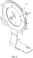
- FIG. 2shows a vibrating element with openings through which the fluid is ejected.
- FIG. 3shows the locking mechanism for the fluid container.
- FIG. 4shows a first housing part with an outer cover removed to show a shutter with an aperture through which the fluid is dispensed.
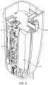
- FIG. 5shows a cross-section of a second housing part which houses the control system and battery.
- FIG. 6shows a front view of the device with the outer cover removed.
- FIG. 7shows the fluid delivery path from the fluid container to an enclosure.
- FIG. 8shows a cross-section of the enclosure.
- FIG. 9shows another cross-section of the enclosure.
- FIG. 10shows a perspective view of the enclosure.
- FIG. 11shows a bottom view of the enclosure including the flow splitting chamber.
- FIG. 12shows an enlarged cross-sectional view of the enclosure.
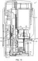
- FIG. 13shows a cross-sectional view with the device in a stored position.
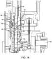
- FIG. 14shows the pump advanced during the forward stroke with fluid contained in pump.
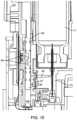
- FIG. 15shows the pump at full forward stroke.
- FIG. 16shows the pump at the end of fluid delivery through the tube and into the enclosure.
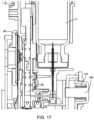
- FIG. 17shows the pump during the return stroke.
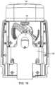
- FIG. 18shows a front view with the shutter in a stored position.
- FIG. 19shows a front view with the shutter in a ready position.
- FIG. 20shows a rear view of the device with the pump in a stored position.
- FIG. 21shows a rear view of the device with the pump in the full forward stroke position.
- FIG. 22shows a perspective view of the device with the pump return springs removed.
- FIG. 23shows a perspective view with the cap and outer cover removed.
- FIG. 24shows a perspective cross-sectional view of the fluid delivery path and shutter.
- FIG. 25shows the shutter mechanism and a firing button in a stored position.
- FIG. 26shows the shutter in a ready state with the shutter spring loaded.
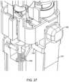
- FIG. 27shows actuation of the firing button which releases the shutter.
- FIG. 28shows the shutter displaced upwardly by the pump spring at the end of the fluid delivery.
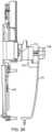
- FIG. 29shows a partial cross-section of the device showing the shutter mechanism.
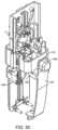
- FIG. 30shows a perspective view of FIG. 29 .
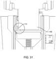
- FIG. 31shows the shutter in the ready state and a sensor which prevents delivery of fluid when the shutter is blocking fluid delivery.
- FIG. 32shows a plan view of another enclosure having a wedge-shaped wall opening.
- FIG. 33is a perspective view of the enclosure of FIG. 32 .
- FIG. 34is a side view of the enclosure of FIGS. 32 - 33 .
- FIG. 35is a cross-sectional view of the enclosure of FIG. 34 .
- a device 1which includes a fluid ejector 2 ( FIG. 2 ) and a fluid handler 14 ( FIG. 7 ).
- the fluid ejector 2includes a vibrating element 4 having a plurality of openings 6 which is vibrated with a piezoelectric element 15 coupled to the vibrating element 4 .
- the term fluid as used hereinrefers to any flowable substance and does not refer only to the liquid state of a material.
- the device 1has a housing 5 which may include a first housing part 7 and a second housing part 9 which lock together with any suitable engagement such as a twist or snap-fit.
- a control system 11which includes a printed circuit board 13 is mounted to the first housing part 7 .
- the control system 11is coupled to and controls the piezoelectric element 15 as is known in the art.
- a battery 19powers the control system 13 and the driving electronics for the piezoelectric element 15 as is known in the art.
- the fluid handling system 14is coupled to the second housing part 9 .
- the control system 11may be reusable while the fluid handler 14 may be disposable.
- the fluidmay be held in a fluid container 17 which may be locked to the first housing 7 to prevent removal so that the fluid handler 14 is disposable after (with) the first fluid container 17 .
- the fluid handling system 14may also be used with more than one container 17 or the container 17 may have a reservoir that is filled without departing from numerous aspects of the invention.
- the entire system 1may be disposable or reusable or separated into disposable and reusable portions in any manner without departing from most aspects of the present invention.
- the piezoelectric element 15may be an annular disc 23 coupled to either a delivery side 8 or a fluid side 10 of the vibrating element 4 with the openings 6 positioned in an open central region 26 of the annular disc 23 .
- the piezoelectric element 15may be made of any suitable material (such as Lead zirconate titanate; an intermetallic inorganic compound with the chemical formula Pb[Zr x Ti 1-x ]O 3 ).
- the piezoelectric element 15may be bonded, adhered, molded or otherwise coupled to the vibrating element in any suitable manner as is known in the art.
- a flexible circuit 21is in electrical communication with the piezoelectric element 15 to control the piezoelectric element 15 .
- the flexible circuit 21is coupled to the control system 1 (see FIG.
- the vibrating element 4is vibrated at a frequency of 100 to 160 khz which may be a resonant frequency.
- the resonant frequencymay be predetermined, measured, determined or tuned as is known in the art.
- the driving frequency of the piezoelectric element 15is described further below. Of course, the frequency of operation may be at a frequency other than a resonant frequency.
- the fluid side 10 of the vibrating element 4 at the openings 6is in contact with the fluid to be delivered and ejects the fluid to the delivery side 8 . Fluid is ejected through the openings 6 toward the eye when the vibrating element 4 is vibrated.
- the openings 6may taper from the fluid side 10 to the delivery side 8 .
- the opening 6 at the fluid sidemay have a diameter of 160-240 microns (and may be 200 microns) while the diameter at the delivery side may be 20-60 microns (and may be 40 microns).
- a column of consistent diameter (20-60 microns)extends to the delivery side 8 and has a length of 10-40 microns and may be about 25 microns in length.
- the openings 6may have a curved wall between the fluid and delivery sides with a radius of curvature of 100 microns.
- the openings 6 at the fluid side 10 and the delivery side 8may have a circular cross-sectional shape.
- the cross-sectional area(or other dimension) may be defined by an effective diameter (or effective radius) for a circle having the same area.
- the vibrating element 4may have a thickness of 100 to 180 microns, or 120-160 microns, and may be about 140 microns, and may be made of any suitable material such as PEEK or Polyimide, with additional layers consisting of copper, polyimide, nickel, and/or gold.
- the vibrating element 4may have a thickness of 125 microns and the coating/plating having a total thickness of about 15 microns so that the vibrating element 4 has thickness of about 140 microns.
- numerous other configurationsmay be practiced within the scope of the invention with respect to the materials and manufacture of the vibrating element 4 and piezoelectric element 15 and dimensions of the openings 6 .
- Fluidmay be ejected so that an average ejection velocity is 2.5 m/s to 15 m/s, as it leaves the opening 6 at the delivery side 8 and may be about 5-6 m/s.
- the vibrating element 4defines a central axis CA which is a central orientation of the plurality of openings 6 defined by a geometric center of the ejection orientation of the plurality of openings 6 .
- the central axis CAextends perpendicular to plane of vibrating element 4 at the center of the circular pattern of openings 6 .
- the central axis CAis perpendicular to a plane defined by the vibrating element 4 and is aligned with the geometric center of the ejection direction that the openings 6 are aligned or with a geometric center of a spray pattern created by the plurality of openings 6 .
- the central axis CAmay be defined by an average or geometric center without departing from scope of the invention when, for example, the openings 6 are clustered or an irregular or asymmetrical shape or varying density of openings 6 (number of openings)/mm2 as used herein.
- multiple doses of the fluidare stored in the fluid container 17 which is locked to the housing 5 (specifically the second part 9 ) when a recess 22 engages locking tabs 24 on a container lock 26 .
- a snap-fit connector 28( FIG. 3 ) locks to a manifold 30 ( FIG. 7 ) of a pump 32 described below.
- a fluid delivery needle 34passes through a pierceable element 36 such as a septum 38 in the container 17 .
- a vent needle 40which may be independent or concentrically arranged with the fluid delivery needle 34 , also passes through the pierceable element 36 .
- Fluidis drawn from the container 17 through a fluid conduit 42 with the pump 32 as explained further below. Air is drawn into an air intake lumen 27 (covered by a filter 29 ) which is used to vent the container 17 as explained below.
- the chamber 16may be substantially dry after delivery of the fluid and dry when stored which may provide advantages over “wet” systems which may suffer from undesirable contamination or evaporation.
- the enclosure 18has a wall 44 with a lip 46 positioned adjacent the fluid side of the vibrating element 4 .
- the lip 46extends around the plurality of openings 6 .
- the enclosure 18 and the vibrating element 4together define the chamber 16 or the chamber 16 may be defined by the enclosure 18 bounded by an open end 33 of the enclosure 18 while the. open end 33 is bounded and defined by the lip 46 .
- the wall 44extends from the open end 33 to a hub 35 which has a main inlet 52 .
- the main inlet 52is coupled to a lumen 54 formed in a tube 56 through which fluid is delivered by the pump 32 .
- the enclosure 18may be formed together with the tube 56 or as separate parts as shown.
- the tube 56may be formed with the manifold 30 which may be defined as part of the pump 32 so that the pump 32 delivers the fluid directly to the enclosure 18 .
- the manifold 30has a mounting rib 31 ( FIG. 22 ) which engages the housing.
- the tube 56may also be defined separate from the pump 32 as used herein, for example, the tube 56 may be part of the enclosure 18 (either as a disposable or a resuable part).
- the lip 46 of the enclosure 18is positioned adjacent to the fluid side 10 of the vibrating element 4 to prevent the fluid from escaping or leaking between the lip 46 and the vibrating element 4 .
- the lip 46 and the vibrating element 4are adjacent one another along a closed loop which encircles the openings 6 and has a diameter of 0.190-0.240 inch and may be 0.210 inch.
- the enclosure 18also defines a central axis CA which is a geometric center of an area bounded by the lip 46 at the open end of the enclosure 18 and oriented perpendicular to the area bounded by the lip 46 .
- central axis CAmay mean any one of the definitions herein applicable and may be interchanged when applicable and such substitutions are expressly incorporated wherever the term central axis CA is used such as when the two are co-linear.
- the central axis CA of the enclosure 18 and the central axis CA of the vibrating element 4may be offset and/or skewed without departing from the scope of the invention as described below and the independent definitions are specifically applied.
- the lip 46 of the enclosure 18may be spaced apart from the vibrating element 4 so that the lip 46 does not impede vibrations of the vibrating element 4 .
- the lip 46must be close to the vibrating element 4 so that surface tension prevents escape of the liquid.
- the lip 46may be spaced apart from the vibrating element 4 by less than 250 microns or less than 125 microns.
- the vibrating element 4may not touch the enclosure 18 during vibration when the maximum amplitude is small enough to prevent contact.
- the lip 46has a surface spaced apart from the vibrating element 4 less than 250 microns average, or less than 125 microns average, and is spaced apart from the vibrating element 4 for at least 270 degrees of total angular extent which does not contact the vibrating element 4 .
- the surfaceis spaced apart by a separation distance of at least 125 microns around at least 270 degrees of the plurality of openings 6 when viewed along the central axis CA.
- the lip 46may extend completely around the openings 6 without contacting the vibrating element 4 even during vibration for fluid delivery.
- the interface on either sidemay be interrupted rather than continuous without departing from the scope of the invention.
- the surface of the lip 46may contact the vibrating element 4 along four small sections which span 20 degrees each so that the lip 46 does not contact the vibrating element 4 along at least 270 degrees even though not continuous.
- the chamber 16is defined by the enclosure 18 and the vibrating element 4 so long as the fluid is prevented from escaping between the enclosure 18 and the vibrating element 4 and the chamber 16 shall be defined as the fluid retaining space even though the chamber 16 is not entirely enclosed.
- the lip 46may be wider like a flange, a rim of a rigid cup, or a rippled surface, undulating or sawtooth shaped surface without departing from the meaning of “lip” as used herein.
- the fluidmay be held in the chamber 16 by surface tension along the lip 46 when the lip 46 is spaced from the vibrating element 4 , the majority of the fluid may be free of capillary feed features as is sometimes used in the prior art.
- Such prior art systems that incorporate capillary feedtypically do so along the fluid feed area immediately adjacent to the openings 6 in the vibrating element 4 .
- the present inventionmay provide sufficient space adjacent to the openings 6 so that capillary action is not required or incorporated to deliver fluid to the openings 6 .
- the lip 46may also be in contact with the vibrating element 4 , rather than spaced apart, while not overly restraining the vibrating element 4 and still retaining the fluid. To this end, the lip 46 may be biased against the vibrating element 4 with a relatively low force.
- the force exerted on the vibrating element 4 by the lip 46may be less than 3 gram-force, and may be less than 2 gram-force, measured in a direction of the central axis CA of the enclosure 18 (and the vibrating element 4 as well).
- the lip 46may also exert a controlled spring load on the vibrating element 4 with an average spring constant of no more than 60 gram-f/mm or even no more than 40 gram-f/mm for displacements up to 0.050 mm in the direction of the central axis CA.
- the controlled spring constantmay aid in operation in extreme conditions which may affect interaction of the lip 46 and vibrating element 4 for extreme temperatures, pressures, and impact loads (dropped).
- the controlled spring constantmay also aid in manufacturability in that manufacturing tolerances can affect the load ultimately exerted by the lip 46 on the vibrating element 4 .
- the lip 46 and/or the wall 44may also be made of a resilient material for compliant contact between the lip 46 and the vibrating element 4 and the resilient material and geometry of the enclosure 18 may contribute to develop the spring force response.
- the lip 46may be made of a material having a durometer of less than 60 A.
- the wall 44may have a thickness of 0.003 to 0.007 inch surrounding the chamber 16 .
- the resilient nature of the enclosure 18may be provided by the material of the lip 46 itself and/or mechanically with a tab, leaf spring, coil spring, cantilever, a resilient mounting for the container 17 , or any other suitable mechanism or combination.
- the enclosure 18may be a rigid cup with an elastomer coating along the rim with an appropriate spring exerting a force on the cup in accordance with this aspect of the invention.
- the wall 44 of the enclosure 18includes a sidewall 56 which may also contribute, and in some cases the largest amount, to the resilient nature of the engagement with the vibrating element 4 .
- the sidewall 56extends from the lip 46 to the hub 35 and extends completely and around the central axis CA.
- the resilient nature of the enclosure 18may be provided for in whole or part by the shape of the sidewall 56 .
- the sidewall 56may have a tapered portion 60 extending from a large end (diameter of 0.210 to 0.220 inch) to a small end (diameter of 0.180 to 0.190 inch) with the large end positioned nearer to the vibrating element 4 (and may be adjacent the lip 46 at the distal end) and surrounds and encompasses a larger area than the small end.
- the tapered portion 60 of the sidewall 56may also include a first frustoconical portion 62 extending from the lip 46 and a radial extension 64 extending primarily radially inward from the small end of the first frustoconical portion 62 to the hub 35 .
- the radial extension 64extends radially inward with respect to a central axis CA of the enclosure 18 .
- the orientation and relative dimensions of the parts of the wall 44 and sidewall 56are described herein with reference to a cross-sectional shape at a plane on which the central axis CA (of the vibrating element 4 and/or the enclosure 18 ) lies for a total angular extent of at least 270 degrees when viewed along the central axis CA (or completely around the central axis CA as shown).
- the radial extension 64extends radially inward at least 20% of an equivalent radius of the open end.
- the radial extension 64may have a ratio of radial to longitudinal displacement of at least 3 to 1 relative to the central axis CA with the central axis CA representing the longitudinal direction and may be positioned 0.014 to 0.030 inch or 0.014 to 0.040 inch from the vibrating element 4 measured along a central axis CA.
- “equivalent radius” or “equivalent diameter”refers to the radius or diameter of a circle having the same area.
- the tapered portion 60 of the sidewall 56has a second frustoconical portion 63 extending from the radial extension 64 to the hub 35 .
- the tapered portion 60 of the sidewall 56extends from the lip 46 to the hub 35 .
- the tapered portion 60may have a radial to longitudinal displacement ratio of at least 1 to 3, at least 2 to 3 or at least 1 to 1 relative to the central axis CA.
- “tapered”does not require a gradual or continuous change and only refers to a reduction in size perpendicular to the central axis CA which represents a feed area. The reduction may be stepped or may extend substantially only radially inward like the radial extension 64 without departing from the definition of “tapered” as used herein.
- the tapered portion 60 of the sidewall 56may extend radially (relative to the central axis CA of the enclosure 18 ) at least 20% of an effective radius of the enclosed boundary of the lip 46 around at least 270 degrees (and may extending completely and fully around the central axis CA) of the enclosure 18 when viewed along the central axis CA.
- the tapered portion 60 of the sidewall 56may have a thickness of 0.003 to 0.007 inch and may be about 0.005 inch to enhance the flexibility of the sidewall 56 .
- the sidewall 56extends to the hub 35 and a connector 66 is formed which engages an end of the tube 56 ( FIG. 7 ) having a mating connector (not shown).
- the main inlet 52is formed by the hub 35 which receives the fluid from the lumen 54 in the tube 56 .
- the other end of the lumen 54 in the tube 56receives fluid from the pump 32 .
- the lip 46may be unattached to the vibrating element 4 while still being in contact with the vibrating element 4 .
- the terms “no attachments”, “not attached” or “unattached” as used hereinmeans no connection other than frictional contact.
- the lip 46may be free to move away from the vibrating element 4 along the central axis CA.
- the enclosure 18(specifically the lip 46 ) is unattached to have a degree of freedom in the direction of the central axis CA relative to the vibrating element 4 .
- the lip 46 and the vibrating element 4may have channels and/or raised baffles or walls which may restrain lateral movement do not constitute an “attachment” as defined herein.
- the lip 46may have a curved surface with a radius of curvature of about 0.005 inch to provide a rounded edge to the lip 46 .
- the vibrating element 4 and lip 46define an enclosed border 41 at the interface of the two (while each one may define the enclosed border 41 by itself in that they define the same boundary with one another).
- the enclosed border 41defines an enclosed feed area 51 ( FIG. 11 ) at the fluid side of the vibrating element 4 which may be 5.3-5.7 mm or about 5.5 mm in diameter.
- the openings 6 in the vibrating element 4encompass and define a delivery area 39 of the vibrating element 4 which is circular and has a diameter of 2.6 to 3.0 mm or stated another way of less than 3.0 mm or about 2.8 mm. Of course, other patterns and shapes other than circular may be used with the effective diameter or radius for comparison.
- the enclosed border 41may be appreciably larger than the delivery area 39 in that the delivery area 39 may be no more than 75%, or no more than 50%, of the enclosed feed area 51 .
- the enclosed feed area 51may be at least 30% larger, and may be at least 100% larger, than the delivery area 39 .
- the enclosed feed area 51may be larger than the delivery area 39 so that an excess feed area 58 (defined by the enclosed feed area 51 not coextensive with the delivery area 39 when viewed along the central axis CA) is at least 30% of the delivery area 39 and may even be larger than the delivery area 39 or even up to 50% larger.
- the excess feed area 58may be an annular ring for a concentric arrangement or crescent shaped for offset circular areas (which may be non-circular but represented and compared as circles when using equivalent radius or diameter).
- the delivery area 39 of the vibrating element 4defines a geometric center and an effective radius for a circle of equivalent area.
- the enclosed feed area 51also defines a geometric center and an effective radius for a circle of equivalent area.
- the geometric center of the enclosed feed area 51may be above the geometric center of the delivery area 39 and offset by at least 0.3 times the effective radius of the delivery area 39 .
- the fluid held in the chamber 16also defines a geometric center positioned less than 0.015 inch from the vibrating element 4 when measured in the direction of the central axis CA.
- the geometric center of the fluidmay similarly be positioned at least 0.3 times the effective radius of the delivery area 39 above the geometric center of the delivery area 39 for an offset design.
- the geometric center of the fluid(or the volume of the chamber 16 ) is less than 0.1 times the effective radius of the delivery area 39 from the central axis CA of the vibrating element 4 .
- the enclosure 18provides a relatively small chamber 16 with a small volume, the chamber 16 may provide fluid to the openings 6 without requiring capillary feed as some prior art teaches.
- the enclosure 18has an internal surface 49 which defines the boundary of the chamber 16 as defined by the enclosure 18 .
- the fluidis held in the chamber 16 in contact with the internal surface 49 .
- An internal wall 45 of the enclosure 18has a side 47 facing the openings 6 which is spaced apart from the openings 6 by a separation which may be about 0.017 inch.
- the spacing between the internal surface 49 of the enclosure 18 and the vibrating element 4may be larger than a capillary spacing so that capillary action is not present.
- Capillary feedmay impede fluid flow when it is desired to deliver the fluid quickly and also makes it difficult to completely deliver from the feed system which presents residual fluid problems.
- the enclosure 18may still be shaped so that the fluid in the chamber 16 doesn't need to travel far to reach the openings 6 for ejection.
- the internal surface 49 of the enclosure 18may be shaped so that at least 75%, or at least 95% or even all, of the fluid in direct fluid communication with the fluid in the chamber 16 is no more than 0.060 inch, or no more than 0.040 inch, from the nearest opening 6 in the vibrating element 4 .
- the chamber 16may be shaped and formed by the internal surface 49 of the enclosure 18 so that at least 75%, 95% or even all of the fluid in the chamber 16 , and optionally all fluid in fluid communication with the fluid in the chamber 16 , has direct line of sight to the nearest opening 6 .
- Many prior art systemshave wet feed tubes or conduits which are filled with liquid and are spaced much further than 0.060 inch from the openings 6 and must overcome surface tension and other forces which may tend to hold the fluid in the conduits which may contribute to residual volume.
- the enclosure 18 forming the chamber 16may be spaced apart by 0.014-0.040 inch from all of the openings 6 when viewed and measured in the direction of the central axis CA of the vibrating element 4 .
- Fluid in communicationwith another fluid refers to fluid that is continuous which includes feed tubes, pipes, wicks and channels which feed fluid to the openings.
- the enclosure 18may be an integrally formed structure which defines the chamber 16 .
- the integrally formed structuremay be made of a thermoplastic elastomer and formed by a suitable method such as injection molding.
- TFSCGNthermoplastic elastomer
- the volume of fluid deliveredmay fill the chamber 16 only 75-90% full which may provide room during delivery to encourage all of the fluid to gather in the chamber 16 due to surface tension forces.
- Delivering the fluid at a velocity of at least 0.5 m/s (or at least 1.0 m/s) to the enclosure 18may also encourage substantially all of the fluid ejected from the tube 56 to collect in the chamber 16 rather than being left behind as residual.
- the pumpdelivers the fluid at a pressure of at least 200 psi (and may be about 300 psi) which may be sufficient to achieve the velocities desired for many fluids delivered to the eye. In this manner, the small fluid amount remains a single fluid “droplet” which is fired into the enclosure 18 .
- the enclosure 18may split the flow from the main inlet 52 into a first inlet 55 and a second inlet 57 each leading to the chamber 16 .
- the enclosure 18may also have a third inlet 59 and a fourth inlet 61 and all aspects of the first and/or second inlets 55 , 57 are expressly incorporated for the third and/or fourth inlets 59 , 61 and the other of the first and second inlets 55 , 57 when discussed independently and all such features and limitations are expressly incorporated for all of the other inlets.
- the first inlet 55directs the fluid at the internal surface 49 of the enclosure 18 , such as the tapered portion 60 of the sidewall 56 , before being directed at the openings 6 in the vibrating element 4 .
- the first inlet 55 and the second inlet 57may lead directly to the chamber 16 with the inlets both being oriented to direct all of the fluid entering the chamber 16 (or at least 90% of the fluid) at the internal surface 49 of the enclosure 18 (such as the internal surface 49 along the sidewall 56 ) before being directed to the openings 6 in the vibrating element 4 .
- the possibility that the fluid is forced through the openings 6 during filling of the chamber 16may be reduced.
- the fluidwhen the fluid is forced into the chamber 16 at a velocity or pressure as suggested herein it may be advantageous to direct the fluid into the enclosure 18 in this manner.
- the main inlet 52initially directs the fluid at the internal wall 45 opposing the openings 6 which forms part of a flow splitting chamber 66 .
- the internal wall 45extends from one side of the sidewall 56 to the other relative to the central axis CA to form the inlets.
- the flow splitting chamber 66splits the flow into four streams that pass through the four inlets each spaced apart from and directed at the tapered portion 60 of the sidewall 56 .
- the flow splitting chamber 66may lead directly to the chamber 16 as shown or may have additional baffles or flow altering features.
- the main inlet 52directs the flow in a direction within 30 degrees of the central axis CA of the enclosure 18 and may be along and aligned with the central axis CA as shown.
- the first inlet 55 and the second inlet 57may be oriented to direct the fluid within 30 degrees of perpendicular to the central axis CA to avoid fluid being directed at the openings 6 .
- the enclosure 18may have a third inlet and a fourth inlet which are also oriented at the sidewall 56 of the enclosure 18 .
- the adjacent inletsare oriented 60-120 degrees from one another and may be about 90 degrees from the adjacent inlets 55 . 57 , 59 , 61 as shown.
- the flow splitting chamber 66has a cup-shaped wall 68 (which includes the internal wall 45 ) with a concave side 70 facing toward from the vibrating element 4 .
- the cup-shaped wall 68has all four inlets formed therein.
- the cup-shaped wall 68extends radially outward from a central axis CA of the enclosure 18 for at least 25% of an effective radius defined by the lip 46 for an angular extent of at least 240 degrees relative to the central axis CA of the lip 46 .
- the first inlet 55has a radial dimension and a longitudinal dimension relative to the central axis CA with a ratio of the radial dimension to the longitudinal dimension being 0.5 to 1.5.
- the first inlet 55 and the second inlet 57extend radially inward toward the central axis to expose some of the main inlet 52 when viewed in the direction of the central axis CA, however, direct longitudinal flow from the main inlet 52 to the vibrating element 4 is prevented by the radial component to the flow which is created by the bulk of the fluid directed radially outward by the internal wall forming the bottom of the cup 68 .
- the chamber 16is also formed so that at least two, three or four inlets 55 , 57 , 59 , 61 are provided which, together with the dimensions of the chamber 16 , provide a lower energy state to encourage the fluid to collect in the chamber 16 rather than any residual part of the fluid remaining in the splitting chamber 66 or extending between the chamber 16 and the flow splitting chamber 66 .
- many aspects of the present inventionare directed to minimizing residual fluid, the present invention may be practiced with some residual volume left and, in fact, some aspects the invention may be used with a wet system without departing from those aspects of the invention.
- the enclosure 18may vent air into the enclosure 18 between the lip 46 and the vibrating element 4 with the lip 46 separating sufficiently from the vibrating element 4 during vibration to vent air into the enclosure 18 without releasing fluid. Air vented between the lip 46 and the vibrating element may aid in fluid delivery by moving or displacing fluid at radially outer regions radially inward toward the openings 6 and by simply occupying these radially outer spaces (excess feed space) rather than residual fluid which might occupy this space.
- Airmay also be drawn into some openings 6 of the vibrating element 4 to vent the enclosure 18 as fluid is ejected through the openings 6 .
- the airis introduced as small bubbles in the chamber 16 which may distribute the fluid among in some sense to find “active” ejection openings 6 .
- the enclosure 18may include no other vent openings, or no dedicated vent, which simplifies the system and eliminates one possible contamination path or source.
- a dedicated ventmay be provided for the chamber 16 without departing from the invention as now described.
- FIGS. 32 - 35another chamber 16 A and enclosure 18 A are shown which are substantially the same as the chamber 16 and the enclosure 18 and all uses and combinations and all other disclosure related to the chamber 16 and the enclosure 18 (and all other enclosures and chambers described herein) are incorporated here. Likewise, all discussion for chamber 16 A and enclosure 18 A are also incorporated for the chamber 16 and the enclosure 18 (and all others).
- the enclosure 18 Ahas a wall 44 A with a lip 46 A adjacent the vibrating element 4 (see FIG. 2 ).
- a wall opening 124is formed in the wall 44 A to vent the chamber 16 A during operation. The wall opening 124 may also have dimensions which enhance the flexibility of the enclosure 18 as described below.
- the lip 46 Amay have a PTFE coating 120 adjacent to the vibrating element 4 to reduce friction therebetween.
- the vibrating element 4may similarly have a PTFE coating 122 adjacent to the lip 46 to reduce friction therebetween.
- the coatings 120 , 122may extend around at least 270 degrees when viewed along the central axis CA. Of course, the coating 122 may extend entirely around the central axis CA.
- An inner surface 123 of the enclosure 16 , 16 Amay be hydrophobic (coated or by virtue of the material property) over at least 70% of the inner surface 123 of the enclosure 18 A in contact with the fluid loaded prior to delivery.
- the wall opening 124may take any suitable shape such as a wedge-shaped opening.
- the wall opening 124extends through the wall 44 A, specifically a sidewall 56 A portion of the wall 44 A, to expose the chamber 16 A.
- the wall opening 124may also form a small gap 131 in the lip 46 A, which together with the geometry of the opening 124 , is small enough to prevent fluid leakage butmay still be large enough to vent the enclosure 18 A by permitting air to enter when fluid is ejected. All discussion and applications concerning venting of the enclosure 18 are incorporated here such as discussion of venting between the lip 14 and the vibrating element 4 , spacing between the lip and vibrating element and the force-displacement characteristics.
- the lip 14 Amay be in contact with the vibrating element 4 or spaced apart in any manner described herein.
- the wall opening 124has a longitudinal dimension 126 measured from the lip 46 in the direction of the central axis CA and a radial dimension 128 measured in a radial direction relative to the central axis CA.
- the longitudinal dimension 126 of the wall opening 124is at least 80% of a separation 125 between the vibrating element 4 and a side 47 A of the enclosure 18 A facing the openings 6 and may extend substantially the entire length as shown.
- the radial dimension 128 of the wall opening 124is not more than 10%, or no more than 5%, of an equivalent circumference of the lip 46 A.
- the radial dimension 128may be about 0.025 inch while the longitudinal dimension 126 may be about 0.022 inch.
- the dimensions of the enclosure 18 A, the wall 124 A and the chamber 16 Amay be any suitable dimensions including those associated with the enclosure 18 and all geometric relationships all of which are incorporated here.
- the wall opening 124extends from the lip 46 A proximally and may increase the flexibility of the enclosure 18 A due to its position and shape.
- the wall opening 124has a circumferential dimension 130 measured in a circumferential manner relative to the central axis CA.
- the circumferential dimension 130may be about 0.012 inch at the lip 46 A (same as the gap 131 ) and tapers so that the two sides converge at a proximal end 132 of the wall opening 124 .
- the circumferential dimension 130is defined herein as a measurement for a line segment that is perpendicular to a radial orientation of the central axis CA.
- the wall opening 124tapers down as the wall opening 124 extends proximally from the lip 46 A.
- the wall opening 124tapers so that a tapered shape 132 of the wall opening 124 is oriented in the direction of (“points at”) at least one of the inlets 55 , 57 , 59 , 61 to the chamber and may be oriented to align with two inlets when viewed along the central axis CA. Orienting the tapered shape 132 of the wall opening 124 with the inlet(s) 55 , 57 in this manner increases flexibility since the inlet(s) and wall opening 124 cooperate to increase flexibility given their geometric alignment.
- the “orientation” of the tapered openingshall be defined as the bisection of the tapered angle extending away from the wall opening 124 .
- the tapered shape 132is also within 10 degrees of a radial orientation relative to the central axis CA and may be substantially radially oriented as shown.
- the wall opening 124is also positioned along a frustoconical portion 62 A with the wall opening extending proximally from the lip for at least 80% of the length of the frustoconical portion 62 A.
- the pump 32draws discrete volumes from the fluid container 17 and delivers these volumes to the chamber 16 .
- the fluid container 17may be any other suitable mechanism such as a piston/plunger associated with the fluid container 17 in some applications.
- the fluid container 17may have a fluid carrying capacity which is at least 150 times the volume of the chamber 16 (or the volume of the fluid delivered) for a multi-dose device.
- the pump 32may be configured to deliver the same (and optionally the only) volume each time.
- a variable volume pump 32may also be used without departing from virtually all aspects of the invention.
- the present inventionmay be used to provide single dose delivery with substantially the whole dose delivered thereby leaving little residual fluid in the chamber 16 .
- the vibrating element 4may deliver the fluid from the enclosure 18 so that no more than 5%, or no more than 2%, of a total volume of the chamber 16 is occupied by residual fluid (from a previous fluid delivery) or less than 1 microliter remains. Stated another way, the vibrating element is operated to dispense substantially the entire volume of fluid in communication with the openings 6 so that no more than 5%, or no more than 2%, of the fluid volume (or less than 1 microliter) remains in the chamber 16 after the fluid is ejected and a single actuation for fluid ejection.
- the chamber 16is substantially empty after a single application of the fluid (a single firing actuation).
- An advantage of some aspects of the present invention over other fluid delivery systemsis that the chamber 16 receives a single dose that is nearly completely delivered to leave the chamber 16 substantially dry and free of residual fluid between activations. Contamination and degradation of the fluid may be reduced compared to “wet” systems that maintain the fluid in contact with the vibrating element 4 between uses or which have incomplete delivery.
- the enclosure 18may be sized so that the enclosure 18 may be at least 70-95% full with the fluid volume as mentioned above which may help the fluid to gather in the chamber 16 as a single droplet.
- the chamber 16may define a relatively small volume such as less than 14 microliters or 10-14 microliters.
- the fluid volumemay be 7-12 microliters or 10-12 microliters.
- the lumen 54 in the tube 56delivers the fluid through the main inlet 52 to the enclosure 18 with the main inlet 52 having a diameter of 0.040 to 0.060 inch and may be about 0.054 inch,
- the flow splitting chamber 66may have a diameter which essentially matches the main inlet 52 of about 0.054 inch.
- the tube 56extends from the main inlet 52 and may have a volume of less than 2 microliters to further minimize residual fluid.
- the tube 56may be part of the enclosure 18 and may be formed with the enclosure 18 rather than as separate parts.
- fluid delivery to the eyemay also be relatively rapid to reduce the likelihood of interference from a blink during delivery.
- the fluid deliverymay take less than 200 ms and may even be less than 150 ms or even 100 ms.
- the vibrating element 4may also be operated with a pause between periods of vibration during a single actuation.
- the vibrating elementmay be driven by the piezoelectric element 15 for a first period of operation of about 26 ms with a pause of about 3.65 ms followed by a second period of operation of about 26 ms.
- the vibrating element 4may be driven by the piezoelectric element 15 with two pauses with the piezoelectric element 15 being energized or activated for a first period of time, a second period of time and a third period of time with the first and second periods separated by the first pause and the second and third separated by a second pause in driving vibration of the vibrating element 4 .
- the first and second pauses in driving vibrationmay be 0.5 ms to 4.0 ms.
- Each of the first, second and third time periodsmay be 20-40 ms and the overall time of delivery may be less than 150 and even less than 100 ms and may be about 85.3 ms.
- Each of the first, second and third periods of vibrationmay be further subdivided into periods of activation for about 816us and deactivated for about 586us for the piezoelectric element 15 .
- the vibrating element 4may continue to vibrate and eject fluid although not being actively driven by the piezoelectric element 15 .
- the vibrating element 4may continue to eject the fluid.
- the “pause”may be defined as a continuous deactivation of at least 2% of the total time and the total pause time for a plurality of pauses being at least 6% and may be about 8.5% of the total delivery time.
- the deactivated timesare defined distinct from the pause in that the pause is at least 2% of the time continuous while the deactivated time is shorter and may be defined as a continuous time of 0.5-1.0% of the total delivery time and a total of the deactivated times being at least 30% of the total delivery time.
- the deactivated timeis a continuous time of 2.0 to 2.5% of the first period of time (and second and third as well) and a total deactivated time of at least 30% of the first period of time.
- the delivery timesare defined to illustrate the invention and the activation times and patterns may change depending on the surface tension of the ejected fluids.
- the frequency of the alternating signal used to activate the piezoelectric element 15 and subsequently activate and vibrate the vibrating element 4is induced at a drive frequency of 100 kHz to 160 kHz.
- the frequencyis selected by the control system 11 as a randomized frequency centered about the drive frequency (ranging from 100 kHz to 160 kHz) for each of the plurality of activations during a single delivery and may be randomized at least 20 and may be at least 40 times.
- the vibration frequencyis changed (randomly in a manner centered on the drive frequency) on average at least 33 times for a single firing actuation so that the piezoelectric element 15 is driven at a frequency for no more than 3% of the delivery time (average) before being changed.
- the chaotic nature of the randomization of the drive signalmay aid in ejecting fluid.
- the randomized naturemay be provided by a predetermined randomized set of values which are applied to the centered operating frequency or the randomized values uniquely generated by the control system 11 .
- the vibrating element 4may also be designed to vibrate with a relatively low maximum amplitude.
- the vibrating element 4may vibrate with a maximum amplitude of less than 2 microns, less than 1.5 microns or within a range of 0.5-1.5 microns, 0.8-1.2 microns or may be about 0.8 microns.
- the maximum amplitude of the vibrating element 4may also be relatively small compared to the size of the openings 6 in the vibrating element 4 .
- the maximum amplitudemay be no more than 5%, or no more than 3%, of an effective diameter of the cross-sectional shape of the openings 6 at the delivery side.
- the maximum amplitudewhen the maximum amplitude is 1.0 microns and the average diameter of the openings 6 at the delivery side is 40 microns the maximum amplitude is only 2.5% of the average diameter or about 2.5% of the average diameter of the fluid droplets ejected.
- the maximum amplitudealso represents a relatively small amount compared to the thickness such as no more than 5.0% or even no more than 3.0% of the thickness of the vibrating element 4 (measured from the fluid side to the delivery side).
- the thicknessmay be an average thickness for the area bounded by the openings 6 . Operation at low amplitude may also contribute to venting through the openings 6 in that air may be admitted through some of the openings 6 having even low displacements.
- Operation at low amplitudemay also help maintain fluid containment between the lip 46 and the vibrating element 4 .
- the lip 46When the lip 46 is spaced apart from the vibrating element 4 , the lip 46 may be spaced apart an average distance greater than the maximum amplitude of the vibrating element 4 during vibration. Stated another way, the maximum amplitude is less than an average separation distance between the surface of the lip 46 and the vibrating element 4 .
- the housingis partially removed to expose the pump 32 .
- the pump 32delivers fluid from the fluid container 17 to the chamber 16 through the lumen 54 in the tube 56 and through the main inlet 52 (see FIG. 12 ).
- the fluid container 17may be any suitable container such as a vial, ampoule, bag, bladder or a fixed container that is filled without departing from the scope of the present invention.
- the pump 32may be any suitable mechanism for delivering the fluid to the enclosure 18 without departing from various aspects of the invention.
- the fluid container 17has a pierceable cap 70 which is pierced by a delivery needle 34 and the vent needle 40 .
- the delivery needle 34defines part of a delivery flow path and the vent needle 40 defines part of a vent path.
- the delivery flow pathextends to the pump 32 and from the pump 32 through the tube 56 and the main inlet 52 into the chamber 16 .
- the delivery needle 34 and the vent needle 40are mounted to a container support 70 on which the container 17 is mounted.
- the container support 70has a coupling 72 which engages the manifold 30 .
- a vent lumen 73includes a one-way valve 76 , such as an umbrella valve 78 , which permits air into the fluid container 17 to make up for the volume of fluid lost as explained below.
- the pump 32has a first part 80 and a second part 82 .
- the first part 80reciprocates between a stored position ( FIG. 13 ) to a partial stroke position ( FIG. 14 ) and to a forward stroke position ( FIG. 15 ) at the greatest displacement.
- the first part 80returns to the stored position to complete a cycle which delivers a volume of fluid to the chamber.
- the second part 82also reciprocates between a stored position to a forward stroke position at a greatest displacement and back to the stored position each cycle.
- the first part 80has an extension 84 extending from a main body 86 .
- the main body 86has an end 88 facing an end 90 of a main body 89 of the second part 82 .
- the extension 84 on the first part 80extends toward and interlocks with an extension 85 extending from the main body 89 of the second part 82 .
- the first part 80is driven and in turn drives the second part 82 through each cycle by engagement of the extensions 84 , 85 and/or the ends 88 , 90 of main bodies 86 , 89 with one another.
- a cavity 92is formed between the first part 80 and the second part 82 with the size of the cavity 92 changing as the first and second parts 80 , 82 move toward and away from one another.
- the cavity 92increases in size when the first and second parts 80 , 82 move away from one another which draws fluid into the cavity 92 during the forward stroke.
- the cavity 92decreases in size when the first and second parts 80 , 82 move toward one another which delivers the fluid from the cavity 92 to the chamber 16 during the return stroke.
- the cavity 92has a volume commensurate with volume of the fluid being delivered which may be 7-12 microliters.
- the fluidis drawn into the cavity 92 during the forward stroke of the first part 80 .
- the first part 80 and the second part 82are movable from a stored position of FIG. 13 , to the partial forward stroke position of FIG. 14 and finally to the full forward stroke position of FIG. 15 .
- the first and second parts 80 , 82move to the full stroke position with the first part 80 pulling the second part 82 upward due to the interlocking extensions 84 , 85 engaging one another.
- the pump 32In the full forward stroke position the pump 32 is ready to deliver the fluid through the tube 56 and into the enclosure 18 .
- the first and second parts 80 , 82When the first and second parts 80 , 82 reach the partial stroke position of FIG. 16 during the return stroke the fluid has been delivered from the cavity 92 to the chamber 16 .
- the first and second parts 80 , 82complete the cycle by moving to the partial reset position of FIG. 17 and to the fully reset position of FIG. 13 again.
- An additional optional stepmay be to purge any fluid left downstream of the chamber 16 with a separate displacing medium.
- the tube 56 , the chamber 16 and the flow splitting chamber 66represent a total downstream volume which is substantially free of fluid prior to delivery of the fluid.
- the volume of fluid delivered by the pump 32may be 40-70% of the total downstream volume so that the tube 56 and flow splitting chamber 66 can be substantially empty when the fluid has been delivered to the chamber 16 .
- the fluidmay be ejected at a relatively high velocity of at least 0.5 m/s (or with the pump delivering the fluid at a pressure of at least 200 psi) to “fire” the droplet into the chamber 16 and which may permit surface tension forces to gather and hold the small volume of fluid together.
- the pump 32may also deliver make up air into the container 17 to make up for the volume of fluid lost.
- the pump 32draws air into a make-up chamber 94 during the forward stroke and forces the air from the make-up chamber 94 toward the fluid container 17 so that air enters and vents the fluid container 17 during the return stroke.
- the first and second parts 80 , 82each have an opposing end 97 positioned opposite the ends 88 , 89 which face each other to form the cavity 92 .
- At least one of the opposing ends 97 of the first and second parts 80 , 82may forms part of the make-up chamber 94 (such as the opposing end 97 of the second part 82 ) so that movement through a full cycle also draws air into the make-up chamber 94 during the forward stroke and expels air during the return stroke. Air is forced through the one-way valve 76 , through the vent needle 40 and into the container 17 to make up for the volume of fluid lost (delivered). When the first and second parts 80 , 82 reach the fully reset position the make-up air has been delivered and the pump 32 is in the stored position again with the first part 80 of the pump 32 blocking the main inlet 52 to the enclosure 18 . O-rings are used to seal junctions and spaces between the first and second parts and the manifold and along the vent and fluid delivery paths.
- the drive mechanismincludes the first actuator 94 (which may be a button 95 ) coupled to a first side 96 of a lever 98 .
- the lever 98rotates about pivot P in the direction of arrow A as the button moves downward.
- a second side 100 of the lever 98is coupled to a support plate 102 of the first part 80 of the pump 32 so that the first part 80 moves upward with the first side 96 of the lever 98 from the stored position of FIGS. 18 and 21 to the forward stroke position of FIGS. 19 , 20 and 22 in which fluid has been drawn into the cavity 92 .
- the lever 98may provide a mechanical advantage of about 11/6 due to the difference in lever arm length.
- a powered system using the battery 19may also be used to move the fluid without departing from other aspects.
- a ratchet 104prevents back-travel as the button 95 is depressed until reaching the necessary downward displacement (full forward stroke) at which point the ratchet 104 is released to permit the return stroke.
- the first actuator 94(such as the button) also loads the pump return spring 95 (and may load two pump springs 95 ) during the forward stroke.
- the loaded pump return spring(s) 95drives the pump 32 back to the default or stored position during the return stroke.
- the pump return spring 95may act on the first actuator 94 , the lever or directly on part of the pump 32 itself such as on the first part 80 as shown.
- the first actuator 94(button 95 ) is also returned to the stored position. In the stored position the main body of the first part 80 blocks flow through the lumen 54 in the tube 56 and the main body of the second part 82 blocks the vent path and the fluid delivery path. In this sense, the pump 32 acts a valve 104 and the present invention may be practiced with a dedicated valve closing the lumen 54 to the tube 56 and fluid being moved in another manner without departing from various aspects of the present invention.
- the device 1also includes a shutter 105 having an aperture 107 through which the fluid is delivered.
- the shutter 105blocks and covers the vibrating element 4 in the stored position and may serve as an “off” switch (or defines the “off” condition) when using a position sensor 110 to detect the position of the shutter 105 (specifically the circled area of the shutter 105 ).
- a shutter spring 109is also loaded as the first actuator 94 is moved through the forward stroke. Unlike the pump return spring 95 , the shutter spring 109 is locked in the loaded position of FIG. 26 .
- the position sensor 110(which may be an optical, electromagnetic, electrical or mechanical sensor) determines when the shutter 105 is in the firing position in which the aperture 107 is aligned with the fluid openings 6 .
- the sensor 110may be an optical sensor coupled to the control unit 11 (and the reusable second housing) which senses a marker on the shutter. Fluid ejection is prevented when the position sensor determines that the shutter 105 is blocking (or will block very soon) delivery of fluid.
- the fluidis delivered upon actuation of a second actuator 106 (which may be a firing or dose button 108 ) which is unlocked when the shutter 105 is in the position of FIG. 26 and the device is ready for delivery of the fluid.
- the firing button 108mechanically releases the shutter 105 and the fluid ejector is activated by the control system 11 while the aperture in the shutter 105 is aligned with openings 6 in the vibrating element 4 as determined by the position sensor 110 .
- the shutter 105 motionis now described in more detail. Referring to FIGS. 4 , 18 and 23 , the shutter 105 is in the stored position. The shutter 105 is moved downward by the first actuator 94 so that a tab 109 slides downwardly in a slot 111 and is locked in a ready state of FIGS. 19 and 26 . The device is now in an “on” state by activation of a switch (not shown) when the dose is loaded. During the shutter locked state, another sensor (not shown) may determine the device has loaded fluid and is ready to dispense a dose. Activation of the dose button 108 and the subsequent activation and deactivation in accordance with the position sensor's 110 determination of the shutter 105 position is the mechanism by which the dose/ejection is triggered and terminated. Of course, numerous other methods of timing delivery may be used and, furthermore, the fluid may be delivered in a manner independent of the shutter 105 operation.
- a shutter lock 115is displaced by the firing button 108 to the position of FIG. 27 so that the tab 109 on the shutter 105 moves upward in a release slot 117 having a ramp 119 .
- the firing button 108is mounted to a resilient arm 121 having a pair of hooks 123 which engage the shutter lock 115 and pulls the shutter lock 115 back to the stored position in part due to the resilient nature of the arm 121 .
- a button return spring 125(see FIG. 17 ) is compressed upon actuation and returns the button 108 to the ready state and may also serve to return the shutter lock 115 to the stored position.
- the fluid container 17may be mounted prior to use or may be pre-loaded or loaded from a prior use.
- the fluid container 17is mounted in a cavity 92 and the button is placed over the fluid container 17 .
- the userthen depresses the first actuator 94 to force the container 17 downward so that the vent needle 40 and the delivery needle 34 pierce the fluid container as shown in FIG. 7 .
- the fluid container 17may be locked to prevent removal and replacement of the fluid container 17 .
- the devicemay be stored in this condition.
- the fluidis delivered to the chamber 16 by actuating (depressing) the first actuator 94 (cap) which moves the pump 32 through a full cycle to load the fluid in the chamber 16 .
- the first actuator 94may be any suitable actuator such as the button 95 , a lever, a slider, a twist knob or any other suitable mechanical or electro-mechanical actuator without departing from numerous aspects of the present invention.
- the fluidmay be delivered to the chamber 16 during delivery of the fluid to the eye or immediately before and in a continuous process without departing from virtually all aspects of the present invention.
- the devicemay also clear the tube 56 of fluid.
- the pump 32may draw a volume of displacing medium and deliver the displacing medium into the tube 56 to displace any fluid in the tube 56 into the enclosure 18 prior to delivery.
- the userWhen the user is ready, the user then actuates the firing button 108 to deliver the fluid to the eye.
- the userpositions the device adjacent the eye and looks into the device through the aperture 107 in the shutter 105 and views the vibrating element 4 .
- a light emitting element 114such as a light tube 116 , illuminates part of the device, such as the vibrating element 4 , to visually aim and align the device.
- the firing button 108is actuated to deliver the fluid to the eye.
- the second actuationmay be with the same actuator or a different actuator such as the firing button 108 .
- the present inventionhas been described with a two-step actuation process the two steps may be combined in a single actuation which delivers the fluid to the chamber 16 then determines an appropriate time to deliver the fluid such as by optically differentiating the eyeball from the eyelid.
- the devicedelivers substantially all of the fluid and the device is ready for storage after a single actuation and delivery of a single dose or quantity to the eye.
- the pump 32may be a syringe
- the enclosure 18may be a rigid dome or the enclosure 18 may be attached to the vibrating element 4 without departing from aspects of the invention.
Landscapes
- Health & Medical Sciences (AREA)
- Engineering & Computer Science (AREA)
- Animal Behavior & Ethology (AREA)
- Veterinary Medicine (AREA)
- Public Health (AREA)
- General Health & Medical Sciences (AREA)
- Life Sciences & Earth Sciences (AREA)
- Heart & Thoracic Surgery (AREA)
- Biomedical Technology (AREA)
- Hematology (AREA)
- Anesthesiology (AREA)
- Vascular Medicine (AREA)
- Ophthalmology & Optometry (AREA)
- Bioinformatics & Cheminformatics (AREA)
- Pulmonology (AREA)
- Pharmacology & Pharmacy (AREA)
- Reciprocating Pumps (AREA)
- Infusion, Injection, And Reservoir Apparatuses (AREA)
Abstract
Description
Claims (57)
Priority Applications (1)
| Application Number | Priority Date | Filing Date | Title |
|---|---|---|---|
| US16/621,564US11938056B2 (en) | 2017-06-10 | 2018-06-11 | Methods and devices for handling a fluid and delivering the fluid to the eye |
Applications Claiming Priority (3)
| Application Number | Priority Date | Filing Date | Title |
|---|---|---|---|
| US201762517914P | 2017-06-10 | 2017-06-10 | |
| US16/621,564US11938056B2 (en) | 2017-06-10 | 2018-06-11 | Methods and devices for handling a fluid and delivering the fluid to the eye |
| PCT/US2018/036908WO2018227190A1 (en) | 2017-06-10 | 2018-06-11 | Methods and devices for handling a fluid and delivering the fluid to the eye |
Related Parent Applications (1)
| Application Number | Title | Priority Date | Filing Date |
|---|---|---|---|
| PCT/US2018/036908A-371-Of-InternationalWO2018227190A1 (en) | 2017-06-10 | 2018-06-11 | Methods and devices for handling a fluid and delivering the fluid to the eye |
Related Child Applications (1)
| Application Number | Title | Priority Date | Filing Date |
|---|---|---|---|
| US18/593,828ContinuationUS12213912B2 (en) | 2017-06-10 | 2024-03-01 | Methods and devices for handling a fluid and delivering the fluid to the eye |
Publications (2)
| Publication Number | Publication Date |
|---|---|
| US20200197218A1 US20200197218A1 (en) | 2020-06-25 |
| US11938056B2true US11938056B2 (en) | 2024-03-26 |
Family
ID=64566794
Family Applications (3)
| Application Number | Title | Priority Date | Filing Date |
|---|---|---|---|
| US16/621,564Active2041-03-18US11938056B2 (en) | 2017-06-10 | 2018-06-11 | Methods and devices for handling a fluid and delivering the fluid to the eye |
| US18/593,828ActiveUS12213912B2 (en) | 2017-06-10 | 2024-03-01 | Methods and devices for handling a fluid and delivering the fluid to the eye |
| US18/981,183PendingUS20250248842A1 (en) | 2017-06-10 | 2024-12-13 | Methods and devices for handling a fluid and delivering the fluid to the eye |
Family Applications After (2)
| Application Number | Title | Priority Date | Filing Date |
|---|---|---|---|
| US18/593,828ActiveUS12213912B2 (en) | 2017-06-10 | 2024-03-01 | Methods and devices for handling a fluid and delivering the fluid to the eye |
| US18/981,183PendingUS20250248842A1 (en) | 2017-06-10 | 2024-12-13 | Methods and devices for handling a fluid and delivering the fluid to the eye |
Country Status (10)
| Country | Link |
|---|---|
| US (3) | US11938056B2 (en) |
| EP (1) | EP3634550A4 (en) |
| JP (2) | JP7227163B2 (en) |
| KR (2) | KR102643190B1 (en) |
| CN (2) | CN115300226A (en) |
| AU (1) | AU2018279940B2 (en) |
| CA (1) | CA3066408A1 (en) |
| IL (1) | IL271229A (en) |
| SG (1) | SG11201911895XA (en) |
| WO (1) | WO2018227190A1 (en) |
Families Citing this family (24)
| Publication number | Priority date | Publication date | Assignee | Title |
|---|---|---|---|---|
| AU2013245946A1 (en) | 2012-04-10 | 2014-11-27 | Eyenovia, Inc. | Spray ejector mechanisms and devices providing charge isolation and controllable droplet charge, and low dosage volume opthalmic administration |
| EA201492094A1 (en) | 2012-05-15 | 2015-04-30 | Айновиа, Инк. | EJECTOR DEVICES, METHODS, PATTERNS AND SCHEMES FOR THEM |
| CA2973471A1 (en) | 2015-01-12 | 2016-07-21 | Kedalion Therapeutics, Inc. | Micro-droplet delivery device and methods |
| KR102412086B1 (en) | 2017-01-20 | 2022-06-22 | 켄달리온 테라퓨틱스 인코포레이티드 | piezoelectric fluid dispenser |
| CA3066408A1 (en) | 2017-06-10 | 2018-12-13 | Eyenovia, Inc. | Methods and devices for handling a fluid and delivering the fluid to the eye |
| CA3083219A1 (en) | 2017-12-08 | 2019-06-13 | Reynaldo Quintana | Fluid delivery alignment system |
| JP7370329B2 (en) | 2018-01-17 | 2023-10-27 | アイノビア,インコーポレイティド | Method and apparatus for delivering atropine to the eye as a microdose stream of droplets |
| US20190314196A1 (en) | 2018-04-12 | 2019-10-17 | Kedalion Therapeutics, Inc. | Topical Ocular Delivery Methods and Devices for Use in the Same |
| US12350194B1 (en) | 2018-04-12 | 2025-07-08 | Bausch + Lomb Ireland Limited | Topical ocular delivery of fluids with controlled mass dosing and wireless communication |
| CN112334099A (en)* | 2018-07-03 | 2021-02-05 | 科达莱昂治疗公司 | Topical ocular delivery devices and methods of using the same |
| CN113660935B (en)* | 2019-03-04 | 2023-12-08 | 艾诺维亚股份有限公司 | Methods and devices for delivering pilocarpine to the eye in microdose droplet streams |
| US11679028B2 (en) | 2019-03-06 | 2023-06-20 | Novartis Ag | Multi-dose ocular fluid delivery system |
| US12097145B2 (en) | 2019-03-06 | 2024-09-24 | Bausch + Lomb Ireland Limited | Vented multi-dose ocular fluid delivery system |
| CA3164288A1 (en) | 2019-12-11 | 2021-06-17 | Eyenovia, Inc. | Systems and devices for delivering fluids to the eye and methods of use |
| US11925577B2 (en) | 2020-04-17 | 2024-03-12 | Bausch + Lomb Ireland Limted | Hydrodynamically actuated preservative free dispensing system |
| US12290472B2 (en) | 2020-04-17 | 2025-05-06 | Bausch + Lomb Ireland Limited | Hydrodynamically actuated preservative free dispensing system |
| EP4120973A4 (en) | 2020-04-17 | 2024-04-17 | Bausch + Lomb Ireland Limited | Hydrodynamically actuated preservative free dispensing system having a collapsible liquid reservoir |
| US11938057B2 (en) | 2020-04-17 | 2024-03-26 | Bausch + Lomb Ireland Limited | Hydrodynamically actuated preservative free dispensing system |
| AU2021416368A1 (en)* | 2021-01-04 | 2023-07-20 | Kusaoke Daiki | Liquid discharge device and dosing device |
| CA3204612A1 (en)* | 2021-02-24 | 2022-09-01 | Aykutlu Dana | Method and device for remote optical monitoring of intraocular pressure |
| CN113082401B (en)* | 2021-04-08 | 2022-11-22 | 山东省千佛山医院 | An atomization device for an eye care treatment machine |
| CN114209494B (en)* | 2021-12-02 | 2023-11-10 | 江西省儿童医院 | Atomizing therapeutic device for treating pinkeye for ophthalmology |
| US12419979B2 (en) | 2021-12-03 | 2025-09-23 | Eyenovia, Inc. | Pulsed ultraviolet in-line sterilization system for primary drug containers |
| US20240415697A1 (en)* | 2023-06-17 | 2024-12-19 | Topnote, Inc. | Device and system for liquid delivery to a surface of an eye |
Citations (576)
| Publication number | Priority date | Publication date | Assignee | Title |
|---|---|---|---|---|
| US558866A (en) | 1896-04-21 | Balanced slide-valve | ||
| US1482747A (en) | 1921-11-26 | 1924-02-05 | Howe Frank Morgan | Spraying outfit |
| US1493410A (en) | 1923-04-20 | 1924-05-06 | Charles H Wolcott | Vaporizer |
| US1799529A (en) | 1926-08-09 | 1931-04-07 | Walter R Poetsch | Molding machine |
| US1988637A (en) | 1933-02-01 | 1935-01-22 | Mccord Radiator & Mfg Co | Fire extinguisher |
| US2189643A (en) | 1936-04-25 | 1940-02-06 | Lawrence T Ward | Dispensing apparatus |
| US2200008A (en) | 1938-03-04 | 1940-05-07 | John J Nowak | Therapeutic apparatus for vapor treatment of the ear |
| US2249608A (en) | 1939-07-03 | 1941-07-15 | Fred E Greene | Fluid gas gun |
| US2322808A (en) | 1940-05-21 | 1943-06-29 | American Can Co | Lubricating dispenser |
| GB558866A (en) | 1942-04-01 | 1944-01-25 | Walter Albin Robinson | Improvements in and relating to nozzles for the discharge of fluids |
| US2552857A (en) | 1946-09-18 | 1951-05-15 | Knapp Monarch Co | Aerosol bomb |
| US2595317A (en) | 1946-05-06 | 1952-05-06 | Jr Roby Byron White | Spray gun |
| US2698619A (en) | 1952-04-22 | 1955-01-04 | Cutter Lab | Flexible bag having self-sealing entryway |
| US2987439A (en) | 1958-01-07 | 1961-06-06 | William Cooper & Nephews Inc | Method of applying an aerosol to the eye |
| FR1271341A (en) | 1959-12-14 | 1961-09-08 | Hitachi Ltd | Method of applying coating materials and devices for its implementation |
| US3170462A (en) | 1962-01-05 | 1965-02-23 | Merck & Co Inc | Aerosol ophthalmic device |
| US3187757A (en) | 1962-12-17 | 1965-06-08 | J & J Casting Inc | Plural dispensing units and toilet kit with central compartmented storage member |
| US3237809A (en) | 1963-01-07 | 1966-03-01 | Oreal | Containers for aerosol solutions and attachment thereof to another apparatus |
| US3310830A (en) | 1965-01-18 | 1967-03-28 | Daniel H Gattone | Self-contained applicator for use with pressurized containers |
| US3314426A (en) | 1964-05-20 | 1967-04-18 | Lever Brothers Ltd | Eyecup and spray dispenser |
| US3439674A (en) | 1966-02-18 | 1969-04-22 | Jhon Lelicoff | Liquid eyewash dispensing device including eyelid engaging means |
| US3602399A (en) | 1969-09-16 | 1971-08-31 | Gen Ordnance Equip | Non-lethal weapon dispenser |
| US3658257A (en) | 1969-09-11 | 1972-04-25 | Nordson Corp | Spray nozzle |
| US3709235A (en) | 1971-03-17 | 1973-01-09 | Washburn W & Sons Inc | Travel cases |
| US3779245A (en) | 1972-06-13 | 1973-12-18 | R Windsor | Device for applying materials to the area of the eye |
| US3780950A (en) | 1972-02-07 | 1973-12-25 | W Brennan | Paint accomodating modules adapted for use with spray guns |
| US3795351A (en) | 1971-01-05 | 1974-03-05 | Polaroid Corp | Apparatus for dispensing a metered amount of fluid |
| US3812854A (en) | 1972-10-20 | 1974-05-28 | A Michaels | Ultrasonic nebulizer |
| US3826258A (en) | 1972-02-07 | 1974-07-30 | S Abraham | Gradual release medicine carrier |
| US3845764A (en) | 1972-06-13 | 1974-11-05 | R Windsor | Device for applying material to the area of the eye |
| US3892235A (en) | 1971-07-27 | 1975-07-01 | Respiratory Care | Multi-use inhalation therapy apparatus |
| US3901443A (en) | 1973-02-06 | 1975-08-26 | Tdk Electronics Co Ltd | Ultrasonic wave nebulizer |
| US3906949A (en) | 1972-05-03 | 1975-09-23 | Research Corp | Corneal bath |
| US3913575A (en) | 1973-11-08 | 1975-10-21 | Robert K Windsor | Eye dropper device with a mirror |
| US3934585A (en) | 1970-08-13 | 1976-01-27 | Maurice David M | Method and apparatus for application of eye drops |
| US4002168A (en) | 1975-04-24 | 1977-01-11 | Tor Petterson | Method of, and dispenser for introducing an opthalmic product into the occular cavity |
| US4012798A (en) | 1975-09-29 | 1977-03-22 | Liautaud John R | Portable emergency eye wash fountain |
| US4052985A (en) | 1976-06-28 | 1977-10-11 | Coleman D Jackson | Apparatus for medicinally spraying an eyeball |
| US4067499A (en) | 1976-02-17 | 1978-01-10 | Cohen Milton J | Non-aerosol continuous spray dispenser |
| US4098431A (en) | 1977-01-13 | 1978-07-04 | Cine Magnetics Inc. | Chemical replenishing system |
| USD249709S (en) | 1976-11-22 | 1978-09-26 | Trovinger Douglas J | Eye drop bottle guide |
| US4119096A (en) | 1975-08-25 | 1978-10-10 | Siemens Aktiengesellschaft | Medical inhalation device for the treatment of diseases of the respiratory tract |
| US4122556A (en) | 1977-03-23 | 1978-10-31 | Stanley Poler | Intra-ocular lens |
| US4131115A (en) | 1976-09-20 | 1978-12-26 | Peng Sung S | Eyelids-turning and eye-washing fixture |
| US4173226A (en) | 1977-11-10 | 1979-11-06 | Alza Corporation | Device for administering solid drug particles to an eye |
| US4175704A (en) | 1976-02-17 | 1979-11-27 | Cohen Milton J | Non-aerosol continuous spray dispenser |
| US4175706A (en) | 1977-07-18 | 1979-11-27 | Scientific Energy Systems Corporation | Spray nozzle |
| GB1569707A (en) | 1976-07-15 | 1980-06-18 | Ici Ltd | Atomisation of liquids |
| US4264837A (en) | 1978-03-31 | 1981-04-28 | Paul Gaboriaud | Ultrasonic atomizer with automatic control circuit |
| US4296071A (en) | 1978-11-29 | 1981-10-20 | Boehringer Mannheim | Pipette with elastic bellows |
| US4319155A (en) | 1979-01-09 | 1982-03-09 | Omron Tateisi Electronics Co. | Nebulization control system for a piezoelectric ultrasonic nebulizer |
| US4323530A (en) | 1977-04-20 | 1982-04-06 | Boehringer Ingelheim Gmbh | Method of lubricating compression tools of molding machines |
| US4338936A (en) | 1980-10-27 | 1982-07-13 | Byron Nelson | Device and method for delivering solid medication to an eye |
| US4356528A (en) | 1976-07-15 | 1982-10-26 | Imperial Chemical Industries Plc | Atomization of liquids |
| EP0011269B1 (en) | 1978-11-15 | 1983-04-13 | Dr. Karl Thomae GmbH | Method and apparatus for dotting moulding devices by means of discrete droplets of a liquid or suspended lubricant during the manufacture of moulded objects in the pharmaceutical, food or catalytic field |
| US4390542A (en) | 1980-12-02 | 1983-06-28 | Schachar Ronald A | Method for inhibiting contraction of opthalmic wounds or incisions |
| US4398909A (en) | 1981-12-31 | 1983-08-16 | Portnoff Joel B | Unit dose applicator |
| US4465234A (en) | 1980-10-06 | 1984-08-14 | Matsushita Electric Industrial Co., Ltd. | Liquid atomizer including vibrator |
| US4471890A (en) | 1982-04-29 | 1984-09-18 | St. Luke's Hospital | Eye drop dispenser |
| US4479609A (en) | 1981-10-09 | 1984-10-30 | Matsushita Electric Works, Ltd. | Liquid sprayer |
| US4493119A (en) | 1982-01-09 | 1985-01-15 | Baumann Ludwig G | Device for the treatment of the eyes with a washing or bathing liquid |
| WO1985000761A1 (en) | 1983-08-18 | 1985-02-28 | Imperial Chemical Industries Plc | Electrostatic spraying process and apparatus |
| US4533082A (en) | 1981-10-15 | 1985-08-06 | Matsushita Electric Industrial Company, Limited | Piezoelectric oscillated nozzle |
| EP0150571A1 (en) | 1984-01-26 | 1985-08-07 | Nordson Corporation | Electrostatic coating system |
| US4543096A (en) | 1983-08-05 | 1985-09-24 | Thomas Keene | Eyedrop dispenser with eyelid opening means |
| US4564016A (en) | 1982-05-24 | 1986-01-14 | The Board Of Trustees Of The Leland Stanford Junior University | Apparatus for introducing ionized drugs into the posterior segment of the eye and method |
| US4580721A (en) | 1981-02-12 | 1986-04-08 | Imperial Chemical Industries Plc | Fluid container |
| US4605167A (en) | 1982-01-18 | 1986-08-12 | Matsushita Electric Industrial Company, Limited | Ultrasonic liquid ejecting apparatus |
| US4605398A (en) | 1984-04-20 | 1986-08-12 | Herrick Robert S | Dispensing device for container having fluid to be controllably dispensed into an eye |
| US4627845A (en) | 1984-12-04 | 1986-12-09 | Demotte Frank E | Eyes-bathing faucet-mateable structure |
| US4642581A (en) | 1985-06-21 | 1987-02-10 | Sono-Tek Corporation | Ultrasonic transducer drive circuit |
| US4641384A (en) | 1986-02-14 | 1987-02-10 | Maddak, Inc. | Battery operated eyewash system |
| US4658290A (en) | 1983-12-08 | 1987-04-14 | Ctba Associates | Television and market research data collection system and method |
| US4659014A (en) | 1985-09-05 | 1987-04-21 | Delavan Corporation | Ultrasonic spray nozzle and method |
| JPS62142110A (en) | 1985-11-13 | 1987-06-25 | インペリアル・ケミカル・インダストリ−ズ・ピ−エルシ− | Ophthalmologically active substance solution and administration method and device |
| US4679551A (en) | 1984-02-23 | 1987-07-14 | Tomtec, N.V. | Device for performing therapeutic treatments |
| US4685906A (en) | 1986-03-31 | 1987-08-11 | Murphy William F | Eye-drops application device |
| US4691885A (en) | 1986-05-05 | 1987-09-08 | Lawrance George F | Display stand |
| US4701167A (en) | 1985-09-16 | 1987-10-20 | The Kendall Company | Multi-dimensional applicator |
| US4702418A (en) | 1985-09-09 | 1987-10-27 | Piezo Electric Products, Inc. | Aerosol dispenser |
| US4706848A (en) | 1986-10-06 | 1987-11-17 | Andrade Bruce M D | High efficiency battery operated water gun |
| US4740206A (en) | 1985-03-27 | 1988-04-26 | Tobin Scandinavia Ab | Disposable pocket-size package for eye-rinsing liquid |
| US4742713A (en) | 1984-06-01 | 1988-05-10 | Omron Tateisi Electronics Co. | Ultrasonic flaw detecting system |
| US4750650A (en) | 1984-06-12 | 1988-06-14 | Ling Carl P C | Extended surface apparatus for use in dispensing liquids |
| US4750902A (en) | 1985-08-28 | 1988-06-14 | Sonomed Technology, Inc. | Endoscopic ultrasonic aspirators |
| US4758237A (en) | 1987-01-20 | 1988-07-19 | Herman Sacks | Device for applying liquid to the corneal surface of the eye |
| US4758727A (en) | 1986-02-12 | 1988-07-19 | Ohio State University Research Foundation | Method and apparatus for the measurement of low-level laser-induced fluorescence |
| US4759755A (en) | 1985-03-05 | 1988-07-26 | Lincoln Diagnostics, Inc. | Device for transferring liquid from a vial to a multi-pointed applicator |
| US4779768A (en) | 1987-07-24 | 1988-10-25 | St. Amand Manufacturing Co., Inc. | Volumetric dispensing pipette |
| US4784652A (en) | 1985-03-27 | 1988-11-15 | Fagersta El & Diesel Ab | Eyewash dispenser |
| US4790479A (en) | 1984-09-07 | 1988-12-13 | Omron Tateisi Electronics Co. | Oscillating construction for an ultrasonic atomizer inhaler |
| US4792334A (en) | 1987-11-06 | 1988-12-20 | Py Daniel C | Occular treatment apparatus |
| US4793339A (en) | 1984-08-29 | 1988-12-27 | Omron Tateisi Electronics Co. | Ultrasonic atomizer and storage bottle and nozzle therefor |
| US4796807A (en) | 1987-03-17 | 1989-01-10 | Lechler Gmbh & C. Kg | Ultrasonic atomizer for liquids |
| US4798599A (en) | 1984-01-03 | 1989-01-17 | George Thomas | Eye washing method and apparatus |
| US4809914A (en) | 1984-08-28 | 1989-03-07 | L'oreal | Flexible bottle making it possible to effect spraying or drop by drop dispensing of a liquid contained therein |
| US4815661A (en) | 1985-04-29 | 1989-03-28 | Tomtec N.V. | Ultrasonic spraying device |
| US4826025A (en) | 1986-11-21 | 1989-05-02 | Toppan Printing Co., Ltd. & Mect Corp. | Ampoule package |
| US4850534A (en) | 1987-05-30 | 1989-07-25 | Tdk Corporation | Ultrasonic wave nebulizer |
| US4863443A (en) | 1988-01-15 | 1989-09-05 | Sterwin Laboratories Inc. | Automatic spray apparatus |
| US4863073A (en) | 1986-10-15 | 1989-09-05 | Glaxo Group Limited | Valve for aerosol container |
| US4863457A (en) | 1986-11-24 | 1989-09-05 | Lee David A | Drug delivery device |
| US4871091A (en) | 1988-09-29 | 1989-10-03 | Mason-Keller Corporation | Disposable package for liquids |
| US4877989A (en) | 1986-08-11 | 1989-10-31 | Siemens Aktiengesellschaft | Ultrasonic pocket atomizer |
| US4880146A (en) | 1988-06-08 | 1989-11-14 | Hudgins J S | Drop dispenser which automatically stirs the contents of the dispenser when the cap is removed |
| US4881283A (en) | 1988-09-09 | 1989-11-21 | Liautaud John R | Self contained eye wash fountain |
| US4886189A (en) | 1988-02-29 | 1989-12-12 | Vanderjagt John A | System for selectively containing metering and dispensing liquids |
| US4896832A (en) | 1987-09-07 | 1990-01-30 | Bespak Plc | Dispensing apparatus for metered quantities of pressurised fluid |
| US4908024A (en) | 1988-05-04 | 1990-03-13 | Py Daniel C | Ocular self-treatment apparatus and method |
| US4912357A (en) | 1986-05-20 | 1990-03-27 | Siemens Aktiengesellschaft | Ultrasonic MHz oscillator, in particular for liquid atomization |
| US4917274A (en) | 1983-09-27 | 1990-04-17 | Maurice Asa | Miniscule droplet dispenser tip |
| US4927115A (en) | 1989-05-26 | 1990-05-22 | Masco Corporation Of Indiana | Valve for a hand held spray nozzle |
| US4927062A (en) | 1988-09-22 | 1990-05-22 | Walsh James W | Precision micro-liter drop dispenser |
| US4946452A (en) | 1987-11-06 | 1990-08-07 | Py Daniel C | Ocular treatment apparatus |
| EP0389665A1 (en) | 1989-03-31 | 1990-10-03 | Siemens Aktiengesellschaft | Ultrasonic sprayer for liquids |
| US4961885A (en) | 1989-11-24 | 1990-10-09 | Elecsys Ltd. | Ultrasonic nebulizer |
| US4969869A (en) | 1987-07-09 | 1990-11-13 | Burgin Kermit H | Pillow construction and medication dispenser |
| US4981479A (en) | 1987-11-06 | 1991-01-01 | Py Daniel C | Ocular treatment apparatus |
| US4996502A (en) | 1988-10-01 | 1991-02-26 | Tdk Corporation | Ultrasonic atomizer circuit having plural oscillators |
| US5007905A (en) | 1990-02-20 | 1991-04-16 | Bauer George C | Eye drop applicator |
| US5019037A (en) | 1989-07-06 | 1991-05-28 | Alcon Laboratories, Inc. | Pneumatic retinopexy injector |
| US5029579A (en) | 1989-01-13 | 1991-07-09 | Ballard Medical Products | Hyperbaric oxygenation apparatus and methods |
| US5030214A (en) | 1990-11-01 | 1991-07-09 | Larry Spector | Ocular delivery system |
| US5032111A (en) | 1987-09-22 | 1991-07-16 | Vitreoretinal Development, Inc. | Method and apparatus for ocular perfusion |
| US5037012A (en) | 1989-07-28 | 1991-08-06 | Harris Pharmaceuticals Limited | Valve for an aerosol dispenser |
| US5040706A (en) | 1989-03-17 | 1991-08-20 | Insite Vision, Inc. | Liquid droplet dispensing apparatus |
| WO1991012687A1 (en) | 1990-02-07 | 1991-08-22 | Inframetrics, Inc. | Infrared imaging system with simultaneously variable field of view and resolution and fixed optical magnification |
| US5047009A (en) | 1987-09-22 | 1991-09-10 | Vitreoretinal Development, Inc. | Method and apparatus for ocular perfusion |
| US5048727A (en) | 1984-11-02 | 1991-09-17 | Alcon Laboratories, Inc. | Preassembled unit dose dispenser having a compressible container and a tube prefilled with a unit dose of opthalmic gel. |
| US5053000A (en) | 1985-11-13 | 1991-10-01 | Imperial Chemical Industries Plc | Ocular treatment |
| WO1991014468A1 (en) | 1990-03-21 | 1991-10-03 | Dmw (Technology) Limited | Atomising devices and methods |
| US5054477A (en) | 1986-09-22 | 1991-10-08 | Omron Tateisi Electronics Co. | Nebulizer |
| US5064420A (en) | 1990-11-16 | 1991-11-12 | Kc Medical Industries Corporation | Eyelid opener |
| US5066276A (en) | 1988-06-21 | 1991-11-19 | Alcon Laboratories, Inc. | Method and apparatus for injecting viscous fluid into the eye to lift pre-retinal and post-retinal membrane with linear pressure control |
| US5069675A (en) | 1989-06-27 | 1991-12-03 | Jehoshua Menchel | Applicator for liquid eye preparations |
| US5069204A (en) | 1989-08-23 | 1991-12-03 | Riker Laboratories, Inc. | Inhaler |
| US5085651A (en) | 1989-03-13 | 1992-02-04 | Py Daniel C | Ocular vial |
| US5098375A (en) | 1989-07-11 | 1992-03-24 | Richard Wolf Gmbh | Unit for insufflating and cleaning gas |
| US5133702A (en) | 1987-11-06 | 1992-07-28 | O.P.T.I.C. | Ocular treatment apparatus |
| US5134993A (en) | 1988-12-13 | 1992-08-04 | Siemens Aktiengesellschaft | Inhalator device, in particular a pocket inhalator |
| US5139496A (en) | 1990-12-20 | 1992-08-18 | Hed Aharon Z | Ultrasonic freeze ablation catheters and probes |
| US5145113A (en) | 1991-08-30 | 1992-09-08 | United Technologies Corporation | Ultrasonic generation of a submicron aerosol mist |
| US5152456A (en) | 1989-12-12 | 1992-10-06 | Bespak, Plc | Dispensing apparatus having a perforate outlet member and a vibrating device |
| US5152435A (en) | 1991-06-13 | 1992-10-06 | Ben Zane Cohen | Ophthalmic dispensing pump |
| US5163929A (en) | 1989-03-13 | 1992-11-17 | O.P.T.I.C., Inc. | Ocular vial |
| US5164740A (en) | 1991-04-24 | 1992-11-17 | Yehuda Ivri | High frequency printing mechanism |
| US5170782A (en) | 1991-09-12 | 1992-12-15 | Devilbiss Health Care, Inc. | Medicament nebulizer with improved aerosol chamber |
| US5171306A (en) | 1991-03-13 | 1992-12-15 | Vo Van T | Eyedrop delivery system |
| US5176856A (en) | 1991-01-14 | 1993-01-05 | Tdk Corporation | Ultrasonic wave nebulizer |
| US5193745A (en) | 1989-03-07 | 1993-03-16 | Karl Holm | Atomizing nozzle device for atomizing a fluid and an inhaler |
| US5200248A (en) | 1990-02-20 | 1993-04-06 | The Procter & Gamble Company | Open capillary channel structures, improved process for making capillary channel structures, and extrusion die for use therein |
| US5201726A (en) | 1988-06-24 | 1993-04-13 | Hans Rohl | Eye-bathing devices |
| US5203506A (en) | 1991-12-16 | 1993-04-20 | Product Development (Z.G.S.) Ltd. | Liquid pump and nebulizer constructed therewith |
| US5226538A (en) | 1992-07-29 | 1993-07-13 | The Procter & Gamble Company | Filled package exhibiting a substantially colorless transparent appearance |
| US5247842A (en) | 1991-09-30 | 1993-09-28 | Tsi Incorporated | Electrospray apparatus for producing uniform submicrometer droplets |
| US5252318A (en) | 1990-06-15 | 1993-10-12 | Allergan, Inc. | Reversible gelation compositions and methods of use |
| US5256157A (en) | 1991-01-31 | 1993-10-26 | Baxter International Inc. | Automated infusion pump with replaceable memory cartridges |
| US5259385A (en) | 1991-12-23 | 1993-11-09 | Advanced Cardiovascular Systems, Inc. | Apparatus for the cannulation of blood vessels |
| US5265288A (en) | 1991-07-07 | 1993-11-30 | Gary Allison | Automatic emergency spray means |
| US5267986A (en) | 1992-04-06 | 1993-12-07 | Self-Instill & Co., Inc. | Cartridge for applying medicament to an eye from a dispenser |
| US5276867A (en) | 1989-12-19 | 1994-01-04 | Epoch Systems, Inc. | Digital data storage system with improved data migration |
| US5296673A (en) | 1989-07-14 | 1994-03-22 | Raychem Limited | Laser machining |
| US5299739A (en) | 1991-05-27 | 1994-04-05 | Tdk Corporation | Ultrasonic wave nebulizer |
| US5312046A (en) | 1991-11-07 | 1994-05-17 | Paul Ritzau Pari Werk Gmbh | Liquid atomizer |
| GB2272389A (en) | 1992-11-04 | 1994-05-18 | Bespak Plc | Dispensing apparatus |
| US5316159A (en) | 1991-03-01 | 1994-05-31 | Plastic Processing Corporation | Dual bottle container |
| US5318014A (en) | 1992-09-14 | 1994-06-07 | Coraje, Inc. | Ultrasonic ablation/dissolution transducer |
| US5320845A (en) | 1993-01-06 | 1994-06-14 | Py Daniel C | Apparatus for delivering multiple medicaments to an eye without premixing in the apparatus |
| WO1994013305A1 (en) | 1992-12-08 | 1994-06-23 | Deo Corporation | Method of ophthalmic drug delivery |
| US5354032A (en) | 1991-10-25 | 1994-10-11 | The Technology Partnership Ltd. | System for controlling fluid flow |
| WO1994023788A1 (en) | 1993-04-20 | 1994-10-27 | Medchem Products, Inc. | Apparatus and method for applying a particulate hemostatic agent to living tissue |
| US5364405A (en) | 1991-04-23 | 1994-11-15 | Allergan, Inc. | Ophthalmic instrument with curved suction conduit and internal ultrasound needle |
| US5368582A (en) | 1992-08-10 | 1994-11-29 | The Schepens Eye Research Institute | Method and apparatus for introducing fluid material into an eye |
| US5401259A (en) | 1992-04-06 | 1995-03-28 | Py Daniel C | Cartridge for applying medicament to an eye |
| US5405614A (en) | 1992-04-08 | 1995-04-11 | International Medical Associates, Inc. | Electronic transdermal drug delivery system |
| WO1995015822A1 (en) | 1993-12-09 | 1995-06-15 | The Technology Partnership Plc | Liquid spray apparatus and method |
| US5431663A (en) | 1990-12-10 | 1995-07-11 | Coraje, Inc. | Miniature ultrasonic transducer for removal of intravascular plaque and clots |
| US5435465A (en) | 1992-04-28 | 1995-07-25 | El-Amin; Hassan A. | Hygiene device |
| US5435282A (en) | 1994-05-19 | 1995-07-25 | Habley Medical Technology Corporation | Nebulizer |
| WO1995026236A1 (en) | 1994-03-25 | 1995-10-05 | Zeneca Limited | Aqueous ophthalmic sprays |
| US5462586A (en) | 1993-09-08 | 1995-10-31 | Japan Gore-Tex, Inc. | Oil-and water repellent gas-permeable filter |
| WO1996000050A1 (en) | 1994-06-23 | 1996-01-04 | R.P. Scherer Corporation | Ocular treatment device |
| US5485828A (en) | 1992-04-29 | 1996-01-23 | Hauser; Jean-Luc | Portable device for micropulverization generated by ultrasound waves |
| JPH0852193A (en) | 1994-08-13 | 1996-02-27 | Koji Toda | Ultrasonic eyewash atomizing apparatus |
| US5496411A (en) | 1991-06-14 | 1996-03-05 | Halcro Nominees Pty. Ltd. | Ultrasonic vibration generator and use of same for cleaning objects in a volume of liquid |
| WO1996006581A1 (en) | 1994-08-30 | 1996-03-07 | R.P. Scherer Limited | Ocular treatment device |
| US5499751A (en) | 1992-01-21 | 1996-03-19 | Meyer; Gabriel | Device for storing a liquid medicinal substance and for administering eye drops |
| USD368774S (en) | 1994-10-19 | 1996-04-09 | Daniel Py | Eye medication applicator |
| US5511726A (en) | 1988-09-23 | 1996-04-30 | Battelle Memorial Institute | Nebulizer device |
| US5515841A (en) | 1993-11-25 | 1996-05-14 | Minnesota Mining And Manufacturing Company | Inhaler |
| US5518179A (en) | 1991-12-04 | 1996-05-21 | The Technology Partnership Limited | Fluid droplets production apparatus and method |
| US5522385A (en) | 1994-09-27 | 1996-06-04 | Aradigm Corporation | Dynamic particle size control for aerosolized drug delivery |
| US5529055A (en) | 1993-06-02 | 1996-06-25 | L'oreal | Piezoelectric nebulizing apparatus |
| US5551416A (en) | 1991-11-12 | 1996-09-03 | Medix Limited | Nebuliser and nebuliser control system |
| US5564016A (en) | 1993-12-17 | 1996-10-08 | International Business Machines Corporation | Method for controlling access to a computer resource based on a timing policy |
| USD374719S (en) | 1995-06-22 | 1996-10-15 | Daniel Py | Eye medication applicator |
| US5584823A (en) | 1995-07-20 | 1996-12-17 | Ontario Incorporated | Illuminated eye dropper device |
| US5586550A (en) | 1995-08-31 | 1996-12-24 | Fluid Propulsion Technologies, Inc. | Apparatus and methods for the delivery of therapeutic liquids to the respiratory system |
| US5588564A (en) | 1995-08-21 | 1996-12-31 | Hutson; Clifford L. | Eye spray mist dispenser |
| WO1997005960A1 (en) | 1995-08-07 | 1997-02-20 | Omron Corporation | Atomization apparatus and method utilizing surface acoustic waves |
| EP0590165B1 (en) | 1992-09-22 | 1997-02-26 | Schablonentechnik Kufstein Aktiengesellschaft | Electrostatic nozzle, in particular for injecting high-viscosity liquids |
| US5607410A (en) | 1993-02-16 | 1997-03-04 | Branch; John D. | Vision directed eye wash |
| US5613957A (en) | 1991-12-02 | 1997-03-25 | Daniel Py | Apparatus for applying medicament to an eye |
| US5614545A (en) | 1988-06-09 | 1997-03-25 | Leonard Bloom | Topical composition for treatment of blepharitis |
| WO1997012687A1 (en) | 1995-10-04 | 1997-04-10 | Boehringer Ingelheim International Gmbh | Device of miniaturised construction for producing high pressure in a fluid to be atomised |
| WO1997023177A1 (en) | 1995-12-21 | 1997-07-03 | Pharmacia & Upjohn Ab | Ophthalmic treatment |
| US5657926A (en) | 1995-04-13 | 1997-08-19 | Toda; Kohji | Ultrasonic atomizing device |
| US5665079A (en) | 1993-02-18 | 1997-09-09 | Stahl; Norman O. | Eye drop dispenser including slide |
| DE19616300A1 (en) | 1996-04-25 | 1997-10-30 | Gesim Ges Fuer Silizium Mikros | Eye drop application |
| US5687874A (en) | 1995-02-14 | 1997-11-18 | Kao Corporation | Device for holding article |
| US5688232A (en) | 1995-09-28 | 1997-11-18 | Becton Dickinson And Company | Iontophoretic drug delivery device having an improved controller |
| US5693016A (en) | 1995-11-08 | 1997-12-02 | Gumaste; Anand V. | Solid state fluid delivery system |
| US5707636A (en) | 1994-08-03 | 1998-01-13 | Saitec S.R.L. | Apparatus and method for preparing solid forms with controlled release of the active ingredient |
| US5724021A (en) | 1996-07-09 | 1998-03-03 | Stephen C. Perrone | Self-contained, programmable, time interval alarm reminder device for eyedrop medication administration and a means for affixing such to eyedrop/medication container |
| WO1998008479A1 (en) | 1996-08-29 | 1998-03-05 | Storz Instrument Company | Dual loop frequency and power control |
| US5730723A (en) | 1995-10-10 | 1998-03-24 | Visionary Medical Products Corporation, Inc. | Gas pressured needle-less injection device and method |
| US5735811A (en) | 1995-11-30 | 1998-04-07 | Pharmasonics, Inc. | Apparatus and methods for ultrasonically enhanced fluid delivery |
| US5740947A (en) | 1996-05-13 | 1998-04-21 | Chesebrough-Pond's Usa Co., Division Of Conopco, Inc. | Dual compartment pump dispenser |
| US5746728A (en) | 1994-10-03 | 1998-05-05 | Py; Daniel | Fluid pump without dead volume |
| WO1998019383A1 (en) | 1996-10-30 | 1998-05-07 | Omron Corporation | Vibration generator |
| US5758637A (en) | 1995-08-31 | 1998-06-02 | Aerogen, Inc. | Liquid dispensing apparatus and methods |
| US5803106A (en) | 1995-12-21 | 1998-09-08 | Kimberly-Clark Worldwide, Inc. | Ultrasonic apparatus and method for increasing the flow rate of a liquid through an orifice |
| US5807357A (en) | 1997-08-19 | 1998-09-15 | Kang; Meng-Che | Compact nebulizer for treating the eyes |
| US5823428A (en) | 1994-06-23 | 1998-10-20 | The Technology Partnership Plc | Liquid spray apparatus and method |
| US5838350A (en) | 1993-03-31 | 1998-11-17 | The Technology Partnership Plc | Apparatus for generating droplets of fluid |
| US5843109A (en) | 1996-05-29 | 1998-12-01 | Allergan | Ultrasonic handpiece with multiple piezoelectric elements and heat dissipator |
| US5855564A (en) | 1997-08-20 | 1999-01-05 | Aradigm Corporation | Aerosol extrusion mechanism |
| US5855322A (en) | 1997-09-10 | 1999-01-05 | Py; Daniel | System and method for one-way spray aerosol tip |
| US5881716A (en) | 1995-09-21 | 1999-03-16 | Pelikan Produktions Ag | Device for dosing of liquid |
| US5881956A (en) | 1996-08-08 | 1999-03-16 | Ben Z. Cohen | Microdispensing ophthalmic pump |
| US5893515A (en) | 1992-11-12 | 1999-04-13 | Gary S. Hahn | Mist generator |
| WO1999017888A1 (en) | 1997-10-06 | 1999-04-15 | Omron Corporation | Spray |
| US5894841A (en) | 1993-06-29 | 1999-04-20 | Ponwell Enterprises Limited | Dispenser |
| US5938637A (en)* | 1997-03-14 | 1999-08-17 | Path | Single-use medicine delivery unit for needleless hypodermic injector |
| US5938117A (en) | 1991-04-24 | 1999-08-17 | Aerogen, Inc. | Methods and apparatus for dispensing liquids as an atomized spray |
| USD413668S (en) | 1997-06-02 | 1999-09-07 | Pharmacia & Upjohn Ab | Aid device for applying eye drops |
| US5957943A (en) | 1997-03-05 | 1999-09-28 | Ethicon Endo-Surgery, Inc. | Method and devices for increasing ultrasonic effects |
| US5970974A (en) | 1995-03-14 | 1999-10-26 | Siemens Aktiengesellschaft | Dosating unit for an ultrasonic atomizer device |
| US5997518A (en) | 1998-01-14 | 1999-12-07 | Laibovitz; Robert A. | Apparatus and method for delivery of small volumes of liquid |
| US6000394A (en) | 1994-10-26 | 1999-12-14 | Paul Rizau Pari-Werk Gmbh | Generation of an aerosol of an exact dose |
| US6008468A (en) | 1993-04-22 | 1999-12-28 | Omron Corporation | Method and apparatus for producing a thin mesh utilizing a laser and mask system |
| US6011062A (en) | 1994-12-22 | 2000-01-04 | Alcon Laboratories, Inc. | Storage-stable prostaglandin compositions |
| US6014970A (en) | 1998-06-11 | 2000-01-18 | Aerogen, Inc. | Methods and apparatus for storing chemical compounds in a portable inhaler |
| JP2000043243A (en) | 1998-07-31 | 2000-02-15 | Mitsubishi Electric Corp | Ink jet recording device |
| US6027450A (en) | 1994-12-30 | 2000-02-22 | Devices For Vascular Intervention | Treating a totally or near totally occluded lumen |
| US6039565A (en) | 1997-01-14 | 2000-03-21 | Chou; Marilyn M. | Combined ultrasonic and laser device and method of use |
| WO2000018455A1 (en) | 1998-09-26 | 2000-04-06 | Glaxo Group Limited | Inhalation device |
| US6083922A (en) | 1996-04-02 | 2000-07-04 | Pathogenesis, Corp. | Method and a tobramycin aerosol formulation for treatment prevention and containment of tuberculosis |
| US6085740A (en) | 1996-02-21 | 2000-07-11 | Aerogen, Inc. | Liquid dispensing apparatus and methods |
| US6116893A (en) | 1997-03-11 | 2000-09-12 | The Aerogen Company Limited | Burner assemblies |
| US6135427A (en) | 1999-01-08 | 2000-10-24 | Kaz, Incorporated | Humidifier |
| WO2000066277A1 (en) | 1999-04-28 | 2000-11-09 | Omron Corporation | Liquid spray device |
| US6152383A (en) | 1999-11-22 | 2000-11-28 | King Ultrasonic Co., Ltd. | Ultrasonic nebulizer |
| US6159188A (en) | 1998-01-14 | 2000-12-12 | Robert L. Rogers | Apparatus and method for delivery of micro and submicro quantities of materials |
| US6158431A (en) | 1998-02-13 | 2000-12-12 | Tsi Incorporated | Portable systems and methods for delivery of therapeutic material to the pulmonary system |
| US6171276B1 (en) | 1997-08-06 | 2001-01-09 | Pharmacia & Upjohn Ab | Automated delivery device and method for its operation |
| WO2001003645A2 (en) | 1999-07-12 | 2001-01-18 | Capnia, Incorporated | Methods and apparatus for relieving headaches, rhinitis and other common ailments |
| US6193683B1 (en) | 1999-07-28 | 2001-02-27 | Allergan | Closed loop temperature controlled phacoemulsification system to prevent corneal burns |
| US6196219B1 (en) | 1997-11-19 | 2001-03-06 | Microflow Engineering Sa | Liquid droplet spray device for an inhaler suitable for respiratory therapies |
| US6203759B1 (en) | 1996-05-31 | 2001-03-20 | Packard Instrument Company | Microvolume liquid handling system |
| WO2001019437A1 (en) | 1999-09-16 | 2001-03-22 | Instrumentarium Corporation | Nebulizer apparatus |
| US6205999B1 (en) | 1995-04-05 | 2001-03-27 | Aerogen, Inc. | Methods and apparatus for storing chemical compounds in a portable inhaler |
| US6216966B1 (en) | 1996-10-30 | 2001-04-17 | The Procter & Gamble Company | Dispensing devices |
| US6221038B1 (en) | 1996-11-27 | 2001-04-24 | Pharmasonics, Inc. | Apparatus and methods for vibratory intraluminal therapy employing magnetostrictive transducers |
| US6228046B1 (en) | 1997-06-02 | 2001-05-08 | Pharmasonics, Inc. | Catheters comprising a plurality of oscillators and methods for their use |
| US6235177B1 (en) | 1999-09-09 | 2001-05-22 | Aerogen, Inc. | Method for the construction of an aperture plate for dispensing liquid droplets |
| US6235024B1 (en) | 1999-06-21 | 2001-05-22 | Hosheng Tu | Catheters system having dual ablation capability |
| US6251952B1 (en) | 1991-01-24 | 2001-06-26 | Belmar Corporation | Method of using lachrymatory agents for moisturizing the eyes |
| US6254587B1 (en) | 1996-02-23 | 2001-07-03 | Allergan Sales, Inc. | Method for delivering viscoelastic material to an eye |
| US6254579B1 (en) | 1999-11-08 | 2001-07-03 | Allergan Sales, Inc. | Multiple precision dose, preservative-free medication delivery system |
| US6263872B1 (en) | 1996-11-21 | 2001-07-24 | Aradigm Corporation | Temperature controlling device for aerosol drug delivery |
| WO2001058236A2 (en) | 2000-02-11 | 2001-08-16 | Medic-Aid Limited | Improvements in and relating to controlling drug delivery apparatus |
| WO2001068169A1 (en) | 2000-03-10 | 2001-09-20 | University Of North Carolina At Chapel Hill | Dry powder inhaler devices, multi-dose dry powder drug packages, control systems, and associated methods |
| US20010025190A1 (en) | 1999-12-30 | 2001-09-27 | Pearl Technology Holdings, Llc | Face-lifting device |
| US6296626B1 (en) | 1998-11-13 | 2001-10-02 | Bradley Fixtures Corporation | Eye wash station |
| WO2001085245A1 (en) | 2000-05-09 | 2001-11-15 | Iep Pharmaceutical Devices Inc. | Pneumatic breath actuated inhaler |
| US6318361B1 (en) | 1998-06-18 | 2001-11-20 | Clavius Devices Inc. | Breath-activated metered-dose inhaler |
| US20010049608A1 (en) | 2000-01-25 | 2001-12-06 | Hochman Mark N. | Injection tracking and management system |
| US20010056258A1 (en) | 2000-03-22 | 2001-12-27 | Evans Robert F. | Drug delivery and monitoring system |
| US6336917B1 (en) | 1998-02-04 | 2002-01-08 | Nulli Secundus, Inc. | Ocular inspection and eye mist apparatus |
| US6341732B1 (en) | 2000-06-19 | 2002-01-29 | S. C. Johnson & Son, Inc. | Method and apparatus for maintaining control of liquid flow in a vibratory atomizing device |
| US20020016576A1 (en) | 2000-03-07 | 2002-02-07 | Wen-Tsao Lee | Apparatus of eyedropper aiming |
| US6357671B1 (en) | 1999-02-04 | 2002-03-19 | Siemens Elema Ab | Ultrasonic nebulizer |
| US6357442B1 (en) | 1995-06-08 | 2002-03-19 | Innovative Devices, Llc | Inhalation actuated device for use with metered dose inhalers (MDIS) |
| US20020039502A1 (en) | 2000-09-28 | 2002-04-04 | Junichi Matsumoto | Toner supply unit and image forming apparatus |
| US6367685B1 (en) | 1999-04-16 | 2002-04-09 | Tongbi Jiang | Ultrasonic vibration mode for wire bonding |
| WO2002028545A1 (en) | 2000-10-05 | 2002-04-11 | Omron Corporation | Liquid spray device |
| US20020043262A1 (en) | 2000-08-22 | 2002-04-18 | Alan Langford | Spray device |
| US6394363B1 (en) | 1998-04-17 | 2002-05-28 | The Technology Partnership Plc | Liquid projection apparatus |
| US6398766B1 (en) | 1999-12-27 | 2002-06-04 | Vista Innovations, Inc. | Eye wash system |
| US6397838B1 (en) | 1998-12-23 | 2002-06-04 | Battelle Pulmonary Therapeutics, Inc. | Pulmonary aerosol delivery device and method |
| US6398737B2 (en) | 1999-01-13 | 2002-06-04 | Scimed Life Systems, Inc. | Safety mechanism and methods to prevent rotating imaging device from exiting a catheter |
| US20020074362A1 (en) | 2000-10-23 | 2002-06-20 | Daniel Py | Fluid dispenser having a rigid vial and flexible inner bladder |
| US20020085067A1 (en) | 2000-12-29 | 2002-07-04 | Robert Palifka | Ink jet printing module |
| JP2002191560A (en) | 2000-12-27 | 2002-07-09 | Konan Medical Inc | Method and system for corneal endotheliocyte analytic service |
| WO2002055131A2 (en) | 2000-11-01 | 2002-07-18 | Advanced Medical Applications, Inc. | Method and device for ultrasound drug delivery |
| US6423040B1 (en) | 1997-06-02 | 2002-07-23 | Pharmacia Ab | Eye fluid applicator |
| US6425888B1 (en) | 1994-08-30 | 2002-07-30 | R. P. Scherer Corporation | Ocular treatment device |
| US6427682B1 (en) | 1995-04-05 | 2002-08-06 | Aerogen, Inc. | Methods and apparatus for aerosolizing a substance |
| US20020104530A1 (en) | 1998-06-11 | 2002-08-08 | Aerogen, Inc. | Piezoelectric polymer flow sensor and methods |
| WO2002062488A1 (en) | 2001-02-08 | 2002-08-15 | Pharmacia Ab | Liquid delivery device and method for operating an ejecting device |
| US6435175B1 (en) | 2000-08-29 | 2002-08-20 | Sensormedics Corporation | Pulmonary drug delivery device |
| US6442423B1 (en) | 1998-02-13 | 2002-08-27 | Hadasit Medical Research Services & Development Limited | Device for iontophoretic administration of drugs |
| US6443146B1 (en) | 1999-02-24 | 2002-09-03 | Ponwell Enterprises Limited | Piezo inhaler |
| US20020121285A1 (en) | 2001-03-02 | 2002-09-05 | Paper Quality Management Associates | Method and apparatus for the generation of ultrasonic energy fields within circular structures containing a liquid |
| US20020124843A1 (en) | 2001-02-01 | 2002-09-12 | Skiba Jeffry B. | Eye medication delivery system |
| WO2002072169A2 (en) | 2001-03-09 | 2002-09-19 | Antares Pharma, Inc. | Ocular drug delivery nebulizer |
| US20020161344A1 (en) | 2001-02-08 | 2002-10-31 | Christian Peclat | Liquid delivery device and method of use thereof |
| US20020158196A1 (en) | 2001-03-29 | 2002-10-31 | Berggren William Travis | Piezoelectric charged droplet source |
| WO2003002265A1 (en) | 2001-06-29 | 2003-01-09 | Boehringer Ingelheim Pharma Gmbh & Co. Kg | Nebulizer for applying liquids on the surface of the eye or the ocular connective tissue |
| WO2003002045A1 (en) | 2001-06-29 | 2003-01-09 | Boehringer Ingelheim Pharma Gmbh & Co. Kg | Nebulizer for applying liquids on the cornea |
| JP2003501157A (en) | 1999-06-08 | 2003-01-14 | メドトロニック ミニメド インコーポレイテッド | Application injection device considering cost |
| US6513682B1 (en) | 1998-09-29 | 2003-02-04 | Ben Z. Cohen | Dispensing pump accessories for preventing the ingress of air and for aiding in alignment |
| US20030024526A1 (en) | 1996-05-13 | 2003-02-06 | Alfonso Ganan-Calvo | Device and method for creating aerosols for drug delivery |
| US20030032930A1 (en) | 2001-02-06 | 2003-02-13 | Vista Innovations, Inc. | Eye drop dispensing system |
| US6524287B1 (en) | 2000-10-10 | 2003-02-25 | Advanced Medical Optics | Housing apparatus with rear activated return button for instilling a medication into an eye |
| US6526976B1 (en) | 1994-06-17 | 2003-03-04 | Trudell Medical Limited | Nebulizing catheter system and method of use and manufacture |
| US6537817B1 (en) | 1993-05-31 | 2003-03-25 | Packard Instrument Company | Piezoelectric-drop-on-demand technology |
| US6540154B1 (en) | 1991-04-24 | 2003-04-01 | Aerogen, Inc. | Systems and methods for controlling fluid feed to an aerosol generator |
| WO2003026556A2 (en) | 2001-09-12 | 2003-04-03 | Ivax Corporation | Breath-enhanced ultrasonic nebulizer and dedicated unit dose ampoule |
| US6543443B1 (en) | 2000-07-12 | 2003-04-08 | Aerogen, Inc. | Methods and devices for nebulizing fluids |
| US6546927B2 (en) | 2001-03-13 | 2003-04-15 | Aerogen, Inc. | Methods and apparatus for controlling piezoelectric vibration |
| US6547770B2 (en) | 2000-04-14 | 2003-04-15 | Aiolos Systems Aktiebolag (Ab) | Ophthalmic dispensing device |
| US6550472B2 (en) | 2001-03-16 | 2003-04-22 | Aerogen, Inc. | Devices and methods for nebulizing fluids using flow directors |
| US6554201B2 (en) | 2001-05-02 | 2003-04-29 | Aerogen, Inc. | Insert molded aerosol generator and methods |
| US6554801B1 (en) | 2000-10-26 | 2003-04-29 | Advanced Cardiovascular Systems, Inc. | Directional needle injection drug delivery device and method of use |
| US6569387B1 (en) | 1999-08-10 | 2003-05-27 | S.C. Johnson & Son, Inc. | Dual function dispenser |
| US20030114901A1 (en) | 2001-12-19 | 2003-06-19 | Loeb Marvin P. | Device for treatment of atrioventricular valve regurgitation |
| US20030144594A1 (en) | 2002-01-31 | 2003-07-31 | Gellman Barry N. | Needle device |
| US6610033B1 (en) | 2000-10-13 | 2003-08-26 | Incept, Llc | Dual component medicinal polymer delivery system and methods of use |
| US6610036B2 (en) | 2001-02-06 | 2003-08-26 | Vista Innovations, Inc. | Eye drop dispensing system |
| US6615824B2 (en) | 2000-05-05 | 2003-09-09 | Aerogen, Inc. | Apparatus and methods for the delivery of medicaments to the respiratory system |
| US6619562B2 (en) | 2000-06-16 | 2003-09-16 | Omron Corporaton | Ultrasonic atomizer allowing states of operation to be readily distinguished |
| DE19934582C2 (en) | 1999-07-23 | 2003-09-18 | Otto Schill Gmbh & Co Kg | aerosol generator |
| US6622720B2 (en) | 2000-12-18 | 2003-09-23 | Xerox Corporation | Using capillary wave driven droplets to deliver a pharmaceutical product |
| US20030185892A1 (en) | 2001-08-17 | 2003-10-02 | Bell Steve J. D. | Intraocular delivery compositions and methods |
| US6629646B1 (en) | 1991-04-24 | 2003-10-07 | Aerogen, Inc. | Droplet ejector with oscillating tapered aperture |
| US20030192532A1 (en) | 2002-04-12 | 2003-10-16 | Hopkins Andrew David | Nebulizer |
| US6650935B1 (en) | 1998-10-09 | 2003-11-18 | David J. Watmough | Ultrasound driven devices for accelerated transfer of substances across porous boundaries |
| US6651844B2 (en) | 2002-02-22 | 2003-11-25 | Schering Corporation | Spray dispenser counter |
| US6651650B1 (en) | 1992-04-09 | 2003-11-25 | Omron Corporation | Ultrasonic atomizer, ultrasonic inhaler and method of controlling same |
| WO2003097139A1 (en) | 2002-05-16 | 2003-11-27 | Boehringer Ingelheim International Gmbh | System comprising a nozzle and a fixing system |
| US6659364B1 (en) | 1999-02-15 | 2003-12-09 | The Technology Partnership, Plc | Droplet generation method and device |
| US6660249B2 (en) | 2000-12-27 | 2003-12-09 | Salus Pharma, Inc. | Inhalable dry powder aztreonam for treatment and prevention of pulmonary bacterial infections |
| US6669961B2 (en) | 2000-08-15 | 2003-12-30 | Board Of Trustees Of University Of Illinois | Microparticles |
| US6676034B2 (en) | 1999-11-11 | 2004-01-13 | Omron Corporation | Atomizer and inhalator using same |
| US6679436B1 (en) | 1998-12-18 | 2004-01-20 | Omron Corporation | Sprayer |
| US6684681B1 (en) | 2002-09-06 | 2004-02-03 | Siemens Westinghouse Power Corporation | Mechanical ultrasonic and high frequency sonic device |
| US6684879B1 (en) | 1998-12-17 | 2004-02-03 | Battelle Memorial Institute | Inhaler |
| DE10236669A1 (en) | 2002-08-09 | 2004-02-19 | Korszak, Dieter | Pen for administration of insulin injections, comprising LED to display amount to be injected, acoustic repeat and timer to give visual and acoustic indications of dosages and timings |
| US20040039355A1 (en) | 2002-08-26 | 2004-02-26 | Gonzalez Jose M. | Fluid dispensing devices and methods |
| EP0933138B1 (en) | 1992-04-09 | 2004-03-03 | Omron Healthcare Co., Ltd. | Ultrasonic atomizer |
| EP1219314B1 (en) | 2000-12-29 | 2004-03-17 | Instrumentarium Corporation | Liquid discharge apparatus having magnetic valve |
| US20040055595A1 (en) | 2002-09-19 | 2004-03-25 | Noymer Peter D. | Aerosol drug delivery system employing formulation pre-heating |
| WO2004028420A1 (en) | 2002-09-26 | 2004-04-08 | Pharmacia Corporation | Method for ophtalmic administration of medicament |
| US6719770B2 (en) | 1998-09-30 | 2004-04-13 | Tony R. Brown | Ultrasonic device for providing reversible tissue damage to heart muscle |
| US20040082884A1 (en) | 2001-03-28 | 2004-04-29 | Dharmendra Pal | Floating probe for ultrasonic transducers |
| US6732944B2 (en) | 2001-05-02 | 2004-05-11 | Aerogen, Inc. | Base isolated nebulizing device and methods |
| US6748944B1 (en) | 2000-05-03 | 2004-06-15 | Dellavecchia Michael Anthony | Ultrasonic dosage device and method |
| US20040116524A1 (en) | 2002-02-04 | 2004-06-17 | Cohen Ben Z. | Method of administering opthalmic fluids |
| US6776309B2 (en) | 2002-05-23 | 2004-08-17 | Ben Z. Cohen | Medically accurate pump system |
| US6782886B2 (en) | 1995-04-05 | 2004-08-31 | Aerogen, Inc. | Metering pumps for an aerosolizer |
| US20040176757A1 (en) | 2003-02-20 | 2004-09-09 | Transurgical, Inc. | Cardiac ablation devices |
| US6789741B2 (en) | 2002-03-27 | 2004-09-14 | S. C. Johnson & Son, Inc. | Method and apparatus for atomizing liquids having minimal droplet size |
| WO2004080367A2 (en) | 2003-03-06 | 2004-09-23 | Alcon Inc. | Device for dispensing fluid medicine |
| US20040186384A1 (en) | 2001-01-12 | 2004-09-23 | Eilaz Babaev | Ultrasonic method and device for wound treatment |
| WO2004084116A1 (en) | 2003-03-18 | 2004-09-30 | Shl Medical Ab | System and method for presenting and distributing medication information |
| JP3104861U (en) | 2004-04-27 | 2004-10-14 | 凱智實業股▲分▼有限公司 | Eye health organ |
| US20040204674A1 (en) | 2003-04-10 | 2004-10-14 | Anderson Daryl E. | Dispensing method and device for delivering material to an eye |
| WO2004103478A1 (en) | 2003-05-20 | 2004-12-02 | Collins James F | Ophthalmic drug delivery system |
| WO2004105864A1 (en) | 2003-06-03 | 2004-12-09 | Eyegate Pharma S.A. | Ocular device for current controlled variable delivery of active principles |
| US6830046B2 (en) | 2002-04-29 | 2004-12-14 | Hewlett-Packard Development Company, L.P. | Metered dose inhaler |
| US6845770B2 (en) | 2002-01-15 | 2005-01-25 | Aerogen, Inc. | Systems and methods for clearing aerosols from the effective anatomic dead space |
| US6851626B2 (en) | 2002-01-07 | 2005-02-08 | Aerogen, Inc. | Methods and devices for nebulizing fluids |
| US20050029307A1 (en) | 2000-10-23 | 2005-02-10 | Daniel Py | Ophthalmic dispenser and associated method |
| US6854662B2 (en) | 2002-06-25 | 2005-02-15 | Kai Chih Industrial Co., Ltd. | Nebulizer assembly |
| US6854461B2 (en) | 2002-05-10 | 2005-02-15 | Philip Morris Usa Inc. | Aerosol generator for drug formulation and methods of generating aerosol |
| US6877642B1 (en) | 2000-01-04 | 2005-04-12 | Joseph S. Kanfer | Wall-mounted dispenser for liquids |
| US6885818B2 (en) | 2001-07-30 | 2005-04-26 | Hewlett-Packard Development Company, L.P. | System and method for controlling electronic devices |
| US20050089545A1 (en) | 2002-02-22 | 2005-04-28 | Mitsuaki Kuwano | Drug delivery system for the subconjunctival administration of fine grains |
| US6886556B2 (en) | 2001-09-18 | 2005-05-03 | Ing. Erich Pfeiffer Gmbh | Dispenser for media |
| US6889690B2 (en) | 2002-05-10 | 2005-05-10 | Oriel Therapeutics, Inc. | Dry powder inhalers, related blister devices, and associated methods of dispensing dry powder substances and fabricating blister packages |
| JP2005515841A (en) | 2002-01-30 | 2005-06-02 | グラクソ グループ リミテッド | Compliance support device |
| US6913205B2 (en) | 2001-10-30 | 2005-07-05 | Valois S.A.S. | Fluid product distributor |
| US6915962B2 (en) | 2002-05-20 | 2005-07-12 | Aerogen, Inc. | Apparatus for providing aerosol for medical treatment and methods |
| US20050195598A1 (en) | 2003-02-07 | 2005-09-08 | Dancs Imre J. | Projecting light and images from a device |
| US6946117B1 (en) | 1997-09-29 | 2005-09-20 | Nektar Therapeutics | Stabilized preparations for use in nebulizers |
| US20050205089A1 (en) | 2002-01-07 | 2005-09-22 | Aerogen, Inc. | Methods and devices for aerosolizing medicament |
| US6948491B2 (en) | 2001-03-20 | 2005-09-27 | Aerogen, Inc. | Convertible fluid feed system with comformable reservoir and methods |
| JP2005288009A (en) | 2004-04-05 | 2005-10-20 | Mikuni Corp | Cosmetic or pharmaceutical supply method and supply device |
| US20050240162A1 (en) | 2004-04-21 | 2005-10-27 | Wen-Pin Chen | Eye treatment device |
| US20050244339A1 (en) | 2003-10-15 | 2005-11-03 | Pari Gmbh | Pharmaceutical aerosol composition |
| WO2005102058A2 (en) | 2004-04-23 | 2005-11-03 | Mystic Pharmaceuticals, Inc. | Multiple unit dose drug delivery system |
| US6964647B1 (en) | 2000-10-06 | 2005-11-15 | Ellaz Babaev | Nozzle for ultrasound wound treatment |
| US20050260203A1 (en) | 1999-06-08 | 2005-11-24 | Wiegand Stanley J | Use of VEGF inhibitors for treatment of eye disorders |
| US6968840B2 (en) | 2000-05-05 | 2005-11-29 | Aerogen, Inc. | Methods and systems for operating an aerosol generator |
| US6969165B2 (en) | 2003-02-24 | 2005-11-29 | Hewlett-Packard Development Company, L.P. | Ink reservoirs |
| US6971383B2 (en) | 2001-01-24 | 2005-12-06 | University Of North Carolina At Chapel Hill | Dry powder inhaler devices, multi-dose dry powder drug packages, control systems, and associated methods |
| US20050275310A1 (en) | 2002-06-21 | 2005-12-15 | Renault S.A.S. | Method for eletronic operation of a control device for an ultrasound piezoelectric actuator |
| US6976279B1 (en) | 2003-08-08 | 2005-12-20 | Berke-Tec, Inc. | Eye injury treatment station |
| US6976969B2 (en) | 1999-10-05 | 2005-12-20 | Ethicon Endo-Surgery, Inc. | Blades with functional balance asymmetries for use with ultrasonic surgical instruments |
| US6978945B2 (en) | 2000-12-01 | 2005-12-27 | Acrux Dds Pty Ltd | Dispensing device |
| WO2006006963A2 (en) | 2004-04-02 | 2006-01-19 | The Government Of The United States Of America As Represented By The Secretary Of The Department Of Health And Human Services, Centers For Disease Control And Prevention | Aerosol delivery systems and methods |
| US6991137B2 (en) | 2001-05-23 | 2006-01-31 | Ben Zane Cohen | Accurate dosing pump |
| US20060024374A1 (en) | 2002-10-31 | 2006-02-02 | Gasco Maria R | Pharmaceutical compositions suitable for the treatment of ophthalmic diseases |
| US20060028420A1 (en) | 2000-03-10 | 2006-02-09 | Sharp Kabushiki Kaisha | Data transfer method, image display device and signal line driving circuit, active-matrix substrate |
| US20060041248A1 (en) | 2004-08-23 | 2006-02-23 | Patton David L | Pharmaceutical compositions delivery system and methods |
| US20060039715A1 (en) | 2004-08-19 | 2006-02-23 | Eastman Kodak Company | Electrostatographic apparatus with cleaning device for controlling release oil transfer |
| US20060057216A1 (en) | 2004-09-15 | 2006-03-16 | Salamone Joseph C | Low-obscuration image transmitting particulate ocular therapeutic formulations |
| US7014068B1 (en) | 1999-08-23 | 2006-03-21 | Ben Z. Cohen | Microdispensing pump |
| US7032590B2 (en) | 2001-03-20 | 2006-04-25 | Aerogen, Inc. | Fluid filled ampoules and methods for their use in aerosolizers |
| WO2006050838A2 (en) | 2004-11-09 | 2006-05-18 | Novagali Pharma Sa | Ophthalmic oil-in-water type emulsion with stable positive zeta potential |
| US7070071B2 (en) | 2002-09-23 | 2006-07-04 | Agouron Pharmaceuticals, Inc. | Dispensing apparatus and method for liquid products, particularly medicinal products |
| US7073733B2 (en) | 2001-09-20 | 2006-07-11 | Ben Z. Cohen | Microdispensing pump |
| US7081757B2 (en) | 2000-08-29 | 2006-07-25 | Siemens Ltd | Re-locatable partial discharge transducer head |
| US20060174869A1 (en) | 2004-02-24 | 2006-08-10 | Gumaste Anand V | Synthetic jet based medicament delivery method and apparatus |
| WO2006082588A2 (en) | 2005-02-07 | 2006-08-10 | Pharmalight Inc. | Method and device for ophthalmic administration of active pharmaceutical ingredients |
| US20060196518A1 (en) | 2003-04-29 | 2006-09-07 | Lik Hon | Flameless electronic atomizing cigarette |
| US20060201501A1 (en) | 2005-03-09 | 2006-09-14 | Ric Investments, Llc | Nebulizing drug delivery device with interlock detection and temperature protection |
| US20060209129A1 (en) | 2005-03-18 | 2006-09-21 | Fuji Photo Film Co., Ltd. | Mist spraying apparatus and method, and image forming apparatus |
| US20060213503A1 (en) | 2005-02-07 | 2006-09-28 | Pari Gmbh Spezialisten Fuer Effektive Inhalation | Inhalation therapy device that can be actuated in different modes |
| US20060219806A1 (en) | 2005-04-01 | 2006-10-05 | Yu-Ran Wang | Micro-droplet generator |
| US7121275B2 (en) | 2000-12-18 | 2006-10-17 | Xerox Corporation | Method of using focused acoustic waves to deliver a pharmaceutical product |
| US20060243820A1 (en) | 2005-05-02 | 2006-11-02 | Ng Lap L | Piezoelectric fluid atomizer apparatuses and methods |
| USD533658S1 (en) | 2004-05-20 | 2006-12-12 | James F. Collins, Jr. | Misting device |
| US7153315B2 (en) | 2002-06-11 | 2006-12-26 | Boston Scientific Scimed, Inc. | Catheter balloon with ultrasonic microscalpel blades |
| US7161269B2 (en) | 2003-06-03 | 2007-01-09 | Sony Corporation | Vibration generator and electronic apparatus |
| US7168633B2 (en) | 2005-04-12 | 2007-01-30 | Industrial Technology Research Institute | Spraying device |
| USD537160S1 (en) | 2005-05-05 | 2007-02-20 | Lowell James R | Combined eye mist applicator and reservoir |
| US20070044792A1 (en) | 2005-08-30 | 2007-03-01 | Aerogen, Inc. | Aerosol generators with enhanced corrosion resistance |
| US7192129B2 (en) | 2004-12-20 | 2007-03-20 | Lexmark International, Inc. | Bridging wick and method for an inkjet printhead |
| US7201167B2 (en) | 2004-04-20 | 2007-04-10 | Aerogen, Inc. | Method and composition for the treatment of lung surfactant deficiency or dysfunction |
| US7204820B2 (en) | 2003-04-04 | 2007-04-17 | Ravi Nallakrishnan | Phacoemulsification needle |
| WO2007056233A1 (en) | 2005-11-03 | 2007-05-18 | Reseal International Limited Partnership | One way valve assembly |
| US20070113841A1 (en) | 2005-11-21 | 2007-05-24 | Karl-Heinz Fuchs | Dispenser and dosing subassembly for dosing of a medium |
| US20070119968A1 (en)* | 2003-05-20 | 2007-05-31 | Optimyst Systems Inc. | Ophthalmic fluid delivery device and method of operation |
| US7229028B2 (en) | 2002-09-18 | 2007-06-12 | Kai Chih Industrial Co., Ltd. | Aerosol impingement baffle |
| US7234460B2 (en) | 2002-09-06 | 2007-06-26 | 3M Innovative Properties Company | Metering valve for a metered dose inhaler providing consistent delivery |
| US7261224B2 (en) | 2001-02-21 | 2007-08-28 | Ben Z. Cohen | Accurate dosing pump and accessories therefor |
| US20070211212A1 (en) | 2002-09-26 | 2007-09-13 | Percy Bennwik | Eye state sensor |
| WO2007115087A1 (en) | 2006-03-30 | 2007-10-11 | Dow Global Technologies Inc. | Method and system for monitoring and analyzing compliance with internal dosing regimen |
| US20070248645A1 (en) | 2004-11-09 | 2007-10-25 | Novagali Pharma Sa | Ophthalmic Oil-in-Water Type Emulsion with Stable Positive Zeta Potential |
| US7290541B2 (en) | 2004-04-20 | 2007-11-06 | Aerogen, Inc. | Aerosol delivery apparatus and method for pressure-assisted breathing systems |
| US20070270768A1 (en) | 2006-05-17 | 2007-11-22 | Bruno Dacquay | Mechanical Linkage Mechanism For Ophthalmic Injection Device |
| US7316067B2 (en) | 2001-09-24 | 2008-01-08 | The Technology Partnership | Forming a perforate membrane by laser drilling and a subsequent electro-polishing step |
| US20080017189A1 (en) | 2005-04-28 | 2008-01-24 | Tom Ruckdeschel | Breath actuated inhaler |
| WO2008015394A1 (en) | 2006-08-02 | 2008-02-07 | Reckitt Benckiser (Uk) Limited | An ultrasonic atomiser for the dispersal of a liquid |
| US20080043061A1 (en) | 2006-05-23 | 2008-02-21 | Nuventix, Inc. | Methods for reducing the non-linear behavior of actuators used for synthetic jets |
| TWI293898B (en) | 2005-07-29 | 2008-03-01 | Sunnytec Electronics Co Ltd | |
| US7357133B2 (en) | 2000-11-13 | 2008-04-15 | The Technology Partnership | Triggering circuit for an aerosol drug-dispensing device |
| US7360536B2 (en) | 2002-01-07 | 2008-04-22 | Aerogen, Inc. | Devices and methods for nebulizing fluids for inhalation |
| JP2008515625A (en) | 2004-10-04 | 2008-05-15 | コダック グラフィック コミュニケーションズ カナダ カンパニー | Apparatus and method for specifying non-conductive fluid droplets |
| US20080142624A1 (en) | 2006-12-18 | 2008-06-19 | Yehuda Ivri | Subminiature thermoelectric fragrance dispenser |
| US20080164339A1 (en) | 2004-12-20 | 2008-07-10 | Nicolas Duru | Device For Atomising A Product, Particularly A Perfume |
| WO2008087250A1 (en) | 2007-01-17 | 2008-07-24 | Optomed Oy | Method and system for data transfer, auxiliary server and examination device |
| US20080208627A1 (en) | 2005-03-17 | 2008-08-28 | Ole Skyggebjerg | Securing Pairing of Electronic Devices |
| WO2008125128A1 (en) | 2007-04-11 | 2008-10-23 | Medicpen Ab | Tablet dispenser system |
| US7442180B2 (en) | 2003-06-10 | 2008-10-28 | Hewlett-Packard Development Company, L.P. | Apparatus and methods for administering bioactive compositions |
| US7448559B2 (en) | 2003-11-07 | 2008-11-11 | Valois S.A.S. | Fluid product spray head and distributing pump comprising this spray head |
| US20080299049A1 (en) | 2006-11-30 | 2008-12-04 | Pari Pharma Gmbh | Inhalation nebulizer |
| US20080303850A1 (en) | 2002-03-28 | 2008-12-11 | Xerox Corporation | Fluid ejector including a drop size symbol, a method of disposing a drop size symbol in a fluid ejector, and an image forming device including a marking fluid ejector with a drop size symbol |
| US20080308096A1 (en) | 2005-02-11 | 2008-12-18 | Pari Pharma Gmbh | Aerosol Generating Device and Inhalation Therapy Unit Provided with This Device |
| US7469874B2 (en) | 2003-05-13 | 2008-12-30 | Seiko Epson Corporation | Tube valve, a tube valve apparatus and a head cleaning apparatus |
| US7472701B2 (en) | 2004-04-07 | 2009-01-06 | Pari Pharma Gmbh | Aerosol generation device and inhalation device therewith |
| US20090025713A1 (en) | 2006-02-10 | 2009-01-29 | Pari Pharma Gmbh | Nebulised Antibiotics for Inhalation Therapy |
| US20090044397A1 (en) | 2007-07-09 | 2009-02-19 | Cohen Ben Z | Ophthalmic pump assembly |
| JP2009072313A (en) | 2007-09-19 | 2009-04-09 | Doshisha | Ophthalmic spray supply device |
| US20090108094A1 (en) | 2007-10-23 | 2009-04-30 | Yehuda Ivri | Synthetic jet air freshener |
| WO2009055733A1 (en) | 2007-10-25 | 2009-04-30 | Proteus Biomedical, Inc. | Fluid transfer port information system |
| US20090114218A1 (en) | 2006-04-13 | 2009-05-07 | Ada Technologies, Inc. | Electrotherapeutic treatment device and method |
| US20090118243A1 (en) | 2007-10-12 | 2009-05-07 | Resolvyx Pharmaceuticals, Inc. | Compositions and methods for the treatment of ophthalmic conditions |
| US20090167812A1 (en) | 2006-09-08 | 2009-07-02 | Canon Kabushiki Kaisha | Liquid discharge head and method of manufacturing the same |
| USD597206S1 (en) | 2007-02-16 | 2009-07-28 | Optimyst Systems, Inc. | Ophthalmic misting device |
| US20090192443A1 (en) | 2008-10-06 | 2009-07-30 | Collins Jr James F | Ophthalmic fluid delivery device and method of operation |
| US7574787B2 (en) | 2003-02-25 | 2009-08-18 | Palo Alto Research Center Incorporated | Methods to make piezoelectric ceramic thick film array and single elements with a reusable single layer substrate structure |
| US20090212133A1 (en) | 2008-01-25 | 2009-08-27 | Collins Jr James F | Ophthalmic fluid delivery device and method of operation |
| US7600511B2 (en) | 2001-11-01 | 2009-10-13 | Novartis Pharma Ag | Apparatus and methods for delivery of medicament to a respiratory system |
| US20090272818A1 (en) | 2008-04-30 | 2009-11-05 | Valpey Iii Richard S | High volume atomizer for common consumer spray products |
| US7628339B2 (en) | 1991-04-24 | 2009-12-08 | Novartis Pharma Ag | Systems and methods for controlling fluid feed to an aerosol generator |
| WO2009148345A2 (en) | 2008-06-05 | 2009-12-10 | Blueworks-Medical Expert Diagnostics, Lda | Process for monitoring the success of the administration of a fluid to a non heterogenous biological target, and system that enables the execution of said process |
| US20090312724A1 (en) | 2007-06-28 | 2009-12-17 | Cydex Pharmaceuticals, Inc. | Nasal and Ophthalmic Delivery of Aqueous Corticosteroid Solutions |
| US7651011B2 (en) | 2001-04-16 | 2010-01-26 | Ben Z. Cohen | Microdispensing pump |
| FR2934128A1 (en) | 2008-07-24 | 2010-01-29 | Oreal | Spraying device for liquid i.e. perfume, on body of person, has piezoelectric element transmitting pressure waves to liquids, and supply paths associated to reservoirs to convey liquids to spray disk, where paths lead to common sprayingzone |
| US20100044460A1 (en) | 2006-11-14 | 2010-02-25 | Jean-Denis Sauzade | Ultrasound liquid atomizer |
| US7677467B2 (en)* | 2002-01-07 | 2010-03-16 | Novartis Pharma Ag | Methods and devices for aerosolizing medicament |
| US7678089B2 (en) | 2003-11-14 | 2010-03-16 | Medical Instill Technologies, Inc. | Delivery device and method of delivery |
| US20100076388A1 (en) | 2008-09-19 | 2010-03-25 | Miro Cater | Discharge device for pharmaceutical media |
| US20100083956A1 (en) | 2008-10-06 | 2010-04-08 | Canon Kabushiki Kaisha | Discharge head and droplet discharging device |
| US20100111843A1 (en) | 2008-10-31 | 2010-05-06 | Searete Llc, A Limited Liability Corporation Of The State Of Delaware | Compositions and methods for therapeutic delivery with frozen particles |
| US7712466B2 (en) | 2004-02-20 | 2010-05-11 | Pneumoflex Systems, Llc | Intra-oral nebulizer |
| US20100126502A1 (en) | 2005-08-23 | 2010-05-27 | Aerogen, Inc. | Self-sealing t-piece and valved t-piece |
| US20100144539A1 (en)* | 2006-10-26 | 2010-06-10 | Symyx Technologies, Inc. | High pressure parallel fixed bed reactor and method |
| US7752058B2 (en) | 2000-11-30 | 2010-07-06 | Canon Kabushiki Kaisha | Portable terminal and health management method and system using portable terminal |
| US20100211408A1 (en) | 2009-02-17 | 2010-08-19 | Carl Hyunsuk Park | Systems and methods for generating medical diagnoses |
| US20100222752A1 (en) | 2003-05-20 | 2010-09-02 | Collins Jr James F | Ophthalmic fluid delivery system |
| US7819115B2 (en) | 2004-01-30 | 2010-10-26 | Hewlett-Packard Development Company, L.P. | Inhalers and methods of controlling airflow in inhalers |
| US20100283601A1 (en) | 2009-05-11 | 2010-11-11 | Tai And Tseng Investments, Llc | Medication usage monitoring and reminding device and method |
| US7849851B2 (en) | 2004-02-24 | 2010-12-14 | Boehringer Ingelheim International Gmbh | Nebulizer |
| US7856975B2 (en) | 2005-09-13 | 2010-12-28 | Canon Kabushiki Kaisha | Liquid medicine ejection device |
| US7900850B2 (en) | 2003-08-14 | 2011-03-08 | Roland Zengerle | Microdosing apparatus and method for dosed dispensing of liquids |
| US20110092925A1 (en) | 2009-10-21 | 2011-04-21 | Voss Leslie A | Liquid dispensing with blink detection |
| US7946291B2 (en) | 2004-04-20 | 2011-05-24 | Novartis Ag | Ventilation systems and methods employing aerosol generators |
| US7971588B2 (en) | 2000-05-05 | 2011-07-05 | Novartis Ag | Methods and systems for operating an aerosol generator |
| US7981097B2 (en) | 2008-03-27 | 2011-07-19 | Paoli Jr Alexander Delli | Medical device for the treatment and prevention of eye and respiratory tract conditions |
| US20110233302A1 (en) | 2010-03-24 | 2011-09-29 | Micro Base Technology Corporation | Nebulizing assembly |
| WO2011117212A1 (en) | 2010-03-22 | 2011-09-29 | Sanofi-Aventis Deutschland Gmbh | Device and method for determining information related to a medical device |
| WO2012009696A2 (en) | 2010-07-15 | 2012-01-19 | Corinthian Ophthalmic, Inc. | Ophthalmic drug delivery |
| WO2012009706A1 (en) | 2010-07-15 | 2012-01-19 | Corinthian Ophthalmic, Inc. | Drop generating device |
| WO2012009702A1 (en) | 2010-07-15 | 2012-01-19 | Corinthian Ophthalmic, Inc. | Method and system for performing remote treatment and monitoring |
| US8128606B2 (en) | 2003-07-03 | 2012-03-06 | Hewlett-Packard Development Company, L.P. | Ophthalmic apparatus and method for administering agents to the eye |
| JP2012508129A (en) | 2008-11-12 | 2012-04-05 | マーケム−イマージュ | Binary continuous jet motion inkjet printer with optimal deflection and maximum printing speed |
| US8163257B2 (en) | 2006-04-13 | 2012-04-24 | Imi Vision Limited | Fluid dispenser |
| US8205971B2 (en) | 2010-01-19 | 2012-06-26 | Xerox Corporation | Electrically grounded inkjet ejector and method for making an electrically grounded inkjet ejector |
| US8246589B2 (en) | 2008-02-05 | 2012-08-21 | Marx Alvin J | Precision lid retracting eyedropper device |
| CA2873582A1 (en) | 2011-05-18 | 2012-11-22 | Nigel Kelly | Fluid dispenser |
| US20120318260A1 (en) | 2011-06-14 | 2012-12-20 | Microbase Technology Corp. | Portable nebulizing apparatus |
| US8342368B2 (en) | 2009-10-02 | 2013-01-01 | Gotohti.Com Inc. | Convertible peristaltic and piston pump dispenser |
| US8348177B2 (en) | 2008-06-17 | 2013-01-08 | Davicon Corporation | Liquid dispensing apparatus using a passive liquid metering method |
| US8387834B2 (en) | 2009-09-10 | 2013-03-05 | Gojo Industries, Inc. | Dispenser with collapsible dispensing tube |
| US20130085459A1 (en) | 2011-09-30 | 2013-04-04 | Johnson & Johnson Vision Care, Inc. | Method and device for dosage and administration feedback |
| US20130150812A1 (en) | 2011-12-12 | 2013-06-13 | Corinthian Ophthalmic, Inc. | High modulus polymeric ejector mechanism, ejector device, and methods of use |
| US8485503B2 (en) | 2011-04-14 | 2013-07-16 | Skip A. Lei | Multi stream wine aerating device |
| US20130206857A1 (en) | 2011-01-21 | 2013-08-15 | Biodot, Inc. | Piezoelectric dispenser with a longitudinal transducer and replaceable capillary tube |
| US20130242255A1 (en) | 2012-03-13 | 2013-09-19 | Salvatore G. Caldarise | Dynamic fluid zones in contact lenses |
| US8556132B2 (en) | 2007-02-15 | 2013-10-15 | Ben Z. Cohen | Inlet for pump |
| WO2013158967A2 (en) | 2012-04-20 | 2013-10-24 | Corinthian Ophthalmic, Inc. | Spray ejector device and methods of use |
| US20130334335A1 (en) | 2012-05-14 | 2013-12-19 | Corinthian Ophthalmic, Inc. | Laminar flow droplet generator device and methods of use |
| US8616195B2 (en) | 2003-07-18 | 2013-12-31 | Novartis Ag | Nebuliser for the production of aerosolized medication |
| US8734408B2 (en) | 2008-02-05 | 2014-05-27 | Alvin J. Marx | Automated eyedrop delivery system with eyelid retracting legs |
| CN203609747U (en) | 2013-03-26 | 2014-05-28 | 微邦科技股份有限公司 | Atomizing device using disposable container |
| US20140151457A1 (en) | 2012-05-15 | 2014-06-05 | Corinthian Ophthalmic, Inc. | Ejector devices, methods, drivers, and circuits therefor |
| US20140151405A1 (en) | 2011-07-27 | 2014-06-05 | Nigel Kelly | Reservoir module for pump dispenser |
| US20140187969A1 (en) | 2010-07-15 | 2014-07-03 | Corinthian Ophthalmic, Inc. | Drop generating device |
| US20140336618A1 (en) | 2012-04-10 | 2014-11-13 | Corinthian Ophthalmic, Inc. | Spray ejector mechanisms and devices providing charge isolation and controllable droplet charge, and low dosage volume ophthalmic administration |
| US20140361095A1 (en) | 2012-01-12 | 2014-12-11 | Scentcom Ltd | Ultrasonic microvalve array unit for production of mist |
| US20150034075A1 (en) | 2005-02-11 | 2015-02-05 | Pari Pharma Gmbh | Aerosol generating means for inhalation therapy devices |
| US8950394B2 (en) | 2010-01-12 | 2015-02-10 | Dance Biopharm Inc. | Preservative-free single dose inhaler systems |
| US9022970B2 (en) | 2006-10-16 | 2015-05-05 | Alcon Research, Ltd. | Ophthalmic injection device including dosage control device |
| US9039666B2 (en) | 2009-10-21 | 2015-05-26 | Johnson & Johnson Vision Care, Inc. | Method and apparatus for liquid dispensing |
| US9050424B2 (en) | 2010-01-11 | 2015-06-09 | Koninklijke Philips N.V. | Magnetic coupling for aerosol generating apparatus |
| US9068566B2 (en) | 2011-01-21 | 2015-06-30 | Biodot, Inc. | Piezoelectric dispenser with a longitudinal transducer and replaceable capillary tube |
| US9108211B2 (en) | 2005-05-25 | 2015-08-18 | Nektar Therapeutics | Vibration systems and methods |
| WO2015123656A1 (en) | 2014-02-17 | 2015-08-20 | University Of Florida Research Foundation, Inc. | Automated eye drop instillation |
| US9180261B2 (en) | 2010-01-12 | 2015-11-10 | Dance Biopharm Inc. | Preservative free insulin formulations and systems and methods for aerosolizing |
| US9186690B2 (en) | 2011-02-01 | 2015-11-17 | Bausch & Lomb Incorporated | Ergonomic hand-operable fluid-dispensing device |
| US9279177B2 (en) | 2010-07-07 | 2016-03-08 | Samsung Display Co., Ltd. | Thin film deposition apparatus, method of manufacturing organic light-emitting display device by using the apparatus, and organic light-emitting display device manufactured by using the method |
| US9333523B2 (en) | 2013-09-09 | 2016-05-10 | Omnimist, Ltd. | Atomizing spray apparatus |
| WO2016115050A1 (en) | 2015-01-12 | 2016-07-21 | Lagunita Llc | Micro-droplet delivery device and methods |
| US9421199B2 (en) | 2014-06-24 | 2016-08-23 | Sydnexis, Inc. | Ophthalmic composition |
| US20160271346A1 (en) | 2010-01-12 | 2016-09-22 | Dance Biopharm Inc. | Preservative-free single dose inhaler systems |
| US20160296367A1 (en) | 2015-04-10 | 2016-10-13 | Yehuda Ivri | Piezoelectric dispenser with replaceable ampoule |
| US20160361494A1 (en)* | 2014-02-26 | 2016-12-15 | Tecpharma Licensing Ag | Device for administering a fluid product |
| US9545488B2 (en) | 2010-01-12 | 2017-01-17 | Dance Biopharm Inc. | Preservative-free single dose inhaler systems |
| US9623174B2 (en) | 2008-05-08 | 2017-04-18 | Minipumps, Llc | Implantable pumps and cannulas therefor |
| US20170156927A1 (en) | 2015-12-08 | 2017-06-08 | Fraunhofer-Gesellschaft Zur Foerderung Der Angewandten Forschung E.V. | Unknow |
| US20170211959A1 (en) | 2014-07-25 | 2017-07-27 | Hoffmann-La Roche Inc. | Dosing a fluid at a volume of less than one milliliter |
| US9801757B2 (en) | 2011-08-31 | 2017-10-31 | Johnson & Johnson Vision Care, Inc. | Liquid dispensing reservoir |
| US20170367882A1 (en) | 2014-11-19 | 2017-12-28 | Nigel Kelly | Dosage Delivery in Miniature Dispensing Pumps |
| US20180021530A1 (en) | 2014-07-01 | 2018-01-25 | Dance Biopharm Inc. | Aerosolization system with flow restrictor and feedback device |
| US20180147214A1 (en) | 2015-05-29 | 2018-05-31 | Sydnexis, Inc. | D20 stabilized pharmaceutical formulations |
| WO2018136618A2 (en) | 2017-01-20 | 2018-07-26 | Kedalion Therapeutics, Inc. | Piezoelectric fluid dispenser |
| US10251875B2 (en) | 2017-05-11 | 2019-04-09 | Nevakar Inc. | Atropine pharmaceutical compositions |
| US10265216B2 (en) | 2014-01-31 | 2019-04-23 | Eye-go A/S | Device for applying an ophthalmic fluid |
| WO2019104191A1 (en) | 2017-11-21 | 2019-05-31 | Sydnexis, Inc. | Ophthalmic composition and delivery device thereof |
| WO2019113483A1 (en) | 2017-12-08 | 2019-06-13 | Kedalion Therapeutics, Inc. | Fluid delivery alignment system |
| US20190314195A1 (en) | 2018-04-12 | 2019-10-17 | Kedalion Therapeutics, Inc. | Topical Ocular Delivery Methods and Devices for Use in the Same |
| WO2020010116A1 (en) | 2018-07-03 | 2020-01-09 | Kedalion Therapeutics, Inc. | Topical ocular delivery devices and methods for using the same |
| US20200019721A1 (en) | 2018-07-13 | 2020-01-16 | Bank Of America Corporation | Holistic and secure resource provisioning gateway system |
| US20200085813A1 (en) | 2014-09-05 | 2020-03-19 | Sydnexis, Inc. | Ophthalmic composition |
| US20200197218A1 (en) | 2017-06-10 | 2020-06-25 | Eyenovia, Inc. | Methods and devices for handling a fluid and delivering the fluid to the eye |
| WO2020180793A1 (en) | 2019-03-04 | 2020-09-10 | Eyenovia, Inc. | Methods and devices for delivering pilocarpine to the eye as a micro-dose stream of droplets |
| US20200306239A1 (en) | 2015-04-23 | 2020-10-01 | Sydnexis, Inc. | Ophthalmic composition |
| US20200315955A1 (en) | 2018-03-13 | 2020-10-08 | Nevakar Inc. | Succinylcholine prefilled syringe, compositions and methods |
| US20200337896A1 (en) | 2018-01-17 | 2020-10-29 | Eyenovia, Inc. | Methods and devices for delivering atropine to the eye as a micro-dose stream of droplets |
| US20210121395A1 (en) | 2018-03-13 | 2021-04-29 | Nevakar Inc. | Succinylcholine prefilled syringe, compositions and methods |
| US20210177650A1 (en) | 2019-12-11 | 2021-06-17 | Eyenovia, Inc. | Systems and devices for delivering fluids to the eye and methods of use |
Family Cites Families (12)
| Publication number | Priority date | Publication date | Assignee | Title |
|---|---|---|---|---|
| JPH0629539U (en) | 1991-10-26 | 1994-04-19 | 輝夫 篠山 | Accumulator for eye drops |
| WO2004037708A2 (en)* | 2002-10-21 | 2004-05-06 | Medical Instill Technologies, Inc. | Fluid dispenser having a rigid vial and flexible inner bladder |
| FR2927240B1 (en) | 2008-02-13 | 2011-11-11 | Oreal | SPRAY HEAD COMPRISING A SINGOTRODE, RUNWAYED BY A CANAL OF THE PRODUCT |
| WO2011123722A1 (en) | 2010-03-31 | 2011-10-06 | Ocuject, Llc | Device and method for intraocular drug delivery |
| JP5931847B2 (en) | 2010-03-31 | 2016-06-08 | オキュジェクト, エルエルシー | Devices and methods for intraocular drug delivery |
| CN103038141A (en) | 2010-04-06 | 2013-04-10 | 雷西尔国际有限合作公司 | Delivery system for dispensing metered volumes of pure or sterile flowable substances |
| CN104185511B (en)* | 2012-01-04 | 2017-07-28 | 雷克公司 | Distributor |
| WO2016073496A2 (en) | 2014-11-03 | 2016-05-12 | Infield Medical, Llc | Medicament dispenser |
| JP7123793B2 (en) | 2015-12-22 | 2022-08-23 | フィリップ・モーリス・プロダクツ・ソシエテ・アノニム | Aerosol generation system with motor |
| JP2019069086A (en) | 2017-10-11 | 2019-05-09 | 光明 桑野 | Ophthalmologic liquid medicine administration apparatus |
| CN109674576B (en) | 2017-10-19 | 2024-02-27 | 深圳市启明医药科技有限公司 | Fluid supply unit, micro-droplet ejection driving device, and generation device |
| US12097145B2 (en) | 2019-03-06 | 2024-09-24 | Bausch + Lomb Ireland Limited | Vented multi-dose ocular fluid delivery system |
- 2018
- 2018-06-11CACA3066408Apatent/CA3066408A1/enactivePending
- 2018-06-11USUS16/621,564patent/US11938056B2/enactiveActive
- 2018-06-11CNCN202211030329.3Apatent/CN115300226A/enactivePending
- 2018-06-11KRKR1020207000562Apatent/KR102643190B1/enactiveActive
- 2018-06-11EPEP18814085.9Apatent/EP3634550A4/enactivePending
- 2018-06-11CNCN201880052007.4Apatent/CN111093742B/enactiveActive
- 2018-06-11WOPCT/US2018/036908patent/WO2018227190A1/ennot_activeCeased
- 2018-06-11SGSG11201911895XApatent/SG11201911895XA/enunknown
- 2018-06-11JPJP2019568010Apatent/JP7227163B2/enactiveActive
- 2018-06-11AUAU2018279940Apatent/AU2018279940B2/enactiveActive
- 2018-06-11KRKR1020247006708Apatent/KR102782406B1/enactiveActive
- 2019
- 2019-12-05ILIL271229Apatent/IL271229A/enunknown
- 2023
- 2023-02-09JPJP2023018546Apatent/JP7342292B2/enactiveActive
- 2024
- 2024-03-01USUS18/593,828patent/US12213912B2/enactiveActive
- 2024-12-13USUS18/981,183patent/US20250248842A1/enactivePending
Patent Citations (702)
| Publication number | Priority date | Publication date | Assignee | Title |
|---|---|---|---|---|
| US558866A (en) | 1896-04-21 | Balanced slide-valve | ||
| US1482747A (en) | 1921-11-26 | 1924-02-05 | Howe Frank Morgan | Spraying outfit |
| US1493410A (en) | 1923-04-20 | 1924-05-06 | Charles H Wolcott | Vaporizer |
| US1799529A (en) | 1926-08-09 | 1931-04-07 | Walter R Poetsch | Molding machine |
| US1988637A (en) | 1933-02-01 | 1935-01-22 | Mccord Radiator & Mfg Co | Fire extinguisher |
| US2189643A (en) | 1936-04-25 | 1940-02-06 | Lawrence T Ward | Dispensing apparatus |
| US2200008A (en) | 1938-03-04 | 1940-05-07 | John J Nowak | Therapeutic apparatus for vapor treatment of the ear |
| US2249608A (en) | 1939-07-03 | 1941-07-15 | Fred E Greene | Fluid gas gun |
| US2322808A (en) | 1940-05-21 | 1943-06-29 | American Can Co | Lubricating dispenser |
| GB558866A (en) | 1942-04-01 | 1944-01-25 | Walter Albin Robinson | Improvements in and relating to nozzles for the discharge of fluids |
| US2595317A (en) | 1946-05-06 | 1952-05-06 | Jr Roby Byron White | Spray gun |
| US2552857A (en) | 1946-09-18 | 1951-05-15 | Knapp Monarch Co | Aerosol bomb |
| US2698619A (en) | 1952-04-22 | 1955-01-04 | Cutter Lab | Flexible bag having self-sealing entryway |
| US2987439A (en) | 1958-01-07 | 1961-06-06 | William Cooper & Nephews Inc | Method of applying an aerosol to the eye |
| FR1271341A (en) | 1959-12-14 | 1961-09-08 | Hitachi Ltd | Method of applying coating materials and devices for its implementation |
| US3170462A (en) | 1962-01-05 | 1965-02-23 | Merck & Co Inc | Aerosol ophthalmic device |
| US3187757A (en) | 1962-12-17 | 1965-06-08 | J & J Casting Inc | Plural dispensing units and toilet kit with central compartmented storage member |
| US3237809A (en) | 1963-01-07 | 1966-03-01 | Oreal | Containers for aerosol solutions and attachment thereof to another apparatus |
| US3314426A (en) | 1964-05-20 | 1967-04-18 | Lever Brothers Ltd | Eyecup and spray dispenser |
| US3310830A (en) | 1965-01-18 | 1967-03-28 | Daniel H Gattone | Self-contained applicator for use with pressurized containers |
| US3439674A (en) | 1966-02-18 | 1969-04-22 | Jhon Lelicoff | Liquid eyewash dispensing device including eyelid engaging means |
| US3658257A (en) | 1969-09-11 | 1972-04-25 | Nordson Corp | Spray nozzle |
| US3602399A (en) | 1969-09-16 | 1971-08-31 | Gen Ordnance Equip | Non-lethal weapon dispenser |
| US3934585A (en) | 1970-08-13 | 1976-01-27 | Maurice David M | Method and apparatus for application of eye drops |
| US3795351A (en) | 1971-01-05 | 1974-03-05 | Polaroid Corp | Apparatus for dispensing a metered amount of fluid |
| US3709235A (en) | 1971-03-17 | 1973-01-09 | Washburn W & Sons Inc | Travel cases |
| US3892235A (en) | 1971-07-27 | 1975-07-01 | Respiratory Care | Multi-use inhalation therapy apparatus |
| US3780950A (en) | 1972-02-07 | 1973-12-25 | W Brennan | Paint accomodating modules adapted for use with spray guns |
| US3826258A (en) | 1972-02-07 | 1974-07-30 | S Abraham | Gradual release medicine carrier |
| US3906949A (en) | 1972-05-03 | 1975-09-23 | Research Corp | Corneal bath |
| US3845764A (en) | 1972-06-13 | 1974-11-05 | R Windsor | Device for applying material to the area of the eye |
| US3779245A (en) | 1972-06-13 | 1973-12-18 | R Windsor | Device for applying materials to the area of the eye |
| US3812854A (en) | 1972-10-20 | 1974-05-28 | A Michaels | Ultrasonic nebulizer |
| US3901443A (en) | 1973-02-06 | 1975-08-26 | Tdk Electronics Co Ltd | Ultrasonic wave nebulizer |
| US3913575A (en) | 1973-11-08 | 1975-10-21 | Robert K Windsor | Eye dropper device with a mirror |
| US4002168A (en) | 1975-04-24 | 1977-01-11 | Tor Petterson | Method of, and dispenser for introducing an opthalmic product into the occular cavity |
| US4119096A (en) | 1975-08-25 | 1978-10-10 | Siemens Aktiengesellschaft | Medical inhalation device for the treatment of diseases of the respiratory tract |
| US4012798A (en) | 1975-09-29 | 1977-03-22 | Liautaud John R | Portable emergency eye wash fountain |
| US4067499A (en) | 1976-02-17 | 1978-01-10 | Cohen Milton J | Non-aerosol continuous spray dispenser |
| US4175704A (en) | 1976-02-17 | 1979-11-27 | Cohen Milton J | Non-aerosol continuous spray dispenser |
| US4052985A (en) | 1976-06-28 | 1977-10-11 | Coleman D Jackson | Apparatus for medicinally spraying an eyeball |
| US4476515A (en) | 1976-07-15 | 1984-10-09 | Imperial Chemical Industries Plc | Atomization of liquids |
| US4381533A (en) | 1976-07-15 | 1983-04-26 | Imperial Chemical Industries Plc | Atomization of liquids |
| GB1569707A (en) | 1976-07-15 | 1980-06-18 | Ici Ltd | Atomisation of liquids |
| US4356528A (en) | 1976-07-15 | 1982-10-26 | Imperial Chemical Industries Plc | Atomization of liquids |
| US4131115A (en) | 1976-09-20 | 1978-12-26 | Peng Sung S | Eyelids-turning and eye-washing fixture |
| USD249709S (en) | 1976-11-22 | 1978-09-26 | Trovinger Douglas J | Eye drop bottle guide |
| US4098431A (en) | 1977-01-13 | 1978-07-04 | Cine Magnetics Inc. | Chemical replenishing system |
| US4122556A (en) | 1977-03-23 | 1978-10-31 | Stanley Poler | Intra-ocular lens |
| US4323530A (en) | 1977-04-20 | 1982-04-06 | Boehringer Ingelheim Gmbh | Method of lubricating compression tools of molding machines |
| US4175706A (en) | 1977-07-18 | 1979-11-27 | Scientific Energy Systems Corporation | Spray nozzle |
| US4173226A (en) | 1977-11-10 | 1979-11-06 | Alza Corporation | Device for administering solid drug particles to an eye |
| US4264837A (en) | 1978-03-31 | 1981-04-28 | Paul Gaboriaud | Ultrasonic atomizer with automatic control circuit |
| US4388343A (en) | 1978-11-04 | 1983-06-14 | Boehringer Ingelheim Gmbh | Method and apparatus for lubricating molding tools |
| EP0011269B1 (en) | 1978-11-15 | 1983-04-13 | Dr. Karl Thomae GmbH | Method and apparatus for dotting moulding devices by means of discrete droplets of a liquid or suspended lubricant during the manufacture of moulded objects in the pharmaceutical, food or catalytic field |
| US4296071A (en) | 1978-11-29 | 1981-10-20 | Boehringer Mannheim | Pipette with elastic bellows |
| US4319155A (en) | 1979-01-09 | 1982-03-09 | Omron Tateisi Electronics Co. | Nebulization control system for a piezoelectric ultrasonic nebulizer |
| US4465234A (en) | 1980-10-06 | 1984-08-14 | Matsushita Electric Industrial Co., Ltd. | Liquid atomizer including vibrator |
| US4338936A (en) | 1980-10-27 | 1982-07-13 | Byron Nelson | Device and method for delivering solid medication to an eye |
| US4390542A (en) | 1980-12-02 | 1983-06-28 | Schachar Ronald A | Method for inhibiting contraction of opthalmic wounds or incisions |
| US4580721A (en) | 1981-02-12 | 1986-04-08 | Imperial Chemical Industries Plc | Fluid container |
| US4479609A (en) | 1981-10-09 | 1984-10-30 | Matsushita Electric Works, Ltd. | Liquid sprayer |
| US4533082A (en) | 1981-10-15 | 1985-08-06 | Matsushita Electric Industrial Company, Limited | Piezoelectric oscillated nozzle |
| US4398909A (en) | 1981-12-31 | 1983-08-16 | Portnoff Joel B | Unit dose applicator |
| US4493119A (en) | 1982-01-09 | 1985-01-15 | Baumann Ludwig G | Device for the treatment of the eyes with a washing or bathing liquid |
| US4605167A (en) | 1982-01-18 | 1986-08-12 | Matsushita Electric Industrial Company, Limited | Ultrasonic liquid ejecting apparatus |
| US4471890A (en) | 1982-04-29 | 1984-09-18 | St. Luke's Hospital | Eye drop dispenser |
| US4564016A (en) | 1982-05-24 | 1986-01-14 | The Board Of Trustees Of The Leland Stanford Junior University | Apparatus for introducing ionized drugs into the posterior segment of the eye and method |
| US4543096A (en) | 1983-08-05 | 1985-09-24 | Thomas Keene | Eyedrop dispenser with eyelid opening means |
| WO1985000761A1 (en) | 1983-08-18 | 1985-02-28 | Imperial Chemical Industries Plc | Electrostatic spraying process and apparatus |
| US4917274A (en) | 1983-09-27 | 1990-04-17 | Maurice Asa | Miniscule droplet dispenser tip |
| US4658290A (en) | 1983-12-08 | 1987-04-14 | Ctba Associates | Television and market research data collection system and method |
| US4798599A (en) | 1984-01-03 | 1989-01-17 | George Thomas | Eye washing method and apparatus |
| EP0150571A1 (en) | 1984-01-26 | 1985-08-07 | Nordson Corporation | Electrostatic coating system |
| US4544570A (en) | 1984-01-26 | 1985-10-01 | Nordson Corporation | Electrostatic high voltage isolation system with internal charge generation |
| US4679551A (en) | 1984-02-23 | 1987-07-14 | Tomtec, N.V. | Device for performing therapeutic treatments |
| US4605398A (en) | 1984-04-20 | 1986-08-12 | Herrick Robert S | Dispensing device for container having fluid to be controllably dispensed into an eye |
| US4742713A (en) | 1984-06-01 | 1988-05-10 | Omron Tateisi Electronics Co. | Ultrasonic flaw detecting system |
| US4750650A (en) | 1984-06-12 | 1988-06-14 | Ling Carl P C | Extended surface apparatus for use in dispensing liquids |
| US4809914A (en) | 1984-08-28 | 1989-03-07 | L'oreal | Flexible bottle making it possible to effect spraying or drop by drop dispensing of a liquid contained therein |
| US4793339A (en) | 1984-08-29 | 1988-12-27 | Omron Tateisi Electronics Co. | Ultrasonic atomizer and storage bottle and nozzle therefor |
| US4790479A (en) | 1984-09-07 | 1988-12-13 | Omron Tateisi Electronics Co. | Oscillating construction for an ultrasonic atomizer inhaler |
| US5048727A (en) | 1984-11-02 | 1991-09-17 | Alcon Laboratories, Inc. | Preassembled unit dose dispenser having a compressible container and a tube prefilled with a unit dose of opthalmic gel. |
| US4627845A (en) | 1984-12-04 | 1986-12-09 | Demotte Frank E | Eyes-bathing faucet-mateable structure |
| US4759755A (en) | 1985-03-05 | 1988-07-26 | Lincoln Diagnostics, Inc. | Device for transferring liquid from a vial to a multi-pointed applicator |
| US4740206A (en) | 1985-03-27 | 1988-04-26 | Tobin Scandinavia Ab | Disposable pocket-size package for eye-rinsing liquid |
| US4784652A (en) | 1985-03-27 | 1988-11-15 | Fagersta El & Diesel Ab | Eyewash dispenser |
| US4815661A (en) | 1985-04-29 | 1989-03-28 | Tomtec N.V. | Ultrasonic spraying device |
| US4642581A (en) | 1985-06-21 | 1987-02-10 | Sono-Tek Corporation | Ultrasonic transducer drive circuit |
| US4750902A (en) | 1985-08-28 | 1988-06-14 | Sonomed Technology, Inc. | Endoscopic ultrasonic aspirators |
| US4659014A (en) | 1985-09-05 | 1987-04-21 | Delavan Corporation | Ultrasonic spray nozzle and method |
| US4702418A (en) | 1985-09-09 | 1987-10-27 | Piezo Electric Products, Inc. | Aerosol dispenser |
| US4701167A (en) | 1985-09-16 | 1987-10-20 | The Kendall Company | Multi-dimensional applicator |
| EP0224352B1 (en) | 1985-11-13 | 1990-08-29 | Imperial Chemical Industries Plc | Ocular treatment |
| US4952212A (en) | 1985-11-13 | 1990-08-28 | Imperial Chemical Industries Plc | Ocular treatment |
| JPS62142110A (en) | 1985-11-13 | 1987-06-25 | インペリアル・ケミカル・インダストリ−ズ・ピ−エルシ− | Ophthalmologically active substance solution and administration method and device |
| US5053000A (en) | 1985-11-13 | 1991-10-01 | Imperial Chemical Industries Plc | Ocular treatment |
| US4758727A (en) | 1986-02-12 | 1988-07-19 | Ohio State University Research Foundation | Method and apparatus for the measurement of low-level laser-induced fluorescence |
| US4641384A (en) | 1986-02-14 | 1987-02-10 | Maddak, Inc. | Battery operated eyewash system |
| US4685906A (en) | 1986-03-31 | 1987-08-11 | Murphy William F | Eye-drops application device |
| US4691885A (en) | 1986-05-05 | 1987-09-08 | Lawrance George F | Display stand |
| US4912357A (en) | 1986-05-20 | 1990-03-27 | Siemens Aktiengesellschaft | Ultrasonic MHz oscillator, in particular for liquid atomization |
| US4877989A (en) | 1986-08-11 | 1989-10-31 | Siemens Aktiengesellschaft | Ultrasonic pocket atomizer |
| US5054477A (en) | 1986-09-22 | 1991-10-08 | Omron Tateisi Electronics Co. | Nebulizer |
| US4706848A (en) | 1986-10-06 | 1987-11-17 | Andrade Bruce M D | High efficiency battery operated water gun |
| US4863073A (en) | 1986-10-15 | 1989-09-05 | Glaxo Group Limited | Valve for aerosol container |
| US4826025A (en) | 1986-11-21 | 1989-05-02 | Toppan Printing Co., Ltd. & Mect Corp. | Ampoule package |
| US4863457A (en) | 1986-11-24 | 1989-09-05 | Lee David A | Drug delivery device |
| US4758237A (en) | 1987-01-20 | 1988-07-19 | Herman Sacks | Device for applying liquid to the corneal surface of the eye |
| US4796807A (en) | 1987-03-17 | 1989-01-10 | Lechler Gmbh & C. Kg | Ultrasonic atomizer for liquids |
| US4850534A (en) | 1987-05-30 | 1989-07-25 | Tdk Corporation | Ultrasonic wave nebulizer |
| US4969869A (en) | 1987-07-09 | 1990-11-13 | Burgin Kermit H | Pillow construction and medication dispenser |
| US4779768A (en) | 1987-07-24 | 1988-10-25 | St. Amand Manufacturing Co., Inc. | Volumetric dispensing pipette |
| US4896832A (en) | 1987-09-07 | 1990-01-30 | Bespak Plc | Dispensing apparatus for metered quantities of pressurised fluid |
| US5047009A (en) | 1987-09-22 | 1991-09-10 | Vitreoretinal Development, Inc. | Method and apparatus for ocular perfusion |
| US5032111A (en) | 1987-09-22 | 1991-07-16 | Vitreoretinal Development, Inc. | Method and apparatus for ocular perfusion |
| US4946452A (en) | 1987-11-06 | 1990-08-07 | Py Daniel C | Ocular treatment apparatus |
| US4792334A (en) | 1987-11-06 | 1988-12-20 | Py Daniel C | Occular treatment apparatus |
| US5133702A (en) | 1987-11-06 | 1992-07-28 | O.P.T.I.C. | Ocular treatment apparatus |
| US4981479A (en) | 1987-11-06 | 1991-01-01 | Py Daniel C | Ocular treatment apparatus |
| US4863443A (en) | 1988-01-15 | 1989-09-05 | Sterwin Laboratories Inc. | Automatic spray apparatus |
| US4886189A (en) | 1988-02-29 | 1989-12-12 | Vanderjagt John A | System for selectively containing metering and dispensing liquids |
| US4908024A (en) | 1988-05-04 | 1990-03-13 | Py Daniel C | Ocular self-treatment apparatus and method |
| US4880146A (en) | 1988-06-08 | 1989-11-14 | Hudgins J S | Drop dispenser which automatically stirs the contents of the dispenser when the cap is removed |
| US5614545A (en) | 1988-06-09 | 1997-03-25 | Leonard Bloom | Topical composition for treatment of blepharitis |
| US5066276A (en) | 1988-06-21 | 1991-11-19 | Alcon Laboratories, Inc. | Method and apparatus for injecting viscous fluid into the eye to lift pre-retinal and post-retinal membrane with linear pressure control |
| US5201726A (en) | 1988-06-24 | 1993-04-13 | Hans Rohl | Eye-bathing devices |
| US4881283A (en) | 1988-09-09 | 1989-11-21 | Liautaud John R | Self contained eye wash fountain |
| US4927062A (en) | 1988-09-22 | 1990-05-22 | Walsh James W | Precision micro-liter drop dispenser |
| US5511726A (en) | 1988-09-23 | 1996-04-30 | Battelle Memorial Institute | Nebulizer device |
| US4871091A (en) | 1988-09-29 | 1989-10-03 | Mason-Keller Corporation | Disposable package for liquids |
| US4996502A (en) | 1988-10-01 | 1991-02-26 | Tdk Corporation | Ultrasonic atomizer circuit having plural oscillators |
| US5134993A (en) | 1988-12-13 | 1992-08-04 | Siemens Aktiengesellschaft | Inhalator device, in particular a pocket inhalator |
| US5029579A (en) | 1989-01-13 | 1991-07-09 | Ballard Medical Products | Hyperbaric oxygenation apparatus and methods |
| US5193745A (en) | 1989-03-07 | 1993-03-16 | Karl Holm | Atomizing nozzle device for atomizing a fluid and an inhaler |
| US5085651A (en) | 1989-03-13 | 1992-02-04 | Py Daniel C | Ocular vial |
| US5163929A (en) | 1989-03-13 | 1992-11-17 | O.P.T.I.C., Inc. | Ocular vial |
| US5040706A (en) | 1989-03-17 | 1991-08-20 | Insite Vision, Inc. | Liquid droplet dispensing apparatus |
| EP0389665A1 (en) | 1989-03-31 | 1990-10-03 | Siemens Aktiengesellschaft | Ultrasonic sprayer for liquids |
| US4927115A (en) | 1989-05-26 | 1990-05-22 | Masco Corporation Of Indiana | Valve for a hand held spray nozzle |
| US5069675A (en) | 1989-06-27 | 1991-12-03 | Jehoshua Menchel | Applicator for liquid eye preparations |
| US5019037A (en) | 1989-07-06 | 1991-05-28 | Alcon Laboratories, Inc. | Pneumatic retinopexy injector |
| US5098375A (en) | 1989-07-11 | 1992-03-24 | Richard Wolf Gmbh | Unit for insufflating and cleaning gas |
| US5296673A (en) | 1989-07-14 | 1994-03-22 | Raychem Limited | Laser machining |
| US5037012A (en) | 1989-07-28 | 1991-08-06 | Harris Pharmaceuticals Limited | Valve for an aerosol dispenser |
| US5069204A (en) | 1989-08-23 | 1991-12-03 | Riker Laboratories, Inc. | Inhaler |
| US4961885A (en) | 1989-11-24 | 1990-10-09 | Elecsys Ltd. | Ultrasonic nebulizer |
| US5152456A (en) | 1989-12-12 | 1992-10-06 | Bespak, Plc | Dispensing apparatus having a perforate outlet member and a vibrating device |
| US5261601A (en) | 1989-12-12 | 1993-11-16 | Bespak Plc | Liquid dispensing apparatus having a vibrating perforate membrane |
| US5276867A (en) | 1989-12-19 | 1994-01-04 | Epoch Systems, Inc. | Digital data storage system with improved data migration |
| WO1991012687A1 (en) | 1990-02-07 | 1991-08-22 | Inframetrics, Inc. | Infrared imaging system with simultaneously variable field of view and resolution and fixed optical magnification |
| US5200248A (en) | 1990-02-20 | 1993-04-06 | The Procter & Gamble Company | Open capillary channel structures, improved process for making capillary channel structures, and extrusion die for use therein |
| US5007905A (en) | 1990-02-20 | 1991-04-16 | Bauer George C | Eye drop applicator |
| US5200248B1 (en) | 1990-02-20 | 1999-02-09 | Procter & Gamble | Open capillary channel structures improved process for making capillary channel structures and extrusion die for use therein |
| US5497944A (en) | 1990-03-21 | 1996-03-12 | Dmw (Technology) Limited | Atomising devices and methods |
| WO1991014468A1 (en) | 1990-03-21 | 1991-10-03 | Dmw (Technology) Limited | Atomising devices and methods |
| US5252318A (en) | 1990-06-15 | 1993-10-12 | Allergan, Inc. | Reversible gelation compositions and methods of use |
| US5030214A (en) | 1990-11-01 | 1991-07-09 | Larry Spector | Ocular delivery system |
| US5064420A (en) | 1990-11-16 | 1991-11-12 | Kc Medical Industries Corporation | Eyelid opener |
| US5431663A (en) | 1990-12-10 | 1995-07-11 | Coraje, Inc. | Miniature ultrasonic transducer for removal of intravascular plaque and clots |
| US5139496A (en) | 1990-12-20 | 1992-08-18 | Hed Aharon Z | Ultrasonic freeze ablation catheters and probes |
| US5176856A (en) | 1991-01-14 | 1993-01-05 | Tdk Corporation | Ultrasonic wave nebulizer |
| US6297289B2 (en) | 1991-01-24 | 2001-10-02 | Belmar Corporation | Product for moisturizing an eye |
| US6251952B1 (en) | 1991-01-24 | 2001-06-26 | Belmar Corporation | Method of using lachrymatory agents for moisturizing the eyes |
| US5256157A (en) | 1991-01-31 | 1993-10-26 | Baxter International Inc. | Automated infusion pump with replaceable memory cartridges |
| US5316159A (en) | 1991-03-01 | 1994-05-31 | Plastic Processing Corporation | Dual bottle container |
| US5171306A (en) | 1991-03-13 | 1992-12-15 | Vo Van T | Eyedrop delivery system |
| US5364405A (en) | 1991-04-23 | 1994-11-15 | Allergan, Inc. | Ophthalmic instrument with curved suction conduit and internal ultrasound needle |
| US7040549B2 (en) | 1991-04-24 | 2006-05-09 | Aerogen, Inc. | Systems and methods for controlling fluid feed to an aerosol generator |
| US6629646B1 (en) | 1991-04-24 | 2003-10-07 | Aerogen, Inc. | Droplet ejector with oscillating tapered aperture |
| US7108197B2 (en) | 1991-04-24 | 2006-09-19 | Aerogen, Inc. | Droplet ejector with oscillating tapered aperture |
| US6540153B1 (en) | 1991-04-24 | 2003-04-01 | Aerogen, Inc. | Methods and apparatus for dispensing liquids as an atomized spray |
| US7628339B2 (en) | 1991-04-24 | 2009-12-08 | Novartis Pharma Ag | Systems and methods for controlling fluid feed to an aerosol generator |
| US6540154B1 (en) | 1991-04-24 | 2003-04-01 | Aerogen, Inc. | Systems and methods for controlling fluid feed to an aerosol generator |
| US5938117A (en) | 1991-04-24 | 1999-08-17 | Aerogen, Inc. | Methods and apparatus for dispensing liquids as an atomized spray |
| US6921020B2 (en) | 1991-04-24 | 2005-07-26 | Aerogen, Inc. | Method and apparatus for dispensing liquids as an atomized spray |
| US6926208B2 (en) | 1991-04-24 | 2005-08-09 | Aerogen, Inc. | Droplet ejector with oscillating tapered aperture |
| US7083112B2 (en) | 1991-04-24 | 2006-08-01 | Aerogen, Inc. | Method and apparatus for dispensing liquids as an atomized spray |
| US5164740A (en) | 1991-04-24 | 1992-11-17 | Yehuda Ivri | High frequency printing mechanism |
| US5299739A (en) | 1991-05-27 | 1994-04-05 | Tdk Corporation | Ultrasonic wave nebulizer |
| US5152435A (en) | 1991-06-13 | 1992-10-06 | Ben Zane Cohen | Ophthalmic dispensing pump |
| US5496411A (en) | 1991-06-14 | 1996-03-05 | Halcro Nominees Pty. Ltd. | Ultrasonic vibration generator and use of same for cleaning objects in a volume of liquid |
| US5265288A (en) | 1991-07-07 | 1993-11-30 | Gary Allison | Automatic emergency spray means |
| US5145113A (en) | 1991-08-30 | 1992-09-08 | United Technologies Corporation | Ultrasonic generation of a submicron aerosol mist |
| US5170782A (en) | 1991-09-12 | 1992-12-15 | Devilbiss Health Care, Inc. | Medicament nebulizer with improved aerosol chamber |
| US5247842A (en) | 1991-09-30 | 1993-09-28 | Tsi Incorporated | Electrospray apparatus for producing uniform submicrometer droplets |
| US5354032A (en) | 1991-10-25 | 1994-10-11 | The Technology Partnership Ltd. | System for controlling fluid flow |
| US5312046A (en) | 1991-11-07 | 1994-05-17 | Paul Ritzau Pari Werk Gmbh | Liquid atomizer |
| US5551416A (en) | 1991-11-12 | 1996-09-03 | Medix Limited | Nebuliser and nebuliser control system |
| US5685869A (en) | 1991-12-02 | 1997-11-11 | Daniel Py | Apparatus for applying medicament to an eye |
| US5613957A (en) | 1991-12-02 | 1997-03-25 | Daniel Py | Apparatus for applying medicament to an eye |
| US5518179A (en) | 1991-12-04 | 1996-05-21 | The Technology Partnership Limited | Fluid droplets production apparatus and method |
| US5203506A (en) | 1991-12-16 | 1993-04-20 | Product Development (Z.G.S.) Ltd. | Liquid pump and nebulizer constructed therewith |
| US5259385A (en) | 1991-12-23 | 1993-11-09 | Advanced Cardiovascular Systems, Inc. | Apparatus for the cannulation of blood vessels |
| US5499751A (en) | 1992-01-21 | 1996-03-19 | Meyer; Gabriel | Device for storing a liquid medicinal substance and for administering eye drops |
| US5401259A (en) | 1992-04-06 | 1995-03-28 | Py Daniel C | Cartridge for applying medicament to an eye |
| US5267986A (en) | 1992-04-06 | 1993-12-07 | Self-Instill & Co., Inc. | Cartridge for applying medicament to an eye from a dispenser |
| US5405614A (en) | 1992-04-08 | 1995-04-11 | International Medical Associates, Inc. | Electronic transdermal drug delivery system |
| EP0933138B1 (en) | 1992-04-09 | 2004-03-03 | Omron Healthcare Co., Ltd. | Ultrasonic atomizer |
| US6651650B1 (en) | 1992-04-09 | 2003-11-25 | Omron Corporation | Ultrasonic atomizer, ultrasonic inhaler and method of controlling same |
| US20040045547A1 (en) | 1992-04-09 | 2004-03-11 | Omron Corporation | Ultrasonic atomizer, ultrasonic inhaler and method of controlling same |
| US6901926B2 (en) | 1992-04-09 | 2005-06-07 | Omron Corporation | Ultrasonic atomizer, ultrasonic inhaler and method of controlling same |
| US5435465A (en) | 1992-04-28 | 1995-07-25 | El-Amin; Hassan A. | Hygiene device |
| US5485828A (en) | 1992-04-29 | 1996-01-23 | Hauser; Jean-Luc | Portable device for micropulverization generated by ultrasound waves |
| US5226538A (en) | 1992-07-29 | 1993-07-13 | The Procter & Gamble Company | Filled package exhibiting a substantially colorless transparent appearance |
| US5368582A (en) | 1992-08-10 | 1994-11-29 | The Schepens Eye Research Institute | Method and apparatus for introducing fluid material into an eye |
| US5318014A (en) | 1992-09-14 | 1994-06-07 | Coraje, Inc. | Ultrasonic ablation/dissolution transducer |
| EP0590165B1 (en) | 1992-09-22 | 1997-02-26 | Schablonentechnik Kufstein Aktiengesellschaft | Electrostatic nozzle, in particular for injecting high-viscosity liquids |
| GB2272389A (en) | 1992-11-04 | 1994-05-18 | Bespak Plc | Dispensing apparatus |
| US6062212A (en) | 1992-11-04 | 2000-05-16 | Bespak Plc | Dispensing apparatus |
| US5893515A (en) | 1992-11-12 | 1999-04-13 | Gary S. Hahn | Mist generator |
| WO1994013305A1 (en) | 1992-12-08 | 1994-06-23 | Deo Corporation | Method of ophthalmic drug delivery |
| US5320845A (en) | 1993-01-06 | 1994-06-14 | Py Daniel C | Apparatus for delivering multiple medicaments to an eye without premixing in the apparatus |
| US5607410A (en) | 1993-02-16 | 1997-03-04 | Branch; John D. | Vision directed eye wash |
| US5665079A (en) | 1993-02-18 | 1997-09-09 | Stahl; Norman O. | Eye drop dispenser including slide |
| US5838350A (en) | 1993-03-31 | 1998-11-17 | The Technology Partnership Plc | Apparatus for generating droplets of fluid |
| WO1994023788A1 (en) | 1993-04-20 | 1994-10-27 | Medchem Products, Inc. | Apparatus and method for applying a particulate hemostatic agent to living tissue |
| US6008468A (en) | 1993-04-22 | 1999-12-28 | Omron Corporation | Method and apparatus for producing a thin mesh utilizing a laser and mask system |
| US6537817B1 (en) | 1993-05-31 | 2003-03-25 | Packard Instrument Company | Piezoelectric-drop-on-demand technology |
| US5529055A (en) | 1993-06-02 | 1996-06-25 | L'oreal | Piezoelectric nebulizing apparatus |
| US5894841A (en) | 1993-06-29 | 1999-04-20 | Ponwell Enterprises Limited | Dispenser |
| US5462586A (en) | 1993-09-08 | 1995-10-31 | Japan Gore-Tex, Inc. | Oil-and water repellent gas-permeable filter |
| US5515841A (en) | 1993-11-25 | 1996-05-14 | Minnesota Mining And Manufacturing Company | Inhaler |
| WO1995015822A1 (en) | 1993-12-09 | 1995-06-15 | The Technology Partnership Plc | Liquid spray apparatus and method |
| US5564016A (en) | 1993-12-17 | 1996-10-08 | International Business Machines Corporation | Method for controlling access to a computer resource based on a timing policy |
| US5630793A (en) | 1994-03-25 | 1997-05-20 | Zeneca Limited | Aqueous ophthalmic sprays |
| WO1995026236A1 (en) | 1994-03-25 | 1995-10-05 | Zeneca Limited | Aqueous ophthalmic sprays |
| US5435282A (en) | 1994-05-19 | 1995-07-25 | Habley Medical Technology Corporation | Nebulizer |
| US6526976B1 (en) | 1994-06-17 | 2003-03-04 | Trudell Medical Limited | Nebulizing catheter system and method of use and manufacture |
| US5823428A (en) | 1994-06-23 | 1998-10-20 | The Technology Partnership Plc | Liquid spray apparatus and method |
| WO1996000050A1 (en) | 1994-06-23 | 1996-01-04 | R.P. Scherer Corporation | Ocular treatment device |
| US5707636A (en) | 1994-08-03 | 1998-01-13 | Saitec S.R.L. | Apparatus and method for preparing solid forms with controlled release of the active ingredient |
| JPH0852193A (en) | 1994-08-13 | 1996-02-27 | Koji Toda | Ultrasonic eyewash atomizing apparatus |
| WO1996006581A1 (en) | 1994-08-30 | 1996-03-07 | R.P. Scherer Limited | Ocular treatment device |
| US6425888B1 (en) | 1994-08-30 | 2002-07-30 | R. P. Scherer Corporation | Ocular treatment device |
| US20040220537A1 (en) | 1994-08-30 | 2004-11-04 | Pharmacia Aktiebolag | Ocular treatment device |
| US5522385A (en) | 1994-09-27 | 1996-06-04 | Aradigm Corporation | Dynamic particle size control for aerosolized drug delivery |
| US5746728A (en) | 1994-10-03 | 1998-05-05 | Py; Daniel | Fluid pump without dead volume |
| USD368774S (en) | 1994-10-19 | 1996-04-09 | Daniel Py | Eye medication applicator |
| US6000394A (en) | 1994-10-26 | 1999-12-14 | Paul Rizau Pari-Werk Gmbh | Generation of an aerosol of an exact dose |
| US6011062A (en) | 1994-12-22 | 2000-01-04 | Alcon Laboratories, Inc. | Storage-stable prostaglandin compositions |
| US6027450A (en) | 1994-12-30 | 2000-02-22 | Devices For Vascular Intervention | Treating a totally or near totally occluded lumen |
| US5687874A (en) | 1995-02-14 | 1997-11-18 | Kao Corporation | Device for holding article |
| US5970974A (en) | 1995-03-14 | 1999-10-26 | Siemens Aktiengesellschaft | Dosating unit for an ultrasonic atomizer device |
| US8561604B2 (en) | 1995-04-05 | 2013-10-22 | Novartis Ag | Liquid dispensing apparatus and methods |
| US6427682B1 (en) | 1995-04-05 | 2002-08-06 | Aerogen, Inc. | Methods and apparatus for aerosolizing a substance |
| US6205999B1 (en) | 1995-04-05 | 2001-03-27 | Aerogen, Inc. | Methods and apparatus for storing chemical compounds in a portable inhaler |
| US6782886B2 (en) | 1995-04-05 | 2004-08-31 | Aerogen, Inc. | Metering pumps for an aerosolizer |
| US7174888B2 (en) | 1995-04-05 | 2007-02-13 | Aerogen, Inc. | Liquid dispensing apparatus and methods |
| US6814071B2 (en) | 1995-04-05 | 2004-11-09 | Aerogen, Inc. | Methods and apparatus for aerosolizing a substance |
| US6755189B2 (en) | 1995-04-05 | 2004-06-29 | Aerogen, Inc. | Methods and apparatus for storing chemical compounds in a portable inhaler |
| US6467476B1 (en) | 1995-04-05 | 2002-10-22 | Aerogen, Inc. | Liquid dispensing apparatus and methods |
| US6640804B2 (en) | 1995-04-05 | 2003-11-04 | Aerogen, Inc. | Liquid dispensing apparatus and methods |
| US5657926A (en) | 1995-04-13 | 1997-08-19 | Toda; Kohji | Ultrasonic atomizing device |
| US6357442B1 (en) | 1995-06-08 | 2002-03-19 | Innovative Devices, Llc | Inhalation actuated device for use with metered dose inhalers (MDIS) |
| USD374719S (en) | 1995-06-22 | 1996-10-15 | Daniel Py | Eye medication applicator |
| US5584823A (en) | 1995-07-20 | 1996-12-17 | Ontario Incorporated | Illuminated eye dropper device |
| US5996903A (en) | 1995-08-07 | 1999-12-07 | Omron Corporation | Atomizer and atomizing method utilizing surface acoustic wave |
| WO1997005960A1 (en) | 1995-08-07 | 1997-02-20 | Omron Corporation | Atomization apparatus and method utilizing surface acoustic waves |
| US5588564A (en) | 1995-08-21 | 1996-12-31 | Hutson; Clifford L. | Eye spray mist dispenser |
| US5586550A (en) | 1995-08-31 | 1996-12-24 | Fluid Propulsion Technologies, Inc. | Apparatus and methods for the delivery of therapeutic liquids to the respiratory system |
| US5758637A (en) | 1995-08-31 | 1998-06-02 | Aerogen, Inc. | Liquid dispensing apparatus and methods |
| US5881716A (en) | 1995-09-21 | 1999-03-16 | Pelikan Produktions Ag | Device for dosing of liquid |
| US5688232A (en) | 1995-09-28 | 1997-11-18 | Becton Dickinson And Company | Iontophoretic drug delivery device having an improved controller |
| WO1997012687A1 (en) | 1995-10-04 | 1997-04-10 | Boehringer Ingelheim International Gmbh | Device of miniaturised construction for producing high pressure in a fluid to be atomised |
| US5730723A (en) | 1995-10-10 | 1998-03-24 | Visionary Medical Products Corporation, Inc. | Gas pressured needle-less injection device and method |
| US5693016A (en) | 1995-11-08 | 1997-12-02 | Gumaste; Anand V. | Solid state fluid delivery system |
| US5735811A (en) | 1995-11-30 | 1998-04-07 | Pharmasonics, Inc. | Apparatus and methods for ultrasonically enhanced fluid delivery |
| WO1997023177A1 (en) | 1995-12-21 | 1997-07-03 | Pharmacia & Upjohn Ab | Ophthalmic treatment |
| US5803106A (en) | 1995-12-21 | 1998-09-08 | Kimberly-Clark Worldwide, Inc. | Ultrasonic apparatus and method for increasing the flow rate of a liquid through an orifice |
| US20040092548A1 (en) | 1995-12-21 | 2004-05-13 | Jonathan Embleton | Ophthalmic treatment |
| US6085740A (en) | 1996-02-21 | 2000-07-11 | Aerogen, Inc. | Liquid dispensing apparatus and methods |
| US6254587B1 (en) | 1996-02-23 | 2001-07-03 | Allergan Sales, Inc. | Method for delivering viscoelastic material to an eye |
| US6083922A (en) | 1996-04-02 | 2000-07-04 | Pathogenesis, Corp. | Method and a tobramycin aerosol formulation for treatment prevention and containment of tuberculosis |
| DE19616300A1 (en) | 1996-04-25 | 1997-10-30 | Gesim Ges Fuer Silizium Mikros | Eye drop application |
| US5740947A (en) | 1996-05-13 | 1998-04-21 | Chesebrough-Pond's Usa Co., Division Of Conopco, Inc. | Dual compartment pump dispenser |
| US20030024526A1 (en) | 1996-05-13 | 2003-02-06 | Alfonso Ganan-Calvo | Device and method for creating aerosols for drug delivery |
| US5843109A (en) | 1996-05-29 | 1998-12-01 | Allergan | Ultrasonic handpiece with multiple piezoelectric elements and heat dissipator |
| US6203759B1 (en) | 1996-05-31 | 2001-03-20 | Packard Instrument Company | Microvolume liquid handling system |
| US6422431B2 (en) | 1996-05-31 | 2002-07-23 | Packard Instrument Company, Inc. | Microvolume liquid handling system |
| US5724021A (en) | 1996-07-09 | 1998-03-03 | Stephen C. Perrone | Self-contained, programmable, time interval alarm reminder device for eyedrop medication administration and a means for affixing such to eyedrop/medication container |
| US5881956A (en) | 1996-08-08 | 1999-03-16 | Ben Z. Cohen | Microdispensing ophthalmic pump |
| USRE38077E1 (en) | 1996-08-08 | 2003-04-15 | Ben Z. Cohen | Microdispensing ophthalmic pump |
| WO1998008479A1 (en) | 1996-08-29 | 1998-03-05 | Storz Instrument Company | Dual loop frequency and power control |
| US6216966B1 (en) | 1996-10-30 | 2001-04-17 | The Procter & Gamble Company | Dispensing devices |
| WO1998019383A1 (en) | 1996-10-30 | 1998-05-07 | Omron Corporation | Vibration generator |
| US6263872B1 (en) | 1996-11-21 | 2001-07-24 | Aradigm Corporation | Temperature controlling device for aerosol drug delivery |
| US6221038B1 (en) | 1996-11-27 | 2001-04-24 | Pharmasonics, Inc. | Apparatus and methods for vibratory intraluminal therapy employing magnetostrictive transducers |
| US6039565A (en) | 1997-01-14 | 2000-03-21 | Chou; Marilyn M. | Combined ultrasonic and laser device and method of use |
| US5957943A (en) | 1997-03-05 | 1999-09-28 | Ethicon Endo-Surgery, Inc. | Method and devices for increasing ultrasonic effects |
| US6116893A (en) | 1997-03-11 | 2000-09-12 | The Aerogen Company Limited | Burner assemblies |
| US5938637A (en)* | 1997-03-14 | 1999-08-17 | Path | Single-use medicine delivery unit for needleless hypodermic injector |
| US6228046B1 (en) | 1997-06-02 | 2001-05-08 | Pharmasonics, Inc. | Catheters comprising a plurality of oscillators and methods for their use |
| USD413668S (en) | 1997-06-02 | 1999-09-07 | Pharmacia & Upjohn Ab | Aid device for applying eye drops |
| US6423040B1 (en) | 1997-06-02 | 2002-07-23 | Pharmacia Ab | Eye fluid applicator |
| US6171276B1 (en) | 1997-08-06 | 2001-01-09 | Pharmacia & Upjohn Ab | Automated delivery device and method for its operation |
| US6547755B1 (en) | 1997-08-06 | 2003-04-15 | Pharmacia Ab | Automated delivery device and method for its operation |
| US5807357A (en) | 1997-08-19 | 1998-09-15 | Kang; Meng-Che | Compact nebulizer for treating the eyes |
| US5855564A (en) | 1997-08-20 | 1999-01-05 | Aradigm Corporation | Aerosol extrusion mechanism |
| US5855322A (en) | 1997-09-10 | 1999-01-05 | Py; Daniel | System and method for one-way spray aerosol tip |
| US6946117B1 (en) | 1997-09-29 | 2005-09-20 | Nektar Therapeutics | Stabilized preparations for use in nebulizers |
| US6273342B1 (en) | 1997-10-06 | 2001-08-14 | Omron Corporation | Atomizer |
| WO1999017888A1 (en) | 1997-10-06 | 1999-04-15 | Omron Corporation | Spray |
| US6196219B1 (en) | 1997-11-19 | 2001-03-06 | Microflow Engineering Sa | Liquid droplet spray device for an inhaler suitable for respiratory therapies |
| US5997518A (en) | 1998-01-14 | 1999-12-07 | Laibovitz; Robert A. | Apparatus and method for delivery of small volumes of liquid |
| US6159188A (en) | 1998-01-14 | 2000-12-12 | Robert L. Rogers | Apparatus and method for delivery of micro and submicro quantities of materials |
| US6336917B1 (en) | 1998-02-04 | 2002-01-08 | Nulli Secundus, Inc. | Ocular inspection and eye mist apparatus |
| US6569131B1 (en) | 1998-02-04 | 2003-05-27 | Joseph J. Berke | Ocular inspection and eye mist apparatus and method |
| US6442423B1 (en) | 1998-02-13 | 2002-08-27 | Hadasit Medical Research Services & Development Limited | Device for iontophoretic administration of drugs |
| US6158431A (en) | 1998-02-13 | 2000-12-12 | Tsi Incorporated | Portable systems and methods for delivery of therapeutic material to the pulmonary system |
| US6394363B1 (en) | 1998-04-17 | 2002-05-28 | The Technology Partnership Plc | Liquid projection apparatus |
| US6014970A (en) | 1998-06-11 | 2000-01-18 | Aerogen, Inc. | Methods and apparatus for storing chemical compounds in a portable inhaler |
| US8578931B2 (en) | 1998-06-11 | 2013-11-12 | Novartis Ag | Methods and apparatus for storing chemical compounds in a portable inhaler |
| US20020104530A1 (en) | 1998-06-11 | 2002-08-08 | Aerogen, Inc. | Piezoelectric polymer flow sensor and methods |
| US6318361B1 (en) | 1998-06-18 | 2001-11-20 | Clavius Devices Inc. | Breath-activated metered-dose inhaler |
| JP2000043243A (en) | 1998-07-31 | 2000-02-15 | Mitsubishi Electric Corp | Ink jet recording device |
| US6612302B1 (en) | 1998-09-26 | 2003-09-02 | Smithkline Beecham Corporation | Inhalation device |
| WO2000018455A1 (en) | 1998-09-26 | 2000-04-06 | Glaxo Group Limited | Inhalation device |
| US6513682B1 (en) | 1998-09-29 | 2003-02-04 | Ben Z. Cohen | Dispensing pump accessories for preventing the ingress of air and for aiding in alignment |
| US6719770B2 (en) | 1998-09-30 | 2004-04-13 | Tony R. Brown | Ultrasonic device for providing reversible tissue damage to heart muscle |
| US6650935B1 (en) | 1998-10-09 | 2003-11-18 | David J. Watmough | Ultrasound driven devices for accelerated transfer of substances across porous boundaries |
| US6296626B1 (en) | 1998-11-13 | 2001-10-02 | Bradley Fixtures Corporation | Eye wash station |
| US6684879B1 (en) | 1998-12-17 | 2004-02-03 | Battelle Memorial Institute | Inhaler |
| US6679436B1 (en) | 1998-12-18 | 2004-01-20 | Omron Corporation | Sprayer |
| US6397838B1 (en) | 1998-12-23 | 2002-06-04 | Battelle Pulmonary Therapeutics, Inc. | Pulmonary aerosol delivery device and method |
| US6135427A (en) | 1999-01-08 | 2000-10-24 | Kaz, Incorporated | Humidifier |
| US6398737B2 (en) | 1999-01-13 | 2002-06-04 | Scimed Life Systems, Inc. | Safety mechanism and methods to prevent rotating imaging device from exiting a catheter |
| US6357671B1 (en) | 1999-02-04 | 2002-03-19 | Siemens Elema Ab | Ultrasonic nebulizer |
| US6659364B1 (en) | 1999-02-15 | 2003-12-09 | The Technology Partnership, Plc | Droplet generation method and device |
| US6443146B1 (en) | 1999-02-24 | 2002-09-03 | Ponwell Enterprises Limited | Piezo inhaler |
| US6367685B1 (en) | 1999-04-16 | 2002-04-09 | Tongbi Jiang | Ultrasonic vibration mode for wire bonding |
| WO2000066277A1 (en) | 1999-04-28 | 2000-11-09 | Omron Corporation | Liquid spray device |
| JP2003501157A (en) | 1999-06-08 | 2003-01-14 | メドトロニック ミニメド インコーポレイテッド | Application injection device considering cost |
| US20050260203A1 (en) | 1999-06-08 | 2005-11-24 | Wiegand Stanley J | Use of VEGF inhibitors for treatment of eye disorders |
| US6235024B1 (en) | 1999-06-21 | 2001-05-22 | Hosheng Tu | Catheters system having dual ablation capability |
| US20050279350A1 (en) | 1999-07-12 | 2005-12-22 | Capnia Incorporated | Methods and apparatus for relieving headaches, rhinitis and other common ailments |
| US7017573B1 (en) | 1999-07-12 | 2006-03-28 | Capnia, Incorporated | Methods and apparatus for relieving headaches, rhinitis and other common ailments |
| WO2001003645A2 (en) | 1999-07-12 | 2001-01-18 | Capnia, Incorporated | Methods and apparatus for relieving headaches, rhinitis and other common ailments |
| DE19934582C2 (en) | 1999-07-23 | 2003-09-18 | Otto Schill Gmbh & Co Kg | aerosol generator |
| US6193683B1 (en) | 1999-07-28 | 2001-02-27 | Allergan | Closed loop temperature controlled phacoemulsification system to prevent corneal burns |
| US6569387B1 (en) | 1999-08-10 | 2003-05-27 | S.C. Johnson & Son, Inc. | Dual function dispenser |
| US7014068B1 (en) | 1999-08-23 | 2006-03-21 | Ben Z. Cohen | Microdispensing pump |
| US7066398B2 (en) | 1999-09-09 | 2006-06-27 | Aerogen, Inc. | Aperture plate and methods for its construction and use |
| US6235177B1 (en) | 1999-09-09 | 2001-05-22 | Aerogen, Inc. | Method for the construction of an aperture plate for dispensing liquid droplets |
| US20070023547A1 (en) | 1999-09-09 | 2007-02-01 | Aerogen, Inc. | Aperture plate and methods for its construction and use |
| WO2001019437A1 (en) | 1999-09-16 | 2001-03-22 | Instrumentarium Corporation | Nebulizer apparatus |
| US6530370B1 (en) | 1999-09-16 | 2003-03-11 | Instrumentation Corp. | Nebulizer apparatus |
| US6976969B2 (en) | 1999-10-05 | 2005-12-20 | Ethicon Endo-Surgery, Inc. | Blades with functional balance asymmetries for use with ultrasonic surgical instruments |
| US6254579B1 (en) | 1999-11-08 | 2001-07-03 | Allergan Sales, Inc. | Multiple precision dose, preservative-free medication delivery system |
| US6676034B2 (en) | 1999-11-11 | 2004-01-13 | Omron Corporation | Atomizer and inhalator using same |
| US6152383A (en) | 1999-11-22 | 2000-11-28 | King Ultrasonic Co., Ltd. | Ultrasonic nebulizer |
| US6398766B1 (en) | 1999-12-27 | 2002-06-04 | Vista Innovations, Inc. | Eye wash system |
| US6974450B2 (en) | 1999-12-30 | 2005-12-13 | Pearl Technology Holdings, Llc | Face-lifting device |
| US20010025190A1 (en) | 1999-12-30 | 2001-09-27 | Pearl Technology Holdings, Llc | Face-lifting device |
| US6877642B1 (en) | 2000-01-04 | 2005-04-12 | Joseph S. Kanfer | Wall-mounted dispenser for liquids |
| US20010049608A1 (en) | 2000-01-25 | 2001-12-06 | Hochman Mark N. | Injection tracking and management system |
| WO2001058236A2 (en) | 2000-02-11 | 2001-08-16 | Medic-Aid Limited | Improvements in and relating to controlling drug delivery apparatus |
| US20020016576A1 (en) | 2000-03-07 | 2002-02-07 | Wen-Tsao Lee | Apparatus of eyedropper aiming |
| WO2001068169A1 (en) | 2000-03-10 | 2001-09-20 | University Of North Carolina At Chapel Hill | Dry powder inhaler devices, multi-dose dry powder drug packages, control systems, and associated methods |
| US20060028420A1 (en) | 2000-03-10 | 2006-02-09 | Sharp Kabushiki Kaisha | Data transfer method, image display device and signal line driving circuit, active-matrix substrate |
| US20010056258A1 (en) | 2000-03-22 | 2001-12-27 | Evans Robert F. | Drug delivery and monitoring system |
| US6547770B2 (en) | 2000-04-14 | 2003-04-15 | Aiolos Systems Aktiebolag (Ab) | Ophthalmic dispensing device |
| US6748944B1 (en) | 2000-05-03 | 2004-06-15 | Dellavecchia Michael Anthony | Ultrasonic dosage device and method |
| US7322349B2 (en) | 2000-05-05 | 2008-01-29 | Aerogen, Inc. | Apparatus and methods for the delivery of medicaments to the respiratory system |
| US7331339B2 (en) | 2000-05-05 | 2008-02-19 | Aerogen, Inc. | Methods and systems for operating an aerosol generator |
| US6968840B2 (en) | 2000-05-05 | 2005-11-29 | Aerogen, Inc. | Methods and systems for operating an aerosol generator |
| US7971588B2 (en) | 2000-05-05 | 2011-07-05 | Novartis Ag | Methods and systems for operating an aerosol generator |
| US6615824B2 (en) | 2000-05-05 | 2003-09-09 | Aerogen, Inc. | Apparatus and methods for the delivery of medicaments to the respiratory system |
| WO2001085245A1 (en) | 2000-05-09 | 2001-11-15 | Iep Pharmaceutical Devices Inc. | Pneumatic breath actuated inhaler |
| US6619562B2 (en) | 2000-06-16 | 2003-09-16 | Omron Corporaton | Ultrasonic atomizer allowing states of operation to be readily distinguished |
| US6341732B1 (en) | 2000-06-19 | 2002-01-29 | S. C. Johnson & Son, Inc. | Method and apparatus for maintaining control of liquid flow in a vibratory atomizing device |
| US6543443B1 (en) | 2000-07-12 | 2003-04-08 | Aerogen, Inc. | Methods and devices for nebulizing fluids |
| US6669961B2 (en) | 2000-08-15 | 2003-12-30 | Board Of Trustees Of University Of Illinois | Microparticles |
| US20020043262A1 (en) | 2000-08-22 | 2002-04-18 | Alan Langford | Spray device |
| US6435175B1 (en) | 2000-08-29 | 2002-08-20 | Sensormedics Corporation | Pulmonary drug delivery device |
| US7081757B2 (en) | 2000-08-29 | 2006-07-25 | Siemens Ltd | Re-locatable partial discharge transducer head |
| US20020039502A1 (en) | 2000-09-28 | 2002-04-04 | Junichi Matsumoto | Toner supply unit and image forming apparatus |
| WO2002028545A1 (en) | 2000-10-05 | 2002-04-11 | Omron Corporation | Liquid spray device |
| US6863224B2 (en) | 2000-10-05 | 2005-03-08 | Omron Corporation | Liquid spray device |
| US20040050953A1 (en) | 2000-10-05 | 2004-03-18 | Takao Terada | Liquid spray device |
| US6964647B1 (en) | 2000-10-06 | 2005-11-15 | Ellaz Babaev | Nozzle for ultrasound wound treatment |
| US6524287B1 (en) | 2000-10-10 | 2003-02-25 | Advanced Medical Optics | Housing apparatus with rear activated return button for instilling a medication into an eye |
| US6610033B1 (en) | 2000-10-13 | 2003-08-26 | Incept, Llc | Dual component medicinal polymer delivery system and methods of use |
| US20050029307A1 (en) | 2000-10-23 | 2005-02-10 | Daniel Py | Ophthalmic dispenser and associated method |
| US20020074362A1 (en) | 2000-10-23 | 2002-06-20 | Daniel Py | Fluid dispenser having a rigid vial and flexible inner bladder |
| US6761286B2 (en) | 2000-10-23 | 2004-07-13 | Medical Instill Technologies, Inc. | Fluid dispenser having a housing and flexible inner bladder |
| US6554801B1 (en) | 2000-10-26 | 2003-04-29 | Advanced Cardiovascular Systems, Inc. | Directional needle injection drug delivery device and method of use |
| US6601581B1 (en) | 2000-11-01 | 2003-08-05 | Advanced Medical Applications, Inc. | Method and device for ultrasound drug delivery |
| WO2002055131A2 (en) | 2000-11-01 | 2002-07-18 | Advanced Medical Applications, Inc. | Method and device for ultrasound drug delivery |
| US7357133B2 (en) | 2000-11-13 | 2008-04-15 | The Technology Partnership | Triggering circuit for an aerosol drug-dispensing device |
| US7752058B2 (en) | 2000-11-30 | 2010-07-06 | Canon Kabushiki Kaisha | Portable terminal and health management method and system using portable terminal |
| US6978945B2 (en) | 2000-12-01 | 2005-12-27 | Acrux Dds Pty Ltd | Dispensing device |
| US7121275B2 (en) | 2000-12-18 | 2006-10-17 | Xerox Corporation | Method of using focused acoustic waves to deliver a pharmaceutical product |
| US6622720B2 (en) | 2000-12-18 | 2003-09-23 | Xerox Corporation | Using capillary wave driven droplets to deliver a pharmaceutical product |
| JP2002191560A (en) | 2000-12-27 | 2002-07-09 | Konan Medical Inc | Method and system for corneal endotheliocyte analytic service |
| US6660249B2 (en) | 2000-12-27 | 2003-12-09 | Salus Pharma, Inc. | Inhalable dry powder aztreonam for treatment and prevention of pulmonary bacterial infections |
| EP1219314B1 (en) | 2000-12-29 | 2004-03-17 | Instrumentarium Corporation | Liquid discharge apparatus having magnetic valve |
| US20020085067A1 (en) | 2000-12-29 | 2002-07-04 | Robert Palifka | Ink jet printing module |
| US20040186384A1 (en) | 2001-01-12 | 2004-09-23 | Eilaz Babaev | Ultrasonic method and device for wound treatment |
| US6971383B2 (en) | 2001-01-24 | 2005-12-06 | University Of North Carolina At Chapel Hill | Dry powder inhaler devices, multi-dose dry powder drug packages, control systems, and associated methods |
| US20020124843A1 (en) | 2001-02-01 | 2002-09-12 | Skiba Jeffry B. | Eye medication delivery system |
| US20030032930A1 (en) | 2001-02-06 | 2003-02-13 | Vista Innovations, Inc. | Eye drop dispensing system |
| US6610036B2 (en) | 2001-02-06 | 2003-08-26 | Vista Innovations, Inc. | Eye drop dispensing system |
| WO2002062488A1 (en) | 2001-02-08 | 2002-08-15 | Pharmacia Ab | Liquid delivery device and method for operating an ejecting device |
| US20040215157A1 (en) | 2001-02-08 | 2004-10-28 | Christian Peclat | Liquid delivery device and method of use thereof |
| US20020161344A1 (en) | 2001-02-08 | 2002-10-31 | Christian Peclat | Liquid delivery device and method of use thereof |
| US7261224B2 (en) | 2001-02-21 | 2007-08-28 | Ben Z. Cohen | Accurate dosing pump and accessories therefor |
| US6736904B2 (en) | 2001-03-02 | 2004-05-18 | Paper Quality Management Associates | Method and apparatus for the generation of ultrasonic energy fields within circular structures containing a liquid |
| US20020121285A1 (en) | 2001-03-02 | 2002-09-05 | Paper Quality Management Associates | Method and apparatus for the generation of ultrasonic energy fields within circular structures containing a liquid |
| WO2002072169A2 (en) | 2001-03-09 | 2002-09-19 | Antares Pharma, Inc. | Ocular drug delivery nebulizer |
| US6546927B2 (en) | 2001-03-13 | 2003-04-15 | Aerogen, Inc. | Methods and apparatus for controlling piezoelectric vibration |
| US6550472B2 (en) | 2001-03-16 | 2003-04-22 | Aerogen, Inc. | Devices and methods for nebulizing fluids using flow directors |
| US7195011B2 (en) | 2001-03-20 | 2007-03-27 | Aerogen, Inc. | Convertible fluid feed system with comformable reservoir and methods |
| US7100600B2 (en) | 2001-03-20 | 2006-09-05 | Aerogen, Inc. | Fluid filled ampoules and methods for their use in aerosolizers |
| US7032590B2 (en) | 2001-03-20 | 2006-04-25 | Aerogen, Inc. | Fluid filled ampoules and methods for their use in aerosolizers |
| US6948491B2 (en) | 2001-03-20 | 2005-09-27 | Aerogen, Inc. | Convertible fluid feed system with comformable reservoir and methods |
| US20040082884A1 (en) | 2001-03-28 | 2004-04-29 | Dharmendra Pal | Floating probe for ultrasonic transducers |
| US20020158196A1 (en) | 2001-03-29 | 2002-10-31 | Berggren William Travis | Piezoelectric charged droplet source |
| US8267285B2 (en) | 2001-04-16 | 2012-09-18 | Ben Z. Cohen | Microdispensing pump |
| US7651011B2 (en) | 2001-04-16 | 2010-01-26 | Ben Z. Cohen | Microdispensing pump |
| US6732944B2 (en) | 2001-05-02 | 2004-05-11 | Aerogen, Inc. | Base isolated nebulizing device and methods |
| US6554201B2 (en) | 2001-05-02 | 2003-04-29 | Aerogen, Inc. | Insert molded aerosol generator and methods |
| US6978941B2 (en) | 2001-05-02 | 2005-12-27 | Aerogen, Inc. | Base isolated nebulizing device and methods |
| US7104463B2 (en) | 2001-05-02 | 2006-09-12 | Aerogen, Inc. | Base isolated nebulizing device and methods |
| US6991137B2 (en) | 2001-05-23 | 2006-01-31 | Ben Zane Cohen | Accurate dosing pump |
| WO2003002045A1 (en) | 2001-06-29 | 2003-01-09 | Boehringer Ingelheim Pharma Gmbh & Co. Kg | Nebulizer for applying liquids on the cornea |
| US20030078551A1 (en) | 2001-06-29 | 2003-04-24 | Boehringer Ingelheim Pharma Kg | Atomizer for applying liquids onto eyes |
| US20040164099A1 (en) | 2001-06-29 | 2004-08-26 | Boehringer Ingelheim Pharma Gmbh & Co., Kg | Nebulizer for applying liquids on the surface of the eye or the ocular connective tissue |
| US7314187B2 (en) | 2001-06-29 | 2008-01-01 | Boehringer Ingelheim Pharma Gmbh & Co. Kg | Atomizer for applying liquids onto eyes |
| WO2003002265A1 (en) | 2001-06-29 | 2003-01-09 | Boehringer Ingelheim Pharma Gmbh & Co. Kg | Nebulizer for applying liquids on the surface of the eye or the ocular connective tissue |
| US20060258993A1 (en) | 2001-06-29 | 2006-11-16 | Dieter Hochrainer | Atomizer for applying liquids onto eyes |
| US20040010239A1 (en) | 2001-06-29 | 2004-01-15 | Boehringer Ingelheim Pharma Kg | Atomizer for applying liquids onto eyes |
| US6885818B2 (en) | 2001-07-30 | 2005-04-26 | Hewlett-Packard Development Company, L.P. | System and method for controlling electronic devices |
| US20030185892A1 (en) | 2001-08-17 | 2003-10-02 | Bell Steve J. D. | Intraocular delivery compositions and methods |
| WO2003026556A2 (en) | 2001-09-12 | 2003-04-03 | Ivax Corporation | Breath-enhanced ultrasonic nebulizer and dedicated unit dose ampoule |
| US6886556B2 (en) | 2001-09-18 | 2005-05-03 | Ing. Erich Pfeiffer Gmbh | Dispenser for media |
| US7073733B2 (en) | 2001-09-20 | 2006-07-11 | Ben Z. Cohen | Microdispensing pump |
| US7316067B2 (en) | 2001-09-24 | 2008-01-08 | The Technology Partnership | Forming a perforate membrane by laser drilling and a subsequent electro-polishing step |
| US6913205B2 (en) | 2001-10-30 | 2005-07-05 | Valois S.A.S. | Fluid product distributor |
| US7600511B2 (en) | 2001-11-01 | 2009-10-13 | Novartis Pharma Ag | Apparatus and methods for delivery of medicament to a respiratory system |
| US20030114901A1 (en) | 2001-12-19 | 2003-06-19 | Loeb Marvin P. | Device for treatment of atrioventricular valve regurgitation |
| US6740107B2 (en) | 2001-12-19 | 2004-05-25 | Trimedyne, Inc. | Device for treatment of atrioventricular valve regurgitation |
| US20050205089A1 (en) | 2002-01-07 | 2005-09-22 | Aerogen, Inc. | Methods and devices for aerosolizing medicament |
| US7677467B2 (en)* | 2002-01-07 | 2010-03-16 | Novartis Pharma Ag | Methods and devices for aerosolizing medicament |
| US7360536B2 (en) | 2002-01-07 | 2008-04-22 | Aerogen, Inc. | Devices and methods for nebulizing fluids for inhalation |
| US6851626B2 (en) | 2002-01-07 | 2005-02-08 | Aerogen, Inc. | Methods and devices for nebulizing fluids |
| US6845770B2 (en) | 2002-01-15 | 2005-01-25 | Aerogen, Inc. | Systems and methods for clearing aerosols from the effective anatomic dead space |
| JP2005515841A (en) | 2002-01-30 | 2005-06-02 | グラクソ グループ リミテッド | Compliance support device |
| US20030144594A1 (en) | 2002-01-31 | 2003-07-31 | Gellman Barry N. | Needle device |
| US20040116524A1 (en) | 2002-02-04 | 2004-06-17 | Cohen Ben Z. | Method of administering opthalmic fluids |
| US6651844B2 (en) | 2002-02-22 | 2003-11-25 | Schering Corporation | Spray dispenser counter |
| US20050089545A1 (en) | 2002-02-22 | 2005-04-28 | Mitsuaki Kuwano | Drug delivery system for the subconjunctival administration of fine grains |
| US6789741B2 (en) | 2002-03-27 | 2004-09-14 | S. C. Johnson & Son, Inc. | Method and apparatus for atomizing liquids having minimal droplet size |
| US20080303850A1 (en) | 2002-03-28 | 2008-12-11 | Xerox Corporation | Fluid ejector including a drop size symbol, a method of disposing a drop size symbol in a fluid ejector, and an image forming device including a marking fluid ejector with a drop size symbol |
| US7524006B2 (en) | 2002-03-28 | 2009-04-28 | Xerox Corporation | Fluid ejector including a drop size symbol, a method of disposing a drop size symbol in a fluid ejector, and an image forming device including a marking fluid ejector with a drop size symbol |
| US20030192532A1 (en) | 2002-04-12 | 2003-10-16 | Hopkins Andrew David | Nebulizer |
| US6830046B2 (en) | 2002-04-29 | 2004-12-14 | Hewlett-Packard Development Company, L.P. | Metered dose inhaler |
| US6854461B2 (en) | 2002-05-10 | 2005-02-15 | Philip Morris Usa Inc. | Aerosol generator for drug formulation and methods of generating aerosol |
| US6889690B2 (en) | 2002-05-10 | 2005-05-10 | Oriel Therapeutics, Inc. | Dry powder inhalers, related blister devices, and associated methods of dispensing dry powder substances and fabricating blister packages |
| US20050077392A1 (en) | 2002-05-16 | 2005-04-14 | Boehringer Ingelheim International Gmbh | System comprising a nozzle and a fixing means therefor |
| WO2003097139A1 (en) | 2002-05-16 | 2003-11-27 | Boehringer Ingelheim International Gmbh | System comprising a nozzle and a fixing system |
| US6915962B2 (en) | 2002-05-20 | 2005-07-12 | Aerogen, Inc. | Apparatus for providing aerosol for medical treatment and methods |
| US6776309B2 (en) | 2002-05-23 | 2004-08-17 | Ben Z. Cohen | Medically accurate pump system |
| US7153315B2 (en) | 2002-06-11 | 2006-12-26 | Boston Scientific Scimed, Inc. | Catheter balloon with ultrasonic microscalpel blades |
| US20050275310A1 (en) | 2002-06-21 | 2005-12-15 | Renault S.A.S. | Method for eletronic operation of a control device for an ultrasound piezoelectric actuator |
| US6854662B2 (en) | 2002-06-25 | 2005-02-15 | Kai Chih Industrial Co., Ltd. | Nebulizer assembly |
| DE10236669A1 (en) | 2002-08-09 | 2004-02-19 | Korszak, Dieter | Pen for administration of insulin injections, comprising LED to display amount to be injected, acoustic repeat and timer to give visual and acoustic indications of dosages and timings |
| US20040039355A1 (en) | 2002-08-26 | 2004-02-26 | Gonzalez Jose M. | Fluid dispensing devices and methods |
| US6684681B1 (en) | 2002-09-06 | 2004-02-03 | Siemens Westinghouse Power Corporation | Mechanical ultrasonic and high frequency sonic device |
| US7234460B2 (en) | 2002-09-06 | 2007-06-26 | 3M Innovative Properties Company | Metering valve for a metered dose inhaler providing consistent delivery |
| US7229028B2 (en) | 2002-09-18 | 2007-06-12 | Kai Chih Industrial Co., Ltd. | Aerosol impingement baffle |
| US20040055595A1 (en) | 2002-09-19 | 2004-03-25 | Noymer Peter D. | Aerosol drug delivery system employing formulation pre-heating |
| US20050263149A1 (en) | 2002-09-19 | 2005-12-01 | Noymer Peter D | Aerosol drug delivery system employing formulation pre-heating |
| US7070071B2 (en) | 2002-09-23 | 2006-07-04 | Agouron Pharmaceuticals, Inc. | Dispensing apparatus and method for liquid products, particularly medicinal products |
| WO2004028420A1 (en) | 2002-09-26 | 2004-04-08 | Pharmacia Corporation | Method for ophtalmic administration of medicament |
| US20050261641A1 (en) | 2002-09-26 | 2005-11-24 | Warchol Mark P | Method for ophthalmic administration of medicament |
| US20070211212A1 (en) | 2002-09-26 | 2007-09-13 | Percy Bennwik | Eye state sensor |
| US20060024374A1 (en) | 2002-10-31 | 2006-02-02 | Gasco Maria R | Pharmaceutical compositions suitable for the treatment of ophthalmic diseases |
| WO2004050065A1 (en) | 2002-11-27 | 2004-06-17 | Biosante Pharmaceuticals, Inc. | Intraocular delivery compositions and methods |
| US20050195598A1 (en) | 2003-02-07 | 2005-09-08 | Dancs Imre J. | Projecting light and images from a device |
| US20040176757A1 (en) | 2003-02-20 | 2004-09-09 | Transurgical, Inc. | Cardiac ablation devices |
| US6969165B2 (en) | 2003-02-24 | 2005-11-29 | Hewlett-Packard Development Company, L.P. | Ink reservoirs |
| US7574787B2 (en) | 2003-02-25 | 2009-08-18 | Palo Alto Research Center Incorporated | Methods to make piezoelectric ceramic thick film array and single elements with a reusable single layer substrate structure |
| WO2004080367A2 (en) | 2003-03-06 | 2004-09-23 | Alcon Inc. | Device for dispensing fluid medicine |
| WO2004084116A1 (en) | 2003-03-18 | 2004-09-30 | Shl Medical Ab | System and method for presenting and distributing medication information |
| US7204820B2 (en) | 2003-04-04 | 2007-04-17 | Ravi Nallakrishnan | Phacoemulsification needle |
| US20040204674A1 (en) | 2003-04-10 | 2004-10-14 | Anderson Daryl E. | Dispensing method and device for delivering material to an eye |
| US7201732B2 (en) | 2003-04-10 | 2007-04-10 | Hewlett-Packard Development Company, L.P. | Dispensing method and device for delivering material to an eye |
| US20060196518A1 (en) | 2003-04-29 | 2006-09-07 | Lik Hon | Flameless electronic atomizing cigarette |
| US7469874B2 (en) | 2003-05-13 | 2008-12-30 | Seiko Epson Corporation | Tube valve, a tube valve apparatus and a head cleaning apparatus |
| US8545463B2 (en) | 2003-05-20 | 2013-10-01 | Optimyst Systems Inc. | Ophthalmic fluid reservoir assembly for use with an ophthalmic fluid delivery device |
| US20090114742A1 (en) | 2003-05-20 | 2009-05-07 | Collins Jr James F | Ophthalmic fluid delivery system |
| US20090149829A1 (en) | 2003-05-20 | 2009-06-11 | Collins Jr James F | Ophthalmic fluid delivery system |
| WO2004103478A1 (en) | 2003-05-20 | 2004-12-02 | Collins James F | Ophthalmic drug delivery system |
| US7883031B2 (en) | 2003-05-20 | 2011-02-08 | James F. Collins, Jr. | Ophthalmic drug delivery system |
| US8936021B2 (en) | 2003-05-20 | 2015-01-20 | Optimyst Systems, Inc. | Ophthalmic fluid delivery system |
| US20040256487A1 (en) | 2003-05-20 | 2004-12-23 | Collins James F. | Ophthalmic drug delivery system |
| US20070119968A1 (en)* | 2003-05-20 | 2007-05-31 | Optimyst Systems Inc. | Ophthalmic fluid delivery device and method of operation |
| US20070119969A1 (en) | 2003-05-20 | 2007-05-31 | Optimyst Systems Inc. | Ophthalmic fluid reservoir assembly for use with an ophthalmic fluid delivery device |
| US20100222752A1 (en) | 2003-05-20 | 2010-09-02 | Collins Jr James F | Ophthalmic fluid delivery system |
| US7161269B2 (en) | 2003-06-03 | 2007-01-09 | Sony Corporation | Vibration generator and electronic apparatus |
| WO2004105864A1 (en) | 2003-06-03 | 2004-12-09 | Eyegate Pharma S.A. | Ocular device for current controlled variable delivery of active principles |
| US7442180B2 (en) | 2003-06-10 | 2008-10-28 | Hewlett-Packard Development Company, L.P. | Apparatus and methods for administering bioactive compositions |
| US8128606B2 (en) | 2003-07-03 | 2012-03-06 | Hewlett-Packard Development Company, L.P. | Ophthalmic apparatus and method for administering agents to the eye |
| US8616195B2 (en) | 2003-07-18 | 2013-12-31 | Novartis Ag | Nebuliser for the production of aerosolized medication |
| US6976279B1 (en) | 2003-08-08 | 2005-12-20 | Berke-Tec, Inc. | Eye injury treatment station |
| US7900850B2 (en) | 2003-08-14 | 2011-03-08 | Roland Zengerle | Microdosing apparatus and method for dosed dispensing of liquids |
| US20050244339A1 (en) | 2003-10-15 | 2005-11-03 | Pari Gmbh | Pharmaceutical aerosol composition |
| US7448559B2 (en) | 2003-11-07 | 2008-11-11 | Valois S.A.S. | Fluid product spray head and distributing pump comprising this spray head |
| US20100280466A1 (en) | 2003-11-14 | 2010-11-04 | Daniel Py | Method For Delivering A Substance To An Eye |
| US7678089B2 (en) | 2003-11-14 | 2010-03-16 | Medical Instill Technologies, Inc. | Delivery device and method of delivery |
| US7819115B2 (en) | 2004-01-30 | 2010-10-26 | Hewlett-Packard Development Company, L.P. | Inhalers and methods of controlling airflow in inhalers |
| US7712466B2 (en) | 2004-02-20 | 2010-05-11 | Pneumoflex Systems, Llc | Intra-oral nebulizer |
| US7849851B2 (en) | 2004-02-24 | 2010-12-14 | Boehringer Ingelheim International Gmbh | Nebulizer |
| US20060174869A1 (en) | 2004-02-24 | 2006-08-10 | Gumaste Anand V | Synthetic jet based medicament delivery method and apparatus |
| US20090223513A1 (en) | 2004-04-02 | 2009-09-10 | Mark J Papania | Aerosol delivery systems and methods |
| WO2006006963A2 (en) | 2004-04-02 | 2006-01-19 | The Government Of The United States Of America As Represented By The Secretary Of The Department Of Health And Human Services, Centers For Disease Control And Prevention | Aerosol delivery systems and methods |
| US7954486B2 (en) | 2004-04-02 | 2011-06-07 | The United States Of America As Represented By The Secretary Of The Department Of Health And Human Services | Aerosol delivery systems and methods |
| JP2005288009A (en) | 2004-04-05 | 2005-10-20 | Mikuni Corp | Cosmetic or pharmaceutical supply method and supply device |
| US7472701B2 (en) | 2004-04-07 | 2009-01-06 | Pari Pharma Gmbh | Aerosol generation device and inhalation device therewith |
| US7267121B2 (en) | 2004-04-20 | 2007-09-11 | Aerogen, Inc. | Aerosol delivery apparatus and method for pressure-assisted breathing systems |
| US7201167B2 (en) | 2004-04-20 | 2007-04-10 | Aerogen, Inc. | Method and composition for the treatment of lung surfactant deficiency or dysfunction |
| US7946291B2 (en) | 2004-04-20 | 2011-05-24 | Novartis Ag | Ventilation systems and methods employing aerosol generators |
| US7290541B2 (en) | 2004-04-20 | 2007-11-06 | Aerogen, Inc. | Aerosol delivery apparatus and method for pressure-assisted breathing systems |
| US20050240162A1 (en) | 2004-04-21 | 2005-10-27 | Wen-Pin Chen | Eye treatment device |
| WO2005102058A2 (en) | 2004-04-23 | 2005-11-03 | Mystic Pharmaceuticals, Inc. | Multiple unit dose drug delivery system |
| JP3104861U (en) | 2004-04-27 | 2004-10-14 | 凱智實業股▲分▼有限公司 | Eye health organ |
| USD533658S1 (en) | 2004-05-20 | 2006-12-12 | James F. Collins, Jr. | Misting device |
| US20060039715A1 (en) | 2004-08-19 | 2006-02-23 | Eastman Kodak Company | Electrostatographic apparatus with cleaning device for controlling release oil transfer |
| US20060041248A1 (en) | 2004-08-23 | 2006-02-23 | Patton David L | Pharmaceutical compositions delivery system and methods |
| US20060057216A1 (en) | 2004-09-15 | 2006-03-16 | Salamone Joseph C | Low-obscuration image transmitting particulate ocular therapeutic formulations |
| JP2008515625A (en) | 2004-10-04 | 2008-05-15 | コダック グラフィック コミュニケーションズ カナダ カンパニー | Apparatus and method for specifying non-conductive fluid droplets |
| US20070248645A1 (en) | 2004-11-09 | 2007-10-25 | Novagali Pharma Sa | Ophthalmic Oil-in-Water Type Emulsion with Stable Positive Zeta Potential |
| WO2006050838A2 (en) | 2004-11-09 | 2006-05-18 | Novagali Pharma Sa | Ophthalmic oil-in-water type emulsion with stable positive zeta potential |
| US20080164339A1 (en) | 2004-12-20 | 2008-07-10 | Nicolas Duru | Device For Atomising A Product, Particularly A Perfume |
| US7192129B2 (en) | 2004-12-20 | 2007-03-20 | Lexmark International, Inc. | Bridging wick and method for an inkjet printhead |
| WO2006082588A2 (en) | 2005-02-07 | 2006-08-10 | Pharmalight Inc. | Method and device for ophthalmic administration of active pharmaceutical ingredients |
| US20080233053A1 (en) | 2005-02-07 | 2008-09-25 | Pharmalight Inc. | Method and Device for Ophthalmic Administration of Active Pharmaceutical Ingredients |
| US20140171490A1 (en) | 2005-02-07 | 2014-06-19 | Pharmalingt Inc. | Method and Device for Ophthalmic Administration of Active Pharmaceutical Ingredients |
| US20060213503A1 (en) | 2005-02-07 | 2006-09-28 | Pari Gmbh Spezialisten Fuer Effektive Inhalation | Inhalation therapy device that can be actuated in different modes |
| US20080308096A1 (en) | 2005-02-11 | 2008-12-18 | Pari Pharma Gmbh | Aerosol Generating Device and Inhalation Therapy Unit Provided with This Device |
| US20150034075A1 (en) | 2005-02-11 | 2015-02-05 | Pari Pharma Gmbh | Aerosol generating means for inhalation therapy devices |
| US20060201501A1 (en) | 2005-03-09 | 2006-09-14 | Ric Investments, Llc | Nebulizing drug delivery device with interlock detection and temperature protection |
| US20080208627A1 (en) | 2005-03-17 | 2008-08-28 | Ole Skyggebjerg | Securing Pairing of Electronic Devices |
| US7455393B2 (en) | 2005-03-18 | 2008-11-25 | Fujifilm Corporation | Mist spraying apparatus and method, and image forming apparatus |
| US20060209129A1 (en) | 2005-03-18 | 2006-09-21 | Fuji Photo Film Co., Ltd. | Mist spraying apparatus and method, and image forming apparatus |
| US20060219806A1 (en) | 2005-04-01 | 2006-10-05 | Yu-Ran Wang | Micro-droplet generator |
| US7168633B2 (en) | 2005-04-12 | 2007-01-30 | Industrial Technology Research Institute | Spraying device |
| US20080017189A1 (en) | 2005-04-28 | 2008-01-24 | Tom Ruckdeschel | Breath actuated inhaler |
| US20060243820A1 (en) | 2005-05-02 | 2006-11-02 | Ng Lap L | Piezoelectric fluid atomizer apparatuses and methods |
| US7954730B2 (en) | 2005-05-02 | 2011-06-07 | Hong Kong Piezo Co. Ltd. | Piezoelectric fluid atomizer apparatuses and methods |
| USD537160S1 (en) | 2005-05-05 | 2007-02-20 | Lowell James R | Combined eye mist applicator and reservoir |
| US9108211B2 (en) | 2005-05-25 | 2015-08-18 | Nektar Therapeutics | Vibration systems and methods |
| US20150340590A1 (en) | 2005-05-25 | 2015-11-26 | Nektar Therapeutics | Vibration systems and methods |
| TWI293898B (en) | 2005-07-29 | 2008-03-01 | Sunnytec Electronics Co Ltd | |
| US20160250437A1 (en) | 2005-08-23 | 2016-09-01 | Nektar Therapeutics | Self-sealing t-piece and valved t-piece |
| US20100126502A1 (en) | 2005-08-23 | 2010-05-27 | Aerogen, Inc. | Self-sealing t-piece and valved t-piece |
| US20070044792A1 (en) | 2005-08-30 | 2007-03-01 | Aerogen, Inc. | Aerosol generators with enhanced corrosion resistance |
| US7856975B2 (en) | 2005-09-13 | 2010-12-28 | Canon Kabushiki Kaisha | Liquid medicine ejection device |
| WO2007056233A1 (en) | 2005-11-03 | 2007-05-18 | Reseal International Limited Partnership | One way valve assembly |
| US20070113841A1 (en) | 2005-11-21 | 2007-05-24 | Karl-Heinz Fuchs | Dispenser and dosing subassembly for dosing of a medium |
| US20090025713A1 (en) | 2006-02-10 | 2009-01-29 | Pari Pharma Gmbh | Nebulised Antibiotics for Inhalation Therapy |
| WO2007115087A1 (en) | 2006-03-30 | 2007-10-11 | Dow Global Technologies Inc. | Method and system for monitoring and analyzing compliance with internal dosing regimen |
| US8163257B2 (en) | 2006-04-13 | 2012-04-24 | Imi Vision Limited | Fluid dispenser |
| US20090114218A1 (en) | 2006-04-13 | 2009-05-07 | Ada Technologies, Inc. | Electrotherapeutic treatment device and method |
| US20070270768A1 (en) | 2006-05-17 | 2007-11-22 | Bruno Dacquay | Mechanical Linkage Mechanism For Ophthalmic Injection Device |
| US20080043061A1 (en) | 2006-05-23 | 2008-02-21 | Nuventix, Inc. | Methods for reducing the non-linear behavior of actuators used for synthetic jets |
| WO2008015394A1 (en) | 2006-08-02 | 2008-02-07 | Reckitt Benckiser (Uk) Limited | An ultrasonic atomiser for the dispersal of a liquid |
| US20090167812A1 (en) | 2006-09-08 | 2009-07-02 | Canon Kabushiki Kaisha | Liquid discharge head and method of manufacturing the same |
| US8376525B2 (en) | 2006-09-08 | 2013-02-19 | Canon Kabushiki Kaisha | Liquid discharge head and method of manufacturing the same |
| US9022970B2 (en) | 2006-10-16 | 2015-05-05 | Alcon Research, Ltd. | Ophthalmic injection device including dosage control device |
| US20100144539A1 (en)* | 2006-10-26 | 2010-06-10 | Symyx Technologies, Inc. | High pressure parallel fixed bed reactor and method |
| US20100044460A1 (en) | 2006-11-14 | 2010-02-25 | Jean-Denis Sauzade | Ultrasound liquid atomizer |
| US20080299049A1 (en) | 2006-11-30 | 2008-12-04 | Pari Pharma Gmbh | Inhalation nebulizer |
| US20080142624A1 (en) | 2006-12-18 | 2008-06-19 | Yehuda Ivri | Subminiature thermoelectric fragrance dispenser |
| WO2008087250A1 (en) | 2007-01-17 | 2008-07-24 | Optomed Oy | Method and system for data transfer, auxiliary server and examination device |
| US8556132B2 (en) | 2007-02-15 | 2013-10-15 | Ben Z. Cohen | Inlet for pump |
| USD597206S1 (en) | 2007-02-16 | 2009-07-28 | Optimyst Systems, Inc. | Ophthalmic misting device |
| WO2008125128A1 (en) | 2007-04-11 | 2008-10-23 | Medicpen Ab | Tablet dispenser system |
| US20090312724A1 (en) | 2007-06-28 | 2009-12-17 | Cydex Pharmaceuticals, Inc. | Nasal and Ophthalmic Delivery of Aqueous Corticosteroid Solutions |
| US20090044397A1 (en) | 2007-07-09 | 2009-02-19 | Cohen Ben Z | Ophthalmic pump assembly |
| JP2009072313A (en) | 2007-09-19 | 2009-04-09 | Doshisha | Ophthalmic spray supply device |
| US20090118243A1 (en) | 2007-10-12 | 2009-05-07 | Resolvyx Pharmaceuticals, Inc. | Compositions and methods for the treatment of ophthalmic conditions |
| US20090108094A1 (en) | 2007-10-23 | 2009-04-30 | Yehuda Ivri | Synthetic jet air freshener |
| WO2009055733A1 (en) | 2007-10-25 | 2009-04-30 | Proteus Biomedical, Inc. | Fluid transfer port information system |
| US20090212133A1 (en) | 2008-01-25 | 2009-08-27 | Collins Jr James F | Ophthalmic fluid delivery device and method of operation |
| US9610192B2 (en) | 2008-02-05 | 2017-04-04 | Alvin J. Marx | Automated incremental eyedrop delivery system with eyelid retracting legs |
| US8734408B2 (en) | 2008-02-05 | 2014-05-27 | Alvin J. Marx | Automated eyedrop delivery system with eyelid retracting legs |
| US8246589B2 (en) | 2008-02-05 | 2012-08-21 | Marx Alvin J | Precision lid retracting eyedropper device |
| US7981097B2 (en) | 2008-03-27 | 2011-07-19 | Paoli Jr Alexander Delli | Medical device for the treatment and prevention of eye and respiratory tract conditions |
| US20090272818A1 (en) | 2008-04-30 | 2009-11-05 | Valpey Iii Richard S | High volume atomizer for common consumer spray products |
| US7891580B2 (en) | 2008-04-30 | 2011-02-22 | S.C. Johnson & Son, Inc. | High volume atomizer for common consumer spray products |
| US9623174B2 (en) | 2008-05-08 | 2017-04-18 | Minipumps, Llc | Implantable pumps and cannulas therefor |
| WO2009148345A2 (en) | 2008-06-05 | 2009-12-10 | Blueworks-Medical Expert Diagnostics, Lda | Process for monitoring the success of the administration of a fluid to a non heterogenous biological target, and system that enables the execution of said process |
| US8348177B2 (en) | 2008-06-17 | 2013-01-08 | Davicon Corporation | Liquid dispensing apparatus using a passive liquid metering method |
| FR2934128A1 (en) | 2008-07-24 | 2010-01-29 | Oreal | Spraying device for liquid i.e. perfume, on body of person, has piezoelectric element transmitting pressure waves to liquids, and supply paths associated to reservoirs to convey liquids to spray disk, where paths lead to common sprayingzone |
| US20100076388A1 (en) | 2008-09-19 | 2010-03-25 | Miro Cater | Discharge device for pharmaceutical media |
| US20090192443A1 (en) | 2008-10-06 | 2009-07-30 | Collins Jr James F | Ophthalmic fluid delivery device and method of operation |
| US20100083956A1 (en) | 2008-10-06 | 2010-04-08 | Canon Kabushiki Kaisha | Discharge head and droplet discharging device |
| US20100111843A1 (en) | 2008-10-31 | 2010-05-06 | Searete Llc, A Limited Liability Corporation Of The State Of Delaware | Compositions and methods for therapeutic delivery with frozen particles |
| JP2012508129A (en) | 2008-11-12 | 2012-04-05 | マーケム−イマージュ | Binary continuous jet motion inkjet printer with optimal deflection and maximum printing speed |
| US20100211408A1 (en) | 2009-02-17 | 2010-08-19 | Carl Hyunsuk Park | Systems and methods for generating medical diagnoses |
| US20100283601A1 (en) | 2009-05-11 | 2010-11-11 | Tai And Tseng Investments, Llc | Medication usage monitoring and reminding device and method |
| US8387834B2 (en) | 2009-09-10 | 2013-03-05 | Gojo Industries, Inc. | Dispenser with collapsible dispensing tube |
| US8342368B2 (en) | 2009-10-02 | 2013-01-01 | Gotohti.Com Inc. | Convertible peristaltic and piston pump dispenser |
| US20110092925A1 (en) | 2009-10-21 | 2011-04-21 | Voss Leslie A | Liquid dispensing with blink detection |
| US9039666B2 (en) | 2009-10-21 | 2015-05-26 | Johnson & Johnson Vision Care, Inc. | Method and apparatus for liquid dispensing |
| US9050424B2 (en) | 2010-01-11 | 2015-06-09 | Koninklijke Philips N.V. | Magnetic coupling for aerosol generating apparatus |
| US9004061B2 (en) | 2010-01-12 | 2015-04-14 | Dance Biopharm, Inc. | Preservative-free single dose inhaler systems |
| US9180261B2 (en) | 2010-01-12 | 2015-11-10 | Dance Biopharm Inc. | Preservative free insulin formulations and systems and methods for aerosolizing |
| US9545488B2 (en) | 2010-01-12 | 2017-01-17 | Dance Biopharm Inc. | Preservative-free single dose inhaler systems |
| US20160129088A1 (en) | 2010-01-12 | 2016-05-12 | Dance Biopharm Inc. | Preservative free insulin formulations and systems and methods for aerosolizing |
| US20160271346A1 (en) | 2010-01-12 | 2016-09-22 | Dance Biopharm Inc. | Preservative-free single dose inhaler systems |
| US8950394B2 (en) | 2010-01-12 | 2015-02-10 | Dance Biopharm Inc. | Preservative-free single dose inhaler systems |
| US8205971B2 (en) | 2010-01-19 | 2012-06-26 | Xerox Corporation | Electrically grounded inkjet ejector and method for making an electrically grounded inkjet ejector |
| WO2011117212A1 (en) | 2010-03-22 | 2011-09-29 | Sanofi-Aventis Deutschland Gmbh | Device and method for determining information related to a medical device |
| US20110233302A1 (en) | 2010-03-24 | 2011-09-29 | Micro Base Technology Corporation | Nebulizing assembly |
| US9279177B2 (en) | 2010-07-07 | 2016-03-08 | Samsung Display Co., Ltd. | Thin film deposition apparatus, method of manufacturing organic light-emitting display device by using the apparatus, and organic light-emitting display device manufactured by using the method |
| US20120143152A1 (en)* | 2010-07-15 | 2012-06-07 | Corinthian Ophthalmic, Inc. | Drop generating device |
| US20170344714A1 (en) | 2010-07-15 | 2017-11-30 | Eyenovia, Inc. | Ophthalmic drug delivery |
| WO2012009696A2 (en) | 2010-07-15 | 2012-01-19 | Corinthian Ophthalmic, Inc. | Ophthalmic drug delivery |
| US20140187969A1 (en) | 2010-07-15 | 2014-07-03 | Corinthian Ophthalmic, Inc. | Drop generating device |
| US20140249491A1 (en) | 2010-07-15 | 2014-09-04 | Corinthian Ophthalmic, Inc. | Method and System for Performing Remote Treatment and Monitoring |
| US20120062840A1 (en) | 2010-07-15 | 2012-03-15 | Corinthian Ophthalmic, Inc. | Method and System for Performing Remote Treatment and Monitoring |
| US20210295989A1 (en) | 2010-07-15 | 2021-09-23 | Eyenovia, Inc. | Ophthalmic drug delivery |
| US20120070467A1 (en) | 2010-07-15 | 2012-03-22 | Corinthian Ophthalmic, Inc. | Ophthalmic Drug Delivery |
| WO2012009706A1 (en) | 2010-07-15 | 2012-01-19 | Corinthian Ophthalmic, Inc. | Drop generating device |
| US20150328151A1 (en) | 2010-07-15 | 2015-11-19 | Eyenovia, Inc. | Ophthalmic drug delivery |
| US20170151088A1 (en) | 2010-07-15 | 2017-06-01 | Eyenovia, Inc. | Method and system for performing remote treatment and monitoring |
| WO2012009702A1 (en) | 2010-07-15 | 2012-01-19 | Corinthian Ophthalmic, Inc. | Method and system for performing remote treatment and monitoring |
| US20190053945A1 (en) | 2010-07-15 | 2019-02-21 | Eyenovia, Inc. | Drop generating device |
| US9068566B2 (en) | 2011-01-21 | 2015-06-30 | Biodot, Inc. | Piezoelectric dispenser with a longitudinal transducer and replaceable capillary tube |
| US20130206857A1 (en) | 2011-01-21 | 2013-08-15 | Biodot, Inc. | Piezoelectric dispenser with a longitudinal transducer and replaceable capillary tube |
| US9186690B2 (en) | 2011-02-01 | 2015-11-17 | Bausch & Lomb Incorporated | Ergonomic hand-operable fluid-dispensing device |
| US8485503B2 (en) | 2011-04-14 | 2013-07-16 | Skip A. Lei | Multi stream wine aerating device |
| US10751214B2 (en) | 2011-05-18 | 2020-08-25 | Nigel Kelly | Fluid dispenser |
| CA2873582A1 (en) | 2011-05-18 | 2012-11-22 | Nigel Kelly | Fluid dispenser |
| US20120318260A1 (en) | 2011-06-14 | 2012-12-20 | Microbase Technology Corp. | Portable nebulizing apparatus |
| US20140151405A1 (en) | 2011-07-27 | 2014-06-05 | Nigel Kelly | Reservoir module for pump dispenser |
| US9801757B2 (en) | 2011-08-31 | 2017-10-31 | Johnson & Johnson Vision Care, Inc. | Liquid dispensing reservoir |
| US20130085459A1 (en) | 2011-09-30 | 2013-04-04 | Johnson & Johnson Vision Care, Inc. | Method and device for dosage and administration feedback |
| US20130150812A1 (en) | 2011-12-12 | 2013-06-13 | Corinthian Ophthalmic, Inc. | High modulus polymeric ejector mechanism, ejector device, and methods of use |
| US20130172830A1 (en) | 2011-12-12 | 2013-07-04 | Corinthian Ophthalmic, Inc. | Ejector mechanism, ejector device, and methods of use |
| US20140361095A1 (en) | 2012-01-12 | 2014-12-11 | Scentcom Ltd | Ultrasonic microvalve array unit for production of mist |
| US20130242255A1 (en) | 2012-03-13 | 2013-09-19 | Salvatore G. Caldarise | Dynamic fluid zones in contact lenses |
| US20140336618A1 (en) | 2012-04-10 | 2014-11-13 | Corinthian Ophthalmic, Inc. | Spray ejector mechanisms and devices providing charge isolation and controllable droplet charge, and low dosage volume ophthalmic administration |
| US20170136484A1 (en) | 2012-04-20 | 2017-05-18 | Eyenovia, Inc. | Spray ejector device and methods of use |
| US20130299607A1 (en) | 2012-04-20 | 2013-11-14 | Corinthiam Ophthalmic, Inc. | Spray ejector device and methods of use |
| WO2013158967A2 (en) | 2012-04-20 | 2013-10-24 | Corinthian Ophthalmic, Inc. | Spray ejector device and methods of use |
| KR20150020542A (en) | 2012-04-20 | 2015-02-26 | 아이노비아 인코포레이티드 | Spray ejector device and methods of use |
| US9463486B2 (en) | 2012-05-14 | 2016-10-11 | Eyenovia, Inc. | Laminar flow droplet generator device and methods of use |
| US20130334335A1 (en) | 2012-05-14 | 2013-12-19 | Corinthian Ophthalmic, Inc. | Laminar flow droplet generator device and methods of use |
| US20170182510A1 (en) | 2012-05-15 | 2017-06-29 | Eyenovia, Inc. | Ejector devices, methods, drivers, and circuits therefor |
| US20200094285A1 (en) | 2012-05-15 | 2020-03-26 | Eyenovia, Inc. | Ejector devices, methods, drivers, and circuits therefor |
| US20140151457A1 (en) | 2012-05-15 | 2014-06-05 | Corinthian Ophthalmic, Inc. | Ejector devices, methods, drivers, and circuits therefor |
| CN203609747U (en) | 2013-03-26 | 2014-05-28 | 微邦科技股份有限公司 | Atomizing device using disposable container |
| US9333523B2 (en) | 2013-09-09 | 2016-05-10 | Omnimist, Ltd. | Atomizing spray apparatus |
| US10265216B2 (en) | 2014-01-31 | 2019-04-23 | Eye-go A/S | Device for applying an ophthalmic fluid |
| WO2015123656A1 (en) | 2014-02-17 | 2015-08-20 | University Of Florida Research Foundation, Inc. | Automated eye drop instillation |
| US20160361494A1 (en)* | 2014-02-26 | 2016-12-15 | Tecpharma Licensing Ag | Device for administering a fluid product |
| US9421199B2 (en) | 2014-06-24 | 2016-08-23 | Sydnexis, Inc. | Ophthalmic composition |
| US10842787B2 (en) | 2014-06-24 | 2020-11-24 | Sydnexis, Inc. | Ophthalmic composition |
| US20180021530A1 (en) | 2014-07-01 | 2018-01-25 | Dance Biopharm Inc. | Aerosolization system with flow restrictor and feedback device |
| US20170211959A1 (en) | 2014-07-25 | 2017-07-27 | Hoffmann-La Roche Inc. | Dosing a fluid at a volume of less than one milliliter |
| US20200085813A1 (en) | 2014-09-05 | 2020-03-19 | Sydnexis, Inc. | Ophthalmic composition |
| US20170367882A1 (en) | 2014-11-19 | 2017-12-28 | Nigel Kelly | Dosage Delivery in Miniature Dispensing Pumps |
| WO2016115050A1 (en) | 2015-01-12 | 2016-07-21 | Lagunita Llc | Micro-droplet delivery device and methods |
| US10624781B2 (en) | 2015-01-12 | 2020-04-21 | Kedalion Therapeutics, Inc. | Micro-droplet delivery device and methods |
| US20200197220A1 (en) | 2015-04-10 | 2020-06-25 | Kedalion Therapeutics, Inc. | Ophthalmic Dispenser With Replaceable Ampoule |
| US20160296367A1 (en) | 2015-04-10 | 2016-10-13 | Yehuda Ivri | Piezoelectric dispenser with replaceable ampoule |
| WO2016164830A1 (en) | 2015-04-10 | 2016-10-13 | Lagunita Llc | Piezoelectric dispenser with replaceable ampoule |
| US10940145B2 (en) | 2015-04-23 | 2021-03-09 | Sydnexis, Inc. | Ophthalmic composition |
| US10953002B2 (en) | 2015-04-23 | 2021-03-23 | Sydnexis, Inc. | Ophthalmic composition |
| US10888557B2 (en) | 2015-04-23 | 2021-01-12 | Sydnexis, Inc. | Ophthalmic composition |
| US20200338060A1 (en) | 2015-04-23 | 2020-10-29 | Sydnexis, Inc. | Ophthalmic composition |
| US20200306239A1 (en) | 2015-04-23 | 2020-10-01 | Sydnexis, Inc. | Ophthalmic composition |
| US20180147214A1 (en) | 2015-05-29 | 2018-05-31 | Sydnexis, Inc. | D20 stabilized pharmaceutical formulations |
| US20170156927A1 (en) | 2015-12-08 | 2017-06-08 | Fraunhofer-Gesellschaft Zur Foerderung Der Angewandten Forschung E.V. | Unknow |
| US10888454B2 (en) | 2017-01-20 | 2021-01-12 | Kedalion Therapeutics, Inc. | Piezoelectric fluid dispenser |
| US20210128350A1 (en) | 2017-01-20 | 2021-05-06 | Kedalion Therapeutics, Inc. | Piezoelectric dispenser with replaceable ampoule |
| WO2018136618A2 (en) | 2017-01-20 | 2018-07-26 | Kedalion Therapeutics, Inc. | Piezoelectric fluid dispenser |
| US10251875B2 (en) | 2017-05-11 | 2019-04-09 | Nevakar Inc. | Atropine pharmaceutical compositions |
| US10583132B2 (en) | 2017-05-11 | 2020-03-10 | Nevakar Inc. | Atropine Pharmaceutical Compositions |
| US20200405705A1 (en) | 2017-05-11 | 2020-12-31 | Nevakar Inc. | Atropine Pharmaceutical Compositions |
| US20190192499A1 (en) | 2017-05-11 | 2019-06-27 | Nevakar Inc. | Atropine pharmaceutical compositions |
| US20200397776A1 (en) | 2017-05-11 | 2020-12-24 | Nevakar Inc. | Atropine Pharmaceutical Compositions |
| US20210128546A1 (en) | 2017-05-11 | 2021-05-06 | Nevakar Inc. | Atropine Pharmaceutical Compositions |
| US20200352928A1 (en) | 2017-05-11 | 2020-11-12 | Nevakar Inc. | Atropine Pharmaceutical Compositions |
| US20200397775A1 (en) | 2017-05-11 | 2020-12-24 | Nevakar Inc. | Atropine Pharmaceutical Compositions |
| US20200197218A1 (en) | 2017-06-10 | 2020-06-25 | Eyenovia, Inc. | Methods and devices for handling a fluid and delivering the fluid to the eye |
| US20200345542A1 (en) | 2017-11-21 | 2020-11-05 | Sydnexis, Inc. | Ophthalmic composition and delivery device thereof |
| WO2019104191A1 (en) | 2017-11-21 | 2019-05-31 | Sydnexis, Inc. | Ophthalmic composition and delivery device thereof |
| US20200315842A1 (en) | 2017-12-08 | 2020-10-08 | Reynaldo Quintana | Fluid Delivery Alignment System |
| WO2019113483A1 (en) | 2017-12-08 | 2019-06-13 | Kedalion Therapeutics, Inc. | Fluid delivery alignment system |
| US20200337896A1 (en) | 2018-01-17 | 2020-10-29 | Eyenovia, Inc. | Methods and devices for delivering atropine to the eye as a micro-dose stream of droplets |
| US20200315955A1 (en) | 2018-03-13 | 2020-10-08 | Nevakar Inc. | Succinylcholine prefilled syringe, compositions and methods |
| US20210121395A1 (en) | 2018-03-13 | 2021-04-29 | Nevakar Inc. | Succinylcholine prefilled syringe, compositions and methods |
| US20190314195A1 (en) | 2018-04-12 | 2019-10-17 | Kedalion Therapeutics, Inc. | Topical Ocular Delivery Methods and Devices for Use in the Same |
| WO2020010116A1 (en) | 2018-07-03 | 2020-01-09 | Kedalion Therapeutics, Inc. | Topical ocular delivery devices and methods for using the same |
| US20200019721A1 (en) | 2018-07-13 | 2020-01-16 | Bank Of America Corporation | Holistic and secure resource provisioning gateway system |
| WO2020180793A1 (en) | 2019-03-04 | 2020-09-10 | Eyenovia, Inc. | Methods and devices for delivering pilocarpine to the eye as a micro-dose stream of droplets |
| US20210177650A1 (en) | 2019-12-11 | 2021-06-17 | Eyenovia, Inc. | Systems and devices for delivering fluids to the eye and methods of use |
Non-Patent Citations (42)
| Title |
|---|
| "Alcon. RTM: Sharing One Vision," 2009 Annual Report, 46 pages, (2009). |
| Becker, E.W. et al. (1986). "Fabrication of microstructures with high aspect ratios and great structural heights by synchrotron radiation lithography, galvanoforming, and plastic moulding (LIGA process)." Microelectronic Engineering, vol. 4, Issue 1, 35-56. |
| Brown et al. (1965). "The Preservation of Ophthalmic Preparations." Journal of the Society of Cosmetic Chemists, vol. 16:369-393. |
| Cheng, C .H. et al. (2005). "Multilevel electroforming for the components of a microdroplet ejector by UV LIGA technology." Journal of Micromechanics and Microengineering. 15. 843-848. doi: 10.1088/0960-1317/15/4/023. |
| Conover (Ed.), "View into the Future of Ophthalmology Treatments," Healthcare Observer, 1(8):2-37, (2009). |
| Dhand, "Nebulizers That Use a Vibrating Mesh or Plate with Multiple Apertures to Generate Aerosol," Respir Care, 47(12):1406-1418, (2002). |
| Donnelly et al., "Using ultrasonic atomization to produce an aerosol of micron-scale particles," Review of Scientific Instruments, 76:113301-1-113301-10, (2005). |
| Durnan et al., "Gold-Chlorine and Gold-Bromine Equilibria in Fused Salts," The Journal of Physical Chemistry, 68(4):847-850, (1964). |
| Edelhauser, H.F. et al. (1979). "The Effect of Phenylephrine on the Cornea." Arch Ophthalmol.; 97(5):937-947. |
| Galambos et al., "Drop ejection utilizing sideways actuation of a MEMS piston," Sensors and Actuators A, 141:182-191, (2008). |
| Hinds. "Aerosol Technology: Properies, Behavior, and Measurement of Airborne Particles," pp. 42-71, 111-119, & 294-301, (1999). |
| Instruction Manual for Omron. RTM. Model NE-U03V MicroAir. RTM. Nebulizer, 20 pages, (No date). |
| International Search Report dated Dec. 12, 2011, in International Application No. PCT/US2011/044291. 5 pages. |
| International Search Report dated Dec. 13, 2011, in International Application No. PCT/US2011/044286. 6 pages. |
| Ming, Jr., L. et al. (2010, published Dec. 14, 2009), "Influence of liquid hydrophobicity and nozzle passage curvature on microfluidic dynamics in a drop ejection process," Journal of Micromechanics and Microengineering, vol. 20:015033, 14 pp, XP020168894. |
| Miyajima, H. et al. (Dec. 1995), "High-Aspect-Ratio Photolithography for MEMS Applications." Journal of Microelectromechanical Systems, vol. 4, No. 4, pp. 220-229, doi: 10.1109/84.475549. |
| Ostendorf, A. et al. (Apr. 1, 2002). "Development of an industrial femtosecond laser micromachining system," Proc. SPIE 4633, Commercial and Biomedical Applications of Ultrafast and Free-Electron Lasers, vol. 4633, pp. 128-135, https://doi.org/10.1117/12.461372. |
| PCT/US2020/064648, Dec. 11, 2020, WO 2021/119513 A1. |
| Product Description for Xalatan. RTM: latanoprost opthalmic solution, Pfizer Manufacturing, Belgium, NV, 8 pages, (2009). |
| Quigley, "Improving Eye Drop Treatment for Glaucoma through Better Adherence," Optometry and Vision Science, 85(6):374-375, (2008). |
| Ranade et al., "Chapter seven: Intranasal and ocular drug delivery," Drug Delivery Systems: Second Edition, CLC Press, 39 pages, (2004). |
| Ratanapakorn, T. et al. (2006). "Single dose of 1% tropicamide and 10% phenylephrine for pupil dilation." Journal of the Medical Association of Thailand, 89(11), 1934-1939. |
| Rosen et al., "Printing High Viscosity Fluids Using Ultrasonic Droplet Generation," The George W. Woodruff School of Mechanical Engineering, Georgia Institute of Technology, pp. 239-253, (2008). |
| Santvliet, L.V., et al. (2004). "Determinants of eye drop size." Survey of Ophthalmology, 49(2), 197-211. https://doi.org/10.1016/j.survophthal.2003.12.009. |
| Shidhaye et al., "Novel drug delivery devices," Pharma Times, 38(7):24-27, (2006). |
| Tamilvanan et al., "The potential of lipid emulsion for ocular delivery of lipophilic drugs," European Journal of Pharmaceutics and Biopharmaceutics, 58:357-368, (2004). |
| U.S. Appl. No. 15/197,033, filed Jun. 29, 2016, US 2017-0136484. |
| U.S. Appl. No. 16/434,428, filed Jun. 7, 2019, US 2020-0094285. |
| U.S. Appl. No. 16/621,564, filed Dec. 11, 2019, US 2020-0197218. |
| U.S. Appl. No. 16/962,608, filed Jul. 16, 2020, US 2020-0337896. |
| U.S. Appl. No. 17/091,607, filed Nov. 6, 2020, US 2021-0295989. |
| U.S. Appl. No. 17/119,905, filed Dec. 11, 2020, US 2021-0177650. |
| U.S. Appl. No. 17/239,832, filed Apr. 26, 2021, US 2021-0398651. |
| U.S. Appl. No. 17/319,401, filed May 13, 2021, US 2021-0407663. |
| U.S. Appl. No. 17/397,874, filed Aug. 9, 2021, US 2022-0062035. |
| U.S. Appl. No. 17/434,711, filed Aug. 27, 2021, US 2022-0125631. |
| U.S. Appl. No. 17/704,395, filed Mar. 25, 2022, US 2022-0355329. |
| U.S. Appl. No. 17/849,425, filed Jun. 24, 2022, US 2022-0395221. |
| U.S. Appl. No. 17/994,693, filed Nov. 28, 2022, US 2023-0173118. |
| Xia et al., "A potential application of a piezoelectric atomiser for opthalmic drug delivery," BOB, 4(1):9-17, (2007). |
| Yee et al., "Trends in Glaucoma Treatment," EyeWorld Educational Symposium, San Francisco, 8 pages, (2006). |
| Yuan et al., "MEMS-based piezoelectric array microjet," Microelectronic Engineering, 66:767-772, (2003). |
Also Published As
| Publication number | Publication date |
|---|---|
| AU2018279940B2 (en) | 2023-12-14 |
| CN111093742B (en) | 2022-09-16 |
| JP7227163B2 (en) | 2023-02-21 |
| WO2018227190A1 (en) | 2018-12-13 |
| US20240285430A1 (en) | 2024-08-29 |
| US20250248842A1 (en) | 2025-08-07 |
| CN111093742A (en) | 2020-05-01 |
| JP2023053118A (en) | 2023-04-12 |
| EP3634550A1 (en) | 2020-04-15 |
| CA3066408A1 (en) | 2018-12-13 |
| KR20240034855A (en) | 2024-03-14 |
| KR102782406B1 (en) | 2025-03-14 |
| KR20200019172A (en) | 2020-02-21 |
| US20200197218A1 (en) | 2020-06-25 |
| JP7342292B2 (en) | 2023-09-11 |
| IL271229A (en) | 2020-01-30 |
| AU2018279940A1 (en) | 2020-01-02 |
| EP3634550A4 (en) | 2021-03-03 |
| KR102643190B1 (en) | 2024-03-04 |
| SG11201911895XA (en) | 2020-01-30 |
| US12213912B2 (en) | 2025-02-04 |
| JP2020523104A (en) | 2020-08-06 |
| CN115300226A (en) | 2022-11-08 |
Similar Documents
| Publication | Publication Date | Title |
|---|---|---|
| US12213912B2 (en) | Methods and devices for handling a fluid and delivering the fluid to the eye | |
| JP2020523104A5 (en) | ||
| JP3886999B2 (en) | Drug dispenser | |
| CN104703640B (en) | pen-type injector device | |
| CN104334227B (en) | Manipulation tool for fluid injector using multi-microneedle device | |
| JP2004245217A (en) | Discharge device manually generating volume flow | |
| WO2003057292A1 (en) | Methods and devices for nebulizing fluids | |
| JP2009119127A (en) | Drug delivery device | |
| EP3856299B1 (en) | Cartridge for an aerosol delivery system | |
| WO2009136304A2 (en) | Disposable drug cartridge | |
| EP3856300B1 (en) | Aerosol delivery system with perforate membrane | |
| CN110719794A (en) | Fluid or powder product dispensing device | |
| JP7714651B2 (en) | Device for delivering a dose of an ophthalmic liquid spray and a pump suitable for a device for delivering an ophthalmic liquid spray - Patents.com | |
| HK40083040A (en) | A device for delivering a volume of fluid to an eye | |
| HK40025977B (en) | Methods and devices for handling a fluid and delivering the fluid to the eye | |
| HK40025977A (en) | Methods and devices for handling a fluid and delivering the fluid to the eye | |
| CN101264363B (en) | Inhaler and ejection head unit attachable to the inhaler | |
| EP3354301B1 (en) | Method and auxiliary device for removing gas and/or gas bubbles from a liquid medicament stored in a reservoir | |
| JP7551251B2 (en) | Liquid Squirter | |
| HK1137951B (en) | Disposable injector comprising at least one draw hook and a sliding wedge-type gear for unlocking a locking element | |
| HK1137951A1 (en) | Disposable injector comprising at least one draw hook and a sliding wedge-type gear for unlocking a locking element |
Legal Events
| Date | Code | Title | Description |
|---|---|---|---|
| FEPP | Fee payment procedure | Free format text:ENTITY STATUS SET TO UNDISCOUNTED (ORIGINAL EVENT CODE: BIG.); ENTITY STATUS OF PATENT OWNER: SMALL ENTITY | |
| FEPP | Fee payment procedure | Free format text:ENTITY STATUS SET TO SMALL (ORIGINAL EVENT CODE: SMAL); ENTITY STATUS OF PATENT OWNER: SMALL ENTITY | |
| STPP | Information on status: patent application and granting procedure in general | Free format text:APPLICATION DISPATCHED FROM PREEXAM, NOT YET DOCKETED | |
| AS | Assignment | Owner name:INNOVATIVE DRIVE CORPORATION, NEVADA Free format text:ASSIGNMENT OF ASSIGNORS INTEREST;ASSIGNORS:NEWELL, MATTHEW;CLAUSON, LUKE;LEWIS, NICHOLAS;SIGNING DATES FROM 20200225 TO 20200228;REEL/FRAME:053101/0692 Owner name:INNOVATIVE DRIVE CORPORATION, NEVADA Free format text:ASSIGNMENT OF ASSIGNORS INTEREST;ASSIGNOR:RAYE, MICHAEL;REEL/FRAME:053101/0591 Effective date:20200225 Owner name:EYENOVIA, INC., NEW YORK Free format text:ASSIGNMENT OF ASSIGNORS INTEREST;ASSIGNOR:INNOVATIVE DRIVE CORPORATION;REEL/FRAME:053101/0983 Effective date:20200228 Owner name:EYENOVIA, INC., NEW YORK Free format text:ASSIGNMENT OF ASSIGNORS INTEREST;ASSIGNOR:INNOVATIVE DRIVE CORPORATION;REEL/FRAME:053102/0513 Effective date:20200228 Owner name:INNOVATIVE DRIVE CORPORATION, NEVADA Free format text:ASSIGNMENT OF ASSIGNORS INTEREST;ASSIGNORS:NEWELL, MATTHEW;CLAUSON, LUKE;LEWIS, NICHOLAS;SIGNING DATES FROM 20200225 TO 20200228;REEL/FRAME:053102/0463 Owner name:INNOVATIVE DRIVE CORPORATION, NEVADA Free format text:ASSIGNMENT OF ASSIGNORS INTEREST;ASSIGNOR:RAYE, MICHAEL;REEL/FRAME:053102/0376 Effective date:20200225 | |
| STPP | Information on status: patent application and granting procedure in general | Free format text:DOCKETED NEW CASE - READY FOR EXAMINATION | |
| STPP | Information on status: patent application and granting procedure in general | Free format text:NON FINAL ACTION MAILED | |
| STPP | Information on status: patent application and granting procedure in general | Free format text:RESPONSE TO NON-FINAL OFFICE ACTION ENTERED AND FORWARDED TO EXAMINER | |
| AS | Assignment | Owner name:AVENUE CAPITAL MANAGEMENT II, L.P., NEW YORK Free format text:SECURITY INTEREST;ASSIGNOR:EYENOVIA, INC.;REEL/FRAME:061922/0825 Effective date:20221122 | |
| STPP | Information on status: patent application and granting procedure in general | Free format text:RESPONSE TO NON-FINAL OFFICE ACTION ENTERED AND FORWARDED TO EXAMINER | |
| STPP | Information on status: patent application and granting procedure in general | Free format text:NON FINAL ACTION MAILED | |
| STPP | Information on status: patent application and granting procedure in general | Free format text:RESPONSE TO NON-FINAL OFFICE ACTION ENTERED AND FORWARDED TO EXAMINER | |
| STPP | Information on status: patent application and granting procedure in general | Free format text:NOTICE OF ALLOWANCE MAILED -- APPLICATION RECEIVED IN OFFICE OF PUBLICATIONS | |
| STPP | Information on status: patent application and granting procedure in general | Free format text:AWAITING TC RESP., ISSUE FEE NOT PAID | |
| STPP | Information on status: patent application and granting procedure in general | Free format text:NOTICE OF ALLOWANCE MAILED -- APPLICATION RECEIVED IN OFFICE OF PUBLICATIONS | |
| STPP | Information on status: patent application and granting procedure in general | Free format text:PUBLICATIONS -- ISSUE FEE PAYMENT VERIFIED | |
| STCF | Information on status: patent grant | Free format text:PATENTED CASE |