US11933172B2 - Method, apparatus by method, and apparatus of guidance positioning members for directional drilling - Google Patents
Method, apparatus by method, and apparatus of guidance positioning members for directional drillingDownload PDFInfo
- Publication number
- US11933172B2 US11933172B2US17/102,618US202017102618AUS11933172B2US 11933172 B2US11933172 B2US 11933172B2US 202017102618 AUS202017102618 AUS 202017102618AUS 11933172 B2US11933172 B2US 11933172B2
- Authority
- US
- United States
- Prior art keywords
- positioner
- drill string
- section
- blades
- bit
- Prior art date
- Legal status (The legal status is an assumption and is not a legal conclusion. Google has not performed a legal analysis and makes no representation as to the accuracy of the status listed.)
- Active, expires
Links
Images


Classifications
- E—FIXED CONSTRUCTIONS
- E21—EARTH OR ROCK DRILLING; MINING
- E21B—EARTH OR ROCK DRILLING; OBTAINING OIL, GAS, WATER, SOLUBLE OR MELTABLE MATERIALS OR A SLURRY OF MINERALS FROM WELLS
- E21B7/00—Special methods or apparatus for drilling
- E21B7/04—Directional drilling
- E—FIXED CONSTRUCTIONS
- E21—EARTH OR ROCK DRILLING; MINING
- E21B—EARTH OR ROCK DRILLING; OBTAINING OIL, GAS, WATER, SOLUBLE OR MELTABLE MATERIALS OR A SLURRY OF MINERALS FROM WELLS
- E21B17/00—Drilling rods or pipes; Flexible drill strings; Kellies; Drill collars; Sucker rods; Cables; Casings; Tubings
- E21B17/20—Flexible or articulated drilling pipes, e.g. flexible or articulated rods, pipes or cables
- E—FIXED CONSTRUCTIONS
- E21—EARTH OR ROCK DRILLING; MINING
- E21B—EARTH OR ROCK DRILLING; OBTAINING OIL, GAS, WATER, SOLUBLE OR MELTABLE MATERIALS OR A SLURRY OF MINERALS FROM WELLS
- E21B44/00—Automatic control systems specially adapted for drilling operations, i.e. self-operating systems which function to carry out or modify a drilling operation without intervention of a human operator, e.g. computer-controlled drilling systems; Systems specially adapted for monitoring a plurality of drilling variables or conditions
- E21B44/02—Automatic control of the tool feed
- E—FIXED CONSTRUCTIONS
- E21—EARTH OR ROCK DRILLING; MINING
- E21B—EARTH OR ROCK DRILLING; OBTAINING OIL, GAS, WATER, SOLUBLE OR MELTABLE MATERIALS OR A SLURRY OF MINERALS FROM WELLS
- E21B47/00—Survey of boreholes or wells
- E21B47/01—Devices for supporting measuring instruments on drill bits, pipes, rods or wirelines; Protecting measuring instruments in boreholes against heat, shock, pressure or the like
- E21B47/013—Devices specially adapted for supporting measuring instruments on drill bits
- E—FIXED CONSTRUCTIONS
- E21—EARTH OR ROCK DRILLING; MINING
- E21B—EARTH OR ROCK DRILLING; OBTAINING OIL, GAS, WATER, SOLUBLE OR MELTABLE MATERIALS OR A SLURRY OF MINERALS FROM WELLS
- E21B7/00—Special methods or apparatus for drilling
- E21B7/04—Directional drilling
- E21B7/06—Deflecting the direction of boreholes
- E21B7/067—Deflecting the direction of boreholes with means for locking sections of a pipe or of a guide for a shaft in angular relation, e.g. adjustable bent sub
- E—FIXED CONSTRUCTIONS
- E21—EARTH OR ROCK DRILLING; MINING
- E21B—EARTH OR ROCK DRILLING; OBTAINING OIL, GAS, WATER, SOLUBLE OR MELTABLE MATERIALS OR A SLURRY OF MINERALS FROM WELLS
- E21B7/00—Special methods or apparatus for drilling
- E21B7/04—Directional drilling
- E21B7/06—Deflecting the direction of boreholes
- E21B7/068—Deflecting the direction of boreholes drilled by a down-hole drilling motor
Definitions
- the technology of the present applicationrelates to improved non-stabilizer guidance positioning members for directional drilling assemblies and for drill strings. It also relates to an improved method for analyzing the fit and engagement of a directional drilling assembly in curved and in generally straight wellbore sections in order to produce improved guidance positioning members. It also relates to a method of designing guidance positioning members for directional drilling.
- bent housing PDMThe popularity of the bent housing PDM arises from its relatively low cost, general availability, familiarity to drillers, and known level of reliability.
- the bent housing PDMhas a number of drawbacks, some of which are further described below.
- a typical bent housing PDM assemblygenerally is made up from four primary sections. At the top is a hydraulic bypass valve called a dump sub. Frequently, the dump sub is augmented by a rotor catch mechanism designed to allow the components of the PDM to be retrieved if the outer housing fails and parts below the rotor catch.
- the power sectionwhich is a housing containing a stator section with a lobed and spiraled central passage. A lobed and spiraled rotor shaft is deployed through the center of the power section and in use is caused to rotate as a result of the pressure exerted by drilling fluid pushed down through the power section.
- the PDMis fitted with a transmission housing that incorporates a prescribed bend angle, typically 0.5 to 4.0 degrees, tilted off of the centerline of the assemblies above.
- the side opposite the bend angleis typically marked with a scribe and is referred to as the scribe side of the tool. It is this bend angle that defines the amount of theoretical course alteration capability of the PDM steerable system.
- the course alteration capability of a given assemblyis referred to as its “build rate” and is measured in degrees of course change per 100 feet of drilled hole.
- the resulting curve of the boreholeis sometimes referred to as Dog Leg Severity (DLS).
- DLSDog Leg Severity
- the bearing assemblyincorporating, among other things, thrust bearings, radial bearings, and a drive shaft.
- the bearing packagetransmits rotary torque and down force from the motor to the bit which is threaded into a connection on the distal end of the bearing package. It should be noted that the traditional API connection of the bit to the bearing assembly comprises a considerable length which is generally deemed problematic to achieving targeted build rate.
- the outer diameter of the bearing assemblyis frequently mounted with a near bit stabilizer to keep the lower part of the assembly centered in the hole.
- a padtypically referred to as a wear pad or kick pad, is frequently deployed at or near the outer side of the bend angle of the transmission housing.
- an additional stabilizeris mounted at or near the proximate end of the motor housing.
- the stabilizer or stabilizersare typically 1 ⁇ 8′′ to 1 ⁇ 4′′ undersized in diameter compared to the nominal drill bit diameter and are typically concentric with the outer diameter of the component to which they are mounted.
- the theoretical build rate of a bent housing motor assembly in slide modeis determined by a “three point curvature” calculation where nominally the bit face and gauge intersection is the first point, the bend/kick pad is the second point, and the motor top or motor top stabilizer is the third point. These points work in unison to provide the fulcrum to drive the bit in the desired direction.
- the distance from the bit face/gauge intersection to the bend/kick padis an aspect of the calculation.
- a goal of directional PDM designhas been to reduce this distance because doing so theoretically enables the system to build angle at a higher rate for a given bend angle. It is important to note that three point calculations are performed on the outer bend side of the assembly, nominally operating on the “low side” of the hole.
- the directional driller employing a bent housing PDMdirects the rig to rotate the drill string including the bottom hole assembly when he feels, based on surveys or measurement while drilling information, that the well trajectory is on plan. This is called rotary mode. It produces a relatively “straight” wellbore section. It should be noted that throughout this application, where a roary drilled section is referred to as generally straight that the description includes sections that are not absolutely straight, because rotary drilled section may for example, build, drop, dip, or walk. The rotary drilled wellbore sections are generally straight in relation to the curved sections made in slide mode drilling.
- the directional drillermakes a correction run. He has the assembly lifted off bottom and then slowly rotated until an alignment mark at surface indicates to him that the bend angle has the bit aimed correctly for the correction run. The rotary table is then locked so that the drill string remains in a position where the bend angle (tool face) is aimed in the direction needed to correct the trajectory of the well path. As drilling fluid is pumped through the drill string, the rotor of the power section turns and rotates the drill bit. The weight on the bottom hole assembly pushes the drill bit forward along the directed path. The drill string slides along behind the bit. This is called “sliding” mode and is the steering component of the well drilling process. Once the directional driller calculates that an adequate course change has been made, he will direct the rig to resume rotating the drill string to drill ahead on the new path.
- the efficiency, predictability, and performance of bent housing PDM assembliesare negatively impacted by a number of factors.
- the components of a steerable PDMcan hang-up in the borehole when the change is made from rotary mode to slide drilling. This can happen as the assembly is lifted for orientation and again when the assembly is slid forward in sliding mode with the rotary locked.
- the hang-upcan require the application of excess weight to the assembly risking damage when the hang up is overcome and the assembly strikes the hole bottom.
- the hang-up conditioncan occur not only at the location of the stabilizing members attached to the PDM, but also at the location of any of the string stabilizers above the motor as they pass through curved sections of well bore.
- the directional drillerWhen rotation of the drill string is stopped to drill ahead in sliding mode, the directional driller needs to be confident that the bend in the PDM has the bit pointed in the proper direction. This is known as “tool face orientation”. To make an efficient course change the tool face orientation needs to be known so the assembly can be aimed in the desired direction, otherwise the resultant section of drilling may be significantly off of the desired course.
- the directional driller's ability to know the tool face orientationis negatively impacted by torque and drag that result from over engagement of the drill string, and especially the stabilizers, with the borehole wall during rotary mode. It also can be altered by excess weight being applied to push the assembly ahead when it is hung up. When the assembly breaks free, the bit face can be overly engaged with the rock face, over torqueing the system, and altering the tool face orientation.
- IADC/SPE 151248Directional Drilling Tests in Concrete Blocks Yield Precise Measurements of Borehole Position and Quality”. In these tests it was found that a PDM assembly with a 1.41° bend produced a 20 mm to 40 mm “lip” on the low side of the hole when transition was made from rotary to slide mode drilling in a pure build (0° scribe) section. A comparable disconformity was created on the high side of the hole in the transition from slide to rotary mode drilling. These lips can account for some of the “hang-up” experience in these transitions. IADC/SPE 151248 is incorporated by reference in its entirety.
- the guidance positioning technology of present applicationcan also be mounted on adjustable diameter mechanisms such as are used on Adjustable Gauge Stabilizers, as are known in the art.
- adjustable diameter mechanismssuch as are used on Adjustable Gauge Stabilizers, as are known in the art.
- a non-limiting exampleis U.S. Pat. No. 4,848,490 to Anderson which is incorporated by reference in its entirety.
- the technology of the present applicationdiscloses a new method of analyzing bent housing PDM directional drilling assemblies operating in and interacting with curved and generally straight hole wellbores.
- Employing this methodallows for the creation of novel non-stabilizer guidance positioning members (generically referred to as positioners such as, for example, the upper positioner or the near bit positioner) that can replace traditional near bit stabilizer and upper stabilizer components on a directional PDM assembly.
- positionerssuch as, for example, the upper positioner or the near bit positioner
- the new methodmay also replace a traditional kick/wear pad on a directional PDM assembly.
- the methodis also applicable to analyzing and replacing traditional string stabilizers with guidance positioning technology.
- the technology of the present applicationis based on the observation that traditional 3 point calculations and BHA modeling fail to take into account the complete set of geometries of a steerable system operating in a curved well bore.
- the technology of the present applicationdefines guidance positioning assemblies that replace traditional centralizing/stabilizing assemblies of the prior art.
- novel assemblies generated by the method stepshave a contoured axially and circumferentially asymmetric eccentric outer shape which provides the needed support for the steering fulcrum effect while minimizing the production of torque, drag, and hang-up such as is attendant in the prior art.
- the asymmetric and/or eccentric shapesprovide for positioners in which different changing cross sectional views of the positioner are different so that a first cross sectional view along a first diameter of the positioner is different than every other cross sectional view taken along any other second diameter different from the first diameter.
- the positionershave a plurality of cross sectional views wherein each of the cross sectional views has different dimensions.
- the new assembliesare designed to accommodate the fit of the directional drilling assembly in a curved wellbore section in sliding mode and a generally straight wellbore in rotary mode. Unlike traditional stabilizers which attempt to force the assembly to the center of the hole, an unnatural condition when utilizing a bent housing, the new assemblies provide appropriate fulcrum points in the sliding mode and act to keep the housing itself off of the hole wall in rotary mode, while mitigating the stresses produced by the prior art technologies.
- the assemblyis capable of drifting the wellbore for which it is designed, in either sliding or rotary mode drilling, while significantly mitigating deflection stress on the assembly and housings.
- Guidance positionersprovide a neutral support of the directional assembly. This is a capability not achieved by traditional directional PDM assemblies utilizing stabilizers.
- the system designermodels in two dimensions a directional drilling assembly of a given bit diameter, bend angle, bit to bend length, distance to the top of the assembly above the power section, and expected well bore curvature.
- the system designeridentifies the bit contact zone, the bend contact zone and the assembly top contact zone.
- the system designermay identify candidate contact zones on the bearing housing, on the transmission housing above the bend angle, or along the body of the power section housing at his discretion.
- the system designerbuilds a three dimensional model of the assembly in the curved hole, as would be drilled in sliding mode, and places on it “mock” members at each non-bit proposed contact zone.
- Each of these mock membersis given a diameter sufficient to allow for the removal of “stock” later in the analysis. This diameter is typically near the bit diameter.
- the system designeralso selects a length for each of the mock members typically longer than 6 inches and shorter than 7 feet. During the process of the method the mock members will be modified to become modeled guidance positioners.
- the system designermodels the interaction of the mock members with the borehole wall in one of the drilling modes, slide drilling mode (sometimes referred to as sliding mode or slide mode) or rotary drilling mode (sometimes referred to as rotating drilling mode or rotary mode).
- slide drilling modesometimes referred to as sliding mode or slide mode
- rotary drilling modesometimes referred to as rotating drilling mode or rotary mode
- the designermay start with either drilling mode but for the purposes of this description sliding mode is chosen.
- the initial drilling modemay be referred to as the first drilling mode in certain embodiments.
- sliding modethe system designer removes stock from each of the mock members where the mock member body falls outside of the modeled curved wellbore wall. This stock removal can be readily accomplished in commercially available CAD programs through a function which checks for interference and then trims the unwanted stock beyond the interference.
- the system designermodels the interaction of the mock members with the borehole wall in the alternate drilling mode, in this instance in the rotary mode.
- the subsequent modelmay be referred to as the second drilling mode in certain embodiments.
- the system designeragain removes stock from each of the mock members. In this instance, it is where the mock member body falls outside of the modeled generally straight hole wellbore wall created in rotary mode.
- the rotary drilling mode modeling and modification step(below) may be optional.
- the system designerdetermines, at his discretion, the number of “flutes” or fluid passageways he wants on each guidance positioner that has been developed in the preceding steps.
- the width, depth, spiral or lack thereof, and circumferential location of each of the flutesis also at the system designer's discretion.
- the positioning of the fluteswill contribute to the resultant geometry of the blades of each of the guidance positioners.
- the system designerremoves by blending any “proud” material that was not removed in the third, fourth, and fifth method steps.
- This stepmay also include removing, at the system designer's discretion, any remaining blade structures that fail to ever come into contact with the borehole wall in both slide and rotary drilling. As a practical matter these unnecessary blades are most likely to fall on the scribe side of a guidance positioner located on the bearing housing very near the bit.
- the system designermay determine to reduce the outer profile of the remaining guidance positioner material in anticipation of building back out to the desired profiles as identified in the modeling steps using the processes described herein, including, for example, the next step.
- the system designerdesignates wear protection for the guidance positioners.
- Thiscan be hard facing, tungsten carbide inserts, or polycrystalline diamond inserts or any combination thereof. These protections are given by way of example only. Any wear protection method as known in the art can be used in any combination to harden and protect the wear surfaces of the guidance positioners.
- protection meansmost notably tungsten carbide or PDC (inserts or domes) may be press fit, brazed, or otherwise attached to the guidance positioner at exposures above the surface of the positioner body, to build back out substantially to the modeled profile. This building back out can be accomplished with welding, brazing of tungsten carbide tiles, or other methods as are known in the art.
- wear protection on the guidance positionersis less critical than on traditional stabilizers since the guidance positioners contact with the borehole wall has been designed to be less aggressive than traditional stabilizers. This is the case because each of the guidance positioners are designed to smoothly engage the borehole wall at their specific position relative to the bend of the bent housing.
- PDCpolycrystalline diamond compact
- tungsten carbide cuttersmay be deployed on the distal surfaces of either the slide drilling mode defined blades or the rotary drilling mode defined blades, or both. These cutters may be deployed in any orientation as is known in the art, to cut in shear in rotary mode, or to plow in sliding mode.
- the system designercan choose the number of flutes and method of wear protection at any stage, even before starting the modeling process.
- the system designerproduces the computer machining files needed to machine or fabricate by subtractive or additive manufacturing techniques the designed guidance positioners that will be deployed on the Bottom Hole Assembly or drill string.
- This descriptionis not meant to limit the manufacturing techniques that may be chosen to create the guidance positioners of the invention. Any manufacturing method, including welding, grinding, turning, milling, or casting or any other method known in the art may be used.
- the system designermay axially distance the slide drilling mode section of a guidance positioner set from the rotary drilling mode section of a guidance positioner set. This can be accomplished by creating a longer mock member, modeling the outer configuration in one of the drilling modes and then the other drilling mode.
- the distal section of the resultant guidance positioner setcan then for instance retain only the slide mode outer configuration, eliminating the remainder of the member on the opposing side of the positioner.
- the proximal section of the guidance positioner setcan then retain only the rotary mode outer configuration, eliminating the opposing slide mode configuration.
- the resulting guidance positioner setthen may have one, two, or three slide mode blades located on one side of the housing and one, two, or three rotary mode blades located on the opposite of the housing and at a different axial location.
- the designermay place two mock members axially distanced from each other and model the distal mock member as slide mode positioner and the more proximal mock member as a rotary mode positioner.
- the designereliminates the steps of creating and then removing mock material in the axial length between the final slide mode positioner and the final rotary mode positioner of a guidance positioner set.
- At least one advantage of this approachis that the flow area for cuttings and fluid is greater in cross section at either of these locations than would be the case if the slide mode and rotary mode blades were located at the same general axial location on the assembly.
- the designercan use a CAD/CAM design software such as AutoCAD, Pro Engineer, Solid Works, Solid Edge or any other commercially available engineering 3D CAD/CAM system.
- CAD/CAM design softwaresuch as AutoCAD, Pro Engineer, Solid Works, Solid Edge or any other commercially available engineering 3D CAD/CAM system.
- the interference and trim function of the CAD systemmay be employed to determine the outer configuration of the guidance positioners.
- each guidance memberBy performing the method steps, a circumferentially and axially asymmetric eccentric configuration of each guidance member results.
- This modeling defined circumferential and axial asymmetric eccentricityis aligned to the bend to provide the appropriate fulcrum effect for steering in sliding mode. It also provides an appropriate configuration to substantially hold the body of the directional drilling assembly off of the wellbore wall in both sliding and rotary drilling modes without bringing about over engagement of the guidance members with wellbore wall.
- An attribute of the modeling defined configurationis that each of the guidance positioning member blades has a slightly axially curved outer surface that conforms to the curve of the curved section of the wellbore.
- an embodiment of the technology of the present applicationmay have a distal slide mode only guidance positioner member opposite the scribe side of the assembly, a more proximal and axially distanced rotary mode only guidance positioner in the same set on the same side of the assembly as the scribe, and an even more proximally located guidance positioner member, with both slide mode and rotary mode blades or only slide mode blades, in the same general axial location where the slide mode blades are on the same side of the assembly as the scribe and the rotary mode blades, if any, are on the side of the assembly opposite the scribe.
- the same design processmay be applied to create guidance positioning members which then can replace traditional string stabilizers or stabilizers deployed on other bottom hole assembly (BHA) devices such as measurement while drilling or logging while drilling tools.
- BHAbottom hole assembly
- These new guidance positioning membersare aligned to the bend angle of the motor and reduce the likelihood of hang-up that can occur at locations on the drill string or BHA as they pass through curved wellbore sections in rotary mode and especially in sliding mode.
- the technologyis also applicable to combined RSS Motor systems.
- Using a less aggressive bend anglereduces the amount of hole oversize created in the rotate drilling mode, reducing operational costs.
- Using a less aggressive bend anglereduces the loads and stresses on the outer periphery of drill bits used in directional drilling PDM assemblies, improving the life and performance of the bits.
- Employing the current technology with the Cutter Integrated Mandrel technology referred to aboveallows for even less aggressive bend angles for a given build rate.
- FIG. 1shows a side view of a prior art steerable PDM drilling in sliding mode in a curved well bore.
- FIG. 2shows a detail of the proximate stabilizer of a prior art steerable PDM over engaging the well bore while drilling in sliding mode.
- FIG. 3shows a side view of a prior art steerable PDM drilling in rotary mode in a straight well bore.
- FIG. 4 Ashows an isometric view of a prior art stabilizer as would be deployed on a prior art steerable PDM.
- FIG. 4 Bshows a cross-section view of the prior art stabilizer of FIG. 4 A .
- FIG. 5 Ashows a side view of a lower directional PDM section employing guidance positioning members consistent with the technology of the present application.
- FIG. 5 Bshows a side view of an alternative embodiment of a lower directional PDM section employing guidance positioning members consistent with the technology of the present application.
- FIG. 6 Ashows a side view of a guidance positioning member consistent with the technology of the present application.
- FIG. 6 Bshows a detailed side view of the guidance positioner of FIG. 6 A rotated 90° from the position shown in FIG. 6 A .
- FIG. 6 Cshows a detailed side view of the guidance positioner of FIG. 6 A rotated 180° from the position shown in FIG. 6 A .
- FIG. 6 Dshows a detailed side view of the guidance positioner of FIG. 6 A rotated 270° from the position shown in FIG. 6 A .
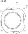
- FIG. 6 Eshows a cross-section view of the guidance positioning member of FIG. 5 .
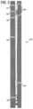
- FIG. 7is a side view of a 2D model of a directional PDM assembly in rotate drilling mode as used in the method of creating guidance positioners consistent with the technology of the present application.
- FIG. 8is a side view of a 2D model of the same directional PDM assembly now in sliding mode as used in the method of modeling guidance positioners consistent with the technology of the present application.
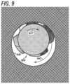
- FIG. 9shows a cross section of an upper motor housing guidance positioner deployed in a wellbore.
- FIG. 10shows a side view of a complete directional drilling assembly utilizing the guidance positioner technology consistent with the technology of the present application.
- FIGS. 11 A- 11 Dshow the progression of method steps used to configure representative guidance positioners consistent with the technology of the present application.
- FIG. 11 Ashows mock members placed on selected locations on a directional drilling assembly in a curved wellbore.
- FIG. 11 Bshows a modified version of the same directional drilling assembly with the mock members now reflecting an initial stock removal determined from the interference of the mock members with the curved wellbore wall in sliding mode.
- FIG. 11 Cshows the modified version of the directional drilling assembly now deployed in a straight wellbore.
- FIG. 11 Dshows the modified version of the directional drilling assembly deployed in straight wellbore with further stock removed from the previously partially modified mock members.
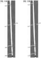
- FIG. 12 Ashows the finished assembly from FIG. 11 D , now with flutes in place on the guidance positioners, deployed in slide drilling mode in a curved wellbore.
- FIG. 12 Bshows the finished assembly from FIG. 11 D , now with flutes in place on the guidance positioners, deployed in rotary drilling mode in a straight wellbore.
- FIG. 1shows a side view of a prior art steerable PDM 100 drilling in sliding mode in a curved wellbore 110 .
- the systemincludes power section 101 , upper bypass valve and rotor catch section 102 fitted with upper stabilizer 103 , transmission housing 104 , bend 105 , kick pad 106 , bearing housing 107 , lower stabilizer 108 , and bit 109 .
- the top of the curved wellbore sectionis shown at 111 .
- the curved wellbore 110 shownis representative of approximately a 12 degree per 100 feet curvature.
- the bend 105 shownis representative of a 1.75 degree bend angle.
- the curvature rate and bend angle shownare for illustrative purposes for this example. The method and apparatus of the invention are equally applicable to any bend angle and resultant curvature rate.
- FIG. 2shows a detail of the proximate stabilizer of a prior art steerable PDM over engaging the wellbore wall while drilling in sliding mode.
- Upper stabilizer 103 and upper part of bypass valve and rotor catch section 102are shown to be in over engagement with the top of curved wellbore 111 generally at section 200 of curved wellbore 110 .
- the over engagement area at 200is on the “low side” of the curved wellbore 110 .
- the competency of the rockresists the over engagement of the upper stabilizer 103 and the upper bypass valve and rotor catch section 102 . This resistance creates drag and also flexes the upper part of the full assembly 100 back towards the center of the hole.
- prior art lower stabilizer 108 in FIG. 1also demonstrates an over engagement with the borehole wall in sliding mode drilling.
- FIG. 3shows a side view of a prior art steerable PDM 100 drilling in rotary mode in a straight wellbore 120 .
- upper stabilizer 103and upper part of bypass valve and rotor catch section 102 are shown to be in over engagement with the top of straight wellbore 121 generally at section 300 of straight wellbore 120 .
- the over engagement area at 300is on the “high side” of the straight wellbore 120 .
- the over engagement area at 300will cycle around the hole with each rotation.
- lower stabilizer 108 in FIG. 3also demonstrates an over engagement with the borehole wall.
- FIG. 4 Ashows an isometric view 400 of a prior art stabilizer 103 .
- the stabilizeris mounted on a representative housing 413 which could be a PDM bearing housing, or an upper power section housing, or a bypass valve/rotor catch housing, or a string component higher up the hole from the PDM.
- Stabilizer 103 and representative housing 413are concentric and share centerline 414 .
- FIG. 4 Bshows a cross section 415 of prior art stabilizer 103 taken across A-A on FIG. 4 A . It can be seen in both FIG. 4 A and FIG. 4 B that blades 412 are equally spaced from each other around the outer perimeter of the stabilizer. This blade configuration may be referred to as blade symmetry. It can also be seen that the outer diameter of the blades 412 is concentric with the diameter of the housing 413 and that the stabilizer and the housing share centerline 414 . This aspect of this type of prior art stabilizer may be referred to as concentricity.
- FIG. 5 Ashows a side view 500 of a lower directional PDM section employing guidance positioning members consistent with the technology of the present application.
- a typical drill bit 509At the distal end of assembly 500 is a typical drill bit 509 .
- a near bit guidance positioneris shown at 508 .
- guidance positioner 508is located on the bearing housing in approximately the same axial position as a prior art near bit stabilizer could be.
- guidance positioner 506is located in approximately the same axial position as a prior art kick/wear pad would be.
- the bend angleis shown at 505 .
- This assemblyis configured to employ an upper assembly guidance positioner (not shown).
- FIG. 5 Bshows a side view 550 of an alternative embodiment of a lower directional PDM section employing guidance positioning members consistent with the technology of the present application.
- a typical drill bit 559At the distal end of assembly 550 is a typical drill bit 559 .
- a near bit guidance positioneris shown at 558 .
- positioner 558is located on the most distal end of the bearing housing.
- guidance positioner 556is located well above the bend angle and well above where a prior art kick/wear pad would be.
- the bend angleis shown at 555 .
- This assemblyis configured to not employ an upper assembly guidance positioner but rather to be run “slick” above the guidance positioner at 556 . This configuration shortens the distance between the three points of the calculation and provides for a stiffer fulcrum effect which can improve performance and allow for a smaller bend angle to achieve a given build rate.
- FIG. 6 Ashows a detailed side view of the guidance positioner 506 . This view is in the same orientation as is shown for 506 in FIG. 5 A .
- Blade 616 shown to the left of FIG. 6 Ais one that has been defined by stock removed in the rotating mode analysis.
- Blade 617 on the right hand side of FIG. 6 Ais one that has been defined by stock removed in the sliding mode analysis.
- FIG. 6 Bshows a detailed side view of the guidance positioner 506 rotated ° from the position shown in FIG. 6 A .
- Blade 617is now to the left and blade 618 has now come into view on the right. Both blades 617 and 618 have been defined by stock removed in the sliding mode analysis.
- FIG. 6 Balso shows scribe mark 620 denoting the scribe side of the tool.
- FIG. 6 Cshows a detailed side view of the guidance positioner 506 rotated 180° from the position shown in FIG. 6 A .
- Blade 618is now on the left and blade 619 has now come into view on the right.
- blade 618is one defined by stock removed in the sliding mode analysis.
- Blade 619is one that has been defined by stock removed in the rotating mode analysis.
- FIG. 6 Dshows a detailed side view of the guidance positioner 506 rotated 270° from the position shown in FIG. 6 A .
- Blade 619is now on the left and blade 616 has now come back into view on the right. Both blades 619 and 616 have been defined by stock removed in the rotating mode analysis
- blade geometry of blades 616 , 617 , 618 , and 619demonstrate a circumferentially and axially asymmetric eccentric configuration.
- FIG. 6 Eshows a cross-section view 615 of the guidance positioning member 506 of FIG. 5 A .
- the two blades on the left, 616 and 619have had their outer shape defined in the model in the rotary drilling mode.
- the two blades on the right, 617 and 618have had their outer shape defined in the model in the slide drilling mode.
- FIG. 6 Eprovides another view of the circumferential asymmetric eccentricity of the guidance positioners of the invention.
- FIG. 7is a side view 700 of a 2D model of a directional PDM assembly in rotate drilling mode in a straight hole as used in the method of modeling guidance positioners of the invention.
- 730denotes the drill bit contact zone in the rotate drilling mode.
- 731denotes a near bit bearing housing contact zone.
- 732denotes a bend angle contact zone.
- 733denotes a contact zone on the transmission housing above the bend angle.
- 734denotes a contact zone at the top of the assembly on the by-pass valve rotor catch housing. It should be noted that in this view contact zone 734 is pushed into the “high side” of the wellbore, however since this is rotate drilling mode the location of the contact zones will rotate around the hole diameter with each rotation.
- the nominal bit diameter being modeledis 8.75′′
- the theoretical build rate of the assemblyis 12°/100′
- the theoretical wellbore diameter made in rotate drilling modeis 9.5′′.
- FIG. 8is a side view 800 of a 2D model of the same directional PDM assembly described in FIG. 7 now in sliding mode in a curved hole as used in the method of modeling guidance positioners of the invention.
- 830denotes the drill bit contact zone in sliding drilling mode.
- 831denotes a near bit bearing housing contact zone.
- 832denotes a bend angle contact zone.
- 833denotes a contact zone on the transmission housing above the bend angle.
- Finally 834denotes a contact zone at the top of the assembly on the by-pass valve rotor catch housing. It should be noted that in sliding mode contact zone 834 is pushed into the “low side” of the wellbore. Since this is sliding mode the contact zones will remain in the same orientation relative to the wellbore throughout the slide.
- FIG. 9shows a cross section of an upper motor housing guidance positioner 900 deployed in a wellbore 940 .
- Arrow 941shows the right hand rotation of the drill pipe.
- Arrow 942shows the direction of progression around the outer circumference of the wellbore of the guidance positioner 900 in rotary drilling mode.
- FIG. 10shows a side view 1000 of a complete directional drilling assembly utilizing the guidance positioner technology of the present application.
- 1009denotes the drill bit
- 1008denotes a near bit guidance positioner
- 1005denotes the bend
- 1006denotes a transmission housing guidance positioner
- 1003denotes an upper housing guidance positioner.
- FIGS. 11 A- 11 Dshow the progression of method steps used to configure representative guidance positioners of the technology of the present application.
- FIG. 11 Ashows full diameter mock members placed on three selected locations on an initial version 1160 of a directional drilling assembly in a curved wellbore 1161 .
- the initial version 1160may be considered an unmodified model or an unmodified directional drilling assembly.
- the curve of the wellbore 1161represents a degree per 100 feet build rate.
- the lowermost mock memberis shown on the bearing housing at 1162 .
- a mock memberis shown on the transmission housing just above the bend angle.
- a final mock memberis shown on the dump valve/rotor catch housing at 1164 .
- the unmodified model 1160is simulated in a curved wellbore section to identify over engagement contact points using a slide drilling mode, which over engagement contact points may be referred to as slide mode over engagement contact points or the like.
- FIG. 11 Bshows a modified version 1170 of the same directional drilling assembly with the mock members now reflecting an initial stock removal determined from the interference of the mock members with the curved wellbore wall in sliding mode.
- the modified version 1170may be referred to as a first modified model or a first modified directional drilling assembly.
- the generation of the modelmay be via a second modeling step to distinguish between the first modeling step showing the unmodified model above.
- the lowermost member 1172is now in its final outer configuration with stock removed on the low side of the mock member from the slide interference analysis step and stock removed from the high side of the mock member at the system designer's discretion.
- Modified mock members 1173 and 1174now show outer configurations with stock removed from the slide drilling interference analysis in curved wellbore 1161 .
- FIG. 11 Cshows the modified version 1170 of the directional drilling assembly now deployed in a straight wellbore 1181 .
- Fully modified (non-interfering) member 1172 and partially modified members 1173 and 1174are now in position to have the rotary drilling interference performed.
- the first modified model 1170is simulated in a straight wellbore section to identify over engagement contact points using a rotary drilling mode, which over engagement contact points may be referred to as rotary mode over engagement contact points or the like.
- FIG. 11 Dshows the modified version 1190 of the directional drilling assembly deployed in straight wellbore 1181 with further stock removed from the previously partially modified mock members.
- the modified version 1190may be referred to as a second modified model or a second modified directional drilling assembly.
- the generation of the modelmay be via a third modeling step to distinguish between the first modeling step showing the unmodified model above.
- Member 1172has not undergone further modification but transmission housing member 1193 and upper housing member 1194 now reflect the additional stock removal resulting from the rotary drilling analysis performed in straight wellbore 1181 .
- the modeled oversized hole diameteris 9.25 inches.
- the outer surface of the guidance positionersis now complete.
- FIG. 12 Ashows the finished assembly 1290 completed from the modified assembly 1190 from FIG. 11 D .
- Finished assembly 1290is shown deployed in slide drilling mode in a curved wellbore 1161 .
- Assembly 1290includes guidance positioners 1292 , 1293 , and 1294 with flutes added completing the modeling of the guidance positioners. These models are now ready for machining/manufacturing as discussed previously.
- FIG. 12 Bshows the finished assembly 1290 completed from the modified assembly 1190 from FIG. 11 D .
- Finished assembly 1290is shown deployed in rotary drilling mode in a straight wellbore 1181 .
- the guidance positioners 1292 , 1293 , and 1294may have their outer surfaces machined to match the curvature of the wellbore in slide drilling mode.
- the guidance positioners 1292 , 1293 , and 1294may be fitted with cutters as mentioned to facilitate reaming of any transition lips associated with a directionally drilled wellbore as described above.
- a wellboremay be drilled using the assembly.
- the wellborewould include both straight sections, which could be vertical sections, inclined sections, horizontal sections, or some combination thereof, as well as curved sections where the directional drilling assembly causes the wellbore to deviate from the axis of the subsequent wellbore section.
- directional drilling assemblywould be provided on a drill string.
- the directional drilling assemblycomprises a power section, a transmission section, a bearing portion, a bit portion, and a bend located below the power section and above the bit portion, the directional drilling assembly having at least an asymmetric near bit positioner located proximal the bit portion and at least an asymmetric upper bit positioner located above the bend.
- the operatorwould cease the rotation of the drill string and orient the drill string such that the directional drilling assembly is oriented in a direction to drill the wellbore.
- the operatormay use known methods to orient the directional drilling assembly including orienting the scribe line.
- the power section of the direction drillwhich may be a positive displacement motor that receives its motive force from drilling mud flow, would be rotated to cause the bit on the bit portion to rotate separate from the remainder of the drill string to drill the wellbore.
- the wellboreis drilled substantially straight by rotating the drill string to drill a substantially straight section of the wellbore.
- the guidance positionersmay be designed such that blades modified by slide drilling mode will be axially displaced from blades modified by rotary drilling mode.
Landscapes
- Engineering & Computer Science (AREA)
- Geology (AREA)
- Mining & Mineral Resources (AREA)
- Life Sciences & Earth Sciences (AREA)
- Physics & Mathematics (AREA)
- General Life Sciences & Earth Sciences (AREA)
- Fluid Mechanics (AREA)
- Environmental & Geological Engineering (AREA)
- Geochemistry & Mineralogy (AREA)
- Geophysics (AREA)
- Remote Sensing (AREA)
- Mechanical Engineering (AREA)
- Earth Drilling (AREA)
Abstract
Description
Claims (24)
Priority Applications (1)
| Application Number | Priority Date | Filing Date | Title |
|---|---|---|---|
| US17/102,618US11933172B2 (en) | 2016-12-28 | 2020-11-24 | Method, apparatus by method, and apparatus of guidance positioning members for directional drilling |
Applications Claiming Priority (3)
| Application Number | Priority Date | Filing Date | Title |
|---|---|---|---|
| US201662439843P | 2016-12-28 | 2016-12-28 | |
| US15/667,704US10890030B2 (en) | 2016-12-28 | 2017-08-03 | Method, apparatus by method, and apparatus of guidance positioning members for directional drilling |
| US17/102,618US11933172B2 (en) | 2016-12-28 | 2020-11-24 | Method, apparatus by method, and apparatus of guidance positioning members for directional drilling |
Related Parent Applications (1)
| Application Number | Title | Priority Date | Filing Date |
|---|---|---|---|
| US15/667,704DivisionUS10890030B2 (en) | 2016-12-28 | 2017-08-03 | Method, apparatus by method, and apparatus of guidance positioning members for directional drilling |
Publications (2)
| Publication Number | Publication Date |
|---|---|
| US20210246727A1 US20210246727A1 (en) | 2021-08-12 |
| US11933172B2true US11933172B2 (en) | 2024-03-19 |
Family
ID=62625550
Family Applications (2)
| Application Number | Title | Priority Date | Filing Date |
|---|---|---|---|
| US15/667,704Active2038-03-08US10890030B2 (en) | 2016-12-28 | 2017-08-03 | Method, apparatus by method, and apparatus of guidance positioning members for directional drilling |
| US17/102,618Active2038-08-14US11933172B2 (en) | 2016-12-28 | 2020-11-24 | Method, apparatus by method, and apparatus of guidance positioning members for directional drilling |
Family Applications Before (1)
| Application Number | Title | Priority Date | Filing Date |
|---|---|---|---|
| US15/667,704Active2038-03-08US10890030B2 (en) | 2016-12-28 | 2017-08-03 | Method, apparatus by method, and apparatus of guidance positioning members for directional drilling |
Country Status (3)
| Country | Link |
|---|---|
| US (2) | US10890030B2 (en) |
| CA (1) | CA3048143A1 (en) |
| WO (1) | WO2018125613A1 (en) |
Families Citing this family (15)
| Publication number | Priority date | Publication date | Assignee | Title |
|---|---|---|---|---|
| US9297205B2 (en) | 2011-12-22 | 2016-03-29 | Hunt Advanced Drilling Technologies, LLC | System and method for controlling a drilling path based on drift estimates |
| US8596385B2 (en) | 2011-12-22 | 2013-12-03 | Hunt Advanced Drilling Technologies, L.L.C. | System and method for determining incremental progression between survey points while drilling |
| US11085283B2 (en) | 2011-12-22 | 2021-08-10 | Motive Drilling Technologies, Inc. | System and method for surface steerable drilling using tactical tracking |
| US8210283B1 (en) | 2011-12-22 | 2012-07-03 | Hunt Energy Enterprises, L.L.C. | System and method for surface steerable drilling |
| US11106185B2 (en) | 2014-06-25 | 2021-08-31 | Motive Drilling Technologies, Inc. | System and method for surface steerable drilling to provide formation mechanical analysis |
| US9428961B2 (en) | 2014-06-25 | 2016-08-30 | Motive Drilling Technologies, Inc. | Surface steerable drilling system for use with rotary steerable system |
| US11933158B2 (en) | 2016-09-02 | 2024-03-19 | Motive Drilling Technologies, Inc. | System and method for mag ranging drilling control |
| CA3071027A1 (en) | 2017-08-10 | 2019-02-14 | Motive Drilling Technologies, Inc. | Apparatus and methods for automated slide drilling |
| US10830033B2 (en) | 2017-08-10 | 2020-11-10 | Motive Drilling Technologies, Inc. | Apparatus and methods for uninterrupted drilling |
| US11111978B2 (en) | 2017-12-14 | 2021-09-07 | Xr Reserve, Llc | Mechanical force breaker |
| US11111770B2 (en)* | 2018-04-24 | 2021-09-07 | Nabors Drilling Technologies Usa, Inc. | Automated steering using operating constraints |
| US11466556B2 (en) | 2019-05-17 | 2022-10-11 | Helmerich & Payne, Inc. | Stall detection and recovery for mud motors |
| US11613929B2 (en) | 2019-11-08 | 2023-03-28 | Xr Dynamics Llc | Dynamic drilling systems and methods |
| USD1045567S1 (en)* | 2021-06-27 | 2024-10-08 | Klein Tools, Inc. | Shank for a threaded fastener bit driver |
| US11885212B2 (en) | 2021-07-16 | 2024-01-30 | Helmerich & Payne Technologies, Llc | Apparatus and methods for controlling drilling |
Citations (174)
| Publication number | Priority date | Publication date | Assignee | Title |
|---|---|---|---|---|
| US356154A (en) | 1887-01-18 | neelands | ||
| US1638337A (en) | 1925-05-25 | 1927-08-09 | Edward S Hutton | Rotary well drill |
| US1667155A (en) | 1927-03-18 | 1928-04-24 | Zalmon B Higdon | Drilling bit |
| US2919897A (en) | 1958-07-07 | 1960-01-05 | Regan Forge & Eng Co | Deflection drilling tool |
| US3061025A (en) | 1959-03-31 | 1962-10-30 | Hughes Tool Co | Unitized drilling bit |
| US3156310A (en) | 1959-12-07 | 1964-11-10 | Eastman Oil Well Survey Co | Stabilized knuckle joint |
| US3159224A (en) | 1960-12-30 | 1964-12-01 | Atlantic Refining Co | Underdrilling rotary bit |
| US3224513A (en) | 1962-11-07 | 1965-12-21 | Jr Frank G Weeden | Apparatus for downhole drilling |
| US3561549A (en) | 1968-06-07 | 1971-02-09 | Smith Ind International Inc | Slant drilling tools for oil wells |
| US3880246A (en) | 1972-09-25 | 1975-04-29 | Ralph J Farris | Optionally stabilized drilling tool, and method of use |
| US3882946A (en) | 1974-04-24 | 1975-05-13 | Rolen Arsenievich Ioannesian | Turbodrill |
| US4270619A (en) | 1979-10-03 | 1981-06-02 | Base Jimmy D | Downhole stabilizing tool with actuator assembly and method for using same |
| US4373592A (en) | 1980-11-28 | 1983-02-15 | Mobil Oil Corporation | Rotary drilling drill string stabilizer-cuttings grinder |
| US4385669A (en) | 1981-08-21 | 1983-05-31 | Paul Knutsen | Integral blade cylindrical gauge stabilizer reamer |
| US4407377A (en) | 1982-04-16 | 1983-10-04 | Russell Larry R | Surface controlled blade stabilizer |
| US4456080A (en) | 1980-09-19 | 1984-06-26 | Holbert Don R | Stabilizer method and apparatus for earth-boring operations |
| US4465147A (en) | 1982-02-02 | 1984-08-14 | Shell Oil Company | Method and means for controlling the course of a bore hole |
| US4485879A (en) | 1982-08-25 | 1984-12-04 | Shell Oil Company | Downhole motor and method for directional drilling of boreholes |
| US4491187A (en) | 1982-06-01 | 1985-01-01 | Russell Larry R | Surface controlled auxiliary blade stabilizer |
| US4492276A (en) | 1982-11-17 | 1985-01-08 | Shell Oil Company | Down-hole drilling motor and method for directional drilling of boreholes |
| US4523652A (en) | 1983-07-01 | 1985-06-18 | Atlantic Richfield Company | Drainhole drilling assembly and method |
| US4577701A (en) | 1984-08-08 | 1986-03-25 | Mobil Oil Corporation | System of drilling deviated wellbores |
| US4618010A (en) | 1986-02-18 | 1986-10-21 | Team Engineering And Manufacturing, Inc. | Hole opener |
| US4623026A (en) | 1982-06-03 | 1986-11-18 | Kemp Billy W | Method and apparatus of a self-aligning sleeve for the correction of the direction of deviated boreholes |
| US4667751A (en)* | 1985-10-11 | 1987-05-26 | Smith International, Inc. | System and method for controlled directional drilling |
| US4690229A (en) | 1986-01-22 | 1987-09-01 | Raney Richard C | Radially stabilized drill bit |
| US4697651A (en) | 1986-12-22 | 1987-10-06 | Mobil Oil Corporation | Method of drilling deviated wellbores |
| US4715453A (en) | 1986-10-30 | 1987-12-29 | Team Construction And Fabrication, Inc. | Drilling deviation control tool |
| US4729438A (en) | 1986-07-03 | 1988-03-08 | Eastman Christensen Co, | Stabilizer for navigational drilling |
| US4739843A (en) | 1986-05-12 | 1988-04-26 | Sidewinder Tool Joint Venture | Apparatus for lateral drilling in oil and gas wells |
| US4775017A (en) | 1986-04-11 | 1988-10-04 | Drilex Uk Limited | Drilling using downhole drilling tools |
| US4807708A (en) | 1985-12-02 | 1989-02-28 | Drilex Uk Limited And Eastman Christensen Company | Directional drilling of a drill string |
| US4842083A (en) | 1986-01-22 | 1989-06-27 | Raney Richard C | Drill bit stabilizer |
| US4848490A (en)* | 1986-07-03 | 1989-07-18 | Anderson Charles A | Downhole stabilizers |
| US4862974A (en) | 1988-12-07 | 1989-09-05 | Amoco Corporation | Downhole drilling assembly, apparatus and method utilizing drilling motor and stabilizer |
| US4877092A (en) | 1988-04-15 | 1989-10-31 | Teleco Oilfield Services Inc. | Near bit offset stabilizer |
| US5010789A (en) | 1989-02-21 | 1991-04-30 | Amoco Corporation | Method of making imbalanced compensated drill bit |
| US5042596A (en) | 1989-02-21 | 1991-08-27 | Amoco Corporation | Imbalance compensated drill bit |
| US5050692A (en) | 1987-08-07 | 1991-09-24 | Baker Hughes Incorporated | Method for directional drilling of subterranean wells |
| US5099931A (en) | 1988-02-02 | 1992-03-31 | Eastman Christensen Company | Method and apparatus for optional straight hole drilling or directional drilling in earth formations |
| US5099929A (en) | 1990-05-04 | 1992-03-31 | Dresser Industries, Inc. | Unbalanced PDC drill bit with right hand walk tendencies, and method of drilling right hand bore holes |
| US5115872A (en)* | 1990-10-19 | 1992-05-26 | Anglo Suisse, Inc. | Directional drilling system and method for drilling precise offset wellbores from a main wellbore |
| US5131479A (en) | 1990-03-07 | 1992-07-21 | Institut Francais Du Petrole | Rotary drilling device comprising means for adjusting the azimuth angle of the path of the drilling tool and corresponding drilling process |
| US5139094A (en) | 1991-02-01 | 1992-08-18 | Anadrill, Inc. | Directional drilling methods and apparatus |
| US5159577A (en) | 1990-10-09 | 1992-10-27 | Baroid Technology, Inc. | Technique for reducing whirling of a drill string |
| US5181576A (en) | 1991-02-01 | 1993-01-26 | Anadrill, Inc. | Downhole adjustable stabilizer |
| US5318137A (en) | 1992-10-23 | 1994-06-07 | Halliburton Company | Method and apparatus for adjusting the position of stabilizer blades |
| US5320179A (en)* | 1992-08-06 | 1994-06-14 | Slimdril International Inc. | Steering sub for flexible drilling |
| US5333699A (en) | 1992-12-23 | 1994-08-02 | Baroid Technology, Inc. | Drill bit having polycrystalline diamond compact cutter with spherical first end opposite cutting end |
| US5343967A (en) | 1984-05-12 | 1994-09-06 | Baker Hughes Incorporated | Apparatus for optional straight or directional drilling underground formations |
| US5361859A (en) | 1993-02-12 | 1994-11-08 | Baker Hughes Incorporated | Expandable gage bit for drilling and method of drilling |
| US5458208A (en)* | 1994-07-05 | 1995-10-17 | Clarke; Ralph L. | Directional drilling using a rotating slide sub |
| EP0530045B1 (en) | 1991-08-30 | 1997-04-23 | Camco Drilling Group Limited | Modulated bias units for steerable rotary drilling systems |
| US5673763A (en) | 1994-06-04 | 1997-10-07 | Camco Drilling Group Ltd. Of Hycalog | Modulated bias unit for rotary drilling |
| US5812068A (en) | 1994-12-12 | 1998-09-22 | Baker Hughes Incorporated | Drilling system with downhole apparatus for determining parameters of interest and for adjusting drilling direction in response thereto |
| US5857531A (en) | 1997-04-10 | 1999-01-12 | Halliburton Energy Services, Inc. | Bottom hole assembly for directional drilling |
| US5904213A (en) | 1995-10-10 | 1999-05-18 | Camco International (Uk) Limited | Rotary drill bits |
| US5931239A (en) | 1995-05-19 | 1999-08-03 | Telejet Technologies, Inc. | Adjustable stabilizer for directional drilling |
| US5937958A (en) | 1997-02-19 | 1999-08-17 | Smith International, Inc. | Drill bits with predictable walk tendencies |
| US5957223A (en) | 1997-03-05 | 1999-09-28 | Baker Hughes Incorporated | Bi-center drill bit with enhanced stabilizing features |
| US5971085A (en) | 1996-11-06 | 1999-10-26 | Camco International (Uk) Limited | Downhole unit for use in boreholes in a subsurface formation |
| US5979570A (en)* | 1995-04-05 | 1999-11-09 | Mcloughlin; Stephen John | Surface controlled wellbore directional steering tool |
| CA2291922A1 (en) | 1998-12-11 | 2000-06-11 | Schlumberger Canada Limited | Rotary steerable well drilling system utilizing sliding sleeve |
| US6073707A (en) | 1998-03-11 | 2000-06-13 | Canadian Downhole Drill Systems Inc. | Downhole sub with kick pad for directional drilling |
| US6079506A (en)* | 1998-04-27 | 2000-06-27 | Digital Control Incorporated | Boring tool control using remote locator |
| US6109372A (en)* | 1999-03-15 | 2000-08-29 | Schlumberger Technology Corporation | Rotary steerable well drilling system utilizing hydraulic servo-loop |
| US6116356A (en) | 1996-10-09 | 2000-09-12 | Baker Hughes Incorporated | Reaming apparatus and method with enhanced stability and transition from pilot hole to enlarged bore diameter |
| US6158533A (en) | 1998-04-09 | 2000-12-12 | Halliburton Energy Services, Inc. | Adjustable gauge downhole drilling assembly |
| US6186251B1 (en) | 1998-07-27 | 2001-02-13 | Baker Hughes Incorporated | Method of altering a balance characteristic and moment configuration of a drill bit and drill bit |
| US6213226B1 (en)* | 1997-12-04 | 2001-04-10 | Halliburton Energy Services, Inc. | Directional drilling assembly and method |
| US6257356B1 (en) | 1999-10-06 | 2001-07-10 | Aps Technology, Inc. | Magnetorheological fluid apparatus, especially adapted for use in a steerable drill string, and a method of using same |
| US6325162B1 (en) | 1997-12-04 | 2001-12-04 | Halliburton Energy Services, Inc. | Bit connector |
| US6349780B1 (en) | 2000-08-11 | 2002-02-26 | Baker Hughes Incorporated | Drill bit with selectively-aggressive gage pads |
| US20020056574A1 (en) | 2000-03-22 | 2002-05-16 | Harvey Peter R. | Stabilizer for use in a drill string |
| US20020070021A1 (en)* | 1998-05-13 | 2002-06-13 | Van Drentham-Susman Hector F.A. | Guide device |
| US6427792B1 (en) | 2000-07-06 | 2002-08-06 | Camco International (Uk) Limited | Active gauge cutting structure for earth boring drill bits |
| US20020112892A1 (en) | 2001-02-16 | 2002-08-22 | Taylor Kyle Lamar | Rotary steering tool system for directional drilling |
| US20020175006A1 (en) | 1999-01-25 | 2002-11-28 | Findley Sidney L. | Drill bits and other articles of manufacture including a layer-manufactured shell integrally secured to a cast structure and methods and molds for fabricating same |
| US20030010534A1 (en)* | 1998-12-21 | 2003-01-16 | Chen Chen-Kang D. | Steerable drilling system and method |
| US20030024742A1 (en)* | 2001-06-12 | 2003-02-06 | George Swietlik | Steerable downhole tools |
| US6523623B1 (en) | 2001-05-30 | 2003-02-25 | Validus International Company, Llc | Method and apparatus for determining drilling paths to directional targets |
| US6722453B1 (en) | 1998-12-14 | 2004-04-20 | Jay C. A. Crooks | Stabilized downhole drilling motor |
| US6742605B2 (en) | 2002-06-12 | 2004-06-01 | Leo A. Martini | Percussion tool for generic downhole fluid motors |
| US20040216921A1 (en) | 1998-11-10 | 2004-11-04 | Baker Hughes Incorporated | Self-controlled directional drilling systems and methods |
| US20050096847A1 (en)* | 2000-10-11 | 2005-05-05 | Smith International, Inc. | Methods for modeling, designing, and optimizing the performance of drilling tool assemblies |
| US20050150692A1 (en)* | 2003-11-05 | 2005-07-14 | Baker Hughes Incorporated | Directional cased hole side track method applying rotary closed loop system and casing mill |
| US20050236187A1 (en)* | 2002-12-16 | 2005-10-27 | Chen Chen-Kang D | Drilling with casing |
| US6991046B2 (en)* | 2003-11-03 | 2006-01-31 | Reedhycalog, L.P. | Expandable eccentric reamer and method of use in drilling |
| US20060196697A1 (en) | 2002-04-30 | 2006-09-07 | Raney Richard C | Stabilizing system and methods for a drill bit |
| US20070007042A1 (en)* | 2005-07-11 | 2007-01-11 | The Charles Machine Works, Inc. | Electric horizontal directional drilling machine system |
| US20070007000A1 (en) | 2005-07-06 | 2007-01-11 | Smith International, Inc. | Method of drilling an enlarged sidetracked well bore |
| US7207398B2 (en) | 2001-07-16 | 2007-04-24 | Shell Oil Company | Steerable rotary drill bit assembly with pilot bit |
| US20070114068A1 (en)* | 2005-11-21 | 2007-05-24 | Mr. David Hall | Drill Bit Assembly for Directional Drilling |
| US20070163810A1 (en)* | 2006-01-18 | 2007-07-19 | Smith International, Inc. | Flexible directional drilling apparatus and method |
| US20070205024A1 (en) | 2005-11-30 | 2007-09-06 | Graham Mensa-Wilmot | Steerable fixed cutter drill bit |
| US20070235227A1 (en)* | 2006-04-07 | 2007-10-11 | Halliburton Energy Services, Inc. | Steering tool |
| US20070272445A1 (en) | 2006-05-26 | 2007-11-29 | Smith International, Inc. | Drill bit with assymetric gage pad configuration |
| US20080000693A1 (en) | 2005-02-11 | 2008-01-03 | Richard Hutton | Steerable rotary directional drilling tool for drilling boreholes |
| US20080047754A1 (en)* | 2006-08-25 | 2008-02-28 | Smith International, Inc. | Passive vertical drilling motor stabilization |
| US20080053707A1 (en)* | 2006-06-02 | 2008-03-06 | Schlumberger Technology Corporation | System and method for reducing the borehole gap for downhole formation testing sensors |
| US20080075618A1 (en)* | 2006-09-19 | 2008-03-27 | Schlumberger Technology Corporation | Metal Powder Layered Apparatus for Downhole Use |
| US20080115974A1 (en) | 2006-11-16 | 2008-05-22 | Ashley Johnson | Steerable drilling system |
| US20080190665A1 (en)* | 2004-01-28 | 2008-08-14 | Halliburton Energy Services, Inc. | Rotary Vector Gear for Use in Rotary Steerable Tools |
| US20080271923A1 (en)* | 2007-05-03 | 2008-11-06 | David John Kusko | Flow hydraulic amplification for a pulsing, fracturing, and drilling (PFD) device |
| US20090000823A1 (en)* | 2007-06-29 | 2009-01-01 | Schlumberger Technology Corporation | Method of Automatically controlling the Trajectory of a Drilled Well |
| US20090044981A1 (en) | 2007-08-15 | 2009-02-19 | Schlumberger Technology Corporation | Method and system for steering a directional drilling system |
| US20090044980A1 (en) | 2007-08-15 | 2009-02-19 | Schlumberger Technology Corporation | System and method for directional drilling a borehole with a rotary drilling system |
| US20090065262A1 (en) | 2007-09-11 | 2009-03-12 | Downton Geoffrey C | Drill bit |
| US20090107722A1 (en) | 2007-10-24 | 2009-04-30 | Schlumberger Technology Corporation | Morphible bit |
| US7562725B1 (en) | 2003-07-10 | 2009-07-21 | Broussard Edwin J | Downhole pilot bit and reamer with maximized mud motor dimensions |
| US20090188720A1 (en) | 2007-08-15 | 2009-07-30 | Schlumberger Technology Corporation | System and method for drilling |
| US20100006341A1 (en)* | 2008-07-11 | 2010-01-14 | Schlumberger Technology Corporation | Steerable piloted drill bit, drill system, and method of drilling curved boreholes |
| US7831419B2 (en) | 2005-01-24 | 2010-11-09 | Smith International, Inc. | PDC drill bit with cutter design optimized with dynamic centerline analysis having an angular separation in imbalance forces of 180 degrees for maximum time |
| US20100307837A1 (en)* | 2009-06-05 | 2010-12-09 | Varel International, Ind., L.P. | Casing bit and casing reamer designs |
| US20110031025A1 (en) | 2009-08-04 | 2011-02-10 | Baker Hughes Incorporated | Drill Bit With An Adjustable Steering Device |
| US20110247816A1 (en)* | 2008-12-10 | 2011-10-13 | Carter Jr Ernest E | Method and Apparatus for Increasing Well Productivity |
| US20120055713A1 (en) | 2010-08-31 | 2012-03-08 | Baker Hughes Incorporated | Drill Bit with Adjustable Side Force |
| US8162081B2 (en) | 2008-08-28 | 2012-04-24 | Varel International Ind., L.P. | Force balanced asymmetric drilling reamer and methods for force balancing |
| US8176999B2 (en) | 2004-06-22 | 2012-05-15 | Smart Stabilizer Systems Limited | Steerable drill bit arrangement |
| US8201642B2 (en) | 2009-01-21 | 2012-06-19 | Baker Hughes Incorporated | Drilling assemblies including one of a counter rotating drill bit and a counter rotating reamer, methods of drilling, and methods of forming drilling assemblies |
| US8210283B1 (en) | 2011-12-22 | 2012-07-03 | Hunt Energy Enterprises, L.L.C. | System and method for surface steerable drilling |
| US20120234610A1 (en)* | 2011-02-10 | 2012-09-20 | Smith International, Inc. | Cutting structures for fixed cutter drill bit and other downhole cutting tools |
| US8316968B2 (en) | 2009-05-01 | 2012-11-27 | Smith International, Inc. | Rolling cone drill bit having sharp cutting elements in a zone of interest |
| US20130043076A1 (en) | 2011-08-19 | 2013-02-21 | Precision Energy Services, Inc. | Rotary Steerable Assembly Inhibiting Counterclockwise Whirl During Directional Drilling |
| US8448722B2 (en) | 2010-05-04 | 2013-05-28 | Arrival Oil Tools, Inc. | Drilling stabilizer |
| US8448721B2 (en) | 2007-12-19 | 2013-05-28 | Schlumberger Technology Corporation | Directional drilling system |
| US20130175092A1 (en)* | 2012-01-05 | 2013-07-11 | Merlin Technology, Inc. | Directional drilling target steering apparatus and method |
| US20130180782A1 (en) | 2012-01-12 | 2013-07-18 | Baker Hughes Incorporated | Turbine Driven Reaming Bit with Blades and Cutting Structure Extending into Concave Nose |
| US8550190B2 (en) | 2010-04-01 | 2013-10-08 | David R. Hall | Inner bit disposed within an outer bit |
| US20140097026A1 (en)* | 2012-09-24 | 2014-04-10 | Schlumberger Technology Corporation | Positive Displacement Motor (PDM) Rotary Steerable System (RSS) And Apparatus |
| US20140110178A1 (en)* | 2012-06-12 | 2014-04-24 | Halliburton Energy Services, Inc. | Modular rotary steerable actuators, steering tools, and rotary steerable drilling systems with modular actuators |
| US8757298B2 (en) | 2011-04-26 | 2014-06-24 | Edwin J. Broussard, JR. | Method and apparatus for dual speed, dual torque drilling |
| US8763726B2 (en) | 2007-08-15 | 2014-07-01 | Schlumberger Technology Corporation | Drill bit gauge pad control |
| USD710176S1 (en) | 2013-08-15 | 2014-08-05 | Black & Decker Inc. | Sleeve for screwdriving bit |
| USD710175S1 (en) | 2013-08-15 | 2014-08-05 | Black & Decker Inc. | Sleeve for screwdriving bit |
| USD710174S1 (en) | 2013-08-15 | 2014-08-05 | Black & Decker Inc. | Sleeve for screwdriving bit |
| US20140246234A1 (en)* | 2013-03-04 | 2014-09-04 | Drilformance Technologies, Llc | Drilling apparatus and method |
| US20140246209A1 (en) | 2011-10-11 | 2014-09-04 | Packers Plus Energy Services Inc. | Wellbore actuators, treatment strings and methods |
| USD713706S1 (en) | 2012-03-05 | 2014-09-23 | Robert Bosch Gmbh | Tool holder portion of an impact driver |
| US20140311801A1 (en) | 2013-04-17 | 2014-10-23 | Baker Hughes Incorporated | Drill Bit with Self-Adjusting Pads |
| USD717626S1 (en) | 2013-03-02 | 2014-11-18 | Ronald W. Dickrede | Adaptor for holding a tap threading device |
| US8905159B2 (en)* | 2009-12-15 | 2014-12-09 | Schlumberger Technology Corporation | Eccentric steering device and methods of directional drilling |
| US20140379133A1 (en)* | 2013-06-21 | 2014-12-25 | Directional Control Systems International (DCSI) Inc. | Methods and systems for monitoring directional drilling |
| US20150101864A1 (en)* | 2013-10-12 | 2015-04-16 | Mark May | Intelligent reamer for rotary/sliding drilling system and method |
| US9016400B2 (en) | 2010-09-09 | 2015-04-28 | National Oilwell Varco, L.P. | Downhole rotary drilling apparatus with formation-interfacing members and control system |
| US20150122551A1 (en)* | 2012-05-30 | 2015-05-07 | Halliburton Energy Services, Inc. | Rotary drill bit and method for designing a rotary drill bit for directional and horizontal drilling |
| US20150152723A1 (en) | 2012-07-05 | 2015-06-04 | Halliburton Energy Services, Inc. | Displaceable components in drilling operations |
| USD731277S1 (en) | 2013-08-16 | 2015-06-09 | Magna-Sonic Stress Testers, Inc. | Barrel for pipe end refacing tool |
| USD732364S1 (en) | 2014-07-02 | 2015-06-23 | Mcginley Engineered Solutions, Llc | Removable chuck |
| US9163460B2 (en) | 2011-10-03 | 2015-10-20 | Extreme Technologies, Llc | Wellbore conditioning system |
| US20150322781A1 (en)* | 2012-08-31 | 2015-11-12 | Halliburton Energy Services, Inc. | System and method for analyzing cuttings using an opto-analytical device |
| US20160024848A1 (en)* | 2013-03-15 | 2016-01-28 | Tercel Ip Ltd. | Downhole directional drilling assembly |
| US20160024846A1 (en)* | 2014-07-24 | 2016-01-28 | Schlumberger Technology Corporation | Inverted Wellbore Drilling Motor |
| US20160115779A1 (en)* | 2014-10-17 | 2016-04-28 | Applied Technologies Associates, Inc. | Active Magnetic Azimuthal Toolface for Vertical Borehole Kickoff in Magnetically Perturbed Environments |
| US20160230465A1 (en) | 2014-04-17 | 2016-08-11 | Halliburton Energy Services, Inc. | Bottom Hole Assembly With Wearable Stabilizer Pad for Directional Steering |
| US20160265287A1 (en)* | 2015-03-13 | 2016-09-15 | European Drilling Projects B.V. | Blade stabiliser tool for drill string |
| US20160281431A1 (en)* | 2015-03-24 | 2016-09-29 | Baker Hughes Incorporated | Self-Adjusting Directional Drilling Apparatus and Methods for Drilling Directional Wells |
| US20160326863A1 (en)* | 2014-10-22 | 2016-11-10 | Halliburton Energy Services, Inc. | Bend angle sensing assembly and method of use |
| US9556683B2 (en) | 2012-12-03 | 2017-01-31 | Ulterra Drilling Technologies, L.P. | Earth boring tool with improved arrangement of cutter side rakes |
| US20170044833A1 (en) | 2015-08-06 | 2017-02-16 | Cathedral Energy Services Ltd. | Directional drilling motor |
| US9605482B2 (en)* | 2015-03-05 | 2017-03-28 | Halliburton Energy Services, Inc. | Directional drilling with adjustable bent housings |
| US20170130533A1 (en) | 2014-07-31 | 2017-05-11 | Halliburton Energy Services, Inc. | Force self-balanced drill bit |
| USD786645S1 (en) | 2015-11-03 | 2017-05-16 | Z Drilling Holdings, Inc. | Reamer |
| USD793831S1 (en) | 2016-02-03 | 2017-08-08 | Mcginley Engineered Solutions, Llc | Removable chuck |
| USD793832S1 (en) | 2016-02-03 | 2017-08-08 | Mcginley Engineered Solutions, Llc | Removable chuck |
| USD793833S1 (en) | 2016-02-03 | 2017-08-08 | Mcginley Engineered Solutions, Llc | Removable chuck |
| US20170234071A1 (en)* | 2016-02-16 | 2017-08-17 | Extreme Rock Destruction LLC | Drilling machine |
| US20170241207A1 (en) | 2011-04-08 | 2017-08-24 | Extreme Technologies, Llc | Method and apparatus for steering a drill string and reaming well bore surfaces nearer the center of drift |
| US20170342778A1 (en)* | 2014-12-30 | 2017-11-30 | Halliburton Energy Services, Inc. | Downhole tool surfaces configured to reduce drag forces and erosion during exposure to fluid flow |
| US20170342773A1 (en)* | 2016-05-27 | 2017-11-30 | Scientific Drilling International, Inc. | Motor Power Section with Integrated Sensors |
| US20180073301A1 (en)* | 2016-09-12 | 2018-03-15 | Hypersciences, Inc. | Augmented drilling system |
| USD813003S1 (en) | 2016-11-15 | 2018-03-20 | Wintek Tools Co., Ltd. | Tool adapter |
| US20180179831A1 (en) | 2016-12-28 | 2018-06-28 | Extreme Rock Destruction, LLC | Bottom hole assemblies for directional drilling |
| US20190055810A1 (en)* | 2015-12-29 | 2019-02-21 | Halliburton Energy Services, Inc. | Wellbore isolation devices with slip bands and wear bands having modified surfaces |
- 2017
- 2017-08-03USUS15/667,704patent/US10890030B2/enactiveActive
- 2017-12-15WOPCT/US2017/066707patent/WO2018125613A1/ennot_activeCeased
- 2017-12-15CACA3048143Apatent/CA3048143A1/enactivePending
- 2020
- 2020-11-24USUS17/102,618patent/US11933172B2/enactiveActive
Patent Citations (181)
| Publication number | Priority date | Publication date | Assignee | Title |
|---|---|---|---|---|
| US356154A (en) | 1887-01-18 | neelands | ||
| US1638337A (en) | 1925-05-25 | 1927-08-09 | Edward S Hutton | Rotary well drill |
| US1667155A (en) | 1927-03-18 | 1928-04-24 | Zalmon B Higdon | Drilling bit |
| US2919897A (en) | 1958-07-07 | 1960-01-05 | Regan Forge & Eng Co | Deflection drilling tool |
| US3061025A (en) | 1959-03-31 | 1962-10-30 | Hughes Tool Co | Unitized drilling bit |
| US3156310A (en) | 1959-12-07 | 1964-11-10 | Eastman Oil Well Survey Co | Stabilized knuckle joint |
| US3159224A (en) | 1960-12-30 | 1964-12-01 | Atlantic Refining Co | Underdrilling rotary bit |
| US3224513A (en) | 1962-11-07 | 1965-12-21 | Jr Frank G Weeden | Apparatus for downhole drilling |
| US3561549A (en) | 1968-06-07 | 1971-02-09 | Smith Ind International Inc | Slant drilling tools for oil wells |
| US3880246A (en) | 1972-09-25 | 1975-04-29 | Ralph J Farris | Optionally stabilized drilling tool, and method of use |
| US3882946A (en) | 1974-04-24 | 1975-05-13 | Rolen Arsenievich Ioannesian | Turbodrill |
| US4270619A (en) | 1979-10-03 | 1981-06-02 | Base Jimmy D | Downhole stabilizing tool with actuator assembly and method for using same |
| US4456080A (en) | 1980-09-19 | 1984-06-26 | Holbert Don R | Stabilizer method and apparatus for earth-boring operations |
| US4373592A (en) | 1980-11-28 | 1983-02-15 | Mobil Oil Corporation | Rotary drilling drill string stabilizer-cuttings grinder |
| US4385669A (en) | 1981-08-21 | 1983-05-31 | Paul Knutsen | Integral blade cylindrical gauge stabilizer reamer |
| US4465147A (en) | 1982-02-02 | 1984-08-14 | Shell Oil Company | Method and means for controlling the course of a bore hole |
| US4407377A (en) | 1982-04-16 | 1983-10-04 | Russell Larry R | Surface controlled blade stabilizer |
| US4491187A (en) | 1982-06-01 | 1985-01-01 | Russell Larry R | Surface controlled auxiliary blade stabilizer |
| US4623026A (en) | 1982-06-03 | 1986-11-18 | Kemp Billy W | Method and apparatus of a self-aligning sleeve for the correction of the direction of deviated boreholes |
| US4485879A (en) | 1982-08-25 | 1984-12-04 | Shell Oil Company | Downhole motor and method for directional drilling of boreholes |
| US4492276A (en) | 1982-11-17 | 1985-01-08 | Shell Oil Company | Down-hole drilling motor and method for directional drilling of boreholes |
| US4492276B1 (en) | 1982-11-17 | 1991-07-30 | Shell Oil Co | |
| US4523652A (en) | 1983-07-01 | 1985-06-18 | Atlantic Richfield Company | Drainhole drilling assembly and method |
| US5343967A (en) | 1984-05-12 | 1994-09-06 | Baker Hughes Incorporated | Apparatus for optional straight or directional drilling underground formations |
| US4577701A (en) | 1984-08-08 | 1986-03-25 | Mobil Oil Corporation | System of drilling deviated wellbores |
| US4667751A (en)* | 1985-10-11 | 1987-05-26 | Smith International, Inc. | System and method for controlled directional drilling |
| US4807708A (en) | 1985-12-02 | 1989-02-28 | Drilex Uk Limited And Eastman Christensen Company | Directional drilling of a drill string |
| US4690229A (en) | 1986-01-22 | 1987-09-01 | Raney Richard C | Radially stabilized drill bit |
| US4842083A (en) | 1986-01-22 | 1989-06-27 | Raney Richard C | Drill bit stabilizer |
| US4618010A (en) | 1986-02-18 | 1986-10-21 | Team Engineering And Manufacturing, Inc. | Hole opener |
| US4775017A (en) | 1986-04-11 | 1988-10-04 | Drilex Uk Limited | Drilling using downhole drilling tools |
| US4739843A (en) | 1986-05-12 | 1988-04-26 | Sidewinder Tool Joint Venture | Apparatus for lateral drilling in oil and gas wells |
| US4729438A (en) | 1986-07-03 | 1988-03-08 | Eastman Christensen Co, | Stabilizer for navigational drilling |
| US4848490A (en)* | 1986-07-03 | 1989-07-18 | Anderson Charles A | Downhole stabilizers |
| US4715453A (en) | 1986-10-30 | 1987-12-29 | Team Construction And Fabrication, Inc. | Drilling deviation control tool |
| US4697651A (en) | 1986-12-22 | 1987-10-06 | Mobil Oil Corporation | Method of drilling deviated wellbores |
| US5050692A (en) | 1987-08-07 | 1991-09-24 | Baker Hughes Incorporated | Method for directional drilling of subterranean wells |
| US5099931A (en) | 1988-02-02 | 1992-03-31 | Eastman Christensen Company | Method and apparatus for optional straight hole drilling or directional drilling in earth formations |
| US4877092A (en) | 1988-04-15 | 1989-10-31 | Teleco Oilfield Services Inc. | Near bit offset stabilizer |
| US4862974A (en) | 1988-12-07 | 1989-09-05 | Amoco Corporation | Downhole drilling assembly, apparatus and method utilizing drilling motor and stabilizer |
| US5042596A (en) | 1989-02-21 | 1991-08-27 | Amoco Corporation | Imbalance compensated drill bit |
| US5010789A (en) | 1989-02-21 | 1991-04-30 | Amoco Corporation | Method of making imbalanced compensated drill bit |
| US5131479A (en) | 1990-03-07 | 1992-07-21 | Institut Francais Du Petrole | Rotary drilling device comprising means for adjusting the azimuth angle of the path of the drilling tool and corresponding drilling process |
| US5099929A (en) | 1990-05-04 | 1992-03-31 | Dresser Industries, Inc. | Unbalanced PDC drill bit with right hand walk tendencies, and method of drilling right hand bore holes |
| US5159577A (en) | 1990-10-09 | 1992-10-27 | Baroid Technology, Inc. | Technique for reducing whirling of a drill string |
| US5115872A (en)* | 1990-10-19 | 1992-05-26 | Anglo Suisse, Inc. | Directional drilling system and method for drilling precise offset wellbores from a main wellbore |
| US5181576A (en) | 1991-02-01 | 1993-01-26 | Anadrill, Inc. | Downhole adjustable stabilizer |
| US5139094A (en) | 1991-02-01 | 1992-08-18 | Anadrill, Inc. | Directional drilling methods and apparatus |
| EP0530045B1 (en) | 1991-08-30 | 1997-04-23 | Camco Drilling Group Limited | Modulated bias units for steerable rotary drilling systems |
| US5320179A (en)* | 1992-08-06 | 1994-06-14 | Slimdril International Inc. | Steering sub for flexible drilling |
| US5318137A (en) | 1992-10-23 | 1994-06-07 | Halliburton Company | Method and apparatus for adjusting the position of stabilizer blades |
| US5333699A (en) | 1992-12-23 | 1994-08-02 | Baroid Technology, Inc. | Drill bit having polycrystalline diamond compact cutter with spherical first end opposite cutting end |
| US5361859A (en) | 1993-02-12 | 1994-11-08 | Baker Hughes Incorporated | Expandable gage bit for drilling and method of drilling |
| US5673763A (en) | 1994-06-04 | 1997-10-07 | Camco Drilling Group Ltd. Of Hycalog | Modulated bias unit for rotary drilling |
| US5458208A (en)* | 1994-07-05 | 1995-10-17 | Clarke; Ralph L. | Directional drilling using a rotating slide sub |
| US5812068A (en) | 1994-12-12 | 1998-09-22 | Baker Hughes Incorporated | Drilling system with downhole apparatus for determining parameters of interest and for adjusting drilling direction in response thereto |
| US5979570A (en)* | 1995-04-05 | 1999-11-09 | Mcloughlin; Stephen John | Surface controlled wellbore directional steering tool |
| US5931239A (en) | 1995-05-19 | 1999-08-03 | Telejet Technologies, Inc. | Adjustable stabilizer for directional drilling |
| US5904213A (en) | 1995-10-10 | 1999-05-18 | Camco International (Uk) Limited | Rotary drill bits |
| US5967246A (en) | 1995-10-10 | 1999-10-19 | Camco International (Uk) Limited | Rotary drill bits |
| US5992547A (en) | 1995-10-10 | 1999-11-30 | Camco International (Uk) Limited | Rotary drill bits |
| US6092613A (en) | 1995-10-10 | 2000-07-25 | Camco International (Uk) Limited | Rotary drill bits |
| US6116356A (en) | 1996-10-09 | 2000-09-12 | Baker Hughes Incorporated | Reaming apparatus and method with enhanced stability and transition from pilot hole to enlarged bore diameter |
| US5971085A (en) | 1996-11-06 | 1999-10-26 | Camco International (Uk) Limited | Downhole unit for use in boreholes in a subsurface formation |
| US5937958A (en) | 1997-02-19 | 1999-08-17 | Smith International, Inc. | Drill bits with predictable walk tendencies |
| US5957223A (en) | 1997-03-05 | 1999-09-28 | Baker Hughes Incorporated | Bi-center drill bit with enhanced stabilizing features |
| US5857531A (en) | 1997-04-10 | 1999-01-12 | Halliburton Energy Services, Inc. | Bottom hole assembly for directional drilling |
| US6325162B1 (en) | 1997-12-04 | 2001-12-04 | Halliburton Energy Services, Inc. | Bit connector |
| US6213226B1 (en)* | 1997-12-04 | 2001-04-10 | Halliburton Energy Services, Inc. | Directional drilling assembly and method |
| US6073707A (en) | 1998-03-11 | 2000-06-13 | Canadian Downhole Drill Systems Inc. | Downhole sub with kick pad for directional drilling |
| US6158533A (en) | 1998-04-09 | 2000-12-12 | Halliburton Energy Services, Inc. | Adjustable gauge downhole drilling assembly |
| US6079506A (en)* | 1998-04-27 | 2000-06-27 | Digital Control Incorporated | Boring tool control using remote locator |
| US20020070021A1 (en)* | 1998-05-13 | 2002-06-13 | Van Drentham-Susman Hector F.A. | Guide device |
| US6186251B1 (en) | 1998-07-27 | 2001-02-13 | Baker Hughes Incorporated | Method of altering a balance characteristic and moment configuration of a drill bit and drill bit |
| US20040216921A1 (en) | 1998-11-10 | 2004-11-04 | Baker Hughes Incorporated | Self-controlled directional drilling systems and methods |
| CA2291922A1 (en) | 1998-12-11 | 2000-06-11 | Schlumberger Canada Limited | Rotary steerable well drilling system utilizing sliding sleeve |
| US6722453B1 (en) | 1998-12-14 | 2004-04-20 | Jay C. A. Crooks | Stabilized downhole drilling motor |
| US20030010534A1 (en)* | 1998-12-21 | 2003-01-16 | Chen Chen-Kang D. | Steerable drilling system and method |
| US20020175006A1 (en) | 1999-01-25 | 2002-11-28 | Findley Sidney L. | Drill bits and other articles of manufacture including a layer-manufactured shell integrally secured to a cast structure and methods and molds for fabricating same |
| US6109372A (en)* | 1999-03-15 | 2000-08-29 | Schlumberger Technology Corporation | Rotary steerable well drilling system utilizing hydraulic servo-loop |
| US6257356B1 (en) | 1999-10-06 | 2001-07-10 | Aps Technology, Inc. | Magnetorheological fluid apparatus, especially adapted for use in a steerable drill string, and a method of using same |
| US20020056574A1 (en) | 2000-03-22 | 2002-05-16 | Harvey Peter R. | Stabilizer for use in a drill string |
| US6427792B1 (en) | 2000-07-06 | 2002-08-06 | Camco International (Uk) Limited | Active gauge cutting structure for earth boring drill bits |
| US6349780B1 (en) | 2000-08-11 | 2002-02-26 | Baker Hughes Incorporated | Drill bit with selectively-aggressive gage pads |
| US20050096847A1 (en)* | 2000-10-11 | 2005-05-05 | Smith International, Inc. | Methods for modeling, designing, and optimizing the performance of drilling tool assemblies |
| US20020112892A1 (en) | 2001-02-16 | 2002-08-22 | Taylor Kyle Lamar | Rotary steering tool system for directional drilling |
| US6523623B1 (en) | 2001-05-30 | 2003-02-25 | Validus International Company, Llc | Method and apparatus for determining drilling paths to directional targets |
| US20030024742A1 (en)* | 2001-06-12 | 2003-02-06 | George Swietlik | Steerable downhole tools |
| US7207398B2 (en) | 2001-07-16 | 2007-04-24 | Shell Oil Company | Steerable rotary drill bit assembly with pilot bit |
| US20060196697A1 (en) | 2002-04-30 | 2006-09-07 | Raney Richard C | Stabilizing system and methods for a drill bit |
| US6742605B2 (en) | 2002-06-12 | 2004-06-01 | Leo A. Martini | Percussion tool for generic downhole fluid motors |
| US20050236187A1 (en)* | 2002-12-16 | 2005-10-27 | Chen Chen-Kang D | Drilling with casing |
| US7562725B1 (en) | 2003-07-10 | 2009-07-21 | Broussard Edwin J | Downhole pilot bit and reamer with maximized mud motor dimensions |
| US6991046B2 (en)* | 2003-11-03 | 2006-01-31 | Reedhycalog, L.P. | Expandable eccentric reamer and method of use in drilling |
| US20050150692A1 (en)* | 2003-11-05 | 2005-07-14 | Baker Hughes Incorporated | Directional cased hole side track method applying rotary closed loop system and casing mill |
| US20080190665A1 (en)* | 2004-01-28 | 2008-08-14 | Halliburton Energy Services, Inc. | Rotary Vector Gear for Use in Rotary Steerable Tools |
| US8176999B2 (en) | 2004-06-22 | 2012-05-15 | Smart Stabilizer Systems Limited | Steerable drill bit arrangement |
| US7831419B2 (en) | 2005-01-24 | 2010-11-09 | Smith International, Inc. | PDC drill bit with cutter design optimized with dynamic centerline analysis having an angular separation in imbalance forces of 180 degrees for maximum time |
| US20080000693A1 (en) | 2005-02-11 | 2008-01-03 | Richard Hutton | Steerable rotary directional drilling tool for drilling boreholes |
| US20070007000A1 (en) | 2005-07-06 | 2007-01-11 | Smith International, Inc. | Method of drilling an enlarged sidetracked well bore |
| US20070007042A1 (en)* | 2005-07-11 | 2007-01-11 | The Charles Machine Works, Inc. | Electric horizontal directional drilling machine system |
| US20070114068A1 (en)* | 2005-11-21 | 2007-05-24 | Mr. David Hall | Drill Bit Assembly for Directional Drilling |
| US20070205024A1 (en) | 2005-11-30 | 2007-09-06 | Graham Mensa-Wilmot | Steerable fixed cutter drill bit |
| US20070163810A1 (en)* | 2006-01-18 | 2007-07-19 | Smith International, Inc. | Flexible directional drilling apparatus and method |
| US20070235227A1 (en)* | 2006-04-07 | 2007-10-11 | Halliburton Energy Services, Inc. | Steering tool |
| US20070272445A1 (en) | 2006-05-26 | 2007-11-29 | Smith International, Inc. | Drill bit with assymetric gage pad configuration |
| US8061453B2 (en) | 2006-05-26 | 2011-11-22 | Smith International, Inc. | Drill bit with asymmetric gage pad configuration |
| US20080053707A1 (en)* | 2006-06-02 | 2008-03-06 | Schlumberger Technology Corporation | System and method for reducing the borehole gap for downhole formation testing sensors |
| US20080047754A1 (en)* | 2006-08-25 | 2008-02-28 | Smith International, Inc. | Passive vertical drilling motor stabilization |
| US20080075618A1 (en)* | 2006-09-19 | 2008-03-27 | Schlumberger Technology Corporation | Metal Powder Layered Apparatus for Downhole Use |
| US20080115974A1 (en) | 2006-11-16 | 2008-05-22 | Ashley Johnson | Steerable drilling system |
| US20080271923A1 (en)* | 2007-05-03 | 2008-11-06 | David John Kusko | Flow hydraulic amplification for a pulsing, fracturing, and drilling (PFD) device |
| US20090000823A1 (en)* | 2007-06-29 | 2009-01-01 | Schlumberger Technology Corporation | Method of Automatically controlling the Trajectory of a Drilled Well |
| US20090188720A1 (en) | 2007-08-15 | 2009-07-30 | Schlumberger Technology Corporation | System and method for drilling |
| US8763726B2 (en) | 2007-08-15 | 2014-07-01 | Schlumberger Technology Corporation | Drill bit gauge pad control |
| US20090044980A1 (en) | 2007-08-15 | 2009-02-19 | Schlumberger Technology Corporation | System and method for directional drilling a borehole with a rotary drilling system |
| US20090044981A1 (en) | 2007-08-15 | 2009-02-19 | Schlumberger Technology Corporation | Method and system for steering a directional drilling system |
| US20090065262A1 (en) | 2007-09-11 | 2009-03-12 | Downton Geoffrey C | Drill bit |
| US20090107722A1 (en) | 2007-10-24 | 2009-04-30 | Schlumberger Technology Corporation | Morphible bit |
| US8448721B2 (en) | 2007-12-19 | 2013-05-28 | Schlumberger Technology Corporation | Directional drilling system |
| US20100006341A1 (en)* | 2008-07-11 | 2010-01-14 | Schlumberger Technology Corporation | Steerable piloted drill bit, drill system, and method of drilling curved boreholes |
| US8162081B2 (en) | 2008-08-28 | 2012-04-24 | Varel International Ind., L.P. | Force balanced asymmetric drilling reamer and methods for force balancing |
| US20110247816A1 (en)* | 2008-12-10 | 2011-10-13 | Carter Jr Ernest E | Method and Apparatus for Increasing Well Productivity |
| US8201642B2 (en) | 2009-01-21 | 2012-06-19 | Baker Hughes Incorporated | Drilling assemblies including one of a counter rotating drill bit and a counter rotating reamer, methods of drilling, and methods of forming drilling assemblies |
| US8316968B2 (en) | 2009-05-01 | 2012-11-27 | Smith International, Inc. | Rolling cone drill bit having sharp cutting elements in a zone of interest |
| US20100307837A1 (en)* | 2009-06-05 | 2010-12-09 | Varel International, Ind., L.P. | Casing bit and casing reamer designs |
| US8240399B2 (en) | 2009-08-04 | 2012-08-14 | Baker Hughes Incorporated | Drill bit with an adjustable steering device |
| US20110031025A1 (en) | 2009-08-04 | 2011-02-10 | Baker Hughes Incorporated | Drill Bit With An Adjustable Steering Device |
| US8905159B2 (en)* | 2009-12-15 | 2014-12-09 | Schlumberger Technology Corporation | Eccentric steering device and methods of directional drilling |
| US8550190B2 (en) | 2010-04-01 | 2013-10-08 | David R. Hall | Inner bit disposed within an outer bit |
| US8448722B2 (en) | 2010-05-04 | 2013-05-28 | Arrival Oil Tools, Inc. | Drilling stabilizer |
| US20120055713A1 (en) | 2010-08-31 | 2012-03-08 | Baker Hughes Incorporated | Drill Bit with Adjustable Side Force |
| US9016400B2 (en) | 2010-09-09 | 2015-04-28 | National Oilwell Varco, L.P. | Downhole rotary drilling apparatus with formation-interfacing members and control system |
| US20120234610A1 (en)* | 2011-02-10 | 2012-09-20 | Smith International, Inc. | Cutting structures for fixed cutter drill bit and other downhole cutting tools |
| US20170241207A1 (en) | 2011-04-08 | 2017-08-24 | Extreme Technologies, Llc | Method and apparatus for steering a drill string and reaming well bore surfaces nearer the center of drift |
| US8757298B2 (en) | 2011-04-26 | 2014-06-24 | Edwin J. Broussard, JR. | Method and apparatus for dual speed, dual torque drilling |
| US20130043076A1 (en) | 2011-08-19 | 2013-02-21 | Precision Energy Services, Inc. | Rotary Steerable Assembly Inhibiting Counterclockwise Whirl During Directional Drilling |
| US9163460B2 (en) | 2011-10-03 | 2015-10-20 | Extreme Technologies, Llc | Wellbore conditioning system |
| US20140246209A1 (en) | 2011-10-11 | 2014-09-04 | Packers Plus Energy Services Inc. | Wellbore actuators, treatment strings and methods |
| US8210283B1 (en) | 2011-12-22 | 2012-07-03 | Hunt Energy Enterprises, L.L.C. | System and method for surface steerable drilling |
| US20130175092A1 (en)* | 2012-01-05 | 2013-07-11 | Merlin Technology, Inc. | Directional drilling target steering apparatus and method |
| US20130180782A1 (en) | 2012-01-12 | 2013-07-18 | Baker Hughes Incorporated | Turbine Driven Reaming Bit with Blades and Cutting Structure Extending into Concave Nose |
| USD713706S1 (en) | 2012-03-05 | 2014-09-23 | Robert Bosch Gmbh | Tool holder portion of an impact driver |
| US20150122551A1 (en)* | 2012-05-30 | 2015-05-07 | Halliburton Energy Services, Inc. | Rotary drill bit and method for designing a rotary drill bit for directional and horizontal drilling |
| US20140110178A1 (en)* | 2012-06-12 | 2014-04-24 | Halliburton Energy Services, Inc. | Modular rotary steerable actuators, steering tools, and rotary steerable drilling systems with modular actuators |
| US20150152723A1 (en) | 2012-07-05 | 2015-06-04 | Halliburton Energy Services, Inc. | Displaceable components in drilling operations |
| US20150322781A1 (en)* | 2012-08-31 | 2015-11-12 | Halliburton Energy Services, Inc. | System and method for analyzing cuttings using an opto-analytical device |
| US20140097026A1 (en)* | 2012-09-24 | 2014-04-10 | Schlumberger Technology Corporation | Positive Displacement Motor (PDM) Rotary Steerable System (RSS) And Apparatus |
| US9556683B2 (en) | 2012-12-03 | 2017-01-31 | Ulterra Drilling Technologies, L.P. | Earth boring tool with improved arrangement of cutter side rakes |
| USD717626S1 (en) | 2013-03-02 | 2014-11-18 | Ronald W. Dickrede | Adaptor for holding a tap threading device |
| US20140246234A1 (en)* | 2013-03-04 | 2014-09-04 | Drilformance Technologies, Llc | Drilling apparatus and method |
| US20160024848A1 (en)* | 2013-03-15 | 2016-01-28 | Tercel Ip Ltd. | Downhole directional drilling assembly |
| US20140311801A1 (en) | 2013-04-17 | 2014-10-23 | Baker Hughes Incorporated | Drill Bit with Self-Adjusting Pads |
| US20140379133A1 (en)* | 2013-06-21 | 2014-12-25 | Directional Control Systems International (DCSI) Inc. | Methods and systems for monitoring directional drilling |
| USD710174S1 (en) | 2013-08-15 | 2014-08-05 | Black & Decker Inc. | Sleeve for screwdriving bit |
| USD710175S1 (en) | 2013-08-15 | 2014-08-05 | Black & Decker Inc. | Sleeve for screwdriving bit |
| USD710176S1 (en) | 2013-08-15 | 2014-08-05 | Black & Decker Inc. | Sleeve for screwdriving bit |
| USD731277S1 (en) | 2013-08-16 | 2015-06-09 | Magna-Sonic Stress Testers, Inc. | Barrel for pipe end refacing tool |
| US20150101864A1 (en)* | 2013-10-12 | 2015-04-16 | Mark May | Intelligent reamer for rotary/sliding drilling system and method |
| US20160230465A1 (en) | 2014-04-17 | 2016-08-11 | Halliburton Energy Services, Inc. | Bottom Hole Assembly With Wearable Stabilizer Pad for Directional Steering |
| USD732364S1 (en) | 2014-07-02 | 2015-06-23 | Mcginley Engineered Solutions, Llc | Removable chuck |
| US20160024846A1 (en)* | 2014-07-24 | 2016-01-28 | Schlumberger Technology Corporation | Inverted Wellbore Drilling Motor |
| US20170130533A1 (en) | 2014-07-31 | 2017-05-11 | Halliburton Energy Services, Inc. | Force self-balanced drill bit |
| US20160115779A1 (en)* | 2014-10-17 | 2016-04-28 | Applied Technologies Associates, Inc. | Active Magnetic Azimuthal Toolface for Vertical Borehole Kickoff in Magnetically Perturbed Environments |
| US20160326863A1 (en)* | 2014-10-22 | 2016-11-10 | Halliburton Energy Services, Inc. | Bend angle sensing assembly and method of use |
| US20170342778A1 (en)* | 2014-12-30 | 2017-11-30 | Halliburton Energy Services, Inc. | Downhole tool surfaces configured to reduce drag forces and erosion during exposure to fluid flow |
| US9605482B2 (en)* | 2015-03-05 | 2017-03-28 | Halliburton Energy Services, Inc. | Directional drilling with adjustable bent housings |
| US20160265287A1 (en)* | 2015-03-13 | 2016-09-15 | European Drilling Projects B.V. | Blade stabiliser tool for drill string |
| US20160281431A1 (en)* | 2015-03-24 | 2016-09-29 | Baker Hughes Incorporated | Self-Adjusting Directional Drilling Apparatus and Methods for Drilling Directional Wells |
| US20170044833A1 (en) | 2015-08-06 | 2017-02-16 | Cathedral Energy Services Ltd. | Directional drilling motor |
| US9963938B2 (en) | 2015-08-06 | 2018-05-08 | Cathedral Energy Services Ltd. | Directional drilling motor |
| USD786645S1 (en) | 2015-11-03 | 2017-05-16 | Z Drilling Holdings, Inc. | Reamer |
| US20190055810A1 (en)* | 2015-12-29 | 2019-02-21 | Halliburton Energy Services, Inc. | Wellbore isolation devices with slip bands and wear bands having modified surfaces |
| USD793831S1 (en) | 2016-02-03 | 2017-08-08 | Mcginley Engineered Solutions, Llc | Removable chuck |
| USD793833S1 (en) | 2016-02-03 | 2017-08-08 | Mcginley Engineered Solutions, Llc | Removable chuck |
| USD793832S1 (en) | 2016-02-03 | 2017-08-08 | Mcginley Engineered Solutions, Llc | Removable chuck |
| US20170234071A1 (en)* | 2016-02-16 | 2017-08-17 | Extreme Rock Destruction LLC | Drilling machine |
| US20170342773A1 (en)* | 2016-05-27 | 2017-11-30 | Scientific Drilling International, Inc. | Motor Power Section with Integrated Sensors |
| US20180073301A1 (en)* | 2016-09-12 | 2018-03-15 | Hypersciences, Inc. | Augmented drilling system |
| USD813003S1 (en) | 2016-11-15 | 2018-03-20 | Wintek Tools Co., Ltd. | Tool adapter |
| US20180179831A1 (en) | 2016-12-28 | 2018-06-28 | Extreme Rock Destruction, LLC | Bottom hole assemblies for directional drilling |
Non-Patent Citations (14)
| Title |
|---|
| APS Technology, "Rotary Steerable Motor for Directional Drilling." downloaded Nov. 13, 2017 from http://www.aps-tech.com/products/drilling-systems/rotary-steerable-motor, 4 pages. |
| Felczak, et al., "The Best of Both Worlds—A Hybrid Rotary Steerable System", Oilfield Review; vol. 23, No. 4, Winter 2011, pp. 36-44. |
| International Search Report and the Written Opinion in PCT Application No. PCT/US2017/017515, dated Apr. 28, 2017, 8 pages. |
| International Search Report and Written Opinion in PCT Application No. PCT/US 18/41316, dated Sep. 25, 2018, 14 pages. |
| International Searching Authority, International Search Report and Written Opinion, PCT Patent Application PCT/US2017/066707, dated Apr. 6, 2018, 13 pages. |
| International Searching Authority, International Search Report and Written Opinion, PCT Patent Application PCT/US2017/066745, dated Feb. 15, 2018, 9 pages. |
| Kim et al. ("A Novel Steering Sections of Hybrid Rotary Steerable System for Directional Drilling", ICCAS 2014, pp. 1617-1619) ( Year: 2014). |
| Matheus et al. ("Hybrid Approach to Closed-loop Directional Drilling Control using Rotary Steerable Systems", IFAC Workshop, 2012, pp. 84-89) (Year: 2012). |
| Micon ( Positive Displacement Motors (PDM), Micon drilling , 2015, pp. 1-50) (Year: 2015).* |
| Non-Final Office Action dated Jul. 8, 2021, during the prosecution of U.S. Appl. No. 15/808,798 [7 pages]. |
| PetroWiki, "Direction deviation tools," downloaded Nov. 13, 2017 from http://petrowiki.org/Directional_deviation_tools, 5 pages. |
| Sawaryn et al. (A Compendium of Directional Calculations Based on the Minimum Curvature Method, SPE 84246, 2003, pp. 1-16) (Year: 2003).* |
| Warren et al. ("Casing Directional Drilling", AADE 2005 National Technical Conference and Exhibition, 2005, pp. 1-10) (Year: 2005). |
| Warren, et al., "Casing Directional Drilling", AADE-05-NTCE-48; American Association of Drilling Engineers (AADE) 2005 National Technical Conference and Exhibition, Houston, Texas, Apr. 5-7, 2005, pp. 1-10. |
Also Published As
| Publication number | Publication date |
|---|---|
| US10890030B2 (en) | 2021-01-12 |
| US20210246727A1 (en) | 2021-08-12 |
| WO2018125613A1 (en) | 2018-07-05 |
| CA3048143A1 (en) | 2018-07-05 |
| US20180179823A1 (en) | 2018-06-28 |
Similar Documents
| Publication | Publication Date | Title |
|---|---|---|
| US11933172B2 (en) | Method, apparatus by method, and apparatus of guidance positioning members for directional drilling | |
| US11255136B2 (en) | Bottom hole assemblies for directional drilling | |
| CN103748308B (en) | Method and apparatus for reaming the surface of a wellbore closer to the center of the bore | |
| EP2766551B1 (en) | Wellbore conditioning system | |
| US9316057B2 (en) | Rotary drill bits with protected cutting elements and methods | |
| US5495899A (en) | Reamer wing with balanced cutting loads | |
| US10487606B2 (en) | Balancing load on milling cutting elements | |
| CN110671044B (en) | Directional drilling system and method | |
| US9828808B2 (en) | Improving drill bit stability using track-set depth of cut control elements | |
| CN109104871B (en) | Drill bit, rotatable cutting structure, cutting structure with adjustable rotational resistance, and related methods | |
| US11988045B2 (en) | Eccentric reaming tool | |
| US20100133015A1 (en) | Rotary Drill Bit with Improved Steerability and Reduced Wear | |
| US10982491B2 (en) | Fixed-cutter drill bits with track-set primary cutters and backup cutters | |
| US11002079B2 (en) | Reaming tool and methods of using the reaming tool in a wellbore | |
| US20240410231A1 (en) | Multi-layer drill bit apparatus and systems | |
| RU2773910C2 (en) | Controlled rotary system with cutters |
Legal Events
| Date | Code | Title | Description |
|---|---|---|---|
| FEPP | Fee payment procedure | Free format text:ENTITY STATUS SET TO UNDISCOUNTED (ORIGINAL EVENT CODE: BIG.); ENTITY STATUS OF PATENT OWNER: SMALL ENTITY | |
| FEPP | Fee payment procedure | Free format text:ENTITY STATUS SET TO SMALL (ORIGINAL EVENT CODE: SMAL); ENTITY STATUS OF PATENT OWNER: SMALL ENTITY | |
| STPP | Information on status: patent application and granting procedure in general | Free format text:DOCKETED NEW CASE - READY FOR EXAMINATION | |
| AS | Assignment | Owner name:EXTREME ROCK DESTRUCTION, LLC, TEXAS Free format text:ASSIGNMENT OF ASSIGNORS INTEREST;ASSIGNORS:SPATZ, EDWARD;REESE, MICHAEL;MIESS, DAVID;AND OTHERS;SIGNING DATES FROM 20170913 TO 20170914;REEL/FRAME:063202/0153 | |
| AS | Assignment | Owner name:XR LATERAL LLC, TEXAS Free format text:CHANGE OF NAME;ASSIGNOR:EXTREME ROCK DESTRUCTION, LLC;REEL/FRAME:063296/0371 Effective date:20180209 | |
| STPP | Information on status: patent application and granting procedure in general | Free format text:FINAL REJECTION MAILED | |
| STPP | Information on status: patent application and granting procedure in general | Free format text:RESPONSE AFTER FINAL ACTION FORWARDED TO EXAMINER | |
| STPP | Information on status: patent application and granting procedure in general | Free format text:ADVISORY ACTION MAILED | |
| STPP | Information on status: patent application and granting procedure in general | Free format text:DOCKETED NEW CASE - READY FOR EXAMINATION | |
| STPP | Information on status: patent application and granting procedure in general | Free format text:NOTICE OF ALLOWANCE MAILED -- APPLICATION RECEIVED IN OFFICE OF PUBLICATIONS | |
| STPP | Information on status: patent application and granting procedure in general | Free format text:PUBLICATIONS -- ISSUE FEE PAYMENT VERIFIED | |
| STCF | Information on status: patent grant | Free format text:PATENTED CASE |