US11932060B2 - Chassis mounted energy extraction and delivery system - Google Patents
Chassis mounted energy extraction and delivery systemDownload PDFInfo
- Publication number
- US11932060B2 US11932060B2US16/466,268US201716466268AUS11932060B2US 11932060 B2US11932060 B2US 11932060B2US 201716466268 AUS201716466268 AUS 201716466268AUS 11932060 B2US11932060 B2US 11932060B2
- Authority
- US
- United States
- Prior art keywords
- torsion tube
- hub
- facility
- coupled
- chassis
- Prior art date
- Legal status (The legal status is an assumption and is not a legal conclusion. Google has not performed a legal analysis and makes no representation as to the accuracy of the status listed.)
- Active, expires
Links
- 238000000605extractionMethods0.000titleabstractdescription22
- 238000010168coupling processMethods0.000claimsdescription30
- 238000005859coupling reactionMethods0.000claimsdescription30
- 230000008878couplingEffects0.000claimsdescription29
- 230000008901benefitEffects0.000description5
- 238000005516engineering processMethods0.000description4
- 239000000446fuelSubstances0.000description4
- 238000012423maintenanceMethods0.000description3
- 238000012986modificationMethods0.000description3
- 230000004048modificationEffects0.000description3
- 238000013461designMethods0.000description2
- 230000005611electricityEffects0.000description2
- 125000001475halogen functional groupChemical group0.000description2
- 238000000034methodMethods0.000description2
- 230000002572peristaltic effectEffects0.000description2
- 230000001681protective effectEffects0.000description2
- 230000009286beneficial effectEffects0.000description1
- 239000003990capacitorSubstances0.000description1
- 238000006073displacement reactionMethods0.000description1
- 230000009977dual effectEffects0.000description1
- 238000004146energy storageMethods0.000description1
- 238000007689inspectionMethods0.000description1
- 230000002452interceptive effectEffects0.000description1
- 238000005259measurementMethods0.000description1
- 238000012544monitoring processMethods0.000description1
- 230000035755proliferationEffects0.000description1
- 238000005086pumpingMethods0.000description1
- 230000001105regulatory effectEffects0.000description1
- VEMKTZHHVJILDY-UHFFFAOYSA-NresmethrinChemical compoundCC1(C)C(C=C(C)C)C1C(=O)OCC1=COC(CC=2C=CC=CC=2)=C1VEMKTZHHVJILDY-UHFFFAOYSA-N0.000description1
- 238000007790scrapingMethods0.000description1
- 230000008054signal transmissionEffects0.000description1
- 230000000007visual effectEffects0.000description1
Images


Classifications
- B—PERFORMING OPERATIONS; TRANSPORTING
- B60—VEHICLES IN GENERAL
- B60C—VEHICLE TYRES; TYRE INFLATION; TYRE CHANGING; CONNECTING VALVES TO INFLATABLE ELASTIC BODIES IN GENERAL; DEVICES OR ARRANGEMENTS RELATED TO TYRES
- B60C23/00—Devices for measuring, signalling, controlling, or distributing tyre pressure or temperature, specially adapted for mounting on vehicles; Arrangement of tyre inflating devices on vehicles, e.g. of pumps or of tanks; Tyre cooling arrangements
- B60C23/001—Devices for manually or automatically controlling or distributing tyre pressure whilst the vehicle is moving
- B60C23/003—Devices for manually or automatically controlling or distributing tyre pressure whilst the vehicle is moving comprising rotational joints between vehicle-mounted pressure sources and the tyres
- B60C23/00305—Wheel circumventing supply lines, e.g. not through or about the axles
- B—PERFORMING OPERATIONS; TRANSPORTING
- B60—VEHICLES IN GENERAL
- B60C—VEHICLE TYRES; TYRE INFLATION; TYRE CHANGING; CONNECTING VALVES TO INFLATABLE ELASTIC BODIES IN GENERAL; DEVICES OR ARRANGEMENTS RELATED TO TYRES
- B60C23/00—Devices for measuring, signalling, controlling, or distributing tyre pressure or temperature, specially adapted for mounting on vehicles; Arrangement of tyre inflating devices on vehicles, e.g. of pumps or of tanks; Tyre cooling arrangements
- B60C23/001—Devices for manually or automatically controlling or distributing tyre pressure whilst the vehicle is moving
- B60C23/003—Devices for manually or automatically controlling or distributing tyre pressure whilst the vehicle is moving comprising rotational joints between vehicle-mounted pressure sources and the tyres
- B60C23/00309—Devices for manually or automatically controlling or distributing tyre pressure whilst the vehicle is moving comprising rotational joints between vehicle-mounted pressure sources and the tyres characterised by the location of the components, e.g. valves, sealings, conduits or sensors
- B60C23/00318—Devices for manually or automatically controlling or distributing tyre pressure whilst the vehicle is moving comprising rotational joints between vehicle-mounted pressure sources and the tyres characterised by the location of the components, e.g. valves, sealings, conduits or sensors on the wheels or the hubs
- B—PERFORMING OPERATIONS; TRANSPORTING
- B60—VEHICLES IN GENERAL
- B60C—VEHICLE TYRES; TYRE INFLATION; TYRE CHANGING; CONNECTING VALVES TO INFLATABLE ELASTIC BODIES IN GENERAL; DEVICES OR ARRANGEMENTS RELATED TO TYRES
- B60C23/00—Devices for measuring, signalling, controlling, or distributing tyre pressure or temperature, specially adapted for mounting on vehicles; Arrangement of tyre inflating devices on vehicles, e.g. of pumps or of tanks; Tyre cooling arrangements
- B60C23/001—Devices for manually or automatically controlling or distributing tyre pressure whilst the vehicle is moving
- B60C23/003—Devices for manually or automatically controlling or distributing tyre pressure whilst the vehicle is moving comprising rotational joints between vehicle-mounted pressure sources and the tyres
- B60C23/00354—Details of valves
- B—PERFORMING OPERATIONS; TRANSPORTING
- B60—VEHICLES IN GENERAL
- B60C—VEHICLE TYRES; TYRE INFLATION; TYRE CHANGING; CONNECTING VALVES TO INFLATABLE ELASTIC BODIES IN GENERAL; DEVICES OR ARRANGEMENTS RELATED TO TYRES
- B60C23/00—Devices for measuring, signalling, controlling, or distributing tyre pressure or temperature, specially adapted for mounting on vehicles; Arrangement of tyre inflating devices on vehicles, e.g. of pumps or of tanks; Tyre cooling arrangements
- B60C23/005—Devices specially adapted for special wheel arrangements
- B60C23/007—Devices specially adapted for special wheel arrangements having multiple wheels arranged side by side
- B—PERFORMING OPERATIONS; TRANSPORTING
- B60—VEHICLES IN GENERAL
- B60L—PROPULSION OF ELECTRICALLY-PROPELLED VEHICLES; SUPPLYING ELECTRIC POWER FOR AUXILIARY EQUIPMENT OF ELECTRICALLY-PROPELLED VEHICLES; ELECTRODYNAMIC BRAKE SYSTEMS FOR VEHICLES IN GENERAL; MAGNETIC SUSPENSION OR LEVITATION FOR VEHICLES; MONITORING OPERATING VARIABLES OF ELECTRICALLY-PROPELLED VEHICLES; ELECTRIC SAFETY DEVICES FOR ELECTRICALLY-PROPELLED VEHICLES
- B60L1/00—Supplying electric power to auxiliary equipment of vehicles
- B60L1/003—Supplying electric power to auxiliary equipment of vehicles to auxiliary motors, e.g. for pumps, compressors
- B—PERFORMING OPERATIONS; TRANSPORTING
- B60—VEHICLES IN GENERAL
- B60L—PROPULSION OF ELECTRICALLY-PROPELLED VEHICLES; SUPPLYING ELECTRIC POWER FOR AUXILIARY EQUIPMENT OF ELECTRICALLY-PROPELLED VEHICLES; ELECTRODYNAMIC BRAKE SYSTEMS FOR VEHICLES IN GENERAL; MAGNETIC SUSPENSION OR LEVITATION FOR VEHICLES; MONITORING OPERATING VARIABLES OF ELECTRICALLY-PROPELLED VEHICLES; ELECTRIC SAFETY DEVICES FOR ELECTRICALLY-PROPELLED VEHICLES
- B60L50/00—Electric propulsion with power supplied within the vehicle
- B60L50/50—Electric propulsion with power supplied within the vehicle using propulsion power supplied by batteries or fuel cells
- B60L50/60—Electric propulsion with power supplied within the vehicle using propulsion power supplied by batteries or fuel cells using power supplied by batteries
- B—PERFORMING OPERATIONS; TRANSPORTING
- B60—VEHICLES IN GENERAL
- B60L—PROPULSION OF ELECTRICALLY-PROPELLED VEHICLES; SUPPLYING ELECTRIC POWER FOR AUXILIARY EQUIPMENT OF ELECTRICALLY-PROPELLED VEHICLES; ELECTRODYNAMIC BRAKE SYSTEMS FOR VEHICLES IN GENERAL; MAGNETIC SUSPENSION OR LEVITATION FOR VEHICLES; MONITORING OPERATING VARIABLES OF ELECTRICALLY-PROPELLED VEHICLES; ELECTRIC SAFETY DEVICES FOR ELECTRICALLY-PROPELLED VEHICLES
- B60L7/00—Electrodynamic brake systems for vehicles in general
- B60L7/10—Dynamic electric regenerative braking
- B—PERFORMING OPERATIONS; TRANSPORTING
- B62—LAND VEHICLES FOR TRAVELLING OTHERWISE THAN ON RAILS
- B62D—MOTOR VEHICLES; TRAILERS
- B62D35/00—Vehicle bodies characterised by streamlining
- B62D35/001—For commercial vehicles or tractor-trailer combinations, e.g. caravans
- B—PERFORMING OPERATIONS; TRANSPORTING
- B60—VEHICLES IN GENERAL
- B60C—VEHICLE TYRES; TYRE INFLATION; TYRE CHANGING; CONNECTING VALVES TO INFLATABLE ELASTIC BODIES IN GENERAL; DEVICES OR ARRANGEMENTS RELATED TO TYRES
- B60C23/00—Devices for measuring, signalling, controlling, or distributing tyre pressure or temperature, specially adapted for mounting on vehicles; Arrangement of tyre inflating devices on vehicles, e.g. of pumps or of tanks; Tyre cooling arrangements
- B60C23/005—Devices specially adapted for special wheel arrangements
- B60C23/009—Devices specially adapted for special wheel arrangements having wheels on a trailer
- B—PERFORMING OPERATIONS; TRANSPORTING
- B60—VEHICLES IN GENERAL
- B60L—PROPULSION OF ELECTRICALLY-PROPELLED VEHICLES; SUPPLYING ELECTRIC POWER FOR AUXILIARY EQUIPMENT OF ELECTRICALLY-PROPELLED VEHICLES; ELECTRODYNAMIC BRAKE SYSTEMS FOR VEHICLES IN GENERAL; MAGNETIC SUSPENSION OR LEVITATION FOR VEHICLES; MONITORING OPERATING VARIABLES OF ELECTRICALLY-PROPELLED VEHICLES; ELECTRIC SAFETY DEVICES FOR ELECTRICALLY-PROPELLED VEHICLES
- B60L2200/00—Type of vehicles
- B60L2200/28—Trailers
- B—PERFORMING OPERATIONS; TRANSPORTING
- B60—VEHICLES IN GENERAL
- B60L—PROPULSION OF ELECTRICALLY-PROPELLED VEHICLES; SUPPLYING ELECTRIC POWER FOR AUXILIARY EQUIPMENT OF ELECTRICALLY-PROPELLED VEHICLES; ELECTRODYNAMIC BRAKE SYSTEMS FOR VEHICLES IN GENERAL; MAGNETIC SUSPENSION OR LEVITATION FOR VEHICLES; MONITORING OPERATING VARIABLES OF ELECTRICALLY-PROPELLED VEHICLES; ELECTRIC SAFETY DEVICES FOR ELECTRICALLY-PROPELLED VEHICLES
- B60L2200/00—Type of vehicles
- B60L2200/36—Vehicles designed to transport cargo, e.g. trucks
- B—PERFORMING OPERATIONS; TRANSPORTING
- B60—VEHICLES IN GENERAL
- B60L—PROPULSION OF ELECTRICALLY-PROPELLED VEHICLES; SUPPLYING ELECTRIC POWER FOR AUXILIARY EQUIPMENT OF ELECTRICALLY-PROPELLED VEHICLES; ELECTRODYNAMIC BRAKE SYSTEMS FOR VEHICLES IN GENERAL; MAGNETIC SUSPENSION OR LEVITATION FOR VEHICLES; MONITORING OPERATING VARIABLES OF ELECTRICALLY-PROPELLED VEHICLES; ELECTRIC SAFETY DEVICES FOR ELECTRICALLY-PROPELLED VEHICLES
- B60L2220/00—Electrical machine types; Structures or applications thereof
- B60L2220/40—Electrical machine applications
- B60L2220/44—Wheel Hub motors, i.e. integrated in the wheel hub
- Y—GENERAL TAGGING OF NEW TECHNOLOGICAL DEVELOPMENTS; GENERAL TAGGING OF CROSS-SECTIONAL TECHNOLOGIES SPANNING OVER SEVERAL SECTIONS OF THE IPC; TECHNICAL SUBJECTS COVERED BY FORMER USPC CROSS-REFERENCE ART COLLECTIONS [XRACs] AND DIGESTS
- Y02—TECHNOLOGIES OR APPLICATIONS FOR MITIGATION OR ADAPTATION AGAINST CLIMATE CHANGE
- Y02T—CLIMATE CHANGE MITIGATION TECHNOLOGIES RELATED TO TRANSPORTATION
- Y02T10/00—Road transport of goods or passengers
- Y02T10/60—Other road transportation technologies with climate change mitigation effect
- Y02T10/70—Energy storage systems for electromobility, e.g. batteries
Definitions
- the present disclosureis generally related to energy extraction and delivery systems which are at least partially integrated with the chassis of a vehicle.
- Pat. No. 8,747,084develops and delivers pressurized air to an adjacent wheel using energy derived from the rotation of that wheel (see, e.g., U.S. Pat. No. 9,039,392).
- Another type of external tire inflation systemthat is currently commercially available from RCR Systems Limited (Canada), D/B/A Vigia (“Vigia”), can be seen at:
- This type of systemhas an air line that extends from the chassis of the vehicle to a location in front of, between, or behind, one or more axles of the vehicle.
- One or more air linesextend from this point to a rotary union attached to the hub of one or more wheels. Air is delivered through the union, and hoses which rotate with the wheel then deliver pressurized air to one or more tires.
- One embodimentprovides an external tire inflation facility adapted for use with a vehicle comprising: a chassis; a first axle coupled to the chassis and having a first hub; a first wheel mounted on the first hub and having a first valve stem; a source of compressed air; a fairing panel configured to reduce the aerodynamic drag of the vehicle when the vehicle is in motion; and a bracket coupled to the chassis and to the panel.
- the tire inflation facilitycomprises: a first compressed air coupler adapted to be coupled to the compressed air source; a first rotary union coupled to the first hub; and a compressed air distribution facility comprising: a first pressure hose coupled between the first rotary union and the first valve stem; and a second pressure hose coupled between the first compressed air coupler and the first rotary union, at least a portion of the second pressure hose being supported by the bracket.
- a torsion bar facilityadapted for use with a vehicle comprising: a chassis; and a first axle coupled to the chassis and having a first hub.
- the torsion bar facilitycomprises: a torsion bar having first and second ends; a first rotary coupling adapted to couple the first end of the torsion bar to the hub; and a second coupling adapted to couple the second end of the torsion bar to the chassis.
- FIG. 1is a perspective view of a first embodiment of our energy extraction and delivery facility in accordance with our invention
- FIG. 2illustrates one alternate embodiment of the fairing panel illustrated in FIG. 1 ;
- FIG. 3is a cross-sectional view of the fairing panel illustrated in FIG. 1 ;
- FIG. 4is a close-up view of the outer portion of FIG. 3 ;
- FIG. 5comprising FIG. 5 A , FIG. 5 B and FIG. 5 C , illustrates other possible embodiments of our energy extraction and delivery facility;
- FIG. 6illustrates the connection of the energy extraction and delivery of FIG. 5 A to the faring panel of FIG. 1 ;
- FIG. 7illustrates, in top plan view, the rear portion of a tractor with the system of FIG. 1 installed on the right side and an un-modified aerodynamic fairing and wheel cover system on the left side;
- FIG. 8is one embodiment of a full fairing system that may be adapted to practice our invention
- FIG. 9is a perspective view of one other embodiment of our energy extraction and delivery facility.
- FIG. 10comprising FIG. 10 A , FIG. 10 B , FIG. 10 C , FIG. 10 D , and FIG. 10 E , FIG. 10 F and FIG. 10 G , illustrates, in schematic form, several possible embodiments of the energy extraction and delivery facility illustrated in FIG. 9 ;
- FIG. 11comprising FIG. 11 A , and FIG. 11 B , illustrates, in schematic form, several possible embodiments of an energy extraction and delivery facility in accordance with another embodiment of our invention
- FIG. 12is a perspective view of additional possible embodiments of our energy extraction and delivery facility;
- FIG. 13is a perspective view of yet another embodiment of our energy extraction and delivery facility
- FIG. 14is a perspective view of one further embodiment of our energy extraction and delivery facility.
- FIG. 15is a perspective view of one more embodiment of our energy extraction and delivery facility
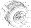
- FIG. 1Shown in FIG. 1 is an external energy extraction and delivery system 10 adapted to be integrated into an existing aerodynamic fairing 12 mounted on the chassis 14 of a vehicle, e.g., a tractor (a trailer, a truck, etc.) such that at least a portion of the fairing 12 projects outboard of the tires 16 - 18 thereby tending to enhance the aerodynamic flow of air past the tires 16 - 18 .
- a vehiclee.g., a tractor (a trailer, a truck, etc.)
- the central portion of the aerodynamic fairing 12located generally between the tires 16 - 18 being pressurized, is retrofitted with pressurized hoses 20 - 22 , each attached at one end to a T-junction 24 (see, FIG.
- the retrofit to an existing aerodynamic fairing panel 12may consist of direct modifications to the panel 12 such as cutouts or additional components attached to the panel 12 such as a protective cover 34 to protect the T-junction 24 .
- the cover 34may be mounted to the existing aerodynamic fairing panel 12 with existing fasteners as shown, or other common attachment methods.
- the cover 34may be aesthetically designed and configured to provide a suitable location for branding.
- the cover 34may be removable for maintenance and inspection of the T-junction 24 and pressurized lines 20 - 22 .
- the fairing panel 12is shaped and positioned so as to create a low drag area between the tires 16 - 18 .
- the pressurized lines 20 - 22are adapted to maintain proper pressure in the tires 16 - 18 for both fuel savings and safety concerns.
- the pressurized air lines 20 - 22may consist of flexible hosing as well as rigid hosing.
- Each pressurized line 20 - 22 from the T-junction 24passes through an orifice (see, e.g., FIG. 5 B ) in a modified wheel cover 30 - 32 , such as one derived from U.S. Pat. No. 9,327,550, and connects to a center-mounted rotary union 26 - 28 such as one derived from U.S. Pat. No.
- this modificationcan be accomplished by including a suitable hole in the center of the wheel cover 30 - 32 , and, if necessary, the wheel cover bracket.
- the holeshould be large enough to allow at least a portion of the rotary union 26 - 28 to pass therethrough.
- the covers 30 - 32should rotate freely without interfering with the air hoses 20 - 22 .
- the wheel cover 30 - 32may be attached to the hoses or to the non-rotating portion of the rotary union 26 - 28 , which may be preferable if it is not desirable for the wheel cover 30 - 32 to rotate with the tires 16 - 18 .
- the aerodynamic fairing 12 ′is modified such that the protective cover and center aerodynamic fairing are integral.
- This configurationhas fewer parts and may be more cost effective than the retro-fittable configuration as illustrated in FIG. 1 A and FIG. 1 B .
- the fairing panel 10is attached to the frame 14 via a hollow, square-tube mounting bracket 36 (shown in cross-section) and its attendant mounting hardware.
- a supply line 38routed through the inside of the mounting bracket 36 , is coupled to the T junction 24 , which is connected via hose 22 to the rotary union 28 in the center of the wheel cover 32 .
- the supply line 38runs from the bracket to the frame 14 of the vehicle where it may connect with the lines run to the other wheels or the conventional vehicle-mounted compressed air source (see, e.g., FIG. 1 C ).
- the systemmay employ any number of one-way valves, air pressure regulators, air pressure sensors, temperature sensors, or other technologies frequently used in combination with other internal and external tire inflation systems known in the art. Although not shown, it may also be desirable to employ the use of quick-disconnect fittings to simplify the removal of the system when changing a tire, for example. It may also be desirable, for example, to employ the use of break-away couplings (see, e.g., www.manntek.se/products/safety-break-away-couplings) to improve the safety of the system. In particular, tire blow outs, for example, could cause damage to the system and the use of break-away couplings could limit the damage to the system, e.g., to a specific section of hosing.
- FIG. 5 Adepicts the wheel inflation facility 40 with the wheel cover 30 removed.
- the rotary union 26is coupled via a hose 42 to the valve stem (not shown) of the outer wheel 46 of the front tandem pair, and via a hose 44 to the valve stem (again, not shown) of the inner wheel 48 of the tandem pair.
- the rotary union 26is spin stabilized, allowing it to rotate co-axially with the wheels 46 - 48 , and to move in the direction of travel of the vehicle when in motion.
- FIG. 5 Bwe have illustrated one embodiment of a bracket assembly adapted to couple both the rotary union 26 and the wheel cover 30 to the hub 58 (see, FIG. 5 B ).
- FIG. 5 Bwe have illustrated one embodiment of a bracket assembly adapted to couple both the rotary union 26 and the wheel cover 30 to the hub 58 (see, FIG. 5 B ).
- a prior art unmodified aerodynamic systemis installed on the left side of the tractor, and our modified aerodynamic system 10 (generally within the dashed oval) installed on the right side.
- our system 10encloses much of the pressurized air lines to protect them from damage resulting from road debris, accident, attachment of a trailer or any other unforeseen event.
- a single large aerodynamic fairing 50is used in lieu of a center aerodynamic fairing panel 12 or wheel covers 30 - 32 .
- the aerodynamic fairing 50may be configured so as to completely hide and protect the hoses, T-junction, and other components of our tire inflation system 10 (generally within the dashed oval).
- the single large fairing 50may be supported by the fairing mounting structures shown in FIG. 1 ; it may be supported by one or more rotary unions 26 - 28 mounted to the hubs; it may be supported by additional mounting brackets connected to the chassis; or it may be supported by any combination thereof. Additional improvements and other features may be added to any of the several illustrated fairing systems. These may include, for example, visual indicators such as LED lights, which could be used to indicate whether or not the system is operating normally or if there is an issue that requires maintenance.
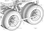
- a single torsion tube 52connects rotary couplings 54 - 56 , each of which is connected to a respective one of the hubs 58 - 60 . Since both the distance between, and the relative orientation of, the hubs 58 - 60 varies dynamically, depending on road conditions, we have configured the torsion tube 52 to be telescopic with respect to length. In general, we intend the torsion tube 52 to provide a relatively fixed point of leverage with respect to both of the hubs 58 - 60 .
- the rotary couplings 54 - 56may need to be more durable with respect to rotary unions commercially available through Vigia, for example, which are not designed to support the load from additional components mounted thereto.
- rotary couplings 54 - 56it may be desirable for a rotary union to be used inside of the rotary coupling, whereby the rotary union is not required to support the additional load of the torsion tube 52 or other devices which may be attached thereto.
- the ability to support a non-rotating load from a hub of the vehiclemay not be demonstrated in prior art.
- we submit that an individual skilled in the art of mechanical systems and bearing support structureswill be able to design a suitably robust rotary coupling 54 - 56 .
- Another potential application for the torsion tube 52could be to provide feedback regarding the linear distance between the two rotary couplings 54 - 56 .
- the distance measurementmay be useful, for example, in order to determine if the axles are aligned or if they have shifted out of tolerance from their original position.
- each of the rotary couplings 54 - 56is adapted to receive a respective air pump 62 - 64 , e.g., a peristaltic pump.
- a respective air pump 62 - 64e.g., a peristaltic pump.
- one portion of pump 62is substantially fixed with respect to hub 60 and the other portion rotates with hub 58 ; and, similarly, one portion of pump 64 is substantially fixed with respect to hub 58 and the other portion rotates with hub 60 .
- the associated pump 62 - 64will deliver compressed air at a predetermined pressure to a respective pair of the valve stems 66 - 68 and 70 - 72 .
- a single pump 62provides compressed air to both pairs of valve stems 66 - 68 and 70 - 72 .
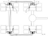
- both of the rotary couplings 54 - 56are adapted to receive a rotary union 74 - 76 .
- compressed airis delivered to both pairs of valve stems 66 - 68 and 70 - 72 directly from the vehicle's existing compressed air source 78 . It should be noted that one advantage of this method over conventional external tire inflation systems is that the utilization of the torsion tube 52 (or other devices described throughout this document that link the hubs) could eliminate or reduce the size of a frame-mounted support structure for the hoses.
- the rear axleis non-driven and can be used as a routing channel for the compressed air line from the supply 78 , similar to commercially available internal tire inflation systems for non-driven axles.
- compressed airis delivered to both pairs of valve stems 66 - 68 and 70 - 72 directly from a compressed air source 78 .
- VigiaOne prior art example of such an arrangement, currently commercially available from Vigia can be seen at:
- the rear axleis again non-driven and can be used as a routing channel for the compressed air line from the pump 62 .
- compressed airis delivered to both pairs of valve stems 66 - 68 and 70 - 72 from a single, hub-driven pump 62 .
- the advantage of using fewer pumpscould include reduced cost, reduced weight, reduced maintenance, lower pumping losses, and others.
- each of the rotary couplings 54 - 56is adapted to receive a respective rotational energy facility 80 - 82 .
- the stator portion of rotational energy facility 80is substantially fixed with respect to hub 60 and the rotor portion rotates with hub 58 ; and, similarly, the stator portion of rotational energy facility 82 is substantially fixed with respect to hub 58 and the rotor portion rotates with hub 60 .
- the rotational energy facility 80is enabled to operate in a motor mode, then, upon controlled delivery of electrical current from an electrical storage 84 via a control facility 86 , the rotational energy facility 80 will exert torque on the hub 58 .
- our rotational energy facility 80is configured such that the stator portion is fixed with respect to the other hub 60 , i.e., it can be considered cross-referencing with respect to the fixed point of leverage.
- each hubwe consider each hub to be cross-referenced to the other hub.
- FIG. 11 Bwe have illustrated one possible embodiment of a rotational energy facility 80 , wherein a stator portion 88 of the rotational energy facility 80 is coupled to a stator portion 90 of the rotary coupler 56 , and a rotor portion 92 of the rotational energy facility 80 is coupled to a rotor portion 94 of the rotary coupler 56 .
- rotational energycan be used on each hub, it may be preferable to use fewer rotational energy facilities, or to configure one rotational energy facility to act as a generator, and a different rotational energy facility to act as a motor. It may also be preferable to utilize energy storage means such as a battery or capacitor which is integrated into the torsion tube 52 , thereby eliminating the need for additional wiring of the system.
- rotational energy systemindependently from an inflation system, it may be preferable to combine both systems and utilize the same torsion tube 52 to transmit a combination of pressurized air and electricity.
- the rotational energy systemmay be hydraulic instead of electric, for example, whereby compressed air could be used for both tire inflation as well as driving motors which assist in powering the vehicle. It may also be preferable to utilize the rotational energy to provide a braking force to one or more wheels.
- the systemcould power commercially available devices such as tire pressure monitoring systems which normally utilize batteries that have a limited lifespan. Providing electrical power to other types of sensors and signal transmission technologies that may be mounted to the wheels may also be beneficial and made possible through various embodiments of this invention.
- tire inflation systemspredominately comprising pumps and the associated means for increasing tire pressure
- means for reducing or regulating the air pressure of the tiresIn some cases the tires could become over-inflated or the temperature changes over time could cause the tire pressure to be higher than the recommended tire pressure. It may also be preferable to reduce the tire pressure if driving off-road, for example.
- Some existing external tire inflation systemsincorporate this technology already, and so, for that reason, we have not described these at length herein.
- Other benefits of our systemmay be for tire pressure equalization.
- Some devicessuch as the crossfire equalize air pressure between two tires mounted on the same side of a single axle. However, with our invention it is now possible to equalize all of the tires on any axle with a hub that is connected via a torsion tube to the hub on another axle, for example.
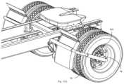
- a single torsion tube 96couples a single rotary coupling 98 directly to a fixed portion of the chassis, e.g., an existing splash guard or the like. Since both the distance between, and the relative orientation of, the hub 100 varies dynamically with respect to the selected fixed portion of the chassis, depending on road conditions, we have configured the torsion tube 96 to be telescopic with respect to length, and, preferably, to rotate with respect to the frame. In general, we intend the torsion tube 96 to provide a relatively fixed point of leverage with respect to the hub 100 . In this single-axle embodiment, we consider the hub to be cross-referenced to the frame. As illustrated in FIG.
- the torsion tube 96may be adapted to support a single wheel faring fairing panel 102 .
- a dual torsion tube assembly 104to couple hub 58 to hub 60 , not only to provide additional stiffness but also to more rigidly support a hinged, multi-wheel fairing system 106 such as that illustrated in FIG. 13 B and FIG. 13 C .
- the fairing system 106may incorporate sliding aerodynamic panels, or other accessibility features known in the art.
- the hose/wireas running through the lower torsion tube portion, it may just as readily be run through the upper torsion bar portion.
- FIG. 14is a perspective view of one further embodiment of an energy extraction and delivery facility 110 .
- an assemblycomprising a first link 112 and second link 114 are used to couple hub 58 to hub 60 .
- FIG. 15is a perspective view of one further embodiment of an energy extraction and delivery facility 120 .
- an assemblycomprising a first link 122 and second link 124 are used to couple hub 58 to hub 60 .
- the compressed airmay also be utilized for other means such as for inflatable aerodynamic fairings such as taught in U.S. Pat. No. 9,873,467.
- the inflatable componentsmay, for example, be extensions of existing fairings which are only deployed when the vehicle is in motion, or when compressed air is being delivered to the system.
- the compressed airmay also be used for boundary layer control of aerodynamic fairings or surfaces of the vehicle as shown in U.S. Pat. No. 8,870,275, and similar art.
- the compressed airmay also be used to replace the air pump on the vehicle, if so equipped.
- the system as shown in FIG. 9 and other figuresmay also incorporate mounting means whereby the torsion tube is mounted to a non-rotating component of the axle. This may be possible if there is an existing hole through the hub, or if a hole can be made through the hub. In this configuration, however, some other means should be provided to support the end of the torsion tube rather than the hub, per se.
Landscapes
- Engineering & Computer Science (AREA)
- Mechanical Engineering (AREA)
- Power Engineering (AREA)
- Transportation (AREA)
- Life Sciences & Earth Sciences (AREA)
- Sustainable Development (AREA)
- Sustainable Energy (AREA)
- Chemical & Material Sciences (AREA)
- Combustion & Propulsion (AREA)
- Tires In General (AREA)
- Arrangement Or Mounting Of Propulsion Units For Vehicles (AREA)
Abstract
Description
Claims (18)
Priority Applications (1)
| Application Number | Priority Date | Filing Date | Title |
|---|---|---|---|
| US16/466,268US11932060B2 (en) | 2016-11-04 | 2017-11-06 | Chassis mounted energy extraction and delivery system |
Applications Claiming Priority (3)
| Application Number | Priority Date | Filing Date | Title |
|---|---|---|---|
| US201662417387P | 2016-11-04 | 2016-11-04 | |
| PCT/US2017/060242WO2018085791A1 (en) | 2016-11-04 | 2017-11-06 | Chassis mounted energy extraction and delivery system |
| US16/466,268US11932060B2 (en) | 2016-11-04 | 2017-11-06 | Chassis mounted energy extraction and delivery system |
Related Parent Applications (1)
| Application Number | Title | Priority Date | Filing Date |
|---|---|---|---|
| PCT/US2017/060242A-371-Of-InternationalWO2018085791A1 (en) | 2016-11-04 | 2017-11-06 | Chassis mounted energy extraction and delivery system |
Related Child Applications (1)
| Application Number | Title | Priority Date | Filing Date |
|---|---|---|---|
| US18/395,338ContinuationUS20240123774A1 (en) | 2016-11-04 | 2023-12-22 | Torsion tube mounted aerodynamic system |
Publications (2)
| Publication Number | Publication Date |
|---|---|
| US20200062048A1 US20200062048A1 (en) | 2020-02-27 |
| US11932060B2true US11932060B2 (en) | 2024-03-19 |
Family
ID=62076443
Family Applications (2)
| Application Number | Title | Priority Date | Filing Date |
|---|---|---|---|
| US16/466,268Active2039-07-14US11932060B2 (en) | 2016-11-04 | 2017-11-06 | Chassis mounted energy extraction and delivery system |
| US18/395,338PendingUS20240123774A1 (en) | 2016-11-04 | 2023-12-22 | Torsion tube mounted aerodynamic system |
Family Applications After (1)
| Application Number | Title | Priority Date | Filing Date |
|---|---|---|---|
| US18/395,338PendingUS20240123774A1 (en) | 2016-11-04 | 2023-12-22 | Torsion tube mounted aerodynamic system |
Country Status (4)
| Country | Link |
|---|---|
| US (2) | US11932060B2 (en) |
| EP (1) | EP3535145B1 (en) |
| CA (1) | CA3046189A1 (en) |
| WO (1) | WO2018085791A1 (en) |
Cited By (1)
| Publication number | Priority date | Publication date | Assignee | Title |
|---|---|---|---|---|
| US12252185B2 (en) | 2012-11-01 | 2025-03-18 | FlowBelow Aero, Inc. | Aerodynamic system and adjustable fairings |
Families Citing this family (6)
| Publication number | Priority date | Publication date | Assignee | Title |
|---|---|---|---|---|
| US10654529B2 (en) | 2017-06-24 | 2020-05-19 | FlowBelow Aero, Inc. | Aerodynamic systems and fairings with fairing caps |
| WO2019014503A1 (en) | 2017-07-12 | 2019-01-17 | FlowBelow Aero, Inc. | Aerodynamic toolbox assembly |
| US10882571B2 (en) | 2017-07-30 | 2021-01-05 | FlowBelow Aero, Inc. | Rotatable aerodynamic fairing system |
| US12344047B2 (en)* | 2020-10-29 | 2025-07-01 | William Pamphile | Automatic air tire technology system |
| US11767064B2 (en) | 2021-01-12 | 2023-09-26 | FlowBelow Aero, Inc. | Spring-biased mud flap hanger with improved pivoting motion guidance |
| DE112022000770B4 (en)* | 2021-01-25 | 2025-07-31 | Hendrickson Usa, L.L.C. | ROTATING JOINT WITH ENERGY HARVESTING STRUCTURE |
Citations (205)
| Publication number | Priority date | Publication date | Assignee | Title |
|---|---|---|---|---|
| US1072907A (en) | 1911-07-26 | 1913-09-09 | Lester L Brooks | Automobile tire-inflating mechanism. |
| US1173434A (en)* | 1915-02-15 | 1916-02-29 | John G Johnson | Motor-driven tire-pump. |
| US1827662A (en) | 1927-11-16 | 1931-10-13 | Goodyear Tire & Rubber | Pneumatic tire inflation system |
| US2059045A (en) | 1935-06-10 | 1936-10-27 | Edward A Seymour | Valve structure |
| US2190117A (en) | 1939-03-01 | 1940-02-13 | Earl W Griffith | Inflation signaling device |
| US2538839A (en) | 1947-01-20 | 1951-01-23 | Gen Motors Corp | Rear wheel housing construction for automobile bodies |
| US2579048A (en) | 1950-01-19 | 1951-12-18 | William R Paul | Automatic pressure control system for pneumatic tires |
| US2605119A (en) | 1949-11-19 | 1952-07-29 | Maxwell L Earnest | Splash guard for vehicles |
| US2652266A (en) | 1950-06-24 | 1953-09-15 | Glenn C Miller | Vehicle mud flap |
| US2685906A (en) | 1952-01-19 | 1954-08-10 | Scovill Manufacturing Co | Running inflation and deflation system |
| US2715430A (en) | 1952-08-02 | 1955-08-16 | Sun Oil Co | Apparatus for controlling pressure in pneumatic tires |
| US2801867A (en) | 1955-08-19 | 1957-08-06 | Keith C Childreth | Mud guard with attaching means therefor |
| US2869929A (en) | 1954-07-06 | 1959-01-20 | Hurd Lock & Mfg Company | Wheel cover |
| US2931414A (en) | 1956-06-27 | 1960-04-05 | Edwin F Jankowski | Vehicle tire inflating system |
| US3006658A (en) | 1957-08-29 | 1961-10-31 | Fred L Wenham | Vehicle splash guard and bracket |
| US3078124A (en) | 1960-05-25 | 1963-02-19 | Firestone Tire & Rubber Co | Wheel cover |
| US3092420A (en) | 1960-04-25 | 1963-06-04 | Gen Motors Corp | Wheel cover |
| US3215384A (en) | 1960-09-26 | 1965-11-02 | Eaton Axles Ltd | Yielding connection for anchoring a rigid arm to a vehicle frame |
| US3224791A (en) | 1962-12-10 | 1965-12-21 | Nash P Sogoian | Hanger for vehicle splash guards |
| US3276502A (en) | 1963-12-05 | 1966-10-04 | Ruf Walter | Vehicle with means for adjusting the air pressure in the tires |
| US3276503A (en) | 1965-01-21 | 1966-10-04 | Scovill Manufacturing Co | Tire pressure maintenance system |
| US3279815A (en) | 1965-06-15 | 1966-10-18 | Charles T Hutchens | Suspension assembly for vehicles and process |
| US3317247A (en) | 1965-05-24 | 1967-05-02 | Robert E Lamme | Combined wheel cover and locking means |
| US3350113A (en) | 1966-05-10 | 1967-10-31 | Walter E Graham | Modular transportation equipment |
| US3367722A (en) | 1966-07-05 | 1968-02-06 | Frank H. Miyanaga | Wheel cover |
| US3401953A (en) | 1965-06-07 | 1968-09-17 | Pro Lock Mfg Company | Detachable supporting arm assembly for mudflaps |
| US3585824A (en) | 1969-03-21 | 1971-06-22 | Dzus Fastener Co | Fastener assembly |
| US3653455A (en)* | 1969-08-01 | 1972-04-04 | Allan E Hetteen | Off-road vehicle wheel suspension |
| US3752498A (en)* | 1971-10-07 | 1973-08-14 | Gen Motors Corp | Oleo-pneumatic suspension assembly |
| US3848842A (en) | 1973-03-14 | 1974-11-19 | M Jepsen | Impingement shield |
| US3874697A (en) | 1973-05-02 | 1975-04-01 | James C Thompson | Shield for controlling road spray |
| US3918764A (en) | 1974-11-01 | 1975-11-11 | Robert E Lamme | Combined lock bracket and wheel cover for automotive vehicles |
| US3940165A (en) | 1974-04-18 | 1976-02-24 | Sogoian Nash P | Hanger for vehicle mud flaps |
| US4007944A (en) | 1975-12-16 | 1977-02-15 | Dingess Jack L | Yielding support for vehicle mud flap |
| US4138129A (en) | 1977-06-24 | 1979-02-06 | American Formed Plastics Corp. | Vehicle wheel well skirt |
| US4169608A (en) | 1978-01-16 | 1979-10-02 | L.T.D. Enterprises, Inc. | Fender extensions |
| US4180230A (en) | 1978-03-13 | 1979-12-25 | Sogoian Nash P | Hanger for vehicle mud flaps |
| US4205861A (en) | 1978-03-02 | 1980-06-03 | Philip A. Stewart | Automotive vehicle wheel spray collector |
| US4235476A (en) | 1978-08-08 | 1980-11-25 | Ab Volvo | Wheel cover for vehicle wheels |
| US4334694A (en) | 1977-07-11 | 1982-06-15 | Iwanicki Andrzej Tomasz | Splash protection assembly for vehicles equipped with mudguards |
| US4436319A (en) | 1981-10-07 | 1984-03-13 | Clutter James E | Vehicle wheel splash guard |
| US4441539A (en) | 1982-07-29 | 1984-04-10 | The Budd Company | Tire pressurization control system |
| US4582107A (en) | 1984-07-26 | 1986-04-15 | The United States Of America As Represented By The Secretary Of The Army | Vehicle tire inflation-deflation mechanism |
| US4619303A (en) | 1984-06-04 | 1986-10-28 | Eaton Corporation | Vehicle air system including central tire inflation system |
| US4627594A (en) | 1985-06-18 | 1986-12-09 | Reed Jesse L | Mudflap mounting assembly |
| US4627631A (en) | 1984-06-01 | 1986-12-09 | Carl J. Messina | Spray-suppressing mud flap assembly |
| US4640331A (en) | 1984-06-04 | 1987-02-03 | Eaton Corporation | Central tire inflation system |
| US4641698A (en) | 1984-11-08 | 1987-02-10 | Am General Corporation | Automated vehicle tire pressurization system |
| US4678017A (en) | 1984-06-04 | 1987-07-07 | Eaton Corporation | Wheel end valve for central tire inflation system |
| US4706980A (en) | 1986-03-19 | 1987-11-17 | Fleet Engineers Inc. | Vehicle quarter fender and assembly for mounting the same |
| US4724879A (en) | 1984-06-04 | 1988-02-16 | Eaton Corporation | Central tire inflation system |
| US4735428A (en) | 1986-06-10 | 1988-04-05 | Fleet Engineers, Inc. | Vehicle quarter fender |
| US4744399A (en) | 1986-07-31 | 1988-05-17 | Paccar Inc. | Central tire inflation system |
| US4754792A (en) | 1984-06-04 | 1988-07-05 | Eaton Corporation | Tire valve assembly for central tire inflation system |
| US4761040A (en) | 1986-12-08 | 1988-08-02 | Johnson W Gordon | Wheel cover mounting system for dual wheels |
| US4770330A (en) | 1986-12-15 | 1988-09-13 | Deflecta-Shield Corporation | Multi-piece straddle bed tool box for use with pickup trucks |
| US4784430A (en) | 1988-02-01 | 1988-11-15 | Chrysler Motors Corporation | Clip and wheel flair molding assembly |
| EP0309611A1 (en) | 1987-10-02 | 1989-04-05 | Bell Technology Associates | Method and apparatus for controlling spray and splash caused by a vehicle while reducing the drag of the vehicle |
| US4836568A (en) | 1987-09-14 | 1989-06-06 | Paccar Inc. | Aerodynamically streamlined step assembly for a truck |
| US4860579A (en) | 1988-05-25 | 1989-08-29 | Eaton Corporation | Tire leakage detection method for central tire inflation system |
| US4889394A (en) | 1987-07-23 | 1989-12-26 | Renzo Ruspa | Mounting arrangement for positively fixing a wheel cover disk to the wheel rim of an industrial vehicle |
| US4892128A (en) | 1987-08-28 | 1990-01-09 | Tire Inflation Systems Corp. | Vehicle wheel seal assembly |
| US4895199A (en) | 1986-07-31 | 1990-01-23 | Paccar Inc | Tire inflation and deflation valve |
| US4921276A (en) | 1988-05-23 | 1990-05-01 | Morin Albert Z | Spray controlling fender |
| US4925235A (en) | 1989-08-25 | 1990-05-15 | Paccar Inc | Cab fairing mounting for truck |
| US4960294A (en) | 1988-09-15 | 1990-10-02 | Leonard Charles F | Truck mud flap support arm |
| US4961611A (en) | 1989-02-06 | 1990-10-09 | Patti Anthony J | Vehicle wheel cover |
| US4974909A (en) | 1989-04-13 | 1990-12-04 | Wheel Masters, Inc. | Vehicle wheel cover attachment |
| US4981162A (en)* | 1988-08-05 | 1991-01-01 | Compagnie Generale Des Etablissements Michelin - Michelin & Cie | Portable reinflator |
| US4984851A (en) | 1988-10-31 | 1991-01-15 | Hashimoto Forming Industry Co., Ltd. | Wheel cover for automobiles |
| US5074573A (en) | 1990-03-12 | 1991-12-24 | Dick Michael H | Pivotal front wheel fenders for tractors |
| US5179981A (en) | 1988-05-25 | 1993-01-19 | Eaton Corporation | Fault detection method for central tire inflation system |
| US5190354A (en) | 1991-05-13 | 1993-03-02 | Serge Levy | Vehicle wheel cover |
| EP0542728A1 (en) | 1988-07-25 | 1993-05-19 | Eaton Corporation | Deflation control system and method |
| US5240039A (en) | 1991-12-19 | 1993-08-31 | Col-Ven S.A. | Rotor for adapting static elements to elements rotating around a shaft |
| US5263770A (en) | 1991-11-07 | 1993-11-23 | Goudey Robert B | Vehicle wheel cover |
| US5269547A (en) | 1992-04-01 | 1993-12-14 | Fleet Engineers, Inc. | Spray suppressant apparatus |
| US5280990A (en) | 1991-10-08 | 1994-01-25 | Rinard Gordon L | Vehicle drag reduction system |
| US5294189A (en) | 1989-09-13 | 1994-03-15 | Dicor Corporation | Wheel cover attachment system |
| USD345332S (en) | 1992-10-01 | 1994-03-22 | Roman Chariot, Inc. | Automobile fender skirt |
| US5324099A (en) | 1993-03-18 | 1994-06-28 | Fitzhugh Lloyd B | Vehicle spray suppression apparatus |
| US5332280A (en) | 1992-10-09 | 1994-07-26 | Dupont J | Demountable deflector for shipping containers and the like |
| US5358313A (en) | 1993-06-11 | 1994-10-25 | Polka John G | Adjustable wheel liner for trucks |
| US5366278A (en) | 1992-08-17 | 1994-11-22 | Brumfield John H | Snap-on retention device and system for wheel cover |
| US5380028A (en)* | 1992-04-27 | 1995-01-10 | John R. Ferris | Demountable trailer suspension system |
| US5398743A (en) | 1993-09-24 | 1995-03-21 | Tire Inflation Systems Corp. | Tire inflating and deflating system |
| US5465772A (en) | 1988-07-14 | 1995-11-14 | Col-Ven S.A. | Controlling and maintaining air-pressure in vehicle tires |
| US5490342A (en) | 1994-07-13 | 1996-02-13 | Rutterman; Michael J. | Non-rotating wheel cover |
| US5538062A (en)* | 1994-08-12 | 1996-07-23 | Marks-Rms, Inc. | Pnuematic tire inflation system |
| US5584949A (en) | 1994-05-06 | 1996-12-17 | Ingram; Anthony L. | Air inflation system for trailer axles |
| US5623777A (en) | 1994-07-13 | 1997-04-29 | Hsiao; Leslie | Wheel cover |
| US5659989A (en) | 1994-07-13 | 1997-08-26 | Hsiao; Leslie | Wheel cover |
| WO1997048590A1 (en) | 1996-06-20 | 1997-12-24 | Gordon Loewen | Longitudinally and vertically adjustable trailer underbody fairing |
| US5769979A (en) | 1996-08-30 | 1998-06-23 | Equalaire Systems, Inc. | Rotary air connection for tire inflation system |
| US5791741A (en) | 1996-08-15 | 1998-08-11 | Kuan Hsieng Industrial Co., Ltd. | Wheel cover clasp structure |
| US5836399A (en) | 1996-08-27 | 1998-11-17 | Deere & Company | Sprayer wheel shield |
| US5850727A (en) | 1997-02-28 | 1998-12-22 | Deere & Company | Shield structure for a tractor with a rear mounted harvester |
| US5884981A (en) | 1996-03-18 | 1999-03-23 | Kabushiki Kaisha Tokai Rika Denki Seisakusho | Wheel cover for a car and a clip device |
| US5938222A (en) | 1997-06-05 | 1999-08-17 | Grand General Accessories Manufacturing Inc. | Hanger and bracket apparatus for vehicle mud flaps |
| US5947520A (en) | 1996-06-27 | 1999-09-07 | Freightliner Corporation | Vehicle with sacrificial fairing |
| US6045195A (en) | 1998-08-24 | 2000-04-04 | Pascal Laboratory Co., Ltd. | Wheel cover |
| US6070893A (en) | 1998-02-13 | 2000-06-06 | Thorndyke; Robert J. | Vehicle wheel retention system |
| DE29922043U1 (en) | 1999-12-15 | 2000-08-03 | Lechner, Anton, Dr., 85774 Unterföhring | Commercial vehicle with devices for reducing air resistance and water spray |
| US6105645A (en) | 1998-05-14 | 2000-08-22 | Ingram; Anthony L. | Rotary union assembly for use in air pressure inflation systems for tractor trailer tires |
| US6120104A (en) | 1996-10-09 | 2000-09-19 | Okamoto; Yoshiaki | Wheel cover |
| GB2348400A (en) | 1999-03-31 | 2000-10-04 | Dare Bryan Valerian | An aerodynamic road vehicle |
| US6219987B1 (en) | 1998-05-26 | 2001-04-24 | Holland Company | Endcaps for fiberglass running boards |
| US6244316B1 (en) | 1999-07-16 | 2001-06-12 | Vehicle Inflation Technologies, Inc | Vehicle tire inflation system |
| US6401743B1 (en) | 1999-08-25 | 2002-06-11 | Vehicle Inflation Technologies | Automatic tire inflation system having a pressure regulator with an integrated leak detection switch |
| US6427739B1 (en) | 2000-05-19 | 2002-08-06 | Precision Seal, Inc. | Coupling assembly |
| US6443529B1 (en) | 2000-08-17 | 2002-09-03 | Curtis A. Williams | Assembly with a non-rotatable wheel cover disc |
| US20020124926A1 (en) | 2001-03-12 | 2002-09-12 | Colussi Rafael A. | Pneumatic rotary wheel coupling with early wheel bearing wear warning |
| US6604724B2 (en) | 1999-12-29 | 2003-08-12 | Fleet Engineers, Incorporated | Mudflap bracket |
| US6666498B1 (en) | 2001-10-04 | 2003-12-23 | W. David Whitten | Deployable airfoil for trucks and trailers |
| US6698482B2 (en) | 2002-07-01 | 2004-03-02 | Equalaire Systems, Inc. | Rotary air connection with bearing for tire inflation system |
| WO2004062953A2 (en) | 2003-01-08 | 2004-07-29 | Pidg Limited | Improving fuel consumption in large road-going vehicles |
| US20040238093A1 (en) | 2003-03-06 | 2004-12-02 | Nelson Christopher A. | Central tire inflation system rotary air union |
| US6857709B1 (en) | 2003-12-16 | 2005-02-22 | Aai Technology Inc. | Non-rotating wheel cover |
| US20050133134A1 (en) | 2001-11-13 | 2005-06-23 | Airgo Ip, Llc | Rotary union assembly for use in air pressure inflation systems for tractor trailer tires |
| US7081081B2 (en) | 2002-04-22 | 2006-07-25 | Kendro Laboratory Products, Lp | Bayonet coupling mechanism for a centrifuge |
| US20060179929A1 (en) | 2002-04-10 | 2006-08-17 | John Becker | Systems and methods for maintaining air pressure in tires |
| US7093909B1 (en) | 2003-06-13 | 2006-08-22 | The United States Of America As Represented By The Secretary Of The Army | Visual and thermal shield system |
| US7131705B1 (en) | 2003-05-22 | 2006-11-07 | Dicor Corporation, Inc. | Wheel hub cover |
| US20080129079A1 (en) | 2006-11-17 | 2008-06-05 | Freightliner Llc, | Selectively removable side fairing for a vehicle |
| WO2008100338A1 (en) | 2006-09-11 | 2008-08-21 | Jonathan Fleck | Flexible wheel cover assembly |
| US20080257620A1 (en) | 2007-03-20 | 2008-10-23 | Peder Ulrik Poulsen | Hybrid Vehicle Drive System |
| US7466049B1 (en) | 2007-05-25 | 2008-12-16 | Peter Vancea | Wheel assembly with electric power generator |
| US7520534B2 (en) | 2005-09-09 | 2009-04-21 | Longchamp Gerard | Fender mountable to a vehicle |
| US7530379B1 (en) | 2002-04-10 | 2009-05-12 | John Henry Becker | Tire inflation system |
| US7547076B2 (en) | 2007-01-24 | 2009-06-16 | Prestige Autotech Corporation | Wheel covering system |
| WO2009105623A1 (en) | 2008-02-21 | 2009-08-27 | Aerofficient, Llc | Vehicle side fairing system |
| US20090273176A1 (en) | 2008-04-30 | 2009-11-05 | Ulgen Mehmet Nevres | Retractable Mud Flap For Vehicles |
| US20090283190A1 (en) | 2008-05-16 | 2009-11-19 | Hendrickson Usa, L.L.C. | Integrated rotary union and hub cap |
| US7651108B2 (en) | 2004-10-25 | 2010-01-26 | Irisbus France S.A. | Assembly comprising at least one drive wheel and a fairing for a heavy goods vehicle, and the corresponding heavy goods vehicle |
| US7658251B2 (en) | 2006-09-20 | 2010-02-09 | James Harry K | Direct drive electric traction motor |
| US20100066123A1 (en) | 2008-09-17 | 2010-03-18 | Ortega Jason M | Trailer wheel fairings |
| US20100066155A1 (en) | 2008-06-13 | 2010-03-18 | Hutchinson, Sa | Tire protection device attachment systems |
| US20100117396A1 (en) | 2008-11-12 | 2010-05-13 | Dayton Roderick M | System for reducing aerodynamic drag on vehicles |
| US7775604B2 (en) | 2008-05-13 | 2010-08-17 | Chen-Chun Chen | Interlocking method and its structure for wheel-rim cover |
| US7806464B2 (en) | 2007-03-30 | 2010-10-05 | Francis Cardolle | Fairing for a trailer |
| US20110011656A1 (en) | 2007-03-20 | 2011-01-20 | Peder Ulrik Poulsen | Hybrid vehicle system with indirect drive |
| US20110057410A1 (en) | 2007-04-16 | 2011-03-10 | Fleet Engineers, Incorporated | Adjustable fender |
| US20110089748A1 (en) | 2009-10-20 | 2011-04-21 | Paul Grill | Wheel cover assembly |
| US7963159B2 (en) | 2008-03-25 | 2011-06-21 | Airgo Ip, Llc | Inflation system for tires |
| US8028732B1 (en) | 1998-05-14 | 2011-10-04 | Airgo Ip, Llc | Tire inflation system |
| US20110253851A1 (en) | 2010-04-14 | 2011-10-20 | Innovative Trailer Design Technologies Inc. | Side skirt mounting assembly for container chassis |
| US20110272963A1 (en) | 2010-05-06 | 2011-11-10 | Henderson Michael Lorenzo | Devices and Methods for Reducing Vehicle Drag |
| US20110272964A1 (en) | 2010-05-06 | 2011-11-10 | Henderson Industries, Llc | Devices and Methods for Reducing Vehicle Drag |
| US20120013146A1 (en) | 2010-07-16 | 2012-01-19 | Dr. Ing. H.C.F. Porsche Aktiengesellschaft | Air guiding device |
| US20120024445A1 (en) | 2010-07-30 | 2012-02-02 | Hendrickson Usa, L.L.C. | Constant pressure pneumatic balancing tire inflation system |
| US8118329B2 (en) | 2007-12-27 | 2012-02-21 | Bushwacker, Inc. | Fender flares and vehicles with fender flares |
| US20120043803A1 (en) | 2010-08-23 | 2012-02-23 | Paul Grill | Hub cover attachment assembly |
| US8177286B2 (en) | 2009-04-16 | 2012-05-15 | Wabash National, L.P. | Side skirt system for a trailer |
| DE102010063263A1 (en) | 2010-12-16 | 2012-06-21 | Röchling Automotive AG & Co. KG | Commercial vehicle, particularly truck-tractor or trailing vehicle, has vehicle frame and payload structure accommodated on vehicle frame, where flat acoustic base made of sound absorbing material is fixed to vehicle frame |
| US8382210B1 (en) | 2006-09-11 | 2013-02-26 | Jonathan E. Fleck | Wheel cover with window for over-the-road trucks, trailers and the like |
| US20130068361A1 (en) | 2011-09-21 | 2013-03-21 | Arvinmeritor Technology, Llc | Vehicle Tire Inflation System and a Method of Control |
| US20130076107A1 (en) | 2010-06-30 | 2013-03-28 | Volvo Group North America, Llc | Wheel cover and mounting device |
| US20130087262A1 (en) | 2010-06-21 | 2013-04-11 | Equalaire Systems, Inc. | Rotary air connection with central valve for tire inflation system |
| US8424956B2 (en) | 2010-09-03 | 2013-04-23 | Cvg Management Corporation | Aerodynamic wheel cover |
| US20130199685A1 (en) | 2012-02-06 | 2013-08-08 | Pursuit LLP | Central Tire Inflation System Rotary Air Union |
| US8517474B2 (en) | 2011-06-20 | 2013-08-27 | Mazen Yousef Falah Salah | Non-rotating wheel cap |
| US8540304B2 (en) | 2008-09-04 | 2013-09-24 | Renault Trucks | Rear aerodynamic device for a vehicle and vehicle equipped with such a device |
| US8567802B2 (en) | 2009-07-27 | 2013-10-29 | Public Transportation Safety Int'l Corp. | Cantilevered, vehicle side mount safety guard |
| WO2013174410A1 (en) | 2012-05-22 | 2013-11-28 | Daimler Ag | Wind-guiding device |
| US8726958B2 (en)* | 2011-05-31 | 2014-05-20 | Compagnie Generale Des Etablissements Michelin | Inertia-controlled tire isolation valve and methods of controlling tire inflation pressures |
| US8747084B2 (en) | 2010-07-21 | 2014-06-10 | Aperia Technologies, Inc. | Peristaltic pump |
| US8746305B2 (en) | 2011-06-15 | 2014-06-10 | Arvinmeritor Technology, Llc | Rotating seal assembly for tire inflation system |
| US8763661B2 (en) | 2010-07-21 | 2014-07-01 | Aperia Technologies, Inc. | Tire inflation system |
| US8814253B1 (en) | 2011-04-21 | 2014-08-26 | Flowbelow, LLC | Aerodynamic quarter fender assembly and construction method |
| US20140284994A1 (en) | 2013-03-21 | 2014-09-25 | RealWheels Corporation | Aerodynamic Wheel Cover Assembly and Method of Mounting |
| US8870275B1 (en) | 2013-10-18 | 2014-10-28 | Peter Schmidt | Active and passive boundary layer control for vehicle drag reduction |
| US8955626B2 (en) | 2010-12-06 | 2015-02-17 | Protean Electric Limited | Electric hybrid vehicle |
| US20150059946A1 (en)* | 2013-09-04 | 2015-03-05 | Arvinmeritor Technology, Llc | Tire Inflation System with External Pressurized Gas Routing |
| US9027983B2 (en) | 2012-11-01 | 2015-05-12 | FlowBelow Aero, Inc. | Aerodynamic system and adjustable fairings |
| US9039386B2 (en) | 2012-03-20 | 2015-05-26 | Aperia Technologies, Inc. | Tire inflation system |
| US20150151569A1 (en) | 2013-11-15 | 2015-06-04 | Moochout Llc | Flexible wheel cover assembly |
| US20150175089A1 (en) | 2013-12-20 | 2015-06-25 | Thomas Inard Reed, III | Pickup Truck Mounted Toolbox |
| GB2524173A (en) | 2015-02-27 | 2015-09-16 | Daimler Ag | Fairing assembly for at least one axle of a commercial vehicle |
| US20150329152A1 (en) | 2014-05-15 | 2015-11-19 | Wabash National, L.P. | Aerodynamic rear drag reduction system for a trailer |
| US20160096557A1 (en) | 2014-10-01 | 2016-04-07 | Transtex Composite Inc. | Modular aerodynamic skirt assembly |
| US9308949B1 (en) | 2013-05-08 | 2016-04-12 | Paccar Inc | Systems and methods for reducing drag on a vehicle or vehicle combination |
| US9327550B2 (en) | 2011-07-12 | 2016-05-03 | FlowBelow Aero, Inc. | Aerodynamic wheel covers and mounting assemblies |
| US20160141934A1 (en) | 2014-11-14 | 2016-05-19 | Bryan Click | Electric power conversion design for liquid fueled vehicles |
| US20160221388A1 (en) | 2015-01-29 | 2016-08-04 | Forward Metal Craft, Inc. | Wheel cover retention system |
| US9429243B2 (en) | 2011-12-14 | 2016-08-30 | Numatics, Incorporated | Adjustable pressure controlled valve |
| US20160288590A1 (en) | 2013-11-11 | 2016-10-06 | Equalaire Systems, Inc. | Rotary Union for Tire Inflation System |
| US20160368545A1 (en) | 2015-06-19 | 2016-12-22 | Aero Industries, Inc. | Aerodynamic Attachment for Underbody torage Boxes |
| US20170029044A1 (en) | 2010-05-27 | 2017-02-02 | Strehl, Llc | Aerodynamic trucking systems |
| US9604157B2 (en) | 2013-03-12 | 2017-03-28 | Aperia Technologies, Inc. | Pump with water management |
| US9637184B1 (en) | 2016-08-05 | 2017-05-02 | Utility Trailer Manufacturing Company | Rear fairing system for a vehicle |
| US20170129549A1 (en) | 2015-11-06 | 2017-05-11 | Heil Trailer International, Co. | Trailer fairing access panel |
| US20170166266A1 (en) | 2014-06-09 | 2017-06-15 | Wall Global Llc | Aerodynamic Fairing Assembly for Tractor-Trailers |
| US20170240220A1 (en) | 2013-09-18 | 2017-08-24 | Steven Kron | Vehicle Fairing with Brake Cooling System |
| US9821598B2 (en) | 2015-02-27 | 2017-11-21 | Moochout Llc | Hard wheel cover |
| US9868318B2 (en) | 2015-11-16 | 2018-01-16 | Mark L. Becker | Illuminated vehicle wheel |
| US20180104994A1 (en)* | 2016-10-14 | 2018-04-19 | The Goodyear Tire & Rubber Company | Air maintenance pump assembly |
| WO2018136529A1 (en) | 2017-01-17 | 2018-07-26 | Moochout Llc | Wheel cover quick mount |
| US20180312115A1 (en) | 2013-12-20 | 2018-11-01 | Thomas Inard Reed | Pickup Truck Mounted Toolbox |
| US20180370580A1 (en) | 2017-06-24 | 2018-12-27 | FlowBelow Aero, Inc. | Aerodynamic systems and fairings with fairing caps |
| US20190031251A1 (en) | 2017-07-30 | 2019-01-31 | Joshua Butler | Rotatable aerodynamic fairing system |
| US20200156555A1 (en) | 2013-12-20 | 2020-05-21 | Thomas Inard Reed, III | Pickup Truck Mounted Toolbox |
| US20200164933A1 (en) | 2017-07-12 | 2020-05-28 | Flowbelow Aero Inc. | Aerodynamic toolbox assembly |
| US20210139086A1 (en) | 2019-11-11 | 2021-05-13 | Andrus Research Inc. | Deployable fairing for transport vehicle |
| US20220097779A1 (en) | 2010-05-27 | 2022-03-31 | Richard P. Senatro | Aerodynamic trucking systems |
| US20220219761A1 (en) | 2021-01-12 | 2022-07-14 | FlowBelow Aero, Inc. | Spring-biased mud flap hanger with improved pivoting motion guidance |
Family Cites Families (6)
| Publication number | Priority date | Publication date | Assignee | Title |
|---|---|---|---|---|
| MXPA04010949A (en)* | 2003-03-06 | 2005-06-08 | Boler Co | Tire inflation system and method. |
| DE202008003758U1 (en)* | 2008-03-18 | 2009-08-13 | Al-Ko Kober Ag | Axle arrangement with air suspension |
| CN104024007A (en)* | 2011-09-15 | 2014-09-03 | 麦格纳国际公司 | Automatic tire inflator system |
| AU2014340018B2 (en)* | 2013-10-23 | 2017-04-13 | Pressure Systems International, Llc | Rotary union for automatic tire inflation system |
| DE112014005076T5 (en)* | 2013-11-05 | 2016-09-01 | Magna Closures Inc. | Automatic tire inflation system with double pump for a truck arrangement |
| US9248707B2 (en)* | 2013-12-25 | 2016-02-02 | Joe Huayue Zhou | Intelligent tire inflation and deflation system apparatus |
- 2017
- 2017-11-06EPEP17866894.3Apatent/EP3535145B1/enactiveActive
- 2017-11-06CACA3046189Apatent/CA3046189A1/enactivePending
- 2017-11-06WOPCT/US2017/060242patent/WO2018085791A1/ennot_activeCeased
- 2017-11-06USUS16/466,268patent/US11932060B2/enactiveActive
- 2023
- 2023-12-22USUS18/395,338patent/US20240123774A1/enactivePending
Patent Citations (244)
| Publication number | Priority date | Publication date | Assignee | Title |
|---|---|---|---|---|
| US1072907A (en) | 1911-07-26 | 1913-09-09 | Lester L Brooks | Automobile tire-inflating mechanism. |
| US1173434A (en)* | 1915-02-15 | 1916-02-29 | John G Johnson | Motor-driven tire-pump. |
| US1827662A (en) | 1927-11-16 | 1931-10-13 | Goodyear Tire & Rubber | Pneumatic tire inflation system |
| US2059045A (en) | 1935-06-10 | 1936-10-27 | Edward A Seymour | Valve structure |
| US2190117A (en) | 1939-03-01 | 1940-02-13 | Earl W Griffith | Inflation signaling device |
| US2538839A (en) | 1947-01-20 | 1951-01-23 | Gen Motors Corp | Rear wheel housing construction for automobile bodies |
| US2605119A (en) | 1949-11-19 | 1952-07-29 | Maxwell L Earnest | Splash guard for vehicles |
| US2579048A (en) | 1950-01-19 | 1951-12-18 | William R Paul | Automatic pressure control system for pneumatic tires |
| US2652266A (en) | 1950-06-24 | 1953-09-15 | Glenn C Miller | Vehicle mud flap |
| US2685906A (en) | 1952-01-19 | 1954-08-10 | Scovill Manufacturing Co | Running inflation and deflation system |
| US2715430A (en) | 1952-08-02 | 1955-08-16 | Sun Oil Co | Apparatus for controlling pressure in pneumatic tires |
| US2869929A (en) | 1954-07-06 | 1959-01-20 | Hurd Lock & Mfg Company | Wheel cover |
| US2801867A (en) | 1955-08-19 | 1957-08-06 | Keith C Childreth | Mud guard with attaching means therefor |
| US2931414A (en) | 1956-06-27 | 1960-04-05 | Edwin F Jankowski | Vehicle tire inflating system |
| US3006658A (en) | 1957-08-29 | 1961-10-31 | Fred L Wenham | Vehicle splash guard and bracket |
| US3092420A (en) | 1960-04-25 | 1963-06-04 | Gen Motors Corp | Wheel cover |
| US3078124A (en) | 1960-05-25 | 1963-02-19 | Firestone Tire & Rubber Co | Wheel cover |
| US3215384A (en) | 1960-09-26 | 1965-11-02 | Eaton Axles Ltd | Yielding connection for anchoring a rigid arm to a vehicle frame |
| US3224791A (en) | 1962-12-10 | 1965-12-21 | Nash P Sogoian | Hanger for vehicle splash guards |
| US3276502A (en) | 1963-12-05 | 1966-10-04 | Ruf Walter | Vehicle with means for adjusting the air pressure in the tires |
| US3276503A (en) | 1965-01-21 | 1966-10-04 | Scovill Manufacturing Co | Tire pressure maintenance system |
| US3317247A (en) | 1965-05-24 | 1967-05-02 | Robert E Lamme | Combined wheel cover and locking means |
| US3401953A (en) | 1965-06-07 | 1968-09-17 | Pro Lock Mfg Company | Detachable supporting arm assembly for mudflaps |
| US3279815A (en) | 1965-06-15 | 1966-10-18 | Charles T Hutchens | Suspension assembly for vehicles and process |
| US3350113A (en) | 1966-05-10 | 1967-10-31 | Walter E Graham | Modular transportation equipment |
| US3367722A (en) | 1966-07-05 | 1968-02-06 | Frank H. Miyanaga | Wheel cover |
| US3585824A (en) | 1969-03-21 | 1971-06-22 | Dzus Fastener Co | Fastener assembly |
| US3653455A (en)* | 1969-08-01 | 1972-04-04 | Allan E Hetteen | Off-road vehicle wheel suspension |
| US3752498A (en)* | 1971-10-07 | 1973-08-14 | Gen Motors Corp | Oleo-pneumatic suspension assembly |
| US3848842A (en) | 1973-03-14 | 1974-11-19 | M Jepsen | Impingement shield |
| US3874697A (en) | 1973-05-02 | 1975-04-01 | James C Thompson | Shield for controlling road spray |
| US3940165A (en) | 1974-04-18 | 1976-02-24 | Sogoian Nash P | Hanger for vehicle mud flaps |
| US3918764A (en) | 1974-11-01 | 1975-11-11 | Robert E Lamme | Combined lock bracket and wheel cover for automotive vehicles |
| US4007944A (en) | 1975-12-16 | 1977-02-15 | Dingess Jack L | Yielding support for vehicle mud flap |
| US4138129A (en) | 1977-06-24 | 1979-02-06 | American Formed Plastics Corp. | Vehicle wheel well skirt |
| US4334694A (en) | 1977-07-11 | 1982-06-15 | Iwanicki Andrzej Tomasz | Splash protection assembly for vehicles equipped with mudguards |
| US4169608A (en) | 1978-01-16 | 1979-10-02 | L.T.D. Enterprises, Inc. | Fender extensions |
| US4205861A (en) | 1978-03-02 | 1980-06-03 | Philip A. Stewart | Automotive vehicle wheel spray collector |
| US4180230A (en) | 1978-03-13 | 1979-12-25 | Sogoian Nash P | Hanger for vehicle mud flaps |
| US4235476A (en) | 1978-08-08 | 1980-11-25 | Ab Volvo | Wheel cover for vehicle wheels |
| US4436319A (en) | 1981-10-07 | 1984-03-13 | Clutter James E | Vehicle wheel splash guard |
| US4441539A (en) | 1982-07-29 | 1984-04-10 | The Budd Company | Tire pressurization control system |
| US4627631A (en) | 1984-06-01 | 1986-12-09 | Carl J. Messina | Spray-suppressing mud flap assembly |
| US4619303A (en) | 1984-06-04 | 1986-10-28 | Eaton Corporation | Vehicle air system including central tire inflation system |
| US4754792A (en) | 1984-06-04 | 1988-07-05 | Eaton Corporation | Tire valve assembly for central tire inflation system |
| US4724879A (en) | 1984-06-04 | 1988-02-16 | Eaton Corporation | Central tire inflation system |
| US4640331A (en) | 1984-06-04 | 1987-02-03 | Eaton Corporation | Central tire inflation system |
| US4678017A (en) | 1984-06-04 | 1987-07-07 | Eaton Corporation | Wheel end valve for central tire inflation system |
| US4582107A (en) | 1984-07-26 | 1986-04-15 | The United States Of America As Represented By The Secretary Of The Army | Vehicle tire inflation-deflation mechanism |
| US4641698A (en) | 1984-11-08 | 1987-02-10 | Am General Corporation | Automated vehicle tire pressurization system |
| US4627594A (en) | 1985-06-18 | 1986-12-09 | Reed Jesse L | Mudflap mounting assembly |
| US4706980A (en) | 1986-03-19 | 1987-11-17 | Fleet Engineers Inc. | Vehicle quarter fender and assembly for mounting the same |
| US4735428A (en) | 1986-06-10 | 1988-04-05 | Fleet Engineers, Inc. | Vehicle quarter fender |
| US4744399A (en) | 1986-07-31 | 1988-05-17 | Paccar Inc. | Central tire inflation system |
| US4895199A (en) | 1986-07-31 | 1990-01-23 | Paccar Inc | Tire inflation and deflation valve |
| US4761040A (en) | 1986-12-08 | 1988-08-02 | Johnson W Gordon | Wheel cover mounting system for dual wheels |
| US4770330A (en) | 1986-12-15 | 1988-09-13 | Deflecta-Shield Corporation | Multi-piece straddle bed tool box for use with pickup trucks |
| US4889394A (en) | 1987-07-23 | 1989-12-26 | Renzo Ruspa | Mounting arrangement for positively fixing a wheel cover disk to the wheel rim of an industrial vehicle |
| US4892128A (en) | 1987-08-28 | 1990-01-09 | Tire Inflation Systems Corp. | Vehicle wheel seal assembly |
| US4836568A (en) | 1987-09-14 | 1989-06-06 | Paccar Inc. | Aerodynamically streamlined step assembly for a truck |
| EP0309611A1 (en) | 1987-10-02 | 1989-04-05 | Bell Technology Associates | Method and apparatus for controlling spray and splash caused by a vehicle while reducing the drag of the vehicle |
| EP0310130A1 (en) | 1987-10-02 | 1989-04-05 | Bell Technology Associates | Method and apparatus for controlling spray and splash caused by a vehicle while reducing the drag of the vehicle |
| US4784430A (en) | 1988-02-01 | 1988-11-15 | Chrysler Motors Corporation | Clip and wheel flair molding assembly |
| US4921276A (en) | 1988-05-23 | 1990-05-01 | Morin Albert Z | Spray controlling fender |
| US4860579A (en) | 1988-05-25 | 1989-08-29 | Eaton Corporation | Tire leakage detection method for central tire inflation system |
| US5179981A (en) | 1988-05-25 | 1993-01-19 | Eaton Corporation | Fault detection method for central tire inflation system |
| US5465772A (en) | 1988-07-14 | 1995-11-14 | Col-Ven S.A. | Controlling and maintaining air-pressure in vehicle tires |
| EP0542728A1 (en) | 1988-07-25 | 1993-05-19 | Eaton Corporation | Deflation control system and method |
| US4981162A (en)* | 1988-08-05 | 1991-01-01 | Compagnie Generale Des Etablissements Michelin - Michelin & Cie | Portable reinflator |
| US4960294A (en) | 1988-09-15 | 1990-10-02 | Leonard Charles F | Truck mud flap support arm |
| US4984851A (en) | 1988-10-31 | 1991-01-15 | Hashimoto Forming Industry Co., Ltd. | Wheel cover for automobiles |
| US4961611A (en) | 1989-02-06 | 1990-10-09 | Patti Anthony J | Vehicle wheel cover |
| US4974909A (en) | 1989-04-13 | 1990-12-04 | Wheel Masters, Inc. | Vehicle wheel cover attachment |
| US4925235A (en) | 1989-08-25 | 1990-05-15 | Paccar Inc | Cab fairing mounting for truck |
| US5294189A (en) | 1989-09-13 | 1994-03-15 | Dicor Corporation | Wheel cover attachment system |
| US5074573A (en) | 1990-03-12 | 1991-12-24 | Dick Michael H | Pivotal front wheel fenders for tractors |
| US5190354A (en) | 1991-05-13 | 1993-03-02 | Serge Levy | Vehicle wheel cover |
| US5280990A (en) | 1991-10-08 | 1994-01-25 | Rinard Gordon L | Vehicle drag reduction system |
| US5263770A (en) | 1991-11-07 | 1993-11-23 | Goudey Robert B | Vehicle wheel cover |
| US5240039A (en) | 1991-12-19 | 1993-08-31 | Col-Ven S.A. | Rotor for adapting static elements to elements rotating around a shaft |
| US5269547A (en) | 1992-04-01 | 1993-12-14 | Fleet Engineers, Inc. | Spray suppressant apparatus |
| US5380028A (en)* | 1992-04-27 | 1995-01-10 | John R. Ferris | Demountable trailer suspension system |
| US5366278A (en) | 1992-08-17 | 1994-11-22 | Brumfield John H | Snap-on retention device and system for wheel cover |
| USD345332S (en) | 1992-10-01 | 1994-03-22 | Roman Chariot, Inc. | Automobile fender skirt |
| US5332280A (en) | 1992-10-09 | 1994-07-26 | Dupont J | Demountable deflector for shipping containers and the like |
| US5324099A (en) | 1993-03-18 | 1994-06-28 | Fitzhugh Lloyd B | Vehicle spray suppression apparatus |
| US5358313A (en) | 1993-06-11 | 1994-10-25 | Polka John G | Adjustable wheel liner for trucks |
| US5398743A (en) | 1993-09-24 | 1995-03-21 | Tire Inflation Systems Corp. | Tire inflating and deflating system |
| US5584949A (en) | 1994-05-06 | 1996-12-17 | Ingram; Anthony L. | Air inflation system for trailer axles |
| US5623777A (en) | 1994-07-13 | 1997-04-29 | Hsiao; Leslie | Wheel cover |
| US5490342A (en) | 1994-07-13 | 1996-02-13 | Rutterman; Michael J. | Non-rotating wheel cover |
| US5659989A (en) | 1994-07-13 | 1997-08-26 | Hsiao; Leslie | Wheel cover |
| US5538062A (en)* | 1994-08-12 | 1996-07-23 | Marks-Rms, Inc. | Pnuematic tire inflation system |
| US5884981A (en) | 1996-03-18 | 1999-03-23 | Kabushiki Kaisha Tokai Rika Denki Seisakusho | Wheel cover for a car and a clip device |
| WO1997048590A1 (en) | 1996-06-20 | 1997-12-24 | Gordon Loewen | Longitudinally and vertically adjustable trailer underbody fairing |
| US5947520A (en) | 1996-06-27 | 1999-09-07 | Freightliner Corporation | Vehicle with sacrificial fairing |
| US5791741A (en) | 1996-08-15 | 1998-08-11 | Kuan Hsieng Industrial Co., Ltd. | Wheel cover clasp structure |
| US5836399A (en) | 1996-08-27 | 1998-11-17 | Deere & Company | Sprayer wheel shield |
| US5769979A (en) | 1996-08-30 | 1998-06-23 | Equalaire Systems, Inc. | Rotary air connection for tire inflation system |
| US6120104A (en) | 1996-10-09 | 2000-09-19 | Okamoto; Yoshiaki | Wheel cover |
| US5850727A (en) | 1997-02-28 | 1998-12-22 | Deere & Company | Shield structure for a tractor with a rear mounted harvester |
| US5938222A (en) | 1997-06-05 | 1999-08-17 | Grand General Accessories Manufacturing Inc. | Hanger and bracket apparatus for vehicle mud flaps |
| US6070893A (en) | 1998-02-13 | 2000-06-06 | Thorndyke; Robert J. | Vehicle wheel retention system |
| US7975739B1 (en) | 1998-05-14 | 2011-07-12 | Airgo Ip, Llc | Rotary union assembly for use in air pressure inflation systems for tractor trailer tires |
| US6105645A (en) | 1998-05-14 | 2000-08-22 | Ingram; Anthony L. | Rotary union assembly for use in air pressure inflation systems for tractor trailer tires |
| US8028732B1 (en) | 1998-05-14 | 2011-10-04 | Airgo Ip, Llc | Tire inflation system |
| US6219987B1 (en) | 1998-05-26 | 2001-04-24 | Holland Company | Endcaps for fiberglass running boards |
| US6045195A (en) | 1998-08-24 | 2000-04-04 | Pascal Laboratory Co., Ltd. | Wheel cover |
| GB2348400A (en) | 1999-03-31 | 2000-10-04 | Dare Bryan Valerian | An aerodynamic road vehicle |
| US6244316B1 (en) | 1999-07-16 | 2001-06-12 | Vehicle Inflation Technologies, Inc | Vehicle tire inflation system |
| US6401743B1 (en) | 1999-08-25 | 2002-06-11 | Vehicle Inflation Technologies | Automatic tire inflation system having a pressure regulator with an integrated leak detection switch |
| DE29922043U1 (en) | 1999-12-15 | 2000-08-03 | Lechner, Anton, Dr., 85774 Unterföhring | Commercial vehicle with devices for reducing air resistance and water spray |
| US6604724B2 (en) | 1999-12-29 | 2003-08-12 | Fleet Engineers, Incorporated | Mudflap bracket |
| US6427739B1 (en) | 2000-05-19 | 2002-08-06 | Precision Seal, Inc. | Coupling assembly |
| US6443529B1 (en) | 2000-08-17 | 2002-09-03 | Curtis A. Williams | Assembly with a non-rotatable wheel cover disc |
| US20020124926A1 (en) | 2001-03-12 | 2002-09-12 | Colussi Rafael A. | Pneumatic rotary wheel coupling with early wheel bearing wear warning |
| US6666498B1 (en) | 2001-10-04 | 2003-12-23 | W. David Whitten | Deployable airfoil for trucks and trailers |
| US20050133134A1 (en) | 2001-11-13 | 2005-06-23 | Airgo Ip, Llc | Rotary union assembly for use in air pressure inflation systems for tractor trailer tires |
| US20060179929A1 (en) | 2002-04-10 | 2006-08-17 | John Becker | Systems and methods for maintaining air pressure in tires |
| US7530379B1 (en) | 2002-04-10 | 2009-05-12 | John Henry Becker | Tire inflation system |
| US7081081B2 (en) | 2002-04-22 | 2006-07-25 | Kendro Laboratory Products, Lp | Bayonet coupling mechanism for a centrifuge |
| US6698482B2 (en) | 2002-07-01 | 2004-03-02 | Equalaire Systems, Inc. | Rotary air connection with bearing for tire inflation system |
| WO2004062953A2 (en) | 2003-01-08 | 2004-07-29 | Pidg Limited | Improving fuel consumption in large road-going vehicles |
| US20040238093A1 (en) | 2003-03-06 | 2004-12-02 | Nelson Christopher A. | Central tire inflation system rotary air union |
| US7131705B1 (en) | 2003-05-22 | 2006-11-07 | Dicor Corporation, Inc. | Wheel hub cover |
| US7093909B1 (en) | 2003-06-13 | 2006-08-22 | The United States Of America As Represented By The Secretary Of The Army | Visual and thermal shield system |
| US6857709B1 (en) | 2003-12-16 | 2005-02-22 | Aai Technology Inc. | Non-rotating wheel cover |
| US7651108B2 (en) | 2004-10-25 | 2010-01-26 | Irisbus France S.A. | Assembly comprising at least one drive wheel and a fairing for a heavy goods vehicle, and the corresponding heavy goods vehicle |
| US7520534B2 (en) | 2005-09-09 | 2009-04-21 | Longchamp Gerard | Fender mountable to a vehicle |
| US20110101767A1 (en) | 2006-09-11 | 2011-05-05 | Jonathan E Fleck | Method of Covering a Wheel, such as on a Long Haul Tractor - Trailer, Truck, or Bus for Decoration, Streamlining, or Advertising Display, and a Flexible Wheel Cover Therefor |
| WO2008100338A1 (en) | 2006-09-11 | 2008-08-21 | Jonathan Fleck | Flexible wheel cover assembly |
| US8382210B1 (en) | 2006-09-11 | 2013-02-26 | Jonathan E. Fleck | Wheel cover with window for over-the-road trucks, trailers and the like |
| US8353375B2 (en) | 2006-09-20 | 2013-01-15 | James Harry K | Direct drive electric traction motor |
| US7658251B2 (en) | 2006-09-20 | 2010-02-09 | James Harry K | Direct drive electric traction motor |
| US20080129079A1 (en) | 2006-11-17 | 2008-06-05 | Freightliner Llc, | Selectively removable side fairing for a vehicle |
| US7547076B2 (en) | 2007-01-24 | 2009-06-16 | Prestige Autotech Corporation | Wheel covering system |
| US20080257620A1 (en) | 2007-03-20 | 2008-10-23 | Peder Ulrik Poulsen | Hybrid Vehicle Drive System |
| US20110011656A1 (en) | 2007-03-20 | 2011-01-20 | Peder Ulrik Poulsen | Hybrid vehicle system with indirect drive |
| US7806464B2 (en) | 2007-03-30 | 2010-10-05 | Francis Cardolle | Fairing for a trailer |
| US20110057410A1 (en) | 2007-04-16 | 2011-03-10 | Fleet Engineers, Incorporated | Adjustable fender |
| US7466049B1 (en) | 2007-05-25 | 2008-12-16 | Peter Vancea | Wheel assembly with electric power generator |
| US8118329B2 (en) | 2007-12-27 | 2012-02-21 | Bushwacker, Inc. | Fender flares and vehicles with fender flares |
| WO2009105623A1 (en) | 2008-02-21 | 2009-08-27 | Aerofficient, Llc | Vehicle side fairing system |
| US7963159B2 (en) | 2008-03-25 | 2011-06-21 | Airgo Ip, Llc | Inflation system for tires |
| US20090273176A1 (en) | 2008-04-30 | 2009-11-05 | Ulgen Mehmet Nevres | Retractable Mud Flap For Vehicles |
| US7775604B2 (en) | 2008-05-13 | 2010-08-17 | Chen-Chun Chen | Interlocking method and its structure for wheel-rim cover |
| US20090283190A1 (en) | 2008-05-16 | 2009-11-19 | Hendrickson Usa, L.L.C. | Integrated rotary union and hub cap |
| US20100066155A1 (en) | 2008-06-13 | 2010-03-18 | Hutchinson, Sa | Tire protection device attachment systems |
| US8540304B2 (en) | 2008-09-04 | 2013-09-24 | Renault Trucks | Rear aerodynamic device for a vehicle and vehicle equipped with such a device |
| US20100066123A1 (en) | 2008-09-17 | 2010-03-18 | Ortega Jason M | Trailer wheel fairings |
| US20100117396A1 (en) | 2008-11-12 | 2010-05-13 | Dayton Roderick M | System for reducing aerodynamic drag on vehicles |
| US8177286B2 (en) | 2009-04-16 | 2012-05-15 | Wabash National, L.P. | Side skirt system for a trailer |
| US8567802B2 (en) | 2009-07-27 | 2013-10-29 | Public Transportation Safety Int'l Corp. | Cantilevered, vehicle side mount safety guard |
| US20110089748A1 (en) | 2009-10-20 | 2011-04-21 | Paul Grill | Wheel cover assembly |
| US20110253851A1 (en) | 2010-04-14 | 2011-10-20 | Innovative Trailer Design Technologies Inc. | Side skirt mounting assembly for container chassis |
| US20110272963A1 (en) | 2010-05-06 | 2011-11-10 | Henderson Michael Lorenzo | Devices and Methods for Reducing Vehicle Drag |
| US8251436B2 (en) | 2010-05-06 | 2012-08-28 | Henderson Industries, Llc | Devices and methods for reducing vehicle drag |
| US8342595B2 (en) | 2010-05-06 | 2013-01-01 | SmartTruckSystems, LLC | Devices and methods for reducing vehicle drag |
| US20110272964A1 (en) | 2010-05-06 | 2011-11-10 | Henderson Industries, Llc | Devices and Methods for Reducing Vehicle Drag |
| US20170029044A1 (en) | 2010-05-27 | 2017-02-02 | Strehl, Llc | Aerodynamic trucking systems |
| US20210009209A1 (en) | 2010-05-27 | 2021-01-14 | Strehl, Llc | Aerodynamic trucking systems |
| US20220097779A1 (en) | 2010-05-27 | 2022-03-31 | Richard P. Senatro | Aerodynamic trucking systems |
| US20130087262A1 (en) | 2010-06-21 | 2013-04-11 | Equalaire Systems, Inc. | Rotary air connection with central valve for tire inflation system |
| US20130076107A1 (en) | 2010-06-30 | 2013-03-28 | Volvo Group North America, Llc | Wheel cover and mounting device |
| US20120013146A1 (en) | 2010-07-16 | 2012-01-19 | Dr. Ing. H.C.F. Porsche Aktiengesellschaft | Air guiding device |
| US8763661B2 (en) | 2010-07-21 | 2014-07-01 | Aperia Technologies, Inc. | Tire inflation system |
| US8747084B2 (en) | 2010-07-21 | 2014-06-10 | Aperia Technologies, Inc. | Peristaltic pump |
| US20120024445A1 (en) | 2010-07-30 | 2012-02-02 | Hendrickson Usa, L.L.C. | Constant pressure pneumatic balancing tire inflation system |
| US20120043803A1 (en) | 2010-08-23 | 2012-02-23 | Paul Grill | Hub cover attachment assembly |
| US8424956B2 (en) | 2010-09-03 | 2013-04-23 | Cvg Management Corporation | Aerodynamic wheel cover |
| US8955626B2 (en) | 2010-12-06 | 2015-02-17 | Protean Electric Limited | Electric hybrid vehicle |
| DE102010063263A1 (en) | 2010-12-16 | 2012-06-21 | Röchling Automotive AG & Co. KG | Commercial vehicle, particularly truck-tractor or trailing vehicle, has vehicle frame and payload structure accommodated on vehicle frame, where flat acoustic base made of sound absorbing material is fixed to vehicle frame |
| US8814253B1 (en) | 2011-04-21 | 2014-08-26 | Flowbelow, LLC | Aerodynamic quarter fender assembly and construction method |
| US8726958B2 (en)* | 2011-05-31 | 2014-05-20 | Compagnie Generale Des Etablissements Michelin | Inertia-controlled tire isolation valve and methods of controlling tire inflation pressures |
| US8746305B2 (en) | 2011-06-15 | 2014-06-10 | Arvinmeritor Technology, Llc | Rotating seal assembly for tire inflation system |
| US8517474B2 (en) | 2011-06-20 | 2013-08-27 | Mazen Yousef Falah Salah | Non-rotating wheel cap |
| US20190270335A1 (en) | 2011-07-12 | 2019-09-05 | FlowBelow Aero, Inc. | Aerodynamic wheel covers and mounting assemblies |
| US20220161594A1 (en) | 2011-07-12 | 2022-05-26 | FlowBelow Aero, Inc. | Aerodynamic wheel covers and mounting assemblies |
| US10343450B2 (en) | 2011-07-12 | 2019-07-09 | FlowBelow Aero, Inc. | Aerodynamic wheel covers and mounting assemblies |
| US9327550B2 (en) | 2011-07-12 | 2016-05-03 | FlowBelow Aero, Inc. | Aerodynamic wheel covers and mounting assemblies |
| US20130068361A1 (en) | 2011-09-21 | 2013-03-21 | Arvinmeritor Technology, Llc | Vehicle Tire Inflation System and a Method of Control |
| US9429243B2 (en) | 2011-12-14 | 2016-08-30 | Numatics, Incorporated | Adjustable pressure controlled valve |
| US20130199685A1 (en) | 2012-02-06 | 2013-08-08 | Pursuit LLP | Central Tire Inflation System Rotary Air Union |
| US9074595B2 (en) | 2012-03-20 | 2015-07-07 | Aperia Technologies, Inc. | Energy extraction system |
| US9222473B2 (en) | 2012-03-20 | 2015-12-29 | Aperia Technologies, Inc. | Passive pressure regulation mechanism |
| US9080565B2 (en) | 2012-03-20 | 2015-07-14 | Aperia Techologies, Inc. | Energy extraction system |
| US9121401B2 (en) | 2012-03-20 | 2015-09-01 | Aperia Technologies, Inc. | Passive pressure regulation mechanism |
| US9039386B2 (en) | 2012-03-20 | 2015-05-26 | Aperia Technologies, Inc. | Tire inflation system |
| US9145887B2 (en) | 2012-03-20 | 2015-09-29 | Aperia Technologies, Inc. | Energy extraction system |
| US9151288B2 (en) | 2012-03-20 | 2015-10-06 | Aperia Technologies, Inc. | Tire inflation system |
| US9039392B2 (en) | 2012-03-20 | 2015-05-26 | Aperia Technologies, Inc. | Tire inflation system |
| WO2013174410A1 (en) | 2012-05-22 | 2013-11-28 | Daimler Ag | Wind-guiding device |
| US20190193797A1 (en) | 2012-11-01 | 2019-06-27 | FlowBelow Aero, Inc. | Aerodynamic system and adjustable fairings |
| US9663157B2 (en) | 2012-11-01 | 2017-05-30 | FlowBelow Aero, Inc. | Aerodynamic system and adjustable fairings |
| US20230249762A1 (en) | 2012-11-01 | 2023-08-10 | FlowBelow Aero, Inc. | Aerodynamic system and adjustable fairings |
| US10252755B2 (en) | 2012-11-01 | 2019-04-09 | FlowBelow Aero, Inc. | Aerodynamic system and adjustable fairings |
| US20200339201A1 (en) | 2012-11-01 | 2020-10-29 | FlowBelow Aero, Inc. | Aerodynamic System and Adjustable Fairings |
| US10293872B2 (en) | 2012-11-01 | 2019-05-21 | FlowBelow Aero, Inc. | Aerodynamic system and adjustable fairings |
| US11667338B2 (en) | 2012-11-01 | 2023-06-06 | FlowBelow Aero, Inc. | Aerodynamic system and adjustable fairings |
| US9027983B2 (en) | 2012-11-01 | 2015-05-12 | FlowBelow Aero, Inc. | Aerodynamic system and adjustable fairings |
| US9604157B2 (en) | 2013-03-12 | 2017-03-28 | Aperia Technologies, Inc. | Pump with water management |
| US20140284994A1 (en) | 2013-03-21 | 2014-09-25 | RealWheels Corporation | Aerodynamic Wheel Cover Assembly and Method of Mounting |
| US9308949B1 (en) | 2013-05-08 | 2016-04-12 | Paccar Inc | Systems and methods for reducing drag on a vehicle or vehicle combination |
| US20150059946A1 (en)* | 2013-09-04 | 2015-03-05 | Arvinmeritor Technology, Llc | Tire Inflation System with External Pressurized Gas Routing |
| US20170240220A1 (en) | 2013-09-18 | 2017-08-24 | Steven Kron | Vehicle Fairing with Brake Cooling System |
| US8870275B1 (en) | 2013-10-18 | 2014-10-28 | Peter Schmidt | Active and passive boundary layer control for vehicle drag reduction |
| US20160288590A1 (en) | 2013-11-11 | 2016-10-06 | Equalaire Systems, Inc. | Rotary Union for Tire Inflation System |
| US20150151569A1 (en) | 2013-11-15 | 2015-06-04 | Moochout Llc | Flexible wheel cover assembly |
| US9321302B2 (en) | 2013-11-15 | 2016-04-26 | Moochout Llc | Flexible wheel cover assembly |
| US20180312115A1 (en) | 2013-12-20 | 2018-11-01 | Thomas Inard Reed | Pickup Truck Mounted Toolbox |
| US20150175089A1 (en) | 2013-12-20 | 2015-06-25 | Thomas Inard Reed, III | Pickup Truck Mounted Toolbox |
| US20200156555A1 (en) | 2013-12-20 | 2020-05-21 | Thomas Inard Reed, III | Pickup Truck Mounted Toolbox |
| US20150329152A1 (en) | 2014-05-15 | 2015-11-19 | Wabash National, L.P. | Aerodynamic rear drag reduction system for a trailer |
| US20170166266A1 (en) | 2014-06-09 | 2017-06-15 | Wall Global Llc | Aerodynamic Fairing Assembly for Tractor-Trailers |
| US20160096557A1 (en) | 2014-10-01 | 2016-04-07 | Transtex Composite Inc. | Modular aerodynamic skirt assembly |
| US20160141934A1 (en) | 2014-11-14 | 2016-05-19 | Bryan Click | Electric power conversion design for liquid fueled vehicles |
| US20160221388A1 (en) | 2015-01-29 | 2016-08-04 | Forward Metal Craft, Inc. | Wheel cover retention system |
| US11110974B2 (en) | 2015-02-27 | 2021-09-07 | Daimler Ag | Fairing assembly for at least one axle of a commercial vehicle |
| US20180072354A1 (en) | 2015-02-27 | 2018-03-15 | Daimier Ag | Fairing Assembly for at Least One Axle of a Commercial Vehicle |
| WO2016134847A1 (en) | 2015-02-27 | 2016-09-01 | Daimler Ag | Fairing assembly for at least one axle of a commercial vehicle |
| GB2524173A (en) | 2015-02-27 | 2015-09-16 | Daimler Ag | Fairing assembly for at least one axle of a commercial vehicle |
| US20200114983A1 (en) | 2015-02-27 | 2020-04-16 | Daimler Ag | Fairing Assembly for at Least One Axle of a Commercial Vehicle |
| US9821598B2 (en) | 2015-02-27 | 2017-11-21 | Moochout Llc | Hard wheel cover |
| US9815506B2 (en) | 2015-06-19 | 2017-11-14 | Aero Industries, Inc. | Aerodynamic attachment for underbody storage boxes |
| US20160368545A1 (en) | 2015-06-19 | 2016-12-22 | Aero Industries, Inc. | Aerodynamic Attachment for Underbody torage Boxes |
| US20170129549A1 (en) | 2015-11-06 | 2017-05-11 | Heil Trailer International, Co. | Trailer fairing access panel |
| US9868318B2 (en) | 2015-11-16 | 2018-01-16 | Mark L. Becker | Illuminated vehicle wheel |
| US9637184B1 (en) | 2016-08-05 | 2017-05-02 | Utility Trailer Manufacturing Company | Rear fairing system for a vehicle |
| US20180104994A1 (en)* | 2016-10-14 | 2018-04-19 | The Goodyear Tire & Rubber Company | Air maintenance pump assembly |
| WO2018136529A1 (en) | 2017-01-17 | 2018-07-26 | Moochout Llc | Wheel cover quick mount |
| US10654529B2 (en) | 2017-06-24 | 2020-05-19 | FlowBelow Aero, Inc. | Aerodynamic systems and fairings with fairing caps |
| US20180370580A1 (en) | 2017-06-24 | 2018-12-27 | FlowBelow Aero, Inc. | Aerodynamic systems and fairings with fairing caps |
| US20200262493A1 (en) | 2017-06-24 | 2020-08-20 | FlowBelow Aero, Inc. | Aerodynamic systems and fairings with fairing caps |
| US11560184B2 (en) | 2017-07-12 | 2023-01-24 | FlowBelow Aero, Inc. | Aerodynamic toolbox assembly |
| US11352073B2 (en) | 2017-07-12 | 2022-06-07 | FlowBelow Aero, Inc. | Aerodynamic toolbox assembly |
| US20200164933A1 (en) | 2017-07-12 | 2020-05-28 | Flowbelow Aero Inc. | Aerodynamic toolbox assembly |
| US20200047824A1 (en) | 2017-07-30 | 2020-02-13 | FlowBelow Aero, Inc. | Rotatable aerodynamic fairing system |
| US20210197902A1 (en) | 2017-07-30 | 2021-07-01 | FlowBelow Aero, Inc. | Rotatable aerodynamic fairing system |
| US11492053B2 (en) | 2017-07-30 | 2022-11-08 | FlowBelow Aero, Inc. | Rotatable aerodynamic fairing system |
| US20190031251A1 (en) | 2017-07-30 | 2019-01-31 | Joshua Butler | Rotatable aerodynamic fairing system |
| US10882571B2 (en) | 2017-07-30 | 2021-01-05 | FlowBelow Aero, Inc. | Rotatable aerodynamic fairing system |
| US20210139086A1 (en) | 2019-11-11 | 2021-05-13 | Andrus Research Inc. | Deployable fairing for transport vehicle |
| US20220219761A1 (en) | 2021-01-12 | 2022-07-14 | FlowBelow Aero, Inc. | Spring-biased mud flap hanger with improved pivoting motion guidance |
| US11767064B2 (en) | 2021-01-12 | 2023-09-26 | FlowBelow Aero, Inc. | Spring-biased mud flap hanger with improved pivoting motion guidance |
Non-Patent Citations (36)
| Title |
|---|
| AMP Research PowerStep™, AMP Research, 2011, Tustin, CA, retrieved from http://www.amp-research.com/products/truckaccessories/powerstep/ on Jul. 24, 2012, 6 pgs. |
| Bresnan, Exterior Accessories, Drink Water Trailer Sales, May 11, 2012, Pembroke, MA, retrieved from http://www.drinkwaterts.com on Jul. 25, 2012, 23 pgs. |
| Deflecktor®, The First-Of-Its-Kind Aerodynamic Wheel Cover, A de F, Ltd., Birchwood, MN, retrieved from http://www.deflecktor.com/DeflecktorBrochure.pdf, 15 pgs. |
| Discount Auto Parts Dee Zee Running Boards Car Truck SUV, Dee Zee, Inc., Des Moines, IA, retrieved from http://www.running-board.nedona.org on Jul. 24, 2012, 6 pgs. |
| Endeavor Running Boards, 4WheelOnline.com, Tampa, FL, retrieved from http://4wheelonline.com/EndeavourRunningBoards.64146 on Jul. 28, 2012, 2 pgs. |
| European Office Action for Patent Application No. 12811575.5 dated May 18, 2020, 5 pgs. |
| European Office Action for Patent Application No. 13851505.1, dated Jun. 12, 2020, 5 pgs. |
| European Partial Search Report for Patent Application No. 17866894.3 dated Jun. 12, 2020, 12 pgs. |
| European Search Report for Application No. 21216349.7, dated Jun. 15, 2022, 7 pgs. |
| European Search Report for European Patent Application No. 18832450.3, dated Mar. 10, 2021, 7 pgs. |
| Examination Report issued for Australian Application No. 2013337652, dated Jan. 13, 2017, 4 pgs. |
| Extended European Search Report for Application No. EP 12811575.5, dated Mar. 4, 2015, 8 pgs. |
| Extended European Search Report for Application No. EP 13851505.1, dated Oct. 14, 2016, 8 pgs. |
| Extended European Search Report for Patent Application No. 17866894.3, dated Oct. 9, 2020, 11 pgs. |
| Extended European Search Report for Patent Application No. 21171821.8, dated Oct. 4, 2021, 8 pgs. |
| Fleet Engineers Product Catalog 2017, Mud Flap Brackets, at pp. 51-66, retrieved Jan. 12, 2021 at <<https://fleetengineers.s3.amazonaws.com/uploads/2017/10/FE2017-ProdCat-101317-web.pdf>>, 228 pgs. |
| International Preliminary Report on Patentability (Ch. I) for Application No. PCT/US2013/068119, dated May 14, 2015, 7 pgs. |
| International Preliminary Report on Patentability (Ch. I) for International Application No. PCT/US2012/046010, dated Jan. 23, 2014, 9 pgs. |
| International Search Report and Written Opinion for International Application No. PCT/US18/41907, dated Dec. 20, 2018, 8 pgs. |
| International Search Report and Written Opinion for International Patent Application No. PCT/US13/68119, dated Jun. 5, 2014, 10 pgs. |
| International Search Report and Written Opinion issued for PCT Application No. PCT/US2012/046010, completed Sep. 11, 2012 and dated Oct. 1, 2012, 10 pgs. |
| International Search Report issued for PCT Application No. PCT/US17/60242, dated Mar. 1, 2018, 4 pages. |
| Isuzu NPR Splash Shield/Mud Flap 1989-Up, Busbee's Trucks & Parts Product Information Page, BusbeeTruckParts's Photostream, Flickr, uploaded Nov. 12, 2010, retrieved from www.flickr.com/photos/busbeetruckparts/5169791014/in/photostream/ on Feb. 25, 2014, 1 pg. |
| Lund Trailrunner Extruded Aluminum Running Boards, JC Whitney, 2012, LaSalle, IL, retrieved from http://www.jcwhitney.com on Jul. 25, 2012, 3 pgs. |
| Non-patent literature, retrieved from http://vigia.ca/webshop/images/categories/parts_hollow.jpg, captured Nov. 5, 2017. |
| Office Action for Canadian Patent Application No. 2890183, dated Jun. 25, 2020, 4 pgs. |
| Office Action for European Patent Application No. 12811575.5, dated Jun. 28, 2019, 6 pgs. |
| Office Action for European Patent Application No. 13851505.1, dated Feb. 10, 2021, 4 pgs. |
| Office Action for European Patent Application No. 18832450.3, dated May 11, 2023, 6 pgs. |
| Office Action for European Patent Application No. 21171821.8, dated May 10, 2023, 6 pgs. |
| Office Action issued for Canadian Application No. 2,877,482, dated May 14, 2018, 4 pgs. |
| TrailBack Aluminium Running Boards, BuyAutoTruckAccessories.com, 2012, Clifton, NJ, retrieved from http://www.buyautotruckaccessories.com on Jul. 24, 2012, 2 pgs. |
| Truck Accessories, Council Hitch Truck Accessories, Council Bluffs, IA, retrieved from http://councilhitch.com/vehicle-accessories/truck-accessories/ on Jul. 24, 2012, 1 pg. |
| Truck Accessories, Council Hitch Truck Accessories, Council Bluffs, IA, retrieved from http://councilhitch.com/vehicle-accessories/truck-accessories/ on May 15, 2013, 5 pgs. |
| Vigia Tire Pressure Systems, retrieved from http://www.vigia.ca/images/Pdf/Vigia_external_brochure.pdf, captured Nov. 5, 2017. |
| Written Opinion issued for PCT Application No. PCT/US17/60242, dated Mar. 1, 2018, 6 pages. |
Cited By (1)
| Publication number | Priority date | Publication date | Assignee | Title |
|---|---|---|---|---|
| US12252185B2 (en) | 2012-11-01 | 2025-03-18 | FlowBelow Aero, Inc. | Aerodynamic system and adjustable fairings |
Also Published As
| Publication number | Publication date |
|---|---|
| WO2018085791A1 (en) | 2018-05-11 |
| CA3046189A1 (en) | 2018-05-11 |
| US20200062048A1 (en) | 2020-02-27 |
| EP3535145A1 (en) | 2019-09-11 |
| EP3535145A4 (en) | 2020-11-11 |
| EP3535145B1 (en) | 2024-05-15 |
| US20240123774A1 (en) | 2024-04-18 |
Similar Documents
| Publication | Publication Date | Title |
|---|---|---|
| US20240123774A1 (en) | Torsion tube mounted aerodynamic system | |
| EP2845750B1 (en) | Tire inflation system with external pressurized gas routing | |
| US10661835B2 (en) | Vehicle system | |
| US10137873B2 (en) | Side-by-side all-terrain vehicle | |
| US2463310A (en) | Independently suspended motor vehicle characterized by a low center of gravity | |
| JP6835866B2 (en) | Wheel configurations for transport vehicles, especially heavy duty vehicles and such transport vehicles | |
| CN102015338A (en) | Suspension systems for a vehicle | |
| CN104029728A (en) | Laterally tiltable, multitrack vehicle | |
| US10604195B2 (en) | System and apparatus for reducing the aerodynamic drag of a vehicle | |
| CA2867009A1 (en) | Convertible tandem axle arrangement and method for converting a tandem axle arrangement to either of a single drive or a dual drive tandem axle arrangement | |
| WO2015097483A1 (en) | An axle assembly, a steering mechanism, a vehicle, and a trailer | |
| US5993273A (en) | Amphibious all terrain vehicle | |
| JP2019189140A (en) | Electrically-driven cargo vehicle | |
| CA2443863C (en) | System for the control of multiple engines in a multi-combination vehicle | |
| CN204037419U (en) | A kind of steel plate transport car | |
| US1458751A (en) | Roller attachment for power-driven machines | |
| HU205558B (en) | Attack vehicle particularly fire-engine | |
| US7115070B2 (en) | System for the control of multiple engines in a multi-combination vehicle having independent throttle controls when under emergency braking | |
| RU142680U1 (en) | DEVICE FOR INCREASING PERFORMANCE OF WHEELED VEHICLE AND ALL-ROAD COMPLEX WITH SUCH DEVICE | |
| CN206125216U (en) | Automatically controlled transfer car(buggy) running gear | |
| EP4094967A1 (en) | Vehicle having an axle assembly and a wheel end support housing | |
| US3899039A (en) | Bus having a separate wheeled motive power unit | |
| BR102013018439B1 (en) | ARRANGEMENT FOR A TRUCK AND TRUCK | |
| CN209972174U (en) | Rear driving system of electric logistics vehicle | |
| US20060085117A1 (en) | System for the control of multiple engines having independent throttle controls in a vehicle when driver becomes ineffective |
Legal Events
| Date | Code | Title | Description |
|---|---|---|---|
| FEPP | Fee payment procedure | Free format text:ENTITY STATUS SET TO UNDISCOUNTED (ORIGINAL EVENT CODE: BIG.); ENTITY STATUS OF PATENT OWNER: SMALL ENTITY | |
| AS | Assignment | Owner name:FLOWBELOW AERO, INC., TEXAS Free format text:ASSIGNMENT OF ASSIGNORS INTEREST;ASSIGNORS:BUTLER, JOSHUA;WALKER, KYLE;SHAH, REDZA;AND OTHERS;SIGNING DATES FROM 20190522 TO 20190603;REEL/FRAME:049367/0147 | |
| FEPP | Fee payment procedure | Free format text:ENTITY STATUS SET TO SMALL (ORIGINAL EVENT CODE: SMAL); ENTITY STATUS OF PATENT OWNER: SMALL ENTITY | |
| AS | Assignment | Owner name:PLEXUS FUND IV-A, L.P., AS ADMINISTRATIVE AGENT, NORTH CAROLINA Free format text:NOTICE OF GRANT OF SECURITY INTEREST IN PATENTS;ASSIGNOR:FLOWBELOW AERO, INC.;REEL/FRAME:050237/0609 Effective date:20190830 | |
| AS | Assignment | Owner name:CADENCE BANK, N.A., TEXAS Free format text:SECURITY INTEREST;ASSIGNOR:FLOWBELOW AERO, INC.;REEL/FRAME:050793/0016 Effective date:20191022 | |
| STPP | Information on status: patent application and granting procedure in general | Free format text:DOCKETED NEW CASE - READY FOR EXAMINATION | |
| AS | Assignment | Owner name:FLOWBELOW AERO, INC., TEXAS Free format text:RELEASE BY SECURED PARTY;ASSIGNOR:CADENCE BANK, N.A.;REEL/FRAME:056463/0650 Effective date:20210601 | |
| STPP | Information on status: patent application and granting procedure in general | Free format text:NON FINAL ACTION MAILED | |
| STPP | Information on status: patent application and granting procedure in general | Free format text:RESPONSE TO NON-FINAL OFFICE ACTION ENTERED AND FORWARDED TO EXAMINER | |
| STPP | Information on status: patent application and granting procedure in general | Free format text:EX PARTE QUAYLE ACTION MAILED | |
| STPP | Information on status: patent application and granting procedure in general | Free format text:DOCKETED NEW CASE - READY FOR EXAMINATION | |
| STPP | Information on status: patent application and granting procedure in general | Free format text:NOTICE OF ALLOWANCE MAILED -- APPLICATION RECEIVED IN OFFICE OF PUBLICATIONS | |
| STPP | Information on status: patent application and granting procedure in general | Free format text:AWAITING TC RESP., ISSUE FEE NOT PAID | |
| STPP | Information on status: patent application and granting procedure in general | Free format text:NOTICE OF ALLOWANCE MAILED -- APPLICATION RECEIVED IN OFFICE OF PUBLICATIONS | |
| STPP | Information on status: patent application and granting procedure in general | Free format text:PUBLICATIONS -- ISSUE FEE PAYMENT RECEIVED | |
| AS | Assignment | Owner name:FLOWBELOW AERO, INC., TEXAS Free format text:RELEASE BY SECURED PARTY;ASSIGNOR:PLEXUS FUND IV-A, L.P., AS ADMINISTRATIVE AGENT;REEL/FRAME:065969/0733 Effective date:20231215 | |
| STPP | Information on status: patent application and granting procedure in general | Free format text:AWAITING TC RESP, ISSUE FEE PAYMENT VERIFIED | |
| STPP | Information on status: patent application and granting procedure in general | Free format text:PUBLICATIONS -- ISSUE FEE PAYMENT VERIFIED | |
| STCF | Information on status: patent grant | Free format text:PATENTED CASE |