US11931484B2 - Composite stent having multi-axial flexibility and method of manufacture thereof - Google Patents
Composite stent having multi-axial flexibility and method of manufacture thereofDownload PDFInfo
- Publication number
- US11931484B2 US11931484B2US17/150,194US202117150194AUS11931484B2US 11931484 B2US11931484 B2US 11931484B2US 202117150194 AUS202117150194 AUS 202117150194AUS 11931484 B2US11931484 B2US 11931484B2
- Authority
- US
- United States
- Prior art keywords
- substrate
- polymer
- polymeric
- ring structures
- stent
- Prior art date
- Legal status (The legal status is an assumption and is not a legal conclusion. Google has not performed a legal analysis and makes no representation as to the accuracy of the status listed.)
- Active, expires
Links
Images


Classifications
- A—HUMAN NECESSITIES
- A61—MEDICAL OR VETERINARY SCIENCE; HYGIENE
- A61L—METHODS OR APPARATUS FOR STERILISING MATERIALS OR OBJECTS IN GENERAL; DISINFECTION, STERILISATION OR DEODORISATION OF AIR; CHEMICAL ASPECTS OF BANDAGES, DRESSINGS, ABSORBENT PADS OR SURGICAL ARTICLES; MATERIALS FOR BANDAGES, DRESSINGS, ABSORBENT PADS OR SURGICAL ARTICLES
- A61L31/00—Materials for other surgical articles, e.g. stents, stent-grafts, shunts, surgical drapes, guide wires, materials for adhesion prevention, occluding devices, surgical gloves, tissue fixation devices
- A61L31/14—Materials characterised by their function or physical properties, e.g. injectable or lubricating compositions, shape-memory materials, surface modified materials
- A61L31/148—Materials at least partially resorbable by the body
- A—HUMAN NECESSITIES
- A61—MEDICAL OR VETERINARY SCIENCE; HYGIENE
- A61F—FILTERS IMPLANTABLE INTO BLOOD VESSELS; PROSTHESES; DEVICES PROVIDING PATENCY TO, OR PREVENTING COLLAPSING OF, TUBULAR STRUCTURES OF THE BODY, e.g. STENTS; ORTHOPAEDIC, NURSING OR CONTRACEPTIVE DEVICES; FOMENTATION; TREATMENT OR PROTECTION OF EYES OR EARS; BANDAGES, DRESSINGS OR ABSORBENT PADS; FIRST-AID KITS
- A61F2/00—Filters implantable into blood vessels; Prostheses, i.e. artificial substitutes or replacements for parts of the body; Appliances for connecting them with the body; Devices providing patency to, or preventing collapsing of, tubular structures of the body, e.g. stents
- A61F2/02—Prostheses implantable into the body
- A61F2/04—Hollow or tubular parts of organs, e.g. bladders, tracheae, bronchi or bile ducts
- A61F2/06—Blood vessels
- A61F2/07—Stent-grafts
- A—HUMAN NECESSITIES
- A61—MEDICAL OR VETERINARY SCIENCE; HYGIENE
- A61F—FILTERS IMPLANTABLE INTO BLOOD VESSELS; PROSTHESES; DEVICES PROVIDING PATENCY TO, OR PREVENTING COLLAPSING OF, TUBULAR STRUCTURES OF THE BODY, e.g. STENTS; ORTHOPAEDIC, NURSING OR CONTRACEPTIVE DEVICES; FOMENTATION; TREATMENT OR PROTECTION OF EYES OR EARS; BANDAGES, DRESSINGS OR ABSORBENT PADS; FIRST-AID KITS
- A61F2/00—Filters implantable into blood vessels; Prostheses, i.e. artificial substitutes or replacements for parts of the body; Appliances for connecting them with the body; Devices providing patency to, or preventing collapsing of, tubular structures of the body, e.g. stents
- A61F2/82—Devices providing patency to, or preventing collapsing of, tubular structures of the body, e.g. stents
- A61F2/86—Stents in a form characterised by the wire-like elements; Stents in the form characterised by a net-like or mesh-like structure
- A61F2/90—Stents in a form characterised by the wire-like elements; Stents in the form characterised by a net-like or mesh-like structure characterised by a net-like or mesh-like structure
- A61F2/91—Stents in a form characterised by the wire-like elements; Stents in the form characterised by a net-like or mesh-like structure characterised by a net-like or mesh-like structure made from perforated sheets or tubes, e.g. perforated by laser cuts or etched holes
- A61F2/915—Stents in a form characterised by the wire-like elements; Stents in the form characterised by a net-like or mesh-like structure characterised by a net-like or mesh-like structure made from perforated sheets or tubes, e.g. perforated by laser cuts or etched holes with bands having a meander structure, adjacent bands being connected to each other
- A—HUMAN NECESSITIES
- A61—MEDICAL OR VETERINARY SCIENCE; HYGIENE
- A61L—METHODS OR APPARATUS FOR STERILISING MATERIALS OR OBJECTS IN GENERAL; DISINFECTION, STERILISATION OR DEODORISATION OF AIR; CHEMICAL ASPECTS OF BANDAGES, DRESSINGS, ABSORBENT PADS OR SURGICAL ARTICLES; MATERIALS FOR BANDAGES, DRESSINGS, ABSORBENT PADS OR SURGICAL ARTICLES
- A61L31/00—Materials for other surgical articles, e.g. stents, stent-grafts, shunts, surgical drapes, guide wires, materials for adhesion prevention, occluding devices, surgical gloves, tissue fixation devices
- A61L31/04—Macromolecular materials
- A61L31/06—Macromolecular materials obtained otherwise than by reactions only involving carbon-to-carbon unsaturated bonds
- A—HUMAN NECESSITIES
- A61—MEDICAL OR VETERINARY SCIENCE; HYGIENE
- A61L—METHODS OR APPARATUS FOR STERILISING MATERIALS OR OBJECTS IN GENERAL; DISINFECTION, STERILISATION OR DEODORISATION OF AIR; CHEMICAL ASPECTS OF BANDAGES, DRESSINGS, ABSORBENT PADS OR SURGICAL ARTICLES; MATERIALS FOR BANDAGES, DRESSINGS, ABSORBENT PADS OR SURGICAL ARTICLES
- A61L31/00—Materials for other surgical articles, e.g. stents, stent-grafts, shunts, surgical drapes, guide wires, materials for adhesion prevention, occluding devices, surgical gloves, tissue fixation devices
- A61L31/14—Materials characterised by their function or physical properties, e.g. injectable or lubricating compositions, shape-memory materials, surface modified materials
- A61L31/16—Biologically active materials, e.g. therapeutic substances
- B—PERFORMING OPERATIONS; TRANSPORTING
- B29—WORKING OF PLASTICS; WORKING OF SUBSTANCES IN A PLASTIC STATE IN GENERAL
- B29C—SHAPING OR JOINING OF PLASTICS; SHAPING OF MATERIAL IN A PLASTIC STATE, NOT OTHERWISE PROVIDED FOR; AFTER-TREATMENT OF THE SHAPED PRODUCTS, e.g. REPAIRING
- B29C41/00—Shaping by coating a mould, core or other substrate, i.e. by depositing material and stripping-off the shaped article; Apparatus therefor
- B29C41/003—Shaping by coating a mould, core or other substrate, i.e. by depositing material and stripping-off the shaped article; Apparatus therefor characterised by the choice of material
- B—PERFORMING OPERATIONS; TRANSPORTING
- B29—WORKING OF PLASTICS; WORKING OF SUBSTANCES IN A PLASTIC STATE IN GENERAL
- B29C—SHAPING OR JOINING OF PLASTICS; SHAPING OF MATERIAL IN A PLASTIC STATE, NOT OTHERWISE PROVIDED FOR; AFTER-TREATMENT OF THE SHAPED PRODUCTS, e.g. REPAIRING
- B29C41/00—Shaping by coating a mould, core or other substrate, i.e. by depositing material and stripping-off the shaped article; Apparatus therefor
- B29C41/02—Shaping by coating a mould, core or other substrate, i.e. by depositing material and stripping-off the shaped article; Apparatus therefor for making articles of definite length, i.e. discrete articles
- B29C41/14—Dipping a core
- A—HUMAN NECESSITIES
- A61—MEDICAL OR VETERINARY SCIENCE; HYGIENE
- A61F—FILTERS IMPLANTABLE INTO BLOOD VESSELS; PROSTHESES; DEVICES PROVIDING PATENCY TO, OR PREVENTING COLLAPSING OF, TUBULAR STRUCTURES OF THE BODY, e.g. STENTS; ORTHOPAEDIC, NURSING OR CONTRACEPTIVE DEVICES; FOMENTATION; TREATMENT OR PROTECTION OF EYES OR EARS; BANDAGES, DRESSINGS OR ABSORBENT PADS; FIRST-AID KITS
- A61F2/00—Filters implantable into blood vessels; Prostheses, i.e. artificial substitutes or replacements for parts of the body; Appliances for connecting them with the body; Devices providing patency to, or preventing collapsing of, tubular structures of the body, e.g. stents
- A61F2/02—Prostheses implantable into the body
- A61F2/24—Heart valves ; Vascular valves, e.g. venous valves; Heart implants, e.g. passive devices for improving the function of the native valve or the heart muscle; Transmyocardial revascularisation [TMR] devices; Valves implantable in the body
- A—HUMAN NECESSITIES
- A61—MEDICAL OR VETERINARY SCIENCE; HYGIENE
- A61F—FILTERS IMPLANTABLE INTO BLOOD VESSELS; PROSTHESES; DEVICES PROVIDING PATENCY TO, OR PREVENTING COLLAPSING OF, TUBULAR STRUCTURES OF THE BODY, e.g. STENTS; ORTHOPAEDIC, NURSING OR CONTRACEPTIVE DEVICES; FOMENTATION; TREATMENT OR PROTECTION OF EYES OR EARS; BANDAGES, DRESSINGS OR ABSORBENT PADS; FIRST-AID KITS
- A61F2/00—Filters implantable into blood vessels; Prostheses, i.e. artificial substitutes or replacements for parts of the body; Appliances for connecting them with the body; Devices providing patency to, or preventing collapsing of, tubular structures of the body, e.g. stents
- A61F2/02—Prostheses implantable into the body
- A61F2/30—Joints
- A61F2002/30001—Additional features of subject-matter classified in A61F2/28, A61F2/30 and subgroups thereof
- A61F2002/30003—Material related properties of the prosthesis or of a coating on the prosthesis
- A61F2002/3006—Properties of materials and coating materials
- A61F2002/30062—(bio)absorbable, biodegradable, bioerodable, (bio)resorbable, resorptive
- A—HUMAN NECESSITIES
- A61—MEDICAL OR VETERINARY SCIENCE; HYGIENE
- A61F—FILTERS IMPLANTABLE INTO BLOOD VESSELS; PROSTHESES; DEVICES PROVIDING PATENCY TO, OR PREVENTING COLLAPSING OF, TUBULAR STRUCTURES OF THE BODY, e.g. STENTS; ORTHOPAEDIC, NURSING OR CONTRACEPTIVE DEVICES; FOMENTATION; TREATMENT OR PROTECTION OF EYES OR EARS; BANDAGES, DRESSINGS OR ABSORBENT PADS; FIRST-AID KITS
- A61F2/00—Filters implantable into blood vessels; Prostheses, i.e. artificial substitutes or replacements for parts of the body; Appliances for connecting them with the body; Devices providing patency to, or preventing collapsing of, tubular structures of the body, e.g. stents
- A61F2/02—Prostheses implantable into the body
- A61F2/30—Joints
- A61F2002/30001—Additional features of subject-matter classified in A61F2/28, A61F2/30 and subgroups thereof
- A61F2002/30316—The prosthesis having different structural features at different locations within the same prosthesis; Connections between prosthetic parts; Special structural features of bone or joint prostheses not otherwise provided for
- A61F2002/30535—Special structural features of bone or joint prostheses not otherwise provided for
- A—HUMAN NECESSITIES
- A61—MEDICAL OR VETERINARY SCIENCE; HYGIENE
- A61F—FILTERS IMPLANTABLE INTO BLOOD VESSELS; PROSTHESES; DEVICES PROVIDING PATENCY TO, OR PREVENTING COLLAPSING OF, TUBULAR STRUCTURES OF THE BODY, e.g. STENTS; ORTHOPAEDIC, NURSING OR CONTRACEPTIVE DEVICES; FOMENTATION; TREATMENT OR PROTECTION OF EYES OR EARS; BANDAGES, DRESSINGS OR ABSORBENT PADS; FIRST-AID KITS
- A61F2/00—Filters implantable into blood vessels; Prostheses, i.e. artificial substitutes or replacements for parts of the body; Appliances for connecting them with the body; Devices providing patency to, or preventing collapsing of, tubular structures of the body, e.g. stents
- A61F2/82—Devices providing patency to, or preventing collapsing of, tubular structures of the body, e.g. stents
- A61F2002/828—Means for connecting a plurality of stents allowing flexibility of the whole structure
- A—HUMAN NECESSITIES
- A61—MEDICAL OR VETERINARY SCIENCE; HYGIENE
- A61F—FILTERS IMPLANTABLE INTO BLOOD VESSELS; PROSTHESES; DEVICES PROVIDING PATENCY TO, OR PREVENTING COLLAPSING OF, TUBULAR STRUCTURES OF THE BODY, e.g. STENTS; ORTHOPAEDIC, NURSING OR CONTRACEPTIVE DEVICES; FOMENTATION; TREATMENT OR PROTECTION OF EYES OR EARS; BANDAGES, DRESSINGS OR ABSORBENT PADS; FIRST-AID KITS
- A61F2/00—Filters implantable into blood vessels; Prostheses, i.e. artificial substitutes or replacements for parts of the body; Appliances for connecting them with the body; Devices providing patency to, or preventing collapsing of, tubular structures of the body, e.g. stents
- A61F2/82—Devices providing patency to, or preventing collapsing of, tubular structures of the body, e.g. stents
- A61F2/86—Stents in a form characterised by the wire-like elements; Stents in the form characterised by a net-like or mesh-like structure
- A61F2/90—Stents in a form characterised by the wire-like elements; Stents in the form characterised by a net-like or mesh-like structure characterised by a net-like or mesh-like structure
- A61F2/91—Stents in a form characterised by the wire-like elements; Stents in the form characterised by a net-like or mesh-like structure characterised by a net-like or mesh-like structure made from perforated sheets or tubes, e.g. perforated by laser cuts or etched holes
- A61F2/915—Stents in a form characterised by the wire-like elements; Stents in the form characterised by a net-like or mesh-like structure characterised by a net-like or mesh-like structure made from perforated sheets or tubes, e.g. perforated by laser cuts or etched holes with bands having a meander structure, adjacent bands being connected to each other
- A61F2002/9155—Adjacent bands being connected to each other
- A61F2002/91558—Adjacent bands being connected to each other connected peak to peak
- A—HUMAN NECESSITIES
- A61—MEDICAL OR VETERINARY SCIENCE; HYGIENE
- A61F—FILTERS IMPLANTABLE INTO BLOOD VESSELS; PROSTHESES; DEVICES PROVIDING PATENCY TO, OR PREVENTING COLLAPSING OF, TUBULAR STRUCTURES OF THE BODY, e.g. STENTS; ORTHOPAEDIC, NURSING OR CONTRACEPTIVE DEVICES; FOMENTATION; TREATMENT OR PROTECTION OF EYES OR EARS; BANDAGES, DRESSINGS OR ABSORBENT PADS; FIRST-AID KITS
- A61F2210/00—Particular material properties of prostheses classified in groups A61F2/00 - A61F2/26 or A61F2/82 or A61F9/00 or A61F11/00 or subgroups thereof
- A61F2210/0004—Particular material properties of prostheses classified in groups A61F2/00 - A61F2/26 or A61F2/82 or A61F9/00 or A61F11/00 or subgroups thereof bioabsorbable
- A—HUMAN NECESSITIES
- A61—MEDICAL OR VETERINARY SCIENCE; HYGIENE
- A61F—FILTERS IMPLANTABLE INTO BLOOD VESSELS; PROSTHESES; DEVICES PROVIDING PATENCY TO, OR PREVENTING COLLAPSING OF, TUBULAR STRUCTURES OF THE BODY, e.g. STENTS; ORTHOPAEDIC, NURSING OR CONTRACEPTIVE DEVICES; FOMENTATION; TREATMENT OR PROTECTION OF EYES OR EARS; BANDAGES, DRESSINGS OR ABSORBENT PADS; FIRST-AID KITS
- A61F2210/00—Particular material properties of prostheses classified in groups A61F2/00 - A61F2/26 or A61F2/82 or A61F9/00 or A61F11/00 or subgroups thereof
- A61F2210/0014—Particular material properties of prostheses classified in groups A61F2/00 - A61F2/26 or A61F2/82 or A61F9/00 or A61F11/00 or subgroups thereof using shape memory or superelastic materials, e.g. nitinol
- A61F2210/0019—Particular material properties of prostheses classified in groups A61F2/00 - A61F2/26 or A61F2/82 or A61F9/00 or A61F11/00 or subgroups thereof using shape memory or superelastic materials, e.g. nitinol operated at only one temperature whilst inside or touching the human body, e.g. constrained in a non-operative shape during surgery, another temperature only occurring before the operation
- A—HUMAN NECESSITIES
- A61—MEDICAL OR VETERINARY SCIENCE; HYGIENE
- A61F—FILTERS IMPLANTABLE INTO BLOOD VESSELS; PROSTHESES; DEVICES PROVIDING PATENCY TO, OR PREVENTING COLLAPSING OF, TUBULAR STRUCTURES OF THE BODY, e.g. STENTS; ORTHOPAEDIC, NURSING OR CONTRACEPTIVE DEVICES; FOMENTATION; TREATMENT OR PROTECTION OF EYES OR EARS; BANDAGES, DRESSINGS OR ABSORBENT PADS; FIRST-AID KITS
- A61F2240/00—Manufacturing or designing of prostheses classified in groups A61F2/00 - A61F2/26 or A61F2/82 or A61F9/00 or A61F11/00 or subgroups thereof
- A61F2240/001—Designing or manufacturing processes
- A61F2240/002—Designing or making customized prostheses
- A61F2240/004—Using a positive or negative model, e.g. moulds
- B—PERFORMING OPERATIONS; TRANSPORTING
- B29—WORKING OF PLASTICS; WORKING OF SUBSTANCES IN A PLASTIC STATE IN GENERAL
- B29C—SHAPING OR JOINING OF PLASTICS; SHAPING OF MATERIAL IN A PLASTIC STATE, NOT OTHERWISE PROVIDED FOR; AFTER-TREATMENT OF THE SHAPED PRODUCTS, e.g. REPAIRING
- B29C49/00—Blow-moulding, i.e. blowing a preform or parison to a desired shape within a mould; Apparatus therefor
- B—PERFORMING OPERATIONS; TRANSPORTING
- B29—WORKING OF PLASTICS; WORKING OF SUBSTANCES IN A PLASTIC STATE IN GENERAL
- B29K—INDEXING SCHEME ASSOCIATED WITH SUBCLASSES B29B, B29C OR B29D, RELATING TO MOULDING MATERIALS OR TO MATERIALS FOR MOULDS, REINFORCEMENTS, FILLERS OR PREFORMED PARTS, e.g. INSERTS
- B29K2105/00—Condition, form or state of moulded material or of the material to be shaped
- B29K2105/0005—Condition, form or state of moulded material or of the material to be shaped containing compounding ingredients
- B29K2105/0035—Medical or pharmaceutical agents
- B—PERFORMING OPERATIONS; TRANSPORTING
- B29—WORKING OF PLASTICS; WORKING OF SUBSTANCES IN A PLASTIC STATE IN GENERAL
- B29K—INDEXING SCHEME ASSOCIATED WITH SUBCLASSES B29B, B29C OR B29D, RELATING TO MOULDING MATERIALS OR TO MATERIALS FOR MOULDS, REINFORCEMENTS, FILLERS OR PREFORMED PARTS, e.g. INSERTS
- B29K2995/00—Properties of moulding materials, reinforcements, fillers, preformed parts or moulds
- B29K2995/0037—Other properties
- B29K2995/0056—Biocompatible, e.g. biopolymers or bioelastomers
- B—PERFORMING OPERATIONS; TRANSPORTING
- B29—WORKING OF PLASTICS; WORKING OF SUBSTANCES IN A PLASTIC STATE IN GENERAL
- B29L—INDEXING SCHEME ASSOCIATED WITH SUBCLASS B29C, RELATING TO PARTICULAR ARTICLES
- B29L2031/00—Other particular articles
- B29L2031/753—Medical equipment; Accessories therefor
- B29L2031/7532—Artificial members, protheses
Definitions
- the present inventionrelates generally to composite prostheses which are implantable within a patient. More particularly, the present invention relates to implantable prostheses which utilize a composite structure having various geometries suitable for implantation within an artery of a patient, such as the superficial femoral artery (SFA) of the patient.
- SFAsuperficial femoral artery
- polymeric implantssuch as stents are fabricated through processes such as extrusion or injection molding, such methods typically begin the process by starting with an inherently weak material.
- the resulting stentcan have imprecise geometric tolerances as well as reduced wall thicknesses which can make these stents susceptible to brittle fracture.
- a stent which is susceptible to brittle fractureis generally undesirable because of its limited ability to collapse for intravascular delivery as well as its limited ability to expand for placement or positioning within a vessel. Moreover, such polymeric stents also exhibit a reduced level of strength. Brittle fracture is particularly problematic in stents as placement of a stent onto a delivery balloon or within a delivery sheath imparts a substantial amount of compressive force in the material comprising the stent.
- a stent made of a brittle materialcan crack or have a very limited ability to collapse or expand without failure. Thus, a certain degree of malleability is desirable for a stent to expand, deform, and maintain its position securely within the vessel.
- SFAsuperficial femoral artery
- stent fractureshave been reported to occur in the iliac, popliteal, subclavian, pulmonary, renal, and coronary arteries.
- SFAcan undergo dramatic non-pulsatile deformations (e.g., axial compression and extension, radial compression, bending, torsion, etc.) such as during hip and knee flexion causing significant SFA shortening and elongation and because the SFA has a tendency to develop long, diffuse, disease states with calcification requiring the use of multiple overlapping stents, stent placement, maintenance, and patency is difficult.
- overlapping of adjacent stentscause metal-to-metal stress points that can initiate a stent fracture.
- a stentWhen a stent is placed into a vessel, particularly vessels such as the superficial femoral artery (SFA), iliac, popliteal, subclavian, pulmonary, renal, or the coronary arteries, the stent's ability to bend and compress is reduced. Moreover, such vessels typically undergo a great range of motion requiring stents implanted within these vessels to have an axial flexibility which allows for its compliance with the arterial movement without impeding or altering the physiological axial compression and bending normally found with positional changes.
- SFAsuperficial femoral artery
- iliaciliac
- poplitealpopliteal
- subclaviansubclavian
- pulmonarypulmonary
- renalrenal
- a composite stent structure having one or more layers of bioabsorbable polymerscan be fabricated with the desired characteristics for implantation within these vessels.
- Each layercan have a characteristic that individually provides a certain aspect of mechanical behavior to the stent such that the aggregate layers form a composite polymeric stent structure capable of withstanding complex, multi-axial loading conditions imparted by an anatomical environment such as the SFA.
- a tubular substratecan be constructed by positioning one or more high-strength bioabsorbable polymeric ring structures spaced apart from one another along a longitudinal axis.
- the ring structurescan be connected to one another by one or more layers of polymeric substrates, such as bioabsorbable polymers which are also elastomeric.
- Such a structureis made of several layers of bioabsorbable polymers with each layer having a specific property that positively affects certain aspects of the mechanical behavior of the stent and all layers collectively as a composite polymeric material creates a structure capable of withstanding the complex, multi-axial loading conditions of an anatomical environment such as the SFA.
- a number of casting processescan be utilized to develop substrates, such as cylindrically shaped substrates having a relatively high level of geometric precision and mechanical strength for forming the aforementioned ring structures.
- These polymeric substratescan then be machined using any number of processes (e.g., high-speed laser sources, mechanical machining, etc.) to create devices such as stents having a variety of geometries for implantation within a patient, such as the peripheral or coronary vasculature of the patient.
- dip-coatingresults in polymeric substrates which are able to retain the inherent properties of the starting materials. This in turn results in polymeric substrates having a relatively high radial strength which is retained through any additional manufacturing processes for implantation. Additionally, dip-coating also allows for the creation of polymeric substrates having multiple layers.
- one or more high molecular weight biocompatible and/or bioabsorbable polymerscan be selected for forming upon a mandrel.
- the one or more polymerscan be dissolved in a compatible solvent in one or more corresponding containers such that the appropriate solution can be placed under the mandrel.
- the substratecan be formed to have multiple layers overlaid upon one another such that the substrate has a first layer of a first polymer, a second layer of a second polymer, and so on depending upon the desired structure and properties of the substrate.
- the various solutions and containerscan be replaced beneath the mandrel between dip-coating operations in accordance with the desired layers to be formed upon the substrate such that the mandrel can be dipped sequentially into the appropriate polymeric solution.
- Parameterssuch as the number of times the mandrel is immersed, the sequence and direction of dipping, the duration of each immersion, the delay time between each immersion, or the drying or curing time between dips can each be controlled to yield a substrate having the desired mechanical characteristics.
- the dip-coating processcan be used to form a polymeric substrate having half the wall thickness of a substrate formed from extrusion while retaining an increased level of strength in the polymeric substrate.
- the immersion times as well as the drying timescan be uniform between each immersion or can be varied as determined by the desired properties of the resulting substrate.
- the substratecan be placed in an oven or dried at ambient temperatures between each immersion or after the final immersion to attain a predetermined level of crystals (e.g., 60%) and a predetermined level of amorphous polymeric regions (e.g., 40%).
- a predetermined level of crystalse.g. 60%
- a predetermined level of amorphous polymeric regionse.g., 40%.
- Dip-coatingcan also be used to impart an orientation between layers (e.g., linear orientation by dipping, radial orientation by spinning the mandrel, etc.) to further enhance the mechanical properties of the formed substrate.
- orientation between layerse.g., linear orientation by dipping, radial orientation by spinning the mandrel, etc.
- post-processing of the formed substratecan be accomplished to impart such attributes.
- polymeric stentssuffer from having relatively thick walls to compensate for the lack of radial strength, and this, in turn, reduces flexibility, impedes navigation, and reduces arterial luminal area immediately post implantation.
- Post-processingcan also help to prevent material creep and recoil which are problems typically associated with polymeric stents. Creep is a time-dependent permanent deformation that occurs to a specimen under stress, typically under elevated temperatures.
- a predetermined amount of forcecan be applied to the substrate where such a force can be generated by a number of different methods.
- One methodis by utilizing an expandable pressure vessel placed within the substrate.
- Another methodis by utilizing a braid structure, such as a braid made from a super-elastic or shape memory alloy, such as Nitinol, to increase in size and to apply the desirable degree of force against the interior surface of the substrate.
- Yet another methodcan apply the expansion force by application of a pressurized inert gas such as nitrogen within the substrate lumen.
- a completed substratecan be placed inside a molding tube which has an inner diameter that is larger than the cast cylinder.
- a distal end or distal portion of the cast cylindercan be clamped or otherwise closed and a pressure source can be coupled to a proximal end of the cast cylinder.
- the entire assemblycan be positioned over a nozzle which applies heat to either the length of the cast cylinder or to a portion of cast cylinder.
- the increase in diameter of the cast cylindercan thus realign the molecular orientation of the cast cylinder to increase its radial strength. After the diameter has been increased, the cast cylinder can be cooled.
- the molecular weight of a polymeris typically one of the factors in determining the mechanical behavior of the polymer. With an increase in the molecular weight of a polymer, there is generally a transition from brittle to ductile failure.
- a mandrelcan be utilized to cast or dip-coat the polymeric substrate. Further examples of high-strength bioabsorbable polymeric substrates formed via dip-coating processes are described in further detail in U.S. patent application Ser. No. 12/143,659 filed Jun. 20, 2008, which is incorporated herein by reference in its entirety.
- the substratecan also be machined, e.g., using laser ablation processes, to produce stents with suitable geometries for particular applications.
- the composite stent structurecan have a relatively high radial strength as provided by the polymeric ring structures while the polymeric portions extending between the adjacent ring structures can allow for elastic compression and extension of the stent structure axially as well as torsionally when axial and rotational stresses are imparted by ambulation and positional changes from the vessel upon the stent structure.
- a bioabsorbable composite stent structurecomprising bioabsorbable polymeric ring structures and one or more interconnecting struts which extend between and couple adjacent ring structures.
- the polymeric ring structurescan retain a molecular weight and mechanical strength of a starting substrate.
- the ring structurescan be formed at a first diameter and be radially compressible to a smaller second diameter.
- the ring structurescan also be re-expandable to the first diameter.
- the ring structurescan be separated from one another and comprise a base polymeric layer.
- the base polymeric layercan be a bioabsorbable polymeric substrate formed via a dip-coating process.
- the one or more interconnecting strutscan extend between and couple adjacent ring structures.
- Each of the interconnecting strutscan have a width which is less than a circumference of one of the ring structures.
- the interconnecting strutscan be formed from or comprise a polymer blend or co-polymer of poly-L-lactide (PLLA) and an elastomeric polymer.
- PLLApoly-L-lactide
- the adjacent ring structurescan be axially and rotationally movable relative to one another via the interconnecting struts.
- the one or more interconnecting strutscan also be bioabsorbable such that the entire composite stent structure can be bioabsorbable.
- the elastomeric polymercan be or comprise polycaprolactone (PCL).
- PCLpolycaprolactone
- the PCLcan be about 1% to about 10% of the polymer blend or co-polymer. In other variations, the PCL can be about 1% to about 50% of the polymer blend or co-polymer. In certain variations, the polymer blend or co-polymer can have a glass transition temperature between 50° C. and 65° C.
- the ring structurescan be spaced closer to one another along a first portion than along a second portion of the stent structure.
- a terminal ring structurecan be relatively more flexible than a remainder of the ring structures.
- bioabsorbable composite stent structurecomprising bioabsorbable polymeric ring structures and a plurality of interconnecting struts which extend between and couple adjacent ring structures.
- the polymeric ring structurescan retain a molecular weight and mechanical strength of a starting substrate.
- the ring structurescan be formed at a first diameter and be radially compressible to a smaller second diameter.
- the ring structurescan also be re-expandable to the first diameter.
- the ring structurescan be separated from one another and comprise a base polymeric layer.
- the base polymeric layercan be a bioabsorbable polymeric substrate formed via a dip-coating process.
- the plurality of interconnecting strutscan extend between and couple adjacent ring structures. Each of the interconnecting struts can have a width which is less than a circumference of one of the ring structures.
- the plurality of interconnecting strutscan be formed from or comprise a polymer blend or co-polymer of poly-L-lactide (PLLA) and an elastomeric polymer.
- the plurality of interconnecting strutscan be positioned along a length of the composite stent structure in a circumferentially alternating manner between immediately adjacent ring structures.
- the adjacent ring structurescan be axially and rotationally movable relative to one another via the interconnecting struts.
- the one or more interconnecting strutscan also be bioabsorbable such that the entire composite stent structure can be bioabsorbable.
- the elastomeric polymer making up part of the polymer blend or co-polymercan be or comprise polycaprolactone (PCL).
- PCLpolycaprolactone
- the PCLcan be about 1% to about 10% of the polymer blend or co-polymer. In other variations, the PCL can be about 1% to about 50% of the polymer blend or co-polymer. In certain variations, the polymer blend or co-polymer can have a glass transition temperature between 50° C. and 65° C.
- the ring structurescan be spaced closer to one another along a first portion than along a second portion of the stent structure.
- a terminal ring structurecan be relatively more flexible than a remainder of the ring structures.
- bioabsorbable composite stent structurecomprising bioabsorbable polymeric ring structures and one or more interconnecting struts which extend between and couple adjacent ring structures.
- the polymeric ring structurescan retain a molecular weight and mechanical strength of a starting substrate.
- the ring structurescan be formed at a first diameter and be radially compressible to a smaller second diameter.
- the ring structurescan also be re-expandable to the first diameter.
- the ring structurescan be separated from one another and comprise a base polymeric layer.
- the base polymeric layercan be a bioabsorbable polymeric substrate formed via a dip-coating process.
- the one or more interconnecting strutscan extend between and couple adjacent ring structures. Each of the interconnecting struts can have a width which is less than a circumference of one of the ring structures.
- the interconnecting strutscan be formed from or comprise a polymer blend or co-polymer of poly-L-lactide (PLLA) and an elastomeric polymer.
- PLLApoly-L-lactide
- the one or more interconnecting strutscan be more elastic than the ring structures.
- the adjacent ring structurescan be axially and rotationally movable relative to one another via the interconnecting struts.
- the one or more interconnecting strutscan also be bioabsorbable such that the entire composite stent structure can be bioabsorbable.
- the elastomeric polymer making up part of the polymer blend or co-polymercan be or comprise polycaprolactone (PCL).
- PCLpolycaprolactone
- the PCLcan be about 1% to about 10% of the polymer blend. In other variations, the PCL can be about 1% to about 50% of the polymer blend or co-polymer. In certain variations, the polymer blend or co-polymer can have a glass transition temperature between 50° C. and 65° C.
- the ring structurescan be spaced closer to one another along a first portion than along a second portion of the stent structure.
- a terminal ring structurecan be relatively more flexible than a remainder of the ring structures.
- FIG. 1 Aillustrates an example of a polymeric substrate having one or more layers formed by dip coating processes creating a substrate having a relatively high radial strength and ductility.
- FIG. 1 Billustrates an example the formed polymeric substrate cut or machined into a number of circular ring-like structures.
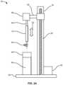
- FIG. 2 Aillustrates an example of a dip-coating assembly or device which can be utilized to form any variation of the polymeric substrates disclosed herein.
- FIG. 2 Billustrates another example of a dip-coating assembly or device which can be utilized to form any variation of the polymeric substrates disclosed herein.
- FIG. 2 Cillustrates yet another example of a dip-coating assembly or device which can be utilized to form any variation of the polymeric substrates disclosed herein.
- FIGS. 3 A to 3 Billustrate partial cross-sectional side views of a portion of an example multi-layer polymeric substrate disclosed herein.
- FIG. 3 Cillustrates a cross-sectional end view of a portion of an example multi-layer polymeric substrate disclosed herein.
- FIG. 4 Aillustrates an example of a polymeric base substrate which can be utilized to form any variation of the polymeric stents or scaffolds disclosed herein.
- FIG. 4 Billustrates an example of how the circular ring-like structures can be positioned or fitted upon a polymeric base substrate to form an intermediate layer of a composite stent structure.
- FIG. 4 Cillustrates an example composite structure formed with an additional polymeric layer overlaid atop the polymeric base substrate and ring structures.
- FIG. 5illustrates an example composite structure where the ring structures can be patterned to form a scaffold structure.
- FIG. 6illustrates an example composite structure where ring structures can be alternated between rings fabricated from different polymeric substrates.
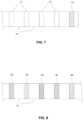
- FIG. 7illustrates an example composite structure where one or more flexible terminal rings can be formed for overlapping between adjacently deployed stents.
- FIG. 8illustrates an example composite structure where each ring structure along the composite stent can be fabricated from polymeric substrates different from one another.
- FIG. 9illustrates an example composite structure where the intermediate polymeric layer is formed as longitudinal strips rather than ring structures.
- FIG. 10illustrates an example composite structure where the intermediate polymeric layer is formed as a helical structure between the base layer and overlaid layer.
- FIG. 11 Aillustrates an example of adjacent composite structures deployed within a vessel with a gap or spacing between the two structures.
- FIG. 11 Billustrates another example of adjacent composite structures deployed within a vessel with the terminal ends of the structures overlapping with one another.
- FIG. 12illustrates a side view of an example composite structure where the terminal ring structures are configured to degrade at a relatively faster rate than the remaining ring structures.
- FIGS. 13 A and 13 Billustrate side views of an example composite structure where polymeric ring structures are positioned along a flexible base coat in a separate manufacturing operation.
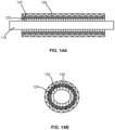
- FIGS. 14 A and 14 Billustrate partial cross-sectional side and end views, respectively, of a composite structure formed by sandwiching a high-strength polymeric material between two or more layers of a flexible polymer to provide for greater flexibility under radial stress while retaining relatively high strength.
- FIG. 15 Aillustrates a perspective view of an example polymeric substrate.
- FIG. 15 Billustrates the polymeric substrate of FIG. 15 A machined into segments having reduced diameters.
- FIG. 15 Cillustrates a perspective view of an example of the machined substrate further coated by one or more polymeric layers.
- FIG. 15 Dillustrates a perspective partial cutaway view of an example of the machined substrate further coated by one or more polymeric layers.
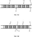
- FIG. 16illustrates a portion of an example of a stent or scaffold which can be formed from any of the polymeric substrates disclosed herein having ring structures connected by struts.
- FIG. 17illustrates a portion of another example of a stent or scaffold which can be formed from any of the polymeric substrates disclosed herein having ring structures connected by struts.
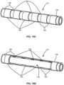
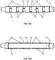
- FIGS. 18 A and 18 Billustrate an example polymeric substrate which has been machined to form ring segments connected via connecting members.
- FIGS. 18 C and 18 Dillustrate an example of the machined substrate coated by one or more polymeric layers and a partial cutaway view of the machined substrate coated by the one or more polymeric layers, respectively.
- FIG. 19illustrates a portion of another example of a stent or scaffold which can be formed from any of the polymeric substrates disclosed herein having ring structures connected by struts.
- FIG. 20illustrates a portion of another example of a stent or scaffold which can be formed from any of the polymeric substrates disclosed herein having ring structures connected by struts.
- a stentWhen a stent is placed into a vessel such as the superficial femoral artery (SFA), iliac, popliteal, subclavian, pulmonary, renal, or coronary arteries, the stent's ability to bend and compress is reduced. Moreover, such vessels typically undergo a great range of motion requiring stents implanted within these vessels to have an axial flexibility which allows for the stent to comply with certain vessel movements without impeding or altering the physiological compression and bending of such vessels.
- SFAsuperficial femoral artery
- a composite stent structure having one or more layers of bioabsorbable polymerscan be fabricated with the desired characteristics for implantation within these vessels.
- Each layercan have a characteristic that individually provides a certain aspect of mechanical behavior to the stent such that the aggregate layers form a composite polymeric stent structure capable of withstanding complex, multi-axial loading conditions imparted by an anatomical environment such as the SFA.
- a tubular substratecan be constructed by positioning one or more high-strength bioabsorbable polymeric ring structures spaced apart from one another along a longitudinal axis.
- the ring structurescan be connected to one another by one or more layers of polymeric substrates, such as bioabsorbable polymers which are also elastomeric.
- the substratecan also be machined, e.g., using laser ablation processes, to produce stents with suitable geometries for particular applications.
- the composite stent structurecan have a relatively high radial strength as provided by the polymeric ring structures while the polymeric portions extending between the adjacent ring structures can allow for elastic compression and extension of the stent structure axially as well as torsionally when axial and rotational stresses are imparted by ambulation and positional changes from the vessel upon the stent structure.
- polymeric materialssuch as biocompatible and/or biodegradable polymers (e.g., poly-L-lactic acid (PLLA) 2.4, PLLA 4.3, PLLA 8.4, PLA, PLGA, etc.)
- PLLApoly-L-lactic acid
- a high-strength tubular material which exhibits a relatively high degree of ductilitycan be fabricated utilizing such polymers having a relatively high molecular weight
- These polymeric substratescan then be machined using any number of processes (e.g., high-speed laser sources, mechanical machining, etc.).
- dip-coatingAn example of such a casting process is to utilize a dip-coating process.
- the utilization of dip-coating to create a base polymeric substrate 10as illustrated in FIG. 1 A , having such desirable characteristics results in substrates 10 which are able to retain the inherent properties of the starting materials. This, in turn, results in substrates 10 having a relatively high radial strength which is mostly retained through any additional manufacturing processes for implantation.
- dip-coating the polymeric substrate 10also allows for the creation of substrates having multiple layers. The multiple layers can be formed from the same or similar materials or they can be varied to include any number of additional agents, such as one or more drugs for treatment of the vessel, as described in further detail below.
- the variability of utilizing multiple layers for the substratecan allow one to control other parameters, conditions, or ranges between individual layers such as varying the degradation rate between layers while maintaining the intrinsic molecular weight and mechanical strength of the polymer at a high level with minimal degradation of the starting materials.
- polymeric substrates 10can be formed which enable the fabrication of devices such as stents with reduced wall thickness which is highly desirable for the treatment of arterial diseases. Furthermore, these processes can produce structures having precise geometric tolerances with respect to wall thicknesses, concentricity, diameter, etc.
- Such dip-coating methodscan be utilized to create polymeric substrates such as base polymeric substrate 10 , which can then be cut into a plurality of polymeric ring structures 12 , as shown in FIG. 1 B .
- These ring structurescan have a width which varies depending upon the application and vessel and can range generally from 1 mm to 10 mm in width.
- substrate 10 and the resulting ring structures 12can be formed to have an initial diameter ranging generally from 2 mm to 10 mm.
- the dip-coating assembly 30can comprise a base 32 supporting a column 34 which houses a drive column 36 and a bracket arm 38 .
- Motor 42can urge drive column 36 vertically along column 34 to move bracket arm 38 accordingly.
- Mandrel 40can be attached to bracket arm 38 above container 44 which can be filled with a polymeric solution 46 (e.g., PLLA, PLA, PLGA, etc.) into which mandrel 40 can be dipped via a linear motion 52 .
- a polymeric solution 46e.g., PLLA, PLA, PLGA, etc.
- the one or more polymerscan be dissolved in a compatible solvent in one or more corresponding containers 44 such that the appropriate solution can be placed under mandrel 40 .
- An optional motor 48can be mounted along bracket arm 38 or elsewhere along assembly 30 to impart an optional rotational motion 54 to mandrel 40 and the substrate 10 formed along mandrel 40 to impart an increase in the circumferential strength of substrate 10 during the dip-coating process, as described in further detail below.
- the assembly 30can be isolated on a vibration-damping or vibrationally isolated table to ensure that the liquid surface held within container 44 remains completely undisturbed to facilitate the formation of a uniform thickness of polymer material along mandrel 40 and/or substrate 10 with each deposition
- the entire assembly 30 or just a portion of the assembly such as the mandrel 40 and polymer solutioncan be placed in an inert environment such as a nitrogen gas environment while maintaining a very low relative humidity (RH) level, e.g., less than 30% RH, and appropriate dipping temperature, e.g., at least 20° C. below the boiling point of the solvent within container 44 so as to ensure adequate bonding between layers of the dip-coated substrate.
- RHrelative humidity
- Multiple mandrelscan also be mounted along bracket arm 38 or directly to column 34 .
- the mandrel 40can be sized appropriately and define a cross-sectional geometry to impart a desired shape and size to the substrate 10 .
- Mandrel 40can be generally circular in cross section although geometries can be utilized as desired.
- mandrel 40can define a circular geometry having a diameter ranging from 1 mm to 20 mm to form a polymeric substrate having a corresponding inner diameter.
- mandrel 40can be made generally from various materials which are suitable to withstand dip-coating processes, e.g., stainless steel, copper, aluminum, silver, brass, nickel, titanium, etc.
- the length of mandrel 40 that is dipped into the polymer solutioncan be optionally limited in length by, e.g., 50 cm, to ensure that an even coat of polymer is formed along the dipped length of mandrel 40 to limit the effects of gravity during the coating process.
- Mandrel 40can also be made from a polymeric material which is lubricious, strong, has good dimensional stability, and is chemically resistant to the polymer solution utilized for dip-coating, e.g., fluoropolymers, polyacetal, polyester, polyamide, polyacrylates, etc.
- mandrel 40can be made to have a smooth surface for the polymeric solution to form upon.
- mandrel 40can define a surface that is coated with a material such as polytetrafluoroethylene to enhance removal of the polymeric substrate formed thereon.
- mandrel 40can be configured to define any number of patterns over its surface, e.g., either over its entire length or just a portion of its surface, that can be mold-transferred during the dip-coating process to the inner surface of the first layer of coating of the dip-coated substrate tube.
- the patternscan form raised or depressed sections to form various patterns such as checkered, cross-hatched, cratered, etc. that can enhance endothelialization with the surrounding tissue after the device is implanted within a patient, e.g., within three months or of implantation.
- mandrel 40can also be alternated or changed between layers of substrate 10 .
- substrate 10can be removed from mandrel 40 and replaced onto mandrel 40 in an opposite direction before the dipping process is continued.
- mandrel 40can be angled relative to bracket arm 38 and/or polymeric solution 46 during or prior to the dipping process.
- FIGS. 2 B and 2 CThis can also be accomplished in yet another variation by utilizing a dipping assembly as illustrated in FIGS. 2 B and 2 C to achieve a uniform wall thickness throughout the length of the formed substrate 10 per dip.
- additional layers formed upon the initial layerscan be formed by dipping mandrel 40 in a second direction opposite to the first dipping direction, e.g., angling the mandrel 40 anywhere up to 180° from the first dipping direction.
- Thiscan be accomplished in one example through the use of one or more pivoting linkages 56 , 58 connecting mandrel 40 to bracket arm 38 , as illustrated.
- the one or more linkages 56 , 58can maintain mandrel 40 in a first vertical position relative to solution 46 to coat the initial layers of substrate 10 , as shown in FIG. 2 B .
- Linkages 56 , 58can then be actuated to reconfigure mandrel 40 from its first vertical position to a second vertical position opposite to the first vertical position, as indicated by direction 59 in FIG. 2 C .
- the dipping processcan be resumed by dipping the entire linkage assembly along with mandrel 40 and substrate 10 . In this manner, neither mandrel 40 nor substrate 10 needs to be removed and thus eliminates any risk of contamination.
- Linkages 56 , 58can comprise any number of mechanical or electromechanical pivoting and/or rotating mechanisms as known in the art.
- Dipping mandrel 40 and substrate 10 in different directionscan also enable the coated layers to have a uniform thickness throughout from its proximal end to its distal end to help compensate for the effects of gravity during the coating process. These values are intended to be illustrative and are not intended to be limiting in any manner. Any excess dip-coated layers on the linkages 56 , 58 can simply be removed from mandrel 40 by breaking the layers. Alternating the dipping direction can also result in the polymers being oriented alternately which can reinforce the tensile strength in the axial direction of the dip coated tubular substrate 10 .
- one or more high molecular weight biocompatible and/or bioabsorbable polymerscan be selected for forming upon mandrel 40 .
- polymers which can be utilized to form the polymeric substratecan include, but is not limited to, polyethylene, polycarbonates, polyamides, polyesteramides, polyetheretherketone, polyacetals, poly ketals, polyurethane, polyolefin, or polyethylene terephthalate and degradable polymers, for example, polylactide (PLA) including poly-L-lactide (PLLA), poly-glycolide (PGA), poly(lactide-co-glycolide) (PLGA) or polycaprolactone, caprolactones, polydioxanones, poly anhydrides, poly orthocarbonates, polyphosphazenes, chitin, chitosan, poly(amino acids), and polyorthoesters, and copolymers, terpolymers and combinations and mixtures thereof
- suitable polymerscan include synthetic polymers, for example, oligomers, homopolymers, and co-polymers, acrylics such as those polymerized from methyl acrylate, methyl methacrylate, acrylic acid, methacrylic acid, acrylamide, hydroxyethyl acrylate, hydroxyethyl methacrylate, glyceryl acrylate, glyceryl methacrylate, methacrylamide and ethacrylamide; vinyls such as styrene, vinyl chloride, vinyl pyrrolidone, polyvinyl alcohol, and vinyls acetate; polymers formed of ethylene, propylene, and tetrafluoroethylene.
- acrylicssuch as those polymerized from methyl acrylate, methyl methacrylate, acrylic acid, methacrylic acid, acrylamide, hydroxyethyl acrylate, hydroxyethyl methacrylate, glyceryl acrylate, glyceryl methacrylate, methacrylamide and
- nylonssuch as polycaprolactam, polylauryl lactam, polyhexamethylene adipamide, and polyhexamethylene dodecanediamide, and also polyurethanes, polycarbonates, polyamides, polysulfones, poly(ethylene terephthalate), polylactic acid, polyglycolic acid, polydimethylsiloxanes, and polyetherketones.
- biodegradable polymerswhich can be used for dip-coating process are polylactide (PLA), polyglycolide (PGA), poly(lactide-co-glycolide) (PLGA), poly- ⁇ -caprolactone (PCL), polydioxanone, polyanhydride, trimethylene carbonate, poly( ⁇ -hydroxybutyrate), poly(g-ethyl glutamate), poly(DTH iminocarbonate), poly(bisphenol A iminocarbonate), poly(ortho ester), polycyanoacrylate, and polyphosphazene, and copolymers, terpolymers and combinations and mixtures thereof.
- biodegradable polymersderived from natural sources such as modified polysaccharides (e.g., cellulose, chitin, chitosan, or dextran) or modified proteins (e.g., fibrin or casein).
- modified polysaccharidese.g., cellulose, chitin, chitosan, or dextran
- modified proteinse.g., fibrin or casein
- suitable polymerscan include synthetic polymers, for example, oligomers, homopolymers, and co-polymers, acrylics such as those polymerized from methyl acrylate, methyl methacrylate, acrylic acid, methacrylic acid, acrylamide, hydroxyethyl acrylate, hydroxyethyl methacrylate, glyceryl acrylate, glyceryl methacrylate, methacrylamide and ethacrylamide; vinyls such as styrene, vinyl chloride, vinyl pyrrolidone, polyvinyl alcohol, and vinyls acetate; polymers formed of ethylene, propylene, and tetrafluoroethylene.
- acrylicssuch as those polymerized from methyl acrylate, methyl methacrylate, acrylic acid, methacrylic acid, acrylamide, hydroxyethyl acrylate, hydroxyethyl methacrylate, glyceryl acrylate, glyceryl methacrylate, methacrylamide and
- nylonssuch as polycaprolactam, polylauryl lactam, polyhexamethylene adipamide, and polyhexamethylene dodecanediamide, and also polyurethanes, polycarbonates, polyamides, polysulfones, poly(ethylene terephthalate), polylactic acid, polyglycolic acid, polydimethylsiloxanes, and polyetherketones.
- the substratecan be formed to have one or more layers overlaid upon one another, the substrate can be formed to have a first layer of a first polymer, a second layer of a second polymer, and so on depending upon the desired structure and properties of the substrate.
- the various solutions and containerscan be replaced beneath mandrel 40 between dip-coating operations in accordance with the desired layers to be formed on the substrate such that the mandrel 40 can be dipped sequentially into the appropriate polymeric solution.
- the mandrel 40can be dipped into the appropriate solution as determined by the number of times the mandrel 40 is immersed, the duration of time of each immersion within the solution, as well as the delay time between each immersion or the drying or curing time between dips. Additionally, parameters such as the dipping and/or withdrawal rate of the mandrel 40 from the polymeric solution can also be controlled to range from, e.g., 5 mm/min to 1000 mm/min. Formation via the dip-coating process can result in a polymeric substrate having half the wall thickness while retaining an increased level of strength in the substrate as compared to an extruded polymeric structure.
- mandrel 40can be dipped between, e.g., 2 to 20 times or more, into the polymeric solution with an immersion time ranging from, e.g., 15 seconds (or less) to 240 minutes (or more).
- the substrate and mandrel 40can be optionally dried or cured for a period of time ranging from, e.g., 15 seconds (or less) to 60 minutes (or more) between each immersion.
- Such polymerscan contain a mixture of crystalline and amorphous regions such that reducing the percentage of the crystalline regions in the polymer can further increase the ductility of the material.
- Polymeric materials not only having a relatively high molecular weight but also having a relatively low crystalline percentagecan be utilized in the processes described herein to form a desirable tubular substrate.
- Table 1show examples of various polymeric materials (e.g., PLLA IV 8.28 and PDLLA 96/4) to illustrate the molecular weights of the materials in comparison to their respective crystallinity percentage.
- the glass transition temperature, T gas well as melting temperature, T m , are given as well.
- An example of PLLA IV 8.28is shown illustrating the raw resin and tube form as having the same molecular weight, M w , of 1.70 ⁇ 10 6 gram/mol. However, the crystallinity percentage of PLLA IV 8.28 Resin is 61.90% while the corresponding Tube form is 38.40%.
- the resin form and tube formeach have a molecular weight, M w , of 9.80 ⁇ 10 5 gram/mol; however, the crystallinity percentages are 46.20% and 20.90%, respectively.
- the drying procedures and processinghelp to preserve the relatively high molecular weight of the polymer from the starting material and throughout processing to substrate and stent formation. Moreover, the drying process in particular can facilitate the formation of desirable crystallinity percentages, as described above.
- the immersion times as well as drying timescan be uniform between each immersion or they can be varied as determined by the desired properties of the resulting substrate.
- the substratecan be placed in an oven or dried at ambient temperature between each immersion or after the final immersion to attain a predetermined level of crystals, e.g., 60%, and a level of amorphous polymeric structure, e.g., 40%.
- a predetermined level of crystalse.g. 60%
- a level of amorphous polymeric structuree.g. 40%.
- Varying the drying conditions of the materialscan also be controlled to effect desirable material parameters.
- the polymerscan be dried at or above the glass transition temperature (e.g., 10° to 20° C. above the glass transition temperature, T g ) of the respective polymer to effectively remove any residual solvents from the polymers to attain residual levels of less than 100 ppm, e.g., between 20 to 100 ppm.
- Positioning of the polymer substrate when dryingis another factor which can be controlled as affecting parameters, such as geometry, of the tube. For instance, the polymer substrate can be maintained in a drying position such that the substrate tube is held in a perpendicular position relative to the ground such that the concentricity of the tubes is maintained.
- the substrate tubecan be dried in an oven at or above the glass transition temperature, as mentioned, for a period of time ranging anywhere from, e.g., 10 days to 30 days or more. However, prolonged drying for a period of time, e.g., greater than 40 days, can result in thermal degradation of the polymer material.
- a shape memory effectcan be induced in the polymer during drying of the substrate.
- a shape memory effectcan be induced in the polymeric tubing to set the tubular shape at the diameter that was formed during the dip-coating process.
- An example of thisis to form a polymeric tube by a dip-coating process described herein at an outer diameter of 5 mm and subjecting the substrate to temperatures above its glass transition temperature, T g .
- the substratecan be elongated, e.g., from a length of 5 cm to 7 cm, while the outer diameter of the substrate is reduced from about 5.0 mm to about 3.0 mm.
- the initial diametercan generally range anywhere from, e.g., 3 mm to 9 mm
- the reduced diametercan generally range anywhere from, e.g., 1.5 mm to 5 mm, provided the reduced diameter is less than the initial diameter.
- the substratecan be quenched or cooled in temperature to a sub-T g level, e.g., about 20° C. below its T g , to allow for the polymeric substrate to transition back to its glass state.
- a sub-T g levele.g., about 20° C. below its T g
- This post-processingcan also be useful for enabling self-expansion of the substrate after a process like laser cutting (e.g., when forming stents or other devices for implantation within the patient) where the substrate tube is typically heated to its glass transition temperature, T g .
- FIGS. 3 A and 3 Bshow partial cross-sectional side views of an example of a portion of a multi-layer polymeric substrate formed along mandrel 40 and the resulting substrate.
- Substrate 10can be formed along mandrel 40 to have a first layer 60 formed of a first polymer, e.g., poly(l-lactide).
- a first polymere.g., poly(l-lactide)
- an optional second layer 62 of polymere.g., poly(L-lactide-co-glycolide
- Yet another optional third layer 64 of polymere.g., poly(d,l-lactide-co-glycolide), can be formed upon second layer 62 to form a resulting substrate defining a lumen 66 therethrough which can be further processed to form any number of devices, such as a stent.
- One or more of the layerscan be formed to degrade at a specified rate or to elute any number of drugs or agents.
- first layer 60can have a molecular weight of M n1
- second layer 62can have a molecular weight of M n2
- third layer 64can have a molecular weight of M n3 .
- a stent fabricated from the tubecan be formed such that the relative molecular weights are such where M n1 >M n2 >M n3 to achieve a preferential layer-by-layer degradation through the thickness of the tube beginning with the inner first layer 60 and eventually degrading to the middle second layer 62 and finally to the outer third layer 64 when deployed within the patient body.
- the stentcan be fabricated where the relative molecular weights are such where M n1 ⁇ M n2 ⁇ M n3 to achieve a layer-by-layer degradation beginning with the outer third layer 64 and degrading towards the inner first layer 60 .
- This exampleis intended to be illustrative and fewer than or more than three layers can be utilized in other examples. Additionally, the molecular weights of each respective layer can be altered in other examples to vary the degradation rates along different layers, if so desired.
- any one or more of the layerscan be formed to impart specified mechanical properties to the substrate 10 such that the composite mechanical properties of the resulting substrate 10 can specifically tuned or designed. Additionally, although three layers are illustrated in this example, any number of layers can be utilized depending upon the desired mechanical properties of the substrate 10 .
- specified layerscan be designated for a particular function in the substrate.
- one or more layerscan be designed as load-bearing layers to provide structural integrity to the stent while certain other layers can be allocated for drug-loading or eluting.
- Those layers which are designated for structural supportcan be formed from high-molecular weight polymers, e.g., PLLA or any other suitable polymer described herein, to provide a high degree of strength by omitting any drugs as certain pharmaceutical agents can adversely affect the mechanical properties of polymers.
- Those layers which are designated for drug-loadingcan be placed within, upon, or between the structural layers.
- multiple layers of different drugscan be loaded within the various layers.
- the manner and rate of drug release from multiple layerscan depend in part upon the degradation rates of the substrate materials. For instance, polymers which degrade relatively quickly can release their drugs layer-by-layer as each successive layer degrades to expose the next underlying layer.
- drug releasecan typically occur from a multilayer matrix via a combination of diffusion and degradation.
- a first layercan elute a first drug for, e.g., the first 30 to 40 days after implantation. Once the first layer has been exhausted or degraded, a second underlying layer having a second drug can release this drug for the next 30 to 40 days, and so on if so desired.
- a first layercan elute a first drug for, e.g., the first 30 to 40 days after implantation. Once the first layer has been exhausted or degraded, a second underlying layer having a second drug can release this drug for the next 30 to 40 days, and so on if so desired.
- layer 64can contain the first drug for release while layer 62 can contain the second drug for release after exhaustion or degradation of layer 64 .
- the underlying layer 60can omit any pharmaceutical agents to provide uncompromised structural support to the entire structure.
- each layer 62 , 64can elute its respective drug simultaneously or at differing rates via a combination of diffusion and degradation.
- three layersare illustrated in this example, any number of layers can be utilized with any practicable combination of drugs for delivery.
- the release kinetics of each drug from each layercan be altered in a variety of ways by changing the formulation of the drug-containing layer.
- drugs or agents which can be loaded within certain layers of substrate 10can include one or more anti-proliferative, anti-neoplastic, anti-genic, anti-inflammatory, and/or anti-restenotic agents.
- the therapeutic agentscan also include anti-lipid, antimitotics, metalloproteinase inhibitors, anti-sclerosing agents.
- Therapeutic agentscan also include peptides, enzymes, radio isotopes or agents for a variety of treatment options. This list of drugs or agents is presented to be illustrative and is not intended to be limiting.
- radio-opaque substancessuch as platinum, gold, etc. to enable visibility of the stent under imaging modalities such as fluoroscopic imaging.
- Radio-opaque substanceslike tungsten, platinum, gold, etc. can be mixed with the polymeric solution and dip-coated upon the substrate such that the radio-opaque substances form a thin sub-micron thick layer upon the substrate.
- the radio-opaque substancescan thus become embedded within layers that degrade in the final stages of degradation or within the structural layers to facilitate stent visibility under an imaging modality, such as fluoroscopy, throughout the life of the implanted device before fully degrading or losing its mechanical strength.
- Radio-opaque marker layerscan also be dip-coated at one or both ends of substrate 10 , e.g., up to 0.5 mm from each respective end. Additionally, the radio-opaque substances can also be spray-coated or cast along a portion of the substrate 10 between its proximal and distal ends in a radial direction by rotating mandrel 40 when any form of radio-opaque substance is to be formed along any section of length of substrate 10 . Rings of polymers having radio-opaque markers can also be formed as part of the structure of the substrate 10 .
- Polymeric stents and other implantable devices made from such substratescan accordingly retain the material properties from the dip-coated polymer materials.
- the resulting stentsfor instance, can exhibit mechanical properties which have a relatively high percentage ductility in radial, torsional, and/or axial directions.
- An example of thisis a resulting stent having an ability to undergo a diameter reduction of anywhere between 5% to 70% when placed under an external load without any resulting plastic deformation.
- Such a stentcan also exhibit high radial strength with, e.g., a 20% radial deformation when placed under a 0.1 N to 20 N load.
- Such a stentcan also be configured to self-expand when exposed to normal body temperatures.
- the stentcan also exhibit other characteristic mechanical properties which are consistent with a substrate formed as described herein, for instance, high ductility and high strength polymeric substrates.
- Such substrates (and processed stents)can exhibit additional characteristics such as a percent reduction in diameter of between 5% to 70% without fracture formation when placed under a compressive load as well as a percent reduction in axial length of between 10% to 30% without fracture formation when placed under an axial load.
- the substrate or stentcan also be adapted to curve up to 180° about a 1 cm curvature radius without fracture formation or failure.
- a stentwhen deployed within a vessel, a stent can also be expanded, e.g., by an inflatable intravascular balloon, by up to 5% to 70% to regain diameter without fracture formation or failure.
- tubes and stentscan be tailored for specific requirements of various anatomical locations within a patient body by altering the polymer and/or copolymer blends to adjust various properties such as strength, ductility, degradation rates, etc.
- Dip-coatingcan be used to impart an orientation between layers (e.g., linear orientation by dipping; radial orientation by spinning the mandrel; etc.) to further enhance the mechanical properties of the formed substrate.
- radial strengthis a desirable attribute of stent design
- post-processing of the formed substratecan be accomplished to impart such attributes.
- polymeric stentssuffer from having relatively thick walls to compensate for the lack of radial strength, and this, in turn, reduces flexibility, impedes navigation, and reduces arterial luminal area immediately post-implantation.
- Post-processingcan also help to prevent material creep and recoil (creep is a time-dependent permanent deformation that occurs to a specimen under stress, typically under elevated temperatures) which are problems typically associated with polymeric stents.
- a polymer that is amorphous or that is partially amorphouswill generally undergo a transition from a pliable, elastic state (at higher temperatures) to a brittle glass-like state (at lower temperature) as it transitions through a particular temperature, referred as the glass transition temperature (T g ).
- T gglass transition temperature
- the glass transition temperature for a given polymerwill vary, depending on the size and flexibility of side chains, as well as the flexibility of the backbone linkages and the size of functional groups incorporated into the polymer backbone. Below T g , the polymer will maintain some flexibility and can be deformed to a new shape. However, the further the temperature below T g the polymer is when being deformed, the greater the force needed to shape it.
- a polymerwhen a polymer is in glass transition temperature its molecular structure can be manipulated to form an orientation in a desired direction. Induced alignment of polymeric chains or orientation improves mechanical properties and behavior of the material. Molecular orientation is typically imparted by application of force while the polymer is in a pliable, elastic state. After sufficient orientation is induced, the temperature of the polymer is reduced to prevent reversal and dissipation of the orientation.
- the polymeric substratecan be heated to increase its temperature along its entire length or along a selected portion of the substrate to a temperature that is at or above the T g of the polymer.
- the substratecan be heated to a temperature between 60° C. to 70° C.
- a forcecan be applied from within the substrate or along a portion of the substrate to increase its diameter from a first diameter D 1 to a second increased diameter D 2 for a period of time necessary to set the increased diameter.
- the application of forceinduces a molecular orientation in a circumferential direction to align the molecular orientation of polymer chains to enhance its mechanical properties.
- the re-formed substratecan then be cooled to a lower temperature typically below T g , for example, by passing the tube through a cold environment, typically dry air or an inert gas to maintain the shape at diameter D 2 and prevent dissipation of molecular orientation.
- a cold environmenttypically dry air or an inert gas to maintain the shape at diameter D 2 and prevent dissipation of molecular orientation.
- the force applied to the substratecan be generated by a number of different methods.
- One methodis by utilizing an expandable pressure vessel placed within the substrate.
- Another methodis by utilizing a braided structure, such as a braid made from a super-elastic or shape memory alloy like NiTi alloy, to increase in size and to apply the desirable degree of force against the interior surface of the substrate.
- Yet another methodcan apply the expansion force by application of a pressurized inert gas such as nitrogen within the substrate lumen.
- a polymeric substratecan also be formed, e.g., also via dip-coating, upon a mandrel to form a base polymeric substrate 70 , as shown in FIG. 4 A .
- the base polymeric substrate 70can refer to another instance of the base polymeric substrate 10 .
- the base polymeric substrate 70can be formed of an elastomeric bioabsorbable polymer, such as, but not limited to, poly- ⁇ -caprolactone (PCL) or trimethylene carbonate (TMC), which can be dissolved in a compatible solvent such as dichloromethane (DCM).
- PCLpoly- ⁇ -caprolactone
- TMCtrimethylene carbonate
- the polymeric solutioncan be poured into a container and placed under the dip-coating assembly 30 in an inert environment.
- a mandrel that is attached to the dip-coating assembly 30can be immersed into the solution to create the base layer of the composite stent structure.
- the resulting polymeric substrate 70can have an initial diameter, e.g., ranging generally from 2 mm to 10 mm, defined by the mandrel which is similar to the diameter of the ring structures 12 .
- the substrate 70can be formed to have an initial length ranging from 5 mm to 500 mm.
- the substrate 70can be left upon the mandrel or removed and placed upon another mandrel.
- the ring structures 12can be positioned upon the base polymeric substrate 70 , as illustrated in FIG. 4 B , at uniform intervals or at predetermined non-uniform distances from one another.
- the spacing between the ring structures 12can be determined in part by the degree of flexibility desired of the resulting composite stent structure where the closer adjacent ring structures 12 are positioned relative to one another, the lesser resulting overall stent flexibility.
- ring structures 12can be positioned relatively closer to one another along a first portion of the composite stent and relatively farther from one another along a second portion of the stent. In one example, the ring structures 12 can be positioned at a uniform distance of 1 mm to 10 mm from one another.
- the ring structures 12are formed to have a diameter which is slightly larger than a diameter of the base polymeric substrate 70 , the ring structures 12 can be compressed to reduce their diameters such that the ring structures 12 are overlaid directly upon the outer surface of the substrate 70 . In use, the ring structures 12 can be compressed to a second smaller diameter for delivery through the vasculature of a patient to a region to be treated. When deployed, the ring structures 12 (as well as the base substrate 70 and overlaid substrate 71 ) can be expanded back to their initial diameter or to a diameter less than the initial diameter.
- the ring and substrate structurecan then be immersed again in the same or different polymeric solution as base polymeric substrate 70 to form an additional polymeric substrate 71 overlaid upon the base substrate 70 and ring structures 12 to form the composite stent structure 72 , as illustrated in FIG. 4 C .
- the ring structures 12can be encapsulated or otherwise encased entirely between the base substrate 70 and the overlaid substrate 71 such that the ring structures 12 are connected or otherwise attached to one another entirely via the elastomeric sections.
- either or both of the ring structures 12 and base or overlaid substrate layers 70 , 71can be configured to retain and deliver or elute any number of pharmaceutical agents, such as an anti-proliferative, an anti-restenotic, etc.
- the ring structures 12can be adjustable along an axial or radially direction independent of one another allowing for any number of configurations and adjustments of the stent structure 72 for conforming within and bending with a vessel which other coated stent structures are unable to achieve.
- This resulting stent structure 72can be removed from the mandrel and machined to length, if necessary, and additional post-processing can be performed upon the stent as well.
- the stent structure 72can have one or more of the ring structures 12 machined into patterned polymeric rings 75 such as expandable scaffold structures, e.g., by laser machining, as illustrated in FIG. 5 .
- the process of removing material from the polymeric rings 75can at least partially expose portions of the polymeric rings 75 to the environment.
- the inner surfaces and the outer surfaces of the polymeric rings 75can remain coated or covered by both respective base and overlaid substrate layers 70 , 71 while side surfaces of the rings 75 can become exposed by removal of the substrate layers as well as portions of the ring material as the stent structure is machined. These exposed surfaces can be re-coated, if desired, or left exposed to the environment.
- the polymeric ring structures 12 utilized in the composite stent structure 72can be fabricated from a common substrate and common polymers. However, in other variations, the ring structures forming the stent 24 can be fabricated from different substrates having different material characteristics.
- FIG. 6illustrates an example where a first set of polymeric rings 76 can be positioned in an alternating pattern with a second set of polymeric rings 77 along the base substrate 70 . In this and other examples, the overlaid polymeric substrate 71 can be omitted from the figures merely for clarity.
- FIG. 7shows an example where a first set of polymeric ring structures 12 can be positioned along the stent with a flexible polymeric ring 73 fabricated to be relatively more flexible than the remaining ring structures 12 positioned along a terminal end of the stent structure.
- each of the ring structurescan be fabricated from different substrates and polymers.
- a stent structurecan be fabricated to have a first polymeric ring 92 , a second polymeric ring 93 , a third polymeric ring 94 , a fourth polymeric ring 95 , a fifth polymeric ring 96 , and so on to form a composite stent structure.
- An example of usecan include a composite stent structure for placement within a tapered or diametrically expanding vessel where each subsequent ring structure can be fabricated to be more radially expandable than an adjacent ring structure, e.g., where the first polymeric ring 92 can be radially expandable to a first diameter, second polymeric ring 93 is radially expandable to a second diameter larger than the first diameter, third polymeric ring 94 can be radially expandable to a third diameter larger than the second diameter, and so on.
- Thisis intended to be exemplary and other examples are, of course, intended to be within the scope of this disclosure.
- FIG. 9illustrates longitudinally-oriented polymeric strips 97 rather than ring structures positioned along the base substrate 70 .
- a composite stent structurecan be configured to allow for greater flexibility under radial stresses.
- FIG. 10shows a helically-oriented polymeric member 98 which can be positioned along base substrate 70 .
- the polymeric substrate utilized to form the ring structurescan be heat treated at, near, or above the glass transition temperature T g of the substrate to set an initial diameter and the substrate can then be processed to produce the ring structures having a corresponding initial diameter.
- the resulting composite stent structurecan be reduced from its initial diameter to a second delivery diameter which is less than the initial diameter such that the composite stent structure can be positioned upon, e.g., an inflation balloon of a delivery catheter.
- the composite stent structure at its reduced diametercan be self-constrained such that the stent remains in its reduced diameter without the need for an outer sheath, although a sheath can be optionally utilized. Additionally, the composite stent structure can be reduced from its initial diameter to its delivery diameter without cracking or material failure.
- the stentWith the composite stent structure positioned upon a delivery catheter, the stent can be advanced intravascularly within the lumen 88 of a vessel 86 until the delivery site is reached.
- the inflation ballooncan be inflated to expand a diameter of composite stent structure into contact against the vessel interior, e.g., to an intermediate diameter, which is less than the stent's initial diameter yet larger than the delivery diameter.
- the composite stent structurecan be expanded to this intermediate diameter without any cracking or failure because of the inherent material characteristics, as shown in FIG. 11 A .
- expansion to the intermediate diametercan allow for the composite stent structure to securely contact the vessel wall while allowing for the withdrawal of the delivery catheter.
- the composite stent structurecan be allowed to then self-expand further over a period of time into further contact with the vessel wall such that composite stent structure conforms securely to the tissue.
- This self-expansion featureultimately allows for the composite stent structure to expand back to its initial diameter which had been heat-set in the ring structures or until the composite stent structure has fully self-expanded within the confines of the vessel lumen 88 .
- the composite stent structurecan be expanded directly to its final diameter, e.g., by balloon inflation, without having to reach an intermediate diameter and subsequent self-expansion.
- a first composite stent 80is shown deployed within vessel lumen 88 adjacent to a second composite stent 82 with spacing 84 between the stents. Additional stent structures can be deployed as well depending upon the length of the lesion to be stented.
- FIG. 11 Billustrates another example where adjacent composite stents 80 , 82 are deployed within vessel lumen 88 with their terminal ends overlapping one another along overlapped portion 90 . As the SFA tends to develop long, diffuse lesions with calcification, multiple stents can be deployed with overlapping ends.
- both overlapped composite stents 80 , 82can be fabricated from an elastomeric polymer allowing for the overlap to occur along these segments. Such overlapping would not significantly compromise axial flexibility and the composite stents can continue its compliance with the arterial movement.
- FIG. 12Another variation which facilitates the overlapping of adjacent stents is shown in the side view of FIG. 12 .
- the overlaid substratehas been omitted for clarity only and can be included as a layer positioned atop the base substrate 70 as well as the polymeric rings, as previously described.
- the polymeric ring structures 12can include terminal polymeric rings 100 which are fabricated to degrade at a relatively faster rate than the remaining ring structures 12 positioned between these terminal rings 100 .
- Such a composite stent structurecan allow for the optimal overlapping of multiple stents along the length of a blood vessel.
- FIGS. 13 A and 13 Billustrate a mandrel 110 that is provided with a flexible polymeric base substrate 112 placed or formed thereon.
- a set of polymeric ring structures 114can be positioned along the longitudinal axis of the flexible base coat 112 in a separate manufacturing operation.
- a composite structurecan be provided by forming a composite stent structure having multiple polymeric layers.
- a middle layer 122can be made of a high strength polymeric material such as poly-L-lactic acid (PLLA) or poly-L-lactide that is sandwiched between two or more layers 120 , 124 of a flexible polymer such as poly- ⁇ -caprolactone (PCL).
- PLLApoly-L-lactic acid
- PCLpoly- ⁇ -caprolactone
- Such a composite stent structurecan be configured to allow for greater flexibility under radial stresses while retaining relatively high strength provided by the middle layer 122 comprising PLLA.
- a bioabsorbable polymeric substrate 130 initially formed by the dip-coating process as previously describedcan be formed into a tubular substrate as shown in the perspective view of FIG. 15 A .
- Substrate 130can be further processed, such as by machining, to form a machined substrate 131 , as shown in the perspective view of FIG. 15 B , having one or more reduced segments 132 which are reduced in diameter alternating with the relatively thicker segments 134 which can be reduced in diameter to a lesser degree or uncut altogether.
- the number of reduced segments 132 and the spacing betweencan be uniform or varied depending upon the desired resulting stent or scaffold and the reduction in diameter of these segments 132 can also be varied as well.
- segments 132can be reduced in diameter by, e.g., 1.85 mm to 11.85 mm.
- FIG. 15 Bshows seven reduced segments 132 between thicker segments 134 , this number can be varied depending upon the desired resulting lengths of segments 132 , e.g., ranging from 0.5 mm to 3 mm in length.
- the substrateIn forming the substrate to have a variable wall thickness as illustrated, laser machining (profiling) of the outer diameter can be utilized.
- the integrity and material properties of the substrate materialare desirably maintained during this process of selectively removing material in order to achieve the desired profile.
- An ultra-short pulse femtosecond type lasercan be used to selectively remove the material from the reduced segments 132 by taking advantage, e.g., of multi-photon absorption, such that the laser removes the material without modifying the material integrity.
- the mechanical properties and molecular structure of the bioabsorbable substrate 130can be unaffected during this machining process.
- variables in utilizing such a laser for this particular applicationcan include, e.g., laser power level, laser pulse frequency, energy profile of the beam, beam diameter, lens focal length, focal position relative to the substrate surface, speed of the substrate/beam relative to the substrate, and any gas jet/shield either coaxial or tangential to the material, etc.
- a multi-level profilecan be readily produced.
- increasing or decreasing the rotational speed of the substrate relative to the laser during processingwill vary the depth of penetration.
- This in combination with a translation rate of the substrate relative to the lasercan also be varied to produce a relatively sharp edge in the relief area or a smooth tapered transition between each of the adjacent segments. Varying both parameters along the longitudinal axis of the substrate 130 can produce a continuously variable profile from which a stent pattern can be cut, as further described below.
- the laser systemcan comprise an ultra-short pulse width laser operating in the femtosecond pulse region, e.g., 100 to 500 fs typical pulse width, and a wavelength, ⁇ , e.g., in the near to mid-IR range (750 to 1600 nm typical ⁇ ).
- the pulse frequency of these laserscan range from single pulse to kilohertz (1 to 10 kHz typical).
- the beam energy profilecan be TEM 00 to a high order mode (TEM 00 is typical, but not necessary).
- the beam delivery systemcan comprise a beam bender, vertical mounted monocular viewing/laser beam focusing head, focusing lens and coaxial gas jet assembly.
- a laser systemcan also include a linear stage having a horizontally mounted rotary stage with a collet clamping system mounted below the focusing/cutting head.
- the laser beam focusing headcan be positioned perpendicular to the longitudinal axis of substrate 130 .
- a non-penetrating channelcan be machined in the substrate 130 .
- Controlling the speed of rotation and/or linear translation of the tube under the beam, a channelcan be machined along the substrate axis. Varying any one or all of the parameters (e.g., position, depth, taper, length, etc.) of machining can be controlled and positioned along the entire length of the substrate 130 .
- the ability to profile the substrate 130can provide a number of advantages in the flexibility of the resulting stent design and performance.
- profilingcan improve the flexibility of the stent geometry and expansion capability in high stress areas, expose single or multiple layers to enhance or expose drug delivery by placing non-penetrating holes into one or more particular drug-infused layer(s) of the substrate 130 or by placing grooves or channels into these drug layer(s).
- the ability to profile the substrate 130can allow for a substrate having a variable profile which can be over-coated with the same or different polymer, as described herein.
- machined substrate 131Once machined substrate 131 has been sufficiently processed, it can then be coated, e.g., via the dip-coating process as previously described, such that one or more additional elastomeric polymer layers are coated upon substrate 131 .
- the example shown in the perspective view of FIG. 15 Cillustrates machined substrate 131 having at least one additional elastomeric polymer layer 136 coated thereupon; however, other variations can have more than one layer coated atop one another depending upon the desired characteristics of the resulting substrate.
- each subsequent layer coated upon machined substrate 131can be of the same, similar, or different material from polymeric substrate 131 , e.g., polyethylene, polycarbonates, polyamides, polyesteramides, polyetheretherketone, polyacetals, poly ketals, polyurethane, polyolefin, polyethylene terephthalate, polylactide, poly-L-lactide, poly-glycolide, poly(lactide-co-glycolide), polycaprolactone, caprolactones, polydioxanones, polyanhydrides, polyorthocarbonates, polyphosphazene, chitin, chitosan, poly(amino acids), polyorthoesters, oligomers, homopolymers, methyl acrylate, methyl methacrylate, acrylic acid, methacrylic acid, acrylamide, hydroxyethyl acrylate, hydroxyethyl methacrylate, glyceryl acrylate, glyce
- the one or more polymeric layers 136can be coated upon machined substrate 131 such that the elastomeric polymer 136 forms within the reduced segments 132 as well as upon segments 134 .
- the resulting coated layer 136can range in thickness accordingly from, e.g., 50 ⁇ m to 500 ⁇ m, such that the layer 136 forms a uniform outer diameter along the length of substrate 131 .
- the thickened elastomeric polymer segments 138 formed along reduced segments 132can be seen along substrate 131 with substrate lumen 140 defined therethrough.
- the entire formed substratecan then be processed, e.g., machined, laser-machined, etc., to form a stent or scaffold (for example, the stent or scaffold 150 shown in FIG. 16 , 17 , 19 , or 20 ).
- a stent or scaffoldfor example, the stent or scaffold 150 shown in FIG. 16 , 17 , 19 , or 20 .
- FIG. 16is a side view of a portion of an example composite stent or scaffold 150 which can be formed (e.g., machined, laser cut, etc.) from a base polymeric substrate such as, for example, base polymeric substrate 10 or base polymeric substrate 70 .
- polymers which can be utilized to form the base polymeric substrate or layercan include, but is not limited to, polyethylene, polycarbonates, polyamides, polyesteramides, polyetheretherketone, polyacetals, polyketals, polyurethane, polyolefin, or polyethylene terephthalate and biodegradable or bioabsorbable polymers, for example, polylactide (PLA) including poly-L-lactide (PLLA), poly-glycolide (PGA), poly(lactide-co-glycolide) (PLGA) or polycaprolactone or poly- ⁇ -caprolactone (PCL), caprolactones, polydioxanones, polyanhydrides, polyorthocarbonates, polyphosphazenes, chitin, chitosan, poly(amino acids), and polyorthoesters, and copolymers, terpolymers and combinations, blends, or mixtures thereof.
- PLApolylactide
- PLApolylactide
- suitable polymerscan include synthetic polymers, for example, oligomers, homopolymers, and co-polymers, acrylics such as those polymerized from methyl acrylate, methyl methacrylate, acrylic acid, methacrylic acid, acrylamide, hydroxyethyl acrylate, hydroxyethyl methacrylate, glyceryl acrylate, glyceryl methacrylate, methacrylamide and ethacrylamide; vinyls such as styrene, vinyl chloride, vinyl pyrrolidone, polyvinyl alcohol, and vinyls acetate; polymers formed of ethylene, propylene, and tetrafluoroethylene.
- acrylicssuch as those polymerized from methyl acrylate, methyl methacrylate, acrylic acid, methacrylic acid, acrylamide, hydroxyethyl acrylate, hydroxyethyl methacrylate, glyceryl acrylate, glyceryl methacrylate, methacrylamide and
- nylonssuch as polycaprolactam, polylauryl lactam, polyhexamethylene adipamide, and polyhexamethylene dodecanediamide, and also polyurethanes, polycarbonates, polyamides, polysulfones, poly(ethylene terephthalate), polylactic acid, polyglycolic acid, polydimethylsiloxanes, and polyetherketones.
- biodegradable polymers derived from natural sourcessuch as modified polysaccharides (cellulose, chitin, chitosan, dextran) or modified proteins (fibrin, casein).
- suitable polymerscan include synthetic polymers, for example, oligomers, homopolymers, and co-polymers, acrylics such as those polymerized from methyl acrylate, methyl methacrylate, acrylic acid, methacrylic acid, acrylamide, hydroxyethyl acrylate, hydroxyethyl methacrylate, glyceryl acrylate, glyceryl methacrylate, methacrylamide and ethacrylamide; vinyls such as styrene, vinyl chloride, vinyl pyrrolidone, polyvinyl alcohol, and vinyls acetate; polymers formed of ethylene, propylene, and tetrafluoroethylene.
- acrylicssuch as those polymerized from methyl acrylate, methyl methacrylate, acrylic acid, methacrylic acid, acrylamide, hydroxyethyl acrylate, hydroxyethyl methacrylate, glyceryl acrylate, glyceryl methacrylate, methacrylamide and
- nylonssuch as polycaprolactam, polylauryl lactam, polyhexamethylene adipamide, and polyhexamethylene dodecanediamide, and also polyurethanes, polycarbonates, polyamides, polysulfones, poly(ethylene terephthalate), polyacetals, polyketals, polydimethylsiloxanes, and polyetherketones.
- the example composite stent or scaffold 150can comprise polymeric ring structures 154 and one or more interconnecting struts 152 which extend between and couple adjacent ring structures 154 .
- the polymeric ring structures 154are made from a base polymeric layer which has been formed via a dip-coating process (such as any of the dip-coating processes described with respect to FIG. 2 A, 2 B, 2 C, 3 A, 3 B , or 3 C) or other finishing processes, the polymeric ring structures 154 can retain a molecular weight and mechanical strength of the starting substrate or the base polymeric substrate.
- the base polymeric substrateis made from a bioabsorbable or biodegradable polymeric substance, such as any of PLA, PLLA, PGA, PLGA, PCL, caprolactones, polydioxanones, polyanhydrides, polyorthocarbonates, polyphosphazenes, chitin, chitosan, poly(amino acids), and polyorthoesters, copolymers thereof, terpolymers thereof, or combinations and mixtures thereof, the polymeric ring structures 154 can be bioabsorbable or biodegradable.
- a bioabsorbable or biodegradable polymeric substancesuch as any of PLA, PLLA, PGA, PLGA, PCL, caprolactones, polydioxanones, polyanhydrides, polyorthocarbonates, polyphosphazenes, chitin, chitosan, poly(amino acids), and polyorthoesters, copolymers thereof, terpoly
- the polymeric ring structures 154can be formed at a first diameter and be radially compressible to a smaller second diameter or a deployment diameter.
- the polymeric ring structures 154can be re-expandable or self-expandable to the larger first diameter when deployed within the vasculature of a patient.
- the polymeric ring structures 154can be axially or longitudinally separated from one another and adjacent polymeric ring structures 154 can be connected or coupled by one or more interconnecting struts 152 .
- Each of the interconnecting struts 152can have a width which is less than a circumference of one of the polymeric ring structures 154 .
- the polymeric ring structures 154can be axially and rotationally movable relative to one another via the interconnecting struts 152 .
- the one or more interconnecting struts 152can also be made of bioabsorbable polymers, polymer blends, or co-polymer such that the entire composite stent structure 150 can be bioabsorbable.
- the interconnecting struts 152can be formed from a polymer blend, a blend of polymer solutions, or co-polymer comprising poly-L-lactide (PLLA) and an elastomeric polymer.
- the polymer blend or co-polymercan have a glass transition temperature between 50° C. and 65° C.
- the elastomeric polymercan be or comprise polycaprolactone (PCL).
- the PCLcan be about 1% to about 10% (for example, weight/weight or volume/volume) of the polymer blend or co-polymer. In other variations, the PCL can be about 1% to about 50% (for example, weight/weight or volume/volume) of the polymer blend or co-polymer.
- the interconnecting struts 152are made of one or more elastomeric polymers, at least one of the interconnecting struts 152 can be more elastic than the polymeric ring structures 154 .
- the polymeric ring structures 154can be spaced closer to one another along a first portion than along a second portion of the composite stent structure 150 .
- a terminal ring structure(for example, a terminal ring structure positioned similar to the terminal ring 73 of FIG. 7 ) can be relatively more flexible than a remainder of the polymeric ring structures 154 .
- the plurality of interconnecting struts 152can be positioned along a length of the composite stent or scaffold 150 in a circumferentially alternating manner between immediately adjacent ring structures 154 .
- the interconnecting struts 152can be longitudinally aligned with one another along a length of the composite stent or scaffold 150 .
- the composite stent or scaffold 150can be formed from a coated substrate 131 such that the interconnecting struts 152 are formed from thickened elastomeric polymer segments 138 while the polymeric ring structures 154 are formed on the polymeric substrate 131 .
- Thiscan result in a contiguous and uniform composite stent or scaffold 150 which comprises high-strength circumferential segments or ring structures 154 connected to one another via elastomeric interconnecting struts 152 such that the composite stent or scaffold 150 exhibits high-strength characteristics yet is flexible overall.
- FIG. 17is a side view of a portion of a variation of a composite stent or scaffold 160 comprising a first polymeric ring structure 162 and a second polymeric ring structure 164 connected by one or more interconnecting struts 152 .
- the first polymeric ring structure 162can be made from a base polymeric substrate comprising an elastomeric bioabsorbable polymer resin such as PCL or TMC while the adjacent second polymeric ring structure 164 can be made from only the base polymeric substrate or another polymeric substrate comprising a different polymer blend or composition.
- the composite stent or scaffold 160 structurecan be formed from the coated polymeric substrate 131 such that the first polymeric ring structure 162 is formed from the elastomeric polymer segments 138 while an adjacent second polymeric ring structure 164 is formed from polymeric substrate 131 such that the second polymeric ring structure 164 is relatively higher in strength than the first polymeric ring structure 162 , which is relatively more flexible.
- the alternating segments of elastomeric segments and substrate segmentscan be repeated along a portion or the entire length of the composite stent or scaffold 160 depending upon the desired degree of flexibility and strength characteristics. Moreover, other variations of alternating between the segments can be employed.
- FIG. 18 Aillustrates an example of polymeric substrate 170 which has been machined to form ring segments 172 connected via one or more interconnecting struts 174 .
- the polymeric substrate 170can be initially formed from a dip-coated base polymeric substrate such as base polymeric substrate 10 or base polymeric substrate 70 .
- the dip-coated base polymeric substratecan be machined or laser cut into a number of ring segments 172 connected via interconnecting struts 174 . Although seven ring segments 172 are shown in this example, fewer than or greater than seven ring segments 172 can be utilized.
- the interconnecting struts 174can be fashioned into alternating apposed members between adjacent ring segments 172 .
- the interconnecting struts 174can be positioned along a length of the polymeric substrate 170 in a circumferentially alternating manner between immediately adjacent ring segments 172 .
- the polymeric substrate 170can be positioned upon mandrel 176 , as shown in FIG. 18 B .
- the mandrel 176 and the entire machined polymeric substrate 170can then be coated again, e.g., via dip-coating as previously described, by one or more layers of bioabsorbable elastomeric polymers 180 (e.g., PCL).
- the one or more layers of bioabsorbable elastomeric polymers 180can form thickened elastomeric interconnecting strut sections 182 as well as thickened elastomeric ring segments 172 , as shown in FIGS. 18 C and 18 D .
- FIGS. 18 C and 18 DIn other variations not shown in FIG.
- the one or more layers of bioabsorbable elastomeric polymers 180can cover only the interconnecting struts 174 . All such composite machined or cut substrates can then be further processed, machined or cut to form one or more composite stent or scaffolds having various unique or advantageous composite structural characteristics.
- FIG. 19is a side view of a portion of an example composite stent or scaffold 190 .
- the composite stent or scaffold 190can comprise polymeric ring structures 194 and one or more interconnecting struts 192 which extend between and coupled adjacent polymeric ring structures 194 .
- the polymeric ring structures 194can be made from a dip-coated base polymeric substrate such as base polymeric substrate 10 or base polymeric substrate 70 .
- polymers which can be utilized to form the base polymeric substrate or layercan include, but is not limited to, polyethylene, polycarbonates, polyamides, polyesteramides, polyetheretherketone, polyacetals, polyketals, polyurethane, polyolefin, or polyethylene terephthalate and biodegradable or bioabsorbable polymers, for example, polylactide (PLA) including poly-L-lactide (PLLA), poly-glycolide (PGA), poly(lactide-co-glycolide) (PLGA) or polycaprolactone or poly- ⁇ -caprolactone (PCL), caprolactones, polydioxanones, polyanhydrides, polyorthocarbonates, polyphosphazenes, chitin, chitosan, poly(amino acids), and polyorthoesters, and copolymers, terpolymers and combinations, blends, or mixtures thereof.
- PLApolylactide
- PLApolylactide
- suitable polymerscan include synthetic polymers, for example, oligomers, homopolymers, and co-polymers, acrylics such as those polymerized from methyl acrylate, methyl methacrylate, acrylic acid, methacrylic acid, acrylamide, hydroxyethyl acrylate, hydroxyethyl methacrylate, glyceryl acrylate, glyceryl methacrylate, methacrylamide and ethacrylamide; vinyls such as styrene, vinyl chloride, vinyl pyrrolidone, polyvinyl alcohol, and vinyls acetate; polymers formed of ethylene, propylene, and tetrafluoroethylene.
- acrylicssuch as those polymerized from methyl acrylate, methyl methacrylate, acrylic acid, methacrylic acid, acrylamide, hydroxyethyl acrylate, hydroxyethyl methacrylate, glyceryl acrylate, glyceryl methacrylate, methacrylamide and
- nylonssuch as polycaprolactam, polylauryl lactam, polyhexamethylene adipamide, and polyhexamethylene dodecanediamide, and also polyurethanes, polycarbonates, polyamides, polysulfones, poly(ethylene terephthalate), polylactic acid, polyglycolic acid, polydimethylsiloxanes, and polyetherketones.
- biodegradable polymers derived from natural sourcessuch as modified polysaccharides (cellulose, chitin, chitosan, dextran) or modified proteins (fibrin, casein).
- suitable polymerscan include synthetic polymers, for example, oligomers, homopolymers, and co-polymers, acrylics such as those polymerized from methyl acrylate, methyl methacrylate, acrylic acid, methacrylic acid, acrylamide, hydroxyethyl acrylate, hydroxyethyl methacrylate, glyceryl acrylate, glyceryl methacrylate, methacrylamide and ethacrylamide; vinyls such as styrene, vinyl chloride, vinyl pyrrolidone, polyvinyl alcohol, and vinyls acetate; polymers formed of ethylene, propylene, and tetrafluoroethylene.
- acrylicssuch as those polymerized from methyl acrylate, methyl methacrylate, acrylic acid, methacrylic acid, acrylamide, hydroxyethyl acrylate, hydroxyethyl methacrylate, glyceryl acrylate, glyceryl methacrylate, methacrylamide and
- nylonssuch as polycaprolactam, polylauryl lactam, polyhexamethylene adipamide, and polyhexamethylene dodecanediamide, and also polyurethanes, polycarbonates, polyamides, polysulfones, poly(ethylene terephthalate), polyacetals, polyketals, polydimethylsiloxanes, and polyetherketones.
- the polymeric ring structures 194are made from a base polymeric layer which has been formed via a dip-coating process (such as any of the dip-coating processes described with respect to FIG. 2 A, 2 B, 2 C, 3 A, 3 B , or 3 C) or other finishing processes, the polymeric ring structures 194 can retain a molecular weight and mechanical strength of the starting substrate or the base polymeric substrate.
- a dip-coating processsuch as any of the dip-coating processes described with respect to FIG. 2 A, 2 B, 2 C, 3 A, 3 B , or 3 C
- the polymeric ring structures 194can retain a molecular weight and mechanical strength of the starting substrate or the base polymeric substrate.
- the base polymeric substrateis made from a bioabsorbable or biodegradable polymeric substance, such as any of PLA, PLLA, PGA, PLGA, PCL, caprolactones, polydioxanones, polyanhydrides, polyorthocarbonates, polyphosphazenes, chitin, chitosan, poly(amino acids), and polyorthoesters, copolymers thereof, terpolymers thereof, or combinations and mixtures thereof, the polymeric ring structures 194 can be bioabsorbable or biodegradable.
- a bioabsorbable or biodegradable polymeric substancesuch as any of PLA, PLLA, PGA, PLGA, PCL, caprolactones, polydioxanones, polyanhydrides, polyorthocarbonates, polyphosphazenes, chitin, chitosan, poly(amino acids), and polyorthoesters, copolymers thereof, terpoly
- the polymeric ring structures 194can be formed at a first diameter and be radially compressible to a smaller second diameter or a deployment diameter.
- the polymeric ring structures 194can be re-expandable or self-expandable to the larger first diameter when deployed within the vasculature of a patient.
- the polymeric ring structures 194can be axially or longitudinally separated from one another and adjacent polymeric ring structures 194 can be connected or coupled by the one or more interconnecting struts 192 .
- Each of the interconnecting struts 192can have a width which is less than a circumference of one of the polymeric ring structures 194 .
- the polymeric ring structures 194can be axially and rotationally movable relative to one another via the interconnecting struts 192 .
- the one or more interconnecting struts 192can also be made of bioabsorbable polymers, polymer blends, or co-polymer such that the entire composite stent structure 190 is bioabsorbable.
- the interconnecting struts 192can be formed from a polymer blend, a blend of polymer solutions, or co-polymer comprising poly-L-lactide (PLLA) and an elastomeric polymer.
- the polymer blend or co-polymercan have a glass transition temperature between 50° C. and 65° C.
- the elastomeric polymercan be or comprise polycaprolactone (PCL).
- the PCLcan be about 1% to about 10% (for example, weight/weight or volume/volume) of the polymer blend or co-polymer. In other variations, the PCL can be about 1% to about 50% (for example, weight/weight or volume/volume) of the polymer blend or co-polymer.
- the interconnecting struts 192are made of one or more elastomeric polymers, at least one of the interconnecting struts 192 can be more elastic than the polymeric ring structures 194 .
- the polymeric ring structures 194can be spaced closer to one another along a first portion than along a second portion of the composite stent structure 190 .
- a terminal ring structure(for example, a terminal ring structure positioned similar to the terminal ring 73 of FIG. 7 ) can be relatively more flexible than a remainder of the polymeric ring structures 194 .
- the plurality of interconnecting struts 192can be positioned along a length of the composite stent or scaffold 190 in a circumferentially alternating manner between immediately adjacent ring structures 194 .
- the interconnecting struts 192can be longitudinally aligned with one another along a length of the composite stent or scaffold 190 .
- interconnecting struts 192can be formed from the thickened elastomeric interconnecting strut sections 182 while the polymeric ring structures 194 can be formed from the ring segments 172 .
- the resulting composite stent or scaffold 190allows for the structure to have significant flexibility along the axial, torsional, and/or bending directions as well as the ability to withstand relatively long fatigue cycles without formation of cracks or fractures, e.g., 1,000,000 to 3,000,000 cycles, in axial compression, extension, and torsional modes. Also, the stent or scaffold 190 can also withstand a pulsatile fatigue life of up to, e.g., 120,000,000 cycles or more.
- FIG. 20is a side view of a portion of a variation of a composite stent or scaffold 200 comprising a first polymeric ring structure 202 and a second polymeric ring structure 204 connected by one or more interconnecting struts 192 .
- the first polymeric ring structure 202can be made from a base polymeric substrate comprising an elastomeric bioabsorbable polymer resin such as PCL, TMC, or DCM while the adjacent second polymeric ring structure 204 can be made from only the base polymeric substrate or another polymeric substrate comprising a different polymer blend or composition.
- interconnecting struts 192can also alternate such that one interconnecting strut 192 can be elastomeric while another adjacent or neighboring interconnecting strut 192 can be non-elastomeric or be made from a polymeric blend or solution having a different percentage of elastomeric polymers.
Landscapes
- Health & Medical Sciences (AREA)
- Life Sciences & Earth Sciences (AREA)
- Animal Behavior & Ethology (AREA)
- Veterinary Medicine (AREA)
- Public Health (AREA)
- General Health & Medical Sciences (AREA)
- Heart & Thoracic Surgery (AREA)
- Vascular Medicine (AREA)
- Engineering & Computer Science (AREA)
- Surgery (AREA)
- Epidemiology (AREA)
- Biomedical Technology (AREA)
- Oral & Maxillofacial Surgery (AREA)
- Cardiology (AREA)
- Transplantation (AREA)
- Mechanical Engineering (AREA)
- Chemical & Material Sciences (AREA)
- Chemical Kinetics & Catalysis (AREA)
- Gastroenterology & Hepatology (AREA)
- Pulmonology (AREA)
- Molecular Biology (AREA)
- Medicinal Chemistry (AREA)
- Physics & Mathematics (AREA)
- Optics & Photonics (AREA)
- Materials For Medical Uses (AREA)
- Media Introduction/Drainage Providing Device (AREA)
- Prostheses (AREA)
Abstract
Description
| TABLE 1 |
| Various polymeric materials and their |
| respective crystallinity percentages. |
| Tg | Tm | Crystallinity | Mw | |
| Material | (° C.) | (° C.) | (%) | (gram/mol) |
| PLLA IV8.28 | 72.5 | 186.4 | 61.90% | 1.70 × 10⁶ |
| Resin | ||||
| PLLA IV8.28 | 73.3 | 176.3 | 38.40% | 1.70 × 10⁶ |
| Tubes | ||||
| PDLLA 96/4 | 61.8 | 155.9 | 46.20% | 9.80 × 10⁵ |
| PDLLA | ||||
| 96/4 | 60.3 | 146.9 | 20.90% | 9.80 × 10⁵ |
| Tubes | ||||
Claims (20)
Priority Applications (2)
| Application Number | Priority Date | Filing Date | Title |
|---|---|---|---|
| US17/150,194US11931484B2 (en) | 2008-06-20 | 2021-01-15 | Composite stent having multi-axial flexibility and method of manufacture thereof |
| US18/438,159US20250025609A1 (en) | 2008-06-20 | 2024-02-09 | Composite stent having multi-axial flexibility and method of manufacture thereof |
Applications Claiming Priority (7)
| Application Number | Priority Date | Filing Date | Title |
|---|---|---|---|
| US12/143,659US8206635B2 (en) | 2008-06-20 | 2008-06-20 | Stent fabrication via tubular casting processes |
| US8843308P | 2008-08-13 | 2008-08-13 | |
| US12/541,095US20100042202A1 (en) | 2008-08-13 | 2009-08-13 | Composite stent having multi-axial flexibility |
| US13/476,853US10646359B2 (en) | 2008-06-20 | 2012-05-21 | Stent fabrication via tubular casting processes |
| US15/439,002US20170157806A1 (en) | 2008-06-20 | 2017-02-22 | Stent fabrication via tubular casting processes |
| US15/624,235US10898620B2 (en) | 2008-06-20 | 2017-06-15 | Composite stent having multi-axial flexibility and method of manufacture thereof |
| US17/150,194US11931484B2 (en) | 2008-06-20 | 2021-01-15 | Composite stent having multi-axial flexibility and method of manufacture thereof |
Related Parent Applications (1)
| Application Number | Title | Priority Date | Filing Date |
|---|---|---|---|
| US15/624,235ContinuationUS10898620B2 (en) | 2008-06-20 | 2017-06-15 | Composite stent having multi-axial flexibility and method of manufacture thereof |
Related Child Applications (1)
| Application Number | Title | Priority Date | Filing Date |
|---|---|---|---|
| US18/438,159ContinuationUS20250025609A1 (en) | 2008-06-20 | 2024-02-09 | Composite stent having multi-axial flexibility and method of manufacture thereof |
Publications (2)
| Publication Number | Publication Date |
|---|---|
| US20210128796A1 US20210128796A1 (en) | 2021-05-06 |
| US11931484B2true US11931484B2 (en) | 2024-03-19 |
Family
ID=59958455
Family Applications (3)
| Application Number | Title | Priority Date | Filing Date |
|---|---|---|---|
| US15/624,235Active2030-02-10US10898620B2 (en) | 2008-06-20 | 2017-06-15 | Composite stent having multi-axial flexibility and method of manufacture thereof |
| US17/150,194Active2029-10-23US11931484B2 (en) | 2008-06-20 | 2021-01-15 | Composite stent having multi-axial flexibility and method of manufacture thereof |
| US18/438,159PendingUS20250025609A1 (en) | 2008-06-20 | 2024-02-09 | Composite stent having multi-axial flexibility and method of manufacture thereof |
Family Applications Before (1)
| Application Number | Title | Priority Date | Filing Date |
|---|---|---|---|
| US15/624,235Active2030-02-10US10898620B2 (en) | 2008-06-20 | 2017-06-15 | Composite stent having multi-axial flexibility and method of manufacture thereof |
Family Applications After (1)
| Application Number | Title | Priority Date | Filing Date |
|---|---|---|---|
| US18/438,159PendingUS20250025609A1 (en) | 2008-06-20 | 2024-02-09 | Composite stent having multi-axial flexibility and method of manufacture thereof |
Country Status (1)
| Country | Link |
|---|---|
| US (3) | US10898620B2 (en) |
Families Citing this family (10)
| Publication number | Priority date | Publication date | Assignee | Title |
|---|---|---|---|---|
| US8206636B2 (en) | 2008-06-20 | 2012-06-26 | Amaranth Medical Pte. | Stent fabrication via tubular casting processes |
| US10898620B2 (en) | 2008-06-20 | 2021-01-26 | Razmodics Llc | Composite stent having multi-axial flexibility and method of manufacture thereof |
| US8206635B2 (en) | 2008-06-20 | 2012-06-26 | Amaranth Medical Pte. | Stent fabrication via tubular casting processes |
| WO2014186755A2 (en)* | 2013-05-16 | 2014-11-20 | Sarvazyan Narine | Myocyte-derived flow assist device: extravasal sheaths of rhythmically contracting myocytes aiding flow of biological fluids |
| US10828184B1 (en)* | 2017-10-13 | 2020-11-10 | Efemoral Medical Llc | Absorbable intravascular devices that provide a decrease in radial rigidity of the vessel over time |
| US12097134B2 (en) | 2017-10-13 | 2024-09-24 | Efemoral Medical, Inc. | Absorbable intravascular devices that provide a decrease in radial rigidity of the vessel over time |
| CN111759552B (en)* | 2020-07-06 | 2025-05-13 | 苏州莱诺医疗器械有限公司 | An absorbable stent system |
| US20220287818A1 (en)* | 2021-03-15 | 2022-09-15 | The Corporation Of Mercer University | Stents and methods of making and using the same |
| CN119948221A (en)* | 2022-03-02 | 2025-05-06 | 自然进化公司 | Composite polymer materials and products and methods of making the same |
| CN115382027B (en)* | 2022-10-26 | 2023-03-24 | 北京美中双和医疗器械股份有限公司 | A kind of cobalt-chromium alloy stent and drug-coated stent |
Citations (444)
| Publication number | Priority date | Publication date | Assignee | Title |
|---|---|---|---|---|
| US4173689A (en) | 1976-02-03 | 1979-11-06 | University Of Utah | Synthetic polymer prosthesis material |
| US4334327A (en) | 1979-12-21 | 1982-06-15 | University Of Utah | Ureteral prosthesis |
| US4655771A (en) | 1982-04-30 | 1987-04-07 | Shepherd Patents S.A. | Prosthesis comprising an expansible or contractile tubular body |
| US4661530A (en) | 1982-07-16 | 1987-04-28 | Medtronic, Inc. | Biocompatible, antithrombogenic materials suitable for reconstructive surgery |
| US4733665A (en) | 1985-11-07 | 1988-03-29 | Expandable Grafts Partnership | Expandable intraluminal graft, and method and apparatus for implanting an expandable intraluminal graft |
| US4770664A (en) | 1984-02-03 | 1988-09-13 | Mendinvent S.A. | Multilayered prosthesis material and a method of producing same |
| US4834747A (en) | 1984-11-08 | 1989-05-30 | Medinvent S.A. | Method of producing a multilayered prosthesis material and the material obtained |
| US4950258A (en) | 1988-01-28 | 1990-08-21 | Japan Medical Supply Co., Ltd. | Plastic molded articles with shape memory property |
| US4955899A (en) | 1989-05-26 | 1990-09-11 | Impra, Inc. | Longitudinally compliant vascular graft |
| DE4030998A1 (en) | 1989-10-04 | 1991-04-18 | Ernst Peter Prof Dr M Strecker | Percutaneously implanted filter in blood vessel - is made from biologically decomposable material and has hooks to engage walls of blood vessel |
| US5061275A (en) | 1986-04-21 | 1991-10-29 | Medinvent S.A. | Self-expanding prosthesis |
| US5102417A (en) | 1985-11-07 | 1992-04-07 | Expandable Grafts Partnership | Expandable intraluminal graft, and method and apparatus for implanting an expandable intraluminal graft |
| US5104400A (en) | 1989-05-26 | 1992-04-14 | Impra, Inc. | Blood vessel patch |
| US5139480A (en) | 1990-08-22 | 1992-08-18 | Biotech Laboratories, Inc. | Necking stents |
| US5152782A (en) | 1989-05-26 | 1992-10-06 | Impra, Inc. | Non-porous coated ptfe graft |
| US5163952A (en) | 1990-09-14 | 1992-11-17 | Michael Froix | Expandable polymeric stent with memory and delivery apparatus and method |
| US5258020A (en) | 1990-09-14 | 1993-11-02 | Michael Froix | Method of using expandable polymeric stent with memory |
| US5288711A (en) | 1992-04-28 | 1994-02-22 | American Home Products Corporation | Method of treating hyperproliferative vascular disease |
| US5383887A (en) | 1992-12-28 | 1995-01-24 | Celsa Lg | Device for selectively forming a temporary blood filter |
| US5421955A (en) | 1991-10-28 | 1995-06-06 | Advanced Cardiovascular Systems, Inc. | Expandable stents and method for making same |
| US5443458A (en) | 1992-12-22 | 1995-08-22 | Advanced Cardiovascular Systems, Inc. | Multilayered biodegradable stent and method of manufacture |
| US5449373A (en) | 1994-03-17 | 1995-09-12 | Medinol Ltd. | Articulated stent |
| US5464450A (en)* | 1991-10-04 | 1995-11-07 | Scimed Lifesystems Inc. | Biodegradable drug delivery vascular stent |
| US5516781A (en) | 1992-01-09 | 1996-05-14 | American Home Products Corporation | Method of treating restenosis with rapamycin |
| EP0754017A1 (en) | 1994-04-29 | 1997-01-22 | SciMed Life Systems, Inc. | Stent with collagen |
| US5630162A (en) | 1990-11-13 | 1997-05-13 | International Business Machines Corporation | Array processor dotted communication network based on H-DOTs |
| WO1997017100A1 (en) | 1995-11-07 | 1997-05-15 | Embol-X, Inc. | Cannula with associated filter and methods of use during cardiac surgery |
| US5630840A (en) | 1993-01-19 | 1997-05-20 | Schneider (Usa) Inc | Clad composite stent |
| US5645559A (en) | 1992-05-08 | 1997-07-08 | Schneider (Usa) Inc | Multiple layer stent |
| US5670161A (en) | 1996-05-28 | 1997-09-23 | Healy; Kevin E. | Biodegradable stent |
| WO1997042879A1 (en) | 1996-05-14 | 1997-11-20 | Embol-X, Inc. | Aortic occluder with associated filter and methods of use during cardiac surgery |
| US5716410A (en) | 1993-04-30 | 1998-02-10 | Scimed Life Systems, Inc. | Temporary stent and method of use |
| US5733303A (en) | 1994-03-17 | 1998-03-31 | Medinol Ltd. | Flexible expandable stent |
| US5741323A (en) | 1993-04-28 | 1998-04-21 | Focal, Inc. | Polymeric article for intraluminal photothermoforming |
| US5744515A (en) | 1995-05-26 | 1998-04-28 | Bsi Corporation | Method and implantable article for promoting endothelialization |
| US5824049A (en) | 1995-06-07 | 1998-10-20 | Med Institute, Inc. | Coated implantable medical device |
| WO1998046297A1 (en) | 1997-04-16 | 1998-10-22 | Embol-X, Inc. | Cannula with associated filter and methods of use during cardiac surgery |
| US5827321A (en) | 1997-02-07 | 1998-10-27 | Cornerstone Devices, Inc. | Non-Foreshortening intraluminal prosthesis |
| US5843120A (en) | 1994-03-17 | 1998-12-01 | Medinol Ltd. | Flexible-expandable stent |
| US5843089A (en) | 1990-12-28 | 1998-12-01 | Boston Scientific Corporation | Stent lining |
| USRE35988E (en) | 1992-08-05 | 1998-12-08 | Winston; Thomas R. | Stent construction of rolled configuration |
| US5848987A (en) | 1996-04-30 | 1998-12-15 | Medtronic, Inc. | Microtextured catheter and method for preventing catheter fluid reflux |
| US5865814A (en) | 1995-06-07 | 1999-02-02 | Medtronic, Inc. | Blood contacting medical device and method |
| EP0894505A2 (en) | 1997-08-01 | 1999-02-03 | Schneider (Usa) Inc. | Bioabsorbable self-expanding stent |
| US5922393A (en) | 1996-08-06 | 1999-07-13 | Jayaraman; Swaminathan | Microporous covered stents and method of coating |
| US5922021A (en) | 1996-04-26 | 1999-07-13 | Jang; G. David | Intravascular stent |
| JPH11188110A (en) | 1997-08-11 | 1999-07-13 | Advanced Cardeovascular Syst Inc | Method for coating stent |
| US5935506A (en) | 1995-10-24 | 1999-08-10 | Biotronik Meβ- und Therapiegerate GmbH & Co. Ingenieurburo Berlin | Method for the manufacture of intraluminal stents of bioresorbable polymeric material |
| US5935164A (en) | 1997-02-25 | 1999-08-10 | Pmt Corporaton | Laminated prosthesis and method of manufacture |
| WO1999042528A2 (en) | 1998-02-23 | 1999-08-26 | Mnemoscience Gmbh | Shape memory polymers |
| US5954744A (en) | 1995-06-06 | 1999-09-21 | Quanam Medical Corporation | Intravascular stent |
| US5962004A (en) | 1995-10-05 | 1999-10-05 | Jannetta; Peter J. | Method and apparatus for treatment of neurogenic diabetes mellitus, and other conditions |
| US5962007A (en) | 1997-12-19 | 1999-10-05 | Indigo Medical, Inc. | Use of a multi-component coil medical construct |
| US5964744A (en) | 1993-01-04 | 1999-10-12 | Menlo Care, Inc. | Polymeric medical device systems having shape memory |
| WO1999065420A1 (en) | 1998-06-15 | 1999-12-23 | Gore Enterprise Holdings, Inc. | Remotely removable covering and support |
| US6007573A (en) | 1996-09-18 | 1999-12-28 | Microtherapeutics, Inc. | Intracranial stent and method of use |
| US6027525A (en) | 1996-05-23 | 2000-02-22 | Samsung Electronics., Ltd. | Flexible self-expandable stent and method for making the same |
| WO2000013737A1 (en) | 1998-09-08 | 2000-03-16 | Kabushikikaisha Igaki Iryo Sekkei | Stent for vessels |
| WO2000018328A1 (en) | 1998-09-30 | 2000-04-06 | Impra, Inc. | Selective adherence of stent-graft coverings, mandrel and method of making stent-graft device |
| US6090134A (en) | 1999-02-16 | 2000-07-18 | Polymerex Medical Corp. | Surface fluorinated stent and methods thereof |
| WO2000044308A2 (en) | 1999-02-01 | 2000-08-03 | Board Of Regents, The University Of Texas System | Woven intravascular devices and methods for making the same and apparatus for delivery of the same |
| US6117168A (en) | 1996-12-31 | 2000-09-12 | Scimed Life Systems, Inc. | Multilayer liquid absorption and deformation devices |
| WO2000066031A1 (en) | 1999-05-03 | 2000-11-09 | Connell Paul T O | Blood filter and method for treating vascular disease |
| US6153252A (en) | 1998-06-30 | 2000-11-28 | Ethicon, Inc. | Process for coating stents |
| US6156064A (en) | 1998-08-14 | 2000-12-05 | Schneider (Usa) Inc | Stent-graft-membrane and method of making the same |
| US6160084A (en) | 1998-02-23 | 2000-12-12 | Massachusetts Institute Of Technology | Biodegradable shape memory polymers |
| US6165212A (en) | 1993-10-21 | 2000-12-26 | Corvita Corporation | Expandable supportive endoluminal grafts |
| US6168619B1 (en) | 1998-10-16 | 2001-01-02 | Quanam Medical Corporation | Intravascular stent having a coaxial polymer member and end sleeves |
| WO2001001886A1 (en) | 1999-07-02 | 2001-01-11 | Scimed Life Systems, Inc. | Helically formed stent/graft assembly |
| WO2001010342A1 (en) | 1999-08-10 | 2001-02-15 | Scimed Life Systems, Inc. | Thrombosis filter having a surface treatment |
| WO2001021101A1 (en) | 1999-09-22 | 2001-03-29 | Andrei Vladimirovich Karev | Flexible expandable stent and method for manufacturing the same |
| US6214115B1 (en) | 1998-07-21 | 2001-04-10 | Biocompatibles Limited | Coating |
| US6217815B1 (en) | 1998-06-10 | 2001-04-17 | Carter-Wallace, Inc. | Method and apparatus for manufacturing prophylactic devices |
| WO2001028454A2 (en) | 1999-10-05 | 2001-04-26 | Amjad Ahmad | Intra vascular stent |
| US6248129B1 (en) | 1990-09-14 | 2001-06-19 | Quanam Medical Corporation | Expandable polymeric stent with memory and delivery apparatus and method |
| US6254632B1 (en) | 2000-09-28 | 2001-07-03 | Advanced Cardiovascular Systems, Inc. | Implantable medical device having protruding surface structures for drug delivery and cover attachment |
| US6264687B1 (en)* | 1998-04-20 | 2001-07-24 | Cordis Corporation | Multi-laminate stent having superelastic articulated sections |
| US20010014717A1 (en) | 1999-12-23 | 2001-08-16 | Hossainy Syed F.A. | Coating for implantable devices and a method of forming the same |
| US6281262B1 (en) | 1998-11-12 | 2001-08-28 | Takiron Co., Ltd. | Shape-memory, biodegradable and absorbable material |
| US20010020181A1 (en)* | 1999-02-02 | 2001-09-06 | Richard Layne | Partial encapsulation of stents using strips and bands |
| US20010025130A1 (en) | 1999-04-06 | 2001-09-27 | Tomonto Charles V. | Method for making a multi-laminate stent having superelastic articulated sections |
| US20010029398A1 (en) | 1999-06-03 | 2001-10-11 | Jadhav Balkrishna S. | Bioresorbable stent |
| US6309414B1 (en) | 1997-11-04 | 2001-10-30 | Sorin Biomedica Cardio S.P.A. | Angioplasty stents |
| US6322847B1 (en) | 1999-05-03 | 2001-11-27 | Boston Scientific, Inc. | Medical device coating methods and devices |
| US6331188B1 (en) | 1994-08-31 | 2001-12-18 | Gore Enterprise Holdings, Inc. | Exterior supported self-expanding stent-graft |
| US6338739B1 (en) | 1999-12-22 | 2002-01-15 | Ethicon, Inc. | Biodegradable stent |
| US6338793B1 (en) | 1999-06-24 | 2002-01-15 | Catalytic Distillation Technologies | Process for the desulfurization of a diesel fraction |
| WO2002011812A1 (en) | 2000-08-04 | 2002-02-14 | Duke University | Temporary vascular filters and methods |
| US6379383B1 (en) | 1999-11-19 | 2002-04-30 | Advanced Bio Prosthetic Surfaces, Ltd. | Endoluminal device exhibiting improved endothelialization and method of manufacture thereof |
| WO2002036045A2 (en) | 2000-10-31 | 2002-05-10 | Scimed Life Systems, Inc. | Endoluminal device having superelastic and plastically deformable sections |
| US20020077596A1 (en) | 1997-05-12 | 2002-06-20 | Embol-X, Inc. | Perfusion shunt apparatus and method |
| US20020077693A1 (en) | 2000-12-19 | 2002-06-20 | Barclay Bruce J. | Covered, coiled drug delivery stent and method |
| US20020116052A1 (en) | 1999-04-22 | 2002-08-22 | Cox Daniel L. | Variable strength stent |
| US6443982B1 (en) | 1994-03-17 | 2002-09-03 | Medinol, Ltd. | Flexible expandable stent |
| WO2002076340A2 (en) | 2001-03-27 | 2002-10-03 | Scimed Life Systems, Inc. | Stent with controlled expansion |
| US6464722B2 (en) | 1994-03-17 | 2002-10-15 | Medinol, Ltd. | Flexible expandable stent |
| US6471721B1 (en) | 1999-12-30 | 2002-10-29 | Advanced Cardiovascular Systems, Inc. | Vascular stent having increased radiopacity and method for making same |
| US20020165601A1 (en) | 2001-05-04 | 2002-11-07 | Clerc Claude O. | Bioabsorbable stent-graft and covered stent |
| US20020169601A1 (en) | 2001-05-11 | 2002-11-14 | Kosuke Nishio | Encoding device, decoding device, and broadcast system |
| US20020188240A1 (en) | 2001-05-14 | 2002-12-12 | Gorsuch Reynolds G. | Process and apparatus for utilization of in vivo extracted plasma with tissue engineering devices, bioreactors, artificial organs, and cell therapy applications |
| US20020193864A1 (en) | 1998-03-25 | 2002-12-19 | Endotex Interventional Systems, Inc. | Coiled sheet graft for single and bifurcated lumens and methods of making and use |
| US20030004563A1 (en) | 2001-06-29 | 2003-01-02 | Jackson Gregg A. | Polymeric stent suitable for imaging by MRI and fluoroscopy |
| US6503270B1 (en) | 1998-12-03 | 2003-01-07 | Medinol Ltd. | Serpentine coiled ladder stent |
| US20030031699A1 (en) | 2002-09-30 | 2003-02-13 | Medtronic Minimed, Inc. | Polymer compositions containing bioactive agents and methods for their use |
| US6520986B2 (en) | 1995-12-14 | 2003-02-18 | Gore Enterprise Holdings, Inc. | Kink resistant stent-graft |
| US20030040772A1 (en) | 1999-02-01 | 2003-02-27 | Hideki Hyodoh | Delivery devices |
| EP1287790A2 (en) | 1992-09-14 | 2003-03-05 | Meadox Medicals Inc. | A radially self-expanding implantable intraluminal device |
| US6530950B1 (en) | 1999-01-12 | 2003-03-11 | Quanam Medical Corporation | Intraluminal stent having coaxial polymer member |
| US20030050678A1 (en) | 2001-08-07 | 2003-03-13 | Sierra Rafael A. | Method of treating acne |
| US20030050687A1 (en) | 2001-07-03 | 2003-03-13 | Schwade Nathan D. | Biocompatible stents and method of deployment |
| US6533805B1 (en) | 1996-04-01 | 2003-03-18 | General Surgical Innovations, Inc. | Prosthesis and method for deployment within a body lumen |
| US6533808B1 (en) | 1998-03-27 | 2003-03-18 | Intratherapeutics, Inc. | Stent with dual support structure |
| US6537295B2 (en) | 2001-03-06 | 2003-03-25 | Scimed Life Systems, Inc. | Wire and lock mechanism |
| US6537311B1 (en) | 1999-12-30 | 2003-03-25 | Advanced Cardiovascular Systems, Inc. | Stent designs for use in peripheral vessels |
| US20030060836A1 (en) | 2000-12-05 | 2003-03-27 | Shu Wang | Polymer and nerve guide conduits formed thereof |
| US6540775B1 (en) | 2000-06-30 | 2003-04-01 | Cordis Corporation | Ultraflexible open cell stent |
| US6540779B2 (en) | 1996-05-03 | 2003-04-01 | Medinol Ltd. | Bifurcated stent with improved side branch aperture and method of making same |
| US6540776B2 (en) | 2000-12-28 | 2003-04-01 | Advanced Cardiovascular Systems, Inc. | Sheath for a prosthesis and methods of forming the same |
| US6540774B1 (en) | 1999-08-31 | 2003-04-01 | Advanced Cardiovascular Systems, Inc. | Stent design with end rings having enhanced strength and radiopacity |
| US6544279B1 (en) | 2000-08-09 | 2003-04-08 | Incept, Llc | Vascular device for emboli, thrombus and foreign body removal and methods of use |
| US20030069629A1 (en) | 2001-06-01 | 2003-04-10 | Jadhav Balkrishna S. | Bioresorbable medical devices |
| US6547815B2 (en) | 1993-08-18 | 2003-04-15 | Gore Enterprise Holdings, Inc. | Intraluminal stent graft |
| US6547817B1 (en) | 1994-02-25 | 2003-04-15 | Cordis Corporation | Stent having a multiplicity of undulating longitudinals |
| EP1301221A1 (en) | 2000-05-16 | 2003-04-16 | Ortho-McNeil Pharmaceutical, Inc. | Process for coating medical devices using super-critical carbon dioxide |
| US6551350B1 (en) | 1996-12-23 | 2003-04-22 | Gore Enterprise Holdings, Inc. | Kink resistant bifurcated prosthesis |
| US6554758B2 (en) | 1998-05-26 | 2003-04-29 | Isostent, Inc. | Radioactive intraluminal endovascular prothesis and method for the treatment of aneurysms |
| US6554858B2 (en) | 1996-04-25 | 2003-04-29 | Corvita Europe | Intraluminal endoprosthesis for ramifying the ducts of a human or animal body and method of manufacture thereof |
| US6562063B1 (en) | 1993-10-22 | 2003-05-13 | Scimed Life Systems, Inc. | Stent delivery apparatus and method |
| US6562065B1 (en) | 1998-03-30 | 2003-05-13 | Conor Medsystems, Inc. | Expandable medical device with beneficial agent delivery mechanism |
| US6565598B1 (en) | 1999-10-26 | 2003-05-20 | Biotronik Mess -Und Therapiegeraete Gmbh & Co. Ingenieurbuero Berlin | Stent with a closed structure |
| US6565600B2 (en) | 1997-03-10 | 2003-05-20 | Cordis Corporation | Articulated expandable intraluminal stent |
| US6565596B1 (en) | 1993-09-30 | 2003-05-20 | Endogad Research Pty Limited | Intraluminal graft |
| US6575994B1 (en) | 1994-02-10 | 2003-06-10 | Teramed, Inc. | Method and apparatus concerning bypass grafts |
| US6575887B1 (en) | 1999-11-18 | 2003-06-10 | Epsilon Medical, Inc. | Devices for the inhibition or suppression of cellular proliferation in tubular body structures |
| US6579310B1 (en) | 2000-08-17 | 2003-06-17 | Advanced Cardiovascular Systems, Inc. | Stent having overlapping struts |
| US6579306B1 (en) | 1998-01-14 | 2003-06-17 | Klinikum Mannheim Ggmbh | Expansion catheter for bypass surgery including two expansion zones and therebetween an intermediate constriction |
| US6579308B1 (en) | 2000-11-28 | 2003-06-17 | Scimed Life Systems, Inc. | Stent devices with detachable distal or proximal wires |
| US6582447B1 (en) | 2000-10-20 | 2003-06-24 | Angiodynamics, Inc. | Convertible blood clot filter |
| US6582467B1 (en) | 2000-10-31 | 2003-06-24 | Vertelink Corporation | Expandable fusion cage |
| US6585757B1 (en) | 1999-09-15 | 2003-07-01 | Advanced Cardiovascular Systems, Inc. | Endovascular stent with radiopaque spine |
| US6585747B1 (en) | 2000-04-14 | 2003-07-01 | Advanced Cardiovascular Systems, Inc. | Interdigitating polymeric endcap for enhanced stent retention |
| US6589562B1 (en) | 2000-10-25 | 2003-07-08 | Salvona L.L.C. | Multicomponent biodegradable bioadhesive controlled release system for oral care products |
| US6592617B2 (en) | 1996-04-30 | 2003-07-15 | Boston Scientific Scimed, Inc. | Three-dimensional braided covered stent |
| US6596021B1 (en) | 1999-10-26 | 2003-07-22 | Biotronik Mess -Und Therapiegeraete Gmbh & Co. Ingenieurbuero Berlin | Stent |
| US6599308B2 (en) | 1994-07-08 | 2003-07-29 | Aga Medical Corporation | Intravascular occlusion devices |
| US6602279B1 (en) | 1994-04-28 | 2003-08-05 | Boston Scientific Corporation | Placement of endoprostheses and stents |
| US6605113B2 (en) | 1999-08-04 | 2003-08-12 | Percardia Inc. | Vascular graft bypass |
| US6605107B1 (en) | 1995-06-05 | 2003-08-12 | Avantec Vascular Corporation | Radially expansible vessel scaffolds mounted over balloons |
| US6605110B2 (en) | 2001-06-29 | 2003-08-12 | Advanced Cardiovascular Systems, Inc. | Stent with enhanced bendability and flexibility |
| US6607553B1 (en) | 2000-11-17 | 2003-08-19 | B. Braun Medical, Inc. | Method for deploying a thermo-mechanically expandable stent |
| US20030157241A1 (en) | 2000-07-25 | 2003-08-21 | Hossainy Syed F.A. | Method for coating an implantable device and system for performing the method |
| US20030176914A1 (en)* | 2003-01-21 | 2003-09-18 | Rabkin Dmitry J. | Multi-segment modular stent and methods for manufacturing stents |
| US6623521B2 (en) | 1998-02-17 | 2003-09-23 | Md3, Inc. | Expandable stent with sliding and locking radial elements |
| US6626939B1 (en) | 1997-12-18 | 2003-09-30 | Boston Scientific Scimed, Inc. | Stent-graft with bioabsorbable structural support |
| US6626934B2 (en) | 1999-06-14 | 2003-09-30 | Scimed Life Systems, Inc. | Stent delivery system |
| US6626938B1 (en) | 2000-11-16 | 2003-09-30 | Cordis Corporation | Stent graft having a pleated graft member |
| US20030195628A1 (en) | 1994-05-06 | 2003-10-16 | Qi-Bin Bao | Method of making an intervertebral disc prosthesis |
| US6635082B1 (en) | 2000-12-29 | 2003-10-21 | Advanced Cardiovascular Systems Inc. | Radiopaque stent |
| US20030208259A1 (en) | 2000-06-29 | 2003-11-06 | Pentech Medical Devices Ltd. | Polymeric stents and other surgical articles |
| US20030216804A1 (en) | 2002-05-14 | 2003-11-20 | Debeer Nicholas C. | Shape memory polymer stent |
| US20030215564A1 (en) | 2001-01-18 | 2003-11-20 | Heller Phillip F. | Method and apparatus for coating an endoprosthesis |
| WO2003094796A1 (en) | 2002-05-10 | 2003-11-20 | Cordis Corporation | Method of placing a tubular membrane on a structural frame |
| US6652572B2 (en) | 1998-10-05 | 2003-11-25 | Cordis Corporation | Endovascular graft system |
| US6652579B1 (en) | 2000-06-22 | 2003-11-25 | Advanced Cardiovascular Systems, Inc. | Radiopaque stent |
| US6652581B1 (en) | 1998-07-07 | 2003-11-25 | Boston Scientific Scimed, Inc. | Medical device with porous surface for controlled drug release and method of making the same |
| US6652575B2 (en) | 1998-05-05 | 2003-11-25 | Scimed Life Systems, Inc. | Stent with smooth ends |
| US6652574B1 (en) | 2000-09-28 | 2003-11-25 | Vascular Concepts Holdings Limited | Product and process for manufacturing a wire stent coated with a biocompatible fluoropolymer |
| US6656219B1 (en) | 1987-10-19 | 2003-12-02 | Dominik M. Wiktor | Intravascular stent |
| US6656220B1 (en) | 2002-06-17 | 2003-12-02 | Advanced Cardiovascular Systems, Inc. | Intravascular stent |
| US20030225447A1 (en) | 2002-05-10 | 2003-12-04 | Majercak David Christopher | Method of making a medical device having a thin wall tubular membrane over a structural frame |
| US6666883B1 (en) | 1996-06-06 | 2003-12-23 | Jacques Seguin | Endoprosthesis for vascular bifurcation |
| US6669722B2 (en) | 2000-09-22 | 2003-12-30 | Cordis Corporation | Stent with optimal strength and radiopacity characteristics |
| USD484979S1 (en) | 1991-06-28 | 2004-01-06 | Cook Incorporated | Implantable intravascular stent |
| US6673106B2 (en) | 2001-06-14 | 2004-01-06 | Cordis Neurovascular, Inc. | Intravascular stent device |
| US6679910B1 (en) | 1999-11-12 | 2004-01-20 | Latin American Devices Llc | Intraluminal stent |
| US6679911B2 (en) | 2001-03-01 | 2004-01-20 | Cordis Corporation | Flexible stent |
| US20040015187A1 (en) | 2002-04-18 | 2004-01-22 | Mnemoscience Corporation | Biodegradable shape memory polymeric sutures |
| US6685736B1 (en) | 1993-09-30 | 2004-02-03 | Endogad Research Pty Limited | Intraluminal graft |
| US6687553B2 (en) | 2000-06-29 | 2004-02-03 | Borgwarner Inc. | Dual gain variable control system |
| US20040030377A1 (en) | 2001-10-19 | 2004-02-12 | Alexander Dubson | Medicated polymer-coated stent assembly |
| US20040034403A1 (en) | 2002-04-27 | 2004-02-19 | Klaus Schmitt | Self-expanding stent |
| US20040033251A1 (en) | 2002-08-13 | 2004-02-19 | Medtronic, Inc. | Active agent delivery system including a polyurethane, medical device, and method |
| US20040034405A1 (en) | 2002-07-26 | 2004-02-19 | Dickson Andrew M. | Axially expanding polymer stent |
| US6699256B1 (en) | 1999-06-04 | 2004-03-02 | St. Jude Medical Atg, Inc. | Medical grafting apparatus and methods |
| US6699276B2 (en) | 1996-09-26 | 2004-03-02 | Scimed Life Systems, Inc. | Support structure/membrane composite medical device |
| US6702850B1 (en) | 2002-09-30 | 2004-03-09 | Mediplex Corporation Korea | Multi-coated drug-eluting stent for antithrombosis and antirestenosis |
| US6702844B1 (en) | 1988-03-09 | 2004-03-09 | Endovascular Technologies, Inc. | Artificial graft and implantation method |
| US6702846B2 (en) | 1996-04-09 | 2004-03-09 | Endocare, Inc. | Urological stent therapy system and method |
| US20040047909A1 (en) | 1995-06-07 | 2004-03-11 | Ragheb Anthony O. | Coated implantable medical device |
| US6706062B2 (en) | 1998-01-14 | 2004-03-16 | Advanced Stent Technologies, Inc. | Extendible stent apparatus |
| US6709425B2 (en) | 1998-09-30 | 2004-03-23 | C. R. Bard, Inc. | Vascular inducing implants |
| US6709454B1 (en) | 1999-05-17 | 2004-03-23 | Advanced Cardiovascular Systems, Inc. | Self-expanding stent with enhanced delivery precision and stent delivery system |
| US6709453B2 (en) | 2000-03-01 | 2004-03-23 | Medinol Ltd. | Longitudinally flexible stent |
| US6719782B1 (en) | 1996-01-04 | 2004-04-13 | Endovascular Technologies, Inc. | Flat wire stent |
| US20040086542A1 (en) | 1999-12-23 | 2004-05-06 | Hossainy Syed F.A. | Coating for implantable devices and a method of forming the same |
| US6740114B2 (en) | 2001-03-01 | 2004-05-25 | Cordis Corporation | Flexible stent |
| US6746476B1 (en) | 1997-09-22 | 2004-06-08 | Cordis Corporation | Bifurcated axially flexible stent |
| US20040113306A1 (en) | 1999-05-19 | 2004-06-17 | Rapacki Alan R | Manufacturing conduits for use in placing a target vessel in fluid communication with a source of blood |
| US6752829B2 (en) | 2001-01-30 | 2004-06-22 | Scimed Life Systems, Inc. | Stent with channel(s) for containing and delivering a biologically active material and method for manufacturing the same |
| US6753071B1 (en) | 2001-09-27 | 2004-06-22 | Advanced Cardiovascular Systems, Inc. | Rate-reducing membrane for release of an agent |
| US6756094B1 (en) | 2000-02-28 | 2004-06-29 | Scimed Life Systems, Inc. | Balloon structure with PTFE component |
| US20040127932A1 (en) | 2002-09-12 | 2004-07-01 | Shah Tilak M. | Dip-molded polymeric medical devices with reverse thickness gradient, and method of making same |
| US20040127978A1 (en) | 2002-08-13 | 2004-07-01 | Medtronic, Inc. | Active agent delivery system including a hydrophilic polymer, medical device, and method |
| US20040127970A1 (en) | 2002-12-30 | 2004-07-01 | Saunders Richard J. | Polymer link hybrid stent |
| US6758859B1 (en) | 2000-10-30 | 2004-07-06 | Kenny L. Dang | Increased drug-loading and reduced stress drug delivery device |
| US6758860B1 (en) | 1996-03-05 | 2004-07-06 | Envysio Medical Devices Ulc | Expandable stent and method for delivery of same |
| US6759481B2 (en) | 2001-01-24 | 2004-07-06 | Tat Hung Tong | Shape memory styrene copolymer |
| US6758858B2 (en) | 1995-03-10 | 2004-07-06 | Bard Peripheral Vascular, Inc. | Diametrically adaptable encapsulated stent and methods for deployment thereof |
| US6764507B2 (en) | 2000-10-16 | 2004-07-20 | Conor Medsystems, Inc. | Expandable medical device with improved spatial distribution |
| US6770091B2 (en) | 1996-05-03 | 2004-08-03 | Medinol Ltd. | Bifurcated stent and method of making same |
| US6770088B1 (en) | 1996-04-26 | 2004-08-03 | Scimed Life Systems, Inc. | Intravascular stent |
| US6770089B1 (en)* | 2000-12-28 | 2004-08-03 | Advanced Cardiovascular Systems, Inc. | Hybrid stent fabrication using metal rings and polymeric links |
| US6773455B2 (en) | 1997-06-24 | 2004-08-10 | Advanced Cardiovascular Systems, Inc. | Stent with reinforced struts and bimodal deployment |
| US6776022B2 (en) | 1999-04-08 | 2004-08-17 | Cordis Corporation | Stent with variable wall thickness |
| US6780164B2 (en) | 2000-04-14 | 2004-08-24 | Glaukos Corporation | L-shaped implant with bi-directional flow |
| US20040164030A1 (en) | 2003-02-24 | 2004-08-26 | Scimed Life Systems, Inc. | Flexible tube for cartridge filter |
| US6783543B2 (en) | 2000-06-05 | 2004-08-31 | Scimed Life Systems, Inc. | Intravascular stent with increasing coating retaining capacity |
| US6783544B2 (en) | 1999-04-26 | 2004-08-31 | Gmp Vision Solutions, Inc. | Stent device and method for treating glaucoma |
| US20040170685A1 (en) | 2003-02-26 | 2004-09-02 | Medivas, Llc | Bioactive stents and methods for use thereof |
| US6786929B2 (en) | 1998-09-30 | 2004-09-07 | C. R. Bard, Inc. | Flexible vascular inducing implants and methods |
| US6790226B2 (en) | 1995-03-10 | 2004-09-14 | Bard Peripheral Vascular, Inc. | Endoluminal prosthesis with support wire |
| US6790227B2 (en) | 2001-03-01 | 2004-09-14 | Cordis Corporation | Flexible stent |
| US6794485B2 (en) | 2000-10-27 | 2004-09-21 | Poly-Med, Inc. | Amorphous polymeric polyaxial initiators and compliant crystalline copolymers therefrom |
| US6796997B1 (en) | 1996-03-05 | 2004-09-28 | Evysio Medical Devices Ulc | Expandable stent |
| US6796999B2 (en) | 2001-09-06 | 2004-09-28 | Medinol Ltd. | Self articulating stent |
| US20040199242A1 (en)* | 2001-12-27 | 2004-10-07 | James Hong | Hybrid intravascular stent |
| US6805898B1 (en) | 2000-09-28 | 2004-10-19 | Advanced Cardiovascular Systems, Inc. | Surface features of an implantable medical device |
| US6805706B2 (en) | 2002-08-15 | 2004-10-19 | Gmp Cardiac Care, Inc. | Stent-graft with rails |
| US6808533B1 (en) | 2000-07-28 | 2004-10-26 | Atrium Medical Corporation | Covered stent and method of covering a stent |
| US6814748B1 (en) | 1995-06-07 | 2004-11-09 | Endovascular Technologies, Inc. | Intraluminal grafting system |
| US6814746B2 (en) | 2002-11-01 | 2004-11-09 | Ev3 Peripheral, Inc. | Implant delivery system with marker interlock |
| US6818013B2 (en) | 2001-06-14 | 2004-11-16 | Cordis Corporation | Intravascular stent device |
| US6818014B2 (en) | 1995-03-01 | 2004-11-16 | Scimed Life Systems, Inc. | Longitudinally flexible expandable stent |
| US6818015B2 (en) | 1995-11-27 | 2004-11-16 | Schneider (Europe) Gmbh | Conical stent |
| US20040230290A1 (en)* | 2003-05-15 | 2004-11-18 | Jan Weber | Medical devices and methods of making the same |
| US6833153B1 (en) | 2000-10-31 | 2004-12-21 | Advanced Cardiovascular Systems, Inc. | Hemocompatible coatings on hydrophobic porous polymers |
| WO2004110315A1 (en) | 2003-06-16 | 2004-12-23 | Nanyang Technological University | Polymeric stent and method of manufacture |
| US6835203B1 (en) | 1996-11-04 | 2004-12-28 | Advanced Stent Technologies, Inc. | Extendible stent apparatus |
| US20050004684A1 (en) | 2003-07-01 | 2005-01-06 | General Electric Company | System and method for adjusting a control model |
| WO2005002646A1 (en) | 2003-07-01 | 2005-01-13 | Ntu Ventures Private Limited | Pump |
| WO2005004249A1 (en) | 2003-07-01 | 2005-01-13 | Ntu Ventures Private Limited | Piezoelectric tubes |
| US20050010170A1 (en) | 2004-02-11 | 2005-01-13 | Shanley John F | Implantable medical device with beneficial agent concentration gradient |
| US20050010275A1 (en) | 2002-10-11 | 2005-01-13 | Sahatjian Ronald A. | Implantable medical devices |
| US20050012171A1 (en) | 2002-07-09 | 2005-01-20 | Kabushiki Kaisha Toshiba | Semiconductor device and method of fabricating the same |
| US6846323B2 (en) | 2003-05-15 | 2005-01-25 | Advanced Cardiovascular Systems, Inc. | Intravascular stent |
| US6849086B2 (en) | 1992-02-21 | 2005-02-01 | Scimed Life Systems, Inc. | Intraluminal stent and graft |
| US6855125B2 (en) | 1999-05-20 | 2005-02-15 | Conor Medsystems, Inc. | Expandable medical device delivery system and method |
| US6855162B2 (en) | 1997-03-24 | 2005-02-15 | Scimed Life Systems, Inc. | Arterial graft device |
| US20050038505A1 (en) | 2001-11-05 | 2005-02-17 | Sun Biomedical Ltd. | Drug-delivery endovascular stent and method of forming the same |
| US6858037B2 (en) | 1996-03-05 | 2005-02-22 | Evysio Medical Devices Ulc | Expandable stent and method for delivery of same |
| US6860901B1 (en) | 1988-03-09 | 2005-03-01 | Endovascular Technologies, Inc. | Intraluminal grafting system |
| US6863685B2 (en) | 2001-03-29 | 2005-03-08 | Cordis Corporation | Radiopacity intraluminal medical device |
| US6875229B2 (en) | 1997-08-13 | 2005-04-05 | Advanced Cardiovascular Systems, Inc. | Stent and catheter assembly and method for treating bifurcations |
| US6884258B2 (en) | 1999-06-04 | 2005-04-26 | Advanced Stent Technologies, Inc. | Bifurcation lesion stent delivery using multiple guidewires |
| US6890350B1 (en) | 1999-07-28 | 2005-05-10 | Scimed Life Systems, Inc. | Combination self-expandable, balloon-expandable endoluminal device |
| US20050100577A1 (en) | 2003-11-10 | 2005-05-12 | Parker Theodore L. | Expandable medical device with beneficial agent matrix formed by a multi solvent system |
| US6896697B1 (en) | 2002-12-30 | 2005-05-24 | Advanced Cardiovascular Systems, Inc. | Intravascular stent |
| US20050112171A1 (en) | 2003-11-21 | 2005-05-26 | Yiwen Tang | Coatings for implantable devices including biologically erodable polyesters and methods for fabricating the same |
| US6899729B1 (en) | 2002-12-18 | 2005-05-31 | Advanced Cardiovascular Systems, Inc. | Stent for treating vulnerable plaque |
| US20050143817A1 (en) | 2003-11-10 | 2005-06-30 | Angiotech International Ag | Medical implants and anti-scarring agents |
| US6913619B2 (en) | 1995-03-01 | 2005-07-05 | Boston Scientific Scimed, Inc. | Longitudinally flexible expandable stent |
| US20050154455A1 (en) | 2003-12-18 | 2005-07-14 | Medtronic Vascular, Inc. | Medical devices to treat or inhibit restenosis |
| US20050154451A1 (en) | 2003-12-18 | 2005-07-14 | Medtronic Vascular, Inc. | Medical devices to treat or inhibit restenosis |
| US20050154452A1 (en) | 2003-12-23 | 2005-07-14 | Medtronic Vascular, Inc. | Medical devices to treat or inhibit restenosis |
| US6920882B2 (en) | 1998-11-06 | 2005-07-26 | St. Jude Medical Atg, Inc. | Medical grafting methods and apparatus |
| WO2005070335A1 (en) | 2004-01-12 | 2005-08-04 | Boston Scientific Limited | Stent reducing system |
| US20050177246A1 (en) | 1999-12-22 | 2005-08-11 | Arindam Datta | Biodegradable stent |
| US20050182480A1 (en) | 1998-11-20 | 2005-08-18 | Scimed Life Systems, Inc. | Flexible and expandable stent |
| US6932930B2 (en) | 2003-03-10 | 2005-08-23 | Synecor, Llc | Intraluminal prostheses having polymeric material with selectively modified crystallinity and methods of making same |
| WO2005077303A2 (en) | 2004-02-09 | 2005-08-25 | The Government Of The United States Of America As Represented By The Secretary, Department Of Health And Human Services | Venous filter with detachable fixation members and a venous filter with adjustable biodegradability |
| US20050187608A1 (en) | 2004-02-24 | 2005-08-25 | O'hara Michael D. | Radioprotective compound coating for medical devices |
| US6935404B2 (en) | 1998-01-09 | 2005-08-30 | Thomas Duerig | Intravascular device with improved radiopacity |
| WO2005079301A2 (en) | 2001-03-20 | 2005-09-01 | Gmp Cardiac Care, Inc. | Vena cava rail filter |
| US6945949B2 (en) | 1998-01-30 | 2005-09-20 | Percardia, Inc. | Left ventricular conduits to coronary arteries and methods for coronary bypass |
| US20050233061A1 (en) | 2004-04-14 | 2005-10-20 | Schwarz Marlene C | Method and apparatus for coating a medical device using a coating head |
| US6960219B2 (en) | 1999-03-09 | 2005-11-01 | St. Jude Medical Atg, Inc. | Medical grafting methods and apparatus |
| US20050254451A1 (en) | 2004-05-14 | 2005-11-17 | Grosbach Roy G | Internet micro cell |
| US20050254455A1 (en) | 2002-11-06 | 2005-11-17 | Jurgen Plehn | Method and device for optimising cellular wireless communication networks |
| US20050271701A1 (en) | 2000-03-15 | 2005-12-08 | Orbus Medical Technologies, Inc. | Progenitor endothelial cell capturing with a drug eluting implantable medical device |
| US6981986B1 (en) | 1995-03-01 | 2006-01-03 | Boston Scientific Scimed, Inc. | Longitudinally flexible expandable stent |
| US6981985B2 (en) | 2002-01-22 | 2006-01-03 | Boston Scientific Scimed, Inc. | Stent bumper struts |
| US6986855B1 (en) | 2001-01-24 | 2006-01-17 | Cornerstone Research Group | Structural and optical applications for shape memory polymers (SMP) |
| WO2006009883A2 (en) | 2004-06-17 | 2006-01-26 | Gel-Del Technologies, Inc. | Encapsulated or coated stent systems |
| US20060020330A1 (en) | 2004-07-26 | 2006-01-26 | Bin Huang | Method of fabricating an implantable medical device with biaxially oriented polymers |
| US20060025852A1 (en) | 2004-08-02 | 2006-02-02 | Armstrong Joseph R | Bioabsorbable self-expanding endolumenal devices |
| US20060024373A1 (en) | 2000-11-14 | 2006-02-02 | N.V.R. Labs Ltd. | Cross-linked hyaluronic acid-laminin gels and use thereof in cell culture and medical implants |
| WO2006015161A2 (en) | 2004-07-29 | 2006-02-09 | Advanced Bio Prosthetic Surfaces, Ltd. | Metallic drug-releasing medical devices and method of making same |
| US6997949B2 (en) | 1993-04-26 | 2006-02-14 | Medtronic, Inc. | Medical device for delivering a therapeutic agent and method of preparation |
| US20060036311A1 (en) | 2002-08-23 | 2006-02-16 | Yasuhide Nakayama | Stent and process for producing the same |
| US20060036316A1 (en) | 2004-08-13 | 2006-02-16 | Joan Zeltinger | Inherently radiopaque bioresorbable polymers for multiple uses |
| US7001419B2 (en) | 2000-10-05 | 2006-02-21 | Boston Scientific Scimed, Inc. | Stent delivery system with membrane |
| WO2006019634A1 (en) | 2004-08-12 | 2006-02-23 | Medtronic Vascular, Inc. | Stent coating with gradient porosity |
| US20060041271A1 (en) | 2004-08-20 | 2006-02-23 | Gjalt Bosma | Vascular filter with sleeve |
| US7004966B2 (en) | 1998-09-30 | 2006-02-28 | C. R. Bard, Inc. | Selective adherence of stent-graft coverings |
| US20060045901A1 (en) | 2004-08-26 | 2006-03-02 | Jan Weber | Stents with drug eluting coatings |
| US7008466B2 (en) | 2001-08-29 | 2006-03-07 | Bp Exploration Operating Company | Method for inhibiting hydrate formation |
| USD516723S1 (en) | 2004-07-06 | 2006-03-07 | Conor Medsystems, Inc. | Stent wall structure |
| US7008446B1 (en) | 2001-08-17 | 2006-03-07 | James Peter Amis | Thermally pliable and carbon fiber stents |
| US20060051394A1 (en) | 2004-03-24 | 2006-03-09 | Moore Timothy G | Biodegradable polyurethane and polyurethane ureas |
| US20060052859A1 (en) | 2002-09-25 | 2006-03-09 | Keiji Igaki | Thread for vascular stent and vascular stent using the thread |
| US20060051390A1 (en) | 2004-09-03 | 2006-03-09 | Schwarz Marlene C | Medical devices having self-forming rate-controlling barrier for drug release |
| US20060058832A1 (en) | 2002-12-12 | 2006-03-16 | Andreas Melzer | Vessel filter |
| US20060058863A1 (en) | 2004-04-02 | 2006-03-16 | Antoine Lafont | Polymer-based stent assembly |
| US20060063316A1 (en) | 2004-09-17 | 2006-03-23 | Satoru Yamagata | Method for fabricating semiconductor device |
| US20060067974A1 (en) | 2004-09-28 | 2006-03-30 | Atrium Medical Corporation | Drug delivery coating for use with a stent |
| US20060069427A1 (en) | 2004-09-24 | 2006-03-30 | Savage Douglas R | Drug-delivery endovascular stent and method for treating restenosis |
| US20060076708A1 (en) | 2004-09-30 | 2006-04-13 | Bin Huang | Method of fabricating a biaxially oriented implantable medical device |
| US7029493B2 (en) | 2002-01-25 | 2006-04-18 | Cordis Corporation | Stent with enhanced crossability |
| US7029492B1 (en) | 1999-03-05 | 2006-04-18 | Terumo Kabushiki Kaisha | Implanting stent and dilating device |
| US20060085062A1 (en) | 2003-11-28 | 2006-04-20 | Medlogics Device Corporation | Implantable stent with endothelialization factor |
| WO2006049907A2 (en) | 2004-10-29 | 2006-05-11 | Advanced Cardiovascular Systems, Inc. | Implantable devices comprising biologically absorbable star polymers |
| US20060122686A1 (en) | 2004-05-10 | 2006-06-08 | Ran Gilad | Stent and method of manufacturing same |
| US20060122522A1 (en) | 2004-12-03 | 2006-06-08 | Abhi Chavan | Devices and methods for positioning and anchoring implantable sensor devices |
| US7060088B1 (en) | 1998-11-13 | 2006-06-13 | Cordis Corporation | Stent with improved flexible connecting links |
| US7060089B2 (en) | 2002-01-23 | 2006-06-13 | Boston Scientific Scimed, Inc. | Multi-layer stent |
| US20060136043A1 (en) | 2004-12-22 | 2006-06-22 | Cully Edward H | Filament-wound implantable devices |
| US20060142736A1 (en) | 2002-11-01 | 2006-06-29 | Hissink Catharina E | Biodegradable drains for medical applications |
| USRE39157E1 (en) | 1991-09-05 | 2006-07-04 | Calmedica, Llc | Apparatus for restenosis treatment |
| US20060149365A1 (en) | 2002-10-22 | 2006-07-06 | Medtronic Vascular, Inc. | Stent with eccentric coating |
| US20060147491A1 (en) | 2005-01-05 | 2006-07-06 | Dewitt David M | Biodegradable coating compositions including multiple layers |
| WO2006074163A2 (en) | 2005-01-03 | 2006-07-13 | Crux Biomedical, Inc. | Retrievable endoluminal filter |
| US20060155364A1 (en)* | 2002-03-26 | 2006-07-13 | Thoratec Corporation | Flexible stent and method of making the same |
| US7081130B2 (en) | 1996-04-26 | 2006-07-25 | Boston Scientific Scimed, Inc. | Intravascular Stent |
| US7087078B2 (en) | 2000-11-21 | 2006-08-08 | Schering Ag | Tubular vascular implants (stents) and methods for producing the same |
| US20060184227A1 (en)* | 2005-02-11 | 2006-08-17 | Medtronic Vascular, Inc. | Increased friction inner member for stent-graft deployment |
| US7097652B2 (en) | 2001-01-25 | 2006-08-29 | Scimed Life Systems, Inc. | Variable wall thickness for delivery sheath housing |
| US20060193891A1 (en) | 2005-02-25 | 2006-08-31 | Robert Richard | Medical devices and therapeutic delivery devices composed of bioabsorbable polymers produced at room temperature, method of making the devices, and a system for making the devices |
| US7100617B1 (en) | 1991-07-03 | 2006-09-05 | Cardiothoracic Systems, Inc. | Bypass grafting method |
| US7101392B2 (en) | 1992-03-31 | 2006-09-05 | Boston Scientific Corporation | Tubular medical endoprostheses |
| US7105019B2 (en) | 1996-01-26 | 2006-09-12 | Cordis Corporation | Bifurcated axially flexible stent |
| US7112298B2 (en) | 2001-10-03 | 2006-09-26 | Scimed Life Systems, Inc. | Method for forming a medical device with polymer coated inner lumen |
| WO2006107939A1 (en) | 2005-04-04 | 2006-10-12 | B. Braun Medical Sas | Removable filter head |
| US20060229711A1 (en) | 2005-04-05 | 2006-10-12 | Elixir Medical Corporation | Degradable implantable medical devices |
| US20060229660A1 (en) | 2005-03-15 | 2006-10-12 | Dharmendra Pal | Embolic protection device |
| US7122049B2 (en) | 2003-03-19 | 2006-10-17 | Advanced Bio Prosthetic Surfaces, Ltd. | Endoluminal stent having mid-strut interconnecting members |
| US20060235505A1 (en) | 2005-03-14 | 2006-10-19 | Oepen Randolf V | Visible endoprosthesis |
| US7135039B2 (en) | 2000-03-06 | 2006-11-14 | Boston Scientific Scimed, Inc. | Intraluminar perforated radially expandable drug delivery prosthesis and a method for the production thereof |
| US20060259133A1 (en) | 2002-06-25 | 2006-11-16 | Scimed Life Systems, Inc. | Elastomerically impregnated ePTFE to enhance stretch and recovery properties for vascular grafts and coverings |
| US7137993B2 (en) | 2001-12-03 | 2006-11-21 | Xtent, Inc. | Apparatus and methods for delivery of multiple distributed stents |
| US7141062B1 (en) | 2000-03-01 | 2006-11-28 | Medinol, Ltd. | Longitudinally flexible stent |
| US20060287715A1 (en) | 2005-06-20 | 2006-12-21 | Atladottir Svava M | Method of manufacturing an implantable polymeric medical device |
| US7160592B2 (en) | 2002-02-15 | 2007-01-09 | Cv Therapeutics, Inc. | Polymer coating for medical devices |
| US7169170B2 (en) | 2002-02-22 | 2007-01-30 | Cordis Corporation | Self-expanding stent delivery system |
| US7169177B2 (en) | 2003-01-15 | 2007-01-30 | Boston Scientific Scimed, Inc. | Bifurcated stent |
| US7169173B2 (en) | 2001-06-29 | 2007-01-30 | Advanced Cardiovascular Systems, Inc. | Composite stent with regioselective material and a method of forming the same |
| US7172623B2 (en) | 2001-10-09 | 2007-02-06 | William Cook Europe Aps | Cannula stent |
| US7175654B2 (en) | 2003-10-16 | 2007-02-13 | Cordis Corporation | Stent design having stent segments which uncouple upon deployment |
| US20070038290A1 (en) | 2005-08-15 | 2007-02-15 | Bin Huang | Fiber reinforced composite stents |
| US20070038241A1 (en) | 2005-08-04 | 2007-02-15 | Cook Incorporated | Embolic protection device having inflatable frame |
| US20070038226A1 (en) | 2005-07-29 | 2007-02-15 | Galdonik Jason A | Embolectomy procedures with a device comprising a polymer and devices with polymer matrices and supports |
| US7179288B2 (en) | 1998-03-30 | 2007-02-20 | Conor Medsystems, Inc. | Expandable medical device for delivery of beneficial agent |
| US7179286B2 (en) | 2003-02-21 | 2007-02-20 | Boston Scientific Scimed, Inc. | Stent with stepped connectors |
| US20070050018A1 (en) | 2005-09-01 | 2007-03-01 | John Wainwright | Biodegradable stents |
| US7195648B2 (en) | 2002-05-16 | 2007-03-27 | Cordis Neurovascular, Inc. | Intravascular stent device |
| US20070078513A1 (en) | 2002-09-18 | 2007-04-05 | Medtronic Vascular, Inc. | Controllable drug releasing gradient coatings for medical devices |
| US7204848B1 (en) | 1995-03-01 | 2007-04-17 | Boston Scientific Scimed, Inc. | Longitudinally flexible expandable stent |
| US7204847B1 (en) | 2000-07-28 | 2007-04-17 | C. R. Bard, Inc. | Implant anchor systems |
| US20070088383A1 (en) | 2005-10-03 | 2007-04-19 | Cook Incorporated | Embolic protection device |
| US7208010B2 (en) | 2000-10-16 | 2007-04-24 | Conor Medsystems, Inc. | Expandable medical device for delivery of beneficial agent |
| US7208011B2 (en) | 2001-08-20 | 2007-04-24 | Conor Medsystems, Inc. | Implantable medical device with drug filled holes |
| US20070100430A1 (en) | 2004-03-30 | 2007-05-03 | Leon Rudakov | Medical device |
| US7214240B2 (en) | 2003-03-20 | 2007-05-08 | Cordis Corporation | Split-bridge stent design |
| US20070106361A1 (en) | 2005-10-31 | 2007-05-10 | Scott Epstein | Structural hydrogel polymer device |
| US20070110889A1 (en) | 2003-06-04 | 2007-05-17 | Medtronic Vascular, Inc. | Reflowed Drug-Polymer Coated Stent and Method Thereof |
| US7220275B2 (en) | 1996-11-04 | 2007-05-22 | Advanced Stent Technologies, Inc. | Stent with protruding branch portion for bifurcated vessels |
| US7226558B2 (en) | 2000-11-22 | 2007-06-05 | Bard Peripheral Vascular, Inc. | Method of making an expanded polytetrafluoroethylene structure |
| US20070135905A1 (en) | 2005-12-13 | 2007-06-14 | Robert Burgermeister | Polymeric stent having modified molecular structures in selected regions of the hoops |
| US7232421B1 (en) | 2000-05-12 | 2007-06-19 | C. R. Bard, Inc. | Agent delivery systems |
| US20070154512A1 (en) | 2005-12-29 | 2007-07-05 | Vipul Dave | Low temperature drying methods for forming drug-containing polymeric compositions |
| US20070178129A1 (en) | 2006-02-01 | 2007-08-02 | Boston Scientific Scimed, Inc. | Bioabsorbable metal medical device and method of manufacture |
| US20070179219A1 (en) | 2006-01-31 | 2007-08-02 | Bin Huang | Method of fabricating an implantable medical device using gel extrusion and charge induced orientation |
| US7252680B2 (en) | 2001-04-18 | 2007-08-07 | Alveolus, Inc. | Removable essentially cylindrical implants |
| US7252679B2 (en) | 2001-09-13 | 2007-08-07 | Cordis Corporation | Stent with angulated struts |
| US20070185561A1 (en) | 2006-02-07 | 2007-08-09 | Tepha, Inc. | Polymeric, Degradable Drug-Eluting Stents and Coatings |
| US20070191926A1 (en)* | 2006-02-14 | 2007-08-16 | Advanced Cardiovascular Systems, Inc. | Stent pattern for high stent retention |
| US7258697B1 (en) | 2003-12-22 | 2007-08-21 | Advanced Cardiovascular Systems, Inc. | Stent with anchors to prevent vulnerable plaque rupture during deployment |
| US20070202046A1 (en)* | 2006-02-24 | 2007-08-30 | Vipul Dave | Implantable device formed from polymer blends |
| US7264633B2 (en) | 2003-03-20 | 2007-09-04 | Cordis Corp. | Anvil bridge stent design |
| US20070207186A1 (en) | 2006-03-04 | 2007-09-06 | Scanlon John J | Tear and abrasion resistant expanded material and reinforcement |
| US7270668B2 (en) | 2001-12-03 | 2007-09-18 | Xtent, Inc. | Apparatus and methods for delivering coiled prostheses |
| US7276195B1 (en) | 2003-06-05 | 2007-10-02 | Cornerstone Research Group | Maleimide based high temperature shape memory polymers |
| US20070250153A1 (en) | 2006-04-21 | 2007-10-25 | Cully Edward H | Expandable covered stent with wide range of wrinkle-free deployed diameters |
| US20070253999A1 (en) | 2006-04-28 | 2007-11-01 | Bin Huang | Method of fabricating an implantable medical device to reduce chance of late inflammatory response |
| US7291166B2 (en) | 2005-05-18 | 2007-11-06 | Advanced Cardiovascular Systems, Inc. | Polymeric stent patterns |
| US7294146B2 (en) | 2001-12-03 | 2007-11-13 | Xtent, Inc. | Apparatus and methods for delivery of variable length stents |
| US7294214B2 (en) | 2003-01-08 | 2007-11-13 | Scimed Life Systems, Inc. | Medical devices |
| US7300456B2 (en) | 2004-06-28 | 2007-11-27 | Xtent, Inc. | Custom-length self-expanding stent delivery systems with stent bumpers |
| US20070281117A1 (en) | 2006-06-02 | 2007-12-06 | Xtent, Inc. | Use of plasma in formation of biodegradable stent coating |
| WO2007140320A2 (en) | 2006-05-26 | 2007-12-06 | Nanyang Technological University | Implantable article, method of forming same and method for reducing thrombogenicity |
| US20070283552A1 (en) | 2006-05-30 | 2007-12-13 | Gale David C | Manufacturing process for polymeric stents |
| US7311727B2 (en) | 2003-02-05 | 2007-12-25 | Board Of Trustees Of The University Of Arkansas | Encased stent |
| US7316711B2 (en) | 2003-10-29 | 2008-01-08 | Medtronic Vascular, Inc. | Intralumenal stent device for use in body lumens of various diameters |
| US7316710B1 (en) | 2002-12-30 | 2008-01-08 | Advanced Cardiovascular Systems, Inc. | Flexible stent |
| US7320702B2 (en) | 2005-06-08 | 2008-01-22 | Xtent, Inc. | Apparatus and methods for deployment of multiple custom-length prostheses (III) |
| US7323007B2 (en) | 2003-06-02 | 2008-01-29 | Nipro Corporation | Soft stent with excellent follow-up capability to blood vessel |
| US7326245B2 (en) | 2002-01-31 | 2008-02-05 | Boston Scientific Scimed, Inc. | Medical device for delivering biologically active material |
| US7329366B1 (en) | 2003-06-25 | 2008-02-12 | Advanced Cardiovascular Systems Inc. | Method of polishing implantable medical devices to lower thrombogenecity and increase mechanical stability |
| US7331984B2 (en) | 2001-08-28 | 2008-02-19 | Glaukos Corporation | Glaucoma stent for treating glaucoma and methods of use |
| US20080051866A1 (en) | 2003-02-26 | 2008-02-28 | Chao Chin Chen | Drug delivery devices and methods |
| US7341598B2 (en) | 1999-01-13 | 2008-03-11 | Boston Scientific Scimed, Inc. | Stent with protruding branch portion for bifurcated vessels |
| US7347867B2 (en) | 1998-09-10 | 2008-03-25 | Wilk Patent And Development Corporation | Designs for left ventricular conduit |
| US20080091275A1 (en) | 2006-10-16 | 2008-04-17 | Wilson-Cook Medical, Inc. | Nonexpandable stent |
| US20080103584A1 (en) | 2006-10-25 | 2008-05-01 | Biosensors International Group | Temporal Intraluminal Stent, Methods of Making and Using |
| US20080138375A1 (en) | 2006-09-13 | 2008-06-12 | Elixir Medical Corporation | Macrocyclic lactone compounds and methods for their use |
| US20080177374A1 (en) | 2007-01-19 | 2008-07-24 | Elixir Medical Corporation | Biodegradable endoprostheses and methods for their fabrication |
| US20080188924A1 (en)* | 2002-04-01 | 2008-08-07 | Advanced Cardiovascular Systems, Inc. | Hybrid stent and method of making |
| US7422714B1 (en) | 2001-01-24 | 2008-09-09 | Cornerstone Research Group, Inc. | Method of using a shape memory material as a mandrel for composite part manufacturing |
| US20080234309A1 (en) | 2006-09-13 | 2008-09-25 | Elixir Medical Corporation | Macrocyclic lactone compounds and methods for their use |
| EP1977721A1 (en) | 2007-04-04 | 2008-10-08 | Cordis Corporation | Bioabsorbable polymer, non-bioabsorbable metal composite stents |
| US20090005856A1 (en)* | 2007-06-27 | 2009-01-01 | Abbott Laboratories | Endoprostheses for peripheral arteries and other body vessels |
| WO2009005909A2 (en) | 2007-06-29 | 2009-01-08 | Abbott Cardiovascular Systems Inc. | Biodegradable triblock copolymers for implantable devices |
| US20090012604A1 (en) | 2006-02-07 | 2009-01-08 | Tepha, Inc. | Polymeric, degradable drug-eluting stents and coatings |
| WO2009020797A2 (en) | 2007-08-03 | 2009-02-12 | Abbott Cardiovascular Systems Inc. | Polymers for implantable devices exhibiting shape-memory effects |
| US20090093872A1 (en) | 2006-02-07 | 2009-04-09 | Tepha, Inc. | Polymeric, degradable drug-eluting stents and coatings |
| US7572287B2 (en) | 2001-10-25 | 2009-08-11 | Boston Scientific Scimed, Inc. | Balloon expandable polymer stent with reduced elastic recoil |
| US20090228094A1 (en) | 2006-10-20 | 2009-09-10 | Elixir Medical Corporation | Luminal prostheses and methods for coating thereof |
| US20090248141A1 (en) | 2006-03-30 | 2009-10-01 | The Regents Of The University Of Colorado | Shape Memory Polymer Medical Devices |
| US20090287295A1 (en)* | 2008-05-13 | 2009-11-19 | Contiliano Joseph H | Method of Manufacturing a Polymeric Stent with a Hybrid Support Structure |
| WO2009155560A1 (en) | 2008-06-20 | 2009-12-23 | Amaranth Medical Pte | Stent fabrication via tubular casting processes |
| US20100004734A1 (en) | 2008-06-20 | 2010-01-07 | Amaranth Medical Pte. | Stent fabrication via tubular casting processes |
| US20100042202A1 (en) | 2008-08-13 | 2010-02-18 | Kamal Ramzipoor | Composite stent having multi-axial flexibility |
| US20100069946A1 (en) | 2008-04-07 | 2010-03-18 | Abbott Laboratories | Method of securing a medical device onto a balloon and system thereof |
| WO2010030928A1 (en) | 2008-09-15 | 2010-03-18 | Abbott Laboratories Vascular Enterprises Limited | Stent with independent stent rings and transitional attachments |
| WO2010031050A1 (en) | 2008-09-15 | 2010-03-18 | Abbott Vascular Inc. | Redundant tissue closure methods and apparatuses |
| US20100086579A1 (en) | 2008-10-03 | 2010-04-08 | Elixir Medical Corporation | Macrocyclic lactone compounds and methods for their use |
| US20100130965A1 (en) | 2005-08-24 | 2010-05-27 | Abbott Vascular Inc. | Redundant Tissue Closure Methods and Apparatuses |
| WO2010120583A2 (en) | 2009-04-13 | 2010-10-21 | Abbott Cardiovascular Systems Inc. | Stent made from an ultra high molecular weight bioabsorbable polymer with high fatigue and fracture resistance |
| WO2011050979A1 (en) | 2009-10-30 | 2011-05-05 | Abbott Laboratories Vascular Enterprises Limited | Medical devices for medical device delivery systems |
| EP2322118A1 (en) | 2009-11-11 | 2011-05-18 | Abbott Laboratories Vascular Enterprises Limited | Medical devices for medical device delivery systems |
| US20110190871A1 (en) | 2010-01-30 | 2011-08-04 | Abbott Cardiovascular Systems Inc. | Crush Recoverable Polymer Scaffolds |
| US20110190872A1 (en) | 2010-01-30 | 2011-08-04 | Abbott Cardiovascular Systems Inc. | Crush Recoverable Polymer Scaffolds Having a Low Crossing Profile |
| US20120046756A1 (en) | 2008-09-05 | 2012-02-23 | Abbott Cardiovascular Systems Inc. | Treatment of nasal cavities with stent having a soft outer layer |
| WO2012024328A2 (en) | 2010-08-20 | 2012-02-23 | Abbott Cardiovascular Systems Inc. | Post electron beam stabilization of polymeric medical devices |
| US20120071962A1 (en) | 2008-06-12 | 2012-03-22 | Elixir Medical Corporation | Intravascular stent |
| US20120073733A1 (en) | 2010-09-23 | 2012-03-29 | Abbott Cardiovascular Systems Inc. | Processes for making crush recoverable polymer scaffolds |
| US20120271396A1 (en) | 2007-01-19 | 2012-10-25 | Elixir Medical Corporation | Biodegradable endoprostheses and methods for their fabrication |
| WO2012148452A1 (en) | 2011-04-25 | 2012-11-01 | Abbott Cardiovascular Systems Inc. | Post electron beam conditioning of polymeric medical devices |
| US20130026681A1 (en) | 2008-08-04 | 2013-01-31 | Abbott Cardiovascular Systems Inc. | Tube expansion processes for semicrystalline polymers to maximize fracture toughness |
| US20130035753A1 (en) | 2011-08-01 | 2013-02-07 | Abbott Cardiovascular Systems Inc. | Multiple Scaffold Design And Coating Thereof |
| US20130230571A1 (en) | 2010-10-04 | 2013-09-05 | Elixir Medical Corporation | Macrocyclic lactone compounds and methods for their use |
| US20130331927A1 (en) | 2007-01-19 | 2013-12-12 | Elixir Medical Corporation | Biodegradable endoprosthesis and methods for their fabrication |
| US8617337B2 (en) | 1999-02-02 | 2013-12-31 | Bard Peripheral Vascular, Inc. | Partial encapsulation of stents |
| US9675478B2 (en) | 2014-06-11 | 2017-06-13 | Abbott Cardiovascular Systems Inc. | Solvent method for forming a polymer scaffolding |
| US20170281832A1 (en) | 2008-06-20 | 2017-10-05 | Kamal Ramzipoor | Composite stent having multi-axial flexibility and method of manufacture thereof |
Family Cites Families (8)
| Publication number | Priority date | Publication date | Assignee | Title |
|---|---|---|---|---|
| US5643312A (en)* | 1994-02-25 | 1997-07-01 | Fischell Robert | Stent having a multiplicity of closed circular structures |
| US7179289B2 (en)* | 1998-03-30 | 2007-02-20 | Conor Medsystems, Inc. | Expandable medical device for delivery of beneficial agent |
| US6187034B1 (en)* | 1999-01-13 | 2001-02-13 | John J. Frantzen | Segmented stent for flexible stent delivery system |
| US20050187615A1 (en)* | 2004-02-23 | 2005-08-25 | Williams Michael S. | Polymeric endoprostheses with enhanced strength and flexibility and methods of manufacture |
| US20070038292A1 (en)* | 2005-08-09 | 2007-02-15 | Moise Danielpour | Bio-absorbable stent |
| US20070162110A1 (en)* | 2006-01-06 | 2007-07-12 | Vipul Bhupendra Dave | Bioabsorbable drug delivery devices |
| US20070200271A1 (en)* | 2006-02-24 | 2007-08-30 | Vipul Dave | Implantable device prepared from melt processing |
| US20070288085A1 (en)* | 2006-05-31 | 2007-12-13 | Furst Joseph G | Absorbable medical devices with specific design features |
- 2017
- 2017-06-15USUS15/624,235patent/US10898620B2/enactiveActive
- 2021
- 2021-01-15USUS17/150,194patent/US11931484B2/enactiveActive
- 2024
- 2024-02-09USUS18/438,159patent/US20250025609A1/enactivePending
Patent Citations (647)
| Publication number | Priority date | Publication date | Assignee | Title |
|---|---|---|---|---|
| US4173689A (en) | 1976-02-03 | 1979-11-06 | University Of Utah | Synthetic polymer prosthesis material |
| US4334327A (en) | 1979-12-21 | 1982-06-15 | University Of Utah | Ureteral prosthesis |
| US4655771A (en) | 1982-04-30 | 1987-04-07 | Shepherd Patents S.A. | Prosthesis comprising an expansible or contractile tubular body |
| US4655771B1 (en) | 1982-04-30 | 1996-09-10 | Medinvent Ams Sa | Prosthesis comprising an expansible or contractile tubular body |
| US4661530A (en) | 1982-07-16 | 1987-04-28 | Medtronic, Inc. | Biocompatible, antithrombogenic materials suitable for reconstructive surgery |
| US4770664A (en) | 1984-02-03 | 1988-09-13 | Mendinvent S.A. | Multilayered prosthesis material and a method of producing same |
| US4834747A (en) | 1984-11-08 | 1989-05-30 | Medinvent S.A. | Method of producing a multilayered prosthesis material and the material obtained |
| US4739762A (en) | 1985-11-07 | 1988-04-26 | Expandable Grafts Partnership | Expandable intraluminal graft, and method and apparatus for implanting an expandable intraluminal graft |
| US4776337A (en) | 1985-11-07 | 1988-10-11 | Expandable Grafts Partnership | Expandable intraluminal graft, and method and apparatus for implanting an expandable intraluminal graft |
| US4733665A (en) | 1985-11-07 | 1988-03-29 | Expandable Grafts Partnership | Expandable intraluminal graft, and method and apparatus for implanting an expandable intraluminal graft |
| US4739762B1 (en) | 1985-11-07 | 1998-10-27 | Expandable Grafts Partnership | Expandable intraluminal graft and method and apparatus for implanting an expandable intraluminal graft |
| US4733665C2 (en) | 1985-11-07 | 2002-01-29 | Expandable Grafts Partnership | Expandable intraluminal graft and method and apparatus for implanting an expandable intraluminal graft |
| US4776337B1 (en) | 1985-11-07 | 2000-12-05 | Cordis Corp | Expandable intraluminal graft and method and apparatus for implanting an expandable intraluminal graft |
| US5102417A (en) | 1985-11-07 | 1992-04-07 | Expandable Grafts Partnership | Expandable intraluminal graft, and method and apparatus for implanting an expandable intraluminal graft |
| US4733665B1 (en) | 1985-11-07 | 1994-01-11 | Expandable Grafts Partnership | Expandable intraluminal graft,and method and apparatus for implanting an expandable intraluminal graft |
| US5061275A (en) | 1986-04-21 | 1991-10-29 | Medinvent S.A. | Self-expanding prosthesis |
| US6923828B1 (en) | 1987-10-19 | 2005-08-02 | Medtronic, Inc. | Intravascular stent |
| US6656219B1 (en) | 1987-10-19 | 2003-12-02 | Dominik M. Wiktor | Intravascular stent |
| US4950258A (en) | 1988-01-28 | 1990-08-21 | Japan Medical Supply Co., Ltd. | Plastic molded articles with shape memory property |
| US7166125B1 (en) | 1988-03-09 | 2007-01-23 | Endovascular Technologies, Inc. | Intraluminal grafting system |
| US6860901B1 (en) | 1988-03-09 | 2005-03-01 | Endovascular Technologies, Inc. | Intraluminal grafting system |
| US6702844B1 (en) | 1988-03-09 | 2004-03-09 | Endovascular Technologies, Inc. | Artificial graft and implantation method |
| US5152782A (en) | 1989-05-26 | 1992-10-06 | Impra, Inc. | Non-porous coated ptfe graft |
| US5104400A (en) | 1989-05-26 | 1992-04-14 | Impra, Inc. | Blood vessel patch |
| US4955899A (en) | 1989-05-26 | 1990-09-11 | Impra, Inc. | Longitudinally compliant vascular graft |
| DE4030998A1 (en) | 1989-10-04 | 1991-04-18 | Ernst Peter Prof Dr M Strecker | Percutaneously implanted filter in blood vessel - is made from biologically decomposable material and has hooks to engage walls of blood vessel |
| US5139480A (en) | 1990-08-22 | 1992-08-18 | Biotech Laboratories, Inc. | Necking stents |
| US5163952A (en) | 1990-09-14 | 1992-11-17 | Michael Froix | Expandable polymeric stent with memory and delivery apparatus and method |
| US6248129B1 (en) | 1990-09-14 | 2001-06-19 | Quanam Medical Corporation | Expandable polymeric stent with memory and delivery apparatus and method |
| US5258020A (en) | 1990-09-14 | 1993-11-02 | Michael Froix | Method of using expandable polymeric stent with memory |
| US5607467A (en) | 1990-09-14 | 1997-03-04 | Froix; Michael | Expandable polymeric stent with memory and delivery apparatus and method |
| US5630162A (en) | 1990-11-13 | 1997-05-13 | International Business Machines Corporation | Array processor dotted communication network based on H-DOTs |
| US5843089A (en) | 1990-12-28 | 1998-12-01 | Boston Scientific Corporation | Stent lining |
| USD484979S1 (en) | 1991-06-28 | 2004-01-06 | Cook Incorporated | Implantable intravascular stent |
| US7100617B1 (en) | 1991-07-03 | 2006-09-05 | Cardiothoracic Systems, Inc. | Bypass grafting method |
| USRE39157E1 (en) | 1991-09-05 | 2006-07-04 | Calmedica, Llc | Apparatus for restenosis treatment |
| US5464450A (en)* | 1991-10-04 | 1995-11-07 | Scimed Lifesystems Inc. | Biodegradable drug delivery vascular stent |
| US6908479B2 (en) | 1991-10-28 | 2005-06-21 | Advanced Cardiovascular Systems, Inc. | Expandable stents and method for making same |
| US6626933B1 (en) | 1991-10-28 | 2003-09-30 | Advanced Cardiovascular Systems, Inc. | Expandable stents and method for making same stent delivery system |
| US5421955B1 (en) | 1991-10-28 | 1998-01-20 | Advanced Cardiovascular System | Expandable stents and method for making same |
| US6066167A (en) | 1991-10-28 | 2000-05-23 | Advanced Cardiovascular Systems, Inc. | Expandable stents |
| US5514154A (en) | 1991-10-28 | 1996-05-07 | Advanced Cardiovascular Systems, Inc. | Expandable stents |
| US6596022B2 (en) | 1991-10-28 | 2003-07-22 | Advanced Cardiovascular Systems, Inc. | Expandable stents and method for making same |
| US6432133B1 (en) | 1991-10-28 | 2002-08-13 | Advanced Cardiovascular Systems, Inc. | Expandable stents and method for making same |
| US6629991B1 (en) | 1991-10-28 | 2003-10-07 | Advanced Cardiovascular Systems, Inc. | Expandable stents and method for making same |
| US6056776A (en) | 1991-10-28 | 2000-05-02 | Advanced Cardiovascular System, Inc. | Expandable stents and method for making same |
| US6485511B2 (en) | 1991-10-28 | 2002-11-26 | Advanced Cardiovascular Systems, Inc. | Expandable stents and method for making same |
| US6689159B2 (en) | 1991-10-28 | 2004-02-10 | Advanced Cardiovascular Systems, Inc. | Expandable stents and method for making same |
| US5421955A (en) | 1991-10-28 | 1995-06-06 | Advanced Cardiovascular Systems, Inc. | Expandable stents and method for making same |
| US6309412B1 (en) | 1991-10-28 | 2001-10-30 | Advanced Cardiovascular Systems, Inc. | Expandable stents and method for making same |
| US5516781A (en) | 1992-01-09 | 1996-05-14 | American Home Products Corporation | Method of treating restenosis with rapamycin |
| US5563146A (en) | 1992-01-09 | 1996-10-08 | American Home Products Corporation | Method of treating hyperproliferative vascular disease |
| US5665728A (en) | 1992-01-09 | 1997-09-09 | American Home Products Corporation | Method of treating hyperproliferative vascular disease |
| US6849086B2 (en) | 1992-02-21 | 2005-02-01 | Scimed Life Systems, Inc. | Intraluminal stent and graft |
| US7101392B2 (en) | 1992-03-31 | 2006-09-05 | Boston Scientific Corporation | Tubular medical endoprostheses |
| US5288711A (en) | 1992-04-28 | 1994-02-22 | American Home Products Corporation | Method of treating hyperproliferative vascular disease |
| US5645559A (en) | 1992-05-08 | 1997-07-08 | Schneider (Usa) Inc | Multiple layer stent |
| USRE35988E (en) | 1992-08-05 | 1998-12-08 | Winston; Thomas R. | Stent construction of rolled configuration |
| EP1287790A2 (en) | 1992-09-14 | 2003-03-05 | Meadox Medicals Inc. | A radially self-expanding implantable intraluminal device |
| US5443458A (en) | 1992-12-22 | 1995-08-22 | Advanced Cardiovascular Systems, Inc. | Multilayered biodegradable stent and method of manufacture |
| US5383887A (en) | 1992-12-28 | 1995-01-24 | Celsa Lg | Device for selectively forming a temporary blood filter |
| US5964744A (en) | 1993-01-04 | 1999-10-12 | Menlo Care, Inc. | Polymeric medical device systems having shape memory |
| US5630840A (en) | 1993-01-19 | 1997-05-20 | Schneider (Usa) Inc | Clad composite stent |
| US6997949B2 (en) | 1993-04-26 | 2006-02-14 | Medtronic, Inc. | Medical device for delivering a therapeutic agent and method of preparation |
| US5741323A (en) | 1993-04-28 | 1998-04-21 | Focal, Inc. | Polymeric article for intraluminal photothermoforming |
| US5795318A (en) | 1993-04-30 | 1998-08-18 | Scimed Life Systems, Inc. | Method for delivering drugs to a vascular site |
| US5716410A (en) | 1993-04-30 | 1998-02-10 | Scimed Life Systems, Inc. | Temporary stent and method of use |
| US6547815B2 (en) | 1993-08-18 | 2003-04-15 | Gore Enterprise Holdings, Inc. | Intraluminal stent graft |
| US6689158B1 (en) | 1993-09-30 | 2004-02-10 | Endogad Research Pty Limited | Intraluminal graft |
| US6685736B1 (en) | 1993-09-30 | 2004-02-03 | Endogad Research Pty Limited | Intraluminal graft |
| US6565596B1 (en) | 1993-09-30 | 2003-05-20 | Endogad Research Pty Limited | Intraluminal graft |
| US6613073B1 (en) | 1993-09-30 | 2003-09-02 | Endogad Research Pty Limited | Intraluminal graft |
| US6582458B1 (en) | 1993-09-30 | 2003-06-24 | Geoffrey H. White | Intraluminal graft |
| US6165212A (en) | 1993-10-21 | 2000-12-26 | Corvita Corporation | Expandable supportive endoluminal grafts |
| US6562063B1 (en) | 1993-10-22 | 2003-05-13 | Scimed Life Systems, Inc. | Stent delivery apparatus and method |
| US6575994B1 (en) | 1994-02-10 | 2003-06-10 | Teramed, Inc. | Method and apparatus concerning bypass grafts |
| US6716240B2 (en) | 1994-02-25 | 2004-04-06 | Cordis Corporation | Stent having a multiplicity of undulating longitudinals |
| US6547817B1 (en) | 1994-02-25 | 2003-04-15 | Cordis Corporation | Stent having a multiplicity of undulating longitudinals |
| US6635084B2 (en) | 1994-03-17 | 2003-10-21 | Medinol, Ltd. | Flexible expandable stent |
| US6589276B2 (en) | 1994-03-17 | 2003-07-08 | Medinol Ltd. | Articulated stent |
| US5972018A (en) | 1994-03-17 | 1999-10-26 | Medinol Ltd. | Flexible expandable stent |
| US6059811A (en) | 1994-03-17 | 2000-05-09 | Medinol Ltd. | Articulated stent |
| US6508834B1 (en) | 1994-03-17 | 2003-01-21 | Medinol Ltd. | Articulated stent |
| US6875228B2 (en) | 1994-03-17 | 2005-04-05 | Medinol, Ltd. | Articulated stent |
| US5733303A (en) | 1994-03-17 | 1998-03-31 | Medinol Ltd. | Flexible expandable stent |
| US5449373A (en) | 1994-03-17 | 1995-09-12 | Medinol Ltd. | Articulated stent |
| US6443982B1 (en) | 1994-03-17 | 2002-09-03 | Medinol, Ltd. | Flexible expandable stent |
| US6464722B2 (en) | 1994-03-17 | 2002-10-15 | Medinol, Ltd. | Flexible expandable stent |
| US6461381B2 (en) | 1994-03-17 | 2002-10-08 | Medinol, Ltd. | Flexible expandable stent |
| US5980552A (en) | 1994-03-17 | 1999-11-09 | Medinol Ltd. | Articulated stent |
| US5843120A (en) | 1994-03-17 | 1998-12-01 | Medinol Ltd. | Flexible-expandable stent |
| US6602279B1 (en) | 1994-04-28 | 2003-08-05 | Boston Scientific Corporation | Placement of endoprostheses and stents |
| EP0754017A1 (en) | 1994-04-29 | 1997-01-22 | SciMed Life Systems, Inc. | Stent with collagen |
| US20030195628A1 (en) | 1994-05-06 | 2003-10-16 | Qi-Bin Bao | Method of making an intervertebral disc prosthesis |
| US6599308B2 (en) | 1994-07-08 | 2003-07-29 | Aga Medical Corporation | Intravascular occlusion devices |
| US6331188B1 (en) | 1994-08-31 | 2001-12-18 | Gore Enterprise Holdings, Inc. | Exterior supported self-expanding stent-graft |
| US7204848B1 (en) | 1995-03-01 | 2007-04-17 | Boston Scientific Scimed, Inc. | Longitudinally flexible expandable stent |
| US6913619B2 (en) | 1995-03-01 | 2005-07-05 | Boston Scientific Scimed, Inc. | Longitudinally flexible expandable stent |
| US6818014B2 (en) | 1995-03-01 | 2004-11-16 | Scimed Life Systems, Inc. | Longitudinally flexible expandable stent |
| US6981986B1 (en) | 1995-03-01 | 2006-01-03 | Boston Scientific Scimed, Inc. | Longitudinally flexible expandable stent |
| US6962603B1 (en) | 1995-03-01 | 2005-11-08 | Boston Scientific Scimed, Inc. | Longitudinally flexible expandable stent |
| US6790226B2 (en) | 1995-03-10 | 2004-09-14 | Bard Peripheral Vascular, Inc. | Endoluminal prosthesis with support wire |
| US6758858B2 (en) | 1995-03-10 | 2004-07-06 | Bard Peripheral Vascular, Inc. | Diametrically adaptable encapsulated stent and methods for deployment thereof |
| US5744515A (en) | 1995-05-26 | 1998-04-28 | Bsi Corporation | Method and implantable article for promoting endothelialization |
| US6605107B1 (en) | 1995-06-05 | 2003-08-12 | Avantec Vascular Corporation | Radially expansible vessel scaffolds mounted over balloons |
| US5954744A (en) | 1995-06-06 | 1999-09-21 | Quanam Medical Corporation | Intravascular stent |
| US20040047909A1 (en) | 1995-06-07 | 2004-03-11 | Ragheb Anthony O. | Coated implantable medical device |
| US5824049A (en) | 1995-06-07 | 1998-10-20 | Med Institute, Inc. | Coated implantable medical device |
| US6814748B1 (en) | 1995-06-07 | 2004-11-09 | Endovascular Technologies, Inc. | Intraluminal grafting system |
| US5865814A (en) | 1995-06-07 | 1999-02-02 | Medtronic, Inc. | Blood contacting medical device and method |
| US5962004A (en) | 1995-10-05 | 1999-10-05 | Jannetta; Peter J. | Method and apparatus for treatment of neurogenic diabetes mellitus, and other conditions |
| US5935506A (en) | 1995-10-24 | 1999-08-10 | Biotronik Meβ- und Therapiegerate GmbH & Co. Ingenieurburo Berlin | Method for the manufacture of intraluminal stents of bioresorbable polymeric material |
| WO1997017100A1 (en) | 1995-11-07 | 1997-05-15 | Embol-X, Inc. | Cannula with associated filter and methods of use during cardiac surgery |
| US6423086B1 (en) | 1995-11-07 | 2002-07-23 | Embol-X, Inc. | Cannula with associated filter and methods of use during cardiac surgery |
| US6136016A (en) | 1995-11-07 | 2000-10-24 | Embol-X, Inc. | Cannula with associated filter and methods of use during cardiac surgery |
| US6117154A (en) | 1995-11-07 | 2000-09-12 | Embol-X, Inc. | Cannula with associated filter and methods of use during cardiac surgery |
| US7011672B2 (en) | 1995-11-07 | 2006-03-14 | Edwards Lifesciences Corporation | Cannula with associated filter and methods of use during cardiac surgery |
| US5980555A (en) | 1995-11-07 | 1999-11-09 | Embol-X, Inc. | Method of using cannula with associated filter during cardiac surgery |
| US20040162576A1 (en) | 1995-11-07 | 2004-08-19 | Denise Barbut | Cannula with associated filter and methods of use during cardiac surgery |
| US20020062134A1 (en) | 1995-11-07 | 2002-05-23 | Embol-X, Inc. | Cannula with associated filter and methods of use during cardiac surgery |
| US6235045B1 (en) | 1995-11-07 | 2001-05-22 | Embol-X, Inc. | Cannula with associated filter and methods of use |
| US5989281A (en) | 1995-11-07 | 1999-11-23 | Embol-X, Inc. | Cannula with associated filter and methods of use during cardiac surgery |
| US5769816A (en) | 1995-11-07 | 1998-06-23 | Embol-X, Inc. | Cannula with associated filter |
| US6818015B2 (en) | 1995-11-27 | 2004-11-16 | Schneider (Europe) Gmbh | Conical stent |
| US6520986B2 (en) | 1995-12-14 | 2003-02-18 | Gore Enterprise Holdings, Inc. | Kink resistant stent-graft |
| US6719782B1 (en) | 1996-01-04 | 2004-04-13 | Endovascular Technologies, Inc. | Flat wire stent |
| US7105019B2 (en) | 1996-01-26 | 2006-09-12 | Cordis Corporation | Bifurcated axially flexible stent |
| US7094255B2 (en) | 1996-03-05 | 2006-08-22 | Evysio Medical Devices Ulc | Expandable stent and method for delivery of same |
| US6887264B2 (en) | 1996-03-05 | 2005-05-03 | Evysio Medical Devices Ulc | Expandable stent and method for delivery of same |
| US6758860B1 (en) | 1996-03-05 | 2004-07-06 | Envysio Medical Devices Ulc | Expandable stent and method for delivery of same |
| US6858037B2 (en) | 1996-03-05 | 2005-02-22 | Evysio Medical Devices Ulc | Expandable stent and method for delivery of same |
| US6796997B1 (en) | 1996-03-05 | 2004-09-28 | Evysio Medical Devices Ulc | Expandable stent |
| US6881223B2 (en) | 1996-03-05 | 2005-04-19 | Evysio Medical Devices Ulc | Expandable stent and method for delivery of same |
| US6533805B1 (en) | 1996-04-01 | 2003-03-18 | General Surgical Innovations, Inc. | Prosthesis and method for deployment within a body lumen |
| US6702846B2 (en) | 1996-04-09 | 2004-03-09 | Endocare, Inc. | Urological stent therapy system and method |
| US6554858B2 (en) | 1996-04-25 | 2003-04-29 | Corvita Europe | Intraluminal endoprosthesis for ramifying the ducts of a human or animal body and method of manufacture thereof |
| US5922021A (en) | 1996-04-26 | 1999-07-13 | Jang; G. David | Intravascular stent |
| US7081130B2 (en) | 1996-04-26 | 2006-07-25 | Boston Scientific Scimed, Inc. | Intravascular Stent |
| US6770088B1 (en) | 1996-04-26 | 2004-08-03 | Scimed Life Systems, Inc. | Intravascular stent |
| US7326241B2 (en) | 1996-04-26 | 2008-02-05 | Boston Scientific Scimed, Inc. | Intravascular stent |
| US5848987A (en) | 1996-04-30 | 1998-12-15 | Medtronic, Inc. | Microtextured catheter and method for preventing catheter fluid reflux |
| US7052513B2 (en) | 1996-04-30 | 2006-05-30 | Boston Scientific Scimed, Inc. | Three-dimensional braided covered stent |
| US6592617B2 (en) | 1996-04-30 | 2003-07-15 | Boston Scientific Scimed, Inc. | Three-dimensional braided covered stent |
| US6540779B2 (en) | 1996-05-03 | 2003-04-01 | Medinol Ltd. | Bifurcated stent with improved side branch aperture and method of making same |
| US6770091B2 (en) | 1996-05-03 | 2004-08-03 | Medinol Ltd. | Bifurcated stent and method of making same |
| US6955687B2 (en) | 1996-05-03 | 2005-10-18 | Medinol Ltd. | Bifurcated stent with improved side branch aperture and method of making same |
| US20040158276A1 (en) | 1996-05-14 | 2004-08-12 | Edwards Lifesciences, Inc., Irvine, Ca | Aortic occluder with associated filter and methods of use during cardiac surgery |
| US6589264B1 (en) | 1996-05-14 | 2003-07-08 | Edwards Lifesciences Corp. | Aortic occluder with associated filter and methods of use during cardiac surgery |
| WO1997042879A1 (en) | 1996-05-14 | 1997-11-20 | Embol-X, Inc. | Aortic occluder with associated filter and methods of use during cardiac surgery |
| US6592546B1 (en) | 1996-05-14 | 2003-07-15 | Edwards Lifesciences Corp. | Aortic occluder with associated filter and methods of use during cardiac surgery |
| US6231544B1 (en) | 1996-05-14 | 2001-05-15 | Embol-X, Inc. | Cardioplegia balloon cannula |
| US6090097A (en) | 1996-05-14 | 2000-07-18 | Embol-X, Inc. | Aortic occluder with associated filter and methods of use during cardiac surgery |
| US6027525A (en) | 1996-05-23 | 2000-02-22 | Samsung Electronics., Ltd. | Flexible self-expandable stent and method for making the same |
| US5670161A (en) | 1996-05-28 | 1997-09-23 | Healy; Kevin E. | Biodegradable stent |
| US6666883B1 (en) | 1996-06-06 | 2003-12-23 | Jacques Seguin | Endoprosthesis for vascular bifurcation |
| US5922393A (en) | 1996-08-06 | 1999-07-13 | Jayaraman; Swaminathan | Microporous covered stents and method of coating |
| US6007573A (en) | 1996-09-18 | 1999-12-28 | Microtherapeutics, Inc. | Intracranial stent and method of use |
| US6699276B2 (en) | 1996-09-26 | 2004-03-02 | Scimed Life Systems, Inc. | Support structure/membrane composite medical device |
| US7220275B2 (en) | 1996-11-04 | 2007-05-22 | Advanced Stent Technologies, Inc. | Stent with protruding branch portion for bifurcated vessels |
| US6835203B1 (en) | 1996-11-04 | 2004-12-28 | Advanced Stent Technologies, Inc. | Extendible stent apparatus |
| US6551350B1 (en) | 1996-12-23 | 2003-04-22 | Gore Enterprise Holdings, Inc. | Kink resistant bifurcated prosthesis |
| US6117168A (en) | 1996-12-31 | 2000-09-12 | Scimed Life Systems, Inc. | Multilayer liquid absorption and deformation devices |
| US5827321A (en) | 1997-02-07 | 1998-10-27 | Cornerstone Devices, Inc. | Non-Foreshortening intraluminal prosthesis |
| US6764506B2 (en) | 1997-02-07 | 2004-07-20 | Endosystems Llc | Non-foreshortening intraluminal prosthesis |
| US5935164A (en) | 1997-02-25 | 1999-08-10 | Pmt Corporaton | Laminated prosthesis and method of manufacture |
| US6565600B2 (en) | 1997-03-10 | 2003-05-20 | Cordis Corporation | Articulated expandable intraluminal stent |
| US20050004654A1 (en) | 1997-03-18 | 2005-01-06 | Farhad Khosravi | Coiled sheet graft for single and bifurcated lumens and methods of making and use |
| US6855162B2 (en) | 1997-03-24 | 2005-02-15 | Scimed Life Systems, Inc. | Arterial graft device |
| US6086605A (en) | 1997-04-16 | 2000-07-11 | Embol-X, Inc. | Cannula with associated filter and methods of use during cardiac surgery |
| WO1998046297A1 (en) | 1997-04-16 | 1998-10-22 | Embol-X, Inc. | Cannula with associated filter and methods of use during cardiac surgery |
| US20020077596A1 (en) | 1997-05-12 | 2002-06-20 | Embol-X, Inc. | Perfusion shunt apparatus and method |
| US6773455B2 (en) | 1997-06-24 | 2004-08-10 | Advanced Cardiovascular Systems, Inc. | Stent with reinforced struts and bimodal deployment |
| US6719934B2 (en) | 1997-08-01 | 2004-04-13 | Boston Scientific Scimed, Inc. | Process for making bioabsorbable self-expanding stent |
| US6997948B2 (en) | 1997-08-01 | 2006-02-14 | Boston Scientific Scimed, Inc. | Bioabsorbable self-expanding stent |
| EP0894505A2 (en) | 1997-08-01 | 1999-02-03 | Schneider (Usa) Inc. | Bioabsorbable self-expanding stent |
| JPH11188110A (en) | 1997-08-11 | 1999-07-13 | Advanced Cardeovascular Syst Inc | Method for coating stent |
| US6896699B2 (en) | 1997-08-13 | 2005-05-24 | Advanced Cardiovascular Systems, Inc. | Stent and catheter assembly and method for treating bifurcations |
| US6875229B2 (en) | 1997-08-13 | 2005-04-05 | Advanced Cardiovascular Systems, Inc. | Stent and catheter assembly and method for treating bifurcations |
| US6955688B2 (en) | 1997-08-13 | 2005-10-18 | Advanced Cardiovascular Systems, Inc. | Stent and catheter assembly and method for treating bifurcations |
| US6746476B1 (en) | 1997-09-22 | 2004-06-08 | Cordis Corporation | Bifurcated axially flexible stent |
| US6309414B1 (en) | 1997-11-04 | 2001-10-30 | Sorin Biomedica Cardio S.P.A. | Angioplasty stents |
| US6616690B2 (en) | 1997-11-04 | 2003-09-09 | Sorin Biomedica Cardio S.P.A. | Angioplasty stents |
| US6565602B2 (en) | 1997-11-04 | 2003-05-20 | Sorin Biomedica Cardio S.P.A. | Angioplasty stents |
| US6626939B1 (en) | 1997-12-18 | 2003-09-30 | Boston Scientific Scimed, Inc. | Stent-graft with bioabsorbable structural support |
| US5962007A (en) | 1997-12-19 | 1999-10-05 | Indigo Medical, Inc. | Use of a multi-component coil medical construct |
| US6935404B2 (en) | 1998-01-09 | 2005-08-30 | Thomas Duerig | Intravascular device with improved radiopacity |
| US6579306B1 (en) | 1998-01-14 | 2003-06-17 | Klinikum Mannheim Ggmbh | Expansion catheter for bypass surgery including two expansion zones and therebetween an intermediate constriction |
| US6706062B2 (en) | 1998-01-14 | 2004-03-16 | Advanced Stent Technologies, Inc. | Extendible stent apparatus |
| US7118593B2 (en) | 1998-01-14 | 2006-10-10 | Advanced Stent Technologies, Inc. | Extendible stent apparatus |
| US6945949B2 (en) | 1998-01-30 | 2005-09-20 | Percardia, Inc. | Left ventricular conduits to coronary arteries and methods for coronary bypass |
| US6623521B2 (en) | 1998-02-17 | 2003-09-23 | Md3, Inc. | Expandable stent with sliding and locking radial elements |
| US6160084A (en) | 1998-02-23 | 2000-12-12 | Massachusetts Institute Of Technology | Biodegradable shape memory polymers |
| WO1999042528A2 (en) | 1998-02-23 | 1999-08-26 | Mnemoscience Gmbh | Shape memory polymers |
| US6793672B2 (en) | 1998-03-25 | 2004-09-21 | Endotex Interventional Systems, Inc. | Coiled sheet graft for single and bifurcated lumens and methods of making and use |
| US20020193864A1 (en) | 1998-03-25 | 2002-12-19 | Endotex Interventional Systems, Inc. | Coiled sheet graft for single and bifurcated lumens and methods of making and use |
| US6533808B1 (en) | 1998-03-27 | 2003-03-18 | Intratherapeutics, Inc. | Stent with dual support structure |
| US7179288B2 (en) | 1998-03-30 | 2007-02-20 | Conor Medsystems, Inc. | Expandable medical device for delivery of beneficial agent |
| US6562065B1 (en) | 1998-03-30 | 2003-05-13 | Conor Medsystems, Inc. | Expandable medical device with beneficial agent delivery mechanism |
| US6264687B1 (en)* | 1998-04-20 | 2001-07-24 | Cordis Corporation | Multi-laminate stent having superelastic articulated sections |
| US6652575B2 (en) | 1998-05-05 | 2003-11-25 | Scimed Life Systems, Inc. | Stent with smooth ends |
| US6554758B2 (en) | 1998-05-26 | 2003-04-29 | Isostent, Inc. | Radioactive intraluminal endovascular prothesis and method for the treatment of aneurysms |
| US6217815B1 (en) | 1998-06-10 | 2001-04-17 | Carter-Wallace, Inc. | Method and apparatus for manufacturing prophylactic devices |
| US6231326B1 (en) | 1998-06-10 | 2001-05-15 | Carter-Wallace, Inc. | Apparatus for manufacturing prophylactic devices |
| US6315792B1 (en) | 1998-06-15 | 2001-11-13 | Gore Enterprise Holdings, Inc. | Remotely removable covering and support |
| US6224627B1 (en) | 1998-06-15 | 2001-05-01 | Gore Enterprise Holdings, Inc. | Remotely removable covering and support |
| WO1999065420A1 (en) | 1998-06-15 | 1999-12-23 | Gore Enterprise Holdings, Inc. | Remotely removable covering and support |
| US6153252A (en) | 1998-06-30 | 2000-11-28 | Ethicon, Inc. | Process for coating stents |
| US6652581B1 (en) | 1998-07-07 | 2003-11-25 | Boston Scientific Scimed, Inc. | Medical device with porous surface for controlled drug release and method of making the same |
| US6214115B1 (en) | 1998-07-21 | 2001-04-10 | Biocompatibles Limited | Coating |
| US6156064A (en) | 1998-08-14 | 2000-12-05 | Schneider (Usa) Inc | Stent-graft-membrane and method of making the same |
| US6500204B1 (en) | 1998-09-08 | 2002-12-31 | Kabushikikaisha Igaki Iryo Sekkei | Stent for vessels |
| WO2000013737A1 (en) | 1998-09-08 | 2000-03-16 | Kabushikikaisha Igaki Iryo Sekkei | Stent for vessels |
| US7347867B2 (en) | 1998-09-10 | 2008-03-25 | Wilk Patent And Development Corporation | Designs for left ventricular conduit |
| JP2002525166A (en) | 1998-09-30 | 2002-08-13 | インプラ・インコーポレーテッド | Selective adhesion of stent-graft coating and mandrel and method of making stent-graft device |
| US6802858B2 (en) | 1998-09-30 | 2004-10-12 | C.R. Bard, Inc. | Vascular inducing implants |
| US6786929B2 (en) | 1998-09-30 | 2004-09-07 | C. R. Bard, Inc. | Flexible vascular inducing implants and methods |
| US7004966B2 (en) | 1998-09-30 | 2006-02-28 | C. R. Bard, Inc. | Selective adherence of stent-graft coverings |
| WO2000018328A1 (en) | 1998-09-30 | 2000-04-06 | Impra, Inc. | Selective adherence of stent-graft coverings, mandrel and method of making stent-graft device |
| US6949117B2 (en) | 1998-09-30 | 2005-09-27 | C. R. Bard, Inc. | Vascular inducing implants |
| US6709425B2 (en) | 1998-09-30 | 2004-03-23 | C. R. Bard, Inc. | Vascular inducing implants |
| US6939371B2 (en) | 1998-10-05 | 2005-09-06 | Cordis Corporation | Endovascular graft system |
| US6652572B2 (en) | 1998-10-05 | 2003-11-25 | Cordis Corporation | Endovascular graft system |
| US6168619B1 (en) | 1998-10-16 | 2001-01-02 | Quanam Medical Corporation | Intravascular stent having a coaxial polymer member and end sleeves |
| US6920882B2 (en) | 1998-11-06 | 2005-07-26 | St. Jude Medical Atg, Inc. | Medical grafting methods and apparatus |
| US6281262B1 (en) | 1998-11-12 | 2001-08-28 | Takiron Co., Ltd. | Shape-memory, biodegradable and absorbable material |
| US7060088B1 (en) | 1998-11-13 | 2006-06-13 | Cordis Corporation | Stent with improved flexible connecting links |
| US20050182480A1 (en) | 1998-11-20 | 2005-08-18 | Scimed Life Systems, Inc. | Flexible and expandable stent |
| US6503270B1 (en) | 1998-12-03 | 2003-01-07 | Medinol Ltd. | Serpentine coiled ladder stent |
| US6653426B2 (en) | 1999-01-12 | 2003-11-25 | Quanam Medical Corporation | Polymer compositions for intraluminal stent |
| US6530950B1 (en) | 1999-01-12 | 2003-03-11 | Quanam Medical Corporation | Intraluminal stent having coaxial polymer member |
| US7341598B2 (en) | 1999-01-13 | 2008-03-11 | Boston Scientific Scimed, Inc. | Stent with protruding branch portion for bifurcated vessels |
| US6792979B2 (en) | 1999-02-01 | 2004-09-21 | Board Of Regents, The University Of Texas System | Methods for creating woven devices |
| WO2000044308A2 (en) | 1999-02-01 | 2000-08-03 | Board Of Regents, The University Of Texas System | Woven intravascular devices and methods for making the same and apparatus for delivery of the same |
| US7018401B1 (en) | 1999-02-01 | 2006-03-28 | Board Of Regents, The University Of Texas System | Woven intravascular devices and methods for making the same and apparatus for delivery of the same |
| US7048014B2 (en) | 1999-02-01 | 2006-05-23 | Board Of Regents, The University Of Texas System | Methods for creating woven devices |
| US20030040771A1 (en) | 1999-02-01 | 2003-02-27 | Hideki Hyodoh | Methods for creating woven devices |
| US20030149475A1 (en) | 1999-02-01 | 2003-08-07 | Hideki Hyodoh | Methods for creating woven devices |
| US20030040772A1 (en) | 1999-02-01 | 2003-02-27 | Hideki Hyodoh | Delivery devices |
| US20010020181A1 (en)* | 1999-02-02 | 2001-09-06 | Richard Layne | Partial encapsulation of stents using strips and bands |
| US8617337B2 (en) | 1999-02-02 | 2013-12-31 | Bard Peripheral Vascular, Inc. | Partial encapsulation of stents |
| US6090134A (en) | 1999-02-16 | 2000-07-18 | Polymerex Medical Corp. | Surface fluorinated stent and methods thereof |
| US7029492B1 (en) | 1999-03-05 | 2006-04-18 | Terumo Kabushiki Kaisha | Implanting stent and dilating device |
| US6960219B2 (en) | 1999-03-09 | 2005-11-01 | St. Jude Medical Atg, Inc. | Medical grafting methods and apparatus |
| US20010025130A1 (en) | 1999-04-06 | 2001-09-27 | Tomonto Charles V. | Method for making a multi-laminate stent having superelastic articulated sections |
| US7070617B2 (en) | 1999-04-08 | 2006-07-04 | Cordis Corporation | Stent with variable wall thickness |
| US6776022B2 (en) | 1999-04-08 | 2004-08-17 | Cordis Corporation | Stent with variable wall thickness |
| US20020116052A1 (en) | 1999-04-22 | 2002-08-22 | Cox Daniel L. | Variable strength stent |
| US6783544B2 (en) | 1999-04-26 | 2004-08-31 | Gmp Vision Solutions, Inc. | Stent device and method for treating glaucoma |
| US6322847B1 (en) | 1999-05-03 | 2001-11-27 | Boston Scientific, Inc. | Medical device coating methods and devices |
| US6517559B1 (en) | 1999-05-03 | 2003-02-11 | O'connell Paul T. | Blood filter and method for treating vascular disease |
| US6267776B1 (en) | 1999-05-03 | 2001-07-31 | O'connell Paul T. | Vena cava filter and method for treating pulmonary embolism |
| WO2000066031A1 (en) | 1999-05-03 | 2000-11-09 | Connell Paul T O | Blood filter and method for treating vascular disease |
| US20030176888A1 (en) | 1999-05-03 | 2003-09-18 | B. Braun Medical Sa | Blood filter and method for treating vascular disease |
| US6893458B2 (en) | 1999-05-17 | 2005-05-17 | Advanced Cardiovascular Systems, Inc. | Self-expanding stent with enhanced delivery precision and stent delivery system |
| US6709454B1 (en) | 1999-05-17 | 2004-03-23 | Advanced Cardiovascular Systems, Inc. | Self-expanding stent with enhanced delivery precision and stent delivery system |
| US6860898B2 (en) | 1999-05-17 | 2005-03-01 | Advanced Cardiovascular Systems, Inc. | Self-expanding stent with enhanced delivery precision and stent delivery system |
| US20040113306A1 (en) | 1999-05-19 | 2004-06-17 | Rapacki Alan R | Manufacturing conduits for use in placing a target vessel in fluid communication with a source of blood |
| US6855125B2 (en) | 1999-05-20 | 2005-02-15 | Conor Medsystems, Inc. | Expandable medical device delivery system and method |
| US20010029398A1 (en) | 1999-06-03 | 2001-10-11 | Jadhav Balkrishna S. | Bioresorbable stent |
| US6991647B2 (en) | 1999-06-03 | 2006-01-31 | Ams Research Corporation | Bioresorbable stent |
| US6884258B2 (en) | 1999-06-04 | 2005-04-26 | Advanced Stent Technologies, Inc. | Bifurcation lesion stent delivery using multiple guidewires |
| US6699256B1 (en) | 1999-06-04 | 2004-03-02 | St. Jude Medical Atg, Inc. | Medical grafting apparatus and methods |
| US6626934B2 (en) | 1999-06-14 | 2003-09-30 | Scimed Life Systems, Inc. | Stent delivery system |
| US6338793B1 (en) | 1999-06-24 | 2002-01-15 | Catalytic Distillation Technologies | Process for the desulfurization of a diesel fraction |
| WO2001001886A1 (en) | 1999-07-02 | 2001-01-11 | Scimed Life Systems, Inc. | Helically formed stent/graft assembly |
| US6364904B1 (en) | 1999-07-02 | 2002-04-02 | Scimed Life Systems, Inc. | Helically formed stent/graft assembly |
| US6890350B1 (en) | 1999-07-28 | 2005-05-10 | Scimed Life Systems, Inc. | Combination self-expandable, balloon-expandable endoluminal device |
| US6605113B2 (en) | 1999-08-04 | 2003-08-12 | Percardia Inc. | Vascular graft bypass |
| US20010039432A1 (en) | 1999-08-10 | 2001-11-08 | Scimed Life Systems, Inc. | Thrombosis filter having a surface treatment |
| US6589266B2 (en) | 1999-08-10 | 2003-07-08 | Scimed Life Systems, Inc. | Thrombosis filter having a surface treatment |
| US6273901B1 (en) | 1999-08-10 | 2001-08-14 | Scimed Life Systems, Inc. | Thrombosis filter having a surface treatment |
| WO2001010342A1 (en) | 1999-08-10 | 2001-02-15 | Scimed Life Systems, Inc. | Thrombosis filter having a surface treatment |
| US6540774B1 (en) | 1999-08-31 | 2003-04-01 | Advanced Cardiovascular Systems, Inc. | Stent design with end rings having enhanced strength and radiopacity |
| US6585757B1 (en) | 1999-09-15 | 2003-07-01 | Advanced Cardiovascular Systems, Inc. | Endovascular stent with radiopaque spine |
| WO2001021101A1 (en) | 1999-09-22 | 2001-03-29 | Andrei Vladimirovich Karev | Flexible expandable stent and method for manufacturing the same |
| WO2001028454A2 (en) | 1999-10-05 | 2001-04-26 | Amjad Ahmad | Intra vascular stent |
| US6565598B1 (en) | 1999-10-26 | 2003-05-20 | Biotronik Mess -Und Therapiegeraete Gmbh & Co. Ingenieurbuero Berlin | Stent with a closed structure |
| US6596021B1 (en) | 1999-10-26 | 2003-07-22 | Biotronik Mess -Und Therapiegeraete Gmbh & Co. Ingenieurbuero Berlin | Stent |
| US6679910B1 (en) | 1999-11-12 | 2004-01-20 | Latin American Devices Llc | Intraluminal stent |
| US6575887B1 (en) | 1999-11-18 | 2003-06-10 | Epsilon Medical, Inc. | Devices for the inhibition or suppression of cellular proliferation in tubular body structures |
| US6379383B1 (en) | 1999-11-19 | 2002-04-30 | Advanced Bio Prosthetic Surfaces, Ltd. | Endoluminal device exhibiting improved endothelialization and method of manufacture thereof |
| US6423092B2 (en) | 1999-12-22 | 2002-07-23 | Ethicon, Inc. | Biodegradable stent |
| US6338739B1 (en) | 1999-12-22 | 2002-01-15 | Ethicon, Inc. | Biodegradable stent |
| EP1639962A2 (en) | 1999-12-22 | 2006-03-29 | Ethicon, Inc. | Biodegradable stent |
| US20020143388A1 (en) | 1999-12-22 | 2002-10-03 | Arindam Datta | Biodegradable stent |
| US20030144730A1 (en) | 1999-12-22 | 2003-07-31 | Arindam Datta | Biodegradable stent |
| US20050177246A1 (en) | 1999-12-22 | 2005-08-11 | Arindam Datta | Biodegradable stent |
| US20020019661A1 (en) | 1999-12-22 | 2002-02-14 | Arindam Datta | Biodegradable stent |
| US20030045924A1 (en) | 1999-12-22 | 2003-03-06 | Arindam Datta | Biodegradable stent |
| US6537312B2 (en) | 1999-12-22 | 2003-03-25 | Ethicon, Inc. | Biodegradable stent |
| US6790228B2 (en) | 1999-12-23 | 2004-09-14 | Advanced Cardiovascular Systems, Inc. | Coating for implantable devices and a method of forming the same |
| US20040086542A1 (en) | 1999-12-23 | 2004-05-06 | Hossainy Syed F.A. | Coating for implantable devices and a method of forming the same |
| US6908624B2 (en) | 1999-12-23 | 2005-06-21 | Advanced Cardiovascular Systems, Inc. | Coating for implantable devices and a method of forming the same |
| US20010014717A1 (en) | 1999-12-23 | 2001-08-16 | Hossainy Syed F.A. | Coating for implantable devices and a method of forming the same |
| US6537311B1 (en) | 1999-12-30 | 2003-03-25 | Advanced Cardiovascular Systems, Inc. | Stent designs for use in peripheral vessels |
| US6814749B2 (en) | 1999-12-30 | 2004-11-09 | Advanced Cardiovascular Systems, Inc. | Stent designs for use in peripheral vessels |
| US6471721B1 (en) | 1999-12-30 | 2002-10-29 | Advanced Cardiovascular Systems, Inc. | Vascular stent having increased radiopacity and method for making same |
| US6756094B1 (en) | 2000-02-28 | 2004-06-29 | Scimed Life Systems, Inc. | Balloon structure with PTFE component |
| US6709453B2 (en) | 2000-03-01 | 2004-03-23 | Medinol Ltd. | Longitudinally flexible stent |
| US7141062B1 (en) | 2000-03-01 | 2006-11-28 | Medinol, Ltd. | Longitudinally flexible stent |
| US7135039B2 (en) | 2000-03-06 | 2006-11-14 | Boston Scientific Scimed, Inc. | Intraluminar perforated radially expandable drug delivery prosthesis and a method for the production thereof |
| US20050271701A1 (en) | 2000-03-15 | 2005-12-08 | Orbus Medical Technologies, Inc. | Progenitor endothelial cell capturing with a drug eluting implantable medical device |
| US6585747B1 (en) | 2000-04-14 | 2003-07-01 | Advanced Cardiovascular Systems, Inc. | Interdigitating polymeric endcap for enhanced stent retention |
| US6780164B2 (en) | 2000-04-14 | 2004-08-24 | Glaukos Corporation | L-shaped implant with bi-directional flow |
| US7232421B1 (en) | 2000-05-12 | 2007-06-19 | C. R. Bard, Inc. | Agent delivery systems |
| EP1301221A1 (en) | 2000-05-16 | 2003-04-16 | Ortho-McNeil Pharmaceutical, Inc. | Process for coating medical devices using super-critical carbon dioxide |
| US6783543B2 (en) | 2000-06-05 | 2004-08-31 | Scimed Life Systems, Inc. | Intravascular stent with increasing coating retaining capacity |
| US6652579B1 (en) | 2000-06-22 | 2003-11-25 | Advanced Cardiovascular Systems, Inc. | Radiopaque stent |
| US20030208259A1 (en) | 2000-06-29 | 2003-11-06 | Pentech Medical Devices Ltd. | Polymeric stents and other surgical articles |
| US6687553B2 (en) | 2000-06-29 | 2004-02-03 | Borgwarner Inc. | Dual gain variable control system |
| US7169174B2 (en) | 2000-06-30 | 2007-01-30 | Cordis Corporation | Hybrid stent |
| US6540775B1 (en) | 2000-06-30 | 2003-04-01 | Cordis Corporation | Ultraflexible open cell stent |
| US6860946B2 (en) | 2000-07-25 | 2005-03-01 | Advanced Cardiovascular Systems, Inc. | System for the process of coating implantable medical devices |
| US20030157241A1 (en) | 2000-07-25 | 2003-08-21 | Hossainy Syed F.A. | Method for coating an implantable device and system for performing the method |
| US6808533B1 (en) | 2000-07-28 | 2004-10-26 | Atrium Medical Corporation | Covered stent and method of covering a stent |
| US7204847B1 (en) | 2000-07-28 | 2007-04-17 | C. R. Bard, Inc. | Implant anchor systems |
| US7147649B2 (en) | 2000-08-04 | 2006-12-12 | Duke University | Temporary vascular filters |
| WO2002011812A1 (en) | 2000-08-04 | 2002-02-14 | Duke University | Temporary vascular filters and methods |
| US20030208227A1 (en) | 2000-08-04 | 2003-11-06 | John Thomas | Temporary vascular filters and methods |
| US6544279B1 (en) | 2000-08-09 | 2003-04-08 | Incept, Llc | Vascular device for emboli, thrombus and foreign body removal and methods of use |
| US6579310B1 (en) | 2000-08-17 | 2003-06-17 | Advanced Cardiovascular Systems, Inc. | Stent having overlapping struts |
| US6669722B2 (en) | 2000-09-22 | 2003-12-30 | Cordis Corporation | Stent with optimal strength and radiopacity characteristics |
| US6699278B2 (en) | 2000-09-22 | 2004-03-02 | Cordis Corporation | Stent with optimal strength and radiopacity characteristics |
| US7338519B2 (en) | 2000-09-22 | 2008-03-04 | Cordis Corporation | Stent with optimal strength and radiopacity characteristics |
| US6805898B1 (en) | 2000-09-28 | 2004-10-19 | Advanced Cardiovascular Systems, Inc. | Surface features of an implantable medical device |
| US6652574B1 (en) | 2000-09-28 | 2003-11-25 | Vascular Concepts Holdings Limited | Product and process for manufacturing a wire stent coated with a biocompatible fluoropolymer |
| US6254632B1 (en) | 2000-09-28 | 2001-07-03 | Advanced Cardiovascular Systems, Inc. | Implantable medical device having protruding surface structures for drug delivery and cover attachment |
| US7001419B2 (en) | 2000-10-05 | 2006-02-21 | Boston Scientific Scimed, Inc. | Stent delivery system with membrane |
| US6764507B2 (en) | 2000-10-16 | 2004-07-20 | Conor Medsystems, Inc. | Expandable medical device with improved spatial distribution |
| US7208010B2 (en) | 2000-10-16 | 2007-04-24 | Conor Medsystems, Inc. | Expandable medical device for delivery of beneficial agent |
| US6582447B1 (en) | 2000-10-20 | 2003-06-24 | Angiodynamics, Inc. | Convertible blood clot filter |
| US20030163159A1 (en) | 2000-10-20 | 2003-08-28 | Patel Nilesh H. | Convertible blood clot filter |
| US6932832B2 (en) | 2000-10-20 | 2005-08-23 | Angiodynamics, Inc. | Convertible blood clot filter |
| US6652558B2 (en) | 2000-10-20 | 2003-11-25 | Angiodynamics, Inc. | Convertible blood clot filter |
| US7001424B2 (en) | 2000-10-20 | 2006-02-21 | Angiodynamics, Inc. | Convertible blood clot filter |
| US20030199918A1 (en) | 2000-10-20 | 2003-10-23 | Patel Nilesh H. | Convertible blood clot filter |
| US20030139765A1 (en) | 2000-10-20 | 2003-07-24 | Patel Nilesh H. | Convertible blood clot filter |
| US20030153945A1 (en) | 2000-10-20 | 2003-08-14 | Patel Nilesh H. | Convertible blood clot filter |
| US6589562B1 (en) | 2000-10-25 | 2003-07-08 | Salvona L.L.C. | Multicomponent biodegradable bioadhesive controlled release system for oral care products |
| US6794485B2 (en) | 2000-10-27 | 2004-09-21 | Poly-Med, Inc. | Amorphous polymeric polyaxial initiators and compliant crystalline copolymers therefrom |
| US6758859B1 (en) | 2000-10-30 | 2004-07-06 | Kenny L. Dang | Increased drug-loading and reduced stress drug delivery device |
| US6833153B1 (en) | 2000-10-31 | 2004-12-21 | Advanced Cardiovascular Systems, Inc. | Hemocompatible coatings on hydrophobic porous polymers |
| US6582467B1 (en) | 2000-10-31 | 2003-06-24 | Vertelink Corporation | Expandable fusion cage |
| WO2002036045A2 (en) | 2000-10-31 | 2002-05-10 | Scimed Life Systems, Inc. | Endoluminal device having superelastic and plastically deformable sections |
| US20060024373A1 (en) | 2000-11-14 | 2006-02-02 | N.V.R. Labs Ltd. | Cross-linked hyaluronic acid-laminin gels and use thereof in cell culture and medical implants |
| US6626938B1 (en) | 2000-11-16 | 2003-09-30 | Cordis Corporation | Stent graft having a pleated graft member |
| US6607553B1 (en) | 2000-11-17 | 2003-08-19 | B. Braun Medical, Inc. | Method for deploying a thermo-mechanically expandable stent |
| US6736842B2 (en) | 2000-11-17 | 2004-05-18 | B. Braun Medical Inc. | Thermo-mechanically expandable stent |
| US7087078B2 (en) | 2000-11-21 | 2006-08-08 | Schering Ag | Tubular vascular implants (stents) and methods for producing the same |
| US7226558B2 (en) | 2000-11-22 | 2007-06-05 | Bard Peripheral Vascular, Inc. | Method of making an expanded polytetrafluoroethylene structure |
| US6579308B1 (en) | 2000-11-28 | 2003-06-17 | Scimed Life Systems, Inc. | Stent devices with detachable distal or proximal wires |
| US7063719B2 (en) | 2000-11-28 | 2006-06-20 | Boston Scientific Scimed, Inc. | Stent devices with detachable distal or proximal wires |
| US20030060836A1 (en) | 2000-12-05 | 2003-03-27 | Shu Wang | Polymer and nerve guide conduits formed thereof |
| US20020077693A1 (en) | 2000-12-19 | 2002-06-20 | Barclay Bruce J. | Covered, coiled drug delivery stent and method |
| US20020082682A1 (en) | 2000-12-19 | 2002-06-27 | Vascular Architects, Inc. | Biologically active agent delivery apparatus and method |
| US6540776B2 (en) | 2000-12-28 | 2003-04-01 | Advanced Cardiovascular Systems, Inc. | Sheath for a prosthesis and methods of forming the same |
| US6805705B2 (en) | 2000-12-28 | 2004-10-19 | Advanced Cardiovascular Systems, Inc. | Hybrid stent |
| US6770089B1 (en)* | 2000-12-28 | 2004-08-03 | Advanced Cardiovascular Systems, Inc. | Hybrid stent fabrication using metal rings and polymeric links |
| US6635082B1 (en) | 2000-12-29 | 2003-10-21 | Advanced Cardiovascular Systems Inc. | Radiopaque stent |
| US20030215564A1 (en) | 2001-01-18 | 2003-11-20 | Heller Phillip F. | Method and apparatus for coating an endoprosthesis |
| US6986855B1 (en) | 2001-01-24 | 2006-01-17 | Cornerstone Research Group | Structural and optical applications for shape memory polymers (SMP) |
| US7422714B1 (en) | 2001-01-24 | 2008-09-09 | Cornerstone Research Group, Inc. | Method of using a shape memory material as a mandrel for composite part manufacturing |
| US6759481B2 (en) | 2001-01-24 | 2004-07-06 | Tat Hung Tong | Shape memory styrene copolymer |
| US7097652B2 (en) | 2001-01-25 | 2006-08-29 | Scimed Life Systems, Inc. | Variable wall thickness for delivery sheath housing |
| US6752829B2 (en) | 2001-01-30 | 2004-06-22 | Scimed Life Systems, Inc. | Stent with channel(s) for containing and delivering a biologically active material and method for manufacturing the same |
| US6989071B2 (en) | 2001-01-30 | 2006-01-24 | Boston Scientific Scimed, Inc. | Stent with channel(s) for containing and delivering biologically active material and method for manufacturing the same |
| US6679911B2 (en) | 2001-03-01 | 2004-01-20 | Cordis Corporation | Flexible stent |
| US6740114B2 (en) | 2001-03-01 | 2004-05-25 | Cordis Corporation | Flexible stent |
| US6790227B2 (en) | 2001-03-01 | 2004-09-14 | Cordis Corporation | Flexible stent |
| US7357813B2 (en) | 2001-03-01 | 2008-04-15 | Cordis Corporation | Flexible stent |
| US6955686B2 (en) | 2001-03-01 | 2005-10-18 | Cordis Corporation | Flexible stent |
| US6942689B2 (en) | 2001-03-01 | 2005-09-13 | Cordis Corporation | Flexible stent |
| US6537295B2 (en) | 2001-03-06 | 2003-03-25 | Scimed Life Systems, Inc. | Wire and lock mechanism |
| US6991642B2 (en) | 2001-03-06 | 2006-01-31 | Scimed Life Systems, Inc. | Wire and lock mechanism |
| WO2005079301A2 (en) | 2001-03-20 | 2005-09-01 | Gmp Cardiac Care, Inc. | Vena cava rail filter |
| WO2002076340A2 (en) | 2001-03-27 | 2002-10-03 | Scimed Life Systems, Inc. | Stent with controlled expansion |
| EP1372530A2 (en) | 2001-03-27 | 2004-01-02 | SciMed Life Systems, Inc. | Stent with controlled expansion |
| US6863685B2 (en) | 2001-03-29 | 2005-03-08 | Cordis Corporation | Radiopacity intraluminal medical device |
| US7252680B2 (en) | 2001-04-18 | 2007-08-07 | Alveolus, Inc. | Removable essentially cylindrical implants |
| US20020165601A1 (en) | 2001-05-04 | 2002-11-07 | Clerc Claude O. | Bioabsorbable stent-graft and covered stent |
| US20020169601A1 (en) | 2001-05-11 | 2002-11-14 | Kosuke Nishio | Encoding device, decoding device, and broadcast system |
| US20020188240A1 (en) | 2001-05-14 | 2002-12-12 | Gorsuch Reynolds G. | Process and apparatus for utilization of in vivo extracted plasma with tissue engineering devices, bioreactors, artificial organs, and cell therapy applications |
| US6607501B2 (en) | 2001-05-14 | 2003-08-19 | Reynolds G. Gorsuch | Process and apparatus for utilization of in vivo extracted plasma with tissue engineering devices, bioreactors, artificial organs, and cell therapy applications |
| US20030069629A1 (en) | 2001-06-01 | 2003-04-10 | Jadhav Balkrishna S. | Bioresorbable medical devices |
| US6673106B2 (en) | 2001-06-14 | 2004-01-06 | Cordis Neurovascular, Inc. | Intravascular stent device |
| US6818013B2 (en) | 2001-06-14 | 2004-11-16 | Cordis Corporation | Intravascular stent device |
| US7311726B2 (en) | 2001-06-14 | 2007-12-25 | Cordis Neurovascular, Inc. | Intravascular stent device |
| US7037331B2 (en) | 2001-06-14 | 2006-05-02 | Cordis Neurovascular, Inc. | Intravascular stent device |
| US6960228B2 (en) | 2001-06-14 | 2005-11-01 | Cordis Neurovascular, Inc. | Intravascular stent device |
| US6605110B2 (en) | 2001-06-29 | 2003-08-12 | Advanced Cardiovascular Systems, Inc. | Stent with enhanced bendability and flexibility |
| US7169173B2 (en) | 2001-06-29 | 2007-01-30 | Advanced Cardiovascular Systems, Inc. | Composite stent with regioselective material and a method of forming the same |
| US20030004563A1 (en) | 2001-06-29 | 2003-01-02 | Jackson Gregg A. | Polymeric stent suitable for imaging by MRI and fluoroscopy |
| US20030050687A1 (en) | 2001-07-03 | 2003-03-13 | Schwade Nathan D. | Biocompatible stents and method of deployment |
| US20030050678A1 (en) | 2001-08-07 | 2003-03-13 | Sierra Rafael A. | Method of treating acne |
| US7008446B1 (en) | 2001-08-17 | 2006-03-07 | James Peter Amis | Thermally pliable and carbon fiber stents |
| US7208011B2 (en) | 2001-08-20 | 2007-04-24 | Conor Medsystems, Inc. | Implantable medical device with drug filled holes |
| US7331984B2 (en) | 2001-08-28 | 2008-02-19 | Glaukos Corporation | Glaucoma stent for treating glaucoma and methods of use |
| US7008466B2 (en) | 2001-08-29 | 2006-03-07 | Bp Exploration Operating Company | Method for inhibiting hydrate formation |
| US6796999B2 (en) | 2001-09-06 | 2004-09-28 | Medinol Ltd. | Self articulating stent |
| US7252679B2 (en) | 2001-09-13 | 2007-08-07 | Cordis Corporation | Stent with angulated struts |
| US6753071B1 (en) | 2001-09-27 | 2004-06-22 | Advanced Cardiovascular Systems, Inc. | Rate-reducing membrane for release of an agent |
| US7112298B2 (en) | 2001-10-03 | 2006-09-26 | Scimed Life Systems, Inc. | Method for forming a medical device with polymer coated inner lumen |
| US7172623B2 (en) | 2001-10-09 | 2007-02-06 | William Cook Europe Aps | Cannula stent |
| US20040030377A1 (en) | 2001-10-19 | 2004-02-12 | Alexander Dubson | Medicated polymer-coated stent assembly |
| US7572287B2 (en) | 2001-10-25 | 2009-08-11 | Boston Scientific Scimed, Inc. | Balloon expandable polymer stent with reduced elastic recoil |
| US20050038505A1 (en) | 2001-11-05 | 2005-02-17 | Sun Biomedical Ltd. | Drug-delivery endovascular stent and method of forming the same |
| US7137993B2 (en) | 2001-12-03 | 2006-11-21 | Xtent, Inc. | Apparatus and methods for delivery of multiple distributed stents |
| US7270668B2 (en) | 2001-12-03 | 2007-09-18 | Xtent, Inc. | Apparatus and methods for delivering coiled prostheses |
| US7294146B2 (en) | 2001-12-03 | 2007-11-13 | Xtent, Inc. | Apparatus and methods for delivery of variable length stents |
| US6866805B2 (en) | 2001-12-27 | 2005-03-15 | Advanced Cardiovascular Systems, Inc. | Hybrid intravascular stent |
| US20040199242A1 (en)* | 2001-12-27 | 2004-10-07 | James Hong | Hybrid intravascular stent |
| US6981985B2 (en) | 2002-01-22 | 2006-01-03 | Boston Scientific Scimed, Inc. | Stent bumper struts |
| US7060089B2 (en) | 2002-01-23 | 2006-06-13 | Boston Scientific Scimed, Inc. | Multi-layer stent |
| US7029493B2 (en) | 2002-01-25 | 2006-04-18 | Cordis Corporation | Stent with enhanced crossability |
| US7326245B2 (en) | 2002-01-31 | 2008-02-05 | Boston Scientific Scimed, Inc. | Medical device for delivering biologically active material |
| US7160592B2 (en) | 2002-02-15 | 2007-01-09 | Cv Therapeutics, Inc. | Polymer coating for medical devices |
| US7169170B2 (en) | 2002-02-22 | 2007-01-30 | Cordis Corporation | Self-expanding stent delivery system |
| US20060155364A1 (en)* | 2002-03-26 | 2006-07-13 | Thoratec Corporation | Flexible stent and method of making the same |
| US7288111B1 (en) | 2002-03-26 | 2007-10-30 | Thoratec Corporation | Flexible stent and method of making the same |
| US7758629B2 (en)* | 2002-03-26 | 2010-07-20 | Thoratec Corporation | Flexible stent and method of making the same |
| US20080188924A1 (en)* | 2002-04-01 | 2008-08-07 | Advanced Cardiovascular Systems, Inc. | Hybrid stent and method of making |
| US20040015187A1 (en) | 2002-04-18 | 2004-01-22 | Mnemoscience Corporation | Biodegradable shape memory polymeric sutures |
| US20040034403A1 (en) | 2002-04-27 | 2004-02-19 | Klaus Schmitt | Self-expanding stent |
| US20030225447A1 (en) | 2002-05-10 | 2003-12-04 | Majercak David Christopher | Method of making a medical device having a thin wall tubular membrane over a structural frame |
| JP2005525170A (en) | 2002-05-10 | 2005-08-25 | コーディス・コーポレイション | Method for placing a tubular membrane in a structured frame |
| WO2003094796A1 (en) | 2002-05-10 | 2003-11-20 | Cordis Corporation | Method of placing a tubular membrane on a structural frame |
| US20030216804A1 (en) | 2002-05-14 | 2003-11-20 | Debeer Nicholas C. | Shape memory polymer stent |
| US7195648B2 (en) | 2002-05-16 | 2007-03-27 | Cordis Neurovascular, Inc. | Intravascular stent device |
| US6656220B1 (en) | 2002-06-17 | 2003-12-02 | Advanced Cardiovascular Systems, Inc. | Intravascular stent |
| US20060259133A1 (en) | 2002-06-25 | 2006-11-16 | Scimed Life Systems, Inc. | Elastomerically impregnated ePTFE to enhance stretch and recovery properties for vascular grafts and coverings |
| US20050012171A1 (en) | 2002-07-09 | 2005-01-20 | Kabushiki Kaisha Toshiba | Semiconductor device and method of fabricating the same |
| US20040034405A1 (en) | 2002-07-26 | 2004-02-19 | Dickson Andrew M. | Axially expanding polymer stent |
| US20040127978A1 (en) | 2002-08-13 | 2004-07-01 | Medtronic, Inc. | Active agent delivery system including a hydrophilic polymer, medical device, and method |
| US20040033251A1 (en) | 2002-08-13 | 2004-02-19 | Medtronic, Inc. | Active agent delivery system including a polyurethane, medical device, and method |
| US6805706B2 (en) | 2002-08-15 | 2004-10-19 | Gmp Cardiac Care, Inc. | Stent-graft with rails |
| US20060036311A1 (en) | 2002-08-23 | 2006-02-16 | Yasuhide Nakayama | Stent and process for producing the same |
| US20040127932A1 (en) | 2002-09-12 | 2004-07-01 | Shah Tilak M. | Dip-molded polymeric medical devices with reverse thickness gradient, and method of making same |
| US20060212064A1 (en) | 2002-09-12 | 2006-09-21 | Shah Tilak M | Dip-molded polymeric medical devices with reverse thickness gradient, and methood of making same |
| US20070078513A1 (en) | 2002-09-18 | 2007-04-05 | Medtronic Vascular, Inc. | Controllable drug releasing gradient coatings for medical devices |
| US20060052859A1 (en) | 2002-09-25 | 2006-03-09 | Keiji Igaki | Thread for vascular stent and vascular stent using the thread |
| US6702850B1 (en) | 2002-09-30 | 2004-03-09 | Mediplex Corporation Korea | Multi-coated drug-eluting stent for antithrombosis and antirestenosis |
| US20030031699A1 (en) | 2002-09-30 | 2003-02-13 | Medtronic Minimed, Inc. | Polymer compositions containing bioactive agents and methods for their use |
| US20050010275A1 (en) | 2002-10-11 | 2005-01-13 | Sahatjian Ronald A. | Implantable medical devices |
| US20060149365A1 (en) | 2002-10-22 | 2006-07-06 | Medtronic Vascular, Inc. | Stent with eccentric coating |
| US20060142736A1 (en) | 2002-11-01 | 2006-06-29 | Hissink Catharina E | Biodegradable drains for medical applications |
| US6814746B2 (en) | 2002-11-01 | 2004-11-09 | Ev3 Peripheral, Inc. | Implant delivery system with marker interlock |
| US20050254455A1 (en) | 2002-11-06 | 2005-11-17 | Jurgen Plehn | Method and device for optimising cellular wireless communication networks |
| US20060058832A1 (en) | 2002-12-12 | 2006-03-16 | Andreas Melzer | Vessel filter |
| US6899729B1 (en) | 2002-12-18 | 2005-05-31 | Advanced Cardiovascular Systems, Inc. | Stent for treating vulnerable plaque |
| US7316710B1 (en) | 2002-12-30 | 2008-01-08 | Advanced Cardiovascular Systems, Inc. | Flexible stent |
| US6896697B1 (en) | 2002-12-30 | 2005-05-24 | Advanced Cardiovascular Systems, Inc. | Intravascular stent |
| US20040127970A1 (en) | 2002-12-30 | 2004-07-01 | Saunders Richard J. | Polymer link hybrid stent |
| US7294214B2 (en) | 2003-01-08 | 2007-11-13 | Scimed Life Systems, Inc. | Medical devices |
| US7169177B2 (en) | 2003-01-15 | 2007-01-30 | Boston Scientific Scimed, Inc. | Bifurcated stent |
| US20030176914A1 (en)* | 2003-01-21 | 2003-09-18 | Rabkin Dmitry J. | Multi-segment modular stent and methods for manufacturing stents |
| US7311727B2 (en) | 2003-02-05 | 2007-12-25 | Board Of Trustees Of The University Of Arkansas | Encased stent |
| US7179286B2 (en) | 2003-02-21 | 2007-02-20 | Boston Scientific Scimed, Inc. | Stent with stepped connectors |
| US20040164030A1 (en) | 2003-02-24 | 2004-08-26 | Scimed Life Systems, Inc. | Flexible tube for cartridge filter |
| US20080051866A1 (en) | 2003-02-26 | 2008-02-28 | Chao Chin Chen | Drug delivery devices and methods |
| US20040170685A1 (en) | 2003-02-26 | 2004-09-02 | Medivas, Llc | Bioactive stents and methods for use thereof |
| US6932930B2 (en) | 2003-03-10 | 2005-08-23 | Synecor, Llc | Intraluminal prostheses having polymeric material with selectively modified crystallinity and methods of making same |
| US7122049B2 (en) | 2003-03-19 | 2006-10-17 | Advanced Bio Prosthetic Surfaces, Ltd. | Endoluminal stent having mid-strut interconnecting members |
| US7214240B2 (en) | 2003-03-20 | 2007-05-08 | Cordis Corporation | Split-bridge stent design |
| US7264633B2 (en) | 2003-03-20 | 2007-09-04 | Cordis Corp. | Anvil bridge stent design |
| US20040230290A1 (en)* | 2003-05-15 | 2004-11-18 | Jan Weber | Medical devices and methods of making the same |
| US6846323B2 (en) | 2003-05-15 | 2005-01-25 | Advanced Cardiovascular Systems, Inc. | Intravascular stent |
| US7323007B2 (en) | 2003-06-02 | 2008-01-29 | Nipro Corporation | Soft stent with excellent follow-up capability to blood vessel |
| US20070110889A1 (en) | 2003-06-04 | 2007-05-17 | Medtronic Vascular, Inc. | Reflowed Drug-Polymer Coated Stent and Method Thereof |
| US7276195B1 (en) | 2003-06-05 | 2007-10-02 | Cornerstone Research Group | Maleimide based high temperature shape memory polymers |
| US20050021131A1 (en) | 2003-06-16 | 2005-01-27 | Subramanian Venkatraman | Polymeric stent and method of manufacture |
| WO2004110315A1 (en) | 2003-06-16 | 2004-12-23 | Nanyang Technological University | Polymeric stent and method of manufacture |
| US20080208321A1 (en) | 2003-06-16 | 2008-08-28 | Nanyang Technological University | Polymeric stent and method of manufacture |
| US7329366B1 (en) | 2003-06-25 | 2008-02-12 | Advanced Cardiovascular Systems Inc. | Method of polishing implantable medical devices to lower thrombogenecity and increase mechanical stability |
| WO2005002646A1 (en) | 2003-07-01 | 2005-01-13 | Ntu Ventures Private Limited | Pump |
| WO2005004249A1 (en) | 2003-07-01 | 2005-01-13 | Ntu Ventures Private Limited | Piezoelectric tubes |
| US20050004684A1 (en) | 2003-07-01 | 2005-01-06 | General Electric Company | System and method for adjusting a control model |
| US7175654B2 (en) | 2003-10-16 | 2007-02-13 | Cordis Corporation | Stent design having stent segments which uncouple upon deployment |
| US7316711B2 (en) | 2003-10-29 | 2008-01-08 | Medtronic Vascular, Inc. | Intralumenal stent device for use in body lumens of various diameters |
| US20050100577A1 (en) | 2003-11-10 | 2005-05-12 | Parker Theodore L. | Expandable medical device with beneficial agent matrix formed by a multi solvent system |
| US20050143817A1 (en) | 2003-11-10 | 2005-06-30 | Angiotech International Ag | Medical implants and anti-scarring agents |
| US20050112171A1 (en) | 2003-11-21 | 2005-05-26 | Yiwen Tang | Coatings for implantable devices including biologically erodable polyesters and methods for fabricating the same |
| US20060085062A1 (en) | 2003-11-28 | 2006-04-20 | Medlogics Device Corporation | Implantable stent with endothelialization factor |
| US20050154451A1 (en) | 2003-12-18 | 2005-07-14 | Medtronic Vascular, Inc. | Medical devices to treat or inhibit restenosis |
| US20050154455A1 (en) | 2003-12-18 | 2005-07-14 | Medtronic Vascular, Inc. | Medical devices to treat or inhibit restenosis |
| US7258697B1 (en) | 2003-12-22 | 2007-08-21 | Advanced Cardiovascular Systems, Inc. | Stent with anchors to prevent vulnerable plaque rupture during deployment |
| US20050154452A1 (en) | 2003-12-23 | 2005-07-14 | Medtronic Vascular, Inc. | Medical devices to treat or inhibit restenosis |
| WO2005070335A1 (en) | 2004-01-12 | 2005-08-04 | Boston Scientific Limited | Stent reducing system |
| JP2007517587A (en) | 2004-01-12 | 2007-07-05 | ボストン サイエンティフィック リミテッド | Stent reduction system |
| WO2005077303A2 (en) | 2004-02-09 | 2005-08-25 | The Government Of The United States Of America As Represented By The Secretary, Department Of Health And Human Services | Venous filter with detachable fixation members and a venous filter with adjustable biodegradability |
| US20050010170A1 (en) | 2004-02-11 | 2005-01-13 | Shanley John F | Implantable medical device with beneficial agent concentration gradient |
| US20050187608A1 (en) | 2004-02-24 | 2005-08-25 | O'hara Michael D. | Radioprotective compound coating for medical devices |
| US20060051394A1 (en) | 2004-03-24 | 2006-03-09 | Moore Timothy G | Biodegradable polyurethane and polyurethane ureas |
| US20070100430A1 (en) | 2004-03-30 | 2007-05-03 | Leon Rudakov | Medical device |
| US20060058863A1 (en) | 2004-04-02 | 2006-03-16 | Antoine Lafont | Polymer-based stent assembly |
| US20050233061A1 (en) | 2004-04-14 | 2005-10-20 | Schwarz Marlene C | Method and apparatus for coating a medical device using a coating head |
| US20060122686A1 (en) | 2004-05-10 | 2006-06-08 | Ran Gilad | Stent and method of manufacturing same |
| US20050254451A1 (en) | 2004-05-14 | 2005-11-17 | Grosbach Roy G | Internet micro cell |
| US20070299510A1 (en) | 2004-06-15 | 2007-12-27 | Nanyang Technological University | Implantable article, method of forming same and method for reducing thrombogenicity |
| WO2006009883A2 (en) | 2004-06-17 | 2006-01-26 | Gel-Del Technologies, Inc. | Encapsulated or coated stent systems |
| US7300456B2 (en) | 2004-06-28 | 2007-11-27 | Xtent, Inc. | Custom-length self-expanding stent delivery systems with stent bumpers |
| USD523558S1 (en) | 2004-07-06 | 2006-06-20 | Conor Medsystems, Inc. | Stent wall structure |
| USD516723S1 (en) | 2004-07-06 | 2006-03-07 | Conor Medsystems, Inc. | Stent wall structure |
| US20060020330A1 (en) | 2004-07-26 | 2006-01-26 | Bin Huang | Method of fabricating an implantable medical device with biaxially oriented polymers |
| WO2006015161A2 (en) | 2004-07-29 | 2006-02-09 | Advanced Bio Prosthetic Surfaces, Ltd. | Metallic drug-releasing medical devices and method of making same |
| WO2006020425A1 (en) | 2004-08-02 | 2006-02-23 | Gore Enterprise Holdings, Inc. | Bioabsorbable self-expanding endolumenal devices |
| US20060025852A1 (en) | 2004-08-02 | 2006-02-02 | Armstrong Joseph R | Bioabsorbable self-expanding endolumenal devices |
| WO2006019634A1 (en) | 2004-08-12 | 2006-02-23 | Medtronic Vascular, Inc. | Stent coating with gradient porosity |
| US20060036316A1 (en) | 2004-08-13 | 2006-02-16 | Joan Zeltinger | Inherently radiopaque bioresorbable polymers for multiple uses |
| WO2006020616A1 (en) | 2004-08-13 | 2006-02-23 | Reva Medical, Inc. | Inherently radiopaque bioresorbable polymers for multiple uses |
| US20060041271A1 (en) | 2004-08-20 | 2006-02-23 | Gjalt Bosma | Vascular filter with sleeve |
| US20060045901A1 (en) | 2004-08-26 | 2006-03-02 | Jan Weber | Stents with drug eluting coatings |
| US20060051390A1 (en) | 2004-09-03 | 2006-03-09 | Schwarz Marlene C | Medical devices having self-forming rate-controlling barrier for drug release |
| WO2006029012A1 (en) | 2004-09-03 | 2006-03-16 | Boston Scientific Scimed, Inc. | Medical devices having self-forming rate-controlling barrier for drug release |
| US20060063316A1 (en) | 2004-09-17 | 2006-03-23 | Satoru Yamagata | Method for fabricating semiconductor device |
| US20060069427A1 (en) | 2004-09-24 | 2006-03-30 | Savage Douglas R | Drug-delivery endovascular stent and method for treating restenosis |
| US20060067974A1 (en) | 2004-09-28 | 2006-03-30 | Atrium Medical Corporation | Drug delivery coating for use with a stent |
| WO2006036982A2 (en) | 2004-09-28 | 2006-04-06 | Atrium Medical Corporation | Drug delivery coating for use with a stent |
| US20060076708A1 (en) | 2004-09-30 | 2006-04-13 | Bin Huang | Method of fabricating a biaxially oriented implantable medical device |
| EP1804848A2 (en) | 2004-10-29 | 2007-07-11 | Abbott Cardiovascular Systems, Inc. | Implantable devices comprising biologically absorbable star polymers and methods for fabricating the same |
| WO2006049907A2 (en) | 2004-10-29 | 2006-05-11 | Advanced Cardiovascular Systems, Inc. | Implantable devices comprising biologically absorbable star polymers |
| US20060122522A1 (en) | 2004-12-03 | 2006-06-08 | Abhi Chavan | Devices and methods for positioning and anchoring implantable sensor devices |
| US20060136043A1 (en) | 2004-12-22 | 2006-06-22 | Cully Edward H | Filament-wound implantable devices |
| WO2006068981A2 (en) | 2004-12-22 | 2006-06-29 | Gore Enterprise Holdings, Inc. | Filament-wound implantable devices |
| US20060241677A1 (en) | 2005-01-03 | 2006-10-26 | Eric Johnson | Methods for maintaining a filtering device within a lumen |
| US20060248871A1 (en) | 2005-01-03 | 2006-11-09 | Eric Johnson | Spiral shaped filter |
| WO2006074163A2 (en) | 2005-01-03 | 2006-07-13 | Crux Biomedical, Inc. | Retrievable endoluminal filter |
| US20060241675A1 (en) | 2005-01-03 | 2006-10-26 | Eric Johnson | Endoluminal filter |
| US20060241678A1 (en) | 2005-01-03 | 2006-10-26 | Eric Johnson | Retrievable endoluminal filter |
| US20060241676A1 (en) | 2005-01-03 | 2006-10-26 | Eric Johnson | Lumen filtering methods |
| US20060241680A1 (en) | 2005-01-03 | 2006-10-26 | Eric Johnson | Coated endoluminal filter |
| US20060241679A1 (en) | 2005-01-03 | 2006-10-26 | Eric Johnson | Filter delivery methods |
| US20060147491A1 (en) | 2005-01-05 | 2006-07-06 | Dewitt David M | Biodegradable coating compositions including multiple layers |
| US20060184227A1 (en)* | 2005-02-11 | 2006-08-17 | Medtronic Vascular, Inc. | Increased friction inner member for stent-graft deployment |
| US20060193891A1 (en) | 2005-02-25 | 2006-08-31 | Robert Richard | Medical devices and therapeutic delivery devices composed of bioabsorbable polymers produced at room temperature, method of making the devices, and a system for making the devices |
| WO2006093608A2 (en) | 2005-02-25 | 2006-09-08 | Boston Scientific Limited | Medical devices and therapeutic delivery devices |
| US20060235505A1 (en) | 2005-03-14 | 2006-10-19 | Oepen Randolf V | Visible endoprosthesis |
| US20060229660A1 (en) | 2005-03-15 | 2006-10-12 | Dharmendra Pal | Embolic protection device |
| WO2006107939A1 (en) | 2005-04-04 | 2006-10-12 | B. Braun Medical Sas | Removable filter head |
| US20070032816A1 (en) | 2005-04-04 | 2007-02-08 | B.Braun Medical | Removable Filter Head |
| US20060229711A1 (en) | 2005-04-05 | 2006-10-12 | Elixir Medical Corporation | Degradable implantable medical devices |
| US7291166B2 (en) | 2005-05-18 | 2007-11-06 | Advanced Cardiovascular Systems, Inc. | Polymeric stent patterns |
| US7320702B2 (en) | 2005-06-08 | 2008-01-22 | Xtent, Inc. | Apparatus and methods for deployment of multiple custom-length prostheses (III) |
| US20060287715A1 (en) | 2005-06-20 | 2006-12-21 | Atladottir Svava M | Method of manufacturing an implantable polymeric medical device |
| US20070038226A1 (en) | 2005-07-29 | 2007-02-15 | Galdonik Jason A | Embolectomy procedures with a device comprising a polymer and devices with polymer matrices and supports |
| US20070038241A1 (en) | 2005-08-04 | 2007-02-15 | Cook Incorporated | Embolic protection device having inflatable frame |
| US20070038290A1 (en) | 2005-08-15 | 2007-02-15 | Bin Huang | Fiber reinforced composite stents |
| JP2009507528A (en) | 2005-08-15 | 2009-02-26 | アボット カーディオヴァスキュラー システムズ インコーポレイテッド | Fiber-reinforced composite stent |
| WO2007021558A2 (en) | 2005-08-15 | 2007-02-22 | Abbott Cardiovascular Systems Inc. | Fiber reinforced composite stents |
| US20100130965A1 (en) | 2005-08-24 | 2010-05-27 | Abbott Vascular Inc. | Redundant Tissue Closure Methods and Apparatuses |
| US20070050018A1 (en) | 2005-09-01 | 2007-03-01 | John Wainwright | Biodegradable stents |
| US20070088383A1 (en) | 2005-10-03 | 2007-04-19 | Cook Incorporated | Embolic protection device |
| US20070106361A1 (en) | 2005-10-31 | 2007-05-10 | Scott Epstein | Structural hydrogel polymer device |
| US20070135905A1 (en) | 2005-12-13 | 2007-06-14 | Robert Burgermeister | Polymeric stent having modified molecular structures in selected regions of the hoops |
| US20070154512A1 (en) | 2005-12-29 | 2007-07-05 | Vipul Dave | Low temperature drying methods for forming drug-containing polymeric compositions |
| US20070179219A1 (en) | 2006-01-31 | 2007-08-02 | Bin Huang | Method of fabricating an implantable medical device using gel extrusion and charge induced orientation |
| US20070178129A1 (en) | 2006-02-01 | 2007-08-02 | Boston Scientific Scimed, Inc. | Bioabsorbable metal medical device and method of manufacture |
| US20090012604A1 (en) | 2006-02-07 | 2009-01-08 | Tepha, Inc. | Polymeric, degradable drug-eluting stents and coatings |
| US20090093872A1 (en) | 2006-02-07 | 2009-04-09 | Tepha, Inc. | Polymeric, degradable drug-eluting stents and coatings |
| US20070185561A1 (en) | 2006-02-07 | 2007-08-09 | Tepha, Inc. | Polymeric, Degradable Drug-Eluting Stents and Coatings |
| US7618448B2 (en) | 2006-02-07 | 2009-11-17 | Tepha, Inc. | Polymeric, degradable drug-eluting stents and coatings |
| US20070182041A1 (en) | 2006-02-07 | 2007-08-09 | Tepha, Inc. | Toughened Polylactic Acid Polymers and Copolymers |
| US20070191926A1 (en)* | 2006-02-14 | 2007-08-16 | Advanced Cardiovascular Systems, Inc. | Stent pattern for high stent retention |
| US20070202046A1 (en)* | 2006-02-24 | 2007-08-30 | Vipul Dave | Implantable device formed from polymer blends |
| US8585753B2 (en) | 2006-03-04 | 2013-11-19 | John James Scanlon | Fibrillated biodegradable prosthesis |
| US20070207186A1 (en) | 2006-03-04 | 2007-09-06 | Scanlon John J | Tear and abrasion resistant expanded material and reinforcement |
| US20090248141A1 (en) | 2006-03-30 | 2009-10-01 | The Regents Of The University Of Colorado | Shape Memory Polymer Medical Devices |
| US20070250153A1 (en) | 2006-04-21 | 2007-10-25 | Cully Edward H | Expandable covered stent with wide range of wrinkle-free deployed diameters |
| US20070253999A1 (en) | 2006-04-28 | 2007-11-01 | Bin Huang | Method of fabricating an implantable medical device to reduce chance of late inflammatory response |
| US20080097620A1 (en) | 2006-05-26 | 2008-04-24 | Nanyang Technological University | Implantable article, method of forming same and method for reducing thrombogenicity |
| WO2007140320A2 (en) | 2006-05-26 | 2007-12-06 | Nanyang Technological University | Implantable article, method of forming same and method for reducing thrombogenicity |
| US20070283552A1 (en) | 2006-05-30 | 2007-12-13 | Gale David C | Manufacturing process for polymeric stents |
| US20070281117A1 (en) | 2006-06-02 | 2007-12-06 | Xtent, Inc. | Use of plasma in formation of biodegradable stent coating |
| US20120094932A1 (en) | 2006-09-13 | 2012-04-19 | Elixir Medical Corporation | Macrocyclic lactone compounds and methods for their use |
| US7867988B2 (en) | 2006-09-13 | 2011-01-11 | Elixir Medical Corporation | Macrocyclic lactone compounds and methods for their use |
| US8404641B2 (en) | 2006-09-13 | 2013-03-26 | Elixir Medical Corporation | Macrocyclic lactone compounds and methods for their use |
| US20080234309A1 (en) | 2006-09-13 | 2008-09-25 | Elixir Medical Corporation | Macrocyclic lactone compounds and methods for their use |
| US8367081B2 (en) | 2006-09-13 | 2013-02-05 | Elixir Medical Corporation | Macrocyclic lactone compounds and methods for their use |
| US20080138375A1 (en) | 2006-09-13 | 2008-06-12 | Elixir Medical Corporation | Macrocyclic lactone compounds and methods for their use |
| US20120093891A1 (en) | 2006-09-13 | 2012-04-19 | Elixir Medical Corporation | Macrocyclic lactone compounds and methods for their use |
| US20120071500A1 (en) | 2006-09-13 | 2012-03-22 | Elixir Medical Corporation | Macrocyclic lactone compounds and methods for their use |
| US8088789B2 (en) | 2006-09-13 | 2012-01-03 | Elixir Medical Corporation | Macrocyclic lactone compounds and methods for their use |
| US20110097364A1 (en) | 2006-09-13 | 2011-04-28 | Elixir Medical Corporation | Macrocyclic lactone compounds and methods for their use |
| US20080091275A1 (en) | 2006-10-16 | 2008-04-17 | Wilson-Cook Medical, Inc. | Nonexpandable stent |
| US20090228094A1 (en) | 2006-10-20 | 2009-09-10 | Elixir Medical Corporation | Luminal prostheses and methods for coating thereof |
| US20080103584A1 (en) | 2006-10-25 | 2008-05-01 | Biosensors International Group | Temporal Intraluminal Stent, Methods of Making and Using |
| US20080177374A1 (en) | 2007-01-19 | 2008-07-24 | Elixir Medical Corporation | Biodegradable endoprostheses and methods for their fabrication |
| US20130150943A1 (en) | 2007-01-19 | 2013-06-13 | Elixir Medical Corporation | Biodegradable endoprostheses and methods for their fabrication |
| US8814930B2 (en) | 2007-01-19 | 2014-08-26 | Elixir Medical Corporation | Biodegradable endoprosthesis and methods for their fabrication |
| US20140188243A1 (en) | 2007-01-19 | 2014-07-03 | Elixir Medical Corporation | Biodegradable endoprostheses and methods for their fabrication |
| US8636792B2 (en) | 2007-01-19 | 2014-01-28 | Elixir Medical Corporation | Biodegradable endoprostheses and methods for their fabrication |
| US8182890B2 (en) | 2007-01-19 | 2012-05-22 | Elixir Medical Corporation | Biodegradable endoprostheses and methods for their fabrication |
| WO2008089434A2 (en) | 2007-01-19 | 2008-07-24 | Elixir Medical Corporation | Biodegradable endoprostheses and methods for their fabrication |
| US20120187606A1 (en) | 2007-01-19 | 2012-07-26 | Elixir Medical Corporation | Biodegradable endoprostheses and methods for their fabrication |
| US20120226345A1 (en) | 2007-01-19 | 2012-09-06 | Elixir Medical Corporation | Biodegradable endoprostheses and methods for their fabrication |
| US20130331927A1 (en) | 2007-01-19 | 2013-12-12 | Elixir Medical Corporation | Biodegradable endoprosthesis and methods for their fabrication |
| CN101621971A (en) | 2007-01-19 | 2010-01-06 | 万能医药公司 | Biodegradable endoprosthesis structures and methods of making the same |
| US20120271396A1 (en) | 2007-01-19 | 2012-10-25 | Elixir Medical Corporation | Biodegradable endoprostheses and methods for their fabrication |
| US8323760B2 (en) | 2007-01-19 | 2012-12-04 | Elixir Medical Corporation | Biodegradable endoprostheses and methods for their fabrication |
| US20080177373A1 (en) | 2007-01-19 | 2008-07-24 | Elixir Medical Corporation | Endoprosthesis structures having supporting features |
| EP1977721A1 (en) | 2007-04-04 | 2008-10-08 | Cordis Corporation | Bioabsorbable polymer, non-bioabsorbable metal composite stents |
| US20090005856A1 (en)* | 2007-06-27 | 2009-01-01 | Abbott Laboratories | Endoprostheses for peripheral arteries and other body vessels |
| WO2009005909A2 (en) | 2007-06-29 | 2009-01-08 | Abbott Cardiovascular Systems Inc. | Biodegradable triblock copolymers for implantable devices |
| EP2173398A2 (en) | 2007-06-29 | 2010-04-14 | Abbott Cardiovascular Systems Inc. | Biodegradable triblock copolymers for implantable devices |
| WO2009020797A2 (en) | 2007-08-03 | 2009-02-12 | Abbott Cardiovascular Systems Inc. | Polymers for implantable devices exhibiting shape-memory effects |
| US20100069946A1 (en) | 2008-04-07 | 2010-03-18 | Abbott Laboratories | Method of securing a medical device onto a balloon and system thereof |
| US20090287295A1 (en)* | 2008-05-13 | 2009-11-19 | Contiliano Joseph H | Method of Manufacturing a Polymeric Stent with a Hybrid Support Structure |
| US20120071962A1 (en) | 2008-06-12 | 2012-03-22 | Elixir Medical Corporation | Intravascular stent |
| US20120232644A1 (en) | 2008-06-20 | 2012-09-13 | Amaranth Medical Pte. | Stent fabrication via tubular casting processes |
| US20140039600A1 (en) | 2008-06-20 | 2014-02-06 | Amaranth Medical Pte. | Stent fabrication via tubular casting processes |
| US10898620B2 (en) | 2008-06-20 | 2021-01-26 | Razmodics Llc | Composite stent having multi-axial flexibility and method of manufacture thereof |
| US20090319028A1 (en) | 2008-06-20 | 2009-12-24 | Amaranth Medical Pte. | Stent fabrication via tubular casting processes |
| US8206636B2 (en) | 2008-06-20 | 2012-06-26 | Amaranth Medical Pte. | Stent fabrication via tubular casting processes |
| US8206635B2 (en) | 2008-06-20 | 2012-06-26 | Amaranth Medical Pte. | Stent fabrication via tubular casting processes |
| US10646359B2 (en) | 2008-06-20 | 2020-05-12 | Amaranth Medical Pte. | Stent fabrication via tubular casting processes |
| US9908143B2 (en) | 2008-06-20 | 2018-03-06 | Amaranth Medical Pte. | Stent fabrication via tubular casting processes |
| US20170281832A1 (en) | 2008-06-20 | 2017-10-05 | Kamal Ramzipoor | Composite stent having multi-axial flexibility and method of manufacture thereof |
| US20170157806A1 (en) | 2008-06-20 | 2017-06-08 | Amaranth Medical Pte. | Stent fabrication via tubular casting processes |
| US20120232643A1 (en) | 2008-06-20 | 2012-09-13 | Amaranth Medical Pte. | Stent fabrication via tubular casting processes |
| US20140236285A1 (en) | 2008-06-20 | 2014-08-21 | Amaranth Medical Pte. | Stent fabrication via tubular casting processes |
| WO2009155560A1 (en) | 2008-06-20 | 2009-12-23 | Amaranth Medical Pte | Stent fabrication via tubular casting processes |
| US20140035192A1 (en) | 2008-06-20 | 2014-02-06 | Amaranth Medical Pte. | Stent fabrication via tubular casting processes |
| US20100004734A1 (en) | 2008-06-20 | 2010-01-07 | Amaranth Medical Pte. | Stent fabrication via tubular casting processes |
| US20130026681A1 (en) | 2008-08-04 | 2013-01-31 | Abbott Cardiovascular Systems Inc. | Tube expansion processes for semicrystalline polymers to maximize fracture toughness |
| US20100042202A1 (en) | 2008-08-13 | 2010-02-18 | Kamal Ramzipoor | Composite stent having multi-axial flexibility |
| US20120046756A1 (en) | 2008-09-05 | 2012-02-23 | Abbott Cardiovascular Systems Inc. | Treatment of nasal cavities with stent having a soft outer layer |
| EP2355755A1 (en) | 2008-09-15 | 2011-08-17 | Abbott Laboratories Vascular Enterprises Limited | Stent with independent stent rings and transitional attachments |
| WO2010030928A1 (en) | 2008-09-15 | 2010-03-18 | Abbott Laboratories Vascular Enterprises Limited | Stent with independent stent rings and transitional attachments |
| WO2010031050A1 (en) | 2008-09-15 | 2010-03-18 | Abbott Vascular Inc. | Redundant tissue closure methods and apparatuses |
| US20100086579A1 (en) | 2008-10-03 | 2010-04-08 | Elixir Medical Corporation | Macrocyclic lactone compounds and methods for their use |
| WO2010120583A2 (en) | 2009-04-13 | 2010-10-21 | Abbott Cardiovascular Systems Inc. | Stent made from an ultra high molecular weight bioabsorbable polymer with high fatigue and fracture resistance |
| US20170014250A1 (en) | 2009-04-13 | 2017-01-19 | Abbott Cardiovascular Systems Inc. | Stent made from an ultra high molecular weight bioabsorbable polymer with high fatigue and fracture resistance |
| US9492587B2 (en) | 2009-04-13 | 2016-11-15 | Abbott Cardiovascular Systems Inc. | Stent made from an ultra high molecular weight bioabsorbable polymer with high fatigue and fracture resistance |
| WO2011050979A1 (en) | 2009-10-30 | 2011-05-05 | Abbott Laboratories Vascular Enterprises Limited | Medical devices for medical device delivery systems |
| EP2493419A1 (en) | 2009-10-30 | 2012-09-05 | Abbott Laboratories Vascular Enterprises Limited | Medical devices for medical device delivery systems |
| EP2322118A1 (en) | 2009-11-11 | 2011-05-18 | Abbott Laboratories Vascular Enterprises Limited | Medical devices for medical device delivery systems |
| US20110190871A1 (en) | 2010-01-30 | 2011-08-04 | Abbott Cardiovascular Systems Inc. | Crush Recoverable Polymer Scaffolds |
| US20110190872A1 (en) | 2010-01-30 | 2011-08-04 | Abbott Cardiovascular Systems Inc. | Crush Recoverable Polymer Scaffolds Having a Low Crossing Profile |
| WO2011094621A1 (en) | 2010-01-30 | 2011-08-04 | Abbott Cardiovascular Systems Inc. | Crush recoverable polymer scaffolds |
| EP2528555A1 (en) | 2010-01-30 | 2012-12-05 | Abbott Cardiovascular Systems Inc. | Crush recoverable polymer scaffolds |
| WO2012024328A2 (en) | 2010-08-20 | 2012-02-23 | Abbott Cardiovascular Systems Inc. | Post electron beam stabilization of polymeric medical devices |
| US20120073733A1 (en) | 2010-09-23 | 2012-03-29 | Abbott Cardiovascular Systems Inc. | Processes for making crush recoverable polymer scaffolds |
| US20130230571A1 (en) | 2010-10-04 | 2013-09-05 | Elixir Medical Corporation | Macrocyclic lactone compounds and methods for their use |
| WO2012145106A1 (en) | 2011-04-19 | 2012-10-26 | Abbott Cardiovascular Systems Inc. | Processes for making crush recoverable polymer scaffolds |
| WO2012148452A1 (en) | 2011-04-25 | 2012-11-01 | Abbott Cardiovascular Systems Inc. | Post electron beam conditioning of polymeric medical devices |
| US20130035753A1 (en) | 2011-08-01 | 2013-02-07 | Abbott Cardiovascular Systems Inc. | Multiple Scaffold Design And Coating Thereof |
| WO2013019726A1 (en) | 2011-08-01 | 2013-02-07 | Abbott Cardiovascular Systems Inc. | Multiple stent design and coating thereof |
| US9675478B2 (en) | 2014-06-11 | 2017-06-13 | Abbott Cardiovascular Systems Inc. | Solvent method for forming a polymer scaffolding |
Also Published As
| Publication number | Publication date |
|---|---|
| US20250025609A1 (en) | 2025-01-23 |
| US20210128796A1 (en) | 2021-05-06 |
| US20170281832A1 (en) | 2017-10-05 |
| US10898620B2 (en) | 2021-01-26 |
Similar Documents
| Publication | Publication Date | Title |
|---|---|---|
| US11931484B2 (en) | Composite stent having multi-axial flexibility and method of manufacture thereof | |
| US10646359B2 (en) | Stent fabrication via tubular casting processes | |
| US20100042202A1 (en) | Composite stent having multi-axial flexibility | |
| KR101866911B1 (en) | Thin strut stent from bioabsorbable polymer with high fatigue and radial strength and method to manufacture thereof | |
| US20100145433A1 (en) | Endoprostheses for deployment in a body lumen | |
| US9908297B2 (en) | Scaffolds having variable wall thickness | |
| EP2911710B1 (en) | Fully absorbable intraluminal devices and methods of manufacturing the same | |
| US20090287295A1 (en) | Method of Manufacturing a Polymeric Stent with a Hybrid Support Structure | |
| US20100244305A1 (en) | Method of manufacturing a polymeric stent having improved toughness | |
| US20170246243A1 (en) | Bioresorbable scaffold for treatment of bifurcation lesion | |
| WO2009121048A1 (en) | Method of manufacturing a polymeric stent having a circumferential ring configuration | |
| US9918857B2 (en) | Scaffold having a shaped strut and methods for shaping scaffold struts | |
| US20100244334A1 (en) | Method of manufacturing a polymeric stent having a circumferential ring configuration | |
| US20230414385A1 (en) | Implantable scaffolds having biodegradable components and methods of manufacturing and use thereof | |
| JP2004313320A (en) | Manufacturing method of stent | |
| CN114615956A (en) | Absorbable intravascular device that reduces radial stiffness of a blood vessel over time |
Legal Events
| Date | Code | Title | Description |
|---|---|---|---|
| AS | Assignment | Owner name:AMARANTH MEDICAL PTE., SINGAPORE Free format text:ASSIGNMENT OF ASSIGNORS INTEREST;ASSIGNORS:RAMZIPOOR, KAMAL;SAUNDERS, RICHARD J.;SIGNING DATES FROM 20170911 TO 20170915;REEL/FRAME:054933/0325 Owner name:RAZAVI, MAHMOOD, CALIFORNIA Free format text:ASSIGNMENT OF ASSIGNORS INTEREST;ASSIGNOR:AMTH LIQUIDATING TRUST;REEL/FRAME:054933/0497 Effective date:20190409 Owner name:AMTH LIQUIDATING TRUST, CALIFORNIA Free format text:ASSIGNMENT OF ASSIGNORS INTEREST;ASSIGNOR:AMARANTH MEDICAL PTE.;REEL/FRAME:054933/0432 Effective date:20190904 Owner name:RAZMODICS LLC, CALIFORNIA Free format text:ASSIGNMENT OF ASSIGNORS INTEREST;ASSIGNOR:RAZAVI, MAHMOOD;REEL/FRAME:054933/0593 Effective date:20190430 | |
| FEPP | Fee payment procedure | Free format text:ENTITY STATUS SET TO UNDISCOUNTED (ORIGINAL EVENT CODE: BIG.); ENTITY STATUS OF PATENT OWNER: SMALL ENTITY | |
| FEPP | Fee payment procedure | Free format text:ENTITY STATUS SET TO SMALL (ORIGINAL EVENT CODE: SMAL); ENTITY STATUS OF PATENT OWNER: SMALL ENTITY | |
| STPP | Information on status: patent application and granting procedure in general | Free format text:APPLICATION DISPATCHED FROM PREEXAM, NOT YET DOCKETED | |
| STPP | Information on status: patent application and granting procedure in general | Free format text:DOCKETED NEW CASE - READY FOR EXAMINATION | |
| STPP | Information on status: patent application and granting procedure in general | Free format text:NON FINAL ACTION MAILED | |
| STPP | Information on status: patent application and granting procedure in general | Free format text:RESPONSE TO NON-FINAL OFFICE ACTION ENTERED AND FORWARDED TO EXAMINER | |
| STPP | Information on status: patent application and granting procedure in general | Free format text:NOTICE OF ALLOWANCE MAILED -- APPLICATION RECEIVED IN OFFICE OF PUBLICATIONS | |
| STPP | Information on status: patent application and granting procedure in general | Free format text:PUBLICATIONS -- ISSUE FEE PAYMENT VERIFIED | |
| STCF | Information on status: patent grant | Free format text:PATENTED CASE |