US11931098B2 - System and method for carrying out a medical procedure - Google Patents
System and method for carrying out a medical procedureDownload PDFInfo
- Publication number
- US11931098B2 US11931098B2US16/794,799US202016794799AUS11931098B2US 11931098 B2US11931098 B2US 11931098B2US 202016794799 AUS202016794799 AUS 202016794799AUS 11931098 B2US11931098 B2US 11931098B2
- Authority
- US
- United States
- Prior art keywords
- light
- perforating tip
- shaft
- distal portion
- perforation
- Prior art date
- Legal status (The legal status is an assumption and is not a legal conclusion. Google has not performed a legal analysis and makes no representation as to the accuracy of the status listed.)
- Active, expires
Links
Images


Classifications
- A—HUMAN NECESSITIES
- A61—MEDICAL OR VETERINARY SCIENCE; HYGIENE
- A61B—DIAGNOSIS; SURGERY; IDENTIFICATION
- A61B18/00—Surgical instruments, devices or methods for transferring non-mechanical forms of energy to or from the body
- A61B18/04—Surgical instruments, devices or methods for transferring non-mechanical forms of energy to or from the body by heating
- A61B18/12—Surgical instruments, devices or methods for transferring non-mechanical forms of energy to or from the body by heating by passing a current through the tissue to be heated, e.g. high-frequency current
- A61B18/14—Probes or electrodes therefor
- A61B18/1477—Needle-like probes
- A—HUMAN NECESSITIES
- A61—MEDICAL OR VETERINARY SCIENCE; HYGIENE
- A61B—DIAGNOSIS; SURGERY; IDENTIFICATION
- A61B18/00—Surgical instruments, devices or methods for transferring non-mechanical forms of energy to or from the body
- A61B18/04—Surgical instruments, devices or methods for transferring non-mechanical forms of energy to or from the body by heating
- A61B18/12—Surgical instruments, devices or methods for transferring non-mechanical forms of energy to or from the body by heating by passing a current through the tissue to be heated, e.g. high-frequency current
- A61B18/14—Probes or electrodes therefor
- A61B18/1492—Probes or electrodes therefor having a flexible, catheter-like structure, e.g. for heart ablation
- A—HUMAN NECESSITIES
- A61—MEDICAL OR VETERINARY SCIENCE; HYGIENE
- A61B—DIAGNOSIS; SURGERY; IDENTIFICATION
- A61B5/00—Measuring for diagnostic purposes; Identification of persons
- A61B5/68—Arrangements of detecting, measuring or recording means, e.g. sensors, in relation to patient
- A61B5/6846—Arrangements of detecting, measuring or recording means, e.g. sensors, in relation to patient specially adapted to be brought in contact with an internal body part, i.e. invasive
- A61B5/6847—Arrangements of detecting, measuring or recording means, e.g. sensors, in relation to patient specially adapted to be brought in contact with an internal body part, i.e. invasive mounted on an invasive device
- A61B5/6848—Needles
- A—HUMAN NECESSITIES
- A61—MEDICAL OR VETERINARY SCIENCE; HYGIENE
- A61B—DIAGNOSIS; SURGERY; IDENTIFICATION
- A61B5/00—Measuring for diagnostic purposes; Identification of persons
- A61B5/68—Arrangements of detecting, measuring or recording means, e.g. sensors, in relation to patient
- A61B5/6846—Arrangements of detecting, measuring or recording means, e.g. sensors, in relation to patient specially adapted to be brought in contact with an internal body part, i.e. invasive
- A61B5/6847—Arrangements of detecting, measuring or recording means, e.g. sensors, in relation to patient specially adapted to be brought in contact with an internal body part, i.e. invasive mounted on an invasive device
- A61B5/6852—Catheters
- A—HUMAN NECESSITIES
- A61—MEDICAL OR VETERINARY SCIENCE; HYGIENE
- A61B—DIAGNOSIS; SURGERY; IDENTIFICATION
- A61B5/00—Measuring for diagnostic purposes; Identification of persons
- A61B5/68—Arrangements of detecting, measuring or recording means, e.g. sensors, in relation to patient
- A61B5/6846—Arrangements of detecting, measuring or recording means, e.g. sensors, in relation to patient specially adapted to be brought in contact with an internal body part, i.e. invasive
- A61B5/6867—Arrangements of detecting, measuring or recording means, e.g. sensors, in relation to patient specially adapted to be brought in contact with an internal body part, i.e. invasive specially adapted to be attached or implanted in a specific body part
- A61B5/6869—Heart
- A—HUMAN NECESSITIES
- A61—MEDICAL OR VETERINARY SCIENCE; HYGIENE
- A61B—DIAGNOSIS; SURGERY; IDENTIFICATION
- A61B90/00—Instruments, implements or accessories specially adapted for surgery or diagnosis and not covered by any of the groups A61B1/00 - A61B50/00, e.g. for luxation treatment or for protecting wound edges
- A61B90/30—Devices for illuminating a surgical field, the devices having an interrelation with other surgical devices or with a surgical procedure
- A—HUMAN NECESSITIES
- A61—MEDICAL OR VETERINARY SCIENCE; HYGIENE
- A61B—DIAGNOSIS; SURGERY; IDENTIFICATION
- A61B17/00—Surgical instruments, devices or methods
- A61B2017/00017—Electrical control of surgical instruments
- A61B2017/00022—Sensing or detecting at the treatment site
- A61B2017/00057—Light
- A61B2017/00061—Light spectrum
- A—HUMAN NECESSITIES
- A61—MEDICAL OR VETERINARY SCIENCE; HYGIENE
- A61B—DIAGNOSIS; SURGERY; IDENTIFICATION
- A61B17/00—Surgical instruments, devices or methods
- A61B2017/00017—Electrical control of surgical instruments
- A61B2017/00115—Electrical control of surgical instruments with audible or visual output
- A61B2017/00119—Electrical control of surgical instruments with audible or visual output alarm; indicating an abnormal situation
- A—HUMAN NECESSITIES
- A61—MEDICAL OR VETERINARY SCIENCE; HYGIENE
- A61B—DIAGNOSIS; SURGERY; IDENTIFICATION
- A61B17/00—Surgical instruments, devices or methods
- A61B17/00234—Surgical instruments, devices or methods for minimally invasive surgery
- A61B2017/00238—Type of minimally invasive operation
- A61B2017/00243—Type of minimally invasive operation cardiac
- A61B2017/00247—Making holes in the wall of the heart, e.g. laser Myocardial revascularization
- A—HUMAN NECESSITIES
- A61—MEDICAL OR VETERINARY SCIENCE; HYGIENE
- A61B—DIAGNOSIS; SURGERY; IDENTIFICATION
- A61B18/00—Surgical instruments, devices or methods for transferring non-mechanical forms of energy to or from the body
- A61B2018/00315—Surgical instruments, devices or methods for transferring non-mechanical forms of energy to or from the body for treatment of particular body parts
- A61B2018/00345—Vascular system
- A61B2018/00351—Heart
- A61B2018/0038—Foramen ovale
- A—HUMAN NECESSITIES
- A61—MEDICAL OR VETERINARY SCIENCE; HYGIENE
- A61B—DIAGNOSIS; SURGERY; IDENTIFICATION
- A61B18/00—Surgical instruments, devices or methods for transferring non-mechanical forms of energy to or from the body
- A61B2018/00571—Surgical instruments, devices or methods for transferring non-mechanical forms of energy to or from the body for achieving a particular surgical effect
- A61B2018/00601—Cutting
- A—HUMAN NECESSITIES
- A61—MEDICAL OR VETERINARY SCIENCE; HYGIENE
- A61B—DIAGNOSIS; SURGERY; IDENTIFICATION
- A61B18/00—Surgical instruments, devices or methods for transferring non-mechanical forms of energy to or from the body
- A61B2018/00571—Surgical instruments, devices or methods for transferring non-mechanical forms of energy to or from the body for achieving a particular surgical effect
- A61B2018/00613—Irreversible electroporation
- A—HUMAN NECESSITIES
- A61—MEDICAL OR VETERINARY SCIENCE; HYGIENE
- A61B—DIAGNOSIS; SURGERY; IDENTIFICATION
- A61B18/00—Surgical instruments, devices or methods for transferring non-mechanical forms of energy to or from the body
- A61B2018/00636—Sensing and controlling the application of energy
- A61B2018/00642—Sensing and controlling the application of energy with feedback, i.e. closed loop control
- A—HUMAN NECESSITIES
- A61—MEDICAL OR VETERINARY SCIENCE; HYGIENE
- A61B—DIAGNOSIS; SURGERY; IDENTIFICATION
- A61B18/00—Surgical instruments, devices or methods for transferring non-mechanical forms of energy to or from the body
- A61B2018/00636—Sensing and controlling the application of energy
- A61B2018/00696—Controlled or regulated parameters
- A61B2018/00702—Power or energy
- A61B2018/00708—Power or energy switching the power on or off
- A—HUMAN NECESSITIES
- A61—MEDICAL OR VETERINARY SCIENCE; HYGIENE
- A61B—DIAGNOSIS; SURGERY; IDENTIFICATION
- A61B90/00—Instruments, implements or accessories specially adapted for surgery or diagnosis and not covered by any of the groups A61B1/00 - A61B50/00, e.g. for luxation treatment or for protecting wound edges
- A61B90/30—Devices for illuminating a surgical field, the devices having an interrelation with other surgical devices or with a surgical procedure
- A61B2090/306—Devices for illuminating a surgical field, the devices having an interrelation with other surgical devices or with a surgical procedure using optical fibres
- A—HUMAN NECESSITIES
- A61—MEDICAL OR VETERINARY SCIENCE; HYGIENE
- A61B—DIAGNOSIS; SURGERY; IDENTIFICATION
- A61B2505/00—Evaluating, monitoring or diagnosing in the context of a particular type of medical care
- A61B2505/05—Surgical care
- A—HUMAN NECESSITIES
- A61—MEDICAL OR VETERINARY SCIENCE; HYGIENE
- A61B—DIAGNOSIS; SURGERY; IDENTIFICATION
- A61B5/00—Measuring for diagnostic purposes; Identification of persons
- A61B5/145—Measuring characteristics of blood in vivo, e.g. gas concentration or pH-value ; Measuring characteristics of body fluids or tissues, e.g. interstitial fluid or cerebral tissue
- A61B5/1455—Measuring characteristics of blood in vivo, e.g. gas concentration or pH-value ; Measuring characteristics of body fluids or tissues, e.g. interstitial fluid or cerebral tissue using optical sensors, e.g. spectral photometrical oximeters
- A61B5/14551—Measuring characteristics of blood in vivo, e.g. gas concentration or pH-value ; Measuring characteristics of body fluids or tissues, e.g. interstitial fluid or cerebral tissue using optical sensors, e.g. spectral photometrical oximeters for measuring blood gases
- A61B5/14552—Details of sensors specially adapted therefor
- A—HUMAN NECESSITIES
- A61—MEDICAL OR VETERINARY SCIENCE; HYGIENE
- A61B—DIAGNOSIS; SURGERY; IDENTIFICATION
- A61B5/00—Measuring for diagnostic purposes; Identification of persons
- A61B5/145—Measuring characteristics of blood in vivo, e.g. gas concentration or pH-value ; Measuring characteristics of body fluids or tissues, e.g. interstitial fluid or cerebral tissue
- A61B5/1455—Measuring characteristics of blood in vivo, e.g. gas concentration or pH-value ; Measuring characteristics of body fluids or tissues, e.g. interstitial fluid or cerebral tissue using optical sensors, e.g. spectral photometrical oximeters
- A61B5/1459—Measuring characteristics of blood in vivo, e.g. gas concentration or pH-value ; Measuring characteristics of body fluids or tissues, e.g. interstitial fluid or cerebral tissue using optical sensors, e.g. spectral photometrical oximeters invasive, e.g. introduced into the body by a catheter
- A—HUMAN NECESSITIES
- A61—MEDICAL OR VETERINARY SCIENCE; HYGIENE
- A61M—DEVICES FOR INTRODUCING MEDIA INTO, OR ONTO, THE BODY; DEVICES FOR TRANSDUCING BODY MEDIA OR FOR TAKING MEDIA FROM THE BODY; DEVICES FOR PRODUCING OR ENDING SLEEP OR STUPOR
- A61M25/00—Catheters; Hollow probes
- A61M25/01—Introducing, guiding, advancing, emplacing or holding catheters
- A61M25/09—Guide wires
Definitions
- This documentrelates to medical procedures such as transseptal perforation. More specifically, this document relates to devices for use in such medical procedures, and related systems and methods.
- a perforation devicefor use in medical procedures.
- a perforation deviceincludes a shaft.
- the shafthas a proximal portion, and an opposed distal portion.
- a perforating tipis associated with the distal portion.
- At least a first light emitteris associated with the distal portion and is positioned proximate the perforating tip, for illuminating a region surrounding the perforating tip.
- At least a first light collectoris associated with the distal portion and is positioned proximate the perforating tip, for collecting light from the region surrounding the perforating tip.
- the perforation devicefurther includes at least a first illumination optical fiber extending through the shaft from the proximal portion to the distal portion.
- the illumination optical fiberhas a source end for receiving light from a light source and an illumination end proximate the perforating tip. The illumination end forms the light emitter.
- the light collectoris in the form of a light sensor associated with the distal portion of the shaft.
- the perforating tipincludes a radiofrequency perforation electrode.
- the illumination endis shrouded within the shaft, and the perforation device further includes a light scattering material between the illumination end and an opening in the shaft for directing light from the illumination end to an exterior of the shaft.
- the illumination endis distally facing. In some examples, the illumination end is recessed proximally from a distal end face of the shaft. In some examples, the illumination end is flush with a distal end face of the shaft.
- a medical systemincludes a perforation device.
- the perforation deviceincludes a perforation device having a shaft.
- the shafthas a proximal portion, and an opposed distal portion.
- a perforating tipis associated with the distal portion.
- At least a first light emitteris associated with the distal portion and is positioned proximate the perforating tip for illuminating a region surrounding the perforating tip.
- the medical systemfurther includes an analysis system for analyzing returned light that is returned back towards the shaft from the region surrounding the perforating tip.
- the analysis systemincludes a light sensor configured to detect one or more parameters of the returned light, a processor configured to perform an analysis of the one or more parameters, and an alert system connected to the processor for alerting a user to a result of the analysis.
- the medical systemincludes a light source, and at least a first illumination optical fiber extending through the shaft from the proximal portion to the distal portion.
- the illumination optical fiberhas a source end connected to the light source for receiving light from the light source, and an illumination end positioned proximate the perforating tip and forming the light emitter.
- the medical systemfurther includes a first collection optical fiber extending through the shaft from the proximal portion to the distal portion.
- the collection optical fiberhas a light collection end for collecting the returned light, and a sensor end for delivering light to the sensor.
- the senoris mounted to the distal portion of the shaft.
- the resultis an indication of whether blood in the region surrounding the perforating tip is oxygenated blood or deoxygenated blood.
- the perforating tipincludes a radiofrequency perforation electrode.
- the medical systemcan further include a radio frequency generator connected to the radiofrequency perforation electrode for powering the radiofrequency perforation electrode.
- the generatorcan be in communication with the analysis system and can be configured to provide power to the radiofrequency perforation electrode based on the analysis.
- the generatorcan be configured to cease providing power to the radiofrequency perforation electrode if the analysis indicates that the region surrounding the perforating tip contains oxygenated blood.
- a method for carrying out a medical procedureincludes a. positioning a perforating tip of a puncture device adjacent a target region within a patient's body; b. advancing the perforating tip through the target region; c. before, during and/or after step b., illuminating a region surrounding the perforating tip with light, collecting light returned back from the region surrounding the perforating tip, and analyzing the returned light.
- the methodfurther includes ceasing advancement of the perforating tip if the analysis of the returned light indicates that the region surrounding the perforating tip contains oxygenated blood.
- the methodfurther includes continuing or repeating advancement of the perforating tip if the analysis of the returned light indicates that the region surrounding the perforating tip contains deoxygenated blood.
- step b.includes delivering radiofrequency energy to the perforating tip to puncture the fossa ovalis. In some examples, the method further includes ceasing the delivery of radiofrequency energy if the analysis of the returned light indicates that the region surrounding the perforating tip contains oxygenated blood.
- the target regionis a fossa ovalis.
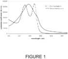
- FIG. 1shows an example absorption spectrum for oxyhemoglobin and hemoglobin
- FIG. 2is a perspective view of an example medical system
- FIG. 3is a perspective view of the perforation device of the medical system of FIG. 2 ;
- FIG. 4is a partial side view of the perforation device of FIG. 3 ;
- FIG. 5is an end view of the perforation device of FIG. 3 ;
- FIG. 6is a partial side view of another example perforation device
- FIG. 7is an end view of the perforation device of FIG. 6 ;
- FIG. 8is a is a partial side view of another example perforation device
- FIG. 9is an end view of the perforation device of FIG. 8 ;
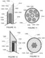
- FIG. 10is a longitudinal cross-section taken through another example perforation device
- FIG. 11is transverse cross-section taken through the perforation device of FIG. 10 ;
- FIG. 12is a longitudinal cross-section taken through another example perforation device
- FIG. 13is transverse cross-section taken through the perforation device of FIG. 12 ;
- FIG. 14shows a step of a method using the system of FIG. 2 ;
- FIG. 15shows another step of a method using the system of FIG. 2 ;
- FIG. 16shows another step of a method using the system of FIG. 2 .
- the devices systemscan be used in transseptal perforation procedures, in which a sheath is advanced to the right atrium of a patient's heart via the femoral vein, and a perforation device (e.g. a radiofrequency (RF) perforation device or a mechanical perforation device) and dilator are guided through the sheath, to the right atrium.
- a perforation devicee.g. a radiofrequency (RF) perforation device or a mechanical perforation device
- the perforation devicecan be advanced out of the sheath and used to create a perforation in the target region, and the dilator can be advanced out of the sheath to dilate the perforation.
- Such procedurescan be carried out, for example, as a medical treatment, or to gain access to the left atrium for a subsequent medical treatment.
- the systems, devices, and methods disclosed hereincan be used to determine whether perforation is complete—i.e. whether the perforation device has indeed perforated the atrial septum and the perforating tip is in the left atrium, or whether perforation is not yet complete and the perforating tip is within the atrial septum, still within the right atrium, or elsewhere. This can in turn reduce the use of fluoroscopy, decrease the complication rate in such procedures, and enhance patient safety.
- the systems and devices disclosed hereinare configured to emit light to (i.e.
- returned lightwhich can be, for example, reflected light or emitted fluorescence.
- returned lightcan be, for example, reflected light or emitted fluorescence.
- This returned lightis then analyzed, for example using absorption or fluorescence spectroscopy.
- blood that is within the right atriumis venous blood, which is not oxygenated and largely contains deoxyhemoglobin.
- blood that is within the left atriumis arterial blood, which is oxygenated and largely contains oxyhemoglobin.
- Deoxyhemoglobin and oxyhemoglobinhave distinct absorption spectra in the range of 520 nm and 600 nm, as shown in FIG. 1 .
- the perforating tipBy analyzing the absorption spectrum of the light returned from the region surrounding the perforating tip, it can be determined whether this region largely contains deoxyhemoglobin or oxyhemoglobin, and in turn it can be determined whether the perforating tip is in the right atrium (which contains largely deoxyhemoglobin) or the left atrium (which contains largely oxyhemoglobin).
- the system 100is a transseptal perforation system, for advancing towards a patient's heart and perforating a fossa ovalis of the patient's heart.
- the systemincludes a set of medical devices, including a sheath 102 , a dilator 104 , and a perforation device 106 having a perforating tip 108 .
- the perforation device 106is a radiofrequency (RF) perforation device
- the perforating tip 108includes a radiofrequency electrode 110 (shown in FIG. 3 ).
- RFradiofrequency
- the sheath 102can be advanced intravenously via the femoral vein towards the right atrium of the patient's heart.
- the dilator 104 and perforation device 106can both be advanced towards the patient's heart via the sheath 102 .
- the RF perforation device 106can be connected to a radiofrequency generator 112 , which can in turn be connected to one or more grounding pads (not shown).
- the RF perforation device 106can be activated to perforate the fossa ovalis.
- the perforation device 106includes a shaft 114 , which can be, for example, fabricated from a plastic.
- the shaft 114has a proximal portion 116 that is connected to a hub 118 , and an opposed distal portion 120 .
- the perforating tip 108is associated with the distal portion 120 of the shaft 114 .
- the term “associated with”means that the first referenced part (i.e. in this case the perforating tip 108 ) and second referenced part (i.e. in this case the shaft 114 ) are configured so that the first referenced part moves with the second referenced part.
- the first referenced partcan be mounted to, extend from, adhered to, embedded in, part of, formed by, and/or integral with second referenced part.
- the perforating tip 108includes the radiofrequency perforation electrode 110 , which is secured to and extends distally from a distal face 122 of the shaft 114 .
- An electrical connector(not shown) is connected to and extends proximally from the radiofrequency perforation electrode 110 through the shaft 114 , for connection to the radiofrequency generator 112 (not shown in FIGS. 3 to 5 )
- the perforation device 106further includes a set of light emitters 124 associated with the distal portion 120 of the shaft 114 and positioned proximate the perforating tip 108 for illuminating the region surrounding the perforating tip 108 (i.e. for delivering light to blood or tissue that is in contact with or near to the perforating tip 108 ).
- the light emitters 124can be of various configurations.
- the perforation device 106includes a first set of optical fibers, referred to herein to as “illumination optical fibers 126 ”.
- the illumination optical fibers 126are embedded in the shaft 114 and extend through the shaft 114 from the proximal portion 116 to the distal portion 120 .
- the illumination optical fibers 126can be embedded in dedicated channels within the shaft 114 .
- the shaft 114can have a lumen, and the illumination optical fibers 126 can extend through the lumen, and be sealed within the lumen by an epoxy or glue.
- the illumination optical fibers 126each have a first end 128 (referred to herein as a “source end) that is connected or connectable to a light source 130 (described below), for receiving light from the light source 130 .
- the illumination optical fibers 126further have a second end 132 (referred to herein as an “illumination end”) proximate the perforating tip 108 .
- the illumination end 132 of each illumination optical fiber 126forms a light emitter 124 , and illuminates the region surrounding the perforating tip 108 .
- each illumination optical fiber 126is flush with the distal end face 122 of the shaft 114 , and is distally facing.
- the illumination end 132 of the illumination optical fibers 126can be recessed proximally from the distal end face 122 of the shaft 114 , or can extend proud of the distal end face 122 of the shaft 114 .
- the perforation device 106further includes a set of light collectors 134 associated with the distal portion 120 of the shaft 114 and positioned proximate the perforating tip 108 , for collecting light returned from the region surrounding the perforating tip 108 (also referred to herein as “returned light”).
- the returned lightcan be reflected light or emitted fluorescence.
- the light collectors 134can be of various configurations.
- the perforation device 106includes a second set of optical fibers, referred to herein as “collection optical fibers 136 ”, for collecting light returned from the region surrounding the perforating tip 108 and delivering the returned light to a light sensor 138 (described below).
- the collection optical fibers 136are embedded in the shaft 114 and extend through the shaft 114 from the distal portion 120 to the proximal portion 116 .
- the collection optical fibers 136can be embedded in dedicated channels within the shaft 114 .
- the shaft 114can have a lumen, and the collection optical fibers 136 can extend through the lumen, and be sealed within the lumen by an epoxy or glue.
- the collection optical fibers 136each have a first end 140 (referred to herein as a “light collection end”) that forms the light collector 134 .
- the collection end 140 of the collection optical fibers 136is flush with the distal end face 122 of the shaft 114 , and is distally facing.
- the collection end 140 of the collection optical fibers 136can be recessed proximally from the distal end face 122 of the shaft 114 , or can extend proud of the distal end face 122 of the shaft 114 .
- the collection optical fibers 136further have a second end 142 (referred to herein as an “sensor end”) for delivering light to the light sensor 138 .
- the illumination optical fibers 126 and collection optical fibers 136are arranged concentrically around the RF electrode 110 in an alternating pattern. In other examples, as will be described below, the illumination optical fibers 126 and collection optical fibers 136 can be of another arrangement.
- the light source 130can be, for example, a laser, a lamp (e.g. an Xe or Arc lamp), or an LED.
- the light source 130can be monochromatic or broad band.
- the light delivered by the light source 130can be continuous or pulsed (e.g. pulsed by a pulse generator or light chopper).
- the system 100includes an analysis system 144 for analyzing the returned light.
- the analysis system 144includes the light sensor 138 , which can be any suitable sensor that can detect one or more parameters (e.g. the absorption or fluorescence spectrum) of the returned light.
- the light sensor 138can be or can include a photodiode, a power meter, a spectrometer, a phototransistor, and/or a photomultiplier.
- the light sensor 138can be a single chip or multi-chip detector.
- the light sensor 138can include a CCD or CMOS camera.
- the analysis system 144further includes a processor 146 connected to the light sensor.
- the processor 146can include various hardware and software, and is configured to perform an analysis of the parameters detected by the light sensor 138 . For example, the processor 146 can compare the absorption spectrum of the returned light to a stored reference absorption spectrum for oxyhemoglobin and deoxyhemoglobin. Based on this comparison, the processor 146 can then determine whether the absorption spectrum of the returned light corresponds to the reference spectrum for oxyhemoglobin (which indicates that the region surrounding the perforating tip 108 contains oxygenated blood) or deoxyhemoglobin (which indicates that the region surrounding the perforating tip 108 contains deoxygenated blood).
- the analysis system 144further includes an alerting system connected to the processor 146 , for alerting a user to a result of the analysis.
- the alerting systemincludes a screen 148 that displays an indicium of the position of the perforating tip 108 .
- the alerting systemcan be, for example, in the form of a light that changes color when the analysis indicates that the region surrounding the perforating tip 108 contains oxygenated blood. The change in color of the light can indicate to a user that the perforating tip 108 is in the left atrium.
- the alerting systemcan provide an auditory alert that indicates to a user that the perforating tip 108 is in the left atrium.
- the light source 130 , light sensor 138 , processor 146 , and screen 148are provided in a single unit 149 .
- the light source 130 , light sensor 138 , processor 146 , and screen 148may be provided in separate units or at separate locations.
- the light sensor 138may be mounted to the perforation device 106 (as described below), and the processor 146 and screen 148 may be provided in a separate unit.
- one or more of the light source 130 , light sensor 138 , processor 146 , and screen 148may be provided in a unit with the RF generator 112 .
- the RF generator 112(shown in FIG. 2 ) can be in communication with the analysis system 144 , and can be configured to provide power to the RF electrode 110 based on the analysis.
- the RF generator 112can be configured to provide power to the RF electrode 110 only while the analysis indicates that the region surrounding the perforating tip 108 contains deoxygenated blood.
- the RF generator 112can be configured to cease providing power to the RF electrode 110 if the analysis indicates that the region surrounding the perforating tip 108 contains oxygenated blood. This may further enhance safety, as once perforation of the fossa ovalis is complete, perforation of additional structures will be prevented (or the risk thereof will be reduced).
- FIGS. 6 and 7another example of a perforation device is shown.
- the perforation device 606 of FIGS. 6 and 7includes only one light emitter 624 , in the form of an illumination end 632 of an illumination optical fiber 626 , and only one light collector 634 , in the form of a collection end 640 of a collection optical fiber 636 .
- the light emitter 624 and light collector 634are positioned side-by-side and adjacent the RF electrode 610 , and are and off-centre within the shaft 614 .
- the illumination optical fiber 626 and collection optical fiber 636have a larger diameter than the corresponding parts of FIGS. 1 to 5 .
- the perforation device 806includes a set of illumination optical fibers 826 , the illumination ends 832 of which form light emitters 824 (only one of the illumination optical fibers 826 is labelled in FIG. 9 ).
- the illumination optical fibers 826are arranged concentrically around the RF electrode 810 .
- the light collector 834is in the form of a light sensor 838 associated with the distal portion 820 of the shaft 814 .
- the light sensor 838is mounted to a side surface 850 of the shaft 814 .
- An electrical connectorextends through the shaft 814 to connect the light sensor 838 to the processor (not shown) of the analysis system (not shown).
- the light sensor 838can be any suitable sensor that can detect one or more parameters (e.g. the absorption or fluorescence spectrum) of the returned light.
- the light sensor 838can be or can include a photodiode, a power meter, a spectrometer, a phototransistor, and/or a photomultiplier.
- the light sensor 838can be a single chip or multi-chip detector.
- the light sensor 838can include a CCD or CMOS camera.
- the perforation device 1006is a mechanical perforation device, in which the distal portion 1020 of the shaft 1014 is beveled to provide a sharp perforating tip 1008 .
- the perforation device 1006includes an illumination optical fiber 1026 , the illumination end 1032 of which forms a light emitter 1024 , and a set of collection optical fibers 1036 (only one of which is labelled in FIG.
- the illumination optical fiber 1026 and the collection optical fibers 1036are positioned within a lumen of the shaft 1014 , and the illumination end 1032 and collection ends 1040 are recessed proximally from the distal end face 1022 of the shaft 1014 .
- a light transmitting material 1052such as an epoxy or glue seals the lumen.
- the perforating device 1006includes a single illumination optical fiber 1026 and six collection optical fibers 1036 . In other examples, another number of illumination optical fibers and collection fibers can be used.
- the perforation device 1206includes a set of illumination optical fiber 1226 (only one of which is labelled), the illumination ends 1232 of which form light emitter 1224 .
- the illumination ends 1232are shrouded within the shaft 1214 , the distal end face 1222 of which is closed.
- a light scattering material 1254is positioned within the shaft 1214 , between the illumination ends 1232 and an opening on the side surface 1250 of the shaft 1214 .
- the light scattering material 1254directs light radially from the illumination ends 1232 to the exterior of the shaft 1214 .
- the light collector 1234is in the form of a light sensor 1238 that is mounted to the side surface 1250 of the shaft 1214 , proximate to the light scattering material 1254 .
- FIGS. 14 to 16A method for transseptal perforation will now be described with reference to FIGS. 14 to 16 .
- the methodwill be described with reference to the system of FIGS. 1 to 5 ; however, the system of FIGS. 1 to 5 can be used according to different methods, and the method can employ different systems.
- a guidewirecan be advanced via the femoral vein towards the heart, and “parked” in the superior vena cava (SVC).
- the dilator 104can then be inserted into the sheath 102 , with the tip of the dilator 104 shrouded within the sheath 102 .
- the sheath 102 and dilator 104can then be advanced over the guidewire, towards the SVC.
- the guidewirecan then be removed.
- the perforation device 106can be advanced through the dilator 104 , until the perforating tip 108 is just shy of the distal end of the dilator 104 .
- the distal end of the sheath 102can then be advanced towards a target location in the patient's heart 1400 , e.g. to the right atrium 1402 of the patient's heart 1400 , to position the distal end of the sheath 102 adjacent the target location.
- the target locationis the fossa ovalis 1404 of the atrial septum.
- the dilator 104can then be advanced so that the dilating end thereof is proud of the sheath 102
- the perforation device 106(not visible in FIG. 14 ) can be advanced so that the perforating tip 108 is proud of or flush with the dilator 104 and is adjacent the fossa ovalis 1404 . This positioning is shown in FIG. 14
- the light source 130(not shown in FIGS. 14 to 16 ) and analysis system 144 (not shown in FIGS. 14 to 16 ) can then be engaged, to confirm the positioning of the perforating tip 108 .
- the light source 130can be engaged to illuminate the region surrounding the perforating tip 108 , and the returned light can be collected and analyzed to determine whether the region surrounding the perforating tip 108 contains oxygenated blood or deoxygenated blood. If the analysis indicates that the region surrounding the perforating tip 108 contains oxygenated blood, this indicates that the perforating tip 108 is not properly positioned, and the procedure can be stopped or the position of the perforation device 106 can be adjusted or checked using imaging. If the analysis indicates that the region surrounding the perforating tip 108 contains deoxygenated blood, this indicates that the perforating tip 108 is properly positioned, and the procedure can continue.
- the RF generator 112(not shown in FIGS. 14 to 16 ) can be engaged, to supply power to the RF electrode 110 .
- the perforating tip 108can then be advanced through the fossa ovalis 1404 , as shown in FIG. 15 .
- the position of the perforating tip 108can be monitored and/or confirmed. That is, the light source 130 can be engaged to illuminate the region surrounding the perforating tip 108 , and the returned light can be collected and analyzed to determine whether the region surrounding the perforating tip 108 contains oxygenated blood or deoxygenated blood.
- the analysisindicates that the region surrounding the perforating tip 108 contains oxygenated blood, this indicates that the perforating tip 108 has perforated the fossa ovalis 1404 and is in the left atrium, and the advancement of the perforating tip 108 and the delivery of RF energy can be ceased. If the analysis indicates that the region surrounding the perforating tip 108 contains deoxygenated blood, this indicates that the perforating tip 108 has not perforated the fossa ovalis 1404 , and advancement of the perforating tip 108 and delivery of RF energy should continue or be repeated.
- the fluorescence spectra of the tissue of the fossa ovalis 1404can be obtained using an excitation wavelength of about 365 nm. Due to the presence of collagen and other fluorophores within the fossa ovalis 1404 , a distinct fluorescence spectrum may be obtained at this wavelength. This can be used to confirm that the perforating tip is within or in contact with the fossa ovalis 1404 .
- the dilator 104can be advanced from the sheath 102 to dilate the perforation, and the sheath 102 can then be advanced through the perforation, to the left atrium. Once access to the left atrium has been gained, a subsequent medical treatment (not shown) can be carried out.
- anatomical regionscan be perforated using the devices, systems, and methods disclosed herein.
- the devices, systems, and methods disclosed hereincan be used to create channels between vessels (i.e. artery to vein or vice versa) and/or in ventricular puncture.
Landscapes
- Health & Medical Sciences (AREA)
- Life Sciences & Earth Sciences (AREA)
- Surgery (AREA)
- Engineering & Computer Science (AREA)
- Physics & Mathematics (AREA)
- Veterinary Medicine (AREA)
- Public Health (AREA)
- General Health & Medical Sciences (AREA)
- Biomedical Technology (AREA)
- Heart & Thoracic Surgery (AREA)
- Medical Informatics (AREA)
- Molecular Biology (AREA)
- Animal Behavior & Ethology (AREA)
- Pathology (AREA)
- Biophysics (AREA)
- Nuclear Medicine, Radiotherapy & Molecular Imaging (AREA)
- Otolaryngology (AREA)
- Plasma & Fusion (AREA)
- Cardiology (AREA)
- Spectroscopy & Molecular Physics (AREA)
- Optics & Photonics (AREA)
- Oral & Maxillofacial Surgery (AREA)
- Measurement Of The Respiration, Hearing Ability, Form, And Blood Characteristics Of Living Organisms (AREA)
Abstract
Description
Claims (21)
Priority Applications (2)
| Application Number | Priority Date | Filing Date | Title |
|---|---|---|---|
| US16/794,799US11931098B2 (en) | 2020-02-19 | 2020-02-19 | System and method for carrying out a medical procedure |
| US18/441,474US12369969B2 (en) | 2020-02-19 | 2024-02-14 | System and method for carrying out a medical procedure |
Applications Claiming Priority (1)
| Application Number | Priority Date | Filing Date | Title |
|---|---|---|---|
| US16/794,799US11931098B2 (en) | 2020-02-19 | 2020-02-19 | System and method for carrying out a medical procedure |
Related Child Applications (1)
| Application Number | Title | Priority Date | Filing Date |
|---|---|---|---|
| US18/441,474ContinuationUS12369969B2 (en) | 2020-02-19 | 2024-02-14 | System and method for carrying out a medical procedure |
Publications (2)
| Publication Number | Publication Date |
|---|---|
| US20210251686A1 US20210251686A1 (en) | 2021-08-19 |
| US11931098B2true US11931098B2 (en) | 2024-03-19 |
Family
ID=77272229
Family Applications (2)
| Application Number | Title | Priority Date | Filing Date |
|---|---|---|---|
| US16/794,799Active2042-12-27US11931098B2 (en) | 2020-02-19 | 2020-02-19 | System and method for carrying out a medical procedure |
| US18/441,474ActiveUS12369969B2 (en) | 2020-02-19 | 2024-02-14 | System and method for carrying out a medical procedure |
Family Applications After (1)
| Application Number | Title | Priority Date | Filing Date |
|---|---|---|---|
| US18/441,474ActiveUS12369969B2 (en) | 2020-02-19 | 2024-02-14 | System and method for carrying out a medical procedure |
Country Status (1)
| Country | Link |
|---|---|
| US (2) | US11931098B2 (en) |
Cited By (1)
| Publication number | Priority date | Publication date | Assignee | Title |
|---|---|---|---|---|
| US12403296B2 (en) | 2018-05-30 | 2025-09-02 | Kardion Gmbh | Apparatus for anchoring a ventricular assist system in a blood vessel, operating method, production method for producing an apparatus and ventricular assist system |
Families Citing this family (1)
| Publication number | Priority date | Publication date | Assignee | Title |
|---|---|---|---|---|
| GB2603789A (en)* | 2021-02-12 | 2022-08-17 | Creo Medical Ltd | Raman spectroscopy probe, Raman spectroscopy apparatus including the Raman spectroscopy probe and elongate assembly |
Citations (291)
| Publication number | Priority date | Publication date | Assignee | Title |
|---|---|---|---|---|
| US175254A (en) | 1876-03-28 | Improvement in game apparatus | ||
| US827626A (en) | 1905-02-15 | 1906-07-31 | Alexis F Gillet | Game apparatus. |
| US848711A (en) | 1906-06-28 | 1907-04-02 | Daniel Weaver | Game apparatus. |
| US1072954A (en) | 1913-03-29 | 1913-09-09 | Frank B Junn | Game apparatus. |
| US1279654A (en) | 1916-04-14 | 1918-09-24 | Horace M Charlesworth | Game apparatus. |
| US1918094A (en) | 1931-04-04 | 1933-07-11 | Demetrius G Geekas | Game device |
| US1996986A (en) | 1932-05-13 | 1935-04-09 | Weinberg Alexander | Game apparatus |
| US2021989A (en) | 1931-12-08 | 1935-11-26 | Master Matthew J De | Ball tossing game |
| US2146636A (en) | 1937-01-09 | 1939-02-07 | Walter F Lipchow | Baseball game |
| US3429574A (en) | 1965-08-12 | 1969-02-25 | Charles L Williams | Game with ball-receiving spaced divider members |
| US3448739A (en) | 1966-08-22 | 1969-06-10 | Edwards Lab Inc | Double lumen diagnostic balloon catheter |
| US3575415A (en) | 1968-05-17 | 1971-04-20 | Franklin G Fulp | Pocketed ball-receiving target |
| US3595239A (en) | 1969-04-04 | 1971-07-27 | Roy A Petersen | Catheter with electrical cutting means |
| US4129129A (en) | 1977-03-18 | 1978-12-12 | Sarns, Inc. | Venous return catheter and a method of using the same |
| US4244362A (en) | 1978-11-29 | 1981-01-13 | Anderson Charles C | Endotracheal tube control device |
| US4401124A (en) | 1981-08-13 | 1983-08-30 | Technicare Corporation | Reflection enhancement of a biopsy needle |
| US4639252A (en) | 1985-04-05 | 1987-01-27 | Research Medical, Inc. | Venous return catheter |
| US4641649A (en) | 1985-10-30 | 1987-02-10 | Rca Corporation | Method and apparatus for high frequency catheter ablation |
| US4669467A (en) | 1985-03-22 | 1987-06-02 | Massachusetts Institute Of Technology | Mode mixer for a laser catheter |
| US4682596A (en) | 1984-05-22 | 1987-07-28 | Cordis Corporation | Electrosurgical catheter and method for vascular applications |
| US4790311A (en) | 1986-06-03 | 1988-12-13 | Ruiz Oscar F | Radio frequency angioplasty catheter system |
| US4790809A (en) | 1985-08-29 | 1988-12-13 | Medical Engineering Corporation | Ureteral stent |
| US4793350A (en) | 1987-01-06 | 1988-12-27 | Advanced Cardiovascular Systems, Inc. | Liquid filled low profile dilatation catheter |
| US4807620A (en) | 1987-05-22 | 1989-02-28 | Advanced Interventional Systems, Inc. | Apparatus for thermal angioplasty |
| US4832048A (en) | 1987-10-29 | 1989-05-23 | Cordis Corporation | Suction ablation catheter |
| US4840622A (en) | 1987-10-06 | 1989-06-20 | Menlo Care, Inc. | Kink resistant catheter |
| US4863441A (en) | 1987-07-17 | 1989-09-05 | Minnesota Mining And Manufacturing Company | Venous return catheter |
| US4884567A (en) | 1987-12-03 | 1989-12-05 | Dimed Inc. | Method for transvenous implantation of objects into the pericardial space of patients |
| US4892104A (en) | 1988-09-02 | 1990-01-09 | Nihon Kohden Corp. | Apparatus for inspecting an electrically stimulated heart |
| US4896671A (en) | 1988-08-01 | 1990-01-30 | C. R. Bard, Inc. | Catheter with contoured ablation electrode |
| US4928693A (en) | 1989-03-13 | 1990-05-29 | Schneider (Usa), Inc. | Pressure monitor catheter |
| US4936281A (en) | 1989-04-13 | 1990-06-26 | Everest Medical Corporation | Ultrasonically enhanced RF ablation catheter |
| US4960410A (en) | 1989-03-31 | 1990-10-02 | Cordis Corporation | Flexible tubular member for catheter construction |
| US4977897A (en) | 1988-08-17 | 1990-12-18 | Robert Hurwitz | Amniocentesis needle with improved sonographic visibility |
| US4998933A (en) | 1988-06-10 | 1991-03-12 | Advanced Angioplasty Products, Inc. | Thermal angioplasty catheter and method |
| US5006119A (en) | 1989-05-25 | 1991-04-09 | Engineering & Research Associates, Inc. | Hollow core coaxial catheter |
| US5019076A (en) | 1986-09-12 | 1991-05-28 | Yamanashi William S | Radio frequency surgical tool and method |
| US5047026A (en) | 1989-09-29 | 1991-09-10 | Everest Medical Corporation | Electrosurgical implement for tunneling through tissue |
| US5081997A (en) | 1989-03-09 | 1992-01-21 | Vance Products Incorporated | Echogenic devices, material and method |
| US5098431A (en) | 1989-04-13 | 1992-03-24 | Everest Medical Corporation | RF ablation catheter |
| US5112048A (en) | 1990-11-05 | 1992-05-12 | Kienle Robert N | Garage roof party game |
| US5154724A (en) | 1990-05-14 | 1992-10-13 | Andrews Winston A | Atherectomy catheter |
| US5201756A (en) | 1990-06-20 | 1993-04-13 | Danforth Biomedical, Inc. | Radially-expandable tubular elements for use in the construction of medical devices |
| US5209741A (en) | 1991-07-08 | 1993-05-11 | Endomedix Corporation | Surgical access device having variable post-insertion cross-sectional geometry |
| US5211183A (en) | 1987-05-13 | 1993-05-18 | Wilson Bruce C | Steerable memory alloy guide wires |
| US5221256A (en) | 1992-02-10 | 1993-06-22 | Mahurkar Sakharam D | Multiple-lumen catheter |
| US5230349A (en) | 1988-11-25 | 1993-07-27 | Sensor Electronics, Inc. | Electrical heating catheter |
| US5281216A (en) | 1992-03-31 | 1994-01-25 | Valleylab, Inc. | Electrosurgical bipolar treating apparatus |
| US5300069A (en) | 1992-08-12 | 1994-04-05 | Daniel Hunsberger | Electrosurgical apparatus for laparoscopic procedures and method of use |
| US5300068A (en) | 1992-04-21 | 1994-04-05 | St. Jude Medical, Inc. | Electrosurgical apparatus |
| US5314418A (en) | 1990-09-21 | 1994-05-24 | Toyo Boseki Kabushiki Kaisha | Cannula |
| US5318525A (en) | 1992-04-10 | 1994-06-07 | Medtronic Cardiorhythm | Steerable electrode catheter |
| US5327905A (en) | 1992-02-14 | 1994-07-12 | Boaz Avitall | Biplanar deflectable catheter for arrhythmogenic tissue ablation |
| US5364393A (en) | 1990-07-02 | 1994-11-15 | Heart Technology, Inc. | Tissue dissipative recanalization catheter |
| US5372596A (en) | 1993-07-27 | 1994-12-13 | Valleylab Inc. | Apparatus for leakage control and method for its use |
| US5380304A (en) | 1991-08-07 | 1995-01-10 | Cook Incorporated | Flexible, kink-resistant, introducer sheath and method of manufacture |
| US5397304A (en) | 1992-04-10 | 1995-03-14 | Medtronic Cardiorhythm | Shapable handle for steerable electrode catheter |
| US5403338A (en) | 1992-01-21 | 1995-04-04 | Scanlan International, Inc. | Punch for opening passages between two compartments |
| US5423809A (en) | 1992-01-21 | 1995-06-13 | Valleylab Inc. | Electrosurgical control for a trocar |
| US5425382A (en) | 1993-09-14 | 1995-06-20 | University Of Washington | Apparatus and method for locating a medical tube in the body of a patient |
| US5490859A (en) | 1992-11-13 | 1996-02-13 | Scimed Life Systems, Inc. | Expandable intravascular occlusion material removal devices and methods of use |
| US5497774A (en) | 1993-11-03 | 1996-03-12 | Daig Corporation | Guiding introducer for left atrium |
| US5507751A (en) | 1988-11-09 | 1996-04-16 | Cook Pacemaker Corporation | Locally flexible dilator sheath |
| US5509411A (en) | 1993-01-29 | 1996-04-23 | Cardima, Inc. | Intravascular sensing device |
| US5540681A (en) | 1992-04-10 | 1996-07-30 | Medtronic Cardiorhythm | Method and system for radiofrequency ablation of tissue |
| US5545200A (en) | 1993-07-20 | 1996-08-13 | Medtronic Cardiorhythm | Steerable electrophysiology catheter |
| US5555618A (en) | 1993-10-12 | 1996-09-17 | Arrow International Investment Corp. | Method of making electrode-carrying catheter |
| US5571088A (en) | 1993-07-01 | 1996-11-05 | Boston Scientific Corporation | Ablation catheters |
| US5575766A (en) | 1993-11-03 | 1996-11-19 | Daig Corporation | Process for the nonsurgical mapping and treatment of atrial arrhythmia using catheters guided by shaped guiding introducers |
| US5599347A (en) | 1991-02-13 | 1997-02-04 | Applied Medical Resources Corporation | Surgical trocar with cutoff circuit |
| US5605162A (en) | 1991-10-15 | 1997-02-25 | Advanced Cardiovascular Systems, Inc. | Method for using a variable stiffness guidewire |
| US5617878A (en) | 1996-05-31 | 1997-04-08 | Taheri; Syde A. | Stent and method for treatment of aortic occlusive disease |
| US5624430A (en) | 1994-11-28 | 1997-04-29 | Eton; Darwin | Magnetic device to assist transcorporeal guidewire placement |
| US5667488A (en) | 1992-08-12 | 1997-09-16 | Vidamed, Inc. | Transurethral needle ablation device and method for the treatment of the prostate |
| US5674208A (en) | 1993-08-18 | 1997-10-07 | Scimed Life Systems, Inc. | Thin-walled catheter |
| US5673695A (en) | 1995-08-02 | 1997-10-07 | Ep Technologies, Inc. | Methods for locating and ablating accessory pathways in the heart |
| US5683366A (en) | 1992-01-07 | 1997-11-04 | Arthrocare Corporation | System and method for electrosurgical tissue canalization |
| US5720744A (en) | 1995-06-06 | 1998-02-24 | Valleylab Inc | Control system for neurosurgery |
| US5741249A (en) | 1996-10-16 | 1998-04-21 | Fidus Medical Technology Corporation | Anchoring tip assembly for microwave ablation catheter |
| US5766135A (en) | 1995-03-08 | 1998-06-16 | Terwilliger; Richard A. | Echogenic needle tip |
| US5779688A (en) | 1994-10-28 | 1998-07-14 | Intella Interventional Systems, Inc. | Low profile balloon-on-a-wire catheter with shapeable and/or deflectable tip and method |
| US5830214A (en) | 1994-11-08 | 1998-11-03 | Heartport, Inc. | Fluid-evacuating electrosurgical device |
| US5836875A (en) | 1995-10-06 | 1998-11-17 | Cordis Webster, Inc. | Split tip electrode catheter |
| US5849011A (en) | 1995-06-19 | 1998-12-15 | Vidamed, Inc. | Medical device with trigger actuation assembly |
| US5851210A (en) | 1997-03-21 | 1998-12-22 | Torossian; Richard | Stent delivery system and method |
| US5885227A (en) | 1997-03-25 | 1999-03-23 | Radius Medical Technologies, Inc. | Flexible guidewire with radiopaque plastic tip |
| US5888201A (en) | 1996-02-08 | 1999-03-30 | Schneider (Usa) Inc | Titanium alloy self-expanding stent |
| US5893848A (en) | 1996-10-24 | 1999-04-13 | Plc Medical Systems, Inc. | Gauging system for monitoring channel depth in percutaneous endocardial revascularization |
| US5893885A (en) | 1996-11-01 | 1999-04-13 | Cordis Webster, Inc. | Multi-electrode ablation catheter |
| US5904679A (en) | 1989-01-18 | 1999-05-18 | Applied Medical Resources Corporation | Catheter with electrosurgical cutter |
| US5916210A (en) | 1990-01-26 | 1999-06-29 | Intraluminal Therapeutics, Inc. | Catheter for laser treatment of atherosclerotic plaque and other tissue abnormalities |
| US5921957A (en) | 1994-07-12 | 1999-07-13 | Scimed Life Systems, Inc. | Intravascular dilation catheter |
| US5931818A (en) | 1997-08-29 | 1999-08-03 | Stereotaxis, Inc. | Method of and apparatus for intraparenchymal positioning of medical devices |
| US5944023A (en) | 1995-12-07 | 1999-08-31 | Sims Deltec, Inc. | Systems and methods for determining the location of an implanted device including a magnet |
| US5951482A (en) | 1997-10-03 | 1999-09-14 | Intraluminal Therapeutics, Inc. | Assemblies and methods for advancing a guide wire through body tissue |
| US5957842A (en) | 1994-01-27 | 1999-09-28 | Cardima, Inc. | High resolution intravascular signal detection |
| US5964757A (en) | 1997-09-05 | 1999-10-12 | Cordis Webster, Inc. | Steerable direct myocardial revascularization catheter |
| US5967976A (en) | 1994-08-19 | 1999-10-19 | Novoste Corporation | Apparatus and methods for procedures related to the electrophysiology of the heart |
| US5989276A (en) | 1996-11-08 | 1999-11-23 | Advanced Bypass Technologies, Inc. | Percutaneous bypass graft and securing system |
| US6007555A (en) | 1997-04-25 | 1999-12-28 | Surgical Design Corp | Ultrasonic needle for surgical emulsification |
| US6009877A (en) | 1994-06-24 | 2000-01-04 | Edwards; Stuart D. | Method for treating a sphincter |
| US6013072A (en) | 1997-07-09 | 2000-01-11 | Intraluminal Therapeutics, Inc. | Systems and methods for steering a catheter through body tissue |
| US6017340A (en) | 1994-10-03 | 2000-01-25 | Wiltek Medical Inc. | Pre-curved wire guided papillotome having a shape memory tip for controlled bending and orientation |
| US6018676A (en) | 1993-08-31 | 2000-01-25 | Medtronic, Inc. | Ultrasound biopsy needle |
| US6030380A (en) | 1996-12-09 | 2000-02-29 | Bsc Northwest Technology Center, Inc. | Radio frequency transmyocardial revascularization |
| US6048349A (en) | 1997-07-09 | 2000-04-11 | Intraluminal Therapeutics, Inc. | Systems and methods for guiding a medical instrument through a body |
| US6053870A (en) | 1997-11-08 | 2000-04-25 | Angiodynamics, Inc. | Ultrasonic visible surgical needle |
| US6053904A (en) | 1996-04-05 | 2000-04-25 | Robert M. Scribner | Thin wall catheter introducer system |
| US6056747A (en) | 1997-08-04 | 2000-05-02 | Gynecare, Inc. | Apparatus and method for treatment of body tissues |
| US6093185A (en) | 1998-03-05 | 2000-07-25 | Scimed Life Systems, Inc. | Expandable PMR device and method |
| US6106520A (en) | 1997-09-30 | 2000-08-22 | Hearten Medical, Inc. | Endocardial device for producing reversible damage to heart tissue |
| US6106515A (en) | 1998-08-13 | 2000-08-22 | Intraluminal Therapeutics, Inc. | Expandable laser catheter |
| US6117131A (en) | 1995-06-09 | 2000-09-12 | Engineering & Research Associates, Inc. | Multi-electrode probe for thermal ablation |
| US6142992A (en) | 1993-05-10 | 2000-11-07 | Arthrocare Corporation | Power supply for limiting power in electrosurgery |
| US6146380A (en) | 1998-01-09 | 2000-11-14 | Radionics, Inc. | Bent tip electrical surgical probe |
| US6156031A (en) | 1995-08-09 | 2000-12-05 | Eclipse Surgical Technologies | Transmyocardial revascularization using radiofrequency energy |
| US6155264A (en) | 1997-03-06 | 2000-12-05 | Scimed Life Systems, Inc. | Percutaneous bypass by tunneling through vessel wall |
| US6171305B1 (en) | 1998-05-05 | 2001-01-09 | Cardiac Pacemakers, Inc. | RF ablation apparatus and method having high output impedance drivers |
| US6179824B1 (en) | 1993-05-10 | 2001-01-30 | Arthrocare Corporation | System and methods for electrosurgical restenosis of body lumens |
| US6193715B1 (en) | 1999-03-19 | 2001-02-27 | Medical Scientific, Inc. | Device for converting a mechanical cutting device to an electrosurgical cutting device |
| US6193676B1 (en) | 1997-10-03 | 2001-02-27 | Intraluminal Therapeutics, Inc. | Guide wire assembly |
| US6210408B1 (en) | 1999-02-24 | 2001-04-03 | Scimed Life Systems, Inc. | Guide wire system for RF recanalization of vascular blockages |
| US6217575B1 (en) | 1999-02-24 | 2001-04-17 | Scimed Life Systems, Inc. | PMR catheter |
| US6221061B1 (en) | 1993-05-12 | 2001-04-24 | Target Therapeutics, Inc. | Lubricious catheters |
| US6228076B1 (en) | 1999-01-09 | 2001-05-08 | Intraluminal Therapeutics, Inc. | System and method for controlling tissue ablation |
| US6245054B1 (en) | 1998-11-09 | 2001-06-12 | Kristine B. Fuimaono | Guiding sheath exchange system |
| US6267758B1 (en) | 1994-01-18 | 2001-07-31 | Esc Medical Systems Ltd. | Apparatus for in situ saphenous vein bypass and less-invasive varicose vein treatment |
| US6283983B1 (en) | 1995-10-13 | 2001-09-04 | Transvascular, Inc. | Percutaneous in-situ coronary bypass method and apparatus |
| US20010021867A1 (en) | 1993-03-16 | 2001-09-13 | Kordis Thomas F. | Cardiac mapping and ablation systems |
| US6292678B1 (en) | 1999-05-13 | 2001-09-18 | Stereotaxis, Inc. | Method of magnetically navigating medical devices with magnetic fields and gradients, and medical devices adapted therefor |
| US6293945B1 (en) | 2000-03-06 | 2001-09-25 | Everest Medical Corporation | Electrosurgical instrument with suction capability |
| US6296615B1 (en) | 1999-03-05 | 2001-10-02 | Data Sciences International, Inc. | Catheter with physiological sensor |
| US6304769B1 (en) | 1997-10-16 | 2001-10-16 | The Regents Of The University Of California | Magnetically directable remote guidance systems, and methods of use thereof |
| US6302898B1 (en) | 1994-06-24 | 2001-10-16 | Advanced Closure Systems, Inc. | Devices for sealing punctures in body vessels |
| US6315777B1 (en) | 1998-07-07 | 2001-11-13 | Medtronic, Inc. | Method and apparatus for creating a virtual electrode used for the ablation of tissue |
| US6328699B1 (en) | 2000-01-11 | 2001-12-11 | Cedars-Sinai Medical Center | Permanently implantable system and method for detecting, diagnosing and treating congestive heart failure |
| US20020019644A1 (en) | 1999-07-12 | 2002-02-14 | Hastings Roger N. | Magnetically guided atherectomy |
| US20020022781A1 (en) | 1998-11-06 | 2002-02-21 | Gregory Mclntire | Products and methods for brachytherapy |
| US20020022836A1 (en) | 1999-03-05 | 2002-02-21 | Gyrus Medical Limited | Electrosurgery system |
| US20020035361A1 (en) | 1999-06-25 | 2002-03-21 | Houser Russell A. | Apparatus and methods for treating tissue |
| US6364877B1 (en) | 1995-06-23 | 2002-04-02 | Gyrus Medical Limited | Electrosurgical generator and system |
| US6385472B1 (en) | 1999-09-10 | 2002-05-07 | Stereotaxis, Inc. | Magnetically navigable telescoping catheter and method of navigating telescoping catheter |
| US6395002B1 (en) | 2000-01-18 | 2002-05-28 | Alan G. Ellman | Electrosurgical instrument for ear surgery |
| US6394976B1 (en) | 2000-01-31 | 2002-05-28 | Intraluminal Therapeutics, Inc. | Catheter for controlling the advancement of a guide wire |
| US20020087156A1 (en) | 1997-07-08 | 2002-07-04 | Maguire Mark A. | Medical device with sensor cooperating with expandable member |
| US20020087153A1 (en) | 1999-08-05 | 2002-07-04 | Broncus Technologies, Inc. | Devices for creating collateral channels |
| US6419674B1 (en) | 1996-11-27 | 2002-07-16 | Cook Vascular Incorporated | Radio frequency dilator sheath |
| US6428551B1 (en) | 1999-03-30 | 2002-08-06 | Stereotaxis, Inc. | Magnetically navigable and/or controllable device for removing material from body lumens and cavities |
| US20020111618A1 (en) | 1999-04-05 | 2002-08-15 | Stewart Mark T. | Ablation catheter assembly with radially decreasing helix and method of use |
| US20020123749A1 (en) | 2001-03-01 | 2002-09-05 | Jain Mudit K. | Ablation catheter with transducer for providing one or more of pressure, temperature and fluid flow data for use in controlling ablation therapy |
| US6450989B2 (en) | 1998-04-27 | 2002-09-17 | Artemis Medical, Inc. | Dilating and support apparatus with disease inhibitors and methods for use |
| US20020147485A1 (en) | 2000-11-15 | 2002-10-10 | George Mamo | Minimally invasive apparatus for implanting a sacral stimulation lead |
| US6475214B1 (en) | 2000-05-01 | 2002-11-05 | Biosense Webster, Inc. | Catheter with enhanced ablation electrode |
| US20020169377A1 (en) | 2000-04-13 | 2002-11-14 | Khairkhahan Alexander K. | Method and apparatus for accessing the left atrial appendage |
| US20020188302A1 (en) | 1998-11-06 | 2002-12-12 | St. Jude Medical Atg, Inc. | Minimally invasive revascularization apparatus and methods |
| US20020198521A1 (en) | 1997-07-08 | 2002-12-26 | Maguire Mark A. | Circumferential ablation device assembly and methods of use and manufacture providing an ablative circumferential band along an expandable member |
| US6508754B1 (en) | 1997-09-23 | 2003-01-21 | Interventional Therapies | Source wire for radiation treatment |
| US20030032929A1 (en) | 1998-12-09 | 2003-02-13 | Mcguckin James F. | Hollow curved superelastic medical needle and method |
| US6524303B1 (en) | 2000-09-08 | 2003-02-25 | Stereotaxis, Inc. | Variable stiffness magnetic catheter |
| US20030040742A1 (en) | 1998-02-20 | 2003-02-27 | Arthrocare Corporation | Systems and methods for electrosurgical spine surgery |
| US6530923B1 (en) | 1998-02-10 | 2003-03-11 | Artemis Medical, Inc. | Tissue removal methods and apparatus |
| US6554827B2 (en) | 2000-12-11 | 2003-04-29 | Scimed Life Systems, Inc. | Radio frequency ablation system |
| US6562049B1 (en) | 2000-03-01 | 2003-05-13 | Cook Vascular Incorporated | Medical introducer apparatus |
| US6565562B1 (en) | 1997-06-27 | 2003-05-20 | Baylis Medical Company Inc. | Method for the radio frequency perforation and the enlargement of a body tissue |
| US20030144658A1 (en) | 2002-01-31 | 2003-07-31 | Yitzhack Schwartz | Radio frequency pulmonary vein isolation |
| US6607529B1 (en) | 1995-06-19 | 2003-08-19 | Medtronic Vidamed, Inc. | Electrosurgical device |
| US20030158480A1 (en) | 2000-05-15 | 2003-08-21 | Audun Tornes | Grooved medical devices with enhanced ultrasound visibility |
| US20030163153A1 (en) | 2002-02-28 | 2003-08-28 | Scheib Mark S. | Retractable dilator needle |
| US6632222B1 (en) | 1993-11-08 | 2003-10-14 | Rita Medical Systems, Inc. | Tissue ablation apparatus |
| US6639999B1 (en) | 1999-11-04 | 2003-10-28 | Eastman Kodak Company | Apparatus for assessing overall quality of hardcopy images |
| US6650923B1 (en) | 2000-04-13 | 2003-11-18 | Ev3 Sunnyvale, Inc. | Method for accessing the left atrium of the heart by locating the fossa ovalis |
| US6651672B2 (en) | 1993-02-22 | 2003-11-25 | Heartport, Inc. | Devices for less-invasive intracardiac interventions |
| US20030225392A1 (en) | 2002-05-31 | 2003-12-04 | Kimberly-Clark Worldwide, Inc. | Low profile transpyloric jejunostomy system and method to enable |
| US6662034B2 (en) | 2000-11-15 | 2003-12-09 | Stereotaxis, Inc. | Magnetically guidable electrophysiology catheter |
| US20040015162A1 (en) | 2002-07-22 | 2004-01-22 | Medtronic Vidamed, Inc. | Method for treating tissue with a wet electrode and apparatus for using same |
| US20040024396A1 (en) | 1999-12-27 | 2004-02-05 | Eggers Philip E. | Electrosurgical accessing of tissue with controlled collateral thermal phenomena |
| US20040030328A1 (en) | 2001-07-12 | 2004-02-12 | Eggers Philip E. | Electrosurgical generator |
| US20040044350A1 (en) | 1999-04-09 | 2004-03-04 | Evalve, Inc. | Steerable access sheath and methods of use |
| US6709444B1 (en) | 1996-02-02 | 2004-03-23 | Transvascular, Inc. | Methods for bypassing total or near-total obstructions in arteries or other anatomical conduits |
| US20040073243A1 (en) | 2000-06-29 | 2004-04-15 | Concentric Medical, Inc., A Delaware Corporation | Systems, methods and devices for removing obstructions from a blood vessel |
| US6723052B2 (en) | 2001-06-07 | 2004-04-20 | Stanley L. Mills | Echogenic medical device |
| US20040077948A1 (en) | 1996-11-06 | 2004-04-22 | Sts Biopolymers, Inc. | Echogenic coatings with overcoat |
| US6733511B2 (en) | 1998-10-02 | 2004-05-11 | Stereotaxis, Inc. | Magnetically navigable and/or controllable device for removing material from body lumens and cavities |
| US20040116851A1 (en) | 2002-12-16 | 2004-06-17 | Intraluminal Therapeutics, Inc. | Deflecting catheter |
| US6752800B1 (en) | 2000-02-18 | 2004-06-22 | Intraluminal Therapeutics Inc. | Catheter handle for controlling the advancement of a guide wire |
| US6755816B2 (en) | 1999-10-04 | 2004-06-29 | Stereotaxis, Inc. | Method for safely and efficiently navigating magnetic devices in the body |
| US20040127963A1 (en) | 1999-01-25 | 2004-07-01 | Uchida Andy H. | Intervertebral decompression |
| US20040133130A1 (en) | 2003-01-06 | 2004-07-08 | Ferry Steven J. | Magnetically navigable medical guidewire |
| US20040133113A1 (en) | 2002-08-24 | 2004-07-08 | Krishnan Subramaniam C. | Method and apparatus for locating the fossa ovalis and performing transseptal puncture |
| US20040143256A1 (en) | 2003-01-21 | 2004-07-22 | Bednarek Michael C. | Ablation catheter and electrode |
| US20040147950A1 (en) | 2003-01-24 | 2004-07-29 | Mueller Richard L. | Atraumatic dilator for human mammary duct |
| US20040181213A1 (en) | 2003-03-11 | 2004-09-16 | Masakatsu Gondo | Electrode rod for treating biological tissue |
| US6811544B2 (en) | 1999-05-11 | 2004-11-02 | Alan K. Schaer | Catheter positioning system |
| US20040230188A1 (en) | 2003-05-12 | 2004-11-18 | Iulian Cioanta | Treatment catheters with thermally insulated regions |
| US6820614B2 (en) | 2000-12-02 | 2004-11-23 | The Bonutti 2003 Trust -A | Tracheal intubination |
| US6834201B2 (en) | 2001-01-29 | 2004-12-21 | Stereotaxis, Inc. | Catheter navigation within an MR imaging device |
| US6842639B1 (en) | 1997-10-03 | 2005-01-11 | Intraluminal Therapeutics, Inc. | Method and apparatus for determining neovascular flow through tissue in a vessel |
| US20050010208A1 (en) | 2002-06-11 | 2005-01-13 | Winston Thomas R. | Radio frequency guide wire assembly with optical coherence reflectometry guidance |
| US6855143B2 (en) | 1997-06-13 | 2005-02-15 | Arthrocare Corporation | Electrosurgical systems and methods for recanalization of occluded body lumens |
| US6860856B2 (en) | 2002-01-11 | 2005-03-01 | Scimed Life Systems, Inc. | Echogenic surface for enhanced ultasonic visibility |
| US20050049628A1 (en) | 2002-08-29 | 2005-03-03 | Medical Components, Inc. | Releasably locking dilator and sheath assembly |
| US20050059966A1 (en) | 2002-02-12 | 2005-03-17 | Mcclurken Michael E. | Fluid-assisted medical devices, systems and methods |
| US20050065507A1 (en) | 2003-09-19 | 2005-03-24 | Baylis Medical Company Inc. | Surgical perforation device with curve |
| US20050085806A1 (en) | 2002-06-06 | 2005-04-21 | Map Technologies, Llc | Methods and devices for electrosurgery |
| US20050096529A1 (en) | 1999-08-05 | 2005-05-05 | Broncus Technologies, Inc. | Methods for treating chronic obstructive pulmonary disease |
| US20050101984A1 (en) | 2003-11-06 | 2005-05-12 | Nmt Medical, Inc. | Transseptal puncture apparatus |
| US20050137527A1 (en) | 2003-12-23 | 2005-06-23 | Medical Components, Inc. | Graduated sheath and dilator assembly |
| US20050149012A1 (en) | 2000-02-22 | 2005-07-07 | Gyrus Medical Limited | Tissue resurfacing |
| US20050203504A1 (en) | 1998-10-23 | 2005-09-15 | Wham Robert H. | Method and system for controlling output of RF medical generator |
| US20050203507A1 (en) | 2004-03-12 | 2005-09-15 | Surgrx, Inc. | Electrosurgical instrument and method of use |
| US6951555B1 (en) | 1998-03-16 | 2005-10-04 | Chase Medical, L.P. | Catheter having integral expandable/collapsible lumen |
| US20050261607A1 (en) | 2003-04-10 | 2005-11-24 | Intraluminal Therapeutics, Inc. | Shapeable intraluminal device and method therefor |
| US6980843B2 (en) | 2003-05-21 | 2005-12-27 | Stereotaxis, Inc. | Electrophysiology catheter |
| US20050288631A1 (en) | 1998-02-03 | 2005-12-29 | Lewis Brian D | Methods and systems for treating ischemia |
| US20060041253A1 (en) | 2004-08-17 | 2006-02-23 | Newton David W | System and method for performing an electrosurgical procedure |
| US20060074398A1 (en) | 2004-09-30 | 2006-04-06 | Whiting James S | Transmembrane access systems and methods |
| US20060079884A1 (en) | 2004-10-08 | 2006-04-13 | Intuitive Surgical Inc. | Robotic tool with wristed monopolar electrosurgical end effectors |
| US20060079769A1 (en) | 2004-09-30 | 2006-04-13 | Whiting James S | Transmembrane access systems and methods |
| US7029470B2 (en) | 2001-04-26 | 2006-04-18 | Medtronic, Inc. | Ablation system and method of use |
| US20060085054A1 (en) | 2004-09-09 | 2006-04-20 | Zikorus Arthur W | Methods and apparatus for treatment of hollow anatomical structures |
| US20060089638A1 (en) | 2004-10-27 | 2006-04-27 | Yuval Carmel | Radio-frequency device for passivation of vascular plaque and method of using same |
| US20060106375A1 (en) | 2004-11-15 | 2006-05-18 | Werneth Randell L | Ablation system with feedback |
| US20060135962A1 (en) | 2004-09-09 | 2006-06-22 | Kick George F | Expandable trans-septal sheath |
| US20060142756A1 (en) | 2003-01-21 | 2006-06-29 | Baylis Medical Company Inc. | Method of surgical perforation via the delivery of energy |
| US7083566B2 (en) | 2000-05-15 | 2006-08-01 | Ge Healthcare Limited | Grooved brachytherapy sources |
| US20060189972A1 (en) | 2005-02-02 | 2006-08-24 | Gynesonics, Inc. | Method and device for uterine fibroid treatment |
| US7112197B2 (en) | 2003-01-21 | 2006-09-26 | Baylis Medical Company Inc. | Surgical device with pressure monitoring ability |
| US20060241586A1 (en) | 2005-04-22 | 2006-10-26 | Wilk Patent, Llc | Intra-abdominal medical device and associated method |
| US20060247672A1 (en) | 2005-04-27 | 2006-11-02 | Vidlund Robert M | Devices and methods for pericardial access |
| US20060264927A1 (en) | 2005-03-04 | 2006-11-23 | Gyrus Ent, L.L.C. | Surgical instrument and method |
| US20060276710A1 (en) | 2005-03-03 | 2006-12-07 | Krishnan Subramaniam C | Method and apparatus for locating the fossa ovalis, creating a virtual fossa ovalis and performing transseptal puncture |
| US20070060879A1 (en) | 2001-02-15 | 2007-03-15 | Hansen Medical, Inc. | Coaxial catheter system |
| US20070066975A1 (en) | 2003-01-21 | 2007-03-22 | Christine Wong | Method for creating a channel through an occlusion and apparatus therefor |
| US20070118099A1 (en) | 2005-08-15 | 2007-05-24 | Trout Hugh H Iii | Method and apparatus for endovascular graft cutting |
| US20070123964A1 (en) | 2003-01-21 | 2007-05-31 | Baylis Medical Company | Magnetically guidable energy delivery apparatus and method of using same |
| US20070167775A1 (en) | 2005-12-15 | 2007-07-19 | Galil Medical Ltd. | Method and apparatus for protecting the rectal wall during cryoablation |
| US20070208256A1 (en) | 2006-03-03 | 2007-09-06 | Medtronic Vascular, Inc. | Multiple Branch Tubular Prosthesis and Methods |
| US7270662B2 (en)* | 2004-01-21 | 2007-09-18 | Naheed Visram | Surgical perforation device with electrocardiogram (ECG) monitoring ability and method of using ECG to position a surgical perforation device |
| US20070225681A1 (en) | 2006-03-21 | 2007-09-27 | Medtronic Vascular | Catheter Having a Selectively Formable Distal Section |
| US20070270791A1 (en) | 2006-05-16 | 2007-11-22 | Huisun Wang | Ablation electrode assembly and methods for improved control of temperature and minimization of coagulation and tissue damage |
| US20080039865A1 (en) | 2006-08-08 | 2008-02-14 | Maasal Shaher | Maasal cervical dilator |
| US20080042360A1 (en) | 2006-08-15 | 2008-02-21 | Veikley Aaron M | Hybrid bag toss and card game |
| US7335197B2 (en) | 2004-10-13 | 2008-02-26 | Medtronic, Inc. | Transurethral needle ablation system with flexible catheter tip |
| US20080086120A1 (en) | 2006-09-29 | 2008-04-10 | Mahmood Mirza | Radiofrequency perforation apparatus |
| US20080097213A1 (en) | 2004-10-14 | 2008-04-24 | Cook Incorporated | Echogenic Medical Device and Method of Forming Echogenic Surface |
| US20080108987A1 (en) | 2006-11-07 | 2008-05-08 | Medtronic Vascular, Inc. | Cutting Radio Frequency Catheter for Creating Fenestrations in Graft Cloth |
| US20080146918A1 (en) | 2005-02-08 | 2008-06-19 | Magnin Paul A | Apparatus and methods for low-cost intravascular ultrasound imaging and for crossing severe vascular occlusions |
| US20080171934A1 (en) | 2007-01-12 | 2008-07-17 | Medtronic Vascular, Inc. | Vessel Position and Configuration Imaging Apparatus and Methods |
| US20080208121A1 (en) | 2006-09-29 | 2008-08-28 | Biadillah Youssef | Method for creating a channel through a foreign material |
| US20080275439A1 (en) | 2002-01-25 | 2008-11-06 | David Francischelli | Cardiac ablation and electrical interface system and instrument |
| US20090105742A1 (en) | 2007-10-19 | 2009-04-23 | Pressure Products Medical Supplies Inc. | Transseptal guidewire |
| US20090138009A1 (en) | 2007-11-05 | 2009-05-28 | Viswanathan Raju R | Magnetically guided energy delivery apparatus |
| US20090156921A1 (en)* | 2007-12-18 | 2009-06-18 | Huisun Wang | Cardiac ablation catheter with oxygen saturation sensor |
| US20090163850A1 (en) | 2006-05-23 | 2009-06-25 | Vertech, Inc. | Radiofrequency Catheter without Needle for Effectuating RF Treatment |
| US20090177114A1 (en) | 2007-12-13 | 2009-07-09 | Yem Chin | Echogenic needle aspiration device |
| US20090264977A1 (en) | 2008-04-21 | 2009-10-22 | Medtronic Vascular, Inc. | Family of Electrodes for Use in Performing in Situ Fenestration Using a Plasma RF Catheter |
| US7651492B2 (en) | 2006-04-24 | 2010-01-26 | Covidien Ag | Arc based adaptive control system for an electrosurgical unit |
| US7678081B2 (en) | 2004-07-12 | 2010-03-16 | Pacesetter, Inc. | Methods and devices for transseptal access |
| US7682360B2 (en) | 2006-12-07 | 2010-03-23 | Tyco Healthcare Group Lp | Bipolar tissue debrider and method |
| US20100087789A1 (en) | 2008-08-29 | 2010-04-08 | AUST Development, LLC | Apparatus and methods for making coated liners and tubular devices including such liners |
| US20100125282A1 (en) | 2008-11-14 | 2010-05-20 | Medtronic Vascular, Inc. | Robotically Steered RF Catheter |
| US20100168684A1 (en) | 2008-12-30 | 2010-07-01 | Shawn Ryan | Echogenic Enhancement for a Needle |
| US7749217B2 (en)* | 2002-05-06 | 2010-07-06 | Covidien Ag | Method and system for optically detecting blood and controlling a generator during electrosurgery |
| US20100179632A1 (en) | 2009-01-12 | 2010-07-15 | Medtronic Vascular, Inc. | Robotic Fenestration Device Having Impedance Measurement |
| US20100191142A1 (en) | 2008-12-29 | 2010-07-29 | Saurav Paul | Anatomical thermal sensing device and method |
| US20100194047A1 (en) | 2009-02-05 | 2010-08-05 | Sauerwine Dean N | Weighted bag toss game |
| US20110046619A1 (en) | 2009-08-19 | 2011-02-24 | Wilson-Cook Medical Inc. | Echogenic Electrosurgical Device |
| US7900928B2 (en) | 2007-01-29 | 2011-03-08 | Sapo U.S.A. Corp. | Target game |
| US20110152716A1 (en) | 2009-12-23 | 2011-06-23 | Rafal Chudzik | Biopsy probe mechanism having multiple echogenic features |
| US20110160592A1 (en) | 2008-07-29 | 2011-06-30 | Coco Research PTY Ltd. | Echogenic medical needle |
| US20110190763A1 (en) | 2010-01-29 | 2011-08-04 | Medtronic, Inc. | Needle Design for Recording Monophasic Action Potential and Delivery of Therapy |
| US8123745B2 (en)* | 2007-06-29 | 2012-02-28 | Biosense Webster, Inc. | Ablation catheter with optically transparent, electrically conductive tip |
| US8257323B2 (en) | 2005-08-03 | 2012-09-04 | Medtronic, Inc. | Cannula system and method |
| US20120265055A1 (en) | 2011-04-15 | 2012-10-18 | Melsheimer Jeffry S | Tubular feeding device having shapeable distal end |
| US20120330156A1 (en) | 2010-12-31 | 2012-12-27 | Volcano Corporation | Pulmonary Embolism Therapeutic Methods Using Therapeutic Ablation Devices and Systems |
| US20130184551A1 (en) | 2012-01-13 | 2013-07-18 | Jude V. Paganelli | Neuromonitoring dilator |
| US20130184735A1 (en) | 2012-01-12 | 2013-07-18 | Fischell Innovations Llc | Carotid sheath with entry and tracking rapid exchange dilators and method of use |
| US8500697B2 (en) | 2007-10-19 | 2013-08-06 | Pressure Products Medical Supplies, Inc. | Transseptal guidewire |
| US20130282084A1 (en) | 2004-09-10 | 2013-10-24 | Vessix Vascular, Inc. | Apparatus and Method for Treatment of In-Stent Restenosis |
| US8577447B2 (en)* | 2007-05-01 | 2013-11-05 | St. Jude Medical, Atrial Fibrillation Division, Inc. | Optic-based contact sensing assembly and system |
| US20140206987A1 (en) | 2003-01-21 | 2014-07-24 | Baylis Medical Company Inc. | Medical apparatus for fluid communication |
| US20140296769A1 (en) | 2013-03-28 | 2014-10-02 | Silk Road Medical, Inc. | Methods and Systems for Establishing Retrograde Carotid Arterial Blood Flow |
| US8986292B2 (en)* | 2011-04-13 | 2015-03-24 | St. Jude Medical, Inc. | Optical feedback RF ablator and ablator tip |
| US8986298B2 (en)* | 2006-11-17 | 2015-03-24 | Biosense Webster, Inc. | Catheter with omni-directional optical tip having isolated optical paths |
| US20160220741A1 (en) | 2014-03-21 | 2016-08-04 | Route 92 Medical, Inc. | Rapid aspiration thrombectomy system and method |
| US20190021763A1 (en) | 2017-07-20 | 2019-01-24 | Terumo Kabushiki Kaisha | Introducer sheath and introducer |
| US10194981B2 (en)* | 2015-07-29 | 2019-02-05 | Medlumics S.L. | Radiofrequency ablation catheter with optical tissue evaluation |
| US20190110838A1 (en)* | 2017-10-17 | 2019-04-18 | Medtronic, Inc. | Ablation catheter with dual optical-electrical stimulation and sensing |
| US20190216503A1 (en)* | 2016-09-30 | 2019-07-18 | Terumo Kabushiki Kaisha | Medical device and treatment method |
| US20190247035A1 (en) | 2016-10-25 | 2019-08-15 | Muffin Incorporated | Vascular anchoring introducer sheath |
| US11339579B1 (en) | 2017-05-17 | 2022-05-24 | Kenneth W Stearns | Electrically powered pool vacuum cleaner |
Family Cites Families (1)
| Publication number | Priority date | Publication date | Assignee | Title |
|---|---|---|---|---|
| US7662152B2 (en)* | 2006-06-13 | 2010-02-16 | Biosense Webster, Inc. | Catheter with multi port tip for optical lesion evaluation |
- 2020
- 2020-02-19USUS16/794,799patent/US11931098B2/enactiveActive
- 2024
- 2024-02-14USUS18/441,474patent/US12369969B2/enactiveActive
Patent Citations (322)
| Publication number | Priority date | Publication date | Assignee | Title |
|---|---|---|---|---|
| US175254A (en) | 1876-03-28 | Improvement in game apparatus | ||
| US827626A (en) | 1905-02-15 | 1906-07-31 | Alexis F Gillet | Game apparatus. |
| US848711A (en) | 1906-06-28 | 1907-04-02 | Daniel Weaver | Game apparatus. |
| US1072954A (en) | 1913-03-29 | 1913-09-09 | Frank B Junn | Game apparatus. |
| US1279654A (en) | 1916-04-14 | 1918-09-24 | Horace M Charlesworth | Game apparatus. |
| US1918094A (en) | 1931-04-04 | 1933-07-11 | Demetrius G Geekas | Game device |
| US2021989A (en) | 1931-12-08 | 1935-11-26 | Master Matthew J De | Ball tossing game |
| US1996986A (en) | 1932-05-13 | 1935-04-09 | Weinberg Alexander | Game apparatus |
| US2146636A (en) | 1937-01-09 | 1939-02-07 | Walter F Lipchow | Baseball game |
| US3429574A (en) | 1965-08-12 | 1969-02-25 | Charles L Williams | Game with ball-receiving spaced divider members |
| US3448739A (en) | 1966-08-22 | 1969-06-10 | Edwards Lab Inc | Double lumen diagnostic balloon catheter |
| US3575415A (en) | 1968-05-17 | 1971-04-20 | Franklin G Fulp | Pocketed ball-receiving target |
| US3595239A (en) | 1969-04-04 | 1971-07-27 | Roy A Petersen | Catheter with electrical cutting means |
| US4129129A (en) | 1977-03-18 | 1978-12-12 | Sarns, Inc. | Venous return catheter and a method of using the same |
| US4244362A (en) | 1978-11-29 | 1981-01-13 | Anderson Charles C | Endotracheal tube control device |
| US4401124A (en) | 1981-08-13 | 1983-08-30 | Technicare Corporation | Reflection enhancement of a biopsy needle |
| US4682596A (en) | 1984-05-22 | 1987-07-28 | Cordis Corporation | Electrosurgical catheter and method for vascular applications |
| US4669467A (en) | 1985-03-22 | 1987-06-02 | Massachusetts Institute Of Technology | Mode mixer for a laser catheter |
| US4639252A (en) | 1985-04-05 | 1987-01-27 | Research Medical, Inc. | Venous return catheter |
| US4790809A (en) | 1985-08-29 | 1988-12-13 | Medical Engineering Corporation | Ureteral stent |
| US4641649A (en) | 1985-10-30 | 1987-02-10 | Rca Corporation | Method and apparatus for high frequency catheter ablation |
| US4790311A (en) | 1986-06-03 | 1988-12-13 | Ruiz Oscar F | Radio frequency angioplasty catheter system |
| US5019076A (en) | 1986-09-12 | 1991-05-28 | Yamanashi William S | Radio frequency surgical tool and method |
| US4793350A (en) | 1987-01-06 | 1988-12-27 | Advanced Cardiovascular Systems, Inc. | Liquid filled low profile dilatation catheter |
| US5211183A (en) | 1987-05-13 | 1993-05-18 | Wilson Bruce C | Steerable memory alloy guide wires |
| US4807620A (en) | 1987-05-22 | 1989-02-28 | Advanced Interventional Systems, Inc. | Apparatus for thermal angioplasty |
| US4863441A (en) | 1987-07-17 | 1989-09-05 | Minnesota Mining And Manufacturing Company | Venous return catheter |
| US4840622A (en) | 1987-10-06 | 1989-06-20 | Menlo Care, Inc. | Kink resistant catheter |
| US4832048A (en) | 1987-10-29 | 1989-05-23 | Cordis Corporation | Suction ablation catheter |
| US4884567A (en) | 1987-12-03 | 1989-12-05 | Dimed Inc. | Method for transvenous implantation of objects into the pericardial space of patients |
| US4998933A (en) | 1988-06-10 | 1991-03-12 | Advanced Angioplasty Products, Inc. | Thermal angioplasty catheter and method |
| US4896671A (en) | 1988-08-01 | 1990-01-30 | C. R. Bard, Inc. | Catheter with contoured ablation electrode |
| US4977897A (en) | 1988-08-17 | 1990-12-18 | Robert Hurwitz | Amniocentesis needle with improved sonographic visibility |
| US4892104A (en) | 1988-09-02 | 1990-01-09 | Nihon Kohden Corp. | Apparatus for inspecting an electrically stimulated heart |
| US5507751A (en) | 1988-11-09 | 1996-04-16 | Cook Pacemaker Corporation | Locally flexible dilator sheath |
| US5230349A (en) | 1988-11-25 | 1993-07-27 | Sensor Electronics, Inc. | Electrical heating catheter |
| US5904679A (en) | 1989-01-18 | 1999-05-18 | Applied Medical Resources Corporation | Catheter with electrosurgical cutter |
| US5081997A (en) | 1989-03-09 | 1992-01-21 | Vance Products Incorporated | Echogenic devices, material and method |
| US4928693A (en) | 1989-03-13 | 1990-05-29 | Schneider (Usa), Inc. | Pressure monitor catheter |
| US4960410A (en) | 1989-03-31 | 1990-10-02 | Cordis Corporation | Flexible tubular member for catheter construction |
| US5098431A (en) | 1989-04-13 | 1992-03-24 | Everest Medical Corporation | RF ablation catheter |
| US4936281A (en) | 1989-04-13 | 1990-06-26 | Everest Medical Corporation | Ultrasonically enhanced RF ablation catheter |
| US5006119A (en) | 1989-05-25 | 1991-04-09 | Engineering & Research Associates, Inc. | Hollow core coaxial catheter |
| US5047026A (en) | 1989-09-29 | 1991-09-10 | Everest Medical Corporation | Electrosurgical implement for tunneling through tissue |
| US5916210A (en) | 1990-01-26 | 1999-06-29 | Intraluminal Therapeutics, Inc. | Catheter for laser treatment of atherosclerotic plaque and other tissue abnormalities |
| US5154724A (en) | 1990-05-14 | 1992-10-13 | Andrews Winston A | Atherectomy catheter |
| US5201756A (en) | 1990-06-20 | 1993-04-13 | Danforth Biomedical, Inc. | Radially-expandable tubular elements for use in the construction of medical devices |
| US5364393A (en) | 1990-07-02 | 1994-11-15 | Heart Technology, Inc. | Tissue dissipative recanalization catheter |
| US5314418A (en) | 1990-09-21 | 1994-05-24 | Toyo Boseki Kabushiki Kaisha | Cannula |
| US5112048A (en) | 1990-11-05 | 1992-05-12 | Kienle Robert N | Garage roof party game |
| US5599347A (en) | 1991-02-13 | 1997-02-04 | Applied Medical Resources Corporation | Surgical trocar with cutoff circuit |
| US5209741A (en) | 1991-07-08 | 1993-05-11 | Endomedix Corporation | Surgical access device having variable post-insertion cross-sectional geometry |
| US5380304A (en) | 1991-08-07 | 1995-01-10 | Cook Incorporated | Flexible, kink-resistant, introducer sheath and method of manufacture |
| US5605162A (en) | 1991-10-15 | 1997-02-25 | Advanced Cardiovascular Systems, Inc. | Method for using a variable stiffness guidewire |
| US6032674A (en) | 1992-01-07 | 2000-03-07 | Arthrocare Corporation | Systems and methods for myocardial revascularization |
| US5810764A (en) | 1992-01-07 | 1998-09-22 | Arthrocare Corporation | Resecting loop electrode and method for electrosurgical cutting and ablation |
| US5683366A (en) | 1992-01-07 | 1997-11-04 | Arthrocare Corporation | System and method for electrosurgical tissue canalization |
| US5403338A (en) | 1992-01-21 | 1995-04-04 | Scanlan International, Inc. | Punch for opening passages between two compartments |
| US5423809A (en) | 1992-01-21 | 1995-06-13 | Valleylab Inc. | Electrosurgical control for a trocar |
| US5221256A (en) | 1992-02-10 | 1993-06-22 | Mahurkar Sakharam D | Multiple-lumen catheter |
| US5327905A (en) | 1992-02-14 | 1994-07-12 | Boaz Avitall | Biplanar deflectable catheter for arrhythmogenic tissue ablation |
| US5281216A (en) | 1992-03-31 | 1994-01-25 | Valleylab, Inc. | Electrosurgical bipolar treating apparatus |
| US5318525A (en) | 1992-04-10 | 1994-06-07 | Medtronic Cardiorhythm | Steerable electrode catheter |
| US5540681A (en) | 1992-04-10 | 1996-07-30 | Medtronic Cardiorhythm | Method and system for radiofrequency ablation of tissue |
| US5397304A (en) | 1992-04-10 | 1995-03-14 | Medtronic Cardiorhythm | Shapable handle for steerable electrode catheter |
| US5300068A (en) | 1992-04-21 | 1994-04-05 | St. Jude Medical, Inc. | Electrosurgical apparatus |
| US5667488A (en) | 1992-08-12 | 1997-09-16 | Vidamed, Inc. | Transurethral needle ablation device and method for the treatment of the prostate |
| US5300069A (en) | 1992-08-12 | 1994-04-05 | Daniel Hunsberger | Electrosurgical apparatus for laparoscopic procedures and method of use |
| US5490859A (en) | 1992-11-13 | 1996-02-13 | Scimed Life Systems, Inc. | Expandable intravascular occlusion material removal devices and methods of use |
| US5509411A (en) | 1993-01-29 | 1996-04-23 | Cardima, Inc. | Intravascular sensing device |
| US6651672B2 (en) | 1993-02-22 | 2003-11-25 | Heartport, Inc. | Devices for less-invasive intracardiac interventions |
| US6360128B2 (en) | 1993-03-16 | 2002-03-19 | Ep Technologies, Inc. | Cardiac mapping and ablation systems |
| US20010021867A1 (en) | 1993-03-16 | 2001-09-13 | Kordis Thomas F. | Cardiac mapping and ablation systems |
| US6142992A (en) | 1993-05-10 | 2000-11-07 | Arthrocare Corporation | Power supply for limiting power in electrosurgery |
| US6179824B1 (en) | 1993-05-10 | 2001-01-30 | Arthrocare Corporation | System and methods for electrosurgical restenosis of body lumens |
| US6221061B1 (en) | 1993-05-12 | 2001-04-24 | Target Therapeutics, Inc. | Lubricious catheters |
| US5575772A (en) | 1993-07-01 | 1996-11-19 | Boston Scientific Corporation | Albation catheters |
| US5571088A (en) | 1993-07-01 | 1996-11-05 | Boston Scientific Corporation | Ablation catheters |
| US5545200A (en) | 1993-07-20 | 1996-08-13 | Medtronic Cardiorhythm | Steerable electrophysiology catheter |
| US5372596A (en) | 1993-07-27 | 1994-12-13 | Valleylab Inc. | Apparatus for leakage control and method for its use |
| US5674208A (en) | 1993-08-18 | 1997-10-07 | Scimed Life Systems, Inc. | Thin-walled catheter |
| US6018676A (en) | 1993-08-31 | 2000-01-25 | Medtronic, Inc. | Ultrasound biopsy needle |
| US5425382A (en) | 1993-09-14 | 1995-06-20 | University Of Washington | Apparatus and method for locating a medical tube in the body of a patient |
| US5622169A (en) | 1993-09-14 | 1997-04-22 | University Of Washington | Apparatus and method for locating a medical tube in the body of a patient |
| US5555618A (en) | 1993-10-12 | 1996-09-17 | Arrow International Investment Corp. | Method of making electrode-carrying catheter |
| US5814028A (en) | 1993-11-03 | 1998-09-29 | Daig Corporation | Curved guiding introducers for cardiac access |
| US5497774A (en) | 1993-11-03 | 1996-03-12 | Daig Corporation | Guiding introducer for left atrium |
| US5575766A (en) | 1993-11-03 | 1996-11-19 | Daig Corporation | Process for the nonsurgical mapping and treatment of atrial arrhythmia using catheters guided by shaped guiding introducers |
| US6632222B1 (en) | 1993-11-08 | 2003-10-14 | Rita Medical Systems, Inc. | Tissue ablation apparatus |
| US6267758B1 (en) | 1994-01-18 | 2001-07-31 | Esc Medical Systems Ltd. | Apparatus for in situ saphenous vein bypass and less-invasive varicose vein treatment |
| US5957842A (en) | 1994-01-27 | 1999-09-28 | Cardima, Inc. | High resolution intravascular signal detection |
| US6296636B1 (en) | 1994-05-10 | 2001-10-02 | Arthrocare Corporation | Power supply and methods for limiting power in electrosurgery |
| US6302898B1 (en) | 1994-06-24 | 2001-10-16 | Advanced Closure Systems, Inc. | Devices for sealing punctures in body vessels |
| US6009877A (en) | 1994-06-24 | 2000-01-04 | Edwards; Stuart D. | Method for treating a sphincter |
| US5921957A (en) | 1994-07-12 | 1999-07-13 | Scimed Life Systems, Inc. | Intravascular dilation catheter |
| US5967976A (en) | 1994-08-19 | 1999-10-19 | Novoste Corporation | Apparatus and methods for procedures related to the electrophysiology of the heart |
| US6017340A (en) | 1994-10-03 | 2000-01-25 | Wiltek Medical Inc. | Pre-curved wire guided papillotome having a shape memory tip for controlled bending and orientation |
| US5779688A (en) | 1994-10-28 | 1998-07-14 | Intella Interventional Systems, Inc. | Low profile balloon-on-a-wire catheter with shapeable and/or deflectable tip and method |
| US5830214A (en) | 1994-11-08 | 1998-11-03 | Heartport, Inc. | Fluid-evacuating electrosurgical device |
| US5624430A (en) | 1994-11-28 | 1997-04-29 | Eton; Darwin | Magnetic device to assist transcorporeal guidewire placement |
| US5766135A (en) | 1995-03-08 | 1998-06-16 | Terwilliger; Richard A. | Echogenic needle tip |
| US5720744A (en) | 1995-06-06 | 1998-02-24 | Valleylab Inc | Control system for neurosurgery |
| US6117131A (en) | 1995-06-09 | 2000-09-12 | Engineering & Research Associates, Inc. | Multi-electrode probe for thermal ablation |
| US5849011A (en) | 1995-06-19 | 1998-12-15 | Vidamed, Inc. | Medical device with trigger actuation assembly |
| US6607529B1 (en) | 1995-06-19 | 2003-08-19 | Medtronic Vidamed, Inc. | Electrosurgical device |
| US6364877B1 (en) | 1995-06-23 | 2002-04-02 | Gyrus Medical Limited | Electrosurgical generator and system |
| US5673695A (en) | 1995-08-02 | 1997-10-07 | Ep Technologies, Inc. | Methods for locating and ablating accessory pathways in the heart |
| US6156031A (en) | 1995-08-09 | 2000-12-05 | Eclipse Surgical Technologies | Transmyocardial revascularization using radiofrequency energy |
| US5836875A (en) | 1995-10-06 | 1998-11-17 | Cordis Webster, Inc. | Split tip electrode catheter |
| US6283983B1 (en) | 1995-10-13 | 2001-09-04 | Transvascular, Inc. | Percutaneous in-situ coronary bypass method and apparatus |
| US5944023A (en) | 1995-12-07 | 1999-08-31 | Sims Deltec, Inc. | Systems and methods for determining the location of an implanted device including a magnet |
| US6709444B1 (en) | 1996-02-02 | 2004-03-23 | Transvascular, Inc. | Methods for bypassing total or near-total obstructions in arteries or other anatomical conduits |
| US5888201A (en) | 1996-02-08 | 1999-03-30 | Schneider (Usa) Inc | Titanium alloy self-expanding stent |
| US6053904A (en) | 1996-04-05 | 2000-04-25 | Robert M. Scribner | Thin wall catheter introducer system |
| US5617878A (en) | 1996-05-31 | 1997-04-08 | Taheri; Syde A. | Stent and method for treatment of aortic occlusive disease |
| US5741249A (en) | 1996-10-16 | 1998-04-21 | Fidus Medical Technology Corporation | Anchoring tip assembly for microwave ablation catheter |
| US5893848A (en) | 1996-10-24 | 1999-04-13 | Plc Medical Systems, Inc. | Gauging system for monitoring channel depth in percutaneous endocardial revascularization |
| US5893885A (en) | 1996-11-01 | 1999-04-13 | Cordis Webster, Inc. | Multi-electrode ablation catheter |
| US20040077948A1 (en) | 1996-11-06 | 2004-04-22 | Sts Biopolymers, Inc. | Echogenic coatings with overcoat |
| US5989276A (en) | 1996-11-08 | 1999-11-23 | Advanced Bypass Technologies, Inc. | Percutaneous bypass graft and securing system |
| US6419674B1 (en) | 1996-11-27 | 2002-07-16 | Cook Vascular Incorporated | Radio frequency dilator sheath |
| US6030380A (en) | 1996-12-09 | 2000-02-29 | Bsc Northwest Technology Center, Inc. | Radio frequency transmyocardial revascularization |
| US6155264A (en) | 1997-03-06 | 2000-12-05 | Scimed Life Systems, Inc. | Percutaneous bypass by tunneling through vessel wall |
| US5851210A (en) | 1997-03-21 | 1998-12-22 | Torossian; Richard | Stent delivery system and method |
| US5885227A (en) | 1997-03-25 | 1999-03-23 | Radius Medical Technologies, Inc. | Flexible guidewire with radiopaque plastic tip |
| US6007555A (en) | 1997-04-25 | 1999-12-28 | Surgical Design Corp | Ultrasonic needle for surgical emulsification |
| US6855143B2 (en) | 1997-06-13 | 2005-02-15 | Arthrocare Corporation | Electrosurgical systems and methods for recanalization of occluded body lumens |
| US6565562B1 (en) | 1997-06-27 | 2003-05-20 | Baylis Medical Company Inc. | Method for the radio frequency perforation and the enlargement of a body tissue |
| US6869431B2 (en) | 1997-07-08 | 2005-03-22 | Atrionix, Inc. | Medical device with sensor cooperating with expandable member |
| US20020198521A1 (en) | 1997-07-08 | 2002-12-26 | Maguire Mark A. | Circumferential ablation device assembly and methods of use and manufacture providing an ablative circumferential band along an expandable member |
| US20020087156A1 (en) | 1997-07-08 | 2002-07-04 | Maguire Mark A. | Medical device with sensor cooperating with expandable member |
| US6970732B2 (en) | 1997-07-09 | 2005-11-29 | Intraluminal Therapeutics, Inc. | Method for guiding a medical instrument through a body |
| US6063093A (en) | 1997-07-09 | 2000-05-16 | Intraluminal Therapeutics, Inc. | Systems and methods for guiding a medical instrument through a body |
| US6048349A (en) | 1997-07-09 | 2000-04-11 | Intraluminal Therapeutics, Inc. | Systems and methods for guiding a medical instrument through a body |
| US6663621B1 (en) | 1997-07-09 | 2003-12-16 | Intraluminal Therapeutics, Inc. | Systems and methods for steering a catheter through body tissue |
| US6013072A (en) | 1997-07-09 | 2000-01-11 | Intraluminal Therapeutics, Inc. | Systems and methods for steering a catheter through body tissue |
| US6056747A (en) | 1997-08-04 | 2000-05-02 | Gynecare, Inc. | Apparatus and method for treatment of body tissues |
| US5931818A (en) | 1997-08-29 | 1999-08-03 | Stereotaxis, Inc. | Method of and apparatus for intraparenchymal positioning of medical devices |
| US5964757A (en) | 1997-09-05 | 1999-10-12 | Cordis Webster, Inc. | Steerable direct myocardial revascularization catheter |
| US6508754B1 (en) | 1997-09-23 | 2003-01-21 | Interventional Therapies | Source wire for radiation treatment |
| US6106520A (en) | 1997-09-30 | 2000-08-22 | Hearten Medical, Inc. | Endocardial device for producing reversible damage to heart tissue |
| US6842639B1 (en) | 1997-10-03 | 2005-01-11 | Intraluminal Therapeutics, Inc. | Method and apparatus for determining neovascular flow through tissue in a vessel |
| US5951482A (en) | 1997-10-03 | 1999-09-14 | Intraluminal Therapeutics, Inc. | Assemblies and methods for advancing a guide wire through body tissue |
| US6193676B1 (en) | 1997-10-03 | 2001-02-27 | Intraluminal Therapeutics, Inc. | Guide wire assembly |
| US6304769B1 (en) | 1997-10-16 | 2001-10-16 | The Regents Of The University Of California | Magnetically directable remote guidance systems, and methods of use thereof |
| US6053870A (en) | 1997-11-08 | 2000-04-25 | Angiodynamics, Inc. | Ultrasonic visible surgical needle |
| US6146380A (en) | 1998-01-09 | 2000-11-14 | Radionics, Inc. | Bent tip electrical surgical probe |
| US20050288631A1 (en) | 1998-02-03 | 2005-12-29 | Lewis Brian D | Methods and systems for treating ischemia |
| US6530923B1 (en) | 1998-02-10 | 2003-03-11 | Artemis Medical, Inc. | Tissue removal methods and apparatus |
| US20030040742A1 (en) | 1998-02-20 | 2003-02-27 | Arthrocare Corporation | Systems and methods for electrosurgical spine surgery |
| US6093185A (en) | 1998-03-05 | 2000-07-25 | Scimed Life Systems, Inc. | Expandable PMR device and method |
| US6951555B1 (en) | 1998-03-16 | 2005-10-04 | Chase Medical, L.P. | Catheter having integral expandable/collapsible lumen |
| US6450989B2 (en) | 1998-04-27 | 2002-09-17 | Artemis Medical, Inc. | Dilating and support apparatus with disease inhibitors and methods for use |
| US6171305B1 (en) | 1998-05-05 | 2001-01-09 | Cardiac Pacemakers, Inc. | RF ablation apparatus and method having high output impedance drivers |
| US6315777B1 (en) | 1998-07-07 | 2001-11-13 | Medtronic, Inc. | Method and apparatus for creating a virtual electrode used for the ablation of tissue |
| US6106515A (en) | 1998-08-13 | 2000-08-22 | Intraluminal Therapeutics, Inc. | Expandable laser catheter |
| US6485485B1 (en) | 1998-08-13 | 2002-11-26 | Intraluminal Therapeutics, Inc. | Expandable laser catheter |
| US20050004585A1 (en) | 1998-10-02 | 2005-01-06 | Hall Andrew F. | Magnetically navigable and/or controllable device for removing material from body lumens and cavities |
| US6733511B2 (en) | 1998-10-02 | 2004-05-11 | Stereotaxis, Inc. | Magnetically navigable and/or controllable device for removing material from body lumens and cavities |
| US6740103B2 (en) | 1998-10-02 | 2004-05-25 | Stereotaxis, Inc. | Magnetically navigable and/or controllable device for removing material from body lumens and cavities |
| US20050203504A1 (en) | 1998-10-23 | 2005-09-15 | Wham Robert H. | Method and system for controlling output of RF medical generator |
| US20020188302A1 (en) | 1998-11-06 | 2002-12-12 | St. Jude Medical Atg, Inc. | Minimally invasive revascularization apparatus and methods |
| US20020022781A1 (en) | 1998-11-06 | 2002-02-21 | Gregory Mclntire | Products and methods for brachytherapy |
| US6245054B1 (en) | 1998-11-09 | 2001-06-12 | Kristine B. Fuimaono | Guiding sheath exchange system |
| US20030032929A1 (en) | 1998-12-09 | 2003-02-13 | Mcguckin James F. | Hollow curved superelastic medical needle and method |
| US6228076B1 (en) | 1999-01-09 | 2001-05-08 | Intraluminal Therapeutics, Inc. | System and method for controlling tissue ablation |
| US20040127963A1 (en) | 1999-01-25 | 2004-07-01 | Uchida Andy H. | Intervertebral decompression |
| US20010012934A1 (en) | 1999-02-24 | 2001-08-09 | Scimed Life Systems, Inc. | Guide wire system for RF recanalization of vascular blockages |
| US6210408B1 (en) | 1999-02-24 | 2001-04-03 | Scimed Life Systems, Inc. | Guide wire system for RF recanalization of vascular blockages |
| US6217575B1 (en) | 1999-02-24 | 2001-04-17 | Scimed Life Systems, Inc. | PMR catheter |
| US6562031B2 (en) | 1999-02-24 | 2003-05-13 | Scime Life Systems, Inc. | Guide wire system for RF recanalization of vascular blockages |
| US6296615B1 (en) | 1999-03-05 | 2001-10-02 | Data Sciences International, Inc. | Catheter with physiological sensor |
| US20020022836A1 (en) | 1999-03-05 | 2002-02-21 | Gyrus Medical Limited | Electrosurgery system |
| US6193715B1 (en) | 1999-03-19 | 2001-02-27 | Medical Scientific, Inc. | Device for converting a mechanical cutting device to an electrosurgical cutting device |
| US6428551B1 (en) | 1999-03-30 | 2002-08-06 | Stereotaxis, Inc. | Magnetically navigable and/or controllable device for removing material from body lumens and cavities |
| US20020111618A1 (en) | 1999-04-05 | 2002-08-15 | Stewart Mark T. | Ablation catheter assembly with radially decreasing helix and method of use |
| US6702811B2 (en) | 1999-04-05 | 2004-03-09 | Medtronic, Inc. | Ablation catheter assembly with radially decreasing helix and method of use |
| US20040044350A1 (en) | 1999-04-09 | 2004-03-04 | Evalve, Inc. | Steerable access sheath and methods of use |
| US6811544B2 (en) | 1999-05-11 | 2004-11-02 | Alan K. Schaer | Catheter positioning system |
| US6292678B1 (en) | 1999-05-13 | 2001-09-18 | Stereotaxis, Inc. | Method of magnetically navigating medical devices with magnetic fields and gradients, and medical devices adapted therefor |
| US20020035361A1 (en) | 1999-06-25 | 2002-03-21 | Houser Russell A. | Apparatus and methods for treating tissue |
| US20020019644A1 (en) | 1999-07-12 | 2002-02-14 | Hastings Roger N. | Magnetically guided atherectomy |
| US6911026B1 (en) | 1999-07-12 | 2005-06-28 | Stereotaxis, Inc. | Magnetically guided atherectomy |
| US20050096529A1 (en) | 1999-08-05 | 2005-05-05 | Broncus Technologies, Inc. | Methods for treating chronic obstructive pulmonary disease |
| US20020087153A1 (en) | 1999-08-05 | 2002-07-04 | Broncus Technologies, Inc. | Devices for creating collateral channels |
| US6385472B1 (en) | 1999-09-10 | 2002-05-07 | Stereotaxis, Inc. | Magnetically navigable telescoping catheter and method of navigating telescoping catheter |
| US6755816B2 (en) | 1999-10-04 | 2004-06-29 | Stereotaxis, Inc. | Method for safely and efficiently navigating magnetic devices in the body |
| US6639999B1 (en) | 1999-11-04 | 2003-10-28 | Eastman Kodak Company | Apparatus for assessing overall quality of hardcopy images |
| US20040024396A1 (en) | 1999-12-27 | 2004-02-05 | Eggers Philip E. | Electrosurgical accessing of tissue with controlled collateral thermal phenomena |
| US6328699B1 (en) | 2000-01-11 | 2001-12-11 | Cedars-Sinai Medical Center | Permanently implantable system and method for detecting, diagnosing and treating congestive heart failure |
| US6395002B1 (en) | 2000-01-18 | 2002-05-28 | Alan G. Ellman | Electrosurgical instrument for ear surgery |
| US6394976B1 (en) | 2000-01-31 | 2002-05-28 | Intraluminal Therapeutics, Inc. | Catheter for controlling the advancement of a guide wire |
| US6752800B1 (en) | 2000-02-18 | 2004-06-22 | Intraluminal Therapeutics Inc. | Catheter handle for controlling the advancement of a guide wire |
| US20050149012A1 (en) | 2000-02-22 | 2005-07-07 | Gyrus Medical Limited | Tissue resurfacing |
| US6562049B1 (en) | 2000-03-01 | 2003-05-13 | Cook Vascular Incorporated | Medical introducer apparatus |
| US6293945B1 (en) | 2000-03-06 | 2001-09-25 | Everest Medical Corporation | Electrosurgical instrument with suction capability |
| US6650923B1 (en) | 2000-04-13 | 2003-11-18 | Ev3 Sunnyvale, Inc. | Method for accessing the left atrium of the heart by locating the fossa ovalis |
| US7056294B2 (en) | 2000-04-13 | 2006-06-06 | Ev3 Sunnyvale, Inc | Method and apparatus for accessing the left atrial appendage |
| US20020169377A1 (en) | 2000-04-13 | 2002-11-14 | Khairkhahan Alexander K. | Method and apparatus for accessing the left atrial appendage |
| US6475214B1 (en) | 2000-05-01 | 2002-11-05 | Biosense Webster, Inc. | Catheter with enhanced ablation electrode |
| US7083566B2 (en) | 2000-05-15 | 2006-08-01 | Ge Healthcare Limited | Grooved brachytherapy sources |
| US20030158480A1 (en) | 2000-05-15 | 2003-08-21 | Audun Tornes | Grooved medical devices with enhanced ultrasound visibility |
| US20040073243A1 (en) | 2000-06-29 | 2004-04-15 | Concentric Medical, Inc., A Delaware Corporation | Systems, methods and devices for removing obstructions from a blood vessel |
| US6524303B1 (en) | 2000-09-08 | 2003-02-25 | Stereotaxis, Inc. | Variable stiffness magnetic catheter |
| US20020147485A1 (en) | 2000-11-15 | 2002-10-10 | George Mamo | Minimally invasive apparatus for implanting a sacral stimulation lead |
| US6662034B2 (en) | 2000-11-15 | 2003-12-09 | Stereotaxis, Inc. | Magnetically guidable electrophysiology catheter |
| US6820614B2 (en) | 2000-12-02 | 2004-11-23 | The Bonutti 2003 Trust -A | Tracheal intubination |
| US6554827B2 (en) | 2000-12-11 | 2003-04-29 | Scimed Life Systems, Inc. | Radio frequency ablation system |
| US6834201B2 (en) | 2001-01-29 | 2004-12-21 | Stereotaxis, Inc. | Catheter navigation within an MR imaging device |
| US20050119556A1 (en) | 2001-01-29 | 2005-06-02 | Gillies George T. | Catheter navigation within an MR imaging device |
| US20070060879A1 (en) | 2001-02-15 | 2007-03-15 | Hansen Medical, Inc. | Coaxial catheter system |
| US20020123749A1 (en) | 2001-03-01 | 2002-09-05 | Jain Mudit K. | Ablation catheter with transducer for providing one or more of pressure, temperature and fluid flow data for use in controlling ablation therapy |
| US6955675B2 (en) | 2001-03-01 | 2005-10-18 | Cardiac Pacemakers, Inc. | Ablation catheter with transducer for providing one or more of pressure, temperature and fluid flow data for use in controlling ablation therapy |
| US7029470B2 (en) | 2001-04-26 | 2006-04-18 | Medtronic, Inc. | Ablation system and method of use |
| US6723052B2 (en) | 2001-06-07 | 2004-04-20 | Stanley L. Mills | Echogenic medical device |
| US20040030328A1 (en) | 2001-07-12 | 2004-02-12 | Eggers Philip E. | Electrosurgical generator |
| US6860856B2 (en) | 2002-01-11 | 2005-03-01 | Scimed Life Systems, Inc. | Echogenic surface for enhanced ultasonic visibility |
| US20080275439A1 (en) | 2002-01-25 | 2008-11-06 | David Francischelli | Cardiac ablation and electrical interface system and instrument |
| US20030144658A1 (en) | 2002-01-31 | 2003-07-31 | Yitzhack Schwartz | Radio frequency pulmonary vein isolation |
| US6814733B2 (en) | 2002-01-31 | 2004-11-09 | Biosense, Inc. | Radio frequency pulmonary vein isolation |
| US20050059966A1 (en) | 2002-02-12 | 2005-03-17 | Mcclurken Michael E. | Fluid-assisted medical devices, systems and methods |
| US7618430B2 (en) | 2002-02-28 | 2009-11-17 | Biosense Webster, Inc. | Retractable dilator needle |
| US20030163153A1 (en) | 2002-02-28 | 2003-08-28 | Scheib Mark S. | Retractable dilator needle |
| US7749217B2 (en)* | 2002-05-06 | 2010-07-06 | Covidien Ag | Method and system for optically detecting blood and controlling a generator during electrosurgery |
| US20030225392A1 (en) | 2002-05-31 | 2003-12-04 | Kimberly-Clark Worldwide, Inc. | Low profile transpyloric jejunostomy system and method to enable |
| US20050085806A1 (en) | 2002-06-06 | 2005-04-21 | Map Technologies, Llc | Methods and devices for electrosurgery |
| US6852109B2 (en) | 2002-06-11 | 2005-02-08 | Intraluminal Therapeutics, Inc. | Radio frequency guide wire assembly with optical coherence reflectometry guidance |
| US20050010208A1 (en) | 2002-06-11 | 2005-01-13 | Winston Thomas R. | Radio frequency guide wire assembly with optical coherence reflectometry guidance |
| US20040015162A1 (en) | 2002-07-22 | 2004-01-22 | Medtronic Vidamed, Inc. | Method for treating tissue with a wet electrode and apparatus for using same |
| US20040133113A1 (en) | 2002-08-24 | 2004-07-08 | Krishnan Subramaniam C. | Method and apparatus for locating the fossa ovalis and performing transseptal puncture |
| US20050049628A1 (en) | 2002-08-29 | 2005-03-03 | Medical Components, Inc. | Releasably locking dilator and sheath assembly |
| US20040116851A1 (en) | 2002-12-16 | 2004-06-17 | Intraluminal Therapeutics, Inc. | Deflecting catheter |
| US6951554B2 (en) | 2002-12-16 | 2005-10-04 | Intraluminal Therapeutics Inc. | Deflecting catheter |
| US20040133130A1 (en) | 2003-01-06 | 2004-07-08 | Ferry Steven J. | Magnetically navigable medical guidewire |
| US20040143256A1 (en) | 2003-01-21 | 2004-07-22 | Bednarek Michael C. | Ablation catheter and electrode |
| US20070123964A1 (en) | 2003-01-21 | 2007-05-31 | Baylis Medical Company | Magnetically guidable energy delivery apparatus and method of using same |
| US20070066975A1 (en) | 2003-01-21 | 2007-03-22 | Christine Wong | Method for creating a channel through an occlusion and apparatus therefor |
| US7828796B2 (en) | 2003-01-21 | 2010-11-09 | Baylis Medical Company Inc. | Method for creating a channel through an occlusion and apparatus therefor |
| US7112197B2 (en) | 2003-01-21 | 2006-09-26 | Baylis Medical Company Inc. | Surgical device with pressure monitoring ability |
| US20140206987A1 (en) | 2003-01-21 | 2014-07-24 | Baylis Medical Company Inc. | Medical apparatus for fluid communication |
| US20060142756A1 (en) | 2003-01-21 | 2006-06-29 | Baylis Medical Company Inc. | Method of surgical perforation via the delivery of energy |
| US20040147950A1 (en) | 2003-01-24 | 2004-07-29 | Mueller Richard L. | Atraumatic dilator for human mammary duct |
| US20040181213A1 (en) | 2003-03-11 | 2004-09-16 | Masakatsu Gondo | Electrode rod for treating biological tissue |
| US20050261607A1 (en) | 2003-04-10 | 2005-11-24 | Intraluminal Therapeutics, Inc. | Shapeable intraluminal device and method therefor |
| US20040230188A1 (en) | 2003-05-12 | 2004-11-18 | Iulian Cioanta | Treatment catheters with thermally insulated regions |
| US6980843B2 (en) | 2003-05-21 | 2005-12-27 | Stereotaxis, Inc. | Electrophysiology catheter |
| US20050065507A1 (en) | 2003-09-19 | 2005-03-24 | Baylis Medical Company Inc. | Surgical perforation device with curve |
| US7666203B2 (en) | 2003-11-06 | 2010-02-23 | Nmt Medical, Inc. | Transseptal puncture apparatus |
| US20050101984A1 (en) | 2003-11-06 | 2005-05-12 | Nmt Medical, Inc. | Transseptal puncture apparatus |
| US20050137527A1 (en) | 2003-12-23 | 2005-06-23 | Medical Components, Inc. | Graduated sheath and dilator assembly |
| US7270662B2 (en)* | 2004-01-21 | 2007-09-18 | Naheed Visram | Surgical perforation device with electrocardiogram (ECG) monitoring ability and method of using ECG to position a surgical perforation device |
| US20050203507A1 (en) | 2004-03-12 | 2005-09-15 | Surgrx, Inc. | Electrosurgical instrument and method of use |
| US7678081B2 (en) | 2004-07-12 | 2010-03-16 | Pacesetter, Inc. | Methods and devices for transseptal access |
| US20060041253A1 (en) | 2004-08-17 | 2006-02-23 | Newton David W | System and method for performing an electrosurgical procedure |
| US20060085054A1 (en) | 2004-09-09 | 2006-04-20 | Zikorus Arthur W | Methods and apparatus for treatment of hollow anatomical structures |
| US20060135962A1 (en) | 2004-09-09 | 2006-06-22 | Kick George F | Expandable trans-septal sheath |
| US20130282084A1 (en) | 2004-09-10 | 2013-10-24 | Vessix Vascular, Inc. | Apparatus and Method for Treatment of In-Stent Restenosis |
| US20060079769A1 (en) | 2004-09-30 | 2006-04-13 | Whiting James S | Transmembrane access systems and methods |
| US20060079787A1 (en) | 2004-09-30 | 2006-04-13 | Whiting James S | Transmembrane access systems and methods |
| US20060074398A1 (en) | 2004-09-30 | 2006-04-06 | Whiting James S | Transmembrane access systems and methods |
| US20060079884A1 (en) | 2004-10-08 | 2006-04-13 | Intuitive Surgical Inc. | Robotic tool with wristed monopolar electrosurgical end effectors |
| US7335197B2 (en) | 2004-10-13 | 2008-02-26 | Medtronic, Inc. | Transurethral needle ablation system with flexible catheter tip |
| US20080097213A1 (en) | 2004-10-14 | 2008-04-24 | Cook Incorporated | Echogenic Medical Device and Method of Forming Echogenic Surface |
| US20060089638A1 (en) | 2004-10-27 | 2006-04-27 | Yuval Carmel | Radio-frequency device for passivation of vascular plaque and method of using same |
| US20060106375A1 (en) | 2004-11-15 | 2006-05-18 | Werneth Randell L | Ablation system with feedback |
| US20060189972A1 (en) | 2005-02-02 | 2006-08-24 | Gynesonics, Inc. | Method and device for uterine fibroid treatment |
| US20080146918A1 (en) | 2005-02-08 | 2008-06-19 | Magnin Paul A | Apparatus and methods for low-cost intravascular ultrasound imaging and for crossing severe vascular occlusions |
| US20060276710A1 (en) | 2005-03-03 | 2006-12-07 | Krishnan Subramaniam C | Method and apparatus for locating the fossa ovalis, creating a virtual fossa ovalis and performing transseptal puncture |
| US20060264927A1 (en) | 2005-03-04 | 2006-11-23 | Gyrus Ent, L.L.C. | Surgical instrument and method |
| US20060241586A1 (en) | 2005-04-22 | 2006-10-26 | Wilk Patent, Llc | Intra-abdominal medical device and associated method |
| US20060247672A1 (en) | 2005-04-27 | 2006-11-02 | Vidlund Robert M | Devices and methods for pericardial access |
| US8257323B2 (en) | 2005-08-03 | 2012-09-04 | Medtronic, Inc. | Cannula system and method |
| US20070118099A1 (en) | 2005-08-15 | 2007-05-24 | Trout Hugh H Iii | Method and apparatus for endovascular graft cutting |
| US20070167775A1 (en) | 2005-12-15 | 2007-07-19 | Galil Medical Ltd. | Method and apparatus for protecting the rectal wall during cryoablation |
| US20070208256A1 (en) | 2006-03-03 | 2007-09-06 | Medtronic Vascular, Inc. | Multiple Branch Tubular Prosthesis and Methods |
| US20070225681A1 (en) | 2006-03-21 | 2007-09-27 | Medtronic Vascular | Catheter Having a Selectively Formable Distal Section |
| US7651492B2 (en) | 2006-04-24 | 2010-01-26 | Covidien Ag | Arc based adaptive control system for an electrosurgical unit |
| US20070270791A1 (en) | 2006-05-16 | 2007-11-22 | Huisun Wang | Ablation electrode assembly and methods for improved control of temperature and minimization of coagulation and tissue damage |
| US20090163850A1 (en) | 2006-05-23 | 2009-06-25 | Vertech, Inc. | Radiofrequency Catheter without Needle for Effectuating RF Treatment |
| US20080039865A1 (en) | 2006-08-08 | 2008-02-14 | Maasal Shaher | Maasal cervical dilator |
| US20080042360A1 (en) | 2006-08-15 | 2008-02-21 | Veikley Aaron M | Hybrid bag toss and card game |
| US8192425B2 (en) | 2006-09-29 | 2012-06-05 | Baylis Medical Company Inc. | Radiofrequency perforation apparatus |
| US20080086120A1 (en) | 2006-09-29 | 2008-04-10 | Mahmood Mirza | Radiofrequency perforation apparatus |
| US20080208121A1 (en) | 2006-09-29 | 2008-08-28 | Biadillah Youssef | Method for creating a channel through a foreign material |
| US20120232546A1 (en) | 2006-09-29 | 2012-09-13 | Baylis Medical Company | Radiofrequency Perforation Apparatus |
| US20080108987A1 (en) | 2006-11-07 | 2008-05-08 | Medtronic Vascular, Inc. | Cutting Radio Frequency Catheter for Creating Fenestrations in Graft Cloth |
| US8986298B2 (en)* | 2006-11-17 | 2015-03-24 | Biosense Webster, Inc. | Catheter with omni-directional optical tip having isolated optical paths |
| US7682360B2 (en) | 2006-12-07 | 2010-03-23 | Tyco Healthcare Group Lp | Bipolar tissue debrider and method |
| US20080171934A1 (en) | 2007-01-12 | 2008-07-17 | Medtronic Vascular, Inc. | Vessel Position and Configuration Imaging Apparatus and Methods |
| US7900928B2 (en) | 2007-01-29 | 2011-03-08 | Sapo U.S.A. Corp. | Target game |
| US8577447B2 (en)* | 2007-05-01 | 2013-11-05 | St. Jude Medical, Atrial Fibrillation Division, Inc. | Optic-based contact sensing assembly and system |
| US8123745B2 (en)* | 2007-06-29 | 2012-02-28 | Biosense Webster, Inc. | Ablation catheter with optically transparent, electrically conductive tip |
| US8500697B2 (en) | 2007-10-19 | 2013-08-06 | Pressure Products Medical Supplies, Inc. | Transseptal guidewire |
| US20090105742A1 (en) | 2007-10-19 | 2009-04-23 | Pressure Products Medical Supplies Inc. | Transseptal guidewire |
| US20090138009A1 (en) | 2007-11-05 | 2009-05-28 | Viswanathan Raju R | Magnetically guided energy delivery apparatus |
| US20090177114A1 (en) | 2007-12-13 | 2009-07-09 | Yem Chin | Echogenic needle aspiration device |
| US20090156921A1 (en)* | 2007-12-18 | 2009-06-18 | Huisun Wang | Cardiac ablation catheter with oxygen saturation sensor |
| US20090264977A1 (en) | 2008-04-21 | 2009-10-22 | Medtronic Vascular, Inc. | Family of Electrodes for Use in Performing in Situ Fenestration Using a Plasma RF Catheter |
| US20110160592A1 (en) | 2008-07-29 | 2011-06-30 | Coco Research PTY Ltd. | Echogenic medical needle |
| US20100087789A1 (en) | 2008-08-29 | 2010-04-08 | AUST Development, LLC | Apparatus and methods for making coated liners and tubular devices including such liners |
| US20100125282A1 (en) | 2008-11-14 | 2010-05-20 | Medtronic Vascular, Inc. | Robotically Steered RF Catheter |
| US8388549B2 (en) | 2008-12-29 | 2013-03-05 | St. Jude Medical, Atrial Fibrillation Division, Inc. | Anatomical thermal sensing device and method |
| US20100191142A1 (en) | 2008-12-29 | 2010-07-29 | Saurav Paul | Anatomical thermal sensing device and method |
| US20100168684A1 (en) | 2008-12-30 | 2010-07-01 | Shawn Ryan | Echogenic Enhancement for a Needle |
| US20100179632A1 (en) | 2009-01-12 | 2010-07-15 | Medtronic Vascular, Inc. | Robotic Fenestration Device Having Impedance Measurement |
| US20100194047A1 (en) | 2009-02-05 | 2010-08-05 | Sauerwine Dean N | Weighted bag toss game |
| US20110046619A1 (en) | 2009-08-19 | 2011-02-24 | Wilson-Cook Medical Inc. | Echogenic Electrosurgical Device |
| US20110152716A1 (en) | 2009-12-23 | 2011-06-23 | Rafal Chudzik | Biopsy probe mechanism having multiple echogenic features |
| US20110190763A1 (en) | 2010-01-29 | 2011-08-04 | Medtronic, Inc. | Needle Design for Recording Monophasic Action Potential and Delivery of Therapy |
| US20120330156A1 (en) | 2010-12-31 | 2012-12-27 | Volcano Corporation | Pulmonary Embolism Therapeutic Methods Using Therapeutic Ablation Devices and Systems |
| US8986292B2 (en)* | 2011-04-13 | 2015-03-24 | St. Jude Medical, Inc. | Optical feedback RF ablator and ablator tip |
| US20120265055A1 (en) | 2011-04-15 | 2012-10-18 | Melsheimer Jeffry S | Tubular feeding device having shapeable distal end |
| US20130184735A1 (en) | 2012-01-12 | 2013-07-18 | Fischell Innovations Llc | Carotid sheath with entry and tracking rapid exchange dilators and method of use |
| US20130184551A1 (en) | 2012-01-13 | 2013-07-18 | Jude V. Paganelli | Neuromonitoring dilator |
| US20140296769A1 (en) | 2013-03-28 | 2014-10-02 | Silk Road Medical, Inc. | Methods and Systems for Establishing Retrograde Carotid Arterial Blood Flow |
| US20160220741A1 (en) | 2014-03-21 | 2016-08-04 | Route 92 Medical, Inc. | Rapid aspiration thrombectomy system and method |
| US10194981B2 (en)* | 2015-07-29 | 2019-02-05 | Medlumics S.L. | Radiofrequency ablation catheter with optical tissue evaluation |
| US20190216503A1 (en)* | 2016-09-30 | 2019-07-18 | Terumo Kabushiki Kaisha | Medical device and treatment method |
| US20190247035A1 (en) | 2016-10-25 | 2019-08-15 | Muffin Incorporated | Vascular anchoring introducer sheath |
| US11339579B1 (en) | 2017-05-17 | 2022-05-24 | Kenneth W Stearns | Electrically powered pool vacuum cleaner |
| US20190021763A1 (en) | 2017-07-20 | 2019-01-24 | Terumo Kabushiki Kaisha | Introducer sheath and introducer |
| US20190110838A1 (en)* | 2017-10-17 | 2019-04-18 | Medtronic, Inc. | Ablation catheter with dual optical-electrical stimulation and sensing |
Cited By (1)
| Publication number | Priority date | Publication date | Assignee | Title |
|---|---|---|---|---|
| US12403296B2 (en) | 2018-05-30 | 2025-09-02 | Kardion Gmbh | Apparatus for anchoring a ventricular assist system in a blood vessel, operating method, production method for producing an apparatus and ventricular assist system |
Also Published As
| Publication number | Publication date |
|---|---|
| US12369969B2 (en) | 2025-07-29 |
| US20240180610A1 (en) | 2024-06-06 |
| US20210251686A1 (en) | 2021-08-19 |
Similar Documents
| Publication | Publication Date | Title |
|---|---|---|
| US12369969B2 (en) | System and method for carrying out a medical procedure | |
| US12150781B1 (en) | Blood vessel detection and avoidance | |
| JP6766244B2 (en) | Optical lesion assessment | |
| EP2548616B1 (en) | Evaluation device | |
| CN105769214B (en) | Noninvasive measurement of blood oxygen saturation | |
| US9211091B2 (en) | System for identifying the location of a device within a patients body in order to locate the fossa ovalis for trans-septal procedures | |
| AU2012221758A2 (en) | Hybrid catheter for tissue resection | |
| WO2007146286A2 (en) | Device and methods for the detection of locally-weighted tissue ischemia | |
| EP2548615A1 (en) | Determination device and determination method | |
| EP2548614A1 (en) | Calculation device and calculation method | |
| US20050165288A1 (en) | Systems and methods for treating breast tissue | |
| EP3040044B1 (en) | Spectral sensing of ablation | |
| AU2020340477A1 (en) | Methods and apparatus for near infrared spectroscopy | |
| JP4886698B2 (en) | Optically guided system for precise patient placement of medical catheters | |
| US10314650B2 (en) | Spectral sensing of ablation | |
| US11490957B2 (en) | Spectral sensing of ablation | |
| CA3124612A1 (en) | Perforation device, perforation system, and method for carrying out perforation | |
| JP5610916B2 (en) | Laser treatment apparatus and laser output control method |
Legal Events
| Date | Code | Title | Description |
|---|---|---|---|
| AS | Assignment | Owner name:BAYLIS MEDICAL COMPANY INC., CANADA Free format text:ASSIGNMENT OF ASSIGNORS INTEREST;ASSIGNOR:MORIYAMA, EDUARDO;REEL/FRAME:051860/0551 Effective date:20200213 | |
| FEPP | Fee payment procedure | Free format text:ENTITY STATUS SET TO UNDISCOUNTED (ORIGINAL EVENT CODE: BIG.); ENTITY STATUS OF PATENT OWNER: LARGE ENTITY | |
| STPP | Information on status: patent application and granting procedure in general | Free format text:DOCKETED NEW CASE - READY FOR EXAMINATION | |
| AS | Assignment | Owner name:BOSTON SCIENTIFIC MEDICAL DEVICE LIMITED, IRELAND Free format text:ASSIGNMENT OF ASSIGNORS INTEREST;ASSIGNOR:BAYLIS MEDICAL COMPANY INC.;REEL/FRAME:060938/0731 Effective date:20220601 | |
| STPP | Information on status: patent application and granting procedure in general | Free format text:RESPONSE TO NON-FINAL OFFICE ACTION ENTERED AND FORWARDED TO EXAMINER | |
| STPP | Information on status: patent application and granting procedure in general | Free format text:FINAL REJECTION MAILED | |
| STPP | Information on status: patent application and granting procedure in general | Free format text:RESPONSE AFTER FINAL ACTION FORWARDED TO EXAMINER | |
| STPP | Information on status: patent application and granting procedure in general | Free format text:ADVISORY ACTION MAILED | |
| STPP | Information on status: patent application and granting procedure in general | Free format text:DOCKETED NEW CASE - READY FOR EXAMINATION | |
| STPP | Information on status: patent application and granting procedure in general | Free format text:AWAITING TC RESP., ISSUE FEE NOT PAID | |
| STPP | Information on status: patent application and granting procedure in general | Free format text:NOTICE OF ALLOWANCE MAILED -- APPLICATION RECEIVED IN OFFICE OF PUBLICATIONS | |
| STPP | Information on status: patent application and granting procedure in general | Free format text:PUBLICATIONS -- ISSUE FEE PAYMENT VERIFIED | |
| STCF | Information on status: patent grant | Free format text:PATENTED CASE |