US11930958B2 - Hot air fryer cooking appliance with a scalable cooking capacity - Google Patents
Hot air fryer cooking appliance with a scalable cooking capacityDownload PDFInfo
- Publication number
- US11930958B2 US11930958B2US16/359,302US201916359302AUS11930958B2US 11930958 B2US11930958 B2US 11930958B2US 201916359302 AUS201916359302 AUS 201916359302AUS 11930958 B2US11930958 B2US 11930958B2
- Authority
- US
- United States
- Prior art keywords
- vessel
- basket
- manipulating handle
- hot air
- manipulating
- Prior art date
- Legal status (The legal status is an assumption and is not a legal conclusion. Google has not performed a legal analysis and makes no representation as to the accuracy of the status listed.)
- Active, expires
Links
- 238000010411cookingMethods0.000titleclaimsabstractdescription86
- 235000013305foodNutrition0.000claimsabstractdescription38
- 238000007664blowingMethods0.000description3
- 241000251468ActinopterygiiSpecies0.000description1
- 241000287828Gallus gallusSpecies0.000description1
- 241001465754MetazoaSpecies0.000description1
- 230000004913activationEffects0.000description1
- 239000008162cooking oilSubstances0.000description1
- 230000009849deactivationEffects0.000description1
- 230000000694effectsEffects0.000description1
- 238000000605extractionMethods0.000description1
- 235000019688fishNutrition0.000description1
- 235000012020french friesNutrition0.000description1
- 235000013372meatNutrition0.000description1
- 235000019645odorNutrition0.000description1
- 239000003921oilSubstances0.000description1
- 230000003014reinforcing effectEffects0.000description1
- 238000003756stirringMethods0.000description1
- 235000013311vegetablesNutrition0.000description1
Images


Classifications
- A—HUMAN NECESSITIES
- A47—FURNITURE; DOMESTIC ARTICLES OR APPLIANCES; COFFEE MILLS; SPICE MILLS; SUCTION CLEANERS IN GENERAL
- A47J—KITCHEN EQUIPMENT; COFFEE MILLS; SPICE MILLS; APPARATUS FOR MAKING BEVERAGES
- A47J37/00—Baking; Roasting; Grilling; Frying
- A47J37/06—Roasters; Grills; Sandwich grills
- A47J37/0623—Small-size cooking ovens, i.e. defining an at least partially closed cooking cavity
- A47J37/0664—Accessories
- A—HUMAN NECESSITIES
- A47—FURNITURE; DOMESTIC ARTICLES OR APPLIANCES; COFFEE MILLS; SPICE MILLS; SUCTION CLEANERS IN GENERAL
- A47J—KITCHEN EQUIPMENT; COFFEE MILLS; SPICE MILLS; APPARATUS FOR MAKING BEVERAGES
- A47J37/00—Baking; Roasting; Grilling; Frying
- A47J37/06—Roasters; Grills; Sandwich grills
- A47J37/0623—Small-size cooking ovens, i.e. defining an at least partially closed cooking cavity
- A47J37/0629—Small-size cooking ovens, i.e. defining an at least partially closed cooking cavity with electric heating elements
- A47J37/0641—Small-size cooking ovens, i.e. defining an at least partially closed cooking cavity with electric heating elements with forced air circulation, e.g. air fryers
- A—HUMAN NECESSITIES
- A47—FURNITURE; DOMESTIC ARTICLES OR APPLIANCES; COFFEE MILLS; SPICE MILLS; SUCTION CLEANERS IN GENERAL
- A47J—KITCHEN EQUIPMENT; COFFEE MILLS; SPICE MILLS; APPARATUS FOR MAKING BEVERAGES
- A47J36/00—Parts, details or accessories of cooking-vessels
- A47J36/16—Inserts
- A—HUMAN NECESSITIES
- A47—FURNITURE; DOMESTIC ARTICLES OR APPLIANCES; COFFEE MILLS; SPICE MILLS; SUCTION CLEANERS IN GENERAL
- A47J—KITCHEN EQUIPMENT; COFFEE MILLS; SPICE MILLS; APPARATUS FOR MAKING BEVERAGES
- A47J37/00—Baking; Roasting; Grilling; Frying
- A47J37/06—Roasters; Grills; Sandwich grills
- A47J37/0623—Small-size cooking ovens, i.e. defining an at least partially closed cooking cavity
- A—HUMAN NECESSITIES
- A47—FURNITURE; DOMESTIC ARTICLES OR APPLIANCES; COFFEE MILLS; SPICE MILLS; SUCTION CLEANERS IN GENERAL
- A47J—KITCHEN EQUIPMENT; COFFEE MILLS; SPICE MILLS; APPARATUS FOR MAKING BEVERAGES
- A47J37/00—Baking; Roasting; Grilling; Frying
- A47J37/06—Roasters; Grills; Sandwich grills
- A47J37/07—Roasting devices for outdoor use; Barbecues
- A47J37/0763—Small-size, portable barbecues
- A—HUMAN NECESSITIES
- A47—FURNITURE; DOMESTIC ARTICLES OR APPLIANCES; COFFEE MILLS; SPICE MILLS; SUCTION CLEANERS IN GENERAL
- A47J—KITCHEN EQUIPMENT; COFFEE MILLS; SPICE MILLS; APPARATUS FOR MAKING BEVERAGES
- A47J37/00—Baking; Roasting; Grilling; Frying
- A47J37/06—Roasters; Grills; Sandwich grills
- A47J37/07—Roasting devices for outdoor use; Barbecues
- A47J37/0786—Accessories
- A—HUMAN NECESSITIES
- A47—FURNITURE; DOMESTIC ARTICLES OR APPLIANCES; COFFEE MILLS; SPICE MILLS; SUCTION CLEANERS IN GENERAL
- A47J—KITCHEN EQUIPMENT; COFFEE MILLS; SPICE MILLS; APPARATUS FOR MAKING BEVERAGES
- A47J37/00—Baking; Roasting; Grilling; Frying
- A47J37/10—Frying pans, e.g. frying pans with integrated lids or basting devices
- A47J37/108—Accessories, e.g. inserts, plates to hold food down during frying
- A—HUMAN NECESSITIES
- A47—FURNITURE; DOMESTIC ARTICLES OR APPLIANCES; COFFEE MILLS; SPICE MILLS; SUCTION CLEANERS IN GENERAL
- A47J—KITCHEN EQUIPMENT; COFFEE MILLS; SPICE MILLS; APPARATUS FOR MAKING BEVERAGES
- A47J37/00—Baking; Roasting; Grilling; Frying
- A47J37/12—Deep fat fryers, e.g. for frying fish or chips
- A47J37/1266—Control devices, e.g. to control temperature, level or quality of the frying liquid
- A—HUMAN NECESSITIES
- A47—FURNITURE; DOMESTIC ARTICLES OR APPLIANCES; COFFEE MILLS; SPICE MILLS; SUCTION CLEANERS IN GENERAL
- A47J—KITCHEN EQUIPMENT; COFFEE MILLS; SPICE MILLS; APPARATUS FOR MAKING BEVERAGES
- A47J37/00—Baking; Roasting; Grilling; Frying
- A47J37/12—Deep fat fryers, e.g. for frying fish or chips
- A47J37/1276—Constructional details
- A—HUMAN NECESSITIES
- A47—FURNITURE; DOMESTIC ARTICLES OR APPLIANCES; COFFEE MILLS; SPICE MILLS; SUCTION CLEANERS IN GENERAL
- A47J—KITCHEN EQUIPMENT; COFFEE MILLS; SPICE MILLS; APPARATUS FOR MAKING BEVERAGES
- A47J45/00—Devices for fastening or gripping kitchen utensils or crockery
- A47J45/06—Handles for hollow-ware articles
- A47J45/061—Saucepan, frying-pan handles
- A—HUMAN NECESSITIES
- A47—FURNITURE; DOMESTIC ARTICLES OR APPLIANCES; COFFEE MILLS; SPICE MILLS; SUCTION CLEANERS IN GENERAL
- A47J—KITCHEN EQUIPMENT; COFFEE MILLS; SPICE MILLS; APPARATUS FOR MAKING BEVERAGES
- A47J45/00—Devices for fastening or gripping kitchen utensils or crockery
- A47J45/06—Handles for hollow-ware articles
- A47J45/07—Handles for hollow-ware articles of detachable type
- A47J45/072—Bowl handles
Definitions
- This inventionconcerns a hot air fryer cooking appliance.
- the inventionaims in particular to make it possible to adapt the cooking capacity according to the quantity of foods to be cooked.
- Hot air fryer cooking appliancesare known to persons skilled in the art. Such appliances significantly reduce, or even completely eliminate, the quantity of fat used to cook foods of plant or animal origin, such as French fries, vegetables, meat or fish. In fact, the cooking takes place with little or no oil because of the hot air circulating in a vessel, making it possible to eat healthier foods that are crisp on the outside and soft on the inside. Since cooking oil is reduced or eliminated, these appliances release fewer odors and fat; in addition, they are easier to clean.
- a hot air fryer cooking appliancegenerally comprises a vessel configured to receive a basket in which the foods to be cooked are arranged. Once the basket is positioned in the vessel and contains the foods, the cooking appliance can be closed to form a chamber which integrates the vessel integrating the basket with the foods. Hot air is then forced into this chamber using a hot air blowing system incorporated in the appliance. The forced hot air circulates in the chamber and in the vessel integrating the basket with the foods, thus cooking the foods. Once cooking is finished, the cooking appliance can be opened to extract the basket containing the cooked foods; a manipulating handle is secured to the basket so that it is possible to extract it from the vessel without burning oneself and to remove the cooked foods.
- the vesselis removable from the body of the cooking appliance.
- the vesselis inserted into the body and removed from the latter like a drawer. Inserting the vessel into the body permits closing the appliance and forming the chamber, integrating the vessel with the basket placed in the latter and containing the foods to be cooked.
- the basketis manipulated by means of its manipulating handle; when the basket is placed in the vessel, the manipulating handle is positioned outside the vessel.
- an assembly deviceallows securing the vessel with the basket placed inside the latter; in this way, the user can manipulate the vessel with the basket placed inside the latter by grasping the manipulating handle in order to insert them into the body of the cooking appliance or to remove them from the latter.
- the userpulls on the manipulating handle to remove the vessel with the basket from the body, then he actuates a control button allowing the deactivation of the assembly device, which makes it possible to extract the basket with the cooked foods from the vessel. The manipulation is done without risk of burning the user's hand.
- the baskethas a defined capacity allowing it to receive a certain quantity of foods.
- a second cookingmust then be carried out, which may last thirty minutes or longer, even though a small quantity of additional foods would have been sufficient.
- certain foodsmay be a bit too voluminous in relation to the basket's capacity, such as a chicken, which must be cooked differently, for example in an oven.
- An aspect of the inventionimplements a hot air fryer cooking appliance which allows increasing the cooking capacity of the appliance.
- an embodiment of the inventionconcerns a hot air fryer cooking appliance which comprises a main body, a vessel that can be removed from the main body and a basket that can be removed from the vessel.
- the cooking appliancecomprises a manipulating system having a configuration changing system that makes it possible to manipulate the vessel incorporating the basket at the same time, or to manipulate the basket alone, released and removed from the vessel, or to manipulate the vessel alone, released and removed from the basket, so as to allow a first mode of cooking foods in the basket incorporated in the vessel and a second mode of cooking foods directly in the vessel, the basket being extracted from the latter.
- the manipulating systemmakes it possible to modify the configuration of the cooking appliance in order to use the latter either as a traditional cooking appliance (first cooking mode), the cooking capacity being defined by the volume of the basket in which the foods to be cooked are placed, the basket, which may or may not be secured to the vessel, being manipulated through the use of the manipulating system without risk of burning oneself, or by increasing the cooking capacity (second cooking mode), the foods to be cooked then being placed directly in the vessel which can be manipulated easily without the basket by means of the manipulating system in order to be inserted into the body of the appliance and removed from the body once the foods are cooked, and without risk of burning oneself.
- first cooking modethe cooking capacity being defined by the volume of the basket in which the foods to be cooked are placed
- the basketwhich may or may not be secured to the vessel, being manipulated through the use of the manipulating system without risk of burning oneself, or by increasing the cooking capacity (second cooking mode)
- the foods to be cookedthen being placed directly in the vessel which can be manipulated easily without the basket by means of the manipulating
- the cooking appliancecomprises other characteristics similar to traditional cooking appliances which allow the vessel to be inserted into the body and removed from the latter like a drawer. Inserting the vessel into the body—with or without the basket, through the use of the manipulating system—allows closing the appliance and forming a chamber, integrating the vessel—with or without the basket.
- a hot air blowing system incorporated in the applianceallows forcing hot air into this chamber; the forced hot air circulates in the chamber and in the vessel which may or may not contain the basket, thus cooking the foods placed in the vessel or in the basket.
- the manipulating systemcomprises a first manipulating handle arranged on the vessel and a second manipulating handle arranged on the basket.
- the manipulating systemalso comprises a removable assembly device arranged between the basket and the vessel in order to attach the basket to the vessel or to detach it from the latter.
- the first manipulating handlecomprises an embedding area configured to at least partially receive the second manipulating handle when the basket is attached to the vessel and to allow simultaneous gripping of the first and second manipulating handles.
- the assembly deviceensures that they are secured and the first and second manipulating handles combine to form a single manipulating handle which the user grasps in order to engage the vessel with the basket containing the foods in the body of the cooking appliance and to remove them from the body at the end of cooking. Once these have been removed, the user grasps only the second manipulating handle and deactivates the assembly device to separate the basket from the vessel.
- the assembly devicecomprises a body arranged behind the second manipulating handle, a receiving area arranged behind the first manipulating handle in order to receive the body when the basket is placed on the vessel and a locking system allowing the connection of the body housed in the receiving area.
- the locking systemcomprises an opening arranged on the receiving area, a latch arranged on the body to engage in the opening and an actuating mechanism of the latch.
- the front and backare defined on the cooking appliance by its facade which forms the front side.
- the second manipulating handleis mounted with a pivoting connection on the body so as to move it to a position stowed in the embedding area or to a position released from the embedding area.
- This pivoting of the second manipulating handlefacilitates grasping the handle in its released position in order to place the basket in the vessel and to remove it from the latter.
- a second manipulating handlefixed with respect to the body but equipped with a gripping system that facilitates grasping it separately from the first manipulating handle in which the second manipulating handle is at least partially embedded.
- a locking mechanismmakes it possible to keep the second manipulating handle in the released position.
- This lockingmakes it safe to use the basket.
- this lockingfacilitates shaking the basket to stir the foods, as well as turning the basket over to pour the cooked foods onto a dish.
- the second manipulating handleis arranged substantially parallel to a bottom of the basket, in the released position. This facilitates the manipulation of the basket, in particular when shaking the basket to mix the foods.
- the locking systemis configured to be actuated by the second manipulating handle in the released position, this actuation allowing the body to be disconnected from the receiving area.
- the assembly deviceis automatically deactivated when the second manipulating handle is moved to its position released from the embedding area. This facilitates the manipulation of the cooking appliance. It will be appreciated that one could envision actuating the locking system independent of the released position of the second manipulating handle, for example by using a control button attached to this second manipulating handle or to the body arranged behind the latter.
- the manipulating systemcomprises a manipulating handle, a first removable assembly device arranged between the basket and the manipulating handle in order to place the manipulating handle on the basket or remove it from the latter, and a second removable assembly device arranged between the vessel and the manipulating handle in order to place the manipulating handle, whether or not it is assembled with the basket, on the vessel or to remove it from the latter.
- the manipulating systemcomprises only one manipulating handle which can be fixed to the basket alone, to the vessel alone or to the basket and the vessel at the same time.
- the first removable assembly devicecomprises a support bracket arranged on the basket, a seating arranged on a body connected to the manipulating handle in order to receive the bracket and first locking system allowing the connection of the bracket housed in the body connected to the manipulating handle.
- the first locking systemcomprises a striker arranged on the bracket, a bolt arranged on the body connected to the manipulating handle and an actuating mechanism of the bolt.
- the second removable assembly devicecomprises a body connected to the manipulating handle, a receiving area arranged on the vessel in order to receive the body and second locking system allowing the connection of the body housed in the receiving area.
- the second locking systemcomprises an opening arranged on the receiving area, a latch arranged on the body and an actuating mechanism of the latch.
- switching from the first cooking mode in the basket to the second cooking mode in the vesselallows the cooking capacity to be increased by approximately 30 to 60 percent.
- FIGS. 1 to 6illustrate a first embodiment of the manipulating system on a hot air fryer cooking appliance according to the invention
- FIGS. 7 to 14illustrate a second embodiment of the manipulating system on a hot fryer cooking appliance according to the invention.
- FIGS. 1 to 6show a first design of a basket 1 , of a vessel 2 and of a manipulating system 3 between the basket 1 and the vessel 2 .
- the vessel 2is illustrated alone.
- This vessel 2comprises a facade 4 arranged in front of a first container 5 .
- a first manipulating handle 6which comprises an embedding area 7 .
- the upper part 6 a of the first manipulating handle 6is extended toward the rear, within the thickness of the facade 4 , by a receiving area 8 .
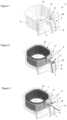
- the vessel 2comprises a second manipulating handle 9 arranged in front of a second container 10 .
- the second manipulating handle 9is fixed to the front side 10 a of the second container 10 by means of a body 11 and a support bracket 12 , as illustrated by FIGS. 2 , 3 and 6 .
- the body 11is housed in the receiving area 8 and the support bracket 12 rests against a notch 13 arranged on the upper edge 14 of the first container 5 , opposite the receiving area 8 .
- the second manipulating handle 9is mounted with a pivoting connection 15 on the body 11 to pivot to a position stowed in the embedding area 7 (see FIGS. 2 and 4 ) or to a position released from the embedding area 7 (see FIGS. 3 , 5 and 6 ). In this released position, the second manipulating handle 9 is positioned more or less parallel to the bottom 16 of the second container 10 , in a configuration similar to that of a frying pan, to facilitate the shaking of the foods contained in the basket 1 .
- the second manipulating handle 9is integrated in near-totality in the embedding area 7 , which allows the first manipulating handle 6 and the second manipulating handle 9 to combine to form a single manipulating handle that can be grasped with one hand for manipulation of the vessel 2 with the basket 1 integrated and assembled with the vessel 2 .
- the assembly between the basket 1 and the vessel 2is implemented by means of a removable assembly device 17 , as illustrated in more detail in FIGS. 4 to 6 .
- the receiving area 8 on the vessel 2comprises in its lower part 8 a an opening 18 .
- the body 11comprises a latch 19 which is mounted with a pivoting connection 20 inside the body 11 .
- the latch 19comprises at its lower end a head 21 forming a hook, the head 21 projecting from the lower face 11 a of the body 11 .
- the latch 19comprises at its upper end a curved finger 22 forming a support, the curved finger 22 projecting from the front face 11 b of the body 11 .
- This latch 19is mounted in return by a spring 23 in order to be automatically returned to a normal position illustrated in FIG.
- the basket 1can thus be removed from the vessel 2 , as shown in FIG. 6 .
- a locking mechanism 25allows the second manipulating handle 9 to be kept in the position released from the embedding area 7 .
- the second manipulating handle 9comprises a window 26 in which a control button 27 is mounted in translation. This control button 27 is mounted in return by a spring 28 in an active position illustrated in FIGS. 5 and 6 .
- the control button 27comprises a stop finger 29 which rests against an edge 30 of the body 11 , thus preventing the second manipulating handle 9 from pivoting in relation to the body 11 .
- the translation of the control button 27 in the direction of an arrow 31allows the stop finger 29 to be released from the edge 30 , which allows the second manipulating handle 9 to pivot to the stowed position in the embedding area 7 .
- the pivoting of the second manipulating handle 9 to the stowed positionallows the head 21 of the latch 19 to be locked under the rear contour 18 a of the opening 18 , ensuring the assembly of the basket 1 with the vessel 2 .
- the first manipulating handle 6can all the same be grasped with one hand, which allows the vessel to be manipulated individually, without any risk of burning oneself at the end of cooking.
- the usermay choose to place foods in the second container 10 of the basket 1 which is then placed in the vessel 2 and then inserted with the vessel 2 into the cooking appliance.
- hecan choose to place the foods in the first container 5 of the vessel 2 which is then inserted directly into the cooking appliance, without the basket 1 .
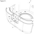
- FIGS. 7 to 14illustrate a second design variant of the manipulating system 3 between the basket 1 and the vessel 2 , achieving the same effects as the first design variant described above, namely, offering two cooking modes, one in the container and the other in the basket, in order to adapt the cooking capacity of the cooking appliance.
- this second variant of FIGS. 7 to 14we find a great number of characteristics identical to the first variant of FIGS. 1 to 6 .
- the vessel 2comprises a first container 5 , a facade 4 , a receiving area 8 equipped with an opening 18 and a notch 13 arranged on the upper edge 14 of the first container 5 .
- the basket 1comprises a second container 10 , a body 11 and a support bracket 12 fixed to the front side 10 a of the second container 10 .
- the manipulating system 3 implemented on this second variant of FIGS. 7 to 14differs from the first variant of FIGS. 1 to 6 in that it provides a single manipulating handle 32 , and not a first manipulating handle 6 and a second manipulating handle 9 .
- the manipulating handle 32is fixed to the front face 11 b of the body 11 , the elements forming a single part 33 illustrated in FIG. 11 .
- This part 33integrating the manipulating handle 32 , can be assembled simultaneously with the basket 1 and the vessel 2 , as illustrated in FIGS. 7 and 12 , or only with the basket 1 , as illustrated in FIGS. 9 and 13 , or only with the vessel 2 , as illustrated in FIG. 8 .
- the body 11integrates a latch 19 mounted with a pivoting connection 20 and comprises at its lower end a head 21 forming a hook.
- the upper end 19 a of the latch 19is fixed to a control button 34 accessible on the front face 11 b of the body 11 , as shown in FIGS. 7 to 9 , 12 and 13 .
- the actuation of the control button 34allows the latch 19 to be pivoted in order to move the head 21 in the axis of the opening 18 , thus allowing the body 11 to be removed from the receiving area 8 .
- a spring 35ensures that the latch 19 returns to the locking position, with the head 21 arranged under the rear contour 18 a of the opening 18 , as illustrated in FIG. 12 , once the body 11 is inserted into the receiving area 8 and the control button 34 is released.
- Two fingers 36 , 37are arranged on the lateral sides 11 c , 11 d of the body 11 , as illustrated in FIGS. 9 and 11 . These fingers 36 , 37 are positioned in guide notches 38 , 39 arranged on the lateral sides 8 b , 8 c of the receiving area 8 ; when the fingers 36 , 37 are housed in the notches 38 , 39 , the body 11 is blocked in translation from front to back with respect to the receiving area 8 .
- the part 33 comprising the body 11 and the manipulating handle 32may be detached from the support bracket 12 fixed to the second container 10 .
- the body 11comprises on its lateral sides 11 c , 11 d two triggers 40 , 41 which are projecting and formed by means of a single actuating part 42 mounted with a pivoting connection 43 on the body 11 .
- This actuating part 42comprises a bolt 44 .
- the support bracket 12comprises a striker 45 formed by an orifice 46 on a curved part 12 a arranged in front of the support bracket 12 , as illustrated in FIG. 10 .
- the body 11comprises on its upper face 11 e a seating 47 , illustrated in FIG.
- the part 33can be assembled with the second container 10 of the basket 1 through the use of a first removable assembly device 48 implemented by means of the actuating part 42 in the body 11 which comprises the bolt 44 , of the curved part 12 a of the support bracket 12 which comprises the striker 45 , the bolt 44 mounted in return by a spring 35 and the striker 45 ensuring the locking of the body 11 with the support bracket 12 .
- the part 33can be assembled with the first container 5 of the vessel 2 through the use of a second removable assembly device 49 implemented by means of the body 11 incorporating the latch 19 and of the receiving area 8 comprising the opening 18 ,
- the part 33may be assembled with the basket 1 alone, with the vessel 2 alone and with the basket 1 and the vessel 2 at the same time.
- control button 34 illustrated on the second variant in FIGS. 7 to 14would be arranged in an identical manner on the first variant in FIGS. 1 to 6 .
- the actuation of the first manipulating handle 6 in the position released from the embedding area 7would have no impact on the unlocking between the body 11 and the receiving area 8 .
- the first container 5 on the vesselcan hold 4.5 liters and allows 1.2 kg of foods to be cooked
- the second container 10 on the basket 1can hold 2.2 liters and allows 800 g of foods to be cooked, which allows a 50 percent increase in the cooking capacity.
- These holding capacitiescould be varied in order to increase the cooking capacity by approximately 30 to 60 percent.
Landscapes
- Engineering & Computer Science (AREA)
- Food Science & Technology (AREA)
- Frying-Pans Or Fryers (AREA)
- Cookers (AREA)
Abstract
Description
Claims (14)
Applications Claiming Priority (2)
| Application Number | Priority Date | Filing Date | Title |
|---|---|---|---|
| FR1852455AFR3079120B1 (en) | 2018-03-21 | 2018-03-21 | HOT AIR FRYER TYPE COOKING APPLIANCE WITH AN EVOLVING COOKING CAPACITY |
| FR1852455 | 2018-03-21 |
Publications (2)
| Publication Number | Publication Date |
|---|---|
| US20190290062A1 US20190290062A1 (en) | 2019-09-26 |
| US11930958B2true US11930958B2 (en) | 2024-03-19 |
Family
ID=62597684
Family Applications (1)
| Application Number | Title | Priority Date | Filing Date |
|---|---|---|---|
| US16/359,302Active2042-03-04US11930958B2 (en) | 2018-03-21 | 2019-03-20 | Hot air fryer cooking appliance with a scalable cooking capacity |
Country Status (7)
| Country | Link |
|---|---|
| US (1) | US11930958B2 (en) |
| EP (2) | EP3542684B1 (en) |
| KR (1) | KR102712585B1 (en) |
| CN (2) | CN110292316B (en) |
| BR (1) | BR102019005507B1 (en) |
| CA (1) | CA3037240A1 (en) |
| FR (1) | FR3079120B1 (en) |
Families Citing this family (23)
| Publication number | Priority date | Publication date | Assignee | Title |
|---|---|---|---|---|
| WO2019032876A1 (en) | 2017-08-09 | 2019-02-14 | Sharkninja Operating Llc | Cooking device and components thereof |
| FR3079120B1 (en)* | 2018-03-21 | 2021-03-05 | Seb Sa | HOT AIR FRYER TYPE COOKING APPLIANCE WITH AN EVOLVING COOKING CAPACITY |
| US11051654B2 (en) | 2019-02-25 | 2021-07-06 | Sharkninja Operating Llc | Cooking device and components thereof |
| WO2020176477A1 (en) | 2019-02-25 | 2020-09-03 | Sharkninja Operating Llc | Cooking system with guard |
| US20220408966A1 (en) | 2019-07-15 | 2022-12-29 | Sharkninja Operating Llc | Cooking device and components thereof |
| KR102254654B1 (en) | 2020-01-23 | 2021-05-21 | 김설진 | Airfryer Cooking Vessel for Food dry |
| US11678765B2 (en) | 2020-03-30 | 2023-06-20 | Sharkninja Operating Llc | Cooking device and components thereof |
| CN113745016B (en)* | 2020-05-27 | 2024-01-16 | 浙江天喜厨电股份有限公司 | Micro-gap switch and have this micro-gap switch's air fryer |
| CA201436S (en)* | 2020-07-02 | 2021-12-17 | Midea Group Co Ltd | Air fryer |
| CN114052519A (en)* | 2020-08-06 | 2022-02-18 | 广东美的生活电器制造有限公司 | Food cooking equipment |
| US12171369B2 (en) | 2020-11-06 | 2024-12-24 | Midea Group Co., Ltd. | Air fryer cooking appliance |
| US12137838B2 (en) | 2020-12-30 | 2024-11-12 | Sharkninja Operating Llc | Cooking device and components thereof |
| KR200495376Y1 (en)* | 2020-12-31 | 2022-05-10 | (주)사이이 | A cover for frying basket of airfryer |
| CN215937110U (en)* | 2021-07-30 | 2022-03-04 | 宁波嘉乐智能科技股份有限公司 | Handle mounting structure of air fryer and air fryer |
| CN114886310B (en)* | 2022-05-27 | 2023-08-11 | 浙江新唐实业有限公司 | An air fryer that is easy to disassemble and clean |
| WO2024119221A1 (en)* | 2022-12-05 | 2024-06-13 | Breville Pty Limited | An appliance |
| US12035725B2 (en) | 2022-12-12 | 2024-07-16 | Sharkninja Operating, Llc | Grill systems |
| US12070042B2 (en) | 2022-12-12 | 2024-08-27 | Sharkninja Operating Llc | Grill systems |
| EP4400009A1 (en) | 2023-01-12 | 2024-07-17 | Versuni Holding B.V. | Air fryer food support |
| US11882961B1 (en) | 2023-01-18 | 2024-01-30 | Sharkninja Operating Llc | Cover plate for cooking devices |
| US12035845B1 (en) | 2023-04-26 | 2024-07-16 | Sharkninja Operating Llc | Systems and methods for cooking pizza |
| US12372247B2 (en) | 2023-04-26 | 2025-07-29 | Sharkninja Operating Llc | Systems and methods for cooking pizza |
| USD1063483S1 (en) | 2023-06-15 | 2025-02-25 | Sharkninja Operating Llc | Cooking device |
Citations (48)
| Publication number | Priority date | Publication date | Assignee | Title |
|---|---|---|---|---|
| US2444447A (en)* | 1945-04-18 | 1948-07-06 | Josselyn Winsor | Hinged handle for utensils |
| US2593549A (en)* | 1949-04-23 | 1952-04-22 | West Bend Aluminum Co | French fryer |
| US2822747A (en)* | 1955-09-30 | 1958-02-11 | Dormeyer Corp | Skillet |
| US2868112A (en)* | 1955-05-13 | 1959-01-13 | George H Bushway | Cooking machine |
| EP0037562A1 (en) | 1980-04-04 | 1981-10-14 | Moulinex S.A. | Frying appliance for home use |
| US5373608A (en)* | 1994-03-17 | 1994-12-20 | Welch Distributing Company | Cooking vessel handle |
| US5400700A (en)* | 1991-07-30 | 1995-03-28 | Bois; Bernard M. | Electrical cooking apparatus and its method of manufacture |
| US5441169A (en)* | 1994-01-10 | 1995-08-15 | Petty; Christopher K. | Saucepan |
| US5746117A (en)* | 1997-02-14 | 1998-05-05 | Lyu Jan Co., Ltd. | Deep fryer |
| US5803307A (en)* | 1995-12-12 | 1998-09-08 | Demetrio; Bruno | Nestable cooking utensil with an articulable handle |
| US5992308A (en)* | 1998-07-10 | 1999-11-30 | Newell Operating Company | Cooking vessel |
| US6220477B1 (en)* | 1999-12-02 | 2001-04-24 | Mark H. Schneider | Flip-handle cookware |
| US6237471B1 (en)* | 1999-07-30 | 2001-05-29 | Kyoung Ho Nam | Folding handle assembly for cooking pans |
| US6250213B1 (en)* | 1999-01-12 | 2001-06-26 | De'longhi S.P.A. | Device for moving the basket of a fryer |
| KR200309456Y1 (en)* | 2002-12-31 | 2003-04-03 | 서재우 | Deep fryer and a structure thereof |
| CA2452634A1 (en)* | 2002-12-06 | 2004-06-06 | Seb S.A. | Electric cooking appliance comprising a vessel coupled with a pouring device |
| EP1428464A1 (en)* | 2002-12-13 | 2004-06-16 | Seb Sa | Electric deep fat fryer with outer housing |
| US20040154474A1 (en)* | 2003-01-10 | 2004-08-12 | Alex Chan | Food cooker |
| US20050127063A1 (en)* | 2003-12-12 | 2005-06-16 | Garziera Roberto V. | Saucepan |
| WO2006100367A1 (en)* | 2005-03-18 | 2006-09-28 | Seb Sa | Stackable cooking utensils and adapted cover and accessory |
| US20080169281A1 (en)* | 2007-01-16 | 2008-07-17 | Hamilton Beach/Proctor-Silex, Inc. | Deep Fryer for Cooking Foodstuff |
| US20080213447A1 (en)* | 2004-06-08 | 2008-09-04 | Seb S.A. | Fryer with Automatic Coating of Fat |
| US7775156B2 (en)* | 2006-04-28 | 2010-08-17 | Restaurant Technology, Inc. | Fry basket for processing of bulk food items and method |
| US20110185917A1 (en)* | 2006-02-01 | 2011-08-04 | Seb S.A. | Cooking appliance with stirring means and associated method |
| US8037812B1 (en)* | 2007-05-02 | 2011-10-18 | Sumner Sr Douglas Arthur | Bottom opening fryer basket |
| US8267277B2 (en)* | 2005-12-23 | 2012-09-18 | Seb. S.A. | Cooking receptacle with at least one pivoting handle |
| WO2012123464A1 (en) | 2011-03-16 | 2012-09-20 | Seb S.A. | Cooking accessory comprising a cooking support and a removable gripping handle |
| US8322564B2 (en)* | 2010-07-06 | 2012-12-04 | Seb S.A. | Cooking article with folding handle |
| WO2014095659A1 (en)* | 2012-12-20 | 2014-06-26 | Arcelik Anonim Sirketi | An oven comprising a cooking pot |
| US8783170B2 (en)* | 2006-11-15 | 2014-07-22 | Seb S.A. | Cooking appliance and pivotal device for raising and lowering a basket for draining cooked food |
| US20140299049A1 (en)* | 2013-04-04 | 2014-10-09 | John Constantino, JR. | Handheld powdering device |
| WO2014198040A1 (en) | 2013-06-13 | 2014-12-18 | 凯羿贸易(深圳)有限公司 | Air fryer |
| CN204105798U (en)* | 2014-08-21 | 2015-01-21 | 广东容声电器股份有限公司厨卫分公司 | Air fryer easy to use, safe |
| US8950621B2 (en)* | 2012-03-02 | 2015-02-10 | Charles HINZMAN | Cooking utensil with rotatable handle |
| CN204467868U (en)* | 2015-03-31 | 2015-07-15 | 杨振巧 | an air fryer |
| US9179795B1 (en)* | 2014-05-29 | 2015-11-10 | Dong Woo Lee | Cooking pan system having foldable handle |
| CN105640363A (en)* | 2016-03-09 | 2016-06-08 | 宁波比依电器有限公司 | Oil-filtering electric fryer |
| WO2017085679A1 (en)* | 2015-11-19 | 2017-05-26 | De' Longhi Appliances S.R.L. Con Unico Socio | Cooking apparatus |
| US20170231430A1 (en)* | 2016-02-12 | 2017-08-17 | Nuwave, Llc | Air Fryer |
| US20180035698A1 (en)* | 2016-08-02 | 2018-02-08 | Spectrum Brands, Inc. | Air frying systems and methods |
| US10016092B2 (en)* | 2011-12-16 | 2018-07-10 | National Presto Industries, Inc. | Countertop appliance having detachable base |
| CN109124312A (en)* | 2018-11-23 | 2019-01-04 | 宁波再兴厨具有限公司 | A kind of multipurpose non-stick pan |
| US20190290072A1 (en)* | 2018-03-21 | 2019-09-26 | Seb S.A. | Hot air fryer cooking appliance |
| US20190328179A1 (en)* | 2005-08-08 | 2019-10-31 | Ron's Enterprises, Inc. | Device to efficiently cook foods using liquids and hot vapors |
| US20200405100A1 (en)* | 2017-08-24 | 2020-12-31 | Columbia Insurance Company | Removable Cookware Handle |
| US20210121011A1 (en)* | 2020-03-30 | 2021-04-29 | Sharkninja Operating Llc | Cooking device and components thereof |
| US11033146B2 (en)* | 2019-02-25 | 2021-06-15 | Sharkninja Operating Llc | Cooking device and components thereof |
| US11389026B2 (en)* | 2019-07-15 | 2022-07-19 | Sharkninja Operating Llc | Cooking device and components thereof |
Family Cites Families (2)
| Publication number | Priority date | Publication date | Assignee | Title |
|---|---|---|---|---|
| CN204839219U (en)* | 2015-07-16 | 2015-12-09 | 浙江绍兴苏泊尔生活电器有限公司 | fryer |
| FR3079120B1 (en)* | 2018-03-21 | 2021-03-05 | Seb Sa | HOT AIR FRYER TYPE COOKING APPLIANCE WITH AN EVOLVING COOKING CAPACITY |
- 2018
- 2018-03-21FRFR1852455Apatent/FR3079120B1/ennot_activeExpired - Fee Related
- 2019
- 2019-03-18EPEP19163563.0Apatent/EP3542684B1/enactiveActive
- 2019-03-18EPEP21185171.2Apatent/EP3912532B1/enactiveActive
- 2019-03-18CACA3037240Apatent/CA3037240A1/enactivePending
- 2019-03-20CNCN201910212300.9Apatent/CN110292316B/enactiveActive
- 2019-03-20CNCN201920355698.7Upatent/CN210185375U/ennot_activeWithdrawn - After Issue
- 2019-03-20USUS16/359,302patent/US11930958B2/enactiveActive
- 2019-03-20BRBR102019005507-3Apatent/BR102019005507B1/enactiveIP Right Grant
- 2019-03-21KRKR1020190032104Apatent/KR102712585B1/enactiveActive
Patent Citations (52)
| Publication number | Priority date | Publication date | Assignee | Title |
|---|---|---|---|---|
| US2444447A (en)* | 1945-04-18 | 1948-07-06 | Josselyn Winsor | Hinged handle for utensils |
| US2593549A (en)* | 1949-04-23 | 1952-04-22 | West Bend Aluminum Co | French fryer |
| US2868112A (en)* | 1955-05-13 | 1959-01-13 | George H Bushway | Cooking machine |
| US2822747A (en)* | 1955-09-30 | 1958-02-11 | Dormeyer Corp | Skillet |
| EP0037562A1 (en) | 1980-04-04 | 1981-10-14 | Moulinex S.A. | Frying appliance for home use |
| US5400700A (en)* | 1991-07-30 | 1995-03-28 | Bois; Bernard M. | Electrical cooking apparatus and its method of manufacture |
| US5441169A (en)* | 1994-01-10 | 1995-08-15 | Petty; Christopher K. | Saucepan |
| US5373608A (en)* | 1994-03-17 | 1994-12-20 | Welch Distributing Company | Cooking vessel handle |
| US5803307A (en)* | 1995-12-12 | 1998-09-08 | Demetrio; Bruno | Nestable cooking utensil with an articulable handle |
| US5746117A (en)* | 1997-02-14 | 1998-05-05 | Lyu Jan Co., Ltd. | Deep fryer |
| US5992308A (en)* | 1998-07-10 | 1999-11-30 | Newell Operating Company | Cooking vessel |
| US6250213B1 (en)* | 1999-01-12 | 2001-06-26 | De'longhi S.P.A. | Device for moving the basket of a fryer |
| US6237471B1 (en)* | 1999-07-30 | 2001-05-29 | Kyoung Ho Nam | Folding handle assembly for cooking pans |
| US6220477B1 (en)* | 1999-12-02 | 2001-04-24 | Mark H. Schneider | Flip-handle cookware |
| CA2452634A1 (en)* | 2002-12-06 | 2004-06-06 | Seb S.A. | Electric cooking appliance comprising a vessel coupled with a pouring device |
| EP1426001A1 (en)* | 2002-12-06 | 2004-06-09 | Seb S.A. | Electrical cooking appliance with a bowl having a pouring device |
| US20040112227A1 (en)* | 2002-12-06 | 2004-06-17 | Seb S.A. | Electric cooking appliance having a tank associated with a pouring device |
| EP1428464A1 (en)* | 2002-12-13 | 2004-06-16 | Seb Sa | Electric deep fat fryer with outer housing |
| KR200309456Y1 (en)* | 2002-12-31 | 2003-04-03 | 서재우 | Deep fryer and a structure thereof |
| US20040154474A1 (en)* | 2003-01-10 | 2004-08-12 | Alex Chan | Food cooker |
| US20050127063A1 (en)* | 2003-12-12 | 2005-06-16 | Garziera Roberto V. | Saucepan |
| US20080213447A1 (en)* | 2004-06-08 | 2008-09-04 | Seb S.A. | Fryer with Automatic Coating of Fat |
| WO2006100367A1 (en)* | 2005-03-18 | 2006-09-28 | Seb Sa | Stackable cooking utensils and adapted cover and accessory |
| US20190328179A1 (en)* | 2005-08-08 | 2019-10-31 | Ron's Enterprises, Inc. | Device to efficiently cook foods using liquids and hot vapors |
| US8267277B2 (en)* | 2005-12-23 | 2012-09-18 | Seb. S.A. | Cooking receptacle with at least one pivoting handle |
| US20110185917A1 (en)* | 2006-02-01 | 2011-08-04 | Seb S.A. | Cooking appliance with stirring means and associated method |
| US7775156B2 (en)* | 2006-04-28 | 2010-08-17 | Restaurant Technology, Inc. | Fry basket for processing of bulk food items and method |
| US8783170B2 (en)* | 2006-11-15 | 2014-07-22 | Seb S.A. | Cooking appliance and pivotal device for raising and lowering a basket for draining cooked food |
| US20080169281A1 (en)* | 2007-01-16 | 2008-07-17 | Hamilton Beach/Proctor-Silex, Inc. | Deep Fryer for Cooking Foodstuff |
| US8037812B1 (en)* | 2007-05-02 | 2011-10-18 | Sumner Sr Douglas Arthur | Bottom opening fryer basket |
| US8322564B2 (en)* | 2010-07-06 | 2012-12-04 | Seb S.A. | Cooking article with folding handle |
| WO2012123464A1 (en) | 2011-03-16 | 2012-09-20 | Seb S.A. | Cooking accessory comprising a cooking support and a removable gripping handle |
| US10016092B2 (en)* | 2011-12-16 | 2018-07-10 | National Presto Industries, Inc. | Countertop appliance having detachable base |
| US8950621B2 (en)* | 2012-03-02 | 2015-02-10 | Charles HINZMAN | Cooking utensil with rotatable handle |
| WO2014095659A1 (en)* | 2012-12-20 | 2014-06-26 | Arcelik Anonim Sirketi | An oven comprising a cooking pot |
| US20140299049A1 (en)* | 2013-04-04 | 2014-10-09 | John Constantino, JR. | Handheld powdering device |
| WO2014198040A1 (en) | 2013-06-13 | 2014-12-18 | 凯羿贸易(深圳)有限公司 | Air fryer |
| US9179795B1 (en)* | 2014-05-29 | 2015-11-10 | Dong Woo Lee | Cooking pan system having foldable handle |
| CN204105798U (en)* | 2014-08-21 | 2015-01-21 | 广东容声电器股份有限公司厨卫分公司 | Air fryer easy to use, safe |
| CN204467868U (en)* | 2015-03-31 | 2015-07-15 | 杨振巧 | an air fryer |
| WO2017085679A1 (en)* | 2015-11-19 | 2017-05-26 | De' Longhi Appliances S.R.L. Con Unico Socio | Cooking apparatus |
| US20170231430A1 (en)* | 2016-02-12 | 2017-08-17 | Nuwave, Llc | Air Fryer |
| CN105640363A (en)* | 2016-03-09 | 2016-06-08 | 宁波比依电器有限公司 | Oil-filtering electric fryer |
| US20180035698A1 (en)* | 2016-08-02 | 2018-02-08 | Spectrum Brands, Inc. | Air frying systems and methods |
| US20200405100A1 (en)* | 2017-08-24 | 2020-12-31 | Columbia Insurance Company | Removable Cookware Handle |
| US20190290072A1 (en)* | 2018-03-21 | 2019-09-26 | Seb S.A. | Hot air fryer cooking appliance |
| US11160421B2 (en)* | 2018-03-21 | 2021-11-02 | Seb S.A. | Hot air fryer cooking appliance |
| CN109124312A (en)* | 2018-11-23 | 2019-01-04 | 宁波再兴厨具有限公司 | A kind of multipurpose non-stick pan |
| US11033146B2 (en)* | 2019-02-25 | 2021-06-15 | Sharkninja Operating Llc | Cooking device and components thereof |
| US11389026B2 (en)* | 2019-07-15 | 2022-07-19 | Sharkninja Operating Llc | Cooking device and components thereof |
| US20210121011A1 (en)* | 2020-03-30 | 2021-04-29 | Sharkninja Operating Llc | Cooking device and components thereof |
| US11134808B2 (en)* | 2020-03-30 | 2021-10-05 | Sharkninja Operating Llc | Cooking device and components thereof |
Non-Patent Citations (5)
| Title |
|---|
| Philips air fryer advertisement amazon (Year: 2021).* |
| Review Philips air fryer (Year: 2017).* |
| Search Report as issued in French Patent Application No. 1852455, dated Nov. 14, 2018. |
| Translation CN204105798 (Year: 2022).* |
| Translation WO 2014198040 (Year: 2022).* |
Also Published As
| Publication number | Publication date |
|---|---|
| EP3912532A1 (en) | 2021-11-24 |
| CN110292316B (en) | 2025-07-22 |
| CN110292316A (en) | 2019-10-01 |
| US20190290062A1 (en) | 2019-09-26 |
| CA3037240A1 (en) | 2019-09-21 |
| BR102019005507B1 (en) | 2023-11-21 |
| EP3912532C0 (en) | 2023-08-16 |
| FR3079120A1 (en) | 2019-09-27 |
| EP3542684B1 (en) | 2021-08-18 |
| KR20190110940A (en) | 2019-10-01 |
| FR3079120B1 (en) | 2021-03-05 |
| BR102019005507A2 (en) | 2019-10-08 |
| KR102712585B1 (en) | 2024-10-04 |
| EP3542684A1 (en) | 2019-09-25 |
| EP3912532B1 (en) | 2023-08-16 |
| CN210185375U (en) | 2020-03-27 |
Similar Documents
| Publication | Publication Date | Title |
|---|---|---|
| US11930958B2 (en) | Hot air fryer cooking appliance with a scalable cooking capacity | |
| EP3823504B1 (en) | Hot air fryer cooking apparatus with cooking accessories for various food preparations | |
| US8584579B1 (en) | Bottom opening fryer basket | |
| FR3106262A1 (en) | HOT AIR FRYER TYPE COOKING APPLIANCE WITH EVOLVING COOKING CAPACITY | |
| US7165489B1 (en) | Cooking vessel | |
| US20140042170A1 (en) | Multi-use cooking system | |
| JP2009513295A (en) | Cooking container lid | |
| US3798706A (en) | Detachable handle | |
| KR200450286Y1 (en) | Cookware with Foldable Handle | |
| KR20210028936A (en) | Cooking Pans with Replaceable Handles | |
| KR102247932B1 (en) | Double basket | |
| US20050052038A1 (en) | Oven rack tool | |
| CN210158493U (en) | Safety switch triggering structure of air fryer | |
| BE1031328B1 (en) | Steamer drawer | |
| JP7326866B2 (en) | heating cooker | |
| CN210276923U (en) | Air fryer with safety switch | |
| JPH0125436Y2 (en) | ||
| KR20210009498A (en) | Easy-to-use kitchen storage door | |
| KR20220000033A (en) | Cooking apparatus of the hot air fryer type having evolving cooking capacity, outer flip-over, and height adjustable | |
| CN207654053U (en) | A kind of deep fryer | |
| KR20230105252A (en) | Cooking appliance | |
| CA1123300A (en) | Portable grilling device | |
| CN112438622A (en) | Hot air cooking appliance provided with a cooking container receiving base and a locking device between the container and the base | |
| JPH1033369A (en) | Electric rice cooker | |
| KR20190096213A (en) | door of sink |
Legal Events
| Date | Code | Title | Description |
|---|---|---|---|
| FEPP | Fee payment procedure | Free format text:ENTITY STATUS SET TO UNDISCOUNTED (ORIGINAL EVENT CODE: BIG.); ENTITY STATUS OF PATENT OWNER: LARGE ENTITY | |
| AS | Assignment | Owner name:SEB S.A., FRANCE Free format text:ASSIGNMENT OF ASSIGNORS INTEREST;ASSIGNORS:PRIETO, GUILLAUME;CORNU, JEREMY;SIGNING DATES FROM 20190306 TO 20190327;REEL/FRAME:049703/0438 | |
| STPP | Information on status: patent application and granting procedure in general | Free format text:NON FINAL ACTION MAILED | |
| STPP | Information on status: patent application and granting procedure in general | Free format text:RESPONSE TO NON-FINAL OFFICE ACTION ENTERED AND FORWARDED TO EXAMINER | |
| STPP | Information on status: patent application and granting procedure in general | Free format text:FINAL REJECTION MAILED | |
| STPP | Information on status: patent application and granting procedure in general | Free format text:ADVISORY ACTION MAILED | |
| STPP | Information on status: patent application and granting procedure in general | Free format text:DOCKETED NEW CASE - READY FOR EXAMINATION | |
| STPP | Information on status: patent application and granting procedure in general | Free format text:NON FINAL ACTION MAILED | |
| STPP | Information on status: patent application and granting procedure in general | Free format text:RESPONSE TO NON-FINAL OFFICE ACTION ENTERED AND FORWARDED TO EXAMINER | |
| STPP | Information on status: patent application and granting procedure in general | Free format text:NOTICE OF ALLOWANCE MAILED -- APPLICATION RECEIVED IN OFFICE OF PUBLICATIONS | |
| ZAAB | Notice of allowance mailed | Free format text:ORIGINAL CODE: MN/=. | |
| STPP | Information on status: patent application and granting procedure in general | Free format text:PUBLICATIONS -- ISSUE FEE PAYMENT VERIFIED | |
| STCF | Information on status: patent grant | Free format text:PATENTED CASE |