US11930563B2 - Monitoring and extending heater life through power supply polarity switching - Google Patents
Monitoring and extending heater life through power supply polarity switchingDownload PDFInfo
- Publication number
- US11930563B2 US11930563B2US16/572,200US201916572200AUS11930563B2US 11930563 B2US11930563 B2US 11930563B2US 201916572200 AUS201916572200 AUS 201916572200AUS 11930563 B2US11930563 B2US 11930563B2
- Authority
- US
- United States
- Prior art keywords
- polarity
- heating
- leakage current
- heater
- processor
- Prior art date
- Legal status (The legal status is an assumption and is not a legal conclusion. Google has not performed a legal analysis and makes no representation as to the accuracy of the status listed.)
- Active, expires
Links
Images


Classifications
- G—PHYSICS
- G01—MEASURING; TESTING
- G01P—MEASURING LINEAR OR ANGULAR SPEED, ACCELERATION, DECELERATION, OR SHOCK; INDICATING PRESENCE, ABSENCE, OR DIRECTION, OF MOVEMENT
- G01P5/00—Measuring speed of fluids, e.g. of air stream; Measuring speed of bodies relative to fluids, e.g. of ship, of aircraft
- G01P5/14—Measuring speed of fluids, e.g. of air stream; Measuring speed of bodies relative to fluids, e.g. of ship, of aircraft by measuring differences of pressure in the fluid
- G01P5/16—Measuring speed of fluids, e.g. of air stream; Measuring speed of bodies relative to fluids, e.g. of ship, of aircraft by measuring differences of pressure in the fluid using Pitot tubes, e.g. Machmeter
- G01P5/165—Arrangements or constructions of Pitot tubes
- B—PERFORMING OPERATIONS; TRANSPORTING
- B64—AIRCRAFT; AVIATION; COSMONAUTICS
- B64D—EQUIPMENT FOR FITTING IN OR TO AIRCRAFT; FLIGHT SUITS; PARACHUTES; ARRANGEMENT OR MOUNTING OF POWER PLANTS OR PROPULSION TRANSMISSIONS IN AIRCRAFT
- B64D15/00—De-icing or preventing icing on exterior surfaces of aircraft
- B64D15/12—De-icing or preventing icing on exterior surfaces of aircraft by electric heating
- H—ELECTRICITY
- H05—ELECTRIC TECHNIQUES NOT OTHERWISE PROVIDED FOR
- H05B—ELECTRIC HEATING; ELECTRIC LIGHT SOURCES NOT OTHERWISE PROVIDED FOR; CIRCUIT ARRANGEMENTS FOR ELECTRIC LIGHT SOURCES, IN GENERAL
- H05B3/00—Ohmic-resistance heating
- H05B3/0014—Devices wherein the heating current flows through particular resistances
- G—PHYSICS
- G01—MEASURING; TESTING
- G01F—MEASURING VOLUME, VOLUME FLOW, MASS FLOW OR LIQUID LEVEL; METERING BY VOLUME
- G01F1/00—Measuring the volume flow or mass flow of fluid or fluent solid material wherein the fluid passes through a meter in a continuous flow
- G01F1/05—Measuring the volume flow or mass flow of fluid or fluent solid material wherein the fluid passes through a meter in a continuous flow by using mechanical effects
- G01F1/34—Measuring the volume flow or mass flow of fluid or fluent solid material wherein the fluid passes through a meter in a continuous flow by using mechanical effects by measuring pressure or differential pressure
- G01F1/36—Measuring the volume flow or mass flow of fluid or fluent solid material wherein the fluid passes through a meter in a continuous flow by using mechanical effects by measuring pressure or differential pressure the pressure or differential pressure being created by the use of flow constriction
- G01F1/40—Details of construction of the flow constriction devices
- G01F1/46—Pitot tubes
- G—PHYSICS
- G01—MEASURING; TESTING
- G01M—TESTING STATIC OR DYNAMIC BALANCE OF MACHINES OR STRUCTURES; TESTING OF STRUCTURES OR APPARATUS, NOT OTHERWISE PROVIDED FOR
- G01M3/00—Investigating fluid-tightness of structures
- G01M3/40—Investigating fluid-tightness of structures by using electric means, e.g. by observing electric discharges
- G—PHYSICS
- G01—MEASURING; TESTING
- G01P—MEASURING LINEAR OR ANGULAR SPEED, ACCELERATION, DECELERATION, OR SHOCK; INDICATING PRESENCE, ABSENCE, OR DIRECTION, OF MOVEMENT
- G01P13/00—Indicating or recording presence, absence, or direction, of movement
- G01P13/02—Indicating direction only, e.g. by weather vane
- G01P13/025—Indicating direction only, e.g. by weather vane indicating air data, i.e. flight variables of an aircraft, e.g. angle of attack, side slip, shear, yaw
- G—PHYSICS
- G01—MEASURING; TESTING
- G01R—MEASURING ELECTRIC VARIABLES; MEASURING MAGNETIC VARIABLES
- G01R31/00—Arrangements for testing electric properties; Arrangements for locating electric faults; Arrangements for electrical testing characterised by what is being tested not provided for elsewhere
- G01R31/005—Testing of electric installations on transport means
- G01R31/008—Testing of electric installations on transport means on air- or spacecraft, railway rolling stock or sea-going vessels
- G—PHYSICS
- G01—MEASURING; TESTING
- G01R—MEASURING ELECTRIC VARIABLES; MEASURING MAGNETIC VARIABLES
- G01R31/00—Arrangements for testing electric properties; Arrangements for locating electric faults; Arrangements for electrical testing characterised by what is being tested not provided for elsewhere
- G01R31/28—Testing of electronic circuits, e.g. by signal tracer
- G01R31/282—Testing of electronic circuits specially adapted for particular applications not provided for elsewhere
- G01R31/2829—Testing of circuits in sensor or actuator systems
- G—PHYSICS
- G01—MEASURING; TESTING
- G01R—MEASURING ELECTRIC VARIABLES; MEASURING MAGNETIC VARIABLES
- G01R31/00—Arrangements for testing electric properties; Arrangements for locating electric faults; Arrangements for electrical testing characterised by what is being tested not provided for elsewhere
- G01R31/50—Testing of electric apparatus, lines, cables or components for short-circuits, continuity, leakage current or incorrect line connections
- G01R31/52—Testing for short-circuits, leakage current or ground faults
- G—PHYSICS
- G05—CONTROLLING; REGULATING
- G05D—SYSTEMS FOR CONTROLLING OR REGULATING NON-ELECTRIC VARIABLES
- G05D23/00—Control of temperature
- G05D23/19—Control of temperature characterised by the use of electric means
- H—ELECTRICITY
- H01—ELECTRIC ELEMENTS
- H01H—ELECTRIC SWITCHES; RELAYS; SELECTORS; EMERGENCY PROTECTIVE DEVICES
- H01H1/00—Contacts
- H01H1/62—Heating or cooling of contacts
- H—ELECTRICITY
- H05—ELECTRIC TECHNIQUES NOT OTHERWISE PROVIDED FOR
- H05B—ELECTRIC HEATING; ELECTRIC LIGHT SOURCES NOT OTHERWISE PROVIDED FOR; CIRCUIT ARRANGEMENTS FOR ELECTRIC LIGHT SOURCES, IN GENERAL
- H05B1/00—Details of electric heating devices
- H05B1/02—Automatic switching arrangements specially adapted to apparatus ; Control of heating devices
- H05B1/0227—Applications
- H05B1/023—Industrial applications
- H05B1/0236—Industrial applications for vehicles
- H—ELECTRICITY
- H05—ELECTRIC TECHNIQUES NOT OTHERWISE PROVIDED FOR
- H05B—ELECTRIC HEATING; ELECTRIC LIGHT SOURCES NOT OTHERWISE PROVIDED FOR; CIRCUIT ARRANGEMENTS FOR ELECTRIC LIGHT SOURCES, IN GENERAL
- H05B3/00—Ohmic-resistance heating
- H05B3/20—Heating elements having extended surface area substantially in a two-dimensional plane, e.g. plate-heater
- H05B3/22—Heating elements having extended surface area substantially in a two-dimensional plane, e.g. plate-heater non-flexible
- H05B3/28—Heating elements having extended surface area substantially in a two-dimensional plane, e.g. plate-heater non-flexible heating conductor embedded in insulating material
- B—PERFORMING OPERATIONS; TRANSPORTING
- B64—AIRCRAFT; AVIATION; COSMONAUTICS
- B64D—EQUIPMENT FOR FITTING IN OR TO AIRCRAFT; FLIGHT SUITS; PARACHUTES; ARRANGEMENT OR MOUNTING OF POWER PLANTS OR PROPULSION TRANSMISSIONS IN AIRCRAFT
- B64D45/00—Aircraft indicators or protectors not otherwise provided for
Definitions
- the present disclosurerelates generally to probes, and in particular, to a monitoring and life-extension system for air data probe heaters.
- Air data probesare utilized to determine characteristics of an environment.
- air data probesmay be implemented on the external portions of the aircraft to aid in determination of conditions such as airspeed, altitude, and angle of attack, among others.
- Air data probesare prone to ice accretion during flight, which can affect their performance.
- electrical heatersare integrated into modern air data probes for helping control ice build-up. Being exposed to harsh environmental conditions and temperature extremes, the electric heaters in air data probes are prone to degradation over time, possibly leading to their ultimate failure.
- an air data probe heaterfails, the performance of the air data probe can be affected.
- a failed air data probecan ground a flight, thereby impacting flight scheduling.
- a method of monitoring a heating arrangementincludes applying a first polarity voltage to a heater of the heating arrangement, detecting a first polarity heating leakage current, applying a second polarity voltage to the heating arrangement, detecting a second polarity heating leakage current, and determining health of the heating arrangement via the first polarity heating leakage current and the second polarity heating leakage current.
- a heating arrangement monitoring systemincludes a leakage current measurement circuit configured to measure a heating leakage current, where the heating leakage current is either a first polarity heating leakage current as a result of applying a first polarity voltage to the heating arrangement or a second polarity heating leakage current as a result of applying a second polarity voltage to the heating arrangement, and a processor configured to determine a health of the heating arrangement based on one or more measured values of the first polarity heating leakage current and the second polarity heating leakage current.
- FIG. 1is a schematic diagram illustrating an aircraft that includes a plurality of air data probes.
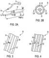
- FIG. 2 Ais a schematic diagram of an air data probe heater circuit.
- FIG. 2 Bis a cross-sectional view of the air data probe heater taken along line 2 B- 2 B of FIG. 2 A .
- FIG. 3is a partial cross-sectional view illustrating the air data probe heater with compromised insulation taken along line 3 - 3 of FIG. 2 B .
- FIG. 4is a partial cross-sectional view illustrating the air data probe heater with compromised insulation and a compromised resistive heating element taken along line 4 - 4 of FIG. 2 B .
- FIG. 5is a block diagram of a heater monitoring and life extension circuit.
- FIG. 6is a schematic diagram of the air data probe heater and a portion of the heater monitoring and life extension circuit in FIG. 5 .
- FIG. 7is a graph of electrical potential across the heater insulation shown in FIG. 6 for a forward voltage polarity.
- FIG. 8is a graph of electrical potential across the heater insulation shown in FIG. 6 for a reverse voltage polarity.
- FIG. 9is a graph of electrical potentials across the heater insulation, leakage currents, and a ratio of forward polarity leakage current to reverse polarity leakage current for the heater insulation shown in FIG. 6 .
- FIG. 10is a process flow chart for the heater monitoring and life extension circuit shown in FIG. 5 .
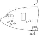
- FIG. 1is a schematic diagram illustrating aircraft 10 that includes a plurality of air data probes 12 a - 12 n .
- Air data probes 12 a - 12 ncan be any type of probe with non-limiting examples including pitot probes, pitot-static probes, total air temperature (TAT) probes, or angle-of-attack (AOA) sensors. Any number n of air data probes can be included on a particular aircraft, with each air data probe 12 a - 12 n typically including an integrated heater to control icing. As used in the present disclosure, one of any air data probes 12 a - 12 n can be referred to as air data probe 12 .
- the exemplary embodiment shown in FIG. 1is a commercial fixed-wing aircraft. Air data probe 12 can be used on other vehicles, with non-limiting examples including military aircraft, rotary wing aircraft, unmanned aerial vehicles, spacecraft, and ground vehicles.
- FIG. 2 Ais a schematic diagram of an air data probe heater circuit. Shown in FIG. 2 A are aircraft power supply 13 , power cable 14 , first power lead 16 , second power lead 18 , and heater 20 . Also labeled in FIG. 2 A are inlet current I in , outlet current I out , and length L (i.e., heater length). Aircraft power supply 13 provides electrical power via power cable 14 . In an exemplary embodiment, aircraft power supply 13 provides 115 VAC at 400 Hz. In some embodiments, aircraft power supply 13 can provide a voltage and/or frequency that are different from this. In other embodiments, aircraft power supply 13 can provide a direct current (DC) voltage.
- DCdirect current
- Heater 20can be referred to as an air data probe heater.
- heater 20can consume 200-300 Watts in converting electrical power into thermal power.
- heater 20can draw an electrical power level that is different form this.
- Heater 20is typically integrated into air data probe 12 , and is energized (i.e., powered) to reduce or prevent ice formation on the respective air data probe by raising the surface temperature of the air data probe to a value that can melt and/or control the formation of ice on air data probe 12 .
- Inlet current I inflows into heater 20 through first power lead 16
- outlet current I outflows from heater 20 through second power lead 18 , as shown in FIG. 2 A .
- the directions of current flow I in , I outare illustrative, using a convention that is used in the electrical art. Under ideal circumstances, I in and I out are approximately equivalent, meaning that there is no other path for current to flow from heater 20 .
- heater 20is prone to failure, as will be described in detail later in FIGS. 3 - 4 .
- a failure of heater 20will generally occur at a point along the length L of heater 20 , with a failure of heater 20 typically requiring a replacement of the associated air data probe.
- Heater 20is depicted as a straight element for ease of illustration, but can have other physical configurations in various embodiments. The values provided for power supply voltage and frequency, and heater power consumption, are exemplary and can be different in various embodiments. Power cable 14 , first power lead 16 , second power lead 18 , and heater 20 can be referred to as a heating arrangement.
- FIG. 2 Bis a cross-sectional view of an air data probe heater taken along line 2 B- 2 B of FIG. 2 A . Shown in FIG. 2 B are heater 20 , resistive heating element 22 , insulation 24 , and sheath 26 .
- resistive heating element 22is made of an oxidation-resistant alloy.
- Insulation 24surrounds resistive heating element 22 .
- Insulation 24is an electrically-insulating material that provides heat conduction outward from resistive heating element 22 .
- Sheath 26is an oxidation-resistant metallic material that surrounds insulation 24 , thereby containing insulation 24 while providing thermal conductivity from heater 20 to the air data probe in which heater 20 is installed. Sheath 26 can be referred to as a metallic sheath.
- the various materialsare selected to provide various desirable properties (e.g., strength, thermal conductivity, oxidation resistance), while also optimizing service life. Notwithstanding, heater 20 is prone to failure over time, as will be described in more detail in FIGS. 3 - 4 .
- FIG. 3is a partial cross-sectional view illustrating heater 20 with compromised insulation 24 taken along line 3 - 3 of FIG. 2 B .
- FIG. 4is a partial cross-sectional view illustrating heater 20 with compromised insulation 24 and compromised resistive heating element 24 taken along line 4 - 4 of FIG. 2 B .
- FIGS. 3 - 4illustrate an exemplary mode of failure of heater 20 , as will be described, while other failure mechanisms for heater 20 can also occur in various embodiments. Shown in FIGS. 3 - 4 are heater 20 , resistive heating element 22 , insulation 24 , sheath 26 , and heater faults 32 , 32 A.
- Heater fault 32shown in FIG. 3 , depicts exemplary heater fault 32 that can result from the aforementioned failure mechanism. Leakage current I L flows through heater fault 32 from resistive heating element 22 to sheath 26 , as shown.
- heater fault 32can grow in magnitude, becoming heater fault 32 A as shown in FIG. 4 .
- An increase in the value of leakage current I Ltypically accompanies the progression of heater fault 32 over the life of heater 20 .
- the value of leakage current I L flowing through heater fault 32affect the rate of deterioration of heater fault 32 , with higher values of leakage current I L generally resulting in a greater rate of deterioration. Accordingly, if the value of leakage current I L for a particular heater fault 32 can be reduced, the rate of deterioration can be correspondingly reduced, thereby prolonging the useful life of heater 20 .
- reversing the electrical polarity of power supplied to heater 20can reduce the rate of deterioration of heater fault 32 , which can extend the life of heater 20 .
- FIG. 5is a block diagram of a heater monitoring and life extension circuit. Shown in FIG. 5 are aircraft power supply 13 , power cable 14 , heater 20 , control system 40 , heater control circuit 42 , heater control signal 44 , aircraft data system 46 , polarity selection circuit 48 , polarity selection signal 50 , polarity control circuit 52 , leakage current measurement system 58 , leakage current signal 70 , processor 72 , flight status signal 74 , polarity control signal 76 , and prognostic data output 78 .
- the descriptions of aircraft power supply 13 , power cable 14 , and heater 20are substantially as provided above in regard to FIGS. 2 A- 2 B .
- Control system 40provides monitoring and extension of the life of heater 20 , as will be described.
- control system 40can also be referred to as a heater monitoring and life extension circuit.
- Heater control circuit 42receives heater control signal 44 from aircraft data system 46 , thereby controlling the flow of electrical power from power supply 13 to heater 20 to control the accretion of ice on air data probe 12 , as described above in regard to FIG. 2 A .
- heater control signal 44can be generated in part based on the air temperature and liquid water content (LWC) that is measured by other systems (not shown) on aircraft 10 , and heater control circuit 42 cycles electrical power on and off (i.e., power duty cycle control) to heater 20 .
- Polarity selection circuit 48controls the polarity of electrical power supplied to heater 20 .
- electrical polaritycan be either “forward” or “reverse” polarity.
- the forward polaritycan also be referred to as the normal polarity (i.e., as would exist in the absence of polarity selection circuit 48 ).
- Polarity selection circuit 48receives polarity selection signal 50 from polarity control circuit 52 , thereby directing either the “forward” or “reverse” electrical polarity of power supplied to heater 20 .
- the forward polaritycan be referred to as a first polarity, and the reverse polarity can be referred to as a second polarity.
- Leakage current measurement system 58measures the value of leakage current I L in heater 20 under the particular polarity (i.e., forward or reverse) that is established by polarity selection circuit 48 , providing leakage current signal 70 to processor 72 .
- leakage current signal 70is a digital signal that represents the measured value of leakage current I L .
- Leakage current measurement system 58will be described in more detail later, in FIG. 6 .
- aircraft data system 46provides flight status signal 74 to processor 72 , thereby allowing processor 72 to monitor flight conditions of aircraft 10 , and accordingly, the operating conditions (i.e., operational parameters) of air data probe 12 and associated heater 20 .
- Processor 72monitors and records the flight hours (i.e., operational hours) of heater 20 as received via flight status signal 74 .
- Processor 72controls, monitors, and records the polarity of the electrical power provided to heater 20 associated with the operation of heater 20 (i.e., flight hours).
- Processor 72also monitors and records the leakage current I L that is measured by leakage current measurement system 58 at the particular power supply polarity (i.e., forward or reverse) for each operating period (e.g., flight) of heater 20 .
- Processor 72generates polarity control signal 76 that is provided to polarity control circuit 52 , as described above. Therefore, processor 72 monitors the health of heater 20 , while controlling the polarity of electrical power provided to heater 20 , thereby extending the life of heater 20 as will be described in more detail in FIGS. 6 - 10 .
- Processor 72can be referred to as a prognostic processor.
- processor 72provides prognostic data output 78 which can be received by various consumers onboard aircraft 10 and/or external to aircraft 10 .
- the remaining useful life (RUL) of heater 20can be included in prognostic data output 78 .
- processor 72is a digital processor that receives, processes, and provides digital data.
- FIG. 6is a schematic diagram of heater 20 and a portion of control system 40 shown in FIG. 5 .
- Shown in FIG. 6are power cable 14 , first power lead 16 , second power lead 18 , heater 20 , resistive heating element 22 , insulation 24 , sheath 26 , leakage current path 30 , heater control circuit 42 , polarity selection circuit 48 , leakage current measurement system 58 , leakage current detector 60 , amplifier 62 , rectifier 64 , filter 66 , analog-to-digital converter (ADC) 68 , leakage current signal 70 , and processor 72 .
- Also labeled in FIG. 5are inlet current I in , outlet current I out , leakage current I L , and length L.
- Power cable 14is depicted schematically, representing an unspecified length of a two-or-more conductor cable that includes first power lead 16 and second power lead 18 .
- the descriptions of aircraft power supply 13 , power cable 14 , first power lead 16 , second power lead 18 , and heater 20 , resistive heating element 22 , insulation 24 , and sheath 26are substantially as provided above in regard to FIGS. 2 A- 2 B .
- the descriptions of heater control circuit 42 and polarity selection circuit 48are substantially as provided above in regard to FIG. 5 .
- polarity selection circuit 48is represented visually as a mechanical polarity-reversing circuit using a double-pole/double-throw (DPDT) electrical switch.
- DPDTdouble-pole/double-throw
- polarity selection circuit 48can use electronic components (e.g., semiconductor devices) to reverse the electrical polarity.
- inlet current I inflows into resistive heating element 22 (i.e., heater 20 ) through first power lead 16
- outlet current I outflows from resistive heating element 22 through second power lead 18 , with I in being approximately equal to I out as described above in regard to FIG. 2 A .
- a typical value of heater current flowi.e., I in , I out
- a small amount of leakage current I Lflows through leakage current path 30 , schematically represented as flowing from sheath 26 to ground (i.e., chassis ground).
- inlet current I inI out +I L Equation 1: It is to be appreciated that a properly functioning heater 20 will experience a nominal value of leakage current I L by virtue of the nature of insulation 24 .
- the baseline value of leakage current I Lis typically measured and recorded for each power supply polarity (i.e., forward and reverse). These values can be referred to as the baseline leakage current I L-baseline , or as the leakage current I L at inception.
- baseline leakage current I L-baselinecan range from about 10-50 microamps ( ⁇ A), but this value can vary over a wide range depending on the particular embodiment of heater 20 .
- baseline leakage current I L-baselinecan range up to about 2 milliamps (mA), or higher. In other embodiments, baseline leakage current I L-baseline can be less than 10 ⁇ A.
- the normal migration of environmental impuritiese.g., contaminants as discussed above in regard to FIGS. 3 - 4 ) into insulation 24 is an example of a typical degradation of insulation 24 over the lifetime of a particular heater 20 .
- an expected heater lifetimecan be expressed as a measure of flight hours.
- factorse.g., physical size of heater 20 , power consumption of heater 20 , physical location of heater 20
- the expected lifetime of heater 20can exceed 100K hours, because an object of the present disclosure is directed to a method of extending the lifetime of heater 20 .
- the expected lifetime of heater 20can shift higher within the typical range of 13K-100K flight hours (i.e., the mean time between failures (MTBF) can become a larger number of hours).
- Heater end-of-lifeis typically associated with a particular threshold value I L-threshold , which can vary depending on the particular embodiment of heater 20 .
- Exemplary values of threshold value I L-thresholdcan range from about 2-50 mA, but this can vary in different embodiments.
- the remaining useful life (RUL)can be estimated from a measured value of leakage current I L .
- An object of the present disclosureis to provide a system and method of measuring the value of leakage current I L throughout the service life of heater 20 for each of the forward and reverse polarities of power supplied to heater 20 , thereby providing an indication of RUL while also identifying an abnormal condition that could be indicative of a premature failure of heater 20 .
- leakage current measurement system 58includes leakage current detector 60 , amplifier 62 , rectifier 64 , filter 66 , and ADC 68 .
- Leakage current detector 60senses leakage current I L by sensing the difference between inlet current I in and outlet current I out .
- leakage current detector 60is a differential inductive device that produces an output AC waveform representative of the value of leakage current I L .
- leakage current detector 60During operation, the output of leakage current detector 60 is amplified by amplifier 62 , rectified by rectifier 64 to produce a direct current (DC) signal, filtered by filter 66 , and then digitized by ADC 68 , thereby producing leakage current signal 70 that is a digitized representation of the value of leakage current I L .
- Leakage current signal 70is provided to processor 72 (i.e., prognostic processor), as described above in regard to FIG. 5 .
- leakage current detector 60can include resistive devices that produce voltage signals representative of the values of inlet and outlet current I in , I out , respectively, that are input to a difference amplifier.
- other detectorscan be used to sense the value of leakage current I L .
- leakage current detector 60can measure leakage current I L resulting from an AC and/or DC voltage that is supplied to heater 20 .
- leakage current measurement system 58can omit any one or more of the various constituent elements shown in FIG. 6 .
- Leakage current I Lcan be referred to as heating leakage current (i.e., corresponding to leakage current I L of the heating arrangement).
- Processor 72is a digital processor that receives, stores, scales, and processes leakage current signal 70 (i.e., the digitized value of leakage current I L ) that is received throughout the lifecycle of heater 20 , while associating leakage current signal 70 with the polarity of electrical power supplied to heater 20 , flight hours, and so on. Therefore, processor 72 includes internal and/or connected memory and/or storage devices. Processor 72 can receive and process the digitized leakage current value continuously or periodically. In the illustrated embodiment, processor 72 can include one or more processors (not shown in FIGS. 5 - 6 ) that are configured to implement functionality and/or process instructions for execution within processor 72 .
- the one or more processorscan be capable of processing instructions stored in one or more storage device(s) (not shown in FIGS. 5 - 6 ).
- Examples of processorscan include any one or more of a microprocessor, a microcontroller, a digital signal processor (DSP), an application specific integrated circuit (ASIC), a field-programmable gate array (FPGA), or other equivalent discrete or integrated logic circuitry.
- processor 72can receive multiple inputs corresponding to multiple leakage current signals 70 from multiple associated heaters 20 .
- processor 72can receive data from other aircraft data sources and/or perform other functions in addition to those described here.
- processor 72can be a neural network.
- processor 72can provide information regarding one or more heaters 20 with regard to the present and/or most recent values of leakage current I L for the forward and reverse polarities, the history of leakage current I L over time for each polarity (e.g., operating time, calendar time), the service life of heater 20 (e.g., operating time), the expected EOL, the calculated RUL, and status as to whether heater 20 is restricted in operation to a particular polarity.
- these various datacan be referred to as prognostic data.
- the aforementioned datacan be provided to other systems (e.g., avionics system) for use by crew members.
- prognostic data output 78can be transmitted and/or downloaded to engineering teams at an airline's operator, maintenance facility, and/or the various component suppliers whereby the data can be reviewed, analyzed, and/or archived.
- control system 40can track the health of each of multiple heaters 20 aboard aircraft 10 , allowing maintenance personnel to predict when failure of heaters 20 are likely to occur so that maintenance can be scheduled prior to the point of expected failure for any particular heater 20 . This can avoid flight delays that could ground an aircraft for emergent maintenance requirements, and it can also help prevent the in-flight failure of a particular heater 20 that could be disruptive to the performance of an associated air data probe 12 .
- FIG. 7is a graph of electrical potential across insulation 24 shown in FIG. 6 for a forward voltage polarity (i.e., first polarity). Shown in FIG. 7 are heater 20 and forward polarity voltage graph 80 .
- Heater 20includes resistive heating element 22 , insulation 24 , sheath 26 , and heater fault 32 , all having a description as provided above in regard to FIG. 6 .
- Inlet current I in , outlet current I out , leakage current I L , and length Lare labeled on heater 20 in a manner similar to that shown in FIG. 6 .
- Forward polarity voltage graph 80is scaled to overlie heater 20 , with the horizontal axis depicting heater fault 32 position along length L of heater 20 .
- forward polarity voltage graph 80is scaled from zero to length L.
- heater supply voltage V Sis supplied to the end of heater 20 corresponding to where inlet current I in enters heater 20 .
- the opposite end of heater 20i.e., corresponding to where outlet current I out exits heater 20
- ground potentiali.e., 0 volts.
- Forward polarity voltage graph 80depicts the voltage potential across insulation 22 (i.e., voltage potential between resistive heating element 22 and sheath 26 ) at any point along heater 20 .
- resistive heating element 22has a uniform electrical resistance per unit length, thereby resulting in a linear decrease in voltage potential along heater 20 from heater supply voltage V S to zero.
- insulation fault point 82has a fault voltage potential V Fault that exists across heater fault 32 .
- heater fault 32i.e., insulation fault
- fault voltage potential V Faultwill be about 90% of heater supply voltage V S .
- fault voltage potential V Faultis about 103.5 volts (i.e., 90% of 115 volts).
- leakage current I LV Fault R Fault Equation ⁇ ⁇ 3 Accordingly, in this exemplary embodiment, leakage current I L will be driven across heater fault 32 by a fault voltage potential V Fault of about 103.5 volts. The significance of this will be discussed in greater detail later, in FIGS. 8 - 9 .
- FIG. 8is a graph of electrical potential across insulation 24 shown in FIG. 6 for a reverse voltage polarity (i.e., second polarity). Shown in FIG. 8 are heater 20 and reverse polarity voltage graph 90 , with reverse polarity voltage graph 90 showing insulation fault point 92 .
- Heater 20including resistive heating element 22 , insulation 24 , sheath 26 , and heater fault 32 , each have a description that is substantially similar to that provided above in regard to FIGS. 6 - 7 .
- Inlet current I in , outlet current I out , leakage current I L , length L, heater supply voltage V S , and fault voltage potential V Faultare labeled on FIG. 8 , each having a description that is substantially similar to those provided above in regard to FIG.
- Reverse polarity voltage graph 90depicts the voltage potential across insulation 22 (i.e., voltage potential between resistive heating element 22 and sheath 26 ) at any point along heater 20 as a result of the reverse polarity being supplied to heater 20 .
- heater fault 32i.e., insulation fault
- fault voltage potential V Faultis about 10% of heater supply voltage V S .
- fault voltage potential V Faultis about 11.5 volts (i.e., 10% of 115 volts).
- the polarity of heater supply voltage V Scan have an effect of the value of leakage current I L depending on the location of heater fault 32 . Because with higher values of leakage current I L can generally result in a greater rate of deterioration of heater fault 32 , it can be advantageous to evaluate whether a forward or reverse polarity of heater supply voltage V S results in a lower value of leakage current I L , and to preferentially operate control system 40 in a mode that reduces the value of leakage current I L , thereby prolonging the service life of heater 20 .
- Knowing the values of both forward polarity leakage current I F (i.e., forward leakage current I F ) and reverse polarity leakage current I R (i.e., reverse leakage current I R )will provide a better understanding of the severity of heater fault 32 . In some embodiments, this can reduce or eliminate the dependence on the RUL estimate that is obtained from a single-polarity heater leakage current I L measurement and associated prognostic calculations. In some embodiments, knowing the values of both forward and reverse leakage currents I F , I R can give an indication of the inception of a heater insulation failure that is otherwise undetectable by a single-polarity heater leakage current I L measurement.
- FIG. 9is a graph of electrical potentials across the heater insulation, leakage currents, and a ratio of forward polarity leakage current to reverse polarity leakage current for the heater insulation shown in FIG. 6 . Shown in FIG. 9 are graphs 100 , forward voltage graph 102 , forward current graph 104 , reverse voltage graph 106 , reverse current graph 108 , and current ratio graph 110 .
- Forward voltage graph 102depicts the voltage potential (i.e., forward voltage V F ) across insulation 22 along length L of heater 20 , linearly ranging from zero to heater supply voltage V S , as described above in regard to FIG. 7 .
- Forward current graph 104depicts leakage current I L for a particular heater fault 32 having a particular fault electrical resistance R Fault value at any point along length L of heater 20 . It is to be appreciated that forward voltage and current graphs 102 , 104 are conceptual, and that specific values of voltage, current, and resistance are not provided.
- Reverse voltage graph 106depicts the voltage potential (i.e., reverse voltage V R ) across insulation 22 along length L of heater 20 , linearly ranging from zero to heater supply voltage V S in a direction that is the reverse of that provided for forward voltage graph 102 .
- reverse current graph 108follows reverse voltage graph 106 , while having a description similar to that provided for forward current graph 104 .
- Current ratio graph 110graphically depicts the quotient of forward current graph 104 to reverse current graph 104 , with equation 4 being used to expresses the current ratio in terms of forward leakage current I F and reverse leakage current I R for a particular heater fault 32 at any position along length L of heater 20 :
- current ratiohas a value of 1.0 where forward current I F and reverse current I R are equal, occurring at a fault position that is midpoint along heater 20 (i.e., corresponding to L/2 as shown in FIG. 9 ). Accordingly, a comparison of the values of forward current I F and reverse current I R for a particular heater fault 32 can be made to identify the position of heater fault 32 (i.e., fault position).
- processor 72shown in FIGS. 5 - 6
- processor 72can use one or more of I F , I R , (I F +I R ), and (I F ⁇ I R ) to identify the fault position. In other embodiments, processor 72 can use one or more of the aforementioned parameters, and/or any other parameters, to identify the fault position.
- a current differential ratiocan also be defined using measured values of I F and I R as follows:
- FIG. 10is a process flow chart for the heater monitoring and life extension circuit shown in FIG. 5 .
- Shown in FIG. 10are heater monitoring and life extension flow chart 200 , starting step 202 , system startup step 204 , recall previous polarity step 206 , restricted heater operation decision 208 , toggle polarity step 210 , measure I L step 212 , make I L ⁇ I T decision 214 , normal heater operation step 216 , system shutdown step 218 , record heater polarity, I L , and flight hours step 220 , end step 222 , toggle polarity step 230 , measure IL step 232 , make I L ⁇ I C decision 234 , restricted heater operation on fixed polarity step 236 , system shutdown step 238 , record heater polarity, flight hours, I L , and restricted heater status step 240 , end step 242 , heater failure step 250 , and end step 252 .
- Heater monitoring and life extension flow chart 200depicts an exemplary embodiment of using control system 40 for monitoring and extending the lifetime of heater 20 , with many other embodiments being able to achieve the same object of the present disclosure.
- Heater monitoring and life extension flow chart 200presumes that a properly-functioning heater 20 is installed for use, and that heater 20 had previously operated properly. It is to be appreciated that modifications can be made to heater monitoring and life extension flow chart 200 , if necessary, to accommodate extraordinary circumstances (e.g., a newly-installed heater 20 with previous usage hours, or a repaired heater 20 ).
- system startup step 204occurs when aircraft 10 prepares for flight operations after which electrical power will be applied to heater 20 to control ice accumulation of air data probe 12 .
- a particular polarityi.e., forward or reverse
- Control system 40recalls the stored polarity that had been used during the previous flight in recall previous polarity step 206 , and whether heater operation had been restricted to a preferred polarity (e.g., either forward or reverse) in restricted heater operation decision 208 . If heater operation is not restricted, control system 40 toggles the polarity from the previous polarity in toggle polarity step 210 .
- toggling the polarity for each flightcan help in balancing the operating hours heater 20 experiences between forward and reverse polarities, thereby balancing insulation 24 loading in the early phase of heater 20 lifetime, which can help extend the lifetime of heater 20 .
- control systemtoggles the polarity for the present operation to “reverse”, and vice versa.
- leakage current I Lhas a value that is approximately that of baseline leakage current I L-baseline , and it can be preferable to alternate the polarity for every flight.
- toggle polarity step 210accomplishes the objective of alternating the polarity for each flight.
- measure I L step 212measures the value of leakage current I L for the selected polarity, so that a determination can be made as to whether leakage current I L is at or above a particular leakage current threshold value I L-threshold (i.e., I T ) for the particular polarity.
- I L-thresholdi.e., I T
- achieving leakage current threshold value I L-thresholdcan be an end-of-life indication for heater 20 , and under some conditions, it is desirable to nor operate heater 20 at a value of leakage current I L at or above leakage current threshold value I L-threshold . Accordingly, in make I L ⁇ I T decision 214 , if the value of leakage current I L is less than the threshold value I T , normal heater operation can occur for the flight in normal heater operation step 216 . At the end of the flight, after aircraft 10 has landed and ice control on air data probe 12 is no longer required, the electrical power to heater 20 is removed in system shutdown step 218 .
- control system 40can provide accurate information at prognostic data output 78 , as described above in regard to FIG. 5 .
- control system 40can remedy the aforementioned imbalance by temporarily restricting heater operation to the polarity having the fewer number of operating hours.
- control system 40can cancel the restricted heater operation condition after the flight hours have been balanced.
- flight hourscan be said to be balanced when the number of flight hours for each of the forward and reverse polarities are within 200 hours of each other.
- leakage current I Lis measured in measure I L step 232 , followed by make I L ⁇ I T decision 234 where the measured value of leakage current I L is compared against the leakage current threshold value I L-threshold .
- control system 40determines that heater 20 is usable only under the selected polarity, which is then permanently set for heater 20 in restricted heater operation on fixed polarity step 236 .
- the operational life of heater 20can be significantly extended using restricted heater operation on fixed polarity step 236 as compared to removing heater 20 from service as soon as the value of leakage current I L achieves the leakage current threshold value I L-threshold under the previous polarity.
- system shutdown step 238record heater polarity, flight hours, I L , and restricted heater status step 240 , end step 242 are substantially similar to those provided above, while noting that the permanently-restricted heater operation condition is recorded for the duration of the service life of heater 20 .
- I L ⁇ I T decision 234if the measured value of leakage current I L is at or above the leakage current threshold value I L-threshold , then control system 40 determines that heater 20 is unusable under either polarity, thereby invoking heater failure step 250 and end step 252 .
- control system 40shown and described in FIG. 10 is one of many possible algorithms that control system 40 can be used to measure and extend the life of heater 20 through power supply polarity switching.
- Heater monitoring and life extension flow chart 200included exemplary recording steps where control system 40 recorded values. It is to be appreciated that control system 40 can record and/or transmit various values and/or other parameters at times and/or under conditions other than those shown in FIG. 10 .
- leakage current I Lcan be measured at times and/or under conditions other than those shown in FIG. 10 . In some embodiments, leakage current I L can be measured periodically and/or continuously during flight, and/or prior to system shutdown steps 218 , 238 at the end of a flight. Moreover, as described above in regard to FIG.
- control system 40i.e., processor 72
- heater monitoring and life extension flow chart 200can include additional measurements and/or data (e.g., prognostic data output 78 ) in various decision steps and/or in setting and/or removing a restricted heater operation condition.
- control system 40can be used on one or more heaters 20 that are located or installed in any vehicle, building, or other location.
- Non-limiting examples of types of heatersthat are within the scope of the present disclosure include wing ice protection heaters, water heaters, tank heaters, process heaters, stoves, ovens, and floor heaters that can be installed on aircraft, non-aircraft vehicles, buildings (e.g., residential, commercial, industrial, military), factories, and so on.
- a method of monitoring a heating arrangementcomprising: applying a first polarity voltage to a heater of the heating arrangement; detecting a first polarity heating leakage current; applying a second polarity voltage to the heating arrangement; detecting a second polarity heating leakage current; and determining health of the heating arrangement via the first polarity heating leakage current and the second polarity heating leakage current.
- the method of the preceding paragraphcan optionally include, additionally and/or alternatively, any one or more of the following features, configurations and/or additional components:
- a further embodiment of the foregoing methodfurther comprising: generating, via a polarity control circuit, a heater voltage polarity signal based on the first polarity heating leakage current and the second polarity heating leakage current; and applying to the heater, via a polarity selection circuit and based on the heater voltage polarity signal, either the first polarity heater voltage or the second polarity heater voltage, thereby increasing useful life of the heating arrangement.
- a further embodiment of the foregoing methodfurther comprising: measuring, via a leakage measurement circuit, the first polarity heating leakage current or the second polarity heating leakage current; storing, via a processor, the first polarity heating leakage current or the second polarity heating leakage current; retrieving, via the processor, a last measured value of the first polarity heating leakage current; retrieving, via the processor, a last measured value of the second polarity heating leakage current; and comparing, via the processor, the last measured value of the first polarity heating leakage current with the last measured value of the second polarity heating leakage current to determine the heater voltage polarity signal that minimizes the heating leakage current.
- the heater of the heating arrangementcomprises: a resistive heating element; electrical insulation surrounding the resistive heating element; and a metallic sheath surrounding the electrical insulation; an inlet current flows into the resistive heating element; an outlet current flows out of the resistive heating element; the heating leakage current flows from the resistive heating element to the metallic sheath; and the inlet current is equal to the sum of the outlet current and the heating leakage current.
- a further embodiment of the foregoing methodfurther comprising determining, via the leakage current measurement circuit, the heating leakage current by measuring a difference between the inlet current and the outlet current.
- a further embodiment of the foregoing methodfurther comprising: calculating, via a processor, the first polarity heating leakage current; calculating, via the processor, the second polarity heating leakage current; calculating, via the processor, a remaining first polarity useful life of the heating arrangement using the first polarity heating leakage current; and calculating, via the processor, a remaining second polarity useful life of the heating arrangement using the second polarity heating leakage current.
- generating the heater voltage polarity signalcomprises: setting the polarity command signal to the first polarity if the second polarity heating leakage current exceeds a threshold value of heating leakage current; and setting the polarity command signal to the second polarity if the first polarity heating leakage current exceeds the threshold value of heating leakage current.
- a further embodiment of the foregoing methodfurther comprising balancing, via the processor, a heating arrangement operational time using the first polarity heater voltage with the heating arrangement operational time using the second polarity heater voltage, thereby extending the useful life of the heating arrangement.
- a further embodiment of the foregoing methodfurther comprising providing, via the processor, one or more heater health notifications, each of the one or more heater health notifications selected from the list consisting of: first polarity heating leakage current, second polarity heating leakage current, first polarity heating arrangement operational hours, second polarity heating arrangement operational hours, total heating arrangement operational hours, remaining first polarity useful heating arrangement life, remaining second polarity useful heating arrangement life, and remaining total useful heating arrangement life.
- a heating arrangement monitoring systemcomprising: a leakage current measurement circuit configured to measure a heating leakage current, wherein the heating leakage current is either: a first polarity heating leakage current as a result of applying a first polarity voltage to the heating arrangement; or a second polarity heating leakage current as a result of applying a second polarity voltage to the heating arrangement; and a processor, configured to determine a health of the heating arrangement based on one or more measured values of the first polarity heating leakage current and the second polarity heating leakage current.
- the system of the preceding paragraphcan optionally include, additionally and/or alternatively, any one or more of the following features, configurations and/or additional components:
- a further embodiment of the foregoing systemfurther comprising: a polarity selection circuit configured to apply a heater voltage to the heating arrangement using either a first polarity or a second polarity; and a polarity control circuit configured to receive a polarity command signal and to direct the polarity selection circuit to apply a selected heater voltage polarity that is either the first polarity or the second polarity; wherein the processor is configured to: calculate the first polarity heating leakage current; calculate the second polarity heating leakage current; and generate the polarity command signal based on the calculated values of the first polarity heating leakage current and the second polarity heating leakage current.
- the processoris further configured to optimize a useful life of the heating arrangement by generating the polarity command signal based on the first polarity heating leakage current and the second polarity heating leakage current by: setting the polarity command signal to the first polarity if the second polarity heating leakage current exceeds a threshold value of heating leakage current; and setting the polarity command signal to the second polarity if the first polarity heating leakage current exceeds the threshold value of heating leakage current.
- the heating arrangementincludes a heater, comprising: a resistive heating element; electrical insulation surrounding the resistive heating element; and a metallic sheath surrounding the electrical insulation; an inlet current flows into the resistive heating element; an outlet current flows out of the resistive heating element; the heating leakage current flows from the resistive heating element to the metallic sheath; and the heating leakage current is a difference between the inlet current and the outlet current.
- processoris configured to predict a failure of the heating arrangement based on the measured first polarity heating leakage current, or the measured second polarity heating leakage current, or both.
- processoris configured to: calculate a remaining first polarity useful life of the heating arrangement using the first polarity heating leakage current; and calculate a remaining second polarity useful life of the heating arrangement using the second polarity heating leakage current.
- processoris configured to calculate a heating arrangement insulation fault location based on a comparison of the first polarity heating leakage current and the second polarity heating leakage current.
- processoris a prediction processor configured to produce a health signal representative of a health of the heating arrangement.
- the prediction processoris further configured to provide one or more heating arrangement health notifications, each of the one or more heating arrangement health notifications selected from the list consisting of: first polarity heating leakage current, second polarity heating leakage current, first polarity heating arrangement operational hours, second polarity heating arrangement operational hours, total heating arrangement operational hours, remaining first polarity useful heating arrangement life, remaining second polarity useful heating arrangement life, and remaining total useful heating arrangement life.
- prediction processoris further configured to provide a history of the one or more heating arrangement health notifications.
- the heateris disposed on an aircraft component; the aircraft component is disposed on an external portion of an aircraft; and the heater is configured to control ice formation on the aircraft component.
Landscapes
- Physics & Mathematics (AREA)
- General Physics & Mathematics (AREA)
- Engineering & Computer Science (AREA)
- Aviation & Aerospace Engineering (AREA)
- Fluid Mechanics (AREA)
- Automation & Control Theory (AREA)
- Electromagnetism (AREA)
- General Engineering & Computer Science (AREA)
- Testing Of Short-Circuits, Discontinuities, Leakage, Or Incorrect Line Connections (AREA)
Abstract
Description
Iin=Iout+IL Equation 1:
It is to be appreciated that a properly functioning
IL=Iin−Iout Equation 2:
In the illustrated embodiment, leakage
Accordingly, in this exemplary embodiment, leakage current ILwill be driven across
It is noteworthy that current ratio has a value of 1.0 where forward current IFand reverse current IRare equal, occurring at a fault position that is midpoint along heater20 (i.e., corresponding to L/2 as shown in
It is to be appreciated that a graph of current differential ratio for nominal values of IFand IRcould also be shown along length L of heater20 (i.e., as in
Claims (18)
Priority Applications (4)
| Application Number | Priority Date | Filing Date | Title |
|---|---|---|---|
| US16/572,200US11930563B2 (en) | 2019-09-16 | 2019-09-16 | Monitoring and extending heater life through power supply polarity switching |
| CA3063050ACA3063050A1 (en) | 2019-09-16 | 2019-11-26 | Monitoring and extending heater life through power supply polarity switching |
| EP19215831.9AEP3792643B1 (en) | 2019-09-16 | 2019-12-12 | Monitoring and extending heater life through power supply polarity switching |
| BR102019026494-2ABR102019026494B1 (en) | 2019-09-16 | 2019-12-12 | METHOD FOR MONITORING A HEATING DEVICE, AND HEATING DEVICE MONITORING SYSTEM |
Applications Claiming Priority (1)
| Application Number | Priority Date | Filing Date | Title |
|---|---|---|---|
| US16/572,200US11930563B2 (en) | 2019-09-16 | 2019-09-16 | Monitoring and extending heater life through power supply polarity switching |
Publications (2)
| Publication Number | Publication Date |
|---|---|
| US20210084718A1 US20210084718A1 (en) | 2021-03-18 |
| US11930563B2true US11930563B2 (en) | 2024-03-12 |
Family
ID=68916273
Family Applications (1)
| Application Number | Title | Priority Date | Filing Date |
|---|---|---|---|
| US16/572,200Active2042-03-10US11930563B2 (en) | 2019-09-16 | 2019-09-16 | Monitoring and extending heater life through power supply polarity switching |
Country Status (3)
| Country | Link |
|---|---|
| US (1) | US11930563B2 (en) |
| EP (1) | EP3792643B1 (en) |
| CA (1) | CA3063050A1 (en) |
Citations (193)
| Publication number | Priority date | Publication date | Assignee | Title |
|---|---|---|---|---|
| GB809608A (en) | 1955-04-22 | 1959-02-25 | Curtiss Wright Corp | Improved aircraft static pressure simulating system |
| GB884415A (en) | 1958-11-10 | 1961-12-13 | Kyowa Hakko Kogyo Kk | Method for producing l-pyrrolidonecarboxylic acid and its salts |
| US3795652A (en) | 1968-11-14 | 1974-03-05 | K Sakamoto | Novel rubbery copolymer compositions |
| US3798652A (en) | 1972-09-11 | 1974-03-19 | Gen Electric | Pitot tube dielectric antenna system |
| US4121088A (en) | 1976-10-18 | 1978-10-17 | Rosemount Inc. | Electrically heated air data sensing device |
| US4207566A (en) | 1978-05-05 | 1980-06-10 | American Aerospace Controls, Inc. | DC Current level detector for monitoring a pitot tube heater and associated method |
| US4267721A (en) | 1979-11-09 | 1981-05-19 | Timeter Instrument Corp. | Respiratory analyzer |
| US4506259A (en) | 1981-11-24 | 1985-03-19 | Raychem Corporation | Digital fault monitor for conductive heaters |
| US4698583A (en) | 1985-03-26 | 1987-10-06 | Raychem Corporation | Method of monitoring a heater for faults |
| US5130652A (en) | 1988-11-30 | 1992-07-14 | Eddio Corporation | AC magnetic flux leakage flaw detecting apparatus for detecting flaws in flat surfaces with rotating leakage detection element |
| CA1311028C (en) | 1988-05-20 | 1992-12-01 | Westinghouse Electric Corporation | Instrumentation and monitoring systems employing differential temperature |
| US5216226A (en) | 1991-03-04 | 1993-06-01 | Mitsubishi Denki Kabushiki Kaisha | Apparatus for preventing and predicting deterioration of insulation in an electric equipment |
| US5218294A (en) | 1991-01-22 | 1993-06-08 | Advanced Test Technologies Inc. | Contactless test method for testing printed circuit boards |
| JPH0720577U (en)* | 1993-09-20 | 1995-04-11 | 株式会社ムサシ電機計器製作所 | Leakage current measuring device |
| US5464965A (en) | 1993-04-20 | 1995-11-07 | Honeywell Inc. | Apparatus for controlling temperature of an element having a temperature variable resistance |
| US5767781A (en) | 1995-06-15 | 1998-06-16 | Applied Materials, Inc. | Method for detection of failed heater in a daisy chain connection |
| US5883512A (en) | 1995-12-14 | 1999-03-16 | Siemens Aktiengesellschaft | Checking heat exchanger tubes with an eddy-current integrity test |
| US5942682A (en) | 1998-02-02 | 1999-08-24 | Northrop Grumman Corporation | Apparatus to simulate aerodynamic cooling and heating effects on aircraft/missile equipment |
| WO1999043066A1 (en) | 1998-02-19 | 1999-08-26 | Square D Company | Zone arc fault detection |
| US5986444A (en) | 1994-11-10 | 1999-11-16 | Power Breaker Plc | Device having a shaped, magnetic toroidal member and a magnetoresistive sensor for detecting low magnitude electrical currents |
| DE19833454A1 (en)* | 1998-07-24 | 2000-02-17 | Siemens Ag | Method for reducing drift behavior in resistive high-temperature gas sensors and device for carrying out the method |
| US6070475A (en) | 1997-10-15 | 2000-06-06 | Rosemont Aerospace Inc. | Air data probe with heater means within wall |
| US6107611A (en) | 1998-01-19 | 2000-08-22 | Msx, Inc. | Method and apparatus for detecting ground faults in a shielded heater wire by sensing electrical arcing |
| US6151560A (en) | 1995-03-27 | 2000-11-21 | Jones; Thaddeus M. | Open circuit failure monitoring apparatus for controlled electrical resistance heaters |
| US6188423B1 (en) | 1997-09-15 | 2001-02-13 | Monarch Marking Systems, Inc. | Early thermal printhead failure prediction system |
| US6218647B1 (en) | 1998-01-19 | 2001-04-17 | Msx, Inc. | Method and apparatus for using direct current to detect ground faults in a shielded heater wire |
| US6266219B1 (en) | 1998-06-02 | 2001-07-24 | Pass & Seymour, Inc. | Combination ground fault and arc fault circuit interrupter |
| US6270460B1 (en) | 1999-06-24 | 2001-08-07 | Acuson Corporation | Apparatus and method to limit the life span of a diagnostic medical ultrasound probe |
| US6300767B1 (en) | 1998-11-30 | 2001-10-09 | General Electric Company | System and apparatus for predicting failure in insulated systems |
| US20010054611A1 (en) | 1999-08-19 | 2001-12-27 | Totoku Electric Co., Ltd. | Heater cable in combination with a lead cable |
| US6336083B1 (en) | 1999-05-21 | 2002-01-01 | Watlow Electric Manufacturing Company | Method and apparatus for predicting heater failure |
| CN1330766A (en) | 1998-10-20 | 2002-01-09 | 航空电子特制品有限公司 | Aircraft probe with integral air temp. sensor |
| US6370450B1 (en) | 1999-12-10 | 2002-04-09 | Rosemount Aerospace Inc. | Integrated total temperature probe system |
| US6400334B1 (en) | 1999-08-11 | 2002-06-04 | Fuba Automotive Gmbh & Co. Kg | Diversity antenna system for a motor vehicle |
| US20020078752A1 (en) | 2000-12-22 | 2002-06-27 | Braunling Russell D. | Method for detecting multiple types of corrosion |
| US6414508B1 (en) | 1999-06-28 | 2002-07-02 | Adaptec, Inc. | Methods for predicting reliability of semiconductor devices using voltage stressing |
| US6414282B1 (en) | 2000-11-01 | 2002-07-02 | Rosemount Aerospace Inc. | Active heater control circuit and method used for aerospace probes |
| US6430996B1 (en) | 1999-11-09 | 2002-08-13 | Mark Anderson | Probe and integrated ice detection and air data system |
| US20020154029A1 (en) | 1999-02-26 | 2002-10-24 | Sri International | Sensor devices for structural health monitoring |
| US6476624B1 (en) | 1999-11-16 | 2002-11-05 | Mitsubishi Heavy Industries, Ltd. | Crack monitoring method and apparatus |
| US6543298B2 (en) | 2001-07-13 | 2003-04-08 | Rosemount Aerospace Inc. | Method of reducing total temperature errors and multi-function probe implementing same |
| US6560551B1 (en) | 2000-08-18 | 2003-05-06 | Rosemount Aerospace Inc. | Liquid water content measurement apparatus and method |
| US20030169031A1 (en) | 2002-03-07 | 2003-09-11 | Viola Jeffrey Louis | Housing with retainer tab for positioning a current sensor magnetic field concentrating core |
| US20030206111A1 (en) | 2002-05-03 | 2003-11-06 | General Electric Company | Monitoring system and method for wiring systems |
| US6668640B1 (en) | 2002-08-12 | 2003-12-30 | Rosemount Aerospace Inc. | Dual-channel electronic multi-function probes and methods for realizing dissimilar and independent air data outputs |
| US20040024538A1 (en) | 2000-08-18 | 2004-02-05 | Rosemount Aerospace Inc. | Liquid water content measurement apparatus and method using rate of change of ice accretion |
| US20040032270A1 (en) | 2002-08-19 | 2004-02-19 | Goldberg Joshua I. | System for controlling the temperature of an aircraft airfoil component |
| US20040075567A1 (en) | 2002-07-17 | 2004-04-22 | Peck Kevin B. | Heating element condition monitor |
| US20040124358A1 (en) | 2002-01-24 | 2004-07-01 | Central Glass Company, Limited | Method for finding disconnection of conductive wires formed on plate glass and apparatus therefor |
| US6759962B2 (en) | 2001-04-25 | 2004-07-06 | Rosemount Aerospace Inc. | Inflight ice detector to distinguish supercooled large droplet (SLD) icing |
| EP1441429A1 (en) | 2003-01-24 | 2004-07-28 | Schneider Electric Industries Sas | Differential protection device and apparatus for switching off comprising such a device |
| US20040217106A1 (en) | 2003-04-29 | 2004-11-04 | Igor Giterman | High reliability heater modules |
| US20040243949A1 (en) | 2003-05-30 | 2004-12-02 | Wang Albert Zihui | Parameter checking method for on-chip ESD protection circuit physical design layout verification |
| US20050200363A1 (en) | 2004-03-12 | 2005-09-15 | Mitsui Mining & Smelting Co., Ltd. | Electrical inspection method and apparatus for printed wiring board for the electronic component mounting, and computer-readable recording medium |
| US20050232331A1 (en) | 2004-04-15 | 2005-10-20 | Rosemount Aerospace Inc. | Temperature sensor with controlled thermal offset for determining static temperature |
| US20050232332A1 (en) | 2003-09-16 | 2005-10-20 | Thales | Device and method for determining total temperature for aircraft |
| US20050231153A1 (en) | 2004-04-20 | 2005-10-20 | Scott Dewey | High voltage isolation detection of a fuel cell system using magnetic field cancellation |
| US20060033504A1 (en) | 2004-08-10 | 2006-02-16 | United Technologies Corporation | Non-destructive monitoring of material integrity |
| JP2006088391A (en) | 2004-09-21 | 2006-04-06 | Fuji Xerox Co Ltd | Failure prediction system of inkjet recording head |
| US20060096971A1 (en) | 2004-11-08 | 2006-05-11 | Allied Precision Industries, Inc. | System and method of deactivating a fluid receptacle deicer |
| US20060133447A1 (en) | 2002-11-19 | 2006-06-22 | Rosemount Aerospace Inc. | Thermal icing conditions detector |
| US20060250143A1 (en) | 2002-12-06 | 2006-11-09 | Anthony Moon | Capacitive sensor and associated methods of operation |
| US7193428B1 (en) | 2006-01-19 | 2007-03-20 | Veris Industries, Llc | Low threshold current switch |
| US7202451B2 (en) | 2002-06-26 | 2007-04-10 | Mitsui Engineering & Shipbuilding Co., Ltd. | Induction heating method and unit |
| US20070084857A1 (en) | 2005-10-13 | 2007-04-19 | Sanken Electric Co., Ltd. | Induction heating apparatus |
| US7209651B1 (en) | 2005-12-07 | 2007-04-24 | Aos Holding Company | Fluid-heating apparatus, circuit for heating a fluid, and method of operating the same |
| US7219023B2 (en) | 2004-11-19 | 2007-05-15 | ESW-Extel Systems Wedel Gësellschaft fuer Ausruestung mbH | Method and device for the detection of fault current arcing in electric circuits |
| US20070125764A1 (en) | 2005-12-07 | 2007-06-07 | Aos Holding Company | Fluid-heating apparatus, circuit for heating a fluid, and method of operating the same |
| US20070208520A1 (en) | 2006-03-01 | 2007-09-06 | Siemens Energy & Automation, Inc. | Systems, devices, and methods for arc fault management |
| US20080018340A1 (en) | 2004-07-06 | 2008-01-24 | Chauvin Arnoux | Method for Determining Loop Impedance Active and Reactive Components of an Alternative Current Network |
| US20080112100A1 (en) | 2006-11-10 | 2008-05-15 | Daniel Liu | Digital electric leakage detecting and monitoring device |
| US20080147255A1 (en) | 2006-12-19 | 2008-06-19 | Rosemount Aerospace Inc. | Air Data Stall Protection System |
| US20080151963A1 (en) | 2006-12-19 | 2008-06-26 | Sandnas Mathew L | Integrated total air temperature probe and electronics |
| US20080183404A1 (en) | 2007-01-13 | 2008-07-31 | Arsalan Alan Emami | Monitoring heater condition to predict or detect failure of a heating element |
| US20080250796A1 (en) | 2005-02-15 | 2008-10-16 | Control Devices, Inc. | Methods and Apparatus for Detecting and Making Ice |
| WO2009011532A2 (en) | 2007-07-19 | 2009-01-22 | Ips Ltd. | Apparatus, method for depositing thin film on wafer and method for gap-filling trench using the same |
| US7490510B2 (en) | 2005-10-24 | 2009-02-17 | Ametek, Inc. | Multi-function air data sensor |
| US20090055036A1 (en) | 2005-08-26 | 2009-02-26 | Yevgeny Semenovich Vozhdaev | System for acquiring air data during flight |
| US20090065502A1 (en) | 2005-04-04 | 2009-03-12 | Haruo Suenaga | Power control method of high frequency dielectric heating and apparatus thereof |
| US20090251152A1 (en) | 2006-12-22 | 2009-10-08 | Mettler-Toledo Ag | Method and device for monitoring and/or determining the condition of a measuring probe |
| US20090321415A1 (en) | 2008-06-25 | 2009-12-31 | Honeywell International Inc. | Flexible heater comprising a temperature sensor at least partially embedded within |
| US7647843B2 (en) | 2006-09-19 | 2010-01-19 | Los Robles Advertising, Inc. | Universal sensor controller for a thermal anemometer |
| CN101696986A (en) | 2009-10-26 | 2010-04-21 | 吴为麟 | Fault arc detection method and protection device adopting same |
| US20100108662A1 (en) | 2008-10-30 | 2010-05-06 | Taylor Bruce F | Plasticating Barrel With Integrated Exterior Heater Layer |
| US20100156426A1 (en) | 2008-08-11 | 2010-06-24 | Ju-Hyun Kang | Apparatus and method for sensing leakage current of battery, and battery-driven apparatus and battery pack comprising the apparatus |
| US20100163433A1 (en) | 2005-04-05 | 2010-07-01 | Harald Horn | Method and device for measuring the condition of steel structures |
| US20100213960A1 (en) | 2007-10-11 | 2010-08-26 | Sammy Mok | Probe Card Test Apparatus And Method |
| US20100231249A1 (en) | 2009-03-12 | 2010-09-16 | Dang Son N | Probe Head Structure For Probe Test Cards |
| US20110036160A1 (en) | 2007-11-30 | 2011-02-17 | Thales | Aeronautical Probe with Integrated Heater |
| WO2011026740A1 (en) | 2009-08-21 | 2011-03-10 | Pilkington Automotive Deutschland Gmbh | Heatable glazing inspection |
| US20110058397A1 (en) | 2009-09-10 | 2011-03-10 | B/E Aerospace, Inc. | Systems and methods for polyphase alternating current transformer inrush current limiting |
| US7915567B2 (en) | 2003-06-27 | 2011-03-29 | Auxitrol S.A. | Heated resistance especially for heating a solid part such as a temperature probe and/or a pressure probe |
| US20110089958A1 (en) | 2009-10-19 | 2011-04-21 | Applied Nanostructured Solutions, Llc | Damage-sensing composite structures |
| US20110106475A1 (en) | 2009-11-02 | 2011-05-05 | Rosemount Aerospace Inc. | Total Air Temperature Probe and Method for Reducing De-Icing/Anti-Icing Heater Error |
| US20110118990A1 (en) | 2008-05-27 | 2011-05-19 | Jagjit Sidhu | Damage sensors and processing arrangements therefor |
| KR20110124542A (en) | 2010-05-11 | 2011-11-17 | 한국항공우주산업 주식회사 | Heating equipment monitoring device of aircraft |
| US20110290784A1 (en) | 2008-10-14 | 2011-12-01 | Airbus Operations Sas | Heating system having at least one electrothermal heating layer, a structural component having such a heating layer, a heating method and a method for producing a semi-finished component or a component having a heating device |
| US20110320139A1 (en) | 2010-06-23 | 2011-12-29 | Noam Amir | Method and system for testing a bundle of tubular objects guided by a computing device |
| KR101110789B1 (en) | 2010-04-09 | 2012-02-24 | 쿠쿠전자주식회사 | Malfunction detecting apparatus of heater in induction heating cooker |
| US8182143B2 (en) | 2006-08-09 | 2012-05-22 | Spectrasensors, Inc. | Mobile temperature sensor |
| US20120133384A1 (en) | 2006-02-03 | 2012-05-31 | Universite Paul Cezanne | Electrically modulatable extended light source and a measurement device for characterizing a semiconductor including one such source |
| KR20120062301A (en) | 2010-12-06 | 2012-06-14 | 한국세라믹기술원 | Reliability assessment method for quartz tube heater |
| US20120213246A1 (en) | 2011-02-23 | 2012-08-23 | Hitachi Cable, Ltd. | Method for Evaluating Life of Cable Insulating Coating Material |
| US8269513B2 (en) | 2005-09-20 | 2012-09-18 | Siemens Aktiengesellschaft | Method and device for monitoring and electrical heating apparatus |
| JP2012196812A (en) | 2011-03-18 | 2012-10-18 | Seiko Epson Corp | Printer, printing control method and printing control program |
| US20120268074A1 (en) | 2010-12-21 | 2012-10-25 | Fastcap Systems Corporation | Power system for high temperature applications with rechargeable energy storage |
| US20120319706A1 (en) | 2011-06-14 | 2012-12-20 | Aurora Flight Sciences Corporation | Capacitance-based system health monitoring system, apparatus and method for layered structure |
| US20130039565A1 (en) | 2010-04-28 | 2013-02-14 | Hamamatsu Photonics K.K. | Semiconductor fault analysis device and fault analysis method |
| US20130037535A1 (en) | 2010-06-10 | 2013-02-14 | Panasonic Corporation | Induction cooker |
| US8466390B2 (en) | 2008-01-08 | 2013-06-18 | Rosemount Aerospace Inc. | Heater control architecture for an ice protection system |
| WO2013107371A1 (en) | 2012-01-18 | 2013-07-25 | Shenzhen Byd Auto R&D Company Limited | Electric vehicle running control system |
| US20130194101A1 (en) | 2012-01-31 | 2013-08-01 | General Electric Company | System and method for health monitoring of power cables |
| US20130314082A1 (en) | 2012-05-22 | 2013-11-28 | Industry-Academic Cooperation Foundation Chosun University | Apparatus and method for detecting crack in small-bore piping system |
| US20140033175A1 (en) | 2012-07-27 | 2014-01-30 | Hon Hai Precision Industry Co., Ltd. | Computing device and method for creating test cases of software program |
| US20140103938A1 (en) | 2012-10-12 | 2014-04-17 | Msx, Incorporated | Self-regulating heater cable fault detector |
| US8711008B2 (en) | 2003-08-20 | 2014-04-29 | The Boeing Company | Methods and systems for detecting icing conditions |
| EP2755443A2 (en) | 2011-09-08 | 2014-07-16 | Jae Jun Lee | Intelligent heating cable having a smart function and method for manufacturing same |
| US20140245830A1 (en) | 2013-03-01 | 2014-09-04 | Thales | Probe for measuring the total pressure of an airflow and method of using the probe |
| US20140331751A1 (en) | 2013-05-10 | 2014-11-13 | Rolls-Royce Plc | Equipment monitoring system |
| US8890703B2 (en) | 2013-02-06 | 2014-11-18 | General Electric Company | Passive water heater anode rod depletion sensor algorithm |
| US20150014303A1 (en) | 2012-03-14 | 2015-01-15 | Ralf Köhler | Pliable heating device |
| CN104296957A (en) | 2014-09-11 | 2015-01-21 | 中国商用飞机有限责任公司 | Method and system for measuring water drop collection coefficient of aerodynamic surface |
| US20150042980A1 (en) | 2012-09-28 | 2015-02-12 | Huazhong University Of Science And Technology | Device for detecting quality level of microelectronic packaging samples using photo-thermal imaging |
| US20150055940A1 (en) | 2011-08-30 | 2015-02-26 | Watlow Electric Manufacturing Company | Thermal dynamic response sensing systems for heaters |
| US20150104888A1 (en) | 2013-10-10 | 2015-04-16 | Do Hyeong LEE | System for determining presence of abnormality of heater for semiconductor thin film deposition apparatus |
| US20150123688A1 (en) | 2013-11-07 | 2015-05-07 | Filter Sensing Technologies, Inc. | Advanced Radio Frequency Sensing Probe |
| US20150142343A1 (en) | 2013-11-15 | 2015-05-21 | Juergen J. Zach | Thermal Age Tracking System and Method |
| US9046899B2 (en) | 2011-11-01 | 2015-06-02 | Goodrich Corporation | Aircraft heating system |
| US20150160148A1 (en) | 2013-12-05 | 2015-06-11 | Bourns, Inc. | Conductive liquid property measurement using multiple charge transfer times |
| US20150174843A1 (en) | 2012-02-24 | 2015-06-25 | Sonaca S.A. | Method for producing a leading edge skin by baking a stack incorporating heating elements and layers of pre-impregnated fibres |
| US9080917B2 (en) | 2011-10-07 | 2015-07-14 | Shell Oil Company | System and methods for using dielectric properties of an insulated conductor in a subsurface formation to assess properties of the insulated conductor |
| US20150237680A1 (en) | 2012-05-18 | 2015-08-20 | Neturen Co., Ltd. | Induction heating system, induction heating method, output monitoring apparatus, output monitoring method, and induction heating apparatus |
| CN105092050A (en) | 2015-08-13 | 2015-11-25 | 国家电网公司 | Method and device for detecting overheat fault of GIS (Gas Insulated Switchgear) internal conductors |
| US20160013169A1 (en) | 2007-02-27 | 2016-01-14 | International Rectifier Corporation | Passive component integrated with semiconductor device in semiconductor package |
| US20160054233A1 (en) | 2013-03-29 | 2016-02-25 | Snecma | System for detecting defects on an object |
| US20160084986A1 (en) | 2014-09-19 | 2016-03-24 | Pentair Thermal Management Llc | Snow and Ice Melting System and Sensors Therefor |
| EP3018057A1 (en) | 2014-11-06 | 2016-05-11 | Rosemount Aerospace Inc. | System and method for probe heater health indication |
| US20160131690A1 (en) | 2014-10-17 | 2016-05-12 | Keihin Corporation | Power source voltage detection apparatus |
| US20160178221A1 (en) | 2014-12-22 | 2016-06-23 | Battelle Memorial Institute | Estimation of unknown states for an electric water heater with thermal stratification and use of same in demand response and condition-based maintenance |
| US20160178680A1 (en) | 2013-07-26 | 2016-06-23 | Helmholtz Zentrum München Deutsches Forschungszentrum Für Gesundheit Und Unwelt (Gmbh) | Sensor device and method for thermoacoustic measurement of electromagnetic fields |
| US20160255184A1 (en) | 2013-10-31 | 2016-09-01 | Amogreentech Co., Ltd. | Heat dissipation member and portable terminal having same |
| US20160280391A1 (en) | 2015-03-23 | 2016-09-29 | Rosemount Aerospace Inc. | Air data probes |
| US20160291051A1 (en) | 2015-04-02 | 2016-10-06 | Rosemount Aerospace, Inc. | Corrision-resistant heated air data probe |
| US9463879B2 (en) | 2014-03-03 | 2016-10-11 | The Boeing Company | Systems and methods for predicting and controlling ice formation |
| US20160313259A1 (en) | 2015-04-20 | 2016-10-27 | Vayyar Imaging Ltd. | Temperature compensated dielectric characterization of substances |
| US20160338569A1 (en) | 2015-05-19 | 2016-11-24 | General Electric Company | Detecting current leakage in a heating element |
| US20160364629A1 (en) | 2015-06-10 | 2016-12-15 | Flir Systems Ab | Image retrieval and processing systems and methods |
| US20160377487A1 (en) | 2015-06-29 | 2016-12-29 | Pratt & Whitney Canada Corp. | Sensor probe with anti-icing |
| US20170016947A1 (en) | 2015-07-15 | 2017-01-19 | Vale S.A. | Apparatus and method for ground-fault circuit interrupter for use in ground-return circuit |
| US20170037090A1 (en) | 2005-11-08 | 2017-02-09 | Eth Zurich | Recombinant expression of multiprotein complexes using polygenes |
| US20170099699A1 (en) | 2015-10-01 | 2017-04-06 | Watlow Electric Manufacturing Company | Integrated device and method for enhancing heater life and performance |
| US20170110887A1 (en) | 2015-09-16 | 2017-04-20 | Energous Corporation | Systems and methods of object detection in wireless power charging systems |
| US20170115139A1 (en) | 2015-10-21 | 2017-04-27 | Honeywell International Inc. | Air data probe heater utilizing low melting point metal |
| US9638436B2 (en)* | 2013-03-15 | 2017-05-02 | Emerson Electric Co. | HVAC system remote monitoring and diagnosis |
| US9654054B1 (en) | 2014-09-30 | 2017-05-16 | Technology For Energy Corporation | Device and method for saturation prevention by transfer function modulation associated with conditioning of electrical current or voltage |
| US20170167925A1 (en) | 2015-12-11 | 2017-06-15 | The Boeing Company | Lightweight fire detection systems and methods |
| US20170182447A1 (en) | 2015-06-08 | 2017-06-29 | Cts Corporation | Radio Frequency Process Sensing, Control, and Diagnostics Network and System |
| US20170191875A1 (en) | 2008-12-26 | 2017-07-06 | Fluke Corporation | Infrared imaging probe |
| US20170215936A1 (en) | 2014-04-29 | 2017-08-03 | William Dean Wallace | Treatments methods and portable surgical devices for treating neoplastic and hyperplastic cells in the cervix and other dermatologically or survace related disorders |
| US9733135B2 (en) | 2013-04-16 | 2017-08-15 | Airbus Operations (Sas) | Method and device for automatically detecting an incorrect measurement of a total temperature on an aircraft |
| US20170259927A1 (en) | 2016-03-14 | 2017-09-14 | Rosemount Aerospace, Inc. | Ac power heater short-to-chassis ground detection circuit |
| US20170273142A1 (en) | 2014-08-22 | 2017-09-21 | Bombardier Inc. | Apparatus and method for controlled heating of a vehicle window |
| US20170299626A1 (en) | 2016-04-19 | 2017-10-19 | The Boeing Company | System and Method for Performing a Test on a Pitot Probe Heating Element |
| US20170336156A1 (en) | 2016-05-19 | 2017-11-23 | Hs Marston Aerospace Limited | Method and system for thermographic analysis |
| US20170343418A1 (en) | 2016-05-27 | 2017-11-30 | Erin Hurbi | Thermal camera calibration palette |
| US20170370960A1 (en) | 2016-06-28 | 2017-12-28 | Rosemount Aerospace, Inc. | Air data sensing probe with icing condition detector |
| US20170370748A1 (en) | 2016-06-27 | 2017-12-28 | Rolls-Royce Corporation | Capacitive measurement device |
| US20170374296A1 (en) | 2016-06-23 | 2017-12-28 | Fluke Corporation | Thermal anomaly detection |
| US20180026550A1 (en) | 2011-05-08 | 2018-01-25 | Paul Wilkinson Dent | Inverter with independent current and voltage controlled outputs |
| US9885761B2 (en) | 2016-03-14 | 2018-02-06 | Rosemount Aerospace, Inc. | DC power heater short-to-chassis ground detection circuit |
| US20180037338A1 (en) | 2016-08-08 | 2018-02-08 | The Boeing Company | Early Detection of Faulty Deicing Heaters on Wide-Body Aircraft |
| US20180123441A1 (en) | 2016-10-27 | 2018-05-03 | Mitsubishi Electric Corporation | Power supply control device and control characteristic correction data generation method for power supply control device |
| US20180183404A1 (en) | 2016-12-22 | 2018-06-28 | Commissariat A L'energie Atomique Et Aux Energies Alternatives | Microelectronic structure comprising means of control of viscous damping |
| US20180197350A1 (en) | 2017-01-10 | 2018-07-12 | Honeywell International Inc. | Aircraft maintenance systems and methods for ecs fouling predictions |
| EP3379265A1 (en) | 2017-03-24 | 2018-09-26 | Rosemount Aerospace Inc. | Probe heater remaining useful life determination |
| EP3379266A1 (en) | 2017-03-24 | 2018-09-26 | Rosemount Aerospace Inc. | Probe heater remaining useful life determination |
| US20180275182A1 (en) | 2017-03-24 | 2018-09-27 | Rosemount Aerospace Inc. | Probe heater remaining useful life determination |
| US20180275184A1 (en) | 2017-03-24 | 2018-09-27 | Rosemount Aerospace Inc. | Probe heater remaining useful life determination |
| US20180275080A1 (en) | 2017-03-24 | 2018-09-27 | Rosemount Aerospace Inc. | Probe heater remaining useful life determination |
| US20180275085A1 (en) | 2017-03-24 | 2018-09-27 | Rosemount Aerospace Inc. | Probe heater remaining useful life determination |
| US20180275181A1 (en) | 2017-03-24 | 2018-09-27 | Rosemount Aerospace Inc. | Probe heater remaining useful life determination |
| US20180290756A1 (en) | 2017-04-10 | 2018-10-11 | B/E Aerospace, Inc. | Inline heater controller |
| CN109246868A (en) | 2018-07-23 | 2019-01-18 | 合肥暖心电器有限公司 | A kind of electric blanket with creepage protection function |
| CN109521252A (en) | 2018-11-27 | 2019-03-26 | 北京智芯微电子科技有限公司 | The detection device of DC leakage current |
| US20190297675A1 (en) | 2018-03-23 | 2019-09-26 | Rosemount Aerospace Inc. | Power efficient heater control of air data sensor |
| GB2561393B (en) | 2017-04-13 | 2019-12-04 | Gkn Aerospace Services Ltd | Electrothermal heater |
| US20190382139A1 (en) | 2018-06-19 | 2019-12-19 | The Boeing Company | Methods and apparatus to detect deicing heater conditions |
| US20200011761A1 (en) | 2018-07-06 | 2020-01-09 | The Boeing Company | System for temperature insensitive damage detection |
| US20200063682A1 (en) | 2018-08-22 | 2020-02-27 | Rosemount Aerospace Inc. | Heater in-circuit capacitive measurement |
| US20200191851A1 (en) | 2018-12-14 | 2020-06-18 | Rosemount Aerospace Inc. | Real time operational leakage current measurement for probe heater phm and prediction of remaining useful life |
| US20200340889A1 (en) | 2019-04-23 | 2020-10-29 | Pall Corporation | Aircraft air contaminant analyzer and method of use |
| EP3745141A1 (en) | 2019-05-29 | 2020-12-02 | Rosemount Aerospace Inc. | Differential leakage current measurement for heater health monitoring |
| US20200391871A1 (en) | 2019-06-14 | 2020-12-17 | Rosemount Aerospace Inc. | Health monitoring of an electrical heater of an air data probe |
- 2019
- 2019-09-16USUS16/572,200patent/US11930563B2/enactiveActive
- 2019-11-26CACA3063050Apatent/CA3063050A1/enactivePending
- 2019-12-12EPEP19215831.9Apatent/EP3792643B1/enactiveActive
Patent Citations (212)
| Publication number | Priority date | Publication date | Assignee | Title |
|---|---|---|---|---|
| GB809608A (en) | 1955-04-22 | 1959-02-25 | Curtiss Wright Corp | Improved aircraft static pressure simulating system |
| GB884415A (en) | 1958-11-10 | 1961-12-13 | Kyowa Hakko Kogyo Kk | Method for producing l-pyrrolidonecarboxylic acid and its salts |
| US3795652A (en) | 1968-11-14 | 1974-03-05 | K Sakamoto | Novel rubbery copolymer compositions |
| US3798652A (en) | 1972-09-11 | 1974-03-19 | Gen Electric | Pitot tube dielectric antenna system |
| US4121088A (en) | 1976-10-18 | 1978-10-17 | Rosemount Inc. | Electrically heated air data sensing device |
| US4207566A (en) | 1978-05-05 | 1980-06-10 | American Aerospace Controls, Inc. | DC Current level detector for monitoring a pitot tube heater and associated method |
| US4267721A (en) | 1979-11-09 | 1981-05-19 | Timeter Instrument Corp. | Respiratory analyzer |
| US4506259A (en) | 1981-11-24 | 1985-03-19 | Raychem Corporation | Digital fault monitor for conductive heaters |
| US4698583A (en) | 1985-03-26 | 1987-10-06 | Raychem Corporation | Method of monitoring a heater for faults |
| CA1311028C (en) | 1988-05-20 | 1992-12-01 | Westinghouse Electric Corporation | Instrumentation and monitoring systems employing differential temperature |
| US5130652A (en) | 1988-11-30 | 1992-07-14 | Eddio Corporation | AC magnetic flux leakage flaw detecting apparatus for detecting flaws in flat surfaces with rotating leakage detection element |
| US5218294A (en) | 1991-01-22 | 1993-06-08 | Advanced Test Technologies Inc. | Contactless test method for testing printed circuit boards |
| US5216226A (en) | 1991-03-04 | 1993-06-01 | Mitsubishi Denki Kabushiki Kaisha | Apparatus for preventing and predicting deterioration of insulation in an electric equipment |
| US5464965A (en) | 1993-04-20 | 1995-11-07 | Honeywell Inc. | Apparatus for controlling temperature of an element having a temperature variable resistance |
| JPH0720577U (en)* | 1993-09-20 | 1995-04-11 | 株式会社ムサシ電機計器製作所 | Leakage current measuring device |
| US5986444A (en) | 1994-11-10 | 1999-11-16 | Power Breaker Plc | Device having a shaped, magnetic toroidal member and a magnetoresistive sensor for detecting low magnitude electrical currents |
| US6151560A (en) | 1995-03-27 | 2000-11-21 | Jones; Thaddeus M. | Open circuit failure monitoring apparatus for controlled electrical resistance heaters |
| US5767781A (en) | 1995-06-15 | 1998-06-16 | Applied Materials, Inc. | Method for detection of failed heater in a daisy chain connection |
| US5883512A (en) | 1995-12-14 | 1999-03-16 | Siemens Aktiengesellschaft | Checking heat exchanger tubes with an eddy-current integrity test |
| US6188423B1 (en) | 1997-09-15 | 2001-02-13 | Monarch Marking Systems, Inc. | Early thermal printhead failure prediction system |
| US6070475A (en) | 1997-10-15 | 2000-06-06 | Rosemont Aerospace Inc. | Air data probe with heater means within wall |
| US6218647B1 (en) | 1998-01-19 | 2001-04-17 | Msx, Inc. | Method and apparatus for using direct current to detect ground faults in a shielded heater wire |
| US6107611A (en) | 1998-01-19 | 2000-08-22 | Msx, Inc. | Method and apparatus for detecting ground faults in a shielded heater wire by sensing electrical arcing |
| US5942682A (en) | 1998-02-02 | 1999-08-24 | Northrop Grumman Corporation | Apparatus to simulate aerodynamic cooling and heating effects on aircraft/missile equipment |
| WO1999043066A1 (en) | 1998-02-19 | 1999-08-26 | Square D Company | Zone arc fault detection |
| US6266219B1 (en) | 1998-06-02 | 2001-07-24 | Pass & Seymour, Inc. | Combination ground fault and arc fault circuit interrupter |
| DE19833454A1 (en)* | 1998-07-24 | 2000-02-17 | Siemens Ag | Method for reducing drift behavior in resistive high-temperature gas sensors and device for carrying out the method |
| CN1330766A (en) | 1998-10-20 | 2002-01-09 | 航空电子特制品有限公司 | Aircraft probe with integral air temp. sensor |
| US6300767B1 (en) | 1998-11-30 | 2001-10-09 | General Electric Company | System and apparatus for predicting failure in insulated systems |
| US20020154029A1 (en) | 1999-02-26 | 2002-10-24 | Sri International | Sensor devices for structural health monitoring |
| US6336083B1 (en) | 1999-05-21 | 2002-01-01 | Watlow Electric Manufacturing Company | Method and apparatus for predicting heater failure |
| US6270460B1 (en) | 1999-06-24 | 2001-08-07 | Acuson Corporation | Apparatus and method to limit the life span of a diagnostic medical ultrasound probe |
| US6414508B1 (en) | 1999-06-28 | 2002-07-02 | Adaptec, Inc. | Methods for predicting reliability of semiconductor devices using voltage stressing |
| US6400334B1 (en) | 1999-08-11 | 2002-06-04 | Fuba Automotive Gmbh & Co. Kg | Diversity antenna system for a motor vehicle |
| US20010054611A1 (en) | 1999-08-19 | 2001-12-27 | Totoku Electric Co., Ltd. | Heater cable in combination with a lead cable |
| US6430996B1 (en) | 1999-11-09 | 2002-08-13 | Mark Anderson | Probe and integrated ice detection and air data system |
| US6476624B1 (en) | 1999-11-16 | 2002-11-05 | Mitsubishi Heavy Industries, Ltd. | Crack monitoring method and apparatus |
| US6370450B1 (en) | 1999-12-10 | 2002-04-09 | Rosemount Aerospace Inc. | Integrated total temperature probe system |
| US6560551B1 (en) | 2000-08-18 | 2003-05-06 | Rosemount Aerospace Inc. | Liquid water content measurement apparatus and method |
| US20040024538A1 (en) | 2000-08-18 | 2004-02-05 | Rosemount Aerospace Inc. | Liquid water content measurement apparatus and method using rate of change of ice accretion |
| US6414282B1 (en) | 2000-11-01 | 2002-07-02 | Rosemount Aerospace Inc. | Active heater control circuit and method used for aerospace probes |
| US20020078752A1 (en) | 2000-12-22 | 2002-06-27 | Braunling Russell D. | Method for detecting multiple types of corrosion |
| US6759962B2 (en) | 2001-04-25 | 2004-07-06 | Rosemount Aerospace Inc. | Inflight ice detector to distinguish supercooled large droplet (SLD) icing |
| US6543298B2 (en) | 2001-07-13 | 2003-04-08 | Rosemount Aerospace Inc. | Method of reducing total temperature errors and multi-function probe implementing same |
| US20040124358A1 (en) | 2002-01-24 | 2004-07-01 | Central Glass Company, Limited | Method for finding disconnection of conductive wires formed on plate glass and apparatus therefor |
| US20030169031A1 (en) | 2002-03-07 | 2003-09-11 | Viola Jeffrey Louis | Housing with retainer tab for positioning a current sensor magnetic field concentrating core |
| US20030206111A1 (en) | 2002-05-03 | 2003-11-06 | General Electric Company | Monitoring system and method for wiring systems |
| US7202451B2 (en) | 2002-06-26 | 2007-04-10 | Mitsui Engineering & Shipbuilding Co., Ltd. | Induction heating method and unit |
| US20040075567A1 (en) | 2002-07-17 | 2004-04-22 | Peck Kevin B. | Heating element condition monitor |
| US7012538B2 (en) | 2002-07-17 | 2006-03-14 | Mrl Industries | Heating element condition monitor |
| US6668640B1 (en) | 2002-08-12 | 2003-12-30 | Rosemount Aerospace Inc. | Dual-channel electronic multi-function probes and methods for realizing dissimilar and independent air data outputs |
| US6906537B2 (en) | 2002-08-19 | 2005-06-14 | Hamilton Sundstrand | System for controlling the temperature of an aircraft airfoil component |
| US20040032270A1 (en) | 2002-08-19 | 2004-02-19 | Goldberg Joshua I. | System for controlling the temperature of an aircraft airfoil component |
| US20060133447A1 (en) | 2002-11-19 | 2006-06-22 | Rosemount Aerospace Inc. | Thermal icing conditions detector |
| US20090003408A1 (en) | 2002-11-19 | 2009-01-01 | Rosemount Aerospace, Inc. | Thermal icing conditions detector |
| US20060250143A1 (en) | 2002-12-06 | 2006-11-09 | Anthony Moon | Capacitive sensor and associated methods of operation |
| EP1441429A1 (en) | 2003-01-24 | 2004-07-28 | Schneider Electric Industries Sas | Differential protection device and apparatus for switching off comprising such a device |
| US20040217106A1 (en) | 2003-04-29 | 2004-11-04 | Igor Giterman | High reliability heater modules |
| US20040243949A1 (en) | 2003-05-30 | 2004-12-02 | Wang Albert Zihui | Parameter checking method for on-chip ESD protection circuit physical design layout verification |
| US7915567B2 (en) | 2003-06-27 | 2011-03-29 | Auxitrol S.A. | Heated resistance especially for heating a solid part such as a temperature probe and/or a pressure probe |
| US8711008B2 (en) | 2003-08-20 | 2014-04-29 | The Boeing Company | Methods and systems for detecting icing conditions |
| US20050232332A1 (en) | 2003-09-16 | 2005-10-20 | Thales | Device and method for determining total temperature for aircraft |
| US20050200363A1 (en) | 2004-03-12 | 2005-09-15 | Mitsui Mining & Smelting Co., Ltd. | Electrical inspection method and apparatus for printed wiring board for the electronic component mounting, and computer-readable recording medium |
| US20050232331A1 (en) | 2004-04-15 | 2005-10-20 | Rosemount Aerospace Inc. | Temperature sensor with controlled thermal offset for determining static temperature |
| US20050231153A1 (en) | 2004-04-20 | 2005-10-20 | Scott Dewey | High voltage isolation detection of a fuel cell system using magnetic field cancellation |
| US20080018340A1 (en) | 2004-07-06 | 2008-01-24 | Chauvin Arnoux | Method for Determining Loop Impedance Active and Reactive Components of an Alternative Current Network |
| US20060033504A1 (en) | 2004-08-10 | 2006-02-16 | United Technologies Corporation | Non-destructive monitoring of material integrity |
| JP2006088391A (en) | 2004-09-21 | 2006-04-06 | Fuji Xerox Co Ltd | Failure prediction system of inkjet recording head |
| US20060096971A1 (en) | 2004-11-08 | 2006-05-11 | Allied Precision Industries, Inc. | System and method of deactivating a fluid receptacle deicer |
| US7219023B2 (en) | 2004-11-19 | 2007-05-15 | ESW-Extel Systems Wedel Gësellschaft fuer Ausruestung mbH | Method and device for the detection of fault current arcing in electric circuits |
| US20080250796A1 (en) | 2005-02-15 | 2008-10-16 | Control Devices, Inc. | Methods and Apparatus for Detecting and Making Ice |
| US20090065502A1 (en) | 2005-04-04 | 2009-03-12 | Haruo Suenaga | Power control method of high frequency dielectric heating and apparatus thereof |
| US20100163433A1 (en) | 2005-04-05 | 2010-07-01 | Harald Horn | Method and device for measuring the condition of steel structures |
| US20090055036A1 (en) | 2005-08-26 | 2009-02-26 | Yevgeny Semenovich Vozhdaev | System for acquiring air data during flight |
| US8269513B2 (en) | 2005-09-20 | 2012-09-18 | Siemens Aktiengesellschaft | Method and device for monitoring and electrical heating apparatus |
| US20070084857A1 (en) | 2005-10-13 | 2007-04-19 | Sanken Electric Co., Ltd. | Induction heating apparatus |
| US7490510B2 (en) | 2005-10-24 | 2009-02-17 | Ametek, Inc. | Multi-function air data sensor |
| US20170037090A1 (en) | 2005-11-08 | 2017-02-09 | Eth Zurich | Recombinant expression of multiprotein complexes using polygenes |
| US7209651B1 (en) | 2005-12-07 | 2007-04-24 | Aos Holding Company | Fluid-heating apparatus, circuit for heating a fluid, and method of operating the same |
| US20070125764A1 (en) | 2005-12-07 | 2007-06-07 | Aos Holding Company | Fluid-heating apparatus, circuit for heating a fluid, and method of operating the same |
| US7256372B2 (en)* | 2005-12-07 | 2007-08-14 | Aos Holding Company | Fluid-heating apparatus, circuit for heating a fluid, and method of operating the same |
| US7193428B1 (en) | 2006-01-19 | 2007-03-20 | Veris Industries, Llc | Low threshold current switch |
| US20120133384A1 (en) | 2006-02-03 | 2012-05-31 | Universite Paul Cezanne | Electrically modulatable extended light source and a measurement device for characterizing a semiconductor including one such source |
| US20070208520A1 (en) | 2006-03-01 | 2007-09-06 | Siemens Energy & Automation, Inc. | Systems, devices, and methods for arc fault management |
| US8182143B2 (en) | 2006-08-09 | 2012-05-22 | Spectrasensors, Inc. | Mobile temperature sensor |
| US7647843B2 (en) | 2006-09-19 | 2010-01-19 | Los Robles Advertising, Inc. | Universal sensor controller for a thermal anemometer |
| US20080112100A1 (en) | 2006-11-10 | 2008-05-15 | Daniel Liu | Digital electric leakage detecting and monitoring device |
| US7854548B2 (en) | 2006-12-19 | 2010-12-21 | Rosemount Aerospace Inc. | Integrated total air temperature probe and electronics |
| US20080147255A1 (en) | 2006-12-19 | 2008-06-19 | Rosemount Aerospace Inc. | Air Data Stall Protection System |
| US20080151963A1 (en) | 2006-12-19 | 2008-06-26 | Sandnas Mathew L | Integrated total air temperature probe and electronics |
| US20090251152A1 (en) | 2006-12-22 | 2009-10-08 | Mettler-Toledo Ag | Method and device for monitoring and/or determining the condition of a measuring probe |
| US20080183404A1 (en) | 2007-01-13 | 2008-07-31 | Arsalan Alan Emami | Monitoring heater condition to predict or detect failure of a heating element |
| US20160013169A1 (en) | 2007-02-27 | 2016-01-14 | International Rectifier Corporation | Passive component integrated with semiconductor device in semiconductor package |
| WO2009011532A2 (en) | 2007-07-19 | 2009-01-22 | Ips Ltd. | Apparatus, method for depositing thin film on wafer and method for gap-filling trench using the same |
| US20100213960A1 (en) | 2007-10-11 | 2010-08-26 | Sammy Mok | Probe Card Test Apparatus And Method |
| US20110036160A1 (en) | 2007-11-30 | 2011-02-17 | Thales | Aeronautical Probe with Integrated Heater |
| US8466390B2 (en) | 2008-01-08 | 2013-06-18 | Rosemount Aerospace Inc. | Heater control architecture for an ice protection system |
| US20110118990A1 (en) | 2008-05-27 | 2011-05-19 | Jagjit Sidhu | Damage sensors and processing arrangements therefor |
| US20090321415A1 (en) | 2008-06-25 | 2009-12-31 | Honeywell International Inc. | Flexible heater comprising a temperature sensor at least partially embedded within |
| US20100156426A1 (en) | 2008-08-11 | 2010-06-24 | Ju-Hyun Kang | Apparatus and method for sensing leakage current of battery, and battery-driven apparatus and battery pack comprising the apparatus |
| US20110290784A1 (en) | 2008-10-14 | 2011-12-01 | Airbus Operations Sas | Heating system having at least one electrothermal heating layer, a structural component having such a heating layer, a heating method and a method for producing a semi-finished component or a component having a heating device |
| US20100108662A1 (en) | 2008-10-30 | 2010-05-06 | Taylor Bruce F | Plasticating Barrel With Integrated Exterior Heater Layer |
| US20170191875A1 (en) | 2008-12-26 | 2017-07-06 | Fluke Corporation | Infrared imaging probe |
| US20100231249A1 (en) | 2009-03-12 | 2010-09-16 | Dang Son N | Probe Head Structure For Probe Test Cards |
| WO2011026740A1 (en) | 2009-08-21 | 2011-03-10 | Pilkington Automotive Deutschland Gmbh | Heatable glazing inspection |
| US20110058397A1 (en) | 2009-09-10 | 2011-03-10 | B/E Aerospace, Inc. | Systems and methods for polyphase alternating current transformer inrush current limiting |
| US20110089958A1 (en) | 2009-10-19 | 2011-04-21 | Applied Nanostructured Solutions, Llc | Damage-sensing composite structures |
| CN101696986A (en) | 2009-10-26 | 2010-04-21 | 吴为麟 | Fault arc detection method and protection device adopting same |
| US20110106475A1 (en) | 2009-11-02 | 2011-05-05 | Rosemount Aerospace Inc. | Total Air Temperature Probe and Method for Reducing De-Icing/Anti-Icing Heater Error |
| KR101110789B1 (en) | 2010-04-09 | 2012-02-24 | 쿠쿠전자주식회사 | Malfunction detecting apparatus of heater in induction heating cooker |
| US20130039565A1 (en) | 2010-04-28 | 2013-02-14 | Hamamatsu Photonics K.K. | Semiconductor fault analysis device and fault analysis method |
| KR20110124542A (en) | 2010-05-11 | 2011-11-17 | 한국항공우주산업 주식회사 | Heating equipment monitoring device of aircraft |
| US20130037535A1 (en) | 2010-06-10 | 2013-02-14 | Panasonic Corporation | Induction cooker |
| US20110320139A1 (en) | 2010-06-23 | 2011-12-29 | Noam Amir | Method and system for testing a bundle of tubular objects guided by a computing device |
| KR20120062301A (en) | 2010-12-06 | 2012-06-14 | 한국세라믹기술원 | Reliability assessment method for quartz tube heater |
| US20120268074A1 (en) | 2010-12-21 | 2012-10-25 | Fastcap Systems Corporation | Power system for high temperature applications with rechargeable energy storage |
| US20120213246A1 (en) | 2011-02-23 | 2012-08-23 | Hitachi Cable, Ltd. | Method for Evaluating Life of Cable Insulating Coating Material |
| JP2012196812A (en) | 2011-03-18 | 2012-10-18 | Seiko Epson Corp | Printer, printing control method and printing control program |
| US20180026550A1 (en) | 2011-05-08 | 2018-01-25 | Paul Wilkinson Dent | Inverter with independent current and voltage controlled outputs |
| US20120319706A1 (en) | 2011-06-14 | 2012-12-20 | Aurora Flight Sciences Corporation | Capacitance-based system health monitoring system, apparatus and method for layered structure |
| US20150055940A1 (en) | 2011-08-30 | 2015-02-26 | Watlow Electric Manufacturing Company | Thermal dynamic response sensing systems for heaters |
| EP2755443A2 (en) | 2011-09-08 | 2014-07-16 | Jae Jun Lee | Intelligent heating cable having a smart function and method for manufacturing same |
| US20140238968A1 (en) | 2011-09-08 | 2014-08-28 | Wan-Soo Lee | Intelligent heating cable having a smart function and method for manufacturing same |
| US9080917B2 (en) | 2011-10-07 | 2015-07-14 | Shell Oil Company | System and methods for using dielectric properties of an insulated conductor in a subsurface formation to assess properties of the insulated conductor |
| US9046899B2 (en) | 2011-11-01 | 2015-06-02 | Goodrich Corporation | Aircraft heating system |
| WO2013107371A1 (en) | 2012-01-18 | 2013-07-25 | Shenzhen Byd Auto R&D Company Limited | Electric vehicle running control system |
| US20130194101A1 (en) | 2012-01-31 | 2013-08-01 | General Electric Company | System and method for health monitoring of power cables |
| US20150174843A1 (en) | 2012-02-24 | 2015-06-25 | Sonaca S.A. | Method for producing a leading edge skin by baking a stack incorporating heating elements and layers of pre-impregnated fibres |
| US20150014303A1 (en) | 2012-03-14 | 2015-01-15 | Ralf Köhler | Pliable heating device |
| US20150237680A1 (en) | 2012-05-18 | 2015-08-20 | Neturen Co., Ltd. | Induction heating system, induction heating method, output monitoring apparatus, output monitoring method, and induction heating apparatus |
| US20130314082A1 (en) | 2012-05-22 | 2013-11-28 | Industry-Academic Cooperation Foundation Chosun University | Apparatus and method for detecting crack in small-bore piping system |
| US20140033175A1 (en) | 2012-07-27 | 2014-01-30 | Hon Hai Precision Industry Co., Ltd. | Computing device and method for creating test cases of software program |
| US20150042980A1 (en) | 2012-09-28 | 2015-02-12 | Huazhong University Of Science And Technology | Device for detecting quality level of microelectronic packaging samples using photo-thermal imaging |
| US20140103938A1 (en) | 2012-10-12 | 2014-04-17 | Msx, Incorporated | Self-regulating heater cable fault detector |
| US8890703B2 (en) | 2013-02-06 | 2014-11-18 | General Electric Company | Passive water heater anode rod depletion sensor algorithm |
| US20140245830A1 (en) | 2013-03-01 | 2014-09-04 | Thales | Probe for measuring the total pressure of an airflow and method of using the probe |
| US9638436B2 (en)* | 2013-03-15 | 2017-05-02 | Emerson Electric Co. | HVAC system remote monitoring and diagnosis |
| US20160054233A1 (en) | 2013-03-29 | 2016-02-25 | Snecma | System for detecting defects on an object |
| US9733135B2 (en) | 2013-04-16 | 2017-08-15 | Airbus Operations (Sas) | Method and device for automatically detecting an incorrect measurement of a total temperature on an aircraft |
| US20140331751A1 (en) | 2013-05-10 | 2014-11-13 | Rolls-Royce Plc | Equipment monitoring system |
| US20160178680A1 (en) | 2013-07-26 | 2016-06-23 | Helmholtz Zentrum München Deutsches Forschungszentrum Für Gesundheit Und Unwelt (Gmbh) | Sensor device and method for thermoacoustic measurement of electromagnetic fields |
| US20150104888A1 (en) | 2013-10-10 | 2015-04-16 | Do Hyeong LEE | System for determining presence of abnormality of heater for semiconductor thin film deposition apparatus |
| US20160255184A1 (en) | 2013-10-31 | 2016-09-01 | Amogreentech Co., Ltd. | Heat dissipation member and portable terminal having same |
| US20150123688A1 (en) | 2013-11-07 | 2015-05-07 | Filter Sensing Technologies, Inc. | Advanced Radio Frequency Sensing Probe |
| US20150142343A1 (en) | 2013-11-15 | 2015-05-21 | Juergen J. Zach | Thermal Age Tracking System and Method |
| US20150160148A1 (en) | 2013-12-05 | 2015-06-11 | Bourns, Inc. | Conductive liquid property measurement using multiple charge transfer times |
| US9463879B2 (en) | 2014-03-03 | 2016-10-11 | The Boeing Company | Systems and methods for predicting and controlling ice formation |
| US20170215936A1 (en) | 2014-04-29 | 2017-08-03 | William Dean Wallace | Treatments methods and portable surgical devices for treating neoplastic and hyperplastic cells in the cervix and other dermatologically or survace related disorders |
| US20170273142A1 (en) | 2014-08-22 | 2017-09-21 | Bombardier Inc. | Apparatus and method for controlled heating of a vehicle window |
| CN104296957A (en) | 2014-09-11 | 2015-01-21 | 中国商用飞机有限责任公司 | Method and system for measuring water drop collection coefficient of aerodynamic surface |
| US20160084986A1 (en) | 2014-09-19 | 2016-03-24 | Pentair Thermal Management Llc | Snow and Ice Melting System and Sensors Therefor |
| US9654054B1 (en) | 2014-09-30 | 2017-05-16 | Technology For Energy Corporation | Device and method for saturation prevention by transfer function modulation associated with conditioning of electrical current or voltage |
| US20160131690A1 (en) | 2014-10-17 | 2016-05-12 | Keihin Corporation | Power source voltage detection apparatus |
| US20160131691A1 (en) | 2014-11-06 | 2016-05-12 | Rosemount Aerospace, Inc. | System and method for probe heater health indication |
| EP3018057A1 (en) | 2014-11-06 | 2016-05-11 | Rosemount Aerospace Inc. | System and method for probe heater health indication |
| US9927480B2 (en) | 2014-11-06 | 2018-03-27 | Rosemount Aerospace, Inc. | System and method for probe heater health indication |
| US20160178221A1 (en) | 2014-12-22 | 2016-06-23 | Battelle Memorial Institute | Estimation of unknown states for an electric water heater with thermal stratification and use of same in demand response and condition-based maintenance |
| US20160280391A1 (en) | 2015-03-23 | 2016-09-29 | Rosemount Aerospace Inc. | Air data probes |
| US20160291051A1 (en) | 2015-04-02 | 2016-10-06 | Rosemount Aerospace, Inc. | Corrision-resistant heated air data probe |
| US20160313259A1 (en) | 2015-04-20 | 2016-10-27 | Vayyar Imaging Ltd. | Temperature compensated dielectric characterization of substances |
| US20160338569A1 (en) | 2015-05-19 | 2016-11-24 | General Electric Company | Detecting current leakage in a heating element |
| US20170182447A1 (en) | 2015-06-08 | 2017-06-29 | Cts Corporation | Radio Frequency Process Sensing, Control, and Diagnostics Network and System |
| US20160364629A1 (en) | 2015-06-10 | 2016-12-15 | Flir Systems Ab | Image retrieval and processing systems and methods |
| US20160377487A1 (en) | 2015-06-29 | 2016-12-29 | Pratt & Whitney Canada Corp. | Sensor probe with anti-icing |
| US20170016947A1 (en) | 2015-07-15 | 2017-01-19 | Vale S.A. | Apparatus and method for ground-fault circuit interrupter for use in ground-return circuit |
| CN105092050A (en) | 2015-08-13 | 2015-11-25 | 国家电网公司 | Method and device for detecting overheat fault of GIS (Gas Insulated Switchgear) internal conductors |
| US20170110887A1 (en) | 2015-09-16 | 2017-04-20 | Energous Corporation | Systems and methods of object detection in wireless power charging systems |
| US20170099699A1 (en) | 2015-10-01 | 2017-04-06 | Watlow Electric Manufacturing Company | Integrated device and method for enhancing heater life and performance |
| US20170115139A1 (en) | 2015-10-21 | 2017-04-27 | Honeywell International Inc. | Air data probe heater utilizing low melting point metal |
| US20170167925A1 (en) | 2015-12-11 | 2017-06-15 | The Boeing Company | Lightweight fire detection systems and methods |
| US20170259927A1 (en) | 2016-03-14 | 2017-09-14 | Rosemount Aerospace, Inc. | Ac power heater short-to-chassis ground detection circuit |
| US9885761B2 (en) | 2016-03-14 | 2018-02-06 | Rosemount Aerospace, Inc. | DC power heater short-to-chassis ground detection circuit |
| US9939459B2 (en) | 2016-04-19 | 2018-04-10 | The Boeing Company | System and method for performing a test on a pitot probe heating element |
| US20170299626A1 (en) | 2016-04-19 | 2017-10-19 | The Boeing Company | System and Method for Performing a Test on a Pitot Probe Heating Element |
| US20170336156A1 (en) | 2016-05-19 | 2017-11-23 | Hs Marston Aerospace Limited | Method and system for thermographic analysis |
| US20170343418A1 (en) | 2016-05-27 | 2017-11-30 | Erin Hurbi | Thermal camera calibration palette |
| US20170374296A1 (en) | 2016-06-23 | 2017-12-28 | Fluke Corporation | Thermal anomaly detection |
| US20170370748A1 (en) | 2016-06-27 | 2017-12-28 | Rolls-Royce Corporation | Capacitive measurement device |
| US20170370960A1 (en) | 2016-06-28 | 2017-12-28 | Rosemount Aerospace, Inc. | Air data sensing probe with icing condition detector |
| US10132824B2 (en) | 2016-06-28 | 2018-11-20 | Rosemount Aerospace Inc. | Air data sensing probe with icing condition detector |
| US9919812B2 (en) | 2016-08-08 | 2018-03-20 | The Boeing Company | Early detection of faulty deicing heaters on wide-body aircraft |
| EP3281874A1 (en) | 2016-08-08 | 2018-02-14 | The Boeing Company | Early detection of faulty deicing heaters on wide-body aircraft |
| US20180037338A1 (en) | 2016-08-08 | 2018-02-08 | The Boeing Company | Early Detection of Faulty Deicing Heaters on Wide-Body Aircraft |
| US20180123441A1 (en) | 2016-10-27 | 2018-05-03 | Mitsubishi Electric Corporation | Power supply control device and control characteristic correction data generation method for power supply control device |
| US20180183404A1 (en) | 2016-12-22 | 2018-06-28 | Commissariat A L'energie Atomique Et Aux Energies Alternatives | Microelectronic structure comprising means of control of viscous damping |
| US20180197350A1 (en) | 2017-01-10 | 2018-07-12 | Honeywell International Inc. | Aircraft maintenance systems and methods for ecs fouling predictions |
| EP3379266A1 (en) | 2017-03-24 | 2018-09-26 | Rosemount Aerospace Inc. | Probe heater remaining useful life determination |
| US10197517B2 (en) | 2017-03-24 | 2019-02-05 | Rosemount Aerospace, Inc. | Probe heater remaining useful life determination |
| US20180275183A1 (en) | 2017-03-24 | 2018-09-27 | Rosemount Aerospace Inc. | Probe heater remaining useful life determination |
| US20180275185A1 (en) | 2017-03-24 | 2018-09-27 | Rosemount Aerospace Inc. | Probe heater remaining useful life determination |
| US20180275184A1 (en) | 2017-03-24 | 2018-09-27 | Rosemount Aerospace Inc. | Probe heater remaining useful life determination |
| US20180275080A1 (en) | 2017-03-24 | 2018-09-27 | Rosemount Aerospace Inc. | Probe heater remaining useful life determination |
| US20180275085A1 (en) | 2017-03-24 | 2018-09-27 | Rosemount Aerospace Inc. | Probe heater remaining useful life determination |
| US20180275181A1 (en) | 2017-03-24 | 2018-09-27 | Rosemount Aerospace Inc. | Probe heater remaining useful life determination |
| US11060992B2 (en)* | 2017-03-24 | 2021-07-13 | Rosemount Aerospace Inc. | Probe heater remaining useful life determination |
| EP3379265A1 (en) | 2017-03-24 | 2018-09-26 | Rosemount Aerospace Inc. | Probe heater remaining useful life determination |
| US10151785B2 (en) | 2017-03-24 | 2018-12-11 | Rosemount Aerospace Inc. | Probe heater remaining useful life determination |
| US10180449B2 (en) | 2017-03-24 | 2019-01-15 | Rosemount Aerospace Inc. | Probe heater remaining useful life determination |
| US10564203B2 (en) | 2017-03-24 | 2020-02-18 | Rosemount Aerospace Inc. | Probe heater remaining useful life determination |
| US20180275182A1 (en) | 2017-03-24 | 2018-09-27 | Rosemount Aerospace Inc. | Probe heater remaining useful life determination |
| US20180290756A1 (en) | 2017-04-10 | 2018-10-11 | B/E Aerospace, Inc. | Inline heater controller |
| GB2561393B (en) | 2017-04-13 | 2019-12-04 | Gkn Aerospace Services Ltd | Electrothermal heater |
| US20190297675A1 (en) | 2018-03-23 | 2019-09-26 | Rosemount Aerospace Inc. | Power efficient heater control of air data sensor |
| US20190382139A1 (en) | 2018-06-19 | 2019-12-19 | The Boeing Company | Methods and apparatus to detect deicing heater conditions |
| US20200011761A1 (en) | 2018-07-06 | 2020-01-09 | The Boeing Company | System for temperature insensitive damage detection |
| CN109246868A (en) | 2018-07-23 | 2019-01-18 | 合肥暖心电器有限公司 | A kind of electric blanket with creepage protection function |
| US20200063682A1 (en) | 2018-08-22 | 2020-02-27 | Rosemount Aerospace Inc. | Heater in-circuit capacitive measurement |
| CN109521252A (en) | 2018-11-27 | 2019-03-26 | 北京智芯微电子科技有限公司 | The detection device of DC leakage current |
| US20200191851A1 (en) | 2018-12-14 | 2020-06-18 | Rosemount Aerospace Inc. | Real time operational leakage current measurement for probe heater phm and prediction of remaining useful life |
| US20200340889A1 (en) | 2019-04-23 | 2020-10-29 | Pall Corporation | Aircraft air contaminant analyzer and method of use |
| EP3745141A1 (en) | 2019-05-29 | 2020-12-02 | Rosemount Aerospace Inc. | Differential leakage current measurement for heater health monitoring |
| US20200391871A1 (en) | 2019-06-14 | 2020-12-17 | Rosemount Aerospace Inc. | Health monitoring of an electrical heater of an air data probe |
Non-Patent Citations (34)
| Title |
|---|
| Bechhoefer, John, et al. "Temperature Dependence of the Capacitance of a Ferroelectric Material." in: American Journal of Physics (2007), vol. 75, No. 11, pp. 1046-1053. |
| Cedric Gillet and Andreas Freidrich, "Guidelines for Designing a Concentrator for High-Current Sensing Applications with an Allegro Hall-Effect Sensor IC", 2013, 7 pages. |
| Chen, L. , et al., "Double-Coupled Systems for IPT Roadway Applications", L. Chen, G. R. Nagendra, J. T. Boys and G. A. Covic, "Double-Coupled Systems for IPT Roadway Applications," in IEEE Journal of Emerging and Selected Topics in Power Electronics, vol. 3, No. 1, pp. 37-49, Mar. 2015, doi: 10.1109/JESTPE.2014.2325943., Mar. 2015, 37-49. |
| Communication Pursuant to Article 94(3) EPC for European Patent Application No. 18153822.4, dated Jan. 16, 2020, 4 pages. |
| Communication Pursuant to Article 94(3) EPC for European Patent Application No. 18153824.0, dated Jan. 16, 2020, 5 pages. |
| Communication Pursuant to Article 94(3) EPC for European Patent Application No. 18153824.0, dated Jun. 12, 2019, 7 pages. |
| Communication Pursuant to Article 94(3) EPC for European Patent Application No. 18162251.5, dated Jun. 12, 2019, 3 pages. |
| Communication Under Rule 71(3) EPC dated Jan. 5, 2024, for corresponding European Application No. 19215831.9. |
| European Examination Report dated Jul. 6, 2023, received for corresponding European Application No. 21164413.3, pp. 6. |
| Extended European Search Report dated Jul. 26, 2021, received for corresponding European Application No. 21164413.3, eight pages. |
| Extended European Search Report dated Jul. 3, 2020, received for corresponding European Application No. 19215831.9, 12 pages. |
| Extended European Search Report dated May 4, 2020, received for corresponding European application No. 19214929.2, 40 pages. |
| Extended European Search Report dated Sep. 1, 2021 for corresponding European Application No. 21169946.7, seven pages. |
| Extended European Search Report for European Patent Application No. 18153822.4, dated May 17, 2018, 9 pages. |
| Extended European Search Report for European Patent Application No. 18153824.0, dated May 17, 2018, 9 pages. |
| Extended European Search Report for European Patent Application No. 18153825.7, dated Apr. 9, 2018, 7 pages. |
| Extended European Search Report for European Patent Application No. 18153830.7, dated May 23, 2018, 9 pages. |
| Extended European Search Report for European Patent Application No. 18153832.3, dated May 24, 2018, 9 pages. |
| Extended European Search Report for European Patent Application No. 18153834.9, dated May 29, 2018, 9 pages. |
| Extended European Search Report for European Patent Application No. 18162251.5, dated Jul. 5, 2018, 9 pages. |
| Extended European Search Report for European Patent Application No. 19203208.4, dated Nov. 18, 2019, 7 pages. |
| Extended European Search Report for European Patent Application No. 19205621.6, dated Nov. 22, 2019, 9 pages. |
| Extended European Search Report for European Patent Application No. 19207401.1, dated Jan. 27, 2020, 8 pages. |
| Extended European Search Report for European Patent Application No. 19213783.4, dated Jun. 23, 2020, 7 pages. |
| Extended European Search Report for European Patent Application No. 19216159.4, dated May 28, 2020. 9 pages. |
| Extended European Search Report for European Patent Application No. 19216276.6, dated Jul. 6, 2020, 10 pages. |
| First Chinese Office Action dated Dec. 29, 2023, for corresponding Chinese Application No. 201911285610.X. |
| Lu, P. , et al., "Real-Time Monitoring of Temperature Rises of Energized Transformer Cores With Distributed Optical Fiber Sensors", P. Lu et al., "Real-Time Monitoring of Temperature Rises of Energized Transformer Cores With Distributed Optical Fiber Sensors," in IEEE Transactions on Power Delivery, vol. 34, No. 4, pp. 1588-1598, Aug. 2019, doi: 10.1109/TPWRD.2019.2912866., Aug. 2019. |
| Machine translation of DE-19833454: Bausewein, Method for reducing drift behavior in resistive high-temperature gas sensors and device for carrying out the method, 2000 (Year: 2000).* |
| Machine translation of JP-H0720577: Machida, To provide a leakage current measuring device, 1993 (Year: 1993).* |
| Magnetics Division of Sprang & Company, Technical Bulletin "Magnetic Cores for Hall Effect Devices", 1997, 6 pages. |
| Miller, J. M., et al., "lements of Wireless Power Transfer Essential to High Power Charging of Heavy Duty Vehicles", J. M. Miller and A. Daga, "Elements of Wireless Power Transfer Essential to High Power Charging of Heavy Duty Vehicles," in IEEE Transactions on Transportation Electrification, vol. 1, No. 1, pp. 26-39, Jun. 2015, doi: 10.1109/TTE.2015.2426500., Jun. 2015, 26-39. |
| S. Taheri, M. Farzaneh and I. Fofana, Equivalent Surface Conductivity of Ice Accumulated on Insulators during Development of AC and DC Flashovers Arcs, IEEE Transactions on Dielectrics and Electrical Insulation, vol. 20, No. 5; Oct. 2013, pp. 10. |
| Trigui, A. , et al., "Generic Wireless Power Transfer and Data Communication System Based on a Novel Modulation Technique", A. Trigui et al., "Generic Wireless Power Transfer and Data Communication System Based on a Novel Modulation Technique," in IEEE Transactions on Circuits and Systems I: Regular Papers, vol. 67, No. 11, pp. 3978-3990, Nov. 2020,, Nov. 2020, 3978-3990. |
Also Published As
| Publication number | Publication date |
|---|---|
| EP3792643A1 (en) | 2021-03-17 |
| US20210084718A1 (en) | 2021-03-18 |
| CA3063050A1 (en) | 2021-03-16 |
| BR102019026494A2 (en) | 2021-03-23 |
| EP3792643B1 (en) | 2024-04-17 |
Similar Documents
| Publication | Publication Date | Title |
|---|---|---|
| EP3751292B1 (en) | Health monitoring of an electrical heater of an air data probe | |
| US11639954B2 (en) | Differential leakage current measurement for heater health monitoring | |
| EP3671223B1 (en) | Real time operational leakage current measurement for probe heater phm and prediction of remaining useful life | |
| EP3617713B1 (en) | Air data probe replacement determination system | |
| US10962580B2 (en) | Electric arc detection for probe heater PHM and prediction of remaining useful life | |
| WO2022175055A1 (en) | Battery management system for an electric air vehicle | |
| EP3885777B1 (en) | Differential leakage current measurement for heater health monitoring | |
| EP4067911B1 (en) | Predicting failure and estimating remaining useful life of an air-data-probe heater | |
| US11930563B2 (en) | Monitoring and extending heater life through power supply polarity switching | |
| BR102019026494B1 (en) | METHOD FOR MONITORING A HEATING DEVICE, AND HEATING DEVICE MONITORING SYSTEM | |
| CN106487058A (en) | Advancing device, assembly, device and method for determining a component replacement time point | |
| EP3855189B1 (en) | Air data probe replacement determination system | |
| BR102019026487B1 (en) | SYSTEM FOR MONITORING THE INTEGRITY OF AN ELECTRIC HEATER OF AN AIR DATA PROBE | |
| BR102019026467B1 (en) | SYSTEM FOR MONITORING THE INTEGRITY OF A HEATER, AND METHOD FOR PROVIDING AN INDICATION OF HEATER INTEGRITY OF A HEATER | |
| Goto et al. | Residual Life Prediction System for Condition Based Maintenance of Rotating Equipment |
Legal Events
| Date | Code | Title | Description |
|---|---|---|---|
| FEPP | Fee payment procedure | Free format text:ENTITY STATUS SET TO UNDISCOUNTED (ORIGINAL EVENT CODE: BIG.); ENTITY STATUS OF PATENT OWNER: LARGE ENTITY | |
| AS | Assignment | Owner name:ROSEMOUNT AEROSPACE INC., MINNESOTA Free format text:ASSIGNMENT OF ASSIGNORS INTEREST;ASSIGNORS:ESSAWY, MAGDI A.;HUYNH, CUONG THO;REEL/FRAME:050397/0159 Effective date:20190913 | |
| STPP | Information on status: patent application and granting procedure in general | Free format text:DOCKETED NEW CASE - READY FOR EXAMINATION | |
| STPP | Information on status: patent application and granting procedure in general | Free format text:NON FINAL ACTION MAILED | |
| STPP | Information on status: patent application and granting procedure in general | Free format text:NOTICE OF ALLOWANCE MAILED -- APPLICATION RECEIVED IN OFFICE OF PUBLICATIONS | |
| STPP | Information on status: patent application and granting procedure in general | Free format text:DOCKETED NEW CASE - READY FOR EXAMINATION | |
| STPP | Information on status: patent application and granting procedure in general | Free format text:NOTICE OF ALLOWANCE MAILED -- APPLICATION RECEIVED IN OFFICE OF PUBLICATIONS | |
| STPP | Information on status: patent application and granting procedure in general | Free format text:AWAITING TC RESP, ISSUE FEE PAYMENT VERIFIED | |
| STPP | Information on status: patent application and granting procedure in general | Free format text:PUBLICATIONS -- ISSUE FEE PAYMENT VERIFIED | |
| STCF | Information on status: patent grant | Free format text:PATENTED CASE |