US11927944B2 - Method and system for connected advanced flare analytics - Google Patents
Method and system for connected advanced flare analyticsDownload PDFInfo
- Publication number
- US11927944B2 US11927944B2US16/861,522US202016861522AUS11927944B2US 11927944 B2US11927944 B2US 11927944B2US 202016861522 AUS202016861522 AUS 202016861522AUS 11927944 B2US11927944 B2US 11927944B2
- Authority
- US
- United States
- Prior art keywords
- flare
- data
- images
- camera
- deep learning
- Prior art date
- Legal status (The legal status is an assumption and is not a legal conclusion. Google has not performed a legal analysis and makes no representation as to the accuracy of the status listed.)
- Active, expires
Links
Images


Classifications
- G—PHYSICS
- G05—CONTROLLING; REGULATING
- G05B—CONTROL OR REGULATING SYSTEMS IN GENERAL; FUNCTIONAL ELEMENTS OF SUCH SYSTEMS; MONITORING OR TESTING ARRANGEMENTS FOR SUCH SYSTEMS OR ELEMENTS
- G05B23/00—Testing or monitoring of control systems or parts thereof
- G05B23/02—Electric testing or monitoring
- G05B23/0205—Electric testing or monitoring by means of a monitoring system capable of detecting and responding to faults
- G05B23/0218—Electric testing or monitoring by means of a monitoring system capable of detecting and responding to faults characterised by the fault detection method dealing with either existing or incipient faults
- G05B23/0224—Process history based detection method, e.g. whereby history implies the availability of large amounts of data
- G05B23/0227—Qualitative history assessment, whereby the type of data acted upon, e.g. waveforms, images or patterns, is not relevant, e.g. rule based assessment; if-then decisions
- G—PHYSICS
- G05—CONTROLLING; REGULATING
- G05B—CONTROL OR REGULATING SYSTEMS IN GENERAL; FUNCTIONAL ELEMENTS OF SUCH SYSTEMS; MONITORING OR TESTING ARRANGEMENTS FOR SUCH SYSTEMS OR ELEMENTS
- G05B13/00—Adaptive control systems, i.e. systems automatically adjusting themselves to have a performance which is optimum according to some preassigned criterion
- G05B13/02—Adaptive control systems, i.e. systems automatically adjusting themselves to have a performance which is optimum according to some preassigned criterion electric
- G05B13/0265—Adaptive control systems, i.e. systems automatically adjusting themselves to have a performance which is optimum according to some preassigned criterion electric the criterion being a learning criterion
- G05B13/027—Adaptive control systems, i.e. systems automatically adjusting themselves to have a performance which is optimum according to some preassigned criterion electric the criterion being a learning criterion using neural networks only
- G—PHYSICS
- G06—COMPUTING OR CALCULATING; COUNTING
- G06N—COMPUTING ARRANGEMENTS BASED ON SPECIFIC COMPUTATIONAL MODELS
- G06N3/00—Computing arrangements based on biological models
- G06N3/02—Neural networks
- G06N3/04—Architecture, e.g. interconnection topology
- G06N3/045—Combinations of networks
- G—PHYSICS
- G06—COMPUTING OR CALCULATING; COUNTING
- G06N—COMPUTING ARRANGEMENTS BASED ON SPECIFIC COMPUTATIONAL MODELS
- G06N3/00—Computing arrangements based on biological models
- G06N3/02—Neural networks
- G06N3/04—Architecture, e.g. interconnection topology
- G06N3/0464—Convolutional networks [CNN, ConvNet]
- G—PHYSICS
- G06—COMPUTING OR CALCULATING; COUNTING
- G06N—COMPUTING ARRANGEMENTS BASED ON SPECIFIC COMPUTATIONAL MODELS
- G06N3/00—Computing arrangements based on biological models
- G06N3/02—Neural networks
- G06N3/04—Architecture, e.g. interconnection topology
- G06N3/0475—Generative networks
- G—PHYSICS
- G06—COMPUTING OR CALCULATING; COUNTING
- G06N—COMPUTING ARRANGEMENTS BASED ON SPECIFIC COMPUTATIONAL MODELS
- G06N3/00—Computing arrangements based on biological models
- G06N3/02—Neural networks
- G06N3/08—Learning methods
- G—PHYSICS
- G06—COMPUTING OR CALCULATING; COUNTING
- G06N—COMPUTING ARRANGEMENTS BASED ON SPECIFIC COMPUTATIONAL MODELS
- G06N3/00—Computing arrangements based on biological models
- G06N3/02—Neural networks
- G06N3/08—Learning methods
- G06N3/09—Supervised learning
- G—PHYSICS
- G06—COMPUTING OR CALCULATING; COUNTING
- G06N—COMPUTING ARRANGEMENTS BASED ON SPECIFIC COMPUTATIONAL MODELS
- G06N3/00—Computing arrangements based on biological models
- G06N3/02—Neural networks
- G06N3/08—Learning methods
- G06N3/094—Adversarial learning
- G—PHYSICS
- G06—COMPUTING OR CALCULATING; COUNTING
- G06V—IMAGE OR VIDEO RECOGNITION OR UNDERSTANDING
- G06V10/00—Arrangements for image or video recognition or understanding
- G06V10/70—Arrangements for image or video recognition or understanding using pattern recognition or machine learning
- G06V10/764—Arrangements for image or video recognition or understanding using pattern recognition or machine learning using classification, e.g. of video objects
- G—PHYSICS
- G06—COMPUTING OR CALCULATING; COUNTING
- G06V—IMAGE OR VIDEO RECOGNITION OR UNDERSTANDING
- G06V10/00—Arrangements for image or video recognition or understanding
- G06V10/70—Arrangements for image or video recognition or understanding using pattern recognition or machine learning
- G06V10/82—Arrangements for image or video recognition or understanding using pattern recognition or machine learning using neural networks
- G—PHYSICS
- G06—COMPUTING OR CALCULATING; COUNTING
- G06V—IMAGE OR VIDEO RECOGNITION OR UNDERSTANDING
- G06V20/00—Scenes; Scene-specific elements
- G06V20/50—Context or environment of the image
- G06V20/52—Surveillance or monitoring of activities, e.g. for recognising suspicious objects
- G—PHYSICS
- G06—COMPUTING OR CALCULATING; COUNTING
- G06N—COMPUTING ARRANGEMENTS BASED ON SPECIFIC COMPUTATIONAL MODELS
- G06N3/00—Computing arrangements based on biological models
- G06N3/02—Neural networks
- G06N3/04—Architecture, e.g. interconnection topology
- G06N3/047—Probabilistic or stochastic networks
- G—PHYSICS
- G06—COMPUTING OR CALCULATING; COUNTING
- G06V—IMAGE OR VIDEO RECOGNITION OR UNDERSTANDING
- G06V10/00—Arrangements for image or video recognition or understanding
- G06V10/70—Arrangements for image or video recognition or understanding using pattern recognition or machine learning
- G06V10/74—Image or video pattern matching; Proximity measures in feature spaces
- G06V10/75—Organisation of the matching processes, e.g. simultaneous or sequential comparisons of image or video features; Coarse-fine approaches, e.g. multi-scale approaches; using context analysis; Selection of dictionaries
- G06V10/751—Comparing pixel values or logical combinations thereof, or feature values having positional relevance, e.g. template matching
- G—PHYSICS
- G08—SIGNALLING
- G08B—SIGNALLING OR CALLING SYSTEMS; ORDER TELEGRAPHS; ALARM SYSTEMS
- G08B17/00—Fire alarms; Alarms responsive to explosion
- G08B17/12—Actuation by presence of radiation or particles, e.g. of infrared radiation or of ions
- G08B17/125—Actuation by presence of radiation or particles, e.g. of infrared radiation or of ions by using a video camera to detect fire or smoke
Definitions
- the fieldrelates generally to monitoring of flares for smoke emissions. Particularly, to a method and system for monitoring and controlling of flare operations in industrial plants.
- the United States Environmental Protection Agencyhas imposed strict regulations that heavily penalize the release of smoke into the atmosphere during flaring operations in industrial plant such as in the oil and gas industry. In the event of the reslease of smoke, a very short reaction window is provided for correction.
- oil and gas companiesemploy human operators to mointor the flare operations continuously. However, the procedure of utilzing human operators contains the risk of error due to lapses in human judgement and attention.
- This disclosurerelates to a method and system for connected advanced flare analytics.
- a first embodimentis directed to a method for monitoring and controlling flare operations of an industrial plant using a machine deep learning-based self-adaptive industrial automation system.
- the methodcomprises obtaining, from at least one camera, a sequence of real time images of the flare operation and obtaining data from a network of the industrial plant as to at least one flare parameter.
- the real time images and the data from the networkare input into a machine deep learning configurable system module where the data is analyzed by the machine deep learning configurable system module using machine learning models and algorithms to assign the pixels of the images according to categories selected from smoke, flame, and steam.
- the results of the analysisare displayed, and a notice is issued when the percentage of pixels in a specific category falls outside a predetermined range.
- a second embodimentis directed to a system for monitoring and controlling flare operations of an industrial plant using a machine deep learning-based self-adaptive configurable subsystem.
- the systemcomprising an analytics system having a processor including: an optical flow subsystem, a data augmentation subsystem and a machine deep learning based self-adaptive configurable subsystem.
- the systemfurther includes a camera hub comprised of at least one camera and a processor configured to receive images from the at least one camera and transmit the images to the analytics system.
- a displayreceives the images from the analytics subsystem and is configured to display the images generated by the machine deep learning based self-adaptive configurable subsystem, wherein pixels of the images are categorized and displayed as smoke, steam, or flame.
- a third embodimentis directed to a method of displaying flare operations of an industrial plant using a machine learning-based self-adaptive industrial automation system, the method comprising: dynamically displaying images of the flare operations processed by a machine deep learning configurable subsystem wherein pixels of camera images are categorized as smoke, steam, or flame.
- the methodmay further comprise dynamically displaying images of the flare operations in a live feed from a camera.
- the methodmay further comprise dynamically displaying a count of missed events and or mitigated events; dynamically displaying a representation of the percentage of pixels in each category; and dynamically displaying a graphical log of events.
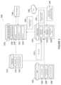
- FIG. 1is a block diagram of the advanced system for monitoring and controlling an industrial flare operation.
- FIG. 2is a flowchart of the learning algorithm of a deep learning core of a monitoring and control system for a flaring operation in an industrial plant.
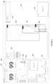
- FIG. 3is an example of a display of output from a monitoring and control system for a flaring operation in an industrial plant.
- FIG. 4is an example of a display of output from a monitoring and control system for a flaring operation in an industrial plant.
- FIG. 5is an example of a display of output from a monitoring and control system for a flaring operation in an industrial plant.
- Industrial flare stacksare an important feature of many of today's industrial plant operations. There is a need for monitoring and controlling industrial flare operations in industrial plants to continually provide enhanced levels of control even in challenging situations. There is a need for greater flexibility in the implementation and operation of industrial automation systems which include flare operations monitoring and control.
- An operatorcan monitor a flare stack and a combustion process by observing the flare stack and tracking flare activity.
- Previous approaches to flare stack monitoringcan include physically watching the flare stack and/or observing images captured of the flare stack by an optical imaging component.
- the operatormay have to perform manual actions in a system associated with the flare stack to identify and/or record the flare activity.
- an optical imaging componentmay capture images at night (e.g., low light and/or no light) that are difficult to interpret.
- Recently, some federal and state authorities across the worldhave mandated recording of video images as evidence of compliance with various laws and ordinances. Others have moved to include flare stack monitoring methods, systems, and computer-readable and executable instructions that improve user efficiency and reduce manual action as compared to previous approaches.
- Flare stack monitoringcan include processing thermal images captured of a flare stack area (e.g., an image of the flare stack and air space near the flare stack).
- the thermal images capturedcan be used, in various embodiments, to train a system to identify flare portions and smoke portions of the images based on the rate of movement of portions between a sequence of images. For instance, smoke particles can move faster than flare/flame particles. This is because smoke particles are less dense than particles that are on fire. Further, the thermal images can capture the flare stack activity in low lighting and/or reduced visibility, unlike an optical image.
- the end-to-end solutionstarts with data acquisition and continues all the way through final issuance of alerts and alarms.
- the systemcontains a data acquisition and augmentation mechanism whereby data is aquired through connected sensor systems which include single or multicamera hubs, flare gas temerature sensors, flare gas flow sensors and the like.
- the automated flare analytics systemstreamlines the data and converts the date to a format that is compatible with a deep learning core.
- the systemfurther has an optical flow mechanism that generate motion information to distinguish background elements.
- the systemhas a deep learning core to perform the analytics.
- the systemalso has post processing mechanisms for data visualization, issing alerts, and logging events.
- the disclsourefurther provides for the opportunity of global connectivity through the cloud.
- the global connectivityprovides continual improvement of the deep empering core through learning from information sharing through a multisite neural-net.
- the global connectivityfurther provides for remote alerts and remote access to event logs and allows monitoring and aiding with global analytics by remote experts.
- the systemis unique in that it employs a machine learning/deep learning core that categorizes image frames at a pixel level, semantic segmentation, into regions of black smoke, steam and flame.
- the regions of smoke, steam, and flameare not defined shape objects as they are nonuniform and therefore previous image processing techniques were not able to sufficiently distinguish the specific categories.
- the machine learning/deep learning coreprovides a step forward in that the deep learning core is able to distinguish these categories in a significantly more reliable and consistent manner.
- the machine learningmay begin by training the model with images that have been annotated as portions that are black smoke, steam, and flame.
- the annotationmay be manual markings as to which portions are black smoke, which are steam, and which are flame.
- the annotated imagesare input into the machine learning/deep learning core and then the system may be fine-tuned further to arrive at the best results.
- the training datamay then be separated from the test data to be analyzed. Accuracy may be at greater than 90% accuracy for all situations and greater than 95% for ideal conditions.
- Optical Flow methodsare applied in the deep learning core in order to take advantage of motion information between image frames from video and thermal cameras. Optical Flow methods are described in, for example, U.S. Pat. No. 10,041,673. Movement can be established by analyzing the current frame in a sequence of images in comparison to the previous frame. In this way the foreground images are distinguished from the background images and with other data of the deep learning core the steam can be distinguished from clouds.
- the deep learning coreis capable of processing augmentation of data such as raw images from video and thermal cameras, Optical Flow data from image sequences provided by video and thermal cameras and other data from the plant on gas flow related to properties of the flare gas such as flow temperature and composition.
- the method of this disclosuremay be operated in all weather conditions due to the incorporation of the optical flow feature and the data augmentation feature.
- the systemmay employ both a vision camera and a thermal camera.
- the inferencing from the imagesmay employ images from the vision camera, from the thermal camera, or both. In good weather conditions and in the daytime inferences may be made from images of the vision camera alone. However, in bad weather, or at night, inferences may be made from the thermal images or the combination of thermal images along with vision camera images. Engaging both types of cameras to provide image input to the system results in a low percentage of false positive in the system results.
- the systemallows for multiple flare monitoring and control data to be analyzed and used to continually train the deep learning core.
- Multiple flares at an industrial plantmay be monitored and controlled though a single system using a deep learning core.
- multiple industrial plants, each having multiple flare operationsmay all be monitored and controlled through a single system having a deep learning core.
- the deep learning coreis continually refined with wide sets of data and over time becomes more efficient and more accurate in a wide range of conditions. In this way, operations at one industrial plant is being used to assist operations at a different industrial plant.
- Analytics system 110receives input from plant 102 such as gas flow data 104 , gas temperature and pressure data 106 , and gas composition data 108 .
- Analytics system 110also receives raw image frames 112 from camera hub 114 having both a vision camera 116 and a thermal camera 118 .
- Vision camera 116may be a video camera.
- Analytics system 110has optical flow mechanism 120 which operates to separate the background from the data to be measured in the raw frames 112 .
- Analytics system 110also has data augmentation mechanism 122 which operates to augment the data input to analytics system 122 and then provides the augmented data to deep learning core 124 which is also part of analytics system 110 .
- the purpose of the data augmentation mechanismis to augment the data to a form compatible to deep learning core 124 .
- the subsystems of optical flow mechanism 120 , data augmentation mechanism 122 and deep learning core 124provide the analytics on the input data and issues high accuracy results even under challenging conditions. For example, some raw frame images from a first flare at a first plant operating on a clear day and some raw frame images may be from a second flare at a second plant operating at night.
- GANGenerative Adversarial Network system
- Analytics system 110provides data, such as segmented frame alerts and events 136 to digital video manager (DVM) 126 which is used to display information.
- DVM 126can display a visual image frames display 128 , a thermal image frames display 130 , an analytics user interface 132 , and an alerts user interface 134 .
- Alerts manager 138which communicates with and may be controlled by DVM 126 , may be used to inform operators regarding out of limits situations in any flare. Smoking, excessive steam and the like are examples of alerts.
- Analytics system 110may be connected to a cloud 140 in order to share local analytics to a global network 142 . An operator accessing the global network would be able to assess flare operations across multiple different plant sites.
- Analytical system 110also receives from cloud 140 , global analytics information from other plants and remote experts 144 . Incorporating global analytics information from other plants and remote experts into the continuing training of the deep learning core provides for a more robust and accurate system.
- the methodstarts by capturing data from different sources and from multiple industrial plants 202 .
- the datamay be captured from visual cameras, thermal cameras, and data from the plant operations.
- Visual camera datamay include time stamped image frames 206 obtained from continuous video camera feed.
- Thermal camera datamay include time stamped thermal image frames 204 obtained from a continuous thermal camera.
- Plant operations datamay include flow rate and temperature of flare gas and flare gas composition 208 .
- Remote datamay be captured from the cloud 210 including global analytics and remote expert commentary and recommendations. The data arrives at the analytics system almost in real time. The acquisition may happen through either through edge or cloud network.
- Thermal image frames and visual image framesare input, 204 and 206 respectively, to the optical flow algorithm 212 .
- Optical Flow methodsare applied on incoming image frames to gather motion information between frames and augment with other acquired data.
- the motion informationis secondary data derived by running Optical Flow algorithms on sequence of obtained thermal and video frames.
- the optical flow algorithm 212separates the background information from the useful information and generates the motion information 214 .
- the captured data of thermal images 204 and visual images 206 and the motion information 214is input into the deep learning core 216 .
- Captured data from the plant operations 208is also input into deep learning core 216 .
- Remote data from cloud storage 210is also input into deep learning core 216 .
- the data input to the deep learning coreis unpacked and augmented into a format that the deep learning core can process.
- the Deep Learning Modelmay be a variant of the Fully Convolution Neural Network architecture.
- the modelcan perform semantic segmentation of received frames to identify pixels of smoke, steam and flame.
- the modelingests frames from video and thermal cameras, motion information of pixels between frames and miscellaneous data on the flare gas obtained from plant. The motion information is gathered by applying state of the art optical flow methods between frames as a preprocessing step.
- the segmentation map generated by the Deep Learning modelis then used to issue alerts.
- the deep learning coreoutputs analytics and segmented image frames indicating flame, smoke, and steam pixels 218 .
- the framesare segmented at the pixel level.
- Each pixel that is not backgroundis assigned a category of flame, smoke or steam.
- the segmentation map obtained from the deep learning coremay be visualized in an operator user interface. Further processing steps are applied to issue alerts and log events as the segmented frames allow for the generation of events and alerts 220 which may be output 222 to a DVM or sent for cloud storage 224 . Selected outputs may be displayed on a user interface 226 .
- the results of the analyticsmay be shared globally through cloud connectivity.
- the analytics systemmay run on a graphics processing unit (GPU) enabled system or on a standalone platform.
- GPUgraphics processing unit
- the systemmay be integrated with Digital Video Manager available from Honeywell International Inc, and the results of the analytics may be communicated to the Digital Video Manager and displayed on an operator's display.
- Possible information provided to the operatorinclude detection of a no flame condition, flame size tracking, steam plume detection and steam plume size information, instantaneous black smoke detection and smoke plume size information, visualization of steam, smoke, and flame regions in the flare stack video, continuous logging of events and issues of the alerts and alarms.
- the systemutilizes multiple networks, multiple types of images, sequences of multiple frames of types of images, and is able to separate background information from the information to be measured.
- the neural network of the deep learning coreis trained and continuously trains to provide a pixel level classification into smoke steam or flame.
- the graphical interface display for the results of the systemmay show a variety of results important to operators.
- the displaymaybe a mobile device or may be a stationary monitor.
- FIG. 3One such display is shown in FIG. 3 .
- Display 300shows panel 302 where the video frames that are being processed are displayed along with the categorization results at the pixel level into the flame category the steam category and the smoke category.
- the categoriesare organized in display masks for ready understanding by an operator and can be color coded as well.
- the processing of the imagescan include outputting an image with visual identification of flare portions and smoke portions and steam portions in each image. For instance, a visual color differentiation can be applied to a flare portion and a smoke portion of the images.
- Example color differentiationcan include a scale range of colors based on an identified movement of each portion and/or based on thermal intensity identified in the images.
- pixels identified as flamemay be colored green
- pixels identified with smokemay be colored red
- pixels identified as steammay be colored purple.
- FIG. 3shows flame in display mask 304 , steam in display mask 306 , and smoke in display mask 308 .
- Display mask selection controlssuch as a toggle or radial button, may provide the option of selecting or deselecting different display masks.
- Panel 302may also show data such as date, time, flare identification, and the like as information data display 314 .
- the number of mitigated events 316 and number of missed alarms 318are also shown.
- Distribution 320shows both the numeric readouts as well as graphicly, of the amounts of steam, flame and smoke present. Thresholds may be established for each category.
- the displaymay be interactive and can accept inputs from an operator.
- the processing of the imagescan include outputting an image with visual identification of flare portions and/or smoke portions in each image.
- a visual color differentiationcan be applied to a flare portion and a smoke portion of the images.
- Example color differentiationcan include a scale range of colors based on an identified movement of each portion and/or based on thermal intensity identified in the images.
- Live feed 324 from camerasmay be displayed as well as, alerts 326 .
- FIG. 4shows another possible display.
- FIG. 4may be displayed, for example on a monitor. Additional features to that shown in FIG. 3 include event log and trends 402 is shown allowing for visualization of the events and trends and recorded camera feed 404 that may be synchronized with event log 402 .
- FIG. 5Shows yet another alternative display.
Landscapes
- Engineering & Computer Science (AREA)
- Theoretical Computer Science (AREA)
- Physics & Mathematics (AREA)
- General Physics & Mathematics (AREA)
- Evolutionary Computation (AREA)
- Artificial Intelligence (AREA)
- Software Systems (AREA)
- Health & Medical Sciences (AREA)
- General Health & Medical Sciences (AREA)
- Computing Systems (AREA)
- General Engineering & Computer Science (AREA)
- Biophysics (AREA)
- Mathematical Physics (AREA)
- Computational Linguistics (AREA)
- Data Mining & Analysis (AREA)
- Life Sciences & Earth Sciences (AREA)
- Biomedical Technology (AREA)
- Molecular Biology (AREA)
- Multimedia (AREA)
- Medical Informatics (AREA)
- Computer Vision & Pattern Recognition (AREA)
- Databases & Information Systems (AREA)
- Automation & Control Theory (AREA)
- Testing And Monitoring For Control Systems (AREA)
- Alarm Systems (AREA)
Abstract
Description
Claims (20)
Priority Applications (3)
| Application Number | Priority Date | Filing Date | Title |
|---|---|---|---|
| PCT/US2020/035676WO2020247358A1 (en) | 2019-06-07 | 2020-06-02 | Method and system for connected advanced flare analytics |
| EP20178129.1AEP3748444B1 (en) | 2019-06-07 | 2020-06-03 | Method and system for connected advanced flare analytics |
| CA3081967ACA3081967C (en) | 2019-06-07 | 2020-06-04 | Method and system for connected advanced flare analytics |
Applications Claiming Priority (2)
| Application Number | Priority Date | Filing Date | Title |
|---|---|---|---|
| IN201911022667 | 2019-06-07 | ||
| IN201911022667 | 2019-06-07 |
Publications (2)
| Publication Number | Publication Date |
|---|---|
| US20200387120A1 US20200387120A1 (en) | 2020-12-10 |
| US11927944B2true US11927944B2 (en) | 2024-03-12 |
Family
ID=73651538
Family Applications (1)
| Application Number | Title | Priority Date | Filing Date |
|---|---|---|---|
| US16/861,522Active2041-04-18US11927944B2 (en) | 2019-06-07 | 2020-04-29 | Method and system for connected advanced flare analytics |
Country Status (3)
| Country | Link |
|---|---|
| US (1) | US11927944B2 (en) |
| CA (1) | CA3081967C (en) |
| WO (1) | WO2020247358A1 (en) |
Cited By (1)
| Publication number | Priority date | Publication date | Assignee | Title |
|---|---|---|---|---|
| US20240202902A1 (en)* | 2022-12-20 | 2024-06-20 | Honeywell International Inc. | Systems, apparatuses, methods, and computer program products for determining a flaring efficiency estimate based on captured image data and operations data |
Families Citing this family (8)
| Publication number | Priority date | Publication date | Assignee | Title |
|---|---|---|---|---|
| US20220179399A1 (en)* | 2020-07-07 | 2022-06-09 | Maillance SAS | Method and System for Flare Stack Monitoring and Optimization |
| US11908195B2 (en)* | 2020-12-01 | 2024-02-20 | Devon Energy Corporation | Systems, methods, and computer program products for object detection and analysis of an image |
| US20220268523A1 (en)* | 2021-02-19 | 2022-08-25 | Inirv Labs, Inc. | Camera-enabled machine learning for device control in a kitchen environment |
| CN112699858B (en)* | 2021-03-24 | 2021-05-18 | 中国人民解放军国防科技大学 | Unmanned platform smoke and dust sensing method, system, computer equipment and storage medium |
| BR102021020663A2 (en) | 2021-10-14 | 2023-04-25 | Petróleo Brasileiro S.A. - Petrobras | EVALUATION METHOD OF THE QUALITY OF THE BURNING OF GASES IN THE TORCH AND CONTINUOUS AND CONSTANT STEAM FLOW ADJUSTMENT |
| WO2024137906A1 (en)* | 2022-12-23 | 2024-06-27 | Schlumberger Technology Corporation | Adjustable flare tip |
| WO2024168206A1 (en)* | 2023-02-10 | 2024-08-15 | Schlumberger Technology Corporation | Flare stream classification with semantic segmentation and generative adversarial networks in normal and low-light conditions |
| WO2025054692A1 (en)* | 2023-09-15 | 2025-03-20 | Ouro Negro Tecnologias Em Equipamentos Industriais S/A | Method for increasing the accuracy of lidar sensing in the measurement of the efficiency of flare gas combustion in face of environmental variations and degradation of the flare combustion control system |
Citations (21)
| Publication number | Priority date | Publication date | Assignee | Title |
|---|---|---|---|---|
| US20030141980A1 (en)* | 2000-02-07 | 2003-07-31 | Moore Ian Frederick | Smoke and flame detection |
| US20100080417A1 (en)* | 2008-09-29 | 2010-04-01 | Qureshi Shehrzad A | Object-Tracking Systems and Methods |
| US7876229B2 (en) | 2007-08-14 | 2011-01-25 | Honeywell International Inc. | Flare monitoring |
| US20110085030A1 (en)* | 2009-10-07 | 2011-04-14 | John Zink Company, Llc | Image sensing system, software, apparatus and method for controlling combustion equipment |
| US8138927B2 (en) | 2007-03-22 | 2012-03-20 | Honeywell International Inc. | Flare characterization and control system |
| US8300890B1 (en)* | 2007-01-29 | 2012-10-30 | Intellivision Technologies Corporation | Person/object image and screening |
| US20140049491A1 (en)* | 2012-08-20 | 2014-02-20 | Samsung Electronics Co., Ltd | System and method for perceiving images with multimodal feedback |
| US20150077263A1 (en)* | 2012-03-01 | 2015-03-19 | Nuovo Pignone Srl | Method and system for condition monitoring of a group of plants |
| US20160116164A1 (en)* | 2014-10-24 | 2016-04-28 | Lumasense Technologies Holdings, Inc. | Measuring and controlling flame quality in real-time |
| US9594359B2 (en) | 2014-04-14 | 2017-03-14 | Honeywell International Inc. | Feedback control for reducing flaring process smoke and noise |
| WO2017058832A1 (en) | 2015-09-28 | 2017-04-06 | Schlumberger Technology Corporation | Burner monitoring and control systems |
| CN106845410A (en) | 2017-01-22 | 2017-06-13 | 西安科技大学 | A kind of flame identification method based on deep learning model |
| US20180209853A1 (en) | 2017-01-23 | 2018-07-26 | Honeywell International Inc. | Equipment and method for three-dimensional radiance and gas species field estimation in an open combustion environment |
| US10041673B2 (en) | 2013-07-25 | 2018-08-07 | Honeywell International Inc. | Flare stack monitoring |
| US20180276792A1 (en)* | 2016-08-19 | 2018-09-27 | Intelligent Security Systems Corporation | Systems and methods for dewarping images |
| US20190146478A1 (en)* | 2016-05-09 | 2019-05-16 | Strong Force Iot Portfolio 2016, Llc | Methods and systems of diagnosing machine components using analog sensor data and neural network |
| US20190155973A1 (en)* | 2017-11-02 | 2019-05-23 | Airworks Solutions, Inc. | Methods and apparatus for automatically defining computer-aided design files using machine learning, image analytics, and/or computer vision |
| US20190244504A1 (en)* | 2016-10-24 | 2019-08-08 | Hochiki Corporation | Fire monitoring system |
| US20190251702A1 (en)* | 2018-02-12 | 2019-08-15 | Avodah Labs, Inc. | Real-time gesture recognition method and apparatus |
| US20190355128A1 (en)* | 2017-01-06 | 2019-11-21 | Board Of Regents, The University Of Texas System | Segmenting generic foreground objects in images and videos |
| US20200278465A1 (en)* | 2017-09-12 | 2020-09-03 | Schlumberger Technology Corporation | Seismic image data interpretation system |
Family Cites Families (2)
| Publication number | Priority date | Publication date | Assignee | Title |
|---|---|---|---|---|
| US7660440B2 (en)* | 2002-11-07 | 2010-02-09 | Frito-Lay North America, Inc. | Method for on-line machine vision measurement, monitoring and control of organoleptic properties of products for on-line manufacturing processes |
| US7202794B2 (en)* | 2004-07-20 | 2007-04-10 | General Monitors, Inc. | Flame detection system |
- 2020
- 2020-04-29USUS16/861,522patent/US11927944B2/enactiveActive
- 2020-06-02WOPCT/US2020/035676patent/WO2020247358A1/ennot_activeCeased
- 2020-06-04CACA3081967Apatent/CA3081967C/enactiveActive
Patent Citations (22)
| Publication number | Priority date | Publication date | Assignee | Title |
|---|---|---|---|---|
| US20030141980A1 (en)* | 2000-02-07 | 2003-07-31 | Moore Ian Frederick | Smoke and flame detection |
| US7002478B2 (en)* | 2000-02-07 | 2006-02-21 | Vsd Limited | Smoke and flame detection |
| US8300890B1 (en)* | 2007-01-29 | 2012-10-30 | Intellivision Technologies Corporation | Person/object image and screening |
| US8138927B2 (en) | 2007-03-22 | 2012-03-20 | Honeywell International Inc. | Flare characterization and control system |
| US7876229B2 (en) | 2007-08-14 | 2011-01-25 | Honeywell International Inc. | Flare monitoring |
| US20100080417A1 (en)* | 2008-09-29 | 2010-04-01 | Qureshi Shehrzad A | Object-Tracking Systems and Methods |
| US20110085030A1 (en)* | 2009-10-07 | 2011-04-14 | John Zink Company, Llc | Image sensing system, software, apparatus and method for controlling combustion equipment |
| US20150077263A1 (en)* | 2012-03-01 | 2015-03-19 | Nuovo Pignone Srl | Method and system for condition monitoring of a group of plants |
| US20140049491A1 (en)* | 2012-08-20 | 2014-02-20 | Samsung Electronics Co., Ltd | System and method for perceiving images with multimodal feedback |
| US10041673B2 (en) | 2013-07-25 | 2018-08-07 | Honeywell International Inc. | Flare stack monitoring |
| US9594359B2 (en) | 2014-04-14 | 2017-03-14 | Honeywell International Inc. | Feedback control for reducing flaring process smoke and noise |
| US20160116164A1 (en)* | 2014-10-24 | 2016-04-28 | Lumasense Technologies Holdings, Inc. | Measuring and controlling flame quality in real-time |
| WO2017058832A1 (en) | 2015-09-28 | 2017-04-06 | Schlumberger Technology Corporation | Burner monitoring and control systems |
| US20190146478A1 (en)* | 2016-05-09 | 2019-05-16 | Strong Force Iot Portfolio 2016, Llc | Methods and systems of diagnosing machine components using analog sensor data and neural network |
| US20180276792A1 (en)* | 2016-08-19 | 2018-09-27 | Intelligent Security Systems Corporation | Systems and methods for dewarping images |
| US20190244504A1 (en)* | 2016-10-24 | 2019-08-08 | Hochiki Corporation | Fire monitoring system |
| US20190355128A1 (en)* | 2017-01-06 | 2019-11-21 | Board Of Regents, The University Of Texas System | Segmenting generic foreground objects in images and videos |
| CN106845410A (en) | 2017-01-22 | 2017-06-13 | 西安科技大学 | A kind of flame identification method based on deep learning model |
| US20180209853A1 (en) | 2017-01-23 | 2018-07-26 | Honeywell International Inc. | Equipment and method for three-dimensional radiance and gas species field estimation in an open combustion environment |
| US20200278465A1 (en)* | 2017-09-12 | 2020-09-03 | Schlumberger Technology Corporation | Seismic image data interpretation system |
| US20190155973A1 (en)* | 2017-11-02 | 2019-05-23 | Airworks Solutions, Inc. | Methods and apparatus for automatically defining computer-aided design files using machine learning, image analytics, and/or computer vision |
| US20190251702A1 (en)* | 2018-02-12 | 2019-08-15 | Avodah Labs, Inc. | Real-time gesture recognition method and apparatus |
Non-Patent Citations (9)
| Title |
|---|
| Bährecke, Automatic Classification and Visualisation of Gas from Infrared Video Data, 2015, KTH Technology and Health (Year: 2015).* |
| EP Search Report for corresponding European Application No. 20178129.1 dated Oct. 23, 2020. |
| Ig et al., "FlowNet 2.0_ Evolution of Optical Flow Estimation With Deep Networks", 2017, Computer Vision Foundation (Year: 2017).* |
| Prativadibhayankaram et al., "Compressive Online Video Background-Foreground Separation Using Multiple Prior Information and Optical Flow", 2018, Journal of Imaging (Year: 2018).* |
| Search Report and Written Opinion for International Application No. PCT/US2020/035676, dated Sep. 17, 2020, ISA/RU. |
| Taher, Deep learning for road area semantic segmentation in multispectral lidar data, Mar. 31, 2019, Aalto University (Year: 2019).* |
| Umar et al. State of the art of smoke and fire detection using image processing, 2017, Inderscience Enterprises Ltd (Year: 2017).* |
| Xu et al., Video smoke detection based on deep saliency network, Jun. 30, 2018, Elsevier Ltd (Year: 2018).* |
| Yuan et al, Deep smoke segmentation—May 10, 2019, Neurocomputing (Year: 2019).* |
Cited By (2)
| Publication number | Priority date | Publication date | Assignee | Title |
|---|---|---|---|---|
| US20240202902A1 (en)* | 2022-12-20 | 2024-06-20 | Honeywell International Inc. | Systems, apparatuses, methods, and computer program products for determining a flaring efficiency estimate based on captured image data and operations data |
| US12417527B2 (en)* | 2022-12-20 | 2025-09-16 | Honeywell International Inc. | Apparatus, method, and program product for determining a flaring efficiency estimate based on captured image data, a simulation model, and operations data |
Also Published As
| Publication number | Publication date |
|---|---|
| US20200387120A1 (en) | 2020-12-10 |
| WO2020247358A1 (en) | 2020-12-10 |
| CA3081967A1 (en) | 2020-12-07 |
| CA3081967C (en) | 2022-06-28 |
Similar Documents
| Publication | Publication Date | Title |
|---|---|---|
| US11927944B2 (en) | Method and system for connected advanced flare analytics | |
| US11519602B2 (en) | Processes and systems for analyzing images of a flare burner | |
| US20160260306A1 (en) | Method and device for automated early detection of forest fires by means of optical detection of smoke clouds | |
| US12392488B2 (en) | Method of assessment of the quality of the burn of the gases in the flare and adjustment to the vapor flow rate in a continuous and constant way | |
| CN113820326B (en) | Defect detection system of long-code zipper | |
| JP7481956B2 (en) | Inference device, method, program and learning device | |
| CN116543241B (en) | Detection method and device for leakage gas cloud, storage medium and electronic equipment | |
| EP3748444B1 (en) | Method and system for connected advanced flare analytics | |
| CN111178424A (en) | A real-time detection system and method for safety compliance of petrochemical production site | |
| CN116579609B (en) | Illegal operation analysis method based on inspection process | |
| CN115793673A (en) | Natural gas station robot inspection method and device based on VR technology | |
| CN119132027A (en) | Tunnel environment real-time monitoring and evaluation system | |
| CN120014549A (en) | Method and system for detecting construction workers crossing dangerous areas based on neural network | |
| CN115909212A (en) | A real-time early warning method for typical violations in electric power operations | |
| CN119339535A (en) | Fire monitoring method and fire monitoring device | |
| CN117373113A (en) | Live working personnel behavior recognition method | |
| CN109028234B (en) | Range hood capable of identifying smoke grade | |
| CN117830953B (en) | Intelligent network color image tracking monitoring method, system, terminal and storage medium | |
| US20250069404A1 (en) | System and method for continuous flame quality assessment of industrial burners | |
| CN119135852B (en) | A cruise ship safety video monitoring method and system based on video classification | |
| CN109655411A (en) | For the lingemann blackness real-time analysis method and system of pollution source smoke discharge | |
| EP4250244A1 (en) | Vision based testing augmented with out of visible band signaling | |
| WO2025057684A1 (en) | Image processing system and information processing system | |
| CN119004370A (en) | Data calling processing method and device based on steel production scene task | |
| EP3819817A1 (en) | A method and system of evaluating the valid analysis region of a specific scene |
Legal Events
| Date | Code | Title | Description |
|---|---|---|---|
| FEPP | Fee payment procedure | Free format text:ENTITY STATUS SET TO UNDISCOUNTED (ORIGINAL EVENT CODE: BIG.); ENTITY STATUS OF PATENT OWNER: LARGE ENTITY | |
| STPP | Information on status: patent application and granting procedure in general | Free format text:APPLICATION DISPATCHED FROM PREEXAM, NOT YET DOCKETED | |
| AS | Assignment | Owner name:HONEYWELL INTERNATIONAL INC, NEW JERSEY Free format text:ASSIGNMENT OF ASSIGNORS INTEREST;ASSIGNORS:PAMULAPARTHY, VENKATA DHRUVA;BEHERA, BIMALANANDA;PRABHAKAR, VARUN;AND OTHERS;SIGNING DATES FROM 20200420 TO 20200603;REEL/FRAME:052925/0536 | |
| STPP | Information on status: patent application and granting procedure in general | Free format text:DOCKETED NEW CASE - READY FOR EXAMINATION | |
| STPP | Information on status: patent application and granting procedure in general | Free format text:NON FINAL ACTION MAILED | |
| STPP | Information on status: patent application and granting procedure in general | Free format text:RESPONSE TO NON-FINAL OFFICE ACTION ENTERED AND FORWARDED TO EXAMINER | |
| STPP | Information on status: patent application and granting procedure in general | Free format text:FINAL REJECTION MAILED | |
| STPP | Information on status: patent application and granting procedure in general | Free format text:RESPONSE AFTER FINAL ACTION FORWARDED TO EXAMINER | |
| STPP | Information on status: patent application and granting procedure in general | Free format text:NOTICE OF ALLOWANCE MAILED -- APPLICATION RECEIVED IN OFFICE OF PUBLICATIONS | |
| STPP | Information on status: patent application and granting procedure in general | Free format text:PUBLICATIONS -- ISSUE FEE PAYMENT VERIFIED | |
| STCF | Information on status: patent grant | Free format text:PATENTED CASE |