US11927152B2 - Reaction control vortex thruster system - Google Patents
Reaction control vortex thruster systemDownload PDFInfo
- Publication number
- US11927152B2 US11927152B2US18/094,300US202318094300AUS11927152B2US 11927152 B2US11927152 B2US 11927152B2US 202318094300 AUS202318094300 AUS 202318094300AUS 11927152 B2US11927152 B2US 11927152B2
- Authority
- US
- United States
- Prior art keywords
- monopropellant
- vortex
- decomposed
- combustion chamber
- catalyst bed
- Prior art date
- Legal status (The legal status is an assumption and is not a legal conclusion. Google has not performed a legal analysis and makes no representation as to the accuracy of the status listed.)
- Active
Links
- 238000006243chemical reactionMethods0.000titledescription2
- 238000002485combustion reactionMethods0.000claimsabstractdescription92
- 239000003380propellantSubstances0.000claimsabstractdescription30
- 238000000034methodMethods0.000claimsabstractdescription15
- 239000003054catalystSubstances0.000claimsdescription55
- 238000002347injectionMethods0.000claimsdescription20
- 239000007924injectionSubstances0.000claimsdescription20
- MHAJPDPJQMAIIY-UHFFFAOYSA-NHydrogen peroxideChemical groupOOMHAJPDPJQMAIIY-UHFFFAOYSA-N0.000claimsdescription18
- IJGRMHOSHXDMSA-UHFFFAOYSA-NAtomic nitrogenChemical compoundN#NIJGRMHOSHXDMSA-UHFFFAOYSA-N0.000claimsdescription14
- OAKJQQAXSVQMHS-UHFFFAOYSA-Nhydrazine groupChemical groupNNOAKJQQAXSVQMHS-UHFFFAOYSA-N0.000claimsdescription10
- 230000003213activating effectEffects0.000claimsdescription9
- 239000003350keroseneSubstances0.000claimsdescription8
- 229910052757nitrogenInorganic materials0.000claimsdescription7
- 238000004891communicationMethods0.000claimsdescription6
- 239000012530fluidSubstances0.000claimsdescription6
- QVGXLLKOCUKJST-UHFFFAOYSA-Natomic oxygenChemical compound[O]QVGXLLKOCUKJST-UHFFFAOYSA-N0.000claimsdescription5
- 239000001301oxygenSubstances0.000claimsdescription5
- 229910052760oxygenInorganic materials0.000claimsdescription5
- XLYOFNOQVPJJNP-UHFFFAOYSA-NwaterChemical compoundOXLYOFNOQVPJJNP-UHFFFAOYSA-N0.000claimsdescription5
- QGZKDVFQNNGYKY-UHFFFAOYSA-NAmmoniaChemical compoundNQGZKDVFQNNGYKY-UHFFFAOYSA-N0.000claimsdescription4
- 229910021529ammoniaInorganic materials0.000claimsdescription2
- 239000001257hydrogenSubstances0.000claimsdescription2
- 229910052739hydrogenInorganic materials0.000claimsdescription2
- 125000004435hydrogen atomChemical class[H]*0.000claimsdescription2
- 238000011144upstream manufacturingMethods0.000claims2
- 238000004519manufacturing processMethods0.000abstractdescription3
- 238000002156mixingMethods0.000description4
- 238000001816coolingMethods0.000description3
- 239000007788liquidSubstances0.000description3
- 229910052758niobiumInorganic materials0.000description3
- 239000010955niobiumSubstances0.000description3
- GUCVJGMIXFAOAE-UHFFFAOYSA-Nniobium atomChemical compound[Nb]GUCVJGMIXFAOAE-UHFFFAOYSA-N0.000description3
- 230000008901benefitEffects0.000description2
- 239000007789gasSubstances0.000description2
- 230000007246mechanismEffects0.000description2
- 239000000203mixtureSubstances0.000description2
- 239000007800oxidant agentSubstances0.000description2
- 230000037361pathwayEffects0.000description2
- 238000007792additionMethods0.000description1
- PNEYBMLMFCGWSK-UHFFFAOYSA-Naluminium oxideInorganic materials[O-2].[O-2].[O-2].[Al+3].[Al+3]PNEYBMLMFCGWSK-UHFFFAOYSA-N0.000description1
- 239000011248coating agentSubstances0.000description1
- 238000000576coating methodMethods0.000description1
- 239000002826coolantSubstances0.000description1
- 238000000354decomposition reactionMethods0.000description1
- 238000013461designMethods0.000description1
- 239000000446fuelSubstances0.000description1
- 229910052741iridiumInorganic materials0.000description1
- GKOZUEZYRPOHIO-UHFFFAOYSA-Niridium atomChemical compound[Ir]GKOZUEZYRPOHIO-UHFFFAOYSA-N0.000description1
- 238000011068loading methodMethods0.000description1
- 238000012986modificationMethods0.000description1
- 230000004048modificationEffects0.000description1
- 238000013021overheatingMethods0.000description1
- 230000003647oxidationEffects0.000description1
- 238000007254oxidation reactionMethods0.000description1
- 230000001590oxidative effectEffects0.000description1
- 239000008188pelletSubstances0.000description1
- 230000001172regenerating effectEffects0.000description1
- 229910021332silicideInorganic materials0.000description1
- FVBUAEGBCNSCDD-UHFFFAOYSA-Nsilicide(4-)Chemical compound[Si-4]FVBUAEGBCNSCDD-UHFFFAOYSA-N0.000description1
- 230000008646thermal stressEffects0.000description1
Images


Classifications
- F—MECHANICAL ENGINEERING; LIGHTING; HEATING; WEAPONS; BLASTING
- F02—COMBUSTION ENGINES; HOT-GAS OR COMBUSTION-PRODUCT ENGINE PLANTS
- F02K—JET-PROPULSION PLANTS
- F02K9/00—Rocket-engine plants, i.e. plants carrying both fuel and oxidant therefor; Control thereof
- F02K9/42—Rocket-engine plants, i.e. plants carrying both fuel and oxidant therefor; Control thereof using liquid or gaseous propellants
- F02K9/60—Constructional parts; Details not otherwise provided for
- F02K9/68—Decomposition chambers
- F—MECHANICAL ENGINEERING; LIGHTING; HEATING; WEAPONS; BLASTING
- F02—COMBUSTION ENGINES; HOT-GAS OR COMBUSTION-PRODUCT ENGINE PLANTS
- F02K—JET-PROPULSION PLANTS
- F02K9/00—Rocket-engine plants, i.e. plants carrying both fuel and oxidant therefor; Control thereof
- F02K9/08—Rocket-engine plants, i.e. plants carrying both fuel and oxidant therefor; Control thereof using solid propellants
- F02K9/28—Rocket-engine plants, i.e. plants carrying both fuel and oxidant therefor; Control thereof using solid propellants having two or more propellant charges with the propulsion gases exhausting through a common nozzle
- F—MECHANICAL ENGINEERING; LIGHTING; HEATING; WEAPONS; BLASTING
- F02—COMBUSTION ENGINES; HOT-GAS OR COMBUSTION-PRODUCT ENGINE PLANTS
- F02K—JET-PROPULSION PLANTS
- F02K9/00—Rocket-engine plants, i.e. plants carrying both fuel and oxidant therefor; Control thereof
- F02K9/42—Rocket-engine plants, i.e. plants carrying both fuel and oxidant therefor; Control thereof using liquid or gaseous propellants
- F02K9/425—Propellants
- F—MECHANICAL ENGINEERING; LIGHTING; HEATING; WEAPONS; BLASTING
- F02—COMBUSTION ENGINES; HOT-GAS OR COMBUSTION-PRODUCT ENGINE PLANTS
- F02K—JET-PROPULSION PLANTS
- F02K9/00—Rocket-engine plants, i.e. plants carrying both fuel and oxidant therefor; Control thereof
- F02K9/42—Rocket-engine plants, i.e. plants carrying both fuel and oxidant therefor; Control thereof using liquid or gaseous propellants
- F02K9/44—Feeding propellants
- F02K9/56—Control
- F02K9/58—Propellant feed valves
- F—MECHANICAL ENGINEERING; LIGHTING; HEATING; WEAPONS; BLASTING
- F02—COMBUSTION ENGINES; HOT-GAS OR COMBUSTION-PRODUCT ENGINE PLANTS
- F02K—JET-PROPULSION PLANTS
- F02K9/00—Rocket-engine plants, i.e. plants carrying both fuel and oxidant therefor; Control thereof
- F02K9/72—Rocket-engine plants, i.e. plants carrying both fuel and oxidant therefor; Control thereof using liquid and solid propellants, i.e. hybrid rocket-engine plants
- F—MECHANICAL ENGINEERING; LIGHTING; HEATING; WEAPONS; BLASTING
- F05—INDEXING SCHEMES RELATING TO ENGINES OR PUMPS IN VARIOUS SUBCLASSES OF CLASSES F01-F04
- F05D—INDEXING SCHEME FOR ASPECTS RELATING TO NON-POSITIVE-DISPLACEMENT MACHINES OR ENGINES, GAS-TURBINES OR JET-PROPULSION PLANTS
- F05D2240/00—Components
- F05D2240/10—Stators
- F05D2240/12—Fluid guiding means, e.g. vanes
- F05D2240/127—Vortex generators, turbulators, or the like, for mixing
Definitions
- Design requirements for a rocket combustion enginecan include competing or conflicting requirements.
- an efficient rocket combustion chambercan thoroughly mix fuel and oxidizer to generate complete combustion.
- complete combustioncan cause intense thermal stress of the rocket engine hardware.
- a cooling mechanismmay be required to prevent overheating, but conventional cooling mechanisms can add weight to a system that is mass-sensitive.
- Some rocket enginescan achieve high mixing rates and combustion efficiencies through the use of complex propellant injectors that can be heavy and expensive to manufacture. Furthermore, some rocket engines include intricate regenerative coolant channels to remove heat from the rocket hardware. Such rocket engine configurations may be difficult and expensive to manufacture, as well as require an increase in overall size and weight of the rocket engine.
- the vortex thruster systemcan include a catalyst bed configured to decompose a monopropellant delivered to the catalyst bed. Additionally, the vortex thruster system can include a first valve for controlling delivery of the monopropellant at a first flow rate into the catalyst bed to transform the monopropellant into a decomposed monopropellant. Furthermore, the vortex thruster system can include a vortex combustion chamber in fluid communication with the catalyst bed. The vortex combustion chamber can be configured to receive the decomposed monopropellant from the catalyst bed and the decomposed monopropellant can assist with creating a first thrust level.
- the vortex thruster systemcan include a second valve for controlling a second flow rate of the monopropellant into the catalyst bed.
- the second flow ratecan be greater than the first flow rate.
- the delivery of the monopropellant at the second flow ratecan generate a second thrust level that is greater than the first thrust level.
- the vortex thruster systemcan include a secondary propellant valve configured to deliver a secondary propellant into the vortex combustion chamber including the decomposed monopropellant to create a third thrust level that is greater than the second thrust level.
- the monopropellantcan include hydrogen peroxide or hydrazine.
- the decomposed monopropellantcan include water vapor and oxygen.
- the decomposed monopropellantcan include nitrogen, hydrogen, and ammonia.
- the secondary propellantcan include a kerosene or a mixed oxide of nitrogen.
- the vortex combustion chambercan include at least one side injection port positioned proximate to a sidewall of the vortex combustion chamber and configured to deliver a first amount of the decomposed monopropellant into the vortex combustion chamber in a direction that is approximately tangent to the sidewall.
- the vortex combustion chambercan include a proximal injection port positioned proximate to a proximal end of the vortex combustion chamber and configured to deliver a second amount of the decomposed monopropellant into a center area of the vortex combustion chamber.
- a methodin another interrelated aspect of the current subject matter, includes activating a first monopropellant valve to deliver a monopropellant at a first flow rate to a catalyst bed of the vortex thruster system to form a decomposed monopropellant.
- the methodcan further include decomposing the monopropellant in the catalyst bed.
- the methodcan include delivering the decomposed monopropellant into a vortex combustion chamber of the vortex thruster system to assist with generating a first thrust level.
- the delivering of the decomposed monopropellant into the vortex combustion chambercan include delivering a first amount of the decomposed monopropellant through a first injection port positioned proximate a sidewall of the vortex combustion chamber and configured to deliver the first amount of the decomposed monopropellant in a direction tangent to the sidewall.
- the delivering of the decomposed monopropellant into the vortex combustion chambercan include delivering a second amount of the decomposed monopropellant through a second injection port positioned proximate to a proximal end of the vortex combustion chamber and configured to deliver the second amount of the decomposed monopropellant into a center area of the vortex combustion chamber.
- the methodcan further include activating a second monopropellant valve to deliver the monopropellant at a second flow rate to the catalyst bed.
- the second flow ratecan be greater than the first flow rate.
- the delivery of the monopropellant at the second flow ratecan create a second thrust level that is greater than the first thrust level.
- the methodcan further include activating a secondary propellant valve to deliver a secondary propellant into the vortex combustion chamber including the decomposed monopropellant to create a third thrust level that is greater than the second thrust level.
- the monopropellantcan include hydrogen peroxide or hydrazine.
- the secondary propellantcan include kerosene or a mixed oxide of nitrogen.
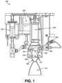
- FIG. 1illustrates a first section view of an embodiment of a vortex thruster system consistent with implementations of the current subject matter
- FIG. 2illustrates a second section view of the vortex thruster system of FIG. 1 showing a first propellant valve and a second propellant valve in fluid communication with a catalyst bed;
- FIG. 3illustrates a partial section view of the vortex thruster system of FIG. 1 showing a fluid pathway between a secondary propellant injector and a vortex combustion chamber, as well as fluid pathways between the catalyst bed and the vortex combustion chamber.
- a vortex thruster systemcan be included in various propulsion systems and can provide an efficient and effective way to generate various thrust levels.
- the vortex thruster systemcan be configured to efficiently generate at least three discrete thrust levels, such as a high thrust level, a medium thrust level, and a low thrust level.
- the vortex thruster systemcan be configured to generate a swirling or vortex flow field in a combustion chamber to limit thermal loading of the hardware of the vortex thruster system.
- Various vortex thruster system embodimentsare described in greater detail below.
- the vortex thruster systemcan include a catalyst bed and at least one oxidizer or monopropellant injector configured to deliver a monopropellant into the catalyst bed.
- the catalyst bedcan be configured to decompose the monopropellant, such as decompose hydrogen peroxide into high-temperature water vapor and gaseous oxygen.
- the catalyst bedcan be in communication with a vortex combustion chamber such that the decomposed monopropellant formed in the catalyst bed can be delivered into the vortex combustion chamber. Delivery of the decomposed monopropellant into the vortex combustion chamber can generate thrust by exhausting the products of decomposition through a nozzle extending from the vortex combustion chamber.
- the vortex thruster systemcan control a flow rate at which the monopropellant is delivered to the catalyst bed, which can affect the amount of thrust generated at the nozzle.
- the vortex thruster systemcan include a first monopropellant valve and a second monopropellant valve that are each configured to deliver the monopropellant at a different flow rate (e.g., a greater flow rate of the monopropellant into the catalyst bed can result in a greater generated thrust).
- the vortex thruster systemcan include a secondary propellant valve that directly injects a secondary propellant (e.g., a kerosene) into the vortex combustion chamber to ignite with the decomposed monopropellant in a bi-propellant configuration to generate a highest thrust level that can be achieved by the vortex thruster system.
- a secondary propellante.g., a kerosene
- the vortex combustion chambercan include at least one tangential injection port, such as at least an array of tangential injection ports, that are configured to deliver the decomposed monopropellant in a direction tangential to a circumference of an inner cylindrical surface of the vortex combustion chamber.
- This tangential injectioncan cause a flow of the decomposed monopropellant to swirl in the vortex combustion chamber.
- the swirl flowmay translate upwards towards the proximal end of the vortex combustion chamber where the flow can turn inward and move spirally away from a closed proximal end of the vortex combustion chamber, down the center of the vortex combustion chamber, and out the nozzle.
- the vortex thruster systemmay include at least one axial proximal injection port for delivering a portion of the decomposed monopropellant into a center area of the vortex combustion chamber. This may assist with efficiently and effectively optimizing the vortex combustion chamber for achieving a desired thrust level while simultaneously limiting the thermal load on the thruster hardware.
- a thrust levelcan include an approximate range of thrust loads, such as a low thrust level including a first thrust load range (e.g., approximately 20 lbf to 30 lbf), a medium thrust level including a second thrust load range (e.g., approximately 50 lbf to 60 lbf), and a high thrust level including a third thrust load range (e.g., approximately 100 lbf to 120 lbf).
- a low thrust levelincluding a first thrust load range (e.g., approximately 20 lbf to 30 lbf)
- a medium thrust levelincluding a second thrust load range
- a high thrust levele.g., approximately 100 lbf to 120 lbf.
- Other thrust levels and thrust load rangesare within the scope of this disclosure.
- FIGS. 1 - 3illustrate an embodiment of a vortex thruster system 100 configured to efficiently and effectively generate at least three discrete thrust levels.
- the vortex thruster system 100can include a vortex combustion chamber 102 having a proximal end 104 , a distal end 106 , and a sidewall 108 extending between the proximal end 104 and distal end 106 .
- the vortex combustion chamber 102may be cylindrical in shape, as shown in FIG. 1 , however, other shapes are within the scope of this disclosure.
- the proximal end 104 of the vortex combustion chambermay include a hollow dome-shape and the distal end 106 may include a converging-diverging nozzle 110 that provides a passageway through the distal end 106 of the vortex combustion chamber 102 , as shown in FIG. 1 .
- the vortex thruster system 100may include a catalyst bed 120 and at least one monopropellant valve, such as a first monopropellant valve 130 and a second monopropellant valve 140 , in communication with the catalyst bed 120 .
- the first monopropellant valve 130is configured to provide a different flow rate of monopropellant 105 into the catalyst bed 120 compared to the second monopropellant valve 140 .
- the first monopropellant valve 130can provide a lower flow rate of monopropellant to allow the vortex thruster system 100 to generate a first, lower thrust level.
- the second monopropellant valve 130can provide a higher flow rate of monopropellant to allow the vortex thruster system 100 to generate a higher, second thrust level that is greater than the first, lower thrust load.
- the catalyst bed 120can be configured to decompose the monopropellant 105 as it flows axially through the catalyst bed 120 .
- the decomposed monopropellant 107can then be delivered into the vortex combustion chamber 102 to assist with generating thrust, as will be described in greater detail below.
- the monopropellant 105can include a liquid hydrogen peroxide (e.g., 90% hydrogen peroxide) and the decomposed monopropellant 107 can include water vapor and gaseous oxygen.
- Other monopropellantse.g. hydrazine
- the catalyst bed 120can include a stack of reactive and inert metallic screens.
- Other catalyst beds that can decompose monopropellantse.g. iridium-coated alumina pellet beds are within the scope of this disclosure.
- some embodiments of the vortex thruster system 100can include an annular chamber 125 positioned around at least a part of the vortex combustion chamber 102 and in fluid communication with an outlet of the catalyst bed 120 .
- the annular chamber 125can allow the decomposed monopropellant 107 to enter the vortex combustion chamber by passing through at least one array of tangential injection ports 127 positioned along the sidewall 108 of the vortex combustion chamber 102 , as shown in FIG. 3 .
- the vortex thruster system 100can include a proximal chamber 126 for allowing the decomposed monopropellant 107 to be injected into a proximal end of the vortex combustion chamber 102 through at least one proximal injection port 129 , as also shown in FIG. 3 . Any number of chambers and injectors can be included in the vortex thruster system 100 for directing and controlling the delivery of the decomposed monopropellant 107 into the vortex combustion chamber 102 .
- At least one array of tangential injection ports 127may be positioned along the sidewall 108 of the vortex combustion chamber and configured to direct the decomposed monopropellant 107 at a direction that is tangential to the circumference of the inner cylindrical surface of the sidewall 108 of the vortex combustion chamber 102 .
- Such swirlingcan improve combustion efficiency and control hardware temperatures by shielding the vortex combustion chamber walls from high-temperature products of combustion.
- At least one proximal injection port 129may be axially positioned along the proximal end 104 of the vortex combustion chamber 102 .
- the proximal injection port 129may be positioned approximately parallel to or along a longitudinal axis of the vortex combustion chamber 102 .
- the proximal injection port 129may be configured to deliver a portion of the decomposed monopropellant 107 into a combustion zone at or near the centerline of the vortex combustion chamber 102 (e.g., along a longitudinal axis of the vortex combustion chamber).
- the proximal injection port 129may provide a trim function that can balance mixing and cooling functions of the vortex flow field.
- some embodiments of the vortex thruster system 100can include a secondary propellant valve 150 configured to directly inject a secondary propellant (e.g., kerosene, such as RP-1 kerosene) directly into the vortex combustion chamber 102 .
- a secondary propellante.g., kerosene, such as RP-1 kerosene
- Other secondary propellantse.g., mixed oxides of nitrogen (MON)
- MONmixed oxides of nitrogen
- the secondary propellantcan be delivered to a proximal end of the vortex combustion chamber.
- the secondary propellantcan mix with high-temperature products of the decomposed monopropellant in the vortex combustion chamber to generate a desired thrust level (e.g., a high thrust mode).
- the vortex thruster system 100can be configured to generate at least three different thrust levels that each generate discrete thrust loads or load ranges.
- the vortex thruster system 100can generate a low thrust level (e.g., generates approximately 24 lbf), a medium thrust level (e.g., generates approximately 55 lbf), and a high thrust level (e.g., generates approximately 110 lbf).
- the low thrust levelcan be achieved by activating the first monopropellant valve 130 thereby delivering the monopropellant at a first, lower flow rate into the catalyst bed 120 .
- the medium thrust levelcan be achieved by activating the second monopropellant valve 140 thereby delivering the monopropellant at a second, greater flow rate into the catalyst bed 120 .
- the high thrust levelcan be achieved by activating the second monopropellant valve 140 as well as the secondary propellant valve 150 to allow the secondary propellant to mix and ignite with the decomposed monopropellant 107 in the vortex combustion chamber 102 .
- liquid hydrogen peroxidecan be injected into the catalyst bed 120 where the liquid hydrogen peroxide exothermically decomposes into gaseous oxygen and water vapor as it flows axially through the catalyst bed 120 .
- the decomposed monopropellant 107can be approximately 1,400 degrees F. and can flow into the annular chamber 125 and/or proximal chamber 126 surrounding the vortex combustion chamber 102 .
- the hot oxidizing gas(e.g., the decomposed monopropellant 107 ) can then enter the vortex combustion chamber 102 through the array of tangential injection ports 127 and/or the proximal injection port 129 .
- the result of the decomposed monopropellant in the vortex combustion chambercan result in the flow of hot gas through the nozzle 110 (e.g., niobium nozzle) and the generation of monopropellant thrust (e.g., low or medium thrust levels).
- a secondary propellante.g., kerosene
- a secondary propellante.g., kerosene
- the products of such mixing and burningcan result in combustion flow through the nozzle 110 (e.g., niobium nozzle) and generation of bipropellant thrust.
- the nozzle 110may be coated with a silicide coating that can protect against oxidation of the niobium.
- Other features, functions and benefits of the vortex thruster system 100are within the scope of this disclosure.
- phrases such as “at least one of” or “one or more of”may occur followed by a conjunctive list of elements or features.
- the term “and/or”may also occur in a list of two or more elements or features. Unless otherwise implicitly or explicitly contradicted by the context in which it is used, such a phrase is intended to mean any of the listed elements or features individually or any of the recited elements or features in combination with any of the other recited elements or features.
- the phrases “at least one of A and B;” “one or more of A and B;” and “A and/or B”are each intended to mean “A alone, B alone, or A and B together.”
- a similar interpretationis also intended for lists including three or more items.
- the phrases “at least one of A, B, and C;” “one or more of A, B, and C;” and “A, B, and/or C”are each intended to mean “A alone, B alone, C alone, A and B together, A and C together, B and C together, or A and B and C together.”
- Use of the term “based on,” above and in the claimsis intended to mean, “based at least in part on,” such that an unrecited feature or element is also permissible.
Landscapes
- Engineering & Computer Science (AREA)
- Chemical & Material Sciences (AREA)
- Combustion & Propulsion (AREA)
- Mechanical Engineering (AREA)
- General Engineering & Computer Science (AREA)
- Incineration Of Waste (AREA)
Abstract
Description
Claims (20)
Priority Applications (1)
| Application Number | Priority Date | Filing Date | Title |
|---|---|---|---|
| US18/094,300US11927152B2 (en) | 2019-06-21 | 2023-01-06 | Reaction control vortex thruster system |
Applications Claiming Priority (2)
| Application Number | Priority Date | Filing Date | Title |
|---|---|---|---|
| US16/449,229US11572851B2 (en) | 2019-06-21 | 2019-06-21 | Reaction control vortex thruster system |
| US18/094,300US11927152B2 (en) | 2019-06-21 | 2023-01-06 | Reaction control vortex thruster system |
Related Parent Applications (1)
| Application Number | Title | Priority Date | Filing Date |
|---|---|---|---|
| US16/449,229ContinuationUS11572851B2 (en) | 2019-06-21 | 2019-06-21 | Reaction control vortex thruster system |
Publications (2)
| Publication Number | Publication Date |
|---|---|
| US20230160359A1 US20230160359A1 (en) | 2023-05-25 |
| US11927152B2true US11927152B2 (en) | 2024-03-12 |
Family
ID=74037421
Family Applications (2)
| Application Number | Title | Priority Date | Filing Date |
|---|---|---|---|
| US16/449,229ActiveUS11572851B2 (en) | 2019-06-21 | 2019-06-21 | Reaction control vortex thruster system |
| US18/094,300ActiveUS11927152B2 (en) | 2019-06-21 | 2023-01-06 | Reaction control vortex thruster system |
Family Applications Before (1)
| Application Number | Title | Priority Date | Filing Date |
|---|---|---|---|
| US16/449,229ActiveUS11572851B2 (en) | 2019-06-21 | 2019-06-21 | Reaction control vortex thruster system |
Country Status (6)
| Country | Link |
|---|---|
| US (2) | US11572851B2 (en) |
| EP (1) | EP3987167B1 (en) |
| BR (1) | BR112021025838A2 (en) |
| IL (1) | IL289076B2 (en) |
| PL (1) | PL3987167T3 (en) |
| WO (1) | WO2020257649A1 (en) |
Families Citing this family (3)
| Publication number | Priority date | Publication date | Assignee | Title |
|---|---|---|---|---|
| US11952967B2 (en) | 2021-08-19 | 2024-04-09 | Sierra Space Corporation | Liquid propellant injector for vortex hybrid rocket motor |
| WO2023177942A1 (en)* | 2022-03-17 | 2023-09-21 | Skyrocket Industries, Llc | Advanced monopropellant thruster |
| US11879414B2 (en) | 2022-04-12 | 2024-01-23 | Sierra Space Corporation | Hybrid rocket oxidizer flow control system including regression rate sensors |
Citations (87)
| Publication number | Priority date | Publication date | Assignee | Title |
|---|---|---|---|---|
| US3059429A (en) | 1958-03-25 | 1962-10-23 | Sunstrand Corp | Reaction chamber |
| US3091520A (en) | 1958-12-19 | 1963-05-28 | North American Aviation Inc | Radial outflow catalytic pack |
| US3115007A (en) | 1958-09-22 | 1963-12-24 | Phillips Petroleum Co | Self-actuating hybrid rocket motor |
| US3135703A (en) | 1959-09-21 | 1964-06-02 | Bell Aerospace Corp | Thrust chamber catalyst structure |
| US3158997A (en) | 1962-05-15 | 1964-12-01 | United Aircraft Corp | Tribrid rocket combustion chamber |
| US3177657A (en) | 1961-10-02 | 1965-04-13 | Thiokol Chemical Corp | Rocket engine |
| US3201973A (en) | 1962-12-14 | 1965-08-24 | John E Fitzgerald | Solid propellant burning rate detector |
| US3315472A (en) | 1961-08-30 | 1967-04-25 | Onera (Off Nat Aerospatiale) | Hypergolic gas generator |
| US3368353A (en) | 1965-09-30 | 1968-02-13 | United Aircraft Corp | Automatic o/f control |
| US3402552A (en) | 1964-01-29 | 1968-09-24 | France Etat | Liquid injection device |
| US3426534A (en) | 1966-06-02 | 1969-02-11 | Thiokol Chemical Corp | Fuel control device |
| US3560407A (en) | 1967-11-30 | 1971-02-02 | Fmc Corp | Method of making a catalyst coated with samarium oxide |
| US3591907A (en) | 1966-10-04 | 1971-07-13 | North American Rockwell | Shrink fit fabrication method for fluid injectors |
| US3618324A (en) | 1967-09-23 | 1971-11-09 | Bolkow Gmbh | Apparatus for decomposition of a fluid monergol for running a rocket motor |
| US3640072A (en) | 1968-07-20 | 1972-02-08 | Lutz Tilo Kayser | Rocket engine |
| US3648461A (en) | 1970-05-13 | 1972-03-14 | Nasa | Solid propellent rocket motor nozzle |
| US3695041A (en)* | 1970-05-08 | 1972-10-03 | Rocket Research Corp | Two-stage hydrazine rocket motor |
| US3712059A (en) | 1970-12-03 | 1973-01-23 | Textron Inc | Reverse flow internally-cooled rocket engine |
| US3715888A (en) | 1969-11-26 | 1973-02-13 | Universal Oil Prod Co | Hybrid rocket |
| US3768253A (en) | 1968-05-13 | 1973-10-30 | Westinghouse Electric Corp | Vortex ring nuclear reactor |
| US3773462A (en) | 1969-04-04 | 1973-11-20 | Stein Industrie | Heat exchanger |
| US3871828A (en) | 1972-10-10 | 1975-03-18 | Hughes Aircraft Co | Hydrazine gas generator |
| US3899815A (en) | 1973-09-28 | 1975-08-19 | Rockwell International Corp | Thermal bed screen pack |
| US3903693A (en) | 1973-03-26 | 1975-09-09 | Anthony Fox | Rocket motor housing |
| US3956885A (en) | 1974-09-03 | 1976-05-18 | Avco Corporation | Electrothermal reactor |
| US4069664A (en) | 1974-01-24 | 1978-01-24 | Hughes Aircraft Company | Monopropellant thruster |
| US4322946A (en) | 1975-01-22 | 1982-04-06 | Trw Inc. | Thermal thruster with superheater |
| US4811556A (en) | 1986-10-14 | 1989-03-14 | General Electric Company | Multiple-propellant air vehicle and propulsion system |
| US4817890A (en) | 1986-10-14 | 1989-04-04 | General Electric Company | Multiple-propellant air vehicle and propulsion system |
| US4840025A (en) | 1986-10-14 | 1989-06-20 | General Electric Company | Multiple-propellant air vehicle and propulsion system |
| US4841723A (en) | 1986-10-14 | 1989-06-27 | General Electric Company | Multiple-propellant air vehicle and propulsion system |
| US5010730A (en) | 1988-02-24 | 1991-04-30 | Acurex Corporation | Gas-fed hybrid propulsion system |
| US5101623A (en) | 1990-02-06 | 1992-04-07 | Rockwell International Corporation | Rocket motor containing improved oxidizer injector |
| US5107129A (en) | 1990-06-04 | 1992-04-21 | General Dynamics Corporation/Space Systems Division | Fiber optic solid/hybrid rocket motor grain regression rate sensor |
| US5319926A (en)* | 1991-07-10 | 1994-06-14 | Erno Raumfahrttechnik | Thruster for spacecraft |
| US5367872A (en) | 1993-04-27 | 1994-11-29 | Thiokol Corporation | Method and apparatus for enhancing combustion efficiency of solid fuel hybrid rocket motors |
| US5372070A (en) | 1992-02-10 | 1994-12-13 | Thiokol Corporation | Burn rate modification of solid propellants with bismuth trioxide |
| US5404715A (en) | 1992-12-09 | 1995-04-11 | Societe Europeenne De Propulsion | Liquid propellant rocket engine with parallel auxiliary flow, and an integrated gas generator |
| JPH07310594A (en) | 1994-05-20 | 1995-11-28 | American Rocket Co | Solid fuel grain of hybrid rocket motor |
| US5529648A (en) | 1993-12-23 | 1996-06-25 | Aerodyne Research, Inc. | Heterogeneous fuel for hybrid rocket |
| US5582001A (en) | 1989-08-24 | 1996-12-10 | Bradford; Michael D. | Hybrid rocket combustion enhancement |
| US5622046A (en) | 1995-08-28 | 1997-04-22 | The United States Of America As Represented By The Secretary Of The Army | Multiple impinging stream vortex injector |
| DE19650411A1 (en) | 1996-12-05 | 1997-06-19 | Thomas Dr Stinnesbeck | Maximising hybrid rocket fuel regression rate |
| US5715675A (en) | 1994-10-21 | 1998-02-10 | Environmental Aeroscience Corp. | Hybrid rocket system and integrated motor for use therein |
| US5794435A (en) | 1996-02-07 | 1998-08-18 | Lockhhed Martin Corporation | Stable-combustion oxidizer vaporizer for hybrid rockets |
| US5799902A (en) | 1995-09-18 | 1998-09-01 | Microcosm, Inc. | Economical launch vehicle |
| US5819526A (en) | 1996-02-23 | 1998-10-13 | Trw Inc. | Low power arcjet propellant feed system |
| US6014857A (en) | 1996-12-05 | 2000-01-18 | Stinnesbeck; Thomas L. | High fuel regression hybrid rocket motor |
| US6073437A (en) | 1994-10-13 | 2000-06-13 | Lockheed Martin Corporation | Stable-combustion oxidizer for hybrid rockets |
| US6101808A (en) | 1998-05-29 | 2000-08-15 | Orbital Technologies Corporation | Cryogenic solid hybrid rocket engine and method of propelling a rocket |
| US6135393A (en) | 1997-11-25 | 2000-10-24 | Trw Inc. | Spacecraft attitude and velocity control thruster system |
| US6272846B1 (en) | 1999-04-14 | 2001-08-14 | The United States Of America As Represented By The Administrator Of The National Aeronautics And Space Administration | Reduced toxicity fuel satellite propulsion system |
| US20010022954A1 (en) | 2000-03-15 | 2001-09-20 | Motoaki Sakashita | Chemical decontamination liquid decomposing system having catalyst tower and catalyst tower therefor |
| US6298659B1 (en) | 1999-03-24 | 2001-10-09 | Orbital Technologies Corporation | Vortex flow field and apparatus and method for producing the same |
| US6354074B1 (en) | 2000-05-24 | 2002-03-12 | Lockheed Martin Corp. | Hybrid injection thrust vector control |
| US20020036038A1 (en) | 1998-07-22 | 2002-03-28 | M. Arif Karabeyoglu | High Regression Rate Hybrid Rocket Propellants and Method of Selecting |
| US20020069636A1 (en) | 1999-03-24 | 2002-06-13 | Knuth William H. | Hybrid rocket engine and method of propelling a rocket |
| US6590403B1 (en) | 2000-04-17 | 2003-07-08 | Orbital Technologies Corporation | Material regression sensor |
| US20040197247A1 (en) | 2003-04-01 | 2004-10-07 | Lohner Kevin A. | Design and assembly of a catalyst bed gas generator for the catalytic decomposition of high concentration hydrogen peroxide propellants and the catalytic combustion of hydrocarbon/air mixtures |
| US6860099B1 (en) | 2003-01-09 | 2005-03-01 | The United States Of America As Represented By The Administrator Of The National Aeronautics And Space Administration | Liquid propellant tracing impingement injector |
| US20070074501A1 (en) | 2003-12-08 | 2007-04-05 | Rafael Armament Development Authority Ltd. | Thruster with electro-thermal thrust augmentation |
| US20070144140A1 (en) | 2005-12-22 | 2007-06-28 | Sarigul-Klijn Martinus M | High propellant mass fraction hybrid rocket propulsion |
| US7257939B2 (en) | 2003-08-15 | 2007-08-21 | United States Of America As Represented By The Secretary Of The Army | Sliding-action magneto-mechanical injector throttling device |
| US20080056961A1 (en) | 2006-09-02 | 2008-03-06 | Igor Matveev | Triple Helical Flow Vortex Reactor |
| US20080256924A1 (en) | 2007-04-17 | 2008-10-23 | Pratt & Whitney Rocketdyne, Inc. | Ultra-compact, high performance aerovortical rocket thruster |
| US20090031700A1 (en) | 2006-11-13 | 2009-02-05 | Space Propulsion Group, Inc. | Mixtures of oxides of nitrogen and oxygen as oxidizers for propulsion, gas generation and power generation applications |
| US20090217642A1 (en) | 2008-02-28 | 2009-09-03 | Fuller Jerome K | Radial flow stereolithographic rocket motor |
| US20090217525A1 (en) | 2008-02-28 | 2009-09-03 | Fuller Jerome K | Stereolithographic rocket motor manufacturing method |
| US7770380B2 (en) | 2002-01-16 | 2010-08-10 | Michael Dulligan | Methods of controlling solid propellant ignition, combustion, and extinguishment |
| US20120060464A1 (en) | 2007-07-24 | 2012-03-15 | James Robert Grote | Systems, methods and apparatus for propulsion |
| US20130031888A1 (en) | 2011-08-01 | 2013-02-07 | The Aerospace Corporation | Systems, Methods, and Apparatus for Providing a Multi-Fuel Hybrid Rocket Motor |
| US20130042596A1 (en) | 2011-08-02 | 2013-02-21 | The Aerospace Corporation | Systems and Methods for Fabricating Hybrid Rocket Fuel Motor Fuel Grains |
| US20130074472A1 (en) | 2011-09-24 | 2013-03-28 | Robert J. Jensen | Injector having multiple impingement lengths |
| US20140026537A1 (en) | 2012-07-30 | 2014-01-30 | Utah State University | Multiple Use Hybrid Rocket Motor |
| US20140123654A1 (en) | 2012-11-07 | 2014-05-08 | General Electric Companpy | Fuel metering valve system |
| US20140260305A1 (en) | 2013-03-13 | 2014-09-18 | Rolls-Royce Canada, Ltd. | Lean azimuthal flame combustor |
| US20140352276A1 (en) | 2013-05-31 | 2014-12-04 | National Chiao Tung University | Dual-Vortical-Flow Hybrid Rocket Engine |
| CN105020050A (en) | 2015-06-03 | 2015-11-04 | 中国人民解放军装备学院 | On-line adjustable fuel gas generator adopting jet flow collision combustion mode |
| US20170122259A1 (en) | 2015-11-04 | 2017-05-04 | Orbital Atk, Inc. | Solid rocket motors including flight termination systems, and related multi-stage solid rocket motor assemblies and methods |
| US20180118634A1 (en) | 2016-09-09 | 2018-05-03 | Terves Inc. | High Density Hybrid Rocket Motor |
| US20180156159A1 (en) | 2016-07-12 | 2018-06-07 | Additive Rocket Corporation | Regenerative hybrid rocket motor |
| US20180334996A1 (en) | 2017-05-21 | 2018-11-22 | Streamline Automation Llc | Hybrid Rocket Motor |
| CN110118136A (en) | 2019-04-29 | 2019-08-13 | 南京理工大学 | The hydrogen peroxide single group member thruster of adjustable thrust |
| US20200063692A1 (en) | 2018-08-23 | 2020-02-27 | Rocket Crafters Propulsion Llc | Linear throttling high regression rate vortex flow field injection system within a hybrid rocket engine |
| WO2020076975A1 (en) | 2018-10-11 | 2020-04-16 | Sierra Nevada Corporation | Vortex hybrid rocket motor |
| EP3677766A1 (en) | 2019-01-04 | 2020-07-08 | Taiwan Innovative Space, Inc. | Oxidizer injector for motor |
| US20200240365A1 (en) | 2019-01-30 | 2020-07-30 | Laboratoire Reaction Dynamics Inc. | Thrust vector control for hybrid propellants rocket engine with embedded fluid injection ports |
- 2019
- 2019-06-21USUS16/449,229patent/US11572851B2/enactiveActive
- 2020
- 2020-06-19PLPL20827630.3Tpatent/PL3987167T3/enunknown
- 2020-06-19ILIL289076Apatent/IL289076B2/enunknown
- 2020-06-19EPEP20827630.3Apatent/EP3987167B1/enactiveActive
- 2020-06-19WOPCT/US2020/038735patent/WO2020257649A1/ennot_activeCeased
- 2020-06-19BRBR112021025838Apatent/BR112021025838A2/ennot_activeApplication Discontinuation
- 2023
- 2023-01-06USUS18/094,300patent/US11927152B2/enactiveActive
Patent Citations (94)
| Publication number | Priority date | Publication date | Assignee | Title |
|---|---|---|---|---|
| US3059429A (en) | 1958-03-25 | 1962-10-23 | Sunstrand Corp | Reaction chamber |
| US3115007A (en) | 1958-09-22 | 1963-12-24 | Phillips Petroleum Co | Self-actuating hybrid rocket motor |
| US3091520A (en) | 1958-12-19 | 1963-05-28 | North American Aviation Inc | Radial outflow catalytic pack |
| US3135703A (en) | 1959-09-21 | 1964-06-02 | Bell Aerospace Corp | Thrust chamber catalyst structure |
| US3315472A (en) | 1961-08-30 | 1967-04-25 | Onera (Off Nat Aerospatiale) | Hypergolic gas generator |
| US3177657A (en) | 1961-10-02 | 1965-04-13 | Thiokol Chemical Corp | Rocket engine |
| US3158997A (en) | 1962-05-15 | 1964-12-01 | United Aircraft Corp | Tribrid rocket combustion chamber |
| US3201973A (en) | 1962-12-14 | 1965-08-24 | John E Fitzgerald | Solid propellant burning rate detector |
| US3402552A (en) | 1964-01-29 | 1968-09-24 | France Etat | Liquid injection device |
| US3368353A (en) | 1965-09-30 | 1968-02-13 | United Aircraft Corp | Automatic o/f control |
| US3426534A (en) | 1966-06-02 | 1969-02-11 | Thiokol Chemical Corp | Fuel control device |
| US3591907A (en) | 1966-10-04 | 1971-07-13 | North American Rockwell | Shrink fit fabrication method for fluid injectors |
| US3618324A (en) | 1967-09-23 | 1971-11-09 | Bolkow Gmbh | Apparatus for decomposition of a fluid monergol for running a rocket motor |
| US3560407A (en) | 1967-11-30 | 1971-02-02 | Fmc Corp | Method of making a catalyst coated with samarium oxide |
| US3768253A (en) | 1968-05-13 | 1973-10-30 | Westinghouse Electric Corp | Vortex ring nuclear reactor |
| US3640072A (en) | 1968-07-20 | 1972-02-08 | Lutz Tilo Kayser | Rocket engine |
| US3773462A (en) | 1969-04-04 | 1973-11-20 | Stein Industrie | Heat exchanger |
| US3715888A (en) | 1969-11-26 | 1973-02-13 | Universal Oil Prod Co | Hybrid rocket |
| US3695041A (en)* | 1970-05-08 | 1972-10-03 | Rocket Research Corp | Two-stage hydrazine rocket motor |
| US3648461A (en) | 1970-05-13 | 1972-03-14 | Nasa | Solid propellent rocket motor nozzle |
| US3712059A (en) | 1970-12-03 | 1973-01-23 | Textron Inc | Reverse flow internally-cooled rocket engine |
| US3871828A (en) | 1972-10-10 | 1975-03-18 | Hughes Aircraft Co | Hydrazine gas generator |
| US3903693A (en) | 1973-03-26 | 1975-09-09 | Anthony Fox | Rocket motor housing |
| US3899815A (en) | 1973-09-28 | 1975-08-19 | Rockwell International Corp | Thermal bed screen pack |
| US4069664A (en) | 1974-01-24 | 1978-01-24 | Hughes Aircraft Company | Monopropellant thruster |
| US3956885A (en) | 1974-09-03 | 1976-05-18 | Avco Corporation | Electrothermal reactor |
| US4322946A (en) | 1975-01-22 | 1982-04-06 | Trw Inc. | Thermal thruster with superheater |
| US4811556A (en) | 1986-10-14 | 1989-03-14 | General Electric Company | Multiple-propellant air vehicle and propulsion system |
| US4817890A (en) | 1986-10-14 | 1989-04-04 | General Electric Company | Multiple-propellant air vehicle and propulsion system |
| US4840025A (en) | 1986-10-14 | 1989-06-20 | General Electric Company | Multiple-propellant air vehicle and propulsion system |
| US4841723A (en) | 1986-10-14 | 1989-06-27 | General Electric Company | Multiple-propellant air vehicle and propulsion system |
| US5010730A (en) | 1988-02-24 | 1991-04-30 | Acurex Corporation | Gas-fed hybrid propulsion system |
| US5582001A (en) | 1989-08-24 | 1996-12-10 | Bradford; Michael D. | Hybrid rocket combustion enhancement |
| US5101623A (en) | 1990-02-06 | 1992-04-07 | Rockwell International Corporation | Rocket motor containing improved oxidizer injector |
| US5107129A (en) | 1990-06-04 | 1992-04-21 | General Dynamics Corporation/Space Systems Division | Fiber optic solid/hybrid rocket motor grain regression rate sensor |
| US5319926A (en)* | 1991-07-10 | 1994-06-14 | Erno Raumfahrttechnik | Thruster for spacecraft |
| US5372070A (en) | 1992-02-10 | 1994-12-13 | Thiokol Corporation | Burn rate modification of solid propellants with bismuth trioxide |
| US5404715A (en) | 1992-12-09 | 1995-04-11 | Societe Europeenne De Propulsion | Liquid propellant rocket engine with parallel auxiliary flow, and an integrated gas generator |
| US5367872A (en) | 1993-04-27 | 1994-11-29 | Thiokol Corporation | Method and apparatus for enhancing combustion efficiency of solid fuel hybrid rocket motors |
| US5529648A (en) | 1993-12-23 | 1996-06-25 | Aerodyne Research, Inc. | Heterogeneous fuel for hybrid rocket |
| JPH07310594A (en) | 1994-05-20 | 1995-11-28 | American Rocket Co | Solid fuel grain of hybrid rocket motor |
| US6073437A (en) | 1994-10-13 | 2000-06-13 | Lockheed Martin Corporation | Stable-combustion oxidizer for hybrid rockets |
| US5715675A (en) | 1994-10-21 | 1998-02-10 | Environmental Aeroscience Corp. | Hybrid rocket system and integrated motor for use therein |
| US5622046A (en) | 1995-08-28 | 1997-04-22 | The United States Of America As Represented By The Secretary Of The Army | Multiple impinging stream vortex injector |
| US5799902A (en) | 1995-09-18 | 1998-09-01 | Microcosm, Inc. | Economical launch vehicle |
| US5794435A (en) | 1996-02-07 | 1998-08-18 | Lockhhed Martin Corporation | Stable-combustion oxidizer vaporizer for hybrid rockets |
| US5819526A (en) | 1996-02-23 | 1998-10-13 | Trw Inc. | Low power arcjet propellant feed system |
| DE19650411A1 (en) | 1996-12-05 | 1997-06-19 | Thomas Dr Stinnesbeck | Maximising hybrid rocket fuel regression rate |
| US6014857A (en) | 1996-12-05 | 2000-01-18 | Stinnesbeck; Thomas L. | High fuel regression hybrid rocket motor |
| US6135393A (en) | 1997-11-25 | 2000-10-24 | Trw Inc. | Spacecraft attitude and velocity control thruster system |
| US6101808A (en) | 1998-05-29 | 2000-08-15 | Orbital Technologies Corporation | Cryogenic solid hybrid rocket engine and method of propelling a rocket |
| US20020036038A1 (en) | 1998-07-22 | 2002-03-28 | M. Arif Karabeyoglu | High Regression Rate Hybrid Rocket Propellants and Method of Selecting |
| US6601380B2 (en) | 1999-03-24 | 2003-08-05 | Orbital Technologies Corporation | Hybrid rocket engine and method of propelling a rocket |
| US6298659B1 (en) | 1999-03-24 | 2001-10-09 | Orbital Technologies Corporation | Vortex flow field and apparatus and method for producing the same |
| US6865878B2 (en) | 1999-03-24 | 2005-03-15 | Orbital Technologies Corporation | Hybrid rocket engine and method of propelling a rocket |
| US20020069636A1 (en) | 1999-03-24 | 2002-06-13 | Knuth William H. | Hybrid rocket engine and method of propelling a rocket |
| US20040068976A1 (en) | 1999-03-24 | 2004-04-15 | Knuth William H. | Hybrid rocket engine and method of propelling a rocket |
| US6272846B1 (en) | 1999-04-14 | 2001-08-14 | The United States Of America As Represented By The Administrator Of The National Aeronautics And Space Administration | Reduced toxicity fuel satellite propulsion system |
| US6311477B1 (en) | 1999-04-14 | 2001-11-06 | The United States Of America As Represented By The Administrator Of The National Aeronautics Space Administration | Reduced toxicity fuel satellite propulsion system including axial thruster and ACS thruster combination |
| US20010022954A1 (en) | 2000-03-15 | 2001-09-20 | Motoaki Sakashita | Chemical decontamination liquid decomposing system having catalyst tower and catalyst tower therefor |
| US6590403B1 (en) | 2000-04-17 | 2003-07-08 | Orbital Technologies Corporation | Material regression sensor |
| US6354074B1 (en) | 2000-05-24 | 2002-03-12 | Lockheed Martin Corp. | Hybrid injection thrust vector control |
| US7770380B2 (en) | 2002-01-16 | 2010-08-10 | Michael Dulligan | Methods of controlling solid propellant ignition, combustion, and extinguishment |
| US6860099B1 (en) | 2003-01-09 | 2005-03-01 | The United States Of America As Represented By The Administrator Of The National Aeronautics And Space Administration | Liquid propellant tracing impingement injector |
| US20040197247A1 (en) | 2003-04-01 | 2004-10-07 | Lohner Kevin A. | Design and assembly of a catalyst bed gas generator for the catalytic decomposition of high concentration hydrogen peroxide propellants and the catalytic combustion of hydrocarbon/air mixtures |
| US7257939B2 (en) | 2003-08-15 | 2007-08-21 | United States Of America As Represented By The Secretary Of The Army | Sliding-action magneto-mechanical injector throttling device |
| US20070074501A1 (en) | 2003-12-08 | 2007-04-05 | Rafael Armament Development Authority Ltd. | Thruster with electro-thermal thrust augmentation |
| US20070144140A1 (en) | 2005-12-22 | 2007-06-28 | Sarigul-Klijn Martinus M | High propellant mass fraction hybrid rocket propulsion |
| US20080056961A1 (en) | 2006-09-02 | 2008-03-06 | Igor Matveev | Triple Helical Flow Vortex Reactor |
| US20090031700A1 (en) | 2006-11-13 | 2009-02-05 | Space Propulsion Group, Inc. | Mixtures of oxides of nitrogen and oxygen as oxidizers for propulsion, gas generation and power generation applications |
| US20080256924A1 (en) | 2007-04-17 | 2008-10-23 | Pratt & Whitney Rocketdyne, Inc. | Ultra-compact, high performance aerovortical rocket thruster |
| US20120060464A1 (en) | 2007-07-24 | 2012-03-15 | James Robert Grote | Systems, methods and apparatus for propulsion |
| US20090217525A1 (en) | 2008-02-28 | 2009-09-03 | Fuller Jerome K | Stereolithographic rocket motor manufacturing method |
| US20090217642A1 (en) | 2008-02-28 | 2009-09-03 | Fuller Jerome K | Radial flow stereolithographic rocket motor |
| US9038368B2 (en) | 2011-08-01 | 2015-05-26 | The Aerospace Corporation | Systems, methods, and apparatus for providing a multi-fuel hybrid rocket motor |
| US20130031888A1 (en) | 2011-08-01 | 2013-02-07 | The Aerospace Corporation | Systems, Methods, and Apparatus for Providing a Multi-Fuel Hybrid Rocket Motor |
| US20130042596A1 (en) | 2011-08-02 | 2013-02-21 | The Aerospace Corporation | Systems and Methods for Fabricating Hybrid Rocket Fuel Motor Fuel Grains |
| US20130074472A1 (en) | 2011-09-24 | 2013-03-28 | Robert J. Jensen | Injector having multiple impingement lengths |
| US20140026537A1 (en) | 2012-07-30 | 2014-01-30 | Utah State University | Multiple Use Hybrid Rocket Motor |
| US20140123654A1 (en) | 2012-11-07 | 2014-05-08 | General Electric Companpy | Fuel metering valve system |
| US20140260305A1 (en) | 2013-03-13 | 2014-09-18 | Rolls-Royce Canada, Ltd. | Lean azimuthal flame combustor |
| US20140352276A1 (en) | 2013-05-31 | 2014-12-04 | National Chiao Tung University | Dual-Vortical-Flow Hybrid Rocket Engine |
| US9458796B2 (en) | 2013-05-31 | 2016-10-04 | National Applied Research Laboratories | Dual-vortical-flow hybrid rocket engine |
| CN105020050A (en) | 2015-06-03 | 2015-11-04 | 中国人民解放军装备学院 | On-line adjustable fuel gas generator adopting jet flow collision combustion mode |
| US20170122259A1 (en) | 2015-11-04 | 2017-05-04 | Orbital Atk, Inc. | Solid rocket motors including flight termination systems, and related multi-stage solid rocket motor assemblies and methods |
| US20180156159A1 (en) | 2016-07-12 | 2018-06-07 | Additive Rocket Corporation | Regenerative hybrid rocket motor |
| US20180118634A1 (en) | 2016-09-09 | 2018-05-03 | Terves Inc. | High Density Hybrid Rocket Motor |
| US20180334996A1 (en) | 2017-05-21 | 2018-11-22 | Streamline Automation Llc | Hybrid Rocket Motor |
| US20200063692A1 (en) | 2018-08-23 | 2020-02-27 | Rocket Crafters Propulsion Llc | Linear throttling high regression rate vortex flow field injection system within a hybrid rocket engine |
| WO2020076975A1 (en) | 2018-10-11 | 2020-04-16 | Sierra Nevada Corporation | Vortex hybrid rocket motor |
| US20200116106A1 (en) | 2018-10-11 | 2020-04-16 | Sierra Nevada Corporation | Vortex hybrid rocket motor |
| EP3677766A1 (en) | 2019-01-04 | 2020-07-08 | Taiwan Innovative Space, Inc. | Oxidizer injector for motor |
| US20200240365A1 (en) | 2019-01-30 | 2020-07-30 | Laboratoire Reaction Dynamics Inc. | Thrust vector control for hybrid propellants rocket engine with embedded fluid injection ports |
| CN110118136A (en) | 2019-04-29 | 2019-08-13 | 南京理工大学 | The hydrogen peroxide single group member thruster of adjustable thrust |
Non-Patent Citations (33)
| Title |
|---|
| "Mesh and Micron Sizes" ISM Industrial Specialties Mfg. & IS MED Specialties, Mar. 11, 2020, pp. 1-7 (Year: 2020). |
| Bath, Andrew, Performance Characterization of Complex Fuel Port Geometries for Hybrid Rocket Fuel Grains, Dec. 2012, Utah State University, pp. 13-14 (Year: 2012). |
| Brinkley, A et al. (2015). Development and test of a 90% H2O2/Kerosene decent thruster for the rocket City Space Pioneer's Google X Prize Lunar Lander. Dynetics Inc., 25 pages. |
| Cervone, A. et al. (2015). "Development of Hydrogen Peroxide Monopropellant Rockets," AIAA. 11 pages. |
| Chemical and Material Sciences Department, Research Division. Hydrogen Peroxide Handbook, Technical Report AFRPL-TR-67-144. Rocketdyne, a Division of North American Aviation, Inc., 1967. 488 pages. |
| Fletcher-Wood, R. (2016). "Hydrazine," 2016, RSC Education. 3 pages. |
| Haq, N. Ui, et al. (2017). "Design, Development and Testing of 1N Hydrogen Peroxide Thruster." 2017 14th International Bhurban Conference on Applied Sciences and Technology (IBCAST). IEEE, 2017. pp. 599-607. |
| Jonker, W.A., et al. (2011). "Development of a Rocket Engine Igniter Using the Catalytic Decomposition of Hydrogen Peroxide." TNO Science and Industry, 6 pages. |
| Krishnan, S., Ahn, S., & Lee, C. (2010). Design and Development of a Hydrogen-Peroxide Rocket Engine Facility. 10 pages. oai:generic.eprints.org:7057/core392. |
| Lancelle, D. and O. Bo{hacek over (z)}ić. (2015). "Thermal Protection, Aerodynamics, and Control Simulation of an Electromagnetically Launched Projectile." in IEEE Transactions on Plasma Science , IEEE Service Center, Piscataway, NJ, US, vol. 43, No. 5, pp. 1156-1161, May 1, 2015, doi: 10.1109/TPS.2015.2415040. [retrieved on May 6, 2015]. |
| Lee, S-L. et al. (Jan. 2009, e-published Apr. 24, 2008). "Performance characteristics of silver catalyst bed for hydrogen peroxide." Aerospace Science and Technology, 13, 12-17. |
| Li, H. et al. (2017, e-published Sep. 11, 2017). "The design and main performance of a hydrogen peroxide/kerosene coaxial-swirl injector in a lab-scale rocket engine." Aerospace Science and Technology, vol. 70, pp. 636-643, ISSN 1270-9638, https://doi.org/10.1016/j.ast.2017.09.003. |
| Love, J. E., & Stillwell, W. H. (1959). The hydrogen-peroxide rocket reaction-control system for the X-1B research airplane. Tech Note D-185. Washington, DC: National Aeronautics and Space Administration. 30 pages. |
| Maia, F.F. et al. (2014). "Development and Optimization of a Catalytic Thruster for Hydrogen Peroxide Decomposition." Journal of Aerospace Technology and Management, 6, 61-67. |
| McCormick, J.C. (1965). "Hydrogen Peroxide Rocket Manual." FMC Corporation. Propulsion Department, 220 pages. |
| Messineo et al. (2018). "Introduction to Resistor-Based sensors for Feedback Control of Hybrid Rocket Engines", Publication Jun. 2018, pp. 1-4 (Year: 2018). |
| Messineo et al. (2019). "Theoretical Investigation on Feedback Control of Hybrid Rocket Engines, Institute of Space and Astronautical Science", Japan Aerospace Exploration Agency, Published Jun. 3, 2019, pp. 1-51, (Year: 2019). |
| Nakka, Richard (2001). "Solid Rocket Motor Theory: Propellant Grain." Richard Nakka's Experimental Rocketry Website. Jul. 5, 2001. 6 pages. |
| Neumaier, W.W. et al. (2012). "Development of a 90% Hydrogen Peroxide Mono-Propellant Propulsion System for the Warm Gas Test Article." 48th AIAA/ASME/SAE/ASEE Joint Propulsion Conference & Exhibit. 2012. pp. 1-11. |
| Othman, N. et al. (2011). "Design and Testing of a 50N Hydrogen Peroxide Monopropellant Rocket Thruster." Jurnal Mekanikal. 33(2):70-81. |
| Palmer, M. J. (2014). Experimental evaluation of hydrogen peroxide catalysts for monopropellant attitude control thrusters. University of Southampton, Faculty of Engineering and the Environment, Aerodynamics and Flight Mechanics Group, PHD Thesis. 271 pages. https://eprints.soton.ac.uk/385352/. |
| Palmer, M., Musker, A., & Roberts, G. (2011). Experimental Assessment of Heterogeneous Catalysts for the Decomposition of Hydrogen Peroxide. 47th AIAA/ASME/SAE/ASEE Joint Propulsion Conference & Exhibit. 9 pages. doi:10.2514/6.2011-5695. |
| Palmer, M., Roberts, G., & Musker, A. (2011). Design, Build and Test of a 20 N Hydrogen Peroxide Monopropellant Thruster. 47th AIAA/ASME/SAE/ASEE Joint Propulsion Conference & Exhibit. 17 pages. doi:10.2514/6.2011-5697. |
| Ross, R., D. Sewell, and M. Cockrell. (2001). "High Test Peroxide Incident at Stennis Space Center." No. SE-2001-04-00018-SSC. 2001, pp. 1-5 (Year: 2001). |
| Ryan, H.M. et al. (Jan.-Feb. 1995). "Atomization characteristics of impinging liquid jets." Journal of Propulsion and Power, 11:1, 135-145. |
| Scharlemann, C. et al. (Jul. 2006). "Development and Test of a Miniature Hydrogen Peroxide Monopropellant Thruster." AIAA Joint Propulsion Conference, Sacramento, CA, Jul. 2006, 42nd AIAA/ASME/SAE/ASEE Joint Propulsion Conference & Exhibit, pp. 1-12. (Year: 2006). |
| Thomas et al. (2015). "Enhancement of Regression Rates in Hybrid Rockets with HTPB Fuel Grains by Metallic Additives", AIAA Propulsion and Energy Forum, Jul. 27-29, 2015, pp. 1-16 (Year: 2015). |
| Ventura, M., Wernimont, E., Heister, S., & Yuan, S. (2007). Rocket Grade Hydrogen Peroxide (RGHP) for use in Propulsion and Power Devices—Historical Discussion of Hazards. 43rd AIAA/ASME/SAE/ASEE Joint Propulsion Conference & Exhibit. 22 pages. doi: 10.2514/6.2007-5468. |
| Wernimont, E., & Durant, D. (2004). State of the Art High Performance Hydrogen Peroxide Catalyst Beds. 40th AIAA/ASME/SAE/ASEE Joint Propulsion Conference and Exhibit. 7 pages. doi: 10.2514/6.2004-4147. |
| Wernimont, E.J. et al. (1999). "Past and Present Uses of Rocket Grade Hydrogen Peroxide." 2nd International Hydrogen Peroxide Propulsion Conference, 15 pages. |
| Wieling, W., Zandbergen, B.T.C., Mayer, A, & Schrijer, F. (2012). Development of a Hydrogen Peroxide/Ethanol Thruster for the Advanced Re-entry Vehicle. Space Propulsion 2012. 11 pages. |
| Willis, C.M. (1960). The Effect of Catalyst-Bed Arrangement on Thrust Buildup and Decay Time for a 90 Percent Hydrogen Peroxide Control Rocket. Tech Note D-516, National Aeronautics and Space Administration, 39 pages. |
| Zandbergen, Some Typical Solid Propellant Rocket Motors, Dec. 2013, Delft University of Technology, pp. 4-6 (Year: 2013). |
Also Published As
| Publication number | Publication date |
|---|---|
| IL289076B1 (en) | 2025-01-01 |
| US20200400103A1 (en) | 2020-12-24 |
| IL289076B2 (en) | 2025-05-01 |
| US11572851B2 (en) | 2023-02-07 |
| PL3987167T3 (en) | 2025-05-19 |
| EP3987167A4 (en) | 2023-06-28 |
| EP3987167B1 (en) | 2025-01-22 |
| IL289076A (en) | 2022-02-01 |
| WO2020257649A1 (en) | 2020-12-24 |
| EP3987167A1 (en) | 2022-04-27 |
| BR112021025838A2 (en) | 2022-04-26 |
| US20230160359A1 (en) | 2023-05-25 |
Similar Documents
| Publication | Publication Date | Title |
|---|---|---|
| US11927152B2 (en) | Reaction control vortex thruster system | |
| US6679049B2 (en) | Hybrid rocket motor having a precombustion chamber | |
| US6865878B2 (en) | Hybrid rocket engine and method of propelling a rocket | |
| EP0620895B1 (en) | Satellite propulsion and power system | |
| US8776526B2 (en) | Motor with solid fuel installed within combustion chamber and vortex generator installed on inner wall of combustion chamber | |
| US12071915B2 (en) | Vortex hybrid rocket motor | |
| EP1715173B1 (en) | Pintle injector | |
| US11480136B1 (en) | Monopropellant continuous detonation engines | |
| US3423943A (en) | Hybrid rocket motor | |
| US10920714B2 (en) | Stable hybrid rocket technology | |
| US20220120240A1 (en) | Vortex thruster system including catalyst bed with screen assembly | |
| JP4915868B2 (en) | 2-component thruster | |
| US20240125287A1 (en) | Monopropellant continuous detonation engines | |
| US6739121B2 (en) | Flame holder for a hybrid rocket motor | |
| US11952967B2 (en) | Liquid propellant injector for vortex hybrid rocket motor | |
| KR102793795B1 (en) | High performance bipropellant engine | |
| JP2009085159A (en) | Thruster for spacecraft | |
| WO2024239046A1 (en) | A manifold for a rocket engine | |
| HK40050939A (en) | Swirl preburner system and method | |
| HK40050939B (en) | Swirl preburner system and method | |
| JPH08326605A (en) | Hybrid rocket |
Legal Events
| Date | Code | Title | Description |
|---|---|---|---|
| FEPP | Fee payment procedure | Free format text:ENTITY STATUS SET TO UNDISCOUNTED (ORIGINAL EVENT CODE: BIG.); ENTITY STATUS OF PATENT OWNER: LARGE ENTITY | |
| STPP | Information on status: patent application and granting procedure in general | Free format text:DOCKETED NEW CASE - READY FOR EXAMINATION | |
| AS | Assignment | Owner name:SIERRA SPACE CORPORATION, COLORADO Free format text:ASSIGNMENT OF ASSIGNORS INTEREST;ASSIGNOR:SIERRA NEVADA CORPORATION;REEL/FRAME:063090/0313 Effective date:20210601 Owner name:SIERRA NEVADA CORPORATION, NEVADA Free format text:ASSIGNMENT OF ASSIGNORS INTEREST;ASSIGNORS:CAVITT, RYAN C.;ORMONDE, TREVOR P.;CAREY, JAKE W.;AND OTHERS;REEL/FRAME:063090/0198 Effective date:20190806 | |
| STPP | Information on status: patent application and granting procedure in general | Free format text:NON FINAL ACTION MAILED | |
| STPP | Information on status: patent application and granting procedure in general | Free format text:RESPONSE TO NON-FINAL OFFICE ACTION ENTERED AND FORWARDED TO EXAMINER | |
| STPP | Information on status: patent application and granting procedure in general | Free format text:NOTICE OF ALLOWANCE MAILED -- APPLICATION RECEIVED IN OFFICE OF PUBLICATIONS | |
| STPP | Information on status: patent application and granting procedure in general | Free format text:PUBLICATIONS -- ISSUE FEE PAYMENT RECEIVED | |
| STPP | Information on status: patent application and granting procedure in general | Free format text:PUBLICATIONS -- ISSUE FEE PAYMENT VERIFIED | |
| STCF | Information on status: patent grant | Free format text:PATENTED CASE |