US11925363B2 - System and method for joint resurfacing and repair - Google Patents
System and method for joint resurfacing and repairDownload PDFInfo
- Publication number
- US11925363B2 US11925363B2US17/543,420US202117543420AUS11925363B2US 11925363 B2US11925363 B2US 11925363B2US 202117543420 AUS202117543420 AUS 202117543420AUS 11925363 B2US11925363 B2US 11925363B2
- Authority
- US
- United States
- Prior art keywords
- alignment pin
- bone
- tibial
- drill bit
- generally
- Prior art date
- Legal status (The legal status is an assumption and is not a legal conclusion. Google has not performed a legal analysis and makes no representation as to the accuracy of the status listed.)
- Active, expires
Links
- 238000000034methodMethods0.000titledescription22
- 230000008439repair processEffects0.000titledescription5
- 210000000988bone and boneAnatomy0.000claimsabstractdescription105
- 239000007943implantSubstances0.000claimsabstractdescription74
- 230000007547defectEffects0.000claimsabstractdescription35
- 210000002303tibiaAnatomy0.000claimsdescription28
- 210000001699lower legAnatomy0.000claimsdescription5
- 230000000007visual effectEffects0.000claimsdescription4
- 238000002271resectionMethods0.000abstractdescription4
- 210000000689upper legAnatomy0.000description34
- 239000000463materialSubstances0.000description6
- 210000005036nerveAnatomy0.000description6
- 230000037361pathwayEffects0.000description6
- 210000001188articular cartilageAnatomy0.000description4
- 210000003035hyaline cartilageAnatomy0.000description4
- 238000005259measurementMethods0.000description4
- 230000008878couplingEffects0.000description3
- 238000010168coupling processMethods0.000description3
- 238000005859coupling reactionMethods0.000description3
- 210000003127kneeAnatomy0.000description3
- 210000000629knee jointAnatomy0.000description3
- 238000010330laser markingMethods0.000description3
- 230000005499meniscusEffects0.000description3
- 230000009286beneficial effectEffects0.000description2
- 230000008901benefitEffects0.000description2
- 210000000845cartilageAnatomy0.000description2
- 210000004027cellAnatomy0.000description2
- 239000004568cementSubstances0.000description2
- 238000010586diagramMethods0.000description2
- 238000005553drillingMethods0.000description2
- 210000000968fibrocartilageAnatomy0.000description2
- 238000000926separation methodMethods0.000description2
- 102000008186CollagenHuman genes0.000description1
- 108010035532CollagenProteins0.000description1
- 241000237503PectinidaeSpecies0.000description1
- 229920010741Ultra High Molecular Weight Polyethylene (UHMWPE)Polymers0.000description1
- 239000000853adhesiveSubstances0.000description1
- 230000001070adhesive effectEffects0.000description1
- 230000015572biosynthetic processEffects0.000description1
- 230000000740bleeding effectEffects0.000description1
- 239000002639bone cementSubstances0.000description1
- -1but not limited toSubstances0.000description1
- 239000000919ceramicSubstances0.000description1
- 229920001436collagenPolymers0.000description1
- 230000001419dependent effectEffects0.000description1
- 239000012530fluidSubstances0.000description1
- 230000035876healingEffects0.000description1
- 238000003780insertionMethods0.000description1
- 230000037431insertionEffects0.000description1
- 210000003141lower extremityAnatomy0.000description1
- 239000003550markerSubstances0.000description1
- 238000012986modificationMethods0.000description1
- 230000004048modificationEffects0.000description1
- 210000004417patellaAnatomy0.000description1
- 230000035515penetrationEffects0.000description1
- 230000000717retained effectEffects0.000description1
- 235000020637scallopNutrition0.000description1
- 231100000241scarToxicity0.000description1
- 239000007787solidSubstances0.000description1
- 238000006467substitution reactionMethods0.000description1
- 210000003906tibiofibular jointAnatomy0.000description1
- 210000001519tissueAnatomy0.000description1
- 230000036346tooth eruptionEffects0.000description1
- 210000001364upper extremityAnatomy0.000description1
Images


Classifications
- A—HUMAN NECESSITIES
- A61—MEDICAL OR VETERINARY SCIENCE; HYGIENE
- A61B—DIAGNOSIS; SURGERY; IDENTIFICATION
- A61B17/00—Surgical instruments, devices or methods
- A61B17/16—Instruments for performing osteoclasis; Drills or chisels for bones; Trepans
- A61B17/17—Guides or aligning means for drills, mills, pins or wires
- A—HUMAN NECESSITIES
- A61—MEDICAL OR VETERINARY SCIENCE; HYGIENE
- A61B—DIAGNOSIS; SURGERY; IDENTIFICATION
- A61B17/00—Surgical instruments, devices or methods
- A61B17/16—Instruments for performing osteoclasis; Drills or chisels for bones; Trepans
- A61B17/1637—Hollow drills or saws producing a curved cut, e.g. cylindrical
- A—HUMAN NECESSITIES
- A61—MEDICAL OR VETERINARY SCIENCE; HYGIENE
- A61B—DIAGNOSIS; SURGERY; IDENTIFICATION
- A61B17/00—Surgical instruments, devices or methods
- A61B17/16—Instruments for performing osteoclasis; Drills or chisels for bones; Trepans
- A61B17/1662—Instruments for performing osteoclasis; Drills or chisels for bones; Trepans for particular parts of the body
- A61B17/1675—Instruments for performing osteoclasis; Drills or chisels for bones; Trepans for particular parts of the body for the knee
- A—HUMAN NECESSITIES
- A61—MEDICAL OR VETERINARY SCIENCE; HYGIENE
- A61B—DIAGNOSIS; SURGERY; IDENTIFICATION
- A61B17/00—Surgical instruments, devices or methods
- A61B17/16—Instruments for performing osteoclasis; Drills or chisels for bones; Trepans
- A61B17/17—Guides or aligning means for drills, mills, pins or wires
- A61B17/1739—Guides or aligning means for drills, mills, pins or wires specially adapted for particular parts of the body
- A61B17/1764—Guides or aligning means for drills, mills, pins or wires specially adapted for particular parts of the body for the knee
- A—HUMAN NECESSITIES
- A61—MEDICAL OR VETERINARY SCIENCE; HYGIENE
- A61F—FILTERS IMPLANTABLE INTO BLOOD VESSELS; PROSTHESES; DEVICES PROVIDING PATENCY TO, OR PREVENTING COLLAPSING OF, TUBULAR STRUCTURES OF THE BODY, e.g. STENTS; ORTHOPAEDIC, NURSING OR CONTRACEPTIVE DEVICES; FOMENTATION; TREATMENT OR PROTECTION OF EYES OR EARS; BANDAGES, DRESSINGS OR ABSORBENT PADS; FIRST-AID KITS
- A61F2/00—Filters implantable into blood vessels; Prostheses, i.e. artificial substitutes or replacements for parts of the body; Appliances for connecting them with the body; Devices providing patency to, or preventing collapsing of, tubular structures of the body, e.g. stents
- A61F2/02—Prostheses implantable into the body
- A61F2/28—Bones
- A—HUMAN NECESSITIES
- A61—MEDICAL OR VETERINARY SCIENCE; HYGIENE
- A61F—FILTERS IMPLANTABLE INTO BLOOD VESSELS; PROSTHESES; DEVICES PROVIDING PATENCY TO, OR PREVENTING COLLAPSING OF, TUBULAR STRUCTURES OF THE BODY, e.g. STENTS; ORTHOPAEDIC, NURSING OR CONTRACEPTIVE DEVICES; FOMENTATION; TREATMENT OR PROTECTION OF EYES OR EARS; BANDAGES, DRESSINGS OR ABSORBENT PADS; FIRST-AID KITS
- A61F2/00—Filters implantable into blood vessels; Prostheses, i.e. artificial substitutes or replacements for parts of the body; Appliances for connecting them with the body; Devices providing patency to, or preventing collapsing of, tubular structures of the body, e.g. stents
- A61F2/02—Prostheses implantable into the body
- A61F2/30—Joints
- A61F2/30756—Cartilage endoprostheses
- A—HUMAN NECESSITIES
- A61—MEDICAL OR VETERINARY SCIENCE; HYGIENE
- A61F—FILTERS IMPLANTABLE INTO BLOOD VESSELS; PROSTHESES; DEVICES PROVIDING PATENCY TO, OR PREVENTING COLLAPSING OF, TUBULAR STRUCTURES OF THE BODY, e.g. STENTS; ORTHOPAEDIC, NURSING OR CONTRACEPTIVE DEVICES; FOMENTATION; TREATMENT OR PROTECTION OF EYES OR EARS; BANDAGES, DRESSINGS OR ABSORBENT PADS; FIRST-AID KITS
- A61F2/00—Filters implantable into blood vessels; Prostheses, i.e. artificial substitutes or replacements for parts of the body; Appliances for connecting them with the body; Devices providing patency to, or preventing collapsing of, tubular structures of the body, e.g. stents
- A61F2/02—Prostheses implantable into the body
- A61F2/30—Joints
- A61F2/38—Joints for elbows or knees
- A61F2/3859—Femoral components
- A—HUMAN NECESSITIES
- A61—MEDICAL OR VETERINARY SCIENCE; HYGIENE
- A61B—DIAGNOSIS; SURGERY; IDENTIFICATION
- A61B17/00—Surgical instruments, devices or methods
- A61B17/16—Instruments for performing osteoclasis; Drills or chisels for bones; Trepans
- A—HUMAN NECESSITIES
- A61—MEDICAL OR VETERINARY SCIENCE; HYGIENE
- A61F—FILTERS IMPLANTABLE INTO BLOOD VESSELS; PROSTHESES; DEVICES PROVIDING PATENCY TO, OR PREVENTING COLLAPSING OF, TUBULAR STRUCTURES OF THE BODY, e.g. STENTS; ORTHOPAEDIC, NURSING OR CONTRACEPTIVE DEVICES; FOMENTATION; TREATMENT OR PROTECTION OF EYES OR EARS; BANDAGES, DRESSINGS OR ABSORBENT PADS; FIRST-AID KITS
- A61F2/00—Filters implantable into blood vessels; Prostheses, i.e. artificial substitutes or replacements for parts of the body; Appliances for connecting them with the body; Devices providing patency to, or preventing collapsing of, tubular structures of the body, e.g. stents
- A61F2/02—Prostheses implantable into the body
- A61F2/30—Joints
- A61F2002/30001—Additional features of subject-matter classified in A61F2/28, A61F2/30 and subgroups thereof
- A61F2002/30108—Shapes
- A61F2002/30199—Three-dimensional shapes
- A61F2002/30224—Three-dimensional shapes cylindrical
- A61F2002/30232—Half-cylinders
- A—HUMAN NECESSITIES
- A61—MEDICAL OR VETERINARY SCIENCE; HYGIENE
- A61F—FILTERS IMPLANTABLE INTO BLOOD VESSELS; PROSTHESES; DEVICES PROVIDING PATENCY TO, OR PREVENTING COLLAPSING OF, TUBULAR STRUCTURES OF THE BODY, e.g. STENTS; ORTHOPAEDIC, NURSING OR CONTRACEPTIVE DEVICES; FOMENTATION; TREATMENT OR PROTECTION OF EYES OR EARS; BANDAGES, DRESSINGS OR ABSORBENT PADS; FIRST-AID KITS
- A61F2/00—Filters implantable into blood vessels; Prostheses, i.e. artificial substitutes or replacements for parts of the body; Appliances for connecting them with the body; Devices providing patency to, or preventing collapsing of, tubular structures of the body, e.g. stents
- A61F2/02—Prostheses implantable into the body
- A61F2/30—Joints
- A61F2002/30001—Additional features of subject-matter classified in A61F2/28, A61F2/30 and subgroups thereof
- A61F2002/30316—The prosthesis having different structural features at different locations within the same prosthesis; Connections between prosthetic parts; Special structural features of bone or joint prostheses not otherwise provided for
- A61F2002/30535—Special structural features of bone or joint prostheses not otherwise provided for
- A61F2002/30617—Visible markings for adjusting, locating or measuring
- A—HUMAN NECESSITIES
- A61—MEDICAL OR VETERINARY SCIENCE; HYGIENE
- A61F—FILTERS IMPLANTABLE INTO BLOOD VESSELS; PROSTHESES; DEVICES PROVIDING PATENCY TO, OR PREVENTING COLLAPSING OF, TUBULAR STRUCTURES OF THE BODY, e.g. STENTS; ORTHOPAEDIC, NURSING OR CONTRACEPTIVE DEVICES; FOMENTATION; TREATMENT OR PROTECTION OF EYES OR EARS; BANDAGES, DRESSINGS OR ABSORBENT PADS; FIRST-AID KITS
- A61F2/00—Filters implantable into blood vessels; Prostheses, i.e. artificial substitutes or replacements for parts of the body; Appliances for connecting them with the body; Devices providing patency to, or preventing collapsing of, tubular structures of the body, e.g. stents
- A61F2/02—Prostheses implantable into the body
- A61F2/30—Joints
- A61F2/30767—Special external or bone-contacting surface, e.g. coating for improving bone ingrowth
- A61F2/30771—Special external or bone-contacting surface, e.g. coating for improving bone ingrowth applied in original prostheses, e.g. holes or grooves
- A61F2002/3082—Grooves
- A—HUMAN NECESSITIES
- A61—MEDICAL OR VETERINARY SCIENCE; HYGIENE
- A61F—FILTERS IMPLANTABLE INTO BLOOD VESSELS; PROSTHESES; DEVICES PROVIDING PATENCY TO, OR PREVENTING COLLAPSING OF, TUBULAR STRUCTURES OF THE BODY, e.g. STENTS; ORTHOPAEDIC, NURSING OR CONTRACEPTIVE DEVICES; FOMENTATION; TREATMENT OR PROTECTION OF EYES OR EARS; BANDAGES, DRESSINGS OR ABSORBENT PADS; FIRST-AID KITS
- A61F2/00—Filters implantable into blood vessels; Prostheses, i.e. artificial substitutes or replacements for parts of the body; Appliances for connecting them with the body; Devices providing patency to, or preventing collapsing of, tubular structures of the body, e.g. stents
- A61F2/02—Prostheses implantable into the body
- A61F2/30—Joints
- A61F2/30767—Special external or bone-contacting surface, e.g. coating for improving bone ingrowth
- A61F2/30771—Special external or bone-contacting surface, e.g. coating for improving bone ingrowth applied in original prostheses, e.g. holes or grooves
- A61F2002/30878—Special external or bone-contacting surface, e.g. coating for improving bone ingrowth applied in original prostheses, e.g. holes or grooves with non-sharp protrusions, for instance contacting the bone for anchoring, e.g. keels, pegs, pins, posts, shanks, stems, struts
- A61F2002/30884—Fins or wings, e.g. longitudinal wings for preventing rotation within the bone cavity
- A—HUMAN NECESSITIES
- A61—MEDICAL OR VETERINARY SCIENCE; HYGIENE
- A61F—FILTERS IMPLANTABLE INTO BLOOD VESSELS; PROSTHESES; DEVICES PROVIDING PATENCY TO, OR PREVENTING COLLAPSING OF, TUBULAR STRUCTURES OF THE BODY, e.g. STENTS; ORTHOPAEDIC, NURSING OR CONTRACEPTIVE DEVICES; FOMENTATION; TREATMENT OR PROTECTION OF EYES OR EARS; BANDAGES, DRESSINGS OR ABSORBENT PADS; FIRST-AID KITS
- A61F2/00—Filters implantable into blood vessels; Prostheses, i.e. artificial substitutes or replacements for parts of the body; Appliances for connecting them with the body; Devices providing patency to, or preventing collapsing of, tubular structures of the body, e.g. stents
- A61F2/02—Prostheses implantable into the body
- A61F2/30—Joints
- A61F2/38—Joints for elbows or knees
- A61F2002/3895—Joints for elbows or knees unicompartimental
- A—HUMAN NECESSITIES
- A61—MEDICAL OR VETERINARY SCIENCE; HYGIENE
- A61F—FILTERS IMPLANTABLE INTO BLOOD VESSELS; PROSTHESES; DEVICES PROVIDING PATENCY TO, OR PREVENTING COLLAPSING OF, TUBULAR STRUCTURES OF THE BODY, e.g. STENTS; ORTHOPAEDIC, NURSING OR CONTRACEPTIVE DEVICES; FOMENTATION; TREATMENT OR PROTECTION OF EYES OR EARS; BANDAGES, DRESSINGS OR ABSORBENT PADS; FIRST-AID KITS
- A61F2310/00—Prostheses classified in A61F2/28 or A61F2/30 - A61F2/44 being constructed from or coated with a particular material
- A61F2310/00005—The prosthesis being constructed from a particular material
- A61F2310/00179—Ceramics or ceramic-like structures
- A—HUMAN NECESSITIES
- A61—MEDICAL OR VETERINARY SCIENCE; HYGIENE
- A61F—FILTERS IMPLANTABLE INTO BLOOD VESSELS; PROSTHESES; DEVICES PROVIDING PATENCY TO, OR PREVENTING COLLAPSING OF, TUBULAR STRUCTURES OF THE BODY, e.g. STENTS; ORTHOPAEDIC, NURSING OR CONTRACEPTIVE DEVICES; FOMENTATION; TREATMENT OR PROTECTION OF EYES OR EARS; BANDAGES, DRESSINGS OR ABSORBENT PADS; FIRST-AID KITS
- A61F2310/00—Prostheses classified in A61F2/28 or A61F2/30 - A61F2/44 being constructed from or coated with a particular material
- A61F2310/00389—The prosthesis being coated or covered with a particular material
- A61F2310/00976—Coating or prosthesis-covering structure made of proteins or of polypeptides, e.g. of bone morphogenic proteins BMP or of transforming growth factors TGF
- A61F2310/00982—Coating made of collagen
Definitions
- This disclosurerelates to the repair of defects that occur on the surface of bones, and, more particularly, devices and methods for the repair of defects that occur in articular cartilage on the surface of bones of the tibiofemoral joint, or knee joint.
- hyaline cartilagefound at the ends of articulating bone in the body, is typically composed of hyaline cartilage, which has many unique properties that allow it to function effectively as a smooth and lubricious load-bearing surface. When injured, however, hyaline cartilage cells are not typically replaced by new hyaline cartilage cells. Healing is dependent upon the occurrence of bleeding from the underlying bone and formation of scar or reparative cartilage called fibrocartilage. While similar, fibrocartilage does not possess the same unique aspects of native hyaline cartilage and tends to be far less durable.
- the implantshould have a shape substantially corresponding to the articular cartilage proximate the area where the implant is to be placed in order to maximize the patient's comfort, minimize damage to surrounding areas, and maximize the functional life of the implant.
- FIG. 1is a schematic diagram illustrating an incision proximate the knee
- FIG. 2is a perspective view illustrating one embodiment of a guide coupled to the tibia consistent with the present disclosure
- FIG. 3is a perspective view illustrating pins advanced within the guide and into the tibia consistent with the present disclosure
- FIG. 4is a perspective view illustrating a drill bit advanced onto one of the pins consistent with the present disclosure
- FIG. 5is a perspective view of one embodiment of a drill bit consistent with the present disclosure
- FIG. 6illustrates one embodiment of a first and second excision site formed on the tibial articular surface using the drill bit consistent with the present disclosure
- FIGS. 7 and 8are perspective views illustrating one embodiment of a tibial implant coupled to the first and second excision site of the tibial articular surface consistent with the present disclosure
- FIG. 9is a schematic diagram illustrating an incision proximate the knee.
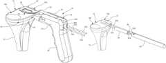
- FIG. 10is a perspective view illustrating one embodiment of a first guide coupled to the femur and having a pin advanced within the guide and into the femur consistent with the present disclosure
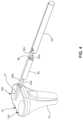
- FIGS. 11 and 12are side and perspective views of one embodiment of a surface reamer consistent with the present disclosure
- FIGS. 13 and 14are perspective views of the surface reamer of FIGS. 11 and 12 aligned with the pin and engaging the femur consistent with the present disclosure
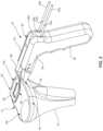
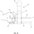
- FIG. 15is a perspective view illustrating one embodiment of a second guide configured to be coupled to the femur consistent with the present disclosure
- FIG. 16is a side plan view of one embodiment of a second guide coupled to the femur as generally shown in FIG. 15 consistent with the present disclosure
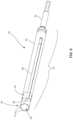
- FIG. 17is a front view of the second guide coupled to the femur in a first position consistent with the present disclosure
- FIG. 18is a front view of the second guide coupled to the femur and moving from the first position to a second position;
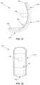
- FIGS. 19 and 20are front and side views of one embodiment of first and second excision sites formed on an articular surface of a femoral condyle using the reamer and second guide consistent with the present disclosure
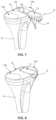
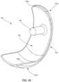
- FIGS. 21 - 23are side, frontal and perspective views of one embodiment of a femoral implant consistent with the present disclosure.
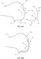
- FIGS. 24 A and 24 Bare side views of the femoral implant of FIGS. 21 - 23 aligned with and coupled to first and second excision sites of the articular surface of the femoral condyle consistent with the present disclosure.
- one embodiment of the present disclosuremay feature a system and method for repairing a portion of the articular surface proximate to a defect. While the present disclosure will be described in terms of a system and method for repairing a portion of the tibial and femoral articular surfaces, it should be understood that the system and method may be used to repair other articular surfaces (such as, but not limited to, humeral articular surfaces and the like).
- the system and methodmay include securing a guide defining one or more passageways to a portion of the tibia (e.g., immediately below the tibial articular surface) proximate to the defect.
- the passagewaysmay define a generally cylindrical core pathway for one or more alignment pins to pass through.
- a first truncated cylindrical excision sitemay be formed in the articular surface and/or bone beneath the articular surface by advancing a drill bit (i.e., a coring drill bit) along the alignment pins.
- the drillmay have a diameter large enough to remove a portion of the articular surface as it is advanced through the guide and into the articular surface. Additional truncated cylindrical excision sites may also be formed. One or more of the additional truncated cylindrical excision sites may partially overlap with adjacent truncated cylindrical excision sites.
- the guide and/or the drillmay include a depth feature configured to control the depth of the truncated cylindrical excision site formed in the articular surface/bone of the tibia.
- the depth featuremay prevent the drill from being advanced too far, thereby preventing the drill from accidentally damaging any structures proximate to the excision sites (e.g., nerves).
- the system and methodmay also include a tibial implant having a load bearing surface having a surface contour/geometry based on the surface contour/geometry of the patient's original removed articular surface of the tibia.
- the surface contour/geometry of the load bearing surfacemay be based on one or more measurements taken of the patient's original articular surface.
- the implantmay also feature a bone facing or distal surface having a surface contour/geometry configured to be received in the truncated cylindrical excision sites.
- the system and methodmay further include a first guide for aligning and securing a second drill guide to a portion of the femur (e.g., lateral or medial femoral condyle) proximate to the defect.
- the first guidemay define a channel for receiving and retaining a pin. Upon advancing the pin through the channel of the first guide in a direction towards the femur, the pin may engage and pierce the bone to form a bore within a portion of the femur (e.g., femoral condyle).
- the system and methodmay further include securing the second drill guide defining one or more passageways to a portion of the femur (e.g. femoral condyle).
- At least one of the passagewaysmay define a generally cylindrical core pathway for a support rod to pass therethrough and secure the second drill guide to the femur.
- Another passagewaymay define a generally cylindrical core pathway for a drill bit (i.e., a router drill bit).
- the support rodmay serve as an axis about which the drill bit may rotate.
- An excision sitemay be formed in the articular surface of a femoral condyle and/or bone beneath the articular surface by rotating the drill guide, and the drill bit, about the support rod.
- the drillmay have a diameter large enough to remove a portion of the articular surface as it is rotated about the support rod and into the articular surface.
- the second drill guide and/or the drillmay include a depth feature configured to control the depth of the excision site formed in the articular surface/bone of the femoral condyle of the femur.
- the depth featuremay prevent the drill from being advanced too far, thereby preventing the drill from accidentally damaging any structures proximate to the excision site (e.g., nerves).
- the system and methodmay also include a femoral condyle implant having a load bearing surface having a surface contour/geometry based on the surface contour/geometry of the patient's original removed articular surface of the femur.
- the surface contour/geometry of the load bearing surfacemay be based on one or more measurements taken of the patient's original articular surface.
- the implantmay also feature a bone facing or distal surface having a surface contour/geometry configured to be received in the excision site.
- the tibial articular surface 12may include a tibial plateau comprising a plurality of concaved surfaces 14 a , 14 b configured to articulate with the femoral condyles (not shown for clarity). It may be further appreciated that the tibial articular surface 12 may include additional concaved surfaces not shown for the sake of clarity. One or more of the concaved surfaces (e.g., concaved surface 14 a ) may include a defect 13 in the tibial articular surface 12 to be repaired. On the distal side of the tibia 10 , a nerve bundle 16 is located. As described herein, the system and method according to one embodiment of the present disclosure may be configured to avoid damaging the nerve bundle when forming the excision site(s).
- the followingwill describe a system and method for preparing an implant site on the tibial articular surface including two partially overlapping truncated cylindrical excision sites and an implant configured to fit therein.
- the system and method according to the present disclosuremay be used to form an implant site having greater than or fewer than two partially overlapping truncated cylindrical excision sites.
- the truncated cylindrical excision sitesmay be formed by drilling along the anterior-posterior plane (i.e., from an anterior face of the tibia 10 and extending generally towards the posterior face of the tibia 10 ).
- the guide 18may include a jig 20 and a spoon 22 .
- the jig 20may include a body portion 24 and a handle portion 26 extending therefrom.
- the body portion 24may define at least two passageways 28 a , 28 b .
- the passageways 28 a , 28 bmay each define a generally cylindrical pathway for alignment pins 30 a , 30 b .
- the alignment pins 30 a , 30 bmay be advanced through the passageways 28 a , 28 b into the tibia 10 , as generally illustrated in FIG. 3 .
- the alignment pins 30 a , 30 bmay include a depth feature 32 a , 32 b configured to control the depth of the pins 30 a , 30 b in the bone 10 (i.e., to prevent the pins 30 a , 30 b from being set too deep or too shallow into the bone 10 ).
- the depth feature 32 a , 32 bmay comprise an indicia (e.g., but not limited to, a laser marking, groove, or the like) which may be aligned with the proximal end of the passageways 28 a , 28 b .
- the alignment pins 30 a , 30 bmay be configured to generally align a drill bit with a desired are of bone 10 to be cut and to maintain alignment of the drill bit during excision of the bone 10 , as described in greater detail herein.
- the position of the jig 20(and in particular, the passageways 28 a , 28 b ) may be set based on, at least in part, the spoon 22 .
- the spoon 22may include a generally convex base portion 34 having a surface contour substantially corresponding to the curvature of the concaved surface 14 a being repaired (e.g., the concaved surface 14 a which has the defect 13 ).
- An upper portion 36 of the spoon 22may have a generally concaved surface (e.g., generally corresponding to the curvature of the concaved surface 14 a being repaired).
- the spoon 22may have a cross-sectional thickness configured to facilitate advancement of the spoon 22 between the tibial articular surface 12 and the femoral condyles (shown in FIG. 9 , for example).
- the cross-sectional thickness of the spoon 22may be selected to provide sufficient rigidity to align the jig 20 relative to the tibial articular surface 12 (and in particular, the defect 13 on the concaved surface 14 a ) while also minimizing the required separation between the tibia 10 and the femur.
- the spoon 22may be an integral component of the jig 20 (e.g., a unitary or single one-piece structure) or may be configured to be releasably coupled to the jig 20 .
- the spoon 22may include an arm portion 38 configured to extend generally outwardly from a distal face 40 (e.g., a bone facing surface) of the jig 20 .
- the body 24 of the jig 20may include a channel 42 shaped and/or sized to receive and retain a portion of the arm 38 .
- the size and shape of the arm portion 38may be configured to allow a portion of the distal face 40 to be disposed proximate to the perimeter (e.g., proximate to the meniscus 44 ) when the spoon 22 is disposed on the concaved surface 14 a such that the first and second passageways 28 a , 28 b partially overlap with the tibial articular surface 12 .
- the guide 18may be positioned relative to the defect 13 on the concaved surface 14 a by advancing the spoon 22 between the tibial articular surface 12 and the femur such that the base portion 34 of the spoon 22 is disposed over at least a portion of the defect 13 on the tibial articular surface 12 .
- the spoon 22may be advanced until the distal face 40 of the jig 20 generally abuts against a portion of the tibia 10 (e.g., proximate to the meniscus 44 ).
- the size and shape of the base portion 34 as well as the arm portion 38 /distal face 40may be configured to generally center the spoon 22 within the concaved surface 14 a .
- the alignment pins 30 a , 30 bmay be advanced through the passageways 28 a , 28 b and into the tibia 10 , as shown in FIG. 3 . It should be noted that internal features and/or surfaces are illustrated in phantom in FIG. 3 . As shown, distal ends 31 a , 31 b of the alignment pins 30 a , 30 b may engage and pierce the bone 10 , thereby securely coupling the alignment pins 30 a , 30 b to the bone 10 .
- the guide 18may be removed from the bone 10 .
- the alignment pins 30 a , 30 bmay remain within the bone 10 and may be configured to provide alignment of a drill bit with the bone 10 to form first and second excision sites.
- a bushing 46may be advanced along the alignment pins 30 a , 30 b and against the bone 10 .
- the bushing 46may include a longitudinally disposed passageway 48 shaped and/or sized to receive at least the first alignment pin 28 a .
- the bushing 46may be advanced along the alignment pin 28 a until the bushing 46 engages against (e.g., abuts) a portion of the tibia 10 (e.g., proximate to the meniscus 44 ).
- a cannulated drill 50may then be advanced over the bushing 46 and the alignment pin 28 a and into the bone 10 to form a first truncated cylindrical excision site (shown in FIG. 6 ).
- the drill 50 and bushing 46may be removed from the first alignment pin 28 a and then placed over and advanced along the second alignment pin 28 b to form a second truncated cylindrical excision site in the bone 10 (shown in FIG. 6 ).
- the cannulated drill 50may feature a core drill bit 52 having a barrel portion 53 and optionally a shank portion 54 extending from the barrel portion 53 .
- the shank portion 54may include a multi-faceted proximal end configured to be secured to a drill (e.g., a hand drill, electric drill, pneumatic drill or the like).
- a proximal end of the core drill bit 52may be directly coupled to the drill.
- the core drill bit 52may include a cutting surface 56 (for example, comprising a plurality of cutting teeth 57 ) disposed about a distal end of the barrel portion 53 .
- the cutting surface 56may be evenly disposed around the generally circular distal end of the barrel portion 53 .
- the barrel portion 53may define a core cavity 58 configured to receive the removed portion of the tibial articular surface 12 and bone 10 .
- the only portion of the tibial articular surface 12 and bone 10 that is cut by the core drill bit 50corresponds to the thickness of the cutting surface 56 , which itself is a function of the wall thickness of the barrel 53 . As such, these thicknesses may be selected to remove the least amount of material while also providing the necessary rigidity and/or strength to the core drill bit 50 .
- the core drill bit 52may optionally feature one or more windows 60 disposed along the length of the barrel portion 53 .
- the window 60may allow air, fluid, and cutting chips to exit the barrel portion 53 .
- the window 60may also allow the user to align the core drill bit 52 with the alignment pins 30 a , 30 b to control the depth of the excision site (i.e., the length of the excision site as measured across the tibial articular surface 12 ).
- the core drill bit 52may be shaped and/or sized to receive the bushing 46 configured facilitate alignment of the core drill bit 52 as the core drill bit 52 is advanced into the tibial articular surface 12 and bone 10 .
- the bushing 46may be translatably disposed along the longitudinal axis of the core drill bit 52 and may include a passageway 48 configured to receive the alignment pins 30 a , 30 b .
- the bushing 46may be initially located near the distal end of the barrel portion 53 .
- an alignment pin 30 a , 30 bmay be received in the passageway 48 and the bushing 46 may translate towards the proximal end.
- the drill bit 50As the drill bit 50 is advanced towards the bone 10 , a portion of the cutting surface 56 may engage the tibial articular surface 12 and/or the bone 10 , thereby forming a truncated cylindrical excision site.
- the second truncated cylindrical excision sitemay be formed.
- the bushing 46 and drill bit 50may be removed from the first alignment pin 30 a and placed on the second alignment pin 30 b and the drill bit 50 may be advanced toward the bone 10 in a manner similar to that described herein.
- bushing 46 and drill bit 50are described as being used to create the first and second excision sites, a second bushing and drill bit may be used with the second alignment pin 30 b to create the second excision site, wherein the first and second drill bits may have the same or different outer diameters.
- FIG. 6generally illustrates one embodiment of the first and the second truncated cylindrical excision sites 62 a , 62 b corresponding to the drill bit 50 and the first and second alignment pins 30 a , 30 b .
- the first and second excision sites 62 a , 62 bmay be separated by a distance generally perpendicular to the longitudinal axes of the first and second alignment pins 30 a , 30 such that the first and the second truncated cylindrical excision sites 62 a , 62 b do not overlap.
- the resulting implant sitemay therefore include the first and second truncated cylindrical excision sites 62 a , 62 b , wherein the first and second truncated cylindrical excision sites 62 a , 62 b partially overlap with one another.
- the truncated cylindrical excision sites 62 a , 62 bmay be centered/revolved around the alignment pins 30 a , 30 b and may extend along the articular surface 12 generally along the anterior-posterior plane.
- the truncated cylindrical excision sites 62 a , 62 bmay extend from the anterior face of the tibial articular surface 12 generally towards the posterior face.
- the implant sitemay therefore include a base portion 64 including two overlapping truncated cylindrical extensions or scallops defined by the two excision sites 62 a , 62 b .
- the resulting implant sitetherefore may generally eliminate/reduce the occurrence of 90 degree cuts and therefore more evenly distribute loads/forces to the bone 10 compared a traditional 90 degree notch cut.
- the truncated cylindrical excision sites 62 a , 62 bhave been illustrated extending partially across the tibial articular surface 12 (i.e., one or more of the truncated cylindrical excision sites 62 a , 62 b do not extend completely across the articular surface 12 thus leaving a portion 66 of the tibial articular surface 12 and/or bone 10 remaining).
- This embodimentmay be particularly beneficial since it further minimizes the potential for accidentally damaging the nerve bundle.
- the system and method according to the present disclosuremay also allow for one or more of the truncated cylindrical excision sites 62 a , 62 b to extend completely across the articular surface 12 .
- the implant 70may include a load bearing surface 72 and a bone facing or distal surface 74 .
- the load bearing surface 72may have a surface contour/geometry substantially corresponding to the contour/geometry of the removed tibial articular surface 12 proximate the defect 13 .
- the contour/geometry of the load bearing surfacemay be based on a plurality of measurement take of the patient's tibial articular surface 12 .
- the bone facing surface 74may have an overall contour/geometry generally corresponding to the contour/geometry of the base portion 64 of the first and second truncated cylindrical excision sites 62 a , 62 b and the removed bone 10 .
- the bone facing surface 74may include one or more relief cavities, pockets and/or cross-cuts 76 configured to enhance securing the implant 70 to the bone 10 within the truncated cylindrical excision sites 62 a , 62 b .
- the relief cavities 76may be configured to allow bone regrowth around a portion of the implant 70 and/or promote cement adhesion.
- the implant 70may include a generally unitary structure (i.e., the implant 70 may be a solid, single-piece component).
- the implant 70may be made from ultra-high molecular weight polyethylene (UHMWPE) material. Additionally (or alternatively), the implant 70 may be made from a material based on donor tissue and/or synthetic bone and cartilage construct.
- the implant 70may include a ceramic porous base layer that defining the bone facing surface 74 and a collagen material disposed on a top portion thereof and defining the load bearing surface 72 .
- the implant 70may include multiple portions configured to be coupled together. Additionally, the implant 70 may optionally comprise one or more keels, tails, protrusions or the like, that extend generally downwardly from the bone facing surface 74 and away from the load bearing surface 72 . The keels, tails, or protrusions may be configured to engage a corresponding notch (not shown) formed in the base portion 64 of the truncated cylindrical excision sites 62 a , 62 b.
- an implant consistent with at least one embodiment of the present disclosuremay have a non-planar load bearing surface 72 . While some known tibial implants have had a generally planar or flat load bearing surface, an implant consistent with at least one embodiment of the present disclosure may have a concaved geometry which may better approximate the geometry of the patient's removed tibial articular surface 12 .
- the femur 102may generally include femoral articular surface 104 that may include femoral condyles 106 a , 106 b configured to articulate with the tibial articular surface 12 and concaved surfaces 14 a , 14 b of the tibia 10 . It may be further appreciated that the knee joint 100 include a patella (not shown for the sake of clarity). One of the femoral condyles (e.g., condyle 106 ) may include a defect 108 in the articular surface 104 to be repaired.
- the followingwill describe a system and method for preparing an implant site on the articular surface of a femoral condyle including an excision site and an implant configured to fit therein.
- the excision sitesmay be formed by drilling along the horizontal plane of a femoral condyle (i.e., from lateral to medial and/or vice versa).
- the first guide 110may include a jig 112 and a spoon 114 .
- the jig 112may include a body portion 116 including at least one channel 118 longitudinally disposed on a portion thereof.
- the channel 118may extend from a proximal end 119 a to a distal end 119 b of the body 116 .
- the channel 118may be shaped and/or sized to receive and retain a pin 120 . As shown, the pin 120 may be advanced through the channel 118 and into the femur 102 (e.g.
- the pin 120may further include a distal end 121 configured to engage and pierce the bone 102 .
- the pin 120may further include a depth feature 122 configured to control the depth of the pin 120 into the bone 102 (i.e., to prevent the pin 120 from being set too deep or too shallow into the bone 102 ).
- the depth feature 121may include an indicia (e.g., but not limited to, a laser marking, groove, or the like) which may be aligned with the proximal end 119 a of the body 116 of the first guide 110 .
- the position of the jig 112may be set based on, at least in part, the spoon 114 .
- the spoon 114may include a generally convex base portion 124 having a surface contour substantially corresponding to the curvature of a concaved surface opposing the associated femoral condyle being repaired (e.g., the concaved surface 14 a opposing the femoral condyle 106 a which has the defect 108 ).
- An upper portion 126 of the spoon 114may have a generally concaved surface (e.g., generally corresponding to the curvature of the femoral condyle 106 a surface being repaired).
- the spoon 112may have a cross-sectional thickness configured to facilitate advancement of the spoon 114 between the tibial articular surface 12 and the femoral condyles 106 a , 106 b .
- the cross-sectional thickness of the spoon 112may be selected to provide sufficient rigidity to align the jig 112 relative to the tibial articular surface 12 and one of the femoral condyles (and in particular, the defect 108 on the femoral condyle 106 a ) while also minimizing the required separation between the tibia 10 and the femur 102 .
- the spoon 112may be an integral component of the jig 112 (e.g., a unitary or single one-piece structure) or may be configured to be releasably coupled to the jig 112 .
- the spoon 114may include an arm portion 128 configured to extend generally outwardly from the distal end 119 b of the body 116 of the jig 112 .
- the body 116 of the jig 112may include a channel 130 shaped and/or sized to receive and retain a portion of the arm 128 .
- the jig 112may further include an alignment member 132 extending from the distal end 119 b of the body 116 .
- the alignment member 132may include a distal face 134 (e.g., a bone facing surface).
- the distal face 134may have a generally concaved surface (e.g., generally corresponding to the curvature of the femoral condyle 106 a surface being repaired).
- the size and shape of the arm portion 128may allow a portion of the distal face 134 of the alignment member 132 to be disposed proximate to the femoral condyle 106 a when the spoon 114 is disposed between the tibial articular surface 12 and the femoral condyle 106 a (and in particular, on the concaved surface 14 a and the femoral condyle 106 a ) such that the channel 118 is aligned with a portion of the articular surface of the femoral condyle 106 a .
- the alignment member 132may further include a passageway 136 .
- the passageway 136may be shaped and/or sized to allow the pin 120 to pass through upon advancement towards the bone 102 .
- the passageway 136may further provide a user with visual observation of the penetration site 137 of the pin 120 into the bone 102 .
- the first guide 110may be positioned relative to the defect 108 on articular surface of the femoral condyle 106 a by advancing the spoon 114 between the tibial articular surface 12 and the femoral condyle 106 a such that the upper portion 126 of the spoon 114 and/or distal face 134 of the alignment member 132 is disposed over at least a portion of the defect 108 on the articular surface of the femoral condyle 106 a .
- the spoon 114may be advanced until the distal face 134 of the alignment member 132 generally abuts against a portion of the femoral condyle 106 a .
- the size and shape of the base portion 124 and upper portion 126 of the spoon 112 , as well as the arm portion 128 /distal face 134 ,may be configured to generally center the spoon 112 within the concaved surface 14 a of the tibia 10 and associated femoral condyle 106 a .
- the pin 120may be advanced along the channel 118 and through the passageway 136 and into the femur 102 .
- the distal end 121 of the pin 120may be configured to engage and pierce the bone 102 to create a substantially longitudinal bore within the bone 102 (shown in FIG. 15 ).
- the surface reamer 140may be configured to remove a portion of bone and form a first excision site 141 (shown in FIG. 15 ) on the articular surface 104 of the femoral condyle 106 a adjacent the pin 120 .
- the surface reamer 140includes a cannulated body 142 having a proximal end 144 and an opposing distal end 146 .
- the distal end 146includes one or more cutting surfaces 148 configured to remove bone and the proximal end 144 is configured to be coupled to a drill 150 (e.g., a hand drill, electric drill, pneumatic drill or the like).
- a drill 150e.g., a hand drill, electric drill, pneumatic drill or the like.
- the drill 150may be configured to drive (e.g. rotate) the distal end 146 and, in turn, the cutting surfaces 148 of the surface reamer 140 to facilitate bone removal when the cutting surfaces 148 engage bone of the femur 102 .
- the body 142 of the surface reamer 140is cannulated (e.g. include a passageway 152 extending the length thereof), allowing the surface reamer 140 to be disposed over the alignment pin 120 along a reference axis A.
- FIGS. 13 and 14are perspective views of the surface reamer 140 aligned with the pin 120 and engaging a portion of the femoral condyle 106 a consistent with the present disclosure.
- the surface reamer 140may be advanced over the pin 120 along a reference axis A.
- the surface reamer 140may include an indicia (for example, an opening/window, laser marker, or the like) configured to control the depth of the first excision site to be formed.
- the indiciamay include a laser marking or the like configured to be aligned with the articular surface 104 .
- the indiciamay also include an opening/window or the like which may be aligned with an indicia on the pin 120 .
- the cutting surfaces 148may optionally be positioned about the surface reamer 140 to leave more material proximate the pin 120 along the reference axis A to facilitate removal and insertion of devices further along the method.
- the surface reamer 140may have a specific geometry and/or pattern to minimize vibrations and improve tactile feel while negotiating an interrupted cut on the articular surface 104 of the femoral condyle 106 a .
- the diameter of the surface reamer 140including the diameter of the proximal end 146 , may be selected based on, for example, the desired size of implant to be positioned thereon.
- the second guide 154may include a jig 156 having a body portion 158 including a handle 160 disposed at one end and first and second passageways 162 a , 162 b defined at an opposing end.
- the first and second passageways 162 a , 162 bmay each define a generally cylindrical core pathway.
- the first passageway 162 amay be shaped and/or sized to receive and retain a support rod 164 therein.
- the support rod 164may be configured to secure the second guide 154 to the femoral condyle 106 a . More specifically, a portion of the support rod 164 may be received within a portion of the bore 153 formed in the femoral condyle 106 a and may be securely coupled to the bone 102 .
- the second passageway 162 bmay be shaped and/or sized to receive and retain a drill bit 166 which may be used to form an excision site on the articular surface of the femoral condyle 106 a.
- first and the second passageways 162 a , 162 bmay be offset relative to each other (i.e., the first and the second passageways 162 a , 162 b may be separated by a distance generally perpendicular to the longitudinal axes of the first and the second passageways 162 a , 162 b , such that the depth of excision site formed by the drill bit in the articular surface of the femoral condyle 106 a may be dictated by such a distance between the first and second passageways 162 a , 162 b ).
- the second guide 154may be secured to the femur 102 by the support rod 164 .
- the pin 120may be removed from the femur 102 , leaving the bore 153 exposed and the support rod 164 may include a distal end 168 configured to be driven into the bore 153 and securely couple the support rod 164 within the bone 102 .
- the pin 120may remain secured within the bore 153 and the support rod 164 may be configured to be disposed over the pin 120 (e g cannulated) and secured within the bone 102 .
- the support rod 164may serve as an axis (generally aligned with reference axis A) about which the jig 156 , and ultimately the drill bit 166 , may rotate, as described in greater detail herein.
- a portion of the drill bit 166may be positioned adjacent a portion of the articular surface of the femoral condyle 106 a having the defect 108 to be repaired.
- the drill bit 166may include a cutting surface 169 positioned adjacent the articular surface and configured to form a second excision site in the articular surface of the femoral condyle 106 a and/or bone beneath the articular surface.
- the drill bit 166may further include a shank portion 170 .
- the shank portion 170may include a multi-faceted proximal end configured to be secured to a drill (e.g., a hand drill, electric drill, pneumatic drill or the like). Alternatively, a proximal end of the drill bit 166 may be directly coupled to the drill.
- FIGS. 17 and 18are frontal views of the second guide 154 coupled to the femur 102 by way of the support rod 164 . More specifically, FIG. 17 illustrates the second guide 154 in a first position and FIG. 18 illustrates the second guide 154 moving from the first position to a second position and forming a second excision site 176 in the femur 102 .
- the support rod 164may serve as an axis about which the jig 156 , including the drill bit 166 , may rotate.
- the drill bit 166is adjacent a portion of femoral condyle 106 a and may not directly engage the femoral condyle 106 a .
- the second excision site 176may be formed in the articular surface of the femoral condyle 106 a and/or bone beneath by moving the second guide 154 from the first position to the second position, as shown in FIG. 18 . More specifically, a user may use the handle 160 of the jig 156 to rotate the jig 156 from the first position to the second position.
- the drill bit 166may also rotate about the support rod 164 , as indicated by arrow 174 , thereby causing the drill bit 166 to advance towards the femoral condyle 106 a .
- a portion of the cutting surface 169 of the drill bit 166engages the articular surface of the femoral condyle 106 a and/or the bone beneath, thereby forming the second excision site 176 .
- the drill bit 166further advances towards and engages uncut articular surface and/or bone of the femoral condyle 106 a to form the second excision site 162 .
- the usermay stop rotating the jig 156 once the desired size and/or shape of the second excision site 176 has been formed.
- the only portion of the femoral condyle 106 a , including articular surface and/or bone beneath, that is cut by the drill bit 166corresponds to the distance D between the support rod 164 and the drill bit 166 , and the length L of the cutting surface 169 of the drill bit 166 .
- the distance Dmay vary depending on the desired depth in the anterior-posterior plane (i.e., from the posterior surface of the femur 102 and extending generally towards the anterior surface of the femur 102 ).
- the length Lmay vary depending on the desired depth in the superior-inferior plane (i.e.
- the distance D and length Lmay each be selected to remove the least amount of material so as to control the depth of the second excision site 176 (i.e., the length of the second excision site 176 as measured across the articular surface of the femoral condyle 106 a in both the anterior-posterior and superior-inferior planes).
- FIGS. 19 and 20generally illustrate one embodiment of the first and second excision sites 141 , 174 corresponding to the surface reamer 140 and drill bit 166 , respectively.
- the first excision site 141may extend along a portion of the articular surface of the femoral condyle 106 a proximate the longitudinal bore 153 and generally along the superior-inferior and medial-lateral planes.
- the first excision site 141may extend from the inferior portion of the femur 102 to the superior portion.
- the second excision site 176may extend along the articular surface of the femoral condyle 106 a generally along the anterior-posterior and superior-inferior planes.
- the second excision site 176may extend from the posterior face of the femoral condyle 106 a generally towards the anterior face and from the inferior portion of the femur 102 to the superior portion.
- the first and second excision sites 141 , 176may collectively serve as an implant site for a femoral condyle implant to be received within, as described in greater detail herein.
- the first excision site 141includes a base portion 177 configured to receive a portion of the femoral condyle implant.
- the second excision site 176includes a base portion 178 configured to receive a portion of the femoral condyle implant.
- the second excision site 176has been illustrated extending partially across a portion of the femoral condyle 106 a (i.e., the second excision site 176 does not extend completely across the articular surface of the femoral condyle 106 a , thus leaving a portion 179 of the articular surface and/or bone beneath remaining). This embodiment may be particularly beneficial since it further minimizes the potential for accidentally damaging the nerve bundle.
- the system and method according to the present disclosuremay also allow for the second excision site 176 to extend completely across the articular surface.
- the femoral implant 180includes a first portion 182 a and a second portion 182 b .
- the first portion 182 amay generally correspond to a portion of the femoral condyle 106 a proximate the first excision site 141 and the second portion 182 b may generally correspond to a portion of the femoral condyle 106 a proximate the second excision site 176 .
- the first and second portions 182 a , 182 bmay be formed from single, unitary structure. It should be noted that in other embodiments, the first and second portions 182 a , 182 b may be separate components and may be joined to one another by any known means generally understood by one skilled in the art so as to form the femoral implant 180 .
- the first and second portions 182 a , 182 bmay include a load bearing surface 184 and a bone facing surface 186 .
- the load bearing surface 184 of the first portion 182 amay have a surface contour/geometry substantially corresponding to the contour/geometry of the removed femoral articular surface and/or bone of the first excision site 141 .
- the load bearing surface 184 of the second portion 182 bmay have a surface contour/geometry substantially corresponding to the contour/geometry of the removed femoral articular surface and/or bone of the second excision site 176 .
- the load bearing surface 184may generally correspond to the patient's original articular surface 104 of the femoral condyle 106 a , as seen in FIG. 9 , for example.
- the contour/geometry of the load bearing surface 184may be based on a plurality of measurements taken of the patient's femoral articular surface.
- the bone facing surface 186 of the first portion 182 a of the femoral implant 180may have an overall contour/geometry generally corresponding to the contour/geometry of the base portion 177 of the first excision site 141 .
- the bone facing surface 186 of the second portion 182 bmay have an overall contour/geometry generally corresponding to the contour/geometry of the base portion 178 of the second excision site 176 .
- the bone facing surface 186may include one or more relief cavities, pockets and/or cross-cuts (not shown) configured to enhance securing the implant 180 to the bone 102 .
- the relief cavitiesmay be configured to allow bone regrowth around a portion of the implant 180 and/or promote cement adhesion.
- the bone facing surface 186may optionally include indicia (not shown) representing either inferior and/or superior sides of the implant 180 as well as the size of the implant 180 . These indicia may be used by the surgeon to properly align the implant 180 along the inferior-superior and medial-lateral planes within the first and second excision sites.
- the bone facing surface 186may also optionally include one or more rims, ribs or protrusions 190 extending generally away from the bone facing surface 184 , for example, as clearly illustrated in FIG. 23 .
- the rims 190may extend along the entire periphery of the implant 180 .
- the rims 190may include a superior rim 190 a disposed proximate the first portion 182 a of the implant 180 and/or an inferior rim 190 b disposed proximate the second portion 182 b of the implant 180 .
- the first and second excisions sites 141 , 176 corresponding to the rims 190may be include a contour configured to receive the rims 190 .
- the implant 180may further include a fixation member 188 coupled to and extending away from the bone facing surface 186 .
- the fixation member 188may be configured to be received in the longitudinal bore 153 formed in the articular surface 104 and secure the implant 180 to the femoral condyle 106 a .
- the fixation member 188may optionally be configured to engage with another fixation element (not shown) configured to be secured into the bore 153 of the patient's bone.
- the other fixation elementmay include a post having a threaded outer region configured to engage with an interior surface of the bore 153 .
- the postmay include a female opening configured to frictionally engage with the fixation member 188 .
- FIG. 24 Ais a side view of the femoral implant 180 aligned with the femoral condyle 106 a (e.g. fixation member 188 is generally aligned with bore 153 along reference axis A).
- FIG. 24 Bis a side view of the femoral implant 180 coupled to the first and second excision sites 141 , 176 formed in the femoral condyle 106 a consistent with the present disclosure.
- An adhesive(such as, but not limited to, bone cement or the like) may be applied to the bone facing surface 186 and may securely coupled the implant 180 to the bone 102 .
- the bore 153may be shaped and/or sized to receive and frictionally engage the fixation member 188 of the implant 180 and the first and second portions 182 a , 182 b may be received within the first and second excision sites 141 , 176 .
- a femoral implant consistent with at least one embodiment of the present disclosuremay be configured to cooperate with a tibial implant consistent with at least one embodiment of the present disclosure.
- the load bearing surface 184 of the femoral implant 180may be configured to matingly engage and cooperate with the load bearing surface 72 of the tibial implant 70 , thereby allowing flexing of the knee.
- the present disclosurefeatures an implant resection system for preparing an implant site to replace a defect in an articular surface of a first bone.
- the implant resection systemincludes a first guide configured to be coupled to a first bone.
- the first guideincludes a body portion having at least one channel defined on a portion thereof.
- the channelis configured to extend generally perpendicular to a portion of the first bone proximate to the defect.
- At least one pinis configured to be received and retained within the channel.
- the pinhas a distal end configured to pierce the first bone and to extend and form a longitudinally disposed bore within the first bone.
- the present disclosurefeatures a method for preparing an implant site to replace a defect in an articular surface of a bone.
- the methodincludes securing a first guide to a bone.
- the first guideincludes a body portion having at least one channel defined on a portion thereof.
- the channelis configured to extend generally perpendicular to a portion of the bone proximate to said defect.
- the methodfurther includes advancing at least one pin along the channel and into the bone and forming a longitudinally disposed bore within the bone.
- the methodfurther includes removing the pin from the bone and securing a second guide generally perpendicular to the bone proximate to the defect.
- the second guideincludes a body portion having a handle member disposed at one end and a first passageway and a second passageway defined on an opposing end.
- the passagewayseach define a generally cylindrical core pathway configured to extend generally perpendicular to the bone.
- the methodfurther includes forming an excision site on the bone.
Landscapes
- Health & Medical Sciences (AREA)
- Life Sciences & Earth Sciences (AREA)
- Surgery (AREA)
- Orthopedic Medicine & Surgery (AREA)
- Veterinary Medicine (AREA)
- General Health & Medical Sciences (AREA)
- Oral & Maxillofacial Surgery (AREA)
- Engineering & Computer Science (AREA)
- Biomedical Technology (AREA)
- Heart & Thoracic Surgery (AREA)
- Public Health (AREA)
- Animal Behavior & Ethology (AREA)
- Molecular Biology (AREA)
- Nuclear Medicine, Radiotherapy & Molecular Imaging (AREA)
- Medical Informatics (AREA)
- Dentistry (AREA)
- Cardiology (AREA)
- Transplantation (AREA)
- Vascular Medicine (AREA)
- Rheumatology (AREA)
- Physical Education & Sports Medicine (AREA)
- Prostheses (AREA)
- Surgical Instruments (AREA)
Abstract
Description
Claims (20)
Priority Applications (1)
| Application Number | Priority Date | Filing Date | Title |
|---|---|---|---|
| US17/543,420US11925363B2 (en) | 2012-07-03 | 2021-12-06 | System and method for joint resurfacing and repair |
Applications Claiming Priority (5)
| Application Number | Priority Date | Filing Date | Title |
|---|---|---|---|
| US201261667562P | 2012-07-03 | 2012-07-03 | |
| US13/930,737US9468448B2 (en) | 2012-07-03 | 2013-06-28 | System and method for joint resurfacing and repair |
| US15/296,772US10307172B2 (en) | 2012-07-03 | 2016-10-18 | System and method for joint resurfacing and repair |
| US16/430,947US11191552B2 (en) | 2012-07-03 | 2019-06-04 | System and method for joint resurfacing and repair |
| US17/543,420US11925363B2 (en) | 2012-07-03 | 2021-12-06 | System and method for joint resurfacing and repair |
Related Parent Applications (1)
| Application Number | Title | Priority Date | Filing Date |
|---|---|---|---|
| US16/430,947ContinuationUS11191552B2 (en) | 2012-07-03 | 2019-06-04 | System and method for joint resurfacing and repair |
Publications (2)
| Publication Number | Publication Date |
|---|---|
| US20220338884A1 US20220338884A1 (en) | 2022-10-27 |
| US11925363B2true US11925363B2 (en) | 2024-03-12 |
Family
ID=49879087
Family Applications (4)
| Application Number | Title | Priority Date | Filing Date |
|---|---|---|---|
| US13/930,737Active2034-03-31US9468448B2 (en) | 2012-07-03 | 2013-06-28 | System and method for joint resurfacing and repair |
| US15/296,772ActiveUS10307172B2 (en) | 2012-07-03 | 2016-10-18 | System and method for joint resurfacing and repair |
| US16/430,947Active2033-10-08US11191552B2 (en) | 2012-07-03 | 2019-06-04 | System and method for joint resurfacing and repair |
| US17/543,420Active2033-09-14US11925363B2 (en) | 2012-07-03 | 2021-12-06 | System and method for joint resurfacing and repair |
Family Applications Before (3)
| Application Number | Title | Priority Date | Filing Date |
|---|---|---|---|
| US13/930,737Active2034-03-31US9468448B2 (en) | 2012-07-03 | 2013-06-28 | System and method for joint resurfacing and repair |
| US15/296,772ActiveUS10307172B2 (en) | 2012-07-03 | 2016-10-18 | System and method for joint resurfacing and repair |
| US16/430,947Active2033-10-08US11191552B2 (en) | 2012-07-03 | 2019-06-04 | System and method for joint resurfacing and repair |
Country Status (3)
| Country | Link |
|---|---|
| US (4) | US9468448B2 (en) |
| DE (1) | DE112013003358T5 (en) |
| WO (1) | WO2014008126A1 (en) |
Families Citing this family (32)
| Publication number | Priority date | Publication date | Assignee | Title |
|---|---|---|---|---|
| US6520964B2 (en) | 2000-05-01 | 2003-02-18 | Std Manufacturing, Inc. | System and method for joint resurface repair |
| US6610067B2 (en) | 2000-05-01 | 2003-08-26 | Arthrosurface, Incorporated | System and method for joint resurface repair |
| US8177841B2 (en) | 2000-05-01 | 2012-05-15 | Arthrosurface Inc. | System and method for joint resurface repair |
| US7914545B2 (en) | 2002-12-03 | 2011-03-29 | Arthrosurface, Inc | System and method for retrograde procedure |
| US8388624B2 (en) | 2003-02-24 | 2013-03-05 | Arthrosurface Incorporated | Trochlear resurfacing system and method |
| WO2006004885A2 (en) | 2004-06-28 | 2006-01-12 | Arthrosurface, Inc. | System for articular surface replacement |
| US7828853B2 (en) | 2004-11-22 | 2010-11-09 | Arthrosurface, Inc. | Articular surface implant and delivery system |
| US9358029B2 (en) | 2006-12-11 | 2016-06-07 | Arthrosurface Incorporated | Retrograde resection apparatus and method |
| EP2262448A4 (en) | 2008-03-03 | 2014-03-26 | Arthrosurface Inc | Bone resurfacing system and method |
| EP2407115B1 (en) | 2008-08-01 | 2014-08-20 | DePuy Products, Inc. | Instrumentation for use in a patellofemoral arthroplasty procedure |
| AU2010236182A1 (en) | 2009-04-17 | 2011-11-24 | Arthrosurface Incorporated | Glenoid resurfacing system and method |
| US10945743B2 (en) | 2009-04-17 | 2021-03-16 | Arthrosurface Incorporated | Glenoid repair system and methods of use thereof |
| WO2010121250A1 (en) | 2009-04-17 | 2010-10-21 | Arthrosurface Incorporated | Glenoid resurfacing system and method |
| EP2542165A4 (en) | 2010-03-05 | 2015-10-07 | Arthrosurface Inc | Tibial resurfacing system and method |
| US9066716B2 (en) | 2011-03-30 | 2015-06-30 | Arthrosurface Incorporated | Suture coil and suture sheath for tissue repair |
| EP2804565B1 (en) | 2011-12-22 | 2018-03-07 | Arthrosurface Incorporated | System for bone fixation |
| ES2656974T3 (en)* | 2012-01-19 | 2018-03-01 | Stryker European Holdings I, Llc | Cuff for suprarrotulian surgery |
| WO2014008126A1 (en) | 2012-07-03 | 2014-01-09 | Arthrosurface Incorporated | System and method for joint resurfacing and repair |
| US9427334B2 (en)* | 2013-03-08 | 2016-08-30 | Stryker Corporation | Bone pads |
| US9492200B2 (en) | 2013-04-16 | 2016-11-15 | Arthrosurface Incorporated | Suture system and method |
| US9931219B2 (en) | 2014-03-07 | 2018-04-03 | Arthrosurface Incorporated | Implant and anchor assembly |
| US10624748B2 (en) | 2014-03-07 | 2020-04-21 | Arthrosurface Incorporated | System and method for repairing articular surfaces |
| US11607319B2 (en) | 2014-03-07 | 2023-03-21 | Arthrosurface Incorporated | System and method for repairing articular surfaces |
| US10426550B2 (en) | 2014-04-11 | 2019-10-01 | Think Surgical, Inc. | Rotatable curved bit and robotic cutting in orthopaedic applications |
| US10038591B1 (en)* | 2015-01-09 | 2018-07-31 | Juniper Networks, Inc. | Apparatus, system, and method for secure remote configuration of network devices |
| US10045826B2 (en)* | 2015-01-20 | 2018-08-14 | Mako Surgical Corporation | Systems and methods for repairing bone with multiple tools |
| US10702291B2 (en)* | 2015-07-02 | 2020-07-07 | Episurf Ip-Management Ab | System, guide tools and design methods related thereto for performing osteochondral transplantation surgery in a joint |
| US11160663B2 (en) | 2017-08-04 | 2021-11-02 | Arthrosurface Incorporated | Multicomponent articular surface implant |
| CA3086956A1 (en) | 2018-01-02 | 2019-07-11 | Cartiheal (2009) Ltd. | Implantation tool and protocol for optimized solid substrates promoting cell and tissue growth |
| WO2020186099A1 (en) | 2019-03-12 | 2020-09-17 | Arthrosurface Incorporated | Humeral and glenoid articular surface implant systems and methods |
| US20200360028A1 (en)* | 2019-05-14 | 2020-11-19 | Stefan Eggli | Surgical method and a bone punch instrument for creating a bone tunnel |
| CN110974340B (en)* | 2019-12-13 | 2025-03-25 | 俞良钢 | Bone Resection Device |
Citations (22)
| Publication number | Priority date | Publication date | Assignee | Title |
|---|---|---|---|---|
| US2919692A (en)* | 1956-02-23 | 1960-01-05 | Ackermann Wolfgang | Vertebral trephine biopsy instruments |
| US5411504A (en)* | 1993-08-02 | 1995-05-02 | Vilas; John W. | Drill jig for animal prosthesis insertion |
| US5964805A (en)* | 1997-02-12 | 1999-10-12 | Stone; Kevin R. | Method and paste for articular cartilage transplantation |
| US20030130741A1 (en)* | 2002-01-07 | 2003-07-10 | Mcminn Derek James Wallace | Hip prosthesis |
| US20040082906A1 (en)* | 1998-07-22 | 2004-04-29 | Tallarida Steven J. | Vascular suction cannula, dilator and surgical stapler |
| US20040230315A1 (en)* | 2000-05-01 | 2004-11-18 | Ek Steven W. | Articular surface implant |
| US20040254585A1 (en)* | 2001-03-13 | 2004-12-16 | Whittaker Gregory R. | Method and apparatus for fixing a graft in a bone tunnel |
| US20050090905A1 (en)* | 2003-10-23 | 2005-04-28 | Hawkins Michael E. | Porous implant with a dried, lubricious when wet, in vivo absorbable coating |
| US20080015607A1 (en)* | 2006-06-21 | 2008-01-17 | Howmedica Osteonics Corp. | Unicondylar knee implants and insertion methods therefor |
| US20080177200A1 (en)* | 2007-01-23 | 2008-07-24 | Jimro Co., Ltd. | Bone marrow harvesting drill |
| US20090228031A1 (en)* | 2008-03-10 | 2009-09-10 | Zimmer Orthobiologics, Inc. | Instruments and methods used when repairing a defect on a tissue surface |
| US20090254094A1 (en)* | 2008-04-08 | 2009-10-08 | Knapp Troy D | Ratcheting mechanical driver for cannulated surgical systems |
| US7618451B2 (en)* | 2001-05-25 | 2009-11-17 | Conformis, Inc. | Patient selectable joint arthroplasty devices and surgical tools facilitating increased accuracy, speed and simplicity in performing total and partial joint arthroplasty |
| US20100217315A1 (en)* | 2009-02-19 | 2010-08-26 | Jolly Jacob A | Drill pin for suture passing |
| US20100249935A1 (en)* | 2009-03-30 | 2010-09-30 | Slivka Michael A | Zero Profile Spinal Fusion Cage |
| US7815681B2 (en)* | 2006-04-28 | 2010-10-19 | Warsaw Orthopedic, Inc. | Orthopedic support locating or centering feature and method |
| US20120065734A1 (en)* | 2010-09-15 | 2012-03-15 | Spinal USA LLC | Intervertebral plate system |
| US20130237987A1 (en)* | 2012-03-08 | 2013-09-12 | The Cleveland Clinic Foundation | Arthrodesis apparatus and method |
| US20150265328A1 (en)* | 2014-03-18 | 2015-09-24 | Osteomed Llc | Percutaneous exchange tube and method of use |
| US20160022374A1 (en)* | 2013-03-15 | 2016-01-28 | Board Of Regents Of The University Of Nebraska | On-board tool tracking system and methods of computer assisted surgery |
| US9468448B2 (en)* | 2012-07-03 | 2016-10-18 | Arthrosurface Incorporated | System and method for joint resurfacing and repair |
| US20180154041A1 (en)* | 2015-05-06 | 2018-06-07 | Cartiheal (2009) Ltd | Optimized Solid Substrates, Tools for Use with Same and Uses Thereof for Promoting Cell and Tissue Growth |
Family Cites Families (961)
| Publication number | Priority date | Publication date | Assignee | Title |
|---|---|---|---|---|
| US103645A (en) | 1870-05-31 | Chakles s | ||
| US992819A (en) | 1910-07-18 | 1911-05-23 | Daniel E Springer | Glass-cutter. |
| US1451610A (en) | 1921-09-15 | 1923-04-10 | Gestas Isidore | Boring machine for paper |
| US2267925A (en) | 1941-02-11 | 1941-12-30 | Herbert A Johnston | Fracture securing apparatus |
| US2379984A (en) | 1943-07-16 | 1945-07-10 | Wright Aeronautical Corp | Simplified drive for cutting tools |
| US2381102A (en) | 1943-10-12 | 1945-08-07 | Douglas Aircraft Co Inc | Flexible adapter |
| US2570465A (en) | 1949-08-01 | 1951-10-09 | Joseph S Lundholm | Means for fixation of hip fractures |
| US3176395A (en) | 1963-12-27 | 1965-04-06 | David H Warner | Photoengraver's saber |
| US3351115A (en) | 1965-11-22 | 1967-11-07 | Roger W Boehlow | Thread-forming and fastening screw |
| US3664345A (en) | 1970-07-06 | 1972-05-23 | Clyde Harwell Dabbs | Surgical buttons |
| US3715763A (en)* | 1971-04-21 | 1973-02-13 | W Link | Artificial limb for the knee joint |
| GB1448818A (en) | 1972-09-18 | 1976-09-08 | Nat Res Dev | Prosthetic knee joint devices |
| US3852830A (en) | 1973-02-15 | 1974-12-10 | Richards Mfg Co | Knee prosthesis |
| SE7409652L (en) | 1973-08-31 | 1975-03-03 | Oscobal Ag | |
| US3910281A (en) | 1973-10-09 | 1975-10-07 | Bio Medicus Inc | Suture anchor |
| US3976079A (en) | 1974-08-01 | 1976-08-24 | Samuels Peter B | Securing devices for sutures |
| JPS5223514B2 (en) | 1974-09-25 | 1977-06-24 | ||
| CA1045752A (en) | 1975-05-26 | 1979-01-09 | Robert W. Jackson | Prosthetic implant |
| USD245259S (en) | 1976-01-29 | 1977-08-02 | Zimmer U.S.A. Inc. | Tibial prosthesis |
| US4016874A (en) | 1976-05-19 | 1977-04-12 | Maffei Ernest J | Three-part intramedullary bone-setting pin |
| US4044464A (en) | 1976-07-27 | 1977-08-30 | Georg Schiess | Circular cutting device |
| US4158894A (en) | 1978-03-13 | 1979-06-26 | Worrell Richard V | Patellar prosthesis and method of implanting the same |
| CH632923A5 (en) | 1978-10-06 | 1982-11-15 | Sulzer Ag | Implant for partial replacement of a sliding surface of a human joint |
| SE416175B (en) | 1979-03-07 | 1980-12-08 | Per Ingvar Branemark | FOR IMPLANTATION IN BODY TISSUE Separate Bone Tissue, Dedicated Material |
| DE2916221C2 (en) | 1979-04-21 | 1980-10-30 | Aesculap-Werke Ag Vormals Jetter & Scheerer, 7200 Tuttlingen | Cranial trepan |
| US4309778A (en) | 1979-07-02 | 1982-01-12 | Biomedical Engineering Corp. | New Jersey meniscal bearing knee replacement |
| US4340978A (en) | 1979-07-02 | 1982-07-27 | Biomedical Engineering Corp. | New Jersey meniscal bearing knee replacement |
| US4433687A (en) | 1980-05-02 | 1984-02-28 | Acufex Microsurgical, Inc. | Microsurgical scissors |
| CH648197A5 (en) | 1980-05-28 | 1985-03-15 | Synthes Ag | IMPLANT AND SCREW FASTENING ON ITS BONE. |
| US4344192A (en) | 1980-07-14 | 1982-08-17 | Imbert Jean C | Full dual element prosthesis designed for the femoro-patellar joint |
| US4304011A (en) | 1980-08-25 | 1981-12-08 | Whelan Iii Edward J | Semi-constrained metacarpophalangeal prosthesis |
| FR2508793A1 (en) | 1981-07-06 | 1983-01-07 | Andre Rambert | TOTAL KNEE PROSTHESIS |
| US4535768A (en) | 1981-08-26 | 1985-08-20 | South African Inventions Development Corporation | Set of surgical instruments |
| US4567885A (en)* | 1981-11-03 | 1986-02-04 | Androphy Gary W | Triplanar knee resection system |
| US4741330A (en) | 1983-05-19 | 1988-05-03 | Hayhurst John O | Method and apparatus for anchoring and manipulating cartilage |
| US4662371A (en) | 1983-01-26 | 1987-05-05 | Whipple Terry L | Surgical instrument |
| US4997434A (en) | 1983-02-16 | 1991-03-05 | Seedhom Bahaa B | Prosthetic ligaments and instruments for use in the surgical replacement of ligaments |
| JPS59160506A (en) | 1983-02-28 | 1984-09-11 | Kuraray Co Ltd | Composite hollow yarn separating membrane and its production |
| US4474177A (en) | 1983-03-09 | 1984-10-02 | Wright Manufacturing Company | Method and apparatus for shaping a distal femoral surface |
| US4911720A (en) | 1983-03-10 | 1990-03-27 | Collier John P | Particular surface replacement prosthesis |
| US4531517A (en) | 1983-03-24 | 1985-07-30 | Forte Thomas E | Extractor for intramedullary fasteners |
| JPS59222833A (en) | 1983-06-01 | 1984-12-14 | Hitachi Chem Co Ltd | Photosensitive composition |
| US4655752A (en) | 1983-10-24 | 1987-04-07 | Acufex Microsurgical, Inc. | Surgical cannula |
| US4778473A (en)* | 1983-11-28 | 1988-10-18 | The University Of Michigan | Prosthesis interface surface and method of implanting |
| SE442083B (en) | 1984-03-14 | 1985-12-02 | Magnus Odensten | DEVICE FOR ALIGNMENT AND CONTROL OF A FRONT AND RELEASABLE DRILLING ROD FOR DRILLING A CIRCULAR HALL IN ATMINSTONE ONE OF TWO KNEELED MAKING RAILS AND LARBES |
| US4712545A (en) | 1984-04-05 | 1987-12-15 | Acufex Microsurgical, Inc. | Surgical instrument |
| US4681589A (en) | 1984-06-01 | 1987-07-21 | Tronzo Raymond G | Adjustable acetabular cup prosthesis as part of a total cup replacement system |
| US4634720A (en) | 1985-02-19 | 1987-01-06 | The Dow Chemical Company | Process for the preparation of hard tissue prosthetics |
| US5007930A (en) | 1985-02-19 | 1991-04-16 | The Dow Chemical Company | Composites of unsintered calcium phosphates and synthetic biodegradable polymers useful as hard tissue prosthetics |
| US4842604A (en) | 1985-02-19 | 1989-06-27 | The Dow Chemical Company | Composites of unsintered calcium phosphates and synthetic biodegradable polymers useful as hard tissue prosthetics |
| US4661536A (en) | 1985-02-19 | 1987-04-28 | The Dow Chemical Company | Process for the preparation of hard tissue prosthetics |
| US4673407A (en) | 1985-02-20 | 1987-06-16 | Martin Daniel L | Joint-replacement prosthetic device |
| DE3516743A1 (en) | 1985-05-09 | 1986-11-13 | orthoplant Endoprothetik GmbH, 2800 Bremen | Endoprosthesis for a femoral head |
| US5053049A (en) | 1985-05-29 | 1991-10-01 | Baxter International | Flexible prostheses of predetermined shapes and process for making same |
| US4743260A (en) | 1985-06-10 | 1988-05-10 | Burton Charles V | Method for a flexible stabilization system for a vertebral column |
| US4693986A (en) | 1985-06-25 | 1987-09-15 | Orthomatrix, Inc. | Ceramic process and products |
| US4722331A (en) | 1985-09-03 | 1988-02-02 | Fox James M | Orthopaedic tool guide |
| US4729761A (en) | 1985-11-27 | 1988-03-08 | White Thomas C | Tissue-implantable, fluid-dissipating device |
| US4787383A (en)* | 1985-12-19 | 1988-11-29 | Howmedica, Inc. | Prosthetic knee implantation |
| US4714478A (en) | 1986-01-17 | 1987-12-22 | Fischer William B | Prosthesis, method, and tool for installing same |
| US4708139A (en) | 1986-02-24 | 1987-11-24 | Dunbar Iv William H | Arthroscopic drill guide |
| DD258359A5 (en) | 1986-04-01 | 1988-07-20 | Stabilizer for adjusting the drilling when drilling holes in the bone | |
| US4738255A (en) | 1986-04-07 | 1988-04-19 | Biotron Labs, Inc. | Suture anchor system |
| US4703761A (en) | 1986-08-04 | 1987-11-03 | Rathbone R Rodion | Blood sampling device for obtaining small quantity of venous blood |
| US4719908A (en)* | 1986-08-15 | 1988-01-19 | Osteonics Corp. | Method and apparatus for implanting a prosthetic device |
| US4781182A (en) | 1986-10-03 | 1988-11-01 | Purnell Mark L | Apparatus and method for use in performing a surgical operation |
| US4920958A (en) | 1986-11-05 | 1990-05-01 | Minnesota Mining And Manufacturing Company | Drill guide assembly |
| WO1988003781A1 (en) | 1986-11-25 | 1988-06-02 | Synthes Ag | Osteosynthetic device |
| US5127920A (en) | 1987-03-27 | 1992-07-07 | Macarthur A Creig | Prosthesis and methods for subtotal dome arthroplasty of the hip joint |
| CH671690A5 (en) | 1987-05-15 | 1989-09-29 | Sulzer Ag | |
| JP2632850B2 (en) | 1987-05-30 | 1997-07-23 | 京セラ株式会社 | Artificial vertebral body |
| US5306311A (en) | 1987-07-20 | 1994-04-26 | Regen Corporation | Prosthetic articular cartilage |
| US5194066A (en) | 1988-01-11 | 1993-03-16 | Boehringer Mannheim Corporation | Modular joint prosthesis |
| US4940467A (en) | 1988-02-03 | 1990-07-10 | Tronzo Raymond G | Variable length fixation device |
| US4911153A (en) | 1988-02-04 | 1990-03-27 | Biomet, Inc. | Orthopedic surgical instrument |
| GB8802671D0 (en)* | 1988-02-05 | 1988-03-02 | Goodfellow J W | Orthopaedic joint components tools & methods |
| US4976037A (en) | 1988-03-21 | 1990-12-11 | Hines Burl D | Marking and cutting device |
| SE468199B (en) | 1988-04-11 | 1992-11-23 | Astra Ab | KNAELEDSPROTES |
| US4998938A (en) | 1988-06-09 | 1991-03-12 | Neurodynamics, Inc. | Removable skull mounted work platform and method of assembling same |
| SE463072B (en) | 1988-06-10 | 1990-10-08 | Bjoern Albrektsson | HOEFTLEDSPROTES |
| IT1225780B (en) | 1988-07-13 | 1990-11-27 | Mauro Rosa | CENTRAL DEVICE FOR THE EXECUTION OF BONE TUNNELS IN FEMORAL CONDILIAS |
| US5147386A (en) | 1988-08-22 | 1992-09-15 | Techmedica, Inc. | Securable pistoning finger prosthesis |
| US4896663A (en) | 1988-10-14 | 1990-01-30 | Boehringer Mannheim Corporation | Self centering femoral drill jig |
| DE8814941U1 (en) | 1988-12-01 | 1989-02-02 | Lieke, Michael, Dipl.-Ing. Dr., 7835 Teningen | Special milling cutters for use in implant technology |
| US4936853A (en) | 1989-01-11 | 1990-06-26 | Kirschner Medical Corporation | Modular knee prosthesis |
| FR2642301A1 (en) | 1989-01-31 | 1990-08-03 | Laboureau Jacques Philippe | Composite prosthesis, intended in particular for replacement of the patella, the tibial plates, the cotyles or any other articulation, and providing a shock-absorbing effect |
| US4990163A (en) | 1989-02-06 | 1991-02-05 | Trustees Of The University Of Pennsylvania | Method of depositing calcium phosphate cermamics for bone tissue calcification enhancement |
| US4989110A (en) | 1989-03-01 | 1991-01-29 | Datatape Incorporated | Full radius carrier to drum contact in a rotary head scanner |
| DE3912248A1 (en) | 1989-04-14 | 1990-10-18 | Hilti Ag | MILLING TOOL |
| US4955916A (en) | 1989-05-01 | 1990-09-11 | Techmedica, Inc. | Thumb joint prosthesis |
| US5620055A (en) | 1989-05-02 | 1997-04-15 | Javerlhac Jean C | Plow disk of the type intended to be mounted free in rotation on a shaft integral with the frame of a plow |
| US4927421A (en) | 1989-05-15 | 1990-05-22 | Marlowe Goble E | Process of endosteal fixation of a ligament |
| US5263987A (en) | 1989-08-25 | 1993-11-23 | Shah Mrugesh K | Method and apparatus for arthroscopically replacing a bone joint |
| JPH0392328A (en) | 1989-09-06 | 1991-04-17 | Tonen Chem Corp | Preparation of rolled sheet made of transparent high density polyethylene |
| US4979957A (en) | 1989-09-11 | 1990-12-25 | Zimmer, Inc. | Textured prosthetic implant |
| US5122144A (en)* | 1989-09-26 | 1992-06-16 | Kirschner Medical Corporation | Method and instrumentation for unicompartmental total knee arthroplasty |
| FR2653326B1 (en) | 1989-10-24 | 1994-09-16 | Favortho | TOTAL HIP PROSTHESIS. |
| US4945904A (en) | 1989-10-25 | 1990-08-07 | W. L. Gore & Associates, Inc. | Orthopedic drill guide device |
| US5171276A (en) | 1990-01-08 | 1992-12-15 | Caspari Richard B | Knee joint prosthesis |
| US5171244A (en)* | 1990-01-08 | 1992-12-15 | Caspari Richard B | Methods and apparatus for arthroscopic prosthetic knee replacement |
| US5019104A (en) | 1990-01-16 | 1991-05-28 | Dow Corning Wright Corporation | Patellar prosthesis and method of making the same |
| US5030219A (en) | 1990-01-22 | 1991-07-09 | Boehringer Mannheim Corporation | Glenoid component installation tools |
| US5197986A (en) | 1990-04-11 | 1993-03-30 | Mikhail Michael W E | Recessed patellar prosthesis |
| US5092895A (en) | 1990-05-30 | 1992-03-03 | Albrektsson Bjoern | Knee-joint prosthesis |
| US5078731A (en) | 1990-06-05 | 1992-01-07 | Hayhurst John O | Suture clip |
| CA2084762C (en) | 1990-06-06 | 1996-02-20 | Ronald Sekel | Hip prosthesis |
| US6254604B1 (en) | 1990-07-16 | 2001-07-03 | Arthrotek, Inc. | Tibial guide |
| US6019767A (en) | 1990-07-16 | 2000-02-01 | Arthrotek | Tibial guide |
| US5127413A (en) | 1990-08-09 | 1992-07-07 | Ebert Edward A | Sinous suture |
| US5990382A (en) | 1990-08-29 | 1999-11-23 | Biomedical Enterprises, Inc. | Method and implant for surgical manipulation of bone |
| US5100405A (en) | 1990-09-07 | 1992-03-31 | Mclaren Alexander C | Locking cap for medical implants |
| GB9026592D0 (en) | 1990-12-06 | 1991-01-23 | Meswania Jayantilal M | Surgical instrument |
| US5609639A (en) | 1991-02-04 | 1997-03-11 | Walker; Peter S. | Prosthesis for knee replacement |
| US5180384A (en) | 1991-02-08 | 1993-01-19 | Mikhail Michael W E | Method for implanting a patellar prosthesis |
| US5207753A (en) | 1991-02-18 | 1993-05-04 | Kannivelu Badrinath | Bone fracture repair apparatus and method |
| US5234435A (en) | 1991-03-08 | 1993-08-10 | Seagrave Jr Richard A | Surgical method and apparatus |
| US5720753A (en) | 1991-03-22 | 1998-02-24 | United States Surgical Corporation | Orthopedic fastener |
| JP3007903B2 (en) | 1991-03-29 | 2000-02-14 | 京セラ株式会社 | Artificial disc |
| FR2676917B1 (en) | 1991-05-29 | 1993-08-27 | Omci | ANKLE PROSTHESIS. |
| US5395401A (en) | 1991-06-17 | 1995-03-07 | Bahler; Andre | Prosthetic device for a complex joint |
| JP3285595B2 (en) | 1991-07-09 | 2002-05-27 | 三菱重工業株式会社 | Fine solid fuel combustion equipment |
| US5201881A (en) | 1991-08-13 | 1993-04-13 | Smith & Nephew Richards Inc. | Joint prosthesis with improved shock absorption |
| US5254119A (en)* | 1991-08-23 | 1993-10-19 | Schreiber Saul N | Osteotomy device and method therefor |
| US5152797A (en) | 1991-10-25 | 1992-10-06 | Johnson & Johnson Orthopaedics, Inc. | Modular prosthesis |
| CH686339A5 (en) | 1991-12-10 | 1996-03-15 | Synthes Ag | Nut for the plate fixation. |
| US5681320A (en) | 1991-12-13 | 1997-10-28 | Mcguire; David A. | Bone-cutting guide |
| US5374270A (en) | 1991-12-13 | 1994-12-20 | David A. McGuire | Device and method for insertion of guide pin |
| US5683400A (en) | 1991-12-13 | 1997-11-04 | Mcguire; David A. | Graft preparation table |
| US5192291A (en) | 1992-01-13 | 1993-03-09 | Interventional Technologies, Inc. | Rotationally expandable atherectomy cutter assembly |
| US5224945A (en) | 1992-01-13 | 1993-07-06 | Interventional Technologies, Inc. | Compressible/expandable atherectomy cutter |
| US5534031A (en) | 1992-01-28 | 1996-07-09 | Asahi Kogaku Kogyo Kabushiki Kaisha | Prosthesis for spanning a space formed upon removal of an intervertebral disk |
| US5480443A (en) | 1992-01-31 | 1996-01-02 | Elias; Sarmed G. | Artifical implant component and method for securing same |
| US5520695A (en)* | 1992-02-14 | 1996-05-28 | Johnson & Johnson Professional, Inc. | Instruments for use in knee replacement surgery |
| US5425733A (en) | 1992-02-19 | 1995-06-20 | Arthrex, Inc. | Interference screw with rounded back end and cannulated sheath for endosteal fixation of ligaments |
| US5211647A (en) | 1992-02-19 | 1993-05-18 | Arthrex Inc. | Interference screw and cannulated sheath for endosteal fixation of ligaments |
| US5154720A (en) | 1992-02-19 | 1992-10-13 | Linvatec Corporation | Surgical drill guide |
| US5562664A (en) | 1992-02-20 | 1996-10-08 | Arthrex Inc. | Drill guide with target PCL-oriented marking hook |
| US5269786A (en) | 1992-02-20 | 1993-12-14 | Arthrex Inc. | PCL oriented placement tibial guide method |
| US5324295A (en) | 1992-04-24 | 1994-06-28 | Shapiro Michael R | Drill guide for surgical pins |
| US6102954A (en)* | 1992-05-18 | 2000-08-15 | Astra Aktiebolag | Joint prosthesis and apparatus for preparing the bone prior to fitting of the prosthesis |
| US5250055A (en) | 1992-06-08 | 1993-10-05 | Orthopedic Systems Inc. | Method and apparatus for tying suture to bone |
| DE4221006C2 (en) | 1992-06-26 | 1994-06-30 | S & G Implants Gmbh | Implant to replace a back patella part |
| FR2693650B1 (en) | 1992-07-16 | 1994-09-30 | Simon Henri | Implant for partial or total replacement of organs preferably cartilaginous or bone. |
| US5306278A (en) | 1992-09-11 | 1994-04-26 | Ace Medical Company | Corticotomy drill guide |
| DE9212879U1 (en) | 1992-09-24 | 1994-01-27 | Waldemar Link GmbH & Co, 22339 Hamburg | Knee joint endoprosthesis to replace the shin joint surfaces |
| US5888210A (en) | 1992-10-12 | 1999-03-30 | Draenert; Klaus | Stem of a femoral component of a hip joint endoprosthesis |
| US5312411A (en) | 1992-10-27 | 1994-05-17 | Smith & Nephew Richards, Inc. | Uni-compartmental femoral knee instruments and prosthesis |
| US5290313A (en) | 1992-11-23 | 1994-03-01 | Zimmer, Inc. | Offset prosthetic stem extension |
| US5336224A (en) | 1992-11-30 | 1994-08-09 | Ace Medical Company | Bone fixation plate |
| US5255838A (en) | 1992-12-17 | 1993-10-26 | Zimmer, Inc. | Method of providing a threaded bore in a prosthetic implant |
| US5360446A (en) | 1992-12-18 | 1994-11-01 | Zimmer, Inc. | Interactive prosthesis design system for implantable prosthesis |
| US5358525A (en) | 1992-12-28 | 1994-10-25 | Fox John E | Bearing surface for prosthesis and replacement of meniscal cartilage |
| US5354300A (en) | 1993-01-15 | 1994-10-11 | Depuy Inc. | Drill guide apparatus for installing a transverse pin |
| US5964768A (en) | 1993-01-21 | 1999-10-12 | Acumed, Inc. | Tapered bone screw with continuously varying pitch |
| US5423822A (en) | 1993-01-27 | 1995-06-13 | Biomet, Inc. | Method and apparatus for preparing a bone for receiving a prosthetic device |
| US5306301A (en) | 1993-02-11 | 1994-04-26 | American Cyanamid Company | Graft attachment device and method of using same |
| US5306290A (en) | 1993-02-12 | 1994-04-26 | Mitek Surgical Products, Inc. | Suture button |
| US5575794A (en) | 1993-02-12 | 1996-11-19 | Walus; Richard L. | Tool for implanting a fiducial marker |
| US5326366A (en) | 1993-02-16 | 1994-07-05 | Wright Medical Technology, Inc. | Biomechanical great toe implant |
| US5423823A (en) | 1993-02-18 | 1995-06-13 | Arthrex Inc. | Coring reamer |
| US5509918A (en) | 1993-05-11 | 1996-04-23 | David Romano | Method and apparatus for drilling a curved bore in an object |
| US5908423A (en) | 1993-05-27 | 1999-06-01 | Howmedica, Inc. | Flexible medullary reaming system |
| JP3176176B2 (en) | 1993-06-01 | 2001-06-11 | 京セラ株式会社 | Artificial cartilage and method for producing the same |
| US5702401A (en) | 1993-06-23 | 1997-12-30 | Shaffer; Benjamin | Intra-articular measuring device |
| US5474559A (en) | 1993-07-06 | 1995-12-12 | Zimmer, Inc. | Femoral milling instrumentation for use in total knee arthroplasty with optional cutting guide attachment |
| US5409490A (en) | 1993-08-16 | 1995-04-25 | Depuy Inc. | Shoulder separation reconstruction |
| US5503236A (en) | 1993-09-03 | 1996-04-02 | Baker Hughes Incorporated | Swivel/tilting bit crown for earth-boring drills |
| US5607480A (en) | 1993-11-10 | 1997-03-04 | Implant Innovations, Inc. | Surgically implantable prosthetic devices |
| US5522900A (en) | 1993-12-17 | 1996-06-04 | Avanta Orthopaedics | Prosthetic joint and method of manufacture |
| US5879396A (en) | 1993-12-28 | 1999-03-09 | Walston; D. Kenneth | Joint prosthesis having PTFE cushion |
| US5486178A (en) | 1994-02-16 | 1996-01-23 | Hodge; W. Andrew | Femoral preparation instrumentation system and method |
| IL108659A (en) | 1994-02-16 | 1997-11-20 | Noga Eng Ltd | Reversible countersink |
| US5885298A (en) | 1994-02-23 | 1999-03-23 | Biomet, Inc. | Patellar clamp and reamer with adjustable stop |
| FR2718014A1 (en) | 1994-04-05 | 1995-10-06 | Chagneau Francis | Anchor screw assembly for joint prosthesis cup implant |
| GB9407135D0 (en) | 1994-04-11 | 1994-06-01 | Aberdeen University And Plasma | Treatment of osteoporosis |
| IL109344A (en) | 1994-04-19 | 1998-02-22 | Mendes David | Prosthetic patella implant of the knee joint |
| US20050043808A1 (en) | 1994-05-06 | 2005-02-24 | Advanced Bio Surfaces, Inc. | Knee joint prosthesis |
| US5616146A (en) | 1994-05-16 | 1997-04-01 | Murray; William M. | Method and apparatus for machining bone to fit an orthopedic surgical implant |
| DE4417872A1 (en) | 1994-05-22 | 1995-11-23 | Robert Prof Dr Ing Massen | Optical digitization of body parts |
| US5549688A (en) | 1994-08-04 | 1996-08-27 | Smith & Nephew Richards Inc. | Asymmetric femoral prosthesis |
| US5769899A (en) | 1994-08-12 | 1998-06-23 | Matrix Biotechnologies, Inc. | Cartilage repair unit |
| US5632745A (en) | 1995-02-07 | 1997-05-27 | R&D Biologicals, Inc. | Surgical implantation of cartilage repair unit |
| US6517583B1 (en) | 2000-01-30 | 2003-02-11 | Diamicron, Inc. | Prosthetic hip joint having a polycrystalline diamond compact articulation surface and a counter bearing surface |
| US5514139A (en)* | 1994-09-02 | 1996-05-07 | Hudson Surgical Design, Inc. | Method and apparatus for femoral resection |
| US5529075A (en) | 1994-09-12 | 1996-06-25 | Clark; David | Fixation device and method for repair of pronounced hallux valgus |
| GB9418492D0 (en) | 1994-09-14 | 1994-11-02 | Goodfellow John W | Prosthetic knee joint device |
| US5681311A (en) | 1994-09-15 | 1997-10-28 | Smith & Nephew, Inc. | Osteosynthesis apparatus |
| CN1478812A (en) | 1994-09-21 | 2004-03-03 | Bmg��ʽ���� | Ultra-high molecular weight polyethylene molding for artificial joint and method for producing same |
| GB9420071D0 (en) | 1994-10-05 | 1994-11-16 | Howmedica | Metal backing for inclusion in the manufacture of a prosthetic component |
| US5591170A (en) | 1994-10-14 | 1997-01-07 | Genesis Orthopedics | Intramedullary bone cutting saw |
| US5601550A (en) | 1994-10-25 | 1997-02-11 | Esser; Rene D. | Pelvic pin guide system for insertion of pins into iliac bone |
| CA2160198C (en) | 1994-10-27 | 2003-12-30 | Michael J. Pappas | Prosthesis fixturing device |
| US5540696A (en) | 1995-01-06 | 1996-07-30 | Zimmer, Inc. | Instrumentation for use in orthopaedic surgery |
| US5713374A (en) | 1995-02-10 | 1998-02-03 | The Hospital For Joint Diseases Orthopaedic Institute | Fixation method for the attachment of wound repair materials to cartilage defects |
| US5919196A (en) | 1995-02-16 | 1999-07-06 | Arthrex, Inc. | Method and apparatus for osteochondral autograft transplantation |
| US5593450A (en) | 1995-02-27 | 1997-01-14 | Johnson & Johnson Professional, Inc. | Oval domed shaped patella prosthesis |
| US5782835A (en) | 1995-03-07 | 1998-07-21 | Innovasive Devices, Inc. | Apparatus and methods for articular cartilage defect repair |
| GB2301032B (en) | 1995-04-07 | 1999-10-06 | David Giorgio Mendes | Prosthetic patella implant of the knee joint and reamer |
| US5882350A (en) | 1995-04-13 | 1999-03-16 | Fastenetix, Llc | Polyaxial pedicle screw having a threaded and tapered compression locking mechanism |
| FR2733904B1 (en) | 1995-05-12 | 1997-09-26 | Ligatec | COTYLOID IMPLANT FOR TOTAL HIP PROSTHESIS |
| US6019790A (en) | 1995-05-24 | 2000-02-01 | St. Jude Medical, Inc. | Heart valve holder having a locking collar |
| US5776137A (en) | 1995-05-31 | 1998-07-07 | Katz; Lawrence | Method and apparatus for locating bone cuts at the distal condylar femur region to receive a knee prosthesis |
| US6024746A (en) | 1995-05-31 | 2000-02-15 | Lawrence Katz | Method and apparatus for locating bone cuts at the distal condylar femur region to receive a femoral prothesis and to coordinate tibial and patellar resection and replacement with femoral resection and replacement |
| US6077270A (en) | 1995-05-31 | 2000-06-20 | Katz; Lawrence | Method and apparatus for locating bone cuts at the distal condylar femur region to receive a femoral prothesis and to coordinate tibial and patellar resection and replacement with femoral resection and replacement |
| US5728161A (en) | 1995-06-08 | 1998-03-17 | Depuy Orthopedics, Inc. | Large taper modular shoulder prosthesis |
| CH690905A5 (en) | 1995-06-14 | 2001-02-28 | Sodem Diffusion Sa | And process connection device and surgical instrument for driving interchangeable rotary tools. |
| US5634927A (en) | 1995-07-06 | 1997-06-03 | Zimmer, Inc. | Sizing plate and drill guide assembly for orthopaedic knee instrumentation |
| US6540786B2 (en) | 1995-08-23 | 2003-04-01 | Jean Chibrac | Joint prosthesis members and method for making same |
| FR2739151B1 (en) | 1995-09-22 | 1997-11-28 | Numedic | DEVICE FOR SOLIDARIZING A PART ON A SUPPORT |
| US5871493A (en) | 1995-10-31 | 1999-02-16 | Smith & Nephew Endoscopy Inc. | Surgical instrument handpiece and system |
| US5593448A (en) | 1995-11-14 | 1997-01-14 | Osteonics Corp. | Glenoid component for shoulder prosthesis and implant method |
| US5709683A (en) | 1995-12-19 | 1998-01-20 | Spine-Tech, Inc. | Interbody bone implant having conjoining stabilization features for bony fusion |
| US5682886A (en) | 1995-12-26 | 1997-11-04 | Musculographics Inc | Computer-assisted surgical system |
| GB9600036D0 (en) | 1996-01-03 | 1996-03-06 | Imperial College | Patelofemoral joint prosthesis |
| US5766253A (en) | 1996-01-16 | 1998-06-16 | Surgical Dynamics, Inc. | Spinal fusion device |
| US5817095A (en) | 1996-02-22 | 1998-10-06 | Smith & Nephew, Inc. | Undercutting surgical instrument |
| US5810851A (en) | 1996-03-05 | 1998-09-22 | Yoon; Inbae | Suture spring device |
| US5683465A (en) | 1996-03-18 | 1997-11-04 | Shinn; Gary Lee | Artificial intervertebral disk prosthesis |
| US5683466A (en) | 1996-03-26 | 1997-11-04 | Vitale; Glenn C. | Joint surface replacement system |
| DE19616122C1 (en) | 1996-04-23 | 1997-08-14 | Aesculap Ag | Implant for fixture of tendon replacement plastic in channel in knee area of tibia |
| US5771310A (en) | 1996-12-30 | 1998-06-23 | Shriners Hospitals For Children | Method and apparatus for recording three-dimensional topographies |
| CA2205107A1 (en) | 1996-05-10 | 1997-11-10 | Eugenia Ribeiro De Sousa Fidalgo Leitao | Implant material and process for producing it |
| US5702465A (en) | 1996-05-13 | 1997-12-30 | Sulzer Orthopedics Inc. | Patella prosthesis having rotational and translational freedom |
| DE69716339T2 (en) | 1996-05-28 | 2003-02-20 | Howmedica International S. De R.L., Shannon | Tibial part for a knee prosthesis |
| US5702467A (en) | 1996-06-12 | 1997-12-30 | Johnson & Johnson Professional, Inc. | Patellar resurfacing component |
| FR2749753B1 (en)* | 1996-06-14 | 1998-12-24 | Mosseri Raphael | TOTAL HIP PROSTHESIS FOR ENDO-ARTICULAR PLACEMENT AND ITS ANCILLARY DEVICE |
| US5779710A (en)* | 1996-06-21 | 1998-07-14 | Matsen, Iii; Frederick A. | Joint replacement method and apparatus |
| US5700264A (en) | 1996-07-01 | 1997-12-23 | Zucherman; James F. | Apparatus and method for preparing a site for an interbody fusion implant |
| US5964808A (en) | 1996-07-11 | 1999-10-12 | Wright Medical Technology, Inc. | Knee prosthesis |
| US6045554A (en) | 1996-07-16 | 2000-04-04 | University Of Florida Tissue Bank, Inc. | Cortical bone interference screw |
| US5888200A (en) | 1996-08-02 | 1999-03-30 | Stryker Corporation | Multi-purpose surgical tool system |
| US5989269A (en) | 1996-08-30 | 1999-11-23 | Vts Holdings L.L.C. | Method, instruments and kit for autologous transplantation |
| US5741266A (en) | 1996-09-19 | 1998-04-21 | Biomet, Inc. | Pin placement guide and method of making a bone entry hole for implantation of an intramedullary nail |
| JP3611934B2 (en) | 1996-10-23 | 2005-01-19 | メイラ株式会社 | Bone drilling device for ligament reconstruction |
| DE19646891A1 (en) | 1996-11-13 | 1998-05-14 | Kubein Meesenburg Dietmar | Artificial joint, especially an endoprosthesis to replace natural joints |
| US5891150A (en) | 1996-12-04 | 1999-04-06 | Chan; Kwan-Ho | Apparatus and method for fixing a ligament in a bone tunnel |
| US5827285A (en) | 1996-12-12 | 1998-10-27 | Bramlet; Dale G. | Multipiece interfragmentary fixation assembly |
| US6322500B1 (en) | 1996-12-23 | 2001-11-27 | University Of Massachusetts | Minimally invasive surgical apparatus |
| US7534263B2 (en) | 2001-05-25 | 2009-05-19 | Conformis, Inc. | Surgical tools facilitating increased accuracy, speed and simplicity in performing joint arthroplasty |
| US8882847B2 (en) | 2001-05-25 | 2014-11-11 | Conformis, Inc. | Patient selectable knee joint arthroplasty devices |
| US7468075B2 (en) | 2001-05-25 | 2008-12-23 | Conformis, Inc. | Methods and compositions for articular repair |
| US8545569B2 (en) | 2001-05-25 | 2013-10-01 | Conformis, Inc. | Patient selectable knee arthroplasty devices |
| US6083522A (en) | 1997-01-09 | 2000-07-04 | Neucoll, Inc. | Devices for tissue repair and methods for preparation and use thereof |
| AU737097B2 (en) | 1997-01-28 | 2001-08-09 | New York Society For The Relief Of The Ruptured And Crippled, Maintaining The Hospital For Special Surgery | Method and apparatus for femoral resection |
| US6004323A (en) | 1997-02-04 | 1999-12-21 | The University Of Iowa Research Foundation | Surgically implantable fastening system |
| US5769894A (en) | 1997-02-05 | 1998-06-23 | Smith & Nephew, Inc. | Graft attachment device and method of attachment |
| US6146385A (en) | 1997-02-11 | 2000-11-14 | Smith & Nephew, Inc. | Repairing cartilage |
| US5918604A (en) | 1997-02-12 | 1999-07-06 | Arthrex, Inc. | Method of loading tendons into the knee |
| GB2322304B (en) | 1997-02-21 | 2001-03-14 | Biomet Ltd | Surgical Tool Aligning Device |
| US6217549B1 (en) | 1997-02-28 | 2001-04-17 | Lumend, Inc. | Methods and apparatus for treating vascular occlusions |
| US5800440A (en) | 1997-03-18 | 1998-09-01 | Johnson & Johnson Professional, Inc. | Device for inserting a surgical pin |
| US5782866A (en) | 1997-03-25 | 1998-07-21 | Ethicon, Inc. | System for anchoring tissue to bone |
| US5876457A (en) | 1997-05-20 | 1999-03-02 | George J. Picha | Spinal implant |
| US5893889A (en) | 1997-06-20 | 1999-04-13 | Harrington; Michael | Artificial disc |
| WO1999003430A1 (en) | 1997-07-16 | 1999-01-28 | Knapp John G | Joint prosthesis |
| US6258126B1 (en) | 1997-09-09 | 2001-07-10 | Depuy Orthopaedics, Inc. | Cushioned joint prosthesis |
| US6379386B1 (en) | 1997-09-09 | 2002-04-30 | Stryker Technologies Corporation | Anatomic glenoid shoulder prosthesis together with methods and tools for implanting same |
| FR2768613B1 (en) | 1997-09-23 | 1999-12-17 | Tornier Sa | KNEE PROSTHESIS WITH ROTATABLE PLATFORM |
| US5951603A (en) | 1997-09-25 | 1999-09-14 | Johnson & Johnson Professional, Inc. | Rotatable joint prosthesis with axial securement |
| US6053945A (en) | 1997-09-25 | 2000-04-25 | Johnson & Johnson Professional, Inc. | Joint prosthesis having controlled rotation |
| US6206926B1 (en) | 1997-10-06 | 2001-03-27 | Biomedical Engineering Trust I | Prosthetic knee joint with enhanced posterior stabilization and dislocation prevention features |
| US6310116B1 (en) | 1997-10-09 | 2001-10-30 | Kuraray Co., Ltd. | Molded polymer article having a hydrophilic surface and process for producing the same |
| US6120511A (en) | 1997-11-18 | 2000-09-19 | Chan; Kwan-Ho | Drill guide assembly and method for producing a bone tunnel |
| US5968050A (en) | 1997-12-05 | 1999-10-19 | Smith & Nephew, Inc. | Positioning a tibial tunnel |
| DE19754079A1 (en) | 1997-12-05 | 1999-06-10 | Gmt Medizinische Technik Gmbh | Endoprosthesis for at least partial replacement of a tibia |
| US5957979A (en) | 1997-12-12 | 1999-09-28 | Bristol-Myers Squibb Company | Mobile bearing knee with metal on metal interface |
| US6086614A (en) | 1998-01-23 | 2000-07-11 | Sulzer Orthopedics Inc. | Orthopedic prosthesis having anti-backout screw |
| US5964752A (en) | 1998-02-02 | 1999-10-12 | Stone; Kevin R. | Articular cartilage surface shaping apparatus and method |
| US5921986A (en) | 1998-02-06 | 1999-07-13 | Bonutti; Peter M. | Bone suture |
| US6045551A (en) | 1998-02-06 | 2000-04-04 | Bonutti; Peter M. | Bone suture |
| JP3699585B2 (en) | 1998-02-27 | 2005-09-28 | 京セラ株式会社 | Osteotomy device for proximal femur |
| US6171340B1 (en) | 1998-02-27 | 2001-01-09 | Mcdowell Charles L. | Method and device for regenerating cartilage in articulating joints |
| US6099568A (en) | 1998-03-03 | 2000-08-08 | Linvatec Corporation | ACL graft fixation device and method |
| GB9805214D0 (en) | 1998-03-11 | 1998-05-06 | Univ Glasgow | Cell adhesion |
| US5928239A (en) | 1998-03-16 | 1999-07-27 | University Of Washington | Percutaneous surgical cavitation device and method |
| US6428541B1 (en) | 1998-04-09 | 2002-08-06 | Sdgi Holdings, Inc. | Method and instrumentation for vertebral interbody fusion |
| US6206885B1 (en) | 1998-04-14 | 2001-03-27 | Fathali Ghahremani | Catheter guide and drill guide apparatus and method for perpendicular insertion into a cranium orifice |
| US5997582A (en) | 1998-05-01 | 1999-12-07 | Weiss; James M. | Hip replacement methods and apparatus |
| JP2964035B1 (en) | 1998-05-21 | 1999-10-18 | 有限会社エイド−ル | Fixed structure of artificial joint |
| US6149654A (en) | 1998-05-21 | 2000-11-21 | Johnson; Lanny L. | Intra-articular drill |
| US6623474B1 (en) | 1998-06-04 | 2003-09-23 | Biosense Webster, Inc. | Injection catheter with needle stop |
| US6081741A (en) | 1998-06-05 | 2000-06-27 | Vector Medical, Inc. | Infrared surgical site locating device and method |
| US6228119B1 (en) | 1998-06-09 | 2001-05-08 | Depuy Orthopaedics, Inc. | Modular glenoid assembly |
| US6086593A (en) | 1998-06-30 | 2000-07-11 | Bonutti; Peter M. | Method and apparatus for use in operating on a bone |
| US6395011B1 (en) | 1998-07-17 | 2002-05-28 | Johnson & Johnson | Method and apparatus for harvesting and implanting bone plugs |
| US6139508A (en) | 1998-08-04 | 2000-10-31 | Endonetics, Inc. | Articulated medical device |
| US6052909A (en) | 1998-08-26 | 2000-04-25 | Gardner; Mark T. | Hand-held oval cutting device |
| US6159216A (en) | 1998-09-09 | 2000-12-12 | Sulzer Orthopedics Inc. | Combination tibial preparation instrumentation |
| US6530956B1 (en) | 1998-09-10 | 2003-03-11 | Kevin A. Mansmann | Resorbable scaffolds to promote cartilage regeneration |
| DE69906441T2 (en) | 1998-09-15 | 2004-04-08 | Isotis B.V. | Coating process for medical implants |
| US6152960A (en) | 1998-10-13 | 2000-11-28 | Biomedical Engineering Trust I | Femoral component for knee endoprosthesis |
| US6063091A (en) | 1998-10-13 | 2000-05-16 | Stryker Technologies Corporation | Methods and tools for tibial intermedullary revision surgery and associated tibial components |
| US6585666B2 (en) | 1998-10-13 | 2003-07-01 | The Administrators Of The Tulane Educational Fund | Arthroscopic diagnostic probe to measure mechanical properties of articular cartilage |
| US6482210B1 (en) | 1998-11-12 | 2002-11-19 | Orthopaedic Biosystems, Ltd., Inc. | Soft tissue/ligament to bone fixation device with inserter |
| US6193724B1 (en) | 1998-11-25 | 2001-02-27 | Kwan-Ho Chan | Apparatus and method for determining the relative position of bones during surgery |
| EP1137451A4 (en) | 1998-12-07 | 2003-05-21 | Std Mfg Inc | Implantable vascular access device |
| SE9804492D0 (en) | 1998-12-22 | 1998-12-22 | Astra Ab | A prosthesis structure |
| JP4167398B2 (en) | 1998-12-23 | 2008-10-15 | ネナド セシック, | Metaphyseal direction intramedullary screw for osteosynthesis of long bones |
| US6783551B1 (en) | 1998-12-30 | 2004-08-31 | Biomet, Inc. | Method and apparatus for enabling access to an intramedullary canal of a femur through a femoral knee joint prosthesis |
| US6033410A (en) | 1999-01-04 | 2000-03-07 | Bristol-Myers Squibb Company | Orthopaedic instrumentation |
| US6547823B2 (en) | 1999-01-22 | 2003-04-15 | Osteotech, Inc. | Intervertebral implant |
| US9521999B2 (en) | 2005-09-13 | 2016-12-20 | Arthrex, Inc. | Fully-threaded bioabsorbable suture anchor |
| US8343186B2 (en) | 2004-04-06 | 2013-01-01 | Arthrex, Inc. | Fully threaded suture anchor with transverse anchor pin |
| US6743234B2 (en) | 1999-02-04 | 2004-06-01 | Sdgi Holdings, Inc. | Methods and instrumentation for vertebral interbody fusion |
| EP1168988B1 (en) | 1999-02-19 | 2006-01-18 | James B. Grimes | Bone prosthesis |
| US6165223A (en) | 1999-03-01 | 2000-12-26 | Biomet, Inc. | Floating bearing knee joint prosthesis with a fixed tibial post |
| US6558422B1 (en) | 1999-03-26 | 2003-05-06 | University Of Washington | Structures having coated indentations |
| US6059831A (en) | 1999-03-31 | 2000-05-09 | Biomet, Inc. | Method of implanting a uni-condylar knee prosthesis |
| US7476250B1 (en) | 1999-04-06 | 2009-01-13 | Mansmann Kevin A | Semi-permeable membranes to assist in cartilage repair |
| US6332887B1 (en) | 1999-04-06 | 2001-12-25 | Benjamin D. Knox | Spinal fusion instrumentation system |
| US7338524B2 (en) | 1999-05-10 | 2008-03-04 | Fell Barry M | Surgically implantable knee prosthesis |
| US7491235B2 (en) | 1999-05-10 | 2009-02-17 | Fell Barry M | Surgically implantable knee prosthesis |
| IT1310371B1 (en) | 1999-05-13 | 2002-02-13 | Ist Ortopedici Rizzoli | HUMAN ARTICULATION PROSTHESIS DEVICE, IN PARTICULAR TIBOTARSIC PARTICULATION AND RELATED METHOD OF IMPLANTATION. |
| US7959649B2 (en) | 2003-03-31 | 2011-06-14 | Arthrex, Inc. | Suture anchor device, kit and method |
| SE514323C2 (en) | 1999-05-31 | 2001-02-12 | Nobel Biocare Ab | Implants and procedure and use in implants |
| AU770261B2 (en) | 1999-06-04 | 2004-02-19 | Warsaw Orthopedic, Inc. | Artificial disc implant |
| US6251143B1 (en) | 1999-06-04 | 2001-06-26 | Depuy Orthopaedics, Inc. | Cartilage repair unit |
| US6270347B1 (en) | 1999-06-10 | 2001-08-07 | Rensselaer Polytechnic Institute | Nanostructured ceramics and composite materials for orthopaedic-dental implants |
| WO2001005336A1 (en) | 1999-07-16 | 2001-01-25 | Eska Implants Gmbh & Co. | Implant designed to fill up cartilage and bone defects in joints |
| US6299645B1 (en) | 1999-07-23 | 2001-10-09 | William S. Ogden | Dove tail total knee replacement unicompartmental |
| FR2796836B1 (en) | 1999-07-26 | 2002-03-22 | Michel Bercovy | NEW KNEE PROSTHESIS |
| US6517542B1 (en) | 1999-08-04 | 2003-02-11 | The Cleveland Clinic Foundation | Bone anchoring system |
| US20010047980A1 (en) | 1999-09-01 | 2001-12-06 | Mcnallan Michael J. | Process for converting a metal carbide to diamond by etching in halogens |
| US6245074B1 (en) | 1999-09-01 | 2001-06-12 | Bristol-Myers Squibb Co. | Orthopaedic glenoid reamer |
| US7687462B2 (en) | 1999-10-05 | 2010-03-30 | The Regents Of The University Of California | Composition for promoting cartilage formation or repair comprising a nell gene product and method of treating cartilage-related conditions using such composition |
| DE60025532T2 (en) | 1999-10-22 | 2006-09-14 | Reiley, Mark A., Peidmont | ANKLE PROSTHESIS |
| US6554866B1 (en) | 1999-10-29 | 2003-04-29 | Sulzer Orthopedics Ltd. | Mono-condylar knee joint prosthesis |
| GB9926564D0 (en) | 1999-11-10 | 2000-01-12 | Depuy Int Ltd | Bone resection device |
| GB9929599D0 (en) | 1999-12-15 | 2000-02-09 | Atlantech Medical Devices Limi | A graft suspension device |
| FR2802799B1 (en) | 1999-12-23 | 2002-08-16 | Depuy France | SHOULDER PROSTHESIS KIT |
| US6447512B1 (en) | 2000-01-06 | 2002-09-10 | Spinal Concepts, Inc. | Instrument and method for implanting an interbody fusion device |
| US6770078B2 (en) | 2000-01-14 | 2004-08-03 | Peter M. Bonutti | Movable knee implant and methods therefor |
| US7104996B2 (en) | 2000-01-14 | 2006-09-12 | Marctec. Llc | Method of performing surgery |
| US8764797B2 (en) | 2000-02-02 | 2014-07-01 | Arthrex, Inc. | Suture anchor with insert-molded suture eyelet |
| WO2001078798A1 (en) | 2000-02-10 | 2001-10-25 | Regeneration Technologies, Inc. | Assembled implant |
| US6383188B2 (en) | 2000-02-15 | 2002-05-07 | The Spineology Group Llc | Expandable reamer |
| US6342075B1 (en) | 2000-02-18 | 2002-01-29 | Macarthur A. Creig | Prosthesis and methods for total knee arthroplasty |
| US6591581B2 (en) | 2000-03-08 | 2003-07-15 | Arthrex, Inc. | Method for preparing and inserting round, size specific osteochondral cores in the knee |
| ES2553715T3 (en) | 2000-03-10 | 2015-12-11 | Smith & Nephew, Inc. | Apparatus for use in arthroplasty in a knee joint |
| US6626945B2 (en) | 2000-03-14 | 2003-09-30 | Chondrosite, Llc | Cartilage repair plug |
| US6632246B1 (en) | 2000-03-14 | 2003-10-14 | Chondrosite, Llc | Cartilage repair plug |
| US6299648B1 (en) | 2000-03-17 | 2001-10-09 | Hammill Manufacturing Co. | Locking hip prosthesis |
| US6358251B1 (en) | 2000-03-21 | 2002-03-19 | University Of Washington | Method and apparatus for forming a cavity in soft tissue or bone |
| US6629997B2 (en) | 2000-03-27 | 2003-10-07 | Kevin A. Mansmann | Meniscus-type implant with hydrogel surface reinforced by three-dimensional mesh |
| US8114163B2 (en) | 2000-04-10 | 2012-02-14 | Biomet Manufacturing Corp. | Method and apparatus for adjusting height and angle for a radial head |
| US8920509B2 (en) | 2000-04-10 | 2014-12-30 | Biomet Manufacturing, Llc | Modular radial head prosthesis |
| AU5738801A (en) | 2000-04-26 | 2001-11-07 | Std Mfg Inc | Implantable hemodialysis access device |
| US6375658B1 (en) | 2000-04-28 | 2002-04-23 | Smith & Nephew, Inc. | Cartilage grafting |
| US7713305B2 (en) | 2000-05-01 | 2010-05-11 | Arthrosurface, Inc. | Articular surface implant |
| US6520964B2 (en) | 2000-05-01 | 2003-02-18 | Std Manufacturing, Inc. | System and method for joint resurface repair |
| US7618462B2 (en) | 2000-05-01 | 2009-11-17 | Arthrosurface Incorporated | System and method for joint resurface repair |
| US6610067B2 (en) | 2000-05-01 | 2003-08-26 | Arthrosurface, Incorporated | System and method for joint resurface repair |
| AU2008207536B2 (en) | 2000-05-01 | 2011-03-17 | Arthrosurface, Incorporated | System and method for joint resurface repair |
| AU2006202337B2 (en) | 2000-05-01 | 2008-05-29 | Arthrosurface, Incorporated | System and method for joint resurface repair |
| AU2005202099B2 (en) | 2000-05-01 | 2007-06-07 | Arthrosurface, Incorporated | System and method for joint resurface repair |
| US7163541B2 (en) | 2002-12-03 | 2007-01-16 | Arthrosurface Incorporated | Tibial resurfacing system |
| US8177841B2 (en) | 2000-05-01 | 2012-05-15 | Arthrosurface Inc. | System and method for joint resurface repair |
| ES2324282T3 (en) | 2000-05-01 | 2009-08-04 | Arthro Surface, Inc. | SYSTEM OF REPAIR OF THE SURFACE OF AN ARTICULATION. |
| US7678151B2 (en) | 2000-05-01 | 2010-03-16 | Ek Steven W | System and method for joint resurface repair |
| US6679917B2 (en) | 2000-05-01 | 2004-01-20 | Arthrosurface, Incorporated | System and method for joint resurface repair |
| US7556638B2 (en) | 2000-05-26 | 2009-07-07 | Arthrex, Inc. | Retrograde fixation technique with insert-molded interference screw |
| DE10026157A1 (en) | 2000-05-26 | 2002-02-28 | Link Waldemar Gmbh Co | Procedure and instruments for inserting an acetabular prosthesis |
| US7063717B2 (en) | 2000-05-26 | 2006-06-20 | Arthrex, Inc. | Biointerference screw fixation technique |
| US6461373B2 (en) | 2000-05-26 | 2002-10-08 | Arthrex, Inc. | Biointerference screw fixation technique |
| US6599321B2 (en) | 2000-06-13 | 2003-07-29 | Edward R. Hyde, Jr. | Magnetic array implant and prosthesis |
| US7993369B2 (en) | 2000-06-22 | 2011-08-09 | Arthrex, Inc. | Graft fixation using a plug against suture |
| AU2001271440A1 (en) | 2000-06-27 | 2002-01-08 | Kyphon Inc. | Systems and methods for injecting flowable materials into bones |
| GB0017148D0 (en) | 2000-07-12 | 2000-08-30 | Isis Innovation | An improved bone-implant prosthesis |
| US6814735B1 (en) | 2000-07-28 | 2004-11-09 | Biomet Merck Gmbh | Device for aligning a guide template |
| WO2002010348A2 (en) | 2000-07-29 | 2002-02-07 | Smith & Nephew Plc | Tissue implant for cartilage repair |
| DE60139262D1 (en) | 2000-08-28 | 2009-08-27 | Disc Dynamics Inc | SYSTEM FOR RECONSTRUCTING JOINT SURFACES OF MAMMALS |
| US6468309B1 (en) | 2000-10-05 | 2002-10-22 | Cleveland Clinic Foundation | Method and apparatus for stabilizing adjacent bones |
| US6551322B1 (en) | 2000-10-05 | 2003-04-22 | The Cleveland Clinic Foundation | Apparatus for implantation into bone |
| CA2426691A1 (en) | 2000-10-25 | 2002-05-02 | Paul M. Sand | Systems and methods for mixing and transferring flowable materials |
| US6679889B1 (en) | 2000-11-13 | 2004-01-20 | Hs West Investments, Llc | Apparatus and methods for independently conditioning and pretensioning a plurality of ligament grafts during joint repair surgery |
| US6415516B1 (en) | 2000-11-17 | 2002-07-09 | Javier B. Tirado | Power cutting device |
| US6494914B2 (en) | 2000-12-05 | 2002-12-17 | Biomet, Inc. | Unicondylar femoral prosthesis and instruments |
| GB0100199D0 (en) | 2001-01-05 | 2001-02-14 | Mcminn Derek J W | Hip prosthesis |
| US6589281B2 (en) | 2001-01-16 | 2003-07-08 | Edward R. Hyde, Jr. | Transosseous core approach and instrumentation for joint replacement and repair |
| US6451023B1 (en) | 2001-01-25 | 2002-09-17 | Linvatec Corporation | Guide bushing for coring reamer, storage package for reamer assembly, and method of use |
| WO2002060330A1 (en) | 2001-01-29 | 2002-08-08 | Stephen Ritland | Retractor and method for spinal pedicle screw placement |
| US7544196B2 (en) | 2001-02-20 | 2009-06-09 | Orthovita, Inc. | System and kit for delivery of restorative materials |
| US6478822B1 (en) | 2001-03-20 | 2002-11-12 | Spineco, Inc. | Spherical spinal implant |
| ES2278716T3 (en) | 2001-03-26 | 2007-08-16 | Zimmer Gmbh | KNEE PROSTHESIS. |
| ATE281116T1 (en) | 2001-03-29 | 2004-11-15 | Ct Pulse Orthopedics Ltd | EXPANDER FOR KNEE JOINTS |
| US6569202B2 (en) | 2001-04-02 | 2003-05-27 | Whiteside Biomechanics, Inc. | Tray and liner for joint replacement system |
| US6620195B2 (en) | 2001-04-18 | 2003-09-16 | Medicinelodge, Inc. | Apparatus and method for attaching a graft ligament to a bone |
| US6730324B2 (en) | 2001-04-20 | 2004-05-04 | The University Of British Columbia | Biofunctional hydroxyapatite coatings and microspheres for in-situ drug encapsulation |
| US6443954B1 (en) | 2001-04-24 | 2002-09-03 | Dale G. Bramlet | Femoral nail intramedullary system |
| US7776085B2 (en) | 2001-05-01 | 2010-08-17 | Amedica Corporation | Knee prosthesis with ceramic tibial component |
| US6770077B2 (en) | 2001-05-21 | 2004-08-03 | Nemco Medical, Ltd. | Femoral knee saw guide and method |
| US6554838B2 (en)* | 2001-05-31 | 2003-04-29 | Howmedica Osteonics Corp. | Method and apparatus for implanting a prosthetic device |
| US6746451B2 (en) | 2001-06-01 | 2004-06-08 | Lance M. Middleton | Tissue cavitation device and method |
| US6482209B1 (en) | 2001-06-14 | 2002-11-19 | Gerard A. Engh | Apparatus and method for sculpting the surface of a joint |
| US6626950B2 (en) | 2001-06-28 | 2003-09-30 | Ethicon, Inc. | Composite scaffold with post anchor for the repair and regeneration of tissue |
| US6416518B1 (en) | 2001-07-09 | 2002-07-09 | Imp Inc. | Combined surgical drill and surgical screw guide |
| US6364910B1 (en)* | 2001-07-11 | 2002-04-02 | Biomet, Inc. | Method and apparatus for use of a glenoid component |
| AU2002313694B2 (en) | 2001-07-16 | 2007-08-30 | Depuy Products, Inc. | Cartilage repair apparatus and method |
| US6478801B1 (en) | 2001-07-16 | 2002-11-12 | Third Millennium Engineering, Llc | Insertion tool for use with tapered trial intervertebral distraction spacers |
| JP4197158B2 (en) | 2001-07-16 | 2008-12-17 | デピュイ・プロダクツ・インコーポレイテッド | Devices with naturally occurring biologically derived materials |
| US8753402B2 (en) | 2001-07-27 | 2014-06-17 | Biomet Manufacturing, Llc | Modular humeral head resurfacing system |
| US7708741B1 (en) | 2001-08-28 | 2010-05-04 | Marctec, Llc | Method of preparing bones for knee replacement surgery |
| US9005245B2 (en) | 2002-08-30 | 2015-04-14 | Arthrex, Inc. | Acromioclavicular joint fixation technique |
| US8512376B2 (en) | 2002-08-30 | 2013-08-20 | Arthrex, Inc. | Method and apparatus for internal fixation of an acromioclavicular joint dislocation of the shoulder |
| US7235091B2 (en) | 2002-06-20 | 2007-06-26 | Brian Thornes | Apparatus and method for fixation of ankle syndesmosis |
| US6755865B2 (en) | 2001-09-24 | 2004-06-29 | Imad Ed. Tarabishy | Joint prosthesis and method for placement |
| US6916321B2 (en) | 2001-09-28 | 2005-07-12 | Ethicon, Inc. | Self-tapping resorbable two-piece bone screw |
| US6712849B2 (en) | 2001-10-01 | 2004-03-30 | Scandius Biomedical, Inc. | Apparatus and method for reconstructing a ligament |
| US6607561B2 (en) | 2001-10-02 | 2003-08-19 | James Kevin Brannon | Biaxial core compression |
| JP3504932B2 (en) | 2001-10-11 | 2004-03-08 | 西松建設株式会社 | Shield excavator and its cutter bit replacement method |
| US20040210309A1 (en) | 2001-10-11 | 2004-10-21 | Denzer Alain J | Osteophilic implants |
| FR2831426B1 (en) | 2001-10-30 | 2004-07-16 | Tornier Sa | JOINT IMPLANT AND KNEE PROSTHESIS INCORPORATING SUCH AN IMPLANT |
| US20030105465A1 (en) | 2001-11-13 | 2003-06-05 | Reinhold Schmieding | Implant screw and washer assembly and method of fixation |
| EP1448908B1 (en) | 2001-11-23 | 2006-02-01 | Universität Duisburg-Essen | Implant |
| AU2002365379A1 (en) | 2001-11-28 | 2003-06-10 | Wright Medical Technology, Inc. | Knee joint prostheses |
| US7572295B2 (en) | 2001-12-04 | 2009-08-11 | Active Implants Corporation | Cushion bearing implants for load bearing applications |
| US6827722B1 (en) | 2001-12-11 | 2004-12-07 | Biomet, Inc. | Method and apparatus for use of a guide wire capturing surgical instrument |
| US20050075642A1 (en) | 2001-12-19 | 2005-04-07 | Felt Jeffrey C. | Bone smoothing method and system |
| DE10200690B4 (en) | 2002-01-10 | 2005-03-03 | Intraplant Ag | Aid for implantation of a hip joint endoprosthesis |
| US6726690B2 (en) | 2002-01-17 | 2004-04-27 | Concept Matrix, Llc | Diskectomy instrument and method |
| AU2003207615A1 (en) | 2002-01-18 | 2003-12-02 | Std Manufacturing, Inc. | Ablation technology for catheter based delivery systems |
| US8409250B2 (en) | 2002-01-23 | 2013-04-02 | Arthrex, Inc. | Meniscal repair system and method |
| AU2003206104A1 (en) | 2002-01-24 | 2003-09-02 | Discure Ltd. | Joint prostheses |
| US6641613B2 (en) | 2002-01-30 | 2003-11-04 | Cortek, Inc. | Double dowel spinal fusion implant |
| DE10305584A1 (en) | 2002-02-04 | 2003-08-07 | Arthrex Inc | Endoscopic instrument, provided with gripping device suitable for gripping surgical thread and precise positioning of knot |
| US7090677B2 (en) | 2002-02-12 | 2006-08-15 | Medicine Lodge, Inc. | Surgical milling instrument for shaping a bone cavity |
| US7575578B2 (en) | 2002-02-13 | 2009-08-18 | Karl Storz Gmbh & Co. Kg | Surgical drill guide |
| US6913463B2 (en) | 2002-02-20 | 2005-07-05 | Gordon D. Blacklock | Drilling guide for dental implantation |
| US20030176868A1 (en) | 2002-02-22 | 2003-09-18 | Pepper John R. | Long bone reaming apparatus and method |
| US6951565B2 (en) | 2002-04-24 | 2005-10-04 | Linvatec Biomaterials Ltd. | Device for inserting surgical implants |
| US6679916B1 (en) | 2002-04-29 | 2004-01-20 | Mark A. Frankle | Shoulder prosthesis system |
| US20030204267A1 (en) | 2002-04-30 | 2003-10-30 | Hazebrouck Stephen A. | Modular limb preservation system |
| DE10220591B4 (en) | 2002-05-08 | 2004-03-18 | Mathys Medizinaltechnik Ag | Joint prosthesis with an intermediate element with different radii of curvature |
| US8328716B2 (en) | 2002-05-23 | 2012-12-11 | Arthrex, Inc. | Retracting cannula |
| US7922772B2 (en)* | 2002-05-24 | 2011-04-12 | Zimmer, Inc. | Implants and related methods and apparatus for securing an implant on an articulating surface of an orthopedic joint |
| US7771483B2 (en) | 2003-12-30 | 2010-08-10 | Zimmer, Inc. | Tibial condylar hemiplasty implants, anchor assemblies, and related methods |
| US7615081B2 (en) | 2002-05-24 | 2009-11-10 | Zimmer, Inc. | Femoral components for knee arthroplasty |
| US20100185294A1 (en) | 2002-06-04 | 2010-07-22 | Arthrosurface Incorporated | Nanorough Alloy Substrate |
| US20030229352A1 (en) | 2002-06-10 | 2003-12-11 | Penenberg Brad L. | Apparatus for and method of providing a hip replacement |
| US7048767B2 (en) | 2002-06-11 | 2006-05-23 | Spire Corporation | Nano-crystalline, homo-metallic, protective coatings |
| US7166133B2 (en) | 2002-06-13 | 2007-01-23 | Kensey Nash Corporation | Devices and methods for treating defects in the tissue of a living being |
| US8211113B2 (en) | 2002-06-21 | 2012-07-03 | Depuy Products, Inc. | Prosthesis cutting guide, cutting tool and method |
| SE523288C2 (en) | 2002-07-19 | 2004-04-06 | Astra Tech Ab | An implant and a method of treating an implant surface |
| WO2004014261A2 (en) | 2002-08-08 | 2004-02-19 | Impliant Ltd. | Elastomeric covers for orthopedic implants |
| US7591820B2 (en) | 2002-08-09 | 2009-09-22 | Arthrex, Inc. | Retrograde osteochondral autograft transfer system |
| US7959636B2 (en) | 2002-08-15 | 2011-06-14 | Arthrex, Inc. | Osteochondral repair using plug fashioned from whole distal femur or condyle formed of hydrogel composition |
| US7204854B2 (en) | 2002-08-15 | 2007-04-17 | Arthrex, Inc. | Metal back prosthetic glenoid component with cemented pegs and hollow metal cage screw |
| US7204839B2 (en) | 2002-09-04 | 2007-04-17 | Arthrex, Inc. | Method of using offset drill guide in arthroscopic surgery |
| JP2006500188A (en) | 2002-09-20 | 2006-01-05 | インプライアント・リミテッド | Mechanically mounted elastomeric cover for prosthesis |
| US7264634B2 (en) | 2002-09-20 | 2007-09-04 | Arthrex, Inc. | Method and instrumentation for osteochondral repair using preformed implants |
| US6755837B2 (en) | 2002-09-23 | 2004-06-29 | Maxilon Laboratories, Inc. | Apparatus and method for harvesting bone |
| US7011686B2 (en) | 2002-09-30 | 2006-03-14 | Depuy Products, Inc. | Reverse-type humeral prosthesis |
| US7329264B2 (en) | 2002-10-07 | 2008-02-12 | Arthrex, Inc. | Instrument handle for storing suture and needles |
| JP2006501977A (en) | 2002-10-07 | 2006-01-19 | コンフォーミス・インコーポレイテッド | Minimally invasive joint implant with a three-dimensional profile that conforms to the joint surface |
| WO2004043271A1 (en) | 2002-11-08 | 2004-05-27 | Sdgi Holdings, Inc. | Transpedicular intervertebral disk access methods and devices |
| US20060121080A1 (en) | 2002-11-13 | 2006-06-08 | Lye Whye K | Medical devices having nanoporous layers and methods for making the same |
| US7901408B2 (en) | 2002-12-03 | 2011-03-08 | Arthrosurface, Inc. | System and method for retrograde procedure |
| US7914545B2 (en) | 2002-12-03 | 2011-03-29 | Arthrosurface, Inc | System and method for retrograde procedure |
| GB0228964D0 (en) | 2002-12-12 | 2003-01-15 | Depuy Int Ltd | Bone resection device |
| TWI255852B (en) | 2002-12-23 | 2006-06-01 | Ind Tech Res Inst | Method and carrier for culturing multi-layer tissue in vitro |
| US20040153087A1 (en) | 2003-02-04 | 2004-08-05 | Sanford Adam H. | Provisional orthopedic implant with removable guide |
| US7172597B2 (en)* | 2003-02-04 | 2007-02-06 | Zimmer Technology, Inc. | Provisional orthopedic implant and recutting instrument guide |
| US7722676B2 (en) | 2003-02-05 | 2010-05-25 | Wright Medical Technology, Inc. | Articulating implant system |
| US7303577B1 (en) | 2003-02-05 | 2007-12-04 | Dean John C | Apparatus and method for use in repairs of injured soft tissue |
| US8388624B2 (en) | 2003-02-24 | 2013-03-05 | Arthrosurface Incorporated | Trochlear resurfacing system and method |
| US20040167632A1 (en) | 2003-02-24 | 2004-08-26 | Depuy Products, Inc. | Metallic implants having roughened surfaces and methods for producing the same |
| JP4045194B2 (en) | 2003-02-25 | 2008-02-13 | 京セラ株式会社 | Artificial knee joint |
| US7160305B2 (en) | 2003-03-07 | 2007-01-09 | Arthrex, Inc. | Retrodrill technique for insertion of autograft, allograft or synthetic osteochondral implants |
| US7238189B2 (en) | 2003-03-18 | 2007-07-03 | Arthrex, Inc. | ACL reconstruction technique using retrodrill |
| US7201756B2 (en) | 2003-03-24 | 2007-04-10 | Herbert Earl Ross | Device and method to assist in arthroscopic repair of detached connective tissue |
| WO2004096085A2 (en) | 2003-03-27 | 2004-11-11 | Purdue Research Foundation | Nanofibers as a neural biomaterial |
| US7141067B2 (en) | 2003-03-31 | 2006-11-28 | Depuy Products, Inc. | Intercalary implant |
| US7125423B2 (en) | 2003-03-31 | 2006-10-24 | Depuy Products, Inc. | Intercalary prosthesis, kit and method |
| US7527631B2 (en) | 2003-03-31 | 2009-05-05 | Depuy Products, Inc. | Arthroplasty sizing gauge |
| US20050222687A1 (en) | 2004-04-02 | 2005-10-06 | Gordana Vunjak-Novakovic | Cartilage implant assembly and method for implantation |
| US7488348B2 (en) | 2003-05-16 | 2009-02-10 | Musculoskeletal Transplant Foundation | Cartilage allograft plug |
| AU2003902467A0 (en) | 2003-05-19 | 2003-06-05 | Boris Rjazancev | A prosthetic component, a method of attaching a prosthetic component to a bone, a method of performing knee replacement surgery and a frame for application to a knee joint during knee replacement surgery |
| FR2855743B1 (en) | 2003-06-06 | 2006-02-10 | Biotechni | COTYLOID IMPLANT CUP INSERT FOR JOINT PROSTHESIS, COTYLOID IMPLANT AND ARTICULAR PROSTHESIS |
| US7112205B2 (en) | 2003-06-17 | 2006-09-26 | Boston Scientific Scimed, Inc. | Apparatus and methods for delivering compounds into vertebrae for vertebroplasty |
| US7255700B2 (en) | 2003-06-18 | 2007-08-14 | Biomet Sports Medicine, Inc. | Device and method of fastening a graft to a bone |
| ATE396669T1 (en) | 2003-06-24 | 2008-06-15 | Robert Mathys Foundation Dr H | PROSTHETIC DEVICE FOR RESTORING CARTILAGE |
| US9364214B2 (en) | 2003-07-10 | 2016-06-14 | Arthrex, Inc. | Cannulated instrument with curved shaft for passing suture through tissue |
| US7731721B2 (en) | 2003-07-16 | 2010-06-08 | Synthes Usa, Llc | Plating system with multiple function drill guide |
| US20050119758A1 (en) | 2003-07-30 | 2005-06-02 | Bio-Lok International Inc. | Surgical implant for promotion of osseo-integration |
| US20050043805A1 (en) | 2003-08-11 | 2005-02-24 | Chudik Steven C. | Devices and methods used for shoulder replacement |
| US10583220B2 (en) | 2003-08-11 | 2020-03-10 | DePuy Synthes Products, Inc. | Method and apparatus for resurfacing an articular surface |
| US20050049595A1 (en)* | 2003-09-03 | 2005-03-03 | Suh Sean S. | Track-plate carriage system |
| US6923813B2 (en) | 2003-09-03 | 2005-08-02 | Kyphon Inc. | Devices for creating voids in interior body regions and related methods |
| US7585327B2 (en) | 2003-09-24 | 2009-09-08 | Biomet Manufacturing Corp. | Extended articular surface resurfacing head |
| US7632294B2 (en) | 2003-09-29 | 2009-12-15 | Promethean Surgical Devices, Llc | Devices and methods for spine repair |
| US7435263B2 (en) | 2003-09-30 | 2008-10-14 | Depuy Products, Inc. | Modular long bone prosthesis for partial or total bone replacement |
| EP1722717B1 (en) | 2003-10-02 | 2013-06-19 | Kevin A. Mansmann | Hydrogels having charged surfaces for cartilage replacement |
| US8070820B2 (en) | 2003-10-08 | 2011-12-06 | Biomet Manufacturing Corp. | Shoulder implant assembly |
| US20050085909A1 (en) | 2003-10-15 | 2005-04-21 | Sdgi Holding, Inc. | Semi-constrained and mobile-bearing disc prosthesis |
| US8333774B2 (en) | 2003-10-23 | 2012-12-18 | Arthrex, Inc. | Suturing instrument with needle dock |
| GB0325141D0 (en) | 2003-10-28 | 2003-12-03 | Xiros Plc | Repair of damaged tissue on a bone site |
| US7326247B2 (en) | 2003-10-30 | 2008-02-05 | Arthrex, Inc. | Method for creating a double bundle ligament orientation in a single bone tunnel during knee ligament reconstruction |
| AU2004293042A1 (en) | 2003-11-20 | 2005-06-09 | Arthrosurface, Inc. | Retrograde delivery of resurfacing devices |
| US7951163B2 (en) | 2003-11-20 | 2011-05-31 | Arthrosurface, Inc. | Retrograde excision system and apparatus |
| EP1537839A1 (en) | 2003-12-02 | 2005-06-08 | Dr. h. c. Robert Mathys Foundation | Prosthetic device for cartilage repair |
| US7578824B2 (en) | 2003-12-30 | 2009-08-25 | Zimmer, Inc. | Methods and apparatus for forming a tunnel through a proximal end of a tibia |
| US7867236B2 (en) | 2003-12-30 | 2011-01-11 | Zimmer, Inc. | Instruments and methods for preparing a joint articulation surface for an implant |
| US7819878B2 (en) | 2003-12-30 | 2010-10-26 | Zimmer, Inc. | Tibial condylar hemiplasty tissue preparation instruments and methods |
| US8002840B2 (en) | 2004-01-12 | 2011-08-23 | Depuy Products, Inc. | Systems and methods for compartmental replacement in a knee |
| US7815645B2 (en) | 2004-01-14 | 2010-10-19 | Hudson Surgical Design, Inc. | Methods and apparatus for pinplasty bone resection |
| US20050165407A1 (en) | 2004-01-23 | 2005-07-28 | Diaz Robert L. | Disk arthroplasty instrumentation and implants |
| US20050165487A1 (en) | 2004-01-28 | 2005-07-28 | Muhanna Nabil L. | Artificial intervertebral disc |
| EP1786485A4 (en) | 2004-02-06 | 2012-05-30 | Georgia Tech Res Inst | Surface directed cellular attachment |
| US7455683B2 (en) | 2004-02-26 | 2008-11-25 | Depuy Mitek, Inc. | Methods and devices for repairing triangular fibrocartilage complex tears |
| EP1574185B1 (en) | 2004-03-09 | 2012-05-23 | Zimmer Technology, Inc. | Tibial knee component with a mobile bearing |
| WO2005086849A2 (en) | 2004-03-09 | 2005-09-22 | Osteobiologics, Inc. | Implant scaffold combined with autologous or allogenic tissue |
| US8579940B2 (en) | 2004-04-06 | 2013-11-12 | Arthrex, Inc. | Suture anchor with apertures at tip |
| US20050245932A1 (en) | 2004-04-16 | 2005-11-03 | Fanton Gary S | Apparatus and methods for securing tissue to bone |
| US7648676B2 (en) | 2004-04-20 | 2010-01-19 | Rti Biologics, Inc. | Process and apparatus for treating implants comprising soft tissue |
| US7051451B2 (en) | 2004-04-22 | 2006-05-30 | Archus Orthopedics, Inc. | Facet joint prosthesis measurement and implant tools |
| US7604658B2 (en) | 2004-05-04 | 2009-10-20 | Codman & Shurtleff, Inc. | Multiple lumen sensor attachment |
| US8083746B2 (en) | 2004-05-07 | 2011-12-27 | Arthrex, Inc. | Open wedge osteotomy system and surgical method |
| WO2005117724A2 (en) | 2004-05-26 | 2005-12-15 | Mcnamara Michael G | Three-dimensional osteotomy device and method for treating bone deformities |
| US7758581B2 (en) | 2005-03-28 | 2010-07-20 | Facet Solutions, Inc. | Polyaxial reaming apparatus and method |
| US7294133B2 (en) | 2004-06-03 | 2007-11-13 | Zimmer Technology, Inc. | Method and apparatus for preparing a glenoid surface |
| US9504583B2 (en) | 2004-06-10 | 2016-11-29 | Spinal Elements, Inc. | Implant and method for facet immobilization |
| EP1607065B1 (en) | 2004-06-18 | 2008-10-22 | Arthrex, Inc. | Knotless anchor for surgical repair |
| WO2006004885A2 (en) | 2004-06-28 | 2006-01-12 | Arthrosurface, Inc. | System for articular surface replacement |
| US8852195B2 (en) | 2004-07-09 | 2014-10-07 | Zimmer, Inc. | Guide templates for surgical implants and related methods |
| US20080071381A1 (en) | 2004-07-16 | 2008-03-20 | Robin Buscher | Implant |
| US20060041261A1 (en) | 2004-08-17 | 2006-02-23 | Osypka Thomas P | Apparatus and method for attaching connective tissue to bone |
| US20060052878A1 (en) | 2004-08-18 | 2006-03-09 | Reinhold Schmieding | Modular joint replacement implant with hydrogel surface |
| US8043315B2 (en) | 2004-09-23 | 2011-10-25 | Arthrex, Inc. | Osteochondral repair using plug fashioned from partial distal allograft femur or condyle |
| US7927335B2 (en) | 2004-09-27 | 2011-04-19 | Depuy Products, Inc. | Instrument for preparing an implant support surface and associated method |
| US7922769B2 (en) | 2004-09-27 | 2011-04-12 | Depuy Products, Inc. | Modular glenoid prosthesis and associated method |
| DE102004048042B4 (en) | 2004-09-29 | 2011-12-01 | Karl Storz Gmbh & Co.Kg | Device for guiding a drilling tool |
| ITTO20040692A1 (en) | 2004-10-08 | 2005-01-08 | Torino Politecnico | PROSTETIC MEDICAL BIOCOMPATIBLE DEVICES BASED ON COBALT ALLOYS AND PROCEDURE FOR THEIR PREPARATION |
| US8721722B2 (en) | 2004-10-18 | 2014-05-13 | Ebi, Llc | Intervertebral implant and associated method |
| US20060085077A1 (en) | 2004-10-18 | 2006-04-20 | Ebi, L.P. | Intervertebral implant and associated method |
| US7559932B2 (en) | 2004-12-06 | 2009-07-14 | Dfine, Inc. | Bone treatment systems and methods |
| DE102004053606A1 (en) | 2004-11-05 | 2006-05-11 | Plus Orthopedics Ag | glenoid prosthesis |
| US8329202B2 (en) | 2004-11-12 | 2012-12-11 | Depuy Products, Inc. | System and method for attaching soft tissue to an implant |
| US7828853B2 (en) | 2004-11-22 | 2010-11-09 | Arthrosurface, Inc. | Articular surface implant and delivery system |
| US7879105B2 (en) | 2004-11-23 | 2011-02-01 | Arthrex, Inc. | Method and apparatus for arthroscopic joint resurfacing |
| US8277929B2 (en) | 2004-12-17 | 2012-10-02 | The University Of Tokushima | Method for modifying surface of substrate, substrate having modified surface, and method for producing same |
| US7867282B2 (en) | 2004-12-17 | 2011-01-11 | Depuy Products, Inc. | Modular implant system and method with diaphyseal implant and adapter |
| ATE369812T1 (en) | 2004-12-23 | 2007-09-15 | Plus Orthopedics Ag | METHOD FOR SURFACE FINISHING BONE IMPLANTS |
| US20060142772A1 (en) | 2004-12-29 | 2006-06-29 | Ralph James D | Surgical fasteners and related implant devices having bioabsorbable components |
| AU2006211174B2 (en) | 2005-01-27 | 2012-05-31 | Cook Medical Technologies Llc | Endoscopic cutting device |
| US8540777B2 (en) | 2005-01-31 | 2013-09-24 | Arthrex, Inc. | Method and apparatus for performing an open wedge, high tibial osteotomy |
| US7935119B2 (en) | 2005-01-31 | 2011-05-03 | Ibalance Medical, Inc. | Method for performing an open wedge, high tibial osteotomy |
| US7967823B2 (en) | 2005-01-31 | 2011-06-28 | Arthrex, Inc. | Method and apparatus for performing an open wedge, high tibial osteotomy |
| WO2008016687A2 (en) | 2006-08-02 | 2008-02-07 | Ibalance Medical, Inc. | Method and apparatus for performing a high tibial, dome osteotomy |
| US8496662B2 (en) | 2005-01-31 | 2013-07-30 | Arthrex, Inc. | Method and apparatus for forming a wedge-like opening in a bone for an open wedge osteotomy |
| US8771279B2 (en) | 2005-01-31 | 2014-07-08 | Arthrex, Inc. | Method and apparatus for performing an osteotomy in bone |
| US8906026B2 (en) | 2005-01-31 | 2014-12-09 | Arthrex, Inc. | Method and apparatus for performing an open wedge, high tibial osteotomy |
| CA2597228C (en) | 2005-02-09 | 2014-07-22 | Ibalance Medical, Inc. | Multi-part implant for open wedge knee osteotomies |
| EP1850800A4 (en) | 2005-02-22 | 2010-01-06 | Arthrosurface Inc | Articular surface implant |
| ATE413844T1 (en) | 2005-03-02 | 2008-11-15 | Arthrex Inc | ENDOSCOPIC ROTATING MILLING INSTRUMENT |
| CA2599269A1 (en) | 2005-03-07 | 2006-09-14 | The Regents Of The University Of California | Medical implants |
| EP1700582A3 (en) | 2005-03-09 | 2010-05-26 | Allograft Tissue Systems, Inc. | Osteochondral core centrifugation system |
| HRP20050295B1 (en) | 2005-03-29 | 2010-11-30 | Roth Sandor | The canulated titanium implant for correcting flat feet in children |
| US20090187216A1 (en) | 2006-05-18 | 2009-07-23 | Arthrex, Inc. | Fenestrated swivel anchor for knotless fixation of tissue |
| US20090192546A1 (en) | 2005-03-30 | 2009-07-30 | Reinhold Schmieding | Fenestrated suture anchor and method for knotless fixation of tissue |
| US20080208253A1 (en) | 2006-05-18 | 2008-08-28 | Dreyfuss Peter J | Self-punching swivel anchor and method for knotless fixation of tissue |
| CA2603400C (en) | 2005-04-01 | 2015-11-24 | Ibalance Medical, Inc. | Method and apparatus for performing an open wedge, high tibial osteotomy |
| EP1709921B1 (en) | 2005-04-04 | 2013-07-03 | Arthrex, Inc. | Bone plate with suture loops |
| WO2006107222A2 (en) | 2005-04-05 | 2006-10-12 | Orthopaedic Innovations Manufacturing, Inc. | Intramedullary nail distal targeting device |
| US7291169B2 (en) | 2005-04-15 | 2007-11-06 | Zimmer Technology, Inc. | Cartilage implant |
| US7601154B2 (en) | 2005-04-18 | 2009-10-13 | Uni-Knee, Llc | Unicondylar knee instrument system |
| US7833244B2 (en) | 2005-04-20 | 2010-11-16 | Arthroscopic Innovations Llc | Suture fixation device and method for surgical repair |
| WO2006116752A2 (en) | 2005-04-28 | 2006-11-02 | The Regents Of The University Of California | Compositions comprising nanostructures for cell, tissue and artificial organ growth, and methods for making and using same |
| US7842042B2 (en) | 2005-05-16 | 2010-11-30 | Arthrocare Corporation | Convergent tunnel guide apparatus and method |
| ITRM20050265A1 (en) | 2005-05-27 | 2006-11-28 | Enrico Russo | MODULAR PROSTHESIS REFINED FOR OSTEOSYNTHESIS, IN PARTICULAR FOR THE OSTEOSYNTHESIS OF THE HUMERUS. |
| US8864650B2 (en) | 2005-06-21 | 2014-10-21 | Ams Research Corporation | Methods and apparatus for securing a urethral sling to a pubic bone |
| US7368065B2 (en) | 2005-06-23 | 2008-05-06 | Depuy Products, Inc. | Implants with textured surface and methods for producing the same |
| US7572293B2 (en) | 2005-06-30 | 2009-08-11 | Depuy Products, Inc. | Tibial insert and associated surgical method |
| WO2007008721A1 (en) | 2005-07-07 | 2007-01-18 | Crosstrees Medical, Inc. | Device for delivery of bone void filling materials |
| GB0514384D0 (en) | 2005-07-14 | 2005-08-17 | Depuy Int Ltd | Femoral sizing guide |
| WO2007016540A2 (en) | 2005-07-29 | 2007-02-08 | Arthrosurface, Inc. | System and method for articular surface repair |
| US20070038302A1 (en) | 2005-08-15 | 2007-02-15 | Biomet Manufacturing Corp. | Method and apparatus for the preparation of an inlaid glenoid |
| US7959681B2 (en) | 2005-08-22 | 2011-06-14 | Vilex In Tennessee, Inc. | Cannulated hemi-implant and methods of use thereof |
| EP1764065B1 (en) | 2005-08-25 | 2019-08-14 | Arthrex, Inc. | Shoulder prosthesis |
| EP1762189A1 (en) | 2005-09-12 | 2007-03-14 | Arthrex, Inc. | Mesh reinforced tissue anchor |
| US20110004215A1 (en) | 2005-09-12 | 2011-01-06 | Bradley James P | Labrum retracting burr |
| EP1762186B1 (en) | 2005-09-12 | 2011-02-16 | Arthrex, Inc. | Suture anchor with eyelet |
| US20070093848A1 (en) | 2005-09-29 | 2007-04-26 | Peter Harris | Cervical drill guide apparatus |
| US8778017B2 (en) | 2005-10-26 | 2014-07-15 | Cardiosolutions, Inc. | Safety for mitral valve implant |
| US8092525B2 (en) | 2005-10-26 | 2012-01-10 | Cardiosolutions, Inc. | Heart valve implant |
| US8449606B2 (en) | 2005-10-26 | 2013-05-28 | Cardiosolutions, Inc. | Balloon mitral spacer |
| US7371260B2 (en) | 2005-10-26 | 2008-05-13 | Biomet Sports Medicine, Inc. | Method and instrumentation for the preparation and transplantation of osteochondral allografts |
| EP1954802B1 (en) | 2005-10-31 | 2017-05-31 | Bio Solution Co., Ltd. | Artificial cartilage containing chondrocytes obtained from costal cartilage and preparation process thereof |
| EP1973498B1 (en) | 2005-11-09 | 2014-04-23 | Zimmer GmbH | Implant |
| ATE481039T1 (en) | 2005-11-10 | 2010-10-15 | Arthrex Inc | DEVICE FOR RESTORING THE ANTERIOR CRUCIAL LIGAMENT USING A DRILL FOR RETROGRADE SHAPING OF CANALS |
| US9078650B2 (en) | 2005-11-23 | 2015-07-14 | Arthrex, Inc. | Handle system for suture driving device |
| US7766969B2 (en) | 2005-12-05 | 2010-08-03 | Zimmer, Inc. | Modular progressive implant for a joint articulation surface |
| US7731738B2 (en) | 2005-12-09 | 2010-06-08 | Orthopro, Llc | Cannulated screw |
| TWI316860B (en) | 2005-12-29 | 2009-11-11 | Ind Tech Res Inst | Multi-layered matrix, method of tissue repair using the same and multi-layered implant prepared thereof |
| US8043319B2 (en) | 2006-01-10 | 2011-10-25 | Arthrex, Inc. | Expanding cannula |
| US7744600B2 (en)* | 2006-01-10 | 2010-06-29 | Zimmer Technology, Inc. | Bone resection guide and method |
| US8012174B2 (en) | 2006-02-01 | 2011-09-06 | Arthrex, Inc. | Method for double row fixation of tendon to bone |
| ATE480192T1 (en) | 2006-02-01 | 2010-09-15 | Arthrex Inc | HANDLE FOR SURGICAL INSTRUMENTS |
| US9271713B2 (en) | 2006-02-03 | 2016-03-01 | Biomet Sports Medicine, Llc | Method and apparatus for tensioning a suture |
| US7959650B2 (en) | 2006-09-29 | 2011-06-14 | Biomet Sports Medicine, Llc | Adjustable knotless loops |
| US9173661B2 (en)* | 2006-02-27 | 2015-11-03 | Biomet Manufacturing, Llc | Patient specific alignment guide with cutting surface and laser indicator |
| EP1832246B1 (en) | 2006-03-08 | 2019-06-12 | Arthrex, Inc. | Bundle graft and method of making same |
| JP5204755B2 (en) | 2006-03-20 | 2013-06-05 | カイエン メディカル インコーポレイテッド | Apparatus, system, and method for material fixation |
| US7637910B2 (en) | 2006-03-21 | 2009-12-29 | Arthrex, Inc. | Method of ACL reconstruction using dual-sided rotary drill cutter |
| US8298284B2 (en) | 2006-03-21 | 2012-10-30 | Arthrex, Inc. | Whip stitched graft construct and method of making the same |
| US7572291B2 (en) | 2006-03-28 | 2009-08-11 | Warsaw Orthopedic, Inc. | Osteochondral repair assembly including retracting spacer, kit and method |
| US8221423B2 (en) | 2006-03-28 | 2012-07-17 | Warsaw Orthopedic, Inc. | Osteochondral plug graft harvesting instrument and kit |
| WO2007123861A2 (en) | 2006-04-18 | 2007-11-01 | University Of Florida | Prosthetic device |
| US7615079B2 (en) | 2006-04-20 | 2009-11-10 | Meditech Advisors, Llc | Monorail system |
| US8038678B2 (en) | 2006-04-25 | 2011-10-18 | Arthrex, Inc. | Arthroscopic unicompartmental knee and method of formation |
| AU2007202269B2 (en) | 2006-05-18 | 2013-01-24 | Arthrex, Inc. | Swivel anchor and method for knotless fixation of tissue |
| US8163027B2 (en) | 2006-06-22 | 2012-04-24 | Depuy Products, Inc. | Tibial insert having a reinforced keel |
| US8764839B2 (en) | 2006-06-22 | 2014-07-01 | DePuy Synthes Products, LLC | Tibial insert having a keel including a bore formed therein |
| US8540778B2 (en) | 2006-06-22 | 2013-09-24 | DePuy Synthes Products, LLC | Tibial insert having multiple keels |
| US7993360B2 (en) | 2006-07-11 | 2011-08-09 | Arthrex, Inc. | Rotary shaver with improved connection between flexible and rigid rotatable tubes |
| WO2008011409A2 (en) | 2006-07-17 | 2008-01-24 | Arthrosurface Incorporated | System and method for tissue resection |
| EP1884200B1 (en) | 2006-07-31 | 2010-08-25 | Arthrex, Inc. | Suture loop construct with free floating needle |
| WO2008019049A2 (en) | 2006-08-03 | 2008-02-14 | Ibalance Medical Inc. | Method and apparatus for performing an open wedge, high tibial osteotomy |
| ES2337737T3 (en) | 2006-08-16 | 2010-04-28 | Arthrex, Inc. | BUTTON AND CONTINUOUS TIE FOR THE SETTING OF LIGAMENTS. |
| US20080046084A1 (en) | 2006-08-21 | 2008-02-21 | John Sledge | Anterior cervical spine instrumentation and related surgical method |
| US8858560B2 (en) | 2006-08-23 | 2014-10-14 | Arthrex, Inc. | Arthroscopic harvesting and therapeutic application of bone marrow aspirate |
| US20080051834A1 (en) | 2006-08-28 | 2008-02-28 | Mazzocca Augustus D | High strength suture coated with collagen |
| WO2008034047A2 (en) | 2006-09-15 | 2008-03-20 | Boston Scientific Limited | Endoprosthesis with adjustable surface features |
| ES2357661T3 (en) | 2006-09-15 | 2011-04-28 | Boston Scientific Scimed, Inc. | BIOEROSIONABLE ENDOPROOTHESIS WITH BIOESTABLE INORGANIC LAYERS. |
| WO2008039508A2 (en) | 2006-09-27 | 2008-04-03 | Ibalance Medical, Inc. | Method and apparatus for performing an open wedge, high tibial osteotomy |
| US9149750B2 (en) | 2006-09-29 | 2015-10-06 | Mott Corporation | Sinter bonded porous metallic coatings |
| US8021367B2 (en) | 2006-10-04 | 2011-09-20 | Arthrex, Inc. | Toe deformity repair using bioabsorbable pin |
| US7947053B2 (en) | 2006-10-10 | 2011-05-24 | Mckay Raymond G | Suturing device and technique |
| US20080091272A1 (en) | 2006-10-13 | 2008-04-17 | Aram Luke J | Mobile/fixed prosthetic knee systems |
| US20080091271A1 (en) | 2006-10-13 | 2008-04-17 | Bonitati John A | Mobile/fixed prosthetic knee systems |
| US7740662B2 (en) | 2006-10-13 | 2010-06-22 | Depuy Products, Inc. | Mobile/fixed prosthetic knee systems |
| US20080114463A1 (en) | 2006-10-13 | 2008-05-15 | Auger Daniel D | Mobile/fixed prosthetic knee systems |
| US20080097618A1 (en) | 2006-10-18 | 2008-04-24 | Kevin Charles Baker | Deposition of calcium-phosphate (CaP) and calcium-phosphate with bone morphogenic protein (CaP+BMP) coatings on metallic and polymeric surfaces |
| WO2008073588A2 (en) | 2006-10-24 | 2008-06-19 | Cayenne Medical, Inc. | Methods and systems for material fixation |
| US8491595B2 (en) | 2006-10-30 | 2013-07-23 | Depuy Mitek, Llc | Methods and devices for ligament repair |
| US8066670B2 (en) | 2006-11-06 | 2011-11-29 | Becton, Dickinson And Company | Vascular access device septum venting |
| US8409209B2 (en) | 2006-11-22 | 2013-04-02 | Arthrex, Inc. | Method and apparatus for performing an open wedge, high tibial osteotomy |
| US7896923B2 (en) | 2006-11-30 | 2011-03-01 | Biomet Manufacturing Corp. | Arthroscopic unicompartmental knee implantation system and related method |
| WO2008070027A2 (en) | 2006-12-01 | 2008-06-12 | Ibalance Medical, Inc. | Method and apparatus for performing an open wedge, low femoral osteotomy |
| EP1929945A3 (en) | 2006-12-07 | 2009-01-14 | Arthrex, Inc. | Measuring device |
| US9358029B2 (en) | 2006-12-11 | 2016-06-07 | Arthrosurface Incorporated | Retrograde resection apparatus and method |
| DE102006062382B4 (en) | 2006-12-22 | 2014-08-07 | Karl Storz Gmbh & Co. Kg | Device for guiding a drilling tool for introducing a second bore in a bone |
| US7875058B2 (en) | 2007-01-17 | 2011-01-25 | Arthrex, Inc. | Bunion repair using suture-button construct |
| US7901431B2 (en) | 2007-01-17 | 2011-03-08 | Arthrex, Inc. | Lisfranc repair using suture-button construct |
| US7875057B2 (en) | 2007-01-19 | 2011-01-25 | Arthrex, Inc. | Method and suture-button construct for stabilization of cranial cruciate ligament deficient stifle |
| EP2120788B1 (en) | 2007-01-25 | 2013-11-27 | Arthrex, Inc. | Drill pin for fixation of ligaments using button/loop construct |
| US20090287309A1 (en) | 2007-01-30 | 2009-11-19 | Tornier Sas | Intra-articular joint replacement |
| US20110093085A1 (en) | 2007-02-09 | 2011-04-21 | Morton Troy N | Artificial joint and insert |
| US8753391B2 (en) | 2007-02-12 | 2014-06-17 | The Trustees Of Columbia University In The City Of New York | Fully synthetic implantable multi-phased scaffold |
| WO2008101011A1 (en) | 2007-02-13 | 2008-08-21 | Lehigh University | Nano/macroporous bioactive glasses made by melt-quench methods |
| US8591523B2 (en) | 2007-02-13 | 2013-11-26 | Arthrex, Inc. | Mid-point lock suture cutter |
| US8048157B2 (en) | 2007-02-13 | 2011-11-01 | Arthrex, Inc. | Tunnel measuring device for ligament reconstruction |
| US20080195113A1 (en) | 2007-02-14 | 2008-08-14 | Arthrosurface Incorporated | Bone Cement Delivery Device |
| DE102007007865A1 (en) | 2007-02-14 | 2008-08-21 | Jennissen, Herbert, Prof. Dr. | Process for the preparation of storable implants with an ultrahydrophilic surface |
| US7670381B2 (en) | 2007-02-26 | 2010-03-02 | Marvin Schwartz | Prosthesis for interpositional location between bone joint articular surfaces and method of use |
| US7758643B2 (en) | 2007-02-26 | 2010-07-20 | Biomet Sports Medicine, Llc | Stable cartilage defect repair plug |
| GB0703691D0 (en) | 2007-02-26 | 2007-04-04 | Benoist Girard Sas | Apparatus for Preparing A Prosthetic Stem Cavity in A Femur |
| GB0705617D0 (en) | 2007-03-23 | 2007-05-02 | Univ Robert Gordon | Bone treatment apparatus and method |
| US8147558B2 (en) | 2007-03-30 | 2012-04-03 | Depuy Products, Inc. | Mobile bearing assembly having multiple articulation interfaces |
| US8328874B2 (en) | 2007-03-30 | 2012-12-11 | Depuy Products, Inc. | Mobile bearing assembly |
| US8162947B2 (en) | 2007-04-04 | 2012-04-24 | Arthrex, Inc. | Dome shaped implant and inserter |
| US8926618B2 (en)* | 2007-04-19 | 2015-01-06 | Howmedica Osteonics Corp. | Cutting guide with internal distraction |
| US8591592B2 (en) | 2007-05-01 | 2013-11-26 | Arthrex, Inc. | Method of implanting partial humeral head prosthesis |
| US8974537B2 (en) | 2007-05-01 | 2015-03-10 | Arthrex, Inc. | Method for an articulating humeral head prosthesis |
| US8591514B2 (en) | 2007-05-02 | 2013-11-26 | Arthrex, Inc. | Retrograde cutter with rotating blade |
| EP1987779B1 (en) | 2007-05-02 | 2016-04-13 | Arthrex, Inc. | Suture tensioning device |
| US8652139B2 (en) | 2007-05-02 | 2014-02-18 | Arthrex, Inc. | Flip retrograde cutting instrument |
| US8083803B2 (en) | 2007-05-03 | 2011-12-27 | Arthrex, Inc. | Arthroscopic unicompartmental knee technique and instrumentation |
| US7985226B2 (en)* | 2007-05-04 | 2011-07-26 | Mcallister Craig M | Distal femoral cutting guide |
| WO2008140748A1 (en) | 2007-05-09 | 2008-11-20 | Ibalance Medical, Inc. | Method and apparatus for reconstructing a ligament and/or repairing cartilage, and for performing an open wedge, high tibial osteotomy |
| DE602007007737D1 (en) | 2007-05-23 | 2010-08-26 | Stryker Trauma Gmbh | milling cutter |
| MX2009012655A (en) | 2007-05-23 | 2009-12-14 | Entegris Inc | Articles comprising wettable structured surfaces. |
| GB0710023D0 (en) | 2007-05-25 | 2007-07-04 | Facilities Council | Graft fixation device |
| DE102008002024A1 (en) | 2007-06-05 | 2008-12-11 | Carl Zeiss Smt Ag | Optical element, projection lens and projection exposure machine with it |
| US8048079B2 (en) | 2007-06-07 | 2011-11-01 | Arthrex, Inc. | Retrograde cutting instrument |
| US20100028387A1 (en) | 2007-06-12 | 2010-02-04 | Ganesan Balasundaram | Biocompatible Coated Nanostructured Titanium Surfaces |
| US20080317807A1 (en) | 2007-06-22 | 2008-12-25 | The University Of Hong Kong | Strontium fortified calcium nano-and microparticle compositions and methods of making and using thereof |
| US8663324B2 (en) | 2007-06-29 | 2014-03-04 | Arthrex, Inc. | Double socket ACL reconstruction |
| US20090018581A1 (en) | 2007-07-11 | 2009-01-15 | Axya Medical, Inc. | Soft tissue fixation assembly and method |
| WO2009009666A2 (en) | 2007-07-12 | 2009-01-15 | Nanovis, Inc | Method to enhance osteoblast functionality and measure electrochemical properties for a medical implant |
| US8348960B2 (en) | 2007-07-12 | 2013-01-08 | Arthrex, Inc. | Applicator for suture/button construct |
| US20100227372A1 (en) | 2007-07-27 | 2010-09-09 | The University Of Sydney | Biological functionalisation of substrates |
| US7931683B2 (en) | 2007-07-27 | 2011-04-26 | Boston Scientific Scimed, Inc. | Articles having ceramic coated surfaces |
| US20090035722A1 (en) | 2007-08-01 | 2009-02-05 | Ganesan Balasundaram | Hydroxyapatite coated nanostructured titanium surfaces |
| US8696716B2 (en) | 2007-08-02 | 2014-04-15 | Proactive Orthopedics, Llc | Fixation and alignment device and method used in orthopaedic surgery |
| US8882816B2 (en) | 2007-08-02 | 2014-11-11 | Proactive Orthopedics, Llc | Fixation and alignment device and method used in orthopaedic surgery |
| US8182489B2 (en) | 2007-08-07 | 2012-05-22 | Arthrex, Inc. | Method and apparatus for performing an open wedge osteotomy |
| ATE538816T1 (en) | 2007-08-20 | 2012-01-15 | Smith & Nephew | METHOD FOR PRODUCING A BIOACTIVE IMPLANT |
| WO2009029507A1 (en) | 2007-08-24 | 2009-03-05 | Nanovis, Inc. | A method for producing nanostructures on a surface of a medical implant |
| US8535703B2 (en) | 2007-08-27 | 2013-09-17 | Arthrex, Inc. | Methods of arthroscopic osteochondral resurfacing |
| EP2033583B1 (en) | 2007-08-27 | 2013-03-13 | Arthrex, Inc. | In-line suture passer |
| US9486317B2 (en) | 2007-08-27 | 2016-11-08 | Arthrex Inc. | Method of arthroscopic osteochondral resurfacing using PRP strengthened with fibrin glue |
| EP2030575A1 (en) | 2007-08-27 | 2009-03-04 | Arthrex Inc. | Suturing instrument with dual needles |
| US8470047B2 (en) | 2007-09-25 | 2013-06-25 | Depuy (Ireland) | Fixed-bearing knee prosthesis |
| EP2194889B1 (en) | 2007-09-30 | 2015-09-23 | DePuy Products, Inc. | Customized patient-specific orthopaedic surgical instrumentation |
| US8927283B2 (en) | 2007-11-20 | 2015-01-06 | The Regents Of The University Of California | Method to control cell adhesion and growth on biopolymer surfaces |
| DE102007057075A1 (en) | 2007-11-23 | 2009-05-28 | Karl Storz Gmbh & Co. Kg | Tibial target device for the dual channel technique |
| US8382810B2 (en) | 2007-12-05 | 2013-02-26 | Arthrex, Inc. | Torsion cutter and cannulated cutter for cutting orthopedic fasteners |
| WO2009099963A2 (en) | 2008-01-31 | 2009-08-13 | Cayenne Medical, Inc | Self-tapping biocompatible interference bone screw |
| US20120189833A1 (en) | 2008-02-11 | 2012-07-26 | Sawyer Technical Materials Llc | Alpha alumina (corundum) whiskers and fibrous-porous ceramics and method of preparing thereof |
| US20090216268A1 (en) | 2008-02-21 | 2009-08-27 | Panter Gideon G | Suture and suturing technique for facilitating knotting |
| CN102026591A (en) | 2008-02-25 | 2011-04-20 | 利纳雷斯医疗设备有限责任公司 | Artificial wear-resistant pegs for mounting to pre-existing articular bone |
| EP2291147B1 (en) | 2008-02-28 | 2018-10-10 | Biopoly, Llc | Partial joint resurfacing implant |
| EP3569168B1 (en) | 2008-02-29 | 2020-12-16 | Arthrex Inc | Button cannula |
| US8475534B2 (en) | 2008-02-29 | 2013-07-02 | Arthrex, Inc. | Canine elbow repair and instrumentation |
| EP2098177B1 (en) | 2008-03-03 | 2013-10-16 | Arthrex, Inc. | Combined flip cutter and drill |
| EP2262448A4 (en) | 2008-03-03 | 2014-03-26 | Arthrosurface Inc | Bone resurfacing system and method |
| EP2098172B1 (en) | 2008-03-04 | 2017-02-22 | Arthrex, Inc. | System for meniscal repair using suture implant cinch construct |
| EP2098171A1 (en) | 2008-03-04 | 2009-09-09 | Arthrex, Inc. | Knot pusher and suture cutter instrument |
| US8043375B2 (en) | 2008-03-06 | 2011-10-25 | MoiRai Orthopaedic, LLC | Cartilage implants |
| US8152846B2 (en) | 2008-03-06 | 2012-04-10 | Musculoskeletal Transplant Foundation | Instrumentation and method for repair of meniscus tissue |
| US8114087B2 (en) | 2008-04-04 | 2012-02-14 | Depuy Products, Inc. | Humeral rotating burr guide |
| US7611653B1 (en) | 2008-04-09 | 2009-11-03 | Active Implants Corporation | Manufacturing and material processing for prosthetic devices |
| US9168065B2 (en) | 2008-04-30 | 2015-10-27 | Moximed, Inc. | Ball and socket assembly |
| EP2116210B1 (en) | 2008-05-06 | 2012-04-25 | Episurf Medical AB | Knee implant |
| US8353915B2 (en) | 2008-06-19 | 2013-01-15 | Arthrex, Inc. | AMZ tibial tuberosity transfer system |
| US8202296B2 (en) | 2008-06-19 | 2012-06-19 | Arthrex, Inc. | Technique for tissue fixation by capturing and anchoring a link of suture chain attached to tissue |
| US8202297B2 (en) | 2008-06-19 | 2012-06-19 | Arthrex, Inc. | Technique for tissue fixation by reeling in and anchoring suture attached to tissue |
| EP2135566B1 (en) | 2008-06-20 | 2011-03-09 | Arthrex, Inc. | Latarjet instrumentation |
| EP2135562B1 (en) | 2008-06-20 | 2015-09-09 | Arthrex, Inc. | Wedged profile plate |
| US9095396B2 (en) | 2008-07-02 | 2015-08-04 | Zimmer Dental, Inc. | Porous implant with non-porous threads |
| US8562348B2 (en) | 2008-07-02 | 2013-10-22 | Zimmer Dental, Inc. | Modular implant with secured porous portion |
| WO2010003062A2 (en) | 2008-07-03 | 2010-01-07 | The Regents Of The University Of California | Biomaterials and implants for enhanced cartilage formation, and methods for making and using them |
| US9072555B2 (en) | 2008-07-21 | 2015-07-07 | Arthrex, Inc. | Carbon fiber reinforced peek bone plate with titanium fixation screws |
| US9029149B2 (en) | 2008-07-31 | 2015-05-12 | Carnegie Mellon University | Methods, apparatus, and systems for fabrication of polymeric nano- and micro-fibers in aligned configurations |
| US8246627B2 (en) | 2008-08-07 | 2012-08-21 | Stryker Corporation | Cement delivery device for introducing cement into tissue, the device having a cavity creator |
| CA2734494A1 (en) | 2008-08-27 | 2010-03-11 | Boston Scientific Scimed, Inc. | Medical devices having inorganic coatings for therapeutic agent delivery |
| AT507086B1 (en) | 2008-09-16 | 2010-02-15 | Haininger Christian Dr | IMPLANT, IN PARTICULAR BRAND NAIL FOR THE TREATMENT OF A PROXIMAL HUMERUS FRACTURE |
| US8790368B2 (en) | 2008-09-18 | 2014-07-29 | Smith & Nephew, Inc. | Tenodesis implant |
| US8992538B2 (en) | 2008-09-30 | 2015-03-31 | DePuy Synthes Products, Inc. | Customized patient-specific acetabular orthopaedic surgical instrument and method of use and fabrication |
| US20100092535A1 (en) | 2008-10-10 | 2010-04-15 | Medtronic Vascular, Inc. | Nanoporous Drug Delivery System |
| EP2367485B8 (en) | 2008-10-21 | 2015-05-27 | Arthrex, Inc. | Apparatus for performing an open wedge, high tibial osteotomy |
| WO2010053991A1 (en) | 2008-11-06 | 2010-05-14 | Biosensors International Group, Ltd. | Surface textured implants |
| EP2184015B1 (en) | 2008-11-07 | 2019-12-25 | Arthrex, Inc. | Suturing instrument for passing multiple sutures |
| US8876900B2 (en) | 2008-11-17 | 2014-11-04 | Arthrex, Inc. | AC joint repair using suture button graft construct and method of surgery |
| US8425554B2 (en) | 2008-12-16 | 2013-04-23 | Arthrex, Inc. | Suture passing K-wire |
| US8834521B2 (en) | 2008-12-23 | 2014-09-16 | Arthrex, Inc. | Suturing construct with spliced tails |
| WO2010088229A2 (en) | 2009-01-27 | 2010-08-05 | Zimmer, Inc. | Total knee implant |
| US8870876B2 (en) | 2009-02-13 | 2014-10-28 | Tarsus Medical Inc. | Methods and devices for treating hallux valgus |
| US20120071935A1 (en) | 2009-02-13 | 2012-03-22 | Tarsus Medical Inc. | Methods and devices for treating hallux valgus |
| CA2753047A1 (en) | 2009-02-25 | 2010-09-02 | Arthrosurface Incorporated | Trochlear resurfacing system and method |
| US8734497B2 (en) | 2009-03-13 | 2014-05-27 | The University Of Toledo | Removable anchoring pedicle screw |
| US20100249942A1 (en) | 2009-03-27 | 2010-09-30 | Wright State University | Toe joint replacement models |
| EP2236100B1 (en) | 2009-03-30 | 2017-06-28 | Arthrex, Inc. | Microfracture instrument |
| US8439976B2 (en) | 2009-03-31 | 2013-05-14 | Arthrex, Inc. | Integrated adjustable button-suture-graft construct with two fixation devices |
| CN102481187B (en) | 2009-03-31 | 2016-06-08 | 医学嵌入公司暨Imds共同创新公司 | Double bundle acl is repaired |
| US8512411B2 (en) | 2009-03-31 | 2013-08-20 | Arthrex, Inc. | Trapezoidal bone plugs and method of bone-tendon-bone ACL reconstruction |
| US8460379B2 (en) | 2009-03-31 | 2013-06-11 | Arthrex, Inc. | Adjustable suture button construct and methods of tissue reconstruction |
| US8348975B2 (en) | 2009-03-31 | 2013-01-08 | Arthrex, Inc. | Method for creating knotless double row construct with medial row closure |
| US8231653B2 (en) | 2009-03-31 | 2012-07-31 | Arthrex, Inc. | Method of forming knotless double row construct with graft or patch fixed under repair site |
| US8840619B2 (en) | 2009-04-02 | 2014-09-23 | Arthrex, Inc. | Dovetail method of allograft transplantation |
| US20110257753A1 (en) | 2009-04-02 | 2011-10-20 | Synvasive Technology, Inc. | Implant having a convex surface surrounding a concave articular surface |
| US20100256758A1 (en) | 2009-04-02 | 2010-10-07 | Synvasive Technology, Inc. | Monolithic orthopedic implant with an articular finished surface |
| EP2238936B1 (en) | 2009-04-09 | 2012-05-23 | Arthrex, Inc. | Clavicle nail with locking end cap |
| EP2238920B1 (en) | 2009-04-09 | 2013-02-20 | Arthrex Inc | Medical, in particular surgical, handpiece |
| US8308732B2 (en) | 2009-04-10 | 2012-11-13 | Arthrex, Inc. | Parallel drill guide |
| US8303830B2 (en) | 2009-04-15 | 2012-11-06 | Depuy Products, Inc. | Micro and NANO scale surface textured titanium-containing articles and methods of producing same |
| US20100268227A1 (en) | 2009-04-15 | 2010-10-21 | Depuy Products, Inc. | Methods and Devices for Bone Attachment |
| US8696759B2 (en) | 2009-04-15 | 2014-04-15 | DePuy Synthes Products, LLC | Methods and devices for implants with calcium phosphate |
| US8580134B2 (en) | 2009-04-15 | 2013-11-12 | DePuy Synthes Products, LLC. | Nanotextured cobalt-chromium alloy articles having high wettability and method of producing same |
| US10945743B2 (en) | 2009-04-17 | 2021-03-16 | Arthrosurface Incorporated | Glenoid repair system and methods of use thereof |
| AU2010236182A1 (en) | 2009-04-17 | 2011-11-24 | Arthrosurface Incorporated | Glenoid resurfacing system and method |
| WO2010121250A1 (en) | 2009-04-17 | 2010-10-21 | Arthrosurface Incorporated | Glenoid resurfacing system and method |
| WO2010129880A2 (en) | 2009-05-07 | 2010-11-11 | Smith & Nephew, Inc. | Modular trial heads for a prosthetic |
| US20120065638A1 (en) | 2009-05-21 | 2012-03-15 | Sonoma Orthopedic Products, Inc. | Snap and twist segmented intramedullary system, apparatus and associated methods |
| JP2012527931A (en) | 2009-05-26 | 2012-11-12 | デバイオテック・ソシエテ・アノニム | Controlling porosity in anisotropic coatings. |
| EP2263608B1 (en) | 2009-06-19 | 2016-09-07 | Arthrex, Inc. | Bone-tendon-bone suture button construct |
| US8460350B2 (en) | 2009-06-19 | 2013-06-11 | Arthrex, Inc. | Graft protection mesh and fixation technique |
| US20120128666A1 (en) | 2009-06-24 | 2012-05-24 | Lpath, Inc. | Methods of increasing neuronal differentiation using antibodies to lysophosphatidic acid |
| US8840643B2 (en) | 2009-07-02 | 2014-09-23 | Arthrex, Inc. | Segmented suture anchor |
| US8535330B2 (en) | 2009-07-02 | 2013-09-17 | Arthrex, Inc. | Arthroscopic tibial sizer |
| US8177738B2 (en) | 2009-07-28 | 2012-05-15 | Arthrex, Inc. | Bone void filling tube and shear mechanism |
| AU2010284207B2 (en) | 2009-08-19 | 2016-01-28 | Smith & Nephew, Inc. | Porous implant structures |
| US8277459B2 (en) | 2009-09-25 | 2012-10-02 | Tarsus Medical Inc. | Methods and devices for treating a structural bone and joint deformity |
| US20110085968A1 (en) | 2009-10-13 | 2011-04-14 | The Regents Of The University Of California | Articles comprising nano-materials for geometry-guided stem cell differentiation and enhanced bone growth |
| US8753375B2 (en) | 2009-10-14 | 2014-06-17 | Arthrex, Inc. | Z-shaped button for tissue repair |
| US8444680B2 (en) | 2009-11-09 | 2013-05-21 | Arthrex, Inc. | Polyaxial bushing for locking plate |
| US9113859B2 (en) | 2009-11-16 | 2015-08-25 | Arthrex, Inc. | Suture anchor eyelet with suture loader |
| US8602782B2 (en) | 2009-11-24 | 2013-12-10 | Zimmer Dental, Inc. | Porous implant device with improved core |
| EP2338530B1 (en) | 2009-12-22 | 2015-04-22 | Arthrex, Inc. | Hybrid polymer/metal plug for treating chondral defects |
| US8652141B2 (en) | 2010-01-21 | 2014-02-18 | Tarsus Medical Inc. | Methods and devices for treating hallux valgus |
| US9656900B2 (en) | 2010-01-26 | 2017-05-23 | Lehigh University | Methods to fabricate nano-macro porous glass using a water soluble pore former |
| US8303666B2 (en) | 2010-01-28 | 2012-11-06 | Biomet Manufacturing Corp. | Modular Proximal Interphalangeal Joint |
| US8475536B2 (en) | 2010-01-29 | 2013-07-02 | DePuy Synthes Products, LLC | Methods and devices for implants with improved cement adhesion |
| US9078661B2 (en) | 2010-02-11 | 2015-07-14 | Arthrex, Inc. | Ablator with improved cutting tip |
| US20110238069A1 (en) | 2010-02-11 | 2011-09-29 | Arthrex, Inc. | Threaded hole forming device |
| US9138246B2 (en) | 2010-02-19 | 2015-09-22 | Arthrex, Inc. | Elbow reconstruction instruments and techniques |
| EP2542165A4 (en)* | 2010-03-05 | 2015-10-07 | Arthrosurface Inc | Tibial resurfacing system and method |
| US8398678B2 (en) | 2010-03-15 | 2013-03-19 | Arthrex, Inc. | Hallux valgus repairs using suture-button construct |
| FR2957518B1 (en) | 2010-03-16 | 2015-01-30 | Implanet | KNEE PROSTHESIS WITH MIXED MENISCALE PLAQUE |
| US8518420B2 (en) | 2010-03-26 | 2013-08-27 | Board of Trustees of the Universtiy of Arkansas | Enhanced bone cells growth and proliferation on TiO2 nanotubular substrates treated by radio-frequency plasma discharge |
| US20110251621A1 (en) | 2010-04-13 | 2011-10-13 | Arthrex, Inc. | Drill shaft with offset guide |
| US20110300186A1 (en) | 2010-04-14 | 2011-12-08 | Battelle Memorial Institute | Functionalized Nano- and Micro-materials for Medical Therapies |
| US8882845B2 (en) | 2010-05-05 | 2014-11-11 | DePuy Synthes Products, LLC | Mobile bearing glenoid prosthesis |
| US8784423B2 (en) | 2010-05-17 | 2014-07-22 | Arthrex, Inc. | Tibial cross-pin fixation techniques and instrumentation |
| US8696719B2 (en) | 2010-06-03 | 2014-04-15 | Tarsus Medical Inc. | Methods and devices for treating hallux valgus |
| US8764807B2 (en) | 2010-06-10 | 2014-07-01 | Arthrex, Inc. | Calcaneus step plate |
| US20120016428A1 (en) | 2010-06-28 | 2012-01-19 | Mtp Solutions, Llc | Bunion correction method and device |
| US20130338722A1 (en) | 2010-07-07 | 2013-12-19 | Matthew Adam Yalizis | Compression bone screw |
| US9549701B2 (en) | 2010-07-19 | 2017-01-24 | Becton, Dickinson And Company | Device and method for collecting a blood sample |
| US20120027837A1 (en) | 2010-07-27 | 2012-02-02 | Massachusetts Institute Of Technology | Multilayer coating compositions, coated substrates and methods thereof |
| WO2012021857A2 (en) | 2010-08-13 | 2012-02-16 | Mason James Bettenga | Surgical guides |
| US8983019B2 (en) | 2010-08-31 | 2015-03-17 | Massachusetts Institute Of Technology | Superwetting surfaces for diminishing leidenfrost effect, methods of making and devices incorporating the same |
| US8591594B2 (en) | 2010-09-10 | 2013-11-26 | Zimmer, Inc. | Motion facilitating tibial components for a knee prosthesis |
| US8758356B2 (en) | 2010-09-24 | 2014-06-24 | Arthrex, Inc. | Methods and apparatus for preparing an intercondylar area of a distal femur |
| US8317870B2 (en) | 2010-09-30 | 2012-11-27 | Depuy Products, Inc. | Tibial component of a knee prosthesis having an angled cement pocket |
| US8551101B2 (en) | 2010-10-11 | 2013-10-08 | Arthrex, Inc. | Methods and apparatus for preparing a patient's femur for patellofemoral knee arthroplasty |
| US8617168B2 (en) | 2010-10-25 | 2013-12-31 | Smith & Nephew, Inc. | Oval tibia guide |
| CA3054709C (en) | 2010-10-29 | 2022-04-12 | The Cleveland Clinic Foundation | System and method for association of a guiding aid with a patient tissue |
| SE535961C2 (en) | 2010-10-29 | 2013-03-05 | Gs Dev Ab | Artificial joint |
| EP2452632B1 (en) | 2010-11-11 | 2016-05-11 | Arthrex, Inc. | Wedge knotless suture anchor |
| US8597361B2 (en) | 2010-11-11 | 2013-12-03 | Bioshift, Llc | Joint implant fixation system |
| EP2455040B1 (en) | 2010-11-17 | 2015-03-04 | Arthrex, Inc. | Adjustable suture-button construct for knotless stabilization of cranial cruciate deficient ligament stifle |
| EP2455001B1 (en) | 2010-11-17 | 2020-07-22 | Arthrex, Inc. | Adjustable suture-button constructs for ligament reconstruction |
| EP2455002B1 (en) | 2010-11-17 | 2019-04-03 | Arthrex, Inc. | Adjustable suture-button construct for ankle syndesmosis repair |
| EP2462876B1 (en) | 2010-12-09 | 2015-10-14 | Arthrex, Inc. | Suture button construct with dog-bone shaped button for acromioclavicular joint fixation |
| US8920497B2 (en) | 2011-01-04 | 2014-12-30 | Arthrex, Inc. | Method and instrumentation for acetabular labrum reconstruction |
| EP2474289A1 (en) | 2011-01-11 | 2012-07-11 | Arthrex, Inc. | Humeral component of a shoulder prosthesis |
| FR2971144A1 (en) | 2011-02-08 | 2012-08-10 | Tornier Sa | GLENOIDAL IMPLANT FOR SHOULDER PROSTHESIS AND SURGICAL KIT |
| US9295556B2 (en) | 2011-02-07 | 2016-03-29 | Arthrex, Inc. | Minimally invasive total hip replacement |
| US20120253467A1 (en) | 2011-02-13 | 2012-10-04 | Mark Frankle | Shoulder Arthroplasty Systems and Configurations for Components Thereof |
| EP2675399B1 (en) | 2011-02-14 | 2016-02-03 | Ries, Michael D. | Patellar prostheses |
| US20120214128A1 (en) | 2011-02-18 | 2012-08-23 | Zimmer Dental | Porous Implant Device for Supporting a Denture |
| US9066716B2 (en) | 2011-03-30 | 2015-06-30 | Arthrosurface Incorporated | Suture coil and suture sheath for tissue repair |
| JP6006296B2 (en) | 2011-05-03 | 2016-10-12 | アイメックImec | Nano or microstructures composed of hierarchical carbon |
| US20120330357A1 (en) | 2011-06-24 | 2012-12-27 | Raymond Thal | Multi-loop adjustable knotless anchor assembly and method for repair |
| US8728084B2 (en)* | 2011-06-27 | 2014-05-20 | Biomet Sports Medicine, Llc | Apparatus for repairing bone defects |
| US9301745B2 (en) | 2011-07-21 | 2016-04-05 | Arthrex, Inc. | Knotless suture constructs |
| US9332979B2 (en) | 2011-07-22 | 2016-05-10 | Arthrex, Inc. | Tensionable knotless acromioclavicular repairs and constructs |
| EP2572656A1 (en) | 2011-09-21 | 2013-03-27 | ARTHREX MEDIZINISCHE INSTRUMENTE GmbH | Arthroscope guide |
| US9107653B2 (en) | 2011-09-22 | 2015-08-18 | Arthrex, Inc. | Tensionable knotless anchors with splice and methods of tissue repair |
| US9724138B2 (en) | 2011-09-22 | 2017-08-08 | Arthrex, Inc. | Intermedullary devices for generating and applying compression within a body |
| US9421008B2 (en) | 2011-09-23 | 2016-08-23 | Arthrex, Inc. | Soft suture-based anchors |
| US10245016B2 (en) | 2011-10-12 | 2019-04-02 | Arthrex, Inc. | Adjustable self-locking loop constructs for tissue repairs and reconstructions |
| US9138237B2 (en) | 2011-10-13 | 2015-09-22 | Arthrex, Inc. | Total joint instrumentation and method for use |
| EP2586387A1 (en) | 2011-10-31 | 2013-05-01 | Tornier Orthopedics Ireland Ltd. | Bone reamer |
| US9381013B2 (en) | 2011-11-10 | 2016-07-05 | Biomet Sports Medicine, Llc | Method for coupling soft tissue to a bone |
| US8449617B1 (en) | 2011-11-16 | 2013-05-28 | Biomet Manufacturing Corp. | Convertible glenoid implant |
| EP2599449B1 (en) | 2011-11-29 | 2015-02-25 | Arthrex, Inc. | Applicator for suture/button construct with positive retention and control |
| US9414927B2 (en) | 2011-12-08 | 2016-08-16 | Imds Llc | Shoulder arthroplasty |
| EP2601894B1 (en) | 2011-12-09 | 2018-08-29 | Arthrex, Inc. | Tensionable knotless anchor systems |
| US20130165954A1 (en) | 2011-12-22 | 2013-06-27 | Arthrex, Inc. | Continuous suture passing instrument |
| EP2804565B1 (en) | 2011-12-22 | 2018-03-07 | Arthrosurface Incorporated | System for bone fixation |
| WO2013096855A1 (en) | 2011-12-23 | 2013-06-27 | Arthrex, Inc. | Drive system for tissue repair |
| US20130184818A1 (en) | 2012-01-06 | 2013-07-18 | Arthrex, Inc. | Instruments and methods for complete plantar plate repairs |
| US9839462B2 (en) | 2012-02-06 | 2017-12-12 | Arthrex, Inc. | Surgical cutting block |
| US9795392B2 (en) | 2012-02-06 | 2017-10-24 | Arthrex, Inc. | Surgical instrumentation set and surgical technique |
| US9146576B2 (en) | 2012-02-06 | 2015-09-29 | Arthrex, Inc. | Arthroscope rotation mechanisms and methods of endoscopic rotation |
| US9907657B2 (en) | 2012-02-09 | 2018-03-06 | Arthrex, Inc. | Porous coating for orthopedic implant utilizing porous, shape memory materials |
| US9155819B2 (en) | 2012-02-09 | 2015-10-13 | Mx Orthopedics, Corp. | Dynamic porous coating for orthopedic implant |
| EP2630935B1 (en) | 2012-02-27 | 2014-12-31 | Arthrex, Inc. | Glenoid extension block |
| PL2822483T3 (en) | 2012-03-09 | 2016-05-31 | George J Sikora | Microfracture apparatuses |
| US8961575B2 (en) | 2012-03-14 | 2015-02-24 | Arthrex, Inc. | CMC repair using suture-button construct |
| EP2638881B1 (en) | 2012-03-15 | 2015-08-05 | Arthrex, Inc. | Joint implant trial components |
| US8945229B2 (en) | 2012-03-27 | 2015-02-03 | DePuy Synthes Products, LLC | Reverse shoulder orthopaedic implant having a metaglene component with a screw locking cap |
| JP6166775B2 (en) | 2012-03-28 | 2017-07-19 | オーソソフト インコーポレイティド | Glenoid implants using patient-specific instruments |
| EP2836136A4 (en) | 2012-04-04 | 2016-04-20 | Smith & Nephew Inc | Surgical guide with intraoperative depth feedback |
| EP2649966A1 (en) | 2012-04-12 | 2013-10-16 | Arthrex, Inc. | Talus surface implant |
| ES2627254T3 (en) | 2012-04-23 | 2017-07-27 | Zimmer, Inc. | Glenoidal implant |
| US20130289570A1 (en)* | 2012-04-27 | 2013-10-31 | Conformis, Inc. | Tibial Template and Punch System, Tools and Methods for Preparing the Tibia |
| US9526489B2 (en) | 2012-05-02 | 2016-12-27 | Arthrex, Inc. | Load-sharing rip-stop double row repairs |
| US9138274B1 (en) | 2012-05-04 | 2015-09-22 | Xtraverse, LLC | Fasteners with shape changing bellows and methods using same |
| US20130304209A1 (en) | 2012-05-11 | 2013-11-14 | Arthrex, Inc. | Biologic partial meniscus and method of preparation |
| US20130338792A1 (en) | 2012-06-15 | 2013-12-19 | Arthrex, Inc. | Implantation of micronized allograft tissue over a microfractured defect |
| US9421010B2 (en) | 2012-06-20 | 2016-08-23 | Arthrex, Inc. | Whipping suture anchor |
| US20130345747A1 (en) | 2012-06-20 | 2013-12-26 | Arthrex, Inc. | Biological suture anchor with suture eyelet |
| US9737292B2 (en) | 2012-06-22 | 2017-08-22 | Arthrex, Inc. | Knotless suture anchors and methods of tissue repair |
| US9345471B2 (en) | 2012-06-22 | 2016-05-24 | Arthrex, Inc. | Tensionable knotless labral anchor and methods of tissue repair |
| US9668757B2 (en) | 2012-06-27 | 2017-06-06 | Arthrosurface, Inc. | Devices, apparatuses, kits, and methods for repair of articular surface and/or articular rim |
| US10350078B2 (en) | 2012-06-27 | 2019-07-16 | Arthrosurface, Inc. | Devices, apparatuses, kits, and methods for repair of articular surface and/or articular rim |
| JP6064043B2 (en) | 2012-07-05 | 2017-01-18 | リマコルポラテ エッセピアRimacorporate Spa | Humeral implant for shoulder prosthesis |
| EP2689750B1 (en) | 2012-07-23 | 2016-08-24 | Tornier Orthopedics Ireland Ltd. | Glenoidal implant for shoulder prosthesis and surgical kit |
| US9320512B2 (en) | 2012-08-17 | 2016-04-26 | Arthrex, Inc. | Self-cinching soft anchors |
| US9463011B2 (en) | 2012-08-17 | 2016-10-11 | Arthrex, Inc. | Soft anchors with soft eyelets |
| US9498232B2 (en) | 2012-10-23 | 2016-11-22 | Arthrex, Inc. | Articulating drill guide |
| US9622775B2 (en) | 2012-10-24 | 2017-04-18 | Arthrex, Inc. | Methods and instruments for forming a posterior knee portal and for inserting a cannula |
| US10258320B2 (en) | 2012-10-26 | 2019-04-16 | Arthrex, Inc. | Systems for locking a cinch loop in tissue repair |
| US9089363B2 (en) | 2012-10-26 | 2015-07-28 | Arthrex, Inc. | Arthroscopic cannula dams for fluid control |
| EP2730244B1 (en) | 2012-11-07 | 2017-04-26 | Arthrex, Inc. | Bone plate with suture holes for soft tissue reattachment on the diaphyseal region of the plate |
| US9451951B2 (en) | 2012-11-07 | 2016-09-27 | Arthrex, Inc. | Suture snare with retractable sleeve |
| US9216022B2 (en) | 2013-02-15 | 2015-12-22 | Arthrex, Inc. | Methods and instruments for forming non-circular cartilage grafts |
| US9402730B2 (en) | 2013-02-15 | 2016-08-02 | Arthrex, Inc. | Fenestrated humeral prosthesis and methods of shoulder arthroplasty |
| US20140243891A1 (en) | 2013-02-25 | 2014-08-28 | Arthrex, Inc. | Tissue protector suture constructs |
| US20140243892A1 (en) | 2013-02-27 | 2014-08-28 | Arthrex, Inc. | Knotless swivel anchor with anchor body advanced over anchor tip |
| US9345817B2 (en) | 2013-02-28 | 2016-05-24 | Arthrex, Inc. | Modified porous materials and methods of creating interconnected porosity in materials |
| EP2772193B1 (en) | 2013-02-28 | 2018-07-04 | Arthrex, Inc. | Hybrid double bundle acl/pcl graft construct with a single graft |
| US9687222B2 (en) | 2013-03-05 | 2017-06-27 | Arthrex, Inc. | Knotless repair technique using tape/suture hybrid |
| US10499932B2 (en) | 2013-03-08 | 2019-12-10 | Arthrex, Inc. | Expandable reamer |
| US20140277020A1 (en) | 2013-03-12 | 2014-09-18 | Arthrex, Inc. | Quadriceps tendon stripper/cutter |
| US9414877B2 (en) | 2013-03-13 | 2016-08-16 | Arthrex, Inc. | Osteotomy opening jack |
| US9463013B2 (en) | 2013-03-13 | 2016-10-11 | Stryker Corporation | Adjustable continuous filament structure and method of manufacture and use |
| US8968409B2 (en) | 2013-03-13 | 2015-03-03 | DePuy Synthes Products, LLC | Orthopaedic implant and method of installing same |
| US9913640B2 (en) | 2013-03-13 | 2018-03-13 | Arthrex, Inc. | Suture tensioning device |
| US9687256B2 (en) | 2013-03-13 | 2017-06-27 | Arthrex, Inc. | Drill/driver hybrid instrument for interphalangeal fusion |
| US9168124B2 (en) | 2013-03-14 | 2015-10-27 | Arthrex, Inc. | Methods of making reinforced soft grafts with suture loop/needle construct |
| US9855064B2 (en) | 2013-03-14 | 2018-01-02 | Arthrex, Inc. | Drill guide assembly |
| US20140277181A1 (en) | 2013-03-14 | 2014-09-18 | Arthrex, Inc. | Variable angle locking screw and plate |
| US9485475B2 (en) | 2013-03-15 | 2016-11-01 | Arthrex, Inc. | Surgical imaging system and method for processing surgical images |
| US9333019B2 (en) | 2013-03-15 | 2016-05-10 | Arthrex, Inc. | Wire driver |
| US9492200B2 (en) | 2013-04-16 | 2016-11-15 | Arthrosurface Incorporated | Suture system and method |
| EP2815726B1 (en) | 2013-06-19 | 2015-08-12 | Arthrex, Inc. | Humerus implant |
| US10159518B2 (en) | 2013-07-25 | 2018-12-25 | Arthrex, Inc. | Flexible obturator |
| EP3027118B1 (en) | 2013-07-29 | 2018-11-21 | Arthrex, Inc. | Suture anchor for knotless tissue fixation |
| EP2835105A1 (en) | 2013-08-06 | 2015-02-11 | Point Targeting AG | Surgical guidance system |
| EP2856958A1 (en) | 2013-10-07 | 2015-04-08 | Arthrex Inc | Cannulated bone screw |
| EP3065656B1 (en) | 2013-11-05 | 2020-12-23 | Arthrex, Inc. | Tplo plate with suture holes for rotational stability |
| CN106102612B (en) | 2013-11-11 | 2020-07-21 | 阿特雷克斯公司 | Screw for generating and applying compression in the body |
| EP3068325B1 (en) | 2013-11-13 | 2021-09-15 | Arthrex, Inc. | Intermedullary devices for generating and applying compression within a body |
| EP2873392B1 (en) | 2013-11-14 | 2016-03-30 | Arthrex, Inc. | Shoulder implant with stem |
| US9877712B2 (en) | 2013-12-04 | 2018-01-30 | Arthrex, Inc. | Method and apparatus for placing a cannula over a standard switching stick |
| US9144499B2 (en) | 2013-12-17 | 2015-09-29 | Depuy (Ireland) | Low profile mobile/fixed prosthetic knee systems |
| US9801625B2 (en) | 2013-12-18 | 2017-10-31 | Arthrex, Inc. | Knotless tensionable suture construct for tissue reattachment |
| WO2015113037A1 (en) | 2014-01-27 | 2015-07-30 | Arthrex, Inc. | Knotless tensionable rotator cuff repair |
| US10206694B2 (en) | 2014-01-31 | 2019-02-19 | Arthrex, Inc. | Proximal biceps tenodesis with biceps button |
| US20150216541A1 (en) | 2014-02-03 | 2015-08-06 | Arthrex, Inc. | Pointing device and drilling tool |
| US10624748B2 (en) | 2014-03-07 | 2020-04-21 | Arthrosurface Incorporated | System and method for repairing articular surfaces |
| US9931219B2 (en) | 2014-03-07 | 2018-04-03 | Arthrosurface Incorporated | Implant and anchor assembly |
| US11607319B2 (en) | 2014-03-07 | 2023-03-21 | Arthrosurface Incorporated | System and method for repairing articular surfaces |
| US10117657B2 (en) | 2014-03-21 | 2018-11-06 | Arthrex, Inc. | Nautilus glenoid reamer |
| EP2989998B1 (en) | 2014-08-25 | 2017-12-06 | Arthrex, Inc. | Tibia cutting block |
| US9622738B2 (en) | 2014-09-11 | 2017-04-18 | Arthrex, Inc. | Soft anchor assembly with non-sliding flexible strand and techniques for use |
| US9814499B2 (en) | 2014-09-30 | 2017-11-14 | Arthrex, Inc. | Intramedullary fracture fixation devices and methods |
| US10092340B2 (en) | 2014-12-09 | 2018-10-09 | Arthrex, Inc. | Fracture fixation system including locking cap and wire |
| US10420597B2 (en) | 2014-12-16 | 2019-09-24 | Arthrex, Inc. | Surgical implant with porous region |
| US9808240B2 (en) | 2015-01-12 | 2017-11-07 | Arthrex, Inc. | Retractable cannulated suture passer and method of passing suture |
| US9855132B2 (en) | 2015-01-30 | 2018-01-02 | Arthrex, Inc. | Ligament fixation device and method |
| US10524774B2 (en) | 2015-04-02 | 2020-01-07 | Arthrex, Inc. | Method of repairing cartilage defects |
| US10792035B2 (en) | 2015-04-27 | 2020-10-06 | Arthrex, Inc. | Combined tissue grasper-suture retriever instrument and method of tissue repair |
| US10213219B2 (en) | 2015-06-16 | 2019-02-26 | Arthrex, Inc. | Targeting guide assembly |
| US9888997B2 (en) | 2015-07-20 | 2018-02-13 | Arthrex, Inc. | Soft anchor assembly with barbed flexible strand and techniques for use |
| US9814455B2 (en) | 2015-07-23 | 2017-11-14 | Arthrex, Inc. | Measuring tool using suture and suture anchor |
| US10265060B2 (en) | 2015-08-20 | 2019-04-23 | Arthrex, Inc. | Tensionable constructs with multi-limb locking mechanism through single splice and methods of tissue repair |
| US9855146B2 (en) | 2015-08-24 | 2018-01-02 | Arthrex, Inc. | Arthroscopic resurfacing techniques |
| US9999416B2 (en) | 2015-08-28 | 2018-06-19 | Arthrex, Inc. | Methods and apparatus for internal hip distraction |
| US9918769B2 (en) | 2015-08-28 | 2018-03-20 | Arthrex, Inc. | Instrumentation and technique for sizing a bone reconstruction graft |
| US10172703B2 (en) | 2015-10-01 | 2019-01-08 | Arthrex, Inc. | Joint kinematic reconstruction techniques |
| US10194899B2 (en) | 2015-10-28 | 2019-02-05 | Arthrex, Inc. | Systems and methods for acromioclavicular stabilization |
| EP3178424A1 (en) | 2015-12-08 | 2017-06-14 | Arthrex Inc | Bone fixation plate for the distal fibula and device for distal tibiofibular syndesmosis fixation |
| US10398426B2 (en) | 2016-01-06 | 2019-09-03 | Arthrex, Inc. | Point-loading knotless fixation devices |
| US9895177B2 (en) | 2016-01-15 | 2018-02-20 | ARTHREX, GmbH | Bone fixation device for treatment of femoral fractures |
| US10172606B2 (en) | 2016-01-22 | 2019-01-08 | Arthrex, Inc. | Tensionable knotless anchors and methods of tissue repair |
| US10420600B2 (en) | 2016-02-02 | 2019-09-24 | Arthrex, Inc. | Ablation device with variable aspiration control system |
| US20170239696A1 (en) | 2016-02-19 | 2017-08-24 | Arthrex, Inc. | Medical Instrument with Instrument Flushing System |
| US20170252521A1 (en) | 2016-03-04 | 2017-09-07 | Arthrex, Inc. | System For Positioning A Distal End Of A Surgical Device Within A Patient For Surgery And To Administer A Fluid To The Surgery Site |
| US10182917B2 (en) | 2016-04-11 | 2019-01-22 | Arthrex, Inc. | Components for artificial joints |
| WO2017200974A1 (en) | 2016-05-16 | 2017-11-23 | Arthrex, Inc. | Knee joint capsular disruption and repair |
| US10111649B2 (en) | 2016-05-20 | 2018-10-30 | Arthrex, Inc. | Surgical instrument |
| US9907655B2 (en) | 2016-06-17 | 2018-03-06 | Arthrex, Inc. | Components for artificial joints |
| JP6843969B2 (en) | 2016-08-25 | 2021-03-17 | アースレックス インコーポレイテッド | Surgical fixation system |
| US10405847B2 (en) | 2016-09-26 | 2019-09-10 | Arthrex, Inc. | Cerclage suture tensioner and methods of tensioning |
| US10307154B2 (en) | 2016-09-27 | 2019-06-04 | Arthrex, Inc. | Circular suture constructs and methods for use |
| US20180085104A1 (en) | 2016-09-27 | 2018-03-29 | Arthrex, Inc. | Arthroscopic retracting probe |
| US20180103963A1 (en) | 2016-10-13 | 2018-04-19 | Arthrex, Inc. | Medical device handpiece with interchangeable rotary head and drill bit |
| EP3332750B1 (en) | 2016-12-09 | 2021-06-30 | Tornier | Glenoid implant for a shoulder prosthesis, and set for assembling such a glenoid implant |
| US10456145B2 (en) | 2017-05-16 | 2019-10-29 | Arthrex, Inc. | Expandable reamers |
| US10646215B2 (en) | 2017-07-21 | 2020-05-12 | Arthrex, Inc. | Suture anchor systems with spring loaded suture anchors |
| US11160663B2 (en) | 2017-08-04 | 2021-11-02 | Arthrosurface Incorporated | Multicomponent articular surface implant |
| US10695073B2 (en) | 2017-08-22 | 2020-06-30 | Arthrex, Inc. | Control system for retrograde drill medical device |
| WO2019079104A2 (en) | 2017-10-16 | 2019-04-25 | Imascap Sas | Shoulder implants and methods of use and assembly |
| US10076322B1 (en) | 2018-01-11 | 2018-09-18 | Arthrex, Inc. | Tissue button |
| US11992414B2 (en) | 2018-10-29 | 2024-05-28 | Arthrosurface Incorporated | Articular surface implants with dimples |
| WO2020186099A1 (en) | 2019-03-12 | 2020-09-17 | Arthrosurface Incorporated | Humeral and glenoid articular surface implant systems and methods |
- 2013
- 2013-06-28WOPCT/US2013/048569patent/WO2014008126A1/enactiveApplication Filing
- 2013-06-28USUS13/930,737patent/US9468448B2/enactiveActive
- 2013-06-28DEDE112013003358.5Tpatent/DE112013003358T5/ennot_activeWithdrawn
- 2016
- 2016-10-18USUS15/296,772patent/US10307172B2/enactiveActive
- 2019
- 2019-06-04USUS16/430,947patent/US11191552B2/enactiveActive
- 2021
- 2021-12-06USUS17/543,420patent/US11925363B2/enactiveActive
Patent Citations (22)
| Publication number | Priority date | Publication date | Assignee | Title |
|---|---|---|---|---|
| US2919692A (en)* | 1956-02-23 | 1960-01-05 | Ackermann Wolfgang | Vertebral trephine biopsy instruments |
| US5411504A (en)* | 1993-08-02 | 1995-05-02 | Vilas; John W. | Drill jig for animal prosthesis insertion |
| US5964805A (en)* | 1997-02-12 | 1999-10-12 | Stone; Kevin R. | Method and paste for articular cartilage transplantation |
| US20040082906A1 (en)* | 1998-07-22 | 2004-04-29 | Tallarida Steven J. | Vascular suction cannula, dilator and surgical stapler |
| US20040230315A1 (en)* | 2000-05-01 | 2004-11-18 | Ek Steven W. | Articular surface implant |
| US20040254585A1 (en)* | 2001-03-13 | 2004-12-16 | Whittaker Gregory R. | Method and apparatus for fixing a graft in a bone tunnel |
| US7618451B2 (en)* | 2001-05-25 | 2009-11-17 | Conformis, Inc. | Patient selectable joint arthroplasty devices and surgical tools facilitating increased accuracy, speed and simplicity in performing total and partial joint arthroplasty |
| US20030130741A1 (en)* | 2002-01-07 | 2003-07-10 | Mcminn Derek James Wallace | Hip prosthesis |
| US20050090905A1 (en)* | 2003-10-23 | 2005-04-28 | Hawkins Michael E. | Porous implant with a dried, lubricious when wet, in vivo absorbable coating |
| US7815681B2 (en)* | 2006-04-28 | 2010-10-19 | Warsaw Orthopedic, Inc. | Orthopedic support locating or centering feature and method |
| US20080015607A1 (en)* | 2006-06-21 | 2008-01-17 | Howmedica Osteonics Corp. | Unicondylar knee implants and insertion methods therefor |
| US20080177200A1 (en)* | 2007-01-23 | 2008-07-24 | Jimro Co., Ltd. | Bone marrow harvesting drill |
| US20090228031A1 (en)* | 2008-03-10 | 2009-09-10 | Zimmer Orthobiologics, Inc. | Instruments and methods used when repairing a defect on a tissue surface |
| US20090254094A1 (en)* | 2008-04-08 | 2009-10-08 | Knapp Troy D | Ratcheting mechanical driver for cannulated surgical systems |
| US20100217315A1 (en)* | 2009-02-19 | 2010-08-26 | Jolly Jacob A | Drill pin for suture passing |
| US20100249935A1 (en)* | 2009-03-30 | 2010-09-30 | Slivka Michael A | Zero Profile Spinal Fusion Cage |
| US20120065734A1 (en)* | 2010-09-15 | 2012-03-15 | Spinal USA LLC | Intervertebral plate system |
| US20130237987A1 (en)* | 2012-03-08 | 2013-09-12 | The Cleveland Clinic Foundation | Arthrodesis apparatus and method |
| US9468448B2 (en)* | 2012-07-03 | 2016-10-18 | Arthrosurface Incorporated | System and method for joint resurfacing and repair |
| US20160022374A1 (en)* | 2013-03-15 | 2016-01-28 | Board Of Regents Of The University Of Nebraska | On-board tool tracking system and methods of computer assisted surgery |
| US20150265328A1 (en)* | 2014-03-18 | 2015-09-24 | Osteomed Llc | Percutaneous exchange tube and method of use |
| US20180154041A1 (en)* | 2015-05-06 | 2018-06-07 | Cartiheal (2009) Ltd | Optimized Solid Substrates, Tools for Use with Same and Uses Thereof for Promoting Cell and Tissue Growth |
Also Published As
| Publication number | Publication date |
|---|---|
| US9468448B2 (en) | 2016-10-18 |
| US20200155174A1 (en) | 2020-05-21 |
| US10307172B2 (en) | 2019-06-04 |
| US20140012267A1 (en) | 2014-01-09 |
| WO2014008126A1 (en) | 2014-01-09 |
| US20170281200A1 (en) | 2017-10-05 |
| US20220338884A1 (en) | 2022-10-27 |
| US11191552B2 (en) | 2021-12-07 |
| DE112013003358T5 (en) | 2015-03-19 |
Similar Documents
| Publication | Publication Date | Title |
|---|---|---|
| US11925363B2 (en) | System and method for joint resurfacing and repair | |
| US11471289B2 (en) | Tibial resurfacing system and method | |
| US9216022B2 (en) | Methods and instruments for forming non-circular cartilage grafts | |
| US8758356B2 (en) | Methods and apparatus for preparing an intercondylar area of a distal femur | |
| US6056754A (en) | Method and apparatus for patella resection and guide handle | |
| US9339280B2 (en) | Spot facing trochlear groove | |
| EP3146919B1 (en) | Orthopaedic surgical instrument system | |
| EP2400930B1 (en) | Trochlear resurfacing system | |
| US20100082034A1 (en) | Implant designs, apparatus and methods for total knee resurfacing | |
| US20090198340A1 (en) | Femoral component of knee prosthesis, the femoral component having anterior/posterior claw(s) for digging into bone and/or a raised rib with a bulbous terminus | |
| US20160143749A1 (en) | Glenoid component installation procedure and tooling for shoulder arthroplasty | |
| US11234711B2 (en) | Polymer 4-in-2 femoral cutting instrument having separable A/P and chamfer cutting blocks | |
| US20100222782A1 (en) | Spot facing trochlear groove | |
| US12090058B2 (en) | Tibial resurfacing system and method | |
| AU2012204025B2 (en) | Double cannulated osteotome | |
| US20160100848A1 (en) | Auxiliary jig for trapeziometacarpal joint arthroplasty |
Legal Events
| Date | Code | Title | Description |
|---|---|---|---|
| FEPP | Fee payment procedure | Free format text:ENTITY STATUS SET TO UNDISCOUNTED (ORIGINAL EVENT CODE: BIG.); ENTITY STATUS OF PATENT OWNER: SMALL ENTITY | |
| FEPP | Fee payment procedure | Free format text:ENTITY STATUS SET TO SMALL (ORIGINAL EVENT CODE: SMAL); ENTITY STATUS OF PATENT OWNER: SMALL ENTITY | |
| STPP | Information on status: patent application and granting procedure in general | Free format text:DOCKETED NEW CASE - READY FOR EXAMINATION | |
| AS | Assignment | Owner name:ARTHROSURFACE INCORPORATED, MASSACHUSETTS Free format text:ASSIGNMENT OF ASSIGNORS INTEREST;ASSIGNORS:SIKORA, GEORGE;EK, STEVEN W.;REEL/FRAME:063049/0740 Effective date:20130709 | |
| STPP | Information on status: patent application and granting procedure in general | Free format text:NOTICE OF ALLOWANCE MAILED -- APPLICATION RECEIVED IN OFFICE OF PUBLICATIONS | |
| STPP | Information on status: patent application and granting procedure in general | Free format text:NOTICE OF ALLOWANCE MAILED -- APPLICATION RECEIVED IN OFFICE OF PUBLICATIONS Free format text:AWAITING TC RESP., ISSUE FEE NOT PAID | |
| STPP | Information on status: patent application and granting procedure in general | Free format text:PUBLICATIONS -- ISSUE FEE PAYMENT VERIFIED | |
| STCF | Information on status: patent grant | Free format text:PATENTED CASE | |
| AS | Assignment | Owner name:ANIKA THERAPEUTICS, INC., MASSACHUSETTS Free format text:SECURITY AGREEMENT;ASSIGNORS:ARTHROSURFACE INCORPORATED;PHOENIX BRIO, INCORPORATED;REEL/FRAME:069832/0600 Effective date:20241031 |