US11921917B2 - Compact eye-tracking camera systems and methods - Google Patents
Compact eye-tracking camera systems and methodsDownload PDFInfo
- Publication number
- US11921917B2 US11921917B2US16/842,322US202016842322AUS11921917B2US 11921917 B2US11921917 B2US 11921917B2US 202016842322 AUS202016842322 AUS 202016842322AUS 11921917 B2US11921917 B2US 11921917B2
- Authority
- US
- United States
- Prior art keywords
- axis
- eye
- lens component
- approximately
- camera assembly
- Prior art date
- Legal status (The legal status is an assumption and is not a legal conclusion. Google has not performed a legal analysis and makes no representation as to the accuracy of the status listed.)
- Active
Links
Images


Classifications
- G—PHYSICS
- G06—COMPUTING OR CALCULATING; COUNTING
- G06F—ELECTRIC DIGITAL DATA PROCESSING
- G06F3/00—Input arrangements for transferring data to be processed into a form capable of being handled by the computer; Output arrangements for transferring data from processing unit to output unit, e.g. interface arrangements
- G06F3/01—Input arrangements or combined input and output arrangements for interaction between user and computer
- G06F3/011—Arrangements for interaction with the human body, e.g. for user immersion in virtual reality
- G06F3/013—Eye tracking input arrangements
- H—ELECTRICITY
- H04—ELECTRIC COMMUNICATION TECHNIQUE
- H04N—PICTORIAL COMMUNICATION, e.g. TELEVISION
- H04N23/00—Cameras or camera modules comprising electronic image sensors; Control thereof
- H04N23/50—Constructional details
- H04N23/54—Mounting of pick-up tubes, electronic image sensors, deviation or focusing coils
- H—ELECTRICITY
- H04—ELECTRIC COMMUNICATION TECHNIQUE
- H04N—PICTORIAL COMMUNICATION, e.g. TELEVISION
- H04N23/00—Cameras or camera modules comprising electronic image sensors; Control thereof
- H04N23/50—Constructional details
- H04N23/55—Optical parts specially adapted for electronic image sensors; Mounting thereof
Definitions
- the present inventionrelates, generally, to eye-tracking systems and methods and, more particularly, to compact camera assemblies used in connection with such eye-tracking systems.
- Eye-tracking systemssuch as those used in conjunction with desktop computers, laptops, tablets, head-mounted displays and other such computing devices that include a display, generally incorporate one or more illuminators for directing infrared light to the user's eyes, and a camera assembly (including a lens and image sensor) for capturing reflected images of the user's face for further processing.
- illuminatorsfor directing infrared light to the user's eyes
- camera assemblyincluding a lens and image sensor
- Various embodiments of the present inventionrelate to systems and methods for, inter alia: i) a compact, laterally-mounted lens and image sensor that receive incident IR light via a compound mirror generally oriented toward a user's face while interacting with a display; i) a compact eye-tracking camera assembly incorporating a lens and image sensor whose principal axis is parallel to the plane of the display surface, and a compound angle mirror configured to redirect incident IR light along the principal axis; ii) the use of a compound angle mirror that has a first angle of approximately 45 degrees relative to a first axis, and a second angle of approximately 15-22 degrees (e.g., 18 degrees) relative to a second axis that is orthogonal to the first axis, wherein the first and second axes are substantially parallel to the plane of the display surface.
- FIG. 1is a conceptual overview of a computing device and eye-tracking system in accordance with various embodiments
- FIGS. 2 A and 2 Bare front and side views, respectively, of a user interacting with an eye-tracking system in accordance with various embodiments;
- FIG. 2 Cillustrates the determination of pupil centers (PCs) and corneal reflections (CRs) in accordance with various embodiments;
- FIGS. 3 A, 3 B, and 3 Care schematic diagrams of camera assembly geometry in accordance with various embodiments
- FIG. 4 Ais an isometric overview of a camera assembly in accordance with one embodiment
- FIG. 4 Bis an alternate, partial cut-away view of the camera assembly of FIG. 4 A ;
- FIG. 5is an isometric overview of an eye-tracking assembly in accordance with one embodiment
- FIGS. 6 and 7illustrate the incorporation of the eye-tracking assembly of FIG. 5 into a finished computing device in accordance with one embodiment
- FIG. 8illustrates a compact lens enclosure structure in accordance with one embodiment.
- the present subject matterrelates to systems and methods for a compact, laterally-mounted lens and image sensor that receive IR light via a compound mirror. Since the effective width (e.g., diameter) of such components are generally less than the overall length necessitated by the lens focal length, by mounting the lens and image sensor parallel to the display (rather than orthogonal) and using compound mirror to collect the incident IR light, the camera assembly can be incorporated into much thinner displays.
- the present inventionmay be implemented in the context of a system 100 that includes a computing device 110 (e.g., a desktop computer, tablet computer, laptop, smart-phone, head-mounted display, television panels, dashboard-mounted automotive systems, or the like) having a display 112 and an eye-tracking assembly 120 coupled to, integrated into, or otherwise associated with device 110 .
- a computing device 110e.g., a desktop computer, tablet computer, laptop, smart-phone, head-mounted display, television panels, dashboard-mounted automotive systems, or the like
- a display 112e.g., a desktop computer, tablet computer, laptop, smart-phone, head-mounted display, television panels, dashboard-mounted automotive systems, or the like
- eye-tracking assembly 120coupled to, integrated into, or otherwise associated with device 110 .
- Eye-tracking assembly 120includes one or more infrared (IR) light sources, such as light emitting diodes (LEDs) 121 and 122 (alternatively referred to as “L1” and “L2” respectively) that are configured to illuminate the facial region 281 of a user 200 , while one or more camera assemblies (e.g., camera assembly 125 ) are provided for acquiring, at a suitable frame-rate, reflected IR light from user's facial region 281 within a field-of-view 270 .
- Eye-tracking assemblymay include one or more processors (e.g., processor 128 ) configured to direct the operation of LEDs 121 , 122 and camera assembly 125 .
- Eye-tracking assembly 120is preferably positioned adjacent to the lower edge of screen 112 (relative to the orientation of device 110 as used during normal operation).
- System 100utilizing computing device 110 (and/or a remote cloud-based image processing system) then determines the pupil centers (PCs) and corneal reflections (CRs) for each eye—e.g., PC 211 and CRs 215 , 216 for the user's right eye 210 , and PC 221 and CRs 225 , 226 for the user's left eye 220 .
- the system 100then processes the PC and CR data (the “image data”), as well as available information regarding the head position/orientation for user 200 , and determines the location of the user's gaze point 113 on display 112 .
- PCspupil centers
- CRscorneal reflections
- the gaze point 113may be characterized, for example, by a tuple (x, y) specifying linear coordinates (in pixels, centimeters, or other suitable unit) relative to an arbitrary reference point on display screen 112 .
- the determination of gaze point 113may be accomplished in a variety of ways, e.g., through the use of eye-in-head rotations and head-in-world coordinates to geometrically derive a gaze vector and its intersection with display 112 , as is known in the art.
- eye-tracking datarefers to any data or information directly or indirectly derived from an eye-tracking session using system 100 .
- dataincludes, for example, the stream of images produced from the users' facial region 281 during an eye-tracking session (“image data”), as well as any numeric and/or categorical data derived from the image data, such as gaze point coordinates, corneal reflection and pupil center data, saccade (and micro-saccade) information, and non-image frame data.
- such datamight be include information regarding fixations (phases when the eyes are stationary between movements), saccades (rapid and involuntary eye movements that occur between fixations) scan-path (series of short fixations and saccades alternating before the eyes reach a target location on the screen), duration (sum of all fixations made in an area of interest), blink (quick, temporary closing of eyelids), and pupil size (which might correlate to cognitive workload, etc.).
- image datamay be processed locally (i.e., within computing device 110 and/or processor 128 ) using an installed software client.
- eye trackingis accomplished using an image processing module remote from computing device 110 —e.g., hosted within a cloud computing system communicatively coupled to computing device 110 over a network (not shown).
- the remote image processing moduleperforms all or a portion of the computationally complex operations necessary to determine the gaze point 113 , and the resulting information is transmitted back over the network to computing device 110 .
- An example cloud-based eye-tracking systemthat may be employed in the context of the present invention is illustrated in U.S.
- FIG. 3 Ais a side view of assembly 125
- FIG. 3 Bis a head-on view of assembly 125
- the coordinate axes illustrated in FIGS. 3 A and 3 Bcorrespond to those in FIGS. 1 and 2 B .
- the z-axisgenerally extends outward from the plane defined by display 112 , and may therefore be referred to as the normal vector of display 112 .
- the x and y-axesboth lie in a plane parallel to display 112 , wherein the x-axis is parallel to the major axis of eye-tracking assembly 120 (defined by a line extending through IR LEDs 121 and 122 ), and the y-axis is perpendicular to the x-axis.
- incident IR light 340i.e., reflected from the user's face
- a mirror 331e.g., an IR mirror or “hot mirror”
- an image sensore.g., a CMOS sensor
- Lens 332may be supported by a lens barrel (or other such housing) 333 .
- the centers of image sensor 334 , lens barrel 333 , lens 332 , and mirror 331are generally colinear along a principal axis 360 , as shown.
- assembly 125is laterally or “sideways-mounted” in the sense that the principal axis 360 lies within a plane parallel to the plane of display 112 , rather than orthogonal (parallel to the surface normal) as would traditionally be the case.
- the principal axis 360is parallel to the x-axis (i.e., parallel to the lower edge of display 112 , as depicted in FIG. 1 ).
- mirror 331is oriented at an angle 351 relative to the x-axis—i.e., rotated about the y-axis by an angle ⁇ —wherein ⁇ is substantially equal to 45 degrees (e.g., 45° ⁇ 2°).
- ⁇is substantially equal to 45 degrees (e.g., 45° ⁇ 2°).
- mirror 331is oriented at an angle 352 relative to the z-axis by an angle ⁇ —wherein ⁇ is in the range of 15-20 degrees (e.g., 18° ⁇ 1°).
- mirror 331is positioned at a compound angle that results in camera assembly 125 facing the user at a slightly upward angle ⁇ . This is illustrated, for example, in FIG. 2 B .
- the 45-degree anglecompensates for the camera assembly being mounted laterally (along the x-axis), and the 15-20 degree angle accounts for the usual position and orientation of a user's face during normal operation of device 110 .
- the diameter of lens 332 and/or lens barrel 333ranges from 8 to 12 mm (e.g., 10 mm), and required total track length (i.e., distance along the x-axis from the rightmost surface of lens 332 to the surface of image sensor 334 ranges from 12 to 20 mm (e.g., 15 mm).
- the resulting thickness required for device 110 to accommodate camera assembly 125is reduced by up to 50%.
- the image sensor 334is also rotated about the x-axis (and mounted to a PCB 339 ) to compensate for the rotation of mirror 331 .
- FIG. 4 Ais an isometric overview of a camera assembly in accordance with one embodiment
- FIG. 4 Bis an alternate, partial cut-away view of the same embodiment
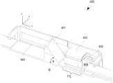
- Camera assembly 400includes a housing 420 , a compound angle mirror 401 , a lens 402 , a lens barrel 403 , and an image sensor 404 —all of which are substantially colinear along a principal axis 460 .
- Assembly 400might also include other sensors, such as a distance sensor 405 facing outward (i.e., the positive z axis).
- mirror 401has an orientation characterized by orthogonal angles ⁇ and ⁇ .
- the track length dextends along the x-axis from the leftmost edge of lens 402 to the surface of image sensor 404 .
- FIG. 5is an isometric overview of an assembly 500 that includes a camera assembly as depicted in FIG. 4 . That is, camera assembly 400 is positioned at the midpoint of a substrate (e.g., a plastic strip) 501 . Antipodal printed circuit boards (PCBs) 511 and 512 are secured to the endpoints of substrate 501 (at a slight inward-facing and upward-facing angle, as shown) and are configured to mechanically and electrically interface with a pair of IR LEDs (e.g., IR LEDs 121 and 122 in FIG. 1 ). A circuit board 502 may also be provided to support the various controllers, image processor chips, and other electronics used to control the components of camera assembly 400 and PCBs 511 , 512 .
- PCBsAntipodal printed circuit boards
- FIGS. 6 and 7illustrate the incorporation of the eye-tracking assembly of FIG. 5 into a finished computing device 700 in accordance with one embodiment.
- assembly 500is positioned between a back enclosure 601 and a display screen component 602 that are configured to be secured together such that module the camera module 400 is framed by an opening 620 in component 602 (allowing a clear view of the user).
- a rear portion of module 400may also be configured to fit within an opening 610 in back enclosure 601 such that module 400 is substantially flush therewith.
- a plate componentthat is substantially transparent to IR light and at least partially opaque to visible light is preferably placed over or inserted within module 400 to protect its internal components while still providing the required functionality.
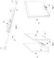
- FIG. 8illustrates a compact lens enclosure 806 in accordance with one embodiment.
- the embodiment shown in FIG. 8is advantageous in that the enclosure 806 for lens 804 is, in at least one dimension, no greater than the diameter of lens 804 .
- a point 811 on the outer perimeter of lens 804is substantially flush with the top surface 810 of enclosure 806 .
- a compact eye-tracking camera assemblyfor a computing device having a display.
- the eye-tracking camera assemblyincludes an infrared image sensor; a lens component; and mirror component.
- the infrared image sensor, lens component, and mirror componentare substantially colinear along a principal axis; and the mirror component is oriented at a compound angle configured to redirect incident IR light along the principal axis, the compound angle characterized by a first angle of approximately 45 degrees relative to a first axis, and a second angle of approximately 15 to 22 degrees relative to a second axis that is orthogonal to the first axis, the first and second axes being substantially parallel to a plane defined by the display.
- a tablet computing devicein accordance with one embodiment includes an enclosure; a display coupled to enclosure; and an eye-tracking camera assembly incorporated into the display, the eye-tracking camera assembly including: an infrared image sensor; a lens component; and a mirror component.
- the infrared image sensor, lens component, and mirror componentare substantially colinear along a principal axis, and the mirror component is oriented at a compound angle configured to redirect incident IR light along the principal axis, wherein the compound angle is characterized by a first angle of approximately 45 degrees relative to a first axis.
- a method of manufacturing a tablet computing device in accordance with one embodimentgenerally includes providing an enclosure; providing a display; and forming an eye-tracking camera assembly including an infrared image sensor, a lens component, and a mirror component, all of which are substantially colinear along a principal axis.
- the methodfurther includes interconnecting the enclosure, display, and eye-tracking camera assembly such that such that the mirror component is oriented at a compound angle configured to redirect incident IR light along the principal axis, the compound angle characterized by a first angle of approximately 45 degrees relative to a first axis substantially parallel to a plane defined by the display.
- Embodiments of the present disclosuremay be described in terms of functional and/or logical block components and various processing steps. It should be appreciated that such block components may be realized by any number of hardware, software, and/or firmware components configured to perform the specified functions. For example, an embodiment of the present disclosure may employ various integrated circuit components, e.g., memory elements, digital signal processing elements, logic elements, look-up tables, or the like, which may carry out a variety of functions under the control of one or more microprocessors or other control devices.
- integrated circuit componentse.g., memory elements, digital signal processing elements, logic elements, look-up tables, or the like, which may carry out a variety of functions under the control of one or more microprocessors or other control devices.
- machine learningmodel is used without loss of generality to refer to any result of an analysis that is designed to make some form of prediction, such as predicting the state of a response variable, clustering patients, determining association rules, and performing anomaly detection.
- machine learningrefers to models that undergo supervised, unsupervised, semi-supervised, and/or reinforcement learning. Such models may perform classification (e.g., binary or multiclass classification), regression, clustering, dimensionality reduction, and/or such tasks.
- ANNartificial neural networks
- RNNrecurrent neural networks
- CNNconvolutional neural network
- CARTclassification and regression trees
- ensemble learning modelssuch as boosting, bootstrapped aggregation, gradient boosting machines, and random forests
- Bayesian network modelse.g., naive Bayes
- PCAprincipal component analysis
- SVMsupport vector machines
- clustering modelssuch as K-nearest-neighbor, K-means, expectation maximization, hierarchical clustering, etc.
- linear discriminant analysis modelssuch as K-nearest-neighbor, K-means, expectation maximization, hierarchical clustering, etc.
- Any of the eye-tracking data generated by system 100may be stored and handled in a secure fashion (i.e., with respect to confidentiality, integrity, and availability).
- a variety of symmetrical and/or asymmetrical encryption schemes and standardsmay be employed to securely handle the eye-tracking data at rest (e.g., in system 100 ) and in motion (e.g., when being transferred between the various modules illustrated above).
- such encryption standards and key-exchange protocolsmight include Triple Data Encryption Standard (3DES), Advanced Encryption Standard (AES) (such as AES-128, 192, or 256), Rivest-Shamir-Adelman (RSA), Twofish, RC4, RC5, RC6, Transport Layer Security (TLS), Diffie-Hellman key exchange, and Secure Sockets Layer (SSL).
- 3DESTriple Data Encryption Standard
- AESAdvanced Encryption Standard
- RSARivest-Shamir-Adelman
- TLSTransport Layer Security
- SSLSecure Sockets Layer
- various hashing functionsmay be used to address integrity concerns associated with the eye-tracking data.
- moduleor “controller” refer to any hardware, software, firmware, electronic control component, processing logic, and/or processor device, individually or in any combination, including without limitation: application specific integrated circuits (ASICs), field-programmable gate-arrays (FPGAs), dedicated neural network devices (e.g., Google Tensor Processing Units), electronic circuits, processors (shared, dedicated, or group) configured to execute one or more software or firmware programs, a combinational logic circuit, and/or other suitable components that provide the described functionality.
- ASICsapplication specific integrated circuits
- FPGAsfield-programmable gate-arrays
- dedicated neural network devicese.g., Google Tensor Processing Units
- processorsshared, dedicated, or group configured to execute one or more software or firmware programs, a combinational logic circuit, and/or other suitable components that provide the described functionality.
- exemplarymeans “serving as an example, instance, or illustration.” Any implementation described herein as “exemplary” is not necessarily to be construed as preferred or advantageous over other implementations, nor is it intended to be construed as a model that must be literally duplicated.
Landscapes
- Engineering & Computer Science (AREA)
- General Engineering & Computer Science (AREA)
- Theoretical Computer Science (AREA)
- Multimedia (AREA)
- Signal Processing (AREA)
- Human Computer Interaction (AREA)
- Physics & Mathematics (AREA)
- General Physics & Mathematics (AREA)
- Studio Devices (AREA)
- Lenses (AREA)
Abstract
Description
Claims (14)
Priority Applications (3)
| Application Number | Priority Date | Filing Date | Title |
|---|---|---|---|
| US16/842,322US11921917B2 (en) | 2020-04-07 | 2020-04-07 | Compact eye-tracking camera systems and methods |
| CN202180027476.2ACN115362429A (en) | 2020-04-07 | 2021-04-06 | Compact eye tracking camera system and method |
| PCT/US2021/025997WO2021207227A1 (en) | 2020-04-07 | 2021-04-06 | Compact eye-tracking camera systems and methods |
Applications Claiming Priority (1)
| Application Number | Priority Date | Filing Date | Title |
|---|---|---|---|
| US16/842,322US11921917B2 (en) | 2020-04-07 | 2020-04-07 | Compact eye-tracking camera systems and methods |
Publications (2)
| Publication Number | Publication Date |
|---|---|
| US20210311549A1 US20210311549A1 (en) | 2021-10-07 |
| US11921917B2true US11921917B2 (en) | 2024-03-05 |
Family
ID=77921733
Family Applications (1)
| Application Number | Title | Priority Date | Filing Date |
|---|---|---|---|
| US16/842,322ActiveUS11921917B2 (en) | 2020-04-07 | 2020-04-07 | Compact eye-tracking camera systems and methods |
Country Status (3)
| Country | Link |
|---|---|
| US (1) | US11921917B2 (en) |
| CN (1) | CN115362429A (en) |
| WO (1) | WO2021207227A1 (en) |
Citations (42)
| Publication number | Priority date | Publication date | Assignee | Title |
|---|---|---|---|---|
| US5367315A (en) | 1990-11-15 | 1994-11-22 | Eyetech Corporation | Method and apparatus for controlling cursor movement |
| US7572008B2 (en) | 2002-11-21 | 2009-08-11 | Tobii Technology Ab | Method and installation for detecting and following an eye and the gaze direction thereof |
| US8350889B1 (en) | 2012-06-28 | 2013-01-08 | Shammoh Ali A A J | Integrated computer, television, and telephone |
| US20130293488A1 (en) | 2012-05-02 | 2013-11-07 | Lg Electronics Inc. | Mobile terminal and control method thereof |
| US20140168056A1 (en) | 2012-12-19 | 2014-06-19 | Qualcomm Incorporated | Enabling augmented reality using eye gaze tracking |
| US20140225131A1 (en) | 2013-02-14 | 2014-08-14 | Apple Inc. | Displays With Camera Window Openings |
| US20150160726A1 (en) | 2013-03-18 | 2015-06-11 | Mirametrix Inc. | System and Method for On-Axis Eye Gaze Tracking |
| US9106819B1 (en)* | 2013-10-14 | 2015-08-11 | Google Inc. | Camera module with compact X-Y form factor |
| US20150223684A1 (en)* | 2014-02-13 | 2015-08-13 | Bryson Hinton | System and method for eye tracking |
| US20150227735A1 (en) | 2014-02-13 | 2015-08-13 | Robert Chappell | System and method for eye tracking authentication |
| US9185352B1 (en) | 2010-12-22 | 2015-11-10 | Thomas Jacques | Mobile eye tracking system |
| US20160106315A1 (en) | 2014-05-30 | 2016-04-21 | Umoove Services Ltd. | System and method of diagnosis using gaze and eye tracking |
| US20160262685A1 (en) | 2013-11-12 | 2016-09-15 | Highland Instruments, Inc. | Motion analysis systemsand methods of use thereof |
| US20160270655A1 (en) | 2013-12-09 | 2016-09-22 | Sensomotoric Instruments Gesellschaft Fur Innovati Ve Sensorik Mbh | Method for operating an eye tracking device and eye tracking device for providing an active illumination control for improved eye tracking robustness |
| US20170068287A1 (en) | 2015-09-09 | 2017-03-09 | Lg Display Co., Ltd. | Display device |
| US9612656B2 (en) | 2012-11-27 | 2017-04-04 | Facebook, Inc. | Systems and methods of eye tracking control on mobile device |
| US20170140224A1 (en)* | 2014-06-27 | 2017-05-18 | Fove, Inc. | Gaze detection device |
| US20170188823A1 (en) | 2015-09-04 | 2017-07-06 | University Of Massachusetts | Eye tracker system and methods for detecting eye parameters |
| US20170285741A1 (en) | 2016-04-01 | 2017-10-05 | Lg Electronics Inc. | Vehicle control apparatus and method thereof |
| US20180089834A1 (en) | 2016-09-29 | 2018-03-29 | Magic Leap, Inc. | Neural network for eye image segmentation and image quality estimation |
| US20180181809A1 (en) | 2016-12-28 | 2018-06-28 | Nvidia Corporation | Unconstrained appearance-based gaze estimation |
| US10061383B1 (en) | 2015-09-16 | 2018-08-28 | Mirametrix Inc. | Multi-feature gaze tracking system and method |
| US20180307270A1 (en) | 2017-06-29 | 2018-10-25 | Inodyn Newmedia Gmbh | Mobile device with front camera and maximized screen surface |
| US10157313B1 (en) | 2014-09-19 | 2018-12-18 | Colorado School Of Mines | 3D gaze control of robot for navigation and object manipulation |
| US20190087973A1 (en) | 2017-09-20 | 2019-03-21 | Magic Leap, Inc. | Personalized neural network for eye tracking |
| US20190102905A1 (en) | 2017-09-29 | 2019-04-04 | Tobii Ab | Head pose estimation from local eye region |
| US20190204585A1 (en)* | 2017-12-28 | 2019-07-04 | Thermo Electron Scientific Instruments Llc | Mirror Alignment in Optical Scientific Instruments |
| US10373992B1 (en)* | 2016-08-09 | 2019-08-06 | Apple Inc. | Compact camera module |
| US10402649B2 (en) | 2016-08-22 | 2019-09-03 | Magic Leap, Inc. | Augmented reality display device with deep learning sensors |
| US20190302973A1 (en) | 2018-03-30 | 2019-10-03 | Microsoft Technology Licensing, Llc | Computationally efficient human-computer interface for web browser tab user interface button |
| US20190303724A1 (en) | 2018-03-30 | 2019-10-03 | Tobii Ab | Neural Network Training For Three Dimensional (3D) Gaze Prediction With Calibration Parameters |
| US20190317597A1 (en) | 2018-04-16 | 2019-10-17 | North Inc. | Method and System for Eye Tracking with Glint Space Recalibration on Wearable Heads-Up Display |
| US20190324532A1 (en) | 2018-04-16 | 2019-10-24 | North Inc. | Method and system for dual mode eye tracking on wearable heads-up display |
| US10521661B2 (en) | 2017-09-01 | 2019-12-31 | Magic Leap, Inc. | Detailed eye shape model for robust biometric applications |
| US20200099835A1 (en)* | 2018-09-21 | 2020-03-26 | Ability Opto-Electronics Technology Co.Ltd. | Optical image capturing module |
| US20200104589A1 (en) | 2018-09-28 | 2020-04-02 | Apple Inc. | Sensor Fusion Eye Tracking |
| US20200110271A1 (en) | 2018-10-04 | 2020-04-09 | Board Of Trustees Of Michigan State University | Photosensor Oculography Eye Tracking For Virtual Reality Systems |
| US10636158B1 (en) | 2020-01-13 | 2020-04-28 | Bodygram, Inc. | Methods and systems for height estimation from a 2D image using augmented reality |
| US20200134868A1 (en) | 2018-09-28 | 2020-04-30 | Beijing Sensetime Technology Development Co., Ltd. | Gaze point determination method and apparatus, electronic device, and computer storage medium |
| US20200143189A1 (en) | 2018-11-07 | 2020-05-07 | Yazaki Corporation | Monitoring system |
| US20200153768A1 (en) | 2015-11-10 | 2020-05-14 | Wrinkl, Inc. | Apparatus and method for message image reference management |
| US20200193206A1 (en) | 2018-12-18 | 2020-06-18 | Slyce Acquisition Inc. | Scene and user-input context aided visual search |
- 2020
- 2020-04-07USUS16/842,322patent/US11921917B2/enactiveActive
- 2021
- 2021-04-06WOPCT/US2021/025997patent/WO2021207227A1/ennot_activeCeased
- 2021-04-06CNCN202180027476.2Apatent/CN115362429A/enactivePending
Patent Citations (42)
| Publication number | Priority date | Publication date | Assignee | Title |
|---|---|---|---|---|
| US5367315A (en) | 1990-11-15 | 1994-11-22 | Eyetech Corporation | Method and apparatus for controlling cursor movement |
| US7572008B2 (en) | 2002-11-21 | 2009-08-11 | Tobii Technology Ab | Method and installation for detecting and following an eye and the gaze direction thereof |
| US9185352B1 (en) | 2010-12-22 | 2015-11-10 | Thomas Jacques | Mobile eye tracking system |
| US20130293488A1 (en) | 2012-05-02 | 2013-11-07 | Lg Electronics Inc. | Mobile terminal and control method thereof |
| US8350889B1 (en) | 2012-06-28 | 2013-01-08 | Shammoh Ali A A J | Integrated computer, television, and telephone |
| US9612656B2 (en) | 2012-11-27 | 2017-04-04 | Facebook, Inc. | Systems and methods of eye tracking control on mobile device |
| US20140168056A1 (en) | 2012-12-19 | 2014-06-19 | Qualcomm Incorporated | Enabling augmented reality using eye gaze tracking |
| US20140225131A1 (en) | 2013-02-14 | 2014-08-14 | Apple Inc. | Displays With Camera Window Openings |
| US20150160726A1 (en) | 2013-03-18 | 2015-06-11 | Mirametrix Inc. | System and Method for On-Axis Eye Gaze Tracking |
| US9106819B1 (en)* | 2013-10-14 | 2015-08-11 | Google Inc. | Camera module with compact X-Y form factor |
| US20160262685A1 (en) | 2013-11-12 | 2016-09-15 | Highland Instruments, Inc. | Motion analysis systemsand methods of use thereof |
| US20160270655A1 (en) | 2013-12-09 | 2016-09-22 | Sensomotoric Instruments Gesellschaft Fur Innovati Ve Sensorik Mbh | Method for operating an eye tracking device and eye tracking device for providing an active illumination control for improved eye tracking robustness |
| US20150223684A1 (en)* | 2014-02-13 | 2015-08-13 | Bryson Hinton | System and method for eye tracking |
| US20150227735A1 (en) | 2014-02-13 | 2015-08-13 | Robert Chappell | System and method for eye tracking authentication |
| US20160106315A1 (en) | 2014-05-30 | 2016-04-21 | Umoove Services Ltd. | System and method of diagnosis using gaze and eye tracking |
| US20170140224A1 (en)* | 2014-06-27 | 2017-05-18 | Fove, Inc. | Gaze detection device |
| US10157313B1 (en) | 2014-09-19 | 2018-12-18 | Colorado School Of Mines | 3D gaze control of robot for navigation and object manipulation |
| US20170188823A1 (en) | 2015-09-04 | 2017-07-06 | University Of Massachusetts | Eye tracker system and methods for detecting eye parameters |
| US20170068287A1 (en) | 2015-09-09 | 2017-03-09 | Lg Display Co., Ltd. | Display device |
| US10061383B1 (en) | 2015-09-16 | 2018-08-28 | Mirametrix Inc. | Multi-feature gaze tracking system and method |
| US20200153768A1 (en) | 2015-11-10 | 2020-05-14 | Wrinkl, Inc. | Apparatus and method for message image reference management |
| US20170285741A1 (en) | 2016-04-01 | 2017-10-05 | Lg Electronics Inc. | Vehicle control apparatus and method thereof |
| US10373992B1 (en)* | 2016-08-09 | 2019-08-06 | Apple Inc. | Compact camera module |
| US10402649B2 (en) | 2016-08-22 | 2019-09-03 | Magic Leap, Inc. | Augmented reality display device with deep learning sensors |
| US20180089834A1 (en) | 2016-09-29 | 2018-03-29 | Magic Leap, Inc. | Neural network for eye image segmentation and image quality estimation |
| US20180181809A1 (en) | 2016-12-28 | 2018-06-28 | Nvidia Corporation | Unconstrained appearance-based gaze estimation |
| US20180307270A1 (en) | 2017-06-29 | 2018-10-25 | Inodyn Newmedia Gmbh | Mobile device with front camera and maximized screen surface |
| US10521661B2 (en) | 2017-09-01 | 2019-12-31 | Magic Leap, Inc. | Detailed eye shape model for robust biometric applications |
| US20190087973A1 (en) | 2017-09-20 | 2019-03-21 | Magic Leap, Inc. | Personalized neural network for eye tracking |
| US20190102905A1 (en) | 2017-09-29 | 2019-04-04 | Tobii Ab | Head pose estimation from local eye region |
| US20190204585A1 (en)* | 2017-12-28 | 2019-07-04 | Thermo Electron Scientific Instruments Llc | Mirror Alignment in Optical Scientific Instruments |
| US20190302973A1 (en) | 2018-03-30 | 2019-10-03 | Microsoft Technology Licensing, Llc | Computationally efficient human-computer interface for web browser tab user interface button |
| US20190303724A1 (en) | 2018-03-30 | 2019-10-03 | Tobii Ab | Neural Network Training For Three Dimensional (3D) Gaze Prediction With Calibration Parameters |
| US20190317597A1 (en) | 2018-04-16 | 2019-10-17 | North Inc. | Method and System for Eye Tracking with Glint Space Recalibration on Wearable Heads-Up Display |
| US20190324532A1 (en) | 2018-04-16 | 2019-10-24 | North Inc. | Method and system for dual mode eye tracking on wearable heads-up display |
| US20200099835A1 (en)* | 2018-09-21 | 2020-03-26 | Ability Opto-Electronics Technology Co.Ltd. | Optical image capturing module |
| US20200134868A1 (en) | 2018-09-28 | 2020-04-30 | Beijing Sensetime Technology Development Co., Ltd. | Gaze point determination method and apparatus, electronic device, and computer storage medium |
| US20200104589A1 (en) | 2018-09-28 | 2020-04-02 | Apple Inc. | Sensor Fusion Eye Tracking |
| US20200110271A1 (en) | 2018-10-04 | 2020-04-09 | Board Of Trustees Of Michigan State University | Photosensor Oculography Eye Tracking For Virtual Reality Systems |
| US20200143189A1 (en) | 2018-11-07 | 2020-05-07 | Yazaki Corporation | Monitoring system |
| US20200193206A1 (en) | 2018-12-18 | 2020-06-18 | Slyce Acquisition Inc. | Scene and user-input context aided visual search |
| US10636158B1 (en) | 2020-01-13 | 2020-04-28 | Bodygram, Inc. | Methods and systems for height estimation from a 2D image using augmented reality |
Non-Patent Citations (5)
| Title |
|---|
| International Preliminary Report on Patentability, PCT/US2020/045149, dated Feb. 17, 2022, 5pgs. |
| International Search Report; PCT/US/21/25997; dated Jun. 30, 2021; 3 pgs. |
| U.S. Appl. No. 16/434,830, filed Jun. 7, 2019; Robert C. Chappell et al. "Devices and Methods for Reducing Computational and Transmission Latencies in Cloud Base Eye Tracking Systems". |
| Written Opinion; PCT/US21/25997; dated Jun. 30, 2021; 4 pgs. |
| Xuan Li et al, "An Efficient Robust Eye Localization by Learning the Convolution Distribution Using Eye Template", Computional Intelligence and Neuroscience, Oct. 2015, vol. 2015, 21pgs. |
Also Published As
| Publication number | Publication date |
|---|---|
| US20210311549A1 (en) | 2021-10-07 |
| WO2021207227A1 (en) | 2021-10-14 |
| CN115362429A (en) | 2022-11-18 |
Similar Documents
| Publication | Publication Date | Title |
|---|---|---|
| Cheng et al. | Gaze estimation by exploring two-eye asymmetry | |
| US11295551B2 (en) | Accumulation and confidence assignment of iris codes | |
| US9285872B1 (en) | Using head gesture and eye position to wake a head mounted device | |
| KR102313256B1 (en) | Eye gaze detection with multiple light sources and sensors | |
| WO2021163362A1 (en) | Systems and methods for secure processing of eye tracking data | |
| US20230060453A1 (en) | Electronic device and operation method thereof | |
| US11435781B1 (en) | Computing device | |
| Sasaki et al. | Screen corner detection using polarization camera for cross-ratio based gaze estimation | |
| US10996753B1 (en) | Multi-mode eye-tracking with independently operable illuminators | |
| US11921917B2 (en) | Compact eye-tracking camera systems and methods | |
| US10860851B2 (en) | Head mounted display apparatus and eye-tracking apparatus thereof | |
| John et al. | Real time blink recognition from various head pose using single eye | |
| Colombo et al. | Robust tracking and remapping of eye appearance with passive computer vision | |
| Türetkin et al. | Real time eye gaze tracking for human machine interaction in the cockpit | |
| US20220192606A1 (en) | Systems and Methods for Acquiring and Analyzing High-Speed Eye Movement Data | |
| US20230094572A1 (en) | Systems and Methods for Passive Calibration in Eye-Tracking System | |
| WO2022267992A1 (en) | Method and apparatus for acquiring target of fixation in head-mounted display device | |
| WO2021042704A1 (en) | Large-sensing-area under-display optical sensor | |
| Ogawa et al. | Point of gaze estimation using corneal surface reflection and omnidirectional camera image | |
| Guo et al. | Fast and Accurate Pupil Localization in Natural Scenes | |
| US20250085915A1 (en) | Electronic device and method for providing virtual space image | |
| EP4224829A1 (en) | Electronic device comprising barometric sensor | |
| Valenti et al. | Simple and efficient visual gaze estimation | |
| US11675428B2 (en) | Determining a gaze direction using depth information | |
| WO2025058615A1 (en) | Methods and systems for a gaze-based image capture mode |
Legal Events
| Date | Code | Title | Description |
|---|---|---|---|
| AS | Assignment | Owner name:EYETECH DIGITAL SYSTEMS, INC., ARIZONA Free format text:ASSIGNMENT OF ASSIGNORS INTEREST;ASSIGNORS:CHAPPELL, ROBERT C.;HINTON, BRYSON C.;HOLFORD, MICHAEL S.;SIGNING DATES FROM 20200401 TO 20200407;REEL/FRAME:052335/0320 | |
| FEPP | Fee payment procedure | Free format text:ENTITY STATUS SET TO UNDISCOUNTED (ORIGINAL EVENT CODE: BIG.); ENTITY STATUS OF PATENT OWNER: SMALL ENTITY | |
| FEPP | Fee payment procedure | Free format text:ENTITY STATUS SET TO SMALL (ORIGINAL EVENT CODE: SMAL); ENTITY STATUS OF PATENT OWNER: SMALL ENTITY | |
| STCV | Information on status: appeal procedure | Free format text:NOTICE OF APPEAL FILED | |
| STPP | Information on status: patent application and granting procedure in general | Free format text:DOCKETED NEW CASE - READY FOR EXAMINATION | |
| STPP | Information on status: patent application and granting procedure in general | Free format text:NON FINAL ACTION MAILED | |
| STPP | Information on status: patent application and granting procedure in general | Free format text:RESPONSE TO NON-FINAL OFFICE ACTION ENTERED AND FORWARDED TO EXAMINER | |
| STPP | Information on status: patent application and granting procedure in general | Free format text:FINAL REJECTION MAILED | |
| STCV | Information on status: appeal procedure | Free format text:NOTICE OF APPEAL FILED | |
| STPP | Information on status: patent application and granting procedure in general | Free format text:DOCKETED NEW CASE - READY FOR EXAMINATION | |
| STPP | Information on status: patent application and granting procedure in general | Free format text:NOTICE OF ALLOWANCE MAILED -- APPLICATION RECEIVED IN OFFICE OF PUBLICATIONS | |
| STPP | Information on status: patent application and granting procedure in general | Free format text:AWAITING TC RESP., ISSUE FEE NOT PAID | |
| STPP | Information on status: patent application and granting procedure in general | Free format text:NOTICE OF ALLOWANCE MAILED -- APPLICATION RECEIVED IN OFFICE OF PUBLICATIONS | |
| STPP | Information on status: patent application and granting procedure in general | Free format text:PUBLICATIONS -- ISSUE FEE PAYMENT VERIFIED | |
| STCF | Information on status: patent grant | Free format text:PATENTED CASE |