US11921481B2 - Systems and methods for determining equipment energy waste - Google Patents
Systems and methods for determining equipment energy wasteDownload PDFInfo
- Publication number
- US11921481B2 US11921481B2US17/697,772US202217697772AUS11921481B2US 11921481 B2US11921481 B2US 11921481B2US 202217697772 AUS202217697772 AUS 202217697772AUS 11921481 B2US11921481 B2US 11921481B2
- Authority
- US
- United States
- Prior art keywords
- fault
- building
- fault condition
- amount
- energy
- Prior art date
- Legal status (The legal status is an assumption and is not a legal conclusion. Google has not performed a legal analysis and makes no representation as to the accuracy of the status listed.)
- Active, expires
Links
Images


Classifications
- G—PHYSICS
- G05—CONTROLLING; REGULATING
- G05B—CONTROL OR REGULATING SYSTEMS IN GENERAL; FUNCTIONAL ELEMENTS OF SUCH SYSTEMS; MONITORING OR TESTING ARRANGEMENTS FOR SUCH SYSTEMS OR ELEMENTS
- G05B23/00—Testing or monitoring of control systems or parts thereof
- G05B23/02—Electric testing or monitoring
- G05B23/0205—Electric testing or monitoring by means of a monitoring system capable of detecting and responding to faults
- G05B23/0259—Electric testing or monitoring by means of a monitoring system capable of detecting and responding to faults characterized by the response to fault detection
- G05B23/0267—Fault communication, e.g. human machine interface [HMI]
- G—PHYSICS
- G05—CONTROLLING; REGULATING
- G05B—CONTROL OR REGULATING SYSTEMS IN GENERAL; FUNCTIONAL ELEMENTS OF SUCH SYSTEMS; MONITORING OR TESTING ARRANGEMENTS FOR SUCH SYSTEMS OR ELEMENTS
- G05B19/00—Programme-control systems
- G05B19/02—Programme-control systems electric
- G05B19/04—Programme control other than numerical control, i.e. in sequence controllers or logic controllers
- G05B19/042—Programme control other than numerical control, i.e. in sequence controllers or logic controllers using digital processors
- G—PHYSICS
- G05—CONTROLLING; REGULATING
- G05B—CONTROL OR REGULATING SYSTEMS IN GENERAL; FUNCTIONAL ELEMENTS OF SUCH SYSTEMS; MONITORING OR TESTING ARRANGEMENTS FOR SUCH SYSTEMS OR ELEMENTS
- G05B23/00—Testing or monitoring of control systems or parts thereof
- G05B23/02—Electric testing or monitoring
- G05B23/0205—Electric testing or monitoring by means of a monitoring system capable of detecting and responding to faults
- G05B23/0218—Electric testing or monitoring by means of a monitoring system capable of detecting and responding to faults characterised by the fault detection method dealing with either existing or incipient faults
- G05B23/0243—Electric testing or monitoring by means of a monitoring system capable of detecting and responding to faults characterised by the fault detection method dealing with either existing or incipient faults model based detection method, e.g. first-principles knowledge model
- G05B23/0245—Electric testing or monitoring by means of a monitoring system capable of detecting and responding to faults characterised by the fault detection method dealing with either existing or incipient faults model based detection method, e.g. first-principles knowledge model based on a qualitative model, e.g. rule based; if-then decisions
- G—PHYSICS
- G05—CONTROLLING; REGULATING
- G05B—CONTROL OR REGULATING SYSTEMS IN GENERAL; FUNCTIONAL ELEMENTS OF SUCH SYSTEMS; MONITORING OR TESTING ARRANGEMENTS FOR SUCH SYSTEMS OR ELEMENTS
- G05B2219/00—Program-control systems
- G05B2219/20—Pc systems
- G05B2219/25—Pc structure of the system
- G05B2219/25011—Domotique, I-O bus, home automation, building automation
- G—PHYSICS
- G05—CONTROLLING; REGULATING
- G05B—CONTROL OR REGULATING SYSTEMS IN GENERAL; FUNCTIONAL ELEMENTS OF SUCH SYSTEMS; MONITORING OR TESTING ARRANGEMENTS FOR SUCH SYSTEMS OR ELEMENTS
- G05B2219/00—Program-control systems
- G05B2219/20—Pc systems
- G05B2219/26—Pc applications
- G05B2219/2614—HVAC, heating, ventillation, climate control
- G—PHYSICS
- G05—CONTROLLING; REGULATING
- G05B—CONTROL OR REGULATING SYSTEMS IN GENERAL; FUNCTIONAL ELEMENTS OF SUCH SYSTEMS; MONITORING OR TESTING ARRANGEMENTS FOR SUCH SYSTEMS OR ELEMENTS
- G05B2219/00—Program-control systems
- G05B2219/20—Pc systems
- G05B2219/26—Pc applications
- G05B2219/2642—Domotique, domestic, home control, automation, smart house
Definitions
- the present disclosurerelates generally to building management systems (BMSs), and more specifically to determining an amount of energy wasted by building equipment due to a fault or alarm condition.
- BMSsbuilding management systems
- a BMSoperates by monitoring and controlling a wide variety building subsystems and equipment.
- a BMScan improve building operations, and can allow building owners or operators to meeting various operating goals, by increasing building (e.g., system and equipment) efficiency, decreasing operating costs, reducing user input (e.g., through automation), reducing downtime, etc.
- Building equipment, such as the equipment included in a BMSmay occasionally experience fault conditions that result in decreased efficiency and unexpected downtime, which in turn may result in a waste of energy (e.g., electricity).
- a waste of energye.g., electricity
- BMSbuilding management system
- One implementation of the present disclosureis a building management system (BMS) that includes one or more memory devices having instructions stored thereon that, when executed by one or more processors, cause the one or more processors to perform operations including using the operating data to evaluate one or more fault detection rules to determine whether at least one of the plurality of building devices is experiencing a fault condition, in response to determining that at least one of the plurality of building devices is experiencing the fault condition, determining an amount of carbon emissions generated due to the fault condition based on a fault emissions model associated with the fault condition and initiating an automated response based on the amount of carbon emissions associated with the fault condition.
- BMSbuilding management system
- the operationsfurther include obtaining at least one of the one or more fault detection rules based on a user input and mapping the one or more fault detection rules to the plurality of building devices.
- the user inputcomprises a description of a fault associated with a fault detection rule of the one or more fault detection rules, a priority of the fault, and an equation defining the fault detection rule.
- the operationsfurther include modifying the fault emissions model based on units of measurement associated with the operating data, wherein the fault emissions model is modified such that each term of the fault emissions model is defined by a common unit of measurement.
- the operationsfurther include calculating an amount of energy wasted due to the fault condition based the fault emissions model associated with the fault condition, wherein the amount of carbon emissions generated is determined based on the amount of energy wasted and energy mix information including the energy sources used to generate the wasted energy.
- the amount of energy wasted due to a fault condition in a first building deviceincludes additional energy consumed by a second building device because of the fault condition in the first building device.
- the automated responseincludes generating a work order to correct the fault condition, the work order identifying the at least one of the plurality of building devices experiencing the fault condition and comprising a description of the fault and a location of the at least one of the plurality of building devices.
- the automated responseincludes generating a graphical user interface based on the fault condition, the graphical user interface comprising an indication of the fault condition, an indication of the at least one of the plurality of building devices experiencing the fault condition, and an indication of the emissions generated and displaying the graphical user interface via a user device.
- the automated responseincludes generating an alert based on the detection of the fault condition, the alert comprising an indication of a priority of the fault condition, wherein the priority is determined based on a amount of emissions generated due to the fault and transmitting the alert to a user device.
- Another implementation of the present disclosureis a method of determining an amount of energy wasted due to a fault condition in a building management system (BMS).
- the methodincludes obtaining operating data from a plurality of building devices, using the operating data to evaluate on one or more fault detection rules to determine whether at least one of the plurality of building devices is experiencing the fault condition, in response to determining that at least one of the plurality of building devices is experiencing the fault condition, determining an amount of carbon emissions generated due to the fault condition based on a fault emissions model associated with the fault condition and initiating an automated response based on the cost associated with the fault condition.
- the methodfurther includes receiving, via a user input to a user device, at least one of the one or more fault detection rules and mapping the one or more fault detection rules to the plurality of building devices.
- the user inputincludes a description of a fault associated with a fault detection rule of the one or more fault detection rules, a priority of the fault, and an equation defining the fault detection rule.
- the methodfurther includes comprising modifying the fault emissions model based on units of measurement associated with the operating data, wherein the fault emissions model is modified such that each term of the fault emissions model is defined by a common unit of measurement.
- the methodfurther includes calculating the amount of energy wasted due to the fault condition based the fault emissions model associated with the fault condition and energy mix information, wherein the amount of energy wasted is determined by comparing a first amount of energy consumed by the at least one of the plurality of building devices over a time period of the fault condition with a second amount of energy consumed by the at least one of the plurality of building devices during a time period of normal operation, and wherein the amount of carbon emissions generated is determined based on the amount of energy wasted and energy mix information including the energy sources used to generate the wasted energy.
- the amount of energy wasted due to a fault condition in a first building deviceincludes additional energy consumed by a second building device because of the fault in the first building device.
- the automated responseincludes generating a work order to correct the fault condition, the work order identifying the at least one of the plurality of building devices experiencing the fault condition and comprising a description of the fault and a location of the at least one of the plurality of building devices.
- the automated responseincludes generating a graphical user interface based on the fault condition, the graphical user interface comprising an indication of the fault condition, an indication of the at least one of the plurality of building devices experiencing the fault condition, and an indication of the emissions generated, and displaying the graphical user interface via a user device.
- the automated responseincludes generating an alert based on the detection of the fault condition, the alert comprising an indication of a priority of the fault condition, wherein the priority is determined based on the amount of emissions generated due to the fault and transmitting the alert to a user device.
- a fault detection systemincluding one or more memory devices having instructions stored thereon that, when executed by one or more processors, cause the one or more processors to perform operations including receiving, via a user input, at least one fault detection rule, the at least one fault detection rule comprising an equation defining the at least one fault detection rule, mapping the at least one fault detection rule to one or more building devices, obtaining operating data from the one or more building devices, using the operating data to evaluate the at least one fault detection rule to determine that a building device of the one or more building devices is experiencing a fault condition, determining an amount of energy wasted due to the fault condition based on a fault emissions model associated with the fault condition, and calculating an amount of carbon emissions generated due to the fault condition based on the amount of energy wasted and energy mix information.
- operationsfurther include initiating an automated response based on the fault condition, the automated response comprising generating a work order to correct the fault condition, the work order identifying the building device experiencing the fault condition and comprising a description of the fault and a location of the building device.
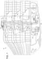
- FIG. 1is a drawing of a building equipped with a HVAC system, according to some embodiments.
- FIG. 2is a block diagram of a waterside system that may be used in conjunction with the building of FIG. 1 , according to some embodiments.
- FIG. 3is a block diagram of an airside system that may be used in conjunction with the building of FIG. 1 , according to some embodiments.
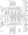
- FIG. 4is a block diagram of a building management system (BMS) that may be used to monitor and/or control the building of FIG. 1 , according to some embodiments.
- BMSbuilding management system
- FIG. 5is a block diagram of another building management system (BMS) that can be used to monitor and control the building and HVAC system of FIG. 1 , according to some embodiments.
- BMSbuilding management system
- FIG. 6 Ais a block diagram of a fault detection system for monitoring building equipment and detecting fault conditions, according to some embodiments.
- FIG. 6 Bis a block diagram of a fault detection system for monitoring building equipment and detecting fault conditions, according to some embodiments.
- FIG. 7 Ais a method for determining a cost associated with a fault, according to some embodiments.
- FIG. 7 Bis a method for determining an amount of emissions generated due to a fault, according to some embodiments.
- FIG. 7 Cis a chart illustrating the data flow that takes place in method of FIG. 7 A .
- FIG. 7 Dis a chart illustrating the data flow that takes place in method of FIG. 7 B .
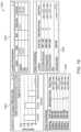
- FIG. 8is an example interface for establishing fault detection rules, according to some embodiments.
- FIG. 9is an example interface for viewing fault data, according to some embodiments.
- FIG. 10is an example interface for work order management, according to some embodiments.
- FIG. 11is an example interface for setting the read frequency of a data point, according to some embodiments.
- FIG. 12is an example interface for viewing a fault list, according to some embodiments.
- FIG. 13is an example interface for establishing fault detection rules, according to some embodiments.
- FIG. 14is an example interface for viewing fault data, according to some embodiments.
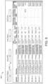
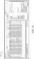
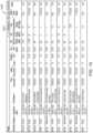
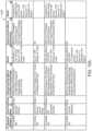
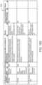
- FIGS. 15 A- 15 Dis a table showing example electrical and thermal cost rules, according to some embodiments.
- FIG. 16is an example interface for entering the cost and carbon emission of energy sources is shown, according to some embodiments.
- FIG. 17is an example interface for viewing fault information, according to some embodiments.
- FIG. 18an example interface for viewing statistical fault data, according to some embodiments.
- FIG. 19an example interface for viewing statistical fault data, according to some embodiments.
- a fault detection systemmay maintain a database of fault detection rules, each of which can be mapped to a corresponding building device, system, subsystem, etc.
- a fault detection ruleseach of which can be mapped to a corresponding building device, system, subsystem, etc.
- building equipment operating datamay be collected and analyzed with respect to the fault detection rules, to determine whether one or more building devices are experiencing a fault (e.g., by meeting certain criteria associated with a fault detection rule).
- the fault detection systemmay be configured to determine an amount of energy (e.g., electrical, thermal, etc.) that is wasted over the duration of the fault. Energy may be wasted due to, for example, the building device operating inefficiently or additional building devices operating at a greater volume to compensate for the device in the fault state. Once an amount of energy wastage is determined, the fault detection system may calculate a cost associated with the wasted energy, based on current costs or rates for the associated energy resources (e.g., electricity, natural gas, etc.).
- energy resourcese.g., electricity, natural gas, etc.
- a chiller of a building HVAC system experiencing a fault condition for half an hourmay waste X kWh of electricity, which was purchased from an energy provider (e.g., a power company) at Y dollars per kWh.
- the cost of the fault conditionmay be determined as the total number of dollars associated with the wasted energy.
- the fault detection systemmay also calculate an amount of emissions generated due to the fault, based on the type of energy source and the duration of the fault.
- an automated actionincludes generating a work order instructing a technician or other user to correct the fault condition.
- a work ordermay include an identification of the building device experiencing the fault condition, and may also include a description of the fault and a location of the building device.
- generating the work ordermay also include automatically scheduling a visit from the technician.
- the automated actionscan include generating and displaying various user interfaces that present information relating to the detected fault and the costs associated with the fault and/or the emissions generated due to the fault. Accordingly, fault conditions may be quickly resolved and, in some cases, high priority, high cost, and/or high-emission faults can be identified and corrected more urgently than other faults.
- FIGS. 1 - 4an exemplary BMS and HVAC system in which the systems and methods of the present disclosure can be implemented are shown, according to some embodiments.
- FIG. 1a perspective view of a building 10 is shown.
- Building 10is served by a BMS.
- a BMSis, in general, a system of devices configured to control, monitor, and manage equipment in or around a building or building area.
- a BMScan include, for example, a HVAC system, a security system, a lighting system, a fire safety system, any other system that is capable of managing building functions or devices, or any combination thereof.
- HVAC system 100can include a plurality of HVAC devices (e.g., heaters, chillers, air handling units, pumps, fans, thermal energy storage, etc.) configured to provide heating, cooling, ventilation, or other services for building 10 .
- HVAC system 100is shown to include a waterside system 120 and an airside system 130 .
- Waterside system 120can provide a heated or chilled fluid to an air handling unit of airside system 130 .
- Airside system 130can use the heated or chilled fluid to heat or cool an airflow provided to building 10 .
- An exemplary waterside system and airside system which can be used in HVAC system 100are described in greater detail with reference to FIGS. 2 - 3 .
- HVAC system 100is shown to include a chiller 102 , a boiler 104 , and a rooftop air handling unit (AHU) 106 .
- Waterside system 120can use boiler 104 and chiller 102 to heat or cool a working fluid (e.g., water, glycol, etc.) and can circulate the working fluid to AHU 106 .
- the HVAC devices of waterside system 120can be located in or around building 10 (as shown in FIG. 1 ) or at an offsite location such as a central plant (e.g., a chiller plant, a steam plant, a heat plant, etc.).
- the working fluidcan be heated in boiler 104 or cooled in chiller 102 , depending on whether heating or cooling is required in building 10 .
- Boiler 104can add heat to the circulated fluid, for example, by burning a combustible material (e.g., natural gas) or using an electric heating element.
- Chiller 102can place the circulated fluid in a heat exchange relationship with another fluid (e.g., a refrigerant) in a heat exchanger (e.g., an evaporator) to absorb heat from the circulated fluid.
- the working fluid from chiller 102 and/or boiler 104can be transported to AHU 106 via piping 108 .
- AHU 106can place the working fluid in a heat exchange relationship with an airflow passing through AHU 106 (e.g., via one or more stages of cooling coils and/or heating coils).
- the airflowcan be, for example, outside air, return air from within building 10 , or a combination of both.
- AHU 106can transfer heat between the airflow and the working fluid to provide heating or cooling for the airflow.
- AHU 106can include one or more fans or blowers configured to pass the airflow over or through a heat exchanger containing the working fluid. The working fluid can then return to chiller 102 or boiler 104 via piping 110 .
- Airside system 130can deliver the airflow supplied by AHU 106 (i.e., the supply airflow) to building 10 via air supply ducts 112 and can provide return air from building 10 to AHU 106 via air return ducts 114 .
- airside system 130includes multiple variable air volume (VAV) units 116 .
- VAVvariable air volume
- airside system 130is shown to include a separate VAV unit 116 on each floor or zone of building 10 .
- VAV units 116can include dampers or other flow control elements that can be operated to control an amount of the supply airflow provided to individual zones of building 10 .
- airside system 130delivers the supply airflow into one or more zones of building 10 (e.g., via supply ducts 112 ) without using intermediate VAV units 116 or other flow control elements.
- AHU 106can include various sensors (e.g., temperature sensors, pressure sensors, etc.) configured to measure attributes of the supply airflow.
- AHU 106can receive input from sensors located within AHU 106 and/or within the building zone and can adjust the flow rate, temperature, or other attributes of the supply airflow through AHU 106 to achieve setpoint conditions for the building zone.
- waterside system 200is shown as a central plant having a plurality of subplants 202 - 212 .
- Subplants 202 - 212are shown to include a heater subplant 202 , a heat recovery chiller subplant 204 , a chiller subplant 206 , a cooling tower subplant 208 , a hot thermal energy storage (TES) subplant 210 , and a cold thermal energy storage (TES) subplant 212 .
- Subplants 202 - 212consume resources (e.g., water, natural gas, electricity, etc.) from utilities to serve the thermal energy loads (e.g., hot water, cold water, heating, cooling, etc.) of a building or campus.
- resourcese.g., water, natural gas, electricity, etc.
- heater subplant 202may be configured to heat water in a hot water loop 214 that circulates the hot water between heater subplant 202 and building 10 .
- Chiller subplant 206may be configured to chill water in a cold water loop 216 that circulates the cold water between chiller subplant 206 building 10 .
- Heat recovery chiller subplant 204may be configured to transfer heat from cold water loop 216 to hot water loop 214 to provide additional heating for the hot water and additional cooling for the cold water.
- Condenser water loop 218may absorb heat from the cold water in chiller subplant 206 and reject the absorbed heat in cooling tower subplant 208 or transfer the absorbed heat to hot water loop 214 .
- Hot TES subplant 210 and cold TES subplant 212may store hot and cold thermal energy, respectively, for subsequent use.
- Hot water loop 214 and cold water loop 216may deliver the heated and/or chilled water to air handlers located on the rooftop of building 10 (e.g., AHU 106 ) or to individual floors or zones of building 10 (e.g., VAV units 116 ).
- the air handlerspush air past heat exchangers (e.g., heating coils or cooling coils) through which the water flows to provide heating or cooling for the air.
- the heated or cooled airmay be delivered to individual zones of building 10 to serve the thermal energy loads of building 10 .
- the waterthen returns to subplants 202 - 212 to receive further heating or cooling.
- subplants 202 - 212are shown and described as heating and cooling water for circulation to a building, it is understood that any other type of working fluid (e.g., glycol, CO2, etc.) may be used in place of or in addition to water to serve the thermal energy loads. In other embodiments, subplants 202 - 212 may provide heating and/or cooling directly to the building or campus without requiring an intermediate heat transfer fluid. These and other variations to waterside system 200 are within the teachings of the present invention.
- working fluide.g., glycol, CO2, etc.
- Each of subplants 202 - 212may include a variety of equipment configured to facilitate the functions of the subplant.
- heater subplant 202is shown to include a plurality of heating elements 220 (e.g., boilers, electric heaters, etc.) configured to add heat to the hot water in hot water loop 214 .
- Heater subplant 202is also shown to include several pumps 222 and 224 configured to circulate the hot water in hot water loop 214 and to control the flow rate of the hot water through individual heating elements 220 .
- Chiller subplant 206is shown to include a plurality of chillers 232 configured to remove heat from the cold water in cold water loop 216 .
- Chiller subplant 206is also shown to include several pumps 234 and 236 configured to circulate the cold water in cold water loop 216 and to control the flow rate of the cold water through individual chillers 232 .
- Heat recovery chiller subplant 204is shown to include a plurality of heat recovery heat exchangers 226 (e.g., refrigeration circuits) configured to transfer heat from cold water loop 216 to hot water loop 214 .
- Heat recovery chiller subplant 204is also shown to include several pumps 228 and 230 configured to circulate the hot water and/or cold water through heat recovery heat exchangers 226 and to control the flow rate of the water through individual heat recovery heat exchangers 226 .
- Cooling tower subplant 208is shown to include a plurality of cooling towers 238 configured to remove heat from the condenser water in condenser water loop 218 .
- Cooling tower subplant 208is also shown to include several pumps 240 configured to circulate the condenser water in condenser water loop 218 and to control the flow rate of the condenser water through individual cooling towers 238 .
- Hot TES subplant 210is shown to include a hot TES tank 242 configured to store the hot water for later use. Hot TES subplant 210 may also include one or more pumps or valves configured to control the flow rate of the hot water into or out of hot TES tank 242 .
- Cold TES subplant 212is shown to include cold TES tanks 244 configured to store the cold water for later use. Cold TES subplant 212 may also include one or more pumps or valves configured to control the flow rate of the cold water into or out of cold TES tanks 244 .
- one or more of the pumps in waterside system 200(e.g., pumps 222 , 224 , 228 , 230 , 234 , 236 , and/or 240 ) or pipelines in waterside system 200 include an isolation valve associated therewith. Isolation valves may be integrated with the pumps or positioned upstream or downstream of the pumps to control the fluid flows in waterside system 200 .
- waterside system 200may include more, fewer, or different types of devices and/or subplants based on the particular configuration of waterside system 200 and the types of loads served by waterside system 200 .
- airside system 300may supplement or replace airside system 130 in HVAC system 100 or may be implemented separate from HVAC system 100 .
- airside system 300may include a subset of the HVAC devices in HVAC system 100 (e.g., AHU 106 , VAV units 116 , ducts 112 - 114 , fans, dampers, etc.) and may be located in or around building 10 .
- Airside system 300may operate to heat or cool an airflow provided to building 10 using a heated or chilled fluid provided by waterside system 200 .
- airside system 300is shown to include an economizer-type air handling unit (AHU) 302 .
- Economizer-type AHUsvary the amount of outside air and return air used by the air handling unit for heating or cooling.
- AHU 302may receive return air 304 from building zone 306 via return air duct 308 and may deliver supply air 310 to building zone 306 via supply air duct 312 .
- AHU 302is a rooftop unit located on the roof of building 10 (e.g., AHU 106 as shown in FIG. 1 ) or otherwise positioned to receive both return air 304 and outside air 314 .
- AHU 302may be configured to operate exhaust air damper 316 , mixing damper 318 , and outside air damper 320 to control an amount of outside air 314 and return air 304 that combine to form supply air 310 . Any return air 304 that does not pass through mixing damper 318 may be exhausted from AHU 302 through exhaust damper 316 as exhaust air 322 .
- Each of dampers 316 - 320may be operated by an actuator.
- exhaust air damper 316may be operated by actuator 324
- mixing damper 318may be operated by actuator 326
- outside air damper 320may be operated by actuator 328 .
- Actuators 324 - 328may communicate with an AHU controller 330 via a communications link 332 .
- Actuators 324 - 328may receive control signals from AHU controller 330 and may provide feedback signals to AHU controller 330 .
- Feedback signalsmay include, for example, an indication of a current actuator or damper position, an amount of torque or force exerted by the actuator, diagnostic information (e.g., results of diagnostic tests performed by actuators 324 - 328 ), status information, commissioning information, configuration settings, calibration data, and/or other types of information or data that may be collected, stored, or used by actuators 324 - 328 .
- diagnostic informatione.g., results of diagnostic tests performed by actuators 324 - 328
- status informatione.g., commissioning information, configuration settings, calibration data, and/or other types of information or data that may be collected, stored, or used by actuators 324 - 328 .
- AHU controller 330may be an economizer controller configured to use one or more control algorithms (e.g., state-based algorithms, extremum seeking control (ESC) algorithms, proportional-integral (PI) control algorithms, proportional-integral-derivative (PID) control algorithms, model predictive control (MPC) algorithms, feedback control algorithms, etc.) to control actuators 324 - 328 .
- control algorithmse.g., state-based algorithms, extremum seeking control (ESC) algorithms, proportional-integral (PI) control algorithms, proportional-integral-derivative (PID) control algorithms, model predictive control (MPC) algorithms, feedback control algorithms, etc.
- AHU 302is shown to include a cooling coil 334 , a heating coil 336 , and a fan 338 positioned within supply air duct 312 .
- Fan 338may be configured to force supply air 310 through cooling coil 334 and/or heating coil 336 and provide supply air 310 to building zone 306 .
- AHU controller 330may communicate with fan 338 via communications link 340 to control a flow rate of supply air 310 .
- AHU controller 330controls an amount of heating or cooling applied to supply air 310 by modulating a speed of fan 338 .
- Cooling coil 334may receive a chilled fluid from waterside system 200 (e.g., from cold water loop 216 ) via piping 342 and may return the chilled fluid to waterside system 200 via piping 344 .
- Valve 346may be positioned along piping 342 or piping 344 to control a flow rate of the chilled fluid through cooling coil 334 .
- cooling coil 334includes multiple stages of cooling coils that can be independently activated and deactivated (e.g., by AHU controller 330 , by BMS controller 366 , etc.) to modulate an amount of cooling applied to supply air 310 .
- Heating coil 336may receive a heated fluid from waterside system 200 (e.g., from hot water loop 214 ) via piping 348 and may return the heated fluid to waterside system 200 via piping 350 .
- Valve 352may be positioned along piping 348 or piping 350 to control a flow rate of the heated fluid through heating coil 336 .
- heating coil 336includes multiple stages of heating coils that can be independently activated and deactivated (e.g., by AHU controller 330 , by BMS controller 366 , etc.) to modulate an amount of heating applied to supply air 310 .
- valves 346 and 352may be controlled by an actuator.
- valve 346may be controlled by actuator 354 and valve 352 may be controlled by actuator 356 .
- Actuators 354 - 356may communicate with AHU controller 330 via communications links 358 - 360 .
- Actuators 354 - 356may receive control signals from AHU controller 330 and may provide feedback signals to controller 330 .
- AHU controller 330receives a measurement of the supply air temperature from a temperature sensor 362 positioned in supply air duct 312 (e.g., downstream of cooling coil 334 and/or heating coil 336 ).
- AHU controller 330may also receive a measurement of the temperature of building zone 306 from a temperature sensor 364 located in building zone 306 .
- AHU controller 330operates valves 346 and 352 via actuators 354 - 356 to modulate an amount of heating or cooling provided to supply air 310 (e.g., to achieve a setpoint temperature for supply air 310 or to maintain the temperature of supply air 310 within a setpoint temperature range).
- the positions of valves 346 and 352affect the amount of heating or cooling provided to supply air 310 by cooling coil 334 or heating coil 336 and may correlate with the amount of energy consumed to achieve a desired supply air temperature.
- AHU controller 330may control the temperature of supply air 310 and/or building zone 306 by activating or deactivating coils 334 - 336 , adjusting a speed of fan 338 , or a combination of both.
- airside system 300is shown to include a building automation system (BMS) controller 366 and a client device 368 .
- BMS controller 366may include one or more computer systems (e.g., servers, supervisory controllers, subsystem controllers, etc.) that serve as system level controllers, application or data servers, head nodes, or master controllers for airside system 300 , waterside system 200 , HVAC system 100 , and/or other controllable systems that serve building 10 .
- computer systemse.g., servers, supervisory controllers, subsystem controllers, etc.
- application or data serverse.g., application or data servers, head nodes, or master controllers for airside system 300 , waterside system 200 , HVAC system 100 , and/or other controllable systems that serve building 10 .
- BMS controller 366may communicate with multiple downstream building systems or subsystems (e.g., HVAC system 100 , a security system, a lighting system, waterside system 200 , etc.) via a communications link 370 according to like or disparate protocols (e.g., LON, BACnet, etc.).
- AHU controller 330 and BMS controller 366may be separate (as shown in FIG. 3 ) or integrated.
- AHU controller 330may be a software module configured for execution by a processor of BMS controller 366 .
- AHU controller 330receives information from BMS controller 366 (e.g., commands, setpoints, operating boundaries, etc.) and provides information to BMS controller 366 (e.g., temperature measurements, valve or actuator positions, operating statuses, diagnostics, etc.). For example, AHU controller 330 may provide BMS controller 366 with temperature measurements from temperature sensors 362 - 364 , equipment on/off states, equipment operating capacities, and/or any other information that can be used by BMS controller 366 to monitor or control a variable state or condition within building zone 306 .
- BMS controller 366e.g., commands, setpoints, operating boundaries, etc.
- BMS controller 366e.g., temperature measurements, valve or actuator positions, operating statuses, diagnostics, etc.
- AHU controller 330may provide BMS controller 366 with temperature measurements from temperature sensors 362 - 364 , equipment on/off states, equipment operating capacities, and/or any other information that can be used by BMS controller 366 to monitor or control a variable
- Client device 368may include one or more human-machine interfaces or client interfaces (e.g., graphical user interfaces, reporting interfaces, text-based computer interfaces, client-facing web services, web servers that provide pages to web clients, etc.) for controlling, viewing, or otherwise interacting with HVAC system 100 , its subsystems, and/or devices.
- Client device 368may be a computer workstation, a client terminal, a remote or local interface, or any other type of user interface device.
- Client device 368may be a stationary terminal or a mobile device.
- client device 368may be a desktop computer, a computer server with a user interface, a laptop computer, a tablet, a smartphone, a PDA, or any other type of mobile or non-mobile device.
- Client device 368may communicate with BMS controller 366 and/or AHU controller 330 via communications link 372 .
- BMS 400may be implemented in building 10 to automatically monitor and control various building functions.
- BMS 400is shown to include BMS controller 366 and a plurality of building subsystems 428 .
- Building subsystems 428are shown to include a building electrical subsystem 434 , an information communication technology (ICT) subsystem 436 , a security subsystem 438 , a HVAC subsystem 440 , a lighting subsystem 442 , a lift/escalators subsystem 432 , and a fire safety subsystem 430 .
- building subsystems 428can include fewer, additional, or alternative subsystems.
- building subsystems 428may also or alternatively include a refrigeration subsystem, an advertising or signage subsystem, a cooking subsystem, a vending subsystem, a printer or copy service subsystem, or any other type of building subsystem that uses controllable equipment and/or sensors to monitor or control building 10 .
- building subsystems 428include waterside system 200 and/or airside system 300 , as described with reference to FIGS. 2 - 3 .
- HVAC subsystem 440may include many of the same components as HVAC system 100 , as described with reference to FIGS. 1 - 3 .
- HVAC subsystem 440may include a chiller, a boiler, any number of air handling units, economizers, field controllers, supervisory controllers, actuators, temperature sensors, and other devices for controlling the temperature, humidity, airflow, or other variable conditions within building 10 .
- Lighting subsystem 442may include any number of light fixtures, ballasts, lighting sensors, dimmers, or other devices configured to controllably adjust the amount of light provided to a building space.
- Security subsystem 438may include occupancy sensors, video surveillance cameras, digital video recorders, video processing servers, intrusion detection devices, access control devices and servers, or other security-related devices.
- BMS controller 366is shown to include a communications interface 407 and a BMS interface 409 .
- Interface 407may facilitate communications between BMS controller 366 and external applications (e.g., monitoring and reporting applications 422 , enterprise control applications 426 , remote systems and applications 444 , applications residing on client devices 448 , etc.) for allowing user control, monitoring, and adjustment to BMS controller 366 and/or subsystems 428 .
- Interface 407may also facilitate communications between BMS controller 366 and client devices 448 .
- BMS interface 409may facilitate communications between BMS controller 366 and building subsystems 428 (e.g., HVAC, lighting security, lifts, power distribution, business, etc.).
- Interfaces 407 , 409can be or include wired or wireless communications interfaces (e.g., jacks, antennas, transmitters, receivers, transceivers, wire terminals, etc.) for conducting data communications with building subsystems 428 or other external systems or devices.
- communications via interfaces 407 , 409may be direct (e.g., local wired or wireless communications) or via a communications network 446 (e.g., a WAN, the Internet, a cellular network, etc.).
- interfaces 407 , 409can include an Ethernet card and port for sending and receiving data via an Ethernet-based communications link or network.
- interfaces 407 , 409can include a WiFi transceiver for communicating via a wireless communications network.
- one or both of interfaces 407 , 409may include cellular or mobile phone communications transceivers.
- communications interface 407is a power line communications interface and BMS interface 409 is an Ethernet interface.
- both communications interface 407 and BMS interface 409are Ethernet interfaces or are the same Ethernet interface.
- BMS controller 366is shown to include a processing circuit 404 including a processor 406 and memory 408 .
- Processing circuit 404may be communicably connected to BMS interface 409 and/or communications interface 407 such that processing circuit 404 and the various components thereof can send and receive data via interfaces 407 , 409 .
- Processor 406can be implemented as a general purpose processor, an application specific integrated circuit (ASIC), one or more field programmable gate arrays (FPGAs), a group of processing components, or other suitable electronic processing components.
- ASICapplication specific integrated circuit
- FPGAsfield programmable gate arrays
- Memory 408may include one or more devices (e.g., RAM, ROM, Flash memory, hard disk storage, etc.) for storing data and/or computer code for completing or facilitating the various processes, layers and modules described in the present application.
- Memory 408may be or include volatile memory or non-volatile memory.
- Memory 408may include database components, object code components, script components, or any other type of information structure for supporting the various activities and information structures described in the present application.
- memory 408is communicably connected to processor 406 via processing circuit 404 and includes computer code for executing (e.g., by processing circuit 404 and/or processor 406 ) one or more processes described herein.
- BMS controller 366is implemented within a single computer (e.g., one server, one housing, etc.). In various other embodiments BMS controller 366 may be distributed across multiple servers or computers (e.g., that can exist in distributed locations). Further, while FIG. 4 shows applications 422 and 426 as existing outside of BMS controller 366 , in some embodiments, applications 422 and 426 may be hosted within BMS controller 366 (e.g., within memory 408 ).
- memory 408is shown to include an enterprise integration layer 410 , an automated measurement and validation (AM&V) layer 412 , a demand response (DR) layer 414 , a fault detection and diagnostics (FDD) layer 416 , an integrated control layer 418 , and a building subsystem integration later 420 .
- Layers 410 - 420may be configured to receive inputs from building subsystems 428 and other data sources, determine optimal control actions for building subsystems 428 based on the inputs, generate control signals based on the optimal control actions, and provide the generated control signals to building subsystems 428 .
- the following paragraphsdescribe some of the general functions performed by each of layers 410 - 420 in BMS 400 .
- Enterprise integration layer 410may be configured to serve clients or local applications with information and services to support a variety of enterprise-level applications.
- enterprise control applications 426may be configured to provide subsystem-spanning control to a graphical user interface (GUI) or to any number of enterprise-level business applications (e.g., accounting systems, user identification systems, etc.).
- GUIgraphical user interface
- Enterprise control applications 426may also or alternatively be configured to provide configuration GUIs for configuring BMS controller 366 .
- enterprise control applications 426can work with layers 410 - 420 to optimize building performance (e.g., efficiency, energy use, comfort, or safety) based on inputs received at interface 407 and/or BMS interface 409 .
- Building subsystem integration layer 420may be configured to manage communications between BMS controller 366 and building subsystems 428 .
- building subsystem integration layer 420may receive sensor data and input signals from building subsystems 428 and provide output data and control signals to building subsystems 428 .
- Building subsystem integration layer 420may also be configured to manage communications between building subsystems 428 .
- Building subsystem integration layer 420translate communications (e.g., sensor data, input signals, output signals, etc.) across a plurality of multi-vendor/multi-protocol systems.
- Demand response layer 414may be configured to optimize resource usage (e.g., electricity use, natural gas use, water use, etc.) and/or the monetary cost of such resource usage in response to satisfy the demand of building 10 .
- the optimizationmay be based on time-of-use prices, curtailment signals, energy availability, or other data received from utility providers, distributed energy generation systems 424 , from energy storage 427 (e.g., hot TES 242 , cold TES 244 , etc.), or from other sources.
- Demand response layer 414may receive inputs from other layers of BMS controller 366 (e.g., building subsystem integration layer 420 , integrated control layer 418 , etc.).
- the inputs received from other layersmay include environmental or sensor inputs such as temperature, carbon dioxide levels, relative humidity levels, air quality sensor outputs, occupancy sensor outputs, room schedules, and the like.
- the inputsmay also include inputs such as electrical use (e.g., expressed in kWh), thermal load measurements, pricing information, projected pricing, smoothed pricing, curtailment signals from utilities, and the like.
- demand response layer 414includes control logic for responding to the data and signals it receives. These responses can include communicating with the control algorithms in integrated control layer 418 , changing control strategies, changing setpoints, or activating/deactivating building equipment or subsystems in a controlled manner. Demand response layer 414 may also include control logic configured to determine when to utilize stored energy. For example, demand response layer 414 may determine to begin using energy from energy storage 427 just prior to the beginning of a peak use hour.
- demand response layer 414includes a control module configured to actively initiate control actions (e.g., automatically changing setpoints) which minimize energy costs based on one or more inputs representative of or based on demand (e.g., price, a curtailment signal, a demand level, etc.).
- demand response layer 414uses equipment models to determine an optimal set of control actions.
- the equipment modelsmay include, for example, thermodynamic models describing the inputs, outputs, and/or functions performed by various sets of building equipment.
- Equipment modelsmay represent collections of building equipment (e.g., subplants, chiller arrays, etc.) or individual devices (e.g., individual chillers, heaters, pumps, etc.).
- Demand response layer 414may further include or draw upon one or more demand response policy definitions (e.g., databases, XML, files, etc.).
- the policy definitionsmay be edited or adjusted by a user (e.g., via a graphical user interface) so that the control actions initiated in response to demand inputs may be tailored for the user's application, desired comfort level, particular building equipment, or based on other concerns.
- the demand response policy definitionscan specify which equipment may be turned on or off in response to particular demand inputs, how long a system or piece of equipment should be turned off, what setpoints can be changed, what the allowable set point adjustment range is, how long to hold a high demand setpoint before returning to a normally scheduled setpoint, how close to approach capacity limits, which equipment modes to utilize, the energy transfer rates (e.g., the maximum rate, an alarm rate, other rate boundary information, etc.) into and out of energy storage devices (e.g., thermal storage tanks, battery banks, etc.), and when to dispatch on-site generation of energy (e.g., via fuel cells, a motor generator set, etc.).
- the energy transfer ratese.g., the maximum rate, an alarm rate, other rate boundary information, etc.
- energy storage devicese.g., thermal storage tanks, battery banks, etc.
- dispatch on-site generation of energye.g., via fuel cells, a motor generator set, etc.
- Integrated control layer 418may be configured to use the data input or output of building subsystem integration layer 420 and/or demand response later 414 to make control decisions. Due to the subsystem integration provided by building subsystem integration layer 420 , integrated control layer 418 can integrate control activities of the subsystems 428 such that the subsystems 428 behave as a single integrated super-system. In an exemplary embodiment, integrated control layer 418 includes control logic that uses inputs and outputs from a plurality of building subsystems to provide greater comfort and energy savings relative to the comfort and energy savings that separate subsystems could provide alone. For example, integrated control layer 418 may be configured to use an input from a first subsystem to make an energy-saving control decision for a second subsystem. Results of these decisions can be communicated back to building subsystem integration layer 420 .
- Integrated control layer 418is shown to be logically below demand response layer 414 .
- Integrated control layer 418may be configured to enhance the effectiveness of demand response layer 414 by enabling building subsystems 428 and their respective control loops to be controlled in coordination with demand response layer 414 .
- This configurationmay advantageously reduce disruptive demand response behavior relative to conventional systems.
- integrated control layer 418may be configured to assure that a demand response-driven upward adjustment to the setpoint for chilled water temperature (or another component that directly or indirectly affects temperature) does not result in an increase in fan energy (or other energy used to cool a space) that would result in greater total building energy use than was saved at the chiller.
- Integrated control layer 418may be configured to provide feedback to demand response layer 414 so that demand response layer 414 checks that constraints (e.g., temperature, lighting levels, etc.) are properly maintained even while demanded load shedding is in progress.
- the constraintsmay also include setpoint or sensed boundaries relating to safety, equipment operating limits and performance, comfort, fire codes, electrical codes, energy codes, and the like.
- Integrated control layer 418is also logically below fault detection and diagnostics layer 416 and automated measurement and validation layer 412 .
- Integrated control layer 418may be configured to provide calculated inputs (e.g., aggregations) to these higher levels based on outputs from more than one building subsystem.
- Automated measurement and validation (AM&V) layer 412may be configured to verify that control strategies commanded by integrated control layer 418 or demand response layer 414 are working properly (e.g., using data aggregated by AM&V layer 412 , integrated control layer 418 , building subsystem integration layer 420 , FDD layer 416 , or otherwise).
- the calculations made by AM&V layer 412may be based on building system energy models and/or equipment models for individual BMS devices or subsystems. For example, AM&V layer 412 may compare a model-predicted output with an actual output from building subsystems 428 to determine an accuracy of the model.
- FDD layer 416may be configured to provide on-going fault detection for building subsystems 428 , building subsystem devices (i.e., building equipment), and control algorithms used by demand response layer 414 and integrated control layer 418 .
- FDD layer 416may receive data inputs from integrated control layer 418 , directly from one or more building subsystems or devices, or from another data source.
- FDD layer 416may automatically diagnose and respond to detected faults. The responses to detected or diagnosed faults may include providing an alert message to a user, a maintenance scheduling system, or a control algorithm configured to attempt to repair the fault or to work-around the fault.
- FDD layer 416may be configured to output a specific identification of the faulty component or cause of the fault (e.g., loose damper linkage) using detailed subsystem inputs available at building subsystem integration layer 420 .
- FDD layer 416is configured to provide “fault” events to integrated control layer 418 which executes control strategies and policies in response to the received fault events.
- FDD layer 416(or a policy executed by an integrated control engine or business rules engine) may shut-down systems or direct control activities around faulty devices or systems to reduce energy waste, extend equipment life, or assure proper control response.
- FDD layer 416may be configured to store or access a variety of different system data stores (or data points for live data). FDD layer 416 may use some content of the data stores to identify faults at the equipment level (e.g., specific chiller, specific AHU, specific terminal unit, etc.) and other content to identify faults at component or subsystem levels.
- building subsystems 428may generate temporal (i.e., time-series) data indicating the performance of BMS 400 and the various components thereof.
- the data generated by building subsystems 428may include measured or calculated values that exhibit statistical characteristics and provide information about how the corresponding system or process (e.g., a temperature control process, a flow control process, etc.) is performing in terms of error from its setpoint. These processes can be examined by FDD layer 416 to expose when the system begins to degrade in performance and alert a user to repair the fault before it becomes more severe.
- BMS 500can be used to monitor and control the devices of HVAC system 100 , waterside system 200 , airside system 300 , building subsystems 428 , as well as other types of BMS devices (e.g., lighting equipment, security equipment, etc.) and/or HVAC equipment.
- BMS devicese.g., lighting equipment, security equipment, etc.
- BMS 500provides a system architecture that facilitates automatic equipment discovery and equipment model distribution.
- Equipment discoverycan occur on multiple levels of BMS 500 across multiple different communications busses (e.g., a system bus 554 , zone buses 556 - 560 and 564 , sensor/actuator bus 566 , etc.) and across multiple different communications protocols.
- equipment discoveryis accomplished using active node tables, which provide status information for devices connected to each communications bus. For example, each communications bus can be monitored for new devices by monitoring the corresponding active node table for new nodes.
- BMS 500can begin interacting with the new device (e.g., sending control signals, using data from the device) without user interaction.
- An equipment modeldefines equipment object attributes, view definitions, schedules, trends, and the associated BACnet value objects (e.g., analog value, binary value, multistate value, etc.) that are used for integration with other systems.
- Some devices in BMS 500store their own equipment models.
- Other devices in BMS 500have equipment models stored externally (e.g., within other devices).
- a zone coordinator 508can store the equipment model for a bypass damper 528 .
- zone coordinator 508automatically creates the equipment model for bypass damper 528 or other devices on zone bus 558 .
- Other zone coordinatorscan also create equipment models for devices connected to their zone busses.
- the equipment model for a devicecan be created automatically based on the types of data points exposed by the device on the zone bus, device type, and/or other device attributes.
- BMS 500is shown to include a system manager 502 ; several zone coordinators 506 , 508 , 510 and 518 ; and several zone controllers 524 , 530 , 532 , 536 , 548 , and 550 .
- System manager 502can monitor data points in BMS 500 and report monitored variables to various monitoring and/or control applications.
- System manager 502can communicate with client devices 504 (e.g., user devices, desktop computers, laptop computers, mobile devices, etc.) via a data communications link 574 (e.g., BACnet IP, Ethernet, wired or wireless communications, etc.).
- System manager 502can provide a user interface to client devices 504 via data communications link 574 .
- the user interfacemay allow users to monitor and/or control BMS 500 via client devices 504 .
- system manager 502is connected with zone coordinators 506 - 510 and 518 via a system bus 554 .
- System manager 502can be configured to communicate with zone coordinators 506 - 510 and 518 via system bus 554 using a master-slave token passing (MSTP) protocol or any other communications protocol.
- System bus 554can also connect system manager 502 with other devices such as a constant volume (CV) rooftop unit (RTU) 512 , an input/output module (TOM) 514 , a thermostat controller 516 (e.g., a TEC5000 series thermostat controller), and a network automation engine (NAE) or third-party controller 520 .
- CVconstant volume
- RTUrooftop unit
- TOMinput/output module
- NAEnetwork automation engine
- RTU 512can be configured to communicate directly with system manager 502 and can be connected directly to system bus 554 .
- Other RTUscan communicate with system manager 502 via an intermediate device.
- a wired input 562can connect a third-party RTU 542 to thermostat controller 516 , which connects to system bus 554 .
- System manager 502can provide a user interface for any device containing an equipment model.
- Devicessuch as zone coordinators 506 - 510 and 518 and thermostat controller 516 can provide their equipment models to system manager 502 via system bus 554 .
- system manager 502automatically creates equipment models for connected devices that do not contain an equipment model (e.g., IOM 514 , third party controller 520 , etc.).
- system manager 502can create an equipment model for any device that responds to a device tree request.
- the equipment models created by system manager 502can be stored within system manager 502 .
- System manager 502can then provide a user interface for devices that do not contain their own equipment models using the equipment models created by system manager 502 .
- system manager 502stores a view definition for each type of equipment connected via system bus 554 and uses the stored view definition to generate a user interface for the equipment.
- Each zone coordinator 506 - 510 and 518can be connected with one or more of zone controllers 524 , 530 - 532 , 536 , and 548 - 550 via zone buses 556 , 558 , 560 , and 564 .
- Zone coordinators 506 - 510 and 518can communicate with zone controllers 524 , 530 - 532 , 536 , and 548 - 550 via zone busses 556 - 560 and 564 using a MSTP protocol or any other communications protocol.
- Zone busses 556 - 560 and 564can also connect zone coordinators 506 - 510 and 518 with other types of devices such as variable air volume (VAV) RTUs 522 and 540 , changeover bypass (COBP) RTUs 526 and 552 , bypass dampers 528 and 546 , and PEAK controllers 534 and 544 .
- VAVvariable air volume
- COBPchangeover bypass
- Zone coordinators 506 - 510 and 518can be configured to monitor and command various zoning systems.
- each zone coordinator 506 - 510 and 518monitors and commands a separate zoning system and is connected to the zoning system via a separate zone bus.
- zone coordinator 506can be connected to VAV RTU 522 and zone controller 524 via zone bus 556 .
- Zone coordinator 508can be connected to COBP RTU 526 , bypass damper 528 , COBP zone controller 530 , and VAV zone controller 532 via zone bus 558 .
- Zone coordinator 510can be connected to PEAK controller 534 and VAV zone controller 536 via zone bus 560 .
- Zone coordinator 518can be connected to PEAK controller 544 , bypass damper 546 , COBP zone controller 548 , and VAV zone controller 550 via zone bus 564 .
- a single model of zone coordinator 506 - 510 and 518can be configured to handle multiple different types of zoning systems (e.g., a VAV zoning system, a COBP zoning system, etc.).
- Each zoning systemcan include a RTU, one or more zone controllers, and/or a bypass damper.
- zone coordinators 506 and 510are shown as Verasys VAV engines (VVEs) connected to VAV RTUs 522 and 540 , respectively.
- Zone coordinator 506is connected directly to VAV RTU 522 via zone bus 556
- zone coordinator 510is connected to a third-party VAV RTU 540 via a wired input 568 provided to PEAK controller 534 .
- Zone coordinators 508 and 518are shown as Verasys COBP engines (VCEs) connected to COBP RTUs 526 and 552 , respectively.
- Zone coordinator 508is connected directly to COBP RTU 526 via zone bus 558
- zone coordinator 518is connected to a third-party COBP RTU 552 via a wired input 570 provided to PEAK controller 544 .
- Zone controllers 524 , 530 - 532 , 536 , and 548 - 550can communicate with individual BMS devices (e.g., sensors, actuators, etc.) via sensor/actuator (SA) busses.
- SAsensor/actuator
- VAV zone controller 536is shown connected to networked sensors 538 via SA bus 566 .
- Zone controller 536can communicate with networked sensors 538 using a MSTP protocol or any other communications protocol.
- SA bus 566only one SA bus 566 is shown in FIG. 5 , it should be understood that each zone controller 524 , 530 - 532 , 536 , and 548 - 550 can be connected to a different SA bus.
- Each SA buscan connect a zone controller with various sensors (e.g., temperature sensors, humidity sensors, pressure sensors, light sensors, occupancy sensors, etc.), actuators (e.g., damper actuators, valve actuators, etc.) and/or other types of controllable equipment (e.g., chillers, heaters, fans, pumps, etc.).
- sensorse.g., temperature sensors, humidity sensors, pressure sensors, light sensors, occupancy sensors, etc.
- actuatorse.g., damper actuators, valve actuators, etc.
- other types of controllable equipmente.g., chillers, heaters, fans, pumps, etc.
- Each zone controller 524 , 530 - 532 , 536 , and 548 - 550can be configured to monitor and control a different building zone.
- Zone controllers 524 , 530 - 532 , 536 , and 548 - 550can use the inputs and outputs provided via their SA busses to monitor and control various building zones.
- a zone controller 536can use a temperature input received from networked sensors 538 via SA bus 566 (e.g., a measured temperature of a building zone) as feedback in a temperature control algorithm.
- Zone controllers 524 , 530 - 532 , 536 , and 548 - 550can use various types of control algorithms (e.g., state-based algorithms, extremum seeking control (ESC) algorithms, proportional-integral (PI) control algorithms, proportional-integral-derivative (PID) control algorithms, model predictive control (MPC) algorithms, feedback control algorithms, etc.) to control a variable state or condition (e.g., temperature, humidity, airflow, lighting, etc.) in or around building 10 .
- control algorithmse.g., state-based algorithms, extremum seeking control (ESC) algorithms, proportional-integral (PI) control algorithms, proportional-integral-derivative (PID) control algorithms, model predictive control (MPC) algorithms, feedback control algorithms, etc.
- a variable state or conditione.g., temperature, humidity, airflow, lighting, etc.
- a BMSmay be configured to monitor and/or control building equipment (e.g., any building equipment shown in FIGS. 1 - 5 ) and/or building subsystems (e.g., building subsystem 428 ) in order to optimize building operations, such as by reducing operating costs and energy usage, decreasing downtime, increasing occupant comfort, etc.
- equipment maintenancemay be a key factor in optimizing building operations. For example, equipment that is operating in a less-than-optimal state may be less efficient than other building equipment, which may lead to higher operating costs, increase energy usage, etc.
- equipment that is non-operablemay cause added stress on other components of the BMS as the demand on the other components is increased to meet building requirements (e.g., setpoints).
- a fault detection systemsuch as the system described herein, may advantageously detect equipment and/or subsystem faults, so that detected faults can be quickly remedied to reduce downtime and wasted energy while maintaining occupant comfort.
- the fault detection systemis configured to determine not only a priority of detected faults, but may also determine an amount of energy waste during a fault condition and, based on the energy wasted, a cost of the fault.
- the fault detection systemmay prioritize faults based on either a predefined priority or the cost associated with the fault. For example, faults that result in much larger costs may be prioritized over other, less expensive faults.
- system 600may be configured to not only detect equipment faults, but may also respond to faults by determining energy wastage, emissions (e.g., greenhouse gas emissions, carbon emissions, pollutants, etc.), cost associated with the fault, and by initiating automated actions such as generating work orders to correct detected faults.
- system 600is implemented via a single computing device, such as a computer, a server, etc., or via multiple computing devices (e.g., via a distributed or cloud-based server system).
- the computing device that implements system 600may be included in a BMS, such as the BMS of building 10 described above.
- system 600is implemented via a BMS controller, such as BMS controller 366 .
- system 600may be a component of FDD layer 416 , also described above.
- System 600is shown to include a processing circuit 602 , which includes a processor 604 and a memory 610 . It will be appreciated that these components can be implemented using a variety of different types and quantities of processors and memory.
- processor 604can be a general purpose processor, an application specific integrated circuit (ASIC), one or more field programmable gate arrays (FPGAs), a group of processing components, or other suitable electronic processing components.
- Processor 604can be communicatively coupled to memory 610 . While processing circuit 602 is shown as including one processor 604 and one memory 610 , it should be understood that, as discussed herein, a processing circuit and/or memory may be implemented using multiple processors and/or memories in various embodiments. All such implementations are contemplated within the scope of the present disclosure.
- Memory 610can include one or more devices (e.g., memory units, memory devices, storage devices, etc.) for storing data and/or computer code for completing and/or facilitating the various processes described in the present disclosure.
- Memory 610can include random access memory (RAM), read-only memory (ROM), hard drive storage, temporary storage, non-volatile memory, flash memory, optical memory, or any other suitable memory for storing software objects and/or computer instructions.
- RAMrandom access memory
- ROMread-only memory
- ROMread-only memory
- Hard drive storagetemporary storage
- non-volatile memoryflash memory
- optical memoryoptical memory
- Memory 610can include database components, object code components, script components, or any other type of information structure for supporting the various activities and information structures described in the present disclosure.
- Memory 610can be communicably connected to processor 604 via processing circuit 602 and can include computer code for executing (e.g., by processor 604 ) one or more processes described herein.
- Memory 610is shown to include a rule generator 612 configured to generate and/or modify fault detection rules.
- a fault detection ruleincludes one or more parameters (e.g., conditions, criteria, threshold values, etc.) that characterize faulty operation and, if met, indicate that the fault detection rule is satisfied and thus a fault is present in the system.
- a fault detection ruleincludes one or more parameters that characterize normal (i.e., non-faulty) operation and, if met, indicate that the fault detection rule is “broken” and thus a fault is present in the system.
- the one or more conditions or criteriacan include a fault expression or equation.
- a fault detection rulemay be a Boolean expression comprising one or more operators (e.g., AND, OR, NOT, etc.) that is evaluated, based on equipment operating data, as either “true” or “false.” Whether an outcome of “true” or “false” indicates a fault condition may depend on whether the fault detection rule characterizes faulty or normal operation.
- a fault detection rulemay include other parameters such as an identifier (i.e., name) for the rule, a rule description, a category and priority of the fault, an associated type of building equipment, and any other suitable parameters. An example fault detection rule is described in greater detail below, with respect to FIG. 8 .
- a first set of fault detection rulesis predefined (e.g., prior to operating a BMS or building equipment), and the first set of fault detection rules is stored in a fault detection and diagnosis (FDD) rules database 624 .
- the first set of fault detection rulesmay be predefined by a user or by a remote system, for example, and may be transmitted to system 600 for storage.
- the first set of fault detection rulesis preprogrammed or stored in FDD rules database 624 prior to initialization of system 600 .
- rule generator 612is configured to generate one or more additional fault detection rules as part of a second set of fault detection rules.
- rule generator 612is configured to receive user inputs defining one or more parameters for a new fault detection rule. Rule generator 612 can then generate the new fault detection rule based on the user input.
- rule generator 612determines new fault detection rules over time, such as by analyzing equipment operating data via a neural network or other artificial intelligence system. In this regard, rule generator 612 may automatically identify and generate new fault detection rules by learning a BMS or user preferences over time.
- Memory 610is also shown to include a mapping engine 614 configured to map fault detection rules to building devices and/or systems (e.g., building subsystems 428 ).
- Mapping a fault detection rule to a building devicegenerally includes associating the building device with the fault detection rule, or vice versa, such that operating data associated with the building device can be analyzed according to the mapped fault detection rule.
- the fault detection ruleincludes a reference to the building device, or a reference to an object (e.g., a software object) in the BMS representing the building device.
- mappingincludes generating a tag or a pointer and storing the tag or pointer in a data object associated with either the fault detection rule and/or the building device.
- a pointer to an object representing the building devicemay be stored in a data structure that includes the fault detection rule. It will be appreciated that other methods of mapping fault detection rules to a building device or multiple building devices may also be utilized, and are therefore contemplated herein.
- memory 610also includes a fault cost model generator 616 configured to generate fault cost models for determining an amount of energy wasted over a time period of a fault and/or for determining a cost associated with the fault.
- a fault cost modelmay include a plurality of parameters including an expression or equation defining the model.
- a fault cost modelmay be utilized, in response to the detection of a fault, to calculate energy wastage and cost for the fault.
- a fault cost modelmay include one or more variables relating to at least an amount of energy consumed by a building device, a time period of the fault, and a cost of a resource consumed by the device.
- memory 610also includes a fault emissions model generator 666 configured to generate fault emissions models for determining an amount of energy wasted over a time period of a fault and/or for determining an amount of emissions (e.g., carbon emissions, greenhouse gas emissions, etc.) associated with the fault.
- a fault emissions modelmay include a plurality of parameters including an expression or equation defining the model.
- a fault emissions modelmay be utilized, in response to the detection of a fault, to calculate the excess emissions (e.g., carbon emissions) generated due to the fault.
- a fault emissions modelmay include one or more variables relating to at least an amount of energy consumed by a building device, a time period of the fault, and a rate of emissions generated by the device or otherwise attributable to the fault.
- fault cost model generator 616may generate and/or modify fault cost models over time, and may store fault cost models in a fault cost model database 626 .
- fault cost model database 626may include a first set of predefined fault cost models, such as models defined by a user and/or defined prior to initialization of system 600 , and a second set of fault cost models that are generated during operations of system 600 .
- fault cost model generator 616may be configured to learn system behaviors or user preferences to generate new models.
- fault cost model generator 616generates new fault cost models based on empirical data gathered during operation of system 600 indicating various faults and changes in resource consumption (e.g., energy consumption, water consumption, etc.) resulting from various faults. For example, fault cost model generator 616 may compare resource consumption before and after a fault is detected to determine an amount that the resource consumption changes as a result of the fault. In some embodiments, each fault cost model generated by fault cost model generator 616 may include a reference to an associated fault, or vice versa. In other embodiments, fault cost models may be generated and stored as part of a fault detection rule.
- fault emissions model generator 666may generate and/or modify fault emissions models over time, and may store fault emissions models in a fault emissions model database 676 .
- fault emissions model database 676may include a first set of predefined fault emissions models, such as models defined by a user and/or defined prior to initialization of system 600 , and a second set of fault emissions models that are generated during operations of system 600 .
- fault emissions model generator 666may be configured to learn system behaviors or user preferences to generate new models.
- fault emissions model generator 666generates new fault cost models based on empirical data gathered during operation of system 600 indicating various faults and changes in resource consumption (e.g., energy consumption, water consumption, etc.) resulting from various faults. For example, fault emissions model generator 666 may compare resource consumption before and after a fault is detected to determine an amount that the resource consumption changes as a result of the fault. In some embodiments, each fault cost model generated by fault emissions model generator 666 may include a reference to an associated fault, or vice versa. In other embodiments, fault emissions models may be generated and stored as part of a fault detection rule.
- Memory 610also includes a fault detector 618 configured to analyze building equipment operating data to detect faults.
- fault detector 618may be configured to obtain operating data from a plurality of building devices or subsystems, either by receiving the operating data or by requesting/retrieving the operating data.
- operating datais received or retrieved at a regular time interval, such as very second, every minute, every hour, etc.
- Fault detector 618may be configured to analyze any newly obtained operating data at each time interval, thereby checking each building device or subsystem for faults at each time interval.
- a time interval for obtaining operating data and subsequently analyzing the data for faultsis determined based on a user input.
- the time intervalis defined or predetermined. For example, the time interval may be set based on a processing speed of processor 604 or based on a rate at which building devices poll and transmit relevant operating data.
- fault detector 618detects faults by comparing and analyzing the operating data with respect to the one or more fault detection rules stored in FDD rules database 624 .
- fault detector 618can identifying a building device or building device type associated with the operating data (e.g., based on metadata included in the operating data), and can retrieve and/or analyze the operating data with respect to an appropriate fault detection rule.
- Analyze a fault detection rulemay include determining whether an expression or equation associated with the fault detection rule is true or false based on the operating data. For example, a fault detection rule for a chiller may be deemed “true” if a chilled water output temperature is below a predefined value (e.g., a threshold). If this fault detection rule is “true,” the rule may be considered satisfied, and fault detector 618 may flag the associated building device as experiencing a fault.
- fault detector 618is also configured to record (i.e., store) additional data regarding a fault, once the fault is detected. For example, fault detector 618 may be configured to record a date and a time that the fault was detected. Likewise, fault detector 618 may also record a date and time that the fault was corrected. In some embodiments, fault detector 618 is configured to estimate a time period for the fault (i.e., an amount of time that the device is likely to experience the fault condition). In some such embodiments, fault detector 618 can be configured to learn, over time, the average time interval between the detection of a fault and the resolution of the fault for each building device or particular fault. Thus, fault detector 618 can estimate the amount of time that it will take to resolve the fault based on historical data. Additionally, fault detector 618 may be configured to update an estimated time to resolution for each fault, as detected faults are resolved.
- memory 610further includes a user interface (UI) generator 620 .
- UI generator 620may be configured to generate graphical interfaces for presenting BPI related information. For example, UI generator 620 may generate interfaces that present graphs, charts, animations, etc. that indicate a BPI value for a BMS. In some embodiments, UI generator 620 may also generate and present interfaces that indicate BMS inefficiencies. For example, an interface may be generated that indicates specific BMS components (e.g., controllers, devices, sensors, etc.) that caused a non-zero penalty score during the calculation of the BPI.
- the various user interfaces generated by UI generator 620are described in greater detail below, with respect to FIGS. 8 - 10 .
- User device 632may be any device having an interface for presenting data to a user.
- user device 632may include at least a screen for presenting interfaces, and an input device for receiving user inputs.
- user device 632is a desktop or laptop computer, a smartphone, a tablet, a smart watch, etc.
- User device 632may be communicably coupled to system 600 via a communications interface 630 , which also provides an interface for system 600 to transmit and receive data via network 446 .
- memory 610also includes a fault cost analyzer 622 configured to determine the amount of energy wasted and the cost of a fault based on one or more fault cost models (e.g., stored in fault cost model database 626 ).
- fault cost analyzer 622may be configured to (e.g., in response to an indication from fault detector 618 ) retrieve a fault cost model (e.g., from fault cost model database 626 ) associated with a detected fault.
- Fault cost analyzer 622may determine, individually or based on an indication from fault detector 618 , a time period of the fault and an amount of energy consumed by the faulty device over the duration of the fault period.
- an amount of energy consumed by the device during a fault conditionis variable based on the type of fault. For example, certain types of faults may cause the device to consume more or less energy than normal. In some embodiments, an amount of energy consumed by the device during a fault condition is fixed or is known, based on the type of fault. For example, it may be known that a certain type of fault will most likely cause the device to consume a set amount of energy or increase energy consumption by a set amount.
- fault cost analyzer 622also accounts for the energy consumption of other, related building devices, which may impact the total amount of energy consumed by a building or system. For example, in a building including three chillers, a fault in a first chiller that reduces the output of the first chiller may cause the two remaining chillers to increase an output to maintain building comfort settings (e.g., setpoints), thereby increasing the energy usage of the two remaining chillers. Accordingly, fault cost analyzer 622 may determine the total excess energy usage (i.e., energy wastage) across all building devices in response to a fault.
- building comfort settingse.g., setpoints
- fault cost analyzer 622is configured to calculate a cost associated with the fault based on the length of time that the building device was experiencing the fault, the determined energy wastage due to the fault, and current rates or costs for obtaining a related energy resource, such as electricity, natural gas, etc.
- fault cost analyzer 622may obtain current rate data from a resource supplier (e.g., a power company, a natural gas provider, etc.), such as via network 446 .
- fault cost analyzer 622may retrieve rate data from a website or server of the resource supplier.
- resource purchasing ratesmay fluctuate over time (e.g., based on demand), thus fault cost analyzer 622 may provide a more accurate cost for the fault by retrieving current rates.
- fault cost analyzer 622utilizes a fixed resource cost or updates resource costs at a regular interval (e.g., not in response to performing a fault cost calculation).
- cost calculationse.g., the fault cost model
- the cost calculationscould be modified or replaced with any type of cost function that accounts for one or more other control objectives (e.g., resource consumption, carbon emissions, occupant comfort, disease transmission risk, equipment degradation or reliability, etc.) in addition to monetary cost or in place of monetary cost without departing from the teachings of the present disclosure.
- control objectivese.g., resource consumption, carbon emissions, occupant comfort, disease transmission risk, equipment degradation or reliability, etc.
- the “cost” calculated in the cost calculationsmay be a monetary cost (e.g., expressed in units of dollars or other currency) and/or other types of cost such as resource consumption (e.g., expressed in units of energy, water, natural gas, or any other resource), carbon emissions (e.g., expressed in units of carbon), occupant comfort (e.g., expressed in units of comfort), disease transmission risk (e.g., expressed in units of risk or probability), and/or equipment reliability (e.g., expressed in units of reliability or expected failures).
- resource consumptione.g., expressed in units of energy, water, natural gas, or any other resource
- carbon emissionse.g., expressed in units of carbon
- occupant comforte.g., expressed in units of comfort
- disease transmission riske.g., expressed in units of risk or probability
- equipment reliabilitye.g., expressed in units of reliability or expected failures
- memory 610also includes a fault emissions analyzer 672 configured to determine the amount of additional emissions generated by a fault based on one or more fault emissions models (e.g., stored in fault cost model database 626 ).
- fault emissions analyzer 672may be configured to (e.g., in response to an indication from fault detector 618 ) retrieve a fault emissions model (e.g., from fault emissions model database 676 ) associated with a detected fault.
- Fault emissions analyzer 672may determine, individually or based on an indication from fault detector 618 , a time period of the fault and an amount of additional emissions generated by the faulty device over the duration of the fault period.
- an amount of additional emissions generated by the device during a fault conditionis variable based on the type of fault. For example, certain types of faults may cause the device to generate more or less emissions than normal. In some embodiments, an amount of energy consumed by the device during a fault condition is fixed or is known, based on the type of fault. For example, it may be known that a certain type of fault will most likely cause the device to consume a set amount of energy, increase energy consumption, or generate increased emissions by a set amount.
- fault emissions analyzer 672also accounts for the energy consumption of other, related building devices, which may impact the total amount of emissions generated by a building or system. For example, in a building including three chillers, a fault in a first chiller that reduces the emissions generated by the first chiller may cause the two remaining chillers to increase in power output to maintain building comfort settings (e.g., setpoints), thereby increasing the amount of emissions generated by the two remaining chillers. Accordingly, fault emissions analyzer 672 may determine the total excess energy usage (i.e., energy wastage) across all building devices in response to a fault.
- energy wastagei.e., energy wastage
- fault emissions analyzer 672is configured to calculate an amount of emissions generated due to the fault based on the length of time that the building device was experiencing the fault and the determined energy wastage due to the fault.
- fault emissions analyzer 672may obtain energy mix data from a resource supplier (e.g., a power company, a natural gas provider, etc.), such as via network 446 .
- the energy mix datamay include the percentage of renewable energy used by the resource supplier and/or the types of fossil fuels used to generate power.
- fault emissions analyzer 672may retrieve energy mix data from a website or server of the resource supplier.
- fault emissions analyzer 672may provide a more accurate calculation of the emissions generated due to the fault by retrieving current rates.
- fault emissions analyzer 672utilizes a fixed emissions rate or retrieves the energy mix data at a regular interval (e.g., not in response to performing a fault emissions calculation).
- system 600in response to a detected fault and/or in response a determination of the energy wasted, emissions generated, or cost of the fault, system 600 (e.g., in particular, fault detector 618 , fault emissions analyzer 672 , and/or fault cost analyzer 622 ) may be configured to initiate automated responses. Automated responses may include, for example, generating a work order for the detected fault and automatically scheduling a visit from a technician to correct the fault.
- system 600generates a work order itself or transmits a request to generate a work order to a remote work order management system.
- the work ordermay indicate a type of fault, a device and location of the device experiencing the fault, a time and date that the fault was detected, and any other relevant fault information that may aid a technician in diagnosing and correcting the fault.
- the automated responseincludes generating and transmitting (e.g., to a user device), an alert identifying the fault and indicating the cost associated with and/or emissions generated by the fault.
- system 600may send the alert via a text message, an email, a voice call, a push notification, or by any other method to user device 632 .
- the automated responseincludes generating, by UI generator 620 , a user interface that displays information identifying the fault and the affected device, and presenting the energy and cost information calculated by fault cost analyzer 622 and/or the emissions information calculated by the fault emissions analyzer 672 .
- a user interfacecan be presented via user device 632 that includes graphs, text, images, and other elements for presenting fault information.
- FIG. 7 Aa method 700 for determining a cost associated with a fault is shown, according to some embodiments.
- FIG. 7 Cis a chart illustrating the data flow that takes place in method 700 .
- Method 700may be implemented by system 600 , for example, in order to detect equipment faults, determine a cost associated with the fault, and initiate automated responses based on the fault.
- determining an amount of wasted energy and a cost associated with a faultmay not only provide more complete insights to a user (e.g., a building manager) but may also allow for the prioritization of high-cost fault conditions.
- method 700may be optional and, in some embodiments, method 700 may be implemented using fewer than all of the steps.
- one or more fault detection rulesare obtained.
- the one or more fault detection rulesare predefined and stored in a database for retrieval.
- at least a portion of the one or more fault detection rulesare user defined.
- a usere.g., a building manager
- obtaining the one or more fault detection rulesmay include retrieving the one or more fault detection rules from a database and/or receiving a user input defining a new fault detection rule.
- a first set of fault detection rulesmay be predefined and a second set of fault detection rules may be defined by a user during operations of system 600 .
- mapping a fault detection rule to a building devicegenerally includes associating the building device with the fault detection rule, or vice versa, such that operating data associated with the building device can be analyzed according to the mapped fault detection rule.
- the fault detection ruleincludes a reference to the building device, or a reference to an object (e.g., a software object) in the BMS representing the building device.
- mappingincludes generating a tag or a pointer and storing the tag or pointer in a data object associated with either the fault detection rule and/or the building device.
- a pointer to an object representing the building devicemay be stored in a data structure that includes the fault detection rule. It will be appreciated that other methods of mapping fault detection rules to a building device or multiple building devices may also be utilized, and are therefore contemplated herein.
- a fault detection rulemay be mapped to a virtual data point or virtual meter, for example, within a digital twin.
- a digital twincan be a virtual representation of a building and/or an entity of the building (e.g., space, piece of equipment, occupant, etc.). Furthermore, the digital twin can represent a service performed in a building, e.g., facility management, clean air optimization, energy prediction, equipment maintenance, etc. Digital twins are further described in U.S. patent application Ser. No. 17/537,046, filed Nov. 29, 2021, the entire content of which is incorporated by reference herein.
- a digital twinmay include virtual data points or virtual meters that correspond to physical parameters not directly measured by physical meters.
- a virtual data pointmay be defined as a function of real data points.
- a virtual enthalpy point that represents the enthalpy of a fluidcan be calculated based on real points that represent the temperature and pressure of the fluid.
- Virtual data pointsare further described in U.S. Pat. No. 10,649,419 (application. Ser. No. 15/182,580), filed Jun. 14, 2016 and U.S. Pat. No. 11,281,169 (application. Ser. No. 16/052,083), filed Aug. 1, 2018, the entire contents of which are incorporated by reference herein.
- operating datais obtained from each of the one or more building devices and/or virtual data points.
- operating datais requested and/or retrieved from the one or more building devices, such as by querying the building devices or building device controllers.
- operating datais received from the one or more building devices automatically.
- operating datamay be obtained at a regular or irregular time interval (e.g., multiple times per second, every minute, every day, every month, intermittently, on demand, etc.).
- system 600may request operating data from each building device at the regular time interval, and/or the one or more building devices may transmit operating data at the regular time interval.
- operating data for each building devicemay be obtained at the same time interval, to prevent a mismatch of data or to prevent data from being received at different times, from different devices.
- the regular time intervalis predefined.
- the time intervalmay be set based on a processing speed of system 600 .
- the time interval for obtaining operating datais defined by a user. For example, a building manager may choose to obtain operating data every 30 seconds, in turn performing a fault check for each building device every 30 seconds.
- a fault conditionis detected based on the operating data.
- the operating datais compared to, or analyzed based on, the one or more fault detection rules.
- a set of operating datamay indicate the associated building device that transmitted and/or collected the operating data, which can then be used to determine one or more fault detection rules associated with the device.
- the fault detection rulesmay then be evaluated based on the operating data to determine if any of the fault detection rules are satisfied (e.g., evaluated as “true”). For example, a value of a particular parameter for the building device may be compared to a fault detection rule to determine if the requirements for the fault detection rule are met. If the fault detection rule is determined to be true, then the rule may be considered satisfied, indicating a fault.
- step 708can include modifying one of the fault detection rule or the operating data prior to analyzing the fault detection rule.
- the fault detection rule and/or operating datamay be modified based on a format or a unit of measurement of the operating data and/or based on a preferred unit of measurement for display (e.g., a user defined unit of measurement). For example, a first chiller may measure water temperatures in Celsius while a second chiller may measure water temperatures in Fahrenheit.
- the operating data and/or a fault detection rule that applies to chillersmay be modified to accommodate for the different units of measurement.
- the fault detection rulemay be automatically modified for Celsius and Fahrenheit, or a second fault detection rule may be automatically generated based on one of the units of measurement.
- the operating datamay be converted to a unit of measurement defined by the fault detection rule.
- an amount of energy wasted over a time period of the fault conditionis determined based on a fault cost model associated with the fault condition.
- a building devicemay be determined to waste 10 kWh of electricity over the course of the fault.
- one or more fault cost modelsmay be generated and/or predefined and stored in a fault cost model database.
- a fault cost model associated with the detected faultmay be retrieved responsive to detecting the fault and based on the identity of the particular fault detected.
- the fault cost model databasemay store many different fault cost models, each of which corresponds to a particular fault.
- a fault cost modelmay include a plurality of parameters including an expression or equation defining the model.
- a fault cost modelmay include an expression or an equation that includes one or more variables relating to at least an amount of energy consumed by a building device, a time period of the fault, and a cost of a resource consumed by the device.
- a fault cost modelis modified based on a format or a unit of measurement of the operating data and/or based on a preferred unit of measurement for display (e.g., a user defined unit of measurement).
- the fault cost modelis modified such that each term of the model is defined by a common unit of measurement, rather than modifying a fault detection rule or the received operating data (e.g., at step 708 ).
- a fault cost model(e.g., and/or the fault cost model generator 616 ) is configured to automatically detect units of measurements, such as based on the input operating data, to adjust the fault cost model itself, or an output of the fault cost model. For example, operating data in various different formats or units of measurement may be input to the fault cost model, and the fault cost model may be configured to automatically convert the disparate data into a common format, and output a result in the common format.
- step 710also includes determining the time period (i.e., duration) of the fault condition, and/or estimating the amount of time that the building device will experience the fault.
- the fault cost modelmay be analyzed for a period of time between the detection of the fault and a present time, to determine an amount of energy wasted up to a current moment (e.g., in real-time).
- the fault cost modelmay be analyzed over the estimated period of time that extends into the future, to estimate the amount of wasted energy.
- the estimated period of time for a faultmay be determined based on historical data, or based on a determination of when a technician can reach the device for service.
- building device dataas well as data from virtual meters or virtual data points may be used, for example, in a digital twin, to determine trends and predict future faults.
- a predicted amount of energy wasted, cost and duration of the faultcan be determined based on trends from previous data readings.
- a faultmay be predicted based on a data point reporting data readings that are continuously increasing toward a level indicating a fault.
- preventative maintenancecan be performed to prevent the fault and reduce or eliminate the potential costs or emissions that would have been generated.
- Some faults or types of faultsmay be temporary faults that typically resolve themselves without the need for corrective action.
- the amount of time that the building device will experience the faultis estimated based on a history of past faults and corresponding time periods during which the faults persisted before resolving themselves. Other faults or types of faults may be permanent faults that typically do not resolve themselves unless corrective action is taken. In some embodiments, the amount of time that the building device will experience the fault is estimated based on how soon a service technician can correct the fault. For example, system 600 may determine a work order schedule and/or a technician's schedule to determine the earliest time that the technician can correct the fault. In yet another example, the fault cost model may be analyzed for a period of time between the detection of the fault and a time when the fault is corrected or the device is turned off.
- the amount of energy wasted over a time period of the fault conditionis determined at a regular time interval, such as based on the rate at which operating data is received.
- the fault cost modelmay be used to determine energy wastage at each time step where new operating data is received from a building device.
- the rate at which the fault cost model is used to determine the equipment energy wasteis dynamically adjusted to match the rate at which data is received, or to account for missing data points. For example, if a single data point required for the determination of energy wastage is not available (e.g., the value was not captured, the corresponding device or sensors reads at a different rate than the other sensors, etc.), then the energy wastage may not be calculated for that time step.
- the BMSmay automatically add or correct data based on data point type when data from a data point is not available. For example, the BMS may use historical data to estimate missing or suspected erroneous data (e.g., the most recent measurement, the average measurement over a predetermined period of time, interpolated data based on a previous measurement and a subsequent measurement etc.).
- a cost of the faultis calculated based on the amount of energy wasted.
- the cost of the faultmay be calculated based on the fault cost model and/or based on an output of the fault cost model.
- calculating the cost of faultincludes determining a cost for the resource consumed by the device (e.g., electricity, water, gas, etc.) and multiplying the cost of the resource by the amount of energy wasted.
- a fault costmay be calculated at one or more individual time steps, such as based on a rate for the consumed resource that changes over time, and the individual time steps may be aggregated to determine the fault cost.
- step 712includes obtaining current or recent resource costs prior to calculating the fault cost.
- resource ratesmay be obtained by accessing a website, server, cloud-hosted database, or other data source for a resource provider (e.g., a power company), or the resource rates may be received at a regular interval from the resource provider.
- the resource providermay regularly publish or update resource rates (i.e., cost) which are then pushed to customers (e.g., system 600 ). Accordingly, the most current resource rates and/or other known resource rates may be utilized when calculating the fault cost, to provide a more accurate fault cost.
- an automated responseis initiated based on the detection of the fault and/or the calculated fault cost.
- automated responsesmay include generating a work order for the detected fault and automatically scheduling a visit from a technician to correct the fault.
- a work ordermay indicate a type of fault, a device and location of the device experiencing the fault, a time and date that the fault was detected, and any other relevant fault information that may aid a technician in diagnosing and correcting the fault.
- the automated responsemay also include a prioritization of multiple work orders based on the relative cost of each fault.
- generating the work ordermay also include automatically scheduling a service call or a technician visit.
- a work order log or a technician schedulemay be referenced to identify and reserve a period of time that the technician can correct the fault.
- a notification that a work order has been createdmay also be transmitted to a device associated with the assigned technician.
- the automated responseincludes generating and transmitting (e.g., to a user device), an alert identifying the fault and indicating the cost associated with the fault.
- a notificationmay be sent via a text message, an email, a voice call, a push notification, or by any other method to user device (e.g., associated with a technician or building manager).
- the automated responseincludes generating one or more user interfaces that display information identifying the fault and the affected device, and presenting the energy and cost information calculated at steps 710 and 712 .
- a user interfacecan be presented via user device 632 that include graphs, text, images, and other elements for presenting fault information. Additional user interfaces are described in greater detail below.
- FIG. 7 Cis a flow chart 750 further illustrating the method 700 .
- the fault detection rule 752is created and repeatedly run, for example, at regular intervals as described above.
- the fault duration 754is based on how long the fault detection rule 752 continues to identify an active fault.
- a fault cost equation 756receives the fault detection rule, the fault duration, and information about the equipment (e.g., the equipment specifications 758 , data points 760 from sensors and other feedback mechanisms, and constants 762 relating to the equipment).
- the fault cost equation 756identifies the amount of each type of energy wasted 764 (e.g., electrical, thermal, etc.).
- the utility rates 766are received by the resource provider and used to calculate the cost 768 of the energy wasted.
- Method 701for determining an amount of emissions generated due to a fault is shown, according to some embodiments.
- Method 701may be implemented by system 600 , for example, in order to detect equipment faults, determine a cost associated with the fault, and initiate automated responses based on the fault.
- determining an amount of emissions generated due to a faultmay not only provide more complete insights to a user (e.g., a building manager) but may also allow for the prioritization of high-emission fault conditions. In this regard, high-emission faults may be attended to more quickly than other, lower-emission faults, thereby minimizing excess emissions due to faults.
- certain steps of method 701may be optional and, in some embodiments, method 701 may be implemented using fewer than all of the steps.
- one or more fault detection rulesare obtained.
- the one or more fault detection rulesare predefined and stored in a database for retrieval.
- at least a portion of the one or more fault detection rulesare user defined.
- a usere.g., a building manager
- obtaining the one or more fault detection rulesmay include retrieving the one or more fault detection rules from a database and/or receiving a user input defining a new fault detection rule.
- a first set of fault detection rulesmay be predefined and a second set of fault detection rules may be defined by a user during operations of system 600 .
- mapping a fault detection rule to a building devicegenerally includes associating the building device with the fault detection rule, or vice versa, such that operating data associated with the building device can be analyzed according to the mapped fault detection rule.
- the fault detection ruleincludes a reference to the building device, or a reference to an object (e.g., a software object) in the BMS representing the building device.
- mappingincludes generating a tag or a pointer and storing the tag or pointer in a data object associated with either the fault detection rule and/or the building device.
- a pointer to an object representing the building devicemay be stored in a data structure that includes the fault detection rule. It will be appreciated that other methods of mapping fault detection rules to a building device or multiple building devices may also be utilized, and are therefore contemplated herein.
- a fault detection rulemay be mapped to a virtual data point or virtual meter, for example, within a digital twin.
- operating datais obtained from each of the one or more building devices and/or virtual data points.
- operating datais requested and/or retrieved from the one or more building devices, such as by querying the building devices or building device controllers.
- operating datais received from the one or more building devices automatically.
- operating datamay be obtained at a regular or irregular time interval (e.g., multiple times per second, every minute, every day, every month, intermittently, on demand, etc.).
- system 600may request operating data from each building device at the regular time interval, and/or the one or more building devices may transmit operating data at the regular time interval.
- operating data for each building devicemay be obtained at the same time interval, to prevent a mismatch of data or to prevent data from being received at different times, from different devices.
- the regular time intervalis predefined.
- the time intervalmay be set based on a processing speed of system 600 .
- the time interval for obtaining operating datais defined by a user. For example, a building manager may choose to obtain operating data every 30 seconds, in turn performing a fault check for each building device every 30 seconds.
- a fault conditionis detected based on the operating data.
- the operating datais compared to, or analyzed based on, the one or more fault detection rules.
- a set of operating datamay indicate the associated building device that transmitted and/or collected the operating data, which can then be used to determine one or more fault detection rules associated with the device.
- the fault detection rulesmay then be evaluated based on the operating data to determine if any of the fault detection rules are satisfied (e.g., evaluated as “true”). For example, a value of a particular parameter for the building device may be compared to a fault detection rule to determine if the requirements for the fault detection rule are met. If the fault detection rule is determined to be true, then the rule may be considered satisfied, indicating a fault.
- step 709can include modifying one of the fault detection rule or the operating data prior to analyzing the fault detection rule.
- the fault detection rule and/or operating datamay be modified based on a format or a unit of measurement of the operating data and/or based on a preferred unit of measurement for display (e.g., a user defined unit of measurement). For example, a first chiller may measure water temperatures in Celsius while a second chiller may measure water temperatures in Fahrenheit.
- the operating data and/or a fault detection rule that applies to chillersmay be modified to accommodate for the different units of measurement.
- the fault detection rulemay be automatically modified for Celsius and Fahrenheit, or a second fault detection rule may be automatically generated based on one of the units of measurement.
- the operating datamay be converted to a unit of measurement defined by the fault detection rule.
- an amount of energy wasted over a time period of the fault conditionis determined based on a fault emissions model associated with the fault condition.
- a building devicemay be determined to waste 10 kWh of electricity over the course of the fault and burn an additional 10 cubic feet of natural gas due to the fault.
- one or more fault emissions modelsmay be generated and/or predefined and stored in a fault emissions model database.
- a fault emissions model associated with the detected faultmay be retrieved responsive to detecting the fault and based on the identity of the particular fault detected.
- the fault emissions model databasemay store many different fault emissions models, each of which corresponds to a particular fault.
- a fault emissions modelmay include a plurality of parameters including an expression or equation defining the model.
- a fault emissions modelmay include an expression or an equation that includes one or more variables relating to at least an amount of energy consumed by a building device, a time period of the fault, and/or an amount of a resource consumed by the device.
- a fault emissions modelis modified based on a format or a unit of measurement of the operating data and/or based on a preferred unit of measurement for display (e.g., a user defined unit of measurement).
- the fault emissions modelis modified such that each term of the model is defined by a common unit of measurement, rather than modifying a fault detection rule or the received operating data (e.g., at step 709 ).
- a fault emissions model(e.g., and/or the fault emissions model generator 676 ) is configured to automatically detect units of measurements, such as based on the input operating data, to adjust the fault emissions model itself, or an output of the fault emissions model. For example, operating data in various different formats or units of measurement may be input to the fault emissions model, and the fault emissions model may be configured to automatically convert the disparate data into a common format, and output a result in the common format.
- step 711also includes determining the time period (i.e., duration) of the fault condition, and/or estimating the amount of time that the building device will experience the fault.
- the fault emissions modelmay be analyzed for a period of time between the detection of the fault and a present time, to determine an amount of energy wasted up to a current moment (e.g., in real-time).
- the fault emissions modelmay be analyzed over the estimated period of time that extends into the future, to estimate the amount of wasted energy.
- the estimated period of time for a faultmay be determined based on historical data, or based on a determination of when a technician can reach the device for service.
- building device dataas well as data from virtual meters or virtual data points may be used, for example, in a digital twin, to determine trends and predict future faults.
- a predicted amount of energy wasted, emissions generated, and duration of the faultcan be determined based on trends from previous data readings.
- Some faults or types of faultsmay be temporary faults that typically resolve themselves without the need for corrective action.
- the amount of time that the building device will experience the faultis estimated based on a history of past faults and corresponding time periods during which the faults persisted before resolving themselves.
- Other faults or types of faultsmay be permanent faults that typically do not resolve themselves unless corrective action is taken.
- the amount of time that the building device will experience the faultis estimated based on how soon a service technician can correct the fault. For example, system 600 may determine a work order schedule and/or a technician's schedule to determine the earliest time that the technician can correct the fault. In yet another example, the fault emissions model may be analyzed for a period of time between the detection of the fault and a time when the fault is corrected or the device is turned off.
- the amount of energy wasted over a time period of the fault conditionis determined at a regular time interval, such as based on the rate at which operating data is received.
- the fault emissions modelmay be used to determine emissions generated at each time step where new operating data is received from a building device.
- datamay be received from each data point at the same time based on an interval defined by user input.
- the rate at which the fault emissions model is used to determine the amount of energy wastedis dynamically adjusted to match the rate at which data is received, or to account for missing data points.
- the BMSmay automatically add or correct data based on data point type when data from a data point is not available. For example, the BMS may use historical data to estimate missing or suspected erroneous data (e.g., the most recent measurement, the average measurement over a predetermined period of time, interpolated data based on a previous measurement and a subsequent measurement etc.).
- an amount of emissions generated due to the faultis determined based on the amount of energy wasted.
- the amount of emissions generated due to the faultmay be calculated based on the fault emissions model and/or based on an output of the fault emissions model.
- calculating the amount of emissions generatedincludes determining the amount of emissions per unit of each power source used to generate the wasted energy and multiplying the cost of the resource by the amount of energy wasted.
- a the amount of emissions generated due to a faultmay be calculated at one or more individual time steps, such as based on a rate for the consumed resource that changes over time, and the individual time steps may be aggregated to determine the amount of emissions generated.
- determining an amount of emissions generatedmay not necessarily require determining a specific numerical amount of emissions, but could include making a binary determination (i.e., emissions present or emissions absent).
- step 713includes obtaining current or recent energy mix data from a resource supplier prior to calculating the emissions generated due to the fault.
- Energy mix datamay include the percentage of electricity supplied by the resource supplier that is generated from renewable sources or fossil fuels, as well as the type of renewable (e.g., solar, wind, hydroelectric, etc.) or fossil fuel (e.g., coal, natural gas, petroleum, etc.) used.
- Energy mix datamay also include the percentage of varying components of fuels, such as natural gas, supplied directly to the building devices.
- the energy mix datamay include the percentages of methane, ethane, propane, butane, etc. in the natural gas. This data may be obtained from the resource supplier or from sensor readings or test data.
- Energy mix datamay be obtained by accessing a website, server, cloud-hosted database, or other data source for a resource provider (e.g., a power company), or the energy mix data may be received at a regular interval from the resource provider.
- the resource providermay regularly publish or update energy mix data, which are then pushed to customers (e.g., system 600 ). Accordingly, the most current energy mix data may be utilized when calculating the emissions generated due to the fault, to provide a more accurate calculation of the emissions generated. Determining and updating the energy mix data can better identify and prioritize higher-emission faults.
- a first fault that results in a building device burning excess natural gasmay be prioritized over a second fault that results in a building device wasting electricity.
- the second faultmay be prioritized over the first fault.
- an automated responseis initiated based on the detection of the fault and/or the calculated emissions generated due to the fault.
- automated responsesmay include generating a work order for the detected fault and automatically scheduling a visit from a technician to correct the fault.
- a work ordermay indicate a type of fault, a device and location of the device experiencing the fault, a time and date that the fault was detected, and any other relevant fault information that may aid a technician in diagnosing and correcting the fault.
- the automated responsemay also include a prioritization of multiple work orders based on the relative amount of emissions generated by each fault.
- generating the work ordermay also include automatically scheduling a service call or a technician visit.
- a work order log or a technician schedulemay be referenced to identify and reserve a period of time that the technician can correct the fault.
- a notification that a work order has been createdmay also be transmitted to a device associated with the assigned technician.
- the automated responseincludes generating and transmitting (e.g., to a user device), an alert identifying the fault and indicating the emissions generated due to the fault.
- a notificationmay be sent via a text message, an email, a voice call, a push notification, or by any other method to user device (e.g., associated with a technician or building manager).
- the automated responseincludes generating one or more user interfaces that display information identifying the fault and the affected device, and presenting the emissions information calculated at step 713 .
- a user interfacecan be presented via user device 632 that include graphs, text, images, and other elements for presenting fault information. Additional user interfaces are described in greater detail below.
- FIG. 7 Dis a flow chart 770 further illustrating the method 700 .
- the fault detection rule 772is created and repeatedly run, for example, at regular intervals as described above.
- the fault duration 774is based on how long the fault detection rule continues to identify an active fault.
- a fault emission equation 776receives the fault detection rule, the fault duration, and information about the equipment (e.g., the equipment specifications 778 , data points 780 from sensors and other feedback mechanisms, and constants 782 relating to the equipment).
- the fault emission equation 776identifies the amount of each type of energy wasted 784 (e.g., electrical, thermal, etc.).
- An emission factor 786(e.g., the amount of emissions generated per unit of the type energy wasted) is received by the resource provider and used to calculate the emissions generated due to the fault and the carbon emission saving potential 788 .
- the fault emission calculationsare substantially similar to the fault cost calculations except that, instead of a cost per unit of each source of energy, the emissions per unit of each source of energy are used to calculate the total emissions.
- interface 800for establishing fault detection rules is shown, according to some embodiments.
- interface 800may be generated by UI generator 620 and may be presented via user device 632 .
- Interface 800may allow a user to input new fault detection rules, modify existing fault detection rules, and/or test and validate rules, among numerous other features.
- Interface 800is shown to include a number of tabs that can be selected to view various pages, for performing various tasks. For example, a user may select “System Fault Rules” to define new system-level fault rules or to modify existing system-level fault rules. In the example shown, a user has selected “Equipment Fault Rules” tab 802 to create an equipment fault rule. Interface 800 includes a number of fields that the user can populate when defining/creating the new rule, includes an “Equation Name” (i.e., fault name) and a description of the rule.
- “System Fault Rules”to define new system-level fault rules or to modify existing system-level fault rules.
- Equipment Fault Rulestab 802 to create an equipment fault rule.
- Interface 800includes a number of fields that the user can populate when defining/creating the new rule, includes an “Equation Name” (i.e., fault name) and a description of the rule.
- Other fields for populationinclude a related equipment category (“Air Handling Unit”), an equipment type (“Mixed Single Air Duct”), a fault category (“Operation”), a parameter value (“After Hours”), an indication of fault detection status (“Enabled”), a tag for the fault (“Custom”), a fault version (“Baseline”), a rule category (“Energy”), a rule function (“Time Delay Based”), a time delay (“10 minutes”), and a fault priority (“High”).
- At least a portion of the fieldsmay be required prior to creating the new fault detection rule. For example, the user may be required to populate the “Equipment Category” field, but may not be required to populate the “Time Delay” field.
- Interface 800also include an “Equation Statement” field 804 , where the user may enter an equation or expression (e.g., a Boolean equation) that defines the fault rule.
- an equation or expressione.g., a Boolean equation
- the fault rulewould be deemed “true” if both the supply air fan status and the supply air flow speed for the specified air handling unit are zero.
- Interface 800may also include a number of operators and/or icons that can be selected to enter or modify the equation in field 804 . For example, the user can select AND, NOT, OR, etc., from the set of operators for defining the equation.
- Icons 806also include elements (e.g., buttons) for testing and/or validating the new fault detection rule, mapping equipment to the new rule, mapping a cost or emissions expression to the rule, saving the rule, etc.
- Interface 900is shown to include a list 902 of fault currently active in a system (e.g., system 600 ).
- List 902may indicate an equipment identifier, an identifier for a space where the equipment is located, a fault name, a time and date that the fault was detected, a fault category, a priority, a duration of the fault, and an electrical energy, thermal energy, and cost savings potential or emissions reduction potential if the fault is corrected.
- equipment RMU-A8-BL-V03is indicated as experiencing a “VAV Low Supply Air Flow—Reheat” fault, which was detected at 17:00 on Mar. 4, 2020.
- This faultis related to comfort and is identified as a medium priority fault.
- the usermay click on the fault name (i.e., identifier), which may contain a hyperlink, thereby navigating to a second user interface that displays additional information relating to the fault.
- the second user interfacemay allow the user to acknowledge the fault and/or respond to the fault by generating a work order.
- interface 1000for work order management is shown, according to some embodiments.
- a usermay be able to generate and/or view various open and/or historical work orders.
- interface 1000includes a work order list 1002 that lists all of the work orders for a particular system (e.g., system 600 ).
- List 1002may include information such as a work order number, a location of a device or building associated with the work order, a building identifier, an equipment type and/or identifier, a request description, a creation date and time, a status, and any available work order documentation.
- the usermay also be able to enter a search term in a search bar to search and/or filter list 1002 .
- the first work order in list 1002is work order 137 relating to an air handling unit in “Building 3.”
- a secondary interface 1004may be presented that displays additional work order details.
- interface 1004displays a location, building, floor, wing, and/or room that the device is located in, as well as a category, equipment identifier, request description, and task details for the work order.
- the usermay be able to add task details by selecting an “Add Task Detail” button, and/or may be able to upload supporting documentation via a “Select Document” field.
- the usermay also be able to export one or more selected work orders (e.g., to a user device associated with a technician, to a remote work order system, etc.) via an “Export Work Order” icon 1006 .
- the data pointcan be used to determine if a fault detection rule detects a fault.
- a usercan enter a data point name 1102 identifying the device or sensor from which the data point reading is taken.
- the usercan also choose a unit type 1104 and a point role 1106 , identifying the type of measurement that is being taken.
- the usermay select a read frequency 1108 for the data point, which determines how often a reading is taken from the sensor or other device.
- all data points within a system or subsystemmay have identical read frequencies such that the cost or emission calculations can be performed without taking into account a large amount of different read frequencies.
- the usermay also select the unit type 1110 that the sensor or device outputs. Because the data point includes the unit type, the fault cost or emissions equations can easily convert all of the readings with the same unit type to the same unit. Alternatively, the data point itself can be immediately converted to a common unit. For example, if some devices read pressure in inches of water and other read pressure in psi, the user may identity the units output by the sensor or device in the data point, and the data point may automatically convert the measurements taken in inches of water and convert them to psi before reporting the measurements to the fault cost or emissions equation. Thus, the fault cost or emissions equation receives all of the readings for a given unit type in the same unit of measure.
- FIGS. 12 - 14show interfaces 1200 , 1300 , 1400 for setting up fault rules and a fault cost equation or fault emission equation.
- the interface 1200includes a fault list 1202 including fault names 1204 and corresponding fault descriptions 1206 .
- Each fault in the listhas corresponding edit buttons to edit the entry, for example, fault information edit buttons 1208 , equipment mapping buttons 1210 linking to an entry form for mapping building equipment to the corresponding fault rule, electrical cost buttons 1212 linking to an entry form for setting up the electrical cost equations, and thermal cost buttons 1214 linking to an entry form for setting up the thermal cost equations.
- each entrymay also include an emissions equation button. In other embodiments, the emissions calculation may be included in the electrical and thermal cost equation entry forms.
- the interface 1300is an entry form for entering the fault cost or emissions equation and is substantially similar to FIG. 8 .
- Interface 1300can be accessed, for example, by selecting the thermal cost button 1214 of one of the faults from the list 1202 .
- the data points sent to the fault cost or emissions equationare all the same because they are translated by a data point function before being sent to the equation.
- the unit dropdown 1302may default to a particular unit based on the equipment category, the type of fault detection, and/or the rule type, and may not be user-selectable within interface 1300 .
- interface 1400is list of faults generated by executed fault detection and cost and emissions equations. Interface is substantially similar to interface 900 , but also includes the calculated carbon emission cost 1402 of each fault.
- Row 1includes an electrical cost rule and a thermal cost rule for an air handling unit experiencing a high static pressure fault.
- the electrical cost ruledetermines an amount of kWh wasted due to the fault according to the equation: Supply Air flow*(Supply Air Static Pressure ⁇ Supply Air Pressure Setpoint)/(6356*0.75))*0.746))
- the electrical cost rule in Row 1is dependent on the supply air flow and difference between a supply air pressure setpoint and the measured static air pressure. Adjustments to the calculated electrical waste can be made based on the fan efficiency and the units of measure used by the pressure and flow sensors, as well as converting from horsepower to output the total electrical energy wastage in kilowatt-hours.
- the thermal cost ruledetermines an amount of kBTU wasted due to the fault according to the equation: (0.3*1.08*(Heating Output/100)*Supply Air Flow*(Supply Air Temperature ⁇ Mixed Air Temperature)/1000))
- the thermal cost rule in Row 1is dependent on the supply air flow, the heating output percentage, and the difference between the supply air temperature and the mixed air temperature in the air handling unit. Adjustments to the calculated thermal waste can be made based on the units of measure used by the airflow sensor and an assumed wastage percentage in order to output the total thermal energy wastage in kBTU.
- Row 2includes an electrical cost rule for an air handling unit experiencing a fault in which it does not run on its energy-saving economy cycle.
- the electrical cost ruledetermines an amount of kWh wasted due to the fault according to the equation: (((4.5*Outside Air Flow*Outside Air Enthalpy)/12000)*0.85)
- the electrical cost rule in Row 2is dependent on the outside air flow and the outside air enthalpy. Adjustments to the calculated electrical waste are made based on the units of measure used by the airflow and enthalpy sensors in order to output the total electrical energy wastage in kilowatt-hours.
- Row 3includes an electrical cost rule and a thermal cost rule for an air handling unit experiencing a fault in which it operates permanently at full load.
- the electrical cost ruledetermines an amount of kWh wasted due to the fault according to the equation: (((Supply Air Flow*(Supply Air Static Pressure ⁇ Supply Air Pressure Setpoint)/(6356*0.75))*0.746)+((Supply Air Flow/400)*0.03*0.85))
- the electrical cost rule in Row 3is dependent on the supply air flow and difference between a supply air pressure setpoint and the measured static air pressure. Adjustments to the calculated electrical waste can be made based on the chiller plant efficiency and the units of measure used by the pressure and flow sensors, as well as converting from horsepower to output the total electrical energy wastage in kilowatt-hours.
- the thermal cost ruledetermines an amount of kBTU wasted due to the fault according to the equation: ((0.3*1.08*(Heating Output/100)*Supply Air Flow*(Supply Air Temperature ⁇ Mixed Air Temperature))/1000)
- the thermal cost rule in Row 3is dependent on the supply air flow, the heating output percentage, and the difference between the supply air temperature and the mixed air temperature in the air handling unit. Adjustments to the calculated thermal waste can be made based on the units of measure used by the airflow sensor and an assumed wastage percentage in order to output the total thermal energy wastage in kBTU.
- Row 4includes an electrical cost rule for an air handling unit experiencing a low zone temperature fault.
- the electrical cost ruledetermines an amount of kWh wasted due to the fault according to the equation: ((((1.08*Supply Air Flow*(Space Temperature Setpoint ⁇ Space Temperature))/12000)*0.85)*(Cooling Output/Cooling Output))
- the electrical cost rule in Row 4is dependent on the supply air flow and the difference between a space temperature setpoint and a measured space temperature. Adjustments to the calculated electrical waste are made based on the units of measure used by the airflow sensor, the chiller plant efficiency, and the cooling output percentage of the air handling unit in order to output the total electrical energy wastage in kilowatt-hours.
- Row 5includes an electrical cost rule and a thermal cost rule for an air handling unit experiencing a simultaneous heating and cooling fault.
- the electrical cost ruledetermines an amount of kWh wasted due to the fault according to the equation: ((Supply Air Flow/400)*(Cooling Output/100)*0.85*0.8)
- the electrical cost rule in Row 5is dependent on the supply air flow and the cooling output percentage. Adjustments to the calculated electrical waste can be made based on the chiller plant efficiency, the units of measure used by the airflow sensor and a confidence factor and the total electrical energy wastage is output in kilowatt-hours.
- the thermal cost ruledetermines an amount of kBTU wasted due to the fault according to the equation: (((Heating Output/100)*Const(Heating Capacity(MBH)))*0.85*0.8)
- the thermal cost rule in Row 5is dependent on the heating output percentage and a heating capacity constant. Adjustments to the calculated thermal waste can be made based on the boiler efficiency and a confidence factor, and the total thermal energy wastage is output in kBTU.
- Row 6includes an electrical cost rule and a thermal cost rule for an air handling unit experiencing a low carbon dioxide fault.
- the electrical cost ruledetermines an amount of kWh wasted due to the fault according to the equation: ((1.08*(Supply Air Flow*((Outdoor Air Damper output ⁇ 20)/100))*(Outside Air Temperature ⁇ Supply Air Temperature)/12000)*0.85)
- the thermal cost ruledetermines an amount of kBTU wasted due to the fault according to the equation: ((1.08*(Supply Air Flow*(Outdoor Air Damper output ⁇ 20))*(Supply Air Temperature ⁇ Outside Air Temperature))/1000)
- the electrical and thermal cost rules in Row 6are dependent on the supply air flow, the outdoor air damper output percentage minus 20 percent, and the difference between the outside air temperature and the supply air temperature. Adjustments to the calculated electrical and thermal waste can be made based on the units of measure used by the airflow and temperature sensors. The total electrical energy wastage is output in k
- Row 7includes an electrical cost rule for a fan coil unit experiencing a low zone temperature fault.
- the electrical cost ruledetermines an amount of kWh wasted due to the fault according to the equation: ((((1.08*Const(FCUDESIGNFLOW)*(Zone Temperature Setpoint ⁇ Zone Temperature))/12000)*0.85)*(Cooling Output/Cooling Output))
- the electrical cost rule in Row 7is dependent on a design flow constant, the difference between the zone temperature setpoint and the measured zone temperature, and the cooling output percentage. Adjustments to the calculated electrical waste are made based on the chiller plant efficiency and the unit of measure used by the temperature sensor in order to output the total electrical energy wastage in kilowatt-hours.
- Row 8includes an electrical cost rule and a thermal cost rule for a rooftop unit experiencing a fault in which outside and return air dampers are both open.
- the electrical cost ruledetermines an amount of kWh wasted due to the fault according to the equation: (((1.08*(Supply Air Flow*(Outdoor Air Damper Output ⁇ 20))*(Outdoor Air Temperature ⁇ Supply Air Temperature))/12000)*0.85))
- the thermal cost ruledetermines an amount of kBTU wasted due to the fault according to the equation: ((1.08*(Supply Air Flow*(Outdoor Air Damper Output ⁇ 20))*(Supply Air Temperature ⁇ Outdoor Air Temperature))/1000)
- the electrical and thermal cost rules in Row 8are dependent on the supply air flow, the outdoor air damper output percentage minus 20 percent, and the difference between the outside air temperature and the supply air temperature. Adjustments to the calculated electrical and thermal waste can be made based on the units of measure used by the airflow and temperature sensors. The total
- Row 9includes an electrical cost rule for a rooftop unit experiencing a low zone temperature fault.
- the electrical cost ruledetermines an amount of kWh wasted due to the fault according to the equation: (((1.08*Supply Air Flow*(Zone Average Temperature Set point ⁇ Zone Average Temperature))/12000)*1.2)
- the electrical cost rule in Row 9is dependent on the supply air flow, the difference between the zone temperature setpoint and the measured zone temperature, and the cooling output percentage. Adjustments to the calculated electrical waste are made based on the rooftop unit efficiency and the units of measure used by the temperature sensor and airflow sensor in order to output the total electrical energy wastage in kilowatt-hours.
- Row 10includes an electrical cost rule for chilled water pumps experiencing a fault in which the pump operation is at high.
- the electrical cost ruledetermines an amount of kWh wasted due to the fault according to the equation:
- Row 11includes an electrical cost rule for a chiller experiencing a poor plant efficiency fault.
- the electrical cost ruledetermines an amount of kWh wasted due to the fault according to the equation: ((Total Plant Room System Efficiency ⁇ (Const(CHW Plant SYS Efficiency ⁇ Design)*Const(Design Efficiency Multiplier)))*Total Chiller Load)))
- the electrical cost rule in Row 11is dependent on the total plant room system efficiency, a plant room system efficiency constant, and a design efficiency multiplier constant.
- the total electrical energy wastageis output in in kilowatt-hours.
- Row 12includes an electrical cost rule for a chiller experiencing a high condenser water header supply temperature fault.
- the electrical cost ruledetermines an amount of kWh wasted due to the fault according to the equation: ((Condenser Water Header Supply Temperature ⁇ 29.5)*0.03*Total Chiller Power)
- the electrical cost rule in row 12is dependent on the condenser water header supply temperature and the total chiller power and is adjusted based on the unit of measure of the temperature sensor.
- the total electrical energy wastageis output in in kilowatt-hours.
- Row 13includes an electrical cost rule for a chiller experiencing a fault in which the air handling unit return air temperature is too cold.
- the electrical cost ruledetermines an amount of kWh wasted due to the fault according to the equation: (0.0002*(Const(RAT LowLimit) ⁇ Return Air Temperature)*((40/50)*Const(AHU Design Airflow)))
- the electrical cost rule in Row 13is dependent on the return air temperature, a lower limit temperature constant, and a design airflow constant. Adjustments to the calculated electrical waste are made based on the units of measure used by the temperature sensor in order to output the total electrical energy wastage in kilowatt-hours.
- Any of the electrical and thermal cost rulesmay include a MAX function such that only operating conditions that return a positive value for energy wasted are identified as faults.
- the fault emission equationscan use the values determined by the electrical and thermal cost rules above. For example, the total electrical energy wastage can be multiplied by a first carbon emission factor determined by the amount of carbon emitted per kWh of electricity generated. The total thermal energy wastage can be multiplied by a second carbon emission factor determined by the amount of carbon emissions generated per kBTU of thermal energy. In some embodiments, the fault emission equations can directly determine the emissions generated without first calculating the amount of energy wasted and entering the amount of energy wasted into an additional equation. In some embodiments, the fault emissions model may be analyzed over an estimated period of time that extends into the future, to predict the amount of emissions generated.
- building device datamay be used to determine trends and predict future faults, as well as the amount of emissions expected from future faults.
- a predicted amount of emissions due to a predicted faultcan be determined based on trends from previous data readings.
- Predicted faults and current faultsmay be assigned priority values based on expected and/or actual emissions. For example, a predicted fault expected to generate a large amount of emissions may be prioritized over a current fault that is generating a relatively low amount of emissions.
- Preventative maintenancemay be performed to prevent the predicted fault before repairs are performed to remedy the current fault.
- a commodity rate setup interface 1600 for entering the cost and carbon emission of energy sourcesis shown, according to some embodiments.
- a usercan enter the unit of measure for various fuel source, the cost per unit for each energy source, and the emissions per unit of each fuel source (not shown).
- the usercan enter an emissions factor per unit of electricity that, when multiplied by a number of kWh, can be used to determine the amount of carbon emissions generated due to electricity waste.
- the cost and emissions per unit for each energy sourcecan be manually or periodically automatically retrieved from a resource provider.
- the cost and emissions generated per unit of electricitymay vary depending on time of day, time of year, energy mx, etc.
- the fault detection rulerelates to detecting an air handling unit (AHU) fault in which the AHU does not run on its energy-saving economy cycle.
- the upper graph 1702shows that the AHU is programmed to turn off periodically to conserve electricity when a space served by the AHU is expected to be unoccupied.
- the AHU output graph 1704 and the AHU status graph 1706show that the AHU remained active during the periods that it was scheduled to be powered off. For example the AHU was powered on before 10:00 AM on March 7 and from 6:00 AM to 9:00 AM and after 9:30 PM on March 8, all times that the AHU should have been powered off, according the upper graph 1702 .
- Fault detection interface 1700also includes a relationship window 708 in which relationships between different building equipment are identified.
- the relationshipsmay include equipment that serves the AHU, equipment that the AHU itself serves, building spaces that the AHU serves and other devices that also serve the same building space.
- the fault cost and emissions equationstake into account these relationships in determining the cost of and emissions generated due to a fault. For example, the fault detection interface 1700 indicates that the AHU was powered off when it was scheduled to be on, from about 9:30 PM to about 10:00 PM on March 7. Because the AHU is powered off, this fault could theoretically reduce the cost and emissions generated by the AHU during that time period.
- the second AHUmay use additional electricity to supplement for the fault in the first AHU.
- the fault cost and emissions equationscan take into account the increased load on the second AHU when determining the cost of and emissions generated due to the fault.
- an interface 1800is a set of views showing various statistical fault data.
- View 1802is a visual representation of the fault count and duration by level. For each level, the size of the box represents the number of faults, while the color of the box represents the average duration of the faults.
- View 1804is a pie chart showing the percentage of each fault by equipment category (e.g., air handling units, chillers, supply fans, etc.).
- View 1806is a fault trend graph showing the total number of faults per day.
- View 1808lists the top five faults in a selected time period. The user can select whether to show the top five faults by cost, duration, or count.
- an interface 1900is a set of views showing various statistical fault data.
- View 1902categorizes a set of faults according to the type of fault (e.g., comfort faults, energy faults, maintenance faults, and miscellaneous faults).
- View 1904lists collective fault costs of various locations.
- Views 1906 and 1908respectively list the collective fault costs and the number of faults by building and by site.
- the present disclosurecontemplates methods, systems and program products on any machine-readable media for accomplishing various operations.
- the embodiments of the present disclosuremay be implemented using existing computer processors, or by a special purpose computer processor for an appropriate system, incorporated for this or another purpose, or by a hardwired system.
- Embodiments within the scope of the present disclosureinclude program products including machine-readable media for carrying or having machine-executable instructions or data structures stored thereon.
- Such machine-readable mediacan be any available media that can be accessed by a general purpose or special purpose computer or other machine with a processor.
- machine-readable mediacan comprise RAM, ROM, EPROM, EEPROM, CD-ROM or other optical disk storage, magnetic disk storage or other magnetic storage devices, or any other medium which can be used to carry or store desired program code in the form of machine-executable instructions or data structures and which can be accessed by a general purpose or special purpose computer or other machine with a processor.
- a network or another communications connectioneither hardwired, wireless, or a combination of hardwired or wireless
- any such connectionis properly termed a machine-readable medium.
- Machine-executable instructionsinclude, for example, instructions and data, which cause a general purpose computer, special purpose computer, or special purpose processing machines to perform a certain function or group of functions.
Landscapes
- Engineering & Computer Science (AREA)
- Physics & Mathematics (AREA)
- General Physics & Mathematics (AREA)
- Automation & Control Theory (AREA)
- Human Computer Interaction (AREA)
- Management, Administration, Business Operations System, And Electronic Commerce (AREA)
- Investigating, Analyzing Materials By Fluorescence Or Luminescence (AREA)
Abstract
Description
Supply Air flow*(Supply Air Static Pressure−Supply Air Pressure Setpoint)/(6356*0.75))*0.746))
The electrical cost rule in
(0.3*1.08*(Heating Output/100)*Supply Air Flow*(Supply Air Temperature−Mixed Air Temperature)/1000))
The thermal cost rule in
(((4.5*Outside Air Flow*Outside Air Enthalpy)/12000)*0.85)
The electrical cost rule in
(((Supply Air Flow*(Supply Air Static Pressure−Supply Air Pressure Setpoint)/(6356*0.75))*0.746)+((Supply Air Flow/400)*0.03*0.85))
The electrical cost rule in
((0.3*1.08*(Heating Output/100)*Supply Air Flow*(Supply Air Temperature−Mixed Air Temperature))/1000)
The thermal cost rule in
((((1.08*Supply Air Flow*(Space Temperature Setpoint−Space Temperature))/12000)*0.85)*(Cooling Output/Cooling Output))
The electrical cost rule in
((Supply Air Flow/400)*(Cooling Output/100)*0.85*0.8)
The electrical cost rule in
(((Heating Output/100)*Const(Heating Capacity(MBH)))*0.85*0.8)
The thermal cost rule in
((1.08*(Supply Air Flow*((Outdoor Air Damper output−20)/100))*(Outside Air Temperature−Supply Air Temperature)/12000)*0.85)
The thermal cost rule determines an amount of kBTU wasted due to the fault according to the equation:
((1.08*(Supply Air Flow*(Outdoor Air Damper output−20))*(Supply Air Temperature−Outside Air Temperature))/1000)
The electrical and thermal cost rules in
((((1.08*Const(FCUDESIGNFLOW)*(Zone Temperature Setpoint−Zone Temperature))/12000)*0.85)*(Cooling Output/Cooling Output))
The electrical cost rule in
(((1.08*(Supply Air Flow*(Outdoor Air Damper Output−20))*(Outdoor Air Temperature−Supply Air Temperature))/12000)*0.85))
The thermal cost rule determines an amount of kBTU wasted due to the fault according to the equation:
((1.08*(Supply Air Flow*(Outdoor Air Damper Output−20))*(Supply Air Temperature−Outdoor Air Temperature))/1000)
The electrical and thermal cost rules in
(((1.08*Supply Air Flow*(Zone Average Temperature Set point−Zone Average Temperature))/12000)*1.2)
The electrical cost rule in
The electrical cost rule in
((Total Plant Room System Efficiency−(Const(CHW Plant SYS Efficiency−Design)*Const(Design Efficiency Multiplier)))*Total Chiller Load))
The electrical cost rule in
((Condenser Water Header Supply Temperature−29.5)*0.03*Total Chiller Power)
The electrical cost rule in
(0.0002*(Const(RAT LowLimit)−Return Air Temperature)*((40/50)*Const(AHU Design Airflow)))
Claims (19)
Applications Claiming Priority (2)
| Application Number | Priority Date | Filing Date | Title |
|---|---|---|---|
| IN202121011425 | 2021-03-17 | ||
| IN202121011425 | 2021-03-17 |
Publications (2)
| Publication Number | Publication Date |
|---|---|
| US20220299963A1 US20220299963A1 (en) | 2022-09-22 |
| US11921481B2true US11921481B2 (en) | 2024-03-05 |
Family
ID=81386995
Family Applications (1)
| Application Number | Title | Priority Date | Filing Date |
|---|---|---|---|
| US17/697,772Active2042-03-30US11921481B2 (en) | 2021-03-17 | 2022-03-17 | Systems and methods for determining equipment energy waste |
Country Status (6)
| Country | Link |
|---|---|
| US (1) | US11921481B2 (en) |
| EP (1) | EP4309013A1 (en) |
| JP (1) | JP7749685B2 (en) |
| CN (1) | CN117280291A (en) |
| AU (1) | AU2022237623A1 (en) |
| WO (1) | WO2022197964A1 (en) |
Families Citing this family (6)
| Publication number | Priority date | Publication date | Assignee | Title |
|---|---|---|---|---|
| US12332617B2 (en) | 2021-09-20 | 2025-06-17 | Tyco Fire & Security Gmbh | Building management system with sustainability improvement |
| WO2023044134A1 (en) | 2021-09-20 | 2023-03-23 | Johnson Controls Tyco IP Holdings LLP | Systems and methods for sustainability planning for a building |
| US20230409020A1 (en)* | 2022-06-14 | 2023-12-21 | International Business Machines Corporation | Digital twin simulation discrepancy detection in multi-machine environment |
| US20240231349A9 (en)* | 2022-10-20 | 2024-07-11 | Johnson Controls Tyco IP Holdings LLP | Building management system with intelligent fault visualization |
| GB2630028A (en)* | 2023-05-11 | 2024-11-20 | Nokia Solutions & Networks Oy | Energy type aware control mechanism for communication network |
| US20250085671A1 (en)* | 2023-09-12 | 2025-03-13 | Tyco Fire & Security Gmbh | Building control system with brokering architecture |
Citations (368)
| Publication number | Priority date | Publication date | Assignee | Title |
|---|---|---|---|---|
| US5301109A (en) | 1990-06-11 | 1994-04-05 | Bell Communications Research, Inc. | Computerized cross-language document retrieval using latent semantic indexing |
| US5446677A (en) | 1994-04-28 | 1995-08-29 | Johnson Service Company | Diagnostic system for use in an environment control network |
| US5581478A (en) | 1995-04-13 | 1996-12-03 | Cruse; Michael | Facility environmental control system |
| JPH1049552A (en) | 1996-08-05 | 1998-02-20 | Shimizu Corp | Centralized energy management and analysis system |
| US5812962A (en) | 1996-12-09 | 1998-09-22 | White Oak Borough Authority | Method and apparatus for organizing storing and retrieving information to administer a sewer system |
| US5960381A (en) | 1998-07-07 | 1999-09-28 | Johnson Controls Technology Company | Starfield display of control system diagnostic information |
| US5973662A (en) | 1997-04-07 | 1999-10-26 | Johnson Controls Technology Company | Analog spectrum display for environmental control |
| US6014612A (en) | 1997-10-02 | 2000-01-11 | Fisher Controls International, Inc. | Remote diagnostics in a process control network having distributed control functions |
| US6031547A (en) | 1997-11-10 | 2000-02-29 | Lam Research Corporation | Computer graphical status display |
| US6134511A (en) | 1998-04-15 | 2000-10-17 | Subbarao; Krishnappa | Method and apparatus for improving building energy simulations |
| US6157943A (en) | 1998-11-12 | 2000-12-05 | Johnson Controls Technology Company | Internet access to a facility management system |
| US6285966B1 (en) | 1998-06-25 | 2001-09-04 | Fisher Controls International, Inc. | Function block apparatus for viewing data in a process control system |
| US20020010562A1 (en) | 1999-02-22 | 2002-01-24 | Fisher Rosemount Systems, Inc. | Diagnostics in a process control system |
| US20020016639A1 (en) | 1996-10-01 | 2002-02-07 | Intelihome, Inc., Texas Corporation | Method and apparatus for improved building automation |
| US6363422B1 (en) | 1998-06-24 | 2002-03-26 | Robert R. Hunter | Multi-capability facilities monitoring and control intranet for facilities management system |
| US6385510B1 (en) | 1997-12-03 | 2002-05-07 | Klaus D. Hoog | HVAC remote monitoring system |
| US6389331B1 (en) | 1999-03-11 | 2002-05-14 | Johnson Controls Technology Company | Technique for monitoring performance of a facility management system |
| US20020059229A1 (en) | 2000-10-04 | 2002-05-16 | Nsk Ltd. | Method and system for providing performance index information of a machine element, and method and system for supporting selection of a machine element |
| US6401027B1 (en) | 1999-03-19 | 2002-06-04 | Wenking Corp. | Remote road traffic data collection and intelligent vehicle highway system |
| US6437691B1 (en) | 1999-01-09 | 2002-08-20 | Heat-Timer Corporation | Electronic message delivery system utilizable in the monitoring of remote equipment and method of same |
| US20020123864A1 (en) | 2001-03-01 | 2002-09-05 | Evren Eryurek | Remote analysis of process control plant data |
| US20020147506A1 (en) | 2001-03-01 | 2002-10-10 | Evren Eryurek | Fiducial technique for estimating and using degradation levels in a process plant |
| US6477518B1 (en) | 2000-01-31 | 2002-11-05 | Visteon Global Technologies, Inc. | Method of knowledge-based engineering cost and weight estimation of an HVAC air-handling assembly for a climate control system |
| US6487457B1 (en) | 1999-02-12 | 2002-11-26 | Honeywell International, Inc. | Database for a remotely accessible building information system |
| US20020177909A1 (en) | 2001-03-23 | 2002-11-28 | Ye Fu | Multi-variable control loop assessment |
| US6493755B1 (en) | 1999-01-15 | 2002-12-10 | Compaq Information Technologies Group, L.P. | Automatic notification rule definition for a network management system |
| US20030005486A1 (en) | 2001-05-29 | 2003-01-02 | Ridolfo Charles F. | Health monitoring display system for a complex plant |
| US20030014130A1 (en) | 2001-05-04 | 2003-01-16 | Alain Grumelart | Process control loop analysis system |
| US20030073432A1 (en) | 2001-10-16 | 2003-04-17 | Meade, William K. | Mobile computing device with method and system for interrupting content performance among appliances |
| JP2003162573A (en) | 2001-11-28 | 2003-06-06 | E & E Planning:Kk | Building energy management method and management system |
| US6577323B1 (en) | 1999-07-01 | 2003-06-10 | Honeywell Inc. | Multivariable process trend display and methods regarding same |
| US20030158704A1 (en) | 2000-11-27 | 2003-08-21 | Phil Triginai | Apparatus and method for diagnosing performance of air-conditioning systems |
| US20030171851A1 (en) | 2002-03-08 | 2003-09-11 | Peter J. Brickfield | Automatic energy management and energy consumption reduction, especially in commercial and multi-building systems |
| US6626366B2 (en) | 2000-09-13 | 2003-09-30 | Miura Co., Ltd. | System for servicing and maintaining heat supply equipment |
| US20030200059A1 (en) | 2002-04-18 | 2003-10-23 | International Business Machines Corporation | Method and system of an integrated simulation tool using business patterns and scripts |
| US6646660B1 (en) | 2000-09-29 | 2003-11-11 | Advanced Micro Devices Inc. | Method and apparatus for presenting process control performance data |
| US6704016B1 (en) | 2000-05-08 | 2004-03-09 | 3Com Corporation | Method and apparatus for the graphical presentation of selected data |
| US20040068390A1 (en) | 2002-10-04 | 2004-04-08 | Saunders Michael A. | Compressor performance calculator |
| US6732540B2 (en) | 2002-07-19 | 2004-05-11 | Hitachi Plant Engineering & Construction Co., Ltd. | Air conditioning plant and control method thereof |
| US20040128314A1 (en) | 2002-12-30 | 2004-07-01 | International Business Machines Corporation | Method, system, and program for optimization of temporal and spatial data processing |
| US20040133314A1 (en) | 2002-03-28 | 2004-07-08 | Ehlers Gregory A. | System and method of controlling an HVAC system |
| US6764019B1 (en) | 2000-06-30 | 2004-07-20 | Miura Co., Ltd. | Method for servicing and maintaining heat supply equipment |
| US20040199360A1 (en) | 2001-08-31 | 2004-10-07 | Mats Friman | Method and system for analysing control circuit performance in industrial process |
| US6816811B2 (en) | 2001-06-21 | 2004-11-09 | Johnson Controls Technology Company | Method of intelligent data analysis to detect abnormal use of utilities in buildings |
| US6826454B2 (en) | 2001-09-19 | 2004-11-30 | Louis E. Sulfstede | Air conditioning diagnostic analyzer |
| US6823680B2 (en) | 2000-11-22 | 2004-11-30 | Copeland Corporation | Remote data acquisition system and method |
| US6865511B2 (en) | 2002-12-10 | 2005-03-08 | Abb Inc. | Process and device for evaluating the performance of a process control system |
| US20050055308A1 (en) | 2000-07-19 | 2005-03-10 | Meyer Mark Gregory | Global asset risk management system and methods |
| US20050108262A1 (en) | 2003-11-13 | 2005-05-19 | Fawcett John Jr. | Systems and methods for retrieving data |
| US20050154494A1 (en) | 2003-09-26 | 2005-07-14 | Osman Ahmed | Integrated building environment data system |
| US20050278703A1 (en) | 2004-06-15 | 2005-12-15 | K5 Systems Inc. | Method for using statistical analysis to monitor and analyze performance of new network infrastructure or software applications for deployment thereof |
| US20050283337A1 (en) | 2004-06-22 | 2005-12-22 | Mehmet Sayal | System and method for correlation of time-series data |
| US6986138B1 (en) | 1999-04-08 | 2006-01-10 | Hitachi, Ltd. | Virtual work flow management method |
| US7031880B1 (en) | 2004-05-07 | 2006-04-18 | Johnson Controls Technology Company | Method and apparatus for assessing performance of an environmental control system |
| US20060095521A1 (en) | 2004-11-04 | 2006-05-04 | Seth Patinkin | Method, apparatus, and system for clustering and classification |
| US20060140207A1 (en) | 2004-12-29 | 2006-06-29 | Eschbach Jeffrey T | Selectively receiving data in a multicast environment |
| US20060184479A1 (en) | 2005-02-14 | 2006-08-17 | Levine Joel H | System and method for automatically categorizing objects using an empirically based goodness of fit technique |
| US20060200476A1 (en) | 2005-03-03 | 2006-09-07 | Microsoft Corporation | Creating, storing and viewing process models |
| US20060265751A1 (en) | 2005-05-18 | 2006-11-23 | Alcatel | Communication network security risk exposure management systems and methods |
| US20060271589A1 (en) | 2005-02-21 | 2006-11-30 | Horowitz Stephen A | Enterprise controller display method |
| JP2007018322A (en) | 2005-07-08 | 2007-01-25 | Yamatake Corp | Energy saving amount estimation apparatus, method, and program |
| US20070028179A1 (en) | 2002-12-31 | 2007-02-01 | Levin Issac S | Method and apparatus to present an integrated process modeler |
| US20070203693A1 (en) | 2002-05-22 | 2007-08-30 | Estes Timothy W | Knowledge Discovery Agent System and Method |
| US20070261062A1 (en) | 2006-04-25 | 2007-11-08 | Emerson Retail Services, Inc. | Building system event manager |
| US20070273497A1 (en) | 2006-05-24 | 2007-11-29 | Tekuya Kuroda | Security monitoring device, security monitoring system and security monitoring method |
| US20070273610A1 (en) | 2006-05-26 | 2007-11-29 | Itt Manufacturing Enterprises, Inc. | System and method to display maintenance and operational instructions of an apparatus using augmented reality |
| US20080034425A1 (en) | 2006-07-20 | 2008-02-07 | Kevin Overcash | System and method of securing web applications across an enterprise |
| JP4073946B1 (en) | 2007-03-30 | 2008-04-09 | 三菱電機株式会社 | Information processing device |
| US20080097816A1 (en) | 2006-04-07 | 2008-04-24 | Juliana Freire | Analogy based updates for rapid development of data processing results |
| US20080094230A1 (en) | 2006-10-23 | 2008-04-24 | Motorola, Inc. | Using location capabilities of a mobile device to permit users to avoid potentially harmful interactions |
| JP2008107930A (en) | 2006-10-23 | 2008-05-08 | Omron Corp | Risk monitoring device, risk monitoring system, and risk monitoring method |
| US7401057B2 (en) | 2002-12-10 | 2008-07-15 | Asset Trust, Inc. | Entity centric computer system |
| US20080186160A1 (en) | 2007-02-06 | 2008-08-07 | Jun-Tae Kim | Integrated management system for multi-air conditioner and integrated management method thereof |
| US20080249756A1 (en) | 2007-04-06 | 2008-10-09 | Pongsak Chaisuparasmikul | Method and system for integrating computer aided design and energy simulation |
| US20080252723A1 (en) | 2007-02-23 | 2008-10-16 | Johnson Controls Technology Company | Video processing systems and methods |
| US20080281472A1 (en) | 2007-03-01 | 2008-11-13 | Syracuse University | Open Web Services-Based Indoor Climate Control System |
| WO2009020158A1 (en) | 2007-08-06 | 2009-02-12 | Panasonic Electric Works Co., Ltd. | Device management system |
| CN101415011A (en) | 2008-10-31 | 2009-04-22 | 北京工业大学 | Safety effective data polymerization method for wireless sensor network |
| US7552467B2 (en) | 2006-04-24 | 2009-06-23 | Jeffrey Dean Lindsay | Security systems for protecting an asset |
| DE102007051347A1 (en) | 2007-10-26 | 2009-07-16 | Fraunhofer-Gesellschaft zur Förderung der angewandten Forschung e.V. | Power consumption determination device for e.g. washing machine, has determination device for determining power consumption by using total power consumption values and information about operating condition of power consumptive devices |
| US20090195349A1 (en) | 2008-02-01 | 2009-08-06 | Energyhub | System and method for home energy monitor and control |
| US7627544B2 (en) | 2005-05-20 | 2009-12-01 | Microsoft Corporation | Recognizing event patterns from event streams |
| US20100045439A1 (en) | 2008-08-22 | 2010-02-25 | Pusan National University Industry-University Cooperation Foundation | Method for optimization in RFID location recognition system using blueprint |
| US20100058248A1 (en) | 2008-08-29 | 2010-03-04 | Johnson Controls Technology Company | Graphical user interfaces for building management systems |
| US20100100521A1 (en)* | 2007-03-29 | 2010-04-22 | Ryohei Fujimaki | Diagnostic system |
| US20100131533A1 (en) | 2008-11-25 | 2010-05-27 | Ortiz Joseph L | System for automatic organization and communication of visual data based on domain knowledge |
| US7818249B2 (en) | 2001-01-02 | 2010-10-19 | Verizon Patent And Licensing Inc. | Object-oriented method, system and medium for risk management by creating inter-dependency between objects, criteria and metrics |
| US20100274366A1 (en) | 2009-04-15 | 2010-10-28 | DiMi, Inc. | Monitoring and control systems and methods |
| US20100281387A1 (en) | 2009-05-01 | 2010-11-04 | Johnson Controls Technology Company | Systems and methods for managing building automation systems and it systems |
| US20100286937A1 (en) | 2009-05-08 | 2010-11-11 | Jay Hedley | Building energy consumption analysis system |
| US20100324962A1 (en) | 2009-06-22 | 2010-12-23 | Johnson Controls Technology Company | Smart building manager |
| US20110015802A1 (en) | 2009-07-20 | 2011-01-20 | Imes Kevin R | Energy management system and method |
| US7889051B1 (en) | 2003-09-05 | 2011-02-15 | The Watt Stopper Inc | Location-based addressing lighting and environmental control system, device and method |
| US20110047418A1 (en) | 2009-06-22 | 2011-02-24 | Johnson Controls Technology Company | Systems and methods for using rule-based fault detection in a building management system |
| US20110061015A1 (en) | 2009-06-22 | 2011-03-10 | Johnson Controls Technology Company | Systems and methods for statistical control and fault detection in a building management system |
| US20110071685A1 (en) | 2009-09-03 | 2011-03-24 | Johnson Controls Technology Company | Creation and use of software defined building objects in building management systems and applications |
| US20110077950A1 (en) | 2009-09-28 | 2011-03-31 | Disney Enterprises, Inc. | Risk profiling system and method |
| US20110087988A1 (en) | 2009-10-12 | 2011-04-14 | Johnson Controls Technology Company | Graphical control elements for building management systems |
| US20110088000A1 (en) | 2009-10-06 | 2011-04-14 | Johnson Controls Technology Company | Systems and methods for displaying a hierarchical set of building management system information |
| US20110087650A1 (en) | 2009-10-06 | 2011-04-14 | Johnson Controls Technology Company | Creation and use of causal relationship models in building management systems and applications |
| US7930144B2 (en) | 2002-12-09 | 2011-04-19 | Verisae, Inc. | Method and system for tracking and reporting emissions |
| US20110125737A1 (en) | 2009-11-21 | 2011-05-26 | Microsoft Corporation | Type Projection Query Of An Instance Space |
| US20110137853A1 (en) | 2009-10-06 | 2011-06-09 | Johnson Controls Technology Company | Systems and methods for reporting a cause of an event or equipment state using causal relationship models in a building management system |
| US20110154363A1 (en) | 2009-12-21 | 2011-06-23 | Amit Karmarkar | Smart device configured to determine higher-order context data |
| US20110153603A1 (en) | 2009-12-17 | 2011-06-23 | Yahoo! Inc. | Time series storage for large-scale monitoring system |
| US20110157357A1 (en) | 2009-12-31 | 2011-06-30 | Honeywell International Inc. | Combined real-time data and live video system |
| US20110178977A1 (en) | 2009-06-22 | 2011-07-21 | Johnson Controls Technology Company | Building management system with fault analysis |
| CN102136099A (en) | 2010-01-25 | 2011-07-27 | 索尼公司 | Analysis server and data analyzing method |
| CN102136100A (en) | 2010-01-25 | 2011-07-27 | 索尼公司 | Power Management Apparatus, Electronic Appliance, and Method of Managing Power |
| US20110191343A1 (en) | 2008-05-19 | 2011-08-04 | Roche Diagnostics International Ltd. | Computer Research Tool For The Organization, Visualization And Analysis Of Metabolic-Related Clinical Data And Method Thereof |
| US7996488B1 (en) | 2006-11-27 | 2011-08-09 | Disney Enterprises, Inc. | Systems and methods for interconnecting media applications and services with automated workflow orchestration |
| WO2011100255A2 (en) | 2010-02-09 | 2011-08-18 | Johnson Controls Technology Company | Systems and methods for measuring and verifying energy savings in buildings |
| US20110205022A1 (en) | 2010-02-24 | 2011-08-25 | Cavallaro Richard H | Tracking system |
| US20110218777A1 (en) | 2010-03-03 | 2011-09-08 | Honeywell International Inc. | System and method for generating a building information model |
| US20120011141A1 (en) | 2010-07-07 | 2012-01-12 | Johnson Controls Technology Company | Query engine for building management systems |
| US20120011126A1 (en) | 2010-07-07 | 2012-01-12 | Johnson Controls Technology Company | Systems and methods for facilitating communication between a plurality of building automation subsystems |
| US8104044B1 (en) | 2007-07-31 | 2012-01-24 | Amazon Technologies, Inc. | System and method for client-side widget communication |
| US20120064923A1 (en) | 2009-08-21 | 2012-03-15 | Allure Energy, Inc. | Method for zone based energy management system with scalable map interface |
| US20120062577A1 (en) | 2010-09-13 | 2012-03-15 | Mark Nixon | Methods and apparatus to display process control information |
| US20120083930A1 (en) | 2010-09-30 | 2012-04-05 | Robert Bosch Gmbh | Adaptive load management: a system for incorporating customer electrical demand information for demand and supply side energy management |
| US20120100825A1 (en) | 2010-10-21 | 2012-04-26 | Sherman Michael Jay | Method and apparatus for prioritizing and routing emergent activity reporting |
| US20120101637A1 (en) | 2009-08-21 | 2012-04-26 | Imes Kevin R | Zone based system for altering an operating condition |
| US20120136485A1 (en) | 2010-11-19 | 2012-05-31 | Weber Theodore E | Control System and Method for Managing Wireless and Wired Components |
| US20120158633A1 (en) | 2002-12-10 | 2012-06-21 | Jeffrey Scott Eder | Knowledge graph based search system |
| US8229470B1 (en) | 2010-10-22 | 2012-07-24 | Narus, Inc. | Correlating user interests and location in a mobile network |
| CN102650876A (en) | 2012-02-17 | 2012-08-29 | 深圳市新基点智能技术有限公司 | Real-time energy saving linkage control device and method for intelligent building |
| US20120245968A1 (en) | 2011-03-21 | 2012-09-27 | Honeywell International Inc. | Building system control and equipment fault and degradation monetization and prioritization |
| US20120259583A1 (en) | 2009-06-22 | 2012-10-11 | Johnson Controls Technology Company | Automated fault detection and diagnostics in a building management system |
| US20120272228A1 (en) | 2011-04-20 | 2012-10-25 | Raj Narayan Marndi | Method and apparatus for determining compatible versions of dependent entities in a computer system |
| US20120278051A1 (en) | 2011-04-29 | 2012-11-01 | International Business Machines Corporation | Anomaly detection, forecasting and root cause analysis of energy consumption for a portfolio of buildings using multi-step statistical modeling |
| EP2528033A1 (en) | 2011-05-24 | 2012-11-28 | Honeywell International Inc. | Virtual sub-metering using combined classifiers |
| US20130007063A1 (en) | 2011-06-30 | 2013-01-03 | Nokia Corporation | Method and apparatus for real-time processing of data items |
| US20130038430A1 (en) | 2010-03-03 | 2013-02-14 | Wireless Energy Management Systems Internatioal Limited | Building management system |
| US20130038707A1 (en) | 2011-08-09 | 2013-02-14 | Tyco Healthcare Group Lp | Apparatus and Method for Using Augmented Reality Vision System in Surgical Procedures |
| US20130060820A1 (en) | 2011-09-01 | 2013-03-07 | Tata Consultancy Services Limited | Data Masking Setup |
| US8401991B2 (en) | 2008-08-08 | 2013-03-19 | Oracle International Corporation | Database-based inference engine for RDFS/OWL constructs |
| US20130086497A1 (en) | 2011-09-30 | 2013-04-04 | Siemens Aktiengesellschaft | Management system using function abstraction for output generation |
| WO2013050333A1 (en) | 2011-10-03 | 2013-04-11 | Siemens Aktiengesellschaft | Application-generated function block for data exchange between control programs and building automation objects |
| US20130097706A1 (en) | 2011-09-16 | 2013-04-18 | Veracode, Inc. | Automated behavioral and static analysis using an instrumented sandbox and machine learning classification for mobile security |
| US20130103221A1 (en) | 2010-07-16 | 2013-04-25 | Verizon Patent And Licensing, Inc. | Remote energy management using persistent smart grid network context |
| US20130170710A1 (en) | 2010-08-09 | 2013-07-04 | Valeo Schalter Und Sensoren Gmbh | Method for supporting a user of a motor vehicle in operating the vehicle and portable communication device |
| US8495745B1 (en) | 2009-11-30 | 2013-07-23 | Mcafee, Inc. | Asset risk analysis |
| US20130204836A1 (en) | 2012-02-08 | 2013-08-08 | Electronics And Telecommunications Research Institute | Method and apparatus for constructing data warehouse to manage mass building energy information |
| JP2013152618A (en) | 2012-01-25 | 2013-08-08 | Hitachi Building Systems Co Ltd | Energy consumption management system |
| US20130246916A1 (en) | 2012-03-19 | 2013-09-19 | Robert Reimann | Context-Based User Music Menu Systems and Methods |
| US20130247205A1 (en) | 2010-07-14 | 2013-09-19 | Mcafee, Inc. | Calculating quantitative asset risk |
| US20130262035A1 (en) | 2012-03-28 | 2013-10-03 | Michael Charles Mills | Updating rollup streams in response to time series of measurement data |
| US20130275908A1 (en) | 2012-04-16 | 2013-10-17 | Rockwell Automation Technologies, Inc. | Mapping between hierarchies in an industrial automation system |
| US20130275174A1 (en) | 2012-03-13 | 2013-10-17 | Lutron Electronics Co., Inc. | Mobile and/or cloud based tool for enabling accurate information of new and retrofit projects |
| US20130298244A1 (en) | 2012-05-01 | 2013-11-07 | Taasera, Inc. | Systems and methods for threat identification and remediation |
| US20130331995A1 (en) | 2012-06-08 | 2013-12-12 | Howard Rosen | Thermostat with Selectable Embedded Preprogrammed Energy Savings Profiles |
| US20140032506A1 (en) | 2012-06-12 | 2014-01-30 | Quality Attributes Software, Inc. | System and methods for real-time detection, correction, and transformation of time series data |
| US20140059483A1 (en) | 2012-08-21 | 2014-02-27 | Trane International Inc. | Mobile device with graphical user interface for interacting with a building automation system |
| JP2014044457A (en) | 2012-08-24 | 2014-03-13 | Hitachi Consumer Electronics Co Ltd | System for supporting continuation of energy-saving action |
| US20140081652A1 (en) | 2012-09-14 | 2014-03-20 | Risk Management Solutions Llc | Automated Healthcare Risk Management System Utilizing Real-time Predictive Models, Risk Adjusted Provider Cost Index, Edit Analytics, Strategy Management, Managed Learning Environment, Contact Management, Forensic GUI, Case Management And Reporting System For Preventing And Detecting Healthcare Fraud, Abuse, Waste And Errors |
| US20140114867A1 (en)* | 2008-02-12 | 2014-04-24 | Accenture Global Services Gmbh | System for providing actions to reduce a carbon footprint |
| US20140135952A1 (en) | 2012-11-15 | 2014-05-15 | Samsung Electronics Co., Ltd. | Home network system |
| US8731724B2 (en) | 2009-06-22 | 2014-05-20 | Johnson Controls Technology Company | Automated fault detection and diagnostics in a building management system |
| US8737334B2 (en) | 2009-12-07 | 2014-05-27 | Lg Electronics Inc. | Method for transmitting a sounding reference signal in an uplink comp communication system, and apparatus for same |
| US20140152651A1 (en) | 2012-11-30 | 2014-06-05 | Honeywell International Inc. | Three dimensional panorama image generation systems and methods |
| US8751487B2 (en) | 2011-02-28 | 2014-06-10 | International Business Machines Corporation | Generating a semantic graph relating information assets using feedback re-enforced search and navigation |
| US20140172184A1 (en) | 2012-12-18 | 2014-06-19 | ThinkEco, Inc. | Systems and Methods for Plug Load Control and Management |
| US20140189861A1 (en) | 2012-10-16 | 2014-07-03 | Bikram Kumar Gupta | System and method for correlating network information with subscriber information in a mobile network environment |
| US20140207282A1 (en) | 2013-01-18 | 2014-07-24 | Irobot Corporation | Mobile Robot Providing Environmental Mapping for Household Environmental Control |
| US8805995B1 (en) | 2008-05-23 | 2014-08-12 | Symantec Corporation | Capturing data relating to a threat |
| CN104040583A (en) | 2011-09-02 | 2014-09-10 | 汉特能源智商公司 | Dynamic tagging to create logical models and optimize caching in energy management systems |
| US20140258052A1 (en) | 2011-10-03 | 2014-09-11 | Avocent Huntsville Corp. | Data center infrastructure management system having real time enhanced reality tablet |
| US20140269614A1 (en) | 2013-03-15 | 2014-09-18 | Facebook, Inc. | Portable Platform for Networked Computing |
| US20140278461A1 (en) | 2013-03-15 | 2014-09-18 | Memorial Sloan-Kettering Cancer Center | System and method for integrating a medical sequencing apparatus and laboratory system into a medical facility |
| US20140277765A1 (en) | 2013-03-15 | 2014-09-18 | University Of Southern California | Human-building interaction framework for personalized comfort driven system operations in buildings |
| US8843238B2 (en) | 2011-09-30 | 2014-09-23 | Johnson Controls Technology Company | Systems and methods for controlling energy use in a building management system using energy budgets |
| US20140327555A1 (en) | 2013-04-23 | 2014-11-06 | Canary Connect, Inc. | Monitoring & security systems and methods with learning capabilities |
| US20150019174A1 (en) | 2013-07-09 | 2015-01-15 | Honeywell International Inc. | Ontology driven building audit system |
| US8941465B2 (en) | 2010-12-02 | 2015-01-27 | Viscount Security Systems Inc. | System and method for secure entry using door tokens |
| US20150042240A1 (en) | 2013-08-12 | 2015-02-12 | Abl Ip Holding Llc | Lighting element-centric network of networks |
| US8990127B2 (en) | 2009-06-22 | 2015-03-24 | Commonwealth Scientific And Industrial Research Organisation | Method and system for ontology-driven querying and programming of sensors |
| US20150105917A1 (en) | 2013-10-15 | 2015-04-16 | Panasonic Intellectual Property Corporation Of America | Control method for air-conditioning equipment, program, and mobile information terminal |
| CN104603832A (en) | 2012-05-04 | 2015-05-06 | 西门子工业公司 | Method and system for improving time cost and accuracy of energy usage benchmarking |
| US20150145468A1 (en) | 2013-11-27 | 2015-05-28 | Spreadtrum Communications (Shanghai) Co., Ltd. | Device and chip for controlling charging, and user terminal |
| US20150156031A1 (en) | 2012-09-21 | 2015-06-04 | Google Inc. | Environmental sensing with a doorbell at a smart-home |
| US20150168931A1 (en) | 2013-01-10 | 2015-06-18 | Kwang-Hone Jin | System for controlling lighting and security by using switch device having built-in bluetooth module |
| US20150172300A1 (en) | 2013-12-17 | 2015-06-18 | Hoplite Industries, Inc. | Behavioral model based malware protection system and method |
| US20150178421A1 (en) | 2013-12-20 | 2015-06-25 | BrightBox Technologies, Inc. | Systems for and methods of modeling, step-testing, and adaptively controlling in-situ building components |
| US9070113B2 (en) | 2010-12-17 | 2015-06-30 | Verizon Patent And Licensing Inc. | Stock keeping units for content processing |
| US20150186777A1 (en) | 2013-12-30 | 2015-07-02 | International Business Machines Corporation | Automated creation of semantically-enriched diagnosis models |
| WO2015106702A1 (en) | 2014-01-17 | 2015-07-23 | 杭州赫智电子科技有限公司 | Cloud platform control method, based on sdmp protocol, for smart device |
| US20150202962A1 (en) | 2014-01-21 | 2015-07-23 | Honda Motor Co., Ltd. | System and method for providing an augmented reality vehicle interface |
| US20150227870A1 (en)* | 2014-02-13 | 2015-08-13 | Johnson Controls Technology Company | Systems and methods for monetizing and prioritizing building faults |
| US20150235267A1 (en) | 2014-02-19 | 2015-08-20 | Cox Target Media, Inc. | Systems and methods for delivering content |
| US20150244732A1 (en) | 2011-11-03 | 2015-08-27 | Cyphort Inc. | Systems And Methods For Malware Detection And Mitigation |
| US20150244730A1 (en) | 2014-02-24 | 2015-08-27 | Cyphort Inc. | System And Method For Verifying And Detecting Malware |
| US20150241895A1 (en) | 2012-09-05 | 2015-08-27 | Siemens Corporation | Tablet based distributed intelligent load management |
| CN104919484A (en) | 2013-01-22 | 2015-09-16 | 株式会社日立制作所 | Energy management device and energy management system |
| US20150263900A1 (en) | 2014-03-11 | 2015-09-17 | Schlumberger Technology Corporation | High performance distributed computing environment particularly suited for reservoir modeling and simulation |
| US20150261863A1 (en) | 2014-03-11 | 2015-09-17 | Tata Consultancy Services Limited | Method and system for identifying a sensor to be deployed in a physical environment |
| WO2015145648A1 (en) | 2014-03-27 | 2015-10-01 | 株式会社 日立製作所 | Disaster handling support system and disaster handling support method |
| US20150286969A1 (en) | 2014-04-08 | 2015-10-08 | Northrop Grumman Systems Corporation | System and method for providing a scalable semantic mechanism for policy-driven assessment and effective action taking on dynamically changing data |
| US20150295796A1 (en) | 2014-04-15 | 2015-10-15 | Splunk Inc. | Adjusting network data storage based on event stream statistics |
| US20150304193A1 (en) | 2012-04-18 | 2015-10-22 | Yokogawa Electric Corporation | Controller, control system, and control method |
| US20150316918A1 (en) | 2002-10-22 | 2015-11-05 | Fisher-Rosemount Systems, Inc. | Smart Process Modules and Objects in Process Plants |
| US9185095B1 (en) | 2012-03-20 | 2015-11-10 | United Services Automobile Association (Usaa) | Behavioral profiling method and system to authenticate a user |
| US20150324422A1 (en) | 2014-05-08 | 2015-11-12 | Marvin Elder | Natural Language Query |
| US9196009B2 (en) | 2009-06-22 | 2015-11-24 | Johnson Controls Technology Company | Systems and methods for detecting changes in energy usage in a building |
| US20150341212A1 (en) | 2014-04-15 | 2015-11-26 | Splunk Inc. | Visualizations of statistics associated with captured network data |
| US20150338314A1 (en) | 2012-12-06 | 2015-11-26 | Richard R. & Suzanne N. Meyer AB Living Trust DTD 2/11/2003 | System Using an HVAC Air Handler and Thermostat for Building Energy Loss Testing, Monitoring and Cost Control |
| US20150348417A1 (en) | 2014-05-30 | 2015-12-03 | Ford Global Technologies, Llc | Boundary detection system |
| US20150379080A1 (en) | 2014-06-30 | 2015-12-31 | Tektronix, Inc. | Dynamic selection of source table for db rollup aggregation and query rewrite based on model driven definitions and cardinality estimates |
| US9229966B2 (en) | 2008-09-15 | 2016-01-05 | Palantir Technologies, Inc. | Object modeling for exploring large data sets |
| US20160011753A1 (en) | 2014-07-09 | 2016-01-14 | Siemens Industry, Inc. | Integration of building automation systems in a logical graphics display without scale and a geographic display with scale |
| US20160033946A1 (en) | 2014-07-31 | 2016-02-04 | Honeywell International Inc. | Building management system analysis |
| US20160035246A1 (en) | 2014-07-31 | 2016-02-04 | Peter M. Curtis | Facility operations management using augmented reality |
| US20160065601A1 (en) | 2014-02-24 | 2016-03-03 | Cyphort Inc. | System And Method For Detecting Lateral Movement And Data Exfiltration |
| CA2957726A1 (en) | 2014-08-26 | 2016-03-03 | Johnson Solid State, Llc | Hvac control system and methods for operating same |
| US20160070736A1 (en) | 2006-10-05 | 2016-03-10 | Splunk Inc. | Determining Timestamps To Be Associated With Events In Machine Data |
| US9286582B2 (en) | 2009-06-22 | 2016-03-15 | Johnson Controls Technology Company | Systems and methods for detecting changes in energy usage in a building |
| US20160078229A1 (en) | 2014-02-24 | 2016-03-17 | Cyphort Inc. | System And Method For Threat Risk Scoring Of Security Threats |
| US20160090839A1 (en) | 2014-11-26 | 2016-03-31 | Larry G. Stolarczyk | Method of protecting the health and well-being of coal mine machine operators |
| US9311807B2 (en) | 2014-09-03 | 2016-04-12 | Oberon, Inc. | Environmental monitor device |
| US20160119434A1 (en) | 2013-05-06 | 2016-04-28 | Convida Wireless LLC | Intelligent negotiation service for internet of things |
| US20160127712A1 (en) | 2013-06-27 | 2016-05-05 | Abb Technology Ltd | Method and video communication device for transmitting video to a remote user |
| US9344751B1 (en) | 2015-05-08 | 2016-05-17 | Istreamplanet Co. | Coordination of fault-tolerant video stream processing in cloud-based video streaming system |
| US20160139752A1 (en) | 2013-06-18 | 2016-05-19 | Samsung Electronics Co., Ltd. | User terminal apparatus and management method of home network thereof |
| US9354968B2 (en) | 2011-09-30 | 2016-05-31 | Johnson Controls Technology Company | Systems and methods for data quality control and cleansing |
| US20160163186A1 (en) | 2014-12-09 | 2016-06-09 | Edison Global Circuits, Llc | Integrated hazard risk management and mitigation system |
| US20160173816A1 (en) | 2013-08-16 | 2016-06-16 | Siemens Healthcare Diagnostics Inc. | User Interface Tool Kit for Mobile Devices |
| US20160170390A1 (en) | 2014-12-16 | 2016-06-16 | Samsung Electronics Co., Ltd. | Method and apparatus for controlling device using a service rule |
| US20160171862A1 (en) | 2014-12-15 | 2016-06-16 | Saptarshi DAS | Dynamic virtual fencing for a hazardous environment |
| US20160179990A1 (en) | 2014-12-18 | 2016-06-23 | Aditazz, Inc. | Room plan generation user interface for rule configuration |
| US20160179342A1 (en) | 2014-12-18 | 2016-06-23 | Aditazz, Inc. | Room plan generation user interface for room plan selection |
| US20160179315A1 (en) | 2014-12-18 | 2016-06-23 | Aditazz, Inc. | Room plan generation user interface for component placement configuration |
| US20160195856A1 (en) | 2014-01-08 | 2016-07-07 | Yechezkal Evan Spero | Integrated Docking System for Intelligent Devices |
| US20160212165A1 (en) | 2013-09-30 | 2016-07-21 | Hewlett Packard Enterprise Development Lp | Hierarchical threat intelligence |
| US20160239660A1 (en) | 2013-09-26 | 2016-08-18 | British Telecommunications Public Limited Company | Sequence identification |
| US20160239756A1 (en) | 2013-10-10 | 2016-08-18 | Ge Intelligent Platforms, Inc. | Correlation and annotation of time series data sequences to extracted or existing discrete data |
| KR20160102923A (en) | 2015-02-23 | 2016-08-31 | 한남대학교 산학협력단 | Apparatus for detecting intrusion |
| US20160313902A1 (en) | 2015-04-27 | 2016-10-27 | David M. Hill | Mixed environment display of attached control elements |
| US20160313752A1 (en) | 2015-04-23 | 2016-10-27 | Johnson Controls Technology Company | Building management system with linked thermodynamic models for hvac equipment |
| US20160313751A1 (en) | 2015-04-23 | 2016-10-27 | Johnson Controls Technology Company | Hvac controller with predictive cost optimization |
| US9507686B2 (en) | 2013-12-20 | 2016-11-29 | Netapp, Inc. | System, method, and computer program product for monitoring health of computer system assets |
| US20160350364A1 (en) | 2015-06-01 | 2016-12-01 | Siemens Aktiengesellschaft | Method And Computer Program Product For Semantically Representing A System Of Devices |
| CN106204392A (en) | 2016-07-05 | 2016-12-07 | 杨林 | Environment risk source early warning system |
| US20160357828A1 (en) | 2015-06-05 | 2016-12-08 | Palantir Technologies Inc. | Time-series data storage and processing database system |
| US20160358432A1 (en) | 2014-07-29 | 2016-12-08 | GeoFrenzy, Inc. | Systems and methods for geofence security |
| US20160363336A1 (en) | 2013-08-18 | 2016-12-15 | Sensibo Ltd. | Method and apparatus for controlling an hvac system |
| US9524594B2 (en) | 2014-01-10 | 2016-12-20 | Honeywell International Inc. | Mobile access control system and method |
| US20160370258A1 (en) | 2015-06-19 | 2016-12-22 | Johnson Controls Technology Company | Building management system with voting-based fault detection and diagnostics |
| US20160379326A1 (en) | 2015-06-25 | 2016-12-29 | Marie N. Chan-Gove | Risk modeling system |
| US20160378306A1 (en) | 2015-06-26 | 2016-12-29 | Iconics, Inc. | Asset-driven dynamically composed visualization system |
| US20170006135A1 (en) | 2015-01-23 | 2017-01-05 | C3, Inc. | Systems, methods, and devices for an enterprise internet-of-things application development platform |
| US20170011318A1 (en) | 2015-07-09 | 2017-01-12 | Johnson Controls Technology Company | Automated monitoring and service provider recommendation platform for hvac equipment |
| US20170017221A1 (en) | 2015-07-16 | 2017-01-19 | Siemens Aktiengesellschaft | Knowledge-based programmable logic controller with flexible in-field knowledge management and analytics |
| US9558196B2 (en) | 2012-12-18 | 2017-01-31 | Cisco Technology, Inc. | Automatic correlation of dynamic system events within computing devices |
| US20170039255A1 (en) | 2015-08-03 | 2017-02-09 | Tata Consultancy Services Ltd. | Computer Implemented System and Method for Integrating and Presenting Heterogeneous Information |
| CN106406806A (en) | 2016-09-19 | 2017-02-15 | 北京智能管家科技有限公司 | A control method and device for intelligent apparatuses |
| US20170052536A1 (en) | 2014-05-28 | 2017-02-23 | Siemens Schweiz Ag | System and method for fault analysis and prioritization |
| US20170053441A1 (en) | 2015-08-19 | 2017-02-23 | Honeywell International Inc. | Augmented reality-based wiring, commissioning and monitoring of controllers |
| US20170063894A1 (en) | 2015-08-31 | 2017-03-02 | Splunk Inc. | Network Security Threat Detection by User/User-Entity Behavioral Analysis |
| WO2017035536A1 (en) | 2015-08-27 | 2017-03-02 | FogHorn Systems, Inc. | Edge intelligence platform, and internet of things sensor streams system |
| US20170068409A1 (en) | 2015-09-04 | 2017-03-09 | Nuwafin Holdings Ltd | Computer implemented system and method for dynamically modeling relationships between entities |
| US20170070775A1 (en) | 2015-09-03 | 2017-03-09 | EchoStar Technologies, L.L.C. | Methods and systems for coordinating home automation activity |
| US20170075984A1 (en) | 2015-09-14 | 2017-03-16 | International Business Machines Corporation | Identifying entity mappings across data assets |
| US20170084168A1 (en) | 2013-02-21 | 2017-03-23 | Thai Oil Public Company Limited | Methods, systems, and devices for managing a plurality of alarms |
| US20170090437A1 (en) | 2015-09-25 | 2017-03-30 | Intel Corporation | Environment customization |
| US20170093700A1 (en) | 2015-09-30 | 2017-03-30 | WoT. io, Inc. | Device platform integrating disparate data sources |
| US20170098086A1 (en) | 2015-10-06 | 2017-04-06 | Netflix, Inc. | Systems and Methods for Security And Risk Assessment And Testing Of Applications |
| US20170103327A1 (en) | 2011-04-22 | 2017-04-13 | Angel A. Penilla | Methods and Cloud Processing Systems for Processing Data Streams From Data Producing Objects of Vehicle and Home Entities |
| US20170103403A1 (en) | 2015-10-12 | 2017-04-13 | International Business Machines Corporation | Transaction data analysis |
| US20170123389A1 (en) | 2015-10-30 | 2017-05-04 | International Business Machines Corporation | Managing internet of things collection having different capabilities |
| US9652813B2 (en) | 2012-08-08 | 2017-05-16 | The Johns Hopkins University | Risk analysis engine |
| US20170177715A1 (en) | 2015-12-21 | 2017-06-22 | Adobe Systems Incorporated | Natural Language System Question Classifier, Semantic Representations, and Logical Form Templates |
| US20170180147A1 (en) | 2015-12-21 | 2017-06-22 | Hartford Fire Insurance Company | Sensors and system for accessing and validating sensor data |
| US20170188216A1 (en) | 2015-12-27 | 2017-06-29 | AMOTZ Koskas | Personal emergency saver system and method |
| CN106960269A (en) | 2017-02-24 | 2017-07-18 | 浙江鹏信信息科技股份有限公司 | Safe emergence treating method and system based on analytic hierarchy process (AHP) |
| US20170212668A1 (en) | 2016-01-22 | 2017-07-27 | Johnson Controls Technology Company | Building energy management system with ad hoc dashboard |
| US20170212482A1 (en) | 2016-01-22 | 2017-07-27 | Johnson Controls Technology Company | Building energy management system with energy analytics |
| US20170220641A1 (en) | 2016-02-01 | 2017-08-03 | Clement Chi | Context-based view service |
| US20170230930A1 (en) | 2016-02-09 | 2017-08-10 | Siemens Schweiz Ag | Method And Arrangement For Commissioning A Building Automation System |
| US20170235817A1 (en) | 2016-02-12 | 2017-08-17 | Nutanix, Inc. | Entity database feedback aggregation |
| US20170251182A1 (en) | 2016-02-26 | 2017-08-31 | BOT Home Automation, Inc. | Triggering Actions Based on Shared Video Footage from Audio/Video Recording and Communication Devices |
| CN107147639A (en) | 2017-05-08 | 2017-09-08 | 国家电网公司 | A real-time security early warning method based on complex event processing |
| US20170270124A1 (en) | 2016-03-17 | 2017-09-21 | Kabushiki Kaisha Toshiba | Data Management Device, Data Management System, and Data Management Method |
| US20170277769A1 (en) | 2016-03-28 | 2017-09-28 | Netapp, Inc. | Techniques to manage time-varying cluster configuration information |
| US20170278003A1 (en) | 2014-12-15 | 2017-09-28 | Huawei Technologies Co., Ltd. | Complex Event Processing Method, Apparatus, and System |
| US20170294132A1 (en) | 2016-04-06 | 2017-10-12 | Gulfstream Aerospace Corporation | Wearable aircraft towing collision warning devices and methods |
| US20170315697A1 (en) | 2016-04-27 | 2017-11-02 | Crestron Electronics, Inc. | Three-dimensional building management system visualization |
| US20170315522A1 (en) | 2016-04-27 | 2017-11-02 | Samsung Sds Co., Ltd. | Virtual simulator and building management system including the same |
| US9811249B2 (en) | 2012-02-24 | 2017-11-07 | Honeywell International Inc. | Generating an operational user interface for a building management system |
| US20170323389A1 (en) | 2016-05-05 | 2017-11-09 | Sensormatic Electronics, LLC | Method and Apparatus for Evaluating Risk Based on Sensor Monitoring |
| US20170322534A1 (en) | 2016-05-04 | 2017-11-09 | Johnson Controls Technology Company | Systems and methods for agent interaction with building management system |
| US20170329289A1 (en) | 2016-05-13 | 2017-11-16 | Atigeo Corp. | Using sensor data to assist in controlling a target system by modeling the functionality of the target system |
| WO2017194244A1 (en) | 2016-05-12 | 2017-11-16 | Continental Automotive Gmbh | Turbine for an exhaust turbocharger having a two-channel turbine housing and a valve for channel connection |
| US20170336770A1 (en) | 2014-12-27 | 2017-11-23 | Switchee Limited | System and method for conrolling energy consuming devices within a building |
| WO2017205330A1 (en) | 2016-05-25 | 2017-11-30 | Tyco Fire & Security Gmbh | Dynamic threat analysis engine for mobile users |
| US20170345287A1 (en) | 2016-05-31 | 2017-11-30 | Honeywell International Inc. | Reducing nuisance notifications from a building automation system |
| US9838844B2 (en) | 2015-09-25 | 2017-12-05 | Ca, Inc. | Using augmented reality to assist data center operators |
| US20170357225A1 (en) | 2016-06-14 | 2017-12-14 | Johnson Controls Technology Company | Building management system with virtual points and optimized data integration |
| US20170357908A1 (en) | 2016-06-13 | 2017-12-14 | General Electric Company | Method and system of alarm rationalization in an industrial control system |
| US20170357490A1 (en) | 2016-06-14 | 2017-12-14 | Johnson Controls Technology Company | Building management system with framework agnostic user interface description |
| WO2017213918A1 (en) | 2016-06-06 | 2017-12-14 | Sensormatic Electronics, LLC | Method and apparatus for increasing the density of data surrounding an event |
| US20180012159A1 (en) | 2016-07-06 | 2018-01-11 | International Business Machines Corporation | System, method, and recording medium for risk optimization through equipment, user, and site modeling |
| US20180013579A1 (en) | 2015-01-02 | 2018-01-11 | Systech Corporation | Control infrastructure |
| CN107598928A (en) | 2017-10-25 | 2018-01-19 | 中国科学院沈阳自动化研究所 | Camera and robot control system and its automatic adaptation method based on semantic model |
| US20180024520A1 (en) | 2016-07-11 | 2018-01-25 | Johnson Controls Technology Company | Systems and methods for agent interaction with building management system |
| US9886478B2 (en) | 2005-10-07 | 2018-02-06 | Honeywell International Inc. | Aviation field service report natural language processing |
| US20180039238A1 (en) | 2016-08-03 | 2018-02-08 | Siemens Schweiz Ag | System and method for detecting faults and/or for providing optimization measures to enhance the performance of one or more buildings |
| US20180048485A1 (en) | 2016-02-09 | 2018-02-15 | Bruce A. Pelton | Integrated building management sensor system |
| CA3043996A1 (en) | 2016-08-09 | 2018-02-15 | Johnson Solid State, Llc | Temperature control system and methods for operating same |
| US20180069932A1 (en) | 2015-03-24 | 2018-03-08 | Carrier Corporation | Floor-plan based learning and registration of distributed devices |
| US9948359B2 (en) | 2013-09-20 | 2018-04-17 | At&T Intellectual Property I, L.P. | Secondary short-range wireless assist for wireless-based access control |
| US20180114140A1 (en) | 2016-10-26 | 2018-04-26 | International Business Machines Corporation | Automatic identification and deployment of virtual sensor models |
| US20180137288A1 (en) | 2016-11-15 | 2018-05-17 | ERPScan B.V. | System and method for modeling security threats to prioritize threat remediation scheduling |
| EP3324306A1 (en) | 2016-11-21 | 2018-05-23 | Sap Se | Cognitive enterprise system |
| US20180157930A1 (en) | 2014-11-18 | 2018-06-07 | Elwha Llc | Satellite constellation with image edge processing |
| US20180162400A1 (en) | 2016-12-08 | 2018-06-14 | Hassa M. Abdar | Controlling a motor vehicle based upon wind |
| US20180176241A1 (en) | 2016-12-21 | 2018-06-21 | Hewlett Packard Enterprise Development Lp | Abnormal behavior detection of enterprise entities using time-series data |
| US20180198627A1 (en) | 2017-01-06 | 2018-07-12 | Microsoft Technology Licensing, Llc | Cryptographic operations in an isolated collection |
| US20180203961A1 (en) | 2016-03-16 | 2018-07-19 | Kabushiki Kaisha Toshiba | Operation draft plan creation apparatus, operation draft plan creation method, non-transitory computer readable medium, and operation draft plan creation system |
| US20180239982A1 (en) | 2014-11-18 | 2018-08-23 | Elwha Llc | Satellite with machine vision |
| US20180276962A1 (en) | 2015-05-01 | 2018-09-27 | Intamac Systems Limited | Monitoring and automation systems, and related methods |
| US20180275625A1 (en) | 2017-03-24 | 2018-09-27 | Johnson Controls Technology Company | Building management system with dynamic channel communication |
| US20180292797A1 (en) | 2014-11-18 | 2018-10-11 | Siemens Aktiengesellschaft | Semantic contextualization in a programmable logic controller |
| US20180336785A1 (en) | 2017-05-18 | 2018-11-22 | Ford Global Technologies, Llc | Vehicle ice strike prediction |
| US20180359111A1 (en) | 2017-06-13 | 2018-12-13 | PassiveLogic, Inc. | Automatic control method of generating sub-systems and sub-system arbitration from the deconstruction of a complex equipment graph |
| US20180364654A1 (en) | 2017-06-15 | 2018-12-20 | Johnson Controls Technology Company | Building management system with artificial intelligence for unified agent based control of building subsystems |
| US10171586B2 (en) | 2013-07-11 | 2019-01-01 | Neura, Inc. | Physical environment profiling through Internet of Things integration platform |
| US10169454B2 (en) | 2016-05-17 | 2019-01-01 | Xerox Corporation | Unsupervised ontology-based graph extraction from texts |
| US20190005025A1 (en) | 2017-06-29 | 2019-01-03 | International Business Machines Corporation | Performing semantic graph search |
| US20190013023A1 (en) | 2017-07-05 | 2019-01-10 | Johnson Controls Technology Company | Systems and methods for conversational interaction with a building automation system |
| US10187258B2 (en) | 2016-04-26 | 2019-01-22 | Cognito Networks, Inc. | Creating and managing dynamic internet of things entities |
| US20190025809A1 (en)* | 2017-07-21 | 2019-01-24 | Johnson Controls Technology Company | Building management system with dynamic work order generation with adaptive diagnostic task details |
| US20190025771A1 (en) | 2017-02-10 | 2019-01-24 | Johnson Controls Technology Company | Web services platform with cloud-based feedback control |
| CN109264522A (en) | 2017-07-18 | 2019-01-25 | 刘春鸣 | System for reporting life cycle, maintenance and measurement audit condition of building equipment |
| US20190037135A1 (en) | 2017-07-26 | 2019-01-31 | Sony Corporation | Image Processing Method and Device for Composite Selfie Image Composition for Remote Users |
| US20190042988A1 (en) | 2017-08-03 | 2019-02-07 | Telepathy Labs, Inc. | Omnichannel, intelligent, proactive virtual agent |
| US20190088106A1 (en) | 2017-09-19 | 2019-03-21 | Hedge Tactical Solutions | Active Alert System |
| US20190096217A1 (en) | 2017-09-27 | 2019-03-28 | Johnson Controls Technology Company | Building risk analysis system with global risk dashboard |
| US20190102840A1 (en) | 2017-09-06 | 2019-04-04 | Swiss Reinsurance Company Ltd. | Electronic System for Dynamic, Quasi-Realtime Measuring and Identifying Driver Maneuvers Solely Based on Mobile Phone Telemetry, and a Corresponding Method Thereof |
| US20190138512A1 (en) | 2017-09-27 | 2019-05-09 | Johnson Controls Technology Company | Building risk analysis system with dynamic and base line risk |
| US20190147883A1 (en) | 2017-07-05 | 2019-05-16 | Johnson Controls Technology Company | Building automation system with nlp service abstraction |
| US20190158309A1 (en) | 2017-02-10 | 2019-05-23 | Johnson Controls Technology Company | Building management system with space graphs |
| US20190163152A1 (en) | 2016-08-11 | 2019-05-30 | Iteros, Inc. | Power sharing in a mesh energy system |
| US20190310979A1 (en) | 2016-07-06 | 2019-10-10 | Mitsubishi Electric Corporation | Anomaly data priority assessment device and anomaly data priority assessment method |
| US20190368759A1 (en) | 2008-10-31 | 2019-12-05 | Optimum Energy Llc | Systems and methods to control energy consumption efficiency |
| US10514963B2 (en) | 2014-12-08 | 2019-12-24 | View, Inc. | Multiple interacting systems at a site |
| US10515098B2 (en) | 2017-02-10 | 2019-12-24 | Johnson Controls Technology Company | Building management smart entity creation and maintenance using time series data |
| US10534326B2 (en) | 2015-10-21 | 2020-01-14 | Johnson Controls Technology Company | Building automation system with integrated building information model |
| US10544954B2 (en) | 2018-03-23 | 2020-01-28 | Lennox Industries Inc. | System and method for monitoring an energy consuming appliance |
| US10705492B2 (en) | 2017-06-12 | 2020-07-07 | PassiveLogic, Inc. | Heuristic method of automated and learning control, and building automation systems thereof |
| US20200226156A1 (en) | 2019-01-14 | 2020-07-16 | Salesforce.Com, Inc. | Systems, methods, and apparatuses for executing a graph query against a graph representing a plurality of data stores |
| US10739027B2 (en) | 2015-06-24 | 2020-08-11 | Emerson Electric Co. | HVAC performance and energy usage monitoring and reporting system |
| US20200285203A1 (en) | 2019-03-07 | 2020-09-10 | Honeywell International Inc. | Systems and approaches for establishing relationships between building automation system components |
| US10845771B2 (en) | 2017-05-22 | 2020-11-24 | PassiveLogic, Inc. | Automated method of generalized building automation from atomic physical models and control loops thereof |
| US10854194B2 (en) | 2017-02-10 | 2020-12-01 | Johnson Controls Technology Company | Building system with digital twin based data ingestion and processing |
| US10862928B1 (en) | 2020-06-12 | 2020-12-08 | Sailpoint Technologies, Inc. | System and method for role validation in identity management artificial intelligence systems using analysis of network identity graphs |
| US10871756B2 (en) | 2014-08-26 | 2020-12-22 | Johnson Solid State, Llc | Temperature control system and methods for operating same |
| US20210042299A1 (en) | 2013-02-08 | 2021-02-11 | Douglas T. Migliori | Metadata-driven computing system |
| US10921760B2 (en) | 2018-06-12 | 2021-02-16 | PassiveLogic, Inc. | Predictive control loops using time-based simulation and building-automation systems thereof |
| US10969133B2 (en) | 2017-05-31 | 2021-04-06 | PassiveLogic, Inc. | Methodology of occupant comfort management in buildings using occupant comfort models and user interfaces thereof |
| US10986121B2 (en) | 2019-01-24 | 2021-04-20 | Darktrace Limited | Multivariate network structure anomaly detector |
| US11113295B2 (en) | 2017-02-10 | 2021-09-07 | Johnson Controls Technology Company | Building management system with declarative views of timeseries data |
| US20210383219A1 (en) | 2020-06-05 | 2021-12-09 | PassiveLogic, Inc. | Neural Network Initialization |
| US11229138B1 (en) | 2020-08-26 | 2022-01-18 | PassiveLogic, Inc. | Controller modules |
| US11281169B2 (en) | 2017-11-15 | 2022-03-22 | Johnson Controls Tyco IP Holdings LLP | Building management system with point virtualization for online meters |
| US11314788B2 (en) | 2017-09-27 | 2022-04-26 | Johnson Controls Tyco IP Holdings LLP | Smart entity management for building management systems |
| US11314726B2 (en) | 2017-09-27 | 2022-04-26 | Johnson Controls Tyco IP Holdings LLP | Web services for smart entity management for sensor systems |
| US20220138684A1 (en) | 2020-10-29 | 2022-05-05 | PassiveLogic, Inc. | Automated Bill of Materials |
| US20220215264A1 (en) | 2021-01-07 | 2022-07-07 | PassiveLogic, Inc. | Heterogenous Neural Network |
| US20230010757A1 (en) | 2021-07-12 | 2023-01-12 | PassiveLogic, Inc. | Device energy use determination |
Family Cites Families (2)
| Publication number | Priority date | Publication date | Assignee | Title |
|---|---|---|---|---|
| JP2003299161A (en)* | 2002-03-29 | 2003-10-17 | Dai-Dan Co Ltd | Remote building management system |
| JP2012168700A (en)* | 2011-02-14 | 2012-09-06 | Toshiba Corp | Environment monitoring support apparatus |
- 2022
- 2022-03-17WOPCT/US2022/020808patent/WO2022197964A1/ennot_activeCeased
- 2022-03-17JPJP2023556744Apatent/JP7749685B2/enactiveActive
- 2022-03-17EPEP22719063.4Apatent/EP4309013A1/enactivePending
- 2022-03-17CNCN202280033905.1Apatent/CN117280291A/enactivePending
- 2022-03-17USUS17/697,772patent/US11921481B2/enactiveActive
- 2022-03-17AUAU2022237623Apatent/AU2022237623A1/enactivePending
Patent Citations (439)
| Publication number | Priority date | Publication date | Assignee | Title |
|---|---|---|---|---|
| US5301109A (en) | 1990-06-11 | 1994-04-05 | Bell Communications Research, Inc. | Computerized cross-language document retrieval using latent semantic indexing |
| US5446677A (en) | 1994-04-28 | 1995-08-29 | Johnson Service Company | Diagnostic system for use in an environment control network |
| US5581478A (en) | 1995-04-13 | 1996-12-03 | Cruse; Michael | Facility environmental control system |
| JPH1049552A (en) | 1996-08-05 | 1998-02-20 | Shimizu Corp | Centralized energy management and analysis system |
| US20020016639A1 (en) | 1996-10-01 | 2002-02-07 | Intelihome, Inc., Texas Corporation | Method and apparatus for improved building automation |
| US5812962A (en) | 1996-12-09 | 1998-09-22 | White Oak Borough Authority | Method and apparatus for organizing storing and retrieving information to administer a sewer system |
| US5973662A (en) | 1997-04-07 | 1999-10-26 | Johnson Controls Technology Company | Analog spectrum display for environmental control |
| US6014612A (en) | 1997-10-02 | 2000-01-11 | Fisher Controls International, Inc. | Remote diagnostics in a process control network having distributed control functions |
| US6031547A (en) | 1997-11-10 | 2000-02-29 | Lam Research Corporation | Computer graphical status display |
| US6385510B1 (en) | 1997-12-03 | 2002-05-07 | Klaus D. Hoog | HVAC remote monitoring system |
| US6134511A (en) | 1998-04-15 | 2000-10-17 | Subbarao; Krishnappa | Method and apparatus for improving building energy simulations |
| US6363422B1 (en) | 1998-06-24 | 2002-03-26 | Robert R. Hunter | Multi-capability facilities monitoring and control intranet for facilities management system |
| US6285966B1 (en) | 1998-06-25 | 2001-09-04 | Fisher Controls International, Inc. | Function block apparatus for viewing data in a process control system |
| US5960381A (en) | 1998-07-07 | 1999-09-28 | Johnson Controls Technology Company | Starfield display of control system diagnostic information |
| US6157943A (en) | 1998-11-12 | 2000-12-05 | Johnson Controls Technology Company | Internet access to a facility management system |
| US6437691B1 (en) | 1999-01-09 | 2002-08-20 | Heat-Timer Corporation | Electronic message delivery system utilizable in the monitoring of remote equipment and method of same |
| US6493755B1 (en) | 1999-01-15 | 2002-12-10 | Compaq Information Technologies Group, L.P. | Automatic notification rule definition for a network management system |
| US6487457B1 (en) | 1999-02-12 | 2002-11-26 | Honeywell International, Inc. | Database for a remotely accessible building information system |
| US20020010562A1 (en) | 1999-02-22 | 2002-01-24 | Fisher Rosemount Systems, Inc. | Diagnostics in a process control system |
| US6389331B1 (en) | 1999-03-11 | 2002-05-14 | Johnson Controls Technology Company | Technique for monitoring performance of a facility management system |
| US6401027B1 (en) | 1999-03-19 | 2002-06-04 | Wenking Corp. | Remote road traffic data collection and intelligent vehicle highway system |
| US6986138B1 (en) | 1999-04-08 | 2006-01-10 | Hitachi, Ltd. | Virtual work flow management method |
| US6577323B1 (en) | 1999-07-01 | 2003-06-10 | Honeywell Inc. | Multivariable process trend display and methods regarding same |
| US6477518B1 (en) | 2000-01-31 | 2002-11-05 | Visteon Global Technologies, Inc. | Method of knowledge-based engineering cost and weight estimation of an HVAC air-handling assembly for a climate control system |
| US6704016B1 (en) | 2000-05-08 | 2004-03-09 | 3Com Corporation | Method and apparatus for the graphical presentation of selected data |
| US6764019B1 (en) | 2000-06-30 | 2004-07-20 | Miura Co., Ltd. | Method for servicing and maintaining heat supply equipment |
| US20050055308A1 (en) | 2000-07-19 | 2005-03-10 | Meyer Mark Gregory | Global asset risk management system and methods |
| US6626366B2 (en) | 2000-09-13 | 2003-09-30 | Miura Co., Ltd. | System for servicing and maintaining heat supply equipment |
| US6646660B1 (en) | 2000-09-29 | 2003-11-11 | Advanced Micro Devices Inc. | Method and apparatus for presenting process control performance data |
| US20020059229A1 (en) | 2000-10-04 | 2002-05-16 | Nsk Ltd. | Method and system for providing performance index information of a machine element, and method and system for supporting selection of a machine element |
| US6782385B2 (en) | 2000-10-04 | 2004-08-24 | Nsk Ltd. | Method and system for providing performance index information of a machine element, and method and system for supporting selection of a machine element |
| US6823680B2 (en) | 2000-11-22 | 2004-11-30 | Copeland Corporation | Remote data acquisition system and method |
| US20030158704A1 (en) | 2000-11-27 | 2003-08-21 | Phil Triginai | Apparatus and method for diagnosing performance of air-conditioning systems |
| US7818249B2 (en) | 2001-01-02 | 2010-10-19 | Verizon Patent And Licensing Inc. | Object-oriented method, system and medium for risk management by creating inter-dependency between objects, criteria and metrics |
| US20020123864A1 (en) | 2001-03-01 | 2002-09-05 | Evren Eryurek | Remote analysis of process control plant data |
| US6925338B2 (en) | 2001-03-01 | 2005-08-02 | Fisher-Rosemount Systems, Inc. | Fiducial technique for estimating and using degradation levels in a process plant |
| US20020147506A1 (en) | 2001-03-01 | 2002-10-10 | Evren Eryurek | Fiducial technique for estimating and using degradation levels in a process plant |
| US6813532B2 (en) | 2001-03-01 | 2004-11-02 | Fisher-Rosemount Systems, Inc. | Creation and display of indices within a process plant |
| US20020177909A1 (en) | 2001-03-23 | 2002-11-28 | Ye Fu | Multi-variable control loop assessment |
| US20030014130A1 (en) | 2001-05-04 | 2003-01-16 | Alain Grumelart | Process control loop analysis system |
| US20030005486A1 (en) | 2001-05-29 | 2003-01-02 | Ridolfo Charles F. | Health monitoring display system for a complex plant |
| US6816811B2 (en) | 2001-06-21 | 2004-11-09 | Johnson Controls Technology Company | Method of intelligent data analysis to detect abnormal use of utilities in buildings |
| US20040199360A1 (en) | 2001-08-31 | 2004-10-07 | Mats Friman | Method and system for analysing control circuit performance in industrial process |
| US6826454B2 (en) | 2001-09-19 | 2004-11-30 | Louis E. Sulfstede | Air conditioning diagnostic analyzer |
| US20030073432A1 (en) | 2001-10-16 | 2003-04-17 | Meade, William K. | Mobile computing device with method and system for interrupting content performance among appliances |
| JP2003162573A (en) | 2001-11-28 | 2003-06-06 | E & E Planning:Kk | Building energy management method and management system |
| US8078330B2 (en) | 2002-03-08 | 2011-12-13 | Intercap Capital Partners, Llc | Automatic energy management and energy consumption reduction, especially in commercial and multi-building systems |
| US20030171851A1 (en) | 2002-03-08 | 2003-09-11 | Peter J. Brickfield | Automatic energy management and energy consumption reduction, especially in commercial and multi-building systems |
| US20040133314A1 (en) | 2002-03-28 | 2004-07-08 | Ehlers Gregory A. | System and method of controlling an HVAC system |
| US20030200059A1 (en) | 2002-04-18 | 2003-10-23 | International Business Machines Corporation | Method and system of an integrated simulation tool using business patterns and scripts |
| US20070203693A1 (en) | 2002-05-22 | 2007-08-30 | Estes Timothy W | Knowledge Discovery Agent System and Method |
| US6732540B2 (en) | 2002-07-19 | 2004-05-11 | Hitachi Plant Engineering & Construction Co., Ltd. | Air conditioning plant and control method thereof |
| US20040068390A1 (en) | 2002-10-04 | 2004-04-08 | Saunders Michael A. | Compressor performance calculator |
| US20150316918A1 (en) | 2002-10-22 | 2015-11-05 | Fisher-Rosemount Systems, Inc. | Smart Process Modules and Objects in Process Plants |
| US7930144B2 (en) | 2002-12-09 | 2011-04-19 | Verisae, Inc. | Method and system for tracking and reporting emissions |
| US7401057B2 (en) | 2002-12-10 | 2008-07-15 | Asset Trust, Inc. | Entity centric computer system |
| US6865511B2 (en) | 2002-12-10 | 2005-03-08 | Abb Inc. | Process and device for evaluating the performance of a process control system |
| US20120158633A1 (en) | 2002-12-10 | 2012-06-21 | Jeffrey Scott Eder | Knowledge graph based search system |
| US20040128314A1 (en) | 2002-12-30 | 2004-07-01 | International Business Machines Corporation | Method, system, and program for optimization of temporal and spatial data processing |
| US20070028179A1 (en) | 2002-12-31 | 2007-02-01 | Levin Issac S | Method and apparatus to present an integrated process modeler |
| US7889051B1 (en) | 2003-09-05 | 2011-02-15 | The Watt Stopper Inc | Location-based addressing lighting and environmental control system, device and method |
| US20050154494A1 (en) | 2003-09-26 | 2005-07-14 | Osman Ahmed | Integrated building environment data system |
| US20050108262A1 (en) | 2003-11-13 | 2005-05-19 | Fawcett John Jr. | Systems and methods for retrieving data |
| US7031880B1 (en) | 2004-05-07 | 2006-04-18 | Johnson Controls Technology Company | Method and apparatus for assessing performance of an environmental control system |
| US20050278703A1 (en) | 2004-06-15 | 2005-12-15 | K5 Systems Inc. | Method for using statistical analysis to monitor and analyze performance of new network infrastructure or software applications for deployment thereof |
| US20050283337A1 (en) | 2004-06-22 | 2005-12-22 | Mehmet Sayal | System and method for correlation of time-series data |
| US20060095521A1 (en) | 2004-11-04 | 2006-05-04 | Seth Patinkin | Method, apparatus, and system for clustering and classification |
| US20060140207A1 (en) | 2004-12-29 | 2006-06-29 | Eschbach Jeffrey T | Selectively receiving data in a multicast environment |
| US20060184479A1 (en) | 2005-02-14 | 2006-08-17 | Levine Joel H | System and method for automatically categorizing objects using an empirically based goodness of fit technique |
| US20060271589A1 (en) | 2005-02-21 | 2006-11-30 | Horowitz Stephen A | Enterprise controller display method |
| US20060200476A1 (en) | 2005-03-03 | 2006-09-07 | Microsoft Corporation | Creating, storing and viewing process models |
| US20060265751A1 (en) | 2005-05-18 | 2006-11-23 | Alcatel | Communication network security risk exposure management systems and methods |
| US7627544B2 (en) | 2005-05-20 | 2009-12-01 | Microsoft Corporation | Recognizing event patterns from event streams |
| JP2007018322A (en) | 2005-07-08 | 2007-01-25 | Yamatake Corp | Energy saving amount estimation apparatus, method, and program |
| US9886478B2 (en) | 2005-10-07 | 2018-02-06 | Honeywell International Inc. | Aviation field service report natural language processing |
| US20080097816A1 (en) | 2006-04-07 | 2008-04-24 | Juliana Freire | Analogy based updates for rapid development of data processing results |
| US7552467B2 (en) | 2006-04-24 | 2009-06-23 | Jeffrey Dean Lindsay | Security systems for protecting an asset |
| US20070261062A1 (en) | 2006-04-25 | 2007-11-08 | Emerson Retail Services, Inc. | Building system event manager |
| US20070273497A1 (en) | 2006-05-24 | 2007-11-29 | Tekuya Kuroda | Security monitoring device, security monitoring system and security monitoring method |
| US20070273610A1 (en) | 2006-05-26 | 2007-11-29 | Itt Manufacturing Enterprises, Inc. | System and method to display maintenance and operational instructions of an apparatus using augmented reality |
| US20080034425A1 (en) | 2006-07-20 | 2008-02-07 | Kevin Overcash | System and method of securing web applications across an enterprise |
| US20160070736A1 (en) | 2006-10-05 | 2016-03-10 | Splunk Inc. | Determining Timestamps To Be Associated With Events In Machine Data |
| JP2008107930A (en) | 2006-10-23 | 2008-05-08 | Omron Corp | Risk monitoring device, risk monitoring system, and risk monitoring method |
| US20080094230A1 (en) | 2006-10-23 | 2008-04-24 | Motorola, Inc. | Using location capabilities of a mobile device to permit users to avoid potentially harmful interactions |
| US7996488B1 (en) | 2006-11-27 | 2011-08-09 | Disney Enterprises, Inc. | Systems and methods for interconnecting media applications and services with automated workflow orchestration |
| US20080186160A1 (en) | 2007-02-06 | 2008-08-07 | Jun-Tae Kim | Integrated management system for multi-air conditioner and integrated management method thereof |
| US20080252723A1 (en) | 2007-02-23 | 2008-10-16 | Johnson Controls Technology Company | Video processing systems and methods |
| US20080281472A1 (en) | 2007-03-01 | 2008-11-13 | Syracuse University | Open Web Services-Based Indoor Climate Control System |
| US20100100521A1 (en)* | 2007-03-29 | 2010-04-22 | Ryohei Fujimaki | Diagnostic system |
| JP4073946B1 (en) | 2007-03-30 | 2008-04-09 | 三菱電機株式会社 | Information processing device |
| US20080249756A1 (en) | 2007-04-06 | 2008-10-09 | Pongsak Chaisuparasmikul | Method and system for integrating computer aided design and energy simulation |
| US8104044B1 (en) | 2007-07-31 | 2012-01-24 | Amazon Technologies, Inc. | System and method for client-side widget communication |
| WO2009020158A1 (en) | 2007-08-06 | 2009-02-12 | Panasonic Electric Works Co., Ltd. | Device management system |
| DE102007051347A1 (en) | 2007-10-26 | 2009-07-16 | Fraunhofer-Gesellschaft zur Förderung der angewandten Forschung e.V. | Power consumption determination device for e.g. washing machine, has determination device for determining power consumption by using total power consumption values and information about operating condition of power consumptive devices |
| US20090195349A1 (en) | 2008-02-01 | 2009-08-06 | Energyhub | System and method for home energy monitor and control |
| US20150185261A1 (en) | 2008-02-01 | 2015-07-02 | Energyhub | System and method for home energy monitor and control |
| US20140114867A1 (en)* | 2008-02-12 | 2014-04-24 | Accenture Global Services Gmbh | System for providing actions to reduce a carbon footprint |
| US20110191343A1 (en) | 2008-05-19 | 2011-08-04 | Roche Diagnostics International Ltd. | Computer Research Tool For The Organization, Visualization And Analysis Of Metabolic-Related Clinical Data And Method Thereof |
| US8805995B1 (en) | 2008-05-23 | 2014-08-12 | Symantec Corporation | Capturing data relating to a threat |
| US8401991B2 (en) | 2008-08-08 | 2013-03-19 | Oracle International Corporation | Database-based inference engine for RDFS/OWL constructs |
| US20100045439A1 (en) | 2008-08-22 | 2010-02-25 | Pusan National University Industry-University Cooperation Foundation | Method for optimization in RFID location recognition system using blueprint |
| US20100058248A1 (en) | 2008-08-29 | 2010-03-04 | Johnson Controls Technology Company | Graphical user interfaces for building management systems |
| US9229966B2 (en) | 2008-09-15 | 2016-01-05 | Palantir Technologies, Inc. | Object modeling for exploring large data sets |
| CN101415011A (en) | 2008-10-31 | 2009-04-22 | 北京工业大学 | Safety effective data polymerization method for wireless sensor network |
| US20190368759A1 (en) | 2008-10-31 | 2019-12-05 | Optimum Energy Llc | Systems and methods to control energy consumption efficiency |
| US20100131533A1 (en) | 2008-11-25 | 2010-05-27 | Ortiz Joseph L | System for automatic organization and communication of visual data based on domain knowledge |
| US20100274366A1 (en) | 2009-04-15 | 2010-10-28 | DiMi, Inc. | Monitoring and control systems and methods |
| US20100281387A1 (en) | 2009-05-01 | 2010-11-04 | Johnson Controls Technology Company | Systems and methods for managing building automation systems and it systems |
| US20100286937A1 (en) | 2009-05-08 | 2010-11-11 | Jay Hedley | Building energy consumption analysis system |
| US8532808B2 (en) | 2009-06-22 | 2013-09-10 | Johnson Controls Technology Company | Systems and methods for measuring and verifying energy savings in buildings |
| US20120259583A1 (en) | 2009-06-22 | 2012-10-11 | Johnson Controls Technology Company | Automated fault detection and diagnostics in a building management system |
| US20110178977A1 (en) | 2009-06-22 | 2011-07-21 | Johnson Controls Technology Company | Building management system with fault analysis |
| US8990127B2 (en) | 2009-06-22 | 2015-03-24 | Commonwealth Scientific And Industrial Research Organisation | Method and system for ontology-driven querying and programming of sensors |
| US20140316743A1 (en)* | 2009-06-22 | 2014-10-23 | Johnson Controls Technology Company | Systems and methods for using rule-based fault detection in a building management system |
| US8532839B2 (en) | 2009-06-22 | 2013-09-10 | Johnson Controls Technology Company | Systems and methods for statistical control and fault detection in a building management system |
| US9196009B2 (en) | 2009-06-22 | 2015-11-24 | Johnson Controls Technology Company | Systems and methods for detecting changes in energy usage in a building |
| US8600556B2 (en) | 2009-06-22 | 2013-12-03 | Johnson Controls Technology Company | Smart building manager |
| US9286582B2 (en) | 2009-06-22 | 2016-03-15 | Johnson Controls Technology Company | Systems and methods for detecting changes in energy usage in a building |
| US8788097B2 (en) | 2009-06-22 | 2014-07-22 | Johnson Controls Technology Company | Systems and methods for using rule-based fault detection in a building management system |
| US8731724B2 (en) | 2009-06-22 | 2014-05-20 | Johnson Controls Technology Company | Automated fault detection and diagnostics in a building management system |
| US20110061015A1 (en) | 2009-06-22 | 2011-03-10 | Johnson Controls Technology Company | Systems and methods for statistical control and fault detection in a building management system |
| US9753455B2 (en) | 2009-06-22 | 2017-09-05 | Johnson Controls Technology Company | Building management system with fault analysis |
| US20110047418A1 (en) | 2009-06-22 | 2011-02-24 | Johnson Controls Technology Company | Systems and methods for using rule-based fault detection in a building management system |
| US20100324962A1 (en) | 2009-06-22 | 2010-12-23 | Johnson Controls Technology Company | Smart building manager |
| US20110015802A1 (en) | 2009-07-20 | 2011-01-20 | Imes Kevin R | Energy management system and method |
| US20120101637A1 (en) | 2009-08-21 | 2012-04-26 | Imes Kevin R | Zone based system for altering an operating condition |
| US20150204563A1 (en) | 2009-08-21 | 2015-07-23 | Allure Energy, Inc. | Auto-adaptable energy management apparatus |
| US20120135759A1 (en) | 2009-08-21 | 2012-05-31 | Imes Kevin R | Method for zone based energy management system with scalable map interface |
| US20120064923A1 (en) | 2009-08-21 | 2012-03-15 | Allure Energy, Inc. | Method for zone based energy management system with scalable map interface |
| US20130167035A1 (en) | 2009-08-21 | 2013-06-27 | Kevin R. Imes | Method for zone based energy management with web browser interface |
| US20110071685A1 (en) | 2009-09-03 | 2011-03-24 | Johnson Controls Technology Company | Creation and use of software defined building objects in building management systems and applications |
| US20110077950A1 (en) | 2009-09-28 | 2011-03-31 | Disney Enterprises, Inc. | Risk profiling system and method |
| US8635182B2 (en) | 2009-10-06 | 2014-01-21 | Johnson Controls Technology Company | Systems and methods for reporting a cause of an event or equipment state using causal relationship models in a building management system |
| US20120022698A1 (en) | 2009-10-06 | 2012-01-26 | Johnson Controls Technology Company | Systems and methods for reporting a cause of an event or equipment state using causal relationship models in a building management system |
| US20110088000A1 (en) | 2009-10-06 | 2011-04-14 | Johnson Controls Technology Company | Systems and methods for displaying a hierarchical set of building management system information |
| US20110087650A1 (en) | 2009-10-06 | 2011-04-14 | Johnson Controls Technology Company | Creation and use of causal relationship models in building management systems and applications |
| US20110137853A1 (en) | 2009-10-06 | 2011-06-09 | Johnson Controls Technology Company | Systems and methods for reporting a cause of an event or equipment state using causal relationship models in a building management system |
| US20110087988A1 (en) | 2009-10-12 | 2011-04-14 | Johnson Controls Technology Company | Graphical control elements for building management systems |
| US20110125737A1 (en) | 2009-11-21 | 2011-05-26 | Microsoft Corporation | Type Projection Query Of An Instance Space |
| US8495745B1 (en) | 2009-11-30 | 2013-07-23 | Mcafee, Inc. | Asset risk analysis |
| US8737334B2 (en) | 2009-12-07 | 2014-05-27 | Lg Electronics Inc. | Method for transmitting a sounding reference signal in an uplink comp communication system, and apparatus for same |
| US20110153603A1 (en) | 2009-12-17 | 2011-06-23 | Yahoo! Inc. | Time series storage for large-scale monitoring system |
| US20110154363A1 (en) | 2009-12-21 | 2011-06-23 | Amit Karmarkar | Smart device configured to determine higher-order context data |
| US20110157357A1 (en) | 2009-12-31 | 2011-06-30 | Honeywell International Inc. | Combined real-time data and live video system |
| CN102136100A (en) | 2010-01-25 | 2011-07-27 | 索尼公司 | Power Management Apparatus, Electronic Appliance, and Method of Managing Power |
| CN102136099A (en) | 2010-01-25 | 2011-07-27 | 索尼公司 | Analysis server and data analyzing method |
| WO2011100255A2 (en) | 2010-02-09 | 2011-08-18 | Johnson Controls Technology Company | Systems and methods for measuring and verifying energy savings in buildings |
| US20110205022A1 (en) | 2010-02-24 | 2011-08-25 | Cavallaro Richard H | Tracking system |
| US20110218777A1 (en) | 2010-03-03 | 2011-09-08 | Honeywell International Inc. | System and method for generating a building information model |
| US20130038430A1 (en) | 2010-03-03 | 2013-02-14 | Wireless Energy Management Systems Internatioal Limited | Building management system |
| US9116978B2 (en) | 2010-07-07 | 2015-08-25 | Johnson Controls Technology Company | Query engine for building management systems |
| US8516016B2 (en) | 2010-07-07 | 2013-08-20 | Johnson Controls Technology Company | Systems and methods for facilitating communication between a plurality of building automation subsystems |
| US9189527B2 (en) | 2010-07-07 | 2015-11-17 | Johnson Controls Technology Company | Systems and methods for facilitating communication between a plurality of building automation subsystems |
| US20120011141A1 (en) | 2010-07-07 | 2012-01-12 | Johnson Controls Technology Company | Query engine for building management systems |
| US20120011126A1 (en) | 2010-07-07 | 2012-01-12 | Johnson Controls Technology Company | Systems and methods for facilitating communication between a plurality of building automation subsystems |
| US8682921B2 (en) | 2010-07-07 | 2014-03-25 | Johnson Controls Technology Company | Query engine for building management systems |
| US20130247205A1 (en) | 2010-07-14 | 2013-09-19 | Mcafee, Inc. | Calculating quantitative asset risk |
| US20130103221A1 (en) | 2010-07-16 | 2013-04-25 | Verizon Patent And Licensing, Inc. | Remote energy management using persistent smart grid network context |
| US20130170710A1 (en) | 2010-08-09 | 2013-07-04 | Valeo Schalter Und Sensoren Gmbh | Method for supporting a user of a motor vehicle in operating the vehicle and portable communication device |
| US20120062577A1 (en) | 2010-09-13 | 2012-03-15 | Mark Nixon | Methods and apparatus to display process control information |
| US20120083930A1 (en) | 2010-09-30 | 2012-04-05 | Robert Bosch Gmbh | Adaptive load management: a system for incorporating customer electrical demand information for demand and supply side energy management |
| US20120100825A1 (en) | 2010-10-21 | 2012-04-26 | Sherman Michael Jay | Method and apparatus for prioritizing and routing emergent activity reporting |
| US8874071B2 (en) | 2010-10-21 | 2014-10-28 | Digital Sandbox | Method and apparatus for prioritizing and routing emergent activity reporting |
| US8229470B1 (en) | 2010-10-22 | 2012-07-24 | Narus, Inc. | Correlating user interests and location in a mobile network |
| US20120136485A1 (en) | 2010-11-19 | 2012-05-31 | Weber Theodore E | Control System and Method for Managing Wireless and Wired Components |
| US8941465B2 (en) | 2010-12-02 | 2015-01-27 | Viscount Security Systems Inc. | System and method for secure entry using door tokens |
| US9070113B2 (en) | 2010-12-17 | 2015-06-30 | Verizon Patent And Licensing Inc. | Stock keeping units for content processing |
| US8751487B2 (en) | 2011-02-28 | 2014-06-10 | International Business Machines Corporation | Generating a semantic graph relating information assets using feedback re-enforced search and navigation |
| US20120245968A1 (en) | 2011-03-21 | 2012-09-27 | Honeywell International Inc. | Building system control and equipment fault and degradation monetization and prioritization |
| US20120272228A1 (en) | 2011-04-20 | 2012-10-25 | Raj Narayan Marndi | Method and apparatus for determining compatible versions of dependent entities in a computer system |
| US20170103327A1 (en) | 2011-04-22 | 2017-04-13 | Angel A. Penilla | Methods and Cloud Processing Systems for Processing Data Streams From Data Producing Objects of Vehicle and Home Entities |
| US8738334B2 (en) | 2011-04-29 | 2014-05-27 | International Business Machines Corporation | Anomaly detection, forecasting and root cause analysis of energy consumption for a portfolio of buildings using multi-step statistical modeling |
| US20120278051A1 (en) | 2011-04-29 | 2012-11-01 | International Business Machines Corporation | Anomaly detection, forecasting and root cause analysis of energy consumption for a portfolio of buildings using multi-step statistical modeling |
| EP2528033A1 (en) | 2011-05-24 | 2012-11-28 | Honeywell International Inc. | Virtual sub-metering using combined classifiers |
| US20130007063A1 (en) | 2011-06-30 | 2013-01-03 | Nokia Corporation | Method and apparatus for real-time processing of data items |
| US20130038707A1 (en) | 2011-08-09 | 2013-02-14 | Tyco Healthcare Group Lp | Apparatus and Method for Using Augmented Reality Vision System in Surgical Procedures |
| US20130060820A1 (en) | 2011-09-01 | 2013-03-07 | Tata Consultancy Services Limited | Data Masking Setup |
| CN104040583A (en) | 2011-09-02 | 2014-09-10 | 汉特能源智商公司 | Dynamic tagging to create logical models and optimize caching in energy management systems |
| US20130097706A1 (en) | 2011-09-16 | 2013-04-18 | Veracode, Inc. | Automated behavioral and static analysis using an instrumented sandbox and machine learning classification for mobile security |
| US9354968B2 (en) | 2011-09-30 | 2016-05-31 | Johnson Controls Technology Company | Systems and methods for data quality control and cleansing |
| US20130086497A1 (en) | 2011-09-30 | 2013-04-04 | Siemens Aktiengesellschaft | Management system using function abstraction for output generation |
| US8843238B2 (en) | 2011-09-30 | 2014-09-23 | Johnson Controls Technology Company | Systems and methods for controlling energy use in a building management system using energy budgets |
| US20140258052A1 (en) | 2011-10-03 | 2014-09-11 | Avocent Huntsville Corp. | Data center infrastructure management system having real time enhanced reality tablet |
| WO2013050333A1 (en) | 2011-10-03 | 2013-04-11 | Siemens Aktiengesellschaft | Application-generated function block for data exchange between control programs and building automation objects |
| US20150244732A1 (en) | 2011-11-03 | 2015-08-27 | Cyphort Inc. | Systems And Methods For Malware Detection And Mitigation |
| JP2013152618A (en) | 2012-01-25 | 2013-08-08 | Hitachi Building Systems Co Ltd | Energy consumption management system |
| US20130204836A1 (en) | 2012-02-08 | 2013-08-08 | Electronics And Telecommunications Research Institute | Method and apparatus for constructing data warehouse to manage mass building energy information |
| CN102650876A (en) | 2012-02-17 | 2012-08-29 | 深圳市新基点智能技术有限公司 | Real-time energy saving linkage control device and method for intelligent building |
| US9811249B2 (en) | 2012-02-24 | 2017-11-07 | Honeywell International Inc. | Generating an operational user interface for a building management system |
| US20130275174A1 (en) | 2012-03-13 | 2013-10-17 | Lutron Electronics Co., Inc. | Mobile and/or cloud based tool for enabling accurate information of new and retrofit projects |
| US20130246916A1 (en) | 2012-03-19 | 2013-09-19 | Robert Reimann | Context-Based User Music Menu Systems and Methods |
| US9185095B1 (en) | 2012-03-20 | 2015-11-10 | United Services Automobile Association (Usaa) | Behavioral profiling method and system to authenticate a user |
| US20130262035A1 (en) | 2012-03-28 | 2013-10-03 | Michael Charles Mills | Updating rollup streams in response to time series of measurement data |
| US20130297050A1 (en) | 2012-04-16 | 2013-11-07 | Rockwell Automation Technologies, Inc. | Multiple applications utilized in an industrial automation system displayed as a single application |
| US20130275908A1 (en) | 2012-04-16 | 2013-10-17 | Rockwell Automation Technologies, Inc. | Mapping between hierarchies in an industrial automation system |
| US20150304193A1 (en) | 2012-04-18 | 2015-10-22 | Yokogawa Electric Corporation | Controller, control system, and control method |
| US20130298244A1 (en) | 2012-05-01 | 2013-11-07 | Taasera, Inc. | Systems and methods for threat identification and remediation |
| CN104603832A (en) | 2012-05-04 | 2015-05-06 | 西门子工业公司 | Method and system for improving time cost and accuracy of energy usage benchmarking |
| US20130331995A1 (en) | 2012-06-08 | 2013-12-12 | Howard Rosen | Thermostat with Selectable Embedded Preprogrammed Energy Savings Profiles |
| US20140032506A1 (en) | 2012-06-12 | 2014-01-30 | Quality Attributes Software, Inc. | System and methods for real-time detection, correction, and transformation of time series data |
| US9652813B2 (en) | 2012-08-08 | 2017-05-16 | The Johns Hopkins University | Risk analysis engine |
| US20140059483A1 (en) | 2012-08-21 | 2014-02-27 | Trane International Inc. | Mobile device with graphical user interface for interacting with a building automation system |
| JP2014044457A (en) | 2012-08-24 | 2014-03-13 | Hitachi Consumer Electronics Co Ltd | System for supporting continuation of energy-saving action |
| US20150241895A1 (en) | 2012-09-05 | 2015-08-27 | Siemens Corporation | Tablet based distributed intelligent load management |
| US20140081652A1 (en) | 2012-09-14 | 2014-03-20 | Risk Management Solutions Llc | Automated Healthcare Risk Management System Utilizing Real-time Predictive Models, Risk Adjusted Provider Cost Index, Edit Analytics, Strategy Management, Managed Learning Environment, Contact Management, Forensic GUI, Case Management And Reporting System For Preventing And Detecting Healthcare Fraud, Abuse, Waste And Errors |
| US20150156031A1 (en) | 2012-09-21 | 2015-06-04 | Google Inc. | Environmental sensing with a doorbell at a smart-home |
| US20140189861A1 (en) | 2012-10-16 | 2014-07-03 | Bikram Kumar Gupta | System and method for correlating network information with subscriber information in a mobile network environment |
| US20140135952A1 (en) | 2012-11-15 | 2014-05-15 | Samsung Electronics Co., Ltd. | Home network system |
| US20140152651A1 (en) | 2012-11-30 | 2014-06-05 | Honeywell International Inc. | Three dimensional panorama image generation systems and methods |
| US20150338314A1 (en) | 2012-12-06 | 2015-11-26 | Richard R. & Suzanne N. Meyer AB Living Trust DTD 2/11/2003 | System Using an HVAC Air Handler and Thermostat for Building Energy Loss Testing, Monitoring and Cost Control |
| US20140172184A1 (en) | 2012-12-18 | 2014-06-19 | ThinkEco, Inc. | Systems and Methods for Plug Load Control and Management |
| US9558196B2 (en) | 2012-12-18 | 2017-01-31 | Cisco Technology, Inc. | Automatic correlation of dynamic system events within computing devices |
| US20150168931A1 (en) | 2013-01-10 | 2015-06-18 | Kwang-Hone Jin | System for controlling lighting and security by using switch device having built-in bluetooth module |
| US20140207282A1 (en) | 2013-01-18 | 2014-07-24 | Irobot Corporation | Mobile Robot Providing Environmental Mapping for Household Environmental Control |
| CN104919484A (en) | 2013-01-22 | 2015-09-16 | 株式会社日立制作所 | Energy management device and energy management system |
| US20210042299A1 (en) | 2013-02-08 | 2021-02-11 | Douglas T. Migliori | Metadata-driven computing system |
| US20170084168A1 (en) | 2013-02-21 | 2017-03-23 | Thai Oil Public Company Limited | Methods, systems, and devices for managing a plurality of alarms |
| US20140278461A1 (en) | 2013-03-15 | 2014-09-18 | Memorial Sloan-Kettering Cancer Center | System and method for integrating a medical sequencing apparatus and laboratory system into a medical facility |
| US20140269614A1 (en) | 2013-03-15 | 2014-09-18 | Facebook, Inc. | Portable Platform for Networked Computing |
| US20140277765A1 (en) | 2013-03-15 | 2014-09-18 | University Of Southern California | Human-building interaction framework for personalized comfort driven system operations in buildings |
| US20140327555A1 (en) | 2013-04-23 | 2014-11-06 | Canary Connect, Inc. | Monitoring & security systems and methods with learning capabilities |
| US20160119434A1 (en) | 2013-05-06 | 2016-04-28 | Convida Wireless LLC | Intelligent negotiation service for internet of things |
| US20160139752A1 (en) | 2013-06-18 | 2016-05-19 | Samsung Electronics Co., Ltd. | User terminal apparatus and management method of home network thereof |
| US20160127712A1 (en) | 2013-06-27 | 2016-05-05 | Abb Technology Ltd | Method and video communication device for transmitting video to a remote user |
| US20150019174A1 (en) | 2013-07-09 | 2015-01-15 | Honeywell International Inc. | Ontology driven building audit system |
| US10171586B2 (en) | 2013-07-11 | 2019-01-01 | Neura, Inc. | Physical environment profiling through Internet of Things integration platform |
| US20150042240A1 (en) | 2013-08-12 | 2015-02-12 | Abl Ip Holding Llc | Lighting element-centric network of networks |
| US20160173816A1 (en) | 2013-08-16 | 2016-06-16 | Siemens Healthcare Diagnostics Inc. | User Interface Tool Kit for Mobile Devices |
| US20160363336A1 (en) | 2013-08-18 | 2016-12-15 | Sensibo Ltd. | Method and apparatus for controlling an hvac system |
| US9948359B2 (en) | 2013-09-20 | 2018-04-17 | At&T Intellectual Property I, L.P. | Secondary short-range wireless assist for wireless-based access control |
| US20160239660A1 (en) | 2013-09-26 | 2016-08-18 | British Telecommunications Public Limited Company | Sequence identification |
| US20160212165A1 (en) | 2013-09-30 | 2016-07-21 | Hewlett Packard Enterprise Development Lp | Hierarchical threat intelligence |
| US20160239756A1 (en) | 2013-10-10 | 2016-08-18 | Ge Intelligent Platforms, Inc. | Correlation and annotation of time series data sequences to extracted or existing discrete data |
| US20150105917A1 (en) | 2013-10-15 | 2015-04-16 | Panasonic Intellectual Property Corporation Of America | Control method for air-conditioning equipment, program, and mobile information terminal |
| US20150145468A1 (en) | 2013-11-27 | 2015-05-28 | Spreadtrum Communications (Shanghai) Co., Ltd. | Device and chip for controlling charging, and user terminal |
| US20150172300A1 (en) | 2013-12-17 | 2015-06-18 | Hoplite Industries, Inc. | Behavioral model based malware protection system and method |
| US9507686B2 (en) | 2013-12-20 | 2016-11-29 | Netapp, Inc. | System, method, and computer program product for monitoring health of computer system assets |
| US20150178421A1 (en) | 2013-12-20 | 2015-06-25 | BrightBox Technologies, Inc. | Systems for and methods of modeling, step-testing, and adaptively controlling in-situ building components |
| US20150186777A1 (en) | 2013-12-30 | 2015-07-02 | International Business Machines Corporation | Automated creation of semantically-enriched diagnosis models |
| US20170351957A1 (en) | 2013-12-30 | 2017-12-07 | International Business Machines Corporation | Automated creation of semantically-enriched diagnosis models |
| US20160195856A1 (en) | 2014-01-08 | 2016-07-07 | Yechezkal Evan Spero | Integrated Docking System for Intelligent Devices |
| US9524594B2 (en) | 2014-01-10 | 2016-12-20 | Honeywell International Inc. | Mobile access control system and method |
| WO2015106702A1 (en) | 2014-01-17 | 2015-07-23 | 杭州赫智电子科技有限公司 | Cloud platform control method, based on sdmp protocol, for smart device |
| US20150202962A1 (en) | 2014-01-21 | 2015-07-23 | Honda Motor Co., Ltd. | System and method for providing an augmented reality vehicle interface |
| US20150227870A1 (en)* | 2014-02-13 | 2015-08-13 | Johnson Controls Technology Company | Systems and methods for monetizing and prioritizing building faults |
| US20150235267A1 (en) | 2014-02-19 | 2015-08-20 | Cox Target Media, Inc. | Systems and methods for delivering content |
| US20160065601A1 (en) | 2014-02-24 | 2016-03-03 | Cyphort Inc. | System And Method For Detecting Lateral Movement And Data Exfiltration |
| US20160078229A1 (en) | 2014-02-24 | 2016-03-17 | Cyphort Inc. | System And Method For Threat Risk Scoring Of Security Threats |
| US20150244730A1 (en) | 2014-02-24 | 2015-08-27 | Cyphort Inc. | System And Method For Verifying And Detecting Malware |
| US20150263900A1 (en) | 2014-03-11 | 2015-09-17 | Schlumberger Technology Corporation | High performance distributed computing environment particularly suited for reservoir modeling and simulation |
| US20150261863A1 (en) | 2014-03-11 | 2015-09-17 | Tata Consultancy Services Limited | Method and system for identifying a sensor to be deployed in a physical environment |
| WO2015145648A1 (en) | 2014-03-27 | 2015-10-01 | 株式会社 日立製作所 | Disaster handling support system and disaster handling support method |
| US20150286969A1 (en) | 2014-04-08 | 2015-10-08 | Northrop Grumman Systems Corporation | System and method for providing a scalable semantic mechanism for policy-driven assessment and effective action taking on dynamically changing data |
| US20150341212A1 (en) | 2014-04-15 | 2015-11-26 | Splunk Inc. | Visualizations of statistics associated with captured network data |
| US20150295796A1 (en) | 2014-04-15 | 2015-10-15 | Splunk Inc. | Adjusting network data storage based on event stream statistics |
| US20150324422A1 (en) | 2014-05-08 | 2015-11-12 | Marvin Elder | Natural Language Query |
| US20170052536A1 (en) | 2014-05-28 | 2017-02-23 | Siemens Schweiz Ag | System and method for fault analysis and prioritization |
| US10289107B2 (en) | 2014-05-28 | 2019-05-14 | Siemens Scweiz Ag | System and method for fault analysis and prioritization |
| US10845791B2 (en) | 2014-05-28 | 2020-11-24 | Siemens Schweiz Ag | System and method for providing optimization or improvement measures for one or more buildings |
| US20150348417A1 (en) | 2014-05-30 | 2015-12-03 | Ford Global Technologies, Llc | Boundary detection system |
| US20150379080A1 (en) | 2014-06-30 | 2015-12-31 | Tektronix, Inc. | Dynamic selection of source table for db rollup aggregation and query rewrite based on model driven definitions and cardinality estimates |
| US20160011753A1 (en) | 2014-07-09 | 2016-01-14 | Siemens Industry, Inc. | Integration of building automation systems in a logical graphics display without scale and a geographic display with scale |
| US20160358432A1 (en) | 2014-07-29 | 2016-12-08 | GeoFrenzy, Inc. | Systems and methods for geofence security |
| US20160033946A1 (en) | 2014-07-31 | 2016-02-04 | Honeywell International Inc. | Building management system analysis |
| US20160035246A1 (en) | 2014-07-31 | 2016-02-04 | Peter M. Curtis | Facility operations management using augmented reality |
| US10871756B2 (en) | 2014-08-26 | 2020-12-22 | Johnson Solid State, Llc | Temperature control system and methods for operating same |
| US11156978B2 (en) | 2014-08-26 | 2021-10-26 | Johnson Solid State, Llc | Intelligent ventilation control for optimizing HVAC operations |
| US10908578B2 (en) | 2014-08-26 | 2021-02-02 | Johnson Solid State, Llc | Temperature control system and methods for operating same |
| US10921768B2 (en) | 2014-08-26 | 2021-02-16 | Johnson Solid State, Llc | Temperature control system and methods for operating same |
| CA2957726A1 (en) | 2014-08-26 | 2016-03-03 | Johnson Solid State, Llc | Hvac control system and methods for operating same |
| EP3186687A4 (en) | 2014-08-26 | 2017-11-01 | Johnson Solid State, LLC | Hvac control system and methods for operating same |
| EP3186687A1 (en) | 2014-08-26 | 2017-07-05 | Johnson Solid State, LLC | Hvac control system and methods for operating same |
| US9447985B2 (en) | 2014-08-26 | 2016-09-20 | Johnson Solid State, Llc | HVAC control system and methods for operating same |
| US9311807B2 (en) | 2014-09-03 | 2016-04-12 | Oberon, Inc. | Environmental monitor device |
| US20180239982A1 (en) | 2014-11-18 | 2018-08-23 | Elwha Llc | Satellite with machine vision |
| US20180157930A1 (en) | 2014-11-18 | 2018-06-07 | Elwha Llc | Satellite constellation with image edge processing |
| US20180292797A1 (en) | 2014-11-18 | 2018-10-11 | Siemens Aktiengesellschaft | Semantic contextualization in a programmable logic controller |
| US20160090839A1 (en) | 2014-11-26 | 2016-03-31 | Larry G. Stolarczyk | Method of protecting the health and well-being of coal mine machine operators |
| US10514963B2 (en) | 2014-12-08 | 2019-12-24 | View, Inc. | Multiple interacting systems at a site |
| US20160163186A1 (en) | 2014-12-09 | 2016-06-09 | Edison Global Circuits, Llc | Integrated hazard risk management and mitigation system |
| US20160171862A1 (en) | 2014-12-15 | 2016-06-16 | Saptarshi DAS | Dynamic virtual fencing for a hazardous environment |
| US20170278003A1 (en) | 2014-12-15 | 2017-09-28 | Huawei Technologies Co., Ltd. | Complex Event Processing Method, Apparatus, and System |
| US20190094824A1 (en) | 2014-12-16 | 2019-03-28 | Samsung Electronics Co., Ltd. | Method and apparatus for controlling device using a service rule |
| US20160170390A1 (en) | 2014-12-16 | 2016-06-16 | Samsung Electronics Co., Ltd. | Method and apparatus for controlling device using a service rule |
| US20160179342A1 (en) | 2014-12-18 | 2016-06-23 | Aditazz, Inc. | Room plan generation user interface for room plan selection |
| US20160179315A1 (en) | 2014-12-18 | 2016-06-23 | Aditazz, Inc. | Room plan generation user interface for component placement configuration |
| US20160179990A1 (en) | 2014-12-18 | 2016-06-23 | Aditazz, Inc. | Room plan generation user interface for rule configuration |
| US20170336770A1 (en) | 2014-12-27 | 2017-11-23 | Switchee Limited | System and method for conrolling energy consuming devices within a building |
| US20180013579A1 (en) | 2015-01-02 | 2018-01-11 | Systech Corporation | Control infrastructure |
| US10116461B2 (en) | 2015-01-02 | 2018-10-30 | Systech Corporation | Control infrastructure |
| US10536295B2 (en) | 2015-01-02 | 2020-01-14 | Systech Corporation | Control infrastructure |
| US20190268178A1 (en) | 2015-01-02 | 2019-08-29 | Systech Corporation | Control infrastructure |
| US20170006135A1 (en) | 2015-01-23 | 2017-01-05 | C3, Inc. | Systems, methods, and devices for an enterprise internet-of-things application development platform |
| KR20160102923A (en) | 2015-02-23 | 2016-08-31 | 한남대학교 산학협력단 | Apparatus for detecting intrusion |
| US20180069932A1 (en) | 2015-03-24 | 2018-03-08 | Carrier Corporation | Floor-plan based learning and registration of distributed devices |
| US20160313751A1 (en) | 2015-04-23 | 2016-10-27 | Johnson Controls Technology Company | Hvac controller with predictive cost optimization |
| US20160313752A1 (en) | 2015-04-23 | 2016-10-27 | Johnson Controls Technology Company | Building management system with linked thermodynamic models for hvac equipment |
| US20160313902A1 (en) | 2015-04-27 | 2016-10-27 | David M. Hill | Mixed environment display of attached control elements |
| US20180276962A1 (en) | 2015-05-01 | 2018-09-27 | Intamac Systems Limited | Monitoring and automation systems, and related methods |
| US9344751B1 (en) | 2015-05-08 | 2016-05-17 | Istreamplanet Co. | Coordination of fault-tolerant video stream processing in cloud-based video streaming system |
| US20160350364A1 (en) | 2015-06-01 | 2016-12-01 | Siemens Aktiengesellschaft | Method And Computer Program Product For Semantically Representing A System Of Devices |
| US20160357828A1 (en) | 2015-06-05 | 2016-12-08 | Palantir Technologies Inc. | Time-series data storage and processing database system |
| US20160370258A1 (en) | 2015-06-19 | 2016-12-22 | Johnson Controls Technology Company | Building management system with voting-based fault detection and diagnostics |
| US10739027B2 (en) | 2015-06-24 | 2020-08-11 | Emerson Electric Co. | HVAC performance and energy usage monitoring and reporting system |
| US20160379326A1 (en) | 2015-06-25 | 2016-12-29 | Marie N. Chan-Gove | Risk modeling system |
| US20160378306A1 (en) | 2015-06-26 | 2016-12-29 | Iconics, Inc. | Asset-driven dynamically composed visualization system |
| US20170011318A1 (en) | 2015-07-09 | 2017-01-12 | Johnson Controls Technology Company | Automated monitoring and service provider recommendation platform for hvac equipment |
| US20170017221A1 (en) | 2015-07-16 | 2017-01-19 | Siemens Aktiengesellschaft | Knowledge-based programmable logic controller with flexible in-field knowledge management and analytics |
| US20170039255A1 (en) | 2015-08-03 | 2017-02-09 | Tata Consultancy Services Ltd. | Computer Implemented System and Method for Integrating and Presenting Heterogeneous Information |
| US20170053441A1 (en) | 2015-08-19 | 2017-02-23 | Honeywell International Inc. | Augmented reality-based wiring, commissioning and monitoring of controllers |
| WO2017035536A1 (en) | 2015-08-27 | 2017-03-02 | FogHorn Systems, Inc. | Edge intelligence platform, and internet of things sensor streams system |
| US20170063894A1 (en) | 2015-08-31 | 2017-03-02 | Splunk Inc. | Network Security Threat Detection by User/User-Entity Behavioral Analysis |
| US20170134415A1 (en) | 2015-08-31 | 2017-05-11 | Splunk Inc. | Network Security Threat Detection by User/User-Entity Behavioral Analysis |
| US20170070775A1 (en) | 2015-09-03 | 2017-03-09 | EchoStar Technologies, L.L.C. | Methods and systems for coordinating home automation activity |
| US20170068409A1 (en) | 2015-09-04 | 2017-03-09 | Nuwafin Holdings Ltd | Computer implemented system and method for dynamically modeling relationships between entities |
| US20170075984A1 (en) | 2015-09-14 | 2017-03-16 | International Business Machines Corporation | Identifying entity mappings across data assets |
| US9838844B2 (en) | 2015-09-25 | 2017-12-05 | Ca, Inc. | Using augmented reality to assist data center operators |
| US20170090437A1 (en) | 2015-09-25 | 2017-03-30 | Intel Corporation | Environment customization |
| US20170093700A1 (en) | 2015-09-30 | 2017-03-30 | WoT. io, Inc. | Device platform integrating disparate data sources |
| US20170098086A1 (en) | 2015-10-06 | 2017-04-06 | Netflix, Inc. | Systems and Methods for Security And Risk Assessment And Testing Of Applications |
| US20170103403A1 (en) | 2015-10-12 | 2017-04-13 | International Business Machines Corporation | Transaction data analysis |
| US10534326B2 (en) | 2015-10-21 | 2020-01-14 | Johnson Controls Technology Company | Building automation system with integrated building information model |
| US20170123389A1 (en) | 2015-10-30 | 2017-05-04 | International Business Machines Corporation | Managing internet of things collection having different capabilities |
| US20170177715A1 (en) | 2015-12-21 | 2017-06-22 | Adobe Systems Incorporated | Natural Language System Question Classifier, Semantic Representations, and Logical Form Templates |
| US20170180147A1 (en) | 2015-12-21 | 2017-06-22 | Hartford Fire Insurance Company | Sensors and system for accessing and validating sensor data |
| US20170188216A1 (en) | 2015-12-27 | 2017-06-29 | AMOTZ Koskas | Personal emergency saver system and method |
| US20170212482A1 (en) | 2016-01-22 | 2017-07-27 | Johnson Controls Technology Company | Building energy management system with energy analytics |
| US20170212668A1 (en) | 2016-01-22 | 2017-07-27 | Johnson Controls Technology Company | Building energy management system with ad hoc dashboard |
| US10921972B2 (en) | 2016-01-22 | 2021-02-16 | Johnson Controls Technology Company | Building system with data model including bidirectional relationships |
| US10055114B2 (en) | 2016-01-22 | 2018-08-21 | Johnson Controls Technology Company | Building energy management system with ad hoc dashboard |
| US11073976B2 (en) | 2016-01-22 | 2021-07-27 | Johnson Controls Technology Company | Building system with a building graph |
| US20170220641A1 (en) | 2016-02-01 | 2017-08-03 | Clement Chi | Context-based view service |
| US20170230930A1 (en) | 2016-02-09 | 2017-08-10 | Siemens Schweiz Ag | Method And Arrangement For Commissioning A Building Automation System |
| US20180048485A1 (en) | 2016-02-09 | 2018-02-15 | Bruce A. Pelton | Integrated building management sensor system |
| US20170235817A1 (en) | 2016-02-12 | 2017-08-17 | Nutanix, Inc. | Entity database feedback aggregation |
| US20170251182A1 (en) | 2016-02-26 | 2017-08-31 | BOT Home Automation, Inc. | Triggering Actions Based on Shared Video Footage from Audio/Video Recording and Communication Devices |
| US20180203961A1 (en) | 2016-03-16 | 2018-07-19 | Kabushiki Kaisha Toshiba | Operation draft plan creation apparatus, operation draft plan creation method, non-transitory computer readable medium, and operation draft plan creation system |
| US20170270124A1 (en) | 2016-03-17 | 2017-09-21 | Kabushiki Kaisha Toshiba | Data Management Device, Data Management System, and Data Management Method |
| US20170277769A1 (en) | 2016-03-28 | 2017-09-28 | Netapp, Inc. | Techniques to manage time-varying cluster configuration information |
| US20170294132A1 (en) | 2016-04-06 | 2017-10-12 | Gulfstream Aerospace Corporation | Wearable aircraft towing collision warning devices and methods |
| US10187258B2 (en) | 2016-04-26 | 2019-01-22 | Cognito Networks, Inc. | Creating and managing dynamic internet of things entities |
| US20170315697A1 (en) | 2016-04-27 | 2017-11-02 | Crestron Electronics, Inc. | Three-dimensional building management system visualization |
| US20170315522A1 (en) | 2016-04-27 | 2017-11-02 | Samsung Sds Co., Ltd. | Virtual simulator and building management system including the same |
| US20170322534A1 (en) | 2016-05-04 | 2017-11-09 | Johnson Controls Technology Company | Systems and methods for agent interaction with building management system |
| US20170323389A1 (en) | 2016-05-05 | 2017-11-09 | Sensormatic Electronics, LLC | Method and Apparatus for Evaluating Risk Based on Sensor Monitoring |
| WO2017192422A1 (en) | 2016-05-05 | 2017-11-09 | Sensormatic Electronics, Inc. | Method and apparatus for evaluating risk based on sensor monitoring |
| WO2017194244A1 (en) | 2016-05-12 | 2017-11-16 | Continental Automotive Gmbh | Turbine for an exhaust turbocharger having a two-channel turbine housing and a valve for channel connection |
| US20170329289A1 (en) | 2016-05-13 | 2017-11-16 | Atigeo Corp. | Using sensor data to assist in controlling a target system by modeling the functionality of the target system |
| US10169454B2 (en) | 2016-05-17 | 2019-01-01 | Xerox Corporation | Unsupervised ontology-based graph extraction from texts |
| WO2017205330A1 (en) | 2016-05-25 | 2017-11-30 | Tyco Fire & Security Gmbh | Dynamic threat analysis engine for mobile users |
| US20170345287A1 (en) | 2016-05-31 | 2017-11-30 | Honeywell International Inc. | Reducing nuisance notifications from a building automation system |
| WO2017213918A1 (en) | 2016-06-06 | 2017-12-14 | Sensormatic Electronics, LLC | Method and apparatus for increasing the density of data surrounding an event |
| US20170357908A1 (en) | 2016-06-13 | 2017-12-14 | General Electric Company | Method and system of alarm rationalization in an industrial control system |
| US20170357490A1 (en) | 2016-06-14 | 2017-12-14 | Johnson Controls Technology Company | Building management system with framework agnostic user interface description |
| US20170357225A1 (en) | 2016-06-14 | 2017-12-14 | Johnson Controls Technology Company | Building management system with virtual points and optimized data integration |
| US10649419B2 (en) | 2016-06-14 | 2020-05-12 | Johnson Controls Technology Company | Building management system with virtual points and optimized data integration |
| US10055206B2 (en) | 2016-06-14 | 2018-08-21 | Johnson Controls Technology Company | Building management system with framework agnostic user interface description |
| CN106204392A (en) | 2016-07-05 | 2016-12-07 | 杨林 | Environment risk source early warning system |
| US20180012159A1 (en) | 2016-07-06 | 2018-01-11 | International Business Machines Corporation | System, method, and recording medium for risk optimization through equipment, user, and site modeling |
| US20190310979A1 (en) | 2016-07-06 | 2019-10-10 | Mitsubishi Electric Corporation | Anomaly data priority assessment device and anomaly data priority assessment method |
| US20180024520A1 (en) | 2016-07-11 | 2018-01-25 | Johnson Controls Technology Company | Systems and methods for agent interaction with building management system |
| US20180039238A1 (en) | 2016-08-03 | 2018-02-08 | Siemens Schweiz Ag | System and method for detecting faults and/or for providing optimization measures to enhance the performance of one or more buildings |
| EP3497377A1 (en) | 2016-08-09 | 2019-06-19 | Johnson Solid State, LLC | Temperature control system and methods for operating same |
| CA3043996A1 (en) | 2016-08-09 | 2018-02-15 | Johnson Solid State, Llc | Temperature control system and methods for operating same |
| US20190163152A1 (en) | 2016-08-11 | 2019-05-30 | Iteros, Inc. | Power sharing in a mesh energy system |
| CN106406806A (en) | 2016-09-19 | 2017-02-15 | 北京智能管家科技有限公司 | A control method and device for intelligent apparatuses |
| US20180114140A1 (en) | 2016-10-26 | 2018-04-26 | International Business Machines Corporation | Automatic identification and deployment of virtual sensor models |
| US20180137288A1 (en) | 2016-11-15 | 2018-05-17 | ERPScan B.V. | System and method for modeling security threats to prioritize threat remediation scheduling |
| EP3324306A1 (en) | 2016-11-21 | 2018-05-23 | Sap Se | Cognitive enterprise system |
| US20180162400A1 (en) | 2016-12-08 | 2018-06-14 | Hassa M. Abdar | Controlling a motor vehicle based upon wind |
| US20180176241A1 (en) | 2016-12-21 | 2018-06-21 | Hewlett Packard Enterprise Development Lp | Abnormal behavior detection of enterprise entities using time-series data |
| US20180198627A1 (en) | 2017-01-06 | 2018-07-12 | Microsoft Technology Licensing, Llc | Cryptographic operations in an isolated collection |
| US10854194B2 (en) | 2017-02-10 | 2020-12-01 | Johnson Controls Technology Company | Building system with digital twin based data ingestion and processing |
| US11038709B2 (en) | 2017-02-10 | 2021-06-15 | Johnson Controls Technology Company | Building system with a space graph with entity relationships and ingested data |
| US20190025771A1 (en) | 2017-02-10 | 2019-01-24 | Johnson Controls Technology Company | Web services platform with cloud-based feedback control |
| US11113295B2 (en) | 2017-02-10 | 2021-09-07 | Johnson Controls Technology Company | Building management system with declarative views of timeseries data |
| US20190158309A1 (en) | 2017-02-10 | 2019-05-23 | Johnson Controls Technology Company | Building management system with space graphs |
| US11070390B2 (en) | 2017-02-10 | 2021-07-20 | Johnson Controls Technology Company | Building system with a space graph with new entity relationship updates |
| US11016998B2 (en) | 2017-02-10 | 2021-05-25 | Johnson Controls Technology Company | Building management smart entity creation and maintenance using time series data |
| US10515098B2 (en) | 2017-02-10 | 2019-12-24 | Johnson Controls Technology Company | Building management smart entity creation and maintenance using time series data |
| US11024292B2 (en) | 2017-02-10 | 2021-06-01 | Johnson Controls Technology Company | Building system with entity graph storing events |
| US11108587B2 (en) | 2017-02-10 | 2021-08-31 | Johnson Controls Tyco IP Holdings LLP | Building management system with space graphs |
| CN106960269A (en) | 2017-02-24 | 2017-07-18 | 浙江鹏信信息科技股份有限公司 | Safe emergence treating method and system based on analytic hierarchy process (AHP) |
| US20180275625A1 (en) | 2017-03-24 | 2018-09-27 | Johnson Controls Technology Company | Building management system with dynamic channel communication |
| CN107147639A (en) | 2017-05-08 | 2017-09-08 | 国家电网公司 | A real-time security early warning method based on complex event processing |
| US20180336785A1 (en) | 2017-05-18 | 2018-11-22 | Ford Global Technologies, Llc | Vehicle ice strike prediction |
| US10845771B2 (en) | 2017-05-22 | 2020-11-24 | PassiveLogic, Inc. | Automated method of generalized building automation from atomic physical models and control loops thereof |
| US10969133B2 (en) | 2017-05-31 | 2021-04-06 | PassiveLogic, Inc. | Methodology of occupant comfort management in buildings using occupant comfort models and user interfaces thereof |
| US10705492B2 (en) | 2017-06-12 | 2020-07-07 | PassiveLogic, Inc. | Heuristic method of automated and learning control, and building automation systems thereof |
| US10708078B2 (en) | 2017-06-13 | 2020-07-07 | PassiveLogic, Inc. | Automatic control method of generating sub-systems and sub-system arbitration from the deconstruction of a complex equipment graph |
| US20180359111A1 (en) | 2017-06-13 | 2018-12-13 | PassiveLogic, Inc. | Automatic control method of generating sub-systems and sub-system arbitration from the deconstruction of a complex equipment graph |
| US20180364654A1 (en) | 2017-06-15 | 2018-12-20 | Johnson Controls Technology Company | Building management system with artificial intelligence for unified agent based control of building subsystems |
| US20190005025A1 (en) | 2017-06-29 | 2019-01-03 | International Business Machines Corporation | Performing semantic graph search |
| US20190013023A1 (en) | 2017-07-05 | 2019-01-10 | Johnson Controls Technology Company | Systems and methods for conversational interaction with a building automation system |
| US20190147883A1 (en) | 2017-07-05 | 2019-05-16 | Johnson Controls Technology Company | Building automation system with nlp service abstraction |
| CN109264522A (en) | 2017-07-18 | 2019-01-25 | 刘春鸣 | System for reporting life cycle, maintenance and measurement audit condition of building equipment |
| US20190025809A1 (en)* | 2017-07-21 | 2019-01-24 | Johnson Controls Technology Company | Building management system with dynamic work order generation with adaptive diagnostic task details |
| US20190037135A1 (en) | 2017-07-26 | 2019-01-31 | Sony Corporation | Image Processing Method and Device for Composite Selfie Image Composition for Remote Users |
| US20190042988A1 (en) | 2017-08-03 | 2019-02-07 | Telepathy Labs, Inc. | Omnichannel, intelligent, proactive virtual agent |
| US20190102840A1 (en) | 2017-09-06 | 2019-04-04 | Swiss Reinsurance Company Ltd. | Electronic System for Dynamic, Quasi-Realtime Measuring and Identifying Driver Maneuvers Solely Based on Mobile Phone Telemetry, and a Corresponding Method Thereof |
| US20190088106A1 (en) | 2017-09-19 | 2019-03-21 | Hedge Tactical Solutions | Active Alert System |
| US20190096217A1 (en) | 2017-09-27 | 2019-03-28 | Johnson Controls Technology Company | Building risk analysis system with global risk dashboard |
| US20190138512A1 (en) | 2017-09-27 | 2019-05-09 | Johnson Controls Technology Company | Building risk analysis system with dynamic and base line risk |
| US11314726B2 (en) | 2017-09-27 | 2022-04-26 | Johnson Controls Tyco IP Holdings LLP | Web services for smart entity management for sensor systems |
| US11314788B2 (en) | 2017-09-27 | 2022-04-26 | Johnson Controls Tyco IP Holdings LLP | Smart entity management for building management systems |
| CN107598928A (en) | 2017-10-25 | 2018-01-19 | 中国科学院沈阳自动化研究所 | Camera and robot control system and its automatic adaptation method based on semantic model |
| US11281169B2 (en) | 2017-11-15 | 2022-03-22 | Johnson Controls Tyco IP Holdings LLP | Building management system with point virtualization for online meters |
| US10544954B2 (en) | 2018-03-23 | 2020-01-28 | Lennox Industries Inc. | System and method for monitoring an energy consuming appliance |
| US10921760B2 (en) | 2018-06-12 | 2021-02-16 | PassiveLogic, Inc. | Predictive control loops using time-based simulation and building-automation systems thereof |
| US20200226156A1 (en) | 2019-01-14 | 2020-07-16 | Salesforce.Com, Inc. | Systems, methods, and apparatuses for executing a graph query against a graph representing a plurality of data stores |
| US10986121B2 (en) | 2019-01-24 | 2021-04-20 | Darktrace Limited | Multivariate network structure anomaly detector |
| US20200285203A1 (en) | 2019-03-07 | 2020-09-10 | Honeywell International Inc. | Systems and approaches for establishing relationships between building automation system components |
| US20210383041A1 (en) | 2020-06-05 | 2021-12-09 | PassiveLogic, Inc. | In-situ thermodynamic model training |
| US20210383236A1 (en) | 2020-06-05 | 2021-12-09 | PassiveLogic, Inc. | Sensor Fusion Quality Of Data Determination |
| US20210381711A1 (en) | 2020-06-05 | 2021-12-09 | PassiveLogic, Inc. | Traveling Comfort Information |
| US20210383235A1 (en) | 2020-06-05 | 2021-12-09 | PassiveLogic, Inc. | Neural networks with subdomain training |
| US20210383042A1 (en) | 2020-06-05 | 2021-12-09 | PassiveLogic, Inc. | Creating equipment control sequences from constraint data |
| US20210381712A1 (en) | 2020-06-05 | 2021-12-09 | PassiveLogic, Inc. | Determining demand curves from comfort curves |
| US20210383219A1 (en) | 2020-06-05 | 2021-12-09 | PassiveLogic, Inc. | Neural Network Initialization |
| US20210383200A1 (en) | 2020-06-05 | 2021-12-09 | PassiveLogic, Inc. | Neural Network Methods for Defining System Topology |
| US20210382445A1 (en) | 2020-06-05 | 2021-12-09 | PasssiveLogic, Inc. | Control sequence generation system and methods |
| US10862928B1 (en) | 2020-06-12 | 2020-12-08 | Sailpoint Technologies, Inc. | System and method for role validation in identity management artificial intelligence systems using analysis of network identity graphs |
| US20220070293A1 (en) | 2020-08-26 | 2022-03-03 | PassiveLogic, Inc. | Automated Line Testing |
| US20220067227A1 (en) | 2020-08-26 | 2022-03-03 | PassiveLogic, Inc. | Automated Point Mapping Generation |
| US20220067230A1 (en) | 2020-08-26 | 2022-03-03 | PassiveLogic, Inc. | Building Automation Programming Using UI Representations of Physical Models |
| US20220066761A1 (en) | 2020-08-26 | 2022-03-03 | PassiveLogic, Inc. | Semantic Lowering |
| US20220069863A1 (en) | 2020-08-26 | 2022-03-03 | PassiveLogic Inc. | Perceptible Indicators Of Wires Being Attached Correctly To Controller |
| US20220066754A1 (en) | 2020-08-26 | 2022-03-03 | PassiveLogic, Inc. | Semantic Labeling Analysis |
| US20220066528A1 (en) | 2020-08-26 | 2022-03-03 | PassiveLogic, Inc. | Energy Efficient Sensor |
| US20220066432A1 (en) | 2020-08-26 | 2022-03-03 | PassiveLogic, Inc. | Control System Having an Adjacent Electronic Display for Auto Labeling and Guided Wiring |
| US20220066434A1 (en) | 2020-08-26 | 2022-03-03 | PassiveLogic, Inc. | Automated Commissioning |
| US20220067226A1 (en) | 2020-08-26 | 2022-03-03 | PassiveLogic, Inc. | Automated Point Mapping Interface |
| US20220066405A1 (en) | 2020-08-26 | 2022-03-03 | Troy Aaron Harvey | Methods and systems of building automation STATE load and user preference via network systems activity |
| US20220066722A1 (en) | 2020-08-26 | 2022-03-03 | PassiveLogic, Inc. | Controller With Moveable Interactive Screen |
| US20220066402A1 (en) | 2020-08-26 | 2022-03-03 | PassiveLogic, Inc. | Distributed building automation controllers |
| US11229138B1 (en) | 2020-08-26 | 2022-01-18 | PassiveLogic, Inc. | Controller modules |
| US20220138684A1 (en) | 2020-10-29 | 2022-05-05 | PassiveLogic, Inc. | Automated Bill of Materials |
| US20220215264A1 (en) | 2021-01-07 | 2022-07-07 | PassiveLogic, Inc. | Heterogenous Neural Network |
| US20230010757A1 (en) | 2021-07-12 | 2023-01-12 | PassiveLogic, Inc. | Device energy use determination |
Non-Patent Citations (100)
| Title |
|---|
| Balaji et al, "Brick: Metadata schema for portable smart building applications," Applied Energy, 2018 (20 pages). |
| Balaji et al, "Brick: Metadata schema for portable smart building applications," Applied Energy, Sep. 15, 2018, 3 pages, (Abstract). |
| Balaji et al, "Demo Abstract: Portable Queries Using the Brick Schema for Building Applications," BuildSys '16, Palo Alto, CA, USA, Nov. 16-17, 2016 (2 pages). |
| Balaji, B et al., "Brick: Towards a Unified Metadata Schema For Buildings." BuildSys '16, Palo Alto, CA, USA, Nov. 16-17, 2016 (10 pages). |
| Bhattacharya et al., "Short Paper: Analyzing Metadata Schemas for Buildings—The Good, The Bad and The Ugly," BuildSys '15, Seoul, South Korea, Nov. 4-5, 2015 (4 pages). |
| Bhattacharya, A., "Enabling Scalable Smart-Building Analytics," Electrical Engineering and Computer Sciences, University of California at Berkeley, Technical Report No. UCB/EECS-2016-201, Dec. 15, 2016 (121 pages). |
| Brick, "Brick Schema: Building Blocks for Smart Buildings," URL: chrome-extension://efaidnbmnnnibpcajpcglclefindmkaj/https://www.memoori.com/wp-content/uploads/2016/06/Brick_Schema_Whitepaper.pdf, Mar. 2019 (17 pages). |
| Brick, "Brick: Towards a Unified Metadata Schema For Buildings," URL: chrome-extension://efaidnbmnnnibpcajpcglclefindmkaj/https://brickschema.org/papers/Brick_BuildSys_Presentation.pdf, Presented at BuildSys '16, Nov. 2016 (46 pages). |
| Brick, "Metadata Schema for Buildings," URL: https://brickschema.org/docs/Brick-Leaflet.pdf, retrieved from internet Dec. 24, 2019 (3 pages). |
| Chinese Office Action on CN Appl. No. 201780003995.9 dated Apr. 8, 2021 (21 pages with English language translation). |
| Chinese Office action on CN Appl. No. 201780043400.2 dated Apr. 25, 2021 (15 pages with English language translation). |
| Coolinglogic, "CoolingLogic: Up early, saving billions." URL: http://coolinglogic.com/documents/MarketingFlyer_FINAL_HiRes8.5x11.pdf, retrieved from internet Oct. 27, 2022 (1 page). |
| Curry, E. et al., "Linking building data in the cloud: Integrating cross-domain building data using linked data." Advanced Engineering Informatics, 2013, 27 (pp. 206-219). |
| Digital Platform Litigation Documents Part 1, includes cover letter, dismissal of case DDE-1-21-cv-01796, IPR2023-00022 (documents filed Jan. 26, 2023-Oct. 7, 2022), and IPR2023-00085 (documents filed Jan. 26, 2023-Oct. 7, 2022) (748 pages total). |
| Digital Platform Litigation Documents Part 10, includes DDE-1-21-cv-01796 (documents filed Nov. 1, 2022-Dec. 22, 2021 (1795 pages total). |
| Digital Platform Litigation Documents Part 2, includes IPR2023-00085 (documents filed Oct. 20, 2022) (172 pages total). |
| Digital Platform Litigation Documents Part 3, includes IPR2023-00085 (documents filed Oct. 20, 2022) and IPR2023-00170 (documents filed Nov. 28, 2022-Nov. 7, 2022) (397 pages total). |
| Digital Platform Litigation Documents Part 4, includes IPR2023-00170 (documents filed Nov. 7, 2022) and IPR2023-00217 (documents filed Jan. 18, 2023-Nov. 15, 2022) (434 pages total). |
| Digital Platform Litigation Documents Part 5, includes IPR2023-00217 (documents filed Nov. 15, 2022) and IPR2023-00257 (documents filed Jan. 25, 2023-Nov. 23, 2022) (316 pages total). |
| Digital Platform Litigation Documents Part 6, includes IPR2023-00257 (documents filed Nov. 23, 2022) and IPR 2023-00346 (documents filed Jan. 3, 2023-Dec. 13, 2022) (295 pages total). |
| Digital Platform Litigation Documents Part 7, includes IPR 2023-00346 (documents filed Dec. 13, 2022) and IPR2023-00347 (documents filed Jan. 3, 2023-Dec. 13, 2022) (217 pages total). |
| Digital Platform Litigation Documents Part 8, includes IPR2023-00347 (documents filed Dec. 13, 2022), EDTX-2-22-cv-00243 (documents filed Sep. 20, 2022-Jun. 29, 2022), and DDE-1-21-cv-01796 (documents filed Feb. 3, 2023-Jan. 10, 2023 (480 pages total). |
| Digital Platform Litigation Documents Part 9, includes DDE-1-21-cv-01796 (documents filed Jan. 10, 2023-Nov. 1, 2022 (203 pages total). |
| El Kaed, C. et al., "Building management insights driven by a multi-system semantic representation approach," 2016 IEEE 3rd World Forum on Internet of Things (WF-IoT), Dec. 12-14, 2016, (pp. 520-525). |
| Ellis, C. et al., "Creating a room connectivity graph of a building from per-room sensor units." BuildSys '12, Toronto, ON, Canada, Nov. 6, 2012 (7 pages). |
| Envizi, "Equipment Fault Detection," URL: https://envizi.com/wp-content/uploads/2016/02/ENVIZI_BROCHURE_MODULE_EFD.pdf, 2016 (4 pages). |
| Extended European Search Report on EP Application No. 18196948.6 dated Apr. 10, 2019 (9 pages). |
| Fierro et al., "Beyond a House of Sticks: Formalizing Metadata Tags with Brick," BuildSys '19, New York, NY, USA, Nov. 13-14, 2019 (10 pages). |
| Fierro et al., "Dataset: An Open Dataset and Collection Tool for BMS Point Labels," DATA'19, New York, NY, USA, Nov. 10, 2019 (3 pages). |
| Fierro et al., "Design and Analysis of a Query Processor for Brick," ACM Transactions on Sensor Networks, Jan. 2018, vol. 1, No. 1, art. 1 (25 pages). |
| Fierro et al., "Design and Analysis of a Query Processor for Brick," BuildSys '17, Delft, Netherlands, Nov. 8-9, 2017 (10 pages). |
| Fierro et al., "Mortar: An Open Testbed for Portable Building Analytics," BuildSys '18, Shenzhen, China, Nov. 7-8, 2018 (10 pages). |
| Fierro et al., "Why Brick is a Game Changer for Smart Buildings," URL: https://brickschema.org/papers/Brick_Memoori_Webinar_Presentation.pdf, Memoori Webinar, 2019 (67 pages). |
| Fierro, "Writing Portable Building Analytics with the Brick Metadata Schema," UC Berkeley, ACM E-Energy, 2019 (39 pages). |
| Fierro, G., "Design of an Effective Ontology and Query Processor Enabling Portable Building Applications," Electrical Engineering and Computer Sciences, University of California at Berkeley, Technical Report No. UCB/EECS-2019-106, Jue 27, 2019 (118 pages). |
| File History for U.S. Appl. No. 12/776,159, filed May 7, 2010 (722 pages). |
| Final Conference Program, ACM BuildSys 2016, Stanford, CA, USA, Nov. 15-17, 2016 (7 pages). |
| Gao et al., "A large-scale evaluation of automated metadata inference approaches on sensors from air handling units," Advanced Engineering Informatics, 2018, 37 (pp. 14-30). |
| Harvey, T., "Quantum Part 3: The Tools of Autonomy, How PassiveLogic's Quantum Creator and Autonomy Studio software works," URL: https://www.automatedbuildings.com/news/jan22/articles/passive/211224010000passive.html, Jan. 2022 (7 pages). |
| Harvey, T., "Quantum: The Digital Twin Standard for Buildings," URL: https://www.automatedbuildings.com/news/feb21/articles/passivelogic/210127124501passivelogic.html, Feb. 2021 (6 pages). |
| Hu, S. et al., "Building performance optimisation: A hybrid architecture for the integration of contextual information and time-series data," Automation in Construction, 2016, 70 (pp. 51-61). |
| Incomplete File of Communication with Various Companies, etc. in 2016-2021, URL: http://coolinglogic.com/documents/22072101_Letters_and_Signature_Receipts.pdf, published, as one document, on: Jul. 21, 2022 (211 pages). |
| International Search Report and Written Opinion for PCT Appl. Ser. No. PCT/US2017/013831 dated Mar. 31, 2017 (14 pages). |
| International Search Report and Written Opinion for PCT Appl. Ser. No. PCT/US2017/035524 dated Jul. 24, 2017 (14 pages). |
| International Search Report and Written Opinion on PCT Appl. No. PCT/US2022/020808 dated Jul. 7, 2022 (16 pages). |
| International Search Report and Written Opinion on PCT/US2017/052060, dated Oct. 5, 2017, 11 pages. |
| International Search Report and Written Opinion on PCT/US2017/052633, dated Oct. 23, 2017, 9 pages. |
| International Search Report and Written Opinion on PCT/US2017/052829, dated Nov. 27, 2017, 24 pages. |
| International Search Report and Written Opinion on PCT/US2018/024068, dated Jun. 15, 2018, 22 pages. |
| International Search Report and Written Opinion on PCT/US2018/052971, dated Mar. 1, 2019, 19 pages. |
| International Search Report and Written Opinion on PCT/US2018/052974, dated Dec. 19, 2018, 13 pages. |
| International Search Report and Written Opinion on PCT/US2018/052975, dated Jan. 2, 2019, 13 pages. |
| International Search Report and Written Opinion on PCT/US2018/052994, dated Jan. 7, 2019, 15 pages. |
| International Search Report and Written Opinion on PCT/US2019/015481, dated May 17, 2019, 78 pages. |
| International Search Report and Written Opinion on PCT/US2020/058381, dated Jan. 27, 2021, 30 pages. |
| Japanese Office Action on JP Appl. No. 2018-534963 dated May 11, 2021 (16 pages with English language translation). |
| Johnson Heating and Cooling L.L.C., "Divine Grace Building Automation (Images)," URL: http://cooljohnson.com/Building-Automation-Systems-Michigan/Oakland-County-Michigan/Building-Automation-Images.html, retrieved from internet Oct. 27, 2022 (8 pages). |
| Johnson Heating and Cooling L.L.C., "Divine Grace Building Automation," URL: http://cooljohnson.com/Building-Automation-Systems-Michigan/Oakland-County-Michigan/Building-Automation-Divine-Grace.html, retrieved from internet Oct. 27, 2022 (3 pages). |
| Johnson Heating and Cooling L.L.C., "Excel Rehabilitation Building Automation," URL: http://cooljohnson.com/Building-Automation-Systems-Michigan/Waterford-Michigan/Building-Automation-System--Excel.html, retrieved from internet Oct. 27, 2022 (2 pages). |
| Johnson Heating and Cooling L.L.C., "Intertek Testing Services Building Automation," URL: http://cooljohnson.com/Building-Automation-Systems-Michigan/Plymouth-Michigan/Building-Automation-System-Plymouth-Michigan.html, retrieved from internet Oct. 27, 2022 (8 pages). |
| Johnson Heating and Cooling L.L.C., "Jla Medical Building Building Automation," URL: http://cooljohnson.com/Building-Automation-Systems-Michigan/Waterford-Michigan/Building-Automation-System--JLA.html, retrieved from internet Oct. 27, 2022 (3 pages). |
| Johnson Heating and Cooling L.L.C., "Mosaic Christian Building Automation (Images)," URL: http://cooljohnson.com/Building-Automation-Systems-Michigan/Detroit/Building-Automation-Images.html, retrieved from internet Oct. 27, 2022 (12 pages). |
| Johnson Heating and Cooling L.L.C., "Mosaic Christian Building Automation," URL: http://cooljohnson.com/Building-Automation-Systems-Michigan/Detroit/Mosaic-Christian.html, retrieved from internet Oct. 27, 2022 (5 pages). |
| Johnson Heating and Cooling L.L.C., "Shepherd's Gate Lutheran Church Building Automation," URL: http://cooljohnson.com/Building-Automation-Systems-Michigan/Shelby-Township-Michigan/Building-Automation-Systems-SG.html, retrieved from internet Oct. 27, 2022 (3 pages). |
| Johnson Heating and Cooling L.L.C., "St. Clair County Residence Building Automation," URL: http://cooljohnson.com/Building-Automation-Systems-Michigan/St-Clair-Michigan/Building-Automation-System-St-Clair-Michigan.html, retrieved from internet Oct. 27, 2022 (4 pages). |
| Johnson Heating and Cooling L.L.C., "St. Joseph Mercy Oakland U. C. Building Automation," URL: http://cooljohnson.com/Building-Automation-Systems-Michigan/Waterford-Michigan/Building-Automation-Systems-SJMO.html, retrieved from internet Oct. 27, 2022 (2 pages). |
| Johnson Heating and Cooling L.L.C., "Waterford Internal Medicine Building Automation," URL: http://cooljohnson.com/Building-Automation-Systems-Michigan/Waterford-Michigan/Building-Automation-Systems-WIM.html, retrieved from internet Oct. 27, 2022 (3 pages). |
| Johnson Heating and Cooling, LLC, "Building Automation Clawson Michigan 2.0," URL: http://cooljohnson.com/Building-Automation-Systems-Michigan/Clawson-Michigan/Building-Automation-Clawson-Manor-2.html, retrieved from the internet Oct. 27, 2022 (6 pages). |
| Johnson Heating and Cooling, LLC, "Building Automation Images Clawson Michigan 2.0," URL: http://cooljohnson.com/Building-Automation-Systems-Michigan/Clawson-Michigan/Building-Automation-Clawson-Manor-2-Images.html, retrieved from the internet Oct. 27, 2022 (14 pages). |
| Johnson Heating and Cooling, LLC, "Building Automation System Clawson Michigan Clawson Manor," URL: http://cooljohnson.com/Building-Automation-Systems-Michigan/Clawson-Michigan/Building-Automation-System-Clawson-Manor.html; retrieved from the internet Oct. 27, 2022 (3 pages). |
| Johnson Heating and Cooling, LLC, "Building Automation System in Michigan Images," URL: http://cooljohnson.com/Building-Automation-Systems-Michigan/Macomb-County-Michigan/Building-Automation-Images.html; retrieved from the internet Oct. 27, 2022 (13 pages). |
| Johnson Heating and Cooling, LLC, "Building Automation System in Michigan," URL: http://cooljohnson.com/Building-Automation-Systems-Michigan/Macomb-County-Michigan/Building-Automation-Confidential-Customer.html; retrieved from the internet, Oct. 27, 2022 (4 pages). |
| Johnson Solid State LLC, "Building Automation Equipment," URL: http://cooljohnson.com/Video/Building_Automation/Confidential_Customer_BLD_2/Building_Automation_Equipment.mp4, retrieved from internet Oct. 27, 2022 (35 pages). |
| Johnson Solid State LLC, "Building Automation GUI," URL: http://cooljohnson.com/Video/Building_Automation/Confidential_Customer_BLD_2/Building_Automation_GUI.mp4, retrieved from internet Oct. 27, 2022 (24 pages). |
| Johnson Solid State LLC, "Cooling Logic Overview," URL: http://coolinglogic.com/documents/CoolingLogic_Overview_High_Quality.mp4, retrieved from internet Oct. 27, 2022 (16 pages). |
| Johnson Solid State LLC, "So what is CoolingLogic™?" URL: http://coolinglogic.com/Coolinglogic-How-it-Works.html, retrieved from the internet Oct. 27, 2022 (3 pages). |
| Johnson, David, "A Method to Increase HVAC System Efficiency And Decrease Energy Consumption," White Paper: Johnson Solid State, LLC, URL: http://coolinglogic.com/documents/16102106_White_Paper_High_Resolution_Protected.pdf, Sep. 24, 2016 (51 pages). |
| Johnson, David, "CoolingLogic™: Mosaic Christian Church A Case Study," Report: Johnson Solid State, LLC, URL: http://coolinglogic.com/documents/19020301_Mosaic_Christian_Coolinglogic_Case_Study.pdf, Feb. 2, 2019 (140 pages). |
| Johnson, David, "Excel Rehabilitation Building Automation: Building Automation System User Manual," URL: http://cooljohnson.com/Building-Automation-Systems-Michigan/Waterford-Michigan/Building-Automation-System-Excel-Manual.html, 2012 (10 pages). |
| Johnson, David, "Temperature Control System and Methods for Operating Same," Pre-Publication printout of U.S. Appl. No. 15/231,943, filed Aug. 9, 2016, URL: http://coolinglogic.com/documents/16080901_CIP_As_Filed.pdf (99 pages). |
| Johnson, David., "CoolingLogic™: Changing the Way You Cool," Report: Johnson Solid State, LLC, URL: http://coolinglogic.com/documents/18111303_Changing_the_way_you_Cool.pdf, Nov. 7, 2018 (12 pages). |
| Koh et al., "Plaster: An Integration, Benchmark, and Development Framework for Metadata Normalization Methods," BuildSys '18, Shenzhen, China, Nov. 7-8, 2018 (10 pages). |
| Koh et al., "Scrabble: Transferrable Semi-Automated Semantic Metadata Normalization using Intermediate Representation," BuildSys '18, Shenzhen, China, Nov. 7-8, 2018 (10 pages). |
| Koh et al., "Who can Access What, and When?" BuildSys '19, New York, NY, USA, Nov. 13-14, 2019 (4 pages). |
| Li et al., "Event Stream Processing with Out-of-Order Data Arrival," International Conferences on Distributed Computing Systems, 2007, (8 pages). |
| Nissin Electric Co., Ltd., "Smart power supply system (SPSS)," Outline of the scale verification plan, Nissin Electric Technical Report, Japan, Apr. 23, 2014, vol. 59, No. 1 (23 pages). |
| Passivelogic, "Explorer: Digital Twin Standard for Autonomous Systems. Made interactive." URL: https://passivelogic.com/software/quantum-explorer/, retrieved from internet Jan. 4, 2023 (13 pages). |
| Passivelogic, "Quantum: The Digital Twin Standard for Autonomous Systems, A physics-based ontology for next-generation control and AI." URL: https://passivelogic.com/software/quantum-standard/, retrieved from internet Jan. 4, 2023 (20 pages). |
| Quantum Alliance, "Quantum Explorer Walkthrough," 2022, (7 pages) (screenshots from video). |
| Results of the Partial International Search for PCT/US2018/052971, dated Jan. 3, 2019, 3 pages. |
| Sinha, Sudhi and Al Huraimel, Khaled, "Reimagining Businesses with AI" John Wiley & Sons, Inc., Hoboken, NJ, USA, 2021 (156 pages). |
| Sinha, Sudhi R. and Park, Youngchoon, "Building an Effective IoT Ecosystem for Your Business," Johnson Controls International, Springer International Publishing, 2017 (286 pages). |
| Sinha, Sudhi, "Making Big Data Work For Your Business: A guide to effective Big Data analytics," Impackt Publishing LTD., Birmingham, UK, Oct. 2014 (170 pages). |
| The Virtual Nuclear Tourist, "Calvert Cliffs Nuclear Power Plant," URL: http://www.nucleartourist.com/us/calvert.htm, Jan. 11, 2006 (2 pages). |
| U.S. Appl. No. 17/537,046, filed Nov. 29, 2021. |
| University of California at Berkeley, EECS Department, "Enabling Scalable Smart-Building Analytics," URL: https://www2.eecs.berkeley.edu/Pubs/TechRpts/2016/EECS-2016-201.html, retrieved from internet Feb. 15, 2022 (7 pages). |
| Van Hoof, Bert, "Announcing Azure Digital Twins: Create digital replicas of spaces and infrastructure using cloud, AI and IoT," URL: https://azure.microsoft.com/en-us/blog/announcing-azure-digital-twins-create-digital-replicas-of-spaces-and-infrastructure-using-cloud-ai-and-iot/, Sep. 24, 2018 (11 pages). |
| W3C, "SPARQL: Query Language for RDF," located on The Wayback Machine, URL: https://web.archive.org/web/20161230061728/http://www.w3.org/TR/rdf-sparql-query/), retrieved from internet Nov. 15, 2022 (89 pages). |
| Wei et al., "Development and Implementation of Software Gateways of Fire Fighting Subsystem Running on EBI," Control, Automation and Systems Engineering, IITA International Conference on, IEEE, Jul. 2009 (pp. 9-12). |
| Zhou, Q. et al., "Knowledge-infused and Consistent Complex Event Processing over Real-time and Persistent Streams," Further Generation Computer Systems, 2017, 76 (pp. 391-406). |
Also Published As
| Publication number | Publication date |
|---|---|
| CN117280291A (en) | 2023-12-22 |
| US20220299963A1 (en) | 2022-09-22 |
| JP7749685B2 (en) | 2025-10-06 |
| JP2024511974A (en) | 2024-03-18 |
| EP4309013A1 (en) | 2024-01-24 |
| WO2022197964A1 (en) | 2022-09-22 |
| AU2022237623A1 (en) | 2023-10-19 |
Similar Documents
| Publication | Publication Date | Title |
|---|---|---|
| US11747800B2 (en) | Model predictive maintenance system with automatic service work order generation | |
| US11182047B2 (en) | Building management system with fault detection and diagnostics visualization | |
| US20200200420A1 (en) | Building management system with central plantroom dashboards | |
| US11921481B2 (en) | Systems and methods for determining equipment energy waste | |
| US11256223B2 (en) | Performance assessment device for monitoring and comparing attributes of a building management system over time | |
| US12093844B2 (en) | Analysis system with machine learning based interpretation | |
| US20170213303A1 (en) | Building fault triage system with crowdsourced feedback for fault diagnostics and suggested resolutions | |
| US10341132B2 (en) | Performance assessment device for evaluating a performance of a building management system | |
| US20230145448A1 (en) | Systems and methods for predicting building faults using machine learning | |
| US20230153490A1 (en) | Systems and methods of anomaly detection for building components | |
| US20230418281A1 (en) | Building system with equipment reliability modeling and proactive control | |
| US11029654B2 (en) | Building management system with searching using aliased points from equipment definitions | |
| US11206153B2 (en) | Building management system with advanced search actions and bulk commands | |
| US11549709B2 (en) | Quantitative monthly visual indicator to determine data availability for utility rates | |
| US12061453B2 (en) | Building management system performance index | |
| US20200208857A1 (en) | Systems and methods for providing multi-dimensional load data on a dashboard | |
| US12019417B2 (en) | Building management system with advanced search actions and bulk commands | |
| US20230297097A1 (en) | Building automation system with remote advisory services | |
| US12399490B2 (en) | Performance monitoring and control system for connected building equipment with stability index | |
| US11221600B2 (en) | Building management system with searching using aliased points from equipment definitions | |
| US20250321549A1 (en) | Systems for and methods of providing user interfaces for observations and recommendations in a building management system | |
| US20230205189A1 (en) | Connected equipment system |
Legal Events
| Date | Code | Title | Description |
|---|---|---|---|
| AS | Assignment | Owner name:JOHNSON CONTROLS TYCO IP HOLDINGS LLP, WISCONSIN Free format text:ASSIGNMENT OF ASSIGNORS INTEREST;ASSIGNORS:WAGHMARE, TULSHIRAM;BHATTACHARYA, SUBRATA;MAJUMDER, BRAJA;AND OTHERS;SIGNING DATES FROM 20220316 TO 20220317;REEL/FRAME:059299/0831 | |
| FEPP | Fee payment procedure | Free format text:ENTITY STATUS SET TO UNDISCOUNTED (ORIGINAL EVENT CODE: BIG.); ENTITY STATUS OF PATENT OWNER: LARGE ENTITY | |
| STPP | Information on status: patent application and granting procedure in general | Free format text:DOCKETED NEW CASE - READY FOR EXAMINATION | |
| STPP | Information on status: patent application and granting procedure in general | Free format text:NON FINAL ACTION MAILED | |
| STPP | Information on status: patent application and granting procedure in general | Free format text:RESPONSE TO NON-FINAL OFFICE ACTION ENTERED AND FORWARDED TO EXAMINER | |
| STPP | Information on status: patent application and granting procedure in general | Free format text:NOTICE OF ALLOWANCE MAILED -- APPLICATION RECEIVED IN OFFICE OF PUBLICATIONS | |
| STPP | Information on status: patent application and granting procedure in general | Free format text:PUBLICATIONS -- ISSUE FEE PAYMENT RECEIVED | |
| STPP | Information on status: patent application and granting procedure in general | Free format text:PUBLICATIONS -- ISSUE FEE PAYMENT VERIFIED | |
| STCF | Information on status: patent grant | Free format text:PATENTED CASE | |
| AS | Assignment | Owner name:TYCO FIRE & SECURITY GMBH, SWITZERLAND Free format text:ASSIGNMENT OF ASSIGNORS INTEREST;ASSIGNOR:JOHNSON CONTROLS TYCO IP HOLDINGS LLP;REEL/FRAME:067056/0552 Effective date:20240201 |