US11920832B2 - Transport container - Google Patents
Transport containerDownload PDFInfo
- Publication number
- US11920832B2 US11920832B2US16/324,149US201716324149AUS11920832B2US 11920832 B2US11920832 B2US 11920832B2US 201716324149 AUS201716324149 AUS 201716324149AUS 11920832 B2US11920832 B2US 11920832B2
- Authority
- US
- United States
- Prior art keywords
- transport container
- latent heat
- heat accumulator
- chamber
- cooling
- Prior art date
- Legal status (The legal status is an assumption and is not a legal conclusion. Google has not performed a legal analysis and makes no representation as to the accuracy of the status listed.)
- Active
Links
Images


Classifications
- F—MECHANICAL ENGINEERING; LIGHTING; HEATING; WEAPONS; BLASTING
- F25—REFRIGERATION OR COOLING; COMBINED HEATING AND REFRIGERATION SYSTEMS; HEAT PUMP SYSTEMS; MANUFACTURE OR STORAGE OF ICE; LIQUEFACTION SOLIDIFICATION OF GASES
- F25D—REFRIGERATORS; COLD ROOMS; ICE-BOXES; COOLING OR FREEZING APPARATUS NOT OTHERWISE PROVIDED FOR
- F25D3/00—Devices using other cold materials; Devices using cold-storage bodies
- F25D3/02—Devices using other cold materials; Devices using cold-storage bodies using ice, e.g. ice-boxes
- F25D3/06—Movable containers
- F25D3/08—Movable containers portable, i.e. adapted to be carried personally
- F—MECHANICAL ENGINEERING; LIGHTING; HEATING; WEAPONS; BLASTING
- F25—REFRIGERATION OR COOLING; COMBINED HEATING AND REFRIGERATION SYSTEMS; HEAT PUMP SYSTEMS; MANUFACTURE OR STORAGE OF ICE; LIQUEFACTION SOLIDIFICATION OF GASES
- F25B—REFRIGERATION MACHINES, PLANTS OR SYSTEMS; COMBINED HEATING AND REFRIGERATION SYSTEMS; HEAT PUMP SYSTEMS
- F25B17/00—Sorption machines, plants or systems, operating intermittently, e.g. absorption or adsorption type
- F25B17/08—Sorption machines, plants or systems, operating intermittently, e.g. absorption or adsorption type the absorbent or adsorbent being a solid, e.g. salt
- F—MECHANICAL ENGINEERING; LIGHTING; HEATING; WEAPONS; BLASTING
- F25—REFRIGERATION OR COOLING; COMBINED HEATING AND REFRIGERATION SYSTEMS; HEAT PUMP SYSTEMS; MANUFACTURE OR STORAGE OF ICE; LIQUEFACTION SOLIDIFICATION OF GASES
- F25D—REFRIGERATORS; COLD ROOMS; ICE-BOXES; COOLING OR FREEZING APPARATUS NOT OTHERWISE PROVIDED FOR
- F25D11/00—Self-contained movable devices, e.g. domestic refrigerators
- F25D11/003—Transport containers
- F—MECHANICAL ENGINEERING; LIGHTING; HEATING; WEAPONS; BLASTING
- F25—REFRIGERATION OR COOLING; COMBINED HEATING AND REFRIGERATION SYSTEMS; HEAT PUMP SYSTEMS; MANUFACTURE OR STORAGE OF ICE; LIQUEFACTION SOLIDIFICATION OF GASES
- F25D—REFRIGERATORS; COLD ROOMS; ICE-BOXES; COOLING OR FREEZING APPARATUS NOT OTHERWISE PROVIDED FOR
- F25D11/00—Self-contained movable devices, e.g. domestic refrigerators
- F25D11/02—Self-contained movable devices, e.g. domestic refrigerators with cooling compartments at different temperatures
- F25D11/027—Self-contained movable devices, e.g. domestic refrigerators with cooling compartments at different temperatures of the sorption cycle type
- F—MECHANICAL ENGINEERING; LIGHTING; HEATING; WEAPONS; BLASTING
- F25—REFRIGERATION OR COOLING; COMBINED HEATING AND REFRIGERATION SYSTEMS; HEAT PUMP SYSTEMS; MANUFACTURE OR STORAGE OF ICE; LIQUEFACTION SOLIDIFICATION OF GASES
- F25D—REFRIGERATORS; COLD ROOMS; ICE-BOXES; COOLING OR FREEZING APPARATUS NOT OTHERWISE PROVIDED FOR
- F25D2201/00—Insulation
- F25D2201/10—Insulation with respect to heat
- F25D2201/12—Insulation with respect to heat using an insulating packing material
- F—MECHANICAL ENGINEERING; LIGHTING; HEATING; WEAPONS; BLASTING
- F25—REFRIGERATION OR COOLING; COMBINED HEATING AND REFRIGERATION SYSTEMS; HEAT PUMP SYSTEMS; MANUFACTURE OR STORAGE OF ICE; LIQUEFACTION SOLIDIFICATION OF GASES
- F25D—REFRIGERATORS; COLD ROOMS; ICE-BOXES; COOLING OR FREEZING APPARATUS NOT OTHERWISE PROVIDED FOR
- F25D2303/00—Details of devices using other cold materials; Details of devices using cold-storage bodies
- F25D2303/08—Devices using cold storage material, i.e. ice or other freezable liquid
- F—MECHANICAL ENGINEERING; LIGHTING; HEATING; WEAPONS; BLASTING
- F25—REFRIGERATION OR COOLING; COMBINED HEATING AND REFRIGERATION SYSTEMS; HEAT PUMP SYSTEMS; MANUFACTURE OR STORAGE OF ICE; LIQUEFACTION SOLIDIFICATION OF GASES
- F25D—REFRIGERATORS; COLD ROOMS; ICE-BOXES; COOLING OR FREEZING APPARATUS NOT OTHERWISE PROVIDED FOR
- F25D2331/00—Details or arrangements of other cooling or freezing apparatus not provided for in other groups of this subclass
- F25D2331/80—Type of cooled receptacles
- F25D2331/804—Boxes
- Y—GENERAL TAGGING OF NEW TECHNOLOGICAL DEVELOPMENTS; GENERAL TAGGING OF CROSS-SECTIONAL TECHNOLOGIES SPANNING OVER SEVERAL SECTIONS OF THE IPC; TECHNICAL SUBJECTS COVERED BY FORMER USPC CROSS-REFERENCE ART COLLECTIONS [XRACs] AND DIGESTS
- Y02—TECHNOLOGIES OR APPLICATIONS FOR MITIGATION OR ADAPTATION AGAINST CLIMATE CHANGE
- Y02E—REDUCTION OF GREENHOUSE GAS [GHG] EMISSIONS, RELATED TO ENERGY GENERATION, TRANSMISSION OR DISTRIBUTION
- Y02E60/00—Enabling technologies; Technologies with a potential or indirect contribution to GHG emissions mitigation
- Y02E60/14—Thermal energy storage
Definitions
- the inventionrelates to a transport container for the transport of temperature-sensitive transport goods comprising a chamber for receiving the transport goods, a casing enclosing the chamber and at least one cooling element for controlling temperature of the chamber, wherein the cooling element comprises:
- predetermined temperature rangesWhen transporting temperature-sensitive transport goods, such as drugs, over periods of several hours or days, predetermined temperature ranges must be met during storage and transport to ensure the usability and safety of the drug.
- predetermined temperature rangesFor various drugs storage and transport conditions are prescribed that require temperature ranges from 2 to 25° C., especially 2 to 8° C.
- the desired temperature rangecan be above or below the ambient temperature, so that either cooling or heating of the interior of the transport container is required. If the environmental conditions change during a transport operation, the required temperature control includes both cooling and heating.
- transport containers with special insulation capacityare used. These containers are equipped with passive or active temperature control elements. Passive temperature control elements do not require any external power supply during use, but use their heat storage capacity, and depending on the temperature level a release or absorption of heat to or from the interior of the transport container occurs. However, such passive temperature control elements are depleted as soon as the temperature equalisation with the interior of the transport container is completed.
- a special form of passive temperature control elementsare latent heat accumulators that are able to store thermal energy in phase change materials, of which the latent heat of fusion, of solution or of absorption are much greater than the heat that they can store due to their normal specific heat capacity.
- a disadvantage of latent heat accumulatorsis the fact that they lose their effect as soon as the entire material has completely gone through the phase change. However, by performing the reverse phase change, the latent heat accumulators may be recharged.
- Active temperature control elementsrequire an external energy supply for their operation. They are based on the transformation of a non-thermal energy form into a thermal energy form. The release or absorption of heat takes place, for example, in the context of a thermodynamic cycle such as, e.g. by means of a compression refrigeration machine. Another embodiment of active temperature control elements works on the basis of the thermoelectric principle, wherein so-called Peltier elements are used.
- the energy needed for the temperature control of a transport containermust be carried in the form of an electrical storage or of a thermal storage.
- the cooling systems existing todayoften have a large weight in relation to the insulation.
- the high weight in passive cooling systemsis due to the limited enthalpy, which, in the utilizable temperature ranges from 2-8° C., 15-25° C. and 34-38° C., is about 200 kJ/kg.
- the energy density of accumulators required for active cooling systemsis generally greater than 200 kJ/kg, but the maximum permissible energy density for transport in aircraft is limited to approximately 180 kJ/kg.
- a transport containerwhich is equipped with a passive temperature control element in the form of a sorption cooling system.
- the cooling systemcomprises an evaporation element with a cooling surface, a desiccant for absorption of the coolant evaporated from the evaporation element, a transport path for transporting the evaporated coolant to the desiccant and a reservoir for the coolant that is fluidly connectable with the evaporation element.
- a coolantfor example, water is used, wherein the amount of heat required for the evaporation of the coolant is removed from the transport goods that are to be cooled, the transport goods being cooled in this manner.
- a cooling systemis inexpensive and has a low volume and a low weight.
- the evaporation rate and thus the cooling capacitycan be adjusted by the following parameters: the water supply per unit time, the size of the evaporation surface and the relative water saturation of the surrounding gas.
- the gas loaded with the evaporated wateris passed to a desiccant, which adsorbs the water.
- the desiccantis in this case on that side of the cooling element, that shall emit the heat, and the evaporation layer is located on that side of the cooling element, on which cooling shall be achieved.
- a disadvantage of the cooling system described in WO 02/099345 A1is that the transport container can only be cooled, but not heated. However, heating is, for example, required if the ambient temperature is well below 0° C. and the transport goods are to be maintained at a temperature range of 2-8° C.
- Another problemis that the evaporative cooling is also active when the ambient temperature is anyway in the desired range of e.g. 2-8° C., e.g. if the transport container is stored for a long time in a refrigerated warehouse, which can sometimes be the case for up to 60 days during customs clearance. The coolant to be evaporated is consumed after such a long time, so that after leaving the refrigerated warehouse no further cooling power is available for further transport.
- the inventiontherefore aims to provide a transport container of the type mentioned at the outset that has an improved cooling system.
- the cooling systemis to be improved to the effect that the transport goods can be kept in a predefined temperature range over a longer transport time without changing the weight of the cooling system, or that a weight and/or volume reduction of the cooling system can be achieved without reducing the maximum possible transport time, respectively.
- the predefined temperature rangeshall not only be maintained at an ambient temperature that is higher than the temperature range, but also at an ambient temperature that is lower than the temperature range.
- the inventionessentially provides that the transport container further comprises a latent heat accumulator that communicates with the chamber for heat exchange.
- the combination of two different cooling systemsnamely an evaporative cooling system with a latent heat accumulator, results in a number of advantages.
- the cooling capacity of the evaporative cooling systemcan be reduced so that it can be made smaller and with less weight.
- the total cooling capacitycan be divided between the evaporative cooling system and the latent heat accumulator.
- the cooling systemcan be designed so that—if the performance of the evaporative cooling system is insufficient and the temperature of the chamber increases—the additional cooling power is obtained from the latent heat accumulator, which requires energy for the phase transition from solid to liquid.
- the cooling systemmay preferably be designed such that the phase transition temperature (solid to liquid) of the latent heat accumulator is chosen to be lower than the temperature resulting from the cooling capacity of the evaporative cooling system.
- the temperature of the chambercan be preferably reduced to a temperature of 12-20° C., the further cooling to a temperature in the range of 2-8° C. being performed by means of the latent heat accumulator. Due to this combination the desiccant of the evaporative cooling system can be operated at a higher relative humidity, whereby the amount of desiccant can be reduced. Also, the amount of the latent heat accumulator can be reduced, since it must only provide the energy for cooling from the range of 12-20° C. to the range of 2-8° C.
- Another advantageis that, in a partially charged (i.e. not fully crystallized) latent heat accumulator, the same can be used to protect the chamber from overcooling or to keep the chamber within the desired temperature range of e.g. 2-8° C., when the outside temperature drops below the level of the desired temperature range.
- the latent heat accumulatorhas a phase transition temperature of approx. 4-6° C.
- the transport containeris stored in a refrigerated warehouse (e.g. in a customs warehouse) for a longer time (e.g. for several days), e.g. at a temperature of 2-8° C., and the evaporative cooling system is set to a cooling capacity so as to achieve a temperature lying above the temperature prevailing in the refrigerated warehouse, the evaporative cooling system is not active during the storage period, so that no coolant is consumed. Furthermore, the period of storage can be used to charge the latent heat accumulator, which happens automatically in the refrigerated warehouse at a temperature of e.g. below 6° C., if the phase transition temperature of the latent heat accumulator is 6° C. As a result, with minimal dimensioning of the two systems (latent heat accumulator and evaporative cooling system) a longer operation or transport duration of the transport container can be achieved as if only one cooling system would be used alone.
- a refrigerated warehousee.g. in a customs warehouse
- Another advantage of the inventionarises when the evaporative cooling system provides more cooling capacity than required. The excess cooling power can then be used to recharge the latent heat accumulator, i.e. to have it returned into the solid or crystallized state.
- a preferred embodiment of the inventionprovides that the evaporative cooling system and the latent heat accumulator are arranged in a cascading manner, i.e. that seen in the direction from the outside to the inside of the transport container first the evaporative cooling system is effective and then the latent heat accumulator.
- the cooling surface of the evaporation elementtherefore communicates with the latent heat accumulator for the heat exchange and the latent heat accumulator communicates with the chamber for the heat exchange. From a constructive point of view, this can preferably be realized in that the latent heat accumulator is arranged between the cooling surface and the chamber.
- cooling capacity of the evaporative cooling systemis set to a temperature above the phase transition temperature of the latent heat accumulator, a preferred embodiment provides that the cooling surface and the latent heat accumulator are separated by a thermal insulation. Although the cooling surface of the evaporation element and the latent heat accumulator are then in heat exchange connection with each other, the heat exchange, however, is significantly slowed down by the thermal insulation, so that a corresponding temperature gradient results therefrom.
- the cooling elementis sealed against the environment in a vapour diffusion tight manner.
- the evaporated coolantis thus completely adsorbed in the desiccant, wherein the cooling capacity may be adjusted in a simple manner by adjusting the relative humidity prevailing in the gas atmosphere of the evaporative cooling system.
- the evaporation element and the desiccantare separated by a thermal insulation.
- the thermal insulationmay be formed as an insulation layer arranged between the evaporation element and the desiccant, wherein the insulation layer can be used as a transport path for transporting the evaporated coolant to the desiccant.
- the thermal insulation between the evaporation element and the desiccantcomprises an insulating layer that is permeable to vapour diffusion, which forms the transport path.
- the transport pathmay comprise at least one channel extending between the evaporation element and the desiccant.
- silica gelsare inexpensive and can absorb up to 60% of their own weight of liquid, especially water.
- the evaporation elementadvantageously comprises a textile, in particular a felt, which contains the coolant, in particular water.
- a textilein particular a felt, which contains the coolant, in particular water.
- the coolantin particular water.
- any material that has a large surfaceis suitable.
- phase change materialsinclude paraffins and salt mixtures, such as e.g. RT5 of the company Rubitherm or paraffins from the company Sasol.
- the latent heat accumulatorhas a phase transition temperature of 3-10° C., in particular 5° C., so that the chamber for the transport goods can be kept in a simple manner in a temperature range of 2-8° C.
- the latent heat accumulatormay preferably be formed as a plate-shaped element.
- the plate-shaped elementmay comprise a plurality of in particular honeycomb-shaped hollow chambers, which are filled with the latent heat accumulator material, wherein a honeycomb structural element according to WO 2011/032299 A1 is particularly advantageous.
- a particularly efficient temperature controlis achieved according to a preferred embodiment, if the latent heat accumulator chamber surrounds the chamber on all sides. Furthermore, it can also be provided that the cooling surface of the evaporation element, surrounds the chamber on all sides.
- the Latent heat accumulator and the evaporation elementeach form a layer of the shell of the transport container.
- the transport container according to the inventioncan in principle be realized in any dimensions.
- FIG. 1shows a first embodiment of the cooling system for a transport container according to the invention
- FIG. 2shows a second embodiment of the cooling system for a transport container according to the invention
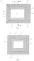
- FIG. 3shows a cross section of a first embodiment of a transport container with a cooling system
- FIG. 4shows a cross section along the line IV-IV of FIG. 3 .
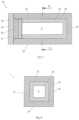
- FIG. 5shows a cross section of a second embodiment of a transport container with a cooling system
- FIG. 6shows a cross-section along the line VI-VI of FIG. 5 .
- a cooling systemwhich comprises an evaporative cooling system 1 and a latent heat accumulator 2 .
- the evaporative cooling system 1comprises an evaporation element 3 , which is soaked with a coolant, such as water, and has a cooling surface 4 , and a desiccant 5 for receiving evaporated coolant from the evaporation element 3 .
- a thermal insulation layer 7is arranged, which is formed open to vapour diffusion, in order to allow the transport of the evaporated coolant from the evaporation element 3 to the desiccant 5 .
- That evaporated coolantis adsorbed in the desiccant 5 , which, e.g., is formed as silica gel.
- the described elements of the evaporative cooling system 1are surrounded by a gas-tight shell or a gas-tight housing 8 so that the relative humidity of the gas atmosphere within the evaporative cooling system 1 can be controlled independently of the environment.
- the desiccant 5is arranged on that side of the evaporative cooling system 1 , on which heat is to be given off, and the evaporation element 3 is located on the (opposite) side of the evaporative cooling system 1 , on which cooling is to be effected.
- a plate-shaped latent heat accumulator 2is now arranged, which is in heat exchange connection with the cooling surface 4 of the evaporative cooling system 1 either directly or with the interposition of a thermal insulation (not shown).
- the chamber 9 to be temperature controlledis arranged on the side of the latent heat accumulator 2 that faces away from the evaporative cooling system 1 .
- FIG. 2an alternative embodiment is shown, wherein the same reference numerals designate the same components as in FIG. 1 .
- the embodiment of FIG. 2differs from the embodiment of FIG. 1 in that the transport of the evaporated coolant from the evaporation element 3 to the desiccant 5 is not performed through the insulating layer 7 , but via a separate channel 10 .
- the gas-tight shelltherefore does not have to surround the insulating layer 7 , but is limited to the evaporation element 3 , the channel 10 and the desiccant 5 .
- This designallows greater flexibility in the arrangement of the desiccant 5 , wherein the desiccant, for example, may be interchangeably arranged in the transport container.
- a reservoir 6 for the coolant, in particular wateris provided, which is connected to the evaporation element 3 , which allows refilling of coolant in a simple manner.
- the embodiment as shown in FIG. 2is particularly suitable for large-volume transport containers.
- FIGS. 3 and 4show a cuboid transport container 11 , the walls of which are designated with 12 , 13 , 14 , 15 and 16 .
- the transport container 11On the sixth side the transport container 11 is closed by a door or a lid 17 .
- the walls and the lidhave the following layer structure.
- the walls 12 , 13 , 14 , 15 and 16each comprise an outer insulating layer 18 made of a thermally insulating material. This is followed by a layer 19 formed as an evaporation element.
- the innermost layer 20which delimits the chamber 9 to be temperature controlled, is designed as a latent heat accumulator layer.
- the wall 13additionally has the desiccant as the outermost layer 21 .
- the desiccant-containing layermay also be arranged on another wall as the outermost layer.
- the insulating layer 18is formed to be permeable to vapour diffusion, in order to allow the transport of the evaporated coolant from the evaporation layer 19 to the desiccant 21 .
- the lid 17comprises only the outer insulating layer 18 and the latent heat accumulator layer 20 .
- FIGS. 5 and 6show a modified embodiment of a cuboid transport container 22 , the walls of which are designated by 23 , 24 , 25 , 26 and 27 .
- the transport container 22On the sixth side the transport container 22 is closed by a door or a lid 28 .
- the walls and the lidhave the following layer structure.
- the walls 23 , 24 , 25 , 26 and 27each comprise an outer insulating layer 29 and an inner latent heat accumulator layer 30 .
- the lid 28likewise comprises an insulating layer 29 , which is located between an inner layer 31 designed as an evaporation element and an outer layer 32 comprising the desiccant.
- the lid 28is replaceable in a simple manner, whereby a consumed cooling element can be exchanged for an unconsumed cooling element.
Landscapes
- Engineering & Computer Science (AREA)
- Physics & Mathematics (AREA)
- Mechanical Engineering (AREA)
- Thermal Sciences (AREA)
- General Engineering & Computer Science (AREA)
- Chemical & Material Sciences (AREA)
- Combustion & Propulsion (AREA)
- Packages (AREA)
- Devices That Are Associated With Refrigeration Equipment (AREA)
Abstract
Description
- an evaporation element with a cooling surface,
- a desiccant for receiving coolant evaporated in the evaporation element,
- a transport path for transporting the evaporated coolant to the desiccant,
- optionally, a reservoir for the coolant that is fluidly connectable with the evaporation element.
Claims (13)
Applications Claiming Priority (3)
| Application Number | Priority Date | Filing Date | Title |
|---|---|---|---|
| ATA368/2016 | 2016-08-09 | ||
| ATA368/2016AAT518924A1 (en) | 2016-08-09 | 2016-08-09 | transport container |
| PCT/IB2017/000941WO2018029522A1 (en) | 2016-08-09 | 2017-08-09 | Transport container |
Publications (2)
| Publication Number | Publication Date |
|---|---|
| US20190178534A1 US20190178534A1 (en) | 2019-06-13 |
| US11920832B2true US11920832B2 (en) | 2024-03-05 |
Family
ID=59738372
Family Applications (1)
| Application Number | Title | Priority Date | Filing Date |
|---|---|---|---|
| US16/324,149ActiveUS11920832B2 (en) | 2016-08-09 | 2017-08-09 | Transport container |
Country Status (6)
| Country | Link |
|---|---|
| US (1) | US11920832B2 (en) |
| EP (1) | EP3497384A1 (en) |
| CN (2) | CN120650881A (en) |
| AT (1) | AT518924A1 (en) |
| CA (1) | CA3033119A1 (en) |
| WO (1) | WO2018029522A1 (en) |
Cited By (1)
| Publication number | Priority date | Publication date | Assignee | Title |
|---|---|---|---|---|
| US20230250998A1 (en)* | 2020-09-25 | 2023-08-10 | Guangzhou Institute Of Energy Conversion, Chinese Academy Of Sciences | Heat-pipe type heat extraction integrated with combined cooling power and heating exploitation-utilization integrated geothermal system |
Families Citing this family (3)
| Publication number | Priority date | Publication date | Assignee | Title |
|---|---|---|---|---|
| AT518923A1 (en) | 2016-08-09 | 2018-02-15 | Rep Ip Ag | transport container |
| AT520919B1 (en)* | 2018-05-29 | 2019-09-15 | Rep Ip Ag | Transport container for transporting temperature-sensitive cargo |
| AT524696A1 (en)* | 2021-01-15 | 2022-08-15 | Rep Ip Ag | transport container |
Citations (42)
| Publication number | Priority date | Publication date | Assignee | Title |
|---|---|---|---|---|
| US1729082A (en) | 1925-03-11 | 1929-09-24 | Silica Gel Corp | Refrigerating apparatus |
| US1729081A (en) | 1924-10-25 | 1929-09-24 | Silica Gel Corp | Refrigeration |
| DE1262306B (en) | 1958-11-25 | 1968-03-07 | Edmund Metzner | Transport container equipped with a periodically operating absorption chiller |
| US4152901A (en) | 1975-12-30 | 1979-05-08 | Aktiebolaget Carl Munters | Method and apparatus for transferring energy in an absorption heating and cooling system |
| US4199959A (en) | 1977-03-24 | 1980-04-29 | Institute Of Gas Technology | Solid adsorption air conditioning apparatus and method |
| JPS58164954A (en) | 1982-03-25 | 1983-09-29 | Sumitomo Light Metal Ind Ltd | Solar heat exchange equipment |
| JPS6016280A (en) | 1983-07-07 | 1985-01-28 | 三洋電機株式会社 | Refrigerator |
| DE3412556A1 (en) | 1984-04-04 | 1985-10-24 | Albin Dipl.-Phys. Dr. 7253 Renningen Kehl | Small portable cooling device |
| WO1992013244A1 (en) | 1991-01-23 | 1992-08-06 | Rocky Research | Portable cooler |
| US5363670A (en) | 1993-04-19 | 1994-11-15 | Anthony Bartilucci | Self-contained cooler/freezer apparatus |
| US5497630A (en) | 1992-09-30 | 1996-03-12 | Thermal Electric Devices, Inc. | Method and apparatus for hydride heat pumps |
| WO2000050827A1 (en) | 1999-02-26 | 2000-08-31 | Tempra Technology, Inc. | Preparation of heat sink materials |
| US20010025510A1 (en)* | 2000-04-03 | 2001-10-04 | Zeolith-Technologie, Gmbh. | Sorption cooler |
| JP2002107003A (en) | 2000-07-24 | 2002-04-10 | Mayekawa Mfg Co Ltd | Panel-shaped adsorption type refrigerator |
| US6412295B2 (en) | 2000-06-09 | 2002-07-02 | Zeo-Tech Zeolith Technologie, Gmbh | Sorption device for heating and cooling gas streams |
| WO2002099345A1 (en) | 2001-06-06 | 2002-12-12 | Nanopore, Inc. | Sorption cooling devices and temperature-controlled shipping containers incorporating sorption cooling devices |
| US20020189279A1 (en) | 2001-04-12 | 2002-12-19 | Pfister Dennis M. | Active sorption thermal storage container |
| US6584797B1 (en)* | 2001-06-06 | 2003-07-01 | Nanopore, Inc. | Temperature-controlled shipping container and method for using same |
| WO2003059779A1 (en) | 2002-01-18 | 2003-07-24 | Thermagen | Insulation of a self-cooling beverage package |
| US20040079106A1 (en)* | 2002-10-29 | 2004-04-29 | Zeo-Tech Zeolith-Technologie, Gmbh | Adsorption cooling apparatus with buffer reservoir |
| FR2858601A1 (en) | 2003-08-08 | 2005-02-11 | Sogelog | Refrigerated container especially for fish and seafood products incorporates polymer particle layer that absorbs water from melting ice |
| JP2005299974A (en) | 2004-04-08 | 2005-10-27 | Sharp Corp | Adsorption refrigerator |
| US7213403B2 (en) | 2003-01-28 | 2007-05-08 | Zeo-Tech Zeolith-Technologie Gmbh | Cooling container with an adsorption cooling apparatus |
| DE102007010981A1 (en) | 2007-03-05 | 2008-09-11 | Zeo-Tech Zeolith-Technologie Gmbh | Cooling element for cooling a transport box is hermetically surrounded by a gas-tight multiple layer film to enclose a regulating unit, a steam passage and a vaporizer |
| CN101280991A (en) | 2007-04-05 | 2008-10-08 | 深圳清华大学研究院 | A device and method for automatically adjusting the air pressure balance inside and outside of a refrigerated container |
| US20090044556A1 (en) | 2005-05-10 | 2009-02-19 | Bsh Bosch Und Siemens Hausgeraete Gmbh | Refrigerating device with frame heating |
| US20090301127A1 (en) | 2008-06-10 | 2009-12-10 | Jonathan William Kaufman | Air Conditioning System |
| US20100024439A1 (en)* | 2006-07-11 | 2010-02-04 | Sgl Carbon Ag | Cooling Device |
| US20100170286A1 (en)* | 2007-06-22 | 2010-07-08 | High Technology Partecipation S.A. | Refrigerator for fresh products with temperature leveling means |
| WO2011032299A1 (en) | 2009-09-15 | 2011-03-24 | Nico Ros | Honeycomb structure element |
| US20110271691A1 (en) | 2004-03-22 | 2011-11-10 | General Mills, Inc. | Portable cooled merchandizing unit |
| US20120097216A1 (en)* | 2009-05-06 | 2012-04-26 | Commissariat A L'energie Atomique Et Aux Energies Alternatives | Hybrid solar receiver and concentrating solar system comprising the same |
| US20130152612A1 (en)* | 2011-08-16 | 2013-06-20 | Nanopore, Inc. | Sorption cooling systems and climate control using multi-channel thermal swing adsorption |
| US20140202661A1 (en)* | 2013-01-24 | 2014-07-24 | Visteon Global Technologies, Inc. | Thermal storage evaporator and system |
| US20140290293A1 (en) | 2013-03-29 | 2014-10-02 | Tokitae Llc | Temperature-controlled portable cooling units |
| US20140360214A1 (en)* | 2012-01-27 | 2014-12-11 | The Sure Chill Company Limited | Refrigeration apparatus |
| DE202015101481U1 (en) | 2014-03-25 | 2015-08-17 | Ford Global Technologies, Llc | Adsorptionsklimatisierungssystem |
| CN205002492U (en) | 2015-08-28 | 2016-01-27 | 青岛海尔智能技术研发有限公司 | Refrigeration plant with pressure compensation function |
| US20160290696A1 (en) | 2013-03-15 | 2016-10-06 | Oxicool Inc. | Cooling System |
| US20170350635A1 (en) | 2016-06-06 | 2017-12-07 | Google Inc. | Container with passive temperature controls |
| WO2018029521A1 (en) | 2016-08-09 | 2018-02-15 | Rep Ip Ag | Transport container |
| US20180080701A1 (en) | 2016-09-16 | 2018-03-22 | Bennet Karl Langlotz | Pressure Relief Facility for Refrigeration Appliances |
Family Cites Families (7)
| Publication number | Priority date | Publication date | Assignee | Title |
|---|---|---|---|---|
| JPS58151954A (en)* | 1982-03-04 | 1983-09-09 | Kawasaki Heavy Ind Ltd | Formation of liner layer |
| JP2740402B2 (en)* | 1992-04-06 | 1998-04-15 | サンデン株式会社 | Cool storage box cool storage device |
| CN2385285Y (en)* | 1999-07-29 | 2000-06-28 | 青岛市家用电器研究所 | Cooling-storage structure for medical refrigerator |
| JP2010107156A (en)* | 2008-10-31 | 2010-05-13 | Yanmar Co Ltd | Engine-driven heat pump |
| ES2372458B1 (en)* | 2010-07-07 | 2012-12-10 | Sociedad Anónima Damm | DRINK COOLING DEVICE. |
| DE102012213542A1 (en)* | 2012-08-01 | 2014-02-06 | Goselig UG | Cold storage device and cooling system arrangement |
| CN105222454A (en)* | 2014-06-17 | 2016-01-06 | 李渊 | A kind of energy-accumulating refrigerator |
- 2016
- 2016-08-09ATATA368/2016Apatent/AT518924A1/enunknown
- 2017
- 2017-08-09WOPCT/IB2017/000941patent/WO2018029522A1/ennot_activeCeased
- 2017-08-09CNCN202510858286.5Apatent/CN120650881A/enactivePending
- 2017-08-09USUS16/324,149patent/US11920832B2/enactiveActive
- 2017-08-09CACA3033119Apatent/CA3033119A1/enactivePending
- 2017-08-09EPEP17758612.0Apatent/EP3497384A1/enactivePending
- 2017-08-09CNCN201780049331.6Apatent/CN109716042A/enactivePending
Patent Citations (44)
| Publication number | Priority date | Publication date | Assignee | Title |
|---|---|---|---|---|
| US1729081A (en) | 1924-10-25 | 1929-09-24 | Silica Gel Corp | Refrigeration |
| US1729082A (en) | 1925-03-11 | 1929-09-24 | Silica Gel Corp | Refrigerating apparatus |
| DE1262306B (en) | 1958-11-25 | 1968-03-07 | Edmund Metzner | Transport container equipped with a periodically operating absorption chiller |
| US4152901A (en) | 1975-12-30 | 1979-05-08 | Aktiebolaget Carl Munters | Method and apparatus for transferring energy in an absorption heating and cooling system |
| US4199959A (en) | 1977-03-24 | 1980-04-29 | Institute Of Gas Technology | Solid adsorption air conditioning apparatus and method |
| JPS58164954A (en) | 1982-03-25 | 1983-09-29 | Sumitomo Light Metal Ind Ltd | Solar heat exchange equipment |
| JPS6016280A (en) | 1983-07-07 | 1985-01-28 | 三洋電機株式会社 | Refrigerator |
| DE3412556A1 (en) | 1984-04-04 | 1985-10-24 | Albin Dipl.-Phys. Dr. 7253 Renningen Kehl | Small portable cooling device |
| WO1992013244A1 (en) | 1991-01-23 | 1992-08-06 | Rocky Research | Portable cooler |
| US5497630A (en) | 1992-09-30 | 1996-03-12 | Thermal Electric Devices, Inc. | Method and apparatus for hydride heat pumps |
| US5363670A (en) | 1993-04-19 | 1994-11-15 | Anthony Bartilucci | Self-contained cooler/freezer apparatus |
| WO2000050827A1 (en) | 1999-02-26 | 2000-08-31 | Tempra Technology, Inc. | Preparation of heat sink materials |
| US20010025510A1 (en)* | 2000-04-03 | 2001-10-04 | Zeolith-Technologie, Gmbh. | Sorption cooler |
| JP2002013835A (en)* | 2000-04-03 | 2002-01-18 | Zeo-Tech Zeolith-Technologie Gmbh | Sorption cooler |
| US6412295B2 (en) | 2000-06-09 | 2002-07-02 | Zeo-Tech Zeolith Technologie, Gmbh | Sorption device for heating and cooling gas streams |
| JP2002107003A (en) | 2000-07-24 | 2002-04-10 | Mayekawa Mfg Co Ltd | Panel-shaped adsorption type refrigerator |
| US20020189279A1 (en) | 2001-04-12 | 2002-12-19 | Pfister Dennis M. | Active sorption thermal storage container |
| WO2002099345A1 (en) | 2001-06-06 | 2002-12-12 | Nanopore, Inc. | Sorption cooling devices and temperature-controlled shipping containers incorporating sorption cooling devices |
| US6584797B1 (en)* | 2001-06-06 | 2003-07-01 | Nanopore, Inc. | Temperature-controlled shipping container and method for using same |
| WO2003059779A1 (en) | 2002-01-18 | 2003-07-24 | Thermagen | Insulation of a self-cooling beverage package |
| US20040079106A1 (en)* | 2002-10-29 | 2004-04-29 | Zeo-Tech Zeolith-Technologie, Gmbh | Adsorption cooling apparatus with buffer reservoir |
| EP1416233A2 (en) | 2002-10-29 | 2004-05-06 | ZEO-TECH Zeolith Technologie GmbH | Adsorption refrigerator with heat accumulator |
| US7213403B2 (en) | 2003-01-28 | 2007-05-08 | Zeo-Tech Zeolith-Technologie Gmbh | Cooling container with an adsorption cooling apparatus |
| FR2858601A1 (en) | 2003-08-08 | 2005-02-11 | Sogelog | Refrigerated container especially for fish and seafood products incorporates polymer particle layer that absorbs water from melting ice |
| US20110271691A1 (en) | 2004-03-22 | 2011-11-10 | General Mills, Inc. | Portable cooled merchandizing unit |
| JP2005299974A (en) | 2004-04-08 | 2005-10-27 | Sharp Corp | Adsorption refrigerator |
| US20090044556A1 (en) | 2005-05-10 | 2009-02-19 | Bsh Bosch Und Siemens Hausgeraete Gmbh | Refrigerating device with frame heating |
| US20100024439A1 (en)* | 2006-07-11 | 2010-02-04 | Sgl Carbon Ag | Cooling Device |
| DE102007010981A1 (en) | 2007-03-05 | 2008-09-11 | Zeo-Tech Zeolith-Technologie Gmbh | Cooling element for cooling a transport box is hermetically surrounded by a gas-tight multiple layer film to enclose a regulating unit, a steam passage and a vaporizer |
| CN101280991A (en) | 2007-04-05 | 2008-10-08 | 深圳清华大学研究院 | A device and method for automatically adjusting the air pressure balance inside and outside of a refrigerated container |
| US20100170286A1 (en)* | 2007-06-22 | 2010-07-08 | High Technology Partecipation S.A. | Refrigerator for fresh products with temperature leveling means |
| US20090301127A1 (en) | 2008-06-10 | 2009-12-10 | Jonathan William Kaufman | Air Conditioning System |
| US20120097216A1 (en)* | 2009-05-06 | 2012-04-26 | Commissariat A L'energie Atomique Et Aux Energies Alternatives | Hybrid solar receiver and concentrating solar system comprising the same |
| WO2011032299A1 (en) | 2009-09-15 | 2011-03-24 | Nico Ros | Honeycomb structure element |
| US20130152612A1 (en)* | 2011-08-16 | 2013-06-20 | Nanopore, Inc. | Sorption cooling systems and climate control using multi-channel thermal swing adsorption |
| US20140360214A1 (en)* | 2012-01-27 | 2014-12-11 | The Sure Chill Company Limited | Refrigeration apparatus |
| US20140202661A1 (en)* | 2013-01-24 | 2014-07-24 | Visteon Global Technologies, Inc. | Thermal storage evaporator and system |
| US20160290696A1 (en) | 2013-03-15 | 2016-10-06 | Oxicool Inc. | Cooling System |
| US20140290293A1 (en) | 2013-03-29 | 2014-10-02 | Tokitae Llc | Temperature-controlled portable cooling units |
| DE202015101481U1 (en) | 2014-03-25 | 2015-08-17 | Ford Global Technologies, Llc | Adsorptionsklimatisierungssystem |
| CN205002492U (en) | 2015-08-28 | 2016-01-27 | 青岛海尔智能技术研发有限公司 | Refrigeration plant with pressure compensation function |
| US20170350635A1 (en) | 2016-06-06 | 2017-12-07 | Google Inc. | Container with passive temperature controls |
| WO2018029521A1 (en) | 2016-08-09 | 2018-02-15 | Rep Ip Ag | Transport container |
| US20180080701A1 (en) | 2016-09-16 | 2018-03-22 | Bennet Karl Langlotz | Pressure Relief Facility for Refrigeration Appliances |
Non-Patent Citations (6)
| Title |
|---|
| International Search Report issued in International Application No. PCT/IB2017/000941 dated Oct. 23, 2017. |
| Maier-Laxhuber et al., Sorption Cooler, Jan. 18, 2002, JP2002013835A, Whole Document (Year: 2002).* |
| Notice of Allowance dated Jul. 21, 2021, issued in U.S. Appl. No. 16/324,170 (10 pgs.). |
| Office Action dated May 12, 2023, issued in corresponding U.S. Appl. No. 17/428,536 (24 pgs.). |
| Sakashita, Panel Shaped Adsorption Type Refrigerator, Apr. 10, 2002, JP2002107003A, Whole Document (Year: 2002).* |
| Terai et al, Solar Heat Utilizing Heat Exchanger, Sep. 29, 1983, JPS58164954A, Whole Document (Year: 1983).* |
Cited By (2)
| Publication number | Priority date | Publication date | Assignee | Title |
|---|---|---|---|---|
| US20230250998A1 (en)* | 2020-09-25 | 2023-08-10 | Guangzhou Institute Of Energy Conversion, Chinese Academy Of Sciences | Heat-pipe type heat extraction integrated with combined cooling power and heating exploitation-utilization integrated geothermal system |
| US12152810B2 (en)* | 2020-09-25 | 2024-11-26 | Guangzhou Institute Of Energy Conversion, Chinese Academy Of Sciences | Heat-pipe type heat extraction integrated with combined cooling power and heating exploitation-utilization integrated geothermal system |
Also Published As
| Publication number | Publication date |
|---|---|
| EP3497384A1 (en) | 2019-06-19 |
| US20190178534A1 (en) | 2019-06-13 |
| WO2018029522A1 (en) | 2018-02-15 |
| CN109716042A (en) | 2019-05-03 |
| AT518924A1 (en) | 2018-02-15 |
| CA3033119A1 (en) | 2018-02-15 |
| CN120650881A (en) | 2025-09-16 |
| BR112019002561A2 (en) | 2019-05-21 |
Similar Documents
| Publication | Publication Date | Title |
|---|---|---|
| US11614267B2 (en) | Transport container | |
| US11920832B2 (en) | Transport container | |
| EP3368442B1 (en) | A transportation box | |
| US6968711B2 (en) | Temperature controlled shipping containers | |
| US7257963B2 (en) | Thermal insert for container having a passive controlled temperature interior | |
| US11359852B2 (en) | Transport container for transporting temperature-sensitive transport goods | |
| JP2012242075A (en) | Refrigerator | |
| CN113366275A (en) | Transport container | |
| JP2016512879A (en) | Portable self-cooling autonomous system | |
| US20170038116A1 (en) | Transport Container for Transporting Temperature-Sensitive Transport Goods | |
| US20240310086A1 (en) | Portable Regulated Temperature Container with Phase Change Materials | |
| JP2017503136A (en) | External module device that automatically adjusts the temperature of the enclosure | |
| JP6434867B2 (en) | Heat storage material filling container and heat storage tank | |
| JP2018179355A (en) | Heat storage system and installation method for latent heat storage material | |
| GB2632529A (en) | Medical storage and transportation device | |
| BR112019002561B1 (en) | SHIPPING CONTAINER | |
| CN112368530A (en) | Transport container for transporting temperature-sensitive transport goods | |
| BR112019002555B1 (en) | SHIPPING CONTAINER | |
| ES2613711T3 (en) | Improved transport packaging | |
| JP7296116B2 (en) | Heat and cold insulation device | |
| CN214267452U (en) | A kit transport device | |
| AU2002310347A1 (en) | Sorption cooling devices and temperature-controlled shipping containers incorporating sorption colling devices |
Legal Events
| Date | Code | Title | Description |
|---|---|---|---|
| FEPP | Fee payment procedure | Free format text:ENTITY STATUS SET TO UNDISCOUNTED (ORIGINAL EVENT CODE: BIG.); ENTITY STATUS OF PATENT OWNER: SMALL ENTITY | |
| FEPP | Fee payment procedure | Free format text:ENTITY STATUS SET TO SMALL (ORIGINAL EVENT CODE: SMAL); ENTITY STATUS OF PATENT OWNER: SMALL ENTITY | |
| AS | Assignment | Owner name:REP IP AG, SWITZERLAND Free format text:ASSIGNMENT OF ASSIGNORS INTEREST;ASSIGNOR:ROS, NICO;REEL/FRAME:048543/0166 Effective date:20190212 | |
| STPP | Information on status: patent application and granting procedure in general | Free format text:DOCKETED NEW CASE - READY FOR EXAMINATION | |
| STPP | Information on status: patent application and granting procedure in general | Free format text:NON FINAL ACTION MAILED | |
| STPP | Information on status: patent application and granting procedure in general | Free format text:FINAL REJECTION MAILED | |
| STPP | Information on status: patent application and granting procedure in general | Free format text:RESPONSE AFTER FINAL ACTION FORWARDED TO EXAMINER | |
| STPP | Information on status: patent application and granting procedure in general | Free format text:ADVISORY ACTION MAILED | |
| STPP | Information on status: patent application and granting procedure in general | Free format text:DOCKETED NEW CASE - READY FOR EXAMINATION | |
| STPP | Information on status: patent application and granting procedure in general | Free format text:NON FINAL ACTION MAILED | |
| STPP | Information on status: patent application and granting procedure in general | Free format text:RESPONSE TO NON-FINAL OFFICE ACTION ENTERED AND FORWARDED TO EXAMINER | |
| STPP | Information on status: patent application and granting procedure in general | Free format text:FINAL REJECTION MAILED | |
| STPP | Information on status: patent application and granting procedure in general | Free format text:RESPONSE AFTER FINAL ACTION FORWARDED TO EXAMINER | |
| STPP | Information on status: patent application and granting procedure in general | Free format text:ADVISORY ACTION MAILED | |
| STPP | Information on status: patent application and granting procedure in general | Free format text:DOCKETED NEW CASE - READY FOR EXAMINATION | |
| STPP | Information on status: patent application and granting procedure in general | Free format text:NON FINAL ACTION MAILED | |
| STPP | Information on status: patent application and granting procedure in general | Free format text:NON FINAL ACTION MAILED | |
| STPP | Information on status: patent application and granting procedure in general | Free format text:RESPONSE TO NON-FINAL OFFICE ACTION ENTERED AND FORWARDED TO EXAMINER | |
| STPP | Information on status: patent application and granting procedure in general | Free format text:NOTICE OF ALLOWANCE MAILED -- APPLICATION RECEIVED IN OFFICE OF PUBLICATIONS | |
| ZAAB | Notice of allowance mailed | Free format text:ORIGINAL CODE: MN/=. | |
| STPP | Information on status: patent application and granting procedure in general | Free format text:PUBLICATIONS -- ISSUE FEE PAYMENT VERIFIED | |
| STCF | Information on status: patent grant | Free format text:PATENTED CASE |