US11918737B2 - Electronic vapor provision device - Google Patents
Electronic vapor provision deviceDownload PDFInfo
- Publication number
- US11918737B2 US11918737B2US16/402,546US201916402546AUS11918737B2US 11918737 B2US11918737 B2US 11918737B2US 201916402546 AUS201916402546 AUS 201916402546AUS 11918737 B2US11918737 B2US 11918737B2
- Authority
- US
- United States
- Prior art keywords
- heating element
- airflow
- provision device
- electronic vapor
- vapor provision
- Prior art date
- Legal status (The legal status is an assumption and is not a legal conclusion. Google has not performed a legal analysis and makes no representation as to the accuracy of the status listed.)
- Active, expires
Links
- 238000010438heat treatmentMethods0.000claimsabstractdescription142
- 230000008016vaporizationEffects0.000claimsabstractdescription35
- 238000009834vaporizationMethods0.000claimsabstractdescription35
- 239000006200vaporizerSubstances0.000claimsabstractdescription32
- 239000007788liquidSubstances0.000claimsdescription60
- 239000003571electronic cigaretteSubstances0.000claimsdescription16
- 230000007423decreaseEffects0.000description5
- 239000011148porous materialSubstances0.000description5
- 230000000694effectsEffects0.000description4
- 239000006260foamSubstances0.000description4
- 230000003068static effectEffects0.000description4
- 230000005465channelingEffects0.000description3
- 239000011800void materialSubstances0.000description3
- SNICXCGAKADSCV-JTQLQIEISA-N(-)-NicotineChemical compoundCN1CCC[C@H]1C1=CC=CN=C1SNICXCGAKADSCV-JTQLQIEISA-N0.000description2
- PXHVJJICTQNCMI-UHFFFAOYSA-NNickelChemical compound[Ni]PXHVJJICTQNCMI-UHFFFAOYSA-N0.000description2
- 235000019504cigarettesNutrition0.000description2
- 238000012986modificationMethods0.000description2
- 230000004048modificationEffects0.000description2
- 229960002715nicotineDrugs0.000description2
- SNICXCGAKADSCV-UHFFFAOYSA-NnicotineNatural productsCN1CCCC1C1=CC=CN=C1SNICXCGAKADSCV-UHFFFAOYSA-N0.000description2
- 229920006395saturated elastomerPolymers0.000description2
- WHXSMMKQMYFTQS-UHFFFAOYSA-NLithiumChemical compound[Li]WHXSMMKQMYFTQS-UHFFFAOYSA-N0.000description1
- 230000009471actionEffects0.000description1
- 239000000443aerosolSubstances0.000description1
- XAGFODPZIPBFFR-UHFFFAOYSA-NaluminiumChemical compound[Al]XAGFODPZIPBFFR-UHFFFAOYSA-N0.000description1
- 229910052782aluminiumInorganic materials0.000description1
- 229910010293ceramic materialInorganic materials0.000description1
- 238000001514detection methodMethods0.000description1
- 230000009977dual effectEffects0.000description1
- 229910052744lithiumInorganic materials0.000description1
- 238000012423maintenanceMethods0.000description1
- 229910001120nichromeInorganic materials0.000description1
- 229910052759nickelInorganic materials0.000description1
- 230000004044responseEffects0.000description1
- 230000000717retained effectEffects0.000description1
- 239000000725suspensionSubstances0.000description1
Images


Classifications
- A—HUMAN NECESSITIES
- A61—MEDICAL OR VETERINARY SCIENCE; HYGIENE
- A61M—DEVICES FOR INTRODUCING MEDIA INTO, OR ONTO, THE BODY; DEVICES FOR TRANSDUCING BODY MEDIA OR FOR TAKING MEDIA FROM THE BODY; DEVICES FOR PRODUCING OR ENDING SLEEP OR STUPOR
- A61M15/00—Inhalators
- A61M15/06—Inhaling appliances shaped like cigars, cigarettes or pipes
- A—HUMAN NECESSITIES
- A24—TOBACCO; CIGARS; CIGARETTES; SIMULATED SMOKING DEVICES; SMOKERS' REQUISITES
- A24B—MANUFACTURE OR PREPARATION OF TOBACCO FOR SMOKING OR CHEWING; TOBACCO; SNUFF
- A24B15/00—Chemical features or treatment of tobacco; Tobacco substitutes, e.g. in liquid form
- A24B15/10—Chemical features of tobacco products or tobacco substitutes
- A24B15/16—Chemical features of tobacco products or tobacco substitutes of tobacco substitutes
- A24B15/167—Chemical features of tobacco products or tobacco substitutes of tobacco substitutes in liquid or vaporisable form, e.g. liquid compositions for electronic cigarettes
- A—HUMAN NECESSITIES
- A24—TOBACCO; CIGARS; CIGARETTES; SIMULATED SMOKING DEVICES; SMOKERS' REQUISITES
- A24F—SMOKERS' REQUISITES; MATCH BOXES; SIMULATED SMOKING DEVICES
- A24F40/00—Electrically operated smoking devices; Component parts thereof; Manufacture thereof; Maintenance or testing thereof; Charging means specially adapted therefor
- A24F40/40—Constructional details, e.g. connection of cartridges and battery parts
- A24F40/42—Cartridges or containers for inhalable precursors
- A—HUMAN NECESSITIES
- A24—TOBACCO; CIGARS; CIGARETTES; SIMULATED SMOKING DEVICES; SMOKERS' REQUISITES
- A24F—SMOKERS' REQUISITES; MATCH BOXES; SIMULATED SMOKING DEVICES
- A24F40/00—Electrically operated smoking devices; Component parts thereof; Manufacture thereof; Maintenance or testing thereof; Charging means specially adapted therefor
- A24F40/40—Constructional details, e.g. connection of cartridges and battery parts
- A24F40/46—Shape or structure of electric heating means
- A—HUMAN NECESSITIES
- A24—TOBACCO; CIGARS; CIGARETTES; SIMULATED SMOKING DEVICES; SMOKERS' REQUISITES
- A24F—SMOKERS' REQUISITES; MATCH BOXES; SIMULATED SMOKING DEVICES
- A24F40/00—Electrically operated smoking devices; Component parts thereof; Manufacture thereof; Maintenance or testing thereof; Charging means specially adapted therefor
- A24F40/40—Constructional details, e.g. connection of cartridges and battery parts
- A24F40/48—Fluid transfer means, e.g. pumps
- A24F40/485—Valves; Apertures
- A—HUMAN NECESSITIES
- A61—MEDICAL OR VETERINARY SCIENCE; HYGIENE
- A61M—DEVICES FOR INTRODUCING MEDIA INTO, OR ONTO, THE BODY; DEVICES FOR TRANSDUCING BODY MEDIA OR FOR TAKING MEDIA FROM THE BODY; DEVICES FOR PRODUCING OR ENDING SLEEP OR STUPOR
- A61M11/00—Sprayers or atomisers specially adapted for therapeutic purposes
- A61M11/04—Sprayers or atomisers specially adapted for therapeutic purposes operated by the vapour pressure of the liquid to be sprayed or atomised
- A61M11/041—Sprayers or atomisers specially adapted for therapeutic purposes operated by the vapour pressure of the liquid to be sprayed or atomised using heaters
- A61M11/042—Sprayers or atomisers specially adapted for therapeutic purposes operated by the vapour pressure of the liquid to be sprayed or atomised using heaters electrical
- A—HUMAN NECESSITIES
- A61—MEDICAL OR VETERINARY SCIENCE; HYGIENE
- A61M—DEVICES FOR INTRODUCING MEDIA INTO, OR ONTO, THE BODY; DEVICES FOR TRANSDUCING BODY MEDIA OR FOR TAKING MEDIA FROM THE BODY; DEVICES FOR PRODUCING OR ENDING SLEEP OR STUPOR
- A61M15/00—Inhalators
- A61M15/0001—Details of inhalators; Constructional features thereof
- A61M15/002—Details of inhalators; Constructional features thereof with air flow regulating means
- A—HUMAN NECESSITIES
- A24—TOBACCO; CIGARS; CIGARETTES; SIMULATED SMOKING DEVICES; SMOKERS' REQUISITES
- A24F—SMOKERS' REQUISITES; MATCH BOXES; SIMULATED SMOKING DEVICES
- A24F40/00—Electrically operated smoking devices; Component parts thereof; Manufacture thereof; Maintenance or testing thereof; Charging means specially adapted therefor
- A24F40/10—Devices using liquid inhalable precursors
- A—HUMAN NECESSITIES
- A61—MEDICAL OR VETERINARY SCIENCE; HYGIENE
- A61M—DEVICES FOR INTRODUCING MEDIA INTO, OR ONTO, THE BODY; DEVICES FOR TRANSDUCING BODY MEDIA OR FOR TAKING MEDIA FROM THE BODY; DEVICES FOR PRODUCING OR ENDING SLEEP OR STUPOR
- A61M16/00—Devices for influencing the respiratory system of patients by gas treatment, e.g. ventilators; Tracheal tubes
- A61M16/0003—Accessories therefor, e.g. sensors, vibrators, negative pressure
- A61M2016/0015—Accessories therefor, e.g. sensors, vibrators, negative pressure inhalation detectors
- A61M2016/0018—Accessories therefor, e.g. sensors, vibrators, negative pressure inhalation detectors electrical
- A61M2016/0021—Accessories therefor, e.g. sensors, vibrators, negative pressure inhalation detectors electrical with a proportional output signal, e.g. from a thermistor
- A—HUMAN NECESSITIES
- A61—MEDICAL OR VETERINARY SCIENCE; HYGIENE
- A61M—DEVICES FOR INTRODUCING MEDIA INTO, OR ONTO, THE BODY; DEVICES FOR TRANSDUCING BODY MEDIA OR FOR TAKING MEDIA FROM THE BODY; DEVICES FOR PRODUCING OR ENDING SLEEP OR STUPOR
- A61M16/00—Devices for influencing the respiratory system of patients by gas treatment, e.g. ventilators; Tracheal tubes
- A61M16/0003—Accessories therefor, e.g. sensors, vibrators, negative pressure
- A61M2016/0015—Accessories therefor, e.g. sensors, vibrators, negative pressure inhalation detectors
- A61M2016/0018—Accessories therefor, e.g. sensors, vibrators, negative pressure inhalation detectors electrical
- A61M2016/0024—Accessories therefor, e.g. sensors, vibrators, negative pressure inhalation detectors electrical with an on-off output signal, e.g. from a switch
- A—HUMAN NECESSITIES
- A61—MEDICAL OR VETERINARY SCIENCE; HYGIENE
- A61M—DEVICES FOR INTRODUCING MEDIA INTO, OR ONTO, THE BODY; DEVICES FOR TRANSDUCING BODY MEDIA OR FOR TAKING MEDIA FROM THE BODY; DEVICES FOR PRODUCING OR ENDING SLEEP OR STUPOR
- A61M16/00—Devices for influencing the respiratory system of patients by gas treatment, e.g. ventilators; Tracheal tubes
- A61M16/0003—Accessories therefor, e.g. sensors, vibrators, negative pressure
- A61M2016/003—Accessories therefor, e.g. sensors, vibrators, negative pressure with a flowmeter
- A61M2016/0033—Accessories therefor, e.g. sensors, vibrators, negative pressure with a flowmeter electrical
- A61M2016/0039—Accessories therefor, e.g. sensors, vibrators, negative pressure with a flowmeter electrical in the inspiratory circuit
- A—HUMAN NECESSITIES
- A61—MEDICAL OR VETERINARY SCIENCE; HYGIENE
- A61M—DEVICES FOR INTRODUCING MEDIA INTO, OR ONTO, THE BODY; DEVICES FOR TRANSDUCING BODY MEDIA OR FOR TAKING MEDIA FROM THE BODY; DEVICES FOR PRODUCING OR ENDING SLEEP OR STUPOR
- A61M2205/00—General characteristics of the apparatus
- A61M2205/33—Controlling, regulating or measuring
- A61M2205/3375—Acoustical, e.g. ultrasonic, measuring means
- A—HUMAN NECESSITIES
- A61—MEDICAL OR VETERINARY SCIENCE; HYGIENE
- A61M—DEVICES FOR INTRODUCING MEDIA INTO, OR ONTO, THE BODY; DEVICES FOR TRANSDUCING BODY MEDIA OR FOR TAKING MEDIA FROM THE BODY; DEVICES FOR PRODUCING OR ENDING SLEEP OR STUPOR
- A61M2205/00—General characteristics of the apparatus
- A61M2205/36—General characteristics of the apparatus related to heating or cooling
- A61M2205/3653—General characteristics of the apparatus related to heating or cooling by Joule effect, i.e. electric resistance
- A—HUMAN NECESSITIES
- A61—MEDICAL OR VETERINARY SCIENCE; HYGIENE
- A61M—DEVICES FOR INTRODUCING MEDIA INTO, OR ONTO, THE BODY; DEVICES FOR TRANSDUCING BODY MEDIA OR FOR TAKING MEDIA FROM THE BODY; DEVICES FOR PRODUCING OR ENDING SLEEP OR STUPOR
- A61M2205/00—General characteristics of the apparatus
- A61M2205/82—Internal energy supply devices
- A61M2205/8206—Internal energy supply devices battery-operated
- A—HUMAN NECESSITIES
- A61—MEDICAL OR VETERINARY SCIENCE; HYGIENE
- A61M—DEVICES FOR INTRODUCING MEDIA INTO, OR ONTO, THE BODY; DEVICES FOR TRANSDUCING BODY MEDIA OR FOR TAKING MEDIA FROM THE BODY; DEVICES FOR PRODUCING OR ENDING SLEEP OR STUPOR
- A61M2206/00—Characteristics of a physical parameter; associated device therefor
- A61M2206/10—Flow characteristics
- A61M2206/16—Rotating swirling helical flow, e.g. by tangential inflows
Definitions
- the specificationrelates to electronic vapor provision devices.
- Electronic vapor provision devicesare typically cigarette-sized and function by allowing a user to inhale a nicotine vapor from a liquid store by applying a suction force to a mouthpiece. Some electronic vapor provision devices have an airflow sensor that activates when a user applies the suction force and causes a heater coil to heat up and vaporize the liquid. Electronic vapor provision devices include electronic cigarettes.
- an electronic vapor provision devicecomprising a power cell; and a vaporizer, wherein the vaporizer comprises a heating element, a vaporization cavity, and an airflow channeler, wherein the airflow channeler is situated outside of the vaporization cavity, and wherein the heating element and a heating element support configured to support the heating element are situated within the vaporization cavity.
- an electronic vapor provision devicecomprising a power cell and a vaporizer, where the vaporizer comprises a heating element and a vaporization cavity, wherein the vaporizer further comprises an airflow channeler configured in use to channel airflow over the heating element.
- the airflow channelermay be configured to focus the airflow over the heating element or a region of the heating element. Moreover, the airflow channeler may form part of a heating element support. Furthermore, the electronic vapor provision device may comprise a mouthpiece section and the vaporizer may be part of the mouthpiece section.
- a vaporizerfor use in an electronic vapor provision device, comprising a heating element and an airflow channeler configured to channel airflow over the heating element.
- an electronic vapor provision devicecomprising a heating element coil; a liquid store for providing liquid to be vaporized by the heating element; an air outlet for vaporized liquid from the heating element; and an airflow channeler configured to obstruct airflow within the coil and to direct the airflow to one or more parts of the coil surface.
- the devicemay for example comprise a power cell for powering the heating element.
- FIG. 1is a side perspective view of an electronic cigarette.
- FIG. 2is a schematic sectional view of an electronic cigarette having a parallel coil.
- FIG. 3is a side perspective view of a heating element coil.
- FIG. 4is a side perspective view of an outer heating element support.
- FIG. 5is a side perspective view of a heating element coil within an outer heating element support.
- FIG. 6is a side sectional view of a heating element coil within an outer heating element support.
- FIG. 7is an end view of a heating element coil within an outer heating element support, where a central channel has a square cross-section.
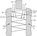
- FIG. 8is a side view of a coil and a cylindrical airflow channeler.
- FIG. 9is a side view of a coil and a conical airflow channeler.
- FIG. 10is a side view of a coil and an inverted conical airflow channeler.
- FIG. 11is a side view of a coil and an airflow channeler with a central bulge.
- FIG. 12is a side view of a coil and an airflow channeler partially outside the coil.
- FIG. 13is a side view of a coil and an airflow channeler outside of the coil.
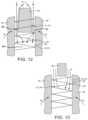
- FIG. 14is a side view of a coil and an airflow channeler forming part of a heating element support.
- FIG. 15is an end view of an airflow channeler forming part of a heating element support.
- an electronic vapor provision devicecomprising a power cell and a vaporizer, where the vaporizer comprises a heating element and a vaporization cavity, wherein the vaporizer further comprises an airflow channeler configured to channel airflow over the heating element.
- the electronic vapor provision devicemay be an electronic cigarette.
- the vaporizeracts to vaporize liquid.
- liquidWhen liquid is vaporized by the vaporizer, the resulting vapor is carried away by the airflow and inhaled by the user. Channeling the airflow over the heating element increases the rate at which vapor is carried away. This can lead to a more efficient vapor release.
- the airflow channelermay be configured to focus the airflow over the heating element. By focusing the airflow over the heating element, the device becomes more efficient at carrying away vapor from the vaporizer. The device may therefore require less airflow and less suction effort by the user.
- the airflow channelermay be configured to channel airflow over the surface of the heating element. Moreover, the airflow channeler may be configured to channel airflow along the length of the heating element. Channeling the airflow along the length of the heating element ensures that increased vapor removal occurs along the entire heating element.
- the airflow channelermay be configured to focus airflow in a region of the heating element. Moreover, the airflow channeler may be configured to focus airflow in an end region of the heating element. For example, the airflow channeler may be configured to focus airflow in a central region of the heating element or at two or more points along the heating element. Furthermore the airflow channeler may be configured to create an airflow gradient over the heating element.
- Liquidmay be transferred onto the vaporizer heating element but this transfer may not be uniform along the length of the heating element. Thus, it may be advantageous to channel airflow to regions of the heating element where there is more liquid to be vaporized.
- the airflow channelermay be situated within the vaporization cavity. Moreover, the airflow channeler may provide an obstruction in the vaporization cavity such that airflow is channeled over the heating element.
- the airflow channelermay be situated outside of the vaporization cavity or may form part of a wall of the vaporization cavity. Moreover, the airflow channeler may be situated within the heating element.
- An obstruction in the vaporization cavitymeans that the airflow will flow around the obstruction and can be directed towards the heating element.
- an airflow channeler situated within the heating elementis able to direct the airflow to the heating element surface for increased efficiency.
- the airflow channelermay be situated outside of the heating element.
- the airflow channelermay be elongated in the direction of the longitudinal coil axis. Furthermore, the airflow channeler may be cylindrical. Part of the airflow channeler may comprise a conical shape. For example, the airflow channeler may be substantially conical or frusto-conical.
- the airflow channelermay comprise a wider end and a narrower end and may be configured such that air is drawn towards the wider end.
- the airflow channelermay comprise a wider end and a narrower end and the airflow channeler may be configured such that air is drawn towards the narrower end.
- the airflow channelermay be shaped so as to bulge in a region.
- the airflow channelermay be shaped so as to bulge in a central region or in two or more places along its length.
- the cross-sectional shape of the airflow channelermay be a polygon, such as a square. Moreover, the airflow channeler may comprise a spiral shape.
- the heating elementmay be a heating coil, such as a wire coil.
- the airflow channelermay be configured to focus airflow over the heating coil turns.
- the airflow channelermay be configured to focus airflow along the length of the coil.
- the airflow channelermay be configured to focus airflow on the end of the coil.
- the airflow channelermay be configured to focus airflow on the inside of the coil.
- the airflow channelermay be configured to focus airflow on the outside of the coil.
- the airflow channelermay be configured to focus airflow through the coil turns.
- the airflow channelermay be configured to spiral airflow over the coil.
- the heating elementmay be not supported on its inside.
- the vaporizermay further comprise a heating element support.
- the heating element supportmay be a liquid store.
- the heating elementmay be on the inside of the heating element support.
- Having a separate heating element and supportallows a finer heating element to be constructed. This is advantageous because a finer heating element can be more efficiently heated.
- By having the heating element on the inside of the supportmeans that a much smaller and narrower heating element can be used since space is not needed inside the heating element to house the support. This enables a much larger and therefore stronger support to be used.
- One or more gapsmay be provided between the heating element and the heating element support.
- the heating elementmay be in contact with the heating element support at points along the length of the support.
- the airflow channelermay form part of the heating element support. Alternatively, the airflow channeler may not form part of the heating element support.
- the airflow channelermay not be in contact with the heating element. By having an airflow channeler that is not in contact with the heating element, the airflow channeler does not impede the heating surface of the heating element.
- the electronic vapor provision devicemay further comprise a mouthpiece section and the vaporizer may be part of the mouthpiece section.
- the heating element supportmay substantially fill the mouthpiece section.
- the supportis on the outside of the coil and can act as a liquid store, a liquid store container is not needed in addition to the liquid store and the heating element support can fill the mouthpiece section to give greater storage capacity and a more efficient device.
- FIG. 1there is shown an embodiment of the electronic vapor provision device 1 in the form of an electronic cigarette 1 comprising a mouthpiece 2 and a body 3 .
- the electronic cigarette 1is shaped like a conventional cigarette having a cylindrical shape.
- the mouthpiece 2has an air outlet 4 and the electronic cigarette 1 is operated when a user places the mouthpiece 2 of the electronic cigarette 1 in their mouth and inhales, drawing air through the air outlet 4 .
- Both the mouthpiece 2 and body 3are cylindrical and are configured to connect to each other coaxially so as to form the conventional cigarette shape.
- FIG. 2shows an example of the electronic cigarette 1 of FIG. 1 .
- the body 3is referred to herein as a battery assembly 5
- the mouthpiece 2includes a liquid store 6 and a vaporizer 7 .
- the electronic cigarette 1is shown in its assembled state, wherein the detachable parts 2 , 5 are connected. Liquid wicks from the liquid store 6 to the vaporizer 7 .
- the battery assembly 5provides electrical power to the vaporizer 7 via mutual electrical contacts of the battery assembly 5 and the mouthpiece 2 .
- the vaporizer 7vaporizes the wicked liquid and the vapor passes out of the air outlet 4 .
- the liquidmay for example comprise a nicotine solution.
- the battery assembly 5comprises a battery assembly casing 8 , a power cell 9 , electrical contacts 10 and a control circuit 11 .
- the battery assembly casing 8comprises a hollow cylinder which is open at a first end 12 .
- the battery assembly casing 8may be plastic.
- the electrical contacts 10are located at the first end 12 of the casing 8
- the power cell 9 and control circuit 11are located within the hollow of the casing 8 .
- the power cell 9may for example be a Lithium Cell.
- the control circuit 11includes an air pressure sensor 13 and a controller 14 and is powered by the power cell 9 .
- the controller 14is configured to interface with the air pressure sensor 13 and to control provision of electrical power from the power cell 9 to the vaporizer 7 , via the electrical contacts 10 .
- the mouthpiece 2further includes a mouthpiece casing 15 and electrical contacts 26 .
- the mouthpiece casing 15comprises a hollow cylinder which is open at a first end 16 , with the air outlet 4 comprising a hole in the second end 17 of the casing 15 .
- the mouthpiece casing 15also comprises an air inlet 27 , comprising a hole near the first end 16 of the casing 15 .
- the mouthpiece casingmay be formed of aluminum.
- the electrical contacts 26are located at the first end of the casing 15 .
- the first end 16 of the mouthpiece casing 15is releasably connected to the first end 12 of the battery assembly casing 8 , such that the electrical contacts 26 of the mouthpiece 2 are electrically connected to the electrical contacts 10 of the battery assembly 5 .
- the device 1may be configured such that the mouthpiece casing 15 connects to the battery assembly casing 8 by a threaded connection.
- the liquid store 6is situated within the hollow mouthpiece casing 15 towards the second end 17 of the casing 15 .
- the liquid store 6comprises a cylindrical tube of porous material saturated in liquid.
- the outer circumference of the liquid store 6matches the inner circumference of the mouthpiece casing 15 .
- the hollow of the liquid store 6provides an air passageway 18 .
- the porous material of the liquid store 6may comprise foam, wherein the foam is substantially saturated in the liquid intended for vaporization.
- the vaporizer 7comprises a vaporization cavity 19 , a heating element support 20 , a heating element 21 and an airflow channeler 50 .
- the vaporization cavity 19comprises a region within the hollow of the mouthpiece casing 15 in which liquid is vaporized.
- the heating element 21 and a portion 22 of the support 20are situated within the vaporization cavity 19 .
- the heating element support 20is configured to support the heating element 21 and to facilitate vaporization of liquid by the heating element 21 .
- the heating element support 20is an outer support and is illustrated in FIGS. 4 to 7 .
- the support 20comprises a hollow cylinder of rigid, porous material and is situated within the mouthpiece casing 15 , towards the first end 16 of the casing 15 , such that it abuts the liquid store 6 .
- the outer circumference of the support 20matches the inner circumference of the mouthpiece casing 15 .
- the hollow of the supportcomprises a longitudinal, central channel 23 through the length of the support 20 .
- the channel 23has a square cross-sectional shape, the cross-section being perpendicular to the longitudinal axis of the support.
- the support 20acts as a wicking element, as it is configured to wick liquid in the direction W from the liquid store 6 of the mouthpiece 2 to the heating element 21 .
- the porous material of the support 20may be nickel foam, wherein the porosity of the foam is such that the described wicking occurs. Once liquid wicks W from the liquid store 6 to the support 20 , it is stored in the porous material of the support 20 .
- the support 20is an extension of the liquid store 6 .
- the heating element 21is formed of a single wire and comprises a heating element coil 24 and two leads 25 , as is illustrated in FIGS. 3 , 5 , 6 and 7 .
- the heating element 21may be formed of Nichrome.
- the coil 24comprises a section of the wire where the wire is formed into a helix about an axis A. At either end of the coil 24 , the wire departs from its helical form to provide the leads 25 .
- the leads 25are connected to the electrical contacts 26 and are thereby configured to route electrical power, provided by the power cell 9 , to the coil 24 .
- the wire of the coil 24is approximately 0.12 mm in diameter.
- the coilis approximately 25 mm in length, has an internal diameter of approximately 2 mm and a helix pitch of approximately 420 micrometers.
- the void between the successive turns of the coilis therefore approximately 300 micrometers.
- the coil 24 of the heating element 21is located coaxially within the channel 23 of the support.
- the heating element coil 24is thus coiled within the channel 23 of the heating element support 20 .
- the axis A of the coil 24is thus parallel to the cylindrical axis B of the mouthpiece casing 15 and the longitudinal axis C of the electronic cigarette 1 .
- the device 1is configured such that the axis A of the coil 24 is substantially parallel to airflow F through the device when a user sucks on the device. Use of the device 1 by a user is later described in more detail.
- the coil 24is the same length as the support 20 , such that the ends of the coil 24 are flush with the ends of the support 20 .
- the outer diameter of the helix of the coil 24is similar to the cross-sectional width of the channel 23 .
- the wire of the coil 24is in contact with the surface 28 of the channel 23 and is thereby supported, facilitating maintenance of the shape of the coil 24 .
- Each turn of the coilis in contact with the surface 28 of the channel 23 at a contact point 29 on each of the four walls 28 of the channel 23 .
- the combination of the coil 24 and the support 20provides a heating rod 30 , as illustrated in FIGS. 5 , 6 and 7 .
- the heating rod 30is later described in more detail with reference to FIGS. 5 , 6 and 7 .
- the inner surface 28 of the support 20provides a surface for liquid to wick onto the coil 24 at the points 29 of contact between the coil 24 and the channel 23 walls 28 .
- the inner surface 28 of the support 20also provides surface area for exposing wicked liquid to the heat of the heating element 21 .
- the airflow channeler 50is cylindrical in shape, with a diameter smaller than that of the coil 24 , and is located coaxially within the coil 24 as shown in FIG. 8 .
- the airflow channeler 50is configured to influence the path of airflow through the vaporization cavity 19 when a user sucks on the device. The influence of the airflow channeler 50 on the path of the airflow is described in more detail later.
- the channeler 50may for example be secured in place by suitable connectors, it may be allowed to be retained freely in the heater element 21 , or the heater 21 may be designed so as to retain the channeler 50 .
- the airflow channeler 50may for example be formed of ceramic material.
- a usersucks on the second end 17 of the mouthpiece casing 15 . This causes a drop in the air pressure throughout the inner cavity 31 of the electronic cigarette 1 , particularly at the air outlet 4 .
- the pressure drop within the inner cavity 31is detected by the pressure sensor 13 .
- the controller 14triggers the provision of power from the power cell 9 to the heating element 21 via the electrical contacts 10 , 26 .
- the coil of the heating element 21therefore heats up.
- liquid in the vaporization cavity 19is vaporized.
- liquid on the coil 24is vaporized
- liquid on the inner surface 28 of the heating element support 20is vaporized and liquid in the portions 22 of the support 20 which are in the immediate vicinity of the heating element 21 may be vaporized.
- liquidmay have gathered on the airflow channeler 50 and this liquid may also be vaporized.
- the pressure drop within the inner cavity 31also causes air from outside of the electronic cigarette 1 to be drawn, along route F, through the inner cavity from the air inlet 27 to the air outlet 4 .
- airis drawn along route F, it passes through the vaporization cavity 19 , picking up vaporized liquid, and the air passageway 18 .
- the vaporized liquidis therefore conveyed along the air passageway 18 and out of the air outlet 4 to be inhaled by the user.
- the air containing the vaporized liquidAs the air containing the vaporized liquid is conveyed to the air outlet 4 , some of the vapor may condense, producing a fine suspension of liquid droplets in the airflow. Moreover, movement of air through the vaporizer 7 as the user sucks on the mouthpiece 2 can lift fine droplets of liquid off of the heating element 21 and/or the heating element support 20 .
- the air passing out of the air outlet 4may therefore comprise an aerosol of fine liquid droplets as well as vaporized liquid.
- the airflow path Fpasses through the channel 23 of the support 20 . This involves the airflow travelling along the length of the coil 24 , both within and outside of the circumference of the coil 24 .
- the airflow channeler 50influences the passage of the airflow through the channel 23 such that the airflow is restricted to an air passageway 51 about the channeler 50 having an annular cross-section and encompassing the wire of the coil 24 .
- the airflow channeler 50therefore causes a venturi effect, whereby restricting the airflow to the annular passageway 51 causes an increase in the speed of the airflow and a decrease in the static pressure of the airflow.
- Restricting the airflow to the annular passageway 51improves the efficiency of the vaporizer 7 as airflow is forced to pass close to the wire of the coil 24 .
- the increase in the speed of the airflow over the coil 24can result in an increased rate of vaporization.
- the channeler 50also influences the wicking of liquid, as the decrease in the static pressure at the surface 28 of the channel 23 causes an increase in the wicking of liquid from the liquid store 6 to the support 20 , and from the support 20 to the coil 24 .
- the airflow channeler 50therefore facilitates an increase in the amount of vapor delivered to the outlet 4 for a given volume of airflow through the device 1 .
- gaps 35are formed between the inner surface 28 of the heating element support 20 and the coil 24 .
- a gap 35is provided between the wire and the area of the inner surface 28 closest to the wire due to the wire substantially maintaining its helical form.
- the distance between the wire and the surface 28 at each gap 35is in the range of 10 micrometers to 500 micrometers.
- the gaps 35are configured to facilitate the wicking of liquid onto the coil 24 through capillary action at the gaps 35 .
- the gaps 35also provide areas in which liquid can gather prior to vaporization, and thereby provide areas for liquid to be stored prior to vaporization.
- the gaps 35also expose more of the coil 24 for increased vaporization in these areas.
- FIGS. 9 to 15show other airflow channeler 50 configurations.
- FIGS. 9 to 11each show an airflow channeler 50 situated within the coil 24 in order to obstruct the airflow within the coil 24 and direct the airflow to different points on the coil 24 surface.
- the channeler 50prevents air flowing through the coil 24 in a central region, restricting the airflow to a substantially annular passageway 51 about the channeler 50 encompassing the wire of the coil.
- the effects of the channeler 50 , on the vaporizer 7 efficiency and the wicking of liquid, described with reference to FIG. 8apply similarly to the channeler 50 configurations of FIGS. 9 to 11 .
- the airflow channeler 50has a conical shape where the height dimension H of the cone is coaxial with the coil 24 . Moreover, the channeler 50 is situated within the coil 24 such that the direction F of airflow in use leads from a narrower section of the cone to a wider section of the cone.
- the cross-sectional area of the annular passageway 51decreases as the air moves along the channeler 50 .
- the venturi effect caused by the channeler 50increases as air moves along the channeler 50 . It therefore builds up an airflow speed and pressure gradient over the coil surface towards the base of the coil.
- the rate of vaporizationincreases as the air passes along the passageway 51 .
- the increased wicking caused by the channeler 50increases towards the narrowest point of the passageway 51 .
- the airflow channeler 50has an inverted conical shape compared to that of FIG. 9 , where the height dimension H of the cone is coaxial with the coil 24 .
- the direction of airflow in useleads from a wider cone section to a narrower cone section.
- the cross-sectional area of the annular passageway 51increases as the air moves along the channeler 50 .
- the airflowis directed closer to the coil 24 surface at the start of the path and less so as the air flows down the cone sides. This creates an airflow speed and pressure gradient over the coil 24 surface.
- the airflow pathfollows the shape of the cone and as the cone narrows acts to draw vapor towards the centre of the coil 24 and away from the coil surface.
- the airflow channeler 50has a generally cylindrical shape bulging in a central region 52 , and is coaxial with the coil 24 .
- the direction of airflow in useleads along the channeler 50 from a narrower section at one end of the channeler 50 to the wider central bulge section 52 and back to a narrower section at the other end of the channeler 50 .
- the cross-sectional area of the annular passageway 51decreases and then increases again as the air moves along the channeler 50 .
- the airflowis directed closer to the coil 24 surface at a central region 52 and then away from the coil surface past the central region 52 .
- the airflowis therefore focused on the central coil region. This creates two airflow gradients, one before the bulge and one after it.
- the airflow in the annular passageway 51is therefore fastest at the bulge 52 .
- the static pressure at the surface 28 of the channel 23is lowest in the vicinity of the bulge 52 . Wicking of liquid to the heating element 21 is therefore highest in the vicinity of the bulge 52 .
- FIG. 12The example shown in FIG. 12 is similar to that of FIG. 9 with the exception that the airflow channeler 50 is partially outside the coil 24 , such that wider end of the cone lies within the coil 24 . As the air flows along the outside of the cone surface it is directed closer to the coil 24 surface, its speed increases and its static pressure decreases. Once the airflow passes the channeler 50 it enters an unobstructed region 53 within the coil 24 . As the airflow passes into the unobstructed region 53 , it is drawn towards the central region of the coil 24 and thereby draws vapor away from the coil 24 surface.
- the airflow channeler 50is situated outside of the coil 24 .
- the airflow channeler 50is a cylinder and is located such that it is coaxial with the coil 24 .
- the airflow channeler 50causes an obstruction such that air flows down the side of the cylinder and is incident on the ends of the coil 24 .
- the airflowpasses through the coil turns and in the absence of an obstruction within the coil 24 , the airflow moves towards the inner coil 24 section taking vapor with it.
- FIGS. 14 and 15show another example configuration of an airflow channeler 50 .
- the airflow channeler 50is an end cap 50 , or plate 50 , located over a first end of the channel 23 .
- the channeler 50has an annular aperture 55 aligned with the annular profile of the coil 24 .
- the end cap 50determines how the air enters the channel 23 in that air can only flow through the annular aperture 55 onto the coil 24 end. Thus, airflow is drawn over the coil end and through the coil turns. Once the airflow has passed the end cap 50 it can flow into the central region of the coil 24 . In use, this flow through the end of the coil 24 and the coil turns and into the centre of the coil 24 acts to efficiently remove vapor from the coil 24 to be inhaled by the user.
- the end cap channeler 50may form part of the heating element support 20 .
- the airflow channeler 50may be configured to channel the airflow such that the airflow over wire of the coil 24 is fastest at a point where liquid is provided to the coil 24 .
- An electronic vapor provision device 1comprising an electronic cigarette 1 is described herein. However, other types of electronic vapor provision device 1 are possible.
- the electronic vapor provision device 1may be configured such that the axis A of the coil is at an angle to a longitudinal axis of the electronic vapor provision device 1 .
- the components of the device 1may be configured such that the coil is perpendicular to the longitudinal axis of the electronic vapor provision device 1 and such that air flow F over the coil when a user sucks on the mouthpiece is substantially parallel to the coil axis.
- An air pressure sensor 13is described herein.
- an airflow sensormay be used to detect that a user is sucking on the device 1 .
- the electronic vapor provision device 1is not restricted to the sequence of components described and other sequences could be used such as the control circuit 11 being in the tip of the device 1 or the liquid store 6 being in the body 3 rather than the mouthpiece 2 .
- the electronic vapor provision device 1 of FIG. 2is described as comprising two detachable parts, the mouthpiece 2 and the body 3 , comprising the battery assembly 5 .
- the device 1may be configured such these parts 2 , 5 are combined into a single integrated unit.
- the mouthpiece 2 and the body 3may not be detachable.
- the distance between the wire and the surface 28 at each gap 35is described above as being in the range of 10 micrometers to 500 micrometers. However, other gap sizes are possible.
- the wire of the coil 24is described above as being approximately 0.12 mm thick. However, other wire diameters are possible. For example, the diameter of the coil 24 wire may be in the range of 0.05 mm to 0.2 mm. Moreover, the coil 24 length may be different to that described above. For example, the coil 24 length may be in the range of 20 mm to 40 mm.
- the internal diameter of the coil 24may be different to that described above.
- the internal diameter of the coil 24may be in the range of 0.5 mm to 2 mm.
- the pitch of the helical coil 24may be different to that described above.
- the pitchmay be between 120 micrometers and 600 micrometers.
- the distance of the voids between turns of the coil 24is described above as being approximately 300, different void distances are possible.
- the voidmay be between 20 micrometers and 500 micrometers.
- the size of the gaps 35may be different to that described above.
- the heating elementis not restricted to being a uniform coil.
- Airflow channelers 50 having other shapescould be used to achieve different airflow requirements. Moreover, any of the example shapes described as airflow channelers 50 within the coil could be only partially within the coil or situated outside the coil.
- apertures 55 of different shapescould be used to create different incident airflows.
- the airflow channeler 50is not restricted to channeling the airflow through a coil and could, for example, be arranged to channel airflow on to the side of a coil or heating element.
- heating element supportthis is not restricted to being an outer support and could be an inner support.
- An inner supportcould have a dual function as a support and as an airflow channeler 50 , adopting any of the example shapes.
- Reference herein to a vaporization cavity 19may be replaced by reference to a vaporization region.
- Various embodimentsmay suitably comprise, consist of, or consist essentially of, various combinations of the disclosed elements, components, features, parts, steps, means, etc.
- the disclosureincludes other inventions not presently claimed, but which may be claimed in future. Any feature of any embodiment can be used independently of, or in combination with, any other feature.
Landscapes
- Health & Medical Sciences (AREA)
- Engineering & Computer Science (AREA)
- Veterinary Medicine (AREA)
- Biomedical Technology (AREA)
- Heart & Thoracic Surgery (AREA)
- Hematology (AREA)
- Life Sciences & Earth Sciences (AREA)
- Animal Behavior & Ethology (AREA)
- General Health & Medical Sciences (AREA)
- Public Health (AREA)
- Anesthesiology (AREA)
- Pulmonology (AREA)
- Bioinformatics & Cheminformatics (AREA)
- Chemical Kinetics & Catalysis (AREA)
- General Chemical & Material Sciences (AREA)
- Chemical & Material Sciences (AREA)
- Catching Or Destruction (AREA)
- Resistance Heating (AREA)
- Air Humidification (AREA)
- Secondary Cells (AREA)
- Separation By Low-Temperature Treatments (AREA)
- Hybrid Cells (AREA)
Abstract
Description
Claims (30)
Priority Applications (2)
| Application Number | Priority Date | Filing Date | Title |
|---|---|---|---|
| US16/402,546US11918737B2 (en) | 2012-07-16 | 2019-05-03 | Electronic vapor provision device |
| US18/472,334US20240009410A1 (en) | 2012-07-16 | 2023-09-22 | Electronic vapor provision device |
Applications Claiming Priority (6)
| Application Number | Priority Date | Filing Date | Title |
|---|---|---|---|
| GB1212608 | 2012-07-16 | ||
| GB1212608.2 | 2012-07-16 | ||
| GB1212608.2AGB2504077A (en) | 2012-07-16 | 2012-07-16 | Electronic smoking device |
| PCT/EP2013/064953WO2014012907A1 (en) | 2012-07-16 | 2013-07-15 | Electronic smoking device |
| US201514415510A | 2015-01-16 | 2015-01-16 | |
| US16/402,546US11918737B2 (en) | 2012-07-16 | 2019-05-03 | Electronic vapor provision device |
Related Parent Applications (2)
| Application Number | Title | Priority Date | Filing Date |
|---|---|---|---|
| US14/415,510ContinuationUS10278421B2 (en) | 2012-07-16 | 2013-07-15 | Electronic vapor provision device |
| PCT/EP2013/064953ContinuationWO2014012907A1 (en) | 2012-07-16 | 2013-07-15 | Electronic smoking device |
Related Child Applications (1)
| Application Number | Title | Priority Date | Filing Date |
|---|---|---|---|
| US18/472,334ContinuationUS20240009410A1 (en) | 2012-07-16 | 2023-09-22 | Electronic vapor provision device |
Publications (2)
| Publication Number | Publication Date |
|---|---|
| US20190254350A1 US20190254350A1 (en) | 2019-08-22 |
| US11918737B2true US11918737B2 (en) | 2024-03-05 |
Family
ID=46799671
Family Applications (3)
| Application Number | Title | Priority Date | Filing Date |
|---|---|---|---|
| US14/415,510ActiveUS10278421B2 (en) | 2012-07-16 | 2013-07-15 | Electronic vapor provision device |
| US16/402,546Active2036-09-25US11918737B2 (en) | 2012-07-16 | 2019-05-03 | Electronic vapor provision device |
| US18/472,334PendingUS20240009410A1 (en) | 2012-07-16 | 2023-09-22 | Electronic vapor provision device |
Family Applications Before (1)
| Application Number | Title | Priority Date | Filing Date |
|---|---|---|---|
| US14/415,510ActiveUS10278421B2 (en) | 2012-07-16 | 2013-07-15 | Electronic vapor provision device |
Family Applications After (1)
| Application Number | Title | Priority Date | Filing Date |
|---|---|---|---|
| US18/472,334PendingUS20240009410A1 (en) | 2012-07-16 | 2023-09-22 | Electronic vapor provision device |
Country Status (16)
| Country | Link |
|---|---|
| US (3) | US10278421B2 (en) |
| EP (1) | EP2871985B1 (en) |
| JP (1) | JP6031192B2 (en) |
| KR (1) | KR101766380B1 (en) |
| CN (1) | CN104661545B (en) |
| AU (1) | AU2013292107B2 (en) |
| BR (1) | BR112015000686B1 (en) |
| CA (1) | CA2878977C (en) |
| ES (1) | ES2604473T3 (en) |
| GB (1) | GB2504077A (en) |
| MY (1) | MY172843A (en) |
| PL (1) | PL2871985T3 (en) |
| RU (1) | RU2603123C2 (en) |
| UA (1) | UA110898C2 (en) |
| WO (1) | WO2014012907A1 (en) |
| ZA (1) | ZA201500193B (en) |
Families Citing this family (99)
| Publication number | Priority date | Publication date | Assignee | Title |
|---|---|---|---|---|
| US20160345631A1 (en) | 2005-07-19 | 2016-12-01 | James Monsees | Portable devices for generating an inhalable vapor |
| US7726320B2 (en) | 2006-10-18 | 2010-06-01 | R. J. Reynolds Tobacco Company | Tobacco-containing smoking article |
| CN103491815B (en) | 2011-02-11 | 2016-01-20 | 巴特马克有限公司 | Inhalator assembly |
| AT510837B1 (en) | 2011-07-27 | 2012-07-15 | Helmut Dr Buchberger | INHALATORKOMPONENTE |
| US9078473B2 (en) | 2011-08-09 | 2015-07-14 | R.J. Reynolds Tobacco Company | Smoking articles and use thereof for yielding inhalation materials |
| GB2504075A (en) | 2012-07-16 | 2014-01-22 | Nicoventures Holdings Ltd | Electronic smoking device |
| GB2504076A (en) | 2012-07-16 | 2014-01-22 | Nicoventures Holdings Ltd | Electronic smoking device |
| GB2504074A (en)* | 2012-07-16 | 2014-01-22 | Nicoventures Holdings Ltd | Electronic cigarette |
| US10034988B2 (en) | 2012-11-28 | 2018-07-31 | Fontem Holdings I B.V. | Methods and devices for compound delivery |
| US10279934B2 (en) | 2013-03-15 | 2019-05-07 | Juul Labs, Inc. | Fillable vaporizer cartridge and method of filling |
| US10194693B2 (en) | 2013-09-20 | 2019-02-05 | Fontem Holdings 1 B.V. | Aerosol generating device |
| US10039321B2 (en) | 2013-11-12 | 2018-08-07 | Vmr Products Llc | Vaporizer |
| US10159282B2 (en) | 2013-12-23 | 2018-12-25 | Juul Labs, Inc. | Cartridge for use with a vaporizer device |
| US10076139B2 (en) | 2013-12-23 | 2018-09-18 | Juul Labs, Inc. | Vaporizer apparatus |
| US10058129B2 (en) | 2013-12-23 | 2018-08-28 | Juul Labs, Inc. | Vaporization device systems and methods |
| USD842536S1 (en) | 2016-07-28 | 2019-03-05 | Juul Labs, Inc. | Vaporizer cartridge |
| USD825102S1 (en) | 2016-07-28 | 2018-08-07 | Juul Labs, Inc. | Vaporizer device with cartridge |
| DE202014011260U1 (en) | 2013-12-23 | 2018-11-13 | Juul Labs Uk Holdco Limited | Systems for an evaporation device |
| US20160366947A1 (en) | 2013-12-23 | 2016-12-22 | James Monsees | Vaporizer apparatus |
| US9839238B2 (en) | 2014-02-28 | 2017-12-12 | Rai Strategic Holdings, Inc. | Control body for an electronic smoking article |
| US9955726B2 (en) | 2014-05-23 | 2018-05-01 | Rai Strategic Holdings, Inc. | Sealed cartridge for an aerosol delivery device and related assembly method |
| US10058123B2 (en)* | 2014-07-11 | 2018-08-28 | R. J. Reynolds Tobacco Company | Heater for an aerosol delivery device and methods of formation thereof |
| GB2530980A (en)* | 2014-09-19 | 2016-04-13 | Kind Consumer Ltd | Simulated cigarette |
| WO2016065607A1 (en)* | 2014-10-31 | 2016-05-06 | 惠州市吉瑞科技有限公司 | Electric heating wire winding apparatus and method for manufacturing electric heating wire assembly |
| WO2016065597A1 (en)* | 2014-10-31 | 2016-05-06 | 惠州市吉瑞科技有限公司 | Electric heating wire winding apparatus and method for manufacturing electric heating wire assembly |
| WO2016065605A1 (en)* | 2014-10-31 | 2016-05-06 | 惠州市吉瑞科技有限公司 | Electric heating wire winding apparatus and manufacturing method for electric heating wire component |
| MX394125B (en) | 2014-12-05 | 2025-03-24 | Juul Labs Inc | CALIBRATED DOSE CONTROL |
| GB2533135B (en) | 2014-12-11 | 2020-11-11 | Nicoventures Holdings Ltd | Aerosol provision systems |
| KR102745597B1 (en) | 2014-12-15 | 2024-12-23 | 필립모리스 프로덕츠 에스.에이. | An aerosol-generating system suing the venturi effect to deliver substrate to a heating element |
| GB201501950D0 (en)* | 2015-02-05 | 2015-03-25 | Jt Int Sa | Aerosol guiding device and aerosol generating system comprising said aerosol guiding device |
| GB201501951D0 (en) | 2015-02-05 | 2015-03-25 | Jt Int Sa | Aerosol guiding device and aerosol generating system comprising said aerosol guiding device |
| CN104770878B (en)* | 2015-03-23 | 2017-11-24 | 云南中烟工业有限责任公司 | A kind of electric heating type cigarette smoking device with electronic cigarette pumping function |
| GB201505595D0 (en) | 2015-03-31 | 2015-05-13 | British American Tobacco Co | Cartridge for use with apparatus for heating smokeable material |
| GB201505597D0 (en) | 2015-03-31 | 2015-05-13 | British American Tobacco Co | Article for use with apparatus for heating smokable material |
| EP3319466B1 (en) | 2015-07-10 | 2025-08-13 | Juul Labs, Inc. | Wickless vaporizing devices and methods |
| US20170055574A1 (en) | 2015-08-31 | 2017-03-02 | British American Tobacco (Investments) Limited | Cartridge for use with apparatus for heating smokable material |
| US20170059554A1 (en) | 2015-09-02 | 2017-03-02 | R. J. Reynolds Tobacco Company | Method for monitoring use of a tobacco product |
| MX2018003327A (en) | 2015-09-25 | 2018-11-09 | Lubby Holdings Llc | Personal vaporizer having reversing air flow. |
| GB2542838B (en) | 2015-10-01 | 2022-01-12 | Nicoventures Trading Ltd | Aerosol provision system |
| US20170119051A1 (en) | 2015-10-30 | 2017-05-04 | British American Tobacco (Investments) Limited | Article for Use with Apparatus for Heating Smokable Material |
| US20170119050A1 (en) | 2015-10-30 | 2017-05-04 | British American Tobacco (Investments) Limited | Article for Use with Apparatus for Heating Smokable Material |
| US20180317554A1 (en) | 2015-10-30 | 2018-11-08 | British American Tobacco (Investments) Limited | Article for use with apparatus for heating smokable material |
| US12193501B2 (en)* | 2015-12-03 | 2025-01-14 | Jt International S.A. | Heating system and method for an inhaler device |
| CN105717812B (en)* | 2016-01-25 | 2019-03-29 | 深圳市合元科技有限公司 | A kind of Intelligentized control method based on electronic cigarette, control system and electronic cigarette |
| CO2018009342A2 (en) | 2016-02-11 | 2018-09-20 | Juul Labs Inc | Secure fixing cartridges for vaporizing devices |
| EP3413960B1 (en) | 2016-02-11 | 2021-03-31 | Juul Labs, Inc. | Fillable vaporizer cartridge and method of filling |
| JP6738357B2 (en)* | 2016-02-16 | 2020-08-12 | 日本たばこ産業株式会社 | Flavor suction device |
| GB2598872B (en)* | 2016-02-26 | 2022-09-07 | Nerudia Ltd | An aerosol delivery system, a carrier unit and carrier cartridge |
| US10405582B2 (en) | 2016-03-10 | 2019-09-10 | Pax Labs, Inc. | Vaporization device with lip sensing |
| GB201605101D0 (en) | 2016-03-24 | 2016-05-11 | Nicoventures Holdings Ltd | Electronic vapour provision system |
| GB201605105D0 (en) | 2016-03-24 | 2016-05-11 | Nicoventures Holdings Ltd | Vapour provision apparatus |
| GB201605100D0 (en) | 2016-03-24 | 2016-05-11 | Nicoventures Holdings Ltd | Vapour provision system |
| WO2017185051A1 (en) | 2016-04-22 | 2017-10-26 | Pax Labs, Inc. | Aerosol devices having compartmentalized materials |
| ES2987583T3 (en) | 2016-04-27 | 2024-11-15 | Nicoventures Trading Ltd | Electronic aerosol supply system and aerosol vaporizer |
| CN105935155B (en)* | 2016-06-08 | 2021-02-12 | 卓尔悦欧洲控股有限公司 | Electronic cigarette |
| GB201610220D0 (en)* | 2016-06-13 | 2016-07-27 | Nicoventures Holdings Ltd | Aerosol delivery device |
| USD849996S1 (en) | 2016-06-16 | 2019-05-28 | Pax Labs, Inc. | Vaporizer cartridge |
| USD848057S1 (en) | 2016-06-23 | 2019-05-07 | Pax Labs, Inc. | Lid for a vaporizer |
| USD836541S1 (en) | 2016-06-23 | 2018-12-25 | Pax Labs, Inc. | Charging device |
| USD851830S1 (en) | 2016-06-23 | 2019-06-18 | Pax Labs, Inc. | Combined vaporizer tamp and pick tool |
| US10463077B2 (en) | 2016-06-24 | 2019-11-05 | Altria Client Services Llc | Cartridge for e-vaping device with open-microchannels |
| AU2017289114B2 (en) | 2016-06-29 | 2020-04-30 | Nicoventures Trading Limited | Apparatus for heating smokable material |
| RU2020134241A (en)* | 2016-06-29 | 2020-11-24 | Бритиш Америкэн Тобэкко (Инвестментс) Лимитед | DEVICE FOR HEATING SMOKING MATERIAL |
| RU2020135859A (en) | 2016-06-29 | 2020-12-04 | Никовенчерс Трейдинг Лимитед | DEVICE FOR HEATING SMOKING MATERIAL |
| WO2018094638A1 (en)* | 2016-11-24 | 2018-05-31 | 深圳市赛尔美电子科技有限公司 | Heating and non-combusting smoking apparatus and heating component thereof |
| JP3220624U (en)* | 2016-11-24 | 2019-03-28 | スミス テクノロジー カンパニー リミテッド | Non-combustion heating type smoking device and heating assembly thereof |
| RU2754659C2 (en)* | 2016-12-19 | 2021-09-06 | Филип Моррис Продактс С.А. | Aerosol generating system with cartridge and bypass air inlet |
| US10716333B2 (en) | 2016-12-19 | 2020-07-21 | Altria Client Services Llc | Aerosol-generating system having a cartridge and a bypass air inlet |
| GB201703284D0 (en) | 2017-03-01 | 2017-04-12 | Nicoventures Holdings Ltd | Vapour provision device with liquid capture |
| CN108783594B (en)* | 2017-05-04 | 2024-04-09 | 常州市派腾电子技术服务有限公司 | Atomizing head, atomizer and electronic cigarette thereof |
| GB201707805D0 (en)* | 2017-05-16 | 2017-06-28 | Nicoventures Holdings Ltd | Atomiser for vapour provision device |
| WO2018220586A2 (en)* | 2017-06-01 | 2018-12-06 | Fontem Holdings 1 B.V. | Electronic cigarette fluid pump |
| GB201709201D0 (en)* | 2017-06-09 | 2017-07-26 | Nicoventures Holdings Ltd | Electronic aerosol provision system |
| USD887632S1 (en) | 2017-09-14 | 2020-06-16 | Pax Labs, Inc. | Vaporizer cartridge |
| MY203861A (en) | 2017-09-15 | 2024-07-22 | Nicoventures Trading Ltd | Apparatus for heating smokable material |
| GB2604314A (en) | 2017-09-22 | 2022-09-07 | Nerudia Ltd | Device, system and method |
| GB201716417D0 (en)* | 2017-10-06 | 2017-11-22 | Project Paradise Ltd | Inhalation device and substrate |
| IL263217B (en)* | 2017-11-24 | 2022-06-01 | Juul Labs Inc | Emission sensing and power circuit for vaporizers |
| GB201719867D0 (en) | 2017-11-29 | 2018-01-10 | British American Tobacco Investments Ltd | Apparatus for heating aerosolisable |
| CN110074458B (en)* | 2018-01-25 | 2023-09-12 | 湖南中烟工业有限责任公司 | Electronic cigarette core, electronic cigarette and method for generating smoke |
| US11413409B2 (en) | 2018-09-12 | 2022-08-16 | Juul Labs, Inc. | Vaporizer including positive temperature coefficient of resistivity (PTCR) heating element |
| EP4537877A3 (en) | 2018-11-05 | 2025-06-04 | Juul Labs, Inc. | Cartridges for vaporizer devices |
| JP7502015B2 (en) | 2018-11-08 | 2024-06-18 | ジュール・ラブズ・インコーポレイテッド | Vaporizer device with one or more heating elements |
| WO2020142523A1 (en) | 2018-12-31 | 2020-07-09 | Juul Labs, Inc. | Cartridges for vaporizer devices |
| WO2020205561A1 (en) | 2019-03-29 | 2020-10-08 | Juul Labs, Inc. | Cartridges for vaporizer devices |
| US12369639B2 (en) | 2019-06-21 | 2025-07-29 | Imperial Tobacco Limited | Aerosol delivery device |
| WO2020254668A1 (en)* | 2019-06-21 | 2020-12-24 | Nerudia Limited | Aerosol delivery device |
| GB201909338D0 (en)* | 2019-06-28 | 2019-08-14 | Nicoventures Trading Ltd | Inductor |
| US11528938B2 (en)* | 2019-11-26 | 2022-12-20 | Altria Client Services Llc | Non-nicotine pod assemblies and non-nicotine e-vaping devices |
| EP4099856B1 (en) | 2020-02-04 | 2025-02-26 | Juul Labs, Inc. | Aerosol dispensing device with disposable container |
| KR102399213B1 (en)* | 2020-06-18 | 2022-05-17 | 주식회사 케이티앤지 | Heater with improved heating efficiency and aerosol-generating apparatus including the same |
| US11839239B2 (en) | 2020-08-12 | 2023-12-12 | DES Products Ltd. | Adjustable airflow cartridge for electronic vaporizer |
| KR102574395B1 (en) | 2020-12-03 | 2023-09-04 | 주식회사 케이티앤지 | Aerosol generating device |
| US12274295B2 (en) | 2021-01-18 | 2025-04-15 | Altria Client Services Llc | Heat-not-burn (HNB) aerosol-generating devices and capsules |
| CN114287669A (en)* | 2021-12-23 | 2022-04-08 | 深圳市华诚达精密工业有限公司 | Atomizing device with good atomizing effect |
| WO2023115481A1 (en)* | 2021-12-23 | 2023-06-29 | 深圳市华诚达精密工业有限公司 | Atomization device having good atomization effect |
| KR102859117B1 (en)* | 2021-12-23 | 2025-09-12 | 썬전 화청다 프리시젼 인더스트리 컴퍼니 리미티드 | Atomizing core with airflow chamber |
| CN114468385A (en)* | 2021-12-23 | 2022-05-13 | 深圳市华诚达精密工业有限公司 | Atomizing core with airflow bin |
| GB202215363D0 (en)* | 2022-10-18 | 2022-11-30 | Nicoventures Trading Ltd | Aerosol delivery systems and methods |
Citations (24)
| Publication number | Priority date | Publication date | Assignee | Title |
|---|---|---|---|---|
| SU1641182A3 (en) | 1986-07-28 | 1991-04-07 | Р.Дж.Рейнольдс Тобакко Компани (Фирма) | Fumigating product |
| EP0430559A2 (en) | 1989-12-01 | 1991-06-05 | Philip Morris Products Inc. | Flavor-delivery article |
| DE19854009A1 (en) | 1998-11-12 | 2000-05-18 | Reemtsma H F & Ph | Inhalable aerosol delivery system |
| US20030063902A1 (en) | 2001-08-07 | 2003-04-03 | Andrea Pedrotti | Multi-functional electrical vaporizer for a liquid substance and method of manufacturing such a vaporizer |
| RU2297781C2 (en) | 2001-10-24 | 2007-04-27 | Бритиш Америкэн Тобэкко (Инвестментс) Лимитед | Artificial smoking article (versions) and heat-releasing member for the same |
| WO2007078273A1 (en) | 2005-12-22 | 2007-07-12 | Augite Incorporation | No-tar electronic smoking utensils |
| CN201051862Y (en) | 2007-06-08 | 2008-04-30 | 西安天健医药科学研究所 | Simulation cigarette |
| CN201079011Y (en) | 2006-05-16 | 2008-07-02 | 韩力 | An atomized electronic cigarette |
| CN201104588Y (en) | 2007-11-09 | 2008-08-27 | 黄滋茼 | Multipurpose packsack |
| CN201104488Y (en) | 2007-09-30 | 2008-08-27 | 深圳市康尔科技有限公司 | Non-ignitability atomizing electric cigarette |
| WO2009132793A1 (en) | 2008-04-30 | 2009-11-05 | Philip Morris Products S.A. | An electrically heated smoking system having a liquid storage portion |
| UA89752C2 (en) | 2003-04-29 | 2010-03-10 | Бест Партнерс Ворлдвайд Лимитед | Non-smokable electronic spray cigarette |
| CA2641869A1 (en) | 2008-11-06 | 2010-05-06 | Hao Ran Xia | Environmental friendly, non-combustible, atomizing electronic cigarette having the function of a cigarette substitute |
| US20110094523A1 (en)* | 2009-10-27 | 2011-04-28 | Philip Morris Usa Inc. | Smoking system having a liquid storage portion |
| WO2011124033A1 (en) | 2010-04-09 | 2011-10-13 | Liu Qiuming | Electronic cigarette atomization device |
| WO2011160788A1 (en) | 2010-06-23 | 2011-12-29 | Philip Morris Products S.A. | An improved aerosol generator and liquid storage portion for use with the aerosol generator |
| EP2404515A1 (en) | 2009-02-11 | 2012-01-11 | Lik Hon | Improved atomizing electronic cigarette |
| JP2012029633A (en) | 2010-07-30 | 2012-02-16 | Jbs:Kk | Electronic cigarette |
| UA67598U (en) | 2011-08-26 | 2012-02-27 | Дмитрий Юрьевич Рогов | Electronic cigarette |
| RU2450780C2 (en) | 2007-03-20 | 2012-05-20 | Ведегрее Гмбх | Smokeless cigarette substitute |
| US20150157055A1 (en) | 2012-07-16 | 2015-06-11 | Nicoventures Holdings Limited | Electronic vapour provision device |
| US20150196058A1 (en) | 2012-07-16 | 2015-07-16 | Nicoventures Holdings Limited | Electronic vapour provision device |
| CN105142443A (en) | 2013-03-22 | 2015-12-09 | 奥驰亚客户服务有限责任公司 | Electronic smoking article |
| US9943108B2 (en) | 2012-07-16 | 2018-04-17 | Nicoventures Holdings Limited | Electronic vapor provision device |
- 2012
- 2012-07-16GBGB1212608.2Apatent/GB2504077A/ennot_activeWithdrawn
- 2013
- 2013-07-15BRBR112015000686-8Apatent/BR112015000686B1/enactiveIP Right Grant
- 2013-07-15WOPCT/EP2013/064953patent/WO2014012907A1/enactiveApplication Filing
- 2013-07-15KRKR1020157003703Apatent/KR101766380B1/enactiveActive
- 2013-07-15PLPL13736601Tpatent/PL2871985T3/enunknown
- 2013-07-15CNCN201380038096.4Apatent/CN104661545B/enactiveActive
- 2013-07-15USUS14/415,510patent/US10278421B2/enactiveActive
- 2013-07-15EPEP13736601.9Apatent/EP2871985B1/enactiveActive
- 2013-07-15UAUAA201500322Apatent/UA110898C2/enunknown
- 2013-07-15ESES13736601.9Tpatent/ES2604473T3/enactiveActive
- 2013-07-15RURU2015101747/12Apatent/RU2603123C2/enactive
- 2013-07-15MYMYPI2015700105Apatent/MY172843A/enunknown
- 2013-07-15AUAU2013292107Apatent/AU2013292107B2/enactiveActive
- 2013-07-15JPJP2015522066Apatent/JP6031192B2/enactiveActive
- 2013-07-15CACA2878977Apatent/CA2878977C/enactiveActive
- 2015
- 2015-01-12ZAZA2015/00193Apatent/ZA201500193B/enunknown
- 2019
- 2019-05-03USUS16/402,546patent/US11918737B2/enactiveActive
- 2023
- 2023-09-22USUS18/472,334patent/US20240009410A1/enactivePending
Patent Citations (40)
| Publication number | Priority date | Publication date | Assignee | Title |
|---|---|---|---|---|
| SU1641182A3 (en) | 1986-07-28 | 1991-04-07 | Р.Дж.Рейнольдс Тобакко Компани (Фирма) | Fumigating product |
| EP0430559A2 (en) | 1989-12-01 | 1991-06-05 | Philip Morris Products Inc. | Flavor-delivery article |
| DE19854009A1 (en) | 1998-11-12 | 2000-05-18 | Reemtsma H F & Ph | Inhalable aerosol delivery system |
| WO2000028842A1 (en) | 1998-11-12 | 2000-05-25 | H.F. & Ph.F. Reemtsma Gmbh | System for supplying an inhalable aerosol |
| US20030063902A1 (en) | 2001-08-07 | 2003-04-03 | Andrea Pedrotti | Multi-functional electrical vaporizer for a liquid substance and method of manufacturing such a vaporizer |
| RU2297781C2 (en) | 2001-10-24 | 2007-04-27 | Бритиш Америкэн Тобэкко (Инвестментс) Лимитед | Artificial smoking article (versions) and heat-releasing member for the same |
| UA89752C2 (en) | 2003-04-29 | 2010-03-10 | Бест Партнерс Ворлдвайд Лимитед | Non-smokable electronic spray cigarette |
| WO2007078273A1 (en) | 2005-12-22 | 2007-07-12 | Augite Incorporation | No-tar electronic smoking utensils |
| CN201079011Y (en) | 2006-05-16 | 2008-07-02 | 韩力 | An atomized electronic cigarette |
| EP2022349A1 (en) | 2006-05-16 | 2009-02-11 | Li Han | Aerosol electronic cigrarette |
| US20090126745A1 (en) | 2006-05-16 | 2009-05-21 | Lik Hon | Emulation Aerosol Sucker |
| RU2450780C2 (en) | 2007-03-20 | 2012-05-20 | Ведегрее Гмбх | Smokeless cigarette substitute |
| CN201051862Y (en) | 2007-06-08 | 2008-04-30 | 西安天健医药科学研究所 | Simulation cigarette |
| CN201104488Y (en) | 2007-09-30 | 2008-08-27 | 深圳市康尔科技有限公司 | Non-ignitability atomizing electric cigarette |
| CN201104588Y (en) | 2007-11-09 | 2008-08-27 | 黄滋茼 | Multipurpose packsack |
| WO2009132793A1 (en) | 2008-04-30 | 2009-11-05 | Philip Morris Products S.A. | An electrically heated smoking system having a liquid storage portion |
| CA2720293A1 (en) | 2008-04-30 | 2009-11-05 | Philip Morris Products S.A. | An electrically heated smoking system having a liquid storage portion |
| CA2641869A1 (en) | 2008-11-06 | 2010-05-06 | Hao Ran Xia | Environmental friendly, non-combustible, atomizing electronic cigarette having the function of a cigarette substitute |
| US20120111347A1 (en) | 2009-02-11 | 2012-05-10 | Lik Hon | Atomizing electronic cigarette |
| EP2404515A1 (en) | 2009-02-11 | 2012-01-11 | Lik Hon | Improved atomizing electronic cigarette |
| EP2319334A1 (en) | 2009-10-27 | 2011-05-11 | Philip Morris Products S.A. | A smoking system having a liquid storage portion |
| US20110094523A1 (en)* | 2009-10-27 | 2011-04-28 | Philip Morris Usa Inc. | Smoking system having a liquid storage portion |
| WO2011124033A1 (en) | 2010-04-09 | 2011-10-13 | Liu Qiuming | Electronic cigarette atomization device |
| WO2011160788A1 (en) | 2010-06-23 | 2011-12-29 | Philip Morris Products S.A. | An improved aerosol generator and liquid storage portion for use with the aerosol generator |
| JP2012029633A (en) | 2010-07-30 | 2012-02-16 | Jbs:Kk | Electronic cigarette |
| UA67598U (en) | 2011-08-26 | 2012-02-27 | Дмитрий Юрьевич Рогов | Electronic cigarette |
| US11039643B2 (en) | 2012-07-16 | 2021-06-22 | Nicoventures Trading Limited | Electronic vapor provision device |
| US10582729B2 (en) | 2012-07-16 | 2020-03-10 | Nicoventures Holdings, Limited | Electronic vapor provision device |
| US11272740B2 (en) | 2012-07-16 | 2022-03-15 | Nicoventures Holdings Limited | Electronic vapor provision device |
| US20160353804A1 (en) | 2012-07-16 | 2016-12-08 | Nicoventures Holdings Limited | Electronic vapor provision device |
| US9943108B2 (en) | 2012-07-16 | 2018-04-17 | Nicoventures Holdings Limited | Electronic vapor provision device |
| US9974335B2 (en) | 2012-07-16 | 2018-05-22 | Nicoventures Holdings Limited | Electronic vapor provision device |
| US10368582B2 (en) | 2012-07-16 | 2019-08-06 | Nicoventures Holdings Limited | Electronic vapor provision device |
| US20150196058A1 (en) | 2012-07-16 | 2015-07-16 | Nicoventures Holdings Limited | Electronic vapour provision device |
| US10588354B2 (en) | 2012-07-16 | 2020-03-17 | Nicoventures Holdings Limited | Electronic vapor provision device |
| US20200154767A1 (en) | 2012-07-16 | 2020-05-21 | Nicoventures Holdings Limited | Electronic vapor provision device |
| US20150157055A1 (en) | 2012-07-16 | 2015-06-11 | Nicoventures Holdings Limited | Electronic vapour provision device |
| US11039647B2 (en) | 2012-07-16 | 2021-06-22 | Nicoventures Trading Limited | Electronic vapor provision device |
| US20210274845A1 (en) | 2012-07-16 | 2021-09-09 | Nicoventures Trading Limited | Electronic vapor provision device |
| CN105142443A (en) | 2013-03-22 | 2015-12-09 | 奥驰亚客户服务有限责任公司 | Electronic smoking article |
Non-Patent Citations (10)
| Title |
|---|
| Decision to Grant dated Oct. 29, 2015 for Ukraine Application No. A201500322, 5 pages. |
| International Preliminary Report on Patentability for Application No. PCT/EP2013/064953, dated Oct. 30, 2014, 10 pages. |
| International Search Report and Written Opinion for Application No. PCT/EP2013/064953, dated Oct. 11, 2013, 7 pages. |
| Office Action dated Jul. 19, 2016 Chinese Application No. 201380038096.4, 14 pages. |
| Office Action dated Sep. 12, 2016 for Korean Application No. 2015-7003703, 12 pages. |
| Office Action for Canadian Application No. 2,878,977, dated Jan. 22, 2016, 6 pages. |
| Office Action for Japanese Application No. 2015-522066, dated Dec. 8, 2015, 3 pages. |
| Search Report dated Jul. 11, 2016, for Chinese Application No. 2013800380964, 2 pages. |
| Search Report dated Jun. 17, 2016 for Russian Application No. 2015101747, 5 pages. |
| WO0028842, Machine Translation, retrieved Online from Espacenet on Sep. 14, 2015, (http://worldwide.espacenet.com/?locale=en_EP). |
Also Published As
| Publication number | Publication date |
|---|---|
| EP2871985B1 (en) | 2016-09-07 |
| US10278421B2 (en) | 2019-05-07 |
| KR20150036557A (en) | 2015-04-07 |
| HK1204237A1 (en) | 2015-11-13 |
| JP6031192B2 (en) | 2016-11-24 |
| JP2015524259A (en) | 2015-08-24 |
| ZA201500193B (en) | 2017-09-27 |
| US20190254350A1 (en) | 2019-08-22 |
| CN104661545B (en) | 2018-06-19 |
| AU2013292107A1 (en) | 2015-01-29 |
| US20240009410A1 (en) | 2024-01-11 |
| ES2604473T3 (en) | 2017-03-07 |
| RU2015101747A (en) | 2016-08-27 |
| US20150201675A1 (en) | 2015-07-23 |
| EP2871985A1 (en) | 2015-05-20 |
| AU2013292107B2 (en) | 2016-07-28 |
| GB201212608D0 (en) | 2012-08-29 |
| BR112015000686A2 (en) | 2017-06-27 |
| RU2603123C2 (en) | 2016-11-20 |
| CN104661545A (en) | 2015-05-27 |
| CA2878977C (en) | 2018-05-15 |
| UA110898C2 (en) | 2016-02-25 |
| BR112015000686B1 (en) | 2022-05-10 |
| MY172843A (en) | 2019-12-12 |
| PL2871985T3 (en) | 2017-09-29 |
| WO2014012907A1 (en) | 2014-01-23 |
| KR101766380B1 (en) | 2017-08-08 |
| CA2878977A1 (en) | 2014-01-23 |
| GB2504077A (en) | 2014-01-22 |
Similar Documents
| Publication | Publication Date | Title |
|---|---|---|
| US20240009410A1 (en) | Electronic vapor provision device | |
| US12408700B2 (en) | Electronic vapor provision device | |
| US20210274845A1 (en) | Electronic vapor provision device | |
| HK1204237B (en) | Electronic smoking device |
Legal Events
| Date | Code | Title | Description |
|---|---|---|---|
| FEPP | Fee payment procedure | Free format text:ENTITY STATUS SET TO UNDISCOUNTED (ORIGINAL EVENT CODE: BIG.); ENTITY STATUS OF PATENT OWNER: LARGE ENTITY | |
| STPP | Information on status: patent application and granting procedure in general | Free format text:DOCKETED NEW CASE - READY FOR EXAMINATION | |
| AS | Assignment | Owner name:NICOVENTURES HOLDINGS LIMITED, UNITED KINGDOM Free format text:ASSIGNMENT OF ASSIGNORS INTEREST;ASSIGNOR:LORD, CHRISTOPHER;REEL/FRAME:050062/0006 Effective date:20150206 | |
| AS | Assignment | Owner name:NICOVENTURES TRADING LIMITED, UNITED KINGDOM Free format text:ASSIGNMENT OF ASSIGNORS INTEREST;ASSIGNOR:NICOVENTURES HOLDINGS LIMITED;REEL/FRAME:055424/0056 Effective date:20200305 | |
| STPP | Information on status: patent application and granting procedure in general | Free format text:NON FINAL ACTION MAILED | |
| STPP | Information on status: patent application and granting procedure in general | Free format text:RESPONSE TO NON-FINAL OFFICE ACTION ENTERED AND FORWARDED TO EXAMINER | |
| STPP | Information on status: patent application and granting procedure in general | Free format text:NOTICE OF ALLOWANCE MAILED -- APPLICATION RECEIVED IN OFFICE OF PUBLICATIONS | |
| ZAAA | Notice of allowance and fees due | Free format text:ORIGINAL CODE: NOA | |
| ZAAB | Notice of allowance mailed | Free format text:ORIGINAL CODE: MN/=. | |
| STPP | Information on status: patent application and granting procedure in general | Free format text:AWAITING TC RESP., ISSUE FEE NOT PAID | |
| STPP | Information on status: patent application and granting procedure in general | Free format text:NOTICE OF ALLOWANCE MAILED -- APPLICATION RECEIVED IN OFFICE OF PUBLICATIONS | |
| STPP | Information on status: patent application and granting procedure in general | Free format text:PUBLICATIONS -- ISSUE FEE PAYMENT RECEIVED | |
| STPP | Information on status: patent application and granting procedure in general | Free format text:PUBLICATIONS -- ISSUE FEE PAYMENT VERIFIED | |
| STCF | Information on status: patent grant | Free format text:PATENTED CASE |