US11918475B2 - Modular acetabular surgical implant assembly - Google Patents
Modular acetabular surgical implant assemblyDownload PDFInfo
- Publication number
- US11918475B2 US11918475B2US17/219,583US202117219583AUS11918475B2US 11918475 B2US11918475 B2US 11918475B2US 202117219583 AUS202117219583 AUS 202117219583AUS 11918475 B2US11918475 B2US 11918475B2
- Authority
- US
- United States
- Prior art keywords
- shell component
- plate
- lip
- central ring
- acetabular
- Prior art date
- Legal status (The legal status is an assumption and is not a legal conclusion. Google has not performed a legal analysis and makes no representation as to the accuracy of the status listed.)
- Active, expires
Links
Images


Classifications
- A—HUMAN NECESSITIES
- A61—MEDICAL OR VETERINARY SCIENCE; HYGIENE
- A61F—FILTERS IMPLANTABLE INTO BLOOD VESSELS; PROSTHESES; DEVICES PROVIDING PATENCY TO, OR PREVENTING COLLAPSING OF, TUBULAR STRUCTURES OF THE BODY, e.g. STENTS; ORTHOPAEDIC, NURSING OR CONTRACEPTIVE DEVICES; FOMENTATION; TREATMENT OR PROTECTION OF EYES OR EARS; BANDAGES, DRESSINGS OR ABSORBENT PADS; FIRST-AID KITS
- A61F2/00—Filters implantable into blood vessels; Prostheses, i.e. artificial substitutes or replacements for parts of the body; Appliances for connecting them with the body; Devices providing patency to, or preventing collapsing of, tubular structures of the body, e.g. stents
- A61F2/02—Prostheses implantable into the body
- A61F2/30—Joints
- A61F2/32—Joints for the hip
- A61F2/34—Acetabular cups
- A—HUMAN NECESSITIES
- A61—MEDICAL OR VETERINARY SCIENCE; HYGIENE
- A61F—FILTERS IMPLANTABLE INTO BLOOD VESSELS; PROSTHESES; DEVICES PROVIDING PATENCY TO, OR PREVENTING COLLAPSING OF, TUBULAR STRUCTURES OF THE BODY, e.g. STENTS; ORTHOPAEDIC, NURSING OR CONTRACEPTIVE DEVICES; FOMENTATION; TREATMENT OR PROTECTION OF EYES OR EARS; BANDAGES, DRESSINGS OR ABSORBENT PADS; FIRST-AID KITS
- A61F2/00—Filters implantable into blood vessels; Prostheses, i.e. artificial substitutes or replacements for parts of the body; Appliances for connecting them with the body; Devices providing patency to, or preventing collapsing of, tubular structures of the body, e.g. stents
- A61F2/02—Prostheses implantable into the body
- A61F2/30—Joints
- A61F2/30721—Accessories
- A61F2/30749—Fixation appliances for connecting prostheses to the body
- A—HUMAN NECESSITIES
- A61—MEDICAL OR VETERINARY SCIENCE; HYGIENE
- A61F—FILTERS IMPLANTABLE INTO BLOOD VESSELS; PROSTHESES; DEVICES PROVIDING PATENCY TO, OR PREVENTING COLLAPSING OF, TUBULAR STRUCTURES OF THE BODY, e.g. STENTS; ORTHOPAEDIC, NURSING OR CONTRACEPTIVE DEVICES; FOMENTATION; TREATMENT OR PROTECTION OF EYES OR EARS; BANDAGES, DRESSINGS OR ABSORBENT PADS; FIRST-AID KITS
- A61F2/00—Filters implantable into blood vessels; Prostheses, i.e. artificial substitutes or replacements for parts of the body; Appliances for connecting them with the body; Devices providing patency to, or preventing collapsing of, tubular structures of the body, e.g. stents
- A61F2/02—Prostheses implantable into the body
- A61F2/30—Joints
- A61F2/46—Special tools for implanting artificial joints
- A61F2/4603—Special tools for implanting artificial joints for insertion or extraction of endoprosthetic joints or of accessories thereof
- A61F2/4609—Special tools for implanting artificial joints for insertion or extraction of endoprosthetic joints or of accessories thereof of acetabular cups
- A—HUMAN NECESSITIES
- A61—MEDICAL OR VETERINARY SCIENCE; HYGIENE
- A61F—FILTERS IMPLANTABLE INTO BLOOD VESSELS; PROSTHESES; DEVICES PROVIDING PATENCY TO, OR PREVENTING COLLAPSING OF, TUBULAR STRUCTURES OF THE BODY, e.g. STENTS; ORTHOPAEDIC, NURSING OR CONTRACEPTIVE DEVICES; FOMENTATION; TREATMENT OR PROTECTION OF EYES OR EARS; BANDAGES, DRESSINGS OR ABSORBENT PADS; FIRST-AID KITS
- A61F2/00—Filters implantable into blood vessels; Prostheses, i.e. artificial substitutes or replacements for parts of the body; Appliances for connecting them with the body; Devices providing patency to, or preventing collapsing of, tubular structures of the body, e.g. stents
- A61F2/02—Prostheses implantable into the body
- A61F2/30—Joints
- A61F2002/30001—Additional features of subject-matter classified in A61F2/28, A61F2/30 and subgroups thereof
- A61F2002/30003—Material related properties of the prosthesis or of a coating on the prosthesis
- A61F2002/30004—Material related properties of the prosthesis or of a coating on the prosthesis the prosthesis being made from materials having different values of a given property at different locations within the same prosthesis
- A61F2002/30011—Material related properties of the prosthesis or of a coating on the prosthesis the prosthesis being made from materials having different values of a given property at different locations within the same prosthesis differing in porosity
- A—HUMAN NECESSITIES
- A61—MEDICAL OR VETERINARY SCIENCE; HYGIENE
- A61F—FILTERS IMPLANTABLE INTO BLOOD VESSELS; PROSTHESES; DEVICES PROVIDING PATENCY TO, OR PREVENTING COLLAPSING OF, TUBULAR STRUCTURES OF THE BODY, e.g. STENTS; ORTHOPAEDIC, NURSING OR CONTRACEPTIVE DEVICES; FOMENTATION; TREATMENT OR PROTECTION OF EYES OR EARS; BANDAGES, DRESSINGS OR ABSORBENT PADS; FIRST-AID KITS
- A61F2/00—Filters implantable into blood vessels; Prostheses, i.e. artificial substitutes or replacements for parts of the body; Appliances for connecting them with the body; Devices providing patency to, or preventing collapsing of, tubular structures of the body, e.g. stents
- A61F2/02—Prostheses implantable into the body
- A61F2/30—Joints
- A61F2002/30001—Additional features of subject-matter classified in A61F2/28, A61F2/30 and subgroups thereof
- A61F2002/30003—Material related properties of the prosthesis or of a coating on the prosthesis
- A61F2002/30004—Material related properties of the prosthesis or of a coating on the prosthesis the prosthesis being made from materials having different values of a given property at different locations within the same prosthesis
- A61F2002/30028—Material related properties of the prosthesis or of a coating on the prosthesis the prosthesis being made from materials having different values of a given property at different locations within the same prosthesis differing in tissue ingrowth capacity, e.g. made from both ingrowth-promoting and ingrowth-preventing parts
- A—HUMAN NECESSITIES
- A61—MEDICAL OR VETERINARY SCIENCE; HYGIENE
- A61F—FILTERS IMPLANTABLE INTO BLOOD VESSELS; PROSTHESES; DEVICES PROVIDING PATENCY TO, OR PREVENTING COLLAPSING OF, TUBULAR STRUCTURES OF THE BODY, e.g. STENTS; ORTHOPAEDIC, NURSING OR CONTRACEPTIVE DEVICES; FOMENTATION; TREATMENT OR PROTECTION OF EYES OR EARS; BANDAGES, DRESSINGS OR ABSORBENT PADS; FIRST-AID KITS
- A61F2/00—Filters implantable into blood vessels; Prostheses, i.e. artificial substitutes or replacements for parts of the body; Appliances for connecting them with the body; Devices providing patency to, or preventing collapsing of, tubular structures of the body, e.g. stents
- A61F2/02—Prostheses implantable into the body
- A61F2/30—Joints
- A61F2002/30001—Additional features of subject-matter classified in A61F2/28, A61F2/30 and subgroups thereof
- A61F2002/30316—The prosthesis having different structural features at different locations within the same prosthesis; Connections between prosthetic parts; Special structural features of bone or joint prostheses not otherwise provided for
- A61F2002/30535—Special structural features of bone or joint prostheses not otherwise provided for
- A61F2002/30579—Special structural features of bone or joint prostheses not otherwise provided for with mechanically expandable devices, e.g. fixation devices
- A—HUMAN NECESSITIES
- A61—MEDICAL OR VETERINARY SCIENCE; HYGIENE
- A61F—FILTERS IMPLANTABLE INTO BLOOD VESSELS; PROSTHESES; DEVICES PROVIDING PATENCY TO, OR PREVENTING COLLAPSING OF, TUBULAR STRUCTURES OF THE BODY, e.g. STENTS; ORTHOPAEDIC, NURSING OR CONTRACEPTIVE DEVICES; FOMENTATION; TREATMENT OR PROTECTION OF EYES OR EARS; BANDAGES, DRESSINGS OR ABSORBENT PADS; FIRST-AID KITS
- A61F2/00—Filters implantable into blood vessels; Prostheses, i.e. artificial substitutes or replacements for parts of the body; Appliances for connecting them with the body; Devices providing patency to, or preventing collapsing of, tubular structures of the body, e.g. stents
- A61F2/02—Prostheses implantable into the body
- A61F2/30—Joints
- A61F2/32—Joints for the hip
- A61F2/34—Acetabular cups
- A61F2002/3401—Acetabular cups with radial apertures, e.g. radial bores for receiving fixation screws
- A—HUMAN NECESSITIES
- A61—MEDICAL OR VETERINARY SCIENCE; HYGIENE
- A61F—FILTERS IMPLANTABLE INTO BLOOD VESSELS; PROSTHESES; DEVICES PROVIDING PATENCY TO, OR PREVENTING COLLAPSING OF, TUBULAR STRUCTURES OF THE BODY, e.g. STENTS; ORTHOPAEDIC, NURSING OR CONTRACEPTIVE DEVICES; FOMENTATION; TREATMENT OR PROTECTION OF EYES OR EARS; BANDAGES, DRESSINGS OR ABSORBENT PADS; FIRST-AID KITS
- A61F2/00—Filters implantable into blood vessels; Prostheses, i.e. artificial substitutes or replacements for parts of the body; Appliances for connecting them with the body; Devices providing patency to, or preventing collapsing of, tubular structures of the body, e.g. stents
- A61F2/02—Prostheses implantable into the body
- A61F2/30—Joints
- A61F2/32—Joints for the hip
- A61F2/34—Acetabular cups
- A61F2002/3429—Acetabular cups with an integral peripheral collar or flange, e.g. oriented away from the shell centre line
- A61F2002/3432—Acetabular cups with an integral peripheral collar or flange, e.g. oriented away from the shell centre line having apertures for receiving fixation screws
- A—HUMAN NECESSITIES
- A61—MEDICAL OR VETERINARY SCIENCE; HYGIENE
- A61F—FILTERS IMPLANTABLE INTO BLOOD VESSELS; PROSTHESES; DEVICES PROVIDING PATENCY TO, OR PREVENTING COLLAPSING OF, TUBULAR STRUCTURES OF THE BODY, e.g. STENTS; ORTHOPAEDIC, NURSING OR CONTRACEPTIVE DEVICES; FOMENTATION; TREATMENT OR PROTECTION OF EYES OR EARS; BANDAGES, DRESSINGS OR ABSORBENT PADS; FIRST-AID KITS
- A61F2/00—Filters implantable into blood vessels; Prostheses, i.e. artificial substitutes or replacements for parts of the body; Appliances for connecting them with the body; Devices providing patency to, or preventing collapsing of, tubular structures of the body, e.g. stents
- A61F2/02—Prostheses implantable into the body
- A61F2/30—Joints
- A61F2/32—Joints for the hip
- A61F2/34—Acetabular cups
- A61F2002/3429—Acetabular cups with an integral peripheral collar or flange, e.g. oriented away from the shell centre line
- A61F2002/3435—Acetabular cups with an integral peripheral collar or flange, e.g. oriented away from the shell centre line peripheral lip, e.g. elastic lip
Definitions
- the present disclosurerelates generally to orthopaedic surgical implants and, more particularly, to modular orthopaedic surgical implant systems.
- Joint arthroplastyis a well-known surgical procedure by which a diseased and/or damaged natural joint is replaced by a prosthetic joint.
- a prosthetic hip jointincludes an acetabular prosthetic component and a femoral head prosthetic component.
- An acetabular prosthetic componentgenerally includes an outer shell configured to engage the acetabulum of the patient and an inner bearing or liner coupled to the shell and configured to engage the femoral head.
- the femoral head prosthetic component and inner liner of the acetabular componentform a ball and socket joint that approximates the natural hip joint.
- revision surgerymay be performed to replace an acetabular prosthetic component.
- a portion of the patient's hipbone adjacent to the acetabulumis damaged or diseased.
- a surgeonmay typically use a cemented acetabular cup implant combined with a cage device that attaches to a remaining part of the patient's bone.
- Such cup and cage constructstypically require use of bone cement and may have limited structural strength.
- a surgeonmay use a patient-specific custom tri-flange acetabular cup implant. Such patient-specific custom implants may have long manufacturing lead times and high expense.
- an orthopaedic prosthetic systemincludes a plate and an acetabular shell component.
- the plateincludes a central ring and one or more flanges, wherein a plurality of apertures are defined in the central ring, and wherein each flange of the one or more flanges extends radially away from a corresponding predetermined position on the central ring.
- Each of the one or more flangesincludes a proximal surface to engage a patient's bone.
- the acetabular shell componentincludes a distal rim, a convex outer wall extending from the distal rim, and a circumferential lip positioned on the outer wall and extending away from the outer wall.
- the lipis separated from the distal rim by a lateralization distance, and an inclination angle is defined between a first imaginary plane defined by the lip and a second imaginary plane defined by the distal rim.
- a plurality of aperturesare defined in the lip.
- the plateis configured to be positioned on the acetabular shell component such that each aperture of the central ring is aligned with a corresponding aperture of the lip of the acetabular shell component.
- the orthopaedic prosthetic systemfurther includes a fastener that, when the plate is positioned on the acetabular shell component, extends through an aperture of the central ring into a corresponding aperture of the lip to secure the plate to the acetabular shell component.
- the outer wall of the acetabular shell componentincludes an annular outer surface that extends from the distal rim to a hemispherical outer surface, and wherein the lip is positioned on the annular outer surface.
- the platewhen the plate is positioned on the acetabular shell component, a proximal surface of the central ring engages a distal surface of the lip, and the central ring receives the distal rim of the acetabular shell component.
- the outer wall of the acetabular shell componentcomprises an annular outer surface that extends from the distal rim to a hemispherical outer surface, and wherein when the plate is positioned on the acetabular shell component a distal surface of the central ring engages a proximal surface of the lip and the central ring receives the hemispherical outer surface of the acetabular shell component.
- the one or more flangesincludes an ilial flange configured to engage an ilium of the patient and an ischial flange configured to engage an ischium of the patient.
- the plateis a first plate of a plurality of plates, each plate having a different configuration from other plates of the plurality of plates.
- each flange of the one or more flanges of each plateextends radially away from the corresponding predetermined position on the central ring to a corresponding flange end, wherein a flange length is defined between the central ring and the flange end for each flange of the one or more flanges; and the different configuration of each plate includes at least one of the flange length of one or more flange or the predetermined position on the central ring of one or more flange.
- the acetabular shell componentis a first shell component of a plurality of acetabular shell components, each acetabular shell component having a different configuration from other acetabular shell components of the plurality of acetabular shell components.
- the different configuration of each acetabular shell componentincludes at least one of the lateralization distance or the inclination angle.
- each of the one or more flangesis malleable. In an embodiment, each of the one or more flanges is nonmalleable. In an embodiment, the proximal surface of each of the one or more flanges and the outer wall of the acetabular shell component includes a porous coating to promote bone ingrowth.
- the plateincludes a distal surface and a proximal surface opposite the distal surface, wherein the plurality of apertures extend through the distal surface and the proximal surface.
- a flange of the one or more flangesincludes an aperture configured to receive a fastener to attach the flange to the patient's bone.
- the orthopaedic prosthetic systemfurther includes a spacer ring.
- a plurality of aperturesextend through the spacer ring.
- the spacer ringis configured to be positioned between the lip of the acetabular shell component and the central ring of the plate such that each aperture of the spacer ring is aligned with a corresponding aperture of the lip and a corresponding aperture of the acetabular shell component.
- the acetabular shell componentfurther includes a concave inner wall that extends inwardly from the distal rim to define a cavity sized to receive an acetabular bearing.
- the acetabular shell componentincludes a first subcomponent and a second subcomponent, and wherein the first subcomponent comprises the outer wall and the lip, and the second subcomponent comprises the distal rim and the inner wall; wherein the first subcomponent includes a second concave inner wall that defines a cavity sized to receive the second subcomponent, and wherein the second component is mechanically coupled to the first subcomponent.
- the second concave inner wallincludes a taper configured to receive the second subcomponent.
- the second concave inner wall of the first subcomponentdefines a first polar axis; the inner wall of the second subcomponent defines a second polar axis; and a nonzero inclination angle is defined between the first polar axis and the second polar axis.
- a method for assembling an orthopaedic prosthesisincludes selecting a first plate from a plurality of plates, wherein each plate of the plurality of plates comprises a central ring and one or more flanges, wherein each flange of the one or more flanges extends radially away from a corresponding predetermined position on the central ring, and wherein each of the one or more flanges includes a proximal surface to engage a patient's bone; selecting a first shell component from a plurality of acetabular shell components, wherein each acetabular shell component of the plurality of acetabular shell components comprises a distal rim, a convex outer wall extending from the distal rim, and a circumferential lip positioned on the outer wall and extending away from the outer wall; and mechanically attaching the lip of the first shell component to the central ring of the first plate.
- a plurality of aperturesare defined in the central ring of each plate of the plurality of plates, and a plurality of apertures are defined in the lip of each acetabular shell component of the plurality of acetabular shell components; and mechanically attaching the lip of the first shell component to the central ring of the first plate comprises, for each aperture defined in the central ring, securing a fastener to the aperture of the central ring and to a corresponding aperture of the lip.
- mechanically attaching the lip of the first shell component to the central ringcomprises (i) attaching a spacer ring to the central ring and (ii) attaching the spacer ring to the lip.
- selecting first shell componentincludes selecting a first subcomponent, wherein the first subcomponent comprises the outer wall and the lip of the first shell component; selecting a second subcomponent, wherein the second subcomponent comprises the distal rim and a concave inner wall that extends inwardly from the distal rim; and attaching the first shell subcomponent to the second shell subcomponent.
- the methodfurther includes inserting the first shell component into a surgically prepared acetabulum of a patient in response to mechanically attaching the lip of the first shell component to the central ring of the first plate; and contacting the one or more flanges of the first plate against the patient's bone in response to inserting the first shell component.
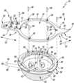
- FIG. 1is an exploded perspective view of an orthopaedic prosthetic system for an acetabular prosthetic implant
- FIG. 2is a perspective view of an assembled orthopaedic prosthetic system of FIG. 1 ;
- FIG. 3is a cross-sectional perspective view of the assembled orthopaedic prosthetic system of FIGS. 1 - 2 ;
- FIG. 4is a cross-sectional perspective view of an assembled orthopaedic prosthetic system of FIG. 1 having a different lateralization
- FIG. 5is a cross-sectional perspective view of an assembled orthopaedic prosthetic system of FIG. 1 having a different inclination angle;
- FIG. 6is a cross-sectional perspective view of an assembled orthopaedic prosthetic system of FIG. 1 having a different lateralization and a different inclination angle;
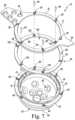
- FIG. 7is an exploded perspective view of the orthopaedic prosthetic system of FIG. 1 including a ring spacer;
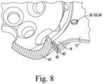
- FIG. 8is a cross-sectional perspective view of an assembled orthopaedic prosthetic system of FIG. 8 ;
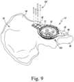
- FIG. 9is a perspective view showing the acetabular shell component of FIGS. 1 - 3 installed in a patient's hip;
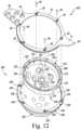
- FIG. 10is an exploded perspective view of another orthopaedic prosthetic system for an acetabular prosthetic implant including a two-part shell component;
- FIG. 11is a cross-sectional perspective view of an assembled orthopaedic prosthetic system of FIG. 10 ;
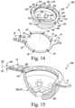
- FIG. 12is an exploded perspective view of the orthopaedic prosthetic system of FIG. 10 include a different inclination angle
- FIG. 13is a cross-sectional perspective view of an assembled orthopaedic prosthetic system of FIG. 12 ;
- FIG. 14is an exploded perspective view of another embodiment of an orthopaedic prosthetic system for an acetabular prosthetic implant
- FIG. 15is a cross-sectional perspective view of an assembled orthopaedic prosthetic system of FIG. 14 ;
- FIG. 16is an exploded perspective view of the orthopaedic prosthetic system of FIG. 14 including a ring spacer;
- FIG. 17is a cross-sectional perspective view of an assembled orthopaedic prosthetic system of FIG. 16 .
- anatomical referencessuch as anterior, posterior, medial, lateral, superior, inferior, etcetera
- terms representing anatomical referencesmay be used throughout the specification in reference to the orthopaedic implants and surgical instruments described herein as well as in reference to the patient's natural anatomy.
- Such termshave well-understood meanings in both the study of anatomy and the field of orthopaedics. Use of such anatomical reference terms in the written description and claims is intended to be consistent with their well-understood meanings unless noted otherwise.
- an illustrative acetabular prosthetic implant system 10includes an anatomic plate 12 and an acetabular shell component 42 .
- the anatomic plate 12includes a proximal surface 14 opposite a distal surface 16 , and is formed from an implant-grade metallic material such as cobalt chromium or titanium.
- the anatomic plate 12includes a central ring 18 that is surrounded by one or more flanges 20 .
- the central ring 18includes an inner wall 22 that extends between the surfaces 14 , 16 and defines an opening 24 . As described further below, the opening 24 is sized to receive part of the acetabular shell component 42 .
- Multiple apertures 26are defined in the central ring 18 .
- each aperture 26may include a threaded inner wall that is configured to mate with a threaded body of a screw. As described further below, the apertures 26 and corresponding fasteners may be used to mechanically attach the plate 12 to the shell component 42 .
- each flange 20extends outwardly from the central ring 18 of the anatomic plate 12 .
- each flange 20extends from a predetermined position 28 on the central ring 18 to a flange end 30 .
- a flange length 32is defined between the central ring 18 and the flange end 30 .
- Each flangehas a generally flat shape, and the proximal surface 14 of each flange 20 is configured to engage or otherwise intimately contact the patient's bone.
- each flange 20may include a Porocoat® outer coating 34 that permits bone to affix biologically to the flange 20 after implantation.
- the Porocoat® outer coating 34covers the proximal surface 14 of each flange 20 and follows its geometric shape. It should be appreciated that in other embodiments the Porocoat® outer coating 34 may be omitted.
- Each flange 20may extend straight away from the central ring 18 or may extend at an angle from the central ring 18 in a proximal and/or distal direction.
- Each flange 20may be rigid, or in some embodiments may be malleable. For example, in some embodiments a surgeon may be capable of manually bending a flange 20 in order to achieve intimate contact with the patient's bone.
- the illustrative anatomic plate 12includes two flanges 20 , particularly an ilial flange 36 and an ischial flange 38 .
- the illial flange 36is configured (e.g., with a position 28 and/or flange length 30 ) to contact the patient's ilium
- the ischial flange 38is configured (e.g., with a position 28 and/or flange length 30 ) to contact the patient's ischium.
- the ilial flange 38further includes multiple apertures 40 defined through the surfaces 14 , 16 .
- screws, pins, or other fastenersmay be inserted through the apertures 40 to secure the plate 12 to the patient's bone.
- the plate 12may include one flange 20 , three flanges 20 , or another number of flanges 20 .
- the flanges 20may include a different number or arrangement of apertures 40 or other fixation guides to allow the plate 12 to be secured to the patient's bone.
- the prosthetic system 10further includes the acetabular prosthetic shell component 42 , which is shaped to be implanted in a surgically-prepared acetabulum of a patient's pelvis.
- the shell component 42is formed from an implant-grade metallic material such as cobalt chromium or titanium.
- the shell component 42has a distal rim 44 and an outer wall 46 that extends from the distal rim 44 .
- the outer wall 46includes an annular outer surface 48 that extends from the distal rim 44 to a convex curved outer surface 50 .
- the convex curved outer surface 50is semi-spherical and shaped to match the shape of a patient's surgical prepared acetabulum.
- the shell component 42also includes a Porocoat® outer coating 52 that permits bone to affix biologically to the shell component 42 after implantation.
- the Porocoat® outer coating 52covers the outer surface 50 and follows its geometric shape. It should be appreciated that in other embodiments the Porocoat® outer coating 52 may be omitted.
- a lip 54is positioned on the annular outer surface 48 , between the distal rim 44 and the convex outer surface 50 .
- the lip 54extends outwardly away from the annular outer surface 48 , and includes a distal surface 56 positioned opposite a proximal surface 58 .
- Multiple apertures 60are defined in the lip 54 .
- the apertures 60are positioned on the lip 54 in positions that correspond to the apertures 26 of the anatomic plate 12 .
- each of the apertures 60are configured to receive a fastener.
- each aperture 60may include a threaded inner wall that is configured to mate with a threaded body of a screw.
- the apertures 26 , 60 and corresponding fastenersmay be used to mechanically attach the plate 12 to the shell component 42 .
- the distal surface 56 of the lip 54is spaced apart from distal rim 44 by a distance 62 .
- the distance 62may determine the degree of lateralization of the shell component 42 . That is, the distance 62 between the lip 54 and the distal rim 44 may determine the medial/lateral position of the center of rotation defined by the acetabular shell component 42 .
- a surgeonmay select the shell component 42 from among multiple shell components 42 that each have a different lateralization distance 62 .
- an imaginary plane 64is defined by extending the surface of the distal rim 44 .
- an imaginary plane 66is defined by the lip 54 , more particularly by extending the distal surface 56 of the lip 54 .
- An angle 68which may be zero or nonzero, is defined between the imaginary planes 64 , 66 .
- the angle 68may determine the relative angle between the surface of the distal rim 44 and the plate 12 . As described further below, in use this angle may determine the inclination, the version, or otherwise determine the orientation of distal rim 44 relative to the patient's hip. As described further below, in use a surgeon may select the shell component 42 from among multiple shell components 42 that each have a different angle 68 .
- the shell component 42further includes an inner wall 70 that extends inwardly from the distal rim 44 to define a cavity 72 in the shell component 42 .
- the illustrative cavity 72is sized to receive a bearing component (not shown), which may be formed from a polymeric material such as, for example, polyethylene, a ceramic material, a metallic material, or other material.
- the inner wall 70 of the shell component 42includes an annular inner surface 74 that is positioned opposite the annular outer surface 48 , and a concave curved inner surface 76 that is opposite the convex curved outer surface 50 .
- a plurality of slots 78extend outwardly from the inner wall 70 of the distal rim 44 .
- the slots 78are spaced apart around the circumference of the distal rim 44 and are shaped to receive corresponding keys of the bearing and/or other prosthetic component.
- the concave curved inner surface 76defines a polar axis 80 extending through the cavity 72 .
- the polar axis 80is normal to the plane 64 defined by the distal rim 44 .
- the polar axis 80may be non-normal to the plane 66 defined by the lip 54 , for example in embodiments with a nonzero angle 68 .
- one or more slots 82 or other fixation guidesmay be defined through the curved surfaces 50 , 76 . In use, screws, pins, or other fasteners may be inserted through the fixation guides 82 to secure the shell component to the patient's bone.
- multiple apertures 26are defined in the central ring 18 of the anatomic plate 12 .
- a corresponding aperture 60is defined in the lip 54 of the shell component 42 .
- multiple screws 84may be used to secure the central ring 18 to the lip 54 .
- each screw 84passes through a pair of corresponding apertures 26 , 60 , which mechanically attaches the plate 12 to the shell component 42 .
- the plate 12 and the shell component 42may be attached using pins, rivets, or any other appropriate fastener.
- a cross-sectional view of the prosthetic system 10illustrates the distance 62 defined between the distal rim 44 and the distal surface 56 of the lip 54 .
- the distance 62is two millimeters. It should be understood that other shell components included in the prosthetic system 10 may define different lateralization distances 62 .
- FIG. 4a cross-sectional view of another prosthetic system 10 shows the anatomic plate 12 secured to another acetabular shell component 86 .
- the acetabular shell component 86is similar to the shell component 42 shown in FIGS. 1 - 3 ; however, in the illustrative embodiment, the distance 62 defined between the distal rim 44 and the distal surface 56 of the shell component 86 is four millimeters. Accordingly, the center of rotation defined by the shell component 86 may be lateralized by two millimeters (i.e., moved two millimeters in a lateral direction) as compared to the center of rotation defined by the acetabular shell component 42 .
- shell components included in the prosthetic system 10may define different inclination angles 68 .
- FIG. 5a cross-sectional view of another prosthetic system 10 shows the anatomic plate 12 secured to another acetabular shell component 88 .
- the acetabular shell component 88is similar to the shell components 42 , 86 shown in FIGS. 1 - 4 ; however, in the illustrative embodiment, the angle 68 of the shell component 88 defined between the imaginary plate 64 defined by the distal rim 44 and the imaginary plane 66 defined by the lip 54 is non-zero. Additionally and as a result, the distance 62 between the distal rim 44 and the distal surface 56 of the lip 54 varies.
- the distance 62 at its largest pointis two millimeters, similar to the acetabular shell component 42 .
- the position of this largest point relative to the plate 12may be adjusted by rotating the shell component 88 relative to the plate 12 before securing the shell component 88 to the plate 12 with the screws 84 or other fasteners.
- FIG. 6a cross-sectional view of another prosthetic system 10 shows the anatomic plate 12 secured to another acetabular shell component 90 .
- the acetabular shell component 90is similar to the shell components 42 , 86 , 88 shown in FIGS. 1 - 5 .
- the angle 68 of the shell component 90 defined between the imaginary plane 64 defined by the distal rim 44 and the imaginary plane 66 defined by the lip 54is non-zero, similar to the shell component 88 .
- the distance 62 between the distal rim 44 and the distal surface 56 at its largest pointis four millimeters, similar to the acetabular shell component 86 .
- the illustrative shell components 42 , 86 , 88 , 90represent multiple potential combinations of lateralization distance 62 and inclination angle 68 . Additionally or alternatively, in some embodiments other configurations such as size may also vary between acetabular shell components.
- the acetabular prosthetic implant system 10may also include a ring spacer 92 that may be attached between the lip 54 of the acetabular shell component 42 and the central ring 18 of the anatomic plate 12 .
- the ring spacer 92is formed from an implant-grade metallic material such as cobalt chromium or titanium.
- the ring spacer 92includes a proximal surface 94 spaced apart from a distal surface 96 .
- An inner wall 98extends between the surfaces 94 , 96 and defines an opening 100 .
- the opening 100is sized to receive part of the acetabular shell component 42 .
- each aperture 102is defined through the surfaces 94 , 96 .
- the apertures 102are each configured to receive a fastener.
- each aperture 102may include a threaded inner wall that is configured to mate with a threaded body of a screw.
- each aperture 102aligns with corresponding apertures 26 , 60 defined in the plate 12 and the shell component 42 , respectively.
- Those apertures 26 , 102 , 60 and corresponding fastenersmay be used to mechanically attach the spacer 92 between the plate 12 and the shell component 42 .
- the proximal surface 14 of the plate 12may be moved toward the distal rim 44 of the shell component 42 by the thickness of the spacer ring 92 .
- the surgeonmay adjust the amount of lateralization of the assembled prosthetic system 10 .
- FIG. 9illustrates a patient's hip bone 104 .
- the hip bone 104includes three parts, an ilium 106 , an ischium 108 , and a pubis 110 , that define a natural acetabulum 112 .
- the surgeonsurgically prepares the patient's bone to receive the prosthetic assembly 10 .
- the surgeonmay utilize a surgical reamer to prepare the patient's acetabulum 112 to receive the prosthetic assembly 10 .
- the surgeonmay also remove any existing acetabular component or other prosthetic components from the patient's bone.
- each of those anatomic plates 12has a different configuration from the other anatomic plates 12 .
- each of the anatomic plates 12may have a different number and/or arrangement of flanges 20 , a different handedness (e.g., left/right), or other configuration.
- the flanges 20 of each anatomic plate 12may have a different predetermined position 28 relative to the central ring 18 or a different flange length 32 .
- each of those shell components 42has a different configuration from the other shell components 42 .
- each of the acetabular shell components 42may have a different combination of lateralization distance 62 and/or inclination angle 68 .
- the surgeonmechanically attaches the selected anatomic plate 12 to the selected acetabular shell component 42 .
- the surgeonmay position the central ring 18 of the plate 12 on the lip 54 of the acetabular shell component 42 and secure the central ring 18 to the lip 54 using multiple screws 84 or other fasteners.
- the surgeonmay rotate the shell component 42 relative to the anatomic plate 12 to achieve a desired orientation prior to securing the plate 12 to the shell component 42 .
- the surgeonmay select a spacer ring 92 prior to attaching the anatomic plate 12 to the acetabular shell component 42 .
- the surgeonmay position the spacer ring 92 on the lip 54 of the acetabular shell component 42 , position the central ring 18 of the plate 12 on the spacer ring 92 , and then secure the central ring 18 to the spacer ring 92 and the lip 54 using multiple screws 84 or other fasteners.
- the surgeonnext inserts the shell component 42 of the assembled prosthetic system 10 into the patient's surgically prepared acetabulum 112 until the flanges 20 of the anatomic plate 12 contact the patient's bone 104 .
- the ilial flange 36contacts the ilium 106 and the ischial flange 38 contacts the ischium 108 .
- the surgeonmay assess whether intimate contact is achieved between the flanges 20 and the bone 104 or otherwise assess stability of the prosthetic implant 10 in the bone 104 .
- the surgeonmay manually bend or otherwise adjust one or more of the flanges 20 in order to achieve intimate contact with the bone 104 .
- the surgeonmay remove the prosthetic system 10 , select a different anatomic plate 12 and/or acetabular shell component 42 , and re-assemble the prosthetic system 10 as described above to improve fit or otherwise improve fixation.
- the prosthetic system 10After positioning the prosthetic system 10 in the surgically prepared acetabulum 112 , the prosthetic system 10 is impacted or otherwise fixed into a final position and orientation.
- one or more bone screws 114 or other fastenersmay be used to attach the flanges 20 to the bone 104 .
- the bone screws 114may be used to secure the ilial flange 36 to the ilium 106 .
- the prosthetic system 10may be securely attached or otherwise fixed to solid bone of the patient, and may avoid attachment to diseased bone, voids, or other areas of bone loss surrounding the patient's acetabulum 112 .
- the prosthetic system 10may thus achieve a high degree of strength and may avoid the use of bone cement.
- the prosthetic implant system 200includes an anatomic plate 12 similar to the anatomic plate of FIGS. 1 - 9 and an acetabular shell component 202 . Similar to the shell component 42 of FIGS. 1 - 3 , the shell component 202 is shaped to be implanted in a surgically-prepared acetabulum of a patient's pelvis. Unlike the shell component 42 , the shell component 202 is formed from two subcomponents 204 , 206 that are mechanically attached to form the shell component 202 . Each of the subcomponents 204 , 206 is formed from an implant-grade metallic material such as cobalt chromium or titanium.
- the inner subcomponent 204has a distal rim 208 and an outer wall 210 that extends from the distal rim 208 .
- the outer wall 210includes an annular outer surface 212 that extends from the distal rim 208 to a convex curved outer surface 214 .
- the convex curved outer surface 214may be tapered or otherwise shaped to mate with a corresponding inner surface of the outer subcomponent 206 , which is described further below.
- the inner subcomponent 204further includes an inner wall 216 that extends inwardly from the distal rim 208 to define a cavity 218 in the inner subcomponent 204 .
- the illustrative cavity 218is sized to receive a bearing component (not shown), which may be formed from a polymeric material such as, for example, polyethylene, a ceramic material, a metallic material, or other material.
- the inner wall 216 of the inner subcomponent 204includes an annular inner surface 220 that is positioned opposite the annular outer surface 212 , and a concave curved inner surface 222 that is positioned opposite the convex curved outer surface 214 .
- a plurality of slots 224extend outwardly from the inner wall 216 of the distal rim 208 .
- the slots 224are spaced apart around the circumference of the distal rim 208 and are shaped to receive corresponding keys of the bearing and/or other prosthetic component.
- the concave curved inner surface 222defines a polar axis 226 extending through the cavity 218 .
- the polar axis 226is illustratively normal to an imaginary plane defined by the distal rim 208 .
- one or more slots 228 or other fixation guidesmay be defined through the curved surfaces 214 , 222 .
- the outer subcomponent 206also includes a convex curved outer surface 230 .
- the convex curved outer surface 230is semi-spherical and shaped to match the shape of a patient's surgical prepared acetabulum.
- the outer subcomponentmay also include a Porocoat® outer coating 232 that permits bone to affix biologically to the shell component 202 after implantation.
- the Porocoat® outer coating 232covers the outer surface 230 and follows its geometric shape. It should be appreciated that in other embodiments the Porocoat® outer coating 232 may be omitted.
- a lip 234surrounds the convex curved outer surface 230 .
- the lip 234extends outwardly away from the curved outer surface 230 , and includes a distal surface 236 positioned opposite a proximal surface 238 .
- Multiple apertures 240are defined in the lip 234 .
- the apertures 240are positioned on the lip 234 in positions that correspond to the apertures 26 of the anatomic plate 12 .
- each of the apertures 240are configured to receive a fastener.
- each aperture 240may include a threaded inner wall that is configured to mate with a threaded body of a screw.
- the apertures 26 , 240 and corresponding fastenersmay be used to mechanically attach the plate 12 to the shell component 202 .
- the outer subcomponent 206further includes an inner wall 242 that extends inwardly from the lip 234 to define a cavity 244 in the outer subcomponent 206 .
- the illustrative cavity 244is sized to receive the inner subcomponent 204 .
- the inner wall 242is shaped to engage the convex outer surface 214 of the inner subcomponent 202 .
- the inner wall 242may include a taper or other shape configured to mechanically lock with the outer surface 214 of the inner subcomponent 202 .
- the inner wall 242further defines a polar axis 246 extending through the cavity 244 .
- one or more slots 248 or other fixation guidesmay be defined through the inner wall 242 and the outer surface 230 . As described further below, after assembly of the shell component 202 , screws, pins, or other fasteners may be inserted through the fixation guides 228 , 248 to secure the shell component 202 to the patient's bone.
- the inner subcomponent 204may be inserted into the cavity 244 defined in the outer subcomponent 206 , thereby attaching the subcomponents 204 , 206 together to form the acetabular shell component 202 .
- the distal surface 236 of the lip 234is spaced apart from distal rim 218 by a distance 250 .
- the distance 250may determine the degree of lateralization of the assembled shell component 202 . That is, similar to the distance 62 , the distance 250 determine the medial/lateral position of the center of rotation defined by the acetabular shell component 202 .
- a surgeonmay select the subcomponents 204 , 206 from among multiple subcomponents 204 , 206 in order to assemble a shell component 202 with a particular lateralization distance 250 .
- the distance 250is two millimeters. It should be understood that other shell components 202 included in the prosthetic system 200 may define different lateralization distances 250 .
- each of the inner subcomponent 204 and the outer subcomponent 206define a polar axis 226 , 246 , respectively.
- An angle 252which may be zero or nonzero is defined between the polar axes 226 , 246 .
- the angle 252may determine the relative angle between the surface of the distal rim 208 and the plate 12 . In use, this angle may determine the inclination, the version, or otherwise determine the orientation of distal rim 208 relative to the patient's hip.
- a surgeonmay select the subcomponents 204 , 206 from among multiple subcomponents 204 , 206 to assemble a shell components 202 that each has a particular angle 252 .
- another prosthetic system 200includes an acetabular shell component 202 formed from the outer subcomponent 206 and an inner subcomponent 254 .
- the inner subcomponent 254is similar to the inner subcomponent 204 shown in FIGS. 10 - 11 ; however, in the illustrative embodiment, when assembled with the outer subcomponent 206 , a nonzero angle 252 is defined between the polar axis 226 of the inner subcomponent 254 and the polar axis 246 of the outer subcomponent 206 . Additionally and as a result, the distance 250 between the distal rim 208 and the distal surface 236 of the lip 234 varies.
- the distance 250 at its largest pointis two millimeters, similar to the acetabular shell components 42 , 88 .
- the position of this largest point relative to the plate 12may be adjusted, for example, by rotating the inner subcomponent 254 relative to the outer subcomponent 206 before assembling the plate 12 before assembling the shell component 202 .
- an acetabular prosthetic implant system 300may be used during the orthopaedic surgical procedure described above in addition to or as an alternative to the prosthetic implant systems 10 , 200 .
- the prosthetic implant system 300includes an anatomic plate 12 similar to the anatomic plate of FIGS. 1 - 13 and an acetabular shell component 302 . Similar to the shell component 42 of FIGS. 1 - 3 , the shell component 302 is shaped to be implanted in a surgically-prepared acetabulum of a patient's pelvis.
- the shell component 302is formed from an implant-grade metallic material such as cobalt chromium or titanium.
- the shell component 302has a distal rim 304 and an outer wall 306 that extends from the distal rim 304 .
- the outer wall 306includes a convex curved outer surface 308 that extends from the distal rim 304 .
- the convex curved outer surface 308is semi-spherical and shaped to match the shape of a patient's surgical prepared acetabulum.
- the shell component 302also includes a Porocoat® outer coating 310 that permits bone to affix biologically to the shell component 302 after implantation.
- the Porocoat® outer coating 310covers the outer surface 308 and follows its geometric shape. It should be appreciated that in other embodiments the Porocoat® outer coating 310 may be omitted.
- a lip 312is positioned at the distal rim 304 , extending outwardly away from the convex outer surface 308 .
- the lip 312includes a distal surface 314 at the distal rim 304 and further includes a proximal surface 316 positioned opposite the distal surface 314 .
- Multiple apertures 318are defined in the lip 312 .
- the apertures 318are positioned on the lip 312 in positions that correspond to the apertures 26 of the anatomic plate 12 .
- each of the apertures 318are configured to receive a fastener.
- each aperture 318may include a threaded inner wall that is configured to mate with a threaded body of a screw.
- the apertures 26 , 318 and corresponding fastenersmay be used to mechanically attach the plate 12 to the shell component 302 .
- the proximal surface 316 of the lip 312is spaced apart from the distal rim 304 by a distance 320 .
- the distance 320may determine the degree of lateralization of the shell component 302 . That is, the distance 320 between the proximal surface 316 of the lip 312 and the distal rim 304 may determine the medial/lateral position of the center of rotation defined by the acetabular shell component 302 .
- a surgeonmay select the shell component 302 from among multiple shell components 302 that each have a different lateralization distance 320 .
- an imaginary plane 322is defined by extending the surface of the distal rim 312 .
- an imaginary plane 324is defined by the lip 312 , more particularly by extending the proximal surface 316 of the lip 312 .
- An angle 326which may be zero or nonzero, is defined between the imaginary planes 322 , 324 .
- the angle 326may determine the relative angle between the surface of the distal rim 304 and the plate 12 . As described further below, in use this angle may determine the inclination, the version, or otherwise determine the orientation of distal rim 304 relative to the patient's hip.
- a surgeonmay select the shell component 302 from among multiple shell components 302 that each have a different angle 326 .
- the shell component 302further includes an inner wall 328 that extends inwardly from the distal rim 304 to define a cavity 330 in the shell component 302 .
- the illustrative cavity 330is sized to receive a bearing component (not shown), which may be formed from a polymeric material such as, for example, polyethylene, a ceramic material, a metallic material, or other material.
- the inner wall 328 of the shell component 302includes an annular inner surface 332 that is positioned opposite the lip 312 , and a concave curved inner surface 334 that is opposite the convex curved outer surface 308 .
- a plurality of slots 336extend outwardly from the inner wall 328 of the distal rim 304 .
- the slots 336are spaced apart around the circumference of the distal rim 304 and are shaped to receive corresponding keys of the bearing and/or other prosthetic component.
- the concave curved inner surface 334defines a polar axis 338 extending through the cavity 330 .
- the polar axis 338is normal to the plane 322 defined by the distal rim 304 .
- the polar axis 338may be non-normal to the plane 324 defined by the lip 312 , for example in embodiments with a nonzero angle 326 .
- one or more slots 340 or other fixation guidesmay be defined through the curved surfaces 308 , 334 . In use, screws, pins, or other fasteners may be inserted through the fixation guides to secure the shell component to the patient's bone.
- multiple apertures 26are defined in the central ring 18 of the anatomic plate 12 .
- a corresponding aperture 318is defined in the lip 312 of the shell component 302 .
- the concave outer surface 308 of the shell component 302may pass through the central opening 24 of the anatomic plate 12 .
- the proximal surface 316 of the lip 312engages the distal surface 16 of the anatomic plate 12 on the central ring 18 .
- multiple screws 84may be used to secure the central ring 18 to the lip 312 .
- each screw 84passes through a pair of corresponding apertures 26 , 318 , which mechanically attaches the plate 12 to the shell component 302 .
- the plate 12 and the shell component 302may be attached using pins, rivets, or any other appropriate fastener.
- the acetabular prosthetic implant system 300may also include a ring spacer 92 similar to the ring spacer 92 shown in FIGS. 7 and 8 .
- the ring spacer 92may be attached between the lip 312 of the acetabular shell component 302 and the central ring 18 of the anatomic plate 12 .
- the distal surface 96 of the ring spacer 92engages the proximal surface 316 of the shell component 302
- the distal surface 16 of the anatomic plate 12engages the proximal surface 94 of the ring spacer 92 .
- the anatomic plate 12 , the ring spacer 92 , and the shell component 302may be mechanically attached together using multiple screws 84 or other fasteners engaged through corresponding apertures 26 , 102 , 318 .
- the spacer 92 between the plate 12 and the shell component 302By attaching the spacer 92 between the plate 12 and the shell component 302 , the proximal surface 14 of the plate 12 may be moved away from the distal rim 304 of the shell component 302 by the thickness of the spacer ring 92 .
- the surgeonmay adjust the amount of lateralization of the assembled prosthetic system 300 .
Landscapes
- Health & Medical Sciences (AREA)
- Orthopedic Medicine & Surgery (AREA)
- Transplantation (AREA)
- Vascular Medicine (AREA)
- Oral & Maxillofacial Surgery (AREA)
- Engineering & Computer Science (AREA)
- Biomedical Technology (AREA)
- Heart & Thoracic Surgery (AREA)
- Cardiology (AREA)
- Life Sciences & Earth Sciences (AREA)
- Animal Behavior & Ethology (AREA)
- General Health & Medical Sciences (AREA)
- Public Health (AREA)
- Veterinary Medicine (AREA)
- Physical Education & Sports Medicine (AREA)
- Prostheses (AREA)
Abstract
Description
Claims (14)
Priority Applications (7)
| Application Number | Priority Date | Filing Date | Title |
|---|---|---|---|
| US17/219,583US11918475B2 (en) | 2021-03-31 | 2021-03-31 | Modular acetabular surgical implant assembly |
| CN202280025629.4ACN117136039A (en) | 2021-03-31 | 2022-03-30 | Modular acetabular surgical implant assembly |
| PCT/IB2022/052978WO2022208405A1 (en) | 2021-03-31 | 2022-03-30 | Modular acetabular surgical implant assembly |
| EP22715192.5AEP4312887A1 (en) | 2021-03-31 | 2022-03-30 | Modular acetabular surgical implant assembly |
| AU2022251206AAU2022251206A1 (en) | 2021-03-31 | 2022-03-30 | Modular acetabular surgical implant assembly |
| JP2023560579AJP2024511673A (en) | 2021-03-31 | 2022-03-30 | Modular acetabular surgical implant assembly |
| US18/594,465US20240197484A1 (en) | 2021-03-31 | 2024-03-04 | Modular acetabular surgical implant assembly |
Applications Claiming Priority (1)
| Application Number | Priority Date | Filing Date | Title |
|---|---|---|---|
| US17/219,583US11918475B2 (en) | 2021-03-31 | 2021-03-31 | Modular acetabular surgical implant assembly |
Related Child Applications (1)
| Application Number | Title | Priority Date | Filing Date |
|---|---|---|---|
| US18/594,465DivisionUS20240197484A1 (en) | 2021-03-31 | 2024-03-04 | Modular acetabular surgical implant assembly |
Publications (2)
| Publication Number | Publication Date |
|---|---|
| US20220313444A1 US20220313444A1 (en) | 2022-10-06 |
| US11918475B2true US11918475B2 (en) | 2024-03-05 |
Family
ID=81325414
Family Applications (2)
| Application Number | Title | Priority Date | Filing Date |
|---|---|---|---|
| US17/219,583Active2041-06-28US11918475B2 (en) | 2021-03-31 | 2021-03-31 | Modular acetabular surgical implant assembly |
| US18/594,465PendingUS20240197484A1 (en) | 2021-03-31 | 2024-03-04 | Modular acetabular surgical implant assembly |
Family Applications After (1)
| Application Number | Title | Priority Date | Filing Date |
|---|---|---|---|
| US18/594,465PendingUS20240197484A1 (en) | 2021-03-31 | 2024-03-04 | Modular acetabular surgical implant assembly |
Country Status (6)
| Country | Link |
|---|---|
| US (2) | US11918475B2 (en) |
| EP (1) | EP4312887A1 (en) |
| JP (1) | JP2024511673A (en) |
| CN (1) | CN117136039A (en) |
| AU (1) | AU2022251206A1 (en) |
| WO (1) | WO2022208405A1 (en) |
Families Citing this family (1)
| Publication number | Priority date | Publication date | Assignee | Title |
|---|---|---|---|---|
| US12042390B2 (en) | 2022-05-10 | 2024-07-23 | Depuy Ireland Unlimited Company | Acetabular prosthesis with adjustable acetabular cup cages |
Citations (104)
| Publication number | Priority date | Publication date | Assignee | Title |
|---|---|---|---|---|
| US2947308A (en) | 1956-11-02 | 1960-08-02 | Harry A Gorman | Hip joint prosthesis |
| US3067740A (en)* | 1959-09-08 | 1962-12-11 | Edward J Haboush | Hip joint prosthesis |
| US3903549A (en)* | 1974-06-12 | 1975-09-09 | William Minor Deyerle | Acetabular cup prosthesis component for total or subtotal hip prosthesis system |
| US4623352A (en)* | 1982-01-18 | 1986-11-18 | Indong Oh | Protrusio cup |
| EP0846453A2 (en) | 1996-12-07 | 1998-06-10 | Johnson & Johnson Professional, Inc. | Modular acetabular reinforcement system |
| US6302890B1 (en) | 2000-03-16 | 2001-10-16 | Leone Innovations Corporation | Pelvic alignment assembly |
| US20020082706A1 (en)* | 2000-11-07 | 2002-06-27 | Patrick Raugel | Handling device for acetabular bearing liner |
| US6416553B1 (en)* | 1999-03-31 | 2002-07-09 | Biomet, Inc. | Method and apparatus for providing a modular acetabular prosthesis |
| US6458161B1 (en) | 2001-02-23 | 2002-10-01 | Biomet, Inc. | Method and apparatus for acetabular reconstruction |
| US20030153982A1 (en)* | 2002-02-14 | 2003-08-14 | Pria Paolo Dalla | Acetabular prosthesis of the hip |
| US6620200B1 (en)* | 1999-09-28 | 2003-09-16 | Depuy France | Acetabular implant for hip prosthesis |
| EP1377237A2 (en) | 2001-01-25 | 2004-01-07 | Smith & Nephew, Inc. | Containment system for constraining a prosthetic component |
| US20040199258A1 (en)* | 2001-07-23 | 2004-10-07 | Frederique Macara | Modular acetabular cup and anchoring screw for fixing a prosphetic implant such as said acetabular cup |
| US20040225369A1 (en)* | 2001-07-31 | 2004-11-11 | Lakin Ryan C. | Method and apparatus for use of a metal-metal constrained liner |
| US20060058887A1 (en)* | 2004-09-15 | 2006-03-16 | Desmet Koen | Unitary acetabular cup prosthesis with extension for deficient acetabulum |
| US20060190089A1 (en)* | 2005-02-18 | 2006-08-24 | Howmedica Osteonics Corp. | Internal adaptor for hip acetabular cage |
| US20060241776A1 (en) | 2005-04-21 | 2006-10-26 | Biomet Manufacturing Corp. | Method and apparatus for use of porous implants |
| US7175664B1 (en) | 2002-07-03 | 2007-02-13 | Biomet, Inc. | Prosthetic having a modular soft tissue fixation mechanism |
| US7207993B1 (en) | 2000-02-03 | 2007-04-24 | Pioneer Laboratories, Inc. | Apparatus and method for repairing the femur |
| EP1845849A2 (en) | 2005-01-18 | 2007-10-24 | The Regents of the University of California | Lower extremity exoskeleton |
| EP1874239A2 (en) | 2005-04-13 | 2008-01-09 | The Regents of the University of California | Semi-powered lower extremity exoskeleton |
| US7393335B2 (en) | 2004-05-06 | 2008-07-01 | Carvey Matthew R | Metabolically efficient leg brace |
| US20080161738A1 (en) | 2007-01-03 | 2008-07-03 | Dirk Giesen | Supporting device |
| US20080172130A1 (en)* | 2001-07-23 | 2008-07-17 | Frederique Macara | Modular acetabular cup and anchoring screw for fixing a prosthetic implant |
| US7416538B2 (en) | 2003-05-21 | 2008-08-26 | Honda Motor Co., Ltd. | Walking assistance device |
| US20080214976A1 (en) | 2004-11-10 | 2008-09-04 | Michael Memminger | Device For Guiding The Leg During A Hip Operation, Particularly During An Endoprosthesis Implantation |
| EP1388329B1 (en) | 2002-08-05 | 2009-05-13 | LIMA Lto SpA | Femoral prosthesis for hip joint |
| EP1605838B1 (en) | 2003-03-24 | 2009-06-17 | OM Surgical (UK) Limited | System for ensuring correct insertion of an artificial hip joint |
| US7559909B2 (en) | 2003-05-21 | 2009-07-14 | Honda Motor Co., Ltd. | Walking assistance device |
| US20090292369A1 (en) | 2008-05-20 | 2009-11-26 | Berkeley Bionics | Device and Method for Decreasing Energy Consumption of a Person by Use of a Lower Extremity Exoskeleton |
| US7641698B1 (en) | 2004-06-04 | 2010-01-05 | Biomet Manufacturing Corp. | Modular hip joint implant |
| US7780616B2 (en) | 2003-05-21 | 2010-08-24 | Honda Motor Co., Ltd. | Walking assistance device |
| US7798983B2 (en) | 2003-05-21 | 2010-09-21 | Honda Motor Co., Ltd. | Walking assistance device |
| WO2010109235A1 (en) | 2009-03-24 | 2010-09-30 | Stanmore Implants Worldwide Limited | Intracorporeal component for a percutaneous device |
| US20110099720A1 (en) | 2009-09-30 | 2011-05-05 | Maquet Gmbh & Co. Kg | Adapter for connecting at least one accessory device to an operating table |
| WO2011065378A1 (en) | 2009-11-24 | 2011-06-03 | 株式会社 レキシー | Preoperative planning program for artificial hip joint replacement surgery and surgery support jig |
| US20110213466A1 (en) | 2009-08-27 | 2011-09-01 | The Foundry Llc | Method and Apparatus for Force Redistribution in Articular Joints |
| WO2011117644A2 (en) | 2010-03-24 | 2011-09-29 | Andrew Joseph Stanley Dawood | Apparatus for guiding position of hip joint prostheses |
| US8048166B2 (en) | 2004-05-04 | 2011-11-01 | Biomet Manufacturing Corp. | Method and apparatus for constructing a modular acetabulum |
| US20110282460A1 (en)* | 2008-11-20 | 2011-11-17 | Aesculap Ag | Hip joint socket |
| WO2011156506A2 (en) | 2010-06-08 | 2011-12-15 | Smith & Nephew, Inc. | Implant components and methods |
| US20120053699A1 (en)* | 2010-08-24 | 2012-03-01 | Biomet Manufacturing Corp. | Acetabular Cup Having Deformation Resistant Features |
| WO2011146617A9 (en) | 2010-05-18 | 2012-03-01 | Smith & Nephew, Inc. | Revision hip implants and prosthesis systems |
| EP1637112B1 (en) | 2003-05-21 | 2012-05-09 | Honda Motor Co., Ltd. | Walking aid device |
| US8192453B2 (en) | 2006-03-16 | 2012-06-05 | Valla Joseph R | Surgical cutting tool and system |
| WO2012103881A2 (en) | 2011-04-20 | 2012-08-09 | Bernhard Hildebrandt | Implantable biological joint replacement |
| WO2013025546A1 (en) | 2011-08-12 | 2013-02-21 | The Seaberg Company, Inc. | Device and method for stabilization of a fractured pelvis or an injured neck, and for control of hemorrhage |
| US8439921B2 (en) | 2008-02-12 | 2013-05-14 | Amir Jamali | Device and method for allograft total hip arthroplasty |
| US8460393B2 (en) | 2010-03-05 | 2013-06-11 | Biomet Manufacturing Corp. | Modular lateral hip augments |
| EP1301652B1 (en) | 2000-07-10 | 2013-09-11 | Exogenesis Corporation | Improving effectiveness of artificial hip by gcib |
| EP2502604B1 (en) | 2011-03-21 | 2013-09-25 | Jossi Holding AG | Joint socket implant |
| US20130297036A1 (en)* | 2010-07-20 | 2013-11-07 | Corin Limited | Acetabular Cup |
| WO2014052151A1 (en) | 2012-09-27 | 2014-04-03 | Elwha Llc | Artificial joint components including mechanized synovial fluid deflecting structures and particle retaining structures |
| EP2200542B1 (en) | 2007-10-23 | 2014-04-30 | Arnhold, Christian | Universal extractor for total endoprostheses of the hip joint, modular elongate shaft components of prosthetic systems or intramedullary pins |
| WO2014094002A2 (en) | 2012-12-14 | 2014-06-19 | The Seaberg Company, Inc. | Device and method for control of hemorrhage |
| WO2014132221A1 (en) | 2013-02-28 | 2014-09-04 | Universidad Militar Nueva Granada | Active orthosis for surgeons |
| US8828089B1 (en) | 2010-07-12 | 2014-09-09 | Howmedica Osteonics Corp. | Augmenting an acetabular implant site |
| US20140296991A1 (en) | 2007-11-08 | 2014-10-02 | Linares Medical Devices, Llc | Hip & knee joint assemblies incorporating debris collection architecture between the ball and seat interface |
| FR3004102A1 (en) | 2013-04-09 | 2014-10-10 | Hubert Georges Marcel Candavoine | MIXED COTYLOID IMPLANT WITH REPORTED FIXING LEGS |
| US20140336776A1 (en)* | 2011-11-23 | 2014-11-13 | Depuy (Ireland) | Medical implant, instrument head and assembly |
| US8888786B2 (en) | 2003-06-09 | 2014-11-18 | OrthAlign, Inc. | Surgical orientation device and method |
| WO2014197451A1 (en) | 2013-06-03 | 2014-12-11 | Murphy Stephen B | Method and apparatus for performing anterior hip surgery |
| US8920351B2 (en) | 2009-08-07 | 2014-12-30 | The Seaberg Company, Inc. | Emergency stabilization of a fractured pelvis or an injured neck |
| WO2015018340A1 (en) | 2013-08-09 | 2015-02-12 | Luo Yun | Knee joint orthosis having offloading function |
| WO2015135377A1 (en) | 2014-03-11 | 2015-09-17 | 加莎热特·杰力勒 | Therapeutic device for slowly stretching three-dimensional hip joint for restoration movement |
| WO2015165817A1 (en) | 2014-05-02 | 2015-11-05 | Peter Brehm | Device for attaching a positioning means on a bone of a patient, device for machining a bone of a patient, and hip implant system |
| EP2995284A2 (en) | 2014-08-18 | 2016-03-16 | Samsung Electronics Co., Ltd. | Fixing module and motion assistance apparatus including the same |
| USRE46032E1 (en) | 2005-11-30 | 2016-06-21 | Smith & Nephew, Inc. | Hip distraction |
| EP2623082B1 (en) | 2012-02-06 | 2016-06-29 | Arthrex, Inc. | Perineal post pad for patient lower extremity positioning systems |
| US9387080B2 (en) | 2012-09-27 | 2016-07-12 | Elwha Llc | Artificial joint components including synovial fluid deflecting structures |
| US9402728B2 (en) | 2013-05-01 | 2016-08-02 | Lichu Liu | Cementless hip stem |
| EP2897568B1 (en) | 2012-09-18 | 2016-08-17 | Medacta International S.A. | Apparatus for positioning the lower limb of a patient during operation, in particular for hip replacement operations with anterior approach, and surgical positioning system comprising said apparatus |
| US9427238B2 (en) | 2009-08-07 | 2016-08-30 | The Seaberg Company, Inc. | Device for control of hemorrhage including stabilized point pressure device |
| WO2017010797A1 (en) | 2015-07-14 | 2017-01-19 | 박윤미 | 3d human body correction apparatus |
| WO2017022950A1 (en) | 2015-07-31 | 2017-02-09 | 아이메디컴(주) | Acetabular cup detaching apparatus for artificial hip joint |
| US9566156B2 (en) | 2012-01-09 | 2017-02-14 | Zimmer, Inc. | Composite device that combines porous metal and bone stimuli |
| EP1889591B1 (en) | 2005-05-17 | 2017-03-01 | Honda Motor Co., Ltd. | Thigh part mounting device for walking assisting device |
| US9615942B2 (en) | 2010-03-05 | 2017-04-11 | Biomet Manufacturing, Llc | Method and apparatus for trialing and implanting a modular femoral hip |
| US20170112628A1 (en)* | 2015-10-22 | 2017-04-27 | DePuy Synthes Products, Inc. | Customized patient-specific orthopaedic instruments for component placement in a total hip arthroplasty |
| WO2017073458A1 (en) | 2015-10-29 | 2017-05-04 | 株式会社 レキシー | Device for patient body positioning and immobilizing, and angle indicator |
| EP2699213B1 (en) | 2011-04-20 | 2017-05-10 | Paul Hartmann AG | Fastening and carrying device for the safe holding of a disposable absorbent incontinence pad |
| WO2017098039A1 (en) | 2015-12-10 | 2017-06-15 | Mobelife N.V. | Device for supporting defect-filling material and its method of manufacturing |
| WO2017133730A1 (en) | 2016-02-05 | 2017-08-10 | Benjamin Bruder | Method for acquiring biomechanical and biometric data, and relevant device |
| EP3228280A1 (en) | 2016-04-04 | 2017-10-11 | Rainer Baumgart | Supporting device mountable at the pelvic bone |
| EP1889592B1 (en) | 2005-05-17 | 2018-01-10 | Honda Motor Co., Ltd. | Thigh part mounting device for walking assisting device |
| WO2018012990A1 (en) | 2016-07-15 | 2018-01-18 | Iddmedical Sp. Z O.O. | Device for the examination of limb joints |
| US9883954B1 (en) | 2007-11-01 | 2018-02-06 | Stephen B. Murphy | Acetabular template component and method of using same during hip arthrosplasty |
| EP2996639B1 (en) | 2012-09-21 | 2018-03-07 | David Langton | Prosthetic hip alignment device |
| US20180071128A1 (en) | 2016-09-12 | 2018-03-15 | Jeffrey Ray Palmer | Removable Pediatric Hip Orthotic |
| US20180116828A1 (en) | 2016-11-03 | 2018-05-03 | University Of New Brunswick | Powered lower limb devices and methods of control thereof |
| US20180153725A1 (en) | 2016-09-12 | 2018-06-07 | Jeffrey Ray Palmer | Removable Pediatric Hip Orthotic |
| US20180271692A1 (en) | 2016-09-12 | 2018-09-27 | Jeffrey Ray Palmer | Removable Pediatric Hip Orthotic |
| WO2018219376A1 (en) | 2017-05-31 | 2018-12-06 | Nazar Sadiq | Threaded joint for supporting and stabilizing a rear fracture of the pelvic ring or for stabilizing and stiffening the sacroiliac joint |
| US10159520B2 (en) | 2012-06-18 | 2018-12-25 | Mquet Gmbh | Device for fixing a femur for hip endoprosthesis surgery |
| US20190053965A1 (en) | 2017-08-17 | 2019-02-21 | Steven T. Woolson | Frame and method for positioning a patient undergoing hip surgery |
| WO2019038203A1 (en) | 2017-08-21 | 2019-02-28 | Depuy Ireland Unlimited Company | A guide, kit of parts and guide assembly for hip surgery |
| US20190076256A1 (en) | 2017-09-12 | 2019-03-14 | Zimmer, Inc. | Methods for attaching acetabular augments together or to acetabular shells |
| US10231739B1 (en) | 2001-08-28 | 2019-03-19 | Bonutti Skeletal Innovations Llc | System and method for robotic surgery |
| US10245149B2 (en) | 2015-08-03 | 2019-04-02 | Nicholas John Loffredo | Reverse total hip replacement |
| US10357391B2 (en) | 2013-01-24 | 2019-07-23 | Ossur Hf | Orthopedic device for treating complications of the hip |
| WO2019200174A1 (en) | 2018-04-11 | 2019-10-17 | Vivek Mohan | A haptic based system for bone gap measurement and distraction |
| US20200205987A1 (en)* | 2018-12-31 | 2020-07-02 | Alena M. Brandewie | Acetabular orthopaedic prosthesis and method |
| US20210077262A1 (en)* | 2019-09-13 | 2021-03-18 | Smith & Nephew, Inc. | Acetabular apparatus with dual mobility for hip revision surgery |
| DE102020109617A1 (en)* | 2020-04-07 | 2021-10-07 | Aesculap Ag | Hip socket and revision hip joint endoprosthesis |
- 2021
- 2021-03-31USUS17/219,583patent/US11918475B2/enactiveActive
- 2022
- 2022-03-30JPJP2023560579Apatent/JP2024511673A/enactivePending
- 2022-03-30CNCN202280025629.4Apatent/CN117136039A/enactivePending
- 2022-03-30WOPCT/IB2022/052978patent/WO2022208405A1/ennot_activeCeased
- 2022-03-30AUAU2022251206Apatent/AU2022251206A1/enactivePending
- 2022-03-30EPEP22715192.5Apatent/EP4312887A1/enactivePending
- 2024
- 2024-03-04USUS18/594,465patent/US20240197484A1/enactivePending
Patent Citations (126)
| Publication number | Priority date | Publication date | Assignee | Title |
|---|---|---|---|---|
| US2947308A (en) | 1956-11-02 | 1960-08-02 | Harry A Gorman | Hip joint prosthesis |
| US3067740A (en)* | 1959-09-08 | 1962-12-11 | Edward J Haboush | Hip joint prosthesis |
| US3903549A (en)* | 1974-06-12 | 1975-09-09 | William Minor Deyerle | Acetabular cup prosthesis component for total or subtotal hip prosthesis system |
| US4623352A (en)* | 1982-01-18 | 1986-11-18 | Indong Oh | Protrusio cup |
| EP0846453A2 (en) | 1996-12-07 | 1998-06-10 | Johnson & Johnson Professional, Inc. | Modular acetabular reinforcement system |
| US5871548A (en)* | 1996-12-07 | 1999-02-16 | Johnson & Johnson Professional, Inc. | Modular acetabular reinforcement system |
| US6416553B1 (en)* | 1999-03-31 | 2002-07-09 | Biomet, Inc. | Method and apparatus for providing a modular acetabular prosthesis |
| US6620200B1 (en)* | 1999-09-28 | 2003-09-16 | Depuy France | Acetabular implant for hip prosthesis |
| US7207993B1 (en) | 2000-02-03 | 2007-04-24 | Pioneer Laboratories, Inc. | Apparatus and method for repairing the femur |
| US6302890B1 (en) | 2000-03-16 | 2001-10-16 | Leone Innovations Corporation | Pelvic alignment assembly |
| EP1301652B1 (en) | 2000-07-10 | 2013-09-11 | Exogenesis Corporation | Improving effectiveness of artificial hip by gcib |
| US20020082706A1 (en)* | 2000-11-07 | 2002-06-27 | Patrick Raugel | Handling device for acetabular bearing liner |
| EP1377237A2 (en) | 2001-01-25 | 2004-01-07 | Smith & Nephew, Inc. | Containment system for constraining a prosthetic component |
| US6458161B1 (en) | 2001-02-23 | 2002-10-01 | Biomet, Inc. | Method and apparatus for acetabular reconstruction |
| US20040199258A1 (en)* | 2001-07-23 | 2004-10-07 | Frederique Macara | Modular acetabular cup and anchoring screw for fixing a prosphetic implant such as said acetabular cup |
| US20080172130A1 (en)* | 2001-07-23 | 2008-07-17 | Frederique Macara | Modular acetabular cup and anchoring screw for fixing a prosthetic implant |
| US20040225369A1 (en)* | 2001-07-31 | 2004-11-11 | Lakin Ryan C. | Method and apparatus for use of a metal-metal constrained liner |
| US10231739B1 (en) | 2001-08-28 | 2019-03-19 | Bonutti Skeletal Innovations Llc | System and method for robotic surgery |
| US20030153982A1 (en)* | 2002-02-14 | 2003-08-14 | Pria Paolo Dalla | Acetabular prosthesis of the hip |
| US7175664B1 (en) | 2002-07-03 | 2007-02-13 | Biomet, Inc. | Prosthetic having a modular soft tissue fixation mechanism |
| EP1388329B1 (en) | 2002-08-05 | 2009-05-13 | LIMA Lto SpA | Femoral prosthesis for hip joint |
| EP1605838B1 (en) | 2003-03-24 | 2009-06-17 | OM Surgical (UK) Limited | System for ensuring correct insertion of an artificial hip joint |
| US7416538B2 (en) | 2003-05-21 | 2008-08-26 | Honda Motor Co., Ltd. | Walking assistance device |
| US7559909B2 (en) | 2003-05-21 | 2009-07-14 | Honda Motor Co., Ltd. | Walking assistance device |
| EP1637112B1 (en) | 2003-05-21 | 2012-05-09 | Honda Motor Co., Ltd. | Walking aid device |
| EP1637116B1 (en) | 2003-05-21 | 2012-05-09 | Honda Motor Co., Ltd. | Walk assisting device |
| US7798983B2 (en) | 2003-05-21 | 2010-09-21 | Honda Motor Co., Ltd. | Walking assistance device |
| EP1637115B1 (en) | 2003-05-21 | 2015-11-11 | Honda Motor Co., Ltd. | Walking aid device |
| US7780616B2 (en) | 2003-05-21 | 2010-08-24 | Honda Motor Co., Ltd. | Walking assistance device |
| US8888786B2 (en) | 2003-06-09 | 2014-11-18 | OrthAlign, Inc. | Surgical orientation device and method |
| US8048166B2 (en) | 2004-05-04 | 2011-11-01 | Biomet Manufacturing Corp. | Method and apparatus for constructing a modular acetabulum |
| US8696757B2 (en) | 2004-05-04 | 2014-04-15 | Biomet Manufacturing, Llc | Prosthetic hip device and associated method |
| EP1742711B1 (en) | 2004-05-06 | 2019-07-31 | Matthew R. Carvey | A metabolically efficient leg brace |
| US7393335B2 (en) | 2004-05-06 | 2008-07-01 | Carvey Matthew R | Metabolically efficient leg brace |
| US7641698B1 (en) | 2004-06-04 | 2010-01-05 | Biomet Manufacturing Corp. | Modular hip joint implant |
| US20060058887A1 (en)* | 2004-09-15 | 2006-03-16 | Desmet Koen | Unitary acetabular cup prosthesis with extension for deficient acetabulum |
| US20080214976A1 (en) | 2004-11-10 | 2008-09-04 | Michael Memminger | Device For Guiding The Leg During A Hip Operation, Particularly During An Endoprosthesis Implantation |
| EP1845849A2 (en) | 2005-01-18 | 2007-10-24 | The Regents of the University of California | Lower extremity exoskeleton |
| US20060190089A1 (en)* | 2005-02-18 | 2006-08-24 | Howmedica Osteonics Corp. | Internal adaptor for hip acetabular cage |
| EP1874239A2 (en) | 2005-04-13 | 2008-01-09 | The Regents of the University of California | Semi-powered lower extremity exoskeleton |
| US20060241776A1 (en) | 2005-04-21 | 2006-10-26 | Biomet Manufacturing Corp. | Method and apparatus for use of porous implants |
| EP1889592B1 (en) | 2005-05-17 | 2018-01-10 | Honda Motor Co., Ltd. | Thigh part mounting device for walking assisting device |
| EP1889591B1 (en) | 2005-05-17 | 2017-03-01 | Honda Motor Co., Ltd. | Thigh part mounting device for walking assisting device |
| USRE46032E1 (en) | 2005-11-30 | 2016-06-21 | Smith & Nephew, Inc. | Hip distraction |
| US8192453B2 (en) | 2006-03-16 | 2012-06-05 | Valla Joseph R | Surgical cutting tool and system |
| US20080161738A1 (en) | 2007-01-03 | 2008-07-03 | Dirk Giesen | Supporting device |
| EP2200542B1 (en) | 2007-10-23 | 2014-04-30 | Arnhold, Christian | Universal extractor for total endoprostheses of the hip joint, modular elongate shaft components of prosthetic systems or intramedullary pins |
| US9883954B1 (en) | 2007-11-01 | 2018-02-06 | Stephen B. Murphy | Acetabular template component and method of using same during hip arthrosplasty |
| US20140296991A1 (en) | 2007-11-08 | 2014-10-02 | Linares Medical Devices, Llc | Hip & knee joint assemblies incorporating debris collection architecture between the ball and seat interface |
| US8439921B2 (en) | 2008-02-12 | 2013-05-14 | Amir Jamali | Device and method for allograft total hip arthroplasty |
| US20090292369A1 (en) | 2008-05-20 | 2009-11-26 | Berkeley Bionics | Device and Method for Decreasing Energy Consumption of a Person by Use of a Lower Extremity Exoskeleton |
| US20110282460A1 (en)* | 2008-11-20 | 2011-11-17 | Aesculap Ag | Hip joint socket |
| EP2410952B8 (en) | 2009-03-24 | 2014-10-08 | Stanmore Implants Worldwide Limited | Intracorporeal component for a percutaneous device |
| EP2410952B1 (en) | 2009-03-24 | 2014-08-20 | Stanmore Implants Worldwide Limited | Intracorporeal component for a percutaneous device |
| WO2010109235A1 (en) | 2009-03-24 | 2010-09-30 | Stanmore Implants Worldwide Limited | Intracorporeal component for a percutaneous device |
| US9427238B2 (en) | 2009-08-07 | 2016-08-30 | The Seaberg Company, Inc. | Device for control of hemorrhage including stabilized point pressure device |
| US8920351B2 (en) | 2009-08-07 | 2014-12-30 | The Seaberg Company, Inc. | Emergency stabilization of a fractured pelvis or an injured neck |
| US8926536B2 (en) | 2009-08-07 | 2015-01-06 | The Seaberg Company, Inc. | Device and method for control of hemorrhage |
| US20110213466A1 (en) | 2009-08-27 | 2011-09-01 | The Foundry Llc | Method and Apparatus for Force Redistribution in Articular Joints |
| US10188571B2 (en) | 2009-09-30 | 2019-01-29 | Maquet Gmbh & Co. Kg | Adapter for connecting at least one accessory device to an operating table |
| US20110099720A1 (en) | 2009-09-30 | 2011-05-05 | Maquet Gmbh & Co. Kg | Adapter for connecting at least one accessory device to an operating table |
| EP2505165B1 (en) | 2009-11-24 | 2018-04-25 | LEXI Co., Ltd. | Preoperative planning program for artificial hip joint replacement surgery and surgery support jig |
| WO2011065378A1 (en) | 2009-11-24 | 2011-06-03 | 株式会社 レキシー | Preoperative planning program for artificial hip joint replacement surgery and surgery support jig |
| US8460393B2 (en) | 2010-03-05 | 2013-06-11 | Biomet Manufacturing Corp. | Modular lateral hip augments |
| US10188520B2 (en) | 2010-03-05 | 2019-01-29 | Biomet Manufacturing, Llc | Modular lateral hip augments |
| US8906109B2 (en) | 2010-03-05 | 2014-12-09 | Biomet Manufacturing, Llc | Modular lateral hip augments |
| US9615942B2 (en) | 2010-03-05 | 2017-04-11 | Biomet Manufacturing, Llc | Method and apparatus for trialing and implanting a modular femoral hip |
| WO2011117644A2 (en) | 2010-03-24 | 2011-09-29 | Andrew Joseph Stanley Dawood | Apparatus for guiding position of hip joint prostheses |
| US9192478B2 (en) | 2010-05-18 | 2015-11-24 | Smith & Nephew, Inc. | Revision hip implants and prosthesis systems |
| WO2011146617A9 (en) | 2010-05-18 | 2012-03-01 | Smith & Nephew, Inc. | Revision hip implants and prosthesis systems |
| WO2011156506A2 (en) | 2010-06-08 | 2011-12-15 | Smith & Nephew, Inc. | Implant components and methods |
| US8828089B1 (en) | 2010-07-12 | 2014-09-09 | Howmedica Osteonics Corp. | Augmenting an acetabular implant site |
| US20130297036A1 (en)* | 2010-07-20 | 2013-11-07 | Corin Limited | Acetabular Cup |
| US20120053699A1 (en)* | 2010-08-24 | 2012-03-01 | Biomet Manufacturing Corp. | Acetabular Cup Having Deformation Resistant Features |
| EP2688517B1 (en) | 2011-03-21 | 2018-07-25 | Jossi Holding AG | Ball-and-socket implant |
| EP2502604B1 (en) | 2011-03-21 | 2013-09-25 | Jossi Holding AG | Joint socket implant |
| WO2012103881A2 (en) | 2011-04-20 | 2012-08-09 | Bernhard Hildebrandt | Implantable biological joint replacement |
| EP2699213B1 (en) | 2011-04-20 | 2017-05-10 | Paul Hartmann AG | Fastening and carrying device for the safe holding of a disposable absorbent incontinence pad |
| US9028435B2 (en) | 2011-08-12 | 2015-05-12 | The Seaberg Company, LLC | Device and method for control of hemorrhage |
| WO2013025546A1 (en) | 2011-08-12 | 2013-02-21 | The Seaberg Company, Inc. | Device and method for stabilization of a fractured pelvis or an injured neck, and for control of hemorrhage |
| US20140336776A1 (en)* | 2011-11-23 | 2014-11-13 | Depuy (Ireland) | Medical implant, instrument head and assembly |
| US9566156B2 (en) | 2012-01-09 | 2017-02-14 | Zimmer, Inc. | Composite device that combines porous metal and bone stimuli |
| US9468577B2 (en) | 2012-02-06 | 2016-10-18 | Arthrex, Inc. | Perineal post pad for patient lower extremity positioning systems |
| EP2623082B1 (en) | 2012-02-06 | 2016-06-29 | Arthrex, Inc. | Perineal post pad for patient lower extremity positioning systems |
| US10159520B2 (en) | 2012-06-18 | 2018-12-25 | Mquet Gmbh | Device for fixing a femur for hip endoprosthesis surgery |
| EP2897568B1 (en) | 2012-09-18 | 2016-08-17 | Medacta International S.A. | Apparatus for positioning the lower limb of a patient during operation, in particular for hip replacement operations with anterior approach, and surgical positioning system comprising said apparatus |
| EP2996639B1 (en) | 2012-09-21 | 2018-03-07 | David Langton | Prosthetic hip alignment device |
| US9398955B2 (en) | 2012-09-27 | 2016-07-26 | Elwha Llc | Artificial joint components including mechanized synovial fluid deflecting structures and particle retaining structures |
| US9387080B2 (en) | 2012-09-27 | 2016-07-12 | Elwha Llc | Artificial joint components including synovial fluid deflecting structures |
| WO2014052151A1 (en) | 2012-09-27 | 2014-04-03 | Elwha Llc | Artificial joint components including mechanized synovial fluid deflecting structures and particle retaining structures |
| WO2014094002A2 (en) | 2012-12-14 | 2014-06-19 | The Seaberg Company, Inc. | Device and method for control of hemorrhage |
| US10357391B2 (en) | 2013-01-24 | 2019-07-23 | Ossur Hf | Orthopedic device for treating complications of the hip |
| WO2014132221A1 (en) | 2013-02-28 | 2014-09-04 | Universidad Militar Nueva Granada | Active orthosis for surgeons |
| FR3004102A1 (en) | 2013-04-09 | 2014-10-10 | Hubert Georges Marcel Candavoine | MIXED COTYLOID IMPLANT WITH REPORTED FIXING LEGS |
| US9402728B2 (en) | 2013-05-01 | 2016-08-02 | Lichu Liu | Cementless hip stem |
| US10016287B2 (en) | 2013-06-03 | 2018-07-10 | Stephen B. Murphy | Method and apparatus for performing anterior hip surgery |
| WO2014197451A1 (en) | 2013-06-03 | 2014-12-11 | Murphy Stephen B | Method and apparatus for performing anterior hip surgery |
| US10456274B2 (en) | 2013-06-03 | 2019-10-29 | Stephen B. Murphy | Method and apparatus for performing anterior hip surgery |
| WO2015018340A1 (en) | 2013-08-09 | 2015-02-12 | Luo Yun | Knee joint orthosis having offloading function |
| WO2015135377A1 (en) | 2014-03-11 | 2015-09-17 | 加莎热特·杰力勒 | Therapeutic device for slowly stretching three-dimensional hip joint for restoration movement |
| WO2015165817A1 (en) | 2014-05-02 | 2015-11-05 | Peter Brehm | Device for attaching a positioning means on a bone of a patient, device for machining a bone of a patient, and hip implant system |
| EP2995284A2 (en) | 2014-08-18 | 2016-03-16 | Samsung Electronics Co., Ltd. | Fixing module and motion assistance apparatus including the same |
| WO2017010797A1 (en) | 2015-07-14 | 2017-01-19 | 박윤미 | 3d human body correction apparatus |
| WO2017022950A1 (en) | 2015-07-31 | 2017-02-09 | 아이메디컴(주) | Acetabular cup detaching apparatus for artificial hip joint |
| US20180200073A1 (en) | 2015-07-31 | 2018-07-19 | Imedicom | Acetabular cup detaching apparatus for artificial hip joint |
| US10245149B2 (en) | 2015-08-03 | 2019-04-02 | Nicholas John Loffredo | Reverse total hip replacement |
| US20170112628A1 (en)* | 2015-10-22 | 2017-04-27 | DePuy Synthes Products, Inc. | Customized patient-specific orthopaedic instruments for component placement in a total hip arthroplasty |
| WO2017073458A1 (en) | 2015-10-29 | 2017-05-04 | 株式会社 レキシー | Device for patient body positioning and immobilizing, and angle indicator |
| WO2017098039A1 (en) | 2015-12-10 | 2017-06-15 | Mobelife N.V. | Device for supporting defect-filling material and its method of manufacturing |
| WO2017133730A1 (en) | 2016-02-05 | 2017-08-10 | Benjamin Bruder | Method for acquiring biomechanical and biometric data, and relevant device |
| EP3228280A1 (en) | 2016-04-04 | 2017-10-11 | Rainer Baumgart | Supporting device mountable at the pelvic bone |
| US20190231217A1 (en) | 2016-07-15 | 2019-08-01 | Iddmedical Sp. Z O.O. | Device for the examination of limb joints |
| EP3484361A1 (en) | 2016-07-15 | 2019-05-22 | Iddmedical SP. Z O.O. | Device for the examination of limb joints |
| WO2018012990A1 (en) | 2016-07-15 | 2018-01-18 | Iddmedical Sp. Z O.O. | Device for the examination of limb joints |
| US20180071128A1 (en) | 2016-09-12 | 2018-03-15 | Jeffrey Ray Palmer | Removable Pediatric Hip Orthotic |
| US20180271692A1 (en) | 2016-09-12 | 2018-09-27 | Jeffrey Ray Palmer | Removable Pediatric Hip Orthotic |
| US20180153725A1 (en) | 2016-09-12 | 2018-06-07 | Jeffrey Ray Palmer | Removable Pediatric Hip Orthotic |
| US20180116828A1 (en) | 2016-11-03 | 2018-05-03 | University Of New Brunswick | Powered lower limb devices and methods of control thereof |
| WO2018219376A1 (en) | 2017-05-31 | 2018-12-06 | Nazar Sadiq | Threaded joint for supporting and stabilizing a rear fracture of the pelvic ring or for stabilizing and stiffening the sacroiliac joint |
| US20190053965A1 (en) | 2017-08-17 | 2019-02-21 | Steven T. Woolson | Frame and method for positioning a patient undergoing hip surgery |
| WO2019038203A1 (en) | 2017-08-21 | 2019-02-28 | Depuy Ireland Unlimited Company | A guide, kit of parts and guide assembly for hip surgery |
| US20190076256A1 (en) | 2017-09-12 | 2019-03-14 | Zimmer, Inc. | Methods for attaching acetabular augments together or to acetabular shells |
| WO2019200174A1 (en) | 2018-04-11 | 2019-10-17 | Vivek Mohan | A haptic based system for bone gap measurement and distraction |
| US20200205987A1 (en)* | 2018-12-31 | 2020-07-02 | Alena M. Brandewie | Acetabular orthopaedic prosthesis and method |
| US20210077262A1 (en)* | 2019-09-13 | 2021-03-18 | Smith & Nephew, Inc. | Acetabular apparatus with dual mobility for hip revision surgery |
| DE102020109617A1 (en)* | 2020-04-07 | 2021-10-07 | Aesculap Ag | Hip socket and revision hip joint endoprosthesis |
Non-Patent Citations (2)
| Title |
|---|
| International Search Report for International Application No. PCT/IB2022/052978, dated Jun. 23, 2022, 7 pages. |
| Machine Translation of DE 102020109617 A1; Schneider; whole document (Year: 2020).* |
Also Published As
| Publication number | Publication date |
|---|---|
| CN117136039A (en) | 2023-11-28 |
| US20220313444A1 (en) | 2022-10-06 |
| JP2024511673A (en) | 2024-03-14 |
| AU2022251206A1 (en) | 2023-11-16 |
| EP4312887A1 (en) | 2024-02-07 |
| US20240197484A1 (en) | 2024-06-20 |
| WO2022208405A1 (en) | 2022-10-06 |
Similar Documents
| Publication | Publication Date | Title |
|---|---|---|
| US10265177B2 (en) | Method of implanting an acetabular shell and an augment | |
| AU2010239614B2 (en) | Acetabular cup | |
| US11517441B2 (en) | Acetabular apparatus with dual mobility for hip revision surgery | |
| US11376128B2 (en) | Acetabular orthopaedic prosthesis and method | |
| US20240197484A1 (en) | Modular acetabular surgical implant assembly | |
| US20160250027A1 (en) | System and method for improved constrained prosthetic acetabulum | |
| US11298236B2 (en) | Devices and methods for cementing insert bearing liner into acetabular cup component |
Legal Events
| Date | Code | Title | Description |
|---|---|---|---|
| FEPP | Fee payment procedure | Free format text:ENTITY STATUS SET TO UNDISCOUNTED (ORIGINAL EVENT CODE: BIG.); ENTITY STATUS OF PATENT OWNER: LARGE ENTITY | |
| STPP | Information on status: patent application and granting procedure in general | Free format text:NON FINAL ACTION MAILED | |
| AS | Assignment | Owner name:DEPUY INTERNATIONAL LIMITED, UNITED KINGDOM Free format text:ASSIGNMENT OF ASSIGNORS INTEREST;ASSIGNOR:FLATTERS, IAN J.;REEL/FRAME:060929/0047 Effective date:20220310 Owner name:DEPUY ORTHOPAEDICS, INC., INDIANA Free format text:ASSIGNMENT OF ASSIGNORS INTEREST;ASSIGNOR:LEWIS, PAUL P.;REEL/FRAME:060929/0105 Effective date:20220316 | |
| STPP | Information on status: patent application and granting procedure in general | Free format text:RESPONSE TO NON-FINAL OFFICE ACTION ENTERED AND FORWARDED TO EXAMINER | |
| STPP | Information on status: patent application and granting procedure in general | Free format text:NON FINAL ACTION MAILED | |
| STPP | Information on status: patent application and granting procedure in general | Free format text:FINAL REJECTION MAILED | |
| AS | Assignment | Owner name:DEPUY SYNTHES PRODUCTS, INC., MASSACHUSETTS Free format text:ASSIGNMENT OF ASSIGNORS INTEREST;ASSIGNOR:DEPUY ORTHOPAEDICS, INC.;REEL/FRAME:064196/0211 Effective date:20230213 | |
| AS | Assignment | Owner name:DEPUY SYNTHES PRODUCTS, INC., MASSACHUSETTS Free format text:ASSIGNMENT OF ASSIGNORS INTEREST;ASSIGNOR:DEPUY INTERNATIONAL LIMITED;REEL/FRAME:064618/0476 Effective date:20230810 | |
| STPP | Information on status: patent application and granting procedure in general | Free format text:RESPONSE AFTER FINAL ACTION FORWARDED TO EXAMINER | |
| STPP | Information on status: patent application and granting procedure in general | Free format text:ADVISORY ACTION MAILED | |
| STPP | Information on status: patent application and granting procedure in general | Free format text:DOCKETED NEW CASE - READY FOR EXAMINATION | |
| STPP | Information on status: patent application and granting procedure in general | Free format text:NOTICE OF ALLOWANCE MAILED -- APPLICATION RECEIVED IN OFFICE OF PUBLICATIONS | |
| STPP | Information on status: patent application and granting procedure in general | Free format text:PUBLICATIONS -- ISSUE FEE PAYMENT VERIFIED | |
| STCF | Information on status: patent grant | Free format text:PATENTED CASE |