US11918258B2 - Device and method for reinforcement of a facet - Google Patents
Device and method for reinforcement of a facetDownload PDFInfo
- Publication number
- US11918258B2 US11918258B2US16/815,869US202016815869AUS11918258B2US 11918258 B2US11918258 B2US 11918258B2US 202016815869 AUS202016815869 AUS 202016815869AUS 11918258 B2US11918258 B2US 11918258B2
- Authority
- US
- United States
- Prior art keywords
- fastener
- implant
- facet
- fastener member
- lumen
- Prior art date
- Legal status (The legal status is an assumption and is not a legal conclusion. Google has not performed a legal analysis and makes no representation as to the accuracy of the status listed.)
- Active, expires
Links
Images


Classifications
- A—HUMAN NECESSITIES
- A61—MEDICAL OR VETERINARY SCIENCE; HYGIENE
- A61B—DIAGNOSIS; SURGERY; IDENTIFICATION
- A61B17/00—Surgical instruments, devices or methods
- A61B17/56—Surgical instruments or methods for treatment of bones or joints; Devices specially adapted therefor
- A61B17/58—Surgical instruments or methods for treatment of bones or joints; Devices specially adapted therefor for osteosynthesis, e.g. bone plates, screws or setting implements
- A61B17/68—Internal fixation devices, including fasteners and spinal fixators, even if a part thereof projects from the skin
- A61B17/70—Spinal positioners or stabilisers, e.g. stabilisers comprising fluid filler in an implant
- A61B17/7062—Devices acting on, attached to, or simulating the effect of, vertebral processes, vertebral facets or ribs ; Tools for such devices
- A61B17/7064—Devices acting on, attached to, or simulating the effect of, vertebral facets; Tools therefor
- A—HUMAN NECESSITIES
- A61—MEDICAL OR VETERINARY SCIENCE; HYGIENE
- A61B—DIAGNOSIS; SURGERY; IDENTIFICATION
- A61B17/00—Surgical instruments, devices or methods
- A61B17/56—Surgical instruments or methods for treatment of bones or joints; Devices specially adapted therefor
- A61B17/58—Surgical instruments or methods for treatment of bones or joints; Devices specially adapted therefor for osteosynthesis, e.g. bone plates, screws or setting implements
- A61B17/68—Internal fixation devices, including fasteners and spinal fixators, even if a part thereof projects from the skin
- A61B17/82—Internal fixation devices, including fasteners and spinal fixators, even if a part thereof projects from the skin for bone cerclage
Definitions
- Some embodiments described hereinrelate generally to methods and implants for fusing bone, for example, fusing vertebrae by securing the articular processes of the vertebrae.
- One source of back and spine painis related to degeneration of the facets of the spine or facet arthritis.
- Bony contact or grinding of degenerated facet joint surfacescan play a role in some pain syndromes. While many technological advances have focused on the intervertebral disc and artificial replacement or repair of the intervertebral disc, little advancement in facet repair has been made. Facet joint and disc degeneration frequently occur together. Thus, a need exists to address the clinical concerns raised by degenerative facet joints.
- Injuries and/or surgical procedure on and/or effecting other bonescan also result in the desire to fixate and/or stabilize a bone until the bone, or bone portions, can fuse, for example, to stabilize a sternum after heart surgery, to stabilize a rib after a break, etc.
- Current procedures to fixate and/or stabilize adjacent vertebrae and/or other bonescan be slow and/or complex
- a device for reinforcing a facet joint implantcomprises a first securing segment comprising a proximal surface and a distal surface.
- the first securing segmentcomprises a first lumen disposed between the proximal surface and the distal surface.
- the first lumenis adapted for receiving a fastener member.
- the devicecomprises a second securing segment comprising a proximal surface and a distal surface.
- the second securing segmentcomprises a second lumen.
- the devicecomprises a central portion between the first securing segment and the second securing segment.
- a longitudinal axis of the first securing segmentis disposed at an angle relative to a longitudinal axis of the second securing segment.
- a plane of the distal surface of the first securing segmentis not parallel to a plane of the distal surface of the second securing segment.
- the distal surface of the facet reinforcement deviceis configured for engaging a bony surface of a facet.
- the distal surface of the facet reinforcement devicecomprises sharp engagement members.
- a kit for treating a spinecomprises a fastener member.
- the kitcomprises a facet reinforcement device.
- the facet reinforcement devicecomprises a proximal surface and a distal surface.
- the facet reinforcement devicecomprises a lumen disposed between the proximal surface and the distal surface. The lumen is adapted for receiving the fastener member.
- the facet reinforcement devicefurther comprises a second portion adapted to attach to a spinous process of a vertebra.
- the second portion of the facet reinforcement devicecomprises at least one lumen.
- Some embodiments of the kitfurther comprise a fastener for securing the facet reinforcement device to the vertebra.
- the fastenersecures the facet reinforcement device to the spinous process of the superior vertebra.
- the fasteneris a screw or bolt.
- a method for treating a spinemay include placing a facet reinforcement device comprising a lumen adjacent to a first vertebra.
- the methodmay include passing a fastener member through the lumen.
- the methodincludes passing the fastener member through a first articular process of a facet joint.
- the methodmay include passing the fastener member through a second articular process of the facet joint.
- the methodmay include securing one end of the fastener member to the other end of the fastener member, thereby retaining the facet reinforcement device.
- a method for treating a spinemay include the step of preparing a facet joint for fixation.
- the methodmay include passing a fastener member through a first articular process of a facet joint.
- the methodmay include passing a fastener member through a second articular process of the facet joint.
- the methodmay include placing a facet reinforcement device with a lumen for receiving the flexible fastening band against a surface of the first articular process.
- the methodmay include passing a fastener member through the lumen.
- the methodmay include securing the fastener member.
- the methodmay include securing the facet reinforcement device to a spinous process with a fastener.
- the methodsmay further comprise inserting a facet implant with an interface configured to receive the fastener member into the facet joint.
- the methodsmay further comprise passing the fastener member through the interface of the facet implant.
- a method for treating a spinemay further comprise preparing a second facet joint at a same level of the spine for fixation.
- the methodmay include placing a second facet reinforcement device against a first articular process of the second facet joint.
- the methodmay include passing a second fastener member through a first articular process of the second facet joint.
- the methodmay include passing a second fastener member through a second articular process of the second facet joint.
- the methodmay include securing the second fastener member.
- the methodmay include securing the second facet reinforcement device to a spinous process with a fastener.
- the methodsmay further comprise inserting a second facet implant with an interface configured to receive the fastener member into the facet joint.
- the methodsmay further comprise passing the second fastener member through the interface of the second facet implant.
- a device for placement on a facet jointis provided, the purpose of the device being to provide reinforcement to the bone when a fastener member is used to secure the joint.
- the devicemay include sharp engagement members on a bone contact side to prevent migration.
- the devicemay include a through-opening to accept a primary facet fixation device.
- the device for placement on a facet jointhas a second through-opening for accepting at least one additional fastener.
- a screwmay be provided for placement through the second through-opening.
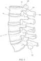
- FIG. 1is a lateral elevational view of a portion of the vertebral column.
- FIG. 2 Ais a schematic superior view of an isolated thoracic vertebra.
- FIG. 2 Bare schematic side view of an isolated thoracic vertebra.
- FIG. 3 Ais a schematic posterior elevational view of a portion of the vertebral column.
- FIG. 3 Bis a posterior-oblique elevational view of a portion of the vertebral column.
- FIG. 4 Ais a schematic side view of a facet joint in the cervical vertebrae.
- FIG. 4 Bis a schematic superior view of a facet joint in the cervical vertebrae.
- FIG. 5 Ais a schematic side view of a facet joint in the thoracic vertebrae.
- FIG. 5 Bis a schematic superior view of a facet joint in the thoracic vertebrae.
- FIG. 6 Ais a schematic side view of a facet joint in the lumbar vertebrae.
- FIG. 6 Bis a schematic superior view of a facet joint in the lumbar vertebrae.
- FIG. 7is a block diagram of an implant according to an embodiment.
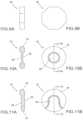
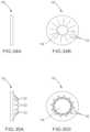
- FIGS. 8 A and 8 Bare schematic views of one embodiment of a facet joint implant comprising a circular disc.
- FIG. 8 Cis a schematic view of the implant from FIG. 7 A implanted in a facet joint.
- FIGS. 9 A and 9 Bare schematic views of one embodiment of a facet joint implant comprising an octagonal disc.
- FIGS. 10 A and 10 Bare schematic views of one embodiment of a facet joint implant comprising a biconcave disc.
- FIGS. 11 A and 11 Bare schematic views of one embodiment of a facet joint implant comprising a single-face variable thickness disc.
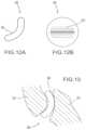
- FIGS. 12 A and 12 Bare schematic views of one embodiment of a facet joint implant comprising a curved disc.
- FIG. 13is a schematic view of the implant from FIG. 12 A implanted in a facet joint.
- FIGS. 14 A and 14 Bare schematic views of one embodiment of a facet joint implant comprising a disc with a roughened surface on one face.
- FIGS. 15 A and 15 Bare schematic views of one embodiment of a facet joint implant comprising a disc with a porous surface on one face.
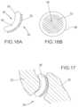
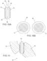
- FIGS. 16 A and 16 Bare schematic views of one embodiment of a facet joint implant comprising a bent disc with a roughened surface on the greater face.
- FIG. 17is a schematic view of the implant from FIG. 16 A implanted in a facet joint.
- FIGS. 18 A and 18 Bare schematic views of one embodiment of a facet joint implant comprising two discs, each with a roughened surface on one face.
- FIG. 19is a schematic view of the implant from FIG. 18 A implanted in a facet joint.
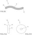
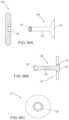
- FIG. 20is a schematic view of a fastener member comprising a braided cable.
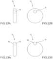
- FIGS. 21 A and 21 Bare schematic views of one embodiment of a facet joint implant with a fastener interface comprising a centrally located hole.
- FIGS. 22 A and 22 Bare schematic views of one embodiment of a facet joint implant with a fastener interface comprising an eccentrically located hole.
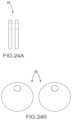
- FIGS. 23 A and 23 Bare schematic views of one embodiment of a facet joint implant with a fastener interface comprising an edge contiguous hole.
- FIGS. 24 A and 24 Bare schematic views of one embodiment of a facet joint implant comprising two discs, each with an eccentrically located hole.
- FIGS. 25 A and 25 Bare schematic views of one embodiment of a facet joint implant comprising a curved disc with a fastener interface.
- FIG. 26depicts one embodiment where the cable is engaged to the articular processes using knots in the cable.
- FIGS. 27 A and 27 Bdepict another embodiment of the fastener member comprising a braided cable with threaded ends adapted to accept threaded nuts.
- FIG. 28depicts one embodiment where a cable is engaged to the articular processes using nuts threaded onto the cable.
- FIG. 29depicts a preferred embodiment comprising a curved implant, cable and two set-screw fastener rings.
- FIGS. 30 A and 30 Bare elevational and cross-sectional views of one embodiment of the set-screw fastener rings, respectively.
- FIGS. 31 through 33are elevational views of various embodiments of the screw in the set-screw fastener rings.
- FIGS. 34 A to 35 Bare one embodiment comprising friction fit fastener rings.
- FIGS. 34 A and 34 Bdepict the fastener rings in their reduced state and
- FIGS. 35 A and 35 Bdepict the fastener rings in their expanded state.
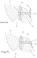
- FIGS. 36 A to 36 Cillustrate embodiments comprising a implant with a close-ended threaded fastener interface and a threaded fastener member.
- FIGS. 36 B and 36 Cdepict a threaded fastener member with a pivotable washer.
- FIG. 37 Ais a cross sectional view of the implant in FIG. 36 A implanted in a facet joint
- FIG. 37 Bis a cross sectional view of the implant in FIG. 36 B implanted in a facet joint.
- FIG. 38is a cross sectional view of a two-part implant comprising flat discs implanted into a facet joint.
- FIG. 39is a cross sectional view of a two-part implant comprising curved discs implanted into a facet joint.
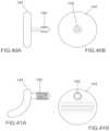
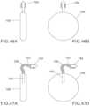
- FIGS. 40 A and 40 Bare schematic views of one embodiment of a facet joint implant with an integral fastener member comprising a centrally located barbed spike.
- FIGS. 41 A and 41 Bare schematic views of one embodiment of a facet joint implant with an integral fastener member comprising an eccentrically located barbed spike.
- FIG. 42depicts the implant of FIG. 41 A implanted into a facet joint.
- FIG. 43illustrates a two-part implant implanted into a facet joint.
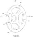
- FIG. 44shows one embodiment comprising a implant with multiple anchoring projections.
- FIG. 45shows the implant of FIG. 44 implanted into a facet joint.
- FIGS. 46 A and 46 Bdepict one embodiment comprising a implant with a rigid soft tissue side anchor.
- FIGS. 47 A and 47 Bdepict one embodiment comprising a implant with an embedded flexible soft tissue side anchor.
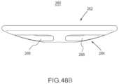
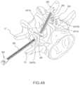
- FIG. 48 Ais a perspective view of an implant according to an embodiment.
- FIG. 48 Bis a side view of the implant of FIG. 48 A .
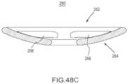
- FIG. 48 Cis a cross-sectional side view of the implant of FIG. 48 A .
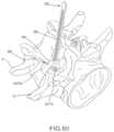
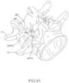
- FIGS. 49 - 51are posterior perspective views of a portion of the vertebral column depicting a method of stabilizing a vertebra using an implant and fastener member according to an embodiment.
- FIG. 52is a flow chart illustrating a method of using the implant and fastener member depicted FIGS. 49 - 51 .
- FIG. 53is a perspective view of a flexible fastening band according to an embodiment.
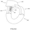
- FIG. 54is a perspective view of a portion of the flexible fastening band depicted in FIG. 53 .
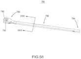
- FIG. 55is a side view of a flexible fastening band according to an embodiment.
- FIG. 56is a top view the flexible fastening band depicted in FIG. 55 .
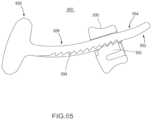
- FIG. 57is a side view of a flexible fastening band according to an embodiment.
- FIG. 58is a perspective view of a flexible fastening band according to an embodiment.
- FIG. 59is a cross-sectional side view of the flexible fastening band depicted in FIG. 58 .
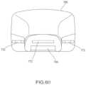
- FIG. 60is a cross-sectional view taken along line XXIII of the flexible fastening band depicted in FIG. 58 .
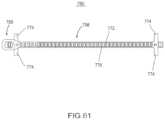
- FIG. 61is a cross-sectional top view of the flexible fastening band depicted in FIG. 58 in a first configuration.
- FIG. 62is a cross-sectional top view of the flexible fastening band depicted in FIG. 58 in a second configuration.
- FIG. 63is an exploded view of a flexible fastening band according to an embodiment.
- FIG. 64is a perspective view of the flexible fastening band depicted in FIG. 63 .
- FIG. 65is a cross-sectional view of the flexible fastening band depicted in FIG. 64 .
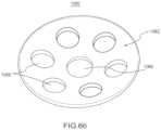
- FIG. 66is a front perspective view of implant according to an embodiment.
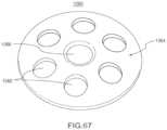
- FIG. 67is a rear perspective view of the implant of FIG. 66 .
- FIG. 68is a side view of the implant of FIG. 66 .
- FIG. 69is a cross-sectional side view of the implant of FIG. 66 .
- FIG. 70is a front perspective view of implant according to an embodiment.
- FIG. 71is a rear perspective view of the implant of FIG. 70 .
- FIG. 72is a side view of the implant of FIG. 70 .
- FIG. 73is a cross-sectional side view of the implant of FIG. 70 .
- FIG. 74is a front perspective view of implant according to an embodiment.
- FIG. 75is a rear perspective view of the implant of FIG. 74 .
- FIG. 76is a side view of the implant of FIG. 74 .
- FIG. 77is a cross-sectional side view of the implant of FIG. 74 .
- FIG. 78is a front perspective view of implant according to an embodiment.
- FIG. 79is a rear perspective view of the implant of FIG. 78 .
- FIG. 80is a side view of the implant of FIG. 78 .
- FIG. 81is a cross-sectional side view of the implant of FIG. 78 .
- FIG. 82is a front perspective view of a facet reinforcement device according to an embodiment.
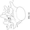
- FIGS. 83 - 84are posterior perspective views of a portion of the vertebral column depicting a method of stabilizing a vertebra using the facet reinforcement device of FIG. 82 and a fastener member according to an embodiment.
- FIG. 85is a front perspective view of a facet reinforcement device according to an embodiment.
- FIGS. 86 - 87are posterior perspective views of a portion of the vertebral column depicting a method of stabilizing a vertebra using the facet reinforcement device of FIG. 85 and a fastener member according to an embodiment.
- FIG. 88is a front perspective view of a facet reinforcement device according to an embodiment.
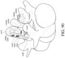
- FIGS. 89 - 91are perspective views of a portion of the vertebral column depicting a method of stabilizing a vertebra using a first facet reinforcement device of FIG. 88 , a second facet reinforcement device, and one or more fastener members according to an embodiment.
- a ratchetis intended to mean a single ratchet or a combination of ratchets.
- a substancecan include any biologic and/or chemical substance, including, but not limited to, medicine, adhesives, etc, and/or a bone graft, including, but not limited to, autograft, allograft, xenograft, alloplastic graft, a synthetic graft, and/or combinations of grafts, medicines, and/or adhesives. While exemplary references are made with respect to vertebra, in some embodiments another bone can be involved. While specific reference may be made to a specific vertebra and/or subset and/or grouping of vertebrae, it is understood that any vertebra and/or subset and/or grouping, or combination of vertebrae can be used.
- the vertebral column 2comprises a series of alternating vertebrae 4 and fibrous discs 6 that provide axial support and movement to the upper portions of the body.
- the vertebral column 2typically comprises thirty-three vertebrae 4 , with seven cervical (C1-C7), twelve thoracic (T1-T12), five lumbar (L1-15), five fused sacral (S1-S5) and four fused coccygeal vertebrae.
- FIGS. 2 A and 2 Bdepict a typical thoracic vertebra.
- Each vertebraincludes an anterior body 8 with a posterior arch 10 .
- the posterior arch 10comprises two pedicles 12 and two laminae 14 that join posteriorly to form a spinous process 16 .
- a transverse 18 , superior 20 and inferior articular process 22Projecting from each side of the posterior arch 10 is a transverse 18 , superior 20 and inferior articular process 22 .
- the facets 24 , 26 of the superior 20 and inferior articular processes 22form facet joints 28 with the articular processes of the adjacent vertebrae (see FIGS. 3 A and 3 B ).
- the facet jointsare true synovial joints with cartilaginous surfaces and a joint capsule.
- the orientation of the facet jointsvary, depending on the level of the vertebral column.
- the facet jointsare parallel to the transverse plane.
- FIGS. 4 A to 6 Bdepict examples of the orientations of the facet joints at different levels of the vertebral column.
- the facetsare oriented at a 45-degree angle to the transverse plane 30 and parallel to the frontal plane 32 , respectively. This orientation allows the facet joints of the cervical vertebrae to flex, extend, lateral flex and rotate.
- FIGS. 5 A and 5 Bdepict examples of the thoracic vertebrae, where the facets are oriented at a 60-degree angle to the transverse plane 30 and a 20-degree angle to the frontal plane 32 , respectively. This orientation is capable of providing lateral flexion and rotation, but only limited flexion and extension.
- FIGS. 6 A and 6 Billustrate examples of the lumbar region, where the facet joints are oriented at 90-degree angles to the transverse plane 30 and a 45-degree angle to the frontal plane 32 , respectively.
- the lumbar vertebraeare capable of flexion, extension and lateral flexion, but little, if any, rotation because of the 90-degree orientation of the facet joints in the transverse plane.
- the actual range of motion along the vertebral columncan vary considerably with each individual vertebra.
- the facet jointsIn addition to guiding movement of the vertebrae, the facet joints also contribute to the load-bearing ability of the vertebral column.
- the facet jointsmay also play a role in resisting shear stresses between the vertebrae. Over time, these forces acting on the facet joints can cause degeneration and arthritis.
- a vertebral facet joint implantcan be used to stabilize, fixate, and/or fuse a first vertebra to a second vertebra to reduce pain, to reduce further degradation of a spine, or of a specific vertebra of a spine, and/or until the first vertebra and the second vertebra have fused.
- the vertebral facet joint implantcan be implanted and deployed to restore the space between facets of a superior articular process of a first vertebra and an inferior articular process of an adjacent vertebra.
- the vertebral facet joint implantcan be implanted and deployed to help stabilize adjacent vertebrae with adhesives, and/or can be implanted and deployed to deliver a medication.
- FIG. 7depicts a block diagram of a vertebral facet joint implant (“implant”) 160 .
- Implant 160includes a first side 162 , a second side 164 , a fastener interface 166 , and a substance interface 168 .
- FIGS. 8 A- 47 Bdepict implants and fasteners according to different embodiments.
- implant 160can be, for example, substantially disc shaped.
- the spacercan be other shapes, e.g., square, elliptical, or any other shape.
- First side 162 and/or second side 164can be, for example, convex, concave, or flat. Said another way, first side 162 can be concave, convex, or flat, and second side 164 can be concave, convex, or flat; for example, first side 162 can be concave and second side 164 can be concave, first side 162 can be concave and second side 164 can be convex, etc.
- the shapecan be determined based on a shape of a bone portion that the first side 162 and/or the second side 164 is configured to contact.
- the first side 162 and/or the second side 164can be shaped to substantially compliment the shape of a bone portion.
- the first side 162 or the second side 164need not exactly match the shape of the corresponding bone portion, but instead can have a concave shape for a bone portion with a generally convex shape where the contact with the implant is to occur or can have a convex shape for a bone portion with a generally concave shape where the contact with the implant is to occur.
- Implant 160can include any biocompatible material, e.g., stainless steel, titanium, PEEK, nylon, etc.
- Implant 160includes fastener interface 166 .
- Fastener interface 166can be configured to retain implant 160 in substantially the same position. Specifically, fastener interface 166 can be configured to accept a fastener member (not shown) to substantially prevent movement of implant 160 .
- Fastener interface 166can include an aperture and/or other opening.
- Fastener interface 166can extend through implant 160 , e.g. can extend from first side 162 and through to second side 164 . In some embodiments, fastener interface 166 can extend through only a portion of implant 160 , e.g. can extend from first side 162 and through less than half of a width (not shown) of implant 160 .
- Fastener interface 166can be disposed on and/or through first side 162 , second side 164 , and/or both first side 162 and second side 164 .
- Fastener interface 166can be disposed through a center (not shown) of implant 160 .
- fastener interface 166can be disposed anywhere on and/or through implant 160 , e.g., offset from center.
- Fastener interface 166can be substantially circular (cylindrical).
- fastener interface 166can be other shapes and/or can be shaped based on a shape of the fastener member, for example, rectangular (cuboid).
- fastener interface 166can be a irregular shape, based at least in part in the location of fastener interface 166 , see, e.g., FIG. 48 , and/or partial shapes, see, e.g., FIG. 23 B .
- Fastener interface 166can include a substantially smooth inner surface (not shown) to allow the fastener member to easily pass through and/or into fastener interface 166 , and/or can include a threaded inner surface to allow the fastener member to thread into fastener interface 166 . While depicted in FIG. 7 as including one fastener interface, implant 160 can include more than one fastener interface 160 .
- Implant 160includes substance interface 168 .
- Substance interfacecan be configured to retain, carry and/or otherwise deliver a substance to aid in fusion, such as, for example, medicines, adhesives, bone graft, and/or combinations of substances.
- Substance interface 168can include an aperture and/or other opening.
- Substance interface 168can extend through implant 160 , e.g. can extend from first side 162 and through to second side 164 .
- fastener interfacecan extend through only a portion of implant 160 , e.g. can extend from first side 162 and through less than half of a width (not shown) of implant 160 .
- Substance interface 168can be disposed on and/or through first side 162 , second side 164 , and/or both first side 162 and second side 164 .
- Substance interface 168can be disposed through a center (not shown) of implant 160 .
- substance interface 168can be disposed anywhere on and/or through implant 160 , e.g., offset from center.
- Substance interface 168can be substantially circular (cylindrical).
- substance interface 168can be other shapes and/or can be shaped based on a shape of the fastener member, for example, rectangular (cuboid).
- substance interface 168can be an irregular shape, based at least in part in the location of substance interface 168 .
- implant 160can include more than one substance interface 160 .
- the location, size, shape, and/or number of substance interface(s) 168can be determined based on the location, size, shape, and/or number of fastener interface(s) 166 .
- a device for restoring the spacing between two facets of a facet jointcomprises a implant 34 with a least two faces, a first face 36 adapted to contact the articular surface of one facet of the facet joint and a second face 38 adapted to contact the articular surface of the other facet.
- the implant 34has a generally circular profile and is sized to fit generally within the joint capsule of the facet joint 28 .
- FIG. 8 Cillustrates the implant 34 of FIGS. 8 A and 8 B positioned in a facet joint.
- the implantcan have any of a variety of profiles, including but not limited to square, rectangle, oval, star, polygon or combination thereof.
- a implant having the desired shapeis selected from an array of prostheses after radiographic visualization of the articular processes and/or by radio-contrast injection into the facet joint to visualize the joint capsule.
- the implanthas a diameter of about 4 mm to about 30 mm. In another embodiment, the implant has a diameter of about 5 mm to about 25 mm. In still another embodiment, the implant has a diameter of about 10 mm to about 20 mm. In one embodiment, the implant has a cross-sectional area of about 10 mm 2 to about 700 mm 2 . In another embodiment, the implant has a cross-sectional area of about 25 mm 2 to about 500 mm 2 . In still another embodiment, the implant has a cross-sectional area of about 20 mm 2 to about 400 mm 2 , or about 25 mm 2 to about 100 mm 2 .
- the implanthas a thickness generally equal to about the anatomic spacing between two facets of a facet joint.
- the implantgenerally has a thickness within the range of about 0.5 mm to about 3.0 mm. In certain embodiments, the implant has a thickness of about 1 mm to about 2 mm. In one preferred embodiment, the implant has a thickness of about 0.5 mm to about 1.5 mm. In one embodiment, the thickness of the implant is nonuniform within the same implant. For example, in FIGS. 10 A and 10 B , the thickness of the implant 42 is increased around the entire outer edge 44 , along at least one and, as illustrated, both faces 46 , 48 . In FIGS.
- edge 44 on one face 46 of the implant 42has a thickness that is greater than the thickness of a central region, and, optionally, also thicker than the typical anatomic spacing between two facets of a facet joint.
- An increased edge thicknessmay resist lateral displacement of the implant out of the facet joint.
- the implantis configured to provide an improved fit with the articular process and/or joint capsule.
- the implant 49has a bend, angle or curve 50 to generally match the natural shape of an articular facet.
- FIG. 13depicts the implant of FIGS. 12 A and 12 B positioned in a facet joint.
- the implantmay be rigid with a preformed bend.
- the implantmay be sufficiently malleable that it will conform post implantation to the unique configuration of the adjacent facet face. Certain embodiments, such as those depicted in FIG. 8 C and FIG.
- the implantis configured to be implanted between the articular processes and/or within the joint capsule of the facet joint, without securing of the implant to any bony structures.
- Such embodimentscan thus be used without invasion or disruption of the vertebral bone and/or structure, thereby maintaining the integrity of the vertebral bone and/or structure.
- At least a portion of one surface of the implantis highly polished.
- a highly polished portion of the implantmay reduce the surface friction and/or wear in that portion of the implant as it contacts bone, cartilage or another surface of the implant.
- a highly polished surface on the implantmay also decrease the risk of the implant wedging between the articular surfaces of the facet joint, which can cause pain and locking of the facet joint.
- At least a portion of one surface of the implant 50has a roughened surface 52 .
- a roughened surfacemay be advantageous when in contact with a bone or tissue surface because it may prevent slippage of the implant 50 against the bone and aid in maintaining the implant 50 in the joint.
- at least a portion of one surface of the implant 50has a porous surface 54 .
- a porous surface 54can be created in any a variety of ways known in the art, such as by applying sintered beads or spraying plasma onto the implant surface.
- a porous surface 54can allow bone to grow into or attach to the surface of the implant 50 , thus securing the implant 50 to the bone.
- an adhesive or sealantsuch as a cyanoacrylate, polymethylmethacrylate, or other adhesive known in the art, is used to bond one face of the implant to an articular surface.
- one surface of the implantis roughened or porous and a second surface that is highly polished.
- the first surfacecontacts or engages one facet of the facet joint and aids in maintaining the implant between the articular surfaces.
- the second surface of the implantis highly polished and contacts the other facet of the facet joint to provide movement at that facet joint.
- FIGS. 16 A and 16 Brepresent one embodiment of the implant comprising a curved or bent disc 56 with a roughened surface 52 on the greater face 58 of the disc and a highly polished surface 60 on the lesser face 62 .
- FIG. 17depicts the implant of FIGS. 16 A and 16 B positioned in a facet joint. The implant generally maintains a fixed position relative to the facet contacting the roughened surface while the movement of the facet joint is preserved between the other facet and the highly polished lesser face of the implant.
- FIGS. 18 A and 18 Bshow one embodiment, where the implant 64 comprises two separate discs 66 , each disc comprising a first face 68 that articulates with the complementary first face 68 of the other disc, and a second face 70 adapted to secure the disc to the adjacent bone or cartilage of one facet of the facet joint 28 .
- the thickness of one discwill generally be about half of the anatomic spacing between two facets of the facet joint.
- the implantcomprises three or more discs.
- the total thickness of all the discsis generally about 25% to about 300% of the anatomic spacing between the two facets.
- the total thickness of the discsis generally about 50% to about 150% of the anatomic spacing.
- the total thickness of the discsis about 75% to about 125% of the anatomic spacing.
- Each disc of the two-part implantcan otherwise also have features similar to those of a single-disc implant, including but not limited to curved or bent configurations, highly polished or roughened surfaces, and other feature mentioned below.
- the two discsneed not have the same size, thickness, configuration or features.
- FIG. 19depicts one embodiment of a two-part implant 64 positioned within a facet joint 28 .
- the implantcan be manufactured from any of a variety of materials known in the art, including but not limited to a polymer such as polyetheretherketone (PEEK), polyetherketoneketone (PEKK), polyethylene, fluoropolymer, hydrogel, or elastomer; a ceramic such as zirconia, alumina, or silicon nitride; a metal such as titanium, titanium alloy, cobalt chromium or stainless steel; or any combination of the above materials.
- a polymersuch as polyetheretherketone (PEEK), polyetherketoneketone (PEKK), polyethylene, fluoropolymer, hydrogel, or elastomer
- a ceramicsuch as zirconia, alumina, or silicon nitride
- a metalsuch as titanium, titanium alloy, cobalt chromium or stainless steel; or any combination of the above materials.
- the implantis maintained between the two facets of the facet joint by taking advantage of the joint capsule and/or other body tissue surrounding the facet joint to limit the migration of the implant out of the facet joint.
- the shape of the implant itselfis capable of resisting displacement of the implant from its position generally between the facet joint surfaces.
- a concave or biconcave configurationresists displacement of the implant by providing an increased thickness at the periphery of the implant that requires a larger force and/or greater distraction of facet joint surfaces in order to cause displacement.
- surface treatments or texturingare used to maintain the implant against a facet of the facet joint, as described previously.
- a combination of disc configuration, surface texturing and existing body tissue or structuresare used to maintain the position of the implant.
- Bone growth facilitatorsmay be used to accelerate osteoincorporation of textured or microporous anchoring surfaces.
- the implantmay be configured with a fastener interface to engage (“secure”) a fastener member that facilitates retention of the implant within the joint capsule of the facet joint.
- a fastener membermay be advantageous for preventing migration of the implant over time use or with the extreme ranges of vertebral movement that may distract the articular surfaces sufficiently to allow the implant to slip out.
- the fastener membercomprises a wire or cable 72 with a portion 74 that engages the implant 76 at a fastener interface 78 , and at least one other portion 80 that engages or anchors to the bone or soft tissue surrounding the facet joint.
- the wire or cablemay be solid, braided or multi-filamented.
- the fastener member in this embodimentwill be described primarily as a cable or wire, but it is to be understood that any of a variety of elongate structures capable of extending through a central aperture will also work, including pins, screws, and single strand or multistrand polymeric strings or weaves, polymeric meshes and fabric and other structures that will be apparent to those of skill in the art in view of the disclosure herein.
- the cross-sectional shape of the fastener membercan be any of a variety of shapes, including but not limited to circles, ovals, squares, rectangles, other polygons or any other shape.
- the wire or cablegenerally has a diameter of about 0.5 mm to about 2 mm and a length of about 5 mm to about 60 mm. In other embodiments, wire or cable has a diameter of about 0.25 mm to about 1 mm, or about 0.75 mm to about 1.25 mm. The diameter of the wire or cable may vary along the length of the wire or cable. In one embodiment, the wire or cable has a length of about 10 mm to about 40 mm. In another embodiment, the wire or cable has a length of about 20 mm to about 30 mm.
- the fastener interface 78 of the implant 76is a conduit between the two faces 82 , 84 of the implant 76 , forming an aperture 78 .
- the aperture 78has a diameter larger than the diameter of the wire or cable 72 , to provide the implant 76 with a range of motion as the facet joint moves.
- the aperture 78 inside diametermay be at least about 110%, often at least about 150% and in certain embodiments at least about 200% or 300% or greater of the outside diameter or corresponding dimension of the fastener member in the vicinity of the engagement portion 78 .
- the cross-sectional shape of the aperture 78can match or not match the cross sectional shape of the wire or cable used.
- the fastener interface 78extends only partially through the implant 72 .
- the fastener interface 78may be located generally in the center of the implant, or it may be located eccentrically, as depicted in FIGS. 22 A and 22 B .
- the fastener interface 78is located at the edge 86 of the implant 76 such that the interior surface of the hole 78 is contiguous with the outer edge of the implant. This configuration of the fastener interface 78 does not require the cable 72 to be threaded through the fastener interface 78 and may facilitate engagement of the fastener member with the implant.
- FIGS. 24 A and 24 Bdepict an embodiment comprising a two-part implant 88 . Either a single cable or two separate cables may be used retain both discs within the facet joint.
- FIGS. 25 A and 25 Bdepict another embodiment comprising a curved implant 90 with a fastener interface 78 adapted to accept a cable.
- the wire or cable 72is secured to the articular processes 20 , 22 by tying one or more knots 92 in the cable 72 that can resist pulling of the wire or cable through the articular process.
- one or both ends of the wire or cableare provided with an anchor to resist migration of the implants.
- one or both ends of the wire or cable 72may be threaded such that a nut 94 can be tightened on the wire or cable 72 to secure the wire or cable to the articular processes 20 , 22 .
- FIG. 28depicts the attachment of a nut onto a threaded end of a cable.
- the threaded portion 96 of the wire or cablecan be secured to the cable by pressing, crimping or twisting the threaded 96 portion onto the cable 72 .
- the threaded portion 96is made from titanium, titanium alloy, cobalt chromium, stainless steel, or any combination thereof.
- the wire or cablehas two threaded ends 96 for engaging the bony or cartilaginous tissue, one portion for each facet of the facet joint.
- the wire or cableis secured to the articular process with fastener rings 98 .
- the fastener rings 98comprise a ring 100 with a central lumen 102 and a locking element to facilitate locking the ring 100 to a fastener member.
- the central lumen 102is adapted to accept insertion of a wire or cable through it.
- the illustrated locking elementis in the form of a side lumen 104 which is threaded and configured to accept a rotatable screw 106 with a proximal end 108 , a threaded body 110 and a distal end 112 .
- the threaded body 110is complementary to the threads of the side lumen 104 so that when the screw 106 is rotated at its distal end 112 , the proximal end 108 of the screw 106 moves further into the central lumen 102 and is capable of applying increasing force to a wire or cable inserted through the central lumen 102 .
- the force on the wire or cableis capable of creating a friction fit or a mechanical interfit to resist movement between the wire or cable and the fastener ring 98 , thereby securing the wire or cable to the articular process 20 or 22 .
- the distal end 112 of the screw 106can be configured to engage the wire or cable in any of a variety designs, including but no limited to a blunt tip 114 , curved tip 116 and piercing tip 118 .
- the wire or cableis securable to the articular process with a fastener ring 120 have radially inward biased projections 122 defining a central lumen 124 .
- the central lumenhas a cross-sectional shape smaller than that of the wire or cable but is capable of enlargement when the inward projections 122 are bent away, as shown in FIGS. 35 A and 35 B .
- the inward projections 122apply increasing force to the wire or cable within the central lumen 124 as the projections 122 are bent, thereby creating a friction fit.
- one end of the wire or cable fastener memberis preformed with a retainer for engaging the articular process.
- the retainermay be a preformed ring, bulb, flared end, T-bar end, or any of a variety of shapes having a greater cross sectional area than the other portions of the wire or cable fastener member.
- This configuration of the wire or cable fastener memberis adapted to engage an articular process by passing the free end of a wire or cable fastener member through an articular process such that the end with the preformed retainer can engage the articular process.
- the wire or cable fastener memberis secured to the articular processes with sufficient laxity or length between the secured ends or between the implant and one secured end so that the two articular processes are not fixed in position relative to each other and remain capable of performing movements such as flexion, extension, lateral flexion and/or rotation.
- the fastener membercomprises a cable of braided polymer, including but not limited to a braided polymer such as PEEK or PEKK, or a braided metal, such as braided cobalt chromium or titanium.
- the cablecan be selected with different degrees of flexibility to provide different degrees of movement at that facet joint.
- the cablehas a first segment capable of engaging the implant at its fastener interface to limit the movement.
- the fastener membercomprises a screw or bolt 126 with a proximal end 128 , body 130 and distal end 132 .
- the distal end 132 of the screw or boltis capable of forming a mechanical interfit with a complementary fastener interface 134 on the implant or spacer 136 .
- the distal end 132typically comprises threads, but other configurations may be used to form a mechanical interfit.
- the complementary fastener interface 134 on the implant 136could be a threaded through hole or, a close-ended hole.
- the proximal end 128 of the screw or bolt 126has a hex or other type of interface known in the art, capable of engaging a rotating tool to manipulate the screw or bolt 126 .
- the body of the screw or bolt 126has a length sufficient to at least span the length of the hole or conduit created through the articular process for securing the implant.
- the fastener memberfurther comprises a pivotable washer 127 with a pivot surface 129 that articulates with the proximal end 128 of the screw 126 .
- the pivotable washer 127is capable of a range of positions relative to the screw 126 and provides the screw 126 with a better surface area contact with the bone.
- FIG. 37is a cross-sectional view of a facet joint 28 with a spacer 136 bolted to one articular process 20 of a facet joint 28 .
- the spacer 136 positionis fixed relative to one facet 24 of the joint 28 , but provides for spacing and movement of the other facet 26 with respect to the spacer 136 .
- each discmay have its own screw or bolt fastener member.
- FIG. 38depicts a flat two-part implant 138 and
- FIG. 39depicts a curved two-part implant 140 .
- the fastener memberis integral with or attached to the implant and comprises a projection 142 from the implant 144 that is adapted to engage the adjacent articular process or surrounding tissue.
- the projectioncomprises at least one spike 142 or hook projecting from one face of the implant 144 .
- the spike 142 or hookcan be ribbed, barbed or threaded to resist separation after insertion into bone or tissue.
- FIG. 42depicts the implant 144 of FIG. 40 A engaged to a facet 24 of the facet joint 28 .
- each disc 148may have its own projection-fastener member 142 .
- FIG. 44more than one projection 150 is provided on the implant 152 .
- FIG. 45illustrates the implant of FIG. 44 placed in a facet joint 28 .
- the projections 150may be angled with respect to the implant 152 to resist dislodgement by the movement at the joint.
- FIGS. 46 A to 47 Billustrate embodiments where the fastener member comprises a projection 154 extending laterally such as from the side of the implant 156 , and adapted to engage the soft tissue surrounding the facet joint, rather than a bony or cartilaginous articular process.
- the implant of FIG. 46could be inserted into a facet joint through an incision made in the joint capsule, but the integrity of the joint capsule opposite the incision site is maintained and used as an anchoring site for the implant.
- the orientation of the projectioncan be fixed as in FIG. 44 , or flexible.
- a flexible tethersuch as a wire 158 with its proximal end 160 embedded in or otherwise attached to the implant and one or more barbs which may be attached to its distal end 162 .
- a flexible projectionmay provide greater selection of soft tissue anchoring sites for the implant.
- the joint capsuleis closed after placement of the implant. Closure may be performed using adhesives, suturing, stapling or any of a variety of closure mechanisms known in the art.
- FIGS. 48 A- 48 Cdepict an implant 260 according to an embodiment.
- FIG. 48 Ais a front perspective view of implant 260
- FIG. 48 Bis a side view of implant 260
- FIG. 48 Cis a cross-sectional side view of implant 260 .
- Implant 260can be similar to, and have similar elements and uses as implant 160 described above.
- a fastener interface 266 of implant 260can be similar to fastener interface 166 of implant 160 .
- Implant 260includes a concave first face 262 , a convex second face 264 , a centrally disposed circular fastener interface 266 , and four irregular shaped substance interfaces 268 .
- FIGS. 49 - 51show posterior perspective views of a portion of the vertebral column during a method for fusing adjacent vertebrae using an implant 260 according to an embodiment.
- implant 260 and a fastener member 280can be used to fuse a vertebra V1 and vertebra V2 via the inferior articular process IAP1A of vertebra V1 and the superior articular process SAP2A of vertebra V2.
- Any fastener membercan include any biocompatible material, e.g., stainless steel, titanium, PEEK, nylon, etc. Also as shown in FIG.
- an implant 360 and a fastener member 380are used to fuse a vertebra V1 and vertebra V2 via the inferior articular process IAP1B of vertebra V1 and the superior articular process SAP2B of vertebra V2.
- vertebra V1 and/or vertebra V2are fused using only one of implant 260 or implant 360 .
- one of implant 260 and fastener member 280 or implant 360 and fastener member 380can be used to stabilize vertebra V1 and/or vertebra V2 via one of via the inferior articular process IAP1A of vertebra V1 and the superior articular process SAP2A of vertebra V2, or, via the inferior articular process IAP1B of vertebra V1 and the superior articular process SAP2B of vertebra V2.
- one of fastener member 280 or fastener member 380can be used to stabilize vertebra V1 and/or vertebra V2 via both of the inferior articular process IAP1A of vertebra V1 and the superior articular process SAP2A of vertebra V2 (for example, in combination with implant 260 ), and, the inferior articular process IAP1B of vertebra V1 and the superior articular process SAP2B of vertebra V2 (for example, in combination with implant 360 ).
- FIG. 52depicts a flow chart illustrating a method 6000 of using implant 260 with fastener member 280 and/or implant 360 with fastener member 380 .
- a patientPrior to use of implant 260 and/or implant 360 , a patient can be prepared for surgery, at 6002 .
- Some examples of preparations for surgeryare described in U.S. patent application Ser. No. 12/859,009; filed Aug. 18, 2010, and titled “Vertebral Facet Joint Drill and Method of Use” (referred to as “the '009 application”), and is incorporated herein by reference in its entirety.
- the surgical procedurecan include direct visualization of the vertebra(e) to be stabilized.
- the medical practitionercan perform the operation without the use of fluoroscopy.
- This direct visualizationcan be possible due to the small incision necessary for implantation of the implant, for example, less than about 25 mm, and due to the ease of implanting and deploying the implant.
- the surgical procedure usedcan include forming an opening in body tissue substantially equidistant between a first articular process of the first vertebra and a second articular process of the first vertebra.
- a cannula(not shown) can be inserted through the opening and a proximal end of the cannula can be positioned near the superior articular process SAP2A of vertebra V2.
- the surgical procedurecan include preparing the area near and/or around the vertebra V2 by, for example, removing all or a portion of ligaments, cartilage, and/or other tissue.
- the area near and/or around a facet jointcan be prepared by removing all or a portion of the facet joint capsule.
- a drill or other devicecan be used to form a lumen in superior articular process SAP2A of vertebra V2 and inferior articular process IAP1A of vertebra V1, at 6004 .
- the drillcan be used to form the lumen in a facet of superior articular process SAP2A of vertebra V2 and to form the lumen in a facet of inferior articular process IAP1A of vertebra V1.
- Methods and devices for forming lumens in vertebraare described in the '009 application.
- a portion of the surface of the facet of SAP2A and IAP1Acan be prepared for fusion, at 6006 .
- a portion of the surface of the facetcan be ground, scored, roughened, sanded, etc, such that the surface of the facet can better adhere to any substances to aid in fusion and/or otherwise fuse more readily to the implant.
- the fastener member 280can be positioned within the cannula and can be advanced through the cannula until a proximal end portion 282 of fastener member 280 is positioned near the lumen of superior articular process SAP2A of vertebra V2.
- the proximal end of the cannulacan have a bend to direct the proximal end portion 282 of fastener member 280 into the lumen of superior articular process SAP2A of vertebra V2.
- the proximal end portion 282 of fastener member 280is inserted into the lumen of superior articular process SAP2A of vertebra V2, at 6008 .
- a substancecan be disposed in a substance interface 268 of implant 260 , at 6010 .
- implant 260can have a substance disposed in substance interface 268 prior to a surgical procedure, for example, during manufacturing of implant 260 , post-manufacturing, and/or as part of a kit.
- Implant 260is inserted between the superior articular process SAP2A of vertebra V2 and inferior articular process IAP1A of vertebra V1, at 6012 .
- the proximal end portion 282 of fastener member 280is inserted into the lumen of inferior articular process IAP1A of vertebra V1, at 6014 .
- the fastener membercan be secured, at 6016 .
- Securing the fastener member 280can be based on the type of fastener member used.
- securing a fastener member similar to a flexible fastener band as depicted in FIGS. 49 - 51can include inserting the proximal end portion 282 into a fastening mechanism of a distal end portion 284 of the fastener member 280 , and advancing the proximal end portion 282 through the fastening mechanism to secure the fastening mechanism.
- fastener membercan be secured by tying a first portion the fastener member to a second portion of the fastener member, by screwing the fastener member into a threaded fastener interface, threading a fastener onto a threaded end of a fastener member disposed through a fastener interface, combinations of above, etc.
- implant 260can be disposed prior to inserting the proximal end portion of the fastener member 280 into the lumen of superior articular process SAP2A of vertebra V2.
- the cannulacan be removed and/or reinserted at various points during the method 6000 , including, for example, after the proximal end portion 282 of fastener member 280 is inserted into the lumen formed within the superior articular process SAP2A of vertebra V2, after vertebra V1 and/or Vertebra V2 has been stabilized, or at other points during method 6000 .
- superior articular process SAP2A of vertebra V2can fuse to inferior articular process IAP1A of vertebra V1.
- Fusingcan include one or more of bone material from superior articular process SAP2A of vertebra V2, bone material from inferior articular process IAP1A of vertebra V1, and the substance that fuses articular process SAP2A of vertebra V2 to inferior articular process IAP1A of vertebra V1 through substance interface 268 .
- the fastener member 280is not removed.
- fastener member 280can be removed after fusion of superior articular process SAP2A of vertebra V2 to inferior articular process IAP1A of vertebra V1 has started, but has not finished.
- FIGS. 53 - 65show fastener members according to other embodiments.
- FIG. 53depicts views of a fastener member 480 .
- Fastener member 480can be a flexible fastening band (“band”) 480
- FIG. 54depicts a view of a portion of band 480 can be similar to band 280 described above and can include similar components.
- band 480includes a proximal end portion 482 , a first portion 484 , a second portion 486 , and a distal end portion 488 including a fastening mechanism 490 .
- band 480includes a cylindrical second portion 486 and each includes a third portion 489 . As depicted in FIGS. 53 - 54 , third portion 489 is substantially the same shape as first portion 482 .
- band 480includes a gear rack 487 and gears 494 .
- gears 494can be wedge shaped to allow each of gears 494 to displace the ratchet of fastening mechanism 490 in only one direction.
- gears 494can be other shapes, such as blocks, etc.
- FIG. 55is a side view and FIG. 56 is a top view of a fastener member 840 .
- Fastener member 840can be a flexible fastening band (“band”) 580 according to another embodiment.
- Band 840can be similar to band 280 and band 480 described above and can include similar components.
- band 840includes a proximal end portion 842 , a first portion 844 including a gear rack 847 , a second portion 846 , and a distal end portion 848 including a fastening mechanism 850 and a ratchet 862 .
- gear rack 487a cross sectional area of each gear 864 of gear rack 847 is rectangular in shape instead of wedge shaped.
- first portion 844is cylindrical in shape instead of cuboidal in shape.
- the lumen 866 of the fastening mechanism 850is cylindrical in shape.
- a band according to this embodimentmay be particularly useful in deployments where a single band in used to stabilize adjacent vertebrae.
- the second portioncan be disposed within the lumen of the first articular process of the first vertebra and a portion of the first portion can be disposed within the lumen of the second articular process of the first vertebra.
- the portion of the band within the first articular process of the first vertebra and the portion of the band within in the second articular process of the first vertebracan both have substantially the same shape as the lumen in the first articular process of the first vertebra and the lumen in the second articular process of the first vertebra.
- band 480the amount of open space within the lumens can be minimized, the amount of surface area of the first portion and/or second portion of the band in contact with the lumens can increase, and subsequently the movement of the first vertebra and/or the second vertebra can be reduced or minimized.
- forces acting against the bandcan be more equally distributed throughout the first portion and/or the second portion, due at least to the increased surface area of the band in contact with the lumens.
- FIG. 57is a side view a fastener member 940 .
- Fastener member 940can be a flexible fastening band (“band”) 940 according to an embodiment.
- Band 940can be similar to band 280 , band 480 , and band 840 described above and can include similar components.
- band 840includes a proximal end portion 942 , a first portion 944 including a gear rack 947 , a second portion 946 , and a distal end portion 948 including a fastening mechanism 950 .
- gear rack 847Similar to gear rack 847 , a cross sectional area of each gear 964 of gear rack 947 is rectangular in shape.
- each of gears 964extend the entire circumference of first portion 944 instead of only a portion of the circumference of first portion 944 .
- first portion 944is cylindrical in shape instead of cuboidal in shape.
- the lumen 966 of the fastening mechanism 950is cylindrical in shape.
- a band according to this embodimentmay be particularly useful in deployments where the movement and repositioning of the band after implantation may be difficult. In this manner, because each of the gears can be the entire circumference of the first portion and/or the second portion, the first portion and/or the second portion can enter the fastening mechanism in any radial orientation and still engage the ratchet.
- FIGS. 58 - 62are views of a fastener member 780 .
- Fastener member 780can be a flexible fastening band (“band”) 780 according to another embodiment.
- FIG. 58is a perspective view and FIG. 59 is a cross-sectional side view of band 780 .
- FIG. 60is a cross-sectional view of band 780 taken along line XXIII.
- FIG. 61is a cross-sectional top view of band 780 in a first configuration and FIG. 62 is a cross-sectional top view of band 780 in a second configuration.
- Band 780can be similar to band 280 and band 480 described above and can include similar components.
- band 780includes a proximal end portion (not shown), a first portion 784 including a gear rack 787 (see FIG. 59 ), a second portion 786 , and a distal end portion 788 including a fastening mechanism 790 and a ratchet 792 .
- band 780includes a reinforcement piece 772 .
- Reinforcement piece 772can include any of the materials described above for a fastener member.
- reinforcement piece 772can include a material stronger than second portion 786 and/or first portion 784 , for example, first portion 784 and second portion 786 can include PEEK and reinforcement piece 772 can include titanium.
- reinforcement piece 772can be disposed within band 780 approximately along the entire length of second portion 786 , and a portion of reinforcement piece 772 can be disposed within the distal end portion 788 .
- reinforcement piececan include a length along at least a portion of the length of second portion 786 and/or first portion 784 but not the distal end portion.
- reinforcement piece 772can be disposed only within second portion 786 .
- Reinforcement piece 772can have a length in first dimension (length), a length in a second dimension (width), and a length in a third dimension (height).
- a reinforcement piecebe different shapes that can include more or fewer dimensions.
- the reinforcement piececan be molded within the band. Said another way, in embodiments where the first portion, the second portion, and or the distal end portion are moldable materials, the reinforcement piece can be placed in the mold and the moldable materials can be injected or otherwise put in the mold around the reinforcement piece.
- each portion of the band (for example, the proximal end portion, the first portion, the second portion, the third portion, and/or the distal end portion) around the reinforcement piececan have a top half and a bottom half, and each of the top half and the bottom half can be placed around the reinforcement piece, and sealed.
- reinforcement piece 772includes support members 774 . While FIG.
- reinforcement piece 772including four support members 774 , in some embodiments, more or fewer support members 774 can be used. Support members 774 can maintain the position of reinforcement piece 772 during the molding and/or assembly process of band 780 . As shown in FIG. 62 , support members 774 are removed before band 780 is used.
- reinforcement piece 772can has a substantially uniform cuboidal shape.
- reinforcement piece 772can have other shapes.
- the shape of the reinforcement piececan be selected depending on the desired bending and/or torsion characteristics of the material chosen.
- a substantially planar cuboidal shapecan provide a greater increase in bending strength while providing a lesser increase in torsion strength
- a cylindrical shapecan provide an increase in bending strength while providing very little increase in torsion strength
- a substantially square and/or tubular cuboidal shapecan provide similar bending and torsion increases. Any shape can be selected to achieve the desired bending and torsion strength. Combinations of materials and shapes can also be considered.
- reinforcement piece 772includes holes 776 distributed along the length of the first dimension. While FIGS. 61 and 62 shows band 780 including many holes 776 , in some embodiments, more or fewer holes 776 can be used. FIGS. 61 and 62 depict holes 776 distributed substantially equally along the length of the first dimension, in some embodiments, the holes can be distributed differently or along different dimensions depending on the shape and/or material chosen, and/or whether the reinforcement piece is solid or hollow. Holes 776 can be configured to reduce the weight of reinforcement piece 772 while still provided band 780 additional strength. Holes 776 can be round, oval, square, or any other shape.
- FIG. 63is an exploded view
- FIG. 64is a perspective view
- FIG. 65is a cross-sectional view of a fastener member 880 .
- Fastener member 880can be a flexible fastening band (“band”) 880 according to another embodiment.
- Band 880can be similar to band 280 and band 480 described above and can include similar components.
- band 880includes a proximal end portion 882 , a first portion 884 , a second portion 886 including a gear rack 887 , a distal end portion 888 , a fastening mechanism 890 and a ratchet 892 .
- band 880In contrast to band 280 and band 480 , the fastening mechanism 890 of band 880 is separately formed from distal portion 888 of band 880 . While second portion 886 of band 880 is shown in FIGS. 63 - 65 as having a substantially cuboidal shape, in some embodiments, second portion 886 can be substantially cylindrical in shape or any other appropriate shape discussed herein. As shown in FIGS. 64 and 65 , band 880 includes a gear rack 887 and gears 894 . Each of gears 894 can be wedge shaped to allow each of gears 894 to displace a ratchet 892 of fastening mechanism 890 in only one direction. In some embodiments, gears 894 can be other shapes, such as blocks, or any other appropriate shape discussed herein.
- distal end portion 888can be substantially circular in shape and can have a diameter greater than a width of second portion 886 .
- distal portion 888can have other shapes, for example, oval, rectangular, square, etc.
- FIGS. 66 - 81show implants according to other embodiments.
- FIGS. 66 - 69depict an implant 1060 according to an embodiment. Specifically, FIG. 66 is a front perspective view of implant 1060 , FIG. 67 is a rear perspective view of implant 1060 , FIG. 68 is a side view of implant 1060 , and FIG. 69 is a cross-sectional side view of implant 1060 . Implant 1060 can be similar to, and have similar elements and uses as implant 160 and implant 260 described above.
- a fastener interface 1066 of implant 1060can be similar to fastener interface 166 of implant 160 , and similar to fastener interface 266 of implant 260
- Implant 1060includes a concave first face 1062 , a convex second face 1064 , a centrally-disposed substantially-circular fastener interface 1066 , and six substantially-circular shaped substance interfaces 1068 .
- FIGS. 70 - 73depict an implant 1160 according to an embodiment.
- FIG. 70is a front perspective view of implant 1160
- FIG. 71is a rear perspective view of implant 1160
- FIG. 72is a side view of implant 1160
- FIG. 73is a cross-sectional side view of implant 1160 .
- Implant 1160can be similar to, and have similar elements and uses as implant 160 and implant 260 described above.
- a fastener interface 1166 of implant 1160can be similar to fastener interface 166 of implant 160 , and similar to fastener interface 266 of implant 260 .
- Implant 1160includes a concave first face 1162 , a convex second face 1164 , a centrally-disposed substantially-circular fastener interface 1166 , and five rounded rectangular shaped substance interfaces 1168 .
- FIGS. 74 - 77depict an implant 1260 according to an embodiment. Specifically, FIG. 74 is a front perspective view of implant 1260 , FIG. 75 is a rear perspective view of implant 1260 , FIG. 76 is a side view of implant 1260 , and FIG. 77 is a cross-sectional side view of implant 1260 .
- Implant 1260can be similar to, and have similar elements and uses as implant 160 and implant 260 described above.
- a fastener interface 1266 of implant 1260can be similar to fastener interface 166 of implant 160 , and similar to fastener interface 266 of implant 260 .
- Implant 1260includes a concave first face 1262 , a convex second face 1264 , a centrally-disposed substantially-circular fastener interface 1266 , and several substantially-circular shaped and variably-sized substance interfaces 1268 .
- FIGS. 78 - 81depict an implant 1360 according to an embodiment. Specifically, FIG. 78 is a front perspective view of implant 1360 , FIG. 79 is a rear perspective view of implant 1360 , FIG. 80 is a side view of implant 1360 , and FIG. 81 is a cross-sectional side view of implant 1360 .
- Implant 1360can be similar to, and have similar elements and uses as implant 160 and implant 260 described above.
- a fastener interface 1366 of implant 1360can be similar to fastener interface 166 of implant 160 , and similar to fastener interface 266 of implant 260 .
- Implant 1360includes a concave first face 1362 , a convex second face 1364 , a centrally-disposed substantially-circular fastener interface 1166 , four irregular shaped substance interfaces 1368 , and four projections 1369 .
- Each of the four projections 1369can engage, or other wise dig, latch, lock, or hook into or onto, a bone portion to prevent or reduce movement of the implant 1360 , such as, for example, rotation of implant 1360 , longitudinal movement of implant 1360 , and/or lateral movement of implant 1360 .
- the projections 1369can secure implant 1360 to a bone portion during a fusion procedure.
- projections 1369can substantially maintain a position of implant 1369 after a fastener member is removed.
- a fastener membercan be used to stabilize and/or fixate an intramedullary (IM) rod or nail.
- IMintramedullary
- the fastener membercan be used at different longitudinal locations along an IM rod or nail, and used to couple adjacent bone portions to the IM rod or nail.
- a given fastener membercan fix a first bone portion, the IM rod or nail, and a second bone portion, all of which are positioned between the distal portion and the proximal portion of the fastener member.
- a fastener membercan be used to stabilize and/or fixate a bone fragment. While various embodiments have been described above with regard to natural bone spaces, (e.g., the space between an inferior articulate process and a superior articulate process), in other embodiments, the bone spacing can be man-made (e.g., sternum split during a heart procedure), and/or due to an injury (e.g., broken bone).
- FIGS. 54 and 56depict band 580 including a single ratchet 592
- FIG. 57depicts band 680 including a single ratchet 692
- any of the fastener memberscan include any number of ratchets.
- any of fastener memberscan include a reinforcement piece and/or a implant.
- an implantmay be shown in use with one embodiment of a fastener member, in other embodiments, implants and fastener member can be used with other implants and fastener members.
- FIG. 28depicts an implant being secured with a threaded wire, in some embodiments, a flexible fastening band can be used.
- the flexible fastening bandmay be used alone or with an embodiment of facet implant as described above, in some applications it may be desirable to reinforce the fixation of the band as it exits the bone of the articular process. This may prevent cut out by relieving pressure on the surface of the articular process and hold in the bone from the fastener band and/or fastening mechanism.
- the facet reinforcementmay also anchor the flexible facet band to the vertebra using a fastener. This may prevent migration of the band and restrict motion at the facet joint to improve fusion.
- FIG. 82depicts one arrangement of facet reinforcement device 1400 .
- the facet reinforcement device 1400 of the illustrated arrangementcan include a proximal surface 1402 , a distal surface 1406 , an abluminal surface 1404 extending from the proximal surface 1402 to the distal surface 1406 .
- the proximal surface 1402 and/or distal surface 1406can be curved and/or malleable to conform to the shape of the facet.
- the facet reinforcement device 1400can include a luminal surface 1410 surrounding a central lumen 1420 .
- the luminal surface 1410can extend from the proximal surface 1402 to the distal surface 1406 .
- the central lumen 1420can be centrally disposed within the device 1400 .
- the luminal surface 1410can include a fastener interface (not illustrated) in certain embodiments.
- the facet reinforcement devices described hereincan be used in combination with the implants depicted in FIGS. 8 A- 81 A and/or other implants described herein.
- the facet reinforcement device 1400can also be used in combination with the fastener members depicted in FIGS. 20 - 65 , and/or other fastener members described herein.
- the fastener member 1480 depicted in FIG. 84can refer to any fastener member described herein; and the fastener member 1580 depicted in FIG. 87 can refer to any fastener member described herein; and the fastener members 1680 , 1680 A depicted in FIG. 89 can refer to any fastener member described herein.
- At least a portion of one surface of the facet reinforcement device 1400can include a roughened surface.
- a roughened surfacemay be advantageous when in contact with a bone or tissue surface because it may prevent slippage or migration of the facet reinforcement device 1400 against the bone.
- a roughened surfacemay aid in maintaining the facet reinforcement device 1400 and the fastener member 1480 (see FIG. 83 ) engaged with tissue or bone.
- the roughened surfacecan include at least one projection 1416 .
- the facet reinforcement device 1400can comprise a plurality of projections 1416 .
- the projections 1416can extend from the distal surface 1406 and can include a sharp edge or tip.
- the projections 1416can also extend between the abluminal surface 1404 and the luminal surface 1410 or in certain embodiments only extend along a portion of said area.
- the projections 1416comprise at least one spike, barb, wedge, or hook projecting from at least a portion of one surface of the facet reinforcement device 1400 .
- the projections 1416can be ribbed, barbed, or threaded to resist separation after insertion into bone or tissue.
- the projections 1416may have different shapes from one another or they may have a uniform shape.
- a portion of the surface of the projections 1416can be porous.
- a porous surfacecan be created in any a variety of ways known in the art, such as by applying sintered beads or spraying plasma onto the surface of the projection 1416 .
- a porous surfacecan allow bone to grow into or attach to the surface of the projection 1416 , thus securing the projection 1416 and the facet reinforcement device 1400 to the bone.
- other surfaces of the facet reinforcement device 1400can be porous.
- an adhesive or sealantsuch as a cyanoacrylate, polymethylmethacrylate, or other adhesive known in the art, is used to bond at least one surface of the facet reinforcement device 1400 to a bone or tissue surface.
- an adhesive or sealantis used to bond the distal surface 1406 of the facet reinforcement device 1400 to the surface of the facet.
- the facet reinforcement device 1400may include one row of projections 1416 or may include multiple rows of projections 1416 .
- the facet reinforcement device 1400may include projections 1416 arranged in a random order or orientation.
- the abluminal surface 1404 of the facet reinforcement device 1400can include a substantially circular cross-section (cylindrical), as shown in FIG. 82 .
- the abluminal surface 1404can have other cross-sectional shapes including, but not limited to, circular (cylindrical), hexagonal, rectangular (cuboid), square, elliptical, and/or have a combination of curved, flat surfaces and/or partial shapes.
- the abluminal surface 1404may conform to the shape of an insertion tool.
- the central lumen 1420 and the luminal surface 1410can be circular (cylindrical).
- the central lumen 1420 and the luminal surface 1410can have other cross-sectional shapes including, but not limited to, hexagonal, rectangular (cuboid), square, elliptical, and/or have a combination of curved, flat surfaces and/or partial shapes.
- the central lumen 1420 and the luminal surface 1410may conform to the shape of an insertion tool.
- the central lumen 1420 and the luminal surface 1410can be shaped based on a shape of the fastener member (not shown) (e.g., the central lumen and luminal surface can have a similar cross-sectional shape as the fastener member extending through the central lumen).
- the central lumen 1420 and the luminal surface 1410can include a substantially smooth inner surface to allow the fastener member 1480 to easily pass through.
- the central lumen 1420 and the luminal surface 1410can include a threaded inner surface to allow the fastener member 1480 to thread into central lumen 1420 .
- the central lumen 1420 and the luminal surface 1410may be configured to match the shape of a lumen formed in the articular process, during a method of use.
- the central lumen 1420 and the luminal surface 1410may be smaller than a lumen formed in the articular process, during a method of use.
- the facet reinforcement device 1400may reduce stress at the outer aspect of the lumen in the bone.
- the central lumen 1420 and the luminal surface 1410may be larger than a lumen formed in the articular process, during a method of use.
- the facet reinforcement device 1400may be in contact with a larger surface area of the facet, thereby distributing the forces of the fastener member.
- the proximal surface 1402may have a feature to mechanically interfit with an insertion tool, including grooves and/or protrusions configured to mate with a corresponding groove and/or protrusion of the insertion tool.
- the proximal surface 1402may have a feature (e.g., a groove or recess) to mechanically interfit with a portion of the fastener member 1480 (shown in FIG. 84 ).
- the feature to mechanically interfit with a portion of the fastener membermay increase stability of the system and resistance to migration of components of the system.
- the diameter of the facet reinforcement device 1400may be in the range of 2 mm-20 mm or in the range of 4 mm-15 mm.
- the diameter of the central lumen 1420may be in the range of 0.5 mm-10 mm or range of 1-7 mm.
- FIGS. 83 - 84show posterior perspective views of a portion of the vertebral column during a method for fusing adjacent vertebrae using the embodiment of the facet reinforcement device 1400 shown in FIG. 82 .
- the methodcan include using an implant deployed to restore the space between facets of a superior articular process of a first vertebra and an inferior articular process of an adjacent vertebra.
- a drill or other devicecan be used to form a lumen in superior articular process SAP2A of vertebra V2 and inferior articular process IAP1A of vertebra V1.
- a portion of the surface of the facet of SAP2A and a portion of the surface of the facet of IAP1Acan be prepared for fusion.
- a portion of the surface of the facetcan be ground, scored, roughened, sanded, etc., such that the surface of the facet can better adhere to any substances to aid in fusion and/or otherwise fuse more readily to an implant positioned within the facet joint.
- FIG. 83illustrates the facet reinforcement device 1400 placed on the outer, posterior facing surface of the left inferior articular process IAP1A of the superior vertebra V1.
- the facet reinforcement devicecan be placed on the surface of the facet of SAP2A.
- a lumenis formed in the articular process.
- the facet reinforcement device 1400can be placed after a lumen is formed in the articular process.
- the facet reinforcement device 1400can be placed prior to forming a lumen in the articular process.
- the facet reinforcement device 1400may serve as a guide for drilling the lumen.
- the facet reinforcement device 1400can be placed after or prior preparation for fusion.
- An insertion toolmay remain on the facet reinforcement device 1400 during the steps of forming the lumen and/or during the step of preparing for fusion.
- a facet reinforcement device 1400 and a fastener member 1480can be used to fuse a vertebra V1 and vertebra V2 via the inferior articular process IAP1A of vertebra V1 and the superior articular process SAP2A of vertebra V2.
- at least one implant(not shown in FIG. 84 ) is used with the fastener member 1480 to fuse a vertebra V1 and vertebra V2.
- FIG. 84depicts fusing the inferior articular process IAP1A of vertebra V1 and the superior articular process SAP2A of vertebra V2.
- the inferior articular process IAP1B of vertebra V1can be fused to the superior articular process SAP2B of vertebra V2.
- the fastener member 1480can be positioned within a cannula and can be advanced through the cannula. The proximal end portion of fastener member 1480 can then be inserted into the central lumen 1420 of the facet reinforcement device 1400 . The proximal end portion of the fastener member 1480 can be adjacent and/or abut the luminal surface 1410 . The proximal end portion of fastener member 1480 can then be inserted into the lumen of inferior articular process IAP1A of vertebra V1.
- the proximal end portion of fastener member 1480can be advanced until a proximal end portion of fastener member is positioned near the lumen of superior articular process SAP2A of vertebra V2.
- the proximal end of the cannulacan have a bend to direct the proximal end portion of fastener member 1480 into the lumen of superior articular process SAP2A of vertebra V2.
- the proximal end portion of fastener member 1480can be inserted into the lumen of superior articular process SAP2A of vertebra V2.
- An implantcan be inserted between the superior articular process SAP2A of vertebra V2 and inferior articular process IAP1A of vertebra V1.
- the implantcan be disposed prior to inserting the proximal end portion of the fastener member 1480 into the lumen of superior articular process SAP2A of vertebra V2.
- the cannulacan be removed and/or reinserted at various points during the method, including, for example, after the proximal end portion of fastener member 1480 is inserted into the lumen formed within the superior articular process SAP2A of vertebra V2, after vertebra V1 and/or vertebra V2 have been stabilized, or at any other point during the method.
- the fastener member 1480can be secured. Securing the fastener member 1480 can be based on the type of fastener member used. By way of example, securing a fastener member 1480 having the characteristics of the fastener member depicted in FIGS.
- 49 - 51can include the following steps: inserting the proximal end portion of the fastener member 1480 into a fastening mechanism 1484 ; the fastener mechanism located at a distal end portion of the fastener member 1480 ; securing an end of the fastener member 1480 to the opposite end of the fastener member 1480 ; securing the proximal end portion of the fastener member 1480 to the distal end portion of the fastener member 1480 ; and/or advancing the proximal end portion of the fastener member 1480 through the fastening mechanism 1484 .
- fastener member 1480can be secured by tying a first portion the fastener member to a second portion of the fastener member, by forming a knot in a first end and second end; by screwing the fastener member into a threaded central lumen, by threading a fastener onto a threaded end of a fastener member disposed through a threaded central lumen, by including enlarged portion at the end of the fastener member, and/or combinations of above.
- the fastener member 1480can be secured in order to retain the facet reinforcement device 1400 .
- the facet reinforcement device 1400is retained within a loop or other defined segment of the fastener member 1480 .
- the reinforcement device 1400can remain freely movable along a portion of the defined segment after the fastener member 1480 is secured. In some embodiments, the reinforcement device 1400 is immobile or otherwise secured along a portion of the defined segment after the fastener member 1480 is secured.
- FIG. 84illustrates the assembled system, including the facet reinforcement device 1400 and the fastener member 1480 .
- the assembled systemis implanted on the left facet joint 1490 between the superior vertebra V1 and the inferior vertebra V2.
- the left facet joint 1490may be compressed by the assembled system, thereby bringing the two facet surfaces in close apposition. This compression is in contrast with the unsecured right facet joint 1492 .
- a second facet reinforcement device 1400 , a second fastener member 1480 with or without a second implantmay be implanted in the right facet joint 1492 , according to the method described above with respect to the left facet joint 1490 .
- the implantation of a second facet reinforcement device 1400 and a second fastenermay improve stabilization.
- a second facet reinforcement device 1400 and a second fastener member 1480 with or without a second implantmay be implanted on other levels of the spine.
- a plurality of reinforcement devices 1400 and a plurality of fastener members 1480 with or without a plurality of implantsmay be implanted on other levels of the spine, and at various locations on the spine.
- the same and/or similar method of fixation, the same fastener members 1480 , the same implants and/or the same facet reinforcement devices 1400may be used at different locations. In other embodiments, a different method of fixation, different fastener members 1480 , different implants and/or different facet reinforcement devices 1400 may be used at different locations.
- FIG. 85shows another embodiment of a facet reinforcement device 1500 .
- the facet reinforcement device 1500has an inferior end 1502 and a superior end 1504 .
- the facet reinforcement device 1500has a first securing portion 1530 toward the inferior end 1502 and a second securing portion 1540 toward the superior end 1504 .
- the first securing portion 1530 and second securing portion 1540can be connected to each other by a central portion 1510 .
- the first securing portion 1530can be configured for placement on an outer facet surface of a facet.
- the first securing portion 1530can include a lumen 1506 surrounded by a luminal surface 1511 .
- the lumen 1506 and the luminal surface 1511can be substantially circular (cylindrical) as shown in the illustrated embodiment.
- the lumen 1506can have other cross-sectional shapes including, but not limited to, circular (cylindrical), hexagonal, rectangular (cuboid), square, elliptical, and/or have a combination of curved, flat surfaces and/or partial shapes.
- the lumen 1506 and the luminal surface 1511can be shaped based on a shape of a fastener member 1580 (e.g., having a shape complimentary or similar to the outer shape of the portion of the fastener member 1580 extending there-through).
- the lumen 1506 and the luminal surface 1511may conform to the shape of an insertion tool.
- the lumen 1506 and the luminal surface 1511can include a substantially smooth inner surface to allow the fastener member 1580 to easily pass through.
- the lumen 1506 and the luminal surface 1511can include a threaded surface to allow the fastener member to thread into the lumen 1506 .
- the first securing portion 1530can include one (as illustrated), two, three or a plurality of lumens 1506 .
- the one or more lumens 1506can have the same shape or different shape.
- the first securing portion 1530may include one row of lumen 1506 , for example, the lumens 1506 can be aligned along an axis. In other arrangements, the first securing portion 1530 may include multiple rows of lumens 1506 .
- the first securing portion 1530may include lumens 1506 arranged in a random order or orientation. As will be described below, the one or more lumens 1506 can be configured to accept one or more fastener members 1580 and/or one or more fasteners 1590 .
- the second securing portion 1540can be configured for placement on a vertebral structure.
- the vertebral structurecan be remote or distanced from the outer facet surface of a facet.
- the second securing portion 1540can be configured for placement on an outer surface or base of the spinous process 1570 ; a translaminar position, and/or for placement on an outer surface of the lamina (e.g., base of spinous process).
- the second securing portion 1540can include a lumen 1508 surrounded by a luminal surface 1521 .
- the lumen 1508 and the luminal surface 1521can be circular (cylindrical).
- the lumen 1508can have other cross-sectional shapes including, but not limited to, hexagonal, rectangular (cuboid), square, elliptical, and/or have a combination of curved, flat surfaces and/or partial shapes.
- the lumen 1508can be shaped based on a shape of the fastener member 1580 and/or the fastener 1590 .
- the lumen 1508 and the luminal surface 1521may be circular, hexagonal, rectangular (cuboid), square, elliptical, and/or have a combination of curved, flat surfaces and/or partial shapes.
- the lumen 1508 and the luminal surface 1521may conform to the shape of an insertion tool.
- the lumen 1508 and the luminal surface 1521can include a substantially smooth surface to allow the fastener member 1580 and/or the fastener 1590 to easily pass through, or the lumen 1508 can include a threaded surface to allow the fastener member 1580 and/or the fastener 1590 to thread into the lumen 1508 .
- the second securing portion 1540can include one, two (as illustrated), three or a plurality of lumens 1508 . Additional lumens 1508 may increase fixation security and reduce torsional forces.
- the one or more lumens 1508can have the same shape or different shape.
- the two lumens 1508 depicted in FIG. 85have substantially the same shape.
- the second securing portion 1540may include one row of lumens 1508 , for example, the lumens 1508 can be aligned along an axis.
- the row of lumens 1508may be aligned along a longitudinal axis of the second securing portion 1540 .
- the second securing portion 1540may include multiple rows of lumens 1508 .
- the second securing portion 1540may include lumens 1508 arranged in a random order or orientation.
- the one or more lumens 1508can be configured to accept one or more fastener members 1580 and/or one or more fasteners 1590 .
- the one or more lumens 1508can be oriented in order to facilitate placement of the fastener members 1580 and/or the fasteners 1590 .
- the fastener 1590may be placed in a translaminar position.
- the fastener 1590may be placed in the spinous process, or the base of the spinous process.
- the fastener 1590may be placed across the spinous process of a vertebra.
- At least one surface of the facet reinforcement device 1500may have a feature to mechanically interfit with an insertion tool (not shown), including grooves and/or protrusions configured to mate with a corresponding groove and/or protrusion of the insertion tool. At least one surface of the facet reinforcement device 1500 can have a feature (e.g., a recess or groove) to mechanically interfit with the fastener member 1580 and/or fastener 1590 .
- the feature to mechanically interfit with the fastener member 1580 and/or fastener 1590 membermay increase stability of the system and resistance to migration of components of the system.
- the diameter of the first securing portion 1530may be in the range of 2 mm-20 mm or the diameter may be in the range of 4 mm-15 mm.
- the diameter of the lumen 1506may be in the range of 0.5 mm-10 mm or in the range of 1-7 mm.
- the diameter of the lumen 1508may be in the range of 0.5 mm-10 mm or 1-7 mm.
- At least a portion of one surface of the facet reinforcement device 1500has a roughened surface and/or a porous surface, as described above with respect to FIG. 82 .
- the roughened surfacecan comprise at least one projection 1516 .
- the projection 1516can comprise at least one spike, barb, wedge, or hook projecting from one surface of the facet reinforcement device 1500 .
- the first securing portion 1530 , the second securing portion 1540 , the central portion 1510 , and/or any combination of these portionsmay include a roughened surface and/or a porous surface.
- an adhesive or sealantsuch as a cyanoacrylate, polymethylmethacrylate, or other adhesive known in the art, is used to bond one surface of the facet reinforcement device 1500 to a bone or tissue surface.
- at least a portion of one surface of the facet reinforcement device 1500may be curved or malleable.
- the portion of one surface of the facet reinforcement device 1500may be shaped to conform to a shape of an anatomic structure, such as a facet or spinous process.
- the first securing portion 1530 and the second securing portion 1540may lie on different planes as shown in FIG. 85 .
- the first securing portion 1530can lie on a plane P1, as shown in FIG. 85 .
- the first securing portion 1530can include the lumen 1506 .
- the lumen 1506has a central, longitudinal axis, Axis 1, extending through the lumen 1506 .
- the plane P1can lie perpendicular to the Axis 1 of the lumen 1506 of the first securing portion 1530 .
- the plane P1can lie adjacent to a distal surface 1531 of the first securing portion 1530 .
- the plane P1can lie adjacent to a surface of the first securing portion 1530 configured to engage a bone or tissue.
- the second securing portion 1540can lie on a plane P2.
- the second securing portion 1540can include at least one lumen 1508 .
- the lumen 1508has a central, longitudinal axis, Axis 2, extending through the lumen 1508 .
- the plane P2can lie parallel to the Axis 2 of the lumen 1508 of the second securing portion 1540 .
- the plane P2can lie adjacent to a distal surface 1541 of the second securing portion 1540 .
- the plane P2can lie adjacent to a surface of the second securing portion 1540 configured to engage a bone or tissue.
- the plane P1may be angled relative to the plane P2 to form an angle A (see FIG. 85 ) between the plane P1 and the plane P2.
- the angle Amay be between 30-150 degrees.
- the angle Amay be 60-105 degrees in one arrangement.
- the Axis 1 and the Axis 2may not be parallel in such arrangements. In one embodiment, the Axis 1 and the Axis 2 may be perpendicular. In other embodiments, the Axis 1 may be angled relative to the Axis 2.
- the first securing portion 1530may be offset in multiple dimensions from the second securing portion 1540 .
- the first securing portion 1530may be offset along a longitudinal axis of the facet replacement device 1500 from the second securing portion 1540 .
- the longitudinal axis of the first securing portion 1530may be offset, angled, or otherwise not aligned with the longitudinal axis of the second securing portion 1540 .
- the second securing portion 1540may lie medial and/or posterior to the first securing portion 1530 .
- the second securing portion 1540may lie superior to the first securing portion 1530 .
- Proximal or posteriorrefers to the part of the vertebra or the facet reinforcement device that is configured to be implanted in a vertebra toward the tip of the spinous process.
- Distal and anteriorrefer to the part of the vertebra or the facet reinforcement device that is configured to be implanted in a vertebra toward the vertebral body.
- Medialrefers to toward the midline (center of spinous process)
- lateralrefers to a direction away from the midline (toward the tip of the transverse processes).
- Superiorrefers to a direction toward the head, or to a part of the facet reinforcement device that configured to face toward the head on placement, and inferior to a structure or part of the facet reinforcement device which faces or is positioned toward the feet.
- the central portion 1510may be bent and/or twisted to provide the offset and/or angulation of the first securing portion 1530 relative to the second securing portion 1540 .
- FIGS. 86 - 87show perspective views of a portion of the vertebral column during a method for fusing adjacent vertebrae using the facet reinforcement device 1500 .
- the methodmay include using an implant deployed to restore the space between facets of a superior articular process of a first vertebra and an inferior articular process of an adjacent vertebra.
- a drill or other devicecan be used to form a lumen in superior articular process SAP2A of vertebra V2 and inferior articular process IAP1A of vertebra V1.
- a portion of the surface of the facet of SAP2A and a portion of the surface of the facet of IAP1Acan be prepared for fusion.
- a portion of the surface of the facetcan be ground, scored, roughened, sanded, etc., such that the surface of the facet can better adhere to any substances to aid in fusion and/or otherwise fuse more readily to the implant if used.
- FIG. 86illustrates the facet reinforcement device 1500 placed on an outer surface of the superior vertebra V1.
- the first securing portion 1530is placed on outer, posterior facing surface of the left inferior articular process IAP1A of the superior vertebra V1.
- the second securing portion 1540is placed on outer surface of the spinous process, near the base of the spinous process of V1.
- a lumenis formed in the articular process.
- the facet reinforcement device 1500can be placed after a lumen is formed in the articular process.
- the facet reinforcement device 1500can be placed prior to forming a lumen in the articular process.
- the facet reinforcement device 1500may serve as a guide for drilling the lumen.
- the facet reinforcement device 1500can be placed after preparation for fusion.
- the facet reinforcement device 1500can be placed before preparation for fusion.
- An insertion toolmay remain on the facet reinforcement device 1500 during the steps of forming the lumen and/or during the step of preparing for fusion.
- a facet reinforcement device 1500 and a fastener member 1580can be used to fuse a vertebra V1 and vertebra V2 via the inferior articular process IAP1A of vertebra V1 and the superior articular process SAP2A of vertebra V2.
- at least one implantis used with the fastener member 1580 to fuse a vertebra V1 and vertebra V2.
- FIG. 87depicts fusing the inferior articular process IAP1A of vertebra V1 and the superior articular process SAP2A of vertebra V2.
- the inferior articular process IAP1B of vertebra V1can be fused to the superior articular process SAP2B of vertebra V2.
- the fastener member 1580can be secured. Securing the fastener member 1580 can be based on the type of fastener member used. By way of example, securing a fastener member 1580 having the characteristics of the fastener member depicted in FIGS.
- 49 - 51can include the following steps: inserting the proximal end portion of the fastener member 1580 into a fastening mechanism 1584 ; the fastener mechanism located at a distal end portion of the fastener member 1580 ; securing an end of the fastener member 1580 to the opposite end of the fastener member 1580 ; securing the proximal end portion of the fastener member 1580 to the distal end portion of the fastener member 1580 ; and/or advancing the proximal end portion of the fastener member 1580 through the fastening mechanism 1584 .
- fastener member 1580can be secured by tying a first portion the fastener member to a second portion of the fastener member, by forming a knot in a first end and second end; by screwing the fastener member into a threaded central lumen, by threading a fastener onto a threaded end of a fastener member disposed through a threaded central lumen, by include at the end of the fastener member, and/or combinations of above.
- the fastener member 1580can be secured in order to retain the facet reinforcement device 1500 .
- the facet reinforcement device 1500is retained within a loop or other defined segment of the fastener member 1580 .
- the reinforcement device 1500can remain freely movable along a portion of the defined segment after the fastener member 1580 is secured. In some embodiments, the reinforcement device 1500 is immobile or otherwise secured along a portion of the defined segment after the fastener member 1580 is secured. The fastener member 1580 can be secured in order to retain the first securing portion 1530 .
- a lumenis formed in the spinous process.
- the facet reinforcement device 1500can be placed after a lumen is formed in the spinous process.
- the facet reinforcement device 1500can be placed prior to forming a lumen in the spinous process.
- the facet reinforcement device 1500may serve as a guide for drilling the lumen.
- the second securing portion 1540can be secured to V1 using fastener member 1580 and/or other fastener 1590 .
- the fastener 1590may be a screw, a bolt, a dual headed screw, a pedicle screw, a transpedicular screw, a post, a plug, a tether, artificial ligament, a rod or any other device of securing a plate to bone, which would be known to one skilled in the art.
- the fasteners 1590may pass transluminally or through the base of the spinous process 1570 .
- the fastener 1590is threaded and the lumen 1508 is threaded.
- the corresponding threading between lumen 1508 and fastener 1590may facilitate the securing and/or locking of the fastener 1590 to the facet reinforcement device 1500 .
- FIG. 86depicts two lumens 1508 in the second securing portion 1540 .
- the fasteners 1590 associated with the lumens 1508may be the same or different, or a combination of similar and different fasteners for three or more lumens 1508 .
- FIG. 87illustrates the assembled system, including the facet reinforcement device 1500 and the fastener member 1580 .
- the assembled systemis implanted on the left facet joint between a superior vertebra V1 and an inferior vertebra V2.
- the left facet jointmay be compressed by the assembled system, thereby bringing the two facet surfaces in close apposition. This compression is in contrasts with the unsecured right facet joint.
- FIG. 88shows an embodiment of a facet reinforcement device 1600 .
- the facet reinforcement device 1600has similar features to the facet reinforcement device 1500 , described herein.
- the facet reinforcement device 1600includes a first securing portion 1630 toward an inferior end 1602 and a second securing portion 1640 toward a superior end 1604 .
- a central portion 1610connects the first securing portion 1630 and the second securing portion 1640 .
- the first securing portion 1630can include at least one lumen 1606 surrounded by a luminal surface 1611 .
- the first securing portion 1630can be configured for placement on an outer facet surface of a facet.
- at least a portion of one surface of the facet reinforcement device 1600has a roughened surface and/or a porous surface, which may include at least one projection 1616 .
- the second securing portion 1640can be configured for placement on a vertebral structure.
- the vertebral structurecan be remote from the outer facet surface of a facet.
- the second securing portion 1640can be configured for placement on an outer surface of the spinous process 1670 .
- the second securing portion 1640can include at least one lumen 1608 surrounded by a luminal surface 1621 .
- the second securing portion 1640can include two lumens 1608 .
- the two lumens 1608may be in a different configuration than lumens 1508 , shown in FIG. 85 .
- the two lumens 1608are oriented vertically along the spinous process in the second securing portion 1640 .
- the two lumens 1508are oriented horizontally along the base of the spinous process in the second securing portion 1540 .
- the orientation of the two lumens 1608 of the facet reinforcement device 1600is generally perpendicular to the lumens 1508 of the facet reinforcement device 1500 . The orientation shown in FIG.
- FIG. 89may be advantageous in countering forces on the facet reinforcement device 1600 .
- the orientation shown in FIG. 89may permit increased visualization of posterior vertebral structures such as the V1 lamina.
- the orientation of the lumens 1608permits placement of fasteners 1690 A across the spinous process 1670 .
- the first securing portion 1630 and the second securing portion 1640may lie on different planes.
- the first securing portion 1630lies on a plane P3, as shown in FIG. 88 .
- the lumen 1606has a central, longitudinal axis, Axis 1, extending through the lumen 1606 .
- the plane P3lies perpendicular to the Axis 1 of the lumen 1606 of the first securing portion 1630 .
- the plane P3can lie adjacent to a distal surface 1631 of the first securing portion 1630 .
- the second securing portion 1640lies on a plane P4.
- the second securing portion 1640can include at least one lumen 1608 .
- the lumen 1608has a central, longitudinal axis, Axis 2, extending through the lumen 1608 .
- the plane P4lies parallel to the Axis 2 of the lumen 1608 of the second securing portion 1640 .
- the plane P4can lie adjacent to a distal surface 1641 of the second securing portion 1640 .
- the plane P3may be angled relative to the plane P4.
- An angle Amay be formed between the plane P3 and the plane P4.
- the angle Amay be between 30-150 degrees.
- the angle Amay be 60-105 degrees.
- the first securing portion 1630may be offset in multiple dimensions from the second securing portion 1640 .
- FIGS. 89 - 91show perspective views of a portion of the vertebral column during a method for fusing adjacent vertebrae using a facet reinforcement device 1600 and a facet reinforcement device 1600 A.
- the implantation of the facet reinforcement devices 1600 , 1600 Acan be substantially similar to the implantation of the facet reinforcement device 1500 .
- FIG. 90illustrates the facet reinforcement devices 1600 and 1600 A placed on an outer surface of the superior vertebra V1.
- a first securing portion 1630is placed on outer, posterior facing surface of the left inferior articular process IAP1A of the superior vertebra V1.
- a second securing portion 1640is placed on outer surface of the spinous process 1670 .
- a first securing portion 1630 Ais placed on outer, posterior facing surface of the right inferior articular process IAP1B of the superior vertebra V1.
- a second securing portion 1640 Ais placed on outer surface of the spinous process 1670 .
- the second securing portion 1640can include two lumens 1608 .
- the two lumens 1608are oriented vertically along the spinous process in the second securing portion 1640 .
- the second securing portion 1640 Acan include two lumens 1608 A.
- the two lumens 1608 Aare oriented vertically along the spinous process in the second securing portion 1640 A.
- the orientation of the lumens 1608 , 1608 Apermits placement of fasteners 1690 A across the spinous process 1670 .
- a lumencan be formed in superior articular process SAP2A of vertebra V2 and inferior articular process IAP1A of vertebra V1.
- a lumencan be formed in superior articular process SAP2B of vertebra V2 and inferior articular process IAP1B of vertebra V1.
- a fastener member 1680 and a fastener member 1680 Acan be inserted in a manner as described above. The proximal end portion of a fastener member 1680 can be inserted into the lumen 1606 of the first securing portion 1630 , the lumen of inferior articular process IAP1A of vertebra V1, and the lumen of superior articular process SAP2A of vertebra V2.
- a fastener member 1680 Acan be inserted into a lumen in the first securing portion 1630 A, the lumen of inferior articular process IAP1B of vertebra V1, and the lumen of superior articular process SAP2B of vertebra V2.
- An implantcan be inserted between the superior articular process and the inferior articular process.
- the fastener members 1680 , 1680 Acan have the characteristics of the fastener member 1580 and can be secured in a similar manner to securing fastener member 1580 .
- the proximal end portion of the fastener member 1680 , 1680 Acan be inserted into a fastening mechanism 1684 , 1684 A.
- the fastener mechanism 1684 , 1684 Acan be located at a distal end portion of the fastener member 1680 , 1680 A.
- the facet reinforcement device 1600 and the fastener member 1680can be used to fuse a vertebra V1 and vertebra V2 via the inferior articular process IAP1A of vertebra V1 and the superior articular process SAP2A of vertebra V2.
- the facet reinforcement device 1600 A and a fastener member 1680 Acan be used to fuse a vertebra V1 and vertebra V2 via the inferior articular process IAP1B of vertebra V1 and the superior articular process SAP2B of vertebra V2.
- the facet reinforcement device 1600can be substantially similar to the facet reinforcement device 1600 A.
- the facet reinforcement device 1600can be a mirror image of the facet reinforcement device 1600 A.
- the second securing portions 1640 , 1640 Acan be secured to V1 using the fastener members 1680 , the fastener 1690 , and/or the fastener 1690 A.
- the fastener members 1680 and the fastener 1690can be inserted in a manner as describe above with respect to fastener members 1580 and the fastener 1590 .
- the fastener 1690may be a screw, a bolt, a dual headed screw, a pedicle screw, a transpedicular screw, a post, a plug, a tether, artificial ligament, a rod or any other means of securing a plate to bone, which would be known to one skilled in the art.
- the fastener 1690is threaded and the lumen 1608 is threaded.
- the corresponding threading between the lumen 1608 and the fastener 1690may facilitate the securing and/or locking of the fastener 1690 to the facet reinforcement device 1600 .
- FIG. 89depicts two lumens 1608 in the second securing portion 1640 .
- the fasteners 1690 associated with the lumens 1608may be the same or different, or a combination of similar and different fasteners for three or more lumens 1608 .
- the fastener 1690 Amay pass transluminally or through the spinous process 1670 .
- the fastener 1690 Ais located between the lumen 1608 and the lumen 1608 A.
- the fastener 1690 Ais located between the second securing portion 1640 and the second securing portion 1640 A. Referring to FIGS. 90 and 91 , the fastener 1690 A is illustrated with head 1694 , shaft 1696 , and nut 1692 .
- the shaft 1696may be threaded or smooth.
- the fastener 1690 Acan take the form of a screw, a bolt, a dual headed screw, a pedicle screw, a transpedicular screw, a post, a plug, a tether, artificial ligament, a rod or any other form known in the art. Additional security may be provided by securing the two facet reinforcement devices 1600 , 1600 A together through the spinous process.
- FIGS. 89 - 91illustrate the assembled system, including the facet reinforcement device 1600 and 1600 A.
- FIG. 91illustrates the system, viewed from superior to V1.
- the fasteners 1690 Amay be seen passing through lumen 1608 in facet reinforcement device 1600 , through spinous process 1670 and through lumen 1608 A in facet reinforcement device 1600 A in FIG. 90 .
- the assembled systemis implanted on the left facet joint and the right facet joint between a superior vertebra V1 and an inferior vertebra V2.
- the facet jointsmay be compressed by the assembled system, thereby bringing the two facet surfaces in close apposition.
- the implantation of the second facet reinforcement device 1600 A and the second fastener member 1680 Amay improve stabilization.
- the facet reinforcement device 1400 , 1500 , 1600 , 1600 A and fasteners 1580 , 1590 , 1680 , 1690 , 1690 Amay be made of any of a variety of materials known in the art, including but not limited to a polymer such as polyetheretherketone (PEEK), polyetherketoneketone (PEKK), polyethylene, fluoropolymer, hydrogel, or elastomer; a ceramic such as zirconia, alumina, or silicon nitride; a metal such as titanium, titanium alloy, cobalt chromium or stainless steel; or any combination of the above materials.
- PEEKpolyetheretherketone
- PEKKpolyetherketoneketone
- the facet reinforcement device 1400 , 1500 , 1600 , 1600 Amay be made of multiple materials in combination.
- the abluminal surface 1404can comprise a polymer, such as PEEK or polyethylene, and the luminal surface 1410 can comprise a metal or ceramic.
- the proximal surface 1402can comprise a polymer and the distal surface 1406 and/or the projections 1416 can comprise a metal or ceramic.
- the material of the facet reinforcement device 1400can be the same as the material of the fastener member and/or the implant. The material of the facet reinforcement device 1400 can be different from the material of the fastener member and/or the implant.
- Kitsmay be provided to facilitate spine fixation procedures.
- Kitsmay include one or more facet reinforcement devices, such as any of those described herein. Different sizes and configurations of facet reinforcement devices may be provided in a single kit. Different kits may be available that have different sizes and configurations of facet reinforcement devices.
- Kitsmay include one or more fastener members, such as any of those described herein.
- the kitsmay include one or more fasteners, such as any of those described herein. These fasteners may be screws, bolts and nuts, tethers, plugs, posts or other configurations of fastener that would be known to one of skill in the art.
- Kitsmay include one or more facet implants, such as any of those described herein.
- Kitsmay include drills or drill bits for creating lumens in the articular processes of a facet joint.
- the kitsmay include drills or drill bits for creating lumens in the spinous process.
- Kitsmay include drills or drill bits for creating a fastener lumen in bone.
- the kitsmay include tools for preparing the facet joint surface. Kits may include one or more tools for implantation.
- Methods of usemay include any of the following steps.
- Method stepsmay include: using an implant deployed to restore the space between facets of a superior articular process of a first vertebra and an inferior articular process of an adjacent vertebra; forming a lumen in a superior articular process of a vertebra; forming a lumen in a inferior articular process of a vertebra; forming a lumen in a second superior articular process of a vertebra; forming a lumen in a second inferior articular process of a vertebra; and/or preparing the surface of the facet for fusion.
- Method stepsmay include: placing a facet reinforcement device on an outer surface of the superior vertebra; placing the first securing portion on the inferior articular process; and/or placing second securing portion on outer surface of the spinous process.
- Method stepsmay include: fusing the vertebra with a fastener member; positioning the fastener member in a first securing portion; inserting the fastener member into a lumen of a first securing portion; inserting the fastener member into the lumen of an inferior articular process of a vertebra; advancing the fastener member; and/or inserting the fastener member into the lumen of a superior articular process of a vertebra.
- Method stepsmay include: securing the fastener member; inserting an end of the fastener member into a fastening mechanism; advancing the fastener member through the fastening mechanism; retaining the facet reinforcement device; and/or retaining the first securing portion.
- Method stepsmay include: forming a lumen in the spinous process; positioning a fastener member in a second securing portion; positioning a fastener in a second securing portion; positioning a fastener in a second securing portion that passes transluminally; and/or positioning a fastener between the second securing portion of a first facet reinforcement device and the second securing portion of a second facet reinforcement device.
- Method stepsmay include: preparing a facet joint; positioning a facet reinforcement device, placing a fastener member through a facet reinforcement device; placing a fastener member through a first articular process of a facet joint; placing a fastener member through a second articular process of the facet joint; and/or securing the fastener member over the facet reinforcement device.
- the positioning of the facet reinforcement devicemay be performed prior to preparing the facet joint or after preparing the facet joint.
- the step of preparing the facet jointmay involve drilling a lumen through both articular processes of the facet joint.
- the step of preparing the facet jointmay involve roughening up, drilling, burring, or otherwise preparing the articular surfaces of the facet joint.
- the methodmay include passing the fastener member through an aperture in an implant.
- the methodmay include any of the following steps from the following order: placing a fastener member through the facet reinforcement device; then placing the fastener member through a first articular process of a facet joint; then placing the fastener member through an implant; then placing the fastener member through a second articular process of the facet joint.
- the methodmay include securing the fastener member.
- the methodmay include passing an end of the fastener member through a fastening mechanism; inserting the proximal end portion of the fastener member 1480 into a fastening mechanism 1484 ; the fastener mechanism located at a distal end portion of the fastener member 1480 ; securing an end of the fastener member 1480 to the opposite end of the fastener member 1480 ; securing the proximal end portion of the fastener member 1480 to the distal end portion of the fastener member 1480 ; and/or advancing the proximal end portion of the fastener member 1480 through the fastening mechanism 1484 .
- the methodmay include tying a first portion the fastener member to a second portion of the fastener member; forming a knot in a first end and second end; screwing the fastener member into a threaded central lumen; threading a fastener onto a threaded end of a fastener member disposed through a threaded central lumen; and/or including enlarged portions at the end of the fastener member.
- the methodmay include using the fastener member to secure the facet reinforcement device; and/or using the fastener member to secure the facet first securing portion.
- the methodmay include securing the fastener.
- the methodmay include passing an end of the fastener through the second securing portion; passing an end of the fastener through the second securing portion of a first facet reinforcement device; and/or passing an end of the fastener through the second securing portion of a second facet reinforcement device.
- the step of positioning the facet reinforcement devicemay be followed by the step of using a fastener.
- the methodmay include using a fastener to secure the facet reinforcement device to a vertebral structure. This vertebral structure may be a spinous process, the base of a spinous process, or other posterior structure.
- the step of using a fastenermay include placing one or more fasteners.
- the methodmay include repeating steps to place a second facet reinforcement device at the contralateral facet joint.
- the methodmay include repeating steps to place a second facet reinforcement device at another facet joint.
- the methodmay include repeating steps to place a second facet reinforcement device at another vertebral level.
- the methodmay include using a fastener to secure the facet reinforcement device to a vertebral structure.
- the methodmay include by placing one or more fasteners through a lumen in the first facet reinforcement device and through a lumen in the second facet reinforcement device.
- the fastenermay be placed through a vertebral structure.
- the fastenermay be placed through a spinous process.
- the fastenermay be secured with a nut or other securing element.
- the fastenermay be threaded into a lumen in the first facet reinforcement device and/or a lumen in the second facet reinforcement device.
- fastener membersimilar to any of those described above, for example, at 72 , 280 , 380 , 480 , 580 , 680 , 780 , and 880 , may be used with any of the embodiments of the facet reinforcement device described herein.
- the facet reinforcement devicesmay be used with various of the facet implants described herein, such as those with a wire or cable retaining device. Though the facet reinforcement devices are primarily described in relation to reinforcing the inferior articular process, it is to be understood that embodiments may also be used to reinforce the superior articular process.
- a facet reinforcement device similar to 1500may be shaped and sized such that the second securing portion 1540 meets the vertebra.
- the facet reinforcement device 1500could permit placement of one or more fasteners 1590 through, for example, the pedicle or into the vertebral body.
- facet reinforcement deviceshows the facet reinforcement device applied to lumbar vertebrae, it will be understood that multiple sizes and shapes may be provided adapted for placement on facet surfaces in the cervical or thoracic region.
- the terms “generally” “approximately”, “about”, and “substantially” as used hereinrepresent an amount or characteristic close to the stated amount or characteristic that still performs a desired function or achieves a desired result.
- the terms “approximately”, “generally” “about”, and “substantially”may refer to an amount that is within less than 10% of, within less than 5% of, within less than 1% of, within less than 0.1% of, and within less than 0.01% of the stated amount or characteristic.
- the term “up to about” as used hereinhas its ordinary meaning as known to those skilled in the art and may include 0 wt. %, minimum or trace wt. %, the given wt. %, and all wt. % in between.
Landscapes
- Health & Medical Sciences (AREA)
- Orthopedic Medicine & Surgery (AREA)
- Life Sciences & Earth Sciences (AREA)
- Surgery (AREA)
- Neurology (AREA)
- Heart & Thoracic Surgery (AREA)
- General Health & Medical Sciences (AREA)
- Biomedical Technology (AREA)
- Nuclear Medicine, Radiotherapy & Molecular Imaging (AREA)
- Medical Informatics (AREA)
- Molecular Biology (AREA)
- Animal Behavior & Ethology (AREA)
- Engineering & Computer Science (AREA)
- Public Health (AREA)
- Veterinary Medicine (AREA)
- Prostheses (AREA)
- Surgical Instruments (AREA)
- Wire Processing (AREA)
- Moulding By Coating Moulds (AREA)
Abstract
Description
Claims (21)
Priority Applications (1)
| Application Number | Priority Date | Filing Date | Title |
|---|---|---|---|
| US16/815,869US11918258B2 (en) | 2013-09-27 | 2020-03-11 | Device and method for reinforcement of a facet |
Applications Claiming Priority (4)
| Application Number | Priority Date | Filing Date | Title |
|---|---|---|---|
| US201361883960P | 2013-09-27 | 2013-09-27 | |
| US14/274,575US9839450B2 (en) | 2013-09-27 | 2014-05-09 | Device and method for reinforcement of a facet |
| US15/804,112US10624680B2 (en) | 2013-09-27 | 2017-11-06 | Device and method for reinforcement of a facet |
| US16/815,869US11918258B2 (en) | 2013-09-27 | 2020-03-11 | Device and method for reinforcement of a facet |
Related Parent Applications (1)
| Application Number | Title | Priority Date | Filing Date |
|---|---|---|---|
| US15/804,112DivisionUS10624680B2 (en) | 2013-09-27 | 2017-11-06 | Device and method for reinforcement of a facet |
Publications (2)
| Publication Number | Publication Date |
|---|---|
| US20200214746A1 US20200214746A1 (en) | 2020-07-09 |
| US11918258B2true US11918258B2 (en) | 2024-03-05 |
Family
ID=52740878
Family Applications (3)
| Application Number | Title | Priority Date | Filing Date |
|---|---|---|---|
| US14/274,575Active2034-08-23US9839450B2 (en) | 2013-09-27 | 2014-05-09 | Device and method for reinforcement of a facet |
| US15/804,112Expired - Fee RelatedUS10624680B2 (en) | 2013-09-27 | 2017-11-06 | Device and method for reinforcement of a facet |
| US16/815,869Active2036-03-07US11918258B2 (en) | 2013-09-27 | 2020-03-11 | Device and method for reinforcement of a facet |
Family Applications Before (2)
| Application Number | Title | Priority Date | Filing Date |
|---|---|---|---|
| US14/274,575Active2034-08-23US9839450B2 (en) | 2013-09-27 | 2014-05-09 | Device and method for reinforcement of a facet |
| US15/804,112Expired - Fee RelatedUS10624680B2 (en) | 2013-09-27 | 2017-11-06 | Device and method for reinforcement of a facet |
Country Status (6)
| Country | Link |
|---|---|
| US (3) | US9839450B2 (en) |
| EP (1) | EP3049004B1 (en) |
| JP (3) | JP6641267B2 (en) |
| AU (3) | AU2014327083C1 (en) |
| CA (2) | CA3212677A1 (en) |
| WO (1) | WO2015047909A1 (en) |
Cited By (4)
| Publication number | Priority date | Publication date | Assignee | Title |
|---|---|---|---|---|
| US12232778B2 (en) | 2020-02-14 | 2025-02-25 | Spinal Elements, Inc. | Bone tie methods |
| US12343048B2 (en) | 2011-02-24 | 2025-07-01 | Spinal Elements, Inc. | Methods and apparatus for stabilizing bone |
| US12369952B2 (en) | 2021-12-10 | 2025-07-29 | Spinal Elements, Inc. | Bone tie and portal |
| US12440242B2 (en) | 2024-04-29 | 2025-10-14 | Spinal Elements, Inc. | Flexible fastening band connector |
Families Citing this family (19)
| Publication number | Priority date | Publication date | Assignee | Title |
|---|---|---|---|---|
| US7846183B2 (en) | 2004-02-06 | 2010-12-07 | Spinal Elements, Inc. | Vertebral facet joint prosthesis and method of fixation |
| US9504583B2 (en) | 2004-06-10 | 2016-11-29 | Spinal Elements, Inc. | Implant and method for facet immobilization |
| US8992533B2 (en) | 2007-02-22 | 2015-03-31 | Spinal Elements, Inc. | Vertebral facet joint drill and method of use |
| EP2813190B1 (en) | 2007-02-22 | 2017-04-26 | Spinal Elements, Inc. | Vertebral facet joint drill |
| USD724733S1 (en) | 2011-02-24 | 2015-03-17 | Spinal Elements, Inc. | Interbody bone implant |
| US9271765B2 (en) | 2011-02-24 | 2016-03-01 | Spinal Elements, Inc. | Vertebral facet joint fusion implant and method for fusion |
| USD739935S1 (en) | 2011-10-26 | 2015-09-29 | Spinal Elements, Inc. | Interbody bone implant |
| US9820784B2 (en) | 2013-03-14 | 2017-11-21 | Spinal Elements, Inc. | Apparatus for spinal fixation and methods of use |
| US9421044B2 (en) | 2013-03-14 | 2016-08-23 | Spinal Elements, Inc. | Apparatus for bone stabilization and distraction and methods of use |
| US9730737B2 (en)* | 2013-03-14 | 2017-08-15 | Atlas Spine, Inc. | Facet fixation with anchor wire |
| USD765853S1 (en) | 2013-03-14 | 2016-09-06 | Spinal Elements, Inc. | Flexible elongate member with a portion configured to receive a bone anchor |
| US9839450B2 (en) | 2013-09-27 | 2017-12-12 | Spinal Elements, Inc. | Device and method for reinforcement of a facet |
| US9456855B2 (en) | 2013-09-27 | 2016-10-04 | Spinal Elements, Inc. | Method of placing an implant between bone portions |
| US11478275B2 (en) | 2014-09-17 | 2022-10-25 | Spinal Elements, Inc. | Flexible fastening band connector |
| AU2016212009C1 (en) | 2015-01-27 | 2021-02-25 | Spinal Elements, Inc. | Facet joint implant |
| US10251724B2 (en)* | 2017-05-02 | 2019-04-09 | Synaptive Medical (Barbados) Inc. | Vertebral reference clamp |
| BR112021022695A2 (en) | 2019-05-22 | 2021-12-28 | Spinal Elements Inc | Bone tethering and bone tethering inserter |
| US11457959B2 (en) | 2019-05-22 | 2022-10-04 | Spinal Elements, Inc. | Bone tie and bone tie inserter |
| CA3157932A1 (en)* | 2019-10-14 | 2021-04-22 | Leith Medical, LLC | Apparatus for stablization of a bone fracture site |
Citations (527)
| Publication number | Priority date | Publication date | Assignee | Title |
|---|---|---|---|---|
| US86016A (en) | 1869-01-19 | Silas j | ||
| US1630239A (en) | 1924-05-09 | 1927-05-24 | Roy S Binkley | Antrum burr |
| US1822330A (en) | 1930-01-13 | 1931-09-08 | Ainslie George | Suturing instrument |
| US1822280A (en) | 1929-06-26 | 1931-09-08 | John F Ervay | Carpenter's hammer |
| US2486303A (en) | 1948-04-29 | 1949-10-25 | Harry Herschel Leiter | Surgical appliance for bone fractures |
| US2706023A (en) | 1952-01-02 | 1955-04-12 | Ronald A Merritt | Gripping device for securing guy wires to a mast |
| US2967282A (en) | 1957-09-30 | 1961-01-03 | Gen Electric | High temperature resistor |
| US3111945A (en) | 1961-01-05 | 1963-11-26 | Solbrig Charles R Von | Bone band and process of applying the same |
| US3149808A (en) | 1963-09-25 | 1964-09-22 | Weckesser Co | Wedge-lock band clamp |
| US3570497A (en) | 1969-01-16 | 1971-03-16 | Gerald M Lemole | Suture apparatus and methods |
| US3867728A (en) | 1971-12-30 | 1975-02-25 | Cutter Lab | Prosthesis for spinal repair |
| US3875595A (en) | 1974-04-15 | 1975-04-08 | Edward C Froning | Intervertebral disc prosthesis and instruments for locating same |
| US3879767A (en) | 1972-01-26 | 1975-04-29 | Cutter Lab | Prosthesis for articulating body structures |
| US4001896A (en) | 1975-06-09 | 1977-01-11 | Zimmer, U.S.A. Inc. | Prosthetic joint for total knee replacement |
| US4037603A (en) | 1975-05-13 | 1977-07-26 | Wendorff Erwin R | Metallic surgical suture |
| JPS535889A (en) | 1976-07-06 | 1978-01-19 | Partridge Anthony John | Orthopedic surgical operation band and bone setting method |
| US4085466A (en) | 1974-11-18 | 1978-04-25 | National Research Development Corporation | Prosthetic joint device |
| US4156296A (en) | 1977-04-08 | 1979-05-29 | Bio-Dynamics, Inc. | Great (large) toe prosthesis and method of implanting |
| US4164793A (en) | 1978-04-26 | 1979-08-21 | Swanson Alfred B | Lunate implant |
| US4166292A (en) | 1977-09-08 | 1979-09-04 | Carbomedics, Inc. | Stress reinforced artificial joint prostheses |
| US4231121A (en) | 1979-07-05 | 1980-11-04 | Wright Dow Corning | Metacarpal-phalangeal prosthesis |
| USD261935S (en) | 1978-12-18 | 1981-11-17 | Halloran William X | Slotted intramedullary rod |
| US4312337A (en) | 1980-09-08 | 1982-01-26 | Donohue Brian T | Cannula and drill guide apparatus |
| US4323217A (en) | 1980-01-30 | 1982-04-06 | General Electric Company | Motor mounting assembly including extendable band |
| US4349921A (en) | 1980-06-13 | 1982-09-21 | Kuntz J David | Intervertebral disc prosthesis |
| US4502161A (en) | 1981-09-21 | 1985-03-05 | Wall W H | Prosthetic meniscus for the repair of joints |
| USD279502S (en) | 1982-11-26 | 1985-07-02 | Halloran William X | Intramedullary rod having a s-shaped cross section |
| USD279503S (en) | 1982-11-26 | 1985-07-02 | Halloran William X | Grooved intramedullary rod |
| US4535764A (en) | 1983-04-15 | 1985-08-20 | Tayco Developments, Inc. | Surgical bone tie |
| US4570618A (en) | 1983-11-23 | 1986-02-18 | Henry Ford Hospital | Intervertebral body wire stabilization |
| US4573459A (en) | 1983-08-25 | 1986-03-04 | Litton Bruce W | Thumb and finger extension device |
| US4573458A (en) | 1982-08-17 | 1986-03-04 | Zimmer, Inc. | Bone fixation plate |
| US4634445A (en) | 1981-01-30 | 1987-01-06 | Oec Europe Limited | Joint prosthesis |
| US4643178A (en) | 1984-04-23 | 1987-02-17 | Fabco Medical Products, Inc. | Surgical wire and method for the use thereof |
| US4662371A (en) | 1983-01-26 | 1987-05-05 | Whipple Terry L | Surgical instrument |
| EP0238219A1 (en) | 1986-03-03 | 1987-09-23 | Pfizer Hospital Products Group, Inc. | A sternum closure device |
| US4706659A (en) | 1984-12-05 | 1987-11-17 | Regents Of The University Of Michigan | Flexible connecting shaft for intramedullary reamer |
| US4714469A (en) | 1987-02-26 | 1987-12-22 | Pfizer Hospital Products Group, Inc. | Spinal implant |
| US4722331A (en) | 1985-09-03 | 1988-02-02 | Fox James M | Orthopaedic tool guide |
| US4759766A (en) | 1984-09-04 | 1988-07-26 | Humboldt-Universitaet Zu Berlin | Intervertebral disc endoprosthesis |
| US4759769A (en) | 1987-02-12 | 1988-07-26 | Health & Research Services Inc. | Artificial spinal disc |
| WO1988006022A1 (en) | 1987-02-20 | 1988-08-25 | Farrell Edward M | Surgical tying devices |
| US4772287A (en) | 1987-08-20 | 1988-09-20 | Cedar Surgical, Inc. | Prosthetic disc and method of implanting |
| US4773402A (en) | 1985-09-13 | 1988-09-27 | Isola Implants, Inc. | Dorsal transacral surgical implant |
| US4834757A (en) | 1987-01-22 | 1989-05-30 | Brantigan John W | Prosthetic implant |
| EP0322334A1 (en) | 1987-12-23 | 1989-06-28 | Cremascoli France | Prosthesis implanted between vertebral spinous processes |
| US4863477A (en) | 1987-05-12 | 1989-09-05 | Monson Gary L | Synthetic intervertebral disc prosthesis |
| US4880429A (en) | 1987-07-20 | 1989-11-14 | Stone Kevin R | Prosthetic meniscus |
| US4907577A (en) | 1989-04-03 | 1990-03-13 | Wu Shing Sheng | Spinal transpedicle drill jig |
| US4911718A (en) | 1988-06-10 | 1990-03-27 | University Of Medicine & Dentistry Of N.J. | Functional and biocompatible intervertebral disc spacer |
| US4919667A (en) | 1988-12-02 | 1990-04-24 | Stryker Corporation | Implant |
| US4923471A (en) | 1989-10-17 | 1990-05-08 | Timesh, Inc. | Bone fracture reduction and fixation devices with identity tags |
| US4936848A (en) | 1989-09-22 | 1990-06-26 | Bagby George W | Implant for vertebrae |
| US4941466A (en) | 1987-04-13 | 1990-07-17 | Romano Jack W | Curved bore drilling method and apparatus |
| US4955913A (en) | 1985-03-28 | 1990-09-11 | Robinson Walter C | Surgical tie |
| US4959065A (en) | 1989-07-14 | 1990-09-25 | Techmedica, Inc. | Bone plate with positioning member |
| EP0392124A1 (en) | 1987-11-16 | 1990-10-17 | Francis Henri Bréard | Surgical implant for limiting the relative movement of vertebrae |
| US4969909A (en) | 1987-10-27 | 1990-11-13 | Barouk Louis S | Articular prosthetic implant with temporary fixing means |
| US5000165A (en) | 1989-05-15 | 1991-03-19 | Watanabe Robert S | Lumbar spine rod fixation system |
| US5002546A (en) | 1987-04-13 | 1991-03-26 | Romano Jack W | Curved bore drilling apparatus |
| JPH03100154A (en) | 1989-09-13 | 1991-04-25 | Kawasaki Steel Corp | Production of alloying hot dip galvanized steel strip |
| US5015255A (en) | 1989-05-10 | 1991-05-14 | Spine-Tech, Inc. | Spinal stabilization method |
| US5047055A (en) | 1990-12-21 | 1991-09-10 | Pfizer Hospital Products Group, Inc. | Hydrogel intervertebral disc nucleus |
| JPH03240660A (en) | 1990-02-02 | 1991-10-28 | Yazaki Corp | Focusing tool |
| US5071437A (en) | 1989-02-15 | 1991-12-10 | Acromed Corporation | Artificial disc |
| US5092868A (en) | 1987-07-17 | 1992-03-03 | Mehdian Seyed M H | Apparatus for use in the treatment of spinal disorders |
| US5092866A (en) | 1989-02-03 | 1992-03-03 | Breard Francis H | Flexible inter-vertebral stabilizer as well as process and apparatus for determining or verifying its tension before installation on the spinal column |
| US5112346A (en) | 1989-06-08 | 1992-05-12 | Richard Wolf Gmbh | Retrograde cutting hook punch |
| US5112013A (en) | 1991-02-25 | 1992-05-12 | Chrysler Corporation | Tie strap structure for electric wiring |
| US5127912A (en) | 1990-10-05 | 1992-07-07 | R. Charles Ray | Sacral implant system |
| US5135188A (en) | 1990-02-06 | 1992-08-04 | Anderson Franklin R | Attachable bundling strap |
| US5147404A (en) | 1987-12-07 | 1992-09-15 | Downey Ernest L | Vertebra prosthesis |
| US5171280A (en) | 1990-04-20 | 1992-12-15 | Sulzer Brothers Limited | Intervertebral prosthesis |
| US5192327A (en) | 1991-03-22 | 1993-03-09 | Brantigan John W | Surgical prosthetic implant for vertebrae |
| US5192326A (en) | 1990-12-21 | 1993-03-09 | Pfizer Hospital Products Group, Inc. | Hydrogel bead intervertebral disc nucleus |
| US5209755A (en) | 1992-06-05 | 1993-05-11 | Stella Abrahan | Dermal exciser |
| DE9304368U1 (en) | 1993-03-18 | 1993-05-13 | AAP GmbH & Co. Betriebs KG, 1000 Berlin | Spinal implant |
| WO1993014721A1 (en) | 1992-01-28 | 1993-08-05 | Salut, Ltd. | Sacral implant system |
| US5258031A (en) | 1992-01-06 | 1993-11-02 | Danek Medical | Intervertebral disk arthroplasty |
| US5282861A (en) | 1992-03-11 | 1994-02-01 | Ultramet | Open cell tantalum structures for cancellous bone implants and cell and tissue receptors |
| US5286249A (en) | 1989-10-31 | 1994-02-15 | Thibodaux Peggy L | Brace for fixation of bone fractures |
| WO1994004088A1 (en) | 1992-08-19 | 1994-03-03 | Surgicraft Limited | Surgical implants, etc |
| US5304178A (en) | 1992-05-29 | 1994-04-19 | Acromed Corporation | Sublaminar wire |
| US5306309A (en) | 1992-05-04 | 1994-04-26 | Calcitek, Inc. | Spinal disk implant and implantation kit |
| US5306308A (en) | 1989-10-23 | 1994-04-26 | Ulrich Gross | Intervertebral implant |
| US5306275A (en) | 1992-12-31 | 1994-04-26 | Bryan Donald W | Lumbar spine fixation apparatus and method |
| US5326364A (en) | 1992-12-16 | 1994-07-05 | Wright Medical Technology, Inc. | Trapezial implant |
| US5330479A (en) | 1993-03-11 | 1994-07-19 | Whitmore Henry B | Reciprocating bone punch |
| EP0610837A1 (en) | 1993-02-09 | 1994-08-17 | Acromed Corporation | Spine disc |
| US5360431A (en) | 1990-04-26 | 1994-11-01 | Cross Medical Products | Transpedicular screw system and method of use |
| FR2704745A1 (en) | 1993-05-07 | 1994-11-10 | Erpios | Device for connecting the ends of a ligament for osteosynthesis, in particular for vertebral osteosynthesis. |
| JPH06319742A (en) | 1993-04-21 | 1994-11-22 | Amei Technol Inc | Fixing system and fixing method for fixing medical cable, medical cable fixing device, and crimping and cutting device |
| US5368596A (en) | 1992-03-18 | 1994-11-29 | Burkhart; Stephen S. | Augmented awl for creating channels in human bone tissue |
| US5370697A (en) | 1992-04-21 | 1994-12-06 | Sulzer Medizinaltechnik Ag | Artificial intervertebral disk member |
| US5372598A (en) | 1987-05-14 | 1994-12-13 | Howmedica Gmbh | Small bone plate for cranial or facial fractures or the like |
| US5400784A (en) | 1993-10-15 | 1995-03-28 | Case Western Reserve University | Slowly penetrating inter-fascicular nerve cuff electrode and method of using |
| US5401269A (en) | 1992-03-13 | 1995-03-28 | Waldemar Link Gmbh & Co. | Intervertebral disc endoprosthesis |
| US5413576A (en) | 1993-02-10 | 1995-05-09 | Rivard; Charles-Hilaire | Apparatus for treating spinal disorder |
| US5415661A (en) | 1993-03-24 | 1995-05-16 | University Of Miami | Implantable spinal assist device |
| US5425773A (en) | 1992-01-06 | 1995-06-20 | Danek Medical, Inc. | Intervertebral disk arthroplasty device |
| US5437672A (en) | 1992-11-12 | 1995-08-01 | Alleyne; Neville | Spinal cord protection device |
| US5445639A (en) | 1989-05-10 | 1995-08-29 | Spine-Tech, Inc. | Intervertebral reamer construction |
| US5458642A (en) | 1994-01-18 | 1995-10-17 | Beer; John C. | Synthetic intervertebral disc |
| US5458643A (en) | 1991-03-29 | 1995-10-17 | Kyocera Corporation | Artificial intervertebral disc |
| US5462542A (en) | 1994-01-24 | 1995-10-31 | United States Surgical Corporation | Sternum buckle with serrated strap |
| US5487756A (en) | 1994-12-23 | 1996-01-30 | Simon Fraser University | Implantable cuff having improved closure |
| FR2722980A1 (en) | 1994-07-26 | 1996-02-02 | Samani Jacques | Spinal implant for securing adjacent pair of vertebrae |
| US5491882A (en) | 1993-12-28 | 1996-02-20 | Walston; D. Kenneth | Method of making joint prosthesis having PTFE cushion |
| US5496142A (en) | 1993-07-20 | 1996-03-05 | Applied Materials, Inc. | Slotted conical spring washer |
| US5496318A (en) | 1993-01-08 | 1996-03-05 | Advanced Spine Fixation Systems, Inc. | Interspinous segmental spine fixation device |
| US5509918A (en) | 1993-05-11 | 1996-04-23 | David Romano | Method and apparatus for drilling a curved bore in an object |
| US5514180A (en) | 1994-01-14 | 1996-05-07 | Heggeness; Michael H. | Prosthetic intervertebral devices |
| US5527314A (en) | 1993-01-04 | 1996-06-18 | Danek Medical, Inc. | Spinal fixation system |
| US5527312A (en) | 1994-08-19 | 1996-06-18 | Salut, Ltd. | Facet screw anchor |
| US5534028A (en) | 1993-04-20 | 1996-07-09 | Howmedica, Inc. | Hydrogel intervertebral disc nucleus with diminished lateral bulging |
| US5540703A (en) | 1993-01-06 | 1996-07-30 | Smith & Nephew Richards Inc. | Knotted cable attachment apparatus formed of braided polymeric fibers |
| US5540706A (en) | 1993-01-25 | 1996-07-30 | Aust; Gilbert M. | Surgical instrument |
| US5545229A (en) | 1988-08-18 | 1996-08-13 | University Of Medicine And Dentistry Of Nj | Functional and biocompatible intervertebral disc spacer containing elastomeric material of varying hardness |
| US5549619A (en) | 1991-06-04 | 1996-08-27 | Clinical Product Development Limited | Medical/surgical devices |
| US5556431A (en) | 1992-03-13 | 1996-09-17 | B+E,Uml U+Ee Ttner-Janz; Karin | Intervertebral disc endoprosthesis |
| US5571105A (en) | 1993-07-06 | 1996-11-05 | Gundolf; Ferdinand | Osteosynthesis apparatus for the fixation of bone fragments |
| US5571189A (en) | 1994-05-20 | 1996-11-05 | Kuslich; Stephen D. | Expandable fabric implant for stabilizing the spinal motion segment |
| US5571131A (en) | 1995-06-07 | 1996-11-05 | Smith & Nephew Endoscopy, Inc. | Back biting punch |
| US5571191A (en) | 1995-03-16 | 1996-11-05 | Fitz; William R. | Artificial facet joint |
| US5577995A (en) | 1991-06-13 | 1996-11-26 | Grace L. Walker | Spinal and soft tissue mobilizer |
| US5586989A (en) | 1995-01-27 | 1996-12-24 | Bray, Jr.; Robert | Microsurgical curette |
| US5591165A (en) | 1992-11-09 | 1997-01-07 | Sofamor, S.N.C. | Apparatus and method for spinal fixation and correction of spinal deformities |
| US5603713A (en) | 1991-09-24 | 1997-02-18 | Aust; Gilbert M. | Anterior lumbar/cervical bicortical compression plate |
| US5609634A (en) | 1992-07-07 | 1997-03-11 | Voydeville; Gilles | Intervertebral prosthesis making possible rotatory stabilization and flexion/extension stabilization |
| US5638700A (en) | 1996-01-11 | 1997-06-17 | Shechter; Jaime | Earring post |
| US5645597A (en) | 1995-12-29 | 1997-07-08 | Krapiva; Pavel I. | Disc replacement method and apparatus |
| US5649947A (en) | 1990-11-09 | 1997-07-22 | Arthrotek, Inc. | Surgical instrument |
| US5653762A (en) | 1994-03-18 | 1997-08-05 | Pisharodi; Madhavan | Method of stabilizing adjacent vertebrae with rotating, lockable, middle-expanded intervertebral disk stabilizer |
| US5674295A (en) | 1994-10-17 | 1997-10-07 | Raymedica, Inc. | Prosthetic spinal disc nucleus |
| US5674296A (en) | 1994-11-14 | 1997-10-07 | Spinal Dynamics Corporation | Human spinal disc prosthesis |
| US5676701A (en) | 1993-01-14 | 1997-10-14 | Smith & Nephew, Inc. | Low wear artificial spinal disc |
| US5683466A (en) | 1996-03-26 | 1997-11-04 | Vitale; Glenn C. | Joint surface replacement system |
| WO1997047246A1 (en) | 1996-06-10 | 1997-12-18 | Influence Medical Technologies Ltd. | Suture insertion device for the treatment of urinary stress incontinence |
| US5702450A (en) | 1993-06-28 | 1997-12-30 | Bisserie; Michel | Intervertebral disk prosthesis |
| US5707373A (en) | 1996-04-26 | 1998-01-13 | Ikonos Corporation | Bone fastener and instrument for insertion thereof |
| US5713542A (en) | 1995-07-11 | 1998-02-03 | Avery Dennison Corporation | Locator tie |
| US5716415A (en) | 1993-10-01 | 1998-02-10 | Acromed Corporation | Spinal implant |
| US5741261A (en) | 1996-06-25 | 1998-04-21 | Sdgi Holdings, Inc. | Minimally invasive spinal surgical methods and instruments |
| US5741260A (en) | 1994-02-24 | 1998-04-21 | Pioneer Laboratories, Inc. | Cable system for bone securance |
| US5766251A (en) | 1992-03-13 | 1998-06-16 | Tomihisa Koshino | Wedge-shaped spacer for correction of deformed extremities |
| USD395138S (en) | 1996-05-20 | 1998-06-16 | Kenji Ohata | Metallic cranial burr hole cover and bone flap fixation plate |
| US5766253A (en) | 1996-01-16 | 1998-06-16 | Surgical Dynamics, Inc. | Spinal fusion device |
| US5772663A (en) | 1994-02-17 | 1998-06-30 | Whiteside; Leo A. | Surgical device for banding bone with cable |
| JPH10179622A (en) | 1996-12-20 | 1998-07-07 | Mizuho Ika Kogyo Kk | Vertebral implant |
| US5797916A (en) | 1996-12-10 | 1998-08-25 | Johnson & Johnson Professional, Inc. | Trochanteric reattachment cerclage device |
| US5810854A (en) | 1997-01-24 | 1998-09-22 | Beach; William R. | Method and apparatus for attaching connective tissue to each other or underlying bone |
| US5824094A (en) | 1997-10-17 | 1998-10-20 | Acromed Corporation | Spinal disc |
| US5824093A (en) | 1994-10-17 | 1998-10-20 | Raymedica, Inc. | Prosthetic spinal disc nucleus |
| WO1998048717A1 (en) | 1997-04-30 | 1998-11-05 | Jean Taylor | Apparatus for interlocking two contiguous, in particular lumbar, vertebrae |
| US5836948A (en) | 1997-01-02 | 1998-11-17 | Saint Francis Medical Technologies, Llc | Spine distraction implant and method |
| US5851208A (en) | 1996-10-15 | 1998-12-22 | Linvatec Corporation | Rotatable surgical burr |
| US5860977A (en) | 1997-01-02 | 1999-01-19 | Saint Francis Medical Technologies, Llc | Spine distraction implant and method |
| US5868745A (en) | 1992-11-12 | 1999-02-09 | Alleyne; Neville | Spinal protection device |
| US5879396A (en) | 1993-12-28 | 1999-03-09 | Walston; D. Kenneth | Joint prosthesis having PTFE cushion |
| US5888203A (en) | 1995-03-09 | 1999-03-30 | Goldberg; Robert | Biaxial ligamentous-restrained prostheses for upper and lower extremity arthroplasties |
| US5893889A (en) | 1997-06-20 | 1999-04-13 | Harrington; Michael | Artificial disc |
| US5895428A (en) | 1996-11-01 | 1999-04-20 | Berry; Don | Load bearing spinal joint implant |
| WO1999023963A1 (en) | 1997-11-10 | 1999-05-20 | Dimso (Distribution Medicale Du Sud-Ouest) | Vertebra implant |
| USRE36221E (en) | 1989-02-03 | 1999-06-01 | Breard; Francis Henri | Flexible inter-vertebral stabilizer as well as process and apparatus for determining or verifying its tension before installation on the spinal column |
| US5918604A (en) | 1997-02-12 | 1999-07-06 | Arthrex, Inc. | Method of loading tendons into the knee |
| EP0928603A1 (en) | 1998-01-12 | 1999-07-14 | Salvatore Sessa | Intervertebral connecting device |
| US5951555A (en) | 1996-03-27 | 1999-09-14 | Rehak; Lubos | Device for the correction of spinal deformities |
| US5964765A (en) | 1998-04-16 | 1999-10-12 | Axya Medical, Inc. | Soft tissue fixation device |
| US5993452A (en) | 1998-08-24 | 1999-11-30 | Biomet Inc. | Cerclage system |
| US5997542A (en) | 1997-11-18 | 1999-12-07 | Biomet, Inc. | Surgical wire assembly and method of use |
| US6014588A (en) | 1998-04-07 | 2000-01-11 | Fitz; William R. | Facet joint pain relief method and apparatus |
| US6019768A (en) | 1997-11-18 | 2000-02-01 | Ethicon, Inc, | Suture anchor retriever and method for retrieving an implanted suture anchor |
| US6019792A (en) | 1998-04-23 | 2000-02-01 | Cauthen Research Group, Inc. | Articulating spinal implant |
| US6019763A (en) | 1996-10-25 | 2000-02-01 | Gunze Limited | Bone joining device |
| US6039763A (en) | 1998-10-27 | 2000-03-21 | Disc Replacement Technologies, Inc. | Articulating spinal disc prosthesis |
| US6048342A (en) | 1997-01-02 | 2000-04-11 | St. Francis Medical Technologies, Inc. | Spine distraction implant |
| US6050998A (en) | 1999-05-21 | 2000-04-18 | Stephen A. Fletcher | Bone fastener |
| US6063121A (en) | 1998-07-29 | 2000-05-16 | Xavier; Ravi | Vertebral body prosthesis |
| US6066325A (en) | 1996-08-27 | 2000-05-23 | Fusion Medical Technologies, Inc. | Fragmented polymeric compositions and methods for their use |
| US6068630A (en) | 1997-01-02 | 2000-05-30 | St. Francis Medical Technologies, Inc. | Spine distraction implant |
| US6080157A (en) | 1995-09-12 | 2000-06-27 | Cg Surgical Limited | Device to stabilize the lamina |
| WO2000038582A1 (en) | 1998-12-23 | 2000-07-06 | Nuvasive, Inc. | Bony tissue resector |
| JP2000201941A (en) | 1999-01-13 | 2000-07-25 | Kyowa Tokei Kogyo Kk | Bone binding band |
| JP2000210297A (en) | 1999-01-26 | 2000-08-02 | Ishibashi Toru | Steel wire |
| US6099531A (en) | 1998-08-20 | 2000-08-08 | Bonutti; Peter M. | Changing relationship between bones |
| US6102347A (en) | 1997-09-03 | 2000-08-15 | Avery Dennison Corporation | Cable tie |
| US6106558A (en) | 1997-09-15 | 2000-08-22 | Applied Medical Research, Inc. | Neuro decompression device |
| US6113637A (en) | 1998-10-22 | 2000-09-05 | Sofamor Danek Holdings, Inc. | Artificial intervertebral joint permitting translational and rotational motion |
| WO2000053126A1 (en) | 1999-03-10 | 2000-09-14 | Aesculap Ag & Co. Kg | Implant for fixing an articulated joint |
| US6132465A (en) | 1998-06-04 | 2000-10-17 | Raymedica, Inc. | Tapered prosthetic spinal disc nucleus |
| US6132464A (en) | 1994-06-24 | 2000-10-17 | Paulette Fairant | Vertebral joint facets prostheses |
| US6146422A (en) | 1999-01-25 | 2000-11-14 | Lawson; Kevin Jon | Prosthetic nucleus replacement for surgical reconstruction of intervertebral discs and treatment method |
| US6179839B1 (en) | 1999-09-20 | 2001-01-30 | Kinetikos Medical Incorporated | Bone fusion apparatus and method |
| US6200322B1 (en) | 1999-08-13 | 2001-03-13 | Sdgi Holdings, Inc. | Minimal exposure posterior spinal interbody instrumentation and technique |
| USD439340S1 (en) | 2000-01-03 | 2001-03-20 | Gary K. Michelson | End cap for a spinal implant |
| WO2001030248A1 (en) | 1999-10-22 | 2001-05-03 | Reiley Mark A | Facet arthroplasty devices and methods |
| US20010018614A1 (en) | 1999-03-16 | 2001-08-30 | Bianchi John R. | Implants for orthopedic applications |
| US6293949B1 (en) | 2000-03-01 | 2001-09-25 | Sdgi Holdings, Inc. | Superelastic spinal stabilization system and method |
| DE20112123U1 (en) | 2001-07-23 | 2001-09-27 | Aesculap AG & Co. KG, 78532 Tuttlingen | Facet joint implant |
| US6325803B1 (en) | 1998-02-18 | 2001-12-04 | Walter Lorenz Surgical, Inc. | Method and apparatus for mandibular osteosynthesis |
| US20020018799A1 (en) | 2000-06-28 | 2002-02-14 | Myron Spector | Collagen tubes for nerve regeneration |
| US20020019637A1 (en) | 1999-10-21 | 2002-02-14 | George Frey | Devices and techniques for a posterior lateral disc space approach |
| US20020029039A1 (en) | 1997-01-02 | 2002-03-07 | Zucherman James F. | Supplemental spine fixation device and methods |
| US20020040227A1 (en) | 1999-06-04 | 2002-04-04 | Boaz Harari | Bone suturing device |
| US6368350B1 (en) | 1999-03-11 | 2002-04-09 | Sulzer Spine-Tech Inc. | Intervertebral disc prosthesis and method |
| US6368325B1 (en) | 1998-05-27 | 2002-04-09 | Nuvasive, Inc. | Bone blocks and methods for inserting bone blocks into intervertebral spaces |
| US6371958B1 (en) | 2000-03-02 | 2002-04-16 | Ethicon, Inc. | Scaffold fixation device for use in articular cartilage repair |
| US6375573B2 (en) | 1997-12-31 | 2002-04-23 | Jack W. Romano | Method and apparatus for transferring drilling energy to a cutting member |
| US6379386B1 (en) | 1997-09-09 | 2002-04-30 | Stryker Technologies Corporation | Anatomic glenoid shoulder prosthesis together with methods and tools for implanting same |
| EP1201256A2 (en) | 2000-10-28 | 2002-05-02 | DEUTSCHE INSTITUTE FÜR TEXTIL- UND FASERFORSCHUNG STUTTGART Stiftung des öffentlichen Rechts | Bioresorbable nerve guidance channels |
| EP1201202A1 (en) | 1999-07-07 | 2002-05-02 | Tapic International Co., Ltd. | Artificial neural tube |
| US20020065557A1 (en) | 2000-11-29 | 2002-05-30 | Goble E. Marlowe | Facet joint replacement |
| US20020072800A1 (en) | 2000-12-13 | 2002-06-13 | Goble E. Marlowe | Multiple facet joint replacement |
| WO2002045765A2 (en) | 2000-12-08 | 2002-06-13 | Osteotech, Inc. | Biocompatible osteogenic band for repair of spinal disorders |
| US20020077700A1 (en) | 2000-06-12 | 2002-06-20 | Ortho Development Corporation | Intervertebral spacer |
| US6409765B1 (en) | 1997-06-03 | 2002-06-25 | Sdgi Holdings, Inc. | Open intervertebral spacer |
| USD460189S1 (en) | 1999-12-09 | 2002-07-09 | Gary K. Michelson | Trailing end of a spinal implant |
| US6419703B1 (en) | 2001-03-01 | 2002-07-16 | T. Wade Fallin | Prosthesis for the replacement of a posterior element of a vertebra |
| US6419678B1 (en) | 2000-11-28 | 2002-07-16 | Wilson T. Asfora | Curved drill guide system |
| US6423071B1 (en) | 2000-07-25 | 2002-07-23 | Kevin Jon Lawson | Surgical tool and method for passing pilot-line sutures through spinal vertebrae |
| US20020099444A1 (en) | 2001-01-22 | 2002-07-25 | Boyd Lawrence M. | Modular interbody fusion implant |
| US6436099B1 (en) | 1999-04-23 | 2002-08-20 | Sdgi Holdings, Inc. | Adjustable spinal tether |
| US6436101B1 (en) | 1999-10-13 | 2002-08-20 | James S. Hamada | Rasp for use in spine surgery |
| US6436146B1 (en) | 1997-12-10 | 2002-08-20 | Bioprofile | Implant for treating ailments of a joint or a bone |
| WO2002065954A1 (en) | 2001-02-16 | 2002-08-29 | Queen's University At Kingston | Method and device for treating scoliosis |
| US20020120335A1 (en) | 2001-02-28 | 2002-08-29 | Angelucci Christopher M. | Laminoplasty implants and methods of use |
| US20020123806A1 (en) | 1999-10-22 | 2002-09-05 | Total Facet Technologies, Inc. | Facet arthroplasty devices and methods |
| US6447544B1 (en) | 1995-06-07 | 2002-09-10 | Gary Karlin Michelson | Lordotic interbody spinal fusion implants |
| US20020138077A1 (en) | 2001-03-26 | 2002-09-26 | Ferree Bret A. | Spinal alignment apparatus and methods |
| US6470207B1 (en) | 1999-03-23 | 2002-10-22 | Surgical Navigation Technologies, Inc. | Navigational guidance via computer-assisted fluoroscopic imaging |
| US6475220B1 (en) | 1999-10-15 | 2002-11-05 | Whiteside Biomechanics, Inc. | Spinal cable system |
| US20020173813A1 (en) | 2001-04-05 | 2002-11-21 | Peterson Francis C. | Circumferential resecting reamer tool |
| US20020173800A1 (en) | 2001-05-21 | 2002-11-21 | Peter Dreyfuss | Suture passer |
| WO2002096300A1 (en) | 2001-05-25 | 2002-12-05 | Hb Medicals Corporation | Nerve anastomosis device |
| US20020198527A1 (en) | 2001-06-21 | 2002-12-26 | Helmut Muckter | Implantable screw for stabilization of a joint or a bone fracture |
| US20030004572A1 (en) | 2001-03-02 | 2003-01-02 | Goble E. Marlowe | Method and apparatus for spine joint replacement |
| US20030028250A1 (en) | 1999-10-22 | 2003-02-06 | Archus Orthopedics, Inc. | Prostheses, systems and methods for replacement of natural facet joints with artifical facet joint surfaces |
| JP2003079649A (en) | 2001-09-12 | 2003-03-18 | Pentax Corp | Atlas fixation spacer |
| JP2003516173A (en) | 1999-10-15 | 2003-05-13 | スパイン・ネクスト | Intervertebral implant |
| US20030093154A1 (en) | 2000-10-25 | 2003-05-15 | Estes Bradley T. | Vertically expanding intervertebral body fusion device |
| US20030093152A1 (en) | 1999-12-17 | 2003-05-15 | Pedersen Walther Batsberg | Prosthetic device |
| US6589244B1 (en) | 1996-02-14 | 2003-07-08 | Walter Lorenz Surgical, Inc. | Bone fastener and instrument for insertion thereof |
| US6600956B2 (en) | 2001-08-21 | 2003-07-29 | Cyberonics, Inc. | Circumneural electrode assembly |
| US6607530B1 (en) | 1999-05-10 | 2003-08-19 | Highgate Orthopedics, Inc. | Systems and methods for spinal fixation |
| USD479331S1 (en) | 2002-11-05 | 2003-09-02 | Zimmer | Orthopedic bone plate |
| US20030176919A1 (en) | 1997-02-12 | 2003-09-18 | Reinhold Schmieding | Transverse fixation technique for ACL reconstruction using bone-tendon-bone graft with loop at end |
| US20030176922A1 (en) | 2002-03-13 | 2003-09-18 | Cross Medical Products, Inc. | Keeled prosthetic nucleus |
| US20030181979A1 (en)* | 2002-01-23 | 2003-09-25 | Ferree Bret A. | Bone reinforcers |
| US6626944B1 (en) | 1998-02-20 | 2003-09-30 | Jean Taylor | Interspinous prosthesis |
| US6641614B1 (en) | 1997-05-01 | 2003-11-04 | Spinal Concepts, Inc. | Multi-variable-height fusion device |
| US20030216669A1 (en) | 2001-05-25 | 2003-11-20 | Imaging Therapeutics, Inc. | Methods and compositions for articular repair |
| US6656195B2 (en) | 2000-09-22 | 2003-12-02 | Medtronic Xomed, Inc. | Flexible inner tubular members and rotary tissue cutting instruments having flexible inner tubular members |
| US6656178B1 (en) | 1999-07-28 | 2003-12-02 | Baat B.V. Engineering | Vertebral-column fusion devices and surgical methods |
| US20030233146A1 (en) | 2002-06-18 | 2003-12-18 | Alexander Grinberg | Intervertebral disc |
| US6669697B1 (en) | 1998-09-25 | 2003-12-30 | Perumala Corporation | Self-retaining bolt for internal spinal stabilizers |
| US6669729B2 (en) | 2002-03-08 | 2003-12-30 | Kingsley Richard Chin | Apparatus and method for the replacement of posterior vertebral elements |
| US20040010318A1 (en) | 2002-05-15 | 2004-01-15 | Ferree Bret A. | Conformable endplates for artificial disc replacement (ADR) devices and other applications |
| US6679914B1 (en) | 2000-11-14 | 2004-01-20 | Shlomo Gabbay | Implantable orthopedic support apparatus |
| US20040024462A1 (en) | 2002-04-12 | 2004-02-05 | Ferree Bret A. | Spacerless artificial disc replacements |
| US20040049271A1 (en) | 2001-08-03 | 2004-03-11 | Lutz Biedermann | Spacer having a variable axial length |
| US6706068B2 (en) | 2002-04-23 | 2004-03-16 | Bret A. Ferree | Artificial disc replacements with natural kinematics |
| JP2004508888A (en) | 2000-09-19 | 2004-03-25 | エスディージーアイ・ホールディングス・インコーポレーテッド | Bone formation fusion device |
| US20040059429A1 (en) | 2002-09-20 | 2004-03-25 | Uri Amin | Mechanically attached elastomeric cover for prosthesis |
| US20040087954A1 (en) | 2002-08-28 | 2004-05-06 | Allen C . Wayne | Systems, methods, and apparatuses for clamping and reclamping an orthopedic surgical cable |
| US6743232B2 (en) | 2001-02-26 | 2004-06-01 | David W. Overaker | Tissue scaffold anchor for cartilage repair |
| US20040116927A1 (en) | 2000-12-01 | 2004-06-17 | Henry Graf | Intervertebral stabilizing device |
| US20040127989A1 (en) | 2002-12-31 | 2004-07-01 | Andrew Dooris | Prosthetic facet joint ligament |
| JP2004181236A (en) | 2002-12-03 | 2004-07-02 | Arthrosurface Inc | Drill guide, bone chisel and articular face implant |
| US20040143264A1 (en) | 2002-08-23 | 2004-07-22 | Mcafee Paul C. | Metal-backed UHMWPE rod sleeve system preserving spinal motion |
| WO2004071358A1 (en) | 2003-02-06 | 2004-08-26 | Archus Orthopedics Inc. | Facet arthroplasty devices and methods |
| US6783527B2 (en) | 2001-10-30 | 2004-08-31 | Sdgi Holdings, Inc. | Flexible spinal stabilization system and method |
| US20040172019A1 (en)* | 1999-10-08 | 2004-09-02 | Ferree Bret A. | Reinforcers for artificial disc replacement methods and apparatus |
| US20040176844A1 (en) | 2003-03-06 | 2004-09-09 | Rafail Zubok | Cervical disc replacement |
| US6790210B1 (en) | 2000-02-16 | 2004-09-14 | Trans1, Inc. | Methods and apparatus for forming curved axial bores through spinal vertebrae |
| US20040199166A1 (en) | 2003-03-18 | 2004-10-07 | Reinhold Schmieding | ACL reconstruction technique using retrodrill |
| US20040195727A1 (en) | 2002-10-09 | 2004-10-07 | Pragtech, Inc. | Knee Meniscus implant |
| US20040230201A1 (en) | 2003-05-14 | 2004-11-18 | Archus Orthopedics Inc. | Prostheses, tools and methods for replacement of natural facet joints with artifical facet joint surfaces |
| US20040230304A1 (en) | 2003-05-14 | 2004-11-18 | Archus Orthopedics Inc. | Prostheses, tools and methods for replacement of natural facet joints with artifical facet joint surfaces |
| JP2004537354A (en) | 2001-07-20 | 2004-12-16 | スパイナル・コンセプツ・インコーポレーテッド | Spinal stabilization system and method |
| US20050010291A1 (en) | 2003-07-08 | 2005-01-13 | Archus Orthopedics Inc. | Prostheses, tools and methods for replacement of natural facet joints with artificial facet joint surfaces |
| US20050015146A1 (en) | 2001-11-15 | 2005-01-20 | Rene Louis | Posterior vertebral joint prosthesis |
| US20050043797A1 (en) | 2003-07-17 | 2005-02-24 | Lee Casey K. | Facet joint prosthesis |
| US20050049705A1 (en) | 2003-08-29 | 2005-03-03 | Hale Horace Winston | Facet implant |
| US20050055096A1 (en) | 2002-12-31 | 2005-03-10 | Depuy Spine, Inc. | Functional spinal unit prosthetic |
| US20050059972A1 (en) | 2003-09-16 | 2005-03-17 | Spineco, Inc., An Ohio Corporation | Bone anchor prosthesis and system |
| US20050107879A1 (en) | 2002-02-13 | 2005-05-19 | John Christensen | Implant for spine and method for manufacturing same |
| US6902566B2 (en) | 1997-01-02 | 2005-06-07 | St. Francis Medical Technologies, Inc. | Spinal implants, insertion instruments, and methods of use |
| US20050131409A1 (en) | 2003-12-10 | 2005-06-16 | Alan Chervitz | Linked bilateral spinal facet implants and methods of use |
| US20050143818A1 (en) | 2003-05-14 | 2005-06-30 | Hansen Yuan | Prostheses, tools and methods for replacement of natural facet joints with artifical facet joint surfaces |
| US20050154463A1 (en) | 2000-08-30 | 2005-07-14 | Trieu Hal H. | Spinal nucleus replacement implants and methods |
| US20050159746A1 (en) | 2004-01-21 | 2005-07-21 | Dieter Grob | Cervical facet resurfacing implant |
| US20050171547A1 (en) | 2004-01-29 | 2005-08-04 | Aram Tony N. | Surgical instrument, and related methods |
| US20050197700A1 (en) | 2004-02-18 | 2005-09-08 | Boehm Frank H.Jr. | Facet joint prosthesis and method of replacing a facet joint |
| US20050204515A1 (en) | 2004-03-18 | 2005-09-22 | Hewes David A | Cable tie |
| US20050216017A1 (en) | 2004-03-09 | 2005-09-29 | Louie Fielding | Spinal implant and method for restricting spinal flexion |
| US20050240201A1 (en) | 2001-02-13 | 2005-10-27 | Yeung Jeffrey E | Disc shunt delivery devices |
| US20050256494A1 (en) | 2004-04-29 | 2005-11-17 | Kimberly-Clark Worldwide, Inc. | Easy open diaper |
| US6966930B2 (en) | 2003-10-20 | 2005-11-22 | Impliant Ltd. | Facet prosthesis |
| US6974479B2 (en) | 2002-12-10 | 2005-12-13 | Sdgi Holdings, Inc. | System and method for blocking and/or retaining a prosthetic spinal implant |
| US20060004367A1 (en)* | 2004-06-17 | 2006-01-05 | Alamin Todd F | Facet joint fusion devices and methods |
| US20060036323A1 (en) | 2004-08-03 | 2006-02-16 | Carl Alan L | Facet device and method |
| US20060041311A1 (en) | 2004-08-18 | 2006-02-23 | Mcleer Thomas J | Devices and methods for treating facet joints |
| US7004971B2 (en) | 2002-12-31 | 2006-02-28 | Depuy Acromed, Inc. | Annular nucleus pulposus replacement |
| WO2006023980A2 (en) | 2002-12-03 | 2006-03-02 | Arthrosurface, Inc. | System and method for retrograde procedure |
| US7008429B2 (en) | 2004-06-23 | 2006-03-07 | Golobek Donald D | Bio-absorbable bone tie with convex head |
| USD517404S1 (en) | 2004-03-19 | 2006-03-21 | Robert Schluter | Anti-tamper fastener |
| US7013675B2 (en) | 2003-12-04 | 2006-03-21 | Terri Marquez-Pickering | Smooth backed pierced earring |
| US20060084985A1 (en) | 2004-10-20 | 2006-04-20 | The Board Of Trustees Of The Leland Stanford Junior University | Systems and methods for posterior dynamic stabilization of the spine |
| US20060085072A1 (en) | 2004-04-22 | 2006-04-20 | Archus Orthopedics, Inc. | Implantable orthopedic device component selection instrument and methods |
| US20060085006A1 (en) | 2002-12-03 | 2006-04-20 | Ek Steven W | System and method for retrograde procedure |
| US20060106381A1 (en) | 2004-11-18 | 2006-05-18 | Ferree Bret A | Methods and apparatus for treating spinal stenosis |
| US20060111782A1 (en) | 2004-11-22 | 2006-05-25 | Orthopedic Development Corporation | Spinal plug for a minimally invasive facet joint fusion system |
| US7051451B2 (en) | 2004-04-22 | 2006-05-30 | Archus Orthopedics, Inc. | Facet joint prosthesis measurement and implant tools |
| US20060149289A1 (en) | 2004-12-13 | 2006-07-06 | St. Francis Medical Technologies, Inc. | Inter-cervical facet implant and method |
| US20060190081A1 (en) | 2005-02-09 | 2006-08-24 | Gary Kraus | Facet stabilization schemes |
| US7101375B2 (en) | 1997-01-02 | 2006-09-05 | St. Francis Medical Technologies, Inc. | Spine distraction implant |
| JP2006230722A (en) | 2005-02-25 | 2006-09-07 | Takiron Co Ltd | Biomaterial for artificial cartilage |
| WO2006096803A2 (en) | 2005-03-08 | 2006-09-14 | Chester Sutterlin Iii | Facet joint stabilization |
| US20060241758A1 (en) | 2005-04-20 | 2006-10-26 | Sdgi Holdings, Inc. | Facet spacers |
| US20060241601A1 (en) | 2005-04-08 | 2006-10-26 | Trautwein Frank T | Interspinous vertebral and lumbosacral stabilization devices and methods of use |
| US20060241597A1 (en) | 2004-12-13 | 2006-10-26 | St. Francis Medical Technologies, Inc. | Inter-cervical facet joint implant with locking screw system |
| US20060241778A1 (en) | 2003-04-18 | 2006-10-26 | Ascension Orthopedics, Inc. | Interpositional biarticular disk implant |
| JP2006528540A (en) | 2003-05-30 | 2006-12-21 | ウォーソー・オーソペディック・インコーポレーテッド | Spinal graft assembly |
| US20060293691A1 (en) | 2005-06-07 | 2006-12-28 | Avir Mitra | Apparatus and methods for performing cerclage |
| US20070055236A1 (en) | 2005-09-02 | 2007-03-08 | Zimmer Spine, Inc. | Translaminar facet augmentation and flexible spinal stabilization |
| US20070055373A1 (en) | 2005-09-08 | 2007-03-08 | Zimmer Spine, Inc. | Facet replacement/spacing and flexible spinal stabilization |
| US20070055252A1 (en) | 2005-03-17 | 2007-03-08 | Jason Blain | Flanged interbody fusion device with oblong fastener apertures |
| US20070073293A1 (en) | 2003-10-16 | 2007-03-29 | Martz Erik O | System and method for flexible correction of bony motion segment |
| US20070078464A1 (en) | 2005-09-30 | 2007-04-05 | Depuy Products, Inc. | Separator tool for a modular prosthesis |
| US20070100452A1 (en) | 2003-12-02 | 2007-05-03 | Alphatec Spine, Inc. | Vertebral body replacement cage assembly |
| US20070118218A1 (en) | 2005-11-22 | 2007-05-24 | Hooper David M | Facet joint implant and procedure |
| US7223269B2 (en) | 2002-12-02 | 2007-05-29 | Chappuis James L | Facet fusion system |
| US20070123863A1 (en) | 2004-12-13 | 2007-05-31 | St. Francis Medical Technologies, Inc. | Inter-cervical facet implant with multiple direction articulation joint and method for implanting |
| US20070135814A1 (en) | 2005-12-12 | 2007-06-14 | Sdgi Holdings, Inc. | Facet spacer |
| JP2007517627A (en) | 2004-01-15 | 2007-07-05 | ウォーソー・オーソペディック・インコーポレーテッド | Spine structure |
| JP2007190389A (en) | 2006-01-17 | 2007-08-02 | Stryker Trauma Gmbh | Medical device, equipment component, and method for spatially adjusting an aiming device relative to a biological implant |
| JP2007521881A (en) | 2004-02-06 | 2007-08-09 | スパイナル・エレメンツ・インコーポレーテッド | Vertebral facet prosthesis and its fixation method |
| US20070250166A1 (en) | 2006-04-25 | 2007-10-25 | Sdgi Holdings, Inc. | Facet fusion implants and methods of use |
| US20070255414A1 (en) | 2006-05-01 | 2007-11-01 | Sdgi Holdings, Inc. | Intervertebral implants with one or more covers and methods of use |
| US20070270812A1 (en) | 2006-04-14 | 2007-11-22 | Sdgi Holdings, Inc. | Fixation plate and method of use |
| US20080009866A1 (en) | 2004-03-09 | 2008-01-10 | Todd Alamin | Methods and systems for constraint of spinous processes with attachment |
| WO2008008522A2 (en) | 2006-07-13 | 2008-01-17 | Highgate Orthopedics, Inc. | Devices and methods for stabilizing a spinal region |
| US20080033552A1 (en) | 2004-05-17 | 2008-02-07 | Canon Kasushiki Kaisha | Sensor Device |
| US20080046083A1 (en) | 2006-08-15 | 2008-02-21 | Motionback Llc | Spinal implant |
| JP2008508067A (en) | 2004-08-04 | 2008-03-21 | アエスキュラップ アーゲー ウント ツェーオー カーゲー | Implants for fixing adjacent bone plates |
| USD565180S1 (en) | 2004-07-08 | 2008-03-25 | Jung-Yen Liao | Device for bone grafting |
| US20080082103A1 (en) | 2006-06-16 | 2008-04-03 | Alphatec Spine, Inc. | Systems and methods for manipulating and/or installing a pedicle screw |
| US20080082172A1 (en) | 2006-09-29 | 2008-04-03 | Jackson Roger P | Interspinous process spacer |
| JP2008510526A (en) | 2004-08-20 | 2008-04-10 | アースロサーフィス・インコーポレーテッド | System and method for retrograde treatment |
| JP2008086827A (en) | 1997-02-11 | 2008-04-17 | Warsaw Orthopaedic Inc | Plate |
| US20080114357A1 (en) | 2006-11-15 | 2008-05-15 | Warsaw Orthopedic, Inc. | Inter-transverse process spacer device and method for use in correcting a spinal deformity |
| JP2008522787A (en) | 2004-12-13 | 2008-07-03 | セント フランシス メディカル テクノロジーズ インコーポレイテッド | Intervertebral implant |
| US20080161853A1 (en) | 2006-12-28 | 2008-07-03 | Depuy Spine, Inc. | Spine stabilization system with dynamic screw |
| US20080177264A1 (en) | 2006-10-19 | 2008-07-24 | Simpirica Spine, Inc. | Methods and systems for laterally stabilized constraint of spinous processes |
| US20080177326A1 (en) | 2007-01-19 | 2008-07-24 | Matthew Thompson | Orthosis to correct spinal deformities |
| US20080183209A1 (en) | 2005-09-23 | 2008-07-31 | Spinal Kinetics, Inc. | Spinal Stabilization Device |
| US20080183211A1 (en) | 2007-01-11 | 2008-07-31 | Lanx, Llc | Spinous process implants and associated methods |
| US20080228225A1 (en) | 2006-11-30 | 2008-09-18 | Paradigm Spine, Llc | Interlaminar-Interspinous Vertebral Stabilization System |
| US20080255664A1 (en) | 2007-04-10 | 2008-10-16 | Mdesign International | Percutaneously deliverable orthopedic joint device |
| US20080262549A1 (en) | 2006-10-19 | 2008-10-23 | Simpirica Spine, Inc. | Methods and systems for deploying spinous process constraints |
| US20090005873A1 (en) | 2007-06-29 | 2009-01-01 | Michael Andrew Slivka | Spinous Process Spacer Hammock |
| US20090005818A1 (en) | 2007-06-27 | 2009-01-01 | Spinefrontier Inc | Dynamic facet replacement system |
| US20090018662A1 (en) | 2005-08-26 | 2009-01-15 | Abbott Laboratories | Intervertebral implant for the lumbosacral joint |
| US20090024165A1 (en) | 2007-07-17 | 2009-01-22 | Ferree Bret A | Methods of annulus and ligament reconstruction using flexible devices |
| US20090024166A1 (en) | 2004-08-03 | 2009-01-22 | Vertech Innovations, Llc. | Facet device and method |
| WO2009015100A2 (en) | 2007-07-20 | 2009-01-29 | Synthes (U.S.A.) | Polyaxial bone fixation element |
| WO2009013397A1 (en) | 2007-07-25 | 2009-01-29 | Ros Guillen, Francisco | Vertebral fastening device for a system for correcting the abnormal curvatures of the rachis |
| US20090036926A1 (en) | 2007-07-31 | 2009-02-05 | Zimmer Spine, Inc. | Method for stabilizing a facet joint |
| WO2009021876A2 (en) | 2007-08-10 | 2009-02-19 | Neos Surgery, S.L. | A fixation device for the fixation of bone fragments |
| US20090072006A1 (en) | 2007-03-08 | 2009-03-19 | Cardica, Inc. | Surgical Stapler With Splaying Mechanism |
| US20090076617A1 (en) | 2006-01-17 | 2009-03-19 | Ralph James D | Craniotomy Closures |
| US7517358B2 (en) | 2004-11-22 | 2009-04-14 | Orthopedic Development Corporation | Implant device used in minimally invasive facet joint hemi-arthroplasty |
| US20090105766A1 (en) | 2007-01-19 | 2009-04-23 | Matthew Thompson | Systems, Devices and Methods for the Correction of Spinal Deformities |
| US20090138048A1 (en) | 2005-09-21 | 2009-05-28 | Abbott Laboratories | Instrument for tensioning a flexible tie |
| US7559940B2 (en) | 2002-12-18 | 2009-07-14 | Smith & Nephew, Inc. | Surgical biting punch |
| US7563286B2 (en) | 2002-08-15 | 2009-07-21 | Synthes Usa, Llc | Controlled artificial intervertebral disc implant |
| US20090198339A1 (en) | 2008-02-06 | 2009-08-06 | Nuvasive, Inc. | Systems and methods for spinal fusion |
| US7585300B2 (en) | 2003-12-19 | 2009-09-08 | Spinascope, Inc. | Dissecting high speed burr for spinal surgery |
| US20090248077A1 (en) | 2008-03-31 | 2009-10-01 | Derrick William Johns | Hybrid dynamic stabilization |
| US20090248082A1 (en) | 2008-03-04 | 2009-10-01 | David Crook | Surgical systems and methods for joint fixation |
| US20090264928A1 (en) | 2004-06-10 | 2009-10-22 | Spinal Elements, Inc. | Implant and method for facet immobilization |
| US20090264929A1 (en) | 2006-10-19 | 2009-10-22 | Simpirica Spine, Inc. | Structures and methods for constraining spinal processes with single connector |
| US20090270918A1 (en) | 2005-04-08 | 2009-10-29 | David Attia | Surgical Intervertebral Implant Forming a Swivel Joint |
| US20090270929A1 (en) | 2008-04-24 | 2009-10-29 | Loubert Suddaby | Facet joint fixation device |
| US20090292317A1 (en) | 2008-05-20 | 2009-11-26 | Zimmer Spine S.A.S. | System for stabilizing at least two vertebrae |
| US20090306716A1 (en) | 2006-12-08 | 2009-12-10 | Aesculap Ag | Implant and implant system |
| EP2138122A1 (en) | 2008-06-25 | 2009-12-30 | Abbott Spine | Stabilization system between a sacrum and a lumbar vertebra |
| US20090326589A1 (en) | 2008-06-26 | 2009-12-31 | Lemoine Jeremy J | Hinged plate for dynamic stabilization |
| US20100004657A1 (en) | 2008-01-18 | 2010-01-07 | Spinecore, Inc. | Instruments and methods for inserting artificial intervertebral implants |
| US20100010548A1 (en) | 2008-07-11 | 2010-01-14 | Elias Humberto Hermida Ochoa | Instruments and Method of Use for Minimally Invasive Spine Surgery in Interspine Space Through Only One Side |
| US20100036442A1 (en) | 2004-11-18 | 2010-02-11 | Depuy Spine, Inc. | Cervical bone preparation tool and implant guide systems |
| US20100063550A1 (en) | 2008-09-11 | 2010-03-11 | Innovasis, Inc, | Radiolucent screw with radiopaque marker |
| US20100076503A1 (en) | 2007-02-07 | 2010-03-25 | N.M.B. Medical Applications Ltd | Bone implant |
| US20100087859A1 (en) | 2008-10-03 | 2010-04-08 | Jackson Jr Darrell | Facet button assembly and related surgical methods |
| JP2010510852A (en) | 2006-11-29 | 2010-04-08 | サージクラフト リミテッド | Orthopedic implants and prostheses |
| US7695472B2 (en) | 2003-03-26 | 2010-04-13 | Swiss Orthopedic Solutions Sa | Locking bone plate |
| US20100106194A1 (en) | 2004-10-26 | 2010-04-29 | P Tech, Llc | Stabilizing a spinal anatomical structure |
| US20100121387A1 (en) | 2008-11-07 | 2010-05-13 | Zimmer Spine | Surgical tool for tensioning a flexible member |
| US20100131008A1 (en) | 2008-11-25 | 2010-05-27 | Thomas Overes | Visco-elastic facet joint implant |
| WO2010060072A1 (en) | 2008-11-24 | 2010-05-27 | Simpirica Spine, Inc. | Methods and devices for restricting flexion and extension of a spinal segment |
| US20100168864A1 (en) | 2008-09-12 | 2010-07-01 | Articulinx, Inc. | Tensioned delivery of orthopedic joint device |
| US20100179553A1 (en) | 2006-01-17 | 2010-07-15 | Ralph James D | Craniotomy Closures and Plugs |
| US20100185241A1 (en) | 2009-01-16 | 2010-07-22 | Malandain Hugues F | Adjustable surgical cables and methods for treating spinal stenosis |
| US20100191286A1 (en) | 2008-10-03 | 2010-07-29 | Butler Jesse P | Facet compression system and related surgical methods |
| US20100204700A1 (en) | 2009-02-06 | 2010-08-12 | Falahee Mark H | Percutaneous locking bone fixation system |
| JP2010173739A (en) | 2010-03-19 | 2010-08-12 | Mitsubishi Engineering Plastics Corp | Binding band and molded object having hinge structure |
| US20100204732A1 (en) | 2007-09-14 | 2010-08-12 | Felix Aschmann | Interspinous spacer |
| US20100234894A1 (en) | 2009-03-10 | 2010-09-16 | Simpirica Spine, Inc. | Surgical tether apparatus and methods of use |
| US7799077B2 (en) | 2002-10-07 | 2010-09-21 | Conformis, Inc. | Minimally invasive joint implant with 3-dimensional geometry matching the articular surfaces |
| US20100249937A1 (en) | 2009-03-27 | 2010-09-30 | Spinal Elements, Inc. | Flanged interbody fusion device |
| US7806895B2 (en) | 2006-05-08 | 2010-10-05 | Device Evolutions Llc | Thoracic closure device and methods |
| US20100256680A1 (en) | 2006-02-28 | 2010-10-07 | Abbott Spine | Intervertebral Implant |
| WO2010122472A1 (en) | 2009-04-21 | 2010-10-28 | Malan De Villiers | Spinal implant |
| US20100274289A1 (en) | 2009-04-24 | 2010-10-28 | Warsaw Orthopedic, Inc. | Medical implant with tie configured to deliver a therapeutic substance |
| US20100292698A1 (en) | 2009-05-12 | 2010-11-18 | Urs Hulliger | Self-Retaining Cable Tie |
| US20100298829A1 (en) | 2009-05-20 | 2010-11-25 | Konrad Schaller | Peri-Prosthetic Fixation Implant and Method |
| US20100318133A1 (en) | 2009-06-11 | 2010-12-16 | Clariance Sas | Device to protect adjacent stages of a spinal segment |
| US7862590B2 (en) | 2005-04-08 | 2011-01-04 | Warsaw Orthopedic, Inc. | Interspinous process spacer |
| US20110015744A1 (en) | 2009-07-20 | 2011-01-20 | Warsaw Orthopedic, Inc. | Prosthetic spinal disc system |
| US20110022050A1 (en) | 2009-03-19 | 2011-01-27 | Mcclellan William Thomas | Systems and methods for sternum repair |
| WO2011011621A1 (en) | 2009-07-24 | 2011-01-27 | Zyga Technology, Inc. | Systems and methods for facet joint treatment |
| US20110034956A1 (en) | 2002-07-23 | 2011-02-10 | Keyvan Mazda | Vertebral fixing system |
| US20110040301A1 (en) | 2007-02-22 | 2011-02-17 | Spinal Elements, Inc. | Vertebral facet joint drill and method of use |
| US20110060366A1 (en) | 2007-06-29 | 2011-03-10 | Stephen Heim | Facet Joint Implant and Related Methods |
| US20110082504A1 (en) | 2008-06-02 | 2011-04-07 | Synthes Usa, Llc | Inflatable interspinous spacer |
| US20110098816A1 (en) | 2009-10-28 | 2011-04-28 | Warsaw Orthopedic, Inc. | Sacro-iliac joint implant system and method |
| US20110106163A1 (en) | 2006-01-23 | 2011-05-05 | Hochschuler Stephen H | Interlaminar Stabilizing System |
| US20110106259A1 (en) | 2009-11-05 | 2011-05-05 | Synthes Usa, L.L.C. | Self-Pivoting Spinal Implant and Associated Instrumentation |
| US20110160772A1 (en) | 2009-12-28 | 2011-06-30 | Arcenio Gregory B | Systems and methods for performing spinal fusion |
| JP2011519303A (en) | 2008-04-30 | 2011-07-07 | モキシメッド インコーポレイテッド | Base component for femur and tibia |
| JP2011522627A (en) | 2008-06-06 | 2011-08-04 | シンピリカ・スパイン・インコーポレーテッド | Method and apparatus for securing a band |
| USD643121S1 (en) | 2010-05-27 | 2011-08-09 | Ebi, Llc | Orthopedic wrist spanning bone plate |
| US7993370B2 (en) | 2003-09-24 | 2011-08-09 | N Spine, Inc. | Method and apparatus for flexible fixation of a spine |
| US20110224790A1 (en) | 2009-09-11 | 2011-09-15 | Articulinx, Inc. | Disc-based orthopedic devices |
| US20110245875A1 (en) | 2010-04-05 | 2011-10-06 | Neurosurj Research & Development, LLC | Sublaminar wired screwed device for spinal fusion |
| US20110301644A1 (en) | 2010-06-08 | 2011-12-08 | Zimmer Spine | Spinal stabilization system |
| US20110320000A1 (en) | 2010-06-24 | 2011-12-29 | O'neil Michael J | Multi-Segment Lateral Cage Adapted to Flex Substantially in the Coronal Plane |
| WO2012007941A2 (en) | 2010-07-11 | 2012-01-19 | Mininvasive Ltd. | Circular bone tunneling device |
| US20120022591A1 (en) | 2005-09-20 | 2012-01-26 | Christian Baccelli | Vertebral fixing system |
| US8109971B2 (en) | 2007-10-29 | 2012-02-07 | Horace Winston Hale | Orthopedic fixation mechanism |
| US20120041441A1 (en) | 2010-08-10 | 2012-02-16 | Acute Innovations, Llc. | Cable tie system for stabilizing bone |
| US20120046749A1 (en) | 2009-04-13 | 2012-02-23 | Rlt Healthcare, Llc | Interspinous spacer and facet joint fixation device |
| US8133225B2 (en) | 2006-11-21 | 2012-03-13 | Oliver Pieske | Implant for long bones and treatment method |
| US8163016B2 (en) | 2007-09-17 | 2012-04-24 | Linares Medical Devices, Llc | Artificial ligaments for joint applications and including ligaments crosswise extending ligaments between first and second bones |
| US20120101502A1 (en) | 2007-08-02 | 2012-04-26 | Proactive Orthopedic, Llc | Fixation and alignment device and method used in orthopaedic surgery |
| US8172877B2 (en) | 2004-12-13 | 2012-05-08 | Kyphon Sarl | Inter-cervical facet implant with surface enhancements |
| US8192468B2 (en) | 2005-12-23 | 2012-06-05 | Biedermann Technologies Gmbh & Co. Kg | Dynamic stabilization device for bones or vertebrae |
| US20120150231A1 (en) | 2009-02-02 | 2012-06-14 | Simpirica Spine, Inc. | Sacral tether anchor and methods of use |
| US8231661B2 (en) | 2009-09-30 | 2012-07-31 | Warsaw Orthopedic | Systems and methods for minimally invasive facet fusion |
| US8246655B2 (en) | 2009-01-09 | 2012-08-21 | Pioneer Surgical Technology, Inc. | Intervertebral implant devices and methods for insertion thereof |
| WO2012116267A2 (en) | 2011-02-24 | 2012-08-30 | Spinal Elements, Inc. | Vertebral facet joint fusion implant and method for fusion |
| WO2012116266A1 (en) | 2011-02-24 | 2012-08-30 | Spinal Elements, Inc. | Methods and apparatus for stabilizing bone |
| US8267966B2 (en) | 2008-06-06 | 2012-09-18 | Providence Medical Technology, Inc. | Facet joint implants and delivery tools |
| US20120245586A1 (en) | 2011-03-21 | 2012-09-27 | Oulun Yliopisto | Bone Drill |
| US20120271354A1 (en) | 2010-01-06 | 2012-10-25 | Implanet, Societe Anonyme | Vertebral attachment device |
| US20120277801A1 (en) | 2011-04-29 | 2012-11-01 | Warsaw Orthopedic, Inc. | Methods and Instruments for Use in Vertebral Treatment |
| US8306307B2 (en) | 2009-03-25 | 2012-11-06 | Fuji Xerox Co., Ltd. | Component assembly inspection method and component assembly inspection apparatus |
| WO2012154265A1 (en) | 2011-02-22 | 2012-11-15 | Simpirica Spine, Inc. | Spinous process cerclage for bone graft containment |
| US20120310244A1 (en) | 2007-02-22 | 2012-12-06 | Spinal Elements, Inc. | Method of using a vertebral facet joint drill |
| US20130023878A1 (en) | 2011-07-21 | 2013-01-24 | Zimmer Spine | Fixing device |
| WO2013022880A1 (en) | 2011-08-08 | 2013-02-14 | Zimmer Spine, Inc. | Bone anchoring device |
| US8382801B2 (en) | 2007-01-11 | 2013-02-26 | Lanx, Inc. | Spinous process implants, instruments, and methods |
| US20130079778A1 (en) | 2011-09-26 | 2013-03-28 | Atex Technologies, Inc. | Loop |
| US20130123923A1 (en) | 2011-05-10 | 2013-05-16 | Paul Pavlov | Facet interference cage |
| US8486078B2 (en) | 1999-05-10 | 2013-07-16 | Highgate Orthopedics | Systems, devices and apparatuses for bony fixation and disk repair and replacement methods related thereto |
| US20130197643A1 (en) | 2012-01-31 | 2013-08-01 | Blackstone Medical, Inc. | Intervertebral disc prosthesis and method |
| US20130204250A1 (en) | 2012-02-07 | 2013-08-08 | Mnr Device Corporation | Method and apparatus for treating a bone fracture |
| JP2013535247A (en) | 2010-07-12 | 2013-09-12 | デピュイ・スパイン・インコーポレイテッド | Pedicle facet joint fusion screw with plate |
| WO2013138655A1 (en) | 2012-03-14 | 2013-09-19 | Zyga Technology, Inc. | Sacroiliac fusion system |
| US20130253649A1 (en) | 2012-02-17 | 2013-09-26 | Timothy T. DAVIS | Implantable facet fusion devices |
| US20130261625A1 (en) | 2012-03-28 | 2013-10-03 | Rudolf Koch | Bone fixation member systems and methods of use |
| US20140012318A1 (en) | 2011-09-06 | 2014-01-09 | Atul Goel | Devices and method for treatment of spondylotic disease |
| US20140018816A1 (en) | 2012-07-12 | 2014-01-16 | Synthes Usa, Llc | Torque transmitting ball joint driver having a rigid fixation mechanism |
| JP2014504905A (en) | 2010-12-10 | 2014-02-27 | セルゲン アーゲー | Device for bone regeneration and bone extension |
| US20140066758A1 (en) | 2012-08-28 | 2014-03-06 | Warsaw Orthopedic, Inc. | Spinal implant system and methods of use |
| WO2014078541A1 (en) | 2012-11-15 | 2014-05-22 | Zyga Technology, Inc. | Systems and methods for facet joint treatment |
| US8753345B2 (en) | 2008-06-06 | 2014-06-17 | Providence Medical Technology, Inc. | Vertebral joint implants and delivery tools |
| US8784423B2 (en) | 2010-05-17 | 2014-07-22 | Arthrex, Inc. | Tibial cross-pin fixation techniques and instrumentation |
| US20140214084A1 (en) | 2013-01-28 | 2014-07-31 | Roger P. Jackson | Polyaxial bone anchor with receiver with spheric edge for friction fit |
| US20140257397A1 (en) | 2013-03-11 | 2014-09-11 | K2M, Inc. | Flexible fastening system |
| US20140277148A1 (en) | 2013-03-14 | 2014-09-18 | Spinal Elements, Inc. | Apparatus for bone stabilization and distraction and methods of use |
| US20140277149A1 (en) | 2013-03-15 | 2014-09-18 | Warsaw Orthopedic, Inc. | Spinal correction system and method |
| US20140277142A1 (en) | 2013-03-14 | 2014-09-18 | Spinal Elements, Inc. | Apparatus for spinal fixation and methods of use |
| US20140309699A1 (en) | 2013-02-07 | 2014-10-16 | Louis Houff | Sternum fixation device and method |
| US20140336653A1 (en) | 2013-05-13 | 2014-11-13 | Empire Technology Development Llc | Articulated bone drill and tap |
| US20140378976A1 (en) | 2011-06-29 | 2014-12-25 | Biomet Microfixation, Llc | Locking mechanism to secure ends of an implantable fabric |
| JP2015500701A (en) | 2011-12-07 | 2015-01-08 | スミス アンド ネフュー インコーポレーテッド | Orthopedic augmentation with recessed pockets |
| US20150045794A1 (en) | 2013-03-15 | 2015-02-12 | Biomet Microfixation, Llc | Sternal Closure Cerclage, Plate Implant And Instrumentation |
| US8961613B2 (en) | 2009-10-07 | 2015-02-24 | Zyga Technology, Inc. | Low friction resurfacing implant |
| US8974456B2 (en) | 2011-05-19 | 2015-03-10 | Dallen Medical, Inc. | Hybrid medical device implant with migration management |
| US8979529B2 (en) | 2007-12-10 | 2015-03-17 | Jeffrey R. Marcus | Intermaxillary fixation device and method of using same |
| USD724733S1 (en) | 2011-02-24 | 2015-03-17 | Spinal Elements, Inc. | Interbody bone implant |
| US20150094767A1 (en) | 2013-09-27 | 2015-04-02 | Spinal Elements, Inc. | Method of placing an implant between bone portions |
| US9028522B1 (en) | 2011-11-15 | 2015-05-12 | Seaspine, Inc. | Tissue dilator and retractor system and method of use |
| US20150190149A1 (en) | 2014-01-09 | 2015-07-09 | Zyga Technology, Inc. | Undercutting system for use in conjunction with sacroiliac fusion |
| US20150209096A1 (en) | 2012-11-21 | 2015-07-30 | Pioneer Surgical Technology, Inc. | Tensioning instrument |
| US9101410B1 (en)* | 2007-10-24 | 2015-08-11 | Robert E. Urrea | Facet joint fusion device and method for using same |
| US20150257770A1 (en) | 2010-01-04 | 2015-09-17 | Zyga Technology, Inc. | Method of cutting tissue |
| USD739935S1 (en) | 2011-10-26 | 2015-09-29 | Spinal Elements, Inc. | Interbody bone implant |
| US20150305792A1 (en) | 2011-02-02 | 2015-10-29 | DePuy Synthes Products, Inc. | Bone fixation assembly |
| US20150313656A1 (en) | 2014-04-30 | 2015-11-05 | DePuy Synthes Products, Inc. | Tensioning instrument and related bone fixation systems and methods |
| US20150342657A1 (en) | 2014-05-30 | 2015-12-03 | DePuy Synthes Products, Inc. | Bone fixation assembly |
| US20150342648A1 (en) | 2014-05-27 | 2015-12-03 | Bruce M. McCormack | Lateral mass fixation implant |
| US9233006B2 (en) | 2010-06-15 | 2016-01-12 | Zyga Technology, Inc. | Systems and methods for facet joint treatment |
| WO2016044432A1 (en) | 2014-09-17 | 2016-03-24 | Spinal Elements, Inc. | Flexible fastening band connector |
| US9314277B2 (en) | 2010-06-15 | 2016-04-19 | Zyga Technology, Inc. | Systems and methods for facet joint treatment |
| US20160113692A1 (en) | 2013-07-11 | 2016-04-28 | Stryker Leibinger Gmbh & Co. Kg | Fixation assembly with a flexible elongated member for securing parts of a sternum |
| US20160213481A1 (en) | 2015-01-27 | 2016-07-28 | Spinal Elements, Inc. | Facet joint implant |
| USD765853S1 (en) | 2013-03-14 | 2016-09-06 | Spinal Elements, Inc. | Flexible elongate member with a portion configured to receive a bone anchor |
| US9615861B2 (en) | 2010-09-16 | 2017-04-11 | Mi4Spine, Llc | Minimally invasive vertebral laminar reconstructive plate |
| USD784536S1 (en) | 2014-11-06 | 2017-04-18 | Pfm Medical Ag | Medical device |
| USD799037S1 (en) | 2015-10-27 | 2017-10-03 | OrthoGrid Systems, Inc | Grid positioning device |
| US20170296234A1 (en) | 2009-06-15 | 2017-10-19 | Roger P. Jackson | Polyaxial bone anchor with pop-on shank and friction fit retainer with low profile edge lock |
| US20170333091A1 (en) | 2007-01-11 | 2017-11-23 | Zimmer Biomet Spine, Inc. | Spinous process implants and associated methods |
| US20170333205A1 (en) | 2016-05-03 | 2017-11-23 | Ldr Medical | Vertebral System, Implant and Inserts for Vertebral System |
| US9839450B2 (en) | 2013-09-27 | 2017-12-12 | Spinal Elements, Inc. | Device and method for reinforcement of a facet |
| US20180064461A1 (en) | 2016-09-07 | 2018-03-08 | Vertos Medical, Inc. | Percutaneous lateral recess resection methods and instruments |
| US20180132915A1 (en) | 2016-11-11 | 2018-05-17 | Stryker European Holdings I, Llc | Implant for bone fixation |
| USD848623S1 (en) | 2017-08-10 | 2019-05-14 | Therrex Innovations, Llc | Physical therapy balance board |
| US20190167314A1 (en) | 2017-12-01 | 2019-06-06 | Medicrea International | Method and apparatus for inhibiting proximal junctional failure |
| WO2020030656A1 (en) | 2018-08-08 | 2020-02-13 | Brook Orthopaedics Ltd | A clamp and cable |
| US10610364B2 (en) | 2008-12-04 | 2020-04-07 | Subchondral Solutions, Inc. | Method for ameliorating joint conditions and diseases and preventing bone hypertrophy |
| US20200367945A1 (en) | 2019-05-22 | 2020-11-26 | Spinal Elements, Inc. | Bone tie and bone tie inserter |
| US20210121207A1 (en) | 2019-05-22 | 2021-04-29 | Spinal Elements, Inc. | Bone tie and bone tie inserter |
| US11304733B2 (en) | 2020-02-14 | 2022-04-19 | Spinal Elements, Inc. | Bone tie methods |
| US20220273442A1 (en) | 2021-03-01 | 2022-09-01 | Spinal Elements, Inc. | Bone tie methods |
| WO2023108007A2 (en) | 2021-12-10 | 2023-06-15 | Spinal Elements, Inc. | Bone tie and portal |
- 2014
- 2014-05-09USUS14/274,575patent/US9839450B2/enactiveActive
- 2014-09-19WOPCT/US2014/056598patent/WO2015047909A1/enactiveApplication Filing
- 2014-09-19CACA3212677Apatent/CA3212677A1/enactivePending
- 2014-09-19AUAU2014327083Apatent/AU2014327083C1/ennot_activeCeased
- 2014-09-19EPEP14850082.0Apatent/EP3049004B1/enactiveActive
- 2014-09-19CACA2923623Apatent/CA2923623C/enactiveActive
- 2014-09-19JPJP2016517392Apatent/JP6641267B2/enactiveActive
- 2017
- 2017-11-06USUS15/804,112patent/US10624680B2/ennot_activeExpired - Fee Related
- 2019
- 2019-07-17AUAU2019206045Apatent/AU2019206045B2/enactiveActive
- 2019-12-26JPJP2019236855Apatent/JP7535850B2/enactiveActive
- 2020
- 2020-03-11USUS16/815,869patent/US11918258B2/enactiveActive
- 2021
- 2021-10-28JPJP2021176650Apatent/JP2022009674A/enactivePending
- 2021-12-09AUAU2021282492Apatent/AU2021282492B2/enactiveActive
Patent Citations (730)
| Publication number | Priority date | Publication date | Assignee | Title |
|---|---|---|---|---|
| US86016A (en) | 1869-01-19 | Silas j | ||
| US1630239A (en) | 1924-05-09 | 1927-05-24 | Roy S Binkley | Antrum burr |
| US1822280A (en) | 1929-06-26 | 1931-09-08 | John F Ervay | Carpenter's hammer |
| US1822330A (en) | 1930-01-13 | 1931-09-08 | Ainslie George | Suturing instrument |
| US2486303A (en) | 1948-04-29 | 1949-10-25 | Harry Herschel Leiter | Surgical appliance for bone fractures |
| US2706023A (en) | 1952-01-02 | 1955-04-12 | Ronald A Merritt | Gripping device for securing guy wires to a mast |
| US2967282A (en) | 1957-09-30 | 1961-01-03 | Gen Electric | High temperature resistor |
| US3111945A (en) | 1961-01-05 | 1963-11-26 | Solbrig Charles R Von | Bone band and process of applying the same |
| US3149808A (en) | 1963-09-25 | 1964-09-22 | Weckesser Co | Wedge-lock band clamp |
| US3570497A (en) | 1969-01-16 | 1971-03-16 | Gerald M Lemole | Suture apparatus and methods |
| US3867728A (en) | 1971-12-30 | 1975-02-25 | Cutter Lab | Prosthesis for spinal repair |
| US3879767A (en) | 1972-01-26 | 1975-04-29 | Cutter Lab | Prosthesis for articulating body structures |
| US3875595A (en) | 1974-04-15 | 1975-04-08 | Edward C Froning | Intervertebral disc prosthesis and instruments for locating same |
| US4085466A (en) | 1974-11-18 | 1978-04-25 | National Research Development Corporation | Prosthetic joint device |
| US4037603A (en) | 1975-05-13 | 1977-07-26 | Wendorff Erwin R | Metallic surgical suture |
| US4001896A (en) | 1975-06-09 | 1977-01-11 | Zimmer, U.S.A. Inc. | Prosthetic joint for total knee replacement |
| JPS535889A (en) | 1976-07-06 | 1978-01-19 | Partridge Anthony John | Orthopedic surgical operation band and bone setting method |
| US4119091A (en) | 1976-07-06 | 1978-10-10 | Chichester Partridge Limited | Tie for use in bone fracture surgery |
| US4156296A (en) | 1977-04-08 | 1979-05-29 | Bio-Dynamics, Inc. | Great (large) toe prosthesis and method of implanting |
| US4166292A (en) | 1977-09-08 | 1979-09-04 | Carbomedics, Inc. | Stress reinforced artificial joint prostheses |
| US4164793A (en) | 1978-04-26 | 1979-08-21 | Swanson Alfred B | Lunate implant |
| USD261935S (en) | 1978-12-18 | 1981-11-17 | Halloran William X | Slotted intramedullary rod |
| US4231121A (en) | 1979-07-05 | 1980-11-04 | Wright Dow Corning | Metacarpal-phalangeal prosthesis |
| US4323217A (en) | 1980-01-30 | 1982-04-06 | General Electric Company | Motor mounting assembly including extendable band |
| US4349921A (en) | 1980-06-13 | 1982-09-21 | Kuntz J David | Intervertebral disc prosthesis |
| US4312337A (en) | 1980-09-08 | 1982-01-26 | Donohue Brian T | Cannula and drill guide apparatus |
| US4634445A (en) | 1981-01-30 | 1987-01-06 | Oec Europe Limited | Joint prosthesis |
| US4502161A (en) | 1981-09-21 | 1985-03-05 | Wall W H | Prosthetic meniscus for the repair of joints |
| US4502161B1 (en) | 1981-09-21 | 1989-07-25 | ||
| US4573458A (en) | 1982-08-17 | 1986-03-04 | Zimmer, Inc. | Bone fixation plate |
| USD279503S (en) | 1982-11-26 | 1985-07-02 | Halloran William X | Grooved intramedullary rod |
| USD279502S (en) | 1982-11-26 | 1985-07-02 | Halloran William X | Intramedullary rod having a s-shaped cross section |
| US4662371A (en) | 1983-01-26 | 1987-05-05 | Whipple Terry L | Surgical instrument |
| US4535764A (en) | 1983-04-15 | 1985-08-20 | Tayco Developments, Inc. | Surgical bone tie |
| US4573459A (en) | 1983-08-25 | 1986-03-04 | Litton Bruce W | Thumb and finger extension device |
| US4570618A (en) | 1983-11-23 | 1986-02-18 | Henry Ford Hospital | Intervertebral body wire stabilization |
| US4643178A (en) | 1984-04-23 | 1987-02-17 | Fabco Medical Products, Inc. | Surgical wire and method for the use thereof |
| US4759766A (en) | 1984-09-04 | 1988-07-26 | Humboldt-Universitaet Zu Berlin | Intervertebral disc endoprosthesis |
| US4706659A (en) | 1984-12-05 | 1987-11-17 | Regents Of The University Of Michigan | Flexible connecting shaft for intramedullary reamer |
| US4955913A (en) | 1985-03-28 | 1990-09-11 | Robinson Walter C | Surgical tie |
| US4722331A (en) | 1985-09-03 | 1988-02-02 | Fox James M | Orthopaedic tool guide |
| US4773402A (en) | 1985-09-13 | 1988-09-27 | Isola Implants, Inc. | Dorsal transacral surgical implant |
| JPS62270147A (en) | 1986-03-03 | 1987-11-24 | デクナテル テクノロジー コーポレイション | sternal closure device |
| EP0238219A1 (en) | 1986-03-03 | 1987-09-23 | Pfizer Hospital Products Group, Inc. | A sternum closure device |
| US4730615A (en) | 1986-03-03 | 1988-03-15 | Pfizer Hospital Products Group, Inc. | Sternum closure device |
| US4834757A (en) | 1987-01-22 | 1989-05-30 | Brantigan John W | Prosthetic implant |
| US4759769A (en) | 1987-02-12 | 1988-07-26 | Health & Research Services Inc. | Artificial spinal disc |
| WO1988006022A1 (en) | 1987-02-20 | 1988-08-25 | Farrell Edward M | Surgical tying devices |
| US4714469A (en) | 1987-02-26 | 1987-12-22 | Pfizer Hospital Products Group, Inc. | Spinal implant |
| US5002546A (en) | 1987-04-13 | 1991-03-26 | Romano Jack W | Curved bore drilling apparatus |
| US4941466A (en) | 1987-04-13 | 1990-07-17 | Romano Jack W | Curved bore drilling method and apparatus |
| US4863477A (en) | 1987-05-12 | 1989-09-05 | Monson Gary L | Synthetic intervertebral disc prosthesis |
| US5372598A (en) | 1987-05-14 | 1994-12-13 | Howmedica Gmbh | Small bone plate for cranial or facial fractures or the like |
| US5092868A (en) | 1987-07-17 | 1992-03-03 | Mehdian Seyed M H | Apparatus for use in the treatment of spinal disorders |
| US4880429A (en) | 1987-07-20 | 1989-11-14 | Stone Kevin R | Prosthetic meniscus |
| US4772287A (en) | 1987-08-20 | 1988-09-20 | Cedar Surgical, Inc. | Prosthetic disc and method of implanting |
| US4904260A (en) | 1987-08-20 | 1990-02-27 | Cedar Surgical, Inc. | Prosthetic disc containing therapeutic material |
| US4969909A (en) | 1987-10-27 | 1990-11-13 | Barouk Louis S | Articular prosthetic implant with temporary fixing means |
| EP0392124A1 (en) | 1987-11-16 | 1990-10-17 | Francis Henri Bréard | Surgical implant for limiting the relative movement of vertebrae |
| US5011484A (en) | 1987-11-16 | 1991-04-30 | Breard Francis H | Surgical implant for restricting the relative movement of vertebrae |
| US5147404A (en) | 1987-12-07 | 1992-09-15 | Downey Ernest L | Vertebra prosthesis |
| EP0322334A1 (en) | 1987-12-23 | 1989-06-28 | Cremascoli France | Prosthesis implanted between vertebral spinous processes |
| US4911718A (en) | 1988-06-10 | 1990-03-27 | University Of Medicine & Dentistry Of N.J. | Functional and biocompatible intervertebral disc spacer |
| US5545229A (en) | 1988-08-18 | 1996-08-13 | University Of Medicine And Dentistry Of Nj | Functional and biocompatible intervertebral disc spacer containing elastomeric material of varying hardness |
| US4919667A (en) | 1988-12-02 | 1990-04-24 | Stryker Corporation | Implant |
| USRE36221E (en) | 1989-02-03 | 1999-06-01 | Breard; Francis Henri | Flexible inter-vertebral stabilizer as well as process and apparatus for determining or verifying its tension before installation on the spinal column |
| US5092866A (en) | 1989-02-03 | 1992-03-03 | Breard Francis H | Flexible inter-vertebral stabilizer as well as process and apparatus for determining or verifying its tension before installation on the spinal column |
| US5071437A (en) | 1989-02-15 | 1991-12-10 | Acromed Corporation | Artificial disc |
| US4907577A (en) | 1989-04-03 | 1990-03-13 | Wu Shing Sheng | Spinal transpedicle drill jig |
| US5015255A (en) | 1989-05-10 | 1991-05-14 | Spine-Tech, Inc. | Spinal stabilization method |
| US5445639A (en) | 1989-05-10 | 1995-08-29 | Spine-Tech, Inc. | Intervertebral reamer construction |
| US5062845A (en) | 1989-05-10 | 1991-11-05 | Spine-Tech, Inc. | Method of making an intervertebral reamer |
| US5000165A (en) | 1989-05-15 | 1991-03-19 | Watanabe Robert S | Lumbar spine rod fixation system |
| US5112346A (en) | 1989-06-08 | 1992-05-12 | Richard Wolf Gmbh | Retrograde cutting hook punch |
| US4959065A (en) | 1989-07-14 | 1990-09-25 | Techmedica, Inc. | Bone plate with positioning member |
| JPH03100154A (en) | 1989-09-13 | 1991-04-25 | Kawasaki Steel Corp | Production of alloying hot dip galvanized steel strip |
| US4936848A (en) | 1989-09-22 | 1990-06-26 | Bagby George W | Implant for vertebrae |
| US4923471A (en) | 1989-10-17 | 1990-05-08 | Timesh, Inc. | Bone fracture reduction and fixation devices with identity tags |
| US5306308A (en) | 1989-10-23 | 1994-04-26 | Ulrich Gross | Intervertebral implant |
| US5286249A (en) | 1989-10-31 | 1994-02-15 | Thibodaux Peggy L | Brace for fixation of bone fractures |
| JPH03240660A (en) | 1990-02-02 | 1991-10-28 | Yazaki Corp | Focusing tool |
| US5135188A (en) | 1990-02-06 | 1992-08-04 | Anderson Franklin R | Attachable bundling strap |
| US5171280A (en) | 1990-04-20 | 1992-12-15 | Sulzer Brothers Limited | Intervertebral prosthesis |
| US5360431A (en) | 1990-04-26 | 1994-11-01 | Cross Medical Products | Transpedicular screw system and method of use |
| US5300073A (en) | 1990-10-05 | 1994-04-05 | Salut, Ltd. | Sacral implant system |
| US5127912A (en) | 1990-10-05 | 1992-07-07 | R. Charles Ray | Sacral implant system |
| US5649947A (en) | 1990-11-09 | 1997-07-22 | Arthrotek, Inc. | Surgical instrument |
| US5047055A (en) | 1990-12-21 | 1991-09-10 | Pfizer Hospital Products Group, Inc. | Hydrogel intervertebral disc nucleus |
| US5192326A (en) | 1990-12-21 | 1993-03-09 | Pfizer Hospital Products Group, Inc. | Hydrogel bead intervertebral disc nucleus |
| US5112013A (en) | 1991-02-25 | 1992-05-12 | Chrysler Corporation | Tie strap structure for electric wiring |
| US5192327A (en) | 1991-03-22 | 1993-03-09 | Brantigan John W | Surgical prosthetic implant for vertebrae |
| US5458643A (en) | 1991-03-29 | 1995-10-17 | Kyocera Corporation | Artificial intervertebral disc |
| US5549619A (en) | 1991-06-04 | 1996-08-27 | Clinical Product Development Limited | Medical/surgical devices |
| US5577995A (en) | 1991-06-13 | 1996-11-26 | Grace L. Walker | Spinal and soft tissue mobilizer |
| US5603713A (en) | 1991-09-24 | 1997-02-18 | Aust; Gilbert M. | Anterior lumbar/cervical bicortical compression plate |
| US5258031A (en) | 1992-01-06 | 1993-11-02 | Danek Medical | Intervertebral disk arthroplasty |
| US5562738A (en) | 1992-01-06 | 1996-10-08 | Danek Medical, Inc. | Intervertebral disk arthroplasty device |
| US5425773A (en) | 1992-01-06 | 1995-06-20 | Danek Medical, Inc. | Intervertebral disk arthroplasty device |
| WO1993014721A1 (en) | 1992-01-28 | 1993-08-05 | Salut, Ltd. | Sacral implant system |
| US5282861A (en) | 1992-03-11 | 1994-02-01 | Ultramet | Open cell tantalum structures for cancellous bone implants and cell and tissue receptors |
| US5556431A (en) | 1992-03-13 | 1996-09-17 | B+E,Uml U+Ee Ttner-Janz; Karin | Intervertebral disc endoprosthesis |
| US5766251A (en) | 1992-03-13 | 1998-06-16 | Tomihisa Koshino | Wedge-shaped spacer for correction of deformed extremities |
| US5401269A (en) | 1992-03-13 | 1995-03-28 | Waldemar Link Gmbh & Co. | Intervertebral disc endoprosthesis |
| US5368596A (en) | 1992-03-18 | 1994-11-29 | Burkhart; Stephen S. | Augmented awl for creating channels in human bone tissue |
| US5370697A (en) | 1992-04-21 | 1994-12-06 | Sulzer Medizinaltechnik Ag | Artificial intervertebral disk member |
| US5306309A (en) | 1992-05-04 | 1994-04-26 | Calcitek, Inc. | Spinal disk implant and implantation kit |
| US5683464A (en) | 1992-05-04 | 1997-11-04 | Sulzer Calcitek Inc. | Spinal disk implantation kit |
| US5304178A (en) | 1992-05-29 | 1994-04-19 | Acromed Corporation | Sublaminar wire |
| US5209755A (en) | 1992-06-05 | 1993-05-11 | Stella Abrahan | Dermal exciser |
| US5609634A (en) | 1992-07-07 | 1997-03-11 | Voydeville; Gilles | Intervertebral prosthesis making possible rotatory stabilization and flexion/extension stabilization |
| US5725582A (en) | 1992-08-19 | 1998-03-10 | Surgicraft Limited | Surgical implants |
| WO1994004088A1 (en) | 1992-08-19 | 1994-03-03 | Surgicraft Limited | Surgical implants, etc |
| US5591165A (en) | 1992-11-09 | 1997-01-07 | Sofamor, S.N.C. | Apparatus and method for spinal fixation and correction of spinal deformities |
| US5437672A (en) | 1992-11-12 | 1995-08-01 | Alleyne; Neville | Spinal cord protection device |
| US5868745A (en) | 1992-11-12 | 1999-02-09 | Alleyne; Neville | Spinal protection device |
| US5326364A (en) | 1992-12-16 | 1994-07-05 | Wright Medical Technology, Inc. | Trapezial implant |
| US5306275A (en) | 1992-12-31 | 1994-04-26 | Bryan Donald W | Lumbar spine fixation apparatus and method |
| US5527314A (en) | 1993-01-04 | 1996-06-18 | Danek Medical, Inc. | Spinal fixation system |
| US5540703A (en) | 1993-01-06 | 1996-07-30 | Smith & Nephew Richards Inc. | Knotted cable attachment apparatus formed of braided polymeric fibers |
| US5496318A (en) | 1993-01-08 | 1996-03-05 | Advanced Spine Fixation Systems, Inc. | Interspinous segmental spine fixation device |
| US5676701A (en) | 1993-01-14 | 1997-10-14 | Smith & Nephew, Inc. | Low wear artificial spinal disc |
| US5540706A (en) | 1993-01-25 | 1996-07-30 | Aust; Gilbert M. | Surgical instrument |
| EP0610837A1 (en) | 1993-02-09 | 1994-08-17 | Acromed Corporation | Spine disc |
| US5534030A (en) | 1993-02-09 | 1996-07-09 | Acromed Corporation | Spine disc |
| US5413576A (en) | 1993-02-10 | 1995-05-09 | Rivard; Charles-Hilaire | Apparatus for treating spinal disorder |
| US5330479A (en) | 1993-03-11 | 1994-07-19 | Whitmore Henry B | Reciprocating bone punch |
| DE9304368U1 (en) | 1993-03-18 | 1993-05-13 | AAP GmbH & Co. Betriebs KG, 1000 Berlin | Spinal implant |
| US5415661A (en) | 1993-03-24 | 1995-05-16 | University Of Miami | Implantable spinal assist device |
| US5534028A (en) | 1993-04-20 | 1996-07-09 | Howmedica, Inc. | Hydrogel intervertebral disc nucleus with diminished lateral bulging |
| US5540698A (en) | 1993-04-21 | 1996-07-30 | Amei Technologies Inc. | System and method for securing a medical cable |
| JPH06319742A (en) | 1993-04-21 | 1994-11-22 | Amei Technol Inc | Fixing system and fixing method for fixing medical cable, medical cable fixing device, and crimping and cutting device |
| FR2704745A1 (en) | 1993-05-07 | 1994-11-10 | Erpios | Device for connecting the ends of a ligament for osteosynthesis, in particular for vertebral osteosynthesis. |
| US5509918A (en) | 1993-05-11 | 1996-04-23 | David Romano | Method and apparatus for drilling a curved bore in an object |
| US5700265A (en) | 1993-05-11 | 1997-12-23 | Romano; Jack W. | Method and apparatus for drilling a curved bore in an object |
| JPH08509918A (en) | 1993-05-11 | 1996-10-22 | ロマノ、ジャック・ダブリュ | Equipment for drilling curved bores |
| US5702450A (en) | 1993-06-28 | 1997-12-30 | Bisserie; Michel | Intervertebral disk prosthesis |
| US5571105A (en) | 1993-07-06 | 1996-11-05 | Gundolf; Ferdinand | Osteosynthesis apparatus for the fixation of bone fragments |
| US5496142A (en) | 1993-07-20 | 1996-03-05 | Applied Materials, Inc. | Slotted conical spring washer |
| US5716415A (en) | 1993-10-01 | 1998-02-10 | Acromed Corporation | Spinal implant |
| US5400784A (en) | 1993-10-15 | 1995-03-28 | Case Western Reserve University | Slowly penetrating inter-fascicular nerve cuff electrode and method of using |
| US5491882A (en) | 1993-12-28 | 1996-02-20 | Walston; D. Kenneth | Method of making joint prosthesis having PTFE cushion |
| US5879396A (en) | 1993-12-28 | 1999-03-09 | Walston; D. Kenneth | Joint prosthesis having PTFE cushion |
| US5507823A (en) | 1993-12-28 | 1996-04-16 | Walston; D. Kenneth | Joint prosthesis having PTFE cushion |
| US5514180A (en) | 1994-01-14 | 1996-05-07 | Heggeness; Michael H. | Prosthetic intervertebral devices |
| US5458642A (en) | 1994-01-18 | 1995-10-17 | Beer; John C. | Synthetic intervertebral disc |
| US5462542A (en) | 1994-01-24 | 1995-10-31 | United States Surgical Corporation | Sternum buckle with serrated strap |
| US5772663A (en) | 1994-02-17 | 1998-06-30 | Whiteside; Leo A. | Surgical device for banding bone with cable |
| US5741260A (en) | 1994-02-24 | 1998-04-21 | Pioneer Laboratories, Inc. | Cable system for bone securance |
| US5653762A (en) | 1994-03-18 | 1997-08-05 | Pisharodi; Madhavan | Method of stabilizing adjacent vertebrae with rotating, lockable, middle-expanded intervertebral disk stabilizer |
| US5571189A (en) | 1994-05-20 | 1996-11-05 | Kuslich; Stephen D. | Expandable fabric implant for stabilizing the spinal motion segment |
| US6132464A (en) | 1994-06-24 | 2000-10-17 | Paulette Fairant | Vertebral joint facets prostheses |
| US5645599A (en) | 1994-07-26 | 1997-07-08 | Fixano | Interspinal vertebral implant |
| FR2722980A1 (en) | 1994-07-26 | 1996-02-02 | Samani Jacques | Spinal implant for securing adjacent pair of vertebrae |
| US5527312A (en) | 1994-08-19 | 1996-06-18 | Salut, Ltd. | Facet screw anchor |
| US5674295A (en) | 1994-10-17 | 1997-10-07 | Raymedica, Inc. | Prosthetic spinal disc nucleus |
| US5824093A (en) | 1994-10-17 | 1998-10-20 | Raymedica, Inc. | Prosthetic spinal disc nucleus |
| US6156067A (en) | 1994-11-14 | 2000-12-05 | Spinal Dynamics Corporation | Human spinal disc prosthesis |
| US6001130A (en) | 1994-11-14 | 1999-12-14 | Bryan; Vincent | Human spinal disc prosthesis with hinges |
| US5674296A (en) | 1994-11-14 | 1997-10-07 | Spinal Dynamics Corporation | Human spinal disc prosthesis |
| US5865846A (en) | 1994-11-14 | 1999-02-02 | Bryan; Vincent | Human spinal disc prosthesis |
| US5487756A (en) | 1994-12-23 | 1996-01-30 | Simon Fraser University | Implantable cuff having improved closure |
| US5586989A (en) | 1995-01-27 | 1996-12-24 | Bray, Jr.; Robert | Microsurgical curette |
| US5888203A (en) | 1995-03-09 | 1999-03-30 | Goldberg; Robert | Biaxial ligamentous-restrained prostheses for upper and lower extremity arthroplasties |
| US5571191A (en) | 1995-03-16 | 1996-11-05 | Fitz; William R. | Artificial facet joint |
| USRE36758E (en) | 1995-03-16 | 2000-06-27 | Fitz; William R. | Artificial facet joint |
| US5571131A (en) | 1995-06-07 | 1996-11-05 | Smith & Nephew Endoscopy, Inc. | Back biting punch |
| US6447544B1 (en) | 1995-06-07 | 2002-09-10 | Gary Karlin Michelson | Lordotic interbody spinal fusion implants |
| US5713542A (en) | 1995-07-11 | 1998-02-03 | Avery Dennison Corporation | Locator tie |
| US6080157A (en) | 1995-09-12 | 2000-06-27 | Cg Surgical Limited | Device to stabilize the lamina |
| US5645597A (en) | 1995-12-29 | 1997-07-08 | Krapiva; Pavel I. | Disc replacement method and apparatus |
| US5638700A (en) | 1996-01-11 | 1997-06-17 | Shechter; Jaime | Earring post |
| US5766253A (en) | 1996-01-16 | 1998-06-16 | Surgical Dynamics, Inc. | Spinal fusion device |
| US6589244B1 (en) | 1996-02-14 | 2003-07-08 | Walter Lorenz Surgical, Inc. | Bone fastener and instrument for insertion thereof |
| US5683466A (en) | 1996-03-26 | 1997-11-04 | Vitale; Glenn C. | Joint surface replacement system |
| US5951555A (en) | 1996-03-27 | 1999-09-14 | Rehak; Lubos | Device for the correction of spinal deformities |
| US5707373A (en) | 1996-04-26 | 1998-01-13 | Ikonos Corporation | Bone fastener and instrument for insertion thereof |
| USD395138S (en) | 1996-05-20 | 1998-06-16 | Kenji Ohata | Metallic cranial burr hole cover and bone flap fixation plate |
| WO1997047246A1 (en) | 1996-06-10 | 1997-12-18 | Influence Medical Technologies Ltd. | Suture insertion device for the treatment of urinary stress incontinence |
| US5741261A (en) | 1996-06-25 | 1998-04-21 | Sdgi Holdings, Inc. | Minimally invasive spinal surgical methods and instruments |
| US6066325A (en) | 1996-08-27 | 2000-05-23 | Fusion Medical Technologies, Inc. | Fragmented polymeric compositions and methods for their use |
| US5851208A (en) | 1996-10-15 | 1998-12-22 | Linvatec Corporation | Rotatable surgical burr |
| US6019763A (en) | 1996-10-25 | 2000-02-01 | Gunze Limited | Bone joining device |
| US5895428A (en) | 1996-11-01 | 1999-04-20 | Berry; Don | Load bearing spinal joint implant |
| US5797916A (en) | 1996-12-10 | 1998-08-25 | Johnson & Johnson Professional, Inc. | Trochanteric reattachment cerclage device |
| JPH10179622A (en) | 1996-12-20 | 1998-07-07 | Mizuho Ika Kogyo Kk | Vertebral implant |
| US6048342A (en) | 1997-01-02 | 2000-04-11 | St. Francis Medical Technologies, Inc. | Spine distraction implant |
| US5836948A (en) | 1997-01-02 | 1998-11-17 | Saint Francis Medical Technologies, Llc | Spine distraction implant and method |
| US5876404A (en) | 1997-01-02 | 1999-03-02 | St. Francis Medical Technologies, Llc | Spine distraction implant and method |
| US20020029039A1 (en) | 1997-01-02 | 2002-03-07 | Zucherman James F. | Supplemental spine fixation device and methods |
| US6902566B2 (en) | 1997-01-02 | 2005-06-07 | St. Francis Medical Technologies, Inc. | Spinal implants, insertion instruments, and methods of use |
| US6068630A (en) | 1997-01-02 | 2000-05-30 | St. Francis Medical Technologies, Inc. | Spine distraction implant |
| US7101375B2 (en) | 1997-01-02 | 2006-09-05 | St. Francis Medical Technologies, Inc. | Spine distraction implant |
| US5860977A (en) | 1997-01-02 | 1999-01-19 | Saint Francis Medical Technologies, Llc | Spine distraction implant and method |
| US5810854A (en) | 1997-01-24 | 1998-09-22 | Beach; William R. | Method and apparatus for attaching connective tissue to each other or underlying bone |
| JP2008086827A (en) | 1997-02-11 | 2008-04-17 | Warsaw Orthopaedic Inc | Plate |
| US20090171360A1 (en) | 1997-02-12 | 2009-07-02 | Whelan Jeffery M | Apparatus for loading tendons into the knee |
| US5918604A (en) | 1997-02-12 | 1999-07-06 | Arthrex, Inc. | Method of loading tendons into the knee |
| US20060116684A1 (en) | 1997-02-12 | 2006-06-01 | Whelan Jeffery M | Method of loading tendons into the knee |
| US20030176919A1 (en) | 1997-02-12 | 2003-09-18 | Reinhold Schmieding | Transverse fixation technique for ACL reconstruction using bone-tendon-bone graft with loop at end |
| US20030120343A1 (en) | 1997-02-12 | 2003-06-26 | Whelan Jeffery M. | Method of loading tendons into the knee |
| US20080058929A1 (en) | 1997-02-12 | 2008-03-06 | Whelan Jeffery M | Method of loading tendons into the knee |
| WO1998048717A1 (en) | 1997-04-30 | 1998-11-05 | Jean Taylor | Apparatus for interlocking two contiguous, in particular lumbar, vertebrae |
| US6641614B1 (en) | 1997-05-01 | 2003-11-04 | Spinal Concepts, Inc. | Multi-variable-height fusion device |
| US6409765B1 (en) | 1997-06-03 | 2002-06-25 | Sdgi Holdings, Inc. | Open intervertebral spacer |
| US5893889A (en) | 1997-06-20 | 1999-04-13 | Harrington; Michael | Artificial disc |
| US6102347A (en) | 1997-09-03 | 2000-08-15 | Avery Dennison Corporation | Cable tie |
| US6379386B1 (en) | 1997-09-09 | 2002-04-30 | Stryker Technologies Corporation | Anatomic glenoid shoulder prosthesis together with methods and tools for implanting same |
| US6106558A (en) | 1997-09-15 | 2000-08-22 | Applied Medical Research, Inc. | Neuro decompression device |
| US5824094A (en) | 1997-10-17 | 1998-10-20 | Acromed Corporation | Spinal disc |
| WO1999023963A1 (en) | 1997-11-10 | 1999-05-20 | Dimso (Distribution Medicale Du Sud-Ouest) | Vertebra implant |
| US6572617B1 (en) | 1997-11-10 | 2003-06-03 | Stryker Spine | Vertebra implant |
| US6019768A (en) | 1997-11-18 | 2000-02-01 | Ethicon, Inc, | Suture anchor retriever and method for retrieving an implanted suture anchor |
| US5997542A (en) | 1997-11-18 | 1999-12-07 | Biomet, Inc. | Surgical wire assembly and method of use |
| US6436146B1 (en) | 1997-12-10 | 2002-08-20 | Bioprofile | Implant for treating ailments of a joint or a bone |
| US6375573B2 (en) | 1997-12-31 | 2002-04-23 | Jack W. Romano | Method and apparatus for transferring drilling energy to a cutting member |
| EP0928603A1 (en) | 1998-01-12 | 1999-07-14 | Salvatore Sessa | Intervertebral connecting device |
| US6325803B1 (en) | 1998-02-18 | 2001-12-04 | Walter Lorenz Surgical, Inc. | Method and apparatus for mandibular osteosynthesis |
| US6626944B1 (en) | 1998-02-20 | 2003-09-30 | Jean Taylor | Interspinous prosthesis |
| US6014588A (en) | 1998-04-07 | 2000-01-11 | Fitz; William R. | Facet joint pain relief method and apparatus |
| US5964765A (en) | 1998-04-16 | 1999-10-12 | Axya Medical, Inc. | Soft tissue fixation device |
| US6019792A (en) | 1998-04-23 | 2000-02-01 | Cauthen Research Group, Inc. | Articulating spinal implant |
| US6368325B1 (en) | 1998-05-27 | 2002-04-09 | Nuvasive, Inc. | Bone blocks and methods for inserting bone blocks into intervertebral spaces |
| US6132465A (en) | 1998-06-04 | 2000-10-17 | Raymedica, Inc. | Tapered prosthetic spinal disc nucleus |
| US6063121A (en) | 1998-07-29 | 2000-05-16 | Xavier; Ravi | Vertebral body prosthesis |
| US6099531A (en) | 1998-08-20 | 2000-08-08 | Bonutti; Peter M. | Changing relationship between bones |
| US5993452A (en) | 1998-08-24 | 1999-11-30 | Biomet Inc. | Cerclage system |
| US6669697B1 (en) | 1998-09-25 | 2003-12-30 | Perumala Corporation | Self-retaining bolt for internal spinal stabilizers |
| US20030187454A1 (en) | 1998-10-22 | 2003-10-02 | Gill Steven S. | Artificial intervertebral joint permitting translational and rotational motion |
| US6113637A (en) | 1998-10-22 | 2000-09-05 | Sofamor Danek Holdings, Inc. | Artificial intervertebral joint permitting translational and rotational motion |
| US6039763A (en) | 1998-10-27 | 2000-03-21 | Disc Replacement Technologies, Inc. | Articulating spinal disc prosthesis |
| WO2000038582A1 (en) | 1998-12-23 | 2000-07-06 | Nuvasive, Inc. | Bony tissue resector |
| JP2000201941A (en) | 1999-01-13 | 2000-07-25 | Kyowa Tokei Kogyo Kk | Bone binding band |
| US6146422A (en) | 1999-01-25 | 2000-11-14 | Lawson; Kevin Jon | Prosthetic nucleus replacement for surgical reconstruction of intervertebral discs and treatment method |
| JP2000210297A (en) | 1999-01-26 | 2000-08-02 | Ishibashi Toru | Steel wire |
| WO2000053126A1 (en) | 1999-03-10 | 2000-09-14 | Aesculap Ag & Co. Kg | Implant for fixing an articulated joint |
| US6368350B1 (en) | 1999-03-11 | 2002-04-09 | Sulzer Spine-Tech Inc. | Intervertebral disc prosthesis and method |
| US20010018614A1 (en) | 1999-03-16 | 2001-08-30 | Bianchi John R. | Implants for orthopedic applications |
| US6470207B1 (en) | 1999-03-23 | 2002-10-22 | Surgical Navigation Technologies, Inc. | Navigational guidance via computer-assisted fluoroscopic imaging |
| US6436099B1 (en) | 1999-04-23 | 2002-08-20 | Sdgi Holdings, Inc. | Adjustable spinal tether |
| US6607530B1 (en) | 1999-05-10 | 2003-08-19 | Highgate Orthopedics, Inc. | Systems and methods for spinal fixation |
| US8486078B2 (en) | 1999-05-10 | 2013-07-16 | Highgate Orthopedics | Systems, devices and apparatuses for bony fixation and disk repair and replacement methods related thereto |
| US20040059333A1 (en) | 1999-05-10 | 2004-03-25 | Allen Carl | Systems, methods, devices and device kits for fixation of bones and spinal vertebrae |
| US6050998A (en) | 1999-05-21 | 2000-04-18 | Stephen A. Fletcher | Bone fastener |
| US20020040227A1 (en) | 1999-06-04 | 2002-04-04 | Boaz Harari | Bone suturing device |
| EP1201202A1 (en) | 1999-07-07 | 2002-05-02 | Tapic International Co., Ltd. | Artificial neural tube |
| US6656178B1 (en) | 1999-07-28 | 2003-12-02 | Baat B.V. Engineering | Vertebral-column fusion devices and surgical methods |
| US6200322B1 (en) | 1999-08-13 | 2001-03-13 | Sdgi Holdings, Inc. | Minimal exposure posterior spinal interbody instrumentation and technique |
| US6179839B1 (en) | 1999-09-20 | 2001-01-30 | Kinetikos Medical Incorporated | Bone fusion apparatus and method |
| US20040172019A1 (en)* | 1999-10-08 | 2004-09-02 | Ferree Bret A. | Reinforcers for artificial disc replacement methods and apparatus |
| US6436101B1 (en) | 1999-10-13 | 2002-08-20 | James S. Hamada | Rasp for use in spine surgery |
| US6475220B1 (en) | 1999-10-15 | 2002-11-05 | Whiteside Biomechanics, Inc. | Spinal cable system |
| US6761720B1 (en) | 1999-10-15 | 2004-07-13 | Spine Next | Intervertebral implant |
| JP2003516173A (en) | 1999-10-15 | 2003-05-13 | スパイン・ネクスト | Intervertebral implant |
| US6764491B2 (en) | 1999-10-21 | 2004-07-20 | Sdgi Holdings, Inc. | Devices and techniques for a posterior lateral disc space approach |
| US20020019637A1 (en) | 1999-10-21 | 2002-02-14 | George Frey | Devices and techniques for a posterior lateral disc space approach |
| US20020123806A1 (en) | 1999-10-22 | 2002-09-05 | Total Facet Technologies, Inc. | Facet arthroplasty devices and methods |
| US20050251256A1 (en) | 1999-10-22 | 2005-11-10 | Archus Orthopedics, Inc. | Facet arthroplasty devices and methods |
| US20040006391A1 (en) | 1999-10-22 | 2004-01-08 | Archus Orthopedics Inc. | Facet arthroplasty devices and methods |
| US6811567B2 (en) | 1999-10-22 | 2004-11-02 | Archus Orthopedics Inc. | Facet arthroplasty devices and methods |
| US20050043799A1 (en) | 1999-10-22 | 2005-02-24 | Archus Orthopedics Inc. | Facet arthroplasty devices and methods |
| US20040049278A1 (en) | 1999-10-22 | 2004-03-11 | Archus Orthopedics, Inc. | Facet arthroplasty devices and methods |
| US6610091B1 (en) | 1999-10-22 | 2003-08-26 | Archus Orthopedics Inc. | Facet arthroplasty devices and methods |
| US20040049276A1 (en) | 1999-10-22 | 2004-03-11 | Archus Orthopedics, Inc. | Facet arthroplasty devices and methods |
| WO2001030248A1 (en) | 1999-10-22 | 2001-05-03 | Reiley Mark A | Facet arthroplasty devices and methods |
| US20040049275A1 (en) | 1999-10-22 | 2004-03-11 | Archus Orthopedics, Inc. | Facet arthroplasty devices and methods |
| US20040049272A1 (en) | 1999-10-22 | 2004-03-11 | Archus Orthopedics, Inc. | Facet arthroplasty devices and methods |
| US20030028250A1 (en) | 1999-10-22 | 2003-02-06 | Archus Orthopedics, Inc. | Prostheses, systems and methods for replacement of natural facet joints with artifical facet joint surfaces |
| US20040049277A1 (en) | 1999-10-22 | 2004-03-11 | Archus Orthopedics, Inc. | Facet arthroplasty devices and methods |
| US20040049273A1 (en) | 1999-10-22 | 2004-03-11 | Archus Orthopedics, Inc. | Facet Arthroplasty devices and methods |
| US20040049274A1 (en) | 1999-10-22 | 2004-03-11 | Archus Orthopedics, Inc. | Facet arthroplasty devices and methods |
| US6974478B2 (en) | 1999-10-22 | 2005-12-13 | Archus Orthopedics, Inc. | Prostheses, systems and methods for replacement of natural facet joints with artificial facet joint surfaces |
| US20040049281A1 (en) | 1999-10-22 | 2004-03-11 | Archus Orthopedics, Inc. | Facet arthroplasty devices and methods |
| USD460189S1 (en) | 1999-12-09 | 2002-07-09 | Gary K. Michelson | Trailing end of a spinal implant |
| US20030093152A1 (en) | 1999-12-17 | 2003-05-15 | Pedersen Walther Batsberg | Prosthetic device |
| USD454953S1 (en) | 2000-01-03 | 2002-03-26 | Gary K. Michelson | End cap for a spinal implant |
| USD463560S1 (en) | 2000-01-03 | 2002-09-24 | Gary K. Michelson | End cap for a spinal implant |
| USD450122S1 (en) | 2000-01-03 | 2001-11-06 | Gary K. Michelson | End cap for a spinal implant |
| USD460188S1 (en) | 2000-01-03 | 2002-07-09 | Gary K. Michelson | End cap for a spinal implant |
| USD439340S1 (en) | 2000-01-03 | 2001-03-20 | Gary K. Michelson | End cap for a spinal implant |
| US6790210B1 (en) | 2000-02-16 | 2004-09-14 | Trans1, Inc. | Methods and apparatus for forming curved axial bores through spinal vertebrae |
| US6293949B1 (en) | 2000-03-01 | 2001-09-25 | Sdgi Holdings, Inc. | Superelastic spinal stabilization system and method |
| US6371958B1 (en) | 2000-03-02 | 2002-04-16 | Ethicon, Inc. | Scaffold fixation device for use in articular cartilage repair |
| US20020077700A1 (en) | 2000-06-12 | 2002-06-20 | Ortho Development Corporation | Intervertebral spacer |
| US6579318B2 (en) | 2000-06-12 | 2003-06-17 | Ortho Development Corporation | Intervertebral spacer |
| US20020018799A1 (en) | 2000-06-28 | 2002-02-14 | Myron Spector | Collagen tubes for nerve regeneration |
| GB2366736A (en) | 2000-06-28 | 2002-03-20 | Geistlich Soehne Ag | Collagen tubes |
| US6423071B1 (en) | 2000-07-25 | 2002-07-23 | Kevin Jon Lawson | Surgical tool and method for passing pilot-line sutures through spinal vertebrae |
| US20050154463A1 (en) | 2000-08-30 | 2005-07-14 | Trieu Hal H. | Spinal nucleus replacement implants and methods |
| JP2004508888A (en) | 2000-09-19 | 2004-03-25 | エスディージーアイ・ホールディングス・インコーポレーテッド | Bone formation fusion device |
| US6656195B2 (en) | 2000-09-22 | 2003-12-02 | Medtronic Xomed, Inc. | Flexible inner tubular members and rotary tissue cutting instruments having flexible inner tubular members |
| US20030093154A1 (en) | 2000-10-25 | 2003-05-15 | Estes Bradley T. | Vertically expanding intervertebral body fusion device |
| EP1201256A2 (en) | 2000-10-28 | 2002-05-02 | DEUTSCHE INSTITUTE FÜR TEXTIL- UND FASERFORSCHUNG STUTTGART Stiftung des öffentlichen Rechts | Bioresorbable nerve guidance channels |
| US20020086047A1 (en) | 2000-10-28 | 2002-07-04 | Erhard Mueller | Bioresorbable nerve guide rail |
| US6679914B1 (en) | 2000-11-14 | 2004-01-20 | Shlomo Gabbay | Implantable orthopedic support apparatus |
| US6419678B1 (en) | 2000-11-28 | 2002-07-16 | Wilson T. Asfora | Curved drill guide system |
| US20020065557A1 (en) | 2000-11-29 | 2002-05-30 | Goble E. Marlowe | Facet joint replacement |
| US20030191532A1 (en) | 2000-11-29 | 2003-10-09 | Goble E. Marlowe | Facet joint replacement |
| US6579319B2 (en) | 2000-11-29 | 2003-06-17 | Medicinelodge, Inc. | Facet joint replacement |
| US20040116927A1 (en) | 2000-12-01 | 2004-06-17 | Henry Graf | Intervertebral stabilizing device |
| WO2002045765A2 (en) | 2000-12-08 | 2002-06-13 | Osteotech, Inc. | Biocompatible osteogenic band for repair of spinal disorders |
| US20040215341A1 (en) | 2000-12-08 | 2004-10-28 | Sybert Daryl R | Biocompatible osteogenic band for repair of spinal disorders |
| US20030204259A1 (en) | 2000-12-13 | 2003-10-30 | Goble E. Marlowe | Multiple facet joint replacement |
| US20120035658A1 (en) | 2000-12-13 | 2012-02-09 | Marlowe Goble E | Multiple Facet Joint Replacement |
| US20020072800A1 (en) | 2000-12-13 | 2002-06-13 | Goble E. Marlowe | Multiple facet joint replacement |
| US6565605B2 (en) | 2000-12-13 | 2003-05-20 | Medicinelodge, Inc. | Multiple facet joint replacement |
| US20020099444A1 (en) | 2001-01-22 | 2002-07-25 | Boyd Lawrence M. | Modular interbody fusion implant |
| US20050240201A1 (en) | 2001-02-13 | 2005-10-27 | Yeung Jeffrey E | Disc shunt delivery devices |
| CA2437575A1 (en) | 2001-02-16 | 2002-08-29 | Queen's University At Kingston | Method and device for treating abnormal curvature of the spine |
| US20080287996A1 (en) | 2001-02-16 | 2008-11-20 | Soboleski Donald A | Method and device for treating scoliosis |
| US20060200137A1 (en) | 2001-02-16 | 2006-09-07 | St. Francis Medical Technologies, Inc. | Method and device for treating ailments of the spine |
| US20020151895A1 (en) | 2001-02-16 | 2002-10-17 | Soboleski Donald A. | Method and device for treating scoliosis |
| WO2002065954A1 (en) | 2001-02-16 | 2002-08-29 | Queen's University At Kingston | Method and device for treating scoliosis |
| US7371238B2 (en) | 2001-02-16 | 2008-05-13 | Queen's University At Kingston | Method and device for treating scoliosis |
| US6743232B2 (en) | 2001-02-26 | 2004-06-01 | David W. Overaker | Tissue scaffold anchor for cartilage repair |
| US20020120335A1 (en) | 2001-02-28 | 2002-08-29 | Angelucci Christopher M. | Laminoplasty implants and methods of use |
| US20030040797A1 (en) | 2001-03-01 | 2003-02-27 | Fallin T. Wade | Prosthesis for the replacement of a posterior element of a vertebra |
| US6419703B1 (en) | 2001-03-01 | 2002-07-16 | T. Wade Fallin | Prosthesis for the replacement of a posterior element of a vertebra |
| US20030004572A1 (en) | 2001-03-02 | 2003-01-02 | Goble E. Marlowe | Method and apparatus for spine joint replacement |
| US20020138077A1 (en) | 2001-03-26 | 2002-09-26 | Ferree Bret A. | Spinal alignment apparatus and methods |
| US20020173813A1 (en) | 2001-04-05 | 2002-11-21 | Peterson Francis C. | Circumferential resecting reamer tool |
| US20020173800A1 (en) | 2001-05-21 | 2002-11-21 | Peter Dreyfuss | Suture passer |
| WO2002096300A1 (en) | 2001-05-25 | 2002-12-05 | Hb Medicals Corporation | Nerve anastomosis device |
| US20030216669A1 (en) | 2001-05-25 | 2003-11-20 | Imaging Therapeutics, Inc. | Methods and compositions for articular repair |
| US20020198527A1 (en) | 2001-06-21 | 2002-12-26 | Helmut Muckter | Implantable screw for stabilization of a joint or a bone fracture |
| JP2004537354A (en) | 2001-07-20 | 2004-12-16 | スパイナル・コンセプツ・インコーポレーテッド | Spinal stabilization system and method |
| DE10135771A1 (en) | 2001-07-23 | 2003-02-20 | Aesculap Ag & Co Kg | Vertebral facet joint implant comprises at least one fixing element with surfaces which are in full areal contact with at least one facet |
| DE20112123U1 (en) | 2001-07-23 | 2001-09-27 | Aesculap AG & Co. KG, 78532 Tuttlingen | Facet joint implant |
| US20040049271A1 (en) | 2001-08-03 | 2004-03-11 | Lutz Biedermann | Spacer having a variable axial length |
| US6600956B2 (en) | 2001-08-21 | 2003-07-29 | Cyberonics, Inc. | Circumneural electrode assembly |
| JP2003079649A (en) | 2001-09-12 | 2003-03-18 | Pentax Corp | Atlas fixation spacer |
| US6783527B2 (en) | 2001-10-30 | 2004-08-31 | Sdgi Holdings, Inc. | Flexible spinal stabilization system and method |
| US20050015146A1 (en) | 2001-11-15 | 2005-01-20 | Rene Louis | Posterior vertebral joint prosthesis |
| US20030181979A1 (en)* | 2002-01-23 | 2003-09-25 | Ferree Bret A. | Bone reinforcers |
| US20050107879A1 (en) | 2002-02-13 | 2005-05-19 | John Christensen | Implant for spine and method for manufacturing same |
| US6669729B2 (en) | 2002-03-08 | 2003-12-30 | Kingsley Richard Chin | Apparatus and method for the replacement of posterior vertebral elements |
| US6802863B2 (en) | 2002-03-13 | 2004-10-12 | Cross Medical Products, Inc. | Keeled prosthetic nucleus |
| US20030176922A1 (en) | 2002-03-13 | 2003-09-18 | Cross Medical Products, Inc. | Keeled prosthetic nucleus |
| US20040024462A1 (en) | 2002-04-12 | 2004-02-05 | Ferree Bret A. | Spacerless artificial disc replacements |
| US6706068B2 (en) | 2002-04-23 | 2004-03-16 | Bret A. Ferree | Artificial disc replacements with natural kinematics |
| US20040010318A1 (en) | 2002-05-15 | 2004-01-15 | Ferree Bret A. | Conformable endplates for artificial disc replacement (ADR) devices and other applications |
| WO2003101350A1 (en) | 2002-05-30 | 2003-12-11 | Archus Orthopedics Inc. | Prostheses, systems and methods for replacement of natural facet joints with artificial facet joint surfaces |
| US6770095B2 (en) | 2002-06-18 | 2004-08-03 | Depuy Acroned, Inc. | Intervertebral disc |
| US20030233146A1 (en) | 2002-06-18 | 2003-12-18 | Alexander Grinberg | Intervertebral disc |
| US20110034956A1 (en) | 2002-07-23 | 2011-02-10 | Keyvan Mazda | Vertebral fixing system |
| US7563286B2 (en) | 2002-08-15 | 2009-07-21 | Synthes Usa, Llc | Controlled artificial intervertebral disc implant |
| US20040143264A1 (en) | 2002-08-23 | 2004-07-22 | Mcafee Paul C. | Metal-backed UHMWPE rod sleeve system preserving spinal motion |
| US20040087954A1 (en) | 2002-08-28 | 2004-05-06 | Allen C . Wayne | Systems, methods, and apparatuses for clamping and reclamping an orthopedic surgical cable |
| US20040059429A1 (en) | 2002-09-20 | 2004-03-25 | Uri Amin | Mechanically attached elastomeric cover for prosthesis |
| US7799077B2 (en) | 2002-10-07 | 2010-09-21 | Conformis, Inc. | Minimally invasive joint implant with 3-dimensional geometry matching the articular surfaces |
| US20040195727A1 (en) | 2002-10-09 | 2004-10-07 | Pragtech, Inc. | Knee Meniscus implant |
| USD479331S1 (en) | 2002-11-05 | 2003-09-02 | Zimmer | Orthopedic bone plate |
| US7223269B2 (en) | 2002-12-02 | 2007-05-29 | Chappuis James L | Facet fusion system |
| WO2006023980A2 (en) | 2002-12-03 | 2006-03-02 | Arthrosurface, Inc. | System and method for retrograde procedure |
| US20060085006A1 (en) | 2002-12-03 | 2006-04-20 | Ek Steven W | System and method for retrograde procedure |
| JP2004181236A (en) | 2002-12-03 | 2004-07-02 | Arthrosurface Inc | Drill guide, bone chisel and articular face implant |
| US6974479B2 (en) | 2002-12-10 | 2005-12-13 | Sdgi Holdings, Inc. | System and method for blocking and/or retaining a prosthetic spinal implant |
| US7559940B2 (en) | 2002-12-18 | 2009-07-14 | Smith & Nephew, Inc. | Surgical biting punch |
| US20050055096A1 (en) | 2002-12-31 | 2005-03-10 | Depuy Spine, Inc. | Functional spinal unit prosthetic |
| US20040127989A1 (en) | 2002-12-31 | 2004-07-01 | Andrew Dooris | Prosthetic facet joint ligament |
| US7004971B2 (en) | 2002-12-31 | 2006-02-28 | Depuy Acromed, Inc. | Annular nucleus pulposus replacement |
| WO2004071358A1 (en) | 2003-02-06 | 2004-08-26 | Archus Orthopedics Inc. | Facet arthroplasty devices and methods |
| US20040176844A1 (en) | 2003-03-06 | 2004-09-09 | Rafail Zubok | Cervical disc replacement |
| US6908484B2 (en) | 2003-03-06 | 2005-06-21 | Spinecore, Inc. | Cervical disc replacement |
| US20040199166A1 (en) | 2003-03-18 | 2004-10-07 | Reinhold Schmieding | ACL reconstruction technique using retrodrill |
| US7695472B2 (en) | 2003-03-26 | 2010-04-13 | Swiss Orthopedic Solutions Sa | Locking bone plate |
| US20060241778A1 (en) | 2003-04-18 | 2006-10-26 | Ascension Orthopedics, Inc. | Interpositional biarticular disk implant |
| US20050143818A1 (en) | 2003-05-14 | 2005-06-30 | Hansen Yuan | Prostheses, tools and methods for replacement of natural facet joints with artifical facet joint surfaces |
| US7608104B2 (en) | 2003-05-14 | 2009-10-27 | Archus Orthopedics, Inc. | Prostheses, tools and methods for replacement of natural facet joints with artifical facet joint surfaces |
| US20040230201A1 (en) | 2003-05-14 | 2004-11-18 | Archus Orthopedics Inc. | Prostheses, tools and methods for replacement of natural facet joints with artifical facet joint surfaces |
| US20040230304A1 (en) | 2003-05-14 | 2004-11-18 | Archus Orthopedics Inc. | Prostheses, tools and methods for replacement of natural facet joints with artifical facet joint surfaces |
| US20060149375A1 (en) | 2003-05-14 | 2006-07-06 | Yuan Hansen A | Prostheses, Tools And Methods For Replacement Of Natural Facet Joints With Artificial Facet Joint Surfaces |
| JP2006528540A (en) | 2003-05-30 | 2006-12-21 | ウォーソー・オーソペディック・インコーポレーテッド | Spinal graft assembly |
| US20050010291A1 (en) | 2003-07-08 | 2005-01-13 | Archus Orthopedics Inc. | Prostheses, tools and methods for replacement of natural facet joints with artificial facet joint surfaces |
| US7074238B2 (en) | 2003-07-08 | 2006-07-11 | Archus Orthopedics, Inc. | Prostheses, tools and methods for replacement of natural facet joints with artificial facet joint surfaces |
| US7537611B2 (en) | 2003-07-17 | 2009-05-26 | Lee Casey K | Facet joint prosthesis |
| US20050043797A1 (en) | 2003-07-17 | 2005-02-24 | Lee Casey K. | Facet joint prosthesis |
| JP2007503884A (en) | 2003-08-29 | 2007-03-01 | ゲラスパイン アー.ゲー. | Small joint surface implant |
| US20070149976A1 (en) | 2003-08-29 | 2007-06-28 | Gerraspine A.G. | Method for resurfacing a lumbar articular facet |
| US20050049705A1 (en) | 2003-08-29 | 2005-03-03 | Hale Horace Winston | Facet implant |
| WO2005020850A2 (en) | 2003-08-29 | 2005-03-10 | Gerraspine A.G. | Facet implant |
| US20050059972A1 (en) | 2003-09-16 | 2005-03-17 | Spineco, Inc., An Ohio Corporation | Bone anchor prosthesis and system |
| US7993370B2 (en) | 2003-09-24 | 2011-08-09 | N Spine, Inc. | Method and apparatus for flexible fixation of a spine |
| US20070073293A1 (en) | 2003-10-16 | 2007-03-29 | Martz Erik O | System and method for flexible correction of bony motion segment |
| US6966930B2 (en) | 2003-10-20 | 2005-11-22 | Impliant Ltd. | Facet prosthesis |
| US20070100452A1 (en) | 2003-12-02 | 2007-05-03 | Alphatec Spine, Inc. | Vertebral body replacement cage assembly |
| US7013675B2 (en) | 2003-12-04 | 2006-03-21 | Terri Marquez-Pickering | Smooth backed pierced earring |
| US20050131409A1 (en) | 2003-12-10 | 2005-06-16 | Alan Chervitz | Linked bilateral spinal facet implants and methods of use |
| US20050131538A1 (en) | 2003-12-10 | 2005-06-16 | Alan Chervitz | Spinal facet implants with mating articulating bearing surface and methods of use |
| US7585300B2 (en) | 2003-12-19 | 2009-09-08 | Spinascope, Inc. | Dissecting high speed burr for spinal surgery |
| JP2007517627A (en) | 2004-01-15 | 2007-07-05 | ウォーソー・オーソペディック・インコーポレーテッド | Spine structure |
| WO2005072661A1 (en) | 2004-01-21 | 2005-08-11 | Gerraspine A.G. | Cervical facet resurfacing implant |
| US20070179619A1 (en) | 2004-01-21 | 2007-08-02 | Gerraspine A.G. | Method for resurfacing a cervical articular facet |
| US20050159746A1 (en) | 2004-01-21 | 2005-07-21 | Dieter Grob | Cervical facet resurfacing implant |
| US20050171547A1 (en) | 2004-01-29 | 2005-08-04 | Aram Tony N. | Surgical instrument, and related methods |
| US8740942B2 (en) | 2004-02-06 | 2014-06-03 | Spinal Elements, Inc. | Vertebral facet joint prosthesis and method of fixation |
| US9675387B2 (en) | 2004-02-06 | 2017-06-13 | Spinal Elements, Inc. | Vertebral facet joint prosthesis and method of fixation |
| US20110313456A1 (en) | 2004-02-06 | 2011-12-22 | Jason Blain | Vertebral facet joint prosthesis and method of fixation |
| US7846183B2 (en) | 2004-02-06 | 2010-12-07 | Spinal Elements, Inc. | Vertebral facet joint prosthesis and method of fixation |
| US10085776B2 (en) | 2004-02-06 | 2018-10-02 | Spinal Elements, Inc. | Vertebral facet joint prosthesis and method of fixation |
| US8858597B2 (en) | 2004-02-06 | 2014-10-14 | Spinal Elements, Inc. | Vertebral facet joint prosthesis and method of fixation |
| US8882804B2 (en) | 2004-02-06 | 2014-11-11 | Spinal Elements, Inc. | Vertebral facet joint prosthesis and method of fixation |
| US20150081023A1 (en) | 2004-02-06 | 2015-03-19 | Spinal Elements, Inc. | Vertebral facet joint prosthesis and method of fixation |
| US20170239060A1 (en) | 2004-02-06 | 2017-08-24 | Spinal Elements, Inc. | Vertebral facet joint prosthesis and method of fixation |
| US8998953B2 (en) | 2004-02-06 | 2015-04-07 | Spinal Elements, Inc. | Vertebral facet joint prosthesis and method of fixation |
| JP2007521881A (en) | 2004-02-06 | 2007-08-09 | スパイナル・エレメンツ・インコーポレーテッド | Vertebral facet prosthesis and its fixation method |
| US20150196330A1 (en) | 2004-02-06 | 2015-07-16 | Spinal Elements, Inc. | Vertebral facet joint prosthesis and method of fixation |
| US7998172B2 (en) | 2004-02-06 | 2011-08-16 | Spinal Elements, Inc. | Vertebral facet joint prosthesis and method of fixation |
| US20050197700A1 (en) | 2004-02-18 | 2005-09-08 | Boehm Frank H.Jr. | Facet joint prosthesis and method of replacing a facet joint |
| US20080009866A1 (en) | 2004-03-09 | 2008-01-10 | Todd Alamin | Methods and systems for constraint of spinous processes with attachment |
| US20090198282A1 (en) | 2004-03-09 | 2009-08-06 | Louis Fielding | Spinal implant and method for restricting spinal flexion |
| US8216275B2 (en) | 2004-03-09 | 2012-07-10 | The Board Of Trustees Of The Leland Stanford Junior University | Spinal implant and method for restricting spinal flexion |
| US20050216017A1 (en) | 2004-03-09 | 2005-09-29 | Louie Fielding | Spinal implant and method for restricting spinal flexion |
| US7458981B2 (en) | 2004-03-09 | 2008-12-02 | The Board Of Trustees Of The Leland Stanford Junior University | Spinal implant and method for restricting spinal flexion |
| US20050204515A1 (en) | 2004-03-18 | 2005-09-22 | Hewes David A | Cable tie |
| USD517404S1 (en) | 2004-03-19 | 2006-03-21 | Robert Schluter | Anti-tamper fastener |
| US7051451B2 (en) | 2004-04-22 | 2006-05-30 | Archus Orthopedics, Inc. | Facet joint prosthesis measurement and implant tools |
| US20060085072A1 (en) | 2004-04-22 | 2006-04-20 | Archus Orthopedics, Inc. | Implantable orthopedic device component selection instrument and methods |
| US20050256494A1 (en) | 2004-04-29 | 2005-11-17 | Kimberly-Clark Worldwide, Inc. | Easy open diaper |
| US20080033552A1 (en) | 2004-05-17 | 2008-02-07 | Canon Kasushiki Kaisha | Sensor Device |
| US20090264928A1 (en) | 2004-06-10 | 2009-10-22 | Spinal Elements, Inc. | Implant and method for facet immobilization |
| US9931142B2 (en) | 2004-06-10 | 2018-04-03 | Spinal Elements, Inc. | Implant and method for facet immobilization |
| US20060004367A1 (en)* | 2004-06-17 | 2006-01-05 | Alamin Todd F | Facet joint fusion devices and methods |
| US20110172712A1 (en) | 2004-06-17 | 2011-07-14 | Uriel Hiram Chee | Facet joint fusion devices and methods |
| US7935136B2 (en) | 2004-06-17 | 2011-05-03 | Alamin Todd F | Facet joint fusion devices and methods |
| US7008429B2 (en) | 2004-06-23 | 2006-03-07 | Golobek Donald D | Bio-absorbable bone tie with convex head |
| USD565180S1 (en) | 2004-07-08 | 2008-03-25 | Jung-Yen Liao | Device for bone grafting |
| US20090024166A1 (en) | 2004-08-03 | 2009-01-22 | Vertech Innovations, Llc. | Facet device and method |
| US20060036323A1 (en) | 2004-08-03 | 2006-02-16 | Carl Alan L | Facet device and method |
| JP2008508067A (en) | 2004-08-04 | 2008-03-21 | アエスキュラップ アーゲー ウント ツェーオー カーゲー | Implants for fixing adjacent bone plates |
| US20060041311A1 (en) | 2004-08-18 | 2006-02-23 | Mcleer Thomas J | Devices and methods for treating facet joints |
| JP2008510526A (en) | 2004-08-20 | 2008-04-10 | アースロサーフィス・インコーポレーテッド | System and method for retrograde treatment |
| US20060084985A1 (en) | 2004-10-20 | 2006-04-20 | The Board Of Trustees Of The Leland Stanford Junior University | Systems and methods for posterior dynamic stabilization of the spine |
| US20100106194A1 (en) | 2004-10-26 | 2010-04-29 | P Tech, Llc | Stabilizing a spinal anatomical structure |
| US20060106381A1 (en) | 2004-11-18 | 2006-05-18 | Ferree Bret A | Methods and apparatus for treating spinal stenosis |
| US20100036442A1 (en) | 2004-11-18 | 2010-02-11 | Depuy Spine, Inc. | Cervical bone preparation tool and implant guide systems |
| US7517358B2 (en) | 2004-11-22 | 2009-04-14 | Orthopedic Development Corporation | Implant device used in minimally invasive facet joint hemi-arthroplasty |
| US20060111782A1 (en) | 2004-11-22 | 2006-05-25 | Orthopedic Development Corporation | Spinal plug for a minimally invasive facet joint fusion system |
| US20060247650A1 (en) | 2004-12-13 | 2006-11-02 | St. Francis Medical Technologies, Inc. | Inter-cervical facet joint fusion implant |
| JP2008522787A (en) | 2004-12-13 | 2008-07-03 | セント フランシス メディカル テクノロジーズ インコーポレイテッド | Intervertebral implant |
| US8172877B2 (en) | 2004-12-13 | 2012-05-08 | Kyphon Sarl | Inter-cervical facet implant with surface enhancements |
| US20060149289A1 (en) | 2004-12-13 | 2006-07-06 | St. Francis Medical Technologies, Inc. | Inter-cervical facet implant and method |
| US20070123863A1 (en) | 2004-12-13 | 2007-05-31 | St. Francis Medical Technologies, Inc. | Inter-cervical facet implant with multiple direction articulation joint and method for implanting |
| US20060241597A1 (en) | 2004-12-13 | 2006-10-26 | St. Francis Medical Technologies, Inc. | Inter-cervical facet joint implant with locking screw system |
| US20120245637A1 (en)* | 2005-02-09 | 2012-09-27 | Gary Kraus | Facet stabilization schemes |
| US20060190081A1 (en) | 2005-02-09 | 2006-08-24 | Gary Kraus | Facet stabilization schemes |
| US20090125066A1 (en) | 2005-02-09 | 2009-05-14 | Gary Kraus | Facet stabilization schemes |
| JP2006230722A (en) | 2005-02-25 | 2006-09-07 | Takiron Co Ltd | Biomaterial for artificial cartilage |
| WO2006096803A2 (en) | 2005-03-08 | 2006-09-14 | Chester Sutterlin Iii | Facet joint stabilization |
| US8496691B2 (en) | 2005-03-17 | 2013-07-30 | Spinal Elements, Inc. | Side-biased orthopedic fastener retention |
| US9936984B2 (en) | 2005-03-17 | 2018-04-10 | Spinal Elements, Inc. | Flanged interbody fusion device with fastener insert and retaining ring |
| US9265546B2 (en) | 2005-03-17 | 2016-02-23 | Spinal Elements, Inc. | Side-biased orthopedic fastener retention |
| JP2008537498A (en) | 2005-03-17 | 2008-09-18 | スパイナル・エレメンツ・インコーポレーテッド | Interbody fusion device with flange |
| US20070055252A1 (en) | 2005-03-17 | 2007-03-08 | Jason Blain | Flanged interbody fusion device with oblong fastener apertures |
| US20060241601A1 (en) | 2005-04-08 | 2006-10-26 | Trautwein Frank T | Interspinous vertebral and lumbosacral stabilization devices and methods of use |
| US20090270918A1 (en) | 2005-04-08 | 2009-10-29 | David Attia | Surgical Intervertebral Implant Forming a Swivel Joint |
| US7862590B2 (en) | 2005-04-08 | 2011-01-04 | Warsaw Orthopedic, Inc. | Interspinous process spacer |
| US20060241758A1 (en) | 2005-04-20 | 2006-10-26 | Sdgi Holdings, Inc. | Facet spacers |
| US20060293691A1 (en) | 2005-06-07 | 2006-12-28 | Avir Mitra | Apparatus and methods for performing cerclage |
| US20090018662A1 (en) | 2005-08-26 | 2009-01-15 | Abbott Laboratories | Intervertebral implant for the lumbosacral joint |
| US20070055236A1 (en) | 2005-09-02 | 2007-03-08 | Zimmer Spine, Inc. | Translaminar facet augmentation and flexible spinal stabilization |
| US20070055373A1 (en) | 2005-09-08 | 2007-03-08 | Zimmer Spine, Inc. | Facet replacement/spacing and flexible spinal stabilization |
| US20120022591A1 (en) | 2005-09-20 | 2012-01-26 | Christian Baccelli | Vertebral fixing system |
| US20090138048A1 (en) | 2005-09-21 | 2009-05-28 | Abbott Laboratories | Instrument for tensioning a flexible tie |
| US20080183209A1 (en) | 2005-09-23 | 2008-07-31 | Spinal Kinetics, Inc. | Spinal Stabilization Device |
| US20070078464A1 (en) | 2005-09-30 | 2007-04-05 | Depuy Products, Inc. | Separator tool for a modular prosthesis |
| US20070118218A1 (en) | 2005-11-22 | 2007-05-24 | Hooper David M | Facet joint implant and procedure |
| US20070135814A1 (en) | 2005-12-12 | 2007-06-14 | Sdgi Holdings, Inc. | Facet spacer |
| US8192468B2 (en) | 2005-12-23 | 2012-06-05 | Biedermann Technologies Gmbh & Co. Kg | Dynamic stabilization device for bones or vertebrae |
| US20100179553A1 (en) | 2006-01-17 | 2010-07-15 | Ralph James D | Craniotomy Closures and Plugs |
| US20090076617A1 (en) | 2006-01-17 | 2009-03-19 | Ralph James D | Craniotomy Closures |
| US8460346B2 (en)* | 2006-01-17 | 2013-06-11 | Biodynamics Llc | Craniotomy closures |
| JP2007190389A (en) | 2006-01-17 | 2007-08-02 | Stryker Trauma Gmbh | Medical device, equipment component, and method for spatially adjusting an aiming device relative to a biological implant |
| US20110106163A1 (en) | 2006-01-23 | 2011-05-05 | Hochschuler Stephen H | Interlaminar Stabilizing System |
| US20100256680A1 (en) | 2006-02-28 | 2010-10-07 | Abbott Spine | Intervertebral Implant |
| US20070270812A1 (en) | 2006-04-14 | 2007-11-22 | Sdgi Holdings, Inc. | Fixation plate and method of use |
| JP2009533167A (en) | 2006-04-14 | 2009-09-17 | ウォーソー・オーソペディック・インコーポレーテッド | Fixing plate and its use |
| US20070250166A1 (en) | 2006-04-25 | 2007-10-25 | Sdgi Holdings, Inc. | Facet fusion implants and methods of use |
| US20070255414A1 (en) | 2006-05-01 | 2007-11-01 | Sdgi Holdings, Inc. | Intervertebral implants with one or more covers and methods of use |
| US7806895B2 (en) | 2006-05-08 | 2010-10-05 | Device Evolutions Llc | Thoracic closure device and methods |
| US20080082103A1 (en) | 2006-06-16 | 2008-04-03 | Alphatec Spine, Inc. | Systems and methods for manipulating and/or installing a pedicle screw |
| US8579903B2 (en) | 2006-07-13 | 2013-11-12 | K2M, Inc. | Devices and methods for stabilizing a spinal region |
| WO2008008522A2 (en) | 2006-07-13 | 2008-01-17 | Highgate Orthopedics, Inc. | Devices and methods for stabilizing a spinal region |
| US20080046083A1 (en) | 2006-08-15 | 2008-02-21 | Motionback Llc | Spinal implant |
| US20080082172A1 (en) | 2006-09-29 | 2008-04-03 | Jackson Roger P | Interspinous process spacer |
| US20080177264A1 (en) | 2006-10-19 | 2008-07-24 | Simpirica Spine, Inc. | Methods and systems for laterally stabilized constraint of spinous processes |
| US20080262549A1 (en) | 2006-10-19 | 2008-10-23 | Simpirica Spine, Inc. | Methods and systems for deploying spinous process constraints |
| US20110295318A1 (en) | 2006-10-19 | 2011-12-01 | Simpirica Spine, Inc. | Methods and systems for laterally stabilized constraint of spinous processes |
| US20090264929A1 (en) | 2006-10-19 | 2009-10-22 | Simpirica Spine, Inc. | Structures and methods for constraining spinal processes with single connector |
| US20080114357A1 (en) | 2006-11-15 | 2008-05-15 | Warsaw Orthopedic, Inc. | Inter-transverse process spacer device and method for use in correcting a spinal deformity |
| US8133225B2 (en) | 2006-11-21 | 2012-03-13 | Oliver Pieske | Implant for long bones and treatment method |
| JP2010510852A (en) | 2006-11-29 | 2010-04-08 | サージクラフト リミテッド | Orthopedic implants and prostheses |
| US20080228225A1 (en) | 2006-11-30 | 2008-09-18 | Paradigm Spine, Llc | Interlaminar-Interspinous Vertebral Stabilization System |
| US20090306716A1 (en) | 2006-12-08 | 2009-12-10 | Aesculap Ag | Implant and implant system |
| US20080161853A1 (en) | 2006-12-28 | 2008-07-03 | Depuy Spine, Inc. | Spine stabilization system with dynamic screw |
| US20170333091A1 (en) | 2007-01-11 | 2017-11-23 | Zimmer Biomet Spine, Inc. | Spinous process implants and associated methods |
| US20080183211A1 (en) | 2007-01-11 | 2008-07-31 | Lanx, Llc | Spinous process implants and associated methods |
| US8382801B2 (en) | 2007-01-11 | 2013-02-26 | Lanx, Inc. | Spinous process implants, instruments, and methods |
| US20080177326A1 (en) | 2007-01-19 | 2008-07-24 | Matthew Thompson | Orthosis to correct spinal deformities |
| US20090105766A1 (en) | 2007-01-19 | 2009-04-23 | Matthew Thompson | Systems, Devices and Methods for the Correction of Spinal Deformities |
| US20100076503A1 (en) | 2007-02-07 | 2010-03-25 | N.M.B. Medical Applications Ltd | Bone implant |
| US9743937B2 (en) | 2007-02-22 | 2017-08-29 | Spinal Elements, Inc. | Vertebral facet joint drill and method of use |
| US20150164516A1 (en) | 2007-02-22 | 2015-06-18 | Spinal Elements, Inc. | Vertebral facet joint drill and method of use |
| US20120310244A1 (en) | 2007-02-22 | 2012-12-06 | Spinal Elements, Inc. | Method of using a vertebral facet joint drill |
| US20150257773A1 (en) | 2007-02-22 | 2015-09-17 | Spinal Elements, Inc. | Vertebral facet joint drill and method of use |
| US9517077B2 (en) | 2007-02-22 | 2016-12-13 | Spinal Elements, Inc. | Vertebral facet joint drill and method of use |
| US8652137B2 (en) | 2007-02-22 | 2014-02-18 | Spinal Elements, Inc. | Vertebral facet joint drill and method of use |
| US20110040301A1 (en) | 2007-02-22 | 2011-02-17 | Spinal Elements, Inc. | Vertebral facet joint drill and method of use |
| US9060787B2 (en) | 2007-02-22 | 2015-06-23 | Spinal Elements, Inc. | Method of using a vertebral facet joint drill |
| US8992533B2 (en) | 2007-02-22 | 2015-03-31 | Spinal Elements, Inc. | Vertebral facet joint drill and method of use |
| US20090072006A1 (en) | 2007-03-08 | 2009-03-19 | Cardica, Inc. | Surgical Stapler With Splaying Mechanism |
| US20080255664A1 (en) | 2007-04-10 | 2008-10-16 | Mdesign International | Percutaneously deliverable orthopedic joint device |
| US20090005818A1 (en) | 2007-06-27 | 2009-01-01 | Spinefrontier Inc | Dynamic facet replacement system |
| US20090005873A1 (en) | 2007-06-29 | 2009-01-01 | Michael Andrew Slivka | Spinous Process Spacer Hammock |
| US20110060366A1 (en) | 2007-06-29 | 2011-03-10 | Stephen Heim | Facet Joint Implant and Related Methods |
| US8177810B2 (en) | 2007-07-17 | 2012-05-15 | Anova Corporation | Methods of annulus and ligament reconstruction using flexible devices |
| US20090024165A1 (en) | 2007-07-17 | 2009-01-22 | Ferree Bret A | Methods of annulus and ligament reconstruction using flexible devices |
| WO2009015100A2 (en) | 2007-07-20 | 2009-01-29 | Synthes (U.S.A.) | Polyaxial bone fixation element |
| WO2009013397A1 (en) | 2007-07-25 | 2009-01-29 | Ros Guillen, Francisco | Vertebral fastening device for a system for correcting the abnormal curvatures of the rachis |
| US20090036926A1 (en) | 2007-07-31 | 2009-02-05 | Zimmer Spine, Inc. | Method for stabilizing a facet joint |
| US8052728B2 (en) | 2007-07-31 | 2011-11-08 | Zimmer Spine, Inc. | Method for stabilizing a facet joint |
| US20120101502A1 (en) | 2007-08-02 | 2012-04-26 | Proactive Orthopedic, Llc | Fixation and alignment device and method used in orthopaedic surgery |
| WO2009021876A2 (en) | 2007-08-10 | 2009-02-19 | Neos Surgery, S.L. | A fixation device for the fixation of bone fragments |
| US20100204732A1 (en) | 2007-09-14 | 2010-08-12 | Felix Aschmann | Interspinous spacer |
| US8163016B2 (en) | 2007-09-17 | 2012-04-24 | Linares Medical Devices, Llc | Artificial ligaments for joint applications and including ligaments crosswise extending ligaments between first and second bones |
| US9101410B1 (en)* | 2007-10-24 | 2015-08-11 | Robert E. Urrea | Facet joint fusion device and method for using same |
| US8109971B2 (en) | 2007-10-29 | 2012-02-07 | Horace Winston Hale | Orthopedic fixation mechanism |
| US8979529B2 (en) | 2007-12-10 | 2015-03-17 | Jeffrey R. Marcus | Intermaxillary fixation device and method of using same |
| US20100004657A1 (en) | 2008-01-18 | 2010-01-07 | Spinecore, Inc. | Instruments and methods for inserting artificial intervertebral implants |
| US20090198339A1 (en) | 2008-02-06 | 2009-08-06 | Nuvasive, Inc. | Systems and methods for spinal fusion |
| US20090248082A1 (en) | 2008-03-04 | 2009-10-01 | David Crook | Surgical systems and methods for joint fixation |
| US20090248077A1 (en) | 2008-03-31 | 2009-10-01 | Derrick William Johns | Hybrid dynamic stabilization |
| US20090270929A1 (en) | 2008-04-24 | 2009-10-29 | Loubert Suddaby | Facet joint fixation device |
| JP2011519303A (en) | 2008-04-30 | 2011-07-07 | モキシメッド インコーポレイテッド | Base component for femur and tibia |
| US20090292317A1 (en) | 2008-05-20 | 2009-11-26 | Zimmer Spine S.A.S. | System for stabilizing at least two vertebrae |
| US20110082504A1 (en) | 2008-06-02 | 2011-04-07 | Synthes Usa, Llc | Inflatable interspinous spacer |
| US8753345B2 (en) | 2008-06-06 | 2014-06-17 | Providence Medical Technology, Inc. | Vertebral joint implants and delivery tools |
| US8267966B2 (en) | 2008-06-06 | 2012-09-18 | Providence Medical Technology, Inc. | Facet joint implants and delivery tools |
| JP2011522627A (en) | 2008-06-06 | 2011-08-04 | シンピリカ・スパイン・インコーポレーテッド | Method and apparatus for securing a band |
| EP2138122A1 (en) | 2008-06-25 | 2009-12-30 | Abbott Spine | Stabilization system between a sacrum and a lumbar vertebra |
| US20090326589A1 (en) | 2008-06-26 | 2009-12-31 | Lemoine Jeremy J | Hinged plate for dynamic stabilization |
| US20100010548A1 (en) | 2008-07-11 | 2010-01-14 | Elias Humberto Hermida Ochoa | Instruments and Method of Use for Minimally Invasive Spine Surgery in Interspine Space Through Only One Side |
| US20100063550A1 (en) | 2008-09-11 | 2010-03-11 | Innovasis, Inc, | Radiolucent screw with radiopaque marker |
| US20100168864A1 (en) | 2008-09-12 | 2010-07-01 | Articulinx, Inc. | Tensioned delivery of orthopedic joint device |
| US20100087859A1 (en) | 2008-10-03 | 2010-04-08 | Jackson Jr Darrell | Facet button assembly and related surgical methods |
| US20100191286A1 (en) | 2008-10-03 | 2010-07-29 | Butler Jesse P | Facet compression system and related surgical methods |
| US20100121387A1 (en) | 2008-11-07 | 2010-05-13 | Zimmer Spine | Surgical tool for tensioning a flexible member |
| WO2010060072A1 (en) | 2008-11-24 | 2010-05-27 | Simpirica Spine, Inc. | Methods and devices for restricting flexion and extension of a spinal segment |
| JP2012509719A (en) | 2008-11-24 | 2012-04-26 | シンピライカ スパイン, インコーポレイテッド | Methods and devices for limiting spinal segment flexion and extension |
| US20100131008A1 (en) | 2008-11-25 | 2010-05-27 | Thomas Overes | Visco-elastic facet joint implant |
| JP2012509740A (en) | 2008-11-25 | 2012-04-26 | ジンテス ゲゼルシャフト ミット ベシュレンクテル ハフツング | Viscoelastic facet joint implant |
| US10610364B2 (en) | 2008-12-04 | 2020-04-07 | Subchondral Solutions, Inc. | Method for ameliorating joint conditions and diseases and preventing bone hypertrophy |
| US8246655B2 (en) | 2009-01-09 | 2012-08-21 | Pioneer Surgical Technology, Inc. | Intervertebral implant devices and methods for insertion thereof |
| US20100185241A1 (en) | 2009-01-16 | 2010-07-22 | Malandain Hugues F | Adjustable surgical cables and methods for treating spinal stenosis |
| US20120150231A1 (en) | 2009-02-02 | 2012-06-14 | Simpirica Spine, Inc. | Sacral tether anchor and methods of use |
| US20100204700A1 (en) | 2009-02-06 | 2010-08-12 | Falahee Mark H | Percutaneous locking bone fixation system |
| US20100234894A1 (en) | 2009-03-10 | 2010-09-16 | Simpirica Spine, Inc. | Surgical tether apparatus and methods of use |
| JP2012521221A (en) | 2009-03-19 | 2012-09-13 | フィギュア 8 サージカル インコーポレイテッド | System and method for repairing sternum |
| US20110022050A1 (en) | 2009-03-19 | 2011-01-27 | Mcclellan William Thomas | Systems and methods for sternum repair |
| US8306307B2 (en) | 2009-03-25 | 2012-11-06 | Fuji Xerox Co., Ltd. | Component assembly inspection method and component assembly inspection apparatus |
| US20100249937A1 (en) | 2009-03-27 | 2010-09-30 | Spinal Elements, Inc. | Flanged interbody fusion device |
| US9220547B2 (en) | 2009-03-27 | 2015-12-29 | Spinal Elements, Inc. | Flanged interbody fusion device |
| US20120046749A1 (en) | 2009-04-13 | 2012-02-23 | Rlt Healthcare, Llc | Interspinous spacer and facet joint fixation device |
| JP2012523903A (en) | 2009-04-17 | 2012-10-11 | シンピライカ スパイン, インコーポレイテッド | Structure and method for spinous process constraint with a single connector |
| WO2010122472A1 (en) | 2009-04-21 | 2010-10-28 | Malan De Villiers | Spinal implant |
| US20100274289A1 (en) | 2009-04-24 | 2010-10-28 | Warsaw Orthopedic, Inc. | Medical implant with tie configured to deliver a therapeutic substance |
| US20100292698A1 (en) | 2009-05-12 | 2010-11-18 | Urs Hulliger | Self-Retaining Cable Tie |
| US20100298829A1 (en) | 2009-05-20 | 2010-11-25 | Konrad Schaller | Peri-Prosthetic Fixation Implant and Method |
| US20100318133A1 (en) | 2009-06-11 | 2010-12-16 | Clariance Sas | Device to protect adjacent stages of a spinal segment |
| US20170296234A1 (en) | 2009-06-15 | 2017-10-19 | Roger P. Jackson | Polyaxial bone anchor with pop-on shank and friction fit retainer with low profile edge lock |
| US20110015744A1 (en) | 2009-07-20 | 2011-01-20 | Warsaw Orthopedic, Inc. | Prosthetic spinal disc system |
| US8394125B2 (en) | 2009-07-24 | 2013-03-12 | Zyga Technology, Inc. | Systems and methods for facet joint treatment |
| WO2011011621A1 (en) | 2009-07-24 | 2011-01-27 | Zyga Technology, Inc. | Systems and methods for facet joint treatment |
| US9017389B2 (en) | 2009-07-24 | 2015-04-28 | Zyga Technology, Inc. | Methods for facet joint treatment |
| US20150164652A1 (en) | 2009-07-24 | 2015-06-18 | Zyga Technology, Inc. | Methods for facet joint treatment |
| US20110022089A1 (en) | 2009-07-24 | 2011-01-27 | Zyga Technology, Inc | Systems and methods for facet joint treatment |
| US8292954B2 (en) | 2009-09-11 | 2012-10-23 | Articulinx, Inc. | Disc-based orthopedic devices |
| US20120022649A1 (en) | 2009-09-11 | 2012-01-26 | Articulinx, Inc. | Disc-shaped orthopedic devices |
| US20110224790A1 (en) | 2009-09-11 | 2011-09-15 | Articulinx, Inc. | Disc-based orthopedic devices |
| US8231661B2 (en) | 2009-09-30 | 2012-07-31 | Warsaw Orthopedic | Systems and methods for minimally invasive facet fusion |
| US8961613B2 (en) | 2009-10-07 | 2015-02-24 | Zyga Technology, Inc. | Low friction resurfacing implant |
| US20110098816A1 (en) | 2009-10-28 | 2011-04-28 | Warsaw Orthopedic, Inc. | Sacro-iliac joint implant system and method |
| US20110106259A1 (en) | 2009-11-05 | 2011-05-05 | Synthes Usa, L.L.C. | Self-Pivoting Spinal Implant and Associated Instrumentation |
| US20110160772A1 (en) | 2009-12-28 | 2011-06-30 | Arcenio Gregory B | Systems and methods for performing spinal fusion |
| US20150327872A1 (en) | 2010-01-04 | 2015-11-19 | Zyga Technology, Inc. | Method of performing sacroiliac fusion |
| US20160128838A1 (en) | 2010-01-04 | 2016-05-12 | Zyga Technology, Inc. | Sacroiliac fusion system |
| US9161763B2 (en) | 2010-01-04 | 2015-10-20 | Zyga Technology, Inc. | Sacroiliac fusion system |
| US9345488B2 (en) | 2010-01-04 | 2016-05-24 | Zyga Technology, Inc. | Method of cutting tissue |
| US20150257770A1 (en) | 2010-01-04 | 2015-09-17 | Zyga Technology, Inc. | Method of cutting tissue |
| US20120271354A1 (en) | 2010-01-06 | 2012-10-25 | Implanet, Societe Anonyme | Vertebral attachment device |
| JP2010173739A (en) | 2010-03-19 | 2010-08-12 | Mitsubishi Engineering Plastics Corp | Binding band and molded object having hinge structure |
| US20110245875A1 (en) | 2010-04-05 | 2011-10-06 | Neurosurj Research & Development, LLC | Sublaminar wired screwed device for spinal fusion |
| US8784423B2 (en) | 2010-05-17 | 2014-07-22 | Arthrex, Inc. | Tibial cross-pin fixation techniques and instrumentation |
| USD643121S1 (en) | 2010-05-27 | 2011-08-09 | Ebi, Llc | Orthopedic wrist spanning bone plate |
| US20110301644A1 (en) | 2010-06-08 | 2011-12-08 | Zimmer Spine | Spinal stabilization system |
| US20150119988A1 (en) | 2010-06-15 | 2015-04-30 | Zyga Technology, Inc. | System and methods for facet joint treatment |
| US9233006B2 (en) | 2010-06-15 | 2016-01-12 | Zyga Technology, Inc. | Systems and methods for facet joint treatment |
| US9314277B2 (en) | 2010-06-15 | 2016-04-19 | Zyga Technology, Inc. | Systems and methods for facet joint treatment |
| US20110320000A1 (en) | 2010-06-24 | 2011-12-29 | O'neil Michael J | Multi-Segment Lateral Cage Adapted to Flex Substantially in the Coronal Plane |
| JP2013534451A (en) | 2010-07-11 | 2013-09-05 | ミニンヴェイシヴ リミティッド | Annular bone tunneling device |
| WO2012007941A2 (en) | 2010-07-11 | 2012-01-19 | Mininvasive Ltd. | Circular bone tunneling device |
| JP2013535247A (en) | 2010-07-12 | 2013-09-12 | デピュイ・スパイン・インコーポレイテッド | Pedicle facet joint fusion screw with plate |
| US20120041441A1 (en) | 2010-08-10 | 2012-02-16 | Acute Innovations, Llc. | Cable tie system for stabilizing bone |
| US9615861B2 (en) | 2010-09-16 | 2017-04-11 | Mi4Spine, Llc | Minimally invasive vertebral laminar reconstructive plate |
| US9149283B2 (en) | 2010-11-03 | 2015-10-06 | Zyga Technology, Inc. | Sacroiliac fusion system |
| JP2014504905A (en) | 2010-12-10 | 2014-02-27 | セルゲン アーゲー | Device for bone regeneration and bone extension |
| US20150305792A1 (en) | 2011-02-02 | 2015-10-29 | DePuy Synthes Products, Inc. | Bone fixation assembly |
| WO2012154265A1 (en) | 2011-02-22 | 2012-11-15 | Simpirica Spine, Inc. | Spinous process cerclage for bone graft containment |
| US20130325065A1 (en) | 2011-02-22 | 2013-12-05 | Simpirica Spine, Inc. | Spinous process cerclage for bone graft containment |
| US20170105767A1 (en) | 2011-02-24 | 2017-04-20 | Spinal Elements, Inc. | Vertebral facet joint fusion implant and method for fusion |
| US10022161B2 (en) | 2011-02-24 | 2018-07-17 | Spinal Elements, Inc. | Vertebral facet joint fusion implant and method for fusion |
| US10368921B2 (en) | 2011-02-24 | 2019-08-06 | Spinal Elements, Inc. | Methods and apparatus for stabilizing bone |
| USD724733S1 (en) | 2011-02-24 | 2015-03-17 | Spinal Elements, Inc. | Interbody bone implant |
| US9808294B2 (en) | 2011-02-24 | 2017-11-07 | Spinal Elements, Inc. | Methods and apparatus for stabilizing bone |
| US20140228883A1 (en) | 2011-02-24 | 2014-08-14 | Spinal Elements, Inc. | Methods and apparatus for stabilizing bone |
| US20160128739A1 (en) | 2011-02-24 | 2016-05-12 | Spinal Elements, Inc. | Vertebral facet joint fusion implant and method for fusion |
| JP2014523751A (en) | 2011-02-24 | 2014-09-18 | スパイナル・エレメンツ・インコーポレーテッド | Intervertebral joint fusion implant and fusion method |
| JP2014513583A (en) | 2011-02-24 | 2014-06-05 | スパイナル・エレメンツ・インコーポレーテッド | Method and apparatus for stabilizing bone |
| US8740949B2 (en) | 2011-02-24 | 2014-06-03 | Spinal Elements, Inc. | Methods and apparatus for stabilizing bone |
| US20190328428A1 (en) | 2011-02-24 | 2019-10-31 | Spinal Elements, Inc. | Methods and apparatus for stabilizing bone |
| US20120221060A1 (en) | 2011-02-24 | 2012-08-30 | Spinal Elements, Inc. | Methods and apparatus for stabilizing bone |
| US9301786B2 (en) | 2011-02-24 | 2016-04-05 | Spinal Elements, Inc. | Methods and apparatus for stabilizing bone |
| US20220401133A1 (en) | 2011-02-24 | 2022-12-22 | Spinal Elements, Inc. | Methods and apparatus for stabilizing bone |
| US11464551B2 (en) | 2011-02-24 | 2022-10-11 | Spinal Elements, Inc. | Methods and apparatus for stabilizing bone |
| WO2012116267A2 (en) | 2011-02-24 | 2012-08-30 | Spinal Elements, Inc. | Vertebral facet joint fusion implant and method for fusion |
| US20180049780A1 (en) | 2011-02-24 | 2018-02-22 | Spinal Elements, Inc. | Methods and apparatus for stabilizing bone |
| US9271765B2 (en) | 2011-02-24 | 2016-03-01 | Spinal Elements, Inc. | Vertebral facet joint fusion implant and method for fusion |
| US20160051294A1 (en) | 2011-02-24 | 2016-02-25 | Spinal Elements, Inc. | Methods and apparatus for stabilizing bone |
| WO2012116266A1 (en) | 2011-02-24 | 2012-08-30 | Spinal Elements, Inc. | Methods and apparatus for stabilizing bone |
| US9572602B2 (en) | 2011-02-24 | 2017-02-21 | Spinal Elements, Inc. | Vertebral facet joint fusion implant and method for fusion |
| USD748793S1 (en) | 2011-02-24 | 2016-02-02 | Spinal Elements, Inc. | Interbody bone implant |
| USD748262S1 (en) | 2011-02-24 | 2016-01-26 | Spinal Elements, Inc. | Interbody bone implant |
| USD777921S1 (en) | 2011-02-24 | 2017-01-31 | Spinal Elements, Inc. | Interbody bone implant |
| US20120221048A1 (en)* | 2011-02-24 | 2012-08-30 | Spinal Elements, Inc. | Methods and apparatus for stabilizing bone |
| US20120221049A1 (en) | 2011-02-24 | 2012-08-30 | Spinal Elements, Inc. | Vertebral facet joint fusion implant and method for fusion |
| US9179943B2 (en) | 2011-02-24 | 2015-11-10 | Spinal Elements, Inc. | Methods and apparatus for stabilizing bone |
| US20120245586A1 (en) | 2011-03-21 | 2012-09-27 | Oulun Yliopisto | Bone Drill |
| US20120277801A1 (en) | 2011-04-29 | 2012-11-01 | Warsaw Orthopedic, Inc. | Methods and Instruments for Use in Vertebral Treatment |
| US20130123923A1 (en) | 2011-05-10 | 2013-05-16 | Paul Pavlov | Facet interference cage |
| US8974456B2 (en) | 2011-05-19 | 2015-03-10 | Dallen Medical, Inc. | Hybrid medical device implant with migration management |
| US20140378976A1 (en) | 2011-06-29 | 2014-12-25 | Biomet Microfixation, Llc | Locking mechanism to secure ends of an implantable fabric |
| US20130023878A1 (en) | 2011-07-21 | 2013-01-24 | Zimmer Spine | Fixing device |
| WO2013022880A1 (en) | 2011-08-08 | 2013-02-14 | Zimmer Spine, Inc. | Bone anchoring device |
| US20130041410A1 (en) | 2011-08-08 | 2013-02-14 | Zimmer Spine, Inc. | Bone anchoring device |
| US20140012318A1 (en) | 2011-09-06 | 2014-01-09 | Atul Goel | Devices and method for treatment of spondylotic disease |
| US20130079778A1 (en) | 2011-09-26 | 2013-03-28 | Atex Technologies, Inc. | Loop |
| USD810942S1 (en) | 2011-10-26 | 2018-02-20 | Spinal Elements, Inc. | Interbody bone implant |
| USD790062S1 (en) | 2011-10-26 | 2017-06-20 | Spinal Elements, Inc. | Interbody bone implant |
| USD958366S1 (en) | 2011-10-26 | 2022-07-19 | Spinal Elements, Inc. | Interbody bone implant |
| USD739935S1 (en) | 2011-10-26 | 2015-09-29 | Spinal Elements, Inc. | Interbody bone implant |
| USD884896S1 (en) | 2011-10-26 | 2020-05-19 | Spinal Elements, Inc. | Interbody bone implant |
| USD926982S1 (en) | 2011-10-26 | 2021-08-03 | Spinal Elements, Inc. | Interbody bone implant |
| USD857900S1 (en) | 2011-10-26 | 2019-08-27 | Spinal Elements, Inc. | Interbody bone implant |
| USD979062S1 (en) | 2011-10-26 | 2023-02-21 | Spinal Elements, Inc. | Interbody bone implant |
| USD765854S1 (en) | 2011-10-26 | 2016-09-06 | Spinal Elements, Inc. | Interbody bone implant |
| USD834194S1 (en) | 2011-10-26 | 2018-11-20 | Spinal Elements, Inc. | Interbody bone implant |
| US9028522B1 (en) | 2011-11-15 | 2015-05-12 | Seaspine, Inc. | Tissue dilator and retractor system and method of use |
| JP2015500701A (en) | 2011-12-07 | 2015-01-08 | スミス アンド ネフュー インコーポレーテッド | Orthopedic augmentation with recessed pockets |
| US20130197643A1 (en) | 2012-01-31 | 2013-08-01 | Blackstone Medical, Inc. | Intervertebral disc prosthesis and method |
| US20130204250A1 (en) | 2012-02-07 | 2013-08-08 | Mnr Device Corporation | Method and apparatus for treating a bone fracture |
| US20130253649A1 (en) | 2012-02-17 | 2013-09-26 | Timothy T. DAVIS | Implantable facet fusion devices |
| WO2013138655A1 (en) | 2012-03-14 | 2013-09-19 | Zyga Technology, Inc. | Sacroiliac fusion system |
| US20130261625A1 (en) | 2012-03-28 | 2013-10-03 | Rudolf Koch | Bone fixation member systems and methods of use |
| US20140018816A1 (en) | 2012-07-12 | 2014-01-16 | Synthes Usa, Llc | Torque transmitting ball joint driver having a rigid fixation mechanism |
| US20140066758A1 (en) | 2012-08-28 | 2014-03-06 | Warsaw Orthopedic, Inc. | Spinal implant system and methods of use |
| EP2919717A1 (en) | 2012-11-15 | 2015-09-23 | Zyga Technology, Inc. | Systems and methods for facet joint treatment |
| WO2014078541A1 (en) | 2012-11-15 | 2014-05-22 | Zyga Technology, Inc. | Systems and methods for facet joint treatment |
| US20150209096A1 (en) | 2012-11-21 | 2015-07-30 | Pioneer Surgical Technology, Inc. | Tensioning instrument |
| US20140214084A1 (en) | 2013-01-28 | 2014-07-31 | Roger P. Jackson | Polyaxial bone anchor with receiver with spheric edge for friction fit |
| US20140309699A1 (en) | 2013-02-07 | 2014-10-16 | Louis Houff | Sternum fixation device and method |
| US20140257397A1 (en) | 2013-03-11 | 2014-09-11 | K2M, Inc. | Flexible fastening system |
| US10426524B2 (en) | 2013-03-14 | 2019-10-01 | Spinal Elements, Inc. | Apparatus for spinal fixation and methods of use |
| US20190365433A1 (en) | 2013-03-14 | 2019-12-05 | Spinal Elements, Inc. | Apparatus for spinal fixation and methods of use |
| US20140277148A1 (en) | 2013-03-14 | 2014-09-18 | Spinal Elements, Inc. | Apparatus for bone stabilization and distraction and methods of use |
| US20190192194A1 (en) | 2013-03-14 | 2019-06-27 | Spinal Elements, Inc. | Apparatus for bone stabilization and distraction and methods of use |
| US20160324549A1 (en) | 2013-03-14 | 2016-11-10 | Spinal Elements, Inc. | Apparatus for bone stabilization and distraction and methods of use |
| US9820784B2 (en) | 2013-03-14 | 2017-11-21 | Spinal Elements, Inc. | Apparatus for spinal fixation and methods of use |
| US20140277142A1 (en) | 2013-03-14 | 2014-09-18 | Spinal Elements, Inc. | Apparatus for spinal fixation and methods of use |
| US20220175424A1 (en) | 2013-03-14 | 2022-06-09 | Spinal Elements, Inc. | Apparatus for bone stabilization and distraction and methods of use |
| US11272961B2 (en) | 2013-03-14 | 2022-03-15 | Spinal Elements, Inc. | Apparatus for bone stabilization and distraction and methods of use |
| US10251679B2 (en) | 2013-03-14 | 2019-04-09 | Spinal Elements, Inc. | Apparatus for bone stabilization and distraction and methods of use |
| USD765853S1 (en) | 2013-03-14 | 2016-09-06 | Spinal Elements, Inc. | Flexible elongate member with a portion configured to receive a bone anchor |
| US9421044B2 (en) | 2013-03-14 | 2016-08-23 | Spinal Elements, Inc. | Apparatus for bone stabilization and distraction and methods of use |
| USD812754S1 (en) | 2013-03-14 | 2018-03-13 | Spinal Elements, Inc. | Flexible elongate member with a portion configured to receive a bone anchor |
| US20180085149A1 (en) | 2013-03-14 | 2018-03-29 | Spinal Elements, Inc. | Apparatus for spinal fixation and methods of use |
| USD780315S1 (en) | 2013-03-14 | 2017-02-28 | Spinal Elements, Inc. | Flexible elongate member with a portion configured to receive a bone anchor |
| US20140277149A1 (en) | 2013-03-15 | 2014-09-18 | Warsaw Orthopedic, Inc. | Spinal correction system and method |
| US20150045794A1 (en) | 2013-03-15 | 2015-02-12 | Biomet Microfixation, Llc | Sternal Closure Cerclage, Plate Implant And Instrumentation |
| US9439686B2 (en) | 2013-03-15 | 2016-09-13 | Warsaw Orthopedic, Inc. | Spinal correction system and method |
| US20140336653A1 (en) | 2013-05-13 | 2014-11-13 | Empire Technology Development Llc | Articulated bone drill and tap |
| US20160113692A1 (en) | 2013-07-11 | 2016-04-28 | Stryker Leibinger Gmbh & Co. Kg | Fixation assembly with a flexible elongated member for securing parts of a sternum |
| US20170000527A1 (en) | 2013-09-27 | 2017-01-05 | Spinal Elements, Inc. | Method of placing an implant between bone portions |
| US10624680B2 (en) | 2013-09-27 | 2020-04-21 | Spinal Elements, Inc. | Device and method for reinforcement of a facet |
| US20230089601A1 (en) | 2013-09-27 | 2023-03-23 | Spinal Elements, Inc. | Method of placing an implant between bone portions |
| US20190142478A1 (en) | 2013-09-27 | 2019-05-16 | Spinal Elements, Inc. | Method of placing an implant between bone portions |
| US20150094767A1 (en) | 2013-09-27 | 2015-04-02 | Spinal Elements, Inc. | Method of placing an implant between bone portions |
| US9456855B2 (en) | 2013-09-27 | 2016-10-04 | Spinal Elements, Inc. | Method of placing an implant between bone portions |
| US11517354B2 (en) | 2013-09-27 | 2022-12-06 | Spinal Elements, Inc. | Method of placing an implant between bone portions |
| US9839450B2 (en) | 2013-09-27 | 2017-12-12 | Spinal Elements, Inc. | Device and method for reinforcement of a facet |
| US10194955B2 (en) | 2013-09-27 | 2019-02-05 | Spinal Elements, Inc. | Method of placing an implant between bone portions |
| US20150190149A1 (en) | 2014-01-09 | 2015-07-09 | Zyga Technology, Inc. | Undercutting system for use in conjunction with sacroiliac fusion |
| US20150313656A1 (en) | 2014-04-30 | 2015-11-05 | DePuy Synthes Products, Inc. | Tensioning instrument and related bone fixation systems and methods |
| US20150342648A1 (en) | 2014-05-27 | 2015-12-03 | Bruce M. McCormack | Lateral mass fixation implant |
| US20150342657A1 (en) | 2014-05-30 | 2015-12-03 | DePuy Synthes Products, Inc. | Bone fixation assembly |
| US20170281232A1 (en) | 2014-09-17 | 2017-10-05 | Spinal Elements, Inc. | Flexible fastening band connector |
| US11478275B2 (en) | 2014-09-17 | 2022-10-25 | Spinal Elements, Inc. | Flexible fastening band connector |
| WO2016044432A1 (en) | 2014-09-17 | 2016-03-24 | Spinal Elements, Inc. | Flexible fastening band connector |
| US20220151659A1 (en) | 2014-09-17 | 2022-05-19 | Spinal Elements, Inc. | Flexible fastening band connector |
| USD784536S1 (en) | 2014-11-06 | 2017-04-18 | Pfm Medical Ag | Medical device |
| US20160213481A1 (en) | 2015-01-27 | 2016-07-28 | Spinal Elements, Inc. | Facet joint implant |
| US20210000608A1 (en) | 2015-01-27 | 2021-01-07 | Spinal Elements, Inc. | Facet joint implant |
| US10758361B2 (en) | 2015-01-27 | 2020-09-01 | Spinal Elements, Inc. | Facet joint implant |
| USD799037S1 (en) | 2015-10-27 | 2017-10-03 | OrthoGrid Systems, Inc | Grid positioning device |
| US20170333205A1 (en) | 2016-05-03 | 2017-11-23 | Ldr Medical | Vertebral System, Implant and Inserts for Vertebral System |
| US20180064461A1 (en) | 2016-09-07 | 2018-03-08 | Vertos Medical, Inc. | Percutaneous lateral recess resection methods and instruments |
| US20180132915A1 (en) | 2016-11-11 | 2018-05-17 | Stryker European Holdings I, Llc | Implant for bone fixation |
| USD848623S1 (en) | 2017-08-10 | 2019-05-14 | Therrex Innovations, Llc | Physical therapy balance board |
| US20190167314A1 (en) | 2017-12-01 | 2019-06-06 | Medicrea International | Method and apparatus for inhibiting proximal junctional failure |
| WO2020030656A1 (en) | 2018-08-08 | 2020-02-13 | Brook Orthopaedics Ltd | A clamp and cable |
| US20230019908A1 (en) | 2019-05-22 | 2023-01-19 | Spinal Elements, Inc. | Bone tie and bone tie inserter |
| US11464552B2 (en) | 2019-05-22 | 2022-10-11 | Spinal Elements, Inc. | Bone tie and bone tie inserter |
| US11457959B2 (en) | 2019-05-22 | 2022-10-04 | Spinal Elements, Inc. | Bone tie and bone tie inserter |
| US20220354547A1 (en) | 2019-05-22 | 2022-11-10 | Spinal Elements, Inc. | Bone tie and bone tie inserter |
| US20200367945A1 (en) | 2019-05-22 | 2020-11-26 | Spinal Elements, Inc. | Bone tie and bone tie inserter |
| US20210121207A1 (en) | 2019-05-22 | 2021-04-29 | Spinal Elements, Inc. | Bone tie and bone tie inserter |
| US20230114473A1 (en) | 2019-05-22 | 2023-04-13 | Spinal Elements, Inc. | Bone tie and bone tie inserter |
| US20220218394A1 (en) | 2020-02-14 | 2022-07-14 | Spinal Elements, Inc. | Bone tie methods |
| US11304733B2 (en) | 2020-02-14 | 2022-04-19 | Spinal Elements, Inc. | Bone tie methods |
| US20220273442A1 (en) | 2021-03-01 | 2022-09-01 | Spinal Elements, Inc. | Bone tie methods |
| WO2023108007A2 (en) | 2021-12-10 | 2023-06-15 | Spinal Elements, Inc. | Bone tie and portal |
| US20230181226A1 (en) | 2021-12-10 | 2023-06-15 | Spinal Elements, Inc. | Bone tie and portal |
Non-Patent Citations (193)
| Title |
|---|
| 3rd Party Lab Notebook, "Facet Cartilage Repair," dated May 20, 2003 in 2 pages. |
| Arthrotek, "CurvTek® Bone Tunneling System," Surgical Technique, 2000, pp. 6. |
| Arthrotek, "CurvTek® Bone Tunneling System," User's Manual, 2000, pp. 20. |
| Ash, H.E., "Proximal Interphalangeal Joint Dimensions for the Design of a Surface Replacement Prosthesis", School of Engineering, University of Durham, Proceedings of the Institution of Mechanical Engineers Part H Journal of Engineering in Medicine Feb. 1996, vol. 210, No. 2, pp. 95-108. |
| Beaman, MD et al., "Substance P Innervation of Lumbar Spine Facet Joints", SPINE, 1993, vol. 18, No. 8, pp. 1044-1049. |
| Butterman, et al., "An Experimental Method for Measuring Force on the Spinal Facet Joint: Description and Application of the Method", Journal of Biomechanical Engineering, Nov. 1991, vol. 113, pp. 375-386. |
| Cruess et al., "The Response of Articular Cartilage to Weight-Bearing Against Metal", The Journal of Bone and Joint Surgery, Aug. 1984, vol. 66-B, No. 4, pp. 592-597. |
| Dalldorf et al., "Rate of Degeneration of Human Acetabular Cartilage after Hemiarthroplasty", The Journal of Bone and Joint Surgery, Jun. 1995, vol. 77. No. 6, pp. 877-882. |
| E-mail from 3rd Party citing U.S. Appl. No. 60/749,000; U.S. Appl. No. 60/749,000 and U.S. Appl. No. 60/749,000, initial e-mail dated May 11, 2009, reply e-mail dated May 18, 2009. |
| Frost, Harold M., "From Wolff's Law to the Utah Paradigm: Insights About Bone Physiology and Its Clinical Applications", The Anatomical Record, 2001, vol. 262, pp. 398-419. |
| International Preliminary Report on Patentability and Written Opinion in International Application No. PCT/US2004/028094, dated Feb. 25, 2013. |
| International Preliminary Report on Patentability and Written Opinion in International Application No. PCT/US2005/000987 filed Jan. 13, 2005, dated Jan. 17, 2006. |
| International Preliminary Report on Patentability and Written Opinion in International Application No. PCT/US2005/003753, dated Jan. 9, 2007. |
| International Preliminary Report on Patentability and Written Opinion in International Application No. PCT/US2008/054607, dated Sep. 3, 2009. |
| International Preliminary Report on Patentability and Written Opinion in International Application No. PCT/US2011/047432, dated Feb. 28, 2013. |
| International Preliminary Report on Patentability and Written Opinion in International Application No. PCT/US2012/026470, dated Sep. 6, 2013. |
| International Preliminary Report on Patentability and Written Opinion in International Application No. PCT/US2012/026472, dated Mar. 12, 2014. |
| International Preliminary Report on Patentability and Written Opinion in International Application No. PCT/US2014/019325, dated Sep. 24, 2015. |
| International Preliminary Report on Patentability and Written Opinion in International Application No. PCT/US2014/056598, dated Apr. 7, 2016. |
| International Preliminary Report on Patentability and Written Opinion in International Application No. PCT/US2015/050441, dated Mar. 30, 2017. |
| International Preliminary Report on Patentability and Written Opinion in International Application No. PCT/US2016/013062, dated Aug. 10, 2017. |
| International Preliminary Report on Patentability and Written Opinion in International Application No. PCT/US2020/014985, dated Dec. 2, 2021. |
| International Preliminary Report on Patentability and Written Opinion in International Application No. PCT/US2021/072351, dated Jun. 1, 2023. |
| International Preliminary Report on Patentability and Written Opinion in International Application No. PCT/US2022/070851, dated Sep. 14, 2023. |
| International Search Report and Written Opinion in International Application No. PCT/US2004/028094, dated May 16, 2005. |
| International Search Report and Written Opinion in International Application No. PCT/US2005/003753, dated Dec. 5, 2006. |
| International Search Report and Written Opinion in International Application No. PCT/US2008/054607, dated Jul. 10, 2008. |
| International Search Report and Written Opinion in International Application No. PCT/US2011/047432, dated Dec. 12, 2011. |
| International Search Report and Written Opinion in International Application No. PCT/US2012/026472, dated Jun. 20, 2012. |
| International Search Report and Written Opinion in International Application No. PCT/US2014/019302, dated May 18, 2015. |
| International Search Report and Written Opinion in International Application No. PCT/US2014/019325, dated Jun. 17, 2014. |
| International Search Report and Written Opinion in International Application No. PCT/US2014/056598, dated Dec. 29, 2014. |
| International Search Report and Written Opinion in International Application No. PCT/US2015/050441, dated Dec. 28, 2015. |
| International Search Report and Written Opinion in International Application No. PCT/US2016/013062, dated Mar. 16, 2016. |
| International Search Report and Written Opinion in International Application No. PCT/US2020/014985, dated Apr. 24, 2020. |
| International Search Report and Written Opinion in International Application No. PCT/US2021/017643, dated Apr. 28, 2021. |
| International Search Report and Written Opinion in International Application No. PCT/US2021/072351, dated Mar. 18, 2022. |
| International Search Report and Written Opinion in International Application No. PCT/US2022/070851, dated May 13, 2022. |
| International Search Report and Written Opinion in International Application No. PCT/US2022/081096, dated Jun. 1, 2023. |
| International Search Report in International Application No. PCT/CA2002/000193 filed Feb. 15, 2002, dated Jun. 18, 2002. |
| International Search Report in International Application No. PCT/US2005/000987 filed Jan. 13, 2005, dated May 24, 2005. |
| International Search Report in International Application No. PCT/US2012/026470, dated May 30, 2012. |
| Invitation to Pay Additional Search Fees in International Application No. PCT/US2021/072351, dated Jan. 13, 2022. |
| Invitation to Pay Additional Search Fees in International Application No. PCT/US2022/081096, dated Mar. 14, 2023. |
| King et al., "Mechanism of Spinal Injury Due to Caudocephalad Acceleration," Symposium on the Lumbar Spine, Orthopedic Clinic of North America, Jan. 1975, vol. 6, pp. 19-31. |
| Kurtz, PhD et al., "Isoelastic Polyaryletheretherketone Implants for Total Joint Replacement", PEEK Biomaterials Handbook, Ch. 14, 2012, pp. 221-226. |
| Meisel et al., "Minimally Invasive Facet Restoration Implant for Chronic Lumbar Zygapophysial Pain: 1-Year Outcomes", Annals of Surgical Innovation and Research (ASIR), 2014, vol. 8, No. 7, pp. 6. |
| Notice of Acceptance in Australian Application No. 2013237744, dated Apr. 23, 2015. |
| Notice of Acceptance in Australian Application No. 2014327083, dated Apr. 3, 2019. |
| Notice of Acceptance in Australian Application No. 2016231622, dated Dec. 4, 2018. |
| Official Communication in Australian Application No. 2005213459, dated Dec. 11, 2009. |
| Official Communication in Australian Application No. 2005213459, dated Dec. 15, 2010. |
| Official Communication in Australian Application No. 2011226832, dated Oct. 31, 2012. |
| Official Communication in Australian Application No. 2011226832, dated Sep. 4, 2012. |
| Official Communication in Australian Application No. 2011292297, dated Jul. 10, 2013. |
| Official Communication in Australian Application No. 2012222229, dated Aug. 21, 2015. |
| Official Communication in Australian Application No. 2012222229, dated May 11, 2016. |
| Official Communication in Australian Application No. 2012222230, dated Aug. 21, 2015. |
| Official Communication in Australian Application No. 2013237744, dated Sep. 2, 2014. |
| Official Communication in Australian Application No. 2014241989, dated Aug. 17, 2018. |
| Official Communication in Australian Application No. 2014241989, dated Aug. 31, 2017. |
| Official Communication in Australian Application No. 2014241989, dated Jun. 20, 2018. |
| Official Communication in Australian Application No. 2014241994, dated Jan. 31, 2020. |
| Official Communication in Australian Application No. 2014241994, dated Oct. 30, 2017. |
| Official Communication in Australian Application No. 2014277721, dated Jan. 9, 2017. |
| Official Communication in Australian Application No. 2014277721, dated Sep. 8, 2016. |
| Official Communication in Australian Application No. 2014327083, dated May 31, 2018. |
| Official Communication in Australian Application No. 2015205875, dated Apr. 2, 2016. |
| Official Communication in Australian Application No. 2015205875, dated Jun. 15, 2016. |
| Official Communication in Australian Application No. 2016212009, dated Jul. 14, 2020. |
| Official Communication in Australian Application No. 2016212009, dated May 26, 2020. |
| Official Communication in Australian Application No. 2016212009, dated Sep. 6, 2019. |
| Official Communication in Australian Application No. 2016231622, dated Dec. 5, 2017. |
| Official Communication in Australian Application No. 2016231622, dated Nov. 22, 2018. |
| Official Communication in Australian Application No. 2018279003, dated Jan. 12, 2021. |
| Official Communication in Australian Application No. 2018279003, dated Jan. 9, 2020. |
| Official Communication in Australian Application No. 2018279003, dated Sep. 18, 2020. |
| Official Communication in Australian Application No. 2019201539, dated Apr. 3, 2020. |
| Official Communication in Australian Application No. 2019201539, dated Jun. 25, 2019. |
| Official Communication in Australian Application No. 2019206045, dated Jul. 16, 2021. |
| Official Communication in Australian Application No. 2019206045, dated Sep. 8, 2020. |
| Official Communication in Australian Application No. 2019206045, dated Sep. 9, 2020. |
| Official Communication in Australian Application No. 2020244544, dated Apr. 27, 2022. |
| Official Communication in Australian Application No. 2020244544, dated Jun. 8, 2022. |
| Official Communication in Australian Application No. 2020244544, dated Nov. 15, 2021. |
| Official Communication in Australian Application No. 2020281016, dated Aug. 26, 2022. |
| Official Communication in Australian Application No. 2020281016, dated Nov. 16, 2022. |
| Official Communication in Australian Application No. 2020281016, dated Nov. 23, 2022. |
| Official Communication in Australian Application No. 2020281016, dated Nov. 24, 2021. |
| Official Communication in Australian Application No. 2020281016, dated Oct. 7, 2022. |
| Official Communication in Australian Application No. 2021202409, dated Jul. 9, 2022. |
| Official Communication in Australian Application No. 2021203165, dated Jun. 8, 2022. |
| Official Communication in Canadian Application No. 2,555,355, dated Sep. 2, 2011. |
| Official Communication in Canadian Application No. 2,803,783, dated Apr. 5, 2017. |
| Official Communication in Canadian Application No. 2,803,783, dated Aug. 5, 2015. |
| Official Communication in Canadian Application No. 2,803,783, dated Jul. 7, 2016. |
| Official Communication in Canadian Application No. 2,803,783, dated Sep. 29, 2014. |
| Official Communication in Canadian Application No. 2,804,223, dated Jun. 5, 2017. |
| Official Communication in Canadian Application No. 2,804,223, dated Mar. 14, 2018. |
| Official Communication in Canadian Application No. 2,903,999, dated Aug. 31, 2020. |
| Official Communication in Canadian Application No. 2,903,999, dated Dec. 9, 2019. |
| Official Communication in Canadian Application No. 2,904,280, dated Apr. 1, 2022. |
| Official Communication in Canadian Application No. 2,904,280, dated Dec. 9, 2019. |
| Official Communication in Canadian Application No. 2,904,280, dated Jun. 7, 2021. |
| Official Communication in Canadian Application No. 2,904,280, dated Sep. 1, 2020. |
| Official Communication in Canadian Application No. 2,923,623, dated Dec. 8, 2020. |
| Official Communication in Canadian Application No. 2,972,788, dated Jan. 31, 2022. |
| Official Communication in Canadian Application No. 2,972,788, dated Oct. 31, 2022. |
| Official Communication in European Application No. 05712981.9, dated Apr. 6, 2009. |
| Official Communication in European Application No. 05712981.9, dated Jul. 24, 2007. |
| Official Communication in European Application No. 05712981.9, dated Jun. 15, 2010. |
| Official Communication in European Application No. 05712981.9, dated Mar. 10, 2008. |
| Official Communication in European Application No. 08730413.5, dated Feb. 16, 2012. |
| Official Communication in European Application No. 10178979.0, dated Aug. 5, 2013. |
| Official Communication in European Application No. 10178979.0, dated Mar. 14, 2011. |
| Official Communication in European Application No. 10178979.0, dated Nov. 13, 2012. |
| Official Communication in European Application No. 11818586.7, dated Apr. 8, 2021. |
| Official Communication in European Application No. 11818586.7, dated Feb. 3, 2017. |
| Official Communication in European Application No. 11818586.7, dated Nov. 6, 2014. |
| Official Communication in European Application No. 12749251.0, dated Aug. 16, 2019. |
| Official Communication in European Application No. 12749251.0, dated Jan. 4, 2017. |
| Official Communication in European Application No. 12749251.0, dated May 9, 2017. |
| Official Communication in European Application No. 12749251.0, dated Oct. 24, 2022. |
| Official Communication in European Application No. 14175088.5, dated Nov. 18, 2015. |
| Official Communication in European Application No. 14175088.5, dated Sep. 8, 2014. |
| Official Communication in European Application No. 14177951.2, dated Nov. 13, 2014. |
| Official Communication in European Application No. 14774714.1, dated May 23, 2019. |
| Official Communication in European Application No. 14774714.1, dated Oct. 21, 2016. |
| Official Communication in European Application No. 14776445.0, dated Jun. 10, 2021. |
| Official Communication in European Application No. 14776445.0, dated May 20, 2022. |
| Official Communication in European Application No. 14776445.0, dated Nov. 7, 2016. |
| Official Communication in European Application No. 14850082.0, dated Aug. 31, 2016. |
| Official Communication in European Application No. 14850082.0, dated Sep. 15, 2020. |
| Official Communication in European Application No. 16180368.9, dated Jan. 11, 2018. |
| Official Communication in European Application No. 16180368.9, dated Mar. 31, 2017. |
| Official Communication in European Application No. 16743832.4, dated Jan. 26, 2023. |
| Official Communication in European Application No. 16743832.4, dated Jul. 24, 2018. |
| Official Communication in European Application No. 19158915.9, dated Jul. 1, 2019. |
| Official Communication in European Application No. 19158915.9, dated Nov. 16, 2022. |
| Official Communication in European Application No. 22180771.2, dated Jan. 2, 2023. |
| Official Communication in European Application No. EP12749447.4, dated Apr. 4, 2017. |
| Official Communication in European Application No. EP12749447.4, dated Aug. 18, 2021. |
| Official Communication in European Application No. EP12749447.4, dated Jan. 4, 2017. |
| Official Communication in European Application No. EP12749447.4, dated Mar. 23, 2023. |
| Official Communication in European Application No. EP12749447.4, dated Nov. 14, 2018. |
| Official Communication in Japanese Application No. 2006-552309, dated Feb. 15, 2011. |
| Official Communication in Japanese Application No. 2006-552309, dated May 25, 2010. |
| Official Communication in Japanese Application No. 2010-221380, dated Feb. 15, 2011. |
| Official Communication in Japanese Application No. 2012-272106, dated Dec. 3, 2013. |
| Official Communication in Japanese Application No. 2012-272106, dated Feb. 23, 2015. |
| Official Communication in Japanese Application No. 2012-272106, dated May 26, 2014. |
| Official Communication in Japanese Application No. 2012-272106, dated Nov. 2, 2015. |
| Official Communication in Japanese Application No. 2013-524882, dated Mar. 2, 2015. |
| Official Communication in Japanese Application No. 2013-524882, dated Nov. 16, 2015. |
| Official Communication in Japanese Application No. 2013-555591, dated Jan. 4, 2016. |
| Official Communication in Japanese Application No. 2013-555592, dated Aug. 8, 2016. |
| Official Communication in Japanese Application No. 2013-555592, dated Dec. 7, 2015. |
| Official Communication in Japanese Application No. 2013-555592, dated Jan. 5, 2018. |
| Official Communication in Japanese Application No. 2015-242990, dated Aug. 21, 2017. |
| Official Communication in Japanese Application No. 2015-242990, dated Dec. 12, 2016. |
| Official Communication in Japanese Application No. 2015-242990, dated May 8, 2017. |
| Official Communication in Japanese Application No. 2016-237460, dated Apr. 16, 2018. |
| Official Communication in Japanese Application No. 2016-237460, dated Oct. 23, 2017. |
| Official Communication in Japanese Application No. 2016-246368, dated Jul. 2, 2018. |
| Official Communication in Japanese Application No. 2016-246368, dated Oct. 30, 2017. |
| Official Communication in Japanese Application No. 2016-500490, dated May 7, 2018. |
| Official Communication in Japanese Application No. 2016-500490, dated Nov. 27, 2017. |
| Official Communication in Japanese Application No. 2016-500498, dated Aug. 9, 2019. |
| Official Communication in Japanese Application No. 2016-500498, dated Jan. 5, 2018. |
| Official Communication in Japanese Application No. 2016-500498, dated Jul. 2, 2018. |
| Official Communication in Japanese Application No. 2016-500498, dated Mar. 4, 2019. |
| Official Communication in Japanese Application No. 2016-517392, dated Apr. 22, 2019. |
| Official Communication in Japanese Application No. 2016-517392, dated Dec. 2, 2019. |
| Official Communication in Japanese Application No. 2016-517392, dated Jun. 4, 2018. |
| Official Communication in Japanese Application No. 2017-557269, dated Jul. 13, 2020. |
| Official Communication in Japanese Application No. 2017-557269, dated Nov. 1, 2021. |
| Official Communication in Japanese Application No. 2017-557269, dated Oct. 21, 2019. |
| Official Communication in Japanese Application No. 2019-163133, dated Jun. 7, 2021. |
| Official Communication in Japanese Application No. 2019-163133, dated Oct. 5, 2020. |
| Official Communication in Japanese Application No. 2019-236855, dated Dec. 17, 2021. |
| Official Communication in Japanese Application No. 2019-236855, dated Jun. 28, 2021. |
| Official Communication in Japanese Application No. 2019-236855, dated Nov. 24, 2020. |
| Official Communication in Japanese Application No. 2019-236855, dated Sep. 12, 2022. |
| Official Communication in Japanese Application No. 2020-181320, Feb. 13, 2023. |
| Official Communication in Japanese Application No. 2020-181320, Sep. 21, 2021. |
| Official Communication in Japanese Application No. 2021-165476, dated Feb. 6, 2023. |
| Official Communication in Japanese Application No. 2021-176650, dated Sep. 20, 2022. |
| Panjabi, PhD et al., "Articular Facets of the Human Spine: Quantitative Three-Dimensional Anatomy", SPINE, 1993, vol. 18, No. 10, pp. 1298-1310. |
| Parteq Innovations, "Facet Joint Implants & Resurfacing Devices," Technology Opportunity Bulletin, Tech ID 1999-012, Queen's University, Ontario Canada, pp. 2. |
| Ravikumar et al., "Internal Fixation Versus Hemiarthroplasty Versus Total Hip Arthroplasty for Displaced Subcapital Fractures of Femur—13 year Results of a Prospective Randomised Study", International Journal of the Care of the Injured (INJURY), 2000, vol. 31, pp. 793-797. |
| Schendel et al., "Experimental Measurement of Ligament Force, Facet Force, and Segment Motion in the Human Lumbar Spine", Journal of Biomechanics, 1993, vol. 26, No. 4/5, pp. 427-438. |
| Sharpe Products, "Metal Round Disks", https://web.archive.org/web/20170705214756/https://sharpeproducts.com/store/metal-round-disks, as archived Jul. 5, 2017 in 3 pages. |
| Tanno et al., "Which Portion in a Facet is Specifically Affected by Articular Cartilage Degeneration with Aging in the Human Lumbar Zygapophysial Joint?", Okajimas Folia Anatomica Japonica, May 2003, vol. 80, No. 1, pp. 29-34. |
Cited By (4)
| Publication number | Priority date | Publication date | Assignee | Title |
|---|---|---|---|---|
| US12343048B2 (en) | 2011-02-24 | 2025-07-01 | Spinal Elements, Inc. | Methods and apparatus for stabilizing bone |
| US12232778B2 (en) | 2020-02-14 | 2025-02-25 | Spinal Elements, Inc. | Bone tie methods |
| US12369952B2 (en) | 2021-12-10 | 2025-07-29 | Spinal Elements, Inc. | Bone tie and portal |
| US12440242B2 (en) | 2024-04-29 | 2025-10-14 | Spinal Elements, Inc. | Flexible fastening band connector |
Also Published As
| Publication number | Publication date |
|---|---|
| JP2016531615A (en) | 2016-10-13 |
| AU2019206045A1 (en) | 2019-08-01 |
| US20200214746A1 (en) | 2020-07-09 |
| US10624680B2 (en) | 2020-04-21 |
| JP6641267B2 (en) | 2020-02-05 |
| AU2021282492A1 (en) | 2022-01-06 |
| CA3212677A1 (en) | 2015-04-02 |
| AU2019206045B2 (en) | 2021-09-09 |
| JP2020049326A (en) | 2020-04-02 |
| US20180085148A1 (en) | 2018-03-29 |
| JP2022009674A (en) | 2022-01-14 |
| AU2021282492B2 (en) | 2024-01-25 |
| EP3049004B1 (en) | 2022-10-12 |
| JP7535850B2 (en) | 2024-08-19 |
| CA2923623A1 (en) | 2015-04-02 |
| WO2015047909A1 (en) | 2015-04-02 |
| US20150094766A1 (en) | 2015-04-02 |
| EP3049004A1 (en) | 2016-08-03 |
| AU2014327083A1 (en) | 2016-03-17 |
| CA2923623C (en) | 2023-10-17 |
| EP3049004A4 (en) | 2016-09-28 |
| AU2014327083B2 (en) | 2019-04-18 |
| AU2014327083C1 (en) | 2019-10-24 |
| US9839450B2 (en) | 2017-12-12 |
Similar Documents
| Publication | Publication Date | Title |
|---|---|---|
| US11918258B2 (en) | Device and method for reinforcement of a facet | |
| US10022161B2 (en) | Vertebral facet joint fusion implant and method for fusion | |
| US8882804B2 (en) | Vertebral facet joint prosthesis and method of fixation | |
| AU2012222230B9 (en) | Vertebral facet joint fusion implant and method for fusion | |
| AU2011226832B2 (en) | Vertebral facet joint prosthesis and method of fixation |
Legal Events
| Date | Code | Title | Description |
|---|---|---|---|
| FEPP | Fee payment procedure | Free format text:ENTITY STATUS SET TO UNDISCOUNTED (ORIGINAL EVENT CODE: BIG.); ENTITY STATUS OF PATENT OWNER: SMALL ENTITY | |
| FEPP | Fee payment procedure | Free format text:ENTITY STATUS SET TO SMALL (ORIGINAL EVENT CODE: SMAL); ENTITY STATUS OF PATENT OWNER: SMALL ENTITY | |
| AS | Assignment | Owner name:SPINAL ELEMENTS, INC., CALIFORNIA Free format text:ASSIGNMENT OF ASSIGNORS INTEREST;ASSIGNORS:BLAIN, JASON;NEWTON, CHRISTOPHER;MARTIN, GREGORY;REEL/FRAME:052272/0986 Effective date:20140401 | |
| STPP | Information on status: patent application and granting procedure in general | Free format text:DOCKETED NEW CASE - READY FOR EXAMINATION | |
| AS | Assignment | Owner name:AMENDIA, INC., CALIFORNIA Free format text:MERGER;ASSIGNOR:SPINAL ELEMENTS, INC.;REEL/FRAME:052372/0207 Effective date:20191231 | |
| AS | Assignment | Owner name:SPINAL ELEMENTS, INC., CALIFORNIA Free format text:CHANGE OF NAME;ASSIGNOR:AMENDIA, INC.;REEL/FRAME:052919/0070 Effective date:20191231 | |
| STPP | Information on status: patent application and granting procedure in general | Free format text:NON FINAL ACTION MAILED | |
| STPP | Information on status: patent application and granting procedure in general | Free format text:RESPONSE TO NON-FINAL OFFICE ACTION ENTERED AND FORWARDED TO EXAMINER | |
| STPP | Information on status: patent application and granting procedure in general | Free format text:NON FINAL ACTION MAILED | |
| STPP | Information on status: patent application and granting procedure in general | Free format text:FINAL REJECTION MAILED | |
| STPP | Information on status: patent application and granting procedure in general | Free format text:DOCKETED NEW CASE - READY FOR EXAMINATION | |
| STPP | Information on status: patent application and granting procedure in general | Free format text:NOTICE OF ALLOWANCE MAILED -- APPLICATION RECEIVED IN OFFICE OF PUBLICATIONS | |
| STPP | Information on status: patent application and granting procedure in general | Free format text:PUBLICATIONS -- ISSUE FEE PAYMENT VERIFIED | |
| STCF | Information on status: patent grant | Free format text:PATENTED CASE | |
| AS | Assignment | Owner name:PERCEPTIVE CREDIT HOLDINGS IV, LP, NEW YORK Free format text:SECURITY INTEREST;ASSIGNORS:SPINAL ELEMENTS, INC.;CUSTOM SPINE ACQUISITION, INC.;OMNI ACQUISITION INC.;REEL/FRAME:067596/0295 Effective date:20240531 |