US11912061B2 - Wavy canvas frame - Google Patents
Wavy canvas frameDownload PDFInfo
- Publication number
- US11912061B2 US11912061B2US16/119,279US201816119279AUS11912061B2US 11912061 B2US11912061 B2US 11912061B2US 201816119279 AUS201816119279 AUS 201816119279AUS 11912061 B2US11912061 B2US 11912061B2
- Authority
- US
- United States
- Prior art keywords
- piece
- frame
- face
- front face
- extending
- Prior art date
- Legal status (The legal status is an assumption and is not a legal conclusion. Google has not performed a legal analysis and makes no representation as to the accuracy of the status listed.)
- Active, expires
Links
- 239000006260foamSubstances0.000claimsabstractdescription26
- 239000011120plywoodSubstances0.000claimsdescription10
- 235000008331Pinus X rigitaedaNutrition0.000claimsdescription7
- 241000018646Pinus brutiaSpecies0.000claimsdescription7
- 235000011613Pinus brutiaNutrition0.000claimsdescription7
- 238000010422paintingMethods0.000abstractdescription18
- 239000002023woodSubstances0.000abstractdescription14
- 239000000463materialSubstances0.000description15
- 239000007787solidSubstances0.000description9
- 239000003973paintSubstances0.000description5
- 239000000853adhesiveSubstances0.000description4
- 230000001070adhesive effectEffects0.000description4
- 238000010276constructionMethods0.000description3
- 238000012986modificationMethods0.000description3
- 230000004048modificationEffects0.000description3
- 239000004033plasticSubstances0.000description3
- 229920003023plasticPolymers0.000description3
- 239000002131composite materialSubstances0.000description2
- 239000003292glueSubstances0.000description2
- 238000005259measurementMethods0.000description2
- 238000000034methodMethods0.000description2
- 244000025254Cannabis sativaSpecies0.000description1
- 235000012766Cannabis sativa ssp. sativa var. sativaNutrition0.000description1
- 235000012765Cannabis sativa ssp. sativa var. spontaneaNutrition0.000description1
- 241000218645CedrusSpecies0.000description1
- 241001251094FormicaSpecies0.000description1
- 241000219071MalvaceaeSpecies0.000description1
- 241000219000PopulusSpecies0.000description1
- 235000009120camoNutrition0.000description1
- 235000005607chanvre indienNutrition0.000description1
- 238000000576coating methodMethods0.000description1
- 238000005520cutting processMethods0.000description1
- 230000007613environmental effectEffects0.000description1
- 239000000835fiberSubstances0.000description1
- 239000011487hempSubstances0.000description1
- 238000002347injectionMethods0.000description1
- 239000007924injectionSubstances0.000description1
- 238000009413insulationMethods0.000description1
- 239000003562lightweight materialSubstances0.000description1
- 230000000750progressive effectEffects0.000description1
- 239000008259solid foamSubstances0.000description1
- 239000007921spraySubstances0.000description1
Images


Classifications
- B—PERFORMING OPERATIONS; TRANSPORTING
- B44—DECORATIVE ARTS
- B44D—PAINTING OR ARTISTIC DRAWING, NOT OTHERWISE PROVIDED FOR; PRESERVING PAINTINGS; SURFACE TREATMENT TO OBTAIN SPECIAL ARTISTIC SURFACE EFFECTS OR FINISHES
- B44D3/00—Accessories or implements for use in connection with painting or artistic drawing, not otherwise provided for; Methods or devices for colour determination, selection, or synthesis, e.g. use of colour tables
- B44D3/18—Boards or sheets with surfaces prepared for painting or drawing pictures; Stretching frames for canvases
- B44D3/185—Stretching frames for canvases
Definitions
- Exemplary embodiments of the present inventionrelate to a curvilinear frame capable of securing a material for painting or other artistic expression and having lightweight, improved strength-bearing studs.
- Canvashas historically been one of the most popular painting mediums. Canvas painting's first known use traces back to the 14th century but wouldn't gain popularity for another couple hundred years. Advancements in the field have come a long way since then. New materials, new processes of making, new stretchers, and new coatings are just a few of the innovations that are ever-changing. Frames for canvas have advanced too, but innovations are few and far between. A canvas frame needs to be sturdy enough to support mounting and not bend under the pressure of the stretched canvas while remaining lightweight for easy transportation. Furthermore, the typical flat rectangular frame adds little variety to our progressive society.
- the present inventionis directed to a wavy or curvilinear frame that includes at least one concave or convex curve.
- the present inventive framewill change not only the viewing experience for the observer but also the painting experience for the artist.
- the wavy or curved framemay be used as a single piece of artwork.
- the wavy or curved framemay also be used in a collection of works either from the same artist or as a collaboration between artists wherein multiple curved frames are mounted in succession creating a single flowing artwork.
- each separate paintingmay occupy a variety of curved frames.
- the inventive framewill allow for 360 degrees of painting. Each surface may be covered in canvas and the artist may further explore painting on the sides of the frame.
- a curved framemay be painted on the back of the frame such that the back-painting may be viewed as a wave extends away from the wall.
- a curved framemay be suspended from the ceiling and allowed to rotate offering much more surface area of the frame to be painted and viewed than previously known in the art.
- Such a framewill allow for elaborate use of shadows in combination with the paint to allow a different observer experience.
- a canvas on such a framemay lead to an artist intentionally painting different portions of the canvas for different light combinations. For example, if such a painting was on display, light could be directed from both left and right angles to display a different painting. Such an exhibit may alter the light periodically to give the observer a never before seen experience wherein the painting looks substantially different when viewed in solely light from the left, solely light from the right, or light from all angles.
- Such an unexplored and innovative canvas frame with a new lighting schemeis something much needed in the art and something that the present invention solves.
- the canvasmay allow for attachment of an LED or other similar backlight to the reverse side of the frame. These backlights and associated batteries may be mounted onto a solid wood stud and fully hidden behind the frame.
- the studmay be made from a combination of a lightweight sturdy material, such as foam, and a rigid member, such as plywood, solid pine, cedar, basswood, or poplar.
- the rigid membermay surround the interior, supporting foam sheets.
- a lightweight sturdy materialsuch as foam
- the rigid membermay surround the interior, supporting foam sheets.
- woods, plastics, composites, or other rigid membersmay be used in constructing the stud.
- the new studmay have many uses beyond the present frame. One such example would be to scale the stud such that it may be used in the frames and walls of homes or for other construction needs.
- FIG. 1is an exemplary embodiment of a frame.
- FIG. 2are cross-section cuttings of the inventive stud.
- FIG. 3is an exploded view of an inventive frame.
- FIG. 4is the complete canvas covered frame of FIG. 3 .
- FIG. 5is the exemplary embodiment of FIG. 1 covered with canvas and depicting a painting.
- FIG. 6is an exemplary display of a painted inventive frame with a backlight.
- FIG. 7depicts a corner of construction wall with use of the inventive stud.
- the frame 100may comprise a variety of curves; both concave 110 and convex 112 are possible.
- shape and length of each curvemay vary between embodiments.
- a curved frame of this naturemay employ more than two curves.
- the sides of the frame 116 and the top and bottom of the frame 114may be made of a rigid material, such as 0.5-inch plywood.
- studs 118may be installed to add additional support.
- the studs 118may comprise a combination of a hollow, rigid, and sturdy material, such as wood, plastic, or composites, with the interior of the stud being lightweight foam.
- the exterior of the studmay comprise at least partially a strong and lightweight fiber such as hemp.
- the studsmay also serve as the sides of the frame 116 instead of adding a separate piece of plywood or other material.
- the studs 118may be made by affixing the outer, sturdy material to an existing foam sheet.
- the hollow cavity of the studmay be injected with expanding foam such that the expanding foam acts as the adhesive between the foam and interior stud cavity walls.
- the first stud 118has an interior made of a 1.5-inch thick foam sheet 210 .
- foamSurrounding the foam sheet, at least partially, may be a layer of solid pine 212 , an inexpensive and strong wood. Additionally, surrounding the foam, at least partially, may be 0.25-inch thick luan plywood 214 , that is, a particular grade of plywood that is made from the wood of the luan (also referred to as “lauan”) tree from the South Pacific Rim. This wood is also noted for its light weight and soft texture, each of which may be useful for the present application.
- Both of the ends of the framemay begin with a stud for support at the weakest point of the frame. Additionally, injection foam 218 may also be used to provide the light interior material. Although pine and plywood are depicted, one skilled in the art will recognize that many other woods, plastics, or any other sturdy material may provide similar results. The majority of studs within the frame should be these lightweight studs. At a minimum, these studs will weigh less than the equivalent solid wood stud and may reduce the weight to one-third or less. Not only does the lighter stud aid in the transportation of the canvas but also reduces environmental effect as less wood or other materials are required. Solid wood studs may be included periodically along the canvas to support mounting to a wall or ceiling. Solid wood studs may be used sparingly and preferably only for mounting as they add unnecessary weight to the finished frame.
- a laminate 312such as commercially available Formica, may be applied to at least the front and back wavy section of the frame.
- Various materialsmay be substituted for laminate provided that the material is flexible and continuous. These qualities prevent the canvas from rippling once applied to the frame, creating a clean appearance and much needed consistent surface for artists to paint upon.
- Canvas 314may then be applied to the entire exterior surface of the frame.
- the canvas surrounding the frame 400is depicted.
- the front, back, and two sides of the framemay comprise a single piece of canvas 412 , creating a continuous look and consistent surface for a finished painting.
- Individual canvas piecesmay be cut to the measurements of the top 414 and bottom surfaces 416 and affixed thereto. Alternatively, individual canvas pieces may be used for each separate surface. Any excess canvas strings at the edge may be cut off and sanded. The edges or the entire piece may then be covered in a primer for a final-finished look, ready for painting.
- Another embodiment of the inventionmay have a frame made entirely of foam.
- a curved, rigid foam piecemay be covered entirely by canvas.
- the foammay also contain a layer of laminate before canvas application.
- Such an embodimentwill be even more lightweight than a frame containing wood.
- Different mounting techniquesmay be required as a solid foam frame would not have the internal strength of the studs or wooden frame.
- the framemay use a variety of adhesives and fasteners to not only secure the canvas to the frame but also to secure components of the frame itself.
- adhesivesinclude construction glue 216 or a spray glue. Any stud components or frame components may be held together as the adhesives dry by use of clamps or clips. Additionally, fasteners such as nails, screws, or staples may be used to connect studs to the top or bottom of the frame or connect the rigid members surrounding the stud together.
- FIGS. 5 and 6exemplary uses of the invention are depicted.
- a wavy canvas frame 500has been painted with an American Flag design 512 .
- the natural curve of the inventive frameallows for a flowing, windblown look and new dimension to the painting landscape.
- Another possible way the American flag may be depicted in an entirely new waywould be to paint 14 inventive frames, 1 for the stars and 1 for each stripe, and hang them all in succession to create the American flag work of art.
- Such a piececould be painted by a collaboration of artists wherein each paint a single frame and all are hung together.
- Such collaborationcould be a project for a school, in which each grade or class paint a separate canvas.
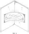
- FIG. 6is an inventive frame and canvas 610 that has been painted with a nature scene 612 .
- This frame 610has been hung in the corner of a wall such that the ends of the frame would travel along the walls if the frame was to continue.
- the frame 610may have solid wood studs at both ends to facilitate mounting. It may also have a solid wood stud at or near the middle of the frame to allow for the mounting of an LED or other backlight 614 to enhance the display of the painting.
- inventive stud described hereinmay be used for more than just the inventive frame described herein.
- This new studmay be used as a strong, lightweight alternative to other weight bearing systems.
- FIG. 7depicts a combination of the inventive stud 710 and traditional solid wood studs 712 that could form the walls of a structure.
- any embodiment of the present inventionmay include any of the optional or exemplary features of the other embodiments of the present invention.
- the exemplary embodiments herein disclosedare not intended to be exhaustive or to unnecessarily limit the scope of the invention.
- the exemplary embodimentswere chosen and described in order to explain the principles of the present invention so that others skilled in the art may practice the invention. Having shown and described exemplary embodiments of the present invention, those skilled in the art will realize that many variations and modifications may be made to the described invention. Many of those variations and modifications will provide the same result and fall within the spirit of the claimed invention. It is the intention, therefore, to limit the invention only as indicated by the scope of the claims.
Landscapes
- Finishing Walls (AREA)
- Mirrors, Picture Frames, Photograph Stands, And Related Fastening Devices (AREA)
Abstract
Description
Claims (10)
Priority Applications (1)
| Application Number | Priority Date | Filing Date | Title |
|---|---|---|---|
| US16/119,279US11912061B2 (en) | 2018-03-20 | 2018-08-31 | Wavy canvas frame |
Applications Claiming Priority (2)
| Application Number | Priority Date | Filing Date | Title |
|---|---|---|---|
| US201862645566P | 2018-03-20 | 2018-03-20 | |
| US16/119,279US11912061B2 (en) | 2018-03-20 | 2018-08-31 | Wavy canvas frame |
Publications (2)
| Publication Number | Publication Date |
|---|---|
| US20190291503A1 US20190291503A1 (en) | 2019-09-26 |
| US11912061B2true US11912061B2 (en) | 2024-02-27 |
Family
ID=67984623
Family Applications (1)
| Application Number | Title | Priority Date | Filing Date |
|---|---|---|---|
| US16/119,279Active2041-11-01US11912061B2 (en) | 2018-03-20 | 2018-08-31 | Wavy canvas frame |
Country Status (1)
| Country | Link |
|---|---|
| US (1) | US11912061B2 (en) |
Citations (24)
| Publication number | Priority date | Publication date | Assignee | Title |
|---|---|---|---|---|
| US3147336A (en)* | 1962-04-17 | 1964-09-01 | Howard G Mathews | Laminate panels for constructing enclosure |
| US3713474A (en)* | 1971-04-26 | 1973-01-30 | J Orlando | Portable wall partition |
| US4065596A (en) | 1976-04-22 | 1977-12-27 | James Groody | Artist's board |
| US4549596A (en) | 1982-09-02 | 1985-10-29 | Giorgio Staro | Device for tensioning material on frames |
| US4635418A (en)* | 1984-12-03 | 1987-01-13 | Hobgood Charles M | Portable partition wall system |
| US5218807A (en)* | 1992-06-05 | 1993-06-15 | Mark Fulford | Wooden door assembly and door jamb assembly having an insulative foam core |
| US5903992A (en)* | 1997-11-21 | 1999-05-18 | Eisenberg; Adam G. | Curved frame structure |
| US5966894A (en)* | 1997-12-02 | 1999-10-19 | Crump, Jr.; Preston L. | Modular insulated framing beam assembly |
| US6094877A (en)* | 1998-08-24 | 2000-08-01 | White; Charles L. | Frame support assembly and method for curved walls |
| US6519881B1 (en) | 2001-10-25 | 2003-02-18 | R. Kingsbury Chase | Stretcher frame assembly |
| US20030126777A1 (en)* | 2002-01-04 | 2003-07-10 | Doone Charles Ian | Versatile stretcher frame system |
| US20040049997A1 (en)* | 2002-09-17 | 2004-03-18 | Frank Wheeler | Header apparatus and method for a structural framing system |
| US6729060B1 (en)* | 2003-03-20 | 2004-05-04 | Carla Rietkerk | Corner fitting frame |
| DE202005017365U1 (en) | 2005-11-05 | 2006-05-24 | Fülle, Martin, Dr. | Canvas for use by artist, has curved surface, where right and left frame sides and upper and lower frame sides of canvas are bent, lined or thinned out |
| US20070130866A1 (en)* | 2003-09-10 | 2007-06-14 | Lott Eric G | Engineered lumber studs for interior wall construction |
| DE102006033193A1 (en) | 2006-07-18 | 2008-01-24 | Carmen Campanini-Korn | Frame for round or oval pictures e.g. oil paintings, has butt-joint between frame sections and device for adjusting butt-joint |
| DE202008000602U1 (en) | 2008-01-15 | 2009-05-28 | Peters, Rudi | Arched canvas |
| US7698840B2 (en) | 2005-05-02 | 2010-04-20 | Willow Rutkowski | Full moon canvas |
| US20110146126A1 (en)* | 2009-12-22 | 2011-06-23 | Charles Phillips | Device for and method of holding and displaying sheet articles |
| US8276335B2 (en)* | 2008-09-15 | 2012-10-02 | Protektorwerk Florenz Maisch Gmbh & Co. Kg | Attachment profile |
| US8707629B2 (en)* | 2008-07-10 | 2014-04-29 | Disposable Exhibits Llc | Disposable tradeshow booths |
| US9096094B2 (en) | 2013-05-03 | 2015-08-04 | Steven Charles Kaishian | Stretched artist canvas with rigid foam back |
| US9783985B2 (en)* | 2015-07-10 | 2017-10-10 | Roosevelt Energy, Llc | Thermal break wood stud with rigid insulation with non-metal fasteners and wall framing system |
| US9890532B2 (en)* | 2015-06-05 | 2018-02-13 | Kenneth R. Thompson | Structural component |
- 2018
- 2018-08-31USUS16/119,279patent/US11912061B2/enactiveActive
Patent Citations (24)
| Publication number | Priority date | Publication date | Assignee | Title |
|---|---|---|---|---|
| US3147336A (en)* | 1962-04-17 | 1964-09-01 | Howard G Mathews | Laminate panels for constructing enclosure |
| US3713474A (en)* | 1971-04-26 | 1973-01-30 | J Orlando | Portable wall partition |
| US4065596A (en) | 1976-04-22 | 1977-12-27 | James Groody | Artist's board |
| US4549596A (en) | 1982-09-02 | 1985-10-29 | Giorgio Staro | Device for tensioning material on frames |
| US4635418A (en)* | 1984-12-03 | 1987-01-13 | Hobgood Charles M | Portable partition wall system |
| US5218807A (en)* | 1992-06-05 | 1993-06-15 | Mark Fulford | Wooden door assembly and door jamb assembly having an insulative foam core |
| US5903992A (en)* | 1997-11-21 | 1999-05-18 | Eisenberg; Adam G. | Curved frame structure |
| US5966894A (en)* | 1997-12-02 | 1999-10-19 | Crump, Jr.; Preston L. | Modular insulated framing beam assembly |
| US6094877A (en)* | 1998-08-24 | 2000-08-01 | White; Charles L. | Frame support assembly and method for curved walls |
| US6519881B1 (en) | 2001-10-25 | 2003-02-18 | R. Kingsbury Chase | Stretcher frame assembly |
| US20030126777A1 (en)* | 2002-01-04 | 2003-07-10 | Doone Charles Ian | Versatile stretcher frame system |
| US20040049997A1 (en)* | 2002-09-17 | 2004-03-18 | Frank Wheeler | Header apparatus and method for a structural framing system |
| US6729060B1 (en)* | 2003-03-20 | 2004-05-04 | Carla Rietkerk | Corner fitting frame |
| US20070130866A1 (en)* | 2003-09-10 | 2007-06-14 | Lott Eric G | Engineered lumber studs for interior wall construction |
| US7698840B2 (en) | 2005-05-02 | 2010-04-20 | Willow Rutkowski | Full moon canvas |
| DE202005017365U1 (en) | 2005-11-05 | 2006-05-24 | Fülle, Martin, Dr. | Canvas for use by artist, has curved surface, where right and left frame sides and upper and lower frame sides of canvas are bent, lined or thinned out |
| DE102006033193A1 (en) | 2006-07-18 | 2008-01-24 | Carmen Campanini-Korn | Frame for round or oval pictures e.g. oil paintings, has butt-joint between frame sections and device for adjusting butt-joint |
| DE202008000602U1 (en) | 2008-01-15 | 2009-05-28 | Peters, Rudi | Arched canvas |
| US8707629B2 (en)* | 2008-07-10 | 2014-04-29 | Disposable Exhibits Llc | Disposable tradeshow booths |
| US8276335B2 (en)* | 2008-09-15 | 2012-10-02 | Protektorwerk Florenz Maisch Gmbh & Co. Kg | Attachment profile |
| US20110146126A1 (en)* | 2009-12-22 | 2011-06-23 | Charles Phillips | Device for and method of holding and displaying sheet articles |
| US9096094B2 (en) | 2013-05-03 | 2015-08-04 | Steven Charles Kaishian | Stretched artist canvas with rigid foam back |
| US9890532B2 (en)* | 2015-06-05 | 2018-02-13 | Kenneth R. Thompson | Structural component |
| US9783985B2 (en)* | 2015-07-10 | 2017-10-10 | Roosevelt Energy, Llc | Thermal break wood stud with rigid insulation with non-metal fasteners and wall framing system |
Non-Patent Citations (3)
| Title |
|---|
| Instagram post entitled "When you have multiple ideas at once, you make it work." 1 page, posted Oct. 9, 2016 by user "stevebartonofficial". Retrieved from Internet: < https://www.instagram.com/p/BLXGi9tD2Yz/?igshid=YmMyMTA2M2Y=>. (Year: 2016).* |
| Peters, Rudi. NPL of Translated Foreign Patent Description of DE202008000602U1, May 28, 2009 (Year: 2009).* |
| Screen captures from YouTube video clip entitled "Steve Barton—Where it began," 2 pages, uploaded on Jul. 31, 2015 by user "Steve Barton". Retrieved from Internet: < https://www.youtube.com/watch?v=s-v-DU8k8GE>. (Year: 2015).* |
Also Published As
| Publication number | Publication date |
|---|---|
| US20190291503A1 (en) | 2019-09-26 |
Similar Documents
| Publication | Publication Date | Title |
|---|---|---|
| US9386856B2 (en) | Painting support board | |
| US9096094B2 (en) | Stretched artist canvas with rigid foam back | |
| US11628681B2 (en) | Pre-assembled canvas for painting or printing | |
| US9421816B2 (en) | Apparatus and methods for displaying fabric based images | |
| JP5384834B2 (en) | Drum cylinder and drum using the same | |
| US11912061B2 (en) | Wavy canvas frame | |
| CN205369764U (en) | Decorative board mosaic structure | |
| DK3115521T3 (en) | FITTINGS AND FITTING SYSTEM FOR REVERSIBLE CONNECTION OF PLANE ELEMENTS AND A MODULAR DIVISION SYSTEM | |
| US6127019A (en) | Braced art surface | |
| CN106945349A (en) | a composite board | |
| CN204071426U (en) | Pin-connected panel picture frame | |
| JP2010106497A (en) | Panel | |
| CN108433467A (en) | Clad type intelligences combination space plane module | |
| JP2009084780A (en) | Door panel | |
| US20220281264A1 (en) | Canvas frame | |
| CN204804252U (en) | Paste and adorn in compound decorative board of foaming of wall | |
| US20110225923A1 (en) | Joist Assemblies and Assembly Kits | |
| CN208784315U (en) | A stick-type wall-mounted storage box | |
| JP3216646U (en) | Melamine-coated front plate for furniture | |
| WO2009138536A1 (en) | Metal coating for wood | |
| CN203321974U (en) | Seamless splicing structure of bathroom cabinet panel | |
| CN205365007U (en) | Novel frameless painting | |
| KR101001615B1 (en) | Glass-mountable furniture panels | |
| CN202723305U (en) | DIY (do it yourself) picture frame | |
| CN202723306U (en) | DIY (do-it-yourself) frame corner device |
Legal Events
| Date | Code | Title | Description |
|---|---|---|---|
| FEPP | Fee payment procedure | Free format text:ENTITY STATUS SET TO UNDISCOUNTED (ORIGINAL EVENT CODE: BIG.); ENTITY STATUS OF PATENT OWNER: MICROENTITY | |
| FEPP | Fee payment procedure | Free format text:ENTITY STATUS SET TO MICRO (ORIGINAL EVENT CODE: MICR); ENTITY STATUS OF PATENT OWNER: MICROENTITY | |
| STPP | Information on status: patent application and granting procedure in general | Free format text:NON FINAL ACTION MAILED | |
| STPP | Information on status: patent application and granting procedure in general | Free format text:RESPONSE TO NON-FINAL OFFICE ACTION ENTERED AND FORWARDED TO EXAMINER | |
| STPP | Information on status: patent application and granting procedure in general | Free format text:FINAL REJECTION MAILED | |
| STPP | Information on status: patent application and granting procedure in general | Free format text:RESPONSE AFTER FINAL ACTION FORWARDED TO EXAMINER | |
| STPP | Information on status: patent application and granting procedure in general | Free format text:ADVISORY ACTION MAILED | |
| STPP | Information on status: patent application and granting procedure in general | Free format text:DOCKETED NEW CASE - READY FOR EXAMINATION | |
| STPP | Information on status: patent application and granting procedure in general | Free format text:NON FINAL ACTION MAILED | |
| STPP | Information on status: patent application and granting procedure in general | Free format text:FINAL REJECTION MAILED | |
| STPP | Information on status: patent application and granting procedure in general | Free format text:RESPONSE AFTER FINAL ACTION FORWARDED TO EXAMINER | |
| STPP | Information on status: patent application and granting procedure in general | Free format text:ADVISORY ACTION MAILED | |
| STPP | Information on status: patent application and granting procedure in general | Free format text:NOTICE OF ALLOWANCE MAILED -- APPLICATION RECEIVED IN OFFICE OF PUBLICATIONS | |
| STPP | Information on status: patent application and granting procedure in general | Free format text:PUBLICATIONS -- ISSUE FEE PAYMENT RECEIVED | |
| STPP | Information on status: patent application and granting procedure in general | Free format text:PUBLICATIONS -- ISSUE FEE PAYMENT VERIFIED | |
| STCF | Information on status: patent grant | Free format text:PATENTED CASE |