US11911077B2 - Head to head transverse connector - Google Patents
Head to head transverse connectorDownload PDFInfo
- Publication number
- US11911077B2 US11911077B2US17/222,105US202117222105AUS11911077B2US 11911077 B2US11911077 B2US 11911077B2US 202117222105 AUS202117222105 AUS 202117222105AUS 11911077 B2US11911077 B2US 11911077B2
- Authority
- US
- United States
- Prior art keywords
- cross member
- ring
- mount
- nut
- screw
- Prior art date
- Legal status (The legal status is an assumption and is not a legal conclusion. Google has not performed a legal analysis and makes no representation as to the accuracy of the status listed.)
- Active, expires
Links
Images


Classifications
- A—HUMAN NECESSITIES
- A61—MEDICAL OR VETERINARY SCIENCE; HYGIENE
- A61B—DIAGNOSIS; SURGERY; IDENTIFICATION
- A61B17/00—Surgical instruments, devices or methods
- A61B17/56—Surgical instruments or methods for treatment of bones or joints; Devices specially adapted therefor
- A61B17/58—Surgical instruments or methods for treatment of bones or joints; Devices specially adapted therefor for osteosynthesis, e.g. bone plates, screws or setting implements
- A61B17/68—Internal fixation devices, including fasteners and spinal fixators, even if a part thereof projects from the skin
- A61B17/70—Spinal positioners or stabilisers, e.g. stabilisers comprising fluid filler in an implant
- A61B17/7049—Connectors, not bearing on the vertebrae, for linking longitudinal elements together
- A61B17/7052—Connectors, not bearing on the vertebrae, for linking longitudinal elements together of variable angle or length
- A—HUMAN NECESSITIES
- A61—MEDICAL OR VETERINARY SCIENCE; HYGIENE
- A61B—DIAGNOSIS; SURGERY; IDENTIFICATION
- A61B17/00—Surgical instruments, devices or methods
- A61B17/56—Surgical instruments or methods for treatment of bones or joints; Devices specially adapted therefor
- A61B17/58—Surgical instruments or methods for treatment of bones or joints; Devices specially adapted therefor for osteosynthesis, e.g. bone plates, screws or setting implements
- A61B17/68—Internal fixation devices, including fasteners and spinal fixators, even if a part thereof projects from the skin
- A61B17/70—Spinal positioners or stabilisers, e.g. stabilisers comprising fluid filler in an implant
- A61B17/7049—Connectors, not bearing on the vertebrae, for linking longitudinal elements together
- A—HUMAN NECESSITIES
- A61—MEDICAL OR VETERINARY SCIENCE; HYGIENE
- A61B—DIAGNOSIS; SURGERY; IDENTIFICATION
- A61B17/00—Surgical instruments, devices or methods
- A61B17/56—Surgical instruments or methods for treatment of bones or joints; Devices specially adapted therefor
- A61B17/58—Surgical instruments or methods for treatment of bones or joints; Devices specially adapted therefor for osteosynthesis, e.g. bone plates, screws or setting implements
- A61B17/68—Internal fixation devices, including fasteners and spinal fixators, even if a part thereof projects from the skin
- A61B17/70—Spinal positioners or stabilisers, e.g. stabilisers comprising fluid filler in an implant
- A61B17/7001—Screws or hooks combined with longitudinal elements which do not contact vertebrae
- A61B17/7032—Screws or hooks with U-shaped head or back through which longitudinal rods pass
- A—HUMAN NECESSITIES
- A61—MEDICAL OR VETERINARY SCIENCE; HYGIENE
- A61B—DIAGNOSIS; SURGERY; IDENTIFICATION
- A61B17/00—Surgical instruments, devices or methods
- A61B17/56—Surgical instruments or methods for treatment of bones or joints; Devices specially adapted therefor
- A61B17/58—Surgical instruments or methods for treatment of bones or joints; Devices specially adapted therefor for osteosynthesis, e.g. bone plates, screws or setting implements
- A61B17/68—Internal fixation devices, including fasteners and spinal fixators, even if a part thereof projects from the skin
- A61B17/70—Spinal positioners or stabilisers, e.g. stabilisers comprising fluid filler in an implant
- A61B17/7001—Screws or hooks combined with longitudinal elements which do not contact vertebrae
- A61B17/7035—Screws or hooks, wherein a rod-clamping part and a bone-anchoring part can pivot relative to each other
- A61B17/7037—Screws or hooks, wherein a rod-clamping part and a bone-anchoring part can pivot relative to each other wherein pivoting is blocked when the rod is clamped
- A—HUMAN NECESSITIES
- A61—MEDICAL OR VETERINARY SCIENCE; HYGIENE
- A61B—DIAGNOSIS; SURGERY; IDENTIFICATION
- A61B17/00—Surgical instruments, devices or methods
- A61B17/56—Surgical instruments or methods for treatment of bones or joints; Devices specially adapted therefor
- A61B17/58—Surgical instruments or methods for treatment of bones or joints; Devices specially adapted therefor for osteosynthesis, e.g. bone plates, screws or setting implements
- A61B17/68—Internal fixation devices, including fasteners and spinal fixators, even if a part thereof projects from the skin
- A61B17/84—Fasteners therefor or fasteners being internal fixation devices
- A61B17/86—Pins or screws or threaded wires; nuts therefor
- A61B17/8665—Nuts
- A61B2017/867—Nuts with integral locking or clamping means
- A61B2017/8675—Nuts with integral locking or clamping means clamping effect due to tapering, e.g. conical thread
Definitions
- the present disclosurerelates to a device for interconnecting bone anchors and, more particularly, to a transverse connector that couples heads of bone anchors together.
- spinal fixation apparatuseshave been employed in surgical procedures for correcting spinal injuries and the effects of spinal diseases. Many of these apparatuses commonly use a pair of longitudinal rods running in a relatively parallel relationship to each other and the spinal column. These rods are connected to connectors, which in turn are secured to the underlying vertebral bone by spinal bone fixation fasteners such as pedicle screws, hooks, and the like.
- the pair of longitudinal rodscan be held in position relative to one another by transverse connectors, also known as transverse bridge elements or cross-connectors.
- the present disclosureis directed to a transverse connector that includes a cross member assembly, a first connector assembly, and a second connector assembly.
- the cross member assemblyincludes a cross member, a first ring, and a second ring.
- the cross memberhas a first end portion and a second end portion.
- the first ringis receivable on the first end portion of the cross member and the second ring is receivable on the second end portion of the cross member.
- the first and second connector assembliesare coupled to the first and second rings of the cross member assembly, respectively, to support the cross member between the first and second connector assemblies.
- the first and second connector assembliesare configured to selectively and releasably secure to bone anchors.
- the first connector assemblymay include a mount configured to seat the first connector assembly on a first bone anchor of the bone anchors.
- the first connector assemblymay include a screw receivable through the mount.
- the screwmay be engagable with the first bone anchor.
- the first connector assemblymay further include a nut that threadably engages the screw to selectively secure the first connector assembly to the first bone anchor.
- the nutmay be configured to tighten against the first ring to tighten the first ring around the cross member and fictionally lock the cross member in position relative to the first connector assembly.
- the mountmay include a head mount portion and a rod mount portion that extends from the head mount portion.
- the rod mount portionmay be configured to receive the cross member.
- the rod mount portionmay include a hooked arm that curves upward and inward toward the head mount portion.
- the hooked armmay define a ring groove that is configured to receive the first ring therein.
- the first ringmay be an open ended ring positioned to move between a first position and second position.
- the first ringmay have a first diameter in the first position and a second diameter in the second position.
- the second diametermay be less than the first diameter.
- the first ringmay be configured to axially lock the cross member to the rod mount portion of the mount when the first ring is in the second position.
- the cross membermay be axially movable relative to the first ring when the first ring is in the first position.
- the cross membermay include an annular flange supported on one of the first and second end portions of the cross member.
- the annular flangemay be configured to limit axial movement of the cross member relative to the first and second connector assemblies.
- a transverse connectorin another aspect of the present disclosure, includes a cross member, a ring, a first connector assembly, and a second connector assembly.
- the cross memberincludes a first end portion and a second end portion.
- the ringis supported on the first end portion of the cross member.
- the first connector assemblyis coupled to the ring to secure the cross member to the connector assembly.
- the first connector assemblyis configured to selectively and releasably secure to a bone anchor.
- the second connector assemblyis coupled to the second end portion of the cross member.
- the first connector assemblymay include a mount and a screw that couple to the bone anchor, and a nut that couples to the screw to secure the cross member to the mount.
- the nut and the screwmay be threadably coupled together.
- the nutmay include a drive portion and a skirt that extends distally from the drive portion.
- the drive portionmay include a distal taper portion that is selectively engagable with the ring as the nut rotates about the screw.
- the ringmay be configured to compress against the cross member as the nut tightens against the ring.
- the mountmay include a hooked arm that supports the ring and the cross member therein.
- a spinal systemin accordance with still another aspect of the present disclosure, includes a first bone anchor configured to support a first spinal rod, a second bone anchor configured to support a second spinal rod, and a transverse connector that couples the first and second bone anchors together.
- the transverse connectorincludes a first connector assembly, a second connector assembly, and a cross member.
- the first connector assemblyincludes a first mount coupled to the first bone anchor and supports a first ring.
- the second connector assemblyincludes a second mount coupled to the second bone anchor and supports a second ring.
- the cross memberis coupled to the first and second rings and extends between the first and second connector assemblies.
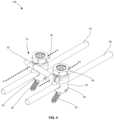
- FIG. 1is a perspective view of a transverse connector in accordance with the present disclosure
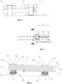
- FIG. 2is a perspective view, with parts separated, of the transverse connector of FIG. 1 ;
- FIG. 3is a side view of the transverse connector of FIG. 1 ;
- FIG. 4is a perspective view of one embodiment of a spinal system including a pair of spinal rods, a pair of bone anchors, and the transverse connector of FIG. 1 ;
- FIG. 5is a perspective view, with parts separated, of the spinal system of FIG. 4 ;
- FIG. 6is a front view of the transverse connector of FIG. 1 with first and second connector assemblies thereof shown positioned offset from one another;
- FIG. 7is a side view of the transverse connector of FIG. 1 as illustrated in FIG. 6 ;
- FIG. 8is an enlarged, cross-sectional view of the transverse connector as illustrated in FIG. 6 and taken along section line 8 - 8 shown in FIG. 7 ;
- FIG. 9is a perspective view of another embodiment a spinal system coupled to a spine.
- proximalrefers to the portion of structure that is closer to the clinician and the term “distal” refers to the portion of structure that is farther from the clinician.
- directional termssuch as front, rear, upper, lower, top, bottom, and the like are used simply for convenience of description and are not intended to limit the disclosure attached hereto.
- Transverse connector 10includes a cross member assembly 20 , a first connector assembly 30 , and a second connector assembly 40 that is identical to first connector assembly 30 .
- First and second connector assemblies 30 , 40are supported on opposite end portions of cross member assembly 20 .
- Cross member assembly 20 of transverse connector 10includes a cross member 22 that defines a long axis “L,” a first ring 24 supported on a first end portion of cross member 22 , and a second ring 26 supported on a second end portion of cross member 22 .
- Cross member 22includes an annular flange 22 a supported on a first end portion thereof that limits axial movement of cross member 22 along long axis “L” of cross member 22 relative to first and second connector assemblies 30 , 40 .
- Cross member 22further defines bore 22 b ( FIG. 8 ) in a second end portion thereof opposite to the first end portion. Bore 22 b is configured to receive an instrument (not shown) to control and/or manipulate a position of cross member 22 .
- First and second rings 24 , 26are identical.
- Each of the first and second rings 24 , 26defines a slot 24 a through a thickness of one end thereof (e.g., an open ended ring) and includes a uniform central portion 24 b configured to frictionally engage an outer surface of cross member 22 . Uniform central portion 24 b , is supported between tapered openings 24 c , 24 d on opposite ends of central portion 24 b (see FIG. 8 ).
- First and second rings 24 , 26may be at least partially formed of a flexible material. As indicated by arrows “C” ( FIG.
- first and second rings 24 , 26may be configured to move between a first position in which first and second rings 24 , 26 have a first diameter, and a second position in which first and second rings 24 , 26 have a second diameter that is smaller than the first diameter. Movement of first and second rings 24 , 26 between the first and second positions may be effectuated via application or removal of radial compression forces thereto via first or second connector assemblies 30 , 40 .
- First connector assembly 30includes a nut 32 , a screw 34 that threadably couples to nut 32 , and a mount 36 that receives screw 34 therethrough.
- Nut 32includes a threaded inner surface 32 a that defines an opening 32 b through nut 32 , a drive portion 32 c on a proximal end portion of nut 32 , and a skirt 32 f that is recessed from, and extends distally from, drive portion 32 c .
- Skirt 32 fis configured to maintain drive portion 32 c at a predetermined height above an upper surface of mount 36 to selectively capture ring 24 between drive portion 32 c and mount 36 (e.g., pinch a side portion of ring 24 as seen in FIG. 3 ).
- Drive portion 32 c of nut 32includes flats 32 d supported at spaced apart locations about an outer surface thereof.
- Drive portion 32 cfurther includes a distal taper portion 32 x (e.g., annular taper) that connects drive portion 32 c to a proximal portion of skirt 32 f of nut 32 .
- Flats 32 dare configured to facilitate engagement with a driving instrument (e.g., a socket wrench—not shown) for rotating nut 32 about axis “A,” as indicated by arrows “R” ( FIG. 1 ).
- a driving instrumente.g., a socket wrench—not shown
- Internal surface 32 a and opening 32 b of nut 32extend along drive portion 32 c and skirt 32 f of nut 32 to connect apertures 32 g , 32 h of nut 32 that open on opposite ends of nut 32 (see FIG. 2 ).
- Screw 34 of first connector assembly 30includes a threaded outer surface 34 a that threadably couples to threaded inner surface 32 a of nut 32 .
- Screw 34further includes a drive recess 34 b defined in a proximal end portion of screw 34 that is configured to receive a drive tool (e.g., a screw driver—not shown) to rotate screw 34 relative to nut 32 and/or mount 36 about a longitudinal axis “A” defined through screw 34 (e.g., clockwise and/or counter clockwise as indicated by arrows “Sc”).
- Drive recess 34 bcan be any suitable configuration such as hexolobular or the like.
- Mount 36 of first connector assembly 30includes a head mount portion 36 a and a rod mount portion 36 b .
- Head mount portion 36 ais configured to selectively and releasably secure to a head 52 of a bone anchor 50 (see FIG. 4 ) that includes a bone screw 54 coupled to head 52 of bone anchor 50 for mounting to a vertebral body “V” of a spine “S” ( FIG. 9 ).
- Bone anchor 50may have a set screw arrangement that is configured for polyaxial movement between head 52 and bone screw 54 .
- bone anchormay have a taper-lock arrangement.
- Head mount portion 36 a of mount 36defines an opening 36 c therethrough that is configured to receive screw 34 therethrough.
- Head mount portion 36 afurther includes an upper surface 36 d and a lower surface 36 e that is keyed to an outer surface of a head 52 of a bone anchor 50 .
- Head mount portion 36 ais configured to maintain mount 36 fixed onto a bone anchor 50 so as to prevent mount 36 from rotating clockwise or counter clockwise about longitudinal axis “A” of screw 34 of first connector assembly 30 (e.g., rotatably locked).
- Rod mount portion 36 bis configured to support a first end portion of cross member 22 and includes a hooked arm 36 f that curves upward and inward toward head mount portion 36 a .
- Rod mount portion 36 bfurther defines a ring groove 36 g along a central portion of an inner surface thereof that is configured to receive first ring 24 therein while cross member 22 is received through first ring 24 .
- Ring groove 36 gis recessed within rod mount portion 36 b to prevent ring 24 from sliding along rod mount portion 36 b (e.g., axially relative to axis “L”).
- each ring groove 36 g of first and second connector assemblies 30 , 40has an arcuate and/or spherical profile that is slightly larger than rings 24 , 26 to enable rings 24 , 26 to move within respective ring grooves 36 g .
- Each ring groove 36 gdefines one or more axes therethrough, for instance, axis “X 1 ” through first connector assembly 30 , and axis “X 2 ” through second connector assembly 40 .
- Rings 24 , 26are positioned for polyaxial movement within ring grooves 36 g so that first and second connector assemblies 30 , 40 can be positioned at different angles relative to one another (e.g., vertical displacement such as up or down, as indicated by arrows “U/D,” horizontal displacement such as forwards or backwards, as indicated by arrows “F/B,” or combinations thereof).
- second connector assembly 40can be moved, for example, relative to first connector assembly 30 (e.g., a height “H”), or vice versa, so that cross member 22 is at an angle “ ⁇ ” and first and second connector assemblies 30 , 40 are vertically offset from one another.
- Angle “ ⁇ ”can be any suitable angle and may range between about 0 and 15 degrees of polyaxial motion, which may be positive or negative depending on respective positions of connector assemblies 30 , 40 .
- each of rings 24 , 26is polyaxially supported in one of the ring grooves 36 g of respective first and second connector assemblies 30 , 40 , as indicated by arrows “P,” for example, so that rings 24 , 26 pivot about respective axes “X 1 ” and “X 2 ” as one or both of first and second connector assemblies 30 , 40 are displaced relative to one another (e.g., vertically, horizontally, or both).
- a spinal system 100may include a transverse connector 10 coupled to bone anchors 50 , 60 that support spinal rods “R 1 ” and “R 2 ” therein, respectively.
- Spinal rods “R 1 ” and “R 2 ”can also be coupled to one or more additional bone anchors 50 a , 50 b , 60 a , 60 b , etc. via set screws “SS.”
- distal portions of screws 34 of first and second connector assemblies 30 , 40can be threadably coupled to threaded inner surfaces 52 a of heads 52 of bone anchors 50 , 60 , respectively secured to one or more vertebral bodies “V” of a spine “S.”
- cross member assembly 20coupled to mounts 36 of first and second connector assemblies 30 , 40 , such that cross member 22 is axially movable relative to first and second connector assemblies 30 , 40 and first and second rings 24 , 26 for selectively adjusting a distance between first and second connector assemblies 30 , 40
- screws 34 of first and second connector assemblies 30 , 40can be received in mounts 36 of first and second connector assemblies 30 , 40 .
- first and second connector assemblies 30 , 40can be threaded onto proximal portions of screws 34 to secure transverse connector 10 to bone anchors 50 , 60 .
- distal taper portions 32 x of nuts 32engage respective first and second rings 24 , 26 .
- Further tightening of nuts 32causes first and second rings 24 , 26 to compress around cross member 22 to frictionally lock cross member 22 (as well as first and second connector assemblies 30 , 40 ) in position (e.g., axially fixed).
- diameters of first and second rings 24 , 26shrink when slots 24 a ( FIG.
- first and second rings 24 , 26close, as indicated by arrows “C” ( FIG. 3 ), in response to radial compression imparted thereto from axial translation of nuts 32 along screws 34 , as indicated by arrows “T” ( FIG. 1 ), when nuts 32 are rotated in a tightening direction about screws 34 , as indicated by arrows “R” ( FIG. 1 ).
- Adjustment of spinal rods “R 1 ” and/or “R 2 ”can be effectuated upon selective untightening and/or retightening of nuts 32 of transverse connector 10 and/or of set screws “SS” of bone anchors 50 a , 50 b , 60 a , 60 b , etc. as desired.
- spinal rods “R 1 ” and/or “R 2 ”can be manipulated as necessary.
- spinal rods “R 1 ” and/or “R 2 ”positioned as desired, nuts 32 of transverse connector 10 and/or of set screws “SS” of bone anchors 50 a , 50 b , 60 a , 60 b , etc. can be retightened to fix spinal rods “R 1 ” and/or “R 2 ” in position.
- kitwhich includes at least one of the transverse connectors.
- the kitcan also include additional orthopedic devices and instruments; such as for example, instruments for tightening or loosening the locking screws, spinal rods, hooks or links and any additional instruments or tools associated therewith.
- additional orthopedic devices and instrumentssuch as for example, instruments for tightening or loosening the locking screws, spinal rods, hooks or links and any additional instruments or tools associated therewith.
- Such a kitcan be provided with sterile packaging to facilitate opening and immediate use in an operating room.
- Any of the presently disclosed devices, or components thereof,can be formed of any suitable biocompatible material or combinations of materials for use in surgical procedures such as mixed metallic materials like titanium, titanium alloy (e.g., Ti-6A1-4V), stainless steel, and cobalt chrome alloy.
- Any of the presently disclosed embodiments, or components thereof,can be formed or secured together using any suitable technique such as welding, fastening, machining, molding, press-fit, etc., or combinations thereof.
Landscapes
- Health & Medical Sciences (AREA)
- Orthopedic Medicine & Surgery (AREA)
- Life Sciences & Earth Sciences (AREA)
- Surgery (AREA)
- Neurology (AREA)
- Heart & Thoracic Surgery (AREA)
- Engineering & Computer Science (AREA)
- Biomedical Technology (AREA)
- Nuclear Medicine, Radiotherapy & Molecular Imaging (AREA)
- Medical Informatics (AREA)
- Molecular Biology (AREA)
- Animal Behavior & Ethology (AREA)
- General Health & Medical Sciences (AREA)
- Public Health (AREA)
- Veterinary Medicine (AREA)
- Surgical Instruments (AREA)
Abstract
Description
Claims (18)
Priority Applications (1)
| Application Number | Priority Date | Filing Date | Title |
|---|---|---|---|
| US17/222,105US11911077B2 (en) | 2018-05-03 | 2021-04-05 | Head to head transverse connector |
Applications Claiming Priority (3)
| Application Number | Priority Date | Filing Date | Title |
|---|---|---|---|
| US201862666313P | 2018-05-03 | 2018-05-03 | |
| US16/401,173US10993746B2 (en) | 2018-05-03 | 2019-05-02 | Head to head transverse connector |
| US17/222,105US11911077B2 (en) | 2018-05-03 | 2021-04-05 | Head to head transverse connector |
Related Parent Applications (1)
| Application Number | Title | Priority Date | Filing Date |
|---|---|---|---|
| US16/401,173ContinuationUS10993746B2 (en) | 2018-05-03 | 2019-05-02 | Head to head transverse connector |
Publications (2)
| Publication Number | Publication Date |
|---|---|
| US20210220021A1 US20210220021A1 (en) | 2021-07-22 |
| US11911077B2true US11911077B2 (en) | 2024-02-27 |
Family
ID=66379766
Family Applications (2)
| Application Number | Title | Priority Date | Filing Date |
|---|---|---|---|
| US16/401,173ActiveUS10993746B2 (en) | 2018-05-03 | 2019-05-02 | Head to head transverse connector |
| US17/222,105Active2040-03-21US11911077B2 (en) | 2018-05-03 | 2021-04-05 | Head to head transverse connector |
Family Applications Before (1)
| Application Number | Title | Priority Date | Filing Date |
|---|---|---|---|
| US16/401,173ActiveUS10993746B2 (en) | 2018-05-03 | 2019-05-02 | Head to head transverse connector |
Country Status (2)
| Country | Link |
|---|---|
| US (2) | US10993746B2 (en) |
| EP (1) | EP3563784B1 (en) |
Families Citing this family (11)
| Publication number | Priority date | Publication date | Assignee | Title |
|---|---|---|---|---|
| WO2017107883A1 (en)* | 2015-12-23 | 2017-06-29 | 马向阳 | Screw-rod fixation device specially used for posterior atlantoaxial vertebrae |
| US10321939B2 (en) | 2016-05-18 | 2019-06-18 | Medos International Sarl | Implant connectors and related methods |
| US10517647B2 (en) | 2016-05-18 | 2019-12-31 | Medos International Sarl | Implant connectors and related methods |
| US10492835B2 (en) | 2016-12-19 | 2019-12-03 | Medos International Sàrl | Offset rods, offset rod connectors, and related methods |
| US10238432B2 (en)* | 2017-02-10 | 2019-03-26 | Medos International Sàrl | Tandem rod connectors and related methods |
| US10561454B2 (en) | 2017-03-28 | 2020-02-18 | Medos International Sarl | Articulating implant connectors and related methods |
| US10966761B2 (en) | 2017-03-28 | 2021-04-06 | Medos International Sarl | Articulating implant connectors and related methods |
| US11076890B2 (en) | 2017-12-01 | 2021-08-03 | Medos International Sàrl | Rod-to-rod connectors having robust rod closure mechanisms and related methods |
| WO2020154435A1 (en)* | 2019-01-22 | 2020-07-30 | Life Spine, Inc | Polyaxial spine screw rod holder having a second, offset rod holder |
| EP3943028B1 (en) | 2020-07-22 | 2023-10-04 | Biedermann Technologies GmbH & Co. KG | Rod system including at least two rods and connector device for rods |
| JP7702694B2 (en)* | 2021-04-08 | 2025-07-04 | ミズホ株式会社 | Percutaneous Spinal Stabilization System |
Citations (27)
| Publication number | Priority date | Publication date | Assignee | Title |
|---|---|---|---|---|
| FR2719759A1 (en)* | 1994-05-16 | 1995-11-17 | Charles Khalife | Intervertebral osteosynthesis screw system |
| FR2720923A1 (en) | 1994-06-10 | 1995-12-15 | Sra Sarl | Osteosynthesis screw for vertical column implant |
| US5938663A (en) | 1995-03-06 | 1999-08-17 | Stryker France, S.A. | Spinal instruments, particularly for a rod |
| US6086588A (en)* | 1997-05-07 | 2000-07-11 | Aesculap Ag & Co. Kg | Osteosynthesis system for vertebra arthrodesis |
| US20040147929A1 (en) | 2002-12-20 | 2004-07-29 | Biedermann Motech Gmbh | Tubular element for an implant for use in spine or bone surgery and implant having such an element |
| US20050010216A1 (en) | 2001-10-30 | 2005-01-13 | Thomas Gradel | Vertebral column support device which is assembled by means of clamping |
| US20050055026A1 (en)* | 2002-10-02 | 2005-03-10 | Biedermann Motech Gmbh | Bone anchoring element |
| US20050228326A1 (en) | 2004-03-31 | 2005-10-13 | Depuy Spine, Inc. | Head-to-head connector spinal fixation system |
| US20060064091A1 (en) | 2004-03-31 | 2006-03-23 | Depuy Spine, Inc. | Rod attachment for head to head cross connector |
| US20060149231A1 (en)* | 2004-12-13 | 2006-07-06 | Rsb Spine Llc | Bone fastener assembly for bone retention apparatus |
| US20060241593A1 (en)* | 2005-04-08 | 2006-10-26 | Sdgi Holdings, Inc. | Multi-piece vertebral attachment device |
| EP1762195A1 (en) | 2005-08-23 | 2007-03-14 | AESCULAP AG & Co. KG | Rod to rod connector |
| US20070123860A1 (en)* | 2005-11-04 | 2007-05-31 | Sdgi Holdings, Inc. | Dorsal adjusting multi-rod connector |
| US20070233062A1 (en)* | 2006-04-04 | 2007-10-04 | Amedica Corporation | Pedicle screw system with offset stabilizer rod |
| US20080172093A1 (en) | 2007-01-15 | 2008-07-17 | Innovative Delta Technology, Llc | Polyaxial Cross Connector and Methods of Use Thereof |
| US20090187217A1 (en) | 2008-01-18 | 2009-07-23 | Mark Weiman | Transverse Connector |
| US20090264931A1 (en) | 2008-04-18 | 2009-10-22 | Warsaw Orthopedic, Inc. | Implantable Article for Use with an Anchor and a Non-Metal Rod |
| US20100094345A1 (en)* | 2006-09-26 | 2010-04-15 | Sean Saidha | Transconnector |
| US7837714B2 (en)* | 2006-04-10 | 2010-11-23 | Warsaw Orthopedic, Inc. | Methods and devices for the interconnection of bone attachment devices |
| US20110071569A1 (en) | 2009-09-21 | 2011-03-24 | Michael Black | Transverse Connector |
| US20110245872A1 (en)* | 2007-01-15 | 2011-10-06 | Innovative Delta Technology, Llc | Polyaxial spinal stabilizer connector and methods of use thereof |
| US20120271355A1 (en) | 2011-04-25 | 2012-10-25 | Warsaw Orthopedic, Inc. | Elongated connecting elements for minimally invasive surgical procedures |
| US20130172934A1 (en) | 2011-12-30 | 2013-07-04 | Blackstone Medical, Inc. | Multi-axial spinal cross connecting device |
| US8672978B2 (en) | 2011-03-04 | 2014-03-18 | Zimmer Spine, Inc. | Transverse connector |
| US8920475B1 (en) | 2011-01-07 | 2014-12-30 | Lanx, Inc. | Vertebral fixation system including torque mitigation |
| US9247964B1 (en) | 2011-03-01 | 2016-02-02 | Nuasive, Inc. | Spinal Cross-connector |
| US20170333084A1 (en)* | 2015-04-07 | 2017-11-23 | K2M, Inc. | Spinal stabilization device, system, and method of use |
Family Cites Families (3)
| Publication number | Priority date | Publication date | Assignee | Title |
|---|---|---|---|---|
| US20080154308A1 (en)* | 2006-12-21 | 2008-06-26 | Warsaw Orthopedic, Inc. | Spinal fixation system |
| JP5651472B2 (en) | 2007-10-23 | 2015-01-14 | ケー2エム, インコーポレイテッド | Posterior pedicle screw with taper lock |
| US9393049B2 (en) | 2010-08-20 | 2016-07-19 | K2M, Inc. | Spinal fixation system |
- 2019
- 2019-05-02USUS16/401,173patent/US10993746B2/enactiveActive
- 2019-05-02EPEP19172236.2Apatent/EP3563784B1/enactiveActive
- 2021
- 2021-04-05USUS17/222,105patent/US11911077B2/enactiveActive
Patent Citations (28)
| Publication number | Priority date | Publication date | Assignee | Title |
|---|---|---|---|---|
| FR2719759A1 (en)* | 1994-05-16 | 1995-11-17 | Charles Khalife | Intervertebral osteosynthesis screw system |
| FR2720923A1 (en) | 1994-06-10 | 1995-12-15 | Sra Sarl | Osteosynthesis screw for vertical column implant |
| US5938663A (en) | 1995-03-06 | 1999-08-17 | Stryker France, S.A. | Spinal instruments, particularly for a rod |
| US6086588A (en)* | 1997-05-07 | 2000-07-11 | Aesculap Ag & Co. Kg | Osteosynthesis system for vertebra arthrodesis |
| US20050010216A1 (en) | 2001-10-30 | 2005-01-13 | Thomas Gradel | Vertebral column support device which is assembled by means of clamping |
| US20050055026A1 (en)* | 2002-10-02 | 2005-03-10 | Biedermann Motech Gmbh | Bone anchoring element |
| US20040147929A1 (en) | 2002-12-20 | 2004-07-29 | Biedermann Motech Gmbh | Tubular element for an implant for use in spine or bone surgery and implant having such an element |
| US20060064091A1 (en) | 2004-03-31 | 2006-03-23 | Depuy Spine, Inc. | Rod attachment for head to head cross connector |
| US20050228326A1 (en) | 2004-03-31 | 2005-10-13 | Depuy Spine, Inc. | Head-to-head connector spinal fixation system |
| US20060149231A1 (en)* | 2004-12-13 | 2006-07-06 | Rsb Spine Llc | Bone fastener assembly for bone retention apparatus |
| US20060241593A1 (en)* | 2005-04-08 | 2006-10-26 | Sdgi Holdings, Inc. | Multi-piece vertebral attachment device |
| EP1762195A1 (en) | 2005-08-23 | 2007-03-14 | AESCULAP AG & Co. KG | Rod to rod connector |
| US20070123860A1 (en)* | 2005-11-04 | 2007-05-31 | Sdgi Holdings, Inc. | Dorsal adjusting multi-rod connector |
| US20070233062A1 (en)* | 2006-04-04 | 2007-10-04 | Amedica Corporation | Pedicle screw system with offset stabilizer rod |
| US7837714B2 (en)* | 2006-04-10 | 2010-11-23 | Warsaw Orthopedic, Inc. | Methods and devices for the interconnection of bone attachment devices |
| US20100094345A1 (en)* | 2006-09-26 | 2010-04-15 | Sean Saidha | Transconnector |
| US20080172093A1 (en) | 2007-01-15 | 2008-07-17 | Innovative Delta Technology, Llc | Polyaxial Cross Connector and Methods of Use Thereof |
| US20110245872A1 (en)* | 2007-01-15 | 2011-10-06 | Innovative Delta Technology, Llc | Polyaxial spinal stabilizer connector and methods of use thereof |
| US20090187217A1 (en) | 2008-01-18 | 2009-07-23 | Mark Weiman | Transverse Connector |
| US20090264931A1 (en) | 2008-04-18 | 2009-10-22 | Warsaw Orthopedic, Inc. | Implantable Article for Use with an Anchor and a Non-Metal Rod |
| US20110071569A1 (en) | 2009-09-21 | 2011-03-24 | Michael Black | Transverse Connector |
| US8920475B1 (en) | 2011-01-07 | 2014-12-30 | Lanx, Inc. | Vertebral fixation system including torque mitigation |
| US9247964B1 (en) | 2011-03-01 | 2016-02-02 | Nuasive, Inc. | Spinal Cross-connector |
| US20180014861A1 (en) | 2011-03-01 | 2018-01-18 | Nuvasive, Inc. | Spinal Cross-Connector |
| US8672978B2 (en) | 2011-03-04 | 2014-03-18 | Zimmer Spine, Inc. | Transverse connector |
| US20120271355A1 (en) | 2011-04-25 | 2012-10-25 | Warsaw Orthopedic, Inc. | Elongated connecting elements for minimally invasive surgical procedures |
| US20130172934A1 (en) | 2011-12-30 | 2013-07-04 | Blackstone Medical, Inc. | Multi-axial spinal cross connecting device |
| US20170333084A1 (en)* | 2015-04-07 | 2017-11-23 | K2M, Inc. | Spinal stabilization device, system, and method of use |
Non-Patent Citations (3)
| Title |
|---|
| English Translation of FR 2720923 from espacenet.com, accessed Apr. 18, 2023.* |
| European Search Report from EP 19172236.2, dated Sep. 24, 2019, pp. 1-10. |
| Macchine English Translation of FR-2719759-A1, espacenet.com, accessed Aug. 12, 2023.* |
Also Published As
| Publication number | Publication date |
|---|---|
| US10993746B2 (en) | 2021-05-04 |
| EP3563784A1 (en) | 2019-11-06 |
| US20210220021A1 (en) | 2021-07-22 |
| EP3563784B1 (en) | 2022-02-16 |
| US20190336178A1 (en) | 2019-11-07 |
Similar Documents
| Publication | Publication Date | Title |
|---|---|---|
| US11911077B2 (en) | Head to head transverse connector | |
| US12303171B2 (en) | Pedicle screw | |
| US11819248B2 (en) | Pivotal bone anchor assembly with snap-in-place pre-lock friction fit bushing | |
| US6786907B2 (en) | Instrumentation for stabilizing certain vertebrae of the spine | |
| US10433876B2 (en) | Pedicle screw having a removable rod coupling | |
| US8828061B2 (en) | Vertebral stabilization devices and associated surgical methods | |
| US8915945B2 (en) | Adjustable multi-axial spinal coupling assemblies | |
| US7896902B2 (en) | Multi-axial double locking bone screw assembly | |
| JP6062950B2 (en) | Reduction device for treatment of spinal cord abnormalities | |
| US8696717B2 (en) | Multi-planar, taper lock screw with additional lock | |
| AU2006270487A1 (en) | Bi-polar bone screw assembly | |
| WO2007040553A1 (en) | Hybrid jointed bone screw system | |
| US20110106168A1 (en) | Laminoplasty Rod System | |
| US11547449B2 (en) | Polyaxial bone fixation element | |
| US10485587B2 (en) | Low profile connectors | |
| WO2007011407A1 (en) | Universal link bone screw system | |
| HK1082398A (en) | Instrumentation for stabilizing certain vertebrae of the spine |
Legal Events
| Date | Code | Title | Description |
|---|---|---|---|
| FEPP | Fee payment procedure | Free format text:ENTITY STATUS SET TO UNDISCOUNTED (ORIGINAL EVENT CODE: BIG.); ENTITY STATUS OF PATENT OWNER: LARGE ENTITY | |
| STPP | Information on status: patent application and granting procedure in general | Free format text:APPLICATION DISPATCHED FROM PREEXAM, NOT YET DOCKETED | |
| AS | Assignment | Owner name:K2M, INC., VIRGINIA Free format text:ASSIGNMENT OF ASSIGNORS INTEREST;ASSIGNORS:FINN, MICHAEL, M.D.;HARROD, CHRISTOPHER, M.D.;NECKRYSH, SERGEY;AND OTHERS;SIGNING DATES FROM 20190516 TO 20210128;REEL/FRAME:056562/0343 | |
| STPP | Information on status: patent application and granting procedure in general | Free format text:DOCKETED NEW CASE - READY FOR EXAMINATION | |
| STPP | Information on status: patent application and granting procedure in general | Free format text:NON FINAL ACTION MAILED | |
| STPP | Information on status: patent application and granting procedure in general | Free format text:FINAL REJECTION MAILED | |
| STPP | Information on status: patent application and granting procedure in general | Free format text:RESPONSE AFTER FINAL ACTION FORWARDED TO EXAMINER | |
| STPP | Information on status: patent application and granting procedure in general | Free format text:NOTICE OF ALLOWANCE MAILED -- APPLICATION RECEIVED IN OFFICE OF PUBLICATIONS | |
| STPP | Information on status: patent application and granting procedure in general | Free format text:PUBLICATIONS -- ISSUE FEE PAYMENT RECEIVED | |
| STPP | Information on status: patent application and granting procedure in general | Free format text:PUBLICATIONS -- ISSUE FEE PAYMENT VERIFIED | |
| STCF | Information on status: patent grant | Free format text:PATENTED CASE | |
| AS | Assignment | Owner name:STRYKER CORPORATION, MICHIGAN Free format text:ASSIGNMENT OF ASSIGNORS INTEREST;ASSIGNOR:K2M, INC.;REEL/FRAME:071271/0170 Effective date:20250328 | |
| AS | Assignment | Owner name:VB SPINE US OPCO LLC, DELAWARE Free format text:ASSIGNMENT OF ASSIGNORS INTEREST;ASSIGNOR:STRYKER CORPORATION;REEL/FRAME:071312/0356 Effective date:20250505 | |
| AS | Assignment | Owner name:ANKURA TRUST COMPANY, LLC, AS COLLATERAL AGENT, CONNECTICUT Free format text:PATENT SECURITY AGREEMENT;ASSIGNORS:K2M, INC.;VB SPINE US OPCO LLC;VB SPINE LLC;REEL/FRAME:071682/0116 Effective date:20250616 |