US11911044B2 - Resection line guide for a medical procedure and method of using same - Google Patents
Resection line guide for a medical procedure and method of using sameDownload PDFInfo
- Publication number
- US11911044B2 US11911044B2US17/227,557US202117227557AUS11911044B2US 11911044 B2US11911044 B2US 11911044B2US 202117227557 AUS202117227557 AUS 202117227557AUS 11911044 B2US11911044 B2US 11911044B2
- Authority
- US
- United States
- Prior art keywords
- clamp
- resection line
- line guide
- stomach
- clamping force
- Prior art date
- Legal status (The legal status is an assumption and is not a legal conclusion. Google has not performed a legal analysis and makes no representation as to the accuracy of the status listed.)
- Active, expires
Links
Images


Classifications
- A—HUMAN NECESSITIES
- A61—MEDICAL OR VETERINARY SCIENCE; HYGIENE
- A61B—DIAGNOSIS; SURGERY; IDENTIFICATION
- A61B17/00—Surgical instruments, devices or methods
- A61B17/12—Surgical instruments, devices or methods for ligaturing or otherwise compressing tubular parts of the body, e.g. blood vessels or umbilical cord
- A61B17/122—Clamps or clips, e.g. for the umbilical cord
- A—HUMAN NECESSITIES
- A61—MEDICAL OR VETERINARY SCIENCE; HYGIENE
- A61B—DIAGNOSIS; SURGERY; IDENTIFICATION
- A61B17/00—Surgical instruments, devices or methods
- A61B17/00234—Surgical instruments, devices or methods for minimally invasive surgery
- A—HUMAN NECESSITIES
- A61—MEDICAL OR VETERINARY SCIENCE; HYGIENE
- A61B—DIAGNOSIS; SURGERY; IDENTIFICATION
- A61B17/00—Surgical instruments, devices or methods
- A61B17/068—Surgical staplers, e.g. containing multiple staples or clamps
- A—HUMAN NECESSITIES
- A61—MEDICAL OR VETERINARY SCIENCE; HYGIENE
- A61B—DIAGNOSIS; SURGERY; IDENTIFICATION
- A61B17/00—Surgical instruments, devices or methods
- A61B17/12—Surgical instruments, devices or methods for ligaturing or otherwise compressing tubular parts of the body, e.g. blood vessels or umbilical cord
- A61B17/12009—Implements for ligaturing other than by clamps or clips, e.g. using a loop with a slip knot
- A—HUMAN NECESSITIES
- A61—MEDICAL OR VETERINARY SCIENCE; HYGIENE
- A61F—FILTERS IMPLANTABLE INTO BLOOD VESSELS; PROSTHESES; DEVICES PROVIDING PATENCY TO, OR PREVENTING COLLAPSING OF, TUBULAR STRUCTURES OF THE BODY, e.g. STENTS; ORTHOPAEDIC, NURSING OR CONTRACEPTIVE DEVICES; FOMENTATION; TREATMENT OR PROTECTION OF EYES OR EARS; BANDAGES, DRESSINGS OR ABSORBENT PADS; FIRST-AID KITS
- A61F5/00—Orthopaedic methods or devices for non-surgical treatment of bones or joints; Nursing devices ; Anti-rape devices
- A61F5/0003—Apparatus for the treatment of obesity; Anti-eating devices
- A61F5/0013—Implantable devices or invasive measures
- A61F5/0083—Reducing the size of the stomach, e.g. gastroplasty
- A—HUMAN NECESSITIES
- A61—MEDICAL OR VETERINARY SCIENCE; HYGIENE
- A61B—DIAGNOSIS; SURGERY; IDENTIFICATION
- A61B17/00—Surgical instruments, devices or methods
- A61B17/068—Surgical staplers, e.g. containing multiple staples or clamps
- A61B17/072—Surgical staplers, e.g. containing multiple staples or clamps for applying a row of staples in a single action, e.g. the staples being applied simultaneously
- A61B17/07207—Surgical staplers, e.g. containing multiple staples or clamps for applying a row of staples in a single action, e.g. the staples being applied simultaneously the staples being applied sequentially
- A—HUMAN NECESSITIES
- A61—MEDICAL OR VETERINARY SCIENCE; HYGIENE
- A61B—DIAGNOSIS; SURGERY; IDENTIFICATION
- A61B17/00—Surgical instruments, devices or methods
- A61B17/12—Surgical instruments, devices or methods for ligaturing or otherwise compressing tubular parts of the body, e.g. blood vessels or umbilical cord
- A61B17/122—Clamps or clips, e.g. for the umbilical cord
- A61B17/1227—Spring clips
- A—HUMAN NECESSITIES
- A61—MEDICAL OR VETERINARY SCIENCE; HYGIENE
- A61B—DIAGNOSIS; SURGERY; IDENTIFICATION
- A61B17/00—Surgical instruments, devices or methods
- A61B2017/00017—Electrical control of surgical instruments
- A61B2017/00022—Sensing or detecting at the treatment site
- A61B2017/00057—Light
- A61B2017/00066—Light intensity
- A—HUMAN NECESSITIES
- A61—MEDICAL OR VETERINARY SCIENCE; HYGIENE
- A61B—DIAGNOSIS; SURGERY; IDENTIFICATION
- A61B17/00—Surgical instruments, devices or methods
- A61B2017/00017—Electrical control of surgical instruments
- A61B2017/00115—Electrical control of surgical instruments with audible or visual output
- A—HUMAN NECESSITIES
- A61—MEDICAL OR VETERINARY SCIENCE; HYGIENE
- A61B—DIAGNOSIS; SURGERY; IDENTIFICATION
- A61B17/00—Surgical instruments, devices or methods
- A61B17/00234—Surgical instruments, devices or methods for minimally invasive surgery
- A61B2017/00292—Surgical instruments, devices or methods for minimally invasive surgery mounted on or guided by flexible, e.g. catheter-like, means
- A61B2017/003—Steerable
- A61B2017/00305—Constructional details of the flexible means
- A61B2017/00314—Separate linked members
- A—HUMAN NECESSITIES
- A61—MEDICAL OR VETERINARY SCIENCE; HYGIENE
- A61B—DIAGNOSIS; SURGERY; IDENTIFICATION
- A61B17/00—Surgical instruments, devices or methods
- A61B17/00234—Surgical instruments, devices or methods for minimally invasive surgery
- A61B2017/00358—Snares for grasping
- A—HUMAN NECESSITIES
- A61—MEDICAL OR VETERINARY SCIENCE; HYGIENE
- A61B—DIAGNOSIS; SURGERY; IDENTIFICATION
- A61B17/00—Surgical instruments, devices or methods
- A61B2017/00367—Details of actuation of instruments, e.g. relations between pushing buttons, or the like, and activation of the tool, working tip, or the like
- A61B2017/00407—Ratchet means
- A—HUMAN NECESSITIES
- A61—MEDICAL OR VETERINARY SCIENCE; HYGIENE
- A61B—DIAGNOSIS; SURGERY; IDENTIFICATION
- A61B17/00—Surgical instruments, devices or methods
- A61B2017/0046—Surgical instruments, devices or methods with a releasable handle; with handle and operating part separable
- A—HUMAN NECESSITIES
- A61—MEDICAL OR VETERINARY SCIENCE; HYGIENE
- A61B—DIAGNOSIS; SURGERY; IDENTIFICATION
- A61B17/00—Surgical instruments, devices or methods
- A61B2017/00743—Type of operation; Specification of treatment sites
- A61B2017/00818—Treatment of the gastro-intestinal system
- A—HUMAN NECESSITIES
- A61—MEDICAL OR VETERINARY SCIENCE; HYGIENE
- A61B—DIAGNOSIS; SURGERY; IDENTIFICATION
- A61B17/00—Surgical instruments, devices or methods
- A61B2017/00831—Material properties
- A61B2017/00867—Material properties shape memory effect
- A—HUMAN NECESSITIES
- A61—MEDICAL OR VETERINARY SCIENCE; HYGIENE
- A61B—DIAGNOSIS; SURGERY; IDENTIFICATION
- A61B17/00—Surgical instruments, devices or methods
- A61B2017/00831—Material properties
- A61B2017/00876—Material properties magnetic
- A—HUMAN NECESSITIES
- A61—MEDICAL OR VETERINARY SCIENCE; HYGIENE
- A61B—DIAGNOSIS; SURGERY; IDENTIFICATION
- A61B17/00—Surgical instruments, devices or methods
- A61B2017/00831—Material properties
- A61B2017/00902—Material properties transparent or translucent
- A—HUMAN NECESSITIES
- A61—MEDICAL OR VETERINARY SCIENCE; HYGIENE
- A61B—DIAGNOSIS; SURGERY; IDENTIFICATION
- A61B17/00—Surgical instruments, devices or methods
- A61B2017/00982—General structural features
- A61B2017/00991—Telescopic means
- A—HUMAN NECESSITIES
- A61—MEDICAL OR VETERINARY SCIENCE; HYGIENE
- A61B—DIAGNOSIS; SURGERY; IDENTIFICATION
- A61B17/00—Surgical instruments, devices or methods
- A61B17/068—Surgical staplers, e.g. containing multiple staples or clamps
- A61B17/072—Surgical staplers, e.g. containing multiple staples or clamps for applying a row of staples in a single action, e.g. the staples being applied simultaneously
- A61B2017/07214—Stapler heads
- A61B2017/07285—Stapler heads characterised by its cutter
- A—HUMAN NECESSITIES
- A61—MEDICAL OR VETERINARY SCIENCE; HYGIENE
- A61B—DIAGNOSIS; SURGERY; IDENTIFICATION
- A61B17/00—Surgical instruments, devices or methods
- A61B17/28—Surgical forceps
- A61B17/29—Forceps for use in minimally invasive surgery
- A61B2017/2926—Details of heads or jaws
- A61B2017/2927—Details of heads or jaws the angular position of the head being adjustable with respect to the shaft
- A61B2017/2929—Details of heads or jaws the angular position of the head being adjustable with respect to the shaft with a head rotatable about the longitudinal axis of the shaft
- A—HUMAN NECESSITIES
- A61—MEDICAL OR VETERINARY SCIENCE; HYGIENE
- A61B—DIAGNOSIS; SURGERY; IDENTIFICATION
- A61B17/00—Surgical instruments, devices or methods
- A61B17/28—Surgical forceps
- A61B17/29—Forceps for use in minimally invasive surgery
- A61B2017/2946—Locking means
- A—HUMAN NECESSITIES
- A61—MEDICAL OR VETERINARY SCIENCE; HYGIENE
- A61B—DIAGNOSIS; SURGERY; IDENTIFICATION
- A61B17/00—Surgical instruments, devices or methods
- A61B17/32—Surgical cutting instruments
- A61B2017/320052—Guides for cutting instruments
- A—HUMAN NECESSITIES
- A61—MEDICAL OR VETERINARY SCIENCE; HYGIENE
- A61B—DIAGNOSIS; SURGERY; IDENTIFICATION
- A61B90/00—Instruments, implements or accessories specially adapted for surgery or diagnosis and not covered by any of the groups A61B1/00 - A61B50/00, e.g. for luxation treatment or for protecting wound edges
- A61B90/06—Measuring instruments not otherwise provided for
- A61B2090/061—Measuring instruments not otherwise provided for for measuring dimensions, e.g. length
- A—HUMAN NECESSITIES
- A61—MEDICAL OR VETERINARY SCIENCE; HYGIENE
- A61B—DIAGNOSIS; SURGERY; IDENTIFICATION
- A61B90/00—Instruments, implements or accessories specially adapted for surgery or diagnosis and not covered by any of the groups A61B1/00 - A61B50/00, e.g. for luxation treatment or for protecting wound edges
- A61B90/08—Accessories or related features not otherwise provided for
- A61B2090/0807—Indication means
- A—HUMAN NECESSITIES
- A61—MEDICAL OR VETERINARY SCIENCE; HYGIENE
- A61B—DIAGNOSIS; SURGERY; IDENTIFICATION
- A61B5/00—Measuring for diagnostic purposes; Identification of persons
- A61B5/103—Measuring devices for testing the shape, pattern, colour, size or movement of the body or parts thereof, for diagnostic purposes
- A61B5/107—Measuring physical dimensions, e.g. size of the entire body or parts thereof
- A61B5/1076—Measuring physical dimensions, e.g. size of the entire body or parts thereof for measuring dimensions inside body cavities, e.g. using catheters
Definitions
- the technologyrelates to medical procedures, and more particularly to apparatuses and methods of using a resection line guide in various medical procedures.
- Obesityas a disease, affects a significant portion of the world's population. Obesity often leads to multiple chronic medical conditions and premature death from cardiovascular events and cancer.
- the U.S. Centers for Disease Control and Prevention (“CDC”)reports that over 33% of the U.S. population is obese, with a body mass index (“BMI”) of over 30, and another 35-40% of the population is overweight, with a BMI of 25-30.
- BMIbody mass index
- the CDCreports that the percent of the population being either overweight or obese by 2018 will be 75%.
- the CDCalso reports that obesity directly costs the U.S. economy $147 billion currently, and projects that the costs will approach $315 billion by 2020.
- the increase in obesity and the financial impact on the local economyis not limited to the United States but impacts many countries throughout the world.
- the resultant gastric pouchgenerally should be about 80 mL to about 820 mL in volume, should not be narrowed at the incisura angularis, should be as straight as possible to avoid obstruction from spiraling or zigzagging, should be about 0.5 cm to about 2 cm away from the gastroesophageal junction, and should be about 2 cm to about 10 cm away from the pylorus.
- a vertical sleeve gastrectomyis typically performed using standard laparoscopic equipment.
- the greater curvature of the stomachis mobilized by using vessel-sealing devices to seal the gastric branches of the gastroepiploic vessels and the short gastric vessels.
- the posterior adhesions of the stomachare also divided so the stomach is fully mobilized while the blood supply to the lesser curvature remains intact.
- the left crus of the diaphragmis an important landmark to ensure the fundus has been fully mobilized.
- a calibration tube or bougieis typically introduced into the stomach through the mouth.
- the bougieis inserted through the mouth, down the esophagus, and into the stomach, where it is used as a point of reference in order to help align the initial staple fire.
- the bougieacts as a left-hand landmark, which the surgeon uses to visualize the path of the staple line.
- a surgeon creating a sleeve gastrectomy staple linewill estimate 2.0 cm away from the lesser curvature of the stomach and visually orient the stapler.
- constant diameter bougiescannot be used to facilitate orienting the stapler, only surgeon experience and estimation is used.
- the staple lineAt the top of the staple line, it is important to not divide part of the esophagus or the ‘sling fibers’ of the cardia, which participate in the physiologic anti-reflux action of the lower esophageal sphincter. Surgeons must use visual cues to ensure that the staple line is a safe distance away from the gastroesophageal junction.
- Resectionis accomplished by a series of applications of a laparoscopic linear surgical stapler.
- the staplers that are most commonly used for sleeve gastrectomyare 60 mm in length and include an integrated cutting blade. Each staple application places three rows of overlapping staples into the tissue on either side of the cutting blade.
- the average number of staple fires per procedureis 4 to 6 in order to create a continuous resection line. This results in a resection line that is approximately 15 cm to about 36 cm on average.
- surgeon training, experience, and trial and errorare the only tools used to aid the surgeon in determining the path of the resection line in a vertical sleeve gastrectomy.
- the resection lineis important in sleeve gastrectomy because the amount of weight loss and subsequent medical complications may be a direct result of the quality of the resultant anatomy.
- the resultant anatomyis determined by the resection line created by the surgeon during the gastrectomy. Negative consequences related to the quality of the resection line may include, for example, gastroesophageal reflux, weight loss failure, weight regain, food intolerance, resection line bleed, and leak.
- Leaksare the most concerning complication of a vertical sleeve gastrectomy. In large pooled databases, the leak rate is approximately 0.3 to 2%. Leak is thought to be prevented by making a straight resection line that avoids crossing staple cartridge applications, has no narrow segments (particularly at the incisura angularis), is about 1 cm from the gastroesophageal junction, and has a squared-off final application. Generally speaking, leak is not prevented by over-sewing the resection line or using buttress material in the resection line. Leak is thought to be more a result of poor resultant stomach anatomy. Poor anatomy is a direct result of the shortcomings of the calibration equipment and technique used to create the resection line. Conventional calibration tubes specifically designed for use in a sleeve gastrectomy may provide some user benefits, but fail to reliably produce the proper geometry of the resultant anatomy from the vertical sleeve gastrectomy.
- new apparatuses and methodsare needed to address the shortcomings of existing apparatuses and methods. More particularly, new apparatuses and methods are needed that improve the consistency and quality of the resection line created during a medical procedure, such as a vertical sleeve gastrectomy.
- a guide for guiding a medical instrument during a medical procedure on an anatomical structurethat addresses these and other shortcomings includes a first clamp member configured to be positioned on a first side of the anatomical structure and a second clamp member configured to be positioned on a second side of the anatomical structure generally opposite that of the first side.
- the first and second clamp membersare configured to provide a clamping force on the anatomical structure to secure the guide to the anatomical structure.
- At least one of the clamp membersis configured to cooperate with the medical instrument in order to guide and support the medical instrument during the medical procedure.
- first and second clamp membersare operatively coupled together adjacent at least one of a first end and a second end of the first and second clamp members.
- the first and second clamp membersmay be operatively coupled together by a hinge joint, a flexible ratchet, a flexible member, a biasing member, or combinations thereof.
- At least one of the clamp membersincludes an alignment surface configured to engage with the medical instrument in order to guide and support the medical instrument during the medical procedure.
- both the alignment surface of at least one of the clamp members and the medical instrumentmay include at least one connector, the connectors being configured to movably couple the at least one of the clamp members and the medical instrument.
- the guideis configured to provide a variable clamping force on the anatomical structure.
- the guidemay be configured to provide a first stage clamping force on the anatomical structure, the first stage clamping force configured to couple the guide to the anatomical structure while permitting the clamp members to be moved relative to the anatomical structure.
- the guidemay be configured to provide a second stage clamping force on the anatomical structure greater than the first stage clamping force, the second stage clamping force configured to substantially prevent the guide from moving relative to the anatomical structure during the medical procedure.
- the guidefurther includes at least one flexible member operatively coupled to the first and second clamp members.
- the flexible memberis configured to be tensioned so as to provide at least a portion of the clamping force on the anatomical structure.
- At least one of the first and second clamp membersmay be moveably coupled to the at least one flexible member. More specifically, at least one of the first and second clamp members may be slidably coupled to at least one flexible member.
- at least one flexible memberextends through the first and second clamp members along substantially an entire longitudinal length of the first and second clamp members.
- a first flexible member and a second flexible memberare operatively coupled to the first and second clamp members.
- the guidemay be configured to provide a clamping force at a first end of the clamp members that is different from a clamping force at a second end of the clamp members.
- the first and second flexible membersmay be individually tensioned. Additionally, a distance between the clamp members at the first end may be different from a distance between the clamp members at the second end.
- first and second flexible membersmay be operatively coupled to the first and second clamp members and the guide is configured to provide a clamping force at a first longitudinal side of the clamp members that is different from a clamping force at a second longitudinal side of the clamp members.
- the first and second flexible membersmay extend through the first and second clamp members along substantially an entire longitudinal length of the first and second clamp members and the first and second flexible members may be individually tensioned.
- the guidefurther includes a tensioning device for tensioning the at least one flexible member and thereby provide at least a portion of the clamping force on the anatomical structure.
- the tensioning devicemay include a cinch tube having a distal tip, wherein the at least one flexible member extends into the cinch tube, and wherein the distal tip is configured to engage against the guide as the flexible member is pulled so as to induce a tension in the flexible member and thereby provide a clamping force on the anatomical structure.
- At least one of the first and second clamp membersincludes a plurality of clamp segments that collectively form the at least one of the first and second clamp members.
- Adjacent clamp segmentsmay be separate elements configured to be in abutting contact with each other when the at least one flexible member is tensioned. Further, the adjacent clamp segments may include an interlock feature. The clamp segments that form the at least one of the first and second clamp members may be moveably coupled to the at least one flexible member.
- the first and second clamp membersare biased towards each other to provide at least a portion of the clamping force on the anatomical structure.
- At least one of the first and second clamp membersmay include a biasing mechanism for biasing the first and second clamp members towards each other.
- the biasing mechanismmay include, for example, an elastic band, shape memory element, or spring.
- the guidefurther includes a hinge joint for coupling the first and second clamp members.
- the hinge jointmay be formed by a living hinge, include a selectively formable hinge, or be formed by a spring hinge configured to bias the first and second clamp members away from each other.
- the guidemay further include at least one flexible member operatively coupled to the first and second clamp members, wherein the flexible member is configured to be tensioned so as to provide at least a portion of the clamping force on the anatomical structure.
- the at least one flexible membermay couple to the first and second clamp members at an end thereof opposite to the hinge joint.
- the guideincludes magnetic characteristics such that at least a portion of the clamping force of the guide on the anatomical structure is due to magnetic attraction forces.
- At least one of the first and second clamp membersinclude at least one connector configured to couple the at least one of the first and second clamp members with a laparoscopic instrument.
- the connectormay be a tab configured to be grasped by the laparoscopic instrument.
- each of the first and second clamp membershas a longitudinal shape that is generally linear or generally curved. At least one of the first and second clamp members may be telescopic for adjusting a length of the at least one of the first and second clamp members. At least one of the first and second clamp members may include a plurality of serially arranged segments. Each of the first and second clamp members may have a cross-sectional shape that is selected from the group consisting of rectangular, circular, crescent, wavy, half-moon, v-shaped, or a combination thereof.
- the guideis configured to indicate at least one of a length of the anatomical structure, a thickness of the anatomical structure, a distance of the guide from an anatomical landmark, and the clamping force being provided by the guide.
- a stabilizing device for stabilizing an anatomical structure during a medical proceduremay include a first clamp member configured to be positioned on a first side of the anatomical structure and a second clamp member configured to be positioned on a second side of the anatomical structure generally opposite that of the first side where the first and second clamp members are configured to provide a clamping force on the anatomical structure to secure the stabilizing device to the anatomical structure.
- the first and second clamp membersmay be operatively coupled together adjacent at least one of a first end and a second end of the first and second clamp members
- the stabilizing devicemay be configured to provide a first stage clamping force on the anatomical structure, the first stage clamping force configured to couple the stabilizing device to the anatomical structure while permitting the clamp members to be moved relative to the anatomical structure.
- the stabilizing devicemay be further configured to provide a second stage clamping force on the anatomical structure greater than the first stage clamping force, the second stage clamping force configured to substantially prevent the stabilizing device from moving relative to the anatomical structure during the medical procedure.
- the stabilizing devicemay further include at least one flexible member operatively coupled to the first and second clamp members, wherein the flexible member is configured to be tensioned so as to provide at least a portion of the clamping force on the anatomical structure. At least one of the first and second clamp members may be moveably coupled to the at least one flexible member.
- the clamping force at the first end of the clamp membersis different from the clamping force at the second end of the clamp members. Further, a distance between the clamp members at the first end may be different from a distance between the clamp members at the second end.
- a method of resecting at least a portion of an anatomical structure during a medical procedureincludes positioning a guide in an abdominal cavity adjacent to the anatomical structure, clamping the guide to the anatomical structure to secure the position of the guide relative to the anatomical structure, and resecting the portion of the anatomical structure along a resection line defined at least in part by the guide using a medical instrument guided and supported by the guide.
- Positioning a guide in an abdominal cavity adjacent to the anatomical structuremay include positioning a first clamp member and a second clamp member in the abdominal cavity adjacent the anatomical structure.
- clamping the guide to the anatomical structurefurther comprises applying a first-stage clamping force on the anatomical structure, the first stage clamping force configured to couple the guide to the anatomical structure while permitting the guide to be moved relative to the anatomical structure.
- clamping the guidemay include applying a second-stage clamping force on the anatomical structure greater than the first-stage clamping force, the second stage clamping force configured to substantially prevent the guide from moving relative to the anatomical structure during the medical procedure.
- first and second clamp membersare operatively coupled by at least one flexible member and clamping the guide to the anatomical structure further comprises tensioning the at least one flexible member.
- the guideincludes an alignment surface and resecting the portion of the anatomical structure further comprises engaging an aspect of the medical instrument to the alignment surface to guide and support the medical instrument during use.
- the methodfurther includes measuring or estimating at least one of a length of the anatomical structure, a thickness of the anatomical structure, a distance of the guide from an anatomical landmark, and the clamping force being provided by the guide.
- a method of stabilizing at least a portion of an anatomical structure during a medical procedureincludes positioning a stabilizing device in an abdominal cavity adjacent to the anatomical structure, and coupling the stabilizing device to the anatomical structure to stabilize the position of the stabilizing device relative to the anatomical structure.
- coupling the stabilizing device to the anatomical structurefurther may include applying a first-stage clamping force on the anatomical structure, the first stage clamping force configured to couple the stabilizing device to the anatomical structure while permitting the stabilizing device to be moved relative to the anatomical structure.
- the methodmay include applying a second-stage clamping force on the anatomical structure greater than the first-stage clamping force, the second stage clamping force configured to substantially prevent the stabilizing device from moving relative to the anatomical structure during the medical procedure.
- first and second clamp membersmay be operatively coupled by at least one flexible member and coupling the stabilizing device to the anatomical structure further includes tensioning the at least one flexible member.
- a medical device for performing a medical proceduremay include a manipulator including a shaft, a resection line guide being coupled to the shaft and being configured to clamp an anatomical structure in the human body, and a flexible member operably coupled to the manipulator and extending through the shaft to the resection line guide, wherein the manipulator is configured to place the flexible member in tension so that the resection line guide imposes a clamping force on the anatomical structure.
- the resection line guidemay be movable relative to the shaft.
- the manipulatormay include a spring reel for letting out a length of the flexible member and/or taking up a length of the flexible member. Further, the manipulator may include a housing and a brake mechanism at least partially within the housing, the brake mechanism being operable for selectively stopping relative movement between the flexible member and the spring reel.
- the manipulatormay include a housing, a clamping mechanism operable to selectively apply tension to the flexible member in an engaged position, and a stop and release mechanism for maintaining the clamping mechanism in the engaged position.
- a medical device for performing a medical proceduremay include a manipulator including a shaft, a stabilizing device being coupled to the shaft and being configured to clamp an anatomical structure in the human body, and a flexible member operably coupled to the manipulator and extending through the shaft to the stabilizing device, wherein the manipulator is configured to place the flexible member in tension so that the stabilizing device imposes a clamping force on the anatomical structure.
- the stabilizing devicemay be configured to provide a first stage clamping force on the anatomical structure, the first stage clamping force configured to couple the stabilizing device to the anatomical structure while permitting the clamp members to be moved relative to the anatomical structure.
- the stabilizing devicemay be further configured to provide a second stage clamping force on the anatomical structure greater than the first stage clamping force, the second stage clamping force configured to substantially prevent the stabilizing device from moving relative to the anatomical structure during the medical procedure.
- a method of clamping at least a portion of an anatomical structure during a medical procedure with a medical device including a manipulator operably coupled to a resection line guide having a first clamp member movably coupled to a second clamp member with a flexible membermay include inserting the resection line guide into a patient, positioning the first clamp member and the second clamp member adjacent the anatomical structure, retracting the flexible member at the manipulator to draw the first clamp member and the second clamp member toward one another and into contact with the anatomical structure, tensioning the flexible member at the manipulator to forcibly clamp the anatomical structure between the first clamp member and the second clamp member, and resecting a portion of the anatomical structure along the resection line guide.
- a method of stabilizing at least a portion of an anatomical structure during a medical procedure with a medical device including a manipulator operably coupled to a stabilizing device having a first clamp member movably coupled to a second clamp member with a flexible membermay include inserting the stabilizing device into a patient, positioning the first clamp member and the second clamp member adjacent to the anatomical structure, retracting the flexible member at the manipulator to draw the first clamp member and the second clamp member toward one another and into contact with the anatomical structure, and tensioning the flexible member at the manipulator to forcibly clamp the anatomical structure between the first clamp member and the second clamp member.
- FIG. 1depicts the anatomy of a stomach.
- FIG. 2 Ais an elevation view of a resection line guide according to one embodiment.
- FIG. 2 Bis an elevation view of the resection line guide of FIG. 2 A positioned on the stomach.
- FIG. 2 Cis an elevation view of a surgical stapler placed next to the resection line guide of FIG. 2 A .
- FIG. 2 Dis an elevation view of a surgical stapler and the resection line guide of FIG. 2 A during resection of a portion of the stomach.
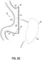
- FIG. 2 Edepicts the stomach anatomy resulting from a vertical sleeve gastrectomy.
- FIG. 3 Ais an elevation view of a resection line guide according to another embodiment.
- FIG. 3 Bis an elevation view of the resection line guide of FIG. 3 A positioned on the stomach.
- FIG. 3 Cis an elevation view of a section of a resection line guide according to another embodiment.
- FIG. 3 Dis an elevation view of the section of a resection line guide of FIG. 3 C positioned around the stomach.
- FIG. 3 Eis an elevation view of a resection line guide according to another embodiment.
- FIG. 3 Fis an elevation view of the resection line guide of FIG. 3 E after the resection line guide has been tensioned.
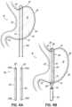
- FIG. 4 Ais an elevation view of a resection line guide according to another embodiment.
- FIG. 4 Bis an elevation view of the resection line guide of FIG. 4 A positioned on the stomach.
- FIG. 4 Cis an elevation view of a resection line guide according to another embodiment.
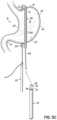
- FIG. 5 Ais an elevation view of a resection line guide according to another embodiment.
- FIG. 5 Bis an elevation view of a part of the placement of the resection line guide of FIG. 5 A around a stomach.
- FIG. 5 Cis an elevation view of a part of the placement of the resection line guide of FIG. 5 A around the stomach.
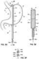
- FIG. 5 Dis an elevation view of the resection line guide FIG. 5 A placed around a stomach.
- FIG. 5 Eis a cross-sectional view of the resection line guide shown in FIG. 5 D .
- FIG. 5 Fis a cross-sectional view of a portion of the resection line guide according to another embodiment.
- FIG. 6depicts a schematic of a resection line guide according to another embodiment.
- FIG. 7is a perspective view of a resection line guide according to another embodiment.
- FIG. 8 Ais an elevation view of a resection line guide according to another embodiment.
- FIG. 8 Bis an elevation view of the resection line guide of FIG. 8 A placed around a stomach.
- FIG. 8 Cis a cross-sectional view of the resection line guide shown in FIG. 8 B .
- FIG. 9 Ais an elevation view of a resection line guide according to another embodiment.
- FIG. 9 Bis an elevation view of the resection line guide of FIG. 9 A placed around a stomach.
- FIG. 10 Ais an elevation view of a resection line guide according to another embodiment.
- FIG. 10 Bis an elevation view of the resection line guide of FIG. 10 A placed around a stomach.
- FIG. 10 Cis a partial cross-sectional view of the resection line guide of FIG. 10 B .
- FIGS. 11 A- 11 Fdepict schematics of a resection line guide including one or more flexible members according to various embodiment.
- FIGS. 12 A- 12 Gillustrate cross-sectional views of two clamp members of a resection line guide according to various embodiments.
- FIGS. 13 A- 13 Dare elevation views of two clamp members of a resection line guide according to various embodiments.
- FIGS. 13 E- 13 Hare elevation views of a clamp member of a resection line guide according to various embodiments.
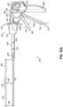
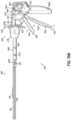
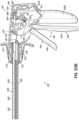
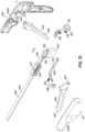
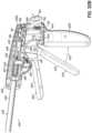
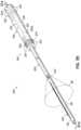
- FIG. 14is a perspective view of a medical device for use in a medical procedure according to one embodiment.
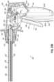
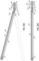
- FIGS. 15 A and 15 Bare partial sectional elevation views of the medical device of FIG. 14 with a resection line guide shown in an opened position and a closed position, respectively.
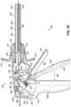
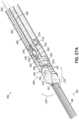
- FIG. 16is an enlarged elevation view of the resection line guide of the medical device of FIG. 14 .
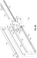
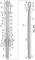
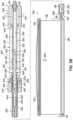
- FIG. 17 Ais a partially exploded view of the medical device of FIG. 14 .
- FIG. 17 Bis an exploded view of the medical device of FIG. 14 .
- FIG. 18is an exploded view of the medical device of FIG. 14 .
- FIG. 18 Ais an exploded view of an exemplary spring reel, shown in FIG. 18 .
- FIG. 19is a partial cross-sectional view of a manipulator of the medical device of FIG. 14 depicting engagement of a mechanism according to an embodiment.
- FIGS. 20 A, 20 B, and 20 Care partial cross-sectional views of the manipulator of FIG. 19 depicting engagement of a mechanism according to an embodiment.
- FIGS. 21 A and 21 Bare partial cross-sectional views of the manipulator of FIG. 19 depicting engagement of a mechanism according to an embodiment.
- FIG. 22is a partial cross-sectional view of the manipulator of FIG. 19 depicting release of the mechanisms according to an embodiment.
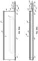
- FIG. 23 Ais a schematic cross-sectional view of a resection line guide of FIG. 16 in an opened position.
- FIG. 23 Bis another schematic cross-sectional view of the resection line guide of FIG. 16 in an opened position.
- FIG. 24 Ais a schematic cross-sectional view of the resection line guide of FIG. 16 in a closed position.
- FIG. 24 Bis another schematic cross-sectional view of the resection line guide of FIG. 16 in a closed position.
- FIG. 25is an exploded perspective view of a shaft of one embodiment of a manipulator.
- FIG. 26is a partial cross-sectional view of a manipulator of the medical device of FIG. 14 depicting engagement of a mechanism according to an embodiment.
- FIGS. 27 A and 27 Bare enlarged cross-sectional views of a joint according to an embodiment.
- FIG. 28is a schematic cross-sectional view of the resection line guide of FIG. 16 illustrating manipulation of the joint shown in FIGS. 27 A and 27 B .
- FIG. 29is a schematic cross-sectional view of the resection line guide of FIG. 16 depicting manipulation thereof.
- FIG. 30is a perspective view of a medical device for use in a medical procedure according to one embodiment.
- FIG. 31is an exploded perspective view of a manipulator of the medical device of FIG. 30 .
- FIGS. 32 A and 32 Bare partial cross-sectional views of the manipulator of the medical device of FIG. 30 depicting engagement of a mechanism according to an embodiment.
- FIG. 32 Cis a cross-sectional view of a resection line guide of the medical device of FIG. 30 .
- FIGS. 33 A and 33 Bare partial cross-sectional views of the manipulator of the medical device of FIG. 30 depicting engagement of a mechanism according to an embodiment.
- FIG. 33 Cis a cross-sectional view of a resection line guide of the medical device of FIG. 30 .
- FIG. 33 Dis a cross-sectional view of the resection line guide of the medical device of FIG. 30 depicting the resection line guide in an opened position.
- FIGS. 34 A and 34 Bare partial cross-sectional views of the manipulator of the medical device of FIG. 30 depicting engagement of a mechanism according to an embodiment.
- FIG. 34 Cis a cross-sectional view of the resection line guide of the medical device of FIG. 30 depicting the resection line guide in a closed position.
- FIG. 35is a perspective view of a medical device for use in a medical procedure according to one embodiment.
- FIG. 36is a perspective view of a resection line guide of the medical device of FIG. 35 with the resection line guide shown in an opened position.
- FIGS. 37 A and 37 Bare cross-sectional views of the medical device of FIG. 35 depicting engagement of a mechanism according to an embodiment.
- FIG. 38is a cross-sectional view of the medical device of FIG. 38 depicting engagement of a mechanism according to an embodiment.
- FIG. 39is a schematic diagram of an accumulator according to one embodiment.
- embodiments of the present inventionare directed to a resection line guide for directing the application of a resection line during a surgical procedure involving the resection of at least a part of an anatomical structure.
- the resection line guidemay be used in a vertical sleeve gastrectomy procedure.
- the resection line guideis a supplement to current practices of a sleeve gastrectomy, including the laparoscopic access, mobilization of the greater curvature of the stomach and multiple applications of a laparoscopic stapler to create the resection line.
- Laparoscopic surgeryis surgery inside of the abdominal cavity performed at a distance by the surgeon.
- Laparoscopic surgery instrumentationis designed to fit through small incisions in the abdominal wall, typically 5 mm to 15 mm in diameter.
- the abdominal access sitesare maintained by cannulae, or trocars, that are designed to maintain pressure in the abdominal cavity with valves that seal around an instrument shaft.
- Devices and methods for performing laparoscopic surgeryare well known in the prior art.
- the resection line guidemay act as a surgical clamp independent of its use as a guide to a medical instrument.
- the resection line guidemay also be used in other procedures involving anatomical structures, such as organs other than the stomach or soft tissue.
- the resection line guidemay be used in a parencymal resection, lung volume reduction surgery, or other procedures involving the lung.
- the resection line guidemay be useful in an anatomic resection such as a lobectomy, a non-anatomic parencymal resection, or other procedures involving the liver.
- a surgeon or other medical professionalmay benefit from using the resection line guide in a partial nephrectomy, total nephrectomy, or other procedures involving the kidney.
- the tissue of the anatomical structuremay be sealed. Tissue may be sealed by any method known in the art, such as, for example, stapling, suturing, gluing, and welding.
- aspects of the present inventionmay be illustrated in the context of a vertical sleeve gastrectomy, it should be appreciated that aspects of the disclosed technology may provide a benefit in a host of medical procedures on anatomical structures and be adapted for use in such medical procedures.
- FIG. 1illustrates the anatomy of the stomach 10 and a resection line 12 , where the resection line 12 represents a resection line for a vertical sleeve gastrectomy.
- the stomach 10generally includes a proximal end 14 , a distal end 16 , an anterior side 18 , and a posterior side 20 .
- the proximal and distal ends 14 , 16 of the stomachare described from the perspective of the operative surgeon.
- the gastroesophageal junction 22opens into the stomach 10 and is a common landmark in bariatric surgeries.
- the fundus 24 and the section of the stomach defined by the greater curvature 26are generally the parts of the stomach 10 removed during a vertical sleeve gastrectomy.
- the remaining pouchis generally defined by the lesser curvature 28 and the resection line 12 and presents a stomach with a significantly reduced volume.
- the desired location of the resection line 12is about 0.5 to 2 cm away from the gastroesophageal junction 22 and about 2 to 10 cm away from the pylorus 30 .
- resection line guides as described hereinaid in forming high quality, consistent resection lines during a medical procedure, such as a vertical sleeve gastrectomy.
- the resection line guidesprovide an accurate visual indication of the resection line and further provide a stabilizing engagement surface along which medical staplers may be guided during a resection procedure.
- the visualization and guiding aspects of the disclosed resection line guidesare believed to result in high quality and consistent resection lines that are significantly improved over resection lines produced by current methodologies.
- Various embodiments of the present inventionmay include a resection line guide including two clamp members capable of being operatively coupled to each other and movable relative to each other so as to provide a clamping force on an anatomical structure, such as a stomach.
- the ability of the resection line guides to generate a clamping forceallows the device to be reliably positioned relative to the anatomical structure in order to eliminate or reduce the likelihood of undesirable movements of the device during a stapling operation.
- a resection line guide 40includes a first clamp member 42 generally positionable on the anterior side 18 of the stomach 10 , and a second clamp member 44 generally positionable on the posterior side 20 of the stomach 10 , where the first clamp member 42 and the second clamp member 44 may be configured to be operatively coupled to effectuate a clamping force on the stomach 10 .
- the first clamp member 42 and the second clamp member 44essentially operate as a surgical clamping device for purposes described in more detail below.
- aspects of the present inventionare not limited to the illustrated arrangement, where the first clamp member 42 is on the anterior side 18 of the stomach 10 and the second clamp member 44 is on the posterior side 20 .
- the arrangementmay be reversed such that the first clamp member 42 is on the posterior side 20 of the stomach 10 and the second clamp member 44 is on the anterior side 18 of the stomach 10 (not shown).
- Other alternative arrangementsmay also be possible.
- first and second clamp members 42 , 44may be configured to be operatively coupled to each other to effectuate a clamping force on an anatomical structure.
- the clamp members 42 , 44couple together at both the proximal end 14 and distal end 16 of the stomach 10 .
- the clamp members 42 , 44may be coupled together using a variety of methods and engagement elements, such as that described below.
- the proximal and distal ends of one the clamp membersmay include a projection or pin that can be engaged or received by the proximal and distal ends of the other clamp member, respectively.
- the clamp membersmay be configured to connect using magnets, a clip-in connection, or other types of connections or connectors that are generally well known in the art.
- the connection method used at the proximal and distal ends of the clamp membersdo not need to be similar.
- the distal ends of the clamp membersmay be configured to connect using a clip-in connection, while the proximal end of one of the clamp members may be configured to slide through an opening on the proximal end of the other clamp member, where the opening is capable of receiving and gripping the proximal end of the one clamp member. Accordingly, there are many ways to couple the clamp members and the invention should not be limited to a certain type of connection.
- FIG. 2 Billustrates the resection line guide 40 placed around the stomach 10 with the clamp members 42 , 44 coupled together at both the proximal and distal ends 14 , 16 of the stomach 10 .
- the second clamp member 44may be inserted under (posterior to) the stomach 10 so that the distal end 44 a of the second clamp member 44 generally extends beyond the distal end 16 of the stomach 10 and the proximal end 44 b generally extends beyond the proximal end 14 of the stomach.
- the first clamp member 42may be inserted over (anterior to) the stomach 10 using laparoscopic instruments, for example, so that the distal end 42 a of the first clamp member 42 generally extends beyond the distal end 16 of the stomach 10 and the proximal end 42 b generally extends beyond the proximal end 14 of the stomach 10 .
- the resection line guide 40may be put in place and used with or without having to mobilize the greater curvature. For example, a surgeon may prefer to leave the greater curvature 26 attached to the omentum (not shown), which could improve stability of the stomach 10 during stapling.
- the distal end 44 a of the second clamp member 44may be received through the distal end 42 a of the first clamp member 42 .
- the proximal end 44 b of the second clamp member 44may be received through the proximal end 42 b of the first clamp member 42 .
- the distal and proximal ends 44 a , 44 bmay include a serrated tab 46 and the distal and proximal ends 42 a , 42 b may include a passage or bore 48 having an opening through which the serrated tabs 46 may pass.
- the tab 46 and bore 48operate as a flexible ratchet capable of bringing the clamp members 42 , 44 together to generate a clamping force.
- the bores 48may be configured to prevent the serrated tabs 46 from moving backwards through the openings.
- the clamp members 42 , 44may be further manipulated so as to provide a sufficient clamping force on the stomach 10 to effectively prevent or minimize the guide 40 from moving, but without damaging the clamped tissue.
- conventional graspersmay be used to pull the tabs 46 through the bores 48 .
- the resection line guide 40may include a release mechanism in the flexible ratchet that allows the tab 46 to be released from the bore 48 and thereby separate the two clamp members 42 , 44 . It should be appreciated that the flexible ratchet may take other forms other than that described above.
- the resection line guide 40may be positioned relative to the stomach 10 using a two-stage clamping process.
- the first and second clamp members 42 , 44may be configured to provide a certain amount of resistance to movement of the resection line guide 40 relative to the stomach 10 .
- the range of clamping force (or clamping pressure) in the first stagemay be about 0.5 g/mm 2 to about 4 g/mm 2 . This resistance is configured to prevent undesirable or unintentional movements of the resection line guide 40 , but yet permit the surgeon to move the resection line guide 40 to a desired position relative to the stomach 10 without significant difficulty.
- the clamping force of the resection line guide 40may be increased to effectively prevent or minimize the guide 40 from moving relative to the stomach 10 .
- the clamping force (or clamping pressure) in the second stagemay be about 4 g/mm 2 to about 12 g/mm 2 .
- the clamping force (or clamping pressure) in the second stagemay be about 8 g/mm 2 .
- the upper limit to which the resection line guide 40 may be clampedis selected so as to avoid any damage to the underlying tissue being clamped. This upper limit may be, for example, about 12 g/mm 2 .
- the value of about 4 g/mm 2represents a threshold clamping force below which constitutes the first stage clamping and above which constitutes the second stage clamping. It should be recognized that these values are merely exemplary and the particular values may depend on several factors, including the anatomical structure being clamped as well as other factors. Thus, the invention should not be limited to the range of values provided herein.
- the surgeonwhen the resection line guide 40 is placed on the stomach 10 (e.g., in the first clamping stage as described above), the surgeon has a clear visualization of the intended results of the vertical sleeve gastrectomy prior to actually performing the resection of the stomach 10 at the resection line 12 .
- the surgeonhas an indication of what the resultant stomach shape and volume defined by the lesser curvature 28 and the resection line 12 will likely be prior to cutting tissue. If the surgeon is not satisfied with the indication of the expected stomach shape and volume, the surgeon may adjust and manipulate the location and alignment of the resection line guide 40 prior to stapling and cutting the stomach 10 .
- the resection line guide 40should be positioned such that it does not provide lateral stretching or tension of the stomach 10 , which may create an undesirable environment for stapling and cutting.
- a resection line guidesuch as resection line guide 40 , ensures proper alignment of the resection line 12 so that the final cut with the stapler removes the fundus 24 portion, is a safe distance away from both the lesser curvature 28 and the gastroesophageal junction 22 , and is squared off at the fundus 24 of the stomach to prevent or reduce the likelihood of necrotic tissue development.
- the surgeonmay then cut and staple (e.g., using a stapler conventionally used in gastrectomy procedures) the tissue using the resection line guide 40 as a track along the entire segment or a significant part of the segment until complete resection of the stomach 10 occurs, as illustrated in FIGS. 2 C and 2 D .
- an aspect of the stapling device(such as an outer edge thereof), schematically shown as stapling device 50 , may abut or engage the resection line guide 40 along an alignment surface 52 to facilitate an improved resection line.
- the outer edges of one or both of the clamp members 42 , 44may operate as an alignment surface 52 configured to securely engage the stapling device 50 and thereby provide an improved resection line 12 . This may be by an abutting engagement.
- one or both of the clamp members 42 , 44may have a first connector and the stapling device 50 may have a second connector, wherein the first and second connectors are configured to movably couple the resection line guide 40 with the stapling device 50 during the resection (not shown).
- the guide 40may include connection features (not shown) such as a weak magnetic feature to attract the stapling device 50 , a channel that couples with a projection on the stapling device 50 that slides into the channel, etc.
- FIG. 2 Dillustrates the application of the stapling device 50 to the stomach 10 along the resection line guide 40 .
- connection featuressuch as a weak magnetic feature to attract the stapling device 50 , a channel that couples with a projection on the stapling device 50 that slides into the channel, etc.
- FIG. 2 Dillustrates the application of the stapling device 50 to the stomach 10 along the resection line guide 40 .
- conventional staplersare generally well known in the art, such staplers will not be described herein in further detail.
- the resection line guide 40may be secured to the stomach 10 so that it does not migrate or move once the surgeon begins stapling (e.g., the second clamping stage). Furthermore, the resection line guide 40 may be generally positioned so that it does not interfere with the activation of the stapling device 50 and ideal formation of each individual staple. As illustrated in FIGS. 2 A- 2 E , the use of the resection line guide 40 aids in creating an ideal gastric sleeve pouch size and shape ( FIG. 2 E ). In an embodiment such as one described above where the flexible ratchet includes a release mechanism, the surgeon may engage the release mechanism after completing the resection of the stomach 10 . This allows the tab 46 to be released from the bore 48 such that the tab 46 may be moved back through and free of the bore 48 . Consequently, the two clamp members 42 , 44 may be separated, and the resection line guide 40 may be removed from the abdominal cavity.
- the resection line guidemay have an articulated configuration for providing relative movement between the clamp members.
- a hingemay be provided at one of the proximal or distal ends of the clamp members to provide pivotable relative movement therebetween.
- FIGS. 3 A and 3 BSuch an embodiment is illustrated in FIGS. 3 A and 3 B , where the hinge may be configured as a living hinge.
- a resection line guide 70includes a first clamp member 72 generally positionable on the anterior side 18 of the stomach 10 and a second clamp member 74 generally positionable on the posterior side 20 of the stomach 10 , where the first clamp member 72 and the second clamp member 74 may be operatively coupled to effectuate a clamping force on the stomach 10 .
- the clamp members 72 , 74may be configured to be coupled at both the proximal and distal ends 14 , 16 of the stomach 10 . More particularly, the distal ends of the clamp members 72 , 74 may be configured as a hinge joint 76 . As noted above, the hinge joint 76 may be configured as a living hinge formed by a flexible band 78 having a first end coupled to the first clamp member 72 adjacent a distal end 72 a thereof and a second end coupled to the second clamp member 74 adjacent a distal end 74 a thereof. With such a living hinge, pivotal movement between the clamp members 72 , 74 may be achieved. As illustrated in FIG.
- the proximal end 74 b of the second clamp member 74may be received through the proximal end 72 b of the first clamp member 72 . More particularly and similar to that above, the proximal end 74 b of the second clamp member 74 may include a serrated tab 46 and the proximal end 72 b of the first clamp member 72 may include a passage or bore 48 having an opening through which the serrated tab 46 may pass.
- hinge joint 76may be at the proximal ends of the clamp members 72 , 74 and the serrated tab 46 /bore 48 may be at the distal ends of the clamp members 72 , 74 (not shown). Other arrangements may also be possible.
- the placement of the resection line guide 70 around the stomach 10is illustrated in FIG. 3 B .
- the surgeonmay manipulate the resection line guide 70 across the stomach 10 so that the first clamp member 72 is generally positioned along the anterior side 18 of the stomach 10 and the second clamp member 74 is generally positioned along the posterior side 20 of the stomach 10 .
- the distal ends 72 a , 74 a of the clamp members 72 , 74may generally extend beyond the distal end 16 of the stomach 10 and the proximal ends 72 b , 74 b of the clamp members 72 , 74 may generally extend beyond the proximal end 14 of the stomach 10 .
- the flexible band 78 between the clamp members 72 , 74may loop or extend around the distal end 16 of the stomach 10 , as illustrated in FIG. 3 B .
- the clamp members 72 , 74may be manipulated so as to provide a clamping force on the stomach 10 .
- the clamp members 72 , 74may be pivoted relative to each other in order to position the resection line guide 70 relative to the stomach 10 .
- the proximal end 72 b of the first clamp member 72 and the proximal end 72 b of the second clamp member 74may be coupled.
- the serrated tab 46may be pulled through the bore 48 at the proximal end 72 b of the first clamp member 72 , such as with conventional graspers.
- the securement of the resection line guide 70 to the stomach 10may be achieved using the two-stage clamping process as described above. More particularly, the tab 46 may be pulled through bore 48 so as to generate a clamping force on the stomach 10 less than the threshold clamping force.
- This first-stage clamping forceis configured and selected to provide a certain amount of resistance to movement of the resection line guide 70 relative to the stomach 10 .
- This resistanceis configured to prevent undesirable or unintentional movements of the resection line guide 70 , but yet permit the surgeon to move the resection line guide 70 to a desired position relative to the stomach 10 without significant difficulty.
- the clamping force of the resection line guide 70may be increased above the threshold clamping force to effectively prevent or minimize the resection line guide 70 from moving relative to the stomach 10 .
- the upper limit to which the resection line guide 70 may be clampedis selected so as to avoid any damage to the underlying tissue being clamped. This may be achieved in this embodiment, for example, by pulling the tab 46 further through the bore 48 .
- the surgeonWhen the resection line guide 70 is placed on the stomach 10 (e.g., in the first clamping stage as described above), the surgeon has a clear visualization of the intended results of the vertical sleeve gastrectomy prior to actually performing the resection of the stomach 10 at the resection line 12 . Hence, the surgeon has an indication of what the resultant stomach volume defined by the lesser curvature 28 and the resection line 12 will be prior to cutting tissue. If the surgeon is not satisfied with the indication of the expected stomach volume, the surgeon may adjust and manipulate the location and alignment of the guide prior to stapling and cutting the stomach 10 .
- the surgeonmay then cut and staple the tissue using the resection line guide 70 as a track along the entire segment or a significant part of the segment until complete resection of the stomach 10 occurs.
- the stapling device 50may abut or engage the resection line guide 70 along an alignment surface to facilitate an improved resection line, similar to that shown above in FIG. 2 D .
- the hinge that connects the first and second clamping membersmay take the form of a selectively formable hinge which may, for example, be formed internal to the abdominal cavity to provide pivotable relative movement between the clamp members.
- a resection line guide 54includes a first clamp member 56 generally positionable on the anterior side 18 of the stomach 10 and a second clamp member 58 generally positionable on the posterior side 20 of the stomach 10 , where the first clamp member 56 and the second clamp member 58 may be operatively coupled to effectuate a clamping force on the stomach 10 .
- the clamp members 56 , 58may be configured to be coupled at both the proximal and distal ends 14 , 16 of the stomach 10 (although the proximal end connection is not shown). More particularly, the distal ends of the first and second clamp members 56 , 58 may be configured as a formable hinge joint.
- the distal end of the second clamp member 58may include a ring or eyelet 57 having an opening
- the distal end of the first clamp member 56may include a hook 59 . With the hook 59 positioned within the eyelet 57 , the hinge joint is assembled and pivotal movement between the clamp members 56 , 58 may be achieved. Though not shown in FIG.
- the proximal ends of the clamp members 56 , 58may be configured to be coupled.
- the proximal end of the second clamp member 58may include a serrated tab and the proximal end of the first clamp member 56 may include a passage or bore having an opening through which the serrated tab may pass, similar to that above.
- Other types of connections at the proximal endsare also possible.
- the second clamp member 58may be inserted under (posterior to) the stomach 10 so that the distal end of the second clamp member 58 generally extends beyond the distal end 16 of the stomach 10 and the proximal end generally extends beyond the proximal end 14 of the stomach 10 .
- the first clamp member 56may be inserted over (anterior to) the stomach 10 using laparoscopic instruments, for example, so that the distal end of the first clamp member 56 generally extends beyond the distal end 16 of the stomach 10 and the proximal end generally extends beyond the proximal end 14 of the stomach 10 .
- the distal end of the second clamp member 58may be configured to flex or bend so that the distal end extends upwardly and around the distal end 16 of the stomach 10 .
- the hook 59 at the distal end of the first clamp member 56may be engaged within the eyelet 57 , thereby forming the hinge joint. This may be accomplished, for example, with conventional graspers (not shown).
- Being able to assemble the resection line guide 54 inside the abdominal cavitymay be advantageous in that it may allow for smaller trocars to be used because the entire guide does not have to fit simultaneously through a single trocar.
- the clamp members 56 , 58may be pivoted relative to each in order to position the resection line guide 54 relative to the stomach 10 .
- the proximal end of the first clamp member 56 and the proximal end of the second clamp member 58may be coupled (not shown).
- the securement of the resection line guide 54 to the stomach 10may be achieved using the two-stage clamping process as described above.
- the first-stage clamping forceis less than a threshold clamping force and is configured and selected to provide a certain amount of resistance to movement of the resection line guide 54 relative to the stomach 10 .
- This resistanceis configured to prevent undesirable or unintentional movements of the resection line guide 54 , but yet permit the surgeon to move the resection line guide 54 to a desired position relative to the stomach 10 without significant difficulty.
- the clamping force of the resection line guide 54may be increased above the threshold clamping force to effectively prevent or minimize the resection line guide 54 from moving relative to the stomach 10 .
- the upper limit to which the resection line guide 54 may be clampedis selected so as to avoid any damage to the underlying tissue being clamped.
- the surgeonWhen the resection line guide 54 is placed on the stomach 10 (e.g., in the first clamping stage as described above), the surgeon has a clear visualization of the intended results of the vertical sleeve gastrectomy prior to actually performing the division of the stomach 10 at the resection line 12 . Hence, the surgeon has an indication of what the resultant stomach volume defined by the lesser curvature 28 and the resection line 12 will be prior to cutting tissue. If the surgeon is not satisfied with the indication of the expected stomach volume, the surgeon may adjust and manipulate the location and alignment of the resection line guide 54 prior to stapling and cutting the stomach 10 .
- the surgeonmay then cut and staple the tissue using the resection line guide 54 as a track along the entire segment or a significant part of the segment until complete resection of the stomach 10 occurs.
- the stapling device 50may abut or engage the resection line guide 54 along an alignment surface to facilitate an improved resection line, similar to that shown above in FIG. 2 D .
- the hinge that connects the first and second clamping membersmay be a spring hinge.
- a resection line guide 60includes a first clamp member 62 generally positionable on the anterior side 18 of the stomach 10 and a second clamp member 64 generally positionable on the posterior side 20 of the stomach 10 , where the first clamp member 62 and the second clamp member 64 may be operatively coupled to effectuate a clamping force on the stomach 10 .
- the clamp members 62 , 64may be configured to be coupled at both the proximal and distal ends 14 , 16 of the stomach 10 .
- the distal ends of the clamp members 62 , 64may be configured as a hinge joint.
- the distal ends 62 a , 64 a of the clamp members 56 , 58may be coupled by the spring hinge 66 , which allows for pivotal movement between the clamp members 62 , 64 .
- Spring hingesare generally well known in the art and thus will not be described in further detail herein.
- the proximal ends 62 b , 64 b of the clamp members 62 , 64may be configured to be coupled. More particularly, the proximal ends 62 b , 64 b may be coupled by a flexible member 68 . Aspects of the flexible member according to the present embodiment are described in more detail below.
- connection at the proximal ends of the first and second clamp members 62 , 64are also possible. While this embodiment is illustrated with the hinge joint at the distal ends of the clamp members 62 , 64 and the flexible member 68 at the proximal ends of the clamp members 62 , 64 , it should be appreciated that in an alternative embodiment (not shown), the hinge joint may couple the proximal ends of the clamp members 62 , 64 and the flexible member 68 may couple the distal ends of the clamp members 62 , 64 .
- the resection line guide 60may be placed around the stomach 10 .
- the surgeonmay manipulate the resection line guide 60 across the stomach 10 so that the first clamp member 62 is generally positioned along the anterior side 18 of the stomach 10 and the second clamp member 64 is generally positioned along the posterior side 20 of the stomach 10 .
- the distal ends 62 a , 64 a of the clamp members 62 , 64generally extend beyond the distal end 16 of the stomach 10 and the proximal ends 62 b , 64 b of the clamp members 62 , 64 generally extend beyond the proximal end 14 of the stomach 10 .
- the spring hinge 66 between the first and second clamp members 62 , 64may extend around the distal end 16 of the stomach 10 .
- the clamp members 62 , 64may be pivoted relative to each in order to position the resection line guide 60 relative to the stomach 10 . This may be done, for example, with conventional graspers.
- the ends of the flexible member 68may be pulled, which tensions the flexible member 68 and decreases the length of the flexible member 68 that is between the clamp members 62 , 64 .
- the proximal ends 62 b , 64 b of the clamp members 62 , 64move towards each other, and the clamp members 62 , 64 begin to provide a clamping force on the stomach 10 .
- the securement of the resection line guide 60 to the stomach 10may be achieved using the two-stage clamping process as described above.
- the first-stage clamping forceis less than a threshold clamping force and is configured and selected to provide a certain amount of resistance to movement of the resection line guide 60 relative to the stomach 10 .
- This resistanceis configured to prevent undesirable or unintentional movements of the resection line guide 60 , but yet permit the surgeon to move the resection line guide 60 to a desired position relative to the stomach 10 without significant difficulty.
- the clamping force of the resection line guide 60may be increased above the threshold clamping force to effectively prevent or minimize the resection line guide 60 from moving relative to the stomach 10 .
- the upper limit to which the resection line guide 60 may be clampedis selected so as to avoid any damage to the underlying tissue being clamped. This may be achieved by pulling further on the ends of the flexible member 68 , which increases the tension on the flexible member 68 and increases the clamping force provided by the clamp members 62 , 64 .
- the surgeonWhen the resection line guide 60 is placed on the stomach 10 (e.g., in the first clamping stage as described above), the surgeon has a clear visualization of the intended results of the vertical sleeve gastrectomy prior to actually performing the division of the stomach 10 at the resection line 12 . Hence, the surgeon has an indication of what the resultant stomach volume defined by the lesser curvature 28 and the resection line 12 will be prior to cutting tissue. If the surgeon is not satisfied with the indication of the expected stomach volume, the surgeon may adjust and manipulate the location and alignment of the resection line guide 60 prior to stapling and cutting the stomach 10 .
- the surgeonmay then cut and staple the tissue using the resection line guide 60 as a track along the entire segment or a significant part of the segment until complete resection of the stomach 10 occurs.
- the stapling device 50may abut or engage the resection line guide 60 along an alignment surface to facilitate an improved resection line, similar to that shown above in FIG. 2 D .
- the flexible member 68may extend through substantially the full length of the clamp members 62 , 64 such that it extends between the distal ends 62 a , 64 a of the clamp members 62 , 64 along with the spring hinge 66 .
- This arrangement of the flexible member 68is shown in phantom in FIGS. 3 E and 3 F . This type of arrangement of the flexible member 68 is also described in more detail below. The operation of this alternative embodiment is similar to that described above for FIGS. 3 E and 3 F .
- the resection line guidemay have a pair of clamp members coupled by an elongate flexible member capable of being tensioned so as to produce a clamping force on an anatomical structure, such as stomach 10 .
- FIGS. 4 A- 4 Cillustrate such an embodiment.
- the resection line guide 80includes a first clamp member 82 generally positionable on the anterior side 18 of the stomach 10 and a second clamp member 84 generally positionable on the posterior side 20 of the stomach 10 , where the first clamp member 82 and the second clamp member 84 may be operatively coupled by a flexible member 86 to effectuate a clamping force on the stomach 10 .
- the flexible member 86may include a flexible cable.
- the clamp members 82 , 84may be configured as hollow bodies having a generally rectangular cross section and a length in a longitudinal direction which may exceed the length of the stomach 10 along the resection line 12 . In an alternative embodiment, however, the clamp members 82 , 84 may be generally solid. Additionally, the cross-sectional shape of the clamp members may also differ, as is noted below. In an exemplary embodiment, each of the clamp members 82 , 84 may be a unity, monolithic member. However, in an alternative embodiment, the clamp members 82 , 84 may be formed from a plurality of individual clamp segments that collectively form a clamp member. Such an embodiment, which is discussed below in greater detail, may allow the length of a clamp member to be easily varied.
- each of the clamp members 82 , 84may include openings 88 at their distal ends 82 a , 84 a and proximal ends 82 b , 84 b (or through bores in the case of solid clamp members) so as to allow the flexible member 86 to extend through and along the length of the clamp members 82 , 84 .
- the clamp members 82 , 84are essentially threaded onto the flexible member 86 .
- the clamp members 82 , 84are also generally movable relative to the flexible member 86 , such as along the length thereof.
- the flexible member 86does not have to extend through (e.g., internal of) the clamp members 82 , 84 , but may extend along an outer surface of the clamp members 82 , 84 , such as through eyelets or the like positioned along a surface of the clamp members 82 , 84 (not shown).
- both clamp members 82 , 84do not have to be movable along the flexible member 86 .
- one of the clamp members 82 , 84may be fixed relative to the flexible member 86 and the other of the clamp members 82 , 84 may be movable relative to the flexible member 86 .
- FIGS. 4 A and 4 Billustrate the placement of the resection line guide 80 around the stomach 10 .
- the surgeonmay manipulate the flexible member 86 around the distal end 16 of the stomach 10 without having one or both clamp members 82 , 84 thereon.
- the surgeonmay then thread or manipulate the second clamp member 84 onto an end of the flexible member 86 and slide the second clamp member 84 along the flexible member 86 until the second clamp member 84 is generally positioned on the posterior side 20 of the stomach 10 .
- the distal end 84 amay generally extend beyond the distal end 16 of the stomach 10 and the proximal end 84 b may generally extend beyond the proximal end 14 of the stomach 10 .
- the surgeonmay thread or manipulate the first clamp member 82 onto the flexible member 86 such that the first clamp member 82 is generally positioned on the anterior side 18 of the stomach 10 .
- the first clamp member 82may be threaded or manipulated onto the other end of the flexible member 86 .
- the distal end 82 amay generally extend beyond the distal end 16 of the stomach 10 and the proximal end 82 b may generally extend beyond the proximal end 14 of the stomach 10 .
- the order of applying the clamp members onto the flexible membersmay be reversed. Being able to assemble the resection line guide 80 inside the abdominal cavity may be advantageous in that it may allow for smaller trocars to be used because the entire guide does not have to fit simultaneously through a single trocar.
- the resection line guide 94may be pre-assembled and then inserted into the abdominal cavity as a unit.
- the surgeonmay manipulate the guide 94 across the stomach 10 so that the first clamp member 96 is generally positioned along the anterior side 18 of the stomach 10 and the second clamp member 98 is generally positioned along the posterior side 20 of the stomach 10 .
- the distal ends 96 a , 98 a of the clamp members 96 , 98generally extend beyond the distal end 16 of the stomach 10 and the proximal ends 96 b , 98 b of the clamp members 96 , 98 generally extend beyond the proximal end 14 of the stomach 10 .
- the section of the flexible member 86 between the clamp members 96 , 98may be loop or extend around the distal end 16 of the stomach 10 , as illustrated in FIG. 4 B .
- the clamp members 96 , 98may be manipulated so as to provide a clamping force on the stomach 10 . This clamping may be achieved by tensioning the flexible member 86 .
- the resection line guides 80 , 94may include a device for tensioning the flexible member 86 thereby providing a clamping force on the anatomical structure, such as the stomach 10 (the process being described below with reference to resection line guide 80 ).
- a tensioning devicemay include a tube 90 that operates in conjunction with the flexible member 86 and clamp members 82 , 84 to generate a clamping force between the clamp members 82 , 84 .
- the flexible member 86may extend through the tube 90 such that, for example, the ends thereof may be positioned outside the body, and thereby be more easily manipulated by the surgeon. The ends of the flexible member 86 may also remain within the abdominal cavity. In any event, the surgeon may then pull on the ends of the flexible member 86 while the end 92 of the tube 90 pushes against the proximal ends 82 b , 84 b of the clamp members 82 , 84 , which are not permitted to pass into the tube 90 . When the flexible member 86 is initially pulled, slack in the flexible member 86 is thereby taken up and the clamp members 82 , 84 move towards each other.
- the clamping force on the stomach 10begins to increase along the length of the clamp members 82 , 84 .
- the length of the intermediate segment of the flexible member 86 between the clamp members 82 , 84decreases.
- tensioning the flexible member 86also generally aligns the clamp members 82 , 84 .
- tension in the flexible member 86may generally vertically align the clamp members 82 , 84 relative to the stomach 10 .
- the clamp members 82 , 84may slide along the flexible member 86 during this tensioning.
- the securement of the resection line guides 80 , 94 to the stomach 10may be achieved using the two-stage clamping process as described above. More particularly, the flexible member 86 may be pulled so as to generate a clamping force on the stomach 10 less than the threshold clamping force. Again, this first-stage clamping force is configured and selected to provide a certain amount of resistance to movement of the resection line guide 80 relative to the stomach 10 . This resistance is configured to prevent undesirable or unintentional movements of the resection line guide 80 , but yet permit the surgeon to move the resection line guide 80 to a desired position relative to the stomach 10 without significant difficulty.
- the clamping force of the resection line guide 80may be increased above the threshold clamping force to effectively prevent or minimize the resection line guide 80 from moving relative to the stomach 10 .
- the upper limit to which the resection line guide 80 may be clampedis selected so as to avoid any damage to the underlying tissue being clamped. This may be achieved in this embodiment by pulling the ends of the flexible member 86 while pushing further against the proximal ends 82 b , 84 b of the clamp members 82 , 84 using the tube 90 .
- the surgeonWhen the resection line guide 80 is placed on the stomach 10 (e.g., in the first clamping stage as described above), the surgeon has a clear visualization of the intended results of the vertical sleeve gastrectomy prior to actually performing the resection of the stomach 10 at the resection line 12 . Hence, the surgeon has an indication of what the resultant stomach volume defined by the lesser curvature 28 and the resection line 12 will be prior to cutting tissue. If the surgeon is not satisfied with the indication of the expected stomach volume, the surgeon may adjust and manipulate the location and alignment of the resection line guide 80 prior to stapling and cutting the stomach 10 .
- the surgeonmay then cut and staple the tissue using the resection line guide 80 as a track along the entire segment or a significant part of the segment until complete resection of the stomach 10 occurs.
- the stapling device 50may abut or engage the resection line guide 80 along an alignment surface to facilitate an improved resection line, similar to that shown above in FIG. 2 D .
- a resection line guidemay have clamp members formed from a plurality of clamp segments in order to allow the length of the clamp members to be more easily varied to fit a certain application.
- FIGS. 5 A- 5 Eillustrate such an embodiment.
- the resection line guide 100includes a first clamp member 102 generally positionable on the anterior side 18 of the stomach 10 and a second clamp member 104 generally positionable on the posterior side 20 of the stomach 10 , where the first clamp member 102 and the second clamp member 104 may be operatively coupled by a flexible member 106 to effectuate a clamping force on the stomach 10 .
- the flexible member 106may include a flexible cable, however, alternative embodiments of the flexible member, as described below, may also be used.
- the clamp members 102 , 104may be formed from a plurality of clamp segments 108 serially arranged in order to form the clamp members 102 , 104 .
- the clamp segments 108may be configured as hollow bodies having a generally rectangular cross section and a length in a longitudinal direction which may be significantly less than the length of the stomach 10 along the resection line 12 .
- the clamp segments 108may be generally solid. Additionally, the cross-sectional shape of the clamp segments 108 may also differ, as described below.
- each of the clamp segments 108may include openings at their distal ends and proximal ends (or through bores in the case of solid clamp members) so as to allow the flexible member 106 to extend through the clamp segments 108 .
- the clamp segments 108are essentially threaded onto the flexible member 106 and are also generally movable relative to the flexible member 106 , such as along the length thereof.
- the flexible member 106does not have to extend through (e.g., internal of) the clamp segments 108 , but may extend along an outer surface of the clamp segments 108 , such as through eyelets or the like along a surface of the clamp segments 108 (not shown).
- Adjacent clamp segments 108 of the first and second clamp members 102 , 104may be configured to couple to each other, such as using a tape or other type of fastener.
- adjacent clamp segments 108may simply be configured to abut each other without any fixed connection therebetween.
- each adjacent segmentmay include a confronting, generally planar faces which abut against each other when the flexible member 106 is tensioned.
- adjacent clamp segments 108 of the clamp members 102 , 104may be configured to abut each other, and include an interlock configuration between the two adjacent clamp segments.
- FIG. 5 Fillustrates two adjacent clamp segments 108 a and 108 b including an interlock configuration.
- clamp segment 108 aincludes a projection 108 c that extends from the main body of the clamp segment 108 a
- clamp segment 108 bincludes a recess 108 d that extends into the main body of the clamp segment 108 b .
- the adjacent clamp segments 108 a , 108 bengage each other through abutting contact.
- the projection 108 cis positioned within the recess 108 d to provide the interlock.
- the interlock between adjacent clamp segments 108may more firmly stabilize the clamp members 102 , 104 during use but yet also allow for a variable length.
- FIGS. 5 B and 5 Cillustrate the placement of the resection line guide 100 around the stomach 10 in accordance with another embodiment.
- the surgeonmay manipulate a leading end 106 b of the flexible member 106 over the stomach 10 along the anterior side 18 and pull it around to the posterior side 20 of the stomach 10 , such as with a grasper 112 .
- the leading end 106 b of the flexible member 106may then be pulled around the stomach 10 until the second clamp member 104 is generally positioned on the posterior side 20 of the stomach 10 and the first clamp member 102 is generally positioned on the anterior side 18 of the stomach 10 , as shown in FIG. 5 C .
- clamp segments 108may be added or removed to provide the desired length to the clamp members 102 , 104 .
- a new clamp segment 108may be threaded onto an end (dictated by which clamp member is having its length adjusted) of the flexible member 106 and slid along the length thereof to position the segment in the desired location.
- the distal end 104 a of the second clamp member 104may generally extend beyond the distal end 16 of the stomach 10 and the proximal end 104 b of the second clamp member 104 may generally extend beyond the proximal end 14 of the stomach 10 .
- the distal end 102 a of the first clamp member 102may generally extend beyond the distal end 16 of the stomach 10 and the proximal end 102 b of the first clamp member 102 may generally extend beyond the proximal end 14 of the stomach 10 .
- the flexible member 106may be positioned around the stomach 10 first and then the clamp members 102 , 104 assembled onto the flexible member 106 , in a manner similar to that described above in FIG. 4 A .
- Being able to assemble the resection line guide 100 inside the abdominal cavitymay be advantageous in that it may allow for smaller trocars to be used because the entire guide does not have to fit simultaneously through a single trocar.
- the clamp members 102 , 104may be manipulated so as to provide a clamping force on the stomach 10 . This clamping force may be achieved by tensioning the flexible member 106 .
- the resection line guide 100may include a device for tensioning the flexible member 106 , thereby providing a clamping force on the anatomical structure, such as the stomach 10 .
- a tensioning devicemay include a cinch ring 110 and a cinch tube 90 that are configured to operate in conjunction with the flexible member 106 and the clamp members 102 , 104 to generate a clamping force between the clamp members 102 , 104 .
- the flexible member 106may extend through the cinch ring 110 and tube 90 such that, for example, the ends 106 a , 106 b thereof may be positioned outside the body, and thereby more easily manipulated by the surgeon.
- the ends 106 a , 106 bmay also remain in the abdominal cavity but be positioned proximal of the cinch ring 110 and tube 90 .
- the surgeonmay then pull on the ends 106 a , 106 b of the flexible member 106 while the end 92 of the tube 90 pushes against the proximal end 114 of the cinch ring 110 .
- the distal end 116 of the cinch ring 110will engage against the proximal ends 102 b , 104 b of the clamp members 102 , 104 , which are not permitted to pass through the cinch ring 110 .
- the clamp members 102 , 104 , and the clamp segments 108 that form these membersmay slide along the flexible member 106 during this tensioning.
- the cinch ring 110is configured to maintain tension in the flexible member 106 once it is applied.
- the cinch ring 110may be a rubber ring or the like such that friction maintains the tension in the flexible member 106 .
- the cinch ring 110may take other forms to maintain the tension in the flexible member 106 .
- the securement of the resection line guide 100 to the stomach 10may be achieved using the two-stage clamping process as described above. More particularly, the flexible member 106 may be pulled so as to generate a clamping force on the stomach 10 less than the threshold clamping force. Again, this first-stage clamping force is configured and selected to provide a certain amount of resistance to movement of the resection line guide 100 relative to the stomach 10 . This resistance is configured to prevent undesirable or unintentional movements of the resection line guide 100 , but yet permit the surgeon to move the resection line guide 100 to a desired position relative to the stomach 10 without significant difficulty.
- the clamping force of the resection line guide 100may be increased above the threshold clamping force to effectively prevent or minimize the resection line guide 100 from moving relative to the stomach 10 , as shown in FIG. 5 E .
- the upper limit to which the guide 100 may be clampedis selected so as to avoid any damage to the underlying tissue being clamped. This may be achieved in this embodiment by pulling the ends 106 a , 106 b of the flexible member 106 while pushing against the proximal ends 102 b , 104 b of the clamp members 102 , 104 using the tube 90 and cinch ring 110 .
- the surgeonWhen the resection line guide 100 is placed on the stomach 10 (e.g., in the first clamping stage as described above), the surgeon has a clear visualization of the intended results of the vertical sleeve gastrectomy prior to actually performing the resection of the stomach 10 at the resection line 12 . Hence, the surgeon has an indication of what the resultant stomach volume defined by the lesser curvature 28 and the resection line 12 will be prior to cutting tissue. If the surgeon is not satisfied with the indication of the expected stomach volume, the surgeon may adjust and manipulate the location and alignment of the resection line guide prior to stapling and cutting the stomach 10 .
- the surgeonmay then cut and staple the tissue using the resection line guide 100 as a track along the entire segment or a significant part of the segment until complete resection of the stomach 10 occurs.
- the stapling device 50may abut or engage the resection line guide 100 along an alignment surface to facilitate an improved resection line, similar to that shown above in FIG. 2 D .
- FIG. 6illustrates another embodiment of a resection line guide in accordance with an embodiment where the clamp members may include a biasing mechanism that biases the clamp members toward one another, thereby generating a clamping force when the guide is placed about an anatomical structure.
- a resection line guide 120includes a first clamp member 122 generally positionable on the anterior side 18 of the stomach 10 and a second clamp member 124 generally positionable on the posterior side 20 of the stomach 10 , where the first clamp member 122 and the second clamp member 124 may be operatively coupled to effectuate a clamping force on the stomach 10 .
- the first and second clamp members 122 , 124may be coupled by a first flexible member 126 and a second flexible member 128 .
- the first flexible member 126may have a first end 130 fixed to the first clamp member 122 adjacent the distal end 122 a thereof and pass out of the first clamp member 122 adjacent the distal end 122 a .
- the flexible member 126may then pass into the second clamp member 124 adjacent a distal end 124 a thereof and extend along at least a portion of the second clamp member 124 toward the proximal end 124 b thereof.
- a second end 132 of the flexible member 126may be fixed to the second clamp member 124 by a biasing device 134 , which when activated creates a tension in the first flexible member 126 .
- the biasing device 134may be generally positioned adjacent a central portion of the clamp member 124 . Other positions, however, are possible.
- the biasing device 134may include a spring, an elastic deformable block (e.g., a rubber block), or other device capable of being biased so as to generate a tension in the first flexible member 126 .
- the length of the flexible members 126 , 128 that is between the clamp members 122 , 124may be externally controlled.
- the flexible members 126 , 128may be externally manipulated to cause the clamp members 122 , 124 to be separated by about 2 to 6 cm, while keeping the clamp members 122 , 124 generally parallel. Consequently, the surgeon would not separate the clamp members 122 , 124 laparoscopically.
- the second flexible member 128may have a first end 136 fixed to the first clamp member 122 adjacent the proximal end 122 b thereof and pass out of the first clamp member 122 adjacent the proximal end 122 b .
- the flexible member 128may then pass into the second clamp member 124 adjacent a proximal end 124 b thereof and extend along at least a portion of the second clamp member 124 toward the distal end 124 a thereof.
- a second end 138 of the flexible member 128is fixed to the second clamp member 124 by a biasing device 140 , which when activated creates a tension in the second flexible member 128 .
- the biasing device 140may be generally positioned adjacent a central portion of the clamp member 124 .
- the flexible members and biasing devicesmay be provided in a different arrangement as that shown in FIG. 6 .
- the biasing devicesmay be located in the first clamp member 122 .
- one biasing devicemay be located in the first clamp member 122 and the second biasing device may be located in the second clamp member 124 .
- Other arrangementsmay also be possible.
- the resection line guide 120may be inserted into the abdominal cavity through a surgical trocar and positioned along the stomach 10 .
- the surgeonmay spread the first and second clamp members 122 , 124 apart from each other using standard laparoscopic instruments and graspers, for example.
- the clamp members 122 , 124may include attachment points or tabs (not shown) that facilitate grasping the clamp members by the laparoscopic instruments.
- the biasing devices 134 , 140activate (or they are pre-activated) to create a biasing force in a direction that directs the clamp members 122 , 124 toward each other.
- This biasing forcemay be overcome by the surgeon using the graspers in order to allow the surgeon to locate the resection line guide 120 on the stomach 10 , where the first clamp member 122 generally extends along the anterior side 18 of the stomach 10 and the second clamp member 124 generally extends along the posterior side 20 of the stomach 10 .
- the surgeonmay slowly release the hold on the clamp members 122 , 124 with the graspers. Due to the bias of the biasing devices 134 , 140 , the clamp members 122 , 124 move toward each other and generate a clamping force on the tissue between the members.
- the biasing devices 134 , 140may be selected to provide a clamping force effective to prevent or minimize the resection line guide 120 from moving relative to the stomach 10 . Due the particular design of this embodiment, there may only be a single stage of clamping to secure the resection line guide 120 on the stomach 10 .
- the upper limit to which the resection line guide 120 may be clampedis selected so as to avoid any damage to the underlying tissue being clamped.
- This clamping forcemay be controlled by properly selecting the biasing generated by the biasing devices 134 , 140 . For example, when the biasing devices 134 , 140 are configured as springs, the spring constants may be selected to provide the desired clamping force.
- the surgeonWhen the resection line guide 120 is initially placed on the stomach 10 , the surgeon has a clear visualization of the intended results of the vertical sleeve gastrectomy prior to actually performing the resection of the stomach 10 at the resection line 12 . Hence, the surgeon has an indication of what the resultant stomach volume defined by the lesser curvature 28 and the resection line 12 will be prior to cutting tissue. If the surgeon is not satisfied with the indication of the expected stomach volume, the surgeon may adjust and manipulate the location and alignment of the resection line guide 120 prior to stapling and cutting the stomach 10 . For example, the laparoscopic graspers may be used to separate the clamp members 122 , 124 and thereby allow the resection line guide 120 to be moved to an alternate position.
- the surgeonmay then cut and staple the tissue using the resection line guide 120 as a track along the entire segment or a significant part of the segment until complete resection of the stomach 10 occurs.
- the stapling device 50may abut or engage the resection line guide 120 along an alignment surface to facilitate an improved resection line, similar to that shown above in FIG. 2 D .
- FIG. 7illustrates another embodiment of a resection line guide in accordance with an embodiment where the clamp members may include a biasing mechanism that biases the clamp members toward one another to generate a clamping force when the guide is placed about an anatomical structure.
- a resection line guide 142includes a first clamp member 144 generally positionable on the anterior side 18 of the stomach 10 and a second clamp member 146 generally positionable on the posterior side 20 of the stomach 10 , where the first clamp member 144 and the second clamp member 146 may be operatively coupled to effectuate a clamping force on the stomach 10 .
- the first and second clamp members 144 , 146may be coupled by a first member 148 and a second member 150 . More particularly, the first member 148 may have a first end 152 coupled to the first clamp member 148 adjacent the distal end 144 a thereof and a second end 154 coupled to the second clamp member 146 adjacent the distal end 146 a thereof. In a similar manner, the second member 150 may have a first end 156 coupled to the first clamp member 144 adjacent the proximal end 144 b thereof and a second end 158 coupled to the second clamp member 146 adjacent the proximal end 146 b thereof. In accordance with this embodiment, the first and second members 144 , 146 may be configured to be biased so as to generate a clamping force between the clamp members.
- the first and second members 148 , 150may be configured as elastic bands (e.g., rubber bands) such that when the bands are pulled apart, tension is created within the members 148 , 150 that tends to drive the clamp members 144 , 146 toward each other.
- the first and second members 144 , 146may be formed as shape memory elements.
- Shape memory elementshave a set shape that they essentially “remember” such that when the shape elements are deformed, they generate a return force directing the element back to its set or remembered shape.
- the shape memory elementsmay take the form of nitinol (NiTi) wires, bands, cables or such wires, bands or cables made of other shape memory materials.
- the shape memory elementsmay be those described in U.S. Patent Application Publication No. 2009/0012545, which is hereby incorporated by reference herein in its entirety.
- the shape memory elementsmay also take other forms.
- the resection line guide 142may be inserted into the abdominal cavity through a surgical trocar and positioned along the stomach 10 .
- the surgeonmay spread the first and second clamp members 144 , 146 apart from each other using standard laparoscopic instruments and graspers, for example.
- the clamp members 144 , 146may include attachment points (not shown) that facilitate grasping the clamp members 144 , 146 by the laparoscopic instruments.
- the first and second members 148 , 150generate a biasing force in a direction that directs the clamp members 144 , 146 toward each other.
- This biasing forcemay be overcome by the surgeon using the graspers in order to allow the surgeon to locate the resection line guide 142 on the stomach 10 , where the first clamp member 144 generally extends along the anterior side 18 of the stomach 10 and the second clamp member 146 generally extends along the posterior side 20 of the stomach 10 .
- the surgeonmay slowly release the hold on the clamp members 144 , 146 with the graspers. Due to the bias of the members 148 , 150 , the clamp members 144 , 146 move toward each other and generate a clamping force on the tissue between the members.
- the biasing force from the members 148 , 150may be selected to provide a clamping force effective to prevent or minimize the resection line guide 142 from moving relative to the stomach 10 . Due the particular design of this embodiment, there may only be a single stage of clamping to secure the resection line guide 142 on the stomach 10 .
- the upper limit to which the resection line guide 142 may be clampedis selected so as to avoid any damage to the underlying tissue being clamped.
- This clamping forcemay be controlled by properly selecting the biasing generated by the members 148 , 150 .
- the set position of the elementsmay be selected in a manner that controls the ultimate clamping force of the clamp members 144 , 146 .
- the surgeonWhen the resection line guide 142 is initially placed on the stomach 10 , the surgeon has a clear visualization of the intended results of the vertical sleeve gastrectomy prior to actually performing the resection of the stomach 10 at the resection line 12 . Hence, the surgeon has an indication of what the resultant stomach volume defined by the lesser curvature 28 and the resection line 12 will be prior to cutting tissue. If the surgeon is not satisfied with the indication of the expected stomach volume, the surgeon may adjust and manipulate the location and alignment of the resection line guide 142 prior to stapling and cutting the stomach 10 . For example, the laparoscopic graspers may be used to separate the clamp members 144 , 146 and thereby allow the resection line guide 142 to be moved to an alternate position.
- the surgeonmay then cut and staple the tissue using the resection line guide 142 as a track along the entire segment or a significant part of the segment until complete resection of the stomach occurs.
- the stapling device 50may abut or engage the resection line guide 142 along an alignment surface to facilitate an improved resection line, similar to that shown above in FIG. 2 D .
- a resection line guidemay include a pair of clamp members having magnetic characteristics or features to produce a clamping force on an anatomical structure, such as stomach 10 .
- FIGS. 8 A- 8 Cillustrate such an embodiment.
- a resection line guide 160includes a first clamp member 162 generally positionable on the anterior side 18 of the stomach 10 and a second clamp member 164 generally positionable on the posterior side 20 of the stomach 10 , where the first clamp member 162 and the second clamp member 164 may be configured to effectuate a clamping force on the stomach 10 .
- clamp members 162 , 164are configured to magnetically couple to each other to provide a clamping force on the stomach 10 .
- the clamp members 162 , 164may be magnetized using methods known in the art.
- the clamp members 162 , 164may be coated in a ferromagnetic metal or other ferromagnetic material.
- the clamp members 162 , 164may contain a ferromagnetic metal or other ferromagnetic material.
- the ferromagnetic metal or other materialmay span the entire length of the clamp members 162 , 164 or may only cover a portion of their entire length.
- the clamp members 162 , 164may be formed as elongate members made of a ferromagnetic metal having a generally cylindrical cross-section and a length generally exceeding that of the stomach 10 .
- other arrangementsare possible as described below.
- FIG. 8 Billustrates the resection line guide 160 placed on the stomach 10 .
- the surgeonmay insert the second clamp member 164 into the abdominal cavity and position the second clamp member 164 generally on the posterior side 20 of the stomach 10 . More particularly, the distal end 164 a may generally extend beyond the distal end 16 of the stomach 10 and the proximal end 164 b may generally extend beyond the proximal end 14 of the stomach 10 .
- the surgeonmay insert the first clamp member 162 into the abdominal cavity and position the first clamp member 162 generally on the anterior side 18 of the stomach 10 .
- the distal end 162 amay generally extend beyond the distal end 16 of the stomach 10 and the proximal end 162 b may generally extend beyond the proximal end 14 of the stomach 10 .
- Being able to assemble the resection line guide 160 inside the abdominal cavitymay be advantageous in that it may allow for smaller trocars to be used because the entire guide does not have to fit simultaneously through a single trocar.
- a magnetic force developed between the two clamp members 162 , 164tends to drive the clamp members toward each other, similar to the biasing force in FIGS. 6 and 7 above.
- This magnetic forcemay be overcome by the surgeon using the graspers in order to allow the surgeon to locate the resection line guide 160 on the stomach 10 .
- the surgeonmay slowly release the hold on one of both of the clamp members 162 , 164 with the graspers. Due to the magnetic attraction, the clamp members 162 , 164 move toward each other and generate a clamping force on the tissue between the members.
- the magnetic forcemay be selected to provide a clamping force effective to prevent or minimize the resection line guide 160 from moving relative to the stomach 10 . Due the particular design of this embodiment, there may only be a single stage of clamping to secure the resection line guide 160 on the stomach 10 .
- the upper limit to which the guide 160 may be clampedis selected so as to avoid any damage to the underlying tissue being clamped.
- This clamping forcemay be controlled by properly selecting the magnetic characteristics of the clamp members 162 , 164 . Those of ordinary skill in the art will understand how to configure the magnetic characteristics of the clamp members 162 , 164 in order to achieve a desired clamping force.
- the surgeonWhen the resection line guide 160 is initially placed on the stomach 10 , the surgeon has a clear visualization of the intended results of the vertical sleeve gastrectomy prior to actually performing the resection of the stomach 10 at the resection line 12 . Hence, the surgeon has an indication of what the resultant stomach volume defined by the lesser curvature 28 and the resection line 12 will be prior to cutting tissue. If the surgeon is not satisfied with the indication of the expected stomach volume, the surgeon may adjust and manipulate the location and alignment of the resection line guide 160 prior to stapling and cutting the stomach 10 . For example, the laparoscopic graspers may be used to separate and move the clamp members 162 , 164 and thereby allow the resection line guide 160 to be moved to an alternate position.
- the surgeonmay then cut and staple the tissue using the resection line guide 160 as a track along the entire segment or a significant part of the segment until complete resection of the stomach 10 occurs.
- the stapling device 50may abut or engage the resection line guide 160 along an alignment surface to facilitate an improved resection line, similar to that shown above in FIG. 2 D .
- the resection line guide 160may be used in combination with a bougie 166 , which is generally known in the art and facilitates placement of the resection line guide 160 along the intended resection line 12 .
- the surgeonmay position the bougie 166 inside the stomach 10 by insertion through the mouth, for example ( FIG. 8 A ). With the bougie 166 so positioned, it defines an alignment surface 168 which may be used to properly position the first and second clamp members 162 , 164 along the intended resection line 12 , as described above.
- the bougie 166may include magnetic features that provide a magnetic attraction force between the bougie 166 and one or both of the clamp members 162 , 164 .
- the bougie 166may be coated in a ferromagnetic metal or other ferromagnetic material.
- the bougie 166may contain a ferromagnetic metal or other ferromagnetic material.
- the ferromagnetic metal or other materialmay span the entire length of the bougie or may only cover a portion of the entire length of the bougie.
- the clamp member 162 , 164may be attracted solely to the bougie 166 in order to generate the clamping force to secure the resection line guide 160 to the stomach 10 .
- the clamp members 162 , 164may be magnetically attracted to both the bougie 166 and the other clamp member.
- only one of the clamp membersmay be magnetically attracted to the bougie 166 and the other clamp member may be attracted solely to the other clamp member.
- FIGS. 9 A and 9 Billustrate another embodiment of a resection line guide utilizing magnetic attraction forces that facilitate locating the clamp members and/or that facilitate generating a clamping force on an anatomical structure, such as stomach 10 .
- This embodimentdiffers from other embodiments in that each clamp member does not extend along the anatomical structure for substantially the full length of the intended resection line 12 .
- the resection line guide 170includes a pair of retaining clips 172 and 174 .
- Each retaining clip 172 , 174includes a guide portion 176 and a resilient arm 178 extending from guide portion 176 and in general parallel relation thereto (e.g., so as to form a u-shaped profile).
- the resilient arm 178may be formed from metal, plastic or other materials suitable for a biological environment and capable of providing a resilient clamping force with guide portion 176 .
- the guide portions 176may be magnetized using methods known in the art.
- the guide portions 176may be coated in a ferromagnetic metal or other ferromagnetic material.
- the guide portions 176may contain a ferromagnetic metal or other ferromagnetic material.
- the ferromagnetic metal or other materialmay span the entire length of the guide portions 176 or may only cover a portion of their entire length.
- the length and width of the retaining clips 172 , 174may be varied according to surgeon preference and the procedure in which they are intended to be used. By way of example and without limitation, the width may range from 0.5 to 1 cm, and the length may range from 2 to 10 cm.
- FIG. 9 Billustrates the resection line guide 170 placed on the stomach 10 .
- the surgeonmay position the bougie 166 inside the stomach 10 by insertion through the mouth, for example. With the bougie 166 so positioned, it defines an alignment surface 168 which may be used to properly position the first and second retaining clips 172 and 174 along the intended resection line 12 .
- the surgeonmay insert the first retaining clip 172 into the abdominal cavity and position the first retaining clip 172 at the proximal end 14 of the stomach 10 .
- the guide portion 176is generally positioned on the anterior side 18 of the stomach 10 and the resilient arm 178 extends around the proximal end 14 and is generally positioned along the posterior side 20 of the stomach 10 .
- the second retaining clip 174may be positioned at the distal end 16 of the stomach 10 .
- the resiliency of the arm 178generates a clamping force so as to secure the retaining clip 172 to the stomach 10 .
- a magnetic forcedevelops between the guide portion 176 of the retaining clip 172 and the bougie 166 . This magnetic force, however, may be overcome by the surgeon using the graspers in order to allow the surgeon to locate the retaining clip 172 on the stomach 10 .
- the surgeonmay slowly release the hold on the retaining clip 172 with the graspers. Due to the magnetic attraction, the guide portion 176 and the bougie 166 move toward each other and generate a clamping force on the tissue therebetween. Once placed on the stomach 10 and mated with the bougie 166 , the surgeon may adjust the axial position of the retaining clip 172 relative to the retaining clip 174 to flatten the stomach and provide a flat, straight stapling surface.
- the magnetic forcemay be selected to provide a clamping force effective to prevent or minimize the resection line guide 170 from moving relative to the stomach 10 .
- the guide portion 176 and the resilient arm 178may be configured to generate a clamping force on the stomach 10 less than the threshold clamping force.
- This first-stage clamping forceis configured and selected to provide a certain amount of resistance to movement of the resection line guide 170 relative to the stomach 10 (e.g., movement of the retaining clips 172 , 174 along the stomach 10 ).
- This resistanceis configured to prevent undesirable or unintentional movements of the resection line guide 170 , but yet permit the surgeon to move the resection line guide 170 to a desired position relative to the stomach 10 without significant difficulty.
- the clamping force of the resection line guide 170may be increased above the threshold clamping force due to the magnetic forces developed between the guide portions 176 and the bougie 166 .
- the upper limit to which the resection line guide 170 may be clampedis selected so as to avoid any damage to the underlying tissue being clamped.
- the surgeonWhen the resection line guide 170 is initially placed on the stomach 10 , the surgeon has a clear visualization of the intended results of the vertical sleeve gastrectomy prior to actually performing the resection of the stomach 10 at the resection line 12 .
- the resection line guide 170may not extend across substantially the full length of the resection line 12 , the two retaining clips 172 , 174 , and more specifically, the guide portions 176 thereof, may provide an effective visualization of the intended resection line 12 , by demonstrating the beginning and ending portions of the resection line 12 .
- the two retaining clips 172 , 174may collectively extend between about 20% and about 100% of the resection line 12 , and preferably between 40% and 100% of the resection line.
- the surgeonhas a sufficiently good indication of what the resultant stomach volume defined by the lesser curvature 28 and the resection line 12 will be prior to cutting tissue. If the surgeon is not satisfied with the indication of the expected stomach volume, the surgeon may adjust and manipulate the location and alignment of the retaining clips 172 , 174 prior to stapling and cutting the stomach 10 .
- the laparoscopic graspersmay be used to separate and move the retaining clips 172 , 174 and thereby allow the resection line guide 170 to be moved to an alternate position.
- the surgeonmay then cut and staple the tissue using the resection line guide 170 as a track along a significant part of the segment until complete resection of the stomach 10 occurs.
- the stapling device 50may abut or engage the resection line guide 170 along an alignment surface to facilitate an improved resection line, similar to that shown above in FIG. 2 D .
- a resection line guide 180may include a light source configured to cooperate with a light collector or sensor to provide an indication of tissue thickness.
- a resection line guide 180includes a first clamp member 182 and a second clamp member 184 coupled by a living hinge 186 , similar to that shown in FIGS. 3 A and 3 B above.
- the second clamp member 184When placed on the stomach 10 , the second clamp member 184 may be generally positioned on the posterior side 20 of the stomach 10 , and the first clamp member 182 may be generally positioned on the anterior side 18 of the stomach 10 .
- the second clamp member 184may be made from a transparent or material, such as a transparent plastic like polycarbonate or other suitable biocompatible material, and include one or more light sources 188 configured to emit light into the tissue being clamped.
- the light sourcesmay include a series of LEDs spaced along the second clamp member 184 . It should be appreciated, however, that the light source can be other suitable sources for emitting light.
- At least a portion of the light from the light source 188is transmitted through the stomach tissue and is received at the first clamp member 182 .
- At least a portion of the first clamp member 182may be transparent and include one or more light sensors 190 configured to measure the amount of light being received.
- the amount of light received at the sensors 190may have a determinable correlation to the thickness of the tissue through which the light is transmitted.
- the resection line guide 180may be operatively coupled to a controller or other processor (not shown) capable of determining the tissue thickness based upon the amount of light emitted by the light source 188 and that received by sensors 190 . Such a thickness determination may aid the surgeon in choosing the proper staple size along the resection line 12 .
- the flexible membermay take several forms.
- the flexible membermay include a wire, suture, thread, chain, or other elongate flexible member.
- the flexible membermay be made of metal, plastic, or any other material that is suitable for a biological environment.
- the flexible membermay be, for example, a braided cable.
- the flexible membershould be capable of a radius of bend of approximately 0.030 inches and further be generally resistant to kinking, knotting, etc. Additionally, the flexible member should be able to accommodate a tensile load sufficient to generate a clamping force (pressure) above the maximum clamping force expected to be imposed during a procedure.
- the flexible membershould be able to accommodate a tensile load sufficient to create a clamping force of about 12 g/mm 2 on the anatomical structure.
- the flexible membershould be able to accommodate a tensile load of between about 25 to 50 lbs.
- the flexible membermay be a multi-strand stainless steel cable or a polymer, such as vectran.
- FIGS. 11 A- 11 Care schematic illustrations of exemplary configurations of two clamp members 192 , 194 and a flexible member 196 configured to be tensioned so as provide a clamping force between the clamp members 192 , 194 .
- the flexible member 196has a first end 196 a which is fixed to clamp member 194 adjacent a distal end 194 a thereof and passes through the second clamp member 194 adjacent the distal end 194 a .
- Flexible member 196then passes through the first clamp member 192 adjacent a distal end 192 a thereof and through and out of the first clamp member 192 adjacent a proximal end 192 b thereof.
- the second end 196 b of the flexible member 196may be positioned outside the body and pulled or otherwise manipulated by the surgeon so as to increase the tension in the flexible member 196 , and thereby generate a clamping force between clamp members 192 , 194 .
- the flexible member 196has a first end 196 a which is fixed to the second clamp member 194 adjacent the proximal end 194 b thereof and passes through the second clamp member 194 adjacent the proximal end 194 b thereof.
- the flexible member 196then passes through the first clamp member 194 adjacent a proximal end 192 b thereof, through the first clamp member 192 , out of the first clamp member 192 adjacent the distal end 192 a thereof, into the second clamp member 194 adjacent the distal end 194 a thereof, through the second clamp member 194 , and out the proximal end 194 b of clamp member 194 .
- the second end 196 b of the flexible member 196may be positioned outside the body and pulled or otherwise manipulated by the surgeon so as to increase the tension in the flexible member 196 , and thereby generate a clamping force between the clamp members 192 , 194 .
- the flexible member 196is fixed to the second clamp member 194 adjacent a proximal end 194 b thereof and extends along the length of the second clamp member 194 toward the distal end 194 a .
- the flexible member 196passes out of the second clamp member 194 adjacent the distal end 194 a thereof and passes into the first clamp member 192 adjacent the distal end 192 a thereof.
- the flexible member 196extends along the length of the first clamp member 192 and out of the first clamp member 192 adjacent the proximal end 192 b thereof. The flexible member 196 then passes back into the second clamp member 194 adjacent the proximal end 194 b thereof and out the proximal end 194 b of second clamp member 194 .
- the second end 194 bmay be positioned outside the body and pulled or otherwise manipulated by the surgeon so as to increase the tension in the flexible member 196 , and thereby generate a clamping force between the clamp members 192 , 194 .
- FIGS. 11 D- 11 Eare schematic illustrations of exemplary configurations of two clamp members 192 , 194 and two flexible members 196 , 198 configured to be tensioned so as provide a clamping force between the clamp members 192 , 194 .
- a first flexible member 196has a first end 196 a fixed to the first clamp member 192 adjacent the distal end 192 a thereof and passes out of the first clamp member 192 adjacent the distal end 192 a thereof.
- the first flexible member 196then passes into the second clamp member 194 adjacent a distal end 194 a thereof and extends along the second clamp member 194 and out of the proximal end 194 b thereof.
- the second end 194 b of the first flexible member 196may be positioned outside the body.
- the arrangementfurther includes a second flexible member 198 having a first end 198 a fixed to the first clamp member 192 adjacent the proximal end 192 b thereof and passes out of the first clamp member 192 adjacent the proximal end 192 b thereof.
- the second flexible member 198then passes into the second clamp member 194 adjacent a proximal end 194 b thereof and passes out of the proximal end 194 b thereof.
- the second end 198 b of the second flexible member 198may be positioned outside the body.
- the second ends 196 b , 198 bmay be pulled or otherwise manipulated by the surgeon so as to increase the tension in the flexible members 196 , 198 and thereby generate a clamping force between the clamp members 192 , 194 .
- this arrangementadvantageously provides for independent control of the clamping force of the proximal and the distal ends of the resection line guide.
- increasing the tension in the first flexible member 196will draw the distal ends 192 a , 194 a of clamp members 192 , 194 towards each other.
- the clamping force at the distal end of the resection line guideincreases.
- FIG. 11 Eillustrates the resection line guide according to the embodiment in FIG. 11 D where the distance between the distal ends 192 a , 194 a of the clamp members 192 , 194 is less than the distance between the proximal ends 192 b , 194 b creating an overall shape of the resection line guide that is generally trapezoidal.
- the clamp members 192 , 194may be in non-parallel relation. Consequently, the clamping force at the distal end of the resection line guide may be greater than the clamping force at the proximal end of the resection line guide when the resection line guide is placed around an anatomical structure.
- This ability to independently control the clamping force along the proximal and distal ends of the resection line guidemay be advantageous in certain applications. For instance, independently controlling the clamping force along the proximal and distal ends of the resection line guide may be advantageous where the tissue thickness of the anatomical structure varies along the length of the resection line.
- the distal end 14 of the stomach 10generally has a thickness less than that of the proximal end 16 of the stomach 10 . Accordingly, the ranges of clamping force used in the two-stage clamping process, as described above, may vary at the distal and proximal ends 14 , 16 of the stomach 10 . Using a resection line guide capable of providing a varying clamping force along the length of, for example, the stomach 10 may aid in creating an improved resection line.
- a first flexible member 196is coupled to first and second clamp members 192 , 194 in a manner similar to that described above for resection line guides 80 , 94 .
- this embodimentfurther includes a second flexible member 198 coupled to the first and second clamp members 192 , 194 in a manner similar to that described above for guides 80 , 94 .
- the first flexible member 196extends through the first and second clamp members 192 , 194 adjacent a first edge 200 thereof and the second flexible member 198 extends through the first and second clamp members 192 , 194 adjacent a second edge 202 thereof.
- This arrangementadvantageously provides for independent control of the right and the left sides of the resection line guide.
- increasing the tension in the first flexible member 196will increase the clamping force at the left side of the resection line guide.
- increasing the tension in the second flexible member 198will increase the clamping force at the right side of the resection line guide. This ability to control the clamping force along the right and left sides of the resection line guide may be advantageous in certain applications.
- the length of the clamp membershave been described as generally exceeding the length of the anatomical structure being clamped (e.g., stomach, lung, kidney, liver, etc.), the invention is not so limited. More particularly, the lengths of the clamping members may vary depending on the specific application to be greater or less than the length of the anatomical structure being clamped. Additionally, the first and second clamp members do not have to be of equal lengths, but may have different lengths. In exemplary embodiments, the two clamp members may be formed from plastic, metal, or other materials suitable for providing a clamping force in a biological environment (i.e., must be biologically compatible). The clamp members may be configured to distribute the clamping force provided to the anatomical structure across the length of the clamp members.
- the clamp membersmay be generally rigid. As noted above, the clamp members may be hollow, solid, partially hollow, or have other configurations. In the embodiments discussed herein, the two clamp members are illustrated as elongate members having a certain cross-section. However, the clamp members may have a variety of cross-sectional shapes, some of which are illustrated in FIGS. 12 A- 12 E . By way of example, the two clamp members 204 , 206 may have cross-sectional shapes that are rectangular ( FIG. 12 A ), cylindrical ( FIG. 12 B ), V-shaped ( FIG. 12 C ), half-moon ( FIG. 12 D-E ), or wavy ( FIG. 12 G ). The two clamp members 204 , 206 may have the same or different cross-sectional shapes.
- FIG. 12 Fillustrates an embodiment where the clamp member 204 may have a crescent cross-sectional shape, while the clamp member 206 may have a half-moon cross-sectional shape.
- the two clamp membersmay be formed as a unitary member or may be formed from a plurality of clamp segments as previously described.
- the surfaces of the clamp members that engage with the anatomical structuremay be textured to enhance the securement of the resection line guide to the anatomical structure.
- these surfacesmay include a traction pattern that facilitates the resistance of movement of the resection line guide relative to the underlying tissue.
- the traction patternmay be formed, for example, by ridges and grooves.
- the ridges and groovesmay be directed generally in the axial direction, the longitudinal direction, or in crisscrossed pattern.
- the surfacesmay be roughened, for example, with various post-processing methods generally known in the art. Other textured patterns may also be possible.
- the clamp membersmay have a longitudinal shape other than straight. This may be beneficial where the surgeon wants to create a non-linear resection line. For example, the surgeon may want to create a curved resection line that reflects the lesser curvature 28 of the stomach 10 .
- FIG. 13 Aillustrates an alternative embodiment where the two clamp members 208 , 210 may be generally arcuate or curved so as to generally correspond to the shape of the lesser curvature 28 of the stomach 10 .
- two clamp members 212 , 214may be made of segments connected by a tape 216 or other spine generally running the length of the two clamp members 212 , 214 .
- the tape 216on the side of the segments facing anatomical right, the sides of the segments facing the anatomical left may generally bend and flex outwardly, as illustrated in FIG. 13 B .
- the segmentsmay be sized based on a staple cartridge. By way of example, if the segments were between about 50 mm and about 60 mm in length, a curved resection line may be made by using one 60 mm staple cartridge per segment.
- the two clamp members 218 , 220may have a telescopic configuration (e.g., nested sections), as illustrated in FIG. 13 C , such that the length of the two clamp members 218 , 220 may be easily varied to meet the needs of a specific application.
- the two clamp members 224 , 226may be configured to be rigid in the longitudinal direction but malleable in a transverse direction.
- the clamp members 224 , 226may include a series of cut-outs or notches 228 that facilitate flexing or bending of the clamp members 224 , 226 in a generally transverse direction (e.g., left and right in the reference frame of FIG. 13 D ).
- each clamp member 224 , 226may include a mechanism allowing for external control of the transverse movement of the clamp members 224 , 226 .
- each clamp member 224 , 226may have one or more control lines coupled to one or more locations along the clamp members 224 , 226 that allow the clamp members to be flexed in a certain manner.
- the control linesmay include flexible, or rigid, or semi-rigid cables.
- tightening one of the flexible membersmay cause the clamp members 224 , 226 to flex.
- the device for tensioning the flexible membershould provide a sufficient clamping force for securing the guide onto the anatomical structure.
- the tensioning deviceshould be configured to implement the two-stage clamping described above.
- a variety of tensioning devicesmay be used to provide a tension in the flexible member in order to secure the resection line guide onto the anatomical structure.
- a cinch tubecan be used in conjunction with the flexible member and clamp members to generate a tension in the flexible member.
- a tensioning mechanism for tightening the flexible membermay include a tightener having a plunger, where the plunger may be lifted to slide the flexible member through and may be released to hold the flexible member in place.
- the tensioning devicemay be configured to move over and rest on the clamp members, such as at a proximal end thereof. Holding the clamp members together in this way may provide increased tension or secure the clamp members in order to generate the clamping force.
- certain embodiments of the present inventionmay provide an indication of the length of the resection line.
- knowing the length of the resection linemay aid the surgeon in planning the number of stapler applications that will be used to accomplish the resection.
- FIG. 13 Eillustrates an exemplary embodiment of a clamp member 230 (only one shown) having a series of markings 232 along the length of a clamp member 230 configured to provide an indication of distance. These markings 232 may be used to mark off distance, for example, in centimeters. Alternatively, the markings 232 may be used to mark off or estimate the number of staple firings that will be needed to resection the anatomical structure.
- certain embodiments of the present inventionmay provide an indication of the distance from the resection line guide to certain anatomical landmarks. Because anatomical landmarks are typically referred to when establishing the ideal resection line, it may be beneficial to know, or be able to more accurately estimate, the distance of the resection line guide to those landmarks.
- a clamp member of a resection line guidemay have a fixed and known width (e.g., 1 cm in width). Because the resection line is frequently 1 cm away from the gastroesophageal junction 22 , using a 1 cm wide clamp member that rests against the gastroesophageal junction 22 would assure a proper spacing from this anatomical landmark.
- the clamp membermay have markings indicating a specific width.
- a clamp member 234may be wider than 1 cm where a marking 236 may be included along the length of the clamp member 234 indicating a width of 1 cm, such as from one of the side edges thereof.
- the resection line guidemay include an adjustable measuring device capable of providing a physical scale for determining or estimating distance from the resection line guide.
- FIG. 13 Gillustrates an embodiment where a clamp member 238 includes a measuring arm 240 coupled to the clamp member 238 .
- the measuring arm 240may be movably coupled, e.g., such as pivotally coupled to the clamp member 238 .
- the measuring arm 240may have a known and pre-determined length.
- the measuring arm 240may include markings 246 indicating distance. This would allow the surgeon to pivot the measuring arm 240 away from the clamp member 238 and use the measuring arm 240 to determine or estimate the distance from the resection line guide to various anatomical landmarks.
- a pivotable armmay have a length of about 2 cm to about 6 cm. In one embodiment, the length of the measuring arm 240 may be variable. More than one of these components may be used the clamp member 238 . Additionally, or in the alternative, the measuring arm may be movable, e.g., slidable, along the length of the clamp member 238 , as is illustrated in FIG. 13 G .
- the measuring arm 240may slide within a longitudinal groove in the clamp member 38 .
- electronic distance measurementmay be possible.
- a reference pointmay be established on a clamp member and the other reference point may be associated with a laparoscopic instrument. In this way, as the instrument moves within the abdomen, electronic feedback may be provided to indicate the distance between the two reference points.
- the clamp member and instrumentmay be operatively coupled to a controller to provide the distance measurement.
- Certain embodiments of the present inventionmay provide an indication of the thickness of the anatomical structure to be stapled. This may be accomplished using a variety of methods.
- a light sourceis used to indicate the thickness of an anatomical structure.
- a clamp member 244may include longitudinal markings 246 indicating the distance from the lower edge of the clamp member facing the anatomical structure to be resected.
- FIG. 13 Hillustrates three longitudinal markings 246 along a side wall of a clamp member 244 . These markings may be, for example, markings of distance or markings based on staple leg lengths. In practice, different staple leg lengths often have corresponding colors depending on their manufacturer.
- the markings, and their spacing,may be based on these colors to indicate what staple size should be used.
- blue, green, and black linesmay be used to indicate staple leg lengths of 3.5 mm, 4.1 mm, and 4.4 mm, respectively.
- a surgeonmay use the markings as a scale on which to base a determination or estimate of the thickness of the tissue of the anatomical structure.
- the surgeonmay compare the thickness of tissue that has already been, for example, stapled with the distances indicated by the longitudinal markings. The surgeon may then choose a staple leg length for the next application of the stapler based on the estimate of the tissue thickness at that location along the anatomical structure.
- an indicator windowmay be used showing an indicator bar that moves based on the length of flexible member between the clamp members. This may be used for a single flexible member or for two thicknesses based on a flexible member at each of the distal and proximal ends of the resection line guide.
- the resection line guidemay be capable of measuring the distance between clamp members using ultrasound.
- an indication of the distance between the two clamp members at the distal and proximal ends of the resection line guidemay indicate tissue thickness at the distal and proximal ends 14 , 16 of the stomach 10 .
- Certain embodiments of the present inventionmay be capable of measuring the clamping force provided by the resection line guide. This may be accomplished using any suitable method known in the art.
- An embodiment of a resection line guidemay include a flexible member and a strain gauge to measure the amount of strain on the flexible member. In embodiments where the guide is applying varying pressure on the anatomical structure, there may be more than one device capable of measuring the clamping force.
- PVDF piezoelectric film or Mylar filmmay be included in the resection line guide.
- a medical device 400includes a resection line guide 402 , which may be one of the guides described above, operatively coupled to a manipulator 404 .
- the manipulator 404includes an elongate member or shaft 408 coupled to a handpiece, such as a pistol-grip device 406 , at one end and the resection line guide 402 at the other end thereof.
- the resection line guide 402 and a portion of the shaft 408may be inserted into the patient, such as via a trocar.
- the surgeonmay then manipulate the resection line guide 402 and/or articulate the resection line guide 402 relative to the manipulator 404 to perform the procedure.
- embodiments of the present inventionmay include mechanisms for effectuating a surgical procedure with the resection line guide 402 and for allowing the resection line guide 402 to articulate relative to the shaft 408 .
- the resection line guide 402includes clamp members 412 , 414 that are movably coupled together via a flexible member 416 .
- the flexible member 416passes through hollow portions of the clamp members 412 , 414 so that, for example, the clamp member 412 may be separated from or brought closer to the clamp member 414 .
- an anchor 417fixes a first end of the flexible member 416 to the clamp member 414 adjacent a proximal end thereof, and the flexible member 416 passes out of a bore adjacent a proximal end of the clamp member 414 into the clamp member 412 adjacent a proximal end thereof.
- Flexible member 416passes through and out of the clamp member 412 adjacent a distal end thereof.
- Flexible member 416then passes into the clamp member 414 adjacent a distal end thereof and through the clamp member 414 into the shaft 408 . Retraction of the flexible member 416 moves at least one of the clamp members 412 , 414 as is shown generally by arrow 418 in FIGS. 15 A and 16 and described below.
- the clamp members 412 , 414may have mating surfaces, as shown in FIGS. 23 B, 24 B, and 29 . In the present embodiment, the mating surfaces are illustrated as the ridged surfaces on the clamp members 412 , 414 .
- the ridged surface on the clamp member 412is capable of mating with the ridged surface on the clamp member 414 in multiple locations.
- the resection line guide 402may include other bores similar to the bore 413 on one or both of the proximal and distal ends of one or both of the clamp members 412 , 414 .
- the resection line guide 402may include a tab 410 , which extends from the clamp member 412 by which the surgeon may manipulate the orientation of the resection line guide 402 . It will be appreciated that a tab may also be mounted on the clamp member 414 . This may allow for more controlled separation of the clamp members 412 , 414 . Alternatively, instead of a tab on one or both of the clamp members 412 , 414 , another element capable of being engaged by a laparoscopic instrument may extend from or be mounted to one or both of the clamp members 412 , 414 . By way of example, a flexible cable or a coupling area may be attached or formed in one of the clamp members 412 , 414 with which a laparoscopic instrument may engage.
- a coupling areamay include a magnet or may be a recess in which a laparoscopic instrument may be configured to clip or snap.
- the resection line guide 402may include one of the exemplary resection line guides described above, such as, for example, those shown in FIGS. 3 E, 4 B, and 5 A .
- the manipulator 404includes mechanisms that the surgeon may manipulate to independently move the resection line guide 402 to open and close the clamp members 412 , 414 and/or to pivot the resection line guide 402 relative to the manipulator 404 , as is described in detail below.
- the manipulator 404includes a case or housing formed by halves 420 a , 420 b that contains mechanisms for operation of the medical device 400 .
- the flexible member 416extends from shaft 408 and is fixed to a spring reel 422 .
- the spring reel 422may include a case or housing formed by halves 422 a , 422 b that contains a spiral spring 422 c and a spool 422 d of the flexible member 416 onto which the flexible member 416 may be wound and unwound.
- the spring reel 422may have a force constant of 0.1 to 1 lb.
- the spring reel 422is therefore configured to release a length of the flexible member 416 and/or take up a length of the flexible member 416 as is generally understood by one of ordinary skill in the art.
- the manipulator 404includes a brake mechanism 426 that is capable of frictionally capturing the flexible member 416 to prevent its unintentional movement relative to the brake mechanism 426 , such as unintentional extension of the flexible member 416 from the spring reel 422 .
- the brake mechanism 426includes a brake lever 428 that is pivotally coupled relative to the housing 420 a , 420 b (as is indicated by arrow 430 ) and operatively positioned to clamp the flexible member 416 at one end.
- the brake lever 428projects from the housing 420 a , 420 b so that it may be manipulated by the surgeon. It will be appreciated that the surgeon may operate the brake lever 428 with one or more fingers during operation of the medical device 400 between a disengaged position ( FIG. 19 ) in which the brake mechanism 426 does not restrict movement of the flexible member 416 and an engaged position ( FIGS. 20 A and 20 B ) in which the brake mechanism 426 contacts the flexible member 416 .
- the brake mechanism 426further includes a brake arm 434 and a brake plate 436 .
- the brake arm 434is pivotally coupled between the housings 420 a , 420 b and positioned to be engaged by the brake lever 428 when pivoted according to the arrow 440 as is generally shown at 438 in FIG. 19 , the operation of which is described below.
- the brake plate 436is integrally formed in the housing 420 a .
- embodimentsare not limited to integral formation as the brake plate 436 may be separately formed and then secured to one or both housings 420 a , 420 b via an adhesive, tack welding, or like means of attachment.
- the brake plate 436may have a generally J-shaped cross-section that receives a portion of the brake arm 434 therein when the brake arm 434 is driven by the movement of the brake lever 428 .
- the mechanisms operating the resection line guide 402may, in addition or alternatively to the brake mechanism 426 , include a clamping mechanism 444 that is capable of applying a force generally crosswise or perpendicular to the flexible member 416 when the clamping mechanism 444 is engaged. In this way, the clamping mechanism 444 tensions the flexible member 416 .
- the clamp members 412 , 414may be moved toward one another and, as is described below, may apply a clamping force to tissue situated between the clamp members 412 , 414 .
- the clamping mechanism 444includes a clamping lever 446 that is pivotally coupled between housings 420 a , 420 b .
- the clamping lever 446extends from the housings 420 a , 420 b and may be manipulated by the surgeon to engage the clamping mechanism 444 .
- engaging the brake mechanism 426may also initiate some slight engagement of the clamping mechanism 444 .
- the surgeonmay independently operate the brake lever 428 and the clamping lever 446 or engagement of the brake mechanism 426 may also engage the clamping mechanism 444 at a low level. Thus, full depression of the brake lever 428 may cause slight movement of the clamping lever 446 .
- clamping mechanism 444includes a limiter finger or plate 452 slidably secured to the clamping bracket 450 and operably coupled to a limiter spring 454 .
- the limiter spring 454biases the limiter plate 452 in an extended direction toward the flexible member 416 (best shown in FIG. 19 ) relative to the clamping bracket 450 . It will be appreciated that the surgeon may operate the clamping lever 446 with one or more fingers during operation of the medical device 400 between a disengaged position ( FIG.
- the clamping mechanism 444does not significantly tension the flexible member 416 and an engaged position ( FIGS. 21 A and 21 B ) in which the clamping mechanism 444 tensions the flexible member 416 by displacing the flexible member 416 from its original path.
- the limiter plate 452forcibly contacts the flexible member 416 and deflects the flexible member 416 from its original path. This deflection thereby increases the tension in the flexible member 416 .
- the limiter plate 452may compress the limiter spring 454 and so the limiter spring 454 may limit the maximum force applied to the flexible member 416 by the clamping mechanism 444 .
- one or both of the brake mechanism 426 and the clamping mechanism 444may be biased toward their disengaged positions.
- each of the levers 428 , 446may spontaneously return to their disengaged positions.
- the flexible member 416may freely extend from the spring reel 422 .
- a spring 456is coupled directly to the clamping lever 446 at one end and is indirectly coupled to the brake lever 428 proximate the clamping lever 446 .
- the spring 456is coupled to the housing 420 a , 420 b at the other end thereof.
- the spring 456biases one or both of the brake lever 428 and the clamping lever 446 toward their disengaged positions. For example, movement of the brake lever 428 and/or the clamping lever 446 toward the flexible member 416 causes the spring 456 to be extended or biased, as can be seen by comparison of FIGS. 19 and 20 A . Release of the brake lever 428 and/or the clamping lever 446 may allow the spring 456 to return to a less biased or unbiased state and automatically disengage the respective brake mechanism 426 and/or the clamping mechanism 444 .
- the housing 420 a , 420 bmay also include a stop and release mechanism 460 .
- the stop and release mechanism 460may engage either or both of the brake mechanism 426 and the clamping mechanism 444 when one or both are engaged with the flexible member 416 .
- the stop and release mechanism 460may include a frame 462 .
- a stop block 464is pivotably secured to the frame 462 and is held in a stop position by a spring 466 (the stop position is shown best in FIG. 19 ).
- the stop and release mechanism 460may include a plurality of serrations 468 on the clamping bracket 450 and a plurality of serrations 470 on the brake lever 428 .
- the stop block 464may engage the serrations 468 and/or the serrations 470 when the surgeon manipulates the corresponding lever 428 and 446 , as is described below. Once the stop block 464 is engaged with one serration 468 and/or one serration 470 , the stop and release mechanism 460 maintains the brake mechanism 426 and/or the clamping mechanism 444 in the engaged position and thus counteracts the bias of the spring 456 .
- the combination of the stop block 464 and the serrations 468 , 470operates as a positive stop for the brake mechanism 426 and the clamping mechanism 444 .
- Having multiple serrations 468 , 470allows the surgeon to independently adjust the force on the flexible member 416 from the brake mechanism 426 and adjust the force on the flexible member 416 from the clamping mechanism 444 .
- the stop and release mechanism 460may include at least three positive stop positions for the brake mechanism 426 in view of the three serrations 470 on the brake lever 428 .
- the stop and release mechanism 460may include at least five positive stop positions for the clamping mechanism 444 in view of the five serrations 468 on the clamping lever 446 .
- the stop and release mechanism 460allows the surgeon to let go of the levers 446 and 428 while maintaining the mechanisms 426 and/or 444 engaged with the flexible member 416 .
- the stop and release mechanism 460reduces hand fatigue while maintaining the mechanisms 426 and 444 engaged with the flexible member 416 , because the surgeon is not required to maintain pressure on each of these mechanisms to maintain engagement with the flexible member 416 .
- the stop and release mechanism 460further includes a release lever 472 that protrudes beyond the housing 420 a , 420 b through an opening 474 therein.
- the surgeonmay selectively disengage the stop block 464 by pressing the release lever 472 .
- the surgeonmay press on the release lever 472 , such as with a thumb, with a sufficient force to counteract the bias produced by the spring 466 .
- the stop block 464rotates out of contact with the serrations 468 , 470 to a release position (shown best in FIG. 22 ).
- the spring 456then spontaneously acts to disengage each of the brake mechanism 426 and/or the clamping mechanism 444 .
- each of the brake mechanism 426 , the clamping mechanism 444 , and the stop and release mechanism 460will be described in conjunction with operation of the resection line guide 402 during a surgical procedure.
- the surgeonmay manipulate the medical device 400 to insert the resection line guide 402 and at least a portion of the shaft 408 into the abdominal cavity through a surgical trocar.
- the surgeonmay separate the clamp members 412 , 414 , for example, by grasping the tab 410 with a laparoscopic instrument. Because the first end of the flexible member 416 is fixed to the anchor 417 , separating the clamp members 412 , 414 causes the spring reel 422 to release a length of the flexible member 416 , which slides through the clamp members 412 , 414 .
- the surgeonmay secure the resection line guide 402 in position by manually moving the clamp member 412 towards the clamp member 414 .
- the spring reel 422takes up any slack in the flexible member 416 .
- the clamp members 412 , 414may generally vertically align relative to the stomach 10 .
- the clamp members 412 , 414may begin to provide a clamping force on the stomach 10 .
- the resection line guide 402provides a clamping force sufficient to ensure that the clamp members 412 , 414 do not migrate after being positioned.
- the surgeonmay initially activate the brake mechanism 426 .
- the surgeongrasps the housing 420 a , 420 b and squeezes the brake lever 428 toward the pistol grip as is indicated by arrow 440 in FIG. 19 .
- the brake arm 434rotates toward the brake plate 436 , as indicated by the arrow 476 .
- the brake lever 428rotates toward the brake plate 436 , as indicated by the arrow 476 .
- the brake arm 434engages the flexible member 416 and captures it between the brake arm 434 and the brake plate 436 .
- the engagement of the brake mechanism 426may cause a slight retraction of the flexible member 416 and a correspondingly small movement of the clamp member 412 toward the clamp member 414 .
- the stop block 464may engage one serration 470 to provide a positive stop to the brake mechanism 426 .
- the spring 456(even though in an extended or biased condition) is unable to overcome the positive stop of the stop and release mechanism 460 and so the brake mechanism 426 remains frictionally engaged with the flexible member 416 .
- the flexible member 416may not move or slide in either direction between the brake arm 434 and the brake plate 436 .
- the brake mechanism 426may be engaged at other points during the medical procedure.
- the surgeonmay engage the brake mechanism 426 after separating the clamp members 412 , 414 when positioning the resection line guide 402 around the stomach 10 . This would allow the surgeon to manipulate the clamp members 412 , 414 without the force from the spring reel 422 acting on the flexible member 416 .
- the securement of the resection line guide 402 to the stomach 10may be achieved using the two-stage clamping process as described above. More particularly, the flexible member 416 may be pulled so as to generate a clamping force on the stomach 10 less than the threshold clamping force. Again, this first-stage clamping force is configured and selected to provide a certain amount of resistance to movement of the resection line guide 402 relative to the stomach 10 . This resistance is configured to prevent undesirable or unintentional movements of the resection line guide 402 , but yet permit the surgeon to move the resection line guide 402 to a desired position relative to the stomach 10 without significant difficulty. This may be achieved in this embodiment when the spring reel 422 takes up the slack in the flexible member 416 and the brake mechanism 426 is engaged.
- the clamping force of the resection line guide 402may be increased above the threshold clamping force to effectively prevent or minimize the resection line guide 402 from moving relative to the stomach 10 .
- the upper limit to which the resection line guide 402 may be clampedis selected so as to avoid any damage to the underlying tissue being clamped. This may be achieved in this embodiment by engaging the clamping mechanism 444 , as described below.
- the surgeonmay engage the clamping mechanism 444 .
- the surgeonmay squeeze the clamping lever 446 in the direction of the arrow 478 or toward the pistol grip. Movement of the clamping lever 446 rotates the clamping bracket 450 so that the limiter plate 452 rotates into contact with the flexible member 416 as is indicated by arrow 480 in FIG. 20 . Because the limiter plate 452 only just begins to contact the flexible member 416 , as shown in FIGS. 20 A and 20 B , there may be only limited retraction of the flexible member 416 from the resection line guide 402 and so the clamp member 412 as shown in FIG. 23 A may not move.
- movement of the clamp member 412 toward the clamp member 414 as is indicated by arrow 482may be achieved if the surgeon continues to squeeze the clamping lever 446 toward the pistol grip as indicated by arrow 478 in FIGS. 21 A and 21 B .
- squeezing the clamping lever 446rotates the limiter plate 452 into contact with the flexible member 416 and causes the flexible member 416 to be displaced from its original path. Because the brake mechanism 426 is engaged, the flexible member 416 may not be pulled from the spring reel 422 .
- the flexible member 416is retracted from the resection line guide 402 as is indicated by arrows 482 . Accordingly, squeezing the clamping lever 446 into the position shown in FIGS. 21 A and 21 B may cause the clamp member 412 to forcibly move toward the clamp member 414 and provide a clamping force on the stomach 10 therebetween. The surgeon may adjust the tension on the flexible member 416 , and therefore adjust the clamping force on the stomach 10 , by further squeezing the clamping lever 446 . As described above, the clamping mechanism 444 limits the maximum clamping force of the resection line guide 402 on the stomach 10 .
- squeezing the clamping lever 446further extends the spring 456 and rotates the clamping bracket 450 into a position in which a serration 468 engages the stop block 464 .
- the stop block 464 in contact with the serration 468forms a positive stop of the clamping mechanism 444 .
- the stop and release mechanism 460prevents the bias in the spring 456 from releasing the clamping mechanism 444 . Any tension on the flexible member 416 produced by the clamping mechanism 444 is thereby maintained by the stop and release mechanism 460 and specifically by the positive stop produced between the stop block 464 and one serration 468 .
- the surgeonWhen the resection line guide 402 is placed on the stomach 10 (e.g., in the first clamping stage as described above), the surgeon has a clear visualization of the intended results of the vertical sleeve gastrectomy prior to actually performing the resection of the stomach 10 at the resection line 12 . Hence, the surgeon has an indication of what the resultant stomach volume defined by the lesser curvature 28 and the resection line 12 will be prior to cutting tissue. If the surgeon is not satisfied with the indication of the expected stomach volume, the surgeon may adjust and manipulate the location and alignment of the resection line guide 402 prior to stapling and cutting the stomach 10 .
- the surgeonmay then cut and staple the tissue using the resection line guide 402 as a track along the entire segment or a significant part of the segment until complete resection of the stomach 10 occurs.
- a stapling devicemay abut or engage the resection line guide 402 along an alignment surface to facilitate an improved resection line, similar to that shown above in FIG. 2 D .
- each of the brake mechanism 426 and the clamping mechanism 444may be released.
- the surgeonmay press the release lever 472 .
- sufficient pressure on the release lever 472overcomes the bias of the spring 466 and rotates the stop block 464 out of engagement with serrations 468 , 470 .
- the stop block 464clears the serrations 468 , 470
- the spring 456that was extended when the surgeon squeezed the levers 428 and 446 disengages the brake mechanism 426 and the clamping mechanism 444 .
- the spring 456moves each of the mechanisms according to arrows 484 .
- the limiter plate 452rotates away from contact with the flexible member 416 .
- the brake arm 434rotates away from the flexible member 416 and out of engagement with the brake plate 436 .
- a length of the flexible member 416may be freed from the spring reel 422 and the clamp member 412 may be separated from the clamp member 414 to release the stomach 10 .
- This movementmay be the reverse of the movement of the clamp member 412 during clamping of the stomach 10 . It will be appreciated that moving the clamp member 412 away from the clamp member 414 may be achieved by pulling on the tab 410 with a laparoscopic instrument.
- the medical device 400includes a joint 488 movably coupling the shaft 408 to the resection line guide 402 .
- the joint 488allows the shaft 408 to articulate relative to the resection line guide 402 .
- the joint 488is lockable so that once the resection line guide 402 is properly positioned, it may be fixed in relative orientation to the shaft 408 .
- the manipulator 404includes a mechanism for locking and unlocking the joint 488 . The surgeon may therefore rotate and position the resection line guide 402 at any time during the procedure during which the resection line guide 402 is located in the patient and then lock the resection line guide 402 relative to the shaft 408 without having direct access to the joint itself.
- the shaft 408includes a tubular housing 490 that encloses a cable guide 492 and a lever guide 494 .
- the cable guide 492 and lever guide 494each have semi-circular cross-sections that when assembled fill the tubular housing 490 and enhance the rigidity of the shaft 408 .
- the cable guide 492defines a channel 496 that extends axially and is open to each end of the cable guide 492 .
- the channel 496defines a passage that is open to each end of the shaft 408 .
- the channel 496receives the flexible member 416 .
- the cable guide 492may have a plurality of fins and corresponding trenches or grooves 510 formed at or near the location of the joint 488 . This configuration may provide some flexibility in the shaft 408 at or near the joint 488 .
- the lever guide 494defines a slot 498 that extends axially along a circumferential surface of the lever guide 494 . As shown, the length of the slot 498 may be less than the full length of the lever guide 494 .
- the slot 498may be open to only one end of the lever guide 494 and, although not shown in FIG. 25 , the slot 498 opens to a bore 500 (shown in FIG. 28 ) at the other end of the lever guide 494 .
- the slot 498receives an elongated member or release lever 502 having a through-hole 504 at one end and a cutout 506 at the other end thereof.
- the cutout 506defines a tab 508 at one end of the release lever 502 .
- the lever guide 494may include a tongue-like projection 512 extending along the longitudinal axis of the lever guide 494 .
- the tongue 512may define a cutout 514 between the cable guide 492 and lever guide 494 when they are assembled.
- the cutout 514movably receives a portion of the resection line guide 402 , described below. As shown in FIG.
- a post 516extends substantially perpendicular to the longitudinal axis of the lever guide 494 and provides a point around which the shaft 408 and the resection line guide 402 pivot relative to one another, as is indicated by the arrows 518 in FIG. 28 .
- the lever guide 494includes a notch 554 that cooperates with a pair of bendable tabs 556 in the housing 490 .
- the housing 490includes a window 558 which cooperates with a release mechanism coupled to the pistol-grip device 406 described below.
- the cable and lever guides 492 , 494house a locking mechanism 540 that may include a locking pin 542 and a locking spring 544 .
- the locking pin 542is a generally rectangular body having a tip 546 extending from one end and a slot 548 formed in one surface.
- the locking spring 544cooperates with the end of the locking pin 542 opposite the tip 546 and so extends generally coincident with the axis of the locking pin 542 .
- the locking pin 542 and the locking spring 544may be movably contained within the bore 500 .
- the locking spring 544cooperates with the bore 500 to bias the locking pin 542 in the direction of the resection line guide 402 .
- the slot 548 of the locking pin 542receives the tab 508 of the release lever 502 when the locking mechanism 540 is positioned in the bore 500 and the release lever 502 is placed in the slot 498 .
- the tip 546 of the locking pin 542extends into the cutout 514 and interacts with a portion of the resection line guide 402 , described below.
- the clamp member 414includes a tongue 520 .
- a bore 522extends through the tongue 520 generally perpendicularly to the longitudinal axis of the resection line guide 402 .
- a plurality of gear-like teeth 528generally define an arcuate-shaped end 526 of the tongue 520 .
- the joint 488includes a centering spring 560 . As shown, the centering spring 560 extends across the joint 488 into recesses in each of the shaft 408 and the clamp member 414 and is configured to elastically bend as loads that may be applied by the surgeon. As described below, the centering spring 560 resists relative movement between the shaft 408 and the resection line guide 402 .
- the cutout 514 of the shaft 408receives the tongue 520 of the clamp member 414 with the post 516 residing in the bore 522 .
- the tip 546 on the locking pin 542cooperates with the teeth 528 on the tongue 520 of the resection line guide 402 .
- the resection line guide 402 and the shaft 408may not move relative to one another and are locked in position.
- the locking spring 544biases the locking pin 542 , specifically the tip 546 , into the teeth 528 (best shown in FIG. 27 B ).
- the locking mechanism 540provides a normally-locked configuration. That is, only when the locking pin 542 is retracted against the bias of the locking spring 544 to clear the teeth 528 is the shaft 408 pivotable relative to the resection line guide 402 .
- the release lever 502cooperates with the locking pin 542 .
- the tab 508cooperates with the slot 548 .
- Sliding movement of the release lever 502 in the direction of the arrow 552 in FIG. 28counteracts the bias in the spring 544 and so slides the locking pin 542 within the bore 500 to compress the locking spring 544 .
- the tip 546is withdrawn from cooperation with the teeth 528 such that the joint 488 is unlocked.
- the resection line guide 402may then be pivoted relative to the shaft 408 about the post 516 as is illustrated by way of comparison in FIGS. 27 A and 27 B with movement indicated by arrows 550 .
- this pivoting action of the resection line guide 402 relative to the shaft 408must be accompanied by a sufficient level force to bend the centering spring 560 .
- the locking mechanism 460must be activated to lock in the nonlinear orientation against the bias produced by the centering spring 560 . In the absence the locking mechanism 460 to lock-in the relative positions of the resection line guide 402 and the shaft 408 , the bias in the centering spring 560 will return the resection line guide 402 and the shaft 408 into a linear orientation in which the centering spring 560 is unbiased.
- the linear orientation between the resection line guide 402 and the shaft 408may be obtained by releasing the locking mechanism 460 in the absence of any forces on either of the resection line guide 402 or the shaft 408 , the centering spring 560 tending to linearly re-orient the resection line guide 402 and the shaft 408 .
- the manipulator 404includes a mechanism by which the surgeon may control the articulation of the resection line guide 402 relative to the shaft 408 .
- the manipulator 404may include a release mechanism 570 coupled to the release lever 502 (shown in FIG. 26 ).
- the release mechanism 570remains exposed during a procedure so that the surgeon may lock and unlock the joint 488 .
- the release mechanism 570includes a shroud 572 having a plurality of tabs 574 extending radially therefrom.
- the housing 420 a , 420 bslidably receives the shroud 572 at the junction of the shaft 408 with the pistol-grip device 406 .
- the shroud 572is coupled with a sleeve 576 that generally corresponds to the outer diameter of the tubular housing 490 .
- the sleeve 576includes a flange 578 extending generally radially therefrom.
- the release mechanism 570further includes a coil spring 580 between the flange 578 and the housing 420 a , 420 b .
- the sleeve 576further includes a pin 584 (shown in FIG. 26 ) that is coupled to the release lever 502 , for example, via the bore 504 .
- the surgeonmay decide to rotate the resection line guide 402 relative to the shaft 408 at the joint 488 . To do so, the surgeon may pull the shroud 572 by the tabs 574 in the direction indicated by arrow 582 with a sufficient amount of force to compress the spring 580 . By this movement, the sleeve 576 pulls the release lever 502 in the direction indicated by arrow 582 .
- the coil spring 580like the locking spring 544 , provides a normally-locked condition of the locking mechanism 540 proximate the joint 488 . It will be appreciated that when the surgeon pivots the resection line guide 402 relative to the shaft 408 , the path length for the flexible member 416 increases. In this case, the spring reel 422 may release a length of the flexible member 416 to compensate for the longer path length. If the spring reel 422 is prevented from releasing an additional length of the flexible member 416 , for example, if the brake mechanism 426 is engaged, the distance between clamp members 412 , 414 may decrease.
- a medical device 600performs substantially the same procedure as the medical device 400 described above.
- the medical device 600includes a resection line guide 602 , which may be one of the guides described above, operatively coupled to a manipulator 604 .
- the manipulator 604includes an elongate member or shaft 608 coupled to a handpiece, such as a pistol-grip device 606 , at one end and the resection line guide 602 at the other end thereof.
- the resection line guide 602 and a portion of the shaft 608may be inserted into the patient, such as via a surgical trocar.
- embodiments of the present inventionmay include mechanisms for allowing the resection line guide 602 to articulate relative to the shaft 608 and for effectuating a surgical procedure with the resection line guide 602 .
- the resection line guide 602includes clamp members 612 , 614 that are movably coupled together via a flexible member 616 .
- the flexible member 616passes through hollow portions of the clamp members 612 , 614 so that, for example, the clamp member 612 may be separated from or brought closer to the clamp member 614 .
- an anchor 617fixes a first end of the flexible member 616 to the clamp member 614 adjacent a distal end thereof.
- Flexible member 616passes into the clamp member 612 adjacent a distal end thereto and out of the clamp member 612 adjacent a proximal end thereto.
- the resection line guide 602may include one of the exemplary resection line guides described above, such as, for example, those shown in FIGS. 3 E, 4 B, and 5 A .
- the manipulator 604includes mechanisms that the surgeon may manipulate to independently move the resection line guide 602 to open and close the clamp members 612 , 614 and/or to pivot the resection line guide 602 relative to the manipulator 604 , as is described in detail below.
- the manipulator 604includes a case or housing formed by halves 620 a , 620 b that contains mechanisms for operation of the medical device 600 .
- the flexible member 616extends from shaft 608 and is fixed to a spring reel 622 (shown best in FIG. 32 A ), which may contain a spool of the flexible member 616 onto which the flexible member 616 may be wound and unwound.
- the spring reel 622may be similar to the spring reel 422 shown in FIG. 18 A .
- the spring reel 622is contained within the housing 620 a , 602 b and releases and/or retracts a length of the flexible member 616 .
- the spring reel 622may simply keep the flexible member 616 taut during the procedure. In other words, any slack in the flexible member 616 may be spontaneously taken up by the spring reel 622 .
- the medical device 600includes a joint 624 movably coupling the shaft 608 to the resection line guide 602 .
- the joint 624may be a ball-and-socket type joint.
- the joint 624allows the shaft 608 to articulate relative to the resection line guide 602 (exemplary motion is shown in phantom line in FIG. 32 C ).
- the joint 624is lockable so that, once the resection line guide 602 is properly positioned, the resection line guide 602 may be fixed in relative orientation to the shaft 608 .
- the manipulator 604includes a mechanism for locking and unlocking the joint 624 . The surgeon may therefore rotate and position the resection line guide 602 at any time during which the resection line guide 602 is located in the patient and then lock the resection line guide 602 relative to the shaft 608 without having direct access to the joint 624 .
- the shaft 608includes a guide tube 626 that encloses an inner guide tube 627 having a socket 628 .
- the socket 628forms one portion of the ball-and-socket joint 624 and pivotally captures a ball 630 that forms another portion of the ball-and-socket joint 624 .
- the ball 630may extend from the clamp member 614 .
- the inner guide tube 627defines a longitudinally extending bore 632 through the shaft 608 through which the flexible member 616 passes.
- the ball 630defines a bore 634 .
- the flexible member 616passes through the bore 632 and through the joint 624 via the bore 634 in the ball 630 .
- the pistol-grip device 606includes a mechanism by which the surgeon may lock the orientation of the resection line guide 602 relative to the shaft 608 . That is, the joint 624 may be locked to inhibit unintentional movement between the resection line guide 602 and the shaft 608 .
- the manipulator 604may include an articulation locking mechanism 640 to lock the joint 624 .
- the articulation locking mechanism 640includes an articulation locking lever 642 that is pivotally mounted within the housing 620 a , 620 b and extends therefrom so as to be operable by the surgeon, such as with one or more fingers.
- the articulation locking lever 642includes an actuation arm 644 that transfers load from the locking lever 642 to the guide tube 626 via a compression bracket 646 , which acts as a plunger against a spring 648 .
- the compression bracket 646 and spring 648generally align with the longitudinal axis of the shaft 608 .
- the pressure from the spring 648pushes the guide tube 626 axially away from the pistol-grip device 606 .
- the inner guide tube 627remains stationary during axial movement of the guide tube 626 . In other words, the guide tubes 626 , 627 move relative to one another. By this movement, the guide tube 626 forcibly engages the socket 628 to lock the ball 630 in position.
- the manipulator 604includes a mechanism for tensioning the flexible member 616 similar to the clamping mechanism 444 shown in FIG. 14 and described above.
- the manipulator 604may include a clamping mechanism 660 to forcibly retract the flexible member 616 from the resection line guide 602 and thereby forcibly retract the clamp member 612 toward the clamp member 614 . The surgeon may therefore clamp tissue between the clamp members 612 , 614 by operating the clamping mechanism 660 .
- the clamping mechanism 660includes a number of components including a clamping lever 662 that is pivotally mounted within the housing 620 a , 620 b proximate the locking lever 642 . As with the locking lever 642 , the surgeon may squeeze the clamping lever 662 during a procedure, as is described below.
- the clamping lever 662includes an actuator arm 664 that transfers the load applied by the surgeon on the clamping lever 662 to a clamping bracket 666 , which is slidably received within the housing 620 a , 620 b .
- the clamping bracket 666includes a notch 668 which receives the actuator arm 664 as the surgeon squeezes the clamping lever 662 .
- the clamping bracket 666further includes a stud 670 onto which a clamping spring 672 is mounted. Translational movement of the clamping bracket 666 compresses the clamping spring 672 against a lever arm 676 .
- the lever arm 676is pivotably mounted within the housing 620 a , 620 b and is operably coupled to the clamping spring 672 proximate the location at which the flexible member 616 extends from the inner guide tube 627 .
- a bead 680(shown in FIG. 32 A ) is fixedly attached to the flexible member 616 proximate the lever arm 676 .
- the bead 680may be a generally enlarged portion of the flexible member 616 or other enlarged discontinuity that is crimped, for example, on the flexible member 616 by which the flexible member 616 may be frictionally engaged. While a bead is shown in FIG. 32 A , it will be appreciated that other structures may be securely fastened to the flexible member 616 .
- a bead catcher 682(shown best in FIG. 34 B ) is operably coupled to the lever arm 676 and is positioned to frictionally engage the bead 680 during rotational action of the lever arm 676 .
- the bead catcher 682translates in a direction generally away from the resection line guide 602 along a path that is generally coincident with the axis of the shaft 608 and, in doing so, pulls on or retracts the flexible member 616 from the resection line guide 602 . It will be appreciated that any slack in the flexible member 616 during retraction from the resection line guide 602 may be taken up by the spring reel 622 .
- the manipulator 604may include a stop and release mechanism 700 by which one or both of the locking mechanism 640 and the clamping mechanism 660 may be locked in their engaged positions and then later released.
- the stop and release mechanism 700includes a release lever 702 (shown in the form of a button) that projects from the housing 620 a , 620 b , for example, from a backside of the pistol-grip device 606 . The surgeon may therefore operate the lever 702 with a thumb or a forefinger.
- the release lever 702may be pivotally mounted within the housing 620 a , 620 b and operably coupled to a spring 704 which biases the lever 702 in an outwardly direction from the pistol-grip device 606 .
- the release lever 702may include a locking finger 706 that is positioned proximate each of the compression bracket 646 and the clamping bracket 666 .
- the spring 704biases the locking finger 706 into engagement with each of the compression bracket 646 and the clamping bracket 666 during manipulation of one or both of the clamping lever 662 and the locking lever 642 .
- the stop and release mechanism 700may further include a first stop 708 on the compression bracket 646 and a second stop 710 on the clamping bracket 666 .
- the locking finger 706engages the first stop 708 of the compression bracket 646 as the locking lever 642 is compressed in the direction of the arrow 650 .
- the locking finger 706is shown engaged with the first stop 708 in FIGS. 33 A and 33 B as the locking lever 642 reaches the housing 620 a , 620 b .
- the locking finger 706engages the second stop 710 of the clamping bracket 666 as the clamping lever 662 is compressed in the direction of the arrow 684 .
- the locking finger 706is shown engaged with the second stop 710 (and the first stop 708 ) in FIG. 34 A as the clamping lever 662 reaches a position proximate the locking lever 642 and the housing 620 a , 620 b.
- a height dimension of the first stop 708is greater than a height dimension of the second stop 710 . It will be appreciated that this configuration allows the locking mechanism 640 to engage with the locking finger 706 first and also allows the locking mechanism 640 to remain engaged with the locking finger 706 even after the clamping mechanism 660 is released. In other words, gradual depression of the release lever 702 releases the clamping mechanism 660 first and only after additional depression of the release lever 702 is the locking mechanism 640 released.
- the stop and release mechanism 700may reduce hand fatigue while also allowing the surgeon the freedom to perform other procedures while the mechanisms 640 , 660 remain engaged.
- the surgeonmay orient the resection line guide 602 relative to the shaft 608 as is generally shown by the arrows 641 in FIG. 32 C .
- the surgeonmay also orient the clamp members 612 , 614 proximate the stomach 10 , as is shown in FIG. 33 D .
- the surgeonmay then fix the joint 624 relative to the shaft 608 by engaging the locking mechanism 640 . It will be appreciated that orienting the clamp members 612 , 614 and fixing the joint 624 may be reversed and/or may be repeated multiple times until the surgeon is satisfied that the clamp members 612 , 614 are properly oriented relative to the stomach 10 .
- the surgeonsqueezes the locking lever 642 in the direction of the arrow 650 as shown in FIGS. 32 A and 32 B .
- This motiondrives the actuation arm 644 into the compression bracket 646 which in turn compresses the spring 648 , as is shown in FIGS. 33 A and 33 B .
- the load from the spring 648drives the guide tube 626 axially in the direction of the arrow 652 and into the socket 628 .
- the compression force from the guide tube 626 on the socket 628causes the socket 628 to compress and frictionally engage the ball 630 .
- the frictional engagement between the ball 630 and the socket 628inhibits relative movement of the ball 630 and thus locks the joint 624 .
- the resection line guide 602is fixed in position relative to the shaft 608 and resists forces encountered during the procedure that would otherwise change the orientation of the shaft 608 relative to the resection line guide 602 and move the resection line guide 602 out of the desired position.
- compressing the locking lever 642 toward the housing 620 a , 620 bpushes the compression bracket 646 in the direction of the shaft 608 to a position in which the locking finger 706 engages the first stop 708 .
- the stop and release mechanism 700will maintain the locking mechanism 640 in its engaged position, and the joint 624 will remain locked.
- the operation the clamping mechanism 660will be described in conjunction with operation of the resection line guide 602 during a surgical procedure.
- the surgeonmay separate the clamp members 612 , 614 , for example, by pulling the clamp member 612 with a laparoscopic instrument. Because the first end of the flexible member 616 is fixed to the anchor 617 , separating the clamp members 612 , 614 causes the spring reel 622 to release a length of the flexible member 616 , which slides through the clamp members 612 , 614 .
- the surgeonmay secure the resection line guide 602 in position by manually moving the clamp member 612 towards the clamp member 614 .
- the spring reel 622takes up any slack in the flexible member 616 .
- the clamp members 612 , 614may generally vertically align relative to the stomach 10 .
- the clamp members 612 , 614may begin to provide a clamping force on the stomach 10 .
- the securement of the resection line guide 602 to the stomach 10may be achieved using the two-stage clamping process as described above. More particularly, the flexible member 616 may be pulled so as to generate a clamping force on the stomach 10 less than the threshold clamping force. Again, this first-stage clamping force is configured and selected to provide a certain amount of resistance to movement of the resection line guide 602 relative to the stomach 10 . This resistance is configured to prevent undesirable or unintentional movements of the resection line guide 602 , but yet permit the surgeon to move the resection line guide 602 to a desired position relative to the stomach 10 without significant difficulty. This may be achieved in this embodiment when the spring reel 622 takes up the slack in the flexible member 616 , described above.
- the clamping force of the resection line guide 602may be increased above the threshold clamping force to effectively prevent or minimize the resection line guide 602 from moving relative to the stomach 10 .
- the upper limit to which the resection line guide 602 may be clampedis selected so as to avoid any damage to the underlying tissue being clamped. This may be achieved in this embodiment by engaging the clamping mechanism 660 , as described below.
- the surgeonmay squeeze the clamping lever 662 in the direction of the arrow 684 in FIGS. 33 A and 33 B .
- the actuator arm 664enters the notch 668 of the clamping bracket 666 and forces the clamping bracket 666 generally parallel to the longitudinal axis of the shaft 608 .
- the spring 672is compressed against the lever arm 676 causing it to pivot and pull the bead catcher against the bead 680 .
- the retraction of the flexible member 616 according to the arrow 686 in FIG. 34 Ais translated into a similar retraction of the flexible member 616 in the resection line guide 602 as is indicated by the arrow 686 in FIG. 34 C .
- Retraction of the flexible member 616causes the clamp member 612 to forcibly collapse the stomach 10 against the clamp member 614 according to the arrow 618 .
- the stomach 10may then be clamped as is shown in FIG. 34 C .
- the surgeonmay then proceed to cut and staple the stomach 10 relying on the resection line guide 602 to provide the staple line as described above.
- compressing the clamping lever 662 toward the housing 620 a , 620 bpushes the clamping bracket 666 in the direction of the shaft 608 to a position in which the locking finger 706 engages the second stop 710 . If the surgeon lets go of the clamping lever 662 , the stop and release mechanism 700 will maintain the clamping mechanism 660 in its engaged position. The surgeon may then let go of the clamping lever 662 and the tension on the flexible member 616 will be maintained.
- the surgeonWhen the resection line guide 602 is placed on the stomach 10 (e.g., in the first clamping stage as described above), the surgeon has a clear visualization of the intended results of the vertical sleeve gastrectomy prior to actually performing the resection of the stomach 10 at the resection line 12 . Hence, the surgeon has an indication of what the resultant stomach volume defined by the lesser curvature 28 and the resection line 12 will be prior to cutting tissue. If the surgeon is not satisfied with the indication of the expected stomach volume, the surgeon may adjust and manipulate the location and alignment of the resection line guide 602 prior to stapling and cutting the stomach 10 .
- the surgeonmay then cut and staple the tissue using the resection line guide 602 as a track along the entire segment or a significant part of the segment until complete resection of the stomach 10 occurs.
- a stapling devicemay abut or engage the resection line guide 602 along an alignment surface to facilitate an improved resection line, similar to that shown above in FIG. 2 D .
- the surgeonmay disengage each of the locking mechanism 640 and the clamping mechanism 660 by activating the stop and release mechanism 700 .
- the surgeonmay depress the release lever 702 with a sufficient force to overcome the outwardly directed bias produced by the spring 704 (and any friction between the stops 708 , 710 and the locking finger 706 ). Pressing on the release lever 702 rotates the locking finger 706 away from the first stop 708 and the second stop 710 .
- the springs 648 and 672may spontaneously expand (unless the surgeon grasps the levers 642 , 662 to control the disengagement) thereby disengaging each of the locking mechanism 640 and the clamping mechanism 660 .
- the springs 648 and 672push the locking lever 642 and the clamping lever 662 from their engaged positions shown in FIG. 34 A to their disengaged positions shown in FIG. 32 B .
- a medical device 800performs substantially the same procedure as the medical devices 400 and 600 , described above.
- the medical device 800includes a resection line guide 802 , which may be one of the guides described above, operatively coupled to a manipulator 804 .
- the manipulator 804includes an elongate member or shaft 808 coupled to a handpiece 806 at one end and the resection line guide 802 at the other end thereof.
- the resection line guide 802 and a portion of the shaft 808may be inserted into the patient, such as via a surgical trocar.
- embodiments of the present inventionmay include mechanisms for allowing the resection line guide 802 to articulate relative to the shaft 808 (as is generally depicted by a cone 810 in FIG. 35 ) and for effectuating a surgical procedure with the resection line guide 802 .
- the manipulator 804includes mechanisms that the surgeon may manipulate to independently move the resection line guide 802 to clamp tissue and/or to pivot the resection line guide 802 relative to the manipulator 804 , as is described in detail below.
- the resection line guide 802includes clamp members 812 , 814 that are movably coupled together via a flexible member 816 (shown in FIG. 36 ).
- the flexible member 816passes through hollow portions of the clamp members 812 , 814 so that, for example, the clamp member 812 may be separated from or brought closer to the clamp member 814 during a surgical procedure.
- an anchor 817fixes a first end of the flexible member 816 to the clamp member 814 adjacent a distal end thereof.
- Flexible member 816passes into the clamp member 812 adjacent a distal end thereto and out of the clamp member 812 adjacent a proximal end thereto.
- Flexible member 816then passes into the clamp member 814 adjacent a proximal end thereto and into the shaft 808 .
- Retraction of the flexible member 816 from the resection line guide 802moves at least one of the clamp members 812 , 814 as is shown generally by the arrow 815 in FIG. 36 and described below.
- the resection line guide 802may include one of the exemplary resection line guides described above, such as, for example, those shown in FIGS. 3 E, 4 B, and 5 A .
- the clamp member 814includes a ball 818 , which forms a portion of a joint 832 with the shaft 808 and through which the flexible member 816 passes into the resection line guide 802 .
- the resection line guide 802includes a tab 822 .
- the tab 822extends from the clamp member 812 and allows the surgeon to more easily position the resection line guide 802 during initial placement and during removal following surgery.
- the tab 822is cable configured to accept surgical grippers, though it will be appreciated that the clamp member 812 may include other features to which the surgeon may more easily grasp and by which the surgeon may manipulate the resection line guide 802 .
- the manipulator 804includes a main body 820 having opposed operating knobs 826 , 828 for manipulating portions of the medical device 800 .
- the main body 820may include housing halves 820 a , 820 b (labeled in FIG. 35 ).
- Each knob 826 , 828is independently rotatable relative to the main body 820 as is indicated by arrows 830 in FIG. 35 .
- the surgeonmay lock and unlock the orientation of the resection line guide 802 relative to the shaft 808 with one of the knobs 826 , 828 .
- the surgeonmay control the extension and retraction of the flexible member 816 from the resection line guide 802 to move clamp member 812 , 814 with the other of the knobs 826 , 828 .
- the joint 832movably couples the resection line guide 802 to the shaft 808 .
- the joint 832may be a ball-and-socket type joint which allows relative pivotal motion between the shaft 808 and the resection line guide 802 as is indicated by cone 810 in FIG. 35 .
- the surgeonmay operate a mechanism located in at least the manipulator 804 to selectively lock and unlock the joint 832 . Unlocking the joint 832 allows the surgeon to change the relative orientation of the shaft 808 and the resection line guide 802 .
- the surgeonmay use another laparoscopic instrument, such as a surgical gripper, to change the orientation of the resection line guide 802 , or the surgeon may push the resection line guide 802 or shaft 808 against another object, such as tissue or the surgical trocar, to provide the desired change in relative orientation.
- another laparoscopic instrumentsuch as a surgical gripper
- the surgeonmay push the resection line guide 802 or shaft 808 against another object, such as tissue or the surgical trocar, to provide the desired change in relative orientation.
- another objectsuch as tissue or the surgical trocar
- the manipulator 804includes a locking mechanism 834 that the surgeon may utilize to lock the orientation between the shaft 808 and the resection line guide 802 .
- the locking mechanism 834allows for selective locking and unlocking of the joint 832 and includes the knob 826 that cooperates with the main body 820 .
- the main body 820may have a roughly cylindrical shape with flats 836 , 838 for ease of handling and gripping.
- a main bore 840extends from one end 842 to an opposite end 844 of the main body 820 and receives portions of the locking mechanism 834 .
- the main bore 840extends along the longitudinal axis of the main body 820 and has a variable inside diameter to define a first channel 846 that receives a portion of the knob 826 , a second channel 848 that receives a portion of the shaft 808 , and a third channel 852 that receives a portion of the knob 828 , each of which is described below.
- the knob 826includes an engagement portion 854 that couples the knob 826 to the main body 820 .
- the knob 826is accessible to the surgeon and is rotatable relative to the main body 820 by hand.
- a rim 856projects radially outward from the engagement portion 854 .
- the engagement portion 854is rotably received in the bore 840 with the rim 856 projecting into the first channel 846 .
- the knob 826may have a toroidal shape with an inside surface 858 . It will be appreciated that embodiments of the present invention are not limited to any particular shape of the knob 826 (or to the shape of the knob 828 ).
- the dimension of the inside surface 858is sized to receive a portion of the shaft 808 therein.
- a portion of the inside surface 858 of the knob 826may include a thread 860 that cooperates with a portion of the shaft 808 . By rotating the knob 826 , the thread 860 moves a portion of the shaft 808 so that the surgeon may lock and unlock the joint 832 as described below.
- the shaft 808includes an outer locking tube 862 and an inner guide tube 864 .
- the flexible member 816extends from the main body 820 through the inner guide tube 864 to the joint 832 .
- the inner guide tube 864has a socket 866 that receives the ball 818 and thus the socket 866 forms a portion of the joint 832 .
- the inner guide tube 864includes a rim 868 that projects radially outward and is received in the second channel 848 of the bore 840 .
- the inner guide tube 864 and outer tube 862are slidable relative to one another along an axis of the shaft 808 . This relative sliding motion facilitates the locking and unlocking of the joint 832 .
- the outer tube 862is slidable relative to the inner guide tube 864 along the axis of the shaft 808 as is indicated by the arrow 870 .
- This motionmay be produced by a thread 872 on the outer tube 862 that cooperates with the thread 860 on the knob 826 .
- the thread 860drives the thread 872 and provides an axially directed sliding motion of the outer tube 862 toward or away from the joint 832 while the inner tube 864 is held in a fixed axial position by interference between the rim 868 and the second channel 848 .
- the outer tube 862compresses the socket 866 of the inner tube 864 on the ball 818 .
- the resulting compression of the socket 866increases the frictional engagement in the joint 832 as the knob 826 is further rotated to tighten the thread 860 against the thread 872 .
- the frictional contact between the ball 818 and the socket 866resists relative motion between the resection line guide 802 and the shaft 808 .
- the joint 832is shown in the locked configuration with the outer tube 862 frictionally engaged with the socket 866 in FIG. 37 A .
- the joint 832is shown in the unlocked configuration in FIG. 37 B such that the resection line guide 802 may be pivotally adjusted, which is exemplified by arrows 874 .
- the surgeonrotates the knob 826 in the opposite direction to that shown in FIG. 37 A .
- This rotational direction of the knob 826decreases the compression of the joint 832 , retracts the outer tube 862 from contact with the socket 866 , and thereby unlocks the joint 832 .
- rotating the knob 826 in one directionlocks the joint 832 in position, and rotation of the knob 826 in the other direction unlocks the joint 832 .
- the manipulator 804includes a clamping mechanism 880 .
- the clamping mechanism 880includes the knob 828 .
- rotating the knob 828 in one directionextends the flexible member 816 from the manipulator 804 to allow the clamp members 812 , 814 to separate.
- Rotating the knob 828 in the other directionretracts the flexible member 816 and causes the clamp members 812 , 814 to move toward one another (as is generally indicated by arrow 886 in FIG. 38 ) or to clamp tissue therebetween.
- the knob 828includes an engagement portion 882 .
- a rim 884projects radially outward from the engagement portion 882 .
- the engagement portion 882is rotably received in the bore 840 with the rim 884 projecting into the third channel 852 .
- the knob 828is prevented from being inadvertently separated from the main body 820 by providing an interference fit therebetween.
- the knob 828resists separation from the main body 820 in an axial direction away therefrom similar to the knob 826 , described above.
- the engagement portion 882defines an inner bore 888 .
- the engagement portion 882 of the knob 828may extend the majority of the length of the main body 820 .
- the engagement portion 882 and the inner bore 888may extend from 50% to 75% of the length of the main body 820 as determined by ends 894 , 896 .
- a narrow region 900 in the main bore 840may separate the inner guide tube 864 from the inner bore 888 .
- the narrow region 900may reduce or eliminate fluid leakage between the inner guide tube 864 and the inner bore 888 or other portions of the main body 820 .
- the knob 828like the knob 826 , is accessible to the surgeon and is rotatable relative to the main body 820 by hand.
- the clamping mechanism 880includes a follower pin 890 that projects into the inner bore 888 and may be mounted in the engagement portion 882 . Further, a cam rod 892 is slidably received in the main bore 840 of the main body 820 and is axially movable relative thereto when the clamping mechanism 880 is engaged. A second end of the flexible member 816 is secured to the cam rod 892 at one end 894 (shown in FIG. 37 B ) and so is retracted from the resection line guide 802 or extended from the main body 820 during manipulation of the clamping mechanism 880 .
- the cam rod 892is slidably received in the inner guide tube 864 and in the inner bore 888 of the engagement portion 882 .
- the cam rod 892has a helical groove 898 along at least a portion of its outer surface.
- the follower pin 890 in the engagement portion 882is slidably received in the helical groove 898 .
- Rotating the knob 828rotates the engagement portion 882 and the follower pin 890 .
- the follower pin 890interacts with the groove 898 to forcibly slide the cam rod 892 in one direction or in the other direction relative to the main body 820 .
- the flexible member 816is extended or retracted depending on the direction that the knob 828 is rotated.
- rotation of the knob 828 in the clockwise directionforces the cam rod 892 in the direction of arrow 904 or toward the knob 828 .
- This movement of the cam rod 892retracts the flexible member 816 from the resection line guide 802 .
- the helical groove 898progressively tightens from one end 896 of the cam rod 892 to the opposite end 894 of the cam rod 892 .
- the spacing or pitch between successive rotations of the groove 898 at the end 896is generally indicated at 906 .
- the spacing or pitch between successive rotations of the groove 898 toward the end 894is generally indicated at 908 .
- the spacing at end 896is larger than the spacing of the groove 898 toward the end 894 .
- a single rotation of the knob 828 while the follower pin 890 is engaged with the groove 898 near the end 894produces a greater axial displacement of the cam rod 892 than a single rotation of the knob 828 while the follower pin 890 is engaged with the groove 898 as the end 894 approaches.
- the surgeonmay be able to more quickly bring the clamp members 812 , 814 from a fully opened configuration (as shown in FIG. 38 ) to collapse the stomach 10 and during which gross movement of the clamp members 812 , 814 is tolerable or even desirable because it saves time.
- the spacing 908provides more refined, slower, axial translation of the cam rod 892 . This finer movement may allow the surgeon to more finely adjust the position of the clamp members 812 , 814 on the stomach 10 and so better control the clamping force.
- the spacing difference in the groove 898allows the surgeon to uncompress the stomach 10 and quickly loosen the flexible member 816 so that the clamp members 812 , 814 may be removed from the patient.
- the inner bore 888 of the knob 828may be capped with a plug 910 .
- the plug 910may define a bore 912 that fluidly communicates with the inner bore 888 and with the cam rod 892 .
- the surgeonfollowing a procedure and prior to the next procedure, may inject cleaning solution into the inner bore 888 via the plug 910 . This may include removing the plug 910 and injecting the cleaning solution or may include inserting a syringe through the bore 912 and injecting the cleaning solution.
- each of the knobs 826 , 828will be described in conjunction with operation of the resection line guide 802 during a surgical procedure.
- the surgeonmay manipulate the medical device 800 to insert the resection line guide 802 and at least a portion of the shaft 808 into the abdominal cavity through a surgical trocar. If the joint 832 is unlocked, the surgeon may rotate the resection line guide 802 relative to the shaft 808 . Once the resection line guide 802 is properly positioned, the surgeon may lock the joint 832 by rotating the knob 826 in a direction which forces the outer locking tube 862 into contact with the socket 866 .
- surgeonmay repeat positioning the resection line guide 802 , locking the joint 832 , and unlocking the joint 832 to reposition the resection line guide 802 numerous times until the surgeon is satisfied that the resection line guide 802 is properly positioned.
- the surgeonmay separate the clamp members 812 , 814 , for example, by grasping and pulling the tab 822 with a laparoscopic instrument. Because the first end of the flexible member 816 is fixed to the anchor 817 , separating the clamp members 812 , 814 causes the flexible member 816 to slide through the clamp members 812 , 814 . After positioning the resection line guide 802 around the stomach 10 , the surgeon may secure the resection line guide 802 in position by manually moving the clamp member 812 towards the clamp member 814 .
- the surgeonmay take up any slack in the flexible member 816 by rotating the knob 828 in a direction that draws the cam rod 892 into the main body 820 so as to pull the flexible member 816 from the resection line guide 802 and cause the clamp members 812 , 814 to compress on the stomach 10 .
- the cam rod 892takes up slack in the flexible member 816
- the clamp members 812 , 814may generally vertically align relative to the stomach 10 .
- the clamp members 812 , 814may begin to provide a clamping force on the stomach 10 .
- the securement of the resection line guide 802 to the stomach 10may be achieved using the two-stage clamping process as described above.
- one mechanismmay be used to provide the clamping force in both the first and second stages. More particularly, the flexible member 816 may be pulled so as to generate a clamping force on the stomach 10 less than the threshold clamping force.
- this first-stage clamping forceis configured and selected to provide a certain amount of resistance to movement of the resection line guide 802 relative to the stomach 10 . This resistance is configured to prevent undesirable or unintentional movements of the resection line guide 802 , but yet permit the surgeon to move the resection line guide 802 to a desired position relative to the stomach 10 without significant difficulty.
- the knob 828may be turned to move the cam rod 892 , which takes up any slack in the flexible member 816 .
- the clamping force of the resection line guide 802may be increased above the threshold clamping force to effectively prevent or minimize the resection line guide 802 from moving relative to the stomach 10 .
- the upper limit to which the resection line guide 802 may be clampedis selected so as to avoid any damage to the underlying tissue being clamped. This may be achieved in this embodiment by further turning knob 828 , as described below.
- the rate at which the clamp members 812 , 814 approach one anothermay slow as the follower pin 890 must trace the tighter spacing of the helical groove 898 as the cam rod 892 slides further into the inner bore 888 .
- the surgeonmay feel an increase in the torque required to rotate the knob 828 and so may make fine adjustments in the position of the knob 828 to control the clamping force on the stomach 10 .
- the surgeonWhen the resection line guide 802 is placed on the stomach 10 (e.g., in the first clamping stage as described above), the surgeon has a clear visualization of the intended results of the vertical sleeve gastrectomy prior to actually performing the resection of the stomach 10 at the resection line 12 . Hence, the surgeon has an indication of what the resultant stomach volume defined by the lesser curvature 28 and the resection line 12 will be prior to cutting tissue. If the surgeon is not satisfied with the indication of the expected stomach volume, the surgeon may adjust and manipulate the location and alignment of the resection line guide 802 prior to stapling and cutting the stomach 10 .
- the surgeonmay then cut and staple the tissue using the resection line guide 802 as a track along the entire segment or a significant part of the segment until complete resection of the stomach 10 occurs.
- a stapling devicemay abut or engage the resection line guide 802 along an alignment surface to facilitate an improved resection line, similar to that shown above in FIG. 2 D .
- the surgeonmay rotate the knob 828 in the opposite direction to allow extension of the flexible member 816 into the resection line guide 802 . If the clamp members 812 , 814 do not spontaneously separate, the slack in the flexible member 816 may allow the surgeon to separate the clamp members 812 , 814 with a tool by pulling on the tab 822 . The surgeon may also rotate the knob 826 in the opposite direction to unlock the joint 832 , which may aid in removing the resection line guide 802 from the abdominal cavity.
- the bore 840may be cleaned by introducing a cleaning solution through the plug 910 .
- the medical devices described abovemay be modified in several ways, but remain within the scope and spirit of present invention.
- the articulation jointmay take several forms.
- a previously discussed embodimentincludes passive articulation at a joint using gear teeth and a locking tab.
- active articulationmay be used.
- a resection line guidemay be pivotally connected to a shaft where the connection includes a turning gear, which, when turned, rotates the resection line guide.
- the turning gearmay be connected to a separate component having gear teeth, where that component may be manipulated using one or more bands or cables.
- Additional previously discussed embodimentsinclude a freely rotating ball joint and a ball joint that can be locked using a locking tube.
- a ball jointmay be locked using features other than a locking tube.
- the surface of the ballmay have a pattern of recessions that are capable of mating with the pattern of protrusions on the locking member surface in a variety of angles. When the locking member is in contact with the ball, the mating surfaces prevent the ball from rotating.
- a ball jointmay be locked using a spring capable of being engaged and disengaged.
- a previously discussed embodimentincludes a resection line guide having two clamp members where the clamp members are capable of mating at multiple angles.
- a resection line guide including a ball jointmay be capable of free rotation.
- the resection line guidemay be connected to the articulation ball through a resection line guide connector where the articulation ball encompasses the resection line guide connector but allows the resection line guide connector to rotate within the articulation ball.
- An alternative embodimentmay include a resection line guide capable of rotation where the rotation may be locked.
- a clamp member connected to a shaftmay be made of two segments have interlocking surfaces connected by a pin. When the two segments are separated, the pin may allow the distal segment to rotate while preventing the two segments from coming completely apart.
- the rotation of the clamp members relative to an axis parallel to the clamp membersmay be provided using any other suitable method or mechanism known in the art.
- the flexible membermay be manipulated in a variety of ways. Previously discussed embodiments include tensioning a flexible member a cinch tube, a cinch ring, a spring reel, and a slidable cam rod.
- the flexible membermay be connected to a manual reel, where the surgeon manually reels in the flexible member to tighten the resection line guide.
- the flexible membermay be connected to a powered reel, where the surgeon controls a motor that causes the flexible member to be taken up.
- the ends of the flexible membermay be clamped together where the ends may be pulled through a shaft by a handle, similar to a feature used in a Rumel tourniquet.
- the flexible cable connecting two clamp memberscould be connected to a rack, where the rack can be ratcheted and held in place by a pin that contacts the ridges of the rack.
- the rackcould be moved by turning a gear that engages the ridges on the rack.
- the rackcould be powered by a motor.
- Another embodimentmay include an accumulator to take up the flexible member. As is shown in FIG. 39 , the accumulator 920 may include a flexible member 922 connected to and entwined in two sets of pins 924 .
- the accumulator 920may include a mechanism 926 that may be configured to increase or decrease the distance between the sets of pins 924 .
- the mechanism 926may include, for example, a torque shaft 926 a and a carriage 926 b that carries one of the sets of pins 924 .
- the carriagemay move to increase the distance between the sets of pins 924 causing the flexible member 922 to be drawn into the accumulator 920 (not shown).
- the length of the flexible member 922 able to be taken up or released by the accumulator 920increases as more pins are used.
- the flexible membermay be taken up using any suitable method known in the art. Additionally, a combination of methods may be utilized to take up the flexible member, which could allow for variation in the speed and control of the take up. For example, a rack and cam rod may be used together, where the flexible member is capable of being taken up by both moving the rack and moving the cam rod. The rack may be pulled for quick take up of the flexible member, and a knob may be spun to move the cam rod for a more controlled take up of the flexible member. Further, if more than one flexible member is used, the flexible members may have the same or independent take up and tensioning mechanisms.
- certain embodimentsmay provide an indication of the magnitude or level of the clamping force being provided by the resection line guide.
- a previously discussed embodiment including a cam rod capable of taking up a length of the flexible memberprovides the surgeon a tactile indication of the magnitude of the clamping force.
- the torque required to move the cam rodmay increase as the amount of flexible member taken up increases.
- a resection line guide or medical devicemay include a visual indicator.
- a medical devicemay include an indicator window showing an indicator bar that moves as the clamping force decreases or increases.
- Another embodiment that is capable of measuring the clamping forcemay display the amount of clamping force or pressure the resection line guide is providing.
- certain embodiments of the present inventionmay include a mechanism that limits the clamping force.
- a previously discussed embodimentincluded a force limiter and force limiter spring that acted upon the flexible member to limit the force.
- a maximum clamping forcemay also be designated, which indicates to the surgeon the danger of exceeding that clamping force.
- the length of flexible member able to be taken upmay be limited.
- the cam rodmay be prevented from moving past a point where an unwanted amount of force is provided by the resection line guide.
- a slip-clutch featuremay be included to prevent an element with a helical groove from moving past a certain point.
- Those of ordinary skill in the artmay recognize still further embodiments that limit the clamping force provided by the resection line guide.
- the resection line guidemay be deployable around an anatomical structure. Further, where a medical device according to the present invention is used, the resection line guide may be separable from the manipulator (not shown). Where the resection line guide may be deployable, the trocar that had been used to place the resection line guide may be used for another purpose, such as inserting another laparoscopic instrument. The resection line guide may be detached at any suitable point in the procedure. In embodiments where two clamp members are connected to provide a clamping force, it is possible that the two clamp members will be placed in the abdominal cavity using two trocars. In a case like this, the surgeon may choose to detach the shaft of the instrument used to place one of the clamp members freeing up one trocar.
- the surgeonmay keep one of the clamp members attached to the handle of the instrument used to place it, which could increase stability of the resection line guide and control over the stomach while stapling along the resection line guide.
- the surgeoncould detach both clamp members leaving the resection line guide fully deployed on the stomach.
- embodiments of the present invention involving resection line guidesmay be placed inside an abdominal cavity, or other portion of the body, and placed around an anatomical structure to be at least partially resected. Once placed around the anatomical structure, the resection line guide may then be manipulated to provide a clamping force on the anatomical structure.
- the resection line guidemay act as a physical guide that assists the surgeon in envisioning and creating a resection line. The surgeon may use the resection line guide as a spacer or as an aid in estimating the distance of the projected resection line to anatomical landmarks.
- the staplermay abut the resection line guide, which aids in creating the desired staple line.
- the surgeonmay choose to resect the anatomical structure to the anatomical left or right of the resection line guide.
- Straight or curved resection linesmay be created in procedures using a resection line guide according to the present invention.
- Embodiments of the present inventionmay also aid in control and manipulation of the anatomical structure during the resection.
- the resection line guidemay act as both a clamp and a guide during the resection.
- certain embodiments of the present inventionmay include two resection line guides positioned on an anatomical structure.
- the two resection line guidesmay be positioned on each side of the desired resection line. This may increase the surgeon's control of the anatomical structure during the medical procedure, which may allow for an improved resection line.
- Embodiments of the present inventionincluding two clamp members coupled by a flexible member contemplate an amount of slack between the two clamp members when separated.
- the extent of the available slackaffects the method of placing the resection line guide around the stomach.
- the clamp membersmay have, for example, about three to about five inches of slack at both the proximal and distal ends between the two clamp members when separated.
- the stomachmay be mobilized and moved to the side while the bottom clamp member is put into place. The stomach may then be flipped over the bottom clamp member and the top clamp member may be manipulated over the stomach.
- the stomachmay be slid between the open clamp members using laparoscopic instruments.
Landscapes
- Health & Medical Sciences (AREA)
- Life Sciences & Earth Sciences (AREA)
- Surgery (AREA)
- General Health & Medical Sciences (AREA)
- Public Health (AREA)
- Biomedical Technology (AREA)
- Heart & Thoracic Surgery (AREA)
- Veterinary Medicine (AREA)
- Engineering & Computer Science (AREA)
- Animal Behavior & Ethology (AREA)
- Nuclear Medicine, Radiotherapy & Molecular Imaging (AREA)
- Molecular Biology (AREA)
- Medical Informatics (AREA)
- Vascular Medicine (AREA)
- Reproductive Health (AREA)
- Gastroenterology & Hepatology (AREA)
- Child & Adolescent Psychology (AREA)
- Obesity (AREA)
- Nursing (AREA)
- Orthopedic Medicine & Surgery (AREA)
- Surgical Instruments (AREA)
Abstract
Description
Claims (19)
Priority Applications (1)
| Application Number | Priority Date | Filing Date | Title |
|---|---|---|---|
| US17/227,557US11911044B2 (en) | 2013-12-17 | 2021-04-12 | Resection line guide for a medical procedure and method of using same |
Applications Claiming Priority (6)
| Application Number | Priority Date | Filing Date | Title |
|---|---|---|---|
| US201361917342P | 2013-12-17 | 2013-12-17 | |
| US201462046700P | 2014-09-05 | 2014-09-05 | |
| PCT/US2014/070869WO2015095333A1 (en) | 2013-12-17 | 2014-12-17 | Resection line guide for a medical procedure and method of using same |
| US201615105198A | 2016-06-16 | 2016-06-16 | |
| US16/353,837US10987108B2 (en) | 2013-12-17 | 2019-03-14 | Resection line guide for a medical procedure and method of using same |
| US17/227,557US11911044B2 (en) | 2013-12-17 | 2021-04-12 | Resection line guide for a medical procedure and method of using same |
Related Parent Applications (1)
| Application Number | Title | Priority Date | Filing Date |
|---|---|---|---|
| US16/353,837ContinuationUS10987108B2 (en) | 2013-12-17 | 2019-03-14 | Resection line guide for a medical procedure and method of using same |
Publications (2)
| Publication Number | Publication Date |
|---|---|
| US20210228213A1 US20210228213A1 (en) | 2021-07-29 |
| US11911044B2true US11911044B2 (en) | 2024-02-27 |
Family
ID=53403633
Family Applications (3)
| Application Number | Title | Priority Date | Filing Date |
|---|---|---|---|
| US15/105,198ActiveUS10278707B2 (en) | 2013-12-17 | 2014-12-17 | Resection line guide for a medical procedure and method of using same |
| US16/353,837Active2035-01-27US10987108B2 (en) | 2013-12-17 | 2019-03-14 | Resection line guide for a medical procedure and method of using same |
| US17/227,557Active2036-01-31US11911044B2 (en) | 2013-12-17 | 2021-04-12 | Resection line guide for a medical procedure and method of using same |
Family Applications Before (2)
| Application Number | Title | Priority Date | Filing Date |
|---|---|---|---|
| US15/105,198ActiveUS10278707B2 (en) | 2013-12-17 | 2014-12-17 | Resection line guide for a medical procedure and method of using same |
| US16/353,837Active2035-01-27US10987108B2 (en) | 2013-12-17 | 2019-03-14 | Resection line guide for a medical procedure and method of using same |
Country Status (9)
| Country | Link |
|---|---|
| US (3) | US10278707B2 (en) |
| EP (2) | EP4344684A3 (en) |
| CN (2) | CN106028976B (en) |
| AU (3) | AU2014364844A1 (en) |
| BR (1) | BR112016014154B1 (en) |
| CA (1) | CA2932285C (en) |
| ES (1) | ES2978808T3 (en) |
| MX (3) | MX369672B (en) |
| WO (1) | WO2015095333A1 (en) |
Families Citing this family (422)
| Publication number | Priority date | Publication date | Assignee | Title |
|---|---|---|---|---|
| US9060770B2 (en) | 2003-05-20 | 2015-06-23 | Ethicon Endo-Surgery, Inc. | Robotically-driven surgical instrument with E-beam driver |
| US20070084897A1 (en) | 2003-05-20 | 2007-04-19 | Shelton Frederick E Iv | Articulating surgical stapling instrument incorporating a two-piece e-beam firing mechanism |
| US9072535B2 (en) | 2011-05-27 | 2015-07-07 | Ethicon Endo-Surgery, Inc. | Surgical stapling instruments with rotatable staple deployment arrangements |
| US11890012B2 (en) | 2004-07-28 | 2024-02-06 | Cilag Gmbh International | Staple cartridge comprising cartridge body and attached support |
| US11998198B2 (en) | 2004-07-28 | 2024-06-04 | Cilag Gmbh International | Surgical stapling instrument incorporating a two-piece E-beam firing mechanism |
| US8215531B2 (en) | 2004-07-28 | 2012-07-10 | Ethicon Endo-Surgery, Inc. | Surgical stapling instrument having a medical substance dispenser |
| US7669746B2 (en) | 2005-08-31 | 2010-03-02 | Ethicon Endo-Surgery, Inc. | Staple cartridges for forming staples having differing formed staple heights |
| US11246590B2 (en) | 2005-08-31 | 2022-02-15 | Cilag Gmbh International | Staple cartridge including staple drivers having different unfired heights |
| US11484312B2 (en) | 2005-08-31 | 2022-11-01 | Cilag Gmbh International | Staple cartridge comprising a staple driver arrangement |
| US9237891B2 (en) | 2005-08-31 | 2016-01-19 | Ethicon Endo-Surgery, Inc. | Robotically-controlled surgical stapling devices that produce formed staples having different lengths |
| US10159482B2 (en) | 2005-08-31 | 2018-12-25 | Ethicon Llc | Fastener cartridge assembly comprising a fixed anvil and different staple heights |
| US7934630B2 (en) | 2005-08-31 | 2011-05-03 | Ethicon Endo-Surgery, Inc. | Staple cartridges for forming staples having differing formed staple heights |
| US20070106317A1 (en) | 2005-11-09 | 2007-05-10 | Shelton Frederick E Iv | Hydraulically and electrically actuated articulation joints for surgical instruments |
| US11224427B2 (en) | 2006-01-31 | 2022-01-18 | Cilag Gmbh International | Surgical stapling system including a console and retraction assembly |
| US8820603B2 (en) | 2006-01-31 | 2014-09-02 | Ethicon Endo-Surgery, Inc. | Accessing data stored in a memory of a surgical instrument |
| US8186555B2 (en) | 2006-01-31 | 2012-05-29 | Ethicon Endo-Surgery, Inc. | Motor-driven surgical cutting and fastening instrument with mechanical closure system |
| US11793518B2 (en) | 2006-01-31 | 2023-10-24 | Cilag Gmbh International | Powered surgical instruments with firing system lockout arrangements |
| US20120292367A1 (en) | 2006-01-31 | 2012-11-22 | Ethicon Endo-Surgery, Inc. | Robotically-controlled end effector |
| US7753904B2 (en) | 2006-01-31 | 2010-07-13 | Ethicon Endo-Surgery, Inc. | Endoscopic surgical instrument with a handle that can articulate with respect to the shaft |
| US8708213B2 (en) | 2006-01-31 | 2014-04-29 | Ethicon Endo-Surgery, Inc. | Surgical instrument having a feedback system |
| US7845537B2 (en) | 2006-01-31 | 2010-12-07 | Ethicon Endo-Surgery, Inc. | Surgical instrument having recording capabilities |
| US20110295295A1 (en) | 2006-01-31 | 2011-12-01 | Ethicon Endo-Surgery, Inc. | Robotically-controlled surgical instrument having recording capabilities |
| US20110024477A1 (en) | 2009-02-06 | 2011-02-03 | Hall Steven G | Driven Surgical Stapler Improvements |
| US11278279B2 (en) | 2006-01-31 | 2022-03-22 | Cilag Gmbh International | Surgical instrument assembly |
| US8992422B2 (en) | 2006-03-23 | 2015-03-31 | Ethicon Endo-Surgery, Inc. | Robotically-controlled endoscopic accessory channel |
| US8322455B2 (en) | 2006-06-27 | 2012-12-04 | Ethicon Endo-Surgery, Inc. | Manually driven surgical cutting and fastening instrument |
| US10568652B2 (en) | 2006-09-29 | 2020-02-25 | Ethicon Llc | Surgical staples having attached drivers of different heights and stapling instruments for deploying the same |
| US11980366B2 (en) | 2006-10-03 | 2024-05-14 | Cilag Gmbh International | Surgical instrument |
| US8652120B2 (en) | 2007-01-10 | 2014-02-18 | Ethicon Endo-Surgery, Inc. | Surgical instrument with wireless communication between control unit and sensor transponders |
| US8684253B2 (en) | 2007-01-10 | 2014-04-01 | Ethicon Endo-Surgery, Inc. | Surgical instrument with wireless communication between a control unit of a robotic system and remote sensor |
| US11291441B2 (en) | 2007-01-10 | 2022-04-05 | Cilag Gmbh International | Surgical instrument with wireless communication between control unit and remote sensor |
| US8632535B2 (en) | 2007-01-10 | 2014-01-21 | Ethicon Endo-Surgery, Inc. | Interlock and surgical instrument including same |
| US11039836B2 (en) | 2007-01-11 | 2021-06-22 | Cilag Gmbh International | Staple cartridge for use with a surgical stapling instrument |
| US20080169333A1 (en) | 2007-01-11 | 2008-07-17 | Shelton Frederick E | Surgical stapler end effector with tapered distal end |
| US7673782B2 (en) | 2007-03-15 | 2010-03-09 | Ethicon Endo-Surgery, Inc. | Surgical stapling instrument having a releasable buttress material |
| US11564682B2 (en) | 2007-06-04 | 2023-01-31 | Cilag Gmbh International | Surgical stapler device |
| US8931682B2 (en) | 2007-06-04 | 2015-01-13 | Ethicon Endo-Surgery, Inc. | Robotically-controlled shaft based rotary drive systems for surgical instruments |
| US7753245B2 (en) | 2007-06-22 | 2010-07-13 | Ethicon Endo-Surgery, Inc. | Surgical stapling instruments |
| US11849941B2 (en) | 2007-06-29 | 2023-12-26 | Cilag Gmbh International | Staple cartridge having staple cavities extending at a transverse angle relative to a longitudinal cartridge axis |
| US7819298B2 (en) | 2008-02-14 | 2010-10-26 | Ethicon Endo-Surgery, Inc. | Surgical stapling apparatus with control features operable with one hand |
| US11986183B2 (en) | 2008-02-14 | 2024-05-21 | Cilag Gmbh International | Surgical cutting and fastening instrument comprising a plurality of sensors to measure an electrical parameter |
| US8758391B2 (en) | 2008-02-14 | 2014-06-24 | Ethicon Endo-Surgery, Inc. | Interchangeable tools for surgical instruments |
| US9179912B2 (en) | 2008-02-14 | 2015-11-10 | Ethicon Endo-Surgery, Inc. | Robotically-controlled motorized surgical cutting and fastening instrument |
| US8573465B2 (en) | 2008-02-14 | 2013-11-05 | Ethicon Endo-Surgery, Inc. | Robotically-controlled surgical end effector system with rotary actuated closure systems |
| JP5410110B2 (en) | 2008-02-14 | 2014-02-05 | エシコン・エンド−サージェリィ・インコーポレイテッド | Surgical cutting / fixing instrument with RF electrode |
| US7866527B2 (en) | 2008-02-14 | 2011-01-11 | Ethicon Endo-Surgery, Inc. | Surgical stapling apparatus with interlockable firing system |
| US8636736B2 (en) | 2008-02-14 | 2014-01-28 | Ethicon Endo-Surgery, Inc. | Motorized surgical cutting and fastening instrument |
| US9585657B2 (en) | 2008-02-15 | 2017-03-07 | Ethicon Endo-Surgery, Llc | Actuator for releasing a layer of material from a surgical end effector |
| US8210411B2 (en) | 2008-09-23 | 2012-07-03 | Ethicon Endo-Surgery, Inc. | Motor-driven surgical cutting instrument |
| US9386983B2 (en) | 2008-09-23 | 2016-07-12 | Ethicon Endo-Surgery, Llc | Robotically-controlled motorized surgical instrument |
| US11648005B2 (en) | 2008-09-23 | 2023-05-16 | Cilag Gmbh International | Robotically-controlled motorized surgical instrument with an end effector |
| US9005230B2 (en) | 2008-09-23 | 2015-04-14 | Ethicon Endo-Surgery, Inc. | Motorized surgical instrument |
| US8608045B2 (en) | 2008-10-10 | 2013-12-17 | Ethicon Endo-Sugery, Inc. | Powered surgical cutting and stapling apparatus with manually retractable firing system |
| US8517239B2 (en) | 2009-02-05 | 2013-08-27 | Ethicon Endo-Surgery, Inc. | Surgical stapling instrument comprising a magnetic element driver |
| RU2525225C2 (en) | 2009-02-06 | 2014-08-10 | Этикон Эндо-Серджери, Инк. | Improvement of drive surgical suturing instrument |
| US8220688B2 (en) | 2009-12-24 | 2012-07-17 | Ethicon Endo-Surgery, Inc. | Motor-driven surgical cutting instrument with electric actuator directional control assembly |
| US8851354B2 (en) | 2009-12-24 | 2014-10-07 | Ethicon Endo-Surgery, Inc. | Surgical cutting instrument that analyzes tissue thickness |
| US8783543B2 (en) | 2010-07-30 | 2014-07-22 | Ethicon Endo-Surgery, Inc. | Tissue acquisition arrangements and methods for surgical stapling devices |
| US11298125B2 (en) | 2010-09-30 | 2022-04-12 | Cilag Gmbh International | Tissue stapler having a thickness compensator |
| US9351730B2 (en) | 2011-04-29 | 2016-05-31 | Ethicon Endo-Surgery, Llc | Tissue thickness compensator comprising channels |
| US9386988B2 (en) | 2010-09-30 | 2016-07-12 | Ethicon End-Surgery, LLC | Retainer assembly including a tissue thickness compensator |
| US12213666B2 (en) | 2010-09-30 | 2025-02-04 | Cilag Gmbh International | Tissue thickness compensator comprising layers |
| US9629814B2 (en) | 2010-09-30 | 2017-04-25 | Ethicon Endo-Surgery, Llc | Tissue thickness compensator configured to redistribute compressive forces |
| US9016542B2 (en) | 2010-09-30 | 2015-04-28 | Ethicon Endo-Surgery, Inc. | Staple cartridge comprising compressible distortion resistant components |
| US9788834B2 (en) | 2010-09-30 | 2017-10-17 | Ethicon Llc | Layer comprising deployable attachment members |
| US11812965B2 (en) | 2010-09-30 | 2023-11-14 | Cilag Gmbh International | Layer of material for a surgical end effector |
| US11925354B2 (en) | 2010-09-30 | 2024-03-12 | Cilag Gmbh International | Staple cartridge comprising staples positioned within a compressible portion thereof |
| US10945731B2 (en) | 2010-09-30 | 2021-03-16 | Ethicon Llc | Tissue thickness compensator comprising controlled release and expansion |
| US8695866B2 (en) | 2010-10-01 | 2014-04-15 | Ethicon Endo-Surgery, Inc. | Surgical instrument having a power control circuit |
| AU2012250197B2 (en) | 2011-04-29 | 2017-08-10 | Ethicon Endo-Surgery, Inc. | Staple cartridge comprising staples positioned within a compressible portion thereof |
| US11207064B2 (en) | 2011-05-27 | 2021-12-28 | Cilag Gmbh International | Automated end effector component reloading system for use with a robotic system |
| US9044230B2 (en) | 2012-02-13 | 2015-06-02 | Ethicon Endo-Surgery, Inc. | Surgical cutting and fastening instrument with apparatus for determining cartridge and firing motion status |
| MX358135B (en) | 2012-03-28 | 2018-08-06 | Ethicon Endo Surgery Inc | Tissue thickness compensator comprising a plurality of layers. |
| BR112014024098B1 (en) | 2012-03-28 | 2021-05-25 | Ethicon Endo-Surgery, Inc. | staple cartridge |
| JP6224070B2 (en) | 2012-03-28 | 2017-11-01 | エシコン・エンド−サージェリィ・インコーポレイテッドEthicon Endo−Surgery,Inc. | Retainer assembly including tissue thickness compensator |
| US9101358B2 (en) | 2012-06-15 | 2015-08-11 | Ethicon Endo-Surgery, Inc. | Articulatable surgical instrument comprising a firing drive |
| US9408606B2 (en) | 2012-06-28 | 2016-08-09 | Ethicon Endo-Surgery, Llc | Robotically powered surgical device with manually-actuatable reversing system |
| JP6290201B2 (en) | 2012-06-28 | 2018-03-07 | エシコン・エンド−サージェリィ・インコーポレイテッドEthicon Endo−Surgery,Inc. | Lockout for empty clip cartridge |
| US12383267B2 (en) | 2012-06-28 | 2025-08-12 | Cilag Gmbh International | Robotically powered surgical device with manually-actuatable reversing system |
| US20140005718A1 (en) | 2012-06-28 | 2014-01-02 | Ethicon Endo-Surgery, Inc. | Multi-functional powered surgical device with external dissection features |
| US9289256B2 (en) | 2012-06-28 | 2016-03-22 | Ethicon Endo-Surgery, Llc | Surgical end effectors having angled tissue-contacting surfaces |
| US20140001231A1 (en) | 2012-06-28 | 2014-01-02 | Ethicon Endo-Surgery, Inc. | Firing system lockout arrangements for surgical instruments |
| BR112014032776B1 (en) | 2012-06-28 | 2021-09-08 | Ethicon Endo-Surgery, Inc | SURGICAL INSTRUMENT SYSTEM AND SURGICAL KIT FOR USE WITH A SURGICAL INSTRUMENT SYSTEM |
| US9282974B2 (en) | 2012-06-28 | 2016-03-15 | Ethicon Endo-Surgery, Llc | Empty clip cartridge lockout |
| US11278284B2 (en) | 2012-06-28 | 2022-03-22 | Cilag Gmbh International | Rotary drive arrangements for surgical instruments |
| BR112015021082B1 (en) | 2013-03-01 | 2022-05-10 | Ethicon Endo-Surgery, Inc | surgical instrument |
| RU2672520C2 (en) | 2013-03-01 | 2018-11-15 | Этикон Эндо-Серджери, Инк. | Hingedly turnable surgical instruments with conducting ways for signal transfer |
| US9808244B2 (en) | 2013-03-14 | 2017-11-07 | Ethicon Llc | Sensor arrangements for absolute positioning system for surgical instruments |
| US9629629B2 (en) | 2013-03-14 | 2017-04-25 | Ethicon Endo-Surgey, LLC | Control systems for surgical instruments |
| BR112015026109B1 (en) | 2013-04-16 | 2022-02-22 | Ethicon Endo-Surgery, Inc | surgical instrument |
| US9826976B2 (en) | 2013-04-16 | 2017-11-28 | Ethicon Llc | Motor driven surgical instruments with lockable dual drive shafts |
| US9775609B2 (en) | 2013-08-23 | 2017-10-03 | Ethicon Llc | Tamper proof circuit for surgical instrument battery pack |
| MX369362B (en) | 2013-08-23 | 2019-11-06 | Ethicon Endo Surgery Llc | Firing member retraction devices for powered surgical instruments. |
| MX369672B (en) | 2013-12-17 | 2019-11-15 | Standard Bariatrics Inc | Resection line guide for a medical procedure and method of using same. |
| US9962161B2 (en) | 2014-02-12 | 2018-05-08 | Ethicon Llc | Deliverable surgical instrument |
| US10013049B2 (en) | 2014-03-26 | 2018-07-03 | Ethicon Llc | Power management through sleep options of segmented circuit and wake up control |
| US12232723B2 (en) | 2014-03-26 | 2025-02-25 | Cilag Gmbh International | Systems and methods for controlling a segmented circuit |
| US10004497B2 (en) | 2014-03-26 | 2018-06-26 | Ethicon Llc | Interface systems for use with surgical instruments |
| US20150272580A1 (en) | 2014-03-26 | 2015-10-01 | Ethicon Endo-Surgery, Inc. | Verification of number of battery exchanges/procedure count |
| BR112016021943B1 (en) | 2014-03-26 | 2022-06-14 | Ethicon Endo-Surgery, Llc | SURGICAL INSTRUMENT FOR USE BY AN OPERATOR IN A SURGICAL PROCEDURE |
| AU2015241193B2 (en) | 2014-03-29 | 2020-01-02 | Standard Bariatrics, Inc. | End effectors surgical stapling devices, and methods of using same |
| WO2015153324A1 (en) | 2014-03-29 | 2015-10-08 | Standard Bariatrics, Inc. | End effectors, surgical stapling devices, and methods of using same |
| US10327764B2 (en) | 2014-09-26 | 2019-06-25 | Ethicon Llc | Method for creating a flexible staple line |
| BR112016023825B1 (en) | 2014-04-16 | 2022-08-02 | Ethicon Endo-Surgery, Llc | STAPLE CARTRIDGE FOR USE WITH A SURGICAL STAPLER AND STAPLE CARTRIDGE FOR USE WITH A SURGICAL INSTRUMENT |
| US10470768B2 (en) | 2014-04-16 | 2019-11-12 | Ethicon Llc | Fastener cartridge including a layer attached thereto |
| CN106456176B (en) | 2014-04-16 | 2019-06-28 | 伊西康内外科有限责任公司 | Fastener Cartridge Including Extensions With Different Configurations |
| CN106456159B (en) | 2014-04-16 | 2019-03-08 | 伊西康内外科有限责任公司 | Fastener Cartridge Assembly and Nail Retainer Cover Arrangement |
| US20150297225A1 (en) | 2014-04-16 | 2015-10-22 | Ethicon Endo-Surgery, Inc. | Fastener cartridges including extensions having different configurations |
| BR112017004361B1 (en) | 2014-09-05 | 2023-04-11 | Ethicon Llc | ELECTRONIC SYSTEM FOR A SURGICAL INSTRUMENT |
| US11311294B2 (en) | 2014-09-05 | 2022-04-26 | Cilag Gmbh International | Powered medical device including measurement of closure state of jaws |
| WO2016037158A1 (en) | 2014-09-05 | 2016-03-10 | Standard Bariatrics, Inc. | Sleeve gastrectomy calibration tube and method of using same |
| US10135242B2 (en) | 2014-09-05 | 2018-11-20 | Ethicon Llc | Smart cartridge wake up operation and data retention |
| US10105142B2 (en) | 2014-09-18 | 2018-10-23 | Ethicon Llc | Surgical stapler with plurality of cutting elements |
| US11523821B2 (en) | 2014-09-26 | 2022-12-13 | Cilag Gmbh International | Method for creating a flexible staple line |
| CN107427300B (en) | 2014-09-26 | 2020-12-04 | 伊西康有限责任公司 | Surgical suture buttresses and auxiliary materials |
| US10076325B2 (en) | 2014-10-13 | 2018-09-18 | Ethicon Llc | Surgical stapling apparatus comprising a tissue stop |
| US9924944B2 (en) | 2014-10-16 | 2018-03-27 | Ethicon Llc | Staple cartridge comprising an adjunct material |
| US11141153B2 (en) | 2014-10-29 | 2021-10-12 | Cilag Gmbh International | Staple cartridges comprising driver arrangements |
| US10517594B2 (en) | 2014-10-29 | 2019-12-31 | Ethicon Llc | Cartridge assemblies for surgical staplers |
| US9844376B2 (en) | 2014-11-06 | 2017-12-19 | Ethicon Llc | Staple cartridge comprising a releasable adjunct material |
| US10736636B2 (en) | 2014-12-10 | 2020-08-11 | Ethicon Llc | Articulatable surgical instrument system |
| US9987000B2 (en) | 2014-12-18 | 2018-06-05 | Ethicon Llc | Surgical instrument assembly comprising a flexible articulation system |
| US9844375B2 (en) | 2014-12-18 | 2017-12-19 | Ethicon Llc | Drive arrangements for articulatable surgical instruments |
| US9844374B2 (en) | 2014-12-18 | 2017-12-19 | Ethicon Llc | Surgical instrument systems comprising an articulatable end effector and means for adjusting the firing stroke of a firing member |
| US10085748B2 (en) | 2014-12-18 | 2018-10-02 | Ethicon Llc | Locking arrangements for detachable shaft assemblies with articulatable surgical end effectors |
| US9943309B2 (en) | 2014-12-18 | 2018-04-17 | Ethicon Llc | Surgical instruments with articulatable end effectors and movable firing beam support arrangements |
| MX389118B (en) | 2014-12-18 | 2025-03-20 | Ethicon Llc | SURGICAL INSTRUMENT WITH AN ANVIL THAT CAN BE SELECTIVELY MOVED ON A DISCRETE, NON-MOBILE AXIS RELATIVE TO A STAPLE CARTRIDGE. |
| US11154301B2 (en) | 2015-02-27 | 2021-10-26 | Cilag Gmbh International | Modular stapling assembly |
| US10687806B2 (en) | 2015-03-06 | 2020-06-23 | Ethicon Llc | Adaptive tissue compression techniques to adjust closure rates for multiple tissue types |
| US9808246B2 (en) | 2015-03-06 | 2017-11-07 | Ethicon Endo-Surgery, Llc | Method of operating a powered surgical instrument |
| US10441279B2 (en) | 2015-03-06 | 2019-10-15 | Ethicon Llc | Multiple level thresholds to modify operation of powered surgical instruments |
| US9924961B2 (en) | 2015-03-06 | 2018-03-27 | Ethicon Endo-Surgery, Llc | Interactive feedback system for powered surgical instruments |
| US10617412B2 (en) | 2015-03-06 | 2020-04-14 | Ethicon Llc | System for detecting the mis-insertion of a staple cartridge into a surgical stapler |
| US10548504B2 (en) | 2015-03-06 | 2020-02-04 | Ethicon Llc | Overlaid multi sensor radio frequency (RF) electrode system to measure tissue compression |
| US9901342B2 (en) | 2015-03-06 | 2018-02-27 | Ethicon Endo-Surgery, Llc | Signal and power communication system positioned on a rotatable shaft |
| US10245033B2 (en) | 2015-03-06 | 2019-04-02 | Ethicon Llc | Surgical instrument comprising a lockable battery housing |
| US9993248B2 (en) | 2015-03-06 | 2018-06-12 | Ethicon Endo-Surgery, Llc | Smart sensors with local signal processing |
| JP2020121162A (en) | 2015-03-06 | 2020-08-13 | エシコン エルエルシーEthicon LLC | Time dependent evaluation of sensor data to determine stability element, creep element and viscoelastic element of measurement |
| US10433844B2 (en) | 2015-03-31 | 2019-10-08 | Ethicon Llc | Surgical instrument with selectively disengageable threaded drive systems |
| US9717515B1 (en)* | 2015-08-10 | 2017-08-01 | MW Support Services, LLC | Medical device for sleeve gastrectomy surgery |
| CN105193471B (en)* | 2015-08-11 | 2017-10-27 | 北京迈迪顶峰医疗科技有限公司 | Auricle clamp and its conveying device |
| US10835249B2 (en) | 2015-08-17 | 2020-11-17 | Ethicon Llc | Implantable layers for a surgical instrument |
| US10285837B1 (en) | 2015-09-16 | 2019-05-14 | Standard Bariatrics, Inc. | Systems and methods for measuring volume of potential sleeve in a sleeve gastrectomy |
| US10238386B2 (en) | 2015-09-23 | 2019-03-26 | Ethicon Llc | Surgical stapler having motor control based on an electrical parameter related to a motor current |
| US10105139B2 (en) | 2015-09-23 | 2018-10-23 | Ethicon Llc | Surgical stapler having downstream current-based motor control |
| US10299878B2 (en) | 2015-09-25 | 2019-05-28 | Ethicon Llc | Implantable adjunct systems for determining adjunct skew |
| US10478188B2 (en) | 2015-09-30 | 2019-11-19 | Ethicon Llc | Implantable layer comprising a constricted configuration |
| US11890015B2 (en) | 2015-09-30 | 2024-02-06 | Cilag Gmbh International | Compressible adjunct with crossing spacer fibers |
| US10433846B2 (en) | 2015-09-30 | 2019-10-08 | Ethicon Llc | Compressible adjunct with crossing spacer fibers |
| US10980539B2 (en) | 2015-09-30 | 2021-04-20 | Ethicon Llc | Implantable adjunct comprising bonded layers |
| US20170172780A1 (en)* | 2015-12-22 | 2017-06-22 | Covidien Lp | Methods of performing a bariatric procedure and surgical devices for use therewith |
| US10292704B2 (en) | 2015-12-30 | 2019-05-21 | Ethicon Llc | Mechanisms for compensating for battery pack failure in powered surgical instruments |
| US10368865B2 (en) | 2015-12-30 | 2019-08-06 | Ethicon Llc | Mechanisms for compensating for drivetrain failure in powered surgical instruments |
| US10265068B2 (en) | 2015-12-30 | 2019-04-23 | Ethicon Llc | Surgical instruments with separable motors and motor control circuits |
| US20190021744A1 (en)* | 2016-01-12 | 2019-01-24 | Jeffery S, Will | Hand-Wound Tourniquet |
| BR112018016098B1 (en) | 2016-02-09 | 2023-02-23 | Ethicon Llc | SURGICAL INSTRUMENT |
| US11213293B2 (en) | 2016-02-09 | 2022-01-04 | Cilag Gmbh International | Articulatable surgical instruments with single articulation link arrangements |
| US10413291B2 (en) | 2016-02-09 | 2019-09-17 | Ethicon Llc | Surgical instrument articulation mechanism with slotted secondary constraint |
| US10448948B2 (en) | 2016-02-12 | 2019-10-22 | Ethicon Llc | Mechanisms for compensating for drivetrain failure in powered surgical instruments |
| US11224426B2 (en) | 2016-02-12 | 2022-01-18 | Cilag Gmbh International | Mechanisms for compensating for drivetrain failure in powered surgical instruments |
| US10617413B2 (en) | 2016-04-01 | 2020-04-14 | Ethicon Llc | Closure system arrangements for surgical cutting and stapling devices with separate and distinct firing shafts |
| US10357247B2 (en) | 2016-04-15 | 2019-07-23 | Ethicon Llc | Surgical instrument with multiple program responses during a firing motion |
| US10492783B2 (en) | 2016-04-15 | 2019-12-03 | Ethicon, Llc | Surgical instrument with improved stop/start control during a firing motion |
| US11607239B2 (en) | 2016-04-15 | 2023-03-21 | Cilag Gmbh International | Systems and methods for controlling a surgical stapling and cutting instrument |
| US11179150B2 (en) | 2016-04-15 | 2021-11-23 | Cilag Gmbh International | Systems and methods for controlling a surgical stapling and cutting instrument |
| US10335145B2 (en) | 2016-04-15 | 2019-07-02 | Ethicon Llc | Modular surgical instrument with configurable operating mode |
| US10456137B2 (en) | 2016-04-15 | 2019-10-29 | Ethicon Llc | Staple formation detection mechanisms |
| US10426467B2 (en) | 2016-04-15 | 2019-10-01 | Ethicon Llc | Surgical instrument with detection sensors |
| US10828028B2 (en) | 2016-04-15 | 2020-11-10 | Ethicon Llc | Surgical instrument with multiple program responses during a firing motion |
| US20170296173A1 (en) | 2016-04-18 | 2017-10-19 | Ethicon Endo-Surgery, Llc | Method for operating a surgical instrument |
| US10363037B2 (en) | 2016-04-18 | 2019-07-30 | Ethicon Llc | Surgical instrument system comprising a magnetic lockout |
| US11317917B2 (en) | 2016-04-18 | 2022-05-03 | Cilag Gmbh International | Surgical stapling system comprising a lockable firing assembly |
| CN106137302B (en)* | 2016-08-16 | 2018-10-09 | 北京迈迪顶峰医疗科技有限公司 | Auricle clamp |
| US10500000B2 (en) | 2016-08-16 | 2019-12-10 | Ethicon Llc | Surgical tool with manual control of end effector jaws |
| WO2018110747A1 (en)* | 2016-12-16 | 2018-06-21 | 울산대학교 산학협력단 | Apparatus and method for manufacturing surgical guide, and surgical guide |
| US10695055B2 (en) | 2016-12-21 | 2020-06-30 | Ethicon Llc | Firing assembly comprising a lockout |
| JP6983893B2 (en) | 2016-12-21 | 2021-12-17 | エシコン エルエルシーEthicon LLC | Lockout configuration for surgical end effectors and replaceable tool assemblies |
| JP2020501815A (en) | 2016-12-21 | 2020-01-23 | エシコン エルエルシーEthicon LLC | Surgical stapling system |
| US10568625B2 (en) | 2016-12-21 | 2020-02-25 | Ethicon Llc | Staple cartridges and arrangements of staples and staple cavities therein |
| JP7010957B2 (en) | 2016-12-21 | 2022-01-26 | エシコン エルエルシー | Shaft assembly with lockout |
| US10973516B2 (en) | 2016-12-21 | 2021-04-13 | Ethicon Llc | Surgical end effectors and adaptable firing members therefor |
| US10758229B2 (en) | 2016-12-21 | 2020-09-01 | Ethicon Llc | Surgical instrument comprising improved jaw control |
| US10582928B2 (en) | 2016-12-21 | 2020-03-10 | Ethicon Llc | Articulation lock arrangements for locking an end effector in an articulated position in response to actuation of a jaw closure system |
| US10485543B2 (en) | 2016-12-21 | 2019-11-26 | Ethicon Llc | Anvil having a knife slot width |
| US20180168625A1 (en) | 2016-12-21 | 2018-06-21 | Ethicon Endo-Surgery, Llc | Surgical stapling instruments with smart staple cartridges |
| US11419606B2 (en) | 2016-12-21 | 2022-08-23 | Cilag Gmbh International | Shaft assembly comprising a clutch configured to adapt the output of a rotary firing member to two different systems |
| US10813638B2 (en) | 2016-12-21 | 2020-10-27 | Ethicon Llc | Surgical end effectors with expandable tissue stop arrangements |
| US11134942B2 (en) | 2016-12-21 | 2021-10-05 | Cilag Gmbh International | Surgical stapling instruments and staple-forming anvils |
| US10898186B2 (en) | 2016-12-21 | 2021-01-26 | Ethicon Llc | Staple forming pocket arrangements comprising primary sidewalls and pocket sidewalls |
| JP7010956B2 (en) | 2016-12-21 | 2022-01-26 | エシコン エルエルシー | How to staple tissue |
| CN110087565A (en) | 2016-12-21 | 2019-08-02 | 爱惜康有限责任公司 | Surgical stapling system |
| MX2019007295A (en) | 2016-12-21 | 2019-10-15 | Ethicon Llc | Surgical instrument system comprising an end effector lockout and a firing assembly lockout. |
| US11090048B2 (en) | 2016-12-21 | 2021-08-17 | Cilag Gmbh International | Method for resetting a fuse of a surgical instrument shaft |
| US20180168615A1 (en) | 2016-12-21 | 2018-06-21 | Ethicon Endo-Surgery, Llc | Method of deforming staples from two different types of staple cartridges with the same surgical stapling instrument |
| US10980536B2 (en) | 2016-12-21 | 2021-04-20 | Ethicon Llc | No-cartridge and spent cartridge lockout arrangements for surgical staplers |
| US10542982B2 (en) | 2016-12-21 | 2020-01-28 | Ethicon Llc | Shaft assembly comprising first and second articulation lockouts |
| US11337722B2 (en)* | 2017-03-01 | 2022-05-24 | Universite Libre De Bruxelles | Device for shearing tissue |
| US10390826B2 (en)* | 2017-05-08 | 2019-08-27 | Covidien Lp | Surgical stapling device with elongated tool assembly and methods of use |
| US10881396B2 (en) | 2017-06-20 | 2021-01-05 | Ethicon Llc | Surgical instrument with variable duration trigger arrangement |
| US10624633B2 (en) | 2017-06-20 | 2020-04-21 | Ethicon Llc | Systems and methods for controlling motor velocity of a surgical stapling and cutting instrument |
| USD890784S1 (en) | 2017-06-20 | 2020-07-21 | Ethicon Llc | Display panel with changeable graphical user interface |
| US11071554B2 (en) | 2017-06-20 | 2021-07-27 | Cilag Gmbh International | Closed loop feedback control of motor velocity of a surgical stapling and cutting instrument based on magnitude of velocity error measurements |
| US11090046B2 (en) | 2017-06-20 | 2021-08-17 | Cilag Gmbh International | Systems and methods for controlling displacement member motion of a surgical stapling and cutting instrument |
| US11653914B2 (en) | 2017-06-20 | 2023-05-23 | Cilag Gmbh International | Systems and methods for controlling motor velocity of a surgical stapling and cutting instrument according to articulation angle of end effector |
| US10813639B2 (en) | 2017-06-20 | 2020-10-27 | Ethicon Llc | Closed loop feedback control of motor velocity of a surgical stapling and cutting instrument based on system conditions |
| US11382638B2 (en) | 2017-06-20 | 2022-07-12 | Cilag Gmbh International | Closed loop feedback control of motor velocity of a surgical stapling and cutting instrument based on measured time over a specified displacement distance |
| USD879809S1 (en) | 2017-06-20 | 2020-03-31 | Ethicon Llc | Display panel with changeable graphical user interface |
| US10779820B2 (en) | 2017-06-20 | 2020-09-22 | Ethicon Llc | Systems and methods for controlling motor speed according to user input for a surgical instrument |
| US10646220B2 (en) | 2017-06-20 | 2020-05-12 | Ethicon Llc | Systems and methods for controlling displacement member velocity for a surgical instrument |
| US10307170B2 (en) | 2017-06-20 | 2019-06-04 | Ethicon Llc | Method for closed loop control of motor velocity of a surgical stapling and cutting instrument |
| US10881399B2 (en) | 2017-06-20 | 2021-01-05 | Ethicon Llc | Techniques for adaptive control of motor velocity of a surgical stapling and cutting instrument |
| US11517325B2 (en) | 2017-06-20 | 2022-12-06 | Cilag Gmbh International | Closed loop feedback control of motor velocity of a surgical stapling and cutting instrument based on measured displacement distance traveled over a specified time interval |
| USD879808S1 (en) | 2017-06-20 | 2020-03-31 | Ethicon Llc | Display panel with graphical user interface |
| US10888321B2 (en) | 2017-06-20 | 2021-01-12 | Ethicon Llc | Systems and methods for controlling velocity of a displacement member of a surgical stapling and cutting instrument |
| US10980537B2 (en) | 2017-06-20 | 2021-04-20 | Ethicon Llc | Closed loop feedback control of motor velocity of a surgical stapling and cutting instrument based on measured time over a specified number of shaft rotations |
| US10856869B2 (en) | 2017-06-27 | 2020-12-08 | Ethicon Llc | Surgical anvil arrangements |
| US11324503B2 (en) | 2017-06-27 | 2022-05-10 | Cilag Gmbh International | Surgical firing member arrangements |
| US10993716B2 (en) | 2017-06-27 | 2021-05-04 | Ethicon Llc | Surgical anvil arrangements |
| US11090049B2 (en) | 2017-06-27 | 2021-08-17 | Cilag Gmbh International | Staple forming pocket arrangements |
| US10772629B2 (en) | 2017-06-27 | 2020-09-15 | Ethicon Llc | Surgical anvil arrangements |
| US11266405B2 (en) | 2017-06-27 | 2022-03-08 | Cilag Gmbh International | Surgical anvil manufacturing methods |
| US10716614B2 (en) | 2017-06-28 | 2020-07-21 | Ethicon Llc | Surgical shaft assemblies with slip ring assemblies with increased contact pressure |
| EP3420947B1 (en) | 2017-06-28 | 2022-05-25 | Cilag GmbH International | Surgical instrument comprising selectively actuatable rotatable couplers |
| USD906355S1 (en) | 2017-06-28 | 2020-12-29 | Ethicon Llc | Display screen or portion thereof with a graphical user interface for a surgical instrument |
| USD869655S1 (en) | 2017-06-28 | 2019-12-10 | Ethicon Llc | Surgical fastener cartridge |
| US10765427B2 (en) | 2017-06-28 | 2020-09-08 | Ethicon Llc | Method for articulating a surgical instrument |
| US11484310B2 (en) | 2017-06-28 | 2022-11-01 | Cilag Gmbh International | Surgical instrument comprising a shaft including a closure tube profile |
| US10758232B2 (en) | 2017-06-28 | 2020-09-01 | Ethicon Llc | Surgical instrument with positive jaw opening features |
| US10903685B2 (en) | 2017-06-28 | 2021-01-26 | Ethicon Llc | Surgical shaft assemblies with slip ring assemblies forming capacitive channels |
| US11259805B2 (en) | 2017-06-28 | 2022-03-01 | Cilag Gmbh International | Surgical instrument comprising firing member supports |
| US11564686B2 (en) | 2017-06-28 | 2023-01-31 | Cilag Gmbh International | Surgical shaft assemblies with flexible interfaces |
| US11246592B2 (en) | 2017-06-28 | 2022-02-15 | Cilag Gmbh International | Surgical instrument comprising an articulation system lockable to a frame |
| US10898183B2 (en) | 2017-06-29 | 2021-01-26 | Ethicon Llc | Robotic surgical instrument with closed loop feedback techniques for advancement of closure member during firing |
| US11007022B2 (en) | 2017-06-29 | 2021-05-18 | Ethicon Llc | Closed loop velocity control techniques based on sensed tissue parameters for robotic surgical instrument |
| US10932772B2 (en) | 2017-06-29 | 2021-03-02 | Ethicon Llc | Methods for closed loop velocity control for robotic surgical instrument |
| US11471155B2 (en) | 2017-08-03 | 2022-10-18 | Cilag Gmbh International | Surgical system bailout |
| US11944300B2 (en) | 2017-08-03 | 2024-04-02 | Cilag Gmbh International | Method for operating a surgical system bailout |
| US11304695B2 (en) | 2017-08-03 | 2022-04-19 | Cilag Gmbh International | Surgical system shaft interconnection |
| US11974742B2 (en) | 2017-08-03 | 2024-05-07 | Cilag Gmbh International | Surgical system comprising an articulation bailout |
| US10912562B2 (en) | 2017-08-14 | 2021-02-09 | Standard Bariatrics, Inc. | End effectors, surgical stapling devices, and methods of using same |
| US10743872B2 (en) | 2017-09-29 | 2020-08-18 | Ethicon Llc | System and methods for controlling a display of a surgical instrument |
| US11399829B2 (en) | 2017-09-29 | 2022-08-02 | Cilag Gmbh International | Systems and methods of initiating a power shutdown mode for a surgical instrument |
| US10729501B2 (en) | 2017-09-29 | 2020-08-04 | Ethicon Llc | Systems and methods for language selection of a surgical instrument |
| USD907647S1 (en) | 2017-09-29 | 2021-01-12 | Ethicon Llc | Display screen or portion thereof with animated graphical user interface |
| USD907648S1 (en) | 2017-09-29 | 2021-01-12 | Ethicon Llc | Display screen or portion thereof with animated graphical user interface |
| USD917500S1 (en) | 2017-09-29 | 2021-04-27 | Ethicon Llc | Display screen or portion thereof with graphical user interface |
| US10765429B2 (en) | 2017-09-29 | 2020-09-08 | Ethicon Llc | Systems and methods for providing alerts according to the operational state of a surgical instrument |
| US10631853B2 (en) | 2017-10-06 | 2020-04-28 | Lsi Solutions, Inc. | Suture securing tube and assembly thereof |
| US11134944B2 (en) | 2017-10-30 | 2021-10-05 | Cilag Gmbh International | Surgical stapler knife motion controls |
| US11090075B2 (en) | 2017-10-30 | 2021-08-17 | Cilag Gmbh International | Articulation features for surgical end effector |
| US10779903B2 (en) | 2017-10-31 | 2020-09-22 | Ethicon Llc | Positive shaft rotation lock activated by jaw closure |
| US10842490B2 (en) | 2017-10-31 | 2020-11-24 | Ethicon Llc | Cartridge body design with force reduction based on firing completion |
| US11006955B2 (en) | 2017-12-15 | 2021-05-18 | Ethicon Llc | End effectors with positive jaw opening features for use with adapters for electromechanical surgical instruments |
| US10966718B2 (en) | 2017-12-15 | 2021-04-06 | Ethicon Llc | Dynamic clamping assemblies with improved wear characteristics for use in connection with electromechanical surgical instruments |
| US11071543B2 (en) | 2017-12-15 | 2021-07-27 | Cilag Gmbh International | Surgical end effectors with clamping assemblies configured to increase jaw aperture ranges |
| US10869666B2 (en) | 2017-12-15 | 2020-12-22 | Ethicon Llc | Adapters with control systems for controlling multiple motors of an electromechanical surgical instrument |
| US10828033B2 (en) | 2017-12-15 | 2020-11-10 | Ethicon Llc | Handheld electromechanical surgical instruments with improved motor control arrangements for positioning components of an adapter coupled thereto |
| US10687813B2 (en) | 2017-12-15 | 2020-06-23 | Ethicon Llc | Adapters with firing stroke sensing arrangements for use in connection with electromechanical surgical instruments |
| US11033267B2 (en) | 2017-12-15 | 2021-06-15 | Ethicon Llc | Systems and methods of controlling a clamping member firing rate of a surgical instrument |
| US10743875B2 (en) | 2017-12-15 | 2020-08-18 | Ethicon Llc | Surgical end effectors with jaw stiffener arrangements configured to permit monitoring of firing member |
| US10779825B2 (en) | 2017-12-15 | 2020-09-22 | Ethicon Llc | Adapters with end effector position sensing and control arrangements for use in connection with electromechanical surgical instruments |
| US10743874B2 (en) | 2017-12-15 | 2020-08-18 | Ethicon Llc | Sealed adapters for use with electromechanical surgical instruments |
| US11197670B2 (en) | 2017-12-15 | 2021-12-14 | Cilag Gmbh International | Surgical end effectors with pivotal jaws configured to touch at their respective distal ends when fully closed |
| US10779826B2 (en) | 2017-12-15 | 2020-09-22 | Ethicon Llc | Methods of operating surgical end effectors |
| US11045270B2 (en) | 2017-12-19 | 2021-06-29 | Cilag Gmbh International | Robotic attachment comprising exterior drive actuator |
| US11020112B2 (en) | 2017-12-19 | 2021-06-01 | Ethicon Llc | Surgical tools configured for interchangeable use with different controller interfaces |
| US10716565B2 (en) | 2017-12-19 | 2020-07-21 | Ethicon Llc | Surgical instruments with dual articulation drivers |
| USD910847S1 (en) | 2017-12-19 | 2021-02-16 | Ethicon Llc | Surgical instrument assembly |
| US10835330B2 (en) | 2017-12-19 | 2020-11-17 | Ethicon Llc | Method for determining the position of a rotatable jaw of a surgical instrument attachment assembly |
| US10729509B2 (en) | 2017-12-19 | 2020-08-04 | Ethicon Llc | Surgical instrument comprising closure and firing locking mechanism |
| US11076853B2 (en) | 2017-12-21 | 2021-08-03 | Cilag Gmbh International | Systems and methods of displaying a knife position during transection for a surgical instrument |
| US12336705B2 (en) | 2017-12-21 | 2025-06-24 | Cilag Gmbh International | Continuous use self-propelled stapling instrument |
| US11129680B2 (en) | 2017-12-21 | 2021-09-28 | Cilag Gmbh International | Surgical instrument comprising a projector |
| US11311290B2 (en) | 2017-12-21 | 2022-04-26 | Cilag Gmbh International | Surgical instrument comprising an end effector dampener |
| US11179151B2 (en)* | 2017-12-21 | 2021-11-23 | Cilag Gmbh International | Surgical instrument comprising a display |
| US10842492B2 (en) | 2018-08-20 | 2020-11-24 | Ethicon Llc | Powered articulatable surgical instruments with clutching and locking arrangements for linking an articulation drive system to a firing drive system |
| US10779821B2 (en) | 2018-08-20 | 2020-09-22 | Ethicon Llc | Surgical stapler anvils with tissue stop features configured to avoid tissue pinch |
| US11291440B2 (en) | 2018-08-20 | 2022-04-05 | Cilag Gmbh International | Method for operating a powered articulatable surgical instrument |
| US11207065B2 (en) | 2018-08-20 | 2021-12-28 | Cilag Gmbh International | Method for fabricating surgical stapler anvils |
| US10856870B2 (en) | 2018-08-20 | 2020-12-08 | Ethicon Llc | Switching arrangements for motor powered articulatable surgical instruments |
| US20200054321A1 (en) | 2018-08-20 | 2020-02-20 | Ethicon Llc | Surgical instruments with progressive jaw closure arrangements |
| US11253256B2 (en) | 2018-08-20 | 2022-02-22 | Cilag Gmbh International | Articulatable motor powered surgical instruments with dedicated articulation motor arrangements |
| US11083458B2 (en) | 2018-08-20 | 2021-08-10 | Cilag Gmbh International | Powered surgical instruments with clutching arrangements to convert linear drive motions to rotary drive motions |
| US11324501B2 (en) | 2018-08-20 | 2022-05-10 | Cilag Gmbh International | Surgical stapling devices with improved closure members |
| USD914878S1 (en) | 2018-08-20 | 2021-03-30 | Ethicon Llc | Surgical instrument anvil |
| US11039834B2 (en) | 2018-08-20 | 2021-06-22 | Cilag Gmbh International | Surgical stapler anvils with staple directing protrusions and tissue stability features |
| US10912559B2 (en) | 2018-08-20 | 2021-02-09 | Ethicon Llc | Reinforced deformable anvil tip for surgical stapler anvil |
| US11045192B2 (en) | 2018-08-20 | 2021-06-29 | Cilag Gmbh International | Fabricating techniques for surgical stapler anvils |
| US11147551B2 (en) | 2019-03-25 | 2021-10-19 | Cilag Gmbh International | Firing drive arrangements for surgical systems |
| US11172929B2 (en) | 2019-03-25 | 2021-11-16 | Cilag Gmbh International | Articulation drive arrangements for surgical systems |
| US11696761B2 (en) | 2019-03-25 | 2023-07-11 | Cilag Gmbh International | Firing drive arrangements for surgical systems |
| US11147553B2 (en) | 2019-03-25 | 2021-10-19 | Cilag Gmbh International | Firing drive arrangements for surgical systems |
| US11432816B2 (en) | 2019-04-30 | 2022-09-06 | Cilag Gmbh International | Articulation pin for a surgical instrument |
| US11471157B2 (en) | 2019-04-30 | 2022-10-18 | Cilag Gmbh International | Articulation control mapping for a surgical instrument |
| US11903581B2 (en) | 2019-04-30 | 2024-02-20 | Cilag Gmbh International | Methods for stapling tissue using a surgical instrument |
| US11426251B2 (en) | 2019-04-30 | 2022-08-30 | Cilag Gmbh International | Articulation directional lights on a surgical instrument |
| US11452528B2 (en) | 2019-04-30 | 2022-09-27 | Cilag Gmbh International | Articulation actuators for a surgical instrument |
| US11648009B2 (en) | 2019-04-30 | 2023-05-16 | Cilag Gmbh International | Rotatable jaw tip for a surgical instrument |
| US11253254B2 (en) | 2019-04-30 | 2022-02-22 | Cilag Gmbh International | Shaft rotation actuator on a surgical instrument |
| US11478241B2 (en) | 2019-06-28 | 2022-10-25 | Cilag Gmbh International | Staple cartridge including projections |
| US11051807B2 (en) | 2019-06-28 | 2021-07-06 | Cilag Gmbh International | Packaging assembly including a particulate trap |
| US11553971B2 (en) | 2019-06-28 | 2023-01-17 | Cilag Gmbh International | Surgical RFID assemblies for display and communication |
| US11298132B2 (en) | 2019-06-28 | 2022-04-12 | Cilag GmbH Inlernational | Staple cartridge including a honeycomb extension |
| US11627959B2 (en) | 2019-06-28 | 2023-04-18 | Cilag Gmbh International | Surgical instruments including manual and powered system lockouts |
| US11426167B2 (en) | 2019-06-28 | 2022-08-30 | Cilag Gmbh International | Mechanisms for proper anvil attachment surgical stapling head assembly |
| US11246678B2 (en) | 2019-06-28 | 2022-02-15 | Cilag Gmbh International | Surgical stapling system having a frangible RFID tag |
| US11259803B2 (en) | 2019-06-28 | 2022-03-01 | Cilag Gmbh International | Surgical stapling system having an information encryption protocol |
| US11660163B2 (en) | 2019-06-28 | 2023-05-30 | Cilag Gmbh International | Surgical system with RFID tags for updating motor assembly parameters |
| US11298127B2 (en) | 2019-06-28 | 2022-04-12 | Cilag GmbH Interational | Surgical stapling system having a lockout mechanism for an incompatible cartridge |
| US11219455B2 (en) | 2019-06-28 | 2022-01-11 | Cilag Gmbh International | Surgical instrument including a lockout key |
| US11291451B2 (en) | 2019-06-28 | 2022-04-05 | Cilag Gmbh International | Surgical instrument with battery compatibility verification functionality |
| US11224497B2 (en) | 2019-06-28 | 2022-01-18 | Cilag Gmbh International | Surgical systems with multiple RFID tags |
| US11241235B2 (en) | 2019-06-28 | 2022-02-08 | Cilag Gmbh International | Method of using multiple RFID chips with a surgical assembly |
| US11376098B2 (en) | 2019-06-28 | 2022-07-05 | Cilag Gmbh International | Surgical instrument system comprising an RFID system |
| US11771419B2 (en) | 2019-06-28 | 2023-10-03 | Cilag Gmbh International | Packaging for a replaceable component of a surgical stapling system |
| US11523822B2 (en) | 2019-06-28 | 2022-12-13 | Cilag Gmbh International | Battery pack including a circuit interrupter |
| US11638587B2 (en) | 2019-06-28 | 2023-05-02 | Cilag Gmbh International | RFID identification systems for surgical instruments |
| US11684434B2 (en) | 2019-06-28 | 2023-06-27 | Cilag Gmbh International | Surgical RFID assemblies for instrument operational setting control |
| US11399837B2 (en) | 2019-06-28 | 2022-08-02 | Cilag Gmbh International | Mechanisms for motor control adjustments of a motorized surgical instrument |
| US12004740B2 (en) | 2019-06-28 | 2024-06-11 | Cilag Gmbh International | Surgical stapling system having an information decryption protocol |
| US11497492B2 (en) | 2019-06-28 | 2022-11-15 | Cilag Gmbh International | Surgical instrument including an articulation lock |
| US11464601B2 (en) | 2019-06-28 | 2022-10-11 | Cilag Gmbh International | Surgical instrument comprising an RFID system for tracking a movable component |
| BR112022008009A2 (en) | 2019-11-04 | 2022-07-12 | Standard Bariatrics Inc | SYSTEMS AND METHODS OF PERFORMING SURGERY USING LAPLACE'S LAW TENSION RETRACTION DURING SURGERY |
| US12274635B2 (en) | 2019-11-04 | 2025-04-15 | Standard Bariatrics, Inc. | Systems and methods of performing surgery using laplace's law tension retraction during surgery |
| KR102279917B1 (en)* | 2019-11-25 | 2021-07-20 | 인제대학교 산학협력단 | Endoscope forceps unit with improved hygiene and convenience |
| US12035913B2 (en) | 2019-12-19 | 2024-07-16 | Cilag Gmbh International | Staple cartridge comprising a deployable knife |
| US11504122B2 (en) | 2019-12-19 | 2022-11-22 | Cilag Gmbh International | Surgical instrument comprising a nested firing member |
| US11701111B2 (en) | 2019-12-19 | 2023-07-18 | Cilag Gmbh International | Method for operating a surgical stapling instrument |
| US11529139B2 (en) | 2019-12-19 | 2022-12-20 | Cilag Gmbh International | Motor driven surgical instrument |
| US11446029B2 (en) | 2019-12-19 | 2022-09-20 | Cilag Gmbh International | Staple cartridge comprising projections extending from a curved deck surface |
| US11607219B2 (en) | 2019-12-19 | 2023-03-21 | Cilag Gmbh International | Staple cartridge comprising a detachable tissue cutting knife |
| US11234698B2 (en) | 2019-12-19 | 2022-02-01 | Cilag Gmbh International | Stapling system comprising a clamp lockout and a firing lockout |
| US11304696B2 (en) | 2019-12-19 | 2022-04-19 | Cilag Gmbh International | Surgical instrument comprising a powered articulation system |
| US11464512B2 (en) | 2019-12-19 | 2022-10-11 | Cilag Gmbh International | Staple cartridge comprising a curved deck surface |
| US11529137B2 (en) | 2019-12-19 | 2022-12-20 | Cilag Gmbh International | Staple cartridge comprising driver retention members |
| US11844520B2 (en) | 2019-12-19 | 2023-12-19 | Cilag Gmbh International | Staple cartridge comprising driver retention members |
| US11931033B2 (en) | 2019-12-19 | 2024-03-19 | Cilag Gmbh International | Staple cartridge comprising a latch lockout |
| US11576672B2 (en) | 2019-12-19 | 2023-02-14 | Cilag Gmbh International | Surgical instrument comprising a closure system including a closure member and an opening member driven by a drive screw |
| US11559304B2 (en) | 2019-12-19 | 2023-01-24 | Cilag Gmbh International | Surgical instrument comprising a rapid closure mechanism |
| US11911032B2 (en) | 2019-12-19 | 2024-02-27 | Cilag Gmbh International | Staple cartridge comprising a seating cam |
| US11291447B2 (en) | 2019-12-19 | 2022-04-05 | Cilag Gmbh International | Stapling instrument comprising independent jaw closing and staple firing systems |
| EP4129211A4 (en) | 2020-03-24 | 2024-04-24 | Jichi Medical University | MEDICAL INSTRUMENT FOR LIGATURE OR SIMILAR |
| EP4129208A4 (en)* | 2020-03-26 | 2024-04-24 | Jichi Medical University | MEDICAL INSTRUMENT FOR LIGATURE OR SIMILAR |
| EP4135599A4 (en)* | 2020-04-17 | 2024-04-17 | Ballast Medical Inc. | Magnetic devices for digestive tract partitioning |
| USD966512S1 (en) | 2020-06-02 | 2022-10-11 | Cilag Gmbh International | Staple cartridge |
| USD975851S1 (en) | 2020-06-02 | 2023-01-17 | Cilag Gmbh International | Staple cartridge |
| USD967421S1 (en) | 2020-06-02 | 2022-10-18 | Cilag Gmbh International | Staple cartridge |
| USD975278S1 (en) | 2020-06-02 | 2023-01-10 | Cilag Gmbh International | Staple cartridge |
| USD975850S1 (en) | 2020-06-02 | 2023-01-17 | Cilag Gmbh International | Staple cartridge |
| USD974560S1 (en) | 2020-06-02 | 2023-01-03 | Cilag Gmbh International | Staple cartridge |
| USD976401S1 (en) | 2020-06-02 | 2023-01-24 | Cilag Gmbh International | Staple cartridge |
| CN115955943A (en) | 2020-06-30 | 2023-04-11 | 标准肥胖病研究公司 | Systems, devices, and methods for preventing or reducing insufflation loss during laparoscopic procedures |
| US11871925B2 (en) | 2020-07-28 | 2024-01-16 | Cilag Gmbh International | Surgical instruments with dual spherical articulation joint arrangements |
| US12053175B2 (en) | 2020-10-29 | 2024-08-06 | Cilag Gmbh International | Surgical instrument comprising a stowed closure actuator stop |
| US11844518B2 (en) | 2020-10-29 | 2023-12-19 | Cilag Gmbh International | Method for operating a surgical instrument |
| US11931025B2 (en) | 2020-10-29 | 2024-03-19 | Cilag Gmbh International | Surgical instrument comprising a releasable closure drive lock |
| USD1013170S1 (en) | 2020-10-29 | 2024-01-30 | Cilag Gmbh International | Surgical instrument assembly |
| US11617577B2 (en) | 2020-10-29 | 2023-04-04 | Cilag Gmbh International | Surgical instrument comprising a sensor configured to sense whether an articulation drive of the surgical instrument is actuatable |
| US11896217B2 (en) | 2020-10-29 | 2024-02-13 | Cilag Gmbh International | Surgical instrument comprising an articulation lock |
| US11517390B2 (en) | 2020-10-29 | 2022-12-06 | Cilag Gmbh International | Surgical instrument comprising a limited travel switch |
| USD980425S1 (en) | 2020-10-29 | 2023-03-07 | Cilag Gmbh International | Surgical instrument assembly |
| US11717289B2 (en) | 2020-10-29 | 2023-08-08 | Cilag Gmbh International | Surgical instrument comprising an indicator which indicates that an articulation drive is actuatable |
| US11452526B2 (en) | 2020-10-29 | 2022-09-27 | Cilag Gmbh International | Surgical instrument comprising a staged voltage regulation start-up system |
| US11534259B2 (en) | 2020-10-29 | 2022-12-27 | Cilag Gmbh International | Surgical instrument comprising an articulation indicator |
| US11779330B2 (en) | 2020-10-29 | 2023-10-10 | Cilag Gmbh International | Surgical instrument comprising a jaw alignment system |
| CN112438781B (en)* | 2020-11-24 | 2022-02-18 | 常州安康医疗器械有限公司 | Negative pressure suction type ultrasonic knife |
| US11890010B2 (en) | 2020-12-02 | 2024-02-06 | Cllag GmbH International | Dual-sided reinforced reload for surgical instruments |
| US11653915B2 (en) | 2020-12-02 | 2023-05-23 | Cilag Gmbh International | Surgical instruments with sled location detection and adjustment features |
| US11737751B2 (en) | 2020-12-02 | 2023-08-29 | Cilag Gmbh International | Devices and methods of managing energy dissipated within sterile barriers of surgical instrument housings |
| US11627960B2 (en) | 2020-12-02 | 2023-04-18 | Cilag Gmbh International | Powered surgical instruments with smart reload with separately attachable exteriorly mounted wiring connections |
| US11744581B2 (en) | 2020-12-02 | 2023-09-05 | Cilag Gmbh International | Powered surgical instruments with multi-phase tissue treatment |
| US11849943B2 (en) | 2020-12-02 | 2023-12-26 | Cilag Gmbh International | Surgical instrument with cartridge release mechanisms |
| US11678882B2 (en) | 2020-12-02 | 2023-06-20 | Cilag Gmbh International | Surgical instruments with interactive features to remedy incidental sled movements |
| US11653920B2 (en) | 2020-12-02 | 2023-05-23 | Cilag Gmbh International | Powered surgical instruments with communication interfaces through sterile barrier |
| US11944296B2 (en) | 2020-12-02 | 2024-04-02 | Cilag Gmbh International | Powered surgical instruments with external connectors |
| US11950777B2 (en) | 2021-02-26 | 2024-04-09 | Cilag Gmbh International | Staple cartridge comprising an information access control system |
| US11723657B2 (en) | 2021-02-26 | 2023-08-15 | Cilag Gmbh International | Adjustable communication based on available bandwidth and power capacity |
| US11730473B2 (en) | 2021-02-26 | 2023-08-22 | Cilag Gmbh International | Monitoring of manufacturing life-cycle |
| US11980362B2 (en) | 2021-02-26 | 2024-05-14 | Cilag Gmbh International | Surgical instrument system comprising a power transfer coil |
| US11812964B2 (en) | 2021-02-26 | 2023-11-14 | Cilag Gmbh International | Staple cartridge comprising a power management circuit |
| US11925349B2 (en) | 2021-02-26 | 2024-03-12 | Cilag Gmbh International | Adjustment to transfer parameters to improve available power |
| US11701113B2 (en) | 2021-02-26 | 2023-07-18 | Cilag Gmbh International | Stapling instrument comprising a separate power antenna and a data transfer antenna |
| US11696757B2 (en) | 2021-02-26 | 2023-07-11 | Cilag Gmbh International | Monitoring of internal systems to detect and track cartridge motion status |
| US11744583B2 (en) | 2021-02-26 | 2023-09-05 | Cilag Gmbh International | Distal communication array to tune frequency of RF systems |
| US12108951B2 (en) | 2021-02-26 | 2024-10-08 | Cilag Gmbh International | Staple cartridge comprising a sensing array and a temperature control system |
| US11749877B2 (en) | 2021-02-26 | 2023-09-05 | Cilag Gmbh International | Stapling instrument comprising a signal antenna |
| US11793514B2 (en) | 2021-02-26 | 2023-10-24 | Cilag Gmbh International | Staple cartridge comprising sensor array which may be embedded in cartridge body |
| US11950779B2 (en) | 2021-02-26 | 2024-04-09 | Cilag Gmbh International | Method of powering and communicating with a staple cartridge |
| US11751869B2 (en) | 2021-02-26 | 2023-09-12 | Cilag Gmbh International | Monitoring of multiple sensors over time to detect moving characteristics of tissue |
| US12324580B2 (en) | 2021-02-26 | 2025-06-10 | Cilag Gmbh International | Method of powering and communicating with a staple cartridge |
| US11737749B2 (en) | 2021-03-22 | 2023-08-29 | Cilag Gmbh International | Surgical stapling instrument comprising a retraction system |
| US11759202B2 (en) | 2021-03-22 | 2023-09-19 | Cilag Gmbh International | Staple cartridge comprising an implantable layer |
| US11717291B2 (en) | 2021-03-22 | 2023-08-08 | Cilag Gmbh International | Staple cartridge comprising staples configured to apply different tissue compression |
| US11806011B2 (en) | 2021-03-22 | 2023-11-07 | Cilag Gmbh International | Stapling instrument comprising tissue compression systems |
| US11723658B2 (en) | 2021-03-22 | 2023-08-15 | Cilag Gmbh International | Staple cartridge comprising a firing lockout |
| US11826042B2 (en) | 2021-03-22 | 2023-11-28 | Cilag Gmbh International | Surgical instrument comprising a firing drive including a selectable leverage mechanism |
| US11826012B2 (en) | 2021-03-22 | 2023-11-28 | Cilag Gmbh International | Stapling instrument comprising a pulsed motor-driven firing rack |
| AU2022242751B2 (en) | 2021-03-23 | 2024-05-02 | Standard Bariatrics, Inc. | Systems and methods for preventing tissue migration in surgical staplers |
| US11896219B2 (en) | 2021-03-24 | 2024-02-13 | Cilag Gmbh International | Mating features between drivers and underside of a cartridge deck |
| US11786243B2 (en) | 2021-03-24 | 2023-10-17 | Cilag Gmbh International | Firing members having flexible portions for adapting to a load during a surgical firing stroke |
| US11944336B2 (en) | 2021-03-24 | 2024-04-02 | Cilag Gmbh International | Joint arrangements for multi-planar alignment and support of operational drive shafts in articulatable surgical instruments |
| US11793516B2 (en) | 2021-03-24 | 2023-10-24 | Cilag Gmbh International | Surgical staple cartridge comprising longitudinal support beam |
| US11786239B2 (en) | 2021-03-24 | 2023-10-17 | Cilag Gmbh International | Surgical instrument articulation joint arrangements comprising multiple moving linkage features |
| US11896218B2 (en) | 2021-03-24 | 2024-02-13 | Cilag Gmbh International | Method of using a powered stapling device |
| US11849945B2 (en) | 2021-03-24 | 2023-12-26 | Cilag Gmbh International | Rotary-driven surgical stapling assembly comprising eccentrically driven firing member |
| US11903582B2 (en) | 2021-03-24 | 2024-02-20 | Cilag Gmbh International | Leveraging surfaces for cartridge installation |
| US11849944B2 (en) | 2021-03-24 | 2023-12-26 | Cilag Gmbh International | Drivers for fastener cartridge assemblies having rotary drive screws |
| US12102323B2 (en) | 2021-03-24 | 2024-10-01 | Cilag Gmbh International | Rotary-driven surgical stapling assembly comprising a floatable component |
| US11744603B2 (en) | 2021-03-24 | 2023-09-05 | Cilag Gmbh International | Multi-axis pivot joints for surgical instruments and methods for manufacturing same |
| US11857183B2 (en) | 2021-03-24 | 2024-01-02 | Cilag Gmbh International | Stapling assembly components having metal substrates and plastic bodies |
| US11832816B2 (en) | 2021-03-24 | 2023-12-05 | Cilag Gmbh International | Surgical stapling assembly comprising nonplanar staples and planar staples |
| RU2763256C1 (en)* | 2021-04-07 | 2021-12-28 | Федеральное государственное бюджетное образовательное учреждение высшего образования "Волгоградский государственный медицинский университет" Министерства здравоохранения Российской Федерации ФГБОУ ВО ВолгГМУ МЗ РФ | Method for performing laparoscopic subtotal distal resection of the stomach |
| US20220354681A1 (en)* | 2021-05-04 | 2022-11-10 | Boehringer Technologies, Lp | Gastric sizing systems including illuminating devices and methods of bariatric surgery using the same |
| US11826047B2 (en) | 2021-05-28 | 2023-11-28 | Cilag Gmbh International | Stapling instrument comprising jaw mounts |
| US11980363B2 (en) | 2021-10-18 | 2024-05-14 | Cilag Gmbh International | Row-to-row staple array variations |
| US12239317B2 (en) | 2021-10-18 | 2025-03-04 | Cilag Gmbh International | Anvil comprising an arrangement of forming pockets proximal to tissue stop |
| US11957337B2 (en) | 2021-10-18 | 2024-04-16 | Cilag Gmbh International | Surgical stapling assembly with offset ramped drive surfaces |
| US11877745B2 (en) | 2021-10-18 | 2024-01-23 | Cilag Gmbh International | Surgical stapling assembly having longitudinally-repeating staple leg clusters |
| US11937816B2 (en) | 2021-10-28 | 2024-03-26 | Cilag Gmbh International | Electrical lead arrangements for surgical instruments |
| US12432790B2 (en) | 2021-10-28 | 2025-09-30 | Cilag Gmbh International | Method and device for transmitting UART communications over a security short range wireless communication |
| US12089841B2 (en) | 2021-10-28 | 2024-09-17 | Cilag CmbH International | Staple cartridge identification systems |
| US20240366229A1 (en)* | 2023-05-01 | 2024-11-07 | Gt Metabolic Solutions, Inc. | Magnetic devices and methods for magnetically clamping a portion of a hollow organ of the digestive tract |
Citations (463)
| Publication number | Priority date | Publication date | Assignee | Title |
|---|---|---|---|---|
| US848126A (en) | 1906-07-27 | 1907-03-26 | Giles F Roosevelt | Anastomotic clamp. |
| US1413896A (en) | 1921-04-16 | 1922-04-25 | Sharp & Smith | Anastomosis clamp |
| US2659371A (en) | 1951-11-27 | 1953-11-17 | Charles F Schnee | Surgical clamp |
| US2686520A (en) | 1951-06-21 | 1954-08-17 | Daniel G Jarvis | Funis clamp |
| US3017637A (en) | 1959-07-10 | 1962-01-23 | Sampson Arnold | Surgical suturing instrument |
| US3490675A (en) | 1966-10-10 | 1970-01-20 | United States Surgical Corp | Instrument for placing lateral gastrointestinal anastomoses |
| US3551987A (en) | 1968-09-12 | 1971-01-05 | Jack E Wilkinson | Stapling clamp for gastrointestinal surgery |
| US3877434A (en) | 1974-02-11 | 1975-04-15 | Sherwood Medical Ind Inc | Vascular tourniquet |
| US4216891A (en) | 1979-02-12 | 1980-08-12 | Behlke Harold O | Surgical stapler |
| US4269190A (en) | 1979-07-23 | 1981-05-26 | Behney Charles A | Method of and clamp for applying pressure to a skin region |
| US4319576A (en) | 1980-02-26 | 1982-03-16 | Senco Products, Inc. | Intralumenal anastomosis surgical stapling instrument |
| US4354628A (en) | 1980-09-29 | 1982-10-19 | United States Surgical Corporation | Surgical stapler apparatus having pivotally related staple holder and anvil |
| US4442964A (en) | 1981-12-07 | 1984-04-17 | Senco Products, Inc. | Pressure sensitive and working-gap controlled surgical stapling instrument |
| US4458681A (en) | 1982-06-10 | 1984-07-10 | Hopkins Donald A | Stomach clamp for and method of proximal gastric partitioning |
| US4494057A (en) | 1981-12-05 | 1985-01-15 | Kabushiki Kaisha Morita Seisakusho | Speed control system for small medical motors |
| EP0140552A2 (en) | 1983-10-14 | 1985-05-08 | Ethicon, Inc. | Disposable linear surgical stapler |
| US4520817A (en) | 1980-02-05 | 1985-06-04 | United States Surgical Corporation | Surgical instruments |
| US4527724A (en) | 1983-06-10 | 1985-07-09 | Senmed, Inc. | Disposable linear surgical stapling instrument |
| US4558699A (en) | 1983-01-03 | 1985-12-17 | Bashour Samuel B | Method of and apparatus for restricting the passage of food through the stomach |
| US4605001A (en) | 1984-10-19 | 1986-08-12 | Senmed, Inc. | Surgical stapling instrument with dual staple height mechanism |
| US4605004A (en) | 1984-07-16 | 1986-08-12 | Ethicon, Inc. | Surgical instrument for applying fasteners said instrument including force supporting means (case IV) |
| US4608981A (en) | 1984-10-19 | 1986-09-02 | Senmed, Inc. | Surgical stapling instrument with staple height adjusting mechanism |
| US4617928A (en) | 1984-09-17 | 1986-10-21 | Alfranca Jose Maria P | Surgical instrument for practicing mechanical sutures and biopsies |
| US4632290A (en) | 1981-08-17 | 1986-12-30 | United States Surgical Corporation | Surgical stapler apparatus |
| US4633861A (en) | 1984-10-19 | 1987-01-06 | Senmed, Inc. | Surgical stapling instrument with jaw clamping mechanism |
| US4676774A (en) | 1984-04-11 | 1987-06-30 | Kurt Semm | Apparatus for the insufflation of gas |
| US4679557A (en) | 1984-09-10 | 1987-07-14 | E. R. Squibb & Sons, Inc. | Electrodynamic transluminal angioplasty system |
| US4705038A (en) | 1985-01-23 | 1987-11-10 | Dyonics, Inc. | Surgical system for powered instruments |
| US4784137A (en) | 1987-11-16 | 1988-11-15 | Kulik Yaroslav P | Surgical suturing instrument |
| US4803985A (en) | 1986-02-14 | 1989-02-14 | Hill Carl W | Gastroplasty method |
| US4819853A (en) | 1987-12-31 | 1989-04-11 | United States Surgical Corporation | Surgical fastener cartridge |
| US4848637A (en) | 1987-06-11 | 1989-07-18 | Pruitt J Crayton | Staple device for use on the mesenteries of the abdomen |
| US4930503A (en) | 1987-06-11 | 1990-06-05 | Pruitt J Crayton | Stapling process and device for use on the mesenteries of the abdomen |
| US4935006A (en) | 1987-11-12 | 1990-06-19 | Hasson Harrith M | Suction and irrigation device with right angle and oblique openings |
| US4941623A (en) | 1987-05-12 | 1990-07-17 | United States Surgical Corporation | Stapling process and device for use on the mesentery of the abdomen |
| US4951861A (en) | 1988-01-15 | 1990-08-28 | Ethicon, Inc. | Surgical stapler pressure regulator |
| EP0399699A1 (en) | 1989-05-26 | 1990-11-28 | United States Surgical Corporation | Surgical stapling apparatus |
| US4976721A (en) | 1988-12-14 | 1990-12-11 | The Research Foundation Of State University Of New York | Surgical clamping device |
| US5040715A (en) | 1989-05-26 | 1991-08-20 | United States Surgical Corporation | Apparatus and method for placing staples in laparoscopic or endoscopic procedures |
| US5136220A (en) | 1991-06-27 | 1992-08-04 | Stryker Corporation | DC powered surgical handpiece having a motor control circuit |
| EP0503662A1 (en) | 1991-03-14 | 1992-09-16 | United States Surgical Corporation | Approximating apparatus for surgical jaw structure |
| US5152744A (en) | 1990-02-07 | 1992-10-06 | Smith & Nephew Dyonics | Surgical instrument |
| US5176651A (en) | 1991-04-01 | 1993-01-05 | Dexide, Inc. | Combination surgical trocar housing and selective reducer sleeve assembly |
| US5205459A (en) | 1991-08-23 | 1993-04-27 | Ethicon, Inc. | Surgical anastomosis stapling instrument |
| US5219111A (en) | 1991-03-11 | 1993-06-15 | Ethicon, Inc. | Pneumatically actuated linear stapling device |
| US5221036A (en) | 1991-06-11 | 1993-06-22 | Haruo Takase | Surgical stapler |
| US5222961A (en) | 1989-12-26 | 1993-06-29 | Naomi Nakao | Endoscopic stapling device and related staple |
| US5258009A (en) | 1992-06-30 | 1993-11-02 | American Cyanamid Company | Malleable, bioabsorbable,plastic staple having a knotted configuration; and method and apparatus for deforming such staple |
| US5295977A (en) | 1993-05-11 | 1994-03-22 | Symbiosis Corporation | Trocar catheter for drainage |
| US5308576A (en) | 1991-10-18 | 1994-05-03 | United States Surgical Corporation | Injection molded anvils |
| US5307976A (en) | 1991-10-18 | 1994-05-03 | Ethicon, Inc. | Linear stapling mechanism with cutting means |
| US5312410A (en) | 1992-12-07 | 1994-05-17 | Danek Medical, Inc. | Surgical cable tensioner |
| US5327914A (en) | 1992-09-02 | 1994-07-12 | Shlain Leonard M | Method and devices for use in surgical gastroplastic procedure |
| US5333772A (en) | 1991-09-12 | 1994-08-02 | Ethicon, Inc. | Multiple fire endoscopic stapling mechanism |
| US5345949A (en) | 1992-09-02 | 1994-09-13 | Shlain Leonard M | Methods for use in surgical gastroplastic procedure |
| US5389098A (en) | 1992-05-19 | 1995-02-14 | Olympus Optical Co., Ltd. | Surgical device for stapling and/or fastening body tissues |
| US5395030A (en) | 1992-06-04 | 1995-03-07 | Olympus Optical Co., Ltd. | Surgical device for stapling and fastening body tissues |
| US5395034A (en) | 1991-11-07 | 1995-03-07 | American Cyanamid Co. | Linear surgical stapling instrument |
| US5413267A (en) | 1991-05-14 | 1995-05-09 | United States Surgical Corporation | Surgical stapler with spent cartridge sensing and lockout means |
| US5415334A (en) | 1993-05-05 | 1995-05-16 | Ethicon Endo-Surgery | Surgical stapler and staple cartridge |
| US5431323A (en) | 1992-10-09 | 1995-07-11 | Ethicon, Inc. | Endoscopic surgical instrument with pivotable and rotatable staple cartridge |
| EP0666057A2 (en) | 1994-02-07 | 1995-08-09 | Ethicon, Inc. | Surgical stapling instrument |
| US5443475A (en) | 1990-11-09 | 1995-08-22 | Arthrotek, Inc. | Surgical instrument |
| EP0669104A1 (en) | 1994-02-25 | 1995-08-30 | Ethicon Endo-Surgery | Anvil pockets for surgical stapler |
| US5452837A (en) | 1994-01-21 | 1995-09-26 | Ethicon Endo-Surgery, Inc. | Surgical stapler with tissue gripping ridge |
| US5456401A (en) | 1991-10-18 | 1995-10-10 | United States Surgical Corporation | Surgical apparatus having articulation mechanism |
| US5465895A (en) | 1994-02-03 | 1995-11-14 | Ethicon Endo-Surgery, Inc. | Surgical stapler instrument |
| US5470006A (en) | 1990-12-06 | 1995-11-28 | United States Surgical Corporation | Surgical fastening apparatus with locking mechanism |
| US5470009A (en) | 1990-12-06 | 1995-11-28 | United States Surgical Corporation | Surgical fastening apparatus with locking mechanism |
| US5469840A (en) | 1991-12-10 | 1995-11-28 | Olympus Optical, Ltd. | Electromotive warping type endoscope with velocity control |
| US5480089A (en) | 1994-08-19 | 1996-01-02 | United States Surgical Corporation | Surgical stapler apparatus with improved staple pockets |
| US5485952A (en) | 1992-09-23 | 1996-01-23 | United States Surgical Corporation | Apparatus for applying surgical fasteners |
| US5487500A (en) | 1994-02-03 | 1996-01-30 | Ethicon Endo-Surgery, Inc. | Surgical stapler instrument |
| US5496333A (en) | 1993-10-20 | 1996-03-05 | Applied Medical Resources Corporation | Laparoscopic surgical clamp |
| US5503638A (en) | 1994-02-10 | 1996-04-02 | Bio-Vascular, Inc. | Soft tissue stapling buttress |
| US5507773A (en) | 1994-02-18 | 1996-04-16 | Ethicon Endo-Surgery | Cable-actuated jaw assembly for surgical instruments |
| US5507426A (en) | 1994-08-05 | 1996-04-16 | United States Surgical Corporation | Apparatus for applying surgical fasteners |
| US5514098A (en) | 1993-02-04 | 1996-05-07 | Owens Precision Systems, Inc. | Caps for sealing a cannula assembly |
| US5531744A (en) | 1991-11-01 | 1996-07-02 | Medical Scientific, Inc. | Alternative current pathways for bipolar surgical cutting tool |
| US5549621A (en) | 1993-05-14 | 1996-08-27 | Byron C. Sutherland | Apparatus and method for performing vertical banded gastroplasty |
| US5551622A (en) | 1994-07-13 | 1996-09-03 | Yoon; Inbae | Surgical stapler |
| GB2298905A (en) | 1995-03-11 | 1996-09-18 | Microsurgical Equipment Ltd | Displaceable seal system for trocars |
| FR2731895A1 (en) | 1995-03-21 | 1996-09-27 | Cyriac Melin | Self-sealing trocar with automatic closure |
| US5560530A (en) | 1994-04-07 | 1996-10-01 | United States Surgical Corporation | Graduated anvil for surgical stapling instruments |
| US5571116A (en) | 1994-10-02 | 1996-11-05 | United States Surgical Corporation | Non-invasive treatment of gastroesophageal reflux disease |
| US5571131A (en) | 1995-06-07 | 1996-11-05 | Smith & Nephew Endoscopy, Inc. | Back biting punch |
| US5586711A (en) | 1994-05-02 | 1996-12-24 | United States Surgical Corporation | Surgical stapler with mechanisms for reducing the firing force |
| US5597107A (en) | 1994-02-03 | 1997-01-28 | Ethicon Endo-Surgery, Inc. | Surgical stapler instrument |
| US5630540A (en) | 1995-05-24 | 1997-05-20 | United States Surgical Corporation | Surgical staple and staple drive member |
| US5632432A (en) | 1994-12-19 | 1997-05-27 | Ethicon Endo-Surgery, Inc. | Surgical instrument |
| US5636780A (en) | 1991-10-18 | 1997-06-10 | United States Surgical Corporation | Self contained gas powered surgical apparatus |
| US5662667A (en) | 1995-09-19 | 1997-09-02 | Ethicon Endo-Surgery, Inc. | Surgical clamping mechanism |
| US5689159A (en) | 1993-12-15 | 1997-11-18 | Stryker Corporation | Surgical tool system with brushless, sensorless motor |
| US5697542A (en) | 1995-10-19 | 1997-12-16 | Ethicon Endo-Surgery, Inc. | Endoscopic surgical stapler with compact profile |
| US5702409A (en) | 1995-07-21 | 1997-12-30 | W. L. Gore & Associates, Inc. | Device and method for reinforcing surgical staples |
| US5704534A (en) | 1994-12-19 | 1998-01-06 | Ethicon Endo-Surgery, Inc. | Articulation assembly for surgical instruments |
| US5707369A (en) | 1995-04-24 | 1998-01-13 | Ethicon Endo-Surgery, Inc. | Temperature feedback monitor for hemostatic surgical instrument |
| US5732871A (en) | 1993-12-06 | 1998-03-31 | Ethicon, Inc. | Surgical stapling instrument with articulated stapling head assembly on rotatable and flexible support shaft |
| US5762256A (en) | 1995-08-28 | 1998-06-09 | United States Surgical Corporation | Surgical stapler |
| US5779130A (en) | 1994-08-05 | 1998-07-14 | United States Surgical Corporation | Self-contained powered surgical apparatus |
| US5782396A (en) | 1995-08-28 | 1998-07-21 | United States Surgical Corporation | Surgical stapler |
| US5797538A (en) | 1994-10-05 | 1998-08-25 | United States Surgical Corporation | Articulating apparatus for applying surgical fasteners to body tissue |
| US5810240A (en) | 1996-03-15 | 1998-09-22 | United States Surgical Corporation | Surgical fastener applying device |
| US5814055A (en) | 1995-09-19 | 1998-09-29 | Ethicon Endo-Surgery, Inc. | Surgical clamping mechanism |
| US5819240A (en) | 1995-10-11 | 1998-10-06 | E-Stamp Corporation | System and method for generating personalized postage indica |
| US5820009A (en) | 1996-02-20 | 1998-10-13 | Richard-Allan Medical Industries, Inc. | Articulated surgical instrument with improved jaw closure mechanism |
| US5865361A (en) | 1997-09-23 | 1999-02-02 | United States Surgical Corporation | Surgical stapling apparatus |
| US5868760A (en) | 1994-12-07 | 1999-02-09 | Mcguckin, Jr.; James F. | Method and apparatus for endolumenally resectioning tissue |
| US5902312A (en) | 1995-07-03 | 1999-05-11 | Frater; Dirk A. | System for mounting bolster material on tissue staplers |
| US5901895A (en) | 1994-10-05 | 1999-05-11 | United States Surgical Corporation | Articulating apparatus for applying surgical fasteners to body tissue |
| US5954259A (en) | 1994-08-05 | 1999-09-21 | United States Surgical Corporation | Self-contained powered surgical apparatus for applying surgical fasteners |
| US5980248A (en) | 1995-07-28 | 1999-11-09 | Kabushiki Kaisha Morita Seisakusho | Motor controller for a dental handpiece |
| US5988479A (en) | 1994-12-13 | 1999-11-23 | United States Surgical Corporation | Apparatus for applying surgical fasteners |
| US6032849A (en) | 1995-08-28 | 2000-03-07 | United States Surgical | Surgical stapler |
| US6048330A (en) | 1994-10-20 | 2000-04-11 | Children's Medical Center Corporation | Systems and methods for promoting tissue growth |
| US6099551A (en) | 1998-03-12 | 2000-08-08 | Shelhigh, Inc. | Pericardial strip and stapler assembly for dividing and sealing visceral tissues and method of use thereof |
| EP1090592A1 (en) | 1999-10-05 | 2001-04-11 | Ethicon Endo-Surgery | Surgical stapler having two staple forming surfaces |
| US6264087B1 (en) | 1999-07-12 | 2001-07-24 | Powermed, Inc. | Expanding parallel jaw device for use with an electromechanical driver device |
| WO2001054594A1 (en) | 2000-01-24 | 2001-08-02 | Ethicon Endo-Surgery (Europe) Gmbh | Surgical stapling instrument |
| US6270507B1 (en) | 1991-12-16 | 2001-08-07 | Michael P. Callicrate | Method and system for raising and castrating cattle |
| US6315184B1 (en) | 1999-06-02 | 2001-11-13 | Powermed, Inc. | Stapling device for use with an electromechanical driver device for use with anastomosing, stapling, and resecting instruments |
| US20010044656A1 (en) | 1996-02-23 | 2001-11-22 | Warren P. Williamson | Means and method of replacing a heart valve in a minimally invasive manner |
| US6325810B1 (en) | 1999-06-30 | 2001-12-04 | Ethicon, Inc. | Foam buttress for stapling apparatus |
| US6345754B1 (en) | 2001-05-04 | 2002-02-12 | Lih-Rong Jeng | Staple magazine for stapler |
| WO2002060328A1 (en) | 2001-01-31 | 2002-08-08 | Rex Medical, Inc. | Apparatus and method for stapling and resectioning gastro-esophageal tissue |
| US6439541B1 (en) | 1999-06-02 | 2002-08-27 | Olympus Winter & Ibe Gmbh | Trocar sleeve with a duckbill valve |
| US6488196B1 (en) | 1999-06-30 | 2002-12-03 | Axya Medical, Inc. | Surgical stapler and method of applying plastic staples to body tissue |
| US6511490B2 (en) | 2001-06-22 | 2003-01-28 | Antoine Jean Henri Robert | Gastric banding device and method |
| US20030125734A1 (en) | 2002-01-03 | 2003-07-03 | Mollenauer Kenneth H. | Combined dissecting, cauterizing, and stapling device |
| US20030135091A1 (en) | 2002-01-11 | 2003-07-17 | Masaaki Nakazawa | Medical treatment method and apparatus |
| US6616446B1 (en) | 1998-05-08 | 2003-09-09 | Heribert Schmid | Working device for drilling, cutting and screwdriver instruments used for medical purposes |
| US20030208209A1 (en) | 2000-03-03 | 2003-11-06 | Gambale Richard A. | Endoscopic tissue apposition device with multiple suction ports |
| WO2003094747A1 (en) | 2002-05-13 | 2003-11-20 | Tyco Healthcare Group, Lp | Surgical stapler and disposable loading unit having different size staples |
| US20030220660A1 (en) | 2002-04-24 | 2003-11-27 | Kortenbach Juergen A. | Tissue fastening devices and processes that promote tissue adhesion |
| US20040006351A1 (en) | 2002-07-02 | 2004-01-08 | Jamy Gannoe | Method and device for use in tissue approximation and fixation |
| US20040006372A1 (en) | 2000-10-20 | 2004-01-08 | Racenet David C. | Directionally biased staple and method of manufacturing |
| US6716233B1 (en) | 1999-06-02 | 2004-04-06 | Power Medical Interventions, Inc. | Electromechanical driver and remote surgical instrument attachment having computer assisted control capabilities |
| US20040068267A1 (en) | 2000-06-27 | 2004-04-08 | Fraser Harvie | Surgical procedures and instruments |
| US6769590B2 (en) | 2001-04-02 | 2004-08-03 | Susan E. Vresh | Luminal anastomotic device and method |
| US20040181239A1 (en) | 2001-04-30 | 2004-09-16 | Jurgen Dorn | Self-expanding stent delivery device |
| US6793652B1 (en) | 1999-06-02 | 2004-09-21 | Power Medical Interventions, Inc. | Electro-mechanical surgical device |
| US20050006432A1 (en) | 2003-06-17 | 2005-01-13 | Racenet David C. | Surgical stapling device |
| USRE38708E1 (en) | 1995-07-11 | 2005-03-01 | United States Surgical Corporation | Disposable loading unit for surgical stapler |
| US20050080444A1 (en) | 2003-10-14 | 2005-04-14 | Kraemer Stefan J.M. | Transesophageal gastric reduction device, system and method |
| US20050139633A1 (en) | 2003-12-30 | 2005-06-30 | Wukusick Peter M. | Cartridge retainer for a curved cutter stapler |
| US20050203548A1 (en) | 2004-03-09 | 2005-09-15 | Gary Weller | Devices and methods for placement of partitions within a hollow body organ |
| US20050203547A1 (en) | 2004-03-09 | 2005-09-15 | Gary Weller | Devices and methods for placement of partitions within a hollow body organ |
| US6953138B1 (en) | 2004-02-18 | 2005-10-11 | Frank W. Dworak | Surgical stapler anvil with nested staple forming pockets |
| US20050256533A1 (en) | 2003-10-14 | 2005-11-17 | Roth Alex T | Single fold device for tissue fixation |
| US6978921B2 (en) | 2003-05-20 | 2005-12-27 | Ethicon Endo-Surgery, Inc. | Surgical stapling instrument incorporating an E-beam firing mechanism |
| EP1616526A1 (en) | 2004-07-14 | 2006-01-18 | Olympus Corporation | Tissue stapling method and tissue stapler |
| US6988649B2 (en) | 2003-05-20 | 2006-01-24 | Ethicon Endo-Surgery, Inc. | Surgical stapling instrument having a spent cartridge lockout |
| US20060016853A1 (en) | 2002-10-04 | 2006-01-26 | Tyco Healthcare Group Lp | Tool assembly for surgical stapling device |
| US20060020277A1 (en) | 2004-07-20 | 2006-01-26 | Gostout Christopher J | Gastric reshaping devices and methods |
| US20060036267A1 (en) | 2004-08-11 | 2006-02-16 | Usgi Medical Inc. | Methods and apparatus for performing malabsorptive bypass procedures within a patient's gastro-intestinal lumen |
| US20060041270A1 (en) | 2004-05-07 | 2006-02-23 | Jay Lenker | Medical access sheath |
| US7025791B2 (en) | 2002-12-02 | 2006-04-11 | Gi Dynamics, Inc. | Bariatric sleeve |
| US20060085030A1 (en) | 2004-10-15 | 2006-04-20 | Bettuchi Michael J | Seal element for anastomosis |
| US7032799B2 (en) | 2001-10-05 | 2006-04-25 | Tyco Healthcare Group Lp | Surgical stapling apparatus and method |
| US7037344B2 (en) | 2002-11-01 | 2006-05-02 | Valentx, Inc. | Apparatus and methods for treatment of morbid obesity |
| US7070083B2 (en) | 2002-04-11 | 2006-07-04 | Tyco Healthcare Group Lp | Surgical stapling apparatus including an anvil and cartridge each having cooperating mating surfaces |
| US20060151568A1 (en) | 2004-03-09 | 2006-07-13 | Gary Weller | Devices and methods for placement of partitions within a hollow body organ |
| US20060229665A1 (en) | 2005-02-18 | 2006-10-12 | Ethicon Endo-Surgery, Inc. | Surgical instrument with articulating shaft with single pivot closure and double pivot frame ground |
| US7134587B2 (en) | 2003-12-30 | 2006-11-14 | Ethicon Endo-Surgery, Inc. | Knife retraction arm for a curved cutter stapler |
| WO2007009099A2 (en) | 2005-07-14 | 2007-01-18 | Idx Medical Ltd. | Apparatus and methods for occluding a hollow anatomical structure |
| US20070023477A1 (en) | 2005-07-27 | 2007-02-01 | Whitman Michael P | Surgical device |
| US20070027469A1 (en) | 2005-07-26 | 2007-02-01 | Kms Medical Llc | Surgical stapling and cutting device and method for using the device |
| US20070029364A1 (en) | 2005-08-05 | 2007-02-08 | Kruszynski Michael L | Swing gate for device lockout in a curved cutter stapler |
| US7175648B2 (en) | 2003-11-18 | 2007-02-13 | Granit Medical Innovations, Llc | Deep endoscopic staple and stapler |
| US20070034667A1 (en) | 2005-08-15 | 2007-02-15 | Holsten Henry E | Surgical stapling instruments including a cartridge having multiple staple sizes |
| US20070034666A1 (en) | 2005-08-15 | 2007-02-15 | Holsten Henry E | Surgical stapling instruments including a cartridge having multiple staple sizes |
| WO2007019268A2 (en) | 2005-08-03 | 2007-02-15 | Brian Kelleher | Method and apparatus for partitioning an organ within the body |
| US20070039997A1 (en) | 2003-12-30 | 2007-02-22 | Mather Michael T | Rotating curved cutter stapler |
| US20070056932A1 (en) | 2005-07-27 | 2007-03-15 | Whitman Michael P | System and method for forming staple pockets of a surgical stapler |
| EP1769766A1 (en) | 2005-09-30 | 2007-04-04 | Sherwood Services AG | Flexible endoscopic catheter with an end effector for coagulating and transecting tissue |
| US20070075114A1 (en) | 2005-09-21 | 2007-04-05 | Ethicon Endo-Surgery, Inc. | Surgical stapling instrument having force controlled spacing end effector |
| US20070083233A1 (en) | 2005-10-11 | 2007-04-12 | Ethicon Endo-Surgery, Inc. | Surgical stapler with an end effector support |
| US7207472B2 (en) | 2003-12-30 | 2007-04-24 | Ethicon Endo-Surgery, Inc. | Cartridge with locking knife for a curved cutter stapler |
| US7229428B2 (en) | 2002-10-23 | 2007-06-12 | Satiety, Inc. | Method and device for use in endoscopic organ procedures |
| US20070131732A1 (en) | 2005-08-15 | 2007-06-14 | Holsten Henry E | Surgical stapling instruments including a cartridge having multiple staple sizes |
| US7235089B1 (en) | 1994-12-07 | 2007-06-26 | Boston Scientific Corporation | Surgical apparatus and method |
| EP1806101A1 (en) | 2004-09-24 | 2007-07-11 | National University Corp. Kobe University | Gut clamper |
| US20070179528A1 (en) | 2006-02-02 | 2007-08-02 | Soltz Michael A | Mechanically tuned buttress material to assist with proper formation of surgical element in diseased tissue |
| US20070194079A1 (en) | 2005-08-31 | 2007-08-23 | Hueil Joseph C | Surgical stapling device with staple drivers of different height |
| WO2007102152A2 (en) | 2006-03-09 | 2007-09-13 | Niti Surgical Solutions Ltd. | Surgical compression clips |
| US7278563B1 (en) | 2006-04-25 | 2007-10-09 | Green David T | Surgical instrument for progressively stapling and incising tissue |
| US20070246505A1 (en) | 2006-04-24 | 2007-10-25 | Medical Ventures Inc. | Surgical buttress assemblies and methods of uses thereof |
| US7288100B2 (en) | 2001-02-12 | 2007-10-30 | Surgical-Ioc | Gastric clamp for performing vertical band gastroplasty and a gastric bypass with lesser curvature |
| US20070262116A1 (en) | 2005-08-31 | 2007-11-15 | Hueil Joseph C | Surgical stapling device with multiple stacked actuator wedge cams for driving staple drivers |
| EP1875868A1 (en) | 2006-07-07 | 2008-01-09 | Ethicon Endo-Surgery, Inc. | A surgical stapling instrument and a staple cartridge and staple for such an instrument |
| EP1875870A1 (en) | 2006-07-07 | 2008-01-09 | Ethicon Endo-Surgery, Inc. | A surgical stapling instrument. |
| US20080015631A1 (en) | 2006-07-11 | 2008-01-17 | Woojin Lee | Surgical instrument |
| US20080023522A1 (en) | 2005-10-04 | 2008-01-31 | Olson Lee A | Staple drive assembly |
| US20080033457A1 (en) | 2004-06-18 | 2008-02-07 | Francischelli David E | Methods and devices for occlusion of an atrial appendage |
| US20080058716A1 (en) | 1993-03-05 | 2008-03-06 | Dubrul William R | Self-conforming surgical seal |
| WO2008039238A1 (en) | 2006-09-29 | 2008-04-03 | Ethicon Endo-Surgery, Inc. | Surgical cutting and stapling instrument with self adjusting anvil |
| WO2008042022A1 (en) | 2006-09-29 | 2008-04-10 | Ethicon Endo-Surgery, Inc. | Surgical stapling instruments with collapsible features for controlling staple height |
| USRE40237E1 (en) | 2000-05-30 | 2008-04-15 | Ethicon Endo-Surgery, Inc. | Surgical stapling instrument |
| US20080097332A1 (en) | 2006-10-18 | 2008-04-24 | Stout Medical Group L.P. | Surgical access port |
| US20080149684A1 (en) | 2006-12-21 | 2008-06-26 | Viola Frank J | Staple driver for articulating surgical stapler |
| EP1938759A2 (en) | 2006-12-28 | 2008-07-02 | Olympus Medical Systems Corp. | Gastric therapy system and method for suturing gastric wall |
| US20080169329A1 (en) | 2007-01-11 | 2008-07-17 | Shelton Frederick E | Curved end effector for a surgical stapling device |
| US7407076B2 (en) | 2000-10-13 | 2008-08-05 | Tyco Healthcare Group Lp | Surgical stapling device |
| US20080203134A1 (en) | 2007-02-28 | 2008-08-28 | Sachin Shah | Surgical stapling apparatus |
| US7422138B2 (en) | 2006-02-01 | 2008-09-09 | Ethicon Endo-Surgery, Inc. | Elliptical intraluminal surgical stapler for anastomosis |
| US7438209B1 (en) | 2007-03-15 | 2008-10-21 | Ethicon Endo-Surgery, Inc. | Surgical stapling instruments having a releasable staple-forming pocket |
| US20080275480A1 (en) | 2007-01-19 | 2008-11-06 | Moises Jacobs | Vertically oriented band for stomach |
| WO2008141288A1 (en) | 2007-05-12 | 2008-11-20 | Barosense, Inc. | Devices and methods for stomach partitioning |
| US20080308602A1 (en) | 2007-06-18 | 2008-12-18 | Timm Richard W | Surgical stapling and cutting instruments |
| US20090001122A1 (en) | 2007-06-27 | 2009-01-01 | Megan Prommersberger | Buttress and surgical stapling apparatus |
| US20090012556A1 (en) | 2007-03-28 | 2009-01-08 | Boudreaux Chad P | Laparoscopic tissue thickness and clamp load measuring devices |
| US20090020584A1 (en) | 2007-07-11 | 2009-01-22 | Michael Soltz | Surgical staple with augmented compression area |
| EP2019633A1 (en) | 2006-04-28 | 2009-02-04 | Medtronic, Inc. | Methods and devices for occlusion of an atrial appendage |
| US20090078739A1 (en) | 2007-09-24 | 2009-03-26 | Tyco Healthcare Group Lp | Materials Delivery System for Stapling Device |
| US20090095791A1 (en) | 2007-10-08 | 2009-04-16 | Sherif Eskaros | Apparatus for supplying surgical staple line reinforcement |
| US20090101692A1 (en) | 2007-09-21 | 2009-04-23 | Power Medical Interventions, Inc. | Surgical Device |
| US20090134200A1 (en) | 2007-03-06 | 2009-05-28 | Danyel Tarinelli | Surgical stapling apparatus |
| US7549564B2 (en) | 2007-06-22 | 2009-06-23 | Ethicon Endo-Surgery, Inc. | Surgical stapling instrument with an articulating end effector |
| US7549654B2 (en) | 2002-05-22 | 2009-06-23 | Unifirst Corporation | Wheel-mounted wire rack system for shipping, storage, and delivery |
| US20090173766A1 (en) | 2008-01-03 | 2009-07-09 | Thomas Wenchell | Surgical Stapler |
| EP2090247A1 (en) | 2008-02-14 | 2009-08-19 | Ethicon Endo-Surgery, Inc. | Disposable loading unit for surgical stapling apparatus |
| US20090209986A1 (en)* | 2008-02-15 | 2009-08-20 | Stewart Michael C | Devices, Tools and Methods for Atrial Appendage Exclusion |
| US20090209946A1 (en) | 2008-02-14 | 2009-08-20 | Ethicon Endo-Surgery, Inc. | Interchangeable tools for surgical instruments |
| US20090255974A1 (en) | 2008-04-14 | 2009-10-15 | Tyco Healthcare Group Lp | Single loop surgical fastener apparatus for applying variable compression |
| CA2663002A1 (en) | 2008-04-22 | 2009-10-22 | Tyco Healthcare Group Lp | A cartridge for applying varying amounts of tissue compression |
| US7617961B2 (en) | 2002-10-04 | 2009-11-17 | Tyco Healthcare Group Lp | Tool assembly for surgical stapling device |
| US20090308907A1 (en) | 2008-06-12 | 2009-12-17 | Nalagatla Anil K | Partially reusable surgical stapler |
| US7641091B2 (en) | 2005-10-04 | 2010-01-05 | Tyco Healthcare Group Lp | Staple drive assembly |
| US7645285B2 (en) | 2004-05-26 | 2010-01-12 | Idx Medical, Ltd | Apparatus and methods for occluding a hollow anatomical structure |
| US20100010512A1 (en) | 2006-10-05 | 2010-01-14 | Taylor Eric J | Flexible endoscopic stitching devices |
| WO2010011661A1 (en) | 2008-07-21 | 2010-01-28 | Atricure, Inc. | Apparatus and methods for occluding an anatomical structure |
| US7658312B2 (en) | 1993-04-30 | 2010-02-09 | Vidal Claude A | Surgical instrument having an articulated jaw structure and a detachable knife |
| US7669746B2 (en) | 2005-08-31 | 2010-03-02 | Ethicon Endo-Surgery, Inc. | Staple cartridges for forming staples having differing formed staple heights |
| US20100072258A1 (en) | 2008-09-23 | 2010-03-25 | David Farascioni | Surgical Instrument And Loading Unit For Use Therewith |
| US7704264B2 (en) | 1999-06-25 | 2010-04-27 | Usgi Medical, Inc. | Apparatus and methods for forming and securing gastrointestinal tissue folds |
| US7708684B2 (en) | 2004-02-27 | 2010-05-04 | Satiety, Inc. | Methods and devices for reducing hollow organ volume |
| US20100121356A1 (en) | 2006-07-15 | 2010-05-13 | Universitaetsklinikum Schleswig-Holstein | Apparatus for Minimum Invasive Fasciectomy |
| US7717312B2 (en) | 2005-06-03 | 2010-05-18 | Tyco Healthcare Group Lp | Surgical instruments employing sensors |
| US7726537B2 (en) | 2002-10-04 | 2010-06-01 | Tyco Healthcare Group Lp | Surgical stapler with universal articulation and tissue pre-clamp |
| US20100137904A1 (en) | 2007-05-07 | 2010-06-03 | Thomas Wenchell | Variable size-uniform compression staple assembly |
| US20100145324A1 (en) | 2008-12-05 | 2010-06-10 | Raj Nihalani | Gastric restriction devices with fillable chambers and ablation means for treating obesity |
| US7758493B2 (en) | 2003-10-23 | 2010-07-20 | Proxy Biomedical Limited | Gastric constriction device |
| US7775967B2 (en) | 2004-03-23 | 2010-08-17 | Michael E. Gertner | Closed loop gastric restriction devices and methods |
| US20100213240A1 (en) | 2009-02-26 | 2010-08-26 | Stanislaw Kostrzewski | Surgical stapling apparatus with curved cartridge and anvil assemblies |
| US7793812B2 (en) | 2008-02-14 | 2010-09-14 | Ethicon Endo-Surgery, Inc. | Disposable motor-driven loading unit for use with a surgical cutting and stapling apparatus |
| USD624182S1 (en) | 2009-03-23 | 2010-09-21 | Karl Storz Gmbh & Co. Kg | Kidney clamp |
| US20100256634A1 (en) | 2009-04-01 | 2010-10-07 | Ethicon Endo-Surgery, Inc. | Methods and devices for cutting and fastening tissue |
| US7815092B2 (en) | 2005-07-27 | 2010-10-19 | Power Medical Interventions, Llc | Staple pocket arrangement for surgical stapler |
| US20100282820A1 (en) | 2009-05-06 | 2010-11-11 | Dino Kasvikis | Pin locking mechanism for a surgical instrument |
| US7846149B2 (en) | 2002-04-15 | 2010-12-07 | Tyco Healthcare Group Lp | Instrument introducer |
| US20100331866A1 (en) | 2009-06-26 | 2010-12-30 | Vihar Surti | Linear clamps for anastomosis |
| US20110004062A1 (en) | 2008-03-24 | 2011-01-06 | Hideaki Asai | Anti-leak valve unit for overtube |
| US7866525B2 (en) | 2006-10-06 | 2011-01-11 | Tyco Healthcare Group Lp | Surgical instrument having a plastic surface |
| US7871416B2 (en) | 2005-07-22 | 2011-01-18 | Phillips Edward H | Clamp device to plicate the stomach |
| US20110017800A1 (en) | 2009-07-21 | 2011-01-27 | Viola Frank J | Surgical instrument with curvilinear tissue-contacting surfaces |
| US20110036888A1 (en) | 2009-08-14 | 2011-02-17 | Tyco Healthcare Group Lp | Tissue fastening system for a medical device |
| US7891533B2 (en) | 1991-10-18 | 2011-02-22 | Tyco Healthcare Group Lp | Surgical stapling apparatus |
| US7891531B1 (en) | 2006-01-31 | 2011-02-22 | Ward Gary L | Sub-miniature surgical staple cartridge |
| US20110046437A1 (en)* | 2009-08-24 | 2011-02-24 | Cvdevices, Llc | Tissue restoration devices, systems, and methods |
| US20110046653A1 (en) | 2005-10-18 | 2011-02-24 | PNEUMOFLEX SYSTEMS, LLC, State of Incorporation: Florida | Oral-esophageal-gastric device with esophageal cuff to reduce gastric reflux and/or emesis |
| US20110071555A1 (en) | 2000-12-06 | 2011-03-24 | Mcbrayer Michael Sean | Method for Applying Surgical Clips Particularly Useful in the Endoluminal Treatment of Gastroesophageal Reflux Disease (GERD) |
| US7918869B2 (en) | 2004-05-07 | 2011-04-05 | Usgi Medical, Inc. | Methods and apparatus for performing endoluminal gastroplasty |
| US20110087169A1 (en) | 2009-10-08 | 2011-04-14 | Parihar Shailendra K | Trocar Assembly |
| US20110087279A1 (en) | 2008-05-21 | 2011-04-14 | Bhavin Shah | Devices and methods for applying bolster materials to surgical fastening apparatuses |
| WO2011044032A2 (en) | 2009-10-09 | 2011-04-14 | Ethicon Endo-Surgery, Inc. | Method for forming a staple |
| US7934630B2 (en) | 2005-08-31 | 2011-05-03 | Ethicon Endo-Surgery, Inc. | Staple cartridges for forming staples having differing formed staple heights |
| US7959050B2 (en) | 2005-07-26 | 2011-06-14 | Ethicon Endo-Surgery, Inc | Electrically self-powered surgical instrument with manual release |
| US20110152895A1 (en) | 2009-12-22 | 2011-06-23 | Colin Nyuli | Apparatus for clamping an organ during surgery |
| US20110160752A1 (en) | 2009-12-30 | 2011-06-30 | Wilson-Cook Medical Inc. | Elongate magnet for a magnetic anastomosis device |
| US20110178454A1 (en) | 2008-02-01 | 2011-07-21 | Michel Gagner | Methods And Devices For Performing Gastroplasty |
| US20110190791A1 (en) | 2010-01-29 | 2011-08-04 | Advanced Bariatric Technology, Llc | Surgical clamp and surgical clamp installation tool |
| US20110186614A1 (en) | 2010-02-02 | 2011-08-04 | Tyco Healthcare Group Lp | Surgical Instrument for Joining Tissue |
| US7992757B2 (en) | 2006-05-03 | 2011-08-09 | Raptor Ridge Llc | Systems and methods of tissue closure |
| US20110208211A1 (en) | 2010-02-25 | 2011-08-25 | Tyco Healthcare Group Lp | Articulating endoscopic surgical clip applier |
| US8016176B2 (en) | 2008-06-04 | 2011-09-13 | Tyco Healthcare Group, Lp | Surgical stapling instrument with independent sequential firing |
| US8020741B2 (en) | 2008-03-18 | 2011-09-20 | Barosense, Inc. | Endoscopic stapling devices and methods |
| US20110226837A1 (en) | 2008-02-13 | 2011-09-22 | Ethicon Endo-Surgery, Inc. | Surgical stapling instrument |
| US20110278343A1 (en) | 2009-01-29 | 2011-11-17 | Cardica, Inc. | Clamping of Hybrid Surgical Instrument |
| US8062236B2 (en) | 2006-02-02 | 2011-11-22 | Tyco Healthcare Group, Lp | Method and system to determine an optimal tissue compression time to implant a surgical element |
| US20110290851A1 (en) | 2005-08-31 | 2011-12-01 | Ethicon Endo-Surgery, Inc. | Robotically-controlled surgical stapling devices that produce formed staples having different lengths |
| US8070036B1 (en) | 2007-09-06 | 2011-12-06 | Cardica, Inc | True multi-fire surgical stapler configured to fire staples of different sizes |
| US8070034B1 (en) | 2009-05-29 | 2011-12-06 | Cardica, Inc. | Surgical stapler with angled staple bays |
| US8091756B2 (en) | 2008-05-09 | 2012-01-10 | Tyco Healthcare Group Lp | Varying tissue compression using take-up component |
| US8132704B2 (en) | 2005-07-27 | 2012-03-13 | Tyco Healthcare Group Lp | Surgical device |
| US8147506B2 (en) | 2005-08-05 | 2012-04-03 | Ethicon Endo-Surgery, Inc. | Method and clamp for gastric reduction surgery |
| US20120116379A1 (en) | 2010-11-05 | 2012-05-10 | Yates David C | Motor Driven Electrosurgical Device With Mechanical And Electrical Feedback |
| US20120123463A1 (en) | 2010-11-11 | 2012-05-17 | Moises Jacobs | Mechanically-guided transoral bougie |
| US8205780B2 (en) | 2007-03-22 | 2012-06-26 | Tyco Healthcare Group Lp | Apparatus for forming variable height surgical fasteners |
| US8216159B1 (en) | 2007-10-08 | 2012-07-10 | Tools For Surgery, Llc | Anastomosis leak testing apparatus and methods |
| US20120175398A1 (en) | 2010-11-22 | 2012-07-12 | Mayo Foundation For Medical Education And Research | Stapling apparatus and methods of assembling or operating the same |
| US8226602B2 (en) | 2007-03-30 | 2012-07-24 | Reshape Medical, Inc. | Intragastric balloon system and therapeutic processes and products |
| US20120203247A1 (en) | 2003-05-20 | 2012-08-09 | Ethicon Endo-Surgery, Inc. | Robotically-controlled surgical end effector system |
| US20120234900A1 (en) | 2011-03-15 | 2012-09-20 | Ethicon Endo-Surgery, Inc. | Surgical staple cartridges with tissue tethers for manipulating divided tissue and methods of using same |
| US20120234899A1 (en) | 2011-03-15 | 2012-09-20 | Ethicon Endo-Surgery, Inc. | Surgical fastener instruments |
| WO2012125615A2 (en) | 2011-03-14 | 2012-09-20 | Ethicon Endo-Surgery, Inc. | Surgical stapling instruments |
| US8276801B2 (en) | 2011-02-01 | 2012-10-02 | Tyco Healthcare Group Lp | Surgical stapling apparatus |
| US20120248169A1 (en) | 2010-09-30 | 2012-10-04 | Ethicon Endo-Surgery, Inc. | Methods for forming tissue thickness compensator arrangements for surgical staplers |
| WO2012141679A1 (en) | 2011-04-11 | 2012-10-18 | Hassan Chandra | Surgical technique(s) and/or device(s) |
| US20120277525A1 (en) | 2009-10-09 | 2012-11-01 | Flip Technologies Limited | Device and a method for facilitating monitoring the cross-section of a gastric sleeve during formation thereof |
| US8308725B2 (en) | 2007-03-20 | 2012-11-13 | Minos Medical | Reverse sealing and dissection instrument |
| US20120289979A1 (en) | 2007-10-08 | 2012-11-15 | Sherif Eskaros | Apparatus for Supplying Surgical Staple Line Reinforcement |
| US8322455B2 (en) | 2006-06-27 | 2012-12-04 | Ethicon Endo-Surgery, Inc. | Manually driven surgical cutting and fastening instrument |
| US8328064B2 (en) | 2009-05-06 | 2012-12-11 | Covidien Lp | Pin locking mechanism for a surgical instrument |
| US8348127B2 (en) | 2010-04-07 | 2013-01-08 | Covidien Lp | Surgical fastener applying apparatus |
| US8348130B2 (en) | 2010-12-10 | 2013-01-08 | Covidien Lp | Surgical apparatus including surgical buttress |
| US8365973B1 (en) | 2009-06-03 | 2013-02-05 | Cardica, Inc. | D-shaped surgical staples |
| US8382775B1 (en) | 2012-01-08 | 2013-02-26 | Vibrynt, Inc. | Methods, instruments and devices for extragastric reduction of stomach volume |
| US8393514B2 (en) | 2010-09-30 | 2013-03-12 | Ethicon Endo-Surgery, Inc. | Selectively orientable implantable fastener cartridge |
| US20130062394A1 (en) | 2011-09-13 | 2013-03-14 | Bret W. Smith | Surgical staple cartridge with self-dispensing staple buttress |
| US8403956B1 (en) | 2007-09-06 | 2013-03-26 | Cardica, Inc. | Multiple-use surgical stapler |
| US20130075447A1 (en) | 2011-09-22 | 2013-03-28 | II William B. Weisenburgh | Adjunct therapy device for applying hemostatic agent |
| US20130075450A1 (en) | 2011-09-23 | 2013-03-28 | Ethicon Endo-Surgery, Inc. | Staple cartridge including collapsible deck |
| US8424739B2 (en) | 2003-10-17 | 2013-04-23 | Covidien Lp | Surgical stapling device with independent tip rotation |
| US20130105549A1 (en) | 2005-08-15 | 2013-05-02 | Covidien Lp | Surgical Stapling Instruments including a Cartridge Having Multiple Staples Sizes |
| US8439244B2 (en) | 2010-01-20 | 2013-05-14 | Ethicon Endo-Surgery, Inc. | Surgical stapler fastening device with movable anvil |
| US8439246B1 (en) | 2010-07-20 | 2013-05-14 | Cardica, Inc. | Surgical stapler with cartridge-adjustable clamp gap |
| US20130131440A1 (en) | 2011-10-03 | 2013-05-23 | Nick H. Gabriel | Orogastric calibration tube with magnets |
| US8449460B2 (en) | 2010-03-23 | 2013-05-28 | Ethicon Endo-Surgery, Inc. | Trocar |
| US8449560B2 (en) | 2004-03-09 | 2013-05-28 | Satiety, Inc. | Devices and methods for placement of partitions within a hollow body organ |
| US8453914B2 (en) | 2009-12-24 | 2013-06-04 | Ethicon Endo-Surgery, Inc. | Motor-driven surgical cutting instrument with electric actuator directional control assembly |
| US20130146641A1 (en) | 2008-02-15 | 2013-06-13 | Ethicon Endo-Surgery, Inc. | Actuator for releasing a layer of material from a surgical end effector |
| US20130146638A1 (en) | 2011-12-07 | 2013-06-13 | Venkataramanan Mandakolathur Vasudevan | Reusable linear stapler cartridge device for tissue thickness measurement |
| US20130153634A1 (en) | 2011-12-14 | 2013-06-20 | Sally Carter | Surgical Stapling Apparatus Including Buttress Attachment Via Tabs |
| US20130153642A1 (en) | 2011-12-15 | 2013-06-20 | Ethicon Endo-Surgery, Inc. | Devices and methods for endoluminal plication |
| US20130153625A1 (en) | 2011-12-15 | 2013-06-20 | Ethicon Endo-Surgery, Inc. | Devices and methods for endoluminal plication |
| US8469977B2 (en) | 2005-10-03 | 2013-06-25 | Barosense, Inc. | Endoscopic plication device and method |
| US8469252B2 (en) | 2009-01-26 | 2013-06-25 | Ethicon Endo-Surgery, Inc. | Surgical stapler fastening device with adjustable anvil |
| US20130165774A1 (en) | 2010-06-23 | 2013-06-27 | Medical Innovation Developpement | Orogastric catheter for longitudinal gastrectomy |
| US20130172929A1 (en) | 2006-09-29 | 2013-07-04 | Ethicon Endo-Surgery, Inc. | Method for forming a staple |
| US8479969B2 (en) | 2007-01-10 | 2013-07-09 | Ethicon Endo-Surgery, Inc. | Drive interface for operably coupling a manipulatable surgical tool to a robot |
| US20130193190A1 (en) | 2012-01-26 | 2013-08-01 | Tyco Healthcare Group Lp | Circular Stapler Including Buttress |
| US20130214025A1 (en) | 2007-10-05 | 2013-08-22 | Covidien Lp | Powered surgical stapling device |
| US8523041B2 (en) | 2008-12-25 | 2013-09-03 | Senko Medical Instruments Mfg. Co., Ltd. | Clamp member, clamp and anastomotic apparatus |
| US20130256372A1 (en) | 2012-03-28 | 2013-10-03 | Ethicon Endo-Surgery, Inc. | Tissue thickness compensator comprising capsules defining a low pressure environment |
| US20130256375A1 (en) | 2012-03-28 | 2013-10-03 | Frederick E. Shelton, IV | Tissue stapler having a thickness compensator incorportating a hydrophobic agent |
| US20130256377A1 (en) | 2010-09-30 | 2013-10-03 | Ethicon Endo-Surgery, Inc. | Layer comprising deployable attachment members |
| WO2013151888A1 (en) | 2012-04-04 | 2013-10-10 | Cardica, Inc. | Surgical staple cartridge with bendable tip |
| US8573465B2 (en) | 2008-02-14 | 2013-11-05 | Ethicon Endo-Surgery, Inc. | Robotically-controlled surgical end effector system with rotary actuated closure systems |
| US8608046B2 (en) | 2010-01-07 | 2013-12-17 | Ethicon Endo-Surgery, Inc. | Test device for a surgical tool |
| US8608043B2 (en) | 2006-10-06 | 2013-12-17 | Covidien Lp | Surgical instrument having a multi-layered drive beam |
| US8616431B2 (en) | 2007-06-04 | 2013-12-31 | Ethicon Endo-Surgery, Inc. | Shiftable drive interface for robotically-controlled surgical tool |
| US8617185B2 (en) | 2007-02-13 | 2013-12-31 | P Tech, Llc. | Fixation device |
| US20140005678A1 (en) | 2012-06-28 | 2014-01-02 | Ethicon Endo-Surgery, Inc. | Rotary drive arrangements for surgical instruments |
| US8628544B2 (en) | 2008-09-23 | 2014-01-14 | Covidien Lp | Knife bar for surgical instrument |
| US20140018722A1 (en) | 2011-04-04 | 2014-01-16 | Mis Solutions, Inc. | Apparatus and method for creating a lumen of a desired shape and size in a hollow viscus organ from tissue of the organ |
| US8647350B2 (en) | 2009-08-11 | 2014-02-11 | Raptor Ridge, Llc | Delivery device and method for compliant tissue fasteners |
| US20140046345A1 (en) | 2012-08-09 | 2014-02-13 | Advanced Bariatric Technology, Llc | Polymer overmolded bariatric clamp and method of installing |
| US8672830B2 (en) | 2009-09-18 | 2014-03-18 | Ethicon Endo-Surgery, Inc. | Implantable restriction system with release mechanism |
| US20140082497A1 (en) | 2012-09-17 | 2014-03-20 | Fanhattan Llc | System and method for browsing and accessing live media content |
| US20140107698A1 (en) | 2012-10-04 | 2014-04-17 | Children's Hospital Medical Center | Gastric traction device and method |
| US20140114121A1 (en) | 2012-10-19 | 2014-04-24 | Covidien Lp | Devices and methods facilitating sleeve gastrectomy procedures |
| US20140110457A1 (en) | 2011-06-14 | 2014-04-24 | Shanghai Chuangyi Medical Device Tech. Co., Ltd. | Surgical staple and staple pocket for forming kidney-shaped staple |
| US8714429B2 (en) | 2003-04-29 | 2014-05-06 | Covidien Lp | Dissecting tip for surgical stapler |
| US20140131418A1 (en) | 2012-11-09 | 2014-05-15 | Covidien Lp | Surgical Stapling Apparatus Including Buttress Attachment |
| US20140131419A1 (en) | 2012-11-09 | 2014-05-15 | Covidien Lp | Recessed Groove for Better Suture Retention |
| US8733613B2 (en) | 2010-09-29 | 2014-05-27 | Ethicon Endo-Surgery, Inc. | Staple cartridge |
| US20140144968A1 (en) | 2012-11-29 | 2014-05-29 | Ethicon Endo-Surgery, Inc. | Surgical staple with integral pledget for tip deflection |
| US20140148731A1 (en) | 2012-11-29 | 2014-05-29 | Boehringer Laboratories Llc | Gastric sizing systems including instruments for use in bariatric surgery |
| US20140171744A1 (en) | 1997-05-02 | 2014-06-19 | Covidien Lp | Trocar seal system |
| US8758392B2 (en) | 2004-11-22 | 2014-06-24 | Design Standards Corporation | Closing assemblies for clamping device |
| US20140184519A1 (en) | 2012-12-28 | 2014-07-03 | Hayat Benchenaa | Adapting user interface based on handedness of use of mobile computing device |
| US20140214025A1 (en) | 2013-01-25 | 2014-07-31 | Ethicon Endo-Surgery, Inc. | End effector with compliant clamping jaw |
| US8800838B2 (en) | 2005-08-31 | 2014-08-12 | Ethicon Endo-Surgery, Inc. | Robotically-controlled cable-based surgical end effectors |
| US8801732B2 (en) | 2009-01-26 | 2014-08-12 | Ethicon Endo-Surgery, Inc. | Surgical stapler to secure a tissue fold |
| US8808161B2 (en) | 2003-10-23 | 2014-08-19 | Covidien Ag | Redundant temperature monitoring in electrosurgical systems for safety mitigation |
| US20140231489A1 (en) | 2008-11-10 | 2014-08-21 | Boston Scientific Scimed, Inc. | Multi-fire stapling systems |
| US20140239037A1 (en) | 2013-02-28 | 2014-08-28 | Ethicon Endo-Surgery, Inc. | Staple forming features for surgical stapling instrument |
| US20140257353A1 (en) | 1999-06-02 | 2014-09-11 | Covidien Lp | Surgical device |
| US20140263570A1 (en) | 2013-03-14 | 2014-09-18 | Applied Medical Resources Corporation | Surgical stapler with partial pockets |
| US20140276932A1 (en) | 2013-03-13 | 2014-09-18 | Covidien Lp | Apparatus for endoscopic procedures |
| US20140291379A1 (en) | 2013-03-27 | 2014-10-02 | Ethicon Endo-Surgery, Inc. | Tissue thickness compensator comprising a cutting member path |
| US8864009B2 (en) | 2010-09-30 | 2014-10-21 | Ethicon Endo-Surgery, Inc. | Tissue thickness compensator for a surgical stapler comprising an adjustable anvil |
| US8882766B2 (en) | 2006-01-24 | 2014-11-11 | Covidien Ag | Method and system for controlling delivery of energy to divide tissue |
| US20150048141A1 (en) | 2013-08-15 | 2015-02-19 | Ethicon Endo-Surgery, Inc. | Endoluminal stapler with rotating wheel cam for multi-staple firing |
| US9011437B2 (en) | 2010-07-23 | 2015-04-21 | Ethicon Endo-Surgery, Inc. | Electrosurgical cutting and sealing instrument |
| US9016541B2 (en) | 2008-05-09 | 2015-04-28 | Covidien Lp | Varying tissue compression with an anvil configuration |
| WO2015063609A2 (en) | 2013-11-04 | 2015-05-07 | Simcha Milo | Surgical stapler |
| US20150133740A1 (en) | 2013-11-08 | 2015-05-14 | Covidien Lp | Devices and methods for facilitating sleeve gastrectomy procedures |
| US9050084B2 (en) | 2011-09-23 | 2015-06-09 | Ethicon Endo-Surgery, Inc. | Staple cartridge including collapsible deck arrangement |
| US20150157318A1 (en) | 2008-05-09 | 2015-06-11 | Covidien Lp | Variable compression surgical fastener cartridge |
| US20150173762A1 (en) | 2013-12-23 | 2015-06-25 | Ethicon Endo-Surgery, Inc. | Fastener cartridge comprising a firing member including fastener transfer surfaces |
| US20150173746A1 (en) | 2013-12-23 | 2015-06-25 | Ethicon Endo-Surgery, Inc. | Surgical cutting and stapling instruments with independent jaw control features |
| US20150173755A1 (en) | 2013-12-23 | 2015-06-25 | Ethicon Endo-Surgery, Inc. | Surgical cutting and stapling instruments with articulatable end effectors |
| US9084600B1 (en) | 2012-02-17 | 2015-07-21 | Cardica, Inc. | Anvil-side staple trap |
| US9138226B2 (en) | 2005-03-30 | 2015-09-22 | Covidien Lp | Cartridge assembly for a surgical stapling device |
| WO2015153340A2 (en) | 2014-03-29 | 2015-10-08 | Standard Bariatrics, Inc. | End effectors surgical stapling devices, and methods of using same |
| WO2015153324A1 (en) | 2014-03-29 | 2015-10-08 | Standard Bariatrics, Inc. | End effectors, surgical stapling devices, and methods of using same |
| US20150297224A1 (en) | 2008-02-14 | 2015-10-22 | Ethicon Endo-Surgery, Inc. | Surgical stapling apparatus with control features operable with one hand |
| US20150297227A1 (en) | 2014-04-16 | 2015-10-22 | Ethicon Endo-Surgery, Inc. | Surgical fastener cartridges with driver stabilizing arrangements |
| US9168039B1 (en) | 2007-09-06 | 2015-10-27 | Cardica, Inc. | Surgical stapler with staples of different sizes |
| US9180035B2 (en) | 2003-10-10 | 2015-11-10 | Boston Scientific Scimed, Inc. | Devices and methods for retaining a gastro-esophageal implant |
| US20150320423A1 (en) | 2014-05-06 | 2015-11-12 | Covidien Lp | Ejecting assembly for a surgical stapler |
| US20150351764A1 (en) | 2014-06-10 | 2015-12-10 | Ethicon Endo-Surgery, Inc. | Devices and methods for sealing staples in tissue |
| US9211120B2 (en) | 2011-04-29 | 2015-12-15 | Ethicon Endo-Surgery, Inc. | Tissue thickness compensator comprising a plurality of medicaments |
| WO2016033221A1 (en) | 2014-08-26 | 2016-03-03 | Advanced Bariatric Technology, Llc | Bariatric clamp with suture portions, magnetic inserts and curvature |
| US20160058447A1 (en) | 2014-09-02 | 2016-03-03 | Ethicon Endo-Surgery, Inc. | Methods and Devices for Locking a Surgical Device Based on Loading of a Fastener Cartridge in the Surgical Device |
| US20160066916A1 (en) | 2014-09-05 | 2016-03-10 | Ethicon Endo-Surgery, Inc. | Multiple motor control for powered medical device |
| US20160067074A1 (en) | 2014-09-05 | 2016-03-10 | Standard Bariatrics, Inc. | Sleeve Gastrectomy Calibration Tube And Method Of Using Same |
| US20160089148A1 (en) | 2014-09-26 | 2016-03-31 | Ethicon Endo-Surgery, Inc. | Surgical staple and driver arrangements for staple cartridges |
| US9314362B2 (en) | 2012-01-08 | 2016-04-19 | Vibrynt, Inc. | Methods, instruments and devices for extragastric reduction of stomach volume |
| US9339442B2 (en) | 2010-09-27 | 2016-05-17 | Avent, Inc. | Multi-balloon dilation device for placing catheter tubes |
| US20160166256A1 (en) | 2014-12-10 | 2016-06-16 | Ethicon Endo-Surgery, Inc. | Articulatable surgical instrument system |
| US9370362B2 (en) | 2011-04-07 | 2016-06-21 | Wake Forest University Health Sciences | Surgical staplers with tissue protection and related methods |
| US9398917B2 (en) | 2007-03-26 | 2016-07-26 | Covidien Lp | Endoscopic surgical clip applier |
| US20160213302A1 (en) | 2015-01-23 | 2016-07-28 | Covidien Lp | System and method for sensing satiety and notification |
| US20160256152A1 (en) | 2015-03-04 | 2016-09-08 | Covidien Lp | Surgical stapling loading unit having articulating jaws |
| US20160262750A1 (en) | 2011-02-15 | 2016-09-15 | Berrnard A. HAUSEN | Tissue removal and closure device |
| US20160287251A1 (en) | 2015-03-31 | 2016-10-06 | Ethicon Endo-Surgery, Llc | Stapling end effector configured to compensate for an uneven gap between a first jaw and a second jaw |
| US20160296272A1 (en) | 2008-09-25 | 2016-10-13 | Covidien Lp | Seal and separate algorithm |
| US20160324527A1 (en) | 2013-12-17 | 2016-11-10 | Standard Bariatrics, Inc. | Resection line guide for a medical procedure and method of using same |
| US20170014125A1 (en) | 2007-01-11 | 2017-01-19 | Ethicon Endo-Surgery, Llc | Surgical stapling device having supports for a flexible drive mechanism |
| US20170027633A1 (en) | 1998-10-23 | 2017-02-02 | Covidien Ag | Vessel sealing system |
| US20170055991A1 (en) | 2015-04-20 | 2017-03-02 | Medi Tulip Co., Ltd | Surgical linear stapler |
| US20170055981A1 (en) | 2015-08-24 | 2017-03-02 | Ethicon Endo-Surgery, Llc | Method of applying a buttress to a surgical stapler end effector |
| US20170056016A1 (en) | 2015-08-24 | 2017-03-02 | Ethicon Endo-Surgery, Llc | Surgical stapler buttress applicator with end effector actuated release mechanism |
| US20170086847A1 (en) | 2015-09-24 | 2017-03-30 | Ethicon Endo-Surgery, Llc | Apparatus and method for cinching a straight staple line |
| US20170105728A1 (en) | 2015-10-15 | 2017-04-20 | Ethicon Endo-Surgery, Llc | Surgical stapler with terminal staple orientation crossing center line |
| US9687233B2 (en) | 2013-05-09 | 2017-06-27 | Dextera Surgical Inc. | Surgical stapling and cutting apparatus—deployment mechanisms, systems and methods |
| US9693816B2 (en) | 2012-01-30 | 2017-07-04 | Covidien Lp | Electrosurgical apparatus with integrated energy sensing at tissue site |
| US20170231633A1 (en) | 2016-02-11 | 2017-08-17 | Covidien Lp | Surgical stapler with small diameter endoscopic portion |
| US9795380B2 (en) | 2014-09-02 | 2017-10-24 | Ethicon Llc | Devices and methods for facilitating closing and clamping of an end effector of a surgical device |
| US20170303952A1 (en) | 2016-04-20 | 2017-10-26 | Ethicon, Inc. | Surgical Stapler/Cutter and Extended Buttress |
| US9801630B2 (en) | 2014-06-10 | 2017-10-31 | Ethicon Llc | Methods and devices for reinforcing a staple line |
| US9808246B2 (en) | 2015-03-06 | 2017-11-07 | Ethicon Endo-Surgery, Llc | Method of operating a powered surgical instrument |
| US9820742B2 (en) | 2013-03-15 | 2017-11-21 | Applied Medical Resources Corporation | Surgical stapler with expandable jaw |
| US20170367697A1 (en) | 2016-06-24 | 2017-12-28 | Ethicon Endo-Surgery, Llc | Staple cartridge comprising offset longitudinal staple rows |
| US20180014826A1 (en) | 2016-07-13 | 2018-01-18 | Ethicon Endo-Surgery, Llc | Apparatus for hydraulic assisted fracture of liver parenchyma |
| US20180036000A1 (en) | 2015-03-31 | 2018-02-08 | Brother Kogyo Kabushiki Kaisha | Knot forming device forming knot by transferring end of tying medium through mechanical operations |
| US9937001B2 (en) | 2012-06-28 | 2018-04-10 | Olympus Corporation | Therapeutic treatment apparatus |
| US20180168594A1 (en) | 2016-12-21 | 2018-06-21 | Ethicon Endo-Surgery, Llc | Bilaterally asymmetric staple forming pocket pairs |
| US20180168633A1 (en) | 2016-12-21 | 2018-06-21 | Ethicon Endo-Surgery, Llc | Surgical stapling instruments and staple-forming anvils |
| US10045780B2 (en) | 2015-12-31 | 2018-08-14 | Ethicon Llc | Method of applying staples in lower anterior bowel resection |
| US20180235625A1 (en) | 2017-02-17 | 2018-08-23 | Ethicon Llc | End effector with adjunct materials |
| US20180235626A1 (en) | 2017-02-17 | 2018-08-23 | Ethicon Llc | Stapling adjunct attachment |
| US10085751B2 (en) | 2015-09-23 | 2018-10-02 | Ethicon Llc | Surgical stapler having temperature-based motor control |
| US10194912B2 (en) | 2015-07-28 | 2019-02-05 | Ethicon Llc | Surgical staple cartridge with outer edge compression features |
| US20190046190A1 (en) | 2017-08-14 | 2019-02-14 | Standard Bariatrics, Inc. | Stapling systems and methods for surgical devices and end effectors |
| US10226250B2 (en) | 2015-02-27 | 2019-03-12 | Ethicon Llc | Modular stapling assembly |
| US10258334B2 (en) | 2015-12-31 | 2019-04-16 | Ethicon Llc | Surgical stapler with variable height drivers for uniform staple formation |
| US20190133577A1 (en) | 2017-11-03 | 2019-05-09 | Ethicon, Inc. | Anvil Assembly for use with Surgical Stapling Instruments |
| US10285837B1 (en) | 2015-09-16 | 2019-05-14 | Standard Bariatrics, Inc. | Systems and methods for measuring volume of potential sleeve in a sleeve gastrectomy |
| US10314580B2 (en) | 2015-07-28 | 2019-06-11 | Ethicon Llc | Surgical staple cartridge with compression feature at knife slot |
| US10390826B2 (en) | 2017-05-08 | 2019-08-27 | Covidien Lp | Surgical stapling device with elongated tool assembly and methods of use |
| US20190261991A1 (en) | 2015-02-27 | 2019-08-29 | Ethicon Llc | Modular stapling assembly |
| US10456571B2 (en) | 2017-01-09 | 2019-10-29 | Stillwater Trust | Sealable, penetrable interface and methods of making and using same |
| US10485540B2 (en) | 2012-07-18 | 2019-11-26 | Covidien Lp | Surgical apparatus including surgical buttress |
| US20190380742A1 (en) | 2018-06-15 | 2019-12-19 | Ethicon Llc | Asymmetric shaft seal |
| US10537325B2 (en) | 2016-12-21 | 2020-01-21 | Ethicon Llc | Staple forming pocket arrangement to accommodate different types of staples |
| US20200054326A1 (en) | 2018-08-20 | 2020-02-20 | Ethicon Llc | Surgical stapler anvils with staple directing protrusions and tissue stability features |
| US10610226B2 (en) | 2014-06-10 | 2020-04-07 | Ethicon Endo-Surgery, Inc. | Methods and devices for sealing stapled tissue |
| US10687810B2 (en) | 2016-12-21 | 2020-06-23 | Ethicon Llc | Stepped staple cartridge with tissue retention and gap setting features |
| US10687807B2 (en) | 2013-02-28 | 2020-06-23 | Ethicon Llc | Integrated tissue positioning and jaw alignment features for surgical stapler |
| US20200206805A1 (en) | 2018-12-31 | 2020-07-02 | Ethicon Llc | Multi-Piece Jaw Assembly for Surgical Clip Applier |
| US20200205827A1 (en) | 2018-12-28 | 2020-07-02 | Ethicon Llc | Curved tip surgical stapler buttress assembly applicator with proximal alignment features |
| US20200205810A1 (en) | 2018-12-28 | 2020-07-02 | Ethicon Llc | Surgical stapler with tissue engagement features around tissue containment pin |
| US10758231B2 (en) | 2017-02-17 | 2020-09-01 | Ethicon Llc | Surgical stapler with bent anvil tip, angled staple cartridge tip, and tissue gripping features |
| US20200305868A1 (en) | 2019-03-25 | 2020-10-01 | Ethicon Llc | Articulation drive arrangements for surgical systems |
| US20200305865A1 (en) | 2019-03-25 | 2020-10-01 | Ethicon Llc | Firing drive arrangements for surgical systems |
| US20200305869A1 (en) | 2019-03-25 | 2020-10-01 | Ethicon Llc | Firing drive arrangements for surgical systems |
| US20210128335A1 (en) | 2019-11-04 | 2021-05-06 | Standard Bariatrics, Inc. | Systems and methods of performing surgery using laplace's law tension retraction during surgery |
| US20210177411A1 (en) | 2019-12-12 | 2021-06-17 | Covidien Lp | Anvil buttress loading for a surgical stapling apparatus |
| US20210369330A1 (en) | 2014-02-11 | 2021-12-02 | Covidien Lp | Temperature-sensing electrically-conductive plate for an end effector of an electrosurgical instrument |
| US20210393319A1 (en) | 2016-01-15 | 2021-12-23 | Cilag Gmbh International | Modular battery powered handheld surgical instrument with selective application of energy based on button displacement, intensity, or local tissue characterization |
Family Cites Families (6)
| Publication number | Priority date | Publication date | Assignee | Title |
|---|---|---|---|---|
| US6685715B2 (en)* | 2001-05-02 | 2004-02-03 | Novare Surgical Systems | Clamp having bendable shaft |
| WO2005046453A2 (en)* | 2003-11-11 | 2005-05-26 | Endoscopic Technologies, Inc. | Left atrial appendage devices and methods |
| US7896890B2 (en)* | 2005-09-02 | 2011-03-01 | Ethicon Endo-Surgery, Inc. | Method and apparatus for endoscopically performing gastric reduction surgery in a single step |
| US20080208324A1 (en)* | 2007-02-23 | 2008-08-28 | Glithero Jason I | Method and apparatus for occluding an anatomical structure |
| US20080287976A1 (en)* | 2007-05-14 | 2008-11-20 | Weaner Lauren S | Gastric band with engagement member |
| US7862581B2 (en)* | 2008-05-01 | 2011-01-04 | Ethicon Endo-Surgery, Inc. | Tissue conveyor for use in gastric reduction surgery and associated method for use |
- 2014
- 2014-12-17MXMX2016007883Apatent/MX369672B/enactiveIP Right Grant
- 2014-12-17CNCN201480075706.2Apatent/CN106028976B/enactiveActive
- 2014-12-17AUAU2014364844Apatent/AU2014364844A1/ennot_activeAbandoned
- 2014-12-17EPEP24155032.6Apatent/EP4344684A3/enactivePending
- 2014-12-17CNCN201910237804.6Apatent/CN110179511B/enactiveActive
- 2014-12-17BRBR112016014154-7Apatent/BR112016014154B1/enactiveIP Right Grant
- 2014-12-17CACA2932285Apatent/CA2932285C/enactiveActive
- 2014-12-17ESES14872137Tpatent/ES2978808T3/enactiveActive
- 2014-12-17EPEP14872137.6Apatent/EP3082620B1/enactiveActive
- 2014-12-17USUS15/105,198patent/US10278707B2/enactiveActive
- 2014-12-17MXMX2019013646Apatent/MX394478B/enunknown
- 2014-12-17WOPCT/US2014/070869patent/WO2015095333A1/enactiveApplication Filing
- 2016
- 2016-06-16MXMX2022009311Apatent/MX2022009311A/enunknown
- 2016-07-29AUAU2016208416Apatent/AU2016208416A1/ennot_activeAbandoned
- 2018
- 2018-05-18AUAU2018203527Apatent/AU2018203527B2/enactiveActive
- 2019
- 2019-03-14USUS16/353,837patent/US10987108B2/enactiveActive
- 2021
- 2021-04-12USUS17/227,557patent/US11911044B2/enactiveActive
Patent Citations (820)
| Publication number | Priority date | Publication date | Assignee | Title |
|---|---|---|---|---|
| US848126A (en) | 1906-07-27 | 1907-03-26 | Giles F Roosevelt | Anastomotic clamp. |
| US1413896A (en) | 1921-04-16 | 1922-04-25 | Sharp & Smith | Anastomosis clamp |
| US2686520A (en) | 1951-06-21 | 1954-08-17 | Daniel G Jarvis | Funis clamp |
| US2659371A (en) | 1951-11-27 | 1953-11-17 | Charles F Schnee | Surgical clamp |
| US3017637A (en) | 1959-07-10 | 1962-01-23 | Sampson Arnold | Surgical suturing instrument |
| US3490675A (en) | 1966-10-10 | 1970-01-20 | United States Surgical Corp | Instrument for placing lateral gastrointestinal anastomoses |
| US3551987A (en) | 1968-09-12 | 1971-01-05 | Jack E Wilkinson | Stapling clamp for gastrointestinal surgery |
| US3877434A (en) | 1974-02-11 | 1975-04-15 | Sherwood Medical Ind Inc | Vascular tourniquet |
| US4216891A (en) | 1979-02-12 | 1980-08-12 | Behlke Harold O | Surgical stapler |
| US4269190A (en) | 1979-07-23 | 1981-05-26 | Behney Charles A | Method of and clamp for applying pressure to a skin region |
| US4520817A (en) | 1980-02-05 | 1985-06-04 | United States Surgical Corporation | Surgical instruments |
| US4319576A (en) | 1980-02-26 | 1982-03-16 | Senco Products, Inc. | Intralumenal anastomosis surgical stapling instrument |
| US4319576B1 (en) | 1980-02-26 | 1986-02-25 | ||
| US4354628A (en) | 1980-09-29 | 1982-10-19 | United States Surgical Corporation | Surgical stapler apparatus having pivotally related staple holder and anvil |
| US4632290A (en) | 1981-08-17 | 1986-12-30 | United States Surgical Corporation | Surgical stapler apparatus |
| US4494057A (en) | 1981-12-05 | 1985-01-15 | Kabushiki Kaisha Morita Seisakusho | Speed control system for small medical motors |
| US4442964A (en) | 1981-12-07 | 1984-04-17 | Senco Products, Inc. | Pressure sensitive and working-gap controlled surgical stapling instrument |
| US4458681A (en) | 1982-06-10 | 1984-07-10 | Hopkins Donald A | Stomach clamp for and method of proximal gastric partitioning |
| US4558699A (en) | 1983-01-03 | 1985-12-17 | Bashour Samuel B | Method of and apparatus for restricting the passage of food through the stomach |
| US4527724A (en) | 1983-06-10 | 1985-07-09 | Senmed, Inc. | Disposable linear surgical stapling instrument |
| US4610383A (en) | 1983-10-14 | 1986-09-09 | Senmed, Inc. | Disposable linear surgical stapler |
| EP0140552A2 (en) | 1983-10-14 | 1985-05-08 | Ethicon, Inc. | Disposable linear surgical stapler |
| US4676774A (en) | 1984-04-11 | 1987-06-30 | Kurt Semm | Apparatus for the insufflation of gas |
| US4605004A (en) | 1984-07-16 | 1986-08-12 | Ethicon, Inc. | Surgical instrument for applying fasteners said instrument including force supporting means (case IV) |
| US4679557A (en) | 1984-09-10 | 1987-07-14 | E. R. Squibb & Sons, Inc. | Electrodynamic transluminal angioplasty system |
| US4617928A (en) | 1984-09-17 | 1986-10-21 | Alfranca Jose Maria P | Surgical instrument for practicing mechanical sutures and biopsies |
| US4633861A (en) | 1984-10-19 | 1987-01-06 | Senmed, Inc. | Surgical stapling instrument with jaw clamping mechanism |
| US4605001A (en) | 1984-10-19 | 1986-08-12 | Senmed, Inc. | Surgical stapling instrument with dual staple height mechanism |
| US4608981A (en) | 1984-10-19 | 1986-09-02 | Senmed, Inc. | Surgical stapling instrument with staple height adjusting mechanism |
| US4705038A (en) | 1985-01-23 | 1987-11-10 | Dyonics, Inc. | Surgical system for powered instruments |
| US4803985A (en) | 1986-02-14 | 1989-02-14 | Hill Carl W | Gastroplasty method |
| US4941623A (en) | 1987-05-12 | 1990-07-17 | United States Surgical Corporation | Stapling process and device for use on the mesentery of the abdomen |
| US4930503A (en) | 1987-06-11 | 1990-06-05 | Pruitt J Crayton | Stapling process and device for use on the mesenteries of the abdomen |
| US4848637A (en) | 1987-06-11 | 1989-07-18 | Pruitt J Crayton | Staple device for use on the mesenteries of the abdomen |
| US4935006A (en) | 1987-11-12 | 1990-06-19 | Hasson Harrith M | Suction and irrigation device with right angle and oblique openings |
| US4784137A (en) | 1987-11-16 | 1988-11-15 | Kulik Yaroslav P | Surgical suturing instrument |
| US4819853A (en) | 1987-12-31 | 1989-04-11 | United States Surgical Corporation | Surgical fastener cartridge |
| US4951861A (en) | 1988-01-15 | 1990-08-28 | Ethicon, Inc. | Surgical stapler pressure regulator |
| US4976721A (en) | 1988-12-14 | 1990-12-11 | The Research Foundation Of State University Of New York | Surgical clamping device |
| US5040715A (en) | 1989-05-26 | 1991-08-20 | United States Surgical Corporation | Apparatus and method for placing staples in laparoscopic or endoscopic procedures |
| US4978049A (en) | 1989-05-26 | 1990-12-18 | United States Surgical Corporation | Three staple drive member |
| US5554169A (en) | 1989-05-26 | 1996-09-10 | United States Surgical Corporation | Method for placing staples in laparoscopic or endoscopic procedures |
| US5040715B1 (en) | 1989-05-26 | 1994-04-05 | United States Surgical Corp | Apparatus and method for placing staples in laparoscopic or endoscopic procedures |
| EP0399699A1 (en) | 1989-05-26 | 1990-11-28 | United States Surgical Corporation | Surgical stapling apparatus |
| US5222961A (en) | 1989-12-26 | 1993-06-29 | Naomi Nakao | Endoscopic stapling device and related staple |
| US5152744A (en) | 1990-02-07 | 1992-10-06 | Smith & Nephew Dyonics | Surgical instrument |
| US5443475A (en) | 1990-11-09 | 1995-08-22 | Arthrotek, Inc. | Surgical instrument |
| US5470009A (en) | 1990-12-06 | 1995-11-28 | United States Surgical Corporation | Surgical fastening apparatus with locking mechanism |
| US5470006A (en) | 1990-12-06 | 1995-11-28 | United States Surgical Corporation | Surgical fastening apparatus with locking mechanism |
| US5219111A (en) | 1991-03-11 | 1993-06-15 | Ethicon, Inc. | Pneumatically actuated linear stapling device |
| EP0503662A1 (en) | 1991-03-14 | 1992-09-16 | United States Surgical Corporation | Approximating apparatus for surgical jaw structure |
| US5176651A (en) | 1991-04-01 | 1993-01-05 | Dexide, Inc. | Combination surgical trocar housing and selective reducer sleeve assembly |
| US5413267A (en) | 1991-05-14 | 1995-05-09 | United States Surgical Corporation | Surgical stapler with spent cartridge sensing and lockout means |
| US5221036A (en) | 1991-06-11 | 1993-06-22 | Haruo Takase | Surgical stapler |
| US5136220A (en) | 1991-06-27 | 1992-08-04 | Stryker Corporation | DC powered surgical handpiece having a motor control circuit |
| US5205459A (en) | 1991-08-23 | 1993-04-27 | Ethicon, Inc. | Surgical anastomosis stapling instrument |
| US5333772A (en) | 1991-09-12 | 1994-08-02 | Ethicon, Inc. | Multiple fire endoscopic stapling mechanism |
| US5456401A (en) | 1991-10-18 | 1995-10-10 | United States Surgical Corporation | Surgical apparatus having articulation mechanism |
| US5308576A (en) | 1991-10-18 | 1994-05-03 | United States Surgical Corporation | Injection molded anvils |
| US5307976A (en) | 1991-10-18 | 1994-05-03 | Ethicon, Inc. | Linear stapling mechanism with cutting means |
| US5636780A (en) | 1991-10-18 | 1997-06-10 | United States Surgical Corporation | Self contained gas powered surgical apparatus |
| US7891533B2 (en) | 1991-10-18 | 2011-02-22 | Tyco Healthcare Group Lp | Surgical stapling apparatus |
| US5531744A (en) | 1991-11-01 | 1996-07-02 | Medical Scientific, Inc. | Alternative current pathways for bipolar surgical cutting tool |
| US5465896A (en) | 1991-11-07 | 1995-11-14 | United States Surgical Corporation | Linear surgical stapling instrument |
| US5395034A (en) | 1991-11-07 | 1995-03-07 | American Cyanamid Co. | Linear surgical stapling instrument |
| US5469840A (en) | 1991-12-10 | 1995-11-28 | Olympus Optical, Ltd. | Electromotive warping type endoscope with velocity control |
| US6270507B1 (en) | 1991-12-16 | 2001-08-07 | Michael P. Callicrate | Method and system for raising and castrating cattle |
| US5389098A (en) | 1992-05-19 | 1995-02-14 | Olympus Optical Co., Ltd. | Surgical device for stapling and/or fastening body tissues |
| US5395030A (en) | 1992-06-04 | 1995-03-07 | Olympus Optical Co., Ltd. | Surgical device for stapling and fastening body tissues |
| US5258009A (en) | 1992-06-30 | 1993-11-02 | American Cyanamid Company | Malleable, bioabsorbable,plastic staple having a knotted configuration; and method and apparatus for deforming such staple |
| US5327914A (en) | 1992-09-02 | 1994-07-12 | Shlain Leonard M | Method and devices for use in surgical gastroplastic procedure |
| US5345949A (en) | 1992-09-02 | 1994-09-13 | Shlain Leonard M | Methods for use in surgical gastroplastic procedure |
| US5485952A (en) | 1992-09-23 | 1996-01-23 | United States Surgical Corporation | Apparatus for applying surgical fasteners |
| US5431323A (en) | 1992-10-09 | 1995-07-11 | Ethicon, Inc. | Endoscopic surgical instrument with pivotable and rotatable staple cartridge |
| US5312410A (en) | 1992-12-07 | 1994-05-17 | Danek Medical, Inc. | Surgical cable tensioner |
| US5514098A (en) | 1993-02-04 | 1996-05-07 | Owens Precision Systems, Inc. | Caps for sealing a cannula assembly |
| US20080058716A1 (en) | 1993-03-05 | 2008-03-06 | Dubrul William R | Self-conforming surgical seal |
| US7658312B2 (en) | 1993-04-30 | 2010-02-09 | Vidal Claude A | Surgical instrument having an articulated jaw structure and a detachable knife |
| US8066168B2 (en) | 1993-04-30 | 2011-11-29 | Tyco Healthcare Group Lp | Surgical instrument having an articulated jaw structure and a detachable knife |
| US5871135A (en) | 1993-05-05 | 1999-02-16 | Ethicon Endo-Surgery | Surgical stapler and staple cartridge |
| US5415334A (en) | 1993-05-05 | 1995-05-16 | Ethicon Endo-Surgery | Surgical stapler and staple cartridge |
| US5295977A (en) | 1993-05-11 | 1994-03-22 | Symbiosis Corporation | Trocar catheter for drainage |
| US5549621A (en) | 1993-05-14 | 1996-08-27 | Byron C. Sutherland | Apparatus and method for performing vertical banded gastroplasty |
| US5496333A (en) | 1993-10-20 | 1996-03-05 | Applied Medical Resources Corporation | Laparoscopic surgical clamp |
| US5732871A (en) | 1993-12-06 | 1998-03-31 | Ethicon, Inc. | Surgical stapling instrument with articulated stapling head assembly on rotatable and flexible support shaft |
| US5689159A (en) | 1993-12-15 | 1997-11-18 | Stryker Corporation | Surgical tool system with brushless, sensorless motor |
| US5452837A (en) | 1994-01-21 | 1995-09-26 | Ethicon Endo-Surgery, Inc. | Surgical stapler with tissue gripping ridge |
| US5465895A (en) | 1994-02-03 | 1995-11-14 | Ethicon Endo-Surgery, Inc. | Surgical stapler instrument |
| US5487500A (en) | 1994-02-03 | 1996-01-30 | Ethicon Endo-Surgery, Inc. | Surgical stapler instrument |
| US5597107A (en) | 1994-02-03 | 1997-01-28 | Ethicon Endo-Surgery, Inc. | Surgical stapler instrument |
| US5452836A (en) | 1994-02-07 | 1995-09-26 | Ethicon Endo-Surgery, Inc. | Surgical stapling instrument with improved jaw closure and staple firing actuator mechanism |
| EP0666057A2 (en) | 1994-02-07 | 1995-08-09 | Ethicon, Inc. | Surgical stapling instrument |
| US5503638A (en) | 1994-02-10 | 1996-04-02 | Bio-Vascular, Inc. | Soft tissue stapling buttress |
| US5562702A (en) | 1994-02-18 | 1996-10-08 | Ethicon Endo-Surgery, Inc. | Cable-actuated jaw assembly for surgical instruments |
| US5507773A (en) | 1994-02-18 | 1996-04-16 | Ethicon Endo-Surgery | Cable-actuated jaw assembly for surgical instruments |
| EP0669104A1 (en) | 1994-02-25 | 1995-08-30 | Ethicon Endo-Surgery | Anvil pockets for surgical stapler |
| US5560530A (en) | 1994-04-07 | 1996-10-01 | United States Surgical Corporation | Graduated anvil for surgical stapling instruments |
| US5586711A (en) | 1994-05-02 | 1996-12-24 | United States Surgical Corporation | Surgical stapler with mechanisms for reducing the firing force |
| US5655698A (en) | 1994-07-13 | 1997-08-12 | Yoon; Inbae | Surgical stapler with curved jaws |
| US5551622A (en) | 1994-07-13 | 1996-09-03 | Yoon; Inbae | Surgical stapler |
| US5954259A (en) | 1994-08-05 | 1999-09-21 | United States Surgical Corporation | Self-contained powered surgical apparatus for applying surgical fasteners |
| US5507426A (en) | 1994-08-05 | 1996-04-16 | United States Surgical Corporation | Apparatus for applying surgical fasteners |
| US5779130A (en) | 1994-08-05 | 1998-07-14 | United States Surgical Corporation | Self-contained powered surgical apparatus |
| US5480089A (en) | 1994-08-19 | 1996-01-02 | United States Surgical Corporation | Surgical stapler apparatus with improved staple pockets |
| US5676674A (en) | 1994-10-02 | 1997-10-14 | Bolanos; Henry | Non-invasive treatment of gastroesophageal reflux disease |
| US5571116A (en) | 1994-10-02 | 1996-11-05 | United States Surgical Corporation | Non-invasive treatment of gastroesophageal reflux disease |
| US5901895A (en) | 1994-10-05 | 1999-05-11 | United States Surgical Corporation | Articulating apparatus for applying surgical fasteners to body tissue |
| US5797538A (en) | 1994-10-05 | 1998-08-25 | United States Surgical Corporation | Articulating apparatus for applying surgical fasteners to body tissue |
| US6048330A (en) | 1994-10-20 | 2000-04-11 | Children's Medical Center Corporation | Systems and methods for promoting tissue growth |
| US20070213743A1 (en) | 1994-12-07 | 2007-09-13 | Mcguckin Jr James F | Surgical Apparatus and Method |
| US5868760A (en) | 1994-12-07 | 1999-02-09 | Mcguckin, Jr.; James F. | Method and apparatus for endolumenally resectioning tissue |
| US7235089B1 (en) | 1994-12-07 | 2007-06-26 | Boston Scientific Corporation | Surgical apparatus and method |
| US5988479A (en) | 1994-12-13 | 1999-11-23 | United States Surgical Corporation | Apparatus for applying surgical fasteners |
| US5704534A (en) | 1994-12-19 | 1998-01-06 | Ethicon Endo-Surgery, Inc. | Articulation assembly for surgical instruments |
| US5632432A (en) | 1994-12-19 | 1997-05-27 | Ethicon Endo-Surgery, Inc. | Surgical instrument |
| GB2298905A (en) | 1995-03-11 | 1996-09-18 | Microsurgical Equipment Ltd | Displaceable seal system for trocars |
| FR2731895A1 (en) | 1995-03-21 | 1996-09-27 | Cyriac Melin | Self-sealing trocar with automatic closure |
| US5707369A (en) | 1995-04-24 | 1998-01-13 | Ethicon Endo-Surgery, Inc. | Temperature feedback monitor for hemostatic surgical instrument |
| US5630540A (en) | 1995-05-24 | 1997-05-20 | United States Surgical Corporation | Surgical staple and staple drive member |
| US5571131A (en) | 1995-06-07 | 1996-11-05 | Smith & Nephew Endoscopy, Inc. | Back biting punch |
| US5902312A (en) | 1995-07-03 | 1999-05-11 | Frater; Dirk A. | System for mounting bolster material on tissue staplers |
| USRE38708E1 (en) | 1995-07-11 | 2005-03-01 | United States Surgical Corporation | Disposable loading unit for surgical stapler |
| US5702409A (en) | 1995-07-21 | 1997-12-30 | W. L. Gore & Associates, Inc. | Device and method for reinforcing surgical staples |
| US5980248A (en) | 1995-07-28 | 1999-11-09 | Kabushiki Kaisha Morita Seisakusho | Motor controller for a dental handpiece |
| US5762256A (en) | 1995-08-28 | 1998-06-09 | United States Surgical Corporation | Surgical stapler |
| US8453912B2 (en) | 1995-08-28 | 2013-06-04 | Covidien Lp | Surgical stapler |
| US6032849A (en) | 1995-08-28 | 2000-03-07 | United States Surgical | Surgical stapler |
| US7308998B2 (en) | 1995-08-28 | 2007-12-18 | United States Surgical Corporation | Surgical stapler |
| US7044353B2 (en) | 1995-08-28 | 2006-05-16 | United States Surgical Corporation | Surgical stapler |
| US7128253B2 (en) | 1995-08-28 | 2006-10-31 | United States Surgical Corporation | Surgical stapler |
| US8740035B2 (en) | 1995-08-28 | 2014-06-03 | Covidien Lp | Surgical stapler |
| US7770774B2 (en) | 1995-08-28 | 2010-08-10 | Tyco Healthcare Group Lp | Surgical stapler |
| US5782396A (en) | 1995-08-28 | 1998-07-21 | United States Surgical Corporation | Surgical stapler |
| US7225964B2 (en) | 1995-08-28 | 2007-06-05 | Tyco Healthcare Group Lp | Surgical stapler |
| US7258262B2 (en) | 1995-08-28 | 2007-08-21 | Tyco Healthcare Group Lp | Surgical stapler |
| US6986451B1 (en) | 1995-08-28 | 2006-01-17 | United States Surgical Corporation | Surgical stapler |
| US7913893B2 (en) | 1995-08-28 | 2011-03-29 | Tyco Healthcare Group Lp | Surgical stapler |
| US7278562B2 (en) | 1995-08-28 | 2007-10-09 | United States Surgical Corporation | Surgical stapler |
| US8056788B2 (en) | 1995-08-28 | 2011-11-15 | Tyco Healthcare Group Lp | Surgical stapler |
| US5814055A (en) | 1995-09-19 | 1998-09-29 | Ethicon Endo-Surgery, Inc. | Surgical clamping mechanism |
| US5662667A (en) | 1995-09-19 | 1997-09-02 | Ethicon Endo-Surgery, Inc. | Surgical clamping mechanism |
| US5819240A (en) | 1995-10-11 | 1998-10-06 | E-Stamp Corporation | System and method for generating personalized postage indica |
| US5697542A (en) | 1995-10-19 | 1997-12-16 | Ethicon Endo-Surgery, Inc. | Endoscopic surgical stapler with compact profile |
| US5779132A (en) | 1995-10-19 | 1998-07-14 | Ethicon Endo-Surgery, Inc. | Endoscopic surgical stapler with compact profile |
| US5820009A (en) | 1996-02-20 | 1998-10-13 | Richard-Allan Medical Industries, Inc. | Articulated surgical instrument with improved jaw closure mechanism |
| US20010044656A1 (en) | 1996-02-23 | 2001-11-22 | Warren P. Williamson | Means and method of replacing a heart valve in a minimally invasive manner |
| US5964394A (en) | 1996-03-15 | 1999-10-12 | United States Surgical Corporation | Surgical fastener applying device |
| US5810240A (en) | 1996-03-15 | 1998-09-22 | United States Surgical Corporation | Surgical fastener applying device |
| US20140171744A1 (en) | 1997-05-02 | 2014-06-19 | Covidien Lp | Trocar seal system |
| US8087563B2 (en) | 1997-09-23 | 2012-01-03 | Tyco Healthcare Group Lp | Surgical stapling apparatus |
| US7565993B2 (en) | 1997-09-23 | 2009-07-28 | Milliman Keith L | Surgical stapling apparatus |
| US5865361A (en) | 1997-09-23 | 1999-02-02 | United States Surgical Corporation | Surgical stapling apparatus |
| US6099551A (en) | 1998-03-12 | 2000-08-08 | Shelhigh, Inc. | Pericardial strip and stapler assembly for dividing and sealing visceral tissues and method of use thereof |
| US6616446B1 (en) | 1998-05-08 | 2003-09-09 | Heribert Schmid | Working device for drilling, cutting and screwdriver instruments used for medical purposes |
| US20170027633A1 (en) | 1998-10-23 | 2017-02-02 | Covidien Ag | Vessel sealing system |
| US6716233B1 (en) | 1999-06-02 | 2004-04-06 | Power Medical Interventions, Inc. | Electromechanical driver and remote surgical instrument attachment having computer assisted control capabilities |
| US20140257353A1 (en) | 1999-06-02 | 2014-09-11 | Covidien Lp | Surgical device |
| US6439541B1 (en) | 1999-06-02 | 2002-08-27 | Olympus Winter & Ibe Gmbh | Trocar sleeve with a duckbill valve |
| US6793652B1 (en) | 1999-06-02 | 2004-09-21 | Power Medical Interventions, Inc. | Electro-mechanical surgical device |
| US6315184B1 (en) | 1999-06-02 | 2001-11-13 | Powermed, Inc. | Stapling device for use with an electromechanical driver device for use with anastomosing, stapling, and resecting instruments |
| US8343175B2 (en) | 1999-06-25 | 2013-01-01 | Usgi Medical, Inc. | Apparatus and methods for forming and securing gastrointestinal tissue folds |
| US7744613B2 (en) | 1999-06-25 | 2010-06-29 | Usgi Medical, Inc. | Apparatus and methods for forming and securing gastrointestinal tissue folds |
| US7955340B2 (en) | 1999-06-25 | 2011-06-07 | Usgi Medical, Inc. | Apparatus and methods for forming and securing gastrointestinal tissue folds |
| US8574243B2 (en) | 1999-06-25 | 2013-11-05 | Usgi Medical, Inc. | Apparatus and methods for forming and securing gastrointestinal tissue folds |
| US7704264B2 (en) | 1999-06-25 | 2010-04-27 | Usgi Medical, Inc. | Apparatus and methods for forming and securing gastrointestinal tissue folds |
| US6325810B1 (en) | 1999-06-30 | 2001-12-04 | Ethicon, Inc. | Foam buttress for stapling apparatus |
| US6488196B1 (en) | 1999-06-30 | 2002-12-03 | Axya Medical, Inc. | Surgical stapler and method of applying plastic staples to body tissue |
| US6264087B1 (en) | 1999-07-12 | 2001-07-24 | Powermed, Inc. | Expanding parallel jaw device for use with an electromechanical driver device |
| US6505768B2 (en) | 1999-07-12 | 2003-01-14 | Power Medical Interventions, Inc. | Expanding parallel jaw device for use with an electromechanical driver device |
| EP1090592A1 (en) | 1999-10-05 | 2001-04-11 | Ethicon Endo-Surgery | Surgical stapler having two staple forming surfaces |
| WO2001054594A1 (en) | 2000-01-24 | 2001-08-02 | Ethicon Endo-Surgery (Europe) Gmbh | Surgical stapling instrument |
| US20030208209A1 (en) | 2000-03-03 | 2003-11-06 | Gambale Richard A. | Endoscopic tissue apposition device with multiple suction ports |
| USRE40237E1 (en) | 2000-05-30 | 2008-04-15 | Ethicon Endo-Surgery, Inc. | Surgical stapling instrument |
| US20040068267A1 (en) | 2000-06-27 | 2004-04-08 | Fraser Harvie | Surgical procedures and instruments |
| US7407076B2 (en) | 2000-10-13 | 2008-08-05 | Tyco Healthcare Group Lp | Surgical stapling device |
| US20040006372A1 (en) | 2000-10-20 | 2004-01-08 | Racenet David C. | Directionally biased staple and method of manufacturing |
| US20110071555A1 (en) | 2000-12-06 | 2011-03-24 | Mcbrayer Michael Sean | Method for Applying Surgical Clips Particularly Useful in the Endoluminal Treatment of Gastroesophageal Reflux Disease (GERD) |
| US20020143346A1 (en) | 2001-01-31 | 2002-10-03 | Mcguckin James F. | Apparatus and method for resectioning gastro-esophageal tissue |
| US20060241692A1 (en) | 2001-01-31 | 2006-10-26 | Mcguckin James F Jr | Apparatus and method for resectioning gastro-esophageal tissue |
| US6835199B2 (en) | 2001-01-31 | 2004-12-28 | Rex Medical, L.P. | Apparatus and method for resectioning gastro-esophageal tissue |
| WO2002060328A1 (en) | 2001-01-31 | 2002-08-08 | Rex Medical, Inc. | Apparatus and method for stapling and resectioning gastro-esophageal tissue |
| US7288100B2 (en) | 2001-02-12 | 2007-10-30 | Surgical-Ioc | Gastric clamp for performing vertical band gastroplasty and a gastric bypass with lesser curvature |
| US6769590B2 (en) | 2001-04-02 | 2004-08-03 | Susan E. Vresh | Luminal anastomotic device and method |
| US20040181239A1 (en) | 2001-04-30 | 2004-09-16 | Jurgen Dorn | Self-expanding stent delivery device |
| US6345754B1 (en) | 2001-05-04 | 2002-02-12 | Lih-Rong Jeng | Staple magazine for stapler |
| US6511490B2 (en) | 2001-06-22 | 2003-01-28 | Antoine Jean Henri Robert | Gastric banding device and method |
| US7032799B2 (en) | 2001-10-05 | 2006-04-25 | Tyco Healthcare Group Lp | Surgical stapling apparatus and method |
| US20030125734A1 (en) | 2002-01-03 | 2003-07-03 | Mollenauer Kenneth H. | Combined dissecting, cauterizing, and stapling device |
| US20030135091A1 (en) | 2002-01-11 | 2003-07-17 | Masaaki Nakazawa | Medical treatment method and apparatus |
| US8292153B2 (en) | 2002-04-11 | 2012-10-23 | Tyco Healthcare Group Lp | Surgical stapling apparatus including an anvil and cartridge each having cooperating mating surfaces |
| US10292706B2 (en) | 2002-04-11 | 2019-05-21 | Covidien Lp | Surgical stapling apparatus including an anvil and cartridge each having cooperating mating surfaces |
| US20080087707A1 (en) | 2002-04-11 | 2008-04-17 | Jankowski Bruce K | Surgical stapling apparatus including an anvil and cartridge each having cooperating mating surfaces |
| US8544712B2 (en) | 2002-04-11 | 2013-10-01 | Covidien Lp | Surgical stapling apparatus including an anvil and cartridge each having cooperating mating surfaces |
| US7070083B2 (en) | 2002-04-11 | 2006-07-04 | Tyco Healthcare Group Lp | Surgical stapling apparatus including an anvil and cartridge each having cooperating mating surfaces |
| US10307161B2 (en) | 2002-04-11 | 2019-06-04 | Covidien Lp | Surgical stapling apparatus including an anvil and cartridge each having cooperating mating surfaces |
| US20140027493A1 (en) | 2002-04-11 | 2014-01-30 | Covidien Lp | Surgical stapling apparatus including an anvil and cartridge each having cooperating mating surfaces |
| US7828188B2 (en) | 2002-04-11 | 2010-11-09 | Tyco Healthcare Group Lp | Surgical stapling apparatus including an anvil and cartridge each having cooperating mating surfaces |
| US8800840B2 (en) | 2002-04-11 | 2014-08-12 | Covidien Lp | Surgical stapling apparatus including an anvil and cartridge each having cooperating mating surfaces |
| US20190269408A1 (en) | 2002-04-11 | 2019-09-05 | Covidien Lp | Surgical stapling apparatus including an anvil and cartridge each having cooperating mating surfaces |
| US8393513B2 (en) | 2002-04-11 | 2013-03-12 | Covidien Lp | Surgical stapling apparatus including an anvil and cartridge each having cooperating mating surfaces |
| US7846149B2 (en) | 2002-04-15 | 2010-12-07 | Tyco Healthcare Group Lp | Instrument introducer |
| US20030220660A1 (en) | 2002-04-24 | 2003-11-27 | Kortenbach Juergen A. | Tissue fastening devices and processes that promote tissue adhesion |
| WO2003094747A1 (en) | 2002-05-13 | 2003-11-20 | Tyco Healthcare Group, Lp | Surgical stapler and disposable loading unit having different size staples |
| US7549654B2 (en) | 2002-05-22 | 2009-06-23 | Unifirst Corporation | Wheel-mounted wire rack system for shipping, storage, and delivery |
| US20040215216A1 (en) | 2002-07-02 | 2004-10-28 | Jamy Gannoe | Method and device for use in tissue approximation and fixation |
| US20040006351A1 (en) | 2002-07-02 | 2004-01-08 | Jamy Gannoe | Method and device for use in tissue approximation and fixation |
| US20180317905A1 (en) | 2002-10-04 | 2018-11-08 | Covidien Lp | Surgical stapler with universal articulation and tissue pre-clamp |
| US8061577B2 (en) | 2002-10-04 | 2011-11-22 | Tyco Healthcare Group Lp | Tool assembly for a surgical stapling device |
| US9848878B2 (en) | 2002-10-04 | 2017-12-26 | Covidien Lp | Tool assembly for a surgical stapling device |
| US8033442B2 (en) | 2002-10-04 | 2011-10-11 | Tyco Heathcare Group Lp | Tool assembly for a surgical stapling device |
| US7726537B2 (en) | 2002-10-04 | 2010-06-01 | Tyco Healthcare Group Lp | Surgical stapler with universal articulation and tissue pre-clamp |
| US8408442B2 (en) | 2002-10-04 | 2013-04-02 | Covidien Lp | Tool assembly for a surgical stapling device |
| US10130360B2 (en) | 2002-10-04 | 2018-11-20 | Covidien Lp | Surgical stapler with universal articulation and tissue pre-clamp |
| US20130284791A1 (en) | 2002-10-04 | 2013-10-31 | Covidien Lp | Surgical stapler with universal articulation and tissue pre-clamp |
| US7690547B2 (en) | 2002-10-04 | 2010-04-06 | Tyco Healthcare Group Lp | Tool assembly for a surgical stapling device |
| US10342538B2 (en) | 2002-10-04 | 2019-07-09 | Covidien Lp | Tool assembly for a surgical stapling device |
| US9433411B2 (en) | 2002-10-04 | 2016-09-06 | Covidien Lp | Tool assembly for a surgical stapling device |
| US7617961B2 (en) | 2002-10-04 | 2009-11-17 | Tyco Healthcare Group Lp | Tool assembly for surgical stapling device |
| US7819896B2 (en) | 2002-10-04 | 2010-10-26 | Tyco Healthcare Group Lp | Tool assembly for a surgical stapling device |
| US7857184B2 (en) | 2002-10-04 | 2010-12-28 | Tyco Healthcare Group Lp | Tool assembly for surgical stapling device |
| US8596513B2 (en) | 2002-10-04 | 2013-12-03 | Covidien Lp | Surgical stapler with universal articulation and tissue pre-clamp |
| US20160367250A1 (en) | 2002-10-04 | 2016-12-22 | Covidien Lp | Tool assembly for a surgical stapling device |
| US20060016853A1 (en) | 2002-10-04 | 2006-01-26 | Tyco Healthcare Group Lp | Tool assembly for surgical stapling device |
| US7588177B2 (en) | 2002-10-04 | 2009-09-15 | Tyco Healthcare Group Lp | Tool assembly for surgical stapling device |
| US20120286022A1 (en) | 2002-10-04 | 2012-11-15 | Tyco Healthcare Group Lp | Surgical Stapler with Universal Articulation and Tissue Pre-Clamp |
| US7229428B2 (en) | 2002-10-23 | 2007-06-12 | Satiety, Inc. | Method and device for use in endoscopic organ procedures |
| US7037344B2 (en) | 2002-11-01 | 2006-05-02 | Valentx, Inc. | Apparatus and methods for treatment of morbid obesity |
| US7025791B2 (en) | 2002-12-02 | 2006-04-11 | Gi Dynamics, Inc. | Bariatric sleeve |
| US8714429B2 (en) | 2003-04-29 | 2014-05-06 | Covidien Lp | Dissecting tip for surgical stapler |
| US6978921B2 (en) | 2003-05-20 | 2005-12-27 | Ethicon Endo-Surgery, Inc. | Surgical stapling instrument incorporating an E-beam firing mechanism |
| US20120203247A1 (en) | 2003-05-20 | 2012-08-09 | Ethicon Endo-Surgery, Inc. | Robotically-controlled surgical end effector system |
| US6988649B2 (en) | 2003-05-20 | 2006-01-24 | Ethicon Endo-Surgery, Inc. | Surgical stapling instrument having a spent cartridge lockout |
| US20050006432A1 (en) | 2003-06-17 | 2005-01-13 | Racenet David C. | Surgical stapling device |
| US8167186B2 (en) | 2003-06-17 | 2012-05-01 | Tyco Healthcare Group Lp | Surgical stapling device |
| US9180035B2 (en) | 2003-10-10 | 2015-11-10 | Boston Scientific Scimed, Inc. | Devices and methods for retaining a gastro-esophageal implant |
| US20050256533A1 (en) | 2003-10-14 | 2005-11-17 | Roth Alex T | Single fold device for tissue fixation |
| US20050080444A1 (en) | 2003-10-14 | 2005-04-14 | Kraemer Stefan J.M. | Transesophageal gastric reduction device, system and method |
| US8424739B2 (en) | 2003-10-17 | 2013-04-23 | Covidien Lp | Surgical stapling device with independent tip rotation |
| US7758493B2 (en) | 2003-10-23 | 2010-07-20 | Proxy Biomedical Limited | Gastric constriction device |
| US10238517B2 (en) | 2003-10-23 | 2019-03-26 | Proxy Biomedical Limited | Gastric constriction device |
| US8808161B2 (en) | 2003-10-23 | 2014-08-19 | Covidien Ag | Redundant temperature monitoring in electrosurgical systems for safety mitigation |
| US7175648B2 (en) | 2003-11-18 | 2007-02-13 | Granit Medical Innovations, Llc | Deep endoscopic staple and stapler |
| US7134587B2 (en) | 2003-12-30 | 2006-11-14 | Ethicon Endo-Surgery, Inc. | Knife retraction arm for a curved cutter stapler |
| US20050139633A1 (en) | 2003-12-30 | 2005-06-30 | Wukusick Peter M. | Cartridge retainer for a curved cutter stapler |
| US20070039997A1 (en) | 2003-12-30 | 2007-02-22 | Mather Michael T | Rotating curved cutter stapler |
| US7207472B2 (en) | 2003-12-30 | 2007-04-24 | Ethicon Endo-Surgery, Inc. | Cartridge with locking knife for a curved cutter stapler |
| US6953138B1 (en) | 2004-02-18 | 2005-10-11 | Frank W. Dworak | Surgical stapler anvil with nested staple forming pockets |
| US7708684B2 (en) | 2004-02-27 | 2010-05-04 | Satiety, Inc. | Methods and devices for reducing hollow organ volume |
| US20060151568A1 (en) | 2004-03-09 | 2006-07-13 | Gary Weller | Devices and methods for placement of partitions within a hollow body organ |
| US20050203547A1 (en) | 2004-03-09 | 2005-09-15 | Gary Weller | Devices and methods for placement of partitions within a hollow body organ |
| US8252009B2 (en) | 2004-03-09 | 2012-08-28 | Ethicon Endo-Surgery, Inc. | Devices and methods for placement of partitions within a hollow body organ |
| US8628547B2 (en) | 2004-03-09 | 2014-01-14 | Ethicon Endo-Surgery, Inc. | Devices and methods for placement of partitions within a hollow body organ |
| EP1722691A1 (en) | 2004-03-09 | 2006-11-22 | Satiey, Inc. | Devices and methods for placement of partitions within a hollow body organ |
| US8449560B2 (en) | 2004-03-09 | 2013-05-28 | Satiety, Inc. | Devices and methods for placement of partitions within a hollow body organ |
| US20050203548A1 (en) | 2004-03-09 | 2005-09-15 | Gary Weller | Devices and methods for placement of partitions within a hollow body organ |
| US7775967B2 (en) | 2004-03-23 | 2010-08-17 | Michael E. Gertner | Closed loop gastric restriction devices and methods |
| US7963907B2 (en) | 2004-03-23 | 2011-06-21 | Michael Gertner | Closed loop gastric restriction devices and methods |
| US20060041270A1 (en) | 2004-05-07 | 2006-02-23 | Jay Lenker | Medical access sheath |
| US7918869B2 (en) | 2004-05-07 | 2011-04-05 | Usgi Medical, Inc. | Methods and apparatus for performing endoluminal gastroplasty |
| US20130245652A1 (en) | 2004-05-26 | 2013-09-19 | The Cleveland Clinic Foundation | Apparatus and methods for occluding a hollow anatomical structure |
| US8465507B2 (en) | 2004-05-26 | 2013-06-18 | Idx Medical, Ltd. | Apparatus and methods for occluding a hollow anatomical structure |
| US10285712B2 (en) | 2004-05-26 | 2019-05-14 | Idx Medical, Ltd. | Apparatus and methods for occluding a hollow anatomical structure |
| US7645285B2 (en) | 2004-05-26 | 2010-01-12 | Idx Medical, Ltd | Apparatus and methods for occluding a hollow anatomical structure |
| US9119627B2 (en) | 2004-05-26 | 2015-09-01 | Idx Medical, Ltd | Apparatus and methods for occluding a hollow anatomical structure |
| US8663245B2 (en) | 2004-06-18 | 2014-03-04 | Medtronic, Inc. | Device for occlusion of a left atrial appendage |
| US20080033457A1 (en) | 2004-06-18 | 2008-02-07 | Francischelli David E | Methods and devices for occlusion of an atrial appendage |
| EP1616526A1 (en) | 2004-07-14 | 2006-01-18 | Olympus Corporation | Tissue stapling method and tissue stapler |
| US20060011698A1 (en) | 2004-07-14 | 2006-01-19 | Olympus Corporation | Tissue stapling method and tissue stapler |
| US20090212088A1 (en) | 2004-07-14 | 2009-08-27 | Olympus Corporation | Tissue stapler with positioning mechanism |
| US7694864B2 (en) | 2004-07-14 | 2010-04-13 | Olympus Corporation | Tissue stapler with positioning mechanism |
| US20060020277A1 (en) | 2004-07-20 | 2006-01-26 | Gostout Christopher J | Gastric reshaping devices and methods |
| US20060036267A1 (en) | 2004-08-11 | 2006-02-16 | Usgi Medical Inc. | Methods and apparatus for performing malabsorptive bypass procedures within a patient's gastro-intestinal lumen |
| EP1806101A1 (en) | 2004-09-24 | 2007-07-11 | National University Corp. Kobe University | Gut clamper |
| US9066721B2 (en) | 2004-09-24 | 2015-06-30 | National University Corporation Kobe University | Gut clamp |
| US20060085030A1 (en) | 2004-10-15 | 2006-04-20 | Bettuchi Michael J | Seal element for anastomosis |
| US8758392B2 (en) | 2004-11-22 | 2014-06-24 | Design Standards Corporation | Closing assemblies for clamping device |
| US20060229665A1 (en) | 2005-02-18 | 2006-10-12 | Ethicon Endo-Surgery, Inc. | Surgical instrument with articulating shaft with single pivot closure and double pivot frame ground |
| US9138226B2 (en) | 2005-03-30 | 2015-09-22 | Covidien Lp | Cartridge assembly for a surgical stapling device |
| US7717312B2 (en) | 2005-06-03 | 2010-05-18 | Tyco Healthcare Group Lp | Surgical instruments employing sensors |
| WO2007009099A2 (en) | 2005-07-14 | 2007-01-18 | Idx Medical Ltd. | Apparatus and methods for occluding a hollow anatomical structure |
| US20120059400A1 (en) | 2005-07-14 | 2012-03-08 | Idx Medical, Ltd | Apparatus and methods for occluding a hollow anatomical structure |
| US8052697B2 (en) | 2005-07-22 | 2011-11-08 | Phillips Edward H | Clamp device to plicate the stomach |
| US7871416B2 (en) | 2005-07-22 | 2011-01-18 | Phillips Edward H | Clamp device to plicate the stomach |
| US8034077B2 (en) | 2005-07-26 | 2011-10-11 | Ethicon Endo-Surgery, Inc. | Method for surgical stapling and cutting device with dual actuating control knob |
| US20070027469A1 (en) | 2005-07-26 | 2007-02-01 | Kms Medical Llc | Surgical stapling and cutting device and method for using the device |
| US7959050B2 (en) | 2005-07-26 | 2011-06-14 | Ethicon Endo-Surgery, Inc | Electrically self-powered surgical instrument with manual release |
| US8245898B2 (en) | 2005-07-26 | 2012-08-21 | Ethicon Endo-Surgery, Inc. | Surgical stapling and cutting device |
| US8579176B2 (en) | 2005-07-26 | 2013-11-12 | Ethicon Endo-Surgery, Inc. | Surgical stapling and cutting device and method for using the device |
| US7404508B2 (en) | 2005-07-26 | 2008-07-29 | Ethicon Endo-Surgery, Inc. | Surgical stapling and cutting device |
| US8132704B2 (en) | 2005-07-27 | 2012-03-13 | Tyco Healthcare Group Lp | Surgical device |
| US20070023477A1 (en) | 2005-07-27 | 2007-02-01 | Whitman Michael P | Surgical device |
| US7815092B2 (en) | 2005-07-27 | 2010-10-19 | Power Medical Interventions, Llc | Staple pocket arrangement for surgical stapler |
| US20070056932A1 (en) | 2005-07-27 | 2007-03-15 | Whitman Michael P | System and method for forming staple pockets of a surgical stapler |
| US20100114124A1 (en) | 2005-08-03 | 2010-05-06 | Brian Kelleher | Method and apparatus for partioning an organ within the body |
| WO2007019268A2 (en) | 2005-08-03 | 2007-02-15 | Brian Kelleher | Method and apparatus for partitioning an organ within the body |
| US20070029364A1 (en) | 2005-08-05 | 2007-02-08 | Kruszynski Michael L | Swing gate for device lockout in a curved cutter stapler |
| US8147506B2 (en) | 2005-08-05 | 2012-04-03 | Ethicon Endo-Surgery, Inc. | Method and clamp for gastric reduction surgery |
| US7398908B2 (en) | 2005-08-15 | 2008-07-15 | Tyco Healthcare Group Lp | Surgical stapling instruments including a cartridge having multiple staple sizes |
| US20070131732A1 (en) | 2005-08-15 | 2007-06-14 | Holsten Henry E | Surgical stapling instruments including a cartridge having multiple staple sizes |
| US20070034667A1 (en) | 2005-08-15 | 2007-02-15 | Holsten Henry E | Surgical stapling instruments including a cartridge having multiple staple sizes |
| US7455676B2 (en) | 2005-08-15 | 2008-11-25 | Tyco Healthcare Group Lp | Surgical stapling instruments including a cartridge having multiple staple sizes |
| US20070034666A1 (en) | 2005-08-15 | 2007-02-15 | Holsten Henry E | Surgical stapling instruments including a cartridge having multiple staple sizes |
| US20080190990A1 (en) | 2005-08-15 | 2008-08-14 | Holsten Henry E | Surgical stapling instruments including a cartridge having multiple staple sizes |
| US7407075B2 (en) | 2005-08-15 | 2008-08-05 | Tyco Healthcare Group Lp | Staple cartridge having multiple staple sizes for a surgical stapling instrument |
| US7401721B2 (en) | 2005-08-15 | 2008-07-22 | Tyco Healthcare Group Lp | Surgical stapling instruments including a cartridge having multiple staple sizes |
| US8113406B2 (en) | 2005-08-15 | 2012-02-14 | Tyco Healthcare Group Lp | Surgical stapling instruments including a cartridge having multiple staple sizes |
| US20080164297A1 (en) | 2005-08-15 | 2008-07-10 | Tyco Healthcare Group Lp | Surgical stapling instruments including a cartridge having multiple staple sizes |
| US7837079B2 (en) | 2005-08-15 | 2010-11-23 | Tyco Healthcare Group Lp | Surgical stapling instruments including a cartridge having multiple staple sizes |
| US8579178B2 (en) | 2005-08-15 | 2013-11-12 | Covidien Lp | Surgical stapling instruments including a cartridge having multiple staples sizes |
| US8840004B2 (en) | 2005-08-15 | 2014-09-23 | Covidien Lp | Surgical stapling instruments including a cartridge having multiple staples sizes |
| US20080041918A1 (en) | 2005-08-15 | 2008-02-21 | Tyco Healthcare Group Lp | Surgical stapling instruments including a cartridge having multiple staple sizes |
| US20080035702A1 (en) | 2005-08-15 | 2008-02-14 | Holsten Henry E | Surgical stapling instruments including a cartridge having multiple staple sizes |
| US7481349B2 (en) | 2005-08-15 | 2009-01-27 | Tyco Healthcare Group Lp | Surgical stapling instruments including a cartridge having multiple staple sizes |
| US20130105549A1 (en) | 2005-08-15 | 2013-05-02 | Covidien Lp | Surgical Stapling Instruments including a Cartridge Having Multiple Staples Sizes |
| US7726538B2 (en) | 2005-08-15 | 2010-06-01 | Tyco Healthcare Group Lp | Surgical stapling instruments including a cartridge having multiple staple sizes |
| US7726539B2 (en) | 2005-08-15 | 2010-06-01 | Tyco Healthcare Group Lp | Surgical stapling instruments including a cartridge having multiple staple sizes |
| US20100108739A1 (en) | 2005-08-15 | 2010-05-06 | Holsten Henry E | Surgical stapling instruments including a cartridge having multiple staple sizes |
| US8464923B2 (en) | 2005-08-31 | 2013-06-18 | Ethicon Endo-Surgery, Inc. | Surgical stapling devices for forming staples with different formed heights |
| US8317070B2 (en) | 2005-08-31 | 2012-11-27 | Ethicon Endo-Surgery, Inc. | Surgical stapling devices that produce formed staples having different lengths |
| US20130327809A1 (en) | 2005-08-31 | 2013-12-12 | Ethicon Endo-Surgery, Inc. | Staple cartridge comprising a staple driver arrangement |
| US20130334288A1 (en) | 2005-08-31 | 2013-12-19 | Ethicon Endo-Surgery, Inc. | Fastener cartridge assembly comprising a driver and staple cavity arrangement |
| US7934630B2 (en) | 2005-08-31 | 2011-05-03 | Ethicon Endo-Surgery, Inc. | Staple cartridges for forming staples having differing formed staple heights |
| US20190274680A1 (en) | 2005-08-31 | 2019-09-12 | Ethicon Llc | Staple cartridges for forming staples having differing formed staple heights |
| US9561032B2 (en) | 2005-08-31 | 2017-02-07 | Ethicon Endo-Surgery, Llc | Staple cartridge comprising a staple driver arrangement |
| US20070194079A1 (en) | 2005-08-31 | 2007-08-23 | Hueil Joseph C | Surgical stapling device with staple drivers of different height |
| US7500979B2 (en) | 2005-08-31 | 2009-03-10 | Ethicon Endo-Surgery, Inc. | Surgical stapling device with multiple stacked actuator wedge cams for driving staple drivers |
| US20190274678A1 (en) | 2005-08-31 | 2019-09-12 | Ethicon Llc | Staple cartridges for forming staples having differing formed staple heights |
| US7673781B2 (en) | 2005-08-31 | 2010-03-09 | Ethicon Endo-Surgery, Inc. | Surgical stapling device with staple driver that supports multiple wire diameter staples |
| US10245032B2 (en) | 2005-08-31 | 2019-04-02 | Ethicon Llc | Staple cartridges for forming staples having differing formed staple heights |
| US7669746B2 (en) | 2005-08-31 | 2010-03-02 | Ethicon Endo-Surgery, Inc. | Staple cartridges for forming staples having differing formed staple heights |
| US20070194081A1 (en) | 2005-08-31 | 2007-08-23 | Hueil Joseph C | Surgical stapling devices that produce formed staples having different lengths |
| US20110290851A1 (en) | 2005-08-31 | 2011-12-01 | Ethicon Endo-Surgery, Inc. | Robotically-controlled surgical stapling devices that produce formed staples having different lengths |
| US20070194080A1 (en) | 2005-08-31 | 2007-08-23 | Swayze Jeffrey S | Surgical stapling device with staple driver that supports multiple wire diameter staples |
| US20190274677A1 (en) | 2005-08-31 | 2019-09-12 | Ethicon Llc | Staple cartridges for forming staples having differing formed staple heights |
| US9326768B2 (en) | 2005-08-31 | 2016-05-03 | Ethicon Endo-Surgery, Llc | Staple cartridges for forming staples having differing formed staple heights |
| US9848873B2 (en) | 2005-08-31 | 2017-12-26 | Ethicon Llc | Fastener cartridge assembly comprising a driver and staple cavity arrangement |
| US20190274679A1 (en) | 2005-08-31 | 2019-09-12 | Ethicon Llc | Staple cartridges for forming staples having differing formed staple heights |
| US20070262116A1 (en) | 2005-08-31 | 2007-11-15 | Hueil Joseph C | Surgical stapling device with multiple stacked actuator wedge cams for driving staple drivers |
| US8800838B2 (en) | 2005-08-31 | 2014-08-12 | Ethicon Endo-Surgery, Inc. | Robotically-controlled cable-based surgical end effectors |
| US20140191015A1 (en) | 2005-08-31 | 2014-07-10 | Ethicon Endo-Surgery, Inc. | Stapling assembly for forming different formed staple heights |
| US7467740B2 (en) | 2005-09-21 | 2008-12-23 | Ethicon Endo-Surgery, Inc. | Surgical stapling instruments having flexible channel and anvil features for adjustable staple heights |
| US20070075114A1 (en) | 2005-09-21 | 2007-04-05 | Ethicon Endo-Surgery, Inc. | Surgical stapling instrument having force controlled spacing end effector |
| US7472815B2 (en) | 2005-09-21 | 2009-01-06 | Ethicon Endo-Surgery, Inc. | Surgical stapling instruments with collapsible features for controlling staple height |
| EP1769766A1 (en) | 2005-09-30 | 2007-04-04 | Sherwood Services AG | Flexible endoscopic catheter with an end effector for coagulating and transecting tissue |
| US8469977B2 (en) | 2005-10-03 | 2013-06-25 | Barosense, Inc. | Endoscopic plication device and method |
| US7866528B2 (en) | 2005-10-04 | 2011-01-11 | Tyco Healthcare Group Lp | Staple drive assembly |
| US20080023522A1 (en) | 2005-10-04 | 2008-01-31 | Olson Lee A | Staple drive assembly |
| US20100072255A1 (en) | 2005-10-04 | 2010-03-25 | Tyco Healthcare Group Lp | Staple drive assembly |
| US7997469B2 (en) | 2005-10-04 | 2011-08-16 | Tyco Healthcare Group Lp | Staple drive assembly |
| US7641091B2 (en) | 2005-10-04 | 2010-01-05 | Tyco Healthcare Group Lp | Staple drive assembly |
| US7635074B2 (en) | 2005-10-04 | 2009-12-22 | Tyco Healthcare Group Lp | Staple drive assembly |
| US20070083233A1 (en) | 2005-10-11 | 2007-04-12 | Ethicon Endo-Surgery, Inc. | Surgical stapler with an end effector support |
| US8096459B2 (en) | 2005-10-11 | 2012-01-17 | Ethicon Endo-Surgery, Inc. | Surgical stapler with an end effector support |
| EP1774916A1 (en) | 2005-10-11 | 2007-04-18 | Ethicon Endo-Surgery, Inc. | Surgical stapler with an end effector support |
| US20110046653A1 (en) | 2005-10-18 | 2011-02-24 | PNEUMOFLEX SYSTEMS, LLC, State of Incorporation: Florida | Oral-esophageal-gastric device with esophageal cuff to reduce gastric reflux and/or emesis |
| US8882766B2 (en) | 2006-01-24 | 2014-11-11 | Covidien Ag | Method and system for controlling delivery of energy to divide tissue |
| US8210415B2 (en) | 2006-01-31 | 2012-07-03 | Ward Gary L | Sub-miniature surgical staple cartridge |
| US7891531B1 (en) | 2006-01-31 | 2011-02-22 | Ward Gary L | Sub-miniature surgical staple cartridge |
| US7422138B2 (en) | 2006-02-01 | 2008-09-09 | Ethicon Endo-Surgery, Inc. | Elliptical intraluminal surgical stapler for anastomosis |
| US8062236B2 (en) | 2006-02-02 | 2011-11-22 | Tyco Healthcare Group, Lp | Method and system to determine an optimal tissue compression time to implant a surgical element |
| US20070179528A1 (en) | 2006-02-02 | 2007-08-02 | Soltz Michael A | Mechanically tuned buttress material to assist with proper formation of surgical element in diseased tissue |
| WO2007102152A2 (en) | 2006-03-09 | 2007-09-13 | Niti Surgical Solutions Ltd. | Surgical compression clips |
| US20070246505A1 (en) | 2006-04-24 | 2007-10-25 | Medical Ventures Inc. | Surgical buttress assemblies and methods of uses thereof |
| US7278563B1 (en) | 2006-04-25 | 2007-10-09 | Green David T | Surgical instrument for progressively stapling and incising tissue |
| EP2019633A1 (en) | 2006-04-28 | 2009-02-04 | Medtronic, Inc. | Methods and devices for occlusion of an atrial appendage |
| US8561872B2 (en) | 2006-05-03 | 2013-10-22 | Raptor Ridge, Llc | Systems and methods of tissue closure |
| US7992757B2 (en) | 2006-05-03 | 2011-08-09 | Raptor Ridge Llc | Systems and methods of tissue closure |
| US8322455B2 (en) | 2006-06-27 | 2012-12-04 | Ethicon Endo-Surgery, Inc. | Manually driven surgical cutting and fastening instrument |
| US20160199061A1 (en) | 2006-06-27 | 2016-07-14 | Ethicon Endo-Surgery, Llc | Manually driven surgical cutting and fastening instrument |
| US10420560B2 (en) | 2006-06-27 | 2019-09-24 | Ethicon Llc | Manually driven surgical cutting and fastening instrument |
| US10314589B2 (en) | 2006-06-27 | 2019-06-11 | Ethicon Llc | Surgical instrument including a shifting assembly |
| US20160183945A1 (en) | 2006-06-27 | 2016-06-30 | Ethicon Endo-Surgery, Llc | Manually driven surgical cutting and fastening instrument |
| US8613384B2 (en) | 2006-07-07 | 2013-12-24 | Ethicon Endo-Surgery, Inc. | Surgical stapling instrument and a staple cartridge and staple for such an instrument |
| EP1875868A1 (en) | 2006-07-07 | 2008-01-09 | Ethicon Endo-Surgery, Inc. | A surgical stapling instrument and a staple cartridge and staple for such an instrument |
| EP1875870A1 (en) | 2006-07-07 | 2008-01-09 | Ethicon Endo-Surgery, Inc. | A surgical stapling instrument. |
| US20080015631A1 (en) | 2006-07-11 | 2008-01-17 | Woojin Lee | Surgical instrument |
| US20100121356A1 (en) | 2006-07-15 | 2010-05-13 | Universitaetsklinikum Schleswig-Holstein | Apparatus for Minimum Invasive Fasciectomy |
| US9706991B2 (en) | 2006-09-29 | 2017-07-18 | Ethicon Endo-Surgery, Inc. | Staple cartridge comprising staples including a lateral base |
| US20170007248A1 (en) | 2006-09-29 | 2017-01-12 | Ethicon Endo-Surgery, Llc | End effector for use with a surgical fastening instrument |
| US9603595B2 (en) | 2006-09-29 | 2017-03-28 | Ethicon Endo-Surgery, Llc | Surgical instrument comprising an adjustable system configured to accommodate different jaw heights |
| US8220690B2 (en) | 2006-09-29 | 2012-07-17 | Ethicon Endo-Surgery, Inc. | Connected surgical staples and stapling instruments for deploying the same |
| WO2009038550A1 (en) | 2006-09-29 | 2009-03-26 | Ethicon Endo-Surgery, Inc. | Surgical staples |
| US7506791B2 (en) | 2006-09-29 | 2009-03-24 | Ethicon Endo-Surgery, Inc. | Surgical stapling instrument with mechanical mechanism for limiting maximum tissue compression |
| US7665647B2 (en) | 2006-09-29 | 2010-02-23 | Ethicon Endo-Surgery, Inc. | Surgical cutting and stapling device with closure apparatus for limiting maximum tissue compression force |
| US9408604B2 (en) | 2006-09-29 | 2016-08-09 | Ethicon Endo-Surgery, Llc | Surgical instrument comprising a firing system including a compliant portion |
| US8720766B2 (en) | 2006-09-29 | 2014-05-13 | Ethicon Endo-Surgery, Inc. | Surgical stapling instruments and staples |
| US20160354085A1 (en) | 2006-09-29 | 2016-12-08 | Ethicon Endo-Surgery, Llc | End effector for use with a surgical fastening instrument |
| US8365976B2 (en) | 2006-09-29 | 2013-02-05 | Ethicon Endo-Surgery, Inc. | Surgical staples having dissolvable, bioabsorbable or biofragmentable portions and stapling instruments for deploying the same |
| US8360297B2 (en) | 2006-09-29 | 2013-01-29 | Ethicon Endo-Surgery, Inc. | Surgical cutting and stapling instrument with self adjusting anvil |
| US8348131B2 (en) | 2006-09-29 | 2013-01-08 | Ethicon Endo-Surgery, Inc. | Surgical stapling instrument with mechanical indicator to show levels of tissue compression |
| WO2008094210A1 (en) | 2006-09-29 | 2008-08-07 | Ethicon Endo-Surgery, Inc. | Surgical staples and stapling instruments |
| US7966799B2 (en) | 2006-09-29 | 2011-06-28 | Ethicon Endo-Surgery, Inc. | Method of manufacturing staples |
| US7794475B2 (en) | 2006-09-29 | 2010-09-14 | Ethicon Endo-Surgery, Inc. | Surgical staples having compressible or crushable members for securing tissue therein and stapling instruments for deploying the same |
| US8499993B2 (en) | 2006-09-29 | 2013-08-06 | Ethicon Endo-Surgery, Inc. | Surgical staple cartridge |
| US10172616B2 (en) | 2006-09-29 | 2019-01-08 | Ethicon Llc | Surgical staple cartridge |
| US8763875B2 (en) | 2006-09-29 | 2014-07-01 | Ethicon Endo-Surgery, Inc. | End effector for use with a surgical fastening instrument |
| US8973804B2 (en) | 2006-09-29 | 2015-03-10 | Ethicon Endo-Surgery, Inc. | Cartridge assembly having a buttressing member |
| WO2008042022A1 (en) | 2006-09-29 | 2008-04-10 | Ethicon Endo-Surgery, Inc. | Surgical stapling instruments with collapsible features for controlling staple height |
| WO2008039270A1 (en) | 2006-09-29 | 2008-04-03 | Ethicon Endo-Surgery, Inc. | Surgical staples having compressible or crushable members for securing tissue therein and stapling instruments for deploying the same |
| WO2008039238A1 (en) | 2006-09-29 | 2008-04-03 | Ethicon Endo-Surgery, Inc. | Surgical cutting and stapling instrument with self adjusting anvil |
| US20080078800A1 (en) | 2006-09-29 | 2008-04-03 | Hess Christopher J | Surgical stapling instruments and staples |
| US8808325B2 (en) | 2006-09-29 | 2014-08-19 | Ethicon Endo-Surgery, Inc. | Surgical stapling instrument with staples having crown features for increasing formed staple footprint |
| US20080082124A1 (en) | 2006-09-29 | 2008-04-03 | Hess Christopher J | Surgical staples having compressible or crushable members for securing tissue therein and stapling instruments for deploying the same |
| US20130172929A1 (en) | 2006-09-29 | 2013-07-04 | Ethicon Endo-Surgery, Inc. | Method for forming a staple |
| US8899465B2 (en) | 2006-09-29 | 2014-12-02 | Ethicon Endo-Surgery, Inc. | Staple cartridge comprising drivers for deploying a plurality of staples |
| US8485412B2 (en) | 2006-09-29 | 2013-07-16 | Ethicon Endo-Surgery, Inc. | Surgical staples having attached drivers and stapling instruments for deploying the same |
| WO2008039249A1 (en) | 2006-09-29 | 2008-04-03 | Ethicon Endo-Surgery, Inc. | Surgical stapling instrument with mechanical mechanism for limiting maximum tissue compression |
| WO2008039250A1 (en) | 2006-09-29 | 2008-04-03 | Ethicon Endo-Surgery, Inc. | Surgical stapling instrument with mechanical indicator to show levels of tissue compression |
| WO2008042044A2 (en) | 2006-09-29 | 2008-04-10 | Ethicon Endo-Surgery, Inc. | Connected surgical staples and stapling instruments for deploying the same |
| WO2008042045A2 (en) | 2006-09-29 | 2008-04-10 | Ethicon Endo-Surgery, Inc. | Surgical staples having attached drivers and stapling instruments for deploying the same |
| WO2008042021A1 (en) | 2006-09-29 | 2008-04-10 | Ethicon Endo-Surgery, Inc. | Surgical stapling instruments having flexible channel and anvil features for adjustable staple heights |
| US9179911B2 (en) | 2006-09-29 | 2015-11-10 | Ethicon Endo-Surgery, Inc. | End effector for use with a surgical fastening instrument |
| WO2008042043A1 (en) | 2006-09-29 | 2008-04-10 | Ethicon Endo-Surgery, Inc. | Surgical staples having dissolvable, bioabsorbable or biofragmentable portions and stapling instruments for deploying the same |
| US20100010512A1 (en) | 2006-10-05 | 2010-01-14 | Taylor Eric J | Flexible endoscopic stitching devices |
| US7866525B2 (en) | 2006-10-06 | 2011-01-11 | Tyco Healthcare Group Lp | Surgical instrument having a plastic surface |
| US8608043B2 (en) | 2006-10-06 | 2013-12-17 | Covidien Lp | Surgical instrument having a multi-layered drive beam |
| US20080097332A1 (en) | 2006-10-18 | 2008-04-24 | Stout Medical Group L.P. | Surgical access port |
| US20080149684A1 (en) | 2006-12-21 | 2008-06-26 | Viola Frank J | Staple driver for articulating surgical stapler |
| US7434716B2 (en) | 2006-12-21 | 2008-10-14 | Tyco Healthcare Group Lp | Staple driver for articulating surgical stapler |
| EP1938759A2 (en) | 2006-12-28 | 2008-07-02 | Olympus Medical Systems Corp. | Gastric therapy system and method for suturing gastric wall |
| US9307981B2 (en) | 2006-12-28 | 2016-04-12 | Olympus Corporation | Method for suturing a gastric wall |
| US20080249404A1 (en) | 2006-12-28 | 2008-10-09 | Olympus Medical Systems Corp. | Gastric therapy system and method for suturing gastric wall |
| US8479969B2 (en) | 2007-01-10 | 2013-07-09 | Ethicon Endo-Surgery, Inc. | Drive interface for operably coupling a manipulatable surgical tool to a robot |
| US20080169332A1 (en) | 2007-01-11 | 2008-07-17 | Shelton Frederick E | Surgical stapling device with a curved cutting member |
| US8701958B2 (en) | 2007-01-11 | 2014-04-22 | Ethicon Endo-Surgery, Inc. | Curved end effector for a surgical stapling device |
| US20130341374A1 (en) | 2007-01-11 | 2013-12-26 | Ethicon Endo-Surgery, Inc. | Surgical stapling device with a curved cutting member |
| US9775613B2 (en) | 2007-01-11 | 2017-10-03 | Ethicon Llc | Surgical stapling device with a curved end effector |
| US9603598B2 (en) | 2007-01-11 | 2017-03-28 | Ethicon Endo-Surgery, Llc | Surgical stapling device with a curved end effector |
| US20170014125A1 (en) | 2007-01-11 | 2017-01-19 | Ethicon Endo-Surgery, Llc | Surgical stapling device having supports for a flexible drive mechanism |
| US9730692B2 (en) | 2007-01-11 | 2017-08-15 | Ethicon Llc | Surgical stapling device with a curved staple cartridge |
| US20160242783A1 (en) | 2007-01-11 | 2016-08-25 | Ethicon Endo-Surgery, Llc | Surgical stapling device with a curved end effector |
| US9675355B2 (en) | 2007-01-11 | 2017-06-13 | Ethicon Llc | Surgical stapling device with a curved end effector |
| US9700321B2 (en) | 2007-01-11 | 2017-07-11 | Ethicon Llc | Surgical stapling device having supports for a flexible drive mechanism |
| US20080169329A1 (en) | 2007-01-11 | 2008-07-17 | Shelton Frederick E | Curved end effector for a surgical stapling device |
| US8540128B2 (en) | 2007-01-11 | 2013-09-24 | Ethicon Endo-Surgery, Inc. | Surgical stapling device with a curved end effector |
| US20160199088A1 (en) | 2007-01-11 | 2016-07-14 | Ethicon Endo-Surgery, Llc | Surgical stapling device having supports for a flexible drive mechanism |
| US20160235409A1 (en) | 2007-01-11 | 2016-08-18 | Ethicon Endo-Surgery, Llc | Surgical stapling device having supports for a flexible drive mechanism |
| US9999431B2 (en) | 2007-01-11 | 2018-06-19 | Ethicon Endo-Surgery, Llc | Surgical stapling device having supports for a flexible drive mechanism |
| US9724091B2 (en) | 2007-01-11 | 2017-08-08 | Ethicon Llc | Surgical stapling device |
| US7434717B2 (en) | 2007-01-11 | 2008-10-14 | Ethicon Endo-Surgery, Inc. | Apparatus for closing a curved anvil of a surgical stapling device |
| US20080275480A1 (en) | 2007-01-19 | 2008-11-06 | Moises Jacobs | Vertically oriented band for stomach |
| US8617185B2 (en) | 2007-02-13 | 2013-12-31 | P Tech, Llc. | Fixation device |
| US20080203134A1 (en) | 2007-02-28 | 2008-08-28 | Sachin Shah | Surgical stapling apparatus |
| US20090134200A1 (en) | 2007-03-06 | 2009-05-28 | Danyel Tarinelli | Surgical stapling apparatus |
| US9289206B2 (en) | 2007-03-15 | 2016-03-22 | Ethicon Endo-Surgery, Llc | Lateral securement members for surgical staple cartridges |
| US20180280020A1 (en) | 2007-03-15 | 2018-10-04 | Ethicon Llc | Surgical stapling instrument having a releasable buttress material |
| US8727197B2 (en) | 2007-03-15 | 2014-05-20 | Ethicon Endo-Surgery, Inc. | Staple cartridge cavity configuration with cooperative surgical staple |
| US7673782B2 (en) | 2007-03-15 | 2010-03-09 | Ethicon Endo-Surgery, Inc. | Surgical stapling instrument having a releasable buttress material |
| US9872682B2 (en) | 2007-03-15 | 2018-01-23 | Ethicon Llc | Surgical stapling instrument having a releasable buttress material |
| US7438209B1 (en) | 2007-03-15 | 2008-10-21 | Ethicon Endo-Surgery, Inc. | Surgical stapling instruments having a releasable staple-forming pocket |
| US20090001130A1 (en) | 2007-03-15 | 2009-01-01 | Hess Christopher J | Surgical procedure using a cutting and stapling instrument having releasable staple-forming pockets |
| US8991676B2 (en) | 2007-03-15 | 2015-03-31 | Ethicon Endo-Surgery, Inc. | Surgical staple having a slidable crown |
| US8925788B2 (en) | 2007-03-15 | 2015-01-06 | Ethicon Endo-Surgery, Inc. | End effectors for surgical stapling instruments |
| US8672208B2 (en) | 2007-03-15 | 2014-03-18 | Ethicon Endo-Surgery, Inc. | Surgical stapling instrument having a releasable buttress material |
| US8668130B2 (en) | 2007-03-15 | 2014-03-11 | Ethicon Endo-Surgery, Inc. | Surgical stapling systems and staple cartridges for deploying surgical staples with tissue compression features |
| US8186560B2 (en) | 2007-03-15 | 2012-05-29 | Ethicon Endo-Surgery, Inc. | Surgical stapling systems and staple cartridges for deploying surgical staples with tissue compression features |
| US7604151B2 (en) | 2007-03-15 | 2009-10-20 | Ethicon Endo-Surgery, Inc. | Surgical stapling systems and staple cartridges for deploying surgical staples with tissue compression features |
| US7735703B2 (en) | 2007-03-15 | 2010-06-15 | Ethicon Endo-Surgery, Inc. | Re-loadable surgical stapling instrument |
| US8590762B2 (en) | 2007-03-15 | 2013-11-26 | Ethicon Endo-Surgery, Inc. | Staple cartridge cavity configurations |
| US7669747B2 (en) | 2007-03-15 | 2010-03-02 | Ethicon Endo-Surgery, Inc. | Washer for use with a surgical stapling instrument |
| US8308725B2 (en) | 2007-03-20 | 2012-11-13 | Minos Medical | Reverse sealing and dissection instrument |
| US8205780B2 (en) | 2007-03-22 | 2012-06-26 | Tyco Healthcare Group Lp | Apparatus for forming variable height surgical fasteners |
| US9398917B2 (en) | 2007-03-26 | 2016-07-26 | Covidien Lp | Endoscopic surgical clip applier |
| US20090012556A1 (en) | 2007-03-28 | 2009-01-08 | Boudreaux Chad P | Laparoscopic tissue thickness and clamp load measuring devices |
| US8226602B2 (en) | 2007-03-30 | 2012-07-24 | Reshape Medical, Inc. | Intragastric balloon system and therapeutic processes and products |
| US20100137904A1 (en) | 2007-05-07 | 2010-06-03 | Thomas Wenchell | Variable size-uniform compression staple assembly |
| US20130306704A1 (en) | 2007-05-12 | 2013-11-21 | Boston Scientific Scimed, Inc. | Devices and methods for stomach partitioning |
| US20160262921A1 (en) | 2007-05-12 | 2016-09-15 | Boston Scientific Scimed, Inc. | Devices and methods for stomach partitioning |
| WO2008141288A1 (en) | 2007-05-12 | 2008-11-20 | Barosense, Inc. | Devices and methods for stomach partitioning |
| US20080294179A1 (en) | 2007-05-12 | 2008-11-27 | Balbierz Daniel J | Devices and methods for stomach partitioning |
| US8616431B2 (en) | 2007-06-04 | 2013-12-31 | Ethicon Endo-Surgery, Inc. | Shiftable drive interface for robotically-controlled surgical tool |
| EP2005898A2 (en) | 2007-06-18 | 2008-12-24 | Ethicon Endo-Surgery, Inc. | Surgical stapling and cutting instrument with improved firing system |
| US7588175B2 (en) | 2007-06-18 | 2009-09-15 | Ethicon Endo-Surgery, Inc. | Surgical stapling and cutting instrument with improved firing system |
| US7731072B2 (en) | 2007-06-18 | 2010-06-08 | Ethicon Endo-Surgery, Inc. | Surgical stapling and cutting instrument with improved anvil opening features |
| EP2382928A1 (en) | 2007-06-18 | 2011-11-02 | Ethicon Endo-Surgery, Inc. | Surgical stapling and cutting instruments |
| US20080308602A1 (en) | 2007-06-18 | 2008-12-18 | Timm Richard W | Surgical stapling and cutting instruments |
| US7510107B2 (en) | 2007-06-18 | 2009-03-31 | Ethicon Endo-Surgery, Inc. | Cable driven surgical stapling and cutting instrument with apparatus for preventing inadvertent cable disengagement |
| EP2005897A2 (en) | 2007-06-18 | 2008-12-24 | Ethicon Endo-Surgery, Inc. | Cable driven surgical stapling and cutting instrument with improved cable attachment arrangements |
| EP2005901A1 (en) | 2007-06-18 | 2008-12-24 | Ethicon Endo-Surgery, Inc. | Surgical stapling and cutting instruments |
| US7588176B2 (en) | 2007-06-18 | 2009-09-15 | Ethicon Endo-Surgery, Inc. | Surgical cutting instrument with improved closure system |
| EP2005899A2 (en) | 2007-06-18 | 2008-12-24 | Ethicon Endo-Surgery, Inc. | Cable driven surgical stapling and cutting instrument with apparatus for preventing inadvertant cable disengagement |
| EP2005900A2 (en) | 2007-06-18 | 2008-12-24 | Ethicon Endo-Surgery, Inc. | Surgical stapling and cutting instrument with improved anvil opening features |
| EP2005896A2 (en) | 2007-06-18 | 2008-12-24 | Ethicon Endo-Surgery, Inc. | Surgical stapling and cutting instrument with improved closure system |
| US7549564B2 (en) | 2007-06-22 | 2009-06-23 | Ethicon Endo-Surgery, Inc. | Surgical stapling instrument with an articulating end effector |
| US20090001122A1 (en) | 2007-06-27 | 2009-01-01 | Megan Prommersberger | Buttress and surgical stapling apparatus |
| US9254131B2 (en) | 2007-07-11 | 2016-02-09 | Covidien Lp | Surgical staple with augmented compression area |
| US20090020584A1 (en) | 2007-07-11 | 2009-01-22 | Michael Soltz | Surgical staple with augmented compression area |
| US20130092718A1 (en) | 2007-07-11 | 2013-04-18 | Covidien Lp | Surgical staple with augmented compression area |
| US20120080494A1 (en) | 2007-09-06 | 2012-04-05 | Cardica, Inc. | Method for Surgical Stapling |
| US8070036B1 (en) | 2007-09-06 | 2011-12-06 | Cardica, Inc | True multi-fire surgical stapler configured to fire staples of different sizes |
| US8403956B1 (en) | 2007-09-06 | 2013-03-26 | Cardica, Inc. | Multiple-use surgical stapler |
| US9168039B1 (en) | 2007-09-06 | 2015-10-27 | Cardica, Inc. | Surgical stapler with staples of different sizes |
| US10405856B2 (en) | 2007-09-06 | 2019-09-10 | Aesculap Ag | Method for surgical stapling |
| US9345478B2 (en) | 2007-09-06 | 2016-05-24 | Cardica, Inc. | Method for surgical stapling |
| US20090101692A1 (en) | 2007-09-21 | 2009-04-23 | Power Medical Interventions, Inc. | Surgical Device |
| US20090078739A1 (en) | 2007-09-24 | 2009-03-26 | Tyco Healthcare Group Lp | Materials Delivery System for Stapling Device |
| US20130214025A1 (en) | 2007-10-05 | 2013-08-22 | Covidien Lp | Powered surgical stapling device |
| US20120289979A1 (en) | 2007-10-08 | 2012-11-15 | Sherif Eskaros | Apparatus for Supplying Surgical Staple Line Reinforcement |
| US8216159B1 (en) | 2007-10-08 | 2012-07-10 | Tools For Surgery, Llc | Anastomosis leak testing apparatus and methods |
| US20090095791A1 (en) | 2007-10-08 | 2009-04-16 | Sherif Eskaros | Apparatus for supplying surgical staple line reinforcement |
| US8727199B2 (en) | 2008-01-03 | 2014-05-20 | Covidien Lp | Surgical stapler |
| US20090173766A1 (en) | 2008-01-03 | 2009-07-09 | Thomas Wenchell | Surgical Stapler |
| US20110178454A1 (en) | 2008-02-01 | 2011-07-21 | Michel Gagner | Methods And Devices For Performing Gastroplasty |
| US20110226837A1 (en) | 2008-02-13 | 2011-09-22 | Ethicon Endo-Surgery, Inc. | Surgical stapling instrument |
| US10307163B2 (en) | 2008-02-14 | 2019-06-04 | Ethicon Llc | Detachable motor powered surgical instrument |
| US7793812B2 (en) | 2008-02-14 | 2010-09-14 | Ethicon Endo-Surgery, Inc. | Disposable motor-driven loading unit for use with a surgical cutting and stapling apparatus |
| US20170319210A1 (en) | 2008-02-14 | 2017-11-09 | Ethicon Llc | Detachable motor powered surgical instrument |
| US9498219B2 (en) | 2008-02-14 | 2016-11-22 | Ethicon Endo-Surgery, Llc | Detachable motor powered surgical instrument |
| US9095339B2 (en) | 2008-02-14 | 2015-08-04 | Ethicon Endo-Surgery, Inc. | Detachable motor powered surgical instrument |
| US20160242770A1 (en) | 2008-02-14 | 2016-08-25 | Ethicon Endo-Surgery, Llc | Detachable motor powered surgical instrument |
| US8998058B2 (en) | 2008-02-14 | 2015-04-07 | Ethicon Endo-Surgery, Inc. | Detachable motor powered surgical instrument |
| US8540130B2 (en) | 2008-02-14 | 2013-09-24 | Ethicon Endo-Surgery, Inc. | Disposable motor-driven loading unit for use with a surgical cutting and stapling apparatus |
| US20160242768A1 (en) | 2008-02-14 | 2016-08-25 | Ethicon Endo-Surgery, Llc | Detachable motor powered surgical instrument |
| US20160242769A1 (en) | 2008-02-14 | 2016-08-25 | Ethicon Endo-Surgery, Llc | Detachable motor powered surgical instrument |
| US8991677B2 (en) | 2008-02-14 | 2015-03-31 | Ethicon Endo-Surgery, Inc. | Detachable motor powered surgical instrument |
| US8196795B2 (en) | 2008-02-14 | 2012-06-12 | Ethicon Endo-Surgery, Inc. | Disposable motor-driven loading unit for use with a surgical cutting and stapling apparatus |
| US9901344B2 (en) | 2008-02-14 | 2018-02-27 | Ethicon Llc | Stapling assembly |
| US9901346B2 (en) | 2008-02-14 | 2018-02-27 | Ethicon Llc | Stapling assembly |
| US20090209946A1 (en) | 2008-02-14 | 2009-08-20 | Ethicon Endo-Surgery, Inc. | Interchangeable tools for surgical instruments |
| US20170333041A1 (en) | 2008-02-14 | 2017-11-23 | Ethicon Llc | Detachable motor powered surgical instrument |
| EP2090247A1 (en) | 2008-02-14 | 2009-08-19 | Ethicon Endo-Surgery, Inc. | Disposable loading unit for surgical stapling apparatus |
| US20150297224A1 (en) | 2008-02-14 | 2015-10-22 | Ethicon Endo-Surgery, Inc. | Surgical stapling apparatus with control features operable with one hand |
| US10004505B2 (en) | 2008-02-14 | 2018-06-26 | Ethicon Llc | Detachable motor powered surgical instrument |
| US9999426B2 (en) | 2008-02-14 | 2018-06-19 | Ethicon Llc | Detachable motor powered surgical instrument |
| US8573465B2 (en) | 2008-02-14 | 2013-11-05 | Ethicon Endo-Surgery, Inc. | Robotically-controlled surgical end effector system with rotary actuated closure systems |
| US9084601B2 (en) | 2008-02-14 | 2015-07-21 | Ethicon Endo-Surgery, Inc. | Detachable motor powered surgical instrument |
| US9980729B2 (en) | 2008-02-14 | 2018-05-29 | Ethicon Endo-Surgery, Llc | Detachable motor powered surgical instrument |
| US20130161374A1 (en) | 2008-02-15 | 2013-06-27 | Ethicon Endo-Surgery, Inc. | Layer arrangements for surgical staple cartridges |
| US20090209986A1 (en)* | 2008-02-15 | 2009-08-20 | Stewart Michael C | Devices, Tools and Methods for Atrial Appendage Exclusion |
| US20130146641A1 (en) | 2008-02-15 | 2013-06-13 | Ethicon Endo-Surgery, Inc. | Actuator for releasing a layer of material from a surgical end effector |
| US8020741B2 (en) | 2008-03-18 | 2011-09-20 | Barosense, Inc. | Endoscopic stapling devices and methods |
| US9636114B2 (en) | 2008-03-18 | 2017-05-02 | Boston Scientific Scimed, Inc. | Endoscopic stapling devices |
| US20110004062A1 (en) | 2008-03-24 | 2011-01-06 | Hideaki Asai | Anti-leak valve unit for overtube |
| US20090255974A1 (en) | 2008-04-14 | 2009-10-15 | Tyco Healthcare Group Lp | Single loop surgical fastener apparatus for applying variable compression |
| US8256655B2 (en) | 2008-04-22 | 2012-09-04 | Tyco Healthcare Group Lp | Cartridge for applying varying amounts of tissue compression |
| EP2111803A2 (en) | 2008-04-22 | 2009-10-28 | Tyco Healthcare Group, LP | A cartridge for applying varying amounts of tissue compression |
| US9364225B2 (en) | 2008-04-22 | 2016-06-14 | Covidien Lp | Cartridge for applying varying amounts of tissue compression |
| CA2663002A1 (en) | 2008-04-22 | 2009-10-22 | Tyco Healthcare Group Lp | A cartridge for applying varying amounts of tissue compression |
| US20110315739A1 (en) | 2008-04-22 | 2011-12-29 | Tyco Healthcare Group Lp | Cartridge for Applying Varying Amounts of Tissue Compression |
| US8496156B2 (en) | 2008-04-22 | 2013-07-30 | Covidien Lp | Cartridge for applying varying amounts of tissue compression |
| EP2319424A1 (en) | 2008-04-22 | 2011-05-11 | Tyco Healthcare Group LP | A cartridge for applying varying amounts of tissue compression |
| US8028884B2 (en) | 2008-04-22 | 2011-10-04 | Tyco Healthcare Group Lp | Cartridge for applying varying amounts of tissue compression |
| US20160270792A1 (en) | 2008-04-22 | 2016-09-22 | Covidien Lp | Cartridge for applying varying amounts of tissue compression |
| US10085754B2 (en) | 2008-04-22 | 2018-10-02 | Covidien Lp | Cartridge for applying varying amounts of tissue compression |
| US20090261144A1 (en) | 2008-04-22 | 2009-10-22 | Kevin Sniffin | cartridge for applying varying amounts of tissue compression |
| US20150157318A1 (en) | 2008-05-09 | 2015-06-11 | Covidien Lp | Variable compression surgical fastener cartridge |
| US9844370B2 (en) | 2008-05-09 | 2017-12-19 | Covidien Lp | Varying tissue compression with an anvil configuration |
| US8091756B2 (en) | 2008-05-09 | 2012-01-10 | Tyco Healthcare Group Lp | Varying tissue compression using take-up component |
| US20150209034A1 (en) | 2008-05-09 | 2015-07-30 | Covidien Lp | Varying tissue compression with an anvil configuration |
| US9016541B2 (en) | 2008-05-09 | 2015-04-28 | Covidien Lp | Varying tissue compression with an anvil configuration |
| US20110087279A1 (en) | 2008-05-21 | 2011-04-14 | Bhavin Shah | Devices and methods for applying bolster materials to surgical fastening apparatuses |
| US8956390B2 (en) | 2008-05-21 | 2015-02-17 | Cook Biotech Incorporated | Devices and methods for applying bolster materials to surgical fastening apparatuses |
| US8172122B2 (en) | 2008-06-04 | 2012-05-08 | Tyco Healthcare Group Lp | Surgical stapling instrument with independent sequential firing |
| US8016176B2 (en) | 2008-06-04 | 2011-09-13 | Tyco Healthcare Group, Lp | Surgical stapling instrument with independent sequential firing |
| US20090308907A1 (en) | 2008-06-12 | 2009-12-17 | Nalagatla Anil K | Partially reusable surgical stapler |
| US20120035631A1 (en)* | 2008-07-21 | 2012-02-09 | Hughett Sr James David | Apparatus and methods for occluding an anatomical structure |
| WO2010011661A1 (en) | 2008-07-21 | 2010-01-28 | Atricure, Inc. | Apparatus and methods for occluding an anatomical structure |
| US8852218B2 (en) | 2008-07-21 | 2014-10-07 | AtriCore, Inc. | Apparatus and methods for occluding an anatomical structure |
| US9724093B2 (en) | 2008-09-23 | 2017-08-08 | Covidien Lp | Surgical instrument and loading unit for use therewith |
| US20100072258A1 (en) | 2008-09-23 | 2010-03-25 | David Farascioni | Surgical Instrument And Loading Unit For Use Therewith |
| US8628544B2 (en) | 2008-09-23 | 2014-01-14 | Covidien Lp | Knife bar for surgical instrument |
| US20140183242A1 (en) | 2008-09-23 | 2014-07-03 | Covidien Lp | Surgical instrument and loading unit for use therewith |
| US20160296272A1 (en) | 2008-09-25 | 2016-10-13 | Covidien Lp | Seal and separate algorithm |
| US20140231489A1 (en) | 2008-11-10 | 2014-08-21 | Boston Scientific Scimed, Inc. | Multi-fire stapling systems |
| US20100145324A1 (en) | 2008-12-05 | 2010-06-10 | Raj Nihalani | Gastric restriction devices with fillable chambers and ablation means for treating obesity |
| US8523041B2 (en) | 2008-12-25 | 2013-09-03 | Senko Medical Instruments Mfg. Co., Ltd. | Clamp member, clamp and anastomotic apparatus |
| US8469252B2 (en) | 2009-01-26 | 2013-06-25 | Ethicon Endo-Surgery, Inc. | Surgical stapler fastening device with adjustable anvil |
| US8801732B2 (en) | 2009-01-26 | 2014-08-12 | Ethicon Endo-Surgery, Inc. | Surgical stapler to secure a tissue fold |
| US20110278343A1 (en) | 2009-01-29 | 2011-11-17 | Cardica, Inc. | Clamping of Hybrid Surgical Instrument |
| US20100213240A1 (en) | 2009-02-26 | 2010-08-26 | Stanislaw Kostrzewski | Surgical stapling apparatus with curved cartridge and anvil assemblies |
| USD624182S1 (en) | 2009-03-23 | 2010-09-21 | Karl Storz Gmbh & Co. Kg | Kidney clamp |
| US8945163B2 (en) | 2009-04-01 | 2015-02-03 | Ethicon Endo-Surgery, Inc. | Methods and devices for cutting and fastening tissue |
| US20100256634A1 (en) | 2009-04-01 | 2010-10-07 | Ethicon Endo-Surgery, Inc. | Methods and devices for cutting and fastening tissue |
| EP2245993A2 (en) | 2009-04-01 | 2010-11-03 | Ethicon Endo-Surgery, Inc. | Methods and devices for cutting and fastening tissue |
| US8328064B2 (en) | 2009-05-06 | 2012-12-11 | Covidien Lp | Pin locking mechanism for a surgical instrument |
| US20100282820A1 (en) | 2009-05-06 | 2010-11-11 | Dino Kasvikis | Pin locking mechanism for a surgical instrument |
| US8353436B2 (en) | 2009-05-06 | 2013-01-15 | Covidien Lp | Pin locking mechanism for a surgical instrument |
| US8070034B1 (en) | 2009-05-29 | 2011-12-06 | Cardica, Inc. | Surgical stapler with angled staple bays |
| US8496155B2 (en) | 2009-05-29 | 2013-07-30 | Cardica, Inc. | Surgical stapler with angled feeder belts |
| US8365973B1 (en) | 2009-06-03 | 2013-02-05 | Cardica, Inc. | D-shaped surgical staples |
| US20100331866A1 (en) | 2009-06-26 | 2010-12-30 | Vihar Surti | Linear clamps for anastomosis |
| US20110017800A1 (en) | 2009-07-21 | 2011-01-27 | Viola Frank J | Surgical instrument with curvilinear tissue-contacting surfaces |
| US8647350B2 (en) | 2009-08-11 | 2014-02-11 | Raptor Ridge, Llc | Delivery device and method for compliant tissue fasteners |
| US20140008412A1 (en) | 2009-08-11 | 2014-01-09 | Coividen Lp | Surgical stapling apparatus |
| US20110036888A1 (en) | 2009-08-14 | 2011-02-17 | Tyco Healthcare Group Lp | Tissue fastening system for a medical device |
| US20110046437A1 (en)* | 2009-08-24 | 2011-02-24 | Cvdevices, Llc | Tissue restoration devices, systems, and methods |
| US8672830B2 (en) | 2009-09-18 | 2014-03-18 | Ethicon Endo-Surgery, Inc. | Implantable restriction system with release mechanism |
| US20110087169A1 (en) | 2009-10-08 | 2011-04-14 | Parihar Shailendra K | Trocar Assembly |
| US8348129B2 (en) | 2009-10-09 | 2013-01-08 | Ethicon Endo-Surgery, Inc. | Surgical stapler having a closure mechanism |
| WO2011044032A2 (en) | 2009-10-09 | 2011-04-14 | Ethicon Endo-Surgery, Inc. | Method for forming a staple |
| US20110084113A1 (en) | 2009-10-09 | 2011-04-14 | Ethicon Endo-Surgery, Inc. | Surgical stapler comprising a staple pocket |
| US20120277525A1 (en) | 2009-10-09 | 2012-11-01 | Flip Technologies Limited | Device and a method for facilitating monitoring the cross-section of a gastric sleeve during formation thereof |
| US8141762B2 (en) | 2009-10-09 | 2012-03-27 | Ethicon Endo-Surgery, Inc. | Surgical stapler comprising a staple pocket |
| US9439633B2 (en) | 2009-10-09 | 2016-09-13 | Flip Technologies Limited | Device and a method for facilitating monitoring the cross-section of a gastric sleeve during formation thereof |
| US20110152895A1 (en) | 2009-12-22 | 2011-06-23 | Colin Nyuli | Apparatus for clamping an organ during surgery |
| US8453914B2 (en) | 2009-12-24 | 2013-06-04 | Ethicon Endo-Surgery, Inc. | Motor-driven surgical cutting instrument with electric actuator directional control assembly |
| US20110160752A1 (en) | 2009-12-30 | 2011-06-30 | Wilson-Cook Medical Inc. | Elongate magnet for a magnetic anastomosis device |
| US8608046B2 (en) | 2010-01-07 | 2013-12-17 | Ethicon Endo-Surgery, Inc. | Test device for a surgical tool |
| US8439244B2 (en) | 2010-01-20 | 2013-05-14 | Ethicon Endo-Surgery, Inc. | Surgical stapler fastening device with movable anvil |
| US9808257B2 (en) | 2010-01-29 | 2017-11-07 | Advanced Bariatric Technology, Llc | Surgical clamp and surgical clamp installation tool |
| US20170360447A1 (en) | 2010-01-29 | 2017-12-21 | Advanced Bariatric Technology, Llc | Surgical clamp and surgical clamp installation tool |
| US8529585B2 (en) | 2010-01-29 | 2013-09-10 | Advanced Bariatric Technology, Llc | Surgical clamp and surgical clamp installation tool |
| WO2011094700A1 (en) | 2010-01-29 | 2011-08-04 | Advanced Bariatric Technology, Llc | Surgical clamp and surgical clamp installation tool |
| US20110190791A1 (en) | 2010-01-29 | 2011-08-04 | Advanced Bariatric Technology, Llc | Surgical clamp and surgical clamp installation tool |
| US20140074131A1 (en) | 2010-01-29 | 2014-03-13 | Advanced Bariatric Technology, Llc | Surgical clamp and surgical clamp installation tool |
| US20110186614A1 (en) | 2010-02-02 | 2011-08-04 | Tyco Healthcare Group Lp | Surgical Instrument for Joining Tissue |
| US8328061B2 (en) | 2010-02-02 | 2012-12-11 | Covidien Lp | Surgical instrument for joining tissue |
| US20110208211A1 (en) | 2010-02-25 | 2011-08-25 | Tyco Healthcare Group Lp | Articulating endoscopic surgical clip applier |
| US8449460B2 (en) | 2010-03-23 | 2013-05-28 | Ethicon Endo-Surgery, Inc. | Trocar |
| US8348127B2 (en) | 2010-04-07 | 2013-01-08 | Covidien Lp | Surgical fastener applying apparatus |
| US20130165774A1 (en) | 2010-06-23 | 2013-06-27 | Medical Innovation Developpement | Orogastric catheter for longitudinal gastrectomy |
| US8439246B1 (en) | 2010-07-20 | 2013-05-14 | Cardica, Inc. | Surgical stapler with cartridge-adjustable clamp gap |
| US9549733B2 (en) | 2010-07-20 | 2017-01-24 | Cardica, Inc. | Surgical stapler with cartridge-adjustable clamp gap |
| US9011437B2 (en) | 2010-07-23 | 2015-04-21 | Ethicon Endo-Surgery, Inc. | Electrosurgical cutting and sealing instrument |
| US9339442B2 (en) | 2010-09-27 | 2016-05-17 | Avent, Inc. | Multi-balloon dilation device for placing catheter tubes |
| US8733613B2 (en) | 2010-09-29 | 2014-05-27 | Ethicon Endo-Surgery, Inc. | Staple cartridge |
| US10130363B2 (en) | 2010-09-29 | 2018-11-20 | Ethicon Llc | Staple cartridge |
| US20150265276A1 (en) | 2010-09-29 | 2015-09-24 | Ethicon Endo-Surgery, Inc. | Staple cartridge |
| US20190105042A1 (en) | 2010-09-29 | 2019-04-11 | Ethicon Llc | Staple cartridge |
| US8864009B2 (en) | 2010-09-30 | 2014-10-21 | Ethicon Endo-Surgery, Inc. | Tissue thickness compensator for a surgical stapler comprising an adjustable anvil |
| US9113862B2 (en) | 2010-09-30 | 2015-08-25 | Ethicon Endo-Surgery, Inc. | Surgical stapling instrument with a variable staple forming system |
| US9033203B2 (en) | 2010-09-30 | 2015-05-19 | Ethicon Endo-Surgery, Inc. | Fastening instrument for deploying a fastener system comprising a retention matrix |
| US9848875B2 (en) | 2010-09-30 | 2017-12-26 | Ethicon Llc | Anvil layer attached to a proximal end of an end effector |
| US20130146642A1 (en) | 2010-09-30 | 2013-06-13 | Ethicon Endo-Surgery, Inc. | Multiple thickness implantable layers for surgical stapling devices |
| US9924947B2 (en) | 2010-09-30 | 2018-03-27 | Ethicon Llc | Staple cartridge comprising a compressible portion |
| US8393514B2 (en) | 2010-09-30 | 2013-03-12 | Ethicon Endo-Surgery, Inc. | Selectively orientable implantable fastener cartridge |
| US20130256377A1 (en) | 2010-09-30 | 2013-10-03 | Ethicon Endo-Surgery, Inc. | Layer comprising deployable attachment members |
| US20120248169A1 (en) | 2010-09-30 | 2012-10-04 | Ethicon Endo-Surgery, Inc. | Methods for forming tissue thickness compensator arrangements for surgical staplers |
| US8978956B2 (en) | 2010-09-30 | 2015-03-17 | Ethicon Endo-Surgery, Inc. | Jaw closure arrangements for surgical instruments |
| US20150083780A1 (en) | 2010-09-30 | 2015-03-26 | Ethicon Endo-Surgery, Inc. | Tissue thickness compensator for a surgical stapler comprising an adjustable anvil |
| US20120116379A1 (en) | 2010-11-05 | 2012-05-10 | Yates David C | Motor Driven Electrosurgical Device With Mechanical And Electrical Feedback |
| US20120123463A1 (en) | 2010-11-11 | 2012-05-17 | Moises Jacobs | Mechanically-guided transoral bougie |
| US20120175398A1 (en) | 2010-11-22 | 2012-07-12 | Mayo Foundation For Medical Education And Research | Stapling apparatus and methods of assembling or operating the same |
| US8348130B2 (en) | 2010-12-10 | 2013-01-08 | Covidien Lp | Surgical apparatus including surgical buttress |
| US8276801B2 (en) | 2011-02-01 | 2012-10-02 | Tyco Healthcare Group Lp | Surgical stapling apparatus |
| US9827002B2 (en) | 2011-02-15 | 2017-11-28 | Dextera Surgical | Tissue removal and closure device |
| US20160262750A1 (en) | 2011-02-15 | 2016-09-15 | Berrnard A. HAUSEN | Tissue removal and closure device |
| WO2012125615A2 (en) | 2011-03-14 | 2012-09-20 | Ethicon Endo-Surgery, Inc. | Surgical stapling instruments |
| US20120234899A1 (en) | 2011-03-15 | 2012-09-20 | Ethicon Endo-Surgery, Inc. | Surgical fastener instruments |
| US20120234900A1 (en) | 2011-03-15 | 2012-09-20 | Ethicon Endo-Surgery, Inc. | Surgical staple cartridges with tissue tethers for manipulating divided tissue and methods of using same |
| US20140018722A1 (en) | 2011-04-04 | 2014-01-16 | Mis Solutions, Inc. | Apparatus and method for creating a lumen of a desired shape and size in a hollow viscus organ from tissue of the organ |
| US9615952B2 (en) | 2011-04-04 | 2017-04-11 | Freehold Surgical, Inc. | Method for performing a gastrectomy |
| US9370362B2 (en) | 2011-04-07 | 2016-06-21 | Wake Forest University Health Sciences | Surgical staplers with tissue protection and related methods |
| WO2012141679A1 (en) | 2011-04-11 | 2012-10-18 | Hassan Chandra | Surgical technique(s) and/or device(s) |
| US20140081176A1 (en) | 2011-04-11 | 2014-03-20 | Chandra Hassan | Surgical technique(s) and/or device(s) |
| US9211120B2 (en) | 2011-04-29 | 2015-12-15 | Ethicon Endo-Surgery, Inc. | Tissue thickness compensator comprising a plurality of medicaments |
| US20140110457A1 (en) | 2011-06-14 | 2014-04-24 | Shanghai Chuangyi Medical Device Tech. Co., Ltd. | Surgical staple and staple pocket for forming kidney-shaped staple |
| US20130062394A1 (en) | 2011-09-13 | 2013-03-14 | Bret W. Smith | Surgical staple cartridge with self-dispensing staple buttress |
| US20130075447A1 (en) | 2011-09-22 | 2013-03-28 | II William B. Weisenburgh | Adjunct therapy device for applying hemostatic agent |
| US9687237B2 (en) | 2011-09-23 | 2017-06-27 | Ethicon Endo-Surgery, Llc | Staple cartridge including collapsible deck arrangement |
| US9050084B2 (en) | 2011-09-23 | 2015-06-09 | Ethicon Endo-Surgery, Inc. | Staple cartridge including collapsible deck arrangement |
| US9216019B2 (en) | 2011-09-23 | 2015-12-22 | Ethicon Endo-Surgery, Inc. | Surgical stapler with stationary staple drivers |
| US20130075450A1 (en) | 2011-09-23 | 2013-03-28 | Ethicon Endo-Surgery, Inc. | Staple cartridge including collapsible deck |
| US20130131440A1 (en) | 2011-10-03 | 2013-05-23 | Nick H. Gabriel | Orogastric calibration tube with magnets |
| US20130146638A1 (en) | 2011-12-07 | 2013-06-13 | Venkataramanan Mandakolathur Vasudevan | Reusable linear stapler cartridge device for tissue thickness measurement |
| US20130153634A1 (en) | 2011-12-14 | 2013-06-20 | Sally Carter | Surgical Stapling Apparatus Including Buttress Attachment Via Tabs |
| US20130153625A1 (en) | 2011-12-15 | 2013-06-20 | Ethicon Endo-Surgery, Inc. | Devices and methods for endoluminal plication |
| US20130153642A1 (en) | 2011-12-15 | 2013-06-20 | Ethicon Endo-Surgery, Inc. | Devices and methods for endoluminal plication |
| US9113868B2 (en) | 2011-12-15 | 2015-08-25 | Ethicon Endo-Surgery, Inc. | Devices and methods for endoluminal plication |
| US9155528B2 (en) | 2012-01-08 | 2015-10-13 | Vibrynt, Inc. | Methods, instruments and devices for extragastic reduction of stomach volume |
| US8382775B1 (en) | 2012-01-08 | 2013-02-26 | Vibrynt, Inc. | Methods, instruments and devices for extragastric reduction of stomach volume |
| US9314362B2 (en) | 2012-01-08 | 2016-04-19 | Vibrynt, Inc. | Methods, instruments and devices for extragastric reduction of stomach volume |
| US20130193190A1 (en) | 2012-01-26 | 2013-08-01 | Tyco Healthcare Group Lp | Circular Stapler Including Buttress |
| US9693816B2 (en) | 2012-01-30 | 2017-07-04 | Covidien Lp | Electrosurgical apparatus with integrated energy sensing at tissue site |
| US9084600B1 (en) | 2012-02-17 | 2015-07-21 | Cardica, Inc. | Anvil-side staple trap |
| US20130256372A1 (en) | 2012-03-28 | 2013-10-03 | Ethicon Endo-Surgery, Inc. | Tissue thickness compensator comprising capsules defining a low pressure environment |
| US20130256375A1 (en) | 2012-03-28 | 2013-10-03 | Frederick E. Shelton, IV | Tissue stapler having a thickness compensator incorportating a hydrophobic agent |
| WO2013151888A1 (en) | 2012-04-04 | 2013-10-10 | Cardica, Inc. | Surgical staple cartridge with bendable tip |
| US20140005678A1 (en) | 2012-06-28 | 2014-01-02 | Ethicon Endo-Surgery, Inc. | Rotary drive arrangements for surgical instruments |
| US9937001B2 (en) | 2012-06-28 | 2018-04-10 | Olympus Corporation | Therapeutic treatment apparatus |
| US10485540B2 (en) | 2012-07-18 | 2019-11-26 | Covidien Lp | Surgical apparatus including surgical buttress |
| US20140046345A1 (en) | 2012-08-09 | 2014-02-13 | Advanced Bariatric Technology, Llc | Polymer overmolded bariatric clamp and method of installing |
| WO2014026170A2 (en) | 2012-08-09 | 2014-02-13 | Advanced Bariatric Technology, Llc | Polymer overmolded bariatric clamp and method of installing |
| US20140082497A1 (en) | 2012-09-17 | 2014-03-20 | Fanhattan Llc | System and method for browsing and accessing live media content |
| US20140107698A1 (en) | 2012-10-04 | 2014-04-17 | Children's Hospital Medical Center | Gastric traction device and method |
| US20140114121A1 (en) | 2012-10-19 | 2014-04-24 | Covidien Lp | Devices and methods facilitating sleeve gastrectomy procedures |
| US20140131419A1 (en) | 2012-11-09 | 2014-05-15 | Covidien Lp | Recessed Groove for Better Suture Retention |
| US20140131418A1 (en) | 2012-11-09 | 2014-05-15 | Covidien Lp | Surgical Stapling Apparatus Including Buttress Attachment |
| US20140148731A1 (en) | 2012-11-29 | 2014-05-29 | Boehringer Laboratories Llc | Gastric sizing systems including instruments for use in bariatric surgery |
| US20140144968A1 (en) | 2012-11-29 | 2014-05-29 | Ethicon Endo-Surgery, Inc. | Surgical staple with integral pledget for tip deflection |
| WO2014085099A1 (en) | 2012-11-29 | 2014-06-05 | Boehringer Laboratories Llc | Gastric sizing systems including instruments for use in bariatric surgery |
| US9289207B2 (en) | 2012-11-29 | 2016-03-22 | Ethicon Endo-Surgery, Llc | Surgical staple with integral pledget for tip deflection |
| US20140184519A1 (en) | 2012-12-28 | 2014-07-03 | Hayat Benchenaa | Adapting user interface based on handedness of use of mobile computing device |
| US9149325B2 (en) | 2013-01-25 | 2015-10-06 | Ethicon Endo-Surgery, Inc. | End effector with compliant clamping jaw |
| US20140214025A1 (en) | 2013-01-25 | 2014-07-31 | Ethicon Endo-Surgery, Inc. | End effector with compliant clamping jaw |
| US10687807B2 (en) | 2013-02-28 | 2020-06-23 | Ethicon Llc | Integrated tissue positioning and jaw alignment features for surgical stapler |
| US20140239037A1 (en) | 2013-02-28 | 2014-08-28 | Ethicon Endo-Surgery, Inc. | Staple forming features for surgical stapling instrument |
| US20140276932A1 (en) | 2013-03-13 | 2014-09-18 | Covidien Lp | Apparatus for endoscopic procedures |
| US20140263570A1 (en) | 2013-03-14 | 2014-09-18 | Applied Medical Resources Corporation | Surgical stapler with partial pockets |
| US20180036005A1 (en) | 2013-03-15 | 2018-02-08 | Applied Medical Resources Corporation | Surgical stapler with expandable jaw |
| US9820742B2 (en) | 2013-03-15 | 2017-11-21 | Applied Medical Resources Corporation | Surgical stapler with expandable jaw |
| US20140291379A1 (en) | 2013-03-27 | 2014-10-02 | Ethicon Endo-Surgery, Inc. | Tissue thickness compensator comprising a cutting member path |
| US9687233B2 (en) | 2013-05-09 | 2017-06-27 | Dextera Surgical Inc. | Surgical stapling and cutting apparatus—deployment mechanisms, systems and methods |
| US20150048141A1 (en) | 2013-08-15 | 2015-02-19 | Ethicon Endo-Surgery, Inc. | Endoluminal stapler with rotating wheel cam for multi-staple firing |
| US20160262744A1 (en) | 2013-11-04 | 2016-09-15 | Quickring Medical Technologies Ltd. | Surgical stapler |
| US10278695B2 (en) | 2013-11-04 | 2019-05-07 | Quickring Medical Technologies Ltd. | Surgical stapler |
| WO2015063609A2 (en) | 2013-11-04 | 2015-05-07 | Simcha Milo | Surgical stapler |
| US20150133740A1 (en) | 2013-11-08 | 2015-05-14 | Covidien Lp | Devices and methods for facilitating sleeve gastrectomy procedures |
| US10278707B2 (en) | 2013-12-17 | 2019-05-07 | Standard Bariatrics, Inc. | Resection line guide for a medical procedure and method of using same |
| US10987108B2 (en) | 2013-12-17 | 2021-04-27 | Standard Bariatrics, Inc. | Resection line guide for a medical procedure and method of using same |
| US20190209175A1 (en) | 2013-12-17 | 2019-07-11 | Standard Bariatrics, Inc. | Resection line guide for a medical procedure and method of using same |
| US20160324527A1 (en) | 2013-12-17 | 2016-11-10 | Standard Bariatrics, Inc. | Resection line guide for a medical procedure and method of using same |
| US20150173746A1 (en) | 2013-12-23 | 2015-06-25 | Ethicon Endo-Surgery, Inc. | Surgical cutting and stapling instruments with independent jaw control features |
| US20150173755A1 (en) | 2013-12-23 | 2015-06-25 | Ethicon Endo-Surgery, Inc. | Surgical cutting and stapling instruments with articulatable end effectors |
| US20150173762A1 (en) | 2013-12-23 | 2015-06-25 | Ethicon Endo-Surgery, Inc. | Fastener cartridge comprising a firing member including fastener transfer surfaces |
| US20210369330A1 (en) | 2014-02-11 | 2021-12-02 | Covidien Lp | Temperature-sensing electrically-conductive plate for an end effector of an electrosurgical instrument |
| US20190388092A1 (en) | 2014-03-29 | 2019-12-26 | Standard Bariatrics, Inc. | End effectors, surgical stapling devices, and methods of using same |
| US10441283B1 (en) | 2014-03-29 | 2019-10-15 | Standard Bariatrics, Inc. | End effectors, surgical stapling devices, and methods of using same |
| US10231734B2 (en) | 2014-03-29 | 2019-03-19 | Standard Bariatrics, Inc. | Compression mechanism for surgical stapling devices |
| US20170172571A1 (en) | 2014-03-29 | 2017-06-22 | Standard Bariatrics, Inc. | End effectors, surgical stapling devices, and methods of using same |
| US20200390443A1 (en) | 2014-03-29 | 2020-12-17 | Standard Bariatrics, Inc. | End effectors, surgical stapling devices, and methods of using same |
| US9936953B2 (en) | 2014-03-29 | 2018-04-10 | Standard Bariatrics, Inc. | End effectors, surgical stapling devices, and methods of using same |
| US10624638B2 (en) | 2014-03-29 | 2020-04-21 | Standard Bariatrics, Inc. | End effectors, surgical stapling devices, and methods of using same |
| US10405860B2 (en) | 2014-03-29 | 2019-09-10 | Standard Bariatrics, Inc. | End effectors, surgical stapling devices, and methods of using same |
| US10278699B2 (en) | 2014-03-29 | 2019-05-07 | Standard Bariatrics, Inc. | End effectors, surgical stapling devices, and methods of using same |
| WO2015153340A2 (en) | 2014-03-29 | 2015-10-08 | Standard Bariatrics, Inc. | End effectors surgical stapling devices, and methods of using same |
| US20170095251A1 (en) | 2014-03-29 | 2017-04-06 | Standard Bariatrics, Inc. | End effectors, surgical stapling devices, and methods of using same |
| US20190209173A1 (en) | 2014-03-29 | 2019-07-11 | Standard Bariatrics, Inc. | End effectors, surgical stapling devices, and methods of using same |
| US20200229818A1 (en) | 2014-03-29 | 2020-07-23 | Standard Bariatrics, Inc. | End effectors, surgical stapling devices, and methods of using same |
| US20180199941A1 (en) | 2014-03-29 | 2018-07-19 | Standard Bariatrics, Inc. | Compression mechanism for surgical stapling devices |
| US20180199939A1 (en) | 2014-03-29 | 2018-07-19 | Standard Bariatrics, Inc. | End effectors, surgical stapling devices, and methods of using same |
| US20200214703A1 (en) | 2014-03-29 | 2020-07-09 | Standard Bariatrics, Inc. | End effectors, surgical stapling devices, and methods of using same |
| US20190307450A1 (en) | 2014-03-29 | 2019-10-10 | Standard Bariatrics, Inc. | End effectors, surgical stapling devices, and methods of using same |
| US9724096B2 (en) | 2014-03-29 | 2017-08-08 | Standard Bariatrics, Inc. | End effectors, surgical stapling devices, and methods of using same |
| US20190343519A1 (en) | 2014-03-29 | 2019-11-14 | Standard Bariatrics, Inc. | End effectors, surgical stapling devices, and methods of using same |
| US10542986B2 (en) | 2014-03-29 | 2020-01-28 | Standard Bariatrics, Inc. | End effectors, surgical stapling devices, and methods of using same |
| US20190150924A1 (en) | 2014-03-29 | 2019-05-23 | Standard Bariatrics, Inc. | End effectors, surgical stapling devices, and methods of using same |
| US20170290588A1 (en) | 2014-03-29 | 2017-10-12 | Standard Bariatrics, Inc. | End effectors, surgical stapling devices, and methods of using same |
| WO2015153324A1 (en) | 2014-03-29 | 2015-10-08 | Standard Bariatrics, Inc. | End effectors, surgical stapling devices, and methods of using same |
| US20150297227A1 (en) | 2014-04-16 | 2015-10-22 | Ethicon Endo-Surgery, Inc. | Surgical fastener cartridges with driver stabilizing arrangements |
| US20150320423A1 (en) | 2014-05-06 | 2015-11-12 | Covidien Lp | Ejecting assembly for a surgical stapler |
| US9861366B2 (en) | 2014-05-06 | 2018-01-09 | Covidien Lp | Ejecting assembly for a surgical stapler |
| US20180092641A1 (en) | 2014-05-06 | 2018-04-05 | Covidien Lp | Ejecting assembly for a surgical stapler |
| US20150351764A1 (en) | 2014-06-10 | 2015-12-10 | Ethicon Endo-Surgery, Inc. | Devices and methods for sealing staples in tissue |
| US10610226B2 (en) | 2014-06-10 | 2020-04-07 | Ethicon Endo-Surgery, Inc. | Methods and devices for sealing stapled tissue |
| US9801630B2 (en) | 2014-06-10 | 2017-10-31 | Ethicon Llc | Methods and devices for reinforcing a staple line |
| US9913646B2 (en) | 2014-06-10 | 2018-03-13 | Ethicon Llc | Devices for sealing staples in tissue |
| US20160058594A1 (en) | 2014-08-26 | 2016-03-03 | Advanced Bariatric Technology, Llc | Bariatric clamp with suture portions, magnetic inserts and curvature |
| WO2016033221A1 (en) | 2014-08-26 | 2016-03-03 | Advanced Bariatric Technology, Llc | Bariatric clamp with suture portions, magnetic inserts and curvature |
| US9795380B2 (en) | 2014-09-02 | 2017-10-24 | Ethicon Llc | Devices and methods for facilitating closing and clamping of an end effector of a surgical device |
| US20160058447A1 (en) | 2014-09-02 | 2016-03-03 | Ethicon Endo-Surgery, Inc. | Methods and Devices for Locking a Surgical Device Based on Loading of a Fastener Cartridge in the Surgical Device |
| US10470911B2 (en) | 2014-09-05 | 2019-11-12 | Standard Bariatrics, Inc. | Sleeve gastrectomy calibration tube and method of using same |
| US20160067074A1 (en) | 2014-09-05 | 2016-03-10 | Standard Bariatrics, Inc. | Sleeve Gastrectomy Calibration Tube And Method Of Using Same |
| US20200008964A1 (en) | 2014-09-05 | 2020-01-09 | Standard Bariatrics, Inc. | Sleeve Gastrectomy Calibration Tube And Method Of Using Same |
| US20160066916A1 (en) | 2014-09-05 | 2016-03-10 | Ethicon Endo-Surgery, Inc. | Multiple motor control for powered medical device |
| US20160089148A1 (en) | 2014-09-26 | 2016-03-31 | Ethicon Endo-Surgery, Inc. | Surgical staple and driver arrangements for staple cartridges |
| US9801628B2 (en) | 2014-09-26 | 2017-10-31 | Ethicon Llc | Surgical staple and driver arrangements for staple cartridges |
| US9801627B2 (en) | 2014-09-26 | 2017-10-31 | Ethicon Llc | Fastener cartridge for creating a flexible staple line |
| US20160166256A1 (en) | 2014-12-10 | 2016-06-16 | Ethicon Endo-Surgery, Inc. | Articulatable surgical instrument system |
| US20160213302A1 (en) | 2015-01-23 | 2016-07-28 | Covidien Lp | System and method for sensing satiety and notification |
| US10226250B2 (en) | 2015-02-27 | 2019-03-12 | Ethicon Llc | Modular stapling assembly |
| US20190261991A1 (en) | 2015-02-27 | 2019-08-29 | Ethicon Llc | Modular stapling assembly |
| US9855040B2 (en) | 2015-03-04 | 2018-01-02 | Covidien Lp | Surgical stapling loading unit having articulating jaws |
| US20160256152A1 (en) | 2015-03-04 | 2016-09-08 | Covidien Lp | Surgical stapling loading unit having articulating jaws |
| US9808246B2 (en) | 2015-03-06 | 2017-11-07 | Ethicon Endo-Surgery, Llc | Method of operating a powered surgical instrument |
| US20160287251A1 (en) | 2015-03-31 | 2016-10-06 | Ethicon Endo-Surgery, Llc | Stapling end effector configured to compensate for an uneven gap between a first jaw and a second jaw |
| US20180036000A1 (en) | 2015-03-31 | 2018-02-08 | Brother Kogyo Kabushiki Kaisha | Knot forming device forming knot by transferring end of tying medium through mechanical operations |
| US20170055991A1 (en) | 2015-04-20 | 2017-03-02 | Medi Tulip Co., Ltd | Surgical linear stapler |
| US10383628B2 (en) | 2015-04-20 | 2019-08-20 | Medi Tulip Co., Ltd | Surgical linear stapler |
| US10314580B2 (en) | 2015-07-28 | 2019-06-11 | Ethicon Llc | Surgical staple cartridge with compression feature at knife slot |
| US10194912B2 (en) | 2015-07-28 | 2019-02-05 | Ethicon Llc | Surgical staple cartridge with outer edge compression features |
| US20170056016A1 (en) | 2015-08-24 | 2017-03-02 | Ethicon Endo-Surgery, Llc | Surgical stapler buttress applicator with end effector actuated release mechanism |
| US20170055981A1 (en) | 2015-08-24 | 2017-03-02 | Ethicon Endo-Surgery, Llc | Method of applying a buttress to a surgical stapler end effector |
| US20190224029A1 (en) | 2015-09-16 | 2019-07-25 | Standard Bariatrics, Inc. | Systems and methods for measuring volume of potential sleeve in a sleeve gastrectomy |
| US10285837B1 (en) | 2015-09-16 | 2019-05-14 | Standard Bariatrics, Inc. | Systems and methods for measuring volume of potential sleeve in a sleeve gastrectomy |
| US10085751B2 (en) | 2015-09-23 | 2018-10-02 | Ethicon Llc | Surgical stapler having temperature-based motor control |
| US20200100790A1 (en) | 2015-09-24 | 2020-04-02 | Ethicon Llc | Apparatus and method for cinching a straight staple line |
| US20170086847A1 (en) | 2015-09-24 | 2017-03-30 | Ethicon Endo-Surgery, Llc | Apparatus and method for cinching a straight staple line |
| US20170105728A1 (en) | 2015-10-15 | 2017-04-20 | Ethicon Endo-Surgery, Llc | Surgical stapler with terminal staple orientation crossing center line |
| US10265073B2 (en) | 2015-10-15 | 2019-04-23 | Ethicon Llc | Surgical stapler with terminal staple orientation crossing center line |
| US20190261985A1 (en) | 2015-12-31 | 2019-08-29 | Ethicon Llc | Surgical stapler with variable height drivers for uniform staple formation |
| US10045780B2 (en) | 2015-12-31 | 2018-08-14 | Ethicon Llc | Method of applying staples in lower anterior bowel resection |
| US10258334B2 (en) | 2015-12-31 | 2019-04-16 | Ethicon Llc | Surgical stapler with variable height drivers for uniform staple formation |
| US20190000455A1 (en) | 2015-12-31 | 2019-01-03 | Ethicon Llc | Method of applying staples in lower anterior bowel resection |
| US20210393319A1 (en) | 2016-01-15 | 2021-12-23 | Cilag Gmbh International | Modular battery powered handheld surgical instrument with selective application of energy based on button displacement, intensity, or local tissue characterization |
| US10420559B2 (en) | 2016-02-11 | 2019-09-24 | Covidien Lp | Surgical stapler with small diameter endoscopic portion |
| US20170231633A1 (en) | 2016-02-11 | 2017-08-17 | Covidien Lp | Surgical stapler with small diameter endoscopic portion |
| US20200015822A1 (en) | 2016-02-11 | 2020-01-16 | Covidien Lp | Surgical stapler with small diameter endoscopic portion |
| US20170303952A1 (en) | 2016-04-20 | 2017-10-26 | Ethicon, Inc. | Surgical Stapler/Cutter and Extended Buttress |
| US20170367697A1 (en) | 2016-06-24 | 2017-12-28 | Ethicon Endo-Surgery, Llc | Staple cartridge comprising offset longitudinal staple rows |
| US20180014826A1 (en) | 2016-07-13 | 2018-01-18 | Ethicon Endo-Surgery, Llc | Apparatus for hydraulic assisted fracture of liver parenchyma |
| US10499912B2 (en) | 2016-07-13 | 2019-12-10 | Ethicon Llc | Apparatus for hydraulic assisted fracture of liver parenchyma |
| US20180168620A1 (en) | 2016-12-21 | 2018-06-21 | Ethicon Endo-Surgery, Llc | Staple forming pocket arrangements |
| US10687810B2 (en) | 2016-12-21 | 2020-06-23 | Ethicon Llc | Stepped staple cartridge with tissue retention and gap setting features |
| US20180168594A1 (en) | 2016-12-21 | 2018-06-21 | Ethicon Endo-Surgery, Llc | Bilaterally asymmetric staple forming pocket pairs |
| US20180168633A1 (en) | 2016-12-21 | 2018-06-21 | Ethicon Endo-Surgery, Llc | Surgical stapling instruments and staple-forming anvils |
| US10537325B2 (en) | 2016-12-21 | 2020-01-21 | Ethicon Llc | Staple forming pocket arrangement to accommodate different types of staples |
| US10456571B2 (en) | 2017-01-09 | 2019-10-29 | Stillwater Trust | Sealable, penetrable interface and methods of making and using same |
| US10716564B2 (en) | 2017-02-17 | 2020-07-21 | Ethicon Llc | Stapling adjunct attachment |
| US20180235625A1 (en) | 2017-02-17 | 2018-08-23 | Ethicon Llc | End effector with adjunct materials |
| US20180235626A1 (en) | 2017-02-17 | 2018-08-23 | Ethicon Llc | Stapling adjunct attachment |
| US10758231B2 (en) | 2017-02-17 | 2020-09-01 | Ethicon Llc | Surgical stapler with bent anvil tip, angled staple cartridge tip, and tissue gripping features |
| US10390826B2 (en) | 2017-05-08 | 2019-08-27 | Covidien Lp | Surgical stapling device with elongated tool assembly and methods of use |
| US10966721B2 (en) | 2017-08-14 | 2021-04-06 | Standard Bariatrics, Inc. | End effectors, surgical stapling devices, and methods of using same |
| US20200305873A1 (en) | 2017-08-14 | 2020-10-01 | Standard Bariatrics, Inc. | Stapling systems and methods for surgical devices and end effectors |
| US10687814B2 (en) | 2017-08-14 | 2020-06-23 | Standard Bariatrics, Inc. | Stapling systems and methods for surgical devices and end effectors |
| US11197672B2 (en) | 2017-08-14 | 2021-12-14 | Standard Bariatrics, Inc. | Buttress systems and methods for surgical stapling devices and end effectors |
| US20190046193A1 (en) | 2017-08-14 | 2019-02-14 | Standard Bariatrics, Inc. | Buttress systems and methods for surgical stapling devices and end effectors |
| US10548597B2 (en) | 2017-08-14 | 2020-02-04 | Standard Bariatrics, Inc. | Surgical stapling devices and methods of using same |
| US20190046192A1 (en) | 2017-08-14 | 2019-02-14 | Standard Bariatrics, Inc. | Buttress systems and methods for surgical stapling devices and end effectors |
| US20190046191A1 (en) | 2017-08-14 | 2019-02-14 | Standard Bariatrics, Inc. | Surgical stapling devices and methods of using same |
| US20190046189A1 (en) | 2017-08-14 | 2019-02-14 | Standard Bariatrics, Inc. | End effectors, surgical stapling devices, and methods of using same |
| US20200268385A1 (en) | 2017-08-14 | 2020-08-27 | Standard Bariatrics, Inc. | End effectors, surgical stapling devices, and methods of using same |
| US20190046186A1 (en) | 2017-08-14 | 2019-02-14 | Standard Bariatrics, Inc. | End effectors, surgical stapling devices, and methods of using same |
| US20200297344A1 (en) | 2017-08-14 | 2020-09-24 | Standard Bariatrics, Inc. | Stapling systems and methods for surgical devices and end effectors |
| US10912562B2 (en) | 2017-08-14 | 2021-02-09 | Standard Bariatrics, Inc. | End effectors, surgical stapling devices, and methods of using same |
| US20190046190A1 (en) | 2017-08-14 | 2019-02-14 | Standard Bariatrics, Inc. | Stapling systems and methods for surgical devices and end effectors |
| US10849623B2 (en) | 2017-08-14 | 2020-12-01 | Standard Bariatrics, Inc. | Buttress systems and methods for surgical stapling devices and end effectors |
| US20190133577A1 (en) | 2017-11-03 | 2019-05-09 | Ethicon, Inc. | Anvil Assembly for use with Surgical Stapling Instruments |
| US20190380742A1 (en) | 2018-06-15 | 2019-12-19 | Ethicon Llc | Asymmetric shaft seal |
| US20200054326A1 (en) | 2018-08-20 | 2020-02-20 | Ethicon Llc | Surgical stapler anvils with staple directing protrusions and tissue stability features |
| US20200205810A1 (en) | 2018-12-28 | 2020-07-02 | Ethicon Llc | Surgical stapler with tissue engagement features around tissue containment pin |
| US20200205827A1 (en) | 2018-12-28 | 2020-07-02 | Ethicon Llc | Curved tip surgical stapler buttress assembly applicator with proximal alignment features |
| US20200206805A1 (en) | 2018-12-31 | 2020-07-02 | Ethicon Llc | Multi-Piece Jaw Assembly for Surgical Clip Applier |
| US20200305869A1 (en) | 2019-03-25 | 2020-10-01 | Ethicon Llc | Firing drive arrangements for surgical systems |
| US20200305865A1 (en) | 2019-03-25 | 2020-10-01 | Ethicon Llc | Firing drive arrangements for surgical systems |
| US20200305868A1 (en) | 2019-03-25 | 2020-10-01 | Ethicon Llc | Articulation drive arrangements for surgical systems |
| US20210128335A1 (en) | 2019-11-04 | 2021-05-06 | Standard Bariatrics, Inc. | Systems and methods of performing surgery using laplace's law tension retraction during surgery |
| US11173060B2 (en) | 2019-11-04 | 2021-11-16 | Standard Bariatrics, Inc. | Systems and methods of performing surgery using Laplace's law tension retraction during surgery |
| US20210177411A1 (en) | 2019-12-12 | 2021-06-17 | Covidien Lp | Anvil buttress loading for a surgical stapling apparatus |
Non-Patent Citations (32)
| Title |
|---|
| AtriCure, Inc.; 510(k) Summary for AtriClip LAA Exclusion System with preloaded Gillinov-Cosgrove Clip; published Jun. 10, 2010; 6 pages. |
| Communication pursuant to Article 94(3) EPC received in European Patent Appln. No. 18 845 739.4; mailed Apr. 28, 2022; 9 pages. |
| De Petz, A; Aseptic Technic of Stomach Resections; 86 Annals of Surgery 388; Sep. 1927; 5 pages. |
| Dept. of Health and Human Services; CMS Description of Open Left Atrial Appendage Occlusion with "U" Fastener Implant; Mar. 9, 2011; 1 page. |
| European Search Report received in European U.S. Appl. No. 15/774,247; dated Dec. 23, 2016; 11 pages. |
| Examination Report received in Australian Application No. 2015241193; dated Dec. 11, 2018; 5 pages. |
| Examination Report received in Australian Application No. 2015241267; dated Feb. 25, 2019; 6 pages. |
| Examination Report received in Australian Application No. 2016208416; dated May 18, 2017; 4 pages. |
| Examination Report received in Australian Application No. 2018203527; dated Oct. 22, 2018; 5 pages. |
| Examination Report received in Australian Patent Appln. No. 2022204678; mailed Jul. 7, 2022; 4 pages. |
| Examination Report received in European U.S. Appl. No. 15/772,561; dated Oct. 29, 2018; 7 pages. |
| Harrah, J. D.; A Lung Clamp for Use with Mechanical Staplers; 28 The Annals of Thoracic Surgery 489; Nov. 1979; 2 pages. |
| International Preliminary Report on Patentability and Written Opinion of the International Searching Authority received In Application No. PCT/US2018/046743; dated Feb. 18, 2020; 17 pages. |
| International Preliminary Report on Patentability and Written Opinion of the International Searching Authority received In International Patent App. No. PCT/US2015/048740; dated Mar. 7, 2017; 8 pages. |
| International Search Report and Written Opinion of the International Searching Authority received in International Patent App. No. PCT/US2014/070869; mailed Apr. 21, 2015; 17 pages. |
| International Search Report and Written Opinion of the International Searching Authority received in International Patent App. No. PCT/US2015/022904; mailed Jun. 25, 2015; 6 pages. |
| International Search Report and Written Opinion of the International Searching Authority received in International Patent App. No. PCT/US2015/022990; mailed Sep. 30, 2015; 10 pages. |
| International Search Report and Written Opinion of the International Searching Authority received in International Patent App. No. PCT/US2015/048740; mailed Feb. 17, 2016; 12 pages. |
| International Search Report and Written Opinion of the International Searching Authority received in International Patent App. No. PCT/US2018/046743; mailed Dec. 4, 2018; 20 pages. |
| International Search Report and Written Opinion of the International Searching Authority received in International Patent Appln. No. PCT/US2022/021250; mailed Jun. 10, 2022; 12 pages. |
| Jacobs, M. et al.; Laparoscopic sleeve gastrectomy: a retrospective review of 1- and 2-year results; Surg Endosc. Apr. 2010; 24(4): 781-5; doi: 10.1007/s00464-009-0619-8; Epub Aug. 19, 2009; abstract only; 2 pages. |
| LAAx, Inc.; 510(k) Summary for TigerPaw(R) System; published Oct. 29, 2010; 6 pages. |
| Parikh, M. et al.; Surgical Strategies That May Decrease Leak After Laparoscopic Sleeve Gastrectomy; 257 Annals of Surgery 231; Feb. 2013; 7 pages. |
| Parker, G.; A New Stomach Clamp; 26 Postgrad Med. J. 550; Oct. 1950; 1 page. |
| Pfiedler Enterprises; Science of Stapling: Urban Legend and Fact; Jun. 4, 2012; 38 pages. |
| Regan, J. P. et al.; Early Experience with Two-Stage Laparoscopic Roux-en-Y Gastric Bypass as an Alternative in the Super-Super Obese Patient; Obes Surg; 13(6):861-4; Dec. 1, 2003; abstract only; 2 pages. |
| Search Report received in Chinese Application No. 201480075706.2; dated Nov. 28, 2018; 3 pages. |
| Steichen, F. M. et al.; Stapling in Surgery; Figures 1-11C; Year Book Medical Publishers, Inc.; 1984; 3 pages. |
| Supplementary European Search Report received in European U.S. Appl. No. 14/872,137; dated Mar. 28, 2017; 15 pages. |
| Supplementary European Search Report received in European U.S. Appl. No. 15/772,561; dated Mar. 15, 2017; 8 pages. |
| Supplementary Partial European Search Report received in European U.S. Appl. No. 14/872,137; dated Dec. 12, 2016; 5 pages. |
| Zuckerman, B. D., Food and Drug Administration; Letter to AtriCure, Inc. Addressing Indication for Use of AtriClip LAA Exclusion System w/Pre-loaded Gillnov-Cosgrove Clip; Jun. 10, 2010; 3 pages. |
Also Published As
| Publication number | Publication date |
|---|---|
| WO2015095333A1 (en) | 2015-06-25 |
| EP4344684A3 (en) | 2024-10-09 |
| CN106028976B (en) | 2019-09-17 |
| CA2932285A1 (en) | 2015-06-25 |
| US10278707B2 (en) | 2019-05-07 |
| US10987108B2 (en) | 2021-04-27 |
| ES2978808T3 (en) | 2024-09-20 |
| CA2932285C (en) | 2019-10-08 |
| BR112016014154A2 (en) | 2017-08-08 |
| CN110179511A (en) | 2019-08-30 |
| AU2018203527A1 (en) | 2018-06-07 |
| US20210228213A1 (en) | 2021-07-29 |
| EP3082620A4 (en) | 2017-04-26 |
| MX2016007883A (en) | 2017-01-23 |
| EP3082620B1 (en) | 2024-03-06 |
| EP4344684A2 (en) | 2024-04-03 |
| MX394478B (en) | 2025-03-11 |
| US20190209175A1 (en) | 2019-07-11 |
| US20160324527A1 (en) | 2016-11-10 |
| AU2018203527B2 (en) | 2019-07-18 |
| MX369672B (en) | 2019-11-15 |
| AU2014364844A1 (en) | 2016-06-23 |
| MX2022009311A (en) | 2022-08-18 |
| EP3082620A1 (en) | 2016-10-26 |
| AU2016208416A1 (en) | 2016-08-18 |
| BR112016014154B1 (en) | 2022-08-23 |
| MX2019013646A (en) | 2020-01-13 |
| CN106028976A (en) | 2016-10-12 |
| CN110179511B (en) | 2022-04-19 |
Similar Documents
| Publication | Publication Date | Title |
|---|---|---|
| US11911044B2 (en) | Resection line guide for a medical procedure and method of using same | |
| US12053178B2 (en) | End effectors, surgical stapling devices, and methods of using same | |
| EP1187559B1 (en) | Gerd treatment apparatus | |
| AU2007202339B2 (en) | Endoscopic gastric restriction methods and devices | |
| US7766937B2 (en) | Minimally invasive surgical assembly and methods | |
| US8500777B2 (en) | Methods for approximation and fastening of soft tissue | |
| US20150182365A1 (en) | Methods and devices for reducing gastric volume | |
| CN111419312A (en) | Suturing device, treatment device with suturing device and treatment system | |
| JP2011101792A (en) | Tissue anchor applicator | |
| AU2007231915B2 (en) | GERD treatment apparatus and method | |
| HK1112827B (en) | Gerd treatment apparatus |
Legal Events
| Date | Code | Title | Description |
|---|---|---|---|
| FEPP | Fee payment procedure | Free format text:ENTITY STATUS SET TO UNDISCOUNTED (ORIGINAL EVENT CODE: BIG.); ENTITY STATUS OF PATENT OWNER: LARGE ENTITY | |
| FEPP | Fee payment procedure | Free format text:ENTITY STATUS SET TO SMALL (ORIGINAL EVENT CODE: SMAL); ENTITY STATUS OF PATENT OWNER: LARGE ENTITY | |
| STPP | Information on status: patent application and granting procedure in general | Free format text:APPLICATION DISPATCHED FROM PREEXAM, NOT YET DOCKETED | |
| AS | Assignment | Owner name:STANDARD BARIATRICS, INC., OHIO Free format text:ASSIGNMENT OF ASSIGNORS INTEREST;ASSIGNORS:THOMPSON, JONATHAN R.;WEITZEL, RYAN;THOMPSON, BENNIE;AND OTHERS;REEL/FRAME:056170/0968 Effective date:20160623 | |
| STPP | Information on status: patent application and granting procedure in general | Free format text:DOCKETED NEW CASE - READY FOR EXAMINATION | |
| FEPP | Fee payment procedure | Free format text:ENTITY STATUS SET TO UNDISCOUNTED (ORIGINAL EVENT CODE: BIG.); ENTITY STATUS OF PATENT OWNER: LARGE ENTITY | |
| AS | Assignment | Owner name:JPMORGAN CHASE BANK, N.A., AS ADMINISTRATIVE AGENT, ILLINOIS Free format text:SECURITY INTEREST;ASSIGNOR:STANDARD BARIATRICS, INC.;REEL/FRAME:062173/0429 Effective date:20221220 | |
| STPP | Information on status: patent application and granting procedure in general | Free format text:NON FINAL ACTION MAILED | |
| STPP | Information on status: patent application and granting procedure in general | Free format text:RESPONSE TO NON-FINAL OFFICE ACTION ENTERED AND FORWARDED TO EXAMINER | |
| STPP | Information on status: patent application and granting procedure in general | Free format text:NOTICE OF ALLOWANCE MAILED -- APPLICATION RECEIVED IN OFFICE OF PUBLICATIONS | |
| STPP | Information on status: patent application and granting procedure in general | Free format text:PUBLICATIONS -- ISSUE FEE PAYMENT RECEIVED | |
| STPP | Information on status: patent application and granting procedure in general | Free format text:PUBLICATIONS -- ISSUE FEE PAYMENT VERIFIED | |
| STCF | Information on status: patent grant | Free format text:PATENTED CASE |