US11911042B2 - Occlusion clip - Google Patents
Occlusion clipDownload PDFInfo
- Publication number
- US11911042B2 US11911042B2US17/131,975US202017131975AUS11911042B2US 11911042 B2US11911042 B2US 11911042B2US 202017131975 AUS202017131975 AUS 202017131975AUS 11911042 B2US11911042 B2US 11911042B2
- Authority
- US
- United States
- Prior art keywords
- spring
- open
- tongs
- ended
- repositioning
- Prior art date
- Legal status (The legal status is an assumption and is not a legal conclusion. Google has not performed a legal analysis and makes no representation as to the accuracy of the status listed.)
- Active, expires
Links
- 238000000034methodMethods0.000claimsabstractdescription30
- 210000005248left atrial appendageAnatomy0.000claimsdescription28
- 230000006835compressionEffects0.000claimsdescription5
- 238000007906compressionMethods0.000claimsdescription5
- 210000000115thoracic cavityAnatomy0.000claimsdescription3
- 230000017074necrotic cell deathEffects0.000claims2
- 238000003780insertionMethods0.000claims1
- 230000037431insertionEffects0.000claims1
- 230000000717retained effectEffects0.000claims1
- 206010003658Atrial FibrillationDiseases0.000description11
- 239000000463materialSubstances0.000description11
- 229910052751metalInorganic materials0.000description11
- 239000002184metalSubstances0.000description11
- 208000020401Depressive diseaseDiseases0.000description9
- 230000007704transitionEffects0.000description9
- 229920000642polymerPolymers0.000description8
- 208000007536ThrombosisDiseases0.000description7
- 208000006011StrokeDiseases0.000description5
- 239000002131composite materialSubstances0.000description5
- 229920000049Carbon (fiber)Polymers0.000description4
- 239000012620biological materialSubstances0.000description4
- 239000004917carbon fiberSubstances0.000description4
- 229910001092metal group alloyInorganic materials0.000description4
- VNWKTOKETHGBQD-UHFFFAOYSA-NmethaneChemical compoundCVNWKTOKETHGBQD-UHFFFAOYSA-N0.000description4
- 230000001746atrial effectEffects0.000description3
- 230000008901benefitEffects0.000description3
- 239000000919ceramicSubstances0.000description3
- 210000005246left atriumAnatomy0.000description3
- 230000002093peripheral effectEffects0.000description3
- 239000012858resilient materialSubstances0.000description3
- 206010014498Embolic strokeDiseases0.000description2
- 239000000654additiveSubstances0.000description2
- 229910045601alloyInorganic materials0.000description2
- 239000000956alloySubstances0.000description2
- 210000003484anatomyAnatomy0.000description2
- 230000015572biosynthetic processEffects0.000description2
- 239000008280bloodSubstances0.000description2
- 210000004369bloodAnatomy0.000description2
- 230000000747cardiac effectEffects0.000description2
- 229940079593drugDrugs0.000description2
- 239000003814drugSubstances0.000description2
- 150000002739metalsChemical class0.000description2
- 231100000241scarToxicity0.000description2
- 238000000926separation methodMethods0.000description2
- 239000007787solidSubstances0.000description2
- 239000002023woodSubstances0.000description2
- 208000005189EmbolismDiseases0.000description1
- 208000025747Rheumatic diseaseDiseases0.000description1
- 206010003119arrhythmiaDiseases0.000description1
- 230000006793arrhythmiaEffects0.000description1
- 230000017531blood circulationEffects0.000description1
- 230000000739chaotic effectEffects0.000description1
- 210000000038chestAnatomy0.000description1
- 230000000295complement effectEffects0.000description1
- 230000008878couplingEffects0.000description1
- 238000010168coupling processMethods0.000description1
- 238000005859coupling reactionMethods0.000description1
- 230000003247decreasing effectEffects0.000description1
- 230000000694effectsEffects0.000description1
- 239000013013elastic materialSubstances0.000description1
- 230000008030eliminationEffects0.000description1
- 238000003379elimination reactionMethods0.000description1
- 230000007717exclusionEffects0.000description1
- 239000004744fabricSubstances0.000description1
- 210000002837heart atriumAnatomy0.000description1
- 230000002008hemorrhagic effectEffects0.000description1
- 230000001788irregularEffects0.000description1
- 230000000302ischemic effectEffects0.000description1
- 238000002483medicationMethods0.000description1
- 210000004115mitral valveAnatomy0.000description1
- 238000011422pharmacological therapyMethods0.000description1
- 210000003492pulmonary veinAnatomy0.000description1
- 230000000552rheumatic effectEffects0.000description1
- 230000009861stroke preventionEffects0.000description1
- 238000007910systemic administrationMethods0.000description1
- 230000002792vascularEffects0.000description1
- PJVWKTKQMONHTI-UHFFFAOYSA-NwarfarinChemical compoundOC=1C2=CC=CC=C2OC(=O)C=1C(CC(=O)C)C1=CC=CC=C1PJVWKTKQMONHTI-UHFFFAOYSA-N0.000description1
- 229960005080warfarinDrugs0.000description1
- -1without limitationSubstances0.000description1
Images


Classifications
- A—HUMAN NECESSITIES
- A61—MEDICAL OR VETERINARY SCIENCE; HYGIENE
- A61B—DIAGNOSIS; SURGERY; IDENTIFICATION
- A61B17/00—Surgical instruments, devices or methods
- A61B17/12—Surgical instruments, devices or methods for ligaturing or otherwise compressing tubular parts of the body, e.g. blood vessels or umbilical cord
- A61B17/122—Clamps or clips, e.g. for the umbilical cord
- A61B17/1227—Spring clips
Definitions
- the present disclosureis directed to devices used to occlude anatomical structures and, more specifically, to clips that may be used to occlude anatomical structures.
- Embolic strokeis the nation's third leading killer for adults, and is a major cause of disability. There are over 700,000 strokes per year in the United States alone. Of these, roughly 100,000 are hemorrhagic, and 600,000 are ischemic (either due to vessel narrowing or to embolism). The most common cause of embolic stroke emanating from the heart is thrombus formation due to atrial fibrillation. Approximately 80,000 strokes per year are attributable to atrial fibrillation. Atrial fibrillation is an arrhythmia of the heart that results in a rapid and chaotic heartbeat that produces lower cardiac output and irregular and turbulent blood flow in the vascular system. There are over five million people worldwide with atrial fibrillation, with about four hundred thousand new cases reported each year. A patient with atrial fibrillation typically has a decreased quality of life due, in part, to the fear of a stroke, and the pharmaceutical regimen commonly used to reduce that risk.
- LAAleft atrial appendage
- the LAAis a cavity that looks like a small pocket or windsock that is connected to the lateral wall of the left atrium between the mitral valve and the root of the left pulmonary vein.
- the LAAnormally contracts with the rest of the left atrium during a normal heart cycle, thus keeping blood from becoming stagnant therein, but often fails to contract with any vigor in patients experiencing atrial fibrillation due to the discoordinate electrical signals associated with atrial fibrillation.
- thrombus formationis predisposed to form in the stagnant blood within the LAA.
- Pharmacological therapies for stroke preventionsuch as oral or systemic administration of warfarin, may be inadequate due to serious side effects of the medications and lack of patient compliance in taking the medication.
- Prior art clipshave not been permanently attached to the base of the LAA and operate to close off the interior pocket from the atrium. Over time, scar tissue seals the LAA at the point where the tissue is sandwiched between the clip, while scar tissue attempts to grow around the clip to maintain it in position.
- Prior art clipshave been closed ended so that application of the clip to the LAA is more complicated because it requires feeding the LAA in between opposed spring arms, while concurrently feeding the LAA in between biased straight bars.
- an occlusion clampcomprising: (a) an occlusion tongs including a primary spring coupling a first longitudinal arm to a second longitudinal arm, the first longitudinal arm including a first linear occlusion surface configured to be parallel to and overlap a second linear occlusion surface of the second longitudinal arm, each of the first and second longitudinal arms having a free distal end, and (b) a secondary spring removably coupled to the occlusion tongs.
- the first longitudinal arm, the spring, and the second longitudinal armare integrated.
- the first longitudinal armincludes a first trench extending longitudinally along a majority of a length of the first longitudinal arm
- the second longitudinal armincludes a second trench extending longitudinally along a majority of a length of the second longitudinal arm
- at least a first portion of the secondary springis configured engage the first trench to removably couple the secondary spring to the occlusion tongs
- at least a second portion of the secondary springis configured to engage the second trench to removably couple the secondary spring to the occlusion tongs.
- the first trenchincludes a first plurality of cavities and each configured to potentially receive the first portion of the secondary spring to maintain a relative position of the secondary spring with respect to the first longitudinal arm.
- the second trenchincludes a second plurality of cavities and each configured to potentially receive the second portion of the secondary spring to maintain a relative position of the secondary spring with respect to the second longitudinal arm.
- the first plurality of cavitiesis spaced apart from one another.
- the first plurality of cavitiesis spaced apart from one another and the second plurality of cavities is spaced apart from one another.
- the first longitudinal armincludes a first projection extending longitudinally along a majority of a length of the first longitudinal arm
- the second longitudinal armincludes a second projection extending longitudinally along a majority of a length of the second longitudinal arm
- at least a first portion of the secondary springis configured to engage the first projection to removably couple the secondary spring to the occlusion tongs
- at least a second portion of the secondary springis configured to engage the second projection to removably couple the secondary spring to the occlusion tongs.
- the first projectioncomprises a first plurality of projections and each configured to potentially engage the first portion of the secondary spring to maintain a relative position of the secondary spring with respect to the first longitudinal arm
- the second projectioncomprises a second plurality of projections and each configured to potentially engage the second portion of the secondary spring to maintain a relative position of the secondary spring with respect to the second longitudinal arm.
- the first plurality of projectionsis spaced apart from one another. In yet another more detailed embodiment, the first plurality of projections is spaced apart from one another and the second plurality of projections is spaced apart from one another.
- the first longitudinal armincludes at least one of a first cavity and a first projection extending longitudinally along a majority of a length of the first longitudinal arm
- the second longitudinal armincludes at least one of a second cavity and a second projection extending longitudinally along a majority of a length of the second longitudinal arm
- at least a first portion of the secondary springis configured to engage at least one of the first cavity and the first projection to removably couple the secondary spring to the occlusion tongs
- at least a second portion of the secondary springis configured to engage at least one of the second cavity and the second projection to removably couple the secondary spring to the occlusion tongs.
- the first projectioncomprises a first plurality of projections and each configured to potentially engage the first portion of the secondary spring to maintain a relative position of the secondary spring with respect to the first longitudinal arm
- the second projectioncomprises a second plurality of projections and each configured to potentially engage the second portion of the secondary spring to maintain a relative position of the secondary spring with respect to the second longitudinal arm.
- the first plurality of projectionsis spaced apart from one another
- the second plurality of projectionsis spaced apart from one another.
- the first cavitycomprises a first plurality of cavities and each configured to potentially engage the first portion of the secondary spring to maintain a relative position of the secondary spring with respect to the first longitudinal arm
- the second cavitycomprises a second plurality of cavities and each configured to potentially engage the second portion of the secondary spring to maintain a relative position of the secondary spring with respect to the second longitudinal arm.
- the first plurality of cavitiesis spaced apart from one another
- the second plurality of cavitiesis spaced apart from one another.
- the springcomprises a discontinuous ring having a first end and a second end, the first end is spaced apart from the second end, the first end is mounted to the first longitudinal arm, and the second end is mounted to the second longitudinal arm.
- the first endincludes a first planar surface
- the second endincludes a second planar surface
- the first planar surfaceextends parallel to the second planar surface.
- the first longitudinal armincludes a first arcuate boundary defining a first arcuate depression
- the second longitudinal armincludes a second arcuate boundary defining a second arcuate depression
- the primary springinterposes the first arcuate boundary and the second arcuate boundary.
- the first longitudinal arm, the primary spring, and the second longitudinal armare fabricated from at least one of a polymer, a composite, concrete, a metal, wood, and a ceramic
- the secondary springis fabricated from at least one of a polymer, a composite, concrete, a metal, wood, and a ceramic.
- first longitudinal arm, the primary spring, and the second longitudinal armare fabricated from a polymer, and the secondary spring is fabricated from a metal.
- first longitudinal arm, the primary spring, and the second longitudinal armare fabricated from the same polymer.
- the secondary springincludes a U-shape.
- the secondary springincludes a longitudinal cross section comprising at least one of circular, rectangular, triangular, and oblong.
- the secondary springcomprises a discontinuous loop having a first closed end and a second open end, the second open end being partially defined by a pair of spaced apart legs each having an arcuate projection.
- an occlusion clampcomprising: (a) a first jaw including a first occlusion surface; (b) a second jaw repositionably mounted to the first jaw, the second jaw including a second occlusion surface; (c) a primary spring removably coupled to the first jaw and the second jaw to exert a first bias acting on proximal ends of the first and second jaws; and, (d) a secondary spring removably coupled to the first jaw and the second jaw to exert a second bias acting on distal ends of the first and second jaws.
- the second jawis configured to be pivotally and radially repositionably mounted to the first jaw.
- the occlusion clampfurther includes a pin mounted to the second jaw, wherein the first jaw includes an orifice sized to allow at least partial throughput of the pin and radial movement of the pin within a boundary of the orifice.
- at least a portion of the pinincludes a circular cross-section, and the second jaw includes a cavity configured to receive a projection of the pin in a friction fit to mount the pint to the second jaw.
- the pinincludes a circular cross-section
- the second jawincludes a projection configured to be received by a cavity of the pin to mount the pin to the second jaw via a friction fit.
- the first jawincludes a first elongated platform having a dominant lengthwise dimension
- the second jawincludes a second elongated platform having a dominant lengthwise dimension and configured to vertically overlap the first elongated platform.
- the first jawincludes a first hub extending from the first elongated platform in the lengthwise dimension, the first hub having a widthwise dimension perpendicular to the lengthwise dimension that is less than a widthwise dimension of the first elongated platform, the first hub includes a height dimension perpendicular to the lengthwise dimension and the widthwise dimension, the height dimension of the first hub being greater than a height dimension of the first elongated platform, the second jaw includes a second hub extending from the second elongated platform in the lengthwise dimension, the second hub having a widthwise dimension perpendicular to the lengthwise dimension that is less than a widthwise dimension of the second elongated platform, and the second hub includes a height dimension perpendicular to the lengthwise dimension and the widthwise dimension, the height dimension of the second hub being greater than a height dimension of the second elongated platform.
- the first jawincludes a first hub extending from the first elongated platform
- the second jawincludes a second hub extending from the second elongated platform
- the first hubis configured to horizontally overlap the second hub.
- the first jawincludes a first elongated platform and a first hub
- the second jawincludes a second elongated platform and a second hub
- the first hubincludes a cavity sized to house the primary spring
- the primary springis concurrently mounted to the first hub and at least one of the second hub and the pin.
- the primary springincludes a U-shaped portion.
- the primary springcomprises a discontinuous loop. In yet another more detailed embodiment, the primary spring comprises a continuous loop. In a further detailed embodiment, the primary spring is fabricated from at least one of a polymer, a composite, and a metal. In still a further detailed embodiment, the primary spring is configured to exert a first bias to retard radial repositioning between the first jaw and the second jaw, and the secondary spring is configured to exert a second bias to retard pivotal repositioning between the first jaw and the second jaw. In a more detailed embodiment, the secondary spring includes a U-shaped portion. In a more detailed embodiment, the secondary spring comprises a discontinuous loop.
- the first jawincludes a first trench
- the second jawincludes a second trench
- the secondary springis configured to be received concurrently with the first trench and the second trench when coupled to the first jaw and the second jaw.
- the first jawincludes a first projection
- the second jawincludes a second projection
- the secondary springis configured to concurrently receive the first projection and the second projection when coupled to the first jaw and the second jaw.
- the first jawincludes a substantially planar first occlusion surface
- the second jawincludes a substantially planar second occlusion surface
- a lengthwise dimension of the first occlusion surfaceis larger than a widthwise dimension perpendicular to the lengthwise dimension
- a lengthwise dimension of the second occlusion surfaceis larger than a widthwise dimension perpendicular to the lengthwise dimension.
- the secondary springis fabricated from at least one of a polymer, a composite, and a metal.
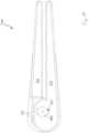
- FIG. 1is an elevated perspective view of a first exemplary occlusion clip in accordance with the instant disclosure.
- FIG. 2is a perspective view of the exemplary embodiment of FIG. 1 .
- FIG. 3is a profile view of the exemplary embodiment of FIG. 1 .
- FIG. 4is a cross-sectional view of the exemplary tongs part of the exemplary embodiment of FIG. 1 .
- FIG. 5is an elevated perspective view from a left side of the exemplary primary spring of the exemplary embodiment of FIG. 1 .
- FIG. 6is an elevated perspective view from a right side of the exemplary primary spring of the exemplary embodiment of FIG. 1 .
- FIG. 7is an elevated perspective view of an exemplary spring in accordance with the first and second exemplary embodiments.
- FIG. 8is a profile view of the exemplary spring of FIG. 7 .
- FIG. 9is an elevated perspective view from the front of a second exemplary occlusion clip in accordance with the instant disclosure.
- FIG. 10is a profile view from the front of the second exemplary occlusion clip of FIG. 9 .
- FIG. 11is an elevated perspective view from the rear of the second exemplary occlusion clip of FIG. 9 .
- FIG. 12is an elevated perspective view from the front of a first jaw of the second exemplary occlusion clip of FIG. 9 .
- FIG. 13is an elevated perspective view from the rear of the first jaw of the second exemplary occlusion clip of FIG. 9 , shown with a first secondary spring and pin mounted to the first jaw.
- FIG. 14is an elevated perspective view from the rear of the first jaw of the second exemplary occlusion clip of FIG. 9 .
- FIG. 15is a bottom view of the first jaw of the second exemplary occlusion clip of FIG. 9 .
- FIG. 16is a bottom perspective view from the front of a second jaw of the second exemplary occlusion clip of FIG. 9 .
- FIG. 17is an elevated perspective view from the front of the second jaw of the second exemplary occlusion clip of FIG. 9 .
- FIG. 18is an elevated perspective view from the left of an alternate first jaw that may be used in lieu of the first jaw with the occlusion clip of FIG. 9 , shown with an alternate first secondary spring and pin mounted to the alternate first jaw.
- FIG. 19is a bottom perspective view from the left of the alternate first jaw of FIG. 18 .
- FIG. 20is a cross-sectional view of a first alternate exemplary tongs in accordance with the instant disclosure.
- FIG. 21is a cross-sectional view of a second alternate exemplary tongs in accordance with the instant disclosure.
- FIG. 22is a profile view of a first alternate exemplary spring in accordance with the instant disclosure.
- FIG. 23is a profile view of a second alternate exemplary spring in accordance with the instant disclosure.
- a first exemplary occlusion clip 100includes tongs 110 that are repositionable with respect to a secondary spring 120 .
- the tongs 110may be fabricated from various materials such as, without limitation, a biologic material, a biologically reabsorbable material, a plastic, a metal, a metal alloy, and carbon fiber.
- the materialmay be formulated, include additives, or naturally be reabsorbable by a mammalian body within a predetermined period of time, such as six months or longer.
- the secondary spring 120may be fabricated from various such as, without limitation, a biologic material, a biologically reabsorbable material, a plastic, a metal, a metal alloy, and carbon fiber.
- the tongs 110include a first longitudinal segment 130 that is mounted to a second longitudinal segment 132 by way of a primary spring 134 .
- the primary spring 134operates to bias a proximal portion of both the first and second longitudinal segments 130 , 132 toward one another, while a distal portion of both the first and second longitudinal segments are biased toward one another using the secondary spring 120 .
- each longitudinal segment 130 , 132is a mirror image of the other and comprises a generally linear arm extending from the primary spring 134 . But it should also be noted that the longitudinal segments need not be mirror images of one another.
- a first exterior surface 140 of the longitudinal segments 130 , 132is substantially convex and includes a semicircular cross-section perpendicular to the longitudinal length thereof. This first surface seamlessly transitions into a pair of lateral surfaces 142 , 144 that extend substantially parallel to one another and spaced apart from one another the width of the segment. Each lateral surface 142 , 144 terminates at a respective rounded edge 146 , 148 that transitions into a concave interior surface 150 .
- the concave interior surface 150has a substantially uniform, semicircular cross-section perpendicular to the longitudinal length thereof and provides a linear, longitudinal channel 152 within which a portion of the secondary spring 120 traverses.
- the three exterior surfaces 140 , 142 , 144 and the interior surface 150longitudinally converge at a distal end 154 that is substantially planar and perpendicular with respect to the exterior surfaces and interior surface, but for a rounded transition 156 linking the surfaces to one another.
- the primary loop spring 134Opposite the distal ends 154 of the longitudinal segments 130 , 132 is the primary loop spring 134 .
- the primary spring 134is integrally formed with the longitudinal segments 130 , 132 and, in this fashion, provides a seamless transition therebetween.
- the primary spring 134includes a central discontinuous loop 160 having an outer circumferential surface 162 with a substantially constant outer diameter until reaching a bottleneck 164 .
- This bottleneck 164connects the discontinuous loop 160 to proximal arcuate housing segments 166 , 168 , that themselves are coupled to the longitudinal segments 130 , 132 .
- lateral and medial ends of the circumferential surface 162are rounded over to transition to a pair of parallel, spaced apart medial and lateral surfaces 170 , 172 .
- An interior of the primary spring 134is hollow and includes a through orifice extending in the medial-lateral direction. This orifice is partially bound by a pair of parallel, flat walls 176 that are connected at respective ends to an arcuate wall 178 .
- the arcuate wall 178is a complementary arcuate wall comprising a first segment 182 spaced apart from a second segment 184 to delineate a slit 186 therebetween.
- the slit 186extends in the medial-lateral direction as well as the proximal-distal direction to provide separation between the housing segments 166 , 168 .
- each housing segment 166 , 168is adjacent a partial opening 190 that extends in the medial-lateral direction and in the anterior-posterior direction (which is perpendicular to the medial-lateral direction and the proximal-distal direction).
- a pair of spaced apart walls 194 , 196that delineate an arcuate groove 200 having a concave, U-shaped profile.
- a distal end of the arcuate groove 200seamlessly transitions into the longitudinal channel 152 .
- the arcuate groove 200 and longitudinal channel 152are adapted to receive a portion of the secondary spring 120 .
- Interposing the housing segments 166 , 168 and the longitudinal segments 130 , 132is a transition area 210 that maintains the cross-section of the longitudinal channel 152 and also increases an anterior-posterior height to reach the substantially constant anterior-posterior height of the longitudinal segments.
- the transition area 210includes an arcuate profile where the anterior-posterior height gradually increases to match that of the longitudinal segment attached thereto. As a result, the transition area 210 and the housing segments 166 , 168 cooperate to define an internal cavity within which the primary spring 134 is positioned.
- an exemplary secondary spring 120 in accordance with the instant disclosureincludes a circular cross-section that is generally perpendicular to the longitudinal length thereof, which is the dominant dimension of the secondary spring. While comprising an integrated structure, the secondary spring 120 can be characterized as including three sections, two of which are repeated.
- a first section 220is generally U-shaped and includes a substantially constant radial arc to resemble a semi-circle. This first section 220 is integrally formed with a pair of second sections 222 at the distal ends of the first section and a proximal end of each second section.
- Each of the second sections 222includes a substantially linear length that extends perpendicularly away from the first section and in parallel to one another and may be biased toward one another to achieve the desired compression force.
- a distal end of each second section 222is mounted to a third section 224 that includes a sinusoidal shape.
- This sinusoidal shapeis typified by a convex exterior surface 228 that operates to decrease an anterior-posterior gap 230 that is present along a longitudinal interior of the secondary spring. More specifically, the gap 230 between the second sections 222 is greater than the gap between the third sections 224 .
- the third sections 224are partially received within a depression formed into the longitudinal segments 130 , 132 along a length of the longitudinal channel 152 .
- assembly and utilization of the exemplary occlusion clip 100includes repositioning the tongs 110 so that tissue to be occluded is positioned between the exterior surfaces 140 of the longitudinal segments 130 , 132 .
- the tissue to be occludedmay be a human left atrial appendage (not shown).
- the tongs 110is positioned so that the longitudinal segments 130 , 132 are parallel and compressed against one another to allow the tongs to pass through a trocar. After passing through the trocar and into a mammalian chest cavity, a spacing between distal ends of the longitudinal segments 130 , 132 is increased so that the spacing between the segments is large enough to accommodate a left atrial appendage of a heart.
- the longitudinal segments 130 , 132are moved closer to one another. This may be accomplished by manually compressing the longitudinal segments 130 , 132 toward one another or by using the secondary spring 120 to move the longitudinal segments toward one another. For purposes of discussion, it will be presumed that that secondary spring 120 is utilized to compress the longitudinal segments 130 , 132 toward one another.
- the secondary spring 120In order to use the secondary spring 120 to compress the longitudinal segments toward one another, the secondary spring is inserted through the trocar and into alignment with the tongs, presuming this alignment is not already completed. More specifically, the third sections 224 of the secondary spring 120 are aligned with the proximal end of the tongs 110 so that each of the third sections is at least partially received within a corresponding arcuate groove 200 . At this time, the secondary spring 120 is repositioned in the distal direction with respect to the tongs 110 so that the convex exterior surface 228 contacts the surface delineating the arcuate groove 200 . Continued movement of the secondary spring 120 toward the distal end of the tongs 110 causes the third sections 224 to increase the gap 230 therebetween to accommodate the tongs.
- the resilient nature of the secondary spring 120resulting from an increase in the gap 230 , exerts a bias force that causes the longitudinal segments 130 , 132 to be compressed toward one another. Even further movement of the secondary spring 120 toward the distal end of the tongs 110 causes the spacing between the longitudinal segments 130 , 132 to decrease and compress the segments against the tissue in question, in this case the left atrial appendage. The further along the secondary spring moves distally with respect to the tongs 110 , the greater the moment that is exerted against the longitudinal members 130 , 132 because the moment necessary to move the second sections 222 apart increases as one moves closer to the first section 220 . Eventually, movement of the secondary spring 120 toward the distal end of the tongs 110 reaches a point where both third sections 224 are received within secondary depressions 250 formed deeper into the longitudinal segments 130 , 132 as part of the longitudinal channels 152 .
- the exemplary embodimentincludes a single secondary depression 250 for each of the longitudinal members 130 , 132 , it is also within the scope of the disclosure to provide multiple secondary depressions 250 longitudinally distributed along the longitudinal members in order to accommodate ranges of force balancing, such as the alternate exemplary tongs 110 ′ depicted in FIG. 20 .
- the exemplary secondary spring 120has been shown to include a pair of third sections 224 , one adapted to engage each longitudinal member 130 , 132 , it is also within the scope of the disclosure for a second alternate secondary spring 120 ′′, 314 ′′, such as depicted in FIG.
- the secondary spring 120When the secondary depressions 250 receive the third sections 224 of the secondary spring 120 , the secondary spring 120 is relatively locked into a longitudinal friction fit with respect to the tongs 110 . Likewise, when the secondary depressions 250 receive the third sections 224 of the secondary spring 120 , a bias exerted upon the longitudinal segments 130 , 132 is approximately equal along the longitudinal length thereof. This longitudinal bias is operate to occlude the tissue clamped between the longitudinal segments 130 , 132 and is the cooperative product of the bias of the secondary spring 120 and the bias of the primary spring 134 . More specifically, the secondary spring 120 may be selected based upon the bias it exerts to match that of the primary spring 134 . Conversely, the primary spring 134 may be designed to include a bias that matches that of a predetermined secondary spring 120 .
- Disassembly of the exemplary occlusion clip 100includes repositioning the secondary spring 120 proximally with respect to the tongs 110 so that the third sections 224 become displaced from the depressions 250 .
- the cross-section of the secondary spring 120may take on a rectangular shape having a dominant dimension that makes distortion in a first plane more difficult that distortion in a second plane, perpendicular to the first plane, typified by a subordinate dimension.
- the cross-section of the secondary spring 120may change along its longitudinal length.
- a circular cross-sectionmay be exhibited by a portion of the secondary spring, followed by a non-circular cross section (e.g., an oblong shape, rectangular shape, or otherwise).
- the cross-section along the length of the secondary springmay have a portion that is configured to retard motion or more readily allow motion in one or more directions, followed by or proceeded by a portion having a different cross-section that is configured to retard motion or more readily allow motion in one or more of the same or different directions.
- the U-shaped proximal first section 220 of the secondary spring 120may have a circular cross-section, while the second sections 222 may have a rectangular profile with a dominant dimension in the lateral direction to allow greater deflection up or down rather than side to side.
- a second exemplary occlusion clip 300includes a first jaw 310 repositionably mounted to a second jaw 312 and adapted to be biased toward one another using a secondary spring 314 .
- the jaws 310 , 312are fabricated from a resilient or partially resilient material such as, without limitation, a biologic material, a biologically reabsorbable material, a plastic, a metal, a metal alloy, and carbon fiber.
- the materialmay be formulated, include additives, or naturally be reabsorbable by a mammalian body within a predetermined period of time, such as six months or longer.
- the spring 314is also fabricated from a resilient material.
- Exemplary materials used to fabricate the spring 314include, without limitation, a biologic material, a biologically reabsorbable material, a plastic, a metal, a metal alloy, and carbon fiber.
- the first jaw 310includes an elongated platform 320 that extends from a hub 322 .
- the elongated platform 320comprises an inclined occlusion surface 326 that is substantially planar but causes the height of the platform to gradually increase from a distal tip 328 to a proximal ending 334 .
- Opposite the inclined surfaceis a bottom surface 330 having formed therein a longitudinal trench 332 having a substantially rectangular cross-section that extends partially beyond the proximal ending 334 .
- the longitudinal trench 332may have a cross-section other than rectangular including, without limitation, oblong and semicircular.
- the distal tip 328interposes the inclined surface 326 and the bottom surface 330 , along with a pair of spaced apart, planar lateral surfaces 340 , 342 .
- the planar lateral surfaces 340 , 342are each generally perpendicular to the inclined surface 326 and the bottom surface 330 .
- the hub 322is located proximate the elongated platform 320 and is laterally inset with respect to one of the lateral surfaces 342 , but flush with respect to the other lateral surface 340 .
- a distal portion 350 of the hub 322includes an arcuate profile from distal to proximal and rounds over at a proximal portion 352 .
- the distal and proximal portions 350 , 352include a peripheral flange 354 having a pair of parallel, linear segments 356 , 358 extending into the interior of the hub 322 .
- Just above the first linear segment 356is an oblong through opening 364 delineated by an oblong interior wall 366 .
- the opening 364extends through a wall having a pair of parallel, lateral surfaces 370 , 372 .
- the first lateral surface 370is co-planar with the lateral surface 340 of the elongated platform 320 .
- a primary spring 378is received within the interior of the hub 322 and configured to provide bias for a proximal end of the exemplary occlusion clip 300 . More specifically, a cylindrical pin 380 extends through the oblong opening 364 and into the interior of the hub 322 , where a smaller diameter portion 382 of the cylindrical pin is adapted to be received within a through hole of the second jaw 312 . A lower portion of the cylindrical pin 380 is bounded by the first linear segment 356 , while an upper portion of the cylindrical pin is bounded by the primary spring 378 . In this manner, the cylindrical pin 380 is able to move vertically within the oblong opening 364 , but to do so the bias of the primary spring 378 must be overcome.
- the primary spring 378comprises a simple U-shaped configuration and where one of the ends of the spring is received between the linear segments 356 , 358 , while the arcuate portion of the secondary spring abuts the peripheral flange 354 .
- the primary spring 378is relatively stationary, but may be deformed to allow the cylindrical pin 380 to vertically travel within the oblong opening 364 , thereby allowing a proximal spacing between the jaws 310 , 312 to be changed.
- the second jaw 312includes an elongated platform 420 that extends from a solid hub 422 .
- the elongated platform 420comprises an inclined occlusion surface 426 that is substantially planar but causes the height of the platform to gradually increase from a distal tip 428 to a proximal ending 434 .
- Opposite the inclined surfaceis a bottom surface 430 having formed therein a longitudinal trench 432 having a substantially rectangular cross-section that extends partially beyond the proximal ending 434 .
- the longitudinal trench 432may have a cross-section other than rectangular including, without limitation, oblong and semicircular.
- the distal tip 428interposes the inclined surface 426 and the bottom surface 430 , along with a pair of spaced apart, planar lateral surfaces 440 , 442 .
- the planar lateral surfaces 440 , 442are each generally perpendicular to the inclined surface 426 and the bottom surface 430 .
- the solid hub 422comprises a pair parallel, spaced apart lateral surfaces 450 , 452 that are bounded by an arcuate circumferential surface 454 .
- the interior lateral surface 450includes an orifice 460 (see FIG. 11 ) that receives the smaller diameter portion 382 of the cylindrical pin 380 via a friction fit, thereby joining the jaws to one another.
- the cylindrical pin 380includes an oversized head 384 that provides a boundary for the first jaw 310 in order to allow the jaws 310 , 312 to move with respect to one another, but inhibit lateral disengagement between the jaws where the jaws might otherwise come apart.
- the secondary spring 314includes generally the same structure and shape as the secondary spring 120 of the first exemplary embodiment, which is shown in FIGS. 7 and 8 . Accordingly, description of the spring 314 has been omitted in this exemplary embodiment in furtherance of brevity.
- assembly and utilization of the exemplary occlusion clip 300includes repositioning the jaws 310 , 312 so that tissue to be occluded is positioned between the inclined surfaces 326 of the elongated platforms 320 .
- the tissue to be occludedmay be a human left atrial appendage (not shown).
- the jaws 310 , 312are positioned so that the inclined surfaces 326 of the elongated platforms 320 are parallel and compressed against one another to allow the jaws to pass through a trocar.
- a spacing between the inclined surfaces 326 of the elongated platforms 320is increased by overcoming the bias of the primary spring 378 in order to vertically reposition the second jaw 312 with respect to the first jaw 310 so that the pin 380 is against an uppermost portion of the oblong interior wall 366 so that the spacing therebetween is large enough to accommodate a left atrial appendage of a heart.
- the elongated platformsare allowed to move closer to one another, in part by discontinuing to overcome the bias of the primary spring 378 .
- additional biasis applied to the jaws 310 , 312 by mounting the spring 314 to the jaws so the elongated platforms 320 , 420 are compressed toward one another.
- the spring 314In order to use the spring 314 to compress the inclined surfaces 326 , 426 of the elongated platforms 320 , 420 toward one another, the spring is first inserted through the trocar and into alignment with the jaws 310 , 312 , presuming the spring is not already in alignment with the elongated platforms. More specifically, the third sections 224 of the spring 314 are aligned with the longitudinal trenches 332 , 432 so that the third sections contact the hubs 322 , 422 of both jaws 310 , 312 .
- the jaws 310 , 312may be fabricated from any biologically compatible material including, without limitation, ceramics, polymers, metals, alloys of the foregoing, and composites.
- the springs 314 , 378may be fabricated from any resilient material including, without limitation, polymers, metals, and alloy of the foregoing.
- the longitudinal trenches 332 , 432may include a series of depressions that are longitudinally spaced apart from one another and adapted to receive the convex exterior surface 228 of the third spring section 224 .
- the locations of the depressionsmay be chosen to balance the moments between the spring 314 and the primary spring 378 .
- Disassembly of the exemplary occlusion clip 300includes repositioning the spring 314 proximally with respect to the jaws 310 , 312 . Eventually, continued proximal movement of the spring 314 with respect to the jaws 310 , 312 results in the third sections 224 passing beyond the proximal most portion of the jaws, resulting in complete disengagement between the jaws and spring.
- an alternate exemplary first jaw 500that may be used in place of the first jaw 310 as part of the second exemplary occlusion clip 300 .
- the hub 502is different from the hub 322 of the first jaw 310 .
- the revised hub 502includes a peripheral flange 504 that cooperates with a lateral interior wall 506 to define an interior cavity 508 .
- Extending through the lateral interior wall 506is an oblong through opening 512 configured to receive a cylindrical pin 380 . In this manner, the shape of the through opening 512 allows vertical travel of the cylindrical pin 380 with respect to the first jaw 500 .
- a platform 516Proximate the bottom of the oblong opening 512 and extending from the interior wall 506 is a platform 516 .
- This platform 516 and the cylindrical pin 380are concurrently circumscribed by an elastic band 520 that operates to exert a bias on the proximal aspects of the jaws 500 , 312 when coupled to one another.
- the resilient band 520may be fabricated from any elastic material.
- the elastic band 520resists vertical movement of the cylindrical pin 380 away from the platform. Vertical motion between the cylindrical pin 380 and the platform 516 causes the vertical spacing to change between the jaws 500 , 312 at the proximal ends of the jaws.
- this jaw 500provides an alternate configuration for using an elastic band 520 , as opposed to using the primary spring 378 and the first jaw 310 , in combination with the second jaw 312 to form an alternate exemplary occlusion clip.
- the exemplary occlusion clipsmay be shrouded in a tissue ingrowth material.
- the exemplary occlusion clipsmay be encased in a C-shaped, loop sleeve that is cylindrical and closed at opposing ends in order to accommodate opening and closing of the exemplary clips (i.e., separation or spacing between the open ends sufficient to position tissue between portions of the clips).
- tissue ingrowth materialssuch as porous fabrics, including Gore Dualmesh (available from W. L. Gore & Associates, www.gore.com) that may be used as to shroud the foregoing exemplary embodiments.
Landscapes
- Health & Medical Sciences (AREA)
- Surgery (AREA)
- Life Sciences & Earth Sciences (AREA)
- Heart & Thoracic Surgery (AREA)
- Nuclear Medicine, Radiotherapy & Molecular Imaging (AREA)
- Vascular Medicine (AREA)
- Engineering & Computer Science (AREA)
- Biomedical Technology (AREA)
- Reproductive Health (AREA)
- Medical Informatics (AREA)
- Molecular Biology (AREA)
- Animal Behavior & Ethology (AREA)
- General Health & Medical Sciences (AREA)
- Public Health (AREA)
- Veterinary Medicine (AREA)
- Surgical Instruments (AREA)
Abstract
Description
Claims (20)
Priority Applications (4)
| Application Number | Priority Date | Filing Date | Title |
|---|---|---|---|
| US17/131,975US11911042B2 (en) | 2012-11-21 | 2020-12-23 | Occlusion clip |
| US18/342,533US12004752B2 (en) | 2012-11-21 | 2023-06-27 | Occlusion clip |
| US18/342,519US12193680B2 (en) | 2012-11-21 | 2023-06-27 | Occlusion clip |
| US18/421,036US20240156464A1 (en) | 2012-11-21 | 2024-01-24 | Occlusion clip |
Applications Claiming Priority (4)
| Application Number | Priority Date | Filing Date | Title |
|---|---|---|---|
| US201261729023P | 2012-11-21 | 2012-11-21 | |
| US14/085,836US9901351B2 (en) | 2012-11-21 | 2013-11-21 | Occlusion clip |
| US15/904,541US10898204B2 (en) | 2012-11-21 | 2018-02-26 | Occlusion clip |
| US17/131,975US11911042B2 (en) | 2012-11-21 | 2020-12-23 | Occlusion clip |
Related Parent Applications (1)
| Application Number | Title | Priority Date | Filing Date |
|---|---|---|---|
| US15/904,541ContinuationUS10898204B2 (en) | 2012-11-21 | 2018-02-26 | Occlusion clip |
Related Child Applications (3)
| Application Number | Title | Priority Date | Filing Date |
|---|---|---|---|
| US18/342,533ContinuationUS12004752B2 (en) | 2012-11-21 | 2023-06-27 | Occlusion clip |
| US18/342,519ContinuationUS12193680B2 (en) | 2012-11-21 | 2023-06-27 | Occlusion clip |
| US18/421,036ContinuationUS20240156464A1 (en) | 2012-11-21 | 2024-01-24 | Occlusion clip |
Publications (2)
| Publication Number | Publication Date |
|---|---|
| US20210106336A1 US20210106336A1 (en) | 2021-04-15 |
| US11911042B2true US11911042B2 (en) | 2024-02-27 |
Family
ID=50728649
Family Applications (6)
| Application Number | Title | Priority Date | Filing Date |
|---|---|---|---|
| US14/085,836ActiveUS9901351B2 (en) | 2012-11-21 | 2013-11-21 | Occlusion clip |
| US15/904,541Active2034-03-21US10898204B2 (en) | 2012-11-21 | 2018-02-26 | Occlusion clip |
| US17/131,975Active2035-05-09US11911042B2 (en) | 2012-11-21 | 2020-12-23 | Occlusion clip |
| US18/342,533ActiveUS12004752B2 (en) | 2012-11-21 | 2023-06-27 | Occlusion clip |
| US18/342,519ActiveUS12193680B2 (en) | 2012-11-21 | 2023-06-27 | Occlusion clip |
| US18/421,036AbandonedUS20240156464A1 (en) | 2012-11-21 | 2024-01-24 | Occlusion clip |
Family Applications Before (2)
| Application Number | Title | Priority Date | Filing Date |
|---|---|---|---|
| US14/085,836ActiveUS9901351B2 (en) | 2012-11-21 | 2013-11-21 | Occlusion clip |
| US15/904,541Active2034-03-21US10898204B2 (en) | 2012-11-21 | 2018-02-26 | Occlusion clip |
Family Applications After (3)
| Application Number | Title | Priority Date | Filing Date |
|---|---|---|---|
| US18/342,533ActiveUS12004752B2 (en) | 2012-11-21 | 2023-06-27 | Occlusion clip |
| US18/342,519ActiveUS12193680B2 (en) | 2012-11-21 | 2023-06-27 | Occlusion clip |
| US18/421,036AbandonedUS20240156464A1 (en) | 2012-11-21 | 2024-01-24 | Occlusion clip |
Country Status (1)
| Country | Link |
|---|---|
| US (6) | US9901351B2 (en) |
Cited By (3)
| Publication number | Priority date | Publication date | Assignee | Title |
|---|---|---|---|---|
| US20210378675A1 (en)* | 2018-11-08 | 2021-12-09 | Cedars-Sinai Medical Center | A novel tool for hemostasis and tissue approximation |
| US11998212B2 (en) | 2013-11-21 | 2024-06-04 | Atricure, Inc. | Occlusion clip |
| US12004752B2 (en) | 2012-11-21 | 2024-06-11 | Atricure, Inc. | Occlusion clip |
Families Citing this family (31)
| Publication number | Priority date | Publication date | Assignee | Title |
|---|---|---|---|---|
| US9017349B2 (en) | 2010-10-27 | 2015-04-28 | Atricure, Inc. | Appendage clamp deployment assist device |
| DE102014114946A1 (en)* | 2014-10-15 | 2016-04-21 | Aesculap Ag | Surgical clip like a carabiner clip |
| US9901352B2 (en) | 2014-12-12 | 2018-02-27 | Atricure, Inc. | Occlusion clip |
| CN104490426A (en)* | 2014-12-22 | 2015-04-08 | 浙江海洋学院 | Ink sac sealer device for anatomizing cuttlefish |
| ES2575727B1 (en)* | 2014-12-30 | 2017-04-12 | Neos Surgery, S.L. | Aneurysm clamp |
| US20170014135A1 (en)* | 2015-07-14 | 2017-01-19 | Keith Edward Martin | Surgical tool |
| JP6632930B2 (en)* | 2016-04-11 | 2020-01-22 | 野村ユニソン株式会社 | Clip unit for ligating device and method of engaging the clip unit |
| US10201352B2 (en)* | 2016-08-08 | 2019-02-12 | Atricure, Inc. | Robotic Assisted clip applier |
| US10993719B2 (en) | 2017-10-11 | 2021-05-04 | Boston Scientific Scimed, Inc. | Reinforced mechanical hemostasis clip |
| US11191547B2 (en) | 2018-01-26 | 2021-12-07 | Syntheon 2.0, LLC | Left atrial appendage clipping device and methods for clipping the LAA |
| US12220119B2 (en) | 2018-05-22 | 2025-02-11 | Boston Scientific Scimed, Inc. | Tissue engagement device |
| EP3796847B1 (en)* | 2018-05-22 | 2025-02-19 | Boston Scientific Scimed, Inc. | Tissue engagement device |
| CN109044473B (en)* | 2018-06-14 | 2020-06-02 | 宁波胜杰康生物科技有限公司 | Detachable endoscopic anastomosis clamp |
| US10531883B1 (en) | 2018-07-20 | 2020-01-14 | Syntheon 2.0, LLC | Aspiration thrombectomy system and methods for thrombus removal with aspiration catheter |
| US11317923B2 (en)* | 2018-08-13 | 2022-05-03 | Covidien Lp | Ligation clip with improved hinge |
| CN109350171B (en) | 2018-11-29 | 2024-04-12 | 张强 | Conjoined double-sided clip for hemostasis and suturing through-digestive endoscope duct and operation method |
| US12239292B2 (en) | 2019-01-10 | 2025-03-04 | Atricure, Inc. | Clip application system and method |
| CN111419325A (en)* | 2019-01-10 | 2020-07-17 | 北京康瑞迪医疗科技有限公司 | Cardiac tissue closure device |
| CN119700232A (en)* | 2019-01-10 | 2025-03-28 | 北京迈迪顶峰医疗科技股份有限公司 | Cardiac tissue closure device |
| CN111714161B (en)* | 2019-03-21 | 2024-09-20 | 北京领健医疗科技有限公司 | Sealing clamp |
| US10925615B2 (en) | 2019-05-03 | 2021-02-23 | Syntheon 2.0, LLC | Recapturable left atrial appendage clipping device and methods for recapturing a left atrial appendage clip |
| CN111904526B (en)* | 2019-05-08 | 2025-01-17 | 北京领健医疗科技有限公司 | A closed clamp |
| US11717301B2 (en) | 2019-09-25 | 2023-08-08 | Lsi Solutions, Inc. | Minimally invasive occlusion device and methods thereof |
| US20210137524A1 (en)* | 2019-11-13 | 2021-05-13 | Covidien Lp | Multi-Part Ligation Clip |
| US12213681B2 (en) | 2020-05-06 | 2025-02-04 | Atricure, Inc. | End effector positioning mechanism |
| US12426886B2 (en) | 2020-11-23 | 2025-09-30 | Eric William Schneeberger | Atrial appendage excluder |
| WO2023014925A1 (en)* | 2021-08-04 | 2023-02-09 | Edwards Lifesciences Corporation | Clip and method for simulating the application of same for closure of left atrial appendage |
| EP4384086A1 (en)* | 2021-08-10 | 2024-06-19 | Edwards Lifesciences Corporation | Clip with opposed jaws for left atrial appendage closure |
| WO2024228639A1 (en)* | 2023-04-30 | 2024-11-07 | Федеральное государственное бюджетное учреждение "Национальный медицинский исследовательский центр хирургии имени А.В. Вишневского" Министерства здравоохранения Российской Федерации (ФГБУ "НМИЦ хирургии им. А.В.Вишневского" Минздрава России) | Occlusion clamp for anatomical structures |
| US12433710B1 (en) | 2024-06-17 | 2025-10-07 | Ohio State Innovation Foundation | Device to restrain opening of an off-the-shelf surgical instrument |
| CN119033418B (en)* | 2024-08-30 | 2025-10-03 | 北京博辉瑞进生物科技有限公司 | Medical clamps |
Citations (17)
| Publication number | Priority date | Publication date | Assignee | Title |
|---|---|---|---|---|
| US6179850B1 (en)* | 1999-01-07 | 2001-01-30 | Tushar Madhu Goradia | Method and apparatus for modulating flow in biological conduits |
| US20010029384A1 (en)* | 1996-07-23 | 2001-10-11 | United States Surgical Corporation | Anastomosis instrument and method |
| US20020111643A1 (en)* | 1999-07-28 | 2002-08-15 | Aesculap Ag & Co. Kg | Surgical clip |
| US20050251183A1 (en)* | 2002-09-13 | 2005-11-10 | Damage Control Surgical Technologies, Inc. | Method and apparatus for vascular and visceral clipping |
| US20060100646A1 (en)* | 2003-02-18 | 2006-05-11 | Hart Charles C | Surgical clip and method for making same |
| US20060100649A1 (en)* | 2002-12-17 | 2006-05-11 | Hart Charles C | Surgical staple-clip and applier |
| US20070032807A1 (en)* | 2005-08-05 | 2007-02-08 | Ortiz Mark S | Method and clamp for gastric reduction surgery |
| US20070213585A1 (en)* | 2006-03-09 | 2007-09-13 | Leonid Monassevitch | Endoscopic full thickness resection using surgical compression clips |
| US20080004637A1 (en)* | 2006-04-29 | 2008-01-03 | Klassen James B | Surgical clip, applicator and applicator methods |
| US20100298849A1 (en)* | 2009-05-20 | 2010-11-25 | Daniel Lazic | Aneurysm Clip |
| US20110046437A1 (en)* | 2009-08-24 | 2011-02-24 | Cvdevices, Llc | Tissue restoration devices, systems, and methods |
| US20120149990A1 (en)* | 2010-12-14 | 2012-06-14 | Patricia Buehler | Devices for performing blepharoplasty and methods of using the same |
| US20150057684A1 (en)* | 2012-04-27 | 2015-02-26 | Aesculap Ag | One-piece surgical clip |
| US20160008001A1 (en)* | 2013-11-21 | 2016-01-14 | Atricure, Inc. | Occlusion clip |
| US9737213B1 (en)* | 2009-03-24 | 2017-08-22 | Vioptix, Inc. | Using an oximeter probe to detect intestinal ischemia |
| US9901351B2 (en)* | 2012-11-21 | 2018-02-27 | Atricure, Inc. | Occlusion clip |
| US10166024B2 (en)* | 2005-07-14 | 2019-01-01 | Idx Medical, Ltd. | Apparatus and methods for occluding a hollow anatomical structure |
Family Cites Families (278)
| Publication number | Priority date | Publication date | Assignee | Title |
|---|---|---|---|---|
| US119938A (en) | 1871-10-17 | Improvement in clothes-pins | ||
| US1152492A (en) | 1913-09-13 | 1915-09-07 | William L Deming | Garment-supporter. |
| US1162578A (en) | 1914-11-02 | 1915-11-30 | Emery N De Forge | Clothes-pin. |
| US1205889A (en) | 1915-09-08 | 1916-11-21 | Julius Halvorson | Clothes-pin. |
| US1357233A (en) | 1920-04-12 | 1920-11-02 | Hagelstein William | Clip |
| US1491941A (en) | 1923-01-04 | 1924-04-29 | Andrew T Wood | Clothespin |
| US1684721A (en) | 1926-09-11 | 1928-09-18 | Andrew T Wood | Clothespin |
| US2051174A (en) | 1934-12-01 | 1936-08-18 | Levigard Martin | Clip |
| US2060724A (en) | 1935-01-19 | 1936-11-10 | William B Carroll | Surgical implement |
| US2371978A (en) | 1941-12-13 | 1945-03-20 | Roy G Perham | Clamp for retaining the edges of a wound in apposition |
| US2384697A (en) | 1944-10-18 | 1945-09-11 | Riccardi Peter | Umbilical clip |
| US2540722A (en) | 1948-04-30 | 1951-02-06 | Espa S Gardner | Clothespin |
| US2593201A (en) | 1949-10-13 | 1952-04-15 | Noel J Saunders | Clothespin |
| US2815557A (en) | 1953-09-21 | 1957-12-10 | Richard F Jorgensen | Clasp |
| US3032039A (en) | 1959-05-26 | 1962-05-01 | Jack O Beaty | Arterial and veinous clamp and clamp applicator |
| US3503398A (en) | 1965-09-10 | 1970-03-31 | American Hospital Supply Corp | Atraumatic clamp for vascular surgery |
| US3503396A (en) | 1967-09-21 | 1970-03-31 | American Hospital Supply Corp | Atraumatic surgical clamp |
| US3496932A (en) | 1967-12-22 | 1970-02-24 | Gen Motors Corp | Method and apparatus for substernal cardiac massage |
| GB1190488A (en) | 1968-05-30 | 1970-05-06 | Lucien Julienne Art Jonckheere | Improvements in or relating to Clips which may be Used in the Medical Field. |
| US3682180A (en) | 1970-06-08 | 1972-08-08 | Coilform Co Inc | Drain clip for surgical drain |
| DE2308846C3 (en) | 1972-02-24 | 1979-11-29 | Pierre Perisse | Device for ligation of blood vessels |
| US3856016A (en) | 1972-11-03 | 1974-12-24 | H Davis | Method for mechanically applying an occlusion clip to an anatomical tubular structure |
| US3954108A (en) | 1972-11-03 | 1976-05-04 | Davis Hugh J | Occlusion clip and instrument for applying same |
| US3854482A (en) | 1972-11-22 | 1974-12-17 | Avis Res Inc | Umbilical cord clamp |
| US3818784A (en) | 1973-01-03 | 1974-06-25 | Scient Components Inc | Changeable tip tweezers and the like |
| US3856018A (en) | 1973-02-26 | 1974-12-24 | P Perisse | Process for ligating sectioned blood vessels |
| DE2730691C2 (en) | 1976-07-16 | 1982-12-16 | Maruho Co. Ltd., Osaka | Surgical clip, connecting element for several surgical clips and forceps for opening and closing the same |
| US4120302A (en) | 1976-10-08 | 1978-10-17 | American Hospital Supply Corporation | Disposable pads for surgical instruments |
| US4226239A (en) | 1978-01-31 | 1980-10-07 | Kli, Inc. | Surgical ligating instrument and method |
| DE2826620C3 (en) | 1978-06-19 | 1982-02-11 | Auergesellschaft Gmbh, 1000 Berlin | Nose clip for breathing apparatus |
| US4428374A (en)* | 1978-12-20 | 1984-01-31 | Auburn Robert M | Umbilical cord clamping assembly |
| USRE32269E (en) | 1980-04-07 | 1986-10-28 | Independent Products Company, Inc. | Plastic clip |
| US4493319A (en) | 1981-06-29 | 1985-01-15 | Cabot Medical Corporation | Ring applicator having floating inner tube |
| US4552128A (en) | 1983-12-29 | 1985-11-12 | Haber Terry M | Elastomechanical sphincter |
| US4821719A (en) | 1984-12-03 | 1989-04-18 | Fogarty Thomas J | Cohesive-adhesive atraumatic clamp |
| US4791707A (en) | 1986-08-26 | 1988-12-20 | Tucker Wilson H | Clip applicator, spreadable clips and method for applying the clips |
| US4716634A (en) | 1987-05-05 | 1988-01-05 | Fan Wen Yuan | Two-piece reinforced clothes peg |
| US4788966A (en) | 1987-05-14 | 1988-12-06 | Inbae Yoon | Plug for use in a reversible sterilization procedure |
| US5171250A (en) | 1987-05-14 | 1992-12-15 | Inbae Yoon | Surgical clips and surgical clip applicator and cutting and transection device |
| US5366459A (en) | 1987-05-14 | 1994-11-22 | Inbae Yoon | Surgical clip and clip application procedures |
| US4869268A (en) | 1987-05-14 | 1989-09-26 | Inbae Yoon | Multi-functional instruments and stretchable ligating and occluding devices |
| CA1303934C (en) | 1987-11-03 | 1992-06-23 | David T. Green | Fascia clip |
| US4917677A (en) | 1989-03-29 | 1990-04-17 | Mccarthy John A | Surgical clamp assembly and method |
| ES1010119Y (en) | 1989-04-26 | 1990-08-01 | Garcia Crespo Agustin | DOUBLE MOUTH CLAMP. |
| US5100416A (en) | 1989-10-17 | 1992-03-31 | Edward Weck Incorporated | Ligating clip applying instrument |
| US5984938A (en) | 1989-12-05 | 1999-11-16 | Yoon; Inbae | Surgical instrument with jaws and movable internal scissors and method for use thereof |
| US5217030A (en) | 1989-12-05 | 1993-06-08 | Inbae Yoon | Multi-functional instruments and stretchable ligating and occluding devices |
| US5922001A (en) | 1989-12-05 | 1999-07-13 | Yoon; Inbae | Surgical instrument with jaws and a movable internal blade member and method for use thereof |
| US5984939A (en) | 1989-12-05 | 1999-11-16 | Yoon; Inbae | Multifunctional grasping instrument with cutting member and operating channel for use in endoscopic and non-endoscopic procedures |
| US5919202A (en) | 1989-12-05 | 1999-07-06 | Yoon; Inbae | Surgical instrument with jaws and movable internal needle and method for use thereof |
| US5026379A (en) | 1989-12-05 | 1991-06-25 | Inbae Yoon | Multi-functional instruments and stretchable ligating and occluding devices |
| US5665100A (en) | 1989-12-05 | 1997-09-09 | Yoon; Inbae | Multifunctional instrument with interchangeable operating units for performing endoscopic procedures |
| US6099550A (en) | 1989-12-05 | 2000-08-08 | Yoon; Inbae | Surgical instrument having jaws and an operating channel and method for use thereof |
| US5217473A (en) | 1989-12-05 | 1993-06-08 | Inbae Yoon | Multi-functional instruments and stretchable ligating and occluding devices |
| US5922002A (en) | 1989-12-05 | 1999-07-13 | Yoon; Inbae | Surgical instrument with jaws and movable internal biopsy device and method for use thereof |
| US5893863A (en) | 1989-12-05 | 1999-04-13 | Yoon; Inbae | Surgical instrument with jaws and movable internal hook member for use thereof |
| US6413234B1 (en) | 1990-02-02 | 2002-07-02 | Ep Technologies, Inc. | Assemblies for creating compound curves in distal catheter regions |
| US5075935A (en) | 1990-06-12 | 1991-12-31 | Abdi Abraham M | Garment hanger and clip |
| US5282844A (en) | 1990-06-15 | 1994-02-01 | Medtronic, Inc. | High impedance, low polarization, low threshold miniature steriod eluting pacing lead electrodes |
| US5190541A (en) | 1990-10-17 | 1993-03-02 | Boston Scientific Corporation | Surgical instrument and method |
| US5119804A (en) | 1990-11-19 | 1992-06-09 | Anstadt George L | Heart massage apparatus |
| US5108420A (en) | 1991-02-01 | 1992-04-28 | Temple University | Aperture occlusion device |
| US5171252A (en) | 1991-02-05 | 1992-12-15 | Friedland Thomas W | Surgical fastening clip formed of a shape memory alloy, a method of making such a clip and a method of using such a clip |
| US5676636A (en) | 1994-07-22 | 1997-10-14 | Origin Medsystems, Inc. | Method for creating a mediastinal working space |
| US5452733A (en) | 1993-02-22 | 1995-09-26 | Stanford Surgical Technologies, Inc. | Methods for performing thoracoscopic coronary artery bypass |
| US5282829A (en) | 1991-08-15 | 1994-02-01 | United States Surgical Corporation | Hollow body implants |
| US5258000A (en) | 1991-11-25 | 1993-11-02 | Cook Incorporated | Tissue aperture repair device |
| US5290299A (en) | 1991-12-11 | 1994-03-01 | Ventritex, Inc. | Double jaw apparatus for attaching implanted materials to body tissue |
| JP3532565B2 (en) | 1991-12-31 | 2004-05-31 | ミネソタ マイニング アンド マニュファクチャリング カンパニー | Removable low melt viscosity acrylic pressure sensitive adhesive |
| US5271543A (en) | 1992-02-07 | 1993-12-21 | Ethicon, Inc. | Surgical anastomosis stapling instrument with flexible support shaft and anvil adjusting mechanism |
| AU3593593A (en) | 1992-02-12 | 1993-09-03 | Dimed, Incorporated | System for access to pericardial space |
| US5282811A (en) | 1992-04-16 | 1994-02-01 | Cook Pacemaker Corporation | Two part surgical ligating clip, applicator and method of use |
| US5336252A (en) | 1992-06-22 | 1994-08-09 | Cohen Donald M | System and method for implanting cardiac electrical leads |
| US5762458A (en) | 1996-02-20 | 1998-06-09 | Computer Motion, Inc. | Method and apparatus for performing minimally invasive cardiac procedures |
| US5891162A (en) | 1992-08-13 | 1999-04-06 | Brigham & Women's Hospital | Expanding polygonal surgical compressor |
| AU4688793A (en) | 1992-08-13 | 1994-03-15 | Brigham And Women's Hospital | Expanding polygonal surgical compressor |
| US5342373A (en) | 1992-09-14 | 1994-08-30 | Ethicon, Inc. | Sterile clips and instrument for their placement |
| US5309927A (en) | 1992-10-22 | 1994-05-10 | Ethicon, Inc. | Circular stapler tissue retention spring method |
| US6161543A (en) | 1993-02-22 | 2000-12-19 | Epicor, Inc. | Methods of epicardial ablation for creating a lesion around the pulmonary veins |
| US5797960A (en) | 1993-02-22 | 1998-08-25 | Stevens; John H. | Method and apparatus for thoracoscopic intracardiac procedures |
| US6494211B1 (en) | 1993-02-22 | 2002-12-17 | Hearport, Inc. | Device and methods for port-access multivessel coronary artery bypass surgery |
| US5306234A (en) | 1993-03-23 | 1994-04-26 | Johnson W Dudley | Method for closing an atrial appendage |
| US5403311A (en) | 1993-03-29 | 1995-04-04 | Boston Scientific Corporation | Electro-coagulation and ablation and other electrotherapeutic treatments of body tissue |
| US5575795A (en) | 1993-07-21 | 1996-11-19 | Minneapolis Children's Medical Center | Umbilical cord holder |
| GR940100335A (en) | 1993-07-22 | 1996-05-22 | Ethicon Inc. | Electrosurgical device for placing staples. |
| US5782397A (en) | 1994-01-04 | 1998-07-21 | Alpha Surgical Technologies, Inc. | Stapling device |
| US5503638A (en) | 1994-02-10 | 1996-04-02 | Bio-Vascular, Inc. | Soft tissue stapling buttress |
| US5681330A (en) | 1994-03-02 | 1997-10-28 | Ethicon Endo-Surgery, Inc. | Sterile occlusion fasteners and instrument and method for their placement |
| US5833700A (en) | 1995-03-15 | 1998-11-10 | Ethicon Endo-Surgery, Inc. | Sterile occlusion fasteners and instrument and method for their placement |
| US5402558A (en) | 1994-05-09 | 1995-04-04 | Selfix, Inc. | Resilient clip |
| US5425740A (en) | 1994-05-17 | 1995-06-20 | Hutchinson, Jr.; William B. | Endoscopic hernia repair clip and method |
| US5582616A (en) | 1994-08-05 | 1996-12-10 | Origin Medsystems, Inc. | Surgical helical fastener with applicator |
| DE4434864C2 (en) | 1994-09-29 | 1997-06-19 | United States Surgical Corp | Surgical staple applicator with interchangeable staple magazine |
| US6464700B1 (en) | 1994-10-07 | 2002-10-15 | Scimed Life Systems, Inc. | Loop structures for positioning a diagnostic or therapeutic element on the epicardium or other organ surface |
| US5707377A (en)* | 1994-11-29 | 1998-01-13 | American Cyanamid Company | Ligation clip remover |
| US5643255A (en) | 1994-12-12 | 1997-07-01 | Hicor, Inc. | Steerable catheter with rotatable tip electrode and method of use |
| US5620452A (en) | 1994-12-22 | 1997-04-15 | Yoon; Inbae | Surgical clip with ductile tissue penetrating members |
| US5904697A (en) | 1995-02-24 | 1999-05-18 | Heartport, Inc. | Devices and methods for performing a vascular anastomosis |
| US5695505A (en) | 1995-03-09 | 1997-12-09 | Yoon; Inbae | Multifunctional spring clips and cartridges and applicators therefor |
| US6132438A (en) | 1995-06-07 | 2000-10-17 | Ep Technologies, Inc. | Devices for installing stasis reducing means in body tissue |
| US5709224A (en) | 1995-06-07 | 1998-01-20 | Radiotherapeutics Corporation | Method and device for permanent vessel occlusion |
| US5827216A (en) | 1995-06-07 | 1998-10-27 | Cormedics Corp. | Method and apparatus for accessing the pericardial space |
| US5653720A (en) | 1995-07-18 | 1997-08-05 | Applied Medical Resources | Surgical clip and method of assembly |
| US5609599A (en) | 1995-07-27 | 1997-03-11 | Levin; John M. | Leak clip |
| US5683405A (en) | 1995-08-25 | 1997-11-04 | Research Medical Inc. | Vascular occluder |
| DE19534323A1 (en) | 1995-09-15 | 1997-03-20 | Aesculap Ag | Clamping ring for a surgical clip |
| DE19534322A1 (en) | 1995-09-15 | 1997-03-20 | Aesculap Ag | Surgical clip, especially a vascular clip |
| US5836311A (en) | 1995-09-20 | 1998-11-17 | Medtronic, Inc. | Method and apparatus for temporarily immobilizing a local area of tissue |
| US5667518A (en) | 1995-10-02 | 1997-09-16 | Pannell; William P. | Method and implements for performing a vasectomy |
| US5634932A (en) | 1995-10-10 | 1997-06-03 | Industrial & Scientific Designs, Ltd. | Cantilever aneurysm clip system |
| US5727569A (en) | 1996-02-20 | 1998-03-17 | Cardiothoracic Systems, Inc. | Surgical devices for imposing a negative pressure to fix the position of cardiac tissue during surgery |
| US5762255A (en) | 1996-02-20 | 1998-06-09 | Richard-Allan Medical Industries, Inc. | Surgical instrument with improvement safety lockout mechanisms |
| US5810851A (en) | 1996-03-05 | 1998-09-22 | Yoon; Inbae | Suture spring device |
| US5782844A (en) | 1996-03-05 | 1998-07-21 | Inbae Yoon | Suture spring device applicator |
| US6016452A (en) | 1996-03-19 | 2000-01-18 | Kasevich; Raymond S. | Dynamic heating method and radio frequency thermal treatment |
| US5728121A (en) | 1996-04-17 | 1998-03-17 | Teleflex Medical, Inc. | Surgical grasper devices |
| WO1997038634A1 (en) | 1996-04-18 | 1997-10-23 | Applied Medical Resources Corporation | Malleable clip applier and method |
| US5938587A (en) | 1996-04-25 | 1999-08-17 | Modified Polymer Components, Inc. | Flexible inner liner for the working channel of an endoscope |
| US5829115A (en) | 1996-09-09 | 1998-11-03 | General Electro Mechanical Corp | Apparatus and method for actuating tooling |
| DE69736601T2 (en) | 1996-09-20 | 2007-12-27 | United States Surgical Corporation, Norwalk | Surgical device for attaching spiral clips |
| US5830221A (en) | 1996-09-20 | 1998-11-03 | United States Surgical Corporation | Coil fastener applier |
| US6152936A (en) | 1996-09-23 | 2000-11-28 | Esd Medical, Llc | Surgical loop delivery device |
| US5766217A (en) | 1996-09-23 | 1998-06-16 | Christy; William J. | Surgical loop delivery device and method |
| US6237605B1 (en) | 1996-10-22 | 2001-05-29 | Epicor, Inc. | Methods of epicardial ablation |
| AU4490097A (en) | 1996-10-25 | 1998-05-22 | Smith & Nephew, Inc. | Surgical vessel clips and methods for closing vessels |
| US6206004B1 (en) | 1996-12-06 | 2001-03-27 | Comedicus Incorporated | Treatment method via the pericardial space |
| US6331181B1 (en) | 1998-12-08 | 2001-12-18 | Intuitive Surgical, Inc. | Surgical robotic tools, data architecture, and use |
| US6096052A (en) | 1998-07-08 | 2000-08-01 | Ovion, Inc. | Occluding device and method of use |
| US6579304B1 (en) | 1997-02-03 | 2003-06-17 | Applied Medical Resources Corporation | Surgical clamp with improved traction |
| US5843101A (en) | 1997-05-02 | 1998-12-01 | Fry; William R. | Disposable clip for temporary vessel occulsion |
| US5971983A (en) | 1997-05-09 | 1999-10-26 | The Regents Of The University Of California | Tissue ablation device and method of use |
| US5843152A (en) | 1997-06-02 | 1998-12-01 | Irvine Biomedical, Inc. | Catheter system having a ball electrode |
| EP2133030A1 (en) | 1997-06-27 | 2009-12-16 | The Trustees of Columbia University of the City of New York | Method and apparatus for circulatory valve repair |
| US6270516B1 (en) | 1997-06-30 | 2001-08-07 | Eva Corporation | Repair apparatus for use in surgical procedures |
| US6652515B1 (en) | 1997-07-08 | 2003-11-25 | Atrionix, Inc. | Tissue ablation device assembly and method for electrically isolating a pulmonary vein ostium from an atrial wall |
| US6088889A (en) | 1997-09-03 | 2000-07-18 | Edward Elson | Clamp operable as a hemostasis valve |
| US6019722A (en) | 1997-09-17 | 2000-02-01 | Guidant Corporation | Device to permit offpump beating heart coronary bypass surgery |
| US6592552B1 (en) | 1997-09-19 | 2003-07-15 | Cecil C. Schmidt | Direct pericardial access device and method |
| US5972013A (en) | 1997-09-19 | 1999-10-26 | Comedicus Incorporated | Direct pericardial access device with deflecting mechanism and method |
| US6007552A (en) | 1997-12-18 | 1999-12-28 | Minumys | Vascular clamps and surgical retractors with directional filaments for tissue engagement |
| US6023818A (en) | 1998-02-26 | 2000-02-15 | Shang; Chen Shui | Spring-biased clip mechanism |
| US5938585A (en) | 1998-03-20 | 1999-08-17 | Boston Scientific Corporation | Anchoring and positioning device and method for an endoscope |
| US6042563A (en) | 1998-03-27 | 2000-03-28 | Cardiothoracic Systems, Inc. | Methods and apparatus for occluding a blood vessel |
| GB2335858A (en) | 1998-04-03 | 1999-10-06 | Gyrus Medical Ltd | Resectoscope having pivoting electrode assembly |
| US6074418A (en) | 1998-04-20 | 2000-06-13 | St. Jude Medical, Inc. | Driver tool for heart valve prosthesis fasteners |
| US6129757A (en) | 1998-05-18 | 2000-10-10 | Scimed Life Systems | Implantable members for receiving therapeutically useful compositions |
| US6241727B1 (en) | 1998-05-27 | 2001-06-05 | Irvine Biomedical, Inc. | Ablation catheter system having circular lesion capabilities |
| ATE420598T1 (en) | 1998-06-03 | 2009-01-15 | Medtronic Inc | DEVICE FOR CONNECTING TISSUES |
| US6514265B2 (en) | 1999-03-01 | 2003-02-04 | Coalescent Surgical, Inc. | Tissue connector apparatus with cable release |
| US6228098B1 (en) | 1998-07-10 | 2001-05-08 | General Surgical Innovations, Inc. | Apparatus and method for surgical fastening |
| US6165183A (en) | 1998-07-15 | 2000-12-26 | St. Jude Medical, Inc. | Mitral and tricuspid valve repair |
| US6099539A (en) | 1998-07-27 | 2000-08-08 | Thomas J. Fogarty | Surgical clamp pad with interdigitating teeth |
| JP3684085B2 (en) | 1998-09-02 | 2005-08-17 | ペンタックス株式会社 | Endoscopic wire loop treatment tool |
| WO2000016701A1 (en) | 1998-09-18 | 2000-03-30 | United States Surgical Corporation | Endovascular fastener applicator |
| US7044134B2 (en) | 1999-11-08 | 2006-05-16 | Ev3 Sunnyvale, Inc | Method of implanting a device in the left atrial appendage |
| US6152144A (en) | 1998-11-06 | 2000-11-28 | Appriva Medical, Inc. | Method and device for left atrial appendage occlusion |
| CA2351531C (en) | 1998-11-18 | 2007-04-24 | General Surgical Innovations, Inc. | Helical fastener and applicator for surgical procedures |
| US6770081B1 (en) | 2000-01-07 | 2004-08-03 | Intuitive Surgical, Inc. | In vivo accessories for minimally invasive robotic surgery and methods |
| GB9827415D0 (en) | 1998-12-11 | 1999-02-03 | Wild Andrew M | Surgical apparatus and method for occluding a body passageway |
| US6193732B1 (en) | 1999-01-08 | 2001-02-27 | Cardiothoracic System | Surgical clips and apparatus and method for clip placement |
| US6248124B1 (en) | 1999-02-22 | 2001-06-19 | Tyco Healthcare Group | Arterial hole closure apparatus |
| US6350269B1 (en) | 1999-03-01 | 2002-02-26 | Apollo Camera, L.L.C. | Ligation clip and clip applier |
| US6701929B2 (en) | 1999-03-03 | 2004-03-09 | Hany Hussein | Device and method for treatment of congestive heart failure |
| US6280415B1 (en) | 1999-03-10 | 2001-08-28 | W. Dudley Johnson | Tissue traction device |
| US6045571A (en) | 1999-04-14 | 2000-04-04 | Ethicon, Inc. | Multifilament surgical cord |
| AU780083B2 (en) | 1999-04-23 | 2005-02-24 | Tyco Healthcare Group Lp | Second generation coil fastener applier with memory ring |
| US6203541B1 (en) | 1999-04-23 | 2001-03-20 | Sherwood Services Ag | Automatic activation of electrosurgical generator bipolar output |
| US6488689B1 (en) | 1999-05-20 | 2002-12-03 | Aaron V. Kaplan | Methods and apparatus for transpericardial left atrial appendage closure |
| US6080173A (en) | 1999-05-26 | 2000-06-27 | Idx Medical Ltd. | Tissue punching instrument |
| US6165204A (en) | 1999-06-11 | 2000-12-26 | Scion International, Inc. | Shaped suture clip, appliance and method therefor |
| US6416554B1 (en) | 1999-08-24 | 2002-07-09 | Spiration, Inc. | Lung reduction apparatus and method |
| US6328689B1 (en) | 2000-03-23 | 2001-12-11 | Spiration, Inc., | Lung constriction apparatus and method |
| US6506149B2 (en) | 1999-09-07 | 2003-01-14 | Origin Medsystems, Inc. | Organ manipulator having suction member supported with freedom to move relative to its support |
| US6231561B1 (en) | 1999-09-20 | 2001-05-15 | Appriva Medical, Inc. | Method and apparatus for closing a body lumen |
| US6312447B1 (en) | 1999-10-13 | 2001-11-06 | The General Hospital Corporation | Devices and methods for percutaneous mitral valve repair |
| US6428548B1 (en) | 1999-11-18 | 2002-08-06 | Russell F. Durgin | Apparatus and method for compressing body tissue |
| US6911032B2 (en) | 1999-11-18 | 2005-06-28 | Scimed Life Systems, Inc. | Apparatus and method for compressing body tissue |
| US8221402B2 (en) | 2000-01-19 | 2012-07-17 | Medtronic, Inc. | Method for guiding a medical device |
| EP1253860A4 (en) | 2000-02-09 | 2006-04-26 | Eva Corp | Surgical fastener |
| US6610074B2 (en) | 2000-02-10 | 2003-08-26 | Albert N. Santilli | Aorta cross clamp assembly |
| US7056294B2 (en) | 2000-04-13 | 2006-06-06 | Ev3 Sunnyvale, Inc | Method and apparatus for accessing the left atrial appendage |
| AU2001249874A1 (en) | 2000-04-27 | 2001-11-12 | Medtronic, Inc. | System and method for assessing transmurality of ablation lesions |
| US20020107514A1 (en) | 2000-04-27 | 2002-08-08 | Hooven Michael D. | Transmural ablation device with parallel jaws |
| DE60111517T2 (en) | 2000-04-27 | 2006-05-11 | Medtronic, Inc., Minneapolis | VIBRATION-SENSITIVE ABLATION DEVICE |
| US6896684B2 (en) | 2000-06-12 | 2005-05-24 | Niti Medical Technologies Ltd. | Surgical clip applicator device |
| IL136702A (en) | 2000-06-12 | 2005-11-20 | Niti Alloys Tech Ltd | Surgical clip |
| US6645196B1 (en) | 2000-06-16 | 2003-11-11 | Intuitive Surgical, Inc. | Guided tool change |
| WO2001097696A1 (en) | 2000-06-19 | 2001-12-27 | Image-Guided Neurologics, Inc. | System and method of minimally-invasive exovascular aneurysm treatment |
| US6340344B1 (en) | 2000-07-18 | 2002-01-22 | Evergreen Medical Incorporated | Endoscope with a removable suction tube |
| SE0002878D0 (en) | 2000-08-11 | 2000-08-11 | Kimblad Ola | Device and method of treatment of atrioventricular regurgitation |
| US6746461B2 (en) | 2000-08-15 | 2004-06-08 | William R. Fry | Low-profile, shape-memory surgical occluder |
| EP1309289A2 (en) | 2000-08-18 | 2003-05-14 | Atritech, Inc. | Expandable implant devices for filtering blood flow from atrial appendages |
| US6709442B2 (en) | 2000-09-01 | 2004-03-23 | Onux Medical, Inc. | Vascular bypass grafting instrument and method |
| EP1318766A2 (en) | 2000-09-21 | 2003-06-18 | Atritech, Inc. | Apparatus for implanting devices in atrial appendages |
| US6666861B1 (en) | 2000-10-05 | 2003-12-23 | James R. Grabek | Atrial appendage remodeling device and method |
| US7077851B2 (en) | 2000-10-17 | 2006-07-18 | Aesculap Ag & Co. Kg | Aneurysm clip |
| US20020111641A1 (en) | 2001-01-08 | 2002-08-15 | Incisive Surgical, Inc. | Bioabsorbable surgical clip with engageable expansion structure |
| US6578585B1 (en) | 2001-02-21 | 2003-06-17 | Barbara Stachowski | Barrette |
| US6872210B2 (en) | 2001-02-23 | 2005-03-29 | James P. Hearn | Sternum fixation device |
| US6465196B1 (en) | 2001-03-13 | 2002-10-15 | Board Of Regents, The University Of Texas System | Drug screen for identifying an agent that modulates low density lipoprotein receptor adaptin-ligand binding |
| US6558400B2 (en) | 2001-05-30 | 2003-05-06 | Satiety, Inc. | Obesity treatment tools and methods |
| US7209783B2 (en) | 2001-06-15 | 2007-04-24 | Cardiac Pacemakers, Inc. | Ablation stent for treating atrial fibrillation |
| US6607504B2 (en) | 2001-06-29 | 2003-08-19 | Scimed Life Systems, Inc. | Percutaneous access |
| US6491706B1 (en) | 2001-07-10 | 2002-12-10 | Spiration, Inc. | Constriction device including fixation structure |
| US20030023266A1 (en) | 2001-07-19 | 2003-01-30 | Borillo Thomas E. | Individually customized atrial appendage implant device |
| AUPR668901A0 (en) | 2001-07-31 | 2001-08-23 | Research Surgical Pty Ltd | Surgical clamps |
| US6676684B1 (en) | 2001-09-04 | 2004-01-13 | Intuitive Surgical, Inc. | Roll-pitch-roll-yaw surgical tool |
| US6679894B2 (en)* | 2001-10-24 | 2004-01-20 | Scimed Life Systems, Inc. | Multiple hemoclip system for an endoscope |
| US20050149069A1 (en) | 2001-12-04 | 2005-07-07 | Bertolero Arthur A. | Left atrial appendage devices and methods |
| US7749157B2 (en) | 2001-12-04 | 2010-07-06 | Estech, Inc. (Endoscopic Technologies, Inc.) | Methods and devices for minimally invasive cardiac surgery for atrial fibrillation |
| US6849075B2 (en) | 2001-12-04 | 2005-02-01 | Estech, Inc. | Cardiac ablation devices and methods |
| AU2003241467A1 (en) | 2002-05-14 | 2003-12-02 | University Of Pittsburgh | Device and method of use for functional isolation of animal or human tissues |
| US7442198B2 (en) | 2002-06-12 | 2008-10-28 | Boston Scientific Scimed, Inc. | Suturing instrument with multi-load cartridge |
| US6773440B2 (en) | 2002-07-02 | 2004-08-10 | Satiety, Inc. | Method and device for use in tissue approximation and fixation |
| US7033378B2 (en) | 2002-09-20 | 2006-04-25 | Id, Llc | Surgical fastener, particularly for the endoluminal treatment of gastroesophageal reflux disease (GERD) |
| US20040073241A1 (en) | 2002-10-11 | 2004-04-15 | Spiration, Inc. | Implantable tissue constriction device and method for suppressing leakage of fluid from resectioned body tissue |
| US8172870B2 (en) | 2003-06-09 | 2012-05-08 | Microline Surgical, Inc. | Ligation clip applier |
| EP2474272B1 (en) | 2003-06-17 | 2020-11-04 | Covidien LP | Surgical stapling device |
| US7344543B2 (en) | 2003-07-01 | 2008-03-18 | Medtronic, Inc. | Method and apparatus for epicardial left atrial appendage isolation in patients with atrial fibrillation |
| US6981628B2 (en) | 2003-07-09 | 2006-01-03 | Ethicon Endo-Surgery, Inc. | Surgical instrument with a lateral-moving articulation control |
| US7862571B2 (en) | 2003-07-25 | 2011-01-04 | Microline Surgical, Inc. | Occlusion clip and method of applying same |
| US7270663B2 (en) | 2003-10-16 | 2007-09-18 | Granit Medical Innovations, Llc | Medical snare loop with indentations for changing effective size of loop and associated method |
| US6960218B2 (en) | 2003-10-20 | 2005-11-01 | Henry Rennich | External incontinence clamp |
| US7473261B2 (en) | 2003-10-20 | 2009-01-06 | Henry Rennich | External incontinence clamp |
| US7572266B2 (en) | 2003-10-21 | 2009-08-11 | Young Wayne P | Clip applier tool having a discharge configuration |
| US20050149068A1 (en) | 2003-12-17 | 2005-07-07 | Mathew Williams | Left atrial appendage exclusion device |
| US20050203561A1 (en) | 2004-03-09 | 2005-09-15 | Palmer Joetta R. | Lighted dissector and method for use |
| AT413940B (en) | 2004-04-06 | 2006-07-15 | Ami Gmbh | LAPAROSCOPIC INSTRUMENT |
| US20050240219A1 (en) | 2004-04-22 | 2005-10-27 | Henry Kahle | Peripheral vascular occlusion devices |
| US7645285B2 (en) | 2004-05-26 | 2010-01-12 | Idx Medical, Ltd | Apparatus and methods for occluding a hollow anatomical structure |
| EP1768575B1 (en) | 2004-06-18 | 2019-01-16 | Medtronic, Inc. | Devices for occlusion of an atrial appendage |
| US8663245B2 (en) | 2004-06-18 | 2014-03-04 | Medtronic, Inc. | Device for occlusion of a left atrial appendage |
| US7958607B2 (en) | 2004-07-30 | 2011-06-14 | Ian Rankin | Double ended peg |
| US7582086B2 (en) | 2004-10-20 | 2009-09-01 | Atricure, Inc. | Surgical clamp |
| US20060161147A1 (en) | 2005-01-18 | 2006-07-20 | Salvatore Privitera | Method and apparatus for controlling a surgical ablation device |
| US20060161149A1 (en) | 2005-01-18 | 2006-07-20 | Salvatore Privitera | Surgical ablation device |
| US20060212049A1 (en) | 2005-03-16 | 2006-09-21 | Mohiuddin Mohammed M | Pyeloplasty clip |
| US7918865B2 (en) | 2005-04-07 | 2011-04-05 | Sentreheart, Inc. | Apparatus and method for the ligation of tissue |
| US8109274B2 (en) | 2005-04-11 | 2012-02-07 | Terumo Kabushiki Kaisha | Methods and electrode apparatus to achieve a closure of a layered tissue defect |
| US8201310B1 (en) | 2005-04-29 | 2012-06-19 | Merrick Engineering Inc | Co-molded plastic pinch clip |
| US8945151B2 (en) | 2005-07-13 | 2015-02-03 | Atricure, Inc. | Surgical clip applicator and apparatus including the same |
| US7871416B2 (en) | 2005-07-22 | 2011-01-18 | Phillips Edward H | Clamp device to plicate the stomach |
| US8157818B2 (en) | 2005-08-01 | 2012-04-17 | Ension, Inc. | Integrated medical apparatus for non-traumatic grasping, manipulating and closure of tissue |
| US20100114124A1 (en) | 2005-08-03 | 2010-05-06 | Brian Kelleher | Method and apparatus for partioning an organ within the body |
| US7881762B2 (en) | 2005-09-30 | 2011-02-01 | Nellcor Puritan Bennett Llc | Clip-style medical sensor and technique for using the same |
| US7896895B2 (en) | 2005-11-23 | 2011-03-01 | Ethicon Endo-Surgery, Inc. | Surgical clip and applier device and method of use |
| US9486225B2 (en) | 2005-12-22 | 2016-11-08 | Robert E. Michler | Exclusion of the left atrial appendage |
| US9480480B2 (en) | 2005-12-22 | 2016-11-01 | Albert N. Santilli | Vascular and intestinal occlusion |
| US7644848B2 (en) | 2006-01-31 | 2010-01-12 | Ethicon Endo-Surgery, Inc. | Electronic lockouts and surgical instrument including same |
| WO2007093198A1 (en) | 2006-02-15 | 2007-08-23 | Ethicon Endo-Surgery, Inc. | A device, clip, endoscope and method for the intraluminal treatment of tissue, e.g. hemorrhoids |
| US7250195B1 (en) | 2006-02-27 | 2007-07-31 | Ionic Fusion Corporation | Molecular plasma deposition of colloidal materials |
| US7892244B2 (en) | 2006-03-09 | 2011-02-22 | Niti Surgical Solutions Ltd. | Surgical compression clips |
| EP2019633B1 (en) | 2006-04-28 | 2012-08-01 | Medtronic, Inc. | Devices for occlusion of an atrial appendage |
| US20080039879A1 (en) | 2006-08-09 | 2008-02-14 | Chin Albert K | Devices and methods for atrial appendage exclusion |
| US20080208324A1 (en) | 2007-02-23 | 2008-08-28 | Glithero Jason I | Method and apparatus for occluding an anatomical structure |
| US7963972B2 (en) | 2007-09-12 | 2011-06-21 | Arthrocare Corporation | Implant and delivery system for soft tissue repair |
| US20090209986A1 (en) | 2008-02-15 | 2009-08-20 | Stewart Michael C | Devices, Tools and Methods for Atrial Appendage Exclusion |
| US8366726B2 (en) | 2008-03-21 | 2013-02-05 | Gyrx Llc | Vessel occlusion clip and application thereof |
| US9055864B2 (en) | 2008-04-02 | 2015-06-16 | Usgi Medical, Inc. | Endoscopic system with torque transmitting sheath |
| US8647254B2 (en) | 2008-07-01 | 2014-02-11 | Maquet Cardiovascular Llc | Epicardial clip |
| US8540748B2 (en) | 2008-07-07 | 2013-09-24 | Intuitive Surgical Operations, Inc. | Surgical instrument wrist |
| WO2010011661A1 (en) | 2008-07-21 | 2010-01-28 | Atricure, Inc. | Apparatus and methods for occluding an anatomical structure |
| DE102008038871A1 (en) | 2008-08-07 | 2010-02-11 | Newfrey Llc, Newark | Plastic clip |
| KR100999466B1 (en) | 2008-08-12 | 2010-12-09 | 정창욱 | Minimally invasive surgical instruments and how to use them |
| US9393023B2 (en) | 2009-01-13 | 2016-07-19 | Atricure, Inc. | Apparatus and methods for deploying a clip to occlude an anatomical structure |
| US9402757B2 (en) | 2009-08-24 | 2016-08-02 | Cvdevices, Llc | Devices, systems and methods for tissue restoration |
| US8979876B2 (en) | 2009-08-24 | 2015-03-17 | Cvdevices, Llc | Devices and methods for tissue restoration |
| US20110224700A1 (en)* | 2010-03-09 | 2011-09-15 | Teleflex Medical Incorporated | Narrow Profile Surgical Ligation Clip |
| US8439945B2 (en) | 2010-05-03 | 2013-05-14 | Zipline Medical, Inc. | Methods for biopsying tissue |
| US20110288571A1 (en) | 2010-05-24 | 2011-11-24 | Aesculap Ag | Surgical clip and surgical method for treating an aneurysm |
| WO2012021207A1 (en) | 2010-06-03 | 2012-02-16 | Kl Medical Llc | Pericardial devices, systems and methods for occluding an atrial appendage |
| US20110313437A1 (en) | 2010-06-16 | 2011-12-22 | Top-Bound Enterprise Co., Ltd. | Vascular clamp structure |
| US9017349B2 (en) | 2010-10-27 | 2015-04-28 | Atricure, Inc. | Appendage clamp deployment assist device |
| US8636754B2 (en) | 2010-11-11 | 2014-01-28 | Atricure, Inc. | Clip applicator |
| RU2485908C2 (en) | 2010-12-07 | 2013-06-27 | Компания с ограниченной ответственностью Глобитек 2000 | Method of creating hemostasis with possibility of blood flow recovery in tubular elastic structures of organism and devices for its realisation |
| RU2559922C1 (en) | 2011-08-15 | 2015-08-20 | Этрикьюэ Инк. | Surgical device |
| US9282973B2 (en) | 2012-01-20 | 2016-03-15 | Atricure, Inc. | Clip deployment tool and associated methods |
| US9901352B2 (en) | 2014-12-12 | 2018-02-27 | Atricure, Inc. | Occlusion clip |
- 2013
- 2013-11-21USUS14/085,836patent/US9901351B2/enactiveActive
- 2018
- 2018-02-26USUS15/904,541patent/US10898204B2/enactiveActive
- 2020
- 2020-12-23USUS17/131,975patent/US11911042B2/enactiveActive
- 2023
- 2023-06-27USUS18/342,533patent/US12004752B2/enactiveActive
- 2023-06-27USUS18/342,519patent/US12193680B2/enactiveActive
- 2024
- 2024-01-24USUS18/421,036patent/US20240156464A1/ennot_activeAbandoned
Patent Citations (17)
| Publication number | Priority date | Publication date | Assignee | Title |
|---|---|---|---|---|
| US20010029384A1 (en)* | 1996-07-23 | 2001-10-11 | United States Surgical Corporation | Anastomosis instrument and method |
| US6179850B1 (en)* | 1999-01-07 | 2001-01-30 | Tushar Madhu Goradia | Method and apparatus for modulating flow in biological conduits |
| US20020111643A1 (en)* | 1999-07-28 | 2002-08-15 | Aesculap Ag & Co. Kg | Surgical clip |
| US20050251183A1 (en)* | 2002-09-13 | 2005-11-10 | Damage Control Surgical Technologies, Inc. | Method and apparatus for vascular and visceral clipping |
| US20060100649A1 (en)* | 2002-12-17 | 2006-05-11 | Hart Charles C | Surgical staple-clip and applier |
| US20060100646A1 (en)* | 2003-02-18 | 2006-05-11 | Hart Charles C | Surgical clip and method for making same |
| US10166024B2 (en)* | 2005-07-14 | 2019-01-01 | Idx Medical, Ltd. | Apparatus and methods for occluding a hollow anatomical structure |
| US20070032807A1 (en)* | 2005-08-05 | 2007-02-08 | Ortiz Mark S | Method and clamp for gastric reduction surgery |
| US20070213585A1 (en)* | 2006-03-09 | 2007-09-13 | Leonid Monassevitch | Endoscopic full thickness resection using surgical compression clips |
| US20080004637A1 (en)* | 2006-04-29 | 2008-01-03 | Klassen James B | Surgical clip, applicator and applicator methods |
| US9737213B1 (en)* | 2009-03-24 | 2017-08-22 | Vioptix, Inc. | Using an oximeter probe to detect intestinal ischemia |
| US20100298849A1 (en)* | 2009-05-20 | 2010-11-25 | Daniel Lazic | Aneurysm Clip |
| US20110046437A1 (en)* | 2009-08-24 | 2011-02-24 | Cvdevices, Llc | Tissue restoration devices, systems, and methods |
| US20120149990A1 (en)* | 2010-12-14 | 2012-06-14 | Patricia Buehler | Devices for performing blepharoplasty and methods of using the same |
| US20150057684A1 (en)* | 2012-04-27 | 2015-02-26 | Aesculap Ag | One-piece surgical clip |
| US9901351B2 (en)* | 2012-11-21 | 2018-02-27 | Atricure, Inc. | Occlusion clip |
| US20160008001A1 (en)* | 2013-11-21 | 2016-01-14 | Atricure, Inc. | Occlusion clip |
Cited By (6)
| Publication number | Priority date | Publication date | Assignee | Title |
|---|---|---|---|---|
| US12004752B2 (en) | 2012-11-21 | 2024-06-11 | Atricure, Inc. | Occlusion clip |
| US12193680B2 (en) | 2012-11-21 | 2025-01-14 | Atricure, Inc. | Occlusion clip |
| US11998212B2 (en) | 2013-11-21 | 2024-06-04 | Atricure, Inc. | Occlusion clip |
| US11998211B2 (en) | 2013-11-21 | 2024-06-04 | Atricure, Inc. | Occlusion clip |
| US12076019B2 (en) | 2013-11-21 | 2024-09-03 | Atricure, Inc. | Occlusion clip |
| US20210378675A1 (en)* | 2018-11-08 | 2021-12-09 | Cedars-Sinai Medical Center | A novel tool for hemostasis and tissue approximation |
Also Published As
| Publication number | Publication date |
|---|---|
| US12004752B2 (en) | 2024-06-11 |
| US9901351B2 (en) | 2018-02-27 |
| US10898204B2 (en) | 2021-01-26 |
| US20140142597A1 (en) | 2014-05-22 |
| US20240156464A1 (en) | 2024-05-16 |
| US20180317922A1 (en) | 2018-11-08 |
| US20230338040A1 (en) | 2023-10-26 |
| US20230338041A1 (en) | 2023-10-26 |
| US20210106336A1 (en) | 2021-04-15 |
| US12193680B2 (en) | 2025-01-14 |
Similar Documents
| Publication | Publication Date | Title |
|---|---|---|
| US11911042B2 (en) | Occlusion clip | |
| US20230338033A1 (en) | Occlusion clip | |
| US20210169473A1 (en) | Implant inserters | |
| US20050149068A1 (en) | Left atrial appendage exclusion device | |
| CA2549323C (en) | Flanged occlusion devices and methods | |
| US20110082495A1 (en) | Apparatus And Methods For Excluding The Left Atrial Appendage | |
| CN216417422U (en) | valve repair device | |
| CN107233116B (en) | Left auricle plugging device | |
| CN110025350B (en) | Adjustable left atrial appendage occluder with sliding damping | |
| CN206214139U (en) | A kind of occluder for left auricle | |
| TWI740239B (en) | Multi-section expandable device | |
| CN216221556U (en) | Blocking device | |
| CN109646155A (en) | It is a kind of to hold condyle device convenient for the multi-purpose formula of Using prosthesis | |
| CN107198552B (en) | Left auricle plugging device | |
| CN115429497B (en) | Artificial cervical intervertebral disc barb fixation device and artificial cervical intervertebral disc prosthesis | |
| CN215018232U (en) | Be applied to left auricle stitching instrument's subassembly and left auricle stitching instrument of sewing up | |
| CN214595936U (en) | a tie buckle | |
| CN120324061A (en) | Segmented plug type left atrial appendage occluder, left atrial appendage occlusion system and use method thereof | |
| CN116999097A (en) | Atrial shunt, deployment device and deployment method thereof |
Legal Events
| Date | Code | Title | Description |
|---|---|---|---|
| FEPP | Fee payment procedure | Free format text:ENTITY STATUS SET TO UNDISCOUNTED (ORIGINAL EVENT CODE: BIG.); ENTITY STATUS OF PATENT OWNER: LARGE ENTITY | |
| STPP | Information on status: patent application and granting procedure in general | Free format text:APPLICATION DISPATCHED FROM PREEXAM, NOT YET DOCKETED | |
| AS | Assignment | Owner name:SILICON VALLEY BANK, CALIFORNIA Free format text:SUPPLEMENT TO INTELLECTUAL PROPERTY SECURITY AGREEMENTS;ASSIGNORS:ATRICURE, INC.;ATRICURE, LLC;ENDOSCOPIC TECHNOLOGIES, LLC;AND OTHERS;REEL/FRAME:055263/0750 Effective date:20210208 | |
| STPP | Information on status: patent application and granting procedure in general | Free format text:DOCKETED NEW CASE - READY FOR EXAMINATION | |
| AS | Assignment | Owner name:ATRICURE, INC., OHIO Free format text:ASSIGNMENT OF ASSIGNORS INTEREST;ASSIGNORS:WINKLER, MATTHEW J.;MILLER, KENNETH LANCE;REEL/FRAME:061184/0170 Effective date:20220921 | |
| STPP | Information on status: patent application and granting procedure in general | Free format text:NON FINAL ACTION MAILED | |
| STPP | Information on status: patent application and granting procedure in general | Free format text:RESPONSE TO NON-FINAL OFFICE ACTION ENTERED AND FORWARDED TO EXAMINER | |
| STPP | Information on status: patent application and granting procedure in general | Free format text:NOTICE OF ALLOWANCE MAILED -- APPLICATION RECEIVED IN OFFICE OF PUBLICATIONS | |
| AS | Assignment | Owner name:SENTREHEART LLC, OHIO Free format text:RELEASE BY SECURED PARTY;ASSIGNOR:SILICON VALLEY BANK, A DIVISION OF FIRST-CITIZENS BANK & TRUST COMPANY;REEL/FRAME:066256/0797 Effective date:20240105 Owner name:NCONTACT SURGICAL, LLC, OHIO Free format text:RELEASE BY SECURED PARTY;ASSIGNOR:SILICON VALLEY BANK, A DIVISION OF FIRST-CITIZENS BANK & TRUST COMPANY;REEL/FRAME:066256/0797 Effective date:20240105 Owner name:ENDOSCOPIC TECHNOLOGIES, LLC, OHIO Free format text:RELEASE BY SECURED PARTY;ASSIGNOR:SILICON VALLEY BANK, A DIVISION OF FIRST-CITIZENS BANK & TRUST COMPANY;REEL/FRAME:066256/0797 Effective date:20240105 Owner name:ATRICURE, LLC, OHIO Free format text:RELEASE BY SECURED PARTY;ASSIGNOR:SILICON VALLEY BANK, A DIVISION OF FIRST-CITIZENS BANK & TRUST COMPANY;REEL/FRAME:066256/0797 Effective date:20240105 Owner name:ATRICURE, INC., OHIO Free format text:RELEASE BY SECURED PARTY;ASSIGNOR:SILICON VALLEY BANK, A DIVISION OF FIRST-CITIZENS BANK & TRUST COMPANY;REEL/FRAME:066256/0797 Effective date:20240105 Owner name:JPMORGAN CHASE BANK, N.A., AS ADMINISTRATIVE AGENT, ILLINOIS Free format text:SECURITY INTEREST;ASSIGNORS:ATRICURE, INC.;ATRICURE, LLC.;REEL/FRAME:066267/0896 Effective date:20240105 | |
| STPP | Information on status: patent application and granting procedure in general | Free format text:PUBLICATIONS -- ISSUE FEE PAYMENT VERIFIED | |
| STCF | Information on status: patent grant | Free format text:PATENTED CASE |