US11909653B2 - Self-learning packet flow monitoring in software-defined networking environments - Google Patents
Self-learning packet flow monitoring in software-defined networking environmentsDownload PDFInfo
- Publication number
- US11909653B2 US11909653B2US16/744,131US202016744131AUS11909653B2US 11909653 B2US11909653 B2US 11909653B2US 202016744131 AUS202016744131 AUS 202016744131AUS 11909653 B2US11909653 B2US 11909653B2
- Authority
- US
- United States
- Prior art keywords
- packet flow
- virtualized computing
- classification
- computing instance
- destination
- Prior art date
- Legal status (The legal status is an assumption and is not a legal conclusion. Google has not performed a legal analysis and makes no representation as to the accuracy of the status listed.)
- Active, expires
Links
Images


Classifications
- H—ELECTRICITY
- H04—ELECTRIC COMMUNICATION TECHNIQUE
- H04L—TRANSMISSION OF DIGITAL INFORMATION, e.g. TELEGRAPHIC COMMUNICATION
- H04L43/00—Arrangements for monitoring or testing data switching networks
- H04L43/02—Capturing of monitoring data
- H04L43/026—Capturing of monitoring data using flow identification
- G—PHYSICS
- G06—COMPUTING OR CALCULATING; COUNTING
- G06N—COMPUTING ARRANGEMENTS BASED ON SPECIFIC COMPUTATIONAL MODELS
- G06N3/00—Computing arrangements based on biological models
- G06N3/02—Neural networks
- G06N3/04—Architecture, e.g. interconnection topology
- G06N3/0464—Convolutional networks [CNN, ConvNet]
- G—PHYSICS
- G06—COMPUTING OR CALCULATING; COUNTING
- G06N—COMPUTING ARRANGEMENTS BASED ON SPECIFIC COMPUTATIONAL MODELS
- G06N3/00—Computing arrangements based on biological models
- G06N3/02—Neural networks
- G06N3/08—Learning methods
- G—PHYSICS
- G06—COMPUTING OR CALCULATING; COUNTING
- G06N—COMPUTING ARRANGEMENTS BASED ON SPECIFIC COMPUTATIONAL MODELS
- G06N3/00—Computing arrangements based on biological models
- G06N3/02—Neural networks
- G06N3/08—Learning methods
- G06N3/09—Supervised learning
- G—PHYSICS
- G06—COMPUTING OR CALCULATING; COUNTING
- G06N—COMPUTING ARRANGEMENTS BASED ON SPECIFIC COMPUTATIONAL MODELS
- G06N3/00—Computing arrangements based on biological models
- G06N3/02—Neural networks
- G06N3/08—Learning methods
- G06N3/091—Active learning
- G—PHYSICS
- G06—COMPUTING OR CALCULATING; COUNTING
- G06N—COMPUTING ARRANGEMENTS BASED ON SPECIFIC COMPUTATIONAL MODELS
- G06N5/00—Computing arrangements using knowledge-based models
- G06N5/01—Dynamic search techniques; Heuristics; Dynamic trees; Branch-and-bound
- H—ELECTRICITY
- H04—ELECTRIC COMMUNICATION TECHNIQUE
- H04L—TRANSMISSION OF DIGITAL INFORMATION, e.g. TELEGRAPHIC COMMUNICATION
- H04L41/00—Arrangements for maintenance, administration or management of data switching networks, e.g. of packet switching networks
- H04L41/08—Configuration management of networks or network elements
- H04L41/0893—Assignment of logical groups to network elements
- H—ELECTRICITY
- H04—ELECTRIC COMMUNICATION TECHNIQUE
- H04L—TRANSMISSION OF DIGITAL INFORMATION, e.g. TELEGRAPHIC COMMUNICATION
- H04L41/00—Arrangements for maintenance, administration or management of data switching networks, e.g. of packet switching networks
- H04L41/16—Arrangements for maintenance, administration or management of data switching networks, e.g. of packet switching networks using machine learning or artificial intelligence
- H—ELECTRICITY
- H04—ELECTRIC COMMUNICATION TECHNIQUE
- H04L—TRANSMISSION OF DIGITAL INFORMATION, e.g. TELEGRAPHIC COMMUNICATION
- H04L41/00—Arrangements for maintenance, administration or management of data switching networks, e.g. of packet switching networks
- H04L41/40—Arrangements for maintenance, administration or management of data switching networks, e.g. of packet switching networks using virtualisation of network functions or resources, e.g. SDN or NFV entities
- H—ELECTRICITY
- H04—ELECTRIC COMMUNICATION TECHNIQUE
- H04L—TRANSMISSION OF DIGITAL INFORMATION, e.g. TELEGRAPHIC COMMUNICATION
- H04L43/00—Arrangements for monitoring or testing data switching networks
- H04L43/04—Processing captured monitoring data, e.g. for logfile generation
- H04L43/045—Processing captured monitoring data, e.g. for logfile generation for graphical visualisation of monitoring data
- H—ELECTRICITY
- H04—ELECTRIC COMMUNICATION TECHNIQUE
- H04L—TRANSMISSION OF DIGITAL INFORMATION, e.g. TELEGRAPHIC COMMUNICATION
- H04L43/00—Arrangements for monitoring or testing data switching networks
- H04L43/20—Arrangements for monitoring or testing data switching networks the monitoring system or the monitored elements being virtualised, abstracted or software-defined entities, e.g. SDN or NFV
- H—ELECTRICITY
- H04—ELECTRIC COMMUNICATION TECHNIQUE
- H04L—TRANSMISSION OF DIGITAL INFORMATION, e.g. TELEGRAPHIC COMMUNICATION
- H04L47/00—Traffic control in data switching networks
- H04L47/10—Flow control; Congestion control
- H04L47/24—Traffic characterised by specific attributes, e.g. priority or QoS
- H04L47/2441—Traffic characterised by specific attributes, e.g. priority or QoS relying on flow classification, e.g. using integrated services [IntServ]
- H—ELECTRICITY
- H04—ELECTRIC COMMUNICATION TECHNIQUE
- H04L—TRANSMISSION OF DIGITAL INFORMATION, e.g. TELEGRAPHIC COMMUNICATION
- H04L47/00—Traffic control in data switching networks
- H04L47/10—Flow control; Congestion control
- H04L47/24—Traffic characterised by specific attributes, e.g. priority or QoS
- H04L47/2483—Traffic characterised by specific attributes, e.g. priority or QoS involving identification of individual flows
- G—PHYSICS
- G06—COMPUTING OR CALCULATING; COUNTING
- G06N—COMPUTING ARRANGEMENTS BASED ON SPECIFIC COMPUTATIONAL MODELS
- G06N20/00—Machine learning
- H—ELECTRICITY
- H04—ELECTRIC COMMUNICATION TECHNIQUE
- H04L—TRANSMISSION OF DIGITAL INFORMATION, e.g. TELEGRAPHIC COMMUNICATION
- H04L41/00—Arrangements for maintenance, administration or management of data switching networks, e.g. of packet switching networks
- H04L41/08—Configuration management of networks or network elements
- H04L41/0894—Policy-based network configuration management
- H—ELECTRICITY
- H04—ELECTRIC COMMUNICATION TECHNIQUE
- H04L—TRANSMISSION OF DIGITAL INFORMATION, e.g. TELEGRAPHIC COMMUNICATION
- H04L41/00—Arrangements for maintenance, administration or management of data switching networks, e.g. of packet switching networks
- H04L41/14—Network analysis or design
- H04L41/149—Network analysis or design for prediction of maintenance
- H—ELECTRICITY
- H04—ELECTRIC COMMUNICATION TECHNIQUE
- H04L—TRANSMISSION OF DIGITAL INFORMATION, e.g. TELEGRAPHIC COMMUNICATION
- H04L41/00—Arrangements for maintenance, administration or management of data switching networks, e.g. of packet switching networks
- H04L41/22—Arrangements for maintenance, administration or management of data switching networks, e.g. of packet switching networks comprising specially adapted graphical user interfaces [GUI]
- H—ELECTRICITY
- H04—ELECTRIC COMMUNICATION TECHNIQUE
- H04L—TRANSMISSION OF DIGITAL INFORMATION, e.g. TELEGRAPHIC COMMUNICATION
- H04L43/00—Arrangements for monitoring or testing data switching networks
- H04L43/02—Capturing of monitoring data
- H04L43/028—Capturing of monitoring data by filtering
- H—ELECTRICITY
- H04—ELECTRIC COMMUNICATION TECHNIQUE
- H04L—TRANSMISSION OF DIGITAL INFORMATION, e.g. TELEGRAPHIC COMMUNICATION
- H04L43/00—Arrangements for monitoring or testing data switching networks
- H04L43/08—Monitoring or testing based on specific metrics, e.g. QoS, energy consumption or environmental parameters
- H04L43/0805—Monitoring or testing based on specific metrics, e.g. QoS, energy consumption or environmental parameters by checking availability
- H04L43/0811—Monitoring or testing based on specific metrics, e.g. QoS, energy consumption or environmental parameters by checking availability by checking connectivity
- H—ELECTRICITY
- H04—ELECTRIC COMMUNICATION TECHNIQUE
- H04L—TRANSMISSION OF DIGITAL INFORMATION, e.g. TELEGRAPHIC COMMUNICATION
- H04L43/00—Arrangements for monitoring or testing data switching networks
- H04L43/16—Threshold monitoring
- H—ELECTRICITY
- H04—ELECTRIC COMMUNICATION TECHNIQUE
- H04L—TRANSMISSION OF DIGITAL INFORMATION, e.g. TELEGRAPHIC COMMUNICATION
- H04L45/00—Routing or path finding of packets in data switching networks
- H04L45/74—Address processing for routing
Definitions
- Virtualizationallows the abstraction and pooling of hardware resources to support virtual machines in a software-defined networking (SDN) environment, such as a software-defined data center (SDDC).
- SDNsoftware-defined networking
- SDDCsoftware-defined data center
- virtual machines running different operating systemsmay be supported by the same physical machine (also referred to as a “host”).
- hostphysical machine
- Each virtual machineis generally provisioned with virtual resources to run an operating system and applications.
- the virtual resourcesmay include central processing unit (CPU) resources, memory resources, storage resources, network resources, etc. Since various network issues may affect traffic among VMs deployed in the SDN environment, it is desirable to perform network troubleshooting and diagnosis to identify those issues.
- CPUcentral processing unit
- FIG. 1is a schematic diagram illustrating an example software-defined networking (SDN) environment in which self-learning packet flow monitoring may be performed;
- SDNsoftware-defined networking
- FIG. 2is a schematic diagram illustrating an example system architecture for self-learning packet flow monitoring in an SDN environment
- FIG. 3is a flowchart of an example process for a computer system to perform self-learning packet flow monitoring in an SDN environment
- FIG. 4is a schematic diagram illustrating example detailed process for self-learning packet flow monitoring in an SDN environment
- FIG. 5is a schematic diagram illustrating an example training dataset for training a classification engine to facilitate self-learning packet flow monitoring
- FIG. 6is a schematic diagram illustrating an example self-learning packet flow monitoring for groups in an SDN environment
- FIG. 7is a schematic diagram illustrating an example self-learning packet flow monitoring for VMs in an SDN environment.
- FIG. 8is a schematic diagram illustrating an example self-learning packet flow monitoring for processes in an SDN environment.
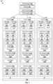
- FIG. 1is a schematic diagram illustrating example software-defined networking (SDN) environment 100 in which self-learning packet flow monitoring may be performed.
- SDN environment 100may include additional and/or alternative components than that shown in FIG. 1 .
- SDN environment 100includes multiple hosts 110 A-C that are interconnected via physical network 104 .
- SDN environment 100may include any number of hosts (also known as a “host computers”, “host devices”, “physical servers”, “server systems”, “transport nodes,” etc.), where each host may be supporting tens or hundreds of virtual machines (VMs).
- hostsalso known as a “host computers”, “host devices”, “physical servers”, “server systems”, “transport nodes,” etc.
- VMsvirtual machines
- Each host 110 A/ 110 B/ 110 Cmay include suitable hardware 112 A/ 112 B/ 112 C and virtualization software (e.g., hypervisor-A 114 A, hypervisor-B 114 B, hypervisor-C 114 C) to support various VMs.
- hosts 110 A-Cmay support respective VMs 131 - 136 (see also FIG. 2 ).
- Hypervisor 114 A/ 114 B/ 114 Cmaintains a mapping between underlying hardware 112 A/ 112 B/ 112 C and virtual resources allocated to respective VMs.
- Hardware 112 A/ 112 B/ 112 Cincludes suitable physical components, such as central processing unit(s) (CPU(s)) or processor(s) 120 A/ 120 B/ 120 C; memory 122 A/ 122 B/ 122 C; physical network interface controllers (NICs) 124 A/ 124 B/ 124 C; and storage disk(s) 126 A/ 126 B/ 126 C, etc.
- CPUcentral processing unit
- processorprocessor
- NICsphysical network interface controllers
- storage disk(s) 126 A/ 126 B/ 126 Cetc.
- Virtual resourcesare allocated to respective VMs 131 - 136 to support a guest operating system (OS) and application(s).
- OSoperating system
- VMs 131 - 136support respective applications 141 - 146 (see “APP1” to “APP6”).
- the virtual resourcesmay include virtual CPU, guest physical memory, virtual disk, virtual network interface controller (VNIC), etc.
- Hardware resourcesmay be emulated using virtual machine monitors (VMMs).
- VNICs 151 - 156are virtual network adapters for VMs 131 - 136 , respectively, and are emulated by corresponding VMMs (not shown for simplicity) instantiated by their respective hypervisor at respective host-A 110 A, host-B 110 B and host-C 110 C.
- the VMMsmay be considered as part of respective VMs, or alternatively, separated from the VMs.
- one VMmay be associated with multiple VNICs (each VNIC having its own network address).
- a virtualized computing instancemay represent an addressable data compute node (DCN) or isolated user space instance.
- DCNaddressable data compute node
- Any suitable technologymay be used to provide isolated user space instances, not just hardware virtualization.
- Other virtualized computing instancesmay include containers (e.g., running within a VM or on top of a host operating system without the need for a hypervisor or separate operating system or implemented as an operating system level virtualization), virtual private servers, client computers, etc. Such container technology is available from, among others, Docker, Inc.
- the VMsmay also be complete computational environments, containing virtual equivalents of the hardware and software components of a physical computing system.
- hypervisormay refer generally to a software layer or component that supports the execution of multiple virtualized computing instances, including system-level software in guest VMs that supports namespace containers such as Docker, etc.
- Hypervisors 114 A-Cmay each implement any suitable virtualization technology, such as VMware ESX® or ESXiTM (available from VMware, Inc.), Kernel-based Virtual Machine (KVM), etc.
- the term “packet”may refer generally to a group of bits that can be transported together, and may be in another form, such as “frame,” “message,” “segment,” etc.
- traffic” or “flow”may refer generally to multiple packets.
- layer-2may refer generally to a link layer or media access control (MAC) layer; “layer-3” to a network or Internet Protocol (IP) layer; and “layer-4” to a transport layer (e.g., using Transmission Control Protocol (TCP), User Datagram Protocol (UDP), etc.), in the Open System Interconnection (OSI) model, although the concepts described herein may be used with other networking models.
- MACmedia access control
- IPInternet Protocol
- layer-4to a transport layer (e.g., using Transmission Control Protocol (TCP), User Datagram Protocol (UDP), etc.), in the Open System Interconnection (OSI) model, although the concepts described herein may be used with other networking models.
- OSIOpen System Interconnection
- Hypervisor 114 A/ 114 B/ 114 Cimplements virtual switch 115 A/ 115 B/ 115 C and logical distributed router (DR) instance 117 A/ 117 B/ 117 C to handle egress packets from, and ingress packets to, corresponding VMs.
- logical switches and logical DRsmay be implemented in a distributed manner and can span multiple hosts.
- logical switches that provide logical layer-2 connectivity, i.e., an overlay networkmay be implemented collectively by virtual switches 115 A-C and represented internally using forwarding tables 116 A-C at respective virtual switches 115 A-C.
- Forwarding tables 116 A-Cmay each include entries that collectively implement the respective logical switches.
- logical DRs that provide logical layer-3 connectivitymay be implemented collectively by DR instances 117 A-C and represented internally using routing tables 118 A-C at respective DR instances 117 A-C.
- Routing tables 118 A-Cmay each include entries that collectively implement the respective logical DRs.
- Packetsmay be received from, or sent to, each VM via an associated logical port.
- logical switch ports 161 - 166are associated with respective VMs 131 - 136 .
- the term “logical port” or “logical switch port”may refer generally to a port on a logical switch to which a virtualized computing instance is connected.
- a “logical switch”may refer generally to a software-defined networking (SDN) construct that is collectively implemented by virtual switches 115 A-C in FIG. 1
- a “virtual switch”may refer generally to a software switch or software implementation of a physical switch.
- mappingthere is usually a one-to-one mapping between a logical port on a logical switch and a virtual port on virtual switch 115 A/ 115 B/ 115 C.
- the mappingmay change in some scenarios, such as when the logical port is mapped to a different virtual port on a different virtual switch after migration of a corresponding virtualized computing instance (e.g., when the source host and destination host do not have a distributed virtual switch spanning them).
- hypervisors 114 A-Cmay implement firewall engines to filter packets.
- distributed firewall engines 171 - 176are configured to filter packets to, and from, respective VMs 131 - 136 according to firewall rules.
- network packetsmay be filtered according to firewall rules at any point along a datapath from a VM to corresponding physical NIC 124 A/ 124 B/ 124 C.
- a filter component(not shown) is incorporated into each VNIC 151 - 156 that enforces firewall rules that are associated with the endpoint corresponding to that VNIC and maintained by respective distributed firewall engines 171 - 176 .
- logical networksmay be provisioned, changed, stored, deleted and restored programmatically without having to reconfigure the underlying physical hardware architecture.
- a logical networkmay be formed using any suitable tunneling protocol, such as Virtual eXtensible Local Area Network (VXLAN), Stateless Transport Tunneling (STT), Generic Network Virtualization Encapsulation (GENEVE), etc.
- VXLANis a layer-2 overlay scheme on a layer-3 network that uses tunnel encapsulation to extend layer-2 segments across multiple hosts which may reside on different layer 2 physical networks.
- SDN manager 180 and SDN controller 184are example network management entities in SDN environment 100 .
- One example of an SDN controlleris the NSX controller component of VMware NSX® (available from VMware, Inc.) that operates on a central control plane.
- SDN controller 184may be a member of a controller cluster (not shown for simplicity) that is configurable using SDN manager 180 operating on a management plane (MP).
- Network management entity 180 / 184may be implemented using physical machine(s), VM(s), or both.
- Logical switches, logical routers, and logical overlay networksmay be configured using SDN controller 184 , SDN manager 180 , etc.
- LCPlocal control plane
- CCPcentral control plane
- Hosts 110 A-Cmay also maintain data-plane connectivity among themselves via physical network 104 to facilitate communication among VMs located on the same logical overlay network.
- Hypervisor 114 A/ 114 B/ 114 Cmay implement a virtual tunnel endpoint (VTEP) (not shown) to encapsulate and decapsulate packets with an outer header (also known as a tunnel header) identifying the relevant logical overlay network (e.g., using a VXLAN or “virtual” network identifier (VNI) added to a header field).
- VNIvirtual network identifier
- hypervisor-B 114 Bimplements a second VTEP with (IP-B, MAC-B, VTEP-B)
- hypervisor-C 114 Cimplements a third VTEP with (IP-C, MAC-C, VTEP-C), etc.
- Encapsulated packetsmay be sent via an end-to-end, bi-directional communication path (known as a tunnel) between a pair of VTEPs over physical network 104 .
- troubleshooting toolsmay be used to diagnose network issues affecting VMs 131 - 136 .
- these toolsusually necessitate users to have detected a network issue in SDN environment 100 , as well as some idea as to where the network issue originates.
- these toolsmay require a user to select two VMs or VNICs to visualize or test topology connectivity between two endpoints.
- a usermight have to visit different appliances and familiarize with different troubleshooting tools to be able to debug network issues.
- self-learning packet flow monitoringmay be implemented to improve network troubleshooting and diagnosis.
- SDN environment 100increases in scale and complexity, any improvement in network troubleshooting and diagnosis may lead to reduced system downtime and better performance.
- self-learningalso known as “continuous learning,” “lifelong learning” and “incremental learning” may refer generally to technique(s) where a classification engine is modified or improved throughout its operation based on improved training data.
- FIG. 2is a schematic diagram illustrating example system architecture 200 for logical network health check in SDN environment 100 in FIG. 1 .
- example architecture 200may include additional and/or alternative components than that shown in FIG. 2 .
- Example architecture 200may include policy manager 210 capable of interacting with various entities in SDN environment 100 , such as SDN manager 180 (see MP 201 ), SDN controller 184 (see CCP 202 ), hosts 110 A-C on LCP 203 and data plane (DP) 204 and user device(s) 240 operated by user(s) 242 .
- SDN manager 180see MP 201
- SDN controller 184see CCP 202
- hosts 110 A-C on LCP 203 and data plane (DP) 204and user device(s) 240 operated by user(s) 242 .
- DPdata plane
- Policy manager 210may represent a configuration layer that interacts with SDN manager 180 representing a realization layer in SDN environment 100 .
- User(s) 242 operating with client device(s) 240may interact with policy manager 210 to perform network configurations, which are then realized on hosts 110 A-C via SDN manager 180 .
- Any suitable UImay be supported by policy manager 210 using application programming interface (API) module 214 , such as graphical user interface (GUI), command-line interface (CLI), representational state transfer (REST) API, etc.
- GUIgraphical user interface
- CLIcommand-line interface
- RESTrepresentational state transfer
- Policy manager 210may support any suitable module(s) to facilitate policy configuration as well as network troubleshooting and diagnosis.
- policy manager 210may include logical network health check module 211 , self-learning packet flow monitoring module 212 , analytics module 213 and API module 214 .
- Policy manager 210may be configured to monitor packet flows among VMs 131 - 136 periodically (e.g., every five minutes) using analytics module 213 , which interacts with context engines (not shown) implemented by respective hosts 110 A-C.
- policy manager 210(“computer system”) may facilitate self-learning packet flow monitoring in SDN environment 100 .
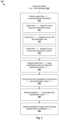
- FIG. 3is a flowchart of example process 300 for a computer system to perform self-learning packet flow monitoring in SDN environment 100 .
- Example process 300may include one or more operations, functions, or actions illustrated by one or more blocks, such as 310 to 350 . The various blocks may be combined into fewer blocks, divided into additional blocks, and/or eliminated depending on the desired implementation.
- a packet flow (X*)may be monitored to identify attribute information associated with the packet flow (X*) between a source and a destination.
- the packet flow (X*)may be between a pair of groups (see 311 ), VMs (see 312 ) or processes (see 313 ).
- a VMmay represent an “object” in a group, and a process supported by the VM a “sub-object.”
- the packet flow (X*)may be between (a) a source group, VM or process and (b) a destination group, VM or process. See 311 - 313 in FIG. 3 .
- the packet flow (X*)may be classified using classification engine 420 (see FIG. 4 ) that is trained using a training dataset to determine a classification output (Y*) associated with the packet flow (X*).
- a UI that includes a visualization of the packet flow (X*) and the classification output (Y*)may be provided to user device 240 .
- the term “provide”may refer generally to generating and sending any suitable information to cause user device 240 to render UI(s) on a display screen.
- a feedback (Z*) associated with the classification output (Y*)may be requested to update classification engine 420 and/or training dataset 410 shown in FIG. 2 .
- policy manager 210may obtain attribute information 230 associated with packet flows from SDN manager 180 and/or hosts 110 A-C.
- the term “obtain”may refer generally to receiving or retrieving information from a source or datastore in which the information is stored.
- policy manager 210may request classification system 220 to classify a packet flow (X*) to determine a classification output (Y*) indicating whether the packet flow is suspicious or otherwise (i.e., good).
- User 242 operating user device 240may interact with API module 214 of policy manager 210 to access UI 250 and provide a feedback (Z*), such as either accepting or rejecting the classification output (Y*).
- Example UI 250specifies a visualization 251 of (X*, Y*) along with UI element 252 to request for feedback (Z*). See corresponding 260 , 270 , 280 and 290 in FIG. 2 .
- classification engine 420may be trained using training dataset 410 that utilizes a combination of historical information, configuration information (e.g., flow tuple information) and user's feedback.
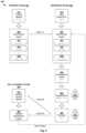
- FIG. 4is a schematic diagram of example detailed process 400 of self-learning packet flow monitoring in SDN environment 100 .
- Example process 400may include one or more operations, functions, data blocks or actions illustrated at 410 to 480 . The various operations, functions or actions may be combined into fewer blocks, divided into additional blocks, and/or eliminated depending on the desired implementation.
- Example process 400may be performed by any suitable computer systems, such as policy manager 210 , classification system 220 , etc.
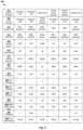
- FIG. 5is a schematic diagram illustrating training dataset 410 for training classification engine 420 to facilitate self-learning packet flow monitoring.
- Classification engine 420may include multiple (M>1) classification blocks or layers 421 - 42 M that are each associated with a set of weights.
- training phase 401may involve finding weights that minimize a training error between training input (X i ) and classification result predicted by classification engine 420 .
- the training processmay be guided by estimating losses associated with the classification error.
- a loss functionmay be mean squared error between true and predicted outcome, but the loss function could have more complex formulas.
- Training dataset 410may be generated based on flow attribute information collected using analytics module 213 to interact with SDN manager 180 and hosts 110 A-C.
- analytics module 213may implement any suitable service, such as VMware NSX® IntelligenceTM to gain insights into packet flows in SDN environment 100 , etc.
- training dataset 410may include any suitable attribute information associated with each packet flow (X i ), such as source information (e.g., source process, VM and group), destination information (e.g., destination process, VM and group), protocol and port number information (e.g., TCP 8080, TCP 80), etc.
- Training dataset 410may further include flow metric information associated with each packet flow (X i ), such as number of events (e.g., traffic between VMs), number of packets transmitted (TX) and/or received (RX), latency, throughput, packet loss, packet size, jitter, amount of TX and/or RX data (bytes), any combination thereof, etc. See 511 - 519 and 521 - 524 in FIG. 5 .
- flow metric information associated with each packet flowX i ), such as number of events (e.g., traffic between VMs), number of packets transmitted (TX) and/or received (RX), latency, throughput, packet loss, packet size, jitter, amount of TX and/or RX data (bytes), any combination thereof, etc. See 511 - 519 and 521 - 524 in FIG. 5 .
- latencymay refer generally to the time required to transmit a packet belonging to the flow from a sender to a recipient, such as round-trip time (RTT), one-way latency, etc.
- Throughputmay refer generally to the amount of data being sent from the sender to the recipient, such as the quantity of data per unit of time.
- Packet lossmay refer generally to the number of packets lost per a fixed number (e.g., 100) of packets sent.
- Jittermay refer generally to a variance in latency over time. The number of packets transmitted or received may be used to calculate a packet drop rate between a pair of checkpoints.
- flow metric informatione.g., latency
- classification engine 420may be an artificial intelligence engine, such as a neural network, etc.
- a neural networkis generally formed using a network of processing elements (called “neurons,” “nodes,” etc.) that are interconnected via connections (called “synapses,” “weights,” etc.).
- a convolutional neural networkmay include multiple classification layers (L j ) that include a convolutional layer, pooling layer, rectified linear units (ReLU) layer, fully connected layer, loss layer, etc. These layers may be trained from end-to-end (e.g., from an input layer to an output layer) to extract feature(s) from an input packet flow and classify the feature(s) to produce a classification output.
- L jclassification layers
- ReLUrectified linear units
- classification engine 420may be trained using any suitable machine learning service.
- the servicemay be responsible for training the desired classification model, as well as performing classification on a set of test data for validation.
- training dataset 410Using training dataset 410 , a full mesh of all possible connections between each pair of source and destination may be considered during training phase 401 .
- a new set of training dataWhen a new set of training data is discovered, it may be sent to storage on classification system 220 to update the model (i.e., engine 420 ).
- the sourcee.g., process, VM or group
- the destinatione.g., process, VM or group
- namecontains “dn,” “postgre,” “sql” or “mysql”.
- a probabilistic classification output 440may be determined, where Y* ⁇ [0,1].
- classification system 220may send classification output 440 (Y*) to policy manager 210 .
- Classification system 220may be configured to integrate and store classification output 440 (Y*) on datastore 222 , as well as sending classification output 440 (Y*) for presentation to user 242 .
- Model builder 221 on classification system 220may periodically update classification engine 420 to better adapt to the user's preferences.
- policy manager 210may provide classification output 440 (Y*) associated with packet flow 430 (X*) to user 242 via API module 214 supported by policy manager 210 .
- policy manager 210may generate and send any suitable information to user device 240 to cause user device to display a visualization of each packet flow 430 (X*) and classification output 440 (Y*) between a pair of source and destination.
- classification UI 450may include a UI element to request for classification feedback 460 (Z*) from user 242 .
- UI elementmay be a window, visual representation (e.g., topology graph), button, menu, text box, list, application icon, title bar, status bar, size grip, toolbar, dropdown list, etc.
- Policy manager 210may detect feedback 460 (Z*) based on any suitable UI event(s) generated by the user's interaction with user interface 450 .
- the “UI event”may be captured in any suitable manager, such as using a keyboard to capture keyboard events (e.g. key press), mouse to capture mouse events (e.g. cursor position, key press) and touch screen to capture touch screen events, etc.
- policy manager 210may store classification feedback 460 (Z*) and refine classification system 220 , thereby generating updated training dataset 470 and/or updated classification engine 480 accordingly.
- a “past occurrence rate”(see 530 ) and/or connection endorsement rate (see 540 ) associated with a packet flow may be updated based on classification feedback 460 (Z*).
- the accuracy of classification system 220should also improve to better adapt to the user's preferences.
- self-learning phase 403may be triggered by other events, such as configuration changes to create new packet flows or update existing packet flows, etc. This helps classification engine 420 to correlate any packet flow changes with configuration changes.
- the self-learning approachis also useful for mitigating the problem of small training sample size that might severely affect classification accuracy.
- policy manager 210may classify a set of packet flows in SDN environment 100 using classification engine 420 to obtain a set of classification outputs. This way, a full mesh of packet flows and associated classification outputs may be presented to user 242 for feedback (e.g., acceptance or rejection).
- UI(s) 250may form part of a wizard for in-context, step-based for network troubleshooting and diagnosis in SDN environment 100 .
- the term “in-context”may mean that the information provided is understandable from a high-level overview of SDN environment 100 . This way, it is not necessary for user(s) 242 to apply different tools on different parts of SDN environment 100 for network troubleshooting and diagnosis.
- each packet flow in the setmay be between a pair of groups, a pair of objects (e.g., VMs) or a pair of sub-objects (e.g., processes or applications).
- Other source-destination pairsmay be considered, such as between a pair of pods (i.e., each pod being a group of containers), a pair of logical elements, etc.
- the term “logical element” or “logical forwarding element”may refer generally to a logical entity that is deployed on a datapath to connect a pair of endpoints (e.g., VM1 131 and VM6 136 ), such as a logical switch port, logical switch, logical router port, logical router, edge appliance, VNIC, etc.
- FIG. 6is a schematic diagram illustrating example self-learning packet flow monitoring 600 for groups in SDN environment 100 .
- group communicationsmay be monitored and presented in the form of a mesh of packet flows among various groups.
- feedback 460may indicate whether user 242 accepts (i.e., endorses) or rejects associated classification output 440 (Y*).
- fifth packet flow 650is classified to be suspicious and highlighted.
- User 242may disagree with the classification output and provide classification feedback 460 (Z*) by hovering over a UI element visualization of packet flow 430 (X*) and selecting whether to “ACCEPT” (see 660 ) or “REJECT” (see 670 ) the classification.
- policy manager 210may suggest a remediation action (see 680 ) in response to detecting a suspicious flow, such as by configuring a DFW rule to block the packet flow. This gives user 242 with the authority to mark a particular communication as good or suspicious in order to enrich training dataset 410 and improve classification accuracy in a self-learning and self-adaptive manner.
- FIG. 7is a schematic diagram illustrating example self-learning packet flow monitoring 700 for VMs 131 - 136 in SDN environment 100 .
- VM communicationsmay be monitored and presented in the form of a mesh of packet flows among various VMs 131 - 136 .
- First packet flow 710is classified to be suspicious and highlighted.
- User 242may provide classification feedback 460 (Z*) by hovering over a UI element visualization of packet flow 430 (X*) and selecting whether to “ACCEPT” (see 720 ) or “REJECT” (see 730 ) the classification.
- Policy manager 210may also suggest a remediation action (see 740 ), such as by blocking the packet flow using a DFW rule.
- metric informationassociated with VMs may be analyzed and highlighted if a threshold is exceeded.
- Any suitable performance metric informationmay be used, such as CPU utilization (e.g., per-process basis), memory utilization (e.g., per-process basis), number of packets transmitted (TX) and received (RX), amount of TX and RX data (bytes), applications (e.g., name, version, manufacturer) installed and/or running on VMs 131 - 136 , any information collectable using VMs 131 - 136 (e.g., using guest OS), etc.
- the example in FIG. 7may also be used to highlight any missing connection between a pair of VMs. Additionally, a connectivity check between a pair of VMs may be initiated.
- FIG. 8is a schematic diagram illustrating example self-learning packet flow monitoring 800 for processes 141 - 146 in SDN environment 100 .
- process communicationsmay be monitored and presented in the form of a mesh of packet flows among various processes 141 - 146 .
- First packet flow 810is classified to be suspicious and highlighted.
- user 242may provide classification feedback 460 (Z*) by hovering over a UI element visualization of packet flow 430 (X*) and selecting whether to “ACCEPT” (see 820 ) or “REJECT” (see 830 ) the classification.
- Policy manager 210may also suggest a remediation action (see 840 ), such as by blocking the packet flow using a DFW rule.
- public cloud environment 100may include other virtual workloads, such as containers, etc.
- containeralso known as “container instance”
- container technologiesmay be used to run various containers inside respective VMs 131 - 136 .
- Containersare “OS-less”, meaning that they do not include any OS that could weigh 10s of Gigabytes (GB). This makes containers more lightweight, portable, efficient and suitable for delivery into an isolated OS environment.
- Running containers inside a VM(known as “containers-on-virtual-machine” approach) not only leverages the benefits of container technologies but also that of virtualization technologies.
- the containersmay be executed as isolated processes inside respective VMs.
- the above examplescan be implemented by hardware (including hardware logic circuitry), software or firmware or a combination thereof.
- the above examplesmay be implemented by any suitable computing device, computer system, etc.
- the computer systemmay include processor(s), memory unit(s) and physical NIC(s) that may communicate with each other via a communication bus, etc.
- the computer systemmay include a non-transitory computer-readable medium having stored thereon instructions or program code that, when executed by the processor, cause the processor to perform processes described herein with reference to FIG. 1 to FIG. 8 .
- a computer system capable of acting as policy manager 210 or classification system 220may be deployed in SDN environment 100 .
- Special-purpose hardwired circuitrymay be in the form of, for example, one or more application-specific integrated circuits (ASICs), programmable logic devices (PLDs), field-programmable gate arrays (FPGAs), and others.
- ASICsapplication-specific integrated circuits
- PLDsprogrammable logic devices
- FPGAsfield-programmable gate arrays
- processoris to be interpreted broadly to include a processing unit, ASIC, logic unit, or programmable gate array etc.
- a computer-readable storage mediummay include recordable/non recordable media (e.g., read-only memory (ROM), random access memory (RAM), magnetic disk or optical storage media, flash memory devices, etc.).
Landscapes
- Engineering & Computer Science (AREA)
- Theoretical Computer Science (AREA)
- Signal Processing (AREA)
- Computer Networks & Wireless Communication (AREA)
- Physics & Mathematics (AREA)
- Data Mining & Analysis (AREA)
- Software Systems (AREA)
- Evolutionary Computation (AREA)
- Artificial Intelligence (AREA)
- Computing Systems (AREA)
- General Physics & Mathematics (AREA)
- Mathematical Physics (AREA)
- General Engineering & Computer Science (AREA)
- Computational Linguistics (AREA)
- Biophysics (AREA)
- Molecular Biology (AREA)
- General Health & Medical Sciences (AREA)
- Biomedical Technology (AREA)
- Life Sciences & Earth Sciences (AREA)
- Health & Medical Sciences (AREA)
- Computer Vision & Pattern Recognition (AREA)
- Medical Informatics (AREA)
- Databases & Information Systems (AREA)
- Data Exchanges In Wide-Area Networks (AREA)
Abstract
Description
Claims (21)
Priority Applications (1)
| Application Number | Priority Date | Filing Date | Title |
|---|---|---|---|
| US16/744,131US11909653B2 (en) | 2020-01-15 | 2020-01-15 | Self-learning packet flow monitoring in software-defined networking environments |
Applications Claiming Priority (1)
| Application Number | Priority Date | Filing Date | Title |
|---|---|---|---|
| US16/744,131US11909653B2 (en) | 2020-01-15 | 2020-01-15 | Self-learning packet flow monitoring in software-defined networking environments |
Publications (2)
| Publication Number | Publication Date |
|---|---|
| US20210216908A1 US20210216908A1 (en) | 2021-07-15 |
| US11909653B2true US11909653B2 (en) | 2024-02-20 |
Family
ID=76764259
Family Applications (1)
| Application Number | Title | Priority Date | Filing Date |
|---|---|---|---|
| US16/744,131Active2041-05-29US11909653B2 (en) | 2020-01-15 | 2020-01-15 | Self-learning packet flow monitoring in software-defined networking environments |
Country Status (1)
| Country | Link |
|---|---|
| US (1) | US11909653B2 (en) |
Families Citing this family (12)
| Publication number | Priority date | Publication date | Assignee | Title |
|---|---|---|---|---|
| US10225094B2 (en)* | 2012-05-29 | 2019-03-05 | Futurewei Technologies, Inc. | SDN facilitated multicast in data center |
| US11283699B2 (en) | 2020-01-17 | 2022-03-22 | Vmware, Inc. | Practical overlay network latency measurement in datacenter |
| US11570090B2 (en) | 2020-07-29 | 2023-01-31 | Vmware, Inc. | Flow tracing operation in container cluster |
| US11303548B2 (en)* | 2020-07-31 | 2022-04-12 | Bank Of America Corporation | Network directionality mapping system |
| US11736436B2 (en) | 2020-12-31 | 2023-08-22 | Vmware, Inc. | Identifying routes with indirect addressing in a datacenter |
| US11336533B1 (en) | 2021-01-08 | 2022-05-17 | Vmware, Inc. | Network visualization of correlations between logical elements and associated physical elements |
| US11687210B2 (en) | 2021-07-05 | 2023-06-27 | Vmware, Inc. | Criteria-based expansion of group nodes in a network topology visualization |
| US11711278B2 (en) | 2021-07-24 | 2023-07-25 | Vmware, Inc. | Visualization of flow trace operation across multiple sites |
| US11706109B2 (en)* | 2021-09-17 | 2023-07-18 | Vmware, Inc. | Performance of traffic monitoring actions |
| US12273389B2 (en)* | 2022-03-22 | 2025-04-08 | International Business Machines Corporation | Smart SDN for intrusion prevention |
| US20230379249A1 (en)* | 2022-05-17 | 2023-11-23 | Mellanox Technologies, Ltd. | Systems and methods of packet classification using artificial intelligence |
| US11983164B1 (en) | 2022-11-17 | 2024-05-14 | Bank Of America Corporation | System and method for data community detection via data network telemetry |
Citations (44)
| Publication number | Priority date | Publication date | Assignee | Title |
|---|---|---|---|---|
| US20110004914A1 (en) | 2009-07-01 | 2011-01-06 | Netcordia, Inc. | Methods and Apparatus for Identifying the Impact of Changes in Computer Networks |
| US8432919B2 (en)* | 2009-02-25 | 2013-04-30 | Cisco Technology, Inc. | Data stream classification |
| US8462786B2 (en)* | 2009-08-17 | 2013-06-11 | Board Of Trustees Of Michigan State University | Efficient TCAM-based packet classification using multiple lookups and classifier semantics |
| US8682812B1 (en)* | 2010-12-23 | 2014-03-25 | Narus, Inc. | Machine learning based botnet detection using real-time extracted traffic features |
| US20140215077A1 (en) | 2013-01-26 | 2014-07-31 | Lyatiss, Inc. | Methods and systems for detecting, locating and remediating a congested resource or flow in a virtual infrastructure |
| US20140280834A1 (en) | 2013-03-15 | 2014-09-18 | Cisco Technology, Inc. | Programmable management engine for networks |
| US20150106670A1 (en)* | 2013-10-10 | 2015-04-16 | Ixia | Methods, systems, and computer readable media for providing user interfaces for specification of system under test (sut) and network tap topology and for presenting topology specific test results |
| US20160219068A1 (en)* | 2015-01-27 | 2016-07-28 | Electronics And Telecommunications Research Institute | Method and apparatus for automatically identifying signature of malicious traffic using latent dirichlet allocation |
| US20160283859A1 (en)* | 2015-03-25 | 2016-09-29 | Cisco Technology, Inc. | Network traffic classification |
| US20160359740A1 (en)* | 2015-06-05 | 2016-12-08 | Cisco Technology, Inc. | Augmenting flow data for improved network monitoring and management |
| US20160378529A1 (en)* | 2015-06-29 | 2016-12-29 | Fortinet, Inc. | Utm integrated hypervisor for virtual machines |
| US20170295207A1 (en)* | 2014-12-22 | 2017-10-12 | Huawei Technologies Co., Ltd. | Attack Data Packet Processing Method, Apparatus, and System |
| US9800470B2 (en) | 2013-11-10 | 2017-10-24 | F5 Networks, Inc. | Methods and system for automated or user-assisted grouping and management of groups in cloud infrastructure and network |
| US20180114126A1 (en)* | 2016-10-24 | 2018-04-26 | Oracle International Corporation | Systems and methods for identifying process flows from log files and visualizing the flow |
| US20180123903A1 (en) | 2016-10-31 | 2018-05-03 | Nicira, Inc. | Network health checker |
| US20180189677A1 (en)* | 2017-01-05 | 2018-07-05 | Cisco Technology, Inc. | Training a machine learning-based traffic analyzer using a prototype dataset |
| US20180367412A1 (en) | 2017-06-16 | 2018-12-20 | Cisco Technology, Inc. | Topology explorer |
| US20180367413A1 (en) | 2017-06-19 | 2018-12-20 | Cisco Technology, Inc. | Network node memory utilization analysis |
| US20190044869A1 (en)* | 2018-08-17 | 2019-02-07 | Intel Corporation | Technologies for classifying network flows using adaptive virtual routing |
| US20190044913A1 (en)* | 2017-08-04 | 2019-02-07 | Hitachi, Ltd. | Network apparatus, method of processing packets, and storage medium having program stored thereon |
| US10305809B2 (en)* | 2016-11-17 | 2019-05-28 | Cisco Technology, Inc. | On-box behavior-based traffic classification |
| US20190190938A1 (en)* | 2017-12-15 | 2019-06-20 | Panasonic Intellectual Property Corporation Of America | Anomaly detection method, learning method, anomaly detection device, and learning device |
| US10348767B1 (en) | 2013-02-26 | 2019-07-09 | Zentera Systems, Inc. | Cloud over IP session layer network |
| US10375090B2 (en)* | 2017-03-27 | 2019-08-06 | Cisco Technology, Inc. | Machine learning-based traffic classification using compressed network telemetry data |
| US10498752B2 (en)* | 2016-03-28 | 2019-12-03 | Cisco Technology, Inc. | Adaptive capture of packet traces based on user feedback learning |
| US10530740B2 (en) | 2017-07-26 | 2020-01-07 | At&T Intellectual Property I, L.P. | Systems and methods for facilitating closed loop processing using machine learning |
| US10560309B1 (en) | 2017-10-11 | 2020-02-11 | Juniper Networks, Inc. | Identifying a root cause of alerts within virtualized computing environment monitoring system |
| US10623285B1 (en) | 2014-05-09 | 2020-04-14 | Amazon Technologies, Inc. | Multi-mode health monitoring service |
| US20200169484A1 (en)* | 2017-01-31 | 2020-05-28 | Splunk Inc. | Visualizing network activity involving networked computing devices distributed across network address spaces |
| US10673765B2 (en)* | 2018-09-11 | 2020-06-02 | Cisco Technology, Inc. | Packet flow classification in spine-leaf networks using machine learning based overlay distributed decision trees |
| US20200285737A1 (en)* | 2019-03-05 | 2020-09-10 | Microsoft Technology Licensing, Llc | Dynamic cybersecurity detection of sequence anomalies |
| US10798015B2 (en) | 2018-01-25 | 2020-10-06 | Cisco Technology, Inc. | Discovery of middleboxes using traffic flow stitching |
| US10868742B2 (en) | 2017-03-29 | 2020-12-15 | Juniper Networks, Inc. | Multi-cluster dashboard for distributed virtualization infrastructure element monitoring and policy control |
| US10897474B2 (en)* | 2016-06-23 | 2021-01-19 | Cisco Technology, Inc. | Adapting classifier parameters for improved network traffic classification using distinct private training data sets |
| US20210021491A1 (en)* | 2019-07-18 | 2021-01-21 | Citrix Systems, Inc. | System and Method for Processing Network Data |
| US20210067455A1 (en)* | 2019-09-04 | 2021-03-04 | Oath Inc. | Intelligent dataflow-based service discovery and analysis |
| US20210075799A1 (en)* | 2019-09-05 | 2021-03-11 | Cisco Technology, Inc. | Threat detection of application traffic flows |
| US11018943B1 (en)* | 2020-05-20 | 2021-05-25 | Cisco Technology, Inc. | Learning packet capture policies to enrich context for device classification systems |
| US20210204152A1 (en)* | 2019-12-31 | 2021-07-01 | Hughes Network Systems, Llc | Traffic flow classification using machine learning |
| US20210218630A1 (en) | 2020-01-15 | 2021-07-15 | Vmware, Inc. | Logical network health check in software-defined networking (sdn) environments |
| US11079744B2 (en) | 2015-10-13 | 2021-08-03 | Schneider Electric Industries Sas | Centralized management of a software defined automation system |
| US11271833B2 (en)* | 2017-10-23 | 2022-03-08 | Cisco Technology, Inc. | Training a network traffic classifier using training data enriched with contextual bag information |
| US11271824B2 (en)* | 2019-07-25 | 2022-03-08 | Vmware, Inc. | Visual overlays for network insights |
| US20220086064A1 (en)* | 2018-12-14 | 2022-03-17 | Newsouth Innovations Pty Limited | Apparatus and process for detecting network security attacks on iot devices |
- 2020
- 2020-01-15USUS16/744,131patent/US11909653B2/enactiveActive
Patent Citations (44)
| Publication number | Priority date | Publication date | Assignee | Title |
|---|---|---|---|---|
| US8432919B2 (en)* | 2009-02-25 | 2013-04-30 | Cisco Technology, Inc. | Data stream classification |
| US20110004914A1 (en) | 2009-07-01 | 2011-01-06 | Netcordia, Inc. | Methods and Apparatus for Identifying the Impact of Changes in Computer Networks |
| US8462786B2 (en)* | 2009-08-17 | 2013-06-11 | Board Of Trustees Of Michigan State University | Efficient TCAM-based packet classification using multiple lookups and classifier semantics |
| US8682812B1 (en)* | 2010-12-23 | 2014-03-25 | Narus, Inc. | Machine learning based botnet detection using real-time extracted traffic features |
| US20140215077A1 (en) | 2013-01-26 | 2014-07-31 | Lyatiss, Inc. | Methods and systems for detecting, locating and remediating a congested resource or flow in a virtual infrastructure |
| US10348767B1 (en) | 2013-02-26 | 2019-07-09 | Zentera Systems, Inc. | Cloud over IP session layer network |
| US20140280834A1 (en) | 2013-03-15 | 2014-09-18 | Cisco Technology, Inc. | Programmable management engine for networks |
| US20150106670A1 (en)* | 2013-10-10 | 2015-04-16 | Ixia | Methods, systems, and computer readable media for providing user interfaces for specification of system under test (sut) and network tap topology and for presenting topology specific test results |
| US9800470B2 (en) | 2013-11-10 | 2017-10-24 | F5 Networks, Inc. | Methods and system for automated or user-assisted grouping and management of groups in cloud infrastructure and network |
| US10623285B1 (en) | 2014-05-09 | 2020-04-14 | Amazon Technologies, Inc. | Multi-mode health monitoring service |
| US20170295207A1 (en)* | 2014-12-22 | 2017-10-12 | Huawei Technologies Co., Ltd. | Attack Data Packet Processing Method, Apparatus, and System |
| US20160219068A1 (en)* | 2015-01-27 | 2016-07-28 | Electronics And Telecommunications Research Institute | Method and apparatus for automatically identifying signature of malicious traffic using latent dirichlet allocation |
| US20160283859A1 (en)* | 2015-03-25 | 2016-09-29 | Cisco Technology, Inc. | Network traffic classification |
| US20160359740A1 (en)* | 2015-06-05 | 2016-12-08 | Cisco Technology, Inc. | Augmenting flow data for improved network monitoring and management |
| US20160378529A1 (en)* | 2015-06-29 | 2016-12-29 | Fortinet, Inc. | Utm integrated hypervisor for virtual machines |
| US11079744B2 (en) | 2015-10-13 | 2021-08-03 | Schneider Electric Industries Sas | Centralized management of a software defined automation system |
| US10498752B2 (en)* | 2016-03-28 | 2019-12-03 | Cisco Technology, Inc. | Adaptive capture of packet traces based on user feedback learning |
| US10897474B2 (en)* | 2016-06-23 | 2021-01-19 | Cisco Technology, Inc. | Adapting classifier parameters for improved network traffic classification using distinct private training data sets |
| US20180114126A1 (en)* | 2016-10-24 | 2018-04-26 | Oracle International Corporation | Systems and methods for identifying process flows from log files and visualizing the flow |
| US20180123903A1 (en) | 2016-10-31 | 2018-05-03 | Nicira, Inc. | Network health checker |
| US10305809B2 (en)* | 2016-11-17 | 2019-05-28 | Cisco Technology, Inc. | On-box behavior-based traffic classification |
| US20180189677A1 (en)* | 2017-01-05 | 2018-07-05 | Cisco Technology, Inc. | Training a machine learning-based traffic analyzer using a prototype dataset |
| US20200169484A1 (en)* | 2017-01-31 | 2020-05-28 | Splunk Inc. | Visualizing network activity involving networked computing devices distributed across network address spaces |
| US10375090B2 (en)* | 2017-03-27 | 2019-08-06 | Cisco Technology, Inc. | Machine learning-based traffic classification using compressed network telemetry data |
| US10868742B2 (en) | 2017-03-29 | 2020-12-15 | Juniper Networks, Inc. | Multi-cluster dashboard for distributed virtualization infrastructure element monitoring and policy control |
| US20180367412A1 (en) | 2017-06-16 | 2018-12-20 | Cisco Technology, Inc. | Topology explorer |
| US20180367413A1 (en) | 2017-06-19 | 2018-12-20 | Cisco Technology, Inc. | Network node memory utilization analysis |
| US10530740B2 (en) | 2017-07-26 | 2020-01-07 | At&T Intellectual Property I, L.P. | Systems and methods for facilitating closed loop processing using machine learning |
| US20190044913A1 (en)* | 2017-08-04 | 2019-02-07 | Hitachi, Ltd. | Network apparatus, method of processing packets, and storage medium having program stored thereon |
| US10560309B1 (en) | 2017-10-11 | 2020-02-11 | Juniper Networks, Inc. | Identifying a root cause of alerts within virtualized computing environment monitoring system |
| US11271833B2 (en)* | 2017-10-23 | 2022-03-08 | Cisco Technology, Inc. | Training a network traffic classifier using training data enriched with contextual bag information |
| US20190190938A1 (en)* | 2017-12-15 | 2019-06-20 | Panasonic Intellectual Property Corporation Of America | Anomaly detection method, learning method, anomaly detection device, and learning device |
| US10798015B2 (en) | 2018-01-25 | 2020-10-06 | Cisco Technology, Inc. | Discovery of middleboxes using traffic flow stitching |
| US20190044869A1 (en)* | 2018-08-17 | 2019-02-07 | Intel Corporation | Technologies for classifying network flows using adaptive virtual routing |
| US10673765B2 (en)* | 2018-09-11 | 2020-06-02 | Cisco Technology, Inc. | Packet flow classification in spine-leaf networks using machine learning based overlay distributed decision trees |
| US20220086064A1 (en)* | 2018-12-14 | 2022-03-17 | Newsouth Innovations Pty Limited | Apparatus and process for detecting network security attacks on iot devices |
| US20200285737A1 (en)* | 2019-03-05 | 2020-09-10 | Microsoft Technology Licensing, Llc | Dynamic cybersecurity detection of sequence anomalies |
| US20210021491A1 (en)* | 2019-07-18 | 2021-01-21 | Citrix Systems, Inc. | System and Method for Processing Network Data |
| US11271824B2 (en)* | 2019-07-25 | 2022-03-08 | Vmware, Inc. | Visual overlays for network insights |
| US20210067455A1 (en)* | 2019-09-04 | 2021-03-04 | Oath Inc. | Intelligent dataflow-based service discovery and analysis |
| US20210075799A1 (en)* | 2019-09-05 | 2021-03-11 | Cisco Technology, Inc. | Threat detection of application traffic flows |
| US20210204152A1 (en)* | 2019-12-31 | 2021-07-01 | Hughes Network Systems, Llc | Traffic flow classification using machine learning |
| US20210218630A1 (en) | 2020-01-15 | 2021-07-15 | Vmware, Inc. | Logical network health check in software-defined networking (sdn) environments |
| US11018943B1 (en)* | 2020-05-20 | 2021-05-25 | Cisco Technology, Inc. | Learning packet capture policies to enrich context for device classification systems |
Non-Patent Citations (10)
| Title |
|---|
| "Analysis of Network Connection Data with Azure Monitor for Virtual Machines", Virtual Machines Blog, Mar. 27, 2019 Retrieved on Jan. 16, 2020 from the Internet at <URL: https://azure.microsoft.com/en-in/blog/analysis-of-network-connection-data-with-azure-monitor-for-virtual-machines/>. |
| "Application of Machine Learning to Flow-based Network Monitoring", Network Polygraph, Retrieved on Jan. 16, 2020 from the Internet at <URL: https://datatracker.ietf.org/meeting/95/materials/slides-95-nmlrg-1>. |
| "Intermapper Flows-Reliable NetFlow Monitoring Software Shows You Top Talkers and Listeners for Clear Answers About Traffic Flow", Help System, Retrieved on Jan. 16, 2020 from the Internet at <URL: https://www.helpsystems.com/products/intermapper-flows>. |
| "Logical Network System Events", VMware NSX Data Center for vSphere 6.4, Last Updated May 31, 2019, Retrieved on Jan. 16, 2020 from the Internet at <URL: https://docs.vmware.com/en/VMware-NSX-Data-Center-for-vSphere/6.4/com.vmware.nsx.logging.doc/GUID-8342573F-797E-4599-947D-CCA3AB794F13.html>. |
| "Troubleshooting a Nonoperational Logical Switch and Corresponding Junos OS OVSDB-Managed VXLAN", Juniper Networks—Techlibrary, Feb. 23, 2018, Retrieved on Jan. 16, 2020 from the Internet at <URL: https://www.juniper.net/documentation/en_US/junos/topics/task/troubleshooting/sdn-ovsdb-non-operational-logical-switch-vxlan.html>. |
| Alienor, "Virtualization Monitoring: How to Gain Visibility into Your Virtual Environment", Plixer, Retrieved on Jan. 16, 2020 from the Internet at <URL: https://www.plixer.com/blog/network-traffic-analysis/virtualization-monitoring/. |
| B. Indira et al. "An approach to enhance packet classification performance of software-defined network using deep learning", Soft Computing (2019) 23:8609-8619, 11 pages. (Year: 2019).* |
| Dirk Wallerstorfer, "Detecting Network Erros and Their Impact on Services", Dynatrace Blog, Dec. 14, 2015, Retrieved on Jan. 16, 2020 from the Internet at <URL: https://www.dynatrace.com/news/blog/detecting-network-errors-impact-on-services/>. |
| Non-Published Commonly Owned U.S. Appl. No. 16/744,123, filed Jan. 15, 2020 , 31 pages, VMware. |
| Shou-Chieh Chao et al. "Flow Classification for Software-Defined Data Centers Using Stream Mining", IEEE Transaction on Services Computing, vol. 12, No. 1, Jan./Feb. 2019, 12 pages. (Year: 2019).* |
Also Published As
| Publication number | Publication date |
|---|---|
| US20210216908A1 (en) | 2021-07-15 |
Similar Documents
| Publication | Publication Date | Title |
|---|---|---|
| US11909653B2 (en) | Self-learning packet flow monitoring in software-defined networking environments | |
| US11558255B2 (en) | Logical network health check in software-defined networking (SDN) environments | |
| US11716265B2 (en) | Anomaly detection and reporting in a network assurance appliance | |
| US11700237B2 (en) | Intent-based policy generation for virtual networks | |
| US11902082B2 (en) | Cross-domain network assurance | |
| US11588708B1 (en) | Inter-application workload network traffic monitoring and visuailization | |
| US9935851B2 (en) | Technologies for determining sensor placement and topology | |
| US10616072B1 (en) | Epoch data interface | |
| US10554477B2 (en) | Network assurance event aggregator | |
| US11038743B2 (en) | Event clustering for a network assurance platform | |
| CN112470431B (en) | Synthesis of models for networks using automatic Boolean learning | |
| US9621431B1 (en) | Classification techniques to identify network entity types and determine network topologies | |
| CN110754063B (en) | Verify endpoint configuration between nodes | |
| US11405278B2 (en) | Validating tunnel endpoint addresses in a network fabric | |
| US11150973B2 (en) | Self diagnosing distributed appliance | |
| US11356362B2 (en) | Adaptive packet flow monitoring in software-defined networking environments | |
| US10931552B1 (en) | Connectivity check with service insertion | |
| US10333833B2 (en) | Endpoint path assurance | |
| US10911338B1 (en) | Packet event tracking | |
| US20250030615A1 (en) | Systems and methods for network status visualization | |
| US12143284B1 (en) | Health check as a service |
Legal Events
| Date | Code | Title | Description |
|---|---|---|---|
| FEPP | Fee payment procedure | Free format text:ENTITY STATUS SET TO UNDISCOUNTED (ORIGINAL EVENT CODE: BIG.); ENTITY STATUS OF PATENT OWNER: LARGE ENTITY | |
| STPP | Information on status: patent application and granting procedure in general | Free format text:APPLICATION DISPATCHED FROM PREEXAM, NOT YET DOCKETED | |
| AS | Assignment | Owner name:VMWARE, INC., CALIFORNIA Free format text:ASSIGNMENT OF ASSIGNORS INTEREST;ASSIGNORS:LU, MENGZHUO;PETRUS, MARGARET;REEL/FRAME:052422/0892 Effective date:20200305 | |
| STPP | Information on status: patent application and granting procedure in general | Free format text:DOCKETED NEW CASE - READY FOR EXAMINATION | |
| STPP | Information on status: patent application and granting procedure in general | Free format text:NON FINAL ACTION MAILED | |
| STPP | Information on status: patent application and granting procedure in general | Free format text:RESPONSE TO NON-FINAL OFFICE ACTION ENTERED AND FORWARDED TO EXAMINER | |
| STPP | Information on status: patent application and granting procedure in general | Free format text:FINAL REJECTION MAILED | |
| STPP | Information on status: patent application and granting procedure in general | Free format text:FINAL REJECTION MAILED | |
| STPP | Information on status: patent application and granting procedure in general | Free format text:DOCKETED NEW CASE - READY FOR EXAMINATION | |
| STPP | Information on status: patent application and granting procedure in general | Free format text:NOTICE OF ALLOWANCE MAILED -- APPLICATION RECEIVED IN OFFICE OF PUBLICATIONS | |
| STPP | Information on status: patent application and granting procedure in general | Free format text:PUBLICATIONS -- ISSUE FEE PAYMENT VERIFIED | |
| STCF | Information on status: patent grant | Free format text:PATENTED CASE | |
| AS | Assignment | Owner name:VMWARE LLC, CALIFORNIA Free format text:CHANGE OF NAME;ASSIGNOR:VMWARE, INC.;REEL/FRAME:067102/0242 Effective date:20231121 |