US11908563B2 - Extracorporeal blood treatment machine - Google Patents
Extracorporeal blood treatment machineDownload PDFInfo
- Publication number
- US11908563B2 US11908563B2US17/063,153US202017063153AUS11908563B2US 11908563 B2US11908563 B2US 11908563B2US 202017063153 AUS202017063153 AUS 202017063153AUS 11908563 B2US11908563 B2US 11908563B2
- Authority
- US
- United States
- Prior art keywords
- blood
- peristaltic
- pump
- infusion pump
- blood treatment
- Prior art date
- Legal status (The legal status is an assumption and is not a legal conclusion. Google has not performed a legal analysis and makes no representation as to the accuracy of the status listed.)
- Active, expires
Links
Images


Classifications
- G—PHYSICS
- G16—INFORMATION AND COMMUNICATION TECHNOLOGY [ICT] SPECIALLY ADAPTED FOR SPECIFIC APPLICATION FIELDS
- G16H—HEALTHCARE INFORMATICS, i.e. INFORMATION AND COMMUNICATION TECHNOLOGY [ICT] SPECIALLY ADAPTED FOR THE HANDLING OR PROCESSING OF MEDICAL OR HEALTHCARE DATA
- G16H20/00—ICT specially adapted for therapies or health-improving plans, e.g. for handling prescriptions, for steering therapy or for monitoring patient compliance
- G16H20/10—ICT specially adapted for therapies or health-improving plans, e.g. for handling prescriptions, for steering therapy or for monitoring patient compliance relating to drugs or medications, e.g. for ensuring correct administration to patients
- G16H20/17—ICT specially adapted for therapies or health-improving plans, e.g. for handling prescriptions, for steering therapy or for monitoring patient compliance relating to drugs or medications, e.g. for ensuring correct administration to patients delivered via infusion or injection
- A—HUMAN NECESSITIES
- A61—MEDICAL OR VETERINARY SCIENCE; HYGIENE
- A61M—DEVICES FOR INTRODUCING MEDIA INTO, OR ONTO, THE BODY; DEVICES FOR TRANSDUCING BODY MEDIA OR FOR TAKING MEDIA FROM THE BODY; DEVICES FOR PRODUCING OR ENDING SLEEP OR STUPOR
- A61M1/00—Suction or pumping devices for medical purposes; Devices for carrying-off, for treatment of, or for carrying-over, body-liquids; Drainage systems
- A61M1/14—Dialysis systems; Artificial kidneys; Blood oxygenators ; Reciprocating systems for treatment of body fluids, e.g. single needle systems for hemofiltration or pheresis
- A61M1/16—Dialysis systems; Artificial kidneys; Blood oxygenators ; Reciprocating systems for treatment of body fluids, e.g. single needle systems for hemofiltration or pheresis with membranes
- A61M1/1601—Control or regulation
- A—HUMAN NECESSITIES
- A61—MEDICAL OR VETERINARY SCIENCE; HYGIENE
- A61M—DEVICES FOR INTRODUCING MEDIA INTO, OR ONTO, THE BODY; DEVICES FOR TRANSDUCING BODY MEDIA OR FOR TAKING MEDIA FROM THE BODY; DEVICES FOR PRODUCING OR ENDING SLEEP OR STUPOR
- A61M1/00—Suction or pumping devices for medical purposes; Devices for carrying-off, for treatment of, or for carrying-over, body-liquids; Drainage systems
- A61M1/36—Other treatment of blood in a by-pass of the natural circulatory system, e.g. temperature adaptation, irradiation ; Extra-corporeal blood circuits
- A61M1/3621—Extra-corporeal blood circuits
- A61M1/3622—Extra-corporeal blood circuits with a cassette forming partially or totally the blood circuit
- A61M1/36225—Extra-corporeal blood circuits with a cassette forming partially or totally the blood circuit with blood pumping means or components thereof
- A—HUMAN NECESSITIES
- A61—MEDICAL OR VETERINARY SCIENCE; HYGIENE
- A61M—DEVICES FOR INTRODUCING MEDIA INTO, OR ONTO, THE BODY; DEVICES FOR TRANSDUCING BODY MEDIA OR FOR TAKING MEDIA FROM THE BODY; DEVICES FOR PRODUCING OR ENDING SLEEP OR STUPOR
- A61M1/00—Suction or pumping devices for medical purposes; Devices for carrying-off, for treatment of, or for carrying-over, body-liquids; Drainage systems
- A61M1/36—Other treatment of blood in a by-pass of the natural circulatory system, e.g. temperature adaptation, irradiation ; Extra-corporeal blood circuits
- A61M1/3621—Extra-corporeal blood circuits
- A61M1/3622—Extra-corporeal blood circuits with a cassette forming partially or totally the blood circuit
- A61M1/36226—Constructional details of cassettes, e.g. specific details on material or shape
- A61M1/362263—Details of incorporated filters
- A61M1/362264—Details of incorporated filters the filter being a blood filter
- A—HUMAN NECESSITIES
- A61—MEDICAL OR VETERINARY SCIENCE; HYGIENE
- A61M—DEVICES FOR INTRODUCING MEDIA INTO, OR ONTO, THE BODY; DEVICES FOR TRANSDUCING BODY MEDIA OR FOR TAKING MEDIA FROM THE BODY; DEVICES FOR PRODUCING OR ENDING SLEEP OR STUPOR
- A61M1/00—Suction or pumping devices for medical purposes; Devices for carrying-off, for treatment of, or for carrying-over, body-liquids; Drainage systems
- A61M1/36—Other treatment of blood in a by-pass of the natural circulatory system, e.g. temperature adaptation, irradiation ; Extra-corporeal blood circuits
- A61M1/3621—Extra-corporeal blood circuits
- A61M1/3626—Gas bubble detectors
- A—HUMAN NECESSITIES
- A61—MEDICAL OR VETERINARY SCIENCE; HYGIENE
- A61M—DEVICES FOR INTRODUCING MEDIA INTO, OR ONTO, THE BODY; DEVICES FOR TRANSDUCING BODY MEDIA OR FOR TAKING MEDIA FROM THE BODY; DEVICES FOR PRODUCING OR ENDING SLEEP OR STUPOR
- A61M1/00—Suction or pumping devices for medical purposes; Devices for carrying-off, for treatment of, or for carrying-over, body-liquids; Drainage systems
- A61M1/36—Other treatment of blood in a by-pass of the natural circulatory system, e.g. temperature adaptation, irradiation ; Extra-corporeal blood circuits
- A61M1/3621—Extra-corporeal blood circuits
- A61M1/367—Circuit parts not covered by the preceding subgroups of group A61M1/3621
- A—HUMAN NECESSITIES
- A61—MEDICAL OR VETERINARY SCIENCE; HYGIENE
- A61M—DEVICES FOR INTRODUCING MEDIA INTO, OR ONTO, THE BODY; DEVICES FOR TRANSDUCING BODY MEDIA OR FOR TAKING MEDIA FROM THE BODY; DEVICES FOR PRODUCING OR ENDING SLEEP OR STUPOR
- A61M1/00—Suction or pumping devices for medical purposes; Devices for carrying-off, for treatment of, or for carrying-over, body-liquids; Drainage systems
- A61M1/36—Other treatment of blood in a by-pass of the natural circulatory system, e.g. temperature adaptation, irradiation ; Extra-corporeal blood circuits
- A61M1/3672—Means preventing coagulation
- A—HUMAN NECESSITIES
- A61—MEDICAL OR VETERINARY SCIENCE; HYGIENE
- A61M—DEVICES FOR INTRODUCING MEDIA INTO, OR ONTO, THE BODY; DEVICES FOR TRANSDUCING BODY MEDIA OR FOR TAKING MEDIA FROM THE BODY; DEVICES FOR PRODUCING OR ENDING SLEEP OR STUPOR
- A61M60/00—Blood pumps; Devices for mechanical circulatory actuation; Balloon pumps for circulatory assistance
- A61M60/50—Details relating to control
- A61M60/585—User interfaces
- G—PHYSICS
- G06—COMPUTING OR CALCULATING; COUNTING
- G06F—ELECTRIC DIGITAL DATA PROCESSING
- G06F3/00—Input arrangements for transferring data to be processed into a form capable of being handled by the computer; Output arrangements for transferring data from processing unit to output unit, e.g. interface arrangements
- G06F3/01—Input arrangements or combined input and output arrangements for interaction between user and computer
- G06F3/048—Interaction techniques based on graphical user interfaces [GUI]
- G06F3/0484—Interaction techniques based on graphical user interfaces [GUI] for the control of specific functions or operations, e.g. selecting or manipulating an object, an image or a displayed text element, setting a parameter value or selecting a range
- G06F3/04847—Interaction techniques to control parameter settings, e.g. interaction with sliders or dials
- G—PHYSICS
- G06—COMPUTING OR CALCULATING; COUNTING
- G06F—ELECTRIC DIGITAL DATA PROCESSING
- G06F3/00—Input arrangements for transferring data to be processed into a form capable of being handled by the computer; Output arrangements for transferring data from processing unit to output unit, e.g. interface arrangements
- G06F3/01—Input arrangements or combined input and output arrangements for interaction between user and computer
- G06F3/048—Interaction techniques based on graphical user interfaces [GUI]
- G06F3/0487—Interaction techniques based on graphical user interfaces [GUI] using specific features provided by the input device, e.g. functions controlled by the rotation of a mouse with dual sensing arrangements, or of the nature of the input device, e.g. tap gestures based on pressure sensed by a digitiser
- G06F3/0488—Interaction techniques based on graphical user interfaces [GUI] using specific features provided by the input device, e.g. functions controlled by the rotation of a mouse with dual sensing arrangements, or of the nature of the input device, e.g. tap gestures based on pressure sensed by a digitiser using a touch-screen or digitiser, e.g. input of commands through traced gestures
- G06F3/04886—Interaction techniques based on graphical user interfaces [GUI] using specific features provided by the input device, e.g. functions controlled by the rotation of a mouse with dual sensing arrangements, or of the nature of the input device, e.g. tap gestures based on pressure sensed by a digitiser using a touch-screen or digitiser, e.g. input of commands through traced gestures by partitioning the display area of the touch-screen or the surface of the digitising tablet into independently controllable areas, e.g. virtual keyboards or menus
- G—PHYSICS
- G16—INFORMATION AND COMMUNICATION TECHNOLOGY [ICT] SPECIALLY ADAPTED FOR SPECIFIC APPLICATION FIELDS
- G16H—HEALTHCARE INFORMATICS, i.e. INFORMATION AND COMMUNICATION TECHNOLOGY [ICT] SPECIALLY ADAPTED FOR THE HANDLING OR PROCESSING OF MEDICAL OR HEALTHCARE DATA
- G16H40/00—ICT specially adapted for the management or administration of healthcare resources or facilities; ICT specially adapted for the management or operation of medical equipment or devices
- G16H40/60—ICT specially adapted for the management or administration of healthcare resources or facilities; ICT specially adapted for the management or operation of medical equipment or devices for the operation of medical equipment or devices
- G16H40/63—ICT specially adapted for the management or administration of healthcare resources or facilities; ICT specially adapted for the management or operation of medical equipment or devices for the operation of medical equipment or devices for local operation
- A—HUMAN NECESSITIES
- A61—MEDICAL OR VETERINARY SCIENCE; HYGIENE
- A61M—DEVICES FOR INTRODUCING MEDIA INTO, OR ONTO, THE BODY; DEVICES FOR TRANSDUCING BODY MEDIA OR FOR TAKING MEDIA FROM THE BODY; DEVICES FOR PRODUCING OR ENDING SLEEP OR STUPOR
- A61M2205/00—General characteristics of the apparatus
- A61M2205/12—General characteristics of the apparatus with interchangeable cassettes forming partially or totally the fluid circuit
- A—HUMAN NECESSITIES
- A61—MEDICAL OR VETERINARY SCIENCE; HYGIENE
- A61M—DEVICES FOR INTRODUCING MEDIA INTO, OR ONTO, THE BODY; DEVICES FOR TRANSDUCING BODY MEDIA OR FOR TAKING MEDIA FROM THE BODY; DEVICES FOR PRODUCING OR ENDING SLEEP OR STUPOR
- A61M2205/00—General characteristics of the apparatus
- A61M2205/50—General characteristics of the apparatus with microprocessors or computers
- A61M2205/502—User interfaces, e.g. screens or keyboards
- A61M2205/505—Touch-screens; Virtual keyboard or keypads; Virtual buttons; Soft keys; Mouse touches
Definitions
- the inventionrelates to a user interface for a machine for extracorporeal blood treatment, as well as to a machine for extracorporeal blood treatment comprising the user interface.
- the inventionis usefully applied in the field of dialysis machines, such as for example machines for intensive treatment for acute renal failure.
- the inventionrelates to a user interface according to the preamble of the first claim.
- Document WO 98/35747teaches a dialysis machine, suitable for carrying out periodical dialysis treatments—including domestic treatment—which is provided with a user interface such as the one described in the preamble of the first claim, in which the user interface has a programmed controller that displays various layouts on a touch-screen monitor, in at least one of which layouts ( FIG. 5 ) the screen is sub-divided into various areas.
- a first of these areasexhibits touch keys, each of which is associated to a parameter relating to the dialysis treatment; while in a second of the areas, following activation of any one of the touch keys in the first area, two further touch keys are displayed, each in the form of an arrow, through which the parameter selected by the first touch key (in the first area) can be modified (up or down).
- a further touch keyis displayed, dedicated in particular to the change of the drip chamber level in the extracorporeal circuit. Selection of this further touch key brings up an illustration of the drip chamber on-screen, and the user can indicate on the illustration the level present in the chamber at the time.
- the touch screenfurther comprises other touch keys having various functions, such as for example, one key for returning to the previous display, another for viewing other data, another still for signaling problems, and so on.
- the touch screenfurther comprises at least one other display ( FIG. 4 ) with various touch keys; by activating this screen other user-processor dialog windows are opened.
- User interfaces in dialysis machinesgenerally have the function of setting up a dialog between the processor of the machine and the user or operator using the machine, for example in order to regulate machine operation or for setting desired treatment parameters, such as, for example, blood pump flow rate, the flow rate and temperature of the dialysis fluid, treatment times, and so on.
- the disposable setusually comprises at least the extracorporeal blood circuit, destined in use to be connected up to a vascular access of the patient about to undergo treatment, and the blood treatment unit, generally comprising a filtration unit (for example a dialyzer).
- a filtration unitfor example a dialyzer
- Treatment preparation proceduresusually further comprise at least one priming stage for the circuit and the blood treatment unit, as well as a connection stage of the extracorporeal circuit to the vascular access of the patient.
- An aim of the present inventionis to provide a user interface which is able to improve setting-up time for the readying of an apparatus for extracorporeal blood treatment.
- a further aim of the inventionis to provide a machine for extracorporeal blood treatment in which the preliminary operations in preparation for a correct functioning of the machine are easy to do and immediate on the part of the user, even where the latter is not specialised.
- An advantage of the inventionis that it makes rapid learning possible, as well as rapid execution even by a non-expert user, of the procedural steps necessary for preparation of the machine for extracorporeal blood treatment.
- a further advantage of the present inventionis to provide a user interface which is easy to use, and by means of which times for carrying out the preliminary stages of machine preparation for extracorporeal blood treatment can be reduced—for example, in relation to the mounting of the single-use parts of the apparatus on the machine.
- the selection of any touch key located in a first area of a displaywill determine display, in a second area of the screen, of a corresponding image, each touch key being associated to a respective image.
- the images associated to the touch keysare shown in a different way, i.e. not at the same time in a second area of the display.
- the images displayed on the second area of the screenare, at least partially, different one from another.
- the user interfacecomprises a memory having a plurality of data (or data groups) which are displayed on the first area of the screen, each item (or group) of data being placed on-screen in a position in which it is visually associated to a respective touch-key.
- the above-cited data groupsare displayed contemporaneously in the first area of the screen.
- the data groupsare not cancelled if one of the touch keys is selected.
- the data groupscomprise operating instructions for readying the machine.
- the images displayed in the second area of the screencomprise pictographs representing configurations of the machine correlated to instructions for operations to be performed on the machine itself.
- the contents of the data shown on the first area of the screencannot be changed via the touch screen by a machine user.
- the data shown in the first area of the screendoes not contain parameters which can be set by the operator.
- the second area of the screenis without touch keys, or other areas predisposed for data input, at least in the areas containing images associated to the touch keys in the first area.
- selecting a touch keydetermines a visible change in a part of the first area of the screen, being the part visibly associated on-screen with the selected touch key.
- a process for assisting an operator in readying the machine for extracorporeal blood treatmentincludes stages of: 1) bringing up on a touch-screen at least one display divided into at least two distinct areas, a first area exhibiting at least two touch keys, each touch key being associated to at least one instruction relating to readying the machine; 2) touching a touch key for selecting at least one operative instruction; 3) in response to the above selection, displaying a pictograph on a second area of the screen which represents a configuration of the machine which is correlated to the instruction given.
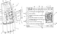
- FIG. 1shows the machine for extracorporeal blood treatment of the invention, to which an integrated module (represented in the figure without associated hydraulic circuit) is associable;
- FIGS. 2 to 9show user-interface displays which can be called on-screen in the machine of FIG. 1 .
- 1denotes in its entirety a machine for extracorporeal blood treatment, represented in the illustrated embodiment by a dialysis machine which is suitable for intensive treatment of acute kidney failure.
- the integrated module 2denotes in its entirety an integrated module which can be coupled to the dialysis machine 1 .
- the integrated module 2is constituted by a combination of at least one support element 3 of a distribution circuit (of known type and not illustrated) arranged on the support element 3 , and a blood treatment unit 4 .
- the blood treatment unit 4can be, for example, a plasma filter, a hemodialysis filter, a hemofiltration filter, or a different unit.
- the hydraulic circuitwhich is completed by a combination of the integrated module 2 and the machine 1 , comprises a blood circuit which removes blood from a patient, for example via a catheter inserted in a vascular access of the patient, and takes the blood through a blood removal line to the treatment unit 4 .
- the bloodpasses through a first chamber (blood chamber) of the treatment unit 4 and, via a return line, is transported back to the patient.
- connectionis made between the removal line and an auxiliary pre-infusion line.
- the machineincludes at least one container of a first sterile fluid 5 for supplying the pre-infusion line; fluid transport means, in the embodiment constituted by a pre-infusion pump 6 , for example a peristaltic pump, control the flow of fluid in the pre-infusion line directly into the blood via a direct connection to the blood removal line.
- a pre-infusion pump 6for example a peristaltic pump
- the container of the first sterile fluid 5can contain a pre-infusion fluid, although the same container can be used for containing an anticoagulant, usually of a locally-acting type.
- the machinefurther comprises means for transporting fluid, i.e. in the embodiment at least one blood pump 7 for control and management of a correct blood flow in the circuit.
- the blood pump 7is peristaltic.
- a blood pressure sensoris included immediately downstream of the auxiliary pre-infusion line.
- a devicefor administration of an anticoagulant, for example a syringe containing appropriate doses of heparin.
- the bloodthen crosses a further pressure sensor which monitors the correct flow rate internally of the blood circuit.
- the treated bloodAfter crossing the first blood chamber of the treatment unit 4 , where substance-exchange and molecular and fluid exchange takes place through a semi-permeable membrane, the treated blood enters the return line, crossing a gas separator (generally air), where any air bubbles present or introduced to the blood during treatment are expelled.
- a gas separatorgenerally air
- the treated blood exiting from the gas separatoralso known as a deaeration chamber
- a bubble sensoralso known as an air detector
- a closure elementis located, which on activation of an alarm can block the blood flow towards the patient.
- the machineby means of the closure element (which can be a cock, a clamp or the like) the blood passage would immediately be stopped in order to prevent any kind of consequence to the patient.
- the closure elementwhich can be a cock, a clamp or the like
- the treated bloodDownstream of the closure element the treated blood is returned to the patient undergoing treatment.
- the distribution circuitrycomprises a first circuit of a second sterile fluid (dialysing liquid) having at least one inlet line to the blood treatment unit 4 and an outlet line from the treatment unit 4 .
- a second sterile fluiddialysing liquid
- At least one container of the second sterile fluid 8is destined to supply the inlet line of the first circuit.
- the inlet lineis destined to cooperate with means for fluid transport, being at least one pump 9 (in the embodiment a peristaltic pump) predisposed on the frontal part of the machine to control the flow of the second sterile fluid coming from the container 8 , and to define a circulation direction.
- means for fluid transportbeing at least one pump 9 (in the embodiment a peristaltic pump) predisposed on the frontal part of the machine to control the flow of the second sterile fluid coming from the container 8 , and to define a circulation direction.
- a branchDownstream of the pump 9 of the second sterile fluid, along the circulation direction, a branch is included which divides the first circuit of the second sterile fluid into an inlet branch and an infusion branch.
- the infusion branchis connected to the blood circuit return line.
- this infusion lineinfusion can be made directly into the blood, using the contents of the container 8 of the second sterile fluid.
- the inlet branchtakes the second sterile fluid directly to the blood treatment unit 4 , in particular to a second chamber (dialysis chamber) of the unit 4 .
- the first circuit of the second sterile fluidis further associated to a first selector which determines the percentage quantities of fluid flow into the infusion branch and the inlet branch.
- the first selectorusually located in proximity of the branch, enables selection between at least a first operative condition, in which the second sterile fluid can pass into the inlet branch but cannot pass into the infusion branch, and a second operative condition, in which they allow passage of fluid into the infusion branch but not into the inlet branch.
- the first selectorcan be constituted by a valve element suitable for operating in a fluid circuit, which can alternatively shut off passage of fluid into one or the other branch.
- Selectorscan be used, if preferred, which can decide prior to starting the quantity of the second sterile fluid which can pass at a same time into one and the other branch. Otherwise the percentage amounts of fluid passing into one branch or the other can be established according to determined times and therapies.
- the second sterile fluid(dialysing liquid) crosses the inlet branch and enters the second chamber (dialysis side) of the blood treatment unit 4 .
- the first chamber(blood chamber), crossed by the blood flow, is separated from the second chamber (dialysis chamber), crossed by the second sterile fluid, by a semi-permeable membrane which enables passage of the damaging molecules and substances and fluids in the blood towards the second sterile fluid (dialysing liquid), mainly through convection and diffusion processes; at the same time, and by the same principles, passage of substances and molecules from the second sterile fluid and towards the blood is allowed.
- the second sterile fluidfor dialysis, enters the outlet line of the first circuit and crosses a special pressure sensor for controlling the functioning of the line.
- Means for transporting the fluidfor example an effluent drainage pump 10 , are present, which control the flow in the fluid circuit outlet line.
- This pump 10is usually peristaltic.
- the discharge fluidthen crosses a blood leak detector 15 and is sent on to an effluent collection container 11 .
- An infusion lineis located on the return line of the blood circuit.
- a third sterile fluid(infusion fluid) is sourced from at least one auxiliary container 12 and, by action of a fluid transport means, generally an infusion pump 13 which controls flow (in the embodiment a peristaltic pump), is sent directly to the blood circuit return line.
- the third sterile fluid(infusion liquid) can be sent directly into the gas separator device.
- the post-infusion branch of the first circuit of the second sterile fluid and the infusion line of the third sterile fluidare provided with a common terminal inlet tract to the blood circuit.
- the terminal inlet tractis located downstream of the infusion pump 13 with respect to an infusion direction, and sends the fluid directly into the gas separator.
- At least one pre-infusion branchis present in the infusion line, connected to the blood circuit removal line.
- a branchlocated downstream of the infusion pump 13 with respect to the infusion direction, which divides the infusion line into a pre-infusion branch and a post-infusion branch.
- the pre-infusion branchtakes the fluid removed from the container to the blood circuit removal line downstream of the blood pump 7 (downstream with respect to the circulation direction).
- the post-infusion branchis directly connected to the common terminal tract.
- the infusion linefurther comprises a second selector for determining the percentage quantities of liquid flow to send into the post-infusion branch and the pre-infusion branch.
- the second selectorlocated in proximity of the branch, is positionable between at least one first operative configuration, in which fluid can pass into the pre-infusion branch but not the post-infusion branch, and at least a second operative configuration, in which fluid is allowed to pass into the post-infusion branch and not the pre-infusion branch.
- the second selectoris able to establish percentages of fluid passing into each of the two branches, and can if necessary vary the times according to the treatments to be carried out.
- the first and second selectorsare usually, but not necessarily, of similar type.
- the machineis provided with means for determining at least the weight of the container of the first sterile fluid 5 and/or the container of the second sterile fluid 8 and/or the container of the third sterile fluid 12 and/or the discharge container 11 .
- the means for determiningare constituted by weight sensors, for example scales (at least one independent scales for each container or fluid bag associated to the machine).
- the CPUis also used for controlling the first circuit of the second sterile fluid, and in particular to receive data sent by the scales relating to the weight of the container 8 ; it is also active on the pump 9 , the first selector, the pressure sensor, the drainage pump 10 and the scales weighing the effluent discharge container 11 .
- the CPUis also active on the infusion line of the third sterile fluid, monitoring the weight of the container 12 (measured by a scales), and also controls the infusion pump 13 and the second selector.
- the CPUis active on the auxiliary line for pre-infusion of the first sterile fluid, measuring the weight of the container 5 via a scales and commanding the pre-infusion pump 6 according to the treatment to be carried out.
- the apparatusBefore the actual treatment begins, the apparatus must be prepared.
- the whole hydraulic circuitry and the treatment unitare correctly associated to the machine so that the various peristaltic pumps engage the respective tracts of tubing, and all the sensors are correctly positioned; also, the relative bags containing the various fluids are joined up to the respective supply or receiving lines of the liquids, and the blood circuit is connected up to an artery or vein of the patient.
- an initial circulation of the blood internally of the respective circuitis made.
- the machine for extracorporeal blood treatmentis automatically activated and controlled by the processing unit.
- the machine 1exhibits a machine body 100 provided, on a front surface 101 thereof, with peristaltic pumps 6 , 7 , 9 , 10 , 13 , destined to cooperate in use with respective tracts of U-shaped tubing on the integrated module.
- the machine body 100exhibits a relief acting as a positioning guide 102 which projects from the front surface 101 , which is complementarily shaped with respect to the support element 3 with which it will couple in use.
- the guide 102exhibits a lateral surface 103 which, when the integrated module is coupled thereto, is contained within a perimeter wall of the support element 3 .
- the peristaltic pumpsalso project from the front surface 101 of the machine body 100 and at least a part of the lateral surface of the pumps is complementarily shaped with respect to the perimeter wall of the support element 3 .
- the projecting peristaltic pumps and the guide 102 in combinationdefine seatings 104 having a semicircular shape, i.e. a U-shape, which seatings 104 are destined to receive the corresponding tracts of U-shaped tubing of the circuitry.
- a first mobile element 105 and a second mobile element 106are destined to be active on the infusion and/or inlet branch of the second sterile fluid (the first mobile element 105 ) and, respectively, on the pre-infusion branch and/or the post-infusion branch of the third sterile fluid (the second mobile element 106 ).
- the first and second selectorscan be constituted by the mobile elements 105 , 106 , destined to be controlled by the CPU to selectively allow or block passage of fluid into one or another of the branches.
- the front surface of the machinefurther exhibits a plurality of fastening elements 14 for fixing the pressure sensors; the pressure sensors associated to the circuitry of the integrated module are hereat connected up to the CPU.
- the blood leak detector 15is also predisposed on the front surface of the machine, and during the apparatus readying stage is associated to the fluid circuit in outlet from the treatment unit 4 .
- the user interfacecomprises a touch screen and a controller programmed to display on the screen 16 of the touch-screen a plurality of displays in which the screen 16 is divided into two distinct areas, in which a first area 161 (on the left in the figure) exhibits a plurality of touch keys 17 , and a second area 162 (on the right in the figure), by the side of the first area, selectively displays a plurality of pictographs 18 , each of which is associated to one of the touch-keys 17 .
- touch screenrefers to a device having a screen for data output, which is also used for input through selection of parts (touch keys) of the screened display using the fingers; the device is able to detect where a user has touched the screen and from this derive the selected commands and perform them.
- FIGS. 2 to 9a series of displays are illustrated which relate to a specific series of procedural steps necessary for readying the dialysis apparatus, in particular the procedural steps for mounting the disposable set on the dialysis machine, in relation to a hemodiafiltration treatment.
- the controller of the user interfaceis programmed to bring up on-screen the display of FIG. 2 , in which the indications relating to the steps the operator must perform to prepare the machine are shown.
- the activityconsists in mounting the disposable set, where the set comprises, as mentioned above, the support element 4 and relative circuitry, and the blood treatment unit 5 .
- the data appearing on-screencomprises, in the example, an English expression viz “Load set”, which is an instruction relating to the next steps to take.
- the displayalso includes an indication of the selected treatment.
- the treatment selectedis hemodiafiltration, and the well-known English acronym for this is “CVVHDF”.
- the displaycomprises a touch key 19 for cancelling the treatment selection, if the operator judges it to be incorrect.
- the touch keys 17correspond to one or more procedural steps, arranged in top-down order according to temporal sequence for carrying out the steps necessary for loading a disposable set on the machine.
- the first area 161 of the displayhas, by the side of each touch key 17 , an alphanumeric indication or legend 20 describing in word form the procedural step or steps the operator must perform that are associated with the respective touch key 17 .
- a pictograph 18appears in the second area 162 of the screen in this display, which pictograph 18 represents the front of the dialysis machine, with the disposable set already mounted on the machine.
- the pictograph 18( FIG. 2 ) describes the fluid distribution circuitry using lines in colour code according to the type of fluid line represented, so that, for example, the blood removal line is represented by a red line, the blood return line is blue, the auxiliary pre-infusion line of the first sterile fluid is white, and so on.
- the controllerOn touching any one of the touch keys 17 the controller brings up a pictograph 18 in the second area of the display, corresponding to the instruction associated to the selected touch key 17 .
- each pictographrepresents the machine for extracorporeal blood treatment and at least a part of the disposable element operatively associated to the machine.
- FIG. 3shows the display which appears on selection of the first touch key 17 giving the instructions for fixing the integrated module 2 in the special seating predisposed on the front of the machine, and for engaging the various fluid lines in the respective guides, also located on the front of the machine.
- Selecting the first keyproduces the following changes to the display: firstly the pictograph 18 ( FIG. 3 ) which appears in the second area 162 exhibits an illustration of the machine front, with an accentuation of the support element 3 of the integrated module in work position; secondly the touch key 17 selected changes appearance (for example it is more luminous or changes colour) with respect to the other touch keys, so that the operator is reminded of which touch key 17 (and therefore which operational instruction) the pictograph 18 in the second area 162 of the display is associated to.
- the pictograph 18 in the second area 162can be associated to the corresponding data or legend shown in the first area 161 ; for example the legend could be colour-coded to distinguish it from the other writing on the screen, or the selected touch key 17 could begin to flash, or similar.
- FIG. 4shows the display which appears by effect of selecting the second touch key 17 from the top of the display.
- This touch key 17is associated to the instruction to apply the pressure sensors (or pods) to the corresponding fastening elements 14 predisposed on the front of the machine.
- the corresponding pictograph 18FIG. 4 ) which appears in the second area 162 of the screen represents the front of the machine, with the pressure sensors highlighted in the work position, coupled to the relative fastening elements 14 .
- the selected touch key 17is in some way distinguished vis-à-vis the other touch keys 17 .
- FIG. 5shows the display that appears on selection of the third touch key 17 from the top.
- This third touch key 17which as before with other keys is in some way differentiated from the other keys, is associated to the instruction to operatively connect the outlet line for used fluid exiting the blood treatment unit (where the effluent dialysis fluid flows, also known as the discharge line) with the blood leak detector 15 predisposed on the front of the machine.
- the pictograph 18FIG. 5
- the above-cited outlet line and the blood leak detector 15are particularly highlighted.
- Visual accentuationin this case as in the following cases, can be achieved in any known way, for example by greater luminosity of the part to be highlighted with regard to the rest.
- FIG. 6shows the display that appears when the fourth touch key 17 from the top is selected.
- This touch key 17is associated to the instruction for temporarily hanging one or more lines, in the embodiment the blood removal line and the discharge fluid line, to a support element provided on the machine, in preparation for a priming operation which will follow on from the mounting operation of the disposable set on the machine.
- the operatoris assisted in the machine preparation, thanks to the fact that after having selected the touch key 17 relating to the instruction to be carried out, the operator finds, in the second area 162 of the screen, a graphic illustration of the same instruction, constituted by a pictograph 18 .
- the operatorIn the first area 161 of the screen display the operator has an overview of the various operations to be carried out to complete the mounting procedure for the disposable set on the machine; but the operator can also receive further data, displayed on-screen in the second area 162 thereof, which relate to each single instruction or group of instructions described in the first part 161 of the screen and selected as required.
- the written data(legends 20 ), remains visible at all times to the operator no matter which touch key 17 is selected, while the data displayed on-screen in the second area 162 of the display change according to which touch key 17 is selected time-by-time by the operator.
- the further and more specific data relating to each touch key 17 and displayed in the second area 162 of the screentakes the form of pictographs 18 represented by the operations the operator is to carry out on the machine.
- FIG. 7shows the display that appears on-screen on selection of the fifth touch key 17 .
- the data (or data group) associated to the fifth touch key 17is related to positioning the gas separator device in the special support element predisposed on the front of the machine, and to connect up an auxiliary line for the pressure connection, which exits from the top of the chamber itself, to an inlet port, also predisposed on the front of the machine, for sending the pressure in the chamber to a pressure transducer inside the machine.
- the pictograph 18FIG. 7
- appearing on the second area 162 of screenis descriptive of the above-cited instruction.
- FIG. 8is the display that appears on selection of the sixth touch key 17 , to which are associated the instructions for connecting the blood return line to the bubble sensor, and closing the line.
- the pictograph 18which appears in the second area 162 of the screen describes the instruction given.
- FIG. 9shows the display which appears when the seventh touch key 17 is selected, containing the instructions for activating the scales of the discharge container of the used liquid, and for hanging the (empty) effluent collection container 11 on the special support hook therefor; and thereafter, for deactivating the scales.
- the pictograph 18 which appears on the right of the screenis illustrative of the above-described group of instructions.
- the operatorpresses another touch key 21 located in a lower region of the display, to continue the dialogue with the machine control unit in order to set up the machine correctly for the treatment required.
- the touch screen controlleris thus programmed to selectively display a plurality of images (pictograms 18 ) on the second area 162 of the screen; selection of one of the touch keys 17 brings on-screen an image which is dedicated only to the selected touch key 17 .
- the controlleris also programmed so that the various images shown on the second part of the display 162 appear alternatively and not contemporaneously.
- the controlleris programmed so that the various images are at least partly different to each other, due to the fact that they describe information which is also different in each case.
- the touch screencomprises a memory containing the above-mentioned data relating to the machine.
- the controlleris programmed so that the various on-screen displays, associated to a same series of procedural steps (for example the series of procedural steps for mounting a disposable set for a hemodiafiltration treatment, as in the illustrated embodiment, or for priming the disposable set, or for preparing and connecting the containers 8 , 11 , 12 of the various sterile liquids to the apparatus, or for connecting up the patient to the apparatus, and so on), each comprise a display including the relevant data (for example by displaying a button-like touch key next to a legend explaining the information, or by writing the data in an area of the screen which functions as a touch key, or in some other way).
- the controllercan be programmed, as in the illustrated example, so that, by effect of activation of any one of the various touch keys 17 , the data displayed cannot be cancelled and is therefore still visible in the first area 161 of the screen.
- the datacomprises instructions for readying the machine.
- the user interfaceis programmed so that it visualizes images which can be pictographs representing configurations of the machine, in which the configurations are correlated to the instructions given.
- the resolution of the second area 162 of the display, which is destined to display the pictographsis at least 80 pixels per inch.
- the resolution of the second area 162 of the screen, which is destined to show the pictographs and which occupies an area of 250 ⁇ 405 pixelis about 83 pixels per inch.
- the touch screen controlleris programmed so that each of the above-mentioned images, displayed in the second area 162 of the screen, is not active in the user-display dialogue process, i.e. there is no interaction on the part of the user using the second area 162 of the screen, which is destined, in the displays relating to the preparation procedure of the machine, to offer only image visualization, with no touch keys or other possibilities of activation on the part of the operator, who is essentially passive as regards what happens in the second area 162 , being able only to view the images.
- the controlleris programmed so that by activation of any one of the touch keys, a part of the first area 161 , visually associated to the activated touch key, undergoes a change.
- the changeconsists in a change of colour in the “button” representation of the touch key on-screen.
- the controlleris also programmed not to enable any change of the contents of the above-described data by a user operating the touch screen.
- the contents of the datacan be modified only by an operator who is also an expert in electronics and who is therefore able to intervene in the machine operating system.
- the nature of the data(for example, operative instructions for readying the machine) is such that there are no variable and settable parameters (as might be the case with the treatment parameters, such as for example the blood flow rate, the duration of treatment, the quantity of fluid to be removed from the patient, and so on).
- the user interface controlleris programmed to visually modify at least one area of the display by effect of carrying out at least one of the above-described operating instructions.
- the part of display which is modifiedis logically connected to the instruction given, and the change in the area of display assumes the guise of a response by the machine to the operator, subsequent to an operating instruction's having been correctly performed.
- the response that appears on-screen when the operation has been correctly carried outmight consist in highlighting, or colour-coding, or flashing etc.
- This signal for indicating a correct carrying-out of the instructioncan last for a predetermined time, or, for example, could cease when the operator presses one of the touch keys 17 , 19 , 21 .
Landscapes
- Health & Medical Sciences (AREA)
- Engineering & Computer Science (AREA)
- Heart & Thoracic Surgery (AREA)
- Vascular Medicine (AREA)
- Biomedical Technology (AREA)
- General Health & Medical Sciences (AREA)
- Public Health (AREA)
- Anesthesiology (AREA)
- Animal Behavior & Ethology (AREA)
- Hematology (AREA)
- Veterinary Medicine (AREA)
- Life Sciences & Earth Sciences (AREA)
- Cardiology (AREA)
- Urology & Nephrology (AREA)
- Emergency Medicine (AREA)
- Theoretical Computer Science (AREA)
- General Engineering & Computer Science (AREA)
- Human Computer Interaction (AREA)
- Epidemiology (AREA)
- Primary Health Care (AREA)
- Medical Informatics (AREA)
- General Physics & Mathematics (AREA)
- Physics & Mathematics (AREA)
- Business, Economics & Management (AREA)
- General Business, Economics & Management (AREA)
- Medicinal Chemistry (AREA)
- Bioinformatics & Cheminformatics (AREA)
- Chemical & Material Sciences (AREA)
- Mechanical Engineering (AREA)
- External Artificial Organs (AREA)
- Paper (AREA)
- Processing Of Meat And Fish (AREA)
- Photographic Developing Apparatuses (AREA)
Abstract
Description
Claims (21)
Priority Applications (1)
| Application Number | Priority Date | Filing Date | Title |
|---|---|---|---|
| US17/063,153US11908563B2 (en) | 2003-09-25 | 2020-10-05 | Extracorporeal blood treatment machine |
Applications Claiming Priority (9)
| Application Number | Priority Date | Filing Date | Title |
|---|---|---|---|
| ITM02003A000259 | 2003-09-25 | ||
| ITM02003A0259 | 2003-09-25 | ||
| IT000259AITMO20030259A1 (en) | 2003-09-25 | 2003-09-25 | USER INTERFACE FOR A TREATMENT MACHINE |
| US53256603P | 2003-12-29 | 2003-12-29 | |
| US10/948,703US20050070837A1 (en) | 2003-09-25 | 2004-09-24 | User interface for an extracorporeal blood treatment machine |
| US13/162,913US9364604B2 (en) | 2003-09-25 | 2011-06-17 | Extracorporeal blood treatment machine |
| US15/177,409US10325680B2 (en) | 2003-09-25 | 2016-06-09 | User interface for an extracorporeal blood treatment machine |
| US16/401,612US10796792B2 (en) | 2003-09-25 | 2019-05-02 | Extracorporeal blood treatment machine |
| US17/063,153US11908563B2 (en) | 2003-09-25 | 2020-10-05 | Extracorporeal blood treatment machine |
Related Parent Applications (1)
| Application Number | Title | Priority Date | Filing Date |
|---|---|---|---|
| US16/401,612ContinuationUS10796792B2 (en) | 2003-09-25 | 2019-05-02 | Extracorporeal blood treatment machine |
Publications (2)
| Publication Number | Publication Date |
|---|---|
| US20210020292A1 US20210020292A1 (en) | 2021-01-21 |
| US11908563B2true US11908563B2 (en) | 2024-02-20 |
Family
ID=34385824
Family Applications (6)
| Application Number | Title | Priority Date | Filing Date |
|---|---|---|---|
| US10/948,703AbandonedUS20050070837A1 (en) | 2003-09-25 | 2004-09-24 | User interface for an extracorporeal blood treatment machine |
| US13/162,913Active2027-04-16US9364604B2 (en) | 2003-09-25 | 2011-06-17 | Extracorporeal blood treatment machine |
| US15/177,409Expired - LifetimeUS10325680B2 (en) | 2003-09-25 | 2016-06-09 | User interface for an extracorporeal blood treatment machine |
| US15/922,418Expired - LifetimeUS10102925B2 (en) | 2003-09-25 | 2018-03-15 | Extracorporeal blood treatment machine |
| US16/401,612Expired - LifetimeUS10796792B2 (en) | 2003-09-25 | 2019-05-02 | Extracorporeal blood treatment machine |
| US17/063,153Active2026-09-02US11908563B2 (en) | 2003-09-25 | 2020-10-05 | Extracorporeal blood treatment machine |
Family Applications Before (5)
| Application Number | Title | Priority Date | Filing Date |
|---|---|---|---|
| US10/948,703AbandonedUS20050070837A1 (en) | 2003-09-25 | 2004-09-24 | User interface for an extracorporeal blood treatment machine |
| US13/162,913Active2027-04-16US9364604B2 (en) | 2003-09-25 | 2011-06-17 | Extracorporeal blood treatment machine |
| US15/177,409Expired - LifetimeUS10325680B2 (en) | 2003-09-25 | 2016-06-09 | User interface for an extracorporeal blood treatment machine |
| US15/922,418Expired - LifetimeUS10102925B2 (en) | 2003-09-25 | 2018-03-15 | Extracorporeal blood treatment machine |
| US16/401,612Expired - LifetimeUS10796792B2 (en) | 2003-09-25 | 2019-05-02 | Extracorporeal blood treatment machine |
Country Status (7)
| Country | Link |
|---|---|
| US (6) | US20050070837A1 (en) |
| EP (1) | EP1668556B1 (en) |
| AT (1) | ATE498869T1 (en) |
| DE (1) | DE602004031441D1 (en) |
| ES (1) | ES2359246T3 (en) |
| IT (1) | ITMO20030259A1 (en) |
| WO (1) | WO2005031628A1 (en) |
Families Citing this family (73)
| Publication number | Priority date | Publication date | Assignee | Title |
|---|---|---|---|---|
| US6852090B2 (en) | 1997-02-14 | 2005-02-08 | Nxstage Medical, Inc. | Fluid processing systems and methods using extracorporeal fluid flow panels oriented within a cartridge |
| US20040243047A1 (en)* | 1997-02-14 | 2004-12-02 | Brugger James M. | Single step fluid circuit engagement device and method |
| US7780619B2 (en)* | 1999-11-29 | 2010-08-24 | Nxstage Medical, Inc. | Blood treatment apparatus |
| US20050010158A1 (en)* | 2001-05-24 | 2005-01-13 | Brugger James M. | Drop-in blood treatment cartridge with filter |
| US20060184051A1 (en)* | 2002-10-11 | 2006-08-17 | Hempstead Russell D | Apparatus and methods for non-invasively measuring hemodynamic parameters |
| US8235931B2 (en) | 2003-01-15 | 2012-08-07 | Nxstage Medical, Inc. | Waste balancing for extracorporeal blood treatment systems |
| US7686778B2 (en)* | 2003-01-15 | 2010-03-30 | Nxstage Medical, Inc. | Waste balancing for extracorporeal blood treatment systems |
| ITMO20030259A1 (en) | 2003-09-25 | 2005-03-26 | Gambro Lundia Ab | USER INTERFACE FOR A TREATMENT MACHINE |
| US7946994B2 (en) | 2004-10-07 | 2011-05-24 | Tensys Medical, Inc. | Compact apparatus and methods for non-invasively measuring hemodynamic parameters |
| EP2468351B1 (en) | 2005-11-21 | 2019-01-09 | ACIST Medical Systems, Inc. | Medical fluid injection system |
| JP5441689B2 (en) | 2006-05-13 | 2014-03-12 | テンシス メディカル インコーポレイテッド | Continuous positioning apparatus and method |
| US20080021334A1 (en)* | 2006-07-19 | 2008-01-24 | Finburgh Simon E | Apparatus and methods for non-invasively measuring hemodynamic parameters |
| EP2126768A2 (en)* | 2006-12-21 | 2009-12-02 | B. Braun Avitum AG | Method for controlling a device for extracorporeal blood treatment, and device for extracorporeal blood treatment |
| US8105487B2 (en) | 2007-09-25 | 2012-01-31 | Fresenius Medical Care Holdings, Inc. | Manifolds for use in conducting dialysis |
| US8597505B2 (en) | 2007-09-13 | 2013-12-03 | Fresenius Medical Care Holdings, Inc. | Portable dialysis machine |
| US8240636B2 (en) | 2009-01-12 | 2012-08-14 | Fresenius Medical Care Holdings, Inc. | Valve system |
| US9358331B2 (en) | 2007-09-13 | 2016-06-07 | Fresenius Medical Care Holdings, Inc. | Portable dialysis machine with improved reservoir heating system |
| US8535522B2 (en)* | 2009-02-12 | 2013-09-17 | Fresenius Medical Care Holdings, Inc. | System and method for detection of disconnection in an extracorporeal blood circuit |
| US9308307B2 (en) | 2007-09-13 | 2016-04-12 | Fresenius Medical Care Holdings, Inc. | Manifold diaphragms |
| US8040493B2 (en) | 2007-10-11 | 2011-10-18 | Fresenius Medical Care Holdings, Inc. | Thermal flow meter |
| CN101896117B (en) | 2007-10-12 | 2015-03-04 | 坦西斯医药股份有限公司 | Device and method for non-invasive measurement of arterial blood pressure in a patient |
| CA3057807C (en) | 2007-11-29 | 2021-04-20 | Thomas P. Robinson | System and method for conducting hemodialysis and hemofiltration |
| US8062513B2 (en)* | 2008-07-09 | 2011-11-22 | Baxter International Inc. | Dialysis system and machine having therapy prescription recall |
| EP3586946B1 (en) | 2008-10-07 | 2023-03-29 | Fresenius Medical Care Holdings, Inc. | Priming system and method for dialysis systems |
| EA024555B1 (en)* | 2008-10-30 | 2016-09-30 | Фрезениус Медикал Кеа Холдингс, Инк. | Modular, portable dialysis system |
| US8298167B2 (en)* | 2008-11-03 | 2012-10-30 | B. Braun Avitum Ag | Modular hemofiltration apparatus with interactive operator instructions and control system |
| TWD130760S1 (en)* | 2008-11-07 | 2009-09-11 | 財團法人工業技術研究院 | Wireless transmission liquid level detection device |
| WO2010114932A1 (en) | 2009-03-31 | 2010-10-07 | Xcorporeal, Inc. | Modular reservoir assembly for a hemodialysis and hemofiltration system |
| US8753515B2 (en) | 2009-12-05 | 2014-06-17 | Home Dialysis Plus, Ltd. | Dialysis system with ultrafiltration control |
| AU2011254555B2 (en)* | 2010-05-21 | 2014-05-08 | Gambro Lundia Ab | User interface, machine and method |
| US8501009B2 (en) | 2010-06-07 | 2013-08-06 | State Of Oregon Acting By And Through The State Board Of Higher Education On Behalf Of Oregon State University | Fluid purification system |
| ES2498744T3 (en)* | 2010-09-27 | 2014-09-25 | Gambro Lundia Ab | Device for extracorporeal blood treatment |
| US9526920B2 (en) | 2010-10-12 | 2016-12-27 | Smith & Nephew, Inc. | Medical device |
| WO2012076683A1 (en)* | 2010-12-09 | 2012-06-14 | Arthur Queval | Micro-fluidic device for the analysis of a fluid sample |
| KR102003076B1 (en) | 2011-03-08 | 2019-07-23 | 감브로 룬디아 아베 | Method, control module, apparatus and system for transferring data |
| US9655530B2 (en) | 2011-04-29 | 2017-05-23 | Tensys Medical, Inc. | Apparatus and methods for non-invasively measuring physiologic parameters of one or more subjects |
| JP5433634B2 (en)* | 2011-06-10 | 2014-03-05 | 日機装株式会社 | Blood purification equipment |
| EP4414005A3 (en) | 2011-08-30 | 2024-11-06 | Gambro Lundia AB | Apparatus for extracorporeal treatment of blood |
| JP2014533133A (en) | 2011-10-07 | 2014-12-11 | ホーム・ダイアリシス・プラス・リミテッドHome DialysisPlus, Ltd. | Purification of heat exchange fluids for dialysis systems |
| US9201036B2 (en) | 2012-12-21 | 2015-12-01 | Fresenius Medical Care Holdings, Inc. | Method and system of monitoring electrolyte levels and composition using capacitance or induction |
| US9157786B2 (en) | 2012-12-24 | 2015-10-13 | Fresenius Medical Care Holdings, Inc. | Load suspension and weighing system for a dialysis machine reservoir |
| US9433720B2 (en) | 2013-03-14 | 2016-09-06 | Fresenius Medical Care Holdings, Inc. | Universal portable artificial kidney for hemodialysis and peritoneal dialysis |
| US20140263062A1 (en) | 2013-03-14 | 2014-09-18 | Fresenius Medical Care Holdings, Inc. | Universal portable machine for online hemodiafiltration using regenerated dialysate |
| US9737649B2 (en) | 2013-03-14 | 2017-08-22 | Smith & Nephew, Inc. | Systems and methods for applying reduced pressure therapy |
| JP2016517318A (en) | 2013-03-14 | 2016-06-16 | スミス アンド ネフュー インコーポレーテッド | System and method for administering decompression therapy |
| WO2015023515A1 (en) | 2013-08-13 | 2015-02-19 | Smith & Nephew, Inc. | Systems and methods for applying reduced pressure therapy |
| US9354640B2 (en) | 2013-11-11 | 2016-05-31 | Fresenius Medical Care Holdings, Inc. | Smart actuator for valve |
| USD731066S1 (en)* | 2014-02-28 | 2015-06-02 | Parker-Hannifin Corporation | Therapeutic apheresis system |
| CN105013032B (en) | 2014-03-31 | 2018-06-22 | 甘布罗伦迪亚股份公司 | Extracorporeal blood treatment system and the method for the system |
| EP3838308A1 (en) | 2014-04-29 | 2021-06-23 | Outset Medical, Inc. | Dialysis system and methods |
| EP3021244A1 (en)* | 2014-11-12 | 2016-05-18 | B. Braun Avitum AG | Blood purification device feedback method |
| CN107847652B (en)* | 2015-07-02 | 2020-12-25 | 甘布罗伦迪亚股份公司 | Process feature graphical elements for medical user interface |
| WO2017001559A1 (en)* | 2015-07-02 | 2017-01-05 | Gambro Lundia Ab | Graphical user interfaces for medical treatment apparatus |
| DE102015122347A1 (en)* | 2015-12-21 | 2017-06-22 | Fresenius Medical Care Deutschland Gmbh | Sensor-controlled display output for dialysis machines |
| DE102016100934A1 (en) | 2016-01-20 | 2017-07-20 | Fresenius Medical Care Deutschland Gmbh | Blood treatment device and organizer |
| EP3203398B1 (en) | 2016-02-08 | 2019-05-08 | B. Braun Avitum AG | Method for setting up a fluid processing medical apparatus |
| EP3886113A1 (en) | 2016-03-14 | 2021-09-29 | Fenwal, Inc. | Cell processing system and method with process parameter control |
| US11191879B2 (en) | 2016-05-27 | 2021-12-07 | Fenwal, Inc. | Cell processing system and method with preliminary process evaluation |
| US11955234B2 (en) | 2016-06-30 | 2024-04-09 | Gambro Lundia Ab | Extracorporeal blood treatment system and method including modifiable settings |
| US11430560B2 (en) | 2016-06-30 | 2022-08-30 | Gambro Lundia Ab | Extracorporeal blood treatment system and method including user-interactable settings |
| EP3270307B1 (en) | 2016-07-13 | 2022-06-22 | Fenwal, Inc. | Cell processing system and method with centralized data management, monitoring and/or control |
| EP3500317B1 (en) | 2016-08-19 | 2022-02-23 | Outset Medical, Inc. | Peritoneal dialysis system and methods |
| USD835648S1 (en) | 2016-10-27 | 2018-12-11 | Smith & Nephew, Inc. | Display screen or portion thereof with a graphical user interface for a therapy device |
| WO2018099784A1 (en) | 2016-11-29 | 2018-06-07 | Gambro Lundia Ab | Normal workflow and deviations therefrom |
| GB2564115A (en)* | 2017-07-03 | 2019-01-09 | Spectrum Medical Ltd | Indicator device and system |
| US12201762B2 (en) | 2018-08-23 | 2025-01-21 | Outset Medical, Inc. | Dialysis system and methods |
| WO2020223500A1 (en) | 2019-04-30 | 2020-11-05 | Outset Medical, Inc. | Dialysis system and methods |
| CN112820391A (en)* | 2019-11-15 | 2021-05-18 | 深圳迈瑞科技有限公司 | Infusion parameter setting and displaying method and infusion pump |
| US12318528B2 (en) | 2020-10-30 | 2025-06-03 | Mozarc Medical Us Llc | Variable orifice fistula graft |
| US20230010811A1 (en)* | 2021-07-07 | 2023-01-12 | Fresenius Medical Care Holdings, Inc. | Determining a Modality of an Extracorporeal Blood Circuit |
| WO2023099452A1 (en) | 2021-12-01 | 2023-06-08 | Gambro Lundia Ab | Dialysis fluid comprising ketone bodies for the treatment of cancer |
| WO2025087731A1 (en) | 2023-10-24 | 2025-05-01 | Gambro Lundia Ab | Compositions comprising insulin and ketones bodies to treat cancer |
| JP7705973B1 (en)* | 2024-03-07 | 2025-07-10 | 日機装株式会社 | Medical equipment, display method and program |
Citations (36)
| Publication number | Priority date | Publication date | Assignee | Title |
|---|---|---|---|---|
| JPS591864B2 (en) | 1980-06-30 | 1984-01-14 | 松下電工株式会社 | Roof with solar heat collector |
| US4443333A (en) | 1981-09-24 | 1984-04-17 | Mahurkar Sakharam D | Portable dialysis system and pump therefor |
| FR2619604A1 (en) | 1987-08-19 | 1989-02-24 | Cobe Lab | SELF-LOADING PERISTALTIC PUMP |
| CA2303714A1 (en) | 1991-09-10 | 1993-03-11 | Hospal Industrie | Multifunctional apparatus for treatment of renal insufficiency |
| CA2119375A1 (en) | 1991-10-11 | 1993-04-15 | Yuli Kitaevich | Hemofiltration system and method |
| US5326476A (en) | 1991-04-19 | 1994-07-05 | Althin Medical, Inc. | Method and apparatus for kidney dialysis using machine with programmable memory |
| CA2115414A1 (en) | 1993-02-12 | 1994-08-13 | Lori Truitt | Technique for extracorporeal treatment of blood |
| US5394732A (en) | 1993-09-10 | 1995-03-07 | Cobe Laboratories, Inc. | Method and apparatus for ultrasonic detection of air bubbles |
| EP0655004A1 (en) | 1993-03-03 | 1995-05-31 | Baxter Travenol Laboratories, Inc. | User interface for automated peritoneal dialysis systems |
| US5441636A (en) | 1993-02-12 | 1995-08-15 | Cobe Laboratories, Inc. | Integrated blood treatment fluid module |
| EP0678301A2 (en) | 1991-09-10 | 1995-10-25 | Hospal Industrie | Multifunctional apparatus for treatment of renal insufficiency |
| FR2724321A1 (en) | 1994-09-14 | 1996-03-15 | Hospal Ind | DEVICE FOR MEASURING THE PRESSURE OF A LIQUID AND METHOD FOR ADJUSTING SUCH A DEVICE |
| EP0706044A1 (en) | 1994-10-07 | 1996-04-10 | Hospal Industrie | Device for detection of a conduit and determination of at least one characteristic of its contents |
| US5591344A (en) | 1995-02-13 | 1997-01-07 | Aksys, Ltd. | Hot water disinfection of dialysis machines, including the extracorporeal circuit thereof |
| US5672399A (en) | 1995-11-17 | 1997-09-30 | Donaldson Company, Inc. | Filter material construction and method |
| WO1998035747A1 (en) | 1997-02-14 | 1998-08-20 | Aksys, Ltd. | Dialysis machines with touch screen user interface |
| US20010026134A1 (en) | 2000-01-25 | 2001-10-04 | Omron Corporation | Current-carrying control device and electric power steering apparatus |
| US6349170B1 (en) | 1999-01-12 | 2002-02-19 | Gambro Inc. | Continuous renal replacement therapy heat loss compensation |
| US6361518B1 (en) | 1995-06-07 | 2002-03-26 | Gambro Inc. | Extracorporeal blood processing methods and apparatus |
| WO2002026286A2 (en) | 2000-09-27 | 2002-04-04 | Cobe Cardiovascular, Inc. | Blood perfusion system |
| US6397971B1 (en) | 1999-12-16 | 2002-06-04 | Mitsubishi Denki Kabushiki Kaisha | Electrically powered steering system |
| US20020151804A1 (en) | 2001-04-13 | 2002-10-17 | O'mahony John J. | User interface for blood treatment device |
| US6771033B2 (en) | 2001-12-12 | 2004-08-03 | Renesas Technology Corp. | Drive control system for sensor-less motor |
| US7033539B2 (en) | 2002-05-24 | 2006-04-25 | Baxter International Inc. | Graphical user interface for automated dialysis system |
| US7061350B2 (en) | 2001-12-18 | 2006-06-13 | Tyco Electronics Amp Gmbh | Electromagnetic relay with a triple contact bridge |
| EP1668556A1 (en) | 2003-09-25 | 2006-06-14 | Gambro Lundia AB | A user interface for an extracorporeal blood treatment machine |
| JP2008211911A (en) | 2007-02-26 | 2008-09-11 | Jtekt Corp | Motor control device and electric power steering device |
| US7504790B2 (en) | 2006-04-03 | 2009-03-17 | Denso Corporation | Control system for multiphase rotary electric machines |
| US7686779B1 (en) | 1999-10-01 | 2010-03-30 | Caridian BCT, Inc | Extracorporeal blood processing methods and apparatus |
| US20100301713A1 (en) | 2007-05-08 | 2010-12-02 | Robert Bosch Gmbh | Motor arrangement with an electronic isolating relay module |
| US8049363B2 (en) | 2005-08-16 | 2011-11-01 | Trw Limited | Motor drive circuit |
| US8051945B2 (en) | 2008-05-23 | 2011-11-08 | Nexteer (Beijing) Technology Co., Ltd. | Electric power steering system, controller, and method of operation |
| US8182440B2 (en) | 2002-09-27 | 2012-05-22 | Baxter International Inc. | Dialysis machine having combination display and handle |
| US8421388B2 (en) | 2009-09-30 | 2013-04-16 | Denso Corporation | Multi-phase rotary machine control apparatus and electric power steering system using the same |
| US8502485B2 (en) | 2009-04-07 | 2013-08-06 | Trw Automotive Us Llc | Motor drive circuitry |
| US9634604B2 (en) | 2013-04-30 | 2017-04-25 | Nxp Usa, Inc. | Device for controlling a multi-phase motor |
Family Cites Families (3)
| Publication number | Priority date | Publication date | Assignee | Title |
|---|---|---|---|---|
| JPS591864A (en) | 1982-06-29 | 1984-01-07 | Kayaba Ind Co Ltd | Hydraulic motor brake control circuit |
| JP3140781U (en) | 2008-01-28 | 2008-04-10 | 照太 嘉勢 | Solid embroidery type |
| JP5402414B2 (en) | 2009-09-02 | 2014-01-29 | 日本精工株式会社 | Electric power steering device |
- 2003
- 2003-09-25ITIT000259Apatent/ITMO20030259A1/enunknown
- 2004
- 2004-09-09WOPCT/IB2004/002929patent/WO2005031628A1/enactiveApplication Filing
- 2004-09-09DEDE602004031441Tpatent/DE602004031441D1/ennot_activeExpired - Lifetime
- 2004-09-09ESES04769327Tpatent/ES2359246T3/ennot_activeExpired - Lifetime
- 2004-09-09ATAT04769327Tpatent/ATE498869T1/ennot_activeIP Right Cessation
- 2004-09-09EPEP04769327Apatent/EP1668556B1/ennot_activeRevoked
- 2004-09-24USUS10/948,703patent/US20050070837A1/ennot_activeAbandoned
- 2011
- 2011-06-17USUS13/162,913patent/US9364604B2/enactiveActive
- 2016
- 2016-06-09USUS15/177,409patent/US10325680B2/ennot_activeExpired - Lifetime
- 2018
- 2018-03-15USUS15/922,418patent/US10102925B2/ennot_activeExpired - Lifetime
- 2019
- 2019-05-02USUS16/401,612patent/US10796792B2/ennot_activeExpired - Lifetime
- 2020
- 2020-10-05USUS17/063,153patent/US11908563B2/enactiveActive
Patent Citations (63)
| Publication number | Priority date | Publication date | Assignee | Title |
|---|---|---|---|---|
| JPS591864B2 (en) | 1980-06-30 | 1984-01-14 | 松下電工株式会社 | Roof with solar heat collector |
| US4443333A (en) | 1981-09-24 | 1984-04-17 | Mahurkar Sakharam D | Portable dialysis system and pump therefor |
| FR2619604A1 (en) | 1987-08-19 | 1989-02-24 | Cobe Lab | SELF-LOADING PERISTALTIC PUMP |
| DE3828123A1 (en) | 1987-08-19 | 1989-03-02 | Cobe Lab | SELF-SELF TUBE PUMP |
| GB2208897A (en) | 1987-08-19 | 1989-04-19 | Cobe Lab | Peristaltic pumps |
| US4861242A (en) | 1987-08-19 | 1989-08-29 | Cobe Laboratories, Inc. | Self-loading peristaltic pump |
| IT1223781B (en) | 1987-08-19 | 1990-09-29 | Cobe Lab | SELF-LOADING PERISTALTIC PUMP |
| CA1284598C (en) | 1987-08-19 | 1991-06-04 | Phillip Michael Finsterwald | Self-loading peristaltic pump |
| US5326476A (en) | 1991-04-19 | 1994-07-05 | Althin Medical, Inc. | Method and apparatus for kidney dialysis using machine with programmable memory |
| CA2303714A1 (en) | 1991-09-10 | 1993-03-11 | Hospal Industrie | Multifunctional apparatus for treatment of renal insufficiency |
| JP3413412B2 (en) | 1991-09-10 | 2003-06-03 | オスパル アンデユストリ | Multifunctional device |
| EP0678301A2 (en) | 1991-09-10 | 1995-10-25 | Hospal Industrie | Multifunctional apparatus for treatment of renal insufficiency |
| US5344568A (en) | 1991-10-11 | 1994-09-06 | Children's Hospital Medical Center | Hemofiltration system and method |
| US5344568B1 (en) | 1991-10-11 | 1999-09-07 | Childrens Hosp Medical Center | Hemofiltration system and method |
| US5211849B1 (en) | 1991-10-11 | 1997-05-27 | Childrens Hosp Medical Center | Hemofiltration system and method |
| JP3140781B2 (en) | 1991-10-11 | 2001-03-05 | チルドレンズ ホスピタル メディカル センター | Blood filtration system |
| CA2119375A1 (en) | 1991-10-11 | 1993-04-15 | Yuli Kitaevich | Hemofiltration system and method |
| US5211849A (en) | 1991-10-11 | 1993-05-18 | Children's Hospital Medical Center | Hemofiltration system and method |
| US5441636A (en) | 1993-02-12 | 1995-08-15 | Cobe Laboratories, Inc. | Integrated blood treatment fluid module |
| JP3591864B2 (en) | 1993-02-12 | 2004-11-24 | オスパル アンデユストリ | Extracorporeal blood treatment method and apparatus |
| CA2115414A1 (en) | 1993-02-12 | 1994-08-13 | Lori Truitt | Technique for extracorporeal treatment of blood |
| EP0611228A2 (en) | 1993-02-12 | 1994-08-17 | Hospal Industrie | Technique for extracorporeal treatment of blood |
| US5910252A (en) | 1993-02-12 | 1999-06-08 | Cobe Laboratories, Inc. | Technique for extracorporeal treatment of blood |
| US5776345A (en) | 1993-02-12 | 1998-07-07 | Cobe Laboratories, Inc. | Automatic priming technique |
| US5679245A (en) | 1993-02-12 | 1997-10-21 | Cobe Laboratories, Inc. | Retention device for extracorporeal treatment apparatus |
| US5762805A (en) | 1993-02-12 | 1998-06-09 | Cobe Laboratories, Inc. | Technique for extracorporeal treatment of blood |
| EP0829265A1 (en) | 1993-02-12 | 1998-03-18 | Hospal Industrie | Method for priming a circuit for multiple blood extracorporeal treatments |
| EP0655004A1 (en) | 1993-03-03 | 1995-05-31 | Baxter Travenol Laboratories, Inc. | User interface for automated peritoneal dialysis systems |
| US5394732A (en) | 1993-09-10 | 1995-03-07 | Cobe Laboratories, Inc. | Method and apparatus for ultrasonic detection of air bubbles |
| JP2823513B2 (en) | 1993-09-10 | 1998-11-11 | コウブ ラボラトリーズ,インコーポレーテッド | Inclusion body detector and detection method |
| EP0643301A1 (en) | 1993-09-10 | 1995-03-15 | Cobe Laboratories, Inc. | Method and apparatus for ultrasonic detection of air bubbles |
| FR2724321A1 (en) | 1994-09-14 | 1996-03-15 | Hospal Ind | DEVICE FOR MEASURING THE PRESSURE OF A LIQUID AND METHOD FOR ADJUSTING SUCH A DEVICE |
| US5722399A (en) | 1994-09-14 | 1998-03-03 | Hospal Industrie | Device for measuring the pressure of a liquid and method for regulating such a device |
| JP3690846B2 (en) | 1994-09-14 | 2005-08-31 | オスパル アンデユストリ | Hydraulic pressure measuring device, adjustment method thereof, and blood processing device |
| EP0701830A1 (en) | 1994-09-14 | 1996-03-20 | Hospal Industrie | Device for measuring the pressure of a liquid and procedure for regulating such a device |
| US5644402A (en) | 1994-10-07 | 1997-07-01 | Hospal Industrie | Device for detecting a conduit and for determining at least one characteristic of its content |
| FR2725522A1 (en) | 1994-10-07 | 1996-04-12 | Hospal Ind | DEVICE FOR DETECTING A CONDUIT AND DETERMINING AT LEAST ONE CHARACTERISTIC OF ITS CONTENT |
| EP0706044A1 (en) | 1994-10-07 | 1996-04-10 | Hospal Industrie | Device for detection of a conduit and determination of at least one characteristic of its contents |
| US5591344A (en) | 1995-02-13 | 1997-01-07 | Aksys, Ltd. | Hot water disinfection of dialysis machines, including the extracorporeal circuit thereof |
| US6361518B1 (en) | 1995-06-07 | 2002-03-26 | Gambro Inc. | Extracorporeal blood processing methods and apparatus |
| US5672399A (en) | 1995-11-17 | 1997-09-30 | Donaldson Company, Inc. | Filter material construction and method |
| WO1998035747A1 (en) | 1997-02-14 | 1998-08-20 | Aksys, Ltd. | Dialysis machines with touch screen user interface |
| US6349170B1 (en) | 1999-01-12 | 2002-02-19 | Gambro Inc. | Continuous renal replacement therapy heat loss compensation |
| US7686779B1 (en) | 1999-10-01 | 2010-03-30 | Caridian BCT, Inc | Extracorporeal blood processing methods and apparatus |
| US6397971B1 (en) | 1999-12-16 | 2002-06-04 | Mitsubishi Denki Kabushiki Kaisha | Electrically powered steering system |
| US20010026134A1 (en) | 2000-01-25 | 2001-10-04 | Omron Corporation | Current-carrying control device and electric power steering apparatus |
| WO2002026286A2 (en) | 2000-09-27 | 2002-04-04 | Cobe Cardiovascular, Inc. | Blood perfusion system |
| US20020085952A1 (en) | 2000-09-27 | 2002-07-04 | Ellingboe Bruce S. | Blood perfusion system |
| US20030135152A1 (en) | 2000-09-27 | 2003-07-17 | Kollar Kevin J. | Disposable cartridge for a blood perfusion system |
| US20020151804A1 (en) | 2001-04-13 | 2002-10-17 | O'mahony John J. | User interface for blood treatment device |
| US6771033B2 (en) | 2001-12-12 | 2004-08-03 | Renesas Technology Corp. | Drive control system for sensor-less motor |
| US7061350B2 (en) | 2001-12-18 | 2006-06-13 | Tyco Electronics Amp Gmbh | Electromagnetic relay with a triple contact bridge |
| US7033539B2 (en) | 2002-05-24 | 2006-04-25 | Baxter International Inc. | Graphical user interface for automated dialysis system |
| US8182440B2 (en) | 2002-09-27 | 2012-05-22 | Baxter International Inc. | Dialysis machine having combination display and handle |
| EP1668556A1 (en) | 2003-09-25 | 2006-06-14 | Gambro Lundia AB | A user interface for an extracorporeal blood treatment machine |
| US8049363B2 (en) | 2005-08-16 | 2011-11-01 | Trw Limited | Motor drive circuit |
| US7504790B2 (en) | 2006-04-03 | 2009-03-17 | Denso Corporation | Control system for multiphase rotary electric machines |
| JP2008211911A (en) | 2007-02-26 | 2008-09-11 | Jtekt Corp | Motor control device and electric power steering device |
| US20100301713A1 (en) | 2007-05-08 | 2010-12-02 | Robert Bosch Gmbh | Motor arrangement with an electronic isolating relay module |
| US8051945B2 (en) | 2008-05-23 | 2011-11-08 | Nexteer (Beijing) Technology Co., Ltd. | Electric power steering system, controller, and method of operation |
| US8502485B2 (en) | 2009-04-07 | 2013-08-06 | Trw Automotive Us Llc | Motor drive circuitry |
| US8421388B2 (en) | 2009-09-30 | 2013-04-16 | Denso Corporation | Multi-phase rotary machine control apparatus and electric power steering system using the same |
| US9634604B2 (en) | 2013-04-30 | 2017-04-25 | Nxp Usa, Inc. | Device for controlling a multi-phase motor |
Non-Patent Citations (5)
| Title |
|---|
| International Preliminary Report on Patentability for International Application No. PCT/IB004/002929 dated Dec. 13, 2004. |
| International Search Report and Written Opinion corresponding to PCT/IB2013/053405 dated Jan. 17, 2014. |
| International Search Report for International Application No. PCT/IB2004/002929 dated Mar. 27, 2006. |
| PRISMA System—Operator's Manual for use with Software versions R03.10; Gambro Dasco S.p.A.; Catalog No. 6983811, Rev. A; P/N 9032167800, Rev. A (Sep. 2006)—276 pages. |
| Wikipedia: Vector control (motor) (http://en.wikipedia.org/wiki/Vector_control_(motor)). |
Also Published As
| Publication number | Publication date |
|---|---|
| EP1668556A1 (en) | 2006-06-14 |
| US10102925B2 (en) | 2018-10-16 |
| EP1668556B1 (en) | 2011-02-16 |
| US20210020292A1 (en) | 2021-01-21 |
| ATE498869T1 (en) | 2011-03-15 |
| US9364604B2 (en) | 2016-06-14 |
| ES2359246T3 (en) | 2011-05-19 |
| US10796792B2 (en) | 2020-10-06 |
| US20160283683A1 (en) | 2016-09-29 |
| US20190259484A1 (en) | 2019-08-22 |
| US20110240537A1 (en) | 2011-10-06 |
| US20180204637A1 (en) | 2018-07-19 |
| US20050070837A1 (en) | 2005-03-31 |
| DE602004031441D1 (en) | 2011-03-31 |
| US10325680B2 (en) | 2019-06-18 |
| WO2005031628A1 (en) | 2005-04-07 |
| ITMO20030259A1 (en) | 2005-03-26 |
Similar Documents
| Publication | Publication Date | Title |
|---|---|---|
| US11908563B2 (en) | Extracorporeal blood treatment machine | |
| CA2799851C (en) | User interface, machine and method | |
| US8075509B2 (en) | Medical apparatus | |
| US7727176B2 (en) | Machine for extracorporeal blood treatment coupled to a support element | |
| CA2822015C (en) | Method and system for detecting or verifying a blood circuit connected to an extracorporeal blood treatment console | |
| JPS6357068B2 (en) | ||
| AU2013322199B2 (en) | Extracorporeal blood treatment apparatus and method of setting an extracorporeal blood treatment | |
| JPH07136250A (en) | Operating method of hemodialyzing machine, programming method of time change parameter, operation method of dialyzing machine, ren dialyzing machine, and hemodialyzing machine | |
| US4721564A (en) | Apparatus for the filtration of plasma from blood | |
| JP3865152B2 (en) | Hemodialysis automatic preparation device | |
| US8715214B2 (en) | Method and device for filling a supply device of a therapy appliance | |
| US20210338908A1 (en) | Systems and methods for estimating ultrafiltration rates | |
| EP0832656A1 (en) | Method and apparatus for controlling the fluid balance of patients subjected to single-needle blood treatments | |
| EP4023271B1 (en) | Disposable circuit for extracorporeal treatment of blood, apparatus for extracorporeal treatment of blood and associated method |
Legal Events
| Date | Code | Title | Description |
|---|---|---|---|
| FEPP | Fee payment procedure | Free format text:ENTITY STATUS SET TO UNDISCOUNTED (ORIGINAL EVENT CODE: BIG.); ENTITY STATUS OF PATENT OWNER: LARGE ENTITY | |
| AS | Assignment | Owner name:H.I.M.M., FRANCE Free format text:ASSIGNMENT OF ASSIGNORS INTEREST;ASSIGNOR:PELLETIER, DANIELLE;REEL/FRAME:054007/0041 Effective date:20030827 Owner name:GAMBRO DASCO S.P.A., ITALY Free format text:ASSIGNMENT OF ASSIGNORS INTEREST;ASSIGNORS:ZACCARELLI, MASSIMO;FERRARINI, LORENZA;REEL/FRAME:054005/0722 Effective date:20030827 | |
| AS | Assignment | Owner name:GAMBRO LUNDIA AB, SWEDEN Free format text:ASSIGNMENT OF ASSIGNORS INTEREST;ASSIGNOR:GAMBRO DASCO S.P.A.;REEL/FRAME:054015/0552 Effective date:20030901 | |
| AS | Assignment | Owner name:GAMBRO LUNDIA AB, SWEDEN Free format text:ASSIGNMENT OF ASSIGNORS INTEREST;ASSIGNOR:H.I.M.M.;REEL/FRAME:054054/0536 Effective date:20030901 | |
| STPP | Information on status: patent application and granting procedure in general | Free format text:APPLICATION DISPATCHED FROM PREEXAM, NOT YET DOCKETED | |
| AS | Assignment | Owner name:GAMBRO RENAL PRODUCTS INC., COLORADO Free format text:ASSIGNMENT OF ASSIGNORS INTEREST;ASSIGNOR:LETTERI, JEFFREY J.;REEL/FRAME:054063/0008 Effective date:20050525 | |
| AS | Assignment | Owner name:GAMBRO LUNDIA AB, SWEDEN Free format text:ASSIGNMENT OF ASSIGNORS INTEREST;ASSIGNOR:GAMBRO RENAL PRODUCTS INC.;REEL/FRAME:054095/0728 Effective date:20050530 | |
| STPP | Information on status: patent application and granting procedure in general | Free format text:DOCKETED NEW CASE - READY FOR EXAMINATION | |
| STPP | Information on status: patent application and granting procedure in general | Free format text:NON FINAL ACTION MAILED | |
| STPP | Information on status: patent application and granting procedure in general | Free format text:RESPONSE TO NON-FINAL OFFICE ACTION ENTERED AND FORWARDED TO EXAMINER | |
| STPP | Information on status: patent application and granting procedure in general | Free format text:NOTICE OF ALLOWANCE MAILED -- APPLICATION RECEIVED IN OFFICE OF PUBLICATIONS | |
| STPP | Information on status: patent application and granting procedure in general | Free format text:PUBLICATIONS -- ISSUE FEE PAYMENT RECEIVED | |
| STPP | Information on status: patent application and granting procedure in general | Free format text:PUBLICATIONS -- ISSUE FEE PAYMENT VERIFIED | |
| STCF | Information on status: patent grant | Free format text:PATENTED CASE |