US11903872B2 - Heat exchange module, system and method - Google Patents
Heat exchange module, system and methodDownload PDFInfo
- Publication number
- US11903872B2 US11903872B2US16/137,124US201816137124AUS11903872B2US 11903872 B2US11903872 B2US 11903872B2US 201816137124 AUS201816137124 AUS 201816137124AUS 11903872 B2US11903872 B2US 11903872B2
- Authority
- US
- United States
- Prior art keywords
- tec
- tray
- heat transfer
- assembly
- tiles
- Prior art date
- Legal status (The legal status is an assumption and is not a legal conclusion. Google has not performed a legal analysis and makes no representation as to the accuracy of the status listed.)
- Active, expires
Links
Images


Classifications
- A—HUMAN NECESSITIES
- A61—MEDICAL OR VETERINARY SCIENCE; HYGIENE
- A61F—FILTERS IMPLANTABLE INTO BLOOD VESSELS; PROSTHESES; DEVICES PROVIDING PATENCY TO, OR PREVENTING COLLAPSING OF, TUBULAR STRUCTURES OF THE BODY, e.g. STENTS; ORTHOPAEDIC, NURSING OR CONTRACEPTIVE DEVICES; FOMENTATION; TREATMENT OR PROTECTION OF EYES OR EARS; BANDAGES, DRESSINGS OR ABSORBENT PADS; FIRST-AID KITS
- A61F7/00—Heating or cooling appliances for medical or therapeutic treatment of the human body
- A61F7/02—Compresses or poultices for effecting heating or cooling
- A—HUMAN NECESSITIES
- A61—MEDICAL OR VETERINARY SCIENCE; HYGIENE
- A61F—FILTERS IMPLANTABLE INTO BLOOD VESSELS; PROSTHESES; DEVICES PROVIDING PATENCY TO, OR PREVENTING COLLAPSING OF, TUBULAR STRUCTURES OF THE BODY, e.g. STENTS; ORTHOPAEDIC, NURSING OR CONTRACEPTIVE DEVICES; FOMENTATION; TREATMENT OR PROTECTION OF EYES OR EARS; BANDAGES, DRESSINGS OR ABSORBENT PADS; FIRST-AID KITS
- A61F7/00—Heating or cooling appliances for medical or therapeutic treatment of the human body
- A61F7/007—Heating or cooling appliances for medical or therapeutic treatment of the human body characterised by electric heating
- A—HUMAN NECESSITIES
- A61—MEDICAL OR VETERINARY SCIENCE; HYGIENE
- A61F—FILTERS IMPLANTABLE INTO BLOOD VESSELS; PROSTHESES; DEVICES PROVIDING PATENCY TO, OR PREVENTING COLLAPSING OF, TUBULAR STRUCTURES OF THE BODY, e.g. STENTS; ORTHOPAEDIC, NURSING OR CONTRACEPTIVE DEVICES; FOMENTATION; TREATMENT OR PROTECTION OF EYES OR EARS; BANDAGES, DRESSINGS OR ABSORBENT PADS; FIRST-AID KITS
- A61F7/00—Heating or cooling appliances for medical or therapeutic treatment of the human body
- A61F7/0085—Devices for generating hot or cold treatment fluids
- A—HUMAN NECESSITIES
- A61—MEDICAL OR VETERINARY SCIENCE; HYGIENE
- A61M—DEVICES FOR INTRODUCING MEDIA INTO, OR ONTO, THE BODY; DEVICES FOR TRANSDUCING BODY MEDIA OR FOR TAKING MEDIA FROM THE BODY; DEVICES FOR PRODUCING OR ENDING SLEEP OR STUPOR
- A61M19/00—Local anaesthesia; Hypothermia
- F—MECHANICAL ENGINEERING; LIGHTING; HEATING; WEAPONS; BLASTING
- F25—REFRIGERATION OR COOLING; COMBINED HEATING AND REFRIGERATION SYSTEMS; HEAT PUMP SYSTEMS; MANUFACTURE OR STORAGE OF ICE; LIQUEFACTION SOLIDIFICATION OF GASES
- F25B—REFRIGERATION MACHINES, PLANTS OR SYSTEMS; COMBINED HEATING AND REFRIGERATION SYSTEMS; HEAT PUMP SYSTEMS
- F25B21/00—Machines, plants or systems, using electric or magnetic effects
- F25B21/02—Machines, plants or systems, using electric or magnetic effects using Peltier effect; using Nernst-Ettinghausen effect
- F—MECHANICAL ENGINEERING; LIGHTING; HEATING; WEAPONS; BLASTING
- F28—HEAT EXCHANGE IN GENERAL
- F28F—DETAILS OF HEAT-EXCHANGE AND HEAT-TRANSFER APPARATUS, OF GENERAL APPLICATION
- F28F3/00—Plate-like or laminated elements; Assemblies of plate-like or laminated elements
- F28F3/08—Elements constructed for building-up into stacks, e.g. capable of being taken apart for cleaning
- F—MECHANICAL ENGINEERING; LIGHTING; HEATING; WEAPONS; BLASTING
- F28—HEAT EXCHANGE IN GENERAL
- F28F—DETAILS OF HEAT-EXCHANGE AND HEAT-TRANSFER APPARATUS, OF GENERAL APPLICATION
- F28F9/00—Casings; Header boxes; Auxiliary supports for elements; Auxiliary members within casings
- F28F9/02—Header boxes; End plates
- F28F9/04—Arrangements for sealing elements into header boxes or end plates
- F28F9/16—Arrangements for sealing elements into header boxes or end plates by permanent joints, e.g. by rolling
- F28F9/18—Arrangements for sealing elements into header boxes or end plates by permanent joints, e.g. by rolling by welding
- A—HUMAN NECESSITIES
- A61—MEDICAL OR VETERINARY SCIENCE; HYGIENE
- A61F—FILTERS IMPLANTABLE INTO BLOOD VESSELS; PROSTHESES; DEVICES PROVIDING PATENCY TO, OR PREVENTING COLLAPSING OF, TUBULAR STRUCTURES OF THE BODY, e.g. STENTS; ORTHOPAEDIC, NURSING OR CONTRACEPTIVE DEVICES; FOMENTATION; TREATMENT OR PROTECTION OF EYES OR EARS; BANDAGES, DRESSINGS OR ABSORBENT PADS; FIRST-AID KITS
- A61F7/00—Heating or cooling appliances for medical or therapeutic treatment of the human body
- A61F2007/0001—Body part
- A61F2007/0002—Head or parts thereof
- A—HUMAN NECESSITIES
- A61—MEDICAL OR VETERINARY SCIENCE; HYGIENE
- A61F—FILTERS IMPLANTABLE INTO BLOOD VESSELS; PROSTHESES; DEVICES PROVIDING PATENCY TO, OR PREVENTING COLLAPSING OF, TUBULAR STRUCTURES OF THE BODY, e.g. STENTS; ORTHOPAEDIC, NURSING OR CONTRACEPTIVE DEVICES; FOMENTATION; TREATMENT OR PROTECTION OF EYES OR EARS; BANDAGES, DRESSINGS OR ABSORBENT PADS; FIRST-AID KITS
- A61F7/00—Heating or cooling appliances for medical or therapeutic treatment of the human body
- A61F2007/0001—Body part
- A61F2007/0039—Leg or parts thereof
- A—HUMAN NECESSITIES
- A61—MEDICAL OR VETERINARY SCIENCE; HYGIENE
- A61F—FILTERS IMPLANTABLE INTO BLOOD VESSELS; PROSTHESES; DEVICES PROVIDING PATENCY TO, OR PREVENTING COLLAPSING OF, TUBULAR STRUCTURES OF THE BODY, e.g. STENTS; ORTHOPAEDIC, NURSING OR CONTRACEPTIVE DEVICES; FOMENTATION; TREATMENT OR PROTECTION OF EYES OR EARS; BANDAGES, DRESSINGS OR ABSORBENT PADS; FIRST-AID KITS
- A61F7/00—Heating or cooling appliances for medical or therapeutic treatment of the human body
- A61F2007/0054—Heating or cooling appliances for medical or therapeutic treatment of the human body with a closed fluid circuit, e.g. hot water
- A61F2007/0056—Heating or cooling appliances for medical or therapeutic treatment of the human body with a closed fluid circuit, e.g. hot water for cooling
- A—HUMAN NECESSITIES
- A61—MEDICAL OR VETERINARY SCIENCE; HYGIENE
- A61F—FILTERS IMPLANTABLE INTO BLOOD VESSELS; PROSTHESES; DEVICES PROVIDING PATENCY TO, OR PREVENTING COLLAPSING OF, TUBULAR STRUCTURES OF THE BODY, e.g. STENTS; ORTHOPAEDIC, NURSING OR CONTRACEPTIVE DEVICES; FOMENTATION; TREATMENT OR PROTECTION OF EYES OR EARS; BANDAGES, DRESSINGS OR ABSORBENT PADS; FIRST-AID KITS
- A61F7/00—Heating or cooling appliances for medical or therapeutic treatment of the human body
- A61F7/007—Heating or cooling appliances for medical or therapeutic treatment of the human body characterised by electric heating
- A61F2007/0071—Heating or cooling appliances for medical or therapeutic treatment of the human body characterised by electric heating using a resistor, e.g. near the spot to be heated
- A—HUMAN NECESSITIES
- A61—MEDICAL OR VETERINARY SCIENCE; HYGIENE
- A61F—FILTERS IMPLANTABLE INTO BLOOD VESSELS; PROSTHESES; DEVICES PROVIDING PATENCY TO, OR PREVENTING COLLAPSING OF, TUBULAR STRUCTURES OF THE BODY, e.g. STENTS; ORTHOPAEDIC, NURSING OR CONTRACEPTIVE DEVICES; FOMENTATION; TREATMENT OR PROTECTION OF EYES OR EARS; BANDAGES, DRESSINGS OR ABSORBENT PADS; FIRST-AID KITS
- A61F7/00—Heating or cooling appliances for medical or therapeutic treatment of the human body
- A61F7/007—Heating or cooling appliances for medical or therapeutic treatment of the human body characterised by electric heating
- A61F2007/0075—Heating or cooling appliances for medical or therapeutic treatment of the human body characterised by electric heating using a Peltier element, e.g. near the spot to be heated or cooled
- A—HUMAN NECESSITIES
- A61—MEDICAL OR VETERINARY SCIENCE; HYGIENE
- A61F—FILTERS IMPLANTABLE INTO BLOOD VESSELS; PROSTHESES; DEVICES PROVIDING PATENCY TO, OR PREVENTING COLLAPSING OF, TUBULAR STRUCTURES OF THE BODY, e.g. STENTS; ORTHOPAEDIC, NURSING OR CONTRACEPTIVE DEVICES; FOMENTATION; TREATMENT OR PROTECTION OF EYES OR EARS; BANDAGES, DRESSINGS OR ABSORBENT PADS; FIRST-AID KITS
- A61F7/00—Heating or cooling appliances for medical or therapeutic treatment of the human body
- A61F7/02—Compresses or poultices for effecting heating or cooling
- A61F2007/0203—Cataplasms, poultices or compresses, characterised by their contents; Bags therefor
- A61F2007/0215—Cataplasms, poultices or compresses, characterised by their contents; Bags therefor containing liquids other than water
- A—HUMAN NECESSITIES
- A61—MEDICAL OR VETERINARY SCIENCE; HYGIENE
- A61F—FILTERS IMPLANTABLE INTO BLOOD VESSELS; PROSTHESES; DEVICES PROVIDING PATENCY TO, OR PREVENTING COLLAPSING OF, TUBULAR STRUCTURES OF THE BODY, e.g. STENTS; ORTHOPAEDIC, NURSING OR CONTRACEPTIVE DEVICES; FOMENTATION; TREATMENT OR PROTECTION OF EYES OR EARS; BANDAGES, DRESSINGS OR ABSORBENT PADS; FIRST-AID KITS
- A61F7/00—Heating or cooling appliances for medical or therapeutic treatment of the human body
- A61F7/02—Compresses or poultices for effecting heating or cooling
- A61F2007/0225—Compresses or poultices for effecting heating or cooling connected to the body or a part thereof
- A61F2007/0233—Compresses or poultices for effecting heating or cooling connected to the body or a part thereof connected to or incorporated in clothing or garments
- A—HUMAN NECESSITIES
- A61—MEDICAL OR VETERINARY SCIENCE; HYGIENE
- A61F—FILTERS IMPLANTABLE INTO BLOOD VESSELS; PROSTHESES; DEVICES PROVIDING PATENCY TO, OR PREVENTING COLLAPSING OF, TUBULAR STRUCTURES OF THE BODY, e.g. STENTS; ORTHOPAEDIC, NURSING OR CONTRACEPTIVE DEVICES; FOMENTATION; TREATMENT OR PROTECTION OF EYES OR EARS; BANDAGES, DRESSINGS OR ABSORBENT PADS; FIRST-AID KITS
- A61F7/00—Heating or cooling appliances for medical or therapeutic treatment of the human body
- A61F7/02—Compresses or poultices for effecting heating or cooling
- A61F2007/0244—Compresses or poultices for effecting heating or cooling with layers
- A61F2007/0249—Compresses or poultices for effecting heating or cooling with layers with a layer having low heat transfer capability
- A61F2007/0255—Compresses or poultices for effecting heating or cooling with layers with a layer having low heat transfer capability with a reflective layer
- F—MECHANICAL ENGINEERING; LIGHTING; HEATING; WEAPONS; BLASTING
- F24—HEATING; RANGES; VENTILATING
- F24H—FLUID HEATERS, e.g. WATER OR AIR HEATERS, HAVING HEAT-GENERATING MEANS, e.g. HEAT PUMPS, IN GENERAL
- F24H2250/00—Electrical heat generating means
- F24H2250/06—Peltier
- F—MECHANICAL ENGINEERING; LIGHTING; HEATING; WEAPONS; BLASTING
- F25—REFRIGERATION OR COOLING; COMBINED HEATING AND REFRIGERATION SYSTEMS; HEAT PUMP SYSTEMS; MANUFACTURE OR STORAGE OF ICE; LIQUEFACTION SOLIDIFICATION OF GASES
- F25B—REFRIGERATION MACHINES, PLANTS OR SYSTEMS; COMBINED HEATING AND REFRIGERATION SYSTEMS; HEAT PUMP SYSTEMS
- F25B2321/00—Details of machines, plants or systems, using electric or magnetic effects
- F25B2321/02—Details of machines, plants or systems, using electric or magnetic effects using Peltier effects; using Nernst-Ettinghausen effects
- F25B2321/025—Removal of heat
- F—MECHANICAL ENGINEERING; LIGHTING; HEATING; WEAPONS; BLASTING
- F25—REFRIGERATION OR COOLING; COMBINED HEATING AND REFRIGERATION SYSTEMS; HEAT PUMP SYSTEMS; MANUFACTURE OR STORAGE OF ICE; LIQUEFACTION SOLIDIFICATION OF GASES
- F25B—REFRIGERATION MACHINES, PLANTS OR SYSTEMS; COMBINED HEATING AND REFRIGERATION SYSTEMS; HEAT PUMP SYSTEMS
- F25B2700/00—Sensing or detecting of parameters; Sensors therefor
- F25B2700/21—Temperatures
- F—MECHANICAL ENGINEERING; LIGHTING; HEATING; WEAPONS; BLASTING
- F28—HEAT EXCHANGE IN GENERAL
- F28F—DETAILS OF HEAT-EXCHANGE AND HEAT-TRANSFER APPARATUS, OF GENERAL APPLICATION
- F28F2275/00—Fastening; Joining
- F28F2275/02—Fastening; Joining by using bonding materials; by embedding elements in particular materials
- F28F2275/025—Fastening; Joining by using bonding materials; by embedding elements in particular materials by using adhesives
- F—MECHANICAL ENGINEERING; LIGHTING; HEATING; WEAPONS; BLASTING
- F28—HEAT EXCHANGE IN GENERAL
- F28F—DETAILS OF HEAT-EXCHANGE AND HEAT-TRANSFER APPARATUS, OF GENERAL APPLICATION
- F28F2275/00—Fastening; Joining
- F28F2275/06—Fastening; Joining by welding
- F—MECHANICAL ENGINEERING; LIGHTING; HEATING; WEAPONS; BLASTING
- F28—HEAT EXCHANGE IN GENERAL
- F28F—DETAILS OF HEAT-EXCHANGE AND HEAT-TRANSFER APPARATUS, OF GENERAL APPLICATION
- F28F2275/00—Fastening; Joining
- F28F2275/08—Fastening; Joining by clamping or clipping
- F28F2275/085—Fastening; Joining by clamping or clipping with snap connection
- H—ELECTRICITY
- H10—SEMICONDUCTOR DEVICES; ELECTRIC SOLID-STATE DEVICES NOT OTHERWISE PROVIDED FOR
- H10N—ELECTRIC SOLID-STATE DEVICES NOT OTHERWISE PROVIDED FOR
- H10N10/00—Thermoelectric devices comprising a junction of dissimilar materials, i.e. devices exhibiting Seebeck or Peltier effects
- H10N10/10—Thermoelectric devices comprising a junction of dissimilar materials, i.e. devices exhibiting Seebeck or Peltier effects operating with only the Peltier or Seebeck effects
- H10N10/17—Thermoelectric devices comprising a junction of dissimilar materials, i.e. devices exhibiting Seebeck or Peltier effects operating with only the Peltier or Seebeck effects characterised by the structure or configuration of the cell or thermocouple forming the device
Definitions
- An aspect of the technology of this disclosurepertains generally to flexible heat exchange modules (HEMs) that contain thermoelectric coolers (TECs) and can be used for heating or cooling.
- HEMsflexible heat exchange modules
- TECsthermoelectric coolers
- Hypothermia treatment of patientsis used for a variety of applications, including but not limited to treatment of brain injuries, spinal cord injuries, muscle injuries, joint injuries, and as a neuroprotective agent for cardiac arrest and neonatal hypoxic ischemic encephalopathy.
- This treatmentis typically afforded by the use of ice packs and/or chemical cool packs that provide incomplete and short-lived cooling, or by pads or caps in which cooling is afforded by circulating chilled water.
- a heat exchange modulehaving a channel enclosure assembly, a thermoelectric cooler (TEC) assembly and a heat transfer (or cover) assembly.
- the enclosure assemblyincludes a liquid channel, and can be formed from radio frequency (RF) or ultrasonically welded plastic films. Every TEC of the TEC assembly transfers heat to the liquid directly or indirectly through a sealed window in the channel wall.
- the reference side of the TECcan be mounted in the window thereby closing the window and forming a part of the channel wall, or a thermally-conductive (typically copper or aluminum) plate piece can be mounted in the window with the reference side of the TEC in thermal contact with the backside of the plate piece.
- the heat transfer (cover) assemblycan include a slotted heat transfer plate (typically copper, aluminum, or other very high thermal conductivity material), or a plurality of interconnected tiles (small plates made of copper, aluminum, or other heat conductive material) for positioning against a body part.
- the user side of the TECis in heat transfer relation with the slotted plate or one of the tiles, depending on the embodiment.
- a thermistor (or a thermocouple)is positioned on an inward face of the slotted plate or the tile.
- the TEC assemblycontrollably, using input from a thermistor or thermocouple, or a plurality of thermistors or thermocouples, adjusts the temperature of the body part by expelling heat into, or withdrawing heat from, the heat-transfer liquid.
- the channel enclosure assemblycan be constructed of three flexible sheets.
- the first and second sheetshave aligned holes and the above-mentioned plate piece can be embedded in and between the sheets, covering the holes.
- the first and second sheetsare secured to a third (top) sheet (such as a reinforced TPU sheet) which is heat compressed, or RF welded, or ultrasonically welded, to the second sheet to form a serpentine channel therebetween with the second sheet.
- a top surface of the plate pieceis at a hole in a channel portion of the second sheet, thereby forming part of the wall of the channel and in direct contact with the liquid flowing in the channel for heat transfer therebetween.
- Multiple plate piecesare typically embedded in and between the first and second sheet, spaced from the previously-mentioned plate piece and also forming parts of the channel wall.
- Reference sides of respective TECs of the TEC assemblyare attached to the back sides of each of the plate pieces, through respective holes in the first sheet.
- the cover (heat transfer) assemblycan include a flexible (plastic) frame having open windows. Trays arranged in an array are each interconnected to adjacent trays by flexible bridges. Each tray has a hole for receiving and holding a respective TEC, and through which the user faces of the TECs are secured to respective ones of the tiles. The matrix of interconnected trays and the plurality of tiles are held together by snapping or hooking into the frame at respective ones of the windows.
- the framekeeps the tiles spaced such that the layer of tiles is flexible along one or more X-axes between tiles, as well as one or more Y-axes.
- the HEMis flexible and conformable against rounded and/or angular body parts by flexing on the axes between the tiles as well as axes between the plate pieces.
- Separate thermistorscan be mounted on inward surfaces of each tile but not so as to interfere with the TEC attachments.
- the liquid that is passed through the channel in the enclosure assemblyacts as a heat sink for the TECs contained within the HEM. Power is supplied by a controller to the TECs to induce cooling or heating.
- the controllercan be located in a console of a system of the present disclosure which also includes the HEM and an umbilical providing electrical, signal and water (fluid) connection between the HEM and the console.
- the consolecontains a combination of radiator and fans that efficiently dissipates the heat transferred to and from the fluid circulating at the HEM by using the umbilical as a conduit.
- the HEMmay be used for heating, cooling or cycling between heating and cooling for various medical uses.
- One or more temperature sensorse.g., thermistors or thermocouples
- a HEM hereincan use a pair of flexible substrates to form open channels using radio-frequency (RF) welding or similar method.
- the resulting channelsmay be used to pass a liquid to dissipate heat out of the HEM.
- the liquid that is passed through the closed channelsacts as a heat sink for the TECs contained within the device. Power is supplied by a controller to the TECs to induce cooling or heating.
- One or more temperature sensorsdetect the temperature of the cooling or heating surface and may be used as feedback to the control unit.
- the HEMmay be used for heating, cooling, or cycling between heating and cooling for various medical uses.
- the HEMcan include a heat exchange stack attached to a water channel assembly, both of which are discussed below according to embodiments of the disclosure.
- Heat exchange stacks hereincan be assemblies that allow for direct cooling and/or heating of tissue or skin. They can be comprised of all the heat exchange module's components except for the water channel assembly and the biocompatible layer that interfaces with a patient's tissue or skin. In this assembly there is a cover that distributes the cooling or heating of the thermoelectric coolers which interfaces with the biocompatible layer, a core composite for interstitial insulation and structural stability, up to two sheets of reflective material to prevents radiation, at least one thermistor for temperature feedback, the thermoelectric cooler array for cooling and heating, and an additional cover or plates for heat dissipation which will be interfaced with the water channels. This last array of plates or cover can be made such that there is an increased flexibility in the heat exchange stack.
- This assembly of components, except for the biocompatible layer unless specified for the designcan then be mechanically fastened with methods including sewing or riveting to make the heat exchange stack.
- the water channelsmay or may not already be attached for the fastening process, again depending on the design.
- Water channels hereincan be assemblies that create paths for fluid to pass near or against the heat exchange stack in order to dissipate the heat produced by the heat exchange stack. They can be constructed pursuant to various methods including radio frequency welded plastic films.
- the present applicationincludes a number of different definitions of the disclosures including the module or device, subassemblies of the method or device (such as the heat exchange stack and the water channels), methods of making the module or device, methods of making the subassemblies, the console, the umbilical, the overall system, methods of making the devices and subassemblies, and methods of using the devices, systems and subassemblies thereof.
- the present disclosureincludes a number of different definitions of the disclosures including the module or device, subassemblies of the method or device (such as the water channel enclosure assembly), the heat transfer (or cover) assembly, methods of making the module or device, methods of making the subassemblies, the console, the umbilical, the overall system, methods of making the devices and subassemblies, and methods of using the devices, systems and subassemblies thereof.
- FIG. 1 Ais a perspective view of a system of the present disclosure shown in operation on a patient to cool and/or heat a muscle, joint and/or tissue for multiple uses, including but not limited to the treatment of sport injuries and pain management.
- FIG. 1 Bis a perspective view of a system of the present disclosure shown in operation on a patient to cool and/or heat the scalp for multiple uses, including but not limited to the treatment of chemotherapy hair loss prevention.
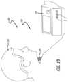
- FIG. 1 Cis a perspective view of a system of the present disclosure shown in operation on a patient to the scalp and/or the brain for multiple uses, including but not limited to the treatment of traumatic brain injury or stroke application.
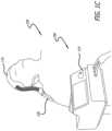
- FIG. 1 Dis a perspective view of a system of the present disclosure shown in operation to regulate cool and/or heat core temperature of a patient for multiple uses, including but not limited to the treatment of cardiac arrest.
- FIG. 2is a perspective view of a heat exchange module of the present disclosure shown in isolation and such as can be used in the systems of FIGS. 1 A- 1 D .
- FIG. 3is an exploded perspective view of the module of FIG. 2 .
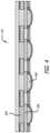
- FIG. 4is a stylized cross-sectional view of the module of FIG. 2 .
- FIG. 5is a plan view of a channel design of a channel assembly of a module of the disclosure.
- FIG. 6is a view similar to FIG. 5 of an alternative channel design.
- FIG. 7is a bottom plan view of a channel assembly, such as that of FIG. 5 , of a module of the disclosure.
- FIG. 8is a perspective view of the channel assembly of FIG. 7 .
- FIG. 9is a perspective view of the module of FIG. 7 illustrated in a strapped position to a leg of a patient.
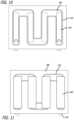
- FIG. 10is a top view of a channel assembly showing the channel windows.
- FIG. 11is a view similar to FIG. 10 showing thermally conductive plates covering the windows.
- FIG. 12 Ais a view similar to FIG. 11 showing the plates as transparent so the backside adhesive on the plates can be seen in the channel assembly for illustrative purposes.
- FIG. 12 Bis a view similar to FIG. 12 A showing the backside of the channel assembly but with the alternative embodiment in which the windows are not cut out, keeping the water channel layer intact.
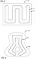
- FIG. 13is an enlarged plan backside view of one of the plates of FIG. 12 A depicting the adhesive around the perimeter of the plate.
- FIG. 14is a view similar to FIG. 11 showing the axes of rotation flexibility of the channel assembly and thus of the module.
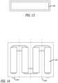
- FIG. 15 Ais a view similar to FIG. 11 but of an alternative embodiment having twelve instead of four plates and thereby providing more axes of rotation flexibility, three in the Y direction and two in the X direction.
- FIG. 15 Bis a view similar to FIG. 15 A but of an alternative embodiment connecting the twelve plates with another cover illustrated by a hashed pattern.
- FIG. 16is a view similar to FIG. 11 and showing the thermoelectric cooler (TEC) assembly in place on the plates.
- TECthermoelectric cooler
- FIG. 17shows in perspective an alternative TEC assembly and thermally conductive plate arrangement with the details of the TEC assembly.
- FIG. 18is a top plan view of FIG. 17 .
- FIG. 19is perspective view of a core composite layer of the module shown in isolation and before configuring.
- FIG. 20is a perspective view similar to FIG. 16 with the core composite layer of FIG. 19 configured and in place.
- FIG. 21is a view similar to FIG. 20 with the upper Mylar sheet in place on top of the core composite layer.
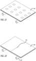
- FIG. 22is a view similar to FIG. 21 with the top plate in place.
- FIG. 23is a view similar to FIG. 22 with the biocompatible layer in place.
- FIG. 24is a stylized cross-sectional view through a module of the disclosure showing a first method of mechanically securing the heat exchange stack together with the mechanical securement not extending through the channel assembly.
- FIG. 25is a view similar to FIG. 24 showing an alternative second method of mechanically securing the heat exchange stack together with the mechanical securement extending through the channel assembly.
- FIG. 26is a top plan view similar to FIG. 16 but showing the areas of mechanical securement of the method of FIG. 24 .
- FIG. 27is a top plan view similar to FIG. 16 but showing the areas of securement of the method of FIG. 25 .
- FIG. 28is a schematic overview of a system of the present disclosure including a module connected by an umbilical to a console and the operational relationships of the components of the console illustrated.
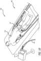
- FIG. 29is a perspective view of the console of FIG. 28 with the enclosure in transparent for illustrative purposes.
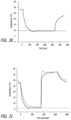
- FIG. 30is a graph showing temperature changes measured on the thigh of an individual in response to controlled cooling to 10 degrees C. for approximately seven minutes.
- FIG. 31is a graph of temperature versus time measured on the skin of the hand of an individual in response to cooling (to 5 degrees C.) and heating (to 36 degrees C.) using controlled profiles of the heat exchange module.
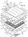
- FIG. 32is an exploded perspective view of a heat exchange module of the present disclosure.
- FIG. 33is a top perspective view of the assembled module of FIG. 32 showing the movement of water into and out of the channel of the module.
- FIG. 34is a bottom perspective view of the module of FIG. 33 .
- FIG. 35is an enlarged cross-sectional view of the module of FIG. 33 against a body part of a patient.
- FIG. 36is an enlarged view taken on circle 36 of FIG. 35 .
- FIG. 37is a top perspective view of the module of FIG. 33 showing the water channel enclosure in exploded relation.
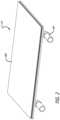
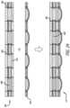
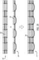
- FIG. 38is a cross-sectional view through the water channel enclosure of FIG. 37 .
- FIG. 39is a cross-sectional view, similar to that of FIG. 38 but with a TEC layer attached thereto.
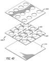
- FIG. 40is an exploded view of a heat transfer (cover) assembly of the module of FIG. 32 .
- FIG. 41is an enlarged perspective view of a bottom corner of the module showing a removable coating being peeled away.
- FIG. 42is a top plan view of an exemplary TEC assembly of the module wherein the TECs are in a single bank and connected in series.
- FIG. 43is a perspective view showing a module of the disclosure in position on a body part of a user and operatively connected to a control and power unit of the disclosure.
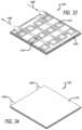
- FIG. 44is a perspective view of an alternative heat transfer (cover) plate of the disclosure illustrated in isolation.
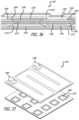
- FIG. 45is a simplified exploded perspective view of a module of the present disclosure having an alternative heat transfer cover assembly.
- FIG. 46is an enlarged perspective view of a portion of the cover assembly of FIG. 45 shown assembled.
- FIG. 47is an enlarged cross-sectional view taken on line 47 - 47 of FIG. 46 .
- FIG. 48is a bottom perspective view of an alternative of the cover assembly having a bottom biocompatible layer, shown being peeled back.
- FIGS. 28 and 29illustrated therein are the heat exchange systems shown generally at 100 and including a heat exchange module shown generally at 110 , a console shown generally at 114 and an umbilical 120 operatively connecting them.
- the consoleincludes an enclosure 130 , fans 140 , radiator 150 , screen drive board 160 , touch screen 170 , pump 180 , jack 190 , power/signal plug 200 , port connector 210 , rotary encoder 220 , H-bridge 230 , DC to DC power supply 240 , reservoir 250 , battery 260 , USB 270 , power outlet 280 , flow meter 290 , microcontroller assembly 300 .
- FIGS. 1 A, 1 B, 1 C and 1 Dgenerally at 310 , 320 , 330 and 340 respectively.
- FIG. 28shows the following connections signal 320 , power 330 , fluid 340 , and heat 350 .
- FIG. 3is an exploded perspective view of one of the modules 110 showing the various layers including two TPU sheets 400 , RF welded 410 to form a channel 420 , with angled inlet and outlet 430 .
- the channelhas a plurality of windows (openings) 440 cut out to expose the interior of the channel at a plurality of locations.
- the sheets, channel with openings and outletform a water channel shown generally at 450 .
- the rest of the moduleforms a heat exchange stack (HES) shown generally at 500 .
- the stackincludes the bottom plates 520 collectively forming a thermally-conductive plate construction or layer shown generally at 530 .
- FIG. 12 Ashows the plates as transparent so the backside adhesive on the plates can be seen in the channel assembly for illustrative purposes.
- An alternative plate constructionis shown in FIG. 12 B where there are plates or plate pieces 540 , but no windows.
- FIG. 15 Ashows an alternative embodiment having twelve instead of four plates and thereby providing more axes of rotation flexibility, three in the Y direction and two in the X direction.
- a further alternativeis shown in FIG. 15 B where the plate pieces 550 are connected together with a web 560 .
- An advantage of the various plate constructions of the present disclosureare that they provide greater flexibility for the device.
- the flexibilitycan be provided about Y axes 600 as shown in FIG. 14 for example. Or with the plate configuration of FIG. 15 A about X axes 610 and Y axes 620 .
- the TEC assemblycan include TEC 680 , the previously-mentioned copper squares 690 , the copper bus line 700 and wires 710 .
- Thermistors 750are shown in the figures.
- a core composite layer 800has holes 810 cut in it.
- the upper Mylar sheet 830also has holes 840 cut in it for the TECs.
- the top plateis shown at 850 and the biocompatible layer at 860 .
- the adhesive for attaching the TEC's to the plate pieces (bottom plate)is shown at 870 and the thermal paste/epoxy for attaching the TECs to the top plate is shown at 880 .
- the threads or other mechanical connectionsare shown at 900 .
- the control consolecan be comprised of the following components:
- the enclosurecan be manufactured from laser cut acrylic, cast urethane, injection molded plastic or a similar method. It can be made from a single piece or by joining multiple panels that are either snapped together, screwed together, or by other mechanical or adhesive methods including a combination of the methods.
- the enclosure's main purposeis to house the internal components of the control console as well as mount the input and output ports and connector needed to interface with the umbilical and therefore HEMs. This enclosure can also maintain its rigidity with vents, for heat dissipation.
- the enclosurealso can be constructed to maintain safety in the event of a fluid leak near electrical components.
- the input and output componentscan be panel mounted to interface with a plug, cable, or tube. They can be installed by creating a cut-out in the enclosure of the specified component, such that it can be inserted partially through the hole and mechanically fixed, whether through screws or a snap-in feature.
- the quick disconnect fittings, the power and signal plug, the USB port, the 1 ⁇ 4′′ jack, and power outletare all installed in this manner.
- the touch screenis installed in a similar manner but rather than being put through the enclosure, it is mounted such that the profile cut out of the enclosure allows access to the screen without the part extending out.
- the internal componentsare all mounted by screw mounts or affixed to platforms with various mechanical or even adhesive methods.
- the fan(s)are mounted to the radiator, and the radiator fan system is mounted such that the fans directly come into contact with a vent, and they are screw-mounted into place.
- the pump, AC to DC power supply, necessary DC to DC power supplies (zero to two depending on the design), H-Bridge, microcontroller PCBA, screen driver boardare all screw mounted.
- the reservoiris held in place by being mounted on a shelf or platform.
- the AC to DC power supply and batteryprovide power to all the components in the system. They are installed such that when the device is plugged into a power source the battery is charging, and when the device is unplugged the device operates on the battery. Depending on the design and component power needs, there are additional DC to DC power supplies that are powered by the power supply or battery. This collection of power supplies and battery are referred to as the power supply system.
- the power outletis then wired with 600V rated cable to the power supply system.
- the power supply systemis then distributed to the appropriate components via wiring.
- the components that require powerinclude the fan(s), the pump, the H-Bridge, the microcontroller PCBA, and in some designs, the screen driver board and touch screen may need individual power. There are additional electrical interconnections separate from the power supply system.
- Wiringis necessary between the power and signal plug to the H-Bridge and to the microcontroller PCBA. Additional wiring is necessary from the USB port, 1 ⁇ 4′′ jack, flow meter, level sensor, H-Bridge, and screen driver board to the microcontroller PCBA. There is also a wiring connection needed between the touch screen and the screen driver board. All this wiring is completed via screw terminals, soldering, crimping, or plugs, depending on the components specification.
- the fluid system within the enclosureis all interconnected with 3 ⁇ 8′′ or 1 ⁇ 4′′ diameter flexible tubing, such as PVC or polyurethane. They are connected to the individual components using barb or compression fittings. They can be straight or angled, and are screwed into the components.
- the tubingis connected from the reservoir to the pump inlet and from the pump outlet to the outlet quick disconnect fitting, where the umbilical is attached.
- the tubingalso goes from the inlet quick disconnect fitting to the radiator and from the radiator back into the reservoir.
- the flow meteris installed with the same barbed fittings.
- a second threaded holeis created in the reservoir so that the level sensor can be installed.
- the umbilicalis an extended section of a paired tube, such as PVC or polyurethane, as well as an extended piece of wiring assembly between 1 ⁇ 3 of a meter to four meters.
- There are two tubes for the fluidagain either 3 ⁇ 8′′ or 1 ⁇ 4′′ in diameter and made from a flexible material, that go from quick disconnect fittings of the control console to the HEM.
- the appropriate connectorwith barbs if necessary, are attached to the ends of these tubes such that it can plug into the quick disconnect fittings and into the HEM.
- the wire assemblyis comprised of two cables capable of carrying current to the HEMs and at least two wires that can bring signals from the HEMs temperature probe. Additional wires are included if there are more than one temperature probe being used in the HEM.
- the cables and wiresare crimped and soldered appropriately in order to be connected to the terminal of the plugs that goes into the control console on one end and into the HEM on the other end.
- a braided sleeve or other sheathecan then be wrapped around the entire cable and tube assembly.
- the touch screenis interfaced by the user and in the simplest case a single temperature below room temperature is set for an indefinite amount of time (it will be possible for the user to set and use or select programmed temperature and time. algorithms).
- the microcontrollerreceives the temperature signal from the HEM. It responds by transmitting the appropriate signal to the H-Bridge which then, powered by the power supply system, can produce and send the necessary power to the HEM through the umbilical assembly. This allows the HEM to approach the set temperature. This feedback loop is repeated as necessary to maintain the user's selected temperature.
- the heat created by the HEMis being removed via the fluid system. Fluid is continuously flowing in a closed loop.
- the pumpis drawing fluid from the reservoir and sending it through the umbilical into the HEM where it collects heat and returns via the umbilical. It then passed through the radiator and returns to the reservoir. When passing through the radiator, the collected heat is dissipated from the air forced through the radiator by the fans. The fans also help to remove excess heat produced from the electrical components in the enclosure.
- HEMHeat Exchange Modules
- TPUthermoplastic polyurethane
- TPU inlets/outletsare also RF welded at the ends of the designed water channels to allow the inlet and outlet of the water to be circulated. These inlets/outlets vary in size and have an inner diameter (ID) of either 1 ⁇ 4′′ or 3 ⁇ 8′′ depending on the specifications of each HEM.
- IDinner diameter
- the TPUis not thermally conductive, an opening can be created in the water channels to allow for sufficient transfer of heat into the water from the device.
- the TPU sheet that does not have the elbows RF welded to itis cut in the shape of rectangles to form ‘windows’ in it. This is typically done via die-cutting, but can be done by other methods.
- a number of the figuresshow the water channels with windows cut out. This figure shows only one of the many possible configurations of the windows cut in the TPU sheet. The number of windows can range from one large window to as many windows as there are TECs in the device. The higher number of windows, the more flexible the device can be. This will be further explained below.
- thermally conductive materialWith an opening now in the water channels, a thermally conductive material must be used to seal the water channels to prevent leaking.
- This materialis typically a thin metal plate, either copper or aluminum of thickness 7-12 mils (to be determined), but can be any semi-flexible thermally conductive substrate.
- the metal plateis cut into pieces that are relatively larger than the window cutouts in the TPU (usually by ⁇ 10 mm). Smaller pieces are preferable over a single large piece of metal to allow for flexibility in the device and to reduce weight.
- the areas in between the metal platesallow for more flexibility in the device, since the TPU is more flexible than the metal.
- the number of metal platescan be the same as the number of windows cut out in the water channels. For instance, a small window can be cut around each TEC (twelve windows total), and twelve metal plates, each a bit bigger than the size of the windows, can be used to seal each window.
- This methodallows for more flexibility since it would have flexibility along two axes instead of just one. This is because all of these plates lie within the same plane, and for ease of discussion, they will collectively be referred to as the ‘bottom plate’.
- This platemay also be referred to as the ‘hot plate’, since during normal cooling operation this plate will heat up, whereas the ‘upper plate’ (discussed later) will be cold. (The bottom plate can be broadly referred to as a ‘cover.’)
- the sealing processcan use either a structural adhesive (typically either epoxy or acrylic), or a pressure sensitive transfer tape.
- a structural adhesivetypically either epoxy or acrylic
- a pressure sensitive transfer tapeexamples include: Devcon HP250 (acrylic adhesive), 3M DP8005 (epoxy adhesive), and 3M 9472 (transfer tape).
- Devcon HP250acrylic adhesive
- 3M DP8005epoxy adhesive
- 3M 9472transfer tape
- both the TPU and metal platescan be thoroughly abraded and cleaned to allow for proper bonding.
- the adhesive or tapeis placed on each plate in the areas that overlap the TPU, but not in areas where water will contact the plate. Putting adhesive over the whole plate would both waste material and form an unwanted barrier that heat must transfer through to reach the water.
- FIG. 7shows adhesive laid onto the plate.
- the rectangular metal pieces with adhesiveare set to the TPU and allowed to cure, thereby sealing the water circulation channels.
- FIG. 8shows the plates bonded to the TPU sheet.
- FIG. 9shows the metal as transparent to illustrate the windows below. In the Second Method (see below) this sealing process can be completed after the rest of the device has been assembled.
- the next stepis to arrange the modules that produce the cooling effect in the device, the thermoelectric coolers (TECs).
- the TECsoperate on electrical power, and are connected to a power source via bus bars.
- These bus barsare made of copper, thin, flexible, and keep a low profile inside the HEMs. The low profile is helps maintain interstitial space within the HEM between the two sides of the TECs.
- the bus barscan be highly electrically conductive, which prevents them from heating up. Any heat generated through resistance losses in the wiring would inherently cause the HEM to be less efficient.
- the wiring on each TECis trimmed down to about 251 ⁇ 4′′. Copper bus bars are cut to the corresponding lengths between TECs, and the TEC wires are soldered to the bus bars.
- FIGS. 10 - 11illustrate the TEC assembly.
- FIG. 12 Bis a view similar to FIG. 12 A showing the backside of the channel assembly but of an alternative embodiment in which the windows are not cut out, keeping the water channel layer intact.
- FIG. 15 Bis a view similar to FIG. 15 A but of another alternative embodiment connecting the twelve plates with another cover represented here by a hashed pattern.
- This covercan be a meshed material, a material with perforations along the axes of flexibility, such as a perforated foil, or a cover with varying thickness, such as a foil that is thinner along the axes of flexibility, all of which would connect the plates and still provide the axes of rotation for flexibility. It is also possible to do this with four plates or any other number of plates necessary to meet the design requirements.
- This layercan be a thermally-conductive metal plate (but can be any semi-flexible thermally conductive substrate) that will be placed on the opposite side of the TECs, and can be referred to as the ‘upper plate’ or ‘cold plate’.
- a thermistoris added to this plate to measure the temperature of the surface that is in contact with the skin. To do this, the thermistor is placed in a suitable location (typically the middle of the plate) and the insulated lead wires are taped to the plate using thermally resistant tape.
- a thermally conductive adhesivetypically Dow Corning 3-6750
- the adhesivecan be cured to set the thermistor in place.
- the interstitial spaceis defined as the area between the top and bottom metal plates that is not taken up by the TECs or other elements (thermistor, bus lines, etc.).
- a material called a ‘core composite’can be used, and examples are Koroyd or Amarid Honeycomb. These are structured materials often shaped as a honeycomb with empty cells. See FIG. 12 A .
- the core compositecan be used instead of, for example, a silicone foam.
- the core compositeis cut in the areas where the TECs are present to fill all but those areas between the two metal plates (interstitial space).
- the materialis a good thermal insulator because there is air in every core cell, minimizing the amount of heat transfer through the material in contact with both plates.
- the core compositealso maintains its structure over time, keeping the separation of the top and bottom plates, for thermal insulation.
- the core compositeadvantageously does not condense or compress over time, which would allow the plates to merge closer to each other.
- the core compositealso maintains the structure of the HEM during the mechanical fastening process, preventing the plates from compressing into each other.
- a sheet of Mylar or similar reflective materialcan be placed on the either side of the core composite for further insulation. These sheets prevent heat from radiating between the two plates by reflecting any emitted radiation back to the plate from which it originates.
- the assembly of the devicecan use a thermally conductive epoxy to adhere the TECs between the two metal plates, or preferably a thermal paste (typically Arctic MX-4 Compound) that allows for some give between the TECs and the plates on either side of them.
- a thermal pastetypically Arctic MX-4 Compound
- a methodis needed to hold the device together (basically creating a sandwich that holds the TECs in contact with the metal plates).
- the TECsmaintain intimate contact with the metal plates, so that that there is sufficient heat transfer between the materials.
- This methodcan be mechanical fastening, such as sewing, use of rivets, or a similar procedure that will hold the device together structurally.
- This discussionwill use sewing as the primary method, although others are just as viable. Two methods of mechanical fastening are described in the following two subsections.
- the TEC chainthat was produced earlier is now used.
- a thin layer or bead of thermally conductive pasteis placed onto the “top” surface (the surface to be in contact with the top plate) of each TEC.
- the chain of TECsis then placed on the top plate.
- the first sheet of Mylaris then placed over the top plate around the TECs.
- the core compositeis then placed over the Mylar sheet and around the TECs.
- the second Mylar sheetis then placed over the core composite and around the TECs.
- a thin layer or bead of thermally conductive pasteis placed onto the ‘bottom’ surface (surface to be in contact with the bottom plate) of each TEC.
- the bottom plateis then placed on the TECs. Recall that the bottom plate is already sealed to the water channels. At this point, the entire device is mated, and it just needs to be mechanically fastened.
- the main difference between the two methodsis how many components the thread (or fastener) will pass through.
- the deviceis fabricated in a different order, in which the sewing is not the last step, and therefore the thread does not have to pass through the entire device. (See FIG. 24 .)
- HESheat exchange stack
- Making the HESfollows the same procedure as the First Method, the only difference being that the bottom plate is not yet adhered to the water channels. Taking the procedure above for clarity:
- the TEC chaincan be as follows. A thin layer or bead of thermally conductive paste is placed onto the ‘top’ surface (surface to be in contact with the top plate) of each TEC. The chain of TECs is then placed on the top plate. The first sheet of Mylar is then placed over the top plate around the TECs. The core composite is then placed over the Mylar sheet and around the TECs. The second Mylar sheet is then placed over the core composite and around the TECs. A thin layer or bead of thermally conductive paste is placed onto the ‘bottom’ surface (surface to be in contact with the bottom plate) of each TEC. The bottom plate is then placed on the TECs.
- the bottom plate in this methodcan simply be a piece of metal, with the water channels not yet adhered.
- Each metal platecan be sewn individually to the HES similarly to First Method. After each bottom plate is sewn to the top plate, the HES is completed.
- the remaining stepis to adhere the water channels to the bottom plate.
- the water channels with windowsare made the same as described earlier, and they are adhered to the bottom plate in the same way, the only difference is that the bottom plate is already attached the HES on the other side. See FIG. 14 for a cross-sectional view of the Second Method.
- a final step in completing the cooleris adding a thin layer (0.2 to 1 mm) of thermally-conductive biocompatible material to the top plate.
- This materialacts a buffer between the body tissue and the top plate so that the skin is not in direct contact with metal.
- Biocompatible materialsinclude silicones for medical use, of which a variety are currently available. Alternatively, biocompatible skin adhesives, such as 3M 2476P, are also applicable.
- FIG. 15 Ashows the completed device and FIG. 16 shows an exploded view of each layer.
- FIG. 32another heat exchange module of the present disclosure is illustrated in exploded view generally at 1100 .
- the fluid hoses 1110 , thermoelectric cooler (TEC) wires 1120 , and thermistor (or thermocouple) wires 1130can pass through an umbilical 1140 to the console 1150 ( FIGS. 42 and 28 and 29 ).
- the HEM system of the present disclosure shown generally at 1200thus includes HEM 1100 , umbilical 1140 and console 1150 .
- FIG. 43shows system 1200 with the HEM 1100 in position, wrapped around a body part 1220 of a patient.
- the HEM 1100can be adapted and used on generally any body part 1220 including, for example, the head. As can be appreciated, the HEM 1100 for many applications should be constructed to be able to flex in all three directions to be fitted by the medical personnel against any body part no matter how rounded, angular, large and small.
- the HEM 1100 and the alternative embodiment HEM shown generally at 1300 in exploded view in FIG. 45include many novel constructions to provide for increased flexibility. Although pictured as being flat when in its natural state, the HEM 1100 (or 1300 ) of the present disclosure also includes cylindrical and cup configurations, and any combination of shapes afforded to follow the contours of various body parts. The HEMs disclosed herein also have novel constructions providing for improved transmission of heat to and from the circulating liquid in the channels and the body parts.
- the channel enclosure assembly 1320 of the HEM 1100can include first, second and third TPU (or other thermoplastic) sheets 1330 , 1340 , 1350 .
- the first and second sheets 1330 and 1340include a plurality of holes 1350 , 1360 , which mate with one another when the sheets are attached together.
- a plate assembly shown generally at 1370is positioned between sheets 1330 , 1340 . It can comprise a plurality of plate pieces shown at 1380 . There is one plate piece 1380 for each of the mating holes 1350 , 1360 .
- the holes 1350 , 1360 and plate piecescan be arranged in a three-by-four array. But then the number and arrangement will be selected as desired for the HEM factoring in the requirements of the TEC assembly and its TECs.
- the HEM 1300is illustrated as having a three-by-three array.
- the first and second sheets 1330 , 1340are thermally sealed together with each of the plate pieces 1380 embedded in the two sheets and covering both of the respective mating holes 1350 , 1360 . See FIG. 38 , for example.
- the plate pieces 1380can have one or more slots, openings or notches 1390 along their perimeters. This aids in the plate pieces 1380 being embedded into the (plastic) of the first and second sheets, as can be seen by embedded plastic pieces 1400 in FIGS. 36 , 38 and 39 .
- the third sheet 1350is secured thereto. It can be secured by thermal compression, ultrasonic welding, RF welding or similar means.
- the welding, etc.is configured to form the perimeter 1400 of a water (or other thermally-conductive liquid) channel 1410 between the second and third sheets 1340 , 1350 .
- Holes 1430 , 1440can be formed in the third sheet at opposite ends of the channel 1410 .
- angled connectors 1450 , 1460attached to the third sheet 1350 at the respective holes and through which water delivered through tubing 1470 is delivered (arrows 1480 , 1490 in FIG. 33 ) between the console 1150 and the channel 1410 .
- each thermoplastic sheeteither urethane (TPU), or vinyl or other thermoplastic sheets
- TPUurethane
- the TPU inlets/outlets 1450 , 1460are also RF welded at the ends of the designed water channel to allow the inlet and outlet of the water to be circulated.
- These inlets/outletsvary in size and can have an inner diameter (ID) of either 1 ⁇ 4′′ or 3 ⁇ 8′′, for example, depending on the specifications of each HEM.
- the third flexible sheet 1350can be a reinforced TPU sheet or multi-layer with an internal cloth layer, strong enough to withstand pressures of the water in the channel of fifteen to twenty-five psi.
- the pressure in the channelshould be kept at less than twenty-five psi so as to not cause the sheet 1450 to rupture.
- Exemplary flow rates in the channel 1410are two liters per minute, and can range from 0.5 to 3.5 liters per minute.
- Holes 1360 in the second sheet 1340are positioned so as to be at the channel 1410 , as can be seen in FIGS. 38 and 39 . Thereby each of the plate pieces 1380 forms a portion of the wall of the channel 1410 . Further, each plate piece 1380 is in direct contact with the water flowing through the channel 1410 for direct thermal transfer therebetween.
- An alternative configurationomits the plate assembly (plate pieces 1380 ) and positions the reference (ceramic) face of the TEC directly in/to the hole 1350 of the second sheet 1340 , and thereby in direct physical contact with the water in the channel for thermal transfer therebetween.
- a further alternativedoes not include a first sheet 1330 . Rather, the plate piece 1380 is secured directly to an inward face of the second sheet 1340 and over the hole. It can be secured, for example, using an adhesive.
- the plate assembly 1370may comprise a single large plate; however, by providing a plurality of smaller plate pieces 1380 spaced from one another in both x and y directions, as described above, additional flexibility/bending of the HEM is possible. This flexibility/bending can be along one or more x axes between the plate pieces 1380 and/or along one or more y axes between the plate pieces. Alternatively but less preferably, the plate pieces 380 can be interconnected with a flexible webbing.
- a TEC assembly 1500 of the HEM 1100can be seen in FIGS. 32 and 42 comprising a plurality of TECs 1510 . They can be formed in a single bank as illustrated in FIG. 42 and connected in series, or in a plurality of banks (e.g., three or four), each connected in series or in parallel. The number of banks can depend on the type of TECs used, and the voltage ranges optimally controlled by the console unit.
- each of the TECs 1510are attached to a respective plate piece 1380 in a manner to provide effective heat transmission, as shown in FIGS. 36 and 39 for example.
- a thin layer of thermally-conductive adhesive, paste or putty 1530can be used.
- the TEC assembly 1500can be operatively connected to the console 1150 by wires 1120 .
- the HEM 1100can include a heat transfer (cover) assembly shown generally at 1600 in FIG. 32 .
- Cover assembly 1600transmits heat between the body part and the user faces of the TECs 1510 .
- the heat transmission vehicle of the cover assembly 1600can be a copper or aluminum (or other highly thermally-conductive material) plate 1620 as can be seen in FIGS. 32 and 40 .
- Short, spaced x and y slots 1630can be formed in the cover plate 1620 to give it greater flexibility and bendability to better conform to rounded and/or angular body parts.
- a thin sheet or film of plastic 1640can be adjacent to an inward face of the cover plate 1620 .
- Sheet 1640can be plasticized to the inward face.
- the third sheet 1350can be sewn or otherwise mechanically secured to the extension perimeter of the plastic sheet to hold at least in part the HEM 1100 together.
- the sewingis shown by reference numerals 1650 and 1660 in FIG. 32 .
- Other mechanical means in addition to or in lieu of sewingcan be used such as snaps, tacks or the like. Additional sewing can be provided through a central part of the HEM 1100 such as through the adhered portions of the third sheet 1350 (outside of the channel) as shown by sewing lines 1670 in FIG. 33 .
- Mechanical attachment meanscan allow for more flexibility of the layers/components of the HEM than by affixing them with an adhesive, for example.
- One or more thermistors (or thermocouples) 1700can be positioned between the cover plate 1620 and the plastic sheet 1640 to accurately measure the temperature of the adjacent body part and transmit this temperature signal to the console 1150 via the wire 1130 .
- the substance(s) 1530 , 1710 used to attach the reference face of the TEC to the copper piece and/or the user face of the TEC to the plate assemblycan be a thermally-conductive putty or similar substance (e.g., a thermally-conductive paste, pad or flexible adhesive) which may allow for some planar movement of the TEC, thereby increasing the flexibility/bendability of the HEM 1100 .
- the substancecan be very thin on the order of fifty to one hundred microns, and have high thermal conductivity, for example greater than three W/m. This substance can be in lieu of a rigid adhesive affixation.
- a biocompatibility layer 1770can be secured to the outward face of the cover plate 1620 . This provides for a smoother, more comfortable and more sanitary contact of the HEM to the body part.
- Layer 1770can be considered to be part of the cover assembly 1600 or as an addition thereto.
- the layer 1770can be affixed to the plate 1620 , it can be a replaceable film or it can be a gel, such as a thermally-conductive silicone gel.
- a filler layer 1780 surrounding the TECs 1510 of the TEC assemblycan be used. It can be, for example, a foam layer or a core composite layer with pre-formed holes for receiving therein respective ones of the TECs. This layer 1780 can be seen in FIGS. 32 and 42 .
- the core composite materialcan provide interstitial insulation and structural stability to the HEM.
- the cover plate 1620can be formed with X and/or Y direction slots 1630 to provide for flexibility/bendability.
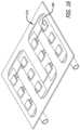
- Another construction of the cover plateis shown by plate 1800 in FIG. 44 which has a tic-tac-toe arrangement of bridges 1820 forming an array of interconnected rectangular plates 1840 .
- the intersections of the x and y bridges 1820can be holes 1850 . If the plate 1800 is made of metal, e.g., copper, then so are the bridges 1820 according to the construction of the embodiment depicted in FIG. 44 .
- Cover assembly 1900can include a frame 1910 which holds the cover assembly together and can be made of a flexible plastic, while the plate assembly 1920 can be made of metal. This plastic construction can have greater flexibility than the copper of plate 1800 , for example, and be less subject to bending fatigue.
- the alternative cover assembly 1900can include a tray assembly 1930 , as discussed in detail below.
- the tray assembly 1930can include a plurality of trays 1934 , one for each TEC 1510 .
- Each tray 1934has a through-hole 1936 for receiving therein a respective TEC 1510 ( FIGS. 46 and 47 ).
- Each trayalso has a perimeter rim 1940 .
- Elongate flexible bridges 1946interconnect rims 1940 of the long side of adjacent trays 1934 .
- Wider and shorter flexible bridges 1950interconnect rims 1940 of the short sides of adjacent trays 1934 . As can be seen in FIG. 47 , smooth curves can connect the bridges with the adjacent rims 1940 .
- the bridgesinterconnect the trays 1934 such that tray assembly 1830 has a matrix-type construction.
- the frame 1810has x and y bars 1960 forming window-openings 1964 .
- the bars in cross sectioncan be shaped as shown in FIG. 47 with enlarged heads 1970 at both ends connected by a smoothly-curved hump or bridge 1974 .
- the plate assembly 1920can include a plurality of thermally-conductive tiles 1980 (copper, aluminum, or any other material with high thermal conductivity) which have flat body members 1984 with raised perimeter lips 1988 .
- the enlarged heads 1970hook onto or snap onto the perimeter lips 1988 when the cover assembly is assembled as shown in FIGS. 46 and 47 .
- the enlarged heads 1970are within the rims 1940 .
- the bridges 1950are on the humps 1974 in conforming relation.
- each of the plate assembly (tiles), the tray assembly (tiles) and the frame (windows)form the same arrays, e.g., a three-by-three array, which are aligned when assembled such that each TEC can penetrate to thermally contact (directly or using an adhesive or the like) with a respective tile 1980 .
- Each of the tiles 1980can have its own thermistor (or thermocouple) 1996 secured to an inward surface thereof.
- the temperature sensors 1996collectively and accurately measure the temperature of the adjacent body part.
- a number of ways of providing a smooth, comfortable, cleanable, thermally-conductive surface on the bottoms of the tiles for direct contact with the body partare within the scope of the present disclosure.
- Oneis to provide a biocompatible thermally-conductive layer 1998 , which for example can be reinforced with carbon fiber/nanotubes/copper mesh (anything to optimize thermal conductivity) to optimize heat extraction via proximity to skin.
- the layercan be permanently affixed and able to be wiped clean. Or it can be a removable layer 1998 ( FIG. 48 ) which can be applied, used, removed and replaced with a fresh layer.
- Another embodimentis to apply a suitable thermally-conductive lacquer directly on the bottom surfaces of the (metal) tiles 980 , and which can be wiped clean.
- a thin, biocompatible, thermally-conductive gelsuch as a silicone gel, can also provide the coating according to another embodiment.
- a further embodimentis to provide a sleeve or bag (not shown) in which the HEM can be inserted. The bag can have a thin biocompatible film (along the lines of those discussed above) on its user contact surface. After each use the bag can be removed, washed and reused.
Landscapes
- Health & Medical Sciences (AREA)
- Engineering & Computer Science (AREA)
- General Health & Medical Sciences (AREA)
- Public Health (AREA)
- Heart & Thoracic Surgery (AREA)
- Veterinary Medicine (AREA)
- Life Sciences & Earth Sciences (AREA)
- Animal Behavior & Ethology (AREA)
- Biomedical Technology (AREA)
- Vascular Medicine (AREA)
- Physics & Mathematics (AREA)
- Thermal Sciences (AREA)
- Mechanical Engineering (AREA)
- General Engineering & Computer Science (AREA)
- Anesthesiology (AREA)
- Hematology (AREA)
- Thermotherapy And Cooling Therapy Devices (AREA)
- Professional, Industrial, Or Sporting Protective Garments (AREA)
Abstract
Description
- (a) Enclosure
- (b) Quick-disconnect fittings
- (c) Power and signal plug
- (d) USB port
- (e) ¼″ Jack
- (f) AC Power inlet
- (g) Fan(s)
- (h) Radiator
- (i) Pump
- (j) Reservoir
- (k) Flow meter
- (l) Level sensor
- (m) AC to DC power supply
- (n) Battery
- (o) DC to DC power supplies
- (p) H-Bridge
- (q) Microcontroller printed circuit board assembly (PCBA)
- (r) Screen driver board
- (s) Touch screen
- (a) A TPU sheet is die-cut to form windows in the material
- (b) Inlet/outlet elbows are RF welded to a second TPU sheet
- (c) These two sheets are RF welded together in a specified shape to form water circulation channels
- (d) Bottom plates are cut to specification; the number of plates is equal to number of windows in TPU
- (e) Adhesive is applied to the perimeter of the bottom plates and they are adhered to the TPU to seal the water channels
- (f) TEC assembly is formed by soldering TECs together using copper bus lines
- (g) Top plate, core composite and mylar materials are cut to specification
- (h) Thermal paste is applied to upper side of TECs
- (i) TECs placed against upper plate
- (j) (Top) Mylar sheet added against upper plate, surrounding TECs
- (k) Core composite added against Mylar sheet, surrounding TECs
- (l) Second (bottom) Mylar sheet added against core composite material, surrounding TECs
- (m) Thermal Paste is placed on bottom side of TECs
- (n) TECs, along with upper plate materials in interstitial space, are placed against the bottom plate which already has the water channels adhered to it
- (o) The HEM is mechanically fastened using sewing, the thread penetrating through the entire device
- (a) TEC assembly is formed by soldering TECs together using copper bus lines
- (b) Top plate, core composite, and Mylar materials are cut to specification
- (c) Bottom plates are cut to specification; the number of plates is equal to number of windows
- (d) Thermal Paste is placed on upper side of TECs
- (e) TECs placed against upper plate
- (f) (Top) Mylar sheet added against upper plate, surrounding TECs
- (g) Core composite added against Mylar sheet, surrounding TECs
- (h) Second (bottom) Mylar sheet added against core composite material, surrounding TECs
- (i) Thermal Paste is placed on bottom side of TECs
- (j) TECs, along with upper plate materials in interstitial space, are placed against the bottom plate
- (k) The HEM is mechanically fastened using sewing, the thread penetrating only through the HES assembly
- (l) First TPU sheet is die-cut to form windows
- (m) Inlet/outlet elbows are RF welded to second TPU sheet
- (n) These two sheets are RF welded together in a specified shape to form the water channels
- (o) Adhesive is applied to the perimeter of the bottom plates, which is already sewn to the rest of the HES, and they are adhered to the TPU to seal the water channels.
Claims (31)
Priority Applications (1)
| Application Number | Priority Date | Filing Date | Title |
|---|---|---|---|
| US16/137,124US11903872B2 (en) | 2016-03-28 | 2018-09-20 | Heat exchange module, system and method |
Applications Claiming Priority (4)
| Application Number | Priority Date | Filing Date | Title |
|---|---|---|---|
| PCT/US2016/024592WO2017171719A1 (en) | 2016-03-28 | 2016-03-28 | Heat exchange module and system for medical applications |
| US201662400836P | 2016-09-28 | 2016-09-28 | |
| PCT/US2017/024628WO2017172836A1 (en) | 2016-03-28 | 2017-03-28 | Heat exchange module, system and method |
| US16/137,124US11903872B2 (en) | 2016-03-28 | 2018-09-20 | Heat exchange module, system and method |
Related Parent Applications (1)
| Application Number | Title | Priority Date | Filing Date |
|---|---|---|---|
| PCT/US2017/024628ContinuationWO2017172836A1 (en) | 2016-03-28 | 2017-03-28 | Heat exchange module, system and method |
Publications (2)
| Publication Number | Publication Date |
|---|---|
| US20190099288A1 US20190099288A1 (en) | 2019-04-04 |
| US11903872B2true US11903872B2 (en) | 2024-02-20 |
Family
ID=59965142
Family Applications (1)
| Application Number | Title | Priority Date | Filing Date |
|---|---|---|---|
| US16/137,124Active2040-05-07US11903872B2 (en) | 2016-03-28 | 2018-09-20 | Heat exchange module, system and method |
Country Status (9)
| Country | Link |
|---|---|
| US (1) | US11903872B2 (en) |
| EP (1) | EP3435935B8 (en) |
| JP (1) | JP7101123B2 (en) |
| KR (1) | KR20190011714A (en) |
| CN (1) | CN109475425A (en) |
| AU (1) | AU2017241923A1 (en) |
| CA (1) | CA3019211A1 (en) |
| IL (1) | IL261871A (en) |
| WO (1) | WO2017172836A1 (en) |
Cited By (1)
| Publication number | Priority date | Publication date | Assignee | Title |
|---|---|---|---|---|
| US20240167736A1 (en)* | 2021-07-22 | 2024-05-23 | Kiran Kota | Flexible thermoelectric device |
Families Citing this family (20)
| Publication number | Priority date | Publication date | Assignee | Title |
|---|---|---|---|---|
| US10201935B2 (en)* | 2007-03-19 | 2019-02-12 | Augustine Temperature Management LLC | Electric heating pad |
| KR20170132218A (en) | 2015-03-28 | 2017-12-01 | 더 리전트 오브 더 유니버시티 오브 캘리포니아 | Thermostatic temperature control cooler for biomedical applications |
| CN109475747A (en) | 2016-03-28 | 2019-03-15 | 加利福尼亚大学董事会 | Heat Exchange Modules and Systems for Medical Applications |
| JP7101123B2 (en) | 2016-03-28 | 2022-07-14 | ハイポサーミア デバイシズ,インコーポレイテッド | Heat exchange modules, systems and methods |
| EP3518843B1 (en) | 2016-09-28 | 2024-06-26 | Hypothermia Devices, Inc. | Heat exchange module, system and method |
| JP6673556B2 (en)* | 2018-03-05 | 2020-03-25 | 特定非営利活動法人ウェアラブル環境情報ネット推進機構 | Electronic heating and cooling clothes and electronic cooling and heating equipment detachable from clothes |
| DE202019001024U1 (en)* | 2019-03-01 | 2019-06-13 | Reinhold Kett | Multifunctional, temperature-controlled body pad (compress) for cold and heat treatment of tissue surfaces |
| US10765580B1 (en) | 2019-03-27 | 2020-09-08 | Augustine Biomedical And Design, Llc | Patient securement system for the surgical trendelenburg position |
| CN110090121A (en)* | 2019-05-31 | 2019-08-06 | 张建平 | Thermostatic massage pad |
| JP2022536084A (en) | 2019-06-03 | 2022-08-12 | クーラー・ヘッズ・ケア・インコーポレイテッド | Cooling cap assembly and cooling unit |
| CN110403751B (en)* | 2019-07-19 | 2021-08-24 | 东南大学 | Flexible thermochromic interactive wearable thermotherapy pad and preparation method |
| CN211234067U (en)* | 2019-07-27 | 2020-08-11 | 上海易曌医药科技有限公司 | Flexible heat transfer conductive device |
| US20210059854A1 (en)* | 2019-09-03 | 2021-03-04 | Purdue Research Foundation | Portable Thermal Therapy System |
| EP4073454A1 (en)* | 2019-12-09 | 2022-10-19 | Hypothermia Devices, Inc. | Optimized water channels and flexible coolers for use in heat exchange module(s), systems, and methods thereof |
| EP4252723A1 (en)* | 2020-03-27 | 2023-10-04 | Quickcool AB | Removable liquid heat exchanging element for use in a device for temperature control treatment |
| WO2022067429A1 (en)* | 2020-09-29 | 2022-04-07 | The University Of Saskatchewan | Apparatus and methods for controlling organ temperature prior to and/or during transplantation procedures |
| US12433785B2 (en) | 2021-02-23 | 2025-10-07 | C. R. Bard, Inc. | Gel pad assembly using free rotatable fluid joints |
| US20230019048A1 (en)* | 2021-07-19 | 2023-01-19 | C. R. Bard, Inc. | Targeted Temperature Management Systems, Pads, and Methods Thereof |
| US20230346053A1 (en)* | 2022-04-29 | 2023-11-02 | Michael Allen Buckman | Personal Cooling Device |
| US11844733B1 (en) | 2022-06-23 | 2023-12-19 | Augustine Biomedical And Design, Llc | Patient securement system for the surgical Trendelenburg position |
Citations (114)
| Publication number | Priority date | Publication date | Assignee | Title |
|---|---|---|---|---|
| US2991627A (en) | 1959-07-01 | 1961-07-11 | Gen Electric | Thermoelectric blanket |
| US3196524A (en) | 1961-04-18 | 1965-07-27 | Carrier Corp | Thermoelectric cooling devices and method of making the same |
| US3827667A (en)* | 1956-05-28 | 1974-08-06 | J Lemelson | Composite mold wall structure |
| US3867939A (en) | 1972-05-18 | 1975-02-25 | Moore Perk Corp | Disposable, sterile temperature control applicator pad for medical application |
| US4470263A (en) | 1980-10-14 | 1984-09-11 | Kurt Lehovec | Peltier-cooled garment |
| US4494380A (en)* | 1984-04-19 | 1985-01-22 | Bilan, Inc. | Thermoelectric cooling device and gas analyzer |
| SU1179987A1 (en) | 1982-07-23 | 1985-09-23 | Всесоюзный Научно-Исследовательский Проектно-Конструкторский И Технологический Институт Источников Тока | Apparatus for local hypothermia |
| US4560083A (en)* | 1984-01-16 | 1985-12-24 | Trw Inc. | Closure and method for an aperture |
| US4846176A (en)* | 1987-02-24 | 1989-07-11 | Golden Theodore A | Thermal bandage |
| US4860748A (en) | 1988-02-23 | 1989-08-29 | Thermapeutics, Inc. | Thermal pattern generator for pain relief |
| US4879152A (en)* | 1989-02-15 | 1989-11-07 | Green Patrick H | Composite panel structure |
| US4962761A (en)* | 1987-02-24 | 1990-10-16 | Golden Theodore A | Thermal bandage |
| JPH0477915A (en) | 1990-07-20 | 1992-03-12 | Toshiba Corp | Magnetic disk controller |
| US5097829A (en)* | 1990-03-19 | 1992-03-24 | Tony Quisenberry | Temperature controlled cooling system |
| US5174266A (en)* | 1991-12-30 | 1992-12-29 | Evdokimo Allen J | Fuel temperature control device with thermoelectric modules |
| US5174285A (en) | 1990-01-08 | 1992-12-29 | Lake Shore Medical Development Partners Ltd. | Localized heat transfer device |
| DE4238291A1 (en) | 1992-11-13 | 1994-05-19 | Diehl Gmbh & Co | Cryo-therapy system for small areal freezing of surfaces esp. for skin alterations - has cold probe and heat exchanger which are connected heat-conducting with each other by Peltier elements having heat contact surfaces |
| US5584183A (en) | 1994-02-18 | 1996-12-17 | Solid State Cooling Systems | Thermoelectric heat exchanger |
| US5603728A (en) | 1994-06-20 | 1997-02-18 | Pachys; Freddy | Scalp cooling/heating apparatus |
| US5653741A (en) | 1995-08-22 | 1997-08-05 | Grant; Edward F. | Heating and cooling pad |
| US5800490A (en) | 1996-11-07 | 1998-09-01 | Patz; Herbert Samuel | Lightweight portable cooling or heating device with multiple applications |
| US5871526A (en) | 1993-10-13 | 1999-02-16 | Gibbs; Roselle | Portable temperature control system |
| US5887435A (en)* | 1995-12-08 | 1999-03-30 | Litton Systems, Inc. | Environmentally protected module |
| US5895418A (en) | 1994-09-30 | 1999-04-20 | Saringer Research Inc. | Device for producing cold therapy |
| US5899077A (en) | 1997-12-02 | 1999-05-04 | Solid State Cooling Systems, Inc. | Thermoelectric cooling/heating system for high purity or corrosive liquids |
| US6019783A (en) | 1999-03-02 | 2000-02-01 | Alsius Corporation | Cooling system for therapeutic catheter |
| US6205790B1 (en) | 1999-05-28 | 2001-03-27 | Lucent Technologies Inc. | Efficient thermoelectric controller |
| WO2001095841A2 (en) | 2000-06-14 | 2001-12-20 | American Healthcare Products,Inc. | Heating pad systems for patient warming |
| US20020026226A1 (en) | 2000-01-27 | 2002-02-28 | Ein Robert J. | Therapeutic apparatus |
| US6375674B1 (en) | 1999-01-04 | 2002-04-23 | Medivance, Inc. | Cooling/heating pad and system |
| WO2002064069A2 (en) | 2000-12-28 | 2002-08-22 | Werner Sinnig | Heat/cold treatment and devices used in pain treatment especially of acute tension headache and migraine |
| US20020120317A1 (en) | 2001-02-27 | 2002-08-29 | Fletcher Robert David | Apparatus for and method of cooling a brain |
| US20020156509A1 (en) | 2001-04-23 | 2002-10-24 | Stephen Cheung | Thermal control suit |
| US20020161419A1 (en) | 2001-04-30 | 2002-10-31 | Carson Gary A. | Localized bodily cooling/heating apparatus and method |
| US20030097845A1 (en) | 2001-11-26 | 2003-05-29 | John Saunders | Thermoelectric modules and a heating and cooling apparatus incorporating same |
| JP2003323219A (en) | 2002-01-22 | 2003-11-14 | Thermo Solution:Kk | Temperature regulator |
| US6764502B2 (en) | 1999-12-14 | 2004-07-20 | Arizant Healthcare Inc. | High-efficiency cooling pads, mattresses, and sleeves |
| US20040158303A1 (en) | 2002-04-29 | 2004-08-12 | Medcool, Inc. | Method and device for rapidly inducing and then maintaining hypothermia |
| US20040159109A1 (en) | 2003-01-14 | 2004-08-19 | Harvie Mark R. | Personal cooling and heating system |
| WO2004111741A1 (en) | 2003-06-16 | 2004-12-23 | Dupont Canada Inc. | Modular thermoelectric personal heat management system |
| US20050065581A1 (en) | 2003-09-22 | 2005-03-24 | Coolhead Technologies, Inc. | Flexible heat exchangers for medical cooling and warming applications |
| US20050143797A1 (en)* | 2003-07-18 | 2005-06-30 | Thermotek, Inc. | Compression sequenced thermal therapy system |
| US7022093B2 (en) | 2003-10-06 | 2006-04-04 | Thermodesigns, Inc. | Self-contained heating and cooling orthopaedic brace |
| JP2006230761A (en) | 2005-02-25 | 2006-09-07 | Nippon System Group:Kk | Medical peltier type partial cooling apparatus |
| US20060280948A1 (en) | 2005-05-26 | 2006-12-14 | Wylie Moreshead | Thin film energy fabric |
| US20060293732A1 (en) | 2005-06-27 | 2006-12-28 | Collins Kenneth A | Thermoelectric cooler (TEC) heat exchanger for intravascular heat exchange catheter |
| WO2007005073A2 (en) | 2005-07-01 | 2007-01-11 | Alsius Corporation | Primary heat exchanger for patient temperature control |
| US20080046047A1 (en)* | 2006-08-21 | 2008-02-21 | Daniel Jacobs | Hot and cold therapy device |
| US20080077211A1 (en) | 2006-09-26 | 2008-03-27 | Juniper Medical, Inc. | Cooling device having a plurality of controllable cooling elements to provide a predetermined cooling profile |
| US20080077201A1 (en) | 2006-09-26 | 2008-03-27 | Juniper Medical, Inc. | Cooling devices with flexible sensors |
| US20080097560A1 (en) | 2006-10-18 | 2008-04-24 | Medcool, Inc. | Adjustable thermal cap |
| US20080097562A1 (en) | 2006-10-19 | 2008-04-24 | Dyamed Biotech Pte Ltd | System For Chemohyperthermia Treatment |
| DE202006020386U1 (en) | 2006-12-08 | 2008-07-17 | Kipper, Manuela | Device for operating a combined heating and cooling device |
| WO2008085162A1 (en) | 2007-01-09 | 2008-07-17 | Tearscience, Inc. | Treatment of meibomian glands |
| US20080188915A1 (en) | 2005-01-13 | 2008-08-07 | Richard Mills | Apparatus For Providing A Heating And Cooling Effect |
| US20080249524A1 (en) | 2007-04-03 | 2008-10-09 | Tyco Healthcare Group Lp | System and method for providing even heat distribution and cooling return pads |
| US20080287839A1 (en) | 2007-05-18 | 2008-11-20 | Juniper Medical, Inc. | Method of enhanced removal of heat from subcutaneous lipid-rich cells and treatment apparatus having an actuator |
| US20090000309A1 (en) | 2007-06-29 | 2009-01-01 | Jeffrey Gerard Hershberger | Flexible assemblies with integrated thermoelectric modules suitable for use in extracting power from or dissipating heat from fluid conduits |
| US20090155838A1 (en) | 2007-11-28 | 2009-06-18 | Smart Tube, Inc. | Devices, systems and methods for the collection, stimulation, stabilization, and analysis of a biological sample |
| US20090264969A1 (en) | 2008-04-20 | 2009-10-22 | Adroit Development, Inc. | Multi-mode cooling garment |
| US20090312822A1 (en) | 2008-06-16 | 2009-12-17 | Robert Besner | Far Infrared Heat Emitting Therapeutic Device |
| US7637263B2 (en)* | 2004-05-07 | 2009-12-29 | Ardica Technologies, Inc. | Method of controlling body temperature with an electrochemical device while providing on-demand power to an electrical device |
| US7666215B2 (en) | 2002-09-12 | 2010-02-23 | Radiant Medical, Inc. | System and method for determining and controlling core body temperature |
| US20100132930A1 (en) | 2007-05-02 | 2010-06-03 | Creare, Inc. | Flexible Heat/Mass Exchanger |
| US20100198322A1 (en) | 2009-02-05 | 2010-08-05 | Disney Enterprises, Inc. | Personal temperature regulator |
| US20100280581A1 (en) | 2009-04-14 | 2010-11-04 | Barry Michael Cushman | Patient warming appliqué |
| US20110030754A1 (en) | 2009-08-06 | 2011-02-10 | Laird Technologies, Inc. | Thermoelectric modules and related methods |
| TW201110282A (en) | 2009-06-17 | 2011-03-16 | Laird Technologies Inc | Compliant multilayered thermally-conductive interface assemblies and memory modules including the same |
| US20110071603A1 (en) | 2009-09-24 | 2011-03-24 | Joshua John Edward Moore | Cyclic Heat Therapy Device |
| US7959657B1 (en) | 2004-07-07 | 2011-06-14 | Harsy Douglas R | Portable thermal therapeutic apparatus and method |
| US20110238050A1 (en) | 2010-01-25 | 2011-09-29 | Zeltiq Aesthetics, Inc. | Home-use applicators for non-invasively removing heat from subcutaneous lipid-rich cells via phase change coolants, and associates devices, systems and methods |
| US8065763B2 (en) | 2006-10-13 | 2011-11-29 | Amerigon Incorporated | Air conditioned bed |
| US20110297358A1 (en)* | 2010-06-07 | 2011-12-08 | The Boeing Company | Nano-coating thermal barrier and method for making the same |
| WO2011156643A1 (en) | 2010-06-11 | 2011-12-15 | Mandel William R | Apparatus for therapeutic cooling and warming of a body portion of a human or mammal |
| US20120118344A1 (en) | 2009-05-15 | 2012-05-17 | Peter Schluck | Heat exchanger and method for converting thermal energy of a fluid into electrical power |
| US8192474B2 (en) | 2006-09-26 | 2012-06-05 | Zeltiq Aesthetics, Inc. | Tissue treatment methods |
| US20120239123A1 (en) | 2011-01-25 | 2012-09-20 | Zeltiq Aesthetics, Inc. | Devices, application systems and methods with localized heat flux zones for removing heat from subcutaneous lipid-rich cells |
| US8283602B2 (en) | 2007-03-19 | 2012-10-09 | Augustine Temperature Management LLC | Heating blanket |
| US20130012388A1 (en) | 2010-03-23 | 2013-01-10 | Basf Se | Pyrazinothiazines Having Herbicidal Action |
| US20130013033A1 (en) | 2011-04-06 | 2013-01-10 | Coolsystems, Inc. | System for Providing Treatment to a Mammal and Method |
| CN103142217A (en) | 2013-03-13 | 2013-06-12 | 江西师范大学 | Electronic body temperature monitor |
| US20130172829A1 (en) | 2012-01-04 | 2013-07-04 | Sight Sciences, Inc. | Dry eye treatment systems |
| WO2013124866A2 (en) | 2012-02-20 | 2013-08-29 | Dhama Innovations Private Limited | Apparel with integral heating and cooling device |
| WO2013144008A1 (en) | 2012-03-27 | 2013-10-03 | Louise Mohn | Moulding method |
| CN203341808U (en) | 2013-05-14 | 2013-12-18 | 上海市闸北区彭浦镇社区卫生服务中心 | Multifunctional cold therapy apparatus |
| WO2014001789A1 (en) | 2012-06-26 | 2014-01-03 | Philp Paul Michael | Heat therapy garment |
| WO2014057450A1 (en) | 2012-10-10 | 2014-04-17 | Neuron Guard S.R.L.S. | A therapeutic collar |
| US20140222121A1 (en)* | 2011-07-20 | 2014-08-07 | Scr Inc. | Athletic cooling and heating systems, devices and methods |
| US20140228718A1 (en)* | 2011-10-04 | 2014-08-14 | Bioheat Transfer, Llc | Cryotherapy devices and methods to limit ischemic injury side effects |
| US20140228918A1 (en) | 2012-07-16 | 2014-08-14 | David M. Brienza | Actively and selectively cooled cushioning surface |
| US20140276257A1 (en) | 2013-03-12 | 2014-09-18 | Board Of Trustees Of Leland Stanford Jr University | Method and system for regulating core body temperature |
| US20140311543A1 (en) | 2013-04-17 | 2014-10-23 | Honda Motor Co., Ltd. | Thermoelectric conversion generating device |
| US20140326287A1 (en) | 2013-05-02 | 2014-11-06 | Perpetua Power Source Technologies, Inc. | Wearable thermoelectric generator assembly and method of manufacturing same |
| US20140352325A1 (en) | 2013-06-03 | 2014-12-04 | Wendell Brown | Electronic coldpack and method of use |
| WO2015048170A1 (en) | 2013-09-30 | 2015-04-02 | The Regents Of The University Of California | Portable thermoelectric cooling device for therapeutic craniocervical hypothermia |
| US20150182375A1 (en)* | 2013-12-30 | 2015-07-02 | Zanith Technical Innovations, Llc | Therapeutic Thermal Compression Device |
| US9078478B2 (en) | 2012-07-09 | 2015-07-14 | Medlab, LLC | Therapeutic sleeve device |
| KR20150083559A (en) | 2014-01-10 | 2015-07-20 | 권기령 | Heating apparatus and mobile communication device |
| US20150223971A1 (en) | 2012-09-07 | 2015-08-13 | Yale University | Brain cooling system |
| US9192474B2 (en) | 2008-10-10 | 2015-11-24 | Peter Forsell | Stimulation of penis erection |
| US20150366703A1 (en) | 2014-06-18 | 2015-12-24 | Xing Du | Alternating hot and cold therapy apparatus |
| US20160035957A1 (en) | 2013-03-15 | 2016-02-04 | Vecarius, Inc. | Thermoelectric Device |
| US9278023B2 (en) | 2012-12-14 | 2016-03-08 | Zoll Circulation, Inc. | System and method for management of body temperature |
| US20160178251A1 (en) | 2014-12-19 | 2016-06-23 | Palo Alto Research Center Incorporated | Flexible thermal regulation device |
| US9421123B2 (en) | 2008-09-29 | 2016-08-23 | Won Joon Lee | Portable combined stimulation device for alleviating menstrual pain |
| CA2980764A1 (en) | 2015-03-28 | 2016-10-06 | The Regents Of The University Of California | Thermoelectric temperature controlled cooler for biomedical applications |
| US20170027053A1 (en) | 2015-07-20 | 2017-01-26 | Marlow Industries, Inc. | Thermoelectric device cooling system |
| WO2017171719A1 (en) | 2016-03-28 | 2017-10-05 | Hypothermia Devices, Inc. | Heat exchange module and system for medical applications |
| WO2017172836A1 (en) | 2016-03-28 | 2017-10-05 | Hypothermia Devices, Inc. | Heat exchange module, system and method |
| WO2018064428A1 (en) | 2016-09-28 | 2018-04-05 | Hypothermia Devices, Inc. | Heat exchange module, system and method |
| WO2018064220A1 (en) | 2016-09-28 | 2018-04-05 | Hypothermia Devices, Inc. | Heat exchange module, system and method |
| US9962284B2 (en) | 2007-12-19 | 2018-05-08 | Johnson & Johnson Consumer Inc. | Thermal treatment device |
| US20180204993A1 (en) | 2015-02-19 | 2018-07-19 | Mahle International Gmbh | Heat-conductive and electrically insulating connection for a thermoelectric module |
| US11240882B2 (en) | 2014-02-14 | 2022-02-01 | Gentherm Incorporated | Conductive convective climate controlled seat |
- 2017
- 2017-03-28JPJP2018551821Apatent/JP7101123B2/enactiveActive
- 2017-03-28WOPCT/US2017/024628patent/WO2017172836A1/ennot_activeCeased
- 2017-03-28KRKR1020187028696Apatent/KR20190011714A/ennot_activeCeased
- 2017-03-28AUAU2017241923Apatent/AU2017241923A1/ennot_activeAbandoned
- 2017-03-28CNCN201780020778.0Apatent/CN109475425A/enactivePending
- 2017-03-28CACA3019211Apatent/CA3019211A1/ennot_activeAbandoned
- 2017-03-28EPEP17776506.2Apatent/EP3435935B8/enactiveActive
- 2018
- 2018-09-20USUS16/137,124patent/US11903872B2/enactiveActive
- 2018-09-20ILIL261871Apatent/IL261871A/enunknown
Patent Citations (139)
| Publication number | Priority date | Publication date | Assignee | Title |
|---|---|---|---|---|
| US3827667A (en)* | 1956-05-28 | 1974-08-06 | J Lemelson | Composite mold wall structure |
| US2991627A (en) | 1959-07-01 | 1961-07-11 | Gen Electric | Thermoelectric blanket |
| US3196524A (en) | 1961-04-18 | 1965-07-27 | Carrier Corp | Thermoelectric cooling devices and method of making the same |
| US3867939A (en) | 1972-05-18 | 1975-02-25 | Moore Perk Corp | Disposable, sterile temperature control applicator pad for medical application |
| US4470263A (en) | 1980-10-14 | 1984-09-11 | Kurt Lehovec | Peltier-cooled garment |
| SU1179987A1 (en) | 1982-07-23 | 1985-09-23 | Всесоюзный Научно-Исследовательский Проектно-Конструкторский И Технологический Институт Источников Тока | Apparatus for local hypothermia |
| US4560083A (en)* | 1984-01-16 | 1985-12-24 | Trw Inc. | Closure and method for an aperture |
| US4494380A (en)* | 1984-04-19 | 1985-01-22 | Bilan, Inc. | Thermoelectric cooling device and gas analyzer |
| US4846176A (en)* | 1987-02-24 | 1989-07-11 | Golden Theodore A | Thermal bandage |
| US4962761A (en)* | 1987-02-24 | 1990-10-16 | Golden Theodore A | Thermal bandage |
| US4860748A (en) | 1988-02-23 | 1989-08-29 | Thermapeutics, Inc. | Thermal pattern generator for pain relief |
| US4879152A (en)* | 1989-02-15 | 1989-11-07 | Green Patrick H | Composite panel structure |
| US5174285A (en) | 1990-01-08 | 1992-12-29 | Lake Shore Medical Development Partners Ltd. | Localized heat transfer device |
| US5097829A (en)* | 1990-03-19 | 1992-03-24 | Tony Quisenberry | Temperature controlled cooling system |
| JPH0477915A (en) | 1990-07-20 | 1992-03-12 | Toshiba Corp | Magnetic disk controller |
| US5174266A (en)* | 1991-12-30 | 1992-12-29 | Evdokimo Allen J | Fuel temperature control device with thermoelectric modules |
| DE4238291A1 (en) | 1992-11-13 | 1994-05-19 | Diehl Gmbh & Co | Cryo-therapy system for small areal freezing of surfaces esp. for skin alterations - has cold probe and heat exchanger which are connected heat-conducting with each other by Peltier elements having heat contact surfaces |
| US5871526A (en) | 1993-10-13 | 1999-02-16 | Gibbs; Roselle | Portable temperature control system |
| US5584183A (en) | 1994-02-18 | 1996-12-17 | Solid State Cooling Systems | Thermoelectric heat exchanger |
| US5603728A (en) | 1994-06-20 | 1997-02-18 | Pachys; Freddy | Scalp cooling/heating apparatus |
| US5895418A (en) | 1994-09-30 | 1999-04-20 | Saringer Research Inc. | Device for producing cold therapy |
| US5653741A (en) | 1995-08-22 | 1997-08-05 | Grant; Edward F. | Heating and cooling pad |
| US5887435A (en)* | 1995-12-08 | 1999-03-30 | Litton Systems, Inc. | Environmentally protected module |
| US5800490A (en) | 1996-11-07 | 1998-09-01 | Patz; Herbert Samuel | Lightweight portable cooling or heating device with multiple applications |
| US5899077A (en) | 1997-12-02 | 1999-05-04 | Solid State Cooling Systems, Inc. | Thermoelectric cooling/heating system for high purity or corrosive liquids |
| US6375674B1 (en) | 1999-01-04 | 2002-04-23 | Medivance, Inc. | Cooling/heating pad and system |
| US6019783A (en) | 1999-03-02 | 2000-02-01 | Alsius Corporation | Cooling system for therapeutic catheter |
| US6205790B1 (en) | 1999-05-28 | 2001-03-27 | Lucent Technologies Inc. | Efficient thermoelectric controller |
| US6764502B2 (en) | 1999-12-14 | 2004-07-20 | Arizant Healthcare Inc. | High-efficiency cooling pads, mattresses, and sleeves |
| US20020026226A1 (en) | 2000-01-27 | 2002-02-28 | Ein Robert J. | Therapeutic apparatus |
| US6840955B2 (en) | 2000-01-27 | 2005-01-11 | Robert J. Ein | Therapeutic apparatus |
| WO2001095841A3 (en) | 2000-06-14 | 2002-07-04 | American Healthcare Products I | Heating pad systems for patient warming |
| WO2001095841A2 (en) | 2000-06-14 | 2001-12-20 | American Healthcare Products,Inc. | Heating pad systems for patient warming |
| WO2002064069A2 (en) | 2000-12-28 | 2002-08-22 | Werner Sinnig | Heat/cold treatment and devices used in pain treatment especially of acute tension headache and migraine |
| US20020120317A1 (en) | 2001-02-27 | 2002-08-29 | Fletcher Robert David | Apparatus for and method of cooling a brain |
| US20020156509A1 (en) | 2001-04-23 | 2002-10-24 | Stephen Cheung | Thermal control suit |
| US20020161419A1 (en) | 2001-04-30 | 2002-10-31 | Carson Gary A. | Localized bodily cooling/heating apparatus and method |
| US6739138B2 (en) | 2001-11-26 | 2004-05-25 | Innovations Inc. | Thermoelectric modules and a heating and cooling apparatus incorporating same |
| US20030097845A1 (en) | 2001-11-26 | 2003-05-29 | John Saunders | Thermoelectric modules and a heating and cooling apparatus incorporating same |
| JP2003323219A (en) | 2002-01-22 | 2003-11-14 | Thermo Solution:Kk | Temperature regulator |
| US20040158303A1 (en) | 2002-04-29 | 2004-08-12 | Medcool, Inc. | Method and device for rapidly inducing and then maintaining hypothermia |
| US7666215B2 (en) | 2002-09-12 | 2010-02-23 | Radiant Medical, Inc. | System and method for determining and controlling core body temperature |
| US20040159109A1 (en) | 2003-01-14 | 2004-08-19 | Harvie Mark R. | Personal cooling and heating system |
| WO2004111741A1 (en) | 2003-06-16 | 2004-12-23 | Dupont Canada Inc. | Modular thermoelectric personal heat management system |
| US20050143797A1 (en)* | 2003-07-18 | 2005-06-30 | Thermotek, Inc. | Compression sequenced thermal therapy system |
| US7077858B2 (en) | 2003-09-22 | 2006-07-18 | Coolhead Technologies, Inc. | Flexible heat exchangers for medical cooling and warming applications |
| US20050065581A1 (en) | 2003-09-22 | 2005-03-24 | Coolhead Technologies, Inc. | Flexible heat exchangers for medical cooling and warming applications |
| US7022093B2 (en) | 2003-10-06 | 2006-04-04 | Thermodesigns, Inc. | Self-contained heating and cooling orthopaedic brace |
| US7637263B2 (en)* | 2004-05-07 | 2009-12-29 | Ardica Technologies, Inc. | Method of controlling body temperature with an electrochemical device while providing on-demand power to an electrical device |
| US7959657B1 (en) | 2004-07-07 | 2011-06-14 | Harsy Douglas R | Portable thermal therapeutic apparatus and method |
| US20080188915A1 (en) | 2005-01-13 | 2008-08-07 | Richard Mills | Apparatus For Providing A Heating And Cooling Effect |
| JP2006230761A (en) | 2005-02-25 | 2006-09-07 | Nippon System Group:Kk | Medical peltier type partial cooling apparatus |
| US20060280948A1 (en) | 2005-05-26 | 2006-12-14 | Wylie Moreshead | Thin film energy fabric |
| US20060293732A1 (en) | 2005-06-27 | 2006-12-28 | Collins Kenneth A | Thermoelectric cooler (TEC) heat exchanger for intravascular heat exchange catheter |
| WO2007005073A2 (en) | 2005-07-01 | 2007-01-11 | Alsius Corporation | Primary heat exchanger for patient temperature control |
| US20080046047A1 (en)* | 2006-08-21 | 2008-02-21 | Daniel Jacobs | Hot and cold therapy device |
| JP2008546510A (en) | 2006-09-26 | 2008-12-25 | ゼルティック エステティックス インコーポレイテッド | Cooling device with flexible sensor |
| WO2008039556A1 (en) | 2006-09-26 | 2008-04-03 | Zeltiq Aesthetics, Inc. | Cooling devices with flexible sensors |
| KR20080060193A (en) | 2006-09-26 | 2008-07-01 | 젤티크 애스세틱스, 인코포레이티드. | Cooling device with multiple controllable cooling elements to provide a predetermined cooling profile |
| JP2011067638A (en) | 2006-09-26 | 2011-04-07 | Zeltiq Aesthetics Inc | Cooling device equipped with flexible sensor |
| US8192474B2 (en) | 2006-09-26 | 2012-06-05 | Zeltiq Aesthetics, Inc. | Tissue treatment methods |
| US20080077211A1 (en) | 2006-09-26 | 2008-03-27 | Juniper Medical, Inc. | Cooling device having a plurality of controllable cooling elements to provide a predetermined cooling profile |
| WO2008039557A1 (en) | 2006-09-26 | 2008-04-03 | Zeltiq Aesthetics, Inc. | Cooling device having a plurality of controllable cooling elements to provide a predetermined cooling profile |
| CN101309657A (en) | 2006-09-26 | 2008-11-19 | 斯尔替克美学股份有限公司 | Cooling device with a plurality of controllable cooling elements to provide a predetermined cooling profile |
| US9132031B2 (en) | 2006-09-26 | 2015-09-15 | Zeltiq Aesthetics, Inc. | Cooling device having a plurality of controllable cooling elements to provide a predetermined cooling profile |
| US20080077201A1 (en) | 2006-09-26 | 2008-03-27 | Juniper Medical, Inc. | Cooling devices with flexible sensors |
| US10292859B2 (en) | 2006-09-26 | 2019-05-21 | Zeltiq Aesthetics, Inc. | Cooling device having a plurality of controllable cooling elements to provide a predetermined cooling profile |
| JP2009501067A (en) | 2006-09-26 | 2009-01-15 | ゼルティック エステティックス インコーポレイテッド | Cooling device having a plurality of controllable cooling elements providing a predetermined cooling profile |
| US8065763B2 (en) | 2006-10-13 | 2011-11-29 | Amerigon Incorporated | Air conditioned bed |
| US20080097560A1 (en) | 2006-10-18 | 2008-04-24 | Medcool, Inc. | Adjustable thermal cap |
| US20080097562A1 (en) | 2006-10-19 | 2008-04-24 | Dyamed Biotech Pte Ltd | System For Chemohyperthermia Treatment |
| DE202006020386U1 (en) | 2006-12-08 | 2008-07-17 | Kipper, Manuela | Device for operating a combined heating and cooling device |
| JP2010515481A (en) | 2007-01-09 | 2010-05-13 | テイアサイエンス・インコーポレーテツド | Meibomian gland treatment |
| WO2008085162A1 (en) | 2007-01-09 | 2008-07-17 | Tearscience, Inc. | Treatment of meibomian glands |
| US8283602B2 (en) | 2007-03-19 | 2012-10-09 | Augustine Temperature Management LLC | Heating blanket |
| US20080249524A1 (en) | 2007-04-03 | 2008-10-09 | Tyco Healthcare Group Lp | System and method for providing even heat distribution and cooling return pads |
| US20100132930A1 (en) | 2007-05-02 | 2010-06-03 | Creare, Inc. | Flexible Heat/Mass Exchanger |
| US20080287839A1 (en) | 2007-05-18 | 2008-11-20 | Juniper Medical, Inc. | Method of enhanced removal of heat from subcutaneous lipid-rich cells and treatment apparatus having an actuator |
| US20090000309A1 (en) | 2007-06-29 | 2009-01-01 | Jeffrey Gerard Hershberger | Flexible assemblies with integrated thermoelectric modules suitable for use in extracting power from or dissipating heat from fluid conduits |
| US20090155838A1 (en) | 2007-11-28 | 2009-06-18 | Smart Tube, Inc. | Devices, systems and methods for the collection, stimulation, stabilization, and analysis of a biological sample |
| US9962284B2 (en) | 2007-12-19 | 2018-05-08 | Johnson & Johnson Consumer Inc. | Thermal treatment device |
| US20090264969A1 (en) | 2008-04-20 | 2009-10-22 | Adroit Development, Inc. | Multi-mode cooling garment |
| US20090312822A1 (en) | 2008-06-16 | 2009-12-17 | Robert Besner | Far Infrared Heat Emitting Therapeutic Device |
| US9421123B2 (en) | 2008-09-29 | 2016-08-23 | Won Joon Lee | Portable combined stimulation device for alleviating menstrual pain |
| US9192474B2 (en) | 2008-10-10 | 2015-11-24 | Peter Forsell | Stimulation of penis erection |
| US20100198322A1 (en) | 2009-02-05 | 2010-08-05 | Disney Enterprises, Inc. | Personal temperature regulator |
| US20100280581A1 (en) | 2009-04-14 | 2010-11-04 | Barry Michael Cushman | Patient warming appliqué |
| US20120118344A1 (en) | 2009-05-15 | 2012-05-17 | Peter Schluck | Heat exchanger and method for converting thermal energy of a fluid into electrical power |
| TW201110282A (en) | 2009-06-17 | 2011-03-16 | Laird Technologies Inc | Compliant multilayered thermally-conductive interface assemblies and memory modules including the same |
| US20110030754A1 (en) | 2009-08-06 | 2011-02-10 | Laird Technologies, Inc. | Thermoelectric modules and related methods |
| US20110071603A1 (en) | 2009-09-24 | 2011-03-24 | Joshua John Edward Moore | Cyclic Heat Therapy Device |
| US20110238050A1 (en) | 2010-01-25 | 2011-09-29 | Zeltiq Aesthetics, Inc. | Home-use applicators for non-invasively removing heat from subcutaneous lipid-rich cells via phase change coolants, and associates devices, systems and methods |
| US20130012388A1 (en) | 2010-03-23 | 2013-01-10 | Basf Se | Pyrazinothiazines Having Herbicidal Action |
| US20110297358A1 (en)* | 2010-06-07 | 2011-12-08 | The Boeing Company | Nano-coating thermal barrier and method for making the same |
| WO2011156643A1 (en) | 2010-06-11 | 2011-12-15 | Mandel William R | Apparatus for therapeutic cooling and warming of a body portion of a human or mammal |
| US20130085552A1 (en) | 2010-06-11 | 2013-04-04 | William R. Mandel | Apparatus for therapeutic cooling and warming of a body portion of a human or mammal |
| US20120239123A1 (en) | 2011-01-25 | 2012-09-20 | Zeltiq Aesthetics, Inc. | Devices, application systems and methods with localized heat flux zones for removing heat from subcutaneous lipid-rich cells |
| US20130013033A1 (en) | 2011-04-06 | 2013-01-10 | Coolsystems, Inc. | System for Providing Treatment to a Mammal and Method |
| US20140222121A1 (en)* | 2011-07-20 | 2014-08-07 | Scr Inc. | Athletic cooling and heating systems, devices and methods |
| US20140228718A1 (en)* | 2011-10-04 | 2014-08-14 | Bioheat Transfer, Llc | Cryotherapy devices and methods to limit ischemic injury side effects |
| US20130172829A1 (en) | 2012-01-04 | 2013-07-04 | Sight Sciences, Inc. | Dry eye treatment systems |
| WO2013124866A2 (en) | 2012-02-20 | 2013-08-29 | Dhama Innovations Private Limited | Apparel with integral heating and cooling device |
| US20150080989A1 (en) | 2012-03-27 | 2015-03-19 | Louise Mohn | Moulding Method |
| KR20140140617A (en) | 2012-03-27 | 2014-12-09 | 루이스 몬 | Moulding Method |
| WO2013144008A1 (en) | 2012-03-27 | 2013-10-03 | Louise Mohn | Moulding method |
| WO2014001789A1 (en) | 2012-06-26 | 2014-01-03 | Philp Paul Michael | Heat therapy garment |
| US9078478B2 (en) | 2012-07-09 | 2015-07-14 | Medlab, LLC | Therapeutic sleeve device |
| US20140228918A1 (en) | 2012-07-16 | 2014-08-14 | David M. Brienza | Actively and selectively cooled cushioning surface |
| US20150223971A1 (en) | 2012-09-07 | 2015-08-13 | Yale University | Brain cooling system |
| US20150238349A1 (en)* | 2012-10-10 | 2015-08-27 | Neuron Guard S.R.L. | Therapeutic collar |
| WO2014057450A1 (en) | 2012-10-10 | 2014-04-17 | Neuron Guard S.R.L.S. | A therapeutic collar |
| US9278023B2 (en) | 2012-12-14 | 2016-03-08 | Zoll Circulation, Inc. | System and method for management of body temperature |
| US20140276257A1 (en) | 2013-03-12 | 2014-09-18 | Board Of Trustees Of Leland Stanford Jr University | Method and system for regulating core body temperature |
| CN103142217A (en) | 2013-03-13 | 2013-06-12 | 江西师范大学 | Electronic body temperature monitor |
| US20160035957A1 (en) | 2013-03-15 | 2016-02-04 | Vecarius, Inc. | Thermoelectric Device |
| US20140311543A1 (en) | 2013-04-17 | 2014-10-23 | Honda Motor Co., Ltd. | Thermoelectric conversion generating device |
| US20140326287A1 (en) | 2013-05-02 | 2014-11-06 | Perpetua Power Source Technologies, Inc. | Wearable thermoelectric generator assembly and method of manufacturing same |
| CN203341808U (en) | 2013-05-14 | 2013-12-18 | 上海市闸北区彭浦镇社区卫生服务中心 | Multifunctional cold therapy apparatus |
| US20140352325A1 (en) | 2013-06-03 | 2014-12-04 | Wendell Brown | Electronic coldpack and method of use |
| US20160270952A1 (en) | 2013-09-30 | 2016-09-22 | The Regents Of The University Of California | Portable thermoelectric cooling device for therapeutic craniocervical hypothermia |
| WO2015048170A1 (en) | 2013-09-30 | 2015-04-02 | The Regents Of The University Of California | Portable thermoelectric cooling device for therapeutic craniocervical hypothermia |
| US20150182375A1 (en)* | 2013-12-30 | 2015-07-02 | Zanith Technical Innovations, Llc | Therapeutic Thermal Compression Device |
| KR20150083559A (en) | 2014-01-10 | 2015-07-20 | 권기령 | Heating apparatus and mobile communication device |
| US11240882B2 (en) | 2014-02-14 | 2022-02-01 | Gentherm Incorporated | Conductive convective climate controlled seat |
| US20150366703A1 (en) | 2014-06-18 | 2015-12-24 | Xing Du | Alternating hot and cold therapy apparatus |
| US20160178251A1 (en) | 2014-12-19 | 2016-06-23 | Palo Alto Research Center Incorporated | Flexible thermal regulation device |
| US20180204993A1 (en) | 2015-02-19 | 2018-07-19 | Mahle International Gmbh | Heat-conductive and electrically insulating connection for a thermoelectric module |
| US20180098903A1 (en) | 2015-03-28 | 2018-04-12 | The Regents Of The University Of California | Thermoelectric temperature controlled cooler for biomedical applications |
| EP3278047A1 (en) | 2015-03-28 | 2018-02-07 | The Regents of The University of California | Thermoelectric temperature controlled cooler for biomedical applications |
| CA2980764A1 (en) | 2015-03-28 | 2016-10-06 | The Regents Of The University Of California | Thermoelectric temperature controlled cooler for biomedical applications |
| WO2016160691A1 (en) | 2015-03-28 | 2016-10-06 | The Regents Of The University Of California | Thermoelectric temperature controlled cooler for biomedical applications |
| US20170027053A1 (en) | 2015-07-20 | 2017-01-26 | Marlow Industries, Inc. | Thermoelectric device cooling system |
| WO2017172836A1 (en) | 2016-03-28 | 2017-10-05 | Hypothermia Devices, Inc. | Heat exchange module, system and method |
| WO2017171719A1 (en) | 2016-03-28 | 2017-10-05 | Hypothermia Devices, Inc. | Heat exchange module and system for medical applications |
| US20190099287A1 (en) | 2016-03-28 | 2019-04-04 | The Regents Of The University Of California | Heat exchange module and system for medical applications |
| WO2018064428A1 (en) | 2016-09-28 | 2018-04-05 | Hypothermia Devices, Inc. | Heat exchange module, system and method |
| WO2018064220A1 (en) | 2016-09-28 | 2018-04-05 | Hypothermia Devices, Inc. | Heat exchange module, system and method |
| US20190262169A1 (en) | 2016-09-28 | 2019-08-29 | The Regents Of The University Of California | Heat exchange module, system and method |
| US11458038B2 (en) | 2016-09-28 | 2022-10-04 | The Regents Of The University Of California | Heat exchange module, system and method |
Non-Patent Citations (47)
| Title |
|---|
| Canadian Intellectual Property Office, office action dated Dec. 29, 2020, related Canadian patent application No. 2,925,094, pp. 1-8, claims examined, pp. 9-12. |
| Canadian Intellectual Property Office, office action dated May 27, 2022, related Canadian patent application No. 2,980,764, pp. 1-3, claims examined, pp. 4-9. |
| European Patent Office (EPO), Communication (extended European search report) dated Apr. 8, 2020, related European patent application No. EP 17857465.3, pp. 1-8, claims searched, pp. 9-11. |
| European Patent Office (EPO), Communication (Extended European Search Report) dated Oct. 18, 2018, related European patent application No. 16773916.8, pp. 1-9, claims searched, pp. 10-12. |
| European Patent Office (EPO), Communication (extended European search report) dated Oct. 22, 2019, related European patent application No. EP 17776506.2, pp. 1-12, claims searched, pp. 13-15. |
| European Patent Office (EPO), Communication (extended European search report) dated Sep. 25, 2019, related European patent application No. EP 16897277.6, pp. 1-9, claims searched, pp. 10-12. |
| European Patent Office (Epo), Communication pursuant to Article 94(3) EPC dated Dec. 12, 2020, repated European patent application No. EP 16773916.8, pp. 1-8, claims examined, p. 9-10. |
| European Patent Office (EPO), Communication pursuant to Article 94(3) EPC dated June, 1, 2021, related European patent application No. 14 849 500.5, pp. 1-6, claims examined, pp. 7-10. |
| European Patent Office (EPO), extended European search report dated Mar. 29, 2017, related European patent application No. 14849500.5, pp. 1-8, with claims searched, pp. 9-11. |
| Intellectual Property India, Examination Report dated Jan. 24, 2020, related India patent application No. 201647009683, pp. 1-6, claims examined, pp. 7-10. |
| IP Australia, Examination report No. 1 for standard patent application dated Aug. 26, 2020, related Australian patent application No. 2016243565, pp. 1-5, claims examined, pp. 6-11. |
| IP Australia, Examination report No. 1 for standard patent application dated Feb. 21, 2022, related Australian patent application No. 2017335975, pp. 1-5, claims examined, pp. 6-19. |
| IP Australia, Examination report No. 2 dated Dec. 6, 2018, related Australian patent application No. 2014326780, pp. 1-7, claims examined, pp. 8-11. |
| IP Australia, Examination report No. 2 for standard patent application dated Aug. 26, 2020, related Australian patent application No. 2016243565, pp. 1-6, claims examined, pp. 7-11. |
| IP Australia, Patent Examination Report 1 dated May 24, 2018, related Australian patent application No. 2014326780, pp. 1-4, with claims examined, pp. 5-7. |
| IPEA/US, United States Patent and Trademark Office (USPTO), International Preliminary Report on Patentability dated Sep. 10, 2018, related PCT international application No. PCT/US2016/024592, pp. 1-12, claims, pp. 13-20, drawings, pp. 21-46, Article 34 amendment, pp. 47-56. |
| IPEA/US, United States Patent and Trademark Office, International Preliminary Report on Patentability dated Mar. 8, 2019, related PCT international application No. PCT/US2017/024628, pp. 1-9, claims examined, pp. 10-34. |
| IPEA/US, United States Patent and Tradmark Office (USPTO), International Preliminary Report on Patentability dated Oct. 21, 2019, related PCT international application No. PCT/US2017/054196, pp. 1-16, claims, pp. 17-45, Article 34 amendment, pp. 46-53. |
| ISA/US, United States Patent and Trademark Office (USPTO), International Search Report and Written Opinion dated Aug. 28, 2017, related PCT international application No. PCT/US2017/024628, pp. 1-23, with claims searched, pp. 24-46. |
| ISA/US, United States Patent and Trademark Office (USPTO), International Search Report and Written Opinion dated Feb. 6, 2018, related PCT international application No. PCT/US2017/054196, pp. 1-18, with claims searched, pp. 19-32. |
| ISA/US, United States Patent and Trademark Office (USPTO), International Search Report and Written Opinion dated Jul. 1, 2016, related PCT international application No. PCT/US2016/024501, pp. 1-19, with claims searched, pp. 20-25. |
| ISA/US, United States Patent and Trademark Office (USPTO), International Search Report and Written Opinion dated Mar. 8, 2018, related PCT international application No. PCT/US2017/053812, pp. 1-16, with claims searched, pp. 17-35. |
| ISA/US, United States Patent and Trademark Office (USPTO), International Search Report and Written Opinion dated Sep. 14, 2016, related PCT international application No. PCT/US2016/024592, pp. 1-13, with claims searched, pp. 14-17. |
| Japan Patent Office (JPO), Decision of Refusal dated Dec. 11, 2018, related Japanese patent application No. 2016-517424, Japanese-language document pp. 1-6, English-language translation pp. 7-11, claims examined pp. 12-15. |
| Japan Patent Office (Jpo), official action dated Apr. 21, 2020, related Japanese patent application No. 2016-517424, pp. 1-4, English-language translation pp. 5-8, claims examined pp. 9-12. |
| Japan Patent Office (JPO), official action dated Aug. 31, 2021, related Japanese patent application No. 2019-516508, pp. 1-6, English-language translation, pp. 7-12, claims examined, pp. 13-20. |
| Japan Patent Office (JPO), official action dated Dec. 20, 2021, related Japanese patent application No. 2018-551821, pp. 1-3, English-language translation pp. 4-6, claims examined, pp. 7-35. |
| Japan Patent Office (JPO), official action dated Jul. 31, 2018, related Japanese patent application No. 2016-517424, Japanese-language document pp. 1-6, English-language translation pp. 7-12, claims examined pp. 13-16. |
| Japan Patent Office (JPO), official action dated Jun. 16, 2020, related Japanese patent application No. 2019-074530, pp. 1-7, English-language translation (partial), pp. 8-12, claims examined, pp. 13-17. |
| Japan Patent Office (JPO), official action dated Mar. 10, 2020, related Japanese patent application No. 2017-549684, pp. 1-5, English-language translation , pp. 6-10, claims examined, pp. 11-16. |
| Japan Patent Office (JPO), official action dated Mar. 17, 2020, related Japanese patent application No. 2018-550772, pp. 1-7, English-language translation, pp. 8-15, claims examined, pp. 16-19. |
| Japan Patent Office (Jpo), official action dated May 10, 2022, related Japanese patent application No. 2019-516508, pp. 1-3, English-language translation, pp. 4-6, claims examined, pp. 7-13. |
| Japan Patent Office, official action dated Jan. 5, 2021, related Japanese patent application No. 2017-549684, pp. 1-4, English-language translation, pp. 5-7, claims examined, pp. 8-12. |
| Korean Intellectual Property Office (KIPO), International Search Report and Written Opinion, counterpart PCT international patent application No. PCT/US2014/057276, dated Jan. 8, 2015, pp. 1-17, with claims searched, pp. 18-21. |
| Korean Intellectual Property Office (KIPO), official action dated Jun. 4, 2020, related Korean patent application No. 10-2018-7028057, pp. 1-4, English-language translation, pp. 5-7, claims examined, pp. 8-11. |
| Korean Intellectual Property Office (KIPO), official action dated Mar. 9, 2020, related Korean patent application No. 10-2017-7030302, pp. 1-7, English-language translation, pp. 8-10, claims examined, pp. 11-16. |
| Korean Intellectual Property Office, Notice of Preliminary Rejection dated Jul. 16, 2021, related Korean patent application No. 10-2018-7028696, pp. 1-7, English-language translation, pp. 8-11, claims examined, pp. 12-24. |
| Korean Intellectual Property Office, official action dated Feb. 16, 2022, related Korean patent application No. 10-2019-7009157, pp. 1-7, English-language translation, pp. 8-11, claims examined, pp. 12-25. |
| Korean Intellectual Property Office, official action dated Jan. 11, 2021, prepared Korean patent application No. 10-2016-7007807, pp. 1-11, English-language translation, pp. 12-14, claimls examined, pp. 15-18. |
| Mexican Institute of the Industrial Property, office action dated Oct. 27, 2022, related Mexican patent application MX/a/2019/003346, pp. 1-3, English translation 4-6, with claims examined, pp. 7-20. |
| National Intellectual Property Administration, PRC (CNIPA), The First Office Action dated Jul. 3, 2019, related China Patent Application No. 201680019132.6, Chinese-language document pp. 1-9, English-language translation p. 10-21, claims examined pp. 22-27. |
| State Intellectual Property Office of the People's Republic of China, The First Office Action dated Jul. 29, 2020, related Chinese patent application No. 201780020778.0, pp. 1-14, English-language translation, pp. 15-33, claims examined, pp. 34-58. |
| State Intellectual Property Office of the People's Republic of China, The Second Office Action dated Mar. 26, 2020, related Chinese patent application No. 201680019132.6, pp. 1-9, English-language translation, pp. 10-24, claims examined, pp. 25-32. |
| State Intellectual Property Office of the People's Republic of China, The Third Office Action dated Feb. 28, 2022, related Chinese patent application No. 201780066498.3, pp. 1-3, English-language translation, pp. 4-8, claims examined, pp. 5-13. |
| State of Israel Ministry of Justice the Patent Authority, Notification No. 26, dated Dec. 1, 2021, related Israel patent application No. 265686, pp. 1-4, English-language translation, pp. 5-8, claims examined, pp. 9-19. |
| The Patent Office of the People's Repubic of China, official action dated Jan. 12, 2021, related Chinese patent application No. 2017800664983, pp. 1-6, Englis-language translation, pp. 7-15, claims examined, pp. 16-29. |
| The Patent Office of the People's Republic of China, official action dated Jan. 6, 2022, related Chinese patent application No. 201680084088.7, pp. 1-10, English-language machine translation, pp. 11-19, claims examined, pp. 20-23. |
Cited By (2)
| Publication number | Priority date | Publication date | Assignee | Title |
|---|---|---|---|---|
| US20240167736A1 (en)* | 2021-07-22 | 2024-05-23 | Kiran Kota | Flexible thermoelectric device |
| US12270579B2 (en)* | 2021-07-22 | 2025-04-08 | Kiran Kota | Flexible thermoelectric device |
Also Published As
| Publication number | Publication date |
|---|---|
| WO2017172836A1 (en) | 2017-10-05 |
| JP2019513450A (en) | 2019-05-30 |
| AU2017241923A1 (en) | 2018-10-18 |
| EP3435935A4 (en) | 2019-11-20 |
| CA3019211A1 (en) | 2017-10-05 |
| JP7101123B2 (en) | 2022-07-14 |
| EP3435935A1 (en) | 2019-02-06 |
| EP3435935B1 (en) | 2024-05-01 |
| CN109475425A (en) | 2019-03-15 |
| KR20190011714A (en) | 2019-02-07 |
| IL261871A (en) | 2018-10-31 |
| EP3435935B8 (en) | 2024-09-11 |
| US20190099288A1 (en) | 2019-04-04 |
Similar Documents
| Publication | Publication Date | Title |
|---|---|---|
| US11903872B2 (en) | Heat exchange module, system and method | |
| US11419754B2 (en) | Heat exchange module and system for medical applications | |
| US6799063B2 (en) | Temperature control pads with integral electrodes | |
| WO2018064220A1 (en) | Heat exchange module, system and method | |
| US20230053398A1 (en) | Heat exchange module, system and method | |
| JP2019509844A5 (en) | ||
| US7077858B2 (en) | Flexible heat exchangers for medical cooling and warming applications | |
| US4962761A (en) | Thermal bandage | |
| US5653741A (en) | Heating and cooling pad | |
| CN219323570U (en) | Skin care assembly and contact skin care device | |
| US20190350752A1 (en) | Wearable temperature therapy system and method | |
| JP2013154181A (en) | Body cooler-warmer using peltier element | |
| JPH0319785B2 (en) | ||
| GB2540863A (en) | Therapeutic apparatus | |
| JP2016504151A (en) | Hybrid medical cooling pad with increased running water area | |
| US20180071138A1 (en) | Thermo electric cooling systems for hypothermia therapy treatment | |
| EP1680640A1 (en) | Flexible heat exchangers | |
| WO2022115501A1 (en) | Heating blanket having one or more heating segments and method of making thereof |
Legal Events
| Date | Code | Title | Description |
|---|---|---|---|
| FEPP | Fee payment procedure | Free format text:ENTITY STATUS SET TO UNDISCOUNTED (ORIGINAL EVENT CODE: BIG.); ENTITY STATUS OF PATENT OWNER: SMALL ENTITY | |
| FEPP | Fee payment procedure | Free format text:ENTITY STATUS SET TO SMALL (ORIGINAL EVENT CODE: SMAL); ENTITY STATUS OF PATENT OWNER: SMALL ENTITY | |
| AS | Assignment | Owner name:THE REGENTS OF THE UNIVERSITY OF CALIFORNIA, CALIFORNIA Free format text:ASSIGNMENT OF ASSIGNORS INTEREST;ASSIGNORS:VERGARA, JULIO L.;PADULA, ANDREW;ESTRADA, DANIEL M.;AND OTHERS;SIGNING DATES FROM 20181101 TO 20181112;REEL/FRAME:047478/0700 Owner name:HYPOTHERMIA DEVICES, INC., CALIFORNIA Free format text:ASSIGNMENT OF ASSIGNORS INTEREST;ASSIGNORS:VERGARA, JULIO L.;PADULA, ANDREW;ESTRADA, DANIEL M.;AND OTHERS;SIGNING DATES FROM 20181101 TO 20181112;REEL/FRAME:047478/0700 Owner name:THE REGENTS OF THE UNIVERSITY OF CALIFORNIA, CALIF Free format text:ASSIGNMENT OF ASSIGNORS INTEREST;ASSIGNORS:VERGARA, JULIO L.;PADULA, ANDREW;ESTRADA, DANIEL M.;AND OTHERS;SIGNING DATES FROM 20181101 TO 20181112;REEL/FRAME:047478/0700 | |
| STPP | Information on status: patent application and granting procedure in general | Free format text:DOCKETED NEW CASE - READY FOR EXAMINATION | |
| STPP | Information on status: patent application and granting procedure in general | Free format text:NON FINAL ACTION MAILED | |
| STPP | Information on status: patent application and granting procedure in general | Free format text:RESPONSE TO NON-FINAL OFFICE ACTION ENTERED AND FORWARDED TO EXAMINER | |
| STPP | Information on status: patent application and granting procedure in general | Free format text:RESPONSE TO NON-FINAL OFFICE ACTION ENTERED AND FORWARDED TO EXAMINER | |
| STPP | Information on status: patent application and granting procedure in general | Free format text:NON FINAL ACTION MAILED | |
| STPP | Information on status: patent application and granting procedure in general | Free format text:RESPONSE TO NON-FINAL OFFICE ACTION ENTERED AND FORWARDED TO EXAMINER | |
| STPP | Information on status: patent application and granting procedure in general | Free format text:AWAITING TC RESP., ISSUE FEE NOT PAID | |
| STPP | Information on status: patent application and granting procedure in general | Free format text:NOTICE OF ALLOWANCE MAILED -- APPLICATION RECEIVED IN OFFICE OF PUBLICATIONS | |
| STPP | Information on status: patent application and granting procedure in general | Free format text:PUBLICATIONS -- ISSUE FEE PAYMENT RECEIVED | |
| STPP | Information on status: patent application and granting procedure in general | Free format text:PUBLICATIONS -- ISSUE FEE PAYMENT VERIFIED | |
| STCF | Information on status: patent grant | Free format text:PATENTED CASE |