US11903636B2 - Energy-based tissue specimen removal - Google Patents
Energy-based tissue specimen removalDownload PDFInfo
- Publication number
- US11903636B2 US11903636B2US16/143,787US201816143787AUS11903636B2US 11903636 B2US11903636 B2US 11903636B2US 201816143787 AUS201816143787 AUS 201816143787AUS 11903636 B2US11903636 B2US 11903636B2
- Authority
- US
- United States
- Prior art keywords
- tissue
- electrically
- return
- tubular
- conductive
- Prior art date
- Legal status (The legal status is an assumption and is not a legal conclusion. Google has not performed a legal analysis and makes no representation as to the accuracy of the status listed.)
- Active, expires
Links
- 238000012544monitoring processMethods0.000claimsdescription4
- 238000003780insertionMethods0.000claims1
- 230000037431insertionEffects0.000claims1
- 239000000523sampleSubstances0.000description11
- 239000012636effectorSubstances0.000description9
- 230000000712assemblyEffects0.000description8
- 238000000429assemblyMethods0.000description8
- 239000004020conductorSubstances0.000description4
- 239000000463materialSubstances0.000description3
- 238000012978minimally invasive surgical procedureMethods0.000description3
- 206010028980NeoplasmDiseases0.000description2
- 239000004677NylonSubstances0.000description2
- 230000015556catabolic processEffects0.000description2
- 238000000605extractionMethods0.000description2
- 238000012986modificationMethods0.000description2
- 230000004048modificationEffects0.000description2
- 229920001778nylonPolymers0.000description2
- 230000037361pathwayEffects0.000description2
- 206010011732CystDiseases0.000description1
- JOYRKODLDBILNP-UHFFFAOYSA-NEthyl urethaneChemical compoundCCOC(N)=OJOYRKODLDBILNP-UHFFFAOYSA-N0.000description1
- 239000000853adhesiveSubstances0.000description1
- 230000001070adhesive effectEffects0.000description1
- 201000011510cancerDiseases0.000description1
- 239000011248coating agentSubstances0.000description1
- 238000000576coating methodMethods0.000description1
- 208000031513cystDiseases0.000description1
- 239000004744fabricSubstances0.000description1
- 230000002401inhibitory effectEffects0.000description1
- 238000002955isolationMethods0.000description1
- 239000004816latexSubstances0.000description1
- 229920000126latexPolymers0.000description1
- 238000000034methodMethods0.000description1
- 238000010899nucleationMethods0.000description1
- 238000012800visualizationMethods0.000description1
Images


Classifications
- A—HUMAN NECESSITIES
- A61—MEDICAL OR VETERINARY SCIENCE; HYGIENE
- A61B—DIAGNOSIS; SURGERY; IDENTIFICATION
- A61B10/00—Instruments for taking body samples for diagnostic purposes; Other methods or instruments for diagnosis, e.g. for vaccination diagnosis, sex determination or ovulation-period determination; Throat striking implements
- A61B10/02—Instruments for taking cell samples or for biopsy
- A—HUMAN NECESSITIES
- A61—MEDICAL OR VETERINARY SCIENCE; HYGIENE
- A61B—DIAGNOSIS; SURGERY; IDENTIFICATION
- A61B18/00—Surgical instruments, devices or methods for transferring non-mechanical forms of energy to or from the body
- A61B18/04—Surgical instruments, devices or methods for transferring non-mechanical forms of energy to or from the body by heating
- A61B18/12—Surgical instruments, devices or methods for transferring non-mechanical forms of energy to or from the body by heating by passing a current through the tissue to be heated, e.g. high-frequency current
- A61B18/14—Probes or electrodes therefor
- A61B18/1482—Probes or electrodes therefor having a long rigid shaft for accessing the inner body transcutaneously in minimal invasive surgery, e.g. laparoscopy
- A—HUMAN NECESSITIES
- A61—MEDICAL OR VETERINARY SCIENCE; HYGIENE
- A61B—DIAGNOSIS; SURGERY; IDENTIFICATION
- A61B18/00—Surgical instruments, devices or methods for transferring non-mechanical forms of energy to or from the body
- A61B18/04—Surgical instruments, devices or methods for transferring non-mechanical forms of energy to or from the body by heating
- A61B18/12—Surgical instruments, devices or methods for transferring non-mechanical forms of energy to or from the body by heating by passing a current through the tissue to be heated, e.g. high-frequency current
- A—HUMAN NECESSITIES
- A61—MEDICAL OR VETERINARY SCIENCE; HYGIENE
- A61B—DIAGNOSIS; SURGERY; IDENTIFICATION
- A61B17/00—Surgical instruments, devices or methods
- A61B17/00234—Surgical instruments, devices or methods for minimally invasive surgery
- A—HUMAN NECESSITIES
- A61—MEDICAL OR VETERINARY SCIENCE; HYGIENE
- A61B—DIAGNOSIS; SURGERY; IDENTIFICATION
- A61B18/00—Surgical instruments, devices or methods for transferring non-mechanical forms of energy to or from the body
- A61B18/04—Surgical instruments, devices or methods for transferring non-mechanical forms of energy to or from the body by heating
- A61B18/12—Surgical instruments, devices or methods for transferring non-mechanical forms of energy to or from the body by heating by passing a current through the tissue to be heated, e.g. high-frequency current
- A61B18/1206—Generators therefor
- A—HUMAN NECESSITIES
- A61—MEDICAL OR VETERINARY SCIENCE; HYGIENE
- A61B—DIAGNOSIS; SURGERY; IDENTIFICATION
- A61B18/00—Surgical instruments, devices or methods for transferring non-mechanical forms of energy to or from the body
- A61B18/04—Surgical instruments, devices or methods for transferring non-mechanical forms of energy to or from the body by heating
- A61B18/12—Surgical instruments, devices or methods for transferring non-mechanical forms of energy to or from the body by heating by passing a current through the tissue to be heated, e.g. high-frequency current
- A61B18/14—Probes or electrodes therefor
- A61B18/1402—Probes for open surgery
- A—HUMAN NECESSITIES
- A61—MEDICAL OR VETERINARY SCIENCE; HYGIENE
- A61B—DIAGNOSIS; SURGERY; IDENTIFICATION
- A61B18/00—Surgical instruments, devices or methods for transferring non-mechanical forms of energy to or from the body
- A61B18/04—Surgical instruments, devices or methods for transferring non-mechanical forms of energy to or from the body by heating
- A61B18/12—Surgical instruments, devices or methods for transferring non-mechanical forms of energy to or from the body by heating by passing a current through the tissue to be heated, e.g. high-frequency current
- A61B18/14—Probes or electrodes therefor
- A61B18/1442—Probes having pivoting end effectors, e.g. forceps
- A61B18/1445—Probes having pivoting end effectors, e.g. forceps at the distal end of a shaft, e.g. forceps or scissors at the end of a rigid rod
- A—HUMAN NECESSITIES
- A61—MEDICAL OR VETERINARY SCIENCE; HYGIENE
- A61B—DIAGNOSIS; SURGERY; IDENTIFICATION
- A61B18/00—Surgical instruments, devices or methods for transferring non-mechanical forms of energy to or from the body
- A61B18/04—Surgical instruments, devices or methods for transferring non-mechanical forms of energy to or from the body by heating
- A61B18/12—Surgical instruments, devices or methods for transferring non-mechanical forms of energy to or from the body by heating by passing a current through the tissue to be heated, e.g. high-frequency current
- A61B18/14—Probes or electrodes therefor
- A61B18/16—Indifferent or passive electrodes for grounding
- A—HUMAN NECESSITIES
- A61—MEDICAL OR VETERINARY SCIENCE; HYGIENE
- A61B—DIAGNOSIS; SURGERY; IDENTIFICATION
- A61B17/00—Surgical instruments, devices or methods
- A61B17/34—Trocars; Puncturing needles
- A61B17/3417—Details of tips or shafts, e.g. grooves, expandable, bendable; Multiple coaxial sliding cannulas, e.g. for dilating
- A61B17/3421—Cannulas
- A61B17/3423—Access ports, e.g. toroid shape introducers for instruments or hands
- A—HUMAN NECESSITIES
- A61—MEDICAL OR VETERINARY SCIENCE; HYGIENE
- A61B—DIAGNOSIS; SURGERY; IDENTIFICATION
- A61B17/00—Surgical instruments, devices or methods
- A61B17/00234—Surgical instruments, devices or methods for minimally invasive surgery
- A61B2017/00287—Bags for minimally invasive surgery
- A—HUMAN NECESSITIES
- A61—MEDICAL OR VETERINARY SCIENCE; HYGIENE
- A61B—DIAGNOSIS; SURGERY; IDENTIFICATION
- A61B17/00—Surgical instruments, devices or methods
- A61B2017/00743—Type of operation; Specification of treatment sites
- A61B2017/00796—Breast surgery
- A61B2017/008—Removal of tumors
- A—HUMAN NECESSITIES
- A61—MEDICAL OR VETERINARY SCIENCE; HYGIENE
- A61B—DIAGNOSIS; SURGERY; IDENTIFICATION
- A61B18/00—Surgical instruments, devices or methods for transferring non-mechanical forms of energy to or from the body
- A61B2018/00571—Surgical instruments, devices or methods for transferring non-mechanical forms of energy to or from the body for achieving a particular surgical effect
- A61B2018/00577—Ablation
- A—HUMAN NECESSITIES
- A61—MEDICAL OR VETERINARY SCIENCE; HYGIENE
- A61B—DIAGNOSIS; SURGERY; IDENTIFICATION
- A61B18/00—Surgical instruments, devices or methods for transferring non-mechanical forms of energy to or from the body
- A61B2018/00571—Surgical instruments, devices or methods for transferring non-mechanical forms of energy to or from the body for achieving a particular surgical effect
- A61B2018/00601—Cutting
- A—HUMAN NECESSITIES
- A61—MEDICAL OR VETERINARY SCIENCE; HYGIENE
- A61B—DIAGNOSIS; SURGERY; IDENTIFICATION
- A61B18/00—Surgical instruments, devices or methods for transferring non-mechanical forms of energy to or from the body
- A61B2018/00636—Sensing and controlling the application of energy
- A61B2018/00666—Sensing and controlling the application of energy using a threshold value
- A—HUMAN NECESSITIES
- A61—MEDICAL OR VETERINARY SCIENCE; HYGIENE
- A61B—DIAGNOSIS; SURGERY; IDENTIFICATION
- A61B18/00—Surgical instruments, devices or methods for transferring non-mechanical forms of energy to or from the body
- A61B2018/00636—Sensing and controlling the application of energy
- A61B2018/00696—Controlled or regulated parameters
- A61B2018/00702—Power or energy
- A61B2018/00708—Power or energy switching the power on or off
- A—HUMAN NECESSITIES
- A61—MEDICAL OR VETERINARY SCIENCE; HYGIENE
- A61B—DIAGNOSIS; SURGERY; IDENTIFICATION
- A61B18/00—Surgical instruments, devices or methods for transferring non-mechanical forms of energy to or from the body
- A61B2018/00636—Sensing and controlling the application of energy
- A61B2018/00696—Controlled or regulated parameters
- A61B2018/00755—Resistance or impedance
- A—HUMAN NECESSITIES
- A61—MEDICAL OR VETERINARY SCIENCE; HYGIENE
- A61B—DIAGNOSIS; SURGERY; IDENTIFICATION
- A61B18/00—Surgical instruments, devices or methods for transferring non-mechanical forms of energy to or from the body
- A61B2018/00636—Sensing and controlling the application of energy
- A61B2018/00773—Sensed parameters
- A61B2018/00875—Resistance or impedance
- A—HUMAN NECESSITIES
- A61—MEDICAL OR VETERINARY SCIENCE; HYGIENE
- A61B—DIAGNOSIS; SURGERY; IDENTIFICATION
- A61B18/00—Surgical instruments, devices or methods for transferring non-mechanical forms of energy to or from the body
- A61B18/04—Surgical instruments, devices or methods for transferring non-mechanical forms of energy to or from the body by heating
- A61B18/12—Surgical instruments, devices or methods for transferring non-mechanical forms of energy to or from the body by heating by passing a current through the tissue to be heated, e.g. high-frequency current
- A61B18/1206—Generators therefor
- A61B2018/1246—Generators therefor characterised by the output polarity
- A61B2018/1253—Generators therefor characterised by the output polarity monopolar
- A—HUMAN NECESSITIES
- A61—MEDICAL OR VETERINARY SCIENCE; HYGIENE
- A61B—DIAGNOSIS; SURGERY; IDENTIFICATION
- A61B18/00—Surgical instruments, devices or methods for transferring non-mechanical forms of energy to or from the body
- A61B18/04—Surgical instruments, devices or methods for transferring non-mechanical forms of energy to or from the body by heating
- A61B18/12—Surgical instruments, devices or methods for transferring non-mechanical forms of energy to or from the body by heating by passing a current through the tissue to be heated, e.g. high-frequency current
- A61B18/14—Probes or electrodes therefor
- A61B18/1442—Probes having pivoting end effectors, e.g. forceps
- A61B2018/146—Scissors
Definitions
- the present disclosurerelates to tissue specimen removal and, more particularly, to electrode configurations facilitating energy-based removal of a tissue specimen from an internal body cavity.
- the entrance openingsmay be natural passageways of the body or may be surgically created, for example, by making a small incision into which a cannula is inserted.
- Minimally-invasive surgical proceduresmay be used for partial or total removal of tissue from an internal body cavity.
- the restricted access provided by minimally-invasive openingspresents challenges with respect to maneuverability and visualization.
- the restricted accessalso presents challenges when large tissue specimens are required to be removed. As such, tissue specimens that are deemed too large for intact removal may be broken down into a plurality of smaller pieces to facilitate removal from the internal body cavity.
- distalrefers to the portion that is described which is further from a user
- proximalrefers to the portion that is being described which is closer to a user
- a tissue removal systemincluding an electrosurgical generator including an active electrode port and a return electrode port, an active electrode device configured to connect to the active electrode port, and a return tissue guard configured to connect to the return electrode port.
- the return tissue guardincludes an electrically-insulative proximal portion, an at least partially electrically-conductive distal portion, and a cable configured to connect the at least partially electrically-conductive distal portion to the return electrode port.
- the return tissue guarddefines an hourglass cross-sectional configuration.
- an inwardly-facing surface of the return tissue guardis at least partially electrically-conductive and configured to connect to the return electrode port.
- the inwardly-facing surface of the return tissue guardincludes a first electrically-conductive portion configured to connect to the return electrode port and a second electrically-conductive portion configured to connect to the return electrode port.
- the electrosurgical generatoris configured to monitor impedance between the first and second electrically-conductive portions and disable energy output from the active electrode port when the impedance is below a set point.
- the return tissue guardincludes a resistor circuit configured to override return electrode monitoring of the electrosurgical generator.
- tissue removal systemincludes an electrosurgical generator including an active electrode port and a return electrode port, an active electrode device configured to connect to the active electrode port, and a return specimen bag configured to connect to the return electrode port.
- the return specimen bagincludes an electrically-insulative outer layer, an at least partially electrically-conductive inner layer, and a cable configured to connect the at least partially electrically-conductive inner layer to the return electrode port.
- the return specimen bagincludes a first electrically-conductive portion configured to connect to the return electrode port and a second electrically-conductive portion configured to connect to the return electrode port.
- the first and second electrically-conductive portionsmay be joined via an insulative seam.
- the electrosurgical generatoris configured to monitor impedance between the first and second electrically-conductive portions and disable energy output from the active electrode port when the impedance is below a set point.
- the return specimen bagincludes a resistor circuit configured to override return electrode monitoring of the electrosurgical generator.
- a return electrode tenaculum provided in accordance with aspects of the present disclosureincludes an end effector assembly.
- the end effector assemblyhas a first jaw assembly and a second jaw assembly.
- the first jaw assemblyincludes a first electrically-conductive inner jaw and a first electrically-insulative outer jaw disposed about the first electrically-conductive inner jaw.
- the second jaw assemblyincludes a second electrically-conductive inner jaw and a second electrically-insulative outer jaw disposed about the second electrically-conductive inner jaw.
- the first and second electrically-insulative outer jawsare flexible to permit the respective first and second electrically-conductive inner jaws to move from a retracted position within the respective electrically-insulative outer jaws to a protruded position extending at least partially from the respective electrically-insulative outer jaws to contact and grasp tissue therebetween.
- first and second elongated shaftsare coupled to the first and second jaw assemblies, respectively, and configured to pivot the first and second jaw assemblies relative to one another between a further spaced-apart position and more-closely approximated position.
- a cableis adapted to connect the first and second electrically-conductive inner jaws to a return electrode port of an electrosurgical generator.
- the first and second electrically-conductive inner jawsare electrically isolated from one another.
- the cablemay be configured to connect the first and second electrically-conductive inner jaws to a return electrode port of an electrosurgical generator in electrical isolation from one another.
- the first and second electrically-conductive inner jawsinclude tissue-grasping teeth protruding therefrom.
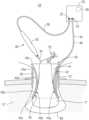
- FIG. 1is a transverse, cross-sectional view illustrating a tissue specimen removal system in accordance with the present disclosure in use removing a tissue specimen from an internal body cavity;
- FIG. 2is a transverse, cross-sectional view illustrating another tissue specimen removal system in accordance with the present disclosure in use removing a tissue specimen from an internal body cavity;
- FIG. 3is a perspective view of a tissue removal device provided in accordance with the present disclosure.
- FIG. 4is a side view of an end effector assembly of the tissue removal device of FIG. 3 ;
- FIG. 5 Ais a transverse, cross-sectional view of the end effector assembly of the tissue removal device of FIG. 3 grasping tissue therebetween with inner jaws thereof disposed in a retracted position;
- FIG. 5 Bis a transverse, cross-sectional view of the end effector assembly of the tissue removal device of FIG. 3 grasping tissue therebetween with inner jaws thereof disposed in a protruded position.
- tissue removal systemsincluding electrode configurations facilitating energy-based removal of a tissue specimen from an internal body cavity while maintaining the tissue specimen in an enclosed environment during break down and removal from the internal body cavity.
- System 10includes an electrosurgical generator 20 , an active electrode device, e.g., a monopolar surgical pencil 30 , and a return electrode device, e.g., a return tissue guard 40 .
- System 10may further include an access port 50 configured for positioning within an opening “O” in tissue providing access to an internal body cavity “C,” a specimen bag 60 configured to receive and retain a tissue specimen “T” therein to enable breakdown and removal of the tissue specimen “T” while the tissue specimen “T” remains isolated from the internal body cavity “C,” and/or a tenaculum 70 to facilitate manipulation and extraction of the tissue specimen “T.”
- Electrosurgical generator 20is configured to enable use in a monopolar mode and, thus, includes an active electrode port 22 and a return electrode port 24 .
- Electrosurgical generator 20may incorporate a Return Electrode Monitoring (REM) module 26 coupled to return electrode port 24 and configured to measure the impedance of the return electrode (which will vary based upon the contact area between tissue and the return electrode) and inhibit the output of energy via active electrode port 22 if the impedance drops below a set point (thus indicating insufficient contact area between tissue and the return electrode).
- REMReturn Electrode Monitoring
- the active electrode deviceis configured as a monopolar surgical pencil 30 , although other suitable active electrode devices are also contemplated.
- Monopolar surgical pencil 30includes a handle 32 , a probe 34 extending distally from handle 32 , and a cable 36 extending proximally from handle 32 .
- Handle 32is configured to enable a user to grasp and manipulate monopolar surgical pencil 30 and may include one or more controls (not shown), e.g., switches, buttons, etc., to enable a user to control the application of energy from active electrode probe 34 to tissue.
- Probe 34is at least partially formed from an electrically-conductive material to supply energy to tissue in contact therewith.
- Cable 36terminates in a plug configured to engage active electrode port 22 of electrosurgical generator 20 to enable the supply of energy from electrosurgical generator 20 to probe 34 , for application from probe 34 to tissue.
- the return electrode deviceis configured as a return tissue guard 40 and functions to both protect tissue, e.g., inhibiting cutting or puncturing of the specimen bag 60 , and serve as a return electrode pathway back to electrosurgical generator 20 .
- Return tissue guard 40includes a body 42 and a cable 46 coupled to body 42 .
- Body 42includes a proximal portion 43 a and a distal portion 43 b .
- Proximal portion 43 aextends from a proximal end 43 c of body 42 to an intermediate waist 43 d of body 42
- distal portion 43 bextends from a distal end 43 e of body to intermediate waist 43 d of body 42 .
- Body 42defines a generally hourglass cross-sectional configuration wherein proximal and distal ends 43 c , 43 e , respectively, of body 42 define relatively larger diameters (similar or different) whereas intermediate waist 43 d defines a relatively narrower diameter. Other suitable configurations are also contemplated. Proximal and distal ends 43 c , 43 e of body 42 may define similar or different diameters and/or proximal and distal portions 43 a , 43 b may define similar or different lengths.
- a passageway 44extends through body 42 from the proximal end 43 c to the distal end 43 e thereof to permit passage of instrumentation, tissue, etc. through return tissue guard 50 .
- Proximal portion 43 a of body 42 of return tissue guard 40is electrically-insulative while at least a portion of the inwardly-facing surface 45 of distal portion 43 b of body 42 of return tissue guard 40 is electrically-conductive.
- Body 42may be formed from a cut and/or puncture-resistant electrically-insulative material and include an electrically-conductive material attached, coated, or otherwise disposed on distal portion 43 b thereof to define the electrically-conductive inwardly-facing surface 45 of distal portion 43 b .
- body 42may be formed from a cut and/or puncture-resistant electrically-conductive material and include an electrically-insulative coating disposed on all but the electrically-conductive inwardly-facing surface 45 of distal portion 43 b .
- Other suitable configurationsare also contemplated.
- inwardly-facing surface 45 of distal portion 43 b of body 42includes first and second electrically-conductive inwardly-facing surface portions 45 a , 45 b electrically isolated from one another.
- first surface portion 45 amay be disposed on a first side portion, e.g., a first half, of body 42 while the second surface portion 45 b is disposed on a second, opposing side portion, e.g., a second half, of body 42 .
- Cable 46is electrically coupled with electrically-conductive inwardly-facing surface 45 of distal portion 43 b of body 42 and extends to a plug configured to engage return electrode port 24 of electrosurgical generator 20 to complete the circuit back to electrosurgical generator 20 from energy supplied to tissue from electrosurgical generator 20 via probe 34 .
- cable 46may include first and second leads (not shown) electrically-isolated from one another and coupled to the respective first and second surface portions 45 a , 45 b.
- tenaculum 70may be utilized to grasp and pull a portion of the tissue specimen “T” at least partially through passageway 44 of return tissue guard 40 such that the portion of the tissue specimen “T” extends through intermediate waist 43 d of body 42 of return tissue guard 40 and into or through proximal portion 43 a of body 42 of return tissue guard 40 .
- tissue specimen “T”is pulled in this manner, a portion of the tissue specimen “T” contacts the electrically-conductive inwardly-facing surface 45 of distal portion 43 b of body 42 .
- Contact between the tissue specimen “T” and electrically-conductive inwardly-facing surface 45is facilitated due to the hourglass cross-sectional configuration of return tissue guard 40 .
- monopolar surgical pencil 30may be maneuvered into position such that probe 34 thereof contacts the tissue specimen “T” and, thereafter, may be activated to deliver energy to the tissue specimen “T” to cut the tissue specimen “T” into smaller pieces to facilitate removal from the internal body cavity “C.”
- the energy supplied to the tissue specimen “T” from probe 34 of monopolar surgical pencil 30is returned to electrosurgical generator 20 via the electrically-conductive inwardly-facing surface 45 of return tissue guard 40 which, as noted above, is disposed in contact with the tissue specimen “T” to complete the electrical circuit.
- cable 46may include a resistor circuit 48 configured to provide the requisite impedance to REM module 26 such that REM module 26 does not inhibit the output of energy via active electrode port 22 .
- REM module 26may measure the impedance therebetween and inhibit the output of energy via active electrode port 22 if the impedance drops below the set point.
- System 110includes an electrosurgical generator 120 , an active electrode device, e.g., a monopolar surgical pencil 130 , and a return electrode device, e.g., a return specimen bag 140 .
- System 110may further include an access port 150 configured for positioning within an opening “O” in tissue providing access to an internal body cavity “C.”
- an access port 150configured for positioning within an opening “O” in tissue providing access to an internal body cavity “C.”
- return specimen bag 140As return specimen bag 140 is provided, a separate specimen bag is not required; rather, return specimen bag 140 is configured to receive and retain a tissue specimen “T” therein to enable breakdown and removal of the tissue specimen “T” while the tissue specimen “T” remains isolated from the remainder of the internal body cavity “C.”
- System 110may further include a tenaculum 170 to facilitate manipulation and extraction of the tissue specimen “T.”
- Electrosurgical generator 120 , monopolar surgical pencil 130 , and tenaculum 170are similar to electrosurgical generator 20 , monopolar surgical pencil 30 , and tenaculum 70 of system 10 (see FIG. 1 ) and, thus, are not described in detail hereinbelow to avoid unnecessary repetition.
- Return specimen bag 140functions to both isolate the tissue specimen “T” from the internal body cavity “C” tissue and serve as a return electrode pathway back to electrosurgical generator 120 .
- Return specimen bag 140includes an open end 142 a and a closed end 142 b and defines an internal area 142 c .
- Return specimen bag 140is formed from an electrically-insulative outer layer 144 and an at least partially electrically-conductive inner layer 146 .
- Electrically-insulative outer layer 144may be formed from, for example, nylon, urethane, ripstop nylon, latex, or other suitable material that provides an electrically-insulative outer layer 144 .
- At least partially electrically-conductive inner layer 146may be formed from, for example, an at least partially-conductive fabric, an at least partially-conductive mesh, etc., and may be joined to electrically-insulative outer layer 144 via an adhesive, mechanical engagement, etc. or may be freely seated within electrically-insulative outer layer 144 .
- electrically-conductive inner layer 146includes first and second electrically-conductive portions 146 a , 146 b electrically isolated from one another, e.g., via an insulated seam 147 .
- the first portion 146 amay be disposed on a first side portion, e.g., a first half, of electrically-conductive inner layer 146 while the second portion 146 b is disposed on a second, opposing side portion, e.g., a second half, of electrically-conductive inner layer 146 .
- first and second halvesmultiple first portions 146 a and second portions 146 b may be provided and arranged in alternating fashion annularly about inner layer 146 , e.g., similarly as the different colored sections of a beach ball.
- Return specimen bag 140further includes a cable 148 electrically coupled with electrically-conductive inner layer 146 and extending to a plug configured to engage return electrode port 124 of electrosurgical generator 120 to complete the circuit back to electrosurgical generator 120 from energy supplied to tissue from electrosurgical generator 120 via probe 134 of monopolar surgical pencil 130 .
- cable 148may include first and second cable potions 148 a , 148 b electrically-isolated from one another and coupled to the respective first and second portions 146 a , 146 b.
- tenaculum 170may be utilized to grasp and pull a portion of the tissue specimen “T” at least partially through the opening “O” in tissue such that a portion of the tissue specimen “T” is disposed in contact with return specimen bag 140 .
- monopolar surgical pencil 130may be maneuvered into position such that probe 134 thereof contacts the tissue specimen “T” and, thereafter, may be activated to deliver energy to the tissue specimen “T” to cut the tissue specimen “T” into smaller pieces to facilitate removal from the internal body cavity “C.”
- the energy supplied to the tissue specimen “T” from probe 134 of monopolar surgical pencil 130is returned to electrosurgical generator 120 via the at least partially electrically-conductive inner layer 146 of return specimen bag 140 which, as noted above, is disposed in contact with the tissue specimen “T” to complete the electrical circuit.
- cable 148may include a resistor circuit 149 configured to provide the requisite impedance to REM module 126 such that REM module 126 does not inhibit the output of energy via active electrode port 122 .
- REM module 126may measure the impedance therebetween and inhibit the output of energy via active electrode port 122 if the impedance drops below the set point.
- Return electrode tenaculum 240may be part of a tissue removal system including, for example, an electrosurgical generator, an active electrode device, e.g., a monopolar surgical pencil, an access port, and/or a specimen bag, similarly as detailed above with respect to system 10 ( FIG. 1 ).
- Return electrode tenaculum 240includes two elongated shaft 242 a , 242 b , each having a proximal end 244 a , 244 b , and a distal end 246 a , 246 b , respectively.
- An end effector assembly 250 including first and second jaw assemblies 252 , 254extends from distal ends 246 a , 246 b of elongated shaft 242 a , 242 b , respectively.
- Each elongated shaft 242 a , 242 bincludes a handle 247 a , 247 b disposed at the proximal end 244 a , 244 b thereof.
- Each handle 247 a , 247 bdefines a finger hole 248 a , 248 b therethrough for receiving a finger of the user.
- finger holes 248 a , 248 bfacilitate movement of elongated shafts 242 a , 242 b relative to one another to, in turn, pivot jaw assemblies 252 , 254 of end effector assembly 250 about pivot 251 and relative to one another between a further spaced-apart position and a more-closely approximated position.
- One of the elongated shaftse.g., elongated shaft 242 a , includes a proximal shaft connector 249 supporting a cable 260 configured to connect return electrode tenaculum 240 to a return electrode port of an electrosurgical generator similar to electrosurgical generator 20 ( FIG. 1 ).
- end effector assembly 250 of return electrode tenaculum 240includes first and second jaw assemblies 252 , 254 attached to respective distal ends 246 a , 246 b of elongated shafts 242 a , 242 b and pivotably coupled to one another about a pivot 251 .
- Each jaw assembly 252 , 254include an inner jaw 253 a , 255 a and an outer jaw 253 b , 255 b , respectively.
- Inner jaws 253 a , 255 aare at least partially formed from an electrically-conductive material, are rigidly coupled to elongated shafts 242 a , 242 b , respectively, and are pivotably coupled to one another about pivot 251 .
- Inner jaws 253 a , 255 aare electrically coupled to cable 260 and may be coupled to the same electrical lead of cable 260 or first and second electrical leads of cable 260 that are electrically-isolated from one another.
- inner jaws 253 a , 355 ainclude tissue-grasping teeth 258 , 259 at the distal ends thereof to facilitate grasping tissue therewith.
- Outer jaws 253 b , 255 bare disposed about distal ends 246 a , 246 b of elongated shafts 242 a , 242 b and inner jaws 253 a , 255 a , respectively, and are formed from a flexible, electrically-insulative material to enable the portions of outer jaws 253 b , 255 b disposed about inner jaws 253 a , 255 a to flex relative to the portions of outer jaws 253 b , 255 b disposed about elongated shafts 242 a , 242 b .
- Outer jaws 253 b , 255 balso define slots (not shown) on the opposed faces thereof to enable inner jaws 253 a , 255 a to extend from outer jaws 253 b , 255 b upon flexion of outer jaws 253 b , 255 b , as detailed below.
- return electrode tenaculum 240is manipulated such that the portion of the tissue specimen “T” to be grasped is disposed between jaw assemblies 252 , 254 . Thereafter, elongated shafts 242 a , 242 b are pivoted towards one another, e.g., using handles 247 a , 247 b , such that jaw assemblies 252 , 254 are pivoted about pivot 251 from the further spaced-apart position towards the more-closely approximated position to grasp the tissue specimen “T” therebetween.
- tissueis grasped between jaw assemblies 252 , 254 , tissue is only grasped between electrically-insulative outer jaws 253 b , 255 b thereof as inner jaws 253 a , 255 a remain disposed within outer jaws 253 b , 255 b .
- inner jaws 253 a , 255 aare not in contact with the tissue specimen “T.”
- outer jaws 253 b , 255 bare urged against the tissue specimen “T” and, as a result, the portions of outer jaws 253 b , 255 b disposed about inner jaws 253 a , 255 a are flexed apart from one another such that inner jaws 253 a , 255 b protrude from outer jaws 253 b , 255 b and directly contact and grasp the tissue specimen “T.”
- a monopolar surgical pencil or other active electrode devicemay be moved into contact with the tissue specimen “T” and activated to deliver energy to the tissue specimen “T” to cut the tissue specimen “T” into smaller pieces to facilitate removal from an internal body cavity.
- the energy supplied to the tissue specimen “T” from the monopolar surgical pencilis returned to the electrosurgical generator via the electrically-conductive inner jaws 253 a , 255 b of return electrode tenaculum 240 which, as noted above, are disposed in contact with and grasping the tissue specimen “T” to complete the electrical circuit.
- cable 260may include a resistor circuit configured to provide the requisite impedance to the REM module such that the REM module does not inhibit the output of energy from the electrosurgical generator.
- the REM modulemay measure the impedance therebetween and inhibit the output of energy if the impedance drops below the set point.
Landscapes
- Health & Medical Sciences (AREA)
- Life Sciences & Earth Sciences (AREA)
- Surgery (AREA)
- Engineering & Computer Science (AREA)
- Animal Behavior & Ethology (AREA)
- Molecular Biology (AREA)
- Veterinary Medicine (AREA)
- Public Health (AREA)
- Biomedical Technology (AREA)
- Heart & Thoracic Surgery (AREA)
- Medical Informatics (AREA)
- General Health & Medical Sciences (AREA)
- Nuclear Medicine, Radiotherapy & Molecular Imaging (AREA)
- Physics & Mathematics (AREA)
- Otolaryngology (AREA)
- Plasma & Fusion (AREA)
- Pathology (AREA)
- Surgical Instruments (AREA)
Abstract
Description
Claims (16)
Priority Applications (3)
| Application Number | Priority Date | Filing Date | Title |
|---|---|---|---|
| US16/143,787US11903636B2 (en) | 2018-09-27 | 2018-09-27 | Energy-based tissue specimen removal |
| EP19199944.0AEP3628258B1 (en) | 2018-09-27 | 2019-09-26 | Energy-based tissue specimen removal |
| CN201910920508.6ACN110946644B (en) | 2018-09-27 | 2019-09-27 | Energy-based tissue sample removal |
Applications Claiming Priority (1)
| Application Number | Priority Date | Filing Date | Title |
|---|---|---|---|
| US16/143,787US11903636B2 (en) | 2018-09-27 | 2018-09-27 | Energy-based tissue specimen removal |
Publications (2)
| Publication Number | Publication Date |
|---|---|
| US20200100835A1 US20200100835A1 (en) | 2020-04-02 |
| US11903636B2true US11903636B2 (en) | 2024-02-20 |
Family
ID=68072180
Family Applications (1)
| Application Number | Title | Priority Date | Filing Date |
|---|---|---|---|
| US16/143,787Active2041-02-16US11903636B2 (en) | 2018-09-27 | 2018-09-27 | Energy-based tissue specimen removal |
Country Status (3)
| Country | Link |
|---|---|
| US (1) | US11903636B2 (en) |
| EP (1) | EP3628258B1 (en) |
| CN (1) | CN110946644B (en) |
Families Citing this family (2)
| Publication number | Priority date | Publication date | Assignee | Title |
|---|---|---|---|---|
| US11298155B2 (en)* | 2019-04-24 | 2022-04-12 | Covidien Lp | Cutting guard with radiofrequency dissection |
| US11147545B1 (en)* | 2020-06-12 | 2021-10-19 | Covidien Lp | Cutting guard with ground connection |
Citations (46)
| Publication number | Priority date | Publication date | Assignee | Title |
|---|---|---|---|---|
| US5312391A (en) | 1992-07-29 | 1994-05-17 | Wilk Peter J | Laparoscopic instrument assembly |
| US5403311A (en) | 1993-03-29 | 1995-04-04 | Boston Scientific Corporation | Electro-coagulation and ablation and other electrotherapeutic treatments of body tissue |
| US5458598A (en) | 1993-12-02 | 1995-10-17 | Cabot Technology Corporation | Cutting and coagulating forceps |
| US5556397A (en) | 1994-10-26 | 1996-09-17 | Laser Centers Of America | Coaxial electrosurgical instrument |
| US5633578A (en) | 1991-06-07 | 1997-05-27 | Hemostatic Surgery Corporation | Electrosurgical generator adaptors |
| US5814044A (en) | 1995-02-10 | 1998-09-29 | Enable Medical Corporation | Apparatus and method for morselating and removing tissue from a patient |
| US5919202A (en) | 1989-12-05 | 1999-07-06 | Yoon; Inbae | Surgical instrument with jaws and movable internal needle and method for use thereof |
| US6086583A (en) | 1997-06-05 | 2000-07-11 | Asahi Kogaku Kogyo Kabushiki Kaisha | Electric cautery for endoscope |
| US6113596A (en) | 1996-12-30 | 2000-09-05 | Enable Medical Corporation | Combination monopolar-bipolar electrosurgical instrument system, instrument and cable |
| WO2001001846A2 (en) | 1999-07-02 | 2001-01-11 | Clavius Devices Inc. | Device and method for removing large tissue masses |
| US20020049442A1 (en) | 1999-07-27 | 2002-04-25 | Roberts Troy W. | Biopsy sampler |
| US6379350B1 (en) | 1999-10-05 | 2002-04-30 | Oratec Interventions, Inc. | Surgical instrument for ablation and aspiration |
| US6387094B1 (en) | 1998-10-30 | 2002-05-14 | Karl Storz Gmbh & Co. Kg | Medical instrument for dissecting tissue |
| US6440138B1 (en) | 1998-04-06 | 2002-08-27 | Kyphon Inc. | Structures and methods for creating cavities in interior body regions |
| US6565560B1 (en) | 1997-07-18 | 2003-05-20 | Gyrus Medical Limited | Electrosurgical instrument |
| US20040242960A1 (en)* | 2003-03-17 | 2004-12-02 | Orban Joseph P. | Endoscopic tissue removal apparatus and method |
| US20050187547A1 (en) | 2004-02-25 | 2005-08-25 | Yoshihiko Sugi | High frequency treatment device having a pair of jaws with electrodes |
| US20050251134A1 (en)* | 2004-05-07 | 2005-11-10 | Arthrocare Corporation | Apparatus and methods for electrosurgical ablation and resection of target tissue |
| US20060095027A1 (en) | 1999-12-27 | 2006-05-04 | Eggers Philip E | Electrosurgical accessing of tissue with controlled collateral thermal phenomena |
| US7232440B2 (en) | 2003-11-17 | 2007-06-19 | Sherwood Services Ag | Bipolar forceps having monopolar extension |
| US7241294B2 (en) | 2003-11-19 | 2007-07-10 | Sherwood Services Ag | Pistol grip electrosurgical pencil with manual aspirator/irrigator and methods of using the same |
| US7303559B2 (en) | 2003-02-19 | 2007-12-04 | Shuyou Peng | Multiplefunction surgical dissector |
| US20080015563A1 (en) | 1995-02-22 | 2008-01-17 | Hoey Michael F | Apparatus and method for creating, maintaining, and controlling a virtual electrode used for the ablation of tissue |
| US7510562B2 (en) | 2003-07-08 | 2009-03-31 | Terumo Corporation | Vein dissector, cauterizing and ligating apparatus for endoscopic harvesting of blood vessels |
| US7537594B2 (en) | 2003-05-01 | 2009-05-26 | Covidien Ag | Suction coagulator with dissecting probe |
| US7588570B2 (en) | 2003-06-09 | 2009-09-15 | Tohru Tani | Medical treatment instrument and medical treatment apparatus including the same |
| US20090254084A1 (en) | 2008-04-08 | 2009-10-08 | Naito Kimihiko | High-frequency treatment apparatus |
| US20100191238A1 (en)* | 2009-01-26 | 2010-07-29 | Niels Kornerup | Bipolar electrosurgical instrument and method of using it |
| US20100318080A1 (en)* | 2002-12-10 | 2010-12-16 | Keppel David S | Circuit for Controlling Arc Energy from an Electrosurgical Generator |
| US7935109B2 (en) | 1996-09-20 | 2011-05-03 | Ioan Cosmescu | Multifunctional telescopic monopolar/bipolar surgical device and method thereof |
| US8267928B2 (en) | 2006-01-24 | 2012-09-18 | Covidien Ag | System and method for closed loop monitoring of monopolar electrosurgical apparatus |
| US8328804B2 (en) | 2008-07-24 | 2012-12-11 | Covidien Lp | Suction coagulator |
| US8454600B2 (en) | 2009-02-18 | 2013-06-04 | Covidien Lp | Two piece tube for suction coagulator |
| US20130178852A1 (en) | 2012-01-06 | 2013-07-11 | Tyco Healthcare Group Lp | Monopolar Pencil With Integrated Bipolar/Ligasure Tweezers |
| US20130267947A1 (en) | 2012-04-10 | 2013-10-10 | Tyco Healthcare Group Lp | Electrosurgical Monopolar Apparatus With Arc Energy Vascular Coagulation Control |
| US8636734B2 (en) | 1999-01-27 | 2014-01-28 | Senorx, Inc. | Tissue specimen isolating and damaging device and method |
| US20140031715A1 (en) | 2012-07-30 | 2014-01-30 | Michael David SHERAR | Coil electrode apparatus for thermal therapy for treating bone tissue |
| US8753341B2 (en) | 2009-06-19 | 2014-06-17 | Covidien Lp | Thermal barrier for suction coagulator |
| CN104955412A (en) | 2012-12-27 | 2015-09-30 | 库克医学技术有限责任公司 | Bipolar sphincterotome |
| WO2016014589A1 (en) | 2014-07-22 | 2016-01-28 | Eximis Surgical, LLC | Large volume tissue reduction and removal system and method |
| US20160058495A1 (en)* | 2014-08-27 | 2016-03-03 | Covidien Lp | Electrosurgically removing tissue with localized return |
| US20160157843A1 (en)* | 2014-12-04 | 2016-06-09 | Gyrus Medical Limited | Tissue bag and method of morcellating tissue |
| US20160175043A1 (en)* | 2014-12-23 | 2016-06-23 | Cook Medical Technologies Llc | Electrosurgical formation of pseudopolyps |
| US20170000553A1 (en)* | 2015-06-30 | 2017-01-05 | Ethicon Endo-Surgery, Llc | Surgical system with user adaptable techniques employing multiple energy modalities based on tissue parameters |
| US20170224321A1 (en)* | 2016-01-22 | 2017-08-10 | Applied Medical Resources Corporation | Systems and methods for tissue removal |
| US20170231611A1 (en)* | 2014-08-19 | 2017-08-17 | Covidien Lp | Specimen retrieval bags and specimen retrieval systems |
Family Cites Families (3)
| Publication number | Priority date | Publication date | Assignee | Title |
|---|---|---|---|---|
| GB2492325B (en)* | 2011-06-23 | 2016-06-22 | Gyrus Medical Ltd | Electrosurgical electrode |
| EP2840996B1 (en)* | 2012-04-26 | 2019-03-20 | Medtronic Ablation Frontiers LLC | System for detecting tissue contact during ablation |
| US9713489B2 (en)* | 2013-03-07 | 2017-07-25 | Arthrocare Corporation | Electrosurgical methods and systems |
- 2018
- 2018-09-27USUS16/143,787patent/US11903636B2/enactiveActive
- 2019
- 2019-09-26EPEP19199944.0Apatent/EP3628258B1/enactiveActive
- 2019-09-27CNCN201910920508.6Apatent/CN110946644B/enactiveActive
Patent Citations (51)
| Publication number | Priority date | Publication date | Assignee | Title |
|---|---|---|---|---|
| US5919202A (en) | 1989-12-05 | 1999-07-06 | Yoon; Inbae | Surgical instrument with jaws and movable internal needle and method for use thereof |
| US5633578A (en) | 1991-06-07 | 1997-05-27 | Hemostatic Surgery Corporation | Electrosurgical generator adaptors |
| US5312391A (en) | 1992-07-29 | 1994-05-17 | Wilk Peter J | Laparoscopic instrument assembly |
| US5403311A (en) | 1993-03-29 | 1995-04-04 | Boston Scientific Corporation | Electro-coagulation and ablation and other electrotherapeutic treatments of body tissue |
| US5458598A (en) | 1993-12-02 | 1995-10-17 | Cabot Technology Corporation | Cutting and coagulating forceps |
| US5556397A (en) | 1994-10-26 | 1996-09-17 | Laser Centers Of America | Coaxial electrosurgical instrument |
| US5814044A (en) | 1995-02-10 | 1998-09-29 | Enable Medical Corporation | Apparatus and method for morselating and removing tissue from a patient |
| US20080015563A1 (en) | 1995-02-22 | 2008-01-17 | Hoey Michael F | Apparatus and method for creating, maintaining, and controlling a virtual electrode used for the ablation of tissue |
| US7935109B2 (en) | 1996-09-20 | 2011-05-03 | Ioan Cosmescu | Multifunctional telescopic monopolar/bipolar surgical device and method thereof |
| US6113596A (en) | 1996-12-30 | 2000-09-05 | Enable Medical Corporation | Combination monopolar-bipolar electrosurgical instrument system, instrument and cable |
| US6086583A (en) | 1997-06-05 | 2000-07-11 | Asahi Kogaku Kogyo Kabushiki Kaisha | Electric cautery for endoscope |
| US6565560B1 (en) | 1997-07-18 | 2003-05-20 | Gyrus Medical Limited | Electrosurgical instrument |
| US6440138B1 (en) | 1998-04-06 | 2002-08-27 | Kyphon Inc. | Structures and methods for creating cavities in interior body regions |
| US6387094B1 (en) | 1998-10-30 | 2002-05-14 | Karl Storz Gmbh & Co. Kg | Medical instrument for dissecting tissue |
| US8636734B2 (en) | 1999-01-27 | 2014-01-28 | Senorx, Inc. | Tissue specimen isolating and damaging device and method |
| WO2001001846A2 (en) | 1999-07-02 | 2001-01-11 | Clavius Devices Inc. | Device and method for removing large tissue masses |
| US20020049442A1 (en) | 1999-07-27 | 2002-04-25 | Roberts Troy W. | Biopsy sampler |
| US6379350B1 (en) | 1999-10-05 | 2002-04-30 | Oratec Interventions, Inc. | Surgical instrument for ablation and aspiration |
| US20060095027A1 (en) | 1999-12-27 | 2006-05-04 | Eggers Philip E | Electrosurgical accessing of tissue with controlled collateral thermal phenomena |
| US7041101B2 (en) | 1999-12-27 | 2006-05-09 | Neothermia Corporation | Electrosurgical accessing of tissue with controlled collateral thermal phenomena |
| US20100318080A1 (en)* | 2002-12-10 | 2010-12-16 | Keppel David S | Circuit for Controlling Arc Energy from an Electrosurgical Generator |
| US7303559B2 (en) | 2003-02-19 | 2007-12-04 | Shuyou Peng | Multiplefunction surgical dissector |
| US20040242960A1 (en)* | 2003-03-17 | 2004-12-02 | Orban Joseph P. | Endoscopic tissue removal apparatus and method |
| US7537594B2 (en) | 2003-05-01 | 2009-05-26 | Covidien Ag | Suction coagulator with dissecting probe |
| US7588570B2 (en) | 2003-06-09 | 2009-09-15 | Tohru Tani | Medical treatment instrument and medical treatment apparatus including the same |
| US7510562B2 (en) | 2003-07-08 | 2009-03-31 | Terumo Corporation | Vein dissector, cauterizing and ligating apparatus for endoscopic harvesting of blood vessels |
| US7232440B2 (en) | 2003-11-17 | 2007-06-19 | Sherwood Services Ag | Bipolar forceps having monopolar extension |
| US7241294B2 (en) | 2003-11-19 | 2007-07-10 | Sherwood Services Ag | Pistol grip electrosurgical pencil with manual aspirator/irrigator and methods of using the same |
| US20050187547A1 (en) | 2004-02-25 | 2005-08-25 | Yoshihiko Sugi | High frequency treatment device having a pair of jaws with electrodes |
| US20050251134A1 (en)* | 2004-05-07 | 2005-11-10 | Arthrocare Corporation | Apparatus and methods for electrosurgical ablation and resection of target tissue |
| US8267928B2 (en) | 2006-01-24 | 2012-09-18 | Covidien Ag | System and method for closed loop monitoring of monopolar electrosurgical apparatus |
| US20090254084A1 (en) | 2008-04-08 | 2009-10-08 | Naito Kimihiko | High-frequency treatment apparatus |
| US8808287B2 (en) | 2008-07-24 | 2014-08-19 | Covidien Lp | Suction coagulator |
| US8328804B2 (en) | 2008-07-24 | 2012-12-11 | Covidien Lp | Suction coagulator |
| US9028490B2 (en)* | 2008-07-24 | 2015-05-12 | Covidien Lp | Suction coagulator |
| US20100191238A1 (en)* | 2009-01-26 | 2010-07-29 | Niels Kornerup | Bipolar electrosurgical instrument and method of using it |
| US8454600B2 (en) | 2009-02-18 | 2013-06-04 | Covidien Lp | Two piece tube for suction coagulator |
| US8753341B2 (en) | 2009-06-19 | 2014-06-17 | Covidien Lp | Thermal barrier for suction coagulator |
| US20130178852A1 (en) | 2012-01-06 | 2013-07-11 | Tyco Healthcare Group Lp | Monopolar Pencil With Integrated Bipolar/Ligasure Tweezers |
| US20130267947A1 (en) | 2012-04-10 | 2013-10-10 | Tyco Healthcare Group Lp | Electrosurgical Monopolar Apparatus With Arc Energy Vascular Coagulation Control |
| US20140031715A1 (en) | 2012-07-30 | 2014-01-30 | Michael David SHERAR | Coil electrode apparatus for thermal therapy for treating bone tissue |
| CN104955412A (en) | 2012-12-27 | 2015-09-30 | 库克医学技术有限责任公司 | Bipolar sphincterotome |
| WO2016014589A1 (en) | 2014-07-22 | 2016-01-28 | Eximis Surgical, LLC | Large volume tissue reduction and removal system and method |
| US20160022352A1 (en) | 2014-07-22 | 2016-01-28 | Eximis Surgical, LLC | Large volume tissue reduction and removal system and method |
| US20170119455A1 (en)* | 2014-07-22 | 2017-05-04 | Eximis Surgical, LLC | Large volume tissue reduction and removal system and method |
| US20170231611A1 (en)* | 2014-08-19 | 2017-08-17 | Covidien Lp | Specimen retrieval bags and specimen retrieval systems |
| US20160058495A1 (en)* | 2014-08-27 | 2016-03-03 | Covidien Lp | Electrosurgically removing tissue with localized return |
| US20160157843A1 (en)* | 2014-12-04 | 2016-06-09 | Gyrus Medical Limited | Tissue bag and method of morcellating tissue |
| US20160175043A1 (en)* | 2014-12-23 | 2016-06-23 | Cook Medical Technologies Llc | Electrosurgical formation of pseudopolyps |
| US20170000553A1 (en)* | 2015-06-30 | 2017-01-05 | Ethicon Endo-Surgery, Llc | Surgical system with user adaptable techniques employing multiple energy modalities based on tissue parameters |
| US20170224321A1 (en)* | 2016-01-22 | 2017-08-10 | Applied Medical Resources Corporation | Systems and methods for tissue removal |
Non-Patent Citations (4)
| Title |
|---|
| European Examination Report issued in corresponding European Application No. 19 199 944.0 dated Feb. 9, 2021, 4 pages. |
| Extended European Search Report issued in European Application No. 19199944.0 dated Feb. 20, 2020, 8 pages. |
| First Chinese Office Action dated Jul. 20, 2022 with English translation, issued in corresponding Chinese Appln. No. 201910920508, 18 pages. |
| Second Chinese Office Action dated Dec. 5, 2022, issued in corresponding Chinese Appln. No. 201910920508, 9 pages. English translation not available. |
Also Published As
| Publication number | Publication date |
|---|---|
| US20200100835A1 (en) | 2020-04-02 |
| EP3628258A1 (en) | 2020-04-01 |
| CN110946644B (en) | 2023-05-30 |
| EP3628258B1 (en) | 2022-04-20 |
| CN110946644A (en) | 2020-04-03 |
Similar Documents
| Publication | Publication Date | Title |
|---|---|---|
| CN107865687B (en) | Reconfigurable instrument | |
| US10179023B2 (en) | Shaped electrode bipolar resection apparatus, system and methods of use | |
| US12220161B2 (en) | Medical devices and related methods | |
| EP1994904B1 (en) | High frequency surgical instrument | |
| EP0536998A2 (en) | Monopolar electrosurgical device with irrigation and suction controls for endoscopic surgery | |
| US11903636B2 (en) | Energy-based tissue specimen removal | |
| EP0885596A1 (en) | Monopolar electrosurgical trocar | |
| US10548656B2 (en) | Multi-functional surgical cautery device, system and method of use | |
| US12329442B2 (en) | Multifunctional electrosurgical instruments with dynamic electrode assemblies | |
| US11864817B2 (en) | Low profile single pole tip for bipolar pencil | |
| EP3494914B1 (en) | Energy-based surgical device and system facilitating tissue removal | |
| JP3342034B2 (en) | High frequency treatment tool | |
| US20230036033A1 (en) | Bipolar energy-based surgical instruments | |
| EP3031420B1 (en) | Energizable attachment for surgical devices | |
| US11596467B2 (en) | Articulating tip for bipolar pencil | |
| US9023041B2 (en) | Electrosurgical instrument including a retractable and selectively activated electrode assembly | |
| EP3628257A1 (en) | Energy-based tissue specimen removal | |
| US20220257304A1 (en) | Continuous rotation cable for surgical instrument | |
| JPWO2022006068A5 (en) |
Legal Events
| Date | Code | Title | Description |
|---|---|---|---|
| AS | Assignment | Owner name:COVIDIEN LP, MASSACHUSETTS Free format text:ASSIGNMENT OF ASSIGNORS INTEREST;ASSIGNORS:DROCHNER, THOMAS E.;ALLEN, JAMES D., IV;KINGSLEY, DYLAN R.;AND OTHERS;SIGNING DATES FROM 20180913 TO 20180925;REEL/FRAME:046992/0449 | |
| FEPP | Fee payment procedure | Free format text:ENTITY STATUS SET TO UNDISCOUNTED (ORIGINAL EVENT CODE: BIG.); ENTITY STATUS OF PATENT OWNER: LARGE ENTITY | |
| STPP | Information on status: patent application and granting procedure in general | Free format text:NON FINAL ACTION MAILED | |
| STPP | Information on status: patent application and granting procedure in general | Free format text:RESPONSE TO NON-FINAL OFFICE ACTION ENTERED AND FORWARDED TO EXAMINER | |
| STPP | Information on status: patent application and granting procedure in general | Free format text:FINAL REJECTION MAILED | |
| STPP | Information on status: patent application and granting procedure in general | Free format text:RESPONSE AFTER FINAL ACTION FORWARDED TO EXAMINER | |
| STPP | Information on status: patent application and granting procedure in general | Free format text:ADVISORY ACTION MAILED | |
| STPP | Information on status: patent application and granting procedure in general | Free format text:DOCKETED NEW CASE - READY FOR EXAMINATION | |
| STPP | Information on status: patent application and granting procedure in general | Free format text:NON FINAL ACTION MAILED | |
| STPP | Information on status: patent application and granting procedure in general | Free format text:RESPONSE TO NON-FINAL OFFICE ACTION ENTERED AND FORWARDED TO EXAMINER | |
| STPP | Information on status: patent application and granting procedure in general | Free format text:RESPONSE TO NON-FINAL OFFICE ACTION ENTERED AND FORWARDED TO EXAMINER | |
| STPP | Information on status: patent application and granting procedure in general | Free format text:NOTICE OF ALLOWANCE MAILED -- APPLICATION RECEIVED IN OFFICE OF PUBLICATIONS | |
| STPP | Information on status: patent application and granting procedure in general | Free format text:PUBLICATIONS -- ISSUE FEE PAYMENT VERIFIED | |
| STCF | Information on status: patent grant | Free format text:PATENTED CASE |