US11900287B2 - Model predictive maintenance system with budgetary constraints - Google Patents
Model predictive maintenance system with budgetary constraintsDownload PDFInfo
- Publication number
- US11900287B2 US11900287B2US16/457,314US201916457314AUS11900287B2US 11900287 B2US11900287 B2US 11900287B2US 201916457314 AUS201916457314 AUS 201916457314AUS 11900287 B2US11900287 B2US 11900287B2
- Authority
- US
- United States
- Prior art keywords
- maintenance
- budget
- building equipment
- equipment
- building
- Prior art date
- Legal status (The legal status is an assumption and is not a legal conclusion. Google has not performed a legal analysis and makes no representation as to the accuracy of the status listed.)
- Active, expires
Links
Images


Classifications
- G—PHYSICS
- G06—COMPUTING OR CALCULATING; COUNTING
- G06Q—INFORMATION AND COMMUNICATION TECHNOLOGY [ICT] SPECIALLY ADAPTED FOR ADMINISTRATIVE, COMMERCIAL, FINANCIAL, MANAGERIAL OR SUPERVISORY PURPOSES; SYSTEMS OR METHODS SPECIALLY ADAPTED FOR ADMINISTRATIVE, COMMERCIAL, FINANCIAL, MANAGERIAL OR SUPERVISORY PURPOSES, NOT OTHERWISE PROVIDED FOR
- G06Q10/00—Administration; Management
- G06Q10/06—Resources, workflows, human or project management; Enterprise or organisation planning; Enterprise or organisation modelling
- G06Q10/063—Operations research, analysis or management
- G06Q10/0631—Resource planning, allocation, distributing or scheduling for enterprises or organisations
- G06Q10/06315—Needs-based resource requirements planning or analysis
- G—PHYSICS
- G06—COMPUTING OR CALCULATING; COUNTING
- G06N—COMPUTING ARRANGEMENTS BASED ON SPECIFIC COMPUTATIONAL MODELS
- G06N5/00—Computing arrangements using knowledge-based models
- G06N5/01—Dynamic search techniques; Heuristics; Dynamic trees; Branch-and-bound
- G—PHYSICS
- G06—COMPUTING OR CALCULATING; COUNTING
- G06N—COMPUTING ARRANGEMENTS BASED ON SPECIFIC COMPUTATIONAL MODELS
- G06N5/00—Computing arrangements using knowledge-based models
- G06N5/02—Knowledge representation; Symbolic representation
- G—PHYSICS
- G06—COMPUTING OR CALCULATING; COUNTING
- G06N—COMPUTING ARRANGEMENTS BASED ON SPECIFIC COMPUTATIONAL MODELS
- G06N7/00—Computing arrangements based on specific mathematical models
- G06N7/01—Probabilistic graphical models, e.g. probabilistic networks
- G—PHYSICS
- G06—COMPUTING OR CALCULATING; COUNTING
- G06Q—INFORMATION AND COMMUNICATION TECHNOLOGY [ICT] SPECIALLY ADAPTED FOR ADMINISTRATIVE, COMMERCIAL, FINANCIAL, MANAGERIAL OR SUPERVISORY PURPOSES; SYSTEMS OR METHODS SPECIALLY ADAPTED FOR ADMINISTRATIVE, COMMERCIAL, FINANCIAL, MANAGERIAL OR SUPERVISORY PURPOSES, NOT OTHERWISE PROVIDED FOR
- G06Q10/00—Administration; Management
- G06Q10/20—Administration of product repair or maintenance
Definitions
- the present disclosurerelates generally to a maintenance system for building equipment and more particularly to a maintenance system that uses a predictive optimization technique to determine an optimal maintenance strategy for the building equipment.
- Building equipmentis typically maintained according to a maintenance strategy for the building equipment.
- One type of maintenance strategyis run-to-fail.
- the run-to-fail strategyallows the building equipment to run until a failure occurs. During this running period, only minor operational maintenance tasks (e.g., oil changes) are performed to maintain the building equipment.
- the preventative maintenance strategytypically involves performing a set of preventative maintenance tasks recommended by the equipment manufactured.
- the preventative maintenance tasksare usually performed at regular intervals (e.g., every month, every year, etc.) which may be a function of the elapsed time of operation and/or the run hours of the building equipment.
- the MPM systemincludes an equipment controller configured to operate the building equipment to affect a variable state or condition in a building, according to some embodiments.
- the MPM systemincludes an operational cost predictor configured to predict a cost of operating the building equipment over a duration of an optimization period, according to some embodiments.
- the MPM systemincludes a budget manager configured to generate one or more budget constraints, according to some embodiments.
- the MPM systemincludes an objective function optimizer configured to optimize an objective function subject to the one or more budget constraints to determine a maintenance and replacement schedule for the building equipment, according to some embodiments.
- the objective functionincludes maintenance and replacement costs of the building equipment and the predicted cost of operating the building equipment, according to some embodiments.
- the budget manageris configured to generate a penalty cost term.
- the objective functionincludes the penalty cost term, according to some embodiments.
- the objective functionincludes a penalty cost.
- the one or more budget constraintsrequire the penalty cost to be at least one of greater than or equal to a product of (1) a first penalty rate associated with spending more than a maintenance and replacement budget and (2) a difference between an amount spent on maintaining and replacing the building equipment and the maintenance and replacement budget or greater than or equal to a product of (1) a second penalty rate associated with spending less than the maintenance and replacement budget and (2) the difference between the amount spent on maintaining and replacing the building equipment and the maintenance and replacement budget, according to some embodiments.
- the MPM systemincludes an objective function generator configured to dynamically update the objective function on a real-time basis based on closed-loop feedback from the building equipment.
- the one or more budget constraintsare generated based on one or more budget time periods and a respective one or more maintenance and replacement budgets associated with the one or more budget time periods.
- the one or more budget constraintsindicate that the maintenance and replacement costs over each of the one or more budget time periods cannot exceed a maintenance and replacement budget associated with each of the one or more budget time periods.
- the budget manageris configured to determine whether one or more of the one or more budget time periods occur partially outside the optimization period.
- the budget manageris configured to, in response to a determination that one or more of the one or more budget time periods occur partially outside the optimization period, determine one or more reduced maintenance and replacement budgets for each of the one or more of the one or more budget time periods that occur partially outside the optimization period, according to some embodiments.
- the MPMincludes one or more processors, according to some embodiments.
- the MPM systemincludes one or more non-transitory computer-readable media storing instructions that, when executed by the one or more processors, cause the one or more processors to perform operations, according to some embodiments.
- the operationsinclude receiving an available budget for an optimization period, according to some embodiments.
- the operationsinclude predicting a cost of operating the building equipment over a duration of the optimization period, according to some embodiments.
- the operationsinclude estimating an amount of degradation of the building equipment over the optimization period based on one or more degradation models of the building equipment, according to some embodiments.
- the operationsinclude allocating a portion of the available budget towards maintenance and replacement of the building equipment based on the predicted cost of operating the building equipment and the amount of degradation of the building equipment, according to some embodiments.
- the operationsinclude operating the building equipment over the duration of the optimization period in accordance with control decisions based on the portion of the available budget allocated towards maintenance and replacement of the building equipment, according to some embodiments.
- the operationsfurther comprise determining a reliability of the building equipment at each time step of the optimization period using equipment performance information received as feedback from the building equipment. Estimating the amount of degradation of the building equipment is further based on the reliability of the building equipment, according to some embodiments.
- the operationsinclude optimizing an objective function based on the allocated portion of the available budget to determine a maintenance and replacement schedule for the building equipment.
- the operationsinclude determining an operating efficiency of the building equipment at each time step of the optimization period. Estimating the amount of degradation of the building equipment is further based on the operating efficiency of the building equipment, according to some embodiments.
- the operationsare performed offline.
- the operationsinclude determining a penalty cost associated with a total expenditure not equaling the allocated portion of the available budget.
- the operationsinclude generating one or more budget constraints that require the penalty cost to be at least one of: greater than or equal to a product of (1) a first penalty rate associated with spending more than the available budget and (2) a difference between an amount spent on maintaining and replacing the building equipment and the available budget or greater than or equal to a product of (1) a second penalty rate associated with spending less than the available budget and (2) the difference between the amount spent on maintaining and replacing the building equipment and the available budget.
- the methodincludes operating the building equipment to affect a variable state or condition in a building, according to some embodiments.
- the methodincludes predicting a cost of operating the building equipment over a duration of an optimization period, according to some embodiments.
- the methodincludes generating one or more budget constraints, according to some embodiments.
- the methodincludes optimizing an objective function subject to the one or more budget constraints to determine a maintenance and replacement schedule for the building equipment.
- the objective functionincludes maintenance and replacement costs of the building equipment and the predicted cost of operating the building equipment, according to some embodiments.
- the methodincludes generating a penalty cost term.
- the objective functionincludes the penalty cost term, according to some embodiments.
- the objective functionincludes a penalty cost and the one or more budget constraints require the penalty cost to be at least one of: greater than or equal to a product of (1) a first penalty rate associated with spending more than the available budget and (2) a difference between an amount spent on maintaining and replacing the building equipment and the available budget or greater than or equal to a product of (1) a second penalty rate associated with spending less than the available budget and (2) the difference between the amount spent on maintaining and replacing the building equipment and the available budget.
- the methodincludes dynamically updating the objective function on a real-time basis based on closed-loop feedback from the building equipment.
- the one or more budget constraintsare generated based on one or more budget time periods and a respective one or more maintenance and replacement budgets associated with the one or more budget time periods.
- the one or more budget constraintsindicate that the maintenance and replacement costs over each of the one or more budget time periods cannot exceed a maintenance and replacement budget associated with each of the one or more budget time periods.
- FIG. 1is a drawing of a building equipped with a HVAC system, according to some embodiments embodiment.
- FIG. 2is a block diagram of a waterside system which can be used to serve the heating or cooling loads of the building of FIG. 1 , according to some embodiments.
- FIG. 3is a block diagram of an airside system which can be used to serve the heating or cooling loads of the building of FIG. 1 , according to some embodiments.
- FIG. 4is a block diagram of a building management system (BMS) which can be used to monitor and control the building of FIG. 1 , according to some embodiments.
- BMSbuilding management system
- FIG. 5is a block diagram of another BMS which can be used to monitor and control the building of FIG. 1 , according to some embodiments.
- FIG. 6is a block diagram of a building system including a model predictive maintenance (MPM) system that monitors equipment performance information from connected equipment installed in the building, according to some embodiments.
- MPMmodel predictive maintenance
- FIG. 7is a schematic diagram of a chiller which may be a type of connected equipment that provides equipment performance information to the MPM system of FIG. 6 , according to some embodiments.
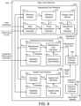
- FIG. 8is a block diagram illustrating the MPM system of FIG. 6 in greater detail, according to some embodiments.
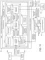
- FIG. 9is a block diagram illustrating a high level optimizer of the MPM system of FIG. 6 in greater detail, according to some embodiments.
- FIG. 10is a flowchart of a process for operating the MPM system of FIG. 6 , according to some embodiments.
- FIG. 11is a graph illustrating optimizing combined costs through increased activity expenditure while constrained by a hard budgetary constraint of a maximum budget, according to some embodiments.
- FIG. 12is a graph illustrating optimizing combined costs through increased activity expenditure while constrained by a soft budgetary constraint of a penalty cost, according to some embodiments.
- FIG. 13is a block diagram illustrating the MPM system of FIG. 8 connected to a user interface, according to some embodiments.
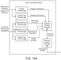
- FIG. 14 Ais a block diagram illustrating the high level optimizer of FIG. 9 with additional constraint managers, according to some embodiments.
- FIG. 14 Bis a block diagram illustrating the high level of optimizer of FIG. 9 including a failure risk predictor is shown, according to some embodiments.
- FIG. 15is a graph illustrating cumulative maintenance expenditures over an optimization period while under a hard budgetary constraint, according to some embodiments.
- FIG. 16is a graph illustrating cumulative maintenance expenditures over an optimization period while under a soft budgetary constraint, according to some embodiments.
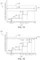
- FIG. 17is a graph illustrating cumulative maintenance costs over an optimization period with multiple budget periods, according to some embodiments.
- FIG. 18is a graph illustrating cumulative maintenance costs over an optimization period with at least one budget period extending partially outside the optimization period, according to some embodiments.
- FIG. 19 Ais a graph illustrating a penalty cost as a function based on a maintenance budget minus an expected maintenance expenditure, according to some embodiments.
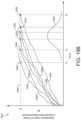
- FIG. 19 Bis a graph illustrating a probability of failure distribution of building equipment based on degradation of the building equipment, according to some embodiments.
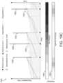
- FIG. 19 Cis a graph illustrating how total costs are affected based on maintenance performed to reduce degradation of building equipment, according to some embodiments.
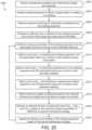
- FIG. 20is a flowchart of a process for operating the MPM system of FIG. 13 subject to one or more hard budgetary constraints, according to some embodiments.
- FIG. 21is a flowchart of a process for operating the MPM system of FIG. 13 subject to a soft budgetary constraint, according to some embodiments.
- FIG. 22is a flowchart of a process for operating the MPM system of FIG. 13 subject to a failure risk of building equipment, according to some embodiments.
- FIGS. 23 A- 23 Bare drawings of a variable refrigerant flow (VRF) system having one or more outdoor VRF units and a plurality of indoor VRF units, according to some embodiments.
- VRFvariable refrigerant flow
- the MPM systemcan be configured to determine an optimal maintenance strategy for building equipment.
- the optimal maintenance strategyis a set of decisions which optimizes the total cost associated with purchasing, maintaining, and operating the building equipment over the duration of an optimization period (e.g., 30 weeks, 52 weeks, 10 years, 30 years, etc.).
- the decisionscan include, for example, equipment purchase decisions, equipment maintenance decisions, and equipment operating decisions.
- the MPM systemcan use a model predictive control technique to formulate an objective function which expresses the total cost as a function of these decisions, which can be included as decision variables in the objective function.
- the MPM systemcan optimize (e.g., minimize) the objective function using any of a variety of optimization techniques to identify the optimal values for each of the decision variables.
- C op,iis the cost per unit of energy (e.g., $/kWh) consumed by the building equipment at time step i of the optimization period
- P op,iis the power consumption (e.g., kW) of the building equipment at time step i
- ⁇ tis the duration of each time step i
- B main,iis a binary variable that indicates whether the maintenance is performed
- C cap,iis the capital cost of purchasing a new device of the building equipment at time step i
- B cap,iis a binary variable that indicates whether the new device is purchased
- his the duration of the horizon or optimization period over which the optimization
- the first term in the objective function Jrepresents the operating cost of the building equipment over the duration of the optimization period.
- the cost per unit of energy C op,iis received from a utility as energy pricing data.
- the cost C op,imay be a time-varying cost that depends on the time of day, the day of the week (e.g., weekday vs. weekend), the current season (e.g., summer vs. winter), or other time-based factors.
- the cost C op,imay be higher during peak energy consumption periods and lower during off-peak or partial-peak energy consumption periods.
- the power consumption P op,iis based on the heating or cooling load of the building.
- the heating or cooling loadcan be predicted by the MPM system as a function of building occupancy, the time of day, the day of the week, the current season, or other factors that can affect the heating or cooling load.
- the MPM systemuses weather forecasts from a weather service to predict the heating or cooling load.
- the power consumption P op,imay also depend on the efficiency ⁇ i of the building equipment. For example, building equipment that operate at a high efficiency may consume less power P op,i to satisfy the same heating or cooling load relative to building equipment that operate at a low efficiency.
- the MPM systemcan model the efficiency ⁇ i of the building equipment at each time step i as a function of the maintenance decisions B main,i and the equipment purchase decisions B cap,i .
- the efficiency ⁇ i for a particular devicemay start at an initial value ⁇ 0 when the device is purchased and may degrade over time such that the efficiency decreases with each successive time step i.
- Performing maintenance on a devicemay reset the efficiency ⁇ i to a higher value immediately after the maintenance is performed.
- purchasing a new device to replace an existing devicemay reset the efficiency ⁇ i to a higher value immediately after the new device is purchased.
- the efficiency ⁇ imay continue to degrade over time until the next time at which maintenance is performed or a new device is purchased.
- Performing maintenance or purchasing a new devicemay result in a relatively lower power consumption P op,i during operation and therefore a lower operating cost at each time step i after the maintenance is performed or the new device is purchased.
- performing maintenance or purchasing a new devicemay decrease the operating cost represented by the first term of the objective function J.
- performing maintenancemay increase the second term of the objective function J and purchasing a new device may increase the third term of the objective function J.
- the objective function Jcaptures each of these costs and can be optimized by the MPM system to determine the optimal set of maintenance and equipment purchase decisions (i.e., optimal values for the binary decision variables B main,i and B cap,i ) over the duration of the optimization period.
- the MPM systemuses equipment performance information received as a feedback from the building equipment to estimate the efficiency and/or the reliability of the building equipment.
- the efficiencymay indicate a relationship between the heating or cooling load on the building equipment and the power consumption of the building equipment.
- the MPM systemcan use the efficiency to calculate the corresponding value of P op,i .
- the reliabilitymay be a statistical measure of the likelihood that the building equipment will continue operating without fault under its current operating conditions. Operating under more strenuous conditions (e.g., high load, high temperatures, etc.) may result in a lower reliability, whereas operating under less strenuous conditions (e.g., low load, moderate temperatures, etc.) may result in a higher reliability.
- the reliabilityis based on an amount of time that has elapsed since the building equipment last received maintenance and/or an amount of time that has elapsed since the building equipment was purchased or installed.
- the MPM systemgenerates and provides equipment purchase and maintenance recommendations.
- the equipment purchase and maintenance recommendations generated by the MPM systemare predictive recommendations based on the actual operating conditions and actual performance of the building equipment.
- the optimization performed by the MPM systemweighs the cost of performing maintenance and the cost of purchasing new equipment against the decrease in operating cost resulting from such maintenance or purchase decisions in order to determine the optimal maintenance strategy that minimizes the total combined cost J.
- the equipment purchase and maintenance recommendations generated by the MPM systemmay be specific to each group of building equipment in order to achieve the optimal cost J for that specific group of building equipment.
- the equipment-specific recommendationsmay result in a lower overall cost J relative to generic preventative maintenance recommendations provided by an equipment manufacturer (e.g., service equipment every year) which may be sub-optimal for some groups of building equipment and/or some operating conditions.
- the MPM systemplaces various budgetary constraints on the optimization of the objective function J. Budgetary constraints can ensure decisions determined during optimization adhere to any economic or other limitations present. Particularly, the MPM system may impose a hard budgetary constraint, a soft budgetary constraint, and/or some combination thereof on the objective function J.
- a hard budgetary constraintcan refer to a constraint that must be adhered to.
- a hard budgetary constraintmay be a maximum allowable budget for maintenance/replacement over an optimization period such that a total cost of all maintenance/replacement cannot exceed the maximum allowable budget.
- a soft budgetary constraintcan be exceeded or otherwise not adhered to, but at an additional penalty.
- a soft budgetary constraintindicates an upper bound of a budget
- a total cost of maintenance/replacementcan exceed the upper bound, but an additional penalty cost will be incurred (e.g., as a percentage of the exceeded amount).
- the soft budgetary constraintcan incentivize optimization to determine decision variables that adhere to the soft budgetary constraint, but allow flexibility if an optimal solution does not adhere to the soft budgetary constraint.
- a penalty costapplies to both exceeding or falling below a budgetary constraint. It may be worthwhile for a total cost of maintenance/replacement over an optimization period to be as close to the budgetary constraint as possible. For example, if maintenance/replacement is allotted a certain amount (e.g., $) in a budget for a building during a fiscal period, any of the allotted amount not spent may move to a different part of the budget, effectively losing the unspent amount from a maintenance/replacement perspective. As such, a penalty cost can be imposed during optimization of the objective function J to determine values of decision variables that result in a total amount spent during the optimization period to be as close to the budgetary constraint as possible. Specifically, as a magnitude of a difference between the budgetary constraint and an estimated total cost increases, a penalty cost added during optimization will also increase.
- the objective function Jincorporates a risk cost associated with failure of building equipment. If a building device of the building equipment fails, costs beyond maintenance/replacement costs of the building device may be incurred. Particularly, failure of building equipment incur costs related both to maintenance/replacement of the building equipment along with various opportunity costs such as unmet loads or missed production.
- the objective function Jcan be augmented to include a risk cost term that accounts for how failure of equipment can affect overall costs during an optimization period.
- the objective function J including the risk cost termis shown in the following equation:
- an amount the risk cost term affects the objective function Jincreases.
- optimization of the objective function Jmay determine that certain building devices should have maintenance performed and/or be replaced at different times than if the risk cost term were not included in the objective function J.
- the risk cost termcan allow the optimization process to identify particular building devices that should have maintenance/replacement performed frequently to keep a probability of failure of the particular building devices low.
- a specific indoor unit (IDU) of a variable refrigerant flow (VRF) systemmay have a large opportunity cost associated with failure if a space of the building is required to temporarily shut down for occupant safety if the specific IDU were to fail. Due to the high opportunity cost, the optimization may prioritize maintenance/replacement of the specific IDU over other building devices that have minimal costs associated with failure.
- the objective function Jincorporates a miscellaneous cost term to account for miscellaneous costs associated with maintenance/replacement.
- a miscellaneous costcan refer to various expenses not accounted for in the operational cost term, maintenance cost term, and/or capital cost term.
- a miscellaneous costimpacts reliability of building equipment but does not impact efficiency of the building equipment.
- a miscellaneous costcan include switching screws of an air vent of an HVAC system with new screws. Accounting for said miscellaneous costs may be useful to accurately determine total costs over an optimization period. Adding the miscellaneous cost term to the objective function J can also be beneficial if the risk cost term is incorporated objective function J.
- the miscellaneous cost termmay provide miscellaneous maintenance activities that can be performed to increase reliability of building equipment, thereby decreasing a probability of failure of said building equipment. Further, if budgetary constraints are placed on the optimization, accounting for miscellaneous costs may be critical to ensure the budgetary constraints are adhered to.
- the objective function Jcan account for the miscellaneous costs as an additional factor.
- the objective function Jmay have the following form:
- the miscellaneous costis accounted for in other terms of the objective function J (e.g., the maintenance cost term, the capital cost term, a risk cost term, etc.).
- the objective function Je.g., the maintenance cost term, the capital cost term, a risk cost term, etc.
- miscellaneous costscan be gathered by user input of the miscellaneous costs, tracking billing statements indicating the miscellaneous costs, estimating some average miscellaneous cost anticipated for a time step of the optimization period, etc.
- FIG. 1shows a building 10 equipped with a HVAC system 100 .
- FIG. 2is a block diagram of a waterside system 200 which can be used to serve building 10 .
- FIG. 3is a block diagram of an airside system 300 which can be used to serve building 10 .
- FIG. 4is a block diagram of a BMS which can be used to monitor and control building 10 .
- FIG. 5is a block diagram of another BMS which can be used to monitor and control building 10 .
- a BMSis, in general, a system of devices configured to control, monitor, and manage equipment in or around a building or building area.
- a BMScan include, for example, a HVAC system, a security system, a lighting system, a fire alerting system, any other system that is capable of managing building functions or devices, or any combination thereof.
- HVAC system 100can include a plurality of HVAC devices (e.g., heaters, chillers, air handling units, pumps, fans, thermal energy storage, etc.) configured to provide heating, cooling, ventilation, or other services for building 10 .
- HVAC system 100is shown to include a waterside system 120 and an airside system 130 .
- Waterside system 120may provide a heated or chilled fluid to an air handling unit of airside system 130 .
- Airside system 130may use the heated or chilled fluid to heat or cool an airflow provided to building 10 .
- An exemplary waterside system and airside system which can be used in HVAC system 100are described in greater detail with reference to FIGS. 2 - 3 .
- HVAC system 100is shown to include a chiller 102 , a boiler 104 , and a rooftop air handling unit (AHU) 106 .
- Waterside system 120may use boiler 104 and chiller 102 to heat or cool a working fluid (e.g., water, glycol, etc.) and may circulate the working fluid to AHU 106 .
- the HVAC devices of waterside system 120can be located in or around building 10 (as shown in FIG. 1 ) or at an offsite location such as a central plant (e.g., a chiller plant, a steam plant, a heat plant, etc.).
- the working fluidcan be heated in boiler 104 or cooled in chiller 102 , depending on whether heating or cooling is required in building 10 .
- Boiler 104may add heat to the circulated fluid, for example, by burning a combustible material (e.g., natural gas) or using an electric heating element.
- Chiller 102may place the circulated fluid in a heat exchange relationship with another fluid (e.g., a refrigerant) in a heat exchanger (e.g., an evaporator) to absorb heat from the circulated fluid.
- the working fluid from chiller 102 and/or boiler 104can be transported to AHU 106 via piping 108 .
- AHU 106may place the working fluid in a heat exchange relationship with an airflow passing through AHU 106 (e.g., via one or more stages of cooling coils and/or heating coils).
- the airflowcan be, for example, outside air, return air from within building 10 , or a combination of both.
- AHU 106may transfer heat between the airflow and the working fluid to provide heating or cooling for the airflow.
- AHU 106can include one or more fans or blowers configured to pass the airflow over or through a heat exchanger containing the working fluid. The working fluid may then return to chiller 102 or boiler 104 via piping 110 .
- Airside system 130may deliver the airflow supplied by AHU 106 (i.e., the supply airflow) to building 10 via air supply ducts 112 and may provide return air from building 10 to AHU 106 via air return ducts 114 .
- airside system 130includes multiple variable air volume (VAV) units 116 .
- VAVvariable air volume
- airside system 130is shown to include a separate VAV unit 116 on each floor or zone of building 10 .
- VAV units 116can include dampers or other flow control elements that can be operated to control an amount of the supply airflow provided to individual zones of building 10 .
- airside system 130delivers the supply airflow into one or more zones of building 10 (e.g., via supply ducts 112 ) without using intermediate VAV units 116 or other flow control elements.
- AHU 106can include various sensors (e.g., temperature sensors, pressure sensors, etc.) configured to measure attributes of the supply airflow.
- AHU 106may receive input from sensors located within AHU 106 and/or within the building zone and may adjust the flow rate, temperature, or other attributes of the supply airflow through AHU 106 to achieve setpoint conditions for the building zone.
- waterside system 200may supplement or replace waterside system 120 in HVAC system 100 or can be implemented separate from HVAC system 100 .
- HVAC system 100waterside system 200 can include a subset of the HVAC devices in HVAC system 100 (e.g., boiler 104 , chiller 102 , pumps, valves, etc.) and may operate to supply a heated or chilled fluid to AHU 106 .
- the HVAC devices of waterside system 200can be located within building 10 (e.g., as components of waterside system 120 ) or at an offsite location such as a central plant.
- waterside system 200is shown as a central plant having a plurality of subplants 202 - 212 .
- Subplants 202 - 212are shown to include a heater subplant 202 , a heat recovery chiller subplant 204 , a chiller subplant 206 , a cooling tower subplant 208 , a hot thermal energy storage (TES) subplant 210 , and a cold thermal energy storage (TES) subplant 212 .
- Subplants 202 - 212consume resources (e.g., water, natural gas, electricity, etc.) from utilities to serve thermal energy loads (e.g., hot water, cold water, heating, cooling, etc.) of a building or campus.
- resourcese.g., water, natural gas, electricity, etc.
- thermal energy loadse.g., hot water, cold water, heating, cooling, etc.
- heater subplant 202can be configured to heat water in a hot water loop 214 that circulates the hot water between heater subplant 202 and building 10 .
- Chiller subplant 206can be configured to chill water in a cold water loop 216 that circulates the cold water between chiller subplant 206 building 10 .
- Heat recovery chiller subplant 204can be configured to transfer heat from cold water loop 216 to hot water loop 214 to provide additional heating for the hot water and additional cooling for the cold water.
- Condenser water loop 218may absorb heat from the cold water in chiller subplant 206 and reject the absorbed heat in cooling tower subplant 208 or transfer the absorbed heat to hot water loop 214 .
- Hot TES subplant 210 and cold TES subplant 212may store hot and cold thermal energy, respectively, for subsequent use.
- Hot water loop 214 and cold water loop 216may deliver the heated and/or chilled water to air handlers located on the rooftop of building 10 (e.g., AHU 106 ) or to individual floors or zones of building 10 (e.g., VAV units 116 ).
- the air handlerspush air past heat exchangers (e.g., heating coils or cooling coils) through which the water flows to provide heating or cooling for the air.
- the heated or cooled aircan be delivered to individual zones of building 10 to serve thermal energy loads of building 10 .
- the waterthen returns to subplants 202 - 212 to receive further heating or cooling.
- subplants 202 - 212are shown and described as heating and cooling water for circulation to a building, it is understood that any other type of working fluid (e.g., glycol, CO2, etc.) can be used in place of or in addition to water to serve thermal energy loads. In other embodiments, subplants 202 - 212 may provide heating and/or cooling directly to the building or campus without requiring an intermediate heat transfer fluid. These and other variations to waterside system 200 are within the teachings of the present disclosure.
- working fluide.g., glycol, CO2, etc.
- Each of subplants 202 - 212can include a variety of equipment configured to facilitate the functions of the subplant.
- heater subplant 202is shown to include a plurality of heating elements 220 (e.g., boilers, electric heaters, etc.) configured to add heat to the hot water in hot water loop 214 .
- Heater subplant 202is also shown to include several pumps 222 and 224 configured to circulate the hot water in hot water loop 214 and to control the flow rate of the hot water through individual heating elements 220 .
- Chiller subplant 206is shown to include a plurality of chillers 232 configured to remove heat from the cold water in cold water loop 216 .
- Chiller subplant 206is also shown to include several pumps 234 and 236 configured to circulate the cold water in cold water loop 216 and to control the flow rate of the cold water through individual chillers 232 .
- Heat recovery chiller subplant 204is shown to include a plurality of heat recovery heat exchangers 226 (e.g., refrigeration circuits) configured to transfer heat from cold water loop 216 to hot water loop 214 .
- Heat recovery chiller subplant 204is also shown to include several pumps 228 and 230 configured to circulate the hot water and/or cold water through heat recovery heat exchangers 226 and to control the flow rate of the water through individual heat recovery heat exchangers 226 .
- Cooling tower subplant 208is shown to include a plurality of cooling towers 238 configured to remove heat from the condenser water in condenser water loop 218 .
- Cooling tower subplant 208is also shown to include several pumps 240 configured to circulate the condenser water in condenser water loop 218 and to control the flow rate of the condenser water through individual cooling towers 238 .
- Hot TES subplant 210is shown to include a hot TES tank 242 configured to store the hot water for later use. Hot TES subplant 210 may also include one or more pumps or valves configured to control the flow rate of the hot water into or out of hot TES tank 242 .
- Cold TES subplant 212is shown to include cold TES tanks 244 configured to store the cold water for later use. Cold TES subplant 212 may also include one or more pumps or valves configured to control the flow rate of the cold water into or out of cold TES tanks 244 .
- one or more of the pumps in waterside system 200(e.g., pumps 222 , 224 , 228 , 230 , 234 , 236 , and/or 240 ) or pipelines in waterside system 200 include an isolation valve associated therewith. Isolation valves can be integrated with the pumps or positioned upstream or downstream of the pumps to control the fluid flows in waterside system 200 .
- waterside system 200can include more, fewer, or different types of devices and/or subplants based on the particular configuration of waterside system 200 and the types of loads served by waterside system 200 .
- airside system 300may supplement or replace airside system 130 in HVAC system 100 or can be implemented separate from HVAC system 100 .
- airside system 300can include a subset of the HVAC devices in HVAC system 100 (e.g., AHU 106 , VAV units 116 , ducts 112 - 114 , fans, dampers, etc.) and can be located in or around building 10 .
- Airside system 300may operate to heat or cool an airflow provided to building 10 using a heated or chilled fluid provided by waterside system 200 .
- airside system 300is shown to include an economizer-type air handling unit (AHU) 302 .
- Economizer-type AHUsvary the amount of outside air and return air used by the air handling unit for heating or cooling.
- AHU 302may receive return air 304 from building zone 306 via return air duct 308 and may deliver supply air 310 to building zone 306 via supply air duct 312 .
- AHU 302is a rooftop unit located on the roof of building 10 (e.g., AHU 106 as shown in FIG. 1 ) or otherwise positioned to receive both return air 304 and outside air 314 .
- AHU 302can be configured to operate exhaust air damper 316 , mixing damper 318 , and outside air damper 320 to control an amount of outside air 314 and return air 304 that combine to form supply air 310 . Any return air 304 that does not pass through mixing damper 318 can be exhausted from AHU 302 through exhaust damper 316 as exhaust air 322 .
- Each of dampers 316 - 320can be operated by an actuator.
- exhaust air damper 316can be operated by actuator 324
- mixing damper 318can be operated by actuator 326
- outside air damper 320can be operated by actuator 328 .
- Actuators 324 - 328may communicate with an AHU controller 330 via a communications link 332 .
- Actuators 324 - 328may receive control signals from AHU controller 330 and may provide feedback signals to AHU controller 330 .
- Feedback signalscan include, for example, an indication of a current actuator or damper position, an amount of torque or force exerted by the actuator, diagnostic information (e.g., results of diagnostic tests performed by actuators 324 - 328 ), status information, commissioning information, configuration settings, calibration data, and/or other types of information or data that can be collected, stored, or used by actuators 324 - 328 .
- diagnostic informatione.g., results of diagnostic tests performed by actuators 324 - 328
- status informatione.g., commissioning information, configuration settings, calibration data, and/or other types of information or data that can be collected, stored, or used by actuators 324 - 328 .
- AHU controller 330can be an economizer controller configured to use one or more control algorithms (e.g., state-based algorithms, extremum seeking control (ESC) algorithms, proportional-integral (PI) control algorithms, proportional-integral-derivative (PID) control algorithms, model predictive control (MPC) algorithms, feedback control algorithms, etc.) to control actuators 324 - 328 .
- control algorithmse.g., state-based algorithms, extremum seeking control (ESC) algorithms, proportional-integral (PI) control algorithms, proportional-integral-derivative (PID) control algorithms, model predictive control (MPC) algorithms, feedback control algorithms, etc.
- AHU 302is shown to include a cooling coil 334 , a heating coil 336 , and a fan 338 positioned within supply air duct 312 .
- Fan 338can be configured to force supply air 310 through cooling coil 334 and/or heating coil 336 and provide supply air 310 to building zone 306 .
- AHU controller 330may communicate with fan 338 via communications link 340 to control a flow rate of supply air 310 .
- AHU controller 330controls an amount of heating or cooling applied to supply air 310 by modulating a speed of fan 338 .
- Cooling coil 334may receive a chilled fluid from waterside system 200 (e.g., from cold water loop 216 ) via piping 342 and may return the chilled fluid to waterside system 200 via piping 344 .
- Valve 346can be positioned along piping 342 or piping 344 to control a flow rate of the chilled fluid through cooling coil 334 .
- cooling coil 334includes multiple stages of cooling coils that can be independently activated and deactivated (e.g., by AHU controller 330 , by BMS controller 366 , etc.) to modulate an amount of cooling applied to supply air 310 .
- Heating coil 336may receive a heated fluid from waterside system 200 (e.g., from hot water loop 214 ) via piping 348 and may return the heated fluid to waterside system 200 via piping 350 .
- Valve 352can be positioned along piping 348 or piping 350 to control a flow rate of the heated fluid through heating coil 336 .
- heating coil 336includes multiple stages of heating coils that can be independently activated and deactivated (e.g., by AHU controller 330 , by BMS controller 366 , etc.) to modulate an amount of heating applied to supply air 310 .
- valves 346 and 352can be controlled by an actuator.
- valve 346can be controlled by actuator 354 and valve 352 can be controlled by actuator 356 .
- Actuators 354 - 356may communicate with AHU controller 330 via communications links 358 - 360 .
- Actuators 354 - 356may receive control signals from AHU controller 330 and may provide feedback signals to controller 330 .
- AHU controller 330receives a measurement of the supply air temperature from a temperature sensor 362 positioned in supply air duct 312 (e.g., downstream of cooling coil 334 and/or heating coil 336 ).
- AHU controller 330may also receive a measurement of the temperature of building zone 306 from a temperature sensor 364 located in building zone 306 .
- AHU controller 330operates valves 346 and 352 via actuators 354 - 356 to modulate an amount of heating or cooling provided to supply air 310 (e.g., to achieve a setpoint temperature for supply air 310 or to maintain the temperature of supply air 310 within a setpoint temperature range).
- the positions of valves 346 and 352affect the amount of heating or cooling provided to supply air 310 by cooling coil 334 or heating coil 336 and may correlate with the amount of energy consumed to achieve a desired supply air temperature.
- AHU 330may control the temperature of supply air 310 and/or building zone 306 by activating or deactivating coils 334 - 336 , adjusting a speed of fan 338 , or a combination of both.
- airside system 300is shown to include a building management system (BMS) controller 366 and a client device 368 .
- BMS controller 366can include one or more computer systems (e.g., servers, supervisory controllers, subsystem controllers, etc.) that serve as system level controllers, application or data servers, head nodes, or master controllers for airside system 300 , waterside system 200 , HVAC system 100 , and/or other controllable systems that serve building 10 .
- computer systemse.g., servers, supervisory controllers, subsystem controllers, etc.
- application or data serverse.g., application or data servers, head nodes, or master controllers for airside system 300 , waterside system 200 , HVAC system 100 , and/or other controllable systems that serve building 10 .
- BMS controller 366may communicate with multiple downstream building systems or subsystems (e.g., HVAC system 100 , a security system, a lighting system, waterside system 200 , etc.) via a communications link 370 according to like or disparate protocols (e.g., LON, BACnet, etc.).
- AHU controller 330 and BMS controller 366can be separate (as shown in FIG. 3 ) or integrated.
- AHU controller 330can be a software module configured for execution by a processor of BMS controller 366 .
- AHU controller 330receives information from BMS controller 366 (e.g., commands, setpoints, operating boundaries, etc.) and provides information to BMS controller 366 (e.g., temperature measurements, valve or actuator positions, operating statuses, diagnostics, etc.). For example, AHU controller 330 may provide BMS controller 366 with temperature measurements from temperature sensors 362 - 364 , equipment on/off states, equipment operating capacities, and/or any other information that can be used by BMS controller 366 to monitor or control a variable state or condition within building zone 306 .
- BMS controller 366e.g., commands, setpoints, operating boundaries, etc.
- BMS controller 366e.g., temperature measurements, valve or actuator positions, operating statuses, diagnostics, etc.
- AHU controller 330may provide BMS controller 366 with temperature measurements from temperature sensors 362 - 364 , equipment on/off states, equipment operating capacities, and/or any other information that can be used by BMS controller 366 to monitor or control a variable
- Client device 368can include one or more human-machine interfaces or client interfaces (e.g., graphical user interfaces, reporting interfaces, text-based computer interfaces, client-facing web services, web servers that provide pages to web clients, etc.) for controlling, viewing, or otherwise interacting with HVAC system 100 , its subsystems, and/or devices.
- Client device 368can be a computer workstation, a client terminal, a remote or local interface, or any other type of user interface device.
- Client device 368can be a stationary terminal or a mobile device.
- client device 368can be a desktop computer, a computer server with a user interface, a laptop computer, a tablet, a smartphone, a PDA, or any other type of mobile or non-mobile device.
- Client device 368may communicate with BMS controller 366 and/or AHU controller 330 via communications link 372 .
- BMS 400can be implemented in building 10 to automatically monitor and control various building functions.
- BMS 400is shown to include BMS controller 366 and a plurality of building subsystems 428 .
- Building subsystems 428are shown to include a building electrical subsystem 434 , an information communication technology (ICT) subsystem 436 , a security subsystem 438 , a HVAC subsystem 440 , a lighting subsystem 442 , a lift/escalators subsystem 432 , and a fire safety subsystem 430 .
- building subsystems 428can include fewer, additional, or alternative subsystems.
- building subsystems 428may also or alternatively include a refrigeration subsystem, an advertising or signage subsystem, a cooking subsystem, a vending subsystem, a printer or copy service subsystem, or any other type of building subsystem that uses controllable equipment and/or sensors to monitor or control building 10 .
- building subsystems 428include waterside system 200 and/or airside system 300 , as described with reference to FIGS. 2 - 3 .
- HVAC subsystem 440can include many of the same components as HVAC system 100 , as described with reference to FIGS. 1 - 3 .
- HVAC subsystem 440can include a chiller, a boiler, any number of air handling units, economizers, field controllers, supervisory controllers, actuators, temperature sensors, and other devices for controlling the temperature, humidity, airflow, or other variable conditions within building 10 .
- Lighting subsystem 442can include any number of light fixtures, ballasts, lighting sensors, dimmers, or other devices configured to controllably adjust the amount of light provided to a building space.
- Security subsystem 438can include occupancy sensors, video surveillance cameras, digital video recorders, video processing servers, intrusion detection devices, access control devices and servers, or other security-related devices.
- BMS controller 366is shown to include a communications interface 407 and a BMS interface 409 .
- Interface 407may facilitate communications between BMS controller 366 and external applications (e.g., monitoring and reporting applications 422 , enterprise control applications 426 , remote systems and applications 444 , applications residing on client devices 448 , etc.) for allowing user control, monitoring, and adjustment to BMS controller 366 and/or subsystems 428 .
- Interface 407may also facilitate communications between BMS controller 366 and client devices 448 .
- BMS interface 409may facilitate communications between BMS controller 366 and building subsystems 428 (e.g., HVAC, lighting security, lifts, power distribution, business, etc.).
- Interfaces 407 , 409can be or include wired or wireless communications interfaces (e.g., jacks, antennas, transmitters, receivers, transceivers, wire terminals, etc.) for conducting data communications with building subsystems 428 or other external systems or devices.
- communications via interfaces 407 , 409can be direct (e.g., local wired or wireless communications) or via a communications network 446 (e.g., a WAN, the Internet, a cellular network, etc.).
- interfaces 407 , 409can include an Ethernet card and port for sending and receiving data via an Ethernet-based communications link or network.
- interfaces 407 , 409can include a Wi-Fi transceiver for communicating via a wireless communications network.
- one or both of interfaces 407 , 409can include cellular or mobile phone communications transceivers.
- communications interface 407is a power line communications interface and BMS interface 409 is an Ethernet interface.
- both communications interface 407 and BMS interface 409are Ethernet interfaces or are the same Ethernet interface.
- BMS controller 366is shown to include a processing circuit 404 including a processor 406 and memory 408 .
- Processing circuit 404can be communicably connected to BMS interface 409 and/or communications interface 407 such that processing circuit 404 and the various components thereof can send and receive data via interfaces 407 , 409 .
- Processor 406can be implemented as a general purpose processor, an application specific integrated circuit (ASIC), one or more field programmable gate arrays (FPGAs), a group of processing components, or other suitable electronic processing components.
- ASICapplication specific integrated circuit
- FPGAsfield programmable gate arrays
- Memory 408(e.g., memory, memory unit, storage device, etc.) can include one or more devices (e.g., RAM, ROM, Flash memory, hard disk storage, etc.) for storing data and/or computer code for completing or facilitating the various processes, layers and modules described in the present application.
- Memory 408can be or include volatile memory or non-volatile memory.
- Memory 408can include database components, object code components, script components, or any other type of information structure for supporting the various activities and information structures described in the present application.
- memory 408is communicably connected to processor 406 via processing circuit 404 and includes computer code for executing (e.g., by processing circuit 404 and/or processor 406 ) one or more processes described herein.
- BMS controller 366is implemented within a single computer (e.g., one server, one housing, etc.). In various other embodiments BMS controller 366 can be distributed across multiple servers or computers (e.g., that can exist in distributed locations). Further, while FIG. 4 shows applications 422 and 426 as existing outside of BMS controller 366 , in some embodiments, applications 422 and 426 can be hosted within BMS controller 366 (e.g., within memory 408 ).
- memory 408is shown to include an enterprise integration layer 410 , an automated measurement and validation (AM&V) layer 412 , a demand response (DR) layer 414 , a fault detection and diagnostics (FDD) layer 416 , an integrated control layer 418 , and a building subsystem integration later 420 .
- Layers 410 - 420can be configured to receive inputs from building subsystems 428 and other data sources, determine optimal control actions for building subsystems 428 based on the inputs, generate control signals based on the optimal control actions, and provide the generated control signals to building subsystems 428 .
- the following paragraphsdescribe some of the general functions performed by each of layers 410 - 420 in BMS 400 .
- Enterprise integration layer 410can be configured to serve clients or local applications with information and services to support a variety of enterprise-level applications.
- enterprise control applications 426can be configured to provide subsystem-spanning control to a graphical user interface (GUI) or to any number of enterprise-level business applications (e.g., accounting systems, user identification systems, etc.).
- GUIgraphical user interface
- Enterprise control applications 426may also or alternatively be configured to provide configuration GUIs for configuring BMS controller 366 .
- enterprise control applications 426can work with layers 410 - 420 to optimize building performance (e.g., efficiency, energy use, comfort, or safety) based on inputs received at interface 407 and/or BMS interface 409 .
- Building subsystem integration layer 420can be configured to manage communications between BMS controller 366 and building subsystems 428 .
- building subsystem integration layer 420may receive sensor data and input signals from building subsystems 428 and provide output data and control signals to building subsystems 428 .
- Building subsystem integration layer 420may also be configured to manage communications between building subsystems 428 .
- Building subsystem integration layer 420translate communications (e.g., sensor data, input signals, output signals, etc.) across a plurality of multi-vendor/multi-protocol systems.
- Demand response layer 414can be configured to optimize resource usage (e.g., electricity use, natural gas use, water use, etc.) and/or the monetary cost of such resource usage in response to satisfy the demand of building 10 .
- the optimizationcan be based on time-of-use prices, curtailment signals, energy availability, or other data received from utility providers, distributed energy generation systems 424 , from energy storage 427 (e.g., hot TES 242 , cold TES 244 , etc.), or from other sources.
- Demand response layer 414may receive inputs from other layers of BMS controller 366 (e.g., building subsystem integration layer 420 , integrated control layer 418 , etc.).
- the inputs received from other layerscan include environmental or sensor inputs such as temperature, carbon dioxide levels, relative humidity levels, air quality sensor outputs, occupancy sensor outputs, room schedules, and the like.
- the inputsmay also include inputs such as electrical use (e.g., expressed in kWh), thermal load measurements, pricing information, projected pricing, smoothed pricing, curtailment signals from utilities, and the like.
- demand response layer 414includes control logic for responding to the data and signals it receives. These responses can include communicating with the control algorithms in integrated control layer 418 , changing control strategies, changing setpoints, or activating/deactivating building equipment or subsystems in a controlled manner. Demand response layer 414 may also include control logic configured to determine when to utilize stored energy. For example, demand response layer 414 may determine to begin using energy from energy storage 427 just prior to the beginning of a peak use hour.
- demand response layer 414includes a control module configured to actively initiate control actions (e.g., automatically changing setpoints) which minimize energy costs based on one or more inputs representative of or based on demand (e.g., price, a curtailment signal, a demand level, etc.).
- demand response layer 414uses equipment models to determine an optimal set of control actions.
- the equipment modelscan include, for example, thermodynamic models describing the inputs, outputs, and/or functions performed by various sets of building equipment.
- Equipment modelsmay represent collections of building equipment (e.g., subplants, chiller arrays, etc.) or individual devices (e.g., individual chillers, heaters, pumps, etc.).
- Demand response layer 414may further include or draw upon one or more demand response policy definitions (e.g., databases, XML files, etc.).
- the policy definitionscan be edited or adjusted by a user (e.g., via a graphical user interface) so that the control actions initiated in response to demand inputs can be tailored for the user's application, desired comfort level, particular building equipment, or based on other concerns.
- the demand response policy definitionscan specify which equipment can be turned on or off in response to particular demand inputs, how long a system or piece of equipment should be turned off, what setpoints can be changed, what the allowable set point adjustment range is, how long to hold a high demand setpoint before returning to a normally scheduled setpoint, how close to approach capacity limits, which equipment modes to utilize, the energy transfer rates (e.g., the maximum rate, an alarm rate, other rate boundary information, etc.) into and out of energy storage devices (e.g., thermal storage tanks, battery banks, etc.), and when to dispatch on-site generation of energy (e.g., via fuel cells, a motor generator set, etc.).
- the energy transfer ratese.g., the maximum rate, an alarm rate, other rate boundary information, etc.
- energy storage devicese.g., thermal storage tanks, battery banks, etc.
- dispatch on-site generation of energye.g., via fuel cells, a motor generator set, etc.
- Integrated control layer 418can be configured to use the data input or output of building subsystem integration layer 420 and/or demand response later 414 to make control decisions. Due to the subsystem integration provided by building subsystem integration layer 420 , integrated control layer 418 can integrate control activities of the subsystems 428 such that the subsystems 428 behave as a single integrated supersystem. In some embodiments, integrated control layer 418 includes control logic that uses inputs and outputs from a plurality of building subsystems to provide greater comfort and energy savings relative to the comfort and energy savings that separate subsystems could provide alone. For example, integrated control layer 418 can be configured to use an input from a first subsystem to make an energy-saving control decision for a second subsystem. Results of these decisions can be communicated back to building subsystem integration layer 420 .
- Integrated control layer 418is shown to be logically below demand response layer 414 .
- Integrated control layer 418can be configured to enhance the effectiveness of demand response layer 414 by enabling building subsystems 428 and their respective control loops to be controlled in coordination with demand response layer 414 .
- This configurationmay advantageously reduce disruptive demand response behavior relative to conventional systems.
- integrated control layer 418can be configured to assure that a demand response-driven upward adjustment to the setpoint for chilled water temperature (or another component that directly or indirectly affects temperature) does not result in an increase in fan energy (or other energy used to cool a space) that would result in greater total building energy use than was saved at the chiller.
- Integrated control layer 418can be configured to provide feedback to demand response layer 414 so that demand response layer 414 checks that constraints (e.g., temperature, lighting levels, etc.) are properly maintained even while demanded load shedding is in progress.
- the constraintsmay also include setpoint or sensed boundaries relating to safety, equipment operating limits and performance, comfort, fire codes, electrical codes, energy codes, and the like.
- Integrated control layer 418is also logically below fault detection and diagnostics layer 416 and automated measurement and validation layer 412 .
- Integrated control layer 418can be configured to provide calculated inputs (e.g., aggregations) to these higher levels based on outputs from more than one building subsystem.
- Automated measurement and validation (AM&V) layer 412can be configured to verify that control strategies commanded by integrated control layer 418 or demand response layer 414 are working properly (e.g., using data aggregated by AM&V layer 412 , integrated control layer 418 , building subsystem integration layer 420 , FDD layer 416 , or otherwise).
- the calculations made by AM&V layer 412can be based on building system energy models and/or equipment models for individual BMS devices or subsystems. For example, AM&V layer 412 may compare a model-predicted output with an actual output from building subsystems 428 to determine an accuracy of the model.
- FDD layer 416can be configured to provide on-going fault detection for building subsystems 428 , building subsystem devices (i.e., building equipment), and control algorithms used by demand response layer 414 and integrated control layer 418 .
- FDD layer 416may receive data inputs from integrated control layer 418 , directly from one or more building subsystems or devices, or from another data source.
- FDD layer 416may automatically diagnose and respond to detected faults. The responses to detected or diagnosed faults can include providing an alert message to a user, a maintenance scheduling system, or a control algorithm configured to attempt to repair the fault or to work-around the fault.
- FDD layer 416can be configured to output a specific identification of the faulty component or cause of the fault (e.g., loose damper linkage) using detailed subsystem inputs available at building subsystem integration layer 420 .
- FDD layer 416is configured to provide “fault” events to integrated control layer 418 which executes control strategies and policies in response to the received fault events.
- FDD layer 416(or a policy executed by an integrated control engine or business rules engine) may shut-down systems or direct control activities around faulty devices or systems to reduce energy waste, extend equipment life, or assure proper control response.
- FDD layer 416can be configured to store or access a variety of different system data stores (or data points for live data). FDD layer 416 may use some content of the data stores to identify faults at the equipment level (e.g., specific chiller, specific AHU, specific terminal unit, etc.) and other content to identify faults at component or subsystem levels.
- building subsystems 428may generate temporal (i.e., time-series) data indicating the performance of BMS 400 and the various components thereof.
- the data generated by building subsystems 428can include measured or calculated values that exhibit statistical characteristics and provide information about how the corresponding system or process (e.g., a temperature control process, a flow control process, etc.) is performing in terms of error from its setpoint. These processes can be examined by FDD layer 416 to expose when the system begins to degrade in performance and alert a user to repair the fault before it becomes more severe.
- BMS 500can be used to monitor and control the devices of HVAC system 100 , waterside system 200 , airside system 300 , building subsystems 428 , as well as other types of BMS devices (e.g., lighting equipment, security equipment, etc.) and/or HVAC equipment.
- BMS devicese.g., lighting equipment, security equipment, etc.
- BMS 500provides a system architecture that facilitates automatic equipment discovery and equipment model distribution.
- Equipment discoverycan occur on multiple levels of BMS 500 across multiple different communications busses (e.g., a system bus 554 , zone buses 556 - 560 and 564 , sensor/actuator bus 566 , etc.) and across multiple different communications protocols.
- equipment discoveryis accomplished using active node tables, which provide status information for devices connected to each communications bus. For example, each communications bus can be monitored for new devices by monitoring the corresponding active node table for new nodes.
- BMS 500can begin interacting with the new device (e.g., sending control signals, using data from the device) without user interaction.
- An equipment modeldefines equipment object attributes, view definitions, schedules, trends, and the associated BACnet value objects (e.g., analog value, binary value, multistate value, etc.) that are used for integration with other systems.
- Some devices in BMS 500store their own equipment models.
- Other devices in BMS 500have equipment models stored externally (e.g., within other devices).
- a zone coordinator 508can store the equipment model for a bypass damper 528 .
- zone coordinator 508automatically creates the equipment model for bypass damper 528 or other devices on zone bus 558 .
- Other zone coordinatorscan also create equipment models for devices connected to their zone busses.
- the equipment model for a devicecan be created automatically based on the types of data points exposed by the device on the zone bus, device type, and/or other device attributes.
- BMS 500is shown to include a system manager 502 ; several zone coordinators 506 , 508 , 510 and 518 ; and several zone controllers 524 , 530 , 532 , 536 , 548 , and 550 .
- System manager 502can monitor data points in BMS 500 and report monitored variables to various monitoring and/or control applications.
- System manager 502can communicate with client devices 504 (e.g., user devices, desktop computers, laptop computers, mobile devices, etc.) via a data communications link 574 (e.g., BACnet IP, Ethernet, wired or wireless communications, etc.).
- System manager 502can provide a user interface to client devices 504 via data communications link 574 .
- the user interfacemay allow users to monitor and/or control BMS 500 via client devices 504 .
- system manager 502is connected with zone coordinators 506 - 510 and 518 via a system bus 554 .
- System manager 502can be configured to communicate with zone coordinators 506 - 510 and 518 via system bus 554 using a master-slave token passing (MSTP) protocol or any other communications protocol.
- System bus 554can also connect system manager 502 with other devices such as a constant volume (CV) rooftop unit (RTU) 512 , an input/output module (IOM) 514 , a thermostat controller 516 (e.g., a TEC5000 series thermostat controller), and a network automation engine (NAE) or third-party controller 520 .
- CVconstant volume
- RTUrooftop unit
- IOMinput/output module
- NAEnetwork automation engine
- RTU 512can be configured to communicate directly with system manager 502 and can be connected directly to system bus 554 .
- Other RTUscan communicate with system manager 502 via an intermediate device.
- a wired input 562can connect a third-party RTU 542 to thermostat controller 516 , which connects to system bus 554 .
- System manager 502can provide a user interface for any device containing an equipment model.
- Devicessuch as zone coordinators 506 - 510 and 518 and thermostat controller 516 can provide their equipment models to system manager 502 via system bus 554 .
- system manager 502automatically creates equipment models for connected devices that do not contain an equipment model (e.g., IOM 514 , third party controller 520 , etc.).
- system manager 502can create an equipment model for any device that responds to a device tree request.
- the equipment models created by system manager 502can be stored within system manager 502 .
- System manager 502can then provide a user interface for devices that do not contain their own equipment models using the equipment models created by system manager 502 .
- system manager 502stores a view definition for each type of equipment connected via system bus 554 and uses the stored view definition to generate a user interface for the equipment.
- Each zone coordinator 506 - 510 and 518can be connected with one or more of zone controllers 524 , 530 - 532 , 536 , and 548 - 550 via zone buses 556 , 558 , 560 , and 564 .
- Zone coordinators 506 - 510 and 518can communicate with zone controllers 524 , 530 - 532 , 536 , and 548 - 550 via zone busses 556 - 560 and 564 using a MSTP protocol or any other communications protocol.
- Zone busses 556 - 560 and 564can also connect zone coordinators 506 - 510 and 518 with other types of devices such as variable air volume (VAV) RTUs 522 and 540 , changeover bypass (COBP) RTUs 526 and 552 , bypass dampers 528 and 546 , and PEAK controllers 534 and 544 .
- VAVvariable air volume
- COBPchangeover bypass
- Zone coordinators 506 - 510 and 518can be configured to monitor and command various zoning systems.
- each zone coordinator 506 - 510 and 518monitors and commands a separate zoning system and is connected to the zoning system via a separate zone bus.
- zone coordinator 506can be connected to VAV RTU 522 and zone controller 524 via zone bus 556 .
- Zone coordinator 508can be connected to COBP RTU 526 , bypass damper 528 , COBP zone controller 530 , and VAV zone controller 532 via zone bus 558 .
- Zone coordinator 510can be connected to PEAK controller 534 and VAV zone controller 536 via zone bus 560 .
- Zone coordinator 518can be connected to PEAK controller 544 , bypass damper 546 , COBP zone controller 548 , and VAV zone controller 550 via zone bus 564 .
- a single model of zone coordinator 506 - 510 and 518can be configured to handle multiple different types of zoning systems (e.g., a VAV zoning system, a COBP zoning system, etc.).
- Each zoning systemcan include a RTU, one or more zone controllers, and/or a bypass damper.
- zone coordinators 506 and 510are shown as Verasys VAV engines (VVEs) connected to VAV RTUs 522 and 540 , respectively.
- Zone coordinator 506is connected directly to VAV RTU 522 via zone bus 556
- zone coordinator 510is connected to a third-party VAV RTU 540 via a wired input 568 provided to PEAK controller 534 .
- Zone coordinators 508 and 518are shown as Verasys COBP engines (VCEs) connected to COBP RTUs 526 and 552 , respectively.
- Zone coordinator 508is connected directly to COBP RTU 526 via zone bus 558
- zone coordinator 518is connected to a third-party COBP RTU 552 via a wired input 570 provided to PEAK controller 544 .
- Zone controllers 524 , 530 - 532 , 536 , and 548 - 550can communicate with individual BMS devices (e.g., sensors, actuators, etc.) via sensor/actuator (SA) busses.
- SAsensor/actuator
- VAV zone controller 536is shown connected to networked sensors 538 via SA bus 566 .
- Zone controller 536can communicate with networked sensors 538 using a MSTP protocol or any other communications protocol.
- SA bus 566only one SA bus 566 is shown in FIG. 5 , it should be understood that each zone controller 524 , 530 - 532 , 536 , and 548 - 550 can be connected to a different SA bus.
- Each SA buscan connect a zone controller with various sensors (e.g., temperature sensors, humidity sensors, pressure sensors, light sensors, occupancy sensors, etc.), actuators (e.g., damper actuators, valve actuators, etc.) and/or other types of controllable equipment (e.g., chillers, heaters, fans, pumps, etc.).
- sensorse.g., temperature sensors, humidity sensors, pressure sensors, light sensors, occupancy sensors, etc.
- actuatorse.g., damper actuators, valve actuators, etc.
- other types of controllable equipmente.g., chillers, heaters, fans, pumps, etc.
- Each zone controller 524 , 530 - 532 , 536 , and 548 - 550can be configured to monitor and control a different building zone.
- Zone controllers 524 , 530 - 532 , 536 , and 548 - 550can use the inputs and outputs provided via their SA busses to monitor and control various building zones.
- a zone controller 536can use a temperature input received from networked sensors 538 via SA bus 566 (e.g., a measured temperature of a building zone) as feedback in a temperature control algorithm.
- Zone controllers 524 , 530 - 532 , 536 , and 548 - 550can use various types of control algorithms (e.g., state-based algorithms, extremum seeking control (ESC) algorithms, proportional-integral (PI) control algorithms, proportional-integral-derivative (PID) control algorithms, model predictive control (MPC) algorithms, feedback control algorithms, etc.) to control a variable state or condition (e.g., temperature, humidity, airflow, lighting, etc.) in or around building 10 .
- control algorithmse.g., state-based algorithms, extremum seeking control (ESC) algorithms, proportional-integral (PI) control algorithms, proportional-integral-derivative (PID) control algorithms, model predictive control (MPC) algorithms, feedback control algorithms, etc.
- a variable state or conditione.g., temperature, humidity, airflow, lighting, etc.
- System 600may include many of the same components as BMS 400 and BMS 500 as described with reference to FIGS. 4 - 5 .
- system 600is shown to include building 10 , network 446 , and client devices 448 .
- Building 10is shown to include connected equipment 610 , which can include any type of equipment used to monitor and/or control building 10 .
- Connected equipment 610can include connected chillers 612 , connected AHUs 614 , connected boilers 616 , connected batteries 618 , or any other type of equipment in a building system (e.g., heaters, economizers, valves, actuators, dampers, cooling towers, fans, pumps, etc.) or building management system (e.g., lighting equipment, security equipment, refrigeration equipment, etc.).
- Connected equipment 610can include any of the equipment of HVAC system 100 , waterside system 200 , airside system 300 , BMS 400 , and/or BMS 500 , as described with reference to FIGS. 1 - 5 .
- Connected equipment 610can be outfitted with sensors to monitor various conditions of the connected equipment 610 (e.g., power consumption, on/off states, operating efficiency, etc.).
- chillers 612can include sensors configured to monitor chiller variables such as chilled water temperature, condensing water temperature, and refrigerant properties (e.g., refrigerant pressure, refrigerant temperature, etc.) at various locations in the refrigeration circuit.
- An example of a chiller 700 which can be used as one of chillers 612is shown in FIG. 7 .
- Chiller 700is shown to include a refrigeration circuit having a condenser 702 , an expansion valve 704 , an evaporator 706 , a compressor 708 , and a control panel 710 .
- chiller 700includes sensors that measure a set of monitored variables at various locations along the refrigeration circuit.
- AHUs 614can be outfitted with sensors to monitor AHU variables such as supply air temperature and humidity, outside air temperature and humidity, return air temperature and humidity, chilled fluid temperature, heated fluid temperature, damper position, etc.
- connected equipment 610can monitor and report variables that characterize the performance of the connected equipment 610 . Each monitored variable can be forwarded to building management system 606 as a data point including a point ID and a point value.
- Monitored variablescan include any measured or calculated values indicating the performance of connected equipment 610 and/or the components thereof.
- monitored variablescan include one or more measured or calculated temperatures (e.g., refrigerant temperatures, cold water supply temperatures, hot water supply temperatures, supply air temperatures, zone temperatures, etc.), pressures (e.g., evaporator pressure, condenser pressure, supply air pressure, etc.), flow rates (e.g., cold water flow rates, hot water flow rates, refrigerant flow rates, supply air flow rates, etc.), valve positions, resource consumptions (e.g., power consumption, water consumption, electricity consumption, etc.), control setpoints, model parameters (e.g., regression model coefficients), or any other time-series values that provide information about how the corresponding system, device, or process is performing.
- temperaturese.g., refrigerant temperatures, cold water supply temperatures, hot water supply temperatures, supply air temperatures, zone temperatures, etc.
- pressurese.g., evaporator pressure, condenser pressure
- Monitored variablescan be received from connected equipment 610 and/or from various components thereof.
- monitored variablescan be received from one or more controllers (e.g., BMS controllers, subsystem controllers, HVAC controllers, subplant controllers, AHU controllers, device controllers, etc.), BMS devices (e.g., chillers, cooling towers, pumps, heating elements, etc.), or collections of BMS devices.
- controllerse.g., BMS controllers, subsystem controllers, HVAC controllers, subplant controllers, AHU controllers, device controllers, etc.
- BMS devicese.g., chillers, cooling towers, pumps, heating elements, etc.
- Connected equipment 610can also report equipment status information.
- Equipment status informationcan include, for example, the operational status of the equipment, an operating mode (e.g., low load, medium load, high load, etc.), an indication of whether the equipment is running under normal or abnormal conditions, the hours during which the equipment is running, a safety fault code, or any other information that indicates the current status of connected equipment 610 .
- each device of connected equipment 610includes a control panel (e.g., control panel 710 shown in FIG. 7 ).
- Control panel 710can be configured to collect monitored variables and equipment status information from connected equipment 610 and provide the collected data to BMS 606 .
- control panel 710can compare the sensor data (or a value derived from the sensor data) to predetermined thresholds. If the sensor data or calculated value crosses a safety threshold, control panel 710 can shut down the device.
- Control panel 710can generate a data point when a safety shut down occurs.
- the data pointcan include a safety fault code which indicates the reason or condition that
- BMS 606can include a building controller (e.g., BMS controller 366 ), a system manager (e.g., system manager 503 ), a network automation engine (e.g., NAE 520 ), or any other system or device of building 10 configured to communicate with connected equipment 610 .
- BMS 606may include some or all of the components of BMS 400 or BMS 500 , as described with reference to FIGS. 4 - 5 .
- the monitored variables and the equipment status informationare provided to BMS 606 as data points. Each data point can include a point ID and a point value.
- the point IDcan identify the type of data point or a variable measured by the data point (e.g., condenser pressure, refrigerant temperature, power consumption, etc.). Monitored variables can be identified by name or by an alphanumeric code (e.g., Chilled_Water_Temp, 7694, etc.).
- the point valuecan include an alphanumeric value indicating the current value of the data point.
- model predictive maintenance system 602can broadcast the monitored variables and the equipment status information to a model predictive maintenance system 602 .
- model predictive maintenance system 602is a component of BMS 606 .
- model predictive maintenance system 602can be implemented as part of a METASYS® brand building automation system, as sold by Johnson Controls Inc.
- model predictive maintenance system 602can be a component of a remote computing system or cloud-based computing system configured to receive and process data from one or more building management systems via network 446 .
- model predictive maintenance system 602can be implemented as part of a PANOPTIX® brand building efficiency platform, as sold by Johnson Controls Inc.
- model predictive maintenance system 602can be a component of a subsystem level controller (e.g., a HVAC controller), a subplant controller, a device controller (e.g., AHU controller 330 , a chiller controller, etc.), a field controller, a computer workstation, a client device, or any other system or device that receives and processes monitored variables from connected equipment 610 .
- a subsystem level controllere.g., a HVAC controller
- a device controllere.g., AHU controller 330 , a chiller controller, etc.
- field controllere.g., a computer workstation, a client device, or any other system or device that receives and processes monitored variables from connected equipment 610 .
- Model predictive maintenance (MPM) system 602may use the monitored variables and/or the equipment status information to identify a current operating state of connected equipment 610 .
- the current operating statecan be examined by MPM system 602 to expose when connected equipment 610 begins to degrade in performance and/or to predict when faults will occur.
- MPM system 602uses the information collected from connected equipment 610 to estimate the reliability of connected equipment 610 . For example, MPM system 602 can estimate a likelihood of various types of failures that could potentially occur based on the current operating conditions of connected equipment 610 and an amount of time that has elapsed since connected equipment 610 has been installed and/or since maintenance was last performed.
- MPM system 602estimates an amount of time until each failure is predicted to occur and identifies a financial cost associated with each failure (e.g., maintenance cost, increased operating cost, replacement cost, etc.). MPM system 602 can use the reliability information and the likelihood of potential failures to predict when maintenance will be needed and to estimate the cost of performing such maintenance over a predetermined time period.
- a financial cost associated with each failuree.g., maintenance cost, increased operating cost, replacement cost, etc.
- MPM system 602can be configured to determine an optimal maintenance strategy for connected equipment 610 .
- the optimal maintenance strategyis a set of decisions which optimizes the total cost associated with purchasing, maintaining, and operating connected equipment 610 over the duration of an optimization period (e.g., 30 weeks, 52 weeks, 10 years, 30 years, etc.).
- the decisionscan include, for example, equipment purchase decisions, equipment maintenance decisions, and equipment operating decisions.
- MPM system 602can use a model predictive control technique to formulate an objective function which expresses the total cost as a function of these decisions, which can be included as decision variables in the objective function.
- MPM system 602can optimize (i.e., minimize) the objective function using any of a variety of optimization techniques to identify the optimal values for each of the decision variables.
- C op,iis the cost per unit of energy (e.g., $/kWh) consumed by connected equipment 610 at time step i of the optimization period
- P op,iis the power consumption (e.g., kW) of connected equipment 610 at time step i
- ⁇ tis the duration of each time step i
- C main,iis the cost of maintenance performed on connected equipment 610 at time step i
- B main,iis a binary variable that indicates whether the maintenance is performed
- C cap,iis the capital cost of purchasing a new device of connected equipment 610 at time step i
- B cap,iis a binary variable that indicates whether the new device is purchased
- his the duration of the
- the first term in the objective function Jrepresents the operating cost of connected equipment 610 over the duration of the optimization period.
- the cost per unit of energy C op,iis received from a utility 608 as energy pricing data.
- the cost C op,imay be a time-varying cost that depends on the time of day, the day of the week (e.g., weekday vs. weekend), the current season (e.g., summer vs. winter), or other time-based factors.
- the cost C op,imay be higher during peak energy consumption periods and lower during off-peak or partial-peak energy consumption periods.
- the power consumption P op,iis based on the heating or cooling load of building 10 .
- the heating or cooling loadcan be predicted by MPM system 602 as a function of building occupancy, the time of day, the day of the week, the current season, or other factors that can affect the heating or cooling load.
- MPM system 602uses weather forecasts from a weather service 604 to predict the heating or cooling load.
- the power consumption P op,imay also depend on the efficiency ⁇ i of connected equipment 610 . For example, connected equipment 610 that operate at a high efficiency may consume less power P op,i to satisfy the same heating or cooling load relative to connected equipment 610 that operate at a low efficiency.
- the power consumption P op,i of a particular device of connected equipment 610can be modeled using the following equations:
- Load ithe heating or cooling load on the device at time step i (e.g., tons cooling, kW heating, etc.)
- P ideal,ithe value of the equipment performance curve (e.g., tons cooling, kW heating, etc.) for the device at the corresponding load point Load i
- ⁇ ithe operating efficiency of the device at time step i (e.g., 0 ⁇ i ⁇ 1).
- the function ⁇ (Load i )may be defined by the equipment performance curve for the device or set of devices represented by the performance curve.
- the equipment performance curveis based on manufacturer specifications for the device under ideal operating conditions.
- the equipment performance curvemay define the relationship between power consumption and heating/cooling load for each device of connected equipment 610 .
- the actual performance of the devicemay vary as a function of the actual operating conditions.
- MPM system 602can analyze the equipment performance information provided by connected equipment 610 to determine the operating efficiency ⁇ i for each device of connected equipment 610 .
- MPM system 602uses the equipment performance information from connected equipment 610 to determine the actual operating efficiency ⁇ i for each device of connected equipment 610 .
- MPM system 602can use the operating efficiency ⁇ i as an input to the objective function J and/or to calculate the corresponding value of P op,i .
- MPM system 602can model the efficiency ⁇ i of connected equipment 610 at each time step i as a function of the maintenance decisions and the equipment purchase decisions B cap,i .
- the efficiency ⁇ i for a particular devicemay start at an initial value ⁇ 0 when the device is purchased and may degrade over time such that the efficiency ⁇ i decreases with each successive time step i.
- Performing maintenance on a devicemay reset the efficiency ⁇ i to a higher value immediately after the maintenance is performed.
- purchasing a new device to replace an existing devicemay reset the efficiency ⁇ i to a higher value immediately after the new device is purchased.
- the efficiency ⁇ imay continue to degrade over time until the next time at which maintenance is performed or a new device is purchased.
- Performing maintenance or purchasing a new devicemay result in a relatively lower power consumption P op,i during operation and therefore a lower operating cost at each time step i after the maintenance is performed or the new device is purchased.
- performing maintenance or purchasing a new devicemay decrease the operating cost represented by the first term of the objective function J.
- performing maintenancemay increase the second term of the objective function J and purchasing a new device may increase the third term of the objective function J.
- the objective function Jcaptures each of these costs and can be optimized by MPM system 602 to determine the optimal set of maintenance and equipment purchase decisions (i.e., optimal values for the binary decision variables B main,i and B cap,i ) over the duration of the optimization period.
- MPM system 602uses the equipment performance information from connected equipment 610 to estimate the reliability of connected equipment 610 .
- the reliabilitymay be a statistical measure of the likelihood that connected equipment 610 will continue operating without fault under its current operating conditions. Operating under more strenuous conditions (e.g., high load, high temperatures, etc.) may result in a lower reliability, whereas operating under less strenuous conditions (e.g., low load, moderate temperatures, etc.) may result in a higher reliability.
- the reliabilityis based on an amount of time that has elapsed since connected equipment 610 last received maintenance.
- MPM system 602may receive operating data from a plurality of devices of connected equipment 610 distributed across multiple buildings and can use the set of operating data (e.g., operating conditions, fault indications, failure times, etc.) to develop a reliability model for each type of equipment.
- the reliability modelscan be used by MPM system 602 to estimate the reliability of any given device of connected equipment 610 as a function of its current operating conditions and/or other extraneous factors (e.g., time since maintenance was last performed, geographic location, water quality, etc.).
- MPM system 602uses the estimated reliability of each device of connected equipment 610 to determine the probability that the device will require maintenance and/or replacement at each time step of the optimization period.
- MPM system 602can use these probabilities to determine the optimal set of maintenance and equipment purchase decisions (i.e., optimal values for the binary decision variables B main,i and B cap,i ) over the duration of the optimization period.
- MPM system 602generates and provides equipment purchase and maintenance recommendations.
- the equipment purchase and maintenance recommendations generated by MPM system 602are predictive recommendations based on the actual operating conditions and actual performance of connected equipment 610 .
- the optimization performed by MPM system 602weighs the cost of performing maintenance and the cost of purchasing new equipment against the decrease in operating cost resulting from such maintenance or purchase decisions in order to determine the optimal maintenance strategy that minimizes the total combined cost J.
- the equipment purchase and maintenance recommendations generated by MPM system 602may be specific to each group of connected equipment 610 in order to achieve the optimal cost J for that specific group of connected equipment 610 .
- the equipment-specific recommendationsmay result in a lower overall cost J relative to generic preventative maintenance recommendations provided by an equipment manufacturer (e.g., service equipment every year) which may be sub-optimal for some groups of connected equipment 610 and/or some operating conditions.
- the equipment purchase and maintenance recommendationsare provided to building 10 (e.g., to BMS 606 ) and/or to client devices 448 .
- An operator or building ownercan use the equipment purchase and maintenance recommendations to assess the costs and benefits of performing maintenance and purchasing new devices.
- the equipment purchase and maintenance recommendationsare provided to service technicians 620 . Service technicians 620 can use the equipment purchase and maintenance recommendations to determine when customers should be contacted to perform service or replace equipment.
- MPM system 602includes a data analytics and visualization platform.
- MPM system 602may provide a web interface which can be accessed by service technicians 620 , client devices 448 , and other systems or devices. The web interface can be used to access the equipment performance information, view the results of the optimization, identify which equipment is in need of maintenance, and otherwise interact with MPM system 602 .
- Service technicians 620can access the web interface to view a list of equipment for which maintenance is recommended by MPM system 602 .
- Service technicians 620can use the equipment purchase and maintenance recommendations to proactively repair or replace connected equipment 610 in order to achieve the optimal cost predicted by the objective function J.
- MPM system 602is shown providing optimization results to a building management system (BMS) 606 .
- BMS 606can include some or all of the features of BMS 400 and/or BMS 500 , as described with reference to FIGS. 4 - 5 .
- the optimization results provided to BMS 606may include the optimal values of the decision variables in the objective function J for each time step i in the optimization period.
- the optimization resultsinclude equipment purchase and maintenance recommendations for each device of connected equipment 610 .
- BMS 606may be configured to monitor the operation and performance of connected equipment 610 .
- BMS 606may receive monitored variables from connected equipment 610 .
- Monitored variablescan include any measured or calculated values indicating the performance of connected equipment 610 and/or the components thereof.
- monitored variablescan include one or more measured or calculated temperatures, pressures, flow rates, valve positions, resource consumptions (e.g., power consumption, water consumption, electricity consumption, etc.), control setpoints, model parameters (e.g., equipment model coefficients), or any other variables that provide information about how the corresponding system, device, or process is performing.
- the monitored variablesindicate the operating efficiency ⁇ i of each device of connected equipment 610 or can be used to calculate the operating efficiency ⁇ i .
- the temperature and flow rate of chilled water output by a chillercan be used to calculate the cooling load (e.g., tons cooling) served by the chiller.
- the cooling loadcan be used in combination with the power consumption of the chiller to calculate the operating efficiency ⁇ i (e.g., tons cooling per kW of electricity consumed).
- BMS 606may report the monitored variables to MPM system 602 for use in calculating the operating efficiency ⁇ i of each device of connected equipment 610 .
- BMS 606monitors the run hours of connected equipment 610 .
- the run hoursmay indicate the number of hours within a given time period during which each device of connected equipment 610 is active.
- the run hours for a chillermay indicate that the chiller is active for approximately eight hours per day.
- the run hourscan be used in combination with the average power consumption of the chiller when active to estimate the total power consumption P op,i of connected equipment 610 at each time step i.
- BMS 606monitors the equipment failures and fault indications reported by connected equipment 610 .
- BMS 606can record the times at which each failure or fault occurs and the operating conditions of connected equipment 610 under which the fault or failure occurred.
- the operating data collected from connected equipment 610can be used by BMS 606 and/or MPM system 602 to develop a reliability model for each device of connected equipment 610 .
- BMS 606may provide the monitored variables, the equipment run hours, the operating conditions, and the equipment failures and fault indications to MPM system 602 as equipment performance information.
- BMS 606may be configured to monitor conditions within a controlled building or building zone.
- BMS 606may receive input from various sensors (e.g., temperature sensors, humidity sensors, airflow sensors, voltage sensors, etc.) distributed throughout the building and may report building conditions to MPM system 602 .
- Building conditionsmay include, for example, a temperature of the building or a zone of the building, a power consumption (e.g., electric load) of the building, a state of one or more actuators configured to affect a controlled state within the building, or other types of information relating to the controlled building.
- BMS 606may operate connected equipment 610 to affect the monitored conditions within the building and to serve the thermal energy loads of the building.
- BMS 606may provide control signals to connected equipment 610 specifying on/off states, charge/discharge rates, and/or setpoints for connected equipment 610 .
- BMS 606may control the equipment (e.g., via actuators, power relays, etc.) in accordance with the control signals to achieve setpoints for various building zones and/or devices of connected equipment 610 .
- BMS 606may be combined with MPM system 602 or may be part of a separate building management system.
- BMS 606is a METASYS® brand building management system, as sold by Johnson Controls, Inc.
- MPM system 602may monitor the performance of connected equipment 610 using information received from BMS 606 .
- MPM system 602may be configured to predict the thermal energy loads (e.g., heating loads, cooling loads, etc.) of the building for plurality of time steps in the optimization period (e.g., using weather forecasts from a weather service 604 ).
- MPM system 602may also predict the cost of electricity or other resources (e.g., water, natural gas, etc.) using pricing data received from utilities 608 .
- MPM system 602may generate optimization results that optimize the economic value of operating, maintaining, and purchasing connected equipment 610 over the duration of the optimization period subject to constraints on the optimization process (e.g., load constraints, decision variable constraints, etc.). The optimization process performed by MPM system 602 is described in greater detail below.
- MPM system 602can be integrated within a single computer (e.g., one server, one housing, etc.). In various other exemplary embodiments, MPM system 602 can be distributed across multiple servers or computers (e.g., that can exist in distributed locations). In another exemplary embodiment, MPM system 602 may integrated with a smart building manager that manages multiple building systems and/or combined with BMS 606 .
- MPM system 602is shown to include a communications interface 804 and a processing circuit 806 .
- Communications interface 804may include wired or wireless interfaces (e.g., jacks, antennas, transmitters, receivers, transceivers, wire terminals, etc.) for conducting data communications with various systems, devices, or networks.
- communications interface 804may include an Ethernet card and port for sending and receiving data via an Ethernet-based communications network and/or a WiFi transceiver for communicating via a wireless communications network.
- Communications interface 804may be configured to communicate via local area networks or wide area networks (e.g., the Internet, a building WAN, etc.) and may use a variety of communications protocols (e.g., BACnet, IP, LON, etc.).
- Communications interface 804may be a network interface configured to facilitate electronic data communications between MPM system 602 and various external systems or devices (e.g., BMS 606 , connected equipment 610 , utilities 510 , etc.).
- MPM system 602may receive information from BMS 606 indicating one or more measured states of the controlled building (e.g., temperature, humidity, electric loads, etc.) and equipment performance information for connected equipment 610 (e.g., run hours, power consumption, operating efficiency, etc.).
- Communications interface 804may receive inputs from BMS 606 and/or connected equipment 610 and may provide optimization results to BMS 606 and/or other external systems or devices. The optimization results may cause BMS 606 to activate, deactivate, or adjust a setpoint for connected equipment 610 in order to achieve the optimal values of the decision variables specified in the optimization results.
- processing circuit 806is shown to include a processor 808 and memory 810 .
- Processor 808may be a general purpose or specific purpose processor, an application specific integrated circuit (ASIC), one or more field programmable gate arrays (FPGAs), a group of processing components, or other suitable processing components.
- ASICapplication specific integrated circuit
- FPGAsfield programmable gate arrays
- Processor 808may be configured to execute computer code or instructions stored in memory 810 or received from other computer readable media (e.g., CDROM, network storage, a remote server, etc.).
- Memory 810may include one or more devices (e.g., memory units, memory devices, storage devices, etc.) for storing data and/or computer code for completing and/or facilitating the various processes described in the present disclosure.
- Memory 810may include random access memory (RAM), read-only memory (ROM), hard drive storage, temporary storage, non-volatile memory, flash memory, optical memory, or any other suitable memory for storing software objects and/or computer instructions.
- Memory 810may include database components, object code components, script components, or any other type of information structure for supporting the various activities and information structures described in the present disclosure.
- Memory 810may be communicably connected to processor 808 via processing circuit 806 and may include computer code for executing (e.g., by processor 808 ) one or more processes described herein.
- MPM system 602is shown to include an equipment performance monitor 824 .
- Equipment performance monitor 824can receive equipment performance information from BMS 606 and/or connected equipment 610 .
- the equipment performance informationcan include samples of monitored variables (e.g., measured temperature, measured pressure, measured flow rate, power consumption, etc.), current operating conditions (e.g., heating or cooling load, current operating state, etc.), fault indications, or other types of information that characterize the performance of connected equipment 610 .
- equipment performance monitor 824uses the equipment performance information to calculate the current efficiency ⁇ i and reliability of each device of connected equipment 610 .
- Equipment performance monitor 824can provide the efficiency ⁇ i and reliability values to model predictive optimizer 830 for use in optimizing the objective function J.
- MPM system 602is shown to include a load/rate predictor 822 .
- Load/rate predictor 822may be configured to predict the energy loads (Load i ) (e.g., heating load, cooling load, electric load, etc.) of the building or campus for each time step i of the optimization period.
- Load/rate predictor 822is shown receiving weather forecasts from a weather service 604 .
- load/rate predictor 822predicts the energy loads Load i as a function of the weather forecasts.
- load/rate predictor 822uses feedback from BMS 606 to predict loads Load i .
- Feedback from BMS 606may include various types of sensory inputs (e.g., temperature, flow, humidity, enthalpy, etc.) or other data relating to the controlled building (e.g., inputs from a HVAC system, a lighting control system, a security system, a water system, etc.).
- sensory inputse.g., temperature, flow, humidity, enthalpy, etc.
- other data relating to the controlled buildinge.g., inputs from a HVAC system, a lighting control system, a security system, a water system, etc.
- load/rate predictor 822receives a measured electric load and/or previous measured load data from BMS 606 (e.g., via equipment performance monitor 824 ).
- Load/rate predictor 822may predict loads Load i as a function of a given weather forecast ( ⁇ circumflex over ( ⁇ ) ⁇ w ), a day type (day), the time of day (t), and previous measured load data (Y i-1 ).
- ⁇ circumflex over ( ⁇ ) ⁇ wa day type
- ttime of day
- Y i-1previous measured load data
- load/rate predictor 822uses a deterministic plus stochastic model trained from historical load data to predict loads Load i .
- Load/rate predictor 822may use any of a variety of prediction methods to predict loads Load i (e.g., linear regression for the deterministic portion and an AR model for the stochastic portion).
- Load/rate predictor 822may predict one or more different types of loads for the building or campus. For example, load/rate predictor 822 may predict a hot water load Load Hot,i , a cold water load Load Cold,i , and an electric load Load Elec,i for each time step i within the optimization period.
- the predicted load values Load ican include some or all of these types of loads.
- load/rate predictor 822makes load/rate predictions using the techniques described in U.S. patent application Ser. No. 14/717,593.
- Load/rate predictor 822is shown receiving utility rates from utilities 608 .
- Utility ratesmay indicate a cost or price per unit of a resource (e.g., electricity, natural gas, water, etc.) provided by utilities 608 at each time step i in the optimization period.
- the utility ratesare time-variable rates.
- the price of electricitymay be higher at certain times of day or days of the week (e.g., during high demand periods) and lower at other times of day or days of the week (e.g., during low demand periods).
- the utility ratesmay define various time periods and a cost per unit of a resource during each time period.
- Utility ratesmay be actual rates received from utilities 608 or predicted utility rates estimated by load/rate predictor 822 .
- the utility ratesinclude demand charges for one or more resources provided by utilities 608 .
- a demand chargemay define a separate cost imposed by utilities 608 based on the maximum usage of a particular resource (e.g., maximum energy consumption) during a demand charge period.
- the utility ratesmay define various demand charge periods and one or more demand charges associated with each demand charge period. In some instances, demand charge periods may overlap partially or completely with each other and/or with the prediction window.
- Model predictive optimizer 830may be configured to account for demand charges in the high level optimization process performed by high level optimizer 832 .
- Utilities 608may be defined by time-variable (e.g., hourly) prices, a maximum service level (e.g., a maximum rate of consumption allowed by the physical infrastructure or by contract) and, in the case of electricity, a demand charge or a charge for the peak rate of consumption within a certain period.
- Load/rate predictor 822may store the predicted loads Load i and the utility rates in memory 810 and/or provide the predicted loads Load i and the utility rates to model predictive optimizer 830 .
- MPM system 602is shown to include a model predictive optimizer 830 .
- Model predictive optimizer 830can be configured to perform a multi-level optimization process to optimize the total cost associated with purchasing, maintaining, and operating connected equipment 610 .
- model predictive optimizer 830includes a high level optimizer 832 and a low level optimizer 834 .
- High level optimizer 832may optimize the objective function J for an entire set of connected equipment 610 (e.g., all of the devices within a building) or for a subset of connected equipment 610 (e.g., a single device, all of the devices of a subplant or building subsystem, etc.) to determine the optimal values for each of the decision variables (e.g., P op,i , B main,i , and B cap,i ) in the objective function J.
- the optimization performed by high level optimizer 832is described in greater detail with reference to FIG. 9 .
- low level optimizer 834receives the optimization results from high level optimizer 832 .
- the optimization resultsmay include optimal power consumption values P op,i and/or load values Load i for each device or set of devices of connected equipment at each time step i in the optimization period.
- Low level optimizer 834may determine how to best run each device or set of devices at the load values determined by high level optimizer 832 .
- low level optimizer 834may determine on/off states and/or operating setpoints for various devices of connected equipment 610 in order to optimize (e.g., minimize) the power consumption of connected equipment 610 meeting the corresponding load value Load i .
- Low level optimizer 834may be configured to generate equipment performance curves for each device or set of devices of connected equipment 610 .
- Each performance curvemay indicate an amount of resource consumption (e.g., electricity use measured in kW, water use measured in L/s, etc.) by a particular device or set of devices of connected equipment 610 as a function of the load on the device or set of devices.
- low level optimizer 834generates the performance curves by performing a low level optimization process at various combinations of load points (e.g., various values of Load i ) and weather conditions to generate multiple data points. The low level optimization may be used to determine the minimum amount of resource consumption required to satisfy the corresponding heating or cooling load.
- Low level optimizer 834may fit a curve to the data points to generate the performance curves.
- low level optimizer 834generates equipment performance curves for a set of connected equipment 610 (e.g., a chiller subplant, a heater subplant, etc.) by combining efficiency curves for individual devices of connected equipment 610 .
- a device efficiency curvemay indicate the amount of resource consumption by the device as a function of load.
- the device efficiency curvesmay be provided by a device manufacturer or generated using experimental data. In some embodiments, the device efficiency curves are based on an initial efficiency curve provided by a device manufacturer and updated using experimental data.
- the device efficiency curvesmay be stored in equipment models 818 . For some devices, the device efficiency curves may indicate that resource consumption is a U-shaped function of load.
- the resultant performance curvemay be a wavy curve.
- the wavesare caused by a single device loading up before it is more efficient to turn on another device to satisfy the subplant load.
- Low level optimizer 834may provide the equipment performance curves to high level optimizer 832 for use in the high level optimization process.
- MPM system 602is shown to include an equipment controller 828 .
- Equipment controller 828can be configured to control connected equipment 610 to affect a variable state or condition in building 10 (e.g., temperature, humidity, etc.).
- equipment controller 828controls connected equipment 610 based on the results of the optimization performed by model predictive optimizer 830 .
- equipment controller 828generates control signals which can be provided to connected equipment 610 via communications interface 804 and/or BMS 606 .
- the control signalsmay be based on the optimal values of the decision variables in the objective function J.
- equipment controller 828may generate control signals which cause connected equipment 610 to achieve the optimal power consumption values P op,i for each time step i in the optimization period.
- Monitoring and reporting applications 826may be configured to generate real time “system health” dashboards that can be viewed and navigated by a user (e.g., a system engineer).
- monitoring and reporting applications 826may include a web-based monitoring application with several graphical user interface (GUI) elements (e.g., widgets, dashboard controls, windows, etc.) for displaying key performance indicators (KPI) or other information to users of a GUI.
- GUIgraphical user interface
- the GUI elementsmay summarize relative energy use and intensity across building management systems in different buildings (real or modeled), different campuses, or the like.
- GUI elements or reportsmay be generated and shown based on available data that allow users to assess performance across one or more energy storage systems from one screen.
- the user interface or report(or underlying data engine) may be configured to aggregate and categorize operating conditions by building, building type, equipment type, and the like.
- the GUI elementsmay include charts or histograms that allow the user to visually analyze the operating parameters and power consumption for the devices of the building system.
- MPM system 602may include one or more GUI servers, web services 812 , or GUI engines 814 to support monitoring and reporting applications 826 .
- applications 826 , web services 812 , and GUI engine 814may be provided as separate components outside of MPM system 602 (e.g., as part of a smart building manager).
- MPM system 602may be configured to maintain detailed historical databases (e.g., relational databases, XML databases, etc.) of relevant data and includes computer code modules that continuously, frequently, or infrequently query, aggregate, transform, search, or otherwise process the data maintained in the detailed databases.
- MPM system 602may be configured to provide the results of any such processing to other databases, tables, XML files, or other data structures for further querying, calculation, or access by, for example, external monitoring and reporting applications.
- MPM system 602is shown to include configuration tools 816 .
- Configuration tools 816can allow a user to define (e.g., via graphical user interfaces, via prompt-driven “wizards,” etc.) how MPM system 602 should react to changing conditions in BMS 606 and/or connected equipment 610 .
- configuration tools 816allow a user to build and store condition-response scenarios that can cross multiple devices of connected equipment 610 , multiple building systems, and multiple enterprise control applications (e.g., work order management system applications, entity resource planning applications, etc.).
- configuration tools 816can provide the user with the ability to combine data (e.g., from subsystems, from event histories) using a variety of conditional logic.
- conditional logiccan range from simple logical operators between conditions (e.g., AND, OR, XOR, etc.) to pseudo-code constructs or complex programming language functions (allowing for more complex interactions, conditional statements, loops, etc.).
- Configuration tools 816can present user interfaces for building such conditional logic.
- the user interfacesmay allow users to define policies and responses graphically.
- the user interfacesmay allow a user to select a pre-stored or pre-constructed policy and adapt it or enable it for use with their system.
- High level optimizer 832can be configured to determine an optimal maintenance strategy for connected equipment 610 .
- the optimal maintenance strategyis a set of decisions which optimizes the total cost associated with purchasing, maintaining, and operating connected equipment 610 over the duration of an optimization period (e.g., 30 weeks, 52 weeks, 10 years, 30 years, etc.).
- the decisionscan include, for example, equipment purchase decisions, equipment maintenance decisions, and equipment operating decisions.
- High level optimizer 832is shown to include an operational cost predictor 910 , a maintenance cost predictor 920 , a capital cost predictor 930 , an objective function generator 935 , and an objective function optimizer 940 .
- Cost predictors 910 , 920 , and 930can use a model predictive control technique to formulate an objective function which expresses the total cost as a function of several decision variables (e.g., maintenance decisions, equipment purchase decisions, etc.) and input parameters (e.g., energy cost, device efficiency, device reliability).
- Operational cost predictor 910can be configured to formulate an operational cost term in the objective function.
- maintenance cost predictor 920can be configured to formulate a maintenance cost term in the objective function and capital cost predictor 930 can be configured to formulate a capital cost term in the objective function.
- Objective function optimizer 940can optimize (i.e., minimize) the objective function using any of a variety of optimization techniques to identify the optimal values for each of the decision variables.
- C op,iis the cost per unit of energy (e.g., $/kWh) consumed by connected equipment 610 at time step i of the optimization period
- P op,iis the power consumption (e.g., kW) of connected equipment 610 at time step i
- ⁇ tis the duration of each time step i
- C main,iis the cost of maintenance performed on connected equipment 610 at time step i
- B main,iis a binary variable that indicates whether the maintenance is performed
- C cap,iis the capital cost of purchasing a new device of connected equipment 610 at time step i
- B cap,iis a binary variable that indicates whether the new device is purchased
- his the duration
- Operational cost predictor 910can be configured to formulate the first term in the objective function J.
- the first term in the objective function Jrepresents the operating cost of connected equipment 610 over the duration of the optimization period and is shown to include three variables or parameters (i.e., C op,i P op,i , and ⁇ t).
- the cost per unit of energy C op,iis determined by energy costs module 915 .
- Energy costs module 915can receive a set of energy prices from utility 608 as energy pricing data.
- the energy pricesare time-varying cost that depend on the time of day, the day of the week (e.g., weekday vs. weekend), the current season (e.g., summer vs. winter), or other time-based factors.
- the cost of electricitymay be higher during peak energy consumption periods and lower during off-peak or partial-peak energy consumption periods.
- Energy costs module 915can use the energy costs to define the value of C op,i for each time step i of the optimization period.
- energy costs module 915stores the energy costs as an array C op including a cost element for each of the h time steps in the optimization period.
- operational cost predictor 910is shown to include an ideal performance calculator 912 .
- Ideal performance calculator 912may receive load predictions Load i from load/rate predictor 822 and may receive performance curves from low level optimizer 834 .
- the performance curvesmay define the ideal power consumption P ideal of a device or set of devices of connected equipment 610 as a function of the heating or cooling load on the device or set of devices.
- the ideal power consumption P ideal,imay represent the power consumption of the one or more devices of connected equipment 610 assuming they operate at perfect efficiency.
- Ideal performance calculator 912can use the performance curve for a device or set of devices of connected equipment 610 to identify the value of P ideal,i that corresponds to the load point Load i for the device or set of devices at each time step of the optimization period.
- ideal performance calculator 912stores the ideal load values as an array P ideal including an element for each of the h time steps in the optimization period.
- operational cost predictor 910is shown to include an efficiency updater 911 and an efficiency degrader 913 .
- Efficiency updater 911can be configured to determine the efficiency ⁇ of connected equipment 610 under actual operating conditions.
- the efficiency ⁇ irepresents the ratio of the ideal power consumption P ideal of connected equipment to the actual power consumption P actual of connected equipment 610 , as shown in the following equation:
- ⁇P ideal P actual
- P idealis the ideal power consumption of connected equipment 610 as defined by the performance curve for connected equipment 610
- P actualis the actual power consumption of connected equipment 610 .
- efficiency updater 911uses the equipment performance information collected from connected equipment 610 to identify the actual power consumption value P actual .
- Efficiency updater 911can use the actual power consumption P actual in combination with the ideal power consumption P ideal to calculate the efficiency ⁇ .
- Efficiency updater 911can be configured to periodically update the efficiency ⁇ to reflect the current operating efficiency of connected equipment 610 .
- efficiency updater 911can calculate the efficiency ⁇ of connected equipment 610 once per day, once per week, once per year, or at any other interval as may be suitable to capture changes in the efficiency ⁇ over time. Each value of the efficiency ⁇ may be based on corresponding values of P ideal and P actual at the time the efficiency ⁇ is calculated.
- efficiency updater 911updates the efficiency ⁇ each time the high level optimization process is performed (i.e., each time the objective function J is optimized).
- the efficiency value calculated by efficiency updater 911may be stored in memory 810 as an initial efficiency value ⁇ 0 , where the subscript 0 denotes the value of the efficiency ⁇ at or before the beginning of the optimization period (e.g., at time step 0 ).
- efficiency updater 911updates the efficiency ⁇ i for one or more time steps during the optimization period to account for increases in the efficiency ⁇ of connected equipment 610 that will result from performing maintenance on connected equipment 610 or purchasing new equipment to replace or supplement one or more devices of connected equipment 610 .
- the time steps i at which the efficiency ⁇ i is updatedmay correspond to the predicted time steps at which the maintenance will be performed or the equipment will replaced.
- the predicted time steps at which maintenance will be performed on connected equipment 610may be defined by the values of the binary decision variables B main,i in the objective function J.
- the predicted time steps at which the equipment will be replacedmay be defined by the values of the binary decision variables B cap,i in the objective function J.
- efficiency updater 911can be configured to reset the value of ⁇ i to ⁇ cap , where ⁇ cap is the efficiency value that is expected to result from purchasing a new device to supplement or replace one or more devices of connected equipment 610 performed at time step i.
- Efficiency updater 911can dynamically reset the efficiency ⁇ i for one or more time steps while the optimization is being performed (e.g., with each iteration of the optimization) based on the values of binary decision variables B main,i and B cap,i .
- Efficiency degrader 913can be configured to predict the efficiency ⁇ i of connected equipment 610 at each time step i of the optimization period.
- the initial efficiency ⁇ 0 at the beginning of the optimization periodmay degrade over time as connected equipment 610 degrade in performance.
- the efficiency of a chillermay degrade over time as a result of the chilled water tubes becoming dirty and reducing the heat transfer coefficient of the chiller.
- the efficiency of a batterymay decrease over time as a result of degradation in the physical or chemical components of the battery.
- Efficiency degrader 913can be configured to account for such degradation by incrementally reducing the efficiency ⁇ i over the duration of the optimization period.
- the initial efficiency value ⁇ 0is updated at the beginning of each optimization period.
- the efficiency ⁇may degrade during the optimization period such that the initial efficiency value ⁇ 0 becomes increasingly inaccurate over the duration of the optimization period.
- the value of ⁇is based on a time series of efficiency values calculated by efficiency updater 911 .
- efficiency degrader 913may record a time series of the initial efficiency values ⁇ 0 calculated by efficiency updater 911 , where each of the initial efficiency values ⁇ 0 represents the empirically-calculated efficiency of connected equipment 610 at a particular time.
- Efficiency degrader 913can examine the time series of initial efficiency values ⁇ 0 to determine the rate at which the efficiency degrades. For example, if the initial efficiency ⁇ 0 at time t 1 is ⁇ 0,1 and the initial efficiency at time t 2 is ⁇ 0,2 , efficiency degrader 913 can calculate the rate of efficiency degradation as follows:
- ⁇ ⁇ ⁇ ⁇ ⁇ t⁇ 0 , 2 - ⁇ 0 , 1 t 2 - t 1
- Efficiency degrader 913can multiply
- efficiency degrader 913stores the efficiency values over the duration of the optimization period in an array ⁇ including an element for each of the h time steps in the optimization period.
- efficiency updater 911 and efficiency degrader 913can model the efficiency ⁇ i of connected equipment 610 at each time step i as a function of the maintenance decisions B main,i and the equipment purchase decisions B cap,i .
- the efficiency ⁇ i for a particular devicemay start at an initial value ⁇ 0 at the beginning of the optimization period and may degrade over time such that the efficiency ⁇ i decreases with each successive time step i.
- Performing maintenance on a devicemay reset the efficiency ⁇ i to a higher value immediately after the maintenance is performed.
- purchasing a new device to replace an existing devicemay reset the efficiency ⁇ i to a higher value immediately after the new device is purchased.
- the efficiency ⁇ imay continue to degrade over time until the next time at which maintenance is performed or a new device is purchased.
- operational cost predictor 910is shown to include a power consumption estimator 914 and an operational cost calculator 916 .
- Power consumption estimator 914can be configured to estimate the power consumption P op,i of connected equipment 610 at each time step i of the optimization period.
- power consumption estimator 914estimates the power consumption P op,i as a function of the ideal power consumption P ideal,i calculated by ideal performance calculator 912 and the efficiency ⁇ i determined by efficiency degrader 913 and/or efficiency updater 911 .
- power consumption estimator 914can calculate the power consumption P op,i using the following equation:
- P ideal,iP ideal , i ⁇ i
- P ideal,ithe power consumption calculated by ideal performance calculator 912 based on the equipment performance curve for the device at the corresponding load point Load i
- ⁇ ithe operating efficiency of the device at time step i.
- power consumption estimator 914stores the power consumption values as an array P op including an element for each of the h time steps in the optimization period.
- Cost opis the operational cost term of the objective function J.
- Maintenance cost predictor 920can be configured to formulate the second term in the objective function J.
- the second term in the objective function Jrepresents the cost of performing maintenance on connected equipment 610 over the duration of the optimization period and is shown to include two variables or parameters (i.e., C main,i and B main,i ).
- Maintenance cost predictor 920is shown to include a maintenance estimator 922 , a reliability estimator 924 , a maintenance cost calculator 926 , and a maintenance costs module 928 .
- Reliability estimator 924can be configured to estimate the reliability of connected equipment 610 based on the equipment performance information received from connected equipment 610 .
- the reliabilitymay be a statistical measure of the likelihood that connected equipment 610 will continue operating without fault under its current operating conditions. Operating under more strenuous conditions (e.g., high load, high temperatures, etc.) may result in a lower reliability, whereas operating under less strenuous conditions (e.g., low load, moderate temperatures, etc.) may result in a higher reliability.
- the reliabilityis based on an amount of time that has elapsed since connected equipment 610 last received maintenance and/or an amount of time that has elapsed since connected equipment 610 was purchased or installed.
- reliability estimator 924uses the equipment performance information to identify a current operating state of connected equipment 610 .
- the current operating statecan be examined by reliability estimator 924 to expose when connected equipment 610 begins to degrade in performance and/or to predict when faults will occur.
- reliability estimator 924estimates a likelihood of various types of failures that could potentially occur in connected equipment 610 . The likelihood of each failure may be based on the current operating conditions of connected equipment 610 , an amount of time that has elapsed since connected equipment 610 has been installed, and/or an amount of time that has elapsed since maintenance was last performed.
- reliability estimator 924identifies operating states and predicts the likelihood of various failures using the systems and methods described in U.S.
- reliability estimator 924receives operating data from a plurality of devices of connected equipment 610 distributed across multiple buildings.
- the operating datacan include, for example, current operating conditions, fault indications, failure times, or other data that characterize the operation and performance of connected equipment 610 .
- Reliability estimator 924can use the set of operating data to develop a reliability model for each type of equipment.
- the reliability modelscan be used by reliability estimator 924 to estimate the reliability of any given device of connected equipment 610 as a function of its current operating conditions and/or other extraneous factors (e.g., time since maintenance was last performed, time since installation or purchase, geographic location, water quality, etc.).
- Reliability i⁇ (OpCond i , ⁇ t main,i , ⁇ t cap,i )
- Reliability iis the reliability of connected equipment 610 at time step i
- OpCond iare the operating conditions at time step i
- ⁇ t main,iis the amount of time that has elapsed between the time at which maintenance was last performed and time step i
- ⁇ t cap,iis the amount of time that has elapsed between the time at which connected equipment 610 was purchased or installed and time step i.
- Reliability estimator 924can be configured to identify the current operating conditions OpCond i based on the equipment performance information received as a feedback from connected equipment 610 . Operating under more strenuous conditions (e.g., high load, extreme temperatures, etc.) may result in a lower reliability, whereas operating under less strenuous conditions (e.g., low load, moderate temperatures, etc.) may result in a higher reliability.
- more strenuous conditionse.g., high load, extreme temperatures, etc.
- less strenuous conditionse.g., low load, moderate temperatures, etc.
- reliability estimator 924can be configured to reset the value of Reliability to Reliability cap , where Reliability cap is the reliability value that is expected to result from purchasing a new device to supplement or replace one or more devices of connected equipment 610 performed at time step i.
- Reliability estimator 924can dynamically reset the reliability for one or more time steps while the optimization is being performed (e.g., with each iteration of the optimization) based on the values of binary decision variables B main,i and B cap,i .
- a reciprocal relationshipexists between the reliability of connected equipment 610 and the values of the binary decision variables B main,i and B cap,i .
- the reliability of connected equipment 610can affect the values of the binary decision variables B main,i and B cap,i selected in the optimization, and the values of the binary decision variables B main,i and B cap,i can affect the reliability of connected equipment 610 .
- the optimization performed by objective function optimizer 940can identify the optimal values of the binary decision variables B main,i and B cap,i while accounting for the reciprocal relationship between the binary decision variables B main,i and B cap,i and the reliability of connected equipment 610 .
- maintenance estimator 922generates a matrix B main of the binary maintenance decision variables.
- the matrix B mainmay include a binary decision variable for each of the different maintenance activities that can be performed at each time step of the optimization period.
- maintenance estimator 922can generate the following matrix:
- B main[ B main , 1 , 1 B main , 1 , 2 ... B main , 1 , h B main , 2 , 1 B main , 2 , 2 ... B main , 2 , h ⁇ ⁇ ⁇ ⁇ B main , m , 1 B main , m , 2 ... B main , m , h ]
- the matrix B mainhas a size of m ⁇ h and each element of the matrix B main includes a binary decision variable for a particular maintenance activity at a particular time step of the optimization period.
- the value of the binary decision variable B main,j,iindicates whether the jth maintenance activity will be performed during the ith time step of the optimization period.
- maintenance cost predictor 920is shown to include a maintenance costs module 928 and a maintenance costs calculator 926 .
- Maintenance costs module 928can be configured to determine costs C main,i associated with performing various types of maintenance on connected equipment 610 .
- Maintenance costs module 928can receive a set of maintenance costs from an external system or device (e.g., a database, a user device, etc.).
- the maintenance costsdefine the economic cost (e.g., $) of performing various types of maintenance.
- Each type of maintenance activitymay have a different economic cost associated therewith. For example, the maintenance activity of changing the oil in a chiller compressor may incur a relatively small economic cost, whereas the maintenance activity of completely disassembling the chiller and cleaning all of the chilled water tubes may incur a significantly larger economic cost.
- Maintenance costs module 928can use the maintenance costs to define the values of C main,i in objective function J.
- maintenance costs module 928stores the maintenance costs as an array C main including a cost element for each of the maintenance activities that can be performed.
- Some maintenance activitiesmay be more expensive than other.
- different types of maintenance activitiesmay result in different levels of improvement to the efficiency ⁇ and/or the reliability of connected equipment 610 .
- merely changing the oil in a chillermay result in a minor improvement in efficiency ⁇ and/or a minor improvement in reliability
- completely disassembling the chiller and cleaning all of the chilled water tubesmay result in a significantly greater improvement to the efficiency ⁇ and/or the reliability of connected equipment 610 .
- multiple different levels of post-maintenance efficiency (i.e., ⁇ main ) and post-maintenance reliability (i.e., Reliability main )may exist. Each level of ⁇ main and Reliability main may correspond to a different type of maintenance activity.
- maintenance estimator 922stores each of the different levels of ⁇ main and Reliability main in a corresponding array.
- the parameter ⁇ maincan be defined as an array ⁇ main with an element for each of the m different types of maintenance activities.
- Reliability main,mwhere the array ⁇ main has a size of 1 ⁇ m and each element of the array ⁇ main includes a post-maintenance efficiency value ⁇ main,j for a particular maintenance activity. Similarly, the array Reliability main has a size of 1 ⁇ m and each element of the array Reliability main includes a post-maintenance reliability value Reliability main,j for a particular maintenance activity.
- Cost mainis the maintenance cost term of the objective function J.
- maintenance cost calculator 926estimates the maintenance cost Cost main by multiplying the maintenance cost array C main by the matrix of binary decision variables B main as shown in the following equations:
- Capital Cost Predictor[ C main , 1 ⁇ C main , 2 ⁇ ⁇ C main , m ] ⁇ ⁇ [ B main , 1 , 1 B main , 1 , 2 ... B main , 1 , h B main , 2 , 1 B main , 2 ... B main , m , h ]
- Capital Cost Predictor[ C main , 1 ⁇ C main , 2 ⁇ ⁇
- Capital cost predictor 930can be configured to formulate the third term in the objective function J.
- the third term in the objective function Jrepresents the cost of purchasing new devices of connected equipment 610 over the duration of the optimization period and is shown to include two variables or parameters (i.e., C cap,i and B cap,i ).
- Capital cost predictor 930is shown to include a purchase estimator 932 , a reliability estimator 934 , a capital cost calculator 936 , and a capital costs module 938 .
- Reliability estimator 934can include some or all of the features of reliability estimator 924 , as described with reference to maintenance cost predictor 920 .
- reliability estimator 934can be configured to estimate the reliability of connected equipment 610 based on the equipment performance information received from connected equipment 610 .
- the reliabilitymay be a statistical measure of the likelihood that connected equipment 610 will continue operating without fault under its current operating conditions. Operating under more strenuous conditions (e.g., high load, high temperatures, etc.) may result in a lower reliability, whereas operating under less strenuous conditions (e.g., low load, moderate temperatures, etc.) may result in a higher reliability.
- the reliabilityis based on an amount of time that has elapsed since connected equipment 610 last received maintenance and/or an amount of time that has elapsed since connected equipment 610 was purchased or installed.
- Reliability estimator 934can include some or all of the features and/or functionality of reliability estimator 924 , as previously described.
- purchase estimator 932generates a matrix B cap of the binary capital decision variables.
- the matrix B capmay include a binary decision variable for each of the different capital purchases that can be made at each time step of the optimization period.
- purchase estimator 932can generate the following matrix:
- B cap[ B cap , 1 , 1 B cap , 1 , 2 ... B cap , 1 , h B cap , 2 , 1 B cap , 2 , 2 ... B cap , 2 , h ⁇ ⁇ ⁇ ⁇ B cap , p , 1 B cap , p , 2 ... B cap , p , h ]
- the matrix B caphas a size of p ⁇ h and each element of the matrix B cap includes a binary decision variable for a particular capital purchase at a particular time step of the optimization period.
- the value of the binary decision variable B cap,k,iindicates whether the kth capital purchase will be made during the ith time step of the optimization period.
- capital cost predictor 930is shown to include a capital costs module 938 and a capital cost calculator 936 .
- Capital costs module 938can be configured to determine costs C cap,i associated with various capital purchases (i.e., purchasing one or more new devices of connected equipment 610 ).
- Capital costs module 938can receive a set of capital costs from an external system or device (e.g., a database, a user device, etc.).
- the capital costsdefine the economic cost (e.g., $) of making various capital purchases.
- Each type of capital purchasemay have a different economic cost associated therewith. For example, purchasing a new temperature sensor may incur a relatively small economic cost, whereas purchasing a new chiller may incur a significantly larger economic cost.
- Capital costs module 938can use the purchase costs to define the values of C cap,i in objective function J.
- capital costs module 938stores the capital costs as an array C cap including a cost element for each of the capital purchases that can be made.
- Some capital purchasesmay be more expensive than other. However, different types of capital purchases may result in different levels of improvement to the efficiency ⁇ and/or the reliability of connected equipment 610 . For example, purchasing a new sensor to replace an existing sensor may result in a minor improvement in efficiency ⁇ and/or a minor improvement in reliability, whereas purchasing a new chiller and control system may result in a significantly greater improvement to the efficiency ⁇ and/or the reliability of connected equipment 610 . Accordingly, multiple different levels of post-purchase efficiency (i.e., ⁇ cap ) and post-purchase reliability (i.e., Reliability cap ) may exist. Each level of ⁇ cap and Reliability cap may correspond to a different type of capital purchase.
- purchase estimator 932stores each of the different levels of ⁇ cap and Reliability cap in a corresponding array.
- the parameter ⁇ capcan be defined as an array ⁇ cap with an element for each of the p different types of capital purchases which can be made.
- Reliability cap,pwhere the array ⁇ cap has a size of 1 ⁇ p and each element of the array ⁇ cap includes a post-purchase efficiency value ⁇ cap,k for a particular capital purchase k. Similarly, the array Reliability cap has a size of 1 ⁇ p and each element of the array Reliability cap includes a post-purchase reliability value Reliability cap,k for a particular capital purchase k.
- Cost capis the capital cost term of the objective function J.
- capital cost calculator 936estimates the capital cost Cost cap by multiplying the capital cost array C cap by the matrix of binary decision variables B cap as shown in the following equations:
- high level optimizer 832is shown to include an objective function generator 935 and an objective function optimizer 940 .
- Objective function generator 935can be configured to generate the objective function J by summing the operational cost term, the maintenance cost term, and the capital cost term formulated by cost predictors 910 , 920 , and 930 .
- One example of an objective function which can be generated by objective function generator 935is shown in the following equation:
- C op,iis the cost per unit of energy (e.g., $/kWh) consumed by connected equipment 610 at time step i of the optimization period
- P op,iis the power consumption (e.g., kW) of connected equipment 610 at time step i
- ⁇ tis the duration of each time step i
- C main,iis the cost of maintenance performed on connected equipment 610 at time step i
- B main,iis a binary variable that indicates whether the maintenance is performed
- C cap,iis the capital cost of purchasing a new device of connected equipment 610 at time step i
- B cap,iis a binary variable that indicates whether the new device is purchased
- his the duration of the
- objective function generator 935Another example of an objective function which can be generated by objective function generator 935 is shown in the following equation:
- Objective function generator 935can be configured to impose constraints on one or more variables or parameters in the objective function J.
- the constraintscan include any of the equations or relationships described with reference to operational cost predictor 910 , maintenance cost predictor 920 , and capital cost predictor 930 .
- Objective function generator 935can impose a constraint which defines the efficiency ⁇ i as a function of the binary decision variables B main,i and B cap,i , as described with reference to efficiency updater 911 and efficiency degrader 913 .
- Objective function generator 935can impose a constraint which constrains the binary decision variables B main,i and B cap,i to a value of either zero or one and defines the binary decision variables B main,i and B cap,i as a function of the reliability Reliability i of connected equipment 610 , as described with reference to maintenance estimator 922 and purchase estimator 932 .
- Objective function generator 935can impose a constraint which defines the reliability Reliability i of connected equipment 610 as a function of the equipment performance information (e.g., operating conditions, run hours, etc.) as described with reference to reliability estimators 924 and 934 .
- Objective function optimizer 940can optimize the objective function J to determine the optimal values of the binary decision variables B main,i and B cap,i over the duration of the optimization period.
- Objective function optimizer 940can use any of a variety of optimization techniques to formulate and optimize the objective function J.
- objective function optimizer 940can use integer programming, mixed integer linear programming, stochastic optimization, convex programming, dynamic programming, or any other optimization technique to formulate the objective function J, define the constraints, and perform the optimization. These and other optimization techniques are known in the art and will not be described in detail here.
- objective function optimizer 940uses mixed integer stochastic optimization to optimize the objective function J.
- some of the variables in the objective function Jcan be defined as functions of random variables or probabilistic variables.
- the decision variables B main,i and B cap,ican be defined as binary variables that have probabilistic values based on the reliability of connected equipment 610 .
- maintenance estimator 922 and purchase estimator 932use a mixed integer stochastic technique to define the values of the binary decision variables B main,i and B cap,i as a probabilistic function of the reliability of connected equipment 610 .
- the objective function Jmay represent the predicted cost of operating, maintaining, and purchasing one or more devices of connected equipment 610 over the duration of the optimization period.
- objective function optimizer 940is configured to project these costs back to a particular point in time (e.g., the current time) to determine the net present value (NPV) of the one or more devices of connected equipment 610 at a particular point in time.
- NPVnet present value
- objective function optimizer 940can project each of the costs in objective function J back to the current time using the following equation:
- rthe interest rate
- Cost ithe cost incurred during time step i of the optimization period
- NPV costis the net present value (i.e., the present cost) of the total costs incurred over the duration of the optimization period.
- objective function optimizer 940optimizes the net present value NPV cost to determine the NPV of one or more devices of connected equipment 610 at a particular point in time.
- one or more variables or parameters in the objective function Jcan be updated dynamically based on closed-loop feedback from connected equipment 610 .
- the equipment performance information received from connected equipment 610can be used to update the reliability and/or the efficiency of connected equipment 610 .
- Objective function optimizer 940can be configured to optimize the objective function J periodically (e.g., once per day, once per week, once per month, etc.) to dynamically update the predicted cost and/or the net present value NPV cost based on the closed-loop feedback from connected equipment 610 .
- objective function optimizer 940generates optimization results.
- the optimization resultsmay include the optimal values of the decision variables in the objective function J for each time step i in the optimization period.
- the optimization resultsinclude operating decisions, equipment maintenance decisions, and/or equipment purchase decisions for each device of connected equipment 610 .
- the optimization resultsoptimize the economic value of operating, maintaining, and purchasing connected equipment 610 over the duration of the optimization period.
- the optimization resultsoptimize the net present value of one or more devices of connected equipment 610 at a particular point in time.
- the optimization resultsmay cause BMS 606 to activate, deactivate, or adjust a setpoint for connected equipment 610 in order to achieve the optimal values of the decision variables specified in the optimization results.
- MPM system 602uses the optimization results to generate equipment purchase and maintenance recommendations.
- the equipment purchase and maintenance recommendationsare provided to building 10 (e.g., to BMS 606 ) and/or to client devices 448 .
- An operator or building ownercan use the equipment purchase and maintenance recommendations to assess the costs and benefits of performing maintenance and purchasing new devices.
- the equipment purchase and maintenance recommendationsare provided to service technicians 620 . Service technicians 620 can use the equipment purchase and maintenance recommendations to determine when customers should be contacted to perform service or replace equipment.
- Process 1000can be performed by one or more components of building system 600 .
- process 1000is performed by MPM system 602 , as described with reference to FIGS. 6 - 9 .
- Process 1000is shown to include operating building equipment to affect a variable state or condition of a building (step 1002 ) and receiving equipment performance information as feedback from the building equipment (step 1004 ).
- the building equipmentcan include type of equipment which can be used to monitor and/or control a building (e.g., connected equipment 610 ).
- the building equipmentcan include chillers, AHUs, boilers, batteries, heaters, economizers, valves, actuators, dampers, cooling towers, fans, pumps, lighting equipment, security equipment, refrigeration equipment, or any other type of equipment in a building system or building management system.
- the building equipmentcan include any of the equipment of HVAC system 100 , waterside system 200 , airside system 300 , BMS 400 , and/or BMS 500 , as described with reference to FIGS. 1 - 5 .
- the equipment performance informationcan include samples of monitored variables (e.g., measured temperature, measured pressure, measured flow rate, power consumption, etc.), current operating conditions (e.g., heating or cooling load, current operating state, etc.), fault indications, or other types of information that characterize the performance of the building equipment.
- Process 1000is shown to include estimating an efficiency and reliability of the building equipment as a function of the equipment performance information (step 1006 ).
- step 1006is performed by efficiency updater 911 and reliability estimators 924 , 926 as described with reference to FIG. 9 .
- Step 1006can include using the equipment performance information to determine the efficiency ⁇ of the building equipment under actual operating conditions.
- the efficiency ⁇ irepresents the ratio of the ideal power consumption P ideal of the building equipment to the actual power consumption P actual of the building equipment, as shown in the following equation:
- step 1006includes using the equipment performance information collected in step 1002 to identify the actual power consumption value P actual .
- Step 1006can include using the actual power consumption P actual in combination with the ideal power consumption P ideal to calculate the efficiency ⁇ .
- Step 1006can include periodically updating the efficiency ⁇ to reflect the current operating efficiency of the building equipment.
- step 1006can include calculating the efficiency ⁇ of the building equipment once per day, once per week, once per year, or at any other interval as may be suitable to capture changes in the efficiency ⁇ over time. Each value of the efficiency ⁇ may be based on corresponding values of P ideal and P actual at the time the efficiency ⁇ is calculated.
- step 1006includes updating the efficiency i each time the high level optimization process is performed (i.e., each time the objective function J is optimized).
- the efficiency value calculated in step 1006may be stored in memory 810 as an initial efficiency value ⁇ 0 , where the subscript 0 denotes the value of the efficiency ⁇ at or before the beginning of the optimization period (e.g., at time step 0 ).
- Step 1006can include predicting the efficiency ⁇ i of the building equipment at each time step i of the optimization period.
- the initial efficiency ⁇ 0 at the beginning of the optimization periodmay degrade over time as the building equipment degrade in performance.
- the efficiency of a chillermay degrade over time as a result of the chilled water tubes becoming dirty and reducing the heat transfer coefficient of the chiller.
- the efficiency of a batterymay decrease over time as a result of degradation in the physical or chemical components of the battery. Step 1006 can account for such degradation by incrementally reducing the efficiency ⁇ i over the duration of the optimization period.
- step 1006can include decreasing the efficiency ⁇ by a predetermined amount with each successive time step.
- the value of ⁇is based on a time series of efficiency values.
- step 1006may include recording a time series of the initial efficiency values ⁇ 0 , where each of the initial efficiency values ⁇ 0 represents the empirically-calculated efficiency of the building equipment at a particular time.
- Step 1006can include examining the time series of initial efficiency values ⁇ 0 to determine the rate at which the efficiency degrades. For example, if the initial efficiency ⁇ 0 at time t 1 is ⁇ 0,1 and the initial efficiency at time t 2 is ⁇ 0,2 , the rate of efficiency degradation can be calculated as follows:
- ⁇ ⁇ ⁇ ⁇ ⁇ t⁇ 0 , 2 - ⁇ 0 , 1 t 2 - t 1
- Step 1006can include multiplying
- Step 1006can include estimating the reliability of the building equipment based on the equipment performance information received in step 1004 .
- the reliabilitymay be a statistical measure of the likelihood that the building equipment will continue operating without fault under its current operating conditions. Operating under more strenuous conditions (e.g., high load, high temperatures, etc.) may result in a lower reliability, whereas operating under less strenuous conditions (e.g., low load, moderate temperatures, etc.) may result in a higher reliability.
- the reliabilityis based on an amount of time that has elapsed since the building equipment last received maintenance and/or an amount of time that has elapsed since the building equipment were purchased or installed.
- step 1006includes using the equipment performance information to identify a current operating state of the building equipment.
- the current operating statecan be examined to expose when the building equipment begin to degrade in performance and/or to predict when faults will occur.
- step 1006includes estimating a likelihood of various types of failures that could potentially occur the building equipment. The likelihood of each failure may be based on the current operating conditions of the building equipment, an amount of time that has elapsed since the building equipment have been installed, and/or an amount of time that has elapsed since maintenance was last performed.
- step 1006includes identifying operating states and predicts the likelihood of various failures using the systems and methods described in U.S.
- step 1006includes receiving operating data from building equipment distributed across multiple buildings.
- the operating datacan include, for example, current operating conditions, fault indications, failure times, or other data that characterize the operation and performance of the building equipment.
- Step 1006can include using the set of operating data to develop a reliability model for each type of equipment.
- the reliability modelscan be used in step 1006 to estimate the reliability of any given device of the building equipment as a function of its current operating conditions and/or other extraneous factors (e.g., time since maintenance was last performed, time since installation or purchase, geographic location, water quality, etc.).
- Step 1006can include identifying the current operating conditions OpCond i based on the equipment performance information received as a feedback from the building equipment. Operating under more strenuous conditions (e.g., high load, extreme temperatures, etc.) may result in a lower reliability, whereas operating under less strenuous conditions (e.g., low load, moderate temperatures, etc.) may result in a higher reliability.
- process 1000is shown to include predicting an energy consumption of the building equipment over an optimization period as a function of the estimated efficiency (step 1008 ).
- step 1008is performed by ideal performance calculator 912 and/or power consumption estimator, as described with reference to FIG. 9 .
- Step 1008can include receiving load predictions Load i from load/rate predictor 822 and performance curves from low level optimizer 834 .
- the performance curvesmay define the ideal power consumption P ideal of the building equipment a function of the heating or cooling load on the device or set of devices.
- the ideal power consumption P ideal,imay represent the power consumption of the building equipment assuming they operate at perfect efficiency.
- Step 1008can include using the performance curve for the building equipment to identify the value of P ideal,i that corresponds to the load point Load i for the building equipment at each time step of the optimization period.
- step 1008includes estimating the power consumption P op,i as a function of the ideal power consumption P ideal,i and the efficiency ⁇ i of the building equipment.
- step 1008can include calculating the power consumption P op,i using the following equation:
- P op , iP ideal , i ⁇ i
- P ideal,ithe power consumption based on the equipment performance curve for the building equipment at the corresponding load point Load i
- ⁇ iis the operating efficiency of the building equipment at time step i.
- process 1000is shown to include defining a cost Cost op of operating the building equipment over the optimization period as a function of the predicted energy consumption (step 1010 ).
- step 1010is performed by operational cost calculator 916 , as described with reference to FIG. 9 .
- Step 1010can include summing the operational costs over the duration of the optimization period as follows:
- Cost opis the operational cost term of the objective function J.
- process 1000is shown to include defining a cost of performing maintenance on the building equipment over the optimization period as a function of the estimated reliability (step 1012 ).
- Step 1012can be performed by maintenance cost predictor 920 , as described with reference to FIG. 9 .
- Step 1012can include using the estimated reliability of the building equipment over the duration of the optimization period to determine the probability that the building equipment will require maintenance and/or replacement at each time step of the optimization period.
- step 1012includes comparing the probability that the building equipment will require maintenance at a given time step to a critical value.
- step 1012can include comparing the probability that the building equipment will require replacement at a given time step to a critical value.
- Step 1012can include determining the costs C main,i associated with performing various types of maintenance on the building equipment.
- Step 1012can include receiving a set of maintenance costs from an external system or device (e.g., a database, a user device, etc.).
- the maintenance costsdefine the economic cost (e.g., $) of performing various types of maintenance.
- Each type of maintenance activitymay have a different economic cost associated therewith. For example, the maintenance activity of changing the oil in a chiller compressor may incur a relatively small economic cost, whereas the maintenance activity of completely disassembling the chiller and cleaning all of the chilled water tubes may incur a significantly larger economic cost.
- Step 1012can include using the maintenance costs to define the values of C main,i in objective function J.
- Step 1012can include estimating the maintenance cost of the building equipment over the duration of the optimization period.
- Step 1012can include summing the maintenance costs over the duration of the optimization period as follows:
- Cost mainis the maintenance cost term of the objective function J.
- process 1000is shown to include defining a cost Cost cap of purchasing or replacing the building equipment over the optimization period as a function of the estimated reliability (step 1014 ).
- Step 1014can be performed by capital cost predictor 930 , as described with reference to FIG. 9 .
- step 1014includes using the estimated reliability of the building equipment over the duration of the optimization period to determine the probability that new devices of the building equipment will be purchased at each time step of the optimization period.
- step 1014includes comparing the probability that new devices of the building equipment will be purchased at a given time step to a critical value.
- Step 1014can include determining the costs C cap,i associated with various capital purchases (i.e., purchasing one or more new devices of the building equipment).
- Step 1014can include receiving a set of capital costs from an external system or device (e.g., a database, a user device, etc.).
- the capital costsdefine the economic cost (e.g., $) of making various capital purchases.
- Each type of capital purchasemay have a different economic cost associated therewith. For example, purchasing a new temperature sensor may incur a relatively small economic cost, whereas purchasing a new chiller may incur a significantly larger economic cost.
- Step 1014can include using the purchase costs to define the values of C cap,i in objective function J.
- Some capital purchasesmay be more expensive than other. However, different types of capital purchases may result in different levels of improvement to the efficiency ⁇ and/or the reliability of the building equipment. For example, purchasing a new sensor to replace an existing sensor may result in a minor improvement in efficiency ⁇ and/or a minor improvement in reliability, whereas purchasing a new chiller and control system may result in a significantly greater improvement to the efficiency ⁇ and/or the reliability of the building equipment. Accordingly, multiple different levels of post-purchase efficiency (i.e., ⁇ cap ) and post-purchase reliability (i.e., Reliability cap ) may exist. Each level of ⁇ cap and Reliability cap may correspond to a different type of capital purchase.
- Step 1014can include estimating the capital cost of the building equipment over the duration of the optimization period.
- Step 1014can include summing the capital costs over the duration of the optimization period as follows:
- Cost capis the capital cost term of the objective function J.
- process 1000is shown to include optimizing an objective function including the costs Cost op , Cost main , and Cost cap to determine an optimal maintenance strategy for the building equipment (step 1016 ).
- Step 1016can include generating the objective function J by summing the operational cost term, the maintenance cost term, and the capital cost term formulated in steps 1010 - 1014 .
- An objective function which can be generated in step 1016is shown in the following equation:
- C op,iis the cost per unit of energy (e.g., $/kWh) consumed by connected equipment 610 at time step i of the optimization period
- P op,iis the power consumption (e.g., kW) of connected equipment 610 at time step i
- ⁇ tis the duration of each time step i
- C main,iis the cost of maintenance performed on connected equipment 610 at time step i
- B main,iis a binary variable that indicates whether the maintenance is performed
- C cap,iis the capital cost of purchasing a new device of connected equipment 610 at time step i
- B cap,iis a binary variable that indicates whether the new device is purchased
- his the duration of the
- Step 1016can include imposing constraints on one or more variables or parameters in the objective function J.
- the constraintscan include any of the equations or relationships described with reference to operational cost predictor 910 , maintenance cost predictor 920 , and capital cost predictor 930 .
- Step 1016can include imposing a constraint which defines the efficiency ⁇ i as a function of the binary decision variables B main,i and B cap,i , as described with reference to efficiency updater 911 and efficiency degrader 913 .
- Step 1016can include imposing a constraint which constrains the binary decision variables B main,i and B cap,i to a value of either zero or one and defines the binary decision variables B main,i and B cap,i as a function of the reliability Reliability i of connected equipment 610 , as described with reference to maintenance estimator 922 and purchase estimator 932 .
- Step 1016can include imposing a constraint which defines the reliability Reliability i of connected equipment 610 as a function of the equipment performance information (e.g., operating conditions, run hours, etc.) as described with reference to reliability estimators 924 and 934 .
- equipment performance informatione.g., operating conditions, run hours, etc.
- Step 1016can include optimizing the objective function J to determine the optimal values of the binary decision variables B main,i and B cap,i over the duration of the optimization period.
- Step 1016can include using any of a variety of optimization techniques to formulate and optimize the objective function J.
- step 1016can include using integer programming, mixed integer linear programming, stochastic optimization, convex programming, dynamic programming, or any other optimization technique to formulate the objective function J, define the constraints, and perform the optimization. These and other optimization techniques are known in the art and will not be described in detail here.
- step 1016includes using mixed integer stochastic optimization to optimize the objective function J.
- some of the variables in the objective function Jcan be defined as functions of random variables or probabilistic variables.
- step 1016includes using a mixed integer stochastic technique to define the values of the binary decision variables B main,i and B cap,i as a probabilistic function of the reliability of the building equipment.
- step 1016includes projecting these costs back to a particular point in time (e.g., the current time) to determine the net present value (NPV) of the one or more devices of the building equipment at a particular point in time.
- step 1016can include projecting each of the costs in objective function J back to the current time using the following equation:
- step 1016includes optimizing the net present value NPV cost to determine the NPV of the building equipment at a particular point in time.
- one or more variables or parameters in the objective function Jcan be updated dynamically based on closed-loop feedback from the building equipment.
- the equipment performance information received from the building equipmentcan be used to update the reliability and/or the efficiency of the building equipment.
- Step 1016can include optimizing the objective function J periodically (e.g., once per day, once per week, once per month, etc.) to dynamically update the predicted cost and/or the net present value NPV cost based on the closed-loop feedback from the building equipment.
- step 1016include generating optimization results.
- the optimization resultsmay include the optimal values of the decision variables in the objective function J for each time step i in the optimization period.
- the optimization resultsinclude operating decisions, equipment maintenance decisions, and/or equipment purchase decisions for each device of the building equipment.
- the optimization resultsoptimize the economic value of operating, maintaining, and purchasing the building equipment over the duration of the optimization period.
- the optimization resultsoptimize the net present value of one or more devices of the building equipment at a particular point in time.
- the optimization resultsmay cause BMS 606 to activate, deactivate, or adjust a setpoint for the building equipment in order to achieve the optimal values of the decision variables specified in the optimization results.
- process 1000includes using the optimization results to generate equipment purchase and maintenance recommendations.
- the equipment purchase and maintenance recommendationsare provided to building 10 (e.g., to BMS 606 ) and/or to client devices 448 .
- An operator or building ownercan use the equipment purchase and maintenance recommendations to assess the costs and benefits of performing maintenance and purchasing new devices.
- the equipment purchase and maintenance recommendationsare provided to service technicians 620 . Service technicians 620 can use the equipment purchase and maintenance recommendations to determine when customers should be contacted to perform service or replace equipment.
- step 1018includes updating the efficiency ⁇ i for one or more time steps during the optimization period to account for increases in the efficiency ⁇ of the building equipment that will result from performing maintenance on the building equipment or purchasing new equipment to replace or supplement one or more devices of the building equipment.
- the time steps i at which the efficiency ⁇ i is updatedmay correspond to the predicted time steps at which the maintenance will be performed or the equipment will replaced.
- the predicted time steps at which maintenance will be performed on the building equipmentmay be defined by the values of the binary decision variables B main,i in the objective function J.
- the predicted time steps at which the building equipment will be replacedmay be defined by the values of the binary decision variables B cap,i in the objective function J.
- step 1018can include resetting the value of ⁇ i to ⁇ cap , where ⁇ cap is the efficiency value that is expected to result from purchasing a new device to supplement or replace one or more devices of the building equipment performed at time step i.
- Step 1018can include resetting the efficiency ⁇ i for one or more time steps while the optimization is being performed (e.g., with each iteration of the optimization) based on the values of binary decision variables B main,i and B cap,i .
- step 1018may include determining the amount of time ⁇ t cap,i that has elapsed since the building equipment were purchased or installed based on the values of the binary decision variables B cap,i .
- step 1018can examine the corresponding values of B cap at time step i and each previous time step (e.g., time steps i ⁇ 1, i ⁇ 2, . . . , 1.
- a long amount of time ⁇ t cap,i since the building equipment were purchased or installedmay result in a lower reliability, whereas a short amount of time since the building equipment were purchased or installed may result in a higher reliability
- Some maintenance activitiesmay be more expensive than other.
- different types of maintenance activitiesmay result in different levels of improvement to the efficiency ⁇ and/or the reliability of the building equipment.
- merely changing the oil in a chillermay result in a minor improvement in efficiency ⁇ and/or a minor improvement in reliability
- completely disassembling the chiller and cleaning all of the chilled water tubesmay result in a significantly greater improvement to the efficiency ⁇ and/or the reliability of the building equipment.
- multiple different levels of post-maintenance efficiency (i.e., ⁇ main ) and post-maintenance reliability (i.e., Reliability main )may exist. Each level of ⁇ main and Reliability main may correspond to a different type of maintenance activity.
- Some capital purchasesmay be more expensive than other. However, different types of capital purchases may result in different levels of improvement to the efficiency ⁇ and/or the reliability of the building equipment. For example, purchasing a new sensor to replace an existing sensor may result in a minor improvement in efficiency ⁇ and/or a minor improvement in reliability, whereas purchasing a new chiller and control system may result in a significantly greater improvement to the efficiency ⁇ and/or the reliability of the building equipment. Accordingly, multiple different levels of post-purchase efficiency (i.e., ⁇ cap ) and post-purchase reliability (i.e., Reliability cap ) may exist. Each level of ⁇ cap and Reliability cap may correspond to a different type of capital purchase.
- FIGS. 11 - 22systems and methods for a model predictive maintenance (MPM) system that accounts for budgetary constraints, risk costs, and/or miscellaneous costs are shown, according to some embodiments.
- MPMmodel predictive maintenance
- any of the systems and methods described in greater detail below with reference to FIGS. 11 - 22are incorporated in MPM system 602 described in greater detail above with reference to FIGS. 6 - 10 .
- high level optimizer 832 of model predictive maintenance system 602 described in greater detail above with reference to FIGS. 8 - 9may include any of the systems and methods (e.g., a hard budgetary constraint) described herein below.
- MPM system 602is configured to generate one or more budgetary constraints and optimize the objective function J subject to the one or more budgetary constraints to determine optimal values of decision variables that minimize costs while adhering to one or more optimization constraints.
- any description related to maintenance activities described with reference to FIGS. 11 - 23 Bcan be applied similarly to and/or the same as capital purchase activities.
- MPM system 602may account for capital purchase activities under budgetary constraints similar to and/or the same as how MPM 602 is described to account for maintenance activities described below with reference to FIGS. 11 - 23 B .
- Capital purchases, as described in greater detail above with reference to FIG. 10can include the replacement of one or more components in a building management system (BMS) (e.g., replacement of an outdoor condensing unit of a variable refrigerant flow (VRF) system, replacement of a ventilation unit with the BMS).
- BMSbuilding management system
- MPM system 602incorporates a risk cost related to building equipment.
- the risk costcan define a cost related to failure of building equipment. Failure of building equipment can be determined based on a degradation state of the building equipment passing some threshold value, an inability of the building equipment to activate, etc. If building equipment fails, multiple costs may be incurred. In some embodiments, failure of building equipment incurs various repair (e.g., maintenance and/or replacement) costs to fix the building equipment. The repair costs may be higher after the building equipment fails in comparison to if repairs are performed prior to failure as additional complications may arise from the failure. For example, failure of wiring in an electrical device may result in other components of the electrical device receiving electrical damage due to the failure of the wiring.
- failure of building equipmentresults in various opportunity costs being incurred.
- Opportunity costscan be include various costs that result due to failure of building equipment beyond general repair costs. For example, if a heater fails in a space of a building during winter, the space may become too cold to be usable by occupants. As such, costs related to relocating the occupants, missed business opportunities due to closing the space, etc. may result in the form of opportunity costs.
- a userdefine opportunity costs related to failure of building equipment.
- opportunity costsare estimated by MPM system 602 based on knowledge regarding how the building equipment impacts an associated building.
- MPM system 602incorporates miscellaneous costs.
- Miscellaneous costscan result from miscellaneous activities (e.g., maintenance and/or replacement activities) that affect reliability of building equipment but may not affect efficiency of the building equipment.
- miscellaneous costsare incorporated with maintenance costs in a cost function (e.g., the objective function J) solved by MPM system 602 .
- miscellaneous costsare separate from maintenance costs in the cost function.
- a miscellaneous activitymay include replacing piping of a ventilation system to reduce a chance of cracking in the piping due to rust.
- Replacing the pipingmay not affect efficiency of the ventilation system, but may increase reliability of the ventilation system as the new piping may be less likely to crack.
- incorporating miscellaneous activitiesis beneficial if the risk cost term is being incorporated as the miscellaneous activities can reduce a chance of failure of the building equipment, thereby reducing the risk cost term.
- combined costscan include the three costs associated with the objective function J, namely maintenance, capital, and operational costs described above with reference to FIG. 10 .
- increased maintenance expenditurecan allow combined costs to be reduced.
- an outdoor condensing unit of a VRF systemmay be using large amounts of power for normal operation. By performing maintenance on the outdoor condensing unit, a maintenance cost may be incurred, but the amount saved on operational costs (e.g., costs related to power consumption) may be reduced by a larger amount.
- the hard budgetary constraintis a maximum maintenance budget 1104 that indicates maximum allowable maintenance expenditures over a maintenance budget time period.
- a hard budgetary constraintis distinguished from a soft budgetary constraint, which can be implemented as a penalty cost in the objective function J (described in greater detail with reference to FIG. 12 ).
- Graph 1100is shown to include curve 1102 which illustrates optimal combined costs (the Y-axis) with respect to maintenance expenditure (the X-axis), according to some embodiments.
- Curve 1102illustrates how optimal combined costs can fluctuate given varying maintenance expenditures.
- BMSbuilding management system
- maintenancemay need to be performed on equipment to keep the equipment operating at some level of efficiency.
- Maintenance of the equipmentmay incur additional costs such as, for example, contractor fees, costs for replacement parts, or costs incurred by the equipment being temporarily offline for maintenance.
- maintenance of the equipmentmay increase the operating efficiency of the equipment, reducing operating costs such as, for example, electrical consumption or fuel consumption.
- An optimal point 1108is shown on curve 1102 .
- Optimal point 1108indicates an amount of maintenance expenditures that minimize the total combined costs.
- the section of curve 1102 to the left of optimal point 1108represents cases when not enough is being spent on maintenance such that combined expenses are higher than optimal.
- the section of curve 1102 to the right of optimal point 1108represents cases when more than an optimal amount is being spent on maintenance.
- Graph 1100is also shown to include a maximum maintenance budget point on curve 1102 , shown as budgetary limit point 1106 , according to some embodiments.
- Budgetary limit point 1106is defined by the intersection of maximum maintenance budget 1104 and curve 1102 , according to some embodiments.
- maximum maintenance budget 1104is a maximum amount that can be spent on maintenance over a maintenance budget time period. For example, a building may have a maintenance budget of $10,000. The maintenance budget of $10,000 indicates that no more than $10,000 should be spent on maintenance over the maintenance budget time period, even if the total combined costs could be lowered by spending more on maintenance over the maintenance budget time period.
- budgetary limit point 1106may be at a lower maintenance expenditure than optimal point 1108 due to maximum maintenance budget 1104 .
- maximum maintenance budget 1104is greater than or equal optimal maintenance expenditure 1112 , optimal point 1108 can be achieved.
- Maximum maintenance budget 1104 being to the right of optimal maintenance expenditure 1112may indicate that a maintenance budget allows for a building to fully optimize (i.e., minimize) how much is spent on combined costs.
- Graph 1100is also shown to include a cost difference 1110 .
- cost difference 1110represents additional costs incurred (above the optimal combined costs value) when maximum maintenance budget 1104 is less than optimal maintenance expenditure 1112 .
- cost difference 1110can be 0, indicating that enough can be spent on maintenance expenditures to fully optimize combined costs.
- cost difference 1110may be greater than 0, indicating that not enough can be spent on maintenance to fully optimize combined costs.
- cost difference 1110acts as an indicator to a user that the user can save money by increasing their maintenance budget to incur a lower combined cost.
- capital expendituresmay have a similar and/or a same result on combined costs as maintenance expenditures.
- budgetary constraintscan be applied to capital expenditures along with maintenance expenditures.
- the objective function Jcan be optimized as to minimize total costs while adhering to the budgetary constraints.
- combined costscan include the three costs associated with the objective function J, namely maintenance, capital, and operational costs described above with reference to FIG. 10 .
- the soft budgetary constraintis not included in the combined costs. If the soft budgetary constraint were included in the combined costs, graph 1200 may be very different than graph 1100 , according to some embodiments.
- the soft budgetary constraintmay be a penalty cost as described in greater detail below with reference to FIG. 19 A .
- the penalty costis an additional cost incurred for allowing a total amount spent on maintenance to deviate from a target maintenance cost 1216 . In some embodiments, the penalty cost is based on a difference between the target maintenance cost 1216 and the total amount spent on maintenance. In some embodiments, the penalty cost incentivizes spending an amount on maintenance close to target maintenance cost 1216 in order to minimize wasted budget.
- a businesscan implement a framework for allocating maintenance budgets from year to year. In some embodiments, a business may implement a “use it or lose it” policy that reduces a maintenance budget for the next year by an unspent amount from the previous year. For example, a target maintenance cost 1216 may be determined for a maintenance budget time period.
- a penalty costmay incentivize optimization of objective function J in such a way as to minimize the unspent portion of target maintenance cost 1216 .
- Graph 1200is shown to include many of the same items shown in graph 1100 . Some or all of the items shown in FIG. 12 may be similar to and/or the same as items with the same reference numbers in FIG. 11 .
- FIG. 12is also shown to include a deadband 1214 .
- deadband 1214may be a range above and/or below target maintenance cost 1216 that can be spent on maintenance without incurring a penalty cost.
- deadband 1214may be implemented as to allow some flexibility when determining an amount to spend on maintenance as it may be extremely difficult to spend an amount exactly equal to target maintenance cost 1216 .
- slightly exceeding target maintenance cost 1216may normally incur a very high penalty cost such that objective function optimizer 940 does not determine a solution to the objective function J where a total cost of all maintenance expenditures exceeds target maintenance cost 1216 .
- a right boundary of deadband 1214may allow objective function optimizer 940 to slightly exceed target maintenance cost 1216 without incurring a penalty cost.
- falling slightly below target maintenance cost 1216may normally incur a lower penalty cost, but a left boundary of deadband 1214 may eliminate the lower penalty cost if objective function optimizer 940 can determine a solution to the objective function J that is greater than the left boundary of deadband 1214 .
- Penalty costsare described in greater detail below with reference to FIG. 19 A , according to some embodiments.
- FIG. 13a block diagram illustrating model predictive maintenance (MPM) system 602 (described in greater detail above with reference to FIGS. 6 - 9 ) connected to a user interface 836 is shown, according to some embodiments.
- user interface 836can communicate maintenance budgets and/or maintenance budget time periods associated with the maintenance budgets to high level optimizer 832 .
- high level optimizer 832can use the maintenance budgets and/or the maintenance budget time periods to determine maintenance budget constraints and/or penalty costs.
- User interface 836can be any interface configured to receive maintenance budgets and/or maintenance budget time periods from a user and communicate with MPM system 602 , according to some embodiments. In some embodiments, user interface 836 can be configured to receive capital budgets and/or capital purchase time periods from the user and communicate the same to MPM system 602 .
- user interface 836can be implemented as a mobile device application, a command-line terminal in a building, a website application, a display device, a touchscreen, a thermostat, etc.
- user interface 836is be configured to communicate with high level optimizer 832 either through a direct connection (e.g., local wired or wireless communications) via communications interface 804 or via a communications network 446 (e.g., a WAN, the Internet, a cellular network, etc.).
- a direct connectione.g., local wired or wireless communications
- a communications network 446e.g., a WAN, the Internet, a cellular network, etc.
- user interface 836is configured to communicate the one or maintenance budgets and/or the maintenance budget time periods to high level optimizer 832 .
- user interface 836is configured to communicate the capital budgets and/or the capital purchase time periods to high level optimizer 832 .
- a maintenance budgetmay indicate a maximum amount that can be spent on maintenance over a maintenance budget time period and/or the optimization period, according to some embodiments.
- a capital budgetmay indicate a maximum amount that can be spent on capital purchases over a capital purchase time period and/or the optimization period, according to some embodiments.
- high level optimizer 832in response to receiving the budgets (i.e., maintenance budgets and/or capital budgets) and/or the time periods (i.e., maintenance budget time periods and/or capital purchase time periods), high level optimizer 832 can determine constraints that can be included in the objective function J.
- the objective function Jmay include a soft budgetary constraint implemented as either a symmetrical constraint or an asymmetrical constraint.
- an auxiliary variable ⁇is constrained as being greater than or equal to a magnitude of a difference between an amount spent on a repair (e.g., maintenance, replacement, etc.) activity and a target amount to spend on the repair activity (e.g., a budget).
- a cost functione.g., the objective function J
- ⁇can be multiplied by a penalty rate and added to the cost function.
- a symmetrical soft constraintin a mixed integer linear programming (MILP) implementation, can have the following form:
- the symmetrical soft constraintis determined for multiple repair activities. As ⁇ approaches 0, an additional penalty cost imposed on the objective function J may decrease. In the objective function J, the additional penalty cost due to the symmetrical soft constraint can be included as:
- ris a penalty rate that can be adjusted to reduce/increase an impact of the symmetrical soft budgetary constraint on the objective function J.
- objective function optimizer 940may attempt to reduce a value of ⁇ to optimize (e.g., reduce) overall costs.
- the soft constraintis implemented as an asymmetrical soft constraint.
- An asymmetrical soft constraintcan allow for having different penalty rates for total costs falling below a target budget and for total costs exceeding the target budget.
- a penalty cost p for a repair activitycan be added to the objective function J where p is subject to the following constraints: p ⁇ r over ( C act ⁇ Bud act ) p ⁇ r under ( C act ⁇ Bud act ) where C act is a total cost from a repair activity (e.g., maintenance, replacement, etc.), Bud act is a budget for the repair activity, r over is a penalty rate for costs exceeding the budget, and r under is a penalty rate for costs falling below the budget.
- the additional penalty cost due to the asymmetrical soft constraintcan be included as:
- objective function optimizer 940uses the constraints to optimize the objective function J over the optimization period. For example, a user may communicate to high level optimizer 832 a maintenance budget that indicates that no more than $10,000 can be spent on maintenance over a next maintenance budget time period. In response to receiving the maintenance budget, high level optimizer 832 may generate a constraint in the objective function J such that that no more than $10,000 can be allocated towards maintenance over the next maintenance budget time period. As such, objective function optimizer 940 may determine an optimal solution to the objective function J such that a total maintenance expenditure for all maintenance during the optimization period is less than or equal to $10,000.
- a usermay communicate to high level optimizer 832 via user interface 836 a first maintenance budget time period indicating a period of time when the first maintenance budget time period occurs.
- the maintenance budget time periodmay include a start time (e.g., month, day, year), and an end time (e.g., month, day, year).
- the first maintenance budget time periodmay fall entirely within the optimization period.
- the first maintenance budget time periodmay fall only partially within the optimization period.
- high level optimizer 832can generate an additional constraint in the optimization problem.
- the additional constraintcan indicate that total maintenance and/or capital costs should be less than a target budget (e.g., a maximum maintenance and replacement budget for a time period). This can result in different decision variables being set in order to not exceed the first maintenance budget, according to some embodiments.
- a target budgete.g., a maximum maintenance and replacement budget for a time period
- high level optimizer 832can be configured to determine constraints for the objective function J and optimize the objective function J based on the constraints.
- high level optimizer 832includes a budget manager 942 configured to generate budget constraints and provide the budget constraints to objective function generator 935 and/or objective function optimizer 940 .
- high level optimizer 832includes a penalty cost manager 944 configured to generate a penalty cost term and provide the penalty cost term to objective function generator 935 .
- high level optimizer 832uses at least one of budget manager 942 and penalty cost manager 944 to generate budget constraints and penalty cost terms, respectively, for objective function generator 935 and/or objective function optimizer 940 .
- certain components of high level optimizer 832are part of a single component. However, each component is shown separately in FIG. 14 A for ease of explanation.
- budget manager 942provides the budget constraints to objective function generator 935 and/or objective function optimizer 940 based on the received maximum budgets and/or the received budget time periods.
- the maximum budgetscan be maximum maintenance budgets and/or maximum capital purchase budgets for corresponding budget time periods.
- the budget time periodscan be maintenance budget time periods and/or capital purchase time periods, according to some embodiments.
- a budget constraintcan associate a budget time period with a maximum budget (i.e., there is a maximum budget for the budget time period).
- the budget constraintmay act as a hard budgetary constraint such that objective function optimizer 940 optimizes the objective function J generated by objective function generator 935 so that an amount spent on maintenance and/or capital purchases (e.g., $) is equal to or less than the maximum budget for each budget time period.
- the maximum budgets and/or the budget time periods communicated to budget manager 942are determined based on previous budget time periods.
- MPM system 602 described with reference to FIG. 6can be configured to use results from previous budget time periods to plan for upcoming budget time periods. For example, if a previous budget time period had an excessively high maximum budget, MPM system 602 may lower a maximum budget for an upcoming budget time period. Likewise, MPM system 602 may be able to estimate a maximum budget for an upcoming budget time period based on future predictions, according to some embodiments. The future predictions may be based on degradation models of equipment, upcoming renovations to a building, future budget restrictions, etc.
- MPM system 602may estimate that a high maximum budget may be needed for the budget time period.
- degradation models of building equipmentare provided during installation of the building equipment.
- degradation models of the building equipmentare generated by MPM system 602 based on measured performance variables of the building equipment over time.
- maintenance cost predictor 920 and/or capital cost predictor 930can provide a maintenance cost term or a capital cost term to determine a total activity expenditure Cost act,j for a j th budget time period and a total activity expenditure Cost act for the optimization period.
- the total activity expenditure for a j th budget time periodcan be calculated by the following equation:
- Cost act,jis the total activity expenditure for the j th budget time period (e.g., the maintenance cost term and/or the capital cost term)
- C act,iis an array of maintenance or replacement costs (e.g., C main,i or C cap,i ), each of which represents the cost of a different maintenance or replacement activity that can be performed at time step i
- B act,iis an array of binary decision variables indicating whether each of the different types of activities will be performed at time step i (e.g., B main,i or P cap,i )
- his the duration of the horizon or optimization period over which the optimization is performed (e.g., a total number of time steps i in the optimization period)
- Mask j,iis a binary variable (e.g., 0 or 1) indicating whether time step i occurs during the j th budget
- Mask j,imay be an element of a matrix Mask that has the following form:
- Mask[ Mask 1 , 1 Mask 1 , 2 ... Mask 1 , h Mask 2 , 1 Mask 2 , 2 ... Mask 2 , h ⁇ ⁇ ⁇ Mask n , 1 Mask n , 2 ... Mask n , h ]
- nis a total number of budget time periods in the optimization period (i.e., a total number of maintenance budget time periods and/or a total number of capital cost budget time periods)
- Mask j,iis a binary decision variable indicating whether time step i occurs during the j th budget time period.
- Maskmay have the following form:
- Mask[ Mask 1 , 1 Mask 1 , 2 Mask 1 , 3 Mask 2 , 1 Mask 2 , 2 Mask 2 , 3 ]
- Mask 1,1is a binary variable indicating whether time step 1 occurs during a budget time period 1
- Mask 2,1is a binary variable indicating whether time step 1 occurs during a budget time period 2, etc.
- Mask of the example abovecan also be shown as:
- graph 1500 and graph 1600 described below with reference to FIG. 15 and FIG. 16respectively can further detail how a total activity expenditure for a j th maintenance budget time period and/or a total activity expenditure for an optimization period can be used.
- objective function generator 935can generate an objective cost function for the case when multiple budget time periods occur within the optimization period. For example, objective function generator 935 can generate the objective function:
- high level optimizer 832can define a maximum budget vector Bud max that includes a maximum budget for each budget time period over an optimization period.
- Bud maxcan have the following form:
- Bud max[ Bud max , 1 Bud max , 2 ⁇ Bud max , n ] where n is a number of budget time periods (e.g., the number of maintenance budget time periods) that occur during the optimization period, and Bud max,j indicates a maximum budget for the j th budget time period.
- budget manager 942can generate a constraint for the objective function J:
- C act,iis an array of costs having an element for each of the possible maintenance/replacement activities that can be performed at time step i
- B act,iis a column vector of binary decision variables that indicate whether each of the possible maintenance/replacement activities is performed at time step i
- Mask iis a column vector (i.e., a column of the Mask matrix corresponding to time step i) and having an element for each budget time period j such that each element of the Mask vector indicates whether the time step i is within the corresponding budget time period j
- Bud maxis a column vector having an element for each budget time period j such that each element of Bud max defines the maintenance/replacement activity budget for the corresponding budget time period j.
- values of Bud maxare determined based on a maximum available budget including all expenses (e.g., operation, maintenance, replacement, employee salary, etc.) for each budget time period and degradation of building equipment. As building equipment degrades, more of the maximum available budget may be required to be allocated towards maintenance and replacement of the building equipment. For example, if degradation state of all building devices of the building equipment is low, values of Bud max may be smaller than if degradation states of some building devices are large. In other words, a budget for maintenance/replacement for each budget time period can be allocated from a maximum available budget each for budget time period based on degradation states of building equipment.
- graph 1700 and graph 1800 described below with reference to FIG. 17 and FIG. 18respectively further illustrate utilization of maximum budget vector Bud max .
- budget manager 942generates a constraint for the objective function J in the form of an additional state of the optimization problem.
- the statecan be, for example, a remaining amount of a budget and/or an amount already spent on maintenance/replacement.
- the statecan be tracked throughout an optimization period to constrain optimization of the objective function J to keep the states within certain parameter bounds. For example, if the state includes the remaining amount of budget, a value of the state may be equal to the maintenance/replacement budget at a beginning of the optimization period and can decrease for each maintenance/replacement performed. If performing the optimization and the state illustrates a hard constraint, the optimization may be required to determine a solution that maintains the value of the state equal to or greater than 0.
- the optimizationmay allow the value of the state to drop below 0, however, an additional penalty cost may be incurred.
- implementing the budgetary constraints as statescan allow the optimization problem to be solved using a dynamic programming framework.
- high level optimizer 832should adjust a maintenance and replacement budget allocated for the budget time period occurring only partially during the optimization period.
- Graph 1800 of FIG. 18shows a first maintenance budget time period 1804 and a third maintenance budget time period 1816 both partially occurring within an optimization period 1802 . If a budget time period occurs only partially within an optimization period, budget manager 942 may be required to determine an available budget for the optimization period as to not disrupt past and/or future optimization periods.
- budget manager 942can set Bud max,1 a maximum budget for first maintenance budget time period 1804 , of a maximum budget vector Bud max to the remaining amount of assets available for first maintenance budget time period 1804 .
- Budget manager 942can account for expenditures (e.g., maintenance expenditures or capital cost expenditures) that occur before optimization period 1802 by setting a value of Bud max,1 to the remaining amount of assets for first maintenance budget time period 1804 .
- budget manager 942determines a reduced budget value.
- the reduced budgetis calculated for budget time periods that start within the optimization period but end after the end of the optimization period (e.g., third maintenance budget time period 1816 starts within optimization period 1802 but ends after the end of optimization period 1802 ).
- penalty cost manager 944can provide penalty cost terms to objective function generator 935 .
- a penalty cost termdefines a penalty cost based on a difference between a maximum budget and an estimated expenditure (e.g., an estimated maintenance expenditure or an estimated capital purchase expenditure) for a budget time period as calculated by objective function optimizer 940 .
- a penalty costis an additional cost taken into consideration by objective function optimizer 940 when optimizing objective function J.
- a modified objective function J modincludes both a solution to objective function J as well as the penalty cost.
- J modcan be modeled by the following equation:
- Jis the objective function J
- w jis a weight that increases or decreases the value of p k,j
- p k,jis the penalty cost incurred over the j th budget time period.
- w 1has a value of 1 which can indicate no additional weight is attributed to p k,j .
- w jis a normalized value that can be adjusted to either increase the effect of p k,j (causing objective function optimizer 940 to achieve a solution that results in the maximum budget and the estimated expenditure for the budget time period being substantially equal), or decreased to reduce the effect of p k,j .
- the penalty costcan be modeled by a piecewise function.
- the piecewise function that models the penalty costcan have the following form:
- a and/or Bcan be increased or decreased to add more weight to the penalty cost. For example, increasing A can result in an increased value of p k,j when Bud max,j ⁇ Cost est,j ⁇ 0. In some embodiments, increasing A and/or B can incentivize determining a solution to the objective function J that lowers the difference between Bud max,j and Cost est,j such that p k,j is substantially equal to zero. In some embodiments, A and B are described in further detail below with reference to FIG. 19 A .
- Awhen calculating p k,j , A can be greater than B which can indicate that a higher penalty cost may be incurred if the estimated expenditure exceeds the maximum budget.
- objective function optimizer 940may, for example, determine optimal values of decision variables that minimize the penalty cost incurred relative to the values of A and B.
- objective function optimizer 940can be configured to minimize the difference between the maximum budget and the estimated expenditure to lower the penalty cost.
- the value of the penalty costis related to the difference between the maximum budget and the estimated expenditure such that increased difference between the maximum budget and the estimated expenditure corresponds to (e.g., results in) a higher value of the penalty cost.
- the penalty costmay increase at a higher rate when the estimated expenditure exceeds the maximum budget rather than when the estimated expenditure falls below the maximum budget.
- objective function optimizer 940may work to reduce the difference between the maximum budget and the estimated expenditure as to minimize the penalty cost.
- high level optimizer 832can define an expenditure difference as a difference between a maximum budget and an estimated expenditure over a budget time period.
- the expenditure differencecan be used by objective function optimizer 940 to estimate whether hard budgetary constraints will be adhered to.
- J gap,jmay be positive, indicating that the final value of the cumulative expenditure is estimated to be under the maximum budget for the budget time period.
- J gap,jmay be equal to 0, indicating that exactly the maximum budget is estimated to be accumulated in costs over the j th budget time period. In some embodiments, J gap,j may be negative, indicating that more than the maximum budget is estimated accumulated in costs over the budget time period.
- the hard budgetary constraintcan result in the objective function J being unsolvable. In some embodiments, if the objective function J is unsolvable, the objective function optimizer 940 can return an error. In some embodiments, expenditure difference can be used by objective function 940 to determine a penalty cost for the budget time period. In general, the larger expenditure difference is, the larger the penalty cost can be. Penalty cost is described in greater detail below with reference to FIG. 19 A . Model Predictive Maintenance with Failure Risk
- high level optimizer 832incorporates a failure risk of building equipment in the objective function J and optimizes the objective function J based on the failure risk.
- high level optimizer 832 as shown in FIG. 14 Bincorporates budget manager 942 and/or penalty cost manager 944 as described above with reference to FIG. 14 A .
- high level optimizer 832 as shown in FIG. 14 Billustrates a separate use case such that an objective function generated by objective function generator 935 incorporates the risk cost term and may or may not incorporate budget constraints/penalty cost terms.
- high level optimizer 832includes a failure risk predictor 946 to generate a risk cost term and provide the risk cost term to objective function generator 935 .
- a probability of the building equipment failingmay increase. Specifically, the probability that the building equipment may fail at a future time step may be greater than or equal to the probability that the building equipment may fail at a current time step if no maintenance/replacement of the building equipment is performed. Failure of building equipment may require BMS 606 to incur costs related to maintenance and/or replacement of the building equipment along with various opportunity costs such as unmet loads or missed production.
- IDUindoor unit
- costs related to performing maintenance/replacement of the IDU and costs related to closing the roome.g., renting a new room for the occupants, cancelling meetings in the room, missed production, etc. may be incurred.
- the risk cost term generated by failure risk predictor 946can incorporate a probability of failure of tracked building equipment for time steps of an optimization period along with a cost of failure of the tracked building equipment.
- the tracked building equipmentcan include any building equipment for which a degradation state and/or other performance information is observed.
- objective function generator 935can generate an objective function (e.g., the objective function J) incorporating the risk cost term along with the cost terms provided by predictors 910 - 930 .
- objective function generator 935may have the following form:
- C op,k ( ⁇ k )is an operational cost dependent on a state of degradation ⁇ k
- C main,kis a cost of maintenance at time step k of an optimization period
- C replace,kis a cost of replacement at time step k
- m kis a binary vector representing which maintenance actions are taken at time step k
- P fail,k ( ⁇ k )is a vector of probabilities of failure for each component of the tracked building equipment (e.g., each tracked component of BMS 606 ) dependent on the state of degradation ⁇ k
- C fail,kis a cost of failure of the tracked building equipment
- his a
- the T superscriptindicates a transpose of the associated matrix.
- Values of C fail,kcan include a cost to repair/replace the tracked building equipment and/or any opportunity costs related to failure of the tracked building equipment.
- the first block of the maintenance vectorincludes maintenance options while the second block of the maintenance vector includes replacement options. The first and second blocks are split apart to illustrate how maintenance and replacement with new building equipment are both considered. In some embodiments, the first and second blocks indicating maintenance and replacement options respectively are combined into a single block.
- C fail,k T P fail,k ( ⁇ k )illustrates the risk cost term of the objective function.
- the objective function generated by objective function generator 935 incorporating the risk cost termhas the following form:
- objective function optimizer 940can determine optimal values of decision variables such that an overall cost is optimized (e.g., minimized). Due to the risk cost term, certain maintenance and/or replacement may occur at an earlier/later time step than if the risk cost term were not included in the objective function. Particularly, the risk cost term can be managed by objective function optimizer 940 such that a probability of failure for any building device of building equipment is kept sufficiently low such that costs are optimized. In some embodiments, the risk cost term may require objective function optimizer 940 to ensure building devices of building equipment have maintenance/replacement performed more frequently than if the risk cost term were not included in the objective function such that degradation states of the building devices do not reach critical levels where the building devices are likely to fail.
- failure of building equipmentis considered to occur if a value of ⁇ i exceeds a randomly distributed threshold value.
- the threshold values of failure for each building device of building equipmentdiffer depending on the specific building device. For example, if degradation is measured as a percentage of reliability as compared to reliability at installation, a specific IDU may be considered to have failed if the specific IDU falls below 30% of installation reliability, whereas a fan of an HVAC system may be considered to have failed if the fan falls below 20% of installation reliability.
- the threshold value of failure for each building device of building equipmentis the same. For example, if degradation is measured based on a percentage of installation reliability, if any building device falls below 15% of installation reliability, the building device may be considered to have failed.
- failure of building equipmentis considered to occur if, for example, the building equipment cannot start, the building equipment is producing outputs that are dangerous for occupants (e.g., smoke, harmful gasses), etc.
- objective function optimizer 940can determine values of decisions variables that decrease a probability of building devices failing.
- objective function optimizer 940allows some building devices of building equipment to have a high probability of failure (e.g., >50%, >60%, etc.) in order to prioritize maintenance/replacement of other building devices. For example, to optimize costs, objective function optimizer 940 may determine values of decisions variables that result in a fan having a high probability of failure in order perform maintenance/replacement of a ventilation shaft at an earlier time step. The decision to temporarily allow the fan to have the high probability of failure may a smaller impact on cost (e.g., due to additional maintenance and/or opportunity costs) in comparison to if the ventilation shaft were to fail.
- coste.g., due to additional maintenance and/or opportunity costs
- maintenance/replacement of the ventilation shaftmay be prioritized over maintenance/replacement of the fan in order to further optimize (e.g., reduce) overall costs.
- Decisions made by objective function optimizer 940 due to a distribution of a probability of failureis shown in greater detail below with reference to FIGS. 19 B and 19 C .
- the optimization performed by objective function optimizer 940is constrained by a risk aversion value.
- a risk aversion valuecan be set by a user and/or the system to indicate a maximum allowable probability of failure for certain building devices. For example, a user may set a risk aversion value of 45% for building devices with a failure cost greater than $500. Due to the risk aversion value, the optimization can determine an optimal maintenance and replacement schedule such that any building device with an estimated failure cost greater than $500 has a probability of failure of less than 45% throughout an optimization period. Effectively, a risk aversion value can place a constraint on the optimization such that decision variables related to maintenance and/or replacement of building equipment ensure probability of failure of certain building devices is kept below a particular value.
- objective function optimizer 940if objective function optimizer 940 cannot determine a solution that maintains a probability of failure of a particular building device below a risk aversion value, an alert is provided to a user indicating the probability of failure of the particular building device may exceed the risk aversion value.
- a probability of failure at any week into the futureis found by integrating a density function from the beginning of a week to the end of the week.
- the probability of failurecan be multiplied by a cost of failure and added to the cost function (e.g., the objective function J).
- the cost of failureis a random variable rather than a fixed variable.
- the probability of failureis displayed on a device (e.g., a mobile device, a computer, etc.).
- a cumulative distribution function (CDF) of the probability of failurecan be indicated on the device as a gradient indicating a probability of failure.
- the gradientmay, for example, transition from green to yellow to red such that green indicates a probability of failure is low, yellow indicates failure is likely approaching, and red indicates failure is likely to happen in the near future.
- High level optimizer 832 of FIG. 14 Bis also shown to include a miscellaneous cost predictor 948 .
- Miscellaneous cost predictor 948can generate a miscellaneous cost term to provide to objective function generator 935 .
- the miscellaneous cost termcan include maintenance activities, replacement activities, and/or other activities that result in miscellaneous expenses.
- the repairs accounted for by miscellaneous cost predictor 948impact reliability of building equipment but do not result in any efficiency changes. If a miscellaneous repair activity (e.g., a maintenance/replacement activity that incurs miscellaneous expenses) does not impact efficiency of building equipment, the miscellaneous repair activity may not affect operational costs over an optimization period.
- a miscellaneous repair activitycan include a building operator replacing screws of an outdoor unit (ODU) of a VRF system to stabilize critical components of the ODU.
- ODUoutdoor unit
- replacing the screws of the ODUaffects reliability of the ODU (i.e., by increasing stabilization of the critical components), but does not impact efficiency of the ODU.
- replacing the screwscan improve reliability of the ODU, but might not have any direct impact on operational costs incurred due to operation of the ODU.
- the miscellaneous cost termallows users to incorporate other miscellaneous expenses with the objective function J to provide a more accurate determination of total costs over an optimization period.
- a usermay incorporate salary costs of employees into the objective function J via the miscellaneous cost term.
- Salary costsmay come out of a same budget as maintenance/replacement expenses and a user may desire to have objective function optimizer 940 determine an optimal solution in accordance with the other miscellaneous expenses entered by users.
- userscan flag certain miscellaneous expenses as mandatory such that the optimization performed by objective function optimizer 940 cannot avoid incurring the flagged miscellaneous expenses.
- the userscan get a more accurate picture of total costs over an optimization period.
- the objective function J including the miscellaneous cost term generated by miscellaneous cost predictor 948can be shown by the following:
- objective function generator 935Another example of an objective function which can be generated by objective function generator 935 is shown in the following equation:
- a userdefines what miscellaneous expenses are to be considered during optimization of the objective function J to improve reliability of building equipment.
- the risk cost termis considered by objective function optimizer 940 in conjunction with the miscellaneous cost term.
- objective function optimizer 940may have more options to decrease a probability of failure of the building equipment.
- a usermay define a miscellaneous repair activity of applying a sealant to piping of a ventilation system to protect against cracks in the piping. While the sealant may not increase efficiency of the piping, it may increase reliability as the piping may be less likely to break due to cracks.
- both the user and the systemcontribute miscellaneous repair activities to miscellaneous cost predictor 948 to include in the miscellaneous cost term.
- Each additional miscellaneous repair activitycan provide an alternative option to increase reliability of building equipment.
- a particular miscellaneous repair activitymay be less expensive than performing a typical maintenance and/or a full replacement of the building equipment that can affect both reliability and efficiency of building equipment.
- the miscellaneous repair activitiesmay allow objective function optimizer 940 to further optimize the objective function J by reducing a value of the risk cost term.
- objective function optimizer 940can determine values of decision variables such that overall costs are optimized (e.g., minimized). Depending on a failure cost of each building device, objective function optimizer 940 may determine that additional maintenance, replacement, and/or miscellaneous repair activities should be performed on building devices with a high failure cost to keep a probability of failure of said building devices low.
- the objective function Jincludes some and/or all of the miscellaneous cost term, the failure cost term, and budgetary constraints. If the objective function J includes all of the miscellaneous cost term, the failure cost term, and budgetary constraints, objective function optimizer 940 can determine an optimal solution to optimize (e.g., minimize) overall costs due to each term of the objective function J while constrained to any budgetary constraints in the optimization.
- a graph 1500 illustrating cumulative maintenance expenditures over an optimization period while under a hard budgetary constraintis shown, according to some embodiments.
- capital purchase over an optimization period while under a hard budgetary constraintcan be illustrated similar to and/or the same as the maintenance expenditures described herein.
- the hard budgetary constraintis a maximum maintenance budget indicating a maximum amount (e.g., $) that can be spent on maintenance over a maintenance budget time period.
- an optimization period 1506is shown, such that optimization period 1506 is the same period of time as the maintenance budget time period.
- optimization period 1506 and the maintenance budget time periodmay be the same such that the objective function J does not need to include multiple maintenance budget time periods, thereby reducing the amount of constraints placed upon the objective function J.
- Graph 1500is also shown to include a maximum maintenance budget 1504 , according to some embodiments.
- maximum maintenance budget 1504can be a maximum allowable amount that can be spent on maintenance over optimization period 1506 .
- maximum maintenance budget 1504can be communicated to model predictive maintenance system 602 via user interface 836 described in greater detail above with reference to FIG. 13 .
- maximum maintenance budget 1504can be represented as a variable Bud max , such that Bud max can equal the maximum amount that is allowed to be spent on maintenance over optimization period 1506 .
- graph 1500illustrates how maintenance expenditures may be determined over optimization period 1506 by objective function optimizer 940 .
- no maintenance expendituresare made, according to some embodiments.
- a first maintenance expenditure 1508is shown, according to some embodiments.
- a cost of first maintenance expenditure 1508can be represented as Cost main,1 .
- B main,imay be B act,i described with reference to FIG. 14 A for a maintenance activity.
- first maintenance expenditure 1508may occur due to a determination from high level optimizer 832 described with reference to FIG. 14 A that maintenance should be performed at time step 6 .
- Graph 1500is also shown to include a time interval 1502 , according to some embodiments.
- a second maintenance expenditure 1510is shown to be performed, such that a cost of second maintenance expenditure 1510 can be represented as Cost main,2 .
- a third maintenance expenditure 1512is shown to occur, such that a cost of third maintenance expenditure 1512 can be represented as Cost main,3 .
- the determination of the optimal maintenance and replacement schedulemay indicate the objective function J for optimization period 1504 is optimized.
- Graph 1500is also shown to include a maintenance expenditure difference 1514 .
- maintenance expenditure differenceis defined as a difference between maximum maintenance budget 1504 and a final value of the cumulative maintenance expenditure Cost main as determined by a total cost of all maintenance expenditures over optimization period 1506 .
- maintenance expenditure difference 1514can be represented as a variable J gap .
- maintenance expenditure difference 1514can be calculated similar to and/or the same as a maintenance expenditure difference calculated by objective function optimizer 940 described above with reference to FIG. 14 A .
- objective function optimizerwill have to determine a new solution to the objective function J as the hard budgetary constraint was exceeded.
- a graph 1600 illustrating cumulative maintenance expenditures over an optimization period while under a soft budgetary constraintis shown, according to an exemplary embodiment.
- capital purchases over an optimization period while under a soft budgetary constraintcan be illustrated similar to and/or the same as the maintenance expenditures described herein.
- the soft budgetary constraintmay be a penalty cost, such that the penalty cost is determined based on a difference between a maximum maintenance budget 1604 and an estimated maintenance expenditure, similar to and/or the same as the penalty cost calculated with reference to FIG. 14 A .
- some and/or all of graph 1600may be similar to and/or the same as graph 1500 described with reference to FIG. 15 .
- Graph 1600is shown to include a maximum maintenance budget 1604 , according to some embodiments. In some embodiments, maximum maintenance budget 1604 may be similar to and/or the same as maximum maintenance budget 1504 described with reference to FIG. 15 .
- Graph 1600is also shown to include an optimization period 1606 , according to some embodiments. In some embodiments, optimization period 1606 is similar to and/or the same as optimization period 1506 described with reference to FIG. 15 .
- Graph 1600is also shown to include a first maintenance expenditure 1608 , a second maintenance expenditure 1610 , and a third maintenance expenditure 1612 , according to some embodiments.
- first maintenance expenditure 1608 , second maintenance expenditure 1610 , and third maintenance expenditure 1612are similar to and/or the same as first maintenance expenditure 1508 , second maintenance expenditure 1510 , and third maintenance expenditure 1512 described above with reference to FIG. 15 respectively.
- Graph 1600is also shown to include a time interval 1602 , such that time interval 1602 may be similar to and/or the same as time interval 1502 described with reference to FIG. 15 , according to some embodiments.
- graph 1600differs from graph 1500 described with reference to FIG. 15 because of the soft budgetary constraint being used rather than a hard budgetary constraint.
- graph 1600is shown to include a fourth maintenance expenditure 1614 that occurs at time step 25 .
- fourth maintenance expenditure 1614may be an additional maintenance expenditure to minimize a maintenance expenditure difference 1616 .
- maintenance expenditure difference 1616may be calculated similar to and/or the same as maintenance expenditure difference 1514 described with reference to FIG. 15 (i.e., maximum maintenance budget 1604 minus a summation of each maintenance expenditure over optimization period 1606 ).
- fourth maintenance expenditure 1614may be performed to minimize maintenance expenditure difference 1616 due to the soft budgetary constraint.
- the penalty cost defined by the soft budgetary constraintincreases as maintenance expenditure difference 1616 increases. Based on a penalty cost term provided by penalty cost manager 944 , the penalty cost can be calculated.
- objective function optimizer 940may optimize the objective function J as to minimize the penalty cost (i.e., by reducing maintenance expenditure difference 1616 ).
- the penalty costcan be a multiple of maintenance expenditure difference 1616 . For example, if all maintenance expenditures over optimization period 1606 exceed maximum maintenance budget 1604 , there may be a triple penalty. For instance, if maximum maintenance budget 1604 were exceeded by $100, then an additional penalty cost of $300 may be incurred.
- objective function optimizer 940can optimize the objective function J by adding additional maintenance expenditures to minimize maintenance expenditure difference 1616 as to lower the penalty cost, according to some embodiments. For example, fourth maintenance expenditure 1614 at time step 25 may not have normally been performed without the soft budgetary constraint. However, in order to optimize objective function J, objective function optimizer 940 can determine that the additional cost incurred through fourth maintenance expenditure 1614 minimizes objective function J by decreasing the penalty cost.
- the soft budgetary constraintmay be implemented in order to encourage most and/or all of maximum maintenance budget 1604 to be spent. For example, a maintenance budget may allocate $15,000 for maintenance over optimization period 1606 . As such, the amount not spent from maximum maintenance budget 1604 after optimization period 1606 is effectively lost from a maintenance perspective. Thus, if a user desires to exhaust the maximum maintenance budget 1604 , the penalty cost term can facilitate in determining an optimal solution of objective function J that corresponds to a maximum amount of maximum maintenance budget 1604 being spent, according to some embodiments.
- Graph 1900 described with reference to FIG. 19 Afurther illustrates how the soft budgetary constraint can be imposed on the objective function J.
- FIG. 17a graph 1700 illustrating cumulative maintenance costs for an optimization period spanning multiple maintenance budget time periods is shown, according to some embodiments.
- cumulative capital purchase costs for an optimization period spanning multiple capital purchase time periodscan be illustrated similar to and/or the same as cumulative maintenance costs are in graph 1700 .
- optimization period 1702may be longer than individual maintenance budget time periods for a building management system (BMS).
- BMSbuilding management system
- the objective function J generated by objective function generator 935may need to be optimized by objective function optimizer 940 in such a way as to optimize (e.g., minimize) the objective function J such that a cumulative maintenance expenditure for each maintenance budget time period does not exceed a maximum maintenance budget for the maintenance budget time period, according to some embodiments.
- Graph 1700is shown to include a first maintenance budget time period 1704 from time step 1 to time step 15 and a second maintenance budget time period 1706 from time step 18 to time step 32 , according to some embodiments.
- first maintenance budget time period 1704has a first maximum maintenance budget 1708 .
- second maintenance budget time period 1706has a second maximum maintenance budget 1710 .
- first maximum maintenance budget 1708is greater than or less than second maximum maintenance budget 1710 .
- first maximum maintenance budget 1708is equal to second maximum maintenance budget 1710 .
- First maintenance budget time period 1704includes a first series 1716 , according to some embodiments.
- first series 1716represents a series of maintenance expenditures over first maintenance budget time period 1704 .
- First series 1716shows a first maintenance expenditure occurring at time step 4 and a second maintenance expenditure occurring at time step 10 , according to some embodiments.
- second maintenance budget time period 1706includes a second series 1718 , according to some embodiments.
- second series 1718represents a series of maintenance expenditures over second maintenance budget time period 1706 .
- Second series 1718shows three maintenance expenditures occurring at time steps 19 , 23 , and 28 , according to some embodiments.
- a total maintenance expenditurecan be calculated for either first maintenance budget time period 1704 and/or second maintenance budget time period 1706 by objective function optimizer 940 through the equation for calculating Cost act,j described above with reference to FIG. 14 A .
- Cost main,1indicates a first total maintenance expenditure 1712 for first maintenance budget time period 1704 .
- first total maintenance expenditure 1712may be different than first maximum maintenance budget 1708 , which indicates that a first maintenance expenditure difference 1714 is non-zero.
- first maintenance expenditure difference 1714can be calculated similar to and/or the same as a maintenance expenditure difference described with reference to FIG. 14 A .
- a penalty costmay be incurred based on how large first maintenance expenditure difference 1714 is.
- Cost main,2indicates a second total maintenance expenditure 1720 .
- second total maintenance expenditure 1720may be equal to second maximum maintenance budget 1710 .
- a penalty costmay be incurred.
- the objective function Jmay need to be optimized by objective function optimizer 940 in such a way as to optimize over the entire duration of optimization period 1702 while adhering to budgetary constraints of both first maintenance budget time period 1704 and second maintenance budget time period 1706 .
- the maximum budget vector Bud max for graph 1700may then be a 2 ⁇ 1 vector with the following form:
- Bud max[ Bud max 1 Bud max 2 ] where Bud max 1 can define first maximum maintenance budget 1708 and Bud max 2 can define second maximum maintenance budget 1710 .
- objective function optimizer 940can utilize the maximum budget vector Bud max when determining an optimal value of the objective function J.
- objective function optimizer 940when determining the optimal value of the objective function J, objective function optimizer 940 will adhere to the maximum budget constraint defined above with reference to FIG. 14 A .
- the objective function Jcan be optimized without exceeding a maximum maintenance budget for any maintenance budget time period in optimization period 1702 .
- the objective function Jmay have a hard budgetary constraint for each time step that does not occur during any maintenance budget time period, such that the hard budgetary constraint can indicate that no costs may be incurred towards maintenance during said time steps.
- all values in a column of Maskcan be 0, indicating that a time step associated with the column does not occur during any maintenance budget time period.
- Maskmay have the values:
- a third columnis all 0's.
- the third column being all 0'scan indicate that neither a maintenance budget time period 1 or a maintenance budget time period 2 occur during time step 3 .
- a graph 1800 illustrating cumulative maintenance costs over an optimization period 1802 with maintenance budget time periods occurring partially outside optimization period 1802is shown, according to some embodiments.
- cumulative capital purchase costs over an optimization period with capital purchase time periods occurring partially outside the optimization periodcan be illustrated similar to and/or the same as graph 1800 is for cumulative maintenance costs.
- a first maintenance budget time period 1804is shown to begin before optimization period 1802 begins, according to some embodiments.
- a second maintenance budget time period 1806is shown to occur during optimization period 1802
- a third maintenance budget time period 1816is shown to begin during optimization period 1802 and continue after optimization period 1802 ends, according to some embodiments.
- First maintenance budget time period 1804is shown to include a first series of maintenance expenditures 1810 , according to some embodiments. As shown in graph 1800 , a first maintenance expenditure was made before the beginning (i.e., time step 1 ) of optimization period 1802 , according to some embodiments. In some embodiments, budget manager 942 described with reference to FIG. 14 A may receive hard budgetary constraints regarding first maintenance budget time period 1804 .
- the hard budgetary constraints regarding first maintenance budget time period 1804may include a first timespan describing a time period when first maintenance budget time period 1804 occurs, a first maximum maintenance budget 1808 describing a maximum amount that may be spent on maintenance during first maintenance budget time period 1804 , and an initial expenditure describing how much has been spent on maintenance during first maintenance budget time period 1804 prior to optimization period 1802 beginning (i.e., before time step 1 ).
- objective function optimizer 940 described with reference to FIG. 14 Amay optimize (i.e., minimize) the objective function/generated by objective function generator 935 in such a way as to determine an optimal solution for the objective function J that will not result in the first maximum maintenance budget 1808 being exceeded, according to some embodiments.
- maximum maintenance budget 1808may be a soft budgetary constraint associated with a penalty cost, in which case objective function optimizer 940 may exceed maximum maintenance budget 1808 and incur a penalty cost in order to lower a cumulative cost over the entire optimization period 1802 .
- Graph 1800is also shown to include second maintenance budget time period 1806 which is shown to include a second series of maintenance expenditures 1814 and a second maximum maintenance budget 1812 , according to some embodiments.
- second maintenance budget time period 1806may be optimized by objective function optimizer 940 in a manner similar to and/or the same as second maintenance budget time period 1706 described with reference to FIG. 17 .
- Graph 1800is also shown to include third maintenance budget time period 1816 , such that third maintenance budget time period 1816 is shown to include a third maximum maintenance budget 1820 and a third set of maintenance expenditures 1818 , according to some embodiments.
- Third maintenance budget time period 1816is shown to begin during optimization period 1802 , but continue after optimization period 1802 ends, according to some embodiments.
- optimization of the objective function Jmay be configured to treat third maintenance budget time period 1816 as a shortened maintenance budget time period such that only the time steps of third maintenance budget time period 1816 occurring during optimization period 1802 are considered.
- decision variablescan be optimized in such a way as to use some and/or all of third maximum maintenance budget 1820 before optimization period 1802 ends.
- optimization of the objective function Jmay be configured to consider time steps during third maintenance budget time period 1816 that occur after optimization period 1802 ends to not unduly complicate a next optimization period.
- the objective function Jcan be constrained to use a portion of third maximum maintenance budget 1820 during optimization period 1802 .
- third maximum maintenance budget 1820can be $10,000 during third maintenance budget time period 1816 , but only a quarter of the time steps occurring during third maintenance budget time period 1816 may occur during optimization period 1802 .
- the objective function Jmay then be constrained to only a predetermined percentage of third maximum maintenance budget 1820 that can be used during the time steps such that third maintenance budget time period 1816 and optimization period 1802 overlap.
- an amount available of the maximum maintenance budget for the maintenance budget time periodis directly proportional to how much of the maintenance budget time period occurs during the optimization period 1802 (e.g., if 50% of the maintenance budget time period occurs during optimization period 1802 then 50% of the maximum maintenance budget for the maintenance budget time period is available).
- Graph 1900illustrating a penalty cost as a function based on a difference between maintenance budget and an estimated maintenance expenditure is shown, according to some embodiments.
- penalty costs for capital purchasescan be illustrated similar to and/or the same as graph 1900 is for maintenance costs.
- Graph 1900is shown to include a positive portion 1904 such that the maintenance budget is greater than the estimated maintenance expenditure, according to some embodiments.
- Graph 1900is also shown to include a negative portion 1902 such that the maintenance budget is less than the estimated maintenance expenditure, according to some embodiments.
- graph 1900is also shown to include an equilibrium point 1914 such that the maintenance budget is equal to the estimated maintenance expenditure, according to some embodiments.
- Graph 1900is also shown to include a slope 1910 and a slope 1912 , according to some embodiments.
- slope 1910may describe the slope for Bud max,j ⁇ Cost est,j ⁇ 0 (i.e., A) in the piecewise function calculating p k,j as described with reference to FIG. 14 A .
- slope 1912may describe the slope for Bud max,j ⁇ Cost est,j >0 (i.e., B) in the piecewise function calculating p k,j as described with reference to FIG. 14 A .
- Bud max,j and Cost est,j as shown in graph 1900may be similar to and/or the same as Bud max,j and Cost est,j described with reference to FIG. 14 A .
- objective function optimizer 940may be able to determine values of decision variables that result in Bud max,j equaling Cost est,j shown as equilibrium point 1914 , in which case no penalty cost may be incurred. In some embodiments, as the penalty cost is decreased, the modified objective function J mod as described with reference to FIG. 14 A is also decreased.
- graph 1900may be for a single type of maintenance in a maintenance budget time period.
- an overall maintenance budget for the maintenance budget time periodcan be broken down into smaller maintenance budgets for specific maintenance projects.
- the overall maintenance budget over the maintenance budget time periodmay be $20,000, such that $5,000 can be allocated towards heating, ventilation, and air conditioning (HVAC) maintenance, $5,000 can be allocated towards window maintenance, and $10,000 can be allocated towards other maintenance.
- HVACheating, ventilation, and air conditioning
- each type of maintenancemay incur a different penalty cost (i.e., the values of A and B may be different for each type of maintenance) for the estimated maintenance expenditure of the specific maintenance project exceeding or falling below the maintenance budget for the specific maintenance project in the maintenance budget time period.
- Objective function optimizer 940can then determine values of decision variables that optimize objective function J that is constrained by an overall value of all penalty costs incurred for each type of maintenance.
- the overall maintenance budget over the maintenance budget time periodmay have a hard budgetary constraint such that the overall maintenance budget is not be exceeded, but the maintenance for each type of maintenance can be exceeded so long as the overall maintenance budget is not exceeded.
- objective function optimizer 940may determine decision variables that exceed the maintenance budget for a specific maintenance project if the objective function J can be further optimized based on those determinations.
- graph 1900may represent an asymmetrical budget constraint such that a penalty cost associated with spending more than a maximum budget is penalized differently than spending less than the maximum budget. However, if slope 1910 is the same as slope 1912 , graph 1900 may represent a symmetrical budget constraint such that spending more than the maximum budget is penalized the same as spending less than the maximum budget.
- Graph 1920is shown to include a distribution 1922 .
- Distribution 1922can indicate a probability of failure of a building device of the building equipment. Based on distribution 1922 , the probability of failure of the building device can be determined for various times during an optimization period. For example, distribution 1922 can indicate that a probability of failure of the building device is a smaller value at time T 1 in comparison to time T 2 . Similarly, at time T n the probability of failure of the building device is shown to be larger than at times T 1 and T 2 . It should be appreciated that while distribution 1922 is shown to follow a standard distribution, distribution 1922 can be any probability distribution depending on how degradation of the building device affects a probability of failure.
- Graph 1920is also shown to include a threshold value X, shown as a threshold value 1924 , and multiple critical points 1926 - 1936 .
- Graph 1920is also shown to include multiple series 1938 - 1948 indicating degradation index values of certain characteristics of the building device over time. At each critical points 1926 - 1936 , one of series 1938 - 1948 is shown to equal an associated point of critical points 1926 - 1936 . For example, series 1938 is shown to equal critical point 1926 at time T 1 .
- a series exceeding threshold value 1924can indicate that some aspect/component/etc. of the building device has exceeded some critical value.
- threshold value 1924may be a number of rotations the fan is estimated to perform without issue (e.g., as indicated by a company that produced the fan).
- each of series 1938 - 1948has a unique threshold value 1924 .
- threshold value 1924 for series 1938may be a number of rotations if series 1938 indicates a number of rotations of the fan, whereas threshold value 1924 for series 1942 may be an amount of time the fan has been operated since installation.
- the probability of failure of the devicemay increase as indicated by distribution 1922 .
- the probability of failure indicated by distribution 1922is shown to increase.
- probability of failure as indicated by distribution 1922is shown to be low (e.g., ⁇ 30%) even after series 1938 and series 1940 exceed threshold value 1924 at times T 1 and T 2 .
- the probability of failure of the building deviceis shown to be large (e.g., >90%).
- objective function optimizer 940can utilize distribution 1922 to estimate how probability of failure of building equipment will vary over a time period and can determine an impact of the risk cost term on results of optimization of the objective function J.
- Objective function optimizer 940can utilize distribution 1922 in combination with an estimated failure cost to determine a value of the risk cost term at different time steps over an optimization period.
- Graph 1950illustrating how total costs are affected based on maintenance performed to reduce degradation of building equipment, according to some embodiments.
- Graph 1950includes maintenance activities, any type of repair activity (e.g., replacement, maintenance, etc.) may have similar effects.
- Graph 1950is shown to include a series 1952 and a series 1954 .
- Series 1952 and series 1954can illustrate degradation index values of various building devices over a time period.
- series 1952can illustrate degradation index values of a heater over the time period
- series 1954can illustrate degradation index values of an IDU over the time period.
- series 1952 and series 1954indicate degradation index values of different components of a single building device.
- series 1952can indicate degradation index values of a condenser coil of an ODU
- series 1954can indicate degradation index values of a fan of the ODU.
- series 1952 and series 1954increase, operational costs may increase due to decreased efficiency of associated components.
- series 1952illustrates degradation index values of an AHU
- operational costs related to operating the AHUmay increase due to efficiency degradation of heating/cooling coils of the AHU, a fan of the AHU, etc.
- series 1952 and series 1954may continue to increase until they exceed a failure threshold such that components associated with series 1952 and series 1954 are considered to have failed. Failure of components can be measured by various states such as, for example, an inability for the components to activate/turn on, the components consuming a certain amount of energy more than optimal energy consumption, a reliability of the components being below some threshold value, etc.
- maintenancecan be performed on the building equipment to improve efficiency of the building equipment. As shown in graph 1950 , maintenance is shown to occur at maintenance times 1956 - 1962 .
- components related to series 1952are shown to receive maintenance at maintenance time 1956 , maintenance time 1960 , and maintenance time 1962 whereas components related to series 1954 are shown to receive maintenance at maintenance time 1958 .
- activities performed at maintenance times 1956 - 1962are shown as maintenance activities for simplicity but can include any maintenance activities, replacement activities, and/or any other activities that can increase efficiency and/or reliability of building equipment.
- a maintenance costis shown to be incurred.
- operational costs of operating components related to series 1952 and series 1954increase as well.
- maintenancecan be performed to increase efficiency of the components, thereby reducing operational costs.
- performing maintenancemay incurs a maintenance cost.
- objective function optimizer 940may need to determine when to perform maintenance such that maintenance costs are not larger than reductions in operational costs.
- performing maintenance to reduce impact of the risk cost termmay further optimize the objective function J even if the cost of maintenance is larger than a reduction in operational costs.
- FIG. 19 Cis also shown to include a reliability gradient 1964 and a reliability gradient 1966 .
- Reliability gradient 1964can indicate how reliability of building equipment changes over time if no repairs (e.g., maintenance, replacement, etc.) are performed. Particularly, as time progresses, reliability gradient 1964 is shown to become darker, indicating that reliability of building equipment is deteriorating.
- Each repair activity performed on building equipmentcan improve reliability of the building equipment, thereby reducing a probability of failure of the building equipment. For example, repairing wiring of electrical equipment can increase reliability of the electrical equipment by ensuring electrical connections are stable. In some embodiments, if no repairs are performed, reliability of the building equipment cannot improve and continues to deteriorate until the building equipment fails.
- Reliability gradient 1966can illustrate how reliability changes over time if an optimal repair schedule is implemented.
- the optimal repair schedulecan include maintenance activities, replacement activities, and/or other activities that can increase reliability of building equipment.
- the optimal repair schedulecan indicate optimal times to perform repairs to ensure reliability of the building equipment is maintained. As shown in reliability gradient 1966 , the reliability of the building equipment is maintained over time as compared to reliability gradient 1964 in which no repairs are performed.
- the optimal repair schedulecan be determined via optimization of a cost function (e.g., the objective function J) to determine what repairs should be performed and when to perform said repairs.
- a cost functione.g., the objective function J
- the optimizationmay be required to determine optimal repair times to optimize (e.g., reduce) costs and ensure reliability of the building equipment is maintained. If a risk cost term is incorporated in the cost function, the risk cost term may affect what/when repairs are performed on the building equipment as to maintain a high level of reliability, thereby reducing an impact of the risk cost term on the cost function.
- process 2000for operating model predicative maintenance (MPM) system 602 described with reference to FIG. 13 subject to hard budgetary constraints is shown, according to some embodiments.
- process 2000can be applied similarly to and/or the same to capital purchases as it is shown to maintenance costs.
- process 2000can be performed by components of building system 600 .
- process 2000can be performed by MPM system 602 , as described in greater detail above with reference to FIGS. 6 - 9 .
- process 2000may be similar to and/or the same as process 1000 described with reference to FIG. 10 .
- Process 2000includes receiving, via MPM system 602 , maintenance budgets and maintenance budget time periods for each maintenance budget (step 2002 ), according to some embodiments.
- a maintenance budget time periodmay be a period of time that the maintenance budget time period occurs during. The period of time in which the maintenance budget time period occurs may occur entirely within, partially within, or not at all within an optimization period of an optimal maintenance strategy, according to some embodiments.
- a maintenance budget for a maintenance budget time periodmay be a hard budgetary constraint that indicates an amount spent on maintenance during the maintenance budget time period should not exceed the maintenance budget. For example, if the maintenance budget is $10,000, no more than $10,000 may be spent on maintenance over the maintenance budget time period.
- budget manager 942 described with reference to FIG. 14 Acan be configured to perform step 2002 .
- Process 2000is also shown to include operating building equipment to affect a variable state or condition in a building (step 2004 ), according to some embodiments.
- step 2004 through step 2016may be similar to and/or the same as step 1002 through step 1014 described with reference to FIG. 10 .
- Process 2000includes defining maximum budget constraints based on the received maintenance budgets and maintenance budget time periods (step 2018 ), according to some embodiments.
- the maximum budget constraintscan be a maximum amount (e.g., $) that can be spent on maintenance over an optimization period.
- a first maintenance budget time period and/or a last maintenance budget time periodwill occur during a portion of the optimization period. If the first maintenance budget time period occurs during a portion of the optimization period, a remaining budget (i.e., an amount not spent in a previous optimization period) can be used as a maximum budget constraint for the first maintenance budget time period, according to some embodiments. If the last maintenance budget time period occurs during a portion of the optimization period, the equation for Bud reduced described above with reference to FIG. 14 A can be used by budget manager 942 to generate a maximum budget constraint based for the last maintenance budget time period, according to some embodiments.
- budget manager 942can be configured to perform step 2018 .
- Process 2000includes the objective function J being optimized subject to the maximum budget constraint and/or the maximum maintenance budgets for the maintenance budget time periods (step 2020 ), according to some embodiments.
- step 2020may be similar to and/or the same as step 1016 described with reference to FIG. 10 .
- the maximum budget constraintmay prevent certain maintenance/replacement activities from being performed if the cost incurred by the maintenance/replacement activities would result in a total maintenance expenditure for the optimization period exceeding the maximum budget constraint.
- the maximum budget constraintmay not be used in step 2020 , and instead the objective function J can be constrained subject to each maintenance budget for each maintenance budget time period received in step 2002 . In this way, the objective function J can be optimized as to not exceed the maintenance budget for each maintenance budget time period.
- the budgetary constraintsmay be implemented as states (e.g., a remaining budget) to be tracked over the optimization period, as additional terms on the objective function J, etc.
- step 2020can ensure that the optimal maintenance strategy adheres to any budgetary constraints defined in step 2018 .
- objective function optimizer 940can be configured to perform step 2020 .
- Process 2000includes MPM system 602 updating efficiency and reliability of the building equipment based on the optimal maintenance strategy (step 2022 ), according to an exemplary embodiment.
- step 2022may be similar to and/or the same as step 1018 described with reference to FIG. 18 .
- process 2000may return to step 2010 .
- process 2000can be applied similarly to and/or the same to capital purchases as it is shown to maintenance costs.
- process 2100can be performed by components of building system 600 .
- process 2100can be performed by MPM system 602 , as described with reference to FIGS. 6 - 9 .
- process 2100may be similar to and/or the same as process 2000 described with reference to FIG. 20 .
- step 2102 through step 2116may be similar to and/or the same as step 2002 through step 2016 described with reference to FIG. 2000 , according to some embodiments.
- Process 2100includes defining a penalty cost term for each maintenance budget time period based on a difference between a maximum maintenance budget and a total maintenance cost during a maintenance budget time period (step 2118 ), according to some embodiments.
- a penalty cost termcan be defined more each maintenance budget time period received in step 2102 .
- Each penalty cost termconstrain optimization of the objective function J such that as the difference between a maintenance budget and a total maintenance cost during a maintenance budget time period increases, a penalty cost associated to the maintenance budget time period can increase.
- penalty cost manager 944can be configured to perform step 2118 .
- Process 2100includes the objective function J being optimized subject to each penalty cost term defined in step 2118 (step 2120 ), according to some embodiments.
- an optimal maintenance strategycan be generated such that objective function J is optimized while adhering to each penalty cost.
- some and/or all of the maintenance budget time periodsmay incur some penalty cost (i.e. p k,j ⁇ 0 for the maintenance budget time period), but the penalty costs incurred may be small enough that objective function J is still optimized.
- objective function optimizer 940can be configured to perform step 2120 .
- Process 2100includes MPM system 602 updating efficiency and reliability of the building equipment based on the optimal maintenance strategy (step 2122 ), according to an exemplary embodiment.
- step 2122may be similar to and/or the same as step 2022 described with reference to FIG. 20 .
- process 2100may continue at step 2110 .
- a process 2200 for operating MPM system 602 as described with reference to FIG. 13 subject to a failure risk of building equipmentis shown, according to some embodiments.
- a cost functione.g., the objective function J
- Incorporating failure riskcan ensure that decisions regarding maintenance/replacement of building equipment reduce a chance of unexpected failure of the building equipment while optimizing costs.
- Unexpected failure of building equipmentcan result in additional costs such as performing maintenance/replacement of the building equipment to return the building equipment to operating condition, and also opportunity costs such as, for example, unmet load or missed production.
- some and/or all steps of process 2200are performed by MPM system 602 .
- Process 2200is shown to include operating building equipment to affect a variable state or condition in a building (step 2202 ), according to some embodiments.
- steps 2202 - 2214are similar to and/or the same as steps 1002 - 1014 of process 1000 as described with reference to FIG. 10 .
- steps 2202 - 2214are performed by MPM system 602 .
- Process 2200is shown to include defining a cost Cost risk associated with a failure risk of the building equipment over the optimization period as a function of the estimated reliability (step 2216 ), according to some embodiments.
- Cost riskcan be defined by a total of all risk costs C risk,i for each time step i of an optimization period.
- step 2216includes using the estimated reliability of the building equipment over the optimization period to determine a probability of failure of devices of the building equipment at each time step of the optimization period. Based on the probability of failure of devices, an impact of failure on total costs over the optimization can be estimated. To estimate the impact of failure on total costs, costs related to equipment failure can be determined.
- a cost to perform maintenance/replacement of building devices and/or opportunity costs related to failure of the building devicescan be determined.
- Opportunity costscan include any costs beyond maintenance/replacement costs that are incurred due to failure of a building device. For example, if a heater of an HVAC system fails, a space where the heater is located may need to be temporarily closed down (e.g., for occupant safety). Closing the space may result in costs related to occupants renting other spaces, cancellation of valuable meetings, etc., all of which can result in additional costs and/or lost opportunities that can affect total costs of a building system over an optimization period.
- Step 2216can include determining the costs C risk,i associated with various risk costs (e.g., a total of maintenance/replacement costs and opportunity costs) at a time step i. Based on the equipment performance information and/or the estimated efficiency and reliability of building equipment determined/estimated in steps 2204 and 2206 respectively, a state of degradation can be estimated. As the estimated state of degradation increases, a probability of failure of building devices may also increase.
- risk costse.g., a total of maintenance/replacement costs and opportunity costs
- step 2216can include, for example, comparing a current estimated reliability of each building device and an optimal reliability based on when each building device was originally installed. To determine a value of C risk,i , step 2216 can also include estimating a failure cost associated with each building device at each time step i.
- failure cost of a building deviceis estimated by users.
- failure cost of a building deviceis estimated by a system (e.g., MPM system 602 ) based on various information such as, for example, a location of the building device, how the building device affects conditions of a space, etc.
- C risk,iC fail,i T P fail,i ( ⁇ i ) where P fail,i ( ⁇ i ) is a vector of probabilities of failure for each building device of the tracked building equipment on the state of degradation ⁇ i , C fail,i matrix defining a cost of failure of each building devices.
- a value of Cost riski.e., a total risk cost over an optimization period
- step 2216is performed by failure risk predictor 946 .
- Process 2200is shown to include defining a cost Cost misc associated with miscellaneous repairs that improve reliability of the building equipment (step 2218 ), according to some embodiments.
- Miscellaneous repairsprovide an additional repair options to improve reliability of building equipment.
- miscellaneous repairsimprove reliability of the building equipment, but do not improve efficiency of the building equipment.
- Miscellaneous repairscan be particularly useful during the optimization described below in step 2220 to reduce an impact of Cost risk on the objective function.
- Cost riskgrows as reliability of the building equipment decreases
- miscellaneous repairs to improve reliabilitymay provide advantageous alternatives to maintenance and replacement activities defined by Cost main and Cost cap .
- miscellaneous repairs associated with Cost mainare incorporated with Cost main and/or Cost cap .
- step 2218is performed by miscellaneous cost predictor 948 .
- Process 2200is shown to include optimizing an objective function including the costs Cost op , Cost main , Cost cap , Cost risk , and Cost misc to determine an optimal maintenance strategy for the building equipment (step 2220 ), according to some embodiments.
- step 2220is similar to and/or the same as step 1016 of process 1000 as described with reference to FIG. 10 .
- the optimal maintenance strategycan include maintenance and/or replacement for building equipment.
- certain building devices of the building equipmentmay be prioritized for maintenance/replacement to ensure a probability of failure is kept low.
- building devices with a high opportunity cost associated with failuremay be determined by the objective function to receive additional and/or more frequent maintenance/replacement to ensure a probability of failure of the building devices with the high opportunity cost is kept low (e.g., 1%, 5%, etc.).
- optimization of the objective functionmay determine certain miscellaneous repairs should be performed to decrease an impact of Cost risk on the objective function.
- Each miscellaneous repaircan increase an estimated reliability of an associated building device, thereby decreasing an impact of Cost risk for the associated building device.
- miscellaneous repairsmay be less expensive than maintenance and/or replacement activities and as such can provide a more inexpensive alternative for reducing Cost risk .
- the optimizationcan account for each repair activity defined by Cost misc , Cost main , and/or Cost cap to determine an optimal maintenance and replacement schedule that minimizes costs over an optimization period.
- the optimizationis constrained by a risk aversion value.
- a risk aversion valuecan be set by a user and/or the system to indicate a maximum allowable probability of failure for certain building devices. For example, a user may set a risk aversion value of 20% for building devices with a failure cost equal to or greater than $1,000. Due to the risk aversion value, the optimization can determine an optimal maintenance and replacement schedule such that any building device with an estimated failure cost equal to or greater than $1,000 has a probability of failure of less than 20% throughout an optimization period. Effectively, a risk aversion value can place a constraint on the optimization such that decision variables related to maintenance and/or replacement of building equipment ensure probability of failure of certain building devices is kept below a particular value.
- step 2220is performed by objective function optimizer 940 .
- Process 2200is shown to include updating the efficiency and reliability of the building equipment based on the optimal maintenance strategy (step 2222 ), according to some embodiments.
- step 2222is similar to and/or the same as step 1018 of process 1000 as described with reference to FIG. 10 .
- step 2222is performed by MPM system 602 .
- VRF system 2300is shown to include a plurality of outdoor VRF units 2302 and a plurality of indoor VRF units 2304 .
- Outdoor VRF units 2302can be located outside a building and can operate to heat or cool a refrigerant. Outdoor VRF units 2302 can consume electricity to convert refrigerant between liquid, gas, and/or super-heated gas phases.
- Indoor VRF units 2304can be distributed throughout various building zones within a building and can receive the heated or cooled refrigerant from outdoor VRF units 2302 . Each indoor VRF unit 2304 can provide temperature control for the particular building zone in which the indoor VRF unit is located.
- a primary advantage of VRF systemsis that some indoor VRF units 2304 can operate in a cooling mode while other indoor VRF units 2304 operate in a heating mode.
- each of outdoor VRF units 2302 and indoor VRF units 2304can operate in a heating mode, a cooling mode, or an off mode.
- Each building zonecan be controlled independently and can have different temperature setpoints.
- each buildinghas up to three outdoor VRF units 2302 located outside the building (e.g., on a rooftop) and up to 128 indoor VRF units 2304 distributed throughout the building (e.g., in various building zones).
- VRF system 2300is a two-pipe system in which each outdoor VRF unit 2302 connects to a single refrigerant return line and a single refrigerant outlet line. In a two-pipe system, all of the outdoor VRF units 2302 operate in the same mode since only one of a heated or chilled refrigerant can be provided via the single refrigerant outlet line. In other embodiments, VRF system 2300 is a three-pipe system in which each outdoor VRF unit 2302 connects to a refrigerant return line, a hot refrigerant outlet line, and a cold refrigerant outlet line. In a three-pipe system, both heating and cooling can be provided simultaneously via dual refrigerant outlet lines.
- VRF system 2300may be integrated with model predictive maintenance (MPM) system 602 described with reference to FIGS. 6 - 9 .
- MPM system 602can be configured to determine an optimal maintenance strategy for VRF system 2300 and any/all components therein.
- MPM system 602can be configured to determine an optimal purchase/replacement strategy for VRF system 2300 and any/all components therein similar to and/or the same as the below.
- MPM system 602can be configured to monitor some and/or all of the components of VRF system 2300 for each component's current state of degradation and usage estimations (e.g., load predictions and performance curves). For example, MPM system 602 may monitor each of the indoor VRF units 2304 and each of the outdoor VRF units 2302 . Each of the VRF units may have a different current state of degradation due to various factors (e.g., when the VRF unit was installed, how often the VRF unit is used, what average level of power the VRF unit is run at, etc.). Based on the current state of degradation and usage estimations, MPM system 602 may be able to predict operational costs, maintenance costs, and/or capital costs. In some embodiments, these predictions are made through a process similar to and/or the same as process 1000 described with reference to FIG. 10 .
- current state of degradation and usage estimationse.g., load predictions and performance curves.
- MPM system 602may monitor each of the indoor VRF units 2304 and each of the outdoor VRF
- the objective function Jcan be generated for an optimization period.
- MPM system 602can be configured to optimize (i.e., minimize) the objective function J.
- this optimizationcan determine optimal values of decision variables for each of the components of VRF system 2300 .
- one decision variablemay indicate that an indoor VRF unit 2304 may need to have maintenance performed on it at a particular time step during the optimization period in response to a building zone not being cooled properly.
- Another decision variablemay indicate that an outdoor VRF unit 2302 may need to be replaced (i.e., incurring a capital cost) at a particular time step in the optimization period in response to a detection that the outdoor VRF unit 2302 is consuming an additional 50% more power than when the outdoor VRF unit 2302 was installed.
- MPM system 602 managing the maintenance of VRF system 2300may be configured to implement budgetary constraints when determining the optimal maintenance strategy for the VRF system 2300 .
- the budgetary constraintsmay include hard budgetary constraints, soft budgetary constraints, or some combination of hard budgetary constraints and soft budgetary constraints, according to various embodiments.
- a hard budgetary constraintmay be a maximum maintenance budget such that maintenance expenditures for a time period (e.g., a budget period) during an optimization period are not exceeded.
- the hard budgetary constraintmay be similar to and/or the same as the hard budgetary constraint described with reference to FIG. 14 A .
- a soft budgetary constraintmay include a penalty cost that can be added during optimization of the objective function J for a difference between a maintenance budget and an actual amount spent on maintenance for a time period during the optimization period.
- the soft budgetary constraintsmay be similar to and/or the same as the soft budgetary constraint described with reference to FIG. 14 A .
- the hard budgetary constraint(s) and/or the soft budgetary constraint(s)may alter the values of decision variables in order to fit within the constraints while optimizing the objective function J.
- the present disclosurecontemplates methods, systems and program products on any machine-readable media for accomplishing various operations.
- the embodiments of the present disclosurecan be implemented using existing computer processors, or by a special purpose computer processor for an appropriate system, incorporated for this or another purpose, or by a hardwired system.
- Embodiments within the scope of the present disclosureinclude program products comprising machine-readable media for carrying or having machine-executable instructions or data structures stored thereon.
- Such machine-readable mediacan be any available media that can be accessed by a general purpose or special purpose computer or other machine with a processor.
- machine-readable mediacan comprise RAM, ROM, EPROM, EEPROM, CD-ROM or other optical disk storage, magnetic disk storage or other magnetic storage devices, or any other medium which can be used to carry or store desired program code in the form of machine-executable instructions or data structures and which can be accessed by a general purpose or special purpose computer or other machine with a processor. Combinations of the above are also included within the scope of machine-readable media.
- Machine-executable instructionsinclude, for example, instructions and data which cause a general purpose computer, special purpose computer, or special purpose processing machines to perform a certain function or group of functions.
Landscapes
- Engineering & Computer Science (AREA)
- Business, Economics & Management (AREA)
- Human Resources & Organizations (AREA)
- Theoretical Computer Science (AREA)
- Physics & Mathematics (AREA)
- General Physics & Mathematics (AREA)
- Strategic Management (AREA)
- Entrepreneurship & Innovation (AREA)
- Economics (AREA)
- Quality & Reliability (AREA)
- Marketing (AREA)
- General Business, Economics & Management (AREA)
- Tourism & Hospitality (AREA)
- Operations Research (AREA)
- Artificial Intelligence (AREA)
- Mathematical Physics (AREA)
- Software Systems (AREA)
- Data Mining & Analysis (AREA)
- General Engineering & Computer Science (AREA)
- Computing Systems (AREA)
- Evolutionary Computation (AREA)
- Computational Linguistics (AREA)
- Development Economics (AREA)
- Educational Administration (AREA)
- Game Theory and Decision Science (AREA)
- Pure & Applied Mathematics (AREA)
- Computational Mathematics (AREA)
- Algebra (AREA)
- Mathematical Optimization (AREA)
- Probability & Statistics with Applications (AREA)
- Mathematical Analysis (AREA)
- Management, Administration, Business Operations System, And Electronic Commerce (AREA)
Abstract
Description
where Cop,iis the cost per unit of energy (e.g., $/kWh) consumed by the building equipment at time step i of the optimization period, Pop,iis the power consumption (e.g., kW) of the building equipment at time step i, Δt is the duration of each time step i, is the cost of maintenance performed on the building equipment at time step i, Bmain,iis a binary variable that indicates whether the maintenance is performed, Ccap,iis the capital cost of purchasing a new device of the building equipment at time step i, Bcap,iis a binary variable that indicates whether the new device is purchased, and h is the duration of the horizon or optimization period over which the optimization is performed.
where Cfail,iis a cost of failure of building equipment at a time step i of an optimization period and Pfail,i(δi) is a probability of failure of building devices of building equipment at time step i based on a state of degradation δiof the building devices at time step i. Particularly, the risk cost term Σi=1hCfail,iTPfail,i(δi) affects an overall cost of maintenance/replacement over the optimization period by taking into account the probability of failure of each building device. In general, as the probability of failure of a building device increases, an amount the risk cost term affects the objective function J increases.
where Costmisc,iis a cost of a miscellaneous activity for time step i and Bmisc,iis a binary variable indicating whether the miscellaneous activity occurs at time step i. In some embodiments, the miscellaneous cost is accounted for in other terms of the objective function J (e.g., the maintenance cost term, the capital cost term, a risk cost term, etc.). To determine values of Cmisc,i, miscellaneous costs can be gathered by user input of the miscellaneous costs, tracking billing statements indicating the miscellaneous costs, estimating some average miscellaneous cost anticipated for a time step of the optimization period, etc. These and other features of the MPM system are described in detail below.
Building HVAC Systems and Building Management Systems
where Cop,iis the cost per unit of energy (e.g., $/kWh) consumed by
where Loadiis the heating or cooling load on the device at time step i (e.g., tons cooling, kW heating, etc.), Pideal,iis the value of the equipment performance curve (e.g., tons cooling, kW heating, etc.) for the device at the corresponding load point Loadi, and ηiis the operating efficiency of the device at time step i (e.g., 0≤ηi≤1). The function ƒ(Loadi) may be defined by the equipment performance curve for the device or set of devices represented by the performance curve.
Loadi=ƒ({circumflex over (ϕ)}w,day,t|Yi-1)
where Cop,iis the cost per unit of energy (e.g., $/kWh) consumed by
Operational Cost Predictor
Cop=[Cop,1Cop,2. . . Cop,h]
where the array Cophas a size of 1×h and each element of the array Copincludes an energy cost value Cop,ifor a particular time step i=1 . . . h of the optimization period.
Pideal,i=ƒ(Loadi)
where Pideal,iis the ideal power consumption (e.g., kW) of connected
Pideal=[Pideal,1Pideal,2. . . Pideal,h]T
where the array Pidealhas a size of h×1 and each element of the array Pidealincludes an ideal power consumption value Pideal,ifor a particular time step i=1 . . . h of the optimization period.
where Pidealis the ideal power consumption of
ηi=ηi-1−Δη
where ηiis the efficiency at time step i, ηi-1is the efficiency at time step i−1, and Δη is the degradation in efficiency between consecutive time steps. In some embodiments, this definition of ηiis applied to each time step for which Bmain,i=0 and Bcap,i=0. However, if either Bmain,i=1 or Bcap,i=1, the value of ηimay be reset to either ηmainor ηcapas previously described.
where
is the rate of efficiency degradation.
by the duration of each time step Δt to calculate the value of Δη
η=[η1η2. . . ηh]
where the array has a size of 1×h and each element of the array includes an efficiency value ηifor a particular time step i=1 . . . h of the optimization period. Each element i of the array η may be calculated based on the value of the previous element and the value of Δη(e.g., if Bmain,i=0 and Bcap,i=0) or may be dynamically reset to either ηmainor ηcap(e.g., if Bmain,i=1 or Bcap,i=1.
ifBmain,i=1→ηi=ηmain
ifBcap,i=1→ηi=ηcap
ifBmain,i=0 andBcap,i=0→ηi=ηi-1−Δη
which can be applied as constraints on the high level optimization performed by
where Pideal,iis the power consumption calculated by
Pop=[Pop,1Pop,2. . . Pop,h]T
where the array Pophas a size of h×1 and each element of the array Popincludes a power consumption value Pop,ifor a particular time step i=1 . . . h of the optimization period.
Costop,i=Cop,iPop,iΔt
where Pop,iis the predicted power consumption at time step i determined by
where Costopis the operational cost term of the objective function J.
Costop=CopPopΔt
Costop=[Cop,1Cop,2. . . Cop,h][Pop,1Pop,2. . . Pop,h]TΔt
Maintenance Cost Predictor
Reliabilityi=ƒ(OpCondi,Δtmain,i,Δtcap,i)
where Reliabilityiis the reliability of
where the matrix Bmainhas a size of m×h and each element of the matrix Bmainincludes a binary decision variable for a particular maintenance activity at a particular time step of the optimization period. For example, the value of the binary decision variable Bmain,j,iindicates whether the jth maintenance activity will be performed during the ith time step of the optimization period.
Cmain=[Cmain,1Cmain,2. . . Cmain,m]
where the array Cmainhas a size of 1×m and each element of the array Cmainincludes a maintenance cost value Cmain,jfor a particular maintenance activity j=1 . . . m.
ηmain=[ηmain,1ηmain,2. . . ηmain,m]
Reliabilitymain=[Reliabilitymain,1Reliabilitymain,2. . . Reliabilitymain,m]
where the array ηmainhas a size of 1×m and each element of the array ηmainincludes a post-maintenance efficiency value ηmain,jfor a particular maintenance activity. Similarly, the array Reliabilitymainhas a size of 1×m and each element of the array Reliabilitymainincludes a post-maintenance reliability value Reliabilitymain,jfor a particular maintenance activity.
Costmain,i=Cmain,iBmain,i
where Cmain,iis an array of maintenance costs including an element for each of the m different types of maintenance activities that can be performed at time step i and Bmain,iis an array of binary decision variables indicating whether each of the m maintenance activities will be performed at time step i.
where Costmainis the maintenance cost term of the objective function J.
Capital Cost Predictor
where the matrix Bcaphas a size of p×h and each element of the matrix Bcapincludes a binary decision variable for a particular capital purchase at a particular time step of the optimization period. For example, the value of the binary decision variable Bcap,k,iindicates whether the kth capital purchase will be made during the ith time step of the optimization period.
Ccap=[Ccap,1Ccap,2. . . Ccap,p]
where the array Ccaphas a size of 1×p and each element of the array Ccapincludes a cost value Ccap,kfor a particular capital purchase k=1 . . . p.
ηcap=[ηcap,1ηcap,2. . . ηcap,p]
Reliabilitycap=[Reliabilitycap,1Reliabilitycap2. . . Reliabilitycap,p]
where the array ηcaphas a size of 1×p and each element of the array ηcapincludes a post-purchase efficiency value ηcap,kfor a particular capital purchase k. Similarly, the array Reliabilitycaphas a size of 1×p and each element of the array Reliabilitycapincludes a post-purchase reliability value Reliabilitycap,kfor a particular capital purchase k.
Costcap,i=Ccap,iBcap,i
where Ccap,iis an array of capital purchase costs including an element for each of the p different capital purchases that can be made at time step i and Bcap,iis an array of binary decision variables indicating whether each of the p capital purchases will be made at time step i.
where Costcapis the capital cost term of the objective function J.
Objective Function Optimizer
where Cop,iis the cost per unit of energy (e.g., $/kWh) consumed by
where the array Copincludes an energy cost value Cop,ifor a particular time step i=1 . . . h of the optimization period, the array Popincludes a power consumption value Pop,ifor a particular time step i=1 . . . h of the optimization period, each element of the array Cmainincludes a maintenance cost value Cmain,jfor a particular maintenance activity j=1 . . . m, each element of the matrix Bmainincludes a binary decision variable for a particular maintenance activity j=1 . . . m at a particular time step i=1 . . . h of the optimization period, each element of the array Crapincludes a capital cost value Ccap,kfor a particular capital purchase k=1 . . . p, and each element of the matrix Bcapincludes a binary decision variable for a particular capital purchase k=1 . . . p at a particular time step i=1 . . . h of the optimization period.
where r is the interest rate, Costiis the cost incurred during time step i of the optimization period, and NPVcostis the net present value (i.e., the present cost) of the total costs incurred over the duration of the optimization period. In some embodiments,
where Pidealis the ideal power consumption of the building equipment as defined by the performance curve for the building equipment and Pactualis the actual power consumption of the building equipment. In some embodiments,
ηi=ηi-1−Δη
where ηiis the efficiency at time step i, ηi-1is the efficiency at time step i−1, and Δη is the degradation in efficiency between consecutive time steps. In some embodiments, this definition of ηiis applied to each time step for which Bmain,i=0 and Bcap,i=0. However, if either Bmain,i=1 or Bcap,i=1, the value of ηimay be reset to either ηmainor ηcapin
where
is the rate of efficiency degradation.
by the duration of each time step Δt to calculate the value of Δη
Reliabilityi=ƒ(OpCondi,Δtmain,i,Δtcap,i)
where Reliabilityiis the reliability of the building equipment at time step i, OpCondiare the operating conditions at time step i, Δtmain,iis the amount of time that has elapsed between the time at which maintenance was last performed and time step i, and Δtcap,iis the amount of time that has elapsed between the time at which the building equipment were purchased or installed and time step i.
Pideal,i=ƒ(Loadi)
where Pideal,iis the ideal power consumption (e.g., kW) of the building equipment at time step i and Loadiis the load (e.g., tons cooling, kW heating, etc.) on the building equipment at time step i. The ideal power consumption Pideal,imay represent the power consumption of the building equipment assuming they operate at perfect efficiency.
where Pideal,iis the power consumption based on the equipment performance curve for the building equipment at the corresponding load point Loadi, and ηiis the operating efficiency of the building equipment at time step i.
Costop,i=Cop,iPop,iΔt
where Pop,iis the predicted power consumption at time step i determined in
where Costopis the operational cost term of the objective function J.
Costop=CopPopΔt
Costop=[Cop,1Cop,2. . . Cop,h][Pop,1Pop,2. . . Pop,h]TΔt
where the array Copincludes an energy cost value Cop,ifor a particular time step i=1 h of the optimization period, the array Popincludes a power consumption value Pop,ifor a particular time step i=1 . . . h of the optimization period.
Costmain,i=Cmain,iBmain,i
where Cmain,iis an array of maintenance costs including an element for each of the m different types of maintenance activities that can be performed at time step i and Bmain,iis an array of binary decision variables indicating whether each of the m maintenance activities will be performed at time step i.
where Costmainis the maintenance cost term of the objective function J.
Costmain=CmainBmain
where each element of the array Cmainincludes a maintenance cost value Cmain,jfor a particular maintenance activity j=1 . . . m and each element of the matrix Bmainincludes a binary decision variable for a particular maintenance activity j=1 . . . m at a particular time step i=1 . . . h of the optimization period.
Costcap,i=Ccap,iBcap,i
where Ccap,iis an array of capital purchase costs including an element for each of the p different capital purchases that can be made at time step i and Bcap,iis an array of binary decision variables indicating whether each of the p capital purchases will be made at time step i.
where Costcapis the capital cost term of the objective function J.
Costcap=CcapBcap
where each element of the array Ccapincludes a capital cost value Ccap,kfor a particular capital purchase k=1 . . . p and each element of the matrix Bcapincludes a binary decision variable for a particular capital purchase k=1 . . . p at a particular time step i=1 . . . h of the optimization period.
where Cop,iis the cost per unit of energy (e.g., $/kWh) consumed by
J=CopPopΔt+CmainBmain+CcapBcap
where the array Copincludes an energy cost value Cop,ifor a particular time step i=1 . . . h of the optimization period, the array Popincludes a power consumption value Pop,ifor a particular time step i=1 . . . h of the optimization period, each element of the array Cmainincludes a maintenance cost value Cmain,jfor a particular maintenance activity j=1 . . . m, each element of the matrix Bmainincludes a binary decision variable for a particular maintenance activity j=1 . . . m at a particular time step i=1 . . . h of the optimization period, each element of the array Ccapincludes a capital cost value Ccap,kfor a particular capital purchase k=1 . . . p, and each element of the matrix Bcapincludes a binary decision variable for a particular capital purchase k=1 . . . p at a particular time step i=1 . . . h of the optimization period.
where r is the interest rate, Costiis the cost incurred during time step i of the optimization period, and NPVcostis the net present value (i.e., the present cost) of the total costs incurred over the duration of the optimization period. In some embodiments,
|Cact−Budact|≤δ
where Cactis a total amount spent on a repair activity (e.g., maintenance, replacement, etc.), Budactis a budget to spend on the repair activity, and δ is an auxiliary variable to be multiplied by a rate to determine a penalty cost for the repair activity. In some embodiments, the symmetrical soft constraint is determined for multiple repair activities. As δ approaches 0, an additional penalty cost imposed on the objective function J may decrease. In the objective function J, the additional penalty cost due to the symmetrical soft constraint can be included as:
where r is a penalty rate that can be adjusted to reduce/increase an impact of the symmetrical soft budgetary constraint on the objective function J. As such, as r increases,
p≥rover(Cact−Budact)
p≥−runder(Cact−Budact)
where Cactis a total cost from a repair activity (e.g., maintenance, replacement, etc.), Budactis a budget for the repair activity, roveris a penalty rate for costs exceeding the budget, and runderis a penalty rate for costs falling below the budget. In the objective function J, the additional penalty cost due to the asymmetrical soft constraint can be included as:
where p is subject to the above constraints. Soft constraints are described in greater detail below with reference to
where Costact,jis the total activity expenditure for the jthbudget time period (e.g., the maintenance cost term and/or the capital cost term), Cact,iis an array of maintenance or replacement costs (e.g., Cmain,ior Ccap,i), each of which represents the cost of a different maintenance or replacement activity that can be performed at time step i, Bact,iis an array of binary decision variables indicating whether each of the different types of activities will be performed at time step i (e.g., Bmain,ior Pcap,i), h is the duration of the horizon or optimization period over which the optimization is performed (e.g., a total number of time steps i in the optimization period), and Maskj,iis a binary variable (e.g., 0 or 1) indicating whether time step i occurs during the jthbudget time period.
where Costactis the total activity expenditure for the optimization period. In some embodiments, Maskj,ican indicate whether or not the time step i occurs during a budget time period (e.g., a maintenance budget time period or a capital cost budget time period). For example, Maskj,i=0 may indicate that the current time step i does not occur during the jthbudget time period, so no expenditures can be incurred towards Costact,jat time step i. In general, Maskj,imay be an element of a matrix Mask that has the following form:
where h is a last time step in the optimization period (i.e., i=h), n is a total number of budget time periods in the optimization period (i.e., a total number of maintenance budget time periods and/or a total number of capital cost budget time periods), and Maskj,iis a binary decision variable indicating whether time step i occurs during the jthbudget time period.
where Mask1,1is a binary variable indicating whether
where Mask1,1=0 indicates that time step i=1 does not occur during the budget time period j=1, Mask1,2=0 indicates that time step i=2 does not occur during the budget time period j=1, Mask1,3=1 indicates that time step i=3 occurs during the budget time period j=1, and Mask2,1=1, Mask2,2=1, and Mask2,3=0 indicates that the budget time period j=2 occurs over time step i=1 to i=2. In some embodiments,
where n is a number of budget time periods (e.g., the number of maintenance budget time periods) that occur during the optimization period, and Budmax,jindicates a maximum budget for the jthbudget time period. In some embodiments,
where Cact,iis an array of costs having an element for each of the possible maintenance/replacement activities that can be performed at time step i, Bact,iis a column vector of binary decision variables that indicate whether each of the possible maintenance/replacement activities is performed at time step i, Maskiis a column vector (i.e., a column of the Mask matrix corresponding to time step i) and having an element for each budget time period j such that each element of the Mask vector indicates whether the time step i is within the corresponding budget time period j, and Budmaxis a column vector having an element for each budget time period j such that each element of Budmaxdefines the maintenance/replacement activity budget for the corresponding budget time period j. For example, if Budmax,1=100,
Budreduced=P*Budmax
where Budreducedis the reduced budget, Budmaxis the maximum budget for the budget time period that partially occurs over the optimization period (e.g., first maintenance budget period1804), and P is a normalized value (i.e., 0≤P≤1) indicating a fraction of the budget time period that occurs within the optimization period. For example, if the budget time period occurs entirely during the optimization period (e.g., second maintenance
Budreduced,n=P*Budmax,n
according to some embodiments.
where J is the objective function J, wjis a weight that increases or decreases the value of pk,j, and pk,jis the penalty cost incurred over the jthbudget time period. In some embodiments, w1has a value of 1 which can indicate no additional weight is attributed to pk,j. In some embodiments, wjis a normalized value that can be adjusted to either increase the effect of pk,j(causing
where pkis the penalty cost, A is a slope for Budmax,j−Costest,j<0, B is a slope for Budmax,j−Costest,j>0, Budmax,jis the maximum budget over budget time period j (e.g., the jthvalue of the maximum budget vector Budmax), and Costest,jis the estimated expenditure over budget time period j. In some embodiments, A and/or B can be increased or decreased to add more weight to the penalty cost. For example, increasing A can result in an increased value of pk,jwhen Budmax,j−Costest,j<0. In some embodiments, increasing A and/or B can incentivize determining a solution to the objective function J that lowers the difference between Budmax,jand Costest,jsuch that pk,jis substantially equal to zero. In some embodiments, A and B are described in further detail below with reference to
Costest,j=Costmain,j+Costcap,j
or:
Costest,j=Costcap,j
or:
Costest,j=Costmain,j
where Costmain,jis the maintenance cost term for a jthbudget time period, and Costcap,jis the capital cost term of the objective function J for the jthbudget time period. In some embodiments, when calculating pk,j, A can be greater than B which can indicate that a higher penalty cost may be incurred if the estimated expenditure exceeds the maximum budget. Based on a value of A and B,
Jgap,j=Budmax,j−Costest,j
where Jgap,jis the expenditure difference for the jthbudget time period, Budmax,jis the maximum budget of the jthbudget time period, and Costest,jis an estimated expenditure over budget time period j. In some embodiments, the expenditure difference can be used by
Model Predictive Maintenance with Failure Risk
where Cop,k(δk) is an operational cost dependent on a state of degradation δk, Cmain,kis a cost of maintenance at time step k of an optimization period, Creplace,kis a cost of replacement at time step k, mkis a binary vector representing which maintenance actions are taken at time step k, Pfail,k(δk) is a vector of probabilities of failure for each component of the tracked building equipment (e.g., each tracked component of BMS606) dependent on the state of degradation δk, Cfail,kis a cost of failure of the tracked building equipment, and h is a total number of time steps of the optimization period. In the above objective function, the T superscript indicates a transpose of the associated matrix. Values of Cfail,kcan include a cost to repair/replace the tracked building equipment and/or any opportunity costs related to failure of the tracked building equipment. It should be appreciated that the first block of the maintenance vector includes maintenance options while the second block of the maintenance vector includes replacement options. The first and second blocks are split apart to illustrate how maintenance and replacement with new building equipment are both considered. In some embodiments, the first and second blocks indicating maintenance and replacement options respectively are combined into a single block. Further, it should be appreciated that Cfail,kTPfail,k(δk) illustrates the risk cost term of the objective function.
where Cfail,iis a cost of failure of building equipment at a time step i of an optimization period, Pfail,i(δi) is a probability of failure at time step i based on a state of degradation δiat time step i, and all other variables are as described above.
where Cmisc,iis a miscellaneous maintenance expense at time step i, and Bmisc,iis a binary variable indicating whether the miscellaneous expense is incurred at time step i.
where the array Cmiscincludes a miscellaneous cost value Cmisc,ifor a particular
Based on the above objective function,
where Budmax
where a third column is all 0's. In some embodiments, the third column being all 0's can indicate that neither a maintenance
Crisk,i=Cfail,iTPfail,i(δi)
where Pfail,i(δi) is a vector of probabilities of failure for each building device of the tracked building equipment on the state of degradation δi, Cfail,imatrix defining a cost of failure of each building devices. Further, a value of Costrisk(i.e., a total risk cost over an optimization period) can be determined by the following equation:
where h is a total number of time steps in the optimization period. In some embodiments,
Claims (20)
Priority Applications (4)
| Application Number | Priority Date | Filing Date | Title |
|---|---|---|---|
| US16/457,314US11900287B2 (en) | 2017-05-25 | 2019-06-28 | Model predictive maintenance system with budgetary constraints |
| US16/518,548US11847617B2 (en) | 2017-02-07 | 2019-07-22 | Model predictive maintenance system with financial analysis functionality |
| JP2020109855AJP2021009694A (en) | 2019-06-28 | 2020-06-25 | Model predicting maintenance system involving budget restrictions |
| JP2022160166AJP7478792B2 (en) | 2019-06-28 | 2022-10-04 | Model predictive maintenance system for building equipment, method for performing same, and non-transitory computer readable medium - Patents.com |
Applications Claiming Priority (3)
| Application Number | Priority Date | Filing Date | Title |
|---|---|---|---|
| US201762511113P | 2017-05-25 | 2017-05-25 | |
| US15/895,836US11487277B2 (en) | 2017-05-25 | 2018-02-13 | Model predictive maintenance system for building equipment |
| US16/457,314US11900287B2 (en) | 2017-05-25 | 2019-06-28 | Model predictive maintenance system with budgetary constraints |
Related Parent Applications (1)
| Application Number | Title | Priority Date | Filing Date |
|---|---|---|---|
| US15/895,836Continuation-In-PartUS11487277B2 (en) | 2017-02-07 | 2018-02-13 | Model predictive maintenance system for building equipment |
Related Child Applications (1)
| Application Number | Title | Priority Date | Filing Date |
|---|---|---|---|
| US15/426,962Continuation-In-PartUS10359748B2 (en) | 2017-01-12 | 2017-02-07 | Building energy cost optimization system with asset sizing |
Publications (2)
| Publication Number | Publication Date |
|---|---|
| US20190325368A1 US20190325368A1 (en) | 2019-10-24 |
| US11900287B2true US11900287B2 (en) | 2024-02-13 |
Family
ID=68237842
Family Applications (1)
| Application Number | Title | Priority Date | Filing Date |
|---|---|---|---|
| US16/457,314Active2039-09-08US11900287B2 (en) | 2017-02-07 | 2019-06-28 | Model predictive maintenance system with budgetary constraints |
Country Status (1)
| Country | Link |
|---|---|
| US (1) | US11900287B2 (en) |
Cited By (3)
| Publication number | Priority date | Publication date | Assignee | Title |
|---|---|---|---|---|
| US20220198405A1 (en)* | 2020-12-22 | 2022-06-23 | Walt L. Pfeifer | Apparatus, system and method for building system diagnostics |
| US20230051975A1 (en)* | 2021-08-13 | 2023-02-16 | Validere Technologies Inc. | System, method, and apparatus for identifying causes of imbalances in facility operations |
| US12124248B1 (en)* | 2023-04-04 | 2024-10-22 | China Electronic Product Reliability And Environmental Testing Research Institute | Method and apparatus for processing accelerated test data based on multiple performance degradation, and computer device |
Families Citing this family (53)
| Publication number | Priority date | Publication date | Assignee | Title |
|---|---|---|---|---|
| US11226598B2 (en) | 2016-05-04 | 2022-01-18 | Johnson Controls Technology Company | Building system with user presentation composition based on building context |
| US11226597B2 (en) | 2016-07-11 | 2022-01-18 | Johnson Controls Technology Company | Systems and methods for interaction with a building management system |
| US11774920B2 (en) | 2016-05-04 | 2023-10-03 | Johnson Controls Technology Company | Building system with user presentation composition based on building context |
| EP3452964A1 (en) | 2016-05-04 | 2019-03-13 | Johnson Controls Technology Company | Systems and methods for agent interaction with building management system |
| US10282796B2 (en) | 2017-01-12 | 2019-05-07 | Johnson Controls Technology Company | Building energy storage system with multiple demand charge cost optimization |
| US11010846B2 (en) | 2017-01-12 | 2021-05-18 | Johnson Controls Technology Company | Building energy storage system with multiple demand charge cost optimization |
| US10324483B2 (en) | 2017-01-12 | 2019-06-18 | Johnson Controls Technology Company | Building energy storage system with peak load contribution cost optimization |
| US11061424B2 (en) | 2017-01-12 | 2021-07-13 | Johnson Controls Technology Company | Building energy storage system with peak load contribution and stochastic cost optimization |
| US11238547B2 (en) | 2017-01-12 | 2022-02-01 | Johnson Controls Tyco IP Holdings LLP | Building energy cost optimization system with asset sizing |
| US10949777B2 (en) | 2017-06-07 | 2021-03-16 | Johnson Controls Technology Company | Building energy optimization system with economic load demand response (ELDR) optimization |
| US11847617B2 (en) | 2017-02-07 | 2023-12-19 | Johnson Controls Tyco IP Holdings LLP | Model predictive maintenance system with financial analysis functionality |
| US11900287B2 (en) | 2017-05-25 | 2024-02-13 | Johnson Controls Tyco IP Holdings LLP | Model predictive maintenance system with budgetary constraints |
| US11280509B2 (en) | 2017-07-17 | 2022-03-22 | Johnson Controls Technology Company | Systems and methods for agent based building simulation for optimal control |
| US11371739B2 (en) | 2017-04-25 | 2022-06-28 | Johnson Controls Technology Company | Predictive building control system with neural network based comfort prediction |
| US11675322B2 (en) | 2017-04-25 | 2023-06-13 | Johnson Controls Technology Company | Predictive building control system with discomfort threshold adjustment |
| JP7184797B2 (en) | 2017-05-25 | 2022-12-06 | ジョンソン コントロールズ テクノロジー カンパニー | Model predictive maintenance system for building equipment |
| US11416955B2 (en) | 2017-05-25 | 2022-08-16 | Johnson Controls Tyco IP Holdings LLP | Model predictive maintenance system with integrated measurement and verification functionality |
| US12282324B2 (en) | 2017-05-25 | 2025-04-22 | Tyco Fire & Security Gmbh | Model predictive maintenance system with degradation impact model |
| US12242259B2 (en) | 2017-05-25 | 2025-03-04 | Tyco Fire & Security Gmbh | Model predictive maintenance system with event or condition based performance |
| US11747800B2 (en) | 2017-05-25 | 2023-09-05 | Johnson Controls Tyco IP Holdings LLP | Model predictive maintenance system with automatic service work order generation |
| US11636429B2 (en) | 2017-05-25 | 2023-04-25 | Johnson Controls Tyco IP Holdings LLP | Model predictive maintenance systems and methods with automatic parts resupply |
| US11409274B2 (en) | 2017-05-25 | 2022-08-09 | Johnson Controls Tyco IP Holdings LLP | Model predictive maintenance system for performing maintenance as soon as economically viable |
| US11120411B2 (en) | 2017-05-25 | 2021-09-14 | Johnson Controls Tyco IP Holdings LLP | Model predictive maintenance system with incentive incorporation |
| US11022947B2 (en) | 2017-06-07 | 2021-06-01 | Johnson Controls Technology Company | Building energy optimization system with economic load demand response (ELDR) optimization and ELDR user interfaces |
| WO2018232147A1 (en) | 2017-06-15 | 2018-12-20 | Johnson Controls Technology Company | Building management system with artificial intelligence for unified agent based control of building subsystems |
| US10681667B2 (en) | 2017-09-18 | 2020-06-09 | Johnson Controls Fire Protection LP | Method and system for service verification using WiFi signal strength mapping |
| US20190086877A1 (en)* | 2017-09-18 | 2019-03-21 | Tyco Fire & Security Gmbh | Method and Apparatus for Cloud Based Predictive Service Scheduling and Evaluation |
| US10755555B2 (en) | 2017-09-18 | 2020-08-25 | Johnson Controls Fire Protection LP | Method and apparatus for verifying service of installed devices using RFID |
| US11687048B2 (en) | 2017-09-18 | 2023-06-27 | Johnson Controls Tyco IP Holdings LLP | Method and apparatus for evaluation of temperature sensors |
| US10735418B2 (en) | 2017-09-18 | 2020-08-04 | Johnson Controls Fire Protection LP | Method and system for service verification using access control system |
| US10768605B2 (en)* | 2018-07-23 | 2020-09-08 | Accenture Global Solutions Limited | Augmented reality (AR) based fault detection and maintenance |
| US12393992B2 (en) | 2018-10-18 | 2025-08-19 | Tyco Fire & Security Gmbh | Systems and methods for assessing and controlling sustainability of an energy plant |
| US12007732B2 (en) | 2019-07-12 | 2024-06-11 | Johnson Controls Tyco IP Holdings LLP | HVAC system with building infection control |
| US11960261B2 (en) | 2019-07-12 | 2024-04-16 | Johnson Controls Tyco IP Holdings LLP | HVAC system with sustainability and emissions controls |
| US11761660B2 (en) | 2019-01-30 | 2023-09-19 | Johnson Controls Tyco IP Holdings LLP | Building control system with feedback and feedforward total energy flow compensation |
| US11429937B2 (en)* | 2019-03-29 | 2022-08-30 | Daikin Industries, Ltd. | Maintenance contract fee calculation system |
| US11274842B2 (en) | 2019-07-12 | 2022-03-15 | Johnson Controls Tyco IP Holdings LLP | Systems and methods for optimizing ventilation, filtration, and conditioning schemes for buildings |
| US11714393B2 (en) | 2019-07-12 | 2023-08-01 | Johnson Controls Tyco IP Holdings LLP | Building control system with load curtailment optimization |
| CN114364926B (en) | 2019-07-12 | 2024-04-05 | 江森自控泰科知识产权控股有限责任合伙公司 | HVAC systems with design and operation tools for infection control in buildings |
| US12264828B2 (en) | 2019-07-12 | 2025-04-01 | Tyco Fire & Security Gmbh | Air quality control and disinfection system |
| US11480360B2 (en) | 2019-08-06 | 2022-10-25 | Johnson Controls Tyco IP Holdings LLP | Building HVAC system with modular cascaded model |
| WO2021050691A1 (en) | 2019-09-10 | 2021-03-18 | Johnson Controls Technology Company | Model predictive maintenance system with short-term scheduling |
| US11438434B2 (en) | 2020-05-07 | 2022-09-06 | Carrier Corporation | System and a method for generating service actionable for equipment |
| US20220027856A1 (en)* | 2020-07-24 | 2022-01-27 | Johnson Controls Tyco IP Holdings LLP | Incident response tool |
| US20220058590A1 (en)* | 2020-08-20 | 2022-02-24 | International Business Machines Corporation | Equipment maintenance in geo-distributed equipment |
| US12235617B2 (en) | 2021-02-08 | 2025-02-25 | Tyco Fire & Security Gmbh | Site command and control tool with dynamic model viewer |
| US12398905B2 (en) | 2021-05-28 | 2025-08-26 | Tyco Fire & Security Gmbh | Building control system with multi-objective control of carbon emissions and occupant comfort |
| US12261434B2 (en) | 2022-02-10 | 2025-03-25 | Tyco Fire & Security Gmbh | Control system with multi-factor carbon emissions optimization |
| US20240169325A1 (en)* | 2022-11-18 | 2024-05-23 | Honeywell International Inc. | Apparatuses, methods, and computer program products for energy-centric predictive maintenance scheduling |
| US12242937B1 (en) | 2023-04-12 | 2025-03-04 | Tyco Fire & Security Gmbh | Building management system with generative AI-based root cause prediction |
| US12181844B2 (en) | 2023-04-12 | 2024-12-31 | Tyco Fire & Security Gmbh | Building management system with natural language model-based data structure generation |
| US12282305B2 (en) | 2023-04-12 | 2025-04-22 | Tyco Fire & Security Gmbh | Building management system with generative AI-based predictive maintenance |
| US12406232B2 (en) | 2023-04-12 | 2025-09-02 | Tyco Fire & Security Gmbh | Building management system with generative AI-based automated flexible customer report generation and standardization |
Citations (495)
| Publication number | Priority date | Publication date | Assignee | Title |
|---|---|---|---|---|
| US5216612A (en) | 1990-07-16 | 1993-06-01 | R. J. Reynolds Tobacco Company | Intelligent computer integrated maintenance system and method |
| US5301109A (en) | 1990-06-11 | 1994-04-05 | Bell Communications Research, Inc. | Computerized cross-language document retrieval using latent semantic indexing |
| US5446677A (en) | 1994-04-28 | 1995-08-29 | Johnson Service Company | Diagnostic system for use in an environment control network |
| US5581478A (en) | 1995-04-13 | 1996-12-03 | Cruse; Michael | Facility environmental control system |
| US5630070A (en) | 1993-08-16 | 1997-05-13 | International Business Machines Corporation | Optimization of manufacturing resource planning |
| JPH1049552A (en) | 1996-08-05 | 1998-02-20 | Shimizu Corp | Centralized energy management and analysis system |
| US5812962A (en) | 1996-12-09 | 1998-09-22 | White Oak Borough Authority | Method and apparatus for organizing storing and retrieving information to administer a sewer system |
| US5960381A (en) | 1998-07-07 | 1999-09-28 | Johnson Controls Technology Company | Starfield display of control system diagnostic information |
| US5973662A (en) | 1997-04-07 | 1999-10-26 | Johnson Controls Technology Company | Analog spectrum display for environmental control |
| US6014612A (en) | 1997-10-02 | 2000-01-11 | Fisher Controls International, Inc. | Remote diagnostics in a process control network having distributed control functions |
| US6031547A (en) | 1997-11-10 | 2000-02-29 | Lam Research Corporation | Computer graphical status display |
| US6134511A (en) | 1998-04-15 | 2000-10-17 | Subbarao; Krishnappa | Method and apparatus for improving building energy simulations |
| US6157943A (en) | 1998-11-12 | 2000-12-05 | Johnson Controls Technology Company | Internet access to a facility management system |
| US6285966B1 (en) | 1998-06-25 | 2001-09-04 | Fisher Controls International, Inc. | Function block apparatus for viewing data in a process control system |
| JP2001357112A (en) | 2000-06-15 | 2001-12-26 | Kinden Corp | Equipment management system |
| US20020010562A1 (en) | 1999-02-22 | 2002-01-24 | Fisher Rosemount Systems, Inc. | Diagnostics in a process control system |
| US20020016639A1 (en) | 1996-10-01 | 2002-02-07 | Intelihome, Inc., Texas Corporation | Method and apparatus for improved building automation |
| US6363422B1 (en) | 1998-06-24 | 2002-03-26 | Robert R. Hunter | Multi-capability facilities monitoring and control intranet for facilities management system |
| US6385510B1 (en) | 1997-12-03 | 2002-05-07 | Klaus D. Hoog | HVAC remote monitoring system |
| US6389331B1 (en) | 1999-03-11 | 2002-05-14 | Johnson Controls Technology Company | Technique for monitoring performance of a facility management system |
| US20020059229A1 (en) | 2000-10-04 | 2002-05-16 | Nsk Ltd. | Method and system for providing performance index information of a machine element, and method and system for supporting selection of a machine element |
| US6401027B1 (en) | 1999-03-19 | 2002-06-04 | Wenking Corp. | Remote road traffic data collection and intelligent vehicle highway system |
| US20020072988A1 (en) | 2000-12-13 | 2002-06-13 | Itt Manufacturing Enterprises, Inc. | Supply management system |
| US6437691B1 (en) | 1999-01-09 | 2002-08-20 | Heat-Timer Corporation | Electronic message delivery system utilizable in the monitoring of remote equipment and method of same |
| US20020123864A1 (en) | 2001-03-01 | 2002-09-05 | Evren Eryurek | Remote analysis of process control plant data |
| US20020147506A1 (en) | 2001-03-01 | 2002-10-10 | Evren Eryurek | Fiducial technique for estimating and using degradation levels in a process plant |
| US6477518B1 (en) | 2000-01-31 | 2002-11-05 | Visteon Global Technologies, Inc. | Method of knowledge-based engineering cost and weight estimation of an HVAC air-handling assembly for a climate control system |
| US6487457B1 (en) | 1999-02-12 | 2002-11-26 | Honeywell International, Inc. | Database for a remotely accessible building information system |
| US20020177909A1 (en) | 2001-03-23 | 2002-11-28 | Ye Fu | Multi-variable control loop assessment |
| US6493755B1 (en) | 1999-01-15 | 2002-12-10 | Compaq Information Technologies Group, L.P. | Automatic notification rule definition for a network management system |
| US20030005486A1 (en) | 2001-05-29 | 2003-01-02 | Ridolfo Charles F. | Health monitoring display system for a complex plant |
| US20030014130A1 (en) | 2001-05-04 | 2003-01-16 | Alain Grumelart | Process control loop analysis system |
| US20030073432A1 (en) | 2001-10-16 | 2003-04-17 | Meade, William K. | Mobile computing device with method and system for interrupting content performance among appliances |
| JP2003141178A (en) | 2001-11-05 | 2003-05-16 | Kajima Corp | Building design support method, system and program |
| JP2003162573A (en) | 2001-11-28 | 2003-06-06 | E & E Planning:Kk | Building energy management method and management system |
| US6577323B1 (en) | 1999-07-01 | 2003-06-10 | Honeywell Inc. | Multivariable process trend display and methods regarding same |
| US20030158803A1 (en) | 2001-12-20 | 2003-08-21 | Darken Christian J. | System and method for estimation of asset lifetimes |
| US20030158704A1 (en) | 2000-11-27 | 2003-08-21 | Phil Triginai | Apparatus and method for diagnosing performance of air-conditioning systems |
| US20030171851A1 (en) | 2002-03-08 | 2003-09-11 | Peter J. Brickfield | Automatic energy management and energy consumption reduction, especially in commercial and multi-building systems |
| US6626366B2 (en) | 2000-09-13 | 2003-09-30 | Miura Co., Ltd. | System for servicing and maintaining heat supply equipment |
| US20030200059A1 (en) | 2002-04-18 | 2003-10-23 | International Business Machines Corporation | Method and system of an integrated simulation tool using business patterns and scripts |
| US6646660B1 (en) | 2000-09-29 | 2003-11-11 | Advanced Micro Devices Inc. | Method and apparatus for presenting process control performance data |
| US6704016B1 (en) | 2000-05-08 | 2004-03-09 | 3Com Corporation | Method and apparatus for the graphical presentation of selected data |
| US20040049295A1 (en)* | 2002-09-11 | 2004-03-11 | Wilhelm Wojsznis | Constraint and limit feasibility handling in a process control system optimizer |
| US20040054564A1 (en) | 2002-09-17 | 2004-03-18 | Fonseca Adolfo M. | Systems and methods for the optimization of resources in energy markets |
| CA2499695A1 (en) | 2002-09-19 | 2004-04-01 | Honda Giken Kogyo Kabashiki Kaisha | Part ordering amount calculation device |
| US20040068390A1 (en) | 2002-10-04 | 2004-04-08 | Saunders Michael A. | Compressor performance calculator |
| US6732540B2 (en) | 2002-07-19 | 2004-05-11 | Hitachi Plant Engineering & Construction Co., Ltd. | Air conditioning plant and control method thereof |
| US20040128314A1 (en) | 2002-12-30 | 2004-07-01 | International Business Machines Corporation | Method, system, and program for optimization of temporal and spatial data processing |
| US20040133314A1 (en) | 2002-03-28 | 2004-07-08 | Ehlers Gregory A. | System and method of controlling an HVAC system |
| US6764019B1 (en) | 2000-06-30 | 2004-07-20 | Miura Co., Ltd. | Method for servicing and maintaining heat supply equipment |
| US20040199360A1 (en) | 2001-08-31 | 2004-10-07 | Mats Friman | Method and system for analysing control circuit performance in industrial process |
| US6816811B2 (en) | 2001-06-21 | 2004-11-09 | Johnson Controls Technology Company | Method of intelligent data analysis to detect abnormal use of utilities in buildings |
| US6826454B2 (en) | 2001-09-19 | 2004-11-30 | Louis E. Sulfstede | Air conditioning diagnostic analyzer |
| US6823680B2 (en) | 2000-11-22 | 2004-11-30 | Copeland Corporation | Remote data acquisition system and method |
| US6865511B2 (en) | 2002-12-10 | 2005-03-08 | Abb Inc. | Process and device for evaluating the performance of a process control system |
| US20050055308A1 (en) | 2000-07-19 | 2005-03-10 | Meyer Mark Gregory | Global asset risk management system and methods |
| US20050091004A1 (en) | 1998-04-15 | 2005-04-28 | Alexander G. Parlos | System and method for condition assessment and end-of-life prediction |
| US20050108262A1 (en) | 2003-11-13 | 2005-05-19 | Fawcett John Jr. | Systems and methods for retrieving data |
| JP2005148955A (en) | 2003-11-12 | 2005-06-09 | Mitsubishi Heavy Ind Ltd | Plant maintenance plan generation system and method |
| JP2005182465A (en) | 2003-12-19 | 2005-07-07 | Toshiba Corp | Maintenance support method and program |
| US20050154494A1 (en) | 2003-09-26 | 2005-07-14 | Osman Ahmed | Integrated building environment data system |
| US20050278703A1 (en) | 2004-06-15 | 2005-12-15 | K5 Systems Inc. | Method for using statistical analysis to monitor and analyze performance of new network infrastructure or software applications for deployment thereof |
| US20050283337A1 (en) | 2004-06-22 | 2005-12-22 | Mehmet Sayal | System and method for correlation of time-series data |
| US6986138B1 (en) | 1999-04-08 | 2006-01-10 | Hitachi, Ltd. | Virtual work flow management method |
| US7031880B1 (en) | 2004-05-07 | 2006-04-18 | Johnson Controls Technology Company | Method and apparatus for assessing performance of an environmental control system |
| US20060095521A1 (en) | 2004-11-04 | 2006-05-04 | Seth Patinkin | Method, apparatus, and system for clustering and classification |
| US7062361B1 (en) | 2000-05-02 | 2006-06-13 | Mark E. Lane | Method and apparatus for controlling power consumption |
| US20060140207A1 (en) | 2004-12-29 | 2006-06-29 | Eschbach Jeffrey T | Selectively receiving data in a multicast environment |
| US20060184479A1 (en) | 2005-02-14 | 2006-08-17 | Levine Joel H | System and method for automatically categorizing objects using an empirically based goodness of fit technique |
| US20060200476A1 (en) | 2005-03-03 | 2006-09-07 | Microsoft Corporation | Creating, storing and viewing process models |
| US7124059B2 (en) | 2000-10-17 | 2006-10-17 | Accenture Global Services Gmbh | Managing maintenance for an item of equipment |
| US20060265751A1 (en) | 2005-05-18 | 2006-11-23 | Alcatel | Communication network security risk exposure management systems and methods |
| US20060271589A1 (en) | 2005-02-21 | 2006-11-30 | Horowitz Stephen A | Enterprise controller display method |
| US20070005191A1 (en) | 2005-06-30 | 2007-01-04 | Sloup Charles J | Real-time global optimization of building setpoints and sequence of operation |
| JP2007018322A (en) | 2005-07-08 | 2007-01-25 | Yamatake Corp | Energy saving amount estimation apparatus, method, and program |
| US20070028179A1 (en) | 2002-12-31 | 2007-02-01 | Levin Issac S | Method and apparatus to present an integrated process modeler |
| US20070203693A1 (en) | 2002-05-22 | 2007-08-30 | Estes Timothy W | Knowledge Discovery Agent System and Method |
| US20070203860A1 (en) | 2006-02-24 | 2007-08-30 | Gridpoint, Inc. | Energy budget manager |
| US20070261062A1 (en) | 2006-04-25 | 2007-11-08 | Emerson Retail Services, Inc. | Building system event manager |
| US20070273610A1 (en) | 2006-05-26 | 2007-11-29 | Itt Manufacturing Enterprises, Inc. | System and method to display maintenance and operational instructions of an apparatus using augmented reality |
| US20070273497A1 (en) | 2006-05-24 | 2007-11-29 | Tekuya Kuroda | Security monitoring device, security monitoring system and security monitoring method |
| US20080034425A1 (en) | 2006-07-20 | 2008-02-07 | Kevin Overcash | System and method of securing web applications across an enterprise |
| JP4073946B1 (en) | 2007-03-30 | 2008-04-09 | 三菱電機株式会社 | Information processing device |
| US20080094230A1 (en) | 2006-10-23 | 2008-04-24 | Motorola, Inc. | Using location capabilities of a mobile device to permit users to avoid potentially harmful interactions |
| US20080097816A1 (en) | 2006-04-07 | 2008-04-24 | Juliana Freire | Analogy based updates for rapid development of data processing results |
| JP2008107930A (en) | 2006-10-23 | 2008-05-08 | Omron Corp | Risk monitoring device, risk monitoring system, and risk monitoring method |
| US7401057B2 (en) | 2002-12-10 | 2008-07-15 | Asset Trust, Inc. | Entity centric computer system |
| US20080186160A1 (en) | 2007-02-06 | 2008-08-07 | Jun-Tae Kim | Integrated management system for multi-air conditioner and integrated management method thereof |
| US20080249756A1 (en) | 2007-04-06 | 2008-10-09 | Pongsak Chaisuparasmikul | Method and system for integrating computer aided design and energy simulation |
| US20080252723A1 (en) | 2007-02-23 | 2008-10-16 | Johnson Controls Technology Company | Video processing systems and methods |
| US20080281472A1 (en) | 2007-03-01 | 2008-11-13 | Syracuse University | Open Web Services-Based Indoor Climate Control System |
| US7457762B2 (en) | 2001-09-04 | 2008-11-25 | Accenture Global Services Gmbh | Optimization of management of maintenance, repair and overhaul of equipment in a specified time window |
| US7464046B2 (en) | 2003-07-15 | 2008-12-09 | At&T Intellectual Properties I, L.P. | Dispatch and service support system |
| WO2009020158A1 (en) | 2007-08-06 | 2009-02-12 | Panasonic Electric Works Co., Ltd. | Device management system |
| CN101415011A (en) | 2008-10-31 | 2009-04-22 | 北京工业大学 | Safety effective data polymerization method for wireless sensor network |
| US7552467B2 (en) | 2006-04-24 | 2009-06-23 | Jeffrey Dean Lindsay | Security systems for protecting an asset |
| US20090195349A1 (en) | 2008-02-01 | 2009-08-06 | Energyhub | System and method for home energy monitor and control |
| US20090204267A1 (en)* | 2001-08-10 | 2009-08-13 | Rockwell Automation Technologies, Inc. | System and method for dynamic multi-objective optimization of machine selection, integration and utilization |
| US20090210081A1 (en) | 2001-08-10 | 2009-08-20 | Rockwell Automation Technologies, Inc. | System and method for dynamic multi-objective optimization of machine selection, integration and utilization |
| US20090240381A1 (en) | 2006-03-24 | 2009-09-24 | Rtp Controls | Method and apparatus for controlling power consumption |
| US7627544B2 (en) | 2005-05-20 | 2009-12-01 | Microsoft Corporation | Recognizing event patterns from event streams |
| US20090313083A1 (en) | 2008-06-13 | 2009-12-17 | Honeywell International Inc. | Renewable energy calculator |
| US20090319090A1 (en) | 2008-06-19 | 2009-12-24 | Honeywell International Inc. | Energy optimization system |
| US20100045439A1 (en) | 2008-08-22 | 2010-02-25 | Pusan National University Industry-University Cooperation Foundation | Method for optimization in RFID location recognition system using blueprint |
| US20100058248A1 (en) | 2008-08-29 | 2010-03-04 | Johnson Controls Technology Company | Graphical user interfaces for building management systems |
| US7693735B2 (en) | 2004-11-23 | 2010-04-06 | Etadirect Holdings, Inc. | Dynamic schedule mediation |
| JP2010078447A (en) | 2008-09-25 | 2010-04-08 | Tokyo Electric Power Co Inc:The | Q value analysis system, q value analysis method, and q value analysis program |
| US20100131533A1 (en) | 2008-11-25 | 2010-05-27 | Ortiz Joseph L | System for automatic organization and communication of visual data based on domain knowledge |
| US20100241285A1 (en) | 2009-03-17 | 2010-09-23 | Palo Alto Research Center Incorporated | Technique for aggregating loads with time-varying operating cycles |
| US7818249B2 (en) | 2001-01-02 | 2010-10-19 | Verizon Patent And Licensing Inc. | Object-oriented method, system and medium for risk management by creating inter-dependency between objects, criteria and metrics |
| US20100274366A1 (en) | 2009-04-15 | 2010-10-28 | DiMi, Inc. | Monitoring and control systems and methods |
| US20100281387A1 (en) | 2009-05-01 | 2010-11-04 | Johnson Controls Technology Company | Systems and methods for managing building automation systems and it systems |
| US20100286937A1 (en) | 2009-05-08 | 2010-11-11 | Jay Hedley | Building energy consumption analysis system |
| US20100324962A1 (en) | 2009-06-22 | 2010-12-23 | Johnson Controls Technology Company | Smart building manager |
| US20110015802A1 (en) | 2009-07-20 | 2011-01-20 | Imes Kevin R | Energy management system and method |
| US20110018502A1 (en) | 2007-11-30 | 2011-01-27 | Elio Bianciotto | Electricity supply apparatus of an industrial site |
| US20110035328A1 (en) | 2009-02-11 | 2011-02-10 | Certusview Technologies, Llc | Methods, apparatus, and systems for generating technician checklists for locate and/or marking operations |
| US7889051B1 (en) | 2003-09-05 | 2011-02-15 | The Watt Stopper Inc | Location-based addressing lighting and environmental control system, device and method |
| US20110047418A1 (en) | 2009-06-22 | 2011-02-24 | Johnson Controls Technology Company | Systems and methods for using rule-based fault detection in a building management system |
| US20110061015A1 (en) | 2009-06-22 | 2011-03-10 | Johnson Controls Technology Company | Systems and methods for statistical control and fault detection in a building management system |
| US20110071685A1 (en) | 2009-09-03 | 2011-03-24 | Johnson Controls Technology Company | Creation and use of software defined building objects in building management systems and applications |
| US20110077950A1 (en) | 2009-09-28 | 2011-03-31 | Disney Enterprises, Inc. | Risk profiling system and method |
| US20110087650A1 (en) | 2009-10-06 | 2011-04-14 | Johnson Controls Technology Company | Creation and use of causal relationship models in building management systems and applications |
| US20110088000A1 (en) | 2009-10-06 | 2011-04-14 | Johnson Controls Technology Company | Systems and methods for displaying a hierarchical set of building management system information |
| US20110087988A1 (en) | 2009-10-12 | 2011-04-14 | Johnson Controls Technology Company | Graphical control elements for building management systems |
| US20110093310A1 (en) | 2008-05-27 | 2011-04-21 | Fujitsu Limited | Computer-readable, non-transitory medium storing a system operations management supporting program, system operations management supporting method, and system operations management supporting apparatus |
| US20110125737A1 (en) | 2009-11-21 | 2011-05-26 | Microsoft Corporation | Type Projection Query Of An Instance Space |
| US20110130857A1 (en) | 2009-11-30 | 2011-06-02 | Exxonmobil Research And Engineering Company | Method and apparatus for optimizing a performance index of a bulk product blending and packaging plant |
| US20110137853A1 (en) | 2009-10-06 | 2011-06-09 | Johnson Controls Technology Company | Systems and methods for reporting a cause of an event or equipment state using causal relationship models in a building management system |
| US20110153603A1 (en) | 2009-12-17 | 2011-06-23 | Yahoo! Inc. | Time series storage for large-scale monitoring system |
| US20110154363A1 (en) | 2009-12-21 | 2011-06-23 | Amit Karmarkar | Smart device configured to determine higher-order context data |
| US20110157357A1 (en) | 2009-12-31 | 2011-06-30 | Honeywell International Inc. | Combined real-time data and live video system |
| WO2011080547A1 (en) | 2009-12-31 | 2011-07-07 | Abb Research Ltd | Process optimization method and system for a power plant |
| US20110178643A1 (en) | 2008-09-29 | 2011-07-21 | Malcolm Stuart Metcalfe | System, method, and computer readable medium for regulating demand for electricity |
| US20110178977A1 (en) | 2009-06-22 | 2011-07-21 | Johnson Controls Technology Company | Building management system with fault analysis |
| CN102136099A (en) | 2010-01-25 | 2011-07-27 | 索尼公司 | Analysis server and data analyzing method |
| CN102136100A (en) | 2010-01-25 | 2011-07-27 | 索尼公司 | Power Management Apparatus, Electronic Appliance, and Method of Managing Power |
| US20110191343A1 (en) | 2008-05-19 | 2011-08-04 | Roche Diagnostics International Ltd. | Computer Research Tool For The Organization, Visualization And Analysis Of Metabolic-Related Clinical Data And Method Thereof |
| US7996488B1 (en) | 2006-11-27 | 2011-08-09 | Disney Enterprises, Inc. | Systems and methods for interconnecting media applications and services with automated workflow orchestration |
| WO2011100255A2 (en) | 2010-02-09 | 2011-08-18 | Johnson Controls Technology Company | Systems and methods for measuring and verifying energy savings in buildings |
| US20110205022A1 (en) | 2010-02-24 | 2011-08-25 | Cavallaro Richard H | Tracking system |
| US8014892B2 (en) | 2005-10-20 | 2011-09-06 | Mtu Aero Engines Gmbh | Method and device for compensating for positional and shape deviations |
| US20110218777A1 (en) | 2010-03-03 | 2011-09-08 | Honeywell International Inc. | System and method for generating a building information model |
| US20110231028A1 (en) | 2009-01-14 | 2011-09-22 | Ozog Michael T | Optimization of microgrid energy use and distribution |
| US20110231320A1 (en) | 2009-12-22 | 2011-09-22 | Irving Gary W | Energy management systems and methods |
| US20120011126A1 (en) | 2010-07-07 | 2012-01-12 | Johnson Controls Technology Company | Systems and methods for facilitating communication between a plurality of building automation subsystems |
| US20120011141A1 (en) | 2010-07-07 | 2012-01-12 | Johnson Controls Technology Company | Query engine for building management systems |
| US20120016607A1 (en) | 2007-06-15 | 2012-01-19 | Michael Edward Cottrell | Remote monitoring systems and methods |
| US8104044B1 (en) | 2007-07-31 | 2012-01-24 | Amazon Technologies, Inc. | System and method for client-side widget communication |
| US20120036250A1 (en) | 2010-08-06 | 2012-02-09 | Silver Spring Networks, Inc. | System, Method and Program for Detecting Anomalous Events in a Utility Network |
| US8126574B2 (en) | 2001-08-10 | 2012-02-28 | Rockwell Automation Technologies, Inc. | System and method for dynamic multi-objective optimization of machine selection, integration and utilization |
| US20120062577A1 (en) | 2010-09-13 | 2012-03-15 | Mark Nixon | Methods and apparatus to display process control information |
| US20120064923A1 (en) | 2009-08-21 | 2012-03-15 | Allure Energy, Inc. | Method for zone based energy management system with scalable map interface |
| US20120083930A1 (en) | 2010-09-30 | 2012-04-05 | Robert Bosch Gmbh | Adaptive load management: a system for incorporating customer electrical demand information for demand and supply side energy management |
| JP2012073866A (en) | 2010-09-29 | 2012-04-12 | Solar Energy Solutions Inc | Method, system, server device, and program for proposing installation of solar light use apparatus |
| US20120092180A1 (en) | 2010-05-14 | 2012-04-19 | Michael Rikkola | Predictive analysis for remote machine monitoring |
| US20120100825A1 (en) | 2010-10-21 | 2012-04-26 | Sherman Michael Jay | Method and apparatus for prioritizing and routing emergent activity reporting |
| US20120101637A1 (en) | 2009-08-21 | 2012-04-26 | Imes Kevin R | Zone based system for altering an operating condition |
| US8170893B1 (en) | 2006-10-12 | 2012-05-01 | Sergio J Rossi | Eliminating sources of maintenance losses |
| US20120136485A1 (en) | 2010-11-19 | 2012-05-31 | Weber Theodore E | Control System and Method for Managing Wireless and Wired Components |
| US20120158633A1 (en) | 2002-12-10 | 2012-06-21 | Jeffrey Scott Eder | Knowledge graph based search system |
| US8229470B1 (en) | 2010-10-22 | 2012-07-24 | Narus, Inc. | Correlating user interests and location in a mobile network |
| CN102650876A (en) | 2012-02-17 | 2012-08-29 | 深圳市新基点智能技术有限公司 | Real-time energy saving linkage control device and method for intelligent building |
| US20120245968A1 (en) | 2011-03-21 | 2012-09-27 | Honeywell International Inc. | Building system control and equipment fault and degradation monetization and prioritization |
| US20120259583A1 (en) | 2009-06-22 | 2012-10-11 | Johnson Controls Technology Company | Automated fault detection and diagnostics in a building management system |
| US20120272228A1 (en) | 2011-04-20 | 2012-10-25 | Raj Narayan Marndi | Method and apparatus for determining compatible versions of dependent entities in a computer system |
| WO2012145563A1 (en) | 2011-04-19 | 2012-10-26 | Viridity Energy, Inc. | Methods, apparatus and systems for managing energy assets |
| US20120278051A1 (en) | 2011-04-29 | 2012-11-01 | International Business Machines Corporation | Anomaly detection, forecasting and root cause analysis of energy consumption for a portfolio of buildings using multi-step statistical modeling |
| US20120296482A1 (en) | 2009-10-23 | 2012-11-22 | Viridity Energy, Inc. | Methods, apparatus and systems for managing energy assets |
| EP2528033A1 (en) | 2011-05-24 | 2012-11-28 | Honeywell International Inc. | Virtual sub-metering using combined classifiers |
| US20120310860A1 (en) | 2011-06-06 | 2012-12-06 | Alcatel-Lucent | Cloud-Based Demand Response |
| US20120316906A1 (en) | 2010-09-02 | 2012-12-13 | International Business Machines Corporation | Spatial-temporal optimization of physical asset maintenance |
| US20130007063A1 (en) | 2011-06-30 | 2013-01-03 | Nokia Corporation | Method and apparatus for real-time processing of data items |
| US20130010348A1 (en) | 2009-12-30 | 2013-01-10 | Samsung Lcd Netherlands R & D Center B.V. | Electrowetting display device |
| US20130020443A1 (en) | 2010-02-01 | 2013-01-24 | Werner Dyckrup | Connecting device, flap system and aircraft having such a connecting device |
| US20130038430A1 (en) | 2010-03-03 | 2013-02-14 | Wireless Energy Management Systems Internatioal Limited | Building management system |
| US20130038707A1 (en) | 2011-08-09 | 2013-02-14 | Tyco Healthcare Group Lp | Apparatus and Method for Using Augmented Reality Vision System in Surgical Procedures |
| US20130060820A1 (en) | 2011-09-01 | 2013-03-07 | Tata Consultancy Services Limited | Data Masking Setup |
| US8396571B2 (en) | 2007-03-19 | 2013-03-12 | United Technologies Corporation | Process and system for multi-objective global optimization of maintenance schedules |
| US8401991B2 (en) | 2008-08-08 | 2013-03-19 | Oracle International Corporation | Database-based inference engine for RDFS/OWL constructs |
| US20130086497A1 (en) | 2011-09-30 | 2013-04-04 | Siemens Aktiengesellschaft | Management system using function abstraction for output generation |
| WO2013050333A1 (en) | 2011-10-03 | 2013-04-11 | Siemens Aktiengesellschaft | Application-generated function block for data exchange between control programs and building automation objects |
| US20130097706A1 (en) | 2011-09-16 | 2013-04-18 | Veracode, Inc. | Automated behavioral and static analysis using an instrumented sandbox and machine learning classification for mobile security |
| US20130103221A1 (en) | 2010-07-16 | 2013-04-25 | Verizon Patent And Licensing, Inc. | Remote energy management using persistent smart grid network context |
| US20130103481A1 (en) | 2012-09-14 | 2013-04-25 | Endorse Corp. | Systems and methods for campaign offers and rewards with offer serving engine based on digitized receipt data |
| US20130113413A1 (en) | 2011-11-04 | 2013-05-09 | Honda Motor Co., Ltd. | Grid connected solar battery charging device for home and vehicle energy management |
| US20130170710A1 (en) | 2010-08-09 | 2013-07-04 | Valeo Schalter Und Sensoren Gmbh | Method for supporting a user of a motor vehicle in operating the vehicle and portable communication device |
| US8495745B1 (en) | 2009-11-30 | 2013-07-23 | Mcafee, Inc. | Asset risk analysis |
| US20130204836A1 (en) | 2012-02-08 | 2013-08-08 | Electronics And Telecommunications Research Institute | Method and apparatus for constructing data warehouse to manage mass building energy information |
| JP2013152618A (en) | 2012-01-25 | 2013-08-08 | Hitachi Building Systems Co Ltd | Energy consumption management system |
| US20130246916A1 (en) | 2012-03-19 | 2013-09-19 | Robert Reimann | Context-Based User Music Menu Systems and Methods |
| US20130247205A1 (en) | 2010-07-14 | 2013-09-19 | Mcafee, Inc. | Calculating quantitative asset risk |
| US20130262035A1 (en) | 2012-03-28 | 2013-10-03 | Michael Charles Mills | Updating rollup streams in response to time series of measurement data |
| US20130275174A1 (en) | 2012-03-13 | 2013-10-17 | Lutron Electronics Co., Inc. | Mobile and/or cloud based tool for enabling accurate information of new and retrofit projects |
| US20130275908A1 (en) | 2012-04-16 | 2013-10-17 | Rockwell Automation Technologies, Inc. | Mapping between hierarchies in an industrial automation system |
| US20130274937A1 (en) | 2010-06-22 | 2013-10-17 | Junho AHN | Component for network system and method for controlling same |
| US20130282195A1 (en) | 2012-04-23 | 2013-10-24 | General Electric Company | Power plant operation enhancement |
| US20130298244A1 (en) | 2012-05-01 | 2013-11-07 | Taasera, Inc. | Systems and methods for threat identification and remediation |
| US20130331995A1 (en) | 2012-06-08 | 2013-12-12 | Howard Rosen | Thermostat with Selectable Embedded Preprogrammed Energy Savings Profiles |
| US20140032506A1 (en) | 2012-06-12 | 2014-01-30 | Quality Attributes Software, Inc. | System and methods for real-time detection, correction, and transformation of time series data |
| US20140039709A1 (en) | 2009-10-23 | 2014-02-06 | Virdity Energy, Inc. | Facilitating revenue generation from wholesale electricity markets |
| US20140059483A1 (en) | 2012-08-21 | 2014-02-27 | Trane International Inc. | Mobile device with graphical user interface for interacting with a building automation system |
| JP2014044457A (en) | 2012-08-24 | 2014-03-13 | Hitachi Consumer Electronics Co Ltd | System for supporting continuation of energy-saving action |
| US20140081652A1 (en) | 2012-09-14 | 2014-03-20 | Risk Management Solutions Llc | Automated Healthcare Risk Management System Utilizing Real-time Predictive Models, Risk Adjusted Provider Cost Index, Edit Analytics, Strategy Management, Managed Learning Environment, Contact Management, Forensic GUI, Case Management And Reporting System For Preventing And Detecting Healthcare Fraud, Abuse, Waste And Errors |
| US20140135952A1 (en) | 2012-11-15 | 2014-05-15 | Samsung Electronics Co., Ltd. | Home network system |
| US8731724B2 (en) | 2009-06-22 | 2014-05-20 | Johnson Controls Technology Company | Automated fault detection and diagnostics in a building management system |
| US8737334B2 (en) | 2009-12-07 | 2014-05-27 | Lg Electronics Inc. | Method for transmitting a sounding reference signal in an uplink comp communication system, and apparatus for same |
| US20140152651A1 (en) | 2012-11-30 | 2014-06-05 | Honeywell International Inc. | Three dimensional panorama image generation systems and methods |
| US8751487B2 (en) | 2011-02-28 | 2014-06-10 | International Business Machines Corporation | Generating a semantic graph relating information assets using feedback re-enforced search and navigation |
| US20140163936A1 (en) | 2012-12-11 | 2014-06-12 | International Business Machines Corporation | System and method for maintenance planning and failure prediction for equipment subject to periodic failure risk |
| US20140172184A1 (en) | 2012-12-18 | 2014-06-19 | ThinkEco, Inc. | Systems and Methods for Plug Load Control and Management |
| US20140189861A1 (en) | 2012-10-16 | 2014-07-03 | Bikram Kumar Gupta | System and method for correlating network information with subscriber information in a mobile network environment |
| US20140201018A1 (en) | 2008-09-29 | 2014-07-17 | Battelle Memorial Institute | Electric power grid control using a market-based resource allocation system |
| US20140207282A1 (en) | 2013-01-18 | 2014-07-24 | Irobot Corporation | Mobile Robot Providing Environmental Mapping for Household Environmental Control |
| US8805995B1 (en) | 2008-05-23 | 2014-08-12 | Symantec Corporation | Capturing data relating to a threat |
| US20140244051A1 (en) | 2011-10-21 | 2014-08-28 | Prime Datum ,Inc a corporation | Direct drive fan system with variable process control |
| US20140249680A1 (en) | 2011-09-30 | 2014-09-04 | Johnson Controls Technology Company | Systems and methods for controlling energy use in a building management system using energy budgets |
| CN104040583A (en) | 2011-09-02 | 2014-09-10 | 汉特能源智商公司 | Dynamic tagging to create logical models and optimize caching in energy management systems |
| US20140258052A1 (en) | 2011-10-03 | 2014-09-11 | Avocent Huntsville Corp. | Data center infrastructure management system having real time enhanced reality tablet |
| US20140277765A1 (en) | 2013-03-15 | 2014-09-18 | University Of Southern California | Human-building interaction framework for personalized comfort driven system operations in buildings |
| US20140277769A1 (en) | 2013-03-15 | 2014-09-18 | Nest Labs, Inc. | Systems, apparatus and methods for managing demand-response programs and events |
| US20140278461A1 (en) | 2013-03-15 | 2014-09-18 | Memorial Sloan-Kettering Cancer Center | System and method for integrating a medical sequencing apparatus and laboratory system into a medical facility |
| US20140269614A1 (en) | 2013-03-15 | 2014-09-18 | Facebook, Inc. | Portable Platform for Networked Computing |
| WO2014143908A1 (en) | 2013-03-15 | 2014-09-18 | Robert Bosch Gmbh | System and method for energy distribution |
| US8843238B2 (en) | 2011-09-30 | 2014-09-23 | Johnson Controls Technology Company | Systems and methods for controlling energy use in a building management system using energy budgets |
| US8880962B2 (en) | 2012-04-24 | 2014-11-04 | International Business Machines Corporation | Maintenance planning and failure prediction from data observed within a time window |
| US20140327555A1 (en) | 2013-04-23 | 2014-11-06 | Canary Connect, Inc. | Monitoring & security systems and methods with learning capabilities |
| US8903554B2 (en) | 2011-02-22 | 2014-12-02 | The Board Of Trustees Of The Leland Stanford Junior University | Energy plant design and operation |
| US20150008884A1 (en) | 2012-11-13 | 2015-01-08 | Panasonic Corporation | Storage battery control apparatus, storage battery control method, and storage battery system |
| US20150019174A1 (en) | 2013-07-09 | 2015-01-15 | Honeywell International Inc. | Ontology driven building audit system |
| US8941465B2 (en) | 2010-12-02 | 2015-01-27 | Viscount Security Systems Inc. | System and method for secure entry using door tokens |
| US20150042240A1 (en) | 2013-08-12 | 2015-02-12 | Abl Ip Holding Llc | Lighting element-centric network of networks |
| WO2015031581A1 (en) | 2013-08-28 | 2015-03-05 | Robert Bosch Gmbh | System and method for energy asset sizing and optimal dispatch |
| US8990127B2 (en) | 2009-06-22 | 2015-03-24 | Commonwealth Scientific And Industrial Research Organisation | Method and system for ontology-driven querying and programming of sensors |
| US20150088576A1 (en) | 2012-05-04 | 2015-03-26 | Viridity Energy, Inc. | Facilitating revenue generation from wholesale electricity markets based on a self-tuning energy asset model |
| US20150105917A1 (en) | 2013-10-15 | 2015-04-16 | Panasonic Intellectual Property Corporation Of America | Control method for air-conditioning equipment, program, and mobile information terminal |
| CN104603832A (en) | 2012-05-04 | 2015-05-06 | 西门子工业公司 | Method and system for improving time cost and accuracy of energy usage benchmarking |
| US20150134123A1 (en) | 2013-11-14 | 2015-05-14 | Ces Group, Llc | Predictive monitoring and control of an environment using cfd |
| US20150145468A1 (en) | 2013-11-27 | 2015-05-28 | Spreadtrum Communications (Shanghai) Co., Ltd. | Device and chip for controlling charging, and user terminal |
| US20150156031A1 (en) | 2012-09-21 | 2015-06-04 | Google Inc. | Environmental sensing with a doorbell at a smart-home |
| US20150172300A1 (en) | 2013-12-17 | 2015-06-18 | Hoplite Industries, Inc. | Behavioral model based malware protection system and method |
| US20150168931A1 (en) | 2013-01-10 | 2015-06-18 | Kwang-Hone Jin | System for controlling lighting and security by using switch device having built-in bluetooth module |
| US20150178421A1 (en) | 2013-12-20 | 2015-06-25 | BrightBox Technologies, Inc. | Systems for and methods of modeling, step-testing, and adaptively controlling in-situ building components |
| US9070113B2 (en) | 2010-12-17 | 2015-06-30 | Verizon Patent And Licensing Inc. | Stock keeping units for content processing |
| US20150186777A1 (en) | 2013-12-30 | 2015-07-02 | International Business Machines Corporation | Automated creation of semantically-enriched diagnosis models |
| WO2015106702A1 (en) | 2014-01-17 | 2015-07-23 | 杭州赫智电子科技有限公司 | Cloud platform control method, based on sdmp protocol, for smart device |
| US20150202962A1 (en) | 2014-01-21 | 2015-07-23 | Honda Motor Co., Ltd. | System and method for providing an augmented reality vehicle interface |
| US20150235267A1 (en) | 2014-02-19 | 2015-08-20 | Cox Target Media, Inc. | Systems and methods for delivering content |
| US20150241895A1 (en) | 2012-09-05 | 2015-08-27 | Siemens Corporation | Tablet based distributed intelligent load management |
| US20150244730A1 (en) | 2014-02-24 | 2015-08-27 | Cyphort Inc. | System And Method For Verifying And Detecting Malware |
| US20150244732A1 (en) | 2011-11-03 | 2015-08-27 | Cyphort Inc. | Systems And Methods For Malware Detection And Mitigation |
| CN104919484A (en) | 2013-01-22 | 2015-09-16 | 株式会社日立制作所 | Energy management device and energy management system |
| US20150261863A1 (en) | 2014-03-11 | 2015-09-17 | Tata Consultancy Services Limited | Method and system for identifying a sensor to be deployed in a physical environment |
| US20150263900A1 (en) | 2014-03-11 | 2015-09-17 | Schlumberger Technology Corporation | High performance distributed computing environment particularly suited for reservoir modeling and simulation |
| WO2015145648A1 (en) | 2014-03-27 | 2015-10-01 | 株式会社 日立製作所 | Disaster handling support system and disaster handling support method |
| US20150286969A1 (en) | 2014-04-08 | 2015-10-08 | Northrop Grumman Systems Corporation | System and method for providing a scalable semantic mechanism for policy-driven assessment and effective action taking on dynamically changing data |
| US20150295796A1 (en) | 2014-04-15 | 2015-10-15 | Splunk Inc. | Adjusting network data storage based on event stream statistics |
| US20150304193A1 (en) | 2012-04-18 | 2015-10-22 | Yokogawa Electric Corporation | Controller, control system, and control method |
| US20150309495A1 (en) | 2009-06-02 | 2015-10-29 | Schneider Electric USA, Inc. | Methods of integrating multiple management domains |
| US20150311713A1 (en) | 2014-04-28 | 2015-10-29 | Nec Laboratories America, Inc. | Service-based Approach Toward Management of Grid-Tied Microgrids |
| US20150316903A1 (en) | 2014-05-01 | 2015-11-05 | Johnson Controls Technology Company | Low level central plant optimization |
| US20150316918A1 (en) | 2002-10-22 | 2015-11-05 | Fisher-Rosemount Systems, Inc. | Smart Process Modules and Objects in Process Plants |
| US9185095B1 (en) | 2012-03-20 | 2015-11-10 | United Services Automobile Association (Usaa) | Behavioral profiling method and system to authenticate a user |
| US9185176B2 (en) | 2009-02-11 | 2015-11-10 | Certusview Technologies, Llc | Methods and apparatus for managing locate and/or marking operations |
| US20150324422A1 (en) | 2014-05-08 | 2015-11-12 | Marvin Elder | Natural Language Query |
| US20150331972A1 (en) | 2014-05-16 | 2015-11-19 | HST Solar Farms, Inc. | System & methods for solar photovoltaic array engineering |
| US9196009B2 (en) | 2009-06-22 | 2015-11-24 | Johnson Controls Technology Company | Systems and methods for detecting changes in energy usage in a building |
| US20150341212A1 (en) | 2014-04-15 | 2015-11-26 | Splunk Inc. | Visualizations of statistics associated with captured network data |
| US20150348417A1 (en) | 2014-05-30 | 2015-12-03 | Ford Global Technologies, Llc | Boundary detection system |
| US20150371328A1 (en) | 2014-06-20 | 2015-12-24 | Honeywell Internatioanl Inc. | Demand bidding operation and bid generation |
| US20150379080A1 (en) | 2014-06-30 | 2015-12-31 | Tektronix, Inc. | Dynamic selection of source table for db rollup aggregation and query rewrite based on model driven definitions and cardinality estimates |
| US9229966B2 (en) | 2008-09-15 | 2016-01-05 | Palantir Technologies, Inc. | Object modeling for exploring large data sets |
| US9235847B2 (en) | 2011-12-16 | 2016-01-12 | Palo Alto Research Center Incorporated | Energy-disutility modeling for agile demand response |
| US20160011753A1 (en) | 2014-07-09 | 2016-01-14 | Siemens Industry, Inc. | Integration of building automation systems in a logical graphics display without scale and a geographic display with scale |
| US20160020608A1 (en) | 2013-03-07 | 2016-01-21 | Siemens Corporation | Demand shaping in an electrical power grid using day ahead market and real time market prices |
| US20160035246A1 (en) | 2014-07-31 | 2016-02-04 | Peter M. Curtis | Facility operations management using augmented reality |
| US20160033946A1 (en) | 2014-07-31 | 2016-02-04 | Honeywell International Inc. | Building management system analysis |
| US20160043550A1 (en) | 2014-08-08 | 2016-02-11 | Nec Laboratories America, Inc. | Management of grid-scale energy storage systems for multiple services |
| US20160065601A1 (en) | 2014-02-24 | 2016-03-03 | Cyphort Inc. | System And Method For Detecting Lateral Movement And Data Exfiltration |
| US20160070736A1 (en) | 2006-10-05 | 2016-03-10 | Splunk Inc. | Determining Timestamps To Be Associated With Events In Machine Data |
| US9286582B2 (en) | 2009-06-22 | 2016-03-15 | Johnson Controls Technology Company | Systems and methods for detecting changes in energy usage in a building |
| US20160078229A1 (en) | 2014-02-24 | 2016-03-17 | Cyphort Inc. | System And Method For Threat Risk Scoring Of Security Threats |
| US20160077880A1 (en)* | 2014-09-12 | 2016-03-17 | Hewlett-Packard Development Company, L.P. | Portfolio Generation Based on a Dynamic Allocation of Resources |
| US20160090839A1 (en) | 2014-11-26 | 2016-03-31 | Larry G. Stolarczyk | Method of protecting the health and well-being of coal mine machine operators |
| US20160092986A1 (en) | 2014-09-26 | 2016-03-31 | Battelle Memorial Institute | Coordination of thermostatically controlled loads with unknown parameters |
| US9311807B2 (en) | 2014-09-03 | 2016-04-12 | Oberon, Inc. | Environmental monitor device |
| US20160119434A1 (en) | 2013-05-06 | 2016-04-28 | Convida Wireless LLC | Intelligent negotiation service for internet of things |
| US20160127712A1 (en) | 2013-06-27 | 2016-05-05 | Abb Technology Ltd | Method and video communication device for transmitting video to a remote user |
| US9344751B1 (en) | 2015-05-08 | 2016-05-17 | Istreamplanet Co. | Coordination of fault-tolerant video stream processing in cloud-based video streaming system |
| US20160139752A1 (en) | 2013-06-18 | 2016-05-19 | Samsung Electronics Co., Ltd. | User terminal apparatus and management method of home network thereof |
| US20160148137A1 (en) | 2014-11-24 | 2016-05-26 | International Business Machines Corporation | Optimized asset maintenance and replacement schedule |
| US9354968B2 (en) | 2011-09-30 | 2016-05-31 | Johnson Controls Technology Company | Systems and methods for data quality control and cleansing |
| US20160163186A1 (en) | 2014-12-09 | 2016-06-09 | Edison Global Circuits, Llc | Integrated hazard risk management and mitigation system |
| US20160173816A1 (en) | 2013-08-16 | 2016-06-16 | Siemens Healthcare Diagnostics Inc. | User Interface Tool Kit for Mobile Devices |
| US20160171862A1 (en) | 2014-12-15 | 2016-06-16 | Saptarshi DAS | Dynamic virtual fencing for a hazardous environment |
| US20160170390A1 (en) | 2014-12-16 | 2016-06-16 | Samsung Electronics Co., Ltd. | Method and apparatus for controlling device using a service rule |
| US20160179990A1 (en) | 2014-12-18 | 2016-06-23 | Aditazz, Inc. | Room plan generation user interface for rule configuration |
| US20160179342A1 (en) | 2014-12-18 | 2016-06-23 | Aditazz, Inc. | Room plan generation user interface for room plan selection |
| US20160179315A1 (en) | 2014-12-18 | 2016-06-23 | Aditazz, Inc. | Room plan generation user interface for component placement configuration |
| US20160190805A1 (en) | 2013-05-06 | 2016-06-30 | Viridity Energy, Inc. | Facilitating revenue generation from wholesale electricity markets based on a self-tuning energy asset model |
| US20160195856A1 (en) | 2014-01-08 | 2016-07-07 | Yechezkal Evan Spero | Integrated Docking System for Intelligent Devices |
| US20160209852A1 (en) | 2015-01-16 | 2016-07-21 | Johnson Controls Technology Company | Systems and methods for adaptive capacity constraint management |
| US20160212165A1 (en) | 2013-09-30 | 2016-07-21 | Hewlett Packard Enterprise Development Lp | Hierarchical threat intelligence |
| US20160216722A1 (en) | 2013-09-30 | 2016-07-28 | Panasonic Intellectual Property Management Co., Ltd. | Power management system, power management method, and computer program |
| US20160239660A1 (en) | 2013-09-26 | 2016-08-18 | British Telecommunications Public Limited Company | Sequence identification |
| US20160239756A1 (en) | 2013-10-10 | 2016-08-18 | Ge Intelligent Platforms, Inc. | Correlation and annotation of time series data sequences to extracted or existing discrete data |
| US9424693B2 (en) | 2014-03-10 | 2016-08-23 | Embraer S.A. | Maintenance planning optimization for repairable items based on prognostics and health monitoring data |
| US20160246908A1 (en) | 2014-09-19 | 2016-08-25 | Siemens Product Lifecycle Management Software Inc. | Computer-aided simulation of additive manufacturing processes |
| KR20160102923A (en) | 2015-02-23 | 2016-08-31 | 한남대학교 산학협력단 | Apparatus for detecting intrusion |
| WO2016144586A1 (en) | 2015-03-11 | 2016-09-15 | Siemens Industry, Inc. | Prediction in building automation |
| US20160275630A1 (en) | 2012-09-15 | 2016-09-22 | Honeywell International Inc. | Decision support system based on energy markets |
| US20160281607A1 (en) | 2015-03-27 | 2016-09-29 | General Electric Company | Methods and systems for enhancing operation of power plant generating units and systems |
| US20160305678A1 (en) | 2015-04-20 | 2016-10-20 | Alexandre PAVLOVSKI | Predictive building control system and method for optimizing energy use and thermal comfort for a building or network of buildings |
| US20160313752A1 (en) | 2015-04-23 | 2016-10-27 | Johnson Controls Technology Company | Building management system with linked thermodynamic models for hvac equipment |
| US20160313751A1 (en) | 2015-04-23 | 2016-10-27 | Johnson Controls Technology Company | Hvac controller with predictive cost optimization |
| US20160313902A1 (en) | 2015-04-27 | 2016-10-27 | David M. Hill | Mixed environment display of attached control elements |
| US20160329708A1 (en) | 2015-05-05 | 2016-11-10 | Trane International Inc. | Day ahead load nomination system |
| US9507686B2 (en) | 2013-12-20 | 2016-11-29 | Netapp, Inc. | System, method, and computer program product for monitoring health of computer system assets |
| US20160350364A1 (en) | 2015-06-01 | 2016-12-01 | Siemens Aktiengesellschaft | Method And Computer Program Product For Semantically Representing A System Of Devices |
| US9514577B2 (en) | 2014-09-26 | 2016-12-06 | International Business Machines Corporation | Integrating economic considerations to develop a component replacement policy based on a cumulative wear-based indicator for a vehicular component |
| CN106204392A (en) | 2016-07-05 | 2016-12-07 | 杨林 | Environment risk source early warning system |
| US20160357828A1 (en) | 2015-06-05 | 2016-12-08 | Palantir Technologies Inc. | Time-series data storage and processing database system |
| US20160356515A1 (en) | 2013-11-14 | 2016-12-08 | Passivsystems Limited | Improvements in and relating to temperature controlled systems |
| US20160358432A1 (en) | 2014-07-29 | 2016-12-08 | GeoFrenzy, Inc. | Systems and methods for geofence security |
| US20160363336A1 (en) | 2013-08-18 | 2016-12-15 | Sensibo Ltd. | Method and apparatus for controlling an hvac system |
| US9524594B2 (en) | 2014-01-10 | 2016-12-20 | Honeywell International Inc. | Mobile access control system and method |
| US20160373453A1 (en) | 2013-03-15 | 2016-12-22 | Google Inc. | Streamlined utility portals for managing demand-response events |
| US20160370258A1 (en) | 2015-06-19 | 2016-12-22 | Johnson Controls Technology Company | Building management system with voting-based fault detection and diagnostics |
| US20160378306A1 (en) | 2015-06-26 | 2016-12-29 | Iconics, Inc. | Asset-driven dynamically composed visualization system |
| US20160379326A1 (en) | 2015-06-25 | 2016-12-29 | Marie N. Chan-Gove | Risk modeling system |
| US20160379149A1 (en) | 2014-05-30 | 2016-12-29 | Kabushiki Kaisha Toshiba | Schedule determination device and schedule determination program |
| US20170003667A1 (en) | 2015-07-03 | 2017-01-05 | Yokogawa Electric Corporation | Equipment maintenance management system and equipment maintenance management method |
| US20170006135A1 (en) | 2015-01-23 | 2017-01-05 | C3, Inc. | Systems, methods, and devices for an enterprise internet-of-things application development platform |
| US20170011318A1 (en) | 2015-07-09 | 2017-01-12 | Johnson Controls Technology Company | Automated monitoring and service provider recommendation platform for hvac equipment |
| US20170017221A1 (en) | 2015-07-16 | 2017-01-19 | Siemens Aktiengesellschaft | Knowledge-based programmable logic controller with flexible in-field knowledge management and analytics |
| US9558196B2 (en) | 2012-12-18 | 2017-01-31 | Cisco Technology, Inc. | Automatic correlation of dynamic system events within computing devices |
| US20170039255A1 (en) | 2015-08-03 | 2017-02-09 | Tata Consultancy Services Ltd. | Computer Implemented System and Method for Integrating and Presenting Heterogeneous Information |
| CN106406806A (en) | 2016-09-19 | 2017-02-15 | 北京智能管家科技有限公司 | A control method and device for intelligent apparatuses |
| US20170052536A1 (en) | 2014-05-28 | 2017-02-23 | Siemens Schweiz Ag | System and method for fault analysis and prioritization |
| US20170053441A1 (en) | 2015-08-19 | 2017-02-23 | Honeywell International Inc. | Augmented reality-based wiring, commissioning and monitoring of controllers |
| WO2017035536A1 (en) | 2015-08-27 | 2017-03-02 | FogHorn Systems, Inc. | Edge intelligence platform, and internet of things sensor streams system |
| US20170063894A1 (en) | 2015-08-31 | 2017-03-02 | Splunk Inc. | Network Security Threat Detection by User/User-Entity Behavioral Analysis |
| US20170070775A1 (en) | 2015-09-03 | 2017-03-09 | EchoStar Technologies, L.L.C. | Methods and systems for coordinating home automation activity |
| US20170068409A1 (en) | 2015-09-04 | 2017-03-09 | Nuwafin Holdings Ltd | Computer implemented system and method for dynamically modeling relationships between entities |
| US20170075984A1 (en) | 2015-09-14 | 2017-03-16 | International Business Machines Corporation | Identifying entity mappings across data assets |
| US20170084168A1 (en) | 2013-02-21 | 2017-03-23 | Thai Oil Public Company Limited | Methods, systems, and devices for managing a plurality of alarms |
| US20170083822A1 (en) | 2015-09-22 | 2017-03-23 | International Business Machines Corporation | Maintenance optimization for asset performance management |
| US20170090437A1 (en) | 2015-09-25 | 2017-03-30 | Intel Corporation | Environment customization |
| US20170093700A1 (en) | 2015-09-30 | 2017-03-30 | WoT. io, Inc. | Device platform integrating disparate data sources |
| US20170097647A1 (en) | 2015-10-02 | 2017-04-06 | Aquasight LLC | Systems and methods for optimizing water utility operation |
| US20170098086A1 (en) | 2015-10-06 | 2017-04-06 | Netflix, Inc. | Systems and Methods for Security And Risk Assessment And Testing Of Applications |
| US20170104344A1 (en) | 2015-10-08 | 2017-04-13 | Johnson Controls Technology Company | Electrical energy storage system with constant state-of charge frequency response optimization |
| US20170102434A1 (en) | 2015-10-08 | 2017-04-13 | Johnson Controls Technology Company | Electrical energy storage system with battery power setpoint optimization based on battery degradation costs and expected frequency response revenue |
| US20170104332A1 (en) | 2015-10-08 | 2017-04-13 | Johnson Controls Technology Company | Energy storage controller with battery life model |
| US20170102433A1 (en) | 2015-10-08 | 2017-04-13 | Johnson Controls Technology Company | Electrical energy storage system with battery power setpoint optimization using predicted values of a frequency regulation signal |
| US20170103483A1 (en) | 2015-10-08 | 2017-04-13 | Johnson Controls Technology Company | Building management system with electrical energy storage optimization based on benefits and costs of participating in PBDR and IBDR programs |
| US20170104337A1 (en) | 2015-10-08 | 2017-04-13 | Johnson Controls Technology Company | Photovoltaic energy system with value function optimization |
| US20170104336A1 (en) | 2015-10-08 | 2017-04-13 | Johnson Controls Technology Company | Power control system with power setpoint adjustment based on poi power limits |
| US20170104342A1 (en) | 2015-10-08 | 2017-04-13 | Johnson Controls Technology Company | Renewable energy system with simultaneous ramp rate control and frequency regulation |
| US20170104345A1 (en) | 2015-10-08 | 2017-04-13 | Johnson Controls Technology Company | Electrical energy storage system with cascaded frequency response optimization |
| US20170103327A1 (en) | 2011-04-22 | 2017-04-13 | Angel A. Penilla | Methods and Cloud Processing Systems for Processing Data Streams From Data Producing Objects of Vehicle and Home Entities |
| US20170102162A1 (en) | 2015-10-08 | 2017-04-13 | Johnson Controls Technology Company | Building management system with electrical energy storage optimization based on statistical estimates of ibdr event probabilities |
| US20170104449A1 (en) | 2015-10-08 | 2017-04-13 | Johnson Controls Technology Company | Photovoltaic energy system with solar intensity prediction |
| US20170103403A1 (en) | 2015-10-12 | 2017-04-13 | International Business Machines Corporation | Transaction data analysis |
| US20170102675A1 (en) | 2015-10-08 | 2017-04-13 | Johnson Controls Technology Company | Photovoltaic energy system with preemptive ramp rate control |
| US20170104346A1 (en) | 2015-10-08 | 2017-04-13 | Johnson Controls Technology Company | Electrical energy storage system with variable state-of-charge frequency response optimization |
| US20170104343A1 (en) | 2015-10-08 | 2017-04-13 | Johnson Controls Technology Company | Power control system with battery power setpoint optimization using one-step-ahead prediction |
| US20170123389A1 (en) | 2015-10-30 | 2017-05-04 | International Business Machines Corporation | Managing internet of things collection having different capabilities |
| US9652813B2 (en) | 2012-08-08 | 2017-05-16 | The Johns Hopkins University | Risk analysis engine |
| US20170169143A1 (en) | 2015-12-15 | 2017-06-15 | Hitachi, Ltd. | System for maintenance recommendation based on performance degradation modeling and monitoring |
| US20170167742A1 (en) | 2015-12-09 | 2017-06-15 | Google Inc. | Dispatch engine for optimizing demand-response thermostat events |
| US20170177715A1 (en) | 2015-12-21 | 2017-06-22 | Adobe Systems Incorporated | Natural Language System Question Classifier, Semantic Representations, and Logical Form Templates |
| US20170180147A1 (en) | 2015-12-21 | 2017-06-22 | Hartford Fire Insurance Company | Sensors and system for accessing and validating sensor data |
| US20170188216A1 (en) | 2015-12-27 | 2017-06-29 | AMOTZ Koskas | Personal emergency saver system and method |
| CN106960269A (en) | 2017-02-24 | 2017-07-18 | 浙江鹏信信息科技股份有限公司 | Safe emergence treating method and system based on analytic hierarchy process (AHP) |
| US20170212482A1 (en) | 2016-01-22 | 2017-07-27 | Johnson Controls Technology Company | Building energy management system with energy analytics |
| US20170212668A1 (en) | 2016-01-22 | 2017-07-27 | Johnson Controls Technology Company | Building energy management system with ad hoc dashboard |
| US20170220641A1 (en) | 2016-02-01 | 2017-08-03 | Clement Chi | Context-based view service |
| US20170230930A1 (en) | 2016-02-09 | 2017-08-10 | Siemens Schweiz Ag | Method And Arrangement For Commissioning A Building Automation System |
| US20170236222A1 (en) | 2016-02-12 | 2017-08-17 | Fujitsu Limited | Critical peak pricing demand response participant assessment |
| US20170235817A1 (en) | 2016-02-12 | 2017-08-17 | Nutanix, Inc. | Entity database feedback aggregation |
| US9740545B2 (en) | 2015-03-20 | 2017-08-22 | Kabushiki Kaisha Toshiba | Equipment evaluation device, equipment evaluation method and non-transitory computer readable medium |
| US20170251182A1 (en) | 2016-02-26 | 2017-08-31 | BOT Home Automation, Inc. | Triggering Actions Based on Shared Video Footage from Audio/Video Recording and Communication Devices |
| CN107147639A (en) | 2017-05-08 | 2017-09-08 | 国家电网公司 | A real-time security early warning method based on complex event processing |
| US9760068B2 (en) | 2012-09-19 | 2017-09-12 | Konecranes Global Corporation | Predictive maintenance method and system |
| US20170268795A1 (en) | 2014-09-01 | 2017-09-21 | Mitsubishi Electric Corporation | Controller of air-conditioning system and method for controlling air-conditioning system |
| US20170270124A1 (en) | 2016-03-17 | 2017-09-21 | Kabushiki Kaisha Toshiba | Data Management Device, Data Management System, and Data Management Method |
| US20170278003A1 (en) | 2014-12-15 | 2017-09-28 | Huawei Technologies Co., Ltd. | Complex Event Processing Method, Apparatus, and System |
| US20170277769A1 (en) | 2016-03-28 | 2017-09-28 | Netapp, Inc. | Techniques to manage time-varying cluster configuration information |
| US20170288455A1 (en) | 2016-04-01 | 2017-10-05 | Demand Energy Networks, Inc. | Prediction of electrical power system behavior, and related systems, apparatuses, and methods |
| US20170294132A1 (en) | 2016-04-06 | 2017-10-12 | Gulfstream Aerospace Corporation | Wearable aircraft towing collision warning devices and methods |
| US20170309094A1 (en) | 2016-04-22 | 2017-10-26 | Hitachi, Ltd. | System for maintenance recommendation based on maintenance effectiveness estimation |
| US20170315697A1 (en) | 2016-04-27 | 2017-11-02 | Crestron Electronics, Inc. | Three-dimensional building management system visualization |
| US20170315522A1 (en) | 2016-04-27 | 2017-11-02 | Samsung Sds Co., Ltd. | Virtual simulator and building management system including the same |
| US9811249B2 (en) | 2012-02-24 | 2017-11-07 | Honeywell International Inc. | Generating an operational user interface for a building management system |
| US20170323389A1 (en) | 2016-05-05 | 2017-11-09 | Sensormatic Electronics, LLC | Method and Apparatus for Evaluating Risk Based on Sensor Monitoring |
| US20170322534A1 (en) | 2016-05-04 | 2017-11-09 | Johnson Controls Technology Company | Systems and methods for agent interaction with building management system |
| WO2017194244A1 (en) | 2016-05-12 | 2017-11-16 | Continental Automotive Gmbh | Turbine for an exhaust turbocharger having a two-channel turbine housing and a valve for channel connection |
| US20170329289A1 (en) | 2016-05-13 | 2017-11-16 | Atigeo Corp. | Using sensor data to assist in controlling a target system by modeling the functionality of the target system |
| US20170336770A1 (en) | 2014-12-27 | 2017-11-23 | Switchee Limited | System and method for conrolling energy consuming devices within a building |
| US20170345287A1 (en) | 2016-05-31 | 2017-11-30 | Honeywell International Inc. | Reducing nuisance notifications from a building automation system |
| WO2017205330A1 (en) | 2016-05-25 | 2017-11-30 | Tyco Fire & Security Gmbh | Dynamic threat analysis engine for mobile users |
| US9838844B2 (en) | 2015-09-25 | 2017-12-05 | Ca, Inc. | Using augmented reality to assist data center operators |
| US20170351234A1 (en) | 2016-06-03 | 2017-12-07 | Bosch Energy Storage Solutions Llc | Methods and systems for reducing a peak energy purchase |
| US20170357908A1 (en) | 2016-06-13 | 2017-12-14 | General Electric Company | Method and system of alarm rationalization in an industrial control system |
| US20170357225A1 (en) | 2016-06-14 | 2017-12-14 | Johnson Controls Technology Company | Building management system with virtual points and optimized data integration |
| US20170357490A1 (en) | 2016-06-14 | 2017-12-14 | Johnson Controls Technology Company | Building management system with framework agnostic user interface description |
| WO2017213918A1 (en) | 2016-06-06 | 2017-12-14 | Sensormatic Electronics, LLC | Method and apparatus for increasing the density of data surrounding an event |
| US20170366414A1 (en) | 2016-06-21 | 2017-12-21 | Johnson Controls Technology Company | Building management system with predictive diagnostics |
| US20180013579A1 (en) | 2015-01-02 | 2018-01-11 | Systech Corporation | Control infrastructure |
| US20180012159A1 (en) | 2016-07-06 | 2018-01-11 | International Business Machines Corporation | System, method, and recording medium for risk optimization through equipment, user, and site modeling |
| CN107598928A (en) | 2017-10-25 | 2018-01-19 | 中国科学院沈阳自动化研究所 | Camera and robot control system and its automatic adaptation method based on semantic model |
| US20180024520A1 (en) | 2016-07-11 | 2018-01-25 | Johnson Controls Technology Company | Systems and methods for agent interaction with building management system |
| US9886478B2 (en) | 2005-10-07 | 2018-02-06 | Honeywell International Inc. | Aviation field service report natural language processing |
| US20180039238A1 (en) | 2016-08-03 | 2018-02-08 | Siemens Schweiz Ag | System and method for detecting faults and/or for providing optimization measures to enhance the performance of one or more buildings |
| US20180048485A1 (en) | 2016-02-09 | 2018-02-15 | Bruce A. Pelton | Integrated building management sensor system |
| US20180069932A1 (en) | 2015-03-24 | 2018-03-08 | Carrier Corporation | Floor-plan based learning and registration of distributed devices |
| US20180082373A1 (en) | 2016-09-19 | 2018-03-22 | Industry-University Cooperation Foundation Hanyang University Erica Campus | Real-time demand bidding for energy management in discrete manufacturing system |
| US9948359B2 (en) | 2013-09-20 | 2018-04-17 | At&T Intellectual Property I, L.P. | Secondary short-range wireless assist for wireless-based access control |
| US20180114140A1 (en) | 2016-10-26 | 2018-04-26 | International Business Machines Corporation | Automatic identification and deployment of virtual sensor models |
| US20180137288A1 (en) | 2016-11-15 | 2018-05-17 | ERPScan B.V. | System and method for modeling security threats to prioritize threat remediation scheduling |
| EP3324306A1 (en) | 2016-11-21 | 2018-05-23 | Sap Se | Cognitive enterprise system |
| US20180157930A1 (en) | 2014-11-18 | 2018-06-07 | Elwha Llc | Satellite constellation with image edge processing |
| US20180162400A1 (en) | 2016-12-08 | 2018-06-14 | Hassa M. Abdar | Controlling a motor vehicle based upon wind |
| US20180176241A1 (en) | 2016-12-21 | 2018-06-21 | Hewlett Packard Enterprise Development Lp | Abnormal behavior detection of enterprise entities using time-series data |
| US20180173214A1 (en) | 2016-12-16 | 2018-06-21 | General Electric Company | Systems and methods for generating maintenance packages |
| US20180180314A1 (en) | 2016-12-23 | 2018-06-28 | Abb Ag | Adaptive modeling method and system for mpc-based building energy control |
| US20180197253A1 (en) | 2017-01-12 | 2018-07-12 | Johnson Controls Technology Company | Building energy storage system with multiple demand charge cost optimization |
| US20180198627A1 (en) | 2017-01-06 | 2018-07-12 | Microsoft Technology Licensing, Llc | Cryptographic operations in an isolated collection |
| US20180196456A1 (en) | 2017-01-12 | 2018-07-12 | Johnson Controls Technology Company | Building energy storage system with peak load contribution cost optimization |
| US20180203961A1 (en) | 2016-03-16 | 2018-07-19 | Kabushiki Kaisha Toshiba | Operation draft plan creation apparatus, operation draft plan creation method, non-transitory computer readable medium, and operation draft plan creation system |
| US20180224814A1 (en) | 2017-02-07 | 2018-08-09 | Johnson Controls Technology Company | Building energy cost optimization system with asset sizing |
| US20180239982A1 (en) | 2014-11-18 | 2018-08-23 | Elwha Llc | Satellite with machine vision |
| US20180276962A1 (en) | 2015-05-01 | 2018-09-27 | Intamac Systems Limited | Monitoring and automation systems, and related methods |
| US20180275625A1 (en) | 2017-03-24 | 2018-09-27 | Johnson Controls Technology Company | Building management system with dynamic channel communication |
| US20180292797A1 (en) | 2014-11-18 | 2018-10-11 | Siemens Aktiengesellschaft | Semantic contextualization in a programmable logic controller |
| US20180336785A1 (en) | 2017-05-18 | 2018-11-22 | Ford Global Technologies, Llc | Vehicle ice strike prediction |
| US20180341255A1 (en) | 2017-05-25 | 2018-11-29 | Johnson Controls Technology Company | Model predictive maintenance system for building equipment |
| US20180359111A1 (en) | 2017-06-13 | 2018-12-13 | PassiveLogic, Inc. | Automatic control method of generating sub-systems and sub-system arbitration from the deconstruction of a complex equipment graph |
| US20180364654A1 (en) | 2017-06-15 | 2018-12-20 | Johnson Controls Technology Company | Building management system with artificial intelligence for unified agent based control of building subsystems |
| US20180373234A1 (en) | 2017-06-23 | 2018-12-27 | Johnson Controls Technology Company | Predictive diagnostics system with fault detector for preventative maintenance of connected equipment |
| US10171586B2 (en) | 2013-07-11 | 2019-01-01 | Neura, Inc. | Physical environment profiling through Internet of Things integration platform |
| US10169454B2 (en) | 2016-05-17 | 2019-01-01 | Xerox Corporation | Unsupervised ontology-based graph extraction from texts |
| US20190005025A1 (en) | 2017-06-29 | 2019-01-03 | International Business Machines Corporation | Performing semantic graph search |
| US20190013023A1 (en) | 2017-07-05 | 2019-01-10 | Johnson Controls Technology Company | Systems and methods for conversational interaction with a building automation system |
| US10187258B2 (en) | 2016-04-26 | 2019-01-22 | Cognito Networks, Inc. | Creating and managing dynamic internet of things entities |
| US20190025771A1 (en) | 2017-02-10 | 2019-01-24 | Johnson Controls Technology Company | Web services platform with cloud-based feedback control |
| US20190037135A1 (en) | 2017-07-26 | 2019-01-31 | Sony Corporation | Image Processing Method and Device for Composite Selfie Image Composition for Remote Users |
| US20190042988A1 (en) | 2017-08-03 | 2019-02-07 | Telepathy Labs, Inc. | Omnichannel, intelligent, proactive virtual agent |
| EP3447258A1 (en) | 2017-08-25 | 2019-02-27 | Johnson Controls Technology Company | Central plant control system with equipment maintenance evaluation |
| US20190088106A1 (en) | 2017-09-19 | 2019-03-21 | Hedge Tactical Solutions | Active Alert System |
| US20190096217A1 (en) | 2017-09-27 | 2019-03-28 | Johnson Controls Technology Company | Building risk analysis system with global risk dashboard |
| US20190102840A1 (en) | 2017-09-06 | 2019-04-04 | Swiss Reinsurance Company Ltd. | Electronic System for Dynamic, Quasi-Realtime Measuring and Identifying Driver Maneuvers Solely Based on Mobile Phone Telemetry, and a Corresponding Method Thereof |
| US20190138512A1 (en) | 2017-09-27 | 2019-05-09 | Johnson Controls Technology Company | Building risk analysis system with dynamic and base line risk |
| US20190147883A1 (en) | 2017-07-05 | 2019-05-16 | Johnson Controls Technology Company | Building automation system with nlp service abstraction |
| US20190158309A1 (en) | 2017-02-10 | 2019-05-23 | Johnson Controls Technology Company | Building management system with space graphs |
| US20190163152A1 (en) | 2016-08-11 | 2019-05-30 | Iteros, Inc. | Power sharing in a mesh energy system |
| US20190271978A1 (en) | 2017-05-25 | 2019-09-05 | Johnson Controls Technology Company | Model predictive maintenance system with automatic service work order generation |
| US20190295034A1 (en) | 2017-05-25 | 2019-09-26 | Johnson Controls Technology Company | Model predictive maintenance systems and methods with automatic parts resupply |
| US10438303B2 (en) | 2015-09-01 | 2019-10-08 | Fujitsu Limited | Optimization and distribution of coupons in residential demand response |
| US20190310979A1 (en) | 2016-07-06 | 2019-10-10 | Mitsubishi Electric Corporation | Anomaly data priority assessment device and anomaly data priority assessment method |
| US20190311332A1 (en) | 2017-05-25 | 2019-10-10 | Johnson Controls Technology Company | Model predictive maintenance system with incentive incorporation |
| US20190325368A1 (en) | 2017-05-25 | 2019-10-24 | Johnson Controls Technology Company | Model predictive maintenance system with budgetary constraints |
| US20190338974A1 (en) | 2018-05-07 | 2019-11-07 | Johnson Controls Technology Company | Building control system with automatic comfort constraint generation |
| US20190338973A1 (en) | 2018-05-07 | 2019-11-07 | Johnson Controls Technology Company | Variable refrigerant flow, room air conditioner, and packaged air conditioner control systems with cost target optimization |
| US20190338977A1 (en) | 2018-05-07 | 2019-11-07 | Johnson Controls Technology Company | Hvac control system with cost target optimization |
| US20190347622A1 (en) | 2017-02-07 | 2019-11-14 | Johnson Controls Technology Company | Model predictive maintenance system with financial analysis functionality |
| US20190354071A1 (en) | 2018-05-18 | 2019-11-21 | Johnson Controls Technology Company | Hvac control system with model driven deep learning |
| US10514963B2 (en) | 2014-12-08 | 2019-12-24 | View, Inc. | Multiple interacting systems at a site |
| US10515098B2 (en) | 2017-02-10 | 2019-12-24 | Johnson Controls Technology Company | Building management smart entity creation and maintenance using time series data |
| US10534326B2 (en) | 2015-10-21 | 2020-01-14 | Johnson Controls Technology Company | Building automation system with integrated building information model |
| US20200090289A1 (en) | 2017-05-25 | 2020-03-19 | Johnson Controls Technology Company | Model predictive maintenance system with integrated measurement and verification functionality |
| US20200096985A1 (en) | 2017-05-25 | 2020-03-26 | Johnson Controls Technology Company | Model predictive maintenance system for performing maintenance as soon as economically viable |
| US20200166230A1 (en) | 2016-08-15 | 2020-05-28 | Liricco Technologies Ltd. | Controller for hvac unit |
| US10705492B2 (en) | 2017-06-12 | 2020-07-07 | PassiveLogic, Inc. | Heuristic method of automated and learning control, and building automation systems thereof |
| US20200226156A1 (en) | 2019-01-14 | 2020-07-16 | Salesforce.Com, Inc. | Systems, methods, and apparatuses for executing a graph query against a graph representing a plurality of data stores |
| US10762475B2 (en) | 2015-02-25 | 2020-09-01 | Siemens Schweiz Ag | Digital twins for energy efficient asset maintenance |
| US20200285203A1 (en) | 2019-03-07 | 2020-09-10 | Honeywell International Inc. | Systems and approaches for establishing relationships between building automation system components |
| US10845771B2 (en) | 2017-05-22 | 2020-11-24 | PassiveLogic, Inc. | Automated method of generalized building automation from atomic physical models and control loops thereof |
| US10854194B2 (en) | 2017-02-10 | 2020-12-01 | Johnson Controls Technology Company | Building system with digital twin based data ingestion and processing |
| US10862928B1 (en) | 2020-06-12 | 2020-12-08 | Sailpoint Technologies, Inc. | System and method for role validation in identity management artificial intelligence systems using analysis of network identity graphs |
| US20210042299A1 (en) | 2013-02-08 | 2021-02-11 | Douglas T. Migliori | Metadata-driven computing system |
| US10921760B2 (en) | 2018-06-12 | 2021-02-16 | PassiveLogic, Inc. | Predictive control loops using time-based simulation and building-automation systems thereof |
| US10969133B2 (en) | 2017-05-31 | 2021-04-06 | PassiveLogic, Inc. | Methodology of occupant comfort management in buildings using occupant comfort models and user interfaces thereof |
| US10986121B2 (en) | 2019-01-24 | 2021-04-20 | Darktrace Limited | Multivariate network structure anomaly detector |
| US11003175B2 (en) | 2016-09-14 | 2021-05-11 | Flexciton Ltd | Automated supervisory control system |
| US11113295B2 (en) | 2017-02-10 | 2021-09-07 | Johnson Controls Technology Company | Building management system with declarative views of timeseries data |
| US20210383235A1 (en) | 2020-06-05 | 2021-12-09 | PassiveLogic, Inc. | Neural networks with subdomain training |
| US11229138B1 (en) | 2020-08-26 | 2022-01-18 | PassiveLogic, Inc. | Controller modules |
| US11314726B2 (en) | 2017-09-27 | 2022-04-26 | Johnson Controls Tyco IP Holdings LLP | Web services for smart entity management for sensor systems |
| US11314788B2 (en) | 2017-09-27 | 2022-04-26 | Johnson Controls Tyco IP Holdings LLP | Smart entity management for building management systems |
| US20220138684A1 (en) | 2020-10-29 | 2022-05-05 | PassiveLogic, Inc. | Automated Bill of Materials |
| US20220215264A1 (en) | 2021-01-07 | 2022-07-07 | PassiveLogic, Inc. | Heterogenous Neural Network |
| US20230010757A1 (en) | 2021-07-12 | 2023-01-12 | PassiveLogic, Inc. | Device energy use determination |
- 2019
- 2019-06-28USUS16/457,314patent/US11900287B2/enactiveActive
Patent Citations (579)
| Publication number | Priority date | Publication date | Assignee | Title |
|---|---|---|---|---|
| US5301109A (en) | 1990-06-11 | 1994-04-05 | Bell Communications Research, Inc. | Computerized cross-language document retrieval using latent semantic indexing |
| US5216612A (en) | 1990-07-16 | 1993-06-01 | R. J. Reynolds Tobacco Company | Intelligent computer integrated maintenance system and method |
| US5630070A (en) | 1993-08-16 | 1997-05-13 | International Business Machines Corporation | Optimization of manufacturing resource planning |
| US5446677A (en) | 1994-04-28 | 1995-08-29 | Johnson Service Company | Diagnostic system for use in an environment control network |
| US5581478A (en) | 1995-04-13 | 1996-12-03 | Cruse; Michael | Facility environmental control system |
| JPH1049552A (en) | 1996-08-05 | 1998-02-20 | Shimizu Corp | Centralized energy management and analysis system |
| US20020016639A1 (en) | 1996-10-01 | 2002-02-07 | Intelihome, Inc., Texas Corporation | Method and apparatus for improved building automation |
| US5812962A (en) | 1996-12-09 | 1998-09-22 | White Oak Borough Authority | Method and apparatus for organizing storing and retrieving information to administer a sewer system |
| US5973662A (en) | 1997-04-07 | 1999-10-26 | Johnson Controls Technology Company | Analog spectrum display for environmental control |
| US6014612A (en) | 1997-10-02 | 2000-01-11 | Fisher Controls International, Inc. | Remote diagnostics in a process control network having distributed control functions |
| US6031547A (en) | 1997-11-10 | 2000-02-29 | Lam Research Corporation | Computer graphical status display |
| US6385510B1 (en) | 1997-12-03 | 2002-05-07 | Klaus D. Hoog | HVAC remote monitoring system |
| US20050091004A1 (en) | 1998-04-15 | 2005-04-28 | Alexander G. Parlos | System and method for condition assessment and end-of-life prediction |
| US6134511A (en) | 1998-04-15 | 2000-10-17 | Subbarao; Krishnappa | Method and apparatus for improving building energy simulations |
| US6363422B1 (en) | 1998-06-24 | 2002-03-26 | Robert R. Hunter | Multi-capability facilities monitoring and control intranet for facilities management system |
| US6285966B1 (en) | 1998-06-25 | 2001-09-04 | Fisher Controls International, Inc. | Function block apparatus for viewing data in a process control system |
| US5960381A (en) | 1998-07-07 | 1999-09-28 | Johnson Controls Technology Company | Starfield display of control system diagnostic information |
| US6157943A (en) | 1998-11-12 | 2000-12-05 | Johnson Controls Technology Company | Internet access to a facility management system |
| US6437691B1 (en) | 1999-01-09 | 2002-08-20 | Heat-Timer Corporation | Electronic message delivery system utilizable in the monitoring of remote equipment and method of same |
| US6493755B1 (en) | 1999-01-15 | 2002-12-10 | Compaq Information Technologies Group, L.P. | Automatic notification rule definition for a network management system |
| US6487457B1 (en) | 1999-02-12 | 2002-11-26 | Honeywell International, Inc. | Database for a remotely accessible building information system |
| US20020010562A1 (en) | 1999-02-22 | 2002-01-24 | Fisher Rosemount Systems, Inc. | Diagnostics in a process control system |
| US6389331B1 (en) | 1999-03-11 | 2002-05-14 | Johnson Controls Technology Company | Technique for monitoring performance of a facility management system |
| US6401027B1 (en) | 1999-03-19 | 2002-06-04 | Wenking Corp. | Remote road traffic data collection and intelligent vehicle highway system |
| US6986138B1 (en) | 1999-04-08 | 2006-01-10 | Hitachi, Ltd. | Virtual work flow management method |
| US6577323B1 (en) | 1999-07-01 | 2003-06-10 | Honeywell Inc. | Multivariable process trend display and methods regarding same |
| US6477518B1 (en) | 2000-01-31 | 2002-11-05 | Visteon Global Technologies, Inc. | Method of knowledge-based engineering cost and weight estimation of an HVAC air-handling assembly for a climate control system |
| US7062361B1 (en) | 2000-05-02 | 2006-06-13 | Mark E. Lane | Method and apparatus for controlling power consumption |
| US6704016B1 (en) | 2000-05-08 | 2004-03-09 | 3Com Corporation | Method and apparatus for the graphical presentation of selected data |
| JP2001357112A (en) | 2000-06-15 | 2001-12-26 | Kinden Corp | Equipment management system |
| US6764019B1 (en) | 2000-06-30 | 2004-07-20 | Miura Co., Ltd. | Method for servicing and maintaining heat supply equipment |
| US20050055308A1 (en) | 2000-07-19 | 2005-03-10 | Meyer Mark Gregory | Global asset risk management system and methods |
| US6626366B2 (en) | 2000-09-13 | 2003-09-30 | Miura Co., Ltd. | System for servicing and maintaining heat supply equipment |
| US6646660B1 (en) | 2000-09-29 | 2003-11-11 | Advanced Micro Devices Inc. | Method and apparatus for presenting process control performance data |
| US6782385B2 (en) | 2000-10-04 | 2004-08-24 | Nsk Ltd. | Method and system for providing performance index information of a machine element, and method and system for supporting selection of a machine element |
| US20020059229A1 (en) | 2000-10-04 | 2002-05-16 | Nsk Ltd. | Method and system for providing performance index information of a machine element, and method and system for supporting selection of a machine element |
| US7124059B2 (en) | 2000-10-17 | 2006-10-17 | Accenture Global Services Gmbh | Managing maintenance for an item of equipment |
| US6823680B2 (en) | 2000-11-22 | 2004-11-30 | Copeland Corporation | Remote data acquisition system and method |
| US20030158704A1 (en) | 2000-11-27 | 2003-08-21 | Phil Triginai | Apparatus and method for diagnosing performance of air-conditioning systems |
| US20020072988A1 (en) | 2000-12-13 | 2002-06-13 | Itt Manufacturing Enterprises, Inc. | Supply management system |
| US7818249B2 (en) | 2001-01-02 | 2010-10-19 | Verizon Patent And Licensing Inc. | Object-oriented method, system and medium for risk management by creating inter-dependency between objects, criteria and metrics |
| US6813532B2 (en) | 2001-03-01 | 2004-11-02 | Fisher-Rosemount Systems, Inc. | Creation and display of indices within a process plant |
| US20020123864A1 (en) | 2001-03-01 | 2002-09-05 | Evren Eryurek | Remote analysis of process control plant data |
| US6925338B2 (en) | 2001-03-01 | 2005-08-02 | Fisher-Rosemount Systems, Inc. | Fiducial technique for estimating and using degradation levels in a process plant |
| US20020147506A1 (en) | 2001-03-01 | 2002-10-10 | Evren Eryurek | Fiducial technique for estimating and using degradation levels in a process plant |
| US20020177909A1 (en) | 2001-03-23 | 2002-11-28 | Ye Fu | Multi-variable control loop assessment |
| US20030014130A1 (en) | 2001-05-04 | 2003-01-16 | Alain Grumelart | Process control loop analysis system |
| US20030005486A1 (en) | 2001-05-29 | 2003-01-02 | Ridolfo Charles F. | Health monitoring display system for a complex plant |
| US6816811B2 (en) | 2001-06-21 | 2004-11-09 | Johnson Controls Technology Company | Method of intelligent data analysis to detect abnormal use of utilities in buildings |
| US20090210081A1 (en) | 2001-08-10 | 2009-08-20 | Rockwell Automation Technologies, Inc. | System and method for dynamic multi-objective optimization of machine selection, integration and utilization |
| US20090204267A1 (en)* | 2001-08-10 | 2009-08-13 | Rockwell Automation Technologies, Inc. | System and method for dynamic multi-objective optimization of machine selection, integration and utilization |
| US8126574B2 (en) | 2001-08-10 | 2012-02-28 | Rockwell Automation Technologies, Inc. | System and method for dynamic multi-objective optimization of machine selection, integration and utilization |
| US20040199360A1 (en) | 2001-08-31 | 2004-10-07 | Mats Friman | Method and system for analysing control circuit performance in industrial process |
| US7457762B2 (en) | 2001-09-04 | 2008-11-25 | Accenture Global Services Gmbh | Optimization of management of maintenance, repair and overhaul of equipment in a specified time window |
| US6826454B2 (en) | 2001-09-19 | 2004-11-30 | Louis E. Sulfstede | Air conditioning diagnostic analyzer |
| US20030073432A1 (en) | 2001-10-16 | 2003-04-17 | Meade, William K. | Mobile computing device with method and system for interrupting content performance among appliances |
| JP2003141178A (en) | 2001-11-05 | 2003-05-16 | Kajima Corp | Building design support method, system and program |
| JP2003162573A (en) | 2001-11-28 | 2003-06-06 | E & E Planning:Kk | Building energy management method and management system |
| US20030158803A1 (en) | 2001-12-20 | 2003-08-21 | Darken Christian J. | System and method for estimation of asset lifetimes |
| US8078330B2 (en) | 2002-03-08 | 2011-12-13 | Intercap Capital Partners, Llc | Automatic energy management and energy consumption reduction, especially in commercial and multi-building systems |
| US20030171851A1 (en) | 2002-03-08 | 2003-09-11 | Peter J. Brickfield | Automatic energy management and energy consumption reduction, especially in commercial and multi-building systems |
| US20040133314A1 (en) | 2002-03-28 | 2004-07-08 | Ehlers Gregory A. | System and method of controlling an HVAC system |
| US20030200059A1 (en) | 2002-04-18 | 2003-10-23 | International Business Machines Corporation | Method and system of an integrated simulation tool using business patterns and scripts |
| US20070203693A1 (en) | 2002-05-22 | 2007-08-30 | Estes Timothy W | Knowledge Discovery Agent System and Method |
| US6732540B2 (en) | 2002-07-19 | 2004-05-11 | Hitachi Plant Engineering & Construction Co., Ltd. | Air conditioning plant and control method thereof |
| US20040049295A1 (en)* | 2002-09-11 | 2004-03-11 | Wilhelm Wojsznis | Constraint and limit feasibility handling in a process control system optimizer |
| US20040054564A1 (en) | 2002-09-17 | 2004-03-18 | Fonseca Adolfo M. | Systems and methods for the optimization of resources in energy markets |
| CA2499695A1 (en) | 2002-09-19 | 2004-04-01 | Honda Giken Kogyo Kabashiki Kaisha | Part ordering amount calculation device |
| US20040068390A1 (en) | 2002-10-04 | 2004-04-08 | Saunders Michael A. | Compressor performance calculator |
| US20150316918A1 (en) | 2002-10-22 | 2015-11-05 | Fisher-Rosemount Systems, Inc. | Smart Process Modules and Objects in Process Plants |
| US20120158633A1 (en) | 2002-12-10 | 2012-06-21 | Jeffrey Scott Eder | Knowledge graph based search system |
| US7401057B2 (en) | 2002-12-10 | 2008-07-15 | Asset Trust, Inc. | Entity centric computer system |
| US6865511B2 (en) | 2002-12-10 | 2005-03-08 | Abb Inc. | Process and device for evaluating the performance of a process control system |
| US20040128314A1 (en) | 2002-12-30 | 2004-07-01 | International Business Machines Corporation | Method, system, and program for optimization of temporal and spatial data processing |
| US20070028179A1 (en) | 2002-12-31 | 2007-02-01 | Levin Issac S | Method and apparatus to present an integrated process modeler |
| US7464046B2 (en) | 2003-07-15 | 2008-12-09 | At&T Intellectual Properties I, L.P. | Dispatch and service support system |
| US7889051B1 (en) | 2003-09-05 | 2011-02-15 | The Watt Stopper Inc | Location-based addressing lighting and environmental control system, device and method |
| US20050154494A1 (en) | 2003-09-26 | 2005-07-14 | Osman Ahmed | Integrated building environment data system |
| JP2005148955A (en) | 2003-11-12 | 2005-06-09 | Mitsubishi Heavy Ind Ltd | Plant maintenance plan generation system and method |
| US20050108262A1 (en) | 2003-11-13 | 2005-05-19 | Fawcett John Jr. | Systems and methods for retrieving data |
| JP2005182465A (en) | 2003-12-19 | 2005-07-07 | Toshiba Corp | Maintenance support method and program |
| US7031880B1 (en) | 2004-05-07 | 2006-04-18 | Johnson Controls Technology Company | Method and apparatus for assessing performance of an environmental control system |
| US20050278703A1 (en) | 2004-06-15 | 2005-12-15 | K5 Systems Inc. | Method for using statistical analysis to monitor and analyze performance of new network infrastructure or software applications for deployment thereof |
| US20050283337A1 (en) | 2004-06-22 | 2005-12-22 | Mehmet Sayal | System and method for correlation of time-series data |
| US20060095521A1 (en) | 2004-11-04 | 2006-05-04 | Seth Patinkin | Method, apparatus, and system for clustering and classification |
| US7693735B2 (en) | 2004-11-23 | 2010-04-06 | Etadirect Holdings, Inc. | Dynamic schedule mediation |
| US20060140207A1 (en) | 2004-12-29 | 2006-06-29 | Eschbach Jeffrey T | Selectively receiving data in a multicast environment |
| US20060184479A1 (en) | 2005-02-14 | 2006-08-17 | Levine Joel H | System and method for automatically categorizing objects using an empirically based goodness of fit technique |
| US20060271589A1 (en) | 2005-02-21 | 2006-11-30 | Horowitz Stephen A | Enterprise controller display method |
| US20060200476A1 (en) | 2005-03-03 | 2006-09-07 | Microsoft Corporation | Creating, storing and viewing process models |
| US20060265751A1 (en) | 2005-05-18 | 2006-11-23 | Alcatel | Communication network security risk exposure management systems and methods |
| US7627544B2 (en) | 2005-05-20 | 2009-12-01 | Microsoft Corporation | Recognizing event patterns from event streams |
| US20070005191A1 (en) | 2005-06-30 | 2007-01-04 | Sloup Charles J | Real-time global optimization of building setpoints and sequence of operation |
| JP2007018322A (en) | 2005-07-08 | 2007-01-25 | Yamatake Corp | Energy saving amount estimation apparatus, method, and program |
| US9886478B2 (en) | 2005-10-07 | 2018-02-06 | Honeywell International Inc. | Aviation field service report natural language processing |
| US8014892B2 (en) | 2005-10-20 | 2011-09-06 | Mtu Aero Engines Gmbh | Method and device for compensating for positional and shape deviations |
| US20070203860A1 (en) | 2006-02-24 | 2007-08-30 | Gridpoint, Inc. | Energy budget manager |
| US20090240381A1 (en) | 2006-03-24 | 2009-09-24 | Rtp Controls | Method and apparatus for controlling power consumption |
| US20080097816A1 (en) | 2006-04-07 | 2008-04-24 | Juliana Freire | Analogy based updates for rapid development of data processing results |
| US7552467B2 (en) | 2006-04-24 | 2009-06-23 | Jeffrey Dean Lindsay | Security systems for protecting an asset |
| US20070261062A1 (en) | 2006-04-25 | 2007-11-08 | Emerson Retail Services, Inc. | Building system event manager |
| US20070273497A1 (en) | 2006-05-24 | 2007-11-29 | Tekuya Kuroda | Security monitoring device, security monitoring system and security monitoring method |
| US20070273610A1 (en) | 2006-05-26 | 2007-11-29 | Itt Manufacturing Enterprises, Inc. | System and method to display maintenance and operational instructions of an apparatus using augmented reality |
| US20080034425A1 (en) | 2006-07-20 | 2008-02-07 | Kevin Overcash | System and method of securing web applications across an enterprise |
| US20160070736A1 (en) | 2006-10-05 | 2016-03-10 | Splunk Inc. | Determining Timestamps To Be Associated With Events In Machine Data |
| US8170893B1 (en) | 2006-10-12 | 2012-05-01 | Sergio J Rossi | Eliminating sources of maintenance losses |
| JP2008107930A (en) | 2006-10-23 | 2008-05-08 | Omron Corp | Risk monitoring device, risk monitoring system, and risk monitoring method |
| US20080094230A1 (en) | 2006-10-23 | 2008-04-24 | Motorola, Inc. | Using location capabilities of a mobile device to permit users to avoid potentially harmful interactions |
| US7996488B1 (en) | 2006-11-27 | 2011-08-09 | Disney Enterprises, Inc. | Systems and methods for interconnecting media applications and services with automated workflow orchestration |
| US20080186160A1 (en) | 2007-02-06 | 2008-08-07 | Jun-Tae Kim | Integrated management system for multi-air conditioner and integrated management method thereof |
| US20080252723A1 (en) | 2007-02-23 | 2008-10-16 | Johnson Controls Technology Company | Video processing systems and methods |
| US20080281472A1 (en) | 2007-03-01 | 2008-11-13 | Syracuse University | Open Web Services-Based Indoor Climate Control System |
| US8396571B2 (en) | 2007-03-19 | 2013-03-12 | United Technologies Corporation | Process and system for multi-objective global optimization of maintenance schedules |
| JP4073946B1 (en) | 2007-03-30 | 2008-04-09 | 三菱電機株式会社 | Information processing device |
| US20080249756A1 (en) | 2007-04-06 | 2008-10-09 | Pongsak Chaisuparasmikul | Method and system for integrating computer aided design and energy simulation |
| US20120016607A1 (en) | 2007-06-15 | 2012-01-19 | Michael Edward Cottrell | Remote monitoring systems and methods |
| US8104044B1 (en) | 2007-07-31 | 2012-01-24 | Amazon Technologies, Inc. | System and method for client-side widget communication |
| WO2009020158A1 (en) | 2007-08-06 | 2009-02-12 | Panasonic Electric Works Co., Ltd. | Device management system |
| US20110018502A1 (en) | 2007-11-30 | 2011-01-27 | Elio Bianciotto | Electricity supply apparatus of an industrial site |
| US20090195349A1 (en) | 2008-02-01 | 2009-08-06 | Energyhub | System and method for home energy monitor and control |
| US20150185261A1 (en) | 2008-02-01 | 2015-07-02 | Energyhub | System and method for home energy monitor and control |
| US20110191343A1 (en) | 2008-05-19 | 2011-08-04 | Roche Diagnostics International Ltd. | Computer Research Tool For The Organization, Visualization And Analysis Of Metabolic-Related Clinical Data And Method Thereof |
| US8805995B1 (en) | 2008-05-23 | 2014-08-12 | Symantec Corporation | Capturing data relating to a threat |
| US20110093310A1 (en) | 2008-05-27 | 2011-04-21 | Fujitsu Limited | Computer-readable, non-transitory medium storing a system operations management supporting program, system operations management supporting method, and system operations management supporting apparatus |
| US20090313083A1 (en) | 2008-06-13 | 2009-12-17 | Honeywell International Inc. | Renewable energy calculator |
| US20090319090A1 (en) | 2008-06-19 | 2009-12-24 | Honeywell International Inc. | Energy optimization system |
| US8401991B2 (en) | 2008-08-08 | 2013-03-19 | Oracle International Corporation | Database-based inference engine for RDFS/OWL constructs |
| US20100045439A1 (en) | 2008-08-22 | 2010-02-25 | Pusan National University Industry-University Cooperation Foundation | Method for optimization in RFID location recognition system using blueprint |
| US20100058248A1 (en) | 2008-08-29 | 2010-03-04 | Johnson Controls Technology Company | Graphical user interfaces for building management systems |
| US9229966B2 (en) | 2008-09-15 | 2016-01-05 | Palantir Technologies, Inc. | Object modeling for exploring large data sets |
| JP2010078447A (en) | 2008-09-25 | 2010-04-08 | Tokyo Electric Power Co Inc:The | Q value analysis system, q value analysis method, and q value analysis program |
| US20140201018A1 (en) | 2008-09-29 | 2014-07-17 | Battelle Memorial Institute | Electric power grid control using a market-based resource allocation system |
| US20110178643A1 (en) | 2008-09-29 | 2011-07-21 | Malcolm Stuart Metcalfe | System, method, and computer readable medium for regulating demand for electricity |
| CN101415011A (en) | 2008-10-31 | 2009-04-22 | 北京工业大学 | Safety effective data polymerization method for wireless sensor network |
| US20100131533A1 (en) | 2008-11-25 | 2010-05-27 | Ortiz Joseph L | System for automatic organization and communication of visual data based on domain knowledge |
| US20110231028A1 (en) | 2009-01-14 | 2011-09-22 | Ozog Michael T | Optimization of microgrid energy use and distribution |
| US20110035328A1 (en) | 2009-02-11 | 2011-02-10 | Certusview Technologies, Llc | Methods, apparatus, and systems for generating technician checklists for locate and/or marking operations |
| US9185176B2 (en) | 2009-02-11 | 2015-11-10 | Certusview Technologies, Llc | Methods and apparatus for managing locate and/or marking operations |
| US20100241285A1 (en) | 2009-03-17 | 2010-09-23 | Palo Alto Research Center Incorporated | Technique for aggregating loads with time-varying operating cycles |
| US20100274366A1 (en) | 2009-04-15 | 2010-10-28 | DiMi, Inc. | Monitoring and control systems and methods |
| US20100281387A1 (en) | 2009-05-01 | 2010-11-04 | Johnson Controls Technology Company | Systems and methods for managing building automation systems and it systems |
| US20100286937A1 (en) | 2009-05-08 | 2010-11-11 | Jay Hedley | Building energy consumption analysis system |
| US20150309495A1 (en) | 2009-06-02 | 2015-10-29 | Schneider Electric USA, Inc. | Methods of integrating multiple management domains |
| US8990127B2 (en) | 2009-06-22 | 2015-03-24 | Commonwealth Scientific And Industrial Research Organisation | Method and system for ontology-driven querying and programming of sensors |
| US20110061015A1 (en) | 2009-06-22 | 2011-03-10 | Johnson Controls Technology Company | Systems and methods for statistical control and fault detection in a building management system |
| US20100324962A1 (en) | 2009-06-22 | 2010-12-23 | Johnson Controls Technology Company | Smart building manager |
| US8600556B2 (en) | 2009-06-22 | 2013-12-03 | Johnson Controls Technology Company | Smart building manager |
| US9196009B2 (en) | 2009-06-22 | 2015-11-24 | Johnson Controls Technology Company | Systems and methods for detecting changes in energy usage in a building |
| US8532808B2 (en) | 2009-06-22 | 2013-09-10 | Johnson Controls Technology Company | Systems and methods for measuring and verifying energy savings in buildings |
| US8788097B2 (en) | 2009-06-22 | 2014-07-22 | Johnson Controls Technology Company | Systems and methods for using rule-based fault detection in a building management system |
| US8532839B2 (en) | 2009-06-22 | 2013-09-10 | Johnson Controls Technology Company | Systems and methods for statistical control and fault detection in a building management system |
| US20110047418A1 (en) | 2009-06-22 | 2011-02-24 | Johnson Controls Technology Company | Systems and methods for using rule-based fault detection in a building management system |
| US20110178977A1 (en) | 2009-06-22 | 2011-07-21 | Johnson Controls Technology Company | Building management system with fault analysis |
| US8731724B2 (en) | 2009-06-22 | 2014-05-20 | Johnson Controls Technology Company | Automated fault detection and diagnostics in a building management system |
| US9286582B2 (en) | 2009-06-22 | 2016-03-15 | Johnson Controls Technology Company | Systems and methods for detecting changes in energy usage in a building |
| US20120259583A1 (en) | 2009-06-22 | 2012-10-11 | Johnson Controls Technology Company | Automated fault detection and diagnostics in a building management system |
| US9753455B2 (en) | 2009-06-22 | 2017-09-05 | Johnson Controls Technology Company | Building management system with fault analysis |
| US20110015802A1 (en) | 2009-07-20 | 2011-01-20 | Imes Kevin R | Energy management system and method |
| US20120135759A1 (en) | 2009-08-21 | 2012-05-31 | Imes Kevin R | Method for zone based energy management system with scalable map interface |
| US20130167035A1 (en) | 2009-08-21 | 2013-06-27 | Kevin R. Imes | Method for zone based energy management with web browser interface |
| US20150204563A1 (en) | 2009-08-21 | 2015-07-23 | Allure Energy, Inc. | Auto-adaptable energy management apparatus |
| US20120101637A1 (en) | 2009-08-21 | 2012-04-26 | Imes Kevin R | Zone based system for altering an operating condition |
| US20120064923A1 (en) | 2009-08-21 | 2012-03-15 | Allure Energy, Inc. | Method for zone based energy management system with scalable map interface |
| US20110071685A1 (en) | 2009-09-03 | 2011-03-24 | Johnson Controls Technology Company | Creation and use of software defined building objects in building management systems and applications |
| US20110077950A1 (en) | 2009-09-28 | 2011-03-31 | Disney Enterprises, Inc. | Risk profiling system and method |
| US20120022698A1 (en) | 2009-10-06 | 2012-01-26 | Johnson Controls Technology Company | Systems and methods for reporting a cause of an event or equipment state using causal relationship models in a building management system |
| US20110087650A1 (en) | 2009-10-06 | 2011-04-14 | Johnson Controls Technology Company | Creation and use of causal relationship models in building management systems and applications |
| US20110088000A1 (en) | 2009-10-06 | 2011-04-14 | Johnson Controls Technology Company | Systems and methods for displaying a hierarchical set of building management system information |
| US8635182B2 (en) | 2009-10-06 | 2014-01-21 | Johnson Controls Technology Company | Systems and methods for reporting a cause of an event or equipment state using causal relationship models in a building management system |
| US20110137853A1 (en) | 2009-10-06 | 2011-06-09 | Johnson Controls Technology Company | Systems and methods for reporting a cause of an event or equipment state using causal relationship models in a building management system |
| US20110087988A1 (en) | 2009-10-12 | 2011-04-14 | Johnson Controls Technology Company | Graphical control elements for building management systems |
| US20150326015A1 (en)* | 2009-10-23 | 2015-11-12 | Viridity Energy, Inc. | Methods, apparatus and systems for managing energy assets |
| US20140039709A1 (en) | 2009-10-23 | 2014-02-06 | Virdity Energy, Inc. | Facilitating revenue generation from wholesale electricity markets |
| US20160363948A1 (en) | 2009-10-23 | 2016-12-15 | Viridity Energy, Inc. | Managing energy assets associated with transport operations |
| US20120296482A1 (en) | 2009-10-23 | 2012-11-22 | Viridity Energy, Inc. | Methods, apparatus and systems for managing energy assets |
| US20130204443A1 (en) | 2009-10-23 | 2013-08-08 | Viridity Energy, Inc. | Managing energy assets associated with transport operations |
| US20140316973A1 (en) | 2009-10-23 | 2014-10-23 | Viridity Energy, Inc. | Facilitating revenue generation from wholesale electricity markets |
| US20110125737A1 (en) | 2009-11-21 | 2011-05-26 | Microsoft Corporation | Type Projection Query Of An Instance Space |
| US20110130857A1 (en) | 2009-11-30 | 2011-06-02 | Exxonmobil Research And Engineering Company | Method and apparatus for optimizing a performance index of a bulk product blending and packaging plant |
| US8495745B1 (en) | 2009-11-30 | 2013-07-23 | Mcafee, Inc. | Asset risk analysis |
| US8737334B2 (en) | 2009-12-07 | 2014-05-27 | Lg Electronics Inc. | Method for transmitting a sounding reference signal in an uplink comp communication system, and apparatus for same |
| US20110153603A1 (en) | 2009-12-17 | 2011-06-23 | Yahoo! Inc. | Time series storage for large-scale monitoring system |
| US20110154363A1 (en) | 2009-12-21 | 2011-06-23 | Amit Karmarkar | Smart device configured to determine higher-order context data |
| US20110231320A1 (en) | 2009-12-22 | 2011-09-22 | Irving Gary W | Energy management systems and methods |
| US20130010348A1 (en) | 2009-12-30 | 2013-01-10 | Samsung Lcd Netherlands R & D Center B.V. | Electrowetting display device |
| WO2011080547A1 (en) | 2009-12-31 | 2011-07-07 | Abb Research Ltd | Process optimization method and system for a power plant |
| US20130006429A1 (en) | 2009-12-31 | 2013-01-03 | Abb Research Ltd. | Process optimization method and system for a power plant |
| US20110157357A1 (en) | 2009-12-31 | 2011-06-30 | Honeywell International Inc. | Combined real-time data and live video system |
| US10591875B2 (en)* | 2009-12-31 | 2020-03-17 | Abb Schweiz Ag | Process optimization method and system for a power plant |
| CN102136099A (en) | 2010-01-25 | 2011-07-27 | 索尼公司 | Analysis server and data analyzing method |
| CN102136100A (en) | 2010-01-25 | 2011-07-27 | 索尼公司 | Power Management Apparatus, Electronic Appliance, and Method of Managing Power |
| US20130020443A1 (en) | 2010-02-01 | 2013-01-24 | Werner Dyckrup | Connecting device, flap system and aircraft having such a connecting device |
| WO2011100255A2 (en) | 2010-02-09 | 2011-08-18 | Johnson Controls Technology Company | Systems and methods for measuring and verifying energy savings in buildings |
| US20110205022A1 (en) | 2010-02-24 | 2011-08-25 | Cavallaro Richard H | Tracking system |
| US20110218777A1 (en) | 2010-03-03 | 2011-09-08 | Honeywell International Inc. | System and method for generating a building information model |
| US20130038430A1 (en) | 2010-03-03 | 2013-02-14 | Wireless Energy Management Systems Internatioal Limited | Building management system |
| US20120092180A1 (en) | 2010-05-14 | 2012-04-19 | Michael Rikkola | Predictive analysis for remote machine monitoring |
| US20130274937A1 (en) | 2010-06-22 | 2013-10-17 | Junho AHN | Component for network system and method for controlling same |
| US20120011126A1 (en) | 2010-07-07 | 2012-01-12 | Johnson Controls Technology Company | Systems and methods for facilitating communication between a plurality of building automation subsystems |
| US20120011141A1 (en) | 2010-07-07 | 2012-01-12 | Johnson Controls Technology Company | Query engine for building management systems |
| US8516016B2 (en) | 2010-07-07 | 2013-08-20 | Johnson Controls Technology Company | Systems and methods for facilitating communication between a plurality of building automation subsystems |
| US9189527B2 (en) | 2010-07-07 | 2015-11-17 | Johnson Controls Technology Company | Systems and methods for facilitating communication between a plurality of building automation subsystems |
| US9116978B2 (en) | 2010-07-07 | 2015-08-25 | Johnson Controls Technology Company | Query engine for building management systems |
| US8682921B2 (en) | 2010-07-07 | 2014-03-25 | Johnson Controls Technology Company | Query engine for building management systems |
| US20130247205A1 (en) | 2010-07-14 | 2013-09-19 | Mcafee, Inc. | Calculating quantitative asset risk |
| US20130103221A1 (en) | 2010-07-16 | 2013-04-25 | Verizon Patent And Licensing, Inc. | Remote energy management using persistent smart grid network context |
| US20120036250A1 (en) | 2010-08-06 | 2012-02-09 | Silver Spring Networks, Inc. | System, Method and Program for Detecting Anomalous Events in a Utility Network |
| US20130170710A1 (en) | 2010-08-09 | 2013-07-04 | Valeo Schalter Und Sensoren Gmbh | Method for supporting a user of a motor vehicle in operating the vehicle and portable communication device |
| US20120316906A1 (en) | 2010-09-02 | 2012-12-13 | International Business Machines Corporation | Spatial-temporal optimization of physical asset maintenance |
| US20120062577A1 (en) | 2010-09-13 | 2012-03-15 | Mark Nixon | Methods and apparatus to display process control information |
| JP2012073866A (en) | 2010-09-29 | 2012-04-12 | Solar Energy Solutions Inc | Method, system, server device, and program for proposing installation of solar light use apparatus |
| US20120083930A1 (en) | 2010-09-30 | 2012-04-05 | Robert Bosch Gmbh | Adaptive load management: a system for incorporating customer electrical demand information for demand and supply side energy management |
| US8874071B2 (en) | 2010-10-21 | 2014-10-28 | Digital Sandbox | Method and apparatus for prioritizing and routing emergent activity reporting |
| US20120100825A1 (en) | 2010-10-21 | 2012-04-26 | Sherman Michael Jay | Method and apparatus for prioritizing and routing emergent activity reporting |
| US8229470B1 (en) | 2010-10-22 | 2012-07-24 | Narus, Inc. | Correlating user interests and location in a mobile network |
| US20120136485A1 (en) | 2010-11-19 | 2012-05-31 | Weber Theodore E | Control System and Method for Managing Wireless and Wired Components |
| US8941465B2 (en) | 2010-12-02 | 2015-01-27 | Viscount Security Systems Inc. | System and method for secure entry using door tokens |
| US9070113B2 (en) | 2010-12-17 | 2015-06-30 | Verizon Patent And Licensing Inc. | Stock keeping units for content processing |
| US8903554B2 (en) | 2011-02-22 | 2014-12-02 | The Board Of Trustees Of The Leland Stanford Junior University | Energy plant design and operation |
| US8751487B2 (en) | 2011-02-28 | 2014-06-10 | International Business Machines Corporation | Generating a semantic graph relating information assets using feedback re-enforced search and navigation |
| US20130339080A1 (en) | 2011-03-21 | 2013-12-19 | Honeywell International Inc. | Building system control and equipment fault and degradation monetization and prioritization |
| US20120245968A1 (en) | 2011-03-21 | 2012-09-27 | Honeywell International Inc. | Building system control and equipment fault and degradation monetization and prioritization |
| WO2012145563A1 (en) | 2011-04-19 | 2012-10-26 | Viridity Energy, Inc. | Methods, apparatus and systems for managing energy assets |
| US20120272228A1 (en) | 2011-04-20 | 2012-10-25 | Raj Narayan Marndi | Method and apparatus for determining compatible versions of dependent entities in a computer system |
| US20170103327A1 (en) | 2011-04-22 | 2017-04-13 | Angel A. Penilla | Methods and Cloud Processing Systems for Processing Data Streams From Data Producing Objects of Vehicle and Home Entities |
| US8738334B2 (en) | 2011-04-29 | 2014-05-27 | International Business Machines Corporation | Anomaly detection, forecasting and root cause analysis of energy consumption for a portfolio of buildings using multi-step statistical modeling |
| US20120278051A1 (en) | 2011-04-29 | 2012-11-01 | International Business Machines Corporation | Anomaly detection, forecasting and root cause analysis of energy consumption for a portfolio of buildings using multi-step statistical modeling |
| EP2528033A1 (en) | 2011-05-24 | 2012-11-28 | Honeywell International Inc. | Virtual sub-metering using combined classifiers |
| US20120310860A1 (en) | 2011-06-06 | 2012-12-06 | Alcatel-Lucent | Cloud-Based Demand Response |
| US20130007063A1 (en) | 2011-06-30 | 2013-01-03 | Nokia Corporation | Method and apparatus for real-time processing of data items |
| US20130038707A1 (en) | 2011-08-09 | 2013-02-14 | Tyco Healthcare Group Lp | Apparatus and Method for Using Augmented Reality Vision System in Surgical Procedures |
| US20130060820A1 (en) | 2011-09-01 | 2013-03-07 | Tata Consultancy Services Limited | Data Masking Setup |
| CN104040583A (en) | 2011-09-02 | 2014-09-10 | 汉特能源智商公司 | Dynamic tagging to create logical models and optimize caching in energy management systems |
| US20130097706A1 (en) | 2011-09-16 | 2013-04-18 | Veracode, Inc. | Automated behavioral and static analysis using an instrumented sandbox and machine learning classification for mobile security |
| US20140249680A1 (en) | 2011-09-30 | 2014-09-04 | Johnson Controls Technology Company | Systems and methods for controlling energy use in a building management system using energy budgets |
| US8843238B2 (en) | 2011-09-30 | 2014-09-23 | Johnson Controls Technology Company | Systems and methods for controlling energy use in a building management system using energy budgets |
| US20130086497A1 (en) | 2011-09-30 | 2013-04-04 | Siemens Aktiengesellschaft | Management system using function abstraction for output generation |
| US9354968B2 (en) | 2011-09-30 | 2016-05-31 | Johnson Controls Technology Company | Systems and methods for data quality control and cleansing |
| US20140258052A1 (en) | 2011-10-03 | 2014-09-11 | Avocent Huntsville Corp. | Data center infrastructure management system having real time enhanced reality tablet |
| WO2013050333A1 (en) | 2011-10-03 | 2013-04-11 | Siemens Aktiengesellschaft | Application-generated function block for data exchange between control programs and building automation objects |
| US20140244051A1 (en) | 2011-10-21 | 2014-08-28 | Prime Datum ,Inc a corporation | Direct drive fan system with variable process control |
| US20150244732A1 (en) | 2011-11-03 | 2015-08-27 | Cyphort Inc. | Systems And Methods For Malware Detection And Mitigation |
| US20130113413A1 (en) | 2011-11-04 | 2013-05-09 | Honda Motor Co., Ltd. | Grid connected solar battery charging device for home and vehicle energy management |
| US9235847B2 (en) | 2011-12-16 | 2016-01-12 | Palo Alto Research Center Incorporated | Energy-disutility modeling for agile demand response |
| JP2013152618A (en) | 2012-01-25 | 2013-08-08 | Hitachi Building Systems Co Ltd | Energy consumption management system |
| US20130204836A1 (en) | 2012-02-08 | 2013-08-08 | Electronics And Telecommunications Research Institute | Method and apparatus for constructing data warehouse to manage mass building energy information |
| CN102650876A (en) | 2012-02-17 | 2012-08-29 | 深圳市新基点智能技术有限公司 | Real-time energy saving linkage control device and method for intelligent building |
| US9811249B2 (en) | 2012-02-24 | 2017-11-07 | Honeywell International Inc. | Generating an operational user interface for a building management system |
| US20130275174A1 (en) | 2012-03-13 | 2013-10-17 | Lutron Electronics Co., Inc. | Mobile and/or cloud based tool for enabling accurate information of new and retrofit projects |
| US20130246916A1 (en) | 2012-03-19 | 2013-09-19 | Robert Reimann | Context-Based User Music Menu Systems and Methods |
| US9185095B1 (en) | 2012-03-20 | 2015-11-10 | United Services Automobile Association (Usaa) | Behavioral profiling method and system to authenticate a user |
| US20130262035A1 (en) | 2012-03-28 | 2013-10-03 | Michael Charles Mills | Updating rollup streams in response to time series of measurement data |
| US20130275908A1 (en) | 2012-04-16 | 2013-10-17 | Rockwell Automation Technologies, Inc. | Mapping between hierarchies in an industrial automation system |
| US20130297050A1 (en) | 2012-04-16 | 2013-11-07 | Rockwell Automation Technologies, Inc. | Multiple applications utilized in an industrial automation system displayed as a single application |
| US20150304193A1 (en) | 2012-04-18 | 2015-10-22 | Yokogawa Electric Corporation | Controller, control system, and control method |
| US20130282195A1 (en) | 2012-04-23 | 2013-10-24 | General Electric Company | Power plant operation enhancement |
| US8880962B2 (en) | 2012-04-24 | 2014-11-04 | International Business Machines Corporation | Maintenance planning and failure prediction from data observed within a time window |
| US20130298244A1 (en) | 2012-05-01 | 2013-11-07 | Taasera, Inc. | Systems and methods for threat identification and remediation |
| CN104603832A (en) | 2012-05-04 | 2015-05-06 | 西门子工业公司 | Method and system for improving time cost and accuracy of energy usage benchmarking |
| US20150088576A1 (en) | 2012-05-04 | 2015-03-26 | Viridity Energy, Inc. | Facilitating revenue generation from wholesale electricity markets based on a self-tuning energy asset model |
| US20130331995A1 (en) | 2012-06-08 | 2013-12-12 | Howard Rosen | Thermostat with Selectable Embedded Preprogrammed Energy Savings Profiles |
| US20140032506A1 (en) | 2012-06-12 | 2014-01-30 | Quality Attributes Software, Inc. | System and methods for real-time detection, correction, and transformation of time series data |
| US9652813B2 (en) | 2012-08-08 | 2017-05-16 | The Johns Hopkins University | Risk analysis engine |
| US20140059483A1 (en) | 2012-08-21 | 2014-02-27 | Trane International Inc. | Mobile device with graphical user interface for interacting with a building automation system |
| JP2014044457A (en) | 2012-08-24 | 2014-03-13 | Hitachi Consumer Electronics Co Ltd | System for supporting continuation of energy-saving action |
| US20150241895A1 (en) | 2012-09-05 | 2015-08-27 | Siemens Corporation | Tablet based distributed intelligent load management |
| US20130103481A1 (en) | 2012-09-14 | 2013-04-25 | Endorse Corp. | Systems and methods for campaign offers and rewards with offer serving engine based on digitized receipt data |
| US20140081652A1 (en) | 2012-09-14 | 2014-03-20 | Risk Management Solutions Llc | Automated Healthcare Risk Management System Utilizing Real-time Predictive Models, Risk Adjusted Provider Cost Index, Edit Analytics, Strategy Management, Managed Learning Environment, Contact Management, Forensic GUI, Case Management And Reporting System For Preventing And Detecting Healthcare Fraud, Abuse, Waste And Errors |
| US20160275630A1 (en) | 2012-09-15 | 2016-09-22 | Honeywell International Inc. | Decision support system based on energy markets |
| US9760068B2 (en) | 2012-09-19 | 2017-09-12 | Konecranes Global Corporation | Predictive maintenance method and system |
| US20150156031A1 (en) | 2012-09-21 | 2015-06-04 | Google Inc. | Environmental sensing with a doorbell at a smart-home |
| US20140189861A1 (en) | 2012-10-16 | 2014-07-03 | Bikram Kumar Gupta | System and method for correlating network information with subscriber information in a mobile network environment |
| US20150008884A1 (en) | 2012-11-13 | 2015-01-08 | Panasonic Corporation | Storage battery control apparatus, storage battery control method, and storage battery system |
| US20140135952A1 (en) | 2012-11-15 | 2014-05-15 | Samsung Electronics Co., Ltd. | Home network system |
| US20140152651A1 (en) | 2012-11-30 | 2014-06-05 | Honeywell International Inc. | Three dimensional panorama image generation systems and methods |
| US9058569B2 (en) | 2012-12-11 | 2015-06-16 | International Business Machines Corporation | System and method for maintenance planning and failure prediction for equipment subject to periodic failure risk |
| US20140163936A1 (en) | 2012-12-11 | 2014-06-12 | International Business Machines Corporation | System and method for maintenance planning and failure prediction for equipment subject to periodic failure risk |
| US9058568B2 (en) | 2012-12-11 | 2015-06-16 | International Business Machines Corporation | System and method for maintenance planning and failure prediction for equipment subject to periodic failure risk |
| US20140172184A1 (en) | 2012-12-18 | 2014-06-19 | ThinkEco, Inc. | Systems and Methods for Plug Load Control and Management |
| US9558196B2 (en) | 2012-12-18 | 2017-01-31 | Cisco Technology, Inc. | Automatic correlation of dynamic system events within computing devices |
| US20150168931A1 (en) | 2013-01-10 | 2015-06-18 | Kwang-Hone Jin | System for controlling lighting and security by using switch device having built-in bluetooth module |
| US20140207282A1 (en) | 2013-01-18 | 2014-07-24 | Irobot Corporation | Mobile Robot Providing Environmental Mapping for Household Environmental Control |
| CN104919484A (en) | 2013-01-22 | 2015-09-16 | 株式会社日立制作所 | Energy management device and energy management system |
| US20210042299A1 (en) | 2013-02-08 | 2021-02-11 | Douglas T. Migliori | Metadata-driven computing system |
| US20170084168A1 (en) | 2013-02-21 | 2017-03-23 | Thai Oil Public Company Limited | Methods, systems, and devices for managing a plurality of alarms |
| US20160020608A1 (en) | 2013-03-07 | 2016-01-21 | Siemens Corporation | Demand shaping in an electrical power grid using day ahead market and real time market prices |
| US20140269614A1 (en) | 2013-03-15 | 2014-09-18 | Facebook, Inc. | Portable Platform for Networked Computing |
| US20140278461A1 (en) | 2013-03-15 | 2014-09-18 | Memorial Sloan-Kettering Cancer Center | System and method for integrating a medical sequencing apparatus and laboratory system into a medical facility |
| US20140277765A1 (en) | 2013-03-15 | 2014-09-18 | University Of Southern California | Human-building interaction framework for personalized comfort driven system operations in buildings |
| US20140277769A1 (en) | 2013-03-15 | 2014-09-18 | Nest Labs, Inc. | Systems, apparatus and methods for managing demand-response programs and events |
| US20160373453A1 (en) | 2013-03-15 | 2016-12-22 | Google Inc. | Streamlined utility portals for managing demand-response events |
| WO2014143908A1 (en) | 2013-03-15 | 2014-09-18 | Robert Bosch Gmbh | System and method for energy distribution |
| US20140327555A1 (en) | 2013-04-23 | 2014-11-06 | Canary Connect, Inc. | Monitoring & security systems and methods with learning capabilities |
| US20160119434A1 (en) | 2013-05-06 | 2016-04-28 | Convida Wireless LLC | Intelligent negotiation service for internet of things |
| US20160190805A1 (en) | 2013-05-06 | 2016-06-30 | Viridity Energy, Inc. | Facilitating revenue generation from wholesale electricity markets based on a self-tuning energy asset model |
| US20160139752A1 (en) | 2013-06-18 | 2016-05-19 | Samsung Electronics Co., Ltd. | User terminal apparatus and management method of home network thereof |
| US20160127712A1 (en) | 2013-06-27 | 2016-05-05 | Abb Technology Ltd | Method and video communication device for transmitting video to a remote user |
| US20150019174A1 (en) | 2013-07-09 | 2015-01-15 | Honeywell International Inc. | Ontology driven building audit system |
| US10171586B2 (en) | 2013-07-11 | 2019-01-01 | Neura, Inc. | Physical environment profiling through Internet of Things integration platform |
| US20150042240A1 (en) | 2013-08-12 | 2015-02-12 | Abl Ip Holding Llc | Lighting element-centric network of networks |
| US20160173816A1 (en) | 2013-08-16 | 2016-06-16 | Siemens Healthcare Diagnostics Inc. | User Interface Tool Kit for Mobile Devices |
| US20160363336A1 (en) | 2013-08-18 | 2016-12-15 | Sensibo Ltd. | Method and apparatus for controlling an hvac system |
| US20160218505A1 (en) | 2013-08-28 | 2016-07-28 | Robert Bosch Gmbh | System and Method for Energy Asset Sizing and Optimal Dispatch |
| WO2015031581A1 (en) | 2013-08-28 | 2015-03-05 | Robert Bosch Gmbh | System and method for energy asset sizing and optimal dispatch |
| US9948359B2 (en) | 2013-09-20 | 2018-04-17 | At&T Intellectual Property I, L.P. | Secondary short-range wireless assist for wireless-based access control |
| US20160239660A1 (en) | 2013-09-26 | 2016-08-18 | British Telecommunications Public Limited Company | Sequence identification |
| US20160212165A1 (en) | 2013-09-30 | 2016-07-21 | Hewlett Packard Enterprise Development Lp | Hierarchical threat intelligence |
| US20160216722A1 (en) | 2013-09-30 | 2016-07-28 | Panasonic Intellectual Property Management Co., Ltd. | Power management system, power management method, and computer program |
| US20160239756A1 (en) | 2013-10-10 | 2016-08-18 | Ge Intelligent Platforms, Inc. | Correlation and annotation of time series data sequences to extracted or existing discrete data |
| US20150105917A1 (en) | 2013-10-15 | 2015-04-16 | Panasonic Intellectual Property Corporation Of America | Control method for air-conditioning equipment, program, and mobile information terminal |
| US20150134123A1 (en) | 2013-11-14 | 2015-05-14 | Ces Group, Llc | Predictive monitoring and control of an environment using cfd |
| US20160356515A1 (en) | 2013-11-14 | 2016-12-08 | Passivsystems Limited | Improvements in and relating to temperature controlled systems |
| US20150145468A1 (en) | 2013-11-27 | 2015-05-28 | Spreadtrum Communications (Shanghai) Co., Ltd. | Device and chip for controlling charging, and user terminal |
| US20150172300A1 (en) | 2013-12-17 | 2015-06-18 | Hoplite Industries, Inc. | Behavioral model based malware protection system and method |
| US9507686B2 (en) | 2013-12-20 | 2016-11-29 | Netapp, Inc. | System, method, and computer program product for monitoring health of computer system assets |
| US20150178421A1 (en) | 2013-12-20 | 2015-06-25 | BrightBox Technologies, Inc. | Systems for and methods of modeling, step-testing, and adaptively controlling in-situ building components |
| US20150186777A1 (en) | 2013-12-30 | 2015-07-02 | International Business Machines Corporation | Automated creation of semantically-enriched diagnosis models |
| US20170351957A1 (en) | 2013-12-30 | 2017-12-07 | International Business Machines Corporation | Automated creation of semantically-enriched diagnosis models |
| US20160195856A1 (en) | 2014-01-08 | 2016-07-07 | Yechezkal Evan Spero | Integrated Docking System for Intelligent Devices |
| US9524594B2 (en) | 2014-01-10 | 2016-12-20 | Honeywell International Inc. | Mobile access control system and method |
| WO2015106702A1 (en) | 2014-01-17 | 2015-07-23 | 杭州赫智电子科技有限公司 | Cloud platform control method, based on sdmp protocol, for smart device |
| US20150202962A1 (en) | 2014-01-21 | 2015-07-23 | Honda Motor Co., Ltd. | System and method for providing an augmented reality vehicle interface |
| US20150235267A1 (en) | 2014-02-19 | 2015-08-20 | Cox Target Media, Inc. | Systems and methods for delivering content |
| US20150244730A1 (en) | 2014-02-24 | 2015-08-27 | Cyphort Inc. | System And Method For Verifying And Detecting Malware |
| US20160065601A1 (en) | 2014-02-24 | 2016-03-03 | Cyphort Inc. | System And Method For Detecting Lateral Movement And Data Exfiltration |
| US20160078229A1 (en) | 2014-02-24 | 2016-03-17 | Cyphort Inc. | System And Method For Threat Risk Scoring Of Security Threats |
| US9424693B2 (en) | 2014-03-10 | 2016-08-23 | Embraer S.A. | Maintenance planning optimization for repairable items based on prognostics and health monitoring data |
| US20150261863A1 (en) | 2014-03-11 | 2015-09-17 | Tata Consultancy Services Limited | Method and system for identifying a sensor to be deployed in a physical environment |
| US20150263900A1 (en) | 2014-03-11 | 2015-09-17 | Schlumberger Technology Corporation | High performance distributed computing environment particularly suited for reservoir modeling and simulation |
| WO2015145648A1 (en) | 2014-03-27 | 2015-10-01 | 株式会社 日立製作所 | Disaster handling support system and disaster handling support method |
| US20150286969A1 (en) | 2014-04-08 | 2015-10-08 | Northrop Grumman Systems Corporation | System and method for providing a scalable semantic mechanism for policy-driven assessment and effective action taking on dynamically changing data |
| US20150295796A1 (en) | 2014-04-15 | 2015-10-15 | Splunk Inc. | Adjusting network data storage based on event stream statistics |
| US20150341212A1 (en) | 2014-04-15 | 2015-11-26 | Splunk Inc. | Visualizations of statistics associated with captured network data |
| US20150311713A1 (en) | 2014-04-28 | 2015-10-29 | Nec Laboratories America, Inc. | Service-based Approach Toward Management of Grid-Tied Microgrids |
| US20150316903A1 (en) | 2014-05-01 | 2015-11-05 | Johnson Controls Technology Company | Low level central plant optimization |
| US20150316907A1 (en) | 2014-05-01 | 2015-11-05 | Johnson Controls Technology Company | Building management system for forecasting time series values of building variables |
| US10101731B2 (en) | 2014-05-01 | 2018-10-16 | Johnson Controls Technology Company | Low level central plant optimization |
| US20150324422A1 (en) | 2014-05-08 | 2015-11-12 | Marvin Elder | Natural Language Query |
| US20150331972A1 (en) | 2014-05-16 | 2015-11-19 | HST Solar Farms, Inc. | System & methods for solar photovoltaic array engineering |
| US20170052536A1 (en) | 2014-05-28 | 2017-02-23 | Siemens Schweiz Ag | System and method for fault analysis and prioritization |
| US20150348417A1 (en) | 2014-05-30 | 2015-12-03 | Ford Global Technologies, Llc | Boundary detection system |
| US20160379149A1 (en) | 2014-05-30 | 2016-12-29 | Kabushiki Kaisha Toshiba | Schedule determination device and schedule determination program |
| US20150371328A1 (en) | 2014-06-20 | 2015-12-24 | Honeywell Internatioanl Inc. | Demand bidding operation and bid generation |
| US20150379080A1 (en) | 2014-06-30 | 2015-12-31 | Tektronix, Inc. | Dynamic selection of source table for db rollup aggregation and query rewrite based on model driven definitions and cardinality estimates |
| US20160011753A1 (en) | 2014-07-09 | 2016-01-14 | Siemens Industry, Inc. | Integration of building automation systems in a logical graphics display without scale and a geographic display with scale |
| US20160358432A1 (en) | 2014-07-29 | 2016-12-08 | GeoFrenzy, Inc. | Systems and methods for geofence security |
| US20160033946A1 (en) | 2014-07-31 | 2016-02-04 | Honeywell International Inc. | Building management system analysis |
| US20160035246A1 (en) | 2014-07-31 | 2016-02-04 | Peter M. Curtis | Facility operations management using augmented reality |
| US20160043550A1 (en) | 2014-08-08 | 2016-02-11 | Nec Laboratories America, Inc. | Management of grid-scale energy storage systems for multiple services |
| US20170268795A1 (en) | 2014-09-01 | 2017-09-21 | Mitsubishi Electric Corporation | Controller of air-conditioning system and method for controlling air-conditioning system |
| US9311807B2 (en) | 2014-09-03 | 2016-04-12 | Oberon, Inc. | Environmental monitor device |
| US20160077880A1 (en)* | 2014-09-12 | 2016-03-17 | Hewlett-Packard Development Company, L.P. | Portfolio Generation Based on a Dynamic Allocation of Resources |
| US20160246908A1 (en) | 2014-09-19 | 2016-08-25 | Siemens Product Lifecycle Management Software Inc. | Computer-aided simulation of additive manufacturing processes |
| US9514577B2 (en) | 2014-09-26 | 2016-12-06 | International Business Machines Corporation | Integrating economic considerations to develop a component replacement policy based on a cumulative wear-based indicator for a vehicular component |
| US20160092986A1 (en) | 2014-09-26 | 2016-03-31 | Battelle Memorial Institute | Coordination of thermostatically controlled loads with unknown parameters |
| US20180292797A1 (en) | 2014-11-18 | 2018-10-11 | Siemens Aktiengesellschaft | Semantic contextualization in a programmable logic controller |
| US20180239982A1 (en) | 2014-11-18 | 2018-08-23 | Elwha Llc | Satellite with machine vision |
| US20180157930A1 (en) | 2014-11-18 | 2018-06-07 | Elwha Llc | Satellite constellation with image edge processing |
| US20160148171A1 (en) | 2014-11-24 | 2016-05-26 | International Business Machines Corporation | Optimized asset maintenance and replacement schedule |
| US20160148137A1 (en) | 2014-11-24 | 2016-05-26 | International Business Machines Corporation | Optimized asset maintenance and replacement schedule |
| US20160090839A1 (en) | 2014-11-26 | 2016-03-31 | Larry G. Stolarczyk | Method of protecting the health and well-being of coal mine machine operators |
| US10514963B2 (en) | 2014-12-08 | 2019-12-24 | View, Inc. | Multiple interacting systems at a site |
| US20160163186A1 (en) | 2014-12-09 | 2016-06-09 | Edison Global Circuits, Llc | Integrated hazard risk management and mitigation system |
| US20170278003A1 (en) | 2014-12-15 | 2017-09-28 | Huawei Technologies Co., Ltd. | Complex Event Processing Method, Apparatus, and System |
| US20160171862A1 (en) | 2014-12-15 | 2016-06-16 | Saptarshi DAS | Dynamic virtual fencing for a hazardous environment |
| US20160170390A1 (en) | 2014-12-16 | 2016-06-16 | Samsung Electronics Co., Ltd. | Method and apparatus for controlling device using a service rule |
| US20190094824A1 (en) | 2014-12-16 | 2019-03-28 | Samsung Electronics Co., Ltd. | Method and apparatus for controlling device using a service rule |
| US20160179315A1 (en) | 2014-12-18 | 2016-06-23 | Aditazz, Inc. | Room plan generation user interface for component placement configuration |
| US20160179342A1 (en) | 2014-12-18 | 2016-06-23 | Aditazz, Inc. | Room plan generation user interface for room plan selection |
| US20160179990A1 (en) | 2014-12-18 | 2016-06-23 | Aditazz, Inc. | Room plan generation user interface for rule configuration |
| US20170336770A1 (en) | 2014-12-27 | 2017-11-23 | Switchee Limited | System and method for conrolling energy consuming devices within a building |
| US20180013579A1 (en) | 2015-01-02 | 2018-01-11 | Systech Corporation | Control infrastructure |
| US10536295B2 (en) | 2015-01-02 | 2020-01-14 | Systech Corporation | Control infrastructure |
| US10116461B2 (en) | 2015-01-02 | 2018-10-30 | Systech Corporation | Control infrastructure |
| US20190268178A1 (en) | 2015-01-02 | 2019-08-29 | Systech Corporation | Control infrastructure |
| US20160209852A1 (en) | 2015-01-16 | 2016-07-21 | Johnson Controls Technology Company | Systems and methods for adaptive capacity constraint management |
| US20170006135A1 (en) | 2015-01-23 | 2017-01-05 | C3, Inc. | Systems, methods, and devices for an enterprise internet-of-things application development platform |
| KR20160102923A (en) | 2015-02-23 | 2016-08-31 | 한남대학교 산학협력단 | Apparatus for detecting intrusion |
| US10762475B2 (en) | 2015-02-25 | 2020-09-01 | Siemens Schweiz Ag | Digital twins for energy efficient asset maintenance |
| WO2016144586A1 (en) | 2015-03-11 | 2016-09-15 | Siemens Industry, Inc. | Prediction in building automation |
| US20180046149A1 (en) | 2015-03-11 | 2018-02-15 | Siemens Industry, Inc. | Prediction in building automation |
| US9740545B2 (en) | 2015-03-20 | 2017-08-22 | Kabushiki Kaisha Toshiba | Equipment evaluation device, equipment evaluation method and non-transitory computer readable medium |
| US20180069932A1 (en) | 2015-03-24 | 2018-03-08 | Carrier Corporation | Floor-plan based learning and registration of distributed devices |
| US20160281607A1 (en) | 2015-03-27 | 2016-09-29 | General Electric Company | Methods and systems for enhancing operation of power plant generating units and systems |
| US20160305678A1 (en) | 2015-04-20 | 2016-10-20 | Alexandre PAVLOVSKI | Predictive building control system and method for optimizing energy use and thermal comfort for a building or network of buildings |
| US10094586B2 (en) | 2015-04-20 | 2018-10-09 | Green Power Labs Inc. | Predictive building control system and method for optimizing energy use and thermal comfort for a building or network of buildings |
| US20160313752A1 (en) | 2015-04-23 | 2016-10-27 | Johnson Controls Technology Company | Building management system with linked thermodynamic models for hvac equipment |
| US20160313751A1 (en) | 2015-04-23 | 2016-10-27 | Johnson Controls Technology Company | Hvac controller with predictive cost optimization |
| EP3088972A2 (en) | 2015-04-23 | 2016-11-02 | Johnson Controls Technology Company | Hvac controller with predictive cost optimization |
| US20160313902A1 (en) | 2015-04-27 | 2016-10-27 | David M. Hill | Mixed environment display of attached control elements |
| US20180276962A1 (en) | 2015-05-01 | 2018-09-27 | Intamac Systems Limited | Monitoring and automation systems, and related methods |
| US20160329708A1 (en) | 2015-05-05 | 2016-11-10 | Trane International Inc. | Day ahead load nomination system |
| US9344751B1 (en) | 2015-05-08 | 2016-05-17 | Istreamplanet Co. | Coordination of fault-tolerant video stream processing in cloud-based video streaming system |
| US20160350364A1 (en) | 2015-06-01 | 2016-12-01 | Siemens Aktiengesellschaft | Method And Computer Program Product For Semantically Representing A System Of Devices |
| US20160357828A1 (en) | 2015-06-05 | 2016-12-08 | Palantir Technologies Inc. | Time-series data storage and processing database system |
| US20160370258A1 (en) | 2015-06-19 | 2016-12-22 | Johnson Controls Technology Company | Building management system with voting-based fault detection and diagnostics |
| US20160379326A1 (en) | 2015-06-25 | 2016-12-29 | Marie N. Chan-Gove | Risk modeling system |
| US20160378306A1 (en) | 2015-06-26 | 2016-12-29 | Iconics, Inc. | Asset-driven dynamically composed visualization system |
| US20170003667A1 (en) | 2015-07-03 | 2017-01-05 | Yokogawa Electric Corporation | Equipment maintenance management system and equipment maintenance management method |
| US20170011318A1 (en) | 2015-07-09 | 2017-01-12 | Johnson Controls Technology Company | Automated monitoring and service provider recommendation platform for hvac equipment |
| US20170017221A1 (en) | 2015-07-16 | 2017-01-19 | Siemens Aktiengesellschaft | Knowledge-based programmable logic controller with flexible in-field knowledge management and analytics |
| US20170039255A1 (en) | 2015-08-03 | 2017-02-09 | Tata Consultancy Services Ltd. | Computer Implemented System and Method for Integrating and Presenting Heterogeneous Information |
| US20170053441A1 (en) | 2015-08-19 | 2017-02-23 | Honeywell International Inc. | Augmented reality-based wiring, commissioning and monitoring of controllers |
| WO2017035536A1 (en) | 2015-08-27 | 2017-03-02 | FogHorn Systems, Inc. | Edge intelligence platform, and internet of things sensor streams system |
| US20170134415A1 (en) | 2015-08-31 | 2017-05-11 | Splunk Inc. | Network Security Threat Detection by User/User-Entity Behavioral Analysis |
| US20170063894A1 (en) | 2015-08-31 | 2017-03-02 | Splunk Inc. | Network Security Threat Detection by User/User-Entity Behavioral Analysis |
| US10438303B2 (en) | 2015-09-01 | 2019-10-08 | Fujitsu Limited | Optimization and distribution of coupons in residential demand response |
| US20170070775A1 (en) | 2015-09-03 | 2017-03-09 | EchoStar Technologies, L.L.C. | Methods and systems for coordinating home automation activity |
| US20170068409A1 (en) | 2015-09-04 | 2017-03-09 | Nuwafin Holdings Ltd | Computer implemented system and method for dynamically modeling relationships between entities |
| US20170075984A1 (en) | 2015-09-14 | 2017-03-16 | International Business Machines Corporation | Identifying entity mappings across data assets |
| US20170205818A1 (en) | 2015-09-22 | 2017-07-20 | International Business Machines Corporation | Maintenance optimization for asset performance management |
| US20170083822A1 (en) | 2015-09-22 | 2017-03-23 | International Business Machines Corporation | Maintenance optimization for asset performance management |
| US9838844B2 (en) | 2015-09-25 | 2017-12-05 | Ca, Inc. | Using augmented reality to assist data center operators |
| US20170090437A1 (en) | 2015-09-25 | 2017-03-30 | Intel Corporation | Environment customization |
| US20170093700A1 (en) | 2015-09-30 | 2017-03-30 | WoT. io, Inc. | Device platform integrating disparate data sources |
| US20170097647A1 (en) | 2015-10-02 | 2017-04-06 | Aquasight LLC | Systems and methods for optimizing water utility operation |
| US20170098086A1 (en) | 2015-10-06 | 2017-04-06 | Netflix, Inc. | Systems and Methods for Security And Risk Assessment And Testing Of Applications |
| US20170104449A1 (en) | 2015-10-08 | 2017-04-13 | Johnson Controls Technology Company | Photovoltaic energy system with solar intensity prediction |
| US20170102433A1 (en) | 2015-10-08 | 2017-04-13 | Johnson Controls Technology Company | Electrical energy storage system with battery power setpoint optimization using predicted values of a frequency regulation signal |
| US20170104337A1 (en) | 2015-10-08 | 2017-04-13 | Johnson Controls Technology Company | Photovoltaic energy system with value function optimization |
| US10250039B2 (en) | 2015-10-08 | 2019-04-02 | Con Edison Battery Storage, Llc | Energy storage controller with battery life model |
| US20170103483A1 (en) | 2015-10-08 | 2017-04-13 | Johnson Controls Technology Company | Building management system with electrical energy storage optimization based on benefits and costs of participating in PBDR and IBDR programs |
| US20170104343A1 (en) | 2015-10-08 | 2017-04-13 | Johnson Controls Technology Company | Power control system with battery power setpoint optimization using one-step-ahead prediction |
| US20170104332A1 (en) | 2015-10-08 | 2017-04-13 | Johnson Controls Technology Company | Energy storage controller with battery life model |
| US20170102434A1 (en) | 2015-10-08 | 2017-04-13 | Johnson Controls Technology Company | Electrical energy storage system with battery power setpoint optimization based on battery degradation costs and expected frequency response revenue |
| US10190793B2 (en) | 2015-10-08 | 2019-01-29 | Johnson Controls Technology Company | Building management system with electrical energy storage optimization based on statistical estimates of IBDR event probabilities |
| US20170104336A1 (en) | 2015-10-08 | 2017-04-13 | Johnson Controls Technology Company | Power control system with power setpoint adjustment based on poi power limits |
| US20170104342A1 (en) | 2015-10-08 | 2017-04-13 | Johnson Controls Technology Company | Renewable energy system with simultaneous ramp rate control and frequency regulation |
| US20170104345A1 (en) | 2015-10-08 | 2017-04-13 | Johnson Controls Technology Company | Electrical energy storage system with cascaded frequency response optimization |
| US20170104344A1 (en) | 2015-10-08 | 2017-04-13 | Johnson Controls Technology Company | Electrical energy storage system with constant state-of charge frequency response optimization |
| US20170102162A1 (en) | 2015-10-08 | 2017-04-13 | Johnson Controls Technology Company | Building management system with electrical energy storage optimization based on statistical estimates of ibdr event probabilities |
| US20170104346A1 (en) | 2015-10-08 | 2017-04-13 | Johnson Controls Technology Company | Electrical energy storage system with variable state-of-charge frequency response optimization |
| US20170102675A1 (en) | 2015-10-08 | 2017-04-13 | Johnson Controls Technology Company | Photovoltaic energy system with preemptive ramp rate control |
| US20170103403A1 (en) | 2015-10-12 | 2017-04-13 | International Business Machines Corporation | Transaction data analysis |
| US10534326B2 (en) | 2015-10-21 | 2020-01-14 | Johnson Controls Technology Company | Building automation system with integrated building information model |
| US20170123389A1 (en) | 2015-10-30 | 2017-05-04 | International Business Machines Corporation | Managing internet of things collection having different capabilities |
| US20170167742A1 (en) | 2015-12-09 | 2017-06-15 | Google Inc. | Dispatch engine for optimizing demand-response thermostat events |
| US20170169143A1 (en) | 2015-12-15 | 2017-06-15 | Hitachi, Ltd. | System for maintenance recommendation based on performance degradation modeling and monitoring |
| US20170180147A1 (en) | 2015-12-21 | 2017-06-22 | Hartford Fire Insurance Company | Sensors and system for accessing and validating sensor data |
| US20170177715A1 (en) | 2015-12-21 | 2017-06-22 | Adobe Systems Incorporated | Natural Language System Question Classifier, Semantic Representations, and Logical Form Templates |
| US20170188216A1 (en) | 2015-12-27 | 2017-06-29 | AMOTZ Koskas | Personal emergency saver system and method |
| US11073976B2 (en) | 2016-01-22 | 2021-07-27 | Johnson Controls Technology Company | Building system with a building graph |
| US20170212668A1 (en) | 2016-01-22 | 2017-07-27 | Johnson Controls Technology Company | Building energy management system with ad hoc dashboard |
| US20170212482A1 (en) | 2016-01-22 | 2017-07-27 | Johnson Controls Technology Company | Building energy management system with energy analytics |
| US10055114B2 (en) | 2016-01-22 | 2018-08-21 | Johnson Controls Technology Company | Building energy management system with ad hoc dashboard |
| US10921972B2 (en) | 2016-01-22 | 2021-02-16 | Johnson Controls Technology Company | Building system with data model including bidirectional relationships |
| US20170220641A1 (en) | 2016-02-01 | 2017-08-03 | Clement Chi | Context-based view service |
| US20170230930A1 (en) | 2016-02-09 | 2017-08-10 | Siemens Schweiz Ag | Method And Arrangement For Commissioning A Building Automation System |
| US20180048485A1 (en) | 2016-02-09 | 2018-02-15 | Bruce A. Pelton | Integrated building management sensor system |
| US20170236222A1 (en) | 2016-02-12 | 2017-08-17 | Fujitsu Limited | Critical peak pricing demand response participant assessment |
| US20170235817A1 (en) | 2016-02-12 | 2017-08-17 | Nutanix, Inc. | Entity database feedback aggregation |
| US20170251182A1 (en) | 2016-02-26 | 2017-08-31 | BOT Home Automation, Inc. | Triggering Actions Based on Shared Video Footage from Audio/Video Recording and Communication Devices |
| US20180203961A1 (en) | 2016-03-16 | 2018-07-19 | Kabushiki Kaisha Toshiba | Operation draft plan creation apparatus, operation draft plan creation method, non-transitory computer readable medium, and operation draft plan creation system |
| US20170270124A1 (en) | 2016-03-17 | 2017-09-21 | Kabushiki Kaisha Toshiba | Data Management Device, Data Management System, and Data Management Method |
| US20170277769A1 (en) | 2016-03-28 | 2017-09-28 | Netapp, Inc. | Techniques to manage time-varying cluster configuration information |
| US20170288455A1 (en) | 2016-04-01 | 2017-10-05 | Demand Energy Networks, Inc. | Prediction of electrical power system behavior, and related systems, apparatuses, and methods |
| US20170294132A1 (en) | 2016-04-06 | 2017-10-12 | Gulfstream Aerospace Corporation | Wearable aircraft towing collision warning devices and methods |
| US20170309094A1 (en) | 2016-04-22 | 2017-10-26 | Hitachi, Ltd. | System for maintenance recommendation based on maintenance effectiveness estimation |
| US10187258B2 (en) | 2016-04-26 | 2019-01-22 | Cognito Networks, Inc. | Creating and managing dynamic internet of things entities |
| US20170315697A1 (en) | 2016-04-27 | 2017-11-02 | Crestron Electronics, Inc. | Three-dimensional building management system visualization |
| US20170315522A1 (en) | 2016-04-27 | 2017-11-02 | Samsung Sds Co., Ltd. | Virtual simulator and building management system including the same |
| US20170322534A1 (en) | 2016-05-04 | 2017-11-09 | Johnson Controls Technology Company | Systems and methods for agent interaction with building management system |
| US20170323389A1 (en) | 2016-05-05 | 2017-11-09 | Sensormatic Electronics, LLC | Method and Apparatus for Evaluating Risk Based on Sensor Monitoring |
| WO2017192422A1 (en) | 2016-05-05 | 2017-11-09 | Sensormatic Electronics, Inc. | Method and apparatus for evaluating risk based on sensor monitoring |
| WO2017194244A1 (en) | 2016-05-12 | 2017-11-16 | Continental Automotive Gmbh | Turbine for an exhaust turbocharger having a two-channel turbine housing and a valve for channel connection |
| US20170329289A1 (en) | 2016-05-13 | 2017-11-16 | Atigeo Corp. | Using sensor data to assist in controlling a target system by modeling the functionality of the target system |
| US10169454B2 (en) | 2016-05-17 | 2019-01-01 | Xerox Corporation | Unsupervised ontology-based graph extraction from texts |
| WO2017205330A1 (en) | 2016-05-25 | 2017-11-30 | Tyco Fire & Security Gmbh | Dynamic threat analysis engine for mobile users |
| US20170345287A1 (en) | 2016-05-31 | 2017-11-30 | Honeywell International Inc. | Reducing nuisance notifications from a building automation system |
| US20170351234A1 (en) | 2016-06-03 | 2017-12-07 | Bosch Energy Storage Solutions Llc | Methods and systems for reducing a peak energy purchase |
| WO2017213918A1 (en) | 2016-06-06 | 2017-12-14 | Sensormatic Electronics, LLC | Method and apparatus for increasing the density of data surrounding an event |
| US20170357908A1 (en) | 2016-06-13 | 2017-12-14 | General Electric Company | Method and system of alarm rationalization in an industrial control system |
| US20170357490A1 (en) | 2016-06-14 | 2017-12-14 | Johnson Controls Technology Company | Building management system with framework agnostic user interface description |
| US20170357225A1 (en) | 2016-06-14 | 2017-12-14 | Johnson Controls Technology Company | Building management system with virtual points and optimized data integration |
| US10055206B2 (en) | 2016-06-14 | 2018-08-21 | Johnson Controls Technology Company | Building management system with framework agnostic user interface description |
| US20170366414A1 (en) | 2016-06-21 | 2017-12-21 | Johnson Controls Technology Company | Building management system with predictive diagnostics |
| CN106204392A (en) | 2016-07-05 | 2016-12-07 | 杨林 | Environment risk source early warning system |
| US20190310979A1 (en) | 2016-07-06 | 2019-10-10 | Mitsubishi Electric Corporation | Anomaly data priority assessment device and anomaly data priority assessment method |
| US20180012159A1 (en) | 2016-07-06 | 2018-01-11 | International Business Machines Corporation | System, method, and recording medium for risk optimization through equipment, user, and site modeling |
| US20180024520A1 (en) | 2016-07-11 | 2018-01-25 | Johnson Controls Technology Company | Systems and methods for agent interaction with building management system |
| US20180039238A1 (en) | 2016-08-03 | 2018-02-08 | Siemens Schweiz Ag | System and method for detecting faults and/or for providing optimization measures to enhance the performance of one or more buildings |
| US20190163152A1 (en) | 2016-08-11 | 2019-05-30 | Iteros, Inc. | Power sharing in a mesh energy system |
| US20200166230A1 (en) | 2016-08-15 | 2020-05-28 | Liricco Technologies Ltd. | Controller for hvac unit |
| US11003175B2 (en) | 2016-09-14 | 2021-05-11 | Flexciton Ltd | Automated supervisory control system |
| CN106406806A (en) | 2016-09-19 | 2017-02-15 | 北京智能管家科技有限公司 | A control method and device for intelligent apparatuses |
| US20180082373A1 (en) | 2016-09-19 | 2018-03-22 | Industry-University Cooperation Foundation Hanyang University Erica Campus | Real-time demand bidding for energy management in discrete manufacturing system |
| US20180114140A1 (en) | 2016-10-26 | 2018-04-26 | International Business Machines Corporation | Automatic identification and deployment of virtual sensor models |
| US20180137288A1 (en) | 2016-11-15 | 2018-05-17 | ERPScan B.V. | System and method for modeling security threats to prioritize threat remediation scheduling |
| EP3324306A1 (en) | 2016-11-21 | 2018-05-23 | Sap Se | Cognitive enterprise system |
| US20180162400A1 (en) | 2016-12-08 | 2018-06-14 | Hassa M. Abdar | Controlling a motor vehicle based upon wind |
| US10437241B2 (en)* | 2016-12-16 | 2019-10-08 | General Electric Company | Systems and methods for generating maintenance packages |
| US20180173214A1 (en) | 2016-12-16 | 2018-06-21 | General Electric Company | Systems and methods for generating maintenance packages |
| US20180176241A1 (en) | 2016-12-21 | 2018-06-21 | Hewlett Packard Enterprise Development Lp | Abnormal behavior detection of enterprise entities using time-series data |
| US20180180314A1 (en) | 2016-12-23 | 2018-06-28 | Abb Ag | Adaptive modeling method and system for mpc-based building energy control |
| US20180198627A1 (en) | 2017-01-06 | 2018-07-12 | Microsoft Technology Licensing, Llc | Cryptographic operations in an isolated collection |
| US20180197253A1 (en) | 2017-01-12 | 2018-07-12 | Johnson Controls Technology Company | Building energy storage system with multiple demand charge cost optimization |
| US20180196456A1 (en) | 2017-01-12 | 2018-07-12 | Johnson Controls Technology Company | Building energy storage system with peak load contribution cost optimization |
| US10359748B2 (en) | 2017-02-07 | 2019-07-23 | Johnson Controls Technology Company | Building energy cost optimization system with asset sizing |
| US20180224814A1 (en) | 2017-02-07 | 2018-08-09 | Johnson Controls Technology Company | Building energy cost optimization system with asset sizing |
| US20190347622A1 (en) | 2017-02-07 | 2019-11-14 | Johnson Controls Technology Company | Model predictive maintenance system with financial analysis functionality |
| US20190158309A1 (en) | 2017-02-10 | 2019-05-23 | Johnson Controls Technology Company | Building management system with space graphs |
| US11108587B2 (en) | 2017-02-10 | 2021-08-31 | Johnson Controls Tyco IP Holdings LLP | Building management system with space graphs |
| US11038709B2 (en) | 2017-02-10 | 2021-06-15 | Johnson Controls Technology Company | Building system with a space graph with entity relationships and ingested data |
| US10854194B2 (en) | 2017-02-10 | 2020-12-01 | Johnson Controls Technology Company | Building system with digital twin based data ingestion and processing |
| US11024292B2 (en) | 2017-02-10 | 2021-06-01 | Johnson Controls Technology Company | Building system with entity graph storing events |
| US20190025771A1 (en) | 2017-02-10 | 2019-01-24 | Johnson Controls Technology Company | Web services platform with cloud-based feedback control |
| US11016998B2 (en) | 2017-02-10 | 2021-05-25 | Johnson Controls Technology Company | Building management smart entity creation and maintenance using time series data |
| US11070390B2 (en) | 2017-02-10 | 2021-07-20 | Johnson Controls Technology Company | Building system with a space graph with new entity relationship updates |
| US10515098B2 (en) | 2017-02-10 | 2019-12-24 | Johnson Controls Technology Company | Building management smart entity creation and maintenance using time series data |
| US11113295B2 (en) | 2017-02-10 | 2021-09-07 | Johnson Controls Technology Company | Building management system with declarative views of timeseries data |
| CN106960269A (en) | 2017-02-24 | 2017-07-18 | 浙江鹏信信息科技股份有限公司 | Safe emergence treating method and system based on analytic hierarchy process (AHP) |
| US20180275625A1 (en) | 2017-03-24 | 2018-09-27 | Johnson Controls Technology Company | Building management system with dynamic channel communication |
| CN107147639A (en) | 2017-05-08 | 2017-09-08 | 国家电网公司 | A real-time security early warning method based on complex event processing |
| US20180336785A1 (en) | 2017-05-18 | 2018-11-22 | Ford Global Technologies, Llc | Vehicle ice strike prediction |
| US10845771B2 (en) | 2017-05-22 | 2020-11-24 | PassiveLogic, Inc. | Automated method of generalized building automation from atomic physical models and control loops thereof |
| US20190271978A1 (en) | 2017-05-25 | 2019-09-05 | Johnson Controls Technology Company | Model predictive maintenance system with automatic service work order generation |
| US20200090289A1 (en) | 2017-05-25 | 2020-03-19 | Johnson Controls Technology Company | Model predictive maintenance system with integrated measurement and verification functionality |
| US20190311332A1 (en) | 2017-05-25 | 2019-10-10 | Johnson Controls Technology Company | Model predictive maintenance system with incentive incorporation |
| US20190129403A1 (en) | 2017-05-25 | 2019-05-02 | Johnson Controls Technology Company | Model predictive maintenance system for building equipment |
| US20180341255A1 (en) | 2017-05-25 | 2018-11-29 | Johnson Controls Technology Company | Model predictive maintenance system for building equipment |
| US20190295034A1 (en) | 2017-05-25 | 2019-09-26 | Johnson Controls Technology Company | Model predictive maintenance systems and methods with automatic parts resupply |
| US20190325368A1 (en) | 2017-05-25 | 2019-10-24 | Johnson Controls Technology Company | Model predictive maintenance system with budgetary constraints |
| WO2018217251A1 (en) | 2017-05-25 | 2018-11-29 | Johnson Controls Technology Company | Model predictive maintenance system for building equipment |
| US20200096985A1 (en) | 2017-05-25 | 2020-03-26 | Johnson Controls Technology Company | Model predictive maintenance system for performing maintenance as soon as economically viable |
| US10969133B2 (en) | 2017-05-31 | 2021-04-06 | PassiveLogic, Inc. | Methodology of occupant comfort management in buildings using occupant comfort models and user interfaces thereof |
| US10705492B2 (en) | 2017-06-12 | 2020-07-07 | PassiveLogic, Inc. | Heuristic method of automated and learning control, and building automation systems thereof |
| US10708078B2 (en) | 2017-06-13 | 2020-07-07 | PassiveLogic, Inc. | Automatic control method of generating sub-systems and sub-system arbitration from the deconstruction of a complex equipment graph |
| US20180359111A1 (en) | 2017-06-13 | 2018-12-13 | PassiveLogic, Inc. | Automatic control method of generating sub-systems and sub-system arbitration from the deconstruction of a complex equipment graph |
| US20180364654A1 (en) | 2017-06-15 | 2018-12-20 | Johnson Controls Technology Company | Building management system with artificial intelligence for unified agent based control of building subsystems |
| US20180373234A1 (en) | 2017-06-23 | 2018-12-27 | Johnson Controls Technology Company | Predictive diagnostics system with fault detector for preventative maintenance of connected equipment |
| US20190005025A1 (en) | 2017-06-29 | 2019-01-03 | International Business Machines Corporation | Performing semantic graph search |
| US20190147883A1 (en) | 2017-07-05 | 2019-05-16 | Johnson Controls Technology Company | Building automation system with nlp service abstraction |
| US20190013023A1 (en) | 2017-07-05 | 2019-01-10 | Johnson Controls Technology Company | Systems and methods for conversational interaction with a building automation system |
| US20190037135A1 (en) | 2017-07-26 | 2019-01-31 | Sony Corporation | Image Processing Method and Device for Composite Selfie Image Composition for Remote Users |
| US20190042988A1 (en) | 2017-08-03 | 2019-02-07 | Telepathy Labs, Inc. | Omnichannel, intelligent, proactive virtual agent |
| EP3447258A1 (en) | 2017-08-25 | 2019-02-27 | Johnson Controls Technology Company | Central plant control system with equipment maintenance evaluation |
| US20190066236A1 (en) | 2017-08-25 | 2019-02-28 | Johnson Controls Technology Company | Central plant control system with equipment maintenance evaluation |
| US20190102840A1 (en) | 2017-09-06 | 2019-04-04 | Swiss Reinsurance Company Ltd. | Electronic System for Dynamic, Quasi-Realtime Measuring and Identifying Driver Maneuvers Solely Based on Mobile Phone Telemetry, and a Corresponding Method Thereof |
| US20190088106A1 (en) | 2017-09-19 | 2019-03-21 | Hedge Tactical Solutions | Active Alert System |
| US20190138512A1 (en) | 2017-09-27 | 2019-05-09 | Johnson Controls Technology Company | Building risk analysis system with dynamic and base line risk |
| US11314788B2 (en) | 2017-09-27 | 2022-04-26 | Johnson Controls Tyco IP Holdings LLP | Smart entity management for building management systems |
| US11314726B2 (en) | 2017-09-27 | 2022-04-26 | Johnson Controls Tyco IP Holdings LLP | Web services for smart entity management for sensor systems |
| US20190096217A1 (en) | 2017-09-27 | 2019-03-28 | Johnson Controls Technology Company | Building risk analysis system with global risk dashboard |
| CN107598928A (en) | 2017-10-25 | 2018-01-19 | 中国科学院沈阳自动化研究所 | Camera and robot control system and its automatic adaptation method based on semantic model |
| US20190338977A1 (en) | 2018-05-07 | 2019-11-07 | Johnson Controls Technology Company | Hvac control system with cost target optimization |
| US20190338973A1 (en) | 2018-05-07 | 2019-11-07 | Johnson Controls Technology Company | Variable refrigerant flow, room air conditioner, and packaged air conditioner control systems with cost target optimization |
| US20190338974A1 (en) | 2018-05-07 | 2019-11-07 | Johnson Controls Technology Company | Building control system with automatic comfort constraint generation |
| US20190354071A1 (en) | 2018-05-18 | 2019-11-21 | Johnson Controls Technology Company | Hvac control system with model driven deep learning |
| US10921760B2 (en) | 2018-06-12 | 2021-02-16 | PassiveLogic, Inc. | Predictive control loops using time-based simulation and building-automation systems thereof |
| US20200226156A1 (en) | 2019-01-14 | 2020-07-16 | Salesforce.Com, Inc. | Systems, methods, and apparatuses for executing a graph query against a graph representing a plurality of data stores |
| US10986121B2 (en) | 2019-01-24 | 2021-04-20 | Darktrace Limited | Multivariate network structure anomaly detector |
| US20200285203A1 (en) | 2019-03-07 | 2020-09-10 | Honeywell International Inc. | Systems and approaches for establishing relationships between building automation system components |
| US20210383042A1 (en) | 2020-06-05 | 2021-12-09 | PassiveLogic, Inc. | Creating equipment control sequences from constraint data |
| US20210382445A1 (en) | 2020-06-05 | 2021-12-09 | PasssiveLogic, Inc. | Control sequence generation system and methods |
| US20210383200A1 (en) | 2020-06-05 | 2021-12-09 | PassiveLogic, Inc. | Neural Network Methods for Defining System Topology |
| US20210383041A1 (en) | 2020-06-05 | 2021-12-09 | PassiveLogic, Inc. | In-situ thermodynamic model training |
| US20210383236A1 (en) | 2020-06-05 | 2021-12-09 | PassiveLogic, Inc. | Sensor Fusion Quality Of Data Determination |
| US20210383219A1 (en) | 2020-06-05 | 2021-12-09 | PassiveLogic, Inc. | Neural Network Initialization |
| US20210381711A1 (en) | 2020-06-05 | 2021-12-09 | PassiveLogic, Inc. | Traveling Comfort Information |
| US20210381712A1 (en) | 2020-06-05 | 2021-12-09 | PassiveLogic, Inc. | Determining demand curves from comfort curves |
| US20210383235A1 (en) | 2020-06-05 | 2021-12-09 | PassiveLogic, Inc. | Neural networks with subdomain training |
| US10862928B1 (en) | 2020-06-12 | 2020-12-08 | Sailpoint Technologies, Inc. | System and method for role validation in identity management artificial intelligence systems using analysis of network identity graphs |
| US20220066405A1 (en) | 2020-08-26 | 2022-03-03 | Troy Aaron Harvey | Methods and systems of building automation STATE load and user preference via network systems activity |
| US20220066402A1 (en) | 2020-08-26 | 2022-03-03 | PassiveLogic, Inc. | Distributed building automation controllers |
| US20220066528A1 (en) | 2020-08-26 | 2022-03-03 | PassiveLogic, Inc. | Energy Efficient Sensor |
| US20220066761A1 (en) | 2020-08-26 | 2022-03-03 | PassiveLogic, Inc. | Semantic Lowering |
| US20220069863A1 (en) | 2020-08-26 | 2022-03-03 | PassiveLogic Inc. | Perceptible Indicators Of Wires Being Attached Correctly To Controller |
| US20220066722A1 (en) | 2020-08-26 | 2022-03-03 | PassiveLogic, Inc. | Controller With Moveable Interactive Screen |
| US20220067227A1 (en) | 2020-08-26 | 2022-03-03 | PassiveLogic, Inc. | Automated Point Mapping Generation |
| US20220067226A1 (en) | 2020-08-26 | 2022-03-03 | PassiveLogic, Inc. | Automated Point Mapping Interface |
| US20220066754A1 (en) | 2020-08-26 | 2022-03-03 | PassiveLogic, Inc. | Semantic Labeling Analysis |
| US20220066434A1 (en) | 2020-08-26 | 2022-03-03 | PassiveLogic, Inc. | Automated Commissioning |
| US20220067230A1 (en) | 2020-08-26 | 2022-03-03 | PassiveLogic, Inc. | Building Automation Programming Using UI Representations of Physical Models |
| US20220070293A1 (en) | 2020-08-26 | 2022-03-03 | PassiveLogic, Inc. | Automated Line Testing |
| US20220066432A1 (en) | 2020-08-26 | 2022-03-03 | PassiveLogic, Inc. | Control System Having an Adjacent Electronic Display for Auto Labeling and Guided Wiring |
| US11229138B1 (en) | 2020-08-26 | 2022-01-18 | PassiveLogic, Inc. | Controller modules |
| US20220138684A1 (en) | 2020-10-29 | 2022-05-05 | PassiveLogic, Inc. | Automated Bill of Materials |
| US20220215264A1 (en) | 2021-01-07 | 2022-07-07 | PassiveLogic, Inc. | Heterogenous Neural Network |
| US20230010757A1 (en) | 2021-07-12 | 2023-01-12 | PassiveLogic, Inc. | Device energy use determination |
Non-Patent Citations (159)
| Title |
|---|
| Afram et al., Artificial Neural Network (ANN) Based Model Predictive Control (MPC) and Optimization of HVAC Systems: A State of the Art Review and Case Study of a Residential HVAC System, Apr. 15, 2017. |
| Ahou et al., "Reliability-centered predictive maintenance scheduling for a continuously monitored system subject to degradation," Reliability Engineering & System Safety, 2007, 92.4, pp. 530-534. |
| Arthur J Helmicki, Clas A Jacobson, and Carl N Nett. Control Oriented System Identification: a Worstcase/deterministic Approach in H1. IEEE Transactions on Automatic control, 36(10):1163-1176, 1991. 13 pages. |
| Aynur, "Variable refrigerant flow systems: A review." Energy and Buildings, 2010, 42.7, pp. 1106-1112. |
| Balaji et al., "Brick: Metadata schema for portable smart building applications," Applied Energy, 2018 (20 pages). |
| Balaji et al., "Brick: Metadata schema for portable smart building applications," Applied Energy, Sep. 15, 2018, 3 pages, (Abstract). |
| Balaji et al., "Demo Abstract: Portable Queries Using the Brick Schema for Building Applications," BuildSys '16, Palo Alto, CA, USA, Nov. 16-17, 2016 (2 pages). |
| Balaji, B. et al., "Brick: Towards a Unified Metadata Schema For Buildings." BuildSys '16, Palo Alto, CA, USA, Nov. 16-17, 2016 (10 pages). |
| Bhattacharya et al., "Short Paper: Analyzing Metadata Schemas for Buildings - The Good, The Bad and The Ugly," BuildSys '15, Seoul, South Korea, Nov. 4-5, 2015 (4 pages). |
| Bhattacharya, A., "Enabling Scalable Smart-Building Analytics," Electrical Engineering and Computer Sciences, University of California at Berkeley, Technical Report No. UCB/EECS-2016- 201, Dec. 15, 2016 (121 pages). |
| Brick, "Brick Schema: Building Blocks for Smart Buildings," URL: chrome-extension://efaidnbmnnnibpcajpcglclefindmkaj/https://www.memoori.com/wp- content/uploads/2016/06/Brick_Schema_Whitepaper.pdf, Mar. 2019 (17 pages). |
| Brick, "Brick: Towards a Unified Metadata Schema For Buildings," URL: chrome-extension://efaidnbmnnnibpcajpcglclefindmkaj/https://brickschema.org/papers/Brick_BuildSys_Presentation.pdf, Presented at BuildSys '16, Nov. 2016 (46 pages). |
| Brick, "Metadata Schema for Buildings," URL: https://brickschema.org/docs/Brick-Leaflet.pdf, retrieved from internet Dec. 24, 2019 (3 pages). |
| Chan et al., "Estimation of Degradation-Based Reliability in Outdoor Environments," Statistics Preprints, Jun. 19, 2001, 25, 33 pages. |
| Chinese Office Action on CN Appl. Ser. No. 201780003995.9 dated Apr. 8, 2021 (21 pages). |
| Chinese Office action on CN Appl. Ser. No. 201780043400.2 dated Apr. 25, 2021 (15 pages). |
| Chu et al., "Predictive maintenance: The one-unit replacement model," International Journal of Production Economics, 1998, 54.3, pp. 285-295. |
| Chua et al., "Achieving better energy-efficient air conditioning-a review of technologies and strategies," Applied Energy, 2013, 104, pp. 87-104. |
| Costa et al., "A multi-criteria model for auditing a Predictive Maintenance Programme," European Journal of Operational Research, Sep. 29, 2011, 217.2, pp. 381-393. |
| Crowder et al., "The Use of Degradation Measures to Design Reliability Test Plans." World Academy of Science, Engineering and Technology, International Journal of Mathematical, Computational, Physical, Electrical and Computer Engineering, 2014, 8, 18 pages. |
| Curry, E. et al., "Linking building data in the cloud: Integrating cross-domain building data using linked data." Advanced Engineering Informatics, 2013, 27 (pp. 206-219). |
| De Carlo et al., Maintenance Cost Optimization in Condition Based Maintenance: A Case Study for Critical Facilities, Oct.-Nov. 2013, 7 pages. |
| Diederik Kingma and Jimmy Ba. Adam: A Method for Stochastic Optimization. In International Conference on Learning Representations (ICLR), 2015, 15 pages. |
| Digital Platform Litigation Documents Part 1, includes cover letter, dismissal of case DDE-1-21-cv-01796, IPR2023-00022 (documents filed Jan. 26, 2023-Oct. 7, 2022), and IPR2023-00085 (documents filed Jan. 26, 2023-Oct. 20, 2022) (748 pages total). |
| Digital Platform Litigation Documents Part 10, includes DDE-1-21-cv-01796 (documents filed Nov. 1, 2022-Dec. 22, 2021 (1795 pages total). |
| Digital Platform Litigation Documents Part 2, includes IPR2023-00085 (documents filed Oct. 20, 2022) (172 pages total). |
| Digital Platform Litigation Documents Part 3, includes IPR2023-00085 (documents filed Oct. 20, 2022) and IPR2023-00170 (documents filed Nov. 28, 2022-Nov. 7, 2022) (397 pages total). |
| Digital Platform Litigation Documents Part 4, includes IPR2023-00170 (documents filed Nov. 7, 2022) and IPR2023-00217 (documents filed Jan. 18, 2023-Nov. 15, 2022) (434 pages total). |
| Digital Platform Litigation Documents Part 5, includes IPR2023-00217 (documents filed Nov. 15, 2022) and IPR2023-00257 (documents filed Jan. 25, 2023-Nov. 23, 2022) (316 pages total). |
| Digital Platform Litigation Documents Part 6, includes IPR2023-00257 (documents filed Nov. 23, 2022) and IPR 2023-00346 (documents filed Jan. 3, 2023-Dec. 13, 2022) (295 pages total). |
| Digital Platform Litigation Documents Part 7, includes IPR 2023-00346 (documents filed Dec. 13, 2022) and IPR2023-00347 (documents filed Jan. 3, 2023-Dec. 13, 2022) (217 pages total). |
| Digital Platform Litigation Documents Part 8, includes IPR2023-00347 (documents filed Dec. 13, 2022), EDTX-2-22-cv-00243 (documents filed Sep. 20, 2022-Jun. 29, 2022), and DDE-1-21-cv-01796 (documents filed Feb. 3, 2023-Jan. 10, 2023, (480 pages total). |
| Digital Platform Litigation Documents Part 9, includes DDE-1-21-cv-01796 (documents filed Jan. 10, 2023-Nov. 1, 2022 (203 pages total). |
| Doring, Matthias, "Prediction vs Forecasting: Predictions do not always concern the future . . . ," Data Science Blog, URL: https://www.datascienceblog.net/post/machine/learning/forecasting_vs_prediction/, 3 pages, Dec. 9, 2018 (3 pages). |
| Ebbers et al. "Smarter Data Centers—Achieving Great Efficiency—Second Edition", Oct. 21, 2011, 138 pages. |
| El Kaed, C. et al., "Building management insights driven by a multi-system semantic representation approach," 2016 IEEE 3rd World Forum on Internet of Things (WF-IoT), Dec. 12-14, 2016, (pp. 520-525). |
| Ellis, C. et al., "Creating a room connectivity graph of a building from per-room sensor units." BuildSys '12, Toronto, ON, Canada, Nov. 6, 2012 (7 pages). |
| Emmerich et al., "State-of-the-Art Review of CO2 Demand Controlled Ventilation Technology and Application," NISTIR, Mar. 2001, 47 pages. |
| EP Office Action on EP Appl. Ser. No. 18806317.6, dated Feb. 8, 2023 (8 pages). |
| Extended European Search Report on EP 18806317.6, dated Jun. 17, 2021, 10 pages. |
| Extended European Search Report on EP Appl. Ser. No. 18196948.6 dated Apr. 10, 2019 (9 pages). |
| Extended European Search Report on European Patent Application No. 18150740.1 dated May 16, 2018. 7 pages. |
| Extended European Search Report on European Patent Application No. 18155069.0 dated Jun. 11, 2018. 6 pages. |
| Extended European Search Report on European Patent Application No. 18190786.6 dated Oct. 10, 2018. 7 pages. |
| Extended European Search Reported on EP Patent Application No. 18176474 dated Sep. 5, 2018, 8 pages. |
| Fierro et al., "Beyond a House of Sticks: Formalizing Metadata Tags with Brick," BuildSys '19, New York, NY, USA, Nov. 13-14, 2019 (10 pages). |
| Fierro et al., "Dataset: An Open Dataset and Collection Tool for BMS Point Labels," DATA'19, New York, NY, USA, Nov. 10, 2019 (3 pages). |
| Fierro et al., "Design and Analysis of a Query Processor for Brick," ACM Transactions on Sensor Networks, Jan. 2018, vol. 1, No. 1, art. 1 (25 pages). |
| Fierro et al., "Design and Analysis of a Query Processor for Brick," BuildSys '17, Delft, Netherlands, Nov. 8-9, 2017 (10 pages). |
| Fierro et al., "Mortar: An Open Testbed for Portable Building Analytics," BuildSys '18, Shenzhen, China, Nov. 7-8, 2018 (10 pages). |
| Fierro et al., "Why Brick is a Game Changer for Smart Buildings," URL: https://brickschema.org/papers/Brick_Memoori_Webinar_Presentation.pdf, Memoori Webinar, 2019 (67 pages). |
| Fierro, "Writing Portable Building Analytics with the Brick Metadata Schema," UC Berkeley, ACM E-Energy, 2019 (39 pages). |
| Fierro, G., "Design of an Effective Ontology and Query Processor Enabling Portable Building Applications," Electrical Engineering and Computer Sciences, University of California at Berkeley, Technical Report No. UCB/EECS-2019-106, Jue 27, 2019 (118 pages). |
| File History for U.S. Appl. No. 12/776,159, filed May 7, 2010 (722 pages). |
| Final Conference Program, ACM BuildSys 2016, Stanford, CA, USA, Nov. 15-17, 2016 (7 pages). |
| Fu et al., "Predictive Maintenance in Intelligent-Control-Maintenance-Management System for Hydroelectric Generating Unit," IEEE Transactions on Energy Conversion, Mar. 2004, 19.1, pp. 179-186. |
| Fuller, Life-Cycle Cost Analysis (LCCA) I WBDG—Whole Building Design Guide, National Institute of Standards and Technology (NIST), https://www.wbdg.org/resources/life-cycle-cost-analysis-lcca, 2016, pp. 1-13. |
| Furuta et al., "Optimal Allocation of Fuzzy Controller and its rule tuning for Structural Vibration," Journal of Japan Society for Fuzzy Theory and Intelligent Informatics, Dec. 2008, vol. 20, No. 6 (pp. 921-934). |
| Gao et al., "A large-scale evaluation of automated metadata inference approaches on sensors from air handling units," Advanced Engineering Informatics, 2018, 37 (pp. 14-30). |
| Gedam, "Optimizing R&M Performance of a System Using Monte Carlo Simulation", 2012 Proceedings Annual Reliability and Maintainability Symposium, 2012, pp. 1-6. |
| George EP Box, Gwilym M Jenkins, Gregory C Reinsel, and Greta M Ljung. Time Series Analysis: Forecasting and Control. John Wiley & Sons, 2015, chapters 13-15. 82 pages. |
| Grall et al., "Continuous-Time Predictive-Maintenance Scheduling for a Deteriorating System," IEEE Transactions on Reliability, Jun. 2002, 51.2, pp. 141-150. |
| Hagmark, et al., "Simulation and Calculation of Reliability Performance and Maintenance Costs", 2007 Annual Reliability and Maintainability Symposium, IEEE Xplore, 2007, pp. 34-40, 2007. |
| Harvey, T., "Quantum Part 3: The Tools of Autonomy, How PassiveLogic's Quantum Creator and Autonomy Studio software works," URL: https://www.automatedbuildings.com/news/jan22/articles/passive/211224010000passive.html, Jan. 2022 (7 pages). |
| Harvey, T., "Quantum: The Digital Twin Standard for Buildings," URL: https://www.automatedbuildings.com/news/feb21/articles/passivelogic/210127124501passivelogic.html, Feb. 2021 (6 pages). |
| Hong et al. "Development and Validation of a New Variable Refrigerant Flow System Model in Energyplus," Energy and Buildings, 2016, 117, pp. 399-411. |
| Hong et al., "Statistical Methods for Degradation Data With Dynamic Covariates Information and an Application To Outdoor Weathering Data," Technometrics, Nov. 2014, 57.2, pp. 180-193. |
| Hu, S. et al., "Building performance optimisation: A hybrid architecture for the integration of contextual information and time-series data," Automation in Construction, 2016, 70 (pp. 51-61). |
| International Preliminary Report on Patentability on PCT Appl. Ser. No. PCT/US2020/042916 dated Feb. 3, 2022 (8 pages). |
| International Preliminary Report on Patentability on PCT Appl. Ser. No. PCT/US2020/045238 dated Feb. 17, 2022 (8 pages). |
| International Search Report and Written Opinion for PCT Appl. Ser. No. PCT/US2017/013831 dated Mar. 31, 2017 (14 pages). |
| International Search Report and Written Opinion for PCT Appl. Ser. No. PCT/US2017/035524 dated Jul. 24, 2017 (14 pages). |
| International Search Report and Written Opinion on PCT/US2017/052060, dated Oct. 5, 2017 (11 pages). |
| International Search Report and Written Opinion on PCT/US2017/052633, dated Oct. 23, 2017 (9 pages). |
| International Search Report and Written Opinion on PCT/US2017/052829, dated Nov. 27, 201 (24 pages). |
| International Search Report and Written Opinion on PCT/US2018/024068, dated Jun. 15, 2018, 22 pages. |
| International Search Report and Written Opinion on PCT/US2018/052971, dated Mar. 1, 2019 (19 pages). |
| International Search Report and Written Opinion on PCT/US2018/052974, dated Dec. 19, 2018 (13 pages). |
| International Search Report and Written Opinion on PCT/US2018/052975, dated Jan. 2, 2019 (13 pages). |
| International Search Report and Written Opinion on PCT/US2018/052994, dated Jan. 7, 2019 (15 pages). |
| International Search Report and Written Opinion on PCT/US2019/015481, dated May 17, 2019 (15 pages). |
| International Search Report and Written Opinion on PCT/US2020/042916, dated Oct. 8, 2020, 14 pages. |
| International Search Report and Written Opinion on PCT/US2020/045238, dated Oct. 26, 2020, 14 pages. |
| International Search Report and Written Opinion on PCT/US2020/058381, dated Jan. 27, 2021 (30 pages). |
| Jakhrani et al., "Life Cycle Cost Analysis of a Standalone PV system," IEEE, 2012 International Conference in Green and Ubiquitous Technology (pp. 82-85). |
| Japanese Office Action on JP Appl. No. 2019-554919 dated Mar. 29, 2022 (9 pages with English language translation). |
| Japanese Office Action on JP Appl. Ser. No. 2018-534963 dated May 11, 2021 (16 pages). |
| Japanese Search Report for International Application No. PCT/US2018/018039, dated Apr. 24, 2018, 14 pages. |
| Jie Chen and Guoxiang Gu. Control-oriented System Identification: an H1 Approach, vol. 19. Wiley-Interscience, 2000, chapters 3 & 8, 38 pages. |
| Jingjuan Dove Feng, Frank Chuang, Francesco Borrelli, and Fred Bauman. Model Predictive Control of Radiant Slab Systems with Evaporative Cooling Sources. Energy and Buildings, 87:199-210, 2015. 11 pages. |
| JP Office Action on JP Appl. Ser. No. 2020-109855 dated Dec. 7, 2021 (10 pages). |
| JP Office Action on JP Appl. Ser. No. 2020-109855 dated Jul. 12, 2022, with translation (7 pages). |
| JP2003141178 Wipo Translation, Accessed Feb. 18, 2020, 15 pages. |
| K. J. Astrom. Optimal Control of Markov Decision Processes with Incomplete State Estimation. J. Math. Anal. Appl., 10:174-205, 1965.31 pages. |
| Kelman and F. Borrelli. Bilinear Model Predictive Control of a HVAC System Using Sequential Quadratic Programming. In Proceedings of the 2011 IFAC World Congress, 2011, 6 pages. |
| Kharoufeh et al., "Semi-Markov Models for Degradation-Based Reliability," IIE Transactions, May 2010, 42.8, pp. 599-612. |
| Koh et al., "Plaster: An Integration, Benchmark, and Development Framework for Metadata Normalization Methods," BuildSys '18, Shenzhen, China, Nov. 7-8, 2018 (10 pages). |
| Koh et al., "Scrabble: Transferrable Semi-Automated Semantic Metadata Normalization using Intermediate Representation," BuildSys '18, Shenzhen, China, Nov. 7-8, 2018 (10 pages). |
| Koh et al., "Who can Access What, and When?" BuildSys '19, New York, NY, USA, Nov. 13-14, 2019 (4 pages). |
| Lennart Ljung and Torsten Soderstrom. Theory and practice of recursive identification, vol. 5. JSTOR, 1983, chapters 2, 3 & 7, 80 pages. |
| Lennart Ljung, editor. System Identification: Theory for the User (2nd Edition). Prentice Hall, Upper Saddle River, New Jersey, 1999, chapters 5 and 7, 40 pages. |
| Li et al., "Event Stream Processing with Out-of-Order Data Arrival," International Conferences on Distributed Computing Systems, 2007, (8 pages). |
| Li et al., "Reliability Modeling and Life Estimation Using an Expectation Maximization Based Wiener Degradation Model for Momentum Wheels" IEEE Transactions on Cybernetics, May 2015, 45.5, pp. 969-977. |
| Mohsenian-Rad et al., "Smart Grid for Smart city Activities in the California City of Riverside," In: Alberto Leon-Garcia et al.: "Smart City 360º", Aug. 6, 2016, 22 Pages. |
| Moon, Jin Woo, "Performance of ANN-based predictive and adaptive thermal-control methods for disturbances in and around residential buildings," Building and Environment, 2012, vol. 48, pp. 15-26. |
| Moritz Hardt, Tengyu Ma, and Benjamin Recht. Gradient Descent Learns Linear Dynamical Systems. arXiv preprint arXiv:1609.05191, 2016, 44 pages. |
| Moseley et al. "Electrochemical Energy Storage for Renewable Sources and Grid Balancing" Nov. 7, 2014. 14 pages. |
| Nevena et al. Data center cooling using model-predictive control, 10 pages. 2018. |
| Nissin Electric Co., Ltd., "Smart power supply system (SPSS)," Outline of the scale verification plan, Nissin Electric Technical Report, Japan, Apr. 23, 2014, vol. 59, No. 1 (23 pages). |
| Office Action on EP 18150740.1, dated Nov. 5, 2019, 6 pages. |
| Office Action on EP 18176474.7 dated Sep. 11, 2019. 5 pages. |
| Office Action on EP 18176474.7, dated Feb. 10, 2020, 6 pages. |
| Office Action on EP 18190786.6, dated Feb. 5, 2020, 4 pages. |
| Office Action on JP 2020-107153, dated Oct. 5, 2021, 7 pages with English language translation. |
| Pan et al., "Reliability modeling of degradation of products with multiple performance characteristics based on gamma processes," Reliability Engineering & System Safety, 2011, 96.8, pp. 949-957. |
| PassiveLogic, "Explorer: Digital Twin Standard for Autonomous Systems. Made interactive." URL: https://passivelogic.com/software/quantum-explorer/, retrieved from internet Jan. 4, 2023 (13 pages). |
| PassiveLogic, "Quantum: The Digital Twin Standard for Autonomous Systems, A physics-based ontology for next-generation control and AI." URL: https://passivelogic.com/software/quantum-standard/, retrieved from internet Jan. 4, 2023 (20 pages). |
| Peng et al., "Bayesian Degradation Analysis with Inverse Gaussian Process Models Under Time-Varying Degradation Rates," IEEE Transactions on Reliability, Mar. 2017, 66.1, pp. 84-96. |
| Peng et al., "Bivariate Analysis of Incomplete Degradation Observations Based On Inverse Gaussian Processes And Copulas," IEEE Transactions on Reliability, Jun. 2016, 65.2, pp. 624-639. |
| Peng et al., "Switching State-Space Degradation Model with Recursive Filter/Smoother for Prognostics Of Remaining Useful Life," IEEE Transactions on Industrial Informatics, Feb. 2019, 15.2, pp. 822-832. |
| Perez-Lombard et al., "A review on buildings energy consumption information," Energy and Buildings, 2008, 40.3, pp. 394-398. |
| PJM Economic Demand Resource in Energy Market, PJM State and Member Training Department, 2014, 119 pages. |
| PJM Manual 11: Energy & Ancillary Services Market Operations, pp. 122-137, PJM, 2015. |
| PJM Open Access Transmission Tariff, Section 3.3A, Apr. 4, 2016, 10 pages. |
| Quantum Alliance, "Quantum Explorer Walkthrough," 2022, (7 pages) (screenshots from video). |
| Rahman et al., "Cost Estimation for Maintenance Contracts for Complex Asset/Equipment", 2008 IEEE International Conference on Industrial Engineering and Engineering Management, 2008, pp. 1355-1358. |
| Results of the Partial International Search for PCT/US2018/052971, dated Jan. 3, 2019 (3 pages). |
| Ruijters et al., "Fault Maintenance Trees: Reliability Centered Maintenance via Statistical Model Checking", 2016 Annual Reliability and Maintainability Symposium (RAMS), Jan. 25-28, 2016, pp. 1-6. |
| Sergio Bittanti, Marco C Campi, et al. Adaptive Control of Linear Time Invariant Systems: The "Bet on the Best" Principle. Communications in Information & Systems, 6(4):299-320, 2006. 21 pages. |
| Sinha, Sudhi and Al Huraimel, Khaled, "Reimagining Businesses with AI" John Wiley & Sons, Inc., Hoboken, NJ, USA, First ed. published 2020 (156 pages). |
| Sinha, Sudhi R. and Park, Youngchoon, "Building an Effective IoT Ecosystem for Your Business," Johnson Controls International, Springer International Publishing, 2017 (286 pages). |
| Sinha, Sudhi, "Making Big Data Work For Your Business: A guide to effective Big Data analytics," Impackt Publishing LTD., Birmingham, UK, Oct. 2014 (170 pages). |
| The Virtual Nuclear Tourist, "Calvert Cliffs Nuclear Power Plant," URL: http://www.nucleartourist.com/us/calvert.htm, Jan. 11, 2006 (2 pages). |
| U.S. Appl. No. 15/968,187, filed May 1, 2018, Johnson Controls Technology Company. |
| U.S. Appl. No. 16/034,057, filed Jul. 12, 2018, Johnson Controls Technology Company. |
| U.S. Appl. No. 16/294,433, filed Mar. 6, 2019, Johnson Controls Technology Company. |
| U.S. Appl. No. 16/418,686, filed May 21, 2019, Johnson Controls Technology Company. |
| U.S. Appl. No. 16/457,314, filed Jun. 28, 2019, Turney et al. |
| U.S. Appl. No. 62/673,479, filed May 18, 2018, Johnson Controls Technology Co. |
| U.S. Appl. No. 62/673,496, filed May 18, 2018, Johnson Controls Technology Co. |
| U.S. Appl. No. 62/853,983, filed May 29, 2019, Johnson Controls Technology Co. |
| University of California At Berkeley, EECS Department, "Enabling Scalable Smart-Building Analytics," URL: https://www2.eecs.berkeley.edu/Pubs/TechRpts/2016/EECS-2016-201.html, retrieved from internet Feb. 15, 2023 (7 pages). |
| Van Hoof, Bert, "Announcing Azure Digital Twins: Create digital replicas of spaces and infrastructure using cloud, AI and IoT," URL: https://azure.microsoft.com/en-us/blog/announcing-azure-digital-twins-create-digital-replicas-of-spaces-and-infrastructure-using-cloud-ai-and-iot/, Sep. 24, 2018 (11 pages). |
| W3C, "SPARQL: Query Language for RDF," located on The Wayback Machine, URL: https://web.archive.org/web/20161230061728/http://www.w3.org/TR/rdf-sparql-query/), retrieved from internet Nov. 15, 2022 (89 pages). |
| Wan et al., "Data Analysis and Reliability Estimation of Step-Down Stress Accelerated Degradation Test Based on Wiener Process," Prognostics and System Health Management Conference (PHM-2014 Hunan), Aug. 2014, 5 pages. |
| Wang et al., "Reliability and Degradation Modeling with Random or Uncertain Failure Threshold," Reliability and Maintainability Symposium, 2007, pp. 392-397. |
| Wei et al., "Development and Implementation of Software Gateways of Fire Fighting Subsystem Running on EBI," Control, Automation and Systems Engineering, IITA International Conference on, IEEE, Jul. 2009 (pp. 9-12). |
| Weigel et al., "applying GIS and OR Techniques to Solve Sears Technician-Dispatching and Home Delivery Problems," Interface, Jan.-Feb. 1999, 29:1, pp. 112-130 (20 pages total). |
| Wikipedia Entry: "Correlation," https://en.wikipedia.org/w/index.php?title=Correlation&oldid=1114178034; printed on Oct. 10, 2022 (12 pages). |
| Xiao et al., "Optimal Design for Destructive Degradation Tests with Random Initial Degradation Values Using the Wiener Process," IEEE Transactions on Reliability, Sep. 2016, 65.3, pp. 1327-1342. |
| Xu et al., "Real-time Reliability Prediction for a Dynamic System Based on the Hidden Degradation Process Identification," IEEE Transactions on Reliability, Jun. 2008, 57.2, pp. 230-242. |
| Yang et al., "Thermal comfort and building energy consumption implications-a review," Applied Energy, 2014, 115, pp. 164-173. |
| Yudong Ma, Anthony Kelman, Allan Daly, and Francesco Borrelli. Predictive Control for Energy Efficient Buildings with Thermal Storage: Modeling, Stimulation, and Experiments. IEEE Control Systems, 32(1):44-64, 2012. 20 pages. |
| Yudong Ma, Francesco Borrelli, Brandon Hencey, Brian Coffey, Sorin Bengea, and Philip Haves. Model Predictive Control for the Operation of Building Cooling Systems. IEEE Transactions on Control Systems Technology, 20(3):796-803, 2012.7 pages. |
| Zhang et al., "A Novel Variable Refrigerant Flow (VRF) Heat Recovery System Model: Development and Validation," Energy and Buildings, Jun. 2018, 168, pp. 399-412. |
| Zhang et al., "An Age- and State-Dependent Nonlinear Prognostic Model for Degrading Systems," IEEE Transactions on Reliability, Dec. 2015, 64.4, pp. 1214-1228. |
| Zhang et al., "Analysis of Destructive Degradation Tests for a Product with Random Degradation Initiation Time," IEEE Transactions on Reliability, Mar. 2015, 64.1, pp. 516-527. |
| Zhou et al. "Asset Life Prediction Using Multiple Degradation Indicators and Lifetime Data: a Gamma-Based State Space Model Approach," 2009 8th International Conference on Reliability, Maintainability and Safety, Aug. 2009, 5 pages. |
| Zhou, Q. et al., "Knowledge-infused and Consistent Complex Event Processing over Real-time and Persistent Streams," Further Generation Computer Systems, 2017, 76 (pp. 391-406). |
Cited By (3)
| Publication number | Priority date | Publication date | Assignee | Title |
|---|---|---|---|---|
| US20220198405A1 (en)* | 2020-12-22 | 2022-06-23 | Walt L. Pfeifer | Apparatus, system and method for building system diagnostics |
| US20230051975A1 (en)* | 2021-08-13 | 2023-02-16 | Validere Technologies Inc. | System, method, and apparatus for identifying causes of imbalances in facility operations |
| US12124248B1 (en)* | 2023-04-04 | 2024-10-22 | China Electronic Product Reliability And Environmental Testing Research Institute | Method and apparatus for processing accelerated test data based on multiple performance degradation, and computer device |
Also Published As
| Publication number | Publication date |
|---|---|
| US20190325368A1 (en) | 2019-10-24 |
Similar Documents
| Publication | Publication Date | Title |
|---|---|---|
| US11900287B2 (en) | Model predictive maintenance system with budgetary constraints | |
| US12379718B2 (en) | Model predictive maintenance system for building equipment | |
| US11847617B2 (en) | Model predictive maintenance system with financial analysis functionality | |
| US11120411B2 (en) | Model predictive maintenance system with incentive incorporation | |
| US11416955B2 (en) | Model predictive maintenance system with integrated measurement and verification functionality | |
| US11409274B2 (en) | Model predictive maintenance system for performing maintenance as soon as economically viable | |
| US11635751B2 (en) | Model predictive maintenance system with short-term scheduling | |
| US11747800B2 (en) | Model predictive maintenance system with automatic service work order generation | |
| US11636429B2 (en) | Model predictive maintenance systems and methods with automatic parts resupply | |
| US12242259B2 (en) | Model predictive maintenance system with event or condition based performance | |
| US12282324B2 (en) | Model predictive maintenance system with degradation impact model | |
| US10838440B2 (en) | Multistage HVAC system with discrete device selection prioritization | |
| US10605477B2 (en) | HVAC system with free cooling optimization based on coolant flowrate | |
| US10838441B2 (en) | Multistage HVAC system with modulating device demand control | |
| WO2021026370A1 (en) | Model predictive maintenance system with degradation impact model | |
| US12332615B2 (en) | Building equipment control system with automated horizon selection | |
| US11549709B2 (en) | Quantitative monthly visual indicator to determine data availability for utility rates | |
| JP7478792B2 (en) | Model predictive maintenance system for building equipment, method for performing same, and non-transitory computer readable medium - Patents.com | |
| JP7054719B2 (en) | Model predictive maintenance system for building equipment and how to perform the same maintenance | |
| WO2021016264A1 (en) | Model predictive maintenance system with financial analysis functionality |
Legal Events
| Date | Code | Title | Description |
|---|---|---|---|
| FEPP | Fee payment procedure | Free format text:ENTITY STATUS SET TO UNDISCOUNTED (ORIGINAL EVENT CODE: BIG.); ENTITY STATUS OF PATENT OWNER: LARGE ENTITY | |
| STPP | Information on status: patent application and granting procedure in general | Free format text:DOCKETED NEW CASE - READY FOR EXAMINATION | |
| AS | Assignment | Owner name:JOHNSON CONTROLS TECHNOLOGY COMPANY, MICHIGAN Free format text:ASSIGNMENT OF ASSIGNORS INTEREST;ASSIGNORS:TURNEY, ROBERT D.;SINHA, SUDHI R.;WENZEL, MICHAEL J.;AND OTHERS;SIGNING DATES FROM 20190620 TO 20190819;REEL/FRAME:050714/0980 | |
| STPP | Information on status: patent application and granting procedure in general | Free format text:NON FINAL ACTION MAILED | |
| STPP | Information on status: patent application and granting procedure in general | Free format text:RESPONSE TO NON-FINAL OFFICE ACTION ENTERED AND FORWARDED TO EXAMINER | |
| STPP | Information on status: patent application and granting procedure in general | Free format text:FINAL REJECTION MAILED | |
| STPP | Information on status: patent application and granting procedure in general | Free format text:ADVISORY ACTION MAILED | |
| STCV | Information on status: appeal procedure | Free format text:NOTICE OF APPEAL FILED | |
| STCV | Information on status: appeal procedure | Free format text:NOTICE OF APPEAL FILED | |
| AS | Assignment | Owner name:JOHNSON CONTROLS TYCO IP HOLDINGS LLP, WISCONSIN Free format text:NUNC PRO TUNC ASSIGNMENT;ASSIGNOR:JOHNSON CONTROLS TECHNOLOGY COMPANY;REEL/FRAME:058959/0764 Effective date:20210806 | |
| STPP | Information on status: patent application and granting procedure in general | Free format text:TC RETURN OF APPEAL | |
| STCV | Information on status: appeal procedure | Free format text:ON APPEAL -- AWAITING DECISION BY THE BOARD OF APPEALS | |
| STPP | Information on status: patent application and granting procedure in general | Free format text:FINAL REJECTION MAILED | |
| STPP | Information on status: patent application and granting procedure in general | Free format text:RESPONSE AFTER FINAL ACTION FORWARDED TO EXAMINER | |
| STPP | Information on status: patent application and granting procedure in general | Free format text:NOTICE OF ALLOWANCE MAILED -- APPLICATION RECEIVED IN OFFICE OF PUBLICATIONS | |
| STPP | Information on status: patent application and granting procedure in general | Free format text:PUBLICATIONS -- ISSUE FEE PAYMENT RECEIVED | |
| STPP | Information on status: patent application and granting procedure in general | Free format text:PUBLICATIONS -- ISSUE FEE PAYMENT VERIFIED | |
| STPP | Information on status: patent application and granting procedure in general | Free format text:AWAITING TC RESP, ISSUE FEE PAYMENT VERIFIED | |
| STPP | Information on status: patent application and granting procedure in general | Free format text:PUBLICATIONS -- ISSUE FEE PAYMENT VERIFIED | |
| STCF | Information on status: patent grant | Free format text:PATENTED CASE |