US11896473B2 - Surgical mesh deployment device - Google Patents
Surgical mesh deployment deviceDownload PDFInfo
- Publication number
- US11896473B2 US11896473B2US17/332,013US202117332013AUS11896473B2US 11896473 B2US11896473 B2US 11896473B2US 202117332013 AUS202117332013 AUS 202117332013AUS 11896473 B2US11896473 B2US 11896473B2
- Authority
- US
- United States
- Prior art keywords
- arm
- covering
- stationary
- mesh
- deployment device
- Prior art date
- Legal status (The legal status is an assumption and is not a legal conclusion. Google has not performed a legal analysis and makes no representation as to the accuracy of the status listed.)
- Active, expires
Links
- 238000004891communicationMethods0.000claimsdescription3
- 210000001519tissueAnatomy0.000description10
- 206010019909HerniaDiseases0.000description6
- 230000003187abdominal effectEffects0.000description3
- 208000014674injuryDiseases0.000description3
- 239000000463materialSubstances0.000description3
- 238000000034methodMethods0.000description3
- 238000012986modificationMethods0.000description3
- 230000004048modificationEffects0.000description3
- 230000008733traumaEffects0.000description3
- 102000008186CollagenHuman genes0.000description2
- 108010035532CollagenProteins0.000description2
- 239000011248coating agentSubstances0.000description2
- 238000000576coating methodMethods0.000description2
- 229920001436collagenPolymers0.000description2
- 230000007547defectEffects0.000description2
- 238000003780insertionMethods0.000description2
- 230000037431insertionEffects0.000description2
- 210000000562peritoneum layerAnatomy0.000description2
- 230000008439repair processEffects0.000description2
- 230000007704transitionEffects0.000description2
- MIZLGWKEZAPEFJ-UHFFFAOYSA-N1,1,2-trifluoroetheneChemical groupFC=C(F)FMIZLGWKEZAPEFJ-UHFFFAOYSA-N0.000description1
- 229920000544Gore-TexPolymers0.000description1
- 206010021620Incisional herniasDiseases0.000description1
- 229920000339MarlexPolymers0.000description1
- 239000004743PolypropyleneSubstances0.000description1
- 206010052428WoundDiseases0.000description1
- 208000027418Wounds and injuryDiseases0.000description1
- 210000001015abdomenAnatomy0.000description1
- 210000003815abdominal wallAnatomy0.000description1
- 230000002159abnormal effectEffects0.000description1
- 230000008901benefitEffects0.000description1
- 239000000560biocompatible materialSubstances0.000description1
- 210000000988bone and boneAnatomy0.000description1
- 238000012976endoscopic surgical procedureMethods0.000description1
- 239000003292glueSubstances0.000description1
- 210000000569greater omentumAnatomy0.000description1
- 238000012977invasive surgical procedureMethods0.000description1
- 238000012830laparoscopic surgical procedureMethods0.000description1
- 238000012423maintenanceMethods0.000description1
- 238000004519manufacturing processMethods0.000description1
- 230000007246mechanismEffects0.000description1
- 210000004379membraneAnatomy0.000description1
- 239000012528membraneSubstances0.000description1
- 210000003205muscleAnatomy0.000description1
- 210000000056organAnatomy0.000description1
- -1polypropylenePolymers0.000description1
- 229920001155polypropylenePolymers0.000description1
- 230000002980postoperative effectEffects0.000description1
- 230000003014reinforcing effectEffects0.000description1
- 238000002432robotic surgeryMethods0.000description1
- 239000007787solidSubstances0.000description1
- 238000001356surgical procedureMethods0.000description1
- 238000012549trainingMethods0.000description1
Images


Classifications
- A—HUMAN NECESSITIES
- A61—MEDICAL OR VETERINARY SCIENCE; HYGIENE
- A61F—FILTERS IMPLANTABLE INTO BLOOD VESSELS; PROSTHESES; DEVICES PROVIDING PATENCY TO, OR PREVENTING COLLAPSING OF, TUBULAR STRUCTURES OF THE BODY, e.g. STENTS; ORTHOPAEDIC, NURSING OR CONTRACEPTIVE DEVICES; FOMENTATION; TREATMENT OR PROTECTION OF EYES OR EARS; BANDAGES, DRESSINGS OR ABSORBENT PADS; FIRST-AID KITS
- A61F2/00—Filters implantable into blood vessels; Prostheses, i.e. artificial substitutes or replacements for parts of the body; Appliances for connecting them with the body; Devices providing patency to, or preventing collapsing of, tubular structures of the body, e.g. stents
- A61F2/0063—Implantable repair or support meshes, e.g. hernia meshes
- A61F2002/0072—Delivery tools therefor
- A—HUMAN NECESSITIES
- A61—MEDICAL OR VETERINARY SCIENCE; HYGIENE
- A61F—FILTERS IMPLANTABLE INTO BLOOD VESSELS; PROSTHESES; DEVICES PROVIDING PATENCY TO, OR PREVENTING COLLAPSING OF, TUBULAR STRUCTURES OF THE BODY, e.g. STENTS; ORTHOPAEDIC, NURSING OR CONTRACEPTIVE DEVICES; FOMENTATION; TREATMENT OR PROTECTION OF EYES OR EARS; BANDAGES, DRESSINGS OR ABSORBENT PADS; FIRST-AID KITS
- A61F2220/00—Fixations or connections for prostheses classified in groups A61F2/00 - A61F2/26 or A61F2/82 or A61F9/00 or A61F11/00 or subgroups thereof
- A61F2220/0025—Connections or couplings between prosthetic parts, e.g. between modular parts; Connecting elements
- A61F2220/0075—Connections or couplings between prosthetic parts, e.g. between modular parts; Connecting elements sutured, ligatured or stitched, retained or tied with a rope, string, thread, wire or cable
- A—HUMAN NECESSITIES
- A61—MEDICAL OR VETERINARY SCIENCE; HYGIENE
- A61F—FILTERS IMPLANTABLE INTO BLOOD VESSELS; PROSTHESES; DEVICES PROVIDING PATENCY TO, OR PREVENTING COLLAPSING OF, TUBULAR STRUCTURES OF THE BODY, e.g. STENTS; ORTHOPAEDIC, NURSING OR CONTRACEPTIVE DEVICES; FOMENTATION; TREATMENT OR PROTECTION OF EYES OR EARS; BANDAGES, DRESSINGS OR ABSORBENT PADS; FIRST-AID KITS
- A61F2230/00—Geometry of prostheses classified in groups A61F2/00 - A61F2/26 or A61F2/82 or A61F9/00 or A61F11/00 or subgroups thereof
- A61F2230/0063—Three-dimensional shapes
- A61F2230/0093—Umbrella-shaped, e.g. mushroom-shaped
Definitions
- the disclosurerelates to surgical devices, and, more particularly, to a device for the deployment of a surgical mesh inside of a patient.
- Herniasare abnormal protrusions of an organ or other body structure through a defect or natural opening in a covering membrane, muscle or bone.
- surgical hernia repair proceduressurgical mesh materials are placed over the defect in the abdominal wall and are often sutured within the surgical opening by conventional suturing techniques.
- hernia repairsinvolved major invasive surgical procedures which often caused excessive trauma to the patient and necessitated long postoperative recuperative periods.
- distalrefers to the portion that is being described which is further from a user
- proximalrefers to the portion that is being described which is closer to a user
- parallel and perpendicularare understood to include relative configurations that are substantially parallel and substantially perpendicular up to about + or ⁇ 10 degrees from true parallel and true perpendicular.
- a mesh deployment deviceincludes a body portion defining a lumen therethrough, a rotating knob rotatably supported on the body portion, an arm assembly operatively coupled with the rotating knob, and a surgical mesh secured to the arm assembly.
- the arm assemblyincludes a stationary arm coupled to the body portion, a covering arm coupled to the rotating knob for concomitant rotation therewith, and a supporting arm rotatably coupled with the covering arm.
- the arm assemblyis transitionable between a retracted configuration, in which, the stationary and covering arms are in registration with each other such that the surgical mesh is folded between the stationary and covering arms by the supporting arm, and a deployed configuration, in which, the stationary and covering arms are circumferentially arranged to spread the surgical mesh.
- the stationary armmay be non-rotatably fixed to the body portion.
- the stationary armmay be distal of the covering arm.
- the surgical meshmay define a slit.
- the surgical meshmay have opposing first and second edges defining the slit.
- the opposing first and second edgesmay be secured with the respective stationary and covering arms.
- the mesh deployment devicemay further include a string securing the surgical mesh to the arm assembly.
- the body portionmay define a lateral opening in communication with the lumen of the body portion.
- the stringmay extend from the arm assembly to the opening of the body portion through the lumen.
- the stationary armmay include a first base, a first guide wall extending proximally from the first base, and a core extending proximally from the first base and connected to the body portion.
- the stationary armmay further include stoppers extending radially outward from the core.
- the covering armmay have a second base and a second guide wall extending distally from the second base and defining a first cutout.
- the first and second guide wallsmay be on opposing sides of the arm assembly in the retracted configuration.
- first and second guide wallsmay be adjacent each other when the arm assembly is in the deployed configuration.
- a first stopper of the coremay be configured to engage the first cutout of the covering arm to limit amount of rotation of the covering arm.
- the supporting armmay include an engaging portion rotatably supported about the core of the stationary arm.
- the engaging portion of the supporting armmay define a second cutout configured to engage a second stopper of the core such that the second stopper limits amount of rotation of the supporting arm.
- the stationary arm and the covering armmay define bores to receive a string therethrough.
- a mesh deployment devicein another aspect of the disclosure, includes a body portion, a rotating knob rotatably supported on the body portion, a surgical mesh, an arm assembly releasably securing the surgical mesh thereon.
- the arm assemblyis operatively coupled to the rotating knob such that the arm assembly is rotatable about the body portion.
- the arm assemblyincludes a stationary arm coupled to the body portion, a covering arm coupled to the rotating knob for concomitant rotation therewith, and a supporting arm rotatably coupled with the covering arm.
- the arm assemblyis transitionable between a retracted configuration, in which, the stationary and covering arms are in superposed relation such that the surgical mesh is supported by the supporting arm therebetween, and a deployed configuration, in which, the stationary, covering, and supporting arms are circumferentially spaced apart to support the surgical mesh thereon.
- the arm assemblymay be orthogonal to the body portion.
- the stationary, covering, and supporting armsmay be configured to rotate about the body portion by different amount.
- the covering arm and the stationary armmay have respective atraumatic tips configured to dissect layers of tissue.
- the surgical meshmay have an arcuate profile defining a slit.
- a mesh deployment devicein yet another aspect of the disclosure, includes a rotating knob, an arm assembly operatively coupled with the rotating knob, and a surgical mesh secured to the arm assembly.
- the arm assemblyincludes a covering arm coupled to the rotating knob for concomitant rotation therewith and a supporting arm rotatably coupled with the covering arm.
- the arm assemblyis transitionable between a retracted configuration, in which, the covering arm and the supporting arms are in registration with each other such that the surgical mesh is folded between the covering arm and the supporting arm, and a deployed configuration, in which, the covering arm and the supporting arm are spaced apart to spread the surgical mesh.
- the covering arm and the supporting armmay be rotatable about a common axis.
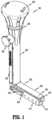
- FIG. 1is a perspective view of a mesh deployment device in accordance with the disclosure
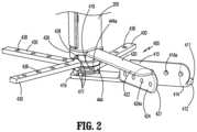
- FIG. 2is a partial perspective view of the mesh deployment device of FIG. 1 , illustrating an arm assembly thereof;
- FIG. 3is a perspective view of the mesh deployment device of FIG. 1 , illustrating the arm assembly in a deployed configuration
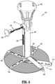
- FIG. 4is a perspective view of the mesh deployment device of FIG. 1 , illustrating a string pulled out of an opening of a body portion of the mesh deployment device.
- FIG. 1illustrates an exemplary a mesh deployment device generally shown as 100 configured to place a surgical mesh 700 ( FIG. 3 ) on tissue retro muscularly in order to avoid, e.g., parastomal hernia, in ostomy patients.
- Parastomal herniais a type of incisional hernia occurring in abdominal integuments in the vicinity of a stoma, e.g., a condition wherein abdominal contents, typically the bowel or greater omentum, protrude through abdominal integuments surrounded by the hernia sac at the location of the formed stoma.
- Deploying a mesh below the peritoneum layer as a reinforcing structuremay involve relatively complex maneuvers.
- the mesh deployment device 100enables a clinician to deploy the surgical mesh 700 retro muscularly without requiring additional skill or training.
- placement of the surgical mesh 700 retro muscularly instead of below peritoneum layereliminates the need for any collagen coating.
- the mesh deployment device 100may be configured to be inserted through an incision in the range of about 12 mm and 15 mm.
- the mesh deployment device 100includes a body portion 200 , a rotating knob 300 , and an arm assembly 400 .
- the arm assembly 400may be substantially orthogonal to the body portion 200 .
- the mesh deployment device 100is transitionable between a retracted configuration ( FIG. 1 ), in which, the arm assembly 400 is configured to facilitate insertion of the surgical mesh 700 through an opening or an incision in tissue, and a deployed configuration ( FIG. 3 ), in which, the arm assembly 400 is configured to spread the surgical mesh 700 over a desired location on tissue.
- the body portion 200has a tubular configuration defining a lumen therethrough.
- the body portion 200further defines an opening 210 ( FIG. 4 ) on a lateral wall 202 of the body portion 200 .
- the opening 210is in communication with the lumen of the body portion 200 .
- the body portion 200further includes a cap 250 configured to be detachably disposed in the opening 210 , and connected to a string 230 ( FIG. 4 ), as will be discussed below.
- the rotating knob 300is operatively coupled with the arm assembly 400 to transition the arm assembly 400 between the retracted and deployed configurations.
- the rotating knob 300is rotatably supported on a proximal end portion 205 of the body portion 200 .
- the rotating knob 300may be coupled to the arm assembly 400 by, e.g., a cable or a rod, extending through the lumen of the body portion 200 for concomitant rotation therewith.
- FIG. 2illustrates the arm assembly 400 in the deployed configuration without the surgical mesh 700 .
- the arm assembly 400includes a stationary arm 410 fixed to the body portion 200 to inhibit rotation relative to the body portion 200 .
- the stationary arm 410includes a base 412 , a guide wall 414 extending proximally from one of the opposing sides of the base 412 , and an engaging portion 416 in registration with the body portion 200 .
- the engaging portion 416includes a core 418 extending proximally from the base 412 and a plurality of stoppers 417 (only three stoppers shown in FIG. 2 ) extending radially outward from the core 418 , as will be discussed below.
- the core 418is coupled to the body portion 200 .
- the arm assembly 400further includes a covering arm 420 and a plurality of supporting arms 430 rotatably coupled to the body portion 200 .
- the covering arm 420 and the supporting arms 430are rotatable about the core 418 of the stationary arm 410 .
- the covering arm 420is coupled to the rotating knob 300 for concomitant rotation therewith. For example, when the rotating knob 300 is rotated in the direction of an arrow “C” ( FIG.
- the covering arm 420rotates in the direction of the arrow “C.”
- the covering arm 420is proximal of the supporting arms 430 such that the supporting arms 420 are interposed between the stationary arm 410 and the covering arm 420 in a superposed relation when the arm assembly 400 is in the retracted configuration.
- the guide walls 412 , 424 of the respective stationary arm 410 and the covering arm 420are on opposing sides of the arm assembly 400 to enable rotation of the covering arm 420 and the plurality of supporting arms 430 about the body portion 200 .
- the guide walls 414 , 424 of the stationary arm 410 and the covering arm 420may define a width therebetween no greater than about 12 mm.
- the bases 412 , 422 of the stationary arm 410 and the covering arm 420may define a width therebetween no greater than about 12 mm. It is contemplated that the stationary arm 410 and the covering arm 420 may have respective blunt tips 411 , 421 ( FIG. 2 ) configured to separate layers of tissue. The blunt tips 411 , 421 may also reduce trauma to tissue during contact with tissue.
- the covering arm 420includes a base 422 , a guide wall 424 extending distally from one of the opposing sides of the base 422 , and an engaging portion 426 concentrically arranged with the body portion 200 .
- the engaging portion 426defines a circumferential cutout 428 configured to engage a proximal-most stopper 417 of the core 418 of the stationary arm 410 .
- the proximal-most stopper 417is positioned on the core 418 of the stationary arm 410 to enable rotation of the covering arm 420 by a pre-determined amount.
- the stopper 417may be placed to enable rotation of the covering arm 420 such that the guide wall 424 of the covering arm 420 is adjacent the guide wall 414 of the stationary arm 410 when the arm assembly 400 is in the deployed configuration, as shown in FIG. 3 .
- the other stoppers 417are also circumferentially arranged to limit amount of rotation of the respective supporting arms 430 .
- the stoppers 417are circumferentially spaced apart to inhibit overlapping of the covering and supporting arms 420 , 430 when the arm assembly 400 is in the deployed configuration. Under such a configuration, the arm assembly 400 may uniformly support the surgical mesh 700 when the surgical mesh 700 is deployed.
- FIG. 2further illustrates the supporting arms 430 including respective engaging portions 444 aligned with the body portion 200 .
- Each engaging portion 444defines a circumferential cutout 444 a configured to engage a respective stopper 417 to limit amount of rotation of the supporting arm 430 .
- the stoppers 417are circumferentially arranged on the core 418 to enable the covering arm 420 and the supporting arms 430 to rotate by different amounts to provide uniform support of the surgical mesh on the arm assembly 400 .
- FIG. 3illustrates the mesh deployment device 100 in the deployed configuration.
- the surgical mesh 700is secured to the arm assembly 400 by a string or suture 230 .
- the surgical mesh 700may be secured to the arm assembly 400 by, e.g., sutures, clips, glue, staples, and/or locks.
- the guide walls 414 , 424 of the respective stationary arm 410 and the covering arm 420define a plurality of bores 414 a , 424 a to receive the string 230 therethrough.
- each supporting arm 430defines a plurality of bores 438 configured to receive the string 230 therethrough. Under such a configuration, the string 230 may be utilized to secure the surgical mesh 700 to the arm assembly 400 .
- Ends of the string 230may be connected to the cap 250 such that after the surgical mesh 700 is secured to tissue by, e.g., tack or suture (not shown), the string 230 connecting the surgical mesh 700 to the arm assembly 400 may be cut by the clinician and the string 230 may be removed from the surgical site by pulling the cap 250 away from the body portion 200 , as shown in FIG. 4 .
- tissuee.g., tack or suture
- the rotating knob 300may be rotatably coupled to the covering arm 420 for concomitant rotation therewith.
- the covering arm 420 and the supporting arms 430may cammingly engage each other.
- the covering arm 420may be configured to cause rotation of an adjacent supporting arm 430 distal of the covering arm 420 during rotation of the covering arm 420 .
- Rotation of the proximal-most supporting arm 430may cause rotation of an adjacent supporting arm 430 distal of the proximal-most supporting arm 430 by a predetermined amount.
- Rotation of the middle supporting arm 430may cause rotation of the distal-most supporting arm 430 in a similar manner.
- the stoppers 417limit the amount of rotation of the covering arm 420 and the supporting arms 430 .
- the covering arm 420 and the supporting arms 430may be independently coupled to the rotating knob 300 for independent rotation thereof by a respective predetermined amount of rotation.
- FIG. 4illustrates the surgical mesh 700 in the deployed configuration.
- the surgical mesh 700includes an arcuate shape defining a slit 710 such that portions of the surgical mesh 700 defining the slit 710 are securable to the respective stationary arm 410 and the covering arm 420 .
- the supporting arms 430may be arranged to provide substantially uniform support to the surgical mesh 700 .
- the surgical mesh 700may be made of a bio-compatible material. It is also envisioned that the surgical mesh 700 may have a solid inner configuration and a mesh outer configuration. Alternately, the surgical mesh 700 may have a mesh inner configuration which is tightly woven and a mesh outer configuration which is loosely woven.
- One example of the surgical mesh 700may include a polypropylene material marketed by C. R.
- the surgical mesh 700may be a tri-fluoroethylene material marketed by W. L. Gore & Associates, Newark, Delaware, under the trademark GORE-TEX.
- the mesh deployment device 100eliminates the need for collagen coating on the surgical mesh 700 .
- the arm assembly 400is transitioned to the deployed configuration ( FIG. 2 ).
- the surgical mesh 700is secured to the arm assembly 400 using the string 230 ( FIG. 1 ) coupled to the cap 250 .
- the arm assembly 400is then transitioned to the retracted position ( FIG. 1 ) such that the surgical mesh 700 is received between the stationary arm 410 and the covering arm 420 , whereby the surgical mesh 700 is folded or wrapped between the supporting arms 430 .
- the surgical siteis prepared by the clinician.
- the clinicianmay dissect layers of tissue using a balloon dissector known in the art or using fingers to provide space for insertion of the arm assembly 400 retro muscularly. Thereafter the clinician inserts the arm assembly 400 through an incision.
- the rotating knob 300is rotated to transition the arm assembly 400 to the deployed configuration.
- the surgical mesh 700may be attached to tissue using, e.g., tacks or stitch, as known in the art.
- the string 230may be cut in order to detach the surgical mesh 700 from the arm assembly 400 .
- the clinicianmay pull on the string 230 by pulling the cap 250 out of the opening 210 on the body portion 200 .
- the mesh deployment device 100may be removed from the patient by transitioning the arm assembly 400 back to the retracted configuration to fit through the incision.
- the mesh deployment device 100reduces risk for complications and trauma to patient. Further, the mesh deployment device 100 has simple mechanism and assembly, which, in turn, reduces costs of maintenance and manufacture.
- the mesh deployment device 100may be adapted for use with robotic surgery systems.
Landscapes
- Health & Medical Sciences (AREA)
- Cardiology (AREA)
- Oral & Maxillofacial Surgery (AREA)
- Transplantation (AREA)
- Engineering & Computer Science (AREA)
- Biomedical Technology (AREA)
- Heart & Thoracic Surgery (AREA)
- Vascular Medicine (AREA)
- Life Sciences & Earth Sciences (AREA)
- Animal Behavior & Ethology (AREA)
- General Health & Medical Sciences (AREA)
- Public Health (AREA)
- Veterinary Medicine (AREA)
- Surgical Instruments (AREA)
Abstract
Description
Claims (20)
Priority Applications (1)
| Application Number | Priority Date | Filing Date | Title |
|---|---|---|---|
| US17/332,013US11896473B2 (en) | 2020-07-13 | 2021-05-27 | Surgical mesh deployment device |
Applications Claiming Priority (2)
| Application Number | Priority Date | Filing Date | Title |
|---|---|---|---|
| US202063050967P | 2020-07-13 | 2020-07-13 | |
| US17/332,013US11896473B2 (en) | 2020-07-13 | 2021-05-27 | Surgical mesh deployment device |
Publications (2)
| Publication Number | Publication Date |
|---|---|
| US20220008185A1 US20220008185A1 (en) | 2022-01-13 |
| US11896473B2true US11896473B2 (en) | 2024-02-13 |
Family
ID=79171923
Family Applications (1)
| Application Number | Title | Priority Date | Filing Date |
|---|---|---|---|
| US17/332,013Active2042-02-07US11896473B2 (en) | 2020-07-13 | 2021-05-27 | Surgical mesh deployment device |
Country Status (1)
| Country | Link |
|---|---|
| US (1) | US11896473B2 (en) |
Citations (38)
| Publication number | Priority date | Publication date | Assignee | Title |
|---|---|---|---|---|
| US5122155A (en) | 1990-10-11 | 1992-06-16 | Eberbach Mark A | Hernia repair apparatus and method of use |
| US5258000A (en) | 1991-11-25 | 1993-11-02 | Cook Incorporated | Tissue aperture repair device |
| US5263969A (en) | 1992-04-17 | 1993-11-23 | Phillips Edward H | Tool for the laparoscopic introduction of a mesh prosthesis |
| US5304187A (en) | 1992-06-30 | 1994-04-19 | United States Surgical Corporation | Surgical element deployment apparatus |
| US5333624A (en) | 1992-02-24 | 1994-08-02 | United States Surgical Corporation | Surgical attaching apparatus |
| US5366460A (en) | 1990-10-11 | 1994-11-22 | Cook Incorporated | Apparatus and method for laparoscope hernia repair |
| US5370650A (en) | 1992-02-24 | 1994-12-06 | United States Surgical Corporation | Articulating mesh deployment apparatus |
| US5383477A (en) | 1991-08-02 | 1995-01-24 | Dematteis; Ralph A. | Method and apparatus for laparoscopic repair of hernias |
| US5397331A (en)* | 1991-11-25 | 1995-03-14 | Cook Incorporated | Supporting device and apparatus for inserting the device |
| US5405360A (en) | 1992-02-24 | 1995-04-11 | United States Surgical Corporation | Resilient arm mesh deployer |
| US5464403A (en) | 1992-10-29 | 1995-11-07 | General Surgical Innovations, Inc. | Placement tool and method for laparoscopic hernia repair |
| EP0706778A1 (en) | 1994-10-13 | 1996-04-17 | Ethicon, Inc. | Applicator for introducing flexible areal implants through an operative channel |
| US5713948A (en) | 1995-07-19 | 1998-02-03 | Uflacker; Renan | Adjustable and retrievable graft and graft delivery system for stent-graft system |
| FR2789888A1 (en) | 1999-02-22 | 2000-08-25 | Francis Lefebvre | Coeloscopic surgical instrument for inguinal hernia treatment has guide tube for control rod with shape memory supports for prosthesis at distal end |
| US6478803B1 (en) | 2000-05-19 | 2002-11-12 | Genzyme Corporation | Device for delivery of surgical materials |
| US6575988B2 (en) | 2001-05-15 | 2003-06-10 | Ethicon, Inc. | Deployment apparatus for supple surgical materials |
| US6582451B1 (en) | 1999-03-16 | 2003-06-24 | The University Of Sydney | Device for use in surgery |
| US20030135257A1 (en) | 2002-01-14 | 2003-07-17 | Taheri Syde A. | Exclusion of ascending/descending aorta and/or aortic arch aneurysm |
| US20040073257A1 (en)* | 2002-10-09 | 2004-04-15 | Spitz Gregory A. | Methods and apparatus for the repair of hernias |
| US6730119B1 (en) | 2000-10-06 | 2004-05-04 | Board Of Regents Of The University Of Texas System | Percutaneous implantation of partially covered stents in aneurysmally dilated arterial segments with subsequent embolization and obliteration of the aneurysm cavity |
| US20040087980A1 (en) | 2002-08-02 | 2004-05-06 | Ford Steven Palmer | Implantable prosthesis |
| US20040117032A1 (en) | 1993-02-22 | 2004-06-17 | Roth Alex T. | Devices for less-invasive intracardiac interventions |
| WO2004080348A1 (en) | 2003-03-13 | 2004-09-23 | Samuel Eldar | Device for deploying and placing a surgical prosthesis mesh |
| US20050131520A1 (en) | 2003-04-28 | 2005-06-16 | Zilla Peter P. | Compliant blood vessel graft |
| US20060189918A1 (en)* | 2003-01-14 | 2006-08-24 | Barker Stephen G E | Laparoscopic port hernia device |
| US20070185506A1 (en)* | 2003-08-04 | 2007-08-09 | Kelly Jackson | Medical instruments and methods for using the same |
| US20070203507A1 (en) | 2005-08-26 | 2007-08-30 | G-Surge Medical Solutions, Inc. | Suturing apparatus and methods |
| WO2008045635A2 (en) | 2006-10-12 | 2008-04-17 | The Catheter Exchange, Inc. | Method and device for attaching a patch |
| US20080188874A1 (en) | 2005-09-09 | 2008-08-07 | University Of South Florida | Laparoscopic hernia mesh spreader |
| US20080195121A1 (en) | 2007-02-14 | 2008-08-14 | Samuel Eldar | Mesh deployment apparatus |
| WO2009104182A2 (en) | 2008-02-18 | 2009-08-27 | Polytouch Medical Ltd | A device and method for deploying and attaching a patch to a biological tissue |
| US7591813B2 (en) | 2003-10-01 | 2009-09-22 | Micrus Endovascular Corporation | Long nose manipulatable catheter |
| US20090248092A1 (en) | 2008-03-26 | 2009-10-01 | Jonathan Bellas | Posterior Intervertebral Disc Inserter and Expansion Techniques |
| WO2010046893A1 (en) | 2008-10-20 | 2010-04-29 | Polytouch Medical Ltd. | A device for attaching a patch to a biological tissue |
| US20100234938A1 (en) | 2008-11-18 | 2010-09-16 | Taheri Syde A | Grasper System For Placement Of Intraluminal Device |
| US20110230947A1 (en) | 2008-08-26 | 2011-09-22 | Cook ,Edical Tecnhologies Llc | Thoracic introducer |
| US10028814B2 (en) | 2010-02-03 | 2018-07-24 | Covidien Lp | X-shaped device and method for deployment and placement of a patch |
| US20180256139A1 (en)* | 2011-01-11 | 2018-09-13 | Amsel Medical Corporation | Methods and apparatus for fastening and clamping tissue |
- 2021
- 2021-05-27USUS17/332,013patent/US11896473B2/enactiveActive
Patent Citations (39)
| Publication number | Priority date | Publication date | Assignee | Title |
|---|---|---|---|---|
| US5122155A (en) | 1990-10-11 | 1992-06-16 | Eberbach Mark A | Hernia repair apparatus and method of use |
| US5366460A (en) | 1990-10-11 | 1994-11-22 | Cook Incorporated | Apparatus and method for laparoscope hernia repair |
| US5383477A (en) | 1991-08-02 | 1995-01-24 | Dematteis; Ralph A. | Method and apparatus for laparoscopic repair of hernias |
| US5258000A (en) | 1991-11-25 | 1993-11-02 | Cook Incorporated | Tissue aperture repair device |
| US5397331A (en)* | 1991-11-25 | 1995-03-14 | Cook Incorporated | Supporting device and apparatus for inserting the device |
| US5333624A (en) | 1992-02-24 | 1994-08-02 | United States Surgical Corporation | Surgical attaching apparatus |
| US5370650A (en) | 1992-02-24 | 1994-12-06 | United States Surgical Corporation | Articulating mesh deployment apparatus |
| US5405360A (en) | 1992-02-24 | 1995-04-11 | United States Surgical Corporation | Resilient arm mesh deployer |
| US5263969A (en) | 1992-04-17 | 1993-11-23 | Phillips Edward H | Tool for the laparoscopic introduction of a mesh prosthesis |
| US5304187A (en) | 1992-06-30 | 1994-04-19 | United States Surgical Corporation | Surgical element deployment apparatus |
| US5464403A (en) | 1992-10-29 | 1995-11-07 | General Surgical Innovations, Inc. | Placement tool and method for laparoscopic hernia repair |
| US20040117032A1 (en) | 1993-02-22 | 2004-06-17 | Roth Alex T. | Devices for less-invasive intracardiac interventions |
| EP0706778A1 (en) | 1994-10-13 | 1996-04-17 | Ethicon, Inc. | Applicator for introducing flexible areal implants through an operative channel |
| US5713948A (en) | 1995-07-19 | 1998-02-03 | Uflacker; Renan | Adjustable and retrievable graft and graft delivery system for stent-graft system |
| FR2789888A1 (en) | 1999-02-22 | 2000-08-25 | Francis Lefebvre | Coeloscopic surgical instrument for inguinal hernia treatment has guide tube for control rod with shape memory supports for prosthesis at distal end |
| US6582451B1 (en) | 1999-03-16 | 2003-06-24 | The University Of Sydney | Device for use in surgery |
| US6478803B1 (en) | 2000-05-19 | 2002-11-12 | Genzyme Corporation | Device for delivery of surgical materials |
| US6730119B1 (en) | 2000-10-06 | 2004-05-04 | Board Of Regents Of The University Of Texas System | Percutaneous implantation of partially covered stents in aneurysmally dilated arterial segments with subsequent embolization and obliteration of the aneurysm cavity |
| US6575988B2 (en) | 2001-05-15 | 2003-06-10 | Ethicon, Inc. | Deployment apparatus for supple surgical materials |
| US20030135257A1 (en) | 2002-01-14 | 2003-07-17 | Taheri Syde A. | Exclusion of ascending/descending aorta and/or aortic arch aneurysm |
| US20040087980A1 (en) | 2002-08-02 | 2004-05-06 | Ford Steven Palmer | Implantable prosthesis |
| US20040073257A1 (en)* | 2002-10-09 | 2004-04-15 | Spitz Gregory A. | Methods and apparatus for the repair of hernias |
| US20060189918A1 (en)* | 2003-01-14 | 2006-08-24 | Barker Stephen G E | Laparoscopic port hernia device |
| WO2004080348A1 (en) | 2003-03-13 | 2004-09-23 | Samuel Eldar | Device for deploying and placing a surgical prosthesis mesh |
| US20050131520A1 (en) | 2003-04-28 | 2005-06-16 | Zilla Peter P. | Compliant blood vessel graft |
| US20070185506A1 (en)* | 2003-08-04 | 2007-08-09 | Kelly Jackson | Medical instruments and methods for using the same |
| US7591813B2 (en) | 2003-10-01 | 2009-09-22 | Micrus Endovascular Corporation | Long nose manipulatable catheter |
| US20070203507A1 (en) | 2005-08-26 | 2007-08-30 | G-Surge Medical Solutions, Inc. | Suturing apparatus and methods |
| US20080188874A1 (en) | 2005-09-09 | 2008-08-07 | University Of South Florida | Laparoscopic hernia mesh spreader |
| WO2008045635A2 (en) | 2006-10-12 | 2008-04-17 | The Catheter Exchange, Inc. | Method and device for attaching a patch |
| US20080195121A1 (en) | 2007-02-14 | 2008-08-14 | Samuel Eldar | Mesh deployment apparatus |
| WO2009104182A2 (en) | 2008-02-18 | 2009-08-27 | Polytouch Medical Ltd | A device and method for deploying and attaching a patch to a biological tissue |
| US20100312357A1 (en)* | 2008-02-18 | 2010-12-09 | PolyTouch Medical, Inc. | Device and method for deploying and attaching an implant to a biological tissue |
| US20090248092A1 (en) | 2008-03-26 | 2009-10-01 | Jonathan Bellas | Posterior Intervertebral Disc Inserter and Expansion Techniques |
| US20110230947A1 (en) | 2008-08-26 | 2011-09-22 | Cook ,Edical Tecnhologies Llc | Thoracic introducer |
| WO2010046893A1 (en) | 2008-10-20 | 2010-04-29 | Polytouch Medical Ltd. | A device for attaching a patch to a biological tissue |
| US20100234938A1 (en) | 2008-11-18 | 2010-09-16 | Taheri Syde A | Grasper System For Placement Of Intraluminal Device |
| US10028814B2 (en) | 2010-02-03 | 2018-07-24 | Covidien Lp | X-shaped device and method for deployment and placement of a patch |
| US20180256139A1 (en)* | 2011-01-11 | 2018-09-13 | Amsel Medical Corporation | Methods and apparatus for fastening and clamping tissue |
Also Published As
| Publication number | Publication date |
|---|---|
| US20220008185A1 (en) | 2022-01-13 |
Similar Documents
| Publication | Publication Date | Title |
|---|---|---|
| EP2114256B1 (en) | Mesh deployment apparatus | |
| US5304187A (en) | Surgical element deployment apparatus | |
| CA2752338C (en) | Means and method for reversibly connecting a patch to a patch deployment device | |
| US8409226B2 (en) | Method of performing transgastric ventral hernia repair and tissue anchors and deployment devices therefor | |
| AU2015321668B2 (en) | Method and means to attach anchor sutures onto mesh implants | |
| US20040249412A1 (en) | Apparatus and methods for puncture site closure | |
| US8795383B2 (en) | Laparoscopic inguinal hernia prosthesis | |
| JP2010042269A (en) | Implant prosthesis | |
| US20120316594A1 (en) | Apparatus for closing an opening, such as a trocar opening, in a patient's body | |
| EP2700379B1 (en) | Lock bar and clip for implant deployment device | |
| WO2004080348A1 (en) | Device for deploying and placing a surgical prosthesis mesh | |
| JP2014530683A (en) | Implantable prosthesis for repairing or reinforcing anatomical defects | |
| US11660178B2 (en) | Ventral hernia defect closure | |
| AU2014201340B2 (en) | Port site closure | |
| US11896473B2 (en) | Surgical mesh deployment device | |
| US12004937B1 (en) | Blunt dissector, delivery and deployment device for delivery and deployment of surgical mesh during soft tissue repairs | |
| EP3291748B1 (en) | Reinforcement scaffolds for maintaining a reduced size of a stomach |
Legal Events
| Date | Code | Title | Description |
|---|---|---|---|
| AS | Assignment | Owner name:COVIDIEN LP, MASSACHUSETTS Free format text:ASSIGNMENT OF ASSIGNORS INTEREST;ASSIGNOR:COVIDIEN AG;REEL/FRAME:056371/0910 Effective date:20210407 Owner name:MEDTRONIC ENGINEERING AND INNOVATION CENTER PRIVATE LIMITED, INDIA Free format text:ASSIGNMENT OF ASSIGNORS INTEREST;ASSIGNORS:MURTHY ARAVALLI AVVLN, SRINIVASA;GUTTI, RAVI SEKHAR;MANDULA, RAJANIKANTH;AND OTHERS;SIGNING DATES FROM 20200211 TO 20200317;REEL/FRAME:056371/0479 Owner name:COVIDIEN PRIVATE LIMITED, SINGAPORE Free format text:ASSIGNMENT OF ASSIGNORS INTEREST;ASSIGNOR:MEDTRONIC ENGINEERING AND INNOVATION CENTER PRIVATE LIMITED;REEL/FRAME:056371/0668 Effective date:20210208 Owner name:COVIDIEN AG, SWITZERLAND Free format text:ASSIGNMENT OF ASSIGNORS INTEREST;ASSIGNOR:COVIDIEN PRIVATE LIMITED;REEL/FRAME:056371/0764 Effective date:20210331 | |
| FEPP | Fee payment procedure | Free format text:ENTITY STATUS SET TO UNDISCOUNTED (ORIGINAL EVENT CODE: BIG.); ENTITY STATUS OF PATENT OWNER: LARGE ENTITY | |
| STPP | Information on status: patent application and granting procedure in general | Free format text:DOCKETED NEW CASE - READY FOR EXAMINATION | |
| STPP | Information on status: patent application and granting procedure in general | Free format text:RESPONSE TO NON-FINAL OFFICE ACTION ENTERED AND FORWARDED TO EXAMINER | |
| STPP | Information on status: patent application and granting procedure in general | Free format text:NOTICE OF ALLOWANCE MAILED -- APPLICATION RECEIVED IN OFFICE OF PUBLICATIONS | |
| STPP | Information on status: patent application and granting procedure in general | Free format text:PUBLICATIONS -- ISSUE FEE PAYMENT VERIFIED | |
| STCF | Information on status: patent grant | Free format text:PATENTED CASE |