US11896291B2 - Electrically-insulative shafts, methods of manufacturing electrically-insulative shafts, and energy-based surgical instruments incorporating electrically-insulative shafts - Google Patents
Electrically-insulative shafts, methods of manufacturing electrically-insulative shafts, and energy-based surgical instruments incorporating electrically-insulative shaftsDownload PDFInfo
- Publication number
- US11896291B2 US11896291B2US16/024,989US201816024989AUS11896291B2US 11896291 B2US11896291 B2US 11896291B2US 201816024989 AUS201816024989 AUS 201816024989AUS 11896291 B2US11896291 B2US 11896291B2
- Authority
- US
- United States
- Prior art keywords
- electrically
- tube
- insulative
- intermediate tube
- inner tubes
- Prior art date
- Legal status (The legal status is an assumption and is not a legal conclusion. Google has not performed a legal analysis and makes no representation as to the accuracy of the status listed.)
- Active, expires
Links
Images


Classifications
- A—HUMAN NECESSITIES
- A61—MEDICAL OR VETERINARY SCIENCE; HYGIENE
- A61B—DIAGNOSIS; SURGERY; IDENTIFICATION
- A61B18/00—Surgical instruments, devices or methods for transferring non-mechanical forms of energy to or from the body
- A61B18/04—Surgical instruments, devices or methods for transferring non-mechanical forms of energy to or from the body by heating
- A61B18/12—Surgical instruments, devices or methods for transferring non-mechanical forms of energy to or from the body by heating by passing a current through the tissue to be heated, e.g. high-frequency current
- A61B18/14—Probes or electrodes therefor
- A61B18/1442—Probes having pivoting end effectors, e.g. forceps
- A61B18/1445—Probes having pivoting end effectors, e.g. forceps at the distal end of a shaft, e.g. forceps or scissors at the end of a rigid rod
- A—HUMAN NECESSITIES
- A61—MEDICAL OR VETERINARY SCIENCE; HYGIENE
- A61B—DIAGNOSIS; SURGERY; IDENTIFICATION
- A61B17/00—Surgical instruments, devices or methods
- A61B17/28—Surgical forceps
- A61B17/29—Forceps for use in minimally invasive surgery
- A61B17/2909—Handles
- A—HUMAN NECESSITIES
- A61—MEDICAL OR VETERINARY SCIENCE; HYGIENE
- A61B—DIAGNOSIS; SURGERY; IDENTIFICATION
- A61B17/00—Surgical instruments, devices or methods
- A61B17/28—Surgical forceps
- A61B17/29—Forceps for use in minimally invasive surgery
- A61B17/295—Forceps for use in minimally invasive surgery combined with cutting implements
- A—HUMAN NECESSITIES
- A61—MEDICAL OR VETERINARY SCIENCE; HYGIENE
- A61B—DIAGNOSIS; SURGERY; IDENTIFICATION
- A61B17/00—Surgical instruments, devices or methods
- A61B17/28—Surgical forceps
- A61B17/29—Forceps for use in minimally invasive surgery
- A61B2017/2901—Details of shaft
- A61B2017/2902—Details of shaft characterized by features of the actuating rod
- A—HUMAN NECESSITIES
- A61—MEDICAL OR VETERINARY SCIENCE; HYGIENE
- A61B—DIAGNOSIS; SURGERY; IDENTIFICATION
- A61B17/00—Surgical instruments, devices or methods
- A61B17/28—Surgical forceps
- A61B17/29—Forceps for use in minimally invasive surgery
- A61B2017/2926—Details of heads or jaws
- A61B2017/2932—Transmission of forces to jaw members
- A61B2017/2939—Details of linkages or pivot points
- A61B2017/294—Connection of actuating rod to jaw, e.g. releasable
- A—HUMAN NECESSITIES
- A61—MEDICAL OR VETERINARY SCIENCE; HYGIENE
- A61B—DIAGNOSIS; SURGERY; IDENTIFICATION
- A61B18/00—Surgical instruments, devices or methods for transferring non-mechanical forms of energy to or from the body
- A61B2018/00053—Mechanical features of the instrument of device
- A61B2018/00059—Material properties
- A61B2018/00071—Electrical conductivity
- A61B2018/00077—Electrical conductivity high, i.e. electrically conducting
- A—HUMAN NECESSITIES
- A61—MEDICAL OR VETERINARY SCIENCE; HYGIENE
- A61B—DIAGNOSIS; SURGERY; IDENTIFICATION
- A61B18/00—Surgical instruments, devices or methods for transferring non-mechanical forms of energy to or from the body
- A61B2018/00053—Mechanical features of the instrument of device
- A61B2018/00059—Material properties
- A61B2018/00071—Electrical conductivity
- A61B2018/00083—Electrical conductivity low, i.e. electrically insulating
- A—HUMAN NECESSITIES
- A61—MEDICAL OR VETERINARY SCIENCE; HYGIENE
- A61B—DIAGNOSIS; SURGERY; IDENTIFICATION
- A61B18/00—Surgical instruments, devices or methods for transferring non-mechanical forms of energy to or from the body
- A61B2018/00571—Surgical instruments, devices or methods for transferring non-mechanical forms of energy to or from the body for achieving a particular surgical effect
- A61B2018/00607—Coagulation and cutting with the same instrument
- A—HUMAN NECESSITIES
- A61—MEDICAL OR VETERINARY SCIENCE; HYGIENE
- A61B—DIAGNOSIS; SURGERY; IDENTIFICATION
- A61B18/00—Surgical instruments, devices or methods for transferring non-mechanical forms of energy to or from the body
- A61B18/04—Surgical instruments, devices or methods for transferring non-mechanical forms of energy to or from the body by heating
- A61B18/12—Surgical instruments, devices or methods for transferring non-mechanical forms of energy to or from the body by heating by passing a current through the tissue to be heated, e.g. high-frequency current
- A61B18/14—Probes or electrodes therefor
- A61B18/1442—Probes having pivoting end effectors, e.g. forceps
- A61B2018/1452—Probes having pivoting end effectors, e.g. forceps including means for cutting
- A61B2018/1455—Probes having pivoting end effectors, e.g. forceps including means for cutting having a moving blade for cutting tissue grasped by the jaws
Definitions
- the present disclosurerelates to energy-based surgical instruments and, more particularly, to electrically-insulative shafts for energy-based surgical instruments, methods of manufacturing the same, and energy-based surgical instruments incorporating the same.
- Bipolar surgical instrumentstypically include two generally opposing electrodes charged to different electric potentials to selectively apply energy to tissue.
- Bipolar electrosurgical forcepsfor example, utilize both mechanical clamping action and electrical energy to treat, e.g., cauterize, coagulate, desiccate, and/or seal, tissue.
- Monopolar surgical instrumentsinclude an active electrode, and are used in conjunction with a remote return electrode, e.g., a return pad, to apply energy to tissue.
- Monopolar instrumentshave the ability to rapidly move through tissue and dissect through narrow tissue planes.
- Multi-function energy-based surgical instrumentsmay incorporate various different energy modalities such as, for example, both bipolar and monopolar features. As such, these multi-function instruments obviate the need to alternatingly remove and insert bipolar and monopolar instruments in favor of one another.
- Electrically-insulative shaftsare commonly utilized in bipolar surgical instruments, monopolar surgical instruments, multi-function surgical instruments, and other energy-based surgical instruments configured to apply or receive energy. Electrically-insulative shafts are widely utilized because they inhibit capacitive coupling and other unwanted electrical interactions, thus protecting the instrument, patient, and surgical team.
- distalrefers to the portion that is being described that is further from a user
- proximalrefers to the portion that is being described that is closer to a user
- an electrically-insulative shaft for an energy-based surgical instrumentincluding an outer tube formed from an electrically-insulative material, an inner tube formed from an electrically-insulative material, and an intermediate tube disposed between the outer and inner tubes.
- the intermediate tubeis formed from an electrically-conductive material. Distal ends of the outer and inner tubes extend beyond a distal end of the intermediate tube and are joined to one another to enclose the distal end of the intermediate tube therebetween.
- the distal ends of the outer and inner tubesare joined along a longitudinally-extending joint.
- the distal ends of the outer and inner tubesmay be joined along a transversely-extending joint.
- an O-ringis disposed between the outer and inner tubes and between the distal end of the intermediate tube and the joined distal ends of the outer and inner tubes.
- a radial spaceis defined between at least one of the intermediate tube and the inner tube or the intermediate tube and the outer tube.
- the intermediate tubemay substantially fully occupy the annular gap between the inner and outer tubes.
- the outer and inner tubesare formed from PTFE and/or the intermediate tube is formed from stainless steel.
- a surgical instrument provided in accordance with aspects of the present disclosureincludes a housing, at least one electrode operably coupled to the housing and configured to supply energy to tissue, and an electrically-insulative shaft extending at least partially between the housing and the at least one electrode.
- the electrically-insulative shaftmay be configured similar to any of the aspects detailed above or otherwise described herein.
- the at least one electrodeincludes a monopolar electrode.
- the at least one electrodeincludes a pair of bipolar electrodes.
- a method of manufacturing an electrically-insulative shaft for a surgical instrumentincludes providing an electrically-insulative outer tube, an electrically-insulative inner tube, and an electrically-conductive intermediate tube. The method further includes joining distal ends of the outer tube and inner tube with one another to form a joint and inserting the intermediate tube into an annular gap defined between the outer and inner tubes.
- the distal ends of the outer tube and inner tubeare joined with one another to form the joint prior to inserting the intermediate tube into the annular gap.
- the distal ends of the outer tube and inner tubeare joined with one another to form the joint after inserting the intermediate tube into the annular gap.
- the distal ends of the outer tube and inner tubeare joined with one another to form the joint such that the joint extends in one of a longitudinal direction or a transverse direction.
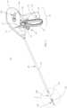
- FIG. 1is a perspective view of an endoscopic surgical instrument provided in accordance with the present disclosure
- FIG. 2is an enlarged, perspective view of the area of detail indicated as “ 2 ” in FIG. 1 ;
- FIG. 3is an enlarged, perspective view of the area of detail indicated as “ 2 ” in FIG. 1 from the opposite side as illustrated in FIG. 2 , with portions removed;
- FIG. 4is a perspective view of the proximal end of the surgical instrument of FIG. 1 with portions removed to illustrate the internal working components thereof;
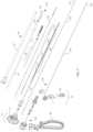
- FIG. 5is an exploded, perspective view of various operable assemblies of the surgical instrument of FIG. 1 ;
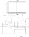
- FIG. 6is a longitudinal, cross-sectional view of a distal end portion of an electrically-insulative shaft provided in accordance with the present disclosure and configured for use with the surgical instrument of FIG. 1 ;
- FIG. 7is an enlarged view of the area of detail indicated as “ 7 ” in FIG. 6 ;
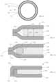
- FIG. 8is a transverse, cross-sectional view taken across section line “ 8 - 8 ” of FIG. 6 ;
- FIGS. 9 - 11are longitudinal, cross-sectional views of portions of other electrically-insulative shafts provided in accordance with the present disclosure and configured for use with the surgical instrument of FIG. 1 .
- the present disclosureprovides electrically-insulative shafts for energy-based surgical instruments, methods of manufacturing electrically-insulative shafts, and energy-based surgical instruments including electrically-insulative shafts.
- endoscopic surgical instrument 10FIG. 1
- the aspects and features of the present disclosureare equally applicable for use with any suitable energy-based surgical instrument or portion(s) thereof.
- different connections and considerationsapply to each particular instrument and the assemblies and/or components thereof; however, the aspects and features of the present disclosure remain generally consistent regardless of the particular instrument, assemblies, and/or components provided.
- endoscopic surgical instrument 10is configured to operate in both a bipolar mode, e.g., for grasping, treating, and/or mechanically dissecting tissue, and a monopolar mode, e.g., for treating and/or electrically/electromechanically dissecting tissue.
- Instrument 10generally includes a housing 20 , a handle assembly 30 , a trigger assembly 60 , a rotation assembly 70 , an elongated shaft assembly 80 , an end effector assembly 100 , a drive assembly 140 , a knife assembly 160 , bipolar and monopolar activation assemblies 170 , 180 , respectively, a monopolar assembly 200 , and a deployment and retraction mechanism 300 .
- Elongated shaft assembly 80extends distally from housing 20 and supports end effector assembly 100 at a distal end thereof.
- Drive assembly 140operably couples handle assembly 30 with end effector assembly 100 to enable selective manipulation of jaw members 110 , 120 of end effector assembly 100 .
- Knife assembly 160is operably coupled with trigger assembly 60 to enable selective translation of knife 164 of knife assembly 160 relative to end effector assembly 100 .
- Monopolar assembly 200is operably coupled with deployment and retraction mechanism 300 to enable selective deployment and retraction of monopolar assembly 200 .
- Rotating assembly 70is operably coupled to elongated shaft assembly 80 and enables selective rotation of elongated shaft assembly 80 , drive assembly 140 , trigger assembly 60 , end effector assembly 100 , and monopolar assembly 200 relative to housing 20 .
- Bipolar and monopolar activation assemblies 170 , 180enable the appropriate energy to be selectively delivered to end effector assembly 100 and monopolar assembly 200 , respectively.
- Instrument 10may also include an electrosurgical cable (not shown) that connects instrument 10 to a generator (not shown) or other suitable power source, although instrument 10 may alternatively be configured as a battery-powered instrument.
- the electrosurgical cable (not shown)includes wires (not shown) extending therethrough that have sufficient length to extend through housing 20 and/or elongated shaft assembly 80 in order to provide energy to at least one of the electrically-conductive surfaces 112 , 122 of jaw members 110 , 120 , respectively, of end effector assembly 100 , e.g., upon activation of bipolar activation switch 172 of bipolar activation assembly 170 in the bipolar mode of operation.
- one or more of the wires of the electrosurgical cableextends through housing 20 and/or elongated shaft assembly 80 in order to provide energy to monopolar assembly 200 , e.g., upon activation of either of the monopolar activation switches 182 of monopolar activation assembly 180 in the monopolar mode of operation.
- Elongated shaft assembly 80includes a fixed outer tube 82 configured for engagement with housing 20 .
- Fixed outer tube 82does not extend distally to end effector assembly 100 but, rather, is spaced-apart therefrom, leaving an exposed section of monopolar assembly 200 .
- Elongated shaft assembly 80further includes an inner proximal tube 83 , an inner distal tube 84 , and an inner guide assembly 86 including a plurality of guide components 87 that cooperate to house and/or guide at least a portion of drive assembly 140 knife assembly 160 , and monopolar assembly 200 .
- Inner proximal tube 83engages rotation assembly 70 and inner distal tube 84 engages jaw member 120 while inner guide assembly 86 extends between inner proximal tube 83 and inner distal tube 84 .
- Inner proximal tube 83 , inner distal tube 84 , and inner guide assembly 86are rotationally coupled with one another such that rotation of inner proximal tube 83 via rotation of rotation assembly 70 effects corresponding rotation of end effector assembly 100 , drive assembly 140 , knife assembly 160 , and monopolar assembly 200 relative to housing 20 ( FIG. 1 ) and fixed outer tube 82 .
- end effector assembly 100is disposed at the distal end of elongated shaft assembly 80 and includes opposing jaw members 110 , 120 pivotably coupled to one another.
- Each of the jaw members 110 , 120includes an electrically-conductive surface 112 , 122 adapted to connect to the source of energy (not shown) whci is configured to conduct energy through tissue grasped therebetween.
- End effector assembly 100defines a bipolar configuration wherein surface 112 is charged to a first electrical potential and surface 122 is charged to a second, different, electrical potential such that an electrical potential gradient is created for conducting energy between surfaces 112 , 122 and through tissue grasped therebetween for treating tissue.
- Bipolar activation switch 172 of bipolar activation assembly 170( FIG. 1 ) is operably coupled between the source of energy (not shown) and surfaces 112 , 122 via one or more wires (not shown), thus allowing the selective application of energy to surfaces 112 , 122 of jaw members 110 , 120 , respectively, of end effector assembly 100 during the bipolar mode of operation.
- End effector assembly 100is designed as a unilateral assembly, e.g., where jaw member 120 is fixed relative to elongated shaft assembly 80 , e.g., jaw member 120 is engaged with inner distal tube 84 of elongated shaft assembly 80 , and jaw member 110 is movable relative to elongated shaft assembly 80 and fixed jaw member 120 .
- end effector assembly 100may alternatively be configured as a bilateral assembly, i.e., where both jaw member 110 and jaw member 120 are movable relative to one another and to elongated shaft assembly 80 .
- a longitudinally-extending knife channelmay be defined within one or both of jaw members 110 , 120 to permit reciprocation of knife 164 therethrough, e.g., upon actuation of a trigger 62 of trigger assembly 60 , to cut tissue grasped between jaw members 110 , 120 .
- handle assembly 30includes movable handle 40 and a fixed handle 50 .
- Fixed handle 50is integrally associated with housing 20 and movable handle 40 is movable relative to fixed handle 50 between an initial position, wherein movable handle 40 is spaced-apart from fixed handle 50 , and a compressed position, wherein movable handle 40 is compressed towards fixed handle 50 .
- drive assembly 140operably couples movable handle 40 to jaw member 110 .
- Drive assembly 140more specifically, includes a drive bar 148 operably coupled to end effector assembly 100 at the distal end of drive bar 148 and operably coupled to movable handle 40 at the proximal end of drive bar 148 .
- Drive bar 148extends through inner proximal tube 83 , inner guide assembly 86 , and inner distal tube 84 . Translation of drive bar 148 relative to end effector assembly 100 pivots jaw member 110 relative to jaw member 120 .
- trigger 62 of trigger assembly 60is selectively actuatable relative to housing 20 from an un-actuated position to an actuated position.
- Knife assembly 160is operably coupled to trigger 62 such that actuation of trigger 62 from the un-actuated position to the actuated position translates knife 164 of knife assembly 160 from a retracted position, wherein knife 164 is disposed proximally of jaw members 110 , 120 , to an extended position, wherein knife 164 extends at least partially between jaw members 110 , 120 and through the knife channel(s) (not shown) thereof to cut tissue grasped between jaw members 110 , 120 .
- Knife assembly 160includes knife bar 162 and knife 164 .
- Knife bar 162extends proximally from knife 164 through inner distal tube 84 , inner guide assembly 86 , and inner proximal tube 83 into housing 20 .
- knife bar 162is operably coupled with trigger 62 to operably couple trigger assembly 60 and knife assembly 160 with one another such that, upon actuation of trigger 62 from the un-actuated position to the actuated position, knife 164 is translated distally from the retracted position to the extended position to cut tissue grasped between jaw members 110 , 120 .
- Rotation assembly 70includes rotation wheel 72 that extends outwardly from housing 20 on either side thereof (see FIG. 1 ).
- Rotation wheel 72is engaged about inner proximal tube 83 of elongated shaft assembly 80 such that, as mentioned above, rotation of rotation wheel 72 effects corresponding rotation of inner proximal tube 83 , inner distal tube 84 , inner guide assembly 86 , end effector assembly 100 , drive assembly 140 , knife assembly 160 , and monopolar assembly 200 relative to housing 20 ( FIG. 1 ) and fixed outer tube 82 .
- monopolar assembly 200includes an electrically-insulative shaft 210 and an energizable member 220 .
- Electrically-insulative shaft 210defines a body portion 217 , an enlarged-diameter distal portion 218 extending distally from body portion 217 , and an annular step 219 disposed therebetween, although other configurations are also contemplated.
- Electrically-insulative shaft 210is movable relative to end effector assembly 100 between a storage position, wherein electrically-insulative shaft 210 is disposed proximally of end effector assembly 100 , and a use position, wherein electrically-insulative shaft 210 is substantially disposed about end effector assembly 100 . Electrically-insulative shaft 210 is described in greater detail below.
- Energizable member 220 of monopolar assembly 200defines a distal tissue-treating portion 227 that is coupled to the source of energy (not shown) and monopolar activation assembly 180 ( FIG. 5 ) via one or more wires (not shown) to function as the active electrode of monopolar assembly 200 .
- Energizable member 220extends through inner proximal tube 83 , inner guide assembly 86 , and inner distal tube 84 and into housing 20 .
- Energizable member 220is disposed on the inner-edge side of jaw members 110 , 120 of end effector assembly 100 and is movable relative thereto between a storage position, wherein distal tissue-treating portion 227 of energizable member 220 is positioned more-proximally, and a use position, wherein distal tissue-treating portion 227 of energizable member 220 extends distally from end effector assembly 100 to facilitate treating tissue therewith.
- electrically-insulative shaft 210serves to electrically insulate end effector assembly 100 from distal tissue-treating portion 227 of energizable member 220 , while distal tissue-treating portion 227 extends distally from end effector assembly 100 .
- energymay be supplied to distal tissue-treating portion 227 of energizable member 220 , e.g., via activation of either of the activation switches 182 of monopolar activation assembly 180 ( FIG. 1 ), for treating tissue in the monopolar mode of operation.
- energizable member 220is engaged with electrically-insulative shaft 210 such that energizable member 220 and electrically-insulative shaft 210 move together between their respective storage and use positions. Further, a proximal end portion of energizable member 220 is operably coupled to deployment and retraction mechanism 300 within housing 20 , thus enabling deployment and retraction mechanism 300 to translate electrically-insulative shaft 210 and energizable member 220 between their respective storage positions, collectively the storage condition of monopolar assembly 200 , and their respective use conditions, collectively the use condition of monopolar assembly 200 .
- Electrically-insulative shaft 210provides sufficient electrical insulation to inhibit capacitive coupling between energizable member 220 and the electrically-conductive surfaces 112 , 122 of jaw members 110 , 120 as well as any other electrically-conductive components disposed within electrically-insulative shaft 210 .
- Electrically-insulative shaft 210is also semi-flexible to permit some bending, e.g., up to 35 degrees from the longitudinal axis thereof, without permanent deformation or breaking.
- the configuration of electrically-insulative shaft 210 and method of manufacturing the same that provides sufficient electrical insulation and also allows for some bending without permanent deformation or breakingis detailed below. However, it is understood that electrically-insulative shaft 210 and the method of manufacturing the same may provide other benefits to a surgical instrument and/or be utilized in a surgical instrument for other purposes.
- At least a distal portion of electrically-insulative shaft 210is formed from outer, intermediate, and inner tubes 250 , 260 , 270 , respectively, concentrically arranged about one another.
- the entire electrically-insulative shaft 210is formed from outer, intermediate, and inner tubes 250 , 260 , 270 , respectively.
- a proximal portion of electrically-insulative shaft 210is formed from outer and inner tubes 250 , 270 , respectively, from intermediate tube 260 , or via another combination of tubes 250 , 260 , 270 and/or other components.
- Outer and inner tubes 250 , 270are formed from an electrically-insulative material such as, for example, a composite material, e.g., PTFE.
- Intermediate tube 260is formed from an electrically-conductive material such as, for example, a metal, e.g., stainless steel.
- Distal ends 252 , 272 of outer and inner tubes 250 , 270extend distally beyond distal end 262 of intermediate tube 260 .
- Distal ends 252 , 272 of outer and inner tubes 250 , 270 , respectively,are joined to one another in side-by-side relation along a longitudinally-extending joint 256 , e.g., via welding, adhesion, or other suitable process, to enclose distal end 262 of intermediate tube 260 between outer and inner tubes 250 , 270 , respectively, thus electrically-insulative intermediate tube 260 from the outer, inner, and distal surroundings of electrically-insulative shaft 210 .
- Intermediate tube 260may define a rounded annular distal edge 264 to inhibit annular distal edge 264 from puncturing or otherwise damaging outer tube 250 , inner tube 270 , or joint 256 during manufacture and/or use.
- proximal ends of outer and inner tubes 250 , 270may extend proximally beyond the proximal end of intermediate tube 260 and may be joined similarly as detailed above or in any other suitable manner.
- the proximal ends of tubes 250 , 260 , 270may be aligned with one another or the proximal end of intermediate tube 260 may extend proximally beyond the proximal ends of outer and inner tubes 250 , 270 .
- the proximal ends of tubes 250 , 260 , 270may be secured to one another and/or other components of surgical instrument 10 ( FIG. 1 ) in any suitable manner.
- Intermediate tube 260 of electrically-insulative shaft 210provides bending strength suitable to permit bending, e.g., up to 35 degrees from the longitudinal axis, of electrically-insulative shaft 210 and serves as an electrical shield, while outer and inner shafts 250 , 270 and the joined distal ends 252 , 272 thereof forming joint 256 electrically insulate intermediate tube 260 from the inner, outer, and distal surroundings of electrically-insulative shaft 210 .
- the annular gap 280 defined between outer and inner shafts 250 , 270 to accommodate intermediate tube 260 therebetweendefines a width “W 1 ” that is sufficiently greater (e.g., at least 10% greater) than a thickness “T 1 ” of intermediate tube 260 such that, in the fully assembled state of electrically-insulative shaft 210 , a radial space exists between intermediate tube 260 and inner shaft 250 and/or between intermediate tube 260 and outer shaft 270 .
- tubes 250 , 260 , 270are manufactured independently. Thereafter, the distal ends 252 , 272 of outer and inner tubes 250 , 270 , respectively, are joined to one another to form joint 256 , e.g., via welding, adhesion, or other suitable process. Intermediate tube 260 is then inserted between outer and inner tubes 250 , 270 from the proximal ends of outer and inner tubes 250 , 270 until intermediate tube 260 is positioned in abutting relation or close proximity to joint 256 .
- intermediate tube 260may first be positioned between outer and inner tubes 250 , 270 and the distal ends 252 , 272 of outer and inner tubes 250 , 270 , respectively, thereafter joined to one another to form joint 256 .
- the proximal ends of the outer and inner tubes 250 , 270may likewise be joined to enclose the proximal end of intermediate tube 260 , or the proximal ends of tubes 250 , 260 , 270 may be secured to one another and/or other components in any other suitable manner.
- FIG. 9another embodiment of an electrically-insulative shaft 2210 is shown.
- Electrically-insulative shaft 2210is similar to electrically-insulative shaft 210 ( FIGS. 5 - 8 ) and includes outer, intermediate, and inner tubes 2250 , 2260 , 2270 , respectively, concentrically arranged about one another.
- electrically-insulative shaft 2210differs from electrically-insulative shaft 210 ( FIGS.
- annular gap 2280 defined between outer and inner shafts 2250 , 2270 to accommodate intermediate tube 2260 therebetweendefines a width “W 2 ” that is sufficiently similar (e.g., less than 10% greater) than a thickness “T 2 ” of intermediate tube 2260 such that, in the fully assembled state of electrically-insulative shaft 2210 , intermediate tube 2260 substantially fully occupies gap 2280 so no radial space or a minimal radial space exists between intermediate tube 2260 and inner shaft 2250 or between intermediate tube 2260 and outer shaft 2270 .
- Intermediate shaft 2260also includes a cut annular distal edge 2264 that is not rounded, although annular distal edge 2264 of intermediate shaft 2260 may alternatively be rounded similar to rounded annular distal edge 264 of intermediate shaft 260 of electrically-insulative tube 260 (see FIG. 7 ).
- Electrically-insulative shaft 3210may be similar to electrically-insulative shaft 210 ( FIGS. 5 - 8 ) or electrically-insulative shaft 2210 ( FIG. 9 ) and includes outer, intermediate, and inner tubes 3250 , 3260 , 3270 , respectively, concentrically arranged about one another. Electrically-insulative shaft 3210 further includes an O-ring 3290 disposed within the annular gap 3280 defined between outer and inner tubes 3250 , 3270 and positioned between distal end 3262 of intermediate tube 3260 and the joint 3256 defined by joined distal ends 3252 , 3272 of outer and inner tubes 3250 , 3270 , respectively.
- O-ring 3290helps maintain intermediate tube 3260 in position between outer and inner tubes 3250 , 3270 and inhibits contact between annular distal edge 3264 of intermediate tube 3260 and joint 3256 or distal ends 3252 , 3272 of outer and inner tubes 3250 , 3270 , respectively.
- Electrically-insulative shaft 4210may be similar to electrically-insulative shaft 210 ( FIGS. 5 - 8 ), electrically-insulative shaft 2210 ( FIG. 9 ), or electrically-insulative shaft 3210 ( FIG. 10 ) and includes outer, intermediate, and inner tubes 4250 , 4260 , 4270 , respectively, concentrically arranged about one another.
- Electrically-insulative shaft 4210differs from the above-detailed electrically-insulative shafts in that, rather than the distal ends of the outer and inner tubes joined in side-by-side relation along a longitudinally-extending joint, distal ends 4252 , 4272 of outer and inner tubes 4250 , 4270 are folded transversely in opposite directions relative to one another to meet along a transversely-extending joint 4256 .
- Distal ends 4252 , 4272may be joined via welding, adhesion, or other suitable process to form joint 4256 .
- distal end 4272 of outer tube 4270may be folded over distal end 4252 of inner tube 4250 , as illustrated, or, alternatively, distal end 4252 of inner tube 4250 may be folded over distal end 4272 of outer tube 4270 .
Landscapes
- Health & Medical Sciences (AREA)
- Surgery (AREA)
- Life Sciences & Earth Sciences (AREA)
- Engineering & Computer Science (AREA)
- Biomedical Technology (AREA)
- Public Health (AREA)
- Nuclear Medicine, Radiotherapy & Molecular Imaging (AREA)
- Veterinary Medicine (AREA)
- General Health & Medical Sciences (AREA)
- Heart & Thoracic Surgery (AREA)
- Medical Informatics (AREA)
- Molecular Biology (AREA)
- Animal Behavior & Ethology (AREA)
- Ophthalmology & Optometry (AREA)
- Physics & Mathematics (AREA)
- Otolaryngology (AREA)
- Plasma & Fusion (AREA)
- Surgical Instruments (AREA)
Abstract
Description
Claims (22)
Priority Applications (1)
| Application Number | Priority Date | Filing Date | Title |
|---|---|---|---|
| US16/024,989US11896291B2 (en) | 2018-07-02 | 2018-07-02 | Electrically-insulative shafts, methods of manufacturing electrically-insulative shafts, and energy-based surgical instruments incorporating electrically-insulative shafts |
Applications Claiming Priority (1)
| Application Number | Priority Date | Filing Date | Title |
|---|---|---|---|
| US16/024,989US11896291B2 (en) | 2018-07-02 | 2018-07-02 | Electrically-insulative shafts, methods of manufacturing electrically-insulative shafts, and energy-based surgical instruments incorporating electrically-insulative shafts |
Publications (2)
| Publication Number | Publication Date |
|---|---|
| US20200000512A1 US20200000512A1 (en) | 2020-01-02 |
| US11896291B2true US11896291B2 (en) | 2024-02-13 |
Family
ID=69007456
Family Applications (1)
| Application Number | Title | Priority Date | Filing Date |
|---|---|---|---|
| US16/024,989Active2042-11-27US11896291B2 (en) | 2018-07-02 | 2018-07-02 | Electrically-insulative shafts, methods of manufacturing electrically-insulative shafts, and energy-based surgical instruments incorporating electrically-insulative shafts |
Country Status (1)
| Country | Link |
|---|---|
| US (1) | US11896291B2 (en) |
Families Citing this family (3)
| Publication number | Priority date | Publication date | Assignee | Title |
|---|---|---|---|---|
| AU2020253238B2 (en) | 2019-03-29 | 2025-03-06 | Gyrus Acmi, Inc. D/B/A Olympus Surgical Technologies America | Forceps motion transfer assembly |
| JP6815610B1 (en)* | 2019-08-08 | 2021-01-20 | リバーフィールド株式会社 | High frequency forceps |
| DE102020126968A1 (en)* | 2020-10-14 | 2022-04-14 | Karl Storz Se & Co. Kg | Insulation of a shaft |
Citations (180)
| Publication number | Priority date | Publication date | Assignee | Title |
|---|---|---|---|---|
| US2801633A (en) | 1954-02-17 | 1957-08-06 | Joseph C Ehrlich | Lancets |
| SU401367A1 (en) | 1971-10-05 | 1973-10-12 | Тернопольский государственный медицинский институт | BIAKTIVNYE ELECTRO SURGICAL INSTRUMENT |
| DE2415263A1 (en) | 1974-03-29 | 1975-10-02 | Aesculap Werke Ag | Surgical H.F. coagulation probe has electrode tongs - with exposed ends of insulated conductors forming tong-jaws |
| DE2514501A1 (en) | 1975-04-03 | 1976-10-21 | Karl Storz | Bipolar coagulation instrument for endoscopes - has two high frequency electrodes looped over central insulating piece |
| DE2627679A1 (en) | 1975-06-26 | 1977-01-13 | Marcel Lamidey | HEMATISTIC HIGH FREQUENCY EXTRACTOR FORCEPS |
| US4311144A (en)* | 1979-04-13 | 1982-01-19 | Kabushiki Kaisha Medos Kenkyusho | Electrical surgical knife device |
| US4512343A (en) | 1982-05-07 | 1985-04-23 | Richard Wolf Gmbh | Medical coagulation device |
| JPS61501068A (en) | 1984-01-30 | 1986-05-29 | ハルコフスキイ ナウチノ−イススレドワテルスキイ インスチチユ−ト オブスチエイ イ ネオトロジノイ ヒルルギイ | bipolar electrosurgical instrument |
| DE3423356C2 (en) | 1984-06-25 | 1986-06-26 | Berchtold Medizin-Elektronik GmbH & Co, 7200 Tuttlingen | Electrosurgical high frequency cutting instrument |
| DE3612646A1 (en) | 1985-04-16 | 1987-04-30 | Ellman International | Electrosurgical handle piece for blades, needles and forceps |
| DE8712328U1 (en) | 1987-09-11 | 1988-02-18 | Jakoubek, Franz, 7201 Emmingen-Liptingen | Endoscopy forceps |
| JPH01147150A (en) | 1987-12-04 | 1989-06-08 | Hitachi Ltd | Variable venturi carburetor |
| US5100420A (en) | 1989-07-18 | 1992-03-31 | United States Surgical Corporation | Apparatus and method for applying surgical clips in laparoscopic or endoscopic procedures |
| US5242456A (en) | 1991-11-21 | 1993-09-07 | Kensey Nash Corporation | Apparatus and methods for clamping tissue and reflecting the same |
| JPH0540112Y2 (en) | 1987-03-03 | 1993-10-12 | ||
| JPH0630945A (en) | 1992-05-19 | 1994-02-08 | Olympus Optical Co Ltd | Suturing apparatus |
| JPH06121797A (en) | 1992-02-27 | 1994-05-06 | United States Surgical Corp | Equipment and method for performing intracutaneous stapling of body tissue |
| US5312401A (en)* | 1991-07-10 | 1994-05-17 | Electroscope, Inc. | Electrosurgical apparatus for laparoscopic and like procedures |
| DE4242143A1 (en) | 1992-12-14 | 1994-06-16 | Delma Elektro Med App | Multi-function HF surgical instrument - has protective sleeve enclosing coagulation and tissue separation probes, rinsing tube and suction tube |
| US5342359A (en) | 1993-02-05 | 1994-08-30 | Everest Medical Corporation | Bipolar coagulation device |
| JPH06285078A (en) | 1993-04-05 | 1994-10-11 | Olympus Optical Co Ltd | Forceps |
| US5368600A (en) | 1993-07-23 | 1994-11-29 | Ethicon, Inc. | Steerable bulldog clamp applier |
| JPH06343644A (en) | 1993-05-04 | 1994-12-20 | Gyrus Medical Ltd | Surgical peritoneoscope equipment |
| US5383471A (en) | 1992-04-10 | 1995-01-24 | Funnell; David M. | Surgical biopsy instrument |
| DE4303882C2 (en) | 1993-02-10 | 1995-02-09 | Kernforschungsz Karlsruhe | Combination instrument for separation and coagulation for minimally invasive surgery |
| DE4403252A1 (en) | 1994-02-03 | 1995-08-10 | Michael Hauser | Instrument shaft for min. invasive surgery |
| US5456684A (en) | 1994-09-08 | 1995-10-10 | Hutchinson Technology Incorporated | Multifunctional minimally invasive surgical instrument |
| JPH07265328A (en) | 1993-11-01 | 1995-10-17 | Gyrus Medical Ltd | Electrode assembly for electric surgery device and electric surgery device using it |
| JPH0856955A (en) | 1994-06-29 | 1996-03-05 | Gyrus Medical Ltd | Electric surgical apparatus |
| DE19515914C1 (en) | 1995-05-02 | 1996-07-25 | Aesculap Ag | Tong or scissor-shaped surgical instrument |
| DE19506363A1 (en) | 1995-02-24 | 1996-08-29 | Frost Lore Geb Haupt | Non-invasive thermometry in organs under hyperthermia and coagulation conditions |
| JPH08252263A (en) | 1994-12-21 | 1996-10-01 | Gyrus Medical Ltd | Electronic surgical incision instrument and electronic surgical incision device using the same |
| JPH08289895A (en) | 1995-04-21 | 1996-11-05 | Olympus Optical Co Ltd | Suture device |
| DE29616210U1 (en) | 1996-09-18 | 1996-11-14 | Olympus Winter & Ibe Gmbh, 22045 Hamburg | Handle for surgical instruments |
| US5578052A (en) | 1992-10-27 | 1996-11-26 | Koros; Tibor | Insulated laparoscopic grasper with removable shaft |
| JPH08317934A (en) | 1995-04-12 | 1996-12-03 | Ethicon Endo Surgery Inc | Hemostatic device for electric surgery with adaptable electrode |
| JPH0910223A (en) | 1995-06-23 | 1997-01-14 | Gyrus Medical Ltd | Generator and system for electric operation |
| DE19608716C1 (en) | 1996-03-06 | 1997-04-17 | Aesculap Ag | Bipolar surgical holding instrument |
| JPH09122138A (en) | 1995-10-20 | 1997-05-13 | Ethicon Endo Surgery Inc | Apparatus for operation |
| JPH10195A (en) | 1996-03-05 | 1998-01-06 | Ethicon Endo Surgery Inc | Surgical suturing machine with fixing mechanism |
| US5707392A (en) | 1995-09-29 | 1998-01-13 | Symbiosis Corporation | Hermaphroditic stamped forceps jaw for disposable endoscopic biopsy forceps and method of making the same |
| JPH1024051A (en) | 1995-09-20 | 1998-01-27 | Olympus Optical Co Ltd | Coagulation forceps with separating function |
| DE19751106A1 (en) | 1996-11-27 | 1998-05-28 | Eastman Kodak Co | Laser printer with array of laser diodes |
| JPH10155798A (en) | 1996-12-04 | 1998-06-16 | Asahi Optical Co Ltd | Hot biopsy forceps for endoscopes |
| USH1745H (en) | 1995-09-29 | 1998-08-04 | Paraschac; Joseph F. | Electrosurgical clamping device with insulation limited bipolar electrode |
| US5830214A (en) | 1994-11-08 | 1998-11-03 | Heartport, Inc. | Fluid-evacuating electrosurgical device |
| JPH1170124A (en) | 1997-05-14 | 1999-03-16 | Ethicon Endo Surgery Inc | Improved electrosurgical hemostatic apparatus having anvil |
| DE19751108A1 (en) | 1997-11-18 | 1999-05-20 | Beger Frank Michael Dipl Desig | Electrosurgical operation tool, especially for diathermy |
| JPH11169381A (en) | 1997-12-15 | 1999-06-29 | Olympus Optical Co Ltd | High frequency treating device |
| JPH11192238A (en) | 1997-10-10 | 1999-07-21 | Ethicon Endo Surgery Inc | Ultrasonic forceps coagulation device improved of pivot-attaching of forceps arm |
| JPH11244298A (en) | 1997-12-19 | 1999-09-14 | Gyrus Medical Ltd | Electric surgical instrument |
| JP2000102545A (en) | 1997-06-18 | 2000-04-11 | Eggers & Associates Inc | Electric tweezers for surgery |
| WO2000036986A1 (en) | 1998-12-18 | 2000-06-29 | Karl Storz Gmbh & Co. Kg | Bipolar medical instrument |
| US6117158A (en) | 1999-07-07 | 2000-09-12 | Ethicon Endo-Surgery, Inc. | Ratchet release mechanism for hand held instruments |
| USH1904H (en) | 1997-05-14 | 2000-10-03 | Ethicon Endo-Surgery, Inc. | Electrosurgical hemostatic method and device |
| WO2000059392A1 (en) | 1999-04-01 | 2000-10-12 | Erbe Elektromedizin | Surgical instrument |
| JP2000342599A (en) | 1999-05-21 | 2000-12-12 | Gyrus Medical Ltd | Generator for electrosurgical operation, electrosurgical operation system, method for operating this system and method for performing amputation and resection of tissue by electrosurgical operation |
| JP2000350732A (en) | 1999-05-21 | 2000-12-19 | Gyrus Medical Ltd | Electrosurgical system, generator for electrosurgery, and method for cutting or excising tissue by electrosurgery |
| JP2001003400A (en) | 1999-06-21 | 2001-01-09 | Sumitomo Constr Mach Co Ltd | Monitor device for hydraulic shovel |
| JP2001008944A (en) | 1999-05-28 | 2001-01-16 | Gyrus Medical Ltd | Electric surgical signal generator and electric surgical system |
| JP2001029356A (en) | 1999-06-11 | 2001-02-06 | Gyrus Medical Ltd | Electric and surgical signal generator |
| WO2001015614A1 (en) | 1999-08-27 | 2001-03-08 | Karl Storz Gmbh & Co. Kg | Bipolar medical instrument |
| JP2001128990A (en) | 1999-05-28 | 2001-05-15 | Gyrus Medical Ltd | Electro surgical instrument and electrosurgical tool converter |
| DE19946527C1 (en) | 1999-09-28 | 2001-07-12 | Storz Karl Gmbh & Co Kg | Bipolar, e.g. laparoscopic surgery instrument, cuts electrically, cauterizes and grips using simple design with high frequency current-concentrating projections |
| JP2001190564A (en) | 2000-01-12 | 2001-07-17 | Olympus Optical Co Ltd | Medical treatment instrument |
| WO2001054604A1 (en) | 2000-01-25 | 2001-08-02 | Aesculap Ag & Co. Kg | Bipolar gripping device |
| EP1159926A2 (en) | 2000-06-03 | 2001-12-05 | Aesculap Ag | Scissor- or forceps-like surgical instrument |
| DE20121161U1 (en) | 2001-01-31 | 2002-04-04 | Olympus Winter & Ibe Gmbh, 22045 Hamburg | Endoscopic instrument |
| JP2002136525A (en) | 2000-10-30 | 2002-05-14 | Olympus Optical Co Ltd | Surgical instrument |
| US6387094B1 (en) | 1998-10-30 | 2002-05-14 | Karl Storz Gmbh & Co. Kg | Medical instrument for dissecting tissue |
| US20020058925A1 (en) | 1999-09-16 | 2002-05-16 | Kaplan Aaron V. | Methods and apparatus for pericardial access |
| WO2002045589A2 (en) | 2000-12-08 | 2002-06-13 | Gfd Gesellschaft Für Diamantprodukte Mbh | Instrument, which is provided for surgical applications and which comprises contact areas made of doped diamond, and method for cleaning the instrument |
| JP2002528166A (en) | 1998-10-23 | 2002-09-03 | シャーウッド サーヴィシス アクチェンゲゼルシャフト | Externally-opened vascular sealing forceps with disposable electrodes |
| DE10045375C2 (en) | 2000-09-14 | 2002-10-24 | Aesculap Ag & Co Kg | Medical instrument |
| JP2003175052A (en) | 2002-11-01 | 2003-06-24 | Olympus Optical Co Ltd | Coagulation treatment tool |
| JP2003245285A (en) | 2002-01-23 | 2003-09-02 | Ethicon Endo Surgery Inc | Feedback light apparatus and method for use with electrosurgical instrument |
| US6733514B2 (en) | 2001-10-05 | 2004-05-11 | Pilling Weck Incorporated | Jaw assembly for endoscopic instruments |
| JP2004517668A (en) | 2000-10-20 | 2004-06-17 | オーナックス・メディカル・インコーポレーテッド | Surgical suturing instrument and method of use |
| US6758857B2 (en) | 2000-11-13 | 2004-07-06 | Acmi Corporation | Treatment catheters with thermally insulated regions |
| JP2004528869A (en) | 2001-01-26 | 2004-09-24 | エシコン・エンド−サージェリィ・インコーポレイテッド | Electrosurgical instruments for coagulation and cutting |
| EP1530952A1 (en) | 2003-11-17 | 2005-05-18 | Sherwood Services AG | Bipolar forceps having monopolar extension |
| JP2005237574A (en) | 2004-02-25 | 2005-09-08 | Olympus Corp | High-frequency treatment instrument |
| JP2005253789A (en) | 2004-03-12 | 2005-09-22 | Olympus Corp | Treatment instrument for operation |
| WO2005110264A2 (en) | 2004-05-14 | 2005-11-24 | Erbe Elektromedizin Gmbh | Electrosurgical instrument |
| JP2006501939A (en) | 2002-10-04 | 2006-01-19 | シャーウッド・サービシーズ・アクチェンゲゼルシャフト | Electrode assembly for sealing and cutting tissue and method for performing sealing and cutting tissue |
| JP2006015078A (en) | 2004-07-05 | 2006-01-19 | Olympus Corp | Medical apparatus |
| JP2006095316A (en) | 2004-09-29 | 2006-04-13 | Sherwood Services Ag | Vessel sealer and divider having elongated knife stroke and safety for cutting mechanism |
| JP2006116320A (en) | 2004-10-21 | 2006-05-11 | Sherwood Services Ag | Bipolar forceps having monopolar extension |
| US7103947B2 (en) | 2001-04-06 | 2006-09-12 | Sherwood Services Ag | Molded insulating hinge for bipolar instruments |
| USD533274S1 (en) | 2004-10-12 | 2006-12-05 | Allegiance Corporation | Handle for surgical suction-irrigation device |
| USD533942S1 (en) | 2004-06-30 | 2006-12-19 | Sherwood Services Ag | Open vessel sealer with mechanical cutter |
| USD535027S1 (en) | 2004-10-06 | 2007-01-09 | Sherwood Services Ag | Low profile vessel sealing and cutting mechanism |
| USD538932S1 (en) | 2005-06-30 | 2007-03-20 | Medical Action Industries Inc. | Surgical needle holder |
| JP2007098136A (en) | 2005-09-30 | 2007-04-19 | Sherwood Services Ag | Flexible endoscope catheter with ligasure |
| USD541418S1 (en) | 2004-10-06 | 2007-04-24 | Sherwood Services Ag | Lung sealing device |
| USD541611S1 (en) | 2006-01-26 | 2007-05-01 | Robert Bosch Gmbh | Cordless screwdriver |
| USD541938S1 (en) | 2004-04-09 | 2007-05-01 | Sherwood Services Ag | Open vessel sealer with mechanical cutter |
| USD545432S1 (en) | 2003-08-08 | 2007-06-26 | Olympus Corporation | Distal portion of hemostatic forceps for endoscope |
| US7244257B2 (en) | 2002-11-05 | 2007-07-17 | Sherwood Services Ag | Electrosurgical pencil having a single button variable control |
| USD547154S1 (en) | 2006-09-08 | 2007-07-24 | Winsource Industries Limited | Rotary driving tool |
| DE202007009317U1 (en) | 2007-06-26 | 2007-08-30 | Aesculap Ag & Co. Kg | Surgical instrument |
| DE202007009165U1 (en) | 2007-06-29 | 2007-08-30 | Kls Martin Gmbh + Co. Kg | Surgical instrument e.g. tube shaft, for use in e.g. high frequency coagulation instrument, has separator inserted through opening such that largest extension of opening transverse to moving direction corresponds to dimension of separator |
| DE202007009318U1 (en) | 2007-06-26 | 2007-08-30 | Aesculap Ag & Co. Kg | Surgical instrument |
| DE10031773B4 (en) | 2000-05-04 | 2007-11-29 | Erbe Elektromedizin Gmbh | Surgical gripping instrument, in particular tweezers or forceps |
| US20080015566A1 (en) | 2006-07-13 | 2008-01-17 | Steve Livneh | Surgical sealing and cutting apparatus |
| DE202007016233U1 (en) | 2007-11-20 | 2008-01-31 | Aesculap Ag & Co. Kg | Surgical forceps |
| USD564662S1 (en) | 2004-10-13 | 2008-03-18 | Sherwood Services Ag | Hourglass-shaped knife for electrosurgical forceps |
| USD567943S1 (en) | 2004-10-08 | 2008-04-29 | Sherwood Services Ag | Over-ratchet safety for a vessel sealing instrument |
| USD575401S1 (en) | 2007-06-12 | 2008-08-19 | Tyco Healthcare Group Lp | Vessel sealer |
| USD575395S1 (en) | 2007-02-15 | 2008-08-19 | Tyco Healthcare Group Lp | Hemostat style elongated dissecting and dividing instrument |
| US7431730B2 (en) | 2002-05-10 | 2008-10-07 | Tyco Healthcare Group Lp | Surgical stapling apparatus having a wound closure material applicator assembly |
| JP2008246222A (en) | 2004-06-15 | 2008-10-16 | Olympus Corp | Energy treatment tool |
| USD582038S1 (en) | 2004-10-13 | 2008-12-02 | Medtronic, Inc. | Transurethral needle ablation device |
| DE19738457B4 (en) | 1997-09-03 | 2009-01-02 | Celon Ag Medical Instruments | Method and device for in vivo deep coagulation of biological tissue volumes while sparing the tissue surface with high frequency alternating current |
| US20090012520A1 (en) | 2006-01-24 | 2009-01-08 | Tyco Healthcare Group Lp | Vessel Sealer and Divider for Large Tissue Structures |
| US20090043305A1 (en) | 2004-08-24 | 2009-02-12 | Erbe Elektromedizin Gmbh | Surgical instrument |
| US20090043304A1 (en) | 1999-10-22 | 2009-02-12 | Tetzlaff Philip M | Vessel Sealing Forceps With Disposable Electrodes |
| US20090088750A1 (en) | 2007-09-28 | 2009-04-02 | Tyco Healthcare Group Lp | Insulating Boot with Silicone Overmold for Electrosurgical Forceps |
| US20090088747A1 (en) | 2007-09-28 | 2009-04-02 | Tyco Healthcare Group Lp | Insulating Sheath for Electrosurgical Forceps |
| US20090088743A1 (en) | 2007-09-28 | 2009-04-02 | Shinya Masuda | Surgical operating apparatus |
| US20090105705A1 (en)* | 2004-10-26 | 2009-04-23 | Poh Choo Mona Tan | Device for cauterising tissue and uses thereof |
| US20090182327A1 (en) | 2006-01-24 | 2009-07-16 | Tyco Healthcare Group Lp | Endoscopic Vessel Sealer and Divider for Large Tissue Structures |
| DE102008018406B3 (en) | 2008-04-10 | 2009-07-23 | Bowa-Electronic Gmbh & Co. Kg | Electrosurgical device |
| CN201299462Y (en) | 2008-10-28 | 2009-09-02 | 宋洪海 | Multi-layer metal composite pot |
| US7594313B2 (en) | 2001-11-02 | 2009-09-29 | Vivant Medical, Inc. | Method of manufacturing a microwave antenna assembly |
| US20090254084A1 (en) | 2008-04-08 | 2009-10-08 | Naito Kimihiko | High-frequency treatment apparatus |
| US20090281477A1 (en)* | 2008-05-09 | 2009-11-12 | Angiodynamics, Inc. | Electroporation device and method |
| US20090306604A1 (en)* | 2008-06-06 | 2009-12-10 | Darmos George P | Hybrid cannula/electrode medical device having protected wire passage |
| US7641653B2 (en) | 2006-05-04 | 2010-01-05 | Covidien Ag | Open vessel sealing forceps disposable handswitch |
| US20100097284A1 (en)* | 2008-10-17 | 2010-04-22 | Vivant Medical, Inc. | Choked Dielectric Loaded Tip Dipole Microwave Antenna |
| US7722607B2 (en) | 2005-09-30 | 2010-05-25 | Covidien Ag | In-line vessel sealer and divider |
| USD617901S1 (en) | 2009-05-13 | 2010-06-15 | Tyco Healthcare Group Lp | End effector chamfered tip |
| USD617900S1 (en) | 2009-05-13 | 2010-06-15 | Tyco Healthcare Group Lp | End effector tip with undercut bottom jaw |
| USD617903S1 (en) | 2009-05-13 | 2010-06-15 | Tyco Healthcare Group Lp | End effector pointed tip |
| USD617902S1 (en) | 2009-05-13 | 2010-06-15 | Tyco Healthcare Group Lp | End effector tip with undercut top jaw |
| USD618798S1 (en) | 2009-05-13 | 2010-06-29 | Tyco Healthcare Group Lp | Vessel sealing jaw seal plate |
| US20100185197A1 (en) | 2009-01-21 | 2010-07-22 | Satomi Sakao | Medical treatment apparatus, treatment instrument and treatment method for living tissue using energy |
| US20100185196A1 (en) | 2009-01-21 | 2010-07-22 | Satomi Sakao | Medical treatment apparatus, treatment instrument and treatment method for living tissue using energy |
| USD621503S1 (en) | 2009-04-28 | 2010-08-10 | Tyco Healthcare Group Ip | Pistol grip laparoscopic sealing and dissection device |
| US7815638B2 (en)* | 2002-09-04 | 2010-10-19 | Erbe Elektromedizin Gmbh | Applicator for an electrosurgical instrument |
| USD627462S1 (en) | 2009-09-09 | 2010-11-16 | Tyco Healthcare Group Lp | Knife channel of a jaw device |
| US20100292690A1 (en) | 2009-03-02 | 2010-11-18 | Bovie Medical Corporation | Surgical apparatus for tissue sealing and cutting |
| USD628290S1 (en) | 2009-11-30 | 2010-11-30 | Tyco Healthcare Group Lp | Surgical instrument handle |
| USD628289S1 (en) | 2009-11-30 | 2010-11-30 | Tyco Healthcare Group Lp | Surgical instrument handle |
| USD630324S1 (en) | 2009-08-05 | 2011-01-04 | Tyco Healthcare Group Lp | Dissecting surgical jaw |
| US20110009864A1 (en) | 2009-07-08 | 2011-01-13 | Tyco Healthcare Group Lp | Electrosurgical Jaws with Offset Knife |
| US20110034918A1 (en) | 2009-08-05 | 2011-02-10 | Tyco Healthcare Group Lp | Blunt Tissue Dissection Surgical Instrument Jaw Designs |
| US7896878B2 (en) | 1998-10-23 | 2011-03-01 | Coviden Ag | Vessel sealing instrument |
| US20110060334A1 (en) | 2009-09-09 | 2011-03-10 | Tyco Healthcare Group Lp | Apparatus and Method of Controlling Cutting Blade Travel Through the Use of Etched Features |
| US20110060356A1 (en) | 2009-09-09 | 2011-03-10 | Tyco Healthcare Group Lp | Low Profile Cutting Assembly with a Return Spring |
| US20110071522A1 (en) | 2009-09-18 | 2011-03-24 | Tyco Healthcare Group Lp | In Vivo Attachable and Detachable End Effector Assembly and Laparoscopic Surgical Instrument and Methods Therefor |
| US20110087218A1 (en) | 2009-10-09 | 2011-04-14 | Ethicon Endo-Surgery, Inc. | Surgical instrument comprising first and second drive systems actuatable by a common trigger mechanism |
| US20110130757A1 (en) | 2008-06-30 | 2011-06-02 | Celon Ag Medical Instruments | Electrosurgical instrument |
| JP2011125195A (en) | 2009-12-14 | 2011-06-23 | Chugoku Electric Power Co Inc:The | Supporter for indirect hot-line work |
| US20110251606A1 (en) | 2010-04-12 | 2011-10-13 | Tyco Healthcare Group Lp | Surgical Instrument with Non-Contact Electrical Coupling |
| US20110264093A1 (en) | 2010-04-22 | 2011-10-27 | Ethicon Endo-Surgery, Inc. | Electrosurgical instrument comprising closing and firing systems |
| USD649249S1 (en) | 2007-02-15 | 2011-11-22 | Tyco Healthcare Group Lp | End effectors of an elongated dissecting and dividing instrument |
| USD649643S1 (en) | 2009-05-13 | 2011-11-29 | Tyco Healthcare Group Lp | End effector with a rounded tip |
| AU2011253698A1 (en) | 2004-10-21 | 2011-12-22 | Covidien Ag | Bipolar forceps having monopolar extension |
| US20110319888A1 (en) | 2010-06-23 | 2011-12-29 | Tyco Healthcare Group Lp | Surgical Instrument with a Separable Coaxial Joint |
| US20120083786A1 (en) | 2010-10-04 | 2012-04-05 | Artale Ryan C | Vessel Sealing Instrument |
| USD661394S1 (en) | 2011-02-24 | 2012-06-05 | Tyco Healthcare Group Lp | Device jaw |
| US8251989B1 (en)* | 2006-06-13 | 2012-08-28 | Encision, Inc. | Combined bipolar and monopolar electrosurgical instrument and method |
| US8328802B2 (en) | 2008-03-19 | 2012-12-11 | Covidien Ag | Cordless medical cauterization and cutting device |
| US20120330351A1 (en) | 2009-09-30 | 2012-12-27 | Aegis Medical Innovations Inc. | Tissue capture and occlusion systems and methods |
| US20130165907A1 (en) | 2011-12-27 | 2013-06-27 | Matthew J. Attar | Instrument with removable tip |
| US8758336B2 (en)* | 2004-08-17 | 2014-06-24 | Encision, Inc. | System and method for monitoring electrosurgical systems |
| CN203736301U (en) | 2012-06-29 | 2014-07-30 | 科维蒂恩有限合伙公司 | Operating forceps |
| US20140276797A1 (en) | 2013-03-15 | 2014-09-18 | GYRUS ACMI, INC., d/b/a Olympus Surgical Technologies America | Combination electrosurgical device |
| US8920461B2 (en) | 2012-05-01 | 2014-12-30 | Covidien Lp | Surgical forceps with bifurcated flanged jaw components |
| US8926610B2 (en) | 2005-10-04 | 2015-01-06 | Erbe Elektromedizin Gmbh | Electrosurgical instrument |
| US20160166317A1 (en)* | 2014-12-10 | 2016-06-16 | Covidien Lp | Energizable attachment for surgical devices |
| US20160242661A1 (en)* | 2013-10-25 | 2016-08-25 | Ablative Solutions, Inc. | Apparatus for effective ablation and nerve sensing associated with denervation |
| US20170050011A1 (en)* | 2015-08-21 | 2017-02-23 | Surgiquest, Inc. | Coupling devices for tube sets used with surgical gas delivery systems |
| US20170112514A1 (en)* | 2015-10-23 | 2017-04-27 | Inari Medical | Intravascular treatment of vascular occlusion and associated devices, systems, and methods |
| US9956032B1 (en)* | 2014-05-06 | 2018-05-01 | Cosman Instruments, Llc | Electrosurgical generator |
| US10166069B2 (en)* | 2014-01-27 | 2019-01-01 | Medtronic Ardian Luxembourg S.A.R.L. | Neuromodulation catheters having jacketed neuromodulation elements and related devices, systems, and methods |
| JP6502328B2 (en) | 2013-09-26 | 2019-04-17 | ヴァレオ ビジョンValeo Vision | Eyeglass lens and eyeglass lens system |
| JP6511401B2 (en) | 2013-02-15 | 2019-05-15 | アラーガン、インコーポレイテッドAllergan,Incorporated | Sustained drug delivery implant |
| US10898291B2 (en)* | 2012-05-31 | 2021-01-26 | Baylis Medical Company Inc. | Radiofrequency perforation apparatus |
- 2018
- 2018-07-02USUS16/024,989patent/US11896291B2/enactiveActive
Patent Citations (188)
| Publication number | Priority date | Publication date | Assignee | Title |
|---|---|---|---|---|
| US2801633A (en) | 1954-02-17 | 1957-08-06 | Joseph C Ehrlich | Lancets |
| SU401367A1 (en) | 1971-10-05 | 1973-10-12 | Тернопольский государственный медицинский институт | BIAKTIVNYE ELECTRO SURGICAL INSTRUMENT |
| DE2415263A1 (en) | 1974-03-29 | 1975-10-02 | Aesculap Werke Ag | Surgical H.F. coagulation probe has electrode tongs - with exposed ends of insulated conductors forming tong-jaws |
| DE2514501A1 (en) | 1975-04-03 | 1976-10-21 | Karl Storz | Bipolar coagulation instrument for endoscopes - has two high frequency electrodes looped over central insulating piece |
| DE2627679A1 (en) | 1975-06-26 | 1977-01-13 | Marcel Lamidey | HEMATISTIC HIGH FREQUENCY EXTRACTOR FORCEPS |
| US4311144A (en)* | 1979-04-13 | 1982-01-19 | Kabushiki Kaisha Medos Kenkyusho | Electrical surgical knife device |
| US4512343A (en) | 1982-05-07 | 1985-04-23 | Richard Wolf Gmbh | Medical coagulation device |
| JPS61501068A (en) | 1984-01-30 | 1986-05-29 | ハルコフスキイ ナウチノ−イススレドワテルスキイ インスチチユ−ト オブスチエイ イ ネオトロジノイ ヒルルギイ | bipolar electrosurgical instrument |
| DE3423356C2 (en) | 1984-06-25 | 1986-06-26 | Berchtold Medizin-Elektronik GmbH & Co, 7200 Tuttlingen | Electrosurgical high frequency cutting instrument |
| DE3612646A1 (en) | 1985-04-16 | 1987-04-30 | Ellman International | Electrosurgical handle piece for blades, needles and forceps |
| JPH0540112Y2 (en) | 1987-03-03 | 1993-10-12 | ||
| DE8712328U1 (en) | 1987-09-11 | 1988-02-18 | Jakoubek, Franz, 7201 Emmingen-Liptingen | Endoscopy forceps |
| JPH01147150A (en) | 1987-12-04 | 1989-06-08 | Hitachi Ltd | Variable venturi carburetor |
| US5100420A (en) | 1989-07-18 | 1992-03-31 | United States Surgical Corporation | Apparatus and method for applying surgical clips in laparoscopic or endoscopic procedures |
| US5312401A (en)* | 1991-07-10 | 1994-05-17 | Electroscope, Inc. | Electrosurgical apparatus for laparoscopic and like procedures |
| US5242456A (en) | 1991-11-21 | 1993-09-07 | Kensey Nash Corporation | Apparatus and methods for clamping tissue and reflecting the same |
| JPH06121797A (en) | 1992-02-27 | 1994-05-06 | United States Surgical Corp | Equipment and method for performing intracutaneous stapling of body tissue |
| US5383471A (en) | 1992-04-10 | 1995-01-24 | Funnell; David M. | Surgical biopsy instrument |
| JPH0630945A (en) | 1992-05-19 | 1994-02-08 | Olympus Optical Co Ltd | Suturing apparatus |
| US5578052A (en) | 1992-10-27 | 1996-11-26 | Koros; Tibor | Insulated laparoscopic grasper with removable shaft |
| DE4242143A1 (en) | 1992-12-14 | 1994-06-16 | Delma Elektro Med App | Multi-function HF surgical instrument - has protective sleeve enclosing coagulation and tissue separation probes, rinsing tube and suction tube |
| US5342359A (en) | 1993-02-05 | 1994-08-30 | Everest Medical Corporation | Bipolar coagulation device |
| DE4303882C2 (en) | 1993-02-10 | 1995-02-09 | Kernforschungsz Karlsruhe | Combination instrument for separation and coagulation for minimally invasive surgery |
| JPH06285078A (en) | 1993-04-05 | 1994-10-11 | Olympus Optical Co Ltd | Forceps |
| JPH06343644A (en) | 1993-05-04 | 1994-12-20 | Gyrus Medical Ltd | Surgical peritoneoscope equipment |
| US5368600A (en) | 1993-07-23 | 1994-11-29 | Ethicon, Inc. | Steerable bulldog clamp applier |
| JPH07265328A (en) | 1993-11-01 | 1995-10-17 | Gyrus Medical Ltd | Electrode assembly for electric surgery device and electric surgery device using it |
| DE4403252A1 (en) | 1994-02-03 | 1995-08-10 | Michael Hauser | Instrument shaft for min. invasive surgery |
| JPH0856955A (en) | 1994-06-29 | 1996-03-05 | Gyrus Medical Ltd | Electric surgical apparatus |
| US5456684A (en) | 1994-09-08 | 1995-10-10 | Hutchinson Technology Incorporated | Multifunctional minimally invasive surgical instrument |
| US5830214A (en) | 1994-11-08 | 1998-11-03 | Heartport, Inc. | Fluid-evacuating electrosurgical device |
| JPH08252263A (en) | 1994-12-21 | 1996-10-01 | Gyrus Medical Ltd | Electronic surgical incision instrument and electronic surgical incision device using the same |
| DE19506363A1 (en) | 1995-02-24 | 1996-08-29 | Frost Lore Geb Haupt | Non-invasive thermometry in organs under hyperthermia and coagulation conditions |
| JPH08317934A (en) | 1995-04-12 | 1996-12-03 | Ethicon Endo Surgery Inc | Hemostatic device for electric surgery with adaptable electrode |
| JPH08289895A (en) | 1995-04-21 | 1996-11-05 | Olympus Optical Co Ltd | Suture device |
| DE19515914C1 (en) | 1995-05-02 | 1996-07-25 | Aesculap Ag | Tong or scissor-shaped surgical instrument |
| JPH0910223A (en) | 1995-06-23 | 1997-01-14 | Gyrus Medical Ltd | Generator and system for electric operation |
| JPH1024051A (en) | 1995-09-20 | 1998-01-27 | Olympus Optical Co Ltd | Coagulation forceps with separating function |
| USH1745H (en) | 1995-09-29 | 1998-08-04 | Paraschac; Joseph F. | Electrosurgical clamping device with insulation limited bipolar electrode |
| US5707392A (en) | 1995-09-29 | 1998-01-13 | Symbiosis Corporation | Hermaphroditic stamped forceps jaw for disposable endoscopic biopsy forceps and method of making the same |
| JPH09122138A (en) | 1995-10-20 | 1997-05-13 | Ethicon Endo Surgery Inc | Apparatus for operation |
| JPH10195A (en) | 1996-03-05 | 1998-01-06 | Ethicon Endo Surgery Inc | Surgical suturing machine with fixing mechanism |
| DE19608716C1 (en) | 1996-03-06 | 1997-04-17 | Aesculap Ag | Bipolar surgical holding instrument |
| DE29616210U1 (en) | 1996-09-18 | 1996-11-14 | Olympus Winter & Ibe Gmbh, 22045 Hamburg | Handle for surgical instruments |
| DE19751106A1 (en) | 1996-11-27 | 1998-05-28 | Eastman Kodak Co | Laser printer with array of laser diodes |
| JPH10155798A (en) | 1996-12-04 | 1998-06-16 | Asahi Optical Co Ltd | Hot biopsy forceps for endoscopes |
| JPH1170124A (en) | 1997-05-14 | 1999-03-16 | Ethicon Endo Surgery Inc | Improved electrosurgical hemostatic apparatus having anvil |
| USH1904H (en) | 1997-05-14 | 2000-10-03 | Ethicon Endo-Surgery, Inc. | Electrosurgical hemostatic method and device |
| USH2037H1 (en) | 1997-05-14 | 2002-07-02 | David C. Yates | Electrosurgical hemostatic device including an anvil |
| JP2000102545A (en) | 1997-06-18 | 2000-04-11 | Eggers & Associates Inc | Electric tweezers for surgery |
| DE19738457B4 (en) | 1997-09-03 | 2009-01-02 | Celon Ag Medical Instruments | Method and device for in vivo deep coagulation of biological tissue volumes while sparing the tissue surface with high frequency alternating current |
| JPH11192238A (en) | 1997-10-10 | 1999-07-21 | Ethicon Endo Surgery Inc | Ultrasonic forceps coagulation device improved of pivot-attaching of forceps arm |
| DE19751108A1 (en) | 1997-11-18 | 1999-05-20 | Beger Frank Michael Dipl Desig | Electrosurgical operation tool, especially for diathermy |
| JPH11169381A (en) | 1997-12-15 | 1999-06-29 | Olympus Optical Co Ltd | High frequency treating device |
| JPH11244298A (en) | 1997-12-19 | 1999-09-14 | Gyrus Medical Ltd | Electric surgical instrument |
| US7896878B2 (en) | 1998-10-23 | 2011-03-01 | Coviden Ag | Vessel sealing instrument |
| JP2002528166A (en) | 1998-10-23 | 2002-09-03 | シャーウッド サーヴィシス アクチェンゲゼルシャフト | Externally-opened vascular sealing forceps with disposable electrodes |
| US6387094B1 (en) | 1998-10-30 | 2002-05-14 | Karl Storz Gmbh & Co. Kg | Medical instrument for dissecting tissue |
| WO2000036986A1 (en) | 1998-12-18 | 2000-06-29 | Karl Storz Gmbh & Co. Kg | Bipolar medical instrument |
| WO2000059392A1 (en) | 1999-04-01 | 2000-10-12 | Erbe Elektromedizin | Surgical instrument |
| JP2000342599A (en) | 1999-05-21 | 2000-12-12 | Gyrus Medical Ltd | Generator for electrosurgical operation, electrosurgical operation system, method for operating this system and method for performing amputation and resection of tissue by electrosurgical operation |
| JP2000350732A (en) | 1999-05-21 | 2000-12-19 | Gyrus Medical Ltd | Electrosurgical system, generator for electrosurgery, and method for cutting or excising tissue by electrosurgery |
| JP2001008944A (en) | 1999-05-28 | 2001-01-16 | Gyrus Medical Ltd | Electric surgical signal generator and electric surgical system |
| JP2001128990A (en) | 1999-05-28 | 2001-05-15 | Gyrus Medical Ltd | Electro surgical instrument and electrosurgical tool converter |
| JP2001029356A (en) | 1999-06-11 | 2001-02-06 | Gyrus Medical Ltd | Electric and surgical signal generator |
| JP2001003400A (en) | 1999-06-21 | 2001-01-09 | Sumitomo Constr Mach Co Ltd | Monitor device for hydraulic shovel |
| US6117158A (en) | 1999-07-07 | 2000-09-12 | Ethicon Endo-Surgery, Inc. | Ratchet release mechanism for hand held instruments |
| WO2001015614A1 (en) | 1999-08-27 | 2001-03-08 | Karl Storz Gmbh & Co. Kg | Bipolar medical instrument |
| US20020058925A1 (en) | 1999-09-16 | 2002-05-16 | Kaplan Aaron V. | Methods and apparatus for pericardial access |
| DE19946527C1 (en) | 1999-09-28 | 2001-07-12 | Storz Karl Gmbh & Co Kg | Bipolar, e.g. laparoscopic surgery instrument, cuts electrically, cauterizes and grips using simple design with high frequency current-concentrating projections |
| US20090043304A1 (en) | 1999-10-22 | 2009-02-12 | Tetzlaff Philip M | Vessel Sealing Forceps With Disposable Electrodes |
| JP2001190564A (en) | 2000-01-12 | 2001-07-17 | Olympus Optical Co Ltd | Medical treatment instrument |
| WO2001054604A1 (en) | 2000-01-25 | 2001-08-02 | Aesculap Ag & Co. Kg | Bipolar gripping device |
| DE10031773B4 (en) | 2000-05-04 | 2007-11-29 | Erbe Elektromedizin Gmbh | Surgical gripping instrument, in particular tweezers or forceps |
| EP1159926A2 (en) | 2000-06-03 | 2001-12-05 | Aesculap Ag | Scissor- or forceps-like surgical instrument |
| EP1159926A3 (en) | 2000-06-03 | 2003-03-19 | Aesculap Ag | Scissor- or forceps-like surgical instrument |
| DE10045375C2 (en) | 2000-09-14 | 2002-10-24 | Aesculap Ag & Co Kg | Medical instrument |
| JP2004517668A (en) | 2000-10-20 | 2004-06-17 | オーナックス・メディカル・インコーポレーテッド | Surgical suturing instrument and method of use |
| JP2002136525A (en) | 2000-10-30 | 2002-05-14 | Olympus Optical Co Ltd | Surgical instrument |
| US6758857B2 (en) | 2000-11-13 | 2004-07-06 | Acmi Corporation | Treatment catheters with thermally insulated regions |
| WO2002045589A2 (en) | 2000-12-08 | 2002-06-13 | Gfd Gesellschaft Für Diamantprodukte Mbh | Instrument, which is provided for surgical applications and which comprises contact areas made of doped diamond, and method for cleaning the instrument |
| JP2004528869A (en) | 2001-01-26 | 2004-09-24 | エシコン・エンド−サージェリィ・インコーポレイテッド | Electrosurgical instruments for coagulation and cutting |
| DE20121161U1 (en) | 2001-01-31 | 2002-04-04 | Olympus Winter & Ibe Gmbh, 22045 Hamburg | Endoscopic instrument |
| US7103947B2 (en) | 2001-04-06 | 2006-09-12 | Sherwood Services Ag | Molded insulating hinge for bipolar instruments |
| US6733514B2 (en) | 2001-10-05 | 2004-05-11 | Pilling Weck Incorporated | Jaw assembly for endoscopic instruments |
| US7594313B2 (en) | 2001-11-02 | 2009-09-29 | Vivant Medical, Inc. | Method of manufacturing a microwave antenna assembly |
| JP2003245285A (en) | 2002-01-23 | 2003-09-02 | Ethicon Endo Surgery Inc | Feedback light apparatus and method for use with electrosurgical instrument |
| US7431730B2 (en) | 2002-05-10 | 2008-10-07 | Tyco Healthcare Group Lp | Surgical stapling apparatus having a wound closure material applicator assembly |
| US7815638B2 (en)* | 2002-09-04 | 2010-10-19 | Erbe Elektromedizin Gmbh | Applicator for an electrosurgical instrument |
| JP2006501939A (en) | 2002-10-04 | 2006-01-19 | シャーウッド・サービシーズ・アクチェンゲゼルシャフト | Electrode assembly for sealing and cutting tissue and method for performing sealing and cutting tissue |
| JP2003175052A (en) | 2002-11-01 | 2003-06-24 | Olympus Optical Co Ltd | Coagulation treatment tool |
| US7244257B2 (en) | 2002-11-05 | 2007-07-17 | Sherwood Services Ag | Electrosurgical pencil having a single button variable control |
| USD545432S1 (en) | 2003-08-08 | 2007-06-26 | Olympus Corporation | Distal portion of hemostatic forceps for endoscope |
| US7232440B2 (en) | 2003-11-17 | 2007-06-19 | Sherwood Services Ag | Bipolar forceps having monopolar extension |
| EP1530952A1 (en) | 2003-11-17 | 2005-05-18 | Sherwood Services AG | Bipolar forceps having monopolar extension |
| JP2005237574A (en) | 2004-02-25 | 2005-09-08 | Olympus Corp | High-frequency treatment instrument |
| JP2005253789A (en) | 2004-03-12 | 2005-09-22 | Olympus Corp | Treatment instrument for operation |
| USD541938S1 (en) | 2004-04-09 | 2007-05-01 | Sherwood Services Ag | Open vessel sealer with mechanical cutter |
| WO2005110264A2 (en) | 2004-05-14 | 2005-11-24 | Erbe Elektromedizin Gmbh | Electrosurgical instrument |
| DE102004026179B4 (en) | 2004-05-14 | 2009-01-22 | Erbe Elektromedizin Gmbh | Electrosurgical instrument |
| WO2005110264A3 (en) | 2004-05-14 | 2006-04-13 | Erbe Elektromedizin | Electrosurgical instrument |
| JP2008246222A (en) | 2004-06-15 | 2008-10-16 | Olympus Corp | Energy treatment tool |
| USD533942S1 (en) | 2004-06-30 | 2006-12-19 | Sherwood Services Ag | Open vessel sealer with mechanical cutter |
| JP2006015078A (en) | 2004-07-05 | 2006-01-19 | Olympus Corp | Medical apparatus |
| US8758336B2 (en)* | 2004-08-17 | 2014-06-24 | Encision, Inc. | System and method for monitoring electrosurgical systems |
| US20090043305A1 (en) | 2004-08-24 | 2009-02-12 | Erbe Elektromedizin Gmbh | Surgical instrument |
| JP2006095316A (en) | 2004-09-29 | 2006-04-13 | Sherwood Services Ag | Vessel sealer and divider having elongated knife stroke and safety for cutting mechanism |
| USD535027S1 (en) | 2004-10-06 | 2007-01-09 | Sherwood Services Ag | Low profile vessel sealing and cutting mechanism |
| USD541418S1 (en) | 2004-10-06 | 2007-04-24 | Sherwood Services Ag | Lung sealing device |
| USD567943S1 (en) | 2004-10-08 | 2008-04-29 | Sherwood Services Ag | Over-ratchet safety for a vessel sealing instrument |
| USD533274S1 (en) | 2004-10-12 | 2006-12-05 | Allegiance Corporation | Handle for surgical suction-irrigation device |
| USD564662S1 (en) | 2004-10-13 | 2008-03-18 | Sherwood Services Ag | Hourglass-shaped knife for electrosurgical forceps |
| USD582038S1 (en) | 2004-10-13 | 2008-12-02 | Medtronic, Inc. | Transurethral needle ablation device |
| JP2006116320A (en) | 2004-10-21 | 2006-05-11 | Sherwood Services Ag | Bipolar forceps having monopolar extension |
| AU2011253698A1 (en) | 2004-10-21 | 2011-12-22 | Covidien Ag | Bipolar forceps having monopolar extension |
| US20090105705A1 (en)* | 2004-10-26 | 2009-04-23 | Poh Choo Mona Tan | Device for cauterising tissue and uses thereof |
| USD538932S1 (en) | 2005-06-30 | 2007-03-20 | Medical Action Industries Inc. | Surgical needle holder |
| JP2007098136A (en) | 2005-09-30 | 2007-04-19 | Sherwood Services Ag | Flexible endoscope catheter with ligasure |
| US7722607B2 (en) | 2005-09-30 | 2010-05-25 | Covidien Ag | In-line vessel sealer and divider |
| US8926610B2 (en) | 2005-10-04 | 2015-01-06 | Erbe Elektromedizin Gmbh | Electrosurgical instrument |
| US20090012520A1 (en) | 2006-01-24 | 2009-01-08 | Tyco Healthcare Group Lp | Vessel Sealer and Divider for Large Tissue Structures |
| US20090182327A1 (en) | 2006-01-24 | 2009-07-16 | Tyco Healthcare Group Lp | Endoscopic Vessel Sealer and Divider for Large Tissue Structures |
| USD541611S1 (en) | 2006-01-26 | 2007-05-01 | Robert Bosch Gmbh | Cordless screwdriver |
| US7641653B2 (en) | 2006-05-04 | 2010-01-05 | Covidien Ag | Open vessel sealing forceps disposable handswitch |
| US8251989B1 (en)* | 2006-06-13 | 2012-08-28 | Encision, Inc. | Combined bipolar and monopolar electrosurgical instrument and method |
| US20080015566A1 (en) | 2006-07-13 | 2008-01-17 | Steve Livneh | Surgical sealing and cutting apparatus |
| USD547154S1 (en) | 2006-09-08 | 2007-07-24 | Winsource Industries Limited | Rotary driving tool |
| USD649249S1 (en) | 2007-02-15 | 2011-11-22 | Tyco Healthcare Group Lp | End effectors of an elongated dissecting and dividing instrument |
| USD575395S1 (en) | 2007-02-15 | 2008-08-19 | Tyco Healthcare Group Lp | Hemostat style elongated dissecting and dividing instrument |
| USD575401S1 (en) | 2007-06-12 | 2008-08-19 | Tyco Healthcare Group Lp | Vessel sealer |
| DE202007009317U1 (en) | 2007-06-26 | 2007-08-30 | Aesculap Ag & Co. Kg | Surgical instrument |
| DE202007009318U1 (en) | 2007-06-26 | 2007-08-30 | Aesculap Ag & Co. Kg | Surgical instrument |
| DE202007009165U1 (en) | 2007-06-29 | 2007-08-30 | Kls Martin Gmbh + Co. Kg | Surgical instrument e.g. tube shaft, for use in e.g. high frequency coagulation instrument, has separator inserted through opening such that largest extension of opening transverse to moving direction corresponds to dimension of separator |
| US20090088743A1 (en) | 2007-09-28 | 2009-04-02 | Shinya Masuda | Surgical operating apparatus |
| US20090088747A1 (en) | 2007-09-28 | 2009-04-02 | Tyco Healthcare Group Lp | Insulating Sheath for Electrosurgical Forceps |
| US20090088750A1 (en) | 2007-09-28 | 2009-04-02 | Tyco Healthcare Group Lp | Insulating Boot with Silicone Overmold for Electrosurgical Forceps |
| DE202007016233U1 (en) | 2007-11-20 | 2008-01-31 | Aesculap Ag & Co. Kg | Surgical forceps |
| US8328802B2 (en) | 2008-03-19 | 2012-12-11 | Covidien Ag | Cordless medical cauterization and cutting device |
| US20090254084A1 (en) | 2008-04-08 | 2009-10-08 | Naito Kimihiko | High-frequency treatment apparatus |
| DE102008018406B3 (en) | 2008-04-10 | 2009-07-23 | Bowa-Electronic Gmbh & Co. Kg | Electrosurgical device |
| US20090281477A1 (en)* | 2008-05-09 | 2009-11-12 | Angiodynamics, Inc. | Electroporation device and method |
| US20090306604A1 (en)* | 2008-06-06 | 2009-12-10 | Darmos George P | Hybrid cannula/electrode medical device having protected wire passage |
| US20110130757A1 (en) | 2008-06-30 | 2011-06-02 | Celon Ag Medical Instruments | Electrosurgical instrument |
| US9113924B2 (en)* | 2008-10-17 | 2015-08-25 | Covidien Lp | Choked dielectric loaded tip dipole microwave antenna |
| US20100097284A1 (en)* | 2008-10-17 | 2010-04-22 | Vivant Medical, Inc. | Choked Dielectric Loaded Tip Dipole Microwave Antenna |
| CN201299462Y (en) | 2008-10-28 | 2009-09-02 | 宋洪海 | Multi-layer metal composite pot |
| US20100185197A1 (en) | 2009-01-21 | 2010-07-22 | Satomi Sakao | Medical treatment apparatus, treatment instrument and treatment method for living tissue using energy |
| US20100185196A1 (en) | 2009-01-21 | 2010-07-22 | Satomi Sakao | Medical treatment apparatus, treatment instrument and treatment method for living tissue using energy |
| US20100292690A1 (en) | 2009-03-02 | 2010-11-18 | Bovie Medical Corporation | Surgical apparatus for tissue sealing and cutting |
| USD621503S1 (en) | 2009-04-28 | 2010-08-10 | Tyco Healthcare Group Ip | Pistol grip laparoscopic sealing and dissection device |
| USD617903S1 (en) | 2009-05-13 | 2010-06-15 | Tyco Healthcare Group Lp | End effector pointed tip |
| USD617901S1 (en) | 2009-05-13 | 2010-06-15 | Tyco Healthcare Group Lp | End effector chamfered tip |
| USD618798S1 (en) | 2009-05-13 | 2010-06-29 | Tyco Healthcare Group Lp | Vessel sealing jaw seal plate |
| USD617902S1 (en) | 2009-05-13 | 2010-06-15 | Tyco Healthcare Group Lp | End effector tip with undercut top jaw |
| USD617900S1 (en) | 2009-05-13 | 2010-06-15 | Tyco Healthcare Group Lp | End effector tip with undercut bottom jaw |
| USD649643S1 (en) | 2009-05-13 | 2011-11-29 | Tyco Healthcare Group Lp | End effector with a rounded tip |
| US8246618B2 (en) | 2009-07-08 | 2012-08-21 | Tyco Healthcare Group Lp | Electrosurgical jaws with offset knife |
| US20110009864A1 (en) | 2009-07-08 | 2011-01-13 | Tyco Healthcare Group Lp | Electrosurgical Jaws with Offset Knife |
| USD630324S1 (en) | 2009-08-05 | 2011-01-04 | Tyco Healthcare Group Lp | Dissecting surgical jaw |
| US20110034918A1 (en) | 2009-08-05 | 2011-02-10 | Tyco Healthcare Group Lp | Blunt Tissue Dissection Surgical Instrument Jaw Designs |
| US20110060334A1 (en) | 2009-09-09 | 2011-03-10 | Tyco Healthcare Group Lp | Apparatus and Method of Controlling Cutting Blade Travel Through the Use of Etched Features |
| US20110060356A1 (en) | 2009-09-09 | 2011-03-10 | Tyco Healthcare Group Lp | Low Profile Cutting Assembly with a Return Spring |
| USD627462S1 (en) | 2009-09-09 | 2010-11-16 | Tyco Healthcare Group Lp | Knife channel of a jaw device |
| US20110071522A1 (en) | 2009-09-18 | 2011-03-24 | Tyco Healthcare Group Lp | In Vivo Attachable and Detachable End Effector Assembly and Laparoscopic Surgical Instrument and Methods Therefor |
| US20120330351A1 (en) | 2009-09-30 | 2012-12-27 | Aegis Medical Innovations Inc. | Tissue capture and occlusion systems and methods |
| US20110087218A1 (en) | 2009-10-09 | 2011-04-14 | Ethicon Endo-Surgery, Inc. | Surgical instrument comprising first and second drive systems actuatable by a common trigger mechanism |
| USD628290S1 (en) | 2009-11-30 | 2010-11-30 | Tyco Healthcare Group Lp | Surgical instrument handle |
| USD628289S1 (en) | 2009-11-30 | 2010-11-30 | Tyco Healthcare Group Lp | Surgical instrument handle |
| JP2011125195A (en) | 2009-12-14 | 2011-06-23 | Chugoku Electric Power Co Inc:The | Supporter for indirect hot-line work |
| US20110251606A1 (en) | 2010-04-12 | 2011-10-13 | Tyco Healthcare Group Lp | Surgical Instrument with Non-Contact Electrical Coupling |
| US20110264093A1 (en) | 2010-04-22 | 2011-10-27 | Ethicon Endo-Surgery, Inc. | Electrosurgical instrument comprising closing and firing systems |
| US20110319888A1 (en) | 2010-06-23 | 2011-12-29 | Tyco Healthcare Group Lp | Surgical Instrument with a Separable Coaxial Joint |
| US20120083786A1 (en) | 2010-10-04 | 2012-04-05 | Artale Ryan C | Vessel Sealing Instrument |
| USD661394S1 (en) | 2011-02-24 | 2012-06-05 | Tyco Healthcare Group Lp | Device jaw |
| US20130165907A1 (en) | 2011-12-27 | 2013-06-27 | Matthew J. Attar | Instrument with removable tip |
| US8920461B2 (en) | 2012-05-01 | 2014-12-30 | Covidien Lp | Surgical forceps with bifurcated flanged jaw components |
| US10898291B2 (en)* | 2012-05-31 | 2021-01-26 | Baylis Medical Company Inc. | Radiofrequency perforation apparatus |
| CN203736301U (en) | 2012-06-29 | 2014-07-30 | 科维蒂恩有限合伙公司 | Operating forceps |
| US9358028B2 (en) | 2012-06-29 | 2016-06-07 | Covidien Lp | Surgical forceps |
| JP6511401B2 (en) | 2013-02-15 | 2019-05-15 | アラーガン、インコーポレイテッドAllergan,Incorporated | Sustained drug delivery implant |
| US20140276797A1 (en) | 2013-03-15 | 2014-09-18 | GYRUS ACMI, INC., d/b/a Olympus Surgical Technologies America | Combination electrosurgical device |
| JP6502328B2 (en) | 2013-09-26 | 2019-04-17 | ヴァレオ ビジョンValeo Vision | Eyeglass lens and eyeglass lens system |
| US20160242661A1 (en)* | 2013-10-25 | 2016-08-25 | Ablative Solutions, Inc. | Apparatus for effective ablation and nerve sensing associated with denervation |
| US10166069B2 (en)* | 2014-01-27 | 2019-01-01 | Medtronic Ardian Luxembourg S.A.R.L. | Neuromodulation catheters having jacketed neuromodulation elements and related devices, systems, and methods |
| US9956032B1 (en)* | 2014-05-06 | 2018-05-01 | Cosman Instruments, Llc | Electrosurgical generator |
| US20160166317A1 (en)* | 2014-12-10 | 2016-06-16 | Covidien Lp | Energizable attachment for surgical devices |
| US20170050011A1 (en)* | 2015-08-21 | 2017-02-23 | Surgiquest, Inc. | Coupling devices for tube sets used with surgical gas delivery systems |
| US20170112514A1 (en)* | 2015-10-23 | 2017-04-27 | Inari Medical | Intravascular treatment of vascular occlusion and associated devices, systems, and methods |
Also Published As
| Publication number | Publication date |
|---|---|
| US20200000512A1 (en) | 2020-01-02 |
Similar Documents
| Publication | Publication Date | Title |
|---|---|---|
| US10709496B2 (en) | Surgical forceps | |
| AU2013205762B2 (en) | Surgical forceps | |
| US9597141B2 (en) | Switch assemblies for multi-function surgical instruments and surgical instruments incorporating the same | |
| US8961514B2 (en) | Articulating surgical apparatus | |
| US10792093B2 (en) | Switch assemblies for multi-function surgical instruments and surgical instruments incorporating the same | |
| US9987076B2 (en) | Multi-function surgical instruments | |
| US11896291B2 (en) | Electrically-insulative shafts, methods of manufacturing electrically-insulative shafts, and energy-based surgical instruments incorporating electrically-insulative shafts | |
| EP3031420B1 (en) | Energizable attachment for surgical devices | |
| US9814516B2 (en) | Deployment mechanisms for multi-function surgical instruments | |
| US11123132B2 (en) | Multi-function surgical instruments and assemblies therefor | |
| AU2016228283B2 (en) | Surgical forceps | |
| AU2015200667B2 (en) | Surgical forceps |
Legal Events
| Date | Code | Title | Description |
|---|---|---|---|
| AS | Assignment | Owner name:COVIDIEN LP, MASSACHUSETTS Free format text:ASSIGNMENT OF ASSIGNORS INTEREST;ASSIGNOR:HEILIGER, ZACHARY S.;REEL/FRAME:046250/0113 Effective date:20180627 | |
| FEPP | Fee payment procedure | Free format text:ENTITY STATUS SET TO UNDISCOUNTED (ORIGINAL EVENT CODE: BIG.); ENTITY STATUS OF PATENT OWNER: LARGE ENTITY | |
| STPP | Information on status: patent application and granting procedure in general | Free format text:NON FINAL ACTION MAILED | |
| STPP | Information on status: patent application and granting procedure in general | Free format text:RESPONSE TO NON-FINAL OFFICE ACTION ENTERED AND FORWARDED TO EXAMINER | |
| STPP | Information on status: patent application and granting procedure in general | Free format text:FINAL REJECTION MAILED | |
| STPP | Information on status: patent application and granting procedure in general | Free format text:RESPONSE AFTER FINAL ACTION FORWARDED TO EXAMINER | |
| STPP | Information on status: patent application and granting procedure in general | Free format text:ADVISORY ACTION MAILED | |
| STCV | Information on status: appeal procedure | Free format text:NOTICE OF APPEAL FILED | |
| STCV | Information on status: appeal procedure | Free format text:APPEAL BRIEF (OR SUPPLEMENTAL BRIEF) ENTERED AND FORWARDED TO EXAMINER | |
| STPP | Information on status: patent application and granting procedure in general | Free format text:NON FINAL ACTION MAILED | |
| STPP | Information on status: patent application and granting procedure in general | Free format text:RESPONSE TO NON-FINAL OFFICE ACTION ENTERED AND FORWARDED TO EXAMINER | |
| STPP | Information on status: patent application and granting procedure in general | Free format text:RESPONSE TO NON-FINAL OFFICE ACTION ENTERED AND FORWARDED TO EXAMINER | |
| STPP | Information on status: patent application and granting procedure in general | Free format text:NOTICE OF ALLOWANCE MAILED -- APPLICATION RECEIVED IN OFFICE OF PUBLICATIONS | |
| STPP | Information on status: patent application and granting procedure in general | Free format text:PUBLICATIONS -- ISSUE FEE PAYMENT VERIFIED | |
| STCF | Information on status: patent grant | Free format text:PATENTED CASE |