US11896221B2 - Surgical cartridge system with impedance sensors - Google Patents
Surgical cartridge system with impedance sensorsDownload PDFInfo
- Publication number
- US11896221B2 US11896221B2US15/930,621US202015930621AUS11896221B2US 11896221 B2US11896221 B2US 11896221B2US 202015930621 AUS202015930621 AUS 202015930621AUS 11896221 B2US11896221 B2US 11896221B2
- Authority
- US
- United States
- Prior art keywords
- tissue
- assembly
- impedance
- zone
- cartridge
- Prior art date
- Legal status (The legal status is an assumption and is not a legal conclusion. Google has not performed a legal analysis and makes no representation as to the accuracy of the status listed.)
- Active, expires
Links
Images


Classifications
- A—HUMAN NECESSITIES
- A61—MEDICAL OR VETERINARY SCIENCE; HYGIENE
- A61B—DIAGNOSIS; SURGERY; IDENTIFICATION
- A61B17/00—Surgical instruments, devices or methods
- A61B17/068—Surgical staplers, e.g. containing multiple staples or clamps
- A61B17/072—Surgical staplers, e.g. containing multiple staples or clamps for applying a row of staples in a single action, e.g. the staples being applied simultaneously
- A61B17/07207—Surgical staplers, e.g. containing multiple staples or clamps for applying a row of staples in a single action, e.g. the staples being applied simultaneously the staples being applied sequentially
- A—HUMAN NECESSITIES
- A61—MEDICAL OR VETERINARY SCIENCE; HYGIENE
- A61B—DIAGNOSIS; SURGERY; IDENTIFICATION
- A61B17/00—Surgical instruments, devices or methods
- A61B17/068—Surgical staplers, e.g. containing multiple staples or clamps
- A—HUMAN NECESSITIES
- A61—MEDICAL OR VETERINARY SCIENCE; HYGIENE
- A61B—DIAGNOSIS; SURGERY; IDENTIFICATION
- A61B17/00—Surgical instruments, devices or methods
- A61B17/28—Surgical forceps
- A61B17/29—Forceps for use in minimally invasive surgery
- A—HUMAN NECESSITIES
- A61—MEDICAL OR VETERINARY SCIENCE; HYGIENE
- A61B—DIAGNOSIS; SURGERY; IDENTIFICATION
- A61B18/00—Surgical instruments, devices or methods for transferring non-mechanical forms of energy to or from the body
- A—HUMAN NECESSITIES
- A61—MEDICAL OR VETERINARY SCIENCE; HYGIENE
- A61B—DIAGNOSIS; SURGERY; IDENTIFICATION
- A61B18/00—Surgical instruments, devices or methods for transferring non-mechanical forms of energy to or from the body
- A61B18/04—Surgical instruments, devices or methods for transferring non-mechanical forms of energy to or from the body by heating
- A61B18/12—Surgical instruments, devices or methods for transferring non-mechanical forms of energy to or from the body by heating by passing a current through the tissue to be heated, e.g. high-frequency current
- A61B18/1206—Generators therefor
- A—HUMAN NECESSITIES
- A61—MEDICAL OR VETERINARY SCIENCE; HYGIENE
- A61B—DIAGNOSIS; SURGERY; IDENTIFICATION
- A61B18/00—Surgical instruments, devices or methods for transferring non-mechanical forms of energy to or from the body
- A61B18/04—Surgical instruments, devices or methods for transferring non-mechanical forms of energy to or from the body by heating
- A61B18/12—Surgical instruments, devices or methods for transferring non-mechanical forms of energy to or from the body by heating by passing a current through the tissue to be heated, e.g. high-frequency current
- A61B18/14—Probes or electrodes therefor
- A61B18/1442—Probes having pivoting end effectors, e.g. forceps
- A61B18/1445—Probes having pivoting end effectors, e.g. forceps at the distal end of a shaft, e.g. forceps or scissors at the end of a rigid rod
- A—HUMAN NECESSITIES
- A61—MEDICAL OR VETERINARY SCIENCE; HYGIENE
- A61B—DIAGNOSIS; SURGERY; IDENTIFICATION
- A61B17/00—Surgical instruments, devices or methods
- A61B17/28—Surgical forceps
- A61B17/29—Forceps for use in minimally invasive surgery
- A61B17/295—Forceps for use in minimally invasive surgery combined with cutting implements
- A—HUMAN NECESSITIES
- A61—MEDICAL OR VETERINARY SCIENCE; HYGIENE
- A61B—DIAGNOSIS; SURGERY; IDENTIFICATION
- A61B17/00—Surgical instruments, devices or methods
- A61B2017/00017—Electrical control of surgical instruments
- A61B2017/00022—Sensing or detecting at the treatment site
- A61B2017/00026—Conductivity or impedance, e.g. of tissue
- A—HUMAN NECESSITIES
- A61—MEDICAL OR VETERINARY SCIENCE; HYGIENE
- A61B—DIAGNOSIS; SURGERY; IDENTIFICATION
- A61B17/00—Surgical instruments, devices or methods
- A61B2017/00017—Electrical control of surgical instruments
- A61B2017/00022—Sensing or detecting at the treatment site
- A61B2017/00075—Motion
- A—HUMAN NECESSITIES
- A61—MEDICAL OR VETERINARY SCIENCE; HYGIENE
- A61B—DIAGNOSIS; SURGERY; IDENTIFICATION
- A61B17/00—Surgical instruments, devices or methods
- A61B2017/00017—Electrical control of surgical instruments
- A61B2017/00022—Sensing or detecting at the treatment site
- A61B2017/00084—Temperature
- A—HUMAN NECESSITIES
- A61—MEDICAL OR VETERINARY SCIENCE; HYGIENE
- A61B—DIAGNOSIS; SURGERY; IDENTIFICATION
- A61B17/00—Surgical instruments, devices or methods
- A61B2017/00017—Electrical control of surgical instruments
- A61B2017/00115—Electrical control of surgical instruments with audible or visual output
- A61B2017/00119—Electrical control of surgical instruments with audible or visual output alarm; indicating an abnormal situation
- A—HUMAN NECESSITIES
- A61—MEDICAL OR VETERINARY SCIENCE; HYGIENE
- A61B—DIAGNOSIS; SURGERY; IDENTIFICATION
- A61B17/00—Surgical instruments, devices or methods
- A61B2017/00017—Electrical control of surgical instruments
- A61B2017/00115—Electrical control of surgical instruments with audible or visual output
- A61B2017/00128—Electrical control of surgical instruments with audible or visual output related to intensity or progress of surgical action
- A—HUMAN NECESSITIES
- A61—MEDICAL OR VETERINARY SCIENCE; HYGIENE
- A61B—DIAGNOSIS; SURGERY; IDENTIFICATION
- A61B17/00—Surgical instruments, devices or methods
- A61B2017/00017—Electrical control of surgical instruments
- A61B2017/00199—Electrical control of surgical instruments with a console, e.g. a control panel with a display
- A—HUMAN NECESSITIES
- A61—MEDICAL OR VETERINARY SCIENCE; HYGIENE
- A61B—DIAGNOSIS; SURGERY; IDENTIFICATION
- A61B17/00—Surgical instruments, devices or methods
- A61B17/00234—Surgical instruments, devices or methods for minimally invasive surgery
- A61B2017/00353—Surgical instruments, devices or methods for minimally invasive surgery one mechanical instrument performing multiple functions, e.g. cutting and grasping
- A—HUMAN NECESSITIES
- A61—MEDICAL OR VETERINARY SCIENCE; HYGIENE
- A61B—DIAGNOSIS; SURGERY; IDENTIFICATION
- A61B17/00—Surgical instruments, devices or methods
- A61B2017/00367—Details of actuation of instruments, e.g. relations between pushing buttons, or the like, and activation of the tool, working tip, or the like
- A61B2017/00398—Details of actuation of instruments, e.g. relations between pushing buttons, or the like, and activation of the tool, working tip, or the like using powered actuators, e.g. stepper motors, solenoids
- A—HUMAN NECESSITIES
- A61—MEDICAL OR VETERINARY SCIENCE; HYGIENE
- A61B—DIAGNOSIS; SURGERY; IDENTIFICATION
- A61B17/00—Surgical instruments, devices or methods
- A61B2017/0046—Surgical instruments, devices or methods with a releasable handle; with handle and operating part separable
- A—HUMAN NECESSITIES
- A61—MEDICAL OR VETERINARY SCIENCE; HYGIENE
- A61B—DIAGNOSIS; SURGERY; IDENTIFICATION
- A61B17/00—Surgical instruments, devices or methods
- A61B2017/0046—Surgical instruments, devices or methods with a releasable handle; with handle and operating part separable
- A61B2017/00464—Surgical instruments, devices or methods with a releasable handle; with handle and operating part separable for use with different instruments
- A—HUMAN NECESSITIES
- A61—MEDICAL OR VETERINARY SCIENCE; HYGIENE
- A61B—DIAGNOSIS; SURGERY; IDENTIFICATION
- A61B17/00—Surgical instruments, devices or methods
- A61B2017/00477—Coupling
- A—HUMAN NECESSITIES
- A61—MEDICAL OR VETERINARY SCIENCE; HYGIENE
- A61B—DIAGNOSIS; SURGERY; IDENTIFICATION
- A61B17/00—Surgical instruments, devices or methods
- A61B2017/00681—Aspects not otherwise provided for
- A61B2017/00734—Aspects not otherwise provided for battery operated
- A—HUMAN NECESSITIES
- A61—MEDICAL OR VETERINARY SCIENCE; HYGIENE
- A61B—DIAGNOSIS; SURGERY; IDENTIFICATION
- A61B17/00—Surgical instruments, devices or methods
- A61B17/068—Surgical staplers, e.g. containing multiple staples or clamps
- A61B17/072—Surgical staplers, e.g. containing multiple staples or clamps for applying a row of staples in a single action, e.g. the staples being applied simultaneously
- A61B2017/07214—Stapler heads
- A61B2017/07257—Stapler heads characterised by its anvil
- A—HUMAN NECESSITIES
- A61—MEDICAL OR VETERINARY SCIENCE; HYGIENE
- A61B—DIAGNOSIS; SURGERY; IDENTIFICATION
- A61B17/00—Surgical instruments, devices or methods
- A61B17/068—Surgical staplers, e.g. containing multiple staples or clamps
- A61B17/072—Surgical staplers, e.g. containing multiple staples or clamps for applying a row of staples in a single action, e.g. the staples being applied simultaneously
- A61B2017/07214—Stapler heads
- A61B2017/07271—Stapler heads characterised by its cartridge
- A—HUMAN NECESSITIES
- A61—MEDICAL OR VETERINARY SCIENCE; HYGIENE
- A61B—DIAGNOSIS; SURGERY; IDENTIFICATION
- A61B17/00—Surgical instruments, devices or methods
- A61B17/068—Surgical staplers, e.g. containing multiple staples or clamps
- A61B17/072—Surgical staplers, e.g. containing multiple staples or clamps for applying a row of staples in a single action, e.g. the staples being applied simultaneously
- A61B2017/07214—Stapler heads
- A61B2017/07278—Stapler heads characterised by its sled or its staple holder
- A—HUMAN NECESSITIES
- A61—MEDICAL OR VETERINARY SCIENCE; HYGIENE
- A61B—DIAGNOSIS; SURGERY; IDENTIFICATION
- A61B17/00—Surgical instruments, devices or methods
- A61B17/068—Surgical staplers, e.g. containing multiple staples or clamps
- A61B17/072—Surgical staplers, e.g. containing multiple staples or clamps for applying a row of staples in a single action, e.g. the staples being applied simultaneously
- A61B2017/07214—Stapler heads
- A61B2017/07285—Stapler heads characterised by its cutter
- A—HUMAN NECESSITIES
- A61—MEDICAL OR VETERINARY SCIENCE; HYGIENE
- A61B—DIAGNOSIS; SURGERY; IDENTIFICATION
- A61B17/00—Surgical instruments, devices or methods
- A61B17/28—Surgical forceps
- A61B17/29—Forceps for use in minimally invasive surgery
- A61B2017/2901—Details of shaft
- A61B2017/2902—Details of shaft characterized by features of the actuating rod
- A—HUMAN NECESSITIES
- A61—MEDICAL OR VETERINARY SCIENCE; HYGIENE
- A61B—DIAGNOSIS; SURGERY; IDENTIFICATION
- A61B17/00—Surgical instruments, devices or methods
- A61B17/28—Surgical forceps
- A61B17/29—Forceps for use in minimally invasive surgery
- A61B2017/2926—Details of heads or jaws
- A61B2017/2927—Details of heads or jaws the angular position of the head being adjustable with respect to the shaft
- A—HUMAN NECESSITIES
- A61—MEDICAL OR VETERINARY SCIENCE; HYGIENE
- A61B—DIAGNOSIS; SURGERY; IDENTIFICATION
- A61B18/00—Surgical instruments, devices or methods for transferring non-mechanical forms of energy to or from the body
- A61B2018/00005—Cooling or heating of the probe or tissue immediately surrounding the probe
- A—HUMAN NECESSITIES
- A61—MEDICAL OR VETERINARY SCIENCE; HYGIENE
- A61B—DIAGNOSIS; SURGERY; IDENTIFICATION
- A61B18/00—Surgical instruments, devices or methods for transferring non-mechanical forms of energy to or from the body
- A61B2018/00053—Mechanical features of the instrument of device
- A61B2018/00172—Connectors and adapters therefor
- A—HUMAN NECESSITIES
- A61—MEDICAL OR VETERINARY SCIENCE; HYGIENE
- A61B—DIAGNOSIS; SURGERY; IDENTIFICATION
- A61B18/00—Surgical instruments, devices or methods for transferring non-mechanical forms of energy to or from the body
- A61B2018/00571—Surgical instruments, devices or methods for transferring non-mechanical forms of energy to or from the body for achieving a particular surgical effect
- A61B2018/00589—Coagulation
- A—HUMAN NECESSITIES
- A61—MEDICAL OR VETERINARY SCIENCE; HYGIENE
- A61B—DIAGNOSIS; SURGERY; IDENTIFICATION
- A61B18/00—Surgical instruments, devices or methods for transferring non-mechanical forms of energy to or from the body
- A61B2018/00571—Surgical instruments, devices or methods for transferring non-mechanical forms of energy to or from the body for achieving a particular surgical effect
- A61B2018/0063—Sealing
- A—HUMAN NECESSITIES
- A61—MEDICAL OR VETERINARY SCIENCE; HYGIENE
- A61B—DIAGNOSIS; SURGERY; IDENTIFICATION
- A61B18/00—Surgical instruments, devices or methods for transferring non-mechanical forms of energy to or from the body
- A61B2018/00636—Sensing and controlling the application of energy
- A61B2018/00642—Sensing and controlling the application of energy with feedback, i.e. closed loop control
- A—HUMAN NECESSITIES
- A61—MEDICAL OR VETERINARY SCIENCE; HYGIENE
- A61B—DIAGNOSIS; SURGERY; IDENTIFICATION
- A61B18/00—Surgical instruments, devices or methods for transferring non-mechanical forms of energy to or from the body
- A61B2018/00636—Sensing and controlling the application of energy
- A61B2018/00773—Sensed parameters
- A61B2018/00791—Temperature
- A—HUMAN NECESSITIES
- A61—MEDICAL OR VETERINARY SCIENCE; HYGIENE
- A61B—DIAGNOSIS; SURGERY; IDENTIFICATION
- A61B18/00—Surgical instruments, devices or methods for transferring non-mechanical forms of energy to or from the body
- A61B2018/00636—Sensing and controlling the application of energy
- A61B2018/00773—Sensed parameters
- A61B2018/00875—Resistance or impedance
- A—HUMAN NECESSITIES
- A61—MEDICAL OR VETERINARY SCIENCE; HYGIENE
- A61B—DIAGNOSIS; SURGERY; IDENTIFICATION
- A61B18/00—Surgical instruments, devices or methods for transferring non-mechanical forms of energy to or from the body
- A61B2018/00636—Sensing and controlling the application of energy
- A61B2018/00898—Alarms or notifications created in response to an abnormal condition
- A—HUMAN NECESSITIES
- A61—MEDICAL OR VETERINARY SCIENCE; HYGIENE
- A61B—DIAGNOSIS; SURGERY; IDENTIFICATION
- A61B18/00—Surgical instruments, devices or methods for transferring non-mechanical forms of energy to or from the body
- A61B2018/00988—Means for storing information, e.g. calibration constants, or for preventing excessive use, e.g. usage, service life counter
- A—HUMAN NECESSITIES
- A61—MEDICAL OR VETERINARY SCIENCE; HYGIENE
- A61B—DIAGNOSIS; SURGERY; IDENTIFICATION
- A61B18/00—Surgical instruments, devices or methods for transferring non-mechanical forms of energy to or from the body
- A61B18/04—Surgical instruments, devices or methods for transferring non-mechanical forms of energy to or from the body by heating
- A61B18/12—Surgical instruments, devices or methods for transferring non-mechanical forms of energy to or from the body by heating by passing a current through the tissue to be heated, e.g. high-frequency current
- A61B18/14—Probes or electrodes therefor
- A61B18/1442—Probes having pivoting end effectors, e.g. forceps
- A61B2018/1452—Probes having pivoting end effectors, e.g. forceps including means for cutting
- A61B2018/1455—Probes having pivoting end effectors, e.g. forceps including means for cutting having a moving blade for cutting tissue grasped by the jaws
- A—HUMAN NECESSITIES
- A61—MEDICAL OR VETERINARY SCIENCE; HYGIENE
- A61B—DIAGNOSIS; SURGERY; IDENTIFICATION
- A61B18/00—Surgical instruments, devices or methods for transferring non-mechanical forms of energy to or from the body
- A61B18/04—Surgical instruments, devices or methods for transferring non-mechanical forms of energy to or from the body by heating
- A61B18/12—Surgical instruments, devices or methods for transferring non-mechanical forms of energy to or from the body by heating by passing a current through the tissue to be heated, e.g. high-frequency current
- A61B18/14—Probes or electrodes therefor
- A61B2018/1495—Electrodes being detachable from a support structure
- A—HUMAN NECESSITIES
- A61—MEDICAL OR VETERINARY SCIENCE; HYGIENE
- A61B—DIAGNOSIS; SURGERY; IDENTIFICATION
- A61B90/00—Instruments, implements or accessories specially adapted for surgery or diagnosis and not covered by any of the groups A61B1/00 - A61B50/00, e.g. for luxation treatment or for protecting wound edges
- A61B90/06—Measuring instruments not otherwise provided for
- A61B2090/061—Measuring instruments not otherwise provided for for measuring dimensions, e.g. length
- A—HUMAN NECESSITIES
- A61—MEDICAL OR VETERINARY SCIENCE; HYGIENE
- A61B—DIAGNOSIS; SURGERY; IDENTIFICATION
- A61B90/00—Instruments, implements or accessories specially adapted for surgery or diagnosis and not covered by any of the groups A61B1/00 - A61B50/00, e.g. for luxation treatment or for protecting wound edges
- A61B90/06—Measuring instruments not otherwise provided for
- A61B2090/064—Measuring instruments not otherwise provided for for measuring force, pressure or mechanical tension
- A61B2090/065—Measuring instruments not otherwise provided for for measuring force, pressure or mechanical tension for measuring contact or contact pressure
Definitions
- the present disclosurerelates to surgical instruments and, in various circumstances, surgical sealing and cutting instruments and RF cartridges and staple cartridges therefore that are designed to seal and cut tissue.
- an interchangeable portion of the surgical instrumentWhen using a surgical sealing and stapling instrument, it may be useful to have an interchangeable portion of the surgical instrument so that the operator may utilize the most effective technology during various aspects of a surgical procedure. Having an interchangeable tool assembly allows the operator, for example, to utilize one type of end effector, performing a first function, during a first portion of a procedure then switch to a second type of end effector, performing a second function, during a second portion of the procedure.
- a methodincludes delivering staples from a surgical staple cartridge of a surgical instrument to a first tissue during a first procedure; removing the surgical staple cartridge from the surgical instrument; and delivering radio-frequency energy from a radio-frequency cartridge of the surgical instrument to a second tissue during a second procedure.
- a method of utilizing an interchangeable tool assemblyincludes utilizing a staple cartridge coupled to the interchangeable tool assembly to deliver staples to seal a first tissue during the first period of time; replacing the staple cartridge; and utilizing a radio-frequency cartridge coupled to the interchangeable tool assembly to deliver radio-frequency energy to seal a second tissue during a second period of time.
- a methodin another aspect, includes sealing a first tissue with staples from a removable staple cartridge of a surgical instrument; sterilizing the surgical instrument; and sealing a second tissue with radio-frequency energy delivered by a removable radio-frequency cartridge of the surgical instrument.
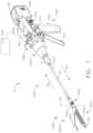
- FIG. 1is a perspective view of a surgical system including a handle assembly coupled to an interchangeable surgical tool assembly that is configured to be used in connection with conventional surgical staple/fastener cartridges and radio frequency (RF) cartridges according to one aspect of this disclosure.
- RFradio frequency
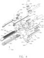
- FIG. 2is an exploded perspective assembly view of the surgical system of FIG. 1 according to one aspect of this disclosure.
- FIG. 3is another exploded perspective assembly view of portions of the handle assembly and interchangeable surgical tool assembly of FIGS. 1 and 2 according to one aspect of this disclosure.
- FIG. 4is an exploded assembly view of a proximal portion of the interchangeable surgical tool assembly of FIGS. 1 - 3 according to one aspect of this disclosure.
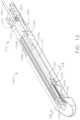
- FIG. 5is another exploded assembly view of a distal portion of the interchangeable surgical tool assembly of FIGS. 1 - 5 according to one aspect of this disclosure.
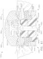
- FIG. 6is a partial cross-sectional view of the end effector depicted in FIGS. 1 - 5 supporting an RF cartridge therein and with tissue clamped between the cartridge and the anvil according to one aspect of this disclosure.
- FIG. 7is a partial cross-sectional view of the anvil of FIG. 6 according to one aspect of this disclosure.
- FIG. 8is another exploded assembly view of a portion of the interchangeable surgical tool assembly of FIGS. 1 - 5 according to one aspect of this disclosure.
- FIG. 9is another exploded assembly view of the interchangeable surgical tool assembly and handle assembly of FIGS. 1 and 2 according to one aspect of this disclosure.
- FIG. 10is a perspective view of an RF cartridge and an elongate channel of the interchangeable surgical tool assembly of FIGS. 1 - 5 according to one aspect of this disclosure.
- FIG. 11is a partial perspective view of portions of the RF cartridge and elongate channel of FIG. 10 with a knife member aspect according to one aspect of this disclosure.
- FIG. 12is another perspective view of the RF cartridge installed in the elongate channel of FIG. 10 and illustrating a portion of a flexible shaft circuit arrangement according to one aspect of this disclosure.
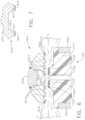
- FIG. 13is a cross-sectional end view of the RF cartridge and elongate channel of FIG. 12 taken along lines 13 - 13 in FIG. 12 according to one aspect of this disclosure.
- FIG. 14is a top cross-sectional view of a portion of the interchangeable surgical tool assembly of FIGS. 1 and 5 with the end effector thereof in an articulated position according to one aspect of this disclosure.
- FIG. 15is a perspective view of an onboard circuit board arrangement and RF generator plus configuration according to one aspect of this disclosure.
- FIGS. 16 A- 16 Bis a block diagram of a control circuit of the surgical instrument of FIG. 1 spanning two drawing sheets according to one aspect of this disclosure.
- FIG. 17is a block diagram of the control circuit of the surgical instrument of FIG. 1 illustrating interfaces between the handle assembly, the power assembly, and the handle assembly and the interchangeable shaft assembly according to one aspect of this disclosure.
- FIG. 18is a schematic diagram of a surgical instrument configured to control various functions according to one aspect of this disclosure.
- FIG. 19is side elevational view of the surgical instrument with the casing removed displaying a trigger sensing assembly, wherein the closure trigger is in the unactuated position according to one aspect of this disclosure.
- FIG. 20is a side elevational view if the surgical instrument with the casing removed displaying a trigger sensing assembly, wherein the closure trigger is in the actuated position according to one aspect of this disclosure.
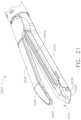
- FIG. 21is a perspective view of an end effector comprising a tissue thickness sensing assembly according to one aspect of this disclosure.
- FIG. 22is a schematic view of a sensor of the tissue thickness sensing assembly according to one aspect of this disclosure.
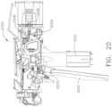
- FIG. 23is an exploded perspective view of a position sensing assembly according to one aspect of this disclosure.
- FIG. 24is a diagram of a circuit and a position sensor of a position sensing assembly according to one aspect of this disclosure.
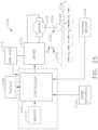
- FIG. 25is a block diagram of one example of a surgical instrument configured to display various statuses of the surgical instrument according to one aspect of this disclosure.
- FIG. 26is a display depicting RF energy status information of the surgical instrument according to one aspect of this disclosure.
- FIG. 27is a display depicting RF energy status information of the surgical instrument according to one aspect of this disclosure.
- FIG. 28is a display depicting RF energy status information of the surgical instrument according to one aspect of this disclosure.
- FIG. 29is a display depicting RF energy status information of the surgical instrument according to one aspect of this disclosure.
- FIG. 30is a display depicting temperature information of the surgical instrument according to one aspect of this disclosure.
- FIG. 31is a display depicting tissue water content information of the surgical instrument according to one aspect of this disclosure.
- FIG. 32is a display depicting operational progress information of the surgical instrument according to one aspect of this disclosure.
- FIG. 33is a display depicting operational progress information of the surgical instrument according to one aspect of this disclosure.
- FIG. 34is a display depicting tissue and operational progress information of the surgical instrument according to one aspect of this disclosure.
- FIG. 35is a display depicting a warning of the surgical instrument according to one aspect of this disclosure.
- FIG. 36is a display depicting a warning of the surgical instrument according to one aspect of this disclosure.
- FIG. 37is a display depicting status, operational progress, and tissue information of the surgical instrument according to one aspect of this disclosure.
- FIG. 38is a display depicting RF cartridge status information of the surgical instrument according to one aspect of this disclosure.
- FIG. 39is a display depicting RF cartridge status information of the surgical instrument according to one aspect of this disclosure
- FIG. 40shows a nozzle assembly that constitutes a modular portion of the surgical tool assembly may include shaft module circuitry uniquely configured to control various functions in the shaft assembly while also communicating with the handle assembly and allowing for an electrosurgical generator to be controlled from the powered stapling handle, according to some aspects.
- FIG. 41illustrates a block diagram of a surgical system programmed to communicate power and control signals with an end effector, according to one aspect of this disclosure.
- FIG. 42is a schematic top view of a jaw in an end effector according to one aspect of this disclosure.
- FIG. 43is a graph depicting voltage applied to electrodes as a function of time according to one aspect of this disclosure.
- FIG. 44is a logic flow diagram depicting a process of a control program or a logic configuration for operating the surgical instrument according to one aspect of this disclosure.
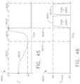
- FIG. 45is a graph of a tissue impedance curve as a function of time according to one aspect of this disclosure.
- FIG. 46is a graph depicting an example motor voltage curve according to one aspect of this disclosure.
- FIG. 47is a logic flow diagram depicting a process of a control program or a logic configuration for operating the surgical instrument according to one aspect of this disclosure.
- FIG. 48is a graph of a tissue impedance curve as a function of time according to one aspect of this disclosure.
- FIG. 49is a graph depicting an example motor voltage curve according to one aspect of this disclosure.
- FIG. 50is a top cross-section view of an aspect of a flexible assembly depicted in FIG. 14 according to one aspect of this disclosure.
- FIG. 51 Ais a top cross-section view of an aspect of the flexible assembly depicted in FIG. 14 for a knife member disposed at a proximal position as disposed within an aspect of an electrosurgical device according to one aspect of this disclosure.
- FIG. 51 Bis a top cross-section view of an aspect of the flexible assembly depicted in FIG. 14 for a knife member disposed at a distal position disposed within an aspect of an electrosurgical device according to one aspect of this disclosure.
- FIG. 52 Ais a top cross-section view of an aspect of the flexible assembly depicted in FIG. 14 for a knife member disposed at a proximal position according to one aspect of this disclosure.
- FIG. 52 Bis a top cross-section view of an aspect of the flexible assembly depicted in FIG. 14 for a knife member disposed at a distal position according to one aspect of this disclosure.
- FIG. 53is a perspective view of various aspects of a surgical system according to one aspect of this disclosure.
- FIG. 54is a partial cross-section of an end effector of the surgical system of FIG. 53 according to one aspect of this disclosure.
- FIG. 55is a partial perspective view of a radio-frequency cartridge supported by an elongate channel of the end effector of FIG. 54 according to one aspect of this disclosure.
- FIG. 56is an exploded perspective assembly view of portions of a handle assembly and an interchangeable tool assembly of the surgical system of FIG. 53 according to one aspect of this disclosure.
- FIG. 57is a cross-sectional view of a jaw member comprising an electrosurgical cartridge supported by an elongated channel, according to some aspects of the present disclosure.
- FIG. 58is a diagram illustrating an operation of a first electrode, according to some aspects of the present disclosure.
- FIG. 59is a diagram illustrating an operation of a second electrode, according to some aspects of the present disclosure.
- FIG. 60is a logic flow diagram of a process depicting a control program or a logic configuration for applying therapeutic electrosurgical energy according to one aspect of this disclosure.
- FIG. 61is a schematic cross-sectional view of an electrosurgical end effector according to one aspect of this disclosure.
- FIG. 62is a perspective view of an end effector according to one aspect of this disclosure.
- FIG. 63 Ais a perspective view of an aspect of an end effector in an open configuration.
- FIG. 63 Bis a side cross-section view of the aspect of the end effector depicted in FIG. 63 A .
- FIG. 64is a diagram of aspects of surface features that may be disposed along a shear electrode as depicted in FIG. 63 A .
- FIG. 65is a perspective view of a staple cartridge of the interchangeable surgical tool assembly of FIGS. 1 - 5 according to one aspect of this disclosure.
- FIG. 66illustrates a method of utilizing the interchangeable tool assembly of FIG. 1 according to various aspects.
- Electrosurgical devicesmay be used in many surgical operations. Electrosurgical devices may apply electrical energy to tissue in order to treat tissue.
- An electrosurgical devicemay comprise an instrument having a distally mounted end effector comprising one or more electrodes. The end effector can be positioned against tissue such that electrical current may be introduced into the tissue.
- Electrosurgical devicescan be configured for monopolar or bipolar operation. During monopolar operation, current may be introduced into the tissue by an active (or source) electrode on the end effector and returned through a return electrode. The return electrode may be a grounding pad and separately located on a patient's body. During bipolar operation, current may be introduced into and returned from the tissue by the active and return electrodes, respectively, of the end effector.
- the end effectormay include two or more jaw members. At least one of the jaw members may have at least one electrode. At least one jaw may be moveable from a position spaced apart from the opposing jaw for receiving tissues to a position in which the space between the jaw members is less than that of the first position. This movement of the moveable jaw may compress the tissue held between. Heat generated by the current flow through the tissue in combination with the compression achieved by the jaw's movement may form hemostatic seals within the tissue and/or between tissues and, thus, may be particularly useful for sealing blood vessels, for example.
- the end effectormay comprise a cutting member. The cutting member may be movable relative to the tissue and the electrodes to transect the tissue.
- Electrosurgical devicesalso may include mechanisms to clamp tissue together, such as a stapling device, and/or mechanisms to sever tissue, such as a tissue knife.
- An electrosurgical devicemay include a shaft for placing the end effector proximate to tissue undergoing treatment.
- the shaftmay be straight or curved, bendable or non-bendable.
- the shaftmay have one or more articulation joints to permit controlled bending of the shaft. Such joints may permit a user of the electrosurgical device to place the end effector in contact with tissue at an angle to the shaft when the tissue being treated is not readily accessible using an electrosurgical device having a straight, non-bending shaft.
- RF energyis a form of electrical energy that may be in the frequency range of 200 kilohertz (kHz) to 1 megahertz (MHz).
- kHzkilohertz
- MHzmegahertz
- an electrosurgical instrumentcan transmit low frequency RF energy through tissue, which causes ionic agitation, or friction, in effect resistive heating, thereby increasing the temperature of the tissue. Because a sharp boundary is created between the affected tissue and the surrounding tissue, surgeons can operate with a high level of precision and control, without sacrificing un-targeted adjacent tissue. The low operating temperatures of RF energy is useful for removing, shrinking, or sculpting soft tissue while simultaneously sealing blood vessels. RF energy works particularly well on connective tissue, which is primarily comprised of collagen and shrinks when contacted by heat.
- the RF energymay be in a frequency range described in EN 60601-2-2:2009+A11:2011, Definition 201.3.218—HIGH FREQUENCY.
- the frequency in monopolar RF applicationsmay be typically restricted to less than 5 MHz.
- the frequency in bipolar RF applicationscan be almost anything. Frequencies above 200 kHz can be typically used for monopolar applications in order to avoid the unwanted stimulation of nerves and muscles that would result from the use of low frequency current. Lower frequencies may be used for bipolar applications if the risk analysis shows the possibility of neuromuscular stimulation has been mitigated to an acceptable level. Normally, frequencies above 5 MHz are not used in order to minimize the problems associated with high frequency leakage currents. Higher frequencies may, however, be used in the case of bipolar applications. It is generally recognized that 10 mA is the lower threshold of thermal effects on tissue.
- FIGS. 1 and 2depict a motor-driven surgical system 10 that may be used to perform a variety of different surgical procedures.
- the surgical system 10comprises an interchangeable surgical tool assembly 1000 that is operably coupled to a handle assembly 500 .
- the interchangeable surgical tool assembly 1000may also be effectively employed with a tool drive assembly of a robotically controlled or automated surgical system.
- the surgical tool assembly 1000 disclosed hereinmay be employed with various robotic systems, instruments, components and methods such as, but not limited to, those disclosed in U.S. Pat. No. 9,072,535, entitled SURGICAL STAPLING INSTRUMENTS WITH ROTATABLE STAPLE DEPLOYMENT ARRANGEMENTS, which is hereby incorporated by reference herein in its entirety.
- the handle assembly 500may comprise a handle housing 502 that includes a pistol grip portion 504 that can be gripped and manipulated by the clinician.
- the handle assembly 500operably supports a plurality of drive systems that are configured to generate and apply various control motions to corresponding portions of the interchangeable surgical tool assembly 1000 .
- the handle assembly 500may further include a handle frame 506 that operably supports the plurality of drive systems.
- the handle frame 506can operably support a “first” or closure drive system, generally designated as 510 , which may be employed to apply closing and opening motions to the interchangeable surgical tool assembly 1000 .
- the closure drive system 510may include an actuator in the form of a closure trigger 512 that is pivotally supported by the handle frame 506 .
- an actuatorin the form of a closure trigger 512 that is pivotally supported by the handle frame 506 .
- Such arrangementenables the closure trigger 512 to be manipulated by a clinician such that when the clinician grips the pistol grip portion 504 of the handle assembly 500 , the closure trigger 512 may be easily pivoted from a starting or “unactuated” position to an “actuated” position and more particularly to a fully compressed or fully actuated position.
- the cliniciandepresses the closure trigger 512 towards the pistol grip portion 504 .
- closure drive system 510when the clinician fully depresses the closure trigger 512 to attain the full closure stroke, the closure drive system 510 is configured to lock the closure trigger 512 into the fully depressed or fully actuated position.
- the clinicianWhen the clinician desires to unlock the closure trigger 512 to permit it to be biased to the unactuated position, the clinician simply activates a closure release button assembly 518 which enables the closure trigger to return to unactuated position.
- the closure release button assembly 518may also be configured to interact with various sensors that communicate with a microcontroller in the handle assembly 500 for tracking the position of the closure trigger 512 . Further details concerning the configuration and operation of the closure release button assembly 518 may be found in U.S. Patent Application Publication No. 2015/0272575, now U.S. Pat. No. 9,913,642.
- the handle assembly 500 and the handle frame 506may operably support another drive system referred to herein as a firing drive system 530 that is configured to apply firing motions to corresponding portions of the interchangeable surgical tool assembly that is attached thereto.
- the firing drive system 530may employ an electric motor 505 that is located in the pistol grip portion 504 of the handle assembly 500 .
- the motor 505may be a DC brushed driving motor having a maximum rotation of, approximately, 25,000 RPM, for example.
- the motor 505may include a brushless motor, a cordless motor, a synchronous motor, a stepper motor, or any other suitable electric motor.
- the motor 505may be powered by a power source 522 that in one form may comprise a removable power pack.
- the power packmay support a plurality of Lithium Ion (“LI”) or other suitable batteries therein. A number of batteries may be connected in series may be used as the power source 522 for the surgical system 10 .
- the power source 522may be replaceable and/or rechargeable.
- the electric motor 505is configured to axially drive a longitudinally movable drive member 540 ( FIG. 3 ) in a distal and proximal directions depending upon the polarity of the motor. For example, when the motor 505 is driven in one rotary direction, the longitudinally movable drive member will be axially driven in a distal direction “DD”. When the motor 505 is driven in the opposite rotary direction, the longitudinally movable drive member 540 will be axially driven in a proximal direction “PD”.
- the handle assembly 500can include a switch 513 which can be configured to reverse the polarity applied to the electric motor 505 by the power source 522 or otherwise control the motor 505 .
- the handle assembly 500can also include a sensor or sensors (not shown) that is configured to detect the position of the drive member and/or the direction in which the drive member is being moved. Actuation of the motor 505 can be controlled by a firing trigger (not shown) that is adjacent to the closure trigger 512 and pivotally supported on the handle assembly 500 .
- the firing triggermay be pivoted between an unactuated position and an actuated position.
- the firing triggermay be biased into the unactuated position by a spring or other biasing arrangement such that when the clinician releases the firing trigger, it may be pivoted or otherwise returned to the unactuated position by the spring or biasing arrangement.
- the firing triggercan be positioned “outboard” of the closure trigger 512 . As discussed in U.S. Patent Application Publication No.
- the handle assembly 500may be equipped with a firing trigger safety button (not shown) to prevent inadvertent actuation of the firing trigger.
- a firing trigger safety button(not shown) to prevent inadvertent actuation of the firing trigger.
- the safety buttonis contained in the handle assembly 500 where the clinician cannot readily access it and move it between a safety position preventing actuation of the firing trigger and a firing position wherein the firing trigger may be fired.
- the safety button and the firing triggerpivot down wherein they can then be manipulated by the clinician.
- the longitudinally movable drive member 540may have a rack of teeth 542 formed thereon for meshing engagement with a corresponding drive gear arrangement (not shown) that interfaces with the motor. See FIG. 3 . Further details regarding those features may be found in U.S. Patent Application Publication No. 2015/0272575, now U.S. Pat. No. 9,913,642.
- the longitudinally movable drive memberis insulated to protect it from inadvertent RF energy.
- At least one formalso includes a manually-actuatable “bailout” assembly that is configured to enable the clinician to manually retract the longitudinally movable drive member should the motor 505 become disabled.
- the bailout assemblymay include a lever or bailout handle assembly that is stored within the handle assembly 500 under a releasable door 550 . See FIG. 2 .
- the levermay be configured to be manually pivoted into ratcheting engagement with the teeth in the drive member.
- the cliniciancan manually retract the drive member 540 by using the bailout handle assembly to ratchet the drive member in the proximal direction “PD”.
- the interchangeable surgical tool assembly 1000includes a surgical end effector 1500 that comprises a first jaw 1600 and a second jaw 1800 .
- the first jawcomprises an elongate channel 1602 that is configured to operably support a conventional (mechanical) surgical staple/fastener cartridge 1400 ( FIG. 4 ) or a radio frequency (RF) cartridge 1700 ( FIGS. 1 and 2 ) therein.
- the second jaw 1800comprises an anvil 1810 that is pivotally supported relative to the elongate channel 1602 .
- the anvil 1810may be is selectively moved toward and away from a surgical cartridge supported in the elongate channel 1602 between open and closed positions by actuating the closure drive system 510 .
- the anvil 1810is pivotally supported on a proximal end portion of the elongate channel 1602 for selective pivotal travel about a pivot axis that is transverse to the shaft axis SA.
- Actuation of the closure drive system 510may result in the distal axial movement of a proximal closure member or proximal closure tube 1910 that is attached to an articulation connector 1920 .
- the articulation connector 1920includes upper and lower tangs 1922 , 1924 protrude distally from a distal end of the articulation connector 1920 to be movably coupled to an end effector closure sleeve or distal closure tube segment 1930 .
- the distal closure tube segment 1930includes an upper tang 1932 and a lower tang (not shown) that protrude proximally from a proximal end thereof.
- An upper double pivot link 1940includes proximal and distal pins 1941 , 1942 that engage corresponding holes in the upper tangs 1922 , 1932 of the articulation connector 1920 and distal closure tube segment 1930 , respectively.
- a lower double pivot link 1944includes proximal and distal pins 1945 , 1946 that engage corresponding holes in the lower tangs 1924 of the articulation connector 1920 and distal closure tube segment 1930 , respectively.
- the distal closure tube segment 1930includes positive jaw opening features or tabs 1936 , 1938 that correspond with corresponding portions of the anvil 1810 to apply opening motions to the anvil 1810 as the distal closure tube segment 1930 is retracted in the proximal direction PD to a starting position.
- positive jaw opening features or tabs 1936 , 1938that correspond with corresponding portions of the anvil 1810 to apply opening motions to the anvil 1810 as the distal closure tube segment 1930 is retracted in the proximal direction PD to a starting position.
- Further details regarding the opening and closing of the anvil 1810may be found in U.S. patent application Ser. No. 15/635,621, entitled SURGICAL INSTRUMENT WITH POSITIVE JAW OPENING FEATURES, filed on Jun. 28, 2017, now U.S. Patent Application Publication No. 2019/0000463, the entire disclosure of which is hereby incorporated by reference herein.
- the interchangeable surgical tool assembly 1000includes a tool frame assembly 1200 that comprises a tool chassis 1210 that operably supports a nozzle assembly 1240 thereon.
- a tool frame assembly 1200that comprises a tool chassis 1210 that operably supports a nozzle assembly 1240 thereon.
- the tool chassis 1210 and nozzle arrangement 1240facilitate rotation of the surgical end effector 1500 about a shaft axis SA relative to the tool chassis 1210 . Such rotational travel is represented by arrow R in FIG. 1 .
- the interchangeable surgical tool assembly 1000includes a spine assembly 1250 that operably supports the proximal closure tube 1910 and is coupled to the surgical end effector 1500 .
- the spine assembly 1250may be fabricated from an upper spine segment 1251 and a lower spine segment 1252 that are interconnected together by snap features, adhesive, welding, etc.
- the spine assembly 1250includes a proximal end 1253 that is rotatably supported in the tool chassis 1210 .
- the proximal end 1253 of the spine assembly 1250is attached to a spine bearing (not shown) that is configured to be supported within the tool chassis 1210 .
- Such arrangementfacilitates rotatable attachment of the spine assembly 1250 to the tool chassis such that the spine assembly 1250 may be selectively rotated about a shaft axis SA relative to the tool chassis 1210 .
- the upper spine segment 1251terminates in an upper lug mount feature 1260 and the lower spine segment 1252 terminates in a lower lug mount feature 1270 .
- the upper lug mount feature 1260is formed with a lug slot 1262 therein that is adapted to mountingly support an upper mounting link 1264 therein.
- the lower lug mount feature 1270is formed with a lug slot 1272 therein that is adapted to mountingly support a lower mounting link 1274 therein.
- the upper mounting link 1264includes a pivot socket 1266 therein that is offset from the shaft axis SA.
- the pivot socket 1266is adapted to rotatably receive therein a pivot pin 1634 that is formed on a channel cap or anvil retainer 1630 that is attached to a proximal end portion 1610 of the elongate channel 1602 .
- the lower mounting link 1274includes lower pivot pin 1276 that adapted to be received within a pivot hole 1611 formed in the proximal end portion 1610 of the elongate channel 1602 .
- the lower pivot pin 1276 as well as the pivot hole 1611is offset from the shaft axis SA.
- the lower pivot pin 1276is vertically aligned with the pivot socket 1266 to define the articulation axis AA about which the surgical end effector 1500 may articulate relative to the shaft axis SA. See FIG. 1 .
- the articulation axis AAis transverse to the shaft axis SA, in at least one arrangement, the articulation axis AA is laterally offset therefrom and does not intersect the shaft axis SA.
- a proximal end 1912 of the proximal closure tube 1910is rotatably coupled to a closure shuttle 1914 by a connector 1916 that is seated in an annular groove 1915 in the proximal closure tube segment 1910 .
- the closure shuttle 1914is supported for axial travel within the tool chassis 1210 and has a pair of hooks 1917 thereon configured to engage the closure drive system 510 when the tool chassis 1210 is coupled to the handle frame 506 .
- the tool chassis 1210further supports a latch assembly 1280 for releasably latching the tool chassis 1210 to the handle frame 506 . Further details regarding the tool chassis 1210 and latch assembly 1280 may be found in U.S.
- the firing drive system 530 in the handle assembly 500is configured to be operably coupled to a firing system 1300 that is operably supported in the interchangeable surgical tool assembly 1000 .
- the firing system 1300may include an intermediate firing shaft portion 1310 that is configured to be axially moved in the distal and proximal directions in response to corresponding firing motions applied thereto by the firing drive system 530 . See FIG. 4 .
- a proximal end 1312 of the intermediate firing shaft portion 1310has a firing shaft attachment lug 1314 formed thereon that is configured to be seated into an attachment cradle 544 ( FIG. 3 ) that is on the distal end of the longitudinally movable drive member 540 of the firing drive system 530 within the handle assembly 500 .
- the intermediate firing shaft portion 1310is configured for attachment to a distal cutting portion or knife bar 1320 .
- the knife bar 1320is connected to a firing member or knife member 1330 .
- the knife member 1330comprises a knife body 1332 that operably supports a tissue cutting blade 1334 thereon.
- the knife body 1332may further include anvil engagement tabs or features 1336 and channel engagement features or a foot 1338 .
- the anvil engagement features 1336may serve to apply additional closure motions to the anvil 1810 as the knife member 1330 is advanced distally through the end effector 1500 .
- the surgical end effector 1500is selectively articulatable about the articulation axis AA by an articulation system 1360 .
- the articulation system 1360includes proximal articulation driver 1370 that is pivotally coupled to an articulation link 1380 .
- an offset attachment lug 1373is formed on a distal end 1372 of the proximal articulation driver 1370 .
- a pivot hole 1374is formed in the offset attachment lug 1373 and is configured to pivotally receive therein a proximal link pin 1382 formed on the proximal end 1381 of the articulation link 1380 .
- a distal end 1383 of the articulation link 1380includes a pivot hole 1384 that is configured to pivotally receive therein a channel pin 1618 formed on the proximal end portion 1610 of the elongate channel 1602 .
- proximal articulation driver 1370will thereby apply articulation motions to the elongate channel 1602 to thereby cause the surgical end effector 1500 to articulate about the articulation axis AA relative to the spine assembly 1250 .
- the proximal articulation driver 1370can be held in position by an articulation lock 1390 when the proximal articulation driver 1370 is not being moved in the proximal or distal directions.
- the interchangeable surgical tool assembly 1000can include a shifter assembly 1100 which can be configured to selectively and releasably couple the proximal articulation driver 1310 to the firing system 1300 .
- the shifter assembly 1100includes a lock collar, or lock sleeve 1110 , positioned around the intermediate firing shaft portion 1310 of the firing system 1300 wherein the lock sleeve 1110 can be rotated between an engaged position in which the lock sleeve 1110 operably couples the proximal articulation driver 1370 to the firing member assembly 1300 and a disengaged position in which the proximal articulation driver 1370 is not operably coupled to the firing member assembly 1300 .
- proximal articulation driver 1370When lock sleeve 1110 is in its engaged position, distal movement of the firing member assembly 1300 can move the proximal articulation driver 1370 distally and, correspondingly, proximal movement of the firing member assembly 1300 can move the proximal articulation driver 1370 proximally.
- lock sleeve 1110When lock sleeve 1110 is in its disengaged position, movement of the firing member assembly 1300 is not transmitted to the proximal articulation driver 1370 and, as a result, the firing member assembly 1300 can move independently of the proximal articulation driver 1370 .
- the proximal articulation driver 1370can be held in position by the articulation lock 1390 when the proximal articulation driver 1370 is not being moved in the proximal or distal directions by the firing member assembly 1300 .
- the intermediate firing shaft portion 1310 of the firing member assembly 1300is formed with two opposed flat sides with a drive notch 1316 formed therein. See FIG. 5 .
- the lock sleeve 1110comprises a cylindrical, or an at least substantially cylindrical, body that includes a longitudinal aperture that is configured to receive the intermediate firing shaft portion 1310 therethrough.
- the lock sleeve 1110can comprise diametrically-opposed, inwardly-facing lock protrusions that, when the lock sleeve 1110 is in one position, are engagingly received within corresponding portions of the drive notch 1316 in the intermediate firing shaft portion 1310 and, when in another position, are not received within the drive notch 1316 to thereby permit relative axial motion between the lock sleeve 1110 and the intermediate firing shaft 1310 .
- the lock sleeve 1110further includes a lock member 1112 that is sized to be movably received within a notch 1375 in a proximal end of the proximal articulation driver 1370 .
- Such arrangementpermits the lock sleeve 1110 to slightly rotate into and out of engagement with the intermediate firing shaft portion 1310 while remaining in position for engagement or in engagement with the notch 1375 in the proximal articulation driver 1370 .
- the lock protrusionsare positioned within the drive notch 1316 in the intermediate firing shaft portion 1310 such that a distal pushing force and/or a proximal pulling force can be transmitted from the firing member assembly 1300 to the lock sleeve 1110 .
- Such axial pushing or pulling motionis then transmitted from the lock sleeve 1110 to the proximal articulation driver 1370 to thereby articulate the surgical end effector 1500 .
- the firing member assembly 1300 , the lock sleeve 1110 , and the proximal articulation driver 1370will move together when the lock sleeve 1110 is in its engaged (articulation) position.
- the lock sleeve 1110is in its disengaged position, the lock protrusions are not received within the drive notch 1316 in the intermediate firing shaft portion 1310 and, as a result, a distal pushing force and/or a proximal pulling force may not be transmitted from the firing member assembly 1300 to the lock sleeve 1110 (and the proximal articulation driver 1370 ).
- the shifter assembly 1100further includes a shifter key 1120 that is configured to be slidably received within a key groove formed in the outer perimeter of the lock sleeve 1110 .
- a shifter key 1120that is configured to be slidably received within a key groove formed in the outer perimeter of the lock sleeve 1110 .
- Such arrangementenables the shifter key 1120 to move axially with respect to the lock sleeve 1110 .
- U.S. patent application Ser. No. 15/635,631entitled SURGICAL INSTRUMENT WITH AXIALLY MOVABLE CLOSURE MEMBER, filed on Jun. 28, 2017, now U.S.
- a portion of the shifter key 1120is configured to cammingly interact with a cam opening (not shown) in the proximal closure tube portion 1910 .
- the shifter assembly 1100further includes a switch drum 1130 that is rotatably received on a proximal end portion of the proximal closure tube portion 1910 .
- a portion of the shifter key 1120extends through an axial slot segment in the switch drum 1130 and is movably received within an arcuate slot segment in the switch drum 1130 .
- a switch drum torsion spring 1132is mounted on the switch drum 1130 and engages a portion of the nozzle assembly 1240 to apply a torsional bias or rotation which serves to rotate the switch drum 1130 until the portion of the shifter key 1120 reaches an end portion of the cam opening in the proximal closure tube portion 1910 .
- the switch drum 1130may provide a torsional bias to the shifter key 1120 which thereby causes the lock sleeve 1110 to rotate into its engaged position with the intermediate firing shaft portion 1310 .
- This positionalso corresponds to the unactuated configuration of the proximal closure tube 1910 (and distal closure tube segment 1930 ).
- actuation of the intermediate firing shaft portion 1310will result in the axial movement of the proximal articulation driver 1370 to facilitate articulation of the end effector 1500 .
- the usermay then actuate the proximal closure tube portion 1910 . Actuation of the proximal closure tube portion 1910 will result in the distal travel of the distal closure tube segment 1930 to ultimately apply a closing motion to the anvil 1810 .
- This distal travel of the proximal closure tube portion 1910will result in the cam opening therein cammingly interacting with a cam portion of the shifter key 1120 to thereby cause the shifter key 1120 to rotate the lock sleeve 1110 in an actuation direction.
- Such rotation of the lock sleeve 1110will result in the disengagement of the lock protrusions from the drive notch 1316 in the intermediate firing shaft portion 1310 .
- the firing drive system 530may be actuated to actuate the intermediate firing shaft portion 1310 without actuating the proximal articulation driver 1370 .
- the interchangeable surgical tool assembly 1000can comprise a slip ring assembly 1150 which can be configured to conduct electrical power to and/or from the surgical end effector 1500 and/or communicate signals to and/or from the surgical end effector 1500 , back to an onboard circuit board 1152 , while facilitating rotational travel of the shaft and end effector 1500 about the shaft axis SA relative to the tool chassis 1210 by rotating the nozzle assembly 1240 .
- the onboard circuit board 1152includes an onboard connector 1154 that is configured to interface with a housing connector 562 ( FIG. 9 ) communicating with a microprocessor 560 that is supported in the handle assembly 500 or robotic system controller, for example.
- the slip ring assembly 1150is configured to interface with a proximal connector 1153 that interfaces with the onboard circuit board 1152 . Further details concerning the slip ring assembly 1150 and associated connectors may be found in U.S. patent application Ser. No. 13/803,086, now U.S. Patent Application Publication No. 2014/0263541, and U.S. patent application Ser. No. 15/019,196, now U.S. Pat. No. 10,413,291, which have each been herein incorporated by reference in their respective entirety as well as in U.S. patent application Ser. No. 13/800,067, entitled STAPLE CARTRIDGE TISSUE THICKNESS SENSOR SYSTEM, now U.S. Patent Application Publication No. 2014/0263552, which is hereby incorporated by reference herein in its entirety.
- FIG. 4An example version of the interchangeable surgical tool assembly 1000 disclosed herein may be employed in connection with a standard (mechanical) surgical fastener cartridge 1400 or a cartridge 1700 that is configured to facilitate cutting of tissue with the knife member and seal the cut tissue using radio frequency (RF) energy.
- RFradio frequency
- FIG. 4a conventional or standard mechanical-type cartridge 1400 is depicted.
- Such cartridge arrangementsare known and may comprise a cartridge body 1402 that is sized and shaped to be removably received and supported in the elongate channel 1602 .
- the cartridge body 1402may be configured to be removably retained in snap engagement with the elongate channel 1602 .
- the cartridge body 1402includes an elongate slot 1404 to accommodate axial travel of the knife member 1330 therethrough.
- the cartridge body 1402operably supports therein a plurality of staple drivers (not shown) that are aligned in rows on each side of the centrally disposed elongate slot 1404 .
- the driversare associated with corresponding staple/fastener pockets 1412 that open through the upper deck surface 1410 of the cartridge body 1402 .
- Each of the staple driverssupports one or more surgical staple or fastener (not shown) thereon.
- a sled assembly 1420is supported within a proximal end of the cartridge body 1402 and is located proximal to the drivers and fasteners in a starting position when the cartridge 1400 is new and unfired.
- the sled assembly 1420includes a plurality of sloped or wedge-shaped cams 1422 wherein each cam 1422 corresponds to a particular line of fasteners or drivers located on a side of the slot 1404 .
- the sled assembly 1420is configured to be contacted and driven by the knife member 1330 as the knife member is driven distally through the tissue that is clamped between the anvil and the cartridge deck surface 1410 .
- the fastener(s) supported thereonare driven out of their staple pockets 1412 and through the tissue that is clamped between anvil and the cartridge.
- the anvil 1810 in at least one formincludes an anvil mounting portion 1820 that has a pair of anvil trunnions 1822 protruding laterally therefrom to be pivotally received in corresponding trunnion cradles 1614 formed in the upstanding walls 1622 of the proximal end portion 1610 of the elongate channel 1602 .
- the anvil trunnions 1822are pivotally retained in their corresponding trunnion cradle 1614 by the channel cap or anvil retainer 1630 .
- the anvil mounting portion 1820is movably or pivotably supported on the elongate channel 1602 for selective pivotal travel relative thereto about a fixed anvil pivot axis that is transverse to the shaft axis SA.
- the anvil 1810includes an anvil body portion 1812 that is fabricated from an electrically conductive metal material for example and has a staple forming undersurface 1813 that has a series of fastener forming pockets 1814 formed therein on each side of a centrally disposed anvil slot 1815 that is configured to slidably accommodate the knife member 1330 therein.
- the anvil slot 1815opens into an upper opening 1816 that extends longitudinally through the anvil body 1812 to accommodate the anvil engagement features 1336 on the knife member 1330 during firing.
- a conventional mechanical surgical staple/fastener cartridge 1400is installed in the elongate channel 1602 , the staples/fasteners are driven through the tissue T and into forming contact with the corresponding fastener forming pockets 1814 .
- the anvil body 1812may have an opening in the upper portion thereof to facilitate ease of installation for example.
- An anvil cap 1818may be inserted therein and welded to the anvil body 1812 to enclose the opening and improve the overall stiffness of the anvil body 1812 .
- the tissue facing segments 1817 of the fastener forming undersurface 1813may have electrically insulative material 1819 thereon.
- the interchangeable surgical tool assembly 1000is configured with a firing member lockout system, generally designated as 1640 . See FIG. 8 .
- the elongate channel 1602includes a bottom surface or bottom portion 1620 that has two upstanding side walls 1622 protruding therefrom.
- a centrally disposed longitudinal channel slot 1624is formed through the bottom portion 1620 to facilitate the axial travel of the knife member 1330 therethrough.
- the channel slot 1624opens into a longitudinal passage 1626 that accommodates the channel engagement feature or foot 1338 on the knife member 1330 .
- the passage 1626serves to define two inwardly extending ledge portions 1628 that serve to engage corresponding portions of the channel engagement feature or foot 1338 .
- the firing member lockout system 1640includes proximal openings 1642 located on each side of the channel slot 1624 that are each configured to receive corresponding portions of the channel engagement feature or foot 1338 when the knife member 1330 is in a starting position.
- a knife lockout spring 1650is supported in the proximal end 1610 of the elongate channel 1602 and serves to bias the knife member 1330 downward.
- the knife lockout spring 1650includes two distally ending spring arms 1652 that are configured to engage corresponding central channel engagement features 1337 on the knife body 1332 .
- the spring arms 1652are configured to bias the central channel engagement features 1337 downward.
- the knife member 1330when in the starting (unfired position), the knife member 1330 is biased downward such that the channel engagement features or foot 1338 is received within the corresponding proximal openings 1642 in the elongate 1602 channel.
- the central channel engagement features 1137 and/or foot 1338When in that locked position, if one were to attempt to distally advance the knife 1330 , the central channel engagement features 1137 and/or foot 1338 would engage upstanding ledges 1654 on the elongate channel 1602 ( FIGS. 8 and 11 ) and the knife 1330 could not be fired.
- the firing member lockout system 1640also includes an unlocking assembly 1660 formed or supported on a distal end of the firing member body 1332 .
- the unlocking assembly 1660includes a distally extending ledge 1662 that is configured to engage an unlocking feature 1426 formed on the sled assembly 1420 when the sled assembly 1420 is in its starting position in an unfired surgical staple cartridge 1400 .
- the ledge 1662 on the unlocking assembly 1660contacts the unlocking feature 1426 on the sled assembly 1420 which serves to bias the knife member 1330 upward such that the central channel engagement features 1137 and/or foot 1338 clear the upstanding ledges 1654 in the channel bottom 1620 to facilitate axial passage of the knife member 1330 through the elongate channel 1602 . If a partially fired cartridge 1400 is unwittingly installed in the elongate channel, the sled assembly 1420 will not be in the starting position and the knife member 1330 will remain in the locked position.
- the clinicianmay position the tool chassis 1210 of the interchangeable surgical tool assembly 1000 above or adjacent to the distal end of the handle frame 506 such that tapered attachment portions 1212 formed on the tool chassis 1210 are aligned with dovetail slots 507 in the handle frame 506 .
- the clinicianmay then move the surgical tool assembly 1000 along an installation axis IA that is perpendicular to the shaft axis SA to seat the tapered attachment portions 1212 in “operable engagement” with the corresponding dovetail receiving slots 507 in the distal end of the handle frame 506 .
- the firing shaft attachment lug 1314 on the intermediate firing shaft portion 1310will also be seated in the cradle 544 in the longitudinally movable drive member 540 within the handle assembly 500 and the portions of a pin 516 on a closure link 514 will be seated in the corresponding hooks 1917 in the closure shuttle 1914 .
- the term “operable engagement” in the context of two componentsmeans that the two components are sufficiently engaged with each other so that upon application of an actuation motion thereto, the components may carry out their intended action, function and/or procedure.
- the onboard connector 1154 on the surgical tool assembly 1000is coupled to the housing connector 562 that communicates with the microprocessor 560 that is supported in the handle assembly 500 or robotic system controller, for example.
- the clinicianmay introduce the surgical end effector 1500 into the surgical site through a trocar or other opening in the patient to access the target tissue.
- the cliniciantypically axially aligns the surgical end effector 1500 along the shaft axis SA (unarticulated state).
- SAshaft axis
- the clinicianmay need to articulate the end effector 1500 to advantageously position it adjacent the target tissue. This is prior to closing the anvil 1810 onto the target tissue, so the closure drive system 510 would remain unactuated.
- actuation of the firing drive system 530will result in the application of articulation motions to the proximal articulation driver 1370 .
- the firing drive system 530is deactivated and the articulation lock 1390 may retain the surgical end effector 1500 in the articulated position.
- the clinicianmay then actuate the closure drive system 510 to close the anvil 1810 onto the target tissue.
- Such actuation of the closure drive system 510may also result in the shifter assembly 1100 delinking the proximal articulation driver 1370 from the intermediate firing shaft portion 1310 .
- the clinicianmay once again actuate the firing drive system 530 to axially advance the firing member 1330 through the surgical staple/fastener cartridge 1400 or RF cartridge 1700 to cut the clamped tissue and fire the staples/fasteners into the cut tissue T.
- Other closure and firing drive arrangements, actuator arrangementsmay also be employed to control the axial movement of the closure system components, the articulation system components and/or the firing system components of the surgical tool assembly 1000 without departing from the scope of the present disclosure.
- the surgical tool assembly 1000is configured to be used in connection with conventional mechanical surgical staple/fastener cartridges 1400 as well as with RF cartridges 1700 .
- the RF cartridge 1700may facilitate mechanical cutting of tissue that is clamped between the anvil 1810 and the RF cartridge 1700 with the knife member 1330 while coagulating electrical current is delivered to the tissue in the current path.
- Alternative arrangements for mechanically cutting and coagulating tissue using electrical currentare disclosed in, for example, U.S. Pat. Nos. 5,403,312; 7,780,663 and U.S. patent application Ser. No.
- the RF surgical cartridge 1700includes a cartridge body 1710 that is sized and shaped to be removably received and supported in the elongate channel 1602 .
- the cartridge body 1710may be configured to be removably retained in snap engagement with the elongate channel 1602 .
- the cartridge body 1710may be fabricated from a polymer material, such as, for example, an engineering thermoplastic such as the liquid crystal polymer (LCP) VECTRATM and the elongate channel 1602 may be fabricated from metal.
- LCPliquid crystal polymer
- the cartridge body 1710includes a centrally disposed elongate slot 1712 that extends longitudinally through the cartridge body to accommodate longitudinal travel of the knife 1330 therethrough.
- a pair of lockout engagement tails 1714extend proximally from the cartridge body 1710 .
- Each lockout engagement tail 1714has a lockout pad 1716 formed on the underside thereof that are sized to be received within a corresponding proximal opening portion 1642 in the channel bottom 1620 .
- the lockout engagement tails 1714cover the openings 1642 and ledges 1654 to retain the knife 1330 in an unlocked position ready for firing.
- the cartridge body 1710is formed with a centrally disposed raised electrode pad 1720 .
- the elongate slot 1712extends through the center of the electrode pad 1720 and serves to divide the pad 1720 into a left pad segment 1720 L and a right pad segment 1720 R.
- a right flexible circuit assembly 1730 Ris attached to the right pad segment 1720 R and a left flexible circuit assembly 1730 L is attached to the left pad segment 1720 L.
- the right flexible circuit 1730 Rcomprises a plurality of electrical conductors 1732 R that may include, for example, wider electrical conductors/conductors for RF purposes and thinner electrical conductors for conventional stapling purposes that are supported or attached or embedded into a right insulator sheath/member 1734 R that is attached to the right pad 1720 R.
- the right flexible circuit assembly 1730 Rincludes a “phase one”, proximal right electrode 1736 R and a “phase two” distal right electrode 1738 R.
- the left flexible circuit assembly 1730 Lcomprises a plurality of electrical conductors 1732 L that may include, for example, wider electrical conductors/conductors for RF purposes and thinner electrical conductors for conventional stapling purposes that are supported or attached or embedded into a left insulator sheath/member 1734 L that is attached to the left pad 1720 L.
- the left flexible circuit assembly 1730 Lincludes a “phase one”, proximal left electrode 1736 L and a “phase two” distal left electrode 1738 L.
- the left and right electrical conductors 1732 L, 1732 Rare attached to a distal micro-chip 1740 mounted to the distal end portion of the cartridge body 1710 .
- each of the right and left flexible circuits 1730 R, 1730 Lmay have an overall width “CW” of approximately 0.025 inches and each of the electrodes 1736 R, 1736 L, 1738 R, 1738 R has a width “EW” of approximately 0.010 inches for example. See FIG. 13 .
- CWoverall width
- EWwidth
- other widths/sizesare contemplated and may be employed in alternative aspects.
- RF energyis supplied to the surgical tool assembly 1000 by a conventional RF generator 400 through a supply lead 402 .
- the supply lead 402includes a male plug assembly 406 that is configured to be plugged into corresponding female connectors 410 that are attached to a segmented RF circuit 1160 on the an onboard circuit board 1152 . See FIG. 15 .
- Such arrangementfacilitates rotational travel of the shaft and end effector 1500 about the shaft axis SA relative to the tool chassis 1210 by rotating the nozzle assembly 1240 without winding up the supply lead 402 from the generator 400 .
- An onboard on/off power switch 420is supported on the latch assembly 1280 and tool chassis 1210 for turning the RF generator on and off.
- the onboard segmented RF circuit 1160communicates with the microprocessor 560 through the connectors 1154 and 562 .
- the handle assembly 500may also include a display screen 430 for viewing information about the progress of sealing, stapling, knife location, status of the cartridge, tissue, temperature, etc.
- the slip ring assembly 1150interfaces with a distal connector 1162 that includes a flexible shaft circuit strip or assembly 1164 that may include a plurality of narrow electrical conductors 1166 for stapling related activities and wider electrical conductors 1168 used for RF purposes. As shown in FIGS.
- the flexible shaft circuit strip 1164is centrally supported between the laminated plates or bars 1322 that form the knife bar 1320 .
- Such arrangementfacilitates sufficient flexing of the knife bar 1320 and flexible shaft circuit strip 1164 during articulation of the end effector 1500 while remaining sufficiently stiff so as to enable the knife member 1330 to be distally advanced through the clamped tissue.
- the elongate channel 1602includes a channel circuit 1670 supported in a recess 1621 that extends from the proximal end 1610 of the elongate channel 1602 to a distal location 1623 in the elongate channel bottom portion 1620 .
- the channel circuit 1670includes a proximal contact portion 1672 that contacts a distal contact portion 1169 of the flexible shaft circuit strip 1164 for electrical contact therewith.
- a distal end 1674 of the channel circuit 1670is received within a corresponding wall recess 1625 formed in one of the channel walls 1622 and is folded over and attached to an upper edge 1627 of the channel wall 1622 .
- a series of corresponding exposed contacts 1676are provided in the distal end 1674 of the channel circuit 1670 as shown in FIG. 10 .
- an end 1752 of a flexible cartridge circuit 1750is attached to the distal micro-chip 1740 and is affixed to the distal end portion of the cartridge body 1710 .
- Another end 1754is folded over the edge of the cartridge deck surface 1711 and includes exposed contacts 1756 configured to make electrical contact with the exposed contacts 1676 of the channel circuit 1670 .
- the electrodes as well as the distal micro-chip 1740are powered and communicate with the onboard circuit board 1152 through contact between the flexible cartridge circuit 1750 , the flexible channel circuit 1670 , the flexible shaft circuit 1164 and the slip ring assembly 1150 .
- FIGS. 16 A- 16 Bis a block diagram of a control circuit 700 of the surgical instrument 10 of FIG. 1 spanning two drawing sheets according to one aspect of this disclosure.
- a handle assembly 702may include a motor 714 which can be controlled by a motor driver 715 and can be employed by the firing system of the surgical instrument 10 .
- the motor 714may be a DC brushed driving motor having a maximum rotational speed of approximately 25,000 RPM.
- the motor 714may include a brushless motor, a cordless motor, a synchronous motor, a stepper motor, or any other suitable electric motor.
- the motor driver 715may comprise an H-Bridge driver comprising field-effect transistors (FETs) 719 , for example.
- the motor 714can be powered by the power assembly 706 releasably mounted to the handle assembly 500 for supplying control power to the surgical instrument 10 .
- the power assembly 706may comprise a battery which may include a number of battery cells connected in series that can be used as the power source to power the surgical instrument 10 .
- the battery cells of the power assembly 706may be replaceable and/or rechargeable.
- the battery cellscan be Lithium-Ion batteries which can be separably couplable to the power assembly 706 .
- the shaft assembly 704may include a shaft assembly controller 722 which can communicate with a safety controller and power management controller 716 through an interface while the shaft assembly 704 and the power assembly 706 are coupled to the handle assembly 702 .
- the interfacemay comprise a first interface portion 725 which may include one or more electric connectors for coupling engagement with corresponding shaft assembly electric connectors and a second interface portion 727 which may include one or more electric connectors for coupling engagement with corresponding power assembly electric connectors to permit electrical communication between the shaft assembly controller 722 and the power management controller 716 while the shaft assembly 704 and the power assembly 706 are coupled to the handle assembly 702 .
- One or more communication signalscan be transmitted through the interface to communicate one or more of the power requirements of the attached interchangeable shaft assembly 704 to the power management controller 716 .
- the power management controllermay modulate the power output of the battery of the power assembly 706 , as described below in greater detail, in accordance with the power requirements of the attached shaft assembly 704 .
- the connectorsmay comprise switches which can be activated after mechanical coupling engagement of the handle assembly 702 to the shaft assembly 704 and/or to the power assembly 706 to allow electrical communication between the shaft assembly controller 722 and the power management controller 716 .
- the interfacecan facilitate transmission of the one or more communication signals between the power management controller 716 and the shaft assembly controller 722 by routing such communication signals through a main controller 717 residing in the handle assembly 702 , for example.
- the interfacecan facilitate a direct line of communication between the power management controller 716 and the shaft assembly controller 722 through the handle assembly 702 while the shaft assembly 704 and the power assembly 706 are coupled to the handle assembly 702 .
- the main controller 717may be any single core or multicore processor such as those known under the trade name ARM Cortex by Texas Instruments.
- the main controller 717may be an LM4F230H5QR ARM Cortex-M4F Processor Core, available from Texas Instruments, for example, comprising on-chip memory of 256 KB single-cycle flash memory, or other non-volatile memory, up to 40 MHz, a prefetch buffer to improve performance above 40 MHz, a 32 KB single-cycle serial random access memory (SRAM), internal read-only memory (ROM) loaded with StellarisWare® software, 2 KB electrically erasable programmable read-only memory (EEPROM), one or more pulse width modulation (PWM) modules, one or more quadrature encoder inputs (QEI) analog, one or more 12-bit Analog-to-Digital Converters (ADC) with 12 analog input channels, details of which are available for the product datasheet.
- the safety controllermay be a safety controller platform comprising two controller-based families such as TMS570 and RM4x known under the trade name Hercules ARM Cortex R4, also by Texas Instruments.
- the safety controllermay be configured specifically for IEC 61508 and ISO 26262 safety critical applications, among others, to provide advanced integrated safety features while delivering scalable performance, connectivity, and memory options.
- the power assembly 706may include a power management circuit which may comprise the power management controller 716 , a power modulator 738 , and a current sense circuit 736 .
- the power management circuitcan be configured to modulate power output of the battery based on the power requirements of the shaft assembly 704 while the shaft assembly 704 and the power assembly 706 are coupled to the handle assembly 702 .
- the power management controller 716can be programmed to control the power modulator 738 of the power output of the power assembly 706 and the current sense circuit 736 can be employed to monitor power output of the power assembly 706 to provide feedback to the power management controller 716 about the power output of the battery so that the power management controller 716 may adjust the power output of the power assembly 706 to maintain a desired output.
- the power management controller 716 and/or the shaft assembly controller 722each may comprise one or more processors and/or memory units which may store a number of software modules.
- the surgical instrument 10may comprise an output device 742 which may include devices for providing a sensory feedback to a user. Such devices may comprise, for example, visual feedback devices (e.g., an LCD display screen, LED indicators), audio feedback devices (e.g., a speaker, a buzzer) or tactile feedback devices (e.g., haptic actuators).
- the output device 742may comprise a display 743 which may be included in the handle assembly 702 .
- the shaft assembly controller 722 and/or the power management controller 716can provide feedback to a user of the surgical instrument 10 through the output device 742 .
- the interfacecan be configured to connect the shaft assembly controller 722 and/or the power management controller 716 to the output device 742 .
- the output device 742can instead be integrated with the power assembly 706 . In such circumstances, communication between the output device 742 and the shaft assembly controller 722 may be accomplished through the interface while the shaft assembly 704 is coupled to the handle assembly 702 .
- the control circuit 700comprises circuit segments configured to control operations of the powered surgical instrument 10 .
- a safety controller segment(Segment 1) comprises a safety controller and the main controller 717 segment (Segment 2).
- the safety controller and/or the main controller 717are configured to interact with one or more additional circuit segments such as an acceleration segment, a display segment, a shaft segment, an encoder segment, a motor segment, and a power segment.
- Each of the circuit segmentsmay be coupled to the safety controller and/or the main controller 717 .
- the main controller 717is also coupled to a flash memory.
- the main controller 717also comprises a serial communication interface.
- the main controller 717comprises a plurality of inputs coupled to, for example, one or more circuit segments, a battery, and/or a plurality of switches.
- the segmented circuitmay be implemented by any suitable circuit, such as, for example, a printed circuit board assembly (PCBA) within the powered surgical instrument 10 .
- PCBAprinted circuit board assembly
- processorincludes any microprocessor, processors, controller, controllers, or other basic computing device that incorporates the functions of a computer's central processing unit (CPU) on an integrated circuit or at most a few integrated circuits.
- the main controller 717is a multipurpose, programmable device that accepts digital data as input, processes it according to instructions stored in its memory, and provides results as output. It is an example of sequential digital logic, as it has internal memory.
- the control circuit 700can be configured to implement one or more of the processes described herein.
- the acceleration segment(Segment 3) comprises an accelerometer.
- the accelerometeris configured to detect movement or acceleration of the powered surgical instrument 10 .
- Input from the accelerometermay be used to transition to and from a sleep mode, identify an orientation of the powered surgical instrument, and/or identify when the surgical instrument has been dropped.
- the acceleration segmentis coupled to the safety controller and/or the main controller 717 .
- the display segment(Segment 4) comprises a display connector coupled to the main controller 717 .
- the display connectorcouples the main controller 717 to a display through one or more integrated circuit drivers of the display.
- the integrated circuit drivers of the displaymay be integrated with the display and/or may be located separately from the display.
- the displaymay comprise any suitable display, such as, for example, an organic light-emitting diode (OLED) display, a liquid-crystal display (LCD), and/or any other suitable display.
- the display segmentis coupled to the safety controller.
- the shaft segment(Segment 5) comprises controls for an interchangeable shaft assembly 500 coupled to the surgical instrument 10 ( FIGS. 1 - 5 ) and/or one or more controls for an end effector 1500 coupled to the interchangeable shaft assembly 500 .
- the shaft segmentcomprises a shaft connector configured to couple the main controller 717 to a shaft PCBA.
- the shaft PCBAcomprises a low-power microcontroller with a ferroelectric random access memory (FRAM), an articulation switch, a shaft release Hall effect switch, and a shaft PCBA EEPROM.
- the shaft PCBA EEPROMcomprises one or more parameters, routines, and/or programs specific to the interchangeable shaft assembly 500 and/or the shaft PCBA.
- the shaft PCBAmay be coupled to the interchangeable shaft assembly 500 and/or integral with the surgical instrument 10 .
- the shaft segmentcomprises a second shaft EEPROM.
- the second shaft EEPROMcomprises a plurality of algorithms, routines, parameters, and/or other data corresponding to one or more shaft assemblies 500 and/or end effectors 1500 that may be interfaced with the powered surgical instrument 10 .
- the position encoder segment(Segment 6) comprises one or more magnetic angle rotary position encoders.
- the one or more magnetic angle rotary position encodersare configured to identify the rotational position of the motor 714 , an interchangeable shaft assembly 500 , and/or an end effector 1500 of the surgical instrument 10 ( FIGS. 1 - 5 ).
- the magnetic angle rotary position encodersmay be coupled to the safety controller and/or the main controller 717 .
- the motor circuit segment(Segment 7) comprises a motor 714 configured to control movements of the powered surgical instrument 10 ( FIGS. 1 - 5 ).
- the motor 714is coupled to the main microcontroller processor 717 by an H-bridge driver comprising one or more H-bridge field-effect transistors (FETs) and a motor controller.
- the H-bridge driveris also coupled to the safety controller.
- a motor current sensoris coupled in series with the motor to measure the current draw of the motor.
- the motor current sensoris in signal communication with the main controller 717 and/or the safety controller.
- the motor 714is coupled to a motor electromagnetic interference (EMI) filter.
- EMImotor electromagnetic interference
- the motor controllercontrols a first motor flag and a second motor flag to indicate the status and position of the motor 714 to the main controller 717 .
- the main controller 717provides a pulse-width modulation (PWM) high signal, a PWM low signal, a direction signal, a synchronize signal, and a motor reset signal to the motor controller through a buffer.
- PWMpulse-width modulation
- the power segmentis configured to provide a segment voltage to each of the circuit segments.
- the power segment(Segment 8) comprises a battery coupled to the safety controller, the main controller 717 , and additional circuit segments.
- the batteryis coupled to the segmented circuit by a battery connector and a current sensor.
- the current sensoris configured to measure the total current draw of the segmented circuit.
- one or more voltage convertersare configured to provide predetermined voltage values to one or more circuit segments.
- the segmented circuitmay comprise 3.3V voltage converters and/or 5V voltage converters.
- a boost converteris configured to provide a boost voltage up to a predetermined amount, such as, for example, up to 13V.
- the boost converteris configured to provide additional voltage and/or current during power intensive operations and prevent brownout or low-power conditions.
- a plurality of switchesare coupled to the safety controller and/or the main controller 717 .
- the switchesmay be configured to control operations of the surgical instrument 10 ( FIGS. 1 - 5 ), of the segmented circuit, and/or indicate a status of the surgical instrument 10 .
- a bail-out door switch and Hall effect switch for bailoutare configured to indicate the status of a bail-out door.
- a plurality of articulation switchessuch as, for example, a left side articulation left switch, a left side articulation right switch, a left side articulation center switch, a right side articulation left switch, a right side articulation right switch, and a right side articulation center switch are configured to control articulation of an interchangeable shaft assembly 500 ( FIGS.
- a left side reverse switch and a right side reverse switchare coupled to the main controller 717 .
- the left side switchescomprising the left side articulation left switch, the left side articulation right switch, the left side articulation center switch, and the left side reverse switch are coupled to the main controller 717 by a left flex connector.
- the right side switchescomprising the right side articulation left switch, the right side articulation right switch, the right side articulation center switch, and the right side reverse switch are coupled to the main controller 717 by a right flex connector.
- a firing switch, a clamp release switch, and a shaft engaged switchare coupled to the main controller 717 .
- any suitable mechanical, electromechanical, or solid state switchesmay be employed to implement the plurality of switches, in any combination.
- the switchesmay be limit switches operated by the motion of components associated with the surgical instrument 10 ( FIGS. 1 - 5 ) or the presence of an object.
- Such switchesmay be employed to control various functions associated with the surgical instrument 10 .
- a limit switchis an electromechanical device that consists of an actuator mechanically linked to a set of contacts. When an object comes into contact with the actuator, the device operates the contacts to make or break an electrical connection.
- Limit switchesare used in a variety of applications and environments because of their ruggedness, ease of installation, and reliability of operation. They can determine the presence or absence, passing, positioning, and end of travel of an object.
- the switchesmay be solid state switches that operate under the influence of a magnetic field such as Hall-effect devices, magneto-resistive (MR) devices, giant magneto-resistive (GMR) devices, magnetometers, among others.
- the switchesmay be solid state switches that operate under the influence of light, such as optical sensors, infrared sensors, ultraviolet sensors, among others.
- the switchesmay be solid state devices such as transistors (e.g., FET, Junction-FET, metal-oxide semiconductor-FET (MOSFET), bipolar, and the like).
- Other switchesmay include electrical conductorless switches, ultrasonic switches, accelerometers, inertial sensors, among others.
- FIG. 17is another block diagram of the control circuit 700 of the surgical instrument of FIG. 1 illustrating interfaces between the handle assembly 702 and the power assembly 706 and between the handle assembly 702 and the interchangeable shaft assembly 704 according to one aspect of this disclosure.
- the handle assembly 702may comprise a main controller 717 , a shaft assembly connector 726 and a power assembly connector 730 .
- the power assembly 706may include a power assembly connector 732 , a power management circuit 734 that may comprise the power management controller 716 , a power modulator 738 , and a current sense circuit 736 .
- the shaft assembly connectors 730 , 732form an interface 727 .
- the power management circuit 734can be configured to modulate power output of the battery 707 based on the power requirements of the interchangeable shaft assembly 704 while the interchangeable shaft assembly 704 and the power assembly 706 are coupled to the handle assembly 702 .
- the power management controller 716can be programmed to control the power modulator 738 of the power output of the power assembly 706 and the current sense circuit 736 can be employed to monitor power output of the power assembly 706 to provide feedback to the power management controller 716 about the power output of the battery 707 so that the power management controller 716 may adjust the power output of the power assembly 706 to maintain a desired output.
- the shaft assembly 704comprises a shaft processor 719 coupled to a non-volatile memory 721 and shaft assembly connector 728 to electrically couple the shaft assembly 704 to the handle assembly 702 .
- the shaft assembly connectors 726 , 728form interface 725 .
- the main controller 717 , the shaft processor 719 , and/or the power management controller 716can be configured to implement one or more of the processes described herein.
- the surgical instrument 10may comprise an output device 742 to a sensory feedback to a user.
- Such devicesmay comprise visual feedback devices (e.g., an LCD display screen, LED indicators), audio feedback devices (e.g., a speaker, a buzzer), or tactile feedback devices (e.g., haptic actuators).
- the output device 742may comprise a display 743 that may be included in the handle assembly 702 .
- the shaft assembly controller 722 and/or the power management controller 716can provide feedback to a user of the surgical instrument 10 through the output device 742 .
- the interface 727can be configured to connect the shaft assembly controller 722 and/or the power management controller 716 to the output device 742 .
- the output device 742can be integrated with the power assembly 706 . Communication between the output device 742 and the shaft assembly controller 722 may be accomplished through the interface 725 while the interchangeable shaft assembly 704 is coupled to the handle assembly 702 .
- a control circuit 700FIGS. 16 A- 16 B and 6 for controlling the operation of the surgical instrument 10 ( FIGS. 1 - 5 )
- the disclosurenow turns to various configurations of the surgical instrument 10 ( FIGS. 1 - 5 ) and control circuit 700 .
- FIG. 18is a schematic diagram of a surgical instrument 600 configured to control various functions according to one aspect of this disclosure.
- the surgical instrument 600is programmed to control distal translation of a displacement member such as the I-beam 614 .
- the surgical instrument 600comprises an end effector 602 that may comprise an anvil 616 , an I-beam 614 , and a removable staple cartridge 618 which may be interchanged with an RF cartridge 609 (shown in dashed line).
- the end effector 602 , anvil 616 , I-beam 614 , staple cartridge 618 , and RF cartridge 609may be configured as described herein, for example, with respect to FIGS. 1 - 15 .
- FIG. 18For conciseness and clarity of disclosure, several aspects of the present disclosure may be described with reference to FIG. 18 . It will be appreciated that the components shown schematically in FIG. 18 such as the control circuit 610 , sensors 638 , position sensor 634 , end effector 602 , I-beam 614 , staple cartridge 618 , RF cartridge 609 , anvil 616 , are described in connection with FIGS. 1 - 17 of this disclosure.
- the components represented schematically in FIG. 18may be readily substituted with the physical and functional equivalent components described in connection with FIGS. 1 - 17 .
- the control circuit 610may be implemented as the control circuit 700 shown and described in connection with FIGS. 16 - 17 .
- the sensors 638may be implemented as a limit switch, electromechanical device, solid state switches, Hall-effect devices, magneto-resistive (MR) devices, giant magneto-resistive (GMR) devices, magnetometers, among others.
- the sensors 638may be solid state switches that operate under the influence of light, such as optical sensors, infrared sensors, ultraviolet sensors, among others.
- the switchesmay be solid state devices such as transistors (e.g., FET, Junction-FET, metal-oxide semiconductor-FET (MOSFET), bipolar, and the like).
- the sensors 638may include electrical conductorless switches, ultrasonic switches, accelerometers, inertial sensors, among others.
- the position sensor 634may be implemented as an absolute positioning system comprising a magnetic rotary absolute positioning system implemented as an AS5055EQFT single-chip magnetic rotary position sensor available from Austria Microsystems, AG. The position sensor 634 may interface with the control circuit 700 to provide an absolute positioning system.
- the positionmay include multiple Hall-effect elements located above a magnet and coupled to a CORDIC processor (for Coordinate Rotation Digital Computer), also known as the digit-by-digit method and Volder's algorithm, is provided to implement a simple and efficient algorithm to calculate hyperbolic and trigonometric functions that require only addition, subtraction, bitshift, and table lookup operations.
- a CORDIC processorfor Coordinate Rotation Digital Computer
- the end effector 602may be implemented as surgical end effector 1500 shown and described in connection with FIGS. 1 , 2 , and 4 .
- the I-beam 614may be implemented as the knife member 1330 comprising a knife body 1332 that operably supports a tissue cutting blade 1334 thereon and may further include anvil engagement tabs or features 1336 and channel engagement features or a foot 1338 as shown and described in connection with FIGS. 2 - 4 , 8 , 11 and 14 .
- the staple cartridge 618may be implemented as the standard (mechanical) surgical fastener cartridge 1400 shown and described in connection with FIG. 4 .
- the RF cartridge 609may be implemented as the radio frequency (RF) cartridge 1700 shown and described in connection with FIGS. 1 , 2 , 6 , and 10 - 13 .
- the anvil 616may be implemented the anvil 1810 shown and described in connection with FIGS. 1 , 2 , 4 , and 6 .
- FIGS. 1 , 2 , 4 , and 6These and other sensors arrangements are described in commonly owned U.S. patent application Ser. No. 15/628,175, entitled TECHNIQUES FOR ADAPTIVE CONTROL OF MOTOR VELOCITY OF A SURGICAL STAPLING AND CUTTING INSTRUMENT, now U.S. Patent Application Publication No. 2018/0360452, which is incorporated herein by reference in its entirety.
- the position, movement, displacement, and/or translation of a liner displacement member, such as the I-beam 614can be measured by an absolute positioning system, sensor arrangement, and position sensor represented as position sensor 634 . Because the I-beam 614 is coupled to the longitudinally movable drive member 540 , the position of the I-beam 614 can be determined by measuring the position of the longitudinally movable drive member 540 employing the position sensor 634 . Accordingly, in the following description, the position, displacement, and/or translation of the I-beam 614 can be achieved by the position sensor 634 as described herein.
- a control circuit 610such as the control circuit 700 described in FIGS.
- the control circuit 610may comprise one or more microcontrollers, microprocessors, or other suitable processors for executing instructions that cause the processor or processors to control the displacement member, e.g., the I-beam 614 , in the manner described.
- a timer/counter circuit 631provides an output signal, such as elapsed time or a digital count, to the control circuit 610 to correlate the position of the I-beam 614 as determined by the position sensor 634 with the output of the timer/counter circuit 631 such that the control circuit 610 can determine the position of the I-beam 614 at a specific time (t) relative to a starting position.
- the timer/counter circuit 631may be configured to measure elapsed time, count external evens, or time external events.
- the control circuit 610may generate a motor set point signal 622 .
- the motor set point signal 622may be provided to a motor controller 608 .
- the motor controller 608may comprise one or more circuits configured to provide a motor drive signal 624 to the motor 604 to drive the motor 604 as described herein.
- the motor 604may be a brushed DC electric motor, such as the motor 505 shown in FIG. 1 .
- the velocity of the motor 604may be proportional to the motor drive signal 624 .
- the motor 604may be a brushless direct current (DC) electric motor and the motor drive signal 624 may comprise a pulse-width-modulated (PWM) signal provided to one or more stator windings of the motor 604 .
- PWMpulse-width-modulated
- the motor controller 608may be omitted and the control circuit 610 may generate the motor drive signal 624 directly.
- the motor 604may receive power from an energy source 612 .
- the energy source 612may be or include a battery, a super capacitor, or any other suitable energy source 612 .
- the motor 604may be mechanically coupled to the I-beam 614 via a transmission 606 .
- the transmission 606may include one or more gears or other linkage components to couple the motor 604 to the I-beam 614 .
- a position sensor 634may sense a position of the I-beam 614 .
- the position sensor 634may be or include any type of sensor that is capable of generating position data that indicates a position of the I-beam 614 .
- the position sensor 634may include an encoder configured to provide a series of pulses to the control circuit 610 as the I-beam 614 translates distally and proximally.
- the control circuit 610may track the pulses to determine the position of the I-beam 614 .
- Other suitable position sensormay be used, including, for example, a proximity sensor.
- Other types of position sensorsmay provide other signals indicating motion of the I-beam 614 .
- the position sensor 634may be omitted. Where the motor 604 is a stepper motor, the control circuit 610 may track the position of the I-beam 614 by aggregating the number and direction of steps that the motor 604 has been instructed to execute.
- the position sensor 634may be located in the end effector 602 or at any other portion of the instrument.
- the control circuit 610may be in communication with one or more sensors 638 .
- the sensors 638may be positioned on the end effector 602 and adapted to operate with the surgical instrument 600 to measure the various derived parameters such as gap distance versus time, tissue compression versus time, and anvil strain versus time.
- the sensors 638may comprise a magnetic sensor, a magnetic field sensor, a strain gauge, a pressure sensor, a force sensor, an inductive sensor such as an eddy current sensor, a resistive sensor, a capacitive sensor, an optical sensor, and/or any other suitable sensor for measuring one or more parameters of the end effector 602 .
- the sensors 638may include one or more sensors.
- the one or more sensors 638may comprise a strain gauge, such as a micro-strain gauge, configured to measure the magnitude of the strain in the anvil 616 during a clamped condition.
- the strain gaugeprovides an electrical signal whose amplitude varies with the magnitude of the strain.
- the sensors 638may comprise a pressure sensor configured to detect a pressure generated by the presence of compressed tissue between the anvil 616 and the staple cartridge 618 .
- the sensors 638may be configured to detect impedance of a tissue section located between the anvil 616 and the staple cartridge 618 that is indicative of the thickness and/or fullness of tissue located therebetween.
- the sensors 638may be is configured to measure forces exerted on the anvil 616 by the closure drive system.
- one or more sensors 638can be at an interaction point between the closure tube 1910 ( FIGS. 1 - 4 ) and the anvil 616 to detect the closure forces applied by the closure tube 1910 to the anvil 616 .
- the forces exerted on the anvil 616can be representative of the tissue compression experienced by the tissue section captured between the anvil 616 and the staple cartridge 618 .
- the one or more sensors 638can be positioned at various interaction points along the closure drive system to detect the closure forces applied to the anvil 616 by the closure drive system.
- the one or more sensors 638may be sampled in real time during a clamping operation by a processor as described in FIGS. 16 A- 16 B .
- the control circuit 610receives real-time sample measurements to provide analyze time based information and assess, in real time, closure forces applied to the anvil 616 .
- a current sensor 636can be employed to measure the current drawn by the motor 604 .
- the force required to advance the I-beam 614corresponds to the current drawn by the motor 604 .
- the forceis converted to a digital signal and provided to the control circuit 610 .
- the RF energy source 400is coupled to the end effector 602 and is applied to the RF cartridge 609 when the RF cartridge 609 is loaded in the end effector 602 in place of the staple cartridge 618 .
- the control circuit 610controls the delivery of the RF energy to the RF cartridge 609 .
- a surgical sealing and stapling instrumentit may be useful to display a variety of information captured by the sensors of the surgical instrument to the operator so that the operator can ensure that the instrument is functioning properly or take corrective action if unexpected tissue conditions are being encountered or if the instrument is not functioning properly.
- the surgical instrumentcan include one or more sensors that are configured to measure a variety of different parameters associated with the operation of the surgical instrument. Such parameters can include the status of the RF energy applied by the surgical instrument, the temperature of the tissue being sealed by the surgical instrument, the water content of the tissue, the operational status of the surgical instrument, and the thickness of the clamped tissue.
- the surgical instrumentcan be configured to monitor these various parameters and present information associated with them to the operator of the instrument via, for example, the display 430 ( FIG. 1 ).
- the display 430can present the monitored parameters to the operator via a graphical display.
- the surgical instrumentcan include a sensor or sensor assembly configured to detect the position of the closure trigger, i.e., whether the closure trigger is actuated.
- FIGS. 19 - 20are side elevational views of the surgical instrument 2000 with the casing removed, wherein the closure trigger 2002 is alternatively in the actuated and unactuated positions, in accordance with one or more aspects of the present disclosure.
- the unactuated position of the closure trigger 2002is associated with an open or unclamped position for the end effector 1500 ( FIG.
- a trigger sensing assembly 2005comprises a magnetic element 2006 , such as a permanent magnet, disposed at a distal end of the arm 2004 and a sensor 2008 that is configured to detect the movement of the magnetic element 2006 .
- the sensor 2008can comprise, for example, a Hall effect sensor configured to detect changes in a magnetic field surrounding the Hall effect sensor caused by the movement of the magnetic element 2006 .
- the trigger sensing assembly 2005can therefore detect whether the closure trigger 2002 is in the actuated position, the unactuated position, or another position therebetween.
- the trigger sensing assembly 2005comprises a sensor or switch that is tripped when the closure drive system 510 ( FIG. 1 ) locks the closure trigger 2002 into the fully depressed or fully actuated position.
- the switchcan generate a signal indicating that the lock is engaged and thus that the closure trigger 2002 is fully depressed.
- the trigger sensing assembly 2005comprises a force sensor positioned between the closure trigger 2002 and the pivot pin 2003 about which the closure trigger 2002 pivots.
- pulling the closure trigger 2002 towards the pistol grip portion 2001causes the closure trigger 512 to exert a force on the pivot pin 2003 .
- the force sensoris configured to detect this force and generate a signal in response thereto.
- the trigger sensing assembly 2005can be in signal communication with a controller 2102 ( FIG. 25 ) via a wired or wireless connection such that any signal generated by the trigger sensing assembly 2005 is relayed to the controller 2102 .
- the trigger sensing assembly 2005can be configured to continuously monitor the position of the closure trigger 2002 throughout the operation of the instrument by sampling the sensed parameter(s) or transmitting a feedback signal indicative of the sensed parameter(s) with a minimal time delay.
- the trigger sensing assembly 2005can comprise an analog sensor configured to generate a signal corresponding to the degree of force exerted on the closure trigger 2002 and/or a particular position of the closure trigger 2002 .
- an analog-to-digital convertermay be positioned between the trigger sensing assembly 2005 and the controller 2102 .
- the trigger sensing assembly 2005can comprise a digital sensor configured to generate a signal indicative only of whether the closure trigger 2002 is actuated or unactuated.
- the surgical instrumentcan include a sensor or sensor assembly that is configured to detect the thickness of tissue clamped by the end effector.
- a sensor or sensor assemblythat is configured to detect the thickness of tissue clamped by the end effector.
- FIGS. 21 - 22are a perspective view of an end effector 2020 comprising a tissue thickness sensing assembly 2022 and a schematic view of a sensor 2024 of the tissue thickness sensing assembly 2022 , in accordance with one or more aspects of the present disclosure.
- the tissue thickness sensing assembly 2022can comprise a sensor 2024 disposed on a first jaw 2034 or RF cartridge 2042 and a magnetic element 2032 , such as a permanent magnet, disposed on a second jaw 2036 of the end effector 2020 .
- the senor 2024is disposed at or adjacent to the distal end 2038 of the first jaw 2034 , such that it is positioned distally with respect to the electrodes of the RF cartridge, and the magnetic element 2032 is correspondingly disposed at or adjacent to the distal end 2040 of the second jaw 2036 .
- the sensor 2024can comprise a magnetic field sensing element 2026 that is configured to detect the movement of the magnetic element 2006 , such as a Hall effect sensor configured to detect changes in a magnetic field surrounding the Hall effect sensor caused by the movement of the magnetic element 2032 .
- the magnetic element 2032rotates downwardly closer to the magnetic field sensing element 2026 , thereby varying the magnetic field detected by the magnetic field sensing element 2026 as the jaw or jaws rotate into the closed (or clamped position).
- the strength of the magnetic field from the magnetic element 2032 sensed by the magnetic field sensing element 2026is indicative of the distance between the first jaw 2034 and the second jaw 2036 , which in turn is indicative of the thickness of the tissue clamped therebetween. For instance, a larger distance between the first jaw 2034 and the second jaw 2036 , and therefore a weaker magnetic field detected by the magnetic field sensing element 2026 , may indicate that thick tissue is present between the first jaw 2034 and the second jaw 2036 .
- the magnetic field sensing element 2026can be configured to detect and generate a signal corresponding to the relative or absolute strength of the sensed magnetic field, thereby allowing the surgical instrument to detect the relative or absolute thickness of the clamped tissue according to the resolution of the magnetic field sending elements 2026 .
- the tissue thickness sensing assembly 2022can comprise a displacement sensor that is disposed at the pivot joint between the first jaw 2034 and the second jaw 2036 .
- the displacement sensoris configured to detect the position of the jaws 2034 , 2036 relative to each other, which in turn is indicative of the thickness of the tissue grasped therebetween when the end effector 2020 is in the clamped position.
- the anvil 1810comprises pivot pins that are received within corresponding openings disposed on the elongate channel ( FIG.
- the tissue thickness sensing assembly 2022can comprise a sensor positioned adjacent to, or within, the openings of the elongate channel 1602 .
- the pivot pinsslide through the openings and into contact with the sensor, causing the sensor to generate a signal indicating that the anvil 1810 is closed.
- the tissue thickness sensing assembly 2022can further comprise a reed switch sensor, a displacement sensor, an optical sensor, a magneto-inductive sensor, a force sensor, a pressure sensor, a piezo-resistive film sensor, an ultrasonic sensor, an eddy current sensor, an accelerometer, a pulse oximetry sensor, a temperature sensor, a sensor configured to detect an electrical characteristic of a tissue path (such as capacitance or resistance), or any combination thereof.
- a reed switch sensora displacement sensor, an optical sensor, a magneto-inductive sensor, a force sensor, a pressure sensor, a piezo-resistive film sensor, an ultrasonic sensor, an eddy current sensor, an accelerometer, a pulse oximetry sensor, a temperature sensor, a sensor configured to detect an electrical characteristic of a tissue path (such as capacitance or resistance), or any combination thereof.
- the tissue thickness sensing assembly 2022can comprise a first electrical sensor disposed on the first jaw 2034 and a corresponding second electrical sensor disposed on the second jaw 2036 , wherein the first sensor is configured to transmit an electrical current that is detected by the second sensor through tissue captured by the end effector 2020 .
- the detected currentcan be utilized by the tissue thickness sensing assembly 2022 to determine the thickness of the clamped tissue as tissue resistivity is a function of its thickness (and tissue type, among a variety of other factors).
- the tissue thickness sensing assembly 2022can be in signal communication with a controller 2102 via a wired or wireless connection such that any signal generated by the tissue thickness sensing assembly 2022 is relayed to the controller 2102 .
- the tissue thickness sensing assembly 2022can comprise a transmitter 2028 configured to transmit the signals generated by the magnetic field sensing element 2026 via a wired or wireless connection to a receiver, which in turn is communicably coupled to the controller 2102 .
- the tissue thickness sensing assembly 2022can be configured to continuously monitor the thickness of the clamped tissue throughout the operation of the instrument by sampling the sensed parameter(s) or transmitting a feedback signal indicative of the sensed parameter(s) with a minimal time delay.
- the tissue thickness sensing assembly 2022can comprise an analog sensor configured to generate a signal corresponding to relative or absolute thickness of the clamped tissue and/or a particular position of either of the first jaw 2034 or the second jaw 2036 .
- an analog-to-digital convertermay be positioned between the tissue thickness sensing assembly 2022 and the controller 2102 .
- the tissue thickness sensing assembly 2022can comprise a digital sensor configured to generate a signal indicative only of whether the jaws 2034 , 2036 are opened or closed.
- the tissue thickness sensing assembly 2022can further comprise a power source 2030 operably connected to the magnetic field sensing element 2026 .
- the power source 2030can be separate from any other power source associated with the surgical instrument.
- the issue thickness sensing assembly 2022can be interconnected with one or more power sources associated with the surgical instrument.
- the surgical instrumentcan include a sensor or sensor assembly configured to detect the position of the longitudinally movable drive member 540 ( FIG. 3 ), knife bar 1320 ( FIG. 4 ), knife member 1330 ( FIG. 4 ), cutting blade 1334 ( FIG. 4 ), and/or other components of the firing drive system 530 ( FIG. 3 ).
- the position sensing assembly 2050can be configured to track the linear displacement of the component of the firing drive system 530 utilizing sensors configured to track the rotation of a gear arrangement 2054 engaged with the firing drive system 530 .
- FIG. 23is an exploded perspective view of a position sensing assembly 2050 configured to detect and track the linear position of the longitudinally movable drive member 540 . In the aspect illustrated in FIG.
- the surgical instrumentcomprises a drive gear 2058 that is operably driven through a drive shaft 2056 by the electric motor 505 ( FIG. 1 ).
- the drive gear 2058meshingly engages the rack of drive teeth 542 ( FIG. 3 ) of the longitudinally movable drive member 540 , thereby allowing the motor 505 to drive the linear displacement of the longitudinally movable drive member 540 .
- Rotation of the drive gear 2058 in a first directioncauses the longitudinally movable drive member 540 to advance in a distal direction and rotation of the drive gear 2058 in a second direction causes the longitudinally movable drive member 540 to retract in a proximal direction P.
- the gear arrangement 2054 of the position sensing assembly 2050can be positioned at or adjacent to the drive gear 2058 engaged with the longitudinally movable drive member 540 , as illustrated in FIG. 23 . In other aspects, the gear arrangement 2054 of the position sensing assembly 2050 can be positioned downstream of the drive gear 2058 in the firing drive system 530 and/or engaged with other components of the firing drive system 530 .
- the gear arrangement 2054 of the position sensing assembly 2050comprises a first gear 2052 that rotates about the shaft 2056 accordingly to the rotation of the drive gear 2058 .
- rotation of the first gear 2052 about the shaft 2056corresponds to the longitudinal translation of the longitudinally movable drive member 540 as driven by the drive gear 2058 .
- the position sensing assembly 2050further comprises a magnet 2064 that rotates in a manner corresponding to the rotation of the first gear 2052 .
- the magnet 2064is disposed on the first gear 2052 .
- one revolution of the first gear 2052and thus the magnet 2064 , corresponds to one revolution of the drive gear 2058 .
- the gear arrangement 2054is configured to serve as a gear reducer assembly providing an alternative ratio between the number of revolutions of the drive gear 2058 and the magnet 2064 .
- the gear arrangement 2054comprises a second gear 2060 , which is meshingly engaged with the first gear 2052 .
- the magnet 2064is disposed on the second gear 2060 .
- the gear ratio connection between the first gear 2052 and the second gear 2060can be configured such that a single revolution of the magnet 2064 corresponds to a set linear displacement of the longitudinally movable drive member 540 .
- the gear ratio connection between the first gear 2052 and the second gear 2060can be configured such that a single revolution of the magnet 2064 can correspond to a full stroke of the longitudinally movable drive member 540 .
- one full stroke of the longitudinally movable drive member 540 in either the distal or proximal directionscorresponds to a single rotation of the second gear 2060 . Since the magnet 2064 is coupled to the second gear 260 , the magnet 2064 thus makes one full rotation with each full stroke of the longitudinally movable drive member 540 .
- the position sensing assembly 2050further comprises a position sensor 2070 operably connected to a circuit 2072 .
- the position sensor 2070comprises one or more magnetic sensing elements, such as Hall effect elements, and is positioned in proximity to the magnet 2064 .
- the magnetic sensing elements of the position sensor 2070determine the absolute angular position of the magnet 2064 over a revolution.
- the particular angular position of the magnet 2064thus corresponds to a particular linear position of the longitudinally movable drive member 540 .
- the position sensing assembly 2050is configured to provide a unique position signal corresponding to the location of the longitudinally movable drive member 540 according to the precise angular position of the magnet 2064 as detected by the position sensor 2070 .
- the position sensor 2070can comprise any number of magnetic sensing elements, such as magnetic sensors classified according to whether they measure the total magnetic field or the vector components of the magnetic field.
- a series of n switches, where n is an integer greater than one,may be employed alone or in combination with gear reduction to provide a unique position signal for more than one revolution of the magnet 2064 .
- the state of the switchescan be fed back to a controller 2080 that applies logic to determine a unique position signal corresponding to the linear displacement of the longitudinally movable drive member 540 .
- the position sensor 2070is supported by a position sensor holder 2066 defining an aperture 2068 configured to contain the position sensor 270 in precise alignment with the magnet 2064 rotating below.
- the magnet 2064can be coupled to a structural element 2062 , such as a bracket, that supports to gear arrangement 2054 and to the circuit 2072 .
- FIG. 24is a diagram of a circuit 2072 and a position sensor 2070 of a position sensing assembly 2050 , in accordance with one or more aspects of the present disclosure.
- the position sensor 2070may be implemented as an AS5055EQFT single-chip magnetic rotary position sensor available from Austria Microsystems, AG.
- the position sensor 2070is interfaced with a controller 2080 , such as a microcontroller, to provide a system that is able to detect the absolute position of the longitudinally movable drive member 540 and/or other components of the firing drive system 530 .
- the position sensor 2070is a low-voltage and low-power component and includes four Hall effect elements 2078 A, 2078 B, 2078 C, 2078 D in an area 2076 of the position sensor 2070 that is located above the magnet 2064 .
- a high-resolution ADC 2082 and a smart power management controller 2084are also provided on the chip.
- a CORDIC (Coordinate Rotation Digital Computer) processor 2086also known as the digit-by-digit method and Volder's algorithm, is provided to implement a simple and efficient algorithm to calculate hyperbolic and trigonometric functions that require only addition, subtraction, bitshift, and table lookup operations.
- the angle position, alarm bits, and magnetic field informationare transmitted over a standard serial communication interface, such as an SPI interface 2088 , to the controller 2080 .
- the position sensor 2070provides 12 or 14 bits of resolution.
- the position sensor 2070may be an AS5055 chip provided in a small QFN 16-pin 4 ⁇ 4 ⁇ 0.85 mm package.
- the Hall effect elements 2078 A, 2078 B, 2078 C, 2078 Dare capable producing a voltage signal that is indicative of the absolute position of the magnet 2064 in terms of the angle over a single revolution of the magnet 264 .
- This value of the angle, which is unique position signal,is calculated by the CORDIC processor 286 is stored onboard the AS5055 position sensor 2070 in a register or memory.
- the value of the angle that is indicative of the position of the magnet 2064 over one revolutionis provided to the controller 2080 in a variety of techniques, e.g., upon power up or upon request by the controller 2080 .
- the position sensor 2070is depicted in FIG. 24 as including four Hall effect elements, in other aspects of the surgical instrument, the number of Hall effect elements included in the position sensor 2070 can vary. Generally, the number of Hall effect elements will correspond to the degree of resolution desired for the position sensor 2070 as a larger number of Hall effect elements would allow the position sensor 2070 to detect finer movements of the longitudinally movable drive member 540 . In various aspects, the distance between the Hall effect elements can be uniform, i.e., the Hall effect elements can be evenly positioned, so that each Hall effect element corresponds to a set displacement distance of the longitudinally movable drive member 540 . Additional aspects of the position sensing assembly 2050 , the circuit 2072 , and the position sensor 2070 are described in U.S.
- the knife bar 1320 , knife member 1330 , cutting blade 1334 , and/or other components of the firing drive system 530could alternatively be configured to include a rack of drive teeth that meshingly engage the gear arrangement 2054 of the position sensing assembly 2050 .
- the position sensing assembly 2050is configured to track the linear displacement of the particular component of the firing drive system 530 , rather than being connected to the drive gear 2058 and/or shaft 2056 driving the displacement of the longitudinally movable drive member 540 .
- the position sensing assembly 2050comprises contact or non-contact linear displacement sensors configured to track the linear displacement of the firing drive system 530 .
- the linear displacement sensorscan comprise linear variable differential transformers (LVDT), differential variable reluctance transducers (DVRT), a slide potentiometer, a magnetic sensing system comprising a movable magnet and a series of linearly arranged Hall effect sensors, a magnetic sensing system comprising a fixed magnet and a series of movable linearly arranged Hall effect sensors, an optical sensing system comprising a movable light source and a series of linearly arranged photo diodes or photo detectors, or an optical sensing system comprising a fixed light source and a series of movable linearly arranged photo diodes or photo detectors, or any combination thereof.
- LVDTlinear variable differential transformers
- DVRTdifferential variable reluctance transducers
- a slide potentiometera magnetic sensing system comprising a movable magnet and a series of linearly arranged Hall
- FIG. 25is a block diagram of one example of a surgical instrument 2100 programmed to display various statuses of the surgical instrument 2100 , in accordance with one or more aspects of the present disclosure.
- the surgical instrument 2100comprises a controller 2102 that is operably connected to one or more sensors 2104 , 2106 and a display 2108 , which may be disposed on the exterior casing of the surgical instrument 2100 .
- the controller 2102embodies or executes a logic that controls the operation of the surgical instrument 2100 according to a variety of inputs, such as signals received from the one or more sensors 2104 , 2106 with which the controller 2102 is in signal communication.
- the controller 2102comprises a processor, such as a CPU, operably connected to a memory 2110 storing program instructions that, when executed by the processor, cause the controller 2102 and/or surgical instrument 2100 to execute a process dictated by the program instructions.
- the controller 2102comprises a control circuit that is configured to execute a process according to digital or analog signal input.
- the control circuitcan comprise an ASIC, a FPGA, or any other circuit that is manufacturable or programmable to execute a logic.
- the controller 2102is configured to display various statuses associated with the use of the surgical instrument 2100 on the display 2108 according to input received from a variety of sensors.
- One such sensorincludes the position sensor 2104 , which can include the position sensing assembly 2050 ( FIG. 23 ), as described above.
- Other sensors 2106 from which the controller 2102 receives inputcan include the trigger sensing assembly 2005 ( FIGS. 19 - 20 ) and the tissue thickness sensing assembly 2022 ( FIGS. 21 - 22 ), as described above.
- the surgical instrument 2100further includes a motor 2116 , such as an electric motor, that drives a rotatable shaft 224 , which operably interfaces with a gear assembly 2122 that is mounted in meshing engagement with a set, or rack, of drive teeth, such as in a rack and pinion arrangement, on a displacement member 2118 .
- the displacement member 2118can include, for example, the longitudinally movable drive member 540 of the firing drive system 530 .
- a sensor element or magnet 2120can be operably coupled to a gear assembly 2122 such that a single revolution of the magnet 2120 corresponds to some linear longitudinal translation of the displacement member 2118 .
- the position sensor 2104can then further include a plurality of magnetic sensing elements configured to detect the angular position of the magnet 2120 , which corresponds to the linear position of the displacement member 2118 and thus allows the position sensor 2104 to detect the absolute or relative position of the displacement member 2118 .
- the position sensor 2104can further be configured to relay a feedback signal to the controller 2102 that is indicative of the position of the displacement member 2118 .
- a driver 2114is operably connected to the motor 2116 and configured to provide a drive signal thereto that sets the velocity at which the motor 2116 is driven, the current drawn by the motor 2116 , the voltage at which the motor 2116 is set, or a variety of other motor 2116 characteristics.
- a power source 2112supplies power to any or all of the driver 2114 , motor 2116 , controller 2102 , display 2108 , sensors 2104 , 2106 , or other components of the surgical instrument 2100 .
- the surgical instrument 2100can include a sensing assembly that is configured to detect the progress or advancement of the closure mechanism.
- the closure mechanism sensing assemblycan comprise the trigger sensing assembly 2005 described above.
- the closure trigger 512is utilized to actuate the closure drive system 510 , which in turn causes the closure shuttle 1914 ( FIG. 5 ) to advance, the actuation or position of the closure trigger 512 can thus be detected as a proxy for the progress or advancement of the closure mechanism.
- the closure mechanism sensing assemblycan be similar to the position sensing assembly 2050 described above with respect to the firing drive system 530 and illustrated in FIGS. 23 - 24 .
- the closure mechanism sensing assembly of the surgical instrument 2100can include the position sensor 2104 , which can be provided in addition to or in lieu of the position sensor described with respect to the position sensing assembly 2050 .
- the displacement member 2118can include one or more components of the closure mechanism, such as the closure shuttle 1914 , proximal closure tube 1910 , and/or distal closure tube 1930 , comprise rack of drive teeth that are meshingly engaged with a corresponding gear assembly 2122 supporting a magnet 2120 thereon.
- the position sensor 2104further includes a plurality of magnetic sensing elements, such as Hall effect elements, that are positioned in proximity to the magnet 2120 .
- the magnetic sensing elements of the position sensor 2104determine the absolute angular position of the magnet 2120 over a revolution.
- the angular position of the magnet 2120corresponds to the position of the displacement member 2118 of the closure mechanism with which the gear assembly 2122 is engaged, the closure tube sensing assembly can thus detect the absolute position of the component of the closure mechanism. Additional details regarding these aspects of the closure mechanism sensing assembly are described above with respect to the position sensing assembly 2050 .
- the velocity at which the knife bar 1320 is being translated by the firing drive system 530 and/or the end effector 1500 is being closed by the closure mechanismcan be determined in various aspects utilizing a position sensor 2104 to track the position of a displacement member 2118 in combination with a timer or timing circuit.
- the position sensor 2104can determine its position d 1 , d 2 , . . . d n at a series of discrete time intervals or time t 1 , stamps t 2 , . . . t n provided by the timer.
- the timercan include a continuously running timer, i.e., a clock, or a timer that is initiated upon activation of either of the firing or closure mechanisms.
- the controller 2102accesses the timer to retrieve a time stamp according to the receipt time of the position measurement.
- the controller 2102can then calculate the velocity of the displacement member 2118 over a set time period according to the change in its displacement position over time.
- the controller 2102can thus determine the firing or closure velocity of the surgical instrument 2100 .
- the other sensors 2106can additionally include a cartridge sensor.
- the cartridge sensorincludes the channel circuit 1670 ( FIG. 10 ), which can be configured to detect the presence and/or status of an RF cartridge 1700 via the exposed contacts 1676 positioned to make electrical contact with the corresponding exposed contacts 1756 of the RF cartridge 1700 .
- the cartridge sensorincludes a sensor, such as the cartridge present sensor and/or cartridge condition sensor disclosed in U.S. Patent Application Publication No. 2014/0296874, now U.S. Pat. No.
- the other sensors 2106can additionally include a temperature sensor that is configured to detect the temperature of the tissue being sealed by the RF energy.
- the temperature sensorincludes a temperature sensing circuit disclosed as described in U.S. Pat. No. 8,888,776, entitled ELECTROSURGICAL INSTRUMENT EMPLOYING AN ELECTRODE, which is incorporated by reference in its entirety.
- the temperature sensing circuitcan be configured to apply a voltage potential that is a function of the temperature sensed by the temperature sensing circuit.
- the temperature sensing circuitcan be configured to apply a first voltage potential to the gate terminal when it detects a first temperature, a second voltage potential when it detects a second temperature, and a third voltage potential when it detects a third temperature, and so forth.
- the temperature sensing circuitcan decrease the voltage potential applied to the gate terminal as the temperature of the electrode increases.
- the temperature sensing circuitcan be configured to apply a first voltage potential to the gate terminal when a first temperature is detected by the temperature sensing circuit and, in addition, a second voltage potential, which is lower than the first voltage potential, when the temperature sensing circuit detects a second temperature which is higher than the first temperature.
- the temperature sensing circuitcan increase the voltage potential applied to the gate terminal as the temperature of the electrode decreases.
- the change in the voltage potential generated by the temperature sensing circuitcan be detected by, for example, a circuit in order to generate a feedback signal indicative of the temperature experienced or sensed by the circuit that is then transmitted to the controller 2102 .
- the temperature sensing circuitcan be included with the first jaw 1600 ( FIG. 3 ), the second jaw 1800 ( FIG. 3 ), and/or the cartridge 1700 ( FIG. 2 ).
- the feedback signal generated by the temperature sensing circuitcan be transmitted to the channel circuit 1670 through the electrical connection between the corresponding exposed contacts 1676 , 1756 .
- the channel circuit 1670can then transmit the feedback signal to the controller 2102 .
- the other sensors 2106can additionally include tissue sensors that are configured to measure one or more characteristics of the tissue undergoing to clamping, sealing, stapling, and/or cutting operations of the surgical instrument 2100 .
- the other sensors 2106comprise a tissue impedance sensor that is configured to measure the impedance of the clamped tissue as RF energy is applied.
- the tissue impedance sensorcomprises, for example, electrodes and an impedance monitoring circuit that are configured to measure the current between the electrodes and/or the impedance of the tissue between the electrodes, as described in U.S. Pat. No.
- the electrodes of the tissue impedance sensorcan be the same electrodes 1736 R, 1736 L, 1738 R, 1738 R for delivery of the therapeutic RF energy or different electrodes.
- the frequency of RF energy delivered through the tissue impedance sensor electrodescan be different from the frequency of energy delivered through the therapeutic electrodes to reduce electrical interference.
- the tissue impedance sensor electrodescomprise at least two electrically opposite electrodes that are arranged on the end effector 1500 such that they contact the tissue clamped thereby.
- the tissue impedance sensor electrodescan be located either on the same surface or opposing surfaces of the end effector 1500 between a portion of the engaged tissue. As the voltage supplied to the tissue impedance sensor electrodes by, for example, the RF generator 400 ( FIG. 1 ) is known and the current between the electrodes is detectable by the impedance monitoring circuit, the impedance of the tissue is thus calculable.
- the impedance monitoring circuitcan calculate the impedance of the clamped tissue itself and then transmit a feedback signal indicative of the impedance to the controller 2102 . In another aspect, the impedance monitoring circuit can transmit a feedback signal indicative of the detected current between the electrodes to the controller 2102 , which then calculates the impedance of the tissue.
- the various sensors or sensor assemblies disclosed hereincan be utilized by the surgical instrument 2100 to monitor the position of the closure trigger 512 , the advancement of the closure drive system 510 and/or components of the closure mechanism, the thickness of the clamped tissue, the position of the knife bar 1320 and/or other components of the firing drive system 530 , the presence of the RF cartridge 1700 , the status of the RF cartridge 1700 , the closure speed of the end effector 1500 , and various other operational statuses of the surgical instrument 2100 .
- These states, parameters, positions, or other information associated with the operation of the surgical instrument 2100can be tracked by the controller 2102 through feedback signals transmitted from the various sensing assemblies.
- the controller 2102can then cause the display 2108 to display one or more of the monitored variables associated with the operation of the surgical instrument 2100 in a graphical format for viewing by the operators of the surgical instrument 2100 .
- FIGS. 26 - 39are displays depicting various statuses, parameters, or other information associated with the operation of the surgical instrument, in accordance with one or more aspects of the present disclosure.
- the display 2200 of the surgical instrumentcan be configured to graphically represent the status of the RF energy being supplied to the tissue engaged by the end effector 1500 ( FIG. 1 ).
- the status of the supplied RF energycan be represented in the format of a graph 2202 , a numerical value 2204 , a dial 2206 , or a bar graph 2208 .
- the RF energy delivered to the tissuecorresponds to the tissue impedance 2210 measured, for example, by a tissue impedance sensor, as described above.
- the tissue impedance 2210varies as a function of time 2212 because the properties of the engaged tissue change due to the application of mechanical force from the jaws of the end effector 1500 and RF energy.
- One such change in the properties of the engaged tissueis the egress of water from the tissue.
- Another such change in the properties of the engaged tissueis the change in conductance of the tissue fibers as RF energy is applied. Therefore in some aspects, the display 2200 can be configured to depict the change in tissue impedance 2210 over time 2212 as, for example, a curve 2216 in a graph 2202 or a series of bars 2224 indicating measurements of the tissue impedance 2210 at discrete time intervals in a bar graph 2208 .
- the display 2200can additionally be configured to depict an expected curve 2217 of the impedance 2210 over time 2212 that is calculated by the controller 2102 according to an algorithm executed thereby.
- the display 2200can represent the tissue impedance 2210 as a numeral 2218 .
- the numeral 2218can represent the absolute value of the measured impedance in, for example, ohms.
- the numeral 2218can represent the relative value or ratio of the measured impedance between a maximum and minimum impedance value.
- the size that the numeral 2218 is depicted on the display 2200can correspond to the relative size of the value.
- the dial 2206 format of the display 2200can likewise depict the measured tissue impedance relative to a maximum impedance 2222 and a minimum impedance 2220 .
- the display 2200can also be configured to depict one or more alerts 2214 or statuses 2226 according to the operation of the surgical instrument 2100 .
- the alerts 2214can include warnings that the tissue impedance has exceeded a maximum tissue impedance, that the electrodes have lost energy, that the measured tissue impedance is deviating from an expected tissue impedance as calculated by the controller 2102 or stored on the memory 2110 , and that the application time of the RF energy has exceeded a maximum or expected time.
- the statuses 2226can include the current or subsequent stage or step of the process of using the surgical instrument 2100 .
- the display 2200can also be configured to depict a variety of other parameters, statuses, or other information as determined by the sensing assemblies in communication with the controller 2102 .
- the display 2200can be configured to depict a temperature status 2228 of the tissue to which RF energy is being applied.
- the temperaturecan be determined by, for example, a temperature sensing circuit, as described above.
- the temperature status 2228can be depicted as an absolute value of the measured temperature or a relative value of the measured temperature between a minimum and maximum temperature.
- the temperature status 2228can be depicted as a curve 2239 of the absolute or relative temperature 2236 as a function of time 2238 .
- the display 2200can additionally be configured to depict an expected curve 2240 of the temperature 2236 over time 2238 that is calculated by the controller 2102 according to an algorithm executed thereby.
- the display 2200can be configured to depict the water content status 2230 of the tissue.
- the water content of the tissuecan be determined, for example, as a function of the change in impedance of the tissue during the clamping and RF sealing operations executed by the surgical instrument 2100 .
- the controller 2102can isolate these effects from the measured change in tissue impedance over time, calculate the change in tissue water content, and then cause the display 2200 to depict the calculated water content status 2230 .
- the display 2200can depict the tissue water content status 2230 in the format of a graph, a numeral, a dial, or any other such graphical representation.
- the display 2200can depict the change in tissue water content 2242 over time 2244 as a curve 2246 .
- the display 2200can additionally be configured to depict an expected curve 2248 of the water content 2242 over time 2244 that is calculated by the controller 2102 according to an algorithm executed thereby.
- the display 2200can be configured to depict the seal completion status 2232 or completion status 2234 according to the operation of the surgical instrument 2100 .
- the seal completion status 2232can correspond, for example, to the RF energy status depicted in FIGS. 26 - 29 and indicate the currently measured delivery of RF energy relative to an expected value.
- the seal completion status 2232is depicted graphically as a measured curve 2254 of the tissue impedance 2250 over time 2252 as compared to an expected curve 2256 of the tissue impedance 2250 over time 2252 .
- the ratio between the measured curve 2254 and the expected curve 2256graphically depicts the relative progress of the application of RF energy relative to an expected progress, which can be determined experimentally and stored on the memory 2110 to be accessed by the controller 2102 .
- the completion status 2234can represent the seal completion status in an alternative graphical format.
- the completion status 2234can represent the percentage of number of steps executed or completed by the surgical instrument 2100 or the percentage completion of any individual step, such as the advancement of the closure mechanism or the current longitudinal displacement of the knife bar 1320 ( FIG. 4 ) relative to the total longitudinal displacement thereof in the step of firing the knife bar 1320 .
- the current progresscan be tracked by the controller 2102 in combination with the various sensing assemblies of the surgical instrument 2100 .
- the completion status 2234can be displayed in the format of a dial depicting a percentage 2258 between a minimum percentage 2260 and a maximum percentage 2262 .
- the display 2200can be configured to display the thickness of the tissue engaged by the end effector 1500 , the advancement of a displacement member, such as the knife bar 1320 , and various statuses associated with the tissue thickness and/or the displacement member.
- the thickness of the tissue engaged by the end effector 1500can be detected, e.g., by a tissue thickness sensing assembly 2022 in communication with the controller 2102 , as described above.
- the controller 2102can cause the display 2200 to depict the tissue thickness according to the feedback signal generated by the tissue thickness sensing assembly 2202 as either an absolute or a relative value in a variety of different graphical formats, such as a series of discrete zones 2264 ranging from thin to thick, as a graph 2266 , or as a dial 2268 , among others.
- the display 2200can additionally comprise alerts to provide graphical warnings to users that the tissue is too thick or too thin for a particular operation.
- an alertcan comprise an icon 2274 , such as an “X” as depicted in FIG. 35 , that is overlaid on the display 2200 to indicate to the operator that the surgical instrument 2100 is currently or will be operating outside of desired conditions.
- the icon 2274may or may not be overlaid on the various graphical formats 2264 , 2266 , 2268 indicating tissue thickness.
- Various other graphical warningscan be utilized, including icons of different designs, changes in color, or textual warnings.
- an alertcan comprise a graphical depiction that a curve 2276 of the tissue thickness, displacement member velocity, or other parameter measured by or calculated from the various sensing assemblies is deviating from an expected curve 2278 .
- various other additional alertscan accompany the depicted alert, such as textual alerts, icons, changes in color, and the like.
- the display 2200can additionally be configured to depict the position of the knife bar 1320 .
- the position of the knife bar 1320can be detected by, for example, a position sensing assembly 2050 in communication with the controller 2102 , as described above.
- the controller 2102can cause the display 2200 to depict the knife bar 1320 displacement according to the feedback signal generated by the position sensing assembly 2050 as, for example, a linear measured position 2270 of the knife bar 1320 relative to a maximum position 2272 thereof.
- the maximum position 2272can include a maximum incision length desired for a particular surgical operation or an absolute maximum length that the knife bar 1320 can translate.
- the display 2200can additionally be configured to depict the advancement or status of the closure mechanism.
- the advancement of the closure mechanismcan be detected, e.g., by a closure trigger sensing assembly 2005 in communication with the controller 2102 , as discussed above, or a position sensing assembly 2050 configured to detect a position of a displacement member 2118 of the closure mechanism, as described above with respect to FIG. 25 .
- the controller 2102can cause the display 2200 to depict the closure mechanism advancement according to the feedback signal generated by the trigger sensing assembly 2005 or the position sensing assembly 2050 as, for example, a detected position of the closure shuttle 1914 relative to a maximum position thereof.
- the controller 2102can be configured to populate the display 2200 with a variety of icons when certain events or statuses occur. For example, a first icon 2280 can indicate that RF energy is currently or has been successfully applied to the tissue. A second icon 2282 can indicate that the knife bar 1320 is currently or has been successfully fired. A third icon 2284 can indicate that an error has occurred at some point during the operation of the instrument. A fourth icon 2286 can indicate that all of the steps of the operation of the instrument have been successfully completed. A fifth icon 2288 can indicate that an error has occurred with a specific component of the instrument, such as the knife bar 1320 .
- the display 2200can additionally be configured to display any other such type of icon indicating that a step or process is complete or that an event has occurred, such as an error.
- the various iconscan be configured to illuminate, become visible, or change color when the status is active or the event has occurred.
- the display 2200can be configured to indicate whether a correct or incorrect cartridge type has been loaded into the end effector 1500 , i.e., inserted into the elongate channel 1602 ( FIG. 10 ).
- the channel circuit 1670can be configured to read or detect the type of cartridge that is received by the end effector 1500 via a sensor or electrical communication between the channel circuit 1670 and the cartridge.
- the cartridgescomprise a memory storing an identifier or value indicative of the cartridge type that is transmitted to the channel circuit 1670 upon the cartridge being inserted into the elongate channel 1602 of the end effector 1500 .
- the channel circuit 1670which is communicably coupled to the controller 2102 , is configured to then transmit the cartridge type identifier or value to the controller 2102 .
- the logic executed by the controller 2102can then compare the cartridge type to the expected cartridge type. If the cartridge type and the expected cartridge type do not match, then the controller 2102 can cause the display 2200 to depict a first icon 2290 . If the cartridge type and the expected cartridge type do match, then the controller 2102 can cause the display 2200 to depict a second icon 2292 .
- the first icon 2290corresponds to a staple cartridge being inserted when an RF cartridge is expected and the second icon 2292 corresponds to an RF cartridge being inserted when an RF cartridge is expected.
- the various aspects of the display 2200 depicted in FIGS. 26 - 39can represent individual representations of a screen displayed to an operator or portions of a screen displayed to an operator. In various aspects, operators can switch between the various screens via user input or the controller 2102 can automatically adjust the display 2200 according to the operation of the surgical instrument 2100 .
- the display 2200can include a graphical user interface that can be manipulated via, for example, a capacitive touchscreen.
- the display 2200 as described hereincan include one or more screens disposed on or connected with the surgical instrument for graphically displaying information captured by the various sensing assemblies.
- the display 2200comprises a single screen positioned on the exterior casing of the surgical instrument, as depicted in FIG. 1 .
- the screenscan be positioned adjacently to each other or separately from each other.
- the display 2200can be positioned directly on the surgical instrument, can be removably connectable to the surgical instrument such that the display 2200 is brought into signal communication with the controller when connected to the surgical instrument, or can be otherwise associated with the surgical instrument.
- the functions or processes of monitoring various statuses of the surgical instrument via various sensing assemblies described hereinmay be executed by any of the processing circuits, either individually or in combination, described herein, such as the onboard circuit board 1152 described in connection with FIGS. 5 and 15 , the channel circuit 1670 described in connection with FIG. 10 , the flexible circuit assemblies 1730 L, 1730 R described in connection with FIGS. 10 - 13 , the controller 2080 described in connection with FIG. 24 , and the controller 2102 described in connection with FIG. 25 .
- Example 1A surgical instrument comprising: a circuit configured to deliver RF energy to a cartridge disposed in an end effector configured to receive the cartridge; a closure mechanism configured to transition the end effector between an open position and a closed position; a display; and a control circuit operably coupled to the display, the control circuit configured to: determine an amount of RF energy delivered to a tissue through the cartridge; display the amount of RF energy on the display; determine a position of the closure mechanism; and display the position of the closure mechanism on the display.
- Example 2The surgical instrument of Example 1, wherein the control circuit is configured to receive a signal from an impedance sensor configured to measure an impedance of the tissue disposed between a first electrode and a second electrode, wherein the control circuit is configured to determine the amount of RF energy delivered to the tissue according to the impedance of the tissue.
- Example 3The surgical instrument of one or more of Example 1 through Example 2, wherein the control circuit is configured to receive a signal from a position sensor configured to detect a position of a displacement member of the closure mechanism, wherein the control circuit is configured to determine the position of the closure mechanism according to the position of the displacement member.
- Example 4The surgical instrument of one or more of Example 1 through Example 3, further comprising: a closure trigger configured to drive the closure mechanism between a first position and a second position; and a closure trigger sensor configured to detect a position of the closure trigger; wherein the control circuit is configured to determine the position of the closure mechanism according to the position of the closure trigger.
- Example 5The surgical instrument of one or more of Example 1 through Example 4, wherein the control circuit is configured to receive a signal from a sensor configured to detect a position of the end effector between the open position and the closed position, wherein the control circuit is configured to determine the position of the closure mechanism according to the position of the end effector.
- Example 6The surgical instrument of one or more of Example 1 through Example 5, wherein the control circuit is configured to receive a signal from a cartridge sensor configured to detect a cartridge type of the cartridge received by the end effector, wherein the control circuit is configured to display whether the cartridge type matches an expected cartridge type on the display.
- Example 7A surgical instrument comprising: a circuit configured to deliver RF energy to a cartridge disposed in an end effector; a closure mechanism configured to transition the end effector between an open position and a closed position; a display; and a processor operably coupled to the display; a memory operably coupled to the processor, the memory storing program instructions that, when executed by the processor, cause the processor to: determine a status of RF energy delivered to a tissue through the cartridge; display the status of RF energy; determine a status of the closure mechanism; and display the status of the closure mechanism.
- Example 8The surgical instrument of Example 7, wherein the memory stores program instructions that when executed by the processor, cause the processor to receive a signal from an impedance sensor configured to measure an impedance of the tissue between a first electrode and a second electrode, wherein the processor is configured to determine the status of RF energy applied to the tissue according to the impedance of the tissue.
- Example 9The surgical instrument of Example 7, wherein the memory stores program instructions that when executed by the processor, cause the processor to receive a signal from a position sensor configured to detect a position of a displacement member of the closure mechanism, wherein the processor is configured to determine the status of the closure mechanism according to the position of the displacement member.
- Example 10The surgical instrument of one or more of Example 7 through Example 9, further comprising: a closure trigger configured to drive the closure mechanism between a first position and a second position; and a closure trigger sensor configured to detect a position of the closure trigger; wherein the surgical instrument determines the status of the closure mechanism according to the position of the closure trigger.
- Example 11The surgical instrument of one or more of Example 7 through Example 10, wherein the memory stores program instructions that when executed by the processor, cause the processor to receive a signal from a sensor configured to detect a position of the end effector between the open position and the closed position, wherein the processor is configured to determine the status of the closure mechanism according to the position of the end effector.
- Example 12The surgical instrument of one or more of Example 7 through Example 11, wherein the memory further stores program instructions that when executed by the processor, cause the processor to receive a signal from a cartridge sensor configured to detect a cartridge type of the cartridge received by the end effector, wherein the processor is configured to display whether the cartridge type matches an expected cartridge type on the display.
- Example 13A method of controlling a display in a surgical instrument, the surgical instrument comprising a circuit configured to deliver RF energy to a cartridge disposed within an end effector configured to receive the cartridge, a closure mechanism configured to transition the end effector between an open position and a closed position, a display, and a control circuit coupled to the display, the method comprising: determining, by the control circuit, an amount of RF energy applied to a tissue through the cartridge; displaying, by the control circuit, the amount of RF energy on the display; determining, by the control circuit, a position of the closure mechanism; and displaying, by the control circuit, the position of the closure mechanism on the display.
- Example 14The method of Example 13, further comprising: measuring, by an impedance sensor, an impedance of the tissue between a first electrode and a second electrode: wherein the control circuit determines the amount of RF energy applied to the tissue according to the impedance of the tissue.
- Example 15The method of one or more of Example 13 through Example 14, further comprising: detecting, by a position sensor, a position of a displacement member of the closure mechanism; wherein the control circuit determines the position of the closure mechanism according to the position of the displacement member.
- Example 16The method of one or more of Example 13 through Example 15, further comprising: detecting, by a closure trigger sensor, a position of a closure trigger configured to drive the closure mechanism between a first position and a second position; wherein the control circuit determines the position of the closure mechanism according to the position of the closure trigger.
- Example 17The method of one or more of Example 13 through Example 16, further comprising: detecting, by a sensor, a position of the end effector between the open position and the closed position: wherein the control circuit determines the position of the closure mechanism according to the position of the end effector.
- Example 18The method of one or more of Example 13 through Example 17, further comprising: detecting, by a cartridge sensor, a cartridge type of the cartridge received by the end effector; and displaying, by the control circuit, whether the cartridge type matches an expected cartridge type on the display.
- a modular designthat allows a single handle assembly to attach to multiple nozzle assemblies, and for a nozzle assembly to attach to multiple handle assemblies. Since the nozzle assembly would include the various surgical instruments in the end effector, special circuitry in the nozzle may be required to allow for instrumentation in a handle assembly to control the various functions in the end effector of the modular nozzle assembly. In addition, energy may need to be applied to the end effector that may or may not originate from the handle assembly. For example, the handle assembly may be battery powered to control the functions of the handle assembly, but may not possess power sufficient to control the end effector.
- a unique circuitry systemis included in the nozzle assembly that allows for a user of the modular surgical instruments described herein to manipulate the end effector directly from the instrumentation contained in the handle assembly.
- the nozzle assemblymay include an onboard circuit board that allows for an electrosurgical generator to attach directly to the nozzle assembly and supply radio frequency (RF) energy to the end effector, while also interfacing with the processor or control circuit of the handle assembly.
- RFradio frequency
- the unique circuitry of the nozzle assemblyalso allows for shaft rotation while still supplying proper energy and functionality to the end effector.
- connecting the surgical instrument to a generatorenables certain shaft functions.
- attachment of RF leads to the generatorallow the surgical instrument onboard circuit board to isolate some of the elongated shaft integral circuit wiring for RF application to an RF cartridge interchangeably usable with stapling cartridges.
- the onboard circuit boardis a segmented circuit configured to isolate the generator inputs (e.g., RF energy, etc.) from the handle electronics where appropriate.
- a flex circuitcontains electrical conductors with different geometries to accommodate RF energy transfer.
- the nozzle assembly 1240 that constitutes a modular portion of the surgical tool assembly 1000may include shaft module circuitry uniquely configured to control various functions in the shaft assembly while also communicating with the handle assembly 500 and allowing for the RF generator 400 to be controlled from the powered stapling handle.
- the circuitry of FIG. 15is shown in the context of an example nozzle assembly 1240 .
- the circuitry according to some aspects of the present disclosuresincludes the onboard circuit board 1152 with various connectors. Female connectors 410 are electrically coupled to the circuit board 1152 , which allows for connection with the male plug assembly 406 that couple to the generator 400 , not shown.
- the onboard on/off power switch 420is electrically coupled to the circuit board 1152 and positioned in such a way so as to be pressed when the nozzle assembly 1240 is attached to the handle assembly 500 , according to some aspects.
- the on/off power switch 420may be positioned to face proximally to the handle assembly and may be pressed as the nozzle assembly slides into the slot of the handle assembly via the closure link 514 (see FIG. 9 ).
- the on/off power switch 420is exposed so that it may be manually pressed by an operator of the surgical tool assembly 1000 .
- the circuit board 1152includes the onboard connector 1154 configured to interface with the housing connector 562 (see FIG. 9 ) communicating with the microprocessor 560 contained in the handle assembly 500 .
- the handle assembly 500is capable of commanding the circuit board 1152 that controls several functions in the nozzle assembly 1240 .
- the design of the circuitry in the nozzle assembly 1240allows for an operator to perform a number of functions from the various controls of the handle assembly 500 , such as through the various controls and display consoles available in the handle assembly 500 .
- the circuit board 1152also includes the proximal connector 1153 that is configured to interface with the slip ring assembly 1150 . Power may be supplied to the end effector even while the shaft rotates due to power being supplied throughout the slip ring assembly 1150 and the distal connector 1162 being in constant contact with the slip ring assembly as the flexible shaft circuit strip 1164 rotates within the proximal closure tube 1910 .
- the shaft circuit strip 1164may include a number of electrical conductors, such as the narrow electrical conductors 1166 for stapling related activities and the wider electrical conductors 1168 for RF purposes (see FIG. 15 ).
- the circuitry 1152may be configured to control the RF generator 400 from the powered handle assembly 500 , allowing for communication with the various functions and interfaces of the handle assembly 500 , and allowing for operation of the RF and stapling functions of the end effector from the handle assembly 500 .
- Other functionsmay include controlling a type of algorithm for performing various surgical procedures and energy applications at the end effector, enabling warning functionality viewable at the handle assembly 500 of any part of the nozzle assembly 1240 , and varying energy modulation from the RF generator 400 .
- the circuit board 1152may be programmed to facilitate these functions, while in other cases the onboard connecter 1154 may allow for the handle assembly circuitry to be programmed to facilitate these functions and the circuit board 1152 is configured to command the end effector accordingly.
- the onboard circuitincludes the segmented RF circuit 1160 , which may allow for the RF energy of the generator 400 to be supplied to the flexible shaft circuit strip via the slip ring assembly (see, e.g., FIG. 15 ).
- the RF generatormay be coupled to the onboard circuit board 1152 via the RF segmented circuit 1160 .
- the on/off power switch 420may be similarly connected to the segmented RF circuit 1160 .
- FIG. 41illustrates a block diagram of a surgical system 3200 programmed to communicate power and control signals with an end effector 3250 according to one aspect of this disclosure.
- the surgical system 3200may include a control circuit 3210 (e.g., microprocessor 560 , segmented RF circuit 1160 , or distal micro-chip 1740 ) having an electrosurgical energy control segment (or an RF energy control segment) 3220 and a shaft control segment 3230 (e.g., shaft segment (Segment 5), motor circuit segment (Segment 7), or power segment (Segment 8)).
- a control circuit 3210e.g., microprocessor 560 , segmented RF circuit 1160 , or distal micro-chip 1740
- an electrosurgical energy control segmentor an RF energy control segment
- shaft control segment 3230e.g., shaft segment (Segment 5), motor circuit segment (Segment 7), or power segment (Segment 8).
- the control circuit 3210may be programmed to provide electrosurgical energy (e.g., RF energy) to electrodes in the end effector 3250 (e.g., end effector 1500 ).
- the surgical system 3200may include one or more electrical conductors 3260 (e.g., electrical conductors 1168 ) used for providing the electrosurgical energy, from an electrosurgical energy generator 3240 (e.g., RF generator 400 ), to the end effector 3250 .
- the one or more electrical conductors 3260may be electrically connected between the end effector 3250 and the control circuit 3210 (e.g., the electrosurgical energy control segment 3220 and the shaft control segment 3230 ).
- the electrosurgical energy control segment 3220may be programmed to provide the electrosurgical energy to the electrodes through the one or more electrical conductors 3260 .
- the shaft control segment 3230may be programmed to provide and/or receive a control signal to/from the end effector 3250 (and/or the surgical tool assembly 1000 , the shaft assembly 704 ) through the one or more electrical conductors 3260 . That is, the one or more electrical conductors 3260 may be used not only for providing the electrosurgical energy to the end effector 3250 , but also for communicating control signals with the end effector 3250 .
- at least some portions of the electrosurgical energy control segment 3220 and the shaft control segment 3230may be electrically isolated from each other.
- the electrosurgical energy control segment 3220may electrically isolate the one or more electrical conductors 3260 from the shaft control segment 3230 , for example, when providing the electrosurgical energy to the electrodes in the end effector 3250 through the one or more electrical conductors 3260 .
- the electrosurgical energy control segment 3220may control a switch 3270 located between the one or more electrical conductors 3260 and the shaft control segment 3230 by providing a signal through a control line 3280 to electrically isolate the one or more electrical conductors 3260 from the shaft control segment 3230 .
- the switch 3270may be configured to switch between an open state and a closed state.
- the shaft control segment 3230 and the one or more electrical conductors 3260may be electrically isolated when the switch 3270 is in the open state, and may be in electrical communication when the switch 3270 is in the closed state.
- the electrosurgical energy control segment 3220may electrically isolate the one or more electrical conductors 3260 from the shaft control segment 3230 in any other suitable manner.
- Other configurations of the switch 3270may enable electrical isolation of the one or more electrical conductors 3260 from the shaft control segment 3230 by closing the switch 3270 .
- the electrosurgical energy control segment 3220may electrically isolate the one or more electrical conductors 3260 from the shaft control segment 3230 when the control circuit 3210 detects that the electrosurgical energy generator 3240 is connected to the connector 3265 (e.g., female connectors 410 ), for example, by continuously checking the connector 3265 or sensing the application of the electrosurgical energy.
- the electrosurgical energy control segment 3220may isolate the electrical conductors 3260 from the shaft control segment 3230 .
- the electrosurgical energy control segment 3220may electrically isolate the one or more electrical conductors 3260 from the shaft control segment 3230 when the electrosurgical energy is provided to the end effector 3250 or at any other suitable moment.
- the surgical systemmay include one or more electrical conductors 3290 (e.g., electrical conductors 1166 ) used for operating the end effector 3250 (and/or the surgical tool assembly 1000 , the shaft assembly 704 ).
- the one or more electrical conductors 3290may not be used to deliver the electrosurgical energy to the end effector 3250 .
- the shaft control segment 3230may be programmed to provide and/or receive a control signal to/from the end effector 3250 through the one or more electrical conductors 3290 .
- the shaft control segment 3230may use the one or more electrical conductors 3290 to provide and/or receive the control signal to/from the end effector 3250 while the switch 3270 is in an open state (e.g., while the electrosurgical energy control segment 3220 is providing the electrosurgical energy to the end effector 3250 through the one or more electrical conductors 3260 ).
- the shaft control segment 3230also may use the one or more electrical conductors 3290 to provide and/or receive the control signal to/from the end effector 3250 while the switch 3270 is in a closed state.
- the switch 3270may be a transistor switch, a mechanical switch, or any other suitable switch.
- the control signals communicated between the control circuit 3210 and the end effector 3250 (and/or the surgical tool assembly 1000 , the shaft assembly 704 ) through the electrical conductors 3260 , 3290include, but are not limited to, signals for driving the end effector 3250 (and/or the surgical tool assembly 1000 , the shaft assembly 704 ) in cutting and/or coagulation operating modes, measuring electrical characteristics of the surgical system 3200 and/or the tissue clamped in the end effector 3250 , providing feedback to use, communicating sensor signals, and identifying certain characteristics of the end effector 3250 (e.g., used/unused status).
- aspects of the present disclosuremay advantageously reduce the number of electrical conductors necessary for communicating control signals between the control circuit 3210 and the end effector 3250 (and/or the surgical tool assembly 1000 , the shaft assembly 704 ) by using some of the electrical conductors (e.g., electrical conductors 3260 ) used for the delivery of the electrosurgical energy to communicate the control signals when those electrical conductors are not used for the electrosurgical energy.
- some of the electrical conductorse.g., electrical conductors 3260
- aspects of the present disclosuremay prevent the electrosurgical energy from flowing into the other circuit segments and/or electrical conductors (e.g., electrical conductors 3290 ) connected to those circuit segments, preventing damages to those circuit segments and/ore electrical conductors.
- Example 1A control circuit for a surgical instrument, the control circuit comprising: a shaft control segment; an electrosurgical energy control segment; and a connector coupled to the electrosurgical energy control segment configured to couple to an electrosurgical generator; wherein the shaft control segment is configured to: communicate with a handle portion of the surgical instrument; and receive user input controls; wherein the electrosurgical energy control segment is configured to: detect connection of the electrosurgical generator to the connector; communicate with the electrosurgical generator; electrically isolate the handle control segment from the electrosurgical energy control segment when the connection of the electrosurgical generator to the connector is detected; and provide electrosurgical energy from the electrosurgical generator to an end effector portion of the surgical instrument through a first set of electrical conductors.
- Example 2The control circuit of Example 1, further comprising a first electrical conductor to electrically connect the control circuit to an end effector; wherein the shaft control segment is configured to provide a control signal for operating the end effector to the end effector through the first electrical conductor; and wherein the electrosurgical energy control segment is configured to provide the electrosurgical energy to the at least one electrode through the first electrical conductor.
- Example 3The control circuit of Example 2, wherein the electrosurgical energy control segment is configured to electrically isolate the first electrical conductor from the shaft control segment when providing the electrosurgical energy to at least one electrode located in the end effector.
- Example 4The control circuit of Example 3, further comprising a switch electrically coupled between the electrosurgical energy control segment and the shaft control segment, wherein the electrosurgical energy control segment is configured to electrically isolate the first electrical conductor from the shaft control segment by controlling the switch.
- Example 5The control circuit of Example 4, wherein the electrosurgical energy control segment is configured to electrically isolate the first electrical conductor from the shaft control segment by opening the switch.
- Example 6The control circuit of one or more of Example 2 through Example 5, further comprising a second electrical conductor, wherein the shaft control segment is configured to provide the control signal to the end effector through the second electrical conductor and wherein the shaft control segment is configured to provide the control signal to the end effector through the second electrical conductor when the electrosurgical energy control segment is providing the electrosurgical energy to the electrode through the first electrical conductor.
- Example 7The control circuit of one or more of Example 2 through Example 6, wherein the shaft control segment is configured to receive executable instructions to operate the end effector.
- Example 8The control circuit of one or more of Example 2 through Example 7, wherein the shaft control segment is configured to coordinate a stapling function and an energy delivery function.
- Example 9The control circuit of one or more of Example 1 through Example 8, wherein the shaft control segment is configured to provide a warning signal.
- Example 10The control circuit of one or more of Example 1 through Example 9, wherein the shaft control segment is configured to transmit instructions to an end effector.
- Example 11The control circuit of one or more of Example 1 through Example 10, further comprising a slip ring assembly coupled to the shaft control segment and the electrosurgical energy control segment.
- Example 12A nozzle assembly of a surgical system, the nozzle assembly comprising: an onboard circuit board; an onboard connector coupled to the onboard circuit board and proximally located on the nozzle assembly, the onboard connector configured to interface with a housing connector of a handle assembly when the nozzle assembly is attached to the handle assembly; a shaft attachment lug proximally located on the nozzle assembly and configured to be coupled to an attachment cradle of the handle assembly to attach the nozzle assembly to the handle assembly; and a control circuit comprising: a shaft control segment; an electrosurgical energy control segment; and a connector coupled to the electrosurgical energy control segment configured to couple to an electrosurgical generator; wherein the shaft control segment is configured to: communicate with a handle portion of the surgical instrument; and receive user input controls; wherein the electrosurgical energy control segment is configured to: detect connection of the electrosurgical generator to the connector; communicate with the electrosurgical generator; electrically isolate the handle control segment from the electrosurgical energy control segment when the connection of the electrosurgical generator to the connector is detected; and provide electrosurgical energy from the
- Example 13The nozzle assembly of Example 12, further comprising: an electrosurgical generator connector electrically coupled to the onboard circuit board and configured to be coupled to a plug assembly of an electrosurgical generator such that the onboard circuit board receives electrosurgical energy from the electrosurgical generator.
- Example 14The nozzle assembly of one or more of Example 12 through Example 13, wherein the onboard circuit board is configured to transmit the electrosurgical energy to the end effector via the one or more electrical conductors.
- Example 15The nozzle assembly of one or more Example 12 through Example 14, further configured to receive instructions from a handle assembly to an end effector through an interface between a housing connector of the handle assembly and the onboard connector of the nozzle assembly.
- Example 16The nozzle assembly of Example 15, further configured to receive the instructions from a microprocessor of the handle assembly through the interface between the housing connector and the onboard connector.
- Example 17The nozzle assembly of one or more of Example 12 through Example 16, wherein the nozzle assembly further comprises a power switch electrically coupled to the onboard circuit board and is configured to activate and deactivate transmission of electrosurgical energy.
- Example 18The nozzle assembly of one or more of Example 12 through Example 17, further comprising a slip ring assembly distally located to the onboard circuit board and configured to interface with the onboard circuit board.
- Example 19The nozzle assembly of Example 18, further comprising: a proximal connector coupled to a distal end of the onboard circuit board and a proximal end of the slip ring assembly; and a distal connector configured to interface with a distal end of the slip ring assembly and coupled to the one or more electrical conductors.
- Example 20The nozzle assembly of one or more of Example 12 through Example 19, further comprising a flexible shaft circuit strip configured to house the one or more electrical conductors.
- Example 21The nozzle assembly of one or more of Example 12 through Example 20, wherein the one or more electrical conductors comprises: a first electrical conductor configured to deliver energy to the end effector for stapler functionality; and a second electrical conductor configured to deliver electrosurgical energy to the end effector for electrosurgical functionality.
- RF energyradio frequency
- tissue captured or clamped within an end-effector or an end-effector assembly of a surgical instrumentin order to cause thermal effects within the tissue.
- RFradio frequency
- the delivery of RF energy to the captured tissuecan elevate the temperature of the tissue and, as a result, the energy can at least partially denature proteins within the tissue.
- Such proteinssuch as collagen, for example, can be denatured into a proteinaceous amalgam that intermixes and fuses, or seals, together as the proteins renature. As the treated region heals over time, this biological seal may be reabsorbed by the body's wound healing process.
- the surgical instrumentcan comprise opposing first and second jaws, wherein each jaw can comprise an electrode.
- the tissuecan be captured between the jaws such that energy can flow between the electrodes in the opposing jaws and through the tissue positioned therebetween.
- Such instrumentsmay have to seal many types of tissues, such as anatomic structures having walls with irregular or thick fibrous content, bundles of disparate anatomic structures, and/or substantially thick or thin anatomic structures.
- a surgical instrumentmay include an end effector having a first jaw with a distal portion and a proximate portion, a second jaw that is movable relative to the first jaw, a first set of electrodes located in the distal portion of the first jaw, and a second set of electrodes located in the proximate portion of the first jaw.
- the surgical instrumentalso may include a control circuit configured to provide electrosurgical energy (e.g., RF energy) to the first set of electrodes and the second set of electrodes.
- the electrosurgical energy provided to the first set of electrodes and the second set of electrodesmay repeatedly alternate between the first set of electrodes and the second set of electrodes at a predetermined time interval.
- the electrosurgical energymay be provided to the first set of electrodes for a first period of time (e.g., 0.25 seconds), to the second set of electrodes for a second period of time (e.g., 0.25 seconds) after the first period of time and, then, to the first set of electrodes for a third period of time (0.25 seconds), and so on.
- the alternation of the electrosurgical energy between the first set of electrodes and the second set of electrodesmay be repeated, for example, until the welding of the tissue starts to complete or is substantially completed.
- the alternation of the electrosurgical energy at a very short period of time interval (e.g., 0.25 seconds) between the first set of electrodes and the second set of electrodesmay facilitate the complete welding of low impedance tissue without excessive heating of the electrodes or a delay of the surgery.
- this alternation of the electrosurgical energymay be carried out by a microchip in the first jaw or a processor in the body of the surgical instrument using the RF energy provided from a conventional RF energy generator.
- aspects of the present disclosuremay enable the surgical instrument to provide the electrosurgical energy to the tissue having low impedance until the welding of the low impedance tissue is substantially completed. Moreover, aspects of the present disclosure may advantageously use the microchip in the first jaw or a processor in the body of the surgical instrument to alternate the electrosurgical energy between the two sets of electrodes using the RF energy from a conventional RF energy generator.
- FIG. 42shows a schematic top view of a jaw 3000 in an end effector (e.g., end effector 1500 ) of a surgical instrument (e.g., surgical system 10 or surgical tool assembly 1000 ) according to one aspect of this disclosure.
- the jaw 3000may include a cartridge 3010 , a flex circuit 3020 having flex circuit contacts 3025 (e.g., exposed contacts 1756 ), and an elongate slot 3030 , within which a cutting member (e.g., knife member 1330 ) is slideably receivable to cut tissue clamped within the end effector along a cutting line 3035 .
- the elongate slotmay extend from a proximate end of the jaw 3000 .
- the flex circuit 3020also may include a microchip (e.g., distal micro-chip 1740 ) and, then, the cartridge 3010 may be referred to as a smart cartridge.
- the jaw 3000also may include a first set of electrodes 3040 L, 3040 R in a first zone 3060 , and a second set of electrodes 3050 L, 3050 R in a second zone 3065 .
- the first zone 3060may be located in a proximate portion of the jaw 3000 and the second zone 3065 may be located in a distal portion of the jaw 3000 .
- the first zone 3060 and the second zone 3065may be located in any other suitable places of the jaw 3000 .
- the first and second set of electrodes 3040 L, 3040 R, 3050 L, 3050 Rmay be in communication with and/or deposited on the flex circuit 3020 .
- the elongate slot 3030may be disposed in the center of the jaw 3000 .
- the elongate slot 3000may be disposed in any other suitable places in the jaw 3000 .
- the electrodes 3040 L and 3050 Lmay be located on the left side of the elongate slot 3030 and the electrodes 3040 R and 3050 R may be located on the right side of the elongate slot 3030 .
- a control circuite.g., microprocessor 560 , segmented RF circuit 1160 , or distal micro-chip 1740 ) may be configured to provide electrosurgical energy to the first set of electrodes 3040 L, 3040 R and the second set of electrodes 3050 L, 3050 R.
- the electrosurgical energymay be in the form of radio frequency (RF) energy.
- RF energyis a form of electrical energy that may be in the frequency range of 200 kilohertz (kHz) to 1 megahertz (MHz).
- kHzkilohertz
- MHzmegahertz
- an electrosurgical devicecan transmit low frequency RF energy through tissue, which causes ionic agitation, or friction, in effect resistive heating, thereby increasing the temperature of the tissue.
- the low operating temperatures of RF energyis useful for removing, shrinking, or sculpting soft tissue while simultaneously sealing blood vessels.
- RF energyworks particularly well on connective tissue, which is primarily comprised of collagen and shrinks when contacted by heat.
- the first set of electrodes 3040 L, 3040 R and the second set of electrodes 3050 L, 3050 Rmay be electronically connected to the control circuit through the flex circuit 3020 .
- the first set of electrodes 3040 L, 3040 R and the second set of electrodes 3050 L, 3050 Rmay be configured to emit RF energy to form a hemostatic (or a coagulation) line on the tissue adjacent the electrodes 3040 L, 3040 R, 3050 L, 3050 R along the cutting line 3035 .
- the length 3070 of the first set of electrodes 3040 L, 3040 Rmay be in the range of about 10 mm to about 100 mm, preferably in the range of about 20 mm to about 50 mm, more preferably in the range of about 25 mm to about 35 mm.
- the length 3075 of the second set of electrodes 3050 L, 3050 Rmay be in the range of about 10 mm to about 100 mm, preferably in the range of about 20 mm to about 50 mm, more preferably in the range of about 25 mm to about 35 mm.
- the first set of electrodes 3040 L, 3040 R and the second set of electrodes 3050 L, 3050 Rmay have any other suitable length.
- a gap between the first set of electrodes 3040 L, 3040 R and the second set of electrodes 3050 L, 3050 Rmay be very small so that the claimed tissue may be welded from the first zone 3060 to the second zone 3065 continuously with no tissue located between the two zones 3060 and 3065 being unsealed/welded.
- the length 3072 of the gap between the first set of electrodes 3040 L, 3040 R and the second set of electrodes 3050 L, 3050 Rmay be in the range of about 0.1 mm to about 20 mm, preferably in the range of about 0.5 mm to about 5 mm, more preferably in the range of about 1 mm to about 3 mm.
- the length 3072 of the gap between the first set of electrodes 3040 L, 3040 R and the second set of electrodes 3050 L, 3050 Rmay have any other suitable length.
- the total length 3080 of the first set of electrodes 3040 L, 3040 R, the second set of electrodes 3050 L, 3050 R, and the gapmay be in the range of about 20 mm to about 210 mm, preferably in the range of about 60 mm to about 100 mm, more preferably in the range of about 50 mm to about 70 mm.
- the first set of electrodes 3040 L, 3040 R and the second set of electrodes 3050 L, 3050 Rmay be electrically coupled to the wider electrical conductors 1168 from which the first set of electrodes 3040 L, 3040 R and the second set of electrodes 3050 L, 3050 R may receive the electrosurgical energy (e.g., RF energy).
- the electrosurgical energye.g., RF energy
- the first set of electrodes 3040 L, 3040 R and the second set of electrodes 3050 L, 3050 Rmay be electronically coupled to a plurality of electrical conductors (e.g., electrical conductors 1732 L and 1732 R) on the flex circuit 3020 through which the wider electrical conductors 1168 may provide the RF energy to the electrodes 3040 L, 3040 R, 3050 L, 3050 R.
- each of the electrodes 3040 L, 3040 R, 3050 L, 3050 Rmay be separately connected to the control circuit (e.g., micro-chip 1740 ) through a different electrical conductor.
- a first electrical conductor of the left electrical conductors 1732 Lmay be connected to the electrode 3040 L and a second electrical conductor of the left electrical conductors 1732 L may be connected to the electrode 3050 L.
- a first electrical conductor of the right electrical conductors 1732 Rmay be connected to the electrode 3040 R and a second electrical conductor of the right electrical conductors 1732 R may be connected to the electrode 3050 R.
- the jaw 3000may include a multiplexer to individually address the electrodes 3040 L, 3040 R, 3050 L, 3050 R.
- the multiplexermay be included in the control circuit (e.g., microprocessor 560 , segmented RF circuit 1160 , or distal micro-chip 1740 ) or located between the control circuit and the electrodes 3040 L, 3040 R, 3050 L, 3050 R.
- the multiplexermay distribute the electrosurgical energy to the electrodes 3040 L, 3040 R, 3050 L, 3050 R under the control of the control circuit.
- the multiplexermay be configured to detect a short of the electrodes 3040 L, 3040 R, 3050 L, 3050 R, for example, caused by a metal staple line or other electrically conductive object left in the tissue from a previous instrument firing or surgical procedure, and the electrosurgical energy could be modulated in a manner appropriate for the short circuit.
- the electrical conductors 1168 , 1732 L, 1732 Rmay be insulated to protect components (e.g., a microchip 1740 , a spine assembly 1250 , laminated plates 1322 , a flex circuit 3020 ) adjacent the electrical conductors 1168 , 1732 L, 1732 R from inadvertent RF energy.
- the cartridge 3010may be interchangeable. When changing the cartridge, the narrow and wider electrical conductors 1166 , 1168 in the surgical instrument may be connected to the new electrical conductors and electrodes in the new cartridge.
- the cutting membere.g., knife member 1330
- a motore.g., motor 505
- the cutting membermay be advanced to the first zone 3060 or the second zone 3065 to cut the tissue in the first and second zones 3060 , 3065 .
- FIG. 43shows a graph 3100 depicting voltage applied to electrodes 3040 L, 3040 R, 3050 L, 3050 R as a function of time in accordance with a non-limiting aspect.
- the pulses 3110may represent the voltage applied to the electrodes 3040 L, 3040 R in the first zone 3060 .
- the pulses 3120may represent the voltage applied to the electrodes 3050 L, 3050 R in the second zone 3065 .
- electrosurgical energymay be applied to the tissue adjacent to the first set of electrodes 3040 L, 3040 R to form a coagulation/welding line there.
- electrosurgical energymay be applied to the tissue adjacent to the second set of electrodes 3050 L, 3050 R to form a coagulation/welding line there.
- the control circuitmay apply a set voltage alternatively throughout the alternation cycles. Then, the power/energy applied to the tissue may change as the tissue impedance changes.
- the control circuit or the generator 400may change the voltage applied to the electrodes (e.g., 30 volts for the first 5 cycles, 50 volts for the next 5 cycles, 80 volts for the next 5 cycles).
- the control circuit or the generator 400may change the voltage applied to the electrodes to provide a constant power to the tissue. In this case, the voltage may change as the tissue impedance changes.
- the electrosurgical energymay repeatedly alternate between the first set of electrodes 3040 L, 3040 R and the second set of electrodes 3050 L, 3050 R at a predetermined time interval.
- the electrosurgical energymay be provided to the first set of electrodes 3040 L, 3040 R for a first period of time (e.g., 0.25 seconds) and, then, to the second set of electrodes 3050 L, 3050 R for a second period of time (e.g., 0.25 seconds).
- the predetermined time intervalmay be in the range of from about 0.05 seconds to about 0.5 seconds, preferably in the range of about 0.1 seconds to about 0.4 seconds, more preferably in the range of about 0.2 seconds to about 0.3 seconds. In another example aspect, the predetermined time interval may have any other suitable time period.
- the predetermined time interval for the alternation of the electrosurgical energymay be sufficiently fast enough that the providing of the electrosurgical energy to the first set of electrodes 3040 L, 3040 R and the second set of electrodes 3050 L, 3050 R may appear to be simultaneous.
- the alternation of the electrosurgical energymay be started once the onboard on/off power switch 420 is turned on and may continue the alternation without an input from a user of the electrosurgical device until the onboard on/off power switch 420 is turned off.
- the onboard on/off power switch 420may be automatically turned off when the measured tissue impedance reaches a predetermined impedance value (e.g., an impedance value indicating that the clamped tissue is completely sealed).
- the number of cycles (e.g., n times) of the alternation of the electrosurgical energy that is necessary for reaching the predetermined impedance valuemay vary depending on various parameters, including tissue type, tissue thickness, how much moisture is in the tissue, etc.
- the time interval for the first set of electrodes 3040 L, 3040 Rmay be the same as the time interval for the second set of electrodes 3050 L, 3050 R. In another example aspect, the time interval for the first set of electrodes 3040 L, 3040 R may be different from the time interval for the second set of electrodes 3050 L, 3050 R. For example, the time interval for the first set of electrodes 3040 L, 3040 R may be 0.3 seconds, while the time interval for the second set of electrodes 3050 L, 3050 R may be 0.2 seconds.
- the electrosurgical energymay be provided to the first set of electrodes 3040 L, 3040 R for 0.3 seconds, then to the second set of electrodes 3050 L, 3050 R for 0.2 seconds, then repeat this alternation.
- the predetermined time intervalmay decrease over time.
- the predetermined time intervalmay be 0.3 seconds in the beginning (e.g., for a couple of cycles), 0.2 seconds after then (for the next couple of cycles), 0.1 seconds after then (for the next couple of cycles before the tissue starts to complete to weld or is welded).
- the predetermined time intervalmay increase over time.
- FIG. 41illustrates a block diagram of a surgical system 3200 programmed to communicate power and control signals with an end effector 3250 according to one aspect of this disclosure.
- the surgical system 3200may include a control circuit 3210 (e.g., microprocessor 560 , segmented RF circuit 1160 , or distal micro-chip 1740 ) having an electrosurgical energy control segment (or an RF energy control segment) 3220 and a shaft control segment 3230 (e.g., shaft segment (Segment 5), motor circuit segment (Segment 7), or power segment (Segment 8)).
- a control circuit 3210e.g., microprocessor 560 , segmented RF circuit 1160 , or distal micro-chip 1740
- an electrosurgical energy control segmentor an RF energy control segment
- shaft control segment 3230e.g., shaft segment (Segment 5), motor circuit segment (Segment 7), or power segment (Segment 8).
- the control circuit 3210may be configured to provide electrosurgical energy (e.g., RF energy) to the electrodes (e.g., electrodes 3040 L, 3040 R, 3050 L, 3050 R) in the end effector 3250 (e.g., end effector 1500 ).
- the surgical system 3200may include one or more electrical conductors 3260 (e.g., electrical conductors 1168 ) used for providing the electrosurgical energy, from an electrosurgical energy generator 3240 (e.g., RF generator 400 ), to the effector 3250 .
- the one or more electrical conductors 3260may be electrically connected between the end effector 3250 and the control circuit 3210 (e.g., the electrosurgical energy control segment 3220 and the shaft control segment 3230 ).
- the shaft control segment 3230may store shaft control programs in a memory and controls sensors and outputs, for example.
- the electrosurgical energy control segment 3220may be configured to provide the electrosurgical energy to the electrodes through the one or more electrical conductors 3260 .
- the shaft control segment 3230may be configured to provide and/or receive a control signal to/from the end effector 3250 (and/or the surgical tool assembly 1000 , the shaft assembly 704 ) through the one or more electrical conductors 3260 . That is, the one or more electrical conductors 3260 may be used not only for providing the electrosurgical energy to the end effector 3250 , but also for communicating control signals with the end effector 3250 .
- at least some portions of the electrosurgical energy control segment 3220 and the shaft control segment 3230may be electrically isolated from each other.
- the electrosurgical energy control segment 3220may electrically isolate the one or more electrical conductors 3260 from the shaft control segment 3230 , for example, when providing the electrosurgical energy to the electrodes in the end effector 3250 through the one or more electrical conductors 3260 .
- the electrosurgical energy control segment 3220may control a switch 3270 located between the one or more electrical conductors 3260 and the shaft control segment 3230 by providing a signal through a control line 3280 to electrically isolate the one or more electrical conductors 3260 from the shaft control segment 3230 .
- the switch 3270may be configured to switch between an open state and a closed state.
- the shaft control segment 3230 and the one or more electrical conductors 3260may be electrically isolated when the switch 3270 is in the open state, and may be in electrical communication when the switch 3270 is in the closed state.
- the electrosurgical energy control segment 3220may electrically isolate the one or more electrical conductors 3260 from the shaft control segment 3230 in any other suitable manner.
- Other configurations of the switch 3270may enable electrical isolation of the one or more electrical conductors 3260 from the shaft control segment 3230 by closing the switch 3270 .
- the electrosurgical energy control segment 3220may electrically isolate the one or more electrical conductors 3260 from the shaft control segment 3230 when the control circuit 3210 detects that the electrosurgical energy generator 3240 is connected to the connector 3265 (e.g., female connectors 410 ), for example, by continuously checking the connector 3265 or sensing the application of the electrosurgical energy.
- the electrosurgical energy control segment 3220may isolate the electrical conductors 3260 from the shaft control segment 3230 .
- the electrosurgical energy control segment 3220may electrically isolate the one or more electrical conductors 3260 from the shaft control segment 3230 when the electrosurgical energy is provided to the end effector 3250 or at any other suitable moment.
- the surgical systemmay include one or more electrical conductors 3290 (e.g., electrical conductors 1166 ) used for operating the end effector 3250 (and/or the surgical tool assembly 1000 , the shaft assembly 704 ).
- the one or more electrical conductors 3290may not be used to deliver the electrosurgical energy to the end effector 3250 .
- the shaft control segment 3230may be programmed to provide and/or receive a control signal to/from the end effector 3250 through the one or more electrical conductors 3290 .
- the shaft control segment 3230may use the one or more electrical conductors 3290 to provide and/or receive the control signal to/from the end effector 3250 while the switch 3270 is in an open state (e.g., while the electrosurgical energy control segment 3220 is providing the electrosurgical energy to the end effector 3250 through the one or more electrical conductors 3260 ).
- the shaft control segment 3230also may use the one or more electrical conductors 3290 to provide and/or receive the control signal to/from the end effector 3250 while the switch 3270 is in a closed state.
- the switch 3270may be a transistor switch, a mechanical switch, electromechanical, relay, or any other suitable switch.
- the control signals communicated between the control circuit 3210 and the end effector 3250 (and/or the surgical tool assembly 1000 , the shaft assembly 704 ) through the electrical conductors 3260 , 3290include, but are not limited to, signals for driving the end effector 3250 (and/or the surgical tool assembly 1000 , the shaft assembly 704 ) in cutting and/or coagulation operating modes, measuring electrical characteristics of the surgical system 3200 and/or the tissue clamped in the end effector 3250 , providing feedback to use, communicating sensor signals, and identifying certain characteristics of the end effector 3250 (e.g., used/unused status).
- aspects of the present disclosuremay advantageously reduce the number of electrical conductors necessary for communicating control signals between the control circuit 3210 and the end effector 3250 (and/or the surgical tool assembly 1000 , the shaft assembly 704 ) by using some of the electrical conductors (e.g., electrical conductors 3260 ) used for the delivery of the electrosurgical energy to communicate the control signals when those electrical conductors are not used for the electrosurgical energy.
- some of the electrical conductorse.g., electrical conductors 3260
- aspects of the present disclosuremay prevent the electrosurgical energy from flowing into the other circuit segments and/or electrical conductors (e.g., electrical conductors 3290 ) connected to those circuit segments, preventing damages to those circuit segments and/ore electrical conductors.
- control circuitmay include two operation modes, Mode I and Mode II.
- Mode Ithe control circuit may cut the tissue when or after the welding of the tissue is completed.
- Mode 2the control circuit may cut the tissue while the welding of the tissue is in progress. Examples of these modes are described in greater detail below and as shown in FIGS. 44 - 49 .
- FIG. 44is a logic flow diagram depicting a process 4500 of a control program or a logic configuration for operating the surgical instrument in accordance with Mode I.
- the example process 4500is described with reference to the logic flow diagram illustrated in FIG. 44 , it will be appreciated that many other methods of performing the acts associated with the method may be used. For example, the order of some of the blocks may be changed, certain blocks may be combined with other blocks, and some of the blocks described are optional.
- a control circuit 610may receive 4510 information about impedance of tissue.
- the control circuit 610may include an impedance feedback circuit and measure the impedance of the tissue clamped in the end effector 602 (e.g., end effector 1500 ) such as, for example, the tissue adjacent the first set of electrodes 3040 L, 3040 R and the second set of electrodes 3050 L, 3050 R.
- the control circuit 610may measure the tissue impedance periodically (e.g., every 0.1 seconds, every 0.5 seconds, or every second).
- the control circuit 610may measure the tissue impedance randomly or in any other suitable manner.
- the control circuit 610may provide 4520 electrosurgical energy to a first set of electrodes and a second set of electrodes, where the providing of the electrosurgical energy repeatedly alternates between the first set of electrodes and the second set of electrodes at a predetermined time interval.
- the control circuit 610may provide electrosurgical energy to the first set of electrodes 3040 L, 3040 R and a second set of electrodes 3050 L, 3050 R alternatively at a predetermined time interval as described above with regard to FIG. 43 .
- the control circuit 610may determine 4530 that the impedance of the tissue reaches a predetermined impedance value.
- the predetermined impedance valuemay be a value indicating that the tissue adjacent the first set of electrodes 3040 L, 3040 R and the second set of electrodes 3050 L, 3050 R is substantially or completely welded or coagulated.
- the control circuit 610may determine that the welding of the tissue is substantially completed by comparing the measured tissue impedance with the predetermined termination impedance value. Then, the control circuit 610 may stop 4540 the provision of the electrosurgical energy to the first set of electrodes and the second set of electrodes.
- the control circuit 610may advance 4550 a cutting member, such as the I-beam 614 , to cut the tissue.
- the control circuit 610may advance the cutting member (e.g., I-beam 614 ) to the first zone 3060 to cut the tissue in the first zone 3060 and, then, to the second zone 3065 to cut the tissue in the second zone 3065 .
- the control circuit 610may cut the tissue in the first zone 3060 and the second zone 3065 at the same time.
- FIG. 45shows a graph 4600 of a tissue impedance curve 4605 as a function of time.
- the tissue impedance curve 4605may represent a change in the impedance of the tissue claimed in the end effector 1500 when the control circuit 610 ( FIG. 18 ) is operating in Mode I.
- the tissue impedancetends to follow a common “bathtub” pattern, decreasing in the beginning of the energy alternation for a first time period 4625 (e.g., 0.3-1.5 seconds), reaching a minimum impedance value (Z M ) at a first time (t 1 ) 4615 and, then, increasing during a second time period 4630 (e.g., 0.3-1.5 seconds) as the clamped tissue is being welded.
- the tissue impedancemay reach a point 4610 at a second time (t 2 ) 4620 , where the tissue impedance at the point 4610 is equal to a predetermined termination impedance (Z T ).
- the tissue impedancedrops from an initial value and decreases, e.g., has a negative slope, until it reaches the minimum impedance value (Z M ) because after energy is applied to the tissue for a certain period the moisture content of the tissue evaporates causing the tissue to dry out and causes the tissue impedance to begin rising, e.g., positive slope, after then in the second period of time 4630 until the tissue impedance reaches the predetermined termination impedance Z T , at which point in time the energy to the end effector may be shut off.
- Z Mminimum impedance value
- the tissue impedancemay maintain the minimum impedance Z M for a certain period of time (e.g., 0.5-5 seconds), where the tissue impedance curve 4605 almost flattens out for that period of time. If the electrosurgical energy (e.g., RF energy) were to be applied continuously instead of being shut off at the termination impedance point 4610 , the tissue impedance may increase continuously passing the point 4610 .
- a certain period of timee.g., 0.5-5 seconds
- the predetermined termination impedance (Z T )may correspond to a point where the tissue adjacent the electrodes 3040 L, 3040 R, 3050 L, 3050 R may be substantially or completely welded so as to cut the tissue (e.g., blood vessel) without bleeding.
- the predetermined termination impedancemay be stored in a memory device of the surgical instrument (e.g., surgical system 10 or surgical tool assembly 1000 ).
- the control circuitmay stop providing the electrosurgical energy to the first set of electrodes 3040 L, 3040 R and the second set of electrodes 3050 L, 3050 R, resulting in the sudden drop of the tissue impedance at t 2 4620 .
- this sudden drop of the tissue impedancemay occur because the control circuit stops measuring the tissue impedance when the provision of the electrosurgical energy is stopped.
- FIG. 46depicting a graph 4650 of an example motor voltage curve
- the control circuitmay provide voltage 4660 to the motor (e.g., motor 505 ) to cut the tissue in the first zone 3060 .
- control circuitalso may provide voltage 4670 to the motor to cut the tissue in the second zone 3065 .
- the cutting of the clamped tissuemay start during a third time period 4635 after the tissue impedance reaches the predetermined termination impedance value (e.g., completion of the tissue welding).
- FIG. 47is a logic flow diagram depicting a process 4700 of a control program or a logic configuration for operating the surgical instrument in accordance with Mode II.
- the example process 4700is described with reference to the logic flow diagram illustrated in FIG. 47 , it will be appreciated that many other methods of performing the acts associated with the method may be used. For example, the order of some of the blocks may be changed, certain blocks may be combined with other blocks, and some of the blocks described are optional.
- a control circuit 610may receive 4710 information about impedance of tissue.
- the control circuit 610may measure the impedance of the tissue clamped in the end effector 602 (e.g., end effector 1500 ).
- the control circuit 610may measure the tissue impedance periodically (e.g., every 0.1 seconds, every 0.5 seconds, or every second).
- the control circuit 610may measure the tissue impedance randomly or in any other suitable manner.
- the control circuit 610may provide 4720 electrosurgical energy to a first set of electrodes in a proximate portion of a jaw and a second set of electrodes in a distal portion of the jaw, where the providing of the electrosurgical energy repeatedly alternates between the first set of electrodes and the second set of electrodes at a predetermined time interval.
- the control circuit 610may provide electrosurgical energy to the first set of electrodes 3040 L, 3040 R and the second set of electrodes 3050 L, 3050 R alternatively at a predetermined time interval as described above with regard to FIG. 43 .
- the control circuit 610may determine 4730 that the impedance of the tissue reaches a predetermined impedance value.
- the predetermined impedance valuemay be a value indicating that welding of the tissue adjacent the first set of electrodes 3040 L, 3040 R and the second set of electrodes 3050 L, 3050 R starts to complete.
- the control circuit 610may advance 4740 the cutting member such as the I-beam 614 to cut the tissue in the proximate portion while providing the electrosurgical energy to the first set of electrodes and the second set of electrodes.
- control circuit 610may advance 4740 the cutting member (e.g., I-beam 614 ) to cut the tissue in the distal portion while providing the electrosurgical energy to the second set of electrodes.
- the cutting membere.g., I-beam 614
- control circuit 610may advance 4750 the cutting member (e.g., I-beam 614 ) to cut the tissue in the distal portion while providing the electrosurgical energy to both the first set of electrodes 3040 L, 3040 R and the second set of electrodes 3050 L, 3050 R.
- control circuit 610may stop providing the electrosurgical energy to the first set of electrodes after cutting the tissue in the proximate portion, and provide the electrosurgical energy only to the second set of electrodes while cutting the tissue in the distal portion. In this case, the provision of the electrosurgical energy to the second set of electrodes 3050 L, 3050 R may still be discontinuous.
- the electrosurgical energymay be provided to the second set of electrodes 3050 L, 3050 R for a set period of time (e.g., 0.25 seconds) and, then, no electrosurgical energy may be provided to the second set of electrodes 3050 L, 3050 R for the next set period of time (e.g., 0.25 seconds) and, then the electrosurgical energy may be provided to the second set of electrodes 3050 L, 3050 R for the next set period of time (e.g., 0.25 seconds). This may be repeated while cutting the tissue in the distal portion of the jaw (e.g., the second zone 3065 ).
- a set period of timee.g. 0.25 seconds
- no electrosurgical energymay be provided to the second set of electrodes 3050 L, 3050 R for the next set period of time (e.g., 0.25 seconds) and, then the electrosurgical energy may be provided to the second set of electrodes 3050 L, 3050 R for the next set period of time (e.g., 0.25 seconds). This may be repeated while cutting the
- control circuit 610may stop providing the electrosurgical energy to the first set of electrodes 3040 L, 3040 R and the second set of electrodes 3050 L, 3050 R after cutting the tissue in the first zone. In this case, no electrosurgical energy may be provided to the tissue while cutting the tissue in the second zone 3065 . In an example aspect, the control circuit 610 may stop providing the electrosurgical energy to the first set of electrodes 3040 L, 3040 R and the second set of electrodes 3050 L, 3050 R when the tissue impedance reaches a predetermined termination impedance value while cutting the tissue in the first zone 3060 and/or the second zone 3065 .
- FIG. 48shows a graph 4800 of a tissue impedance curve 4805 as a function of time.
- the tissue impedance curve 4805may represent a change in the impedance of the tissue claimed in the end effector 1500 when the control circuit is operating in Mode II.
- the tissue impedancehere also tends to follow a common “bathtub” pattern, decreasing in the beginning of the energy alternation (e.g., between the first set of electrodes 3040 L, 3040 R and the second set of electrodes 3050 L, 3050 R) for a first time period 4835 (e.g.
- the tissue impedancedrops from an initial value and decreases, e.g., has a negative slope, until it reaches the minimum impedance value (Z M ) because after energy is applied to the tissue for a certain period the moisture content of the tissue evaporates causing the tissue to dry out and causes the tissue impedance to begin rising, e.g., positive slope, after then in the second period of time 4840 until the tissue impedance reaches the termination impedance Z T1 .
- the tissue impedancemay maintain the minimum impedance for a period of time (e.g., 0.5-5 seconds), where the tissue impedance curve 4805 almost flattens out for that period of time.
- a rate of impedance change(e.g., decrease) may become approximately zero as shown in FIG. 45 .
- the welding of the clamped tissuemay start to complete at this point.
- the control circuitmay start advancing the cutting member when the tissue impedance reaches the minimum impedance value (Z M ).
- the control circuitmay determine that the tissue impedance reaches the minimum impedance value (Z M ) when the rate of impedance change (e.g., decrease) becomes approximately zero.
- the control circuitmay start advancing the cutting member at any other suitable time before the clamped tissue is completely welded.
- the control circuitmay start advancing the cutting member at any suitable moment during that period of time (e.g., in the beginning/middle/end of the flat curve).
- the control circuit 610may provide voltage 4860 to the motor 604 (e.g., motor 505 ) to cut the tissue in the first zone 3060 when or after the tissue impedance reaches the minimum impedance value (Z M ) before the tissue welding is completed.
- the termination impedance Z T1may represent the tissue impedance at the completion of the cutting at a second time (t 2 ) 4825 .
- the control circuitmay provide voltage 4870 to the motor 604 (e.g., motor 505 ) to cut the tissue in the second zone 3065 after cutting the tissue in the first zone 3060 .
- the termination impedance Z T2may represent the tissue impedance at the completion of the cutting at a third time (t 3 ) 4830 .
- the impedance curve 4805may drop near at the second time 4825 right after the cutting of the tissue in the first zone 3060 because the clamped tissue may be wet with some fluids (e.g., blood or any other body fluids) that are produced while cutting the tissue in the first zone 3060 .
- some fluidse.g., blood or any other body fluids
- the measured impedance value 4805may appear to drop after the cutting of the tissue in the first zone 3060 , the actual tissue impedance may not drop, but may be similar to or higher than Z T1 throughout the third time period 4845 .
- the measured impedance valuealso may increase quickly to reflect the actual tissue impedance.
- the control circuit 610may consider the amount of time required to cut the clamped tissue in the end effector 602 in determining when to start advancing the cutting member such as the I-beam 614 . For example, if it takes 1 second to cut the tissue in the first zone 3060 , the control circuit 610 may start advancing the cutting member (e.g. I-beam 614 ) around 1 second before the tissue impedance reaches a predetermined termination impedance value (where around this time the tissue welding is normally completed) such that the tissue welding is substantially completed by the time the cutting of the tissue in the first zone 3060 is completed. In another example aspect, the cutting speed may be adjusted so that the tissue welding is substantially completed by the end of the cutting.
- the cutting speedmay be adjusted so that it would take 0.5 seconds to cut the tissue in the first or second zones 3060 , 3065 .
- control circuit 610may provide the electrosurgical energy to both the first set of electrodes 3040 L, 3040 R and the second set of electrodes 3050 L, 3050 R while cutting the tissue in the second zone 3065 during the third time period 4845 .
- the termination impedance Z T2 at the third time 4830may be higher than the termination impedance Z T1 at the second time 4825 as seen in FIG. 48 .
- control circuit 610may stop providing the electrosurgical energy to the first set of electrodes after cutting the tissue in the first zone 3060 and provide the electrosurgical energy only to the second set of electrodes while cutting the tissue in the second zone 3065 .
- the termination impedance of the tissue in the second zone 3065may be higher than the termination impedance of the tissue in the first zone 3060 since the tissue in the second zone 3065 received more electrosurgical energy for the third time period 4845 than the tissue in the first zone 3060 , assuming that the predetermined time intervals for the two sets of electrodes are the same.
- the functions or processes 4500 , 4700 described hereinmay be executed by any of the processing circuits described herein, such as the control circuit 700 described in connection with FIGS. 16 - 17 , the control circuit 610 described in connection with FIG. 18 .
- a surgical instrumentcomprising: an end effector comprising: a first jaw comprising a distal portion and a proximate portion; a second jaw that is movable relative to the first jaw; and at least one electrode in the first jaw; a control circuit configured to provide electrosurgical energy to the at least one electrode, wherein the control circuit comprises a shaft control segment and an electrosurgical energy control segment; and a first electrical conductor electrically connected between the end effector and the control circuit; wherein the shaft control segment is configured to provide a control signal for operating the end effector to the end effector through the first electrical conductor; wherein the electrosurgical energy control segment is configured to provide the electrosurgical energy to the at least one electrode through the first electrical conductor.
- Example 2The surgical instrument of Example 1, wherein the electrosurgical energy control segment is electrically isolated from the shaft control segment.
- Example 3The surgical instrument of one or more of Example 1 through Example 2, wherein the electrosurgical energy control segment is configured to electrically isolate the first electrical conductor from the shaft control segment when providing the electrosurgical energy to the at least one electrode.
- Example 4The surgical instrument of Example 3, further comprising a switch electrically coupled between the electrosurgical energy control segment and the shaft control segment, wherein the electrosurgical energy control segment is configured to electrically isolate the first electrical conductor from the shaft control segment by controlling the switch.
- Example 5The control circuit of Example 4, wherein the electrosurgical energy control segment is configured to electrically isolate a first electrical conductor from the shaft control segment by opening a switch located between the first electrical conductor and the shaft control segment.
- Example 6The surgical instrument of one or more of Example 1 through Example 5, further comprising a second electrical conductor, wherein the shaft control segment is configured to provide the control signal to the end effector through the second electrical conductor and wherein the shaft control segment is configured to provide the control signal to the end effector through the second electrical conductor when the electrosurgical energy control segment is providing the electrosurgical energy to the at least one electrode through the first electrical conductor.
- Example 7The surgical instrument of one or more of Example 1 through Example 6, wherein the second jaw comprises an anvil.
- Example 8The surgical instrument of one or more of Example 1 through Example 7, wherein the electrosurgical energy comprises radio frequency (RF) energy.
- RFradio frequency
- Example 9The surgical instrument of one or more of Example 1 through Example 8, wherein the at least one electrode comprises a first set of electrodes located in the proximate portion of the first jaw and a second set of electrodes located in the distal portion of the first jaw, and wherein electrosurgical energy segment is configured to repeatedly alternate electrosurgical energy between the first set of electrodes and the second set of electrodes at a predetermined time interval.
- Example 10The surgical instrument of Example 9, further comprising a cutting member, wherein the first jaw and the second jaw define an elongate slot therebetween extending from the proximate portion of the first jaw and wherein the cutting member is slideably receivable within the elongate slot to cut tissue located between the first jaw and the second jaw.
- Example 11The surgical instrument of Example 10, wherein the first set of electrodes comprises a first electrode and a second electrode, wherein the first electrode is located on the left side of the elongate slot and the second electrode is located on the right side of the elongate slot.
- Example 12The surgical instrument of one or more of Example 10 through Example 11, wherein the second set of electrodes comprise a third electrode and a fourth electrode, wherein the third electrode is located on the left side of the elongate slot and the fourth electrode is located on the right side of the elongate slot.
- Example 13The surgical instrument of one or more of Example 9 through Example 12, wherein the predetermined time interval comprises a first time interval for the first set of electrodes and a second time interval for the second set of electrodes, wherein the first time interval is different from the second time interval.
- Example 14The surgical instrument of one or more of Example 9 through Example 12, wherein the predetermined time interval for the alternation is sufficiently fast enough that the providing of the electrosurgical energy to the first set of electrodes and the second set of electrodes appears to be simultaneous.
- Example 15The surgical instrument of one or more of Example 9 through Example 14, wherein the predetermined time interval is in the range of from about 0.1 to 0.5 seconds.
- Example 16A surgical system comprising: a radio frequency (RF) energy generator; a handle body; an end effector comprising: a first jaw comprising a distal portion and a proximate portion; a second jaw that is movable relative to the first jaw; and at least one electrode in the first jaw; a control circuit configured to provide RF energy, from the RF energy generator, to the at least one electrode, wherein the control circuit comprises a shaft control segment and an RF control segment; and a first electrical conductor electrically connected between the end effector and the control circuit; wherein the shaft control segment is configured to provide a control signal for operating the end effector to the end effector through the first electrical conductor; wherein the RF control segment is configured to provide the RF energy to the at least one electrode through the first electrical conductor.
- RFradio frequency
- Example 17The surgical system of Example 16, wherein the RF control segment is electrically isolated from the shaft control segment.
- Example 18The surgical system of one or more of Example 16 through Example 17, wherein the RF control segment is configured to electrically isolate the first electrical conductor from the shaft control segment when providing the RF energy to the at least one electrode.
- Example 19The surgical system of Example 18, further comprising a switch electrically coupled between the first electrical conductor and the shaft control segment, wherein the RF control segment is configured to electrically isolate the first electrical conductor from the shaft control segment by controlling the switch.
- Example 20The control circuit of Example 19, wherein the electrosurgical energy control segment is configured to electrically isolate a first electrical conductor from the shaft control segment by opening a switch located between the first electrical conductor and the shaft control segment.
- Example 21The surgical system of one or more of Example 16 through Example 20, further comprising a second electrical conductor, wherein the shaft control segment is configured to provide the control signal to the end effector through the second electrical conductor, and wherein the shaft control segment is configured to provide the control signal to the end effector to the second electrical conductor when the RF control segment is providing the RF energy to the at least one electrode through the first electrical conductor.
- Example 22The surgical system of one or more of Example 16 through Example 21, wherein the at least one electrode comprises a first set of electrodes located in the proximate portion of the first jaw and a second set of electrodes located in the distal portion of the first jaw, and wherein electrosurgical energy segment is configured to repeatedly alternate RF energy between the first set of electrodes and the second set of electrodes at a predetermined time interval.
- an electrosurgical devicemay have an articulating shaft to permit a user to adjust an angle of an end effector with respect to a handle assembly in order to access tissues at any orientation with respect to the user. Electrical signals exchanged between the end effector and the handle assembly should be unimpeded regardless of the type or extent of the articulation of the shaft.
- Typical electrical wires running between the handle assembly and an end effectormay become tangled and potentially severed over time due to repeated bending of the articulating shaft. Therefore, the present disclosure provides a flexible circuit element that may withstand repeated shaft articulation and any other mechanical motions required to operate the end effector of the electrosurgical device.
- the flexible shaft circuit strip 1164may be disposed in part within the proximal closure tube 1910 and extend through the articulation connector 1920 into the surgical end effector 1500 .
- the knife bar 1320may also be disposed in part within the proximal closure tube 1910 and extend through the articulation connector 1920 into the surgical end effector 1500 .
- the flexible shaft circuit strip 1164may be centrally supported between the laminated plates or bars 1322 that form the knife bar 1320 . Such arrangement facilitates sufficient flexing of the knife bar 1320 and flexible shaft circuit strip 1164 during articulation of the end effector 1500 while remaining sufficiently stiff so as to enable the knife member 1330 to be distally advanced through the clamped tissue.
- the flexible shaft circuit strip 1164 and the laminated plates or bars 1322 that form the knife bar 1320may comprise a flexible assembly to permit the knife bar 1320 to reciprocate while the articulation connector 1920 is bent.
- FIG. 50depicts in greater detail an aspect of a flexible assembly 3500 .
- the knife bar 1320is composed of two pairs of laminated plates 1322 , in which one pair of laminated plates 1322 is disposed along a first side of the flexible shaft circuit strip 1164 and a second pair of laminated plates 1322 is disposed along a second side of the flexible shaft circuit strip 1164 .
- the knife bar 1320is disclosed as having two pairs of laminated plates 1322 , it may be recognized that the knife bar 1320 may be composed of any even number of laminated plates 1322 in which a first half of the even number of laminated plates 1322 are disposed along a first side of the flexible shaft circuit strip 1164 and a second half of the even number of the laminated plates 1322 are disposed along a second side of the flexible shaft circuit strip 1164 .
- the flexible shaft circuit strip 1164includes a distal contact portion 1169 that may be in electrical communication with a proximal contact portion 1672 of a channel circuit 1670 disposed within a wall recess 1625 formed in one of the channel walls 1622 of the elongate channel 1602 .
- the distal end of the flexible shaft circuit strip 1164may be in a fixed position relative to the elongate channel 1602 of the surgical end effector 1500 .
- a proximal end of the flexible shaft circuit strip 1164may be in electrical communication with a distal connector 1162 of a slip ring assembly 1150 disposed in the tool frame assembly 1200 .
- the proximal end of the flexible shaft circuit strip 1164may be in a fixed position relative to the tool frame assembly 1200 . As depicted in FIG. 14 , the flexible shaft circuit strip 1164 may thus traverse the articulation connector 1920 and may therefore bend on articulation of the articulation connector 1920 .
- the knife bar 1320may similarly traverse the articulation connector 1920 from a proximal connection to the intermediate firing shaft portion 1310 disposed in the nozzle assembly 1240 to a distal connection at the knife member 1330 , as depicted in FIG. 3 .
- the knife bar 1320may therefore be configured to reciprocate in order to activate the knife member 1330 while being flexible enough to bend when the articulation connector 1920 articulates.
- the reciprocating action of the knife bar 1320 along the sides of the flexible shaft circuit strip 1164may cause rubbing and/or abrasion of any electrical traces or wires disposed on the flexible shaft circuit strip 1164 .
- the electrical traces or wiresmay comprise wider wires/conductors for RF purposes and thinner wires for conventional stapling purposes (for example to conduct electrical control or sensing signals). Such wear may result in tears or gaps in the electrical wires that may compromise the ability of the electrical wires to conduct electrical, including RF, signals. Consequently, additional protection of the flexible shaft circuit strip 1164 may be required.
- Such protectionmay be provided by one or more leaf springs 3505 disposed on opposing sides of the flexible shaft circuit strip 1164 .
- Each leaf spring 3505may be disposed between a side of the flexible shaft circuit strip 1164 and an inner side of a laminated plate 1322 .
- the leaf springs 3505may remain fixed with respect to the flexible shaft circuit strip 1164 , and may therefor protect each side of the flexible shaft circuit strip 1164 from wear from the knife bar 1320 during deployment of the knife member 1330 .
- Each leaf spring 3505may also provide physical support for the flexible shaft circuit strip 1164 .
- each leaf spring 3505may provide a restoring force to the flexible shaft circuit strip 1164 to return the flexible shaft circuit strip 1164 to an essentially longitudinal (or unbent) geometry once the end effector 1500 is returned to a position co-axial with the shaft of the electrosurgical device. It may be recognized that in some aspect, the flexible assembly 3500 may also include one or more of such leaf springs 3505 in addition to the flexible shaft circuit strip 1164 and the plurality of laminated plates 1322 .
- FIG. 51 Adepicts the flexible assembly 3500 disposed within an electrosurgical device, in which the knife member 1330 is disposed at a proximal knife position 3530 .
- FIG. 51 Bdepicts the flexible assembly 3500 disposed within the electrosurgical device, in which the knife member 1330 is disposed at a distal knife position 3531 .
- the articulation of the shaft of the electrosurgical deviceis depicted in a right direction (from the perspective of a use of the device) in FIGS. 51 A and 51 B , it should be recognized that the articulation of an electrosurgical device shaft may also be in a left direction (from the perspective of a use of the device), with the components of the flexible assembly 3500 suitably bent in the left direction.
- FIG. 51 Ais similar to FIG. 14 and further points out additional details.
- a proximal end of the flexible assembly 3500may be stabilized within the spine assembly 1250 disposed within the proximal closure tube ( 1910 , see FIG. 14 ).
- the distal end of the flexible assembly 2500may be stabilized within the proximal end portion 1610 of the elongate channel ( 1602 , see FIG. 4 ).
- the distal contact portion 1169 of the flexible shaft circuit strip 1164may be both electrically and physically coupled to the proximal contact portion 1672 of the channel circuit ( 1670 , see FIG. 10 ).
- the knife membermay be located at a proximal knife position 3530 .
- the proximal knife position 3530 of the knife membermay have a proximal knife distance (PKD), for example measured from a proximal end of the knife member to a distal end of the distal contact portion 1169 of the flexible shaft circuit strip 1164 .
- PWDproximal knife distance
- FIG. 51 Bdepicts the knife member located at a distal knife position 3531 .
- the distal knife position 3531 of the knife membermay have a distal knife distance (DKD), for example measured from a proximal end of the knife member to a distal end of the distal contact portion 1169 of the flexible shaft circuit strip 1164 .
- DKDdistal knife distance
- PKDproximal knife distance
- DKDdistal knife distance
- the distal end of the flexible shaft circuit strip 1164may be in a fixed position relative to the surgical end effector 1500 and the proximal end of the flexible shaft circuit strip 1164 may be in a fixed position relative to the tool frame assembly 1200 .
- the leaf springs 3505may remain in a fixed position with respect to the flexible shaft circuit strip 1164 .
- a first leaf spring 3505may be disposed proximate to or against a first side of the flexible shaft circuit strip 1164
- a second leaf spring 3505may be disposed proximate to or against a second or opposing side of the flexible shaft circuit strip 1164 .
- the laminated plates 1322 of the knife bar 1320move in a sliding manner in a longitudinal direction with respect to the fixed position of the flexible shaft circuit strip 1164 and the leaf springs 3505 .
- a portion of the first pair of laminated plates 1322may be located at a first proximal position 3522 a along an outer side of a first leaf spring 3505 and a portion of the second pair of laminated plates 1322 may be located at a second proximal position 3522 b along an outer side of a second leaf spring 3505 .
- at portion of the flexible shaft circuit strip 1164 and a portion of the leaf springs 3505separate those portions of the laminated plates 1322 located at the first proximal position 3522 a and the second proximal position 3522 b .
- the portion of the first pair of laminated plates 1322 located at the first proximal position 3522 amay traverse in the distal direction to a first distal position 3522 c .
- the portion of the second pair of laminated plates 1322 located at the second proximal position 3522 bmay traverse in the distal direction to a second distal position 3522 d . In this manner at least some portion of the laminated plates 1322 move in a sliding manner with respect to the leaf springs 3505 .
- the portion of the first pair of laminated plates in the first distal position 3522 c and the portion of the second pair of laminated plates in the second distal position 3522 dare no longer separated by the flexible shaft circuit strip 1164 and the leaf springs 3505 .
- an inner surface of the portion of the first pair of laminated plates in the first distal position 3522 cmay contact an inner surface of the portion of the second pair of laminated plates in the second distal position 3522 d when the knife bar 1320 is moved in the distal direction.
- the knife bar 1320when the knife bar 1320 is moved in a proximal direction, thereby moving the knife member 1330 from the distal knife position 3531 to the proximal knife position 3530 , the portion of the first pair of laminated plates 1322 located at the first distal position 3522 c may traverse in the proximal direction to the first proximal position 3522 a .
- the portion of the second pair of laminated plates 1322 located at the second distal position 3522 dmay traverse in the proximal direction to the second proximal position 3522 b .
- the portion of the first pair of laminated plates in the first proximal position 3522 a and the portion of the second pair of laminated plates in the second proximal position 3522 bmay be separated by the leaf springs 3505 and the flexible shaft circuit strip 1164 .
- FIGS. 52 A and 52 Bdepict the flexible assembly 3500 of FIGS. 51 A and 51 B independent of structures that may house the flexible assembly 3500 in an electrosurgical device.
- FIG. 52 Adepicts an unarticulated flexible assembly 3501 (dotted line) and an articulated flexible assembly 3502 after a right articulation RA.
- FIG. 52 Bdepicts the effect of a motion of the knife bar 1320 in a distal direction DD, thereby moving the knife member 1330 from the proximal knife position 3530 to the distal knife position 3531 .
- FIG. 52 Badditionally depicts the effect of a motion of the knife bar 1320 in a proximal direction PD thereby moving the knife member 1330 from the distal knife position 3531 to the proximal knife position 3530 .
- a flexible assembly 3500may include a flexible shaft circuit strip 1164 disposed between a pair of leaf springs 3505 , and a knife bar 1320 comprising two pairs of laminated plates 1322 , in which a pair of laminated plates 1322 is disposed along an outer surface of each of the leaf springs 3505 .
- Such leaf springs 3505may provide protection of the surfaces of the flexible shaft circuit strip 1164 against abrasion and wear caused by the reciprocating motion of the laminated plates 1322 .
- the flexible assembly 3500may lack the pair of leaf springs 3505 and the laminated plates 1322 may be disposed directly against the sides of the flexible shaft circuit strip 1164 .
- the motion of the laminated plates 1322 against the sides of the flexible shaft circuit strip 1164may include such motions as disclosed above in detail with respect to FIGS. 52 A , B.
- Such an alternative aspect of a flexible assembly 3500 lacking the leaf springs 3505may find use for a flexible assembly 3500 in which the flexible shaft circuit strip 1164 includes a protective coating on its sides, thereby obviating the need for protective leaf springs 3505 .
- the flexible assembly 3500 disclosed abovemay find utility in an electrosurgical device that includes an end effector configured to include a surgical staple/fastener cartridge, a radio frequency (RF) cartridge, or to releasably accept either a surgical staple/fastener cartridge or a radio frequency (RF) cartridge.
- an end effectorconfigured to include a surgical staple/fastener cartridge, a radio frequency (RF) cartridge, or to releasably accept either a surgical staple/fastener cartridge or a radio frequency (RF) cartridge.
- RFradio frequency
- a flexible assemblyconfigured for use within an electrosurgical system comprising an articulating shaft.
- the flexible assemblymay span an articulation connector and include a flexible shaft circuit strip configured to bend in accordance with the bending of the articulation connector.
- the flexible shaft circuit stripmay be configured to permit communication of electrical signals from a handle assembly at a proximal end of the articulating shaft to an end effector at a distal end of the articulating shaft.
- the flexible assemblymay also include one or more components configured to move in a transverse manner along a longitudinal axis of the articulating shaft to control one or more operations of the end effector.
- the flexible assemblymay further include additional components configured to support or protect the flexible shaft circuit strip and/or the components configured to move in a transverse manner along the longitudinal axis of the articulating shaft.
- a flexible assemblyis described with respect to a motor driven surgical system as depicted in FIGS. 1 - 15 and as disclosed above, it may be recognized that a flexible assembly may not be limited to a surgical system having the specific components or functions of such a motor driven surgical system. Such a flexible assembly may be incorporated into any surgical system comprising at least an articulating shaft having a body or handle assembly at a proximal end of the articulating shaft and an end effector at a distal end of the articulating shaft.
- a flexible shaft circuit strip of a flexible assemblymay be configured to conduct any one or more electrical signals including DC electrical signals, AC electrical signals, digital electrical signals, analog electrical signals, RF electrical signals, or any combination or combinations of such electrical signals.
- the flexible shaft circuit stripmay comprise any flexible non-conducting material on which or in which are disposed any number, type, or size of conducting wires or traces.
- the flexible shaft circuit stripmay comprise any number of layers.
- the flexible shaft circuit stripmay further comprise any one or more electronic components such as discrete circuits (for example, resistors, capacitors, and inductors) or integrated circuits.
- the flexible shat circuit stripmay further include protective layers to cover over the one or more conducting wires or traces, and or electronic components.
- the flexible assemblymay include one or more springs, such as leaf springs, disposed on one or more sides of the flexible shaft circuit strip to provide a restoring force after the surgical system is returned from an articulated position.
- the flexible shaft circuit stripmay incorporate such leaf springs in the body of the flexible shaft circuit strip.
- the components configured to move in a transverse manner along the longitudinal axis of the articulating shaftmay include any number or type of component or components capable of both a transverse motion and a flexible bending motion.
- Non-limiting examples of such componentsmay include wires, bands, plates, and flexible shafts.
- One or more of such components configured to move in a transverse mannermay be included in the flexible assembly. Multiple components may move in a concerted manner or may move independently. Multiple components may be disposed along a single side of the flexible shaft circuit strip. Alternatively, some number of the multiple components may be disposed along a first side of the flexible shaft circuit strip while a different number of the multiple components may be disposed along a second side of the flexible shaft circuit strip.
- the components configured to move in a transverse mannermay be operatively coupled to any movable components either in a proximal end or a distal end of the articulating shaft, without limitation regarding the functions of such movable components.
- the flexible assemblymay also include any number or type of components configured to protect or support the flexible shaft circuit strip and/or the components configured to move in a transverse manner.
- additional componentsmay include any number or type of component configured to protect one or more surfaces of the flexible shaft circuit strip including, for example, protective sheets or sheaths.
- the additional componentsmay include a frame to support the flexible shaft circuit strip.
- the additional componentsmay further include protective enclosures for the components configured to move in a transverse manner such as cannulae.
- a motor driven surgical systemcomprising: a handle assembly; and an interchangeable surgical tool assembly, operatively coupled to the handle assembly, comprising: a nozzle assembly; a proximal closure tube having a proximal end operatively coupled to a distal end of the nozzle assembly; an articulation connector having a proximal end operatively coupled to a distal end of the proximal closure tube; a surgical end effector comprising a first jaw and a second jaw and having a proximal end operatively coupled to a distal end of the articulation connector; a flexible shaft circuit strip disposed within at least a portion of the proximal closure tube, at least a portion of the articulation connector, and at least a portion of the surgical end effector; a knife member slideably disposed within the surgical end effector; and a knife bar operatively connected to a proximal end of the knife member, wherein the knife bar comprises a first laminated plate disposed on a first side of the flexible
- Example 2The motor driven surgical system of Example 1, wherein the first laminated plate comprises a first pair of laminated plates and the second laminated plate comprises a second pair of laminated plates.
- Example 3The motor driven surgical system of one or more of Example 1 through Example 2, wherein the first laminated plate is configured to reciprocate along the first side of the flexible shaft circuit strip and the second laminated plate is configured to reciprocate along the second side of the flexible shaft circuit strip.
- Example 4The motor driven surgical system of one or more of Example 1 through Example 3, further comprising a first leaf spring disposed between the first side of the flexible shaft circuit strip and the first laminated plate, and a second leaf spring disposed between the second side of the flexible shaft circuit strip and the second laminated plate.
- Example 5The motor driven surgical system of Example 4, wherein the first laminated plate is configured to reciprocate along a first side of the first leaf spring and the second laminated plate is configured to reciprocate along a first side of the second leaf spring.
- Example 6The motor driven surgical system of one or more of Example 4 through Example 5, wherein the first leaf spring and the second leaf spring are disposed within at least a portion of the articulation connector and at least a portion of the surgical end effector.
- Example 7The motor driven surgical system of one or more of Example 4 through Example 6, wherein the first leaf spring and the second leaf spring are configured to bend around an articulation axis transverse to a longitudinal axis of the proximal closure tube.
- Example 8The motor driven surgical system of one or more of Example 1 through Example 7, further comprising an elongated channel disposed within the first jaw, wherein the elongated channel is configured to releasably receive a surgical fastener cartridge.
- Example 9The motor driven surgical system of one or more of Example 1 through Example 8, further comprising an elongated channel disposed within the first jaw, wherein the elongated channel is configured to releasably receive a radiofrequency cartridge.
- Example 10The motor driven surgical system of Example 9, further comprising a channel circuit disposed along an inner longitudinal side of the elongated channel, wherein the channel circuit comprises a proximal contract portion configured to electrically couple to a distal contact portion of the flexible shaft circuit strip, and wherein the channel circuit comprises a distal contract portion configured to electrically couple to a flexible cartridge circuit disposed on a surface of the radiofrequency cartridge.
- Example 11A flexible assembly for use within an articulated component of a motor driven surgical system, the flexible assembly comprising: a flexible shaft circuit strip; and a knife bar comprising a first laminated plate disposed along a first side of the flexible shaft circuit strip and a second laminated plate disposed along a second side of the flexible shaft circuit strip, wherein the knife bar is configured to reciprocate along a longitudinal axis of the flexible shaft circuit strip.
- Example 12The flexible assembly of Example 11, wherein the flexible assembly is configured to bend around an articulation axis transverse to a longitudinal axis of the flexible shaft circuit strip.
- Example 13The flexible assembly of one or more of Example 11 through Example 12, wherein the first laminated plate comprises a first pair of laminated plates and the second laminated plate comprises a second pair of laminated plates.
- Example 14The flexible assembly of one or more of Example 11 through Example 13, wherein a side of a first portion of the first laminated plate is disposed along the first side of the flexible shaft circuit strip and a side of a first portion of the second laminated plate is disposed along the second side of the flexible shaft circuit strip when the flexible assembly is in a first state, and wherein the side of the first portion of the first laminated plate is disposed along the side of the first portion of the second laminated plate when the flexible assembly is in a second state.
- Example 15The flexible assembly of one or more of Example 11 through Example 14, further comprising a first leaf spring disposed between the first side of the flexible shaft circuit strip and the first laminated plate, and a second leaf spring disposed between the second side of the flexible shaft circuit strip and the second laminated plate.
- Example 16The flexible assembly of Example 15, wherein the first laminated plate is configured to reciprocate along a first side of the first leaf spring and the second laminated plate is configured to reciprocate along a first side of the second leaf spring.
- Example 17The flexible assembly of one or more of Example 15 through Example 16, wherein a side of a first portion of the first laminated plate is disposed along a first side of the first leaf spring and a side of a first portion of the second laminated plate is disposed along a first side of the second leaf spring when the flexible assembly is in a first state, and wherein the side of the first portion of the first laminated plate is disposed along the side of the first portion of the second laminated plate when the flexible assembly is in a second state.
- Example 18The flexible assembly of one or more of Example 11 through Example 17, wherein the flexible shaft circuit strip comprises a distal contact portion.
- Example 19The flexible assembly of one or more of Example 11 through Example 18, wherein the flexible shaft circuit strip comprises a plurality of narrow wires and a plurality of wider wires.
- Example 20The flexible assembly of Example 19, wherein the plurality of wider wires is configured to conduct a radiofrequency signal.
- an electrosurgical devicemay be configured to induce a hemostatic seal in a tissue and/or between tissues.
- the hemostatic sealmay be created by a combination of an applied compressive force to the tissue and an application of electrical energy to the tissue.
- the compressive forcemay be supplied by a compression of the tissue between jaw assemblies.
- the electrical energymay be supplied by one or more electrodes disposed within or on some components of the jaw assemblies. The amount of electrical energy sufficient to effect the hemostatic seal may depend, in part, on the thickness, density, and/or quality of tissue to be sealed.
- a user of the electrosurgical devicemay be required to adjust the amount of electrical energy delivered to the tissue compressed between the jaw assemblies of the device based on the tissue thickness, density, and quality. If a tissue compressed between the jaw assemblies is essentially homogeneous, the user of the electrosurgical device may use simple controls to adjust the amount of electrical energy delivered to the tissue. However, it may be recognized that some tissues for hemostatic sealing are inhomogeneous in any one or more of their thickness, density, and/or quality.
- an electrosurgical devicethat may be configured to deliver a variety of electrical energies to a piece of tissue compressed between the jaw assemblies.
- Electrosurgical instrumentsapply electrosurgical energy to seal tissue.
- tissuemay be sealed with staples delivered by a staple cartridge and at other times the tissue may be sealed by the application of electrosurgical energy.
- Thisrequires the user to inventory two separate instruments. Therefore, it would be desirable to provide an elongate shaft for use with a surgical stapler where an interchangeable RF cartridge is used in place of a staple cartridge.
- the present disclosureprovides various techniques for covering select surfaces with non-conductive coatings to determine the electrical path of radio frequency (RF) applied energy when the interchangeable RF cartridges is used in place of the staple cartridge.
- RFradio frequency
- FIG. 53is a perspective view of a surgical system 4000 .
- the surgical system 4000is similar to the motor-driven surgical system 10 in that the surgical system 4000 is configured to be used in connection with the conventional surgical stapler/fastener cartridges 1400 and the radio-frequency cartridges 1700 .
- the surgical system 4000is different from the motor-driven surgical system 10 in that the surgical system 4000 is also configured to be used in connection with radio-frequency cartridges 4002 which are similar to but different from the radio-frequency cartridges 1700 and are described in more detail below.
- the surgical system 4000is also different from the motor-driven surgical system 10 in that the surgical system 4000 includes a firing system 4004 (See FIG. 56 ) which is similar to but different from the firing system 1300 of the motor driven surgical system 10 and is described in more detail below.
- the surgical system 4000includes a handle assembly 4006 and an interchangeable tool assembly 4008 coupleable to the handle assembly 4006 .
- the handle assembly 4006is similar or identical to the handle assembly 500 and the interchangeable tool assembly 4008 is similar or identical to the interchangeable tool assembly 1000 .
- the interchangeable tool assembly 4008includes an end effector 4010 which includes a first jaw 4012 and a second jaw 4014 .
- the first jaw 4012includes an elongate channel 4016 which is configured to removably support the radio-frequency cartridge 4002 .
- the elongate channel 4016may also be configured to removably support the surgical stapler/fastener cartridge 1400 and the radio frequency cartridge 1700 .
- the second jaw 4014includes an anvil 4018 .
- the end effector 4010is similar or identical to the end effector 1500
- the first jaw 4012is similar or identical to the first jaw 1600
- the second jaw 4014is similar or identical to the second jaw 1800
- the elongate channel 4016is similar or identical to the elongate channel 1602
- the anvil 4018is similar or identical to the anvil 1810 .
- FIG. 54is a partial cross-section of the end effector 4010 of the surgical system 4000 according to various aspects, showing the interface between the radio-frequency cartridge 4002 and the anvil 4018 when the end effector 4010 in a fully closed position.
- the elongate channel 4016is not shown in FIG. 54 .
- the radio-frequency cartridge 4002is similar to the radio frequency cartridge 1700 but is different in that the radio-frequency cartridge 4002 includes a cartridge deck surface 4020 which defines at least two protrusions 4022 . Although only one of the protrusions 4022 is shown in the cross-section of FIG.
- a first one of the protrusions 4022is positioned on one side of a centrally disposed elongate slot 4024 of the radio-frequency cartridge 4002 and a second one of the protrusions 4022 is positioned on the opposite side of the centrally disposed elongate slot 4024 of the radio-frequency cartridge 4002 (See, e.g., FIG. 55 ).
- the radio-frequency cartridge 4002is also different from the radio frequency cartridge 1700 in that the radio-frequency cartridge 4002 includes insulative sheath members 4026 which respectively define protrusions 4028 which are associated with the protrusions 4022 . Although only one of the insulative sheath members 4026 and one of the protrusions 4028 are shown in the cross-section of FIG.
- a first one of the insulative sheath members 4026 and a first one of the protrusions 4028are positioned on one side of the centrally disposed elongate slot 4024 of the radio-frequency cartridge 4002
- a second one of the insulative sheath members 4026 and a second one of the protrusions 4028are positioned on the opposite side of the centrally disposed elongate slot 4024 of the radio-frequency cartridge 4002 (See, e.g., FIG. 55 ).
- the protrusions 4028are positioned between the protrusions 4022 of the cartridge deck surface 4020 and the anvil 4018 of the interchangeable tool assembly 4008 .
- the radio-frequency cartridge 4002is also different from the radio frequency cartridge 1700 in that the radio-frequency cartridge 4002 further includes flexible circuit assemblies 4030 which respectively define protrusions 4032 which are associated with the protrusions 4022 and the protrusions 4028 . Although only one of the flexible circuit assemblies 4030 and one of the protrusions 4032 are shown in the cross-section of FIG.
- a first one of the flexible circuit assemblies 4030 and a first one of the protrusions 4032are positioned on one side of the centrally disposed elongate slot 4024 of the radio-frequency cartridge 4002
- a second one of the flexible circuit assemblies 4030 and a second one of the protrusions 4032are positioned on the opposite side of the centrally disposed elongate slot 4024 of the radio-frequency cartridge 4002 (See, e.g., FIG. 55 ).
- the protrusions 4032are positioned between the protrusions 4028 and the anvil 4020 of the interchangeable tool assembly 4004 .
- the cartridge deck surface 4020is similar to the cartridge deck surface 1711
- the insulative sheath members 4026are similar to the insulator/sheath members 1734
- the flexible circuit assemblies 4030are similar to the flexible circuit assemblies 1730 .
- the minimum gap or distance d 1 between the anvil 4018 and the radio-frequency staple cartridge 4002 proximate the distal end of the end effector 4010is realized when the insulation material 1819 positioned on the tissue facing segments 1817 of the fastener forming undersurface 1813 of the anvil 4018 is brought into physical contact with the protrusions 4032 .
- the protrusions 4032physically prevent (1) the anvil 4018 from being brought closer to the radio-frequency cartridge 4002 and (2) the tissue from being further compressed.
- the establishment of this minimum gap or distance d 1also operates to help prevent the formation of an electrical short circuit between the radio-frequency cartridge 4002 and the anvil 4018 .
- FIGS. 6 and 7An example of an RF cartridge that routes RF energy through tissue from an electrode to an inner surface of a staple pocket is shown in FIGS. 6 and 7 . Accordingly, turning briefly to FIGS. 6 and 7 , there is shown a partial cross-sectional view of the end effector 1500 depicted in FIGS. 1 - 5 supporting an RF cartridge 1700 ( FIGS. 10 - 12 ), 4002 ( FIGS. 53 and 55 ) therein and with tissue T clamped between the cartridge 1400 ( FIG. 4 ) and the anvil 1810 and a partial cross-sectional view of the anvil 1810 . In the example illustrated in FIGS.
- the anvil 1810comprises non-conductive masking except in pockets 1814 such that all of the surfaces not for staple formation are masked off and coated with a non-conductive electrically insulative material 1819 creating a varying return path surface containing dimples and extension minimizing the charring and tissue sticking experienced by flat opposed electrodes.
- the anvil 1810includes an anvil body portion 1812 that is fabricated from an electrically conductive metal material for example and has a staple forming undersurface 1813 that has a series of fastener forming pockets 1814 formed therein on each side of a centrally disposed anvil slot 1815 that is configured to slidably accommodate the knife member 1330 ( FIGS.
- the anvil slot 1815opens into an upper opening 1816 that extends longitudinally through the anvil body to accommodate the anvil engagement features 1336 ( FIG. 4 ) on the knife member 1330 during firing.
- a conventional mechanical surgical staple/fastener cartridge 1400FIG. 4
- the anvil body 1812may have an opening in the upper portion thereof to facilitate ease of installation for example.
- An anvil cap 1818may be inserted therein and welded to the anvil body 1812 to enclose the opening and improve the overall stiffness of the anvil body 1812 .
- the tissue facing segments 1817 of the fastener forming undersurface 1813may have electrically insulative material 1819 thereon. Accordingly, the features described in reference to FIGS. 6 and 7 can be applied to the end effector 4010 ( FIGS. 53 and 55 ) and the RF cartridge 4002 ( FIGS. 53 - 55 ).
- FIG. 55is a partial perspective view of the radio-frequency cartridge 4002 supported by the elongate channel 4016 according to various aspects.
- the radio-frequency cartridge 4002includes flexible circuit assemblies 4030 and protrusions 4032 on each side of the centrally disposed elongate slot 4024 .
- the insulative sheath members 4026are not shown in FIG. 55 . Additionally, it will be appreciated that the protrusions 4022 , 4028 are hidden from view in FIG. 55 .
- FIG. 56is an exploded perspective assembly view of portions of the handle assembly 4006 and the interchangeable tool assembly 4008 according to various aspects.
- the handle assembly 4006is similar or identical to the handle assembly 500 .
- the interchangeable tool assembly 4008is similar to the interchangeable tool assembly 1000 , but is different in that the portion of the firing system 4004 associated with the interchangeable tool assembly 4008 is different from the portion of the firing system 1300 associated with the interchangeable tool system 1000 .
- the portion of the firing system 4004 associated with the handle assembly 4006is similar or identical to the portion of the firing system 1300 associated with the handle assembly 500 .
- the portion of the firing system 4004 associated with the handle assembly 4006includes a firing drive system 4034 which includes a longitudinal drive member 4036 .
- the longitudinal drive member 4036has a rack of teeth 4038 formed thereon and has an attachment cradle 4040 on its distal end.
- the firing drive system 4034 , the longitudinal drive member 4036 , the rack of teeth 4038 and the attachment cradle 4040are similar or identical to the firing drive system 530 , the longitudinal drive member 540 , the rack of teeth 542 and the attachment cradle 544 of the firing system 1300 .
- the portion of the firing system 4004 associated with the interchangeable tool assembly 4008includes a nozzle assembly 4042 , an intermediate firing shaft portion 4044 , a firing shaft attachment lug 4046 , a knife bar 4048 , a firing member/knife member 4050 and a proximal closure tube 4054 which are similar or identical to the nozzle assembly 1240 , the intermediate firing shaft portion 1310 , the firing shaft attachment lug 1314 , the knife bar 1320 , the firing member/knife member 1330 and the proximal closure tube 1910 .
- the portion of the firing system 4004 associated with the interchangeable tool assembly 4008is different from the portion of the firing system 1300 associated with the interchangeable tool assembly 1000 in that the portion of the firing system 4004 associated with the interchangeable tool assembly 4008 further includes an electrically insulative material 4056 (an electrically non-conductive material) which operates to prevent radio-frequency energy from inadvertently passing from the portion of the firing system 4004 associated with the interchangeable tool assembly 4008 to the handle assembly 4006 .
- the firing member/knife member 4050may conduct radio-frequency energy.
- the firing member/knife member 4050may inadvertently conduct radio-frequency energy through the knife bar 4048 , through the intermediate firing shaft portion 4044 and/or through the firing shaft attachment lug 4046 to the portion of the firing system 4004 associated with the handle assembly 4006 .
- the electrically insulative material 4056is a coating which covers the firing shaft attachment lug 4046 .
- electrically insulative material 4056operates to electrically isolate the longitudinal drive member 4036 of the firing drive system 4034 and the handle assembly 4006 from the interchangeable tool assembly 4008 .
- the longitudinal drive member 4036 and the handle assembly 4006are protected from receiving inadvertent radio-frequency energy from the interchangeable tool assembly 4008 .
- the electrically insulative material 4056may also cover other portions of the firing system 4004 to electrically isolate the longitudinal drive member 4036 and the handle assembly 4006 from the interchangeable tool assembly 4008 .
- the electrically insulative material 4056may also cover other portions of a proximal end 4058 of intermediate firing shaft portion 4044 .
- the conductive path of radio-frequency energycan be designed to electrically isolate the handle assembly 4006 from the interchangeable tool assembly 4008 for instances where the radio-frequency cartridge 1700 or the radio-frequency cartridge 4002 is being utilized with the surgical system 4000 .
- Example 1An interchangeable tool assembly, comprising: a first jaw configured to support a staple cartridge during a first time period and a radio-frequency cartridge during a second time period; a second jaw coupled to the first jaw, wherein a surface of the second jaw defines a plurality of staple forming pockets configured to form staples driven from the staple cartridge; and an electrically insulative material covering segments of the surface of the second jaw other than the staple forming pockets, wherein the staple forming pockets define at least one return path for radio-frequency energy delivered by the radio-frequency cartridge.
- Example 2The interchangeable tool assembly of Example 1, wherein the interchangeable tool assembly is configured to be releasably coupleable to a handle assembly, and wherein at least one component positioned within the interchangeable tool assembly comprises electrical insulation to electrically insulate the handle assembly from inadvertent radio-frequency energy from the interchangeable tool assembly.
- Example 3The interchangeable tool assembly of one or more of Example 1 through Example 2, wherein the interchangeable tool assembly is configured to be releasably coupleable to a handle assembly, and wherein at least one component positioned within the interchangeable tool assembly comprises electrical insulation to electrically insulate the handle assembly from inadvertent radio-frequency energy from the interchangeable tool assembly.
- Example 4The interchangeable tool assembly of one or more of Example 1 through Example 3, wherein the plurality of staple forming pockets comprise: a first plurality of staple forming pockets positioned to a first side of a centrally disposed anvil slot; and a second plurality of staple forming pockets positioned to a second side of the centrally disposed anvil slot.
- Example 5The interchangeable tool assembly of one or more of Example 1 through Example 4, wherein the plurality of staple forming pockets provide for a plurality of different return paths for radio-frequency energy delivered by the radio-frequency cartridge.
- Example 6The interchangeable tool assembly of one or more of Example 1 through Example 5, wherein the segments of the surface of the second jaw face the first jaw.
- Example 7The interchangeable tool assembly of one or more of Example 1 through Example 6, further comprising a firing system positioned within the interchangeable tool assembly, wherein the firing system is configured to couple to a handle assembly, wherein the firing system is electrically insulated to electrically insulate the handle assembly from inadvertent radio-frequency energy.
- Example 8The interchangeable tool assembly of one or more of Example 1 through Example 7, further comprising a staple cartridge.
- Example 9The interchangeable tool assembly of one or more of Example 1 through Example 8, wherein the surgical system further comprises the radio-frequency cartridge.
- Example 10The interchangeable tool assembly of Example 9, wherein the radio-frequency cartridge comprises at least two protrusions which collectively provide for a minimum gap distance between the first and second jaws.
- Example 11A surgical tool assembly, comprising: an elongate channel configured to support a staple cartridge during a first time period and a radio-frequency cartridge during a second time period; and an anvil coupled to the elongate channel, wherein the anvil comprises: a surface which faces the elongate channel and defines a plurality of staple forming pockets configured to form staples driven from the staple cartridge; and an electrically insulative material which covers segments of the surface of the second jaw, wherein the plurality of staple forming pockets provide for a plurality of different return paths for radio-frequency energy delivered by the radio-frequency cartridge.
- Example 12The surgical tool assembly of Example 11, wherein the elongate channel and the anvil collectively form an end effector.
- Example 13The surgical tool assembly of one or more of Example 11 through Example 12, wherein the plurality of staple forming pockets comprise: a first plurality of staple forming pockets positioned to a first side of a centrally disposed anvil slot; and a second plurality of staple forming pockets positioned to a second side of the centrally disposed anvil slot.
- Example 14The surgical tool assembly of one or more of Example 11 through Example 13, wherein the segments of the surface of the second jaw are other than the staple forming pockets.
- Example 15The surgical tool assembly of one or more of Example 11 through Example 14, wherein the surgical tool assembly further comprises the staple cartridge.
- Example 16The surgical tool assembly of one or more of Example 11 through Example 15, wherein the surgical tool assembly further comprises the radio-frequency cartridge.
- Example 17The surgical tool assembly of Example 16, wherein the radio-frequency cartridge comprises at least two protrusions which collectively provide for a minimum gap distance between the elongate channel and the anvil.
- Example 18An interchangeable tool assembly, comprising: an end effector configured to releasably couple to a shaft assembly, wherein the end effector comprises: an elongate channel configured to support a staple cartridge during a first time period and a radio-frequency cartridge during a second time period; and an anvil coupled to the elongate channel, wherein the anvil comprises an electrically insulative material and defines a plurality of different return paths for radio frequency energy delivered by the radio-frequency cartridge.
- Example 19The interchangeable tool assembly of Example 18, wherein the electrically insulative material faces the elongate channel.
- Example 20The interchangeable tool assembly of one or more of Example 18 through Example 19, further comprising the radio-frequency cartridge.
- RF energyradio frequency
- tissue captured or clamped within an end-effector or an end-effector assembly of a surgical instrumentin order to cause thermal effects within the tissue.
- RFradio frequency
- the delivery of RF energy to the captured tissuecan elevate the temperature of the tissue and, as a result, the energy can at least partially denature proteins within the tissue.
- Such proteinssuch as collagen, for example, can be denatured into a proteinaceous amalgam that intermixes and fuses, or seals, together as the proteins renature. As the treated region heals over time, this biological seal may be reabsorbed by the body's wound healing process.
- the surgical instrumentcan comprise opposing first and second jaws, wherein each jaw can comprise an electrode.
- the tissuecan be captured between the jaws such that energy can flow between the electrodes in the opposing jaws and through the tissue positioned therebetween.
- Such instrumentsmay have to seal many types of tissues, such as anatomic structures having walls with irregular or thick fibrous content, bundles of disparate anatomic structures, and/or substantially thick or thin anatomic structures.
- a surgical instrumentmay include an end effector having a first jaw with a distal portion and a proximate portion, a second jaw that is movable relative to the first jaw, a first set of electrodes located in the distal portion of the first jaw, and a second set of electrodes located in the proximate portion of the first jaw.
- the surgical instrumentalso may include a control circuit programmed to provide electrosurgical energy (e.g., RF energy) to the first set of electrodes and the second set of electrodes.
- the electrosurgical energy provided to the first set of electrodes and the second set of electrodesmay repeatedly alternate between the first set of electrodes and the second set of electrodes at a predetermined time interval.
- the electrosurgical energymay be provided to the first set of electrodes for a first period of time (e.g., 0.25 seconds), to the second set of electrodes for a second period of time (e.g., 0.25 seconds) after the first period of time and, then, to the first set of electrodes for a third period of time (0.25 seconds), and so on.
- the alternation of the electrosurgical energy between the first set of electrodes and the second set of electrodesmay be repeated, for example, until the welding of the tissue starts to complete or is substantially completed.
- the alternation of the electrosurgical energy at a very short period of time interval (e.g., 0.25 seconds) between the first set of electrodes and the second set of electrodesmay facilitate the complete welding of low impedance tissue without excessive heating of the electrodes or a delay of the surgery.
- this alternation of the electrosurgical energymay be carried out by a microchip in the first jaw or a processor in the body of the surgical instrument using the RF energy provided from a conventional RF energy generator.
- aspects of the present disclosuremay enable the surgical instrument to provide the electrosurgical energy to the tissue having low impedance until the welding of the low impedance tissue is substantially completed. Moreover, aspects of the present disclosure may advantageously use the microchip in the first jaw or a processor in the body of the surgical instrument to alternate the electrosurgical energy between the two sets of electrodes using the RF energy from a conventional RF energy generator.
- FIG. 42shows a schematic top view of a jaw 3000 in an end effector (e.g., end effector 1500 ) of a surgical instrument (e.g., surgical system 10 or surgical tool assembly 1000 ) according to one aspect of this disclosure.
- the jaw 3000may include a cartridge 3010 , a flex circuit 3020 having flex circuit contacts 3025 (e.g., exposed contacts 1756 ), and an elongate slot 3030 , within which a cutting member (e.g., knife member 1330 ) is slideably receivable to cut tissue clamped within the end effector along a cutting line 3035 .
- the elongate slotmay extend from a proximate end of the jaw 3000 .
- the flex circuit 3020also may include a microchip (e.g., distal micro-chip 1740 ) and, then, the cartridge 3010 may be referred to as a smart cartridge.
- the jaw 3000also may include a first set of electrodes 3040 L, 3040 R in a first zone 3060 , and a second set of electrodes 3050 L, 3050 R in a second zone 3065 .
- the first zone 3060may be located in a proximate portion of the jaw 3000 and the second zone 3065 may be located in a distal portion of the jaw 3000 .
- the first zone 3060 and the second zone 3065may be located in any other suitable places of the jaw 3000 .
- the first and second set of electrodes 3040 L, 3040 R, 3050 L, 3050 Rmay be in communication with and/or deposited on the flex circuit 3020 .
- the elongate slot 3030may be disposed in the center of the jaw 3000 .
- the elongate slot 3000may be disposed in any other suitable places in the jaw 3000 .
- the electrodes 3040 L and 3050 Lmay be located on the left side of the elongate slot 3030 and the electrodes 3040 R and 3050 R may be located on the right side of the elongate slot 3030 .
- a control circuite.g., microprocessor 560 , segmented RF circuit 1160 , or distal micro-chip 1740 ) may be configured to provide electrosurgical energy to the first set of electrodes 3040 L, 3040 R and the second set of electrodes 3050 L, 3050 R.
- the electrosurgical energymay be in the form of radio frequency (RF) energy.
- RF energyis a form of electrical energy that may be in the frequency range of 200 kilohertz (kHz) to 1 megahertz (MHz).
- kHzkilohertz
- MHzmegahertz
- an electrosurgical devicecan transmit low frequency RF energy through tissue, which causes ionic agitation, or friction, in effect resistive heating, thereby increasing the temperature of the tissue.
- the low operating temperatures of RF energyis useful for removing, shrinking, or sculpting soft tissue while simultaneously sealing blood vessels.
- RF energyworks particularly well on connective tissue, which is primarily comprised of collagen and shrinks when contacted by heat.
- the first set of electrodes 3040 L, 3040 R and the second set of electrodes 3050 L, 3050 Rmay be electronically connected to the control circuit through the flex circuit 3020 .
- the first set of electrodes 3040 L, 3040 R and the second set of electrodes 3050 L, 3050 Rmay be configured to emit RF energy to form a hemostatic (or a coagulation) line on the tissue adjacent the electrodes 3040 L, 3040 R, 3050 L, 3050 R along the cutting line 3035 .
- the length 3070 of the first set of electrodes 3040 L, 3040 Rmay be in the range of about 10 mm to about 100 mm, preferably in the range of about 20 mm to about 50 mm, more preferably in the range of about 25 mm to about 35 mm.
- the length 3075 of the second set of electrodes 3050 L, 3050 Rmay be in the range of about 10 mm to about 100 mm, preferably in the range of about 20 mm to about 50 mm, more preferably in the range of about 25 mm to about 35 mm.
- the first set of electrodes 3040 L, 3040 R and the second set of electrodes 3050 L, 3050 Rmay have any other suitable length.
- a gap between the first set of electrodes 3040 L, 3040 R and the second set of electrodes 3050 L, 3050 Rmay be very small so that the claimed tissue may be welded from the first zone 3060 to the second zone 3065 continuously with no tissue located between the two zones 3060 and 3065 being unsealed/welded.
- the length 3072 of the gap between the first set of electrodes 3040 L, 3040 R and the second set of electrodes 3050 L, 3050 Rmay be in the range of about 0.1 mm to about 20 mm, preferably in the range of about 0.5 mm to about 5 mm, more preferably in the range of about 1 mm to about 3 mm.
- the length 3072 of the gap between the first set of electrodes 3040 L, 3040 R and the second set of electrodes 3050 L, 3050 Rmay have any other suitable length.
- the total length 3080 of the first set of electrodes 3040 L, 3040 R, the second set of electrodes 3050 L, 3050 R, and the gapmay be in the range of about 20 mm to about 210 mm, preferably in the range of about 60 mm to about 100 mm, more preferably in the range of about 50 mm to about 70 mm.
- the first set of electrodes 3040 L, 3040 R and the second set of electrodes 3050 L, 3050 Rmay be electrically coupled to the wider wires 1168 from which the first set of electrodes 3040 L, 3040 R and the second set of electrodes 3050 L, 3050 R may receive the electrosurgical energy (e.g., RF energy).
- the first set of electrodes 3040 L, 3040 R and the second set of electrodes 3050 L, 3050 Rmay be electronically coupled to a plurality of wires (e.g., wires 1732 L and 1732 R) on the flex circuit 3020 through which the wider wires 1168 may provide the RF energy to the electrodes 3040 L, 3040 R, 3050 L, 3050 R.
- the wires 1168 , 1732 L, 1732 Rmay be insulated to protect components (e.g., a microchip 1740 , a spine assembly 1250 , laminated plates 1322 , a flex circuit 3020 ) adjacent the wires 1168 , 1732 L, 1732 R from inadvertent RF energy.
- the cartridge 3010may be interchangeable. When changing the cartridge, the narrow and wider wires 1166 , 1168 in the surgical instrument may be connected to the new wires and electrodes in the new cartridge.
- the cutting membere.g., knife member 1330
- a motore.g., motor 505
- the cutting membermay be advanced to the first zone 3060 or the second zone 3065 to cut the tissue in the first and second zones 3060 , 3065 .
- FIG. 43shows a graph 3100 depicting voltage applied to electrodes 3040 L, 3040 R, 3050 L, 3050 R as a function of time in accordance with a non-limiting aspect.
- the pulses 3110may represent the voltage applied to the electrodes 3040 L, 3040 R in the first zone 3060 .
- the pulses 3120may represent the voltage applied to the electrodes 3050 L, 3050 R in the second zone 3065 .
- electrosurgical energymay be applied to the tissue adjacent to the first set of electrodes 3040 L, 3040 R to form a coagulation/welding line there.
- electrosurgical energymay be applied to the tissue adjacent to the second set of electrodes 3050 L, 3050 R to form a coagulation/welding line there.
- the control circuitmay apply a set voltage alternatively throughout the alternation cycles. Then, the power/energy applied to the tissue may change as the tissue impedance changes.
- the control circuit or the generator 400may change the voltage applied to the electrodes (e.g., 30 volts for the first 5 cycles, 50 volts for the next 5 cycles, 80 volts for the next 5 cycles).
- the control circuit or the generator 400may change the voltage applied to the electrodes to provide a constant power to the tissue. In this case, the voltage may change as the tissue impedance changes.
- the electrosurgical energymay repeatedly alternate between the first set of electrodes 3040 L, 3040 R and the second set of electrodes 3050 L, 3050 R at a predetermined time interval.
- the electrosurgical energymay be provided to the first set of electrodes 3040 L, 3040 R for a first period of time (e.g., 0.25 seconds) and, then, to the second set of electrodes 3050 L, 3050 R for a second period of time (e.g., 0.25 seconds).
- the predetermined time intervalmay be in the range of from about 0.05 seconds to about 0.5 seconds, preferably in the range of about 0.1 seconds to about 0.4 seconds, more preferably in the range of about 0.2 seconds to about 0.3 seconds. In another example aspect, the predetermined time interval may have any other suitable time period.
- the predetermined time interval for the alternation of the electrosurgical energymay be sufficiently fast enough that the providing of the electrosurgical energy to the first set of electrodes 3040 L, 3040 R and the second set of electrodes 3050 L, 3050 R may appear to be simultaneous.
- the alternation of the electrosurgical energymay be started once the onboard on/off power switch 420 is turned on and may continue the alternation without an input from a user of the electrosurgical device until the onboard on/off power switch 420 is turned off.
- the onboard on/off power switch 420may be automatically turned off when the measured tissue impedance reaches a predetermined impedance value (e.g., an impedance value indicating that the clamped tissue is completely sealed).
- the number of cycles (e.g., n times) of the alternation of the electrosurgical energy that is necessary for reaching the predetermined impedance valuemay vary depending on various parameters, including tissue type, tissue thickness, how much moisture is in the tissue, etc.
- the time interval for the first set of electrodes 3040 L, 3040 Rmay be the same as the time interval for the second set of electrodes 3050 L, 3050 R. In another example aspect, the time interval for the first set of electrodes 3040 L, 3040 R may be different from the time interval for the second set of electrodes 3050 L, 3050 R. For example, the time interval for the first set of electrodes 3040 L, 3040 R may be 0.3 seconds, while the time interval for the second set of electrodes 3050 L, 3050 R may be 0.2 seconds.
- the electrosurgical energymay be provided to the first set of electrodes 3040 L, 3040 R for 0.3 seconds, then to the second set of electrodes 3050 L, 3050 R for 0.2 seconds, then repeat this alternation.
- the predetermined time intervalmay decrease over time.
- the predetermined time intervalmay be 0.3 seconds in the beginning (e.g., for a couple of cycles), 0.2 seconds after then (for the next couple of cycles), 0.1 seconds after then (for the next couple of cycles before the tissue starts to complete to weld or is welded).
- the predetermined time intervalmay increase over time.
- control circuitmay include two operation modes, Mode I and Mode II.
- Mode Ithe control circuit may cut the tissue when or after the welding of the tissue is completed.
- Mode 2the control circuit may cut the tissue while the welding of the tissue is in progress. Examples of these modes are described in greater detail below and as shown in FIGS. 44 - 49 .
- FIG. 41illustrates a block diagram of a surgical system 3200 programmed to communicate power and control signals with an end effector 3250 according to one aspect of this disclosure.
- the surgical system 3200may include a control circuit 3210 (e.g., microprocessor 560 , segmented RF circuit 1160 , or distal micro-chip 1740 ) having an electrosurgical energy control segment (or an RF energy control segment) 3220 and a shaft control segment 3230 (e.g., shaft segment (Segment 5), motor circuit segment (Segment 7), or power segment (Segment 8)).
- a control circuit 3210e.g., microprocessor 560 , segmented RF circuit 1160 , or distal micro-chip 1740
- an electrosurgical energy control segmentor an RF energy control segment
- shaft control segment 3230e.g., shaft segment (Segment 5), motor circuit segment (Segment 7), or power segment (Segment 8).
- the control circuit 3210may be programmed to provide electrosurgical energy (e.g., RF energy) to electrodes in the end effector 3250 (e.g., end effector 1500 ).
- the surgical system 3200may include one or more electrical conductors 3260 (e.g., electrical conductors 1168 ) used for providing the electrosurgical energy, from an electrosurgical energy generator 3240 (e.g., RF generator 400 ), to the end effector 3250 .
- the one or more electrical conductors 3260may be electrically connected between the end effector 3250 and the control circuit 3210 (e.g., the electrosurgical energy control segment 3220 and the shaft control segment 3230 ).
- the electrosurgical energy control segment 3220may be programmed to provide the electrosurgical energy to the electrodes through the one or more electrical conductors 3260 .
- the shaft control segment 3230may be programmed to provide and/or receive a control signal to/from the end effector 3250 (and/or the surgical tool assembly 1000 , the shaft assembly 704 ) through the one or more electrical conductors 3260 . That is, the one or more electrical conductors 3260 may be used not only for providing the electrosurgical energy to the end effector 3250 , but also for communicating control signals with the end effector 3250 .
- at least some portions of the electrosurgical energy control segment 3220 and the shaft control segment 3230may be electrically isolated from each other.
- the electrosurgical energy control segment 3220may electrically isolate the one or more electrical conductors 3260 from the shaft control segment 3230 , for example, when providing the electrosurgical energy to the electrodes in the end effector 3250 through the one or more electrical conductors 3260 .
- the electrosurgical energy control segment 3220may control a switch 3270 located between the one or more electrical conductors 3260 and the shaft control segment 3230 by providing a signal through a control line 3280 to electrically isolate the one or more electrical conductors 3260 from the shaft control segment 3230 .
- the switch 3270may be configured to switch between an open state and a closed state.
- the shaft control segment 3230 and the one or more electrical conductors 3260may be electrically isolated when the switch 3270 is in the open state, and may be in electrical communication when the switch 3270 is in the closed state.
- the electrosurgical energy control segment 3220may electrically isolate the one or more electrical conductors 3260 from the shaft control segment 3230 in any other suitable manner.
- Other configurations of the switch 3270may enable electrical isolation of the one or more electrical conductors 3260 from the shaft control segment 3230 by closing the switch 3270 .
- the electrosurgical energy control segment 3220may electrically isolate the one or more electrical conductors 3260 from the shaft control segment 3230 when the control circuit 3210 detects that the electrosurgical energy generator 3240 is connected to the connector 3265 (e.g., female connectors 410 ), for example, by continuously checking the connector 3265 or sensing the application of the electrosurgical energy.
- the electrosurgical energy control segment 3220may isolate the electrical conductors 3260 from the shaft control segment 3230 .
- the electrosurgical energy control segment 3220may electrically isolate the one or more electrical conductors 3260 from the shaft control segment 3230 when the electrosurgical energy is provided to the end effector 3250 or at any other suitable moment.
- the surgical systemmay include one or more electrical conductors 3290 (e.g., electrical conductors 1166 ) used for operating the end effector 3250 (and/or the surgical tool assembly 1000 , the shaft assembly 704 ).
- the one or more electrical conductors 3290may not be used to deliver the electrosurgical energy to the end effector 3250 .
- the shaft control segment 3230may be programmed to provide and/or receive a control signal to/from the end effector 3250 through the one or more electrical conductors 3290 .
- the shaft control segment 3230may use the one or more electrical conductors 3290 to provide and/or receive the control signal to/from the end effector 3250 while the switch 3270 is in an open state (e.g., while the electrosurgical energy control segment 3220 is providing the electrosurgical energy to the end effector 3250 through the one or more electrical conductors 3260 ).
- the shaft control segment 3230also may use the one or more electrical conductors 3290 to provide and/or receive the control signal to/from the end effector 3250 while the switch 3270 is in a closed state.
- the switch 3270may be a transistor switch, a mechanical switch, or any other suitable switch.
- the control signals communicated between the control circuit 3210 and the end effector 3250 (and/or the surgical tool assembly 1000 , the shaft assembly 704 ) through the electrical conductors 3260 , 3290include, but are not limited to, signals for driving the end effector 3250 (and/or the surgical tool assembly 1000 , the shaft assembly 704 ) in cutting and/or coagulation operating modes, measuring electrical characteristics of the surgical system 3200 and/or the tissue clamped in the end effector 3250 , providing feedback to use, communicating sensor signals, and identifying certain characteristics of the end effector 3250 (e.g., used/unused status).
- aspects of the present disclosuremay advantageously reduce the number of electrical conductors necessary for communicating control signals between the control circuit 3210 and the end effector 3250 (and/or the surgical tool assembly 1000 , the shaft assembly 704 ) by using some of the electrical conductors (e.g., electrical conductors 3260 ) used for the delivery of the electrosurgical energy to communicate the control signals when those electrical conductors are not used for the electrosurgical energy.
- some of the electrical conductorse.g., electrical conductors 3260
- aspects of the present disclosuremay prevent the electrosurgical energy from flowing into the other circuit segments and/or electrical conductors (e.g., electrical conductors 3290 ) connected to those circuit segments, preventing damages to those circuit segments and/ore electrical conductors.
- FIG. 44is a logic flow diagram depicting a process 4500 of a control program or a logic configuration for operating the surgical instrument in accordance with Mode I.
- the example process 4500is described with reference to the logic flow diagram illustrated in FIG. 44 , it will be appreciated that many other methods of performing the acts associated with the method may be used. For example, the order of some of the blocks may be changed, certain blocks may be combined with other blocks, and some of the blocks described are optional.
- a control circuit 610may receive 4510 information about impedance of tissue.
- the control circuit 610may include an impedance feedback circuit and measure the impedance of the tissue clamped in the end effector 602 (e.g., end effector 1500 ) such as, for example, the tissue adjacent the first set of electrodes 3040 L, 3040 R and the second set of electrodes 3050 L, 3050 R.
- the control circuit 610may measure the tissue impedance periodically (e.g., every 0.1 seconds, every 0.5 seconds, or every second).
- the control circuit 610may measure the tissue impedance randomly or in any other suitable manner.
- the control circuit 610may provide 4520 electrosurgical energy to a first set of electrodes and a second set of electrodes, where the providing of the electrosurgical energy repeatedly alternates between the first set of electrodes and the second set of electrodes at a predetermined time interval.
- the control circuit 610may provide electrosurgical energy to the first set of electrodes 3040 L, 3040 R and a second set of electrodes 3050 L, 3050 R alternatively at a predetermined time interval as described above with regard to FIG. 43 .
- the control circuit 610may determine 4530 that the impedance of the tissue reaches a predetermined impedance value.
- the predetermined impedance valuemay be a value indicating that the tissue adjacent the first set of electrodes 3040 L, 3040 R and the second set of electrodes 3050 L, 3050 R is substantially or completely welded or coagulated.
- the control circuit 610may determine that the welding of the tissue is substantially completed by comparing the measured tissue impedance with the predetermined termination impedance value. Then, the control circuit 610 may stop 4540 the provision of the electrosurgical energy to the first set of electrodes and the second set of electrodes.
- the control circuit 610may advance 4550 a cutting member, such as the I-beam 614 , to cut the tissue.
- the control circuit 610may advance the cutting member (e.g., I-beam 614 ) to the first zone 3060 to cut the tissue in the first zone 3060 and, then, to the second zone 3065 to cut the tissue in the second zone 3065 .
- the control circuit 610may cut the tissue in the first zone 3060 and the second zone 3065 at the same time.
- FIG. 45shows a graph 4600 of a tissue impedance curve 4605 as a function of time.
- the tissue impedance curve 4605may represent a change in the impedance of the tissue claimed in the end effector 1500 when the control circuit 610 ( FIG. 18 ) is operating in Mode I.
- the tissue impedancetends to follow a common “bathtub” pattern, decreasing in the beginning of the energy alternation for a first time period 4625 (e.g., 0.3-1.5 seconds), reaching a minimum impedance value (Z M ) at a first time (t 1 ) 4615 and, then, increasing during a second time period 4630 (e.g., 0.3-1.5 seconds) as the clamped tissue is being welded.
- the tissue impedancemay reach a point 4610 at a second time (t 2 ) 4620 , where the tissue impedance at the point 4610 is equal to a predetermined termination impedance (Z T ).
- the tissue impedancedrops from an initial value and decreases, e.g., has a negative slope, until it reaches the minimum impedance value (Z M ) because after energy is applied to the tissue for a certain period the moisture content of the tissue evaporates causing the tissue to dry out and causes the tissue impedance to begin rising, e.g., positive slope, after then in the second period of time 4630 until the tissue impedance reaches the predetermined termination impedance Z T , at which point in time the energy to the end effector may be shut off.
- Z Mminimum impedance value
- the tissue impedancemay maintain the minimum impedance Z M for a certain period of time (e.g., 0.5-5 seconds), where the tissue impedance curve 4605 almost flattens out for that period of time. If the electrosurgical energy (e.g., RF energy) were to be applied continuously instead of being shut off at the termination impedance point 4610 , the tissue impedance may increase continuously passing the point 4610 .
- a certain period of timee.g., 0.5-5 seconds
- the predetermined termination impedance (Z T )may correspond to a point where the tissue adjacent the electrodes 3040 L, 3040 R, 3050 L, 3050 R may be substantially or completely welded so as to cut the tissue (e.g., blood vessel) without bleeding.
- the predetermined termination impedancemay be stored in a memory device of the surgical instrument (e.g., surgical system 10 or surgical tool assembly 1000 ).
- the control circuitmay stop providing the electrosurgical energy to the first set of electrodes 3040 L, 3040 R and the second set of electrodes 3050 L, 3050 R, resulting in the sudden drop of the tissue impedance at t 2 4620 .
- this sudden drop of the tissue impedancemay occur because the control circuit stops measuring the tissue impedance when the provision of the electrosurgical energy is stopped.
- FIG. 46depicting a graph 4650 of an example motor voltage curve
- the control circuitmay provide voltage 4660 to the motor (e.g., motor 505 ) to cut the tissue in the first zone 3060 .
- control circuitalso may provide voltage 4670 to the motor to cut the tissue in the second zone 3065 .
- the cutting of the clamped tissuemay start during a third time period 4635 after the tissue impedance reaches the predetermined termination impedance value (e.g., completion of the tissue welding).
- FIG. 47is a logic flow diagram depicting a process 4700 of a control program or a logic configuration for operating the surgical instrument in accordance with Mode II.
- the example process 4700is described with reference to the logic flow diagram illustrated in FIG. 47 , it will be appreciated that many other methods of performing the acts associated with the method may be used. For example, the order of some of the blocks may be changed, certain blocks may be combined with other blocks, and some of the blocks described are optional.
- a control circuit 610may receive 4710 information about impedance of tissue.
- the control circuit 610may measure the impedance of the tissue clamped in the end effector 602 (e.g., end effector 1500 ).
- the control circuit 610may measure the tissue impedance periodically (e.g., every 0.1 seconds, every 0.5 seconds, or every second).
- the control circuit 610may measure the tissue impedance randomly or in any other suitable manner.
- the control circuit 610may provide 4720 electrosurgical energy to a first set of electrodes in a proximate portion of a jaw and a second set of electrodes in a distal portion of the jaw, where the providing of the electrosurgical energy repeatedly alternates between the first set of electrodes and the second set of electrodes at a predetermined time interval.
- the control circuit 610may provide electrosurgical energy to the first set of electrodes 3040 L, 3040 R and the second set of electrodes 3050 L, 3050 R alternatively at a predetermined time interval as described above with regard to FIG. 43 .
- the control circuit 610may determine 4730 that the impedance of the tissue reaches a predetermined impedance value.
- the predetermined impedance valuemay be a value indicating that welding of the tissue adjacent the first set of electrodes 3040 L, 3040 R and the second set of electrodes 3050 L, 3050 R starts to complete.
- the control circuit 610may advance 4740 the cutting member such as the I-beam 614 to cut the tissue in the proximate portion while providing the electrosurgical energy to the first set of electrodes and the second set of electrodes.
- control circuit 610may advance 4740 the cutting member (e.g., I-beam 614 ) to cut the tissue in the distal portion while providing the electrosurgical energy to the second set of electrodes.
- the cutting membere.g., I-beam 614
- control circuit 610may advance 4750 the cutting member (e.g., I-beam 614 ) to cut the tissue in the distal portion while providing the electrosurgical energy to both the first set of electrodes 3040 L, 3040 R and the second set of electrodes 3050 L, 3050 R.
- control circuit 610may stop providing the electrosurgical energy to the first set of electrodes after cutting the tissue in the proximate portion, and provide the electrosurgical energy only to the second set of electrodes while cutting the tissue in the distal portion. In this case, the provision of the electrosurgical energy to the second set of electrodes 3050 L, 3050 R may still be discontinuous.
- the electrosurgical energymay be provided to the second set of electrodes 3050 L, 3050 R for a set period of time (e.g., 0.25 seconds) and, then, no electrosurgical energy may be provided to the second set of electrodes 3050 L, 3050 R for the next set period of time (e.g., 0.25 seconds) and, then the electrosurgical energy may be provided to the second set of electrodes 3050 L, 3050 R for the next set period of time (e.g., 0.25 seconds). This may be repeated while cutting the tissue in the distal portion of the jaw (e.g., the second zone 3065 ).
- a set period of timee.g. 0.25 seconds
- no electrosurgical energymay be provided to the second set of electrodes 3050 L, 3050 R for the next set period of time (e.g., 0.25 seconds) and, then the electrosurgical energy may be provided to the second set of electrodes 3050 L, 3050 R for the next set period of time (e.g., 0.25 seconds). This may be repeated while cutting the
- control circuit 610may stop providing the electrosurgical energy to the first set of electrodes 3040 L, 3040 R and the second set of electrodes 3050 L, 3050 R after cutting the tissue in the first zone. In this case, no electrosurgical energy may be provided to the tissue while cutting the tissue in the second zone 3065 . In an example aspect, the control circuit 610 may stop providing the electrosurgical energy to the first set of electrodes 3040 L, 3040 R and the second set of electrodes 3050 L, 3050 R when the tissue impedance reaches a predetermined termination impedance value while cutting the tissue in the first zone 3060 and/or the second zone 3065 .
- FIG. 48shows a graph 4800 of a tissue impedance curve 4805 as a function of time.
- the tissue impedance curve 4805may represent a change in the impedance of the tissue claimed in the end effector 1500 when the control circuit is operating in Mode II.
- the tissue impedancehere also tends to follow a common “bathtub” pattern, decreasing in the beginning of the energy alternation (e.g., between the first set of electrodes 3040 L, 3040 R and the second set of electrodes 3050 L, 3050 R) for a first time period 4835 (e.g.
- the tissue impedancedrops from an initial value and decreases, e.g., has a negative slope, until it reaches the minimum impedance value (Z M ) because after energy is applied to the tissue for a certain period the moisture content of the tissue evaporates causing the tissue to dry out and causes the tissue impedance to begin rising, e.g., positive slope, after then in the second period of time 4840 until the tissue impedance reaches the termination impedance Z T1 .
- the tissue impedancemay maintain the minimum impedance for a period of time (e.g., 0.5-5 seconds), where the tissue impedance curve 4805 almost flattens out for that period of time.
- a rate of impedance change(e.g., decrease) may become approximately zero as shown in FIG. 48 .
- the welding of the clamped tissuemay start to complete at this point.
- the control circuitmay start advancing the cutting member when the tissue impedance reaches the minimum impedance value (Z M ).
- the control circuitmay determine that the tissue impedance reaches the minimum impedance value (Z M ) when the rate of impedance change (e.g., decrease) becomes approximately zero.
- the control circuitmay start advancing the cutting member at any other suitable time before the clamped tissue is completely welded.
- the control circuitmay start advancing the cutting member at any suitable moment during that period of time (e.g., in the beginning/middle/end of the flat curve).
- the control circuit 610may provide voltage 4860 to the motor 604 (e.g., motor 505 ) to cut the tissue in the first zone 3060 when or after the tissue impedance reaches the minimum impedance value (Z M ) before the tissue welding is completed.
- the termination impedance Z T1may represent the tissue impedance at the completion of the cutting at a second time (t 2 ) 4825 .
- the control circuitmay provide voltage 4870 to the motor 604 (e.g., motor 505 ) to cut the tissue in the second zone 3065 after cutting the tissue in the first zone 3060 .
- the termination impedance Z T2may represent the tissue impedance at the completion of the cutting at a third time (t 3 ) 4830 .
- the impedance curve 4805may drop near at the second time 4825 right after the cutting of the tissue in the first zone 3060 because the clamped tissue may be wet with some fluids (e.g., blood or any other body fluids) that are produced while cutting the tissue in the first zone 3060 .
- some fluidse.g., blood or any other body fluids
- the measured impedance value 4805may appear to drop after the cutting of the tissue in the first zone 3060 , the actual tissue impedance may not drop, but may be similar to or higher than Z T1 throughout the third time period 4845 .
- the measured impedance valuealso may increase quickly to reflect the actual tissue impedance.
- the control circuit 610may consider the amount of time required to cut the clamped tissue in the end effector 602 in determining when to start advancing the cutting member such as the I-beam 614 . For example, if it takes 1 second to cut the tissue in the first zone 3060 , the control circuit 610 may start advancing the cutting member (e.g. I-beam 614 ) around 1 second before the tissue impedance reaches a predetermined termination impedance value (where around this time the tissue welding is normally completed) such that the tissue welding is substantially completed by the time the cutting of the tissue in the first zone 3060 is completed. In another example aspect, the cutting speed may be adjusted so that the tissue welding is substantially completed by the end of the cutting.
- the cutting speedmay be adjusted so that it would take 0.5 seconds to cut the tissue in the first or second zones 3060 , 3065 .
- control circuit 610may provide the electrosurgical energy to both the first set of electrodes 3040 L, 3040 R and the second set of electrodes 3050 L, 3050 R while cutting the tissue in the second zone 3065 during the third time period 4845 .
- the termination impedance Z T2 at the third time 4830may be higher than the termination impedance Z T1 at the second time 4825 as seen in FIG. 48 .
- control circuit 610may stop providing the electrosurgical energy to the first set of electrodes after cutting the tissue in the first zone 3060 and provide the electrosurgical energy only to the second set of electrodes while cutting the tissue in the second zone 3065 .
- the termination impedance of the tissue in the second zone 3065may be higher than the termination impedance of the tissue in the first zone 3060 since the tissue in the second zone 3065 received more electrosurgical energy for the third time period 4845 than the tissue in the first zone 3060 , assuming that the predetermined time intervals for the two sets of electrodes are the same.
- the functions or processes 4500 , 4700 described hereinmay be executed by any of the processing circuits described herein, such as the control circuit 700 described in connection with FIGS. 16 - 17 , the control circuit 610 described in connection with FIG. 18 .
- a surgical instrumentcomprising: an end effector comprising: a first jaw and a second jaw, wherein the first jaw includes a proximate portion and a distal portion and the second jaw is movable relative to the first jaw; a first set of electrodes and a second set of electrodes, wherein the first set of electrodes are located in a proximate portion of the first jaw and the second set of electrodes are located in a distal portion of the first jaw; and a slot defined between the first set of electrodes and the second set of electrodes; a cutting member configured to reciprocate within the slot; and a control circuit configured to: receive information about impedance of tissue located between the first jaw and the second jaw of the end effector; provide electrosurgical energy to the first set of electrodes and the second set of electrodes and repeatedly alternate the electrosurgical energy between the first set of electrodes and the second set of electrodes at a predetermined time interval; and advance the cutting member.
- Example 2The surgical instrument of Example 1, wherein the control circuit is configured to advance the cutting member to the proximate portion to cut the tissue in the proximate portion after or when welding of the tissue is substantially completed.
- Example 3The surgical instrument of Example 2, wherein the control circuit is configured to stop providing the electrosurgical energy to the first set of electrodes and the second set of electrodes before advancing the cutting member to the proximate portion.
- Example 4The surgical instrument of one or more of Example 2 through Example 3, wherein the control circuit is configured to advance the cutting member to the distal portion to cut the tissue in the distal portion after cutting the tissue in the proximate portion.
- Example 5The surgical instrument of one or more of Example 2 through Example 4, wherein the control circuit is configured to determine that the welding of the tissue is substantially completed by comparing the information about the impedance of the tissue with a predetermined termination impedance value.
- Example 6The surgical instrument of one or more of Example 1 through Example 5, wherein the control circuit is configured to advance the cutting member to the proximate portion to cut the tissue in the proximate portion before welding of the tissue in the proximate portion is completed while providing the electrosurgical energy to the first set of electrodes and the second set of electrodes.
- Example 7The surgical instrument of Example 6, wherein the control circuit is configured to advance the cutting member to the proximate portion to cut the tissue in the proximate portion when the welding of the tissue starts to complete.
- Example 8The surgical instrument of Example 7, wherein the control circuit is configured to determine that the welding of the tissue starts to complete when a rate of impedance decrease becomes approximately zero.
- Example 9The surgical instrument of one or more of Example 6 through Example 8, wherein the control circuit is configured to advance the cutting member to the distal portion to cut the tissue in the distal portion after cutting the tissue in the proximate portion while providing the electrosurgical energy to the second set of electrodes.
- Example 10The surgical instrument of one or more of Example 1 through Example 9, wherein the predetermined time interval is in the range of from about 0.1 to 0.5 seconds.
- Example 11The surgical instrument of one or more of Example 1 through Example 10, wherein the electrosurgical energy comprises radio frequency energy.
- a surgical instrumentcomprising: an end effector comprising: a first jaw comprising a proximate portion and a distal portion; a second jaw that is movable relative to the first jaw; a first set of electrodes located in the proximate portion of the first jaw; and a second set of electrodes located in the distal portion of the first jaw; a cutting member, wherein the first jaw and the second jaw define an elongate slot therebetween extending from a proximate end of the first jaw and wherein the cutting member is slideably receivable within the elongate slot to cut tissue located between the first jaw and the second jaw; a control circuit configured to provide electrosurgical energy to the first set of electrodes and the second set of electrodes, wherein the providing of the electrosurgical energy repeatedly alternates between the first set of electrodes and the second set of electrodes at a predetermined time interval, wherein the control circuit is configured to receive information about impedance of the tissue located between the first jaw and the second jaw.
- Example 13The surgical instrument of Example 12, wherein the control circuit is configured to advance the cutting member to the proximate portion to cut the tissue in the proximate portion after or when welding of the tissue is substantially completed.
- Example 14The surgical instrument of Example 13, wherein the control circuit is configured to stop providing the electrosurgical energy to the first set of electrodes and the second set of electrodes and thereafter advance the cutting member to the proximate portion.
- Example 15The surgical instrument of one or more of Example 13 through Example 14, wherein the control circuit is configured to advance the cutting member to the distal portion to cut the tissue in the distal portion and after cutting the tissue in the proximate portion.
- Example 16The surgical instrument of one or more of Example 13 through Example 15, wherein the control circuit is configured to determine that the welding of the tissue is substantially completed and to compare the information about the impedance of the tissue with a predetermined termination impedance value.
- Example 17The surgical instrument of one or more of Example 12 through Example 16, wherein the control circuit is configured to advance the cutting member to the proximate portion to cut the tissue in the proximate portion before welding of the tissue in the proximate portion is completed and provide the electrosurgical energy to the first set of electrodes and the second set of electrodes.
- Example 18The surgical instrument of Example 17, wherein the control circuit is configured to advance the cutting member to the proximate portion to cut the tissue in the proximate portion when the welding of the tissue starts to complete.
- Example 19The surgical instrument of Example 18, wherein the control circuit is configured to determine that the welding of the tissue starts to complete when a rate of impedance decrease becomes approximately zero.
- Example 20The surgical instrument of one or more of Example 17 through Example 19, wherein the control circuit is configured to advance the cutting member to the distal portion to cut the tissue in the distal portion after cutting the tissue in the proximate portion and simultaneously provide the electrosurgical energy to the second set of electrodes.
- an electrosurgical devicemay be configured to induce a hemostatic seal in a tissue and/or between tissues.
- the hemostatic sealmay be created by a combination of an applied compressive force to the tissue and an application of electrical energy to the tissue.
- the compressive forcemay be supplied by a compression of the tissue between jaw assemblies.
- the electrical energymay be supplied by one or more electrodes disposed within or on some components of the jaw assemblies. The amount of electrical energy sufficient to effect the hemostatic seal may depend, in part, on the thickness, density, and/or quality of tissue to be sealed.
- a user of the electrosurgical devicemay be required to adjust the amount of electrical energy delivered to the tissue compressed between the jaw assemblies of the device based on the tissue thickness, density, and quality. If a tissue compressed between the jaw assemblies is essentially homogeneous, the user of the electrosurgical device may use simple controls to adjust the amount of electrical energy delivered to the tissue. However, it may be recognized that some tissues for hemostatic sealing are inhomogeneous in any one or more of their thickness, density, and/or quality.
- an electrosurgical devicethat may be configured to deliver a variety of electrical energies to a piece of tissue compressed between the jaw assemblies.
- Electrosurgical instrumentsapply electrosurgical energy to seal tissue.
- the application of electrosurgical energyis not optimized for all tissue types. Some types of tissue require the application of electrosurgical energy in one form and other types of tissue require the application of electrosurgical energy in another form. Therefore, it would be desirable, to treat different tissue types by applying electrosurgical energy in one form during a clamping procedure to cut and spread apart the tissue and after the clamping process, applying electrosurgical energy in another form to seal the tissue before advancing a knife to sever the tissue. Therefore, the present disclosure provides an electrosurgical cartridge that is configured to energize different electrode configurations over different time periods to combine or coordinate each of the different functions of the jaws of the end effector such as closing the jaws on tissue, applying electrosurgical energy to seal the tissue, and firing the cutting element to cut the tissue.
- FIG. 57is a cross-sectional view of a jaw member 5000 comprising an electrosurgical cartridge such as, for example, a radio frequency (RF) cartridge 5002 supported by an elongated channel 5004 , according to some aspects of the present disclosure.
- the RF cartridge 5002may comprise an elongated slot 5014 extending through the RF cartridge 5002 .
- the RF cartridge 5002may comprise a first electrode 5006 , 5008 and a second electrode 5010 , 5012 .
- the first electrodemay comprise a first electrode segment 5006 and a second electrode segment 5008 separated by the elongated slot 5014 .
- the second electrodemay comprise a third electrode segment 5010 and a fourth electrode segment 5012 separated by the elongated slot 5014 .
- the first and second electrode segments 5006 , 5008may be closer to the lateral edges 5016 , 5018 of the RF cartridge, and the third and fourth electrode segments 5010 , 5012 may be closer to the elongated slot 5014 .
- the first and second electrodesmay be arranged such that when the jaw member 5000 is in a closed position with another jaw member, a distance between the first electrode 5006 , 5008 and the other jaw member is larger than a distance between the second electrode 5010 , 5012 and the other jaw member. Further, central edges 5020 , 5022 of the first and second electrode segments 5006 , 5008 may be closer to the other jaw member than lateral edges 5024 , 5026 of the first and second electrode segments 5006 , 5008 .
- the first and second electrode segments 5006 , 5008may be at an angle ⁇ with the third and fourth electrode segments 5010 , 5012 .
- a width W 1 of the first and second electrode segments 5006 , 5008may be larger than a width W 2 of the third and fourth electrode segments 5010 , 5012 .
- the width W 1 of the first and second electrode segments 5006 , 5008may be 0.060 inch, and the width W 2 of the third and fourth electrode segments 5006 , 5008 may be 0.020 inch.
- FIG. 58is a diagram 5100 illustrating an operation of the first electrode, according to some aspects of the present disclosure.
- the horizontal axisrepresents time t
- the vertical axisrepresents a force to close (“FTC”).
- An end effectorcomprising two jaws, one of which being the jaw member 5000 for example, may be inserted into an organ, for example liver, with the jaws open. Then the end effector begins clamping.
- the jaw member 5000 shown in FIG. 57approaches another jaw member and applies a force on a tissue therebetween.
- RF energyis supplied to the first electrode 5006 , 5008 , as indicated by the shaded region 5104 .
- the RF energy supplied to the first electrode 5006 , 5008for example, cut and spread apart parenchyma. As shown in FIG. 58 , FTC 5102 increases in the beginning, and then decreases gradually.
- the RF energy supplied to the first electrode 5006 , 5008may be stopped at a first time point t 1 , which may be determined as the time when the FTC 5102 falls below a threshold.
- the first time point t 1may also be determined as a time point when a proper tissue gap, for example 0.0005 inch to 0.1 inch, is formed.
- FIG. 59is a diagram 5200 illustrating an operation of the second electrode, according to some aspects of the present disclosure.
- the horizontal axisrepresents time t
- the vertical axisrepresents a force to fire (“FTF”).
- FFFforce to fire
- RF energyis switched to the second electrode 5010 , 5012 after the first time t 1 , as indicated by the shaded area 5204 .
- the two shaded areas 5104 and 5204are shown as having the same height, the RF energy supplied to the first electrode 5006 , 5008 may be different from the RF energy supplied to the second electrode 5010 , 5012 .
- RF energy supplied to the second electrode 5010 , 5012for example, seals one or more vessels.
- a cutting memberfor example a knife
- a cutting membermay begin to advance or fire, as indicated by a FTF curve 5202 .
- RF energy supplied to the second electrode 5010 , 5012may be stopped.
- the beginning of RF energy supplied to the second electrode 5010 , 5012may not immediately follow the end of RF energy supplied to the first electrode 5006 , 5008 .
- FIG. 60is a logic flow diagram of a process 5300 depicting a control program or a logic configuration for applying therapeutic electrosurgical energy according to one aspect of this disclosure.
- the electrosurgical energyis RF energy, for example.
- the therapeutic electrosurgical energymay be applied to prepare for cutting and coagulating a surgical site such as, a liver, for example.
- the electrosurgical energymay be applied by lateral segmented electrodes for use in tissue welding during closing or clamping (including display feedback of the tissue welding progress).
- a secondary energy switchmay be employed to allow automated application of the electrosurgical energy concurrent with closure or clamping.
- a secondary set of electrodes with a thinner gap for vessel welding after parenchyma tissue weldingalso may be provided.
- the process 5300may be implemented with the surgical instrument 600 shown in FIG. 18 and controlled by the control circuit 610 .
- the control circuit 610is configured to supply 5302 electrosurgical energy through the RF energy source 400 to the RF cartridge 609 of the end effector 602 in a first period of time as measured by the timer/counter circuit 631 .
- the RF cartridge 609is removably coupleable to an elongated channel of a first jaw of the end effector 602 of the surgical instrument 600 .
- the anvil 616is then closed on the RF cartridge 609 apply 5304 a force to tissue located between the anvil 616 and the RF cartridge 609 during at least a part of the first time period as determined b the timer/counter circuit 631 .
- the control circuit 610then supplies 5306 electrosurgical energy to a second electrode of the RF cartridge 609 of the end effector 602 in a second period of time as determined by the timer/counter circuit 631 after the end of the first period of time.
- the control circuit 610is configured to operate the motor 608 to advance a knife such as the I-beam 614 through the tissue during at least a part of the second time period.
- Example 1An end effector for a surgical instrument, comprising: a first jaw; and a second jaw, wherein at least one of the first and second jaws is configured to move from a first position spaced apart from the other one of the first and second jaws to a second position in which the space between the first and second jaws is less than that of the first position, wherein the second jaw comprises: an elongated channel, and a cartridge removably coupled to the elongated channel, comprising a first electrode configured to apply electrosurgical energy to a tissue and a second electrode configured to apply electrosurgical energy to the tissue, wherein in the second position a distance between the first electrode and the first jaw is greater than a distance between the second electrode and the first jaw.
- Example 2The end effector of Example 1, wherein the cartridge further comprises a centrally located elongated slot; the first electrode comprises a first electrode segment and a second electrode segment separated by the elongated slot; and the second electrode comprises a third electrode segment and a fourth electrode segment separated by the elongated slot.
- Example 3The end effector of Example 2, wherein a width of the first and second electrode segments is greater than a width of the third and fourth electrode segments.
- Example 4The end effector of one or more of Example 2 through Example 3, wherein the third and fourth electrode segments are located between the first electrode segment and the second electrode segment.
- Example 5The end effector of one or more of Example 2 through Example 4, wherein in the second position a distance between an central edge of the first electrode segment and the first jaw is smaller than a distance between an lateral edge of the first electrode segment and the first jaw; and a distance between an central edge of the second electrode segment and the first jaw is smaller than a distance between an lateral edge of the second electrode segment and the first jaw.
- Example 6The end effector of one or more of Example 1 through Example 5, wherein the first electrode is configured to apply electrosurgical energy to the tissue in a first time period; and the second electrode is configured to apply electrosurgical energy to the tissue in a second time period after the first time period.
- Example 7The end effector of Example 6, wherein the first and second jaws are configured to apply a force to the tissue during at least a part of the first time period; and the end effector further comprises a knife configured to advance to the tissue during at least a part of the second time period.
- Example 8The end effector of Example 7, wherein the knife is configured to begin advancing after the start of the second time period.
- Example 9The end effector of one or more of Example 1 through Example 8, wherein the electrosurgical energy radio frequency (RF) energy.
- RFradio frequency
- Example 10A cartridge for use in an end effector for a surgical instrument, the surgical instrument comprising a first jaw and a second jaw, wherein at least one of the first and second jaws is configured to move from a first position spaced apart from the other one of the first and second jaws to a second position in which the space between the first and second jaws is less than that of the first position, wherein the cartridge is configured to be removably coupled to an elongated channel of the second jaw, the cartridge comprising: a first electrode configured to apply electrosurgical energy to a tissue; and a second electrode configured to apply electrosurgical energy to the tissue, wherein in the second position a distance between the first electrode and the first jaw is greater than a distance between the second electrode and the first jaw.
- Example 11The cartridge of Example 10, further comprising a centrally located elongated slot, wherein the first electrode comprises a first electrode segment and a second electrode segment separated by the elongated slot; and the second electrode comprises a third electrode segment and a fourth electrode segment separated by the elongated slot.
- Example 12The cartridge of Example 11, wherein a width of the first and second electrode segments is greater than a second width of the third and fourth electrode segments.
- Example 13The cartridge of one or more of Example 11 through Example 12, wherein the third and fourth electrode segments are located between the first electrode segment and the second electrode segment.
- Example 14The cartridge of one or more of Example 11 through Example 13, wherein in the second position a distance between an central edge of the first electrode segment and the first jaw is smaller than a distance between an lateral edge of the first electrode segment and the first jaw; and a distance between an central edge of the second electrode segment and the first jaw is smaller than a distance between an lateral edge of the second electrode segment and the first jaw.
- Example 15The cartridge of one or more of Example 10 through Example 14, wherein the first electrode is configured to apply electrosurgical energy to the tissue in a first time period; and the second electrode is configured to apply electrosurgical energy to the tissue in a second time period after the first time period.
- Example 16The cartridge of one or more of Example 10 through Example 15, wherein the electrosurgical energy radio frequency (RF) energy.
- RFradio frequency
- Example 17A method, comprising: supplying electrosurgical energy to a first electrode of a cartridge in a first period of time, wherein the cartridge is removably coupleable to an elongated channel of a first jaw of an end effector of a surgical instrument; and supplying electrosurgical energy to a second electrode of the cartridge in a second period of time after the first period of time.
- Example 18The method of Example 17, further comprising: applying a force to a tissue with the first jaw during at least a part of the first time period; and advancing a knife to the tissue during at least a part of the second time period.
- Example 19The method of Example 18, wherein advancing the knife begins after the start of the second time period.
- Example 20The method of one or more of Example 17 through Example 19, wherein the end effector further comprises a second jaw, the method further comprising moving at least one of the first and second jaws from a first position spaced apart from the other one of the first and second jaws to a second position in which the space between the first and second jaws is less than that of the first position and in the second position a distance between the first electrode and the second jaw is greater than a distance between the second electrode and the second jaw.
- Example 21The method of one or more of Example 17 through Example 20, wherein supplying electrosurgical energy comprises supplying radio frequency (RF) energy.
- RFradio frequency
- Electrosurgical Cartridgefor Use in Thin Profile Surgical Cutting and Stapling Instrument
- RF energyradio frequency
- tissue captured or clamped within an end-effector or an end-effector assembly of a surgical instrumentin order to cause thermal effects within the tissue.
- RFradio frequency
- the delivery of RF energy to the captured tissuecan elevate the temperature of the tissue and, as a result, the energy can at least partially denature proteins within the tissue.
- Such proteinssuch as collagen, for example, can be denatured into a proteinaceous amalgam that intermixes and fuses, or seals, together as the proteins renature. As the treated region heals over time, this biological seal may be reabsorbed by the body's wound-healing process.
- the surgical instrumentcan comprise opposing first and second jaws, wherein each jaw can comprise an electrode.
- the tissuecan be captured between the jaws such that energy can flow between the electrodes in the opposing jaws and through the tissue positioned therebetween.
- Such instrumentsmay have to seal many types of tissues, such as anatomic structures having walls with irregular or thick fibrous content, bundles of disparate anatomic structures, and/or substantially thick or thin anatomic structures.
- the target tissue in the target zonee.g., near the electrodes
- heat provided to the target tissue in the target zonemay be transferred laterally, damaging the tissue outside of the target zone and increasing the zone of coagulated tissue laterally from the target zone.
- Excessive lateral spread of the coagulation zonemay be harmful to patients undergoing surgical procedures because more tissue is damaged and this may require more recovery time.
- the electrodes used to transmit the electrosurgical energymay be typically placed on an electrically and thermally insulating material, and this may lead to overheating of tissue, which may cause more lateral thermal spread to the tissue outside of the target zone and collateral tissue damage.
- an end effectormay include a first jaw (e.g., a cartridge and a channel) and a second jaw (e.g., anvil), a hot zone in a center portion of the end effector, and cool zones in the side portions of the end effector.
- the first jaw and the second jawmay define an elongate slot therebetween, and a cutting member is slideably receivable within the elongate slot to cut tissue located between the first jaw and the second jaw.
- the first jawmay include electrically and thermally nonconductive insulative layers on each side of the centrally disposed elongate slot, and electrode layers configured to transmit electrosurgical energy may be placed on the insulative layers in the hot zone.
- the first jawalso may include electrically insulating, thermally conductive heat sink layers in the side portions of the first jaw in the cool zones.
- the heat sink layersmay include tissue contacting surfaces that may be in direct contact with the tissue when the tissue is clamped in the end effector.
- the heat sink layersmay be configured to cool the tissue in the cool zones by transferring the heat in the tissue in the cool zones to the outside area to minimize the damage from the transfer of heat from the target tissue in the hot zone to the tissue just outside of the hot zone.
- the first jawmay include raised pads on each side of the elongate slot under the electrode layers.
- the raised padsmay allow the electrode layers to be raised compared with the tissue contacting surfaces of the heat sink layers so that more pressure, and ultimately more heat, can be applied only to the target tissue more precisely while reducing the thermal spread to the lateral tissue.
- the raised pads, in combination with the heat sink layers cooling the tissue just outside of the target zone (e.g., hot zone)may lower the temperature of the tissue just outside of the target zone significantly and, thus, enable a physician to perform more precise sealing of tissue without excessive lateral thermal spread.
- the insulative layersmay include an edge defined by a first surface facing the electrode layers and a second surface facing the elongate slot, and this edge may be chamfered to allow steam to escape through the elongate slot to prevent burning or overheating of tissue, preventing lateral thermal spread that may be caused by the excessive heat from the overheating.
- FIG. 61shows a schematic cross-sectional view of an end effector 5500 according to one aspect of this disclosure.
- the end effector 5500may include a first jaw 5505 and a second jaw 5610 .
- the first jaw 5505may include an elongate channel 5530 (e.g., elongate channel 1602 ) that is configured to operably support a cartridge (e.g., a cartridge 5700 ) therein.
- the first jaw 5505 and the second jaw 5610may define a slot therebetween.
- a cutting membere.g., a blade or a knife member 1330
- the slot in the first jaw 5505is an elongate slot 5560 (e.g., elongate slot 1712 ).
- the elongate slot 5560may extend from a proximate end of the first jaw 5505 .
- the slot in the second jaw 5610is an anvil slot 5630 (e.g., anvil slot 1815 ).
- the slots 5560 , 5630may be disposed in the center of the first and second jaws 5505 , 5610 .
- the slots 5560 , 5630may be disposed in any other suitable places in the first and second jaws 5505 , 5610 .
- the first jaw 5505may include a first insulative layer 5510 L and a second insulative layer 5510 R.
- the first insulative layer 5510 Lmay be on the left side of the elongate slot 5560 and the second insulative layer 5510 R may be on the right side of the elongate slot 5560 .
- the first insulative layer 5510 L, the second insulative layer, and the elongate slot 5560are disposed in a center portion of the first jaw 5505 .
- the center portion of the jaws 5505 , 5610may cover around 1 ⁇ 3-1 ⁇ 2 of the entire portions of the jaws 5505 , 5610 and be located in the center thereof.
- the first insulative layer 5510 L and the second insulative layer 5510 Rmay comprise a thermally and electrically non-conductive material such as a molded plastic.
- the first jaw 5505also may include a first electrode layer 5540 L on the first insulative layer 5510 L and a second electrode layer 5540 R on the second insulative layer 5510 R.
- the first electrode layer 5540 L and the second electrode layer 5540 Rmay be configured for direct application of electrosurgical energy (e.g., RF energy) to the tissue (T) to form a hemostatic (coagulation or cauterization) line on the tissue adjacent the electrode layers 5540 L, 5540 R along the elongate slot 5560 .
- the first electrode layer 5540 L and the second electrode layer 5540 Rmay be located in the center portion of the first jaw 5505 .
- the first electrode layer 5540 L and the second electrode layer 5540 Rmay include a direct contact metal electrode.
- each of the first electrode layer 5540 L and the second electrode layer 5540 Rmay further include a flex circuit.
- the direct contact metal electrodemay be deposited on the flex circuit.
- the first electrode layer 5540 L and the second electrode layer 5540 Rmay define a hot zone 5650 near the first and second electrode layers 5540 L, 5540 R. As illustrated in FIG. 61 , the hot zone 5650 may be in the center portion of the end effector 5500 (and the first and second jaws 5505 , 5610 ).
- the first jaw 5505may include a first heat sink layer 5520 L in a left side portion of the first jaw 5505 and a second heat sink layer 5520 R in a right side portion of the first jaw 5505 .
- the first heat sink layer 5520 Lmay include a first tissue contacting surface 5525 L
- the second heat sink layer 5520 Rmay include a second tissue contacting surface 5525 R.
- the tissue contacting surfaces 5525 L, 5525 Rmay be in direct contact with the tissue (T) when the tissue (T) is clamped in the end effector 5500 .
- the first heat sink layer 5520 Lmay define a first cool zone 5660 in the left side portion of the end effector 5500 (or the first jaw 5505 ) and the second heat sink layer 5520 R may define a second cool zone 5670 in the right side portion of the end effector 5500 (or the first jaw 5505 ).
- the first heat sink layer 5520 L and the second heat sink layer 5520 Rmay be configured to cool the tissue (T) in the first and second cool zones 5560 , 5570 to minimize the transfer of heat from the tissue in the hot zone 5650 to the tissue outside of the hot zone 5560 , preventing damages to the tissue just outside of the hot zone 5560 (and ultimately just outside of the end effector 5500 ).
- the first and second heat sink layers 5520 L, 5520 Rmay be made of an electrically insulating, thermally conductive material, such as a ceramic material (e.g., aluminum nitride) to dissipate heat from the tissue adjacent the heat sink layers 5520 L, 5520 R.
- an electrically insulating, thermally conductive materialsuch as a ceramic material (e.g., aluminum nitride) to dissipate heat from the tissue adjacent the heat sink layers 5520 L, 5520 R.
- the first and second insulative layers 5510 L, 5510 Rmay be around 0.01-0.10 inches away from a center line C of the end effector 5500 .
- the horizontal distance 5555 between the electrode layer 5540 L/ 5540 R and the center line Cmay be in the range of about 0.01 inches to 0.10 inches.
- the first and second heat sink layers 5520 L, 5520 Rmay be around 0.03-0.20 inches away from the center line C.
- first electrode layers 5540 L and the first heat sink layers 5520 Lmay define a first horizontal distance 5545 L between the first electrode layers 5540 L and the first heat sink layers 5520 L.
- second electrode layers 5540 R and the second heat sink layers 5520 Rmay define a second horizontal distance 5545 R between the second electrode layers 5540 R and the second heat sink layers 5520 R.
- the first and second horizontal distances 5545 L, 5545 Rmay be very small to provide a precise tissue sealing for a thin profile end effector with no or little lateral thermal spread.
- first and second horizontal distances 5545 L, 5545 Rmay be in the range of 0.00 to about 0.50 inches, preferably in the range of about 0.00 to 0.10 inches, more preferably in the range of 0.00 to about 0.03 inches. In an example aspect, the first and second horizontal distances 5545 L, 5545 R may be less than half of the width of the electrode layers 5540 L, 5540 R. In another example aspect, the first and second horizontal distances 5545 L, 5545 R may have any other suitable length.
- the first jaw 5505may include a feature that is configured to apply a pressure to the tissue by the first electrode layer 5540 L and the second electrode layer 5540 R in the hot zone 5650 that is greater than a pressure applied to the tissue (T) by the tissue contacting surfaces 5525 L, 5525 R of the first and second heat sink layers 5520 L, 5520 R.
- this featuremay comprise a first raised pad 5550 L and a second raised pad 5550 R.
- the first raised pad 5550 L and the second raised pad 5550 Rmay allow the first electrode layer 5540 L and the second electrode layer 5540 R to be raised compared with the tissue contacting surfaces 5525 L, 5525 R so that more pressure, and ultimately more heat, can be applied only to a target tissue (e.g., tissue in the hot zone 5650 adjacent the electrode layers 5540 L, 5540 R) more precisely with less lateral thermal spread.
- a target tissuee.g., tissue in the hot zone 5650 adjacent the electrode layers 5540 L, 5540 R
- the raised pads 5550 L, 5550 Rmay not include the electrode layers 5540 L, 5540 R.
- the raised pads 5550 L, 5550 Rmay comprise the insulative layers 5510 L, 5510 R, or a combination of the insulative layers 5510 L, 5510 R and the heat sink layers 5520 L, 5520 R.
- the raised pads 5550 L, 5550 Ralso may include the electrode layers 5540 L, 5540 R in addition to the insulative layers 5510 L, 5510 R and/or the heat sink layers 5520 L, 5520 R.
- the thickness of the raised pads 5550 L, 5550 R(e.g., the vertical distance between the electrode layers 5540 L, 5540 R and the tissue contacting surfaces 5525 L, 5525 R) may be at least three to five times of the thickness of the electrode layers 5540 L, 5540 R.
- the thickness of the raised pads 5550 L, 5550 Rmay be in the range of about 0.05. inches to 0.10 inches.
- the raised pads 5550 L, 5550 Rmay have any suitable thickness that is sufficient to reduce the lateral thermal spread.
- the first insulative layer 5510 Lmay include a first surface 5512 L facing the first electrode layer 5540 L and a second surface 5514 L facing the elongate slot 5560 .
- the first surface 5512 L and the second surface 5514 L of the first insulative layer 5510 Lmay define a first edge 5570 L.
- the second insulative layer 5510 Rmay include a first surface 5512 R facing the first electrode layer 5540 R and a second surface 5514 R facing the elongate slot 5560 .
- the first surface 5512 R and the second surface 5514 R of the second insulative layer 5510 Rmay define a second edge 5570 R.
- the first and second edges 55740 L, 5570 Rmay be chamfered to allow steam to escape through the elongate slot 5560 to prevent burning or overheating of tissue that can lead to collateral tissue damage.
- the elongate channel 5530may be formed under the insulative layers 5510 L, 5510 R and heat sink layers 5520 L, 5520 R.
- the elongate channel 5530may comprise a thermally conductive metallic material and in direct contact with the first and second heat sink layers 5520 L, 5520 R to facilitate the cooling of the tissue in the first and second cool zones 5660 , 5670 .
- the heat in the heat sink layers 5520 L, 5520 R transferred from the tissuemay be further transferred to the metallic channel 5530 and this may help reduce the tissue temperature in the cool zones 5660 , 5670 more quickly.
- the average temperature of tissue in the cool zones 5660 , 5670may be much lower than the average temperature of tissue in the hot zone 5650 .
- the temperature of tissue in the cool zones 5660 , 5670may decrease more quickly than the temperature of tissue in the hot zone 5650 .
- the second jaw 5610may comprise an anvil that is pivotally supported relative to the elongate channel 5530 .
- the second jaw 5610may be selectively moved toward and away from a surgical cartridge supported in the elongate channel 5630 between open and closed positions by actuating a closure drive system (e.g., closure drive system 510 ).
- a closure drive systeme.g., closure drive system 510
- FIG. 61the end effector 5500 is in a closed position with tissue (T) clamped between the first jaw 5505 and the second jaw 5610 .
- the anvil slot 5630may open into an upper opening 5640 that is wider than the anvil slot 5630 as shown in FIG. 61 .
- the upper openingmay extend longitudinally through the second jaw 5610 , for example, to accommodate the anvil engagement features (e.g., anvil engagement feature 1336 ) on the cutting member (e.g., knife member 1330 ) during firing.
- the second jaw 5610also may include fastener forming pockets 5620 (e.g., fastener forming pockets 1814 ) formed therein on each side of the anvil slot 5630 .
- FIG. 62shows a perspective view of the end effector 5500 according to one aspect of this disclosure.
- the end effector 5500is in an open position.
- the second jaw 5610may be moveable relative to the first jaw 5505 .
- the first jaw 5505may include a cartridge 5700 that is sized and shaped to be removably received and supported in the elongate channel 5530 .
- the cartridge 5700may include the insulative layers 5510 L, 5510 R, the heat sink layers 5520 L, 5520 R, and the electrode layers 5540 L, 5540 R.
- a distal end of the first electrode layer 5540 Lmay be connected to a distal end of the second electrode layer 5540 R as shown in FIG.
- first electrode layer 5540 Lmay be separate from the second electrode layer 5540 R.
- the first tissue contacting surface 5525 L of the first heat sink layer 5520 Lmay be disposed on the left side of the first electrode layer 5540 L, and the second tissue contacting surface 5525 R of the second heat sink layer 5520 R may be disposed on the right side of the second electrode layer 5540 R.
- the first jaw 5505may include a microchip 5710 in the distal portion of the first jaw 5505 .
- the microchip 5710may be configured to control the electrode layers 5540 L, 5540 R (e.g., providing electrosurgical energy).
- the microchip 5710may be connected to a flexible cartridge circuit 5720 (e.g., flexible cartridge circuit 1750 ), which may in turn connected to a channel circuit (e.g., channel circuit 1670 ).
- the first jaw 5505also may include a dissector electrode 5730 at a distal end 5740 .
- the dissector electrode 5730may be connected to a source of electrical energy (e.g., RF generator 400 ) and configured to transmit electrosurgical energy (RF energy) to the tissue for dissecting the tissue and/or coagulating blood.
- a source of electrical energye.g., RF generator 400
- RF energyelectrosurgical energy
- the dissector electrode 5730may be isolated from and operated separately from the electrode layers 5540 L, 5540 R.
- An surgical instrumentcomprising: an end effector comprising: a first jaw; a second jaw that is movable relative to the first jaw; a hot zone in a center portion of the end effector; a first cool zone in a left side portion of the end effector; and a second cool zone in a right side portion of the end effector; and an elongate slot defined between the first jaw and the second jaw, the elongate slot configured to slideably receive a cutting member within the elongate slot to cut tissue located between the first jaw and the second jaw, wherein the elongate slot is located in the center portion of the end effector; wherein the first jaw comprises: a first insulative layer in the hot zone, wherein the first insulative layer is on the left side of the elongate slot; a second insulative layer in the hot zone, wherein the second insulative layer is on the right side of the elongate slot; a first electrode layer on the first insulative layer; a second electrode layer on the second insulative layer
- Example 2The surgical instrument of Example 1, wherein each of the first and second heat sink layers comprises a thermally conductive ceramic material.
- Example 3The surgical instrument of one or more Example 1 through Example 2, wherein each of the first electrode layer and the second electrode layer comprises a direct contact metal electrode.
- Example 4The surgical instrument of Example 3, wherein each of the first electrode layer and the second electrode layer further comprises a flex circuit wherein the direct contact metal electrode is deposited on the flex circuit.
- Example 5The surgical instrument of one or more Example 1 through Example 4, wherein each of the first heat sink layer and the second heat sink layer comprises a tissue contacting surface.
- Example 6The surgical instrument of Example 5, wherein each of the first electrode layer and the second electrode layer are raised compared with the tissue contacting surfaces of the first heat sink layer and the second heat sink layer, which allows the end effector to apply a pressure to the tissue by the first electrode layer and the second electrode layer in the hot zone that is greater than a pressure applied to the tissue by the tissue contacting surfaces of the first heat sink layer and the second heat sink layer.
- Example 7The surgical instrument of one or more Example 1 through Example 6, wherein the first insulative layer and the second insulative layer comprise a thermally and electrically non-conductive material.
- Example 8The surgical instrument of one or more Example 1 through Example 7, wherein the first insulative layer comprises a first surface facing the first electrode layer and a second surface facing the elongate slot, wherein the first surface and the second surface define a first edge, wherein the first edge is chamfered to allow steam to escape.
- Example 9The surgical instrument of Example 8, wherein the second insulative layer comprises a third surface facing the second electrode layer and a fourth surface facing the elongate slot, wherein the third surface and the fourth surface define a second edge, wherein the second edge is chamfered to allow the steam to escape.
- Example 10The surgical instrument of one or more Example 1 through Example 9, wherein the first jaw further comprises a channel under the first and second heat sink layers.
- Example 11The surgical instrument of Example 10, wherein the channel comprises a thermally conductive metallic material, and the channel is in direct contact with the first and second heat sink layers to facilitate the cooling of the tissue in the first and second cool zones.
- An surgical instrumentcomprising: an end effector comprising: a first jaw; a second jaw that is movable relative to the first jaw; a hot zone in a center portion of the end effector; a first cool zone in a left side portion of the end effector; a second cool zone in a right side portion of the end effector; and a dissector tip at a distal end of the end effector; and an elongate slot defined between the first jaw and the second jaw, the elongate slot configured to slideably receive a blade within the elongate slot to cut tissue located between the first jaw and the second jaw, wherein the elongate slot is located in the center portion of the end effector; wherein the first jaw comprises: a first insulative layer in the hot zone, wherein the first insulative layer is on the left side of the elongate slot; a second insulative layer in the hot zone, wherein the second insulative layer is on the right side of the elongate slot; a first electrode layer on the
- Example 13The surgical instrument of Example 12, wherein each of the first and second heat sink layers comprises a thermally conductive ceramic material.
- Example 14The surgical instrument of one or more Example 12 through Example 12, wherein each of the first electrode layer and the second electrode layer further comprises a flex circuit wherein the direct contact metal electrode is deposited on the flex circuit.
- Example 15The surgical instrument of one or more Example 12 through Example 14, wherein each of the first heat sink layer and the second heat sink layer comprises a tissue contacting surface.
- Example 16The surgical instrument of Example 15, wherein each of the first electrode layer and the second electrode layer are raised compared with the tissue contacting surfaces of the first heat sink layer and the second heat sink layer, which allows the end effector to apply a pressure to the tissue by the first electrode layer and the second electrode layer in the hot zone that is greater than a pressure applied to the tissue by the tissue contacting surfaces of the first heat sink layer and the second heat sink layer.
- Example 17The surgical instrument of one or more Example 12 through Example 16, wherein the first insulative layer and the second insulative layer comprise a thermally and electrically non-conductive material.
- Example 18The surgical instrument of one or more Example 12 through Example 17, wherein the first insulative layer comprises a first surface facing the first electrode layer and a second surface facing the elongate slot, wherein the first surface and the second surface define a first edge, wherein the first edge is chamfered to allow steam to escape.
- Example 19The surgical instrument of one or more Example 12 through Example 18, wherein the first jaw further comprises a channel under the first and second heat sink layers.
- Example 20The surgical instrument of Example 19, wherein the channel comprises a thermally conductive metallic material, and the channel is in direct contact with the first and second heat sink layers to facilitate the cooling of the tissue in the first and second cool zones.
- the density of tissue located between the jaws of an end effectorvaries along the length of the end effector.
- High density tissuemay be located in a proximal portion of the end effector, medium density tissue may be located at a mid portion of the end effector and the low density tissue may be located at a distal portion of the end effector.
- a compliant jawmay be employed to apply variable compression on the variable density tissue.
- a constant energy densitymay not be effective to seal the variable density tissue along the length of a compliant jaw for applying variable compression. Therefore, the present disclosure provides an electrosurgical cartridge that is configured to deliver variable energy density along the length of the compliant jaw for variable compression to provide a suitable seal of the variable density tissue.
- an electrosurgical devicemay include an end effector 1500 that includes a removable electrosurgical cartridge, such as, for example, a radio frequency (RF) surgical cartridge 1700 disposed within an elongate channel 1602 of a first jaw assembly 1600 .
- the electrosurgical devicemay be electrically connected to an RF generator designed to supply RF energy to the RF surgical cartridge and to its components.
- FIG. 10particularly depicts an aspect of the RF surgical cartridge 1700 having a cartridge body 1712 formed with a centrally disposed raised electrode pad 1720 . As can be most particularly seen in FIG.
- the elongate slot 1712extends through the center of the electrode pad 1720 and serves to divide the pad 1720 into a left pad segment 1720 L and a right pad segment 1720 R.
- a right flexible circuit assembly 1730 Ris attached to the right pad segment 1720 R and a left flexible circuit assembly 1730 L is attached to the left pad segment 1720 L.
- the right flexible circuit assembly 1730 Rincludes a “phase one”, proximal right electrode 1736 R and a “phase two” distal right electrode 1738 R.
- the left flexible circuit assembly 1730 Lincludes a “phase one”, proximal left electrode 1736 L and a “phase two” distal left electrode 1738 L.
- FIGS. 63 A and 63 Bdepict an alternative aspect of an end effector 1500 having a replaceable electrosurgical cartridge, such as, for example, an RF surgical cartridge 1700 .
- FIG. 63 Adepicts the end effector 1500 in an open configuration
- FIG. 63 Bdepicts the end effector 1500 in a closed configuration.
- a first jaw assembly 1600 and a second jaw assembly 1800 of the end effector 1500may be spaced proximate to each other at a distance that may result in a piece of tissue 6070 placed therebetween being subjected to a clamping pressure.
- the first jaw assembly 1600 and the second jaw assemblymay be spaced at a greater distance.
- the open or closed configuration of the end effector 1500may be determined by the position and operative action of a proximal closure tube 1910 .
- the end effector 1500includes a first jaw assembly 1600 that may include an elongate channel to receive the replaceable RF surgical cartridge 1700 .
- the RF surgical cartridge 1700includes a cartridge body 1710 on which one or more electrodes may be disposed.
- the RF surgical cartridge 1700may include two types of electrodes, including one or more shear electrodes 6038 and a dissector electrode 6238 .
- the one or more shear electrodes 6038may generally have an elongated aspect that may extend along a longitudinal axis of the RF surgical cartridge 1700 .
- one of a pair of shear electrodes 6038may be disposed on either side of the elongate slot.
- the dissector electrode 6238may be disposed at a distal end of the cartridge body 1710 .
- Further features of the RF surgical cartridge 1700may include a jaw spacer 6060 at the distal end of the cartridge body 1710 .
- the jaw spacermay act to prevent an inner surface of the anvil 1810 from contacting any one or more of the shear electrodes 6038 and the dissector electrode 6238 , as depicted in FIG. 63 B .
- the one or more shear electrodes 6038 in addition to the dissector electrode 6238may be disposed on the flexible circuit assembly that may be part of a flexible cartridge circuit 1750 .
- the one or more shear electrodes 6038may operate to deliver any amount of RF energy to a tissue 6070 disposed proximate to the one or more shear electrodes 6038 .
- FIG. 63 Bdepicts a piece of tissue 6070 clamped between the first jaw assembly 1600 and the second jaw assembly 1800 according to clamping motion CM.
- a combination of RF energy delivered to the tissue 6070 proximate to the shear electrodes 6038 and the compressive force generated by the first jaw assembly 1600 and the second jaw assembly 1800 due to the clamping motion CMmay result in the generation of a hemostatic seal in the tissue.
- the dissector electrode 6238may be used to specifically spot treat tissue by the application of RF energy.
- Each of the one or more shear electrodes 6038 and the dissector electrode 6238may be electrically coupled to the RF energy generator.
- Each of the one or more shear electrodes 6038may further include one or more electrode portions.
- each of the right and left shear electrodesmay include a separate proximal electrode and a distal electrode ( 1736 R, 1738 R, and 1736 L, 1738 L, respectively).
- each of the proximal electrodes and distal electrodesmay be disposed along or parallel to a longitudinal axis of the RF cartridge.
- the proximal electrodes ( 1736 R,L)may be separately activated during a “phase one” procedure and the distal electrodes ( 1738 R,L) may be separately activated during a “phase two” procedure.
- phase onephase one
- the distal electrodes1738 R,L
- each of the shear electrodes 6038may be functionally separated into multiple functional electrode portions, 6138 a - c . Similar to the aspect depicted in FIG. 10 , the electrode portions 6138 a - c may be disposed along or parallel to a longitudinal axis of the RF cartridge. Each electrode portion 6138 a - c may deliver an amount of RF energy to a tissue proximate thereto, but an amount of RF energy delivered by any one electrode portion may differ from an amount of RF energy delivered by a different electrode portion.
- an amount of RF energy delivered to a tissue proximate to a low-energy electrode portion 6138 amay be less than an amount of RF energy delivered to a tissue proximate to a mid-energy electrode portion 6138 b .
- an amount of RF energy delivered to a tissue proximate to the mid-energy electrode portion 6138 bmay be less than an amount of RF energy delivered to a tissue proximate to the high-energy electrode portion 6138 c .
- each of the electrode portions 6138 a - cmay be separately actuatable by means of any appropriate RF electrical switching component. In some alternative aspects, all or some number of the electrode portions 6138 a - c may be actuated together.
- the effectiveness of a hemostatic seal of a tissuemay be dependent on both a compressive pressure applied to the tissue as well as an amount of RF energy delivered to the compressed tissue.
- the amount of RF energy delivered to the tissueshould be sufficient to form an effective hemostatic seal. If too little RF energy is delivered to the tissue, the hemostatic seal may not properly form. Alternatively, if too much RF energy is delivered to the tissue, the tissue may be charred or damaged and be unable to form the hemostatic seal.
- the amount of RF energy necessary to form the effective hemostatic sealmay depend on characteristics of the tissue including, without limitation, a tissue thickness, a tissue density, and a tissue composition.
- a piece of tissue to receive a hemostatic sealmay be effectively homogeneous with respect to the tissue thickness, the tissue density, and/or the tissue composition.
- a piece of tissue to receive a hemostatic sealmay be heterogeneous with respect to the tissue thickness, the tissue density, and/or the tissue composition.
- the tissue 6070may be heterogeneous and have tissue sections that may differ in any one or more of the tissue thickness, the tissue density, and/or the tissue composition.
- the tissue 6070may have a high-density composition 6170 a , a mid-density composition 6170 b , and a low-density composition 6170 c .
- FIG. 63 AA comparison of FIG. 63 A with FIG.
- an effective hemostatic seal of a tissue having a high-density composition 6170 amay be made using a low energy electrode portion 6138 a .
- an effective hemostatic seal of a tissue having a mid-density composition 6170 bmay be made using a mid-energy electrode portion 6138 b
- an effective hemostatic seal of a tissue having a low-density composition 6170 cmay be made using a high-energy electrode portion 6138 c.
- the amount of RF energy delivered by an electrodemay depend, at least in part, on the RF energy density at the electrode surface.
- a variation in one or more of the electrode surface propertiesmay be used to adjust the RF energy delivered by the electrode at that portion of the surface.
- the resistivity of the electrode surface materialmay be adjusted to control the RF energy delivered at that electrode surface.
- the dimensions of the electrode surface(for example, electrode width) may be adjusted to control the RF energy delivered at that electrode surface.
- the electrode surfacemay incorporate physical features that may permit control of the RF energy delivered at that electrode surface. Examples of such features may include the inclusion of resistive or electrically insulative components on or within the electrode surface.
- FIG. 64depicts some example shear electrodes 6038 a - d that may incorporate any number or type of features 6139 a - d .
- Each of the shear electrodes 6038 a - dmay comprise a shear electrode surface 6039 a - d which may be composed of an electrically conductive material, especially one designed to conduct RF energy.
- the disposition of the features 6139 a - d on the shear electrode surfacemay encompass one or more patterned energy delivery surfaces.
- one aspect of a shear electrode 6038 amay have a shear electrode surface 6039 a having a patterned energy delivery surface incorporating a set of transverse rectilinear features 6139 a .
- a shear electrode 6038 bmay have a shear electrode surface 6039 b having a patterned energy delivery surface incorporating a set of circular features 6139 b .
- Yet another aspect of a shear electrode 6038 cmay have a shear electrode surface 6039 c having a patterned energy delivery surface incorporating a set of concave quadrilateral (“chevron-shaped”) features 6139 c . While the features, such as 6139 a - c may be formed from discrete geometrical shapes, the features may also comprise complex components resulting in a graduated feature 6139 d which may continuously or almost-continuously span a portion or portions of the surface of the shear electrode surface 6039 d.
- an amount of RF energy that may be delivered by a portion of a shear electrode 6038 to a tissuemay be controlled by a number, type, size, and/or area density of the features 6139 a - d forming a particular aspect of a patterned energy delivery surface.
- FIG. 64depicts that a low-energy portion 6138 a of a shear electrode may have a patterned energy delivery surface incorporating a larger number of features (for example 6139 a - d ) than a mid-energy portion 6138 b of a shear electrode.
- a mid-energy portion 6138 b of a shear electrodemay have a patterned energy delivery surface incorporating a larger number of features (for example 6139 a - d ) than a high-energy portion 6138 c of a shear electrode.
- a shear electrode 6038may have any number of discrete energy portions. Each of the discrete energy portion may be composed of a patterned energy delivery surface. Non-limiting examples of the number of energy portions incorporated into a shear electrode 6038 may include two energy portions, three energy portions, four energy portions, five energy portions, or any finite number of energy portions. Further, as disclosed above with respect to example shear electrode 6038 d , the surface of the shear electrode 6038 d may have a patterned energy delivery surface incorporating a graduated feature 6039 d configured to supply a continuum of RF energies across the surface of the shear electrode 6038 d .
- the continuum of RF energies supplied by the graduated feature 6039 dmay include, without limitation, a linear continuum of RF energies across the surface of the shear electrode 6038 d , a quadratic continuum of RF energies, a logarithmic continuum of RF energies across the surface of the shear electrode 6038 d , or an exponential continuum of RF energies across the surface of the shear electrode 6038 d.
- the individual features 6139 a - d as depicted in FIG. 64are non-limiting examples of features 6139 a - d that may be incorporated on a shear electrode surface 6039 a - d .
- Other non-limiting example of such featuresmay include features that are linear, circular, elliptical, oval, rectangular, square, rounded rectangular, or have a geometry defined by any closed two-dimensional shape.
- all of the featuresmay have the same shape or may have differing shapes.
- all of the featuresmay have the same size or may have differing sizes.
- all of the featuresmay be physically isolated from each other, may be contiguous to each other, or may be a combination of physically isolated and continuous with respect to each other.
- each of the energy portionsmay include a patterned energy delivery surface.
- Each patterned energy delivery surfacemay incorporate any number, size, shape, or area density of features.
- Each patterned energy delivery surface of a particular aspect of a shear electrodemay have features having identical shapes although the features may differ in number, size, and/or area density between any two patterned energy delivery surfaces of the electrode.
- Each patterned energy delivery surface of a particular aspect of a shear electrodemay have an identical number of features although the features may differ in shape, size, and/or area density between any two patterned energy delivery surfaces of the electrode.
- Each patterned energy delivery surface of a particular aspect of a shear electrodemay have features having identical sizes although the features may differ in number, shape, and/or area density between any two patterned energy delivery surfaces of the electrode.
- Each patterned energy delivery surface of a particular aspect of a shear electrodemay have features having identical feature area density on the shear electrode surface although the features may differ in number, size, and/or shape between any two patterned energy delivery surfaces of the electrode.
- the features 6139 a - dmay be formed from an electrically insulative material deposited on or in a shear electrode 6038 .
- the features 6139 a - d depicted in FIG. 64may be fabricated by removing portions from the shear electrode surface 6039 a - d to form recessed features, for example by the use of an end-mill, and then using a fabrication method to deposit the electrically insulative material in the recessed features to form the features.
- Alternative methods of fabricating the features 6139 a - dmay include, for example, molding the electrode to include the recessed features before depositing the electrically insulative material therewithin.
- the one or more recessed featuresmay extend partially through a thickness of the shear electrode 6038 a - d.
- the one or more recessed featuresmay extend completely through the thickness of the shear electrode 6038 a - d , thereby allowing the recessed feature to receive the electrically insulative material either from a top side or a bottom side of the electrode.
- the electrically insulative materialmay completely fill the recessed features, thereby forming a surface co-planar with the shear electrode surface 6039 a - d .
- the electrically insulative materialmay incompletely fill the recessed features, thereby forming a surface recessed from the shear electrode surface 6039 a - d .
- the electrically insulative materialmay overfill the recessed features, thereby forming a surface protruding above the shear electrode surface 6039 a - d.
- the features 6139 a - d depicted in FIG. 64may be fabricated by a deposition method.
- the shear electrode surface 6039 a - dmay be coated with an electrically insulative material from which portions have been removed, thereby uncovering the electrode surface therebelow.
- the features 6139 a - dmay be fabricated by removing portions of the deposited electrically insulative material, for example by first contacting the electrically insulative material with the shear electrode surface 6039 a - d and then using a fabrication method to remove the portions of the material to form the features 6139 a - d .
- Alternative deposition methods of fabricating the features 6139 a - dmay include, for example, printing the features 6139 a - d directly on the shear electrode surface 6039 a - d . Additional alternative methods for producing the features 6139 a - d on the shear electrode surface 6039 a - d may also be employed.
- an RF electrodethat may be a component of a removable RF cartridge for use with an electrosurgical system.
- Such an RF electrodemay incorporate one or more features incorporated into one or more patterned energy delivery surfaces designed to modify an amount of RF energy that may be sourced by a surface or one or more surface portions of the electrode to a tissue placed proximate thereto.
- patterned energy delivery surfacesmay include any appropriate features that may be configured on a surface of one or more jaw assemblies or electrodes of an electrosurgical system.
- the patterned energy delivery surfacesmay generally include features applied to a planar surface of an electrode, to one or more raised or elevated features that extend vertically above a surface of an electrode, or to one or more depressed features that extend vertically below a surface of an electrode.
- electrically insulative material disposed on an electrodeencompasses the application of the material on a planar surface of an electrode, to one or more raised or elevated features that extend vertically above a surface of an electrode, or to one or more depressed features that extend vertically below a surface of an electrode. No limitations, expressed or implied, are herein imposed on methods of fabricating the features.
- the patterned energy delivery surfacesmay encompass a single feature or multiple features.
- the single feature or multiple featuresmay have a limited extent, such as a small circular portion of the electrically insulative material disposed on an electrode.
- the single feature or multiple featuresmay have a more extended extent such as an elongated portion of the electrically insulative material disposed on an electrode.
- an elongated portion of the electrically insulative materialmay extend along an axis essentially parallel to a longitudinal axis of the electrode.
- an elongated portion of the electrically insulative materialmay extend along an axis essentially perpendicular to a longitudinal axis of the electrode.
- an elongated portion of the electrically insulative materialmay extend along an axis neither essentially parallel to nor essentially perpendicular to a longitudinal axis of the first electrode.
- the patterned energy delivery surfacesmay incorporate multiple features that may include any combination or combinations of portions of the electrically insulative material disposed on an electrode surface or portions removed from a coating of an electrically insulative material disposed on the electrode surface. Multiple features may be combined. Further, multiple features may be symmetrically disposed about the surface of the electrode or they may be asymmetrically disposed about the surface of the electrode. Multiple features—either of limited extent or of extended extent—are not limited in their dispositions about the surface of the electrode with respect to each other.
- An electrosurgical devicecomprising: a cartridge configured to be disposed within an elongate channel of an end effector, wherein the cartridge comprises an electrode having a plurality of electrode portions disposed along a longitudinal axis of the cartridge, wherein the electrode is configured to electrically couple to a generator; wherein each electrode portion of the plurality of electrode portions is configured to deliver an amount of energy to a tissue placed proximate thereto; and wherein an amount of energy delivered by a first electrode portion of the plurality of electrode portions differs from an amount of energy delivered by a second electrode portion of the plurality of electrode portions.
- Example 2The electrosurgical device of Example 1, wherein the cartridge is configured to be releasably disposed within the elongate channel.
- Example 3The electrosurgical device of one or more of Example 1 through Example 2, wherein the plurality of electrode portions comprise a proximal right electrode, a distal right electrode, a proximal left electrode, and a distal left electrode.
- Example 4The electrosurgical device of Example 3, further comprising a right flexible circuit and a left flexible circuit, wherein the proximal right electrode and the distal right electrode are electrically coupled to the right flexible circuit, and wherein the proximal left electrode and the distal left electrode are electrically coupled to the left flexible circuit.
- Example 5The electrosurgical device of Example 4, wherein the right flexible circuit and the left flexible circuit each has an overall width of 0.025 inches, and wherein the proximal right electrode, the distal right electrode, the proximal left electrode and the distal left electrode each has a width of 0.010 inches.
- An electrosurgical devicecomprising: a cartridge configured to be disposed within an elongate channel of an end effector, wherein the cartridge comprises an electrode having a plurality of electrode portions disposed along a longitudinal axis of the cartridge, wherein the electrode is configured to electrically couple to a generator; a flexible cartridge circuit electrically coupled to the electrode, wherein the flexible cartridge circuit is configured to electrically couple to a plurality of exposed contacts on a distal end of a channel circuit disposed within the elongate channel; wherein each electrode portion of the plurality of electrode portions is configured to deliver an amount of energy to a tissue placed proximate thereto; and wherein an amount of energy delivered by a first electrode portion of the plurality of electrode portions differs from an amount of energy delivered by a second electrode portion of the plurality of electrode portions.
- Example 7The electrosurgical device of Example 6, wherein the channel circuit further comprises a proximal contact portion electrically coupled to a distal contact portion of a flexible shaft circuit strip.
- Example 8The electrosurgical device of Example 7, wherein a proximal contact portion of the flexible shaft circuit strip is configured to electrically couple to the generator.
- Example 9An end effector, comprising: a first jaw assembly comprising: an elongate channel; and an electrosurgical cartridge disposed within the elongate channel, wherein the electrosurgical cartridge further comprises: a shear electrode having a plurality of shear electrode portions disposed along a longitudinal axis of the electrosurgical cartridge; and a dissector electrode disposed at a distal end of the electrosurgical cartridge; and a second jaw assembly comprising an anvil configured to move proximate to a surface of the electrosurgical cartridge, wherein the shear electrode and the dissector electrode are each configured to receive electrosurgical energy from an electrosurgical generator, wherein each shear electrode portion of the plurality of shear electrode portions is configured to deliver an amount of electrosurgical energy to a tissue placed proximate thereto, and wherein an amount of electrosurgical energy delivered by a first shear electrode portion of the plurality of shear electrode portions differs from an amount of electrosurgical energy delivered by a second shear electrode portion of the plurality of shear electrode portions.
- Example 10The end effector of Example 9, wherein the electrosurgical cartridge is releasably disposed within the elongate channel.
- Example 11The end effector of one or more of Example 9 through Example 10, wherein the first shear electrode portion is proximal to the second shear electrode portion.
- Example 12The end effector of Example 11, wherein the amount of electrosurgical energy delivered by the first shear electrode portion is less than the amount of electrosurgical energy delivered by the second shear electrode portion.
- Example 13The end effector of one or more of Example 11 through Example 12, wherein the first shear electrode portion has a first patterned energy delivery surface, and the second shear electrode portion has a second patterned energy delivery surface.
- Example 14The end effector of Example 13, wherein the first patterned energy delivery surface differs from the second patterned energy delivery surface.
- Example 15The end effector of one or more of Example 13 through Example 14, wherein the first patterned energy delivery surface and the second patterned energy delivery surface each comprise a plurality of surface features.
- Example 16The end effector of Example 15, wherein the plurality of surface features comprises an electrically insulative material.
- Example 17The end effector of one or more of Example 15 through Example 16, wherein the first patterned energy delivery surface has a first area density of a plurality of surface features, the second patterned energy delivery surface has a second area density of a plurality of surface features, and the first area density of a plurality of surface features is greater than the second area density of a plurality of surface features.
- Example 18The end effector of one or more of Example 15 through Example 17, wherein the plurality of surface features comprises a plurality of transverse rectilinear features.
- Example 19The end effector of one or more of Example 15 through Example 18, wherein the plurality of surface features comprises a plurality of circular features.
- Example 20The end effector of one or more of Example 15 through Example 19, wherein the plurality of surface features comprises a plurality of concave quadrilateral features.
- Example 21The end effector of one or more of Example 15 through Example 20, wherein the first patterned energy delivery surface comprises a first plurality of surface features disposed directly on a surface of the first shear electrode portion, and the second patterned energy delivery surface comprises a second plurality of surface features disposed directly on a surface of the second shear electrode portion.
- Example 22The end effector of one or more of Example 15 through Example 21, wherein first patterned energy delivery surface comprises a first plurality of recessed surface features disposed in a surface of the first shear electrode portion, and the second patterned energy delivery surface comprises a second plurality of recessed surface features disposed in a surface of the second shear electrode portion.
- Example 23The end effector of one or more of Example 9 through Example 22, wherein the shear electrode comprises a left shear electrode and a right shear electrode.
- Example 24The end effector of Example 23, wherein the left shear electrode comprises a plurality of left shear electrode portions disposed along a longitudinal axis of the electrosurgical cartridge, and the right shear electrode comprises a plurality of right shear electrode portions disposed along a longitudinal axis of the electrosurgical cartridge.
- Example 25The end effector of Example 24, wherein the left shear electrode comprises three left shear electrode portions disposed along a longitudinal axis of the electrosurgical cartridge, and the right shear electrode comprises three right shear electrode portions disposed along a longitudinal axis of the electrosurgical cartridge.
- a surgical instrumentit may be useful to control when the cutting member can be advanced through an end effector.
- the surgical instrumentmay provide a type of lockout mechanism to prevent advancement of the cutting member in a staple/fastener cartridge in various circumstances.
- Lockout mechanisms for staple/fastener cartridgemechanically prevent the cutting member from being advanced by engaging part of the cutting member to prohibit distal movement. Preventing advancement of the cutting member may be useful when a surgical cartridge has not been inserted into the end effector, is improperly inserted into the end effector, or when the staple/fastener cartridge is spent.
- a mechanical stapling surgical cartridgemay be inserted improperly, not inserted at all, or may be spent. Therefore, it may be desirable to provide a lockout mechanism that mechanically prevents advancement of a cutting member through an end effector when a staple/fastener cartridge is absent, improperly placed in the end effector, or is spent.
- Such lockout mechanismsinterfere with the operation of a radio frequency (RF) cartridge configured to be used in an end effector configured to receive mechanical staple/fastener cartridges and/or radio frequency cartridges.
- RFradio frequency
- the present disclosureprovides a lockout disablement mechanism to accommodate an RF cartridge in an end effector configured to receive mechanical staple/fastener cartridges or radio frequency cartridges and includes a lockout mechanism suitable to lockout a mechanical staple/fastener cartridge.
- the RF surgical cartridge 1700includes a cartridge body 1710 that is sized and shaped to be removably received and supported in the elongate channel 1602 .
- the cartridge body 1710may be configured to be removably retained in snap engagement with the elongate channel 1602 .
- the cartridge body 1710may be fabricated from a polymer material, such as, for example, an engineering thermoplastic such as the liquid crystal polymer (LCP) VECTRATM and the elongate channel 1602 may be fabricated from metal.
- LCPliquid crystal polymer
- the cartridge body 1710includes a centrally disposed elongate slot 1712 that extends longitudinally through the cartridge body to accommodate longitudinal travel of the knife 1330 therethrough.
- a pair of lockout engagement tails 1714extends proximally from the cartridge body 1710 to disable the lockout mechanism intended to lockout the staple/fastener cartridge 1400 .
- Each lockout engagement tail 1714has a lockout pad 1716 formed on the underside thereof that are sized to be received within a corresponding proximal opening portion 1642 in the channel bottom 1620 .
- the lockout engagement tails 1714cover the openings 1642 and ledges 1654 to retain the knife 1330 in an unlocked position ready for firing.
- the surgical staple cartridge 1900includes a cartridge body 1918 that is sized and shaped to be removably received and supported in the elongate channel 1602 .
- the cartridge body 1918may be configured to be removably retained in snap engagement with the elongate channel 1602 .
- the cartridge body 1918may be fabricated from a polymer material, such as, for example, an engineering thermoplastic such as the liquid crystal polymer (LCP) VECTRATM and the elongate channel 1602 may be fabricated from metal.
- LCPliquid crystal polymer
- the cartridge body 1918includes a centrally disposed elongate slot 1912 that extends longitudinally through the cartridge body to accommodate longitudinal travel of the knife 1330 therethrough.
- a pair of lockout engagement tails 1914extends proximally from the cartridge body 1918 .
- Each lockout engagement tail 1914has a lockout pad 1916 formed on the underside thereof that are sized to be received within a corresponding proximal opening portion 1642 in the channel bottom 1620 .
- the lockout engagement tails 1914cover the openings 1642 and ledges 1654 to retain the knife 1330 in an unlocked position ready for firing.
- a surgical cartridge assemblycomprising: a proximal end; a distal end; an elongate channel, comprising: a base; and at least one opening within the base; a cartridge body configured to be removably received within the elongate channel; a slot configured to receive a cutting member; at least one lockout tab extending from the proximal end of the cartridge body, wherein the at least one lockout tab is configured to cover the at least one opening when the cartridge body is received within the elongate channel, and wherein the at least one lockout tab disables a lockout mechanism to allow the cutting member to advance distally through the slot.
- Example 2The surgical cartridge assembly of Example 1, wherein the elongate channel further comprises at least one ledge on the base positioned distal to the at least one opening.
- Example 3The surgical cartridge assembly of Example 2, wherein the at least one lockout tab is configured to cover the at least one ledge when the cartridge body is received within the elongate channel.
- Example 4The surgical cartridge assembly of one or more of Example 1 through Example 3, wherein the at least one lockout tab comprises at least one lockout pad configured to be received within the at least one opening when the cartridge body is received within the elongate channel.
- Example 5The surgical cartridge assembly of one or more of Example 1 through Example 4, wherein a portion of the cutting member is configured to be received within the at least one opening of the elongate channel in the absence of a cartridge body.
- Example 6The surgical cartridge assembly of one or more of Example 1 through Example 5, wherein the surgical cartridge assembly comprises a staple cartridge.
- Example 7The surgical cartridge assembly of one or more of Example 1 through Example 6, wherein the surgical cartridge assembly comprises a RF cartridge.
- Example 8An end effector for a surgical instrument, the end effector comprising: a proximal end; a distal end; a first jaw; a second jaw comprising an elongate channel including a base, wherein the base of the elongate channel comprises: a first opening; and a second opening; and a surgical cartridge configured to be removably received within the elongate channel, the surgical cartridge comprising: a cartridge body; a slot configured to receive a cutting member; a first tab extending from the proximal end of the cartridge body on a first side of the slot, wherein the first tab is configured to cover the first opening and the first ledge when the surgical cartridge is received within the elongate channel; and a second tab extending from the proximal end of the cartridge body on a second side of the slot, wherein the second tab is configured to cover the second opening and the second ledge when the surgical cartridge is received within the elongate channel, and wherein the first tab and the second tab disable a lockout mechanism to
- Example 9The end effector of Example 8, wherein the elongate channel further comprises a first ledge and a second ledge, wherein the first ledge is positioned on the base distal to the first opening, and wherein the second ledge is positioned on the base distal to the second opening.
- Example 10The end effector of Example 9, wherein the first tab is configured to cover the first ledge when the surgical cartridge is received within the elongate channel, and the second tab is configured to cover the second ledge when the surgical cartridge is received within the elongate channel.
- Example 11The end effector of one or more of Example 8 through Example 10, wherein the first tab comprises a first pad configured to be received within the first opening when the surgical cartridge is received within the elongate channel.
- Example 12The end effector of one or more of Example 8 through Example 11, wherein a first portion of the cutting member is configured to be received within the first opening of the elongate channel in the absence of a surgical cartridge, and wherein a second portion of the cutting member is configured to be received within the second opening of the elongate channel in the absence of a surgical cartridge.
- Example 13The end effector of one or more of Example 8 through Example 12, wherein the surgical cartridge comprises a staple cartridge.
- Example 14The end effector of one or more of Example 8 through Example 13, wherein the surgical cartridge comprises a RF cartridge.
- a surgical cartridge assemblycomprising: a proximal end; a distal end; an elongate channel, comprising: a base; a first opening; and a second opening; a surgical cartridge configured to be removably received within the elongate channel, the surgical cartridge comprising: a cartridge body; a longitudinal slot configured to receive a cutting member; a first lockout projection extending proximally from the proximal end of the cartridge body on a first side of the slot, wherein the first lockout projection is configured to cover the first opening when the surgical cartridge is received within the elongate channel; and a second lockout projection extending proximally from the proximal end of the cartridge body on a second side of the slot, wherein the second lockout projection is configured to cover the second opening when the surgical cartridge is received within the elongate channel, and wherein the first lockout projection and the second lockout projection disable a lockout mechanism to allow a cutting member to advance distally through the slot.
- Example 16The surgical cartridge assembly of Example 15, wherein the elongate channel further comprises a first ledge on the base positioned distal to the first opening and a second ledge on the base positioned distal to the second opening.
- Example 17The surgical cartridge assembly of Example 16, wherein the first lockout projection is configured to cover the first ledge when the surgical cartridge is received within the elongate channel, and the second lockout projection is configured to cover the second ledge when the surgical cartridge is received within the elongate channel.
- Example 18The surgical cartridge assembly of one or more of Example 15 through Example 17, wherein the first lockout projection comprises a first lockout pad configured to be received within the first opening when the surgical cartridge is received within the elongate channel.
- Example 19The surgical cartridge assembly of one or more of Example 15 through Example 18, wherein the surgical cartridge comprises a staple cartridge.
- Example 20The surgical cartridge assembly of one or more of Example 15 through Example 19, wherein the surgical cartridge comprises a RF cartridge.
- a surgical sealing and stapling systemit may be useful to employ a modular design that allows a single handle assembly to attach to multiple nozzle assemblies, and for a nozzle assembly to attach to multiple handle assemblies. Since the nozzle assembly would include the various surgical instruments in the end effector, special circuitry in the nozzle may be required to allow for instrumentation in a handle assembly to control the various functions in the end effector of the modular nozzle assembly. In some examples, each of the various surgical instruments may be designed to effect a specific surgical function, for example one or more types of tissue sealing functions. In addition, it may be necessary to apply energy to the end effector, which may or may not originate from the handle assembly.
- the handle assemblymay be battery powered to control the functions of the handle assembly, but may not posses power sufficient to control the end effector.
- a system including a surgical sealing functionmay have specific power requirements, for example a requirement for sourcing RF energy for applying a hemostatic seal to a tissue, which is not otherwise associated with a handle assembly.
- a modular design of a surgical system having multiple nozzle assembliesmay include various surgical instruments, each configured for a different surgical function.
- a nozzle assemblymay include an end effector further modularized to accept releasable end effector cartridges, in which the surgical function is determined by the end effector cartridge.
- circuitry within the nozzle assemblyshould be capable of conducting electrical signals to the end effector cartridge as necessary to permit the end effector cartridge to operate properly.
- a hemostatic sealmay be induced in the target tissue. Such a hemostatic seal may require the application of RF energy to the tissue.
- the circuitrymay be designed to have some electrical conductors configured to deliver the RF energy to the end effector cartridge.
- the circuitrymay have only a limited number of electrical conductors. It is therefore desirable for the circuitry to supply RF energy to the end effector when needed through dedicated RF electrical conductors, but to reconfigure the RF electrical conductors and/or other components of the circuitry for conducting non-RF energy when RF energy is not required.
- a circuitry systemis included in the nozzle assembly that allows for a user of the modular surgical instruments described herein to manipulate the end effector directly from the instrumentation contained in the handle assembly.
- the nozzle assemblymay be configured to impart a hemostatic seal to tissue through the application of both a clamping force and the application of RF energy to the tissue.
- the nozzle assemblymay include an onboard circuit board that allows for an electrosurgical generator to attach directly to the nozzle assembly and supply radio frequency (RF) energy to the end effector for such a surgical function.
- RFradio frequency
- the circuitry of the nozzle assemblyalso allows for shaft rotation while still supplying proper energy and functionality to the end effector.
- RF energy isolationmay be accomplished by isolating conductors of RF energy to a segmented circuit component of the onboard circuit board.
- the segmented circuit componentmay be configured to incorporate proper electrical conductor geometry, and appropriate localization of ground planes around the RF conductors thereby isolating the RF energy from the other components of the onboard circuit board.
- Such a segmented circuit componentmay be located on a portion of the onboard circuit board physically separated from the other electrical components.
- connecting the surgical instrument to an RF generatorenables certain shaft functions. For example, attachment of RF leads to the RF generator allow the surgical instrument onboard circuit board to isolate some of the elongated shaft integral circuit wiring for RF application to an RF cartridge interchangeably usable with stapling cartridges.
- the nozzle assembly 1240 that constitutes a modular portion of the surgical tool assembly 1000may include shaft module circuitry configured to control various functions in the shaft assembly while also communicating with the handle assembly 500 and allowing for the RF generator 400 to be controlled from the powered stapling handle.
- the circuitry of FIG. 15is shown in the context of an example nozzle assembly 1240 .
- the circuitry according to some aspects of the present disclosuresincludes the onboard circuit board 1152 with various connectors. Female connectors 410 are electrically coupled to the circuit board 1152 , which allows for connection with the male plug assembly 406 that couple to the generator 400 , not shown.
- the onboard on/off power switch 420is electrically coupled to the circuit board 1152 and positioned in such a way so as to be pressed when the nozzle assembly 1240 is attached to the handle assembly 500 , according to some aspects.
- the on/off power switch 420may be positioned to face proximally to the handle assembly and may be pressed as the nozzle assembly slides into the slot of the handle assembly via the closure link 514 (see FIG. 9 ).
- the on/off power switch 420is exposed so that it may be manually pressed by an operator of the surgical tool assembly 1000 .
- the circuit board 1152includes the onboard connector 1154 configured to interface with the housing connector 562 (see FIG. 9 ) communicating with the microprocessor 560 contained in the handle assembly 500 .
- the handle assembly 500is capable of communicating with the circuit board 1152 that controls several functions in the nozzle assembly 1240 .
- Electrical powerfor example from the power assembly 706 , may also be conducted through the onboard connector 1154 to the onboard circuit board 1152 .
- the design of the circuitry in the nozzle assembly 1240allows for an operator to perform a number of functions from the various controls of the handle assembly 500 , such as through the various controls and display consoles available in the handle assembly 500 .
- the circuit board 1152also includes the proximal connector 1153 that is configured to interface with the slip ring assembly 1150 . Power may be supplied to the end effector even while the shaft rotates due to power being supplied throughout the slip ring assembly 1150 and the distal connector 1162 being in constant contact with the slip ring assembly as the flexible shaft circuit strip 1164 rotates within the proximal closure tube 1910 .
- the shaft circuit strip 1164may include a number of electrical conductors, such as the narrow electrical conductors 1166 for stapling related activities and the wider electrical conductors 1168 for RF purposes (see FIG. 15 ).
- the circuitry 1152may be configured to control the RF generator 400 from the powered handle assembly 500 , allowing for communication with the various functions and interfaces of the handle assembly 500 , and allowing for operation of the RF and stapling functions of the end effector from the handle assembly 500 .
- Other functionsmay include controlling a type of algorithm for performing various surgical procedures and energy applications at the end effector, enabling warning functionality viewable at the handle assembly 500 of any part of the nozzle assembly 1240 , and varying energy modulation from the RF generator 400 .
- the circuit board 1152may be programmed to facilitate these functions, while in other cases the onboard connecter 1154 may allow for the handle assembly circuitry to be programmed to facilitate these functions and the circuit board 1152 is configured to communicate with the end effector accordingly.
- the onboard circuit 1152includes the segmented RF circuit 1160 , which may allow for the RF energy of the generator 400 to be supplied to the flexible shaft circuit strip via the slip ring assembly (see, e.g., FIG. 15 ).
- the segmented RF circuit 1160may incorporate electrical conductors for supplying the RF energy and provide electrical isolation of the other components of the onboard circuit board 1152 from RF energy and/or noise.
- the RF generatormay be coupled to the onboard circuit board 1152 via the RF segmented circuit 1160 .
- the on/off power switch 420may be similarly connected to the segmented RF circuit 1160 .
- FIG. 41illustrates a block diagram of a surgical system 3200 programmed to conduct power and control signals to or from an end effector 3250 according to one aspect of this disclosure.
- the surgical system 3200may include a control circuit 3210 (e.g., microprocessor 560 , segmented RF circuit 1160 , or distal micro-chip 1740 ) having an electrosurgical energy control segment (or an RF energy control segment) 3220 and a shaft control segment 3230 (e.g., shaft segment (Segment 5), motor circuit segment (Segment 7), or power segment (Segment 8)).
- a control circuit 3210e.g., microprocessor 560 , segmented RF circuit 1160 , or distal micro-chip 1740
- an electrosurgical energy control segmentor an RF energy control segment
- shaft control segment 3230e.g., shaft segment (Segment 5), motor circuit segment (Segment 7), or power segment (Segment 8).
- the electrosurgical energy control segment 3220may be localized on, in, or proximate to the segmented RF circuit 1160 of the onboard circuit board 1152 .
- the control circuit 3210may be programmed to provide electrosurgical energy (e.g., RF energy) to the electrodes (e.g., electrodes 3040 L, 3040 R, 3050 L, 3050 R) in the end effector 3250 (e.g., end effector 1500 ).
- the surgical system 3200may include one or more electrical conductors 3260 (e.g., electrical conductors 1168 ) used for providing the electrosurgical energy, from an electrosurgical energy generator 3240 (e.g., RF generator 400 ), to the end effector 3250 .
- the one or more electrical conductors 3260may also be electrically connected between the end effector 3250 and the control circuit 3210 (e.g., the electrosurgical energy control segment 3220 and the shaft control segment 3230 ).
- the electrical conductors 3260may provide additional control signals to the end effector 3250 from the shaft control segment 3230 or provide additional sensor signals from the end effector 3250 to the shaft control segment 3230 , especially for surgical systems having an end effector not requiring RF energy for its function.
- the electrosurgical energy control segment 3220may be programmed to provide the electrosurgical energy to the electrodes through the one or more electrical conductors 3260 .
- the shaft control segment 3230may be programmed to provide and/or receive a control signal to/from the end effector 3250 (and/or the surgical tool assembly 1000 , the shaft assembly 704 ) through the one or more electrical conductors 3260 . That is, the one or more electrical conductors 3260 may be used not only for providing the electrosurgical energy to the end effector 3250 , but also for communicating control signals with the end effector 3250 .
- at least some portions of the electrosurgical energy control segment 3220 and the shaft control segment 3230may be electrically isolated from each other.
- the electrosurgical energy control segment 3220may electrically isolate the one or more electrical conductors 3260 from the shaft control segment 3230 , for example, when providing the electrosurgical energy to the electrodes in the end effector 3250 through the one or more electrical conductors 3260 .
- the electrosurgical energy control segment 3220may control a switch 3270 located between the one or more electrical conductors 3260 and the shaft control segment 3230 by providing a signal through a control line 3280 to electrically isolate the one or more electrical conductors 3260 from the shaft control segment 3230 .
- the switch 3270may be configured to switch between an open state and a closed state.
- the shaft control segment 3230 and the one or more electrical conductors 3260may be electrically isolated when the switch 3270 is in the open state, and may be in electrical communication when the switch 3270 is in the closed state.
- the electrosurgical energy control segment 3220may electrically isolate the one or more electrical conductors 3260 from the shaft control segment 3230 in any other suitable manner.
- Other configurations of the switch 3270may enable electrical isolation of the one or more electrical conductors 3260 from the shaft control segment 3230 by closing the switch 3270 .
- the electrosurgical energy control segment 3220may electrically isolate the one or more electrical conductors 3260 from the shaft control segment 3230 when the control circuit 3210 detects that the electrosurgical energy generator 3240 is connected to the connector 3265 (e.g., female connectors 410 ), for example, by continuously checking the connector 3265 or sensing the application of the electrosurgical energy.
- the electrosurgical energy control segment 3220may isolate the electrical conductors 3260 from the shaft control segment 3230 .
- the electrosurgical energy control segment 3220may electrically isolate the one or more electrical conductors 3260 from the shaft control segment 3230 when the electrosurgical energy is provided to the end effector 3250 or under any other suitable condition.
- the surgical systemmay include one or more electrical conductors 3290 (e.g., electrical conductors 1166 ) used for operating the end effector 3250 (and/or the surgical tool assembly 1000 , the shaft assembly 704 ).
- the one or more electrical conductors 3290may not be used to deliver the electrosurgical energy to the end effector 3250 .
- the shaft control segment 3230may be programmed to provide and/or receive a control signal and/or a sensor signal to/from the end effector 3250 through the one or more electrical conductors 3290 .
- the shaft control segment 3230may use the one or more electrical conductors 3290 to provide and/or receive the control signal to/from the end effector 3250 while the switch 3270 is in an open state (e.g., while the electrosurgical energy control segment 3220 is providing the electrosurgical energy to the end effector 3250 through the one or more electrical conductors 3260 ).
- the shaft control segment 3230also may use the one or more electrical conductors 3290 to provide and/or receive the control signal to/from the end effector 3250 while the switch 3270 is in a closed state.
- the one or more electrical conductors 3290may be dedicated signal conductors (for either control signals or sensor signals or both control signals and sensor signals) between the end effector 3250 and the shaft control segment 3230 regardless of the state of switch 3270 .
- the switch 3270may be a transistor switch, a mechanical switch, or any other suitable switch.
- the control signals communicated between the control circuit 3210 and the end effector 3250 (and/or the surgical tool assembly 1000 , the shaft assembly 704 ) through the electrical conductors 3260 , 3290include, but are not limited to, signals for driving the end effector 3250 (and/or the surgical tool assembly 1000 , the shaft assembly 704 ) in cutting and/or coagulation operating modes, measuring electrical characteristics of the surgical system 3200 and/or the tissue clamped in the end effector 3250 , providing feedback to a user of the surgical system, communicating sensor signals, and identifying certain characteristics of the end effector 3250 (e.g., used/unused status).
- aspects of the present disclosuremay advantageously reduce the number of electrical conductors necessary for communicating control signals between the control circuit 3210 and the end effector 3250 (and/or the surgical tool assembly 1000 , the shaft assembly 704 ) by using some of the electrical conductors (e.g., electrical conductors 3260 ) used for the delivery of the electrosurgical energy to communicate the control signals when those electrical conductors are not used for the electrosurgical energy.
- some of the electrical conductorse.g., electrical conductors 3260
- aspects of the present disclosuremay prevent the electrosurgical energy or electrosurgical energy noise from flowing into the other circuit segments and/or electrical conductors (e.g., electrical conductors 3290 ) connected to those circuit segments, preventing damages to those circuit segments and/ore electrical conductors.
- a modular nozzle assemblymay include an onboard circuit board configured to permit a user to communicate with and control an end effector of a surgical system.
- the control of and/or communication with the end effectormay include control and/or communication with the end effector as a whole or with any one or more components of the end effector.
- the end effectormay be configured to releasably incorporate one or more modules and/or cartridges as disclosed above, each of which may be designed for a specific surgical function.
- the end effectormay incorporate a releasable stapling cartridge.
- the end effectormay incorporate a releasable RF cartridge.
- Each of the releasable cartridgesmay have any number or type of electrical conductors configured to electrically couple with the one or more electrical conductors of the onboard circuit board.
- the electrical conductors of each releasable cartridgemay be configured to conduct any type of electrical signal, including, without limitation, an analog signal, a digital signal, a DC signal, an AC signal, and an electrical power signal. Such electrical signals may originate from the onboard circuit board or from electrical components of a releasable cartridge.
- circuit boardthe circuitry itself may be fabricated according to any appropriate means using any appropriate material.
- the circuit boardmay be a single layer board, a multi-layer board, a flex circuit, or any other appropriate device on which electrical components may be suitably mounted.
- electrical conductorsmay include, without limitation, wires and circuit board traces.
- Example 1A control circuit for a surgical instrument, the control circuit comprising: a shaft control segment; a first electrical conductor configured to conduct a first electrical signal between the shaft control segment and a releasable surgical instrument cartridge; an electrosurgical energy control segment; a second electrical conductor configured to conduct a second electrical signal between the electrosurgical energy control segment and the releasable surgical instrument cartridge; and a connector electrically coupled to the electrosurgical energy control segment and configured to receive electrosurgical generator energy from an electrosurgical generator, wherein the electrosurgical energy control segment is configured to: detect a connection of the electrosurgical generator to the connector; and electrically isolate the shaft control segment from the electrosurgical generator energy when the electrosurgical energy control segment detects the connection of the electrosurgical generator to the connector.
- Example 2The control circuit of Example 1, wherein the first electrical signal comprises a control signal transmitted to the releasable surgical instrument cartridge.
- Example 3The control circuit of any one or more of Example 1 through Example 2, wherein the first electrical signal comprises a sensor signal received from the releasable surgical instrument cartridge.
- Example 4The control circuit of any one or more of Example 1 through Example 3, wherein the second electrical signal comprises the electrosurgical generator energy when the electrosurgical energy control segment detects the connection of the electrosurgical generator to the connector.
- Example 5The control circuit of any one or more of Example 1 through Example 4, wherein the second electrical conductor is configured to conduct a third electrical signal between the shaft control segment and the releasable surgical instrument cartridge when the electrosurgical energy control segment detects no connection of the electrosurgical generator to the connector.
- Example 6The control circuit of Example 5, wherein the third electrical signal comprises a second control signal transmitted to the releasable surgical instrument cartridge.
- Example 7The control circuit of Example 5, wherein the third electrical signal comprises a second sensor signal received from the releasable surgical instrument cartridge
- Example 8The control circuit of any one or more of Example 1 through Example 7, further comprising a switch electrically coupled between the electrosurgical energy control segment and the shaft control segment, wherein the electrosurgical energy control segment is configured to electrically isolate the shaft control segment by controlling the switch.
- Example 9The control circuit of Example 8, wherein the electrosurgical energy control segment is configured to electrically isolate the shaft control segment by opening the switch.
- Example 10The control circuit of any one or more of Example 1 through Example 9, wherein the electrosurgical generator comprises an RF generator and the electrosurgical generator energy comprises RF energy.
- Example 11The control circuit of any one or more of Example 1 through Example 10, further comprising a slip ring assembly electrically coupled to the shaft control segment and electrically coupled to the electrosurgical energy control segment.
- a nozzle assembly of a surgical systemcomprising: an onboard circuit board comprising a shaft control segment and an electrosurgical energy control segment; a first electrical conductor configured to conduct a first electrical signal between the shaft control segment and a releasable surgical instrument cartridge in an end effector; a second electrical conductor configured to conduct a second electrical signal between the electrosurgical energy control segment and the releasable surgical instrument cartridge in the end effector; an onboard connector coupled to the onboard circuit board and proximally located on the nozzle assembly, the onboard connector configured to interface with a housing connector of a handle assembly when the nozzle assembly is attached to the handle assembly; a connector electrically coupled to the electrosurgical energy control segment and configured to receive electrosurgical generator energy from an electrosurgical generator; and a shaft attachment lug proximally located on the nozzle assembly and configured to be coupled to an attachment cradle of the handle assembly to attach the nozzle assembly to the handle assembly, wherein the electrosurgical energy control segment is configured to: detect a connection of the electrosurgical generator to the
- Example 13The nozzle assembly of Example 12, wherein the onboard circuit board comprises a segmented RF circuit on the onboard circuit board and the segmented RF circuit comprises the electrosurgical energy control segment.
- Example 14The nozzle assembly of any one or more of Example 12 through Example 13, wherein the onboard circuit board is configured to receive electrical power from a power assembly releasably mounted to the handle assembly.
- Example 15The nozzle assembly of Example 14, wherein the onboard circuit board is configured to receive electrical power through the onboard connector.
- Example 16The nozzle assembly of any one or more of Example 12 through Example 15, wherein the nozzle assembly further comprises a power switch electrically coupled to the onboard circuit board and is configured to activate and deactivate transmission of electrosurgical energy.
- Example 17The nozzle assembly of any one or more of Example 12 through Example 16, further comprising a slip ring assembly distally located to the onboard circuit board and configured to interface with the onboard circuit board.
- Example 18The nozzle assembly of Example 17, further comprising: a proximal connector coupled to a distal end of the onboard circuit board and a proximal end of the slip ring assembly; and a distal connector configured to interface with a distal end of the slip ring assembly and electrically coupled to the first electrical conductor and the second electrical conductor.
- Example 19The nozzle assembly any one or more of Example 12 through Example 19, further comprising a flexible shaft circuit strip electrically coupled to the first electrical conductor and the second electrical conductor.
- FIG. 66illustrates a method 1950 of utilizing the interchangeable tool assembly 1000 according to various aspects.
- the surgical staple/fastener cartridge 1400may be inserted 1952 into and retained within the elongate channel 1602 of the first jaw 1600 of the end effector 1500 of the interchangeable surgical tool assembly 1000 , thereby coupling the surgical staple/fastener cartridge 1400 to the interchangeable surgical tool assembly 1000 .
- the surgical staple/fastener cartridge 1400may then be utilized to deliver 1954 staples from the surgical staple/fastener cartridge 1400 to a tissue in a patient.
- the surgical staple/fastener cartridge 1400may be removed 1956 from the end effector 1500 of the interchangeable surgical tool assembly 1000 , effectively uncoupling the surgical staple/fastener cartridge 1400 from the interchangeable surgical tool assembly 1000 .
- the end effector 1500is removed from the patient's body prior to the removal of the surgical staple/fastener cartridge 1400 from the end effector 1500 .
- the interchangeable tool assembly 1000or portions thereof, may then be cleaned and sterilized to properly prepare the interchangeable tool assembly 1000 for subsequent use.
- the radio-frequency cartridge 1700may be inserted 1958 into and retained within the elongate channel 1602 of the first jaw 1600 of the end effector 1500 of the interchangeable surgical tool assembly 1000 , thereby coupling the radio-frequency cartridge 1700 to the interchangeable surgical tool assembly 1000 and effectively replacing the surgical staple/fastener cartridge 1400 .
- the radio-frequency cartridge 1700may then be utilized to deliver 1960 radio-frequency energy (e.g., coagulating electrical current) to a tissue in a patient.
- the first procedureoccurs during a first time period and the second procedure occurs during a second time period.
- the second proceduremay be a continuation of, or different from the first procedure. Therefore, the tissue receiving the radio-frequency energy may be the same general tissue which previously received the staples, or may be a different tissue from the tissue which previously received the staples.
- the patient associated with the first proceduremay be the same as, or different from, the patient associated with the second procedure.
- the radio-frequency cartridge 1700may be removed 1962 from the end effector 1500 of the interchangeable surgical tool assembly 1000 , effectively uncoupling the radio-frequency cartridge 1700 from the interchangeable surgical tool assembly 1000 .
- the segmented radio-frequency circuit 1160 of the interchangeable surgical tool assembly 1000may also be uncoupled from the radio-frequency generator 400 .
- the end effector 1500is removed from the patient's body prior to the removal of the radio-frequency cartridge 1700 from the end effector 1500 .
- the interchangeable tool assembly 1000may then be cleaned and sterilized to properly prepare the interchangeable tool assembly 1000 for subsequent use.
- Each instance of such subsequent usecan involve either the surgical staple/fastener cartridge 1400 (effectively replacing the radio-frequency cartridge 1700 ) or the radio-frequency cartridge 1700 .
- the above description of the method 1950describes the surgical staple/fastener cartridge 1400 being utilized with the interchangeable surgical tool assembly 1000 for a first procedure and the radio-frequency cartridge 1700 being utilized with the interchangeable surgical tool assembly 1000 for a second procedure
- the above-described method 1950is not strictly limited to the described order of the uses or to strictly alternating uses of the surgical staple/fastener cartridge 1400 and the radio-frequency cartridge 1700 .
- the radio-frequency cartridge 1700may be utilized by the interchangeable surgical tool assembly 1000 for an initial procedure and the surgical staple/fastener cartridge 1400 may be utilized for a subsequent procedure.
- the interchangeable surgical tool assembly 1000may utilize respective surgical staple/fastener cartridges 1400 for any number of sequential procedures before utilizing the radio-frequency cartridge 1700 for a subsequent procedure (or respective radio-frequency cartridges 1700 1400 for any number of subsequent procedures).
- respective surgical staple/fastener cartridges 1400may be the same or different.
- one of the respective surgical staple/fastener cartridges 1400may have an effective longitudinal stapling length which is different from an effective longitudinal stapling length of a different one of the respective surgical staple/fastener cartridges 1400 .
- the interchangeable surgical tool assembly 1000may utilize respective radio-frequency cartridges 1700 for any number of sequential procedures prior to utilizing the surgical staple/fastener cartridge 1400 for a subsequent procedure (or respective surgical staple/fastener cartridges 1400 for any number of subsequent procedures).
- respective radio-frequency cartridges 1700may be the same or different.
- Example 1A method is provided. The method comprises delivering staples from a surgical staple cartridge of a surgical instrument to a first tissue during a first procedure, removing the surgical staple cartridge from the surgical instrument, and delivering radio-frequency energy from a radio-frequency cartridge of the surgical instrument to a second tissue during a second procedure.
- Example 2The method of Example 1, wherein the delivering of the radio-frequency energy from the radio-frequency cartridge occurs before the delivering of the staples from the surgical staple cartridge.
- Example 3The method of one or more of Example 1 through Example 2, wherein the second procedure is different from the first procedure.
- Example 4The method of one or more of Example 1 through Example 3, further comprising inserting the surgical staple cartridge into the surgical instrument prior to the delivering of the staples.
- Example 5The method of Example 4, wherein inserting the surgical staple cartridge into the surgical instrument comprises inserting the surgical staple cartridge into an interchangeable tool assembly.
- Example 6The method of one or more of Example 1 through Example 5, further comprising, prior to the delivering of the radio-frequency energy, inserting a second surgical staple cartridge into the surgical instrument.
- Example 7The method of one or more of Example 1 through Example 6, further comprising, prior to the delivering of the radio-frequency energy, (1) inserting the radio-frequency cartridge into the surgical instrument and (2) coupling the radio-frequency cartridge to a radio-frequency generator.
- Example 8The method of Example 7, wherein inserting the radio-frequency cartridge into the surgical instrument comprises inserting the radio-frequency cartridge into an interchangeable tool assembly.
- Example 9The method of one or more of Example 1 through Example 8, further comprising removing the radio-frequency cartridge from the surgical instrument.
- Example 10The method of Example 9, further comprising inserting a second radio-frequency cartridge into the surgical instrument.
- Example 11The method of Example 9, further comprising inserting a second surgical staple cartridge into the surgical instrument.
- Example 12A method of utilizing an interchangeable tool assembly is provided. The method comprises utilizing a staple cartridge coupled to the interchangeable tool assembly to deliver staples to seal a first tissue during the first period of time, replacing the staple cartridge, and utilizing a radio-frequency cartridge coupled to the interchangeable tool assembly to deliver radio-frequency energy to seal a second tissue during the second period of time.
- Example 13The method of Example 12, wherein replacing the staple cartridge comprises (1) uncoupling the staple cartridge from the interchangeable tool assembly and (2) coupling the radio-frequency cartridge to the interchangeable tool assembly.
- Example 14The method of one or more of Example 12 through Example 13, wherein coupling the radio-frequency cartridge to the interchangeable tool assembly comprises coupling the radio-frequency cartridge to an end effector of the interchangeable tool assembly.
- Example 15The method of one or more of Example 12 through Example 14, further comprising, prior to the utilizing of the staple cartridge, coupling the staple cartridge to an end effector of the interchangeable tool assembly.
- Example 16The method of one or more of Example 12 through Example 15, further comprising, prior to utilizing the radio-frequency cartridge, (1) coupling the radio-frequency cartridge to the interchangeable tool assembly and (2) coupling the interchangeable tool assembly to a radio-frequency generator.
- Example 17The method of one or more of Example 12 through Example 16, further comprising coupling a second staple cartridge to the interchangeable tool assembly.
- Example 18The method of one or more of Example 12 through Example 17, further comprising coupling a second radio-frequency cartridge to the interchangeable tool assembly.
- Example 19A method is provided. The method comprises sealing a first tissue with staples from a removable staple cartridge of a surgical instrument, sterilizing the surgical instrument, and sealing a second tissue with radio-frequency energy delivered by a removable radio-frequency cartridge of the surgical instrument.
- electrical circuitryincludes electrical circuitry having at least one discrete electrical circuit, electrical circuitry having at least one integrated circuit, electrical circuitry having at least one application specific integrated circuit, electrical circuitry forming a general purpose computing device configured by a computer program (e.g., a general purpose computer or processor configured by a computer program, which at least partially carries out processes and/or devices described herein), electrical circuitry forming a memory device (e.g., forms of random access memory), and/or electrical circuitry forming a communications device (e.g., a modem, communications switch, or optical-electric
- ASICsApplication Specific Integrated Circuits
- FPGAsField Programmable Gate Arrays
- DSPsdigital signal processors
- PLDsProgrammable Logic Devices
- circuitsregisters and/or software components, e.g., programs, subroutines, logic and/or combinations of hardware and software components, logic gates, or other integrated formats.
- Some aspects disclosed herein, in whole or in part,can be equivalently implemented in integrated circuits, as one or more computer programs running on one or more computers (e.g., as one or more programs running on one or more computer systems), as one or more programs running on one or more processors (e.g., as one or more programs running on one or more microprocessors), as firmware, or as virtually any combination thereof, and that designing the circuitry and/or writing the code for the software and or firmware would be well within the skill of one of skill in the art in light of this disclosure.
- a signal bearing mediumexamples include the following: a recordable type medium such as a floppy disk, a hard disk drive, a Compact Disc (CD), a Digital Video Disk (DVD), a digital tape, a computer memory, etc.; and a transmission type medium such as a digital and/or an analog communication medium (e.g., a fiber optic cable, a waveguide, a electrical conductor communications link, a electrical conductorless communication link (e.g., transmitter, receiver, transmission logic, reception logic, etc.).
- a recordable type mediumsuch as a floppy disk, a hard disk drive, a Compact Disc (CD), a Digital Video Disk (DVD), a digital tape, a computer memory, etc.
- a transmission type mediumsuch as a digital and/or an analog communication medium (e.g., a fiber optic cable, a waveguide, a electrical conductor communications link, a electrical conductorless communication link (e.g., transmitter, receiver, transmission logic, reception logic, etc
Landscapes
- Health & Medical Sciences (AREA)
- Life Sciences & Earth Sciences (AREA)
- Surgery (AREA)
- Engineering & Computer Science (AREA)
- Medical Informatics (AREA)
- General Health & Medical Sciences (AREA)
- Biomedical Technology (AREA)
- Heart & Thoracic Surgery (AREA)
- Nuclear Medicine, Radiotherapy & Molecular Imaging (AREA)
- Molecular Biology (AREA)
- Animal Behavior & Ethology (AREA)
- Veterinary Medicine (AREA)
- Public Health (AREA)
- Otolaryngology (AREA)
- Physics & Mathematics (AREA)
- Plasma & Fusion (AREA)
- Ophthalmology & Optometry (AREA)
- Surgical Instruments (AREA)
Abstract
Description
Claims (20)
Priority Applications (1)
| Application Number | Priority Date | Filing Date | Title |
|---|---|---|---|
| US15/930,621US11896221B2 (en) | 2017-06-28 | 2020-05-13 | Surgical cartridge system with impedance sensors |
Applications Claiming Priority (2)
| Application Number | Priority Date | Filing Date | Title |
|---|---|---|---|
| US15/636,096US11298128B2 (en) | 2017-06-28 | 2017-06-28 | Surgical system couplable with staple cartridge and radio frequency cartridge, and method of using same |
| US15/930,621US11896221B2 (en) | 2017-06-28 | 2020-05-13 | Surgical cartridge system with impedance sensors |
Related Parent Applications (1)
| Application Number | Title | Priority Date | Filing Date |
|---|---|---|---|
| US15/636,096ContinuationUS11298128B2 (en) | 2017-06-28 | 2017-06-28 | Surgical system couplable with staple cartridge and radio frequency cartridge, and method of using same |
Publications (2)
| Publication Number | Publication Date |
|---|---|
| US20200397432A1 US20200397432A1 (en) | 2020-12-24 |
| US11896221B2true US11896221B2 (en) | 2024-02-13 |
Family
ID=60702476
Family Applications (4)
| Application Number | Title | Priority Date | Filing Date |
|---|---|---|---|
| US15/636,096Active2039-03-07US11298128B2 (en) | 2017-06-28 | 2017-06-28 | Surgical system couplable with staple cartridge and radio frequency cartridge, and method of using same |
| US15/930,621Active2039-10-08US11896221B2 (en) | 2017-06-28 | 2020-05-13 | Surgical cartridge system with impedance sensors |
| US17/683,962ActiveUS12023029B2 (en) | 2017-06-28 | 2022-03-01 | Flexible circuit for surgical instruments |
| US18/757,966PendingUS20250017586A1 (en) | 2017-06-28 | 2024-06-28 | Surgical system couplable with staple cartridge and radio frequency cartridge, and method of using same |
Family Applications Before (1)
| Application Number | Title | Priority Date | Filing Date |
|---|---|---|---|
| US15/636,096Active2039-03-07US11298128B2 (en) | 2017-06-28 | 2017-06-28 | Surgical system couplable with staple cartridge and radio frequency cartridge, and method of using same |
Family Applications After (2)
| Application Number | Title | Priority Date | Filing Date |
|---|---|---|---|
| US17/683,962ActiveUS12023029B2 (en) | 2017-06-28 | 2022-03-01 | Flexible circuit for surgical instruments |
| US18/757,966PendingUS20250017586A1 (en) | 2017-06-28 | 2024-06-28 | Surgical system couplable with staple cartridge and radio frequency cartridge, and method of using same |
Country Status (6)
| Country | Link |
|---|---|
| US (4) | US11298128B2 (en) |
| EP (1) | EP3420932B1 (en) |
| JP (1) | JP7229951B2 (en) |
| CN (1) | CN110809442B (en) |
| BR (1) | BR112019026576B1 (en) |
| WO (1) | WO2019003008A2 (en) |
Families Citing this family (631)
| Publication number | Priority date | Publication date | Assignee | Title |
|---|---|---|---|---|
| US20070084897A1 (en) | 2003-05-20 | 2007-04-19 | Shelton Frederick E Iv | Articulating surgical stapling instrument incorporating a two-piece e-beam firing mechanism |
| US9060770B2 (en) | 2003-05-20 | 2015-06-23 | Ethicon Endo-Surgery, Inc. | Robotically-driven surgical instrument with E-beam driver |
| US11890012B2 (en) | 2004-07-28 | 2024-02-06 | Cilag Gmbh International | Staple cartridge comprising cartridge body and attached support |
| US9072535B2 (en) | 2011-05-27 | 2015-07-07 | Ethicon Endo-Surgery, Inc. | Surgical stapling instruments with rotatable staple deployment arrangements |
| US11998198B2 (en) | 2004-07-28 | 2024-06-04 | Cilag Gmbh International | Surgical stapling instrument incorporating a two-piece E-beam firing mechanism |
| US8215531B2 (en) | 2004-07-28 | 2012-07-10 | Ethicon Endo-Surgery, Inc. | Surgical stapling instrument having a medical substance dispenser |
| US7669746B2 (en) | 2005-08-31 | 2010-03-02 | Ethicon Endo-Surgery, Inc. | Staple cartridges for forming staples having differing formed staple heights |
| US9237891B2 (en) | 2005-08-31 | 2016-01-19 | Ethicon Endo-Surgery, Inc. | Robotically-controlled surgical stapling devices that produce formed staples having different lengths |
| US10159482B2 (en) | 2005-08-31 | 2018-12-25 | Ethicon Llc | Fastener cartridge assembly comprising a fixed anvil and different staple heights |
| US11484312B2 (en) | 2005-08-31 | 2022-11-01 | Cilag Gmbh International | Staple cartridge comprising a staple driver arrangement |
| US7934630B2 (en) | 2005-08-31 | 2011-05-03 | Ethicon Endo-Surgery, Inc. | Staple cartridges for forming staples having differing formed staple heights |
| US11246590B2 (en) | 2005-08-31 | 2022-02-15 | Cilag Gmbh International | Staple cartridge including staple drivers having different unfired heights |
| US20070106317A1 (en) | 2005-11-09 | 2007-05-10 | Shelton Frederick E Iv | Hydraulically and electrically actuated articulation joints for surgical instruments |
| US8186555B2 (en) | 2006-01-31 | 2012-05-29 | Ethicon Endo-Surgery, Inc. | Motor-driven surgical cutting and fastening instrument with mechanical closure system |
| US7845537B2 (en) | 2006-01-31 | 2010-12-07 | Ethicon Endo-Surgery, Inc. | Surgical instrument having recording capabilities |
| US20110024477A1 (en) | 2009-02-06 | 2011-02-03 | Hall Steven G | Driven Surgical Stapler Improvements |
| US11793518B2 (en) | 2006-01-31 | 2023-10-24 | Cilag Gmbh International | Powered surgical instruments with firing system lockout arrangements |
| US11224427B2 (en) | 2006-01-31 | 2022-01-18 | Cilag Gmbh International | Surgical stapling system including a console and retraction assembly |
| US8820603B2 (en) | 2006-01-31 | 2014-09-02 | Ethicon Endo-Surgery, Inc. | Accessing data stored in a memory of a surgical instrument |
| US8708213B2 (en) | 2006-01-31 | 2014-04-29 | Ethicon Endo-Surgery, Inc. | Surgical instrument having a feedback system |
| US20110295295A1 (en) | 2006-01-31 | 2011-12-01 | Ethicon Endo-Surgery, Inc. | Robotically-controlled surgical instrument having recording capabilities |
| US20120292367A1 (en) | 2006-01-31 | 2012-11-22 | Ethicon Endo-Surgery, Inc. | Robotically-controlled end effector |
| US11278279B2 (en) | 2006-01-31 | 2022-03-22 | Cilag Gmbh International | Surgical instrument assembly |
| US7753904B2 (en) | 2006-01-31 | 2010-07-13 | Ethicon Endo-Surgery, Inc. | Endoscopic surgical instrument with a handle that can articulate with respect to the shaft |
| US8992422B2 (en) | 2006-03-23 | 2015-03-31 | Ethicon Endo-Surgery, Inc. | Robotically-controlled endoscopic accessory channel |
| US8322455B2 (en) | 2006-06-27 | 2012-12-04 | Ethicon Endo-Surgery, Inc. | Manually driven surgical cutting and fastening instrument |
| US7506791B2 (en) | 2006-09-29 | 2009-03-24 | Ethicon Endo-Surgery, Inc. | Surgical stapling instrument with mechanical mechanism for limiting maximum tissue compression |
| US10568652B2 (en) | 2006-09-29 | 2020-02-25 | Ethicon Llc | Surgical staples having attached drivers of different heights and stapling instruments for deploying the same |
| US11980366B2 (en) | 2006-10-03 | 2024-05-14 | Cilag Gmbh International | Surgical instrument |
| US8632535B2 (en) | 2007-01-10 | 2014-01-21 | Ethicon Endo-Surgery, Inc. | Interlock and surgical instrument including same |
| US11291441B2 (en) | 2007-01-10 | 2022-04-05 | Cilag Gmbh International | Surgical instrument with wireless communication between control unit and remote sensor |
| US8652120B2 (en) | 2007-01-10 | 2014-02-18 | Ethicon Endo-Surgery, Inc. | Surgical instrument with wireless communication between control unit and sensor transponders |
| US8684253B2 (en) | 2007-01-10 | 2014-04-01 | Ethicon Endo-Surgery, Inc. | Surgical instrument with wireless communication between a control unit of a robotic system and remote sensor |
| US11039836B2 (en) | 2007-01-11 | 2021-06-22 | Cilag Gmbh International | Staple cartridge for use with a surgical stapling instrument |
| US20080169333A1 (en) | 2007-01-11 | 2008-07-17 | Shelton Frederick E | Surgical stapler end effector with tapered distal end |
| US7673782B2 (en) | 2007-03-15 | 2010-03-09 | Ethicon Endo-Surgery, Inc. | Surgical stapling instrument having a releasable buttress material |
| US8931682B2 (en) | 2007-06-04 | 2015-01-13 | Ethicon Endo-Surgery, Inc. | Robotically-controlled shaft based rotary drive systems for surgical instruments |
| US11564682B2 (en) | 2007-06-04 | 2023-01-31 | Cilag Gmbh International | Surgical stapler device |
| US7753245B2 (en) | 2007-06-22 | 2010-07-13 | Ethicon Endo-Surgery, Inc. | Surgical stapling instruments |
| US11849941B2 (en) | 2007-06-29 | 2023-12-26 | Cilag Gmbh International | Staple cartridge having staple cavities extending at a transverse angle relative to a longitudinal cartridge axis |
| US9179912B2 (en) | 2008-02-14 | 2015-11-10 | Ethicon Endo-Surgery, Inc. | Robotically-controlled motorized surgical cutting and fastening instrument |
| US8573465B2 (en) | 2008-02-14 | 2013-11-05 | Ethicon Endo-Surgery, Inc. | Robotically-controlled surgical end effector system with rotary actuated closure systems |
| US7819298B2 (en) | 2008-02-14 | 2010-10-26 | Ethicon Endo-Surgery, Inc. | Surgical stapling apparatus with control features operable with one hand |
| US8758391B2 (en) | 2008-02-14 | 2014-06-24 | Ethicon Endo-Surgery, Inc. | Interchangeable tools for surgical instruments |
| US11986183B2 (en) | 2008-02-14 | 2024-05-21 | Cilag Gmbh International | Surgical cutting and fastening instrument comprising a plurality of sensors to measure an electrical parameter |
| US8636736B2 (en) | 2008-02-14 | 2014-01-28 | Ethicon Endo-Surgery, Inc. | Motorized surgical cutting and fastening instrument |
| US7866527B2 (en) | 2008-02-14 | 2011-01-11 | Ethicon Endo-Surgery, Inc. | Surgical stapling apparatus with interlockable firing system |
| JP5410110B2 (en) | 2008-02-14 | 2014-02-05 | エシコン・エンド−サージェリィ・インコーポレイテッド | Surgical cutting / fixing instrument with RF electrode |
| US9585657B2 (en) | 2008-02-15 | 2017-03-07 | Ethicon Endo-Surgery, Llc | Actuator for releasing a layer of material from a surgical end effector |
| US11648005B2 (en) | 2008-09-23 | 2023-05-16 | Cilag Gmbh International | Robotically-controlled motorized surgical instrument with an end effector |
| US9386983B2 (en) | 2008-09-23 | 2016-07-12 | Ethicon Endo-Surgery, Llc | Robotically-controlled motorized surgical instrument |
| US9005230B2 (en) | 2008-09-23 | 2015-04-14 | Ethicon Endo-Surgery, Inc. | Motorized surgical instrument |
| US8210411B2 (en) | 2008-09-23 | 2012-07-03 | Ethicon Endo-Surgery, Inc. | Motor-driven surgical cutting instrument |
| US8608045B2 (en) | 2008-10-10 | 2013-12-17 | Ethicon Endo-Sugery, Inc. | Powered surgical cutting and stapling apparatus with manually retractable firing system |
| US8517239B2 (en) | 2009-02-05 | 2013-08-27 | Ethicon Endo-Surgery, Inc. | Surgical stapling instrument comprising a magnetic element driver |
| RU2525225C2 (en) | 2009-02-06 | 2014-08-10 | Этикон Эндо-Серджери, Инк. | Improvement of drive surgical suturing instrument |
| US8444036B2 (en) | 2009-02-06 | 2013-05-21 | Ethicon Endo-Surgery, Inc. | Motor driven surgical fastener device with mechanisms for adjusting a tissue gap within the end effector |
| US8851354B2 (en) | 2009-12-24 | 2014-10-07 | Ethicon Endo-Surgery, Inc. | Surgical cutting instrument that analyzes tissue thickness |
| US8220688B2 (en) | 2009-12-24 | 2012-07-17 | Ethicon Endo-Surgery, Inc. | Motor-driven surgical cutting instrument with electric actuator directional control assembly |
| US8783543B2 (en) | 2010-07-30 | 2014-07-22 | Ethicon Endo-Surgery, Inc. | Tissue acquisition arrangements and methods for surgical stapling devices |
| US10945731B2 (en) | 2010-09-30 | 2021-03-16 | Ethicon Llc | Tissue thickness compensator comprising controlled release and expansion |
| US9351730B2 (en) | 2011-04-29 | 2016-05-31 | Ethicon Endo-Surgery, Llc | Tissue thickness compensator comprising channels |
| US9386988B2 (en) | 2010-09-30 | 2016-07-12 | Ethicon End-Surgery, LLC | Retainer assembly including a tissue thickness compensator |
| US11925354B2 (en) | 2010-09-30 | 2024-03-12 | Cilag Gmbh International | Staple cartridge comprising staples positioned within a compressible portion thereof |
| US9629814B2 (en) | 2010-09-30 | 2017-04-25 | Ethicon Endo-Surgery, Llc | Tissue thickness compensator configured to redistribute compressive forces |
| US11298125B2 (en) | 2010-09-30 | 2022-04-12 | Cilag Gmbh International | Tissue stapler having a thickness compensator |
| US9016542B2 (en) | 2010-09-30 | 2015-04-28 | Ethicon Endo-Surgery, Inc. | Staple cartridge comprising compressible distortion resistant components |
| US11812965B2 (en) | 2010-09-30 | 2023-11-14 | Cilag Gmbh International | Layer of material for a surgical end effector |
| US9788834B2 (en) | 2010-09-30 | 2017-10-17 | Ethicon Llc | Layer comprising deployable attachment members |
| US12213666B2 (en) | 2010-09-30 | 2025-02-04 | Cilag Gmbh International | Tissue thickness compensator comprising layers |
| US8695866B2 (en) | 2010-10-01 | 2014-04-15 | Ethicon Endo-Surgery, Inc. | Surgical instrument having a power control circuit |
| AU2012250197B2 (en) | 2011-04-29 | 2017-08-10 | Ethicon Endo-Surgery, Inc. | Staple cartridge comprising staples positioned within a compressible portion thereof |
| US11207064B2 (en) | 2011-05-27 | 2021-12-28 | Cilag Gmbh International | Automated end effector component reloading system for use with a robotic system |
| US9044230B2 (en) | 2012-02-13 | 2015-06-02 | Ethicon Endo-Surgery, Inc. | Surgical cutting and fastening instrument with apparatus for determining cartridge and firing motion status |
| JP6224070B2 (en) | 2012-03-28 | 2017-11-01 | エシコン・エンド−サージェリィ・インコーポレイテッドEthicon Endo−Surgery,Inc. | Retainer assembly including tissue thickness compensator |
| MX358135B (en) | 2012-03-28 | 2018-08-06 | Ethicon Endo Surgery Inc | Tissue thickness compensator comprising a plurality of layers. |
| BR112014024098B1 (en) | 2012-03-28 | 2021-05-25 | Ethicon Endo-Surgery, Inc. | staple cartridge |
| US11871901B2 (en) | 2012-05-20 | 2024-01-16 | Cilag Gmbh International | Method for situational awareness for surgical network or surgical network connected device capable of adjusting function based on a sensed situation or usage |
| US9101358B2 (en) | 2012-06-15 | 2015-08-11 | Ethicon Endo-Surgery, Inc. | Articulatable surgical instrument comprising a firing drive |
| BR112014032776B1 (en) | 2012-06-28 | 2021-09-08 | Ethicon Endo-Surgery, Inc | SURGICAL INSTRUMENT SYSTEM AND SURGICAL KIT FOR USE WITH A SURGICAL INSTRUMENT SYSTEM |
| US9408606B2 (en) | 2012-06-28 | 2016-08-09 | Ethicon Endo-Surgery, Llc | Robotically powered surgical device with manually-actuatable reversing system |
| US20140005718A1 (en) | 2012-06-28 | 2014-01-02 | Ethicon Endo-Surgery, Inc. | Multi-functional powered surgical device with external dissection features |
| JP6290201B2 (en) | 2012-06-28 | 2018-03-07 | エシコン・エンド−サージェリィ・インコーポレイテッドEthicon Endo−Surgery,Inc. | Lockout for empty clip cartridge |
| US20140005640A1 (en) | 2012-06-28 | 2014-01-02 | Ethicon Endo-Surgery, Inc. | Surgical end effector jaw and electrode configurations |
| US9282974B2 (en) | 2012-06-28 | 2016-03-15 | Ethicon Endo-Surgery, Llc | Empty clip cartridge lockout |
| US11278284B2 (en) | 2012-06-28 | 2022-03-22 | Cilag Gmbh International | Rotary drive arrangements for surgical instruments |
| US12383267B2 (en) | 2012-06-28 | 2025-08-12 | Cilag Gmbh International | Robotically powered surgical device with manually-actuatable reversing system |
| US9289256B2 (en) | 2012-06-28 | 2016-03-22 | Ethicon Endo-Surgery, Llc | Surgical end effectors having angled tissue-contacting surfaces |
| US20140001231A1 (en) | 2012-06-28 | 2014-01-02 | Ethicon Endo-Surgery, Inc. | Firing system lockout arrangements for surgical instruments |
| RU2672520C2 (en) | 2013-03-01 | 2018-11-15 | Этикон Эндо-Серджери, Инк. | Hingedly turnable surgical instruments with conducting ways for signal transfer |
| BR112015021082B1 (en) | 2013-03-01 | 2022-05-10 | Ethicon Endo-Surgery, Inc | surgical instrument |
| US9629629B2 (en) | 2013-03-14 | 2017-04-25 | Ethicon Endo-Surgey, LLC | Control systems for surgical instruments |
| US9808244B2 (en) | 2013-03-14 | 2017-11-07 | Ethicon Llc | Sensor arrangements for absolute positioning system for surgical instruments |
| US9826976B2 (en) | 2013-04-16 | 2017-11-28 | Ethicon Llc | Motor driven surgical instruments with lockable dual drive shafts |
| BR112015026109B1 (en) | 2013-04-16 | 2022-02-22 | Ethicon Endo-Surgery, Inc | surgical instrument |
| US9775609B2 (en) | 2013-08-23 | 2017-10-03 | Ethicon Llc | Tamper proof circuit for surgical instrument battery pack |
| MX369362B (en) | 2013-08-23 | 2019-11-06 | Ethicon Endo Surgery Llc | Firing member retraction devices for powered surgical instruments. |
| US9962161B2 (en) | 2014-02-12 | 2018-05-08 | Ethicon Llc | Deliverable surgical instrument |
| BR112016021943B1 (en) | 2014-03-26 | 2022-06-14 | Ethicon Endo-Surgery, Llc | SURGICAL INSTRUMENT FOR USE BY AN OPERATOR IN A SURGICAL PROCEDURE |
| US20150272580A1 (en) | 2014-03-26 | 2015-10-01 | Ethicon Endo-Surgery, Inc. | Verification of number of battery exchanges/procedure count |
| US10004497B2 (en) | 2014-03-26 | 2018-06-26 | Ethicon Llc | Interface systems for use with surgical instruments |
| US12232723B2 (en) | 2014-03-26 | 2025-02-25 | Cilag Gmbh International | Systems and methods for controlling a segmented circuit |
| US10013049B2 (en) | 2014-03-26 | 2018-07-03 | Ethicon Llc | Power management through sleep options of segmented circuit and wake up control |
| CN106456176B (en) | 2014-04-16 | 2019-06-28 | 伊西康内外科有限责任公司 | Fastener Cartridge Including Extensions With Different Configurations |
| CN106456159B (en) | 2014-04-16 | 2019-03-08 | 伊西康内外科有限责任公司 | Fastener Cartridge Assembly and Nail Retainer Cover Arrangement |
| US20150297225A1 (en) | 2014-04-16 | 2015-10-22 | Ethicon Endo-Surgery, Inc. | Fastener cartridges including extensions having different configurations |
| BR112016023825B1 (en) | 2014-04-16 | 2022-08-02 | Ethicon Endo-Surgery, Llc | STAPLE CARTRIDGE FOR USE WITH A SURGICAL STAPLER AND STAPLE CARTRIDGE FOR USE WITH A SURGICAL INSTRUMENT |
| US10470768B2 (en) | 2014-04-16 | 2019-11-12 | Ethicon Llc | Fastener cartridge including a layer attached thereto |
| US10327764B2 (en) | 2014-09-26 | 2019-06-25 | Ethicon Llc | Method for creating a flexible staple line |
| BR112017004361B1 (en) | 2014-09-05 | 2023-04-11 | Ethicon Llc | ELECTRONIC SYSTEM FOR A SURGICAL INSTRUMENT |
| US10135242B2 (en) | 2014-09-05 | 2018-11-20 | Ethicon Llc | Smart cartridge wake up operation and data retention |
| US11311294B2 (en) | 2014-09-05 | 2022-04-26 | Cilag Gmbh International | Powered medical device including measurement of closure state of jaws |
| US10105142B2 (en) | 2014-09-18 | 2018-10-23 | Ethicon Llc | Surgical stapler with plurality of cutting elements |
| US11523821B2 (en) | 2014-09-26 | 2022-12-13 | Cilag Gmbh International | Method for creating a flexible staple line |
| CN107427300B (en) | 2014-09-26 | 2020-12-04 | 伊西康有限责任公司 | Surgical suture buttresses and auxiliary materials |
| US10076325B2 (en) | 2014-10-13 | 2018-09-18 | Ethicon Llc | Surgical stapling apparatus comprising a tissue stop |
| US9924944B2 (en) | 2014-10-16 | 2018-03-27 | Ethicon Llc | Staple cartridge comprising an adjunct material |
| US11141153B2 (en) | 2014-10-29 | 2021-10-12 | Cilag Gmbh International | Staple cartridges comprising driver arrangements |
| US10517594B2 (en) | 2014-10-29 | 2019-12-31 | Ethicon Llc | Cartridge assemblies for surgical staplers |
| US11504192B2 (en) | 2014-10-30 | 2022-11-22 | Cilag Gmbh International | Method of hub communication with surgical instrument systems |
| US9844376B2 (en) | 2014-11-06 | 2017-12-19 | Ethicon Llc | Staple cartridge comprising a releasable adjunct material |
| US10736636B2 (en) | 2014-12-10 | 2020-08-11 | Ethicon Llc | Articulatable surgical instrument system |
| US9943309B2 (en) | 2014-12-18 | 2018-04-17 | Ethicon Llc | Surgical instruments with articulatable end effectors and movable firing beam support arrangements |
| US9987000B2 (en) | 2014-12-18 | 2018-06-05 | Ethicon Llc | Surgical instrument assembly comprising a flexible articulation system |
| US9844375B2 (en) | 2014-12-18 | 2017-12-19 | Ethicon Llc | Drive arrangements for articulatable surgical instruments |
| US9844374B2 (en) | 2014-12-18 | 2017-12-19 | Ethicon Llc | Surgical instrument systems comprising an articulatable end effector and means for adjusting the firing stroke of a firing member |
| US10085748B2 (en) | 2014-12-18 | 2018-10-02 | Ethicon Llc | Locking arrangements for detachable shaft assemblies with articulatable surgical end effectors |
| MX389118B (en) | 2014-12-18 | 2025-03-20 | Ethicon Llc | SURGICAL INSTRUMENT WITH AN ANVIL THAT CAN BE SELECTIVELY MOVED ON A DISCRETE, NON-MOBILE AXIS RELATIVE TO A STAPLE CARTRIDGE. |
| US11154301B2 (en) | 2015-02-27 | 2021-10-26 | Cilag Gmbh International | Modular stapling assembly |
| US10687806B2 (en) | 2015-03-06 | 2020-06-23 | Ethicon Llc | Adaptive tissue compression techniques to adjust closure rates for multiple tissue types |
| US10441279B2 (en) | 2015-03-06 | 2019-10-15 | Ethicon Llc | Multiple level thresholds to modify operation of powered surgical instruments |
| US10245033B2 (en) | 2015-03-06 | 2019-04-02 | Ethicon Llc | Surgical instrument comprising a lockable battery housing |
| US9993248B2 (en) | 2015-03-06 | 2018-06-12 | Ethicon Endo-Surgery, Llc | Smart sensors with local signal processing |
| US10548504B2 (en) | 2015-03-06 | 2020-02-04 | Ethicon Llc | Overlaid multi sensor radio frequency (RF) electrode system to measure tissue compression |
| US9901342B2 (en) | 2015-03-06 | 2018-02-27 | Ethicon Endo-Surgery, Llc | Signal and power communication system positioned on a rotatable shaft |
| US9924961B2 (en) | 2015-03-06 | 2018-03-27 | Ethicon Endo-Surgery, Llc | Interactive feedback system for powered surgical instruments |
| JP2020121162A (en) | 2015-03-06 | 2020-08-13 | エシコン エルエルシーEthicon LLC | Time dependent evaluation of sensor data to determine stability element, creep element and viscoelastic element of measurement |
| US9808246B2 (en) | 2015-03-06 | 2017-11-07 | Ethicon Endo-Surgery, Llc | Method of operating a powered surgical instrument |
| US10617412B2 (en) | 2015-03-06 | 2020-04-14 | Ethicon Llc | System for detecting the mis-insertion of a staple cartridge into a surgical stapler |
| US10433844B2 (en) | 2015-03-31 | 2019-10-08 | Ethicon Llc | Surgical instrument with selectively disengageable threaded drive systems |
| US10835249B2 (en) | 2015-08-17 | 2020-11-17 | Ethicon Llc | Implantable layers for a surgical instrument |
| US10238386B2 (en) | 2015-09-23 | 2019-03-26 | Ethicon Llc | Surgical stapler having motor control based on an electrical parameter related to a motor current |
| US10105139B2 (en) | 2015-09-23 | 2018-10-23 | Ethicon Llc | Surgical stapler having downstream current-based motor control |
| US10299878B2 (en) | 2015-09-25 | 2019-05-28 | Ethicon Llc | Implantable adjunct systems for determining adjunct skew |
| US10980539B2 (en) | 2015-09-30 | 2021-04-20 | Ethicon Llc | Implantable adjunct comprising bonded layers |
| US10433846B2 (en) | 2015-09-30 | 2019-10-08 | Ethicon Llc | Compressible adjunct with crossing spacer fibers |
| US11890015B2 (en) | 2015-09-30 | 2024-02-06 | Cilag Gmbh International | Compressible adjunct with crossing spacer fibers |
| US10478188B2 (en) | 2015-09-30 | 2019-11-19 | Ethicon Llc | Implantable layer comprising a constricted configuration |
| US10548655B2 (en) | 2015-10-16 | 2020-02-04 | Ethicon Llc | Control and electrical connections for electrode endocutter device |
| US10368865B2 (en) | 2015-12-30 | 2019-08-06 | Ethicon Llc | Mechanisms for compensating for drivetrain failure in powered surgical instruments |
| US10265068B2 (en) | 2015-12-30 | 2019-04-23 | Ethicon Llc | Surgical instruments with separable motors and motor control circuits |
| US10292704B2 (en) | 2015-12-30 | 2019-05-21 | Ethicon Llc | Mechanisms for compensating for battery pack failure in powered surgical instruments |
| US10413291B2 (en) | 2016-02-09 | 2019-09-17 | Ethicon Llc | Surgical instrument articulation mechanism with slotted secondary constraint |
| BR112018016098B1 (en) | 2016-02-09 | 2023-02-23 | Ethicon Llc | SURGICAL INSTRUMENT |
| US11213293B2 (en) | 2016-02-09 | 2022-01-04 | Cilag Gmbh International | Articulatable surgical instruments with single articulation link arrangements |
| US10448948B2 (en) | 2016-02-12 | 2019-10-22 | Ethicon Llc | Mechanisms for compensating for drivetrain failure in powered surgical instruments |
| US11224426B2 (en) | 2016-02-12 | 2022-01-18 | Cilag Gmbh International | Mechanisms for compensating for drivetrain failure in powered surgical instruments |
| US10617413B2 (en) | 2016-04-01 | 2020-04-14 | Ethicon Llc | Closure system arrangements for surgical cutting and stapling devices with separate and distinct firing shafts |
| US10456137B2 (en) | 2016-04-15 | 2019-10-29 | Ethicon Llc | Staple formation detection mechanisms |
| US10426467B2 (en) | 2016-04-15 | 2019-10-01 | Ethicon Llc | Surgical instrument with detection sensors |
| US10357247B2 (en) | 2016-04-15 | 2019-07-23 | Ethicon Llc | Surgical instrument with multiple program responses during a firing motion |
| US11179150B2 (en) | 2016-04-15 | 2021-11-23 | Cilag Gmbh International | Systems and methods for controlling a surgical stapling and cutting instrument |
| US10828028B2 (en) | 2016-04-15 | 2020-11-10 | Ethicon Llc | Surgical instrument with multiple program responses during a firing motion |
| US11607239B2 (en) | 2016-04-15 | 2023-03-21 | Cilag Gmbh International | Systems and methods for controlling a surgical stapling and cutting instrument |
| US10335145B2 (en) | 2016-04-15 | 2019-07-02 | Ethicon Llc | Modular surgical instrument with configurable operating mode |
| US10492783B2 (en) | 2016-04-15 | 2019-12-03 | Ethicon, Llc | Surgical instrument with improved stop/start control during a firing motion |
| US20170296173A1 (en) | 2016-04-18 | 2017-10-19 | Ethicon Endo-Surgery, Llc | Method for operating a surgical instrument |
| US11317917B2 (en) | 2016-04-18 | 2022-05-03 | Cilag Gmbh International | Surgical stapling system comprising a lockable firing assembly |
| US10363037B2 (en) | 2016-04-18 | 2019-07-30 | Ethicon Llc | Surgical instrument system comprising a magnetic lockout |
| US10500000B2 (en) | 2016-08-16 | 2019-12-10 | Ethicon Llc | Surgical tool with manual control of end effector jaws |
| US10568625B2 (en) | 2016-12-21 | 2020-02-25 | Ethicon Llc | Staple cartridges and arrangements of staples and staple cavities therein |
| US11419606B2 (en) | 2016-12-21 | 2022-08-23 | Cilag Gmbh International | Shaft assembly comprising a clutch configured to adapt the output of a rotary firing member to two different systems |
| JP7010956B2 (en) | 2016-12-21 | 2022-01-26 | エシコン エルエルシー | How to staple tissue |
| US10813638B2 (en) | 2016-12-21 | 2020-10-27 | Ethicon Llc | Surgical end effectors with expandable tissue stop arrangements |
| US20180168615A1 (en) | 2016-12-21 | 2018-06-21 | Ethicon Endo-Surgery, Llc | Method of deforming staples from two different types of staple cartridges with the same surgical stapling instrument |
| US11134942B2 (en) | 2016-12-21 | 2021-10-05 | Cilag Gmbh International | Surgical stapling instruments and staple-forming anvils |
| MX2019007295A (en) | 2016-12-21 | 2019-10-15 | Ethicon Llc | Surgical instrument system comprising an end effector lockout and a firing assembly lockout. |
| JP7010957B2 (en) | 2016-12-21 | 2022-01-26 | エシコン エルエルシー | Shaft assembly with lockout |
| US10898186B2 (en) | 2016-12-21 | 2021-01-26 | Ethicon Llc | Staple forming pocket arrangements comprising primary sidewalls and pocket sidewalls |
| US20180168625A1 (en) | 2016-12-21 | 2018-06-21 | Ethicon Endo-Surgery, Llc | Surgical stapling instruments with smart staple cartridges |
| US10973516B2 (en) | 2016-12-21 | 2021-04-13 | Ethicon Llc | Surgical end effectors and adaptable firing members therefor |
| US11090048B2 (en) | 2016-12-21 | 2021-08-17 | Cilag Gmbh International | Method for resetting a fuse of a surgical instrument shaft |
| US10980536B2 (en) | 2016-12-21 | 2021-04-20 | Ethicon Llc | No-cartridge and spent cartridge lockout arrangements for surgical staplers |
| JP6983893B2 (en) | 2016-12-21 | 2021-12-17 | エシコン エルエルシーEthicon LLC | Lockout configuration for surgical end effectors and replaceable tool assemblies |
| US10582928B2 (en) | 2016-12-21 | 2020-03-10 | Ethicon Llc | Articulation lock arrangements for locking an end effector in an articulated position in response to actuation of a jaw closure system |
| US10485543B2 (en) | 2016-12-21 | 2019-11-26 | Ethicon Llc | Anvil having a knife slot width |
| US10426471B2 (en) | 2016-12-21 | 2019-10-01 | Ethicon Llc | Surgical instrument with multiple failure response modes |
| CN110087565A (en) | 2016-12-21 | 2019-08-02 | 爱惜康有限责任公司 | Surgical stapling system |
| US10542982B2 (en) | 2016-12-21 | 2020-01-28 | Ethicon Llc | Shaft assembly comprising first and second articulation lockouts |
| US10695055B2 (en) | 2016-12-21 | 2020-06-30 | Ethicon Llc | Firing assembly comprising a lockout |
| JP2020501815A (en) | 2016-12-21 | 2020-01-23 | エシコン エルエルシーEthicon LLC | Surgical stapling system |
| US10758229B2 (en) | 2016-12-21 | 2020-09-01 | Ethicon Llc | Surgical instrument comprising improved jaw control |
| US11517325B2 (en) | 2017-06-20 | 2022-12-06 | Cilag Gmbh International | Closed loop feedback control of motor velocity of a surgical stapling and cutting instrument based on measured displacement distance traveled over a specified time interval |
| US10307170B2 (en) | 2017-06-20 | 2019-06-04 | Ethicon Llc | Method for closed loop control of motor velocity of a surgical stapling and cutting instrument |
| US11382638B2 (en) | 2017-06-20 | 2022-07-12 | Cilag Gmbh International | Closed loop feedback control of motor velocity of a surgical stapling and cutting instrument based on measured time over a specified displacement distance |
| US10779820B2 (en) | 2017-06-20 | 2020-09-22 | Ethicon Llc | Systems and methods for controlling motor speed according to user input for a surgical instrument |
| US10624633B2 (en) | 2017-06-20 | 2020-04-21 | Ethicon Llc | Systems and methods for controlling motor velocity of a surgical stapling and cutting instrument |
| USD879809S1 (en) | 2017-06-20 | 2020-03-31 | Ethicon Llc | Display panel with changeable graphical user interface |
| US10881396B2 (en) | 2017-06-20 | 2021-01-05 | Ethicon Llc | Surgical instrument with variable duration trigger arrangement |
| US11071554B2 (en) | 2017-06-20 | 2021-07-27 | Cilag Gmbh International | Closed loop feedback control of motor velocity of a surgical stapling and cutting instrument based on magnitude of velocity error measurements |
| USD890784S1 (en) | 2017-06-20 | 2020-07-21 | Ethicon Llc | Display panel with changeable graphical user interface |
| USD879808S1 (en) | 2017-06-20 | 2020-03-31 | Ethicon Llc | Display panel with graphical user interface |
| US10881399B2 (en) | 2017-06-20 | 2021-01-05 | Ethicon Llc | Techniques for adaptive control of motor velocity of a surgical stapling and cutting instrument |
| US10980537B2 (en) | 2017-06-20 | 2021-04-20 | Ethicon Llc | Closed loop feedback control of motor velocity of a surgical stapling and cutting instrument based on measured time over a specified number of shaft rotations |
| US10888321B2 (en) | 2017-06-20 | 2021-01-12 | Ethicon Llc | Systems and methods for controlling velocity of a displacement member of a surgical stapling and cutting instrument |
| US11090046B2 (en) | 2017-06-20 | 2021-08-17 | Cilag Gmbh International | Systems and methods for controlling displacement member motion of a surgical stapling and cutting instrument |
| US10646220B2 (en) | 2017-06-20 | 2020-05-12 | Ethicon Llc | Systems and methods for controlling displacement member velocity for a surgical instrument |
| US10813639B2 (en) | 2017-06-20 | 2020-10-27 | Ethicon Llc | Closed loop feedback control of motor velocity of a surgical stapling and cutting instrument based on system conditions |
| US11653914B2 (en) | 2017-06-20 | 2023-05-23 | Cilag Gmbh International | Systems and methods for controlling motor velocity of a surgical stapling and cutting instrument according to articulation angle of end effector |
| US11090049B2 (en) | 2017-06-27 | 2021-08-17 | Cilag Gmbh International | Staple forming pocket arrangements |
| US11324503B2 (en) | 2017-06-27 | 2022-05-10 | Cilag Gmbh International | Surgical firing member arrangements |
| US10993716B2 (en) | 2017-06-27 | 2021-05-04 | Ethicon Llc | Surgical anvil arrangements |
| US11266405B2 (en) | 2017-06-27 | 2022-03-08 | Cilag Gmbh International | Surgical anvil manufacturing methods |
| US10772629B2 (en) | 2017-06-27 | 2020-09-15 | Ethicon Llc | Surgical anvil arrangements |
| US10856869B2 (en) | 2017-06-27 | 2020-12-08 | Ethicon Llc | Surgical anvil arrangements |
| US10813640B2 (en) | 2017-06-28 | 2020-10-27 | Ethicon Llc | Method of coating slip rings |
| US10888325B2 (en) | 2017-06-28 | 2021-01-12 | Ethicon Llc | Cartridge arrangements for surgical cutting and fastening instruments with lockout disablement features |
| US11298128B2 (en) | 2017-06-28 | 2022-04-12 | Cilag Gmbh International | Surgical system couplable with staple cartridge and radio frequency cartridge, and method of using same |
| US11278346B2 (en) | 2017-06-28 | 2022-03-22 | Cilag Gmbh International | Systems and methods of displaying surgical instrument status |
| US10758232B2 (en) | 2017-06-28 | 2020-09-01 | Ethicon Llc | Surgical instrument with positive jaw opening features |
| USD865175S1 (en) | 2017-06-28 | 2019-10-29 | Ethicon Llc | Staple cartridge for surgical instrument |
| USD906355S1 (en) | 2017-06-28 | 2020-12-29 | Ethicon Llc | Display screen or portion thereof with a graphical user interface for a surgical instrument |
| USD893717S1 (en) | 2017-06-28 | 2020-08-18 | Ethicon Llc | Staple cartridge for surgical instrument |
| US10765427B2 (en) | 2017-06-28 | 2020-09-08 | Ethicon Llc | Method for articulating a surgical instrument |
| US11259805B2 (en) | 2017-06-28 | 2022-03-01 | Cilag Gmbh International | Surgical instrument comprising firing member supports |
| US11272976B2 (en) | 2017-06-28 | 2022-03-15 | Cilag Gmbh International | Surgical end effector for applying electrosurgical energy to different electrodes on different time periods |
| USD908216S1 (en) | 2017-06-28 | 2021-01-19 | Ethicon Llc | Surgical instrument |
| US11160604B2 (en) | 2017-06-28 | 2021-11-02 | Cilag Gmbh International | Surgical end effector to adjust jaw compression |
| USD869655S1 (en) | 2017-06-28 | 2019-12-10 | Ethicon Llc | Surgical fastener cartridge |
| US11058477B2 (en) | 2017-06-28 | 2021-07-13 | Cilag Gmbh International | Surgical cutting and fastening instruments with dual power sources |
| US11246592B2 (en) | 2017-06-28 | 2022-02-15 | Cilag Gmbh International | Surgical instrument comprising an articulation system lockable to a frame |
| US10903685B2 (en) | 2017-06-28 | 2021-01-26 | Ethicon Llc | Surgical shaft assemblies with slip ring assemblies forming capacitive channels |
| US10716614B2 (en) | 2017-06-28 | 2020-07-21 | Ethicon Llc | Surgical shaft assemblies with slip ring assemblies with increased contact pressure |
| US11484310B2 (en) | 2017-06-28 | 2022-11-01 | Cilag Gmbh International | Surgical instrument comprising a shaft including a closure tube profile |
| US11564686B2 (en) | 2017-06-28 | 2023-01-31 | Cilag Gmbh International | Surgical shaft assemblies with flexible interfaces |
| EP3420947B1 (en) | 2017-06-28 | 2022-05-25 | Cilag GmbH International | Surgical instrument comprising selectively actuatable rotatable couplers |
| US11013552B2 (en) | 2017-06-28 | 2021-05-25 | Cilag Gmbh International | Electrosurgical cartridge for use in thin profile surgical cutting and stapling instrument |
| US10888369B2 (en) | 2017-06-28 | 2021-01-12 | Ethicon Llc | Systems and methods for controlling control circuits for independent energy delivery over segmented sections |
| US11065048B2 (en) | 2017-06-28 | 2021-07-20 | Cilag Gmbh International | Flexible circuit arrangement for surgical fastening instruments |
| US11103301B2 (en) | 2017-06-28 | 2021-08-31 | Cilag Gmbh International | Surgical system coupleable with staple cartridge and radio frequency cartridge, and having a plurality of radio-frequency energy return paths |
| US11129666B2 (en) | 2017-06-28 | 2021-09-28 | Cilag Gmbh International | Shaft module circuitry arrangements |
| US11007022B2 (en) | 2017-06-29 | 2021-05-18 | Ethicon Llc | Closed loop velocity control techniques based on sensed tissue parameters for robotic surgical instrument |
| US10932772B2 (en) | 2017-06-29 | 2021-03-02 | Ethicon Llc | Methods for closed loop velocity control for robotic surgical instrument |
| US10898183B2 (en) | 2017-06-29 | 2021-01-26 | Ethicon Llc | Robotic surgical instrument with closed loop feedback techniques for advancement of closure member during firing |
| US11471155B2 (en) | 2017-08-03 | 2022-10-18 | Cilag Gmbh International | Surgical system bailout |
| US11944300B2 (en) | 2017-08-03 | 2024-04-02 | Cilag Gmbh International | Method for operating a surgical system bailout |
| US11304695B2 (en) | 2017-08-03 | 2022-04-19 | Cilag Gmbh International | Surgical system shaft interconnection |
| US11974742B2 (en) | 2017-08-03 | 2024-05-07 | Cilag Gmbh International | Surgical system comprising an articulation bailout |
| US10765429B2 (en) | 2017-09-29 | 2020-09-08 | Ethicon Llc | Systems and methods for providing alerts according to the operational state of a surgical instrument |
| USD917500S1 (en) | 2017-09-29 | 2021-04-27 | Ethicon Llc | Display screen or portion thereof with graphical user interface |
| US11399829B2 (en) | 2017-09-29 | 2022-08-02 | Cilag Gmbh International | Systems and methods of initiating a power shutdown mode for a surgical instrument |
| US10729501B2 (en) | 2017-09-29 | 2020-08-04 | Ethicon Llc | Systems and methods for language selection of a surgical instrument |
| US10796471B2 (en) | 2017-09-29 | 2020-10-06 | Ethicon Llc | Systems and methods of displaying a knife position for a surgical instrument |
| US10743872B2 (en) | 2017-09-29 | 2020-08-18 | Ethicon Llc | System and methods for controlling a display of a surgical instrument |
| USD907647S1 (en) | 2017-09-29 | 2021-01-12 | Ethicon Llc | Display screen or portion thereof with animated graphical user interface |
| USD907648S1 (en) | 2017-09-29 | 2021-01-12 | Ethicon Llc | Display screen or portion thereof with animated graphical user interface |
| US11134944B2 (en) | 2017-10-30 | 2021-10-05 | Cilag Gmbh International | Surgical stapler knife motion controls |
| US11317919B2 (en) | 2017-10-30 | 2022-05-03 | Cilag Gmbh International | Clip applier comprising a clip crimping system |
| US11229436B2 (en) | 2017-10-30 | 2022-01-25 | Cilag Gmbh International | Surgical system comprising a surgical tool and a surgical hub |
| US11564756B2 (en) | 2017-10-30 | 2023-01-31 | Cilag Gmbh International | Method of hub communication with surgical instrument systems |
| US11026687B2 (en) | 2017-10-30 | 2021-06-08 | Cilag Gmbh International | Clip applier comprising clip advancing systems |
| US11090075B2 (en) | 2017-10-30 | 2021-08-17 | Cilag Gmbh International | Articulation features for surgical end effector |
| US11510741B2 (en) | 2017-10-30 | 2022-11-29 | Cilag Gmbh International | Method for producing a surgical instrument comprising a smart electrical system |
| US11925373B2 (en) | 2017-10-30 | 2024-03-12 | Cilag Gmbh International | Surgical suturing instrument comprising a non-circular needle |
| US11801098B2 (en) | 2017-10-30 | 2023-10-31 | Cilag Gmbh International | Method of hub communication with surgical instrument systems |
| US11911045B2 (en) | 2017-10-30 | 2024-02-27 | Cllag GmbH International | Method for operating a powered articulating multi-clip applier |
| US11291510B2 (en) | 2017-10-30 | 2022-04-05 | Cilag Gmbh International | Method of hub communication with surgical instrument systems |
| US11311342B2 (en) | 2017-10-30 | 2022-04-26 | Cilag Gmbh International | Method for communicating with surgical instrument systems |
| US10779903B2 (en) | 2017-10-31 | 2020-09-22 | Ethicon Llc | Positive shaft rotation lock activated by jaw closure |
| US10842490B2 (en) | 2017-10-31 | 2020-11-24 | Ethicon Llc | Cartridge body design with force reduction based on firing completion |
| US11033267B2 (en) | 2017-12-15 | 2021-06-15 | Ethicon Llc | Systems and methods of controlling a clamping member firing rate of a surgical instrument |
| US10743874B2 (en) | 2017-12-15 | 2020-08-18 | Ethicon Llc | Sealed adapters for use with electromechanical surgical instruments |
| US11006955B2 (en) | 2017-12-15 | 2021-05-18 | Ethicon Llc | End effectors with positive jaw opening features for use with adapters for electromechanical surgical instruments |
| US10779826B2 (en) | 2017-12-15 | 2020-09-22 | Ethicon Llc | Methods of operating surgical end effectors |
| US10966718B2 (en) | 2017-12-15 | 2021-04-06 | Ethicon Llc | Dynamic clamping assemblies with improved wear characteristics for use in connection with electromechanical surgical instruments |
| US10828033B2 (en) | 2017-12-15 | 2020-11-10 | Ethicon Llc | Handheld electromechanical surgical instruments with improved motor control arrangements for positioning components of an adapter coupled thereto |
| US10743875B2 (en) | 2017-12-15 | 2020-08-18 | Ethicon Llc | Surgical end effectors with jaw stiffener arrangements configured to permit monitoring of firing member |
| US11197670B2 (en) | 2017-12-15 | 2021-12-14 | Cilag Gmbh International | Surgical end effectors with pivotal jaws configured to touch at their respective distal ends when fully closed |
| US11071543B2 (en) | 2017-12-15 | 2021-07-27 | Cilag Gmbh International | Surgical end effectors with clamping assemblies configured to increase jaw aperture ranges |
| US10869666B2 (en) | 2017-12-15 | 2020-12-22 | Ethicon Llc | Adapters with control systems for controlling multiple motors of an electromechanical surgical instrument |
| US10687813B2 (en) | 2017-12-15 | 2020-06-23 | Ethicon Llc | Adapters with firing stroke sensing arrangements for use in connection with electromechanical surgical instruments |
| US10779825B2 (en) | 2017-12-15 | 2020-09-22 | Ethicon Llc | Adapters with end effector position sensing and control arrangements for use in connection with electromechanical surgical instruments |
| USD910847S1 (en) | 2017-12-19 | 2021-02-16 | Ethicon Llc | Surgical instrument assembly |
| US11045270B2 (en) | 2017-12-19 | 2021-06-29 | Cilag Gmbh International | Robotic attachment comprising exterior drive actuator |
| US10835330B2 (en) | 2017-12-19 | 2020-11-17 | Ethicon Llc | Method for determining the position of a rotatable jaw of a surgical instrument attachment assembly |
| US10716565B2 (en) | 2017-12-19 | 2020-07-21 | Ethicon Llc | Surgical instruments with dual articulation drivers |
| US10729509B2 (en) | 2017-12-19 | 2020-08-04 | Ethicon Llc | Surgical instrument comprising closure and firing locking mechanism |
| US11020112B2 (en) | 2017-12-19 | 2021-06-01 | Ethicon Llc | Surgical tools configured for interchangeable use with different controller interfaces |
| US12336705B2 (en) | 2017-12-21 | 2025-06-24 | Cilag Gmbh International | Continuous use self-propelled stapling instrument |
| US11179151B2 (en) | 2017-12-21 | 2021-11-23 | Cilag Gmbh International | Surgical instrument comprising a display |
| US11076853B2 (en) | 2017-12-21 | 2021-08-03 | Cilag Gmbh International | Systems and methods of displaying a knife position during transection for a surgical instrument |
| US11129680B2 (en) | 2017-12-21 | 2021-09-28 | Cilag Gmbh International | Surgical instrument comprising a projector |
| US11311290B2 (en) | 2017-12-21 | 2022-04-26 | Cilag Gmbh International | Surgical instrument comprising an end effector dampener |
| US11423007B2 (en) | 2017-12-28 | 2022-08-23 | Cilag Gmbh International | Adjustment of device control programs based on stratified contextual data in addition to the data |
| US11051876B2 (en) | 2017-12-28 | 2021-07-06 | Cilag Gmbh International | Surgical evacuation flow paths |
| US10849697B2 (en) | 2017-12-28 | 2020-12-01 | Ethicon Llc | Cloud interface for coupled surgical devices |
| US11633237B2 (en) | 2017-12-28 | 2023-04-25 | Cilag Gmbh International | Usage and technique analysis of surgeon / staff performance against a baseline to optimize device utilization and performance for both current and future procedures |
| US11696760B2 (en) | 2017-12-28 | 2023-07-11 | Cilag Gmbh International | Safety systems for smart powered surgical stapling |
| US11311306B2 (en) | 2017-12-28 | 2022-04-26 | Cilag Gmbh International | Surgical systems for detecting end effector tissue distribution irregularities |
| US11304763B2 (en) | 2017-12-28 | 2022-04-19 | Cilag Gmbh International | Image capturing of the areas outside the abdomen to improve placement and control of a surgical device in use |
| US11786245B2 (en) | 2017-12-28 | 2023-10-17 | Cilag Gmbh International | Surgical systems with prioritized data transmission capabilities |
| US11432885B2 (en) | 2017-12-28 | 2022-09-06 | Cilag Gmbh International | Sensing arrangements for robot-assisted surgical platforms |
| US11179175B2 (en) | 2017-12-28 | 2021-11-23 | Cilag Gmbh International | Controlling an ultrasonic surgical instrument according to tissue location |
| US11678881B2 (en) | 2017-12-28 | 2023-06-20 | Cilag Gmbh International | Spatial awareness of surgical hubs in operating rooms |
| US10918310B2 (en) | 2018-01-03 | 2021-02-16 | Biosense Webster (Israel) Ltd. | Fast anatomical mapping (FAM) using volume filling |
| US10758310B2 (en) | 2017-12-28 | 2020-09-01 | Ethicon Llc | Wireless pairing of a surgical device with another device within a sterile surgical field based on the usage and situational awareness of devices |
| US11666331B2 (en) | 2017-12-28 | 2023-06-06 | Cilag Gmbh International | Systems for detecting proximity of surgical end effector to cancerous tissue |
| US12396806B2 (en) | 2017-12-28 | 2025-08-26 | Cilag Gmbh International | Adjustment of a surgical device function based on situational awareness |
| US20190201142A1 (en) | 2017-12-28 | 2019-07-04 | Ethicon Llc | Automatic tool adjustments for robot-assisted surgical platforms |
| US11969142B2 (en) | 2017-12-28 | 2024-04-30 | Cilag Gmbh International | Method of compressing tissue within a stapling device and simultaneously displaying the location of the tissue within the jaws |
| US12376855B2 (en) | 2017-12-28 | 2025-08-05 | Cilag Gmbh International | Safety systems for smart powered surgical stapling |
| US11589888B2 (en) | 2017-12-28 | 2023-02-28 | Cilag Gmbh International | Method for controlling smart energy devices |
| US10892995B2 (en) | 2017-12-28 | 2021-01-12 | Ethicon Llc | Surgical network determination of prioritization of communication, interaction, or processing based on system or device needs |
| US11109866B2 (en) | 2017-12-28 | 2021-09-07 | Cilag Gmbh International | Method for circular stapler control algorithm adjustment based on situational awareness |
| US11903601B2 (en) | 2017-12-28 | 2024-02-20 | Cilag Gmbh International | Surgical instrument comprising a plurality of drive systems |
| US10892899B2 (en) | 2017-12-28 | 2021-01-12 | Ethicon Llc | Self describing data packets generated at an issuing instrument |
| US11304745B2 (en) | 2017-12-28 | 2022-04-19 | Cilag Gmbh International | Surgical evacuation sensing and display |
| US11896322B2 (en) | 2017-12-28 | 2024-02-13 | Cilag Gmbh International | Sensing the patient position and contact utilizing the mono-polar return pad electrode to provide situational awareness to the hub |
| US11304720B2 (en) | 2017-12-28 | 2022-04-19 | Cilag Gmbh International | Activation of energy devices |
| US11056244B2 (en) | 2017-12-28 | 2021-07-06 | Cilag Gmbh International | Automated data scaling, alignment, and organizing based on predefined parameters within surgical networks |
| US11257589B2 (en) | 2017-12-28 | 2022-02-22 | Cilag Gmbh International | Real-time analysis of comprehensive cost of all instrumentation used in surgery utilizing data fluidity to track instruments through stocking and in-house processes |
| US11132462B2 (en) | 2017-12-28 | 2021-09-28 | Cilag Gmbh International | Data stripping method to interrogate patient records and create anonymized record |
| US11160605B2 (en) | 2017-12-28 | 2021-11-02 | Cilag Gmbh International | Surgical evacuation sensing and motor control |
| US12062442B2 (en) | 2017-12-28 | 2024-08-13 | Cilag Gmbh International | Method for operating surgical instrument systems |
| US11419667B2 (en) | 2017-12-28 | 2022-08-23 | Cilag Gmbh International | Ultrasonic energy device which varies pressure applied by clamp arm to provide threshold control pressure at a cut progression location |
| US11446052B2 (en) | 2017-12-28 | 2022-09-20 | Cilag Gmbh International | Variation of radio frequency and ultrasonic power level in cooperation with varying clamp arm pressure to achieve predefined heat flux or power applied to tissue |
| US11786251B2 (en) | 2017-12-28 | 2023-10-17 | Cilag Gmbh International | Method for adaptive control schemes for surgical network control and interaction |
| US11364075B2 (en) | 2017-12-28 | 2022-06-21 | Cilag Gmbh International | Radio frequency energy device for delivering combined electrical signals |
| US11076921B2 (en) | 2017-12-28 | 2021-08-03 | Cilag Gmbh International | Adaptive control program updates for surgical hubs |
| US11202570B2 (en) | 2017-12-28 | 2021-12-21 | Cilag Gmbh International | Communication hub and storage device for storing parameters and status of a surgical device to be shared with cloud based analytics systems |
| US11832840B2 (en) | 2017-12-28 | 2023-12-05 | Cilag Gmbh International | Surgical instrument having a flexible circuit |
| US20190206569A1 (en) | 2017-12-28 | 2019-07-04 | Ethicon Llc | Method of cloud based data analytics for use with the hub |
| US11419630B2 (en) | 2017-12-28 | 2022-08-23 | Cilag Gmbh International | Surgical system distributed processing |
| US11896443B2 (en) | 2017-12-28 | 2024-02-13 | Cilag Gmbh International | Control of a surgical system through a surgical barrier |
| US11273001B2 (en) | 2017-12-28 | 2022-03-15 | Cilag Gmbh International | Surgical hub and modular device response adjustment based on situational awareness |
| US11540855B2 (en) | 2017-12-28 | 2023-01-03 | Cilag Gmbh International | Controlling activation of an ultrasonic surgical instrument according to the presence of tissue |
| US11266468B2 (en) | 2017-12-28 | 2022-03-08 | Cilag Gmbh International | Cooperative utilization of data derived from secondary sources by intelligent surgical hubs |
| US11291495B2 (en) | 2017-12-28 | 2022-04-05 | Cilag Gmbh International | Interruption of energy due to inadvertent capacitive coupling |
| US11308075B2 (en) | 2017-12-28 | 2022-04-19 | Cilag Gmbh International | Surgical network, instrument, and cloud responses based on validation of received dataset and authentication of its source and integrity |
| US11013563B2 (en) | 2017-12-28 | 2021-05-25 | Ethicon Llc | Drive arrangements for robot-assisted surgical platforms |
| US10966791B2 (en) | 2017-12-28 | 2021-04-06 | Ethicon Llc | Cloud-based medical analytics for medical facility segmented individualization of instrument function |
| US12127729B2 (en) | 2017-12-28 | 2024-10-29 | Cilag Gmbh International | Method for smoke evacuation for surgical hub |
| US11304699B2 (en) | 2017-12-28 | 2022-04-19 | Cilag Gmbh International | Method for adaptive control schemes for surgical network control and interaction |
| US10898622B2 (en) | 2017-12-28 | 2021-01-26 | Ethicon Llc | Surgical evacuation system with a communication circuit for communication between a filter and a smoke evacuation device |
| US11100631B2 (en) | 2017-12-28 | 2021-08-24 | Cilag Gmbh International | Use of laser light and red-green-blue coloration to determine properties of back scattered light |
| US11026751B2 (en) | 2017-12-28 | 2021-06-08 | Cilag Gmbh International | Display of alignment of staple cartridge to prior linear staple line |
| US11069012B2 (en) | 2017-12-28 | 2021-07-20 | Cilag Gmbh International | Interactive surgical systems with condition handling of devices and data capabilities |
| US12290231B2 (en) | 2017-12-28 | 2025-05-06 | Cilag Gmbh International | Method of hub communication, processing, storage and display |
| US12096916B2 (en) | 2017-12-28 | 2024-09-24 | Cilag Gmbh International | Method of sensing particulate from smoke evacuated from a patient, adjusting the pump speed based on the sensed information, and communicating the functional parameters of the system to the hub |
| US11424027B2 (en) | 2017-12-28 | 2022-08-23 | Cilag Gmbh International | Method for operating surgical instrument systems |
| US10987178B2 (en) | 2017-12-28 | 2021-04-27 | Ethicon Llc | Surgical hub control arrangements |
| US11937769B2 (en) | 2017-12-28 | 2024-03-26 | Cilag Gmbh International | Method of hub communication, processing, storage and display |
| US11529187B2 (en) | 2017-12-28 | 2022-12-20 | Cilag Gmbh International | Surgical evacuation sensor arrangements |
| US11284936B2 (en) | 2017-12-28 | 2022-03-29 | Cilag Gmbh International | Surgical instrument having a flexible electrode |
| US11832899B2 (en) | 2017-12-28 | 2023-12-05 | Cilag Gmbh International | Surgical systems with autonomously adjustable control programs |
| US20190201034A1 (en) | 2017-12-28 | 2019-07-04 | Ethicon Llc | Powered stapling device configured to adjust force, advancement speed, and overall stroke of cutting member based on sensed parameter of firing or clamping |
| US11857152B2 (en) | 2017-12-28 | 2024-01-02 | Cilag Gmbh International | Surgical hub spatial awareness to determine devices in operating theater |
| US11659023B2 (en) | 2017-12-28 | 2023-05-23 | Cilag Gmbh International | Method of hub communication |
| US20190201090A1 (en) | 2017-12-28 | 2019-07-04 | Ethicon Llc | Capacitive coupled return path pad with separable array elements |
| US11324557B2 (en) | 2017-12-28 | 2022-05-10 | Cilag Gmbh International | Surgical instrument with a sensing array |
| US11317937B2 (en) | 2018-03-08 | 2022-05-03 | Cilag Gmbh International | Determining the state of an ultrasonic end effector |
| US11376002B2 (en) | 2017-12-28 | 2022-07-05 | Cilag Gmbh International | Surgical instrument cartridge sensor assemblies |
| US11602393B2 (en) | 2017-12-28 | 2023-03-14 | Cilag Gmbh International | Surgical evacuation sensing and generator control |
| US10943454B2 (en) | 2017-12-28 | 2021-03-09 | Ethicon Llc | Detection and escalation of security responses of surgical instruments to increasing severity threats |
| US11410259B2 (en) | 2017-12-28 | 2022-08-09 | Cilag Gmbh International | Adaptive control program updates for surgical devices |
| US11559308B2 (en) | 2017-12-28 | 2023-01-24 | Cilag Gmbh International | Method for smart energy device infrastructure |
| US11389164B2 (en) | 2017-12-28 | 2022-07-19 | Cilag Gmbh International | Method of using reinforced flexible circuits with multiple sensors to optimize performance of radio frequency devices |
| US11864728B2 (en) | 2017-12-28 | 2024-01-09 | Cilag Gmbh International | Characterization of tissue irregularities through the use of mono-chromatic light refractivity |
| US11998193B2 (en) | 2017-12-28 | 2024-06-04 | Cilag Gmbh International | Method for usage of the shroud as an aspect of sensing or controlling a powered surgical device, and a control algorithm to adjust its default operation |
| US10755813B2 (en) | 2017-12-28 | 2020-08-25 | Ethicon Llc | Communication of smoke evacuation system parameters to hub or cloud in smoke evacuation module for interactive surgical platform |
| US20190201039A1 (en) | 2017-12-28 | 2019-07-04 | Ethicon Llc | Situational awareness of electrosurgical systems |
| US11818052B2 (en) | 2017-12-28 | 2023-11-14 | Cilag Gmbh International | Surgical network determination of prioritization of communication, interaction, or processing based on system or device needs |
| WO2019133144A1 (en) | 2017-12-28 | 2019-07-04 | Ethicon Llc | Detection and escalation of security responses of surgical instruments to increasing severity threats |
| US11096693B2 (en) | 2017-12-28 | 2021-08-24 | Cilag Gmbh International | Adjustment of staple height of at least one row of staples based on the sensed tissue thickness or force in closing |
| US11612444B2 (en) | 2017-12-28 | 2023-03-28 | Cilag Gmbh International | Adjustment of a surgical device function based on situational awareness |
| US11278281B2 (en) | 2017-12-28 | 2022-03-22 | Cilag Gmbh International | Interactive surgical system |
| US11576677B2 (en) | 2017-12-28 | 2023-02-14 | Cilag Gmbh International | Method of hub communication, processing, display, and cloud analytics |
| US11559307B2 (en) | 2017-12-28 | 2023-01-24 | Cilag Gmbh International | Method of robotic hub communication, detection, and control |
| US10695081B2 (en) | 2017-12-28 | 2020-06-30 | Ethicon Llc | Controlling a surgical instrument according to sensed closure parameters |
| US11969216B2 (en) | 2017-12-28 | 2024-04-30 | Cilag Gmbh International | Surgical network recommendations from real time analysis of procedure variables against a baseline highlighting differences from the optimal solution |
| US11147607B2 (en) | 2017-12-28 | 2021-10-19 | Cilag Gmbh International | Bipolar combination device that automatically adjusts pressure based on energy modality |
| US11179208B2 (en) | 2017-12-28 | 2021-11-23 | Cilag Gmbh International | Cloud-based medical analytics for security and authentication trends and reactive measures |
| US10932872B2 (en) | 2017-12-28 | 2021-03-02 | Ethicon Llc | Cloud-based medical analytics for linking of local usage trends with the resource acquisition behaviors of larger data set |
| US11744604B2 (en) | 2017-12-28 | 2023-09-05 | Cilag Gmbh International | Surgical instrument with a hardware-only control circuit |
| US11571234B2 (en) | 2017-12-28 | 2023-02-07 | Cilag Gmbh International | Temperature control of ultrasonic end effector and control system therefor |
| US10944728B2 (en) | 2017-12-28 | 2021-03-09 | Ethicon Llc | Interactive surgical systems with encrypted communication capabilities |
| US11234756B2 (en) | 2017-12-28 | 2022-02-01 | Cilag Gmbh International | Powered surgical tool with predefined adjustable control algorithm for controlling end effector parameter |
| US11253315B2 (en) | 2017-12-28 | 2022-02-22 | Cilag Gmbh International | Increasing radio frequency to create pad-less monopolar loop |
| US11166772B2 (en) | 2017-12-28 | 2021-11-09 | Cilag Gmbh International | Surgical hub coordination of control and communication of operating room devices |
| US11464559B2 (en) | 2017-12-28 | 2022-10-11 | Cilag Gmbh International | Estimating state of ultrasonic end effector and control system therefor |
| US20190201112A1 (en) | 2017-12-28 | 2019-07-04 | Ethicon Llc | Computer implemented interactive surgical systems |
| US11464535B2 (en) | 2017-12-28 | 2022-10-11 | Cilag Gmbh International | Detection of end effector emersion in liquid |
| US11986233B2 (en) | 2018-03-08 | 2024-05-21 | Cilag Gmbh International | Adjustment of complex impedance to compensate for lost power in an articulating ultrasonic device |
| US12303159B2 (en) | 2018-03-08 | 2025-05-20 | Cilag Gmbh International | Methods for estimating and controlling state of ultrasonic end effector |
| US11259830B2 (en) | 2018-03-08 | 2022-03-01 | Cilag Gmbh International | Methods for controlling temperature in ultrasonic device |
| US11534196B2 (en) | 2018-03-08 | 2022-12-27 | Cilag Gmbh International | Using spectroscopy to determine device use state in combo instrument |
| US10631861B2 (en) | 2018-03-23 | 2020-04-28 | Ethicon Llc | Slip ring assembly for surgical instrument |
| US11219453B2 (en) | 2018-03-28 | 2022-01-11 | Cilag Gmbh International | Surgical stapling devices with cartridge compatible closure and firing lockout arrangements |
| US11278280B2 (en) | 2018-03-28 | 2022-03-22 | Cilag Gmbh International | Surgical instrument comprising a jaw closure lockout |
| US11589865B2 (en) | 2018-03-28 | 2023-02-28 | Cilag Gmbh International | Methods for controlling a powered surgical stapler that has separate rotary closure and firing systems |
| US10973520B2 (en) | 2018-03-28 | 2021-04-13 | Ethicon Llc | Surgical staple cartridge with firing member driven camming assembly that has an onboard tissue cutting feature |
| US11090047B2 (en) | 2018-03-28 | 2021-08-17 | Cilag Gmbh International | Surgical instrument comprising an adaptive control system |
| US11096688B2 (en) | 2018-03-28 | 2021-08-24 | Cilag Gmbh International | Rotary driven firing members with different anvil and channel engagement features |
| US11207067B2 (en) | 2018-03-28 | 2021-12-28 | Cilag Gmbh International | Surgical stapling device with separate rotary driven closure and firing systems and firing member that engages both jaws while firing |
| US11213294B2 (en) | 2018-03-28 | 2022-01-04 | Cilag Gmbh International | Surgical instrument comprising co-operating lockout features |
| US11471156B2 (en) | 2018-03-28 | 2022-10-18 | Cilag Gmbh International | Surgical stapling devices with improved rotary driven closure systems |
| US11571205B2 (en) | 2018-07-16 | 2023-02-07 | Cilag Gmbh International | Surgical visualization feedback system |
| US11039834B2 (en) | 2018-08-20 | 2021-06-22 | Cilag Gmbh International | Surgical stapler anvils with staple directing protrusions and tissue stability features |
| USD914878S1 (en) | 2018-08-20 | 2021-03-30 | Ethicon Llc | Surgical instrument anvil |
| US11045192B2 (en) | 2018-08-20 | 2021-06-29 | Cilag Gmbh International | Fabricating techniques for surgical stapler anvils |
| US10856870B2 (en) | 2018-08-20 | 2020-12-08 | Ethicon Llc | Switching arrangements for motor powered articulatable surgical instruments |
| US11207065B2 (en) | 2018-08-20 | 2021-12-28 | Cilag Gmbh International | Method for fabricating surgical stapler anvils |
| US11083458B2 (en) | 2018-08-20 | 2021-08-10 | Cilag Gmbh International | Powered surgical instruments with clutching arrangements to convert linear drive motions to rotary drive motions |
| US10912559B2 (en) | 2018-08-20 | 2021-02-09 | Ethicon Llc | Reinforced deformable anvil tip for surgical stapler anvil |
| US11324501B2 (en) | 2018-08-20 | 2022-05-10 | Cilag Gmbh International | Surgical stapling devices with improved closure members |
| US11291440B2 (en) | 2018-08-20 | 2022-04-05 | Cilag Gmbh International | Method for operating a powered articulatable surgical instrument |
| US10779821B2 (en) | 2018-08-20 | 2020-09-22 | Ethicon Llc | Surgical stapler anvils with tissue stop features configured to avoid tissue pinch |
| US20200054321A1 (en) | 2018-08-20 | 2020-02-20 | Ethicon Llc | Surgical instruments with progressive jaw closure arrangements |
| US10842492B2 (en) | 2018-08-20 | 2020-11-24 | Ethicon Llc | Powered articulatable surgical instruments with clutching and locking arrangements for linking an articulation drive system to a firing drive system |
| US11253256B2 (en) | 2018-08-20 | 2022-02-22 | Cilag Gmbh International | Articulatable motor powered surgical instruments with dedicated articulation motor arrangements |
| US20200078113A1 (en) | 2018-09-07 | 2020-03-12 | Ethicon Llc | Port presence detection system for modular energy system |
| US11510720B2 (en) | 2018-09-07 | 2022-11-29 | Cilag Gmbh International | Managing simultaneous monopolar outputs using duty cycle and synchronization |
| US11804679B2 (en) | 2018-09-07 | 2023-10-31 | Cilag Gmbh International | Flexible hand-switch circuit |
| US11923084B2 (en) | 2018-09-07 | 2024-03-05 | Cilag Gmbh International | First and second communication protocol arrangement for driving primary and secondary devices through a single port |
| US12144136B2 (en) | 2018-09-07 | 2024-11-12 | Cilag Gmbh International | Modular surgical energy system with module positional awareness with digital logic |
| US11331100B2 (en) | 2019-02-19 | 2022-05-17 | Cilag Gmbh International | Staple cartridge retainer system with authentication keys |
| US11317915B2 (en) | 2019-02-19 | 2022-05-03 | Cilag Gmbh International | Universal cartridge based key feature that unlocks multiple lockout arrangements in different surgical staplers |
| US11464511B2 (en) | 2019-02-19 | 2022-10-11 | Cilag Gmbh International | Surgical staple cartridges with movable authentication key arrangements |
| US11357503B2 (en) | 2019-02-19 | 2022-06-14 | Cilag Gmbh International | Staple cartridge retainers with frangible retention features and methods of using same |
| US11369377B2 (en) | 2019-02-19 | 2022-06-28 | Cilag Gmbh International | Surgical stapling assembly with cartridge based retainer configured to unlock a firing lockout |
| US12257013B2 (en) | 2019-03-15 | 2025-03-25 | Cilag Gmbh International | Robotic surgical systems with mechanisms for scaling camera magnification according to proximity of surgical tool to tissue |
| US11147551B2 (en) | 2019-03-25 | 2021-10-19 | Cilag Gmbh International | Firing drive arrangements for surgical systems |
| US11147553B2 (en) | 2019-03-25 | 2021-10-19 | Cilag Gmbh International | Firing drive arrangements for surgical systems |
| US11696761B2 (en) | 2019-03-25 | 2023-07-11 | Cilag Gmbh International | Firing drive arrangements for surgical systems |
| US11172929B2 (en) | 2019-03-25 | 2021-11-16 | Cilag Gmbh International | Articulation drive arrangements for surgical systems |
| US11218822B2 (en) | 2019-03-29 | 2022-01-04 | Cilag Gmbh International | Audio tone construction for an energy module of a modular energy system |
| US11903581B2 (en) | 2019-04-30 | 2024-02-20 | Cilag Gmbh International | Methods for stapling tissue using a surgical instrument |
| US11452528B2 (en) | 2019-04-30 | 2022-09-27 | Cilag Gmbh International | Articulation actuators for a surgical instrument |
| US11471157B2 (en) | 2019-04-30 | 2022-10-18 | Cilag Gmbh International | Articulation control mapping for a surgical instrument |
| US11253254B2 (en) | 2019-04-30 | 2022-02-22 | Cilag Gmbh International | Shaft rotation actuator on a surgical instrument |
| US11426251B2 (en) | 2019-04-30 | 2022-08-30 | Cilag Gmbh International | Articulation directional lights on a surgical instrument |
| US11432816B2 (en) | 2019-04-30 | 2022-09-06 | Cilag Gmbh International | Articulation pin for a surgical instrument |
| US11648009B2 (en) | 2019-04-30 | 2023-05-16 | Cilag Gmbh International | Rotatable jaw tip for a surgical instrument |
| US20200375596A1 (en) | 2019-05-28 | 2020-12-03 | Ethicon Llc | Nozzle Fluid Ingress Prevention Features for Surgical Stapler |
| USD950728S1 (en) | 2019-06-25 | 2022-05-03 | Cilag Gmbh International | Surgical staple cartridge |
| USD964564S1 (en) | 2019-06-25 | 2022-09-20 | Cilag Gmbh International | Surgical staple cartridge retainer with a closure system authentication key |
| USD952144S1 (en) | 2019-06-25 | 2022-05-17 | Cilag Gmbh International | Surgical staple cartridge retainer with firing system authentication key |
| US11607278B2 (en) | 2019-06-27 | 2023-03-21 | Cilag Gmbh International | Cooperative robotic surgical systems |
| US11013569B2 (en) | 2019-06-27 | 2021-05-25 | Cilag Gmbh International | Surgical systems with interchangeable motor packs |
| US11376083B2 (en) | 2019-06-27 | 2022-07-05 | Cilag Gmbh International | Determining robotic surgical assembly coupling status |
| US11399906B2 (en) | 2019-06-27 | 2022-08-02 | Cilag Gmbh International | Robotic surgical system for controlling close operation of end-effectors |
| US11723729B2 (en) | 2019-06-27 | 2023-08-15 | Cilag Gmbh International | Robotic surgical assembly coupling safety mechanisms |
| US11207146B2 (en) | 2019-06-27 | 2021-12-28 | Cilag Gmbh International | Surgical instrument drive systems with cable-tightening system |
| US11547468B2 (en) | 2019-06-27 | 2023-01-10 | Cilag Gmbh International | Robotic surgical system with safety and cooperative sensing control |
| US11376082B2 (en) | 2019-06-27 | 2022-07-05 | Cilag Gmbh International | Robotic surgical system with local sensing of functional parameters based on measurements of multiple physical inputs |
| US11413102B2 (en) | 2019-06-27 | 2022-08-16 | Cilag Gmbh International | Multi-access port for surgical robotic systems |
| US11278362B2 (en) | 2019-06-27 | 2022-03-22 | Cilag Gmbh International | Surgical instrument drive systems |
| US11369443B2 (en) | 2019-06-27 | 2022-06-28 | Cilag Gmbh International | Method of using a surgical modular robotic assembly |
| US11612445B2 (en) | 2019-06-27 | 2023-03-28 | Cilag Gmbh International | Cooperative operation of robotic arms |
| US11224497B2 (en) | 2019-06-28 | 2022-01-18 | Cilag Gmbh International | Surgical systems with multiple RFID tags |
| US11399837B2 (en) | 2019-06-28 | 2022-08-02 | Cilag Gmbh International | Mechanisms for motor control adjustments of a motorized surgical instrument |
| US11259803B2 (en) | 2019-06-28 | 2022-03-01 | Cilag Gmbh International | Surgical stapling system having an information encryption protocol |
| US11771419B2 (en) | 2019-06-28 | 2023-10-03 | Cilag Gmbh International | Packaging for a replaceable component of a surgical stapling system |
| US11684434B2 (en) | 2019-06-28 | 2023-06-27 | Cilag Gmbh International | Surgical RFID assemblies for instrument operational setting control |
| US11497492B2 (en) | 2019-06-28 | 2022-11-15 | Cilag Gmbh International | Surgical instrument including an articulation lock |
| US11638587B2 (en) | 2019-06-28 | 2023-05-02 | Cilag Gmbh International | RFID identification systems for surgical instruments |
| US11241235B2 (en) | 2019-06-28 | 2022-02-08 | Cilag Gmbh International | Method of using multiple RFID chips with a surgical assembly |
| US11246678B2 (en) | 2019-06-28 | 2022-02-15 | Cilag Gmbh International | Surgical stapling system having a frangible RFID tag |
| US11426167B2 (en) | 2019-06-28 | 2022-08-30 | Cilag Gmbh International | Mechanisms for proper anvil attachment surgical stapling head assembly |
| US11660163B2 (en) | 2019-06-28 | 2023-05-30 | Cilag Gmbh International | Surgical system with RFID tags for updating motor assembly parameters |
| US11464601B2 (en) | 2019-06-28 | 2022-10-11 | Cilag Gmbh International | Surgical instrument comprising an RFID system for tracking a movable component |
| US11298132B2 (en) | 2019-06-28 | 2022-04-12 | Cilag GmbH Inlernational | Staple cartridge including a honeycomb extension |
| US11291451B2 (en) | 2019-06-28 | 2022-04-05 | Cilag Gmbh International | Surgical instrument with battery compatibility verification functionality |
| US11051807B2 (en) | 2019-06-28 | 2021-07-06 | Cilag Gmbh International | Packaging assembly including a particulate trap |
| US12004740B2 (en) | 2019-06-28 | 2024-06-11 | Cilag Gmbh International | Surgical stapling system having an information decryption protocol |
| US11219455B2 (en) | 2019-06-28 | 2022-01-11 | Cilag Gmbh International | Surgical instrument including a lockout key |
| US11523822B2 (en) | 2019-06-28 | 2022-12-13 | Cilag Gmbh International | Battery pack including a circuit interrupter |
| US11553971B2 (en) | 2019-06-28 | 2023-01-17 | Cilag Gmbh International | Surgical RFID assemblies for display and communication |
| US11298127B2 (en) | 2019-06-28 | 2022-04-12 | Cilag GmbH Interational | Surgical stapling system having a lockout mechanism for an incompatible cartridge |
| US11627959B2 (en) | 2019-06-28 | 2023-04-18 | Cilag Gmbh International | Surgical instruments including manual and powered system lockouts |
| US11478241B2 (en) | 2019-06-28 | 2022-10-25 | Cilag Gmbh International | Staple cartridge including projections |
| US11376098B2 (en) | 2019-06-28 | 2022-07-05 | Cilag Gmbh International | Surgical instrument system comprising an RFID system |
| USD928726S1 (en) | 2019-09-05 | 2021-08-24 | Cilag Gmbh International | Energy module monopolar port |
| USD939545S1 (en) | 2019-09-05 | 2021-12-28 | Cilag Gmbh International | Display panel or portion thereof with graphical user interface for energy module |
| USD928725S1 (en) | 2019-09-05 | 2021-08-24 | Cilag Gmbh International | Energy module |
| US11304696B2 (en) | 2019-12-19 | 2022-04-19 | Cilag Gmbh International | Surgical instrument comprising a powered articulation system |
| US11844520B2 (en) | 2019-12-19 | 2023-12-19 | Cilag Gmbh International | Staple cartridge comprising driver retention members |
| US11291447B2 (en) | 2019-12-19 | 2022-04-05 | Cilag Gmbh International | Stapling instrument comprising independent jaw closing and staple firing systems |
| US11559304B2 (en) | 2019-12-19 | 2023-01-24 | Cilag Gmbh International | Surgical instrument comprising a rapid closure mechanism |
| US12035913B2 (en) | 2019-12-19 | 2024-07-16 | Cilag Gmbh International | Staple cartridge comprising a deployable knife |
| US11464512B2 (en) | 2019-12-19 | 2022-10-11 | Cilag Gmbh International | Staple cartridge comprising a curved deck surface |
| US11504122B2 (en) | 2019-12-19 | 2022-11-22 | Cilag Gmbh International | Surgical instrument comprising a nested firing member |
| US11576672B2 (en) | 2019-12-19 | 2023-02-14 | Cilag Gmbh International | Surgical instrument comprising a closure system including a closure member and an opening member driven by a drive screw |
| US11529139B2 (en) | 2019-12-19 | 2022-12-20 | Cilag Gmbh International | Motor driven surgical instrument |
| US11529137B2 (en) | 2019-12-19 | 2022-12-20 | Cilag Gmbh International | Staple cartridge comprising driver retention members |
| US11234698B2 (en) | 2019-12-19 | 2022-02-01 | Cilag Gmbh International | Stapling system comprising a clamp lockout and a firing lockout |
| US11931033B2 (en) | 2019-12-19 | 2024-03-19 | Cilag Gmbh International | Staple cartridge comprising a latch lockout |
| US11446029B2 (en) | 2019-12-19 | 2022-09-20 | Cilag Gmbh International | Staple cartridge comprising projections extending from a curved deck surface |
| US11911032B2 (en) | 2019-12-19 | 2024-02-27 | Cilag Gmbh International | Staple cartridge comprising a seating cam |
| US11607219B2 (en) | 2019-12-19 | 2023-03-21 | Cilag Gmbh International | Staple cartridge comprising a detachable tissue cutting knife |
| US11701111B2 (en) | 2019-12-19 | 2023-07-18 | Cilag Gmbh International | Method for operating a surgical stapling instrument |
| US11759283B2 (en) | 2019-12-30 | 2023-09-19 | Cilag Gmbh International | Surgical systems for generating three dimensional constructs of anatomical organs and coupling identified anatomical structures thereto |
| US11648060B2 (en) | 2019-12-30 | 2023-05-16 | Cilag Gmbh International | Surgical system for overlaying surgical instrument data onto a virtual three dimensional construct of an organ |
| US11896442B2 (en) | 2019-12-30 | 2024-02-13 | Cilag Gmbh International | Surgical systems for proposing and corroborating organ portion removals |
| US12053223B2 (en) | 2019-12-30 | 2024-08-06 | Cilag Gmbh International | Adaptive surgical system control according to surgical smoke particulate characteristics |
| US12002571B2 (en) | 2019-12-30 | 2024-06-04 | Cilag Gmbh International | Dynamic surgical visualization systems |
| US11832996B2 (en) | 2019-12-30 | 2023-12-05 | Cilag Gmbh International | Analyzing surgical trends by a surgical system |
| US11219501B2 (en) | 2019-12-30 | 2022-01-11 | Cilag Gmbh International | Visualization systems using structured light |
| US12207881B2 (en) | 2019-12-30 | 2025-01-28 | Cilag Gmbh International | Surgical systems correlating visualization data and powered surgical instrument data |
| US11284963B2 (en) | 2019-12-30 | 2022-03-29 | Cilag Gmbh International | Method of using imaging devices in surgery |
| US11744667B2 (en) | 2019-12-30 | 2023-09-05 | Cilag Gmbh International | Adaptive visualization by a surgical system |
| US11776144B2 (en) | 2019-12-30 | 2023-10-03 | Cilag Gmbh International | System and method for determining, adjusting, and managing resection margin about a subject tissue |
| US20210204951A1 (en)* | 2020-01-08 | 2021-07-08 | Covidien Lp | Surgical apparatus |
| USD966512S1 (en) | 2020-06-02 | 2022-10-11 | Cilag Gmbh International | Staple cartridge |
| USD975850S1 (en) | 2020-06-02 | 2023-01-17 | Cilag Gmbh International | Staple cartridge |
| USD976401S1 (en) | 2020-06-02 | 2023-01-24 | Cilag Gmbh International | Staple cartridge |
| USD975278S1 (en) | 2020-06-02 | 2023-01-10 | Cilag Gmbh International | Staple cartridge |
| USD975851S1 (en) | 2020-06-02 | 2023-01-17 | Cilag Gmbh International | Staple cartridge |
| USD974560S1 (en) | 2020-06-02 | 2023-01-03 | Cilag Gmbh International | Staple cartridge |
| USD967421S1 (en) | 2020-06-02 | 2022-10-18 | Cilag Gmbh International | Staple cartridge |
| US11871925B2 (en) | 2020-07-28 | 2024-01-16 | Cilag Gmbh International | Surgical instruments with dual spherical articulation joint arrangements |
| WO2022067101A1 (en) | 2020-09-25 | 2022-03-31 | Bard Access Systems, Inc. | Minimum catheter length tool |
| US11883022B2 (en) | 2020-10-02 | 2024-01-30 | Cilag Gmbh International | Shared situational awareness of the device actuator activity to prioritize certain aspects of displayed information |
| US11963683B2 (en) | 2020-10-02 | 2024-04-23 | Cilag Gmbh International | Method for operating tiered operation modes in a surgical system |
| US12016566B2 (en) | 2020-10-02 | 2024-06-25 | Cilag Gmbh International | Surgical instrument with adaptive function controls |
| US11672534B2 (en) | 2020-10-02 | 2023-06-13 | Cilag Gmbh International | Communication capability of a smart stapler |
| US11883052B2 (en) | 2020-10-02 | 2024-01-30 | Cilag Gmbh International | End effector updates |
| US11748924B2 (en) | 2020-10-02 | 2023-09-05 | Cilag Gmbh International | Tiered system display control based on capacity and user operation |
| US12064293B2 (en) | 2020-10-02 | 2024-08-20 | Cilag Gmbh International | Field programmable surgical visualization system |
| US11911030B2 (en) | 2020-10-02 | 2024-02-27 | Cilag Gmbh International | Communication capability of a surgical device with component |
| US12213801B2 (en) | 2020-10-02 | 2025-02-04 | Cilag Gmbh International | Surgical visualization and particle trend analysis system |
| US11992372B2 (en) | 2020-10-02 | 2024-05-28 | Cilag Gmbh International | Cooperative surgical displays |
| US11877792B2 (en)* | 2020-10-02 | 2024-01-23 | Cilag Gmbh International | Smart energy combo control options |
| US11830602B2 (en) | 2020-10-02 | 2023-11-28 | Cilag Gmbh International | Surgical hub having variable interconnectivity capabilities |
| US11877897B2 (en) | 2020-10-02 | 2024-01-23 | Cilag Gmbh International | Situational awareness of instruments location and individualization of users to control displays |
| US11717289B2 (en) | 2020-10-29 | 2023-08-08 | Cilag Gmbh International | Surgical instrument comprising an indicator which indicates that an articulation drive is actuatable |
| US12053175B2 (en) | 2020-10-29 | 2024-08-06 | Cilag Gmbh International | Surgical instrument comprising a stowed closure actuator stop |
| US11931025B2 (en) | 2020-10-29 | 2024-03-19 | Cilag Gmbh International | Surgical instrument comprising a releasable closure drive lock |
| US11844518B2 (en) | 2020-10-29 | 2023-12-19 | Cilag Gmbh International | Method for operating a surgical instrument |
| US11517390B2 (en) | 2020-10-29 | 2022-12-06 | Cilag Gmbh International | Surgical instrument comprising a limited travel switch |
| US11534259B2 (en) | 2020-10-29 | 2022-12-27 | Cilag Gmbh International | Surgical instrument comprising an articulation indicator |
| US11779330B2 (en) | 2020-10-29 | 2023-10-10 | Cilag Gmbh International | Surgical instrument comprising a jaw alignment system |
| US11617577B2 (en) | 2020-10-29 | 2023-04-04 | Cilag Gmbh International | Surgical instrument comprising a sensor configured to sense whether an articulation drive of the surgical instrument is actuatable |
| USD1013170S1 (en) | 2020-10-29 | 2024-01-30 | Cilag Gmbh International | Surgical instrument assembly |
| USD980425S1 (en) | 2020-10-29 | 2023-03-07 | Cilag Gmbh International | Surgical instrument assembly |
| US11452526B2 (en) | 2020-10-29 | 2022-09-27 | Cilag Gmbh International | Surgical instrument comprising a staged voltage regulation start-up system |
| US11896217B2 (en) | 2020-10-29 | 2024-02-13 | Cilag Gmbh International | Surgical instrument comprising an articulation lock |
| JP2023551925A (en)* | 2020-12-02 | 2023-12-13 | シラグ・ゲーエムベーハー・インターナショナル | Powered surgical instruments with multi-step tissue manipulation |
| US11849943B2 (en) | 2020-12-02 | 2023-12-26 | Cilag Gmbh International | Surgical instrument with cartridge release mechanisms |
| US11944296B2 (en) | 2020-12-02 | 2024-04-02 | Cilag Gmbh International | Powered surgical instruments with external connectors |
| US11627960B2 (en) | 2020-12-02 | 2023-04-18 | Cilag Gmbh International | Powered surgical instruments with smart reload with separately attachable exteriorly mounted wiring connections |
| US11890010B2 (en) | 2020-12-02 | 2024-02-06 | Cllag GmbH International | Dual-sided reinforced reload for surgical instruments |
| US11744581B2 (en) | 2020-12-02 | 2023-09-05 | Cilag Gmbh International | Powered surgical instruments with multi-phase tissue treatment |
| US11653920B2 (en) | 2020-12-02 | 2023-05-23 | Cilag Gmbh International | Powered surgical instruments with communication interfaces through sterile barrier |
| US11737751B2 (en) | 2020-12-02 | 2023-08-29 | Cilag Gmbh International | Devices and methods of managing energy dissipated within sterile barriers of surgical instrument housings |
| US11653915B2 (en) | 2020-12-02 | 2023-05-23 | Cilag Gmbh International | Surgical instruments with sled location detection and adjustment features |
| US11678882B2 (en) | 2020-12-02 | 2023-06-20 | Cilag Gmbh International | Surgical instruments with interactive features to remedy incidental sled movements |
| US11701113B2 (en) | 2021-02-26 | 2023-07-18 | Cilag Gmbh International | Stapling instrument comprising a separate power antenna and a data transfer antenna |
| US11950779B2 (en) | 2021-02-26 | 2024-04-09 | Cilag Gmbh International | Method of powering and communicating with a staple cartridge |
| US11980362B2 (en) | 2021-02-26 | 2024-05-14 | Cilag Gmbh International | Surgical instrument system comprising a power transfer coil |
| US11925349B2 (en) | 2021-02-26 | 2024-03-12 | Cilag Gmbh International | Adjustment to transfer parameters to improve available power |
| US11723657B2 (en) | 2021-02-26 | 2023-08-15 | Cilag Gmbh International | Adjustable communication based on available bandwidth and power capacity |
| US11950777B2 (en) | 2021-02-26 | 2024-04-09 | Cilag Gmbh International | Staple cartridge comprising an information access control system |
| US11730473B2 (en) | 2021-02-26 | 2023-08-22 | Cilag Gmbh International | Monitoring of manufacturing life-cycle |
| US11744583B2 (en) | 2021-02-26 | 2023-09-05 | Cilag Gmbh International | Distal communication array to tune frequency of RF systems |
| US12324580B2 (en) | 2021-02-26 | 2025-06-10 | Cilag Gmbh International | Method of powering and communicating with a staple cartridge |
| US12108951B2 (en)* | 2021-02-26 | 2024-10-08 | Cilag Gmbh International | Staple cartridge comprising a sensing array and a temperature control system |
| US11812964B2 (en) | 2021-02-26 | 2023-11-14 | Cilag Gmbh International | Staple cartridge comprising a power management circuit |
| US11751869B2 (en) | 2021-02-26 | 2023-09-12 | Cilag Gmbh International | Monitoring of multiple sensors over time to detect moving characteristics of tissue |
| US11696757B2 (en) | 2021-02-26 | 2023-07-11 | Cilag Gmbh International | Monitoring of internal systems to detect and track cartridge motion status |
| US11793514B2 (en) | 2021-02-26 | 2023-10-24 | Cilag Gmbh International | Staple cartridge comprising sensor array which may be embedded in cartridge body |
| US11749877B2 (en) | 2021-02-26 | 2023-09-05 | Cilag Gmbh International | Stapling instrument comprising a signal antenna |
| US12349983B2 (en)* | 2021-03-05 | 2025-07-08 | Bard Access Systems, Inc. | Systems and methods for ultrasound-and-bioimpedance-based guidance of medical devices |
| US11717291B2 (en) | 2021-03-22 | 2023-08-08 | Cilag Gmbh International | Staple cartridge comprising staples configured to apply different tissue compression |
| US11826042B2 (en) | 2021-03-22 | 2023-11-28 | Cilag Gmbh International | Surgical instrument comprising a firing drive including a selectable leverage mechanism |
| US11806011B2 (en) | 2021-03-22 | 2023-11-07 | Cilag Gmbh International | Stapling instrument comprising tissue compression systems |
| US11826012B2 (en) | 2021-03-22 | 2023-11-28 | Cilag Gmbh International | Stapling instrument comprising a pulsed motor-driven firing rack |
| US11737749B2 (en) | 2021-03-22 | 2023-08-29 | Cilag Gmbh International | Surgical stapling instrument comprising a retraction system |
| US11723658B2 (en) | 2021-03-22 | 2023-08-15 | Cilag Gmbh International | Staple cartridge comprising a firing lockout |
| US11759202B2 (en) | 2021-03-22 | 2023-09-19 | Cilag Gmbh International | Staple cartridge comprising an implantable layer |
| US11903582B2 (en) | 2021-03-24 | 2024-02-20 | Cilag Gmbh International | Leveraging surfaces for cartridge installation |
| US11896219B2 (en) | 2021-03-24 | 2024-02-13 | Cilag Gmbh International | Mating features between drivers and underside of a cartridge deck |
| US11849944B2 (en) | 2021-03-24 | 2023-12-26 | Cilag Gmbh International | Drivers for fastener cartridge assemblies having rotary drive screws |
| US12102323B2 (en) | 2021-03-24 | 2024-10-01 | Cilag Gmbh International | Rotary-driven surgical stapling assembly comprising a floatable component |
| US11744603B2 (en) | 2021-03-24 | 2023-09-05 | Cilag Gmbh International | Multi-axis pivot joints for surgical instruments and methods for manufacturing same |
| US11896218B2 (en) | 2021-03-24 | 2024-02-13 | Cilag Gmbh International | Method of using a powered stapling device |
| US11857183B2 (en) | 2021-03-24 | 2024-01-02 | Cilag Gmbh International | Stapling assembly components having metal substrates and plastic bodies |
| US11793516B2 (en) | 2021-03-24 | 2023-10-24 | Cilag Gmbh International | Surgical staple cartridge comprising longitudinal support beam |
| US11832816B2 (en) | 2021-03-24 | 2023-12-05 | Cilag Gmbh International | Surgical stapling assembly comprising nonplanar staples and planar staples |
| US11849945B2 (en) | 2021-03-24 | 2023-12-26 | Cilag Gmbh International | Rotary-driven surgical stapling assembly comprising eccentrically driven firing member |
| US11786239B2 (en) | 2021-03-24 | 2023-10-17 | Cilag Gmbh International | Surgical instrument articulation joint arrangements comprising multiple moving linkage features |
| US11786243B2 (en) | 2021-03-24 | 2023-10-17 | Cilag Gmbh International | Firing members having flexible portions for adapting to a load during a surgical firing stroke |
| US11944336B2 (en) | 2021-03-24 | 2024-04-02 | Cilag Gmbh International | Joint arrangements for multi-planar alignment and support of operational drive shafts in articulatable surgical instruments |
| US11968776B2 (en) | 2021-03-30 | 2024-04-23 | Cilag Gmbh International | Method for mechanical packaging for modular energy system |
| US12228987B2 (en) | 2021-03-30 | 2025-02-18 | Cilag Gmbh International | Method for energy delivery for modular energy system |
| US11950860B2 (en) | 2021-03-30 | 2024-04-09 | Cilag Gmbh International | User interface mitigation techniques for modular energy systems |
| US12127777B2 (en) | 2021-03-30 | 2024-10-29 | Cilag Gmbh International | Energy delivery mitigations for modular energy systems |
| US12040749B2 (en) | 2021-03-30 | 2024-07-16 | Cilag Gmbh International | Modular energy system with dual amplifiers and techniques for updating parameters thereof |
| US11978554B2 (en) | 2021-03-30 | 2024-05-07 | Cilag Gmbh International | Radio frequency identification token for wireless surgical instruments |
| US11963727B2 (en) | 2021-03-30 | 2024-04-23 | Cilag Gmbh International | Method for system architecture for modular energy system |
| US12369994B2 (en) | 2021-03-30 | 2025-07-29 | Cilag Gmbh International | Modular energy system with multi-energy port splitter for multiple energy devices |
| US12142373B2 (en) | 2021-03-30 | 2024-11-12 | Cilag Gmbh International | Modular energy system with hardware mitigated communication |
| US12004824B2 (en) | 2021-03-30 | 2024-06-11 | Cilag Gmbh International | Architecture for modular energy system |
| US11857252B2 (en) | 2021-03-30 | 2024-01-02 | Cilag Gmbh International | Bezel with light blocking features for modular energy system |
| US12235697B2 (en) | 2021-03-30 | 2025-02-25 | Cilag Gmbh International | Backplane connector attachment mechanism for modular energy system |
| US12329437B2 (en) | 2021-03-30 | 2025-06-17 | Cilag Gmbh International | Surgical proceduralization via modular energy system |
| US11980411B2 (en) | 2021-03-30 | 2024-05-14 | Cilag Gmbh International | Header for modular energy system |
| US20220331051A1 (en) | 2021-04-14 | 2022-10-20 | Cilag Gmbh International | Utilizing contextual parameters of one or more surgical devices to predict a frequency interval for displaying surgical information |
| US20220346785A1 (en)* | 2021-04-30 | 2022-11-03 | Cilag Gmbh International | Surgical instrument comprising end effector with energy sensitive resistance elements |
| US11931035B2 (en) | 2021-04-30 | 2024-03-19 | Cilag Gmbh International | Articulation system for surgical instrument |
| US12232796B2 (en) | 2021-04-30 | 2025-02-25 | Cilag Gmbh International | Electrosurgical techniques for sealing, short circuit detection, and system determination of power level |
| US11826043B2 (en) | 2021-04-30 | 2023-11-28 | Cilag Gmbh International | Staple cartridge comprising formation support features |
| US11944295B2 (en)* | 2021-04-30 | 2024-04-02 | Cilag Gmbh International | Surgical instrument comprising end effector with longitudinal sealing step |
| US11857184B2 (en) | 2021-04-30 | 2024-01-02 | Cilag Gmbh International | Surgical instrument comprising a rotation-driven and translation-driven tissue cutting knife |
| US11918275B2 (en) | 2021-04-30 | 2024-03-05 | Cilag Gmbh International | Electrosurgical adaptation techniques of energy modality for combination electrosurgical instruments based on shorting or tissue impedance irregularity |
| US20220354487A1 (en)* | 2021-05-10 | 2022-11-10 | Cilag Gmbh International | Method for implementing a staple system |
| US11826047B2 (en) | 2021-05-28 | 2023-11-28 | Cilag Gmbh International | Stapling instrument comprising jaw mounts |
| US11931026B2 (en)* | 2021-06-30 | 2024-03-19 | Cilag Gmbh International | Staple cartridge replacement |
| US12358136B2 (en) | 2021-06-30 | 2025-07-15 | Cilag Gmbh International | Grasping work determination and indications thereof |
| US11974829B2 (en) | 2021-06-30 | 2024-05-07 | Cilag Gmbh International | Link-driven articulation device for a surgical device |
| US11877745B2 (en) | 2021-10-18 | 2024-01-23 | Cilag Gmbh International | Surgical stapling assembly having longitudinally-repeating staple leg clusters |
| US12239317B2 (en) | 2021-10-18 | 2025-03-04 | Cilag Gmbh International | Anvil comprising an arrangement of forming pockets proximal to tissue stop |
| US11957337B2 (en) | 2021-10-18 | 2024-04-16 | Cilag Gmbh International | Surgical stapling assembly with offset ramped drive surfaces |
| US11980363B2 (en) | 2021-10-18 | 2024-05-14 | Cilag Gmbh International | Row-to-row staple array variations |
| US12433588B2 (en)* | 2021-10-19 | 2025-10-07 | Verb Surgical | Integrated sensors for surgical staplers |
| US12089841B2 (en) | 2021-10-28 | 2024-09-17 | Cilag CmbH International | Staple cartridge identification systems |
| US12432790B2 (en) | 2021-10-28 | 2025-09-30 | Cilag Gmbh International | Method and device for transmitting UART communications over a security short range wireless communication |
| US11937816B2 (en)* | 2021-10-28 | 2024-03-26 | Cilag Gmbh International | Electrical lead arrangements for surgical instruments |
| US20230181275A1 (en)* | 2021-12-15 | 2023-06-15 | Cilag Gmbh International | Robotic surgical instruments having onboard generators |
| US20230404572A1 (en)* | 2022-06-17 | 2023-12-21 | Cilag Gmbh International | Smart circular staplers |
| US12079460B2 (en) | 2022-06-28 | 2024-09-03 | Cilag Gmbh International | Profiles for modular energy system |
Citations (457)
| Publication number | Priority date | Publication date | Assignee | Title |
|---|---|---|---|---|
| US2961385A (en) | 1958-06-30 | 1960-11-22 | Breeze Corp | Method of forming slip-rings in annular grooves |
| US3370263A (en) | 1965-02-11 | 1968-02-20 | Teldix Lufftfahrt Ausrustungs | Slipring assembly and method of making |
| GB1526401A (en) | 1975-10-28 | 1978-09-27 | Mcgeoch & Co Ltd W | Slip-ring assembly |
| USD278081S (en) | 1982-04-02 | 1985-03-19 | United States Surgical Corporation | Linear anastomosis surgical staple cartridge |
| USD297764S (en) | 1985-12-18 | 1988-09-20 | Ethicon, Inc. | Surgical staple cartridge |
| US5007907A (en) | 1987-10-07 | 1991-04-16 | Olympus Optical Co., Ltd. | Resectoscope apparatus |
| US5312023A (en) | 1991-10-18 | 1994-05-17 | United States Surgical Corporation | Self contained gas powered surgical apparatus |
| US5364395A (en) | 1993-05-14 | 1994-11-15 | West Jr Hugh S | Arthroscopic surgical instrument with cauterizing capability |
| US5403312A (en) | 1993-07-22 | 1995-04-04 | Ethicon, Inc. | Electrosurgical hemostatic device |
| USD360688S (en) | 1993-02-16 | 1995-07-25 | American Cyanamid Company | Combined proximal end and shaft of a low profile surgical suture knot pusher |
| US5485952A (en) | 1992-09-23 | 1996-01-23 | United States Surgical Corporation | Apparatus for applying surgical fasteners |
| US5485947A (en) | 1992-07-20 | 1996-01-23 | Ethicon, Inc. | Linear stapling mechanism with cutting means |
| US5487500A (en)* | 1994-02-03 | 1996-01-30 | Ethicon Endo-Surgery, Inc. | Surgical stapler instrument |
| US5531744A (en) | 1991-11-01 | 1996-07-02 | Medical Scientific, Inc. | Alternative current pathways for bipolar surgical cutting tool |
| US5542949A (en) | 1987-05-14 | 1996-08-06 | Yoon; Inbae | Multifunctional clip applier instrument |
| US5558671A (en) | 1993-07-22 | 1996-09-24 | Yates; David C. | Impedance feedback monitor for electrosurgical instrument |
| US5624452A (en) | 1995-04-07 | 1997-04-29 | Ethicon Endo-Surgery, Inc. | Hemostatic surgical cutting or stapling instrument |
| US5658281A (en) | 1995-12-04 | 1997-08-19 | Valleylab Inc | Bipolar electrosurgical scissors and method of manufacture |
| US5667517A (en)* | 1992-01-17 | 1997-09-16 | Ethicon, Inc. | Endoscopic surgical system with sensing means |
| US5673842A (en) | 1996-03-05 | 1997-10-07 | Ethicon Endo-Surgery | Surgical stapler with locking mechanism |
| US5688270A (en) | 1993-07-22 | 1997-11-18 | Ethicon Endo-Surgery,Inc. | Electrosurgical hemostatic device with recessed and/or offset electrodes |
| US5735848A (en) | 1993-07-22 | 1998-04-07 | Ethicon, Inc. | Electrosurgical stapling device |
| US5817093A (en) | 1993-07-22 | 1998-10-06 | Ethicon Endo-Surgery, Inc. | Impedance feedback monitor with query electrode for electrosurgical instrument |
| US5827279A (en) | 1996-12-06 | 1998-10-27 | Ethicon Endo-Surgery, Inc. | Knife coupler mechanism for an endoscopic instrument |
| US5835829A (en) | 1997-05-12 | 1998-11-10 | Xerox Corporation | Single-ended symmetric resistive ring design for sed rolls |
| WO1999037225A1 (en) | 1998-01-26 | 1999-07-29 | Surgical Laser Technologies, Inc. | Attachable electrosurgical device |
| US6004320A (en) | 1997-09-19 | 1999-12-21 | Oratec Interventions, Inc. | Clip on electrocauterizing sheath for orthopedic shave devices |
| US6014581A (en) | 1998-03-26 | 2000-01-11 | Ep Technologies, Inc. | Interface for performing a diagnostic or therapeutic procedure on heart tissue with an electrode structure |
| US6032849A (en)* | 1995-08-28 | 2000-03-07 | United States Surgical | Surgical stapler |
| EP1157666A1 (en) | 1994-12-22 | 2001-11-28 | Ethicon Endo-Surgery | Impedance feedback monitor for electrosurgical instrument |
| US20030144660A1 (en) | 2002-01-03 | 2003-07-31 | Starion Instruments Corp. | Combined dissecting, cauterizing, and stapling device |
| USD480808S1 (en) | 2001-10-12 | 2003-10-14 | Tyco Healthcare Group Lp | Surgical fastener applying apparatus |
| US6686437B2 (en) | 2001-10-23 | 2004-02-03 | M.M.A. Tech Ltd. | Medical implants made of wear-resistant, high-performance polyimides, process of making same and medical use of same |
| US6696653B1 (en)* | 2001-06-07 | 2004-02-24 | Bed-Check Corporation | Binary switch apparatus and method for manufacturing same |
| JP2004130126A (en) | 2002-09-20 | 2004-04-30 | Pentax Corp | Electronic endoscope device |
| US6730081B1 (en) | 1991-10-18 | 2004-05-04 | Ashvin H. Desai | Endoscopic surgical instrument |
| US20040122423A1 (en) | 2001-04-06 | 2004-06-24 | Dycus Sean T. | Vessel sealer and divider with non-conductive stop members |
| US6843403B2 (en) | 1999-06-02 | 2005-01-18 | Power Medical Interventions, Inc. | Surgical clamping, cutting and stapling device |
| US6905497B2 (en) | 2001-10-22 | 2005-06-14 | Surgrx, Inc. | Jaw structure for electrosurgical instrument |
| US20050131390A1 (en) | 2002-04-25 | 2005-06-16 | Russell Heinrich | Surgical instruments including mems devices |
| US6918906B2 (en) | 2001-03-30 | 2005-07-19 | Gary L. Long | Endoscopic ablation system with improved electrode geometry |
| US20050173490A1 (en) | 2003-05-20 | 2005-08-11 | Ethicon Endo-Surgery, Inc. | Surgical stapling instrument having an electroactive polymer actuated single lockout mechanism for prevention of firing |
| USD509297S1 (en) | 2003-10-17 | 2005-09-06 | Tyco Healthcare Group, Lp | Surgical instrument |
| US20050252756A1 (en)* | 2002-12-17 | 2005-11-17 | Kent Harold B | Mechanical limiter switch |
| US20050261692A1 (en) | 2004-05-21 | 2005-11-24 | Scimed Life Systems, Inc. | Articulating tissue removal probe and methods of using the same |
| US6978921B2 (en) | 2003-05-20 | 2005-12-27 | Ethicon Endo-Surgery, Inc. | Surgical stapling instrument incorporating an E-beam firing mechanism |
| US6988649B2 (en) | 2003-05-20 | 2006-01-24 | Ethicon Endo-Surgery, Inc. | Surgical stapling instrument having a spent cartridge lockout |
| US20060064086A1 (en) | 2003-03-13 | 2006-03-23 | Darren Odom | Bipolar forceps with multiple electrode array end effector assembly |
| US7044352B2 (en) | 2003-05-20 | 2006-05-16 | Ethicon Endo-Surgery, Inc. | Surgical stapling instrument having a single lockout mechanism for prevention of firing |
| EP1006885B1 (en) | 1996-10-23 | 2006-09-20 | Oratec Interventions, Inc. | Apparatus for treating intervertebral discs |
| US7143923B2 (en) | 2003-05-20 | 2006-12-05 | Ethicon Endo-Surgery, Inc. | Surgical stapling instrument having a firing lockout for an unclosed anvil |
| US20070102472A1 (en) | 2005-11-04 | 2007-05-10 | Ethicon Endo-Surgery, Inc. | Electrosurgical stapling instrument with disposable severing / stapling unit |
| US7223267B2 (en) | 2004-02-06 | 2007-05-29 | Misonix, Incorporated | Ultrasonic probe with detachable slidable cauterization forceps |
| US20070158385A1 (en) | 2006-01-10 | 2007-07-12 | Ethicon Endo-Surgery, Inc. | Surgical instrument having an articulating end effector |
| US20070175956A1 (en)* | 2006-01-31 | 2007-08-02 | Swayze Jeffrey S | Electronic lockouts and surgical instrument including same |
| US20070175955A1 (en) | 2006-01-31 | 2007-08-02 | Shelton Frederick E Iv | Surgical cutting and fastening instrument with closure trigger locking mechanism |
| US20080082126A1 (en) | 2006-09-29 | 2008-04-03 | Murray Michael A | Surgical staple having a deformable member with a non-circular cross-sectional geometry |
| US7383611B2 (en) | 2002-08-28 | 2008-06-10 | Castor Technology Ltd. | Castors |
| US20080147062A1 (en) | 2001-10-22 | 2008-06-19 | Surgrx, Inc. | Electrosurgical instrument and method of use |
| USD576278S1 (en) | 2007-07-16 | 2008-09-02 | Ethicon Endo-Surgery, Inc. | Surgical stapler |
| US7422139B2 (en) | 2006-01-31 | 2008-09-09 | Ethicon Endo-Surgery, Inc. | Motor-driven surgical cutting fastening instrument with tactile position feedback |
| US7431720B2 (en) | 2003-11-25 | 2008-10-07 | Ethicon, Inc. | Multi-function clamping device with stapler and ablation heads |
| US20080245841A1 (en)* | 2006-05-19 | 2008-10-09 | Smith Kevin W | Method for Operating an Electrical Surgical Instrument with Optimal Tissue Compression |
| US7464849B2 (en) | 2006-01-31 | 2008-12-16 | Ethicon Endo-Surgery, Inc. | Electro-mechanical surgical instrument with closure system and anvil alignment components |
| US7476222B2 (en) | 2003-06-30 | 2009-01-13 | Johnson & Johnson Consumer Companies, Inc. | Methods of reducing the appearance of pigmentation with galvanic generated electricity |
| US20090090763A1 (en)* | 2007-10-05 | 2009-04-09 | Tyco Healthcare Group Lp | Powered surgical stapling device |
| US7517356B2 (en) | 2002-04-16 | 2009-04-14 | Tyco Healthcare Group Lp | Surgical stapler and method |
| US7559452B2 (en)* | 2005-02-18 | 2009-07-14 | Ethicon Endo-Surgery, Inc. | Surgical instrument having fluid actuated opposing jaws |
| US7575144B2 (en) | 2006-01-31 | 2009-08-18 | Ethicon Endo-Surgery, Inc. | Surgical fastener and cutter with single cable actuator |
| US20090206133A1 (en) | 2008-02-14 | 2009-08-20 | Ethicon Endo-Surgery, Inc. | Articulatable loading units for surgical stapling and cutting instruments |
| US20090240244A1 (en) | 2008-03-19 | 2009-09-24 | Synergetics Usa, Inc. | Electrosurgical Generator Having Boost Mode Control Based on Impedance |
| US7611038B2 (en) | 2000-10-20 | 2009-11-03 | Tyco Healthcare Group Lp | Directionally biased staple and anvil assembly for forming the staple |
| US7617961B2 (en) | 2002-10-04 | 2009-11-17 | Tyco Healthcare Group Lp | Tool assembly for surgical stapling device |
| USD605762S1 (en) | 2007-07-16 | 2009-12-08 | Ethicon Endo-Surgery, Inc. | Surgical stapler cartridge |
| US7673781B2 (en) | 2005-08-31 | 2010-03-09 | Ethicon Endo-Surgery, Inc. | Surgical stapling device with staple driver that supports multiple wire diameter staples |
| US20100072257A1 (en) | 2008-09-23 | 2010-03-25 | David Farascioni | Tissue Stop for Surgical Instrument |
| US7722607B2 (en) | 2005-09-30 | 2010-05-25 | Covidien Ag | In-line vessel sealer and divider |
| US7722610B2 (en) | 2005-06-02 | 2010-05-25 | Tyco Healthcare Group Lp | Multiple coil staple and staple applier |
| US7753245B2 (en) | 2007-06-22 | 2010-07-13 | Ethicon Endo-Surgery, Inc. | Surgical stapling instruments |
| US20100193566A1 (en) | 2009-02-05 | 2010-08-05 | Ethicon Endo-Surgery, Inc. | Surgical stapling instrument |
| US7780663B2 (en) | 2006-09-22 | 2010-08-24 | Ethicon Endo-Surgery, Inc. | End effector coatings for electrosurgical instruments |
| US7784663B2 (en)* | 2005-03-17 | 2010-08-31 | Ethicon Endo-Surgery, Inc. | Surgical stapling instrument having load sensing control circuitry |
| US20100228250A1 (en) | 2009-03-05 | 2010-09-09 | Intuitive Surgical Operations, Inc. | Cut and seal instrument |
| US7803151B2 (en)* | 2001-12-04 | 2010-09-28 | Power Medical Interventions, Llc | System and method for calibrating a surgical instrument |
| US7819296B2 (en) | 2008-02-14 | 2010-10-26 | Ethicon Endo-Surgery, Inc. | Surgical stapling apparatus with retractable firing systems |
| US7839611B2 (en)* | 2007-11-14 | 2010-11-23 | General Electric Company | Programmable logic controller having micro-electromechanical system based switching |
| US7845537B2 (en) | 2006-01-31 | 2010-12-07 | Ethicon Endo-Surgery, Inc. | Surgical instrument having recording capabilities |
| US7861906B2 (en) | 2008-02-14 | 2011-01-04 | Ethicon Endo-Surgery, Inc. | Surgical stapling apparatus with articulatable components |
| US20110028964A1 (en) | 2009-07-28 | 2011-02-03 | Edwards Thomas R K | Electrosurgical instrument |
| US7896877B2 (en) | 2004-05-20 | 2011-03-01 | Gyrus Medical Limited | Surgical instrument |
| US7901400B2 (en) | 1998-10-23 | 2011-03-08 | Covidien Ag | Method and system for controlling output of RF medical generator |
| US7905902B2 (en) | 2003-06-16 | 2011-03-15 | Ethicon Endo-Surgery, Inc. | Surgical implant with preferential corrosion zone |
| US20110106076A1 (en) | 2009-11-04 | 2011-05-05 | Gregorio Hernandez Zendejas | Myoablation system |
| US20110105843A1 (en) | 2009-10-30 | 2011-05-05 | Tyco Healthcare Group Lp | Surgical Instrument With Tendon Preload-and-Locking Device |
| US20110125176A1 (en) | 2008-02-14 | 2011-05-26 | Ethicon Endo-Surgery, Inc. | Motorized surgical cutting and fastening instrument |
| US7953823B2 (en) | 2002-08-07 | 2011-05-31 | International Business Machines Corporation | Controlling access rights to network resources |
| US7972328B2 (en) | 2006-01-24 | 2011-07-05 | Covidien Ag | System and method for tissue sealing |
| US7980443B2 (en) | 2008-02-15 | 2011-07-19 | Ethicon Endo-Surgery, Inc. | End effectors for a surgical cutting and stapling instrument |
| US8056789B1 (en) | 2009-06-03 | 2011-11-15 | Cardica, Inc. | Staple and feeder belt configurations for surgical stapler |
| US20110288573A1 (en) | 2008-02-14 | 2011-11-24 | Ethicon Endo-Surgery, Inc. | Robotically-controlled motorized surgical cutting and fastening instrument |
| US20110290856A1 (en)* | 2006-01-31 | 2011-12-01 | Ethicon Endo-Surgery, Inc. | Robotically-controlled surgical instrument with force-feedback capabilities |
| US20110290851A1 (en) | 2005-08-31 | 2011-12-01 | Ethicon Endo-Surgery, Inc. | Robotically-controlled surgical stapling devices that produce formed staples having different lengths |
| US8070034B1 (en) | 2009-05-29 | 2011-12-06 | Cardica, Inc. | Surgical stapler with angled staple bays |
| USD650074S1 (en) | 2010-10-01 | 2011-12-06 | Ethicon Endo-Surgery, Inc. | Surgical instrument |
| US20120016413A1 (en)* | 2010-07-14 | 2012-01-19 | Ethicon Endo-Surgery, Inc. | Surgical fastening devices comprising rivets |
| US8157145B2 (en)* | 2007-05-31 | 2012-04-17 | Ethicon Endo-Surgery, Inc. | Pneumatically powered surgical cutting and fastening instrument with electrical feedback |
| US20120136347A1 (en) | 2010-10-01 | 2012-05-31 | Applied Medical Resources Corporation | Electrosurgical instruments and connections thereto |
| US8210411B2 (en) | 2008-09-23 | 2012-07-03 | Ethicon Endo-Surgery, Inc. | Motor-driven surgical cutting instrument |
| US8220688B2 (en) | 2009-12-24 | 2012-07-17 | Ethicon Endo-Surgery, Inc. | Motor-driven surgical cutting instrument with electric actuator directional control assembly |
| US20120234893A1 (en) | 2011-03-15 | 2012-09-20 | Ethicon Endo-Surgery, Inc. | Surgical instruments with lockable articulating end effector |
| US8277446B2 (en) | 2009-04-24 | 2012-10-02 | Tyco Healthcare Group Lp | Electrosurgical tissue sealer and cutter |
| US8308040B2 (en) | 2007-06-22 | 2012-11-13 | Ethicon Endo-Surgery, Inc. | Surgical stapling instrument with an articulatable end effector |
| US8356740B1 (en)* | 2009-03-09 | 2013-01-22 | Cardica, Inc. | Controlling compression applied to tissue by surgical tool |
| US8393514B2 (en) | 2010-09-30 | 2013-03-12 | Ethicon Endo-Surgery, Inc. | Selectively orientable implantable fastener cartridge |
| US8424735B2 (en) | 2008-04-14 | 2013-04-23 | Covidien Lp | Variable compression surgical fastener cartridge |
| US8453906B2 (en) | 2010-07-14 | 2013-06-04 | Ethicon Endo-Surgery, Inc. | Surgical instruments with electrodes |
| US20130146638A1 (en)* | 2011-12-07 | 2013-06-13 | Venkataramanan Mandakolathur Vasudevan | Reusable linear stapler cartridge device for tissue thickness measurement |
| US20130146643A1 (en) | 2010-09-30 | 2013-06-13 | Ethicon Endo-Surgery, Inc. | Adhesive film laminate |
| US8465534B2 (en) | 2008-05-20 | 2013-06-18 | David A. Schechter | Radio-frequency tissue welder with polymer reinforcement |
| US8485413B2 (en) | 2009-02-05 | 2013-07-16 | Ethicon Endo-Surgery, Inc. | Surgical stapling instrument comprising an articulation joint |
| US20130186936A1 (en) | 2005-08-31 | 2013-07-25 | Ethicon Endo-Surgery, Inc. | Staple cartridges for forming staples having differing formed staple heights |
| US8517239B2 (en) | 2009-02-05 | 2013-08-27 | Ethicon Endo-Surgery, Inc. | Surgical stapling instrument comprising a magnetic element driver |
| US8523043B2 (en) | 2010-12-07 | 2013-09-03 | Immersion Corporation | Surgical stapler having haptic feedback |
| EP2649948A1 (en) | 2012-04-11 | 2013-10-16 | Covidien LP | Apparatus for endoscopic procedures |
| US8561870B2 (en) | 2008-02-13 | 2013-10-22 | Ethicon Endo-Surgery, Inc. | Surgical stapling instrument |
| US8579176B2 (en) | 2005-07-26 | 2013-11-12 | Ethicon Endo-Surgery, Inc. | Surgical stapling and cutting device and method for using the device |
| US8608045B2 (en) | 2008-10-10 | 2013-12-17 | Ethicon Endo-Sugery, Inc. | Powered surgical cutting and stapling apparatus with manually retractable firing system |
| US8616431B2 (en) | 2007-06-04 | 2013-12-31 | Ethicon Endo-Surgery, Inc. | Shiftable drive interface for robotically-controlled surgical tool |
| US8622274B2 (en) | 2008-02-14 | 2014-01-07 | Ethicon Endo-Surgery, Inc. | Motorized cutting and fastening instrument having control circuit for optimizing battery usage |
| US8636736B2 (en) | 2008-02-14 | 2014-01-28 | Ethicon Endo-Surgery, Inc. | Motorized surgical cutting and fastening instrument |
| US8663222B2 (en) | 2010-09-07 | 2014-03-04 | Covidien Lp | Dynamic and static bipolar electrical sealing and cutting device |
| US8708213B2 (en) | 2006-01-31 | 2014-04-29 | Ethicon Endo-Surgery, Inc. | Surgical instrument having a feedback system |
| US8733613B2 (en) | 2010-09-29 | 2014-05-27 | Ethicon Endo-Surgery, Inc. | Staple cartridge |
| US20140144970A1 (en) | 2011-10-25 | 2014-05-29 | Covidien Lp | Apparatus for endoscopic procedures |
| US8746533B2 (en) | 2011-01-14 | 2014-06-10 | New Hope Ventures, Lp | Surgical stapling device and method |
| US20140165756A1 (en) | 2012-12-19 | 2014-06-19 | Covidien Lp | Lower Anterior Resection 90 Degree Instrument |
| US8764747B2 (en) | 2010-06-10 | 2014-07-01 | Ethicon Endo-Surgery, Inc. | Electrosurgical instrument comprising sequentially activated electrodes |
| US8784415B2 (en) | 2008-05-05 | 2014-07-22 | Stryker Corporation | Powered surgical tool with an isolation circuit connected between the tool power terminals and the memory internal to the tool |
| US20140224686A1 (en) | 2013-02-08 | 2014-08-14 | Ethicon Endo-Surgery, Inc. | Staple cartridge comprising a releasable cover |
| US8820603B2 (en) | 2006-01-31 | 2014-09-02 | Ethicon Endo-Surgery, Inc. | Accessing data stored in a memory of a surgical instrument |
| US20140246475A1 (en) | 2013-03-01 | 2014-09-04 | Ethicon Endo-Surgery, Inc. | Control methods for surgical instruments with removable implement portions |
| US20140263541A1 (en) | 2013-03-14 | 2014-09-18 | Ethicon Endo-Surgery, Inc. | Articulatable surgical instrument comprising an articulation lock |
| US20140263552A1 (en) | 2013-03-13 | 2014-09-18 | Ethicon Endo-Surgery, Inc. | Staple cartridge tissue thickness sensor system |
| US8840603B2 (en) | 2007-01-10 | 2014-09-23 | Ethicon Endo-Surgery, Inc. | Surgical instrument with wireless communication between control unit and sensor transponders |
| US8858547B2 (en) | 2009-03-05 | 2014-10-14 | Intuitive Surgical Operations, Inc. | Cut and seal instrument |
| US8876858B2 (en) | 2010-04-14 | 2014-11-04 | Tuebingen Scientific Medical Gmbh | Surgical instrument with elastically movable instrument head |
| US8888771B2 (en) | 2011-07-15 | 2014-11-18 | Covidien Lp | Clip-over disposable assembly for use with hemostat-style surgical instrument and methods of manufacturing same |
| US8888776B2 (en) | 2010-06-09 | 2014-11-18 | Ethicon Endo-Surgery, Inc. | Electrosurgical instrument employing an electrode |
| US8893946B2 (en)* | 2007-03-28 | 2014-11-25 | Ethicon Endo-Surgery, Inc. | Laparoscopic tissue thickness and clamp load measuring devices |
| US8927660B2 (en) | 2009-08-21 | 2015-01-06 | Cardiac Pacemakers Inc. | Crosslinkable polyisobutylene-based polymers and medical devices containing the same |
| US8926607B2 (en) | 2010-06-09 | 2015-01-06 | Ethicon Endo-Surgery, Inc. | Electrosurgical instrument employing multiple positive temperature coefficient electrodes |
| US8955732B2 (en)* | 2009-08-11 | 2015-02-17 | Covidien Lp | Surgical stapling apparatus |
| US8968317B2 (en) | 2011-08-18 | 2015-03-03 | Covidien Lp | Surgical forceps |
| US8979890B2 (en) | 2010-10-01 | 2015-03-17 | Ethicon Endo-Surgery, Inc. | Surgical instrument with jaw member |
| US20150080876A1 (en) | 2013-09-16 | 2015-03-19 | Ethoicon Endo-Surgery, Inc | Integrated systems for electrosurgical steam or smoke control |
| US20150080887A1 (en) | 2012-06-01 | 2015-03-19 | Olympus Medical Systems Corp. | Surgical device using energy |
| US8998060B2 (en) | 2011-09-13 | 2015-04-07 | Ethicon Endo-Surgery, Inc. | Resistive heated surgical staple cartridge with phase change sealant |
| US9005199B2 (en) | 2010-06-10 | 2015-04-14 | Ethicon Endo-Surgery, Inc. | Heat management configurations for controlling heat dissipation from electrosurgical instruments |
| US9016541B2 (en) | 2008-05-09 | 2015-04-28 | Covidien Lp | Varying tissue compression with an anvil configuration |
| US9050083B2 (en) | 2008-09-23 | 2015-06-09 | Ethicon Endo-Surgery, Inc. | Motorized surgical instrument |
| US9060776B2 (en) | 2009-10-09 | 2015-06-23 | Ethicon Endo-Surgery, Inc. | Surgical generator for ultrasonic and electrosurgical devices |
| US20150173756A1 (en) | 2013-12-23 | 2015-06-25 | Ethicon Endo-Surgery, Inc. | Surgical cutting and stapling methods |
| US9072535B2 (en) | 2011-05-27 | 2015-07-07 | Ethicon Endo-Surgery, Inc. | Surgical stapling instruments with rotatable staple deployment arrangements |
| US20150196348A1 (en) | 2008-02-14 | 2015-07-16 | Ethicon Endo-Surgery, Inc. | Surgical cutting and fastening instrument having rf electrodes |
| US9089326B2 (en) | 2011-10-07 | 2015-07-28 | Ethicon Endo-Surgery, Inc. | Dual staple cartridge for surgical stapler |
| US9101358B2 (en) | 2012-06-15 | 2015-08-11 | Ethicon Endo-Surgery, Inc. | Articulatable surgical instrument comprising a firing drive |
| US9125663B2 (en) | 2011-11-08 | 2015-09-08 | Olympus Corporation | Treatment instrument system with thermally deformable absorbent member and slidable holding surface |
| US20150272580A1 (en) | 2014-03-26 | 2015-10-01 | Ethicon Endo-Surgery, Inc. | Verification of number of battery exchanges/procedure count |
| US20150272557A1 (en) | 2014-03-26 | 2015-10-01 | Ethicon Endo-Surgery, Inc. | Modular surgical instrument system |
| US9149325B2 (en) | 2013-01-25 | 2015-10-06 | Ethicon Endo-Surgery, Inc. | End effector with compliant clamping jaw |
| US9161803B2 (en) | 2010-11-05 | 2015-10-20 | Ethicon Endo-Surgery, Inc. | Motor driven electrosurgical device with mechanical and electrical feedback |
| US9161802B2 (en) | 2013-01-03 | 2015-10-20 | Solta Medical, Inc. | Patterned electrodes for tissue treatment systems |
| US9204879B2 (en) | 2012-06-28 | 2015-12-08 | Ethicon Endo-Surgery, Inc. | Flexible drive member |
| US20150351764A1 (en) | 2014-06-10 | 2015-12-10 | Ethicon Endo-Surgery, Inc. | Devices and methods for sealing staples in tissue |
| US20160066913A1 (en) | 2014-09-05 | 2016-03-10 | Ethicon Endo-Surgery, Inc. | Local display of tissue parameter stabilization |
| US9314263B2 (en) | 2006-06-30 | 2016-04-19 | Atheromed, Inc. | Atherectomy devices, systems, and methods |
| US20160106427A1 (en) | 2014-10-16 | 2016-04-21 | Ethicon Endo-Surgery, Inc. | Staple cartridge comprising a tissue thickness compensator |
| US9326788B2 (en) | 2012-06-29 | 2016-05-03 | Ethicon Endo-Surgery, Llc | Lockout mechanism for use with robotic electrosurgical device |
| US9402627B2 (en) | 2012-12-13 | 2016-08-02 | Covidien Lp | Folded buttress for use with a surgical apparatus |
| US20160249910A1 (en) | 2015-02-27 | 2016-09-01 | Ethicon Endo-Surgery, Llc | Surgical charging system that charges and/or conditions one or more batteries |
| US20160256184A1 (en)* | 2015-03-06 | 2016-09-08 | Ethicon Endo-Surgery, Llc | Powered surgical instrument |
| US9445808B2 (en) | 2012-12-11 | 2016-09-20 | Ethicon Endo-Surgery, Llc | Electrosurgical end effector with tissue tacking features |
| US20160270842A1 (en) | 2015-03-20 | 2016-09-22 | Ethicon Endo-Surgery, Llc | Electrosurgical device having controllable current paths |
| US20160287253A1 (en) | 2015-03-31 | 2016-10-06 | Ethicon Endo-Surgery, Llc. | Surgical instrument with selectively disengageable threaded drive systems |
| US20160345971A1 (en) | 2015-05-08 | 2016-12-01 | Just Right Surgical, Llc | Surgical stapler |
| US9510906B2 (en) | 2013-03-15 | 2016-12-06 | Ethicon Endo-Surgery, Llc | Tissue clamping features of surgical instrument end effector |
| US9526564B2 (en) | 2012-10-08 | 2016-12-27 | Covidien Lp | Electric stapler device |
| US9549733B2 (en) | 2010-07-20 | 2017-01-24 | Cardica, Inc. | Surgical stapler with cartridge-adjustable clamp gap |
| EP3120781A2 (en) | 2010-09-30 | 2017-01-25 | Ethicon Endo-Surgery, Inc. | Surgical stapling instrument with interchangeable staple cartridge arrangements |
| US9554854B2 (en) | 2014-03-18 | 2017-01-31 | Ethicon Endo-Surgery, Llc | Detecting short circuits in electrosurgical medical devices |
| US9566062B2 (en) | 2012-12-03 | 2017-02-14 | Ethicon Endo-Surgery, Llc | Surgical instrument with secondary jaw closure feature |
| US9572622B2 (en) | 2012-12-10 | 2017-02-21 | Ethicon Endo-Surgery, Llc | Bipolar electrosurgical features for targeted hemostasis |
| US9579143B2 (en) | 2010-08-12 | 2017-02-28 | Immersion Corporation | Electrosurgical tool having tactile feedback |
| US20170055998A1 (en) | 2015-08-26 | 2017-03-02 | Ethicon Endo-Surgery, Llc | Surgical staple strips for permitting varying staple properties and enabling easy cartridge loading |
| US9585657B2 (en) | 2008-02-15 | 2017-03-07 | Ethicon Endo-Surgery, Llc | Actuator for releasing a layer of material from a surgical end effector |
| US20170105786A1 (en)* | 2015-10-16 | 2017-04-20 | Ethicon Endo-Surgery, Llc | Electrode wiping surgical device |
| US9629627B2 (en) | 2014-01-28 | 2017-04-25 | Coviden Lp | Surgical apparatus |
| US9629629B2 (en) | 2013-03-14 | 2017-04-25 | Ethicon Endo-Surgey, LLC | Control systems for surgical instruments |
| US9629628B2 (en) | 2013-03-13 | 2017-04-25 | Covidien Lp | Surgical stapling apparatus |
| US20170128121A1 (en)* | 2014-11-11 | 2017-05-11 | Olympus Corporation | Treatment instrument and treatment system |
| US9649110B2 (en) | 2013-04-16 | 2017-05-16 | Ethicon Llc | Surgical instrument comprising a closing drive and a firing drive operated from the same rotatable output |
| US20170143336A1 (en) | 2014-05-15 | 2017-05-25 | Covidien Lp | Surgical fastener applying apparatus |
| US9690362B2 (en) | 2014-03-26 | 2017-06-27 | Ethicon Llc | Surgical instrument control circuit having a safety processor |
| US20170196558A1 (en) | 2006-01-31 | 2017-07-13 | Ethicon Llc | Robotically-controlled end effector |
| US9706993B2 (en) | 2013-03-08 | 2017-07-18 | Covidien Lp | Staple cartridge with shipping wedge |
| US9707028B2 (en) | 2014-08-20 | 2017-07-18 | Gyrus Acmi, Inc. | Multi-mode combination electrosurgical device |
| US9724095B2 (en) | 2011-08-08 | 2017-08-08 | Covidien Lp | Surgical fastener applying apparatus |
| US20170224332A1 (en) | 2016-02-09 | 2017-08-10 | Ethicon Endo-Surgery, Llc | Surgical instruments with non-symmetrical articulation arrangements |
| US20170231628A1 (en) | 2016-02-12 | 2017-08-17 | Ethicon Endo-Surgery, Llc | Mechanisms for compensating for drivetrain failure in powered surgical instruments |
| US20170232157A1 (en) | 2016-02-11 | 2017-08-17 | Arizona Board Of Regents On Behalf Of Arizona State University | Tissue integrating materials for wound repair |
| US9757142B2 (en) | 2006-08-09 | 2017-09-12 | Olympus Corporation | Relay device and ultrasonic-surgical and electrosurgical system |
| US20170281186A1 (en) | 2016-04-01 | 2017-10-05 | Ethicon Endo-Surgery, Llc | Surgical stapling system comprising a contourable shaft |
| US9788835B2 (en) | 2014-09-02 | 2017-10-17 | Ethicon Llc | Devices and methods for facilitating ejection of surgical fasteners from cartridges |
| US20170296191A1 (en) | 2016-04-18 | 2017-10-19 | Ethicon Endo-Surgery, Llc | Surgical instrument comprising a replaceable cartridge jaw |
| US20170296213A1 (en) | 2016-04-15 | 2017-10-19 | Ethicon Endo-Surgery, Llc | Systems and methods for controlling a surgical stapling and cutting instrument |
| US9795379B2 (en) | 2013-02-28 | 2017-10-24 | Ethicon Llc | Surgical instrument with multi-diameter shaft |
| USD800904S1 (en) | 2016-03-09 | 2017-10-24 | Ethicon Endo-Surgery, Llc | Surgical stapling instrument |
| US9814514B2 (en) | 2013-09-13 | 2017-11-14 | Ethicon Llc | Electrosurgical (RF) medical instruments for cutting and coagulating tissue |
| EP3243447A2 (en) | 2016-05-09 | 2017-11-15 | Covidien LP | Adapter assembly for surgical stapling devices |
| US9826978B2 (en) | 2010-09-30 | 2017-11-28 | Ethicon Llc | End effectors with same side closure and firing motions |
| US9833241B2 (en) | 2014-04-16 | 2017-12-05 | Ethicon Llc | Surgical fastener cartridges with driver stabilizing arrangements |
| US9839421B2 (en) | 2013-02-28 | 2017-12-12 | Ethicon Llc | Jaw closure feature for end effector of surgical instrument |
| US9844374B2 (en) | 2014-12-18 | 2017-12-19 | Ethicon Llc | Surgical instrument systems comprising an articulatable end effector and means for adjusting the firing stroke of a firing member |
| US9844375B2 (en) | 2014-12-18 | 2017-12-19 | Ethicon Llc | Drive arrangements for articulatable surgical instruments |
| US9855042B1 (en) | 2016-07-08 | 2018-01-02 | Medi Tulip Co., Ltd | End effector of surgical linear stapler |
| US9877722B2 (en) | 2014-09-02 | 2018-01-30 | Ethicon Llc | Devices and methods for guiding surgical fasteners |
| USD809659S1 (en) | 2011-03-10 | 2018-02-06 | Conmed Corporation | Surgical clip |
| US9895148B2 (en) | 2015-03-06 | 2018-02-20 | Ethicon Endo-Surgery, Llc | Monitoring speed control and precision incrementing of motor for powered surgical instruments |
| US9901342B2 (en) | 2015-03-06 | 2018-02-27 | Ethicon Endo-Surgery, Llc | Signal and power communication system positioned on a rotatable shaft |
| US9913642B2 (en) | 2014-03-26 | 2018-03-13 | Ethicon Llc | Surgical instrument comprising a sensor system |
| US9924961B2 (en) | 2015-03-06 | 2018-03-27 | Ethicon Endo-Surgery, Llc | Interactive feedback system for powered surgical instruments |
| US9924998B2 (en) | 2007-01-12 | 2018-03-27 | Atricure, Inc. | Ablation system, clamp and method of use |
| US9924942B2 (en) | 2013-08-23 | 2018-03-27 | Ethicon Llc | Motor-powered articulatable surgical instruments |
| US9943309B2 (en) | 2014-12-18 | 2018-04-17 | Ethicon Llc | Surgical instruments with articulatable end effectors and movable firing beam support arrangements |
| US9980769B2 (en) | 2014-04-08 | 2018-05-29 | Ethicon Llc | Methods and devices for controlling motorized surgical devices |
| US9987000B2 (en) | 2014-12-18 | 2018-06-05 | Ethicon Llc | Surgical instrument assembly comprising a flexible articulation system |
| US9993248B2 (en) | 2015-03-06 | 2018-06-12 | Ethicon Endo-Surgery, Llc | Smart sensors with local signal processing |
| US9993258B2 (en) | 2015-02-27 | 2018-06-12 | Ethicon Llc | Adaptable surgical instrument handle |
| US20180168623A1 (en) | 2016-12-21 | 2018-06-21 | Ethicon Endo-Surgery, Llc | Surgical stapling systems |
| US20180168648A1 (en) | 2016-12-21 | 2018-06-21 | Ethicon Endo-Surgery, Llc | Durability features for end effectors and firing assemblies of surgical stapling instruments |
| US20180168612A1 (en) | 2016-12-21 | 2018-06-21 | Ethicon Endo-Surgery, Llc | Surgical staplers with independently actuatable closing and firing systems |
| US20180168615A1 (en) | 2016-12-21 | 2018-06-21 | Ethicon Endo-Surgery, Llc | Method of deforming staples from two different types of staple cartridges with the same surgical stapling instrument |
| US20180168617A1 (en) | 2016-12-21 | 2018-06-21 | Ethicon Endo-Surgery, Llc | Staple cartridge comprising staples with different clamping breadths |
| US20180168633A1 (en) | 2016-12-21 | 2018-06-21 | Ethicon Endo-Surgery, Llc | Surgical stapling instruments and staple-forming anvils |
| US20180168608A1 (en) | 2016-12-21 | 2018-06-21 | Ethicon Endo-Surgery, Llc | Surgical instrument system comprising an end effector lockout and a firing assembly lockout |
| US20180168625A1 (en) | 2016-12-21 | 2018-06-21 | Ethicon Endo-Surgery, Llc | Surgical stapling instruments with smart staple cartridges |
| US20180168598A1 (en) | 2016-12-21 | 2018-06-21 | Ethicon Endo-Surgery, Llc | Staple forming pocket arrangements comprising zoned forming surface grooves |
| US10010366B2 (en) | 2014-12-17 | 2018-07-03 | Ethicon Llc | Surgical devices and methods for tissue cutting and sealing |
| USD822206S1 (en) | 2016-06-24 | 2018-07-03 | Ethicon Llc | Surgical fastener |
| US10016186B2 (en) | 2011-11-16 | 2018-07-10 | Gyrus Medical Limited | Surgical instrument and system |
| US10045776B2 (en) | 2015-03-06 | 2018-08-14 | Ethicon Llc | Control techniques and sub-processor contained within modular shaft with select control processing from handle |
| US10052044B2 (en) | 2015-03-06 | 2018-08-21 | Ethicon Llc | Time dependent evaluation of sensor data to determine stability, creep, and viscoelastic elements of measures |
| US10052102B2 (en) | 2015-06-18 | 2018-08-21 | Ethicon Llc | Surgical end effectors with dual cam actuated jaw closing features |
| USD826405S1 (en) | 2016-06-24 | 2018-08-21 | Ethicon Llc | Surgical fastener |
| CN108577913A (en) | 2018-03-29 | 2018-09-28 | 盈甲医疗器械制造(上海)有限公司 | A kind of stapler with the nail bin for being directed to nail |
| US10085748B2 (en) | 2014-12-18 | 2018-10-02 | Ethicon Llc | Locking arrangements for detachable shaft assemblies with articulatable surgical end effectors |
| USD831209S1 (en) | 2017-09-14 | 2018-10-16 | Ethicon Llc | Surgical stapler cartridge |
| US10117649B2 (en) | 2014-12-18 | 2018-11-06 | Ethicon Llc | Surgical instrument assembly comprising a lockable articulation system |
| US10130359B2 (en) | 2006-09-29 | 2018-11-20 | Ethicon Llc | Method for forming a staple |
| USD836198S1 (en) | 2017-02-17 | 2018-12-18 | Ethicon Llc | Staple cartridge for a surgical stapler |
| US20190000533A1 (en) | 2017-06-28 | 2019-01-03 | Ethicon Llc | Systems and methods of displaying surgical instrument status |
| US20190000446A1 (en) | 2017-06-29 | 2019-01-03 | Ethicon Llc | Closed loop velocity control techniques for robotic surgical instrument |
| US20190000470A1 (en) | 2017-06-28 | 2019-01-03 | Ethicon Llc | Surgical shaft assemblies with flexible interfaces |
| US20190000537A1 (en) | 2017-06-28 | 2019-01-03 | Ethicon Llc | Surgical end effector for applying electrosurgical energy to different electrodes on different time periods |
| US20190000478A1 (en) | 2017-06-28 | 2019-01-03 | Ethicon Llc | Surgical system couplable with staple cartridge and radio frequency cartridge, and method of using same |
| US10180463B2 (en) | 2015-02-27 | 2019-01-15 | Ethicon Llc | Surgical apparatus configured to assess whether a performance parameter of the surgical apparatus is within an acceptable performance band |
| US10188385B2 (en) | 2014-12-18 | 2019-01-29 | Ethicon Llc | Surgical instrument system comprising lockable systems |
| US10194912B2 (en) | 2015-07-28 | 2019-02-05 | Ethicon Llc | Surgical staple cartridge with outer edge compression features |
| US10201348B2 (en) | 2015-07-28 | 2019-02-12 | Ethicon Llc | Surgical stapler cartridge with compression features at staple driver edges |
| US10211586B2 (en) | 2017-06-28 | 2019-02-19 | Ethicon Llc | Surgical shaft assemblies with watertight housings |
| US20190059987A1 (en) | 2017-08-29 | 2019-02-28 | Ethicon Llc | Methods, systems, and devices for controlling electrosurgical tools |
| US10231776B2 (en) | 2014-01-29 | 2019-03-19 | Covidien Lp | Tissue sealing instrument with tissue-dissecting electrode |
| US10245033B2 (en) | 2015-03-06 | 2019-04-02 | Ethicon Llc | Surgical instrument comprising a lockable battery housing |
| US10258331B2 (en) | 2016-02-12 | 2019-04-16 | Ethicon Llc | Mechanisms for compensating for drivetrain failure in powered surgical instruments |
| US10265068B2 (en) | 2015-12-30 | 2019-04-23 | Ethicon Llc | Surgical instruments with separable motors and motor control circuits |
| US10265120B2 (en) | 2017-06-28 | 2019-04-23 | Ethicon Llc | Systems and methods for controlling control circuits for an independent energy delivery over segmented sections |
| USD847989S1 (en) | 2016-06-24 | 2019-05-07 | Ethicon Llc | Surgical fastener cartridge |
| US10285705B2 (en) | 2016-04-01 | 2019-05-14 | Ethicon Llc | Surgical stapling system comprising a grooved forming pocket |
| US10292704B2 (en) | 2015-12-30 | 2019-05-21 | Ethicon Llc | Mechanisms for compensating for battery pack failure in powered surgical instruments |
| US10307159B2 (en) | 2016-04-01 | 2019-06-04 | Ethicon Llc | Surgical instrument handle assembly with reconfigurable grip portion |
| USD850617S1 (en) | 2016-06-24 | 2019-06-04 | Ethicon Llc | Surgical fastener cartridge |
| US10327776B2 (en) | 2014-04-16 | 2019-06-25 | Ethicon Llc | Surgical stapling buttresses and adjunct materials |
| US10335147B2 (en) | 2014-06-25 | 2019-07-02 | Ethicon Llc | Method of using lockout features for surgical stapler cartridge |
| US20190200981A1 (en) | 2017-12-28 | 2019-07-04 | Ethicon Llc | Method of compressing tissue within a stapling device and simultaneously displaying the location of the tissue within the jaws |
| US20190201142A1 (en) | 2017-12-28 | 2019-07-04 | Ethicon Llc | Automatic tool adjustments for robot-assisted surgical platforms |
| US20190206561A1 (en) | 2017-12-28 | 2019-07-04 | Ethicon Llc | Data handling and prioritization in a cloud analytics network |
| US20190201140A1 (en) | 2017-12-28 | 2019-07-04 | Ethicon Llc | Surgical hub situational awareness |
| US20190200987A1 (en) | 2017-12-28 | 2019-07-04 | Ethicon Llc | Variable output cartridge sensor assembly |
| US20190201104A1 (en) | 2017-12-28 | 2019-07-04 | Ethicon Llc | Surgical hub spatial awareness to determine devices in operating theater |
| US20190201139A1 (en) | 2017-12-28 | 2019-07-04 | Ethicon Llc | Communication arrangements for robot-assisted surgical platforms |
| US20190206555A1 (en) | 2017-12-28 | 2019-07-04 | Ethicon Llc | Cloud-based medical analytics for customization and recommendations to a user |
| US20190201112A1 (en) | 2017-12-28 | 2019-07-04 | Ethicon Llc | Computer implemented interactive surgical systems |
| US20190200905A1 (en) | 2017-12-28 | 2019-07-04 | Ethicon Llc | Characterization of tissue irregularities through the use of mono-chromatic light refractivity |
| US20190205001A1 (en) | 2017-12-28 | 2019-07-04 | Ethicon Llc | Sterile field interactive control displays |
| US20190201115A1 (en) | 2017-12-28 | 2019-07-04 | Ethicon Llc | Aggregation and reporting of surgical hub data |
| US20190206551A1 (en) | 2017-12-28 | 2019-07-04 | Ethicon Llc | Spatial awareness of surgical hubs in operating rooms |
| US20190200906A1 (en) | 2017-12-28 | 2019-07-04 | Ethicon Llc | Dual cmos array imaging |
| US20190201046A1 (en) | 2017-12-28 | 2019-07-04 | Ethicon Llc | Method for controlling smart energy devices |
| US20190205567A1 (en) | 2017-12-28 | 2019-07-04 | Ethicon Llc | Data pairing to interconnect a device measured parameter with an outcome |
| US10357305B2 (en) | 2014-03-26 | 2019-07-23 | Venclose, Inc. | Venous disease treatment |
| US10368865B2 (en) | 2015-12-30 | 2019-08-06 | Ethicon Llc | Mechanisms for compensating for drivetrain failure in powered surgical instruments |
| US10426471B2 (en) | 2016-12-21 | 2019-10-01 | Ethicon Llc | Surgical instrument with multiple failure response modes |
| US20190298347A1 (en) | 2018-03-28 | 2019-10-03 | Ethicon Llc | Stapling instrument comprising a deactivatable lockout |
| US20190298343A1 (en) | 2018-03-28 | 2019-10-03 | Ethicon Llc | Surgical stapling devices with cartridge compatible closure and firing lockout arrangements |
| US20190298355A1 (en) | 2018-03-28 | 2019-10-03 | Ethicon Llc | Rotary driven firing members with different anvil and channel engagement features |
| US20190298356A1 (en) | 2018-03-28 | 2019-10-03 | Ethicon Llc | Surgical stapling devices with features for blocking advancement of a camming assembly of an incompatible cartridge installed therein |
| US20190298352A1 (en) | 2018-03-28 | 2019-10-03 | Ethicon Llc | Surgical stapling devices with improved rotary driven closure systems |
| US20190298353A1 (en) | 2018-03-28 | 2019-10-03 | Ethicon Llc | Surgical stapling devices with asymmetric closure features |
| US20190298346A1 (en) | 2018-03-28 | 2019-10-03 | Ethicon Llc | Surgical stapling device with separate rotary driven closure and firing systems and firing member that engages both jaws while firing |
| US20190298357A1 (en) | 2018-03-28 | 2019-10-03 | Ethicon Llc | Surgical instrument comprising a jaw closure lockout |
| US20190298351A1 (en) | 2018-03-28 | 2019-10-03 | Ethicon Llc | Surgical staple cartridge with firing member driven camming assembly that has an onboard tissue cutting feature |
| US10441279B2 (en) | 2015-03-06 | 2019-10-15 | Ethicon Llc | Multiple level thresholds to modify operation of powered surgical instruments |
| US20190314018A1 (en) | 2014-04-16 | 2019-10-17 | Ethicon Llc | Fastener cartridge comprising non-uniform fasteners |
| US10448948B2 (en) | 2016-02-12 | 2019-10-22 | Ethicon Llc | Mechanisms for compensating for drivetrain failure in powered surgical instruments |
| US10456137B2 (en) | 2016-04-15 | 2019-10-29 | Ethicon Llc | Staple formation detection mechanisms |
| USD865175S1 (en) | 2017-06-28 | 2019-10-29 | Ethicon Llc | Staple cartridge for surgical instrument |
| US10463368B2 (en) | 2015-04-10 | 2019-11-05 | Covidien Lp | Endoscopic stapler |
| US10485567B2 (en) | 2004-03-16 | 2019-11-26 | Boston Scientific Scimed, Inc. | Endoluminal treatment method and associated surgical assembly |
| US10485543B2 (en) | 2016-12-21 | 2019-11-26 | Ethicon Llc | Anvil having a knife slot width |
| US10492785B2 (en) | 2016-12-21 | 2019-12-03 | Ethicon Llc | Shaft assembly comprising a lockout |
| US10537325B2 (en) | 2016-12-21 | 2020-01-21 | Ethicon Llc | Staple forming pocket arrangement to accommodate different types of staples |
| US10542979B2 (en) | 2016-06-24 | 2020-01-28 | Ethicon Llc | Stamped staples and staple cartridges using the same |
| US10548655B2 (en) | 2015-10-16 | 2020-02-04 | Ethicon Llc | Control and electrical connections for electrode endocutter device |
| US20200046356A1 (en) | 2015-08-26 | 2020-02-13 | Ethicon Llc | Surgical staple strips for permitting varying staple properties and enabling easy cartridge loading |
| US20200054323A1 (en) | 2018-08-20 | 2020-02-20 | Ethicon Llc | Method for fabricating surgical stapler anvils |
| US20200054321A1 (en) | 2018-08-20 | 2020-02-20 | Ethicon Llc | Surgical instruments with progressive jaw closure arrangements |
| US10568626B2 (en) | 2016-12-21 | 2020-02-25 | Ethicon Llc | Surgical instruments with jaw opening features for increasing a jaw opening distance |
| US10588632B2 (en) | 2016-12-21 | 2020-03-17 | Ethicon Llc | Surgical end effectors and firing members thereof |
| US10603117B2 (en) | 2017-06-28 | 2020-03-31 | Ethicon Llc | Articulation state detection mechanisms |
| US10610289B2 (en) | 2013-09-25 | 2020-04-07 | Covidien Lp | Devices, systems, and methods for grasping, treating, and dividing tissue |
| US10617412B2 (en) | 2015-03-06 | 2020-04-14 | Ethicon Llc | System for detecting the mis-insertion of a staple cartridge into a surgical stapler |
| US10624691B2 (en) | 2015-09-30 | 2020-04-21 | Ethicon Llc | Techniques for operating generator for digitally generating electrical signal waveforms and surgical instruments |
| US10631857B2 (en) | 2016-11-04 | 2020-04-28 | Covidien Lp | Loading unit for surgical instruments with low profile pushers |
| US10639037B2 (en) | 2017-06-28 | 2020-05-05 | Ethicon Llc | Surgical instrument with axially movable closure member |
| US10687806B2 (en) | 2015-03-06 | 2020-06-23 | Ethicon Llc | Adaptive tissue compression techniques to adjust closure rates for multiple tissue types |
| US10687810B2 (en) | 2016-12-21 | 2020-06-23 | Ethicon Llc | Stepped staple cartridge with tissue retention and gap setting features |
| US10716614B2 (en) | 2017-06-28 | 2020-07-21 | Ethicon Llc | Surgical shaft assemblies with slip ring assemblies with increased contact pressure |
| USD893717S1 (en) | 2017-06-28 | 2020-08-18 | Ethicon Llc | Staple cartridge for surgical instrument |
| US10758229B2 (en) | 2016-12-21 | 2020-09-01 | Ethicon Llc | Surgical instrument comprising improved jaw control |
| US10772632B2 (en) | 2015-10-28 | 2020-09-15 | Covidien Lp | Surgical stapling device with triple leg staples |
| US10779821B2 (en) | 2018-08-20 | 2020-09-22 | Ethicon Llc | Surgical stapler anvils with tissue stop features configured to avoid tissue pinch |
| US20200305874A1 (en) | 2014-04-16 | 2020-10-01 | Ethicon Llc | Fastener cartridges including extensions having different configurations |
| US10813684B2 (en) | 2015-03-30 | 2020-10-27 | Ethicon Llc | Control of cutting and sealing based on tissue mapped by segmented electrode |
| US10813640B2 (en) | 2017-06-28 | 2020-10-27 | Ethicon Llc | Method of coating slip rings |
| US20200345349A1 (en) | 2019-04-30 | 2020-11-05 | Ethicon Llc | Shaft rotation actuator on a surgical instrument |
| US20200345354A1 (en) | 2019-04-30 | 2020-11-05 | Ethicon Llc | Articulation actuators for a surgical instrument |
| US20200345357A1 (en) | 2019-04-30 | 2020-11-05 | Ethicon Llc | Intelligent firing associated with a surgical instrument |
| US20200345358A1 (en) | 2019-04-30 | 2020-11-05 | Ethicon Llc | Rotatable jaw tip for a surgical instrument |
| US20200345356A1 (en) | 2019-04-30 | 2020-11-05 | Ethicon Llc | Intelligent firing associated with a surgical instrument |
| US20200345360A1 (en) | 2019-04-30 | 2020-11-05 | Ethicon Llc | Articulation pin for a surgical instrument |
| US20200345355A1 (en) | 2019-04-30 | 2020-11-05 | Ethicon Llc | Articulation control mapping for a surgical instrument |
| US20200345359A1 (en) | 2019-04-30 | 2020-11-05 | Ethicon Llc | Tissue stop for a surgical instrument |
| US20200345446A1 (en) | 2019-04-30 | 2020-11-05 | Ethicon Llc | Articulation directional lights on a surgical instrument |
| US20200345353A1 (en) | 2019-04-30 | 2020-11-05 | Ethicon Llc | Methods for stapling tissue using a surgical instrument |
| US10842492B2 (en) | 2018-08-20 | 2020-11-24 | Ethicon Llc | Powered articulatable surgical instruments with clutching and locking arrangements for linking an articulation drive system to a firing drive system |
| US10849697B2 (en) | 2017-12-28 | 2020-12-01 | Ethicon Llc | Cloud interface for coupled surgical devices |
| US10856934B2 (en) | 2016-04-29 | 2020-12-08 | Ethicon Llc | Electrosurgical instrument with electrically conductive gap setting and tissue engaging members |
| US10856870B2 (en) | 2018-08-20 | 2020-12-08 | Ethicon Llc | Switching arrangements for motor powered articulatable surgical instruments |
| US10874453B2 (en) | 2011-03-23 | 2020-12-29 | Acessa Health Inc. | Merged image user interface and navigational tool for remote control of surgical devices |
| US10881399B2 (en) | 2017-06-20 | 2021-01-05 | Ethicon Llc | Techniques for adaptive control of motor velocity of a surgical stapling and cutting instrument |
| US10888369B2 (en) | 2017-06-28 | 2021-01-12 | Ethicon Llc | Systems and methods for controlling control circuits for independent energy delivery over segmented sections |
| US10888325B2 (en) | 2017-06-28 | 2021-01-12 | Ethicon Llc | Cartridge arrangements for surgical cutting and fastening instruments with lockout disablement features |
| US10892899B2 (en) | 2017-12-28 | 2021-01-12 | Ethicon Llc | Self describing data packets generated at an issuing instrument |
| USD908216S1 (en) | 2017-06-28 | 2021-01-19 | Ethicon Llc | Surgical instrument |
| US10903685B2 (en) | 2017-06-28 | 2021-01-26 | Ethicon Llc | Surgical shaft assemblies with slip ring assemblies forming capacitive channels |
| US10912559B2 (en) | 2018-08-20 | 2021-02-09 | Ethicon Llc | Reinforced deformable anvil tip for surgical stapler anvil |
| US20210038223A1 (en) | 2019-08-09 | 2021-02-11 | Ethicon Llc | Linear surgical stapler |
| US10932872B2 (en) | 2017-12-28 | 2021-03-02 | Ethicon Llc | Cloud-based medical analytics for linking of local usage trends with the resource acquisition behaviors of larger data set |
| US20210059674A1 (en) | 2017-12-28 | 2021-03-04 | Ethicon Llc | Surgical instrument cartridge sensor assemblies |
| US10944728B2 (en) | 2017-12-28 | 2021-03-09 | Ethicon Llc | Interactive surgical systems with encrypted communication capabilities |
| US10945727B2 (en) | 2016-12-21 | 2021-03-16 | Ethicon Llc | Staple cartridge with deformable driver retention features |
| USD914878S1 (en) | 2018-08-20 | 2021-03-30 | Ethicon Llc | Surgical instrument anvil |
| US10959723B2 (en) | 2002-10-04 | 2021-03-30 | Covidien Lp | Surgical stapler with universal articulation and tissue pre-clamp |
| US10966791B2 (en) | 2017-12-28 | 2021-04-06 | Ethicon Llc | Cloud-based medical analytics for medical facility segmented individualization of instrument function |
| US10987178B2 (en) | 2017-12-28 | 2021-04-27 | Ethicon Llc | Surgical hub control arrangements |
| US11013552B2 (en) | 2017-06-28 | 2021-05-25 | Cilag Gmbh International | Electrosurgical cartridge for use in thin profile surgical cutting and stapling instrument |
| US11039834B2 (en) | 2018-08-20 | 2021-06-22 | Cilag Gmbh International | Surgical stapler anvils with staple directing protrusions and tissue stability features |
| US11045192B2 (en) | 2018-08-20 | 2021-06-29 | Cilag Gmbh International | Fabricating techniques for surgical stapler anvils |
| US11051873B2 (en) | 2015-06-30 | 2021-07-06 | Cilag Gmbh International | Surgical system with user adaptable techniques employing multiple energy modalities based on tissue parameters |
| US11058477B2 (en) | 2017-06-28 | 2021-07-13 | Cilag Gmbh International | Surgical cutting and fastening instruments with dual power sources |
| US11065048B2 (en) | 2017-06-28 | 2021-07-20 | Cilag Gmbh International | Flexible circuit arrangement for surgical fastening instruments |
| US11069012B2 (en) | 2017-12-28 | 2021-07-20 | Cilag Gmbh International | Interactive surgical systems with condition handling of devices and data capabilities |
| US11076921B2 (en) | 2017-12-28 | 2021-08-03 | Cilag Gmbh International | Adaptive control program updates for surgical hubs |
| US11083458B2 (en) | 2018-08-20 | 2021-08-10 | Cilag Gmbh International | Powered surgical instruments with clutching arrangements to convert linear drive motions to rotary drive motions |
| US11100631B2 (en) | 2017-12-28 | 2021-08-24 | Cilag Gmbh International | Use of laser light and red-green-blue coloration to determine properties of back scattered light |
| US11103301B2 (en) | 2017-06-28 | 2021-08-31 | Cilag Gmbh International | Surgical system coupleable with staple cartridge and radio frequency cartridge, and having a plurality of radio-frequency energy return paths |
| US11109866B2 (en) | 2017-12-28 | 2021-09-07 | Cilag Gmbh International | Method for circular stapler control algorithm adjustment based on situational awareness |
| US11116594B2 (en) | 2016-11-08 | 2021-09-14 | Covidien Lp | Surgical systems including adapter assemblies for interconnecting electromechanical surgical devices and end effectors |
| US11132462B2 (en) | 2017-12-28 | 2021-09-28 | Cilag Gmbh International | Data stripping method to interrogate patient records and create anonymized record |
| US11129666B2 (en) | 2017-06-28 | 2021-09-28 | Cilag Gmbh International | Shaft module circuitry arrangements |
| US11134942B2 (en) | 2016-12-21 | 2021-10-05 | Cilag Gmbh International | Surgical stapling instruments and staple-forming anvils |
| US20210307750A1 (en) | 2018-12-18 | 2021-10-07 | Bolder Surgical, Llc | Surgical stapler and related methods |
| US11141153B2 (en) | 2014-10-29 | 2021-10-12 | Cilag Gmbh International | Staple cartridges comprising driver arrangements |
| US11160604B2 (en) | 2017-06-28 | 2021-11-02 | Cilag Gmbh International | Surgical end effector to adjust jaw compression |
| US11166772B2 (en) | 2017-12-28 | 2021-11-09 | Cilag Gmbh International | Surgical hub coordination of control and communication of operating room devices |
| US11179208B2 (en) | 2017-12-28 | 2021-11-23 | Cilag Gmbh International | Cloud-based medical analytics for security and authentication trends and reactive measures |
| US11202570B2 (en) | 2017-12-28 | 2021-12-21 | Cilag Gmbh International | Communication hub and storage device for storing parameters and status of a surgical device to be shared with cloud based analytics systems |
| US11213293B2 (en) | 2016-02-09 | 2022-01-04 | Cilag Gmbh International | Articulatable surgical instruments with single articulation link arrangements |
| US11224426B2 (en) | 2016-02-12 | 2022-01-18 | Cilag Gmbh International | Mechanisms for compensating for drivetrain failure in powered surgical instruments |
| US11246592B2 (en) | 2017-06-28 | 2022-02-15 | Cilag Gmbh International | Surgical instrument comprising an articulation system lockable to a frame |
| US11253256B2 (en) | 2018-08-20 | 2022-02-22 | Cilag Gmbh International | Articulatable motor powered surgical instruments with dedicated articulation motor arrangements |
| US11266468B2 (en) | 2017-12-28 | 2022-03-08 | Cilag Gmbh International | Cooperative utilization of data derived from secondary sources by intelligent surgical hubs |
| US11284890B2 (en) | 2016-04-01 | 2022-03-29 | Cilag Gmbh International | Circular stapling system comprising an incisable tissue support |
| US11291440B2 (en) | 2018-08-20 | 2022-04-05 | Cilag Gmbh International | Method for operating a powered articulatable surgical instrument |
| US20220133304A1 (en) | 2020-10-29 | 2022-05-05 | Ethicon Llc | Method for operating a surgical instrument |
| US20220133300A1 (en) | 2020-10-29 | 2022-05-05 | Ethicon Llc | Surgical instrument comprising a stowed closure actuator stop |
| US20220133299A1 (en) | 2020-10-29 | 2022-05-05 | Ethicon Llc | Surgical instrument comprising a releasable closure drive lock |
| US20220133303A1 (en) | 2020-10-29 | 2022-05-05 | Ethicon Llc | Surgical instrument comprising sealable interface |
| US20220133310A1 (en) | 2020-10-29 | 2022-05-05 | Ethicon Llc | Surgical instrument comprising a staged voltage regulation start-up system |
| US20220133302A1 (en) | 2020-10-29 | 2022-05-05 | Ethicon Llc | Surgical instrument comprising an articulation lock |
| US20220133301A1 (en) | 2020-10-29 | 2022-05-05 | Ethicon Llc | Surgical instrument comprising an indicator which indicates that an articulation drive is actuatable |
| US20220133312A1 (en) | 2020-10-29 | 2022-05-05 | Ethicon Llc | Surgical instrument comprising a jaw alignment system |
| US11357502B2 (en) | 2003-10-17 | 2022-06-14 | Covidien Lp | Surgical stapling device with independent tip rotation |
| US20220183686A1 (en) | 2019-04-15 | 2022-06-16 | Intuitive Surgical Operations, Inc. | Staple cartridge for a surgical instrument |
| US11410259B2 (en) | 2017-12-28 | 2022-08-09 | Cilag Gmbh International | Adaptive control program updates for surgical devices |
| US11419630B2 (en) | 2017-12-28 | 2022-08-23 | Cilag Gmbh International | Surgical system distributed processing |
| US11419606B2 (en) | 2016-12-21 | 2022-08-23 | Cilag Gmbh International | Shaft assembly comprising a clutch configured to adapt the output of a rotary firing member to two different systems |
| US20220273302A1 (en) | 2021-02-26 | 2022-09-01 | Ethicon Llc | Monitoring of internal systems to detect and track cartridge motion status |
| US20220273303A1 (en) | 2021-02-26 | 2022-09-01 | Ethicon Llc | Staple cartridge comrising a sensing array and a temperature control system |
| US20220273292A1 (en) | 2021-02-26 | 2022-09-01 | Ethicon Llc | Distal communication array to tune frequency of rf systems |
| US20220273305A1 (en) | 2021-02-26 | 2022-09-01 | Cilag Gmbh International | Stapling instrument comprising a separate power antenna and a data transfer antenna |
| US20220273307A1 (en) | 2021-02-26 | 2022-09-01 | Cilag Gmbh International | Method of powering and communicating with a staple cartridge |
| US20220273299A1 (en) | 2021-02-26 | 2022-09-01 | Ethicon Llc | Adjustable communication based on available bandwidth and power capacity |
| US20220273308A1 (en) | 2021-02-26 | 2022-09-01 | Ethicon Llc | Staple cartridge comprising a power management circuit |
| US20220273300A1 (en) | 2021-02-26 | 2022-09-01 | Ethicon Llc | Adjustment to transfer parameters to improve available power |
| US20220273301A1 (en) | 2021-02-26 | 2022-09-01 | Ethicon Llc | Monitoring of manufacturing life-cycle |
| US20220278438A1 (en) | 2021-02-26 | 2022-09-01 | Ethicon Llc | Stapling instrument comprising a signal antenna |
| US20220273304A1 (en) | 2021-02-26 | 2022-09-01 | Ethicon Llc | Staple cartridge comprising an information access control system |
| US20220273294A1 (en) | 2021-02-26 | 2022-09-01 | Cilag Gmbh International | Surgical instrument system comprising a power transfer coil |
| US20220273293A1 (en) | 2021-02-26 | 2022-09-01 | Ethicon Llc | Staple cartridge comprising a sensor array |
| US20220273306A1 (en) | 2021-02-26 | 2022-09-01 | Cilag Gmbh International | Method of powering and communicating with a staple cartridge |
| US20220273291A1 (en) | 2021-02-26 | 2022-09-01 | Ethicon Llc | Monitoring of multiple sensors over time to detect moving characteristics of tissue |
| US11432885B2 (en) | 2017-12-28 | 2022-09-06 | Cilag Gmbh International | Sensing arrangements for robot-assisted surgical platforms |
| US11446052B2 (en) | 2017-12-28 | 2022-09-20 | Cilag Gmbh International | Variation of radio frequency and ultrasonic power level in cooperation with varying clamp arm pressure to achieve predefined heat flux or power applied to tissue |
| US20220304680A1 (en) | 2021-03-24 | 2022-09-29 | Ethicon Llc | Drivers for fastener cartridge assemblies having rotary drive screws |
| US11464559B2 (en) | 2017-12-28 | 2022-10-11 | Cilag Gmbh International | Estimating state of ultrasonic end effector and control system therefor |
| US20220330940A1 (en) | 2016-04-15 | 2022-10-20 | Cilag Gmbh International | Surgical instrument with multiple program responses during a firing motion |
| US20220346858A1 (en) | 2021-04-30 | 2022-11-03 | Cilag Gmbh International | Method for operating a surgical instrument including segmented electrodes |
| US20220346784A1 (en) | 2021-04-30 | 2022-11-03 | Cilag Gmbh International | Surgical instrument comprising a closure bar and a firing bar |
| US20220346783A1 (en) | 2021-04-30 | 2022-11-03 | Cilag Gmbh International | Surgical instrument comprising a rotation-driven and translation-driven tissue cutting knife |
| US20220346860A1 (en) | 2021-04-30 | 2022-11-03 | Cilag Gmbh International | Surgical systems configured to control therapeutic energy application to tissue based on cartridge and tissue parameters |
| US20220346787A1 (en) | 2021-04-30 | 2022-11-03 | Cilag Gmbh International | Interchangeable end effector reloads |
| US20220346853A1 (en) | 2021-04-30 | 2022-11-03 | Cilag Gmbh International | Electrosurgical techniques for sealing, short circuit detection, and system determination of power level |
| US20220346776A1 (en) | 2021-04-30 | 2022-11-03 | Cilag Gmbh International | Surgical instrument comprising end effector with longitudinal sealing step |
| US20220346773A1 (en) | 2021-04-30 | 2022-11-03 | Cilag Gmbh International | Surgical staple for use with combination electrosurgical instruments |
| US20220346782A1 (en) | 2021-04-30 | 2022-11-03 | Cilag Gmbh International | Staple cartridge comprising formation support features |
| US20220346861A1 (en) | 2021-04-30 | 2022-11-03 | Cilag Gmbh International | Surgical systems configured to cooperatively control end effector function and application of therapeutic energy |
| US20220346854A1 (en) | 2021-04-30 | 2022-11-03 | Cilag Gmbh International | Electrosurgical adaptation techniques of energy modality for combination electrosurgical instruments based on shorting or tissue impedance irregularity |
| US20220346859A1 (en) | 2021-04-30 | 2022-11-03 | Cilag Gmbh International | Surgical instrument comprising independently activatable segmented electrodes |
| US20220346785A1 (en) | 2021-04-30 | 2022-11-03 | Cilag Gmbh International | Surgical instrument comprising end effector with energy sensitive resistance elements |
| US20220346788A1 (en) | 2021-04-30 | 2022-11-03 | Cilag Gmbh International | Articulation system for surgical instrument |
| US20220346786A1 (en) | 2021-04-30 | 2022-11-03 | Cilag Gmbh International | Shaft system for surgical instrument |
| US20220346781A1 (en) | 2021-04-30 | 2022-11-03 | Cilag Gmbh International | Staple cartridge comprising staple drivers and stability supports |
| US11510674B2 (en) | 2015-05-27 | 2022-11-29 | Covidien Lp | Multi-fire lead screw stapling device |
| US11510668B2 (en) | 2007-03-06 | 2022-11-29 | Covidien Lp | Surgical stapling apparatus |
| US11517390B2 (en) | 2020-10-29 | 2022-12-06 | Cilag Gmbh International | Surgical instrument comprising a limited travel switch |
| US11534259B2 (en) | 2020-10-29 | 2022-12-27 | Cilag Gmbh International | Surgical instrument comprising an articulation indicator |
Family Cites Families (10)
| Publication number | Priority date | Publication date | Assignee | Title |
|---|---|---|---|---|
| US5810811A (en)* | 1993-07-22 | 1998-09-22 | Ethicon Endo-Surgery, Inc. | Electrosurgical hemostatic device |
| JP5035943B2 (en) | 2005-09-15 | 2012-09-26 | コヴィディエン・アクチェンゲゼルシャフト | Bipolar forceps with multi-electrode array end effector assembly |
| US8574229B2 (en) | 2006-05-02 | 2013-11-05 | Aesculap Ag | Surgical tool |
| US8608044B2 (en) | 2008-02-15 | 2013-12-17 | Ethicon Endo-Surgery, Inc. | Feedback and lockout mechanism for surgical instrument |
| WO2012006306A2 (en) | 2010-07-08 | 2012-01-12 | Ethicon Endo-Surgery, Inc. | Surgical instrument comprising an articulatable end effector |
| US9078677B2 (en)* | 2012-12-03 | 2015-07-14 | Ethicon Endo-Surgery, Inc. | Surgical instrument with curved blade firing path |
| RU2650201C2 (en) | 2013-03-01 | 2018-04-11 | Этикон Эндо-Серджери, Инк. | Rotary powered articulation joint for surgical instruments |
| CA2860197C (en)* | 2013-09-24 | 2021-12-07 | Covidien Lp | Systems and methods for improving efficiency of electrosurgical generators |
| US9839424B2 (en)* | 2014-01-17 | 2017-12-12 | Covidien Lp | Electromechanical surgical assembly |
| BR112016021974B1 (en)* | 2014-03-26 | 2022-07-12 | Ethicon Endo-Surgery, Llc | SURGICAL INSTRUMENT |
- 2017
- 2017-06-28USUS15/636,096patent/US11298128B2/enactiveActive
- 2017-12-21EPEP17209284.3Apatent/EP3420932B1/ennot_activeNot-in-force
- 2018
- 2018-06-12JPJP2019572361Apatent/JP7229951B2/enactiveActive
- 2018-06-12BRBR112019026576-7Apatent/BR112019026576B1/ennot_activeIP Right Cessation
- 2018-06-12CNCN201880044245.0Apatent/CN110809442B/enactiveActive
- 2018-06-12WOPCT/IB2018/054259patent/WO2019003008A2/ennot_activeCeased
- 2020
- 2020-05-13USUS15/930,621patent/US11896221B2/enactiveActive
- 2022
- 2022-03-01USUS17/683,962patent/US12023029B2/enactiveActive
- 2024
- 2024-06-28USUS18/757,966patent/US20250017586A1/enactivePending
Patent Citations (655)
| Publication number | Priority date | Publication date | Assignee | Title |
|---|---|---|---|---|
| US2961385A (en) | 1958-06-30 | 1960-11-22 | Breeze Corp | Method of forming slip-rings in annular grooves |
| US3370263A (en) | 1965-02-11 | 1968-02-20 | Teldix Lufftfahrt Ausrustungs | Slipring assembly and method of making |
| GB1526401A (en) | 1975-10-28 | 1978-09-27 | Mcgeoch & Co Ltd W | Slip-ring assembly |
| USD278081S (en) | 1982-04-02 | 1985-03-19 | United States Surgical Corporation | Linear anastomosis surgical staple cartridge |
| USD297764S (en) | 1985-12-18 | 1988-09-20 | Ethicon, Inc. | Surgical staple cartridge |
| US5542949A (en) | 1987-05-14 | 1996-08-06 | Yoon; Inbae | Multifunctional clip applier instrument |
| US5007907A (en) | 1987-10-07 | 1991-04-16 | Olympus Optical Co., Ltd. | Resectoscope apparatus |
| US5312023A (en) | 1991-10-18 | 1994-05-17 | United States Surgical Corporation | Self contained gas powered surgical apparatus |
| US6730081B1 (en) | 1991-10-18 | 2004-05-04 | Ashvin H. Desai | Endoscopic surgical instrument |
| US5531744A (en) | 1991-11-01 | 1996-07-02 | Medical Scientific, Inc. | Alternative current pathways for bipolar surgical cutting tool |
| US5667517A (en)* | 1992-01-17 | 1997-09-16 | Ethicon, Inc. | Endoscopic surgical system with sensing means |
| US5485947A (en) | 1992-07-20 | 1996-01-23 | Ethicon, Inc. | Linear stapling mechanism with cutting means |
| US5485952A (en) | 1992-09-23 | 1996-01-23 | United States Surgical Corporation | Apparatus for applying surgical fasteners |
| USD360688S (en) | 1993-02-16 | 1995-07-25 | American Cyanamid Company | Combined proximal end and shaft of a low profile surgical suture knot pusher |
| US5364395A (en) | 1993-05-14 | 1994-11-15 | West Jr Hugh S | Arthroscopic surgical instrument with cauterizing capability |
| US5688270A (en) | 1993-07-22 | 1997-11-18 | Ethicon Endo-Surgery,Inc. | Electrosurgical hemostatic device with recessed and/or offset electrodes |
| US5833690A (en) | 1993-07-22 | 1998-11-10 | Ethicon, Inc. | Electrosurgical device and method |
| US5403312A (en) | 1993-07-22 | 1995-04-04 | Ethicon, Inc. | Electrosurgical hemostatic device |
| US5558671A (en) | 1993-07-22 | 1996-09-24 | Yates; David C. | Impedance feedback monitor for electrosurgical instrument |
| US5735848A (en) | 1993-07-22 | 1998-04-07 | Ethicon, Inc. | Electrosurgical stapling device |
| US5817093A (en) | 1993-07-22 | 1998-10-06 | Ethicon Endo-Surgery, Inc. | Impedance feedback monitor with query electrode for electrosurgical instrument |
| US5487500A (en)* | 1994-02-03 | 1996-01-30 | Ethicon Endo-Surgery, Inc. | Surgical stapler instrument |
| EP1157666A1 (en) | 1994-12-22 | 2001-11-28 | Ethicon Endo-Surgery | Impedance feedback monitor for electrosurgical instrument |
| US5624452A (en) | 1995-04-07 | 1997-04-29 | Ethicon Endo-Surgery, Inc. | Hemostatic surgical cutting or stapling instrument |
| US6032849A (en)* | 1995-08-28 | 2000-03-07 | United States Surgical | Surgical stapler |
| US5658281A (en) | 1995-12-04 | 1997-08-19 | Valleylab Inc | Bipolar electrosurgical scissors and method of manufacture |
| US5673842A (en) | 1996-03-05 | 1997-10-07 | Ethicon Endo-Surgery | Surgical stapler with locking mechanism |
| EP1006885B1 (en) | 1996-10-23 | 2006-09-20 | Oratec Interventions, Inc. | Apparatus for treating intervertebral discs |
| US5827279A (en) | 1996-12-06 | 1998-10-27 | Ethicon Endo-Surgery, Inc. | Knife coupler mechanism for an endoscopic instrument |
| US5835829A (en) | 1997-05-12 | 1998-11-10 | Xerox Corporation | Single-ended symmetric resistive ring design for sed rolls |
| US6004320A (en) | 1997-09-19 | 1999-12-21 | Oratec Interventions, Inc. | Clip on electrocauterizing sheath for orthopedic shave devices |
| WO1999037225A1 (en) | 1998-01-26 | 1999-07-29 | Surgical Laser Technologies, Inc. | Attachable electrosurgical device |
| US6014581A (en) | 1998-03-26 | 2000-01-11 | Ep Technologies, Inc. | Interface for performing a diagnostic or therapeutic procedure on heart tissue with an electrode structure |
| US7901400B2 (en) | 1998-10-23 | 2011-03-08 | Covidien Ag | Method and system for controlling output of RF medical generator |
| US6843403B2 (en) | 1999-06-02 | 2005-01-18 | Power Medical Interventions, Inc. | Surgical clamping, cutting and stapling device |
| US7611038B2 (en) | 2000-10-20 | 2009-11-03 | Tyco Healthcare Group Lp | Directionally biased staple and anvil assembly for forming the staple |
| US7824426B2 (en) | 2000-10-20 | 2010-11-02 | Tyco Healthcare Group, Lp | Directionally biased staples and cartridge having directionally biased staples |
| US6918906B2 (en) | 2001-03-30 | 2005-07-19 | Gary L. Long | Endoscopic ablation system with improved electrode geometry |
| US20040122423A1 (en) | 2001-04-06 | 2004-06-24 | Dycus Sean T. | Vessel sealer and divider with non-conductive stop members |
| US6696653B1 (en)* | 2001-06-07 | 2004-02-24 | Bed-Check Corporation | Binary switch apparatus and method for manufacturing same |
| USD480808S1 (en) | 2001-10-12 | 2003-10-14 | Tyco Healthcare Group Lp | Surgical fastener applying apparatus |
| US20080147062A1 (en) | 2001-10-22 | 2008-06-19 | Surgrx, Inc. | Electrosurgical instrument and method of use |
| US6905497B2 (en) | 2001-10-22 | 2005-06-14 | Surgrx, Inc. | Jaw structure for electrosurgical instrument |
| US6686437B2 (en) | 2001-10-23 | 2004-02-03 | M.M.A. Tech Ltd. | Medical implants made of wear-resistant, high-performance polyimides, process of making same and medical use of same |
| US7803151B2 (en)* | 2001-12-04 | 2010-09-28 | Power Medical Interventions, Llc | System and method for calibrating a surgical instrument |
| US20030144660A1 (en) | 2002-01-03 | 2003-07-31 | Starion Instruments Corp. | Combined dissecting, cauterizing, and stapling device |
| US20050072827A1 (en) | 2002-01-03 | 2005-04-07 | Starion Instruments Corporation | Combined dissecting, cauterizing, and stapling device |
| US7517356B2 (en) | 2002-04-16 | 2009-04-14 | Tyco Healthcare Group Lp | Surgical stapler and method |
| US20050131390A1 (en) | 2002-04-25 | 2005-06-16 | Russell Heinrich | Surgical instruments including mems devices |
| US9561031B2 (en) | 2002-04-25 | 2017-02-07 | Covidien Lp | Surgical instrument including MEMS devices |
| US7953823B2 (en) | 2002-08-07 | 2011-05-31 | International Business Machines Corporation | Controlling access rights to network resources |
| US7383611B2 (en) | 2002-08-28 | 2008-06-10 | Castor Technology Ltd. | Castors |
| JP2004130126A (en) | 2002-09-20 | 2004-04-30 | Pentax Corp | Electronic endoscope device |
| US7617961B2 (en) | 2002-10-04 | 2009-11-17 | Tyco Healthcare Group Lp | Tool assembly for surgical stapling device |
| US10959723B2 (en) | 2002-10-04 | 2021-03-30 | Covidien Lp | Surgical stapler with universal articulation and tissue pre-clamp |
| US20050252756A1 (en)* | 2002-12-17 | 2005-11-17 | Kent Harold B | Mechanical limiter switch |
| US20060064086A1 (en) | 2003-03-13 | 2006-03-23 | Darren Odom | Bipolar forceps with multiple electrode array end effector assembly |
| US7000818B2 (en) | 2003-05-20 | 2006-02-21 | Ethicon, Endo-Surger, Inc. | Surgical stapling instrument having separate distinct closing and firing systems |
| US7143923B2 (en) | 2003-05-20 | 2006-12-05 | Ethicon Endo-Surgery, Inc. | Surgical stapling instrument having a firing lockout for an unclosed anvil |
| US20050173490A1 (en) | 2003-05-20 | 2005-08-11 | Ethicon Endo-Surgery, Inc. | Surgical stapling instrument having an electroactive polymer actuated single lockout mechanism for prevention of firing |
| US7044352B2 (en) | 2003-05-20 | 2006-05-16 | Ethicon Endo-Surgery, Inc. | Surgical stapling instrument having a single lockout mechanism for prevention of firing |
| US6988649B2 (en) | 2003-05-20 | 2006-01-24 | Ethicon Endo-Surgery, Inc. | Surgical stapling instrument having a spent cartridge lockout |
| US6978921B2 (en) | 2003-05-20 | 2005-12-27 | Ethicon Endo-Surgery, Inc. | Surgical stapling instrument incorporating an E-beam firing mechanism |
| US7905902B2 (en) | 2003-06-16 | 2011-03-15 | Ethicon Endo-Surgery, Inc. | Surgical implant with preferential corrosion zone |
| US7476222B2 (en) | 2003-06-30 | 2009-01-13 | Johnson & Johnson Consumer Companies, Inc. | Methods of reducing the appearance of pigmentation with galvanic generated electricity |
| US11357502B2 (en) | 2003-10-17 | 2022-06-14 | Covidien Lp | Surgical stapling device with independent tip rotation |
| USD509297S1 (en) | 2003-10-17 | 2005-09-06 | Tyco Healthcare Group, Lp | Surgical instrument |
| US7431720B2 (en) | 2003-11-25 | 2008-10-07 | Ethicon, Inc. | Multi-function clamping device with stapler and ablation heads |
| US7223267B2 (en) | 2004-02-06 | 2007-05-29 | Misonix, Incorporated | Ultrasonic probe with detachable slidable cauterization forceps |
| US10485567B2 (en) | 2004-03-16 | 2019-11-26 | Boston Scientific Scimed, Inc. | Endoluminal treatment method and associated surgical assembly |
| US7896877B2 (en) | 2004-05-20 | 2011-03-01 | Gyrus Medical Limited | Surgical instrument |
| US20050261692A1 (en) | 2004-05-21 | 2005-11-24 | Scimed Life Systems, Inc. | Articulating tissue removal probe and methods of using the same |
| US7559452B2 (en)* | 2005-02-18 | 2009-07-14 | Ethicon Endo-Surgery, Inc. | Surgical instrument having fluid actuated opposing jaws |
| US7784663B2 (en)* | 2005-03-17 | 2010-08-31 | Ethicon Endo-Surgery, Inc. | Surgical stapling instrument having load sensing control circuitry |
| US7722610B2 (en) | 2005-06-02 | 2010-05-25 | Tyco Healthcare Group Lp | Multiple coil staple and staple applier |
| US8579176B2 (en) | 2005-07-26 | 2013-11-12 | Ethicon Endo-Surgery, Inc. | Surgical stapling and cutting device and method for using the device |
| US20110290851A1 (en) | 2005-08-31 | 2011-12-01 | Ethicon Endo-Surgery, Inc. | Robotically-controlled surgical stapling devices that produce formed staples having different lengths |
| US20130186936A1 (en) | 2005-08-31 | 2013-07-25 | Ethicon Endo-Surgery, Inc. | Staple cartridges for forming staples having differing formed staple heights |
| US7673781B2 (en) | 2005-08-31 | 2010-03-09 | Ethicon Endo-Surgery, Inc. | Surgical stapling device with staple driver that supports multiple wire diameter staples |
| US7722607B2 (en) | 2005-09-30 | 2010-05-25 | Covidien Ag | In-line vessel sealer and divider |
| US20070102472A1 (en) | 2005-11-04 | 2007-05-10 | Ethicon Endo-Surgery, Inc. | Electrosurgical stapling instrument with disposable severing / stapling unit |
| US20070158385A1 (en) | 2006-01-10 | 2007-07-12 | Ethicon Endo-Surgery, Inc. | Surgical instrument having an articulating end effector |
| US7670334B2 (en) | 2006-01-10 | 2010-03-02 | Ethicon Endo-Surgery, Inc. | Surgical instrument having an articulating end effector |
| US7972328B2 (en) | 2006-01-24 | 2011-07-05 | Covidien Ag | System and method for tissue sealing |
| US10052100B2 (en) | 2006-01-31 | 2018-08-21 | Ethicon Llc | Surgical instrument system configured to detect resistive forces experienced by a tissue cutting implement |
| US20150060519A1 (en) | 2006-01-31 | 2015-03-05 | Ethicon Endo-Surgery, Inc. | End effector for use with a surgical stapling apparatus comprising a lockout |
| US7575144B2 (en) | 2006-01-31 | 2009-08-18 | Ethicon Endo-Surgery, Inc. | Surgical fastener and cutter with single cable actuator |
| US20070175955A1 (en) | 2006-01-31 | 2007-08-02 | Shelton Frederick E Iv | Surgical cutting and fastening instrument with closure trigger locking mechanism |
| US20170196558A1 (en) | 2006-01-31 | 2017-07-13 | Ethicon Llc | Robotically-controlled end effector |
| US20070175956A1 (en)* | 2006-01-31 | 2007-08-02 | Swayze Jeffrey S | Electronic lockouts and surgical instrument including same |
| US20110290856A1 (en)* | 2006-01-31 | 2011-12-01 | Ethicon Endo-Surgery, Inc. | Robotically-controlled surgical instrument with force-feedback capabilities |
| US7845537B2 (en) | 2006-01-31 | 2010-12-07 | Ethicon Endo-Surgery, Inc. | Surgical instrument having recording capabilities |
| US8708213B2 (en) | 2006-01-31 | 2014-04-29 | Ethicon Endo-Surgery, Inc. | Surgical instrument having a feedback system |
| US7464849B2 (en) | 2006-01-31 | 2008-12-16 | Ethicon Endo-Surgery, Inc. | Electro-mechanical surgical instrument with closure system and anvil alignment components |
| US7422139B2 (en) | 2006-01-31 | 2008-09-09 | Ethicon Endo-Surgery, Inc. | Motor-driven surgical cutting fastening instrument with tactile position feedback |
| US20170311944A1 (en) | 2006-01-31 | 2017-11-02 | Ethicon Llc | Robotically-controlled end effector |
| US8820603B2 (en) | 2006-01-31 | 2014-09-02 | Ethicon Endo-Surgery, Inc. | Accessing data stored in a memory of a surgical instrument |
| US20080245841A1 (en)* | 2006-05-19 | 2008-10-09 | Smith Kevin W | Method for Operating an Electrical Surgical Instrument with Optimal Tissue Compression |
| US9314263B2 (en) | 2006-06-30 | 2016-04-19 | Atheromed, Inc. | Atherectomy devices, systems, and methods |
| US9757142B2 (en) | 2006-08-09 | 2017-09-12 | Olympus Corporation | Relay device and ultrasonic-surgical and electrosurgical system |
| US7780663B2 (en) | 2006-09-22 | 2010-08-24 | Ethicon Endo-Surgery, Inc. | End effector coatings for electrosurgical instruments |
| US20080082126A1 (en) | 2006-09-29 | 2008-04-03 | Murray Michael A | Surgical staple having a deformable member with a non-circular cross-sectional geometry |
| US10130359B2 (en) | 2006-09-29 | 2018-11-20 | Ethicon Llc | Method for forming a staple |
| US20130233906A1 (en) | 2006-09-29 | 2013-09-12 | Ethicon Endo-Surgery, Inc. | Surgical staples having attached drivers and stapling instruments deploying the same |
| US8840603B2 (en) | 2007-01-10 | 2014-09-23 | Ethicon Endo-Surgery, Inc. | Surgical instrument with wireless communication between control unit and sensor transponders |
| US9924998B2 (en) | 2007-01-12 | 2018-03-27 | Atricure, Inc. | Ablation system, clamp and method of use |
| US11510668B2 (en) | 2007-03-06 | 2022-11-29 | Covidien Lp | Surgical stapling apparatus |
| US8893946B2 (en)* | 2007-03-28 | 2014-11-25 | Ethicon Endo-Surgery, Inc. | Laparoscopic tissue thickness and clamp load measuring devices |
| US8157145B2 (en)* | 2007-05-31 | 2012-04-17 | Ethicon Endo-Surgery, Inc. | Pneumatically powered surgical cutting and fastening instrument with electrical feedback |
| US8616431B2 (en) | 2007-06-04 | 2013-12-31 | Ethicon Endo-Surgery, Inc. | Shiftable drive interface for robotically-controlled surgical tool |
| US8308040B2 (en) | 2007-06-22 | 2012-11-13 | Ethicon Endo-Surgery, Inc. | Surgical stapling instrument with an articulatable end effector |
| US7753245B2 (en) | 2007-06-22 | 2010-07-13 | Ethicon Endo-Surgery, Inc. | Surgical stapling instruments |
| USD576278S1 (en) | 2007-07-16 | 2008-09-02 | Ethicon Endo-Surgery, Inc. | Surgical stapler |
| USD605762S1 (en) | 2007-07-16 | 2009-12-08 | Ethicon Endo-Surgery, Inc. | Surgical stapler cartridge |
| US20090090763A1 (en)* | 2007-10-05 | 2009-04-09 | Tyco Healthcare Group Lp | Powered surgical stapling device |
| US7839611B2 (en)* | 2007-11-14 | 2010-11-23 | General Electric Company | Programmable logic controller having micro-electromechanical system based switching |
| US8561870B2 (en) | 2008-02-13 | 2013-10-22 | Ethicon Endo-Surgery, Inc. | Surgical stapling instrument |
| US20150196348A1 (en) | 2008-02-14 | 2015-07-16 | Ethicon Endo-Surgery, Inc. | Surgical cutting and fastening instrument having rf electrodes |
| US20110125176A1 (en) | 2008-02-14 | 2011-05-26 | Ethicon Endo-Surgery, Inc. | Motorized surgical cutting and fastening instrument |
| US8622274B2 (en) | 2008-02-14 | 2014-01-07 | Ethicon Endo-Surgery, Inc. | Motorized cutting and fastening instrument having control circuit for optimizing battery usage |
| US8636736B2 (en) | 2008-02-14 | 2014-01-28 | Ethicon Endo-Surgery, Inc. | Motorized surgical cutting and fastening instrument |
| US20110288573A1 (en) | 2008-02-14 | 2011-11-24 | Ethicon Endo-Surgery, Inc. | Robotically-controlled motorized surgical cutting and fastening instrument |
| US7819296B2 (en) | 2008-02-14 | 2010-10-26 | Ethicon Endo-Surgery, Inc. | Surgical stapling apparatus with retractable firing systems |
| US8573461B2 (en) | 2008-02-14 | 2013-11-05 | Ethicon Endo-Surgery, Inc. | Surgical stapling instruments with cam-driven staple deployment arrangements |
| US20170209146A1 (en) | 2008-02-14 | 2017-07-27 | Ethicon Llc | Robotically-controlled motorized surgical cutting and fastening instrument |
| US7861906B2 (en) | 2008-02-14 | 2011-01-04 | Ethicon Endo-Surgery, Inc. | Surgical stapling apparatus with articulatable components |
| US20090206133A1 (en) | 2008-02-14 | 2009-08-20 | Ethicon Endo-Surgery, Inc. | Articulatable loading units for surgical stapling and cutting instruments |
| US10238385B2 (en) | 2008-02-14 | 2019-03-26 | Ethicon Llc | Surgical instrument system for evaluating tissue impedance |
| US7980443B2 (en) | 2008-02-15 | 2011-07-19 | Ethicon Endo-Surgery, Inc. | End effectors for a surgical cutting and stapling instrument |
| US9585657B2 (en) | 2008-02-15 | 2017-03-07 | Ethicon Endo-Surgery, Llc | Actuator for releasing a layer of material from a surgical end effector |
| US20090240244A1 (en) | 2008-03-19 | 2009-09-24 | Synergetics Usa, Inc. | Electrosurgical Generator Having Boost Mode Control Based on Impedance |
| US8424735B2 (en) | 2008-04-14 | 2013-04-23 | Covidien Lp | Variable compression surgical fastener cartridge |
| US8784415B2 (en) | 2008-05-05 | 2014-07-22 | Stryker Corporation | Powered surgical tool with an isolation circuit connected between the tool power terminals and the memory internal to the tool |
| US9016541B2 (en) | 2008-05-09 | 2015-04-28 | Covidien Lp | Varying tissue compression with an anvil configuration |
| US8465534B2 (en) | 2008-05-20 | 2013-06-18 | David A. Schechter | Radio-frequency tissue welder with polymer reinforcement |
| US9050083B2 (en) | 2008-09-23 | 2015-06-09 | Ethicon Endo-Surgery, Inc. | Motorized surgical instrument |
| US20100072257A1 (en) | 2008-09-23 | 2010-03-25 | David Farascioni | Tissue Stop for Surgical Instrument |
| US8210411B2 (en) | 2008-09-23 | 2012-07-03 | Ethicon Endo-Surgery, Inc. | Motor-driven surgical cutting instrument |
| US8608045B2 (en) | 2008-10-10 | 2013-12-17 | Ethicon Endo-Sugery, Inc. | Powered surgical cutting and stapling apparatus with manually retractable firing system |
| US20100193566A1 (en) | 2009-02-05 | 2010-08-05 | Ethicon Endo-Surgery, Inc. | Surgical stapling instrument |
| US8517239B2 (en) | 2009-02-05 | 2013-08-27 | Ethicon Endo-Surgery, Inc. | Surgical stapling instrument comprising a magnetic element driver |
| US8485413B2 (en) | 2009-02-05 | 2013-07-16 | Ethicon Endo-Surgery, Inc. | Surgical stapling instrument comprising an articulation joint |
| US8858547B2 (en) | 2009-03-05 | 2014-10-14 | Intuitive Surgical Operations, Inc. | Cut and seal instrument |
| US20100228250A1 (en) | 2009-03-05 | 2010-09-09 | Intuitive Surgical Operations, Inc. | Cut and seal instrument |
| US8356740B1 (en)* | 2009-03-09 | 2013-01-22 | Cardica, Inc. | Controlling compression applied to tissue by surgical tool |
| US8277446B2 (en) | 2009-04-24 | 2012-10-02 | Tyco Healthcare Group Lp | Electrosurgical tissue sealer and cutter |
| US8070034B1 (en) | 2009-05-29 | 2011-12-06 | Cardica, Inc. | Surgical stapler with angled staple bays |
| US8056789B1 (en) | 2009-06-03 | 2011-11-15 | Cardica, Inc. | Staple and feeder belt configurations for surgical stapler |
| US20110028964A1 (en) | 2009-07-28 | 2011-02-03 | Edwards Thomas R K | Electrosurgical instrument |
| US8955732B2 (en)* | 2009-08-11 | 2015-02-17 | Covidien Lp | Surgical stapling apparatus |
| US8927660B2 (en) | 2009-08-21 | 2015-01-06 | Cardiac Pacemakers Inc. | Crosslinkable polyisobutylene-based polymers and medical devices containing the same |
| US9060776B2 (en) | 2009-10-09 | 2015-06-23 | Ethicon Endo-Surgery, Inc. | Surgical generator for ultrasonic and electrosurgical devices |
| US9060775B2 (en) | 2009-10-09 | 2015-06-23 | Ethicon Endo-Surgery, Inc. | Surgical generator for ultrasonic and electrosurgical devices |
| US20110105843A1 (en) | 2009-10-30 | 2011-05-05 | Tyco Healthcare Group Lp | Surgical Instrument With Tendon Preload-and-Locking Device |
| US20110106076A1 (en) | 2009-11-04 | 2011-05-05 | Gregorio Hernandez Zendejas | Myoablation system |
| US8220688B2 (en) | 2009-12-24 | 2012-07-17 | Ethicon Endo-Surgery, Inc. | Motor-driven surgical cutting instrument with electric actuator directional control assembly |
| US8876858B2 (en) | 2010-04-14 | 2014-11-04 | Tuebingen Scientific Medical Gmbh | Surgical instrument with elastically movable instrument head |
| US8888776B2 (en) | 2010-06-09 | 2014-11-18 | Ethicon Endo-Surgery, Inc. | Electrosurgical instrument employing an electrode |
| US8926607B2 (en) | 2010-06-09 | 2015-01-06 | Ethicon Endo-Surgery, Inc. | Electrosurgical instrument employing multiple positive temperature coefficient electrodes |
| US8764747B2 (en) | 2010-06-10 | 2014-07-01 | Ethicon Endo-Surgery, Inc. | Electrosurgical instrument comprising sequentially activated electrodes |
| US9005199B2 (en) | 2010-06-10 | 2015-04-14 | Ethicon Endo-Surgery, Inc. | Heat management configurations for controlling heat dissipation from electrosurgical instruments |
| US8613383B2 (en) | 2010-07-14 | 2013-12-24 | Ethicon Endo-Surgery, Inc. | Surgical instruments with electrodes |
| US8453906B2 (en) | 2010-07-14 | 2013-06-04 | Ethicon Endo-Surgery, Inc. | Surgical instruments with electrodes |
| US20120016413A1 (en)* | 2010-07-14 | 2012-01-19 | Ethicon Endo-Surgery, Inc. | Surgical fastening devices comprising rivets |
| US9549733B2 (en) | 2010-07-20 | 2017-01-24 | Cardica, Inc. | Surgical stapler with cartridge-adjustable clamp gap |
| US9579143B2 (en) | 2010-08-12 | 2017-02-28 | Immersion Corporation | Electrosurgical tool having tactile feedback |
| US8663222B2 (en) | 2010-09-07 | 2014-03-04 | Covidien Lp | Dynamic and static bipolar electrical sealing and cutting device |
| US8733613B2 (en) | 2010-09-29 | 2014-05-27 | Ethicon Endo-Surgery, Inc. | Staple cartridge |
| US10213198B2 (en) | 2010-09-30 | 2019-02-26 | Ethicon Llc | Actuator for releasing a tissue thickness compensator from a fastener cartridge |
| US9826978B2 (en) | 2010-09-30 | 2017-11-28 | Ethicon Llc | End effectors with same side closure and firing motions |
| US20130146643A1 (en) | 2010-09-30 | 2013-06-13 | Ethicon Endo-Surgery, Inc. | Adhesive film laminate |
| EP3120781A2 (en) | 2010-09-30 | 2017-01-25 | Ethicon Endo-Surgery, Inc. | Surgical stapling instrument with interchangeable staple cartridge arrangements |
| US8393514B2 (en) | 2010-09-30 | 2013-03-12 | Ethicon Endo-Surgery, Inc. | Selectively orientable implantable fastener cartridge |
| USD650074S1 (en) | 2010-10-01 | 2011-12-06 | Ethicon Endo-Surgery, Inc. | Surgical instrument |
| US8979890B2 (en) | 2010-10-01 | 2015-03-17 | Ethicon Endo-Surgery, Inc. | Surgical instrument with jaw member |
| US20120136347A1 (en) | 2010-10-01 | 2012-05-31 | Applied Medical Resources Corporation | Electrosurgical instruments and connections thereto |
| US9161803B2 (en) | 2010-11-05 | 2015-10-20 | Ethicon Endo-Surgery, Inc. | Motor driven electrosurgical device with mechanical and electrical feedback |
| US8523043B2 (en) | 2010-12-07 | 2013-09-03 | Immersion Corporation | Surgical stapler having haptic feedback |
| US8746533B2 (en) | 2011-01-14 | 2014-06-10 | New Hope Ventures, Lp | Surgical stapling device and method |
| USD809659S1 (en) | 2011-03-10 | 2018-02-06 | Conmed Corporation | Surgical clip |
| US20120234893A1 (en) | 2011-03-15 | 2012-09-20 | Ethicon Endo-Surgery, Inc. | Surgical instruments with lockable articulating end effector |
| US10874453B2 (en) | 2011-03-23 | 2020-12-29 | Acessa Health Inc. | Merged image user interface and navigational tool for remote control of surgical devices |
| US9072535B2 (en) | 2011-05-27 | 2015-07-07 | Ethicon Endo-Surgery, Inc. | Surgical stapling instruments with rotatable staple deployment arrangements |
| US8888771B2 (en) | 2011-07-15 | 2014-11-18 | Covidien Lp | Clip-over disposable assembly for use with hemostat-style surgical instrument and methods of manufacturing same |
| US9724095B2 (en) | 2011-08-08 | 2017-08-08 | Covidien Lp | Surgical fastener applying apparatus |
| US9888958B2 (en) | 2011-08-18 | 2018-02-13 | Covidien Lp | Surgical forceps |
| US8968317B2 (en) | 2011-08-18 | 2015-03-03 | Covidien Lp | Surgical forceps |
| US8998060B2 (en) | 2011-09-13 | 2015-04-07 | Ethicon Endo-Surgery, Inc. | Resistive heated surgical staple cartridge with phase change sealant |
| US9089326B2 (en) | 2011-10-07 | 2015-07-28 | Ethicon Endo-Surgery, Inc. | Dual staple cartridge for surgical stapler |
| US20140144970A1 (en) | 2011-10-25 | 2014-05-29 | Covidien Lp | Apparatus for endoscopic procedures |
| US9125663B2 (en) | 2011-11-08 | 2015-09-08 | Olympus Corporation | Treatment instrument system with thermally deformable absorbent member and slidable holding surface |
| US10016186B2 (en) | 2011-11-16 | 2018-07-10 | Gyrus Medical Limited | Surgical instrument and system |
| US20130146638A1 (en)* | 2011-12-07 | 2013-06-13 | Venkataramanan Mandakolathur Vasudevan | Reusable linear stapler cartridge device for tissue thickness measurement |
| EP2649948A1 (en) | 2012-04-11 | 2013-10-16 | Covidien LP | Apparatus for endoscopic procedures |
| US20150080887A1 (en) | 2012-06-01 | 2015-03-19 | Olympus Medical Systems Corp. | Surgical device using energy |
| US9101358B2 (en) | 2012-06-15 | 2015-08-11 | Ethicon Endo-Surgery, Inc. | Articulatable surgical instrument comprising a firing drive |
| US9204879B2 (en) | 2012-06-28 | 2015-12-08 | Ethicon Endo-Surgery, Inc. | Flexible drive member |
| US9326788B2 (en) | 2012-06-29 | 2016-05-03 | Ethicon Endo-Surgery, Llc | Lockout mechanism for use with robotic electrosurgical device |
| US9526564B2 (en) | 2012-10-08 | 2016-12-27 | Covidien Lp | Electric stapler device |
| US9566062B2 (en) | 2012-12-03 | 2017-02-14 | Ethicon Endo-Surgery, Llc | Surgical instrument with secondary jaw closure feature |
| US9572622B2 (en) | 2012-12-10 | 2017-02-21 | Ethicon Endo-Surgery, Llc | Bipolar electrosurgical features for targeted hemostasis |
| US9445808B2 (en) | 2012-12-11 | 2016-09-20 | Ethicon Endo-Surgery, Llc | Electrosurgical end effector with tissue tacking features |
| US9402627B2 (en) | 2012-12-13 | 2016-08-02 | Covidien Lp | Folded buttress for use with a surgical apparatus |
| US20140165756A1 (en) | 2012-12-19 | 2014-06-19 | Covidien Lp | Lower Anterior Resection 90 Degree Instrument |
| US9161802B2 (en) | 2013-01-03 | 2015-10-20 | Solta Medical, Inc. | Patterned electrodes for tissue treatment systems |
| US9149325B2 (en) | 2013-01-25 | 2015-10-06 | Ethicon Endo-Surgery, Inc. | End effector with compliant clamping jaw |
| US20140224686A1 (en) | 2013-02-08 | 2014-08-14 | Ethicon Endo-Surgery, Inc. | Staple cartridge comprising a releasable cover |
| US9795379B2 (en) | 2013-02-28 | 2017-10-24 | Ethicon Llc | Surgical instrument with multi-diameter shaft |
| US9839421B2 (en) | 2013-02-28 | 2017-12-12 | Ethicon Llc | Jaw closure feature for end effector of surgical instrument |
| US9468438B2 (en) | 2013-03-01 | 2016-10-18 | Eticon Endo-Surgery, LLC | Sensor straightened end effector during removal through trocar |
| US9326767B2 (en) | 2013-03-01 | 2016-05-03 | Ethicon Endo-Surgery, Llc | Joystick switch assemblies for surgical instruments |
| US9554794B2 (en) | 2013-03-01 | 2017-01-31 | Ethicon Endo-Surgery, Llc | Multiple processor motor control for modular surgical instruments |
| US9307986B2 (en) | 2013-03-01 | 2016-04-12 | Ethicon Endo-Surgery, Llc | Surgical instrument soft stop |
| US9398911B2 (en) | 2013-03-01 | 2016-07-26 | Ethicon Endo-Surgery, Llc | Rotary powered surgical instruments with multiple degrees of freedom |
| US9782169B2 (en) | 2013-03-01 | 2017-10-10 | Ethicon Llc | Rotary powered articulation joints for surgical instruments |
| US9700309B2 (en) | 2013-03-01 | 2017-07-11 | Ethicon Llc | Articulatable surgical instruments with conductive pathways for signal communication |
| US20140246475A1 (en) | 2013-03-01 | 2014-09-04 | Ethicon Endo-Surgery, Inc. | Control methods for surgical instruments with removable implement portions |
| US20140249557A1 (en) | 2013-03-01 | 2014-09-04 | Ethicon Endo-Surgery, Inc. | Thumbwheel switch arrangements for surgical instruments |
| US9358003B2 (en) | 2013-03-01 | 2016-06-07 | Ethicon Endo-Surgery, Llc | Electromechanical surgical device with signal relay arrangement |
| US9706993B2 (en) | 2013-03-08 | 2017-07-18 | Covidien Lp | Staple cartridge with shipping wedge |
| US9629628B2 (en) | 2013-03-13 | 2017-04-25 | Covidien Lp | Surgical stapling apparatus |
| US20140263552A1 (en) | 2013-03-13 | 2014-09-18 | Ethicon Endo-Surgery, Inc. | Staple cartridge tissue thickness sensor system |
| US9345481B2 (en) | 2013-03-13 | 2016-05-24 | Ethicon Endo-Surgery, Llc | Staple cartridge tissue thickness sensor system |
| US9332987B2 (en) | 2013-03-14 | 2016-05-10 | Ethicon Endo-Surgery, Llc | Control arrangements for a drive member of a surgical instrument |
| US9808244B2 (en) | 2013-03-14 | 2017-11-07 | Ethicon Llc | Sensor arrangements for absolute positioning system for surgical instruments |
| US9883860B2 (en) | 2013-03-14 | 2018-02-06 | Ethicon Llc | Interchangeable shaft assemblies for use with a surgical instrument |
| US9888919B2 (en) | 2013-03-14 | 2018-02-13 | Ethicon Llc | Method and system for operating a surgical instrument |
| US9629629B2 (en) | 2013-03-14 | 2017-04-25 | Ethicon Endo-Surgey, LLC | Control systems for surgical instruments |
| US9629623B2 (en) | 2013-03-14 | 2017-04-25 | Ethicon Endo-Surgery, Llc | Drive system lockout arrangements for modular surgical instruments |
| US9687230B2 (en) | 2013-03-14 | 2017-06-27 | Ethicon Llc | Articulatable surgical instrument comprising a firing drive |
| US9351727B2 (en) | 2013-03-14 | 2016-05-31 | Ethicon Endo-Surgery, Llc | Drive train control arrangements for modular surgical instruments |
| US20140263541A1 (en) | 2013-03-14 | 2014-09-18 | Ethicon Endo-Surgery, Inc. | Articulatable surgical instrument comprising an articulation lock |
| US10470762B2 (en) | 2013-03-14 | 2019-11-12 | Ethicon Llc | Multi-function motor for a surgical instrument |
| US9351726B2 (en) | 2013-03-14 | 2016-05-31 | Ethicon Endo-Surgery, Llc | Articulation control system for articulatable surgical instruments |
| US9510906B2 (en) | 2013-03-15 | 2016-12-06 | Ethicon Endo-Surgery, Llc | Tissue clamping features of surgical instrument end effector |
| US9649110B2 (en) | 2013-04-16 | 2017-05-16 | Ethicon Llc | Surgical instrument comprising a closing drive and a firing drive operated from the same rotatable output |
| US10136887B2 (en) | 2013-04-16 | 2018-11-27 | Ethicon Llc | Drive system decoupling arrangement for a surgical instrument |
| US9844368B2 (en) | 2013-04-16 | 2017-12-19 | Ethicon Llc | Surgical system comprising first and second drive systems |
| US9826976B2 (en) | 2013-04-16 | 2017-11-28 | Ethicon Llc | Motor driven surgical instruments with lockable dual drive shafts |
| US9814460B2 (en) | 2013-04-16 | 2017-11-14 | Ethicon Llc | Modular motor driven surgical instruments with status indication arrangements |
| US9801626B2 (en) | 2013-04-16 | 2017-10-31 | Ethicon Llc | Modular motor driven surgical instruments with alignment features for aligning rotary drive shafts with surgical end effector shafts |
| US9867612B2 (en) | 2013-04-16 | 2018-01-16 | Ethicon Llc | Powered surgical stapler |
| US10149680B2 (en) | 2013-04-16 | 2018-12-11 | Ethicon Llc | Surgical instrument comprising a gap setting system |
| US10405857B2 (en) | 2013-04-16 | 2019-09-10 | Ethicon Llc | Powered linear surgical stapler |
| US9924942B2 (en) | 2013-08-23 | 2018-03-27 | Ethicon Llc | Motor-powered articulatable surgical instruments |
| US9814514B2 (en) | 2013-09-13 | 2017-11-14 | Ethicon Llc | Electrosurgical (RF) medical instruments for cutting and coagulating tissue |
| US20150080876A1 (en) | 2013-09-16 | 2015-03-19 | Ethoicon Endo-Surgery, Inc | Integrated systems for electrosurgical steam or smoke control |
| US10610289B2 (en) | 2013-09-25 | 2020-04-07 | Covidien Lp | Devices, systems, and methods for grasping, treating, and dividing tissue |
| US20150173756A1 (en) | 2013-12-23 | 2015-06-25 | Ethicon Endo-Surgery, Inc. | Surgical cutting and stapling methods |
| US9629627B2 (en) | 2014-01-28 | 2017-04-25 | Coviden Lp | Surgical apparatus |
| US10231776B2 (en) | 2014-01-29 | 2019-03-19 | Covidien Lp | Tissue sealing instrument with tissue-dissecting electrode |
| US9554854B2 (en) | 2014-03-18 | 2017-01-31 | Ethicon Endo-Surgery, Llc | Detecting short circuits in electrosurgical medical devices |
| US10028761B2 (en) | 2014-03-26 | 2018-07-24 | Ethicon Llc | Feedback algorithms for manual bailout systems for surgical instruments |
| US10013049B2 (en) | 2014-03-26 | 2018-07-03 | Ethicon Llc | Power management through sleep options of segmented circuit and wake up control |
| US9690362B2 (en) | 2014-03-26 | 2017-06-27 | Ethicon Llc | Surgical instrument control circuit having a safety processor |
| US9750499B2 (en) | 2014-03-26 | 2017-09-05 | Ethicon Llc | Surgical stapling instrument system |
| US9804618B2 (en) | 2014-03-26 | 2017-10-31 | Ethicon Llc | Systems and methods for controlling a segmented circuit |
| US10004497B2 (en) | 2014-03-26 | 2018-06-26 | Ethicon Llc | Interface systems for use with surgical instruments |
| US20150272557A1 (en) | 2014-03-26 | 2015-10-01 | Ethicon Endo-Surgery, Inc. | Modular surgical instrument system |
| US10201364B2 (en) | 2014-03-26 | 2019-02-12 | Ethicon Llc | Surgical instrument comprising a rotatable shaft |
| US10357305B2 (en) | 2014-03-26 | 2019-07-23 | Venclose, Inc. | Venous disease treatment |
| US9913642B2 (en) | 2014-03-26 | 2018-03-13 | Ethicon Llc | Surgical instrument comprising a sensor system |
| US9820738B2 (en) | 2014-03-26 | 2017-11-21 | Ethicon Llc | Surgical instrument comprising interactive systems |
| US20150272582A1 (en) | 2014-03-26 | 2015-10-01 | Ethicon Endo-Surgery, Inc. | Power management control systems for surgical instruments |
| US9733663B2 (en) | 2014-03-26 | 2017-08-15 | Ethicon Llc | Power management through segmented circuit and variable voltage protection |
| US9826977B2 (en) | 2014-03-26 | 2017-11-28 | Ethicon Llc | Sterilization verification circuit |
| US20150272580A1 (en) | 2014-03-26 | 2015-10-01 | Ethicon Endo-Surgery, Inc. | Verification of number of battery exchanges/procedure count |
| US20150272571A1 (en) | 2014-03-26 | 2015-10-01 | Ethicon Endo-Surgery, Inc. | Surgical instrument utilizing sensor adaptation |
| US9743929B2 (en) | 2014-03-26 | 2017-08-29 | Ethicon Llc | Modular powered surgical instrument with detachable shaft assemblies |
| US9980769B2 (en) | 2014-04-08 | 2018-05-29 | Ethicon Llc | Methods and devices for controlling motorized surgical devices |
| US10470768B2 (en) | 2014-04-16 | 2019-11-12 | Ethicon Llc | Fastener cartridge including a layer attached thereto |
| US10327776B2 (en) | 2014-04-16 | 2019-06-25 | Ethicon Llc | Surgical stapling buttresses and adjunct materials |
| US11517315B2 (en) | 2014-04-16 | 2022-12-06 | Cilag Gmbh International | Fastener cartridges including extensions having different configurations |
| US10561422B2 (en) | 2014-04-16 | 2020-02-18 | Ethicon Llc | Fastener cartridge comprising deployable tissue engaging members |
| US9877721B2 (en) | 2014-04-16 | 2018-01-30 | Ethicon Llc | Fastener cartridge comprising tissue control features |
| US11185330B2 (en) | 2014-04-16 | 2021-11-30 | Cilag Gmbh International | Fastener cartridge assemblies and staple retainer cover arrangements |
| US9844369B2 (en) | 2014-04-16 | 2017-12-19 | Ethicon Llc | Surgical end effectors with firing element monitoring arrangements |
| US9833241B2 (en) | 2014-04-16 | 2017-12-05 | Ethicon Llc | Surgical fastener cartridges with driver stabilizing arrangements |
| US10299792B2 (en) | 2014-04-16 | 2019-05-28 | Ethicon Llc | Fastener cartridge comprising non-uniform fasteners |
| US20190314018A1 (en) | 2014-04-16 | 2019-10-17 | Ethicon Llc | Fastener cartridge comprising non-uniform fasteners |
| US10010324B2 (en) | 2014-04-16 | 2018-07-03 | Ethicon Llc | Fastener cartridge compromising fastener cavities including fastener control features |
| US20200305874A1 (en) | 2014-04-16 | 2020-10-01 | Ethicon Llc | Fastener cartridges including extensions having different configurations |
| US20170143336A1 (en) | 2014-05-15 | 2017-05-25 | Covidien Lp | Surgical fastener applying apparatus |
| US20150351764A1 (en) | 2014-06-10 | 2015-12-10 | Ethicon Endo-Surgery, Inc. | Devices and methods for sealing staples in tissue |
| US10335147B2 (en) | 2014-06-25 | 2019-07-02 | Ethicon Llc | Method of using lockout features for surgical stapler cartridge |
| US9707028B2 (en) | 2014-08-20 | 2017-07-18 | Gyrus Acmi, Inc. | Multi-mode combination electrosurgical device |
| US9788835B2 (en) | 2014-09-02 | 2017-10-17 | Ethicon Llc | Devices and methods for facilitating ejection of surgical fasteners from cartridges |
| US9877722B2 (en) | 2014-09-02 | 2018-01-30 | Ethicon Llc | Devices and methods for guiding surgical fasteners |
| US10016199B2 (en) | 2014-09-05 | 2018-07-10 | Ethicon Llc | Polarity of hall magnet to identify cartridge type |
| US20160066913A1 (en) | 2014-09-05 | 2016-03-10 | Ethicon Endo-Surgery, Inc. | Local display of tissue parameter stabilization |
| US9788836B2 (en) | 2014-09-05 | 2017-10-17 | Ethicon Llc | Multiple motor control for powered medical device |
| US10135242B2 (en) | 2014-09-05 | 2018-11-20 | Ethicon Llc | Smart cartridge wake up operation and data retention |
| US9757128B2 (en) | 2014-09-05 | 2017-09-12 | Ethicon Llc | Multiple sensors with one sensor affecting a second sensor's output or interpretation |
| US10111679B2 (en) | 2014-09-05 | 2018-10-30 | Ethicon Llc | Circuitry and sensors for powered medical device |
| US9724094B2 (en) | 2014-09-05 | 2017-08-08 | Ethicon Llc | Adjunct with integrated sensors to quantify tissue compression |
| US9737301B2 (en) | 2014-09-05 | 2017-08-22 | Ethicon Llc | Monitoring device degradation based on component evaluation |
| US10426476B2 (en) | 2014-09-26 | 2019-10-01 | Ethicon Llc | Circular fastener cartridges for applying radially expandable fastener lines |
| US9924944B2 (en) | 2014-10-16 | 2018-03-27 | Ethicon Llc | Staple cartridge comprising an adjunct material |
| US20160106427A1 (en) | 2014-10-16 | 2016-04-21 | Ethicon Endo-Surgery, Inc. | Staple cartridge comprising a tissue thickness compensator |
| US11141153B2 (en) | 2014-10-29 | 2021-10-12 | Cilag Gmbh International | Staple cartridges comprising driver arrangements |
| US11241229B2 (en) | 2014-10-29 | 2022-02-08 | Cilag Gmbh International | Staple cartridges comprising driver arrangements |
| US20170128121A1 (en)* | 2014-11-11 | 2017-05-11 | Olympus Corporation | Treatment instrument and treatment system |
| US10010366B2 (en) | 2014-12-17 | 2018-07-03 | Ethicon Llc | Surgical devices and methods for tissue cutting and sealing |
| US9844375B2 (en) | 2014-12-18 | 2017-12-19 | Ethicon Llc | Drive arrangements for articulatable surgical instruments |
| US10085748B2 (en) | 2014-12-18 | 2018-10-02 | Ethicon Llc | Locking arrangements for detachable shaft assemblies with articulatable surgical end effectors |
| US9987000B2 (en) | 2014-12-18 | 2018-06-05 | Ethicon Llc | Surgical instrument assembly comprising a flexible articulation system |
| US10245027B2 (en) | 2014-12-18 | 2019-04-02 | Ethicon Llc | Surgical instrument with an anvil that is selectively movable about a discrete non-movable axis relative to a staple cartridge |
| US9943309B2 (en) | 2014-12-18 | 2018-04-17 | Ethicon Llc | Surgical instruments with articulatable end effectors and movable firing beam support arrangements |
| US9968355B2 (en) | 2014-12-18 | 2018-05-15 | Ethicon Llc | Surgical instruments with articulatable end effectors and improved firing beam support arrangements |
| US10117649B2 (en) | 2014-12-18 | 2018-11-06 | Ethicon Llc | Surgical instrument assembly comprising a lockable articulation system |
| US9844374B2 (en) | 2014-12-18 | 2017-12-19 | Ethicon Llc | Surgical instrument systems comprising an articulatable end effector and means for adjusting the firing stroke of a firing member |
| US10188385B2 (en) | 2014-12-18 | 2019-01-29 | Ethicon Llc | Surgical instrument system comprising lockable systems |
| US10004501B2 (en) | 2014-12-18 | 2018-06-26 | Ethicon Llc | Surgical instruments with improved closure arrangements |
| US10321907B2 (en) | 2015-02-27 | 2019-06-18 | Ethicon Llc | System for monitoring whether a surgical instrument needs to be serviced |
| US20160249910A1 (en) | 2015-02-27 | 2016-09-01 | Ethicon Endo-Surgery, Llc | Surgical charging system that charges and/or conditions one or more batteries |
| US10159483B2 (en) | 2015-02-27 | 2018-12-25 | Ethicon Llc | Surgical apparatus configured to track an end-of-life parameter |
| US10182816B2 (en) | 2015-02-27 | 2019-01-22 | Ethicon Llc | Charging system that enables emergency resolutions for charging a battery |
| US9993258B2 (en) | 2015-02-27 | 2018-06-12 | Ethicon Llc | Adaptable surgical instrument handle |
| US10245028B2 (en) | 2015-02-27 | 2019-04-02 | Ethicon Llc | Power adapter for a surgical instrument |
| US9931118B2 (en) | 2015-02-27 | 2018-04-03 | Ethicon Endo-Surgery, Llc | Reinforced battery for a surgical instrument |
| US10226250B2 (en) | 2015-02-27 | 2019-03-12 | Ethicon Llc | Modular stapling assembly |
| US10180463B2 (en) | 2015-02-27 | 2019-01-15 | Ethicon Llc | Surgical apparatus configured to assess whether a performance parameter of the surgical apparatus is within an acceptable performance band |
| US10045779B2 (en) | 2015-02-27 | 2018-08-14 | Ethicon Llc | Surgical instrument system comprising an inspection station |
| US10687806B2 (en) | 2015-03-06 | 2020-06-23 | Ethicon Llc | Adaptive tissue compression techniques to adjust closure rates for multiple tissue types |
| US9993248B2 (en) | 2015-03-06 | 2018-06-12 | Ethicon Endo-Surgery, Llc | Smart sensors with local signal processing |
| US10045776B2 (en) | 2015-03-06 | 2018-08-14 | Ethicon Llc | Control techniques and sub-processor contained within modular shaft with select control processing from handle |
| US9924961B2 (en) | 2015-03-06 | 2018-03-27 | Ethicon Endo-Surgery, Llc | Interactive feedback system for powered surgical instruments |
| US10548504B2 (en) | 2015-03-06 | 2020-02-04 | Ethicon Llc | Overlaid multi sensor radio frequency (RF) electrode system to measure tissue compression |
| US20160256184A1 (en)* | 2015-03-06 | 2016-09-08 | Ethicon Endo-Surgery, Llc | Powered surgical instrument |
| US10052044B2 (en) | 2015-03-06 | 2018-08-21 | Ethicon Llc | Time dependent evaluation of sensor data to determine stability, creep, and viscoelastic elements of measures |
| US9901342B2 (en) | 2015-03-06 | 2018-02-27 | Ethicon Endo-Surgery, Llc | Signal and power communication system positioned on a rotatable shaft |
| US10245033B2 (en) | 2015-03-06 | 2019-04-02 | Ethicon Llc | Surgical instrument comprising a lockable battery housing |
| US9895148B2 (en) | 2015-03-06 | 2018-02-20 | Ethicon Endo-Surgery, Llc | Monitoring speed control and precision incrementing of motor for powered surgical instruments |
| US9808246B2 (en) | 2015-03-06 | 2017-11-07 | Ethicon Endo-Surgery, Llc | Method of operating a powered surgical instrument |
| US10617412B2 (en) | 2015-03-06 | 2020-04-14 | Ethicon Llc | System for detecting the mis-insertion of a staple cartridge into a surgical stapler |
| US10441279B2 (en) | 2015-03-06 | 2019-10-15 | Ethicon Llc | Multiple level thresholds to modify operation of powered surgical instruments |
| US20160270842A1 (en) | 2015-03-20 | 2016-09-22 | Ethicon Endo-Surgery, Llc | Electrosurgical device having controllable current paths |
| US10813684B2 (en) | 2015-03-30 | 2020-10-27 | Ethicon Llc | Control of cutting and sealing based on tissue mapped by segmented electrode |
| US20160287253A1 (en) | 2015-03-31 | 2016-10-06 | Ethicon Endo-Surgery, Llc. | Surgical instrument with selectively disengageable threaded drive systems |
| US10463368B2 (en) | 2015-04-10 | 2019-11-05 | Covidien Lp | Endoscopic stapler |
| US20160345971A1 (en) | 2015-05-08 | 2016-12-01 | Just Right Surgical, Llc | Surgical stapler |
| US10143474B2 (en) | 2015-05-08 | 2018-12-04 | Just Right Surgical, Llc | Surgical stapler |
| US11510674B2 (en) | 2015-05-27 | 2022-11-29 | Covidien Lp | Multi-fire lead screw stapling device |
| US10405863B2 (en) | 2015-06-18 | 2019-09-10 | Ethicon Llc | Movable firing beam support arrangements for articulatable surgical instruments |
| US10368861B2 (en) | 2015-06-18 | 2019-08-06 | Ethicon Llc | Dual articulation drive system arrangements for articulatable surgical instruments |
| US10178992B2 (en) | 2015-06-18 | 2019-01-15 | Ethicon Llc | Push/pull articulation drive systems for articulatable surgical instruments |
| US10052102B2 (en) | 2015-06-18 | 2018-08-21 | Ethicon Llc | Surgical end effectors with dual cam actuated jaw closing features |
| US10154841B2 (en) | 2015-06-18 | 2018-12-18 | Ethicon Llc | Surgical stapling instruments with lockout arrangements for preventing firing system actuation when a cartridge is spent or missing |
| US10182818B2 (en) | 2015-06-18 | 2019-01-22 | Ethicon Llc | Surgical end effectors with positive jaw opening arrangements |
| US10335149B2 (en) | 2015-06-18 | 2019-07-02 | Ethicon Llc | Articulatable surgical instruments with composite firing beam structures with center firing support member for articulation support |
| US11051873B2 (en) | 2015-06-30 | 2021-07-06 | Cilag Gmbh International | Surgical system with user adaptable techniques employing multiple energy modalities based on tissue parameters |
| US10194912B2 (en) | 2015-07-28 | 2019-02-05 | Ethicon Llc | Surgical staple cartridge with outer edge compression features |
| US10201348B2 (en) | 2015-07-28 | 2019-02-12 | Ethicon Llc | Surgical stapler cartridge with compression features at staple driver edges |
| US20170056008A1 (en) | 2015-08-26 | 2017-03-02 | Ethicon Endo-Surgery, Llc | Surgical staples comprising hardness variations for improved fastening of tissue |
| US20170055998A1 (en) | 2015-08-26 | 2017-03-02 | Ethicon Endo-Surgery, Llc | Surgical staple strips for permitting varying staple properties and enabling easy cartridge loading |
| US10966724B2 (en) | 2015-08-26 | 2021-04-06 | Ethicon Llc | Surgical staples comprising a guide |
| US20200046356A1 (en) | 2015-08-26 | 2020-02-13 | Ethicon Llc | Surgical staple strips for permitting varying staple properties and enabling easy cartridge loading |
| US10624691B2 (en) | 2015-09-30 | 2020-04-21 | Ethicon Llc | Techniques for operating generator for digitally generating electrical signal waveforms and surgical instruments |
| US20170105786A1 (en)* | 2015-10-16 | 2017-04-20 | Ethicon Endo-Surgery, Llc | Electrode wiping surgical device |
| US10548655B2 (en) | 2015-10-16 | 2020-02-04 | Ethicon Llc | Control and electrical connections for electrode endocutter device |
| US10595930B2 (en)* | 2015-10-16 | 2020-03-24 | Ethicon Llc | Electrode wiping surgical device |
| US10772632B2 (en) | 2015-10-28 | 2020-09-15 | Covidien Lp | Surgical stapling device with triple leg staples |
| US10265068B2 (en) | 2015-12-30 | 2019-04-23 | Ethicon Llc | Surgical instruments with separable motors and motor control circuits |
| US10368865B2 (en) | 2015-12-30 | 2019-08-06 | Ethicon Llc | Mechanisms for compensating for drivetrain failure in powered surgical instruments |
| US10292704B2 (en) | 2015-12-30 | 2019-05-21 | Ethicon Llc | Mechanisms for compensating for battery pack failure in powered surgical instruments |
| US10413291B2 (en) | 2016-02-09 | 2019-09-17 | Ethicon Llc | Surgical instrument articulation mechanism with slotted secondary constraint |
| US10245030B2 (en) | 2016-02-09 | 2019-04-02 | Ethicon Llc | Surgical instruments with tensioning arrangements for cable driven articulation systems |
| US11213293B2 (en) | 2016-02-09 | 2022-01-04 | Cilag Gmbh International | Articulatable surgical instruments with single articulation link arrangements |
| US10588625B2 (en) | 2016-02-09 | 2020-03-17 | Ethicon Llc | Articulatable surgical instruments with off-axis firing beam arrangements |
| US10433837B2 (en) | 2016-02-09 | 2019-10-08 | Ethicon Llc | Surgical instruments with multiple link articulation arrangements |
| US10245029B2 (en) | 2016-02-09 | 2019-04-02 | Ethicon Llc | Surgical instrument with articulating and axially translatable end effector |
| US10653413B2 (en) | 2016-02-09 | 2020-05-19 | Ethicon Llc | Surgical instruments with an end effector that is highly articulatable relative to an elongate shaft assembly |
| US20170224332A1 (en) | 2016-02-09 | 2017-08-10 | Ethicon Endo-Surgery, Llc | Surgical instruments with non-symmetrical articulation arrangements |
| US10470764B2 (en) | 2016-02-09 | 2019-11-12 | Ethicon Llc | Surgical instruments with closure stroke reduction arrangements |
| US20170232157A1 (en) | 2016-02-11 | 2017-08-17 | Arizona Board Of Regents On Behalf Of Arizona State University | Tissue integrating materials for wound repair |
| US10258331B2 (en) | 2016-02-12 | 2019-04-16 | Ethicon Llc | Mechanisms for compensating for drivetrain failure in powered surgical instruments |
| US20170231628A1 (en) | 2016-02-12 | 2017-08-17 | Ethicon Endo-Surgery, Llc | Mechanisms for compensating for drivetrain failure in powered surgical instruments |
| US10448948B2 (en) | 2016-02-12 | 2019-10-22 | Ethicon Llc | Mechanisms for compensating for drivetrain failure in powered surgical instruments |
| US11224426B2 (en) | 2016-02-12 | 2022-01-18 | Cilag Gmbh International | Mechanisms for compensating for drivetrain failure in powered surgical instruments |
| USD800904S1 (en) | 2016-03-09 | 2017-10-24 | Ethicon Endo-Surgery, Llc | Surgical stapling instrument |
| US11045191B2 (en) | 2016-04-01 | 2021-06-29 | Cilag Gmbh International | Method for operating a surgical stapling system |
| US10271851B2 (en) | 2016-04-01 | 2019-04-30 | Ethicon Llc | Modular surgical stapling system comprising a display |
| US10433849B2 (en) | 2016-04-01 | 2019-10-08 | Ethicon Llc | Surgical stapling system comprising a display including a re-orientable display field |
| US10542991B2 (en) | 2016-04-01 | 2020-01-28 | Ethicon Llc | Surgical stapling system comprising a jaw attachment lockout |
| US10531874B2 (en) | 2016-04-01 | 2020-01-14 | Ethicon Llc | Surgical cutting and stapling end effector with anvil concentric drive member |
| US10485542B2 (en) | 2016-04-01 | 2019-11-26 | Ethicon Llc | Surgical stapling instrument comprising multiple lockouts |
| US10709446B2 (en) | 2016-04-01 | 2020-07-14 | Ethicon Llc | Staple cartridges with atraumatic features |
| US10478190B2 (en) | 2016-04-01 | 2019-11-19 | Ethicon Llc | Surgical stapling system comprising a spent cartridge lockout |
| US10314582B2 (en) | 2016-04-01 | 2019-06-11 | Ethicon Llc | Surgical instrument comprising a shifting mechanism |
| US10568632B2 (en) | 2016-04-01 | 2020-02-25 | Ethicon Llc | Surgical stapling system comprising a jaw closure lockout |
| US10307159B2 (en) | 2016-04-01 | 2019-06-04 | Ethicon Llc | Surgical instrument handle assembly with reconfigurable grip portion |
| US10420552B2 (en) | 2016-04-01 | 2019-09-24 | Ethicon Llc | Surgical stapling system configured to provide selective cutting of tissue |
| US10456140B2 (en) | 2016-04-01 | 2019-10-29 | Ethicon Llc | Surgical stapling system comprising an unclamping lockout |
| US10413293B2 (en) | 2016-04-01 | 2019-09-17 | Ethicon Llc | Interchangeable surgical tool assembly with a surgical end effector that is selectively rotatable about a shaft axis |
| US10285705B2 (en) | 2016-04-01 | 2019-05-14 | Ethicon Llc | Surgical stapling system comprising a grooved forming pocket |
| US20170281186A1 (en) | 2016-04-01 | 2017-10-05 | Ethicon Endo-Surgery, Llc | Surgical stapling system comprising a contourable shaft |
| US10682136B2 (en) | 2016-04-01 | 2020-06-16 | Ethicon Llc | Circular stapling system comprising load control |
| US10342543B2 (en) | 2016-04-01 | 2019-07-09 | Ethicon Llc | Surgical stapling system comprising a shiftable transmission |
| US10357246B2 (en) | 2016-04-01 | 2019-07-23 | Ethicon Llc | Rotary powered surgical instrument with manually actuatable bailout system |
| US11284890B2 (en) | 2016-04-01 | 2022-03-29 | Cilag Gmbh International | Circular stapling system comprising an incisable tissue support |
| US11064997B2 (en) | 2016-04-01 | 2021-07-20 | Cilag Gmbh International | Surgical stapling instrument |
| US10856867B2 (en) | 2016-04-01 | 2020-12-08 | Ethicon Llc | Surgical stapling system comprising a tissue compression lockout |
| US10376263B2 (en) | 2016-04-01 | 2019-08-13 | Ethicon Llc | Anvil modification members for surgical staplers |
| US10413297B2 (en) | 2016-04-01 | 2019-09-17 | Ethicon Llc | Surgical stapling system configured to apply annular rows of staples having different heights |
| US10675021B2 (en) | 2016-04-01 | 2020-06-09 | Ethicon Llc | Circular stapling system comprising rotary firing system |
| US20220330940A1 (en) | 2016-04-15 | 2022-10-20 | Cilag Gmbh International | Surgical instrument with multiple program responses during a firing motion |
| US10456137B2 (en) | 2016-04-15 | 2019-10-29 | Ethicon Llc | Staple formation detection mechanisms |
| US20170296213A1 (en) | 2016-04-15 | 2017-10-19 | Ethicon Endo-Surgery, Llc | Systems and methods for controlling a surgical stapling and cutting instrument |
| US20170296191A1 (en) | 2016-04-18 | 2017-10-19 | Ethicon Endo-Surgery, Llc | Surgical instrument comprising a replaceable cartridge jaw |
| US10856934B2 (en) | 2016-04-29 | 2020-12-08 | Ethicon Llc | Electrosurgical instrument with electrically conductive gap setting and tissue engaging members |
| EP3243447A2 (en) | 2016-05-09 | 2017-11-15 | Covidien LP | Adapter assembly for surgical stapling devices |
| USD826405S1 (en) | 2016-06-24 | 2018-08-21 | Ethicon Llc | Surgical fastener |
| USD822206S1 (en) | 2016-06-24 | 2018-07-03 | Ethicon Llc | Surgical fastener |
| US10702270B2 (en) | 2016-06-24 | 2020-07-07 | Ethicon Llc | Stapling system for use with wire staples and stamped staples |
| US10675024B2 (en) | 2016-06-24 | 2020-06-09 | Ethicon Llc | Staple cartridge comprising overdriven staples |
| USD847989S1 (en) | 2016-06-24 | 2019-05-07 | Ethicon Llc | Surgical fastener cartridge |
| USD850617S1 (en) | 2016-06-24 | 2019-06-04 | Ethicon Llc | Surgical fastener cartridge |
| US10893863B2 (en) | 2016-06-24 | 2021-01-19 | Ethicon Llc | Staple cartridge comprising offset longitudinal staple rows |
| US10542979B2 (en) | 2016-06-24 | 2020-01-28 | Ethicon Llc | Stamped staples and staple cartridges using the same |
| US11000278B2 (en) | 2016-06-24 | 2021-05-11 | Ethicon Llc | Staple cartridge comprising wire staples and stamped staples |
| US9855042B1 (en) | 2016-07-08 | 2018-01-02 | Medi Tulip Co., Ltd | End effector of surgical linear stapler |
| US10631857B2 (en) | 2016-11-04 | 2020-04-28 | Covidien Lp | Loading unit for surgical instruments with low profile pushers |
| US11116594B2 (en) | 2016-11-08 | 2021-09-14 | Covidien Lp | Surgical systems including adapter assemblies for interconnecting electromechanical surgical devices and end effectors |
| US10918385B2 (en) | 2016-12-21 | 2021-02-16 | Ethicon Llc | Surgical system comprising a firing member rotatable into an articulation state to articulate an end effector of the surgical system |
| US10582928B2 (en) | 2016-12-21 | 2020-03-10 | Ethicon Llc | Articulation lock arrangements for locking an end effector in an articulated position in response to actuation of a jaw closure system |
| US10426471B2 (en) | 2016-12-21 | 2019-10-01 | Ethicon Llc | Surgical instrument with multiple failure response modes |
| US11191539B2 (en) | 2016-12-21 | 2021-12-07 | Cilag Gmbh International | Shaft assembly comprising a manually-operable retraction system for use with a motorized surgical instrument system |
| US20180168615A1 (en) | 2016-12-21 | 2018-06-21 | Ethicon Endo-Surgery, Llc | Method of deforming staples from two different types of staple cartridges with the same surgical stapling instrument |
| US11179155B2 (en) | 2016-12-21 | 2021-11-23 | Cilag Gmbh International | Anvil arrangements for surgical staplers |
| US11160551B2 (en) | 2016-12-21 | 2021-11-02 | Cilag Gmbh International | Articulatable surgical stapling instruments |
| US20180168617A1 (en) | 2016-12-21 | 2018-06-21 | Ethicon Endo-Surgery, Llc | Staple cartridge comprising staples with different clamping breadths |
| US11134942B2 (en) | 2016-12-21 | 2021-10-05 | Cilag Gmbh International | Surgical stapling instruments and staple-forming anvils |
| US20180168612A1 (en) | 2016-12-21 | 2018-06-21 | Ethicon Endo-Surgery, Llc | Surgical staplers with independently actuatable closing and firing systems |
| US11090048B2 (en) | 2016-12-21 | 2021-08-17 | Cilag Gmbh International | Method for resetting a fuse of a surgical instrument shaft |
| US20180168619A1 (en) | 2016-12-21 | 2018-06-21 | Ethicon Endo-Surgery, Llc | Surgical stapling systems |
| US20180168633A1 (en) | 2016-12-21 | 2018-06-21 | Ethicon Endo-Surgery, Llc | Surgical stapling instruments and staple-forming anvils |
| US20180168608A1 (en) | 2016-12-21 | 2018-06-21 | Ethicon Endo-Surgery, Llc | Surgical instrument system comprising an end effector lockout and a firing assembly lockout |
| US20180168579A1 (en) | 2016-12-21 | 2018-06-21 | Ethicon Endo-Surgery, Llc | Surgical end effector with two separate cooperating opening features for opening and closing end effector jaws |
| US10485543B2 (en) | 2016-12-21 | 2019-11-26 | Ethicon Llc | Anvil having a knife slot width |
| US10973516B2 (en) | 2016-12-21 | 2021-04-13 | Ethicon Llc | Surgical end effectors and adaptable firing members therefor |
| US10492785B2 (en) | 2016-12-21 | 2019-12-03 | Ethicon Llc | Shaft assembly comprising a lockout |
| US10499914B2 (en) | 2016-12-21 | 2019-12-10 | Ethicon Llc | Staple forming pocket arrangements |
| US10517596B2 (en) | 2016-12-21 | 2019-12-31 | Ethicon Llc | Articulatable surgical instruments with articulation stroke amplification features |
| US10517595B2 (en) | 2016-12-21 | 2019-12-31 | Ethicon Llc | Jaw actuated lock arrangements for preventing advancement of a firing member in a surgical end effector unless an unfired cartridge is installed in the end effector |
| US10524789B2 (en) | 2016-12-21 | 2020-01-07 | Ethicon Llc | Laterally actuatable articulation lock arrangements for locking an end effector of a surgical instrument in an articulated configuration |
| US20180168625A1 (en) | 2016-12-21 | 2018-06-21 | Ethicon Endo-Surgery, Llc | Surgical stapling instruments with smart staple cartridges |
| US10537324B2 (en) | 2016-12-21 | 2020-01-21 | Ethicon Llc | Stepped staple cartridge with asymmetrical staples |
| US10537325B2 (en) | 2016-12-21 | 2020-01-21 | Ethicon Llc | Staple forming pocket arrangement to accommodate different types of staples |
| US10542982B2 (en) | 2016-12-21 | 2020-01-28 | Ethicon Llc | Shaft assembly comprising first and second articulation lockouts |
| US20180168575A1 (en) | 2016-12-21 | 2018-06-21 | Ethicon Endo-Surgery, Llc | Surgical stapling systems |
| US20180168647A1 (en) | 2016-12-21 | 2018-06-21 | Ethicon Endo-Surgery, Llc | Surgical stapling instruments having end effectors with positive opening features |
| US10959727B2 (en) | 2016-12-21 | 2021-03-30 | Ethicon Llc | Articulatable surgical end effector with asymmetric shaft arrangement |
| US10945727B2 (en) | 2016-12-21 | 2021-03-16 | Ethicon Llc | Staple cartridge with deformable driver retention features |
| US10758229B2 (en) | 2016-12-21 | 2020-09-01 | Ethicon Llc | Surgical instrument comprising improved jaw control |
| US10898186B2 (en) | 2016-12-21 | 2021-01-26 | Ethicon Llc | Staple forming pocket arrangements comprising primary sidewalls and pocket sidewalls |
| US20180168650A1 (en) | 2016-12-21 | 2018-06-21 | Ethicon Endo-Surgery, Llc | Connection portions for disposable loading units for surgical stapling instruments |
| US10893864B2 (en) | 2016-12-21 | 2021-01-19 | Ethicon | Staple cartridges and arrangements of staples and staple cavities therein |
| US10568625B2 (en) | 2016-12-21 | 2020-02-25 | Ethicon Llc | Staple cartridges and arrangements of staples and staple cavities therein |
| US20180168648A1 (en) | 2016-12-21 | 2018-06-21 | Ethicon Endo-Surgery, Llc | Durability features for end effectors and firing assemblies of surgical stapling instruments |
| US10568626B2 (en) | 2016-12-21 | 2020-02-25 | Ethicon Llc | Surgical instruments with jaw opening features for increasing a jaw opening distance |
| US11191540B2 (en) | 2016-12-21 | 2021-12-07 | Cilag Gmbh International | Protective cover arrangements for a joint interface between a movable jaw and actuator shaft of a surgical instrument |
| US10588631B2 (en) | 2016-12-21 | 2020-03-17 | Ethicon Llc | Surgical instruments with positive jaw opening features |
| US10588632B2 (en) | 2016-12-21 | 2020-03-17 | Ethicon Llc | Surgical end effectors and firing members thereof |
| US11419606B2 (en) | 2016-12-21 | 2022-08-23 | Cilag Gmbh International | Shaft assembly comprising a clutch configured to adapt the output of a rotary firing member to two different systems |
| US10588630B2 (en) | 2016-12-21 | 2020-03-17 | Ethicon Llc | Surgical tool assemblies with closure stroke reduction features |
| US10888322B2 (en) | 2016-12-21 | 2021-01-12 | Ethicon Llc | Surgical instrument comprising a cutting member |
| US10603036B2 (en) | 2016-12-21 | 2020-03-31 | Ethicon Llc | Articulatable surgical instrument with independent pivotable linkage distal of an articulation lock |
| US10758230B2 (en) | 2016-12-21 | 2020-09-01 | Ethicon Llc | Surgical instrument with primary and safety processors |
| US10881401B2 (en) | 2016-12-21 | 2021-01-05 | Ethicon Llc | Staple firing member comprising a missing cartridge and/or spent cartridge lockout |
| US10610224B2 (en) | 2016-12-21 | 2020-04-07 | Ethicon Llc | Lockout arrangements for surgical end effectors and replaceable tool assemblies |
| US20180168627A1 (en) | 2016-12-21 | 2018-06-21 | Ethicon Endo-Surgery, Llc | No-cartridge and spent cartridge lockout arrangements for surgical staplers |
| US10617414B2 (en) | 2016-12-21 | 2020-04-14 | Ethicon Llc | Closure member arrangements for surgical instruments |
| US10856868B2 (en) | 2016-12-21 | 2020-12-08 | Ethicon Llc | Firing member pin configurations |
| US10624635B2 (en) | 2016-12-21 | 2020-04-21 | Ethicon Llc | Firing members with non-parallel jaw engagement features for surgical end effectors |
| US20180168577A1 (en) | 2016-12-21 | 2018-06-21 | Ethicon Endo-Surgery, Llc | Axially movable closure system arrangements for applying closure motions to jaws of surgical instruments |
| US10639034B2 (en) | 2016-12-21 | 2020-05-05 | Ethicon Llc | Surgical instruments with lockout arrangements for preventing firing system actuation unless an unspent staple cartridge is present |
| US10639035B2 (en) | 2016-12-21 | 2020-05-05 | Ethicon Llc | Surgical stapling instruments and replaceable tool assemblies thereof |
| US20180168598A1 (en) | 2016-12-21 | 2018-06-21 | Ethicon Endo-Surgery, Llc | Staple forming pocket arrangements comprising zoned forming surface grooves |
| US20180168609A1 (en) | 2016-12-21 | 2018-06-21 | Ethicon Endo-Surgery, Llc | Firing assembly comprising a fuse |
| US10667811B2 (en) | 2016-12-21 | 2020-06-02 | Ethicon Llc | Surgical stapling instruments and staple-forming anvils |
| US10667810B2 (en) | 2016-12-21 | 2020-06-02 | Ethicon Llc | Closure members with cam surface arrangements for surgical instruments with separate and distinct closure and firing systems |
| US10667809B2 (en) | 2016-12-21 | 2020-06-02 | Ethicon Llc | Staple cartridge and staple cartridge channel comprising windows defined therein |
| US10835245B2 (en) | 2016-12-21 | 2020-11-17 | Ethicon Llc | Method for attaching a shaft assembly to a surgical instrument and, alternatively, to a surgical robot |
| US10675026B2 (en) | 2016-12-21 | 2020-06-09 | Ethicon Llc | Methods of stapling tissue |
| US20180168618A1 (en) | 2016-12-21 | 2018-06-21 | Ethicon Endo-Surgery, Llc | Surgical stapling systems |
| US10675025B2 (en) | 2016-12-21 | 2020-06-09 | Ethicon Llc | Shaft assembly comprising separately actuatable and retractable systems |
| US10682138B2 (en) | 2016-12-21 | 2020-06-16 | Ethicon Llc | Bilaterally asymmetric staple forming pocket pairs |
| US10835247B2 (en) | 2016-12-21 | 2020-11-17 | Ethicon Llc | Lockout arrangements for surgical end effectors |
| US10687809B2 (en) | 2016-12-21 | 2020-06-23 | Ethicon Llc | Surgical staple cartridge with movable camming member configured to disengage firing member lockout features |
| US10835246B2 (en) | 2016-12-21 | 2020-11-17 | Ethicon Llc | Staple cartridges and arrangements of staples and staple cavities therein |
| US10687810B2 (en) | 2016-12-21 | 2020-06-23 | Ethicon Llc | Stepped staple cartridge with tissue retention and gap setting features |
| US10695055B2 (en) | 2016-12-21 | 2020-06-30 | Ethicon Llc | Firing assembly comprising a lockout |
| US20180168623A1 (en) | 2016-12-21 | 2018-06-21 | Ethicon Endo-Surgery, Llc | Surgical stapling systems |
| US10779823B2 (en) | 2016-12-21 | 2020-09-22 | Ethicon Llc | Firing member pin angle |
| US10813638B2 (en) | 2016-12-21 | 2020-10-27 | Ethicon Llc | Surgical end effectors with expandable tissue stop arrangements |
| US10736629B2 (en) | 2016-12-21 | 2020-08-11 | Ethicon Llc | Surgical tool assemblies with clutching arrangements for shifting between closure systems with closure stroke reduction features and articulation and firing systems |
| US11571210B2 (en) | 2016-12-21 | 2023-02-07 | Cilag Gmbh International | Firing assembly comprising a multiple failed-state fuse |
| USD836198S1 (en) | 2017-02-17 | 2018-12-18 | Ethicon Llc | Staple cartridge for a surgical stapler |
| US10881399B2 (en) | 2017-06-20 | 2021-01-05 | Ethicon Llc | Techniques for adaptive control of motor velocity of a surgical stapling and cutting instrument |
| US10888325B2 (en) | 2017-06-28 | 2021-01-12 | Ethicon Llc | Cartridge arrangements for surgical cutting and fastening instruments with lockout disablement features |
| US20210093322A1 (en) | 2017-06-28 | 2021-04-01 | Ethicon Llc | Method of coating slip rings |
| US11160604B2 (en) | 2017-06-28 | 2021-11-02 | Cilag Gmbh International | Surgical end effector to adjust jaw compression |
| US10758232B2 (en) | 2017-06-28 | 2020-09-01 | Ethicon Llc | Surgical instrument with positive jaw opening features |
| USD865175S1 (en) | 2017-06-28 | 2019-10-29 | Ethicon Llc | Staple cartridge for surgical instrument |
| USD893717S1 (en) | 2017-06-28 | 2020-08-18 | Ethicon Llc | Staple cartridge for surgical instrument |
| US10716614B2 (en) | 2017-06-28 | 2020-07-21 | Ethicon Llc | Surgical shaft assemblies with slip ring assemblies with increased contact pressure |
| US10813640B2 (en) | 2017-06-28 | 2020-10-27 | Ethicon Llc | Method of coating slip rings |
| US11129666B2 (en) | 2017-06-28 | 2021-09-28 | Cilag Gmbh International | Shaft module circuitry arrangements |
| US11103301B2 (en) | 2017-06-28 | 2021-08-31 | Cilag Gmbh International | Surgical system coupleable with staple cartridge and radio frequency cartridge, and having a plurality of radio-frequency energy return paths |
| US11065048B2 (en) | 2017-06-28 | 2021-07-20 | Cilag Gmbh International | Flexible circuit arrangement for surgical fastening instruments |
| US11058477B2 (en) | 2017-06-28 | 2021-07-13 | Cilag Gmbh International | Surgical cutting and fastening instruments with dual power sources |
| US11246592B2 (en) | 2017-06-28 | 2022-02-15 | Cilag Gmbh International | Surgical instrument comprising an articulation system lockable to a frame |
| US20220361873A1 (en) | 2017-06-28 | 2022-11-17 | Cilag Gmbh International | Surgical system couplable with staple cartridge and radio frequency cartridge, and method of using same |
| US11013552B2 (en) | 2017-06-28 | 2021-05-25 | Cilag Gmbh International | Electrosurgical cartridge for use in thin profile surgical cutting and stapling instrument |
| US10888369B2 (en) | 2017-06-28 | 2021-01-12 | Ethicon Llc | Systems and methods for controlling control circuits for independent energy delivery over segmented sections |
| US20210068891A1 (en) | 2017-06-28 | 2021-03-11 | Ethicon Llc | Systems and methods for controlling control circuits for independent energy delivery over segmented sections |
| US10603117B2 (en) | 2017-06-28 | 2020-03-31 | Ethicon Llc | Articulation state detection mechanisms |
| US20190000533A1 (en) | 2017-06-28 | 2019-01-03 | Ethicon Llc | Systems and methods of displaying surgical instrument status |
| US10211586B2 (en) | 2017-06-28 | 2019-02-19 | Ethicon Llc | Surgical shaft assemblies with watertight housings |
| US20190000470A1 (en) | 2017-06-28 | 2019-01-03 | Ethicon Llc | Surgical shaft assemblies with flexible interfaces |
| US10903685B2 (en) | 2017-06-28 | 2021-01-26 | Ethicon Llc | Surgical shaft assemblies with slip ring assemblies forming capacitive channels |
| USD908216S1 (en) | 2017-06-28 | 2021-01-19 | Ethicon Llc | Surgical instrument |
| US20190000537A1 (en) | 2017-06-28 | 2019-01-03 | Ethicon Llc | Surgical end effector for applying electrosurgical energy to different electrodes on different time periods |
| US10265120B2 (en) | 2017-06-28 | 2019-04-23 | Ethicon Llc | Systems and methods for controlling control circuits for an independent energy delivery over segmented sections |
| US10639037B2 (en) | 2017-06-28 | 2020-05-05 | Ethicon Llc | Surgical instrument with axially movable closure member |
| US20190000478A1 (en) | 2017-06-28 | 2019-01-03 | Ethicon Llc | Surgical system couplable with staple cartridge and radio frequency cartridge, and method of using same |
| US20190000446A1 (en) | 2017-06-29 | 2019-01-03 | Ethicon Llc | Closed loop velocity control techniques for robotic surgical instrument |
| US20190059987A1 (en) | 2017-08-29 | 2019-02-28 | Ethicon Llc | Methods, systems, and devices for controlling electrosurgical tools |
| USD831209S1 (en) | 2017-09-14 | 2018-10-16 | Ethicon Llc | Surgical stapler cartridge |
| US10944728B2 (en) | 2017-12-28 | 2021-03-09 | Ethicon Llc | Interactive surgical systems with encrypted communication capabilities |
| US20190206555A1 (en) | 2017-12-28 | 2019-07-04 | Ethicon Llc | Cloud-based medical analytics for customization and recommendations to a user |
| US11202570B2 (en) | 2017-12-28 | 2021-12-21 | Cilag Gmbh International | Communication hub and storage device for storing parameters and status of a surgical device to be shared with cloud based analytics systems |
| US10892899B2 (en) | 2017-12-28 | 2021-01-12 | Ethicon Llc | Self describing data packets generated at an issuing instrument |
| US11410259B2 (en) | 2017-12-28 | 2022-08-09 | Cilag Gmbh International | Adaptive control program updates for surgical devices |
| US20190205567A1 (en) | 2017-12-28 | 2019-07-04 | Ethicon Llc | Data pairing to interconnect a device measured parameter with an outcome |
| US10849697B2 (en) | 2017-12-28 | 2020-12-01 | Ethicon Llc | Cloud interface for coupled surgical devices |
| US20190200981A1 (en) | 2017-12-28 | 2019-07-04 | Ethicon Llc | Method of compressing tissue within a stapling device and simultaneously displaying the location of the tissue within the jaws |
| US20190201113A1 (en) | 2017-12-28 | 2019-07-04 | Ethicon Llc | Controls for robot-assisted surgical platforms |
| US11432885B2 (en) | 2017-12-28 | 2022-09-06 | Cilag Gmbh International | Sensing arrangements for robot-assisted surgical platforms |
| US11179208B2 (en) | 2017-12-28 | 2021-11-23 | Cilag Gmbh International | Cloud-based medical analytics for security and authentication trends and reactive measures |
| US20190201142A1 (en) | 2017-12-28 | 2019-07-04 | Ethicon Llc | Automatic tool adjustments for robot-assisted surgical platforms |
| US10932872B2 (en) | 2017-12-28 | 2021-03-02 | Ethicon Llc | Cloud-based medical analytics for linking of local usage trends with the resource acquisition behaviors of larger data set |
| US20210059674A1 (en) | 2017-12-28 | 2021-03-04 | Ethicon Llc | Surgical instrument cartridge sensor assemblies |
| US20190201046A1 (en) | 2017-12-28 | 2019-07-04 | Ethicon Llc | Method for controlling smart energy devices |
| US11446052B2 (en) | 2017-12-28 | 2022-09-20 | Cilag Gmbh International | Variation of radio frequency and ultrasonic power level in cooperation with varying clamp arm pressure to achieve predefined heat flux or power applied to tissue |
| US20190206561A1 (en) | 2017-12-28 | 2019-07-04 | Ethicon Llc | Data handling and prioritization in a cloud analytics network |
| US11266468B2 (en) | 2017-12-28 | 2022-03-08 | Cilag Gmbh International | Cooperative utilization of data derived from secondary sources by intelligent surgical hubs |
| US20190201140A1 (en) | 2017-12-28 | 2019-07-04 | Ethicon Llc | Surgical hub situational awareness |
| US20190200987A1 (en) | 2017-12-28 | 2019-07-04 | Ethicon Llc | Variable output cartridge sensor assembly |
| US11464559B2 (en) | 2017-12-28 | 2022-10-11 | Cilag Gmbh International | Estimating state of ultrasonic end effector and control system therefor |
| US10966791B2 (en) | 2017-12-28 | 2021-04-06 | Ethicon Llc | Cloud-based medical analytics for medical facility segmented individualization of instrument function |
| US20190201104A1 (en) | 2017-12-28 | 2019-07-04 | Ethicon Llc | Surgical hub spatial awareness to determine devices in operating theater |
| US20190201118A1 (en) | 2017-12-28 | 2019-07-04 | Ethicon Llc | Display arrangements for robot-assisted surgical platforms |
| US10987178B2 (en) | 2017-12-28 | 2021-04-27 | Ethicon Llc | Surgical hub control arrangements |
| US20190201139A1 (en) | 2017-12-28 | 2019-07-04 | Ethicon Llc | Communication arrangements for robot-assisted surgical platforms |
| US11166772B2 (en) | 2017-12-28 | 2021-11-09 | Cilag Gmbh International | Surgical hub coordination of control and communication of operating room devices |
| US11013563B2 (en) | 2017-12-28 | 2021-05-25 | Ethicon Llc | Drive arrangements for robot-assisted surgical platforms |
| US11026751B2 (en) | 2017-12-28 | 2021-06-08 | Cilag Gmbh International | Display of alignment of staple cartridge to prior linear staple line |
| US20190200906A1 (en) | 2017-12-28 | 2019-07-04 | Ethicon Llc | Dual cmos array imaging |
| US11419630B2 (en) | 2017-12-28 | 2022-08-23 | Cilag Gmbh International | Surgical system distributed processing |
| US11596291B2 (en) | 2017-12-28 | 2023-03-07 | Cilag Gmbh International | Method of compressing tissue within a stapling device and simultaneously displaying of the location of the tissue within the jaws |
| US20190201112A1 (en) | 2017-12-28 | 2019-07-04 | Ethicon Llc | Computer implemented interactive surgical systems |
| US11213359B2 (en) | 2017-12-28 | 2022-01-04 | Cilag Gmbh International | Controllers for robot-assisted surgical platforms |
| US11058498B2 (en) | 2017-12-28 | 2021-07-13 | Cilag Gmbh International | Cooperative surgical actions for robot-assisted surgical platforms |
| US20190200905A1 (en) | 2017-12-28 | 2019-07-04 | Ethicon Llc | Characterization of tissue irregularities through the use of mono-chromatic light refractivity |
| US20190206551A1 (en) | 2017-12-28 | 2019-07-04 | Ethicon Llc | Spatial awareness of surgical hubs in operating rooms |
| US11069012B2 (en) | 2017-12-28 | 2021-07-20 | Cilag Gmbh International | Interactive surgical systems with condition handling of devices and data capabilities |
| US11076921B2 (en) | 2017-12-28 | 2021-08-03 | Cilag Gmbh International | Adaptive control program updates for surgical hubs |
| US11132462B2 (en) | 2017-12-28 | 2021-09-28 | Cilag Gmbh International | Data stripping method to interrogate patient records and create anonymized record |
| US20190205001A1 (en) | 2017-12-28 | 2019-07-04 | Ethicon Llc | Sterile field interactive control displays |
| US11100631B2 (en) | 2017-12-28 | 2021-08-24 | Cilag Gmbh International | Use of laser light and red-green-blue coloration to determine properties of back scattered light |
| US20190201115A1 (en) | 2017-12-28 | 2019-07-04 | Ethicon Llc | Aggregation and reporting of surgical hub data |
| US11109866B2 (en) | 2017-12-28 | 2021-09-07 | Cilag Gmbh International | Method for circular stapler control algorithm adjustment based on situational awareness |
| US20190298340A1 (en) | 2018-03-28 | 2019-10-03 | Ethicon Llc | Staple cartridge comprising a lockout key configured to lift a firing member |
| US20190298341A1 (en) | 2018-03-28 | 2019-10-03 | Ethicon Llc | Surgical instrument comprising co-operating lockout features |
| US11589865B2 (en) | 2018-03-28 | 2023-02-28 | Cilag Gmbh International | Methods for controlling a powered surgical stapler that has separate rotary closure and firing systems |
| US20190298355A1 (en) | 2018-03-28 | 2019-10-03 | Ethicon Llc | Rotary driven firing members with different anvil and channel engagement features |
| US20190298356A1 (en) | 2018-03-28 | 2019-10-03 | Ethicon Llc | Surgical stapling devices with features for blocking advancement of a camming assembly of an incompatible cartridge installed therein |
| US20190298343A1 (en) | 2018-03-28 | 2019-10-03 | Ethicon Llc | Surgical stapling devices with cartridge compatible closure and firing lockout arrangements |
| US20190298351A1 (en) | 2018-03-28 | 2019-10-03 | Ethicon Llc | Surgical staple cartridge with firing member driven camming assembly that has an onboard tissue cutting feature |
| US20190298353A1 (en) | 2018-03-28 | 2019-10-03 | Ethicon Llc | Surgical stapling devices with asymmetric closure features |
| US20190298354A1 (en) | 2018-03-28 | 2019-10-03 | Ethicon Llc | Surgical staplers with arrangements for maintaining a firing member thereof in a locked configuration unless a compatible cartridge has been installed therein |
| US20190298342A1 (en) | 2018-03-28 | 2019-10-03 | Ethicon Llc | Surgical stapling assembly comprising a lockout and an exterior access orifice to permit artificial unlocking of the lockout |
| US20190298352A1 (en) | 2018-03-28 | 2019-10-03 | Ethicon Llc | Surgical stapling devices with improved rotary driven closure systems |
| US20190298346A1 (en) | 2018-03-28 | 2019-10-03 | Ethicon Llc | Surgical stapling device with separate rotary driven closure and firing systems and firing member that engages both jaws while firing |
| US20190298357A1 (en) | 2018-03-28 | 2019-10-03 | Ethicon Llc | Surgical instrument comprising a jaw closure lockout |
| US20190298347A1 (en) | 2018-03-28 | 2019-10-03 | Ethicon Llc | Stapling instrument comprising a deactivatable lockout |
| CN108577913A (en) | 2018-03-29 | 2018-09-28 | 盈甲医疗器械制造(上海)有限公司 | A kind of stapler with the nail bin for being directed to nail |
| US10912559B2 (en) | 2018-08-20 | 2021-02-09 | Ethicon Llc | Reinforced deformable anvil tip for surgical stapler anvil |
| US10779821B2 (en) | 2018-08-20 | 2020-09-22 | Ethicon Llc | Surgical stapler anvils with tissue stop features configured to avoid tissue pinch |
| US11083458B2 (en) | 2018-08-20 | 2021-08-10 | Cilag Gmbh International | Powered surgical instruments with clutching arrangements to convert linear drive motions to rotary drive motions |
| US11045192B2 (en) | 2018-08-20 | 2021-06-29 | Cilag Gmbh International | Fabricating techniques for surgical stapler anvils |
| US11039834B2 (en) | 2018-08-20 | 2021-06-22 | Cilag Gmbh International | Surgical stapler anvils with staple directing protrusions and tissue stability features |
| US11253256B2 (en) | 2018-08-20 | 2022-02-22 | Cilag Gmbh International | Articulatable motor powered surgical instruments with dedicated articulation motor arrangements |
| USD914878S1 (en) | 2018-08-20 | 2021-03-30 | Ethicon Llc | Surgical instrument anvil |
| US20200054323A1 (en) | 2018-08-20 | 2020-02-20 | Ethicon Llc | Method for fabricating surgical stapler anvils |
| US11291440B2 (en) | 2018-08-20 | 2022-04-05 | Cilag Gmbh International | Method for operating a powered articulatable surgical instrument |
| US10842492B2 (en) | 2018-08-20 | 2020-11-24 | Ethicon Llc | Powered articulatable surgical instruments with clutching and locking arrangements for linking an articulation drive system to a firing drive system |
| US10856870B2 (en) | 2018-08-20 | 2020-12-08 | Ethicon Llc | Switching arrangements for motor powered articulatable surgical instruments |
| US20200054321A1 (en) | 2018-08-20 | 2020-02-20 | Ethicon Llc | Surgical instruments with progressive jaw closure arrangements |
| US20210307750A1 (en) | 2018-12-18 | 2021-10-07 | Bolder Surgical, Llc | Surgical stapler and related methods |
| US20220183686A1 (en) | 2019-04-15 | 2022-06-16 | Intuitive Surgical Operations, Inc. | Staple cartridge for a surgical instrument |
| US20200345355A1 (en) | 2019-04-30 | 2020-11-05 | Ethicon Llc | Articulation control mapping for a surgical instrument |
| US20200345356A1 (en) | 2019-04-30 | 2020-11-05 | Ethicon Llc | Intelligent firing associated with a surgical instrument |
| US20200345358A1 (en) | 2019-04-30 | 2020-11-05 | Ethicon Llc | Rotatable jaw tip for a surgical instrument |
| US20200345360A1 (en) | 2019-04-30 | 2020-11-05 | Ethicon Llc | Articulation pin for a surgical instrument |
| US20200345357A1 (en) | 2019-04-30 | 2020-11-05 | Ethicon Llc | Intelligent firing associated with a surgical instrument |
| US20200345359A1 (en) | 2019-04-30 | 2020-11-05 | Ethicon Llc | Tissue stop for a surgical instrument |
| US20200345446A1 (en) | 2019-04-30 | 2020-11-05 | Ethicon Llc | Articulation directional lights on a surgical instrument |
| US20200345353A1 (en) | 2019-04-30 | 2020-11-05 | Ethicon Llc | Methods for stapling tissue using a surgical instrument |
| US20200345349A1 (en) | 2019-04-30 | 2020-11-05 | Ethicon Llc | Shaft rotation actuator on a surgical instrument |
| US20200345354A1 (en) | 2019-04-30 | 2020-11-05 | Ethicon Llc | Articulation actuators for a surgical instrument |
| US20210038223A1 (en) | 2019-08-09 | 2021-02-11 | Ethicon Llc | Linear surgical stapler |
| US20220133304A1 (en) | 2020-10-29 | 2022-05-05 | Ethicon Llc | Method for operating a surgical instrument |
| US11534259B2 (en) | 2020-10-29 | 2022-12-27 | Cilag Gmbh International | Surgical instrument comprising an articulation indicator |
| US11517390B2 (en) | 2020-10-29 | 2022-12-06 | Cilag Gmbh International | Surgical instrument comprising a limited travel switch |
| US20220133312A1 (en) | 2020-10-29 | 2022-05-05 | Ethicon Llc | Surgical instrument comprising a jaw alignment system |
| US20220133301A1 (en) | 2020-10-29 | 2022-05-05 | Ethicon Llc | Surgical instrument comprising an indicator which indicates that an articulation drive is actuatable |
| US20220133302A1 (en) | 2020-10-29 | 2022-05-05 | Ethicon Llc | Surgical instrument comprising an articulation lock |
| US20220133310A1 (en) | 2020-10-29 | 2022-05-05 | Ethicon Llc | Surgical instrument comprising a staged voltage regulation start-up system |
| US20220133303A1 (en) | 2020-10-29 | 2022-05-05 | Ethicon Llc | Surgical instrument comprising sealable interface |
| US20220133299A1 (en) | 2020-10-29 | 2022-05-05 | Ethicon Llc | Surgical instrument comprising a releasable closure drive lock |
| US20220133300A1 (en) | 2020-10-29 | 2022-05-05 | Ethicon Llc | Surgical instrument comprising a stowed closure actuator stop |
| US20220273294A1 (en) | 2021-02-26 | 2022-09-01 | Cilag Gmbh International | Surgical instrument system comprising a power transfer coil |
| US20220273305A1 (en) | 2021-02-26 | 2022-09-01 | Cilag Gmbh International | Stapling instrument comprising a separate power antenna and a data transfer antenna |
| US20220273306A1 (en) | 2021-02-26 | 2022-09-01 | Cilag Gmbh International | Method of powering and communicating with a staple cartridge |
| US20220273293A1 (en) | 2021-02-26 | 2022-09-01 | Ethicon Llc | Staple cartridge comprising a sensor array |
| US20220273291A1 (en) | 2021-02-26 | 2022-09-01 | Ethicon Llc | Monitoring of multiple sensors over time to detect moving characteristics of tissue |
| US20220273304A1 (en) | 2021-02-26 | 2022-09-01 | Ethicon Llc | Staple cartridge comprising an information access control system |
| US20220278438A1 (en) | 2021-02-26 | 2022-09-01 | Ethicon Llc | Stapling instrument comprising a signal antenna |
| US20220273302A1 (en) | 2021-02-26 | 2022-09-01 | Ethicon Llc | Monitoring of internal systems to detect and track cartridge motion status |
| US20220273303A1 (en) | 2021-02-26 | 2022-09-01 | Ethicon Llc | Staple cartridge comrising a sensing array and a temperature control system |
| US20220273292A1 (en) | 2021-02-26 | 2022-09-01 | Ethicon Llc | Distal communication array to tune frequency of rf systems |
| US20220273301A1 (en) | 2021-02-26 | 2022-09-01 | Ethicon Llc | Monitoring of manufacturing life-cycle |
| US20220273307A1 (en) | 2021-02-26 | 2022-09-01 | Cilag Gmbh International | Method of powering and communicating with a staple cartridge |
| US20220273299A1 (en) | 2021-02-26 | 2022-09-01 | Ethicon Llc | Adjustable communication based on available bandwidth and power capacity |
| US20220273308A1 (en) | 2021-02-26 | 2022-09-01 | Ethicon Llc | Staple cartridge comprising a power management circuit |
| US20220273300A1 (en) | 2021-02-26 | 2022-09-01 | Ethicon Llc | Adjustment to transfer parameters to improve available power |
| US20220304680A1 (en) | 2021-03-24 | 2022-09-29 | Ethicon Llc | Drivers for fastener cartridge assemblies having rotary drive screws |
| US20220346782A1 (en) | 2021-04-30 | 2022-11-03 | Cilag Gmbh International | Staple cartridge comprising formation support features |
| US20220346861A1 (en) | 2021-04-30 | 2022-11-03 | Cilag Gmbh International | Surgical systems configured to cooperatively control end effector function and application of therapeutic energy |
| US20220346859A1 (en) | 2021-04-30 | 2022-11-03 | Cilag Gmbh International | Surgical instrument comprising independently activatable segmented electrodes |
| US20220346785A1 (en) | 2021-04-30 | 2022-11-03 | Cilag Gmbh International | Surgical instrument comprising end effector with energy sensitive resistance elements |
| US20220346788A1 (en) | 2021-04-30 | 2022-11-03 | Cilag Gmbh International | Articulation system for surgical instrument |
| US20220346786A1 (en) | 2021-04-30 | 2022-11-03 | Cilag Gmbh International | Shaft system for surgical instrument |
| US20220346781A1 (en) | 2021-04-30 | 2022-11-03 | Cilag Gmbh International | Staple cartridge comprising staple drivers and stability supports |
| US20220346854A1 (en) | 2021-04-30 | 2022-11-03 | Cilag Gmbh International | Electrosurgical adaptation techniques of energy modality for combination electrosurgical instruments based on shorting or tissue impedance irregularity |
| US20220346773A1 (en) | 2021-04-30 | 2022-11-03 | Cilag Gmbh International | Surgical staple for use with combination electrosurgical instruments |
| US20220346776A1 (en) | 2021-04-30 | 2022-11-03 | Cilag Gmbh International | Surgical instrument comprising end effector with longitudinal sealing step |
| US20220346853A1 (en) | 2021-04-30 | 2022-11-03 | Cilag Gmbh International | Electrosurgical techniques for sealing, short circuit detection, and system determination of power level |
| US20220346787A1 (en) | 2021-04-30 | 2022-11-03 | Cilag Gmbh International | Interchangeable end effector reloads |
| US20220346860A1 (en) | 2021-04-30 | 2022-11-03 | Cilag Gmbh International | Surgical systems configured to control therapeutic energy application to tissue based on cartridge and tissue parameters |
| US20220346783A1 (en) | 2021-04-30 | 2022-11-03 | Cilag Gmbh International | Surgical instrument comprising a rotation-driven and translation-driven tissue cutting knife |
| US20220346784A1 (en) | 2021-04-30 | 2022-11-03 | Cilag Gmbh International | Surgical instrument comprising a closure bar and a firing bar |
| US20220346858A1 (en) | 2021-04-30 | 2022-11-03 | Cilag Gmbh International | Method for operating a surgical instrument including segmented electrodes |
Non-Patent Citations (1)
| Title |
|---|
| Bay Area Circuits (https://bayareacircuits.com/multi-layer-stackups/) (Year: 2015). |
Also Published As
| Publication number | Publication date |
|---|---|
| US11298128B2 (en) | 2022-04-12 |
| US20190000478A1 (en) | 2019-01-03 |
| WO2019003008A2 (en) | 2019-01-03 |
| JP2020525199A (en) | 2020-08-27 |
| JP7229951B2 (en) | 2023-02-28 |
| BR112019026576A2 (en) | 2020-06-23 |
| EP3420932A1 (en) | 2019-01-02 |
| US12023029B2 (en) | 2024-07-02 |
| CN110809442A (en) | 2020-02-18 |
| US20250017586A1 (en) | 2025-01-16 |
| BR112019026576B1 (en) | 2023-12-26 |
| CN110809442B (en) | 2023-04-11 |
| US20200397432A1 (en) | 2020-12-24 |
| EP3420932B1 (en) | 2022-05-04 |
| US20220361873A1 (en) | 2022-11-17 |
Similar Documents
| Publication | Publication Date | Title |
|---|---|---|
| US12023029B2 (en) | Flexible circuit for surgical instruments | |
| US11013552B2 (en) | Electrosurgical cartridge for use in thin profile surgical cutting and stapling instrument | |
| EP3420980B1 (en) | Systems for controlling control circuits for an independent energy delivery over segmented sections | |
| EP3420926B1 (en) | Flexible circuit arrangement for surgical fastening instruments | |
| EP3420939B1 (en) | Surgical system coupleable with staple cartridge and radio frequency cartridge, and having a plurality of radio-frequency energy return paths | |
| US11160604B2 (en) | Surgical end effector to adjust jaw compression | |
| US10888369B2 (en) | Systems and methods for controlling control circuits for independent energy delivery over segmented sections | |
| US11129666B2 (en) | Shaft module circuitry arrangements | |
| US11278346B2 (en) | Systems and methods of displaying surgical instrument status | |
| US11058477B2 (en) | Surgical cutting and fastening instruments with dual power sources |
Legal Events
| Date | Code | Title | Description |
|---|---|---|---|
| FEPP | Fee payment procedure | Free format text:ENTITY STATUS SET TO UNDISCOUNTED (ORIGINAL EVENT CODE: BIG.); ENTITY STATUS OF PATENT OWNER: LARGE ENTITY | |
| STPP | Information on status: patent application and granting procedure in general | Free format text:APPLICATION DISPATCHED FROM PREEXAM, NOT YET DOCKETED | |
| AS | Assignment | Owner name:ETHICON LLC, PUERTO RICO Free format text:ASSIGNMENT OF ASSIGNORS INTEREST;ASSIGNORS:MESSERLY, JEFFREY D.;YATES, DAVID C.;HARRIS, JASON L.;AND OTHERS;SIGNING DATES FROM 20170803 TO 20170810;REEL/FRAME:055267/0610 | |
| AS | Assignment | Owner name:ETHICON LLC, PUERTO RICO Free format text:CORRECTIVE ASSIGNMENT TO CORRECT THE ATTORNEY DOCKET NUMBER TO END8184USCNT1/170063MCON1 PREVIOUSLY RECORDED ON REEL 055267 FRAME 0610. ASSIGNOR(S) HEREBY CONFIRMS THE ASSIGNMENT;ASSIGNORS:MESSERLY, JEFFREY D.;YATES, DAVID C.;HARRIS, JASON L.;AND OTHERS;SIGNING DATES FROM 20170803 TO 20170810;REEL/FRAME:055366/0155 | |
| AS | Assignment | Owner name:CILAG GMBH INTERNATIONAL, SWITZERLAND Free format text:ASSIGNMENT OF ASSIGNORS INTEREST;ASSIGNOR:ETHICON LLC;REEL/FRAME:056601/0339 Effective date:20210405 | |
| STPP | Information on status: patent application and granting procedure in general | Free format text:DOCKETED NEW CASE - READY FOR EXAMINATION | |
| STPP | Information on status: patent application and granting procedure in general | Free format text:RESPONSE TO NON-FINAL OFFICE ACTION ENTERED AND FORWARDED TO EXAMINER | |
| STPP | Information on status: patent application and granting procedure in general | Free format text:FINAL REJECTION MAILED | |
| STPP | Information on status: patent application and granting procedure in general | Free format text:RESPONSE AFTER FINAL ACTION FORWARDED TO EXAMINER | |
| STPP | Information on status: patent application and granting procedure in general | Free format text:NOTICE OF ALLOWANCE MAILED -- APPLICATION RECEIVED IN OFFICE OF PUBLICATIONS | |
| STPP | Information on status: patent application and granting procedure in general | Free format text:PUBLICATIONS -- ISSUE FEE PAYMENT RECEIVED | |
| STPP | Information on status: patent application and granting procedure in general | Free format text:PUBLICATIONS -- ISSUE FEE PAYMENT VERIFIED | |
| STCF | Information on status: patent grant | Free format text:PATENTED CASE |