US11893871B2 - Gas detector with visual compliance verification - Google Patents
Gas detector with visual compliance verificationDownload PDFInfo
- Publication number
- US11893871B2 US11893871B2US12/550,976US55097609AUS11893871B2US 11893871 B2US11893871 B2US 11893871B2US 55097609 AUS55097609 AUS 55097609AUS 11893871 B2US11893871 B2US 11893871B2
- Authority
- US
- United States
- Prior art keywords
- sensors
- detector
- successful
- time interval
- compliance
- Prior art date
- Legal status (The legal status is an assumption and is not a legal conclusion. Google has not performed a legal analysis and makes no representation as to the accuracy of the status listed.)
- Active, expires
Links
Images


Classifications
- G—PHYSICS
- G08—SIGNALLING
- G08B—SIGNALLING OR CALLING SYSTEMS; ORDER TELEGRAPHS; ALARM SYSTEMS
- G08B21/00—Alarms responsive to a single specified undesired or abnormal condition and not otherwise provided for
- G08B21/02—Alarms for ensuring the safety of persons
- G08B21/12—Alarms for ensuring the safety of persons responsive to undesired emission of substances, e.g. pollution alarms
- G08B21/14—Toxic gas alarms
- G—PHYSICS
- G01—MEASURING; TESTING
- G01N—INVESTIGATING OR ANALYSING MATERIALS BY DETERMINING THEIR CHEMICAL OR PHYSICAL PROPERTIES
- G01N1/00—Sampling; Preparing specimens for investigation
- G01N1/02—Devices for withdrawing samples
- G01N1/22—Devices for withdrawing samples in the gaseous state
- G—PHYSICS
- G01—MEASURING; TESTING
- G01N—INVESTIGATING OR ANALYSING MATERIALS BY DETERMINING THEIR CHEMICAL OR PHYSICAL PROPERTIES
- G01N33/00—Investigating or analysing materials by specific methods not covered by groups G01N1/00 - G01N31/00
- G01N33/0004—Gaseous mixtures, e.g. polluted air
- G01N33/0006—Calibrating gas analysers
- G—PHYSICS
- G08—SIGNALLING
- G08B—SIGNALLING OR CALLING SYSTEMS; ORDER TELEGRAPHS; ALARM SYSTEMS
- G08B29/00—Checking or monitoring of signalling or alarm systems; Prevention or correction of operating errors, e.g. preventing unauthorised operation
- G08B29/18—Prevention or correction of operating errors
- G08B29/20—Calibration, including self-calibrating arrangements
Definitions
- the inventionpertains to gas detectors. More particularly, the invention pertains to gas detectors which exhibit visual indications that the respective detector is in compliance with organizational safety policies pertaining to testing and calibration.
- Gas detectorswhich might be used in toxic or explosive environments are usually periodically checked for compliance with applicable safety standards. Detector audits are often carried out manually to determine if the respective unit(s) is (are) in compliance with the applicable standards.
- Such standardsinclude determining if the respective detector has been periodically exposed to a respective gas, or gases, usually known as a bump test. Additionally, periodic calibration is usually required to comply with applicable safety standards. Audits to evaluate compliance, carried out on a detector by detector basis, are both slow and expensive.
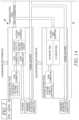
- FIG. 1is a block diagram of a detector which embodies the invention.
- FIG. 2is a flow diagram which illustrates operational aspects of the detector of FIG. 1 .
- informationcan be stored in the detector as to the last attempt to calibrate the device including whether the calibration attempt was successfully completed. If the last calibration attempt was not successfully completed, a visual and/or audible confidence indicator can be disabled.
- informationcan be stored in the detector as to whether the detector successfully completed the last bump test. If the last bump test was not successfully completed, the visual and/or audible confidence indicator can be disabled.
- the visual and/or audible indicatorbe activated.
- a green blinking indicatorcan be provided so long as both conditions are met.
- a housingcan carry a plurality of gas sensors, and a display device to present gas concentration information visually.
- Control circuitscan be provided coupled to all of the sensors as well as the display device.
- condition indicating visual devicessuch as light emitting diodes (LEDs) can be coupled to the control circuits to provide detector status information apart from gas concentrations and the like.
- status informationcan include alarm indicators as well as confidence or compliance indicators.
- the control circuitscan be implemented at least in part, with a programmable processor and associated embedded control software.
- the processorin combination with the control software, when executed by the processor, can locally store day and time indicia as to when the last calibration was attempted and whether it was successful or not. The day and time of the last attempt to carry out a bump test, as well as test results can also be stored.
- the control circuitswill intermittently active the confidence or compliance indicator.
- the respective LEDcan be periodically blinked to visually indicate that the detector is in compliance.
- a green LEDcan be periodically energized, blinked, to provide a widely discernable indicium that the detector is in compliance with applicable safety requirements or policies. If not, activation of the green LED is terminated.
- FIG. 1illustrates an exemplary detector 10 in accordance with the present invention.
- Detector 10includes a housing 12 which carries a plurality of different gas, or ambient condition sensors, generally indicated at 16 on a sensor printed circuit board 18 .
- Sensor board 18is in communication with main printed circuit board 20 (which carries control circuits 22 , including a processor 22 a and associated control software 22 b ), via an interface 24 .
- the control circuits 22activate a liquid crystal display module 30 to illustrate gas concentrations, or other ambient conditions of interest such as temperature, all without limitation.
- alarm conditionsalso can be indicated via vibrator unit 32 a , beeper 32 b and alarm indicating LEDs, which might emit red light.
- Compliance, confidence LED, which might emit green light, 34provides visual indicia (when blinked) that the detector 10 is in compliance, as described above with applicable safety procedures and standards. In the absence of compliance, LED 34 is not activated. Even in the event of non-compliance, control circuits 22 still receive signals from sensors 16 , make gas, temperature concentrations and the like and forward appropriate signals to display module 30 .
- Replaceable batteries 40energize detector 10 . It will be understood that the specific characteristics of batteries 40 are not limitations of the present invention.
- FIG. 2illustrates a block diagram of a method 100 of operating the detector 10 in accordance with the invention.
- the control circuits 22evaluate whether the previous calibration attempt had been successful, as at 102 . If so, the control circuits 22 establish if a pre-set time interval, since the last calibration, has passed, as at 104 . If it is not time to calibrate the sensors, the control circuits 22 evaluate whether the previous bump test had been a success, as at 106 . If the previous bump test was successful, the control circuits establish if a pre-set time interval has passed since the last bump test was carried out, as at 108 . If not, the confidence indicator LED 34 is flashed in accordance with a user specified frequency. Alternately, the confidence indicator will be disabled and not flashed.
- the method 100can be carried out by the detector 10 substantially simultaneously with carrying out the normal gas and environmental sensing operations of that detector.
- the display 30continues to provide visual information and the alarm indicting vibrator 32 a , beeper 32 b and LEDs 32 c continue to be energized to indicate sensed alarm conditions.
Landscapes
- Health & Medical Sciences (AREA)
- Engineering & Computer Science (AREA)
- General Physics & Mathematics (AREA)
- General Health & Medical Sciences (AREA)
- Chemical & Material Sciences (AREA)
- Physics & Mathematics (AREA)
- Life Sciences & Earth Sciences (AREA)
- Toxicology (AREA)
- Biochemistry (AREA)
- Analytical Chemistry (AREA)
- Pathology (AREA)
- Immunology (AREA)
- Combustion & Propulsion (AREA)
- Business, Economics & Management (AREA)
- Environmental & Geological Engineering (AREA)
- Emergency Management (AREA)
- Computer Security & Cryptography (AREA)
- Food Science & Technology (AREA)
- Medicinal Chemistry (AREA)
- Molecular Biology (AREA)
- Biomedical Technology (AREA)
- Emergency Alarm Devices (AREA)
- Investigating Or Analyzing Materials By The Use Of Electric Means (AREA)
Abstract
Description
Claims (12)
Priority Applications (7)
| Application Number | Priority Date | Filing Date | Title |
|---|---|---|---|
| US12/550,976US11893871B2 (en) | 2009-08-31 | 2009-08-31 | Gas detector with visual compliance verification |
| CA2712899ACA2712899A1 (en) | 2009-08-31 | 2010-08-13 | Gas detector with visual compliance verification |
| EP10173109.9AEP2293267B1 (en) | 2009-08-31 | 2010-08-17 | Gas detector with visual compliance verification |
| KR1020100080369AKR20110023765A (en) | 2009-08-31 | 2010-08-19 | Gas detector with visual fulfillment verification |
| BRPI1003023ABRPI1003023A2 (en) | 2009-08-31 | 2010-08-27 | gas detector, and method for establishing whether a gas detector conforms to predefined standards |
| CN201010267802.0ACN102004140B (en) | 2009-08-31 | 2010-08-30 | Gas detector with visual compliance verification |
| KR1020170157806AKR20170133298A (en) | 2009-08-31 | 2017-11-24 | Gas detector with visual compliance verification |
Applications Claiming Priority (1)
| Application Number | Priority Date | Filing Date | Title |
|---|---|---|---|
| US12/550,976US11893871B2 (en) | 2009-08-31 | 2009-08-31 | Gas detector with visual compliance verification |
Publications (2)
| Publication Number | Publication Date |
|---|---|
| US20110048100A1 US20110048100A1 (en) | 2011-03-03 |
| US11893871B2true US11893871B2 (en) | 2024-02-06 |
Family
ID=43288617
Family Applications (1)
| Application Number | Title | Priority Date | Filing Date |
|---|---|---|---|
| US12/550,976Active2031-11-29US11893871B2 (en) | 2009-08-31 | 2009-08-31 | Gas detector with visual compliance verification |
Country Status (6)
| Country | Link |
|---|---|
| US (1) | US11893871B2 (en) |
| EP (1) | EP2293267B1 (en) |
| KR (2) | KR20110023765A (en) |
| CN (1) | CN102004140B (en) |
| BR (1) | BRPI1003023A2 (en) |
| CA (1) | CA2712899A1 (en) |
Families Citing this family (11)
| Publication number | Priority date | Publication date | Assignee | Title |
|---|---|---|---|---|
| US11893871B2 (en) | 2009-08-31 | 2024-02-06 | Honeywell International Inc. | Gas detector with visual compliance verification |
| US20130066565A1 (en)* | 2011-09-14 | 2013-03-14 | Honeywell International Inc. | Systems and methods of configuring gas detection equipment based on a user interview |
| EP3651136B1 (en)* | 2013-10-07 | 2022-12-07 | Google LLC | Smart-home hazard detector providing non-alarm status signals at opportune moments |
| US9557306B2 (en)* | 2013-12-20 | 2017-01-31 | Honeywell International Inc. | Magnetically controlled gas detectors |
| CN105623559A (en)* | 2014-10-31 | 2016-06-01 | 美国圣戈班性能塑料公司 | Cross-linking binder composition |
| US20160178589A1 (en)* | 2014-12-23 | 2016-06-23 | Honeywell International Inc. | System and method of displaying gas concentrations |
| US9858803B2 (en)* | 2015-08-12 | 2018-01-02 | Honeywell International Inc. | Gas detectors safety compliance advertisement via low-power wireless radio |
| DE102016221446A1 (en)* | 2016-11-02 | 2018-05-03 | BSH Hausgeräte GmbH | Calibrating an oxygen sensor of a household appliance |
| JP7051197B2 (en)* | 2017-10-10 | 2022-04-11 | 株式会社ミツトヨ | Measuring instrument |
| WO2020236480A1 (en) | 2019-05-17 | 2020-11-26 | Carrier Corporation | Gas detector test and calibration method and apparatus |
| CN114023050B (en)* | 2021-11-08 | 2023-05-12 | 广州广电计量检测股份有限公司 | Gas alarm calibrating device and calibrating method thereof |
Citations (26)
| Publication number | Priority date | Publication date | Assignee | Title |
|---|---|---|---|---|
| US4428685A (en)* | 1979-08-22 | 1984-01-31 | Lemelson Jerome H | Temperature talking indicating device |
| US6182497B1 (en)* | 1999-08-20 | 2001-02-06 | Neodym Systems Inc | Gas detection system and method |
| US6244093B1 (en)* | 1997-03-14 | 2001-06-12 | Kaushik K. Parekh | Method and apparatus for calibrating an air monitor using a flow matching valve |
| US20010018844A1 (en)* | 1998-03-13 | 2001-09-06 | Parekh Kaushik K. | Method and apparatus for calibrating an air monitor using a flexible element flow matching valve |
| WO2001082063A1 (en) | 2000-04-19 | 2001-11-01 | Industrial Scientific Corporation | Docking station for environmental monitoring instruments |
| US20010050612A1 (en)* | 1999-10-01 | 2001-12-13 | Karl Richard Shaffer | Personal alert device |
| US6428684B1 (en)* | 2000-08-02 | 2002-08-06 | Industrial Scientific Corporation | Method and apparatus for diagnosing the condition of a gas sensor |
| US20030145644A1 (en) | 2002-02-07 | 2003-08-07 | Walter Kidde Portable Equipment, Inc. | Self-calibrating carbon monoxide detector and method |
| US20040007195A1 (en)* | 2002-07-15 | 2004-01-15 | Grewal Amanpal S. | Method and apparatus for cleaning an oil control valve for an internal combustion engine |
| US20040055359A1 (en)* | 2001-06-28 | 2004-03-25 | Rel-Tek | Automatic gas sensor calibration system |
| US6744373B2 (en)* | 2001-09-17 | 2004-06-01 | Riken Keiki Co., Ltd. | Portable gas alarm device |
| US20060081033A1 (en)* | 2004-10-19 | 2006-04-20 | Industrial Scientific Corporation | Apparatus and method for testing gas detection instruments |
| US20060101925A1 (en)* | 2004-10-19 | 2006-05-18 | Industrial Scientific Corporation | Apparatus and method for testing gas detection instruments |
| US7159445B2 (en)* | 2001-07-13 | 2007-01-09 | Inficon Gmbh | Sniffing leak detector and method for operation thereof |
| JP2007132701A (en) | 2005-11-08 | 2007-05-31 | Riken Keiki Co Ltd | Gas detector calibration device |
| US7279688B2 (en)* | 2005-04-04 | 2007-10-09 | Campman James P | Arson and forensic scanner having a hydrocarbon gas detector with a detachable collector cone and kit assembly |
| US20070241261A1 (en)* | 2005-10-21 | 2007-10-18 | Wendt Barry M | Safety indicator and method |
| US20070296569A1 (en) | 2006-06-22 | 2007-12-27 | Honeywell International Inc. | Hardwired alarm system with power-on sequence |
| US7319385B2 (en)* | 2004-09-17 | 2008-01-15 | Nokia Corporation | Sensor data sharing |
| US20080156074A1 (en)* | 2006-12-29 | 2008-07-03 | Peter Tobias | Gas sensor test system and methods related thereto |
| US20090113984A1 (en) | 2007-11-07 | 2009-05-07 | Honeywell International Inc. | Gas sensor system having a zeroing mechanism |
| US7530255B2 (en)* | 2005-01-18 | 2009-05-12 | Mine Safety Appliances Company | Devices, systems and methods for testing of gas detectors |
| US7623028B2 (en)* | 2004-05-27 | 2009-11-24 | Lawrence Kates | System and method for high-sensitivity sensor |
| US7661290B2 (en)* | 2007-07-20 | 2010-02-16 | Honeywell International Inc. | Gas sensor test and calibration system |
| CA2712899A1 (en) | 2009-08-31 | 2011-02-28 | Honeywell International Inc. | Gas detector with visual compliance verification |
| US8537020B2 (en)* | 2008-12-23 | 2013-09-17 | Honeywell International Inc. | Visual indicator of gas sensor impairment |
- 2009
- 2009-08-31USUS12/550,976patent/US11893871B2/enactiveActive
- 2010
- 2010-08-13CACA2712899Apatent/CA2712899A1/enactivePending
- 2010-08-17EPEP10173109.9Apatent/EP2293267B1/enactiveActive
- 2010-08-19KRKR1020100080369Apatent/KR20110023765A/ennot_activeCeased
- 2010-08-27BRBRPI1003023Apatent/BRPI1003023A2/ennot_activeIP Right Cessation
- 2010-08-30CNCN201010267802.0Apatent/CN102004140B/enactiveActive
- 2017
- 2017-11-24KRKR1020170157806Apatent/KR20170133298A/ennot_activeCeased
Patent Citations (38)
| Publication number | Priority date | Publication date | Assignee | Title |
|---|---|---|---|---|
| US4428685A (en)* | 1979-08-22 | 1984-01-31 | Lemelson Jerome H | Temperature talking indicating device |
| US6244093B1 (en)* | 1997-03-14 | 2001-06-12 | Kaushik K. Parekh | Method and apparatus for calibrating an air monitor using a flow matching valve |
| US20010018844A1 (en)* | 1998-03-13 | 2001-09-06 | Parekh Kaushik K. | Method and apparatus for calibrating an air monitor using a flexible element flow matching valve |
| US6182497B1 (en)* | 1999-08-20 | 2001-02-06 | Neodym Systems Inc | Gas detection system and method |
| US20010050612A1 (en)* | 1999-10-01 | 2001-12-13 | Karl Richard Shaffer | Personal alert device |
| US6411207B2 (en)* | 1999-10-01 | 2002-06-25 | Avaya Technology Corp. | Personal alert device |
| WO2001082063A1 (en) | 2000-04-19 | 2001-11-01 | Industrial Scientific Corporation | Docking station for environmental monitoring instruments |
| US6442639B1 (en)* | 2000-04-19 | 2002-08-27 | Industrial Scientific Corporation | Docking station for environmental monitoring instruments |
| US6428684B1 (en)* | 2000-08-02 | 2002-08-06 | Industrial Scientific Corporation | Method and apparatus for diagnosing the condition of a gas sensor |
| US20040055359A1 (en)* | 2001-06-28 | 2004-03-25 | Rel-Tek | Automatic gas sensor calibration system |
| US7159445B2 (en)* | 2001-07-13 | 2007-01-09 | Inficon Gmbh | Sniffing leak detector and method for operation thereof |
| US6744373B2 (en)* | 2001-09-17 | 2004-06-01 | Riken Keiki Co., Ltd. | Portable gas alarm device |
| CN100426334C (en) | 2001-09-17 | 2008-10-15 | 理研计器株式会社 | portable gas alarm |
| US20030145644A1 (en) | 2002-02-07 | 2003-08-07 | Walter Kidde Portable Equipment, Inc. | Self-calibrating carbon monoxide detector and method |
| US20040007195A1 (en)* | 2002-07-15 | 2004-01-15 | Grewal Amanpal S. | Method and apparatus for cleaning an oil control valve for an internal combustion engine |
| US7623028B2 (en)* | 2004-05-27 | 2009-11-24 | Lawrence Kates | System and method for high-sensitivity sensor |
| US7319385B2 (en)* | 2004-09-17 | 2008-01-15 | Nokia Corporation | Sensor data sharing |
| US20060081033A1 (en)* | 2004-10-19 | 2006-04-20 | Industrial Scientific Corporation | Apparatus and method for testing gas detection instruments |
| US20060101925A1 (en)* | 2004-10-19 | 2006-05-18 | Industrial Scientific Corporation | Apparatus and method for testing gas detection instruments |
| US7275411B2 (en)* | 2004-10-19 | 2007-10-02 | Industrial Scientific Corporation | Apparatus and method for testing gas detection instruments |
| US7281404B2 (en)* | 2004-10-19 | 2007-10-16 | Industrial Scientific Corporation | Apparatus and method for testing gas detection instruments |
| US7530255B2 (en)* | 2005-01-18 | 2009-05-12 | Mine Safety Appliances Company | Devices, systems and methods for testing of gas detectors |
| US7279688B2 (en)* | 2005-04-04 | 2007-10-09 | Campman James P | Arson and forensic scanner having a hydrocarbon gas detector with a detachable collector cone and kit assembly |
| US7378954B2 (en)* | 2005-10-21 | 2008-05-27 | Barry Myron Wendt | Safety indicator and method |
| US20070241261A1 (en)* | 2005-10-21 | 2007-10-18 | Wendt Barry M | Safety indicator and method |
| JP2007132701A (en) | 2005-11-08 | 2007-05-31 | Riken Keiki Co Ltd | Gas detector calibration device |
| US20070296569A1 (en) | 2006-06-22 | 2007-12-27 | Honeywell International Inc. | Hardwired alarm system with power-on sequence |
| US20080156074A1 (en)* | 2006-12-29 | 2008-07-03 | Peter Tobias | Gas sensor test system and methods related thereto |
| US7661290B2 (en)* | 2007-07-20 | 2010-02-16 | Honeywell International Inc. | Gas sensor test and calibration system |
| US20090113984A1 (en) | 2007-11-07 | 2009-05-07 | Honeywell International Inc. | Gas sensor system having a zeroing mechanism |
| US8537020B2 (en)* | 2008-12-23 | 2013-09-17 | Honeywell International Inc. | Visual indicator of gas sensor impairment |
| CA2712899A1 (en) | 2009-08-31 | 2011-02-28 | Honeywell International Inc. | Gas detector with visual compliance verification |
| EP2293267A1 (en) | 2009-08-31 | 2011-03-09 | Honeywell International Inc. | Gas detector with visual compliance verification |
| CN102004140A (en) | 2009-08-31 | 2011-04-06 | 霍尼韦尔国际公司 | Gas detector with visual compliance verification |
| EP2293267B1 (en) | 2009-08-31 | 2013-07-10 | Honeywell International Inc. | Gas detector with visual compliance verification |
| KR20110023765A (en) | 2009-08-31 | 2011-03-08 | 허니웰 인터내셔널 인코포레이티드 | Gas detector with visual fulfillment verification |
| BRPI1003023A2 (en) | 2009-08-31 | 2015-09-15 | Honeywell Int Inc | gas detector, and method for establishing whether a gas detector conforms to predefined standards |
| KR20170133298A (en) | 2009-08-31 | 2017-12-05 | 허니웰 인터내셔널 인코포레이티드 | Gas detector with visual compliance verification |
Non-Patent Citations (41)
| Title |
|---|
| Canada Patent Application No. 2,712,899, Office Action, dated Aug. 7, 2017, 7 pages. |
| Canada Patent Application No. 2,712,899, Office Action, dated Jul. 12, 2016, 3 pages. |
| Canada Patent Application No. 2,712,899, Office Action, dated Jul. 13, 2017, 5 pages. |
| China Patent Application No. 2010102678020, Notification to Grant Patent Right, dated Oct. 9, 2014, 4 pages. |
| China Patent Application No. 2010102678020, Office Action, dated Jan. 24, 2014, 12 pages. |
| Europe Patent Application No. 10173109.9, Decision to Grant, dated Jun. 13, 2013, 2 pages. |
| Europe Patent Application No. 10173109.9, European Search Report, dated Dec. 28, 2010, 3 pages. |
| Europe Patent Application No. 10173109.9, Examination Report, dated Jan. 14, 2011, 3 pages. |
| Europe Patent Application No. 10173109.9, Intention to Grant, dated Feb. 26, 2013, 5 pages. |
| European Search Report corresponding to Application No. EP 10 17 3109, dated Dec. 20, 2010. |
| GasAlert Extreme H2S, CO, O2, SO2, PH3, CI2, NH3, NO2, HCN, ETO, CIO2, O3, NO Single-Gas Detectors, BW Technologies, available online at least as early as May 15, 2008. (Year: 2008).* |
| GasAlert Extreme O2, CO, H2S, PH3, SO2, CI2, NH3, HCN, ETO, CIO2, O3, or NO Single-Gas Detector Quick Reference Guide, BW Technologies by Honeywell, Copyright 2005, available online at least as early as May 15, 2008. (Year: 2008).* |
| GasAlert LEL Combustible Gas and Vapors Combustible Gas Detector 0-100% LEL, BW Technologies, available online at least as early as May 15, 2008. (Year: 2008).* |
| GasAlert100 100 Day Disposable Gas Detector Instruction Sheet, BW Technologies, Copyright Sep. 2002, available online at least as early as May 15, 2008. (Year: 2008).* |
| GasAlert100 H2S or CO 100 Day Disposable Gas Detector, BW Technologies, available online at least as early as May 15, 2008. (Year: 2008).* |
| GasAlertClip Extreme 2 or 3 Year Gas Detector Instruction Sheet, BW Technologies, Copyright 2005, available online at least as early as May 15, 2008. (Year: 2008).* |
| GasAlertClip Extreme H2S, Co, SO2, or O2 2 Year Gas Disposable Gas Detector, BW Technologies, available online at least as early as May 15, 2008. (Year: 2008).* |
| GasAlertMax Gas Detector User Manual, BW Technologies, Copyright 2001, dated Dec. 2002, available online at least as early as May 15, 2008. (Year: 2008).* |
| GasAlertMicro 5 and GasAlertMicro 5 PID O2, CO, H2S, PH3, SO2, CI2, NH3, HCN, CIO2, O3, VOC, and Combustibles 1, 2, 3, 4, and 5 Gas Detectors User Manual, BW Technologies, Copyright 2006, available online at least as early as May 15, 2008. (Year: 2008).* |
| GasAlertMicro 5 H2S, CO, O2, SO2, PH3, NH3, NO2, HCN, CI2, CIO2, O3, Combustibles 5 Gas Detector, BW Technologies, available online at least as early as May 15, 2008. (Year: 2008).* |
| GasAlertMicro 5 O2, CO, H2S, PH3, SO2, CI2, NH3, NO2, HCN, CIO2, O3, VOC, and Combustibles 1, 2, 3, 4, and 5 Gas Detectors User Manual, BW Technologies, Copyright 2005, available online at least as early as May 15, 2008. (Year: 2008).* |
| GasAlertMicro 5 VOCs (PID), H2S, CO, O2, SO2, PH3, NH3, NO2, HCN, CI2, CIO2, O3, and Combustibles 5-Gas Detector, BW Technologies, available online at least as early as May 15, 2008. (Year: 2008).* |
| GasAlertMicro H2S, CO, O2, Combustibles 1, 2, 3, and 4 Gas Detectors User Manual, BW Technologies, Copyright 2005, available online at least as early as May 15, 2008. (Year: 2008).* |
| GasAlertMicro H2S, CO, O2, SO2, Combustibles 1, 2, 3, and 4 Gas Detectors Quick Reference Guide, BW Technologies, Copyright 2005, available online at least as early as May 15, 2008. (Year: 2008).* |
| GasAlertMicro H2S, CO, O2, SO2, Combustibles 1, 2, 3, and 4 Gas Detectors User Manual, BW Technologies, Copyright 2002, available online at least as early as May 15, 2008. (Year: 2008).* |
| GasAlertMicro H2S, CO, O2, SO2, Combustibles Multi-Gas Detector Datasheet, JJS Technical Services, available online at least as early as May 15, 2008. (Year: 2008).* |
| GasAlertMicro multi-gas detector Datasheet, BW Technologies by Honeywell, available online at least as early as May 15, 2008. (Year: 2008).* |
| GasAlertMicroClip H2S, CO, O2, Combustibles 1, 2, 3, and 4 Gas Detectors User Manual, BW Technologies by Honeywell, Copyright 2007, available online at least as early as May 15, 2008. (Year: 2008).* |
| GasAlertMicroClip H2S, CO, O2, Combustibles Multi-Gas Detector, BW Technologies by Honeywell, available online at least as early as May 15, 2008. (Year: 2008).* |
| GasAlertMicroClip multi-gas detector Datasheet, BW Technologies by Honeywell, Copyright 2008, available online at least as early as May 15, 2008. (Year: 2008).* |
| Honeywell Analytics Distribution, Inc.: Gas Detection Instrumentation, BNP Media and available online at <https://www.achrnews.com/articles/106719-honeywell-analytics-distribution-inc-gas-detection-instrumentation-2>, Apr. 14, 2008. (Year: 2008).* |
| Korean Patent Application No. 20100080369, Notice of Decision for Rejection, dated Oct. 30, 2017, 5 pages. |
| Korean Patent Application No. 20100080369, Notification of Decision for Rejection, dated Sep. 20, 2017, 2 pages. |
| Korean Patent Application No. 20100080369, Notification of Reason for Rejection, dated Jul. 12, 2017, 5 pages. |
| Korean Patent Application No. 20170157806, Notice of Decision for Rejection, dated Jul. 30, 2018, 5 pages. |
| Korean Patent Application No. 20170157806, Office Action, dated Dec. 27, 2017, 22 pages. |
| Listing of Gas Detectors/Analyzers Available From Instrumart Industrial Instrument Superstore, available online at the Internet Archive <https://web.archive.org/web/20080511150950/http://www.instrumart.com/ProductList.aspx?CategoryID=4892& ManufacturerID=1123>, May 11, 2008. (Year: 2008).* |
| Partial File Directory from JJS Technical Services, Inc. Listing Document Uploads at least as early as May 15, 2008. (Year: 2008).* |
| Sensing Danger, available online at <https://www.oilandgasmiddleeast.com/article-4938-sensing-danger>, Oct. 26, 2008. (Year: 2008).* |
| ToxiRAE 3 User's Guide Revision C, Rae Systems, May 2008. (Year: 2008).* |
| X5 Personal Gas Detector Operating Manual Revision 1, Feb. 2008. (Year: 2008).* |
Also Published As
| Publication number | Publication date |
|---|---|
| EP2293267B1 (en) | 2013-07-10 |
| BRPI1003023A2 (en) | 2015-09-15 |
| CA2712899A1 (en) | 2011-02-28 |
| KR20170133298A (en) | 2017-12-05 |
| CN102004140B (en) | 2015-01-28 |
| CN102004140A (en) | 2011-04-06 |
| KR20110023765A (en) | 2011-03-08 |
| EP2293267A1 (en) | 2011-03-09 |
| US20110048100A1 (en) | 2011-03-03 |
Similar Documents
| Publication | Publication Date | Title |
|---|---|---|
| US11893871B2 (en) | Gas detector with visual compliance verification | |
| EP3175235B1 (en) | Mobile-based collection of water quality measurement data | |
| AU2016206435B2 (en) | Filter assembly for a breathing apparatus | |
| US9827456B2 (en) | Firefighting equipment inspection notification device | |
| US8797157B2 (en) | System and method for monitoring usage and predicting failure of visual notification appliances | |
| US9368012B2 (en) | Detector with integrated sensor platform | |
| US7382245B2 (en) | Method and apparatus for indicating a power condition at a notification appliance | |
| US20240087443A1 (en) | Fire detection system testing | |
| JP2019208926A (en) | Body condition management system | |
| JP2021128577A (en) | Alarm unit | |
| US8653980B2 (en) | Alarm for detecting radiation and/or air pollutants | |
| JP2003022486A (en) | Battery operated CO alarm | |
| US20240310346A1 (en) | Systems and Methods for Portable Gas Detector Configuration Identification | |
| US9024756B2 (en) | Immediate detection system and method thereof | |
| IT202000022378A1 (en) | SYSTEM AND METHOD FOR THE DETECTION OF ONE OR MORE ENVIRONMENTAL PARAMETERS | |
| CN103646515A (en) | Infrared human body induction triggering type fumigant gas alarming device | |
| JP2001344682A (en) | Radio emergency alarm receiver and wireless security system using the same receiver | |
| KR20250149001A (en) | Stress Immunity Measurement System | |
| JP6959080B2 (en) | Alarm | |
| US20150302714A1 (en) | System and Method of Time-Augmented Annunciation of Signals | |
| JP2007102260A (en) | Alarm | |
| JP2011215894A (en) | Confirmation device | |
| WO2017113160A1 (en) | Smart watch-based vital sign detection method and smart watch | |
| JP2006242653A (en) | Electronic gas meter and security system using the same | |
| JP2006350690A (en) | Field equipment |
Legal Events
| Date | Code | Title | Description |
|---|---|---|---|
| AS | Assignment | Owner name:HONEYWELL INTERNATIONAL INC., NEW JERSEY Free format text:ASSIGNMENT OF ASSIGNORS INTEREST;ASSIGNORS:MCEWEN, SHANE LEE;BENSON, PHILLIP W.;KENNARD, CLIVE W.;AND OTHERS;SIGNING DATES FROM 20091027 TO 20091109;REEL/FRAME:023506/0551 | |
| STCV | Information on status: appeal procedure | Free format text:BOARD OF APPEALS DECISION RENDERED | |
| STPP | Information on status: patent application and granting procedure in general | Free format text:AMENDMENT / ARGUMENT AFTER BOARD OF APPEALS DECISION | |
| STPP | Information on status: patent application and granting procedure in general | Free format text:NON FINAL ACTION MAILED | |
| STPP | Information on status: patent application and granting procedure in general | Free format text:RESPONSE TO NON-FINAL OFFICE ACTION ENTERED AND FORWARDED TO EXAMINER | |
| STPP | Information on status: patent application and granting procedure in general | Free format text:FINAL REJECTION MAILED | |
| STPP | Information on status: patent application and granting procedure in general | Free format text:RESPONSE AFTER FINAL ACTION FORWARDED TO EXAMINER | |
| STPP | Information on status: patent application and granting procedure in general | Free format text:ADVISORY ACTION MAILED | |
| STPP | Information on status: patent application and granting procedure in general | Free format text:DOCKETED NEW CASE - READY FOR EXAMINATION | |
| STPP | Information on status: patent application and granting procedure in general | Free format text:FINAL REJECTION MAILED | |
| STPP | Information on status: patent application and granting procedure in general | Free format text:RESPONSE AFTER FINAL ACTION FORWARDED TO EXAMINER | |
| STPP | Information on status: patent application and granting procedure in general | Free format text:ADVISORY ACTION MAILED | |
| STCV | Information on status: appeal procedure | Free format text:NOTICE OF APPEAL FILED | |
| STCV | Information on status: appeal procedure | Free format text:APPEAL BRIEF (OR SUPPLEMENTAL BRIEF) ENTERED AND FORWARDED TO EXAMINER | |
| STCV | Information on status: appeal procedure | Free format text:EXAMINER'S ANSWER TO APPEAL BRIEF MAILED | |
| STCV | Information on status: appeal procedure | Free format text:ON APPEAL -- AWAITING DECISION BY THE BOARD OF APPEALS | |
| STCV | Information on status: appeal procedure | Free format text:BOARD OF APPEALS DECISION RENDERED | |
| STPP | Information on status: patent application and granting procedure in general | Free format text:NOTICE OF ALLOWANCE MAILED -- APPLICATION RECEIVED IN OFFICE OF PUBLICATIONS | |
| ZAAB | Notice of allowance mailed | Free format text:ORIGINAL CODE: MN/=. | |
| STPP | Information on status: patent application and granting procedure in general | Free format text:PUBLICATIONS -- ISSUE FEE PAYMENT RECEIVED | |
| STPP | Information on status: patent application and granting procedure in general | Free format text:PUBLICATIONS -- ISSUE FEE PAYMENT VERIFIED | |
| STCF | Information on status: patent grant | Free format text:PATENTED CASE |