US11892180B2 - HVAC system with automated device pairing - Google Patents
HVAC system with automated device pairingDownload PDFInfo
- Publication number
- US11892180B2 US11892180B2US16/880,707US202016880707AUS11892180B2US 11892180 B2US11892180 B2US 11892180B2US 202016880707 AUS202016880707 AUS 202016880707AUS 11892180 B2US11892180 B2US 11892180B2
- Authority
- US
- United States
- Prior art keywords
- time series
- sensor
- actuation
- sensors
- building
- Prior art date
- Legal status (The legal status is an assumption and is not a legal conclusion. Google has not performed a legal analysis and makes no representation as to the accuracy of the status listed.)
- Active
Links
Images

Classifications
- F—MECHANICAL ENGINEERING; LIGHTING; HEATING; WEAPONS; BLASTING
- F24—HEATING; RANGES; VENTILATING
- F24F—AIR-CONDITIONING; AIR-HUMIDIFICATION; VENTILATION; USE OF AIR CURRENTS FOR SCREENING
- F24F11/00—Control or safety arrangements
- F24F11/30—Control or safety arrangements for purposes related to the operation of the system, e.g. for safety or monitoring
- F—MECHANICAL ENGINEERING; LIGHTING; HEATING; WEAPONS; BLASTING
- F24—HEATING; RANGES; VENTILATING
- F24F—AIR-CONDITIONING; AIR-HUMIDIFICATION; VENTILATION; USE OF AIR CURRENTS FOR SCREENING
- F24F11/00—Control or safety arrangements
- F24F11/50—Control or safety arrangements characterised by user interfaces or communication
- F24F11/61—Control or safety arrangements characterised by user interfaces or communication using timers
- F—MECHANICAL ENGINEERING; LIGHTING; HEATING; WEAPONS; BLASTING
- F24—HEATING; RANGES; VENTILATING
- F24F—AIR-CONDITIONING; AIR-HUMIDIFICATION; VENTILATION; USE OF AIR CURRENTS FOR SCREENING
- F24F11/00—Control or safety arrangements
- F24F11/62—Control or safety arrangements characterised by the type of control or by internal processing, e.g. using fuzzy logic, adaptive control or estimation of values
- F24F11/63—Electronic processing
- G—PHYSICS
- G05—CONTROLLING; REGULATING
- G05B—CONTROL OR REGULATING SYSTEMS IN GENERAL; FUNCTIONAL ELEMENTS OF SUCH SYSTEMS; MONITORING OR TESTING ARRANGEMENTS FOR SUCH SYSTEMS OR ELEMENTS
- G05B19/00—Programme-control systems
- G05B19/02—Programme-control systems electric
- G05B19/04—Programme control other than numerical control, i.e. in sequence controllers or logic controllers
- G05B19/042—Programme control other than numerical control, i.e. in sequence controllers or logic controllers using digital processors
- F—MECHANICAL ENGINEERING; LIGHTING; HEATING; WEAPONS; BLASTING
- F24—HEATING; RANGES; VENTILATING
- F24F—AIR-CONDITIONING; AIR-HUMIDIFICATION; VENTILATION; USE OF AIR CURRENTS FOR SCREENING
- F24F11/00—Control or safety arrangements
- F24F11/50—Control or safety arrangements characterised by user interfaces or communication
- F24F11/56—Remote control
- F—MECHANICAL ENGINEERING; LIGHTING; HEATING; WEAPONS; BLASTING
- F24—HEATING; RANGES; VENTILATING
- F24F—AIR-CONDITIONING; AIR-HUMIDIFICATION; VENTILATION; USE OF AIR CURRENTS FOR SCREENING
- F24F11/00—Control or safety arrangements
- F24F11/62—Control or safety arrangements characterised by the type of control or by internal processing, e.g. using fuzzy logic, adaptive control or estimation of values
- F24F11/63—Electronic processing
- F24F11/64—Electronic processing using pre-stored data
- F—MECHANICAL ENGINEERING; LIGHTING; HEATING; WEAPONS; BLASTING
- F24—HEATING; RANGES; VENTILATING
- F24F—AIR-CONDITIONING; AIR-HUMIDIFICATION; VENTILATION; USE OF AIR CURRENTS FOR SCREENING
- F24F2110/00—Control inputs relating to air properties
- G—PHYSICS
- G05—CONTROLLING; REGULATING
- G05B—CONTROL OR REGULATING SYSTEMS IN GENERAL; FUNCTIONAL ELEMENTS OF SUCH SYSTEMS; MONITORING OR TESTING ARRANGEMENTS FOR SUCH SYSTEMS OR ELEMENTS
- G05B2219/00—Program-control systems
- G05B2219/20—Pc systems
- G05B2219/26—Pc applications
- G05B2219/2614—HVAC, heating, ventillation, climate control
Definitions
- HVACheating, ventilation, and air conditioning
- Building HVAC systemstypically include many different sensors and actuation devices.
- the sensorsmeasure various environmental variables (e.g., temperature, humidity, air flow, etc.) and provide sensor readings to a controller.
- a controlleruses the sensor readings to generate appropriate control signals for the actuation devices (e.g., chillers, boilers, valves, actuators, etc.) which operate to affect the environmental variables measured by the sensors.
- actuation devicese.g., chillers, boilers, valves, actuators, etc.
- Some buildingshave hundreds of sensors and actuation devices. It can be cumbersome, error prone, and time consuming to manually identify the associations between sensors and their corresponding actuation devices. Additionally, buildings evolve over time which can change existing relationships between sensors and actuation devices. For example, remodeling a building can break existing relationships between paired sensors and actuation devices or create new relationships that did not previously exist.
- Time series datacan be used for many purposes including, for example, fault detection, benchmarking, executing queries, and other data analysis applications.
- Some data analysis applicationscompare two or more time series as part of the analysis. However, it can be difficult to compare time series to each other due to dimensional mismatches resulting from different sampling rates, different units of measurement, and other factors. Without the ability to accurately compare time series data, performing actions such as finding similar trends, executing queries on a broad data set, running diagnostic algorithms, conducting benchmarking, reporting on compliance across portfolio of systems or buildings, and other actions can be challenging.
- HVACheating, ventilation, and air conditioning
- the HVAC systemincludes a number of actuation devices operable to affect one or more variables in the building, a number of sensors configured to measure the variables affected by the actuation devices, and a controller.
- the controlleris configured to operate the actuation devices to affect one or more of the measured variables by providing an actuation signal to the actuation devices and to receive sensor response signals from the sensors.
- the sensor response signalsindicate an effect of the actuation signal on the measured variables.
- the controlleris configured to calculate a similarity metric indicating a similarity between the sensor response signal and the actuation signal.
- the controlleris configured to automatically establish a device pairing including one of the actuation devices and one of the sensors based on the similarity metrics.
- the device pairingdefines a control relationship between the actuation device in the device pairing and the sensor in the device pairing.
- the control relationshipcan indicate that the actuation device in the device pairing is operable to control a variable measured by the sensor in the device pairing.
- the controlleris configured to automatically create a feedback control loop including the actuation device in the device pairing and the sensor in the device pairing.
- the controllercan use the feedback control loop to generate and provide control signals to the actuation device in the device pairing based on measurements received from the sensor in the device pairing.
- the controlleris configured to calculate the similarity metrics based on differences between samples of the actuation signal and corresponding samples of each of the sensor response signals.
- the controlleris configured to determine, for each of the sensor response signals, a delay time of the sensor response signal relative to the actuation signal.
- the controllercan identify a sensor corresponding to the sensor response signal having a minimum of the delay times and can establish the device pairing such that the identified sensor is included in the device pairing.
- the controlleris configured to generate an actuation signal time series including a plurality of samples of the actuation signal and generate a sensor response time series for each of the sensor response signals.
- Each sensor response time seriesmay include a plurality of samples of one of the measured variables.
- the controllercalculates the similarity metrics by comparing the actuation signal time series to each of the sensor response time series.
- the controlleris configured to detect a dimensional mismatch between the actuation signal time series and one or more of the sensor response time series and correct the dimensional mismatch by modifying at least one of the actuation signal time series and one or more of the sensor response time series.
- the controlleris configured to apply a discrete cosine transformation (DCT) to the actuation signal and each of the sensor response signals.
- DCTdiscrete cosine transformation
- Each DCTmay generate a plurality of DCT coefficients.
- the controllercan calculate the similarity metrics by comparing the DCT coefficients resulting from the DCT of the actuation signal to DCT coefficients resulting from the DCT of each sensor response signal.
- the controlleris configured to receive baseline sensor signals from each of the plurality of sensors.
- the baseline sensor signalsmay indicate values of the measured variables during a time period before the actuation signal is provided to the actuation devices.
- the controllercan calculate a similarity metric indicating a similarity between the baseline sensor signal and the actuation signal.
- the controlleris configured to determine, for each of the plurality of sensors, whether the similarity metric calculated based on the sensor response signal indicates a greater similarity than the similarity metric calculated based on the baseline sensor signal. In some embodiments, the controller establishes the device pairing in response to a determination that the similarity metric calculated based on the sensor response signal indicates a greater similarity than the similarity metric calculated based on the baseline sensor signal.
- HVACheating, ventilation, and air conditioning
- the methodincludes operating one or more actuation devices to affect one or more measured variables in the building by providing an actuation signal to the actuation devices and receiving sensor response signals from a plurality of sensors configured to measure the variables affected by the actuation devices.
- the sensor response signalsindicate an effect of the actuation signal on the measured variables.
- the methodincludes calculating a similarity metric for each of the sensor response signals. Each similarity metric indicates a similarity between the actuation signal and one of the sensor response signals.
- the methodincludes automatically establishing a device pairing including one of the actuation devices and one of the sensors based on the similarity metrics.
- the device pairingdefines a control relationship between the actuation device in the device pairing and the sensor in the device pairing.
- the control relationshipmay indicate that the actuation device in the device pairing is operable to control a variable measured by the sensor in the device pairing.
- the methodincludes automatically creating a feedback control loop including the actuation device in the device pairing and the sensor in the device pairing.
- the methodmay include using the feedback control loop to generate and provide control signals to the actuation device in the device pairing based on measurements received from the sensor in the device pairing.
- the similarity metricsare calculated based on differences between samples of the actuation signal and corresponding samples of each of the sensor response signals.
- the methodincludes determining, for each of the sensor response signals, a delay time of the sensor response signal relative to the actuation signal.
- the methodmay include identifying a sensor corresponding to the sensor response signal having a minimum of the delay times and establishing the device pairing such that the identified sensor is included in the device pairing.
- the methodincludes generating an actuation signal time series including a plurality of samples of the actuation signal and generating a sensor response time series for each of the sensor response signals.
- Each sensor response time seriesmay include a plurality of samples of one of the measured variables.
- the methodmay include calculating the similarity metrics by comparing the actuation signal time series to each of the sensor response time series.
- the methodincludes detecting a dimensional mismatch between the actuation signal time series and one or more of the sensor response time series and correcting the dimensional mismatch by modifying at least one of the actuation signal time series and one or more of the sensor response time series.
- the methodincludes applying a discrete cosine transformation (DCT) to the actuation signal and each of the sensor response signals.
- DCTdiscrete cosine transformation
- Each DCTmay generate a plurality of DCT coefficients.
- the methodmay include calculating the similarity metrics by comparing the DCT coefficients resulting from the DCT of the actuation signal to DCT coefficients resulting from the DCT of each sensor response signal.
- the methodincludes receiving baseline sensor signals from each of the plurality of sensors.
- the baseline sensor signalsmay indicate values of the measured variables during a time period before the actuation signal is provided to the actuation devices.
- the methodmay include, for each of the baseline sensor signals, calculating a similarity metric indicating a similarity between the baseline sensor signal and the actuation signal.
- the methodincludes determining, for each of the plurality of sensors, whether the similarity metric calculated based on the sensor response signal indicates a greater similarity than the similarity metric calculated based on the baseline sensor signal.
- the methodmay include establishing the device pairing in response to a determination that the similarity metric calculated based on the sensor response signal indicates a greater similarity than the similarity metric calculated based on the baseline sensor signal.
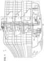
- FIG. 1is a drawing of a building equipped with a heating, ventilation, and air conditioning (HVAC) system, according to an exemplary embodiment
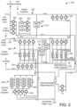
- FIG. 2is a drawing of a waterside system which can be used in combination with the HVAC system of FIG. 1 , according to an exemplary embodiment
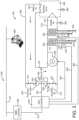
- FIG. 3is a drawing of an airside system which can be used in combination with the HVAC system of FIG. 1 , according to an exemplary embodiment
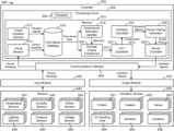
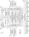
- FIG. 4is a block diagram of a building management system which can be used to monitor and control the building and HVAC system of FIG. 1 , according to an exemplary embodiment
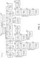
- FIG. 5is a block diagram of another building management system which can be used to monitor and control the building and HVAC system of FIG. 1 , according to an exemplary embodiment
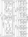
- FIG. 6 Ais a block diagram of a HVAC system including sensors, actuation devices, and a controller, which can be implemented in the building of FIG. 1 , according to an exemplary embodiment;
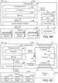
- FIG. 6 Bis a block diagram illustrating a portion of the HVAC system of FIG. 6 A in greater detail including a smart actuator which can be configured to perform automated device pairing, according to an exemplary embodiment;
- FIG. 6 Cis a block diagram illustrating a portion of the HVAC system of FIG. 6 A in greater detail including a smart chiller which can be configured to perform automated device pairing, according to an exemplary embodiment;
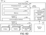
- FIG. 6 Dis a block diagram illustrating a portion of the HVAC system of FIG. 6 A in greater detail including a smart thermostat which can be configured to perform automated device pairing, according to an exemplary embodiment;
- FIG. 7is a graph illustrating different types of signals and time series evaluated by the controller of FIG. 6 A , according to an exemplary embodiment
- FIG. 8is a graph illustrating dimensional mismatch handling performed by the controller of FIG. 6 A , according to an exemplary embodiment
- FIG. 9is a flowchart of a process for establishing device pairings between sensors and actuation devices, which can be performed by the controller of FIG. 6 A , according to an exemplary embodiment.
- FIG. 10is a flowchart of a process for handling dimensional mismatches between actuation signal time series and sensor response time series, which can be performed by the controller of FIG. 6 A , according to an exemplary embodiment.
- HVACheating, ventilation, and air conditioning
- the HVAC systemincludes a plurality of sensors and actuation devices (e.g., chillers, boilers, fans, dampers, actuators, valves, etc.).
- the sensorsmeasure various environmental variables in the building (e.g., zone temperature, humidity, air flow, etc.).
- the actuation devicesoperate to affect the measured variables by providing heating, cooling, airflow, etc. to the building.
- a controllerprovides actuation signals to the actuation devices and receives sensor response signals from the sensors. The controller uses the sensor response signals to determine an effect of the actuation signals on the measured variables.
- the controllerautomatically establishes device pairings between sensors and actuation devices based on the sensor response signals. For each combination of an actuation signal and a sensor response signal, the controller can calculate a similarity metric. The similarity metric indicates the similarity or closeness between the sensor response signal and the actuation signal. The controller can use the similarity metrics to identify which of the sensor response signals most closely matches each actuation signal. The controller can then establish a device pairing between the actuation device and the sensor corresponding to the matching actuation signal and sensor response signal.
- the controllerstores time series data for the actuation signals and sensor response signals. Different variables can be measured at different sampling rates, which can lead do dimensional mismatches between two or more time series that span the same range of times. For example, a time series sampled at a rate often samples per second may include twice the number of samples as a different time series sampled at a rate of five samples per second.
- the controllercan automatically handle dimensional mismatches between two or more time series by performing a discrete cosine transformation for each time series.
- a discrete cosine transformationexpresses a finite sequence of data points in terms of a sum of cosine functions oscillating at different frequencies. Performing the DCT may result in a set of DCT coefficients for each time series.
- the DCT coefficientsrepresent the magnitudes of the cosine functions in the summation.
- the controllercan apply a quantization process to the DCT coefficients in each set such that only a predetermined number of the DCT coefficients in each set are retained. The remaining DCT coefficients can be discarded or replaced with zeros, which has the effect of removing some of the higher frequency cosine functions from the summation.
- the controllercan compare two or more time series by comparing the DCT coefficients resulting from each DCT. Advantageously, this allows for direct comparison between the transformed time series without requiring decompression, interpolation, synchronization, or other processing steps. Other features and advantages of the HVAC system and controller are described in greater detail below.
- FIG. 1shows a building 10 equipped with a HVAC system 100 .
- FIG. 2is a block diagram of a waterside system 200 which can be used to serve building 10 .
- FIG. 3is a block diagram of an airside system 300 which can be used to serve building 10 .
- FIG. 4is a block diagram of a BMS which can be used to monitor and control building 10 .
- FIG. 5is a block diagram of another BMS which can be used to monitor and control building 10 .
- a BMSis, in general, a system of devices configured to control, monitor, and manage equipment in or around a building or building area.
- a BMScan include, for example, a HVAC system, a security system, a lighting system, a fire alerting system, any other system that is capable of managing building functions or devices, or any combination thereof.
- HVAC system 100can include a plurality of HVAC devices (e.g., heaters, chillers, air handling units, pumps, fans, thermal energy storage, etc.) configured to provide heating, cooling, ventilation, or other services for building 10 .
- HVAC system 100is shown to include a waterside system 120 and an airside system 130 .
- Waterside system 120may provide a heated or chilled fluid to an air handling unit of airside system 130 .
- Airside system 130may use the heated or chilled fluid to heat or cool an airflow provided to building 10 .
- An exemplary waterside system and airside system which can be used in HVAC system 100are described in greater detail with reference to FIGS. 2 - 3 .
- HVAC system 100is shown to include a chiller 102 , a boiler 104 , and a rooftop air handling unit (AHU) 106 .
- Waterside system 120may use boiler 104 and chiller 102 to heat or cool a working fluid (e.g., water, glycol, etc.) and may circulate the working fluid to AHU 106 .
- the HVAC devices of waterside system 120can be located in or around building 10 (as shown in FIG. 1 ) or at an offsite location such as a central plant (e.g., a chiller plant, a steam plant, a heat plant, etc.).
- the working fluidcan be heated in boiler 104 or cooled in chiller 102 , depending on whether heating or cooling is required in building 10 .
- Boiler 104may add heat to the circulated fluid, for example, by burning a combustible material (e.g., natural gas) or using an electric heating element.
- Chiller 102may place the circulated fluid in a heat exchange relationship with another fluid (e.g., a refrigerant) in a heat exchanger (e.g., an evaporator) to absorb heat from the circulated fluid.
- the working fluid from chiller 102 and/or boiler 104can be transported to AHU 106 via piping 108 .
- AHU 106may place the working fluid in a heat exchange relationship with an airflow passing through AHU 106 (e.g., via one or more stages of cooling coils and/or heating coils).
- the airflowcan be, for example, outside air, return air from within building 10 , or a combination of both.
- AHU 106may transfer heat between the airflow and the working fluid to provide heating or cooling for the airflow.
- AHU 106can include one or more fans or blowers configured to pass the airflow over or through a heat exchanger containing the working fluid. The working fluid may then return to chiller 102 or boiler 104 via piping 110 .
- Airside system 130may deliver the airflow supplied by AHU 106 (i.e., the supply airflow) to building 10 via air supply ducts 112 and may provide return air from building 10 to AHU 106 via air return ducts 114 .
- airside system 130includes multiple variable air volume (VAV) units 116 .
- VAVvariable air volume
- airside system 130is shown to include a separate VAV unit 116 on each floor or zone of building 10 .
- VAV units 116can include dampers or other flow control elements that can be operated to control an amount of the supply airflow provided to individual zones of building 10 .
- airside system 130delivers the supply airflow into one or more zones of building 10 (e.g., via supply ducts 112 ) without using intermediate VAV units 116 or other flow control elements.
- AHU 106can include various sensors (e.g., temperature sensors, pressure sensors, etc.) configured to measure attributes of the supply airflow.
- AHU 106may receive input from sensors located within AHU 106 and/or within the building zone and may adjust the flow rate, temperature, or other attributes of the supply airflow through AHU 106 to achieve setpoint conditions for the building zone.
- waterside system 200may supplement or replace waterside system 120 in HVAC system 100 or can be implemented separate from HVAC system 100 .
- HVAC system 100waterside system 200 can include a subset of the HVAC devices in HVAC system 100 (e.g., boiler 104 , chiller 102 , pumps, valves, etc.) and may operate to supply a heated or chilled fluid to AHU 106 .
- the HVAC devices of waterside system 200can be located within building 10 (e.g., as components of waterside system 120 ) or at an offsite location such as a central plant.
- waterside system 200is shown as a central plant having a plurality of subplants 202 - 212 .
- Subplants 202 - 212are shown to include a heater subplant 202 , a heat recovery chiller subplant 204 , a chiller subplant 206 , a cooling tower subplant 208 , a hot thermal energy storage (TES) subplant 210 , and a cold thermal energy storage (TES) subplant 212 .
- Subplants 202 - 212consume resources (e.g., water, natural gas, electricity, etc.) from utilities to serve thermal energy loads (e.g., hot water, cold water, heating, cooling, etc.) of a building or campus.
- resourcese.g., water, natural gas, electricity, etc.
- thermal energy loadse.g., hot water, cold water, heating, cooling, etc.
- heater subplant 202can be configured to heat water in a hot water loop 214 that circulates the hot water between heater subplant 202 and building 10 .
- Chiller subplant 206can be configured to chill water in a cold water loop 216 that circulates the cold water between chiller subplant 206 building 10 .
- Heat recovery chiller subplant 204can be configured to transfer heat from cold water loop 216 to hot water loop 214 to provide additional heating for the hot water and additional cooling for the cold water.
- Condenser water loop 218may absorb heat from the cold water in chiller subplant 206 and reject the absorbed heat in cooling tower subplant 208 or transfer the absorbed heat to hot water loop 214 .
- Hot TES subplant 210 and cold TES subplant 212may store hot and cold thermal energy, respectively, for subsequent use.
- Hot water loop 214 and cold water loop 216may deliver the heated and/or chilled water to air handlers located on the rooftop of building 10 (e.g., AHU 106 ) or to individual floors or zones of building 10 (e.g., VAV units 116 ).
- the air handlerspush air past heat exchangers (e.g., heating coils or cooling coils) through which the water flows to provide heating or cooling for the air.
- the heated or cooled aircan be delivered to individual zones of building 10 to serve thermal energy loads of building 10 .
- the waterthen returns to subplants 202 - 212 to receive further heating or cooling.
- subplants 202 - 212are shown and described as heating and cooling water for circulation to a building, it is understood that any other type of working fluid (e.g., glycol, CO2, etc.) can be used in place of or in addition to water to serve thermal energy loads. In other embodiments, subplants 202 - 212 may provide heating and/or cooling directly to the building or campus without requiring an intermediate heat transfer fluid. These and other variations to waterside system 200 are within the teachings of the present disclosure.
- working fluide.g., glycol, CO2, etc.
- Each of subplants 202 - 212can include a variety of equipment configured to facilitate the functions of the subplant.
- heater subplant 202is shown to include a plurality of heating elements 220 (e.g., boilers, electric heaters, etc.) configured to add heat to the hot water in hot water loop 214 .
- Heater subplant 202is also shown to include several pumps 222 and 224 configured to circulate the hot water in hot water loop 214 and to control the flow rate of the hot water through individual heating elements 220 .
- Chiller subplant 206is shown to include a plurality of chillers 232 configured to remove heat from the cold water in cold water loop 216 .
- Chiller subplant 206is also shown to include several pumps 234 and 236 configured to circulate the cold water in cold water loop 216 and to control the flow rate of the cold water through individual chillers 232 .
- Heat recovery chiller subplant 204is shown to include a plurality of heat recovery heat exchangers 226 (e.g., refrigeration circuits) configured to transfer heat from cold water loop 216 to hot water loop 214 .
- Heat recovery chiller subplant 204is also shown to include several pumps 228 and 230 configured to circulate the hot water and/or cold water through heat recovery heat exchangers 226 and to control the flow rate of the water through individual heat recovery heat exchangers 226 .
- Cooling tower subplant 208is shown to include a plurality of cooling towers 238 configured to remove heat from the condenser water in condenser water loop 218 .
- Cooling tower subplant 208is also shown to include several pumps 240 configured to circulate the condenser water in condenser water loop 218 and to control the flow rate of the condenser water through individual cooling towers 238 .
- Hot TES subplant 210is shown to include a hot TES tank 242 configured to store the hot water for later use. Hot TES subplant 210 may also include one or more pumps or valves configured to control the flow rate of the hot water into or out of hot TES tank 242 .
- Cold TES subplant 212is shown to include cold TES tanks 244 configured to store the cold water for later use. Cold TES subplant 212 may also include one or more pumps or valves configured to control the flow rate of the cold water into or out of cold TES tanks 244 .
- one or more of the pumps in waterside system 200(e.g., pumps 222 , 224 , 228 , 230 , 234 , 236 , and/or 240 ) or pipelines in waterside system 200 include an isolation valve associated therewith. Isolation valves can be integrated with the pumps or positioned upstream or downstream of the pumps to control the fluid flows in waterside system 200 .
- waterside system 200can include more, fewer, or different types of devices and/or subplants based on the particular configuration of waterside system 200 and the types of loads served by waterside system 200 .
- airside system 300may supplement or replace airside system 130 in HVAC system 100 or can be implemented separate from HVAC system 100 .
- airside system 300can include a subset of the HVAC devices in HVAC system 100 (e.g., AHU 106 , VAV units 116 , ducts 112 - 114 , fans, dampers, etc.) and can be located in or around building 10 .
- Airside system 300may operate to heat or cool an airflow provided to building 10 using a heated or chilled fluid provided by waterside system 200 .
- airside system 300is shown to include an economizer-type air handling unit (AHU) 302 .
- Economizer-type AHUsvary the amount of outside air and return air used by the air handling unit for heating or cooling.
- AHU 302may receive return air 304 from building zone 306 via return air duct 308 and may deliver supply air 310 to building zone 306 via supply air duct 312 .
- AHU 302is a rooftop unit located on the roof of building 10 (e.g., AHU 106 as shown in FIG. 1 ) or otherwise positioned to receive both return air 304 and outside air 314 .
- AHU 302can be configured to operate exhaust air damper 316 , mixing damper 318 , and outside air damper 320 to control an amount of outside air 314 and return air 304 that combine to form supply air 310 . Any return air 304 that does not pass through mixing damper 318 can be exhausted from AHU 302 through exhaust damper 316 as exhaust air 322 .
- Each of dampers 316 - 320can be operated by an actuator.
- exhaust air damper 316can be operated by actuator 324
- mixing damper 318can be operated by actuator 326
- outside air damper 320can be operated by actuator 328 .
- Actuators 324 - 328may communicate with an AHU controller 330 via a communications link 332 .
- Actuators 324 - 328may receive control signals from AHU controller 330 and may provide feedback signals to AHU controller 330 .
- Feedback signalscan include, for example, an indication of a current actuator or damper position, an amount of torque or force exerted by the actuator, diagnostic information (e.g., results of diagnostic tests performed by actuators 324 - 328 ), status information, commissioning information, configuration settings, calibration data, and/or other types of information or data that can be collected, stored, or used by actuators 324 - 328 .
- diagnostic informatione.g., results of diagnostic tests performed by actuators 324 - 328
- status informatione.g., commissioning information, configuration settings, calibration data, and/or other types of information or data that can be collected, stored, or used by actuators 324 - 328 .
- AHU controller 330can be an economizer controller configured to use one or more control algorithms (e.g., state-based algorithms, extremum seeking control (ESC) algorithms, proportional-integral (PI) control algorithms, proportional-integral-derivative (PID) control algorithms, model predictive control (MPC) algorithms, feedback control algorithms, etc.) to control actuators 324 - 328 .
- control algorithmse.g., state-based algorithms, extremum seeking control (ESC) algorithms, proportional-integral (PI) control algorithms, proportional-integral-derivative (PID) control algorithms, model predictive control (MPC) algorithms, feedback control algorithms, etc.
- AHU 302is shown to include a cooling coil 334 , a heating coil 336 , and a fan 338 positioned within supply air duct 312 .
- Fan 338can be configured to force supply air 310 through cooling coil 334 and/or heating coil 336 and provide supply air 310 to building zone 306 .
- AHU controller 330may communicate with fan 338 via communications link 340 to control a flow rate of supply air 310 .
- AHU controller 330controls an amount of heating or cooling applied to supply air 310 by modulating a speed of fan 338 .
- Cooling coil 334may receive a chilled fluid from waterside system 200 (e.g., from cold water loop 216 ) via piping 342 and may return the chilled fluid to waterside system 200 via piping 344 .
- Valve 346can be positioned along piping 342 or piping 344 to control a flow rate of the chilled fluid through cooling coil 334 .
- cooling coil 334includes multiple stages of cooling coils that can be independently activated and deactivated (e.g., by AHU controller 330 , by BMS controller 366 , etc.) to modulate an amount of cooling applied to supply air 310 .
- Heating coil 336may receive a heated fluid from waterside system 200 (e.g., from hot water loop 214 ) via piping 348 and may return the heated fluid to waterside system 200 via piping 350 .
- Valve 352can be positioned along piping 348 or piping 350 to control a flow rate of the heated fluid through heating coil 336 .
- heating coil 336includes multiple stages of heating coils that can be independently activated and deactivated (e.g., by AHU controller 330 , by BMS controller 366 , etc.) to modulate an amount of heating applied to supply air 310 .
- valves 346 and 352can be controlled by an actuator.
- valve 346can be controlled by actuator 354 and valve 352 can be controlled by actuator 356 .
- Actuators 354 - 356may communicate with AHU controller 330 via communications links 358 - 360 .
- Actuators 354 - 356may receive control signals from AHU controller 330 and may provide feedback signals to controller 330 .
- AHU controller 330receives a measurement of the supply air temperature from a temperature sensor 362 positioned in supply air duct 312 (e.g., downstream of cooling coil 334 and/or heating coil 336 ).
- AHU controller 330may also receive a measurement of the temperature of building zone 306 from a temperature sensor 364 located in building zone 306 .
- AHU controller 330operates valves 346 and 352 via actuators 354 - 356 to modulate an amount of heating or cooling provided to supply air 310 (e.g., to achieve a setpoint temperature for supply air 310 or to maintain the temperature of supply air 310 within a setpoint temperature range).
- the positions of valves 346 and 352affect the amount of heating or cooling provided to supply air 310 by cooling coil 334 or heating coil 336 and may correlate with the amount of energy consumed to achieve a desired supply air temperature.
- AHU 330may control the temperature of supply air 310 and/or building zone 306 by activating or deactivating coils 334 - 336 , adjusting a speed of fan 338 , or a combination of both.
- airside system 300is shown to include a building management system (BMS) controller 366 and a client device 368 .
- BMS controller 366can include one or more computer systems (e.g., servers, supervisory controllers, subsystem controllers, etc.) that serve as system level controllers, application or data servers, head nodes, or master controllers for airside system 300 , waterside system 200 , HVAC system 100 , and/or other controllable systems that serve building 10 .
- computer systemse.g., servers, supervisory controllers, subsystem controllers, etc.
- application or data serverse.g., application or data servers, head nodes, or master controllers for airside system 300 , waterside system 200 , HVAC system 100 , and/or other controllable systems that serve building 10 .
- BMS controller 366may communicate with multiple downstream building systems or subsystems (e.g., HVAC system 100 , a security system, a lighting system, waterside system 200 , etc.) via a communications link 370 according to like or disparate protocols (e.g., LON, BACnet, etc.).
- AHU controller 330 and BMS controller 366can be separate (as shown in FIG. 3 ) or integrated.
- AHU controller 330can be a software module configured for execution by a processor of BMS controller 366 .
- AHU controller 330receives information from BMS controller 366 (e.g., commands, setpoints, operating boundaries, etc.) and provides information to BMS controller 366 (e.g., temperature measurements, valve or actuator positions, operating statuses, diagnostics, etc.). For example, AHU controller 330 may provide BMS controller 366 with temperature measurements from temperature sensors 362 - 364 , equipment on/off states, equipment operating capacities, and/or any other information that can be used by BMS controller 366 to monitor or control a variable state or condition within building zone 306 .
- BMS controller 366e.g., commands, setpoints, operating boundaries, etc.
- BMS controller 366e.g., temperature measurements, valve or actuator positions, operating statuses, diagnostics, etc.
- AHU controller 330may provide BMS controller 366 with temperature measurements from temperature sensors 362 - 364 , equipment on/off states, equipment operating capacities, and/or any other information that can be used by BMS controller 366 to monitor or control a variable
- Client device 368can include one or more human-machine interfaces or client interfaces (e.g., graphical user interfaces, reporting interfaces, text-based computer interfaces, client-facing web services, web servers that provide pages to web clients, etc.) for controlling, viewing, or otherwise interacting with HVAC system 100 , its subsystems, and/or devices.
- Client device 368can be a computer workstation, a client terminal, a remote or local interface, or any other type of user interface device.
- Client device 368can be a stationary terminal or a mobile device.
- client device 368can be a desktop computer, a computer server with a user interface, a laptop computer, a tablet, a smartphone, a PDA, or any other type of mobile or non-mobile device.
- Client device 368may communicate with BMS controller 366 and/or AHU controller 330 via communications link 372 .
- BMS 400can be implemented in building 10 to automatically monitor and control various building functions.
- BMS 400is shown to include BMS controller 366 and a plurality of building subsystems 428 .
- Building subsystems 428are shown to include a building electrical subsystem 434 , an information communication technology (ICT) subsystem 436 , a security subsystem 438 , a HVAC subsystem 440 , a lighting subsystem 442 , a lift/escalators subsystem 432 , and a fire safety subsystem 430 .
- building subsystems 428can include fewer, additional, or alternative subsystems.
- building subsystems 428may also or alternatively include a refrigeration subsystem, an advertising or signage subsystem, a cooking subsystem, a vending subsystem, a printer or copy service subsystem, or any other type of building subsystem that uses controllable equipment and/or sensors to monitor or control building 10 .
- building subsystems 428include waterside system 200 and/or airside system 300 , as described with reference to FIGS. 2 - 3 .
- HVAC subsystem 440can include many of the same components as HVAC system 100 , as described with reference to FIGS. 1 - 3 .
- HVAC subsystem 440can include a chiller, a boiler, any number of air handling units, economizers, field controllers, supervisory controllers, actuators, temperature sensors, and other devices for controlling the temperature, humidity, airflow, or other variable conditions within building 10 .
- Lighting subsystem 442can include any number of light fixtures, ballasts, lighting sensors, dimmers, or other devices configured to controllably adjust the amount of light provided to a building space.
- Security subsystem 438can include occupancy sensors, video surveillance cameras, digital video recorders, video processing servers, intrusion detection devices, access control devices and servers, or other security-related devices.
- BMS controller 366is shown to include a communications interface 407 and a BMS interface 409 .
- Interface 407may facilitate communications between BMS controller 366 and external applications (e.g., monitoring and reporting applications 422 , enterprise control applications 426 , remote systems and applications 444 , applications residing on client devices 448 , etc.) for allowing user control, monitoring, and adjustment to BMS controller 366 and/or subsystems 428 .
- Interface 407may also facilitate communications between BMS controller 366 and client devices 448 .
- BMS interface 409may facilitate communications between BMS controller 366 and building subsystems 428 (e.g., HVAC, lighting security, lifts, power distribution, business, etc.).
- Interfaces 407 , 409can be or include wired or wireless communications interfaces (e.g., jacks, antennas, transmitters, receivers, transceivers, wire terminals, etc.) for conducting data communications with building subsystems 428 or other external systems or devices.
- communications via interfaces 407 , 409can be direct (e.g., local wired or wireless communications) or via a communications network 446 (e.g., a WAN, the Internet, a cellular network, etc.).
- interfaces 407 , 409can include an Ethernet card and port for sending and receiving data via an Ethernet-based communications link or network.
- interfaces 407 , 409can include a Wi-Fi transceiver for communicating via a wireless communications network.
- one or both of interfaces 407 , 409can include cellular or mobile phone communications transceivers.
- communications interface 407is a power line communications interface and BMS interface 409 is an Ethernet interface.
- both communications interface 407 and BMS interface 409are Ethernet interfaces or are the same Ethernet interface.
- BMS controller 366is shown to include a processing circuit 404 including a processor 406 and memory 408 .
- Processing circuit 404can be communicably connected to BMS interface 409 and/or communications interface 407 such that processing circuit 404 and the various components thereof can send and receive data via interfaces 407 , 409 .
- Processor 406can be implemented as a general purpose processor, an application specific integrated circuit (ASIC), one or more field programmable gate arrays (FPGAs), a group of processing components, or other suitable electronic processing components.
- ASICapplication specific integrated circuit
- FPGAsfield programmable gate arrays
- Memory 408(e.g., memory, memory unit, storage device, etc.) can include one or more devices (e.g., RAM, ROM, Flash memory, hard disk storage, etc.) for storing data and/or computer code for completing or facilitating the various processes, layers and modules described in the present application.
- Memory 408can be or include volatile memory or non-volatile memory.
- Memory 408can include database components, object code components, script components, or any other type of information structure for supporting the various activities and information structures described in the present application.
- memory 408is communicably connected to processor 406 via processing circuit 404 and includes computer code for executing (e.g., by processing circuit 404 and/or processor 406 ) one or more processes described herein.
- BMS controller 366is implemented within a single computer (e.g., one server, one housing, etc.). In various other embodiments BMS controller 366 can be distributed across multiple servers or computers (e.g., that can exist in distributed locations). Further, while FIG. 4 shows applications 422 and 426 as existing outside of BMS controller 366 , in some embodiments, applications 422 and 426 can be hosted within BMS controller 366 (e.g., within memory 408 ).
- memory 408is shown to include an enterprise integration layer 410 , an automated measurement and validation (AM&V) layer 412 , a demand response (DR) layer 414 , a fault detection and diagnostics (FDD) layer 416 , an integrated control layer 418 , and a building subsystem integration later 420 .
- Layers 410 - 420can be configured to receive inputs from building subsystems 428 and other data sources, determine optimal control actions for building subsystems 428 based on the inputs, generate control signals based on the optimal control actions, and provide the generated control signals to building subsystems 428 .
- the following paragraphsdescribe some of the general functions performed by each of layers 410 - 420 in BMS 400 .
- Enterprise integration layer 410can be configured to serve clients or local applications with information and services to support a variety of enterprise-level applications.
- enterprise control applications 426can be configured to provide subsystem-spanning control to a graphical user interface (GUI) or to any number of enterprise-level business applications (e.g., accounting systems, user identification systems, etc.).
- GUIgraphical user interface
- Enterprise control applications 426may also or alternatively be configured to provide configuration GUIs for configuring BMS controller 366 .
- enterprise control applications 426can work with layers 410 - 420 to optimize building performance (e.g., efficiency, energy use, comfort, or safety) based on inputs received at interface 407 and/or BMS interface 409 .
- Building subsystem integration layer 420can be configured to manage communications between BMS controller 366 and building subsystems 428 .
- building subsystem integration layer 420may receive sensor data and input signals from building subsystems 428 and provide output data and control signals to building subsystems 428 .
- Building subsystem integration layer 420may also be configured to manage communications between building subsystems 428 .
- Building subsystem integration layer 420translate communications (e.g., sensor data, input signals, output signals, etc.) across a plurality of multi-vendor/multi-protocol systems.
- Demand response layer 414can be configured to optimize resource usage (e.g., electricity use, natural gas use, water use, etc.) and/or the monetary cost of such resource usage in response to satisfy the demand of building 10 .
- the optimizationcan be based on time-of-use prices, curtailment signals, energy availability, or other data received from utility providers, distributed energy generation systems 424 , from energy storage 427 (e.g., hot TES 242 , cold TES 244 , etc.), or from other sources.
- Demand response layer 414may receive inputs from other layers of BMS controller 366 (e.g., building subsystem integration layer 420 , integrated control layer 418 , etc.).
- the inputs received from other layerscan include environmental or sensor inputs such as temperature, carbon dioxide levels, relative humidity levels, air quality sensor outputs, occupancy sensor outputs, room schedules, and the like.
- the inputsmay also include inputs such as electrical use (e.g., expressed in kWh), thermal load measurements, pricing information, projected pricing, smoothed pricing, curtailment signals from utilities, and the like.
- demand response layer 414includes control logic for responding to the data and signals it receives. These responses can include communicating with the control algorithms in integrated control layer 418 , changing control strategies, changing setpoints, or activating/deactivating building equipment or subsystems in a controlled manner. Demand response layer 414 may also include control logic configured to determine when to utilize stored energy. For example, demand response layer 414 may determine to begin using energy from energy storage 427 just prior to the beginning of a peak use hour.
- demand response layer 414includes a control module configured to actively initiate control actions (e.g., automatically changing setpoints) which minimize energy costs based on one or more inputs representative of or based on demand (e.g., price, a curtailment signal, a demand level, etc.).
- demand response layer 414uses equipment models to determine an optimal set of control actions.
- the equipment modelscan include, for example, thermodynamic models describing the inputs, outputs, and/or functions performed by various sets of building equipment.
- Equipment modelsmay represent collections of building equipment (e.g., subplants, chiller arrays, etc.) or individual devices (e.g., individual chillers, heaters, pumps, etc.).
- Demand response layer 414may further include or draw upon one or more demand response policy definitions (e.g., databases, XML files, etc.).
- the policy definitionscan be edited or adjusted by a user (e.g., via a graphical user interface) so that the control actions initiated in response to demand inputs can be tailored for the user's application, desired comfort level, particular building equipment, or based on other concerns.
- the demand response policy definitionscan specify which equipment can be turned on or off in response to particular demand inputs, how long a system or piece of equipment should be turned off, what setpoints can be changed, what the allowable set point adjustment range is, how long to hold a high demand setpoint before returning to a normally scheduled setpoint, how close to approach capacity limits, which equipment modes to utilize, the energy transfer rates (e.g., the maximum rate, an alarm rate, other rate boundary information, etc.) into and out of energy storage devices (e.g., thermal storage tanks, battery banks, etc.), and when to dispatch on-site generation of energy (e.g., via fuel cells, a motor generator set, etc.).
- the energy transfer ratese.g., the maximum rate, an alarm rate, other rate boundary information, etc.
- energy storage devicese.g., thermal storage tanks, battery banks, etc.
- dispatch on-site generation of energye.g., via fuel cells, a motor generator set, etc.
- Integrated control layer 418can be configured to use the data input or output of building subsystem integration layer 420 and/or demand response later 414 to make control decisions. Due to the subsystem integration provided by building subsystem integration layer 420 , integrated control layer 418 can integrate control activities of the subsystems 428 such that the subsystems 428 behave as a single integrated supersystem. In some embodiments, integrated control layer 418 includes control logic that uses inputs and outputs from a plurality of building subsystems to provide greater comfort and energy savings relative to the comfort and energy savings that separate subsystems could provide alone. For example, integrated control layer 418 can be configured to use an input from a first subsystem to make an energy-saving control decision for a second subsystem. Results of these decisions can be communicated back to building subsystem integration layer 420 .
- Integrated control layer 418is shown to be logically below demand response layer 414 .
- Integrated control layer 418can be configured to enhance the effectiveness of demand response layer 414 by enabling building subsystems 428 and their respective control loops to be controlled in coordination with demand response layer 414 .
- This configurationmay advantageously reduce disruptive demand response behavior relative to conventional systems.
- integrated control layer 418can be configured to assure that a demand response-driven upward adjustment to the setpoint for chilled water temperature (or another component that directly or indirectly affects temperature) does not result in an increase in fan energy (or other energy used to cool a space) that would result in greater total building energy use than was saved at the chiller.
- Integrated control layer 418can be configured to provide feedback to demand response layer 414 so that demand response layer 414 checks that constraints (e.g., temperature, lighting levels, etc.) are properly maintained even while demanded load shedding is in progress.
- the constraintsmay also include setpoint or sensed boundaries relating to safety, equipment operating limits and performance, comfort, fire codes, electrical codes, energy codes, and the like.
- Integrated control layer 418is also logically below fault detection and diagnostics layer 416 and automated measurement and validation layer 412 .
- Integrated control layer 418can be configured to provide calculated inputs (e.g., aggregations) to these higher levels based on outputs from more than one building subsystem.
- Automated measurement and validation (AM&V) layer 412can be configured to verify that control strategies commanded by integrated control layer 418 or demand response layer 414 are working properly (e.g., using data aggregated by AM&V layer 412 , integrated control layer 418 , building subsystem integration layer 420 , FDD layer 416 , or otherwise).
- the calculations made by AM&V layer 412can be based on building system energy models and/or equipment models for individual BMS devices or subsystems. For example, AM&V layer 412 may compare a model-predicted output with an actual output from building subsystems 428 to determine an accuracy of the model.
- FDD layer 416can be configured to provide on-going fault detection for building subsystems 428 , building subsystem devices (i.e., building equipment), and control algorithms used by demand response layer 414 and integrated control layer 418 .
- FDD layer 416may receive data inputs from integrated control layer 418 , directly from one or more building subsystems or devices, or from another data source.
- FDD layer 416may automatically diagnose and respond to detected faults. The responses to detected or diagnosed faults can include providing an alert message to a user, a maintenance scheduling system, or a control algorithm configured to attempt to repair the fault or to work-around the fault.
- FDD layer 416can be configured to output a specific identification of the faulty component or cause of the fault (e.g., loose damper linkage) using detailed subsystem inputs available at building subsystem integration layer 420 .
- FDD layer 416is configured to provide “fault” events to integrated control layer 418 which executes control strategies and policies in response to the received fault events.
- FDD layer 416(or a policy executed by an integrated control engine or business rules engine) may shut-down systems or direct control activities around faulty devices or systems to reduce energy waste, extend equipment life, or assure proper control response.
- FDD layer 416can be configured to store or access a variety of different system data stores (or data points for live data). FDD layer 416 may use some content of the data stores to identify faults at the equipment level (e.g., specific chiller, specific AHU, specific terminal unit, etc.) and other content to identify faults at component or subsystem levels.
- building subsystems 428may generate temporal (i.e., time-series) data indicating the performance of BMS 400 and the various components thereof.
- the data generated by building subsystems 428can include measured or calculated values that exhibit statistical characteristics and provide information about how the corresponding system or process (e.g., a temperature control process, a flow control process, etc.) is performing in terms of error from its setpoint. These processes can be examined by FDD layer 416 to expose when the system begins to degrade in performance and alert a user to repair the fault before it becomes more severe.
- BMS 500can be used to monitor and control the devices of HVAC system 100 , waterside system 200 , airside system 300 , building subsystems 428 , as well as other types of BMS devices (e.g., lighting equipment, security equipment, etc.) and/or HVAC equipment.
- BMS devicese.g., lighting equipment, security equipment, etc.
- BMS 500provides a system architecture that facilitates automatic equipment discovery and equipment model distribution.
- Equipment discoverycan occur on multiple levels of BMS 500 across multiple different communications busses (e.g., a system bus 554 , zone buses 556 - 560 and 564 , sensor/actuator bus 566 , etc.) and across multiple different communications protocols.
- equipment discoveryis accomplished using active node tables, which provide status information for devices connected to each communications bus. For example, each communications bus can be monitored for new devices by monitoring the corresponding active node table for new nodes.
- BMS 500can begin interacting with the new device (e.g., sending control signals, using data from the device) without user interaction.
- An equipment modeldefines equipment object attributes, view definitions, schedules, trends, and the associated BACnet value objects (e.g., analog value, binary value, multistate value, etc.) that are used for integration with other systems.
- Some devices in BMS 500store their own equipment models.
- Other devices in BMS 500have equipment models stored externally (e.g., within other devices).
- a zone coordinator 508can store the equipment model for a bypass damper 528 .
- zone coordinator 508automatically creates the equipment model for bypass damper 528 or other devices on zone bus 558 .
- Other zone coordinatorscan also create equipment models for devices connected to their zone busses.
- the equipment model for a devicecan be created automatically based on the types of data points exposed by the device on the zone bus, device type, and/or other device attributes.
- BMS 500is shown to include a system manager 502 ; several zone coordinators 506 , 508 , 510 and 518 ; and several zone controllers 524 , 530 , 532 , 536 , 548 , and 550 .
- System manager 502can monitor data points in BMS 500 and report monitored variables to various monitoring and/or control applications.
- System manager 502can communicate with client devices 504 (e.g., user devices, desktop computers, laptop computers, mobile devices, etc.) via a data communications link 574 (e.g., BACnet IP, Ethernet, wired or wireless communications, etc.).
- System manager 502can provide a user interface to client devices 504 via data communications link 574 .
- the user interfacemay allow users to monitor and/or control BMS 500 via client devices 504 .
- system manager 502is connected with zone coordinators 506 - 510 and 518 via a system bus 554 .
- System manager 502can be configured to communicate with zone coordinators 506 - 510 and 518 via system bus 554 using a master-slave token passing (MSTP) protocol or any other communications protocol.
- System bus 554can also connect system manager 502 with other devices such as a constant volume (CV) rooftop unit (RTU) 512 , an input/output module (IOM) 514 , a thermostat controller 516 (e.g., a TEC5000 series thermostat controller), and a network automation engine (NAE) or third-party controller 520 .
- CVconstant volume
- RTUrooftop unit
- IOMinput/output module
- NAEnetwork automation engine
- RTU 512can be configured to communicate directly with system manager 502 and can be connected directly to system bus 554 .
- Other RTUscan communicate with system manager 502 via an intermediate device.
- a wired input 562can connect a third-party RTU 542 to thermostat controller 516 , which connects to system bus 554 .
- System manager 502can provide a user interface for any device containing an equipment model.
- Devicessuch as zone coordinators 506 - 510 and 518 and thermostat controller 516 can provide their equipment models to system manager 502 via system bus 554 .
- system manager 502automatically creates equipment models for connected devices that do not contain an equipment model (e.g., IOM 514 , third party controller 520 , etc.).
- system manager 502can create an equipment model for any device that responds to a device tree request.
- the equipment models created by system manager 502can be stored within system manager 502 .
- System manager 502can then provide a user interface for devices that do not contain their own equipment models using the equipment models created by system manager 502 .
- system manager 502stores a view definition for each type of equipment connected via system bus 554 and uses the stored view definition to generate a user interface for the equipment.
- Each zone coordinator 506 - 510 and 518can be connected with one or more of zone controllers 524 , 530 - 532 , 536 , and 548 - 550 via zone buses 556 , 558 , 560 , and 564 .
- Zone coordinators 506 - 510 and 518can communicate with zone controllers 524 , 530 - 532 , 536 , and 548 - 550 via zone busses 556 - 560 and 564 using a MSTP protocol or any other communications protocol.
- Zone busses 556 - 560 and 564can also connect zone coordinators 506 - 510 and 518 with other types of devices such as variable air volume (VAV) RTUs 522 and 540 , changeover bypass (COBP) RTUs 526 and 552 , bypass dampers 528 and 546 , and PEAK controllers 534 and 544 .
- VAVvariable air volume
- COBPchangeover bypass
- Zone coordinators 506 - 510 and 518can be configured to monitor and command various zoning systems.
- each zone coordinator 506 - 510 and 518monitors and commands a separate zoning system and is connected to the zoning system via a separate zone bus.
- zone coordinator 506can be connected to VAV RTU 522 and zone controller 524 via zone bus 556 .
- Zone coordinator 508can be connected to COBP RTU 526 , bypass damper 528 , COBP zone controller 530 , and VAV zone controller 532 via zone bus 558 .
- Zone coordinator 510can be connected to PEAK controller 534 and VAV zone controller 536 via zone bus 560 .
- Zone coordinator 518can be connected to PEAK controller 544 , bypass damper 546 , COBP zone controller 548 , and VAV zone controller 550 via zone bus 564 .
- a single model of zone coordinator 506 - 510 and 518can be configured to handle multiple different types of zoning systems (e.g., a VAV zoning system, a COBP zoning system, etc.).
- Each zoning systemcan include a RTU, one or more zone controllers, and/or a bypass damper.
- zone coordinators 506 and 510are shown as Verasys VAV engines (VVEs) connected to VAV RTUs 522 and 540 , respectively.
- Zone coordinator 506is connected directly to VAV RTU 522 via zone bus 556
- zone coordinator 510is connected to a third-party VAV RTU 540 via a wired input 568 provided to PEAK controller 534 .
- Zone coordinators 508 and 518are shown as Verasys COBP engines (VCEs) connected to COBP RTUs 526 and 552 , respectively.
- Zone coordinator 508is connected directly to COBP RTU 526 via zone bus 558
- zone coordinator 518is connected to a third-party COBP RTU 552 via a wired input 570 provided to PEAK controller 544 .
- Zone controllers 524 , 530 - 532 , 536 , and 548 - 550can communicate with individual BMS devices (e.g., sensors, actuators, etc.) via sensor/actuator (SA) busses.
- SAsensor/actuator
- VAV zone controller 536is shown connected to networked sensors 538 via SA bus 566 .
- Zone controller 536can communicate with networked sensors 538 using a MSTP protocol or any other communications protocol.
- SA bus 566only one SA bus 566 is shown in FIG. 5 , it should be understood that each zone controller 524 , 530 - 532 , 536 , and 548 - 550 can be connected to a different SA bus.
- Each SA buscan connect a zone controller with various sensors (e.g., temperature sensors, humidity sensors, pressure sensors, light sensors, occupancy sensors, etc.), actuators (e.g., damper actuators, valve actuators, etc.) and/or other types of controllable equipment (e.g., chillers, heaters, fans, pumps, etc.).
- sensorse.g., temperature sensors, humidity sensors, pressure sensors, light sensors, occupancy sensors, etc.
- actuatorse.g., damper actuators, valve actuators, etc.
- other types of controllable equipmente.g., chillers, heaters, fans, pumps, etc.
- Each zone controller 524 , 530 - 532 , 536 , and 548 - 550can be configured to monitor and control a different building zone.
- Zone controllers 524 , 530 - 532 , 536 , and 548 - 550can use the inputs and outputs provided via their SA busses to monitor and control various building zones.
- a zone controller 536can use a temperature input received from networked sensors 538 via SA bus 566 (e.g., a measured temperature of a building zone) as feedback in a temperature control algorithm.
- Zone controllers 524 , 530 - 532 , 536 , and 548 - 550can use various types of control algorithms (e.g., state-based algorithms, extremum seeking control (ESC) algorithms, proportional-integral (PI) control algorithms, proportional-integral-derivative (PID) control algorithms, model predictive control (MPC) algorithms, feedback control algorithms, etc.) to control a variable state or condition (e.g., temperature, humidity, airflow, lighting, etc.) in or around building 10 .
- control algorithmse.g., state-based algorithms, extremum seeking control (ESC) algorithms, proportional-integral (PI) control algorithms, proportional-integral-derivative (PID) control algorithms, model predictive control (MPC) algorithms, feedback control algorithms, etc.
- a variable state or conditione.g., temperature, humidity, airflow, lighting, etc.
- HVAC system 600is shown to include a controller 602 , an input module 630 , an output module 632 , several sensors 640 , and several actuation devices 650 .
- controller 602receives sensor readings from sensors 640 via input module 630 and uses the sensor readings to generate actuation signals (e.g., control signals, setpoints, operating commands, etc.) for actuation devices 650 .
- Controller 602provides the actuation signals to actuation devices 650 via output module 632 .
- Actuation devices 650operate to affect an environmental condition in a building (e.g., temperature, humidity, airflow, etc.), which can be measured by sensors 640 and provided as a feedback to controller 602 .
- Controller 602can be any type of controller in a HVAC system or BMS.
- controller 602is a zone controller configured to monitor and control a building zone.
- controller 602can be a zone temperature controller, a zone humidity controller, a zone lighting controller, a VAV zone controller (e.g., VAV zone controllers 524 , 532 , 536 , 550 ), a COBP zone controller (e.g., COPB controller 530 , 548 ), or any other type of controller for a building zone.
- controller 602is a system controller or subsystem controller.
- controller 602can be a BMS controller (e.g., BMS controller 366 ), a central plant controller, a subplant controller, a supervisory controller for a HVAC system or any other type of building subsystem (e.g., a controller for any of building subsystems 428 ).
- controller 602is a field controller or device controller configured to monitor and control the performance of a set of HVAC devices or other building equipment.
- controller 602can be an AHU controller (e.g., AHU controller 330 ), a thermostat controller (e.g., thermostat controller 516 ), a rooftop unit controller, a chiller controller, a damper controller, or any other type of controller in a HVAC system or BMS.
- Sensors 640can include any of a variety of physical sensors configured to measure a variable state or condition in a building.
- sensors 640are shown to include temperature sensors 641 , humidity sensors 642 , airflow sensors 643 , lighting sensors 644 , pressure sensors 645 , and voltage sensors 646 .
- Sensors 640can be distributed throughout a building and configured to measure various environmental conditions at different locations in the building.
- one of temperature sensors 641can be located in a first zone of the building and configured to measure the temperature of the first zone, whereas another of temperature sensors 641 can be located in a second zone of the building and configured to measure the temperature of the second zone.
- sensors 640can be distributed throughout a HVAC system and configured to measure conditions at different locations in the HVAC system.
- one of temperature sensors 641can be a supply air temperature sensor configured to measure the temperature of the airflow provided to a building zone from an AHU, whereas another of temperature sensors 641 can be a return air temperature sensor configured to measure the temperature of the airflow returning from the building zone to the AHU.
- Sensors 640are shown providing sensor readings to controller 602 via input module 630 .
- the sensor readingscan include analog inputs, digital inputs, measurements, data samples, and/or other types of data generated by sensors 640 .
- sensors 640provide analog inputs to input module 630 and input module 630 converts the analog inputs to digital data samples.
- Each data samplecan include a data point and associated metadata.
- the data pointcan include a measured value attribute indicating the value of the measured variable and a time attribute indicating the time at which the measured value was observed.
- the metadatacan include a unit of measure (e.g., degrees C., degrees F., kPa, volts, Watts, m/s, etc.), a sampling rate, a source description, a location, a purpose, or other attributes describing the associated data point.
- Controller 602can receive the sensor readings from input module 630 and store the sensor readings as time series data in a time series database 616 (described in greater detail below). Controller 602 can use the sensor readings and/or time series data to generate appropriate actuation signals for actuation devices 650 .
- Actuation devices 650can include any of a variety of physical devices configured to affect a variable state or condition in a building.
- actuation devices 650are shown to include chillers 651 , heaters 652 , valves 653 , air handling units (AHUs) 654 , dampers 655 , and actuators 656 .
- AHUsair handling units
- actuation devices 650can include any type of equipment or device configured to affect building conditions.
- actuation devices 650can power relays, switches, lights, pumps, fans, cooling towers, or other types of building equipment or central plant equipment.
- Actuation devices 650can include some or all of the equipment in building 10 , HVAC system 100 , waterside system 200 , airside system 300 , BMS 400 , and/or BMS 500 , as described with reference to FIGS. 1 - 5 . Actuation devices 650 can operate to affect various building conditions including temperature, humidity, airflow, lighting, air quality, power consumption, or any other variable state or condition in a building.
- Actuation devices 650are shown receiving actuation signals from controller 602 via output module 632 .
- the actuation signalsare control signals for actuation devices 650 (e.g., operating setpoints, on/off commands, etc.).
- the actuation signalscan include commands to activate or deactivate individual chillers 651 or heaters 652 and/or commands to operate chillers 651 or heaters 652 at a variable capacity (e.g., operate at 20% capacity, 40% capacity, etc.).
- the actuation signalscan include position setpoints for valves 653 , dampers 655 , or actuators 656 .
- the position setpointscan include commands to move to a fully closed position, a 50% open position, a fully open position, or any intermediate position.
- the actuation signalsare provided directly to actuation devices 650 from controller 602 and used to adjust a physical operation of actuation devices 650 (e.g., if controller 602 directly controls actuation devices 650 ).
- the actuation signalsare provided to an intermediate controller for actuation devices 650 .
- controller 602can provide a setpoint to a local controller for one or more of actuation devices 650 . The local controller can then generate control signals for actuation devices 650 to achieve the setpoint received from controller 602 .
- Controller 602can use the sensor readings from sensors 640 as feedback to determine appropriate actuation signals for actuation devices 650 .
- Controller 602can be configured to use one or more feedback control algorithms (e.g., state-based algorithms, extremum seeking control (ESC) algorithms, proportional-integral (PI) control algorithms, proportional-integral-derivative (PID) control algorithms, model predictive control (MPC) algorithms, etc.) to control actuation devices 650 based on the sensor readings.
- feedback control algorithmse.g., state-based algorithms, extremum seeking control (ESC) algorithms, proportional-integral (PI) control algorithms, proportional-integral-derivative (PID) control algorithms, model predictive control (MPC) algorithms, etc.
- controller 602can provide an actuation signal to one of heaters 652 , dampers 655 , or AHUs 654 to increase the amount of heating provided to the building zone.
- the feedback control actions performed by controller 602require knowledge of the relationships between sensors 640 and actuation devices 650 .
- controller 602may need to identify which of actuation devices 650 is configured to affect the measured temperature.
- controller 602may need to identify causal relationships between various sensors 640 and actuation devices 650 . If such relationships are not already known, controller 602 can perform an automated device pairing process to establish associations between various sensors 640 and actuation devices 650 .
- controller 602can automatically identify causal relationships between various sensors 640 and actuation devices 650 (e.g., heater A affects temperature sensor B, damper C affects flow sensor D, etc.). Once the causal relationships have been identified, controller 602 can store associations between related sensors 640 and actuation devices 650 and use the stored associations to perform control actions.
- controller 602is shown to include a communications interface 604 and a processing circuit 606 .
- Communications interface 604can include wired or wireless communications interfaces (e.g., jacks, antennas, transmitters, receivers, transceivers, wire terminals, etc.) for conducting data communications with external systems or devices (e.g., input module 630 , output module 632 , sensors 640 , actuation devices 650 , etc.).
- Data communications via communications interface 604can be direct (e.g., local wired or wireless communications) or via a communications network (e.g., a LAN, a WAN, the Internet, a cellular network, etc.).
- communications interface 604can include an Ethernet card and port for sending and receiving data via an Ethernet-based communications link or network, a Wi-Fi transceiver for communicating via a wireless communications network, and/or cellular or mobile phone communications transceivers for communicating via a cellular communications network.
- Processing circuit 606is shown to include a processor 608 and memory 610 .
- Processing circuit 606can be communicably connected to communications interface 604 such that processing circuit 606 and the various components thereof can send and receive data via communications interface 604 .
- Processor 608can be implemented as a general purpose processor, an application specific integrated circuit (ASIC), one or more field programmable gate arrays (FPGAs), a group of processing components, or other suitable electronic processing components.
- ASICapplication specific integrated circuit
- FPGAsfield programmable gate arrays
- Memory 610can include one or more devices (e.g., RAM, ROM, Flash memory, hard disk storage, etc.) for storing data and/or computer code for completing or facilitating the various processes, layers and modules described in the present application.
- Memory 610can be or include volatile memory or non-volatile memory.
- Memory 610can include database components, object code components, script components, or any other type of information structure for supporting the various activities and information structures described in the present application.
- memory 610is communicably connected to processor 608 via processing circuit 606 and includes computer code for executing (e.g., by processing circuit 606 and/or processor 608 ) one or more processes described herein.
- controller 602is shown to include virtual sensors 614 and virtual actuation devices 612 .
- Virtual sensors 614can include logical representations of one or more physical sensors 640 .
- virtual sensors 614can include data objects (e.g., BACnet objects, JSON objects, etc.), each of which corresponds to a particular physical sensor 640 and functions as a logical representation of the corresponding physical sensor 640 within the memory 610 of controller 602 .
- Virtual sensors 614can include various attributes which describe the corresponding physical sensors 640 and include the sensor readings from the corresponding physical sensors 640 .
- Virtual sensors 614can include a unique identifier attribute and a signature attribute.
- the unique identifier attributeis a text string uniquely identifying a particular virtual sensor 614 (e.g., ucis-2327-2127-sded-iesa).
- the signature attributecan be generated by controller 602 as a function of the BACnet object attribute values.
- the signature attributewill also change. Accordingly, the signature attribute enables capturing of source data changes, including changes in the present value of the sensor reading.
- Virtual sensors 614can include a BACnet object attribute with various sub-attributes describing the corresponding physical sensors 640 .
- virtual sensors 614can include an object identifier attribute which identifies the type of input (e.g., analog input, digital input, enumerated value input, binary input, etc.), an object name attribute which names the corresponding physical sensor (e.g., 507_SP2.RET_AIR), a description attribute which provides a description of the measured value (e.g., return air temperature, supply air temperature, relative humidity, etc.), and a device type attribute which indicates the type of physical sensor 640 represented by the virtual sensor 614 (e.g., thermistor, thermocouple, limit switch, piezoelectric, etc.).
- Virtual sensors 614can include a present value attribute which indicates the present value of the sensor reading (e.g., 68 ), a units attribute which indicates the unit of measure of the present value attribute (e.g., degrees F., degrees C., kPa, volts, etc.), and an update interval attribute which indicates how often the present value attribute is updated (e.g., 15 minutes, 1 minute, 1 second, etc.).
- virtual sensors 614include status attributes (e.g., status flags, event status, reliability, etc.) which indicate the current status of the corresponding physical sensor 640 .
- the attributes of virtual sensors 614can be updated in real time (e.g., continuously or periodically as defined by the update interval) to reflect the current sensor readings and/or the status of the corresponding physical sensors 640 .
- virtual sensors 614include software agents which monitor the sensor readings and other information (e.g., metadata) received from sensors 640 and update the corresponding attribute values accordingly.
- virtual actuation devices 612can include logical representations of one or more physical actuation devices 650 .
- virtual actuation devices 612can include data objects (e.g., BACnet objects, JSON objects, etc.), each of which corresponds to a particular physical actuation device 650 and functions as a logical representation of the corresponding physical actuation device 650 within the memory 610 of controller 602 .
- Virtual actuation devices 612can include various attributes which describe the corresponding physical actuation devices 650 .
- virtual actuation devices 612include some or all of the same attributes of virtual sensors 614 , as previously described.
- virtual actuation devices 612include a present value attribute which includes the most recent value of the actuation signal provided to the virtual actuation device.
- controller 602is shown to include a time series database 616 .
- Virtual sensors 614are shown providing sensor readings to time series database 616
- virtual actuation devices 612are shown providing actuation signals to time series database 616 .
- the sensor readings provided by virtual sensors 614can include a series of sensor readings collected by each of sensors 640 over time.
- the actuation signals provided by virtual actuation devices 612can include a series of values of the actuation signals provided to each of actuation devices 650 over time.
- Time series database 616can store the sensor readings and actuation signals as time series data for each of sensors 640 and actuation devices 650 .
- Each time seriescorresponds to one of sensors 640 or actuation devices 650 and includes a series of data values received from the corresponding sensor 640 or provided to the corresponding actuation device 650 .
- Each data pointmay include a series of data values (e.g., sensor reading values or actuation signal values) and corresponding times at which those values were measured or provided.
- Time series database 616can store each time series for use by other components of controller 602 .
- Controller 602can automatically identify causal relationships between various sensors 640 and actuation devices 650 based on the time series data associated therewith. For example, for each actuation signal time series t(x), controller 602 can identify one or more of the sensor response time series r(x) which closely match the actuation signal time series. In some embodiments, controller 602 uses a distance function to determine which of the sensor response time series r(x) most closely match the actuation signal time series t(x). As described in detail below, the distance function may compare corresponding values t i and r i of each time series to calculate a similarity metric or similarity score for pairs of actuation signal time series t(x) and sensor response time series r(x).
- some time seriescan have different numbers of samples (i.e., N ⁇ M), which can be collected at different sampling rates. This is referred to as a dimensional mismatch between time series.
- a dimensional mismatch between time seriescan complicate the similarity metric calculation since it can be difficult to determine the corresponding values t i and r i of each time series.
- controller 602can automatically identify and compensate for dimensional mismatches between time series.
- controller 602is shown to include a dimensional mismatch identifier 618 .
- Dimensional mismatch identifier 618is configured to identify dimensional mismatches between various actuation signal time series t(x) and sensor response time series r(x). As described above, a dimensional mismatch may occur when two time series have a different number of samples and/or sampling rates. In some embodiments, dimensional mismatch identifier 618 determines the size of each time series. For example, dimensional mismatch identifier 618 can determine the number of samples N in the actuation signal time series t(x) and the number of samples M in the sensor response time series r(x).
- Dimensional mismatch identifier 618can detect a dimensional mismatch in response to a determination that the number of samples N in the actuation signal time series t(x) is different from the number of samples M in the sensor response time series r(x) (i.e., N ⁇ M).
- dimensional mismatch identifier 618determines the sampling rate of each time series.
- the sampling rate of a time seriesmay be stored as metadata associated with the time series in time series database 616 .
- Dimensional mismatch identifier 618can determine the sampling rate of a time series by reading the sampling rate from the metadata in time series database 616 .
- dimensional mismatch identifier 618calculates the sampling rate for one or more time series based on the size of the time series and the range of time spanned by the time series.
- Dimensional mismatch identifier 618can identify a start time and an end time for the time series by reading the timestamps associated with the first and last data samples in the time series. Dimensional mismatch identifier 618 can then calculate the sampling rate by dividing the size of the time series by the difference between the end time and the start time, as shown in the following equation:
- sampling_ratesize_of ⁇ _timeseries end_time - start_time
- size_of_timeseriesis the number of samples M or N in the time series
- end_timeis the timestamp associated with the last sample in the time series
- start_timeis the timestamp associated with the first sample in the time series
- sampling_rateis the sampling rate of the time series, expressed as the number of samples per unit time (e.g., 0.8 samples/hour).
- Dimensional mismatch identifier 618can detect a dimensional mismatch in response to a determination that two time series have different sampling rates.
- Dimensional mismatch identifier 618can be configured to correct a dimensional mismatch between two time series. In some embodiments, dimensional mismatch identifier 618 corrects dimensional mismatch by increasing the number of samples of the time series with the fewer number of samples (e.g., by interpolating between samples). In other embodiments, dimensional mismatch identifier 618 corrects dimensional mismatch by reducing the number of samples of the time series with the greater number of samples (e.g., by discarding extra samples). In other embodiments, dimensional mismatch identifier 618 merely identifies a dimensional mismatch to other components of controller 602 which are configured to address the dimensional mismatch. For example, dimensional mismatch identifier 618 is shown reporting a dimensional mismatch to discrete cosine transformer 620 .
- controller 602is shown to include a discrete cosine transformer 620 .
- Discrete cosine transformer 620can be configured to perform a discrete cosine transform (DCT) for each actuation signal time series t(x) and sensor response time series r(x).
- DCTdiscrete cosine transform
- a DCTexpresses a finite sequence of data points in terms of a sum of cosine functions oscillating at different frequencies.
- a DCTis a Fourier-related transform similar to the discrete Fourier transform (DFT), but using only real numbers.
- DCT-IIstandard DCT variants
- DCT-IIIstandard DCT variants
- DCT-IVDCT-V
- DCT-VIDCT-VII
- DCT-VIIDCT-VII
- DCT-VIIIDCT-VIII
- discrete cosine transformer 620performs a DCT for each actuation signal time series t(x) using the following equation:
- T(k)is the kth coefficient of the DCT of the actuation signal time series t(x)
- t iis the ith sample of the actuation signal time series t(x)
- Nis the number of samples of the actuation signal time series t(x).
- discrete cosine transformer 620can perform a DCT for each sensor response time series r(x) using the following equation:
- R(k)is the kth coefficient of the DCT of the sensor response time series r(x)
- r iis the ith sample of the sensor response time series r(x)
- Mis the number of samples of the sensor response time series r(x).
- the following exampleillustrates the result of applying DCT to an input time series X(n).
- the input time series X(n)can be an actuation signal time series t(x) or a sensor response time series r(x) as previously described.
- controller 602is shown to include a DCT quantizer 622 .
- DCT quantizer 622can be configured to apply a quantization process to the sets of DCT coefficients generated by discrete cosine transformer 620 .
- the DCT process performed by discrete cosine transformer 620converts an input data time series X(n) into a sum of cosine functions which oscillate at different frequencies.
- the cosine function with the lowest frequencyis typically first in the summation, followed by cosine functions with successively higher frequencies.
- the DCT coefficient which occurs first in the array of DCT coefficients Y(k)represents the magnitude of the lowest frequency cosine function.
- Each of the following DCT coefficientsrepresents the magnitude of a cosine function with a successively higher oscillation frequency.
- DCT quantizer 622can apply a quantization process to the sets of DCT coefficients by filling some of the higher frequency DCT coefficients with zeros. This has the effect of removing some of the higher frequency components (i.e., cosine functions) from the summation while retaining the lower frequency components.
- DCT quantizer 622performs the quantization process using a predetermined quantization level.
- the quantization levelmay define the number of the DCT coefficients which are retained (i.e., not filled with zeros). For example, a quantization level of six may retain the DCT coefficients applied to the six lowest frequency cosine functions (e.g., the first six DCT coefficients in the array) while the remaining DCT coefficients are filled with zeros.
- DCT quantizer 622can modify the array of DCT coefficients Y(k) shown above to form the following quantized array QY(k):
- QY ( k )[8.80, ⁇ 0.57, ⁇ 2.65, ⁇ 1.15,0.81,0.52,0.00,0.00,0.00,0.00,0.00]
- a quantization level of sixis applied, meaning that only the first six DCT coefficients are retained from the original array of DCT coefficients Y(k). The remaining DCT coefficients are filled with zeros. True compression can be achieved by not storing the zeros.
- the compressed array C(k)has a length of six resulting from the use of a quantization level of six.
- DCT quantizer 622can use a quantization level of six or any other quantization level to produce compressed arrays of various lengths.
- DCT quantizer 622automatically determines the quantization level to apply based on the number of samples in each of the original actuation signal time series t(x) and sensor response time series r(x). As described above, the number of DCT coefficients produced by discrete cosine transformer 620 for a given input time series X(n) may be equal to the number of samples in the time series X(n) prior to performing DCT. For example, an input time series X 1 (n) with twelve samples may result in twelve DCT coefficients in the resultant DCT coefficient array Y 1 (k), whereas an input time series X 2 (n) with ten samples may result in ten DCT coefficients in the resultant DCT coefficient array Y 2 (k). In some embodiments, DCT quantizer 622 identifies the actuation signal time series t(x) or sensor response time series r(x) with the fewest samples and applies a quantization level equal to the number of samples in the identified time series.
- DCT quantizer 622applies the same quantization level to the sets of DCT coefficients corresponding to each of the original actuation signal time series t(x) and sensor response time series r(x). Using the same quantization level for each of the original time series may result in the same number of compressed DCT coefficients being stored for each of the original actuation signal time series t(x) and sensor response time series r(x). In some embodiments, the number of stored DCT coefficients is equal to the number of samples in the original time series with the fewest samples. Advantageously, this allows for direct comparison of the DCT coefficients in the compressed arrays C(k) generated for each of the original time series without requiring decompression, interpolation, synchronization, or other processing steps after the compressed arrays C(k) are generated.
- DCT quantizer 622generates a compressed time series Ta based on each compressed array of DCT coefficients.
- ⁇is the time series ID of the source time series (e.g., the actuation signal time series t(x) or sensor response time series r(x)), ⁇ is the dimension of the source time series (e.g., the number of samples in the source time series), ⁇ is the quantization level applied by DCT quantizer 622 , ⁇ is a pointer for metadata, ⁇ indicates the start time and end time of samples in the source time series, and ⁇ 1 , ⁇ 2 , . . . ⁇ p is the array of compressed DCT coefficients.
- T 203203,12,6, 2016:10:05:12:00:00,2016:10:05:13:00:00 , 8.80, ⁇ 0.57, ⁇ 2.65, ⁇ 1.15,0.81,0.52
- 203is the time series ID of the source time series
- 12is size of the source time series (e.g., 12 samples in the source time series)
- 6is the quantization level applied by DCT quantizer 622
- 2016:10:05:12:00:00is the start time of the source time series (e.g., the timestamp of the earliest sample in the source time series)
- 2016:10:05:13:00:00is the end time of the source time series (e.g., the timestamp of the latest sample in the source time series)
- the array 8.80, ⁇ 0.57, ⁇ 2.65, ⁇ 1.15, 0.81, 0.52includes the compressed DCT coefficients generated by DCT quantizer 622 .
- controller 602is shown to include a similarity calculator 624 .
- Similarity calculator 624can be configured to determine whether two time series are similar to each other based on the compressed DCT coefficients and/or compressed time series generated by DCT quantizer 622 .
- similarity calculator 624determines whether any of the sensor response time series r(x) are similar to a given actuation signal time series t(x). Similarity calculator 624 can repeat this process for each actuation signal time series t(x) to determine whether any of the sensor response time series r(x) are similar to each actuation signal time series t(x).
- similarity calculator 624determines whether two time series are similar to each other by calculating a similarity metric for the two time series.
- the similarity metriccan be based on the compressed DCT coefficients generated by DCT quantizer 622 for the two time series.
- the compressed DCT coefficients generated for a given actuation signal time series t(x)can be represented by an array T
- the compressed DCT coefficients generated for a given sensor response time series r(x)can be represented by an array R.
- the arrays T and Rcan be particular instances of the compressed array C(k) generated by DCT quantizer 622 for the actuation signal time series t(x) and the sensor response time series r(x), respectively.
- Each array T and Rcan include a predetermined number N of DCT coefficients, defined by the quantization level applied by DCT quantizer 622 .
- Similarity calculator 624can calculate a similarity metric for the source time series t(x) and r(x) based on the corresponding arrays T and R of compressed DCT coefficients. In some embodiments, similarity calculator 624 calculates the similarity metric using the following equation:
- t ithe ith DCT coefficient in the array T based on the actuation signal time series t(x)
- r iis the ith DCT coefficient in the array R based on the sensor response time series r(x)
- ⁇ ithe standard deviation of the ith DCT coefficients
- Nis the number of DCT coefficients in each array T and R.
- Low values of the similarity metric d(T, R)indicate a greater similarity
- high values of the similarity metric d (T, R)indicate a lesser similarity.
- Similarity calculator 624can calculate a similarity metric for each pairing of an actuation signal time series t(x) and a sensor response time series r(x).
- controller 602is shown to include a device pairing generator 626 .
- Device pairing generator 626is shown receiving the similarity metrics from similarity calculator 624 .
- Device pairing generator 626can be configured to generate device pairings based on the similarity metrics.
- Each device pairingmay include one of sensors 640 and one of actuation devices 650 .
- a device pairingmay indicate that the actuation device 650 in the device pairing is configured to affect the variable measured by the sensor 640 in the device pairing.
- device pairing generator 626For each potential device pairing (i.e., for each combination of a sensor 640 and an activation device 650 ), device pairing generator 626 can identify the corresponding arrays T and R of compressed DCT coefficients and the calculated similarity metric d(T, R) based on the arrays T and R. Device pairing generator 626 can use the similarity metric d(T, R) to determine whether to generate a device pairing between the given sensor 640 and the given actuation device 650 .
- device pairing generator 626generates device pairings by comparing the similarity metric d(T, R) to a threshold value.
- Device pairing generator 626can be configured to generate a device pairing between a sensor 640 and an actuation device 650 if the similarity metric d(T, R) is less than the threshold value (e.g., d(T, R) ⁇ threshold).
- the threshold valuecan be a predefined value or a calculated value (e.g., a standard deviation of the DCT coefficients).
- the threshold valueis a similarity metric between the actuation signal time series t(x) and a baseline (e.g., average) sensor signal time series a(x) over a predetermined time period.
- the baseline sensor signal time series a(x)can indicate the average sensor response from a particular sensor 640 before the actuation signal is applied to the actuation device 650 (e.g., baseline sensor readings), whereas the sensor response time series r(x) can indicate the sensor response from the same sensor 640 after the actuation signal is applied to the actuation device 650 .
- the actuation signal time series t(x)is expected to be more similar to the sensor response time series r(x) than the baseline sensor signal time series a(x). Accordingly, the similarity metric d(T, R) between the actuation signal time series t(x) and the sensor response time series r(x) is expected to be lower (i.e., more similar) than the similarity metric d(T, A) between the actuation signal time series t(x) and the baseline sensor signal time series a(x).
- time series database 616stores a baseline sensor signal time series a(x) for each of sensors 640 based on sensor readings from sensors 640 before the actuation signal is applied to actuation devices 650 .
- Time series database 616can also store a sensor response time series r(x) for each of sensors 640 based on sensor readings from sensors 640 while the actuation signal is applied to actuation devices 650 or after the actuation signal is applied to actuation devices 650 .
- Discrete cosine transformer 620 and DCT quantizer 622can generate DCT coefficients and compressed DCT coefficients for each baseline sensor signal time series a(x), sensor response time series r(x), and actuation signal time series t(x).
- Similarity calculator 624can then calculate a similarity metric d(T, R) between each actuation signal time series t(x) and sensor response time series r(x) and a similarity metric d(T, A) between each actuation signal time series t(x) and baseline sensor signal time series a(x).
- Device pairing generator 626can generate a device pairing between a sensor 640 and an actuation device 650 if the similarity metric d (T, R) for a given combination of a sensor 640 and an actuation device 650 is less than the similarity metric d(T,A) for the sensor 640 and the actuation device 650 .
- device pairing generator 626generates device pairings by comparing the similarity metrics d(T, R) for various combinations of sensors 640 and actuation devices 650 . For each actuation device 650 , device pairing generator 626 can identify the similarity metrics d(T, R) calculated for the actuation device 650 in combination with each of sensors 640 . Each similarity metric d(T, R) indicates the similarity (i.e., the closeness) between the actuation signal time series t(x) associated with the actuation device 650 and the sensor response time series r(x) associated with one of sensors 640 .
- the similarity metric d(T 1 , R 1 )may indicate the similarity between a first actuation device 650 (corresponding to array T 1 ) and a first sensor 640 (corresponding to array R 1 ), whereas the similarity metric d(T 1 , R 2 ) may indicate the similarity between the first actuation device 650 and a second sensor 640 (corresponding to array R 2 ).
- Device paring generator 626can identify all of the similarity metrics associated with a given actuation device 650 (e.g., d(T 1 , R 1 ), . . . , d(T 1 , R P ), where P is the total number of sensors 640 and/or sensor response time series r(x)).
- Device pairing generator 626can determine which of the identified similarity metrics is the lowest for a given actuation device 650 .
- the lowest similarity metricindicates the closest match between the actuation signal time series t(x) associated with the actuation device 650 and the sensor response time series r(x) associated with one of sensors 640 .
- Device pairing generator 626can generate a device pairing between the actuation device 650 and the sensor 640 having the lowest similarity metric d(T, R) with the actuation device 650 .
- device pairing generator 626can examine the time delay ⁇ w between the actuation signal time series t(x) associated with the actuation device 650 and sensor response time series r(x) associated with each of sensors 640 .
- Device pairing generator 626can determine which of the sensors 640 has the lowest time delay ⁇ w and can generate a device pairing between the actuation device 650 and the sensor 640 with the lowest time delay ⁇ w.
- Device pairing generator 626can generate one or more device pairings for each of actuation devices 650 . Each device pairing can identify one of actuation devices 650 and one of sensors 640 . A device pairing between an actuation device 650 and a sensor 640 indicates that the actuation device 650 is capable of affecting the value measured by the sensor. Device pairing generator 626 can provide the device pairings to device controller 628 . Device controller 628 can use the device pairings to generate the actuation signals for actuation devices 650 . In some embodiments, device controller 628 uses the device pairings to automatically generate and store causal relationships between various sensors 640 and actuation devices 650 .
- device controller 628uses the device pairings to create kits of causally related devices.
- Each kitmay be a logical grouping or set of devices in HVAC system 600 which includes one or more of sensors 640 and one or more of actuation devices 650 .
- each kitincludes all of the sensors 640 and actuation devices 650 that are linked to each other by the device pairings generated by device pairing generator 626 .
- Each device in a given kitmay have a device pairing with at least one other device in the kit.
- a temperature sensor for a building zonemay have a device pairing with a chiller which is operable to affect the temperature of the building zone.
- the temperature sensormay also have device pairings with an air handling unit and an airflow damper which operate to provide airflow to the building zone.
- the kit generated by device controller 628may include the temperature sensor and all of the actuation devices which operate to affect the temperature of the building zone (e.g., the chiller, the air handling unit, the airflow damper, etc.).
- device controller 628uses the kits to detect and diagnose faults or performance issues in the building. For example, a temperature fault for a building zone (e.g., temperature out of range) can be detected by a temperature sensor located in the building zone. However, the temperature fault may originate from a fault in one or more of the actuation devices 650 which affect the temperature measured by the temperature sensor. Device controller 628 can use the kits of causally related devices to identify one or more actuation devices 650 (e.g., a chiller, a heater, an air handling unit, a damper, etc.) which operate to affect the variable in fault (e.g., the temperature measured by the temperature sensor). Device controller 628 can then test the actuation devices 650 in the kit to determine whether any of the actuation devices 650 are operating abnormally and diagnose the cause of the fault.
- actuation devices 650e.g., a chiller, a heater, an air handling unit, a damper, etc.
- device controller 628uses the kits to generate recommendations for resolving the fault. For example, device controller 628 may recommend that all of the actuation devices 650 in a kit be tested or investigated in order to determine which of the actuation devices 650 is contributing to a detected fault associated with a sensor 640 in the kit. In some embodiments, the recommendation is based on a duration of the fault. For example, if the fault has been occurring for an amount of time which is less than a duration threshold, device controller 628 may recommend that one or more of the devices in the kit be investigated or tested. However, if the fault has been occurring for an amount of time which exceeds the duration threshold, device controller 628 may recommend that one or more of the devices in the kit be replaced, repaired, or changed in order to resolve the fault.
- device controller 628provides actuation devices 650 with test signals as part of the device pairing process.
- the test signalsmay be predetermined signals or sequences of control operations which differ from the control signals provided to actuation devices 650 during normal operation.
- the test signalsare the actuation signals t(x) used by other components of controller 602 to generate the device pairings.
- Device controller 628can provide the test signals to actuation devices 650 via communications interface 604 and to virtual actuation devices 612 .
- Virtual actuation devices 612can update their status in real time based on the test signals.
- device controller 628uses the device pairings to create feedback control loops for HVAC system 600 .
- Each feedback control loopcan receive a feedback signal from one or more of sensors 640 and can provide a control signal to one or more of actuation devices 650 .
- Device controller 628can use the device pairings to define the sensors 640 and actuation devices 650 in each control loop.
- device controller 628can create a control loop which receives a feedback signal from the sensor 640 in a device pairing and provides a control signal to the actuation device 650 in the device pairing.
- Device controller 628can map the sensor readings from the sensor 640 in the device pairing to the feedback signal in the control loop.
- device controller 628can map the actuation signals provided to the actuation device 650 in the device pairing to the control signal in the control loop.
- Device controller 628can use the feedback control loops to generate the actuation signals for actuation devices 650 .
- Device controller 628can use state-based algorithms, extremum seeking control (ESC) algorithms, proportional-integral (PI) control algorithms, proportional-integral-derivative (PID) control algorithms, model predictive control (MPC) algorithms, or any other type of control methodology to generate the actuation signals for actuation devices 650 based on the sensor readings.
- ESCextremum seeking control
- PIproportional-integral
- PIDproportional-integral-derivative
- MPCmodel predictive control
- device controller 628can provide an actuation signal to one of heaters 652 , dampers 655 , or AHUs 654 to increase the amount of heating provided to the building zone.
- the relationships between actuation devices 650 and sensors 640can be identified automatically based on the device pairings to allow device controller 628 to determine which of actuation devices 650 can be operated to affect a given sensor reading.
- HVAC system 600is shown to include a smart actuator 658 , sensors 640 , and a valve/damper 672 .
- Smart actuator 658may be one of actuation devices 650 or a separate actuator in HVAC system 600 .
- Valve/damper 672may be an airflow damper, a fluid control valve, an expansion valve, or any other type of flow control device in HVAC system 600 .
- Smart actuator 658can be configured to operate valve/damper 672 (e.g., by opening and closing valve/damper 672 ) based on sensor readings received from sensors 640 .
- smart actuator 658can automatically determine which of sensors 640 is affected by valve/damper 672 and can operate valve/damper 672 based on the sensor readings from the affected sensor or sensors 640 .
- Smart actuator 658is shown to include an actuation device 674 having a motor 676 and a drive device 678 .
- Drive device 678may be mechanically coupled to valve/damper 672 and configured to open and close valve/damper 672 when operated by motor 676 .
- Motor 676may be mechanically coupled to drive device 678 and configured to operate drive device 678 based on actuation signals received from processing circuit 606 .
- smart actuator 658can independently and automatically determine appropriate actuation signals for actuation device 674 without requiring input from an external controller.
- Smart actuator 658is shown to include a communications interface 680 and a processing circuit 606 .
- Communications interface 680may be the same or similar to communications interface 604 , as described with reference to FIG. 6 A .
- Communications interface 680can include wired or wireless communications interfaces (e.g., jacks, antennas, transmitters, receivers, transceivers, wire terminals, etc.) for conducting data communications with external systems or devices (e.g., sensors 640 , user devices, supervisory controllers, etc.).
- Data communications via communications interface 680can be direct (e.g., local wired or wireless communications) or via a communications network (e.g., a LAN, a WAN, the Internet, a cellular network, etc.).
- communications interface 680can include an Ethernet card and port for sending and receiving data via an Ethernet-based communications link or network, a Wi-Fi transceiver for communicating via a wireless communications network, and/or cellular or mobile phone communications transceivers for communicating via a cellular communications network.
- Processing circuit 606may include some or all of the components of processing circuit 606 shown in FIG. 6 A .
- processing circuit 606is shown to include a processor 608 and memory 608 .
- Processing circuit 606can be communicably connected to communications interface 680 such that processing circuit 606 and the various components thereof can send and receive data via communications interface 680 .
- Processor 608can be implemented as a general purpose processor, an application specific integrated circuit (ASIC), one or more field programmable gate arrays (FPGAs), a group of processing components, or other suitable electronic processing components.
- ASICapplication specific integrated circuit
- FPGAsfield programmable gate arrays
- Memory 610can include one or more devices (e.g., RAM, ROM, Flash memory, hard disk storage, etc.) for storing data and/or computer code for completing or facilitating the various processes, layers and modules described in the present application.
- Memory 610can be or include volatile memory or non-volatile memory.
- Memory 610can include database components, object code components, script components, or any other type of information structure for supporting the various activities and information structures described in the present application.
- memory 610is communicably connected to processor 608 via processing circuit 606 and includes computer code for executing (e.g., by processing circuit 606 and/or processor 608 ) one or more processes described herein.
- Memory 610may include some or all of the components of memory 610 shown in FIG. 6 A .
- memory 610may include virtual actuation devices 612 , virtual sensors 614 , time series database 616 , dimensional mismatch identifier 618 , discrete cosine transformer 620 , DCT quantizer 622 , similarity calculator 624 , device pairing generator 626 , and device controller 628 .
- device pairing generator 626can generate pairings between actuation device 674 and one or more of sensors 640 using the techniques described with reference to FIG. 6 A . In other words, device pairing generator 626 can determine which of sensors 640 is/are affected by actuation device 674 .
- Device controller 628can use the device pairings and the sensor readings from the affected sensors 640 to generate actuation signals for actuation device 674 .
- HVAC system 600is shown to include a smart chiller 659 , sensors 640 , and a building zone 670 .
- Smart chiller 659may be one of actuation devices 650 or a separate chiller in HVAC system 600 .
- Smart chiller 659can be configured to provide cooling for building zone 670 based on sensor readings received from sensors 640 .
- smart chiller 659is shown to include a refrigeration circuit 660 having a compressor 662 , a condenser 664 , an expansion device 666 , and an evaporator 668 .
- Compressor 662can be configured to circulate a refrigerant between condenser 664 and evaporator 668 based on actuation signals received from processing circuit 606 .
- Evaporator 668can provide cooling for an airflow provided to building zone 670 either directly (e.g., by directly chilling the airflow) or via an intermediate coolant (e.g., by chilling a coolant which is used to chill the airflow).
- smart chiller 659can independently and automatically determine appropriate actuation signals for refrigeration circuit 660 without requiring input from an external controller.
- Smart chiller 659can automatically determine which of sensors 640 is/are affected by refrigeration circuit 660 and can operate refrigeration circuit 660 based on the sensor readings from the affected sensor(s) 640 .
- sensors 640are shown to include a zone A temperature sensor 641 a , a zone B temperature sensor 641 b , and a zone C temperature sensor 641 C.
- One or more of temperature sensors 641 a - 641 cmay be located in building zone 670 and configured to measure the temperature of building zone 670 .
- the locations of temperature sensors 641 a - 641 cmay be unknown to smart chiller 659 when smart chiller 659 is first installed.
- Smart chiller 659can use the device pairing techniques described with reference to FIG. 6 A to determine which of temperature sensors 641 a - 641 c is affected by refrigeration circuit 660 .
- Smart chiller 659is shown to include a communications interface 680 and a processing circuit 606 .
- Communications interface 680may be the same or similar to communications interface 604 , as described with reference to FIG. 6 A .
- Communications interface 680can include wired or wireless communications interfaces (e.g., jacks, antennas, transmitters, receivers, transceivers, wire terminals, etc.) for conducting data communications with external systems or devices (e.g., sensors 640 , user devices, supervisory controllers, etc.).
- Data communications via communications interface 680can be direct (e.g., local wired or wireless communications) or via a communications network (e.g., a LAN, a WAN, the Internet, a cellular network, etc.).
- communications interface 680can include an Ethernet card and port for sending and receiving data via an Ethernet-based communications link or network, a Wi-Fi transceiver for communicating via a wireless communications network, and/or cellular or mobile phone communications transceivers for communicating via a cellular communications network.
- Processing circuit 606may include some or all of the components of processing circuit 606 shown in FIG. 6 A .
- processing circuit 606is shown to include a processor 608 and memory 608 .
- Processing circuit 606can be communicably connected to communications interface 680 such that processing circuit 606 and the various components thereof can send and receive data via communications interface 680 .
- Processor 608can be implemented as a general purpose processor, an application specific integrated circuit (ASIC), one or more field programmable gate arrays (FPGAs), a group of processing components, or other suitable electronic processing components.
- ASICapplication specific integrated circuit
- FPGAsfield programmable gate arrays
- Memory 610can include one or more devices (e.g., RAM, ROM, Flash memory, hard disk storage, etc.) for storing data and/or computer code for completing or facilitating the various processes, layers and modules described in the present application.
- Memory 610can be or include volatile memory or non-volatile memory.
- Memory 610can include database components, object code components, script components, or any other type of information structure for supporting the various activities and information structures described in the present application.
- memory 610is communicably connected to processor 608 via processing circuit 606 and includes computer code for executing (e.g., by processing circuit 606 and/or processor 608 ) one or more processes described herein.
- Memory 610may include some or all of the components of memory 610 shown in FIG. 6 A .
- memory 610may include virtual actuation devices 612 , virtual sensors 614 , time series database 616 , dimensional mismatch identifier 618 , discrete cosine transformer 620 , DCT quantizer 622 , similarity calculator 624 , device pairing generator 626 , and device controller 628 .
- device pairing generator 626can generate pairings between smart chiller 659 and one or more of sensors 640 .
- device pairing generator 626can determine which of sensors 640 is/are affected by smart chiller 659 .
- Device controller 628can use the device pairings and the sensor readings from the affected sensors 640 to generate actuation signals for compressor 662 and/or other components of refrigeration circuit 660 .
- HVAC system 600is shown to include a smart thermostat 648 , actuation devices 650 , and a building zone 670 .
- Smart thermostat 648is shown to include sensors 640 .
- Sensors 640can include a temperature sensor 641 , humidity sensor 642 , or any other type of sensor 640 , as described with reference to FIG. 6 A .
- Sensors 640can be configured to measure various environmental conditions or variables within building zone 670 .
- temperature sensor 641can measure the temperature of building zone 670
- humidity sensor 642can measure the humidity of building zone 670 .
- Smart thermostat 648can independently and automatically determine appropriate actuation signals for actuation devices 650 without requiring input from an external controller.
- Smart thermostat 648can automatically determine which of actuation devices 650 affect the environmental conditions of building zone 670 and can operate actuation devices 650 to control the environmental conditions measured by sensors 640 .
- actuation devices 650are shown to include several chillers 651 , several heaters 652 , and several air handling units 654 .
- One or more of actuation devices 650may operate to affect conditions within building zone 670 .
- smart thermostat 648may be unaware of such causal relationships when smart thermostat 648 is initially installed. Smart thermostat 648 can use the device pairing techniques described with reference to FIG. 6 A to determine which of actuation devices 650 can be operated to control conditions within building zone 670 .
- Smart thermostat 648is shown to include a communications interface 680 and a processing circuit 606 .
- Communications interface 680may be the same or similar to communications interface 604 , as described with reference to FIG. 6 A .
- Communications interface 680can include wired or wireless communications interfaces (e.g., jacks, antennas, transmitters, receivers, transceivers, wire terminals, etc.) for conducting data communications with external systems or devices (e.g., actuation devices 650 , user devices, supervisory controllers, etc.).
- Data communications via communications interface 680can be direct (e.g., local wired or wireless communications) or via a communications network (e.g., a LAN, a WAN, the Internet, a cellular network, etc.).
- communications interface 680can include an Ethernet card and port for sending and receiving data via an Ethernet-based communications link or network, a Wi-Fi transceiver for communicating via a wireless communications network, and/or cellular or mobile phone communications transceivers for communicating via a cellular communications network.
- Processing circuit 606may include some or all of the components of processing circuit 606 shown in FIG. 6 A .
- processing circuit 606is shown to include a processor 608 and memory 608 .
- Processing circuit 606can be communicably connected to communications interface 680 such that processing circuit 606 and the various components thereof can send and receive data via communications interface 680 .
- Processor 608can be implemented as a general purpose processor, an application specific integrated circuit (ASIC), one or more field programmable gate arrays (FPGAs), a group of processing components, or other suitable electronic processing components.
- ASICapplication specific integrated circuit
- FPGAsfield programmable gate arrays
- Memory 610can include one or more devices (e.g., RAM, ROM, Flash memory, hard disk storage, etc.) for storing data and/or computer code for completing or facilitating the various processes, layers and modules described in the present application.
- Memory 610can be or include volatile memory or non-volatile memory.
- Memory 610can include database components, object code components, script components, or any other type of information structure for supporting the various activities and information structures described in the present application.
- memory 610is communicably connected to processor 608 via processing circuit 606 and includes computer code for executing (e.g., by processing circuit 606 and/or processor 608 ) one or more processes described herein.
- Memory 610may include some or all of the components of memory 610 shown in FIG. 6 A .
- memory 610may include virtual actuation devices 612 , virtual sensors 614 , time series database 616 , dimensional mismatch identifier 618 , discrete cosine transformer 620 , DCT quantizer 622 , similarity calculator 624 , device pairing generator 626 , and device controller 628 .
- device pairing generator 626can generate pairings between sensors 640 and one or more of actuation devices 650 .
- device pairing generator 626can determine which of actuation devices 650 affect the variables or conditions measured by sensors 640 .
- Device controller 628can use the device pairings and the sensor readings from sensors 640 to generate actuation signals for actuation devices 650 .
- a graph 700 illustrating the different types of signals evaluated by controller 602is shown, according to an exemplary embodiment.
- line 702represents an actuation signal t(x)
- line 706represents a sensor response signal r(x)
- line 710represents a baseline sensor signal a(x).
- the actuation signal t(x)can be provided to one or more of actuation devices 650 , as previously described.
- the actuation signal t(x)is a setpoint signal (e.g., a temperature setpoint) which can be provided as an input to actuation devices 650 (e.g., controllable HVAC equipment) which operate to affect the temperature of a building zone.
- the actuation signal t(x)is a predetermined test signal which differs from the normal actuation signals provided to actuation devices 650 .
- the actuation signal t(x)is shown as a step increase from 68° F. to 72° F., which is held for a predetermined time period, followed by a step decrease from 72° F. back to 68° F.
- the actuation signal t(x)causes actuation devices 650 to increase an amount of heating provided to the building zone, which causes the temperature of the building zone to increase.
- the sensor response signal r(x)can be received from one or more of sensors 640 , as previously described.
- the sensor response signal r(x)is a measured temperature signal received from a temperature sensor located in the building zone controlled by actuation devices 650 .
- the temperature of the building zonebegins to increase shortly after the actuation signal t(x) is increased, which results in an increase in the sensor response signal r(x).
- the temperature of the building zonebegins to decrease shortly after the actuation signal t(x) is decreased, which results in a decrease in the sensor response signal r(x).
- the time delay between the actuation signal t(x) and the sensor response signal r(x)is shown as delay time ⁇ w.
- the baseline sensor signal a(x)can be received from the same sensor 640 which provides the sensor response signal r(x). However, the baseline sensor signal a(x) indicates the sensor readings from the sensor 640 from a time period before the actuation signal t(x) is provided to actuation devices 650 .
- the signals shown in graph 700are characteristic of a sensor 640 and an actuation device 650 which have a causal relationship with each other.
- the sensor response signal r(x)closely matches the actuation signal t(x), whereas the baseline sensor signal a(x) is significantly different from both the actuation signal t(x) and the sensor response signal r(x).
- the sensor response signal r(x)is correlated with the actuation signal t(x), which indicates a causal relationship between the corresponding actuation device 650 and sensor 640 .
- graph 700is shown to include a line 704 representing the discrete cosine transform (DCT) of the actuation signal t(x), a line 708 representing the DCT of the sensor response signal r(x), and a line 712 representing the DCT of the baseline sensor signal a(x).
- Discrete cosine transformer 620can be configured to generate DCTs of the various time series signals received or generated by controller 602 , as previously described.
- the DCTs represented by lines 704 , 708 , and 712are continuous functions (i.e., summations of cosine functions) which results in a smooth curves for each of lines 704 , 708 , and 712 .
- the DCT functionsreduce any noise present in the signals t(x), r(x), and a(x), and can be evaluated at any point.
- controller 602compares the DCTs of the actuation signal t(x), sensor response signal r(x), and baseline sensor signal a(x) rather than the original signals to determine whether a causal relationship exists between a particular sensor 640 and a particular actuation device 650 .
- FIG. 8a graph 800 illustrating the dimensional mismatch handling performed by controller 602 is shown, according to an exemplary embodiment.
- line 802represents samples of actuation signal time series t(x) provided to one or more of actuation devices 650
- line 804represents samples of a sensor response time series r(x) received from one or more of sensors 640 .
- the actuation signal time series t(x) and the sensor response time series r(x)cover the same time period.
- sampling rate used to generate the samples of the sensor response time series r(x)is twice the sampling rate used to generate the samples of the actuation time series t(x), which results in twice as many samples of the sensor response time series r(x) being collected during the same time period.
- the sensor response time series r(x)includes twice as many samples (e.g., 24 samples) as the actuation signal time series t(x) (e.g., 12 samples).
- controller 602can generate DCTs of each time series.
- discrete cosine transformer 620can generate DCT coefficients for the actuation signal time series t(x) using the following equation:
- T(k)is the kth coefficient of the DCT of the actuation signal time series t(x)
- t iis the ith sample of the actuation signal time series t(x)
- Nis the number of samples of the actuation signal time series t(x).
- discrete cosine transformer 620can generate DCT coefficients for the sensor response time series r(x) using the following equation:
- R(k)is the kth coefficient of the DCT of the sensor response time series r(x)
- r iis the ith sample of the sensor response time series r(x)
- Mis the number of samples of the sensor response time series r(x).
- DCT quantizer 622can perform a quantization process.
- DCT quantizer 622performs the quantization process using a predetermined quantization level.
- the quantization levelmay define the number of the DCT coefficients in each array T and R which are retained (i.e., not filled with zeros). For example, a quantization level of twelve may retain the first twelve DCT coefficients in each array T and R while the remaining DCT coefficients are filled with zeros.
- DCT quantizer 622applies a quantization level of twelve to each array T and R of DCT coefficients. This quantization level has no effect on the array T since the array T only contains 12 DCT coefficients. However, applying a quantization level of twelve to the array R has the effect of filling the final twelve DCT coefficients with zeros such that only the first twelve DCT coefficients in array R are retained.
- graph 800is shown to include a line 806 representing the inverse DCT of the actuation signal time series t(x) and a line 808 representing the inverse DCT of the sensor response time series r(x).
- Lines 806 - 808illustrate the similarity between the quantized DCT functions based on the actuation signal time series t(x) and the sensor response time series r(x).
- similarity calculator 624can evaluate the similarity between two or more DCT functions without reconstructing the inverse DCT (e.g., by calculating a distance between the DCT coefficients).
- controller 602can reduce the dimension of the sensor response time series r(x) to match the dimension of the actuation signal time series t(x) (or vice versa) by performing a discrete cosine transform and applying a quantization process.
- process 900is performed by one or more components of controller 602 , as described with reference to FIG. 6 A .
- Process 900can be used in a building and/or a building HVAC system to automatically establish device pairings between various sensors and causally-related actuation devices. The device pairings can then be used to automatically generate control loops for use in controlling the actuation devices.
- Process 900is shown to include collecting baseline sensor measurements from a plurality of sensors (step 902 ).
- the sensorscan include some or all of sensors 640 , as described with reference to FIG. 6 A .
- the sensorscan include temperature sensors, humidity sensors, airflow sensors, lighting sensors, pressure sensors, voltage sensors, or any other type of sensor in a building and/or a building HVAC system.
- the sensorscan be distributed throughout a building and configured to measure various environmental conditions at different locations in the building. For example, one temperature sensor can be located in a first zone of the building and configured to measure the temperature of the first zone, whereas another temperature sensor can be located in a second zone of the building and configured to measure the temperature of the second zone.
- the sensorscan be distributed throughout a HVAC system and configured to measure conditions at different locations in the HVAC system.
- one of temperature sensorcan be a supply air temperature sensor configured to measure the temperature of the airflow provided to a building zone from an AHU, whereas another temperature sensor can be a return air temperature sensor configured to measure the temperature of the airflow returning from the building zone to the AHU.
- the baseline sensor measurementsmay be received from the plurality of sensors during a baseline time period before an actuation signal or test signal is provided to actuation devices 650 .
- the baseline temperature measurementsare used to generate a baseline sensor signal time series a(x).
- the baseline sensor signal time series a(x)may indicate the average sensor readings from the plurality of sensors before the actuation signal or test signal is provided to the actuation devices 650 .
- step 902includes storing the baseline sensor signal time series a(x) in a time series database (e.g., time series database 616 ).
- process 900is shown to include providing an actuation signal to an actuation device (step 904 ).
- the actuation devicecan include any of actuation devices 650 , as described with reference to FIG. 6 A .
- the actuation devicecan include a chiller, heater, valve, air handling unit (AHU), damper, actuator, and/or any other physical device configured to affect a variable state or condition in a building or building HVAC system.
- the actuation devicecan include any of the equipment in building 10 , HVAC system 100 , waterside system 200 , airside system 300 , BMS 400 , and/or BMS 500 , as described with reference to FIGS. 1 - 5 .
- the actuation devicecan operate to affect various building conditions including temperature, humidity, airflow, lighting, air quality, power consumption, or any other variable state or condition in a building.
- the actuation devicereceives the actuation signal from a controller (e.g., controller 602 ) via an output module.
- the actuation signalis a control signal for the actuation devices (e.g., operating setpoints, on/off commands, etc.).
- the actuation signalcan include commands to activate or deactivate the actuation device and/or commands to operate the actuation device a variable capacity (e.g., operate at 20% capacity, 40% capacity, etc.).
- the actuation deviceis a device with a variable position (e.g., a valve, a damper, an actuator, etc.) the actuation signal can include position setpoints for the actuation device.
- the position setpointscan include commands to move to a fully closed position, a 50% open position, a fully open position, or any intermediate position.
- the actuation signalis a predetermined test signal which differs from the normal actuation signals provided to the actuation device.
- the actuation signalis provided directly to the actuation device from the controller and used to adjust a physical operation of the actuation device (e.g., if the controller directly controls the actuation device).
- the actuation signalis provided to an intermediate controller for the actuation devices.
- a supervisory controllercan provide a setpoint to a local controller for the actuation device. The local controller can then generate control signals for the actuation devices to achieve the setpoint received from the supervisory controller.
- step 904includes using the actuation signal to generate an actuation signal time series t(x).
- the actuation signal time series t(x)can be stored in the time series database.
- each element t i of the actuation signal time series t(x)is the value of the actuation signal at a particular time (i.e., a sample of the actuation signal) and N is the total number of elements in the actuation signal time series t(x).
- process 900is shown to include recording sensor response signals from the plurality of sensors in response to the actuation signal (step 906 ).
- the sensor response signalsindicate the effect of the actuation device on the variables measured by the plurality of sensors. If a causal relationship exists between the actuation device and a particular sensor (i.e., the actuation device can affect the value measured by the sensor), the sensor response signal may change in response to providing the actuation signal to the actuation device. However, if no causal relationship exists between the actuation device and the sensor (i.e., the actuation device is not capable of affecting the value measured by the sensor), the sensor response signal may not change in response to providing the actuation signal to the actuation device.
- step 906includes generating time series of sensor response values.
- Process 900is shown to include determining a similarity between the actuation signal and each sensor response signal (step 908 ).
- step 908includes calculating a similarity metric or similarity score indicating a similarity (e.g., a distance) between the actuation signal time series t(x) and each of the sensor response time series r(x).
- the following equationcan be used to calculate the similarity metric between the actuation signal time series t(x) and a given sensor response time series r(x):
- Step 908can include calculating a similarity metric for each pairing of the actuation signal time series t(x) with one of the sensor response time series r(x).
- step 908may include performing a discrete cosine transformation (DCT) of the actuation signal time series t(x) and each sensor response time series r(x) to generate sets of DCT coefficients for each time series.
- DCTdiscrete cosine transformation
- the sets of DCT coefficientscan then be quantized, as described with reference to FIG. 6 A , to produce arrays of compressed DCT coefficients for each time series.
- the similarity metricscan then be calculated based on the compressed DCT coefficients generated for each time series.
- the compressed DCT coefficients generated for the actuation signal time series t(x)can be represented by an array T, and the compressed DCT coefficients generated for a given sensor response time series r(x) can be represented by an array R.
- the arrays T and Rcan be particular instances of the compressed array C(k) generated by DCT quantizer 622 for the actuation signal time series t(x) and the sensor response time series r(x), respectively.
- Step 908can include generating an array T of DCT coefficients for the actuation signal time series t(x) and an array R of DCT coefficients for each of the sensor response time series r(x).
- step 908includes calculating a similarity metric for the source time series t(x) and r(x) based on the corresponding arrays T and R of compressed DCT coefficients.
- Step 908can include calculating the similarity metric using the following equation:
- Step 908can include calculating a similarity metric for each pairing of the array T based on the actuation signal time series t(x) with one of the arrays R based on one of the sensor response time series r(x).
- process 900is shown to include identifying the sensor response signal with the greatest similarity to the actuation signal and the corresponding sensor (step 910 ).
- Step 910can include comparing the similarity metrics d(T, R) calculated for the actuation device in combination with each of the plurality of sensors.
- Each similarity metric d (T, R)indicates the similarity (i.e., the closeness) between the actuation signal time series t(x) associated with the actuation device and the sensor response time series r(x) associated with one of the sensors.
- the similarity metric d(T 1 , R 1 )may indicate the similarity between the actuation device and a first sensor of the plurality of sensors (corresponding to array R 1 ), whereas the similarity metric d(T 1 , R 2 ) may indicate the similarity between the actuation device and a second sensor of the plurality of sensors (corresponding to array R 2 ).
- Step 910can include identifying all of the similarity metrics associated with the actuation device (e.g., d(T 1 , R 1 ), . . . , d(T 1 , R P ), where P is the total number of sensors and/or sensor response time series r(x)).
- step 910includes determining which of the identified similarity metrics is the lowest. The lowest similarity metric may indicate the closest match between the actuation signal time series t(x) associated with the actuation device and the sensor response time series r(x) associated with one of the sensors. In other embodiments, step 910 can include determining which of the identified similarity metrics is the highest.
- step 910can include identifying the similarity metric which indicates the closest match between the actuation signal time series t(x) and the corresponding sensor response time series r(x).
- step 910can include examining the time delay ⁇ w between the actuation signal time series t(x) associated with the actuation device and sensor response time series r(x) associated with each of the sensors.
- Step 910can include identifying the sensor and/or sensor response time series r(x) with the lowest time delay ⁇ w relative to the actuation signal time series t(x).
- process 900is shown to include establishing a device pairing between the actuation device and the identified sensor (step 912 ).
- the device pairingcan include the actuation device and the sensor identified in step 910 .
- the device pairing between the actuation device and the sensorindicates that the actuation device is capable of affecting the value measured by the sensor.
- step 910includes using the device pairing to automatically generate and store causal relationships between the actuation device and the identified sensor.
- Process 900is shown to include using the device pairing to generate and provide control signals to the actuation device (step 914 ).
- Step 914can include using the device pairing to create a feedback control loop for HVAC system 600 .
- the feedback control loopcan receive a feedback signal from the identified sensor and can provide a control signal to the actuation device.
- Step 914can include using the device pairing to define the sensor and actuation device in the control loop.
- step 914can include creating a control loop which receives a feedback signal from the sensor in the device pairing and provides a control signal to the actuation device in the device pairing.
- Step 914can include mapping the sensor readings from the sensor in the device pairing to the feedback signal in the control loop.
- step 914can include mapping the actuation signals provided to the actuation device in the device pairing to the control signal in the control loop.
- Step 914can include using the feedback control loop to generate actuation signals for the actuation device.
- Step 914can include using state-based algorithms, extremum seeking control (ESC) algorithms, proportional-integral (PI) control algorithms, proportional-integral-derivative (PID) control algorithms, model predictive control (MPC) algorithms, or any other type of control methodology to generate the actuation signals for the actuation device based on the sensor readings. For example, if the sensor reading from the sensor indicates that the temperature of a particular building zone is below a temperature setpoint for the building zone, step 914 can include providing an actuation signal to the actuation device to increase the amount of heating provided to the building zone.
- process 900can be performed to automatically establish relationships between various actuation devices and sensors based on the device pairings to allow controller 602 to determine which of the actuation devices can be operated to affect a given sensor reading.
- process 1000is performed by one or more components of controller 602 , as described with reference to FIG. 6 A .
- Process 1000can be used in a building and/or a building HVAC system to automatically establish device pairings between various sensors and actuation devices when the time series have different sampling rates and/or different numbers of samples. The device pairings can then be used to automatically generate control loops for use in controlling the actuation devices.
- Process 1000is shown to include performing a discrete cosine transformation (DCT) of actuation signal time series t(x) and sensor response time series r(x) to generate sets of DCT coefficients (step 1002 ).
- step 1002is performed by discrete cosine transformer 620 , as described with reference to FIG. 6 A .
- Step 1002can include performing a DCT for each actuation signal time series t(x) and sensor response time series r(x).
- a DCTexpresses a finite sequence of data points in terms of a sum of cosine functions oscillating at different frequencies.
- a DCTis a Fourier-related transform similar to the discrete Fourier transform (DFT), but using only real numbers.
- DCT-IIThere are eight standard DCT variants, commonly referred to as DCT-I, DCT-II, DCT-III, DCT-IV, DCT-V, DCT-VI, DCT-VII, and DCT-VIII.
- DCT-IIstandard DCT variants
- step 1002includes performing a DCT for each actuation signal time series t(x) using the following equation:
- step 1002can include performing a DCT for each sensor response time series r(x) using the following equation:
- the following exampleillustrates the result of applying DCT to an input time series X(n).
- the input time series X(n)can be an actuation signal time series t(x) or a sensor response time series r(x) as previously described.
- process 1000is shown to include identifying a dimensional mismatch between the actuation signal time series t(x) and the sensor response time series r(x) (step 1004 ).
- step 1004is performed by dimensional mismatch identifier 618 , as described with reference to FIG. 6 A .
- a dimensional mismatchmay occur when two time series have a different number of samples and/or sampling rates.
- step 1004includes determining the size of each time series. For example, step 1004 can include determining the number of samples N in the actuation signal time series t(x) and the number of samples M in the sensor response time series r(x).
- the number of samples N and Mcan be determined by counting the number of samples in the original time series t(x) and r(x) or the number of elements in each of the arrays of DCT coefficients T and R.
- Step 1004can include identifying a dimensional mismatch in response to a determination that the number of samples N in the actuation signal time series t(x) or the array T is different from the number of samples M in the sensor response time series r(x) or the array R (i.e., N ⁇ M).
- step 1004includes determining the sampling rate of each time series.
- the sampling rate of a time seriesmay be stored as metadata associated with the time series in time series database 616 .
- Step 1004can include determining the sampling rate of a time series by reading the sampling rate from the metadata in time series database 616 .
- step 1004includes calculating the sampling rate for one or more time series based on the size of the time series and the range of time spanned by the time series.
- Step 1004can include identifying a start time and an end time for the time series by reading the timestamps associated with the first and last data samples in the time series.
- Step 1004can include calculating the sampling rate by dividing the size of the time series by the difference between the end time and the start time, as shown in the following equation:
- sampling_ratesize_of ⁇ _timeseries end_time - start_time
- size_of_timeseriesis the number of samples M or N in the time series
- end_timeis the timestamp associated with the last sample in the time series
- start_timeis the timestamp associated with the first sample in the time series
- sampling_rateis the sampling rate of the time series, expressed as the number of samples per unit time (e.g., 0.8 samples/hour).
- Step 1004can include identifying a dimensional mismatch in response to a determination that two time series have different sampling rates.
- step 1004includes correcting a dimensional mismatch by increasing the number of samples of the time series with the fewer number of samples (e.g., by interpolating between samples). In other embodiments, step 1004 includes correcting dimensional mismatch by reducing the number of samples of the time series with the greater number of samples (e.g., by discarding extra samples). In other embodiments, step 1004 merely identifies a dimensional mismatch which is corrected by subsequent steps of process 1000 .
- process 1000is shown to include applying a quantization to the sets of DCT coefficients generated in step 1002 to equalize the number of DCT coefficients in each set (step 1006 ).
- step 1006is performed by DCT quantizer 622 , as described with reference to FIG. 6 A .
- Step 1006can be performed in response to a determination in step 1004 that a dimensional mismatch exists between the actuation signal time series t(x) and the sensor response time series r(x).
- the DCT process performed in step 1002converts an input data time series X(n) into a sum of cosine functions which oscillate at different frequencies.
- the cosine function with the lowest frequencyis typically first in the summation, followed by cosine functions with successively higher frequencies.
- the DCT coefficient which occurs first in the array of DCT coefficients Y(k)represents the magnitude of the lowest frequency cosine function.
- Each of the following DCT coefficientsrepresents the magnitude of a cosine function with a successively higher oscillation frequency.
- Step 1006can include applying a quantization process to the sets of DCT coefficients by filling some of the higher frequency DCT coefficients with zeros. This has the effect of removing some of the higher frequency components (i.e., cosine functions) from the summation while retaining the lower frequency components.
- step 1006includes performing the quantization process using a predetermined quantization level.
- the quantization levelmay define the number of the DCT coefficients which are retained (i.e., not filled with zeros). For example, a quantization level of six may retain the DCT coefficients applied to the six lowest frequency cosine functions (e.g., the first six DCT coefficients in the array) while the remaining DCT coefficients are filled with zeros.
- Step 1006can include modifying the array of DCT coefficients Y(k) shown above to form the following quantized array QY(k):
- QY ( k )[8.80, ⁇ 0.57, ⁇ 2.65, ⁇ 1.15,0.81,0.52,0.00,0.00,0.00,0.00,0.00]
- a quantization level of sixis applied, meaning that only the first six DCT coefficients are retained from the original array of DCT coefficients Y(k). The remaining DCT coefficients are filled with zeros. True compression can be achieved by not storing the zeros.
- the compressed array C(k)has a length of six resulting from the use of a quantization level of six.
- step 1006can use a quantization level of six or any other quantization level to produce compressed arrays of various lengths.
- step 1006includes automatically determining the quantization level to apply based on the number of samples in each of the original actuation signal time series t(x) and sensor response time series r(x).
- the number of DCT coefficients produced in step 1002 for a given input time series X(n)may be equal to the number of samples in the time series X(n) prior to performing DCT.
- an input time series X 1 (n) with twelve samplesmay result in twelve DCT coefficients in the resultant DCT coefficient array Y 1 (k)
- an input time series X 2 (n) with ten samplesmay result in ten DCT coefficients in the resultant DCT coefficient array Y 2 (k).
- step 1006includes identifying the actuation signal time series t(x) or sensor response time series r(x) with the fewest samples and applies a quantization level equal to the number of samples in the identified time series.
- step 1006includes applying the same quantization level to the sets of DCT coefficients corresponding to each of the original actuation signal time series t(x) and sensor response time series r(x).
- Using the same quantization level for each of the original time seriesmay result in the same number of compressed DCT coefficients being stored for each of the original actuation signal time series t(x) and sensor response time series r(x).
- the number of stored DCT coefficientsis equal to the number of samples in the original time series with the fewest samples.
- thisallows for direct comparison of the DCT coefficients in the compressed arrays C(k) generated for each of the original time series without requiring decompression, interpolation, synchronization, or other processing steps after the compressed arrays C(k) are generated.
- step 1006includes generating a compressed time series T ⁇ based on each compressed array of DCT coefficients.
- ⁇is the time series ID of the source time series (e.g., the actuation signal time series t(x) or sensor response time series r(x)), ⁇ is the dimension of the source time series (e.g., the number of samples in the source time series), ⁇ is the quantization level applied by in step 1006 , ⁇ is a pointer for metadata, ⁇ indicates the start time and end time of samples in the source time series, and ⁇ 1 , ⁇ 2 , . . . ⁇ p is the array of compressed DCT coefficients.
- T 203203,12,6, 2016:10:05:12:00:00,2016:10:05:13:00:00 , 8.80, ⁇ 0.57, ⁇ 2.65, ⁇ 1.15,0.81,0.52
- 203is the time series ID of the source time series
- 12is size of the source time series (e.g., 12 samples in the source time series)
- 6is the quantization level applied by in step 1006
- 2016:10:05:12:00:00is the start time of the source time series (e.g., the timestamp of the earliest sample in the source time series)
- 2016:10:05:13:00:00is the end time of the source time series (e.g., the timestamp of the latest sample in the source time series)
- the array 8.80, ⁇ 0.57, ⁇ 2.65, ⁇ 1.15, 0.81, 0.52includes the compressed DCT coefficients generated in step 1006 .
- process 1000is shown to include determining a similarity between the actuation signal time series t(x) and the sensor response time series r(x) based on the quantized sets of DCT coefficients (step 1008 ).
- the quantized DCT coefficients generated for the actuation signal time series t(x)can be represented by an array T
- the compressed DCT coefficients generated for a given sensor response time series r(x)can be represented by an array R.
- the arrays T and Rcan be particular instances of the compressed array C(k) generated in step 1006 for the actuation signal time series t(x) and the sensor response time series r(x), respectively.
- Each array T and Rcan include a predetermined number N of DCT coefficients, defined by the quantization level applied in step 1006 .
- step 1008includes calculating a similarity metric for the source time series t(x) and r(x) based on the corresponding arrays T and R of compressed DCT coefficients.
- Step 1008can include calculating the similarity metric using the following equation:
- t ithe ith DCT coefficient in the array T based on the actuation signal time series t(x)
- r iis the ith DCT coefficient in the array R based on the sensor response time series r(x)
- ⁇ ithe standard deviation of the ith DCT coefficients
- Nis the number of DCT coefficients in each array T and R.
- Process 1000is shown to include establishing a device pairing between an actuation device and a sensor based on the similarity between the corresponding time series (step 1010 ).
- the actuation device in step 1010may be the specific actuation device to which the actuation signal t(x) is provided, whereas the sensor in step 1010 may be the specific sensor from which the sensor response signal r(x) is received.
- step 1010includes comparing the similarity metric d(T, R) calculated in step 1008 to a threshold value.
- Step 1010can include generating a device pairing between the sensor and the actuation device if the similarity metric d(T, R) is less than the threshold value (e.g., d(T, R) ⁇ threshold).
- the threshold valuecan be a predefined value or a calculated value (e.g., a standard deviation of the DCT coefficients).
- the threshold valueis a similarity metric between the actuation signal time series t(x) and a baseline (e.g., average) sensor signal time series a(x) over a predetermined time period.
- the baseline sensor signal time series a(x)can indicate the average sensor response from the sensor before the actuation signal is applied to the actuation device (e.g., baseline sensor readings), whereas the sensor response time series r(x) can indicate the sensor response from the same sensor after the actuation signal is applied to the actuation device. If the actuation device affects the sensor, the actuation signal time series t(x) is expected to be more similar to the sensor response time series r(x) than the baseline sensor signal time series a(x).
- the similarity metric d(T, R) between the actuation signal time series t(x) and the sensor response time series r(x)is expected to be lower (i.e., more similar) than the similarity metric d(T, A) between the actuation signal time series t(x) and the baseline sensor signal time series a(x).
- step 1010includes generating DCT coefficients and compressed DCT coefficients for each baseline sensor signal time series a(x), sensor response time series r(x), and actuation signal time series t(x).
- Step 1010can include calculating a similarity metric d(T, R) between the actuation signal time series t(x) and the sensor response time series r(x) associated with the temperature sensor.
- Step 1010can also include calculating a baseline similarity metric d(T, A) between the actuation signal time series t(x) and baseline sensor signal time series a(x) associated with the same temperature sensor.
- Step 1010can include generating a device pairing between the sensor and the actuation device if the similarity metric d(T, R) for the combination of the sensor and the actuation device indicates a greater similarity (e.g., a lower similarity metric) than the baseline similarity metric d(T, A) for the sensor and the actuation device.
- the similarity metric d(T, R) for the combination of the sensor and the actuation deviceindicates a greater similarity (e.g., a lower similarity metric) than the baseline similarity metric d(T, A) for the sensor and the actuation device.
- step 1010includes comparing the similarity metrics d(T, R) calculated for the actuation device in combination with each of a plurality of sensors.
- Each similarity metric d(T, R)indicates the similarity (i.e., the closeness) between the actuation signal time series t(x) associated with the actuation device and the sensor response time series r(x) associated with one of the sensors.
- the similarity metric d(T 1 , R 1 )may indicate the similarity between the actuation device and a first sensor of the plurality of sensors (corresponding to array R 1 ), whereas the similarity metric d(T 1 , R 2 ) may indicate the similarity between the actuation device and a second sensor of the plurality of sensors (corresponding to array R 2 ).
- Step 1010can include identifying all of the similarity metrics associated with the actuation device (e.g., d(T 1 , R 1 ), . . . , d(T 1 , R p ), where P is the total number of sensors and/or sensor response time series r(x)).
- step 1010includes determining which of the identified similarity metrics is the lowest. The lowest similarity metric may indicate the closest match between the actuation signal time series t(x) associated with the actuation device and the sensor response time series r(x) associated with one of the sensors. In other embodiments, step 1010 can include determining which of the identified similarity metrics is the highest.
- step 1010can include identifying the similarity metric which indicates the closest match between the actuation signal time series t(x) and the corresponding sensor response time series r(x).
- step 1010can include examining the time delay ⁇ w between the actuation signal time series t(x) associated with the actuation device and sensor response time series r(x) associated with each of the sensors.
- Step 1010can include identifying the sensor and/or sensor response time series r(x) with the lowest time delay ⁇ w relative to the actuation signal time series t(x).
- process 1000is shown to include using the device pairing to generate and provide control signals to the actuation device (step 1012 ).
- Step 1012can include using the device pairing to create a feedback control loop for HVAC system 600 .
- the feedback control loopcan receive a feedback signal from the identified sensor and can provide a control signal to the actuation device.
- Step 1012can include using the device pairing to define the sensor and actuation device in the control loop.
- step 1012can include creating a control loop which receives a feedback signal from the sensor in the device pairing and provides a control signal to the actuation device in the device pairing.
- Step 1012can include mapping the sensor readings from the sensor in the device pairing to the feedback signal in the control loop.
- step 1012can include mapping the actuation signals provided to the actuation device in the device pairing to the control signal in the control loop.
- Step 1012can include using the feedback control loop to generate actuation signals for the actuation device.
- Step 1012can include using state-based algorithms, extremum seeking control (ESC) algorithms, proportional-integral (PI) control algorithms, proportional-integral-derivative (PID) control algorithms, model predictive control (MPC) algorithms, or any other type of control methodology to generate the actuation signals for the actuation device based on the sensor readings. For example, if the sensor reading from the sensor indicates that the temperature of a particular building zone is below a temperature setpoint for the building zone, step 1012 can include providing an actuation signal to the actuation device to increase the amount of heating provided to the building zone.
- process 1000can be performed to automatically establish relationships between various actuation devices and sensors based on the device pairings to allow controller 602 to determine which of the actuation devices can be operated to affect a given sensor reading.
- the present disclosurecontemplates methods, systems and program products on any machine-readable media for accomplishing various operations.
- the embodiments of the present disclosurecan be implemented using existing computer processors, or by a special purpose computer processor for an appropriate system, incorporated for this or another purpose, or by a hardwired system.
- Embodiments within the scope of the present disclosureinclude program products comprising machine-readable media for carrying or having machine-executable instructions or data structures stored thereon.
- Such machine-readable mediacan be any available media that can be accessed by a general purpose or special purpose computer or other machine with a processor.
- machine-readable mediacan comprise RAM, ROM, EPROM, EEPROM, CD-ROM or other optical disk storage, magnetic disk storage or other magnetic storage devices, or any other medium which can be used to carry or store desired program code in the form of machine-executable instructions or data structures and which can be accessed by a general purpose or special purpose computer or other machine with a processor. Combinations of the above are also included within the scope of machine-readable media.
- Machine-executable instructionsinclude, for example, instructions and data which cause a general purpose computer, special purpose computer, or special purpose processing machines to perform a certain function or group of functions.
Landscapes
- Engineering & Computer Science (AREA)
- Mechanical Engineering (AREA)
- General Engineering & Computer Science (AREA)
- Chemical & Material Sciences (AREA)
- Combustion & Propulsion (AREA)
- Physics & Mathematics (AREA)
- Signal Processing (AREA)
- Fuzzy Systems (AREA)
- Mathematical Physics (AREA)
- Automation & Control Theory (AREA)
- General Physics & Mathematics (AREA)
- Human Computer Interaction (AREA)
- Air Conditioning Control Device (AREA)
Abstract
Description
| { | ||
| “unique identifier” : “ucis-2327-2127-sded-iesa”, | |
| “signature” : “7b1c018bf975c88fbe9df6292bf370b1”, | |
| “BACnet object” : { |
| “object identifier” : “analog input #1101”, | |
| “object name” : “507_SP2.RET_AIR”, | |
| “description” : “return air temp”, | |
| “device type” : “thermistor”, | |
| “object type” : “analog input”, | |
| “units” : “DEG_F”, | |
| “present value” : “68” | |
| “update interval” : “15 min”, | |
| “status flags” : [ |
| “in alarm”, | |
| “fault”, | |
| “overridden”, | |
| “out of service” |
| ], | |
| “event status” : “normal”, | |
| “reliability” : “no fault detected”, | |
| “out of service” : “false”, |
| } |
| } | ||
Signature=MD5(CONCAT(“analog input #1101”,“507_SP2.RET_AIR”,“return air temp”,“thermistor”,“analog input”,“DEG_F”,“15 min”,“68”)
where the CONCAT ( ) function is a string concatenation function of the attribute values and the MD5 ( ) function is a hashing function producing a hash value (e.g., a 128 bit hash value). When any of the attribute values change, the signature attribute will also change. Accordingly, the signature attribute enables capturing of source data changes, including changes in the present value of the sensor reading.
Timeseries=<Data Point,Metadata>
Each data point may include a series of data values (e.g., sensor reading values or actuation signal values) and corresponding times at which those values were measured or provided. An example of a Data Point is shown in the following equation:
Data Point=<time,value>
where each of time and value can include a vector of time series values. Metadata can include various attributes of the corresponding data point, as shown in the following equation:
Metadata=<unit,sampling rate,source description,location,purpose, . . . >
where each item of Metadata represents one of the attributes (and corresponding attribute values) of the
t(x)={t1,t2,t3, . . . ,tN-1,tN}
where each element tiof the actuation signal time series t(x) is the value of the actuation signal at a particular time (i.e., a sample of the actuation signal) and N is the total number of elements in the actuation signal time series t(x). Similarly,
r(x)={r1,r2,r3, . . . ,rM-1,rM}
where each element riof the sensor response time series r(x) is the value of the sensor response signal at a particular time (i.e., a sample of the sensor response signal) and M is the total number of elements in the sensor response time series r(x).
where size_of_timeseries is the number of samples M or N in the time series, end_time is the timestamp associated with the last sample in the time series, start_time is the timestamp associated with the first sample in the time series, and sampling_rate is the sampling rate of the time series, expressed as the number of samples per unit time (e.g., 0.8 samples/hour).
where T(k) is the kth coefficient of the DCT of the actuation signal time series t(x), tiis the ith sample of the actuation signal time series t(x), and N is the number of samples of the actuation signal time series t(x).
where R(k) is the kth coefficient of the DCT of the sensor response time series r(x), riis the ith sample of the sensor response time series r(x), and M is the number of samples of the sensor response time series r(x).
X(n)=[1.00,1.70,2.00,2.00,4.30,4.50,3.00,3.00,2.30,2.20,2.20,2.30]
where the input time series X(n) includes twelve time series values X(1), . . . , X(12). Applying DCT to the input time series X(n) results in a set of DCT coefficients, shown in the following array:
Y(k)=[8.80,−0.57,−2.65,−1.15,0.81,0.52,−0.20,−0.93,−0.63,0.32,0.50,−0.06]
where the array of DCT coefficients Y(k) includes twelve DCT coefficients Y(1), . . . , Y(12).
QY(k)=[8.80,−0.57,−2.65,−1.15,0.81,0.52,0.00,0.00,0.00,0.00,0.00,0.00]
In this example, a quantization level of six is applied, meaning that only the first six DCT coefficients are retained from the original array of DCT coefficients Y(k). The remaining DCT coefficients are filled with zeros. True compression can be achieved by not storing the zeros. For example,
C(k)=[8.80,−0.57,−2.65,−1.15,0.81,0.52]
in which the coefficients filled with zeros are discarded to produce a compressed array with a length equal to the quantization level applied. In this example, the compressed array C(k) has a length of six resulting from the use of a quantization level of six. In various embodiments,
Tα=


where α is the time series ID of the source time series (e.g., the actuation signal time series t(x) or sensor response time series r(x)), δ is the dimension of the source time series (e.g., the number of samples in the source time series), ρ is the quantization level applied by DCT quantizer622, κ is a pointer for metadata,
T203=
where203 is the time series ID of the source time series, 12 is size of the source time series (e.g., 12 samples in the source time series), 6 is the quantization level applied by
T=
R=
where tiis the ith DCT coefficient in the array T based on the actuation signal time series t(x), riis the ith DCT coefficient in the array R based on the sensor response time series r(x), δiis the standard deviation of the ith DCT coefficients, and N is the number of DCT coefficients in each array T and R. Low values of the similarity metric d(T, R) indicate a greater similarity, whereas high values of the similarity metric d (T, R) indicate a lesser similarity.
where T(k) is the kth coefficient of the DCT of the actuation signal time series t(x), tiis the ith sample of the actuation signal time series t(x), and N is the number of samples of the actuation signal time series t(x).
where R(k) is the kth coefficient of the DCT of the sensor response time series r(x), riis the ith sample of the sensor response time series r(x), and M is the number of samples of the sensor response time series r(x).
a(x)={a1,a2,a3, . . . ,aP-1,tP}
where each element aiof the baseline sensor signal time series a(x) is the value of a baseline sensor signal at a particular time (i.e., a sample of the baseline sensor signal) and P is the total number of elements in the baseline sensor signal time series a(x).
t(x)={t1,t2,t3, . . . ,tN-1,tN}
where each element tiof the actuation signal time series t(x) is the value of the actuation signal at a particular time (i.e., a sample of the actuation signal) and N is the total number of elements in the actuation signal time series t(x).
r(x)={r1,r2,r3, . . . ,rM-1,rM}
where each element riof the sensor response time series r(x) is the value of the sensor response signal at a particular time (i.e., a sample of the sensor response signal) and M is the total number of elements in the sensor response time series r(x).
T=
R=
Step908 can include generating an array T of DCT coefficients for the actuation signal time series t(x) and an array R of DCT coefficients for each of the sensor response time series r(x).
where tiis the ith DCT coefficient in the array T based on the actuation signal time series t(x), riis the ith DCT coefficient in the array R based on the sensor response time series r(x), δiis the standard deviation of the ith DCT coefficients, and N is the number of DCT coefficients in each array T and R. Low values of the similarity metric d(T, R) indicate a greater similarity, whereas high values of the similarity metric d(T, R) indicate a lesser similarity. Step908 can include calculating a similarity metric for each pairing of the array T based on the actuation signal time series t(x) with one of the arrays R based on one of the sensor response time series r(x).
where T(k) is the kth coefficient of the DCT of the actuation signal time series t(x), tiis the ith sample of the actuation signal time series t(x), and N is the number of samples of the actuation signal time series t(x).
where R(k) is the kth coefficient of the DCT of the sensor response time series r(x), riis the ith sample of the sensor response time series r(x), and M is the number of samples of the sensor response time series r(x).
X(n)=[1.00,1.70,2.00,2.00,4.30,4.50,3.00,3.00,2.30,2.20,2.20,2.30]
where the input time series X(n) includes twelve time series values X(1), . . . ,X(12). Applying DCT to the input time series X(n) results in a set of DCT coefficients, shown in the following array:
Y(k)=[8.80,−0.57,−2.65,−1.15,0.81,0.52,−0.20,−0.93,−0.63,0.32,0.50,−0.06]
where the array of DCT coefficients Y(k) includes twelve DCT coefficients Y(1), . . . , Y(12).
where size_of_timeseries is the number of samples M or N in the time series, end_time is the timestamp associated with the last sample in the time series, start_time is the timestamp associated with the first sample in the time series, and sampling_rate is the sampling rate of the time series, expressed as the number of samples per unit time (e.g., 0.8 samples/hour).
QY(k)=[8.80,−0.57,−2.65,−1.15,0.81,0.52,0.00,0.00,0.00,0.00,0.00,0.00]
In this example, a quantization level of six is applied, meaning that only the first six DCT coefficients are retained from the original array of DCT coefficients Y(k). The remaining DCT coefficients are filled with zeros. True compression can be achieved by not storing the zeros. For example,
C(k)=[8.80,−0.57,−2.65,−1.15,0.81,0.52]
in which the coefficients filled with zeros are discarded to produce a compressed array with a length equal to the quantization level applied. In this example, the compressed array C(k) has a length of six resulting from the use of a quantization level of six. In various embodiments,
Tα=
where α is the time series ID of the source time series (e.g., the actuation signal time series t(x) or sensor response time series r(x)), δ is the dimension of the source time series (e.g., the number of samples in the source time series), ρ is the quantization level applied by in step1006, κ is a pointer for metadata,
T203=
where203 is the time series ID of the source time series, 12 is size of the source time series (e.g., 12 samples in the source time series), 6 is the quantization level applied by in
T=
R=
where tiis the ith DCT coefficient in the array T based on the actuation signal time series t(x), riis the ith DCT coefficient in the array R based on the sensor response time series r(x), δiis the standard deviation of the ith DCT coefficients, and N is the number of DCT coefficients in each array T and R. Low values of the similarity metric d(T, R) indicate a greater similarity, whereas high values of the similarity metric d (T, R) indicate a lesser similarity.
Claims (15)
Priority Applications (1)
| Application Number | Priority Date | Filing Date | Title |
|---|---|---|---|
| US16/880,707US11892180B2 (en) | 2017-01-06 | 2020-05-21 | HVAC system with automated device pairing |
Applications Claiming Priority (2)
| Application Number | Priority Date | Filing Date | Title |
|---|---|---|---|
| US15/400,926US10684033B2 (en) | 2017-01-06 | 2017-01-06 | HVAC system with automated device pairing |
| US16/880,707US11892180B2 (en) | 2017-01-06 | 2020-05-21 | HVAC system with automated device pairing |
Related Parent Applications (1)
| Application Number | Title | Priority Date | Filing Date |
|---|---|---|---|
| US15/400,926ContinuationUS10684033B2 (en) | 2017-01-06 | 2017-01-06 | HVAC system with automated device pairing |
Publications (2)
| Publication Number | Publication Date |
|---|---|
| US20200284457A1 US20200284457A1 (en) | 2020-09-10 |
| US11892180B2true US11892180B2 (en) | 2024-02-06 |
Family
ID=62782845
Family Applications (2)
| Application Number | Title | Priority Date | Filing Date |
|---|---|---|---|
| US15/400,926Active2037-05-16US10684033B2 (en) | 2017-01-06 | 2017-01-06 | HVAC system with automated device pairing |
| US16/880,707ActiveUS11892180B2 (en) | 2017-01-06 | 2020-05-21 | HVAC system with automated device pairing |
Family Applications Before (1)
| Application Number | Title | Priority Date | Filing Date |
|---|---|---|---|
| US15/400,926Active2037-05-16US10684033B2 (en) | 2017-01-06 | 2017-01-06 | HVAC system with automated device pairing |
Country Status (2)
| Country | Link |
|---|---|
| US (2) | US10684033B2 (en) |
| WO (1) | WO2018128652A1 (en) |
Families Citing this family (33)
| Publication number | Priority date | Publication date | Assignee | Title |
|---|---|---|---|---|
| US10417451B2 (en) | 2017-09-27 | 2019-09-17 | Johnson Controls Technology Company | Building system with smart entity personal identifying information (PII) masking |
| US11774920B2 (en) | 2016-05-04 | 2023-10-03 | Johnson Controls Technology Company | Building system with user presentation composition based on building context |
| US10505756B2 (en) | 2017-02-10 | 2019-12-10 | Johnson Controls Technology Company | Building management system with space graphs |
| US10704796B2 (en)* | 2017-01-06 | 2020-07-07 | Johnson Controls Technology Company | HVAC system with timeseries dimensional mismatch handling |
| US12184444B2 (en) | 2017-02-10 | 2024-12-31 | Johnson Controls Technology Company | Space graph based dynamic control for buildings |
| US10515098B2 (en) | 2017-02-10 | 2019-12-24 | Johnson Controls Technology Company | Building management smart entity creation and maintenance using time series data |
| US11764991B2 (en) | 2017-02-10 | 2023-09-19 | Johnson Controls Technology Company | Building management system with identity management |
| US11280509B2 (en) | 2017-07-17 | 2022-03-22 | Johnson Controls Technology Company | Systems and methods for agent based building simulation for optimal control |
| US11994833B2 (en) | 2017-02-10 | 2024-05-28 | Johnson Controls Technology Company | Building smart entity system with agent based data ingestion and entity creation using time series data |
| US12282324B2 (en) | 2017-05-25 | 2025-04-22 | Tyco Fire & Security Gmbh | Model predictive maintenance system with degradation impact model |
| EP3676673A1 (en)* | 2017-08-30 | 2020-07-08 | Belimo Holding SA | Automatic assignment between flow control devices, sensor devices and control devices in an hvac application |
| US10962945B2 (en) | 2017-09-27 | 2021-03-30 | Johnson Controls Technology Company | Building management system with integration of data into smart entities |
| KR102391331B1 (en)* | 2017-10-24 | 2022-04-28 | 삼성전자주식회사 | Air conditioner system and control method thereof |
| US11085665B2 (en)* | 2018-08-10 | 2021-08-10 | Johnson Controls Tyco IP Holdings LLP | Remote sensor for smart thermostat |
| US10441832B1 (en) | 2018-08-17 | 2019-10-15 | Johnson Controls Technology Company | Systems and methods for building fire detection |
| US11235187B2 (en)* | 2018-08-17 | 2022-02-01 | Johnson Controls Tyco IP Holdings LLP | Systems and methods for detecting building conditions based on wireless signal degradation |
| US11334044B2 (en) | 2018-11-19 | 2022-05-17 | Johnson Controls Tyco IP Holdings LLP | Building system with semantic modeling based searching |
| US20200162280A1 (en) | 2018-11-19 | 2020-05-21 | Johnson Controls Technology Company | Building system with performance identification through equipment exercising and entity relationships |
| US11089654B2 (en)* | 2018-11-30 | 2021-08-10 | Dish Network L.L.C. | Universal narrow-band internet of things communication node for use with environmental sensors and stations |
| US11713895B2 (en) | 2019-01-14 | 2023-08-01 | Research Products Corporation | Multi-zone environmental control system |
| WO2021040706A1 (en)* | 2019-08-28 | 2021-03-04 | Siemens Aktiengesellschaft | Qualitative mechanics based system modeling |
| US11894944B2 (en) | 2019-12-31 | 2024-02-06 | Johnson Controls Tyco IP Holdings LLP | Building data platform with an enrichment loop |
| US12021650B2 (en) | 2019-12-31 | 2024-06-25 | Tyco Fire & Security Gmbh | Building data platform with event subscriptions |
| US20210200912A1 (en) | 2019-12-31 | 2021-07-01 | Johnson Controls Technology Company | Building data platform with graph based policies |
| WO2021142694A1 (en)* | 2020-01-16 | 2021-07-22 | Honeywell International Inc. | Root cause analytics of hvac faults |
| EP3879792B1 (en)* | 2020-03-11 | 2023-09-13 | Tridonic GmbH & Co. KG | Building technology device |
| JP7724431B2 (en)* | 2020-06-29 | 2025-08-18 | パナソニックIpマネジメント株式会社 | Central air conditioning system and method for controlling central air conditioning system |
| WO2022022815A1 (en)* | 2020-07-29 | 2022-02-03 | Telefonaktiebolaget Lm Ericsson (Publ) | Computing device, network node, and methods thereof |
| US20220138492A1 (en) | 2020-10-30 | 2022-05-05 | Johnson Controls Technology Company | Data preprocessing and refinement tool |
| US11480358B2 (en) | 2021-02-25 | 2022-10-25 | Synapse Wireless, Inc. | Machine learning systems for modeling and balancing the activity of air quality devices in industrial applications |
| JP7510373B2 (en)* | 2021-03-17 | 2024-07-03 | 株式会社東芝 | Information processing device, information processing method, information processing system, and computer program |
| DE102021209419A1 (en) | 2021-08-27 | 2023-03-02 | Robert Bosch Gesellschaft mit beschränkter Haftung | Method for commissioning and/or operating a technical building installation and control device for carrying out such a method |
| US12182385B2 (en) | 2021-11-08 | 2024-12-31 | Tyco Fire & Security Gmbh | Building automation system with resource consumption tracking features |
Citations (389)
| Publication number | Priority date | Publication date | Assignee | Title |
|---|---|---|---|---|
| US3067977A (en) | 1960-07-25 | 1962-12-11 | Acf Ind Inc | Ball valve |
| US4815700A (en) | 1988-03-24 | 1989-03-28 | Mohrfeld James W | Ball valve with improved seals |
| US5301109A (en) | 1990-06-11 | 1994-04-05 | Bell Communications Research, Inc. | Computerized cross-language document retrieval using latent semantic indexing |
| US5446677A (en) | 1994-04-28 | 1995-08-29 | Johnson Service Company | Diagnostic system for use in an environment control network |
| US5581478A (en) | 1995-04-13 | 1996-12-03 | Cruse; Michael | Facility environmental control system |
| JPH1049552A (en) | 1996-08-05 | 1998-02-20 | Shimizu Corp | Centralized energy management and analysis system |
| US5812962A (en) | 1996-12-09 | 1998-09-22 | White Oak Borough Authority | Method and apparatus for organizing storing and retrieving information to administer a sewer system |
| US5960381A (en) | 1998-07-07 | 1999-09-28 | Johnson Controls Technology Company | Starfield display of control system diagnostic information |
| US5973662A (en) | 1997-04-07 | 1999-10-26 | Johnson Controls Technology Company | Analog spectrum display for environmental control |
| US6014612A (en) | 1997-10-02 | 2000-01-11 | Fisher Controls International, Inc. | Remote diagnostics in a process control network having distributed control functions |
| US6031547A (en) | 1997-11-10 | 2000-02-29 | Lam Research Corporation | Computer graphical status display |
| US6134511A (en) | 1998-04-15 | 2000-10-17 | Subbarao; Krishnappa | Method and apparatus for improving building energy simulations |
| US6157943A (en) | 1998-11-12 | 2000-12-05 | Johnson Controls Technology Company | Internet access to a facility management system |
| US6206023B1 (en) | 2000-04-27 | 2001-03-27 | Nordstrom Valves, Inc. | Ball valve including seat retainer securing means and method for forming the same |
| US6285966B1 (en) | 1998-06-25 | 2001-09-04 | Fisher Controls International, Inc. | Function block apparatus for viewing data in a process control system |
| US20020010562A1 (en) | 1999-02-22 | 2002-01-24 | Fisher Rosemount Systems, Inc. | Diagnostics in a process control system |
| US20020016639A1 (en) | 1996-10-01 | 2002-02-07 | Intelihome, Inc., Texas Corporation | Method and apparatus for improved building automation |
| US6363422B1 (en) | 1998-06-24 | 2002-03-26 | Robert R. Hunter | Multi-capability facilities monitoring and control intranet for facilities management system |
| US6385510B1 (en) | 1997-12-03 | 2002-05-07 | Klaus D. Hoog | HVAC remote monitoring system |
| US6389331B1 (en) | 1999-03-11 | 2002-05-14 | Johnson Controls Technology Company | Technique for monitoring performance of a facility management system |
| US20020059229A1 (en) | 2000-10-04 | 2002-05-16 | Nsk Ltd. | Method and system for providing performance index information of a machine element, and method and system for supporting selection of a machine element |
| US6401027B1 (en) | 1999-03-19 | 2002-06-04 | Wenking Corp. | Remote road traffic data collection and intelligent vehicle highway system |
| US6437691B1 (en) | 1999-01-09 | 2002-08-20 | Heat-Timer Corporation | Electronic message delivery system utilizable in the monitoring of remote equipment and method of same |
| US20020123864A1 (en) | 2001-03-01 | 2002-09-05 | Evren Eryurek | Remote analysis of process control plant data |
| US20020147506A1 (en) | 2001-03-01 | 2002-10-10 | Evren Eryurek | Fiducial technique for estimating and using degradation levels in a process plant |
| US6477518B1 (en) | 2000-01-31 | 2002-11-05 | Visteon Global Technologies, Inc. | Method of knowledge-based engineering cost and weight estimation of an HVAC air-handling assembly for a climate control system |
| US6487457B1 (en) | 1999-02-12 | 2002-11-26 | Honeywell International, Inc. | Database for a remotely accessible building information system |
| US20020177909A1 (en) | 2001-03-23 | 2002-11-28 | Ye Fu | Multi-variable control loop assessment |
| US6493755B1 (en) | 1999-01-15 | 2002-12-10 | Compaq Information Technologies Group, L.P. | Automatic notification rule definition for a network management system |
| US20030005486A1 (en) | 2001-05-29 | 2003-01-02 | Ridolfo Charles F. | Health monitoring display system for a complex plant |
| US20030014130A1 (en) | 2001-05-04 | 2003-01-16 | Alain Grumelart | Process control loop analysis system |
| US20030073432A1 (en) | 2001-10-16 | 2003-04-17 | Meade, William K. | Mobile computing device with method and system for interrupting content performance among appliances |
| JP2003162573A (en) | 2001-11-28 | 2003-06-06 | E & E Planning:Kk | Building energy management method and management system |
| US6577323B1 (en) | 1999-07-01 | 2003-06-10 | Honeywell Inc. | Multivariable process trend display and methods regarding same |
| US20030158704A1 (en) | 2000-11-27 | 2003-08-21 | Phil Triginai | Apparatus and method for diagnosing performance of air-conditioning systems |
| US20030171851A1 (en) | 2002-03-08 | 2003-09-11 | Peter J. Brickfield | Automatic energy management and energy consumption reduction, especially in commercial and multi-building systems |
| US6626366B2 (en) | 2000-09-13 | 2003-09-30 | Miura Co., Ltd. | System for servicing and maintaining heat supply equipment |
| US20030200059A1 (en) | 2002-04-18 | 2003-10-23 | International Business Machines Corporation | Method and system of an integrated simulation tool using business patterns and scripts |
| US6646660B1 (en) | 2000-09-29 | 2003-11-11 | Advanced Micro Devices Inc. | Method and apparatus for presenting process control performance data |
| US6704016B1 (en) | 2000-05-08 | 2004-03-09 | 3Com Corporation | Method and apparatus for the graphical presentation of selected data |
| US20040068390A1 (en) | 2002-10-04 | 2004-04-08 | Saunders Michael A. | Compressor performance calculator |
| US6732540B2 (en) | 2002-07-19 | 2004-05-11 | Hitachi Plant Engineering & Construction Co., Ltd. | Air conditioning plant and control method thereof |
| US20040128314A1 (en) | 2002-12-30 | 2004-07-01 | International Business Machines Corporation | Method, system, and program for optimization of temporal and spatial data processing |
| US20040133314A1 (en) | 2002-03-28 | 2004-07-08 | Ehlers Gregory A. | System and method of controlling an HVAC system |
| US6764019B1 (en) | 2000-06-30 | 2004-07-20 | Miura Co., Ltd. | Method for servicing and maintaining heat supply equipment |
| US20040199360A1 (en) | 2001-08-31 | 2004-10-07 | Mats Friman | Method and system for analysing control circuit performance in industrial process |
| US6816811B2 (en) | 2001-06-21 | 2004-11-09 | Johnson Controls Technology Company | Method of intelligent data analysis to detect abnormal use of utilities in buildings |
| US6826454B2 (en) | 2001-09-19 | 2004-11-30 | Louis E. Sulfstede | Air conditioning diagnostic analyzer |
| US6823680B2 (en) | 2000-11-22 | 2004-11-30 | Copeland Corporation | Remote data acquisition system and method |
| US6865511B2 (en) | 2002-12-10 | 2005-03-08 | Abb Inc. | Process and device for evaluating the performance of a process control system |
| US20050055308A1 (en) | 2000-07-19 | 2005-03-10 | Meyer Mark Gregory | Global asset risk management system and methods |
| US20050108262A1 (en) | 2003-11-13 | 2005-05-19 | Fawcett John Jr. | Systems and methods for retrieving data |
| US20050154494A1 (en) | 2003-09-26 | 2005-07-14 | Osman Ahmed | Integrated building environment data system |
| US20050256661A1 (en) | 2004-05-13 | 2005-11-17 | Johnson Controls Technology Company | Method of and apparatus for evaluating the performance of a control system |
| US20050278703A1 (en) | 2004-06-15 | 2005-12-15 | K5 Systems Inc. | Method for using statistical analysis to monitor and analyze performance of new network infrastructure or software applications for deployment thereof |
| US20050283337A1 (en) | 2004-06-22 | 2005-12-22 | Mehmet Sayal | System and method for correlation of time-series data |
| US6986138B1 (en) | 1999-04-08 | 2006-01-10 | Hitachi, Ltd. | Virtual work flow management method |
| US7031880B1 (en) | 2004-05-07 | 2006-04-18 | Johnson Controls Technology Company | Method and apparatus for assessing performance of an environmental control system |
| US20060095521A1 (en) | 2004-11-04 | 2006-05-04 | Seth Patinkin | Method, apparatus, and system for clustering and classification |
| US20060140207A1 (en) | 2004-12-29 | 2006-06-29 | Eschbach Jeffrey T | Selectively receiving data in a multicast environment |
| US20060184479A1 (en) | 2005-02-14 | 2006-08-17 | Levine Joel H | System and method for automatically categorizing objects using an empirically based goodness of fit technique |
| US20060200476A1 (en) | 2005-03-03 | 2006-09-07 | Microsoft Corporation | Creating, storing and viewing process models |
| US20060224252A1 (en) | 2003-06-19 | 2006-10-05 | Brindac Christine M | Field panel trending on event in a building control system |
| US20060265751A1 (en) | 2005-05-18 | 2006-11-23 | Alcatel | Communication network security risk exposure management systems and methods |
| US20060271589A1 (en) | 2005-02-21 | 2006-11-30 | Horowitz Stephen A | Enterprise controller display method |
| JP2007018322A (en) | 2005-07-08 | 2007-01-25 | Yamatake Corp | Energy saving amount estimation apparatus, method, and program |
| US20070028179A1 (en) | 2002-12-31 | 2007-02-01 | Levin Issac S | Method and apparatus to present an integrated process modeler |
| US20070053513A1 (en) | 1999-10-05 | 2007-03-08 | Hoffberg Steven M | Intelligent electronic appliance system and method |
| US20070172135A1 (en) | 2005-12-09 | 2007-07-26 | Kai-Sheng Song | Systems, Methods, and Computer Program Products for Image Processing, Sensor Processing, and Other Signal Processing Using General Parametric Families of Distributions |
| US20070203693A1 (en) | 2002-05-22 | 2007-08-30 | Estes Timothy W | Knowledge Discovery Agent System and Method |
| US20070261062A1 (en) | 2006-04-25 | 2007-11-08 | Emerson Retail Services, Inc. | Building system event manager |
| US20070273497A1 (en) | 2006-05-24 | 2007-11-29 | Tekuya Kuroda | Security monitoring device, security monitoring system and security monitoring method |
| US20070273610A1 (en) | 2006-05-26 | 2007-11-29 | Itt Manufacturing Enterprises, Inc. | System and method to display maintenance and operational instructions of an apparatus using augmented reality |
| US20080034425A1 (en) | 2006-07-20 | 2008-02-07 | Kevin Overcash | System and method of securing web applications across an enterprise |
| JP4073946B1 (en) | 2007-03-30 | 2008-04-09 | 三菱電機株式会社 | Information processing device |
| US20080097816A1 (en) | 2006-04-07 | 2008-04-24 | Juliana Freire | Analogy based updates for rapid development of data processing results |
| US20080094230A1 (en) | 2006-10-23 | 2008-04-24 | Motorola, Inc. | Using location capabilities of a mobile device to permit users to avoid potentially harmful interactions |
| JP2008107930A (en) | 2006-10-23 | 2008-05-08 | Omron Corp | Risk monitoring device, risk monitoring system, and risk monitoring method |
| US7401057B2 (en) | 2002-12-10 | 2008-07-15 | Asset Trust, Inc. | Entity centric computer system |
| US20080186160A1 (en) | 2007-02-06 | 2008-08-07 | Jun-Tae Kim | Integrated management system for multi-air conditioner and integrated management method thereof |
| US20080231437A1 (en) | 2007-03-23 | 2008-09-25 | Johnson Controls Technology Company | Building automation systems and methods |
| US20080249756A1 (en) | 2007-04-06 | 2008-10-09 | Pongsak Chaisuparasmikul | Method and system for integrating computer aided design and energy simulation |
| US20080252723A1 (en) | 2007-02-23 | 2008-10-16 | Johnson Controls Technology Company | Video processing systems and methods |
| US20080281472A1 (en) | 2007-03-01 | 2008-11-13 | Syracuse University | Open Web Services-Based Indoor Climate Control System |
| US20080294291A1 (en) | 2007-05-24 | 2008-11-27 | Johnson Controls Technology Company | Building automation systems and methods for controlling interacting control loops |
| US20090033513A1 (en) | 2007-07-31 | 2009-02-05 | Johnson Controls Technology Company | Pairing wireless devices of a network using relative gain arrays |
| WO2009020158A1 (en) | 2007-08-06 | 2009-02-12 | Panasonic Electric Works Co., Ltd. | Device management system |
| CN101415011A (en) | 2008-10-31 | 2009-04-22 | 北京工业大学 | Safety effective data polymerization method for wireless sensor network |
| US20090102640A1 (en)* | 2004-08-09 | 2009-04-23 | Mcfarland Norman R | Wireless Building Control Architecture |
| US7552467B2 (en) | 2006-04-24 | 2009-06-23 | Jeffrey Dean Lindsay | Security systems for protecting an asset |
| US20090195349A1 (en) | 2008-02-01 | 2009-08-06 | Energyhub | System and method for home energy monitor and control |
| US20090261174A1 (en)* | 2007-06-22 | 2009-10-22 | Butler William P | Control system protocol for an hvac system |
| US20090271150A1 (en)* | 2008-04-23 | 2009-10-29 | Honeywell International Inc. | System, method and algorithm for data-driven equipment performance monitoring |
| US7627544B2 (en) | 2005-05-20 | 2009-12-01 | Microsoft Corporation | Recognizing event patterns from event streams |
| US20100045439A1 (en) | 2008-08-22 | 2010-02-25 | Pusan National University Industry-University Cooperation Foundation | Method for optimization in RFID location recognition system using blueprint |
| US20100058248A1 (en) | 2008-08-29 | 2010-03-04 | Johnson Controls Technology Company | Graphical user interfaces for building management systems |
| US20100131533A1 (en) | 2008-11-25 | 2010-05-27 | Ortiz Joseph L | System for automatic organization and communication of visual data based on domain knowledge |
| US7818249B2 (en) | 2001-01-02 | 2010-10-19 | Verizon Patent And Licensing Inc. | Object-oriented method, system and medium for risk management by creating inter-dependency between objects, criteria and metrics |
| US20100274366A1 (en) | 2009-04-15 | 2010-10-28 | DiMi, Inc. | Monitoring and control systems and methods |
| US20100281387A1 (en) | 2009-05-01 | 2010-11-04 | Johnson Controls Technology Company | Systems and methods for managing building automation systems and it systems |
| US20100286937A1 (en) | 2009-05-08 | 2010-11-11 | Jay Hedley | Building energy consumption analysis system |
| US20100324962A1 (en) | 2009-06-22 | 2010-12-23 | Johnson Controls Technology Company | Smart building manager |
| US20110015802A1 (en) | 2009-07-20 | 2011-01-20 | Imes Kevin R | Energy management system and method |
| US7889051B1 (en) | 2003-09-05 | 2011-02-15 | The Watt Stopper Inc | Location-based addressing lighting and environmental control system, device and method |
| US20110047418A1 (en) | 2009-06-22 | 2011-02-24 | Johnson Controls Technology Company | Systems and methods for using rule-based fault detection in a building management system |
| US20110061015A1 (en) | 2009-06-22 | 2011-03-10 | Johnson Controls Technology Company | Systems and methods for statistical control and fault detection in a building management system |
| US20110071685A1 (en) | 2009-09-03 | 2011-03-24 | Johnson Controls Technology Company | Creation and use of software defined building objects in building management systems and applications |
| US20110077950A1 (en) | 2009-09-28 | 2011-03-31 | Disney Enterprises, Inc. | Risk profiling system and method |
| US20110088000A1 (en) | 2009-10-06 | 2011-04-14 | Johnson Controls Technology Company | Systems and methods for displaying a hierarchical set of building management system information |
| US20110087650A1 (en) | 2009-10-06 | 2011-04-14 | Johnson Controls Technology Company | Creation and use of causal relationship models in building management systems and applications |
| US20110087988A1 (en) | 2009-10-12 | 2011-04-14 | Johnson Controls Technology Company | Graphical control elements for building management systems |
| US20110125737A1 (en) | 2009-11-21 | 2011-05-26 | Microsoft Corporation | Type Projection Query Of An Instance Space |
| US20110137853A1 (en) | 2009-10-06 | 2011-06-09 | Johnson Controls Technology Company | Systems and methods for reporting a cause of an event or equipment state using causal relationship models in a building management system |
| US20110154363A1 (en) | 2009-12-21 | 2011-06-23 | Amit Karmarkar | Smart device configured to determine higher-order context data |
| US20110153603A1 (en) | 2009-12-17 | 2011-06-23 | Yahoo! Inc. | Time series storage for large-scale monitoring system |
| US20110157357A1 (en) | 2009-12-31 | 2011-06-30 | Honeywell International Inc. | Combined real-time data and live video system |
| US20110178977A1 (en) | 2009-06-22 | 2011-07-21 | Johnson Controls Technology Company | Building management system with fault analysis |
| CN102136099A (en) | 2010-01-25 | 2011-07-27 | 索尼公司 | Analysis server and data analyzing method |
| CN102136100A (en) | 2010-01-25 | 2011-07-27 | 索尼公司 | Power Management Apparatus, Electronic Appliance, and Method of Managing Power |
| US20110191343A1 (en) | 2008-05-19 | 2011-08-04 | Roche Diagnostics International Ltd. | Computer Research Tool For The Organization, Visualization And Analysis Of Metabolic-Related Clinical Data And Method Thereof |
| US7996488B1 (en) | 2006-11-27 | 2011-08-09 | Disney Enterprises, Inc. | Systems and methods for interconnecting media applications and services with automated workflow orchestration |
| WO2011100255A2 (en) | 2010-02-09 | 2011-08-18 | Johnson Controls Technology Company | Systems and methods for measuring and verifying energy savings in buildings |
| US20110205022A1 (en) | 2010-02-24 | 2011-08-25 | Cavallaro Richard H | Tracking system |
| US20110218777A1 (en) | 2010-03-03 | 2011-09-08 | Honeywell International Inc. | System and method for generating a building information model |
| US20120011126A1 (en) | 2010-07-07 | 2012-01-12 | Johnson Controls Technology Company | Systems and methods for facilitating communication between a plurality of building automation subsystems |
| US20120011141A1 (en) | 2010-07-07 | 2012-01-12 | Johnson Controls Technology Company | Query engine for building management systems |
| US8104044B1 (en) | 2007-07-31 | 2012-01-24 | Amazon Technologies, Inc. | System and method for client-side widget communication |
| US20120062577A1 (en) | 2010-09-13 | 2012-03-15 | Mark Nixon | Methods and apparatus to display process control information |
| US20120064923A1 (en) | 2009-08-21 | 2012-03-15 | Allure Energy, Inc. | Method for zone based energy management system with scalable map interface |
| US20120078423A1 (en) | 2010-09-24 | 2012-03-29 | Zhou John Q | Hvac control system having integrated cph cycling control and deadband staging |
| US20120083930A1 (en) | 2010-09-30 | 2012-04-05 | Robert Bosch Gmbh | Adaptive load management: a system for incorporating customer electrical demand information for demand and supply side energy management |
| US20120100825A1 (en) | 2010-10-21 | 2012-04-26 | Sherman Michael Jay | Method and apparatus for prioritizing and routing emergent activity reporting |
| US20120101637A1 (en) | 2009-08-21 | 2012-04-26 | Imes Kevin R | Zone based system for altering an operating condition |
| US20120136485A1 (en) | 2010-11-19 | 2012-05-31 | Weber Theodore E | Control System and Method for Managing Wireless and Wired Components |
| US20120158633A1 (en) | 2002-12-10 | 2012-06-21 | Jeffrey Scott Eder | Knowledge graph based search system |
| US8229470B1 (en) | 2010-10-22 | 2012-07-24 | Narus, Inc. | Correlating user interests and location in a mobile network |
| CN102650876A (en) | 2012-02-17 | 2012-08-29 | 深圳市新基点智能技术有限公司 | Real-time energy saving linkage control device and method for intelligent building |
| US20120259583A1 (en) | 2009-06-22 | 2012-10-11 | Johnson Controls Technology Company | Automated fault detection and diagnostics in a building management system |
| US20120272228A1 (en) | 2011-04-20 | 2012-10-25 | Raj Narayan Marndi | Method and apparatus for determining compatible versions of dependent entities in a computer system |
| US20120278051A1 (en) | 2011-04-29 | 2012-11-01 | International Business Machines Corporation | Anomaly detection, forecasting and root cause analysis of energy consumption for a portfolio of buildings using multi-step statistical modeling |
| EP2528033A1 (en) | 2011-05-24 | 2012-11-28 | Honeywell International Inc. | Virtual sub-metering using combined classifiers |
| US20130007063A1 (en) | 2011-06-30 | 2013-01-03 | Nokia Corporation | Method and apparatus for real-time processing of data items |
| US20130038707A1 (en) | 2011-08-09 | 2013-02-14 | Tyco Healthcare Group Lp | Apparatus and Method for Using Augmented Reality Vision System in Surgical Procedures |
| US20130038430A1 (en) | 2010-03-03 | 2013-02-14 | Wireless Energy Management Systems Internatioal Limited | Building management system |
| US20130060820A1 (en) | 2011-09-01 | 2013-03-07 | Tata Consultancy Services Limited | Data Masking Setup |
| US8401991B2 (en) | 2008-08-08 | 2013-03-19 | Oracle International Corporation | Database-based inference engine for RDFS/OWL constructs |
| US20130086497A1 (en) | 2011-09-30 | 2013-04-04 | Siemens Aktiengesellschaft | Management system using function abstraction for output generation |
| WO2013050333A1 (en) | 2011-10-03 | 2013-04-11 | Siemens Aktiengesellschaft | Application-generated function block for data exchange between control programs and building automation objects |
| US20130090767A1 (en) | 2011-10-07 | 2013-04-11 | Nest Labs, Inc. | Methods and graphical user interfaces for reporting performance information for an hvac system controlled by a self-programming network-connected thermostat |
| US20130097706A1 (en) | 2011-09-16 | 2013-04-18 | Veracode, Inc. | Automated behavioral and static analysis using an instrumented sandbox and machine learning classification for mobile security |
| US20130103221A1 (en) | 2010-07-16 | 2013-04-25 | Verizon Patent And Licensing, Inc. | Remote energy management using persistent smart grid network context |
| US20130170710A1 (en) | 2010-08-09 | 2013-07-04 | Valeo Schalter Und Sensoren Gmbh | Method for supporting a user of a motor vehicle in operating the vehicle and portable communication device |
| US8495745B1 (en) | 2009-11-30 | 2013-07-23 | Mcafee, Inc. | Asset risk analysis |
| JP2013152618A (en) | 2012-01-25 | 2013-08-08 | Hitachi Building Systems Co Ltd | Energy consumption management system |
| US20130204836A1 (en) | 2012-02-08 | 2013-08-08 | Electronics And Telecommunications Research Institute | Method and apparatus for constructing data warehouse to manage mass building energy information |
| US20130246916A1 (en) | 2012-03-19 | 2013-09-19 | Robert Reimann | Context-Based User Music Menu Systems and Methods |
| US20130247205A1 (en) | 2010-07-14 | 2013-09-19 | Mcafee, Inc. | Calculating quantitative asset risk |
| US20130249710A1 (en) | 2012-03-21 | 2013-09-26 | Mark Alan Johnson | RF4CE for Automotive and Industrial Environments |
| US20130262035A1 (en) | 2012-03-28 | 2013-10-03 | Michael Charles Mills | Updating rollup streams in response to time series of measurement data |
| US20130275908A1 (en) | 2012-04-16 | 2013-10-17 | Rockwell Automation Technologies, Inc. | Mapping between hierarchies in an industrial automation system |
| US20130275174A1 (en) | 2012-03-13 | 2013-10-17 | Lutron Electronics Co., Inc. | Mobile and/or cloud based tool for enabling accurate information of new and retrofit projects |
| US20130289774A1 (en)* | 2012-04-23 | 2013-10-31 | Climate Technologies Retail Solutions, Inc. | System and method for device cluster data display |
| US20130298244A1 (en) | 2012-05-01 | 2013-11-07 | Taasera, Inc. | Systems and methods for threat identification and remediation |
| US20130331995A1 (en) | 2012-06-08 | 2013-12-12 | Howard Rosen | Thermostat with Selectable Embedded Preprogrammed Energy Savings Profiles |
| US20140032506A1 (en) | 2012-06-12 | 2014-01-30 | Quality Attributes Software, Inc. | System and methods for real-time detection, correction, and transformation of time series data |
| US20140058567A1 (en) | 2010-11-19 | 2014-02-27 | Nest Labs, Inc. | Hvac schedule establishment in an intelligent, network-connected thermostat |
| US20140058539A1 (en) | 2012-08-27 | 2014-02-27 | Johnson Controls Technology Company | Systems and methods for classifying data in building automation systems |
| US20140059483A1 (en) | 2012-08-21 | 2014-02-27 | Trane International Inc. | Mobile device with graphical user interface for interacting with a building automation system |
| JP2014044457A (en) | 2012-08-24 | 2014-03-13 | Hitachi Consumer Electronics Co Ltd | System for supporting continuation of energy-saving action |
| US20140081652A1 (en) | 2012-09-14 | 2014-03-20 | Risk Management Solutions Llc | Automated Healthcare Risk Management System Utilizing Real-time Predictive Models, Risk Adjusted Provider Cost Index, Edit Analytics, Strategy Management, Managed Learning Environment, Contact Management, Forensic GUI, Case Management And Reporting System For Preventing And Detecting Healthcare Fraud, Abuse, Waste And Errors |
| US20140135952A1 (en) | 2012-11-15 | 2014-05-15 | Samsung Electronics Co., Ltd. | Home network system |
| US8731724B2 (en) | 2009-06-22 | 2014-05-20 | Johnson Controls Technology Company | Automated fault detection and diagnostics in a building management system |
| US8737334B2 (en) | 2009-12-07 | 2014-05-27 | Lg Electronics Inc. | Method for transmitting a sounding reference signal in an uplink comp communication system, and apparatus for same |
| US20140152651A1 (en) | 2012-11-30 | 2014-06-05 | Honeywell International Inc. | Three dimensional panorama image generation systems and methods |
| US8751487B2 (en) | 2011-02-28 | 2014-06-10 | International Business Machines Corporation | Generating a semantic graph relating information assets using feedback re-enforced search and navigation |
| US20140172184A1 (en) | 2012-12-18 | 2014-06-19 | ThinkEco, Inc. | Systems and Methods for Plug Load Control and Management |
| US20140189861A1 (en) | 2012-10-16 | 2014-07-03 | Bikram Kumar Gupta | System and method for correlating network information with subscriber information in a mobile network environment |
| US20140207282A1 (en) | 2013-01-18 | 2014-07-24 | Irobot Corporation | Mobile Robot Providing Environmental Mapping for Household Environmental Control |
| US8805995B1 (en) | 2008-05-23 | 2014-08-12 | Symantec Corporation | Capturing data relating to a threat |
| CN104040583A (en) | 2011-09-02 | 2014-09-10 | 汉特能源智商公司 | Dynamic tagging to create logical models and optimize caching in energy management systems |
| US20140258052A1 (en) | 2011-10-03 | 2014-09-11 | Avocent Huntsville Corp. | Data center infrastructure management system having real time enhanced reality tablet |
| US20140278461A1 (en) | 2013-03-15 | 2014-09-18 | Memorial Sloan-Kettering Cancer Center | System and method for integrating a medical sequencing apparatus and laboratory system into a medical facility |
| US20140277765A1 (en) | 2013-03-15 | 2014-09-18 | University Of Southern California | Human-building interaction framework for personalized comfort driven system operations in buildings |
| US20140269614A1 (en) | 2013-03-15 | 2014-09-18 | Facebook, Inc. | Portable Platform for Networked Computing |
| US8843238B2 (en) | 2011-09-30 | 2014-09-23 | Johnson Controls Technology Company | Systems and methods for controlling energy use in a building management system using energy budgets |
| US20140327555A1 (en) | 2013-04-23 | 2014-11-06 | Canary Connect, Inc. | Monitoring & security systems and methods with learning capabilities |
| US20150019174A1 (en) | 2013-07-09 | 2015-01-15 | Honeywell International Inc. | Ontology driven building audit system |
| US8941465B2 (en) | 2010-12-02 | 2015-01-27 | Viscount Security Systems Inc. | System and method for secure entry using door tokens |
| US20150042240A1 (en) | 2013-08-12 | 2015-02-12 | Abl Ip Holding Llc | Lighting element-centric network of networks |
| US8990127B2 (en) | 2009-06-22 | 2015-03-24 | Commonwealth Scientific And Industrial Research Organisation | Method and system for ontology-driven querying and programming of sensors |
| US20150105917A1 (en) | 2013-10-15 | 2015-04-16 | Panasonic Intellectual Property Corporation Of America | Control method for air-conditioning equipment, program, and mobile information terminal |
| CN104603832A (en) | 2012-05-04 | 2015-05-06 | 西门子工业公司 | Method and system for improving time cost and accuracy of energy usage benchmarking |
| US20150145468A1 (en) | 2013-11-27 | 2015-05-28 | Spreadtrum Communications (Shanghai) Co., Ltd. | Device and chip for controlling charging, and user terminal |
| US20150156031A1 (en) | 2012-09-21 | 2015-06-04 | Google Inc. | Environmental sensing with a doorbell at a smart-home |
| US20150168931A1 (en) | 2013-01-10 | 2015-06-18 | Kwang-Hone Jin | System for controlling lighting and security by using switch device having built-in bluetooth module |
| US20150172300A1 (en) | 2013-12-17 | 2015-06-18 | Hoplite Industries, Inc. | Behavioral model based malware protection system and method |
| US20150181117A1 (en) | 2013-12-20 | 2015-06-25 | Qualcomm Incorporated | Thermal and power management |
| US20150178421A1 (en) | 2013-12-20 | 2015-06-25 | BrightBox Technologies, Inc. | Systems for and methods of modeling, step-testing, and adaptively controlling in-situ building components |
| US9070113B2 (en) | 2010-12-17 | 2015-06-30 | Verizon Patent And Licensing Inc. | Stock keeping units for content processing |
| US20150186777A1 (en) | 2013-12-30 | 2015-07-02 | International Business Machines Corporation | Automated creation of semantically-enriched diagnosis models |
| WO2015106702A1 (en) | 2014-01-17 | 2015-07-23 | 杭州赫智电子科技有限公司 | Cloud platform control method, based on sdmp protocol, for smart device |
| US20150202962A1 (en) | 2014-01-21 | 2015-07-23 | Honda Motor Co., Ltd. | System and method for providing an augmented reality vehicle interface |
| US20150235267A1 (en) | 2014-02-19 | 2015-08-20 | Cox Target Media, Inc. | Systems and methods for delivering content |
| US20150244732A1 (en) | 2011-11-03 | 2015-08-27 | Cyphort Inc. | Systems And Methods For Malware Detection And Mitigation |
| US20150241895A1 (en) | 2012-09-05 | 2015-08-27 | Siemens Corporation | Tablet based distributed intelligent load management |
| US20150244730A1 (en) | 2014-02-24 | 2015-08-27 | Cyphort Inc. | System And Method For Verifying And Detecting Malware |
| CN104919484A (en) | 2013-01-22 | 2015-09-16 | 株式会社日立制作所 | Energy management device and energy management system |
| US20150263900A1 (en) | 2014-03-11 | 2015-09-17 | Schlumberger Technology Corporation | High performance distributed computing environment particularly suited for reservoir modeling and simulation |
| US20150261863A1 (en) | 2014-03-11 | 2015-09-17 | Tata Consultancy Services Limited | Method and system for identifying a sensor to be deployed in a physical environment |
| WO2015145648A1 (en) | 2014-03-27 | 2015-10-01 | 株式会社 日立製作所 | Disaster handling support system and disaster handling support method |
| US20150276237A1 (en) | 2014-03-28 | 2015-10-01 | Google Inc. | Mounting stand for multi-sensing environmental control device |
| US20150286969A1 (en) | 2014-04-08 | 2015-10-08 | Northrop Grumman Systems Corporation | System and method for providing a scalable semantic mechanism for policy-driven assessment and effective action taking on dynamically changing data |
| US20150295796A1 (en) | 2014-04-15 | 2015-10-15 | Splunk Inc. | Adjusting network data storage based on event stream statistics |
| US20150304193A1 (en) | 2012-04-18 | 2015-10-22 | Yokogawa Electric Corporation | Controller, control system, and control method |
| US20150316918A1 (en) | 2002-10-22 | 2015-11-05 | Fisher-Rosemount Systems, Inc. | Smart Process Modules and Objects in Process Plants |
| US9185095B1 (en) | 2012-03-20 | 2015-11-10 | United Services Automobile Association (Usaa) | Behavioral profiling method and system to authenticate a user |
| US20150327010A1 (en) | 2014-05-07 | 2015-11-12 | Johnson Controls Technology Company | Systems and methods for detecting and using equipment location in a building management system |
| US20150324422A1 (en) | 2014-05-08 | 2015-11-12 | Marvin Elder | Natural Language Query |
| US9196009B2 (en) | 2009-06-22 | 2015-11-24 | Johnson Controls Technology Company | Systems and methods for detecting changes in energy usage in a building |
| US20150341212A1 (en) | 2014-04-15 | 2015-11-26 | Splunk Inc. | Visualizations of statistics associated with captured network data |
| US20150348417A1 (en) | 2014-05-30 | 2015-12-03 | Ford Global Technologies, Llc | Boundary detection system |
| US20150379080A1 (en) | 2014-06-30 | 2015-12-31 | Tektronix, Inc. | Dynamic selection of source table for db rollup aggregation and query rewrite based on model driven definitions and cardinality estimates |
| US9229966B2 (en) | 2008-09-15 | 2016-01-05 | Palantir Technologies, Inc. | Object modeling for exploring large data sets |
| US20160011753A1 (en) | 2014-07-09 | 2016-01-14 | Siemens Industry, Inc. | Integration of building automation systems in a logical graphics display without scale and a geographic display with scale |
| US20160033946A1 (en) | 2014-07-31 | 2016-02-04 | Honeywell International Inc. | Building management system analysis |
| US20160035246A1 (en) | 2014-07-31 | 2016-02-04 | Peter M. Curtis | Facility operations management using augmented reality |
| US20160065601A1 (en) | 2014-02-24 | 2016-03-03 | Cyphort Inc. | System And Method For Detecting Lateral Movement And Data Exfiltration |
| US20160070736A1 (en) | 2006-10-05 | 2016-03-10 | Splunk Inc. | Determining Timestamps To Be Associated With Events In Machine Data |
| US9286582B2 (en) | 2009-06-22 | 2016-03-15 | Johnson Controls Technology Company | Systems and methods for detecting changes in energy usage in a building |
| US20160078229A1 (en) | 2014-02-24 | 2016-03-17 | Cyphort Inc. | System And Method For Threat Risk Scoring Of Security Threats |
| US20160090839A1 (en) | 2014-11-26 | 2016-03-31 | Larry G. Stolarczyk | Method of protecting the health and well-being of coal mine machine operators |
| US9311807B2 (en) | 2014-09-03 | 2016-04-12 | Oberon, Inc. | Environmental monitor device |
| US20160119434A1 (en) | 2013-05-06 | 2016-04-28 | Convida Wireless LLC | Intelligent negotiation service for internet of things |
| US20160127712A1 (en) | 2013-06-27 | 2016-05-05 | Abb Technology Ltd | Method and video communication device for transmitting video to a remote user |
| US9344751B1 (en) | 2015-05-08 | 2016-05-17 | Istreamplanet Co. | Coordination of fault-tolerant video stream processing in cloud-based video streaming system |
| US20160139752A1 (en) | 2013-06-18 | 2016-05-19 | Samsung Electronics Co., Ltd. | User terminal apparatus and management method of home network thereof |
| US9354968B2 (en) | 2011-09-30 | 2016-05-31 | Johnson Controls Technology Company | Systems and methods for data quality control and cleansing |
| US20160163186A1 (en) | 2014-12-09 | 2016-06-09 | Edison Global Circuits, Llc | Integrated hazard risk management and mitigation system |
| US20160170390A1 (en) | 2014-12-16 | 2016-06-16 | Samsung Electronics Co., Ltd. | Method and apparatus for controlling device using a service rule |
| US20160173816A1 (en) | 2013-08-16 | 2016-06-16 | Siemens Healthcare Diagnostics Inc. | User Interface Tool Kit for Mobile Devices |
| US20160171862A1 (en) | 2014-12-15 | 2016-06-16 | Saptarshi DAS | Dynamic virtual fencing for a hazardous environment |
| US20160179990A1 (en) | 2014-12-18 | 2016-06-23 | Aditazz, Inc. | Room plan generation user interface for rule configuration |
| US20160179315A1 (en) | 2014-12-18 | 2016-06-23 | Aditazz, Inc. | Room plan generation user interface for component placement configuration |
| US20160179342A1 (en) | 2014-12-18 | 2016-06-23 | Aditazz, Inc. | Room plan generation user interface for room plan selection |
| US20160195856A1 (en) | 2014-01-08 | 2016-07-07 | Yechezkal Evan Spero | Integrated Docking System for Intelligent Devices |
| US20160212165A1 (en) | 2013-09-30 | 2016-07-21 | Hewlett Packard Enterprise Development Lp | Hierarchical threat intelligence |
| US20160239660A1 (en) | 2013-09-26 | 2016-08-18 | British Telecommunications Public Limited Company | Sequence identification |
| US20160239756A1 (en) | 2013-10-10 | 2016-08-18 | Ge Intelligent Platforms, Inc. | Correlation and annotation of time series data sequences to extracted or existing discrete data |
| US20160239000A1 (en)* | 2015-02-12 | 2016-08-18 | Nec Laboratories America, Inc. | TS-DIST: Learning Adaptive Distance Metric in Time Series Sets |
| KR20160102923A (en) | 2015-02-23 | 2016-08-31 | 한남대학교 산학협력단 | Apparatus for detecting intrusion |
| US20160313751A1 (en) | 2015-04-23 | 2016-10-27 | Johnson Controls Technology Company | Hvac controller with predictive cost optimization |
| US20160313752A1 (en) | 2015-04-23 | 2016-10-27 | Johnson Controls Technology Company | Building management system with linked thermodynamic models for hvac equipment |
| US20160313902A1 (en) | 2015-04-27 | 2016-10-27 | David M. Hill | Mixed environment display of attached control elements |
| US9507686B2 (en) | 2013-12-20 | 2016-11-29 | Netapp, Inc. | System, method, and computer program product for monitoring health of computer system assets |
| US20160350364A1 (en) | 2015-06-01 | 2016-12-01 | Siemens Aktiengesellschaft | Method And Computer Program Product For Semantically Representing A System Of Devices |
| CN106204392A (en) | 2016-07-05 | 2016-12-07 | 杨林 | Environment risk source early warning system |
| US20160357828A1 (en) | 2015-06-05 | 2016-12-08 | Palantir Technologies Inc. | Time-series data storage and processing database system |
| US20160358432A1 (en) | 2014-07-29 | 2016-12-08 | GeoFrenzy, Inc. | Systems and methods for geofence security |
| US20160363336A1 (en) | 2013-08-18 | 2016-12-15 | Sensibo Ltd. | Method and apparatus for controlling an hvac system |
| US9524594B2 (en) | 2014-01-10 | 2016-12-20 | Honeywell International Inc. | Mobile access control system and method |
| US20160370258A1 (en) | 2015-06-19 | 2016-12-22 | Johnson Controls Technology Company | Building management system with voting-based fault detection and diagnostics |
| US20160378306A1 (en) | 2015-06-26 | 2016-12-29 | Iconics, Inc. | Asset-driven dynamically composed visualization system |
| US20160379326A1 (en) | 2015-06-25 | 2016-12-29 | Marie N. Chan-Gove | Risk modeling system |
| US20170006135A1 (en) | 2015-01-23 | 2017-01-05 | C3, Inc. | Systems, methods, and devices for an enterprise internet-of-things application development platform |
| US20170011318A1 (en) | 2015-07-09 | 2017-01-12 | Johnson Controls Technology Company | Automated monitoring and service provider recommendation platform for hvac equipment |
| US20170017221A1 (en) | 2015-07-16 | 2017-01-19 | Siemens Aktiengesellschaft | Knowledge-based programmable logic controller with flexible in-field knowledge management and analytics |
| US9558196B2 (en) | 2012-12-18 | 2017-01-31 | Cisco Technology, Inc. | Automatic correlation of dynamic system events within computing devices |
| US20170039255A1 (en) | 2015-08-03 | 2017-02-09 | Tata Consultancy Services Ltd. | Computer Implemented System and Method for Integrating and Presenting Heterogeneous Information |
| CN106406806A (en) | 2016-09-19 | 2017-02-15 | 北京智能管家科技有限公司 | A control method and device for intelligent apparatuses |
| US20170052536A1 (en) | 2014-05-28 | 2017-02-23 | Siemens Schweiz Ag | System and method for fault analysis and prioritization |
| US20170053441A1 (en) | 2015-08-19 | 2017-02-23 | Honeywell International Inc. | Augmented reality-based wiring, commissioning and monitoring of controllers |
| US20170063894A1 (en) | 2015-08-31 | 2017-03-02 | Splunk Inc. | Network Security Threat Detection by User/User-Entity Behavioral Analysis |
| WO2017035536A1 (en) | 2015-08-27 | 2017-03-02 | FogHorn Systems, Inc. | Edge intelligence platform, and internet of things sensor streams system |
| US20170070775A1 (en) | 2015-09-03 | 2017-03-09 | EchoStar Technologies, L.L.C. | Methods and systems for coordinating home automation activity |
| US20170068409A1 (en) | 2015-09-04 | 2017-03-09 | Nuwafin Holdings Ltd | Computer implemented system and method for dynamically modeling relationships between entities |
| US20170075984A1 (en) | 2015-09-14 | 2017-03-16 | International Business Machines Corporation | Identifying entity mappings across data assets |
| US20170084168A1 (en) | 2013-02-21 | 2017-03-23 | Thai Oil Public Company Limited | Methods, systems, and devices for managing a plurality of alarms |
| US20170093700A1 (en) | 2015-09-30 | 2017-03-30 | WoT. io, Inc. | Device platform integrating disparate data sources |
| US20170090437A1 (en) | 2015-09-25 | 2017-03-30 | Intel Corporation | Environment customization |
| US20170098086A1 (en) | 2015-10-06 | 2017-04-06 | Netflix, Inc. | Systems and Methods for Security And Risk Assessment And Testing Of Applications |
| US20170103403A1 (en) | 2015-10-12 | 2017-04-13 | International Business Machines Corporation | Transaction data analysis |
| US20170103327A1 (en) | 2011-04-22 | 2017-04-13 | Angel A. Penilla | Methods and Cloud Processing Systems for Processing Data Streams From Data Producing Objects of Vehicle and Home Entities |
| EP3156858A1 (en) | 2015-10-16 | 2017-04-19 | Siemens Schweiz AG | Commissioning of sensors and actuators in buildings |
| US20170123389A1 (en) | 2015-10-30 | 2017-05-04 | International Business Machines Corporation | Managing internet of things collection having different capabilities |
| US9652813B2 (en) | 2012-08-08 | 2017-05-16 | The Johns Hopkins University | Risk analysis engine |
| US20170177715A1 (en) | 2015-12-21 | 2017-06-22 | Adobe Systems Incorporated | Natural Language System Question Classifier, Semantic Representations, and Logical Form Templates |
| US20170180147A1 (en) | 2015-12-21 | 2017-06-22 | Hartford Fire Insurance Company | Sensors and system for accessing and validating sensor data |
| US20170188216A1 (en) | 2015-12-27 | 2017-06-29 | AMOTZ Koskas | Personal emergency saver system and method |
| CN106960269A (en) | 2017-02-24 | 2017-07-18 | 浙江鹏信信息科技股份有限公司 | Safe emergence treating method and system based on analytic hierarchy process (AHP) |
| US20170212482A1 (en) | 2016-01-22 | 2017-07-27 | Johnson Controls Technology Company | Building energy management system with energy analytics |
| US20170212668A1 (en) | 2016-01-22 | 2017-07-27 | Johnson Controls Technology Company | Building energy management system with ad hoc dashboard |
| US20170220641A1 (en) | 2016-02-01 | 2017-08-03 | Clement Chi | Context-based view service |
| US20170230930A1 (en) | 2016-02-09 | 2017-08-10 | Siemens Schweiz Ag | Method And Arrangement For Commissioning A Building Automation System |
| US20170235817A1 (en) | 2016-02-12 | 2017-08-17 | Nutanix, Inc. | Entity database feedback aggregation |
| US20170251182A1 (en) | 2016-02-26 | 2017-08-31 | BOT Home Automation, Inc. | Triggering Actions Based on Shared Video Footage from Audio/Video Recording and Communication Devices |
| CN107147639A (en) | 2017-05-08 | 2017-09-08 | 国家电网公司 | A real-time security early warning method based on complex event processing |
| US20170270124A1 (en) | 2016-03-17 | 2017-09-21 | Kabushiki Kaisha Toshiba | Data Management Device, Data Management System, and Data Management Method |
| US20170279489A1 (en) | 2016-03-22 | 2017-09-28 | Qualcomm Incorporated | Techniques for processing and storing vectoring coefficients |
| US20170277769A1 (en) | 2016-03-28 | 2017-09-28 | Netapp, Inc. | Techniques to manage time-varying cluster configuration information |
| US20170278003A1 (en) | 2014-12-15 | 2017-09-28 | Huawei Technologies Co., Ltd. | Complex Event Processing Method, Apparatus, and System |
| US20170294132A1 (en) | 2016-04-06 | 2017-10-12 | Gulfstream Aerospace Corporation | Wearable aircraft towing collision warning devices and methods |
| US20170315522A1 (en) | 2016-04-27 | 2017-11-02 | Samsung Sds Co., Ltd. | Virtual simulator and building management system including the same |
| US20170315697A1 (en) | 2016-04-27 | 2017-11-02 | Crestron Electronics, Inc. | Three-dimensional building management system visualization |
| US9811249B2 (en) | 2012-02-24 | 2017-11-07 | Honeywell International Inc. | Generating an operational user interface for a building management system |
| US20170322534A1 (en) | 2016-05-04 | 2017-11-09 | Johnson Controls Technology Company | Systems and methods for agent interaction with building management system |
| US20170323389A1 (en) | 2016-05-05 | 2017-11-09 | Sensormatic Electronics, LLC | Method and Apparatus for Evaluating Risk Based on Sensor Monitoring |
| US20170329289A1 (en) | 2016-05-13 | 2017-11-16 | Atigeo Corp. | Using sensor data to assist in controlling a target system by modeling the functionality of the target system |
| WO2017194244A1 (en) | 2016-05-12 | 2017-11-16 | Continental Automotive Gmbh | Turbine for an exhaust turbocharger having a two-channel turbine housing and a valve for channel connection |
| US20170336770A1 (en) | 2014-12-27 | 2017-11-23 | Switchee Limited | System and method for conrolling energy consuming devices within a building |
| US20170345287A1 (en) | 2016-05-31 | 2017-11-30 | Honeywell International Inc. | Reducing nuisance notifications from a building automation system |
| WO2017205330A1 (en) | 2016-05-25 | 2017-11-30 | Tyco Fire & Security Gmbh | Dynamic threat analysis engine for mobile users |
| US9838844B2 (en) | 2015-09-25 | 2017-12-05 | Ca, Inc. | Using augmented reality to assist data center operators |
| US20170357490A1 (en) | 2016-06-14 | 2017-12-14 | Johnson Controls Technology Company | Building management system with framework agnostic user interface description |
| US20170357225A1 (en) | 2016-06-14 | 2017-12-14 | Johnson Controls Technology Company | Building management system with virtual points and optimized data integration |
| WO2017213918A1 (en) | 2016-06-06 | 2017-12-14 | Sensormatic Electronics, LLC | Method and apparatus for increasing the density of data surrounding an event |
| US20170357908A1 (en) | 2016-06-13 | 2017-12-14 | General Electric Company | Method and system of alarm rationalization in an industrial control system |
| US20180012159A1 (en) | 2016-07-06 | 2018-01-11 | International Business Machines Corporation | System, method, and recording medium for risk optimization through equipment, user, and site modeling |
| US20180013579A1 (en) | 2015-01-02 | 2018-01-11 | Systech Corporation | Control infrastructure |
| CN107598928A (en) | 2017-10-25 | 2018-01-19 | 中国科学院沈阳自动化研究所 | Camera and robot control system and its automatic adaptation method based on semantic model |
| US20180024520A1 (en) | 2016-07-11 | 2018-01-25 | Johnson Controls Technology Company | Systems and methods for agent interaction with building management system |
| US9886478B2 (en) | 2005-10-07 | 2018-02-06 | Honeywell International Inc. | Aviation field service report natural language processing |
| US20180039238A1 (en) | 2016-08-03 | 2018-02-08 | Siemens Schweiz Ag | System and method for detecting faults and/or for providing optimization measures to enhance the performance of one or more buildings |
| WO2018030968A1 (en) | 2016-08-11 | 2018-02-15 | Positive Surdurulebilir Enerji Yazilim Musavirlik Yatirim Ve Bagimsiz Denetim Hizmetleri A. S. | Architecturally controlled environment parameter building energy management and automation system |
| US20180048485A1 (en) | 2016-02-09 | 2018-02-15 | Bruce A. Pelton | Integrated building management sensor system |
| US20180069932A1 (en) | 2015-03-24 | 2018-03-08 | Carrier Corporation | Floor-plan based learning and registration of distributed devices |
| US9948359B2 (en) | 2013-09-20 | 2018-04-17 | At&T Intellectual Property I, L.P. | Secondary short-range wireless assist for wireless-based access control |
| US20180114140A1 (en) | 2016-10-26 | 2018-04-26 | International Business Machines Corporation | Automatic identification and deployment of virtual sensor models |
| US20180137288A1 (en) | 2016-11-15 | 2018-05-17 | ERPScan B.V. | System and method for modeling security threats to prioritize threat remediation scheduling |
| EP3324306A1 (en) | 2016-11-21 | 2018-05-23 | Sap Se | Cognitive enterprise system |
| US20180157930A1 (en) | 2014-11-18 | 2018-06-07 | Elwha Llc | Satellite constellation with image edge processing |
| US20180162400A1 (en) | 2016-12-08 | 2018-06-14 | Hassa M. Abdar | Controlling a motor vehicle based upon wind |
| US20180176241A1 (en) | 2016-12-21 | 2018-06-21 | Hewlett Packard Enterprise Development Lp | Abnormal behavior detection of enterprise entities using time-series data |
| US20180195748A1 (en) | 2017-01-06 | 2018-07-12 | Johnson Controls Technology Company | Hvac system with timeseries dimensional mismatch handling |
| US20180198627A1 (en) | 2017-01-06 | 2018-07-12 | Microsoft Technology Licensing, Llc | Cryptographic operations in an isolated collection |
| US20180203961A1 (en) | 2016-03-16 | 2018-07-19 | Kabushiki Kaisha Toshiba | Operation draft plan creation apparatus, operation draft plan creation method, non-transitory computer readable medium, and operation draft plan creation system |
| US20180232423A1 (en) | 2017-02-10 | 2018-08-16 | Johnson Controls Technology Company | Building management system with eventseries processing |
| US20180239982A1 (en) | 2014-11-18 | 2018-08-23 | Elwha Llc | Satellite with machine vision |
| US20180276962A1 (en) | 2015-05-01 | 2018-09-27 | Intamac Systems Limited | Monitoring and automation systems, and related methods |
| US20180275625A1 (en) | 2017-03-24 | 2018-09-27 | Johnson Controls Technology Company | Building management system with dynamic channel communication |
| US20180292797A1 (en) | 2014-11-18 | 2018-10-11 | Siemens Aktiengesellschaft | Semantic contextualization in a programmable logic controller |
| US20180336785A1 (en) | 2017-05-18 | 2018-11-22 | Ford Global Technologies, Llc | Vehicle ice strike prediction |
| US20180359111A1 (en) | 2017-06-13 | 2018-12-13 | PassiveLogic, Inc. | Automatic control method of generating sub-systems and sub-system arbitration from the deconstruction of a complex equipment graph |
| US20180364654A1 (en) | 2017-06-15 | 2018-12-20 | Johnson Controls Technology Company | Building management system with artificial intelligence for unified agent based control of building subsystems |
| US10171586B2 (en) | 2013-07-11 | 2019-01-01 | Neura, Inc. | Physical environment profiling through Internet of Things integration platform |
| US10169454B2 (en) | 2016-05-17 | 2019-01-01 | Xerox Corporation | Unsupervised ontology-based graph extraction from texts |
| US20190005025A1 (en) | 2017-06-29 | 2019-01-03 | International Business Machines Corporation | Performing semantic graph search |
| US20190013023A1 (en) | 2017-07-05 | 2019-01-10 | Johnson Controls Technology Company | Systems and methods for conversational interaction with a building automation system |
| US10187258B2 (en) | 2016-04-26 | 2019-01-22 | Cognito Networks, Inc. | Creating and managing dynamic internet of things entities |
| US20190025771A1 (en) | 2017-02-10 | 2019-01-24 | Johnson Controls Technology Company | Web services platform with cloud-based feedback control |
| US20190037135A1 (en) | 2017-07-26 | 2019-01-31 | Sony Corporation | Image Processing Method and Device for Composite Selfie Image Composition for Remote Users |
| US20190042988A1 (en) | 2017-08-03 | 2019-02-07 | Telepathy Labs, Inc. | Omnichannel, intelligent, proactive virtual agent |
| US20190088106A1 (en) | 2017-09-19 | 2019-03-21 | Hedge Tactical Solutions | Active Alert System |
| US20190096217A1 (en) | 2017-09-27 | 2019-03-28 | Johnson Controls Technology Company | Building risk analysis system with global risk dashboard |
| US20190102840A1 (en) | 2017-09-06 | 2019-04-04 | Swiss Reinsurance Company Ltd. | Electronic System for Dynamic, Quasi-Realtime Measuring and Identifying Driver Maneuvers Solely Based on Mobile Phone Telemetry, and a Corresponding Method Thereof |
| US20190138512A1 (en) | 2017-09-27 | 2019-05-09 | Johnson Controls Technology Company | Building risk analysis system with dynamic and base line risk |
| US20190147883A1 (en) | 2017-07-05 | 2019-05-16 | Johnson Controls Technology Company | Building automation system with nlp service abstraction |
| US20190158309A1 (en) | 2017-02-10 | 2019-05-23 | Johnson Controls Technology Company | Building management system with space graphs |
| US20190163152A1 (en) | 2016-08-11 | 2019-05-30 | Iteros, Inc. | Power sharing in a mesh energy system |
| US20190186770A1 (en) | 2017-12-14 | 2019-06-20 | Khalifa University of Science, Technology, and Research | Methods and systems for controlling appliances |
| US20190186768A1 (en) | 2016-05-10 | 2019-06-20 | Sally R Ab | Air treatment system for managing the condition of air in an enclosed environment |
| US20190187642A1 (en) | 2017-12-20 | 2019-06-20 | Hyundai Motor Company | Method and system for controlling temperature of heating element |
| US20190200437A1 (en) | 2016-09-09 | 2019-06-27 | Ambx Uk Limited | Control of output devices |
| US20190310979A1 (en) | 2016-07-06 | 2019-10-10 | Mitsubishi Electric Corporation | Anomaly data priority assessment device and anomaly data priority assessment method |
| US10515098B2 (en) | 2017-02-10 | 2019-12-24 | Johnson Controls Technology Company | Building management smart entity creation and maintenance using time series data |
| US10514963B2 (en) | 2014-12-08 | 2019-12-24 | View, Inc. | Multiple interacting systems at a site |
| US10534326B2 (en) | 2015-10-21 | 2020-01-14 | Johnson Controls Technology Company | Building automation system with integrated building information model |
| US10705492B2 (en) | 2017-06-12 | 2020-07-07 | PassiveLogic, Inc. | Heuristic method of automated and learning control, and building automation systems thereof |
| US20200226156A1 (en) | 2019-01-14 | 2020-07-16 | Salesforce.Com, Inc. | Systems, methods, and apparatuses for executing a graph query against a graph representing a plurality of data stores |
| US20200285203A1 (en) | 2019-03-07 | 2020-09-10 | Honeywell International Inc. | Systems and approaches for establishing relationships between building automation system components |
| US10845771B2 (en) | 2017-05-22 | 2020-11-24 | PassiveLogic, Inc. | Automated method of generalized building automation from atomic physical models and control loops thereof |
| US10854194B2 (en) | 2017-02-10 | 2020-12-01 | Johnson Controls Technology Company | Building system with digital twin based data ingestion and processing |
| US10862928B1 (en) | 2020-06-12 | 2020-12-08 | Sailpoint Technologies, Inc. | System and method for role validation in identity management artificial intelligence systems using analysis of network identity graphs |
| US20210042299A1 (en) | 2013-02-08 | 2021-02-11 | Douglas T. Migliori | Metadata-driven computing system |
| US10921760B2 (en) | 2018-06-12 | 2021-02-16 | PassiveLogic, Inc. | Predictive control loops using time-based simulation and building-automation systems thereof |
| US10969133B2 (en) | 2017-05-31 | 2021-04-06 | PassiveLogic, Inc. | Methodology of occupant comfort management in buildings using occupant comfort models and user interfaces thereof |
| US10986121B2 (en) | 2019-01-24 | 2021-04-20 | Darktrace Limited | Multivariate network structure anomaly detector |
| US20210383042A1 (en) | 2020-06-05 | 2021-12-09 | PassiveLogic, Inc. | Creating equipment control sequences from constraint data |
| US11229138B1 (en) | 2020-08-26 | 2022-01-18 | PassiveLogic, Inc. | Controller modules |
| US11314788B2 (en) | 2017-09-27 | 2022-04-26 | Johnson Controls Tyco IP Holdings LLP | Smart entity management for building management systems |
| US11314726B2 (en) | 2017-09-27 | 2022-04-26 | Johnson Controls Tyco IP Holdings LLP | Web services for smart entity management for sensor systems |
| US20220138684A1 (en) | 2020-10-29 | 2022-05-05 | PassiveLogic, Inc. | Automated Bill of Materials |
| US20220171354A1 (en)* | 2016-10-10 | 2022-06-02 | Johnson Controls Tyco IP Holdings LLP | Performance assessment device for monitoring and comparing attributes of a building management system over time |
| US20220215264A1 (en) | 2021-01-07 | 2022-07-07 | PassiveLogic, Inc. | Heterogenous Neural Network |
| US20230010757A1 (en) | 2021-07-12 | 2023-01-12 | PassiveLogic, Inc. | Device energy use determination |
| US20230071312A1 (en) | 2021-09-08 | 2023-03-09 | PassiveLogic, Inc. | External Activation of Quiescent Device |
| US20230076011A1 (en) | 2021-09-08 | 2023-03-09 | PassiveLogic, Inc. | External Activating of Quiescent Device |
| US20230083703A1 (en) | 2021-09-15 | 2023-03-16 | PassiveLogic, Inc. | Capturing Environmental Features Using 2D and 3D Scans |
| US20230081721A1 (en)* | 2017-09-27 | 2023-03-16 | Johnson Controls Technology Company | Building management system with integration of data into smart entities |
| US11770020B2 (en)* | 2016-01-22 | 2023-09-26 | Johnson Controls Technology Company | Building system with timeseries synchronization |
- 2017
- 2017-01-06USUS15/400,926patent/US10684033B2/enactiveActive
- 2017-09-21WOPCT/US2017/052702patent/WO2018128652A1/ennot_activeCeased
- 2020
- 2020-05-21USUS16/880,707patent/US11892180B2/enactiveActive
Patent Citations (457)
| Publication number | Priority date | Publication date | Assignee | Title |
|---|---|---|---|---|
| US3067977A (en) | 1960-07-25 | 1962-12-11 | Acf Ind Inc | Ball valve |
| US4815700A (en) | 1988-03-24 | 1989-03-28 | Mohrfeld James W | Ball valve with improved seals |
| US5301109A (en) | 1990-06-11 | 1994-04-05 | Bell Communications Research, Inc. | Computerized cross-language document retrieval using latent semantic indexing |
| US5446677A (en) | 1994-04-28 | 1995-08-29 | Johnson Service Company | Diagnostic system for use in an environment control network |
| US5581478A (en) | 1995-04-13 | 1996-12-03 | Cruse; Michael | Facility environmental control system |
| JPH1049552A (en) | 1996-08-05 | 1998-02-20 | Shimizu Corp | Centralized energy management and analysis system |
| US20020016639A1 (en) | 1996-10-01 | 2002-02-07 | Intelihome, Inc., Texas Corporation | Method and apparatus for improved building automation |
| US5812962A (en) | 1996-12-09 | 1998-09-22 | White Oak Borough Authority | Method and apparatus for organizing storing and retrieving information to administer a sewer system |
| US5973662A (en) | 1997-04-07 | 1999-10-26 | Johnson Controls Technology Company | Analog spectrum display for environmental control |
| US6014612A (en) | 1997-10-02 | 2000-01-11 | Fisher Controls International, Inc. | Remote diagnostics in a process control network having distributed control functions |
| US6031547A (en) | 1997-11-10 | 2000-02-29 | Lam Research Corporation | Computer graphical status display |
| US6385510B1 (en) | 1997-12-03 | 2002-05-07 | Klaus D. Hoog | HVAC remote monitoring system |
| US6134511A (en) | 1998-04-15 | 2000-10-17 | Subbarao; Krishnappa | Method and apparatus for improving building energy simulations |
| US6363422B1 (en) | 1998-06-24 | 2002-03-26 | Robert R. Hunter | Multi-capability facilities monitoring and control intranet for facilities management system |
| US6285966B1 (en) | 1998-06-25 | 2001-09-04 | Fisher Controls International, Inc. | Function block apparatus for viewing data in a process control system |
| US5960381A (en) | 1998-07-07 | 1999-09-28 | Johnson Controls Technology Company | Starfield display of control system diagnostic information |
| US6157943A (en) | 1998-11-12 | 2000-12-05 | Johnson Controls Technology Company | Internet access to a facility management system |
| US6437691B1 (en) | 1999-01-09 | 2002-08-20 | Heat-Timer Corporation | Electronic message delivery system utilizable in the monitoring of remote equipment and method of same |
| US6493755B1 (en) | 1999-01-15 | 2002-12-10 | Compaq Information Technologies Group, L.P. | Automatic notification rule definition for a network management system |
| US6487457B1 (en) | 1999-02-12 | 2002-11-26 | Honeywell International, Inc. | Database for a remotely accessible building information system |
| US20020010562A1 (en) | 1999-02-22 | 2002-01-24 | Fisher Rosemount Systems, Inc. | Diagnostics in a process control system |
| US6389331B1 (en) | 1999-03-11 | 2002-05-14 | Johnson Controls Technology Company | Technique for monitoring performance of a facility management system |
| US6401027B1 (en) | 1999-03-19 | 2002-06-04 | Wenking Corp. | Remote road traffic data collection and intelligent vehicle highway system |
| US6986138B1 (en) | 1999-04-08 | 2006-01-10 | Hitachi, Ltd. | Virtual work flow management method |
| US6577323B1 (en) | 1999-07-01 | 2003-06-10 | Honeywell Inc. | Multivariable process trend display and methods regarding same |
| US20070053513A1 (en) | 1999-10-05 | 2007-03-08 | Hoffberg Steven M | Intelligent electronic appliance system and method |
| US6477518B1 (en) | 2000-01-31 | 2002-11-05 | Visteon Global Technologies, Inc. | Method of knowledge-based engineering cost and weight estimation of an HVAC air-handling assembly for a climate control system |
| US6206023B1 (en) | 2000-04-27 | 2001-03-27 | Nordstrom Valves, Inc. | Ball valve including seat retainer securing means and method for forming the same |
| US6704016B1 (en) | 2000-05-08 | 2004-03-09 | 3Com Corporation | Method and apparatus for the graphical presentation of selected data |
| US6764019B1 (en) | 2000-06-30 | 2004-07-20 | Miura Co., Ltd. | Method for servicing and maintaining heat supply equipment |
| US20050055308A1 (en) | 2000-07-19 | 2005-03-10 | Meyer Mark Gregory | Global asset risk management system and methods |
| US6626366B2 (en) | 2000-09-13 | 2003-09-30 | Miura Co., Ltd. | System for servicing and maintaining heat supply equipment |
| US6646660B1 (en) | 2000-09-29 | 2003-11-11 | Advanced Micro Devices Inc. | Method and apparatus for presenting process control performance data |
| US6782385B2 (en) | 2000-10-04 | 2004-08-24 | Nsk Ltd. | Method and system for providing performance index information of a machine element, and method and system for supporting selection of a machine element |
| US20020059229A1 (en) | 2000-10-04 | 2002-05-16 | Nsk Ltd. | Method and system for providing performance index information of a machine element, and method and system for supporting selection of a machine element |
| US6823680B2 (en) | 2000-11-22 | 2004-11-30 | Copeland Corporation | Remote data acquisition system and method |
| US20030158704A1 (en) | 2000-11-27 | 2003-08-21 | Phil Triginai | Apparatus and method for diagnosing performance of air-conditioning systems |
| US7818249B2 (en) | 2001-01-02 | 2010-10-19 | Verizon Patent And Licensing Inc. | Object-oriented method, system and medium for risk management by creating inter-dependency between objects, criteria and metrics |
| US20020147506A1 (en) | 2001-03-01 | 2002-10-10 | Evren Eryurek | Fiducial technique for estimating and using degradation levels in a process plant |
| US6925338B2 (en) | 2001-03-01 | 2005-08-02 | Fisher-Rosemount Systems, Inc. | Fiducial technique for estimating and using degradation levels in a process plant |
| US6813532B2 (en) | 2001-03-01 | 2004-11-02 | Fisher-Rosemount Systems, Inc. | Creation and display of indices within a process plant |
| US20020123864A1 (en) | 2001-03-01 | 2002-09-05 | Evren Eryurek | Remote analysis of process control plant data |
| US20020177909A1 (en) | 2001-03-23 | 2002-11-28 | Ye Fu | Multi-variable control loop assessment |
| US20030014130A1 (en) | 2001-05-04 | 2003-01-16 | Alain Grumelart | Process control loop analysis system |
| US20030005486A1 (en) | 2001-05-29 | 2003-01-02 | Ridolfo Charles F. | Health monitoring display system for a complex plant |
| US6816811B2 (en) | 2001-06-21 | 2004-11-09 | Johnson Controls Technology Company | Method of intelligent data analysis to detect abnormal use of utilities in buildings |
| US20040199360A1 (en) | 2001-08-31 | 2004-10-07 | Mats Friman | Method and system for analysing control circuit performance in industrial process |
| US6826454B2 (en) | 2001-09-19 | 2004-11-30 | Louis E. Sulfstede | Air conditioning diagnostic analyzer |
| US20030073432A1 (en) | 2001-10-16 | 2003-04-17 | Meade, William K. | Mobile computing device with method and system for interrupting content performance among appliances |
| JP2003162573A (en) | 2001-11-28 | 2003-06-06 | E & E Planning:Kk | Building energy management method and management system |
| US20030171851A1 (en) | 2002-03-08 | 2003-09-11 | Peter J. Brickfield | Automatic energy management and energy consumption reduction, especially in commercial and multi-building systems |
| US8078330B2 (en) | 2002-03-08 | 2011-12-13 | Intercap Capital Partners, Llc | Automatic energy management and energy consumption reduction, especially in commercial and multi-building systems |
| US20040133314A1 (en) | 2002-03-28 | 2004-07-08 | Ehlers Gregory A. | System and method of controlling an HVAC system |
| US20030200059A1 (en) | 2002-04-18 | 2003-10-23 | International Business Machines Corporation | Method and system of an integrated simulation tool using business patterns and scripts |
| US20070203693A1 (en) | 2002-05-22 | 2007-08-30 | Estes Timothy W | Knowledge Discovery Agent System and Method |
| US6732540B2 (en) | 2002-07-19 | 2004-05-11 | Hitachi Plant Engineering & Construction Co., Ltd. | Air conditioning plant and control method thereof |
| US20040068390A1 (en) | 2002-10-04 | 2004-04-08 | Saunders Michael A. | Compressor performance calculator |
| US20150316918A1 (en) | 2002-10-22 | 2015-11-05 | Fisher-Rosemount Systems, Inc. | Smart Process Modules and Objects in Process Plants |
| US20120158633A1 (en) | 2002-12-10 | 2012-06-21 | Jeffrey Scott Eder | Knowledge graph based search system |
| US6865511B2 (en) | 2002-12-10 | 2005-03-08 | Abb Inc. | Process and device for evaluating the performance of a process control system |
| US7401057B2 (en) | 2002-12-10 | 2008-07-15 | Asset Trust, Inc. | Entity centric computer system |
| US20040128314A1 (en) | 2002-12-30 | 2004-07-01 | International Business Machines Corporation | Method, system, and program for optimization of temporal and spatial data processing |
| US20070028179A1 (en) | 2002-12-31 | 2007-02-01 | Levin Issac S | Method and apparatus to present an integrated process modeler |
| US20060224252A1 (en) | 2003-06-19 | 2006-10-05 | Brindac Christine M | Field panel trending on event in a building control system |
| US7889051B1 (en) | 2003-09-05 | 2011-02-15 | The Watt Stopper Inc | Location-based addressing lighting and environmental control system, device and method |
| US20050154494A1 (en) | 2003-09-26 | 2005-07-14 | Osman Ahmed | Integrated building environment data system |
| US20050108262A1 (en) | 2003-11-13 | 2005-05-19 | Fawcett John Jr. | Systems and methods for retrieving data |
| US7031880B1 (en) | 2004-05-07 | 2006-04-18 | Johnson Controls Technology Company | Method and apparatus for assessing performance of an environmental control system |
| US20050256661A1 (en) | 2004-05-13 | 2005-11-17 | Johnson Controls Technology Company | Method of and apparatus for evaluating the performance of a control system |
| US7024336B2 (en) | 2004-05-13 | 2006-04-04 | Johnson Controls Technology Company | Method of and apparatus for evaluating the performance of a control system |
| US20050278703A1 (en) | 2004-06-15 | 2005-12-15 | K5 Systems Inc. | Method for using statistical analysis to monitor and analyze performance of new network infrastructure or software applications for deployment thereof |
| US20050283337A1 (en) | 2004-06-22 | 2005-12-22 | Mehmet Sayal | System and method for correlation of time-series data |
| US20090102640A1 (en)* | 2004-08-09 | 2009-04-23 | Mcfarland Norman R | Wireless Building Control Architecture |
| US20060095521A1 (en) | 2004-11-04 | 2006-05-04 | Seth Patinkin | Method, apparatus, and system for clustering and classification |
| US20060140207A1 (en) | 2004-12-29 | 2006-06-29 | Eschbach Jeffrey T | Selectively receiving data in a multicast environment |
| US20060184479A1 (en) | 2005-02-14 | 2006-08-17 | Levine Joel H | System and method for automatically categorizing objects using an empirically based goodness of fit technique |
| US20060271589A1 (en) | 2005-02-21 | 2006-11-30 | Horowitz Stephen A | Enterprise controller display method |
| US20060200476A1 (en) | 2005-03-03 | 2006-09-07 | Microsoft Corporation | Creating, storing and viewing process models |
| US20060265751A1 (en) | 2005-05-18 | 2006-11-23 | Alcatel | Communication network security risk exposure management systems and methods |
| US7627544B2 (en) | 2005-05-20 | 2009-12-01 | Microsoft Corporation | Recognizing event patterns from event streams |
| JP2007018322A (en) | 2005-07-08 | 2007-01-25 | Yamatake Corp | Energy saving amount estimation apparatus, method, and program |
| US9886478B2 (en) | 2005-10-07 | 2018-02-06 | Honeywell International Inc. | Aviation field service report natural language processing |
| US20070172135A1 (en) | 2005-12-09 | 2007-07-26 | Kai-Sheng Song | Systems, Methods, and Computer Program Products for Image Processing, Sensor Processing, and Other Signal Processing Using General Parametric Families of Distributions |
| US20080097816A1 (en) | 2006-04-07 | 2008-04-24 | Juliana Freire | Analogy based updates for rapid development of data processing results |
| US7552467B2 (en) | 2006-04-24 | 2009-06-23 | Jeffrey Dean Lindsay | Security systems for protecting an asset |
| US20070261062A1 (en) | 2006-04-25 | 2007-11-08 | Emerson Retail Services, Inc. | Building system event manager |
| US20070273497A1 (en) | 2006-05-24 | 2007-11-29 | Tekuya Kuroda | Security monitoring device, security monitoring system and security monitoring method |
| US20070273610A1 (en) | 2006-05-26 | 2007-11-29 | Itt Manufacturing Enterprises, Inc. | System and method to display maintenance and operational instructions of an apparatus using augmented reality |
| US20080034425A1 (en) | 2006-07-20 | 2008-02-07 | Kevin Overcash | System and method of securing web applications across an enterprise |
| US20160070736A1 (en) | 2006-10-05 | 2016-03-10 | Splunk Inc. | Determining Timestamps To Be Associated With Events In Machine Data |
| JP2008107930A (en) | 2006-10-23 | 2008-05-08 | Omron Corp | Risk monitoring device, risk monitoring system, and risk monitoring method |
| US20080094230A1 (en) | 2006-10-23 | 2008-04-24 | Motorola, Inc. | Using location capabilities of a mobile device to permit users to avoid potentially harmful interactions |
| US7996488B1 (en) | 2006-11-27 | 2011-08-09 | Disney Enterprises, Inc. | Systems and methods for interconnecting media applications and services with automated workflow orchestration |
| US20080186160A1 (en) | 2007-02-06 | 2008-08-07 | Jun-Tae Kim | Integrated management system for multi-air conditioner and integrated management method thereof |
| US20080252723A1 (en) | 2007-02-23 | 2008-10-16 | Johnson Controls Technology Company | Video processing systems and methods |
| US20080281472A1 (en) | 2007-03-01 | 2008-11-13 | Syracuse University | Open Web Services-Based Indoor Climate Control System |
| US20080231437A1 (en) | 2007-03-23 | 2008-09-25 | Johnson Controls Technology Company | Building automation systems and methods |
| US7847681B2 (en) | 2007-03-23 | 2010-12-07 | Johnson Controls Technology Company | Building automation systems and methods |
| JP4073946B1 (en) | 2007-03-30 | 2008-04-09 | 三菱電機株式会社 | Information processing device |
| US20080249756A1 (en) | 2007-04-06 | 2008-10-09 | Pongsak Chaisuparasmikul | Method and system for integrating computer aided design and energy simulation |
| US20080294291A1 (en) | 2007-05-24 | 2008-11-27 | Johnson Controls Technology Company | Building automation systems and methods for controlling interacting control loops |
| US20090261174A1 (en)* | 2007-06-22 | 2009-10-22 | Butler William P | Control system protocol for an hvac system |
| US20130095868A1 (en) | 2007-07-31 | 2013-04-18 | Johnson Controls Technology Company | Pairing wireless devices of a network using relative gain arrays |
| US20090033513A1 (en) | 2007-07-31 | 2009-02-05 | Johnson Controls Technology Company | Pairing wireless devices of a network using relative gain arrays |
| US8104044B1 (en) | 2007-07-31 | 2012-01-24 | Amazon Technologies, Inc. | System and method for client-side widget communication |
| US8325637B2 (en)* | 2007-07-31 | 2012-12-04 | Johnson Controls Technology Company | Pairing wireless devices of a network using relative gain arrays |
| WO2009020158A1 (en) | 2007-08-06 | 2009-02-12 | Panasonic Electric Works Co., Ltd. | Device management system |
| US20150185261A1 (en) | 2008-02-01 | 2015-07-02 | Energyhub | System and method for home energy monitor and control |
| US20090195349A1 (en) | 2008-02-01 | 2009-08-06 | Energyhub | System and method for home energy monitor and control |
| US20090271150A1 (en)* | 2008-04-23 | 2009-10-29 | Honeywell International Inc. | System, method and algorithm for data-driven equipment performance monitoring |
| US20110191343A1 (en) | 2008-05-19 | 2011-08-04 | Roche Diagnostics International Ltd. | Computer Research Tool For The Organization, Visualization And Analysis Of Metabolic-Related Clinical Data And Method Thereof |
| US8805995B1 (en) | 2008-05-23 | 2014-08-12 | Symantec Corporation | Capturing data relating to a threat |
| US8401991B2 (en) | 2008-08-08 | 2013-03-19 | Oracle International Corporation | Database-based inference engine for RDFS/OWL constructs |
| US20100045439A1 (en) | 2008-08-22 | 2010-02-25 | Pusan National University Industry-University Cooperation Foundation | Method for optimization in RFID location recognition system using blueprint |
| US20100058248A1 (en) | 2008-08-29 | 2010-03-04 | Johnson Controls Technology Company | Graphical user interfaces for building management systems |
| US9229966B2 (en) | 2008-09-15 | 2016-01-05 | Palantir Technologies, Inc. | Object modeling for exploring large data sets |
| CN101415011A (en) | 2008-10-31 | 2009-04-22 | 北京工业大学 | Safety effective data polymerization method for wireless sensor network |
| US20100131533A1 (en) | 2008-11-25 | 2010-05-27 | Ortiz Joseph L | System for automatic organization and communication of visual data based on domain knowledge |
| US20100274366A1 (en) | 2009-04-15 | 2010-10-28 | DiMi, Inc. | Monitoring and control systems and methods |
| US20100281387A1 (en) | 2009-05-01 | 2010-11-04 | Johnson Controls Technology Company | Systems and methods for managing building automation systems and it systems |
| US20100286937A1 (en) | 2009-05-08 | 2010-11-11 | Jay Hedley | Building energy consumption analysis system |
| US20110047418A1 (en) | 2009-06-22 | 2011-02-24 | Johnson Controls Technology Company | Systems and methods for using rule-based fault detection in a building management system |
| US8600556B2 (en) | 2009-06-22 | 2013-12-03 | Johnson Controls Technology Company | Smart building manager |
| US9196009B2 (en) | 2009-06-22 | 2015-11-24 | Johnson Controls Technology Company | Systems and methods for detecting changes in energy usage in a building |
| US20110178977A1 (en) | 2009-06-22 | 2011-07-21 | Johnson Controls Technology Company | Building management system with fault analysis |
| US20110061015A1 (en) | 2009-06-22 | 2011-03-10 | Johnson Controls Technology Company | Systems and methods for statistical control and fault detection in a building management system |
| US8990127B2 (en) | 2009-06-22 | 2015-03-24 | Commonwealth Scientific And Industrial Research Organisation | Method and system for ontology-driven querying and programming of sensors |
| US8532839B2 (en) | 2009-06-22 | 2013-09-10 | Johnson Controls Technology Company | Systems and methods for statistical control and fault detection in a building management system |
| US8788097B2 (en) | 2009-06-22 | 2014-07-22 | Johnson Controls Technology Company | Systems and methods for using rule-based fault detection in a building management system |
| US8532808B2 (en) | 2009-06-22 | 2013-09-10 | Johnson Controls Technology Company | Systems and methods for measuring and verifying energy savings in buildings |
| US9286582B2 (en) | 2009-06-22 | 2016-03-15 | Johnson Controls Technology Company | Systems and methods for detecting changes in energy usage in a building |
| US9753455B2 (en) | 2009-06-22 | 2017-09-05 | Johnson Controls Technology Company | Building management system with fault analysis |
| US20120259583A1 (en) | 2009-06-22 | 2012-10-11 | Johnson Controls Technology Company | Automated fault detection and diagnostics in a building management system |
| US20100324962A1 (en) | 2009-06-22 | 2010-12-23 | Johnson Controls Technology Company | Smart building manager |
| US8731724B2 (en) | 2009-06-22 | 2014-05-20 | Johnson Controls Technology Company | Automated fault detection and diagnostics in a building management system |
| US20110015802A1 (en) | 2009-07-20 | 2011-01-20 | Imes Kevin R | Energy management system and method |
| US20120135759A1 (en) | 2009-08-21 | 2012-05-31 | Imes Kevin R | Method for zone based energy management system with scalable map interface |
| US20120064923A1 (en) | 2009-08-21 | 2012-03-15 | Allure Energy, Inc. | Method for zone based energy management system with scalable map interface |
| US20150204563A1 (en) | 2009-08-21 | 2015-07-23 | Allure Energy, Inc. | Auto-adaptable energy management apparatus |
| US20120101637A1 (en) | 2009-08-21 | 2012-04-26 | Imes Kevin R | Zone based system for altering an operating condition |
| US20130167035A1 (en) | 2009-08-21 | 2013-06-27 | Kevin R. Imes | Method for zone based energy management with web browser interface |
| US20110071685A1 (en) | 2009-09-03 | 2011-03-24 | Johnson Controls Technology Company | Creation and use of software defined building objects in building management systems and applications |
| US20110077950A1 (en) | 2009-09-28 | 2011-03-31 | Disney Enterprises, Inc. | Risk profiling system and method |
| US20110088000A1 (en) | 2009-10-06 | 2011-04-14 | Johnson Controls Technology Company | Systems and methods for displaying a hierarchical set of building management system information |
| US8635182B2 (en) | 2009-10-06 | 2014-01-21 | Johnson Controls Technology Company | Systems and methods for reporting a cause of an event or equipment state using causal relationship models in a building management system |
| US20120022698A1 (en) | 2009-10-06 | 2012-01-26 | Johnson Controls Technology Company | Systems and methods for reporting a cause of an event or equipment state using causal relationship models in a building management system |
| US20110087650A1 (en) | 2009-10-06 | 2011-04-14 | Johnson Controls Technology Company | Creation and use of causal relationship models in building management systems and applications |
| US20110137853A1 (en) | 2009-10-06 | 2011-06-09 | Johnson Controls Technology Company | Systems and methods for reporting a cause of an event or equipment state using causal relationship models in a building management system |
| US20110087988A1 (en) | 2009-10-12 | 2011-04-14 | Johnson Controls Technology Company | Graphical control elements for building management systems |
| US20110125737A1 (en) | 2009-11-21 | 2011-05-26 | Microsoft Corporation | Type Projection Query Of An Instance Space |
| US8495745B1 (en) | 2009-11-30 | 2013-07-23 | Mcafee, Inc. | Asset risk analysis |
| US8737334B2 (en) | 2009-12-07 | 2014-05-27 | Lg Electronics Inc. | Method for transmitting a sounding reference signal in an uplink comp communication system, and apparatus for same |
| US20110153603A1 (en) | 2009-12-17 | 2011-06-23 | Yahoo! Inc. | Time series storage for large-scale monitoring system |
| US20110154363A1 (en) | 2009-12-21 | 2011-06-23 | Amit Karmarkar | Smart device configured to determine higher-order context data |
| US20110157357A1 (en) | 2009-12-31 | 2011-06-30 | Honeywell International Inc. | Combined real-time data and live video system |
| CN102136099A (en) | 2010-01-25 | 2011-07-27 | 索尼公司 | Analysis server and data analyzing method |
| CN102136100A (en) | 2010-01-25 | 2011-07-27 | 索尼公司 | Power Management Apparatus, Electronic Appliance, and Method of Managing Power |
| WO2011100255A2 (en) | 2010-02-09 | 2011-08-18 | Johnson Controls Technology Company | Systems and methods for measuring and verifying energy savings in buildings |
| US20110205022A1 (en) | 2010-02-24 | 2011-08-25 | Cavallaro Richard H | Tracking system |
| US20130038430A1 (en) | 2010-03-03 | 2013-02-14 | Wireless Energy Management Systems Internatioal Limited | Building management system |
| US20110218777A1 (en) | 2010-03-03 | 2011-09-08 | Honeywell International Inc. | System and method for generating a building information model |
| US9189527B2 (en) | 2010-07-07 | 2015-11-17 | Johnson Controls Technology Company | Systems and methods for facilitating communication between a plurality of building automation subsystems |
| US20120011126A1 (en) | 2010-07-07 | 2012-01-12 | Johnson Controls Technology Company | Systems and methods for facilitating communication between a plurality of building automation subsystems |
| US8682921B2 (en) | 2010-07-07 | 2014-03-25 | Johnson Controls Technology Company | Query engine for building management systems |
| US8516016B2 (en) | 2010-07-07 | 2013-08-20 | Johnson Controls Technology Company | Systems and methods for facilitating communication between a plurality of building automation subsystems |
| US20120011141A1 (en) | 2010-07-07 | 2012-01-12 | Johnson Controls Technology Company | Query engine for building management systems |
| US9116978B2 (en) | 2010-07-07 | 2015-08-25 | Johnson Controls Technology Company | Query engine for building management systems |
| US20130247205A1 (en) | 2010-07-14 | 2013-09-19 | Mcafee, Inc. | Calculating quantitative asset risk |
| US20130103221A1 (en) | 2010-07-16 | 2013-04-25 | Verizon Patent And Licensing, Inc. | Remote energy management using persistent smart grid network context |
| US20130170710A1 (en) | 2010-08-09 | 2013-07-04 | Valeo Schalter Und Sensoren Gmbh | Method for supporting a user of a motor vehicle in operating the vehicle and portable communication device |
| US20120062577A1 (en) | 2010-09-13 | 2012-03-15 | Mark Nixon | Methods and apparatus to display process control information |
| US20120078423A1 (en) | 2010-09-24 | 2012-03-29 | Zhou John Q | Hvac control system having integrated cph cycling control and deadband staging |
| US20120083930A1 (en) | 2010-09-30 | 2012-04-05 | Robert Bosch Gmbh | Adaptive load management: a system for incorporating customer electrical demand information for demand and supply side energy management |
| US20120100825A1 (en) | 2010-10-21 | 2012-04-26 | Sherman Michael Jay | Method and apparatus for prioritizing and routing emergent activity reporting |
| US8874071B2 (en) | 2010-10-21 | 2014-10-28 | Digital Sandbox | Method and apparatus for prioritizing and routing emergent activity reporting |
| US8229470B1 (en) | 2010-10-22 | 2012-07-24 | Narus, Inc. | Correlating user interests and location in a mobile network |
| US20120136485A1 (en) | 2010-11-19 | 2012-05-31 | Weber Theodore E | Control System and Method for Managing Wireless and Wired Components |
| US20140058567A1 (en) | 2010-11-19 | 2014-02-27 | Nest Labs, Inc. | Hvac schedule establishment in an intelligent, network-connected thermostat |
| US8941465B2 (en) | 2010-12-02 | 2015-01-27 | Viscount Security Systems Inc. | System and method for secure entry using door tokens |
| US9070113B2 (en) | 2010-12-17 | 2015-06-30 | Verizon Patent And Licensing Inc. | Stock keeping units for content processing |
| US8751487B2 (en) | 2011-02-28 | 2014-06-10 | International Business Machines Corporation | Generating a semantic graph relating information assets using feedback re-enforced search and navigation |
| US20120272228A1 (en) | 2011-04-20 | 2012-10-25 | Raj Narayan Marndi | Method and apparatus for determining compatible versions of dependent entities in a computer system |
| US20170103327A1 (en) | 2011-04-22 | 2017-04-13 | Angel A. Penilla | Methods and Cloud Processing Systems for Processing Data Streams From Data Producing Objects of Vehicle and Home Entities |
| US20120278051A1 (en) | 2011-04-29 | 2012-11-01 | International Business Machines Corporation | Anomaly detection, forecasting and root cause analysis of energy consumption for a portfolio of buildings using multi-step statistical modeling |
| US8738334B2 (en) | 2011-04-29 | 2014-05-27 | International Business Machines Corporation | Anomaly detection, forecasting and root cause analysis of energy consumption for a portfolio of buildings using multi-step statistical modeling |
| EP2528033A1 (en) | 2011-05-24 | 2012-11-28 | Honeywell International Inc. | Virtual sub-metering using combined classifiers |
| US20130007063A1 (en) | 2011-06-30 | 2013-01-03 | Nokia Corporation | Method and apparatus for real-time processing of data items |
| US20130038707A1 (en) | 2011-08-09 | 2013-02-14 | Tyco Healthcare Group Lp | Apparatus and Method for Using Augmented Reality Vision System in Surgical Procedures |
| US20130060820A1 (en) | 2011-09-01 | 2013-03-07 | Tata Consultancy Services Limited | Data Masking Setup |
| CN104040583A (en) | 2011-09-02 | 2014-09-10 | 汉特能源智商公司 | Dynamic tagging to create logical models and optimize caching in energy management systems |
| US20130097706A1 (en) | 2011-09-16 | 2013-04-18 | Veracode, Inc. | Automated behavioral and static analysis using an instrumented sandbox and machine learning classification for mobile security |
| US20130086497A1 (en) | 2011-09-30 | 2013-04-04 | Siemens Aktiengesellschaft | Management system using function abstraction for output generation |
| US9354968B2 (en) | 2011-09-30 | 2016-05-31 | Johnson Controls Technology Company | Systems and methods for data quality control and cleansing |
| US8843238B2 (en) | 2011-09-30 | 2014-09-23 | Johnson Controls Technology Company | Systems and methods for controlling energy use in a building management system using energy budgets |
| WO2013050333A1 (en) | 2011-10-03 | 2013-04-11 | Siemens Aktiengesellschaft | Application-generated function block for data exchange between control programs and building automation objects |
| US20140258052A1 (en) | 2011-10-03 | 2014-09-11 | Avocent Huntsville Corp. | Data center infrastructure management system having real time enhanced reality tablet |
| US20130090767A1 (en) | 2011-10-07 | 2013-04-11 | Nest Labs, Inc. | Methods and graphical user interfaces for reporting performance information for an hvac system controlled by a self-programming network-connected thermostat |
| US20150244732A1 (en) | 2011-11-03 | 2015-08-27 | Cyphort Inc. | Systems And Methods For Malware Detection And Mitigation |
| JP2013152618A (en) | 2012-01-25 | 2013-08-08 | Hitachi Building Systems Co Ltd | Energy consumption management system |
| US20130204836A1 (en) | 2012-02-08 | 2013-08-08 | Electronics And Telecommunications Research Institute | Method and apparatus for constructing data warehouse to manage mass building energy information |
| CN102650876A (en) | 2012-02-17 | 2012-08-29 | 深圳市新基点智能技术有限公司 | Real-time energy saving linkage control device and method for intelligent building |
| US9811249B2 (en) | 2012-02-24 | 2017-11-07 | Honeywell International Inc. | Generating an operational user interface for a building management system |
| US20130275174A1 (en) | 2012-03-13 | 2013-10-17 | Lutron Electronics Co., Inc. | Mobile and/or cloud based tool for enabling accurate information of new and retrofit projects |
| US20130246916A1 (en) | 2012-03-19 | 2013-09-19 | Robert Reimann | Context-Based User Music Menu Systems and Methods |
| US9185095B1 (en) | 2012-03-20 | 2015-11-10 | United Services Automobile Association (Usaa) | Behavioral profiling method and system to authenticate a user |
| US20130249710A1 (en) | 2012-03-21 | 2013-09-26 | Mark Alan Johnson | RF4CE for Automotive and Industrial Environments |
| US20130262035A1 (en) | 2012-03-28 | 2013-10-03 | Michael Charles Mills | Updating rollup streams in response to time series of measurement data |
| US20130275908A1 (en) | 2012-04-16 | 2013-10-17 | Rockwell Automation Technologies, Inc. | Mapping between hierarchies in an industrial automation system |
| US20130297050A1 (en) | 2012-04-16 | 2013-11-07 | Rockwell Automation Technologies, Inc. | Multiple applications utilized in an industrial automation system displayed as a single application |
| US20150304193A1 (en) | 2012-04-18 | 2015-10-22 | Yokogawa Electric Corporation | Controller, control system, and control method |
| US20130289774A1 (en)* | 2012-04-23 | 2013-10-31 | Climate Technologies Retail Solutions, Inc. | System and method for device cluster data display |
| US20130298244A1 (en) | 2012-05-01 | 2013-11-07 | Taasera, Inc. | Systems and methods for threat identification and remediation |
| CN104603832A (en) | 2012-05-04 | 2015-05-06 | 西门子工业公司 | Method and system for improving time cost and accuracy of energy usage benchmarking |
| US20130331995A1 (en) | 2012-06-08 | 2013-12-12 | Howard Rosen | Thermostat with Selectable Embedded Preprogrammed Energy Savings Profiles |
| US20140032506A1 (en) | 2012-06-12 | 2014-01-30 | Quality Attributes Software, Inc. | System and methods for real-time detection, correction, and transformation of time series data |
| US9652813B2 (en) | 2012-08-08 | 2017-05-16 | The Johns Hopkins University | Risk analysis engine |
| US20140059483A1 (en) | 2012-08-21 | 2014-02-27 | Trane International Inc. | Mobile device with graphical user interface for interacting with a building automation system |
| JP2014044457A (en) | 2012-08-24 | 2014-03-13 | Hitachi Consumer Electronics Co Ltd | System for supporting continuation of energy-saving action |
| US20140058539A1 (en) | 2012-08-27 | 2014-02-27 | Johnson Controls Technology Company | Systems and methods for classifying data in building automation systems |
| US20150241895A1 (en) | 2012-09-05 | 2015-08-27 | Siemens Corporation | Tablet based distributed intelligent load management |
| US20140081652A1 (en) | 2012-09-14 | 2014-03-20 | Risk Management Solutions Llc | Automated Healthcare Risk Management System Utilizing Real-time Predictive Models, Risk Adjusted Provider Cost Index, Edit Analytics, Strategy Management, Managed Learning Environment, Contact Management, Forensic GUI, Case Management And Reporting System For Preventing And Detecting Healthcare Fraud, Abuse, Waste And Errors |
| US20150156031A1 (en) | 2012-09-21 | 2015-06-04 | Google Inc. | Environmental sensing with a doorbell at a smart-home |
| US20140189861A1 (en) | 2012-10-16 | 2014-07-03 | Bikram Kumar Gupta | System and method for correlating network information with subscriber information in a mobile network environment |
| US20140135952A1 (en) | 2012-11-15 | 2014-05-15 | Samsung Electronics Co., Ltd. | Home network system |
| US20140152651A1 (en) | 2012-11-30 | 2014-06-05 | Honeywell International Inc. | Three dimensional panorama image generation systems and methods |
| US9558196B2 (en) | 2012-12-18 | 2017-01-31 | Cisco Technology, Inc. | Automatic correlation of dynamic system events within computing devices |
| US20140172184A1 (en) | 2012-12-18 | 2014-06-19 | ThinkEco, Inc. | Systems and Methods for Plug Load Control and Management |
| US20150168931A1 (en) | 2013-01-10 | 2015-06-18 | Kwang-Hone Jin | System for controlling lighting and security by using switch device having built-in bluetooth module |
| US20140207282A1 (en) | 2013-01-18 | 2014-07-24 | Irobot Corporation | Mobile Robot Providing Environmental Mapping for Household Environmental Control |
| CN104919484A (en) | 2013-01-22 | 2015-09-16 | 株式会社日立制作所 | Energy management device and energy management system |
| US20210042299A1 (en) | 2013-02-08 | 2021-02-11 | Douglas T. Migliori | Metadata-driven computing system |
| US20170084168A1 (en) | 2013-02-21 | 2017-03-23 | Thai Oil Public Company Limited | Methods, systems, and devices for managing a plurality of alarms |
| US20140278461A1 (en) | 2013-03-15 | 2014-09-18 | Memorial Sloan-Kettering Cancer Center | System and method for integrating a medical sequencing apparatus and laboratory system into a medical facility |
| US20140277765A1 (en) | 2013-03-15 | 2014-09-18 | University Of Southern California | Human-building interaction framework for personalized comfort driven system operations in buildings |
| US20140269614A1 (en) | 2013-03-15 | 2014-09-18 | Facebook, Inc. | Portable Platform for Networked Computing |
| US20140327555A1 (en) | 2013-04-23 | 2014-11-06 | Canary Connect, Inc. | Monitoring & security systems and methods with learning capabilities |
| US20160119434A1 (en) | 2013-05-06 | 2016-04-28 | Convida Wireless LLC | Intelligent negotiation service for internet of things |
| US20160139752A1 (en) | 2013-06-18 | 2016-05-19 | Samsung Electronics Co., Ltd. | User terminal apparatus and management method of home network thereof |
| US20160127712A1 (en) | 2013-06-27 | 2016-05-05 | Abb Technology Ltd | Method and video communication device for transmitting video to a remote user |
| US20150019174A1 (en) | 2013-07-09 | 2015-01-15 | Honeywell International Inc. | Ontology driven building audit system |
| US10171586B2 (en) | 2013-07-11 | 2019-01-01 | Neura, Inc. | Physical environment profiling through Internet of Things integration platform |
| US20150042240A1 (en) | 2013-08-12 | 2015-02-12 | Abl Ip Holding Llc | Lighting element-centric network of networks |
| US20160173816A1 (en) | 2013-08-16 | 2016-06-16 | Siemens Healthcare Diagnostics Inc. | User Interface Tool Kit for Mobile Devices |
| US20160363336A1 (en) | 2013-08-18 | 2016-12-15 | Sensibo Ltd. | Method and apparatus for controlling an hvac system |
| US9948359B2 (en) | 2013-09-20 | 2018-04-17 | At&T Intellectual Property I, L.P. | Secondary short-range wireless assist for wireless-based access control |
| US20160239660A1 (en) | 2013-09-26 | 2016-08-18 | British Telecommunications Public Limited Company | Sequence identification |
| US20160212165A1 (en) | 2013-09-30 | 2016-07-21 | Hewlett Packard Enterprise Development Lp | Hierarchical threat intelligence |
| US20160239756A1 (en) | 2013-10-10 | 2016-08-18 | Ge Intelligent Platforms, Inc. | Correlation and annotation of time series data sequences to extracted or existing discrete data |
| US20150105917A1 (en) | 2013-10-15 | 2015-04-16 | Panasonic Intellectual Property Corporation Of America | Control method for air-conditioning equipment, program, and mobile information terminal |
| US20150145468A1 (en) | 2013-11-27 | 2015-05-28 | Spreadtrum Communications (Shanghai) Co., Ltd. | Device and chip for controlling charging, and user terminal |
| US20150172300A1 (en) | 2013-12-17 | 2015-06-18 | Hoplite Industries, Inc. | Behavioral model based malware protection system and method |
| US9507686B2 (en) | 2013-12-20 | 2016-11-29 | Netapp, Inc. | System, method, and computer program product for monitoring health of computer system assets |
| US20150178421A1 (en) | 2013-12-20 | 2015-06-25 | BrightBox Technologies, Inc. | Systems for and methods of modeling, step-testing, and adaptively controlling in-situ building components |
| US20150181117A1 (en) | 2013-12-20 | 2015-06-25 | Qualcomm Incorporated | Thermal and power management |
| US20150186777A1 (en) | 2013-12-30 | 2015-07-02 | International Business Machines Corporation | Automated creation of semantically-enriched diagnosis models |
| US20170351957A1 (en) | 2013-12-30 | 2017-12-07 | International Business Machines Corporation | Automated creation of semantically-enriched diagnosis models |
| US20160195856A1 (en) | 2014-01-08 | 2016-07-07 | Yechezkal Evan Spero | Integrated Docking System for Intelligent Devices |
| US9524594B2 (en) | 2014-01-10 | 2016-12-20 | Honeywell International Inc. | Mobile access control system and method |
| WO2015106702A1 (en) | 2014-01-17 | 2015-07-23 | 杭州赫智电子科技有限公司 | Cloud platform control method, based on sdmp protocol, for smart device |
| US20150202962A1 (en) | 2014-01-21 | 2015-07-23 | Honda Motor Co., Ltd. | System and method for providing an augmented reality vehicle interface |
| US20150235267A1 (en) | 2014-02-19 | 2015-08-20 | Cox Target Media, Inc. | Systems and methods for delivering content |
| US20150244730A1 (en) | 2014-02-24 | 2015-08-27 | Cyphort Inc. | System And Method For Verifying And Detecting Malware |
| US20160065601A1 (en) | 2014-02-24 | 2016-03-03 | Cyphort Inc. | System And Method For Detecting Lateral Movement And Data Exfiltration |
| US20160078229A1 (en) | 2014-02-24 | 2016-03-17 | Cyphort Inc. | System And Method For Threat Risk Scoring Of Security Threats |
| US20150263900A1 (en) | 2014-03-11 | 2015-09-17 | Schlumberger Technology Corporation | High performance distributed computing environment particularly suited for reservoir modeling and simulation |
| US20150261863A1 (en) | 2014-03-11 | 2015-09-17 | Tata Consultancy Services Limited | Method and system for identifying a sensor to be deployed in a physical environment |
| WO2015145648A1 (en) | 2014-03-27 | 2015-10-01 | 株式会社 日立製作所 | Disaster handling support system and disaster handling support method |
| US20150276237A1 (en) | 2014-03-28 | 2015-10-01 | Google Inc. | Mounting stand for multi-sensing environmental control device |
| US20150286969A1 (en) | 2014-04-08 | 2015-10-08 | Northrop Grumman Systems Corporation | System and method for providing a scalable semantic mechanism for policy-driven assessment and effective action taking on dynamically changing data |
| US20150295796A1 (en) | 2014-04-15 | 2015-10-15 | Splunk Inc. | Adjusting network data storage based on event stream statistics |
| US20150341212A1 (en) | 2014-04-15 | 2015-11-26 | Splunk Inc. | Visualizations of statistics associated with captured network data |
| US20150327010A1 (en) | 2014-05-07 | 2015-11-12 | Johnson Controls Technology Company | Systems and methods for detecting and using equipment location in a building management system |
| US20150324422A1 (en) | 2014-05-08 | 2015-11-12 | Marvin Elder | Natural Language Query |
| US20170052536A1 (en) | 2014-05-28 | 2017-02-23 | Siemens Schweiz Ag | System and method for fault analysis and prioritization |
| US20150348417A1 (en) | 2014-05-30 | 2015-12-03 | Ford Global Technologies, Llc | Boundary detection system |
| US20150379080A1 (en) | 2014-06-30 | 2015-12-31 | Tektronix, Inc. | Dynamic selection of source table for db rollup aggregation and query rewrite based on model driven definitions and cardinality estimates |
| US20160011753A1 (en) | 2014-07-09 | 2016-01-14 | Siemens Industry, Inc. | Integration of building automation systems in a logical graphics display without scale and a geographic display with scale |
| US20160358432A1 (en) | 2014-07-29 | 2016-12-08 | GeoFrenzy, Inc. | Systems and methods for geofence security |
| US20160033946A1 (en) | 2014-07-31 | 2016-02-04 | Honeywell International Inc. | Building management system analysis |
| US20160035246A1 (en) | 2014-07-31 | 2016-02-04 | Peter M. Curtis | Facility operations management using augmented reality |
| US9311807B2 (en) | 2014-09-03 | 2016-04-12 | Oberon, Inc. | Environmental monitor device |
| US20180292797A1 (en) | 2014-11-18 | 2018-10-11 | Siemens Aktiengesellschaft | Semantic contextualization in a programmable logic controller |
| US20180239982A1 (en) | 2014-11-18 | 2018-08-23 | Elwha Llc | Satellite with machine vision |
| US20180157930A1 (en) | 2014-11-18 | 2018-06-07 | Elwha Llc | Satellite constellation with image edge processing |
| US20160090839A1 (en) | 2014-11-26 | 2016-03-31 | Larry G. Stolarczyk | Method of protecting the health and well-being of coal mine machine operators |
| US10514963B2 (en) | 2014-12-08 | 2019-12-24 | View, Inc. | Multiple interacting systems at a site |
| US20160163186A1 (en) | 2014-12-09 | 2016-06-09 | Edison Global Circuits, Llc | Integrated hazard risk management and mitigation system |
| US20170278003A1 (en) | 2014-12-15 | 2017-09-28 | Huawei Technologies Co., Ltd. | Complex Event Processing Method, Apparatus, and System |
| US20160171862A1 (en) | 2014-12-15 | 2016-06-16 | Saptarshi DAS | Dynamic virtual fencing for a hazardous environment |
| US20190094824A1 (en) | 2014-12-16 | 2019-03-28 | Samsung Electronics Co., Ltd. | Method and apparatus for controlling device using a service rule |
| US20160170390A1 (en) | 2014-12-16 | 2016-06-16 | Samsung Electronics Co., Ltd. | Method and apparatus for controlling device using a service rule |
| US20160179990A1 (en) | 2014-12-18 | 2016-06-23 | Aditazz, Inc. | Room plan generation user interface for rule configuration |
| US20160179315A1 (en) | 2014-12-18 | 2016-06-23 | Aditazz, Inc. | Room plan generation user interface for component placement configuration |
| US20160179342A1 (en) | 2014-12-18 | 2016-06-23 | Aditazz, Inc. | Room plan generation user interface for room plan selection |
| US20170336770A1 (en) | 2014-12-27 | 2017-11-23 | Switchee Limited | System and method for conrolling energy consuming devices within a building |
| US20190268178A1 (en) | 2015-01-02 | 2019-08-29 | Systech Corporation | Control infrastructure |
| US10116461B2 (en) | 2015-01-02 | 2018-10-30 | Systech Corporation | Control infrastructure |
| US20180013579A1 (en) | 2015-01-02 | 2018-01-11 | Systech Corporation | Control infrastructure |
| US10536295B2 (en) | 2015-01-02 | 2020-01-14 | Systech Corporation | Control infrastructure |
| US20170006135A1 (en) | 2015-01-23 | 2017-01-05 | C3, Inc. | Systems, methods, and devices for an enterprise internet-of-things application development platform |
| US20160239000A1 (en)* | 2015-02-12 | 2016-08-18 | Nec Laboratories America, Inc. | TS-DIST: Learning Adaptive Distance Metric in Time Series Sets |
| KR20160102923A (en) | 2015-02-23 | 2016-08-31 | 한남대학교 산학협력단 | Apparatus for detecting intrusion |
| US20180069932A1 (en) | 2015-03-24 | 2018-03-08 | Carrier Corporation | Floor-plan based learning and registration of distributed devices |
| US20160313752A1 (en) | 2015-04-23 | 2016-10-27 | Johnson Controls Technology Company | Building management system with linked thermodynamic models for hvac equipment |
| US20160313751A1 (en) | 2015-04-23 | 2016-10-27 | Johnson Controls Technology Company | Hvac controller with predictive cost optimization |
| US20160313902A1 (en) | 2015-04-27 | 2016-10-27 | David M. Hill | Mixed environment display of attached control elements |
| US20180276962A1 (en) | 2015-05-01 | 2018-09-27 | Intamac Systems Limited | Monitoring and automation systems, and related methods |
| US9344751B1 (en) | 2015-05-08 | 2016-05-17 | Istreamplanet Co. | Coordination of fault-tolerant video stream processing in cloud-based video streaming system |
| US20160350364A1 (en) | 2015-06-01 | 2016-12-01 | Siemens Aktiengesellschaft | Method And Computer Program Product For Semantically Representing A System Of Devices |
| US20160357828A1 (en) | 2015-06-05 | 2016-12-08 | Palantir Technologies Inc. | Time-series data storage and processing database system |
| US20160370258A1 (en) | 2015-06-19 | 2016-12-22 | Johnson Controls Technology Company | Building management system with voting-based fault detection and diagnostics |
| US20160379326A1 (en) | 2015-06-25 | 2016-12-29 | Marie N. Chan-Gove | Risk modeling system |
| US20160378306A1 (en) | 2015-06-26 | 2016-12-29 | Iconics, Inc. | Asset-driven dynamically composed visualization system |
| US20170011318A1 (en) | 2015-07-09 | 2017-01-12 | Johnson Controls Technology Company | Automated monitoring and service provider recommendation platform for hvac equipment |
| US20170017221A1 (en) | 2015-07-16 | 2017-01-19 | Siemens Aktiengesellschaft | Knowledge-based programmable logic controller with flexible in-field knowledge management and analytics |
| US20170039255A1 (en) | 2015-08-03 | 2017-02-09 | Tata Consultancy Services Ltd. | Computer Implemented System and Method for Integrating and Presenting Heterogeneous Information |
| US20170053441A1 (en) | 2015-08-19 | 2017-02-23 | Honeywell International Inc. | Augmented reality-based wiring, commissioning and monitoring of controllers |
| WO2017035536A1 (en) | 2015-08-27 | 2017-03-02 | FogHorn Systems, Inc. | Edge intelligence platform, and internet of things sensor streams system |
| US20170063894A1 (en) | 2015-08-31 | 2017-03-02 | Splunk Inc. | Network Security Threat Detection by User/User-Entity Behavioral Analysis |
| US20170134415A1 (en) | 2015-08-31 | 2017-05-11 | Splunk Inc. | Network Security Threat Detection by User/User-Entity Behavioral Analysis |
| US20170070775A1 (en) | 2015-09-03 | 2017-03-09 | EchoStar Technologies, L.L.C. | Methods and systems for coordinating home automation activity |
| US20170068409A1 (en) | 2015-09-04 | 2017-03-09 | Nuwafin Holdings Ltd | Computer implemented system and method for dynamically modeling relationships between entities |
| US20170075984A1 (en) | 2015-09-14 | 2017-03-16 | International Business Machines Corporation | Identifying entity mappings across data assets |
| US20170090437A1 (en) | 2015-09-25 | 2017-03-30 | Intel Corporation | Environment customization |
| US9838844B2 (en) | 2015-09-25 | 2017-12-05 | Ca, Inc. | Using augmented reality to assist data center operators |
| US20170093700A1 (en) | 2015-09-30 | 2017-03-30 | WoT. io, Inc. | Device platform integrating disparate data sources |
| US20170098086A1 (en) | 2015-10-06 | 2017-04-06 | Netflix, Inc. | Systems and Methods for Security And Risk Assessment And Testing Of Applications |
| US20170103403A1 (en) | 2015-10-12 | 2017-04-13 | International Business Machines Corporation | Transaction data analysis |
| EP3156858A1 (en) | 2015-10-16 | 2017-04-19 | Siemens Schweiz AG | Commissioning of sensors and actuators in buildings |
| US10534326B2 (en) | 2015-10-21 | 2020-01-14 | Johnson Controls Technology Company | Building automation system with integrated building information model |
| US20170123389A1 (en) | 2015-10-30 | 2017-05-04 | International Business Machines Corporation | Managing internet of things collection having different capabilities |
| US20170180147A1 (en) | 2015-12-21 | 2017-06-22 | Hartford Fire Insurance Company | Sensors and system for accessing and validating sensor data |
| US20170177715A1 (en) | 2015-12-21 | 2017-06-22 | Adobe Systems Incorporated | Natural Language System Question Classifier, Semantic Representations, and Logical Form Templates |
| US20170188216A1 (en) | 2015-12-27 | 2017-06-29 | AMOTZ Koskas | Personal emergency saver system and method |
| US11770020B2 (en)* | 2016-01-22 | 2023-09-26 | Johnson Controls Technology Company | Building system with timeseries synchronization |
| US20170212668A1 (en) | 2016-01-22 | 2017-07-27 | Johnson Controls Technology Company | Building energy management system with ad hoc dashboard |
| US11073976B2 (en) | 2016-01-22 | 2021-07-27 | Johnson Controls Technology Company | Building system with a building graph |
| US10055114B2 (en) | 2016-01-22 | 2018-08-21 | Johnson Controls Technology Company | Building energy management system with ad hoc dashboard |
| US20170212482A1 (en) | 2016-01-22 | 2017-07-27 | Johnson Controls Technology Company | Building energy management system with energy analytics |
| US10921972B2 (en) | 2016-01-22 | 2021-02-16 | Johnson Controls Technology Company | Building system with data model including bidirectional relationships |
| US20170220641A1 (en) | 2016-02-01 | 2017-08-03 | Clement Chi | Context-based view service |
| US20170230930A1 (en) | 2016-02-09 | 2017-08-10 | Siemens Schweiz Ag | Method And Arrangement For Commissioning A Building Automation System |
| US20180048485A1 (en) | 2016-02-09 | 2018-02-15 | Bruce A. Pelton | Integrated building management sensor system |
| US20170235817A1 (en) | 2016-02-12 | 2017-08-17 | Nutanix, Inc. | Entity database feedback aggregation |
| US20170251182A1 (en) | 2016-02-26 | 2017-08-31 | BOT Home Automation, Inc. | Triggering Actions Based on Shared Video Footage from Audio/Video Recording and Communication Devices |
| US20180203961A1 (en) | 2016-03-16 | 2018-07-19 | Kabushiki Kaisha Toshiba | Operation draft plan creation apparatus, operation draft plan creation method, non-transitory computer readable medium, and operation draft plan creation system |
| US20170270124A1 (en) | 2016-03-17 | 2017-09-21 | Kabushiki Kaisha Toshiba | Data Management Device, Data Management System, and Data Management Method |
| US20170279489A1 (en) | 2016-03-22 | 2017-09-28 | Qualcomm Incorporated | Techniques for processing and storing vectoring coefficients |
| US20170277769A1 (en) | 2016-03-28 | 2017-09-28 | Netapp, Inc. | Techniques to manage time-varying cluster configuration information |
| US20170294132A1 (en) | 2016-04-06 | 2017-10-12 | Gulfstream Aerospace Corporation | Wearable aircraft towing collision warning devices and methods |
| US10187258B2 (en) | 2016-04-26 | 2019-01-22 | Cognito Networks, Inc. | Creating and managing dynamic internet of things entities |
| US20170315697A1 (en) | 2016-04-27 | 2017-11-02 | Crestron Electronics, Inc. | Three-dimensional building management system visualization |
| US20170315522A1 (en) | 2016-04-27 | 2017-11-02 | Samsung Sds Co., Ltd. | Virtual simulator and building management system including the same |
| US20170322534A1 (en) | 2016-05-04 | 2017-11-09 | Johnson Controls Technology Company | Systems and methods for agent interaction with building management system |
| WO2017192422A1 (en) | 2016-05-05 | 2017-11-09 | Sensormatic Electronics, Inc. | Method and apparatus for evaluating risk based on sensor monitoring |
| US20170323389A1 (en) | 2016-05-05 | 2017-11-09 | Sensormatic Electronics, LLC | Method and Apparatus for Evaluating Risk Based on Sensor Monitoring |
| US20190186768A1 (en) | 2016-05-10 | 2019-06-20 | Sally R Ab | Air treatment system for managing the condition of air in an enclosed environment |
| WO2017194244A1 (en) | 2016-05-12 | 2017-11-16 | Continental Automotive Gmbh | Turbine for an exhaust turbocharger having a two-channel turbine housing and a valve for channel connection |
| US20170329289A1 (en) | 2016-05-13 | 2017-11-16 | Atigeo Corp. | Using sensor data to assist in controlling a target system by modeling the functionality of the target system |
| US10169454B2 (en) | 2016-05-17 | 2019-01-01 | Xerox Corporation | Unsupervised ontology-based graph extraction from texts |
| WO2017205330A1 (en) | 2016-05-25 | 2017-11-30 | Tyco Fire & Security Gmbh | Dynamic threat analysis engine for mobile users |
| US20170345287A1 (en) | 2016-05-31 | 2017-11-30 | Honeywell International Inc. | Reducing nuisance notifications from a building automation system |
| WO2017213918A1 (en) | 2016-06-06 | 2017-12-14 | Sensormatic Electronics, LLC | Method and apparatus for increasing the density of data surrounding an event |
| US20170357908A1 (en) | 2016-06-13 | 2017-12-14 | General Electric Company | Method and system of alarm rationalization in an industrial control system |
| US20170357490A1 (en) | 2016-06-14 | 2017-12-14 | Johnson Controls Technology Company | Building management system with framework agnostic user interface description |
| US20170357225A1 (en) | 2016-06-14 | 2017-12-14 | Johnson Controls Technology Company | Building management system with virtual points and optimized data integration |
| US10055206B2 (en) | 2016-06-14 | 2018-08-21 | Johnson Controls Technology Company | Building management system with framework agnostic user interface description |
| CN106204392A (en) | 2016-07-05 | 2016-12-07 | 杨林 | Environment risk source early warning system |
| US20190310979A1 (en) | 2016-07-06 | 2019-10-10 | Mitsubishi Electric Corporation | Anomaly data priority assessment device and anomaly data priority assessment method |
| US20180012159A1 (en) | 2016-07-06 | 2018-01-11 | International Business Machines Corporation | System, method, and recording medium for risk optimization through equipment, user, and site modeling |
| US20180024520A1 (en) | 2016-07-11 | 2018-01-25 | Johnson Controls Technology Company | Systems and methods for agent interaction with building management system |
| US20180039238A1 (en) | 2016-08-03 | 2018-02-08 | Siemens Schweiz Ag | System and method for detecting faults and/or for providing optimization measures to enhance the performance of one or more buildings |
| US20190163152A1 (en) | 2016-08-11 | 2019-05-30 | Iteros, Inc. | Power sharing in a mesh energy system |
| WO2018030968A1 (en) | 2016-08-11 | 2018-02-15 | Positive Surdurulebilir Enerji Yazilim Musavirlik Yatirim Ve Bagimsiz Denetim Hizmetleri A. S. | Architecturally controlled environment parameter building energy management and automation system |
| US20190200437A1 (en) | 2016-09-09 | 2019-06-27 | Ambx Uk Limited | Control of output devices |
| CN106406806A (en) | 2016-09-19 | 2017-02-15 | 北京智能管家科技有限公司 | A control method and device for intelligent apparatuses |
| US20220171354A1 (en)* | 2016-10-10 | 2022-06-02 | Johnson Controls Tyco IP Holdings LLP | Performance assessment device for monitoring and comparing attributes of a building management system over time |
| US20180114140A1 (en) | 2016-10-26 | 2018-04-26 | International Business Machines Corporation | Automatic identification and deployment of virtual sensor models |
| US20180137288A1 (en) | 2016-11-15 | 2018-05-17 | ERPScan B.V. | System and method for modeling security threats to prioritize threat remediation scheduling |
| EP3324306A1 (en) | 2016-11-21 | 2018-05-23 | Sap Se | Cognitive enterprise system |
| US20180162400A1 (en) | 2016-12-08 | 2018-06-14 | Hassa M. Abdar | Controlling a motor vehicle based upon wind |
| US20180176241A1 (en) | 2016-12-21 | 2018-06-21 | Hewlett Packard Enterprise Development Lp | Abnormal behavior detection of enterprise entities using time-series data |
| US20180195748A1 (en) | 2017-01-06 | 2018-07-12 | Johnson Controls Technology Company | Hvac system with timeseries dimensional mismatch handling |
| US20180198627A1 (en) | 2017-01-06 | 2018-07-12 | Microsoft Technology Licensing, Llc | Cryptographic operations in an isolated collection |
| US11108587B2 (en) | 2017-02-10 | 2021-08-31 | Johnson Controls Tyco IP Holdings LLP | Building management system with space graphs |
| US11070390B2 (en) | 2017-02-10 | 2021-07-20 | Johnson Controls Technology Company | Building system with a space graph with new entity relationship updates |
| US11016998B2 (en) | 2017-02-10 | 2021-05-25 | Johnson Controls Technology Company | Building management smart entity creation and maintenance using time series data |
| US11024292B2 (en) | 2017-02-10 | 2021-06-01 | Johnson Controls Technology Company | Building system with entity graph storing events |
| US11038709B2 (en) | 2017-02-10 | 2021-06-15 | Johnson Controls Technology Company | Building system with a space graph with entity relationships and ingested data |
| US20220129459A1 (en)* | 2017-02-10 | 2022-04-28 | Johnson Controls Technology Company | Building management system with declarative views of timeseries data |
| US10854194B2 (en) | 2017-02-10 | 2020-12-01 | Johnson Controls Technology Company | Building system with digital twin based data ingestion and processing |
| US20190158309A1 (en) | 2017-02-10 | 2019-05-23 | Johnson Controls Technology Company | Building management system with space graphs |
| US20190042629A1 (en)* | 2017-02-10 | 2019-02-07 | Johnson Controls Technology Company | Building management system with timeseries processing |
| US11113295B2 (en) | 2017-02-10 | 2021-09-07 | Johnson Controls Technology Company | Building management system with declarative views of timeseries data |
| US20180232423A1 (en) | 2017-02-10 | 2018-08-16 | Johnson Controls Technology Company | Building management system with eventseries processing |
| US20180232459A1 (en) | 2017-02-10 | 2018-08-16 | Johnson Controls Technology Company | Building management system with timeseries processing |
| US10515098B2 (en) | 2017-02-10 | 2019-12-24 | Johnson Controls Technology Company | Building management smart entity creation and maintenance using time series data |
| US20190025771A1 (en) | 2017-02-10 | 2019-01-24 | Johnson Controls Technology Company | Web services platform with cloud-based feedback control |
| CN106960269A (en) | 2017-02-24 | 2017-07-18 | 浙江鹏信信息科技股份有限公司 | Safe emergence treating method and system based on analytic hierarchy process (AHP) |
| US20180275625A1 (en) | 2017-03-24 | 2018-09-27 | Johnson Controls Technology Company | Building management system with dynamic channel communication |
| CN107147639A (en) | 2017-05-08 | 2017-09-08 | 国家电网公司 | A real-time security early warning method based on complex event processing |
| US20180336785A1 (en) | 2017-05-18 | 2018-11-22 | Ford Global Technologies, Llc | Vehicle ice strike prediction |
| US10845771B2 (en) | 2017-05-22 | 2020-11-24 | PassiveLogic, Inc. | Automated method of generalized building automation from atomic physical models and control loops thereof |
| US10969133B2 (en) | 2017-05-31 | 2021-04-06 | PassiveLogic, Inc. | Methodology of occupant comfort management in buildings using occupant comfort models and user interfaces thereof |
| US10705492B2 (en) | 2017-06-12 | 2020-07-07 | PassiveLogic, Inc. | Heuristic method of automated and learning control, and building automation systems thereof |
| US20180359111A1 (en) | 2017-06-13 | 2018-12-13 | PassiveLogic, Inc. | Automatic control method of generating sub-systems and sub-system arbitration from the deconstruction of a complex equipment graph |
| US10708078B2 (en) | 2017-06-13 | 2020-07-07 | PassiveLogic, Inc. | Automatic control method of generating sub-systems and sub-system arbitration from the deconstruction of a complex equipment graph |
| US20180364654A1 (en) | 2017-06-15 | 2018-12-20 | Johnson Controls Technology Company | Building management system with artificial intelligence for unified agent based control of building subsystems |
| US20190005025A1 (en) | 2017-06-29 | 2019-01-03 | International Business Machines Corporation | Performing semantic graph search |
| US20190013023A1 (en) | 2017-07-05 | 2019-01-10 | Johnson Controls Technology Company | Systems and methods for conversational interaction with a building automation system |
| US20190147883A1 (en) | 2017-07-05 | 2019-05-16 | Johnson Controls Technology Company | Building automation system with nlp service abstraction |
| US20190037135A1 (en) | 2017-07-26 | 2019-01-31 | Sony Corporation | Image Processing Method and Device for Composite Selfie Image Composition for Remote Users |
| US20190042988A1 (en) | 2017-08-03 | 2019-02-07 | Telepathy Labs, Inc. | Omnichannel, intelligent, proactive virtual agent |
| US20190102840A1 (en) | 2017-09-06 | 2019-04-04 | Swiss Reinsurance Company Ltd. | Electronic System for Dynamic, Quasi-Realtime Measuring and Identifying Driver Maneuvers Solely Based on Mobile Phone Telemetry, and a Corresponding Method Thereof |
| US20190088106A1 (en) | 2017-09-19 | 2019-03-21 | Hedge Tactical Solutions | Active Alert System |
| US11314788B2 (en) | 2017-09-27 | 2022-04-26 | Johnson Controls Tyco IP Holdings LLP | Smart entity management for building management systems |
| US20230081721A1 (en)* | 2017-09-27 | 2023-03-16 | Johnson Controls Technology Company | Building management system with integration of data into smart entities |
| US20190096217A1 (en) | 2017-09-27 | 2019-03-28 | Johnson Controls Technology Company | Building risk analysis system with global risk dashboard |
| US20190138512A1 (en) | 2017-09-27 | 2019-05-09 | Johnson Controls Technology Company | Building risk analysis system with dynamic and base line risk |
| US11314726B2 (en) | 2017-09-27 | 2022-04-26 | Johnson Controls Tyco IP Holdings LLP | Web services for smart entity management for sensor systems |
| CN107598928A (en) | 2017-10-25 | 2018-01-19 | 中国科学院沈阳自动化研究所 | Camera and robot control system and its automatic adaptation method based on semantic model |
| US20190186770A1 (en) | 2017-12-14 | 2019-06-20 | Khalifa University of Science, Technology, and Research | Methods and systems for controlling appliances |
| US20190187642A1 (en) | 2017-12-20 | 2019-06-20 | Hyundai Motor Company | Method and system for controlling temperature of heating element |
| US10921760B2 (en) | 2018-06-12 | 2021-02-16 | PassiveLogic, Inc. | Predictive control loops using time-based simulation and building-automation systems thereof |
| US20200226156A1 (en) | 2019-01-14 | 2020-07-16 | Salesforce.Com, Inc. | Systems, methods, and apparatuses for executing a graph query against a graph representing a plurality of data stores |
| US10986121B2 (en) | 2019-01-24 | 2021-04-20 | Darktrace Limited | Multivariate network structure anomaly detector |
| US20200285203A1 (en) | 2019-03-07 | 2020-09-10 | Honeywell International Inc. | Systems and approaches for establishing relationships between building automation system components |
| US20210383235A1 (en) | 2020-06-05 | 2021-12-09 | PassiveLogic, Inc. | Neural networks with subdomain training |
| US20210383041A1 (en) | 2020-06-05 | 2021-12-09 | PassiveLogic, Inc. | In-situ thermodynamic model training |
| US20210383200A1 (en) | 2020-06-05 | 2021-12-09 | PassiveLogic, Inc. | Neural Network Methods for Defining System Topology |
| US20210383219A1 (en) | 2020-06-05 | 2021-12-09 | PassiveLogic, Inc. | Neural Network Initialization |
| US20210383042A1 (en) | 2020-06-05 | 2021-12-09 | PassiveLogic, Inc. | Creating equipment control sequences from constraint data |
| US20210381711A1 (en) | 2020-06-05 | 2021-12-09 | PassiveLogic, Inc. | Traveling Comfort Information |
| US20210381712A1 (en) | 2020-06-05 | 2021-12-09 | PassiveLogic, Inc. | Determining demand curves from comfort curves |
| US20210383236A1 (en) | 2020-06-05 | 2021-12-09 | PassiveLogic, Inc. | Sensor Fusion Quality Of Data Determination |
| US20210382445A1 (en) | 2020-06-05 | 2021-12-09 | PasssiveLogic, Inc. | Control sequence generation system and methods |
| US10862928B1 (en) | 2020-06-12 | 2020-12-08 | Sailpoint Technologies, Inc. | System and method for role validation in identity management artificial intelligence systems using analysis of network identity graphs |
| US20220069863A1 (en) | 2020-08-26 | 2022-03-03 | PassiveLogic Inc. | Perceptible Indicators Of Wires Being Attached Correctly To Controller |
| US20220066754A1 (en) | 2020-08-26 | 2022-03-03 | PassiveLogic, Inc. | Semantic Labeling Analysis |
| US20220067226A1 (en) | 2020-08-26 | 2022-03-03 | PassiveLogic, Inc. | Automated Point Mapping Interface |
| US20220066528A1 (en) | 2020-08-26 | 2022-03-03 | PassiveLogic, Inc. | Energy Efficient Sensor |
| US20220066402A1 (en) | 2020-08-26 | 2022-03-03 | PassiveLogic, Inc. | Distributed building automation controllers |
| US20220066722A1 (en) | 2020-08-26 | 2022-03-03 | PassiveLogic, Inc. | Controller With Moveable Interactive Screen |
| US20220066761A1 (en) | 2020-08-26 | 2022-03-03 | PassiveLogic, Inc. | Semantic Lowering |
| US20220067227A1 (en) | 2020-08-26 | 2022-03-03 | PassiveLogic, Inc. | Automated Point Mapping Generation |
| US20220070293A1 (en) | 2020-08-26 | 2022-03-03 | PassiveLogic, Inc. | Automated Line Testing |
| US20220066434A1 (en) | 2020-08-26 | 2022-03-03 | PassiveLogic, Inc. | Automated Commissioning |
| US20220067230A1 (en) | 2020-08-26 | 2022-03-03 | PassiveLogic, Inc. | Building Automation Programming Using UI Representations of Physical Models |
| US11229138B1 (en) | 2020-08-26 | 2022-01-18 | PassiveLogic, Inc. | Controller modules |
| US20220066405A1 (en) | 2020-08-26 | 2022-03-03 | Troy Aaron Harvey | Methods and systems of building automation STATE load and user preference via network systems activity |
| US20220066432A1 (en) | 2020-08-26 | 2022-03-03 | PassiveLogic, Inc. | Control System Having an Adjacent Electronic Display for Auto Labeling and Guided Wiring |
| US20220138684A1 (en) | 2020-10-29 | 2022-05-05 | PassiveLogic, Inc. | Automated Bill of Materials |
| US20220215264A1 (en) | 2021-01-07 | 2022-07-07 | PassiveLogic, Inc. | Heterogenous Neural Network |
| US20230010757A1 (en) | 2021-07-12 | 2023-01-12 | PassiveLogic, Inc. | Device energy use determination |
| US20230071312A1 (en) | 2021-09-08 | 2023-03-09 | PassiveLogic, Inc. | External Activation of Quiescent Device |
| US20230076011A1 (en) | 2021-09-08 | 2023-03-09 | PassiveLogic, Inc. | External Activating of Quiescent Device |
| US20230083703A1 (en) | 2021-09-15 | 2023-03-16 | PassiveLogic, Inc. | Capturing Environmental Features Using 2D and 3D Scans |
Non-Patent Citations (72)
| Title |
|---|
| Balaji et al, "Brick: Metadata schema for portable smart building applications," Applied Energy, 2018 (20 pages). |
| Balaji et al, "Brick: Metadata schema for portable smart building applications," Applied Energy, Sep. 15, 2018, 3 pages, (Abstract). |
| Balaji et al, "Demo Abstract: Portable Queries Using the Brick Schema for Building Applications," BuildSys '16, Palo Alto, CA, USA, Nov. 16-17, 2016 (2 pages). |
| Balaji, B. et al., "Brick: Towards a Unified Metadata Schema for Buildings." BuildSys '16, Palo Alto, CA, USA, Nov. 16-17, 2016 (10 pages). |
| Bhattacharya et al., "Short Paper: Analyzing Metadata Schemas for Buildings—The Good, The Bad and The Ugly," BuildSys '15, Seoul, South Korea, Nov. 4-5, 2015 (4 pages). |
| Bhattacharya, A., "Enabling Scalable Smart-Building Analytics," Electrical Engineering and Computer Sciences, University of California at Berkeley, Technical Report No. UCB/EECS-2016-201, Dec. 15, 2016 (121 pages). |
| Brick, "Brick Schema: Building Blocks for Smart Buildings," URL: chrome-extension://efaidnbmnnnibpcajpcglclefindmkaj/https://www.memoori.com/wp-content/uploads/2016/06/Brick_Schema_Whitepaper.pdf, Mar. 2019 (17 pages). |
| Brick, "Brick: Towards a Unified Metadata Schema for Buildings," URL: chrome-extension://efaidnbmnnnibpcajpcglclefindmkaj/https://brickschema.org/papers/Brick_BuildSys_Presentation.pdf, Presented at BuildSys '16, Nov. 2016 (46 pages). |
| Brick, "Metadata Schema for Buildings," URL: https://brickschema.org/docs/Brick-Leaflet.pdf, retrieved from internet Dec. 24, 2019 (3 pages). |
| Chinese Office Action on CN Appl. Ser. No. 201780003995.9 dated Apr. 8, 2021 (21 pages with English language translation). |
| Chinese Office action on CN Appl. Ser. No. 201780043400.2 dated Apr. 25, 2021 (15 pages with English language translation). |
| Curry, E. et al., "Linking building data in the cloud: Integrating cross-domain building data using linked data." Advanced Engineering Informatics, 2013, 27 (pp. 206-219). |
| Digital Platform Litigation Documents Part 1, includes cover letter, dismissal of case DDE-1-21-cv-01796, IPR2023-00022 (documents filed Jan. 26, 2023-Oct. 7, 2022), and IPR2023-00085 (documents filed Jan. 26, 2023-Oct. 20, 2022) (748 pages total). |
| Digital Platform Litigation Documents Part 10, includes DDE-1-21-cv-01796 (documents filed Nov. 1, 2022-Dec. 22, 2021 (1795 pages total). |
| Digital Platform Litigation Documents Part 2, includes IPR2023-00085 (documents filed Oct. 20, 2022) (172 pages total). |
| Digital Platform Litigation Documents Part 3, includes IPR2023-00085 (documents filed Oct. 20, 2022) and IPR2023-00170 (documents filed Nov. 28, 2022-Nov. 7, 2022) (397 pages total). |
| Digital Platform Litigation Documents Part 4, includes IPR2023-00170 (documents filed Nov. 7, 2022) and IPR2023-00217 (documents filed Jan. 18, 2023-Nov. 15, 2022) (434 pages total). |
| Digital Platform Litigation Documents Part 5, includes IPR2023-00217 (documents filed Nov. 15, 2022) and IPR2023-00257 (documents filed Jan. 25, 2023-Nov. 23, 2022) (316 pages total). |
| Digital Platform Litigation Documents Part 6, includes IPR2023-00257 (documents filed Nov. 23, 2022) and IPR 2023-00346 (documents filed Jan. 3, 2023-Dec. 13, 2022) (295 pages total). |
| Digital Platform Litigation Documents Part 7, includes IPR 2023-00346 (documents filed Dec. 13, 2022) and IPR2023-00347 (documents filed Jan. 3, 2023-Dec. 13, 2022) (217 pages total). |
| Digital Platform Litigation Documents Part 8, includes IPR2023-00347 (documents filed Dec. 13, 2022), EDTX-2-22-cv-00243 (documents filed Sep. 20, 2022-Jun. 29, 2022), and DDE-1-21-cv-01796 (documents filed Feb. 3, 2023-Jan. 10, 2023 (480 pages total). |
| Digital Platform Litigation Documents Part 9, includes DDE-1-21-cv-01796 (documents filed Jan. 10, 2023-Nov. 1, 2022 (203 pages total). |
| El Kaed, C. et al., "Building management insights driven by a multi-system semantic representation approach," 2016 IEEE 3rd World Forum on Internet of Things (WF-IoT), Dec. 12-14, 2016, (pp. 520-525). |
| Ellis, C. et al., "Creating a room connectivity graph of a building from per-room sensor units." BuildSys '12, Toronto, ON, Canada, Nov. 6, 2012 (7 pages). |
| Extended European Search Report on EP Application No. 18196948.6 dated Apr. 10, 2019 (9 pages). |
| Fierro et al., "Beyond a House of Sticks: Formalizing Metadata Tags with Brick," BuildSys '19, New York, NY, USA, Nov. 13-14, 2019 (10 pages). |
| Fierro et al., "Dataset: An Open Dataset and Collection Tool for BMS Point Labels," Data'19, New York, NY, USA, Nov. 10, 2019 (3 pages). |
| Fierro et al., "Design and Analysis of a Query Processor for Brick," ACM Transactions on Sensor Networks, Jan. 2018, vol. 1, No. 1, art. 1 (25 pages). |
| Fierro et al., "Design and Analysis of a Query Processor for Brick," BuildSys '17, Delft, Netherlands, Nov. 8-9, 2017 (10 pages). |
| Fierro et al., "Mortar: An Open Testbed for Portable Building Analytics," BuildSys '18, Shenzhen, China, Nov. 7-8, 2018 (10 pages). |
| Fierro et al., "Why Brick is a Game Changer for Smart Buildings," URL: https://brickschema.org/papers/Brick_Memoori_Webinar_Presentation.pdf, Memoori Webinar, 2019 (67 pages). |
| Fierro, "Writing Portable Building Analytics with the Brick Metadata Schema," UC Berkeley, ACM E-Energy, 2019 (39 pages). |
| Fierro, G., "Design of an Effective Ontology and Query Processor Enabling Portable Building Applications," Electrical Engineering and Computer Sciences, University of California at Berkeley, Technical Report No. UCB/EECS-2019-106, Jue 27, 2019 (118 pages). |
| File History for U.S. Appl. No. 12/776,159, filed May 7, 2010 (722 pages). |
| Final Conference Program, ACM BuildSys 2016, Stanford, CA, USA, Nov. 15-17, 2016 (7 pages). |
| Gao et al., "A large-scale evaluation of automated metadata inference approaches on sensors from air handling units," Advanced Engineering Informatics, 2018, 37 (pp. 14-30). |
| Harvey, T., "Quantum Part 3: The Tools of Autonomy, How PassiveLogic's Quantum Creator and Autonomy Studio software works," URL: https://www.automatedbuildings.com/news/jan22/articles/passive/211224010000passive.html, Jan. 2022 (7 pages). |
| Harvey, T., "Quantum: The Digital Twin Standard for Buildings," URL: https://www.automatedbuildings.com/news/feb21/articles/passivelogic/210127124501passivelogic.html, Feb. 2021 (6 pages). |
| Hu, S. et al., "Building performance optimisation: A hybrid architecture for the integration of contextual information and time-series data," Automation in Construction, 2016, 70 (pp. 51-61). |
| International Search Report and Written Opinion for PCT Appl. Ser. No. PCT/US2017/013831 dated Mar. 31, 2017 (14 pages). |
| International Search Report and Written Opinion for PCT Appl. Ser. No. PCT/US2017/035524 dated Jul. 24, 2017 (14 pages). |
| International Search Report and Written Opinion on PCT/US2017/052060, dated Oct. 5, 2017, 11 pages. |
| International Search Report and Written Opinion on PCT/US2017/052633, dated Oct. 23, 2017, 9 pages. |
| International Search Report and Written Opinion on PCT/US2017/052829, dated Nov. 27, 2017, 24 pages. |
| International Search Report and Written Opinion on PCT/US2018/024068, dated Jun. 15, 2018, 22 pages. |
| International Search Report and Written Opinion on PCT/US2018/052971, dated Mar. 1, 2019, 19 pages. |
| International Search Report and Written Opinion on PCT/US2018/052974, dated Dec. 19, 2018, 13 pages. |
| International Search Report and Written Opinion on PCT/US2018/052975, dated Jan. 2, 2019, 13 pages. |
| International Search Report and Written Opinion on PCT/US2018/052994, dated Jan. 7, 2019, 15 pages. |
| International Search Report and Written Opinion on PCT/US2019/015481, dated May 17, 2019, 15 pages. |
| International Search Report and Written Opinion on PCT/US2020/058381, dated Jan. 27, 2021, 30 pages. |
| International Search Report on PCT/US2017/052702, dated Nov. 27, 2017, 14 pages. |
| Japanese Office Action on JP Appl. Ser. No. 2018-534963 dated May 11, 2021 (16 pages with English language translation). |
| Koh et al., "Plaster: An Integration, Benchmark, and Development Framework for Metadata Normalization Methods," BuildSys '18, Shenzhen, China, Nov. 7-8, 2018 (10 pages). |
| Koh et al., "Scrabble: Transferrable Semi-Automated Semantic Metadata Normalization using Intermediate Representation," BuildSys '18, Shenzhen, China, Nov. 7-8, 2018 (10 pages). |
| Koh et al., "Who can Access What, and When?" BuildSys '19, New York, NY, USA, Nov. 13-14, 2019 (4 pages). |
| Li et al., "Event Stream Processing with Out-of-Order Data Arrival," International Conferences on Distributed Computing Systems, 2007, (8 pages). |
| Passivelogic, "Explorer: Digital Twin Standard for Autonomous Systems. Made interactive." URL: https://passivelogic.com/software/quantum-explorer/, retrieved from internet Jan. 4, 2023 (13 pages). |
| Passivelogic, "Quantum: The Digital Twin Standard for Autonomous Systems, A physics-based ontology for next-generation control and AI." URL: https://passivelogic.com/software/quantum-standard/, retrieved from internet Jan. 4, 2023 (20 pages). |
| Results of the Partial International Search for PCT/US2018/052971, dated Jan. 3, 2019, 3 pages. |
| Sinha, Sudhi and Al Huraimel, Khaled, "Reimagining Businesses with AI" John Wiley & Sons, Inc., Hoboken, NJ, USA, First ed. published 2020 (156 pages). |
| Sinha, Sudhi R. and Park, Youngchoon, "Building an Effective IoT Ecosystem for Your Business," Johnson Controls International, Springer International Publishing, 2017 (286 pages). |
| Sinha, Sudhi, "Making Big Data Work for Your Business: A guide to effective Big Data analytics," Impackt Publishing LTD., Birmingham, UK, Oct. 2014 (170 pages). |
| The Virtual Nuclear Tourist, "Calvert Cliffs Nuclear Power Plant," URL: http://www.nucleartourist.com/us/calvert.htm, Jan. 11, 2006 (2 pages). |
| U.S. Appl. No. 17/566,029, PASSIVELOGIC, INC. |
| U.S. Appl. No. 17/567,275, PASSIVELOGIC, INC. |
| U.S. Appl. No. 17/722,115, PASSIVELOGIC, INC. |
| University of California at Berkeley, EECS Department, "Enabling Scalable Smart-Building Analytics," URL: https://www2.eecs.berkeley.edu/Pubs/TechRpts/2016/EECS-2016-201.html, retrieved from internet Feb. 15, 2023 (7 pages). |
| Van Hoof, Bert, "Announcing Azure Digital Twins: Create digital replicas of spaces and infrastructure using cloud, AI and IoT," URL: https://azure.microsoft.com/en-us/blog/announcing-azure-digital-twins-create-digital-replicas-of-spaces-and-infrastructure-using-cloud-ai-and-iot/, Sep. 24, 2018 (11 pages). |
| W3C, "SPARQL: Query Language for RDF," located on The Wayback Machine, URL: https://web.archive.org/web/20l61230061728/http://www.w3.org/TR/rdf-sparql-query/), retrieved from internet Nov. 15, 2022 (89 pages). |
| Wei et al., "Development and Implementation of Software Gateways of Fire Fighting Subsystem Running on EBI," Control, Automation and Systems Engineering, IITA International Conference on, IEEE, Jul. 2009 (pp. 9-12). |
| Zhou, Q. et al., "Knowledge-infused and Consistent Complex Event Processing over Real-time and Persistent Streams," Further Generation Computer Systems, 2017, 76 (pp. 391-406). |
Also Published As
| Publication number | Publication date |
|---|---|
| US20200284457A1 (en) | 2020-09-10 |
| US10684033B2 (en) | 2020-06-16 |
| US20180195749A1 (en) | 2018-07-12 |
| WO2018128652A1 (en) | 2018-07-12 |
Similar Documents
| Publication | Publication Date | Title |
|---|---|---|
| US11892180B2 (en) | HVAC system with automated device pairing | |
| US11747034B2 (en) | Systems and methods for steady state detection | |
| US10767886B2 (en) | Building management system with saturation detection and removal for system identification | |
| US12321164B2 (en) | Time varying performance indication system for connected equipment | |
| US10704796B2 (en) | HVAC system with timeseries dimensional mismatch handling | |
| US12093844B2 (en) | Analysis system with machine learning based interpretation | |
| US11782407B2 (en) | Building management system with optimized processing of building system data | |
| US20170366414A1 (en) | Building management system with predictive diagnostics | |
| US11436492B2 (en) | Transfer learning of deep neural network for HVAC heat transfer dynamics | |
| US20150316907A1 (en) | Building management system for forecasting time series values of building variables | |
| US11221614B2 (en) | Control system with automated control sequence verification | |
| US11105528B2 (en) | Building management system with automatic synchronization of point read frequency | |
| US11835930B2 (en) | Systems and methods for modeling and controlling building equipment | |
| US20230315031A1 (en) | Predictive modeling and control system for building equipment with multi-device predictive model generation | |
| US12265366B1 (en) | Building system with synthetic data compliance control | |
| US20230315928A1 (en) | Chiller rating engine digital twin and energy balance model |
Legal Events
| Date | Code | Title | Description |
|---|---|---|---|
| FEPP | Fee payment procedure | Free format text:ENTITY STATUS SET TO UNDISCOUNTED (ORIGINAL EVENT CODE: BIG.); ENTITY STATUS OF PATENT OWNER: LARGE ENTITY | |
| AS | Assignment | Owner name:JOHNSON CONTROLS TECHNOLOGY COMPANY, MICHIGAN Free format text:ASSIGNMENT OF ASSIGNORS INTEREST;ASSIGNORS:SINHA, SUDHI;PARK, YOUNGCHOON;REEL/FRAME:052731/0470 Effective date:20170105 | |
| STPP | Information on status: patent application and granting procedure in general | Free format text:APPLICATION DISPATCHED FROM PREEXAM, NOT YET DOCKETED | |
| STPP | Information on status: patent application and granting procedure in general | Free format text:DOCKETED NEW CASE - READY FOR EXAMINATION | |
| STPP | Information on status: patent application and granting procedure in general | Free format text:NON FINAL ACTION MAILED | |
| STPP | Information on status: patent application and granting procedure in general | Free format text:RESPONSE TO NON-FINAL OFFICE ACTION ENTERED AND FORWARDED TO EXAMINER | |
| AS | Assignment | Owner name:JOHNSON CONTROLS TYCO IP HOLDINGS LLP, WISCONSIN Free format text:NUNC PRO TUNC ASSIGNMENT;ASSIGNOR:JOHNSON CONTROLS TECHNOLOGY COMPANY;REEL/FRAME:058959/0764 Effective date:20210806 | |
| STPP | Information on status: patent application and granting procedure in general | Free format text:NON FINAL ACTION MAILED | |
| STPP | Information on status: patent application and granting procedure in general | Free format text:RESPONSE TO NON-FINAL OFFICE ACTION ENTERED AND FORWARDED TO EXAMINER | |
| STPP | Information on status: patent application and granting procedure in general | Free format text:FINAL REJECTION MAILED | |
| STPP | Information on status: patent application and granting procedure in general | Free format text:ADVISORY ACTION MAILED | |
| STPP | Information on status: patent application and granting procedure in general | Free format text:DOCKETED NEW CASE - READY FOR EXAMINATION | |
| STPP | Information on status: patent application and granting procedure in general | Free format text:NON FINAL ACTION MAILED | |
| STPP | Information on status: patent application and granting procedure in general | Free format text:RESPONSE TO NON-FINAL OFFICE ACTION ENTERED AND FORWARDED TO EXAMINER | |
| STPP | Information on status: patent application and granting procedure in general | Free format text:NOTICE OF ALLOWANCE MAILED -- APPLICATION RECEIVED IN OFFICE OF PUBLICATIONS | |
| STPP | Information on status: patent application and granting procedure in general | Free format text:PUBLICATIONS -- ISSUE FEE PAYMENT VERIFIED | |
| STCF | Information on status: patent grant | Free format text:PATENTED CASE | |
| AS | Assignment | Owner name:TYCO FIRE & SECURITY GMBH, SWITZERLAND Free format text:ASSIGNMENT OF ASSIGNORS INTEREST;ASSIGNOR:JOHNSON CONTROLS TYCO IP HOLDINGS LLP;REEL/FRAME:067056/0552 Effective date:20240201 |