US11890952B2 - Mobile transport for extracting and depositing energy - Google Patents
Mobile transport for extracting and depositing energyDownload PDFInfo
- Publication number
- US11890952B2 US11890952B2US16/821,951US202016821951AUS11890952B2US 11890952 B2US11890952 B2US 11890952B2US 202016821951 AUS202016821951 AUS 202016821951AUS 11890952 B2US11890952 B2US 11890952B2
- Authority
- US
- United States
- Prior art keywords
- transport
- mesu
- time
- energy
- blockchain
- Prior art date
- Legal status (The legal status is an assumption and is not a legal conclusion. Google has not performed a legal analysis and makes no representation as to the accuracy of the status listed.)
- Active, expires
Links
- 238000000151depositionMethods0.000titledescription2
- 238000004146energy storageMethods0.000claimsabstractdescription19
- 238000000034methodMethods0.000claimsdescription30
- 238000012546transferMethods0.000claimsdescription29
- 230000003993interactionEffects0.000claimsdescription6
- 230000003247decreasing effectEffects0.000claims2
- 230000000977initiatory effectEffects0.000claims1
- 230000032258transportEffects0.000description239
- 238000004891communicationMethods0.000description26
- 238000010801machine learningMethods0.000description17
- 238000010586diagramMethods0.000description12
- 230000006870functionEffects0.000description11
- 238000013475authorizationMethods0.000description9
- 230000009471actionEffects0.000description8
- 230000004044responseEffects0.000description8
- 230000004048modificationEffects0.000description7
- 238000012986modificationMethods0.000description7
- 238000012545processingMethods0.000description7
- 239000000446fuelSubstances0.000description6
- 238000004590computer programMethods0.000description5
- 238000005516engineering processMethods0.000description5
- 230000008569processEffects0.000description5
- 238000012549trainingMethods0.000description5
- 238000003491arrayMethods0.000description3
- 238000012423maintenanceMethods0.000description3
- 230000003287optical effectEffects0.000description3
- 230000002093peripheral effectEffects0.000description3
- 238000010200validation analysisMethods0.000description3
- 238000012795verificationMethods0.000description3
- 230000001133accelerationEffects0.000description2
- 238000013459approachMethods0.000description2
- 238000006243chemical reactionMethods0.000description2
- 230000008878couplingEffects0.000description2
- 238000010168coupling processMethods0.000description2
- 238000005859coupling reactionMethods0.000description2
- 230000000694effectsEffects0.000description2
- 230000005611electricityEffects0.000description2
- 230000001939inductive effectEffects0.000description2
- 238000007726management methodMethods0.000description2
- 238000012544monitoring processMethods0.000description2
- 230000001172regenerating effectEffects0.000description2
- 230000008439repair processEffects0.000description2
- 238000012552reviewMethods0.000description2
- 230000011664signalingEffects0.000description2
- 230000007704transitionEffects0.000description2
- 238000009424underpinningMethods0.000description2
- 230000003190augmentative effectEffects0.000description1
- 230000008901benefitEffects0.000description1
- 230000015556catabolic processEffects0.000description1
- 230000001413cellular effectEffects0.000description1
- 230000008859changeEffects0.000description1
- 238000010276constructionMethods0.000description1
- 238000013480data collectionMethods0.000description1
- 238000013479data entryMethods0.000description1
- 238000006731degradation reactionMethods0.000description1
- 230000001934delayEffects0.000description1
- 201000010099diseaseDiseases0.000description1
- 208000037265diseases, disorders, signs and symptomsDiseases0.000description1
- 230000005684electric fieldEffects0.000description1
- 230000010354integrationEffects0.000description1
- 230000001788irregularEffects0.000description1
- 230000007246mechanismEffects0.000description1
- 230000005055memory storageEffects0.000description1
- 238000005065miningMethods0.000description1
- 230000006855networkingEffects0.000description1
- 244000045947parasiteSpecies0.000description1
- 230000008707rearrangementEffects0.000description1
- 239000004065semiconductorSubstances0.000description1
- 238000006467substitution reactionMethods0.000description1
- 239000013589supplementSubstances0.000description1
- 230000008093supporting effectEffects0.000description1
- 230000001960triggered effectEffects0.000description1
- XLYOFNOQVPJJNP-UHFFFAOYSA-NwaterSubstancesOXLYOFNOQVPJJNP-UHFFFAOYSA-N0.000description1
Images


Classifications
- B—PERFORMING OPERATIONS; TRANSPORTING
- B60—VEHICLES IN GENERAL
- B60L—PROPULSION OF ELECTRICALLY-PROPELLED VEHICLES; SUPPLYING ELECTRIC POWER FOR AUXILIARY EQUIPMENT OF ELECTRICALLY-PROPELLED VEHICLES; ELECTRODYNAMIC BRAKE SYSTEMS FOR VEHICLES IN GENERAL; MAGNETIC SUSPENSION OR LEVITATION FOR VEHICLES; MONITORING OPERATING VARIABLES OF ELECTRICALLY-PROPELLED VEHICLES; ELECTRIC SAFETY DEVICES FOR ELECTRICALLY-PROPELLED VEHICLES
- B60L55/00—Arrangements for supplying energy stored within a vehicle to a power network, i.e. vehicle-to-grid [V2G] arrangements
- B—PERFORMING OPERATIONS; TRANSPORTING
- B60—VEHICLES IN GENERAL
- B60L—PROPULSION OF ELECTRICALLY-PROPELLED VEHICLES; SUPPLYING ELECTRIC POWER FOR AUXILIARY EQUIPMENT OF ELECTRICALLY-PROPELLED VEHICLES; ELECTRODYNAMIC BRAKE SYSTEMS FOR VEHICLES IN GENERAL; MAGNETIC SUSPENSION OR LEVITATION FOR VEHICLES; MONITORING OPERATING VARIABLES OF ELECTRICALLY-PROPELLED VEHICLES; ELECTRIC SAFETY DEVICES FOR ELECTRICALLY-PROPELLED VEHICLES
- B60L53/00—Methods of charging batteries, specially adapted for electric vehicles; Charging stations or on-board charging equipment therefor; Exchange of energy storage elements in electric vehicles
- B60L53/10—Methods of charging batteries, specially adapted for electric vehicles; Charging stations or on-board charging equipment therefor; Exchange of energy storage elements in electric vehicles characterised by the energy transfer between the charging station and the vehicle
- B60L53/12—Inductive energy transfer
- B—PERFORMING OPERATIONS; TRANSPORTING
- B60—VEHICLES IN GENERAL
- B60L—PROPULSION OF ELECTRICALLY-PROPELLED VEHICLES; SUPPLYING ELECTRIC POWER FOR AUXILIARY EQUIPMENT OF ELECTRICALLY-PROPELLED VEHICLES; ELECTRODYNAMIC BRAKE SYSTEMS FOR VEHICLES IN GENERAL; MAGNETIC SUSPENSION OR LEVITATION FOR VEHICLES; MONITORING OPERATING VARIABLES OF ELECTRICALLY-PROPELLED VEHICLES; ELECTRIC SAFETY DEVICES FOR ELECTRICALLY-PROPELLED VEHICLES
- B60L53/00—Methods of charging batteries, specially adapted for electric vehicles; Charging stations or on-board charging equipment therefor; Exchange of energy storage elements in electric vehicles
- B60L53/60—Monitoring or controlling charging stations
- B60L53/65—Monitoring or controlling charging stations involving identification of vehicles or their battery types
- B—PERFORMING OPERATIONS; TRANSPORTING
- B60—VEHICLES IN GENERAL
- B60L—PROPULSION OF ELECTRICALLY-PROPELLED VEHICLES; SUPPLYING ELECTRIC POWER FOR AUXILIARY EQUIPMENT OF ELECTRICALLY-PROPELLED VEHICLES; ELECTRODYNAMIC BRAKE SYSTEMS FOR VEHICLES IN GENERAL; MAGNETIC SUSPENSION OR LEVITATION FOR VEHICLES; MONITORING OPERATING VARIABLES OF ELECTRICALLY-PROPELLED VEHICLES; ELECTRIC SAFETY DEVICES FOR ELECTRICALLY-PROPELLED VEHICLES
- B60L2240/00—Control parameters of input or output; Target parameters
- B60L2240/60—Navigation input
- B60L2240/62—Vehicle position
- B60L2240/622—Vehicle position by satellite navigation
- B—PERFORMING OPERATIONS; TRANSPORTING
- B60—VEHICLES IN GENERAL
- B60L—PROPULSION OF ELECTRICALLY-PROPELLED VEHICLES; SUPPLYING ELECTRIC POWER FOR AUXILIARY EQUIPMENT OF ELECTRICALLY-PROPELLED VEHICLES; ELECTRODYNAMIC BRAKE SYSTEMS FOR VEHICLES IN GENERAL; MAGNETIC SUSPENSION OR LEVITATION FOR VEHICLES; MONITORING OPERATING VARIABLES OF ELECTRICALLY-PROPELLED VEHICLES; ELECTRIC SAFETY DEVICES FOR ELECTRICALLY-PROPELLED VEHICLES
- B60L2240/00—Control parameters of input or output; Target parameters
- B60L2240/70—Interactions with external data bases, e.g. traffic centres
- B60L2240/72—Charging station selection relying on external data
- B—PERFORMING OPERATIONS; TRANSPORTING
- B60—VEHICLES IN GENERAL
- B60L—PROPULSION OF ELECTRICALLY-PROPELLED VEHICLES; SUPPLYING ELECTRIC POWER FOR AUXILIARY EQUIPMENT OF ELECTRICALLY-PROPELLED VEHICLES; ELECTRODYNAMIC BRAKE SYSTEMS FOR VEHICLES IN GENERAL; MAGNETIC SUSPENSION OR LEVITATION FOR VEHICLES; MONITORING OPERATING VARIABLES OF ELECTRICALLY-PROPELLED VEHICLES; ELECTRIC SAFETY DEVICES FOR ELECTRICALLY-PROPELLED VEHICLES
- B60L2240/00—Control parameters of input or output; Target parameters
- B60L2240/80—Time limits
- B—PERFORMING OPERATIONS; TRANSPORTING
- B60—VEHICLES IN GENERAL
- B60L—PROPULSION OF ELECTRICALLY-PROPELLED VEHICLES; SUPPLYING ELECTRIC POWER FOR AUXILIARY EQUIPMENT OF ELECTRICALLY-PROPELLED VEHICLES; ELECTRODYNAMIC BRAKE SYSTEMS FOR VEHICLES IN GENERAL; MAGNETIC SUSPENSION OR LEVITATION FOR VEHICLES; MONITORING OPERATING VARIABLES OF ELECTRICALLY-PROPELLED VEHICLES; ELECTRIC SAFETY DEVICES FOR ELECTRICALLY-PROPELLED VEHICLES
- B60L2250/00—Driver interactions
- B60L2250/16—Driver interactions by display
- B—PERFORMING OPERATIONS; TRANSPORTING
- B60—VEHICLES IN GENERAL
- B60L—PROPULSION OF ELECTRICALLY-PROPELLED VEHICLES; SUPPLYING ELECTRIC POWER FOR AUXILIARY EQUIPMENT OF ELECTRICALLY-PROPELLED VEHICLES; ELECTRODYNAMIC BRAKE SYSTEMS FOR VEHICLES IN GENERAL; MAGNETIC SUSPENSION OR LEVITATION FOR VEHICLES; MONITORING OPERATING VARIABLES OF ELECTRICALLY-PROPELLED VEHICLES; ELECTRIC SAFETY DEVICES FOR ELECTRICALLY-PROPELLED VEHICLES
- B60L2250/00—Driver interactions
- B60L2250/20—Driver interactions by driver identification
- B—PERFORMING OPERATIONS; TRANSPORTING
- B60—VEHICLES IN GENERAL
- B60L—PROPULSION OF ELECTRICALLY-PROPELLED VEHICLES; SUPPLYING ELECTRIC POWER FOR AUXILIARY EQUIPMENT OF ELECTRICALLY-PROPELLED VEHICLES; ELECTRODYNAMIC BRAKE SYSTEMS FOR VEHICLES IN GENERAL; MAGNETIC SUSPENSION OR LEVITATION FOR VEHICLES; MONITORING OPERATING VARIABLES OF ELECTRICALLY-PROPELLED VEHICLES; ELECTRIC SAFETY DEVICES FOR ELECTRICALLY-PROPELLED VEHICLES
- B60L2250/00—Driver interactions
- B60L2250/22—Driver interactions by presence detection
- B—PERFORMING OPERATIONS; TRANSPORTING
- B60—VEHICLES IN GENERAL
- B60L—PROPULSION OF ELECTRICALLY-PROPELLED VEHICLES; SUPPLYING ELECTRIC POWER FOR AUXILIARY EQUIPMENT OF ELECTRICALLY-PROPELLED VEHICLES; ELECTRODYNAMIC BRAKE SYSTEMS FOR VEHICLES IN GENERAL; MAGNETIC SUSPENSION OR LEVITATION FOR VEHICLES; MONITORING OPERATING VARIABLES OF ELECTRICALLY-PROPELLED VEHICLES; ELECTRIC SAFETY DEVICES FOR ELECTRICALLY-PROPELLED VEHICLES
- B60L2260/00—Operating Modes
- B60L2260/20—Drive modes; Transition between modes
- B60L2260/22—Standstill, e.g. zero speed
- B—PERFORMING OPERATIONS; TRANSPORTING
- B60—VEHICLES IN GENERAL
- B60L—PROPULSION OF ELECTRICALLY-PROPELLED VEHICLES; SUPPLYING ELECTRIC POWER FOR AUXILIARY EQUIPMENT OF ELECTRICALLY-PROPELLED VEHICLES; ELECTRODYNAMIC BRAKE SYSTEMS FOR VEHICLES IN GENERAL; MAGNETIC SUSPENSION OR LEVITATION FOR VEHICLES; MONITORING OPERATING VARIABLES OF ELECTRICALLY-PROPELLED VEHICLES; ELECTRIC SAFETY DEVICES FOR ELECTRICALLY-PROPELLED VEHICLES
- B60L53/00—Methods of charging batteries, specially adapted for electric vehicles; Charging stations or on-board charging equipment therefor; Exchange of energy storage elements in electric vehicles
- B60L53/30—Constructional details of charging stations
- B60L53/305—Communication interfaces
- B—PERFORMING OPERATIONS; TRANSPORTING
- B60—VEHICLES IN GENERAL
- B60L—PROPULSION OF ELECTRICALLY-PROPELLED VEHICLES; SUPPLYING ELECTRIC POWER FOR AUXILIARY EQUIPMENT OF ELECTRICALLY-PROPELLED VEHICLES; ELECTRODYNAMIC BRAKE SYSTEMS FOR VEHICLES IN GENERAL; MAGNETIC SUSPENSION OR LEVITATION FOR VEHICLES; MONITORING OPERATING VARIABLES OF ELECTRICALLY-PROPELLED VEHICLES; ELECTRIC SAFETY DEVICES FOR ELECTRICALLY-PROPELLED VEHICLES
- B60L58/00—Methods or circuit arrangements for monitoring or controlling batteries or fuel cells, specially adapted for electric vehicles
- B60L58/10—Methods or circuit arrangements for monitoring or controlling batteries or fuel cells, specially adapted for electric vehicles for monitoring or controlling batteries
- B60L58/12—Methods or circuit arrangements for monitoring or controlling batteries or fuel cells, specially adapted for electric vehicles for monitoring or controlling batteries responding to state of charge [SoC]
- Y—GENERAL TAGGING OF NEW TECHNOLOGICAL DEVELOPMENTS; GENERAL TAGGING OF CROSS-SECTIONAL TECHNOLOGIES SPANNING OVER SEVERAL SECTIONS OF THE IPC; TECHNICAL SUBJECTS COVERED BY FORMER USPC CROSS-REFERENCE ART COLLECTIONS [XRACs] AND DIGESTS
- Y02—TECHNOLOGIES OR APPLICATIONS FOR MITIGATION OR ADAPTATION AGAINST CLIMATE CHANGE
- Y02E—REDUCTION OF GREENHOUSE GAS [GHG] EMISSIONS, RELATED TO ENERGY GENERATION, TRANSMISSION OR DISTRIBUTION
- Y02E60/00—Enabling technologies; Technologies with a potential or indirect contribution to GHG emissions mitigation
- Y—GENERAL TAGGING OF NEW TECHNOLOGICAL DEVELOPMENTS; GENERAL TAGGING OF CROSS-SECTIONAL TECHNOLOGIES SPANNING OVER SEVERAL SECTIONS OF THE IPC; TECHNICAL SUBJECTS COVERED BY FORMER USPC CROSS-REFERENCE ART COLLECTIONS [XRACs] AND DIGESTS
- Y02—TECHNOLOGIES OR APPLICATIONS FOR MITIGATION OR ADAPTATION AGAINST CLIMATE CHANGE
- Y02T—CLIMATE CHANGE MITIGATION TECHNOLOGIES RELATED TO TRANSPORTATION
- Y02T10/00—Road transport of goods or passengers
- Y02T10/60—Other road transportation technologies with climate change mitigation effect
- Y02T10/70—Energy storage systems for electromobility, e.g. batteries
- Y—GENERAL TAGGING OF NEW TECHNOLOGICAL DEVELOPMENTS; GENERAL TAGGING OF CROSS-SECTIONAL TECHNOLOGIES SPANNING OVER SEVERAL SECTIONS OF THE IPC; TECHNICAL SUBJECTS COVERED BY FORMER USPC CROSS-REFERENCE ART COLLECTIONS [XRACs] AND DIGESTS
- Y02—TECHNOLOGIES OR APPLICATIONS FOR MITIGATION OR ADAPTATION AGAINST CLIMATE CHANGE
- Y02T—CLIMATE CHANGE MITIGATION TECHNOLOGIES RELATED TO TRANSPORTATION
- Y02T10/00—Road transport of goods or passengers
- Y02T10/60—Other road transportation technologies with climate change mitigation effect
- Y02T10/7072—Electromobility specific charging systems or methods for batteries, ultracapacitors, supercapacitors or double-layer capacitors
- Y—GENERAL TAGGING OF NEW TECHNOLOGICAL DEVELOPMENTS; GENERAL TAGGING OF CROSS-SECTIONAL TECHNOLOGIES SPANNING OVER SEVERAL SECTIONS OF THE IPC; TECHNICAL SUBJECTS COVERED BY FORMER USPC CROSS-REFERENCE ART COLLECTIONS [XRACs] AND DIGESTS
- Y02—TECHNOLOGIES OR APPLICATIONS FOR MITIGATION OR ADAPTATION AGAINST CLIMATE CHANGE
- Y02T—CLIMATE CHANGE MITIGATION TECHNOLOGIES RELATED TO TRANSPORTATION
- Y02T10/00—Road transport of goods or passengers
- Y02T10/60—Other road transportation technologies with climate change mitigation effect
- Y02T10/72—Electric energy management in electromobility
- Y—GENERAL TAGGING OF NEW TECHNOLOGICAL DEVELOPMENTS; GENERAL TAGGING OF CROSS-SECTIONAL TECHNOLOGIES SPANNING OVER SEVERAL SECTIONS OF THE IPC; TECHNICAL SUBJECTS COVERED BY FORMER USPC CROSS-REFERENCE ART COLLECTIONS [XRACs] AND DIGESTS
- Y02—TECHNOLOGIES OR APPLICATIONS FOR MITIGATION OR ADAPTATION AGAINST CLIMATE CHANGE
- Y02T—CLIMATE CHANGE MITIGATION TECHNOLOGIES RELATED TO TRANSPORTATION
- Y02T90/00—Enabling technologies or technologies with a potential or indirect contribution to GHG emissions mitigation
- Y02T90/10—Technologies relating to charging of electric vehicles
- Y02T90/12—Electric charging stations
- Y—GENERAL TAGGING OF NEW TECHNOLOGICAL DEVELOPMENTS; GENERAL TAGGING OF CROSS-SECTIONAL TECHNOLOGIES SPANNING OVER SEVERAL SECTIONS OF THE IPC; TECHNICAL SUBJECTS COVERED BY FORMER USPC CROSS-REFERENCE ART COLLECTIONS [XRACs] AND DIGESTS
- Y02—TECHNOLOGIES OR APPLICATIONS FOR MITIGATION OR ADAPTATION AGAINST CLIMATE CHANGE
- Y02T—CLIMATE CHANGE MITIGATION TECHNOLOGIES RELATED TO TRANSPORTATION
- Y02T90/00—Enabling technologies or technologies with a potential or indirect contribution to GHG emissions mitigation
- Y02T90/10—Technologies relating to charging of electric vehicles
- Y02T90/14—Plug-in electric vehicles
- Y—GENERAL TAGGING OF NEW TECHNOLOGICAL DEVELOPMENTS; GENERAL TAGGING OF CROSS-SECTIONAL TECHNOLOGIES SPANNING OVER SEVERAL SECTIONS OF THE IPC; TECHNICAL SUBJECTS COVERED BY FORMER USPC CROSS-REFERENCE ART COLLECTIONS [XRACs] AND DIGESTS
- Y02—TECHNOLOGIES OR APPLICATIONS FOR MITIGATION OR ADAPTATION AGAINST CLIMATE CHANGE
- Y02T—CLIMATE CHANGE MITIGATION TECHNOLOGIES RELATED TO TRANSPORTATION
- Y02T90/00—Enabling technologies or technologies with a potential or indirect contribution to GHG emissions mitigation
- Y02T90/10—Technologies relating to charging of electric vehicles
- Y02T90/16—Information or communication technologies improving the operation of electric vehicles
- Y—GENERAL TAGGING OF NEW TECHNOLOGICAL DEVELOPMENTS; GENERAL TAGGING OF CROSS-SECTIONAL TECHNOLOGIES SPANNING OVER SEVERAL SECTIONS OF THE IPC; TECHNICAL SUBJECTS COVERED BY FORMER USPC CROSS-REFERENCE ART COLLECTIONS [XRACs] AND DIGESTS
- Y04—INFORMATION OR COMMUNICATION TECHNOLOGIES HAVING AN IMPACT ON OTHER TECHNOLOGY AREAS
- Y04S—SYSTEMS INTEGRATING TECHNOLOGIES RELATED TO POWER NETWORK OPERATION, COMMUNICATION OR INFORMATION TECHNOLOGIES FOR IMPROVING THE ELECTRICAL POWER GENERATION, TRANSMISSION, DISTRIBUTION, MANAGEMENT OR USAGE, i.e. SMART GRIDS
- Y04S10/00—Systems supporting electrical power generation, transmission or distribution
- Y04S10/12—Monitoring or controlling equipment for energy generation units, e.g. distributed energy generation [DER] or load-side generation
- Y04S10/126—Monitoring or controlling equipment for energy generation units, e.g. distributed energy generation [DER] or load-side generation the energy generation units being or involving electric vehicles [EV] or hybrid vehicles [HEV], i.e. power aggregation of EV or HEV, vehicle to grid arrangements [V2G]
Definitions
- This applicationgenerally relates to a transport providing charge to an electric grid, and more particularly, to a mobile transport for extracting and depositing energy.
- One example embodimentprovides a method that includes one or more of maneuvering, by a Mobile Energy Storage Unit (MESU), to a transport that is stationary for an amount of time, that is not currently being charged, that is at a distance between the transport and the MESU and that is within a timeframe for the MESU to reach the transport, and retrieving, by the mobile energy storage unit, a minimum amount of energy from the transport.
- MESUMobile Energy Storage Unit
- a MESUcomprising a processor configured to perform one or more of maneuver to a transport that is stationary for an amount of time, that is not currently in a state of charge, that is at a distance between the transport and the MESU and that is within a timeframe for the MESU to reach the transport, and retrieve a minimum amount of energy from the transport.
- a further example embodimentprovides a non-transitory computer readable medium comprising instructions, that when read by a processor, cause the processor to perform one or more of maneuvering, by a Mobile Energy Storage Unit (MESU), to a transport that is stationary for an amount of time, that is not currently being charged, that is at a distance between the transport and the MESU and that is within a timeframe for the MESU to reach the transport, and retrieving, by the mobile energy storage unit, a minimum amount of energy from the transport.
- MESUMobile Energy Storage Unit
- FIG. 1 Aillustrates a Mobile Energy Storage Unit system overview, according to example embodiments.
- FIG. 1 Billustrates a Mobile Energy Storage Unit routing example, according to example embodiments.
- FIG. 1 Cillustrates a routing table example, according to example embodiments.
- FIG. 2 Aillustrates a transport network diagram, according to example embodiments.
- FIG. 2 Billustrates another transport network diagram, according to example embodiments.
- FIG. 2 Cillustrates yet another transport network diagram, according to example embodiments.
- FIG. 3 Aillustrates a flow diagram, according to example embodiments.
- FIG. 4illustrates a machine learning transport network diagram, according to example embodiments.
- FIG. 5 Aillustrates an example vehicle configuration for managing database transactions associated with a vehicle, according to example embodiments.
- FIG. 5 Billustrates another example vehicle configuration for managing database transactions conducted among various vehicles, according to example embodiments
- FIG. 6 Aillustrates a blockchain architecture configuration, according to example embodiments.
- FIG. 6 Billustrates another blockchain configuration, according to example embodiments.
- FIG. 6 Cillustrates a blockchain configuration for storing blockchain transaction data, according to example embodiments.
- FIG. 6 Dillustrates example data blocks, according to example embodiments.
- FIG. 7illustrates an example system that supports one or more of the example embodiments.
- any connection between elementscan permit one-way and/or two-way communication even if the depicted connection is a one-way or two-way arrow.
- a transportmay include one or more of cars, trucks, walking area battery electric vehicle (BEV), e-Palette, fuel cell bus, motorcycles, scooters, bicycles, boats, recreational vehicles, planes, and any object that may be used to transport people and or goods from one location to another.
- BEVwalking area battery electric vehicle
- e-Palettefuel cell bus
- motorcycles, scootersbicycles
- boatsrecreational vehicles, planes, and any object that may be used to transport people and or goods from one location to another.
- messagesmay have been used in the description of embodiments, the application may be applied to many types of network data, such as, a packet, frame, datagram, etc.
- the term “message”also includes packet, frame, datagram, and any equivalents thereof.
- certain types of messages and signalingmay be depicted in exemplary embodiments they are not limited to a certain type of message, and the application is not limited to a certain type of signaling.
- Example embodimentsprovide methods, systems, components, non-transitory computer readable media, devices, and/or networks, which provide at least one of: a transport (also referred to as a vehicle herein) a data collection system, a data monitoring system, a verification system, an authorization system and a vehicle data distribution system.
- the vehicle status condition datareceived in the form of communication update messages, such as wireless data network communications and/or wired communication messages, may be received and processed to identify vehicle/transport status conditions and provide feedback as to the condition changes of a transport.
- a user profilemay be applied to a particular transport/vehicle to authorize a current vehicle event, service stops at service stations, and to authorize subsequent vehicle rental services.
- a decentralized databaseis a distributed storage system, which includes multiple nodes that communicate with each other.
- a blockchainis an example of a decentralized database, which includes an append-only immutable data structure (i.e. a distributed ledger) capable of maintaining records between untrusted parties.
- the untrusted partiesare referred to herein as peers, nodes or peer nodes.
- Each peermaintains a copy of the database records and no single peer can modify the database records without a consensus being reached among the distributed peers.
- the peersmay execute a consensus protocol to validate blockchain storage entries, group the storage entries into blocks, and build a hash chain via the blocks. This process forms the ledger by ordering the storage entries, as is necessary, for consistency.
- a permissioned blockchain databaseprovides a system, which can secure interactions among a group of entities, which share a common goal, but which do not or cannot fully trust one another, such as businesses that exchange funds, goods, information, and the like.
- the instant solutioncan function in a permissioned and/or a permissionless blockchain setting.
- Smart contractsare trusted distributed applications, which leverage tamper-proof properties of the shared or distributed ledger (i.e., which may be in the form of a blockchain) database and an underlying agreement between member nodes, which is referred to as an endorsement or endorsement policy.
- endorsement policyIn general, blockchain entries are “endorsed” before being committed to the blockchain while entries, which are not endorsed are disregarded.
- a typical endorsement policyallows smart contract executable code to specify endorsers for an entry in the form of a set of peer nodes that are necessary for endorsement.
- the entryis executed to validate the entry. After validation, the entries enter an ordering phase in which a consensus protocol is used to produce an ordered sequence of endorsed entries grouped into blocks.
- Nodesare the communication entities of the blockchain system.
- a “node”may perform a logical function in the sense that multiple nodes of different types can run on the same physical server.
- Nodesare grouped in trust domains and are associated with logical entities that control them in various ways.
- Nodesmay include different types, such as a client or submitting-client node, which submits an entry-invocation to an endorser (e.g., peer), and broadcasts entry-proposals to an ordering service (e.g., ordering node).
- An ordering servicee.g., ordering node
- Another type of nodeis a peer node, which can receive client submitted entries, commit the entries and maintain a state and a copy of the ledger of blockchain entries. Peers can also have the role of an endorser, although it is not a requirement.
- An ordering-service-node or ordereris a node running the communication service for all nodes, and which implements a delivery guarantee, such as a broadcast to each of the peer nodes in the system when committing entries and modifying a world state of the blockchain, which is another name for the initial blockchain entry, which normally includes control and setup information.
- a ledgeris a sequenced, tamper-resistant record of all state transitions of a blockchain. State transitions may result from smart contract executable code invocations (i.e., entries) submitted by participating parties (e.g., client nodes, ordering nodes, endorser nodes, peer nodes, etc.). An entry may result in a set of asset key-value pairs being committed to the ledger as one or more operands, such as creates, updates, deletes, and the like.
- the ledgerincludes a blockchain (also referred to as a chain), which is used to store an immutable, sequenced record in blocks.
- the ledgeralso includes a state database, which maintains a current state of the blockchain. There is typically one ledger per channel. Each peer node maintains a copy of the ledger for each channel of which they are a member.
- a chainis an entry log structured as hash-linked blocks, and each block contains a sequence of N entries where N is equal to or greater than one.
- the block headerincludes a hash of the block's entries, as well as a hash of the prior block's header. In this way, all entries on the ledger may be sequenced and cryptographically linked together. Accordingly, it is not possible to tamper with the ledger data without breaking the hash links.
- a hash of a most recently added blockchain blockrepresents every entry on the chain that has come before it, making it possible to ensure that all peer nodes are in a consistent and trusted state.
- the chainmay be stored on a peer node file system (i.e., local, attached storage, cloud, etc.), efficiently supporting the append-only nature of the blockchain workload.
- the current state of the immutable ledgerrepresents the latest values for all keys that are included in the chain entry log. Because the current state represents the latest key values known to a channel, it is sometimes referred to as a world state. Smart contract executable code invocations execute entries against the current state data of the ledger. To make these smart contract executable code interactions efficient, the latest values of the keys may be stored in a state database.
- the state databasemay be simply an indexed view into the chain's entry log, it can therefore be regenerated from the chain at any time. The state database may automatically be recovered (or generated if needed) upon peer node startup, and before entries are accepted.
- a blockchainis different from a traditional database in that the blockchain is not a central storage but rather a decentralized, immutable, and secure storage, where nodes must share in changes to records in the storage.
- Some properties that are inherent in blockchain and which help implement the blockchaininclude, but are not limited to, an immutable ledger, smart contracts, security, privacy, decentralization, consensus, endorsement, accessibility, and the like.
- Example embodimentsprovide a way for providing a vehicle service to a particular vehicle and/or requesting user associated with a user profile that is applied to the vehicle.
- a usermay be the owner of a vehicle or the operator of a vehicle owned by another party.
- the vehiclemay require service at certain intervals and the service needs may require authorization prior to permitting the services to be received.
- service centersmay offer services to vehicles in a nearby area based on the vehicle's current route plan and a relative level of service requirements (e.g., immediate, severe, intermediate, minor, etc.).
- the vehicle needsmay be monitored via one or more sensors, which report sensed data to a central controller computer device in the vehicle, which in turn, is forwarded to a management server for review and action.
- a sensormay be located on one or more of the interior of the transport, the exterior of the transport, on a fixed object apart from the transport, and on another transport near to the transport.
- the sensormay also be associated with the transport's speed, the transport's braking, the transport's acceleration, fuel levels, service needs, the gear-shifting of the transport, the transport's steering, and the like.
- the notion of a sensormay also be a device, such as a mobile device.
- sensor informationmay be used to identify whether the vehicle is operating safely and whether the occupant user has engaged in any unexpected vehicle conditions, such as during the vehicle access period.
- Vehicle information collected before, during and/or after a vehicle's operationmay be identified and stored in a transaction on a shared/distributed ledger, which may be generated and committed to the immutable ledger as determined by a permission granting consortium, and thus in a “decentralized” manner, such as via a blockchain membership group.
- Each interested partyi.e., company, agency, etc.
- a smart contractmay be used to provide compensation, quantify a user profile score/rating/review, apply vehicle event permissions, determine when service is needed, identify a collision and/or degradation event, identify a safety concern event, identify parties to the event and provide distribution to registered entities seeking access to such vehicle event data.
- the resultsmay be identified, and the necessary information can be shared among the registered companies and/or individuals based on a “consensus” approach associated with the blockchain. Such an approach could not be implemented on a traditional centralized database.
- Autonomous driving systemutilize software and an array of sensors.
- Machine learning, sensors including cameras,can be utilized to allow a self-driving car to navigate.
- GPS, maps and other cameras and sensorsare used in autonomous vehicles without lidar as lidar is often viewed as being expensive and unnecessary.
- researchershave determined that stereo cameras are a low-cost alternative to the more expensive lidar functionality.
- the instant solutionincludes, in certain embodiments, authorizing a vehicle for service via an automated and quick authentication scheme. For example, driving up to a charging station or fuel pump may be performed by a vehicle operator and the authorization to receive charge or fuel may be performed without any delays provided the authorization is received by the service station.
- a vehiclemay provide a communication signal that provides an identification of a vehicle that has a currently active profile linked to an account that is authorized to accept a service, which can be later rectified by compensation. Additional measures may be used to provide further authentication, such as another identifier may be sent from the user's device wirelessly to the service center to replace or supplement the first authorization effort between the transport and the service center with an additional authorization effort.
- Data shared and receivedmay be stored in a database, which maintains data in one single database (e.g., database server) and generally at one particular location.
- This locationis often a central computer, for example, a desktop central processing unit (CPU), a server CPU, or a mainframe computer.
- Information stored on a centralized databaseis typically accessible from multiple different points.
- a centralized databaseis easy to manage, maintain, and control, especially for purposes of security because of its single location.
- data redundancyis minimized as a single storing place of all data also implies that a given set of data only has one primary record.
- the grid or another area associated with the grid that stores powercommunicates with a network and may be implemented through a computer associated with the grid, such that the grid computer sends a message to a server, wherein each of the grid computer and the server are communicably coupled to the network.
- the networkmay be a data network such as the global internet, or any other similar network.
- the messagecontains a request for surplus energy.
- the serverin one embodiment, notifies a Mobile Energy Storage Unit (MESU) of the request.
- MESUMobile Energy Storage Unit
- the MESUis a mobile transport that is capable of storing electric charge and is connected to the grid and/or transports via a wired or wireless connection.
- the MESUmay be a transport that carries occupants, goods, etc., or may be a transport that is smaller in size, used primarily to store charge from other devices.
- the MESUmay be able to travel along many different areas, in addition to a normal road, including a sidewalk, a path, and the like.
- the electric vehicleIn a wired connection, the electric vehicle has a charging port and may be plugged into many different types of charging stations that are broken down (in North America) into three levels: Level 1, which is the charger available to charge an electric vehicle using the standard equipment included with the transport.
- the chargersare plugged with one end of the charger being plugged into any standard 120 volt outlet, and the other end plugged into the transport. This type of port is capable of charging 200 km in 20 hours.
- Level 2include chargers that are plugged into a 240 volt outlet and are capable of charging 200 km in about 5 hours, or 400 in about 11 hours.
- Level 3 chargersare solely supported by Tesla vehicles and are capable of charging 80% of 200 km in about 30 minutes or 80% of 400 km in approximately 1 hour.
- inductive and capacitive transferIn a wireless connection, the transfer of charge from the transport to another object is achieved via at least two distinct methods: inductive and capacitive transfer. In inductive transfer, magnetic field coupling between multiple conducting elements is utilized to transfer energy and in capacitive transfer, electric field coupling between conducting elements are used to transfer the energy.
- the MESUis capable of storing a greater amount of storage than a regular electric transport.
- the MESUalso is capable of connecting to other electric transports and receive charge from the other transports.
- the MESUmay be autonomous, semi-autonomous, or non-autonomous.
- Regenerative brakinga first discussed method, is a method where a transport will generate a charge when the transport is braking.
- Traditional braking systemsproduce friction between the brake pads and the brake rotors to slow or stop the transport.
- the motorWhen running backwards, the motor also acts as an electric generator to produce electricity that is directed to the transport's batteries.
- Solar technologya second discussed method, panel technology is being used more and more to provide power to transports, as the panels provide one of the least expensive method to charge an electric transport. Estimates show that this method can be 50% cheaper than obtaining power from the grid.
- the serverinforms a MESU of a need for surplus energy.
- the MESUdetermines a route to obtain surplus energy from transports, then deliver the stored energy to the grid, via a device such as a vehicle power conversion unit, further described below.
- the MESUtravels along a path, gathers and stores energy from other transports then transfers the energy at another location, such as a charging station associated with the grid, to be placed into the grid.
- This MESUbeing mobile in nature, allows for the gathering and storage of energy from other transports without requiring the transport to be moved.
- the MESU and/or the serverdetermines a route to obtain energy from transports that have a surplus energy while traveling the shortest distance between the transports.
- the MESUgathers energy from transports that have an excess of energy, such as those transports that may generate energy at the transport and are not plugged into the grid charging.
- the MESUwill obtain charge from other transports, and provide the energy to one or more of other transports, and the grid at another time, such as when the grid will require surplus charge.
- Data from the transportsare sent to a system of the current application either when requested or at predetermined intervals.
- the datacomprises the current charge of the transport, whether the transport is currently plugged in, an approximate time that the transport will next be used and an amount of stored energy at that time, and an amount of energy required at that time, the distance from the current location of the MESU, and the distance to the grid.
- the amount of available charge for a transportis determined as follows: (Amount of Charge at Next Use) ⁇ (Amount of Charge Needed at Next Use)
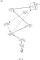
- FIG. 1 Aillustrates a Mobile Energy Storage Unit system overview 100 , according to example embodiments.
- a server 104 communicably coupled to a network 102is used to determine, among other things, an optimal path for a MESU 106 to travel and gather and store the greatest amount of energy in a minimal amount of time, in one embodiment.
- the transports in the system T1-T5 108 - 116 , the grid 118 , and the MESU 106are connected to the network 102 .
- the grid 118refers to a station associated with an electric grid and is capable of receiving a charge from an object (wired or wirelessly), such as a transport or MESU. Additional or fewer transports other than those depicted may be part of the system without deviating from the scope of the current application.
- the MESU 106is a transport that can store energy containing at least one connection port, allowing a connection to different transports to gather and store energy.
- the MESU 106has a connection to the network 102 , allowing it to transfer and receive data such as notifications and requests.
- the MESU 106connects to the transport(s) via a connection port, as is usually utilized to charge electric vehicles.
- a vehicle power conversion unit in the MESUmanages the flow of energy as it is connected to other sources to obtain energy, and to the grid to distribute energy.
- a controller on the MESUis used to control the amount of energy flowing in and out of the MESU.
- the MESU 106communicates with the network 102 , wherein communication includes instructions of the amount of permissioned energy to obtain.
- the transports 108 - 116 , MESU 106 , and the grid 118are connected to a network 102 such as a global network or Internet via a suitable wireless communication protocol, such as a wireless telephony (e.g. GSM, CDMA, LTE, etc.), Wi-Fi (802.11 standards), WiMAX, Bluetooth, infrared or radio frequency communications, etc.
- a serveris communicably coupled to the network, which is used, among other functions, to store data from the elements of the system, such as the transports, the grid, and the MESU, in one embodiment.
- Additional code in a processor associated with the servermay in executed to perform requests and generate responses, to other elements in the system, such as the grid 118 , the transports 108 - 116 , and the MESU 106 .
- a database(not depicted) may be communicably coupled to the server 104 to store data about the functions of the current system.
- the transports 108 - 116send data to the server 104 via the network 102 at predefined intervals, in one embodiment.
- the dataincludes information about the use of the transports, idle time, current and predicted charge levels, as well as information about the future use of the transport, such as upcoming events and scheduled appointments.
- the transports 108 - 116 and/or the server 104interface with Application Programming Interfaces (APIs) of a calendar application associated with occupants of the transports 108 - 116 to determine upcoming, scheduled events on the driver/occupants calendar.
- APIsApplication Programming Interfaces
- the systemcan determine if there are any irregular destinations upcoming.
- the systemalso determines regular routes and regular times by recording daily routes of the transport. Therefore, it can determine how long the transport may be parked at a particular location, and an approximate time when the transport will be in use.
- the MESU 106connects to the transports 108 - 116 to transfer and store any surplus energy in the transports.
- the systemreceives data about the grid such as days when the grid will, at a predetermined time, submit data about needs for surplus energy.
- the systemqueries the grid, such as via the interfacing with APIs therein.
- FIG. 1 Ba MESU routing example 120 , according to example embodiments.
- a MESU 106obtaining surplus charge from transports and transferring the stored energy to a grid.
- the MESU 106determines a route that will obtain a maximum amount of charge from transports then discharge the stored charge at a grid 118 .
- the determination of the routeis based on multiple factors that are described herein.
- the MESUwill examine transports that are not plugged in and have surplus charge to provide back to the grid. This may be a surplus of charge in the transport, wherein the transport is not needing the additional charge to arrive at their next destination.
- the surplus chargemay be from the transport generating additional charge from different methods, such as regenerative braking, solar power charge, and/or the like.
- the MESU 106communicates with a server 104 .
- the server 104communicates with the transports, as further described herein, to determine an amount of surplus charge in the respective transports.
- the MESU 106creates a route according to which transport are available, are in proximity to the MESU 106 , and have a surplus of charge to provide to the MESU 106 .
- the server 104will adjust the remaining charge according to the current environment, such as current traffic and/or weather on the route to the transport's next destination. Also, the condition of the transport and the like may be used to assist the server 104 to determine the remaining charge.
- the MESU 106follows Route A 122 , transport 1 (T1) 108 is the nearest to the MESU, not charging, and has 35 kWh available as surplus to provide to the MESU. Therefore, the MESU will make that transport the first stop.
- the MESU 106then travels to transport 2 (T2) 110 , transport 3 (T3) 112 , transport 4 (T4) 114 , then to the grid 118 to provide the stored charge back to the grid.
- the MESU 106after each transfer of charge may (in one embodiment) query the server 104 for the most up-to-date characteristics of the transports in proximity to the MESU 106 .
- the server 104will then return with a next transport on the route.
- the MESU 106in correspondence with the server 104 determines transports that have surplus charge and determines Route B 124 where it travels to transport 5 (T5) 116 , then to transport 2 (T2) 110 , the back to the grid 118 . In another embodiment, the MESU 106 determines the remaining charge itself.
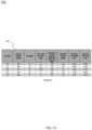
- a routing table example 150including a table of transport data 152 .
- This datais sent to the server 104 , in one embodiment, wherein the server 106 will have data for each transport and have the ability to determine any available surplus charge.
- This surplus chargeis provided to the MESU 106 .
- the server 104recommends a route for the MESU 106 , such that the MESU 106 will follow the route provided and make stops at each respective transport 108 - 114 . The MESU 106 will then travel to the grid 118 to unload the stored charge and continue on its next route.
- the MESU 106when the MESU 106 stops at a transport to obtain surplus charge, an amount of time is passes while the charge is transferred.
- the MESU 106queries the server 106 for data related to the up-to-date route, since an amount of time has passed and there may be modifications to the data and other transports, and therefore modifications to the route.
- the table 152depicts the current charge of the transport, whether the transport is currently being charged, an amount of charge determined to be necessary at the transport's next use, an amount of surplus charge that is available, and the geographic distances, both the distance from the MESU's current location, and the geographic distance between the transport and the electric grid.
- the MESU 106when the MESU 106 is traveling from transport to transport obtaining surplus charge, the MESU is not always traveling on a street or road, but travels on a bike lane, a sidewalk, path or the like. These are locations where a normal transport does not normally travel.
- the MESU 106provides a capability to augment views, such as augmenting the street view of the geographic area. This additional view provides additional periphery to a current street view. Additional information of the area is also provided, such as a sidewalk needing repairs, a lawn that is need of maintenance (such as through disease, parasites, additional maintenance due to current water restrictions, broken sprinkler heads that need repair, etc.
- additional informationis provided about packages left on a front area of a building, such as a porch.
- the MESUwill only take energy from a transport that needs a greater amount of energy to operate as compared to the MESU.
- the MESUwould not take energy from a transport such as a scooter, a golf cart, a motorcycle, and the like.
- each transport in the networkhas opted into an agreement to provide details to a server wherein the details are provided at regular intervals such that the server can retain an understanding of the relatively up-to-date details of the transport.
- the detailsmay include whether the transport is currently plugged into a charging station, whether the transport is moving, how long the transport has not been moving, the geographic location of the transport, and the time of day.
- the MESUpings the transport to determine if the transport is currently in motion and how long the transport has not been in motion (if not currently in motion).
- a computer associated with the transportis in communication with the MESU and provides this information.
- the transportis in communication with a server such as through a global network such as the internet. The MESU communicates with the server to determine characteristics of the transport in the network.
- the MESUscans transports within the network within a geographic area.
- the MESUqueries the server to obtain details of transports in the network within the geographic area.
- the MESUdetermines, through the response from the server, which transports are in the network within the geographic area and have a surplus of charge to provide to the MESU.
- the MESUdetermines the availability of the transports within the area. For example, those transports that are geographically located in a parking lot of business are not available, as the MESU will not be able to park at the transport and avoid impeding traffic in the parking lot. Those transports that are currently located inside a parking garage also would not be available to provide charge. Those transports that are located near a charging station are considered unavailable, as they may be plugged into the charging station.
- the MESUaccounts for periods in the day.
- the dayis broken up into periods, such as period 1 being from 8 am to 11 am, period 2 being from 11 am to 1 pm, period 3 being from 1 pm to 6 pm, and period 4 being from 6 pm to 11 pm.
- a transportis not near a charging station, parked in an accessible area (such as at a parking lot of a corporate business or the like) and has a surplus of charge, the period of the day is taken into consideration in the determination of the availability of the transport. For example, a transport should remain parked if at the beginning of periods 1 and 3. A transport in period 2 is not considered available as the transport may soon be utilized, such as the situation where the operator of the transport is on a lunch break.
- the MESUis querying transports at the end of period 1 and 3, then those transports may soon be used, such as the situation where the person may be heading to a destination during a lunch break, for example. If a transport is parked at a parking lot at the beginning of period 4, then it has a higher probability to be used, as the operator of the transport may be at dinner, or shopping. In further embodiment, if the transport is parked at a movie theater, and has been idle for a short amount of time (such as 10 minutes), that transport would be considered to be available, as it is most probable that the operator is watching a movie.
- the MESUdetermines when it needs to stop transferring charge from a transport. If the MESU is at a transport transferring charge from the transport, if the operator of the transport arrives at the transport during this time, the MESU will stop the transfer upon a determination that the transport is going to be driven.
- one or more biometric elementsare placed on the MESU such that the operator may interact with the one or more elements, allowing the MESU to validate that the person is the operator of the transport. This informs the MESU to disconnect from the transport and continue to another location.
- the MESUthrough communication with a computer associated with the transport, can detect functions of the transport and determine that the transfer should cease. Such as a determination that the driver's door opened and or closed, a seat belt was used to strap an occupant into the transport, an instruction to initiate the transport, and the like.
- the MESUthrough additional elements, can bypass the conditions of stopping the transport.
- the additional elementsmay include an audio component wherein the operator can instruct the MESU to continue regardless of the functions being performed at the transport that would normally stop the transfer.
- the operatormay “call out” to the MESU once it disconnects and begins to a next destination. Such as the operator saying a command, such as “don't disconnect”, or “continue the transfer”, and the like.
- the MESUaccepts gestures to communicate actions. An operator may perform a predefined gesture to instruct the MESU to stop a transfer.
- the MESUcontacts an operator of the transport such as via direct communication via cellular mobility, or through V2V technology or the like.
- the MESUinforms the operator of details related to the desired transaction, such as the expected amount of time until the MESU arrives at the transport, an estimated amount of time it will take to transfer the charge, an estimated amount of charge desired, and an estimated time when the transfer will be complete.
- the MESUrequests a verification that the transfer can take place.
- the operatorsuch as via a mobile device associated with the operator, may either validate the response, or deny the response.
- the operator, through the devicecan respond with a time when the transfer may take place.
- the MESUnotifies the device associated with the operator of a transfer of value to the operator in response to the allowance of the MESU to transfer charge from the transport.
- periods during the dayare established. These periods are used by the MESU to determine a likely availability of transports. For example, three periods are defined: a time between 8:00 am and 11:00 am (Period 1), a time between 1:00 pm and 5:00 pm (Period 2), and a time between 6:00 pm and 10:00 pm (Period 3).
- the MESUcan predict a higher chance that a transport will be available for a charge transfer. If the current time is between 8:00 am and 9:00 am, the transport is not connected to a charging station, and is in an available parking spot, there is a fairly high chance that the transport will be available until 11 am.
- the MESUconsiders an average charging rate and a peak charging rate and the amount of time at the average charging rate and the peak charging rate for determining which charging station to maneuver to, low long to stay at the charging station, how much charge is to be remaining in the MESU upon leaving the charging station, etc.
- the average charging rateis the rate of charge over a given period
- the peak charging rateis the fastest charging kWh over the charging session.
- FIG. 2 Aillustrates a transport network diagram 200 , according to example embodiments.
- the networkcomprises elements including a transport node 202 including a processor 204 , as well as a transport node 202 ′ including a processor 204 ′.
- the transport nodes 202 , 202 ′communicate with one another via the processors 204 , 204 ′, as well as other elements (not shown) including transceivers, transmitters, receivers, storage, sensors and other elements capable of providing communication.
- the communication between the transport nodes 202 , 202 ′can occur directly, via a private and/or a public network (not shown) or via other transport nodes and elements comprising one or more of a processor, memory, and software.
- transport nodes and processorsAlthough depicted as single transport nodes and processors, a plurality of transport nodes and processors may be present. One or more of the applications, features, steps, solutions, etc., described and/or depicted herein may be utilized and/or provided by the instant elements.
- FIG. 2 Billustrates another transport network diagram 210 , according to example embodiments.
- the networkcomprises elements including a transport node 202 including a processor 204 , as well as a transport node 202 ′ including a processor 204 ′.
- the transport nodes 202 , 202 ′communicate with one another via the processors 204 , 204 ′, as well as other elements (not shown) including transceivers, transmitters, receivers, storage, sensors and other elements capable of providing communication.
- the communication between the transport nodes 202 , 202 ′can occur directly, via a private and/or a public network (not shown) or via other transport nodes and elements comprising one or more of a processor, memory, and software.
- the processors 204 , 204 ′can further communicate with one or more elements 230 including sensor 212 , wired device 214 , wireless device 216 , database 218 , mobile phone 220 , transport node 222 , computer 224 , I/O device 226 and voice application 228 .
- the processors 204 , 204 ′can further communicate with elements comprising one or more of a processor, memory, and software.
- the mobile phone 220may provide information to the processor 204 , which may initiate the transport node 202 to take an action, may further provide the information or additional information to the processor 204 ′, which may initiate the transport node 202 ′ to take an action, may further provide the information or additional information to the mobile phone 220 , the transport node 222 , and/or the computer 224 .
- the applications, features, steps, solutions, etc., described and/or depicted hereinmay be utilized and/or provided by the instant elements.
- FIG. 2 Cillustrates yet another transport network diagram 240 , according to example embodiments.
- the networkcomprises elements including a transport node 202 including a processor 204 and a non-transitory computer readable medium 242 C.
- the processor 204is communicably coupled to the computer readable medium 242 C and elements 230 (which were depicted in FIG. 2 B ).
- the processor 204performs one or more of maneuvering, by a Mobile Energy Storage Unit (MESU), to a transport that is stationary for an amount of time, that is not currently being charged, that is at a distance between the transport and the MESU and that is within a timeframe for the MESU to reach the transport 242 , and retrieving, by the mobile energy storage unit, a minimum amount of energy from the transport 244 .
- MESUMobile Energy Storage Unit
- the processors and/or computer readable mediamay fully or partially reside in the interior or exterior of the transport nodes.
- the steps or features stored in the computer readable mediamay be fully or partially performed by any of the processors and/or elements in any order. Additionally, one or more steps or features may be added, omitted, combined, performed at a later time, etc.
- FIG. 3 Aillustrates a flow diagram 300 , according to example embodiments.
- the flowcomprises maneuvering 302 , by a Mobile Energy Storage Unit (MESU), to a transport that is stationary for an amount of time, that is not currently being charged, that is at a distance between the transport and the MESU and that is within a timeframe for the MESU to reach the transport, and retrieving 304 , by the mobile energy storage unit, a minimum amount of energy from the transport.
- MESUMobile Energy Storage Unit
- FIG. 4illustrates a machine learning transport network diagram 400 , according to example embodiments.
- the network 400includes a transport node 402 that interfaces with a machine learning subsystem 406 .
- the transport nodeincludes one or more sensors 404 .
- the machine learning subsystem 406contains a learning model 408 , which is a mathematical artifact created by a machine learning training system 410 that generates predictions by finding patterns in one or more training data sets.
- the machine learning subsystem 406resides in the transport node 402 . In other embodiments, the machine learning subsystem 406 resides outside of the transport node 402 .
- the transport node 402sends data from the one or more sensors 404 to the machine learning subsystem 406 .
- the machine learning subsystem 406provides the one or more sensor 404 data to the learning model 408 , which returns one or more predictions.
- the machine learning subsystem 406sends one or more instructions to the transport node 402 based on the predictions from the learning model 408 .
- the transport node 402may send the one or more sensor data 404 to the machine learning training system 410 .
- the machine learning subsystem 406may send the sensor 404 data to the machine learning training subsystem 410 .
- the machine learning subsystem 406 and the machine learning training subsystem 410may be one system.
- One or more of the applications, features, steps, solutions, etc., described and/or depicted hereinmay utilize the machine learning network 400 as described herein.
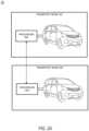
- FIG. 5 Aillustrates an example vehicle configuration 500 for managing database transactions associated with a vehicle, according to example embodiments.
- the vehiclemay receive assets 510 and/or expel/transfer assets 512 according to a transaction(s).
- a transport processor 526resides in the vehicle 525 and communication exists between the transport processor 526 , a database 530 , a transport processor 526 and the transaction module 520 .
- the transaction module 520may record information, such as assets, parties, credits, service descriptions, date, time, location, results, notifications, unexpected events, etc.
- the database 530can be one of a SQL database, an RDBMS, a relational database, a non-relational database, a blockchain, a distributed ledger, and may be on board the transport, may be off board the transport, may be accessible directly and/or through a network, or be accessible to the transport.
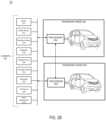
- FIG. 5 Billustrates an example vehicle configuration 550 for managing database transactions conducted among various vehicles, according to example embodiments.
- the vehicle 525may engage with another vehicle 508 to perform various actions such as to share, transfer, acquire service calls, etc. when the vehicle has reached a status where the services need to be shared with another vehicle.
- the vehicle 508may be due for a battery charge and/or may have an issue with a tire and may be in route to pick up a package for delivery.
- a transport processor 528resides in the vehicle 508 and communication exists between the transport processor 528 , a database 554 , a transport processor 528 and the transaction module 552 .
- the vehicle 508may notify another vehicle 525 , which is in its network and which operates on its blockchain member service.
- a transport processor 526resides in the vehicle 525 and communication exists between the transport processor 526 , a database 530 , the transport processor 526 and a transaction module 520 .
- the vehicle 525may then receive the information via a wireless communication request to perform the package pickup from the vehicle 508 and/or from a server (not shown).
- the transactionsare logged in the transaction modules 552 and 520 of both vehicles.
- the creditsare transferred from vehicle 508 to vehicle 525 and the record of the transferred service is logged in the database 530 / 554 assuming that the blockchains are different from one another, or, are logged in the same blockchain used by all members.
- the database 554can be one of a SQL database, an RDBMS, a relational database, a non-relational database, a blockchain, a distributed ledger, and may be on board the transport, may be off board the transport, may be accessible directly and/or through a network.
- FIG. 6 Aillustrates a blockchain architecture configuration 600 , according to example embodiments.
- the blockchain architecture 600may include certain blockchain elements, for example, a group of blockchain member nodes 602 - 606 as part of a blockchain group 610 .
- a permissioned blockchainis not accessible to all parties but only to those members with permissioned access to the blockchain data.
- the blockchain nodesparticipate in a number of activities, such as blockchain entry addition and validation process (consensus).
- One or more of the blockchain nodesmay endorse entries based on an endorsement policy and may provide an ordering service for all blockchain nodes.
- a blockchain nodemay initiate a blockchain action (such as an authentication) and seek to write to a blockchain immutable ledger stored in the blockchain, a copy of which may also be stored on the underpinning physical infrastructure.
- the blockchain transactions 620are stored in memory of computers as the transactions are received and approved by the consensus model dictated by the members' nodes. Approved transactions 626 are stored in current blocks of the blockchain and committed to the blockchain via a committal procedure, which includes performing a hash of the data contents of the transactions in a current block and referencing a previous hash of a previous block.
- one or more smart contracts 630may exist that define the terms of transaction agreements and actions included in smart contract executable application code 632 , such as registered recipients, vehicle features, requirements, permissions, sensor thresholds, etc. The code may be configured to identify whether requesting entities are registered to receive vehicle services, what service features they are entitled/required to receive given their profile statuses and whether to monitor their actions in subsequent events.
- the sensor data monitoringmay be triggered, and a certain parameter, such as a vehicle charge level, may be identified as being above/below a particular threshold for a particular period of time, then the result may be a change to a current status, which requires an alert to be sent to the managing party (i.e., vehicle owner, vehicle operator, server, etc.) so the service can be identified and stored for reference.
- a certain parametersuch as a vehicle charge level
- the resultmay be a change to a current status, which requires an alert to be sent to the managing party (i.e., vehicle owner, vehicle operator, server, etc.) so the service can be identified and stored for reference.
- the vehicle sensor data collectedmay be based on types of sensor data used to collect information about vehicle's status.
- the sensor datamay also be the basis for the vehicle event data 634 , such as a location(s) to be traveled, an average speed, a top speed, acceleration rates, whether there were any collisions, was the expected route taken, what is the next destination, whether safety measures are in place, whether the vehicle has enough charge/fuel, etc. All such information may be the basis of smart contract terms 630 , which are then stored in a blockchain. For example, sensor thresholds stored in the smart contract can be used as the basis for whether a detected service is necessary and when and where the service should be performed.
- FIG. 6 Billustrates a shared ledger configuration, according to example embodiments.
- the blockchain logic example 640includes a blockchain application interface 642 as an API or plug-in application that links to the computing device and execution platform for a particular transaction.
- the blockchain configuration 640may include one or more applications, which are linked to application programming interfaces (APIs) to access and execute stored program/application code (e.g., smart contract executable code, smart contracts, etc.), which can be created according to a customized configuration sought by participants and can maintain their own state, control their own assets, and receive external information. This can be deployed as an entry and installed, via appending to the distributed ledger, on all blockchain nodes.
- APIsapplication programming interfaces
- stored program/application codee.g., smart contract executable code, smart contracts, etc.
- the smart contract application code 644provides a basis for the blockchain transactions by establishing application code, which when executed causes the transaction terms and conditions to become active.
- the smart contract 630when executed, causes certain approved transactions 626 to be generated, which are then forwarded to the blockchain platform 652 .
- the platformincludes a security/authorization 658 , computing devices, which execute the transaction management 656 and a storage portion 654 as a memory that stores transactions and smart contracts in the blockchain.
- the blockchain platformmay include various layers of blockchain data, services (e.g., cryptographic trust services, virtual execution environment, etc.), and underpinning physical computer infrastructure that may be used to receive and store new entries and provide access to auditors, which are seeking to access data entries.
- the blockchainmay expose an interface that provides access to the virtual execution environment necessary to process the program code and engage the physical infrastructure.
- Cryptographic trust servicesmay be used to verify entries such as asset exchange entries and keep information private.
- the blockchain architecture configuration of FIGS. 6 A and 6 Bmay process and execute program/application code via one or more interfaces exposed, and services provided, by the blockchain platform.
- smart contractsmay be created to execute reminders, updates, and/or other notifications subject to the changes, updates, etc.
- the smart contractscan themselves be used to identify rules associated with authorization and access requirements and usage of the ledger.
- the informationmay include a new entry, which may be processed by one or more processing entities (e.g., processors, virtual machines, etc.) included in the blockchain layer.
- the resultmay include a decision to reject or approve the new entry based on the criteria defined in the smart contract and/or a consensus of the peers.
- the physical infrastructuremay be utilized to retrieve any of the data or information described herein.
- a smart contractmay be created via a high-level application and programming language, and then written to a block in the blockchain.
- the smart contractmay include executable code that is registered, stored, and/or replicated with a blockchain (e.g., distributed network of blockchain peers).
- An entryis an execution of the smart contract code, which can be performed in response to conditions associated with the smart contract being satisfied.
- the executing of the smart contractmay trigger a trusted modification(s) to a state of a digital blockchain ledger.
- the modification(s) to the blockchain ledger caused by the smart contract executionmay be automatically replicated throughout the distributed network of blockchain peers through one or more consensus protocols.
- the smart contractmay write data to the blockchain in the format of key-value pairs. Furthermore, the smart contract code can read the values stored in a blockchain and use them in application operations. The smart contract code can write the output of various logic operations into the blockchain. The code may be used to create a temporary data structure in a virtual machine or other computing platform. Data written to the blockchain can be public and/or can be encrypted and maintained as private. The temporary data that is used/generated by the smart contract is held in memory by the supplied execution environment, then deleted once the data needed for the blockchain is identified.
- a smart contract executable codemay include the code interpretation of a smart contract, with additional features.
- the smart contract executable codemay be program code deployed on a computing network, where it is executed and validated by chain validators together during a consensus process.
- the smart contract executable codereceives a hash and retrieves from the blockchain a hash associated with the data template created by use of a previously stored feature extractor. If the hashes of the hash identifier and the hash created from the stored identifier template data match, then the smart contract executable code sends an authorization key to the requested service.
- the smart contract executable codemay write to the blockchain data associated with the cryptographic details.
- FIG. 6 Cillustrates a blockchain configuration for storing blockchain transaction data, according to example embodiments.
- the example configuration 660provides for the vehicle 662 , the user device 664 and a server 666 sharing information with a distributed ledger (i.e., blockchain) 668 .
- the servermay represent a service provider entity inquiring with a vehicle service provider to share user profile rating information in the event that a known and established user profile is attempting to rent a vehicle with an established rated profile.
- the server 666may be receiving and processing data related to a vehicle's service requirements.
- a smart contractmay be used to invoke rules, thresholds, sensor information gathering, etc., which may be used to invoke the vehicle service event.
- the blockchain transaction data 670is saved for each transaction, such as the access event, the subsequent updates to a vehicle's service status, event updates, etc.
- the transactionsmay include the parties, the requirements (e.g., 18 years of age, service eligible candidate, valid driver's license, etc.), compensation levels, the distance traveled during the event, the registered recipients permitted to access the event and host a vehicle service, rights/permissions, sensor data retrieved during the vehicle event operation to log details of the next service event and identify a vehicle's condition status, and thresholds used to make determinations about whether the service event was completed and whether the vehicle's condition status has changed.
- the requirementse.g., 18 years of age, service eligible candidate, valid driver's license, etc.
- compensation levelse.g., the distance traveled during the event
- rights/permissionse.g., sensor data retrieved during the vehicle event operation to log details of the next service event and identify a vehicle's condition status
- thresholdsused to make determinations about whether the service event was completed and whether the vehicle's condition status has changed.
- FIG. 6 Dillustrates blockchain blocks 680 that can be added to a distributed ledger, according to example embodiments, and contents of block structures 682 A to 682 n .
- clientsmay submit entries to blockchain nodes to enact activity on the blockchain.
- clientsmay be applications that act on behalf of a requester, such as a device, person or entity to propose entries for the blockchain.
- the plurality of blockchain peerse.g., blockchain nodes
- Different types of blockchain nodes/peersmay be present in the blockchain network including endorsing peers, which simulate and endorse entries proposed by clients and committing peers which verify endorsements, validate entries, and commit entries to the distributed ledger.
- the blockchain nodesmay perform the role of endorser node, committer node, or both.
- the instant systemincludes a blockchain that stores immutable, sequenced records in blocks, and a state database (current world state) maintaining a current state of the blockchain.
- One distributed ledgermay exist per channel and each peer maintains its own copy of the distributed ledger for each channel of which they are a member.
- the instant blockchainis an entry log, structured as hash-linked blocks where each block contains a sequence of N entries. Blocks may include various components such as those shown in FIG. 6 D .
- the linking of the blocksmay be generated by adding a hash of a prior block's header within a block header of a current block. In this way, all entries on the blockchain are sequenced and cryptographically linked together preventing tampering with blockchain data without breaking the hash links. Furthermore, because of the links, the latest block in the blockchain represents every entry that has come before it.
- the instant blockchainmay be stored on a peer file system (local or attached storage), which supports an append-only blockchain workload.
- the current state of the blockchain and the distributed ledgermay be stored in the state database.
- the current state datarepresents the latest values for all keys ever included in the chain entry log of the blockchain.
- Smart contract executable code invocationsexecute entries against the current state in the state database.
- the state databasemay include an indexed view into the entry log of the blockchain, it can therefore be regenerated from the chain at any time.
- the state databasemay automatically get recovered (or generated if needed) upon peer startup, before entries are accepted.
- Endorsing nodesreceive entries from clients and endorse the entry based on simulated results. Endorsing nodes hold smart contracts, which simulate the entry proposals. When an endorsing node endorses an entry, the endorsing nodes creates an entry endorsement, which is a signed response from the endorsing node to the client application indicating the endorsement of the simulated entry.
- the method of endorsing an entrydepends on an endorsement policy that may be specified within smart contract executable code.
- An example of an endorsement policyis “the majority of endorsing peers must endorse the entry.” Different channels may have different endorsement policies. Endorsed entries are forward by the client application to an ordering service.
- the ordering serviceaccepts endorsed entries, orders them into a block, and delivers the blocks to the committing peers. For example, the ordering service may initiate a new block when a threshold of entries has been reached, a timer times out, or another condition.
- blockchain nodeis a committing peer that has received a data block 682 A for storage on the blockchain.
- the ordering servicemay be made up of a cluster of orderers.
- the ordering servicedoes not process entries, smart contracts, or maintain the shared ledger. Rather, the ordering service may accept the endorsed entries and specifies the order in which those entries are committed to the distributed ledger.
- the architecture of the blockchain networkmay be designed such that the specific implementation of ‘ordering’ (e.g., Solo, Kafka, BFT, etc.) becomes a pluggable component.
- Entriesare written to the distributed ledger in a consistent order.
- the order of entriesis established to ensure that the updates to the state database are valid when they are committed to the network.
- a cryptocurrency blockchain systeme.g., Bitcoin, etc.
- the parties of the distributed ledgermay choose the ordering mechanism that best suits that network.
- a block 682 A(also referred to as a data block) that is stored on the blockchain and/or the distributed ledger may include multiple data segments such as a block header 684 A to 684 n , transaction specific data 686 A to 686 n , and block metadata 688 A to 688 n .
- block header 684 A and the block metadata 688 Amay be smaller than the transaction specific data 686 A, which stores entry data; however, this is not a requirement.
- the block 682 Amay store transactional information of N entries (e.g., 100, 500, 1000, 2000, 3000, etc.) within the block data 690 A to 690 n .
- the block 682 Amay also include a link to a previous block (e.g., on the blockchain) within the block header 684 A.
- the block header 684 Amay include a hash of a previous block's header.
- the block header 684 Amay also include a unique block number, a hash of the block data 690 A of the current block 682 A, and the like.
- the block number of the block 682 Amay be unique and assigned in an incremental/sequential order starting from zero.
- the first block in the blockchainmay be referred to as a genesis block, which includes information about the blockchain, its members, the data stored therein, etc.
- the block data 690 Amay store entry information of each entry that is recorded within the block.
- the entry datamay include one or more of a type of the entry, a version, a timestamp, a channel ID of the distributed ledger, an entry ID, an epoch, a payload visibility, a smart contract executable code path (deploy tx), a smart contract executable code name, a smart contract executable code version, input (smart contract executable code and functions), a client (creator) identify such as a public key and certificate, a signature of the client, identities of endorsers, endorser signatures, a proposal hash, smart contract executable code events, response status, namespace, a read set (list of key and version read by the entry, etc.), a write set (list of key and value, etc.), a start key, an end key, a list of keys, a Merkel tree query summary, and the like.
- the entry datamay be stored for each of the N entries.
- the block data 690 Amay also store transaction specific data 686 A, which adds additional information to the hash-linked chain of blocks in the blockchain. Accordingly, the data 686 A can be stored in an immutable log of blocks on the distributed ledger. Some of the benefits of storing such data 686 A are reflected in the various embodiments disclosed and depicted herein.
- the block metadata 688 Amay store multiple fields of metadata (e.g., as a byte array, etc.). Metadata fields may include signature on block creation, a reference to a last configuration block, an entry filter identifying valid and invalid entries within the block, last offset persisted of an ordering service that ordered the block, and the like. The signature, the last configuration block, and the orderer metadata may be added by the ordering service.
- a committer of the blockmay add validity/invalidity information based on an endorsement policy, verification of read/write sets, and the like.
- the entry filtermay include a byte array of a size equal to the number of entries in the block data 610 A and a validation code identifying whether an entry was valid/invalid.
- each of the headers 684 A to 684 n in the other blocksincludes the hash value of an immediately preceding block.
- the hash value of the immediately preceding blockmay be just the hash of the header of the previous block or may be the hash value of the entire previous block.
- a computer programmay be embodied on a computer readable medium, such as a storage medium.
- a computer programmay reside in random access memory (“RAM”), flash memory, read-only memory (“ROM”), erasable programmable read-only memory (“EPROM”), electrically erasable programmable read-only memory (“EEPROM”), registers, hard disk, a removable disk, a compact disk read-only memory (“CD-ROM”), or any other form of storage medium known in the art.
- An exemplary storage mediummay be coupled to the processor such that the processor may read information from, and write information to, the storage medium.
- the storage mediummay be integral to the processor.
- the processor and the storage mediummay reside in an application specific integrated circuit (“ASIC”).
- ASICapplication specific integrated circuit
- the processor and the storage mediummay reside as discrete components.
- FIG. 7illustrates an example computer system architecture 700 , which may represent or be integrated in any of the above-described components, etc.
- FIG. 7is not intended to suggest any limitation as to the scope of use or functionality of embodiments of the application described herein. Regardless, the computing node 700 is capable of being implemented and/or performing any of the functionality set forth hereinabove.
- computing node 700there is a computer system/server 702 , which is operational with numerous other general purpose or special purpose computing system environments or configurations.
- Examples of well-known computing systems, environments, and/or configurations that may be suitable for use with computer system/server 702include, but are not limited to, personal computer systems, server computer systems, thin clients, thick clients, hand-held or laptop devices, multiprocessor systems, microprocessor-based systems, set top boxes, programmable consumer electronics, network PCs, minicomputer systems, mainframe computer systems, and distributed cloud computing environments that include any of the above systems or devices, and the like.
- Computer system/server 702may be described in the general context of computer system-executable instructions, such as program modules, being executed by a computer system.
- program modulesmay include routines, programs, objects, components, logic, data structures, and so on that perform particular tasks or implement particular abstract data types.
- Computer system/server 702may be practiced in distributed cloud computing environments where tasks are performed by remote processing devices that are linked through a communications network.
- program modulesmay be located in both local and remote computer system storage media including memory storage devices.
- computer system/server 702 in cloud computing node 700is shown in the form of a general-purpose computing device.
- the components of computer system/server 702may include, but are not limited to, one or more processors or processing units 704 , a system memory 706 , and a bus that couples various system components including system memory 706 to processor 704 .
- the busrepresents one or more of any of several types of bus structures, including a memory bus or memory controller, a peripheral bus, an accelerated graphics port, and a processor or local bus using any of a variety of bus architectures.
- bus architecturesinclude Industry Standard Architecture (ISA) bus, Micro Channel Architecture (MCA) bus, Enhanced ISA (EISA) bus, Video Electronics Standards Association (VESA) local bus, and Peripheral Component Interconnects (PCI) bus.
- Computer system/server 702typically includes a variety of computer system readable media. Such media may be any available media that is accessible by computer system/server 702 , and it includes both volatile and non-volatile media, removable and non-removable media.
- System memory 706implements the flow diagrams of the other figures.
- the system memory 706can include computer system readable media in the form of volatile memory, such as random-access memory (RAM) 708 and/or cache memory 710 .
- Computer system/server 702may further include other removable/non-removable, volatile/non-volatile computer system storage media.
- memory 706can be provided for reading from and writing to a non-removable, non-volatile magnetic media (not shown and typically called a “hard drive”).
- a magnetic disk drivefor reading from and writing to a removable, non-volatile magnetic disk (e.g., a “floppy disk”)
- an optical disk drivefor reading from or writing to a removable, non-volatile optical disk such as a CD-ROM, DVD-ROM or other optical media
- eachcan be connected to the bus by one or more data media interfaces.
- memory 706may include at least one program product having a set (e.g., at least one) of program modules that are configured to carry out the functions of various embodiments of the application.
- Program/utilityhaving a set (at least one) of program modules, may be stored in memory 706 by way of example, and not limitation, as well as an operating system, one or more application programs, other program modules, and program data. Each of the operating system, one or more application programs, other program modules, and program data or some combination thereof, may include an implementation of a networking environment.
- Program modulesgenerally carry out the functions and/or methodologies of various embodiments of the application as described herein.
- aspects of the present applicationmay be embodied as a system, method, or computer program product. Accordingly, aspects of the present application may take the form of an entirely hardware embodiment, an entirely software embodiment (including firmware, resident software, micro-code, etc.) or an embodiment combining software and hardware aspects that may all generally be referred to herein as a “circuit,” “module” or “system.” Furthermore, aspects of the present application may take the form of a computer program product embodied in one or more computer readable medium(s) having computer readable program code embodied thereon.
- Computer system/server 702may also communicate with one or more external devices via an I/O device 712 (such as an I/O adapter), which may include a keyboard, a pointing device, a display, a voice recognition module, etc., one or more devices that enable a user to interact with computer system/server 702 , and/or any devices (e.g., network card, modem, etc.) that enable computer system/server 702 to communicate with one or more other computing devices. Such communication can occur via I/O interfaces of the device 712 . Still yet, computer system/server 702 can communicate with one or more networks such as a local area network (LAN), a general wide area network (WAN), and/or a public network (e.g., the Internet) via a network adapter.
- LANlocal area network
- WANwide area network
- public networke.g., the Internet
- device 712communicates with the other components of computer system/server 702 via a bus. It should be understood that although not shown, other hardware and/or software components could be used in conjunction with computer system/server 702 . Examples, include, but are not limited to: microcode, device drivers, redundant processing units, external disk drive arrays, RAID systems, tape drives, and data archival storage systems, etc.
- the information sent between various modulescan be sent between the modules via at least one of: a data network, the Internet, a voice network, an Internet Protocol network, a wireless device, a wired device and/or via plurality of protocols. Also, the messages sent or received by any of the modules may be sent or received directly and/or via one or more of the other modules.
- a “system”could be embodied as a personal computer, a server, a console, a personal digital assistant (PDA), a cell phone, a tablet computing device, a smartphone or any other suitable computing device, or combination of devices.
- PDApersonal digital assistant
- Presenting the above-described functions as being performed by a “system”is not intended to limit the scope of the present application in any way but is intended to provide one example of many embodiments. Indeed, methods, systems and apparatuses disclosed herein may be implemented in localized and distributed forms consistent with computing technology.
- modulesmay be implemented as a hardware circuit comprising custom very large-scale integration (VLSI) circuits or gate arrays, off-the-shelf semiconductors such as logic chips, transistors, or other discrete components.
- VLSIvery large-scale integration
- a modulemay also be implemented in programmable hardware devices such as field programmable gate arrays, programmable array logic, programmable logic devices, graphics processing units, or the like.
- a modulemay also be at least partially implemented in software for execution by various types of processors.
- An identified unit of executable codemay, for instance, comprise one or more physical or logical blocks of computer instructions that may, for instance, be organized as an object, procedure, or function. Nevertheless, the executables of an identified module need not be physically located together but may comprise disparate instructions stored in different locations that when joined logically together, comprise the module and achieve the stated purpose for the module.
- modulesmay be stored on a computer-readable medium, which may be, for instance, a hard disk drive, flash device, random access memory (RAM), tape, or any other such medium used to store data.
- a module of executable codecould be a single instruction, or many instructions, and may even be distributed over several different code segments, among different programs, and across several memory devices.
- operational datamay be identified and illustrated herein within modules and may be embodied in any suitable form and organized within any suitable type of data structure. The operational data may be collected as a single data set or may be distributed over different locations including over different storage devices, and may exist, at least partially, merely as electronic signals on a system or network.
Landscapes
- Engineering & Computer Science (AREA)
- Power Engineering (AREA)
- Transportation (AREA)
- Mechanical Engineering (AREA)
- Management, Administration, Business Operations System, And Electronic Commerce (AREA)
- Traffic Control Systems (AREA)
Abstract
Description
Claims (20)
Priority Applications (1)
| Application Number | Priority Date | Filing Date | Title |
|---|---|---|---|
| US16/821,951US11890952B2 (en) | 2020-03-17 | 2020-03-17 | Mobile transport for extracting and depositing energy |
Applications Claiming Priority (1)
| Application Number | Priority Date | Filing Date | Title |
|---|---|---|---|
| US16/821,951US11890952B2 (en) | 2020-03-17 | 2020-03-17 | Mobile transport for extracting and depositing energy |
Publications (2)
| Publication Number | Publication Date |
|---|---|
| US20210291671A1 US20210291671A1 (en) | 2021-09-23 |
| US11890952B2true US11890952B2 (en) | 2024-02-06 |
Family
ID=77747418
Family Applications (1)
| Application Number | Title | Priority Date | Filing Date |
|---|---|---|---|
| US16/821,951Active2040-07-03US11890952B2 (en) | 2020-03-17 | 2020-03-17 | Mobile transport for extracting and depositing energy |
Country Status (1)
| Country | Link |
|---|---|
| US (1) | US11890952B2 (en) |
Families Citing this family (10)
| Publication number | Priority date | Publication date | Assignee | Title |
|---|---|---|---|---|
| US11618329B2 (en) | 2020-03-17 | 2023-04-04 | Toyota Motor North America, Inc. | Executing an energy transfer directive for an idle transport |
| US11552507B2 (en) | 2020-03-17 | 2023-01-10 | Toyota Motor North America, Inc. | Wirelessly notifying a transport to provide a portion of energy |
| US11890952B2 (en)* | 2020-03-17 | 2024-02-06 | Toyot Motor North America, Inc. | Mobile transport for extracting and depositing energy |
| US11571983B2 (en) | 2020-03-17 | 2023-02-07 | Toyota Motor North America, Inc. | Distance-based energy transfer from a transport |
| US11685283B2 (en) | 2020-03-17 | 2023-06-27 | Toyota Motor North America, Inc. | Transport-based energy allocation |
| US11817378B2 (en)* | 2020-07-08 | 2023-11-14 | Qualcomm Incorporated | Apparatus and method for providing a scalable ball grid array (BGA) assignment and a PCB circuit trace breakout pattern for RF chip interfaces |
| EP4005859A1 (en)* | 2020-11-30 | 2022-06-01 | Wobben Properties GmbH | Method for controlling an exchange between a charging structure and an electrical supply network |
| JP7639638B2 (en)* | 2021-09-24 | 2025-03-05 | トヨタ自動車株式会社 | Mobile power trading processing device |
| JP7609039B2 (en)* | 2021-11-02 | 2025-01-07 | トヨタ自動車株式会社 | Information processing device, system, method, and program |
| US12370918B2 (en)* | 2022-03-10 | 2025-07-29 | Toyota Motor North America, Inc. | Grid event electric vehicle management |
Citations (128)
| Publication number | Priority date | Publication date | Assignee | Title |
|---|---|---|---|---|
| JP2007020397A (en) | 2001-03-15 | 2007-01-25 | Hydrogenics Corp | System enabling real-time selling and buying of electric power output of fuel cell vehicles |
| US20070282495A1 (en) | 2006-05-11 | 2007-12-06 | University Of Delaware | System and method for assessing vehicle to grid (v2g) integration |
| US20080040295A1 (en) | 2006-08-10 | 2008-02-14 | V2 Green, Inc. | Power Aggregation System for Distributed Electric Resources |
| US20080040223A1 (en) | 2006-08-10 | 2008-02-14 | V2 Green Inc. | Electric Resource Module in a Power Aggregation System for Distributed Electric Resources |
| US20080281663A1 (en) | 2007-05-09 | 2008-11-13 | Gridpoint, Inc. | Method and system for scheduling the discharge of distributed power storage devices and for levelizing dispatch participation |
| US20090085522A1 (en)* | 2007-09-27 | 2009-04-02 | Denso Corporation | Charging system |
| JP2009118652A (en) | 2007-11-07 | 2009-05-28 | Chugoku Electric Power Co Inc:The | Charging system for electric vehicle |
| US20090224939A1 (en) | 2008-03-04 | 2009-09-10 | Alcatel-Lucent | Method of transferring energy between a first unit and a second unit |
| CN101678774A (en) | 2006-12-11 | 2010-03-24 | 威图格林股份有限公司 | Power aggregation system for distributed electric resources |
| WO2010060720A2 (en) | 2008-11-03 | 2010-06-03 | Andreas Stopp | Method for automatically charging full-time or part-time electric vehicles, and arrangement for establishing a charging contact |
| WO2011039284A2 (en) | 2009-09-29 | 2011-04-07 | Inensus Gmbh | Monitoring system and method for monitoring energy transfer between a first energy unit and a second energy unit |
| KR101033880B1 (en) | 2009-06-26 | 2011-05-11 | 현대자동차일본기술연구소 | Battery charging and discharging method of electric vehicle |
| US7956570B2 (en) | 2008-01-07 | 2011-06-07 | Coulomb Technologies, Inc. | Network-controlled charging system for electric vehicles |
| WO2011102857A1 (en) | 2010-02-18 | 2011-08-25 | University Of Delaware | Electric vehicle station equipment for grid-integrated vehicles |
| JP2011197932A (en) | 2010-03-18 | 2011-10-06 | Toshiba Corp | Energy navigation control apparatus, energy navigation system and energy navigator |
| US20110276448A1 (en) | 2010-05-05 | 2011-11-10 | Harry Leonard Perper | Plug-in hybrid and electric vehicle charging system |
| US20120025764A1 (en)* | 2010-08-02 | 2012-02-02 | Lsis Co., Ltd. | Charging stand for electric vehicle |
| US20120035778A1 (en) | 2008-11-14 | 2012-02-09 | Kong Stephen Poh Chew | Automated system of democratizing power |
| JP4893653B2 (en) | 2008-02-19 | 2012-03-07 | トヨタ自動車株式会社 | Vehicle, rechargeable battery state of charge estimation method and vehicle control method |
| US8154246B1 (en) | 2009-01-30 | 2012-04-10 | Comverge, Inc. | Method and system for charging of electric vehicles according to user defined prices and price off-sets |
| US20120109798A1 (en)* | 2010-10-27 | 2012-05-03 | The Aes Corporation | Methods and apparatus for managing renewable energy services for fixed and mobile assets |
| AU2012100463A4 (en) | 2012-02-21 | 2012-05-24 | Uniloc Usa, Inc. | Renewable resource distribution management system |
| KR20120062089A (en) | 2010-12-06 | 2012-06-14 | 한국전자통신연구원 | Vehicle mobile gateway for controling charging of electric vehicle using mobile terminal, electric vehicle having the same, and method for controling charging of electric vehicle using mobile terminal |
| JP2012120295A (en) | 2010-11-30 | 2012-06-21 | Mitsubishi Electric Corp | Residential electric energy management device, residential electric energy management system, residential electric energy management method, and program |
| US20120169282A1 (en) | 2009-08-20 | 2012-07-05 | Rwe Ag | Method and Device for Identifying an Electric Vehicle to a Billing Centre |
| WO2012098660A1 (en) | 2011-01-20 | 2012-07-26 | 三菱電機株式会社 | Navigation device and charging control device for electric vehicle |
| US20120245750A1 (en) | 2011-03-25 | 2012-09-27 | Kabushiki Kaisha Toshiba | Electric vehicle charging scheduling system |
| US20120299373A1 (en)* | 2011-05-23 | 2012-11-29 | Denso Corporation | Power transmitting and receiving system for vehicle |
| CN102891505A (en) | 2011-07-20 | 2013-01-23 | 台达电子工业股份有限公司 | Charging device, intelligent vehicle charging system and method of operation thereof |
| WO2013061410A1 (en) | 2011-10-25 | 2013-05-02 | パイオニア株式会社 | Charging information management server, terminal, charging information management method, and program |
| US20130119920A1 (en)* | 2011-11-16 | 2013-05-16 | Industrial Technology Research Institute | Electric vehicle charging system and charging management method thereof |
| JP2013104683A (en) | 2011-11-10 | 2013-05-30 | Honda Motor Co Ltd | Information providing device during battery quick charge to vehicle |
| DE202012105091U1 (en) | 2011-12-31 | 2013-06-25 | Nation-E Ltd. | Real-time system for tracking, locating and charging electric vehicles in transit |
| US20130166096A1 (en) | 2011-12-27 | 2013-06-27 | Toyota Motor Engineering & Manufacturing North America, Inc. | Predictive destination entry for a navigation system |
| WO2013108246A2 (en) | 2012-01-17 | 2013-07-25 | Better Place GmbH | Approximation of remaining travelable distance of a vehicle powered by a battery |
| US20130218458A1 (en) | 2012-02-22 | 2013-08-22 | Harman Becker Automotive Systems Gmbh | Navigation system for an electric vehicle |
| US20130342310A1 (en) | 2012-06-25 | 2013-12-26 | Kookmin Universty Industry Academy Cooperation Foundation | Electric vehicle, battery charging station, battery exchanging reservation system comprising the same and method thereof |
| US8676636B2 (en) | 2009-04-22 | 2014-03-18 | Parkpod Gmbh | System for managing electric energy grid-vehicle exchange devices |
| US8698642B2 (en) | 2009-08-07 | 2014-04-15 | Denso Corporation | Electric power amount information output device and system |
| US20140167678A1 (en) | 2011-07-26 | 2014-06-19 | Commissariat A L'energie Atomique Et Aux Energies Alternatives | Recharging of a Pool of Batteries |
| KR20140078623A (en) | 2011-08-16 | 2014-06-25 | 베터 플레이스 게엠베하 | Estimation and management of loads in electric vehicle networks |
| US8796881B2 (en) | 2009-03-31 | 2014-08-05 | Gridpoint, Inc. | Electric vehicle power management systems |
| KR20140109568A (en) | 2013-03-05 | 2014-09-16 | 주식회사 케이티 | Method of Reservation service for Elctric Vehicles charging |
| US8860362B2 (en) | 2009-07-31 | 2014-10-14 | Deka Products Limited Partnership | System for vehicle battery charging |
| CN101938146B (en) | 2009-06-30 | 2014-12-24 | 曹松伟 | Intelligent power grid group charging electric source induced supply system |
| US20150069970A1 (en) | 2013-09-11 | 2015-03-12 | Proterra Inc. | Methods and systems for electric vehicle charging |
| CN104520133A (en) | 2012-07-31 | 2015-04-15 | 高通股份有限公司 | Selective communication based on distance from a plurality of electric vehicle wireless charging stations in a facility |
| US9024571B2 (en) | 2012-09-28 | 2015-05-05 | Honda Motor Co., Ltd. | Charging of electric vehicles based on historical clean energy profiles |
| US9026347B2 (en) | 2010-06-10 | 2015-05-05 | The Regents Of The University Of California | Smart electric vehicle (EV) charging and grid integration apparatus and methods |
| CN103010040B (en) | 2011-09-22 | 2015-06-03 | 株式会社电装 | Charge control system for electric motor vehicle |
| CN104701931A (en) | 2015-04-18 | 2015-06-10 | 国家电网公司 | Discharge capacity evaluation method of mass electric automobiles |
| KR20150079613A (en) | 2012-10-24 | 2015-07-08 | 커샘 에너지 인코포레이티드 | System, method, and apparatus for settlement for participation in an electric power grid |
| US20150298565A1 (en)* | 2012-09-03 | 2015-10-22 | Hitachi, Ltd. | Charging support system and charging support method for electric vehicle |
| US20150306967A1 (en)* | 2011-08-16 | 2015-10-29 | Better Place GmbH | Identification of an electric vehicle adjacent to a power replenishment station |
| US20150354974A1 (en) | 2014-06-09 | 2015-12-10 | Mitsubishi Electric Corporation | Charging facility information providing system and electrically driven vehicle |
| CN105356459A (en) | 2015-11-23 | 2016-02-24 | 东南大学 | A control method for allowing electric automobiles to participate in power system frequency modulation in a scattered grid-access manner |
| US20160075247A1 (en) | 2014-09-16 | 2016-03-17 | Honda Motor Co., Ltd | Priority based vehicle control strategy |
| CN103915869B (en) | 2014-03-10 | 2016-04-27 | 贾英昊 | A kind of Intelligent charging system of electric automobile based on mobile device and method |
| CN103562001B (en) | 2011-06-30 | 2016-05-25 | 国际商业机器公司 | Battery electric vehicle recharging on smart electric grid system |
| US9371007B1 (en) | 2011-04-22 | 2016-06-21 | Angel A. Penilla | Methods and systems for automatic electric vehicle identification and charging via wireless charging pads |
| US9381821B2 (en) | 2013-05-15 | 2016-07-05 | Qualcomm Incorporated | Systems, methods, and apparatus related to electric vehicle wired and wireless charging |
| US9429974B2 (en) | 2012-07-14 | 2016-08-30 | Causam Energy, Inc. | Method and apparatus for actively managing electric power supply for an electric power grid |
| US20160288653A1 (en) | 2013-03-29 | 2016-10-06 | Nissan Motor Co., Ltd. | Power supply device, vehicle and non-contact power supply system |
| US9493087B2 (en) | 2013-08-07 | 2016-11-15 | Powerhydrant Llc | Method and system for automatic charging of electric vehicles |
| DE202010018487U1 (en) | 2009-10-28 | 2017-01-20 | Google Inc. | Determination of a geographical location |
| CN102947124B (en) | 2010-05-19 | 2017-02-08 | 高通股份有限公司 | Adaptive wireless energy transfer system |
| JP6117868B2 (en) | 2014-09-15 | 2017-04-19 | エルエス産電株式会社Lsis Co., Ltd. | Electric vehicle charger |
| JP2017096497A (en) | 2015-11-18 | 2017-06-01 | パナソニックIpマネジメント株式会社 | Energy source supply system control method and energy source supply system |
| WO2017094431A1 (en) | 2015-12-01 | 2017-06-08 | オムロン株式会社 | Battery charging device, battery charging system and battery charging method |
| US9739844B2 (en) | 2014-07-25 | 2017-08-22 | Qualcomm Incorporated | Guidance and alignment system and methods for electric vehicle wireless charging systems |
| US9744858B2 (en) | 2008-09-27 | 2017-08-29 | Witricity Corporation | System for wireless energy distribution in a vehicle |
| JP6190948B2 (en) | 2013-11-09 | 2017-08-30 | パワーキューブ コーポレーションPowercube Corporation | Electric vehicle charging and billing system |
| US20170259674A1 (en)* | 2016-03-10 | 2017-09-14 | Honda Motor Co., Ltd. | Supplemental charging control device for electric vehicle |
| US9778653B1 (en) | 2014-06-27 | 2017-10-03 | Amazon Technologies, Inc. | Systems, devices and methods delivering energy using an uncrewed autonomous vehicle |
| US20170282736A1 (en) | 2016-04-01 | 2017-10-05 | Ijuze Corporation Pte Ltd. | Automated system for managing and providing a network of charging stations |
| US20170358041A1 (en) | 2012-07-31 | 2017-12-14 | Causam Energy, Inc. | Systems and methods for advanced energy settlements, network-based messaging, and applications supporting the same on a blockchain platform |
| US20170355354A1 (en)* | 2015-06-17 | 2017-12-14 | Ample Inc. | Robot assisted modular battery interchanging system |
| US9873408B2 (en) | 2016-05-11 | 2018-01-23 | Peter D. Capizzo | Device for refueling, exchanging, and charging power sources on remote controlled vehicles, UAVs, drones, or any type of robotic vehicle or machine with mobility |
| US9881259B2 (en) | 2007-08-28 | 2018-01-30 | Landis+Gyr Innovations, Inc. | System and method for estimating and providing dispatchable operating reserve energy capacity through use of active load management |
| US9931952B2 (en) | 2012-06-27 | 2018-04-03 | Qualcomm Incorporated | Electric vehicle wireless charging with monitoring of duration of charging operational mode |
| US20180111494A1 (en) | 2011-04-22 | 2018-04-26 | Emerging Automotive, Llc | Methods and Systems for Automatic Electric Vehicle Identification and Charging Via Wireless Charging Pads |
| US20180118045A1 (en) | 2016-11-02 | 2018-05-03 | Witricity Corporation | Vehicle Charger Network |
| US9969288B2 (en) | 2009-07-15 | 2018-05-15 | Panasonic Intellectual Property Management Co., Ltd. | Power control system, power control method, power control device and power control program |
| CN108054773A (en) | 2017-12-26 | 2018-05-18 | 湖南大学 | A kind of V2G intelligent scheduling method of servicing for peak load |
| US20180143035A1 (en) | 2016-11-21 | 2018-05-24 | NextEv USA, Inc. | Smart refill assistant for electric vehicles |
| US9994118B2 (en) | 2013-05-29 | 2018-06-12 | General Motors Llc | Optimizing vehicle recharging to maximize use of energy generated from particular identified sources |
| US10029577B2 (en) | 2016-06-15 | 2018-07-24 | Qualcomm Incorporated | Methods and apparatus for positioning a vehicle |
| JP2018117517A (en) | 2008-01-07 | 2018-07-26 | チャージポイント インコーポレイテッド | Network controlled charging system for electric vehicles |
| KR20180091976A (en) | 2017-02-06 | 2018-08-17 | 고려대학교 산학협력단 | Method and system of mobility-aware vehicle-to-grid (V2G) control |
| US20180238698A1 (en) | 2017-02-22 | 2018-08-23 | Robert D. Pedersen | Systems And Methods Using Artificial Intelligence For Routing Electric Vehicles |
| WO2018196803A1 (en) | 2017-04-26 | 2018-11-01 | 储晞 | Mobile power unit renting operation system and method, electrical device and operation supporting system and method therefor |
| US20180345808A1 (en) | 2017-05-31 | 2018-12-06 | Honda Motor Co., Ltd. | Vehicle charging station having degraded energy storage units for charging an incoming vehicle and methods thereof |
| US20180345807A1 (en) | 2017-05-31 | 2018-12-06 | Honda Motor Co., Ltd. | Vehicle charging station having degraded energy storage units and methods thereof |
| US20190009756A1 (en)* | 2017-07-10 | 2019-01-10 | Qualcomm Incorporated | System and Method for Itinerant Power Source for Vehicles |
| US20190061546A1 (en)* | 2017-08-29 | 2019-02-28 | Electric Motor Werks, Inc. | Application programming interface for integrating electric vehicle components with vehicle charging network |
| CN109398149A (en) | 2018-11-29 | 2019-03-01 | 江苏大学 | Intelligent electric automobile charge-discharge system and its progress control method based on distributed energy application |
| US10252631B2 (en) | 2015-11-13 | 2019-04-09 | Nio Usa, Inc. | Communications between vehicle and charging system |
| US20190107406A1 (en) | 2017-10-09 | 2019-04-11 | Nio Usa, Inc. | Systems and methods for trip planning under uncertainty |
| US20190122561A1 (en) | 2017-10-25 | 2019-04-25 | Toyota Jidosha Kabushiki Kaisha | Vehicle dispatch system, vehicle dispatch apparatus used for the same, and vehicle dispatch method |
| JP2019075134A (en) | 2018-12-03 | 2019-05-16 | Kddi株式会社 | Data management device, data management method, and data communication system |
| JP2019083528A (en) | 2018-12-03 | 2019-05-30 | Kddi株式会社 | Data management apparatus and data management method |
| US20190202315A1 (en) | 2016-05-06 | 2019-07-04 | Audi Ag | Assignment of motor vehicles to charging stations |
| US10343537B2 (en) | 2016-03-08 | 2019-07-09 | Witricity Corporation | Method and apparatus for positioning a vehicle |
| US20190217735A1 (en) | 2017-01-13 | 2019-07-18 | Uber Technologies, Inc. | Charge Control System for Mobile Energy Storage Fleet |
| US10384775B2 (en) | 2016-05-27 | 2019-08-20 | Qualcomm Incorporated | Autonomous vehicle charging station management |
| US20190280509A1 (en) | 2016-11-01 | 2019-09-12 | Honda Motor Co., Ltd. | Server device and control method |
| US20190275892A1 (en) | 2018-03-12 | 2019-09-12 | Toyota Motor Engineering & Manufacturing North America, Inc. | System and method for autonomous charging of an autonomous vehicle |
| US10414283B2 (en) | 2015-07-15 | 2019-09-17 | Honda Motor Co., Ltd. | V2G system and charge/discharge control method based on an estimated power supply-demand state, a minimum trading unit of an amount of power, and a total amount of power secured for selling to a power system |
| US20190285892A1 (en) | 2017-10-24 | 2019-09-19 | Goertek Technology Co.,Ltd. | Head-mounted display device |
| US20190308513A1 (en)* | 2018-04-09 | 2019-10-10 | The Regents Of The University Of Michigan | System and method for power delivery |
| US20190315236A1 (en) | 2018-04-13 | 2019-10-17 | Bedestrian LLC | Method for autonomous charging of a motor vehicle |
| US20190337392A1 (en)* | 2018-05-02 | 2019-11-07 | Baker Hughes, A Ge Company, Llc | Storing and Providing Electric Energy to Equipment |
| CN107176041B (en) | 2016-03-09 | 2019-11-15 | 丰田自动车株式会社 | Optimised charging and discharging of plug-in electric vehicles |
| US20200175614A1 (en)* | 2018-11-29 | 2020-06-04 | International Business Machines Corporation | Electric vehicle charging station having reverse tiered discount incentive |
| US20200218270A1 (en) | 2019-01-07 | 2020-07-09 | Wing Aviation Llc | Using machine learning techniques to estimate available energy for vehicles |
| US20200262305A1 (en)* | 2019-02-20 | 2020-08-20 | University Of Florida, Research Foundation, Incorporated | System and method for charging a network of mobile battery-operated units on-the-go |
| US20200276910A1 (en) | 2019-02-28 | 2020-09-03 | Honda Motor Co., Ltd. | Hybrid vehicle-to-grid and mobility service request system |
| US20200282859A1 (en)* | 2019-03-05 | 2020-09-10 | Hyundai Motor Company | Charging control method and apparatus for electric vehicle |
| US20200353839A1 (en) | 2019-05-10 | 2020-11-12 | GM Global Technology Operations LLC | Intelligent motor vehicles, charging systems, and control logic for governing vehicle grid integration operations |
| US20210074094A1 (en)* | 2018-04-25 | 2021-03-11 | Egs Entwicklungs- Und Forschungs- Gmbh | Digital access system for vehicles for externally controlled loading processes |
| US10981464B1 (en) | 2020-01-13 | 2021-04-20 | NAD Grid Corp | Methods and systems for facilitating charging sessions for electric vehicles |
| US20210213846A1 (en) | 2020-01-13 | 2021-07-15 | NAD Grid Corp | Methods and systems for facilitating charging sessions for electric vehicles, with improved user interface operation modes |
| US20210213848A1 (en) | 2020-01-13 | 2021-07-15 | NAD Grid Corp | Methods and systems for facilitating charging sessions for electric vehicles |
| US20210256472A1 (en) | 2020-02-14 | 2021-08-19 | Zoox, Inc. | Modular delivery vehicle with access lockers |
| US11108090B2 (en) | 2016-11-01 | 2021-08-31 | Honda Motor Co., Ltd. | Power storage device, transport equipment, and control method |
| US20210291671A1 (en)* | 2020-03-17 | 2021-09-23 | Toyota Motor North America, Inc. | Mobile transport for extracting and depositing energy |
| US20210291691A1 (en) | 2020-03-17 | 2021-09-23 | Toyota Motor North America, Inc. | Transport-based energy allocation |
| US20210331603A1 (en) | 2020-04-28 | 2021-10-28 | Wobben Properties Gmbh | Charging control of a fleet |
- 2020
- 2020-03-17USUS16/821,951patent/US11890952B2/enactiveActive
Patent Citations (134)
| Publication number | Priority date | Publication date | Assignee | Title |
|---|---|---|---|---|
| JP2007020397A (en) | 2001-03-15 | 2007-01-25 | Hydrogenics Corp | System enabling real-time selling and buying of electric power output of fuel cell vehicles |
| US20070282495A1 (en) | 2006-05-11 | 2007-12-06 | University Of Delaware | System and method for assessing vehicle to grid (v2g) integration |
| US20080040295A1 (en) | 2006-08-10 | 2008-02-14 | V2 Green, Inc. | Power Aggregation System for Distributed Electric Resources |
| US20080040223A1 (en) | 2006-08-10 | 2008-02-14 | V2 Green Inc. | Electric Resource Module in a Power Aggregation System for Distributed Electric Resources |
| CN101678774A (en) | 2006-12-11 | 2010-03-24 | 威图格林股份有限公司 | Power aggregation system for distributed electric resources |
| US20080281663A1 (en) | 2007-05-09 | 2008-11-13 | Gridpoint, Inc. | Method and system for scheduling the discharge of distributed power storage devices and for levelizing dispatch participation |
| US9881259B2 (en) | 2007-08-28 | 2018-01-30 | Landis+Gyr Innovations, Inc. | System and method for estimating and providing dispatchable operating reserve energy capacity through use of active load management |
| US20090085522A1 (en)* | 2007-09-27 | 2009-04-02 | Denso Corporation | Charging system |
| JP2009118652A (en) | 2007-11-07 | 2009-05-28 | Chugoku Electric Power Co Inc:The | Charging system for electric vehicle |
| JP2018117517A (en) | 2008-01-07 | 2018-07-26 | チャージポイント インコーポレイテッド | Network controlled charging system for electric vehicles |
| US7956570B2 (en) | 2008-01-07 | 2011-06-07 | Coulomb Technologies, Inc. | Network-controlled charging system for electric vehicles |
| JP4893653B2 (en) | 2008-02-19 | 2012-03-07 | トヨタ自動車株式会社 | Vehicle, rechargeable battery state of charge estimation method and vehicle control method |
| US20090224939A1 (en) | 2008-03-04 | 2009-09-10 | Alcatel-Lucent | Method of transferring energy between a first unit and a second unit |
| US9744858B2 (en) | 2008-09-27 | 2017-08-29 | Witricity Corporation | System for wireless energy distribution in a vehicle |
| WO2010060720A2 (en) | 2008-11-03 | 2010-06-03 | Andreas Stopp | Method for automatically charging full-time or part-time electric vehicles, and arrangement for establishing a charging contact |
| US20120035778A1 (en) | 2008-11-14 | 2012-02-09 | Kong Stephen Poh Chew | Automated system of democratizing power |
| US8154246B1 (en) | 2009-01-30 | 2012-04-10 | Comverge, Inc. | Method and system for charging of electric vehicles according to user defined prices and price off-sets |
| US8796881B2 (en) | 2009-03-31 | 2014-08-05 | Gridpoint, Inc. | Electric vehicle power management systems |
| US8676636B2 (en) | 2009-04-22 | 2014-03-18 | Parkpod Gmbh | System for managing electric energy grid-vehicle exchange devices |
| KR101033880B1 (en) | 2009-06-26 | 2011-05-11 | 현대자동차일본기술연구소 | Battery charging and discharging method of electric vehicle |
| CN101938146B (en) | 2009-06-30 | 2014-12-24 | 曹松伟 | Intelligent power grid group charging electric source induced supply system |
| US9969288B2 (en) | 2009-07-15 | 2018-05-15 | Panasonic Intellectual Property Management Co., Ltd. | Power control system, power control method, power control device and power control program |
| US8860362B2 (en) | 2009-07-31 | 2014-10-14 | Deka Products Limited Partnership | System for vehicle battery charging |
| US8698642B2 (en) | 2009-08-07 | 2014-04-15 | Denso Corporation | Electric power amount information output device and system |
| US20120169282A1 (en) | 2009-08-20 | 2012-07-05 | Rwe Ag | Method and Device for Identifying an Electric Vehicle to a Billing Centre |
| WO2011039284A2 (en) | 2009-09-29 | 2011-04-07 | Inensus Gmbh | Monitoring system and method for monitoring energy transfer between a first energy unit and a second energy unit |
| DE202010018487U1 (en) | 2009-10-28 | 2017-01-20 | Google Inc. | Determination of a geographical location |
| US9754300B2 (en) | 2010-02-18 | 2017-09-05 | University Of Delaware | Electric vehicle station equipment for grid-integrated vehicles |
| WO2011102857A1 (en) | 2010-02-18 | 2011-08-25 | University Of Delaware | Electric vehicle station equipment for grid-integrated vehicles |
| JP2014056589A (en) | 2010-03-18 | 2014-03-27 | Toshiba Corp | Apparatus and method for controlling energy navigation |
| JP2011197932A (en) | 2010-03-18 | 2011-10-06 | Toshiba Corp | Energy navigation control apparatus, energy navigation system and energy navigator |
| US20110276448A1 (en) | 2010-05-05 | 2011-11-10 | Harry Leonard Perper | Plug-in hybrid and electric vehicle charging system |
| CN102947124B (en) | 2010-05-19 | 2017-02-08 | 高通股份有限公司 | Adaptive wireless energy transfer system |
| US9026347B2 (en) | 2010-06-10 | 2015-05-05 | The Regents Of The University Of California | Smart electric vehicle (EV) charging and grid integration apparatus and methods |
| US20120025764A1 (en)* | 2010-08-02 | 2012-02-02 | Lsis Co., Ltd. | Charging stand for electric vehicle |
| US20120109798A1 (en)* | 2010-10-27 | 2012-05-03 | The Aes Corporation | Methods and apparatus for managing renewable energy services for fixed and mobile assets |
| JP2012120295A (en) | 2010-11-30 | 2012-06-21 | Mitsubishi Electric Corp | Residential electric energy management device, residential electric energy management system, residential electric energy management method, and program |
| KR20120062089A (en) | 2010-12-06 | 2012-06-14 | 한국전자통신연구원 | Vehicle mobile gateway for controling charging of electric vehicle using mobile terminal, electric vehicle having the same, and method for controling charging of electric vehicle using mobile terminal |
| WO2012098660A1 (en) | 2011-01-20 | 2012-07-26 | 三菱電機株式会社 | Navigation device and charging control device for electric vehicle |
| US20120245750A1 (en) | 2011-03-25 | 2012-09-27 | Kabushiki Kaisha Toshiba | Electric vehicle charging scheduling system |
| US9371007B1 (en) | 2011-04-22 | 2016-06-21 | Angel A. Penilla | Methods and systems for automatic electric vehicle identification and charging via wireless charging pads |
| US20180111494A1 (en) | 2011-04-22 | 2018-04-26 | Emerging Automotive, Llc | Methods and Systems for Automatic Electric Vehicle Identification and Charging Via Wireless Charging Pads |
| US20200144838A1 (en)* | 2011-04-22 | 2020-05-07 | Emerging Automotive, Llc | Robots for charging electric vehicles (evs) |
| US20120299373A1 (en)* | 2011-05-23 | 2012-11-29 | Denso Corporation | Power transmitting and receiving system for vehicle |
| CN103562001B (en) | 2011-06-30 | 2016-05-25 | 国际商业机器公司 | Battery electric vehicle recharging on smart electric grid system |
| CN102891505A (en) | 2011-07-20 | 2013-01-23 | 台达电子工业股份有限公司 | Charging device, intelligent vehicle charging system and method of operation thereof |
| US20140167678A1 (en) | 2011-07-26 | 2014-06-19 | Commissariat A L'energie Atomique Et Aux Energies Alternatives | Recharging of a Pool of Batteries |
| KR20140078623A (en) | 2011-08-16 | 2014-06-25 | 베터 플레이스 게엠베하 | Estimation and management of loads in electric vehicle networks |
| JP6399928B2 (en) | 2011-08-16 | 2018-10-03 | チャージ ピーク リミテッド | Load estimation and management in electric vehicle networks |
| US20150306967A1 (en)* | 2011-08-16 | 2015-10-29 | Better Place GmbH | Identification of an electric vehicle adjacent to a power replenishment station |
| CN103010040B (en) | 2011-09-22 | 2015-06-03 | 株式会社电装 | Charge control system for electric motor vehicle |
| WO2013061410A1 (en) | 2011-10-25 | 2013-05-02 | パイオニア株式会社 | Charging information management server, terminal, charging information management method, and program |
| JP2013104683A (en) | 2011-11-10 | 2013-05-30 | Honda Motor Co Ltd | Information providing device during battery quick charge to vehicle |
| US20130119920A1 (en)* | 2011-11-16 | 2013-05-16 | Industrial Technology Research Institute | Electric vehicle charging system and charging management method thereof |
| US20130166096A1 (en) | 2011-12-27 | 2013-06-27 | Toyota Motor Engineering & Manufacturing North America, Inc. | Predictive destination entry for a navigation system |
| DE202012105091U1 (en) | 2011-12-31 | 2013-06-25 | Nation-E Ltd. | Real-time system for tracking, locating and charging electric vehicles in transit |
| WO2013108246A2 (en) | 2012-01-17 | 2013-07-25 | Better Place GmbH | Approximation of remaining travelable distance of a vehicle powered by a battery |
| AU2012100463A4 (en) | 2012-02-21 | 2012-05-24 | Uniloc Usa, Inc. | Renewable resource distribution management system |
| US20130218458A1 (en) | 2012-02-22 | 2013-08-22 | Harman Becker Automotive Systems Gmbh | Navigation system for an electric vehicle |
| US20130342310A1 (en) | 2012-06-25 | 2013-12-26 | Kookmin Universty Industry Academy Cooperation Foundation | Electric vehicle, battery charging station, battery exchanging reservation system comprising the same and method thereof |
| US9931952B2 (en) | 2012-06-27 | 2018-04-03 | Qualcomm Incorporated | Electric vehicle wireless charging with monitoring of duration of charging operational mode |
| US9429974B2 (en) | 2012-07-14 | 2016-08-30 | Causam Energy, Inc. | Method and apparatus for actively managing electric power supply for an electric power grid |
| US9302594B2 (en) | 2012-07-31 | 2016-04-05 | Qualcomm Incorporated | Selective communication based on distance from a plurality of electric vehicle wireless charging stations in a facility |
| US20170358041A1 (en) | 2012-07-31 | 2017-12-14 | Causam Energy, Inc. | Systems and methods for advanced energy settlements, network-based messaging, and applications supporting the same on a blockchain platform |
| CN104520133A (en) | 2012-07-31 | 2015-04-15 | 高通股份有限公司 | Selective communication based on distance from a plurality of electric vehicle wireless charging stations in a facility |
| US20150298565A1 (en)* | 2012-09-03 | 2015-10-22 | Hitachi, Ltd. | Charging support system and charging support method for electric vehicle |
| US9024571B2 (en) | 2012-09-28 | 2015-05-05 | Honda Motor Co., Ltd. | Charging of electric vehicles based on historical clean energy profiles |
| KR20150079613A (en) | 2012-10-24 | 2015-07-08 | 커샘 에너지 인코포레이티드 | System, method, and apparatus for settlement for participation in an electric power grid |
| KR20140109568A (en) | 2013-03-05 | 2014-09-16 | 주식회사 케이티 | Method of Reservation service for Elctric Vehicles charging |
| US20160288653A1 (en) | 2013-03-29 | 2016-10-06 | Nissan Motor Co., Ltd. | Power supply device, vehicle and non-contact power supply system |
| US9381821B2 (en) | 2013-05-15 | 2016-07-05 | Qualcomm Incorporated | Systems, methods, and apparatus related to electric vehicle wired and wireless charging |
| US9994118B2 (en) | 2013-05-29 | 2018-06-12 | General Motors Llc | Optimizing vehicle recharging to maximize use of energy generated from particular identified sources |
| US9493087B2 (en) | 2013-08-07 | 2016-11-15 | Powerhydrant Llc | Method and system for automatic charging of electric vehicles |
| US20150069970A1 (en) | 2013-09-11 | 2015-03-12 | Proterra Inc. | Methods and systems for electric vehicle charging |
| JP6190948B2 (en) | 2013-11-09 | 2017-08-30 | パワーキューブ コーポレーションPowercube Corporation | Electric vehicle charging and billing system |
| CN103915869B (en) | 2014-03-10 | 2016-04-27 | 贾英昊 | A kind of Intelligent charging system of electric automobile based on mobile device and method |
| US20150354974A1 (en) | 2014-06-09 | 2015-12-10 | Mitsubishi Electric Corporation | Charging facility information providing system and electrically driven vehicle |
| US9778653B1 (en) | 2014-06-27 | 2017-10-03 | Amazon Technologies, Inc. | Systems, devices and methods delivering energy using an uncrewed autonomous vehicle |
| US9739844B2 (en) | 2014-07-25 | 2017-08-22 | Qualcomm Incorporated | Guidance and alignment system and methods for electric vehicle wireless charging systems |
| JP6117868B2 (en) | 2014-09-15 | 2017-04-19 | エルエス産電株式会社Lsis Co., Ltd. | Electric vehicle charger |
| US20160075247A1 (en) | 2014-09-16 | 2016-03-17 | Honda Motor Co., Ltd | Priority based vehicle control strategy |
| CN104701931A (en) | 2015-04-18 | 2015-06-10 | 国家电网公司 | Discharge capacity evaluation method of mass electric automobiles |
| US20170355354A1 (en)* | 2015-06-17 | 2017-12-14 | Ample Inc. | Robot assisted modular battery interchanging system |
| US10414283B2 (en) | 2015-07-15 | 2019-09-17 | Honda Motor Co., Ltd. | V2G system and charge/discharge control method based on an estimated power supply-demand state, a minimum trading unit of an amount of power, and a total amount of power secured for selling to a power system |
| US10252631B2 (en) | 2015-11-13 | 2019-04-09 | Nio Usa, Inc. | Communications between vehicle and charging system |
| JP2017096497A (en) | 2015-11-18 | 2017-06-01 | パナソニックIpマネジメント株式会社 | Energy source supply system control method and energy source supply system |
| CN105356459A (en) | 2015-11-23 | 2016-02-24 | 东南大学 | A control method for allowing electric automobiles to participate in power system frequency modulation in a scattered grid-access manner |
| WO2017094431A1 (en) | 2015-12-01 | 2017-06-08 | オムロン株式会社 | Battery charging device, battery charging system and battery charging method |
| TW201722025A (en) | 2015-12-01 | 2017-06-16 | 歐姆龍股份有限公司 | Battery charging device, battery charging system and battery charging method |
| US10343537B2 (en) | 2016-03-08 | 2019-07-09 | Witricity Corporation | Method and apparatus for positioning a vehicle |
| CN107176041B (en) | 2016-03-09 | 2019-11-15 | 丰田自动车株式会社 | Optimised charging and discharging of plug-in electric vehicles |
| US20170259674A1 (en)* | 2016-03-10 | 2017-09-14 | Honda Motor Co., Ltd. | Supplemental charging control device for electric vehicle |
| US20170282736A1 (en) | 2016-04-01 | 2017-10-05 | Ijuze Corporation Pte Ltd. | Automated system for managing and providing a network of charging stations |
| US20190202315A1 (en) | 2016-05-06 | 2019-07-04 | Audi Ag | Assignment of motor vehicles to charging stations |
| US9873408B2 (en) | 2016-05-11 | 2018-01-23 | Peter D. Capizzo | Device for refueling, exchanging, and charging power sources on remote controlled vehicles, UAVs, drones, or any type of robotic vehicle or machine with mobility |
| US10384775B2 (en) | 2016-05-27 | 2019-08-20 | Qualcomm Incorporated | Autonomous vehicle charging station management |
| US10029577B2 (en) | 2016-06-15 | 2018-07-24 | Qualcomm Incorporated | Methods and apparatus for positioning a vehicle |
| US11108090B2 (en) | 2016-11-01 | 2021-08-31 | Honda Motor Co., Ltd. | Power storage device, transport equipment, and control method |
| US20190280509A1 (en) | 2016-11-01 | 2019-09-12 | Honda Motor Co., Ltd. | Server device and control method |
| US20180118045A1 (en) | 2016-11-02 | 2018-05-03 | Witricity Corporation | Vehicle Charger Network |
| US20180143035A1 (en) | 2016-11-21 | 2018-05-24 | NextEv USA, Inc. | Smart refill assistant for electric vehicles |
| US20190217735A1 (en) | 2017-01-13 | 2019-07-18 | Uber Technologies, Inc. | Charge Control System for Mobile Energy Storage Fleet |
| KR20180091976A (en) | 2017-02-06 | 2018-08-17 | 고려대학교 산학협력단 | Method and system of mobility-aware vehicle-to-grid (V2G) control |
| US20180238698A1 (en) | 2017-02-22 | 2018-08-23 | Robert D. Pedersen | Systems And Methods Using Artificial Intelligence For Routing Electric Vehicles |
| WO2018196803A1 (en) | 2017-04-26 | 2018-11-01 | 储晞 | Mobile power unit renting operation system and method, electrical device and operation supporting system and method therefor |
| US20180345808A1 (en) | 2017-05-31 | 2018-12-06 | Honda Motor Co., Ltd. | Vehicle charging station having degraded energy storage units for charging an incoming vehicle and methods thereof |
| US20180345807A1 (en) | 2017-05-31 | 2018-12-06 | Honda Motor Co., Ltd. | Vehicle charging station having degraded energy storage units and methods thereof |
| US20190009756A1 (en)* | 2017-07-10 | 2019-01-10 | Qualcomm Incorporated | System and Method for Itinerant Power Source for Vehicles |
| US20190061546A1 (en)* | 2017-08-29 | 2019-02-28 | Electric Motor Werks, Inc. | Application programming interface for integrating electric vehicle components with vehicle charging network |
| US20190107406A1 (en) | 2017-10-09 | 2019-04-11 | Nio Usa, Inc. | Systems and methods for trip planning under uncertainty |
| US20190285892A1 (en) | 2017-10-24 | 2019-09-19 | Goertek Technology Co.,Ltd. | Head-mounted display device |
| US20190122561A1 (en) | 2017-10-25 | 2019-04-25 | Toyota Jidosha Kabushiki Kaisha | Vehicle dispatch system, vehicle dispatch apparatus used for the same, and vehicle dispatch method |
| CN108054773A (en) | 2017-12-26 | 2018-05-18 | 湖南大学 | A kind of V2G intelligent scheduling method of servicing for peak load |
| US20190275892A1 (en) | 2018-03-12 | 2019-09-12 | Toyota Motor Engineering & Manufacturing North America, Inc. | System and method for autonomous charging of an autonomous vehicle |
| US20190308513A1 (en)* | 2018-04-09 | 2019-10-10 | The Regents Of The University Of Michigan | System and method for power delivery |
| US20190315236A1 (en) | 2018-04-13 | 2019-10-17 | Bedestrian LLC | Method for autonomous charging of a motor vehicle |
| US20210074094A1 (en)* | 2018-04-25 | 2021-03-11 | Egs Entwicklungs- Und Forschungs- Gmbh | Digital access system for vehicles for externally controlled loading processes |
| US20190337392A1 (en)* | 2018-05-02 | 2019-11-07 | Baker Hughes, A Ge Company, Llc | Storing and Providing Electric Energy to Equipment |
| CN109398149A (en) | 2018-11-29 | 2019-03-01 | 江苏大学 | Intelligent electric automobile charge-discharge system and its progress control method based on distributed energy application |
| US20200175614A1 (en)* | 2018-11-29 | 2020-06-04 | International Business Machines Corporation | Electric vehicle charging station having reverse tiered discount incentive |
| JP2019083528A (en) | 2018-12-03 | 2019-05-30 | Kddi株式会社 | Data management apparatus and data management method |
| JP2019075134A (en) | 2018-12-03 | 2019-05-16 | Kddi株式会社 | Data management device, data management method, and data communication system |
| US20200218270A1 (en) | 2019-01-07 | 2020-07-09 | Wing Aviation Llc | Using machine learning techniques to estimate available energy for vehicles |
| US20200262305A1 (en)* | 2019-02-20 | 2020-08-20 | University Of Florida, Research Foundation, Incorporated | System and method for charging a network of mobile battery-operated units on-the-go |
| US20200276910A1 (en) | 2019-02-28 | 2020-09-03 | Honda Motor Co., Ltd. | Hybrid vehicle-to-grid and mobility service request system |
| US20200282859A1 (en)* | 2019-03-05 | 2020-09-10 | Hyundai Motor Company | Charging control method and apparatus for electric vehicle |
| US20200353839A1 (en) | 2019-05-10 | 2020-11-12 | GM Global Technology Operations LLC | Intelligent motor vehicles, charging systems, and control logic for governing vehicle grid integration operations |
| US20210213846A1 (en) | 2020-01-13 | 2021-07-15 | NAD Grid Corp | Methods and systems for facilitating charging sessions for electric vehicles, with improved user interface operation modes |
| US20210213848A1 (en) | 2020-01-13 | 2021-07-15 | NAD Grid Corp | Methods and systems for facilitating charging sessions for electric vehicles |
| US10981464B1 (en) | 2020-01-13 | 2021-04-20 | NAD Grid Corp | Methods and systems for facilitating charging sessions for electric vehicles |
| US20210256472A1 (en) | 2020-02-14 | 2021-08-19 | Zoox, Inc. | Modular delivery vehicle with access lockers |
| US20210291671A1 (en)* | 2020-03-17 | 2021-09-23 | Toyota Motor North America, Inc. | Mobile transport for extracting and depositing energy |
| US20210291691A1 (en) | 2020-03-17 | 2021-09-23 | Toyota Motor North America, Inc. | Transport-based energy allocation |
| US20210331603A1 (en) | 2020-04-28 | 2021-10-28 | Wobben Properties Gmbh | Charging control of a fleet |
Non-Patent Citations (3)
| Title |
|---|
| EP Search Report issued in the related EP International Application No. EP21163080, dated Jul. 30, 2021. |
| Notice of Reasons for Rejection issued in the JP Patent Application No. 2021-042261, dated Aug. 23, 2022. |
| Notification of the First Office Action issued in the CN Application No. 202110279683.9, dated Apr. 15, 2023. |
Also Published As
| Publication number | Publication date |
|---|---|
| US20210291671A1 (en) | 2021-09-23 |
Similar Documents
| Publication | Publication Date | Title |
|---|---|---|
| US11890952B2 (en) | Mobile transport for extracting and depositing energy | |
| US12337714B2 (en) | Transport-based energy allocation | |
| US12109905B2 (en) | Priority-based energy transfer | |
| US11993170B2 (en) | Distance-based energy transfer from a transport | |
| US11760223B2 (en) | Need-based energy sharing | |
| US20230118100A1 (en) | Wirelessly notifying a transport to provide a portion of energy | |
| US12128785B2 (en) | Transport charge offload management | |
| US20250088043A1 (en) | Wireless energy transfer to transport based on route data | |
| US12377750B2 (en) | Load effects on transport energy | |
| US20220285937A1 (en) | Microgrid energy distribution | |
| US20230202336A1 (en) | Power allocation based on energy source | |
| US20250289341A1 (en) | Power distribution based on mobile data | |
| US12397668B2 (en) | Executing an energy transfer directive for an idle transport | |
| US20210287183A1 (en) | Geo-fence responsibility creation and management | |
| US20210294339A1 (en) | Intermediate destination and supplemental transportation for optimized transport | |
| US12181292B2 (en) | Automatic alternate transportation | |
| US20230419234A1 (en) | Ev battery degradation in a fleet |
Legal Events
| Date | Code | Title | Description |
|---|---|---|---|
| AS | Assignment | Owner name:TOYOTA MOTOR NORTH AMERICA, INC., TEXAS Free format text:ASSIGNMENT OF ASSIGNORS INTEREST;ASSIGNOR:LU, NORMAN;REEL/FRAME:052143/0595 Effective date:20200316 | |
| FEPP | Fee payment procedure | Free format text:ENTITY STATUS SET TO UNDISCOUNTED (ORIGINAL EVENT CODE: BIG.); ENTITY STATUS OF PATENT OWNER: LARGE ENTITY | |
| STPP | Information on status: patent application and granting procedure in general | Free format text:DOCKETED NEW CASE - READY FOR EXAMINATION | |
| STPP | Information on status: patent application and granting procedure in general | Free format text:NON FINAL ACTION MAILED | |
| STPP | Information on status: patent application and granting procedure in general | Free format text:RESPONSE TO NON-FINAL OFFICE ACTION ENTERED AND FORWARDED TO EXAMINER | |
| STPP | Information on status: patent application and granting procedure in general | Free format text:FINAL REJECTION MAILED | |
| STPP | Information on status: patent application and granting procedure in general | Free format text:RESPONSE AFTER FINAL ACTION FORWARDED TO EXAMINER | |
| STPP | Information on status: patent application and granting procedure in general | Free format text:ADVISORY ACTION MAILED | |
| STPP | Information on status: patent application and granting procedure in general | Free format text:DOCKETED NEW CASE - READY FOR EXAMINATION | |
| STPP | Information on status: patent application and granting procedure in general | Free format text:NON FINAL ACTION MAILED | |
| STPP | Information on status: patent application and granting procedure in general | Free format text:RESPONSE TO NON-FINAL OFFICE ACTION ENTERED AND FORWARDED TO EXAMINER | |
| STPP | Information on status: patent application and granting procedure in general | Free format text:NOTICE OF ALLOWANCE MAILED -- APPLICATION RECEIVED IN OFFICE OF PUBLICATIONS | |
| STPP | Information on status: patent application and granting procedure in general | Free format text:AWAITING TC RESP., ISSUE FEE NOT PAID | |
| STPP | Information on status: patent application and granting procedure in general | Free format text:AWAITING TC RESP, ISSUE FEE PAYMENT VERIFIED | |
| STPP | Information on status: patent application and granting procedure in general | Free format text:PUBLICATIONS -- ISSUE FEE PAYMENT VERIFIED | |
| STCF | Information on status: patent grant | Free format text:PATENTED CASE |