US11890431B2 - Steerable guide catheter - Google Patents
Steerable guide catheterDownload PDFInfo
- Publication number
- US11890431B2 US11890431B2US17/035,460US202017035460AUS11890431B2US 11890431 B2US11890431 B2US 11890431B2US 202017035460 AUS202017035460 AUS 202017035460AUS 11890431 B2US11890431 B2US 11890431B2
- Authority
- US
- United States
- Prior art keywords
- guide tube
- distal end
- tensioning
- drive
- guide catheter
- Prior art date
- Legal status (The legal status is an assumption and is not a legal conclusion. Google has not performed a legal analysis and makes no representation as to the accuracy of the status listed.)
- Active, expires
Links
Images


Classifications
- A—HUMAN NECESSITIES
- A61—MEDICAL OR VETERINARY SCIENCE; HYGIENE
- A61M—DEVICES FOR INTRODUCING MEDIA INTO, OR ONTO, THE BODY; DEVICES FOR TRANSDUCING BODY MEDIA OR FOR TAKING MEDIA FROM THE BODY; DEVICES FOR PRODUCING OR ENDING SLEEP OR STUPOR
- A61M25/00—Catheters; Hollow probes
- A61M25/01—Introducing, guiding, advancing, emplacing or holding catheters
- A61M25/0105—Steering means as part of the catheter or advancing means; Markers for positioning
- A61M25/0133—Tip steering devices
- A61M25/0147—Tip steering devices with movable mechanical means, e.g. pull wires
- A—HUMAN NECESSITIES
- A61—MEDICAL OR VETERINARY SCIENCE; HYGIENE
- A61M—DEVICES FOR INTRODUCING MEDIA INTO, OR ONTO, THE BODY; DEVICES FOR TRANSDUCING BODY MEDIA OR FOR TAKING MEDIA FROM THE BODY; DEVICES FOR PRODUCING OR ENDING SLEEP OR STUPOR
- A61M25/00—Catheters; Hollow probes
- A61M25/0067—Catheters; Hollow probes characterised by the distal end, e.g. tips
- A61M25/008—Strength or flexibility characteristics of the catheter tip
- A—HUMAN NECESSITIES
- A61—MEDICAL OR VETERINARY SCIENCE; HYGIENE
- A61M—DEVICES FOR INTRODUCING MEDIA INTO, OR ONTO, THE BODY; DEVICES FOR TRANSDUCING BODY MEDIA OR FOR TAKING MEDIA FROM THE BODY; DEVICES FOR PRODUCING OR ENDING SLEEP OR STUPOR
- A61M25/00—Catheters; Hollow probes
- A61M25/0097—Catheters; Hollow probes characterised by the hub
- A—HUMAN NECESSITIES
- A61—MEDICAL OR VETERINARY SCIENCE; HYGIENE
- A61M—DEVICES FOR INTRODUCING MEDIA INTO, OR ONTO, THE BODY; DEVICES FOR TRANSDUCING BODY MEDIA OR FOR TAKING MEDIA FROM THE BODY; DEVICES FOR PRODUCING OR ENDING SLEEP OR STUPOR
- A61M25/00—Catheters; Hollow probes
- A61M25/01—Introducing, guiding, advancing, emplacing or holding catheters
- A61M25/0105—Steering means as part of the catheter or advancing means; Markers for positioning
- A61M25/0108—Steering means as part of the catheter or advancing means; Markers for positioning using radio-opaque or ultrasound markers
- A—HUMAN NECESSITIES
- A61—MEDICAL OR VETERINARY SCIENCE; HYGIENE
- A61M—DEVICES FOR INTRODUCING MEDIA INTO, OR ONTO, THE BODY; DEVICES FOR TRANSDUCING BODY MEDIA OR FOR TAKING MEDIA FROM THE BODY; DEVICES FOR PRODUCING OR ENDING SLEEP OR STUPOR
- A61M25/00—Catheters; Hollow probes
- A61M25/01—Introducing, guiding, advancing, emplacing or holding catheters
- A61M25/0105—Steering means as part of the catheter or advancing means; Markers for positioning
- A61M25/0113—Mechanical advancing means, e.g. catheter dispensers
- A—HUMAN NECESSITIES
- A61—MEDICAL OR VETERINARY SCIENCE; HYGIENE
- A61M—DEVICES FOR INTRODUCING MEDIA INTO, OR ONTO, THE BODY; DEVICES FOR TRANSDUCING BODY MEDIA OR FOR TAKING MEDIA FROM THE BODY; DEVICES FOR PRODUCING OR ENDING SLEEP OR STUPOR
- A61M25/00—Catheters; Hollow probes
- A61M25/01—Introducing, guiding, advancing, emplacing or holding catheters
- A61M25/0105—Steering means as part of the catheter or advancing means; Markers for positioning
- A61M25/0133—Tip steering devices
- A61M25/0136—Handles therefor
- A—HUMAN NECESSITIES
- A61—MEDICAL OR VETERINARY SCIENCE; HYGIENE
- A61M—DEVICES FOR INTRODUCING MEDIA INTO, OR ONTO, THE BODY; DEVICES FOR TRANSDUCING BODY MEDIA OR FOR TAKING MEDIA FROM THE BODY; DEVICES FOR PRODUCING OR ENDING SLEEP OR STUPOR
- A61M25/00—Catheters; Hollow probes
- A61M25/01—Introducing, guiding, advancing, emplacing or holding catheters
- A61M25/09—Guide wires
- A61M25/09041—Mechanisms for insertion of guide wires
- A—HUMAN NECESSITIES
- A61—MEDICAL OR VETERINARY SCIENCE; HYGIENE
- A61M—DEVICES FOR INTRODUCING MEDIA INTO, OR ONTO, THE BODY; DEVICES FOR TRANSDUCING BODY MEDIA OR FOR TAKING MEDIA FROM THE BODY; DEVICES FOR PRODUCING OR ENDING SLEEP OR STUPOR
- A61M25/00—Catheters; Hollow probes
- A61M25/01—Introducing, guiding, advancing, emplacing or holding catheters
- A61M25/0105—Steering means as part of the catheter or advancing means; Markers for positioning
- A61M25/0133—Tip steering devices
- A61M25/0147—Tip steering devices with movable mechanical means, e.g. pull wires
- A61M2025/015—Details of the distal fixation of the movable mechanical means
- A—HUMAN NECESSITIES
- A61—MEDICAL OR VETERINARY SCIENCE; HYGIENE
- A61M—DEVICES FOR INTRODUCING MEDIA INTO, OR ONTO, THE BODY; DEVICES FOR TRANSDUCING BODY MEDIA OR FOR TAKING MEDIA FROM THE BODY; DEVICES FOR PRODUCING OR ENDING SLEEP OR STUPOR
- A61M25/00—Catheters; Hollow probes
- A61M25/01—Introducing, guiding, advancing, emplacing or holding catheters
- A61M25/0105—Steering means as part of the catheter or advancing means; Markers for positioning
- A61M25/0133—Tip steering devices
- A61M2025/0161—Tip steering devices wherein the distal tips have two or more deflection regions
- A—HUMAN NECESSITIES
- A61—MEDICAL OR VETERINARY SCIENCE; HYGIENE
- A61M—DEVICES FOR INTRODUCING MEDIA INTO, OR ONTO, THE BODY; DEVICES FOR TRANSDUCING BODY MEDIA OR FOR TAKING MEDIA FROM THE BODY; DEVICES FOR PRODUCING OR ENDING SLEEP OR STUPOR
- A61M2210/00—Anatomical parts of the body
- A61M2210/12—Blood circulatory system
- A61M2210/125—Heart
Definitions
- the present technologyrelates generally to medical devices, systems, and associated methods. More particularly, the present technology relates to devices, methods, and systems for steering a flexible guide catheter or introducer, including, but not limited to, those used in procedures related to treatment of the heart.
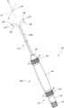
- FIG. 1is a perspective view of a steerable guide catheter in accordance with one aspect of the technology
- FIG. 2 Ais a cross-sectional view of a guide tube in accordance with one aspect of the technology
- FIG. 2 Bis a cross-sectional view of a guide tube in accordance with one aspect of the technology
- FIG. 3is a side view of a portion of a steerable guide catheter with a portion of the housing removed in accordance with one aspect of the technology
- FIG. 4is back perspective view of a steerable guide catheter with a portion of the housing removed in accordance with one aspect of the technology.
- FIG. 5is a back perspective view of a steerable guide catheter with a portion of the housing and valve removed in accordance with one aspect of the technology.
- the term “substantially”refers to the complete or nearly complete extent or degree of an action, characteristic, property, state, structure, item, or result.
- an object that is “substantially” enclosedwould mean that the object is either completely enclosed or nearly completely enclosed.
- the exact allowable degree of deviation from absolute completenessmay in some cases depend on the specific context. However, generally speaking the nearness of completion will be so as to have the same overall result as if absolute and total completion were obtained.
- the use of “substantially”is equally applicable when used in a negative connotation to refer to the complete or near complete lack of an action, characteristic, property, state, structure, item, or result.
- compositions that is “substantially free of” particleswould either completely lack particles, or so nearly completely lack particles that the effect would be the same as if it completely lacked particles.
- a composition that is “substantially free of” an ingredient or elementmay still actually contain such item as long as there is no measurable effect thereof.
- the term “about”is used to provide flexibility to a numerical range endpoint by providing that a given value may be “a little above” or “a little below” the endpoint. Unless otherwise stated, use of the term “about” in accordance with a specific number or numerical range should also be understood to provide support for such numerical terms or range without the term “about”. For example, for the sake of convenience and brevity, a numerical range of “about 50 angstroms to about 80 angstroms” should also be understood to provide support for the range of “50 angstroms to 80 angstroms.”
- tensioning lineis used to describe any number of devices or mechanisms by which a force is applied to a portion of a guide tube.
- the forcemay be applied as a result of a “pulling” force exerted on a connector or wire extending from the distal end of the guide tube to a proximal end of the guide tube, a “pushing” force, the result of deformation of a connector or wire in the distal end of the guide tube due to a change in temperature, etc. or any other means whereby a flexible element disposed within the distal end of the guide tube exerts a flexing or tensioning force on portion of the guide tube.
- guide catheteris used herein to describe any number of guiding elements used to place a “treating catheter” or “treating instrument” into a patient.
- the guide catheteris removed before treatment of the patient begins and the treating catheter remains in the patient.
- the guide cathetermay be a solid guide wire over which the treating catheter is placed or a hollow guide tube through which the treating catheter is placed.
- the guide catheteris removed from the patient.
- the guide catheterremains in place while a treating instrument is advanced to a location within the patient and remains in place while one or more treating instruments (e.g., ablation tool, suturing tool, etc.) are employed by a clinician.
- treating instrumentse.g., ablation tool, suturing tool, etc.
- the treating instruments and guide catheterare removed from the patient. While specific mention is made herein to use of the technology in the vasculature of the patient, it is understood that the technology may be employed to advance a guide catheter into any portion of the body.
- aspects of the current technologyoperate to improve a medical practitioner's ability to steer a flexible guide catheter within a cavity of a patient.
- a cavitymay include, but is not limited to, a vessel, a canal, a tissue opening, or other opening within the body of the patient.
- a catheterIn order advance a catheter into the cavity of a patient, including, but not limited to the vascular system, a catheter must be substantially stiff to move through the vasculature of a patient. That is, while gripping the catheter on its proximal end, the distal end must have sufficient stiffness to not to kink while pushing the proximal end of the catheter when the distal end encounters resistance.
- the flexible guide tubehas a deflectable distal end with two tensioning lines disposed on opposing sides of the deflectable distal end.
- the first tensioning lineis configured to deflect the distal end of the flexible guide tube in a first direction
- the second tensioning lineis configured to deflect the distal end of the flexible guide tube in a second direction that is opposite the first direction and in the same plane as the first direction.
- the tensioning lineoperates to deflect the distal end of the flexible guide tube in a direction “X”
- the second tensioning lineoperates to deflect the distal end of the flexible tube in a direction “ ⁇ X,” or in the opposite direction.
- a proximal end of the flexible guide catheter and the two tensioning linesare coupled to a handle that is configured to be gripped by a medical practitioner to steer and insert the flexible guide catheter into the patient.
- the practitionerholds the handle while advancing and steering the guide catheter through the vasculature of the patient.
- the medical practitioneradvances the treating catheter or treating instrument through the interior of the guide catheter.
- the handlemay have many forms, but in one aspect, the handle has a medial portion with a longitudinal axis substantially parallel with a distal portion of the flexible guide tube.
- a first actuatoris disposed on a front end of the handle (i.e., proximal the medial section).
- a second actuatoris disposed on a back end of the handle (i.e., distal the medial section).
- the two actuatorseach operate to generate tensioning force acting on the first tensioning line and the second tensioning line.
- the medical practitionercan flex (i.e., deflect or bend) the distal end of the catheter in the same plane of deflection with either hand or both hands employing either the first actuator, the second actuator, or both actuators at the same time. This enhances the practitioner's ability to effectively steer the guide catheter in the patient by optimizing the practitioner's steering options to steer the distal end of the guide catheter in the same plane of movement.
- the first and second actuatorsare both coupled to a first drive adapted to pull on the first tensioning line and the second drive adapted to pull on the second tensioning line.
- the guide cathetermay be advanced through a subxiphoid access point to access the thoracic cavity and the heart in particular.
- an incisionmay be made below the xiphoid process overlying the entry site and the linea alba, for instance, may be incised to obtain the subxiphoid access.
- the guide cathetermay be introduced through the incision and superiorly into the thoracic cavity until the distal tip of the guide catheter is adjacent to the pericardial sac of the heart.
- the working or surgical theateris assessed and the clinician is free to advance a treating catheter or other treating tool about (i.e., over the guide or through an internal lumen) the guide catheter.
- FIGS. 1 , 2 A and 2 Bshow a steerable guide catheter 10 in accordance with one aspect of the present technology.
- the guide catheter 10comprises a deflectable guide tube 12 with an internal lumen 16 carried by a handle 40 that houses at least a portion of the proximal end of the guide tube 12 therein.
- the handle 40is adapted to house a steering mechanism described in greater detail below.
- Distal (or front) actuator 18 and proximal (or back) actuator 19comprise a dial and internal components that can be rotationally manipulated in opposing directions as indicated by arrows C and D.
- the actuatorsare disposed at opposing ends of the handle 40 , either in front of or behind a medial portion 41 of the handle 40 .
- the actuatorsare coupled to a steering mechanism such that together the actuators and the steering mechanism components comprise a steering assembly.
- the steering mechanismcomprises first and second tensioning lines 20 disposed within the housing 40 and comprise, for example, a cord, a Kevlar line, a control wire, or other line made from metallic or non-metallic materials.
- the tensioning lines 20are coupled to the guide tube 12 such that a tension force (e.g., pulling) acting on the tensioning lines operates to flex the guide tube 12 .
- FIG. 2 Ashows a cross section of the guide tube 12 a when the guide tube 12 is within handle 40 in accordance with one aspect.
- FIG. 2 Bshows a cross section of the guide tube 12 b when the guide tube 12 is outside the handle 40 in accordance with one aspect of the technology. A portion, however, can also be within the handle as the guide tube 12 transitions form outside the handle 40 to inside the handle 40 .
- the tensioning lines 20travel substantially an entire length of the guide tube 12 b to the distal end portion 28 to couple with a steering mechanism inside the handle 40 . More particularly, the tensioning lines 20 travel within a secondary lumen 25 a and 25 b (shown on FIG.
- the guide tube 12 bcomprises an exterior diameter that is greater when outside of handle 40 than when guide tube 12 a is inside handle 40 , while the interior diameter of the guide tube 12 a and 12 b remains the same regardless.
- the flexible guide tube 12may be constructed, for example, by extrusion using standard flexible, medical grade plastic materials or by other means and other materials as is known in the art.
- the guide tube 12while flexible, may have a plastic memory or bias that normally orients the distal end portion 28 , sometimes called the distal end region 28 , of the guide tube 12 in an essentially straight configuration.
- the steering mechanismis used to enable greater control of the orientation of the distal end portion 28 even if a plastic memory or bias is used to resist a deflected distal region.
- actuators 18 , 19can be locked in place to maintain a particular guide tube 12 geometry.
- the handle 40is sized to be conveniently held by a clinician, and is sized to introduce the guide tube 12 b into an interior body region that has been targeted for treatment.
- the handle 40may be constructed, for example, from molded plastic, though other materials and types of manufacturing are contemplated and known to persons of ordinary skill in the art.
- the steering mechanismis actuated by actuators 18 and 19 to deflect the distal end portion 28 of guide tube 12 b out of its essentially straight configuration and into a bent or deflected configuration, as shown in FIG. 1 .
- the tensioning lines 20which are coupled to guide tube 12 b at (or adjacent) the distal end portion 28 and are tensioned by the steering mechanism to provide a force that deflects the distal end portion 28 of guide tube 12 b .
- the steering mechanismis adapted to hold the distal end portion 28 of the guide tube 12 b in its deflected condition, thereby maintaining a treating tool placed within the guide tube 12 b in its desired relationship during use.
- the steerable guide tube 12 bobviates the need to equip the treating tool with an on-board steering mechanism or a guide wire lumen.
- the actuators 18 and 19each control the tensioning lines 20 .
- the cliniciancan therefore move the distal end portion 28 of guide tube 12 in the same plane of movement from either the distal or proximal end of the handle 40 .
- Thisoptimizes the operator's ability to advance/operate the guide tube 12 with either hand (left or right hand). This is particularly useful when advancing a treatment catheter or operating a treatment tool with one hand while holding and/or operating the guide catheter 10 with the other hand.
- the proximal end of the guide tube 12 acomprises hemostasis or backflow check seals or valves to prevent blood loss and retrograde flow of air into the circulatory system.
- a hub 14is disposed on the proximal end of the handle 40 and comprises such a hemostasis seal.
- the sealcomprises an annular soft elastomeric gasket that seals against catheters, instruments, and the dilator, inserted therethrough.
- the sealcan further comprise a valve such as a stopcock, one-way valve such as a duckbill or flap valve, or the like to prevent significant blood loss and air entry when an instrument or catheter is removed from the lumen 16 of the guide catheter 10 .
- the soft annular sealcan further comprise a mechanism to compress the inner diameter of the seal radially inward, such as the mechanisms found on Tuohy-Borst valves.
- the hub 14further comprises one or more sideports for injection of contrast media such as Omnipaque, Renografin, or other Barium-loaded solutions, for example, or anticoagulant solutions such as heparin, coumadin, persantin, or the like, or for the measurement of pressure at or near the distal end 28 of the guide catheter 10 , though fluids may be injected directly through the valve in the hub 14 .
- the hub 14comprises a central lumen 15 coupled directly to a Tuohy-Borst valve 11 integrally formed with the hub 14 .
- the lumen of the hub 14is coupled to the lumen 16 of the guide tube 12 or comprises the proximal end of the guide tube 12 itself.
- a hemostasis adapteris inserted through the Tuohy-Borst valve.
- the hub 14comprises a large diameter Tuohy-Borst valve 11 , which can have a capacity ranging from 10 to 30 French (though other much smaller valves, 5-9 French, for example, may be used).
- Such large Tuohy-Borst valvesmay not seal fully on closure, or it may not seal at all unless it surrounds a tube larger than 5 or 6 French, for example.
- the hemostasis adaptercan be inserted into such a Tuohy-Borst valve 11 and the Tuohy-Borst valve 11 tightened to obtain a seal around the hemostasis adapter tubing, which can range in diameter from 5 to 10 French.
- the Tuohy-Borst valve 11can seal around and allow passage of tubing ranging from 6 to 18 French in diameter.
- the enlargementcan pass through the Tuohy-Borst or other valve but with increased force, which can be relieved once the enlargement can be past the valve.
- a stopcock and purge linecan be used for aspiration of blood or saline or the purging of air from the hub lumen.
- the distal end 28 of the guide tube 12comprises radiopaque markers to denote the beginning and end of the deflecting regions of the catheter.
- the guide catheter 10can comprise radiopaque materials such as gold wire, platinum wire, tantalum wire, or coatings of the aforementioned over a malleable, stainless steel, deformable reinforcing layer.
- the radiopaque materialsmay also comprise hybrid metallic polymer materials. Such radiopaque markings are especially useful insofar as they allow the operator to more clearly visualize the extent to which the guide catheter 10 is properly placed and/or the extent to which the distal end 28 of the guide tube 12 has been deflected by the operator.
- a radiopaque marker bandis affixed to the distal end 28 of the guide catheter 10 substantially near the distal tip 29 so that the position of the distal tip 29 can be observed and controlled relative to the wall of the left atrium, other cardiac structures, or other portions of the body.
- This radiopaque marker bandcan be a non-expandable, axially elongate tubular structure that is coupled to the guide tube 12 .
- the radiopaque marker bandscan further be configured to appear different under fluoroscopy by using different shapes and/or types of materials for different bands.
- Yet another configuration of radiopaque marker bandscan be achieved by using malleable wire windings or nano-sized particles of gold, tantalum, platinum alloys, or the like, which are embedded within the guide tube 12 .
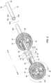
- FIGS. 3 - 5disclose components of the steering mechanism in accordance with one aspect of the technology with portions of the housing removed. Different components of the handle 40 are not shown in order to illustrate aspects of the steering assembly within the handle 40 .
- the steering assemblycomprises first and second actuators 18 , 19 .
- the actuatorseach include internal teeth 45 that are adapted to mate with teeth 46 of gear 47 .
- Gear 47is disposed about opposing sides of linear drive shaft 49 that is configured for rotation and translation relative to the actuators.
- the drive shaft 49comprises a first set of spiraled threads 50 with a pitch oriented in a first direction and a second set of spiraled threads 51 having a pitch oriented in a second direction and a shaft hub 52 disposed in the center of the shaft 49 and between the first and second set of spiraled threads.
- a first drive 60also referred to herein as a drive nut
- second drive 61are disposed about opposing sides of the linear drive shaft 49 .
- Each of the first and second drive nutscomprise an aperture within the main body 62 with internal threads adapted to mate with the threads 50 , 51 of the shaft 49 .
- the drive nuts 60 , 61further comprise a tab or wing portion 63 extending away from the main body 62 such that wings 63 of the respective drive nuts 60 , 61 are on opposing sides of the guide tube 12 inside handle 40 .
- the drive nuts 60 , 61are configured to mate with tensioning lines 21 and 22 that also extend longitudinally about opposing sides of the guide tube 12 to a distal end 28 of guide tube 12 .
- the tensioning lines 21 , 22are coupled to apertures 65 located within with wing 63 of drive nuts 60 , 61 , however, the tensioning lines may be soldered, bonded, or otherwise coupled to the drive nuts so long as the linear movement of the nuts translates into linear movement the tensioning lines 21 , 22 .
- gear 47is likewise rotated resulting in rotation of linear drive shaft 49 .
- the rotational movement of the linear drive shaft 49translates into linear movement of the drive nuts 60 , 61 about drive shaft 49 .
- the respective pitches of the first and second spiraled threads 50 , 51are substantially the same even though they are oriented in different directions. That is, as the drive shaft 49 is rotated, drive nuts 60 , 61 will travel the same linear distance about the shaft 49 .
- drive nut 61is moved in direction A (i.e., away from the proximal end of the handle 40 ) provide slack in the tensioning line 22 .
- drive nut 61is moved in direction B and drive nut 60 is moved in direction A.
- a second drive shaftis enclosed within the cavity of handle 40 and coupled to a second set of actuators.
- the second drive shaftis coupled to third and fourth drive nuts that operate to create a tensioning force in the third and fourth tensioning lines.
- the third and fourth drive nutsare off-set from the first and second drive nuts 60 , 61 about the circumference of the guide tube 12 by 90 degrees. In this manner, third and fourth tensioning lines that extend longitudinally about the length of the guide tube 12 through secondary lumens 26 a and 26 b and are operated by movement of the third and fourth drive nuts and function to flex the distal end 28 of the guide tube 12 b in a Y and ⁇ Y direction.
- the third and fourth tensioning linesfunction to flex the distal end 28 of the guide tube 12 in an additional plane of movement (i.e., an imaginary Y and ⁇ Y direction). While a 90 degree off-set has been referenced herein, it is understood that the third and fourth tensioning lines can be oriented to deflect the distal end 28 of the guide tube 12 in any other plane off-set from the plane of operation associated with the first and second tensioning lines.
- the third and fourth tensioning linesare off-set from the plane of operation associated with the first and second tensioning lines by 15 degrees, 30 degrees, 45 degrees, or 60 degrees.
- the tensioning linesmay also be off-set at other orientations that lie between 1 and 89 degrees as suits a particular application.
- the third and fourth tensioning linesare directed through secondary lumens 27 a and 27 b .
- Secondary lumens 27 a and 27 b(which may also be called tertiary lumens or quaternary lumens) are disposed adjacent lumens 25 a and 25 b but terminate at a pre-determined distance away from the tip 29 of the distal end 28 of guide tube 12 .
- the third and fourth tensioning linesoperate to flex the guide tube in substantially the same direction (and hence the same operating plane) as the first and second tensioning lines 50 , 51 .
- the flexing actionoccurs a greater distance away from the distal tip 29 than the flexing that results from operation of the first and second tensioning lines.
- numerous tensioning linescan be used in the same secondary lumen ( 25 a , 25 b , 26 a , 26 b , 27 a , and 27 b ) if desired, a single tensioning line can be used in each secondary lumen, or a one or more pairs of tensioning lines may be used in one or more secondary lumens.
- the second drive shaftcomprises threads oriented in opposing directions.
- the opposing threadshave a similar pitch so that the distance of linear travel of the associated drive nuts is equivalent even though the direction of the travel is in opposite directions.
- the threads of the second linear drive shafthave a pitch that is more shallow (i.e., having a lighter or less angled pitch) than the pitch of the threads on the first linear drive shaft. A lighter or shallower pitch results in smaller linear travel with the same amount of rotation of the drive shaft.
- the cliniciancan place the distal end 28 of the guide tube 12 in a “rough” location by using the first set of actuators 18 , 19 and the first linear drive shaft 49 and switch to the second set of actuators and the second drive shaft to flex the distal end 28 of guide tube at smaller intervals for more precise movements.
- the third and fourth tensioning linescan terminate at the same longitudinal location as the first and second tensioning lines.
- first 18 and second 19 actuatorsare configured to operate the first linear drive shaft 49 and the second linear drive shaft.
- the actuators 18 and 19comprise a plurality of internal teeth that mate with the teeth 46 of gear 47 of drive shaft 49 .
- the drive shaft 49is also rotated.
- the second drive shaftalso comprises a gear with teeth configured to mate with actuator 18 and 19 .
- the gears of the second drive shaftare longitudinally off-set from the actuators 18 and 19 .
- the gears associated with the second drive shaftare slightly closer to the center of the second drive shaft than the gears 47 located on the first drive shaft.
- the actuators 18 and 19are disposed about the handle such that they are longitudinally biased to engage gear 47 of drive shaft 49 . However, the actuators may slide on the handle longitudinally inward towards the medial portion 41 of the handle 40 thereby engaging the gears of the second drive shaft. In this manner, the same set of actuators may be used to drive a plurality of different tensioning lines, whether the different (e.g., the third and fourth) tensioning lines operate in the same plane as the first and second tensioning lines, or in a different plane (e.g., the Y and ⁇ Y plane, etc.).
- the tensioning linesmay comprise a shape memory alloy (e.g., Nitinol) that is biased in a straight or linear configuration but when subjected to an electrical signal or charge, will flex into a pre-determined configuration.
- a shape memory alloye.g., Nitinol
- an actuator disposed on a proximal end of the handle 40would function to flex the distal end 28 of guide tube 12 in both the X and ⁇ X directions.
- a second actuator disposed on a distal end of the handle 40would operate the same tensioning lines associated with the proximal actuator and function to flex the distal end 28 of guide tube 12 in both the X and ⁇ X directions.
- Certain aspects of the technologyinclude methods of flexing a distal end 28 of a guide tube wherein a clinician displaces either (or both) a first or second actuator 18 , 19 disposed about a handle 40 of the steerable guide catheter 10 .
- the steerable guide catheter 10comprises a flexible guide tube 12 having a deflectable distal end 28 and a proximal end housed within a cavity of a handle 40 .
- First and second drive nuts 60 , 61are disposed about a linear drive shaft 49 within the handle 40 , the first drive nut 60 being coupled to a first tensioning line 21 and the second drive nut 61 being coupled to a second tensioning line 22 .
- the first and second tensioning linesare disposed on opposing sides of the flexible guide tube 12 and extend longitudinally along the guide tube 12 to its distal end 28 .
- the methodfurther comprises displacing the first drive nut 60 in a first direction while simultaneously displacing the second drive nut 61 in a second direction, wherein the first direction is opposite and parallel the second direction.
- the linear distance of displacement of the first drive nut 60is substantially equivalent to the linear displacement of the second drive nut 61 .
- the methodfurther comprises displacing the first tensioning line 21 when the first drive nut 60 is displaced in the first direction and displacing the second tensioning line 22 in the first direction when the second drive nut 62 is displaced in the first direction thereby deflecting a distal end of the flexible guide tube 12 .
- the first and second drive nuts 60 , 61are both displaced linearly about the linear drive shaft 49 by displacing either the first 18 or second actuator 19 .
Landscapes
- Health & Medical Sciences (AREA)
- Life Sciences & Earth Sciences (AREA)
- Engineering & Computer Science (AREA)
- Biomedical Technology (AREA)
- Pulmonology (AREA)
- Anesthesiology (AREA)
- Biophysics (AREA)
- Heart & Thoracic Surgery (AREA)
- Hematology (AREA)
- Animal Behavior & Ethology (AREA)
- General Health & Medical Sciences (AREA)
- Public Health (AREA)
- Veterinary Medicine (AREA)
- Mechanical Engineering (AREA)
- Media Introduction/Drainage Providing Device (AREA)
Abstract
Description
Claims (9)
Priority Applications (2)
| Application Number | Priority Date | Filing Date | Title |
|---|---|---|---|
| US17/035,460US11890431B2 (en) | 2017-03-07 | 2020-09-28 | Steerable guide catheter |
| US18/434,766US20240216648A1 (en) | 2017-03-07 | 2024-02-06 | Steerable guide catheter |
Applications Claiming Priority (2)
| Application Number | Priority Date | Filing Date | Title |
|---|---|---|---|
| US15/452,675US10786651B2 (en) | 2017-03-07 | 2017-03-07 | Steerable guide catheter |
| US17/035,460US11890431B2 (en) | 2017-03-07 | 2020-09-28 | Steerable guide catheter |
Related Parent Applications (1)
| Application Number | Title | Priority Date | Filing Date |
|---|---|---|---|
| US15/452,675ContinuationUS10786651B2 (en) | 2017-03-07 | 2017-03-07 | Steerable guide catheter |
Related Child Applications (1)
| Application Number | Title | Priority Date | Filing Date |
|---|---|---|---|
| US18/434,766ContinuationUS20240216648A1 (en) | 2017-03-07 | 2024-02-06 | Steerable guide catheter |
Publications (2)
| Publication Number | Publication Date |
|---|---|
| US20210008345A1 US20210008345A1 (en) | 2021-01-14 |
| US11890431B2true US11890431B2 (en) | 2024-02-06 |
Family
ID=63446186
Family Applications (3)
| Application Number | Title | Priority Date | Filing Date |
|---|---|---|---|
| US15/452,675Active2038-03-30US10786651B2 (en) | 2017-03-07 | 2017-03-07 | Steerable guide catheter |
| US17/035,460Active2037-08-27US11890431B2 (en) | 2017-03-07 | 2020-09-28 | Steerable guide catheter |
| US18/434,766PendingUS20240216648A1 (en) | 2017-03-07 | 2024-02-06 | Steerable guide catheter |
Family Applications Before (1)
| Application Number | Title | Priority Date | Filing Date |
|---|---|---|---|
| US15/452,675Active2038-03-30US10786651B2 (en) | 2017-03-07 | 2017-03-07 | Steerable guide catheter |
Family Applications After (1)
| Application Number | Title | Priority Date | Filing Date |
|---|---|---|---|
| US18/434,766PendingUS20240216648A1 (en) | 2017-03-07 | 2024-02-06 | Steerable guide catheter |
Country Status (5)
| Country | Link |
|---|---|
| US (3) | US10786651B2 (en) |
| EP (1) | EP3592232B8 (en) |
| JP (1) | JP7311083B2 (en) |
| CN (2) | CN116271424A (en) |
| WO (1) | WO2018165345A1 (en) |
Cited By (1)
| Publication number | Priority date | Publication date | Assignee | Title |
|---|---|---|---|---|
| US20210060297A1 (en)* | 2019-09-03 | 2021-03-04 | Creganna Unlimited Company | Medical device handle for articulation of a catheter |
Families Citing this family (16)
| Publication number | Priority date | Publication date | Assignee | Title |
|---|---|---|---|---|
| US11219746B2 (en) | 2016-03-21 | 2022-01-11 | Edwards Lifesciences Corporation | Multi-direction steerable handles for steering catheters |
| US11045143B2 (en) | 2017-06-03 | 2021-06-29 | Sentinel Medical Technologies, LLC | Catheter with connectable hub for monitoring pressure |
| US11185245B2 (en) | 2017-06-03 | 2021-11-30 | Sentinel Medical Technologies, Llc. | Catheter for monitoring pressure for muscle compartment syndrome |
| US11045128B2 (en) | 2017-06-03 | 2021-06-29 | Sentinel Medical Technologies, LLC | Catheter for monitoring intra-abdominal pressure |
| EP3672675A1 (en)* | 2017-08-24 | 2020-07-01 | Tricares SAS | Double steerable sheath and method for deployment of a medical device |
| US11040174B2 (en)* | 2017-09-19 | 2021-06-22 | Edwards Lifesciences Corporation | Multi-direction steerable handles for steering catheters |
| US11207499B2 (en)* | 2017-10-20 | 2021-12-28 | Edwards Lifesciences Corporation | Steerable catheter |
| US11672457B2 (en) | 2018-11-24 | 2023-06-13 | Sentinel Medical Technologies, Llc. | Catheter for monitoring pressure |
| US11779263B2 (en) | 2019-02-08 | 2023-10-10 | Sentinel Medical Technologies, Llc. | Catheter for monitoring intra-abdominal pressure for assessing preeclampsia |
| JP7376612B2 (en)* | 2019-05-24 | 2023-11-08 | ベクトン・ディキンソン・アンド・カンパニー | Articulating reinforcement cannulas, access sets, and methods |
| US11730385B2 (en) | 2019-08-08 | 2023-08-22 | Sentinel Medical Technologies, LLC | Cable for use with pressure monitoring catheters |
| WO2021127222A1 (en)* | 2019-12-18 | 2021-06-24 | The Regents Of The University Of California | Rapid exchange endoscope system |
| US11617543B2 (en) | 2019-12-30 | 2023-04-04 | Sentinel Medical Technologies, Llc. | Catheter for monitoring pressure |
| EP4232132A4 (en)* | 2020-10-20 | 2024-09-11 | Boston Scientific Medical Device Limited | STEERABLE MEDICAL DEVICE, HANDLE FOR A MEDICAL DEVICE AND METHOD OF OPERATING A MEDICAL DEVICE |
| EP4516264A4 (en)* | 2022-04-29 | 2025-08-13 | Wuhan Weike Medical Tech Co Ltd | DELIVERY SYSTEM FOR INTERVENTIONAL HEART VALVE STENTS |
| CN116712111A (en)* | 2023-05-25 | 2023-09-08 | 中国医学科学院阜外医院 | A kind of left bundle branch guide sheath |
Citations (146)
| Publication number | Priority date | Publication date | Assignee | Title |
|---|---|---|---|---|
| US4203430A (en) | 1976-12-16 | 1980-05-20 | Nagashige Takahashi | Device for controlling curvature of an end section in an endoscope |
| US4874371A (en) | 1987-11-05 | 1989-10-17 | Medilase, Inc. | Control handle |
| CA2061215A1 (en) | 1991-02-15 | 1992-08-16 | Ingemar H. Lundquist | Torquable catheter and method |
| US5167221A (en) | 1990-03-14 | 1992-12-01 | Kabushiki Kaisha Machida Seisakusho | Bending device |
| US5185004A (en) | 1991-06-03 | 1993-02-09 | Danforth Biomedical, Inc. | Turn-limiting proximal adaptor for steerable catheter systems |
| US5195968A (en) | 1990-02-02 | 1993-03-23 | Ingemar Lundquist | Catheter steering mechanism |
| US5254088A (en) | 1990-02-02 | 1993-10-19 | Ep Technologies, Inc. | Catheter steering mechanism |
| US5263493A (en) | 1992-02-24 | 1993-11-23 | Boaz Avitall | Deflectable loop electrode array mapping and ablation catheter for cardiac chambers |
| US5325845A (en) | 1992-06-08 | 1994-07-05 | Adair Edwin Lloyd | Steerable sheath for use with selected removable optical catheter |
| EP0605796A2 (en) | 1992-12-04 | 1994-07-13 | C.R. Bard, Inc. | Catheter with independent proximal and distal control and actuator for use with same |
| US5358478A (en) | 1990-02-02 | 1994-10-25 | Ep Technologies, Inc. | Catheter steering assembly providing asymmetric left and right curve configurations |
| US5364352A (en) | 1993-03-12 | 1994-11-15 | Heart Rhythm Technologies, Inc. | Catheter for electrophysiological procedures |
| US5364351A (en) | 1992-11-13 | 1994-11-15 | Ep Technologies, Inc. | Catheter steering mechanism |
| US5395329A (en) | 1994-01-19 | 1995-03-07 | Daig Corporation | Control handle for steerable catheter |
| US5413107A (en) | 1994-02-16 | 1995-05-09 | Tetrad Corporation | Ultrasonic probe having articulated structure and rotatable transducer head |
| US5427017A (en) | 1994-01-26 | 1995-06-27 | Cheung; Chun-Kong | Toaster attachment |
| US5431675A (en) | 1992-09-23 | 1995-07-11 | United States Surgical Corporation | Locking mechanism for endoscopic or laparoscopic surgical instruments |
| US5441483A (en) | 1992-11-16 | 1995-08-15 | Avitall; Boaz | Catheter deflection control |
| US5462527A (en) | 1993-06-29 | 1995-10-31 | C.R. Bard, Inc. | Actuator for use with steerable catheter |
| US5465716A (en) | 1993-11-22 | 1995-11-14 | Avitall; Boaz | Catheter control handle |
| US5527279A (en) | 1992-12-01 | 1996-06-18 | Cardiac Pathways Corporation | Control mechanism and system and method for steering distal extremity of a flexible elongate member |
| US5545200A (en) | 1993-07-20 | 1996-08-13 | Medtronic Cardiorhythm | Steerable electrophysiology catheter |
| US5549542A (en)* | 1992-11-17 | 1996-08-27 | Life Medical Technologies, Inc. | Deflectable endoscope |
| US5571085A (en) | 1995-03-24 | 1996-11-05 | Electro-Catheter Corporation | Steerable open lumen catheter |
| US5643255A (en) | 1994-12-12 | 1997-07-01 | Hicor, Inc. | Steerable catheter with rotatable tip electrode and method of use |
| US5656030A (en) | 1995-05-22 | 1997-08-12 | Boston Scientific Corporation | Bidirectional steerable catheter with deflectable distal tip |
| US5741320A (en) | 1995-05-02 | 1998-04-21 | Heart Rhythm Technologies, Inc. | Catheter control system having a pulley |
| US5755760A (en) | 1996-03-11 | 1998-05-26 | Medtronic, Inc. | Deflectable catheter |
| WO1998041276A1 (en) | 1997-03-17 | 1998-09-24 | C.R. Bard, Inc. | Slidable control mechanism for steerable catheter |
| US5823955A (en) | 1995-11-20 | 1998-10-20 | Medtronic Cardiorhythm | Atrioventricular valve tissue ablation catheter and method |
| US5861024A (en) | 1997-06-20 | 1999-01-19 | Cardiac Assist Devices, Inc | Electrophysiology catheter and remote actuator therefor |
| US5938616A (en)* | 1997-01-31 | 1999-08-17 | Acuson Corporation | Steering mechanism and steering line for a catheter-mounted ultrasonic transducer |
| US5954654A (en) | 1997-01-31 | 1999-09-21 | Acuson Corporation | Steering mechanism and steering line for a catheter-mounted ultrasonic transducer |
| US5987344A (en) | 1996-08-08 | 1999-11-16 | Medtronic, Inc. | Handle for catheter assembly with multifunction wire |
| US6030360A (en) | 1996-12-30 | 2000-02-29 | Biggs; Robert C. | Steerable catheter |
| US6033378A (en) | 1990-02-02 | 2000-03-07 | Ep Technologies, Inc. | Catheter steering mechanism |
| US6059739A (en) | 1998-05-29 | 2000-05-09 | Medtronic, Inc. | Method and apparatus for deflecting a catheter or lead |
| US6120476A (en)* | 1997-12-01 | 2000-09-19 | Cordis Webster, Inc. | Irrigated tip catheter |
| US6123699A (en) | 1997-09-05 | 2000-09-26 | Cordis Webster, Inc. | Omni-directional steerable catheter |
| US6132390A (en) | 1996-02-28 | 2000-10-17 | Eupalamus Llc | Handle for manipulation of a stylet used for deflecting a tip of a lead or catheter |
| US6146355A (en) | 1996-12-30 | 2000-11-14 | Myelotec, Inc. | Steerable catheter |
| WO2000067834A1 (en) | 1999-05-11 | 2000-11-16 | Zynergy Cardiovascular, Inc. | Steerable catheter |
| US6171277B1 (en) | 1997-12-01 | 2001-01-09 | Cordis Webster, Inc. | Bi-directional control handle for steerable catheter |
| US6183435B1 (en) | 1999-03-22 | 2001-02-06 | Cordis Webster, Inc. | Multi-directional steerable catheters and control handles |
| US6198974B1 (en) | 1998-08-14 | 2001-03-06 | Cordis Webster, Inc. | Bi-directional steerable catheter |
| US6231974B1 (en) | 1997-05-22 | 2001-05-15 | Dow Corning Toray Silicone Company, Ltd. | Hot-melt adhesive sheet and semiconductor devices |
| US6267746B1 (en) | 1999-03-22 | 2001-07-31 | Biosense Webster, Inc. | Multi-directional steerable catheters and control handles |
| WO2001089624A1 (en) | 2000-05-19 | 2001-11-29 | C.R. Bard, Inc. | Steerable biliary catheter |
| WO2002043560A2 (en) | 2000-11-29 | 2002-06-06 | C.R. Bard, Inc. | Active counterforce handle for use in bidirectional deflectable tip instruments |
| US6464645B1 (en) | 1997-01-31 | 2002-10-15 | Acuson Corporation | Ultrasonic transducer assembly controller |
| US6468260B1 (en) | 1999-05-07 | 2002-10-22 | Biosense Webster, Inc. | Single gear drive bidirectional control handle for steerable catheter |
| US6485455B1 (en) | 1990-02-02 | 2002-11-26 | Ep Technologies, Inc. | Catheter steering assembly providing asymmetric left and right curve configurations |
| US20020177840A1 (en) | 2001-05-22 | 2002-11-28 | Scimed Life Systems, Inc. | Torqueable and deflectable medical device shaft |
| US6533783B1 (en) | 1999-07-14 | 2003-03-18 | Biotronik Mess -Und Therapiegeraete Gmbh & Co. Ingenieurbuero Berlin | Catheter |
| US6571131B1 (en) | 2000-11-10 | 2003-05-27 | Biosense Webster, Inc. | Deflectable catheter with modifiable handle |
| US20030106970A1 (en) | 2001-12-07 | 2003-06-12 | Mcmillen Robert | Apparatus and method for telescoping actuator |
| US20030114832A1 (en) | 2001-12-14 | 2003-06-19 | Kohler Robert Edward | Interventional catheter with three dimensional articulation |
| US20030163085A1 (en) | 2002-01-16 | 2003-08-28 | Tanner Howard M. | Catheter hand-piece apparatus and method of using the same |
| US20040044342A1 (en) | 2002-09-03 | 2004-03-04 | Mackay Dale Victor | Electrosurgical apparatus |
| US6749572B2 (en) | 2001-03-14 | 2004-06-15 | Ge Medical Systems Global Technology Company, Llc | Transesophageal ultrasound probe having a rotating endoscope shaft |
| US20050187455A1 (en) | 2004-02-23 | 2005-08-25 | St. Jude Medical, Daig Division, Inc. | Electrophysiology/ablation catheter having deflection assembly |
| US6979312B2 (en) | 2001-04-12 | 2005-12-27 | Biotran Corporation, Inc. | Steerable sheath catheters |
| US20050288627A1 (en)* | 2004-06-25 | 2005-12-29 | Mogul Jamil A | Linkage steering mechanism for deflectable catheters |
| US7056314B1 (en) | 2003-05-30 | 2006-06-06 | Pacesetter, Inc. | Steerable obturator |
| WO2006135551A2 (en) | 2005-06-08 | 2006-12-21 | Xtent, Inc. | Devices and methods for operating and controlling interventional apparatus |
| US20070156116A1 (en) | 2005-12-30 | 2007-07-05 | Gonzalez Pablo A | Dual-lever bi-directional handle |
| US20070260225A1 (en) | 2002-11-15 | 2007-11-08 | Applied Medical Resources Corporation | Steerable sheath actuator |
| US20070282358A1 (en) | 2006-05-19 | 2007-12-06 | Stan Remiszewski | Steerable medical instrument |
| US20080009745A1 (en) | 2006-04-04 | 2008-01-10 | Volcano Corporation | Ultrasound catheter and hand-held device for manipulating a transducer on the catheter's distal end |
| US7350811B2 (en) | 2005-04-01 | 2008-04-01 | Toyoda Gosei Co., Ltd. | Side airbag apparatus |
| US7387628B1 (en) | 2000-09-15 | 2008-06-17 | Boston Scientific Scimed, Inc. | Methods and systems for focused bipolar tissue ablation |
| US20080146875A1 (en) | 2005-07-08 | 2008-06-19 | Olympus Medical Systems Corp. | Endoscope apparatus |
| US20090149805A1 (en) | 2001-12-31 | 2009-06-11 | James Coleman | Dual-function catheter handle |
| US7615044B2 (en) | 2006-05-03 | 2009-11-10 | Greatbatch Ltd. | Deflectable sheath handle assembly and method therefor |
| US20090281524A1 (en) | 2008-05-09 | 2009-11-12 | Greatbatch Ltd. | Bi-directional sheath deflection mechanism |
| US20100004633A1 (en) | 2008-07-07 | 2010-01-07 | Voyage Medical, Inc. | Catheter control systems |
| US20100076408A1 (en) | 2007-10-19 | 2010-03-25 | Matthew Krever | Deflecting guide catheter for use in a minimally invasive medical procedure for the treatment of mitral valve regurgitation |
| US7691095B2 (en)* | 2004-12-28 | 2010-04-06 | St. Jude Medical, Atrial Fibrillation Division, Inc. | Bi-directional steerable catheter control handle |
| US20100168642A1 (en)* | 2008-12-30 | 2010-07-01 | Angiodynamics, Inc. | Multilumen Venous Catheter and Method of Use |
| US20100168827A1 (en) | 2008-12-30 | 2010-07-01 | Schultz Jeffrey W | Deflectable sheath introducer |
| US20110054287A1 (en)* | 2009-08-28 | 2011-03-03 | Jefferey William Schultz | Catheter with multi-functional control handle having rotational mechanism |
| US20110054446A1 (en) | 2009-08-28 | 2011-03-03 | Jeffrey William Schultz | Catheter with multi-functional control handle having linear mechanism |
| US20110054465A1 (en) | 2009-08-25 | 2011-03-03 | Randell Werneth | Bi-modal catheter steering mechanism |
| US7914515B2 (en) | 2007-07-18 | 2011-03-29 | St. Jude Medical, Atrial Fibrillation Division, Inc. | Catheter and introducer catheter having torque transfer layer and method of manufacture |
| US7955314B2 (en) | 2005-05-12 | 2011-06-07 | Greatbatch Ltd. | Articulating handle for a deflectable catheter and method therefor |
| US20110137309A1 (en) | 2008-03-20 | 2011-06-09 | David Bruce Ogle | Steerable stylet |
| US20110196298A1 (en) | 2008-10-31 | 2011-08-11 | Cathrx Ltd | Catheter Assembly |
| US20110257499A1 (en) | 2010-04-14 | 2011-10-20 | De La Rama Alan | Dual-Deflecting Electrophysiology Catheter |
| US20110264074A1 (en) | 2004-12-28 | 2011-10-27 | Tegg Troy T | Five degree of freedom ultrasound catheter and catheter control handle |
| US20110282176A1 (en) | 2010-05-11 | 2011-11-17 | Tegg Troy T | Multi-directional catheter control handle |
| US20120029334A1 (en) | 2010-07-30 | 2012-02-02 | Tegg Troy T | Catheter with a mechanism for omni-directional deflection of a catheter shaft |
| US8123703B2 (en) | 1999-04-09 | 2012-02-28 | Evalve, Inc. | Steerable access sheath and methods of use |
| US8137308B2 (en) | 2008-09-16 | 2012-03-20 | Biosense Webster, Inc. | Catheter with adjustable deflection sensitivity |
| US20120089125A1 (en) | 2010-10-08 | 2012-04-12 | Greatbatch Ltd. | Bi-Directional Catheter Steering Handle |
| US8162934B2 (en) | 2007-12-21 | 2012-04-24 | St. Jude Medical, Atrial Fibrillation Division, Inc. | Medical catheter assembly with deflection pull ring and distal tip interlock |
| US20120172703A1 (en) | 2010-12-30 | 2012-07-05 | Maribeth Esguerra | Catheter with single axial sensors |
| US20120203169A1 (en) | 2008-12-31 | 2012-08-09 | Tegg Troy T | Shaft and handle for a catheter with independently-deflectable segments |
| US20120209122A1 (en) | 2011-02-16 | 2012-08-16 | Siemens Medical Solutions Usa, Inc. | Shape-Controllable Catheters and Catheter System |
| US20120277730A1 (en) | 2009-06-24 | 2012-11-01 | Amr Salahieh | Steerable Delivery Sheaths |
| US20130030520A1 (en) | 2011-07-27 | 2013-01-31 | Walter Lee | Delivery systems for prosthetic heart valve |
| US20130041314A1 (en) | 2011-08-11 | 2013-02-14 | Cook Medical Technologies Llc | Steerable Catheters |
| US20130085492A1 (en)* | 2011-09-30 | 2013-04-04 | Rogelio Plascencia, JR. | Electrophysiology catheter handle having accessible interior |
| US20130102960A1 (en) | 2011-03-29 | 2013-04-25 | Olympus Medical Systems Corp. | Endoscope |
| US20130172813A1 (en)* | 2011-12-30 | 2013-07-04 | Dennis C. Caples | Medical device control handle with multiple puller wires |
| JP2013132432A (en) | 2011-12-27 | 2013-07-08 | Sumitomo Bakelite Co Ltd | Medical device and method of manufacturing the same |
| US20130178838A1 (en) | 2012-01-09 | 2013-07-11 | Covidien Lp | Surgical Articulation Assembly |
| US20130184528A1 (en) | 2011-02-16 | 2013-07-18 | Olympus Medical Systems Corp. | Endoscope, and treatment instrument for endoscope |
| US20130184542A1 (en) | 2006-09-10 | 2013-07-18 | Abbott Diabetes Care Inc. | Method and System for Providing an Integrated Analyte Sensor Insertion Device and Data Processing Unit |
| US8500733B2 (en) | 2009-02-20 | 2013-08-06 | Boston Scientific Scimed, Inc. | Asymmetric dual directional steerable catheter sheath |
| US20130204096A1 (en) | 2012-02-03 | 2013-08-08 | Rui Xing Limited | Medical Device with a Deflectable Shaft Section and Tension Control |
| US8506562B2 (en) | 2007-06-15 | 2013-08-13 | Cathrx Ltd. | Deflectable stylet |
| US20130317542A1 (en) | 2012-05-25 | 2013-11-28 | Boston Scientific Scimed, Inc. | Steerable delivery system |
| US20130324972A1 (en)* | 2004-04-13 | 2013-12-05 | Gyrus Acmi, Inc. | Atraumatic Ureteral Access Sheath |
| US20130324973A1 (en) | 2012-06-04 | 2013-12-05 | Justin A. Reed | Handle extension for an elongate medical device |
| WO2013190475A2 (en) | 2012-06-19 | 2013-12-27 | Baylis Medical Company Inc. | Steerable medical device handle |
| US20140039387A1 (en)* | 2012-08-03 | 2014-02-06 | Korea Institute Of Science And Technology | Guide tube for microsurgical instruments |
| US20140100445A1 (en) | 2011-12-15 | 2014-04-10 | Imricor Medical Systems, Inc. | Mri compatible handle and steerable sheath |
| US8734699B2 (en) | 2006-05-16 | 2014-05-27 | St. Jude Medical, Atrial Fibrillation Division, Inc. | Steerable catheter using flat pull wires and having torque transfer layer made of braided flat wires |
| WO2014126795A1 (en) | 2013-02-12 | 2014-08-21 | St. Jude Medical, Atrial Fibrillation Division, Inc. | Elongate medical device handle autolock |
| US20140336573A1 (en)* | 2013-05-07 | 2014-11-13 | St. Jude Medical, Atrial Fibrillation Division, Inc. | Steering actuator for deflectable catheter |
| US20150057610A1 (en)* | 2013-08-23 | 2015-02-26 | Oscor Inc. | Steerable medical devices |
| US20150105721A1 (en) | 2013-10-10 | 2015-04-16 | Oscor Inc. | Steerable medical devices |
| WO2015092768A1 (en) | 2013-12-20 | 2015-06-25 | Baylis Medical Company Inc. | Steerable medical device handle |
| US20150196736A1 (en) | 2014-01-13 | 2015-07-16 | St. Jude Medical, Cardiology Division, Inc. | Catheter deflection actuator providing mechanical advantage |
| US9155865B2 (en) | 2008-05-13 | 2015-10-13 | Boston Scientific Scimed, Inc. | Steering system with locking mechanism |
| US9174024B1 (en) | 2013-03-15 | 2015-11-03 | St. Jude Medical Luxembourg Holdings S.À.R.L. | Steering control mechanisms for catheters |
| WO2015175200A1 (en) | 2014-05-13 | 2015-11-19 | Covidien Lp | Robotic surgical systems and instrument drive units |
| US20150335861A1 (en) | 2014-05-20 | 2015-11-26 | Oscor Inc. | Guided intravascular catheter sheath having bi-directional steering assembly |
| US9220868B2 (en) | 2010-12-03 | 2015-12-29 | Biosense Webster, Inc. | Control handle with rotational cam mechanism for contraction/deflection of medical device |
| US9247990B2 (en) | 2006-10-10 | 2016-02-02 | St. Jude Medical, Atrial Fibrillation Division, Inc. | Steerable sheath access device |
| US20160058974A1 (en) | 2011-12-15 | 2016-03-03 | Imricor Medical Systems, Inc. | Steerable sheath including elastomeric member |
| WO2016036774A1 (en) | 2014-09-01 | 2016-03-10 | Clph, Llc | Steerable catheters and methods for making them |
| US20160074625A1 (en) | 2014-09-12 | 2016-03-17 | Helix Medical, Llc | Modular handle assembly for a steerable catheter |
| WO2018116162A1 (en) | 2016-12-22 | 2018-06-28 | Baylis Medical Company Inc. | Steerable medical device |
| WO2018116509A1 (en) | 2016-12-21 | 2018-06-28 | 日本ライフライン株式会社 | Handle for medical appliance, and medical appliance |
| US20180214669A1 (en) | 2016-12-22 | 2018-08-02 | Baylis Medical Company Inc. | Feedback Mechanisms for a Steerable Medical Device |
| WO2018182836A1 (en) | 2017-03-30 | 2018-10-04 | Shifamed Holdings, Llc | Medical tool positioning devices, systems, and methods of use and manufacture |
| US20190038873A1 (en) | 2017-08-04 | 2019-02-07 | Cryterion Medical, Inc. | Steering assembly for intravascular catheter system |
| US20190083750A1 (en) | 2017-09-19 | 2019-03-21 | Cryterion Medical, Inc. | Catheter steering assembly for intravascular catheter system |
| US20190083747A1 (en) | 2017-09-19 | 2019-03-21 | Edwards Lifesciences Corporation | Multi-direction steerable handles for steering catheters |
| WO2019185724A1 (en) | 2018-03-28 | 2019-10-03 | Life Science Inkubator Betriebs Gmbh & Co. Kg | Implantation device |
| WO2020041716A1 (en) | 2018-08-23 | 2020-02-27 | Shifamed Holdings, Llc | Medical tool positioning devices, systems, and methods of use and manufacture |
| US20200179114A1 (en) | 2011-11-08 | 2020-06-11 | Valtech Cardio, Ltd. | Controlled steering functionality for implant-delivery tool |
| US20200205856A1 (en) | 2018-12-28 | 2020-07-02 | St. Jude Medical, Cardiology Division, Inc. | Operating Handle For Selective Deflection Or Rotation Of A Catheter |
| US10709870B2 (en) | 2017-03-14 | 2020-07-14 | Greatbatch Ltd. | Steerable medical device and method |
| US10799677B2 (en) | 2016-03-21 | 2020-10-13 | Edwards Lifesciences Corporation | Multi-direction steerable handles for steering catheters |
Family Cites Families (3)
| Publication number | Priority date | Publication date | Assignee | Title |
|---|---|---|---|---|
| US5766151A (en)* | 1991-07-16 | 1998-06-16 | Heartport, Inc. | Endovascular system for arresting the heart |
| US6398776B1 (en)* | 1996-06-03 | 2002-06-04 | Terumo Kabushiki Kaisha | Tubular medical device |
| US20050004515A1 (en) | 2002-11-15 | 2005-01-06 | Hart Charles C. | Steerable kink resistant sheath |
- 2017
- 2017-03-07USUS15/452,675patent/US10786651B2/enactiveActive
- 2018
- 2018-03-07EPEP18763879.6Apatent/EP3592232B8/enactiveActive
- 2018-03-07WOPCT/US2018/021418patent/WO2018165345A1/ennot_activeCeased
- 2018-03-07CNCN202211691279.3Apatent/CN116271424A/enactivePending
- 2018-03-07CNCN201880024749.6Apatent/CN110913763B/enactiveActive
- 2018-03-07JPJP2019570342Apatent/JP7311083B2/enactiveActive
- 2020
- 2020-09-28USUS17/035,460patent/US11890431B2/enactiveActive
- 2024
- 2024-02-06USUS18/434,766patent/US20240216648A1/enactivePending
Patent Citations (192)
| Publication number | Priority date | Publication date | Assignee | Title |
|---|---|---|---|---|
| US4203430A (en) | 1976-12-16 | 1980-05-20 | Nagashige Takahashi | Device for controlling curvature of an end section in an endoscope |
| US4874371A (en) | 1987-11-05 | 1989-10-17 | Medilase, Inc. | Control handle |
| US5254088A (en) | 1990-02-02 | 1993-10-19 | Ep Technologies, Inc. | Catheter steering mechanism |
| US6033378A (en) | 1990-02-02 | 2000-03-07 | Ep Technologies, Inc. | Catheter steering mechanism |
| US5358478A (en) | 1990-02-02 | 1994-10-25 | Ep Technologies, Inc. | Catheter steering assembly providing asymmetric left and right curve configurations |
| US6485455B1 (en) | 1990-02-02 | 2002-11-26 | Ep Technologies, Inc. | Catheter steering assembly providing asymmetric left and right curve configurations |
| US5195968A (en) | 1990-02-02 | 1993-03-23 | Ingemar Lundquist | Catheter steering mechanism |
| US5167221A (en) | 1990-03-14 | 1992-12-01 | Kabushiki Kaisha Machida Seisakusho | Bending device |
| US5322064A (en) | 1991-02-15 | 1994-06-21 | Lundquist Ingemar H | Torquable catheter and method |
| EP0521595A2 (en) | 1991-02-15 | 1993-01-07 | Ingemar H. Lundquist | Torquable catheter and method |
| CA2061215A1 (en) | 1991-02-15 | 1992-08-16 | Ingemar H. Lundquist | Torquable catheter and method |
| EP0790066A2 (en) | 1991-02-15 | 1997-08-20 | Ingemar H. Lundquist | Steerable catheter |
| US5185004A (en) | 1991-06-03 | 1993-02-09 | Danforth Biomedical, Inc. | Turn-limiting proximal adaptor for steerable catheter systems |
| US5263493A (en) | 1992-02-24 | 1993-11-23 | Boaz Avitall | Deflectable loop electrode array mapping and ablation catheter for cardiac chambers |
| US5325845A (en) | 1992-06-08 | 1994-07-05 | Adair Edwin Lloyd | Steerable sheath for use with selected removable optical catheter |
| US5431675A (en) | 1992-09-23 | 1995-07-11 | United States Surgical Corporation | Locking mechanism for endoscopic or laparoscopic surgical instruments |
| US5364351A (en) | 1992-11-13 | 1994-11-15 | Ep Technologies, Inc. | Catheter steering mechanism |
| US5441483A (en) | 1992-11-16 | 1995-08-15 | Avitall; Boaz | Catheter deflection control |
| US5549542A (en)* | 1992-11-17 | 1996-08-27 | Life Medical Technologies, Inc. | Deflectable endoscope |
| US5527279A (en) | 1992-12-01 | 1996-06-18 | Cardiac Pathways Corporation | Control mechanism and system and method for steering distal extremity of a flexible elongate member |
| EP0605796A2 (en) | 1992-12-04 | 1994-07-13 | C.R. Bard, Inc. | Catheter with independent proximal and distal control and actuator for use with same |
| US5364352A (en) | 1993-03-12 | 1994-11-15 | Heart Rhythm Technologies, Inc. | Catheter for electrophysiological procedures |
| US5462527A (en) | 1993-06-29 | 1995-10-31 | C.R. Bard, Inc. | Actuator for use with steerable catheter |
| US5545200A (en) | 1993-07-20 | 1996-08-13 | Medtronic Cardiorhythm | Steerable electrophysiology catheter |
| US5465716A (en) | 1993-11-22 | 1995-11-14 | Avitall; Boaz | Catheter control handle |
| US5395329A (en) | 1994-01-19 | 1995-03-07 | Daig Corporation | Control handle for steerable catheter |
| US5427017A (en) | 1994-01-26 | 1995-06-27 | Cheung; Chun-Kong | Toaster attachment |
| US5413107A (en) | 1994-02-16 | 1995-05-09 | Tetrad Corporation | Ultrasonic probe having articulated structure and rotatable transducer head |
| US5643255A (en) | 1994-12-12 | 1997-07-01 | Hicor, Inc. | Steerable catheter with rotatable tip electrode and method of use |
| US5571085A (en) | 1995-03-24 | 1996-11-05 | Electro-Catheter Corporation | Steerable open lumen catheter |
| US5741320A (en) | 1995-05-02 | 1998-04-21 | Heart Rhythm Technologies, Inc. | Catheter control system having a pulley |
| US5656030A (en) | 1995-05-22 | 1997-08-12 | Boston Scientific Corporation | Bidirectional steerable catheter with deflectable distal tip |
| US5823955A (en) | 1995-11-20 | 1998-10-20 | Medtronic Cardiorhythm | Atrioventricular valve tissue ablation catheter and method |
| US6132390A (en) | 1996-02-28 | 2000-10-17 | Eupalamus Llc | Handle for manipulation of a stylet used for deflecting a tip of a lead or catheter |
| US5755760A (en) | 1996-03-11 | 1998-05-26 | Medtronic, Inc. | Deflectable catheter |
| US6263224B1 (en) | 1996-08-08 | 2001-07-17 | Medtronic, Inc. | Handle for catheter assembly with multifunction wire |
| US5987344A (en) | 1996-08-08 | 1999-11-16 | Medtronic, Inc. | Handle for catheter assembly with multifunction wire |
| US6146355A (en) | 1996-12-30 | 2000-11-14 | Myelotec, Inc. | Steerable catheter |
| US6030360A (en) | 1996-12-30 | 2000-02-29 | Biggs; Robert C. | Steerable catheter |
| US6464645B1 (en) | 1997-01-31 | 2002-10-15 | Acuson Corporation | Ultrasonic transducer assembly controller |
| US5954654A (en) | 1997-01-31 | 1999-09-21 | Acuson Corporation | Steering mechanism and steering line for a catheter-mounted ultrasonic transducer |
| JP2002508675A (en) | 1997-01-31 | 2002-03-19 | アキューソン コーポレイション | Steering mechanism and steering line for catheter-mounted ultrasonic transducer |
| US5938616A (en)* | 1997-01-31 | 1999-08-17 | Acuson Corporation | Steering mechanism and steering line for a catheter-mounted ultrasonic transducer |
| WO1998041276A1 (en) | 1997-03-17 | 1998-09-24 | C.R. Bard, Inc. | Slidable control mechanism for steerable catheter |
| US5944690A (en) | 1997-03-17 | 1999-08-31 | C.R. Bard, Inc. | Slidable control mechanism for steerable catheter |
| US6231974B1 (en) | 1997-05-22 | 2001-05-15 | Dow Corning Toray Silicone Company, Ltd. | Hot-melt adhesive sheet and semiconductor devices |
| US5861024A (en) | 1997-06-20 | 1999-01-19 | Cardiac Assist Devices, Inc | Electrophysiology catheter and remote actuator therefor |
| US6123699A (en) | 1997-09-05 | 2000-09-26 | Cordis Webster, Inc. | Omni-directional steerable catheter |
| US6171277B1 (en) | 1997-12-01 | 2001-01-09 | Cordis Webster, Inc. | Bi-directional control handle for steerable catheter |
| US6120476A (en)* | 1997-12-01 | 2000-09-19 | Cordis Webster, Inc. | Irrigated tip catheter |
| US6059739A (en) | 1998-05-29 | 2000-05-09 | Medtronic, Inc. | Method and apparatus for deflecting a catheter or lead |
| US6198974B1 (en) | 1998-08-14 | 2001-03-06 | Cordis Webster, Inc. | Bi-directional steerable catheter |
| US6183435B1 (en) | 1999-03-22 | 2001-02-06 | Cordis Webster, Inc. | Multi-directional steerable catheters and control handles |
| US6267746B1 (en) | 1999-03-22 | 2001-07-31 | Biosense Webster, Inc. | Multi-directional steerable catheters and control handles |
| US8123703B2 (en) | 1999-04-09 | 2012-02-28 | Evalve, Inc. | Steerable access sheath and methods of use |
| US6468260B1 (en) | 1999-05-07 | 2002-10-22 | Biosense Webster, Inc. | Single gear drive bidirectional control handle for steerable catheter |
| WO2000067834A1 (en) | 1999-05-11 | 2000-11-16 | Zynergy Cardiovascular, Inc. | Steerable catheter |
| US6533783B1 (en) | 1999-07-14 | 2003-03-18 | Biotronik Mess -Und Therapiegeraete Gmbh & Co. Ingenieurbuero Berlin | Catheter |
| WO2001089624A1 (en) | 2000-05-19 | 2001-11-29 | C.R. Bard, Inc. | Steerable biliary catheter |
| US7387628B1 (en) | 2000-09-15 | 2008-06-17 | Boston Scientific Scimed, Inc. | Methods and systems for focused bipolar tissue ablation |
| US6571131B1 (en) | 2000-11-10 | 2003-05-27 | Biosense Webster, Inc. | Deflectable catheter with modifiable handle |
| WO2002043560A2 (en) | 2000-11-29 | 2002-06-06 | C.R. Bard, Inc. | Active counterforce handle for use in bidirectional deflectable tip instruments |
| US7524301B2 (en) | 2000-11-29 | 2009-04-28 | C.R. Bard, Inc. | Active counterforce handle for use in bidirectional deflectable tip instruments |
| US6663588B2 (en) | 2000-11-29 | 2003-12-16 | C.R. Bard, Inc. | Active counterforce handle for use in bidirectional deflectable tip instruments |
| US6749572B2 (en) | 2001-03-14 | 2004-06-15 | Ge Medical Systems Global Technology Company, Llc | Transesophageal ultrasound probe having a rotating endoscope shaft |
| US6979312B2 (en) | 2001-04-12 | 2005-12-27 | Biotran Corporation, Inc. | Steerable sheath catheters |
| US20020177840A1 (en) | 2001-05-22 | 2002-11-28 | Scimed Life Systems, Inc. | Torqueable and deflectable medical device shaft |
| US20030106970A1 (en) | 2001-12-07 | 2003-06-12 | Mcmillen Robert | Apparatus and method for telescoping actuator |
| US20030114832A1 (en) | 2001-12-14 | 2003-06-19 | Kohler Robert Edward | Interventional catheter with three dimensional articulation |
| US20090149805A1 (en) | 2001-12-31 | 2009-06-11 | James Coleman | Dual-function catheter handle |
| US20030163085A1 (en) | 2002-01-16 | 2003-08-28 | Tanner Howard M. | Catheter hand-piece apparatus and method of using the same |
| US20040044342A1 (en) | 2002-09-03 | 2004-03-04 | Mackay Dale Victor | Electrosurgical apparatus |
| US20070260225A1 (en) | 2002-11-15 | 2007-11-08 | Applied Medical Resources Corporation | Steerable sheath actuator |
| US7056314B1 (en) | 2003-05-30 | 2006-06-06 | Pacesetter, Inc. | Steerable obturator |
| US20050187455A1 (en) | 2004-02-23 | 2005-08-25 | St. Jude Medical, Daig Division, Inc. | Electrophysiology/ablation catheter having deflection assembly |
| US20130324972A1 (en)* | 2004-04-13 | 2013-12-05 | Gyrus Acmi, Inc. | Atraumatic Ureteral Access Sheath |
| US20050288627A1 (en)* | 2004-06-25 | 2005-12-29 | Mogul Jamil A | Linkage steering mechanism for deflectable catheters |
| US10960181B2 (en) | 2004-12-28 | 2021-03-30 | St. Jude Medical, Atrial Fibrillation Division, Inc. | Fixed dimensional and bi-directional steerable catheter control handle |
| US20110264074A1 (en) | 2004-12-28 | 2011-10-27 | Tegg Troy T | Five degree of freedom ultrasound catheter and catheter control handle |
| US8323239B2 (en) | 2004-12-28 | 2012-12-04 | St. Jude Medical, Atrial Fibrillation Division, Inc. | Fixed dimensional and bi-directional steerable catheter control handle |
| US8858495B2 (en) | 2004-12-28 | 2014-10-14 | St. Jude Medical, Atrial Fibrillation Division, Inc. | Five degree of freedom ultrasound catheter and catheter control handle |
| US9132258B2 (en) | 2004-12-28 | 2015-09-15 | St. Jude Medical, Atrial Fibrillation Division, Inc. | Fixed dimensional and bi-directional steerable catheter control handle |
| US10035000B2 (en) | 2004-12-28 | 2018-07-31 | St. Jude Medical, Atrial Fibrillation Division, Inc. | Fixed dimensional and bi-directional steerable catheter control handle |
| US20190015633A1 (en) | 2004-12-28 | 2019-01-17 | St. Jude Medical, Atrial Fibrillation Division, Inc. | Fixed dimensional and bi-directional steerable catheter control handle |
| US10183149B2 (en) | 2004-12-28 | 2019-01-22 | St. Jude Medical, Atrial Fibrillation Division, Inc. | Five degree of freedom ultrasound catheter and catheter control handle |
| US7691095B2 (en)* | 2004-12-28 | 2010-04-06 | St. Jude Medical, Atrial Fibrillation Division, Inc. | Bi-directional steerable catheter control handle |
| US7350811B2 (en) | 2005-04-01 | 2008-04-01 | Toyoda Gosei Co., Ltd. | Side airbag apparatus |
| US7955314B2 (en) | 2005-05-12 | 2011-06-07 | Greatbatch Ltd. | Articulating handle for a deflectable catheter and method therefor |
| US7938851B2 (en) | 2005-06-08 | 2011-05-10 | Xtent, Inc. | Devices and methods for operating and controlling interventional apparatus |
| WO2006135551A2 (en) | 2005-06-08 | 2006-12-21 | Xtent, Inc. | Devices and methods for operating and controlling interventional apparatus |
| US20080146875A1 (en) | 2005-07-08 | 2008-06-19 | Olympus Medical Systems Corp. | Endoscope apparatus |
| US20070156116A1 (en) | 2005-12-30 | 2007-07-05 | Gonzalez Pablo A | Dual-lever bi-directional handle |
| US20080009745A1 (en) | 2006-04-04 | 2008-01-10 | Volcano Corporation | Ultrasound catheter and hand-held device for manipulating a transducer on the catheter's distal end |
| US8840560B2 (en) | 2006-04-04 | 2014-09-23 | Volcano Corporation | Ultrasound catheter and hand-held device for manipulating a transducer on the catheter's distal end |
| US7615044B2 (en) | 2006-05-03 | 2009-11-10 | Greatbatch Ltd. | Deflectable sheath handle assembly and method therefor |
| US8734699B2 (en) | 2006-05-16 | 2014-05-27 | St. Jude Medical, Atrial Fibrillation Division, Inc. | Steerable catheter using flat pull wires and having torque transfer layer made of braided flat wires |
| US20070282358A1 (en) | 2006-05-19 | 2007-12-06 | Stan Remiszewski | Steerable medical instrument |
| US20130184542A1 (en) | 2006-09-10 | 2013-07-18 | Abbott Diabetes Care Inc. | Method and System for Providing an Integrated Analyte Sensor Insertion Device and Data Processing Unit |
| US9247990B2 (en) | 2006-10-10 | 2016-02-02 | St. Jude Medical, Atrial Fibrillation Division, Inc. | Steerable sheath access device |
| US8506562B2 (en) | 2007-06-15 | 2013-08-13 | Cathrx Ltd. | Deflectable stylet |
| US10130791B2 (en) | 2007-07-18 | 2018-11-20 | St. Jude Medical, Atrial Fibrillation Division, Inc. | Catheter and introducer catheter having torque transfer layer and method of manufacture |
| US9259813B2 (en) | 2007-07-18 | 2016-02-16 | St. Jude Medical, Atrial Fibrillation Division, Inc. | Catheter and introducer catheter having torque transfer layer and method of manufacture |
| US7914515B2 (en) | 2007-07-18 | 2011-03-29 | St. Jude Medical, Atrial Fibrillation Division, Inc. | Catheter and introducer catheter having torque transfer layer and method of manufacture |
| US9492636B2 (en) | 2007-07-18 | 2016-11-15 | St. Jude Medical, Atrial Fibrillation Division, Inc. | Catheter and introducer catheter having torque transfer layer and method of manufacture |
| US8603066B2 (en) | 2007-07-18 | 2013-12-10 | St. Jude Medical, Atrial Fibrillation Division, Inc. | Catheter and introducer catheter having torque transfer layer and method of manufacture |
| US20100076408A1 (en) | 2007-10-19 | 2010-03-25 | Matthew Krever | Deflecting guide catheter for use in a minimally invasive medical procedure for the treatment of mitral valve regurgitation |
| US8162934B2 (en) | 2007-12-21 | 2012-04-24 | St. Jude Medical, Atrial Fibrillation Division, Inc. | Medical catheter assembly with deflection pull ring and distal tip interlock |
| US20110137309A1 (en) | 2008-03-20 | 2011-06-09 | David Bruce Ogle | Steerable stylet |
| US8308659B2 (en) | 2008-05-09 | 2012-11-13 | Greatbatch Ltd. | Bi-directional sheath deflection mechanism |
| US20090281524A1 (en) | 2008-05-09 | 2009-11-12 | Greatbatch Ltd. | Bi-directional sheath deflection mechanism |
| US9155865B2 (en) | 2008-05-13 | 2015-10-13 | Boston Scientific Scimed, Inc. | Steering system with locking mechanism |
| US20100004633A1 (en) | 2008-07-07 | 2010-01-07 | Voyage Medical, Inc. | Catheter control systems |
| US8137308B2 (en) | 2008-09-16 | 2012-03-20 | Biosense Webster, Inc. | Catheter with adjustable deflection sensitivity |
| US20110196298A1 (en) | 2008-10-31 | 2011-08-11 | Cathrx Ltd | Catheter Assembly |
| US20100168827A1 (en) | 2008-12-30 | 2010-07-01 | Schultz Jeffrey W | Deflectable sheath introducer |
| US20100168642A1 (en)* | 2008-12-30 | 2010-07-01 | Angiodynamics, Inc. | Multilumen Venous Catheter and Method of Use |
| US20120203169A1 (en) | 2008-12-31 | 2012-08-09 | Tegg Troy T | Shaft and handle for a catheter with independently-deflectable segments |
| US8500733B2 (en) | 2009-02-20 | 2013-08-06 | Boston Scientific Scimed, Inc. | Asymmetric dual directional steerable catheter sheath |
| US20120277730A1 (en) | 2009-06-24 | 2012-11-01 | Amr Salahieh | Steerable Delivery Sheaths |
| US20110054465A1 (en) | 2009-08-25 | 2011-03-03 | Randell Werneth | Bi-modal catheter steering mechanism |
| US20110054287A1 (en)* | 2009-08-28 | 2011-03-03 | Jefferey William Schultz | Catheter with multi-functional control handle having rotational mechanism |
| US9033916B2 (en) | 2009-08-28 | 2015-05-19 | Biosense Webster, Inc. | Catheter with multi-functional control handle having rotational mechanism |
| US20110054446A1 (en) | 2009-08-28 | 2011-03-03 | Jeffrey William Schultz | Catheter with multi-functional control handle having linear mechanism |
| US20110257499A1 (en) | 2010-04-14 | 2011-10-20 | De La Rama Alan | Dual-Deflecting Electrophysiology Catheter |
| US20110282176A1 (en) | 2010-05-11 | 2011-11-17 | Tegg Troy T | Multi-directional catheter control handle |
| US20120029334A1 (en) | 2010-07-30 | 2012-02-02 | Tegg Troy T | Catheter with a mechanism for omni-directional deflection of a catheter shaft |
| US20120089125A1 (en) | 2010-10-08 | 2012-04-12 | Greatbatch Ltd. | Bi-Directional Catheter Steering Handle |
| US9149607B2 (en) | 2010-10-08 | 2015-10-06 | Greatbatch Ltd. | Bi-directional catheter steering handle |
| US9220868B2 (en) | 2010-12-03 | 2015-12-29 | Biosense Webster, Inc. | Control handle with rotational cam mechanism for contraction/deflection of medical device |
| US20120172703A1 (en) | 2010-12-30 | 2012-07-05 | Maribeth Esguerra | Catheter with single axial sensors |
| US20120209122A1 (en) | 2011-02-16 | 2012-08-16 | Siemens Medical Solutions Usa, Inc. | Shape-Controllable Catheters and Catheter System |
| US20130184528A1 (en) | 2011-02-16 | 2013-07-18 | Olympus Medical Systems Corp. | Endoscope, and treatment instrument for endoscope |
| US20130102960A1 (en) | 2011-03-29 | 2013-04-25 | Olympus Medical Systems Corp. | Endoscope |
| WO2012158263A1 (en) | 2011-05-13 | 2012-11-22 | St. Jude Medical, Atrial Fibrillation Division, Inc. | Five degree of freedom ultrasound catheter and catheter control handle |
| US20130030520A1 (en) | 2011-07-27 | 2013-01-31 | Walter Lee | Delivery systems for prosthetic heart valve |
| US20130041314A1 (en) | 2011-08-11 | 2013-02-14 | Cook Medical Technologies Llc | Steerable Catheters |
| US20130085492A1 (en)* | 2011-09-30 | 2013-04-04 | Rogelio Plascencia, JR. | Electrophysiology catheter handle having accessible interior |
| US20200179114A1 (en) | 2011-11-08 | 2020-06-11 | Valtech Cardio, Ltd. | Controlled steering functionality for implant-delivery tool |
| US20160058974A1 (en) | 2011-12-15 | 2016-03-03 | Imricor Medical Systems, Inc. | Steerable sheath including elastomeric member |
| US20140100445A1 (en) | 2011-12-15 | 2014-04-10 | Imricor Medical Systems, Inc. | Mri compatible handle and steerable sheath |
| US20140135745A1 (en) | 2011-12-15 | 2014-05-15 | Imricor Medical Systems, Inc. | Mri compatible handle and steerable sheath |
| JP2013132432A (en) | 2011-12-27 | 2013-07-08 | Sumitomo Bakelite Co Ltd | Medical device and method of manufacturing the same |
| US20130172813A1 (en)* | 2011-12-30 | 2013-07-04 | Dennis C. Caples | Medical device control handle with multiple puller wires |
| US20130178838A1 (en) | 2012-01-09 | 2013-07-11 | Covidien Lp | Surgical Articulation Assembly |
| US20130204096A1 (en) | 2012-02-03 | 2013-08-08 | Rui Xing Limited | Medical Device with a Deflectable Shaft Section and Tension Control |
| US20130317542A1 (en) | 2012-05-25 | 2013-11-28 | Boston Scientific Scimed, Inc. | Steerable delivery system |
| US20130324973A1 (en) | 2012-06-04 | 2013-12-05 | Justin A. Reed | Handle extension for an elongate medical device |
| WO2013190475A2 (en) | 2012-06-19 | 2013-12-27 | Baylis Medical Company Inc. | Steerable medical device handle |
| US10806896B2 (en) | 2012-06-19 | 2020-10-20 | Baylis Medical Company Inc. | Steerable medical device handle |
| US20210001087A1 (en) | 2012-06-19 | 2021-01-07 | Baylis Medical Company Inc. | Steerable Medical Device Handle |
| US20150231366A1 (en) | 2012-06-19 | 2015-08-20 | Baylis Medical Company Inc. | Steerable Medical Device Handle |
| US20140039387A1 (en)* | 2012-08-03 | 2014-02-06 | Korea Institute Of Science And Technology | Guide tube for microsurgical instruments |
| WO2014126795A1 (en) | 2013-02-12 | 2014-08-21 | St. Jude Medical, Atrial Fibrillation Division, Inc. | Elongate medical device handle autolock |
| US9173642B2 (en) | 2013-02-12 | 2015-11-03 | St. Jude Medical, Atrial Fibrillation Division, Inc. | Elongate medical device handle autolock |
| US10668250B2 (en) | 2013-02-12 | 2020-06-02 | St. Jude Medical, Atrial Fibrillation Division, Inc. | Elongate medical device handle autolock |
| US9174024B1 (en) | 2013-03-15 | 2015-11-03 | St. Jude Medical Luxembourg Holdings S.À.R.L. | Steering control mechanisms for catheters |
| US20140336573A1 (en)* | 2013-05-07 | 2014-11-13 | St. Jude Medical, Atrial Fibrillation Division, Inc. | Steering actuator for deflectable catheter |
| US20150057610A1 (en)* | 2013-08-23 | 2015-02-26 | Oscor Inc. | Steerable medical devices |
| US20150105721A1 (en) | 2013-10-10 | 2015-04-16 | Oscor Inc. | Steerable medical devices |
| US10661057B2 (en) | 2013-12-20 | 2020-05-26 | Baylis Medical Company Inc. | Steerable medical device handle |
| WO2015092768A1 (en) | 2013-12-20 | 2015-06-25 | Baylis Medical Company Inc. | Steerable medical device handle |
| US20150196736A1 (en) | 2014-01-13 | 2015-07-16 | St. Jude Medical, Cardiology Division, Inc. | Catheter deflection actuator providing mechanical advantage |
| US10639113B2 (en) | 2014-05-13 | 2020-05-05 | Covidien Lp | Robotic surgical systems and instrument drive units |
| WO2015175200A1 (en) | 2014-05-13 | 2015-11-19 | Covidien Lp | Robotic surgical systems and instrument drive units |
| US9498602B2 (en) | 2014-05-20 | 2016-11-22 | Oscor Inc. | Guided intravascular catheter sheath having bi-directional steering assembly |
| US20150335861A1 (en) | 2014-05-20 | 2015-11-26 | Oscor Inc. | Guided intravascular catheter sheath having bi-directional steering assembly |
| US20180304044A1 (en) | 2014-09-01 | 2018-10-25 | Clph, Llc | Steerable catheters and methods for making them |
| US20160082226A1 (en) | 2014-09-01 | 2016-03-24 | Clph, Llc | Steerable catheters and methods for making them |
| US9950142B2 (en) | 2014-09-01 | 2018-04-24 | Clph, Llc | Steerable catheters and methods for making them |
| WO2016036774A1 (en) | 2014-09-01 | 2016-03-10 | Clph, Llc | Steerable catheters and methods for making them |
| US20160074625A1 (en) | 2014-09-12 | 2016-03-17 | Helix Medical, Llc | Modular handle assembly for a steerable catheter |
| US9737688B2 (en) | 2014-09-12 | 2017-08-22 | Freudenberg Medical, Llc | Modular handle assembly for a steerable catheter |
| US10806897B2 (en) | 2014-09-12 | 2020-10-20 | Freudenberg Medical, Llc | Modular handle assembly for a steerable catheter |
| US10799677B2 (en) | 2016-03-21 | 2020-10-13 | Edwards Lifesciences Corporation | Multi-direction steerable handles for steering catheters |
| WO2018116509A1 (en) | 2016-12-21 | 2018-06-28 | 日本ライフライン株式会社 | Handle for medical appliance, and medical appliance |
| WO2018116162A1 (en) | 2016-12-22 | 2018-06-28 | Baylis Medical Company Inc. | Steerable medical device |
| US20180214669A1 (en) | 2016-12-22 | 2018-08-02 | Baylis Medical Company Inc. | Feedback Mechanisms for a Steerable Medical Device |
| US20200289789A1 (en) | 2017-03-14 | 2020-09-17 | Greatbatch Ltd. | Steerable medical device and method |
| US10709870B2 (en) | 2017-03-14 | 2020-07-14 | Greatbatch Ltd. | Steerable medical device and method |
| US10537306B2 (en) | 2017-03-30 | 2020-01-21 | Shifamed Holdings, Llc | Medical tool positioning devices, systems, and methods of use and manufacture |
| WO2018182836A1 (en) | 2017-03-30 | 2018-10-04 | Shifamed Holdings, Llc | Medical tool positioning devices, systems, and methods of use and manufacture |
| US20190038873A1 (en) | 2017-08-04 | 2019-02-07 | Cryterion Medical, Inc. | Steering assembly for intravascular catheter system |
| US20190083750A1 (en) | 2017-09-19 | 2019-03-21 | Cryterion Medical, Inc. | Catheter steering assembly for intravascular catheter system |
| WO2019060261A1 (en) | 2017-09-19 | 2019-03-28 | Edwards Lifesciences Corporation | Multi-direction steerable handles for steering catheters |
| US20190083748A1 (en) | 2017-09-19 | 2019-03-21 | Edwards Lifesciences Corporation | Multi-direction steerable handles for steering catheters |
| US20190083747A1 (en) | 2017-09-19 | 2019-03-21 | Edwards Lifesciences Corporation | Multi-direction steerable handles for steering catheters |
| WO2019185724A1 (en) | 2018-03-28 | 2019-10-03 | Life Science Inkubator Betriebs Gmbh & Co. Kg | Implantation device |
| US20210045904A1 (en) | 2018-03-28 | 2021-02-18 | Life Science Inkubator Betriebs Gmbh & Co. Kg | Implantation device |
| US20200061340A1 (en) | 2018-08-23 | 2020-02-27 | Colin Mixter | Medical tool positioning devices, systems, and methods of use and manufacture |
| WO2020041716A1 (en) | 2018-08-23 | 2020-02-27 | Shifamed Holdings, Llc | Medical tool positioning devices, systems, and methods of use and manufacture |
| WO2020139692A1 (en) | 2018-12-28 | 2020-07-02 | St. Jude Medical, Cardiology Division, Inc. | Operating handle for selective deflection or rotation of a catheter |
| US20200205856A1 (en) | 2018-12-28 | 2020-07-02 | St. Jude Medical, Cardiology Division, Inc. | Operating Handle For Selective Deflection Or Rotation Of A Catheter |
Non-Patent Citations (9)
| Title |
|---|
| European Patent Office, Communication Pursuant to Article 94(3) EPC in European Patent Application No. 18763879.6, dated May 10, 2022 (4 pages). |
| European Patent Office, Communication Pursuant to Article 94(3) EPC in European Patent Application No. 18763879.6, dated Sep. 30, 2021 (4 pages). |
| European Patent Office, Extended European Search Report in European Patent Application No. 18763879.6, dated Jan. 25, 2021 (7 pages). |
| International Searching Authority, International Search Report and Written Opinion of the International Searching Authority in International Application No. PCT/US2018/021418, dated May 15, 2018 (7 pages). |
| Japanese Patent Office, Final Notice of Reasons for Rejection in Japanese Patent Application No. 2019-570342, dated Oct. 17, 2022 (8 pages). |
| Japanese Patent Office, Notice of Reasons for Rejection in Japanese Patent Application No. 2019-570342, dated Dec. 6, 2021 (14 pages). |
| National Intellectual Property Administration, Prc, First Office Action in Chinese Patent Application No. 201880024749.6, dated Dec. 8, 2021 (8 pages). |
| National Intellectual Property Administration, PRC, Notification of Fulfilling of Registration Fomality in Chinese Patent Application No. 201880024749.6, dated Oct. 13, 2022 (4 pages). |
| National Intellectual Property Administration, PRC, Second Office Action in Chinese Patent Application No. 201880024749.6, dated Jun. 16, 2022 (4 pages). |
Cited By (2)
| Publication number | Priority date | Publication date | Assignee | Title |
|---|---|---|---|---|
| US20210060297A1 (en)* | 2019-09-03 | 2021-03-04 | Creganna Unlimited Company | Medical device handle for articulation of a catheter |
| US12161815B2 (en)* | 2019-09-03 | 2024-12-10 | Creganna Unlimited Company | Medical device handle for articulation of a catheter |
Also Published As
| Publication number | Publication date |
|---|---|
| US20240216648A1 (en) | 2024-07-04 |
| US10786651B2 (en) | 2020-09-29 |
| US20210008345A1 (en) | 2021-01-14 |
| JP2020509910A (en) | 2020-04-02 |
| EP3592232B8 (en) | 2024-03-06 |
| CN110913763B (en) | 2023-01-13 |
| EP3592232B1 (en) | 2023-08-09 |
| EP3592232A1 (en) | 2020-01-15 |
| CN110913763A (en) | 2020-03-24 |
| EP3592232A4 (en) | 2021-02-24 |
| WO2018165345A1 (en) | 2018-09-13 |
| US20180256851A1 (en) | 2018-09-13 |
| JP7311083B2 (en) | 2023-07-19 |
| CN116271424A (en) | 2023-06-23 |
Similar Documents
| Publication | Publication Date | Title |
|---|---|---|
| US11890431B2 (en) | Steerable guide catheter | |
| US7615044B2 (en) | Deflectable sheath handle assembly and method therefor | |
| CN104968390B (en) | Steerable guide wire and method of use | |
| US8663196B2 (en) | Endovascular sheath with gradable stiffness device and method | |
| US9572957B2 (en) | Steerable medical devices and steering assemblies | |
| JP7660914B2 (en) | Steerable Sheath | |
| US8246585B2 (en) | Hemostatic clip | |
| US20250312569A1 (en) | Rapid exchange catheter | |
| WO2005004730A1 (en) | Handle for medical devices, and medical device assemblies including a handle | |
| WO2020025945A1 (en) | Valve component and valve assembly | |
| US20230064082A1 (en) | Pigtail dilator system | |
| CN217960935U (en) | Controllable bent catheter and control handle thereof | |
| US20250049424A1 (en) | Method and apparatus for epicardial access | |
| US20250318837A1 (en) | Left Atrial Appendage Occluder Delivery System | |
| US20220347437A1 (en) | Deflectable peel away sheath | |
| US20240382233A1 (en) | Pigtail dilator system | |
| US20250235666A1 (en) | Medical systems, devices, and related methods for steering or deflecting a portion of a medical device |
Legal Events
| Date | Code | Title | Description |
|---|---|---|---|
| FEPP | Fee payment procedure | Free format text:ENTITY STATUS SET TO UNDISCOUNTED (ORIGINAL EVENT CODE: BIG.); ENTITY STATUS OF PATENT OWNER: SMALL ENTITY | |
| FEPP | Fee payment procedure | Free format text:ENTITY STATUS SET TO SMALL (ORIGINAL EVENT CODE: SMAL); ENTITY STATUS OF PATENT OWNER: SMALL ENTITY | |
| STPP | Information on status: patent application and granting procedure in general | Free format text:APPLICATION DISPATCHED FROM PREEXAM, NOT YET DOCKETED | |
| AS | Assignment | Owner name:BIOMERICS, LLC, UTAH Free format text:ASSIGNMENT OF ASSIGNORS INTEREST;ASSIGNORS:EDMINSTER, DARREN;WAHNSCHAFFE, DOUGLAS;BERHOW, STEVE;REEL/FRAME:054539/0184 Effective date:20190319 Owner name:TALON MEDICAL, LLC, UTAH Free format text:ASSIGNMENT OF ASSIGNORS INTEREST;ASSIGNOR:BIOMERICS, LLC;REEL/FRAME:054539/0271 Effective date:20200824 | |
| STPP | Information on status: patent application and granting procedure in general | Free format text:DOCKETED NEW CASE - READY FOR EXAMINATION | |
| STPP | Information on status: patent application and granting procedure in general | Free format text:NON FINAL ACTION MAILED | |
| AS | Assignment | Owner name:CIRCA SCIENTIFIC, INC., COLORADO Free format text:ASSIGNMENT OF ASSIGNORS INTEREST;ASSIGNOR:TALON MEDICAL, LLC D/B/A TALON SURGICAL;REEL/FRAME:063185/0695 Effective date:20230317 | |
| STPP | Information on status: patent application and granting procedure in general | Free format text:DOCKETED NEW CASE - READY FOR EXAMINATION | |
| STPP | Information on status: patent application and granting procedure in general | Free format text:FINAL REJECTION MAILED | |
| STPP | Information on status: patent application and granting procedure in general | Free format text:DOCKETED NEW CASE - READY FOR EXAMINATION | |
| STPP | Information on status: patent application and granting procedure in general | Free format text:NOTICE OF ALLOWANCE MAILED -- APPLICATION RECEIVED IN OFFICE OF PUBLICATIONS | |
| STPP | Information on status: patent application and granting procedure in general | Free format text:PUBLICATIONS -- ISSUE FEE PAYMENT VERIFIED | |
| STCF | Information on status: patent grant | Free format text:PATENTED CASE | |
| AS | Assignment | Owner name:THE STEPHEN WALL 2011 TRUST, FLORIDA Free format text:SECURITY INTEREST;ASSIGNOR:CIRCA SCIENTIFIC, INC.;REEL/FRAME:066547/0064 Effective date:20240216 | |
| AS | Assignment | Owner name:JPMORGAN CHASE BANK, N.A., ILLINOIS Free format text:SECURITY INTEREST;ASSIGNOR:CIRCA SCIENTIFIC, INC.;REEL/FRAME:066945/0263 Effective date:20240327 | |
| AS | Assignment | Owner name:CIRCA SCIENTIFIC, INC., COLORADO Free format text:RELEASE BY SECURED PARTY;ASSIGNOR:JPMORGAN CHASE BANK, N.A.;REEL/FRAME:067959/0857 Effective date:20240710 |