US11890038B2 - Vertebral joint implants and delivery tools - Google Patents
Vertebral joint implants and delivery toolsDownload PDFInfo
- Publication number
- US11890038B2 US11890038B2US18/095,064US202318095064AUS11890038B2US 11890038 B2US11890038 B2US 11890038B2US 202318095064 AUS202318095064 AUS 202318095064AUS 11890038 B2US11890038 B2US 11890038B2
- Authority
- US
- United States
- Prior art keywords
- implant
- delivery device
- chisel
- facet
- facet joint
- Prior art date
- Legal status (The legal status is an assumption and is not a legal conclusion. Google has not performed a legal analysis and makes no representation as to the accuracy of the status listed.)
- Active
Links
Images


Classifications
- A—HUMAN NECESSITIES
- A61—MEDICAL OR VETERINARY SCIENCE; HYGIENE
- A61B—DIAGNOSIS; SURGERY; IDENTIFICATION
- A61B17/00—Surgical instruments, devices or methods
- A61B17/02—Surgical instruments, devices or methods for holding wounds open, e.g. retractors; Tractors
- A61B17/025—Joint distractors
- A—HUMAN NECESSITIES
- A61—MEDICAL OR VETERINARY SCIENCE; HYGIENE
- A61B—DIAGNOSIS; SURGERY; IDENTIFICATION
- A61B17/00—Surgical instruments, devices or methods
- A61B17/16—Instruments for performing osteoclasis; Drills or chisels for bones; Trepans
- A61B17/1604—Chisels; Rongeurs; Punches; Stamps
- A—HUMAN NECESSITIES
- A61—MEDICAL OR VETERINARY SCIENCE; HYGIENE
- A61B—DIAGNOSIS; SURGERY; IDENTIFICATION
- A61B17/00—Surgical instruments, devices or methods
- A61B17/16—Instruments for performing osteoclasis; Drills or chisels for bones; Trepans
- A61B17/1659—Surgical rasps, files, planes, or scrapers
- A—HUMAN NECESSITIES
- A61—MEDICAL OR VETERINARY SCIENCE; HYGIENE
- A61B—DIAGNOSIS; SURGERY; IDENTIFICATION
- A61B17/00—Surgical instruments, devices or methods
- A61B17/16—Instruments for performing osteoclasis; Drills or chisels for bones; Trepans
- A61B17/1662—Instruments for performing osteoclasis; Drills or chisels for bones; Trepans for particular parts of the body
- A61B17/1671—Instruments for performing osteoclasis; Drills or chisels for bones; Trepans for particular parts of the body for the spine
- A—HUMAN NECESSITIES
- A61—MEDICAL OR VETERINARY SCIENCE; HYGIENE
- A61B—DIAGNOSIS; SURGERY; IDENTIFICATION
- A61B17/00—Surgical instruments, devices or methods
- A61B17/16—Instruments for performing osteoclasis; Drills or chisels for bones; Trepans
- A61B17/17—Guides or aligning means for drills, mills, pins or wires
- A61B17/1735—Guides or aligning means for drills, mills, pins or wires for rasps or chisels
- A—HUMAN NECESSITIES
- A61—MEDICAL OR VETERINARY SCIENCE; HYGIENE
- A61B—DIAGNOSIS; SURGERY; IDENTIFICATION
- A61B17/00—Surgical instruments, devices or methods
- A61B17/16—Instruments for performing osteoclasis; Drills or chisels for bones; Trepans
- A61B17/17—Guides or aligning means for drills, mills, pins or wires
- A61B17/1739—Guides or aligning means for drills, mills, pins or wires specially adapted for particular parts of the body
- A61B17/1757—Guides or aligning means for drills, mills, pins or wires specially adapted for particular parts of the body for the spine
- A—HUMAN NECESSITIES
- A61—MEDICAL OR VETERINARY SCIENCE; HYGIENE
- A61B—DIAGNOSIS; SURGERY; IDENTIFICATION
- A61B17/00—Surgical instruments, devices or methods
- A61B17/56—Surgical instruments or methods for treatment of bones or joints; Devices specially adapted therefor
- A61B17/58—Surgical instruments or methods for treatment of bones or joints; Devices specially adapted therefor for osteosynthesis, e.g. bone plates, screws or setting implements
- A61B17/68—Internal fixation devices, including fasteners and spinal fixators, even if a part thereof projects from the skin
- A61B17/70—Spinal positioners or stabilisers, e.g. stabilisers comprising fluid filler in an implant
- A61B17/7062—Devices acting on, attached to, or simulating the effect of, vertebral processes, vertebral facets or ribs ; Tools for such devices
- A61B17/7064—Devices acting on, attached to, or simulating the effect of, vertebral facets; Tools therefor
- A—HUMAN NECESSITIES
- A61—MEDICAL OR VETERINARY SCIENCE; HYGIENE
- A61B—DIAGNOSIS; SURGERY; IDENTIFICATION
- A61B17/00—Surgical instruments, devices or methods
- A61B17/56—Surgical instruments or methods for treatment of bones or joints; Devices specially adapted therefor
- A61B17/58—Surgical instruments or methods for treatment of bones or joints; Devices specially adapted therefor for osteosynthesis, e.g. bone plates, screws or setting implements
- A61B17/68—Internal fixation devices, including fasteners and spinal fixators, even if a part thereof projects from the skin
- A61B17/70—Spinal positioners or stabilisers, e.g. stabilisers comprising fluid filler in an implant
- A61B17/7074—Tools specially adapted for spinal fixation operations other than for bone removal or filler handling
- A—HUMAN NECESSITIES
- A61—MEDICAL OR VETERINARY SCIENCE; HYGIENE
- A61B—DIAGNOSIS; SURGERY; IDENTIFICATION
- A61B17/00—Surgical instruments, devices or methods
- A61B17/56—Surgical instruments or methods for treatment of bones or joints; Devices specially adapted therefor
- A61B17/58—Surgical instruments or methods for treatment of bones or joints; Devices specially adapted therefor for osteosynthesis, e.g. bone plates, screws or setting implements
- A61B17/68—Internal fixation devices, including fasteners and spinal fixators, even if a part thereof projects from the skin
- A61B17/80—Cortical plates, i.e. bone plates; Instruments for holding or positioning cortical plates, or for compressing bones attached to cortical plates
- A61B17/8004—Cortical plates, i.e. bone plates; Instruments for holding or positioning cortical plates, or for compressing bones attached to cortical plates with means for distracting or compressing the bone or bones
- A—HUMAN NECESSITIES
- A61—MEDICAL OR VETERINARY SCIENCE; HYGIENE
- A61B—DIAGNOSIS; SURGERY; IDENTIFICATION
- A61B17/00—Surgical instruments, devices or methods
- A61B17/56—Surgical instruments or methods for treatment of bones or joints; Devices specially adapted therefor
- A61B17/58—Surgical instruments or methods for treatment of bones or joints; Devices specially adapted therefor for osteosynthesis, e.g. bone plates, screws or setting implements
- A61B17/68—Internal fixation devices, including fasteners and spinal fixators, even if a part thereof projects from the skin
- A61B17/84—Fasteners therefor or fasteners being internal fixation devices
- A61B17/86—Pins or screws or threaded wires; nuts therefor
- A61B17/8625—Shanks, i.e. parts contacting bone tissue
- A61B17/863—Shanks, i.e. parts contacting bone tissue with thread interrupted or changing its form along shank, other than constant taper
- A—HUMAN NECESSITIES
- A61—MEDICAL OR VETERINARY SCIENCE; HYGIENE
- A61B—DIAGNOSIS; SURGERY; IDENTIFICATION
- A61B17/00—Surgical instruments, devices or methods
- A61B17/56—Surgical instruments or methods for treatment of bones or joints; Devices specially adapted therefor
- A61B17/58—Surgical instruments or methods for treatment of bones or joints; Devices specially adapted therefor for osteosynthesis, e.g. bone plates, screws or setting implements
- A61B17/88—Osteosynthesis instruments; Methods or means for implanting or extracting internal or external fixation devices
- A61B17/8802—Equipment for handling bone cement or other fluid fillers
- A61B17/8805—Equipment for handling bone cement or other fluid fillers for introducing fluid filler into bone or extracting it
- A61B17/8811—Equipment for handling bone cement or other fluid fillers for introducing fluid filler into bone or extracting it characterised by the introducer tip, i.e. the part inserted into or onto the bone
- A—HUMAN NECESSITIES
- A61—MEDICAL OR VETERINARY SCIENCE; HYGIENE
- A61B—DIAGNOSIS; SURGERY; IDENTIFICATION
- A61B17/00—Surgical instruments, devices or methods
- A61B17/56—Surgical instruments or methods for treatment of bones or joints; Devices specially adapted therefor
- A61B17/58—Surgical instruments or methods for treatment of bones or joints; Devices specially adapted therefor for osteosynthesis, e.g. bone plates, screws or setting implements
- A61B17/88—Osteosynthesis instruments; Methods or means for implanting or extracting internal or external fixation devices
- A61B17/8802—Equipment for handling bone cement or other fluid fillers
- A61B17/8805—Equipment for handling bone cement or other fluid fillers for introducing fluid filler into bone or extracting it
- A61B17/8819—Equipment for handling bone cement or other fluid fillers for introducing fluid filler into bone or extracting it characterised by the introducer proximal part, e.g. cannula handle, or by parts which are inserted inside each other, e.g. stylet and cannula
- A—HUMAN NECESSITIES
- A61—MEDICAL OR VETERINARY SCIENCE; HYGIENE
- A61B—DIAGNOSIS; SURGERY; IDENTIFICATION
- A61B17/00—Surgical instruments, devices or methods
- A61B17/56—Surgical instruments or methods for treatment of bones or joints; Devices specially adapted therefor
- A61B17/58—Surgical instruments or methods for treatment of bones or joints; Devices specially adapted therefor for osteosynthesis, e.g. bone plates, screws or setting implements
- A61B17/88—Osteosynthesis instruments; Methods or means for implanting or extracting internal or external fixation devices
- A61B17/8802—Equipment for handling bone cement or other fluid fillers
- A61B17/8805—Equipment for handling bone cement or other fluid fillers for introducing fluid filler into bone or extracting it
- A61B17/8822—Equipment for handling bone cement or other fluid fillers for introducing fluid filler into bone or extracting it characterised by means facilitating expulsion of fluid from the introducer, e.g. a screw pump plunger, hydraulic force transmissions, application of vibrations or a vacuum
- A—HUMAN NECESSITIES
- A61—MEDICAL OR VETERINARY SCIENCE; HYGIENE
- A61F—FILTERS IMPLANTABLE INTO BLOOD VESSELS; PROSTHESES; DEVICES PROVIDING PATENCY TO, OR PREVENTING COLLAPSING OF, TUBULAR STRUCTURES OF THE BODY, e.g. STENTS; ORTHOPAEDIC, NURSING OR CONTRACEPTIVE DEVICES; FOMENTATION; TREATMENT OR PROTECTION OF EYES OR EARS; BANDAGES, DRESSINGS OR ABSORBENT PADS; FIRST-AID KITS
- A61F2/00—Filters implantable into blood vessels; Prostheses, i.e. artificial substitutes or replacements for parts of the body; Appliances for connecting them with the body; Devices providing patency to, or preventing collapsing of, tubular structures of the body, e.g. stents
- A61F2/02—Prostheses implantable into the body
- A61F2/30—Joints
- A61F2/44—Joints for the spine, e.g. vertebrae, spinal discs
- A61F2/4405—Joints for the spine, e.g. vertebrae, spinal discs for apophyseal or facet joints, i.e. between adjacent spinous or transverse processes
- A—HUMAN NECESSITIES
- A61—MEDICAL OR VETERINARY SCIENCE; HYGIENE
- A61F—FILTERS IMPLANTABLE INTO BLOOD VESSELS; PROSTHESES; DEVICES PROVIDING PATENCY TO, OR PREVENTING COLLAPSING OF, TUBULAR STRUCTURES OF THE BODY, e.g. STENTS; ORTHOPAEDIC, NURSING OR CONTRACEPTIVE DEVICES; FOMENTATION; TREATMENT OR PROTECTION OF EYES OR EARS; BANDAGES, DRESSINGS OR ABSORBENT PADS; FIRST-AID KITS
- A61F2/00—Filters implantable into blood vessels; Prostheses, i.e. artificial substitutes or replacements for parts of the body; Appliances for connecting them with the body; Devices providing patency to, or preventing collapsing of, tubular structures of the body, e.g. stents
- A61F2/02—Prostheses implantable into the body
- A61F2/30—Joints
- A61F2/44—Joints for the spine, e.g. vertebrae, spinal discs
- A61F2/4455—Joints for the spine, e.g. vertebrae, spinal discs for the fusion of spinal bodies, e.g. intervertebral fusion of adjacent spinal bodies, e.g. fusion cages
- A61F2/447—Joints for the spine, e.g. vertebrae, spinal discs for the fusion of spinal bodies, e.g. intervertebral fusion of adjacent spinal bodies, e.g. fusion cages substantially parallelepipedal, e.g. having a rectangular or trapezoidal cross-section
- A—HUMAN NECESSITIES
- A61—MEDICAL OR VETERINARY SCIENCE; HYGIENE
- A61F—FILTERS IMPLANTABLE INTO BLOOD VESSELS; PROSTHESES; DEVICES PROVIDING PATENCY TO, OR PREVENTING COLLAPSING OF, TUBULAR STRUCTURES OF THE BODY, e.g. STENTS; ORTHOPAEDIC, NURSING OR CONTRACEPTIVE DEVICES; FOMENTATION; TREATMENT OR PROTECTION OF EYES OR EARS; BANDAGES, DRESSINGS OR ABSORBENT PADS; FIRST-AID KITS
- A61F2/00—Filters implantable into blood vessels; Prostheses, i.e. artificial substitutes or replacements for parts of the body; Appliances for connecting them with the body; Devices providing patency to, or preventing collapsing of, tubular structures of the body, e.g. stents
- A61F2/02—Prostheses implantable into the body
- A61F2/30—Joints
- A61F2/46—Special tools for implanting artificial joints
- A61F2/4603—Special tools for implanting artificial joints for insertion or extraction of endoprosthetic joints or of accessories thereof
- A61F2/4611—Special tools for implanting artificial joints for insertion or extraction of endoprosthetic joints or of accessories thereof of spinal prostheses
- H—ELECTRICITY
- H04—ELECTRIC COMMUNICATION TECHNIQUE
- H04L—TRANSMISSION OF DIGITAL INFORMATION, e.g. TELEGRAPHIC COMMUNICATION
- H04L45/00—Routing or path finding of packets in data switching networks
- H—ELECTRICITY
- H04—ELECTRIC COMMUNICATION TECHNIQUE
- H04L—TRANSMISSION OF DIGITAL INFORMATION, e.g. TELEGRAPHIC COMMUNICATION
- H04L45/00—Routing or path finding of packets in data switching networks
- H04L45/02—Topology update or discovery
- H—ELECTRICITY
- H04—ELECTRIC COMMUNICATION TECHNIQUE
- H04L—TRANSMISSION OF DIGITAL INFORMATION, e.g. TELEGRAPHIC COMMUNICATION
- H04L45/00—Routing or path finding of packets in data switching networks
- H04L45/22—Alternate routing
- H—ELECTRICITY
- H04—ELECTRIC COMMUNICATION TECHNIQUE
- H04L—TRANSMISSION OF DIGITAL INFORMATION, e.g. TELEGRAPHIC COMMUNICATION
- H04L45/00—Routing or path finding of packets in data switching networks
- H04L45/28—Routing or path finding of packets in data switching networks using route fault recovery
- A—HUMAN NECESSITIES
- A61—MEDICAL OR VETERINARY SCIENCE; HYGIENE
- A61B—DIAGNOSIS; SURGERY; IDENTIFICATION
- A61B17/00—Surgical instruments, devices or methods
- A61B17/064—Surgical staples, i.e. penetrating the tissue
- A61B17/0642—Surgical staples, i.e. penetrating the tissue for bones, e.g. for osteosynthesis or connecting tendon to bone
- A—HUMAN NECESSITIES
- A61—MEDICAL OR VETERINARY SCIENCE; HYGIENE
- A61B—DIAGNOSIS; SURGERY; IDENTIFICATION
- A61B17/00—Surgical instruments, devices or methods
- A61B17/56—Surgical instruments or methods for treatment of bones or joints; Devices specially adapted therefor
- A61B17/58—Surgical instruments or methods for treatment of bones or joints; Devices specially adapted therefor for osteosynthesis, e.g. bone plates, screws or setting implements
- A61B17/68—Internal fixation devices, including fasteners and spinal fixators, even if a part thereof projects from the skin
- A61B17/70—Spinal positioners or stabilisers, e.g. stabilisers comprising fluid filler in an implant
- A61B17/7001—Screws or hooks combined with longitudinal elements which do not contact vertebrae
- A61B17/7044—Screws or hooks combined with longitudinal elements which do not contact vertebrae also having plates, staples or washers bearing on the vertebrae
- A—HUMAN NECESSITIES
- A61—MEDICAL OR VETERINARY SCIENCE; HYGIENE
- A61B—DIAGNOSIS; SURGERY; IDENTIFICATION
- A61B17/00—Surgical instruments, devices or methods
- A61B17/56—Surgical instruments or methods for treatment of bones or joints; Devices specially adapted therefor
- A61B17/58—Surgical instruments or methods for treatment of bones or joints; Devices specially adapted therefor for osteosynthesis, e.g. bone plates, screws or setting implements
- A61B17/68—Internal fixation devices, including fasteners and spinal fixators, even if a part thereof projects from the skin
- A61B17/70—Spinal positioners or stabilisers, e.g. stabilisers comprising fluid filler in an implant
- A61B17/7059—Cortical plates
- A—HUMAN NECESSITIES
- A61—MEDICAL OR VETERINARY SCIENCE; HYGIENE
- A61B—DIAGNOSIS; SURGERY; IDENTIFICATION
- A61B17/00—Surgical instruments, devices or methods
- A61B17/56—Surgical instruments or methods for treatment of bones or joints; Devices specially adapted therefor
- A61B17/58—Surgical instruments or methods for treatment of bones or joints; Devices specially adapted therefor for osteosynthesis, e.g. bone plates, screws or setting implements
- A61B17/68—Internal fixation devices, including fasteners and spinal fixators, even if a part thereof projects from the skin
- A61B17/84—Fasteners therefor or fasteners being internal fixation devices
- A61B17/86—Pins or screws or threaded wires; nuts therefor
- A61B17/8625—Shanks, i.e. parts contacting bone tissue
- A—HUMAN NECESSITIES
- A61—MEDICAL OR VETERINARY SCIENCE; HYGIENE
- A61B—DIAGNOSIS; SURGERY; IDENTIFICATION
- A61B17/00—Surgical instruments, devices or methods
- A61B2017/0042—Surgical instruments, devices or methods with special provisions for gripping
- A61B2017/00424—Surgical instruments, devices or methods with special provisions for gripping ergonomic, e.g. fitting in fist
- A—HUMAN NECESSITIES
- A61—MEDICAL OR VETERINARY SCIENCE; HYGIENE
- A61B—DIAGNOSIS; SURGERY; IDENTIFICATION
- A61B17/00—Surgical instruments, devices or methods
- A61B2017/0042—Surgical instruments, devices or methods with special provisions for gripping
- A61B2017/00429—Surgical instruments, devices or methods with special provisions for gripping with a roughened portion
- A—HUMAN NECESSITIES
- A61—MEDICAL OR VETERINARY SCIENCE; HYGIENE
- A61B—DIAGNOSIS; SURGERY; IDENTIFICATION
- A61B17/00—Surgical instruments, devices or methods
- A61B17/02—Surgical instruments, devices or methods for holding wounds open, e.g. retractors; Tractors
- A61B17/025—Joint distractors
- A61B2017/0256—Joint distractors for the spine
- A—HUMAN NECESSITIES
- A61—MEDICAL OR VETERINARY SCIENCE; HYGIENE
- A61B—DIAGNOSIS; SURGERY; IDENTIFICATION
- A61B17/00—Surgical instruments, devices or methods
- A61B17/32—Surgical cutting instruments
- A61B17/320016—Endoscopic cutting instruments, e.g. arthroscopes, resectoscopes
- A61B17/32002—Endoscopic cutting instruments, e.g. arthroscopes, resectoscopes with continuously rotating, oscillating or reciprocating cutting instruments
- A61B2017/320028—Endoscopic cutting instruments, e.g. arthroscopes, resectoscopes with continuously rotating, oscillating or reciprocating cutting instruments with reciprocating movements
- A—HUMAN NECESSITIES
- A61—MEDICAL OR VETERINARY SCIENCE; HYGIENE
- A61B—DIAGNOSIS; SURGERY; IDENTIFICATION
- A61B90/00—Instruments, implements or accessories specially adapted for surgery or diagnosis and not covered by any of the groups A61B1/00 - A61B50/00, e.g. for luxation treatment or for protecting wound edges
- A61B90/03—Automatic limiting or abutting means, e.g. for safety
- A61B2090/031—Automatic limiting or abutting means, e.g. for safety torque limiting
- A—HUMAN NECESSITIES
- A61—MEDICAL OR VETERINARY SCIENCE; HYGIENE
- A61B—DIAGNOSIS; SURGERY; IDENTIFICATION
- A61B90/00—Instruments, implements or accessories specially adapted for surgery or diagnosis and not covered by any of the groups A61B1/00 - A61B50/00, e.g. for luxation treatment or for protecting wound edges
- A61B90/03—Automatic limiting or abutting means, e.g. for safety
- A61B2090/033—Abutting means, stops, e.g. abutting on tissue or skin
- A61B2090/034—Abutting means, stops, e.g. abutting on tissue or skin abutting on parts of the device itself
- A—HUMAN NECESSITIES
- A61—MEDICAL OR VETERINARY SCIENCE; HYGIENE
- A61B—DIAGNOSIS; SURGERY; IDENTIFICATION
- A61B90/00—Instruments, implements or accessories specially adapted for surgery or diagnosis and not covered by any of the groups A61B1/00 - A61B50/00, e.g. for luxation treatment or for protecting wound edges
- A61B90/03—Automatic limiting or abutting means, e.g. for safety
- A61B2090/037—Automatic limiting or abutting means, e.g. for safety with a frangible part, e.g. by reduced diameter
- A—HUMAN NECESSITIES
- A61—MEDICAL OR VETERINARY SCIENCE; HYGIENE
- A61F—FILTERS IMPLANTABLE INTO BLOOD VESSELS; PROSTHESES; DEVICES PROVIDING PATENCY TO, OR PREVENTING COLLAPSING OF, TUBULAR STRUCTURES OF THE BODY, e.g. STENTS; ORTHOPAEDIC, NURSING OR CONTRACEPTIVE DEVICES; FOMENTATION; TREATMENT OR PROTECTION OF EYES OR EARS; BANDAGES, DRESSINGS OR ABSORBENT PADS; FIRST-AID KITS
- A61F2/00—Filters implantable into blood vessels; Prostheses, i.e. artificial substitutes or replacements for parts of the body; Appliances for connecting them with the body; Devices providing patency to, or preventing collapsing of, tubular structures of the body, e.g. stents
- A61F2/02—Prostheses implantable into the body
- A61F2/30—Joints
- A61F2002/30001—Additional features of subject-matter classified in A61F2/28, A61F2/30 and subgroups thereof
- A61F2002/30108—Shapes
- A61F2002/3011—Cross-sections or two-dimensional shapes
- A61F2002/30112—Rounded shapes, e.g. with rounded corners
- A61F2002/30131—Rounded shapes, e.g. with rounded corners horseshoe- or crescent- or C-shaped or U-shaped
- A—HUMAN NECESSITIES
- A61—MEDICAL OR VETERINARY SCIENCE; HYGIENE
- A61F—FILTERS IMPLANTABLE INTO BLOOD VESSELS; PROSTHESES; DEVICES PROVIDING PATENCY TO, OR PREVENTING COLLAPSING OF, TUBULAR STRUCTURES OF THE BODY, e.g. STENTS; ORTHOPAEDIC, NURSING OR CONTRACEPTIVE DEVICES; FOMENTATION; TREATMENT OR PROTECTION OF EYES OR EARS; BANDAGES, DRESSINGS OR ABSORBENT PADS; FIRST-AID KITS
- A61F2/00—Filters implantable into blood vessels; Prostheses, i.e. artificial substitutes or replacements for parts of the body; Appliances for connecting them with the body; Devices providing patency to, or preventing collapsing of, tubular structures of the body, e.g. stents
- A61F2/02—Prostheses implantable into the body
- A61F2/30—Joints
- A61F2002/30001—Additional features of subject-matter classified in A61F2/28, A61F2/30 and subgroups thereof
- A61F2002/30108—Shapes
- A61F2002/3011—Cross-sections or two-dimensional shapes
- A61F2002/30159—Concave polygonal shapes
- A61F2002/30168—L-shaped
- A—HUMAN NECESSITIES
- A61—MEDICAL OR VETERINARY SCIENCE; HYGIENE
- A61F—FILTERS IMPLANTABLE INTO BLOOD VESSELS; PROSTHESES; DEVICES PROVIDING PATENCY TO, OR PREVENTING COLLAPSING OF, TUBULAR STRUCTURES OF THE BODY, e.g. STENTS; ORTHOPAEDIC, NURSING OR CONTRACEPTIVE DEVICES; FOMENTATION; TREATMENT OR PROTECTION OF EYES OR EARS; BANDAGES, DRESSINGS OR ABSORBENT PADS; FIRST-AID KITS
- A61F2/00—Filters implantable into blood vessels; Prostheses, i.e. artificial substitutes or replacements for parts of the body; Appliances for connecting them with the body; Devices providing patency to, or preventing collapsing of, tubular structures of the body, e.g. stents
- A61F2/02—Prostheses implantable into the body
- A61F2/30—Joints
- A61F2002/30001—Additional features of subject-matter classified in A61F2/28, A61F2/30 and subgroups thereof
- A61F2002/30108—Shapes
- A61F2002/3011—Cross-sections or two-dimensional shapes
- A61F2002/30159—Concave polygonal shapes
- A61F2002/30176—V-shaped
- A—HUMAN NECESSITIES
- A61—MEDICAL OR VETERINARY SCIENCE; HYGIENE
- A61F—FILTERS IMPLANTABLE INTO BLOOD VESSELS; PROSTHESES; DEVICES PROVIDING PATENCY TO, OR PREVENTING COLLAPSING OF, TUBULAR STRUCTURES OF THE BODY, e.g. STENTS; ORTHOPAEDIC, NURSING OR CONTRACEPTIVE DEVICES; FOMENTATION; TREATMENT OR PROTECTION OF EYES OR EARS; BANDAGES, DRESSINGS OR ABSORBENT PADS; FIRST-AID KITS
- A61F2/00—Filters implantable into blood vessels; Prostheses, i.e. artificial substitutes or replacements for parts of the body; Appliances for connecting them with the body; Devices providing patency to, or preventing collapsing of, tubular structures of the body, e.g. stents
- A61F2/02—Prostheses implantable into the body
- A61F2/30—Joints
- A61F2002/30001—Additional features of subject-matter classified in A61F2/28, A61F2/30 and subgroups thereof
- A61F2002/30108—Shapes
- A61F2002/30199—Three-dimensional shapes
- A61F2002/30261—Three-dimensional shapes parallelepipedal
- A61F2002/30266—Three-dimensional shapes parallelepipedal wedge-shaped parallelepipeds
- A—HUMAN NECESSITIES
- A61—MEDICAL OR VETERINARY SCIENCE; HYGIENE
- A61F—FILTERS IMPLANTABLE INTO BLOOD VESSELS; PROSTHESES; DEVICES PROVIDING PATENCY TO, OR PREVENTING COLLAPSING OF, TUBULAR STRUCTURES OF THE BODY, e.g. STENTS; ORTHOPAEDIC, NURSING OR CONTRACEPTIVE DEVICES; FOMENTATION; TREATMENT OR PROTECTION OF EYES OR EARS; BANDAGES, DRESSINGS OR ABSORBENT PADS; FIRST-AID KITS
- A61F2/00—Filters implantable into blood vessels; Prostheses, i.e. artificial substitutes or replacements for parts of the body; Appliances for connecting them with the body; Devices providing patency to, or preventing collapsing of, tubular structures of the body, e.g. stents
- A61F2/02—Prostheses implantable into the body
- A61F2/30—Joints
- A61F2002/30001—Additional features of subject-matter classified in A61F2/28, A61F2/30 and subgroups thereof
- A61F2002/30108—Shapes
- A61F2002/30199—Three-dimensional shapes
- A61F2002/30289—Three-dimensional shapes helically-coiled
- A—HUMAN NECESSITIES
- A61—MEDICAL OR VETERINARY SCIENCE; HYGIENE
- A61F—FILTERS IMPLANTABLE INTO BLOOD VESSELS; PROSTHESES; DEVICES PROVIDING PATENCY TO, OR PREVENTING COLLAPSING OF, TUBULAR STRUCTURES OF THE BODY, e.g. STENTS; ORTHOPAEDIC, NURSING OR CONTRACEPTIVE DEVICES; FOMENTATION; TREATMENT OR PROTECTION OF EYES OR EARS; BANDAGES, DRESSINGS OR ABSORBENT PADS; FIRST-AID KITS
- A61F2/00—Filters implantable into blood vessels; Prostheses, i.e. artificial substitutes or replacements for parts of the body; Appliances for connecting them with the body; Devices providing patency to, or preventing collapsing of, tubular structures of the body, e.g. stents
- A61F2/02—Prostheses implantable into the body
- A61F2/30—Joints
- A61F2002/30001—Additional features of subject-matter classified in A61F2/28, A61F2/30 and subgroups thereof
- A61F2002/30316—The prosthesis having different structural features at different locations within the same prosthesis; Connections between prosthetic parts; Special structural features of bone or joint prostheses not otherwise provided for
- A61F2002/30329—Connections or couplings between prosthetic parts, e.g. between modular parts; Connecting elements
- A61F2002/30331—Connections or couplings between prosthetic parts, e.g. between modular parts; Connecting elements made by longitudinally pushing a protrusion into a complementarily-shaped recess, e.g. held by friction fit
- A61F2002/30378—Spherically-shaped protrusion and recess
- A—HUMAN NECESSITIES
- A61—MEDICAL OR VETERINARY SCIENCE; HYGIENE
- A61F—FILTERS IMPLANTABLE INTO BLOOD VESSELS; PROSTHESES; DEVICES PROVIDING PATENCY TO, OR PREVENTING COLLAPSING OF, TUBULAR STRUCTURES OF THE BODY, e.g. STENTS; ORTHOPAEDIC, NURSING OR CONTRACEPTIVE DEVICES; FOMENTATION; TREATMENT OR PROTECTION OF EYES OR EARS; BANDAGES, DRESSINGS OR ABSORBENT PADS; FIRST-AID KITS
- A61F2/00—Filters implantable into blood vessels; Prostheses, i.e. artificial substitutes or replacements for parts of the body; Appliances for connecting them with the body; Devices providing patency to, or preventing collapsing of, tubular structures of the body, e.g. stents
- A61F2/02—Prostheses implantable into the body
- A61F2/30—Joints
- A61F2002/30001—Additional features of subject-matter classified in A61F2/28, A61F2/30 and subgroups thereof
- A61F2002/30316—The prosthesis having different structural features at different locations within the same prosthesis; Connections between prosthetic parts; Special structural features of bone or joint prostheses not otherwise provided for
- A61F2002/30329—Connections or couplings between prosthetic parts, e.g. between modular parts; Connecting elements
- A61F2002/30405—Connections or couplings between prosthetic parts, e.g. between modular parts; Connecting elements made by screwing complementary threads machined on the parts themselves
- A—HUMAN NECESSITIES
- A61—MEDICAL OR VETERINARY SCIENCE; HYGIENE
- A61F—FILTERS IMPLANTABLE INTO BLOOD VESSELS; PROSTHESES; DEVICES PROVIDING PATENCY TO, OR PREVENTING COLLAPSING OF, TUBULAR STRUCTURES OF THE BODY, e.g. STENTS; ORTHOPAEDIC, NURSING OR CONTRACEPTIVE DEVICES; FOMENTATION; TREATMENT OR PROTECTION OF EYES OR EARS; BANDAGES, DRESSINGS OR ABSORBENT PADS; FIRST-AID KITS
- A61F2/00—Filters implantable into blood vessels; Prostheses, i.e. artificial substitutes or replacements for parts of the body; Appliances for connecting them with the body; Devices providing patency to, or preventing collapsing of, tubular structures of the body, e.g. stents
- A61F2/02—Prostheses implantable into the body
- A61F2/30—Joints
- A61F2002/30001—Additional features of subject-matter classified in A61F2/28, A61F2/30 and subgroups thereof
- A61F2002/30316—The prosthesis having different structural features at different locations within the same prosthesis; Connections between prosthetic parts; Special structural features of bone or joint prostheses not otherwise provided for
- A61F2002/30329—Connections or couplings between prosthetic parts, e.g. between modular parts; Connecting elements
- A61F2002/30451—Connections or couplings between prosthetic parts, e.g. between modular parts; Connecting elements soldered or brazed or welded
- A—HUMAN NECESSITIES
- A61—MEDICAL OR VETERINARY SCIENCE; HYGIENE
- A61F—FILTERS IMPLANTABLE INTO BLOOD VESSELS; PROSTHESES; DEVICES PROVIDING PATENCY TO, OR PREVENTING COLLAPSING OF, TUBULAR STRUCTURES OF THE BODY, e.g. STENTS; ORTHOPAEDIC, NURSING OR CONTRACEPTIVE DEVICES; FOMENTATION; TREATMENT OR PROTECTION OF EYES OR EARS; BANDAGES, DRESSINGS OR ABSORBENT PADS; FIRST-AID KITS
- A61F2/00—Filters implantable into blood vessels; Prostheses, i.e. artificial substitutes or replacements for parts of the body; Appliances for connecting them with the body; Devices providing patency to, or preventing collapsing of, tubular structures of the body, e.g. stents
- A61F2/02—Prostheses implantable into the body
- A61F2/30—Joints
- A61F2002/30001—Additional features of subject-matter classified in A61F2/28, A61F2/30 and subgroups thereof
- A61F2002/30316—The prosthesis having different structural features at different locations within the same prosthesis; Connections between prosthetic parts; Special structural features of bone or joint prostheses not otherwise provided for
- A61F2002/30329—Connections or couplings between prosthetic parts, e.g. between modular parts; Connecting elements
- A61F2002/30471—Connections or couplings between prosthetic parts, e.g. between modular parts; Connecting elements connected by a hinged linkage mechanism, e.g. of the single-bar or multi-bar linkage type
- A—HUMAN NECESSITIES
- A61—MEDICAL OR VETERINARY SCIENCE; HYGIENE
- A61F—FILTERS IMPLANTABLE INTO BLOOD VESSELS; PROSTHESES; DEVICES PROVIDING PATENCY TO, OR PREVENTING COLLAPSING OF, TUBULAR STRUCTURES OF THE BODY, e.g. STENTS; ORTHOPAEDIC, NURSING OR CONTRACEPTIVE DEVICES; FOMENTATION; TREATMENT OR PROTECTION OF EYES OR EARS; BANDAGES, DRESSINGS OR ABSORBENT PADS; FIRST-AID KITS
- A61F2/00—Filters implantable into blood vessels; Prostheses, i.e. artificial substitutes or replacements for parts of the body; Appliances for connecting them with the body; Devices providing patency to, or preventing collapsing of, tubular structures of the body, e.g. stents
- A61F2/02—Prostheses implantable into the body
- A61F2/30—Joints
- A61F2002/30001—Additional features of subject-matter classified in A61F2/28, A61F2/30 and subgroups thereof
- A61F2002/30316—The prosthesis having different structural features at different locations within the same prosthesis; Connections between prosthetic parts; Special structural features of bone or joint prostheses not otherwise provided for
- A61F2002/30329—Connections or couplings between prosthetic parts, e.g. between modular parts; Connecting elements
- A61F2002/30476—Connections or couplings between prosthetic parts, e.g. between modular parts; Connecting elements locked by an additional locking mechanism
- A61F2002/30484—Mechanically expandable devices located on the first prosthetic part for locking into or onto the second prosthetic part
- A—HUMAN NECESSITIES
- A61—MEDICAL OR VETERINARY SCIENCE; HYGIENE
- A61F—FILTERS IMPLANTABLE INTO BLOOD VESSELS; PROSTHESES; DEVICES PROVIDING PATENCY TO, OR PREVENTING COLLAPSING OF, TUBULAR STRUCTURES OF THE BODY, e.g. STENTS; ORTHOPAEDIC, NURSING OR CONTRACEPTIVE DEVICES; FOMENTATION; TREATMENT OR PROTECTION OF EYES OR EARS; BANDAGES, DRESSINGS OR ABSORBENT PADS; FIRST-AID KITS
- A61F2/00—Filters implantable into blood vessels; Prostheses, i.e. artificial substitutes or replacements for parts of the body; Appliances for connecting them with the body; Devices providing patency to, or preventing collapsing of, tubular structures of the body, e.g. stents
- A61F2/02—Prostheses implantable into the body
- A61F2/30—Joints
- A61F2002/30001—Additional features of subject-matter classified in A61F2/28, A61F2/30 and subgroups thereof
- A61F2002/30316—The prosthesis having different structural features at different locations within the same prosthesis; Connections between prosthetic parts; Special structural features of bone or joint prostheses not otherwise provided for
- A61F2002/30329—Connections or couplings between prosthetic parts, e.g. between modular parts; Connecting elements
- A61F2002/30476—Connections or couplings between prosthetic parts, e.g. between modular parts; Connecting elements locked by an additional locking mechanism
- A61F2002/30507—Connections or couplings between prosthetic parts, e.g. between modular parts; Connecting elements locked by an additional locking mechanism using a threaded locking member, e.g. a locking screw or a set screw
- A—HUMAN NECESSITIES
- A61—MEDICAL OR VETERINARY SCIENCE; HYGIENE
- A61F—FILTERS IMPLANTABLE INTO BLOOD VESSELS; PROSTHESES; DEVICES PROVIDING PATENCY TO, OR PREVENTING COLLAPSING OF, TUBULAR STRUCTURES OF THE BODY, e.g. STENTS; ORTHOPAEDIC, NURSING OR CONTRACEPTIVE DEVICES; FOMENTATION; TREATMENT OR PROTECTION OF EYES OR EARS; BANDAGES, DRESSINGS OR ABSORBENT PADS; FIRST-AID KITS
- A61F2/00—Filters implantable into blood vessels; Prostheses, i.e. artificial substitutes or replacements for parts of the body; Appliances for connecting them with the body; Devices providing patency to, or preventing collapsing of, tubular structures of the body, e.g. stents
- A61F2/02—Prostheses implantable into the body
- A61F2/30—Joints
- A61F2002/30001—Additional features of subject-matter classified in A61F2/28, A61F2/30 and subgroups thereof
- A61F2002/30316—The prosthesis having different structural features at different locations within the same prosthesis; Connections between prosthetic parts; Special structural features of bone or joint prostheses not otherwise provided for
- A61F2002/30329—Connections or couplings between prosthetic parts, e.g. between modular parts; Connecting elements
- A61F2002/30518—Connections or couplings between prosthetic parts, e.g. between modular parts; Connecting elements with possibility of relative movement between the prosthetic parts
- A61F2002/3052—Connections or couplings between prosthetic parts, e.g. between modular parts; Connecting elements with possibility of relative movement between the prosthetic parts unrestrained in only one direction, e.g. moving unidirectionally
- A—HUMAN NECESSITIES
- A61—MEDICAL OR VETERINARY SCIENCE; HYGIENE
- A61F—FILTERS IMPLANTABLE INTO BLOOD VESSELS; PROSTHESES; DEVICES PROVIDING PATENCY TO, OR PREVENTING COLLAPSING OF, TUBULAR STRUCTURES OF THE BODY, e.g. STENTS; ORTHOPAEDIC, NURSING OR CONTRACEPTIVE DEVICES; FOMENTATION; TREATMENT OR PROTECTION OF EYES OR EARS; BANDAGES, DRESSINGS OR ABSORBENT PADS; FIRST-AID KITS
- A61F2/00—Filters implantable into blood vessels; Prostheses, i.e. artificial substitutes or replacements for parts of the body; Appliances for connecting them with the body; Devices providing patency to, or preventing collapsing of, tubular structures of the body, e.g. stents
- A61F2/02—Prostheses implantable into the body
- A61F2/30—Joints
- A61F2002/30001—Additional features of subject-matter classified in A61F2/28, A61F2/30 and subgroups thereof
- A61F2002/30316—The prosthesis having different structural features at different locations within the same prosthesis; Connections between prosthetic parts; Special structural features of bone or joint prostheses not otherwise provided for
- A61F2002/30329—Connections or couplings between prosthetic parts, e.g. between modular parts; Connecting elements
- A61F2002/30518—Connections or couplings between prosthetic parts, e.g. between modular parts; Connecting elements with possibility of relative movement between the prosthetic parts
- A61F2002/30523—Connections or couplings between prosthetic parts, e.g. between modular parts; Connecting elements with possibility of relative movement between the prosthetic parts by means of meshing gear teeth
- A—HUMAN NECESSITIES
- A61—MEDICAL OR VETERINARY SCIENCE; HYGIENE
- A61F—FILTERS IMPLANTABLE INTO BLOOD VESSELS; PROSTHESES; DEVICES PROVIDING PATENCY TO, OR PREVENTING COLLAPSING OF, TUBULAR STRUCTURES OF THE BODY, e.g. STENTS; ORTHOPAEDIC, NURSING OR CONTRACEPTIVE DEVICES; FOMENTATION; TREATMENT OR PROTECTION OF EYES OR EARS; BANDAGES, DRESSINGS OR ABSORBENT PADS; FIRST-AID KITS
- A61F2/00—Filters implantable into blood vessels; Prostheses, i.e. artificial substitutes or replacements for parts of the body; Appliances for connecting them with the body; Devices providing patency to, or preventing collapsing of, tubular structures of the body, e.g. stents
- A61F2/02—Prostheses implantable into the body
- A61F2/30—Joints
- A61F2002/30001—Additional features of subject-matter classified in A61F2/28, A61F2/30 and subgroups thereof
- A61F2002/30316—The prosthesis having different structural features at different locations within the same prosthesis; Connections between prosthetic parts; Special structural features of bone or joint prostheses not otherwise provided for
- A61F2002/30535—Special structural features of bone or joint prostheses not otherwise provided for
- A61F2002/30537—Special structural features of bone or joint prostheses not otherwise provided for adjustable
- A61F2002/30538—Special structural features of bone or joint prostheses not otherwise provided for adjustable for adjusting angular orientation
- A—HUMAN NECESSITIES
- A61—MEDICAL OR VETERINARY SCIENCE; HYGIENE
- A61F—FILTERS IMPLANTABLE INTO BLOOD VESSELS; PROSTHESES; DEVICES PROVIDING PATENCY TO, OR PREVENTING COLLAPSING OF, TUBULAR STRUCTURES OF THE BODY, e.g. STENTS; ORTHOPAEDIC, NURSING OR CONTRACEPTIVE DEVICES; FOMENTATION; TREATMENT OR PROTECTION OF EYES OR EARS; BANDAGES, DRESSINGS OR ABSORBENT PADS; FIRST-AID KITS
- A61F2/00—Filters implantable into blood vessels; Prostheses, i.e. artificial substitutes or replacements for parts of the body; Appliances for connecting them with the body; Devices providing patency to, or preventing collapsing of, tubular structures of the body, e.g. stents
- A61F2/02—Prostheses implantable into the body
- A61F2/30—Joints
- A61F2002/30001—Additional features of subject-matter classified in A61F2/28, A61F2/30 and subgroups thereof
- A61F2002/30316—The prosthesis having different structural features at different locations within the same prosthesis; Connections between prosthetic parts; Special structural features of bone or joint prostheses not otherwise provided for
- A61F2002/30535—Special structural features of bone or joint prostheses not otherwise provided for
- A61F2002/30537—Special structural features of bone or joint prostheses not otherwise provided for adjustable
- A61F2002/30556—Special structural features of bone or joint prostheses not otherwise provided for adjustable for adjusting thickness
- A—HUMAN NECESSITIES
- A61—MEDICAL OR VETERINARY SCIENCE; HYGIENE
- A61F—FILTERS IMPLANTABLE INTO BLOOD VESSELS; PROSTHESES; DEVICES PROVIDING PATENCY TO, OR PREVENTING COLLAPSING OF, TUBULAR STRUCTURES OF THE BODY, e.g. STENTS; ORTHOPAEDIC, NURSING OR CONTRACEPTIVE DEVICES; FOMENTATION; TREATMENT OR PROTECTION OF EYES OR EARS; BANDAGES, DRESSINGS OR ABSORBENT PADS; FIRST-AID KITS
- A61F2/00—Filters implantable into blood vessels; Prostheses, i.e. artificial substitutes or replacements for parts of the body; Appliances for connecting them with the body; Devices providing patency to, or preventing collapsing of, tubular structures of the body, e.g. stents
- A61F2/02—Prostheses implantable into the body
- A61F2/30—Joints
- A61F2002/30001—Additional features of subject-matter classified in A61F2/28, A61F2/30 and subgroups thereof
- A61F2002/30316—The prosthesis having different structural features at different locations within the same prosthesis; Connections between prosthetic parts; Special structural features of bone or joint prostheses not otherwise provided for
- A61F2002/30535—Special structural features of bone or joint prostheses not otherwise provided for
- A61F2002/30599—Special structural features of bone or joint prostheses not otherwise provided for stackable
- A—HUMAN NECESSITIES
- A61—MEDICAL OR VETERINARY SCIENCE; HYGIENE
- A61F—FILTERS IMPLANTABLE INTO BLOOD VESSELS; PROSTHESES; DEVICES PROVIDING PATENCY TO, OR PREVENTING COLLAPSING OF, TUBULAR STRUCTURES OF THE BODY, e.g. STENTS; ORTHOPAEDIC, NURSING OR CONTRACEPTIVE DEVICES; FOMENTATION; TREATMENT OR PROTECTION OF EYES OR EARS; BANDAGES, DRESSINGS OR ABSORBENT PADS; FIRST-AID KITS
- A61F2/00—Filters implantable into blood vessels; Prostheses, i.e. artificial substitutes or replacements for parts of the body; Appliances for connecting them with the body; Devices providing patency to, or preventing collapsing of, tubular structures of the body, e.g. stents
- A61F2/02—Prostheses implantable into the body
- A61F2/30—Joints
- A61F2/30721—Accessories
- A61F2002/30733—Inserts placed into an endoprosthetic cavity, e.g. for modifying a material property
- A—HUMAN NECESSITIES
- A61—MEDICAL OR VETERINARY SCIENCE; HYGIENE
- A61F—FILTERS IMPLANTABLE INTO BLOOD VESSELS; PROSTHESES; DEVICES PROVIDING PATENCY TO, OR PREVENTING COLLAPSING OF, TUBULAR STRUCTURES OF THE BODY, e.g. STENTS; ORTHOPAEDIC, NURSING OR CONTRACEPTIVE DEVICES; FOMENTATION; TREATMENT OR PROTECTION OF EYES OR EARS; BANDAGES, DRESSINGS OR ABSORBENT PADS; FIRST-AID KITS
- A61F2/00—Filters implantable into blood vessels; Prostheses, i.e. artificial substitutes or replacements for parts of the body; Appliances for connecting them with the body; Devices providing patency to, or preventing collapsing of, tubular structures of the body, e.g. stents
- A61F2/02—Prostheses implantable into the body
- A61F2/30—Joints
- A61F2/30767—Special external or bone-contacting surface, e.g. coating for improving bone ingrowth
- A61F2/30771—Special external or bone-contacting surface, e.g. coating for improving bone ingrowth applied in original prostheses, e.g. holes or grooves
- A61F2002/30841—Sharp anchoring protrusions for impaction into the bone, e.g. sharp pins, spikes
- A—HUMAN NECESSITIES
- A61—MEDICAL OR VETERINARY SCIENCE; HYGIENE
- A61F—FILTERS IMPLANTABLE INTO BLOOD VESSELS; PROSTHESES; DEVICES PROVIDING PATENCY TO, OR PREVENTING COLLAPSING OF, TUBULAR STRUCTURES OF THE BODY, e.g. STENTS; ORTHOPAEDIC, NURSING OR CONTRACEPTIVE DEVICES; FOMENTATION; TREATMENT OR PROTECTION OF EYES OR EARS; BANDAGES, DRESSINGS OR ABSORBENT PADS; FIRST-AID KITS
- A61F2/00—Filters implantable into blood vessels; Prostheses, i.e. artificial substitutes or replacements for parts of the body; Appliances for connecting them with the body; Devices providing patency to, or preventing collapsing of, tubular structures of the body, e.g. stents
- A61F2/02—Prostheses implantable into the body
- A61F2/30—Joints
- A61F2/30767—Special external or bone-contacting surface, e.g. coating for improving bone ingrowth
- A61F2/30771—Special external or bone-contacting surface, e.g. coating for improving bone ingrowth applied in original prostheses, e.g. holes or grooves
- A61F2002/3085—Special external or bone-contacting surface, e.g. coating for improving bone ingrowth applied in original prostheses, e.g. holes or grooves with a threaded, e.g. self-tapping, bone-engaging surface, e.g. external surface
- A—HUMAN NECESSITIES
- A61—MEDICAL OR VETERINARY SCIENCE; HYGIENE
- A61F—FILTERS IMPLANTABLE INTO BLOOD VESSELS; PROSTHESES; DEVICES PROVIDING PATENCY TO, OR PREVENTING COLLAPSING OF, TUBULAR STRUCTURES OF THE BODY, e.g. STENTS; ORTHOPAEDIC, NURSING OR CONTRACEPTIVE DEVICES; FOMENTATION; TREATMENT OR PROTECTION OF EYES OR EARS; BANDAGES, DRESSINGS OR ABSORBENT PADS; FIRST-AID KITS
- A61F2/00—Filters implantable into blood vessels; Prostheses, i.e. artificial substitutes or replacements for parts of the body; Appliances for connecting them with the body; Devices providing patency to, or preventing collapsing of, tubular structures of the body, e.g. stents
- A61F2/02—Prostheses implantable into the body
- A61F2/30—Joints
- A61F2/30767—Special external or bone-contacting surface, e.g. coating for improving bone ingrowth
- A61F2/30771—Special external or bone-contacting surface, e.g. coating for improving bone ingrowth applied in original prostheses, e.g. holes or grooves
- A61F2002/30904—Special external or bone-contacting surface, e.g. coating for improving bone ingrowth applied in original prostheses, e.g. holes or grooves serrated profile, i.e. saw-toothed
- A—HUMAN NECESSITIES
- A61—MEDICAL OR VETERINARY SCIENCE; HYGIENE
- A61F—FILTERS IMPLANTABLE INTO BLOOD VESSELS; PROSTHESES; DEVICES PROVIDING PATENCY TO, OR PREVENTING COLLAPSING OF, TUBULAR STRUCTURES OF THE BODY, e.g. STENTS; ORTHOPAEDIC, NURSING OR CONTRACEPTIVE DEVICES; FOMENTATION; TREATMENT OR PROTECTION OF EYES OR EARS; BANDAGES, DRESSINGS OR ABSORBENT PADS; FIRST-AID KITS
- A61F2/00—Filters implantable into blood vessels; Prostheses, i.e. artificial substitutes or replacements for parts of the body; Appliances for connecting them with the body; Devices providing patency to, or preventing collapsing of, tubular structures of the body, e.g. stents
- A61F2/02—Prostheses implantable into the body
- A61F2/30—Joints
- A61F2/44—Joints for the spine, e.g. vertebrae, spinal discs
- A61F2002/448—Joints for the spine, e.g. vertebrae, spinal discs comprising multiple adjacent spinal implants within the same intervertebral space or within the same vertebra, e.g. comprising two adjacent spinal implants
- A—HUMAN NECESSITIES
- A61—MEDICAL OR VETERINARY SCIENCE; HYGIENE
- A61F—FILTERS IMPLANTABLE INTO BLOOD VESSELS; PROSTHESES; DEVICES PROVIDING PATENCY TO, OR PREVENTING COLLAPSING OF, TUBULAR STRUCTURES OF THE BODY, e.g. STENTS; ORTHOPAEDIC, NURSING OR CONTRACEPTIVE DEVICES; FOMENTATION; TREATMENT OR PROTECTION OF EYES OR EARS; BANDAGES, DRESSINGS OR ABSORBENT PADS; FIRST-AID KITS
- A61F2/00—Filters implantable into blood vessels; Prostheses, i.e. artificial substitutes or replacements for parts of the body; Appliances for connecting them with the body; Devices providing patency to, or preventing collapsing of, tubular structures of the body, e.g. stents
- A61F2/02—Prostheses implantable into the body
- A61F2/30—Joints
- A61F2/46—Special tools for implanting artificial joints
- A61F2/4603—Special tools for implanting artificial joints for insertion or extraction of endoprosthetic joints or of accessories thereof
- A61F2002/4625—Special tools for implanting artificial joints for insertion or extraction of endoprosthetic joints or of accessories thereof with relative movement between parts of the instrument during use
- A61F2002/4627—Special tools for implanting artificial joints for insertion or extraction of endoprosthetic joints or of accessories thereof with relative movement between parts of the instrument during use with linear motion along or rotating motion about the instrument axis or the implantation direction, e.g. telescopic, along a guiding rod, screwing inside the instrument
- H—ELECTRICITY
- H04—ELECTRIC COMMUNICATION TECHNIQUE
- H04W—WIRELESS COMMUNICATION NETWORKS
- H04W28/00—Network traffic management; Network resource management
- H04W28/02—Traffic management, e.g. flow control or congestion control
- H04W28/04—Error control
Definitions
- the following detailed descriptionrelates to a device for distracting the spine. More particularly the description relates to a tool for distracting a facet joint of the spine and an implant for maintaining the distracted position of the joint. More particularly the description relates to an implant that may be used together with a tool to distract a facet joint, the implant remaining in place separated from the tool. In some instances, the implant itself may extract the joint.
- Adverse spinal conditionsmay be characteristic of age.
- spinal stenosisincluding, but not limited to, central, canal, and lateral stenosis
- facet arthropathymay increase with age.
- Spinal stenosisresults in a reduction of foraminal area (i.e. the available space for the passage of nerves and blood vessels), which may compress cervical nerve roots and cause radicular pain.
- neck extension and ipsilateral rotationin contrast to neck flexion, may further reduce the foraminal area and contribute to pain, nerve root compression, and neural injury.
- Cervical disc herniationsmay be a factor in spinal stenosis and may predominantly present upper extremity radicular symptoms.
- treatmentmay take the form of closed traction.
- a number of closed traction devicesare available that alleviate pain by pulling on the head to increase foraminal height.
- Cervical disc herniationsmay also be treated with anterior and posterior surgery. Many of these surgeries are performed through an anterior approach, which requires a spinal fusion. These surgeries may be expensive and beget additional surgeries due to changing the biomechanics of the neck. There is a three percent incidence of re-operation after cervical spine surgery. Moreover, these surgeries may be highly invasive leading to long recovery times.
- a spinal joint distraction systemmay include a driver assembly including a tubular shaft having a longitudinal axis and a pair of implant holder arms positioned on a distal end of the tubular shaft, where the arms are configured to hold a spinal implant.
- the driver assemblymay also include an implant distractor positioned along the longitudinal axis near the distal end of the tubular shaft, an internal actuator positioned within the tubular shaft and adapted to advance the implant distractor, and a distractor knob adapted to control the internal actuator.
- the systemmay also include a delivery device with a tubular shaft, a receiving assembly positioned on a proximal end of the tubular shaft, and a pair of forks extending from a distal end of the tubular shaft, where the may be adapted to penetrate a facet joint and the delivery device may be adapted to slidably receive the driver assembly.
- the systemmay include an implant adapted for holding by the implant holding arms of the driver assembly.
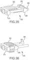
- the systemmay include a chisel with a shaft portion, a tip at a distal end of the shaft, and a head at a proximal end of the shaft, where the delivery device is adapted to receive the chisel, and the head of the chisel is adapted to be tapped by a driving member to insert the tip of the chisel into a facet joint.
- the systemmay include an injector with a cannula with a closed distal end and two exit doors positioned on opposite sides of the distal end, a plunger with a seal positioned within the cannula, a stop disc at a proximal end of the cannula, and a handle positioned on a proximal end of the plunger, where the delivery device is further adapted to receive an injector.
- the internal actuatormay be a stand alone device insertable into the driver assembly.
- the internal actuatormay include a handle and an internal rod, the internal rod being adapted to hold an implant distractor, and the handle being configured to release the implant distractor.
- the systemmay include a collet positioned on a distal end of the internal rod, the collet adapted to securely hold the implant distractor.
- a spinal distraction implantmay include an upper member and a lower member, the upper and lower member being generally rectangular and each having a distal edge, a proximal edge, and two parallel lateral edges, the upper and lower member positioned adjacent and substantially parallel to each other and having an inner surface and an outer surface, the distal edges of the upper and lower member connected to each other and the proximal edges adapted to receive an implant distractor, and teeth positioned along the lateral edges of at least one of the upper or lower member and extending outwardly.
- the implantmay include flanges extending substantially orthogonally from a proximal end of the upper and lower members.
- the flangesmay include openings for receiving anchors to anchor the implant to a lateral mass of a facet joint.
- the implantmay include a truncated threaded slot adapted to engage a cross-cut thread feature of an implant distractor.
- the upper and lower membersmay each include an interlocking scissor feature.
- a method of distracting a facet joint of the spinemay include inserting a delivery device to access the facet joint of a patient, inserting a driver assembly holding an implant into the delivery device, and actuating the driver assembly thereby distracting the implant.
- a spinal distraction implantmay include an upper member, a lower member, and a proximal member, the upper and lower members being generally rectangular and each having a distal edge and two parallel lateral edges, the upper and lower members extending generally continuously into each other to form the proximal member, the upper and lower member positioned adjacent and substantially parallel to each other and having an inner surface and an outer surface, the proximal member being generally perpendicular relative to the upper and lower members, at least one of the upper and lower members further including threaded slots adapted to receive threads of an implant distractor and outwardly extending teeth positioned along the lateral edges of at least one of the upper or lower members.
- the proximal membermay include a penetration for receiving an implant distractor.
- a spinal distraction implantmay include a threaded bolt with a proximal end terminating in a head, a proximal non-threaded block positioned along the bolt and abutting the head of the bolt, a distal threaded block positioned a distance away from the proximal threaded block, and a plurality of expansion members positioned between the proximal and the distal threaded blocks.
- the plurality of expansion membersmay be V-shaped members.
- the plurality of V-shaped membersmay be adapted to deformably flatten out and expand laterally when compressed between the distal and proximal blocks.
- the plurality of expansion membersmay be planar plates with slotted holes such that when freely positioned on the bolt, the plates are positioned in a skewed position relative to a longitudinal axis of the bolt.
- the planar platesmay be adapted to engage one another and thus position themselves perpendicular to the bolt when compressed between the distal and proximal blocks.
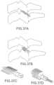
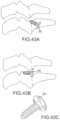
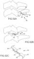
- a spinal distraction implantmay include a pair of stacked structures separated by a sloping plane, the structures having an engagement surface along the plane including ratchet teeth.
- a first structure of the pair of stacked structuresincreases in thickness in a proximal direction and a second structure of the pair of stacked structures increases in thickness in a distal direction.
- a spinal distraction implantmay include a generally tapered shaft in the form of a screw, the shaft defining a longitudinal axis and having a length, the shaft having threads along an outer surface for engaging articular surfaces of a facet joint.
- the threadsmay be notched along the length of the implant creating serrations for cutting into the articular surfaces of a facet joint.
- the threadsmay include leaf springs for preventing backing out of the implant.
- the threadsmay have a T-shaped cross-section.
- the implantmay include a relatively broad head with a decorticating feature on a distal surface thereof.
- the decorticating featuremay include tabs projecting distally from the head.
- the decorticating featuremay include spurs.
- the headmay be in the form of a floating collar and be free to pivot about the longitudinal axis of the implant in a ball and socket type fashion.
- the implantmay include a torque limiting mechanism.
- the shaftmay include a hollow cavity and take the form of a cone, the cone being made from a relatively malleable material, the implant further including an inner core support member for use when inserting the implant and for removal once the implant is in place.
- the generally tapered shaftmay be a first tapered shaft and the implant may also include a second generally tapered shaft in the form of a screw where the second generally tapered shaft may be positioned adjacent to the first generally tapered shaft and have communicative threaded serrations such that when one shaft is rotated, the other shaft rotates in the opposite direction.
- the implantmay include an arm type locking mechanism, the arm being biased in a distal direction such that when implanted the arm provides a biasing force to maintain friction on the threads.
- the armmay have engaging teeth.
- the implantmay include flaps extending from the head of the shaft and including teeth for engaging a lateral mass of a facet joint.
- a spinal distraction implantmay include a plate and a orthogonally positioned bumper, the superior aspect of the bumper having a rounded surface for opposing the lateral mass of a superior vertebra, the implant including an anchoring screw for securing the implant to a lateral mass of a facet joint.
- a spinal distraction implantmay include a wedge insertable between facet surfaces, the wedge having teeth on at least one of an anterior and inferior surface thereof.
- the implantmay also include a diagonally placed anchor screw positioned through the implant for advancing into the surface of a facet joint.
- a spinal distraction implantmay include an anterior hook, a posterior hook, and a bolt joining the anterior and posterior hook.
- the anterior hookmay be C-shaped with a lip and the posterior hook may be S-shaped with a lip, the anterior hook adapted to engage the anterior aspect of the inferior facet and the posterior hook adapted to engage the posterior aspect of the posterior facet.
- a spinal distraction implantmay include an insert and tabs positioned to extend orthogonally from a proximal end of the insert.
- the insertmay be rectangular and the tabs may have holes for receiving an anchor.
- a spinal distraction implantmay include a collapsible diamond shaped structure including two opposing threaded corners, and two opposing non-threaded corners including pads.
- the implantmay also include a bolt threaded through the threaded corners of the diamond shaped structure, where actuating the bolt draws the threaded corners together and extends the non-threaded corners.
- a spinal distraction implantmay include an upper member, a lower member, a hinge connecting the upper member to the lower member, and a brace member for maintaining the implant in an open position.
- a spinal distraction implantmay include a generally cylindrically shaped member including at least two sections separated by a slot, the sections connected together at distal ends to form a tip, the member adapted to receive a screw to cause it to expand, and the outer surface of the sections including teeth for engaging articular surfaces of a facet joint.
- a method of securing a superior verterbramay include applying a force to the superior vertebra to increase the foraminal area between the superior vertebra and an inferior vertebra and placing an angled screw through a superior facet, through a facet capsule, and into an inferior facet.
- a spinal distraction implantmay include a collapsible triangular shaped implant including a central shaft and at least two springing leaves connected to the distal end of the shaft, extending proximally along the shaft, and biased in a direction to form an arrow shape, where the implant may be collapsed within a tube and delivered to a site where the tube is removed and the implant is allowed to expand.
- a spinal distraction implantmay include a facet spacer plate and screw, wherein the screw may be inserted diagonally through a facet surface to engage the facet spacer plate thereby forcing separation of a facet joint.
- the spacermay have a C-shape and the screw may pass through the spacer plate prior to entering the spinal structure.
- a spinal distraction implantmay include a first bracket, second bracket, and a bolt extending between the brackets, where the brackets are adapted to separate when the bolt is turned.
- the first and second bracketsmay be adapted to be attached to a lateral mass of a facet joint.
- the first and second bracketsmay include a leg adapted to be inserted into a facet joint.
- a spinal distraction implantmay include a triangular shaped wedge, an anchor screw positioned diagonally through the wedge, and a malleable flap extending from the wedge including teeth for engaging a lateral mass of a facet joint.
- a spinal distraction implantmay include an anchoring plug, an expandable plate, and two external plates, where securing the external plates to a lateral mass of a facet joint and inserting the anchoring plug causes the facet joint to separate.
- a spinal distraction implantmay include a delivery system and at least two nitinol hooks, where the hooks may be flattened and inserted with the delivery system and once in place may be allowed to assume their pre-flattened shape.
- a spinal distraction implantmay include a hollow screw sleeve having barbs adapted to be ejected from a retracted position and a wedge adapted to be inserted in the hollow screw sleeve to eject the barbs.
- a spinal distraction implantmay include a collapsible nut positioned over a bolt, the bolt defining a longitudinal axis, where advancing the bolt may cause the nut to collapse along the longitudinal axis in an accordion shape, thereby expanding laterally.
- a spinal distraction implantmay include a collapsible plate positioned over a bolt, the bolt defining a longitudinal axis, where advancing the bolt causes the plate to collapse along the longitudinal axis in an accordion shape, thereby expanding laterally.
- a spinal distraction implantmay include a wire surrounding a block in a helical fashion, the wire adapted to contract and expand laterally when pulled taught or released respectively.
- a spinal distraction implantmay include an outer housing and an internal spring, where the housing may be biased to be in a laterally broad position when the spring is in a neutral position.
- a spinal distraction implantmay include a pair of stacked structures separated by a sloping plane and a fastener positioned at an angle through the pair of structures thereby preventing relative movement along the plane.
- a spinal distraction implantmay include a collapsible cylinder with side cutouts, the cylinder made from a resilient elastic material.
- a spinal distraction implantmay include a distal tip of a delivery tool, where the tip is adapted to distract a facet joint and detach from the delivery tool.
- a spinal distraction implantmay include a housing, a central gear rotatably positioned within the housing, and two plates slidably positioned in the housing and positioned opposite one another adjacent to the central gear and including teeth for engaging the gear, where rotating the gear slidably extends the plates beyond an outer surface of the housing in opposite directions.
- a spinal distraction implantmay include a triangularly bent plate with a first and second bracket on each side, the first bracket adapted to receive an anchor screw and the second bracket including teeth for biting into a lateral mass of a facet joint.
- a spinal distraction implantmay include a rotatable cone with a longitudinal axis including a shoulder with a ledge defining a cam surface and an anchor screw, where the shoulder is adapted to be inserted into a facet joint and the implant rotated to cause a superior facet to ride upward along the cam surface and distract the joint, wherein the screw may be advanced to secure the implant.
- a spinal distraction implantmay include a housing with penetrations for ejection of spikes, internal spikes positioned with the housing and in alignment with the penetrations, and an internal wire routed through the spike positions, where pulling the wire taught forces the spikes from the housing to engage articular surfaces of a facet joint.
- a spinal distraction implantmay include a housing, a cavity within the housing, penetrations on lateral surfaces of the housing extending from the cavity through the wall of the housing, spikes positioned to be ejected through the penetrations, the spikes having a beveled inner surface, and a piston having a torpedo shaped distal end positioned within the cavity, where advancing the piston engages the torpedo shaped distal end with the beveled inner surface of the spikes causing them to eject through the penetrations and engage articular surfaces of a facet joint.
- a spinal distraction implantmay include two parallel equal length side bars and at least two struts pivotably positioned between the side bars at each end, the struts having textured surfaces on each end thereof, where the struts may be pivoted to lie in plane with and parallel to the side bars and once in position in a facet joint, may be pivoted substantially perpendicular to the side bars to distract the facet joint.
- a spinal joint distraction systemmay include a delivery device with a tubular shaft, a receiving assembly positioned on a proximal end of the tubular shaft and including a seating cavity, and a pair of forks extending from a distal end of the tubular shaft, the forks adapted to penetrate a facet joint.
- the systemmay also include a chisel including a shaft with a chamfered tip, the chisel being adapted for slidable insertion through the delivery device.
- the systemmay further include a decorticator sleevably positioned on the tubular shaft of the delivery device, the decorticator including a tubular shaft portion with a chamfered distal end, a plurality of serrated teeth at the distal tip of the chamfered end, a beveled edge extending along the periphery of the chamfered distal end, and a handle positioned on the proximal end of the tubular shaft portion, the handle having a bore adapted to receive a gripping tool and a threaded bore for receiving a set screw.
- a decorticatorsleevably positioned on the tubular shaft of the delivery device, the decorticator including a tubular shaft portion with a chamfered distal end, a plurality of serrated teeth at the distal tip of the chamfered end, a beveled edge extending along the periphery of the chamfered distal end, and a handle positioned on the proximal end of the tubular shaft
- the systemmay also include a driver assembly adapted for slidable insertion through the delivery device, the driver assembly including an implant shaft, a handle positioned on the proximal end of the implant shaft, and implant holding arms extending from the distal end of the implant shaft.
- the systemmay also include an internal actuator adapted for slidable insertion through the driver assembly and further adapted to advance an implant distractor, the internal actuator including a longitudinal shaft, a handle positioned on the proximal end of the longitudinal shaft and adapted to rotatably advance the implant distractor, and an internal rod including an engagement feature adapted to secure the implant distractor.
- the systemmay further include an injector adapted for slidable insertion through the delivery device, the injector including a longitudinal delivery shaft, a seating feature positioned around the shaft, and a plunger adapted to pass through the longitudinal delivery shaft causing ejection of material from the distal end of the longitudinal delivery shaft.
- an injectoradapted for slidable insertion through the delivery device, the injector including a longitudinal delivery shaft, a seating feature positioned around the shaft, and a plunger adapted to pass through the longitudinal delivery shaft causing ejection of material from the distal end of the longitudinal delivery shaft.
- a spinal joint distraction systemmay include a delivery device with a decorticator sleevably positioned thereon, a chisel adapted for insertion through the delivery device, a driver assembly adapted for insertion through the delivery device and further adapted to hold an implant, an internal actuator adapted for insertion through the driver assembly and adapted to deliver and advance an implant distractor thereby distracting the implant, and an injector adapted for insertion through the delivery device and further adapted to deliver flowable material to or around the joint.
- a spinal distraction implantmay include an upper member and a lower member each with a distal end, the distal end of the lower member coupled to the distal end of the upper member, and an implant distractor adapted to be advanced between the upper and lower member and separate the upper and lower members causing the upper and lower member to pivot relative to one another about their respective distal ends.
- a spinal distraction implantmay include an upper member and a lower member each including a distal edge, a proximal edge, and two parallel lateral edges, the edges defining a generally rectangular shape, an inner surface, an outer surface, a threaded slot passing through the member from the inner surface to the outer surface, a truncated threaded slot passing through the member from the inner surface to the outer surface, a plurality of teeth spaced along the two parallel lateral edges, a guide feature positioned on the proximal edge, and an interlocking scissor feature positioned on the distal edge.
- the implantmay also include an implant distractor including a cylindrical body tapering to a point at a distal end, a coil shaped thread feature having an abrupt proximal end and being interrupted by at least one cross-cut, and an annular stop ring; wherein the upper and lower members may be pivotally coupled to one another via their respective interlocking scissor features, the respective guide features on the upper member and the lower member may oppose one another and may be adapted to receive and guide the distal end of the implant distractor between the upper and lower members, the respective threaded slots on the upper and lower member may be adapted to receive the coil shaped thread feature, and the respective truncated threaded slots may be adapted to engage the abrupt proximal end or the at least one cross-cut of the coil-shaped thread feature.
- an implant distractorincluding a cylindrical body tapering to a point at a distal end, a coil shaped thread feature having an abrupt proximal end and being interrupted by at least one cross-cut, and an annular stop ring;
- a method of distracting a facet joint of the spinemay include dilating a path to a facet joint using a dilator set, inserting a chisel into the facet joint, advancing a delivery device over the chisel and inserting forks of the delivery device into the facet joint, removing the chisel from the joint, inserting a driver assembly with an implant into the delivery device, seating the driver assembly in the delivery device thereby positioning the implant between the forks of the delivery device and in the facet joint, inserting an internal actuator into the driver assembly and advancing an implant distractor into the implant thereby distracting the implant, actuating a button on the internal actuator thereby releasing a grip on the implant distractor and removing the internal actuator and the driver assembly, and inserting an injector and injecting a flowable material into or around the facet joint.
- a method of distracting a facet joint of the spinemay include inserting a chisel into a facet joint to provide initial distraction and decorticate the surface of the joint, inserting a delivery device over the chisel to maintain the initial distraction, inserting an implant through the delivery device and into the joint, the implant having teeth adapted to engage the surfaces of the joint, distracting the implant by advancing an implant distractor, the implant distractor having a coil-shaped thread feature for engaging threaded slots of the implant, the implant distractor further having cross-cut threads for engaging truncated threaded slots on the implant, wherein, advancing the implant distractor includes causing the cross-cut threads to engage the truncated threaded slots and prevent backing out of the implant, and releasing the implant distractor and removing the delivery device thereby leaving the implant and the implant distractor in place in the joint.
- a spinal joint distraction systemmay include a delivery device, a driver assembly adapted for insertion through the delivery device and further adapted to hold an implant, and an internal actuator adapted for insertion through the driver assembly and adapted to deliver and advance an implant distractor thereby distracting the implant.
- a spinal joint distraction systemmay include a driver assembly adapted to hold an implant and an internal actuator adapted for insertion through the driver assembly and adapted to deliver and advance an implant distractor thereby distracting the implant.
- a spinal joint distraction systemmay include an implant, an implant distractor adapted to engage the implant, and an internal actuator adapted to advance the implant distractor thereby distracting the implant.
- a method of distracting a facet joint of the spinemay include inserting a delivery device into a facet joint, inserting an implant through the delivery device and into the joint, and distracting the implant by advancing an implant distractor.
- a method of distracting a facet joint of the spinemay include partially engaging an implant distractor with an implant and engaging the implant distractor with an internal actuator to form an assembly, inserting the implant portion of the assembly into the facet joint, and distracting the facet joint.
- a spinal distraction implantmay include an upper member and a lower member each with a distal end, the distal end of the lower member coupled to the distal end of the upper member, wherein the upper member and lower member each comprise a plurality of threaded slots adapted to engage an implant distractor.
- a spinal distraction implantmay include an upper member and a lower member each with a distal end, the distal end of the lower member including an interlocking scissor feature coupled to a corresponding interlocking scissor feature included on the distal end of the upper member.
- a spinal distraction implantcomprising an upper member and a lower member, each with a distal end, the distal end of the lower member coupled to the distal end of the upper member, wherein the implant is adapted to receive an implant distractor between the upper and lower member.
- a spinal distraction implantmay include an upper member and a lower member, the upper member and lower member coupled at respective distal ends, the upper and lower members being biased toward a position parallel to one another.
- a spinal joint distraction system for treating a facet joint including articular surfaces having a contourcan include a delivery device including a generally tubular structure adapted to engage a facet joint, an implant adapted to be delivered through the delivery device and into the facet joint, the implant comprising two members arranged in opposed position, and an implant distractor comprising a generally elongate member adapted to advance between the two members of the implant causing separation of the members and distraction of the facet joint, wherein the implant is adapted to conform to the shape of the implant distractor upon being delivered to the facet joint.
- the systemcan also include a driver assembly adapted to hold the implant and advance the implant distractor and the driver assembly can further be adapted for insertion through the delivery device.
- the systemcan also include a chisel adapted for insertion through the delivery device to facilitate initial engagement with the facet joint and a decorticator can be provided for lateral engagement with the delivery device.
- a malleting toolcan be included with a first end adapted to engage the decorticator for a malleting process and a second end adapted to facilitate separation of parts of the system and an injector can be provided and adapted for insertion through the delivery device and further can be adapted to deliver a bone paste.
- a spinal joint distraction systemcan include a delivery device and chisel assembly adapted to engage a facet joint and a driver assembly adapted to hold and distract an implant, where the driver assembly can be adapted for insertion through the delivery device to deliver and distract the implant.
- the systemcan also include a place holding chisel adapted to replace the chisel and maintain the established position of the delivery device and chisel assembly.
- the delivery devicecan include a tubular shaft and a receiving assembly positioned on a proximal end of the tubular shaft and the chisel of the assembly can include a handle having a connection feature adapted to engage the receiving assembly.
- connection featurecan include a protrusion or recess adapted to form a detent relationship with an opposing protrusion or recess respectively.
- connection featurecan include a latch type feature positioned on a deflectable portion of the handle, wherein advancing the chisel handle toward the receiving assembly causes the latch type feature to snap into place and depressing the deflectable portion of the handle releases the latch type feature.
- the receiving assemblycan include a malleting anvil positioned on a proximal face of the receiving assembly and the chisel can include a slot cavity adapted to receive the malleting anvil and a malleting head adapted to engage the malleting anvil to resist relative motion between the delivery device and the chisel during malleting.
- the delivery device of the assemblycan include forks adapted to penetrate the facet joint and it can also include a bull nose positioned on the surface of the forks near the intersection of the forks with the tubular structure, where the bull nose can be adapted to mark the position of the delivery device.
- the systemcan also include an indication hole positioned along the lateral side of the delivery device near the intersection of the forks and the tubular structure.
- the driver assemblycan include an implant shaft having a diameter substantially equal to or less than a width of the implant and can also include a handle with a malleting bar adapted to transfer malleting blows to the driver assembly.
- the driver assemblycan also include a slot cavity having a bearing surface where the slot cavity can be adapted to receive the malleting anvil of the receiving assembly and the bearing surface can be adapted to engage the malleting anvil to resist relative motion between the delivery device and the driver assembly during malleting.
- a decorticatorcan also be provided and can be adapted for positioning upon the delivery device from a lateral side of the delivery device.
- the decorticatorcan include a U-shaped longitudinally extending member with teeth on a distal end and it can include a malleting element at a proximal end adapted to distribute malleting blows to the longitudinally extending member.
- the driver assemblycan include arms adapted to hold an implant and the arms can be positioned within a boundary defined by a width of the implant.
- a spinal distraction implant for the distraction of a facet joint having articular surfacescan include a first and a second member arranged in opposing position.
- Each of the first and second membercan include a threaded slot passing through the member adapted to receive a thread feature and a plurality of teeth spaced along two parallel lateral edges, the teeth adapted to engage the articular surfaces of the facet joint, where the implant is constructed from a malleable material and is further adapted to conform to the shape of the articular surfaces upon being distracted within a facet joint.
- the plurality of teethcan have a linearly sloped distal face and a proximal face positioned orthogonally to the respective first or second member and the teeth can be equally spaced.
- the first and second memberscan each have an interlocking engagement feature on respective distal edges, wherein the first and second members engage one another via their respective interlocking engagement features.
- the first and second memberscan also be coupled together via a weld.
- a method of distracting a facet joint and a contralateral facet joint of a spinecan include inserting a delivery device and chisel assembly into the facet joint, removing the chisel from the assembly and replacing the chisel with a place holding chisel, removing the delivery device from the facet joint, inserting the delivery device and chisel assembly into the contralateral facet joint, removing the chisel from the assembly, placing and distracting a first implant in the contralateral facet joint, removing the delivery device from the contralateral facet joint, placing the delivery device back in the facet joint via the place holding chisel, placing and distracting a second implant in the facet joint.
- the place holding chiselcan be a radiolucent chisel and the method can also include performing lateral fluoroscopy to determine proper placement of the first implant.
- a method of distracting a facet joint of the spinecan include inserting a delivery device and chisel assembly into the facet joint to provide initial distraction and decorticate the surface of the joint, removing the chisel assembly from the delivery device, inserting a driver assembly through the delivery device, the driver assembly holding an implant and further comprising an implant distractor adapted to distract the implant, distracting the implant, and removing the driver assembly and the delivery device.
- the methodcan also include positioning the delivery device and chisel assembly by selectively malleting a proximal end thereof and/or selectively malleting a proximal end of the driver assembly.
- a decorticatorcan be positioned on the delivery device from the lateral side of the device and the method can include advancing the decorticator along the length of the driver assembly, positioning a malleting tool against the proximal end of the decorticator, and malleting the malleting tool to forcibly advance the decorticator and decorticate the lateral mass of the facet joint.
- the decorticatorcan be retracted, rotated, and re-advanced to a new position for malleted with the malleting tool to decorticate a different location. Intra-operative patient symptom feedback can also be obtained.
- a spinal distraction implant delivery toolcan include an implant and an assembly, where the assembly includes a means for holding the implant, a means for positioning the implant within a facet joint, and a means for distracting the implant.
- the implantcan include a first substantially planar member and a second substantially planar member arranged in parallel and opposing position to the first substantially planar member and a biasing connection connecting the first and second planar members to one another, the biasing connection adapted to create a biasing force directed toward biasing the members toward the parallel and opposing position.
- the means for holdingcan include a pair of implant holding arms, the arms adapted to pass between the planar members and force them apart against the biasing force.
- the holding armscan each include a means for engaging the implant.
- the means for distracting the implantcan include an implant distractor and a means for rotatably advancing the implant distractor.
- the implant distractorcan include a generally elongate member adapted to pass between the substantially planar members and force the members apart against the biasing force.
- a method of performing an interbody fusioncan include inserting a delivery device and chisel assembly into a joint between vertebral bodies of the spine, removing the chisel assembly from the delivery device, and inserting a driver assembly through the delivery device.
- the driver assemblycan hold an implant and an implant distractor adapted to distract the implant.
- the methodcan also include distracting the implant and removing the driver assembly and the delivery device.
- the methodcan further include repeating the steps to place a second implant in the joint.
- FIG. 1is a perspective view of a delivery device and chisel positioned relative to a facet joint of a spine, according to certain embodiments.
- FIG. 1 Ais a perspective view of a chisel according to certain embodiments.
- FIG. 2is a perspective view of a distal end of a delivery device, according to certain embodiments.
- FIG. 3is a perspective view of a distal end of a delivery device with an advanced chisel, according to certain embodiments.
- FIG. 4is a perspective view of a distal end of a delivery device with an advanced internal decorticator, according to certain embodiments.
- FIG. 5is a perspective view of a delivery device and chisel positioned relative to a facet joint of a spine with a driving member positioned proximally to the chisel head, according to certain embodiments.
- FIG. 6is a perspective view of a delivery device with an exterior decorticator in an advanced position, according to certain embodiments.
- FIG. 6 A- 6 Care perspective views of a delivery device and an internal decorticator, according to certain embodiments.
- FIG. 7is a perspective view of a delivery device with an exterior decorticator being retracted, according to certain embodiments.
- FIG. 8is a perspective view of a delivery device with a driver assembly and implant poised for insertion into the delivery device, according to certain embodiments.
- FIG. 9is a close-up view of a distal end of a driver assembly and a delivery device, according to certain embodiments.
- FIG. 10is close-up view of a distal end of a driver assembly, according to certain embodiments.
- FIG. 11is a perspective view of an implant and a distal end of a driver assembly, according to certain embodiments.
- FIG. 12is a perspective view of distal end of a driver assembly holding an implant, according to certain embodiments.
- FIG. 13is a perspective view of a distal end of a driver assembly positioned within a delivery device, according to certain embodiments.
- FIG. 14is a perspective view of an implant distractor, according to certain embodiments.
- FIG. 15is a perspective view of a distal end of a driver assembly positioned within a delivery device, according to certain embodiments.
- FIG. 16is a perspective view of an implant according to certain embodiments.
- FIG. 16 Ais a perspective view of an implant showing a guide feature, according to certain embodiments.
- FIG. 16 Bis a perspective view of an implant showing a guide feature, according to certain embodiments.
- FIG. 17is a side view of an implant according to certain embodiments.
- FIG. 18is a top view of an implant according to certain embodiments.
- FIG. 18 Ais a top view of an implant showing the guide feature of FIG. 16 A , according to certain embodiments.
- FIG. 18 Bis a top view of an implant showing the guide feature of FIG. 16 B , according to certain embodiments.
- FIG. 19is a proximal end view of an implant according to certain embodiments.
- FIG. 20is a side view of an implant according to certain embodiments.
- FIG. 21is side view of a U-member according to certain embodiments.
- FIG. 22is a perspective view of a U-member according to certain embodiments.
- FIG. 23is a perspective view of an implant according to certain embodiments.
- FIG. 23 Ais a perspective view of an implant according to certain embodiments.
- FIG. 24is a top view of an implant according to certain embodiments.
- FIG. 24 Ais a side view of the implant shown in FIG. 23 A , according to certain embodiments.
- FIG. 25is perspective view of a deliver device with a driver assembly inserted and advance, according to certain embodiments.
- FIG. 26is perspective view showing the removal of the driver assembly from the delivery device having left the implant behind, according to certain embodiments.
- FIG. 27is a perspective view of an injector, according to certain embodiments.
- FIG. 28is a perspective view of a delivery device with an advanced injector inserted and ejecting a material, according to certain embodiments.
- FIG. 29is a perspective view of an implant in a collapsed position according to certain embodiments.
- FIG. 30is a perspective view of an expanded implant according to certain embodiments.
- FIG. 31is a perspective view of an implant in a collapsed position according to certain embodiments.
- FIG. 32is a perspective view of an expanded implant according to certain embodiments.
- FIG. 33is a perspective view of an implant in a collapsed position according to certain embodiments.
- FIG. 34is a perspective view of an expanded implant according to certain embodiments.
- FIG. 35is a perspective view of an implant in a collapsed position according to certain embodiments.
- FIG. 36is a perspective view of an expanded implant according to certain embodiments.
- FIGS. 37 A-Dinclude side and perspective views of an implant, according to certain embodiments.
- FIGS. 38 A-Cinclude side and perspective views of an implant, according to certain embodiments.
- FIGS. 39 A-Dinclude side and perspective views of an implant, according to certain embodiments.
- FIGS. 40 A-Cinclude side views of an implant, according to certain embodiments.
- FIGS. 41 A-Dinclude side and perspective views of an implant, according to certain embodiments.
- FIGS. 42 A-Finclude side and perspective views of an implant, according to certain embodiments.
- FIGS. 43 A-Cinclude side and perspective views of an implant, according to certain embodiments.
- FIGS. 44 A-Dinclude side and perspective views of an implant, according to certain embodiments.
- FIGS. 45 A-Dinclude side and perspective views of an implant, according to certain embodiments.
- FIGS. 46 A-Dinclude side and perspective views of an implant, according to certain embodiments.
- FIGS. 47 A-Binclude side views of an implant, according to certain embodiments.
- FIGS. 48 A-Cinclude side and end views of an implant, according to certain embodiments.
- FIGS. 49 A-Cinclude side and perspective views of an implant, according to certain embodiments.
- FIGS. 50 A-Binclude side views of an implant, according to certain embodiments.
- FIGS. 51 A-Binclude side views of an implant, according to certain embodiments.
- FIGS. 52 A-Cinclude side and perspective views of an implant, according to certain embodiments.
- FIGS. 53 A-Cinclude side and perspective views of an implant, according to certain embodiments.
- FIGS. 54 A-Cinclude side and perspective views of an implant, according to certain embodiments.
- FIGS. 55 A-Cinclude side and perspective views of an implant, according to certain embodiments.
- FIGS. 56 A-Cinclude side and perspective views of an implant, according to certain embodiments.
- FIGS. 57 A-Cinclude side and perspective views of an implant, according to certain embodiments.
- FIGS. 58 A-Binclude side views of an implant, according to certain embodiments.
- FIGS. 59 A-Binclude side views of an implant, according to certain embodiments.
- FIGS. 60 A-Binclude side views of an implant, according to certain embodiments.
- FIGS. 61 A-Cinclude side and perspective views of an implant, according to certain embodiments.
- FIGS. 62 A-Cinclude side and perspective views of an implant, according to certain embodiments.
- FIGS. 63 A-Cinclude side and perspective views of an implant, according to certain embodiments.
- FIGS. 64 A-Cinclude side and perspective views of an implant, according to certain embodiments.
- FIGS. 65 A-Cinclude side and perspective views of an implant, according to certain embodiments.
- FIGS. 66 A-Cinclude side views of an implant, according to certain embodiments.
- FIGS. 67 A-Cinclude side and perspective views of an implant, according to certain embodiments.
- FIGS. 68 A-Cinclude side and perspective views of an implant, according to certain embodiments.
- FIGS. 69 A-Cinclude side and perspective views of an implant, according to certain embodiments.
- FIGS. 70 A-Cinclude side views of an implant, according to certain embodiments.
- FIGS. 71 A-Cinclude side and perspective views of an implant, according to certain embodiments.
- FIGS. 72 A-Cinclude side and perspective views of an implant, according to certain embodiments.
- FIGS. 73 A-Cinclude side and perspective views of an implant, according to certain embodiments.
- FIGS. 74 A-Cinclude side and perspective views of an implant, according to certain embodiments.
- FIGS. 75 A-Binclude side views of an implant, according to certain embodiments.
- FIGS. 76 A-Cinclude side and perspective views of an implant, according to certain embodiments.
- FIGS. 77 A-Cinclude side and perspective views of an implant, according to certain embodiments.
- FIGS. 78 A-Cinclude side and perspective views of an implant, according to certain embodiments.
- FIGS. 79 A-Cinclude side and perspective views of an implant, according to certain embodiments.
- FIGS. 80 A-Dinclude side and perspective views of an implant, according to certain embodiments.
- FIGS. 81 A-Cinclude side views of an implant, according to certain embodiments.
- FIGS. 82 A-Finclude side and perspective views of an implant, according to certain embodiments.
- FIGS. 83 A-Binclude side and perspective views of an implant, according to certain embodiments.
- FIGS. 84 A-Binclude perspective views of an implant, according to certain embodiments.
- FIG. 85is an exploded perspective view of a kit, according to certain embodiments.
- FIG. 86is an assembled perspective view of a kit, according to certain embodiments.
- FIGS. 87 and 88are perspective views of a chisel portion of the kit shown in FIGS. 85 and 86 .
- FIGS. 89 and 90are perspective views of a delivery device portion of the kit shown in FIGS. 85 and 86 .
- FIG. 91is a perspective view of part of a driver assembly portion of the kit shown in FIGS. 85 and 86 .
- FIGS. 92 and 93are perspective views of a part of a driver assembly portion of the kit shown in FIGS. 85 and 86 .
- FIGS. 94 and 94 Aare views of a chisel according to certain embodiments.
- FIGS. 95 , 95 A and 95 Bare views of a delivery device according to certain embodiments.
- FIG. 96is a perspective view of a driver assembly according to certain embodiments.
- FIG. 97is a perspective view of an internal actuator according to certain embodiments.
- FIG. 98is a perspective view of an injector according to certain embodiments.
- FIGS. 99 - 99 Dare several views of a driver assembly according to certain embodiments.
- FIGS. 100 - 101depict relative positions of a driver assembly and a delivery device according to certain embodiments.
- FIGS. 102 - 103depict relative positions of an internal actuator, a driver assembly, and a delivery device according to certain embodiments.
- FIG. 104is a side view of an internal actuator according to certain embodiments.
- FIG. 105is a side view of an internal actuator according to certain embodiments.
- FIGS. 106 - 108are several side and cross-section view of an internal actuator according to certain embodiments.
- FIG. 109is a side view of a collet according to certain embodiments.
- FIG. 110is a side view of a longitudinal shaft of an internal actuator according to certain embodiments.
- FIGS. 111 - 113include several views of an implant distractor according to certain embodiments.
- FIG. 114is a perspective view of an injector according to certain embodiments.
- FIGS. 115 - 116depict relative positions of an injector and a delivery device according to certain embodiments.
- FIGS. 117 - 120include several perspective views of an implant according to certain embodiments.
- FIG. 121includes several parts of a tool according to certain embodiments.
- FIG. 122is a perspective view of a chisel according to certain embodiments.
- FIG. 123is a perspective view of a delivery device according to certain embodiments.
- FIG. 123 Ais a perspective view of the proximal end of a delivery device according to certain embodiments.
- FIG. 124is a perspective view of a decorticator according to certain embodiments.
- FIG. 125is a perspective view of a driver assembly according to certain embodiments.
- FIG. 126is a perspective view of an internal actuator according to certain embodiments.
- FIGS. 126 A and 126 Bare cross-sectional views of an internal actuator according to certain embodiments.
- FIGS. 127 and 127 Aare perspective views of an internal rod with a collet according to certain embodiments.
- FIG. 128is a perspective view of an injector according to certain embodiments.
- FIGS. 129 - 131are several view of a dilator set according to certain embodiments.
- FIGS. 132 and 132 Aare two views of a dilator rod according to certain embodiments.
- FIGS. 133 , 133 A, and 133 Bare several views of a dilator sleeve according to certain embodiments.
- FIGS. 134 and 134 Aare two views of a dilator sleeve according to certain embodiments.
- FIGS. 135 , 135 A, and 135 Bare several views of a dilator sleeve according to certain embodiments.
- FIG. 136includes a perspective view of several parts of a tool according to certain embodiments.
- FIG. 137includes a perspective view of several parts of the tool of FIG. 136 .
- FIG. 138is a perspective view of a chisel of the tool of FIG. 136 .
- FIGS. 139 A-Cinclude several views of a chisel of the tool of FIG. 136 .
- FIG. 140is a perspective view of a malleting head of the chisel of FIG. 138 .
- FIG. 141is a top view thereof.
- FIG. 142is a top view of a shaft portion of the chisel of FIG. 138 .
- FIG. 143is a close up side view of a tip of the chisel of FIG. 138 .
- FIG. 144is a top view of a chisel and delivery device of the tool of FIG. 136 .
- FIG. 145is a close up side view of a tip of a chisel and delivery device of the tool of FIG. 136 .
- FIG. 146is a perspective view of a decorticator of the tool of FIG. 136 .
- FIG. 147is a perspective view of a driver assembly of the tool of FIG. 136 .
- FIG. 148is a perspective view thereof.
- FIG. 149is a perspective view of several tips of several of the elements of the tool of FIG. 136 .
- FIG. 150is a perspective view of the proximal ends of several of the elements of the tool of FIG. 136 .
- FIG. 151is a perspective view of a plunger of the injector of the tool of FIG. 136 .
- FIG. 152is a perspective view of an implant distractor, according to certain embodiments.
- FIG. 153 A-Care several side views thereof.
- FIG. 154is a perspective view of several handles and their engaging features for engaging with the receiving assembly of the delivery device of the tool of FIG. 136 .
- FIG. 155 A-Binclude a cross-sectional view and close-up view thereof
- FIG. 156is a perspective view of an implant according to certain embodiments.
- FIG. 157 - 161 Binclude several perspective views thereof including the relationship of the implant to a facet joint.
- FIG. 162is a side view of a mechanically tested implant, according to certain embodiments.
- FIG. 163is a table of exemplary dimensions of an implant.
- FIG. 164is a table of exemplary dimensions of a delivery device.
- FIG. 165is a table of exemplary dimensions of an implant distractor.
- FIG. 166is a table of exemplary dimensions of a chisel.
- FIG. 167is a table of exemplary dimensions of a place holding chisel.
- FIG. 168is a table of exemplary dimensions of a driver assembly.
- FIG. 169is a table of exemplary dimensions of a decorticator.
- FIG. 170is a table of exemplary dimensions of a malleting tool.
- FIG. 171is a perspective view of a chisel according to certain embodiments.
- FIG. 172is a top perspective view of a distal portion thereof.
- FIG. 173is a bottom perspective view of a distal portion thereof.
- FIG. 174is a perspective view of a proximal portion thereof.
- FIG. 175is a top view of implants positioned in a joint between two vertebral bodies.
- FIG. 176is another top view of implants positioned in a joint between two vertebral bodies.
- FIG. 177is yet another top view of implants positioned in a joint between two vertebral bodies.
- FIGS. 178 - 185depict several methods according to certain embodiments.
- Spinal stenosisreflects a narrowing of one or more areas of the spine often in the upper or lower back. This narrowing can put pressure on the spinal cord or on the nerves that branch out from the compressed areas.
- Individual vertebrae of the spineare positioned relative to each other and their separation is maintained by discs separating main vertebral bodies and by capsules positioned within facet joints. The discs and capsules are separated from the bone of their respective joints by cartilage.
- Spinal stenosisis often indicative of degeneration of a disc, a capsule, or the cartilage in a joint, which leads to a compression of the joints and the narrowing mentioned.
- the devicemay include a tool and an implant for distracting and maintaining the distracted position of the joint.
- an implantis described in addition to several embodiments of a tool.
- the implant and the toolwork together to distract the facet joint and thereafter leave the implant behind to maintain the distraction of the joint.
- the devicemay be adapted to access a facet joint by inserting a delivery tool and an implant, forcibly separate the associated articular surfaces with the tool, the implant, or both, and leave the implant in place to maintain the separation of the articular surfaces. This approach may allow for maintaining the distraction of the joint, thereby relieving symptoms associated with spinal stenosis.
- FIG. 1shows the tool 100 in position posterior to the spine 102 .
- the tool 100includes a delivery device 104 , a decorticator 106 , and a chisel 108 .
- the delivery device 104may include a receiving assembly 110 at a proximal end, anchoring forks 112 at a distal end, and a generally tubular shaft 114 defining a longitudinal axis and extending between the receiving assembly 110 and the anchoring forks 112 .
- the tubular shaft 114may have an annular shaped cross-section with an inner radius and an outer radius, where the difference between the two radii defines a thickness of the tubular shaft 114 .
- the receiving assembly 110 of the delivery device 104may have a generally conical outer surface defining a generally hollow volume or solid mass.
- the conical outer surfacemay have a longitudinal axis that coincides with that of the tubular shaft 114 .
- the conical outer surfacemay be defined by a first radius at a proximal end and a second radius at a distal end. Where the tubular shaft 114 and the receiving assembly 110 are manufactured as one piece, the second radius may match the outer radius of the tubular shaft.
- the distal end of the receiving assembly 110may be adapted for a press fit over the proximal end of the tubular shaft 114 .
- the receiving assembly 110may also include a longitudinally extending bore 116 having an inner radius matching that of the tubular shaft 114 or may have a conically shaped inner surface leading to the tubular shaft 114 .
- the receiving assembly 110may also include a relatively thin annular ring 118 offset from its distal end by two relatively thin extension elements 120 . The space between the proximal end of the conical portion of the receiving assembly 110 and the distal end of the annular ring 118 may define an access opening 122 .
- a receiving assembly 111may not include the annular ring 118 and the extension elements 120 , but may remain generally conical and may include the longitudinally extending bore 116 .
- seating recesses 119may be included near the proximal end of the receiving assembly 111 . These recesses 119 may be positioned on opposing sides of the bore 116 and may recess into the proximal end of the receiving assembly 111 and the inner surface of the bore 116 . These recesses may function to receive positionally matched protrusions from any one or all of the devices being inserted into the deliver device.
- the recesses 119may allow for orienting the devices properly relative to the forks 112 positioned in the facet joint. It is noted that any number of recesses may be provided and that any orientation may be used, either symmetrical or non-symmetrical, such that one or several orientations may be controlled. That is, an asymmetrical arrangement may allow for only one proper insertion position as opposed to the symmetrical orientation shown, which may allow for two proper insertion positions.
- the delivery device 104may include two anchoring forks 112 formed by coping two opposing portions of the distal end of the tubular shaft 114 .
- the forks 112may have a generally V-shaped tip 124 at their distal end and may have a generally rectangular cross-section extending from the V-shaped tip 124 to the proximal end of the forks 112 .
- the rectangular cross-sectionmay have an inside face and an outside face where the inside face faces the longitudinal axis of the delivery device 104 .
- the rectangular cross-sectionmay also have opposing surfaces connecting the inside face to the outside face and completing the rectangular cross-section.
- the cross-sectionmay gradually change from rectangular to a shape matching that of half of the annular shape of the tubular shaft portion.
- the forks 112may also include serrations or teeth along the opposing surfaces to assist with anchoring the delivery device 104 .
- the chisel 108may have a generally cylindrical cross-section forming a shaft 128 .
- the shaft 128may have a radius substantially equal to the inner radius of the tubular shaft 114 portion of the delivery device 104 allowing for slidable insertion of the chisel 108 within the delivery device 104 .
- the chisel 108may include a basic single or doubly chamfered tip 130 at a distal end or may have a coped distal end.
- the chisel 108may also include a head 132 at a proximal end.
- the head 132may be a generally solid material and may have a generally flat distal face and a spherically shaped proximal face.
- the shaft 128 and tip 130 portion of the chisel 108measured from the distal face of the head 132 to the distal end of the chamfered tip 130 , may have a length substantially equal to the distance from a proximal face of the annular ring 118 of the delivery device 104 to the distal tip of the delivery device 104 .
- the chisel 108may include a longitudinal lumen 131 as shown in FIG. 1 A . While not shown, this embodiment may also include the head 132 shown in FIG. 1 and the lumen 131 may extend there through.
- the lumen 131 in the chisel 108may be used for advancing a scope along with the chisel 108 to properly place the chisel 108 and the delivery device 104 .
- the lumen 131may also be used to provide suction or fluid flushing to the surgical site to remove or flush debris created by inserting the serrated forks 112 of the delivery device 104 and the tip 130 of the chisel 108 .
- the tip 130 of the chisel 108may have a coped shaped similar to that of the forks 112 of delivery device 104 .
- the tip 130may include a generally V-shaped distal end matching that of the forks 112 .
- the tip 130may have a width substantially equal to twice the inner radius of the tubular shaft 114 of the delivery device 104 such that the tip 130 extends between the two inside faces of the forks 112 .
- the decorticator 106may have a tubular shaft 134 portion, an abrasive distal end 136 , and a handle 138 at a proximal end.
- the tubular shaft 134may have an inner radius substantially equal to the outer radius of the tubular shaft 114 of the delivery device 104 and may allow for sliding movement of the decorticator 106 along the length of the delivery device 104 and rotationally around the delivery device 104 .
- the abrasive distal end 136may include serrated teeth as shown, or may include a more flat annular surface with a gritty surface.
- the handle 138may have a generally cylindrical portion with randomly or patterned raised portions or recesses adapted to assist gripping the handle.
- the proximal and distal ends of the handle 138may be generally spherical. It is noted that the decorticator 106 may alternatively be separate from the delivery device 104 and may be slidably inserted within the delivery device 104 as shown in FIG. 4 . In this embodiment, the decorticator 106 may be inserted, advanced to the implantation site, and rotated similar to the decorticator 106 described above to roughen the bone surface.
- a decorticator 106may take the form of a relatively sharp pick, as shown in FIG. 6 A- 6 C .
- the decorticator 106may include a control handle 139 for advancing and pivoting the device.
- the control handle 139may be connected to a tubular shaft 135 , which may be connected to a sharp flexible tip 137 .
- the tip 137may be relatively thin and may have a neutral position relative to the longitudinal axis of the delivery device 104 so as to position the tip 137 within the boundary defined by the inner surface of the delivery device 104 . As such, when inserted in the delivery device 104 , the tip 137 may slide readily through the delivery device 104 .
- the tip 137When the decorticator 106 is advanced to the distal end of the delivery device 104 , the tip 137 may be rotated and maneuvered to decorticate the surface of the lateral mass. It is noted that the shaft 135 may be relatively narrow when compared to the inner bore of the delivery device 104 to facilitate better maneuverability of the tip of the decorticator as it extends out the end of the deliver device.
- the decorticatormay be used as shown in FIGS. 6 B and 6 C to rotationally scrape or longitudinally penetrate the lateral mass of a facet joint.
- a driving membermay be used to assist the decorticating process.
- the tool 100is shown with the chisel 108 fully inserted into the delivery device 104 such that the distal face of the head 132 of the chisel 108 is in abutting relationship with the annular ring 118 of the receiving assembly 110 on the delivery device 104 .
- the distal tip 130 of the chisel 108thus extends to the distal end of the delivery device 104 .
- a hammer 140is shown for use in tapping the proximal end of the chisel 108 and thus advancing the forks 112 of the delivery device 104 and the tip 130 of the chisel 108 into the facet joint.
- the forks 112 of the delivery devicemay channel into the fact surface and displace or remove tissue. In some embodiments, this may be removed by a suction lumen in the chisel. Once the chisel 108 and delivery device 104 are tapped into place, the chisel 108 may be removed and the serrations on the opposing surfaces of the forks 112 may aid in anchoring the delivery device 104 in the joint and preventing dislodgement.
- FIG. 6shows the decorticator 106 in an advanced position along the length of the delivery device 104 such that the distal end is in contact with the bone surfaces surrounding the facet joint.
- the handle 138is being used to rotate the decorticator 106 around the perimeter of the delivery device 104 to roughen the associated bone surfaces.
- either of the internal decorticators shown in FIG. 4 or 6 A- 6 Cmay be used.
- FIG. 7shows the decorticator 106 retracted and also shows the resulting roughened bone surfaces.
- the tool 100including the delivery device 104 and retracted decorticator 106 , is shown lodged in a facet joint. Also shown is a driver assembly 142 portion of the tool 100 .
- the driver assembly 142includes a distractor knob 144 , an implant shaft 146 , implant holding arms 148 , an implant distractor 150 , and an internal actuator 152 (not shown).
- the driver assembly 142 shownis holding an implant 154 and is poised for insertion into the delivery device 104 .
- FIGS. 9 - 15several views of the driver assembly 142 are shown.
- a portion of the delivery device 104is shown for receiving the driver assembly 142 .
- the distal end of the driver assembly 142is also shown.
- FIG. 10shows a close-up view of the distal end of the driver assembly 142 where the implant 154 , the implant distractor 150 and the internal actuator 152 are not shown.
- the implant shaft 146 of the driver assembly 142defines a longitudinal axis thereof and has a generally annular cross-section with an inner radius and an outer radius where the difference between the two radii defines the wall thickness of the shaft 146 .
- the outer radius of the implant shaft 146is substantially equal to the inner radius of the tubular shaft 114 of the delivery device 104 .
- the implant shaft 146also includes a keyway feature 156 for preventing relative rotation between the tubular shaft 114 of the delivery device 104 and the implant shaft 146 of the driver assembly 142 when inserted.
- the keyway feature 156may include a pair of tabs on opposing sides of the implant shaft 146 for engaging with a corresponding longitudinal slot in the inner surface of the tubular shaft 114 of the delivery device 104 .
- this keyway feature 156may be in the form of a longitudinal slot in the outer surface of the implant shaft 146 of the driver assembly 142 , as shown in FIG. 11 , which may receive an internal ridge, tab, or other protrusion from the inner surface of the tubular shaft 114 of the delivery device 104 .
- the arms 148are shown extending from the distal end of the implant shaft 146 .
- the arms 148may be formed by coping opposing surfaces of the implant shaft 146 .
- the arms 148have a generally rectangular cross-section with an inside face facing the longitudinal axis of the implant shaft 146 and an opposite outside face. The inside and outside faces of the cross-section are connected by two opposing faces.
- the arms 148may include an engagement feature 158 at a distal end for engaging an implant 154 .
- the engagement feature 158may include a generally rectangular element positioned orthogonal to the arms 148 and flush with the outside face of the arms.
- the implant 154may slide over the distal end of the arms 148 and may include a receiving feature 160 for receiving the engagement feature 158 of each of the arms 148 .
- the arms 148may still be formed by coping opposing surfaces of the implant shaft 146 .
- the outside face of the arm 148may be a continuation of the outside surface of the implant shaft 146 .
- the inside face of the arm 148is more detailed than that of the embodiment shown in FIG. 10 . That is, as shown in FIG. 11 , the inside surface may include a longitudinal ridge 162 extending the length of the arm 148 .
- the arm 148may also include a bull nose engagement feature 158 extending transverse to the longitudinal axis of the implant shaft 146 along the inside face of the arm 148 . As shown in FIG.
- each arm 148is engaged with and holding the implant 154
- the longitudinal ridges 162 of each arm 148are positioned between upper and lower planar members of the implant 154 and the bull nose engagement features 158 are positioned in the U-shaped receiving feature slots 160 on the lateral edges of the implant 154 .
- the implant distractor 150is shown in FIG. 9 and a close-up view is shown in FIG. 14 .
- the implant distractor 150may be a generally narrow conical element tapered to a point at a distal end. At a proximal end, the implant distractor 150 is shown to include an extruded hexagon shape 164 .
- the outer surface of the implant distractor 150includes a continuous coil-shaped thread feature 166 .
- the implant distractor 150is shown positioned proximal to the implant 154 and engaged by the internal actuator 152 .
- the implant distractor 150may take on a variety of shapes and sizes other than that shown in the present embodiment.
- the implant distractor 150may be a triangular shaped wedge, a generally conical shape without threads, or other shape adapted to cause separation and distraction of a facet joint.
- the internal actuator 152is visible extending from the distal end of the implant shaft 146 .
- the internal actuator 152generally includes a longitudinal shaft positioned within the driver assembly 142 .
- the internal actuator 152may have a radius substantially equal to the inner radius of the driver assembly 142 and may be adapted for slidable longitudinal and rotational movement relative to the driver assembly 142 .
- the internal actuator 152may be moved relative to the implant shaft 146 longitudinally, rotationally, or both via the distractor knob 144 and may cause a corresponding motion of the implant distractor 150 . As such, the internal actuator 152 may advance the implant distractor 150 into the implant 154 thus expanding the implant 154 in the joint causing distraction of the joint.
- the distal end of the internal actuator 152may include a hex driver type tip as most clearly shown in FIG. 15 for engaging the extruded hexagonal shaped proximal end of the implant distractor 150 .
- a hex driver type tipas most clearly shown in FIG. 15 for engaging the extruded hexagonal shaped proximal end of the implant distractor 150 .
- the driver assembly 142when the driver assembly 142 is inserted, it may carry the internal actuator 152 , the implant distractor 150 , as well as the implant 154 with it. However, to properly position the driver assembly 142 and the implant 154 , some force may be required via a mallet or other member driving member.
- the internal actuator 152may be slightly isolated from the driver assembly 142 , so as to avoid advancing the internal actuator 152 , and thus the implant distractor 150 , when forcing the driver assembly 142 into the joint. This isolation may help to avoid inadvertently advancing the internal actuator 152 and the implant distractor 150 , thus avoiding inadvertent distration prior to proper placement.
- the isolation of the internal actuator 152 from the driver assemblymay take the form of a loosely fitting threaded engagement between the driver assembly 142 and the internal actuator 152 . Alternatively, this isolation may be in the form of a clip between the two features.
- FIGS. 16 - 24For a detailed discussion of an implant 154 according to certain embodiments, reference is now made to FIGS. 16 - 24 .
- the implant 154may include upper 168 and lower 170 members.
- the members 168 , 170may be generally planar and may also be generally rectangular.
- each of the upper 168 and lower 170 membersmay include a proximal edge 172 , a distal edge 174 , and a pair of parallel lateral edges 176 extending longitudinally between the distal edges 174 and the proximal edges 172 .
- the distal 174 and proximal edges 172may be generally square edges, while the lateral edges 176 may be defined by a radiused curve. As shown in cross-section in FIG.
- the inner surface 178 of the upper 168 and lower 170 membermay be generally flat as it approaches the lateral edge 176 .
- the inner surface 178departs from generally flat and follows a radiused curve until it intersects with the outer surface 180 .
- the members 168 , 170may be joined at their respective distal edges 174 by a U-member 182 to form a leading end.
- the leading endmay be formed via a weld (not shown) that couples the distal edges 174 of the planar members 168 , 170 together.
- the upper 168 and lower 170 membersmay be formed from a single plate bent to create the implant as shown in FIGS. 23 A and 24 A .
- the planar members 168 , 170may be biased by the leading end to be generally parallel to each other, the inner faces 178 of the planar members 168 , 170 facing each other in an opposed fashion and abutting or nearly abutting each other.
- a guide feature 184may be included on each of the upper 168 and lower 170 members as well as teeth 186 projecting outwardly from the outer faces 180 of the members 168 , 170 .
- the receiving features 160 mentioned above with respect to FIGS. 11 and 12may also be included. Threaded slots 188 may also be included in each planar member 168 , 170 for receiving the coil-shaped thread feature 166 on the implant distractor 150 .
- the guide feature 184may take the form of a half-conical feature and may be positioned at or near the proximal edge 172 of each of the upper 168 and lower 170 members.
- the half-conical featuremay begin at the proximal edge 172 with the widest radius of the half-conical feature and may taper to a zero or approximately zero radius as the half-conical feature extends in the direction of the distal edge 174 .
- the half conical featuresmay oppose one another and function to receive and guide an advancing implant distractor 150 .
- the half-conical featuresmay also include threaded slots 188 for receiving the coil-shaped thread feature 166 on the implant distractor 150 .
- the half-conical featuremay not actually be a full half cone. Instead, the proximal end of the feature may be a segment of a circle and the feature may be relatively subtle in the form of a cone segment.
- the guide feature 184may include a V-shaped notch or a rectangular notch in the proximal end of the upper 168 and lower 170 members as shown in FIGS. 16 A and 18 A and FIGS. 16 B and 18 B respectively.
- Those skilled in the artwill understand and appreciate that other shaped notches or elements may be positioned on proximal end of the upper 168 and lower 170 members to guide the implant distractor 150 , and these elements are within the scope of the present disclosure.
- the upper 168 and lower 170 membersmay also each include teeth 186 projecting outwardly (e.g. a direction opposite the position of the other upper or lower member) from the outer surfaces 180 of the upper 168 and lower 170 members.
- the teeth 186may be equally spaced along each lateral edge 176 and may have a linearly sloped distal face 190 and a proximal face 192 oriented orthogonally to its respective upper 168 or lower 170 member.
- the distal face 190 and proximal face 192may intersect to form a point 194 .
- the teeth 186may also be bounded by opposing inside 196 and outside 198 lateral faces separated by a thickness approximately equal to the thickness of the upper 168 and lower 170 members. As shown in FIG. 19 , the outside face 198 of the teeth 186 follows an extension of the radiused curve formed by the inner surface 178 of the upper 168 or lower 170 member at the lateral edge 176 , this curve being referred to as a first radiused curve. Additionally, the inside face 196 of the teeth 186 follows a second radiused curve offset from the first radiused curve, such that the teeth 186 have a generally constant thickness from the location where they depart from the outer surface 180 of the upper 168 or lower 170 member to the point 194 .
- the radiused shape of the teeth 186allows the implant 154 to slidably engage the inside of the delivery device 104 when it is advanced toward the implantation site.
- the upper 168 and lower 170 membersmay include teeth 186 to facilitate freedom of motion of the facet joint once the implant 154 is in place.
- the U-member 182may overlap the upper 168 and lower 170 members.
- the U-member 182may attach to the distal ends 174 of the upper 168 and lower 170 members via a butt joint. In either case, the U-member 182 may be fastened via welding, fusing, or other techniques known in the art.
- the U-member 182may be a relatively thin, generally rectangular piece of material formed into the shape of the letter if.
- the rectangular piece of materialmay have a length defined by the amount of overlap of the upper member 168 and the lower member 170 in addition to the length associated with hairpin or U portion of the member 182 .
- the width of the rectangular platemay be substantially equal to the distance between the teeth 186 of the upper 168 and lower 170 members.
- the U-member 182may be adapted to provide the parallel biased position mentioned and yet allow distraction of the upper 168 and lower 170 member when a separation force is applied, the proximal edge 172 of the upper 168 and lower 170 member distracting more than the distal edge 174 .
- the distal edges 174 of the upper 168 and lower 170 membermay include a notch to facilitate more weld length and to cause flexure to occur in the upper 168 and lower 170 members rather than in the weld itself.
- the U-shaped receiving feature slots 160are shown in FIGS. 23 and 24 for receiving the bull nosed engagement features 158 of the arms 148 of the driver assembly 142 . As shown most clearly in FIG. 24 , the U-shaped receiving feature slots 160 are positioned between the equally spaced teeth 186 and extend into the lateral edges 176 of the upper 168 and lower 170 member just beyond the inside edge of where the teeth 186 begin extending from the outer surfaces 180 .
- the receiving feature 160may take several forms including a rectangular notch in the lateral edge 176 of the upper 168 and lower 170 member or a U-shaped notch.
- the receiving feature 160may be adapted to receive an engagement feature 158 positioned on the arm 148 of the driver assembly 142 .
- the receiving feature 160may be any shaped recess and may be adapted to be engaged by the engagement feature 158 so as to prevent or limit relative longitudinal motion between the arms 148 and the implant 154 , when the implant 154 is in the neutral position. However, when in an expanded or distracted position, the receiving features 160 may be such that they are lifted free of the engagement feature 158 of the arms 148 , thus allowing relative longitudinal motion between the driver assembly 142 and the implant 154 .
- the driver assembly 142 and implant 154 described with respect to FIGS. 8 - 24may be used to distract a facet joint.
- the implant 154With the delivery device 104 positioned as shown and described with respect to FIG. 7 , the implant 154 may be positioned to be held by the arms 148 of the driver assembly 142 .
- the driver assembly 142 and implant 154may then be inserted into the delivery device 104 and slidably advanced such that the implant 154 is positioned between the forks 112 of the delivery device 104 and within the facet joint.
- the advanced position of the driver assembly 142 and implant 154 within the delivery device 104may be most clearly seen in FIG. 13 .
- the proximal end of the driver assembly 142may be tapped on to fully advance the driver assembly 142 and properly position the implant 154 .
- the implant shaft 146 of the driver assembly 142may be prevented from rotating by the keyway feature 156 securing it against relative rotation with respect to the delivery device 104 .
- the distractor knob 144 of the driver assembly 142may be turned, as shown in FIG. 25 , thereby advancing the internal actuator 152 and further advancing the implant distractor 150 .
- the coil-shaped thread feature 166 on the implant distractor 150may engage the threaded slots 188 of the half-conical features 184 of the upper 168 and lower 170 members of the implant 154 .
- the implant distractor 150may be guided and remain in position to further engage the threaded slots 188 on the upper 168 and lower 170 members.
- the implant distractor 150continues to advance, those of skill in the art will understand and appreciate that its tapered shape advancing between the upper 168 and lower 170 members will force the upper 168 and lower 170 members of the implant 154 apart causing them to pivot about a point defined by the attachment to each other at their distal ends 174 .
- the upper 168 and lower 170 members of the implant 154are laterally separated such that they clear the engagement features 158 on the arms 148 of the driver assembly 142 .
- the driver assembly 142may be slidably removed from the delivery device 104 leaving behind the implant distractor 150 and the implant 154 .
- FIG. 27shows yet another device, the device being adapted for placing bone paste over the implant 154 in the joint.
- An injector 202is shown and includes a syringe type cannula 204 with a closed distal end 206 and two exit doors 208 positioned on opposite sides of the distal end 206 of the cannula 204 .
- the cannula 204includes a plunger 210 with a seal and further includes a stopping disc 212 at its proximal end, the plunger 210 penetrating the stopping disc 212 and having a handle 214 .
- the cannula 204may have an outer radius substantially equal to that of the inner radius of the delivery device 104 to allow for slidable engagement of the two devices.
- the disc 212 at the proximal endis generally flat and is adapted to engage the receiving assembly 110 of the delivery device 104 and provide a stop point for the injector 202 when inserted into the delivery device 104 .
- the cannula 204may contain a bone paste material in a liquid form.
- the injector 202may be inserted into the delivery device 104 and slidably advanced such that the distal end 206 is near the implantation site and the disc 212 abuts the annular ring 118 of the receiving assembly 110 of the delivery device 104 .
- the injector 202may be rotatably positioned such that the doors 208 are positioned to open perpendicular to a line connecting the distal ends of the forks 112 .
- the disc 212may include tabs 216 for such positioning relative to the annular ring 118 on the receiving assembly 110 .
- the plunger 210may be actuated to compress the bone paste material creating an internal pressure which forces the exit doors 208 open allowing the bone paste to escape and flow over the implantation site.
- the above descriptionhas included some references to use to allow for a better understanding of the structure. Below is a more detailed discussion of that use including the devices and techniques for distracting and retaining a facet joint in a distracted and forwardly translated condition.
- the implantation proceduremay be performed under conscious sedation in order to obtain intra-operative patient symptom feedback.
- an incisionmay be made in the patients back. Tools known in the art may be used to create this incision and to open an access path through the tissues of the back to access the spine.
- the chisel 108 described abovemay be inserted into the delivery device 104 and the two of them may be inserted through the incision and the distal tip 130 may be positioned adjacent the target facet joint. It is noted that visualization may be provided by first inserting a scope down the delivery device 104 rather than the chisel 108 . Additionally, an incision in the facet joint capsule may be made prior to beginning the procedure, and thus prior to insertion of the chisel 108 .
- the chisel 108may be inserted. Once the chisel 108 and delivery device 104 are properly positioned, the head 132 of the chisel 108 may be tapped with a driving device 140 such as a hammer or other instrument to advance the distal tip 130 of the chisel 108 and the forks 112 of the delivery device 104 into the facet joint. Once the delivery device 104 is properly positioned, the chisel 108 may be removed. At this point, the implant 154 may be placed in the driver assembly 142 and the implant 154 and driver assembly 142 may be slidably advanced through the delivery device 104 .
- a driving device 140such as a hammer or other instrument
- the forks 112 of the delivery device 104may be holding the facet joint slightly distracted.
- the implant 154in its flat and parallel position, may slide relatively easily into the facet joint.
- the proximal end of the driver assembly 142may be tapped to properly advance and position the implant 154 .
- the distractor knob 144 on the driver assemblymay be rotated or otherwise actuated to activate the internal actuator 152 .
- the internal actuator 152advances the implant distractor 150 into the implant 154 and thus distracts the implant 154 .
- the distraction of the implant 154may cause the upper 168 and lower 170 member of the implant 154 to clear the engagement features 158 of the holder arms 148 thus allowing the driver assembly 142 to be freely removed from the delivery device 104 leaving the implant 154 and the implant distractor 150 behind.
- the injector 202may then be advanced through the delivery device 104 and positioned to allow the doors 208 to open in a direction approximately perpendicular to the forks 112 of the delivery device 104 .
- the handle 214may be depressed thus advancing the plunger 210 and ejecting the bone paste or other anchoring material.
- the injector 202may then be removed.
- the delivery device 104may also be removed and the incision closed.
- an implant 218 similar to that previously describedis shown and includes a body 220 and a screw 222 .
- the body 220includes an upper 224 and lower 226 face joined together at a leading end 228 and separated from each other at a trailing end 230 .
- the upper 224 and lower 226 facesmay reside against each other such that the body 220 is generally flat.
- the upper 224 and lower 226 facesmay be separated from each other, the degree of separation increasing as the screw 222 is increasingly received in the body 220 .
- the body 220takes on more of a wedge shape, with the leading end 228 being the narrow end of the wedge and the trailing end 230 being the wide end.
- the facesmay include teeth 232 and the trailing end 230 of the upper face 224 may be formed to project towards the leading end, both of these features assisting in the implant 218 anchoring to the bone facet surfaces.
- Holes 234may exist in the faces 224 , 226 such that when the screw 222 is received in the body 220 , the thread edges of the screw 222 may project through the holes 234 to bite into the facet surfaces.
- the wedge shape of the implant 218may facilitate anchoring the implant 218 within the facet joint and may also facilitate distraction, translation, or subluxation of the facet surfaces relative to each other.
- the collapsed and flattened body 220may be placed between the opposing surfaces of the facet joint.
- the posterior or trailing end 230 of the body 220is configured to be capable of receiving a screw, bolt, or some other inserted component 222 .
- the body 220upon insertion of the screw, bolt, etc. 222 , the body 220 begins to expand. This expansion and separation is enabled by a hinge 236 at the anterior or leading end 228 of the body 220 .
- teeth, cleats, or keels 232 on the opposing (superior &inferior) surfaces or faces 224 , 226 of the body 220may become anchored in the cortical bone of the opposing facet surfaces.
- These teeth, cleats, or keels 232may engage the facet surfaces and provide acute fixation of the body 220 within the facet joint.
- the teeth, cleats, or keels 232may be included on only one surface 224 , 226 as opposed to both surfaces 224 , 226 so as to allow for a movement of the joint after placement of the implant 218 .
- the distraction and separation of the facet joint via the expanded implantmay increase foraminal area and reduce the symptoms associated with nerve root compression.
- FIGS. 31 and 32Another implant embodiment is depicted in FIGS. 31 and 32 , wherein a screw 238 also acts to spread apart the faces 240 , 242 of the body 244 of the implant 236 .
- the implant 236may have an upper 240 and a lower 242 member positioned adjacent to each other.
- the upper 240 and lower 242 membermay be substantially rectangular with a distal edge a proximal edge and parallel lateral edges. The distal edge may be slightly radiused.
- the upper 240 and lower 242 membersmay be connected along their distal edge by a connection member 246 in the form of a triangularly bent plate or other connection.
- the connection membermay include a penetration 248 adapted to receive an implant distractor 238 .
- the implant 236may include teeth 250 on the outer surface of the upper member 240 or the lower member 242 or both as shown.
- the implant 236may be formed from a single plate and folded to create the shape shown.
- the implant 236may be positioned in a facet joint and the implant distractor 238 may be advanced thereby separating the upper 240 and lower 242 member and distracting the joint. Similar to that discussed above with respect to FIGS. 29 and 30 , such an embodiment as depicted in FIGS. 31 and 32 may have holes (not shown in FIGS. 31 and 32 ) in the body surfaces 240 , 242 so as to allow the threads of the implant distractor 238 to extend through the surfaces of the body 244 to bite into the facet surfaces.
- FIGS. 33 and 34depict isometric views of another implant 248 with V-shaped members 250 residing on a threaded bolt 252 between an anterior threaded block 254 and a posterior non-threaded block 256 .
- the V-shaped members 250may slidably engage the bolt 252 As shown in FIG. 33 , the V-shaped members 250 are in a non-expanded state and are spaced apart from each other along the length of the bolt 252 .
- the implant 248may be inserted into the facet joint in the non-expanded state depicted in FIG. 33 . As can be understood from FIG.
- the bolt 252may be rotated to cause the anterior threaded block 254 to travel along the bolt 252 towards the posterior non-threaded block 256 .
- the rotation of the blocks 254 , 256may be prevented by their position within a facet joint, thus causing the anterior threaded block 245 to travel rather than rotate when the bolt 252 is rotated.
- the posterior non-threaded block 256may be in abutting position against the head 258 of the bolt 252 thereby preventing it from moving away from the anterior thread block 254 .
- the anterior threaded block 254advances toward the posterior non-threaded block 256 , the V-shaped members 250 are squeezed together.
- V-shaped members 250are increasingly squeezed together between the blocks 254 , 256 , the V-shaped members 250 are increasingly expanded outward, thereby biting into the facet joint surfaces to anchor the implant 248 in the facet joint and distract, translate and/or subluxate the facet surfaces relative to each other.
- FIGS. 35 - 36 and 37 A -Ddepict isometric views of another implant 260 with planar plates or leaves 262 residing on a threaded bolt 264 and parallel shafts 266 between an anterior threaded block 268 and a posterior non-threaded block 270 .
- the planar plates 262are in a skewed non-expanded state and are spaced apart from each other along the length of the bolt 264 such that may lie generally flat or, more specifically, at approximately 45 degrees on the bolt 264 and shafts 266 .
- the plates 262may include a slotted hole for receiving the bolt 264 , which allows for the position described.
- the implant 260may be inserted into the facet joint in the non-expanded state depicted in FIG. 35 .
- the bolt 264may then be rotated to cause the anterior threaded block 268 to travel along the bolt 264 towards the posterior non-threaded block 270 , thereby causing the planar plates 262 to squeeze together.
- the planar plates 262are increasingly squeezed together between the blocks 268 , 270 , the planar plates 262 are increasingly expanded outward or, more specifically, are caused to be generally perpendicular to the bolt 264 and shafts 266 .
- the planar plates 262bite into the facet joint surfaces to anchor the implant 260 in the facet joint and distract, translate and/or subluxate the facet surfaces relative to each other.
- FIGS. 37 A-Dshow an embodiment, which combines features of the embodiment shown in FIGS. 33 and 34 with features of the embodiment shown in FIGS. 35 and 36 .
- FIGS. 38 A-Cshows another embodiment of an implant 272 .
- the implant 272may include two stacked structures 274 that interface along a plane 276 .
- Each structure 274may include opposing ratchet teeth 278 along the plane.
- the position and orientation of the ratchet teeth 278may be such that relative translation between the two structures 274 is allowed when a force is applied to each structure 274 in opposing directions. That is, once the implant 272 is properly positioned within the facet, a device may be use to apply a force to the superior structure 274 which causes forward translation of that structure 274 relative to the inferior structure 274 .
- the ratchet teeth 278 on the superior structure 274may slide up the slope of the teeth 278 on the inferior structure 274 until opposing apexes of teeth 278 pass by each other causing the two structures 274 to nest in a new relative position, the displacement being equal to the length of the teeth 278 .
- Each structure 274 , or only one of the structures 274may increase in thickness along its length, such that continual relative ratcheted displacement creates a greater overall thickness.
- the increasing thickness of the implant structures 274may cause distraction and forward translation in the facet joint.
- the opposing facet surfacesmay be separated and the superior vertebra may be pushed anterior relative to the inferior vertebra.
- anchoring teeth 280may be provided on the outer surface of both structures 274 of the implant 272 to provide acute fixation to the articular surfaces.
- the implant 272may be configured in a number of different shapes including, but not limited to, a wedge, a double wedge, a rectangular box, and “v” shaped.
- FIGS. 39 A-Dshow another embodiment of an implant 282 .
- a screw like implant 282may be inserted between the facet. The insertion of this screw may serve to distract the joint surfaces resulting in a decompression of the nerve root.
- the threads 284 of the screwmay include V-shaped notches 286 in the threads 284 spaced throughout the length of the screw creating serrated teeth. As the screw implant 282 is threaded progressively further anterior, the serrated teeth may cut/bore into the cortical bone of the opposing facet surfaces.
- the defect in the bone these serrations producemay prevent the implant 282 from backing out posteriorly or migrating medial/lateral because the threads 284 are configured with the serrated teeth to allow the implant 282 to catch or “bite” in the bone if any posterior withdraw or backing out occurs.
- the screw threads 284may include a leaf spring 288 to maintain friction of the threads 284 against the newly cut threads in the bone thereby preventing the screw from backing out.
- FIGS. 41 A-Dshow another embodiment similar to the one shown in FIGS. 39 A-D . That is, in this embodiment, the implant 290 may take the form of a screw, but the threads 292 of the screw may have a T-shaped profile as shown in FIG. 41 D . In addition, the flat surface of the T-shaped profile may define a diameter at any given point along the length of the screw. In one embodiment, the diameter may increase over the length of the screw and not be limited to just the tip like a traditional screw. As such, when the implant 290 is placed, the more it is advanced into the facet joint, the more separation it creates.
- FIGS. 42 A-Fshow another embodiment of an implant 294 .
- the implant 294may again take the form of screw.
- the screwmay have a washer or extra broad head 296 with sharp protrusions 298 on the distal surface of the head 296 that engage the superior and inferior lateral mass surfaces as the screw is inserted into the facet joint.
- the engagement of the sharp protrusions 298may occur as a result of both the longitudinal translation of the screw together with the rotational motion causing the sharp protrusions 298 to cut into the lateral mass surface as the screw is advanced and rotated.
- the washer 296rotates, the sharp protrusions 298 roughen the lateral masses and create a fracture environment. This fracture environment causes osteoblastic activity that will lead to bone production and assist in fusion of the joint at the lateral mass.
- the moat created by the rotating and cutting protrusions 298may begin to lock the facet surfaces together.
- the protrusions 298may be tab like and cut relatively deeply into the lateral mass.
- the tabsmay position themselves as shown where the superior tab is flared to engage the lateral mass and the inferior tab is wedged into the joint. In this configuration, the tabs may act to further distract the joint beyond that provided by the diameter of the screw portion of the implant.
- the sharp protrusions 300may be sharp prongs or spurs adapted to roughen the surface.
- FIGS. 44 A-Dshow another embodiment of an implant 302 .
- a facet distraction implant 302has a floating collar 304 for use with a screw type implant.
- the collar 304may be positioned to pivot about the head 306 of the screw due to the spherical shaped head 306 on the screw in a ball and socket fashion.
- the floating collar 304allows the screw implant to accommodate irregular, non-planar surfaces of the lateral mass and may aid in the prevention of reverse threading of the implant 302 once the screw has been advanced to the proper position within the facet.
- the screwmay be implanted to provide distraction and forward translation of the joint.
- the floating collar 304may include teeth or spikes 308 that roughen/decorticate the cortical bone of the superior and inferior lateral masses resulting in the creation of a fracture environment. This may improve the chance of posterior lateral mass facet fusion.
- FIGS. 45 A-Dshow yet another embodiment of a decorticating screw type implant 310 .
- FIGS. 46 A-Dshow another embodiment of an implant 312 .
- a structural implant 312is inserted between the opposing surfaces of a facet joint.
- This implant 312may be in the form of a screw as described above or may be a different implant requiring a torque or other force to be applied to anchor the implant 312 in the facet joint.
- a torque limiting mechanism 314 within the devicemay measure the force or torque applied to the system. Once a predetermined value of torque or force is achieved, the distal end of the system may detach causing the implant 312 to become a permanent distraction implant.
- the torque limiting mechanism 314may be a necked down portion of the device creating a calibrated weakened portion intended to fail when a specified torque is exceeded.
- the implant 312may also include a number of anti migration features to prevent backout. These features may include directional teeth, roughened surfaces, keels, spikes, or other features known in the art. As with other implants, the geometry of the implant may cause distraction of the joint and lead to a more pronounced forward translation of the joint as the opposing facet surfaces separate.
- FIGS. 47 A-Bshow another embodiment of an implant 316 .
- a screw shaped implant 316may be inserted into the facet to distract the facet surfaces and increase foraminal height resulting in a decompression of a symptomatic nerve root.
- the implantmay include two main components.
- the implant 316may include a relatively stiff but malleable cone-shaped screw structure 318 with aggressive threads for biting into the opposing surfaces of the facet joint. These threads may have a number of variations for preventing movement of the implant after it is implanted.
- the implantmay include an inner core support member 320 .
- the core support member 320may be in place when the implant 316 is placed to assist in maintaining the shape of the screw structure 318 .
- the core support member 320may be removed.
- the malleability of the screw structure 318may allow it to collapse slightly once the implant 316 is properly positioned and inserted. The collapsing of the screw structure 318 would change the alignment of the threads and prevent reverse threading that could lead to posterior migration.
- FIGS. 48 A-CYet another embodiment is show in FIGS. 48 A-C .
- a superior 324 and an inferior 326 screwmay be used to create an implant 322 .
- the two screws 324 , 326may have communicative threaded serrations that work in opposition to one another. As such, when the inferior screw 326 is rotated, the threads may interact with the superior screw 324 causing it to rotate in the opposite direction.
- the threads on the inferior screw 326 and superior screw 324are such that opposite direction rotation draws both screws 324 , 326 in to the facet joint. As the screws 324 , 326 enter the joint, the facet surfaces are distracted apart from one another and the threads of the screw bite into the facet surfaces.
- the opposing rotation of the two screws 324 , 326may also assist in preventing back out of the implant or reverse threading/unscrewing. It is noted that several configurations may be used to create the opposite rotation of the screws.
- a housingmay be placed over each screw allowing the screws to freely rotate relative to the housing, but securing the screws adjacent to one another.
- the opposite rotationmay occur due to the threads engaging with one another as described above or the screw heads may have gear teeth for engaging one another and causing opposite rotation.
- the screwsmay have gears on them positioned within the housing to engage one another and cause opposite direction rotation.
- FIGS. 49 A-Cshow yet another embodiment of an implant 328 .
- a translating systemincluding a vertical plate 330 and a bumper 332 may be included.
- the superior aspect 334 of the bumper 332may have a rounded concave surface for opposing the lateral mass of a superior vertebra.
- the translating systemmay be secured by anchoring a screw 336 to the lateral mass of an inferior vertebrae.
- the screw 336may act as the foundation for a bumper system intended to push a superior vertebra forward (anterior) creating translation of the superior vertebra relative the inferior vertebra. This forward translation may create an increase in foraminal area and results in a decompression of the nerve root.
- the implant 328may be configured to maintain permanent forward translation in order to prevent foraminal narrowing and nerve root compression.
- the implant 328may provide rigid resistance when the superior vertebra exerts posterior translation vectors because it is anchored by the inferior lateral mass screw. The prevention of this posterior translation may keep the segment in a state of forward translation and preserve the associated increase in foraminal area.
- FIGS. 50 A-Bshow another embodiment of an implant 338 .
- a wedge shaped or triangular implant 338may be inserted between the face surfaces.
- the angled/pointed portion 340 with two acute line segmentsmay allow the implant 338 to enter into the flat facet joint when sufficient force is applied.
- the distraction of the opposing facet surfacesmay increase. This separation results in an increase of foraminal height and decompresses the symptomatic nerve root.
- the surfaces of this implant 338may include teeth, spikes, cleats, surface roughening, and/or keels 342 to help prevent migration or backout.
- the wedge shaped or triangular implant 338may be anchored in position by one or two (one shown in FIG.) lateral mass screws/nails 344 that would connect the superior &inferior aspects of the implant 338 to the corresponding superior &inferior lateral masses of the affected segment.
- FIGS. 52 A-Cshow another embodiment of an implant 346 .
- a distraction/translation systemmay include an anterior hook 348 and a posterior hook 350 joined by a threaded bolt 352 .
- the anterior hook 348may be placed over the anterior aspect of the inferior facet and the posterior hook 350 may be positioned posterior to the superior facet.
- the anterior hook 348may have a C-shaped profile with a lip for engaging the anterior aspect of the inferior facet.
- the posterior hook 350may have a S-shaped profile with a lip for engaging the posterior aspect of the superior facet.
- the threaded bolt 352may be positioned through the facet joint and may threadably engage a posterior leg 354 of the anterior hook 348 and an anterior leg 356 of the posterior hook 350 as shown.
- the hooks 348 , 350are drawn together, they create anterior translation of the superior vertebra relative to the inferior vertebra. This translation may result in increased foraminal area and nerve root decompression. The translation is maintained through the permanent placement of the hooks and bolt.
- FIGS. 53 A-Cshow another embodiment of an implant 358 .
- an insert 360may be placed in the facet joint between two opposing facet surfaces.
- the geometry of the implant 358could take a number of shapes including, but not limited to, rectangular, conical, triangular, or trapezoidal shape.
- the implant 358may then be rotated some degree of rotation. This rotation may result in an increased height of the implant and cause facet surface separation and thus increased foraminal area and decompression of the symptomatic nerve root.
- the rotated implant 358may have outer tabs 362 that are capable of receiving a bone screw, nail, or pin that can be anchored in the superior and inferior lateral masses. These tabs 362 and anchors may assist in the prevention of implant migration leading to a reduction in the foraminal area.
- FIGS. 54 A-Cshow another embodiment of an implant 364 .
- an implant 364may take the form of a collapsible diamond shape 366 with an adjustment bolt 368 abutting a first corner 371 and threaded through an opposing corner 370 of the shape.
- the other corners 372may include pads 374 for positioning against opposing articular faces of a facet joint.
- the implant 364may be placed into the facet joint in a collapsed position and the adjustment bolt 368 may then be actuated to draw the opposing corners 371 , 372 of the shape together thereby expanding the shape and pressing the pads 374 against the articular faces. As the shape expands, additional facet distraction is achieved resulting in an increased foraminal opening.
- This implant 364may be provided in a number of geometries or materials to provide directional distraction where, for example, more distraction occurs near the posterior edge of the facet relative to the anterior edge of the facet. Additionally, the surface of the pad 374 may include teeth or keels to enable bone purchase in the facet.
- FIGS. 55 A-Cshow another embodiment of an implant 376 .
- the implant 376may take the form of an expandable hinged structure with an upper member 378 and a lower member 379 connected at their distal ends 380 by a hinge 382 .
- the implant 376may be placed between the facet surfaces in a collapsed state.
- the posterior aspect of the implant 376may include a receiving slot that is able to receive a screw, bolt, or other activation system. Engaging this slot with an activator would cause the implant 376 to expand on its hinge 382 creating distraction and translation of the joint.
- the activatormay be a wedge, a turnable flat tool, a tapered screw, or any other device that may be inserted into the receiving slot to forcibly expand the upper 378 and lower 379 members.
- the hinge 382may also include a brace member 384 for maintaining the posterior halves of the hinge in a separated position.
- the brace member 384may be spring loaded or otherwise engaged with the hinge halves 378 , 379 such that when expanded the brace 384 moves into position to support the open position of the hinge 382 .
- the upper 378 and lower 379 member of the implant 376may have teeth, cleats, or keels 386 to engage the cortical bone of the opposing facet surfaces. These mechanisms would provide fixation of the implant 376 to the joint.
- FIGS. 56 A-Cinclude another embodiment of an implant 388 .
- a collapsed and flattened structure 390may be placed between the opposing surfaces of the facet joint.
- the posterior aspect 392 of the structure 390may be configured to be capable of receiving a screw, bolt, or some other inserted component 394 .
- the structuremay begin to expand. This expansion and separation may be enabled by a hinge 396 at the anterior aspects of the structure 390 .
- sharp directional teeth, cleats, or keels 398 on the opposing (superior &inferior) surfaces of the structuremay become anchored in the cortical bone of the opposing facet surfaces.
- the proximal end of the implant 388may also include flanges 400 that overlap the lateral mass of the facet joint.
- These flanges 400may include holes 402 for anchoring the implant 388 to the superior and inferior facet masses, or to only one of the masses.
- the superior and inferior surfacesmay have open ports 404 that enable the screw threads to exit the structure and gain purchase in the opposing facet surfaces. The distraction and separation of the joint may increase foraminal area and reduce the symptoms associated with nerve root compression.
- FIGS. 57 A-Cshow yet another embodiment of an implant 406 .
- the implant 406may resemble a screw and wall anchor.
- the wall anchor portion 408may be generally cylindrically shaped and include two half sections 410 separated by a slot or it may include a multitude of longitudinally extending sections 410 . These sections 410 may be connected together at the tip 412 as shown or they may be connected together at the proximal end 414 of the implant 406 and at the tip 412 and may include several connections along the length of the implant 406 .
- the implant 406may have a sharp, triangular or conical tip 412 that allows for access into the flattened facet joint.
- a screw, bolt, or other insertion component 416may be inserted into the implant 406 .
- the sections 410may expand creating additional separation of the joint and allowing for measured distraction of the space.
- the sections 410 of the wall anchor portion 408may include sharp directional teeth, cleats, or keels 418 that engage the cortical bone of the opposing facet surfaces.
- FIGS. 58 A-Bshow yet another embodiment of an implant 420 .
- a tool 422may be used to apply a force to the superior vertebra of a motion segment. This forward translation would result in an increase in foraminal area and reduced nerve root decompression.
- an angled screw 424would be placed through the superior facet surface, facet capsule, and inferior facet surface. This screw 424 would provide temporary immobilization of the joint which leads to fusion.
- FIGS. 59 A-Bshow yet another embodiment of an implant 426 .
- a collapsed, triangular shaped implantis inserted into the facet.
- the implant 426may include a central shaft 428 and two or more springing leaves 430 .
- the leaves 430may be connected to the distal end of the shaft 428 and may extend proximally along the shaft 428 .
- the leaves 430may be connected at the distal end so as to be biased in a direction to form an arrow shape.
- the leaves 430may be held in the compressed state by an insertion &delivery tool 432 .
- the delivery tool's compression of the implant 426prevents the superior and inferior surfaces of the implant 426 from springing open to a distracted position. Once the compressed implant 426 is positioned correctly, the delivery tool 432 may be removed. Removing the tools causes the leaves 430 to open/expand causing distraction and separation of the facet joint thus resulting in increased foraminal area and reduced nerve root compression.
- FIGS. 60 A-Bshow yet another embodiment of an implant 434 .
- the first embodimentconsists of a direction facet joint screw 436 that is advanced through an inferior facet until it makes contact with the opposing superior facet. Once the screw 436 makes contact with superior facet surface, the energy applied to advance the screw 436 results in distraction and separation of the joint due to bearing of the screw tip 438 on the underside of the superior articular surface.
- the hole for the screw in the inferior facetmay be pre-drilled. When the screw is installed and encounters the superior facet, the screw may bite into the superior facet as it forces the fact upward and distracts the joint. Alternatively, in this embodiment, the screw may have a blunt tip 438 to distract the joint without biting into the superior facet.
- a directional facet screw 436may be advanced through the inferior facet surface until it engages with a facet spacer/plate 440 that is inserted in between the facet surfaces within the facet capsule. As the screw 436 makes contact with the facet spacer/plate 440 , the flat surface of the spacer/plate 440 may push up against the opposing superior facet surface causes distraction and forward translation. This separation of the facet surfaces results in increased foraminal area and reduced nerve root compression.
- the spacer/plate 440may have a shape to allow the screw 436 to pass through a first end and the other end to be placed in the facet joint.
- the C-shaped spacer 440may be positioned in the joint, thereby slightly distracting the joint.
- the screwmay then penetrate a first end of the spacer 440 thereby anchoring the spacer 440 in the joint.
- the screwmay then be advanced through the inferior facet surface until it engages with the spacer/plate 440 .
- the flat surface of the spacer/plate 440may push up against the opposing superior facet surface causes distraction and forward translation.
- the screwmay penetrate the spacer and aid in fixing the joint.
- FIGS. 61 A-Cshow yet another embodiment of an implant 442 .
- bracket type structures 444may be attached to the superior and inferior lateral masses.
- the bracket type structures 444may enable the attachment of a single bolt 446 .
- the bolt 446may be configured to create a distraction energy. That is, it may be connected to the inferior bracket 444 to allow rotation but not relative translation.
- the boltmay threadably engage the superior bracket 444 .
- the bolt 446when the bolt 446 is “unscrewed” it may function to push the inferior and superior brackets 444 apart. This distraction may result in increased foraminal area and reduction in nerve root compression.
- FIGS. 62 A-Cshow yet another embodiment of an implant 448 .
- bracket type structures 450may each have a leg 452 for positioning within a facet joint and another leg 454 for receiving a bolt 456 .
- the bolt 456may be configured to create distraction energy. That is, it may be connected to one of the superior or inferior bracket 450 so as to allow rotation but not relative translation.
- the other bracket 450may threadably engage the bolt 456 . As such, when the bolt 456 is “unscrewed” it may function to push the brackets apart resulting in and increased foraminal area.
- FIGS. 63 A-Cshow yet another embodiment of an implant 458 .
- a triangular shaped implant 458including a bent plate and a filler wedge may be inserted in the facet joint.
- the jointmay be distracted to an optimal level.
- an anchoring screw 460may be inserted through the implant 458 and into the inferior lateral mass.
- the superior aspect of the implant 458may include a metal flap 462 with teeth, spikes, or cleats 464 .
- This malleable flap 462may be contoured to the superior lateral mass and anchored using its teeth, spikes, or cleats 464 .
- the metal flap 462 and inferior screw 460may provide permanent fixation of the triangular implant 458 to enable permanent distraction of the facet and immobilization of the joint facilitating permanent fusion of the joint.
- FIGS. 64 A-Cshow yet another embodiment of an implant 466 .
- a distraction systemconsists of a central anchoring plug 468 , an initiating plate 470 , and two external plates 472 .
- the two external (superior and inferior) plates 472may be attached to the lateral masses of a motion segment and may be anchored using screws.
- the initiating plate 470may then be inserted in the gap 471 between the external plates 472 to initiate opening of the plates 472 and the joint and allow for further insertion of the anchoring plug 468 .
- the central anchoring plug 468may then be advanced into the gap 471 between the external plates 472 causing expansion of the plates and distraction and separation of the joint.
- FIGS. 65 A-Cshow yet another embodiment of an implant 474 .
- nitinol hooks 476may be configured to have a memory.
- the hooks 476may be flattened and inserted through a delivery system 478 .
- the delivery system 478may be placed in a facet joint.
- the nitinol hooks 476may be activated via temperature, force, or other activation means causing them to assume their original (pre-flattened) shape and hook into the opposing facet surfaces. As the hooks 476 engage the cortical bone of the facet surfaces, they distract the joint. This separation results in increased foraminal area and reduced nerve root compression.
- FIGS. 66 A-Cshow yet another embodiment of an implant 480 .
- a hollow screw sleeve 482may be placed within the facet joint.
- a wedge 484may then be placed within the hollow screw sleeve 482 causing it to expand and distract the joint.
- the screw sleeve 482may include sharp barbs 486 having a refracted position and a ejected position. As the wedge 484 is inserted, the wedge 484 displaces the sharp barbs 486 causing them to be ejected through the screw sleeve 482 and engage the facet surfaces. These barbs 486 may provide acute fixation of the implant 480 to the joint and prevent migration of the implant 480 . The distraction and separation of the joint result in increased foraminal area and reduced nerve root compression.
- FIGS. 67 A-Cshow yet another embodiment of an implant 488 .
- a panel anchor implant 488may be placed within the facet joint.
- the implant 488may include a bolt 490 and collapsible nut 492 that is rotationally free from the bolt 490 near the head of the bolt 490 and threadably engaged with the bolt 490 near the end opposite the head.
- the distal end of the nut 492is squeezed toward the proximal end of the nut 492 and the nut 492 may collapse with an accordion effect.
- the compression of the nut 492results in a taller structure that applies a distraction force to the opposing facet surfaces. This distraction leads to increased foraminal area and reduced nerve root compression.
- FIGS. 68 A-Cmay collapse causing distraction of the joint.
- this embodimentshows a flat plate 494 that collapses into an accordion shape.
- FIGS. 69 A-Cshow yet another embodiment of an implant 496 .
- an implant 496is placed within the facet joint.
- the implantcould have a number of shapes and sizes but, in this embodiment, has a tension wire 498 that surrounds the implant 496 and is pulled taught during implantation. Once the implant 496 is properly positioned, the wire's tension is released. The release of this tension causes the wire 498 to return to a preset expanded shape and height that causes the implant 496 to expand. The expansion of the implant 496 as the wire returns to its preset, and larger profile, shape causes separation of the facet joint. This distraction results in increased foraminal area and reduced nerve root compression.
- an implant 500 with an outer housing 502 and an internal spring 504may be positioned in the facet joint with the wire spring 504 in a tensioned or elongated position. Once properly positioned, the tension on the spring 504 may be released thus collapsing the spring 504 and expanding the associated housing 502 of the implant 500 .
- FIGS. 71 A-Cshow yet another embodiment of an implant 506 .
- screw type implant 506may be provided and may also include an arm type locking mechanism 508 .
- the locking mechanism 508may extend from all sides of the head of the screw as shown and may be biased in a distal direction. As the screw advances, the locking mechanism 508 may anchor in the lateral mass of a vertebra. The biased position of the arm 508 pressing against the lateral mass may provide a force biasing the implant 506 against the advancing direction. However, this may cause constant friction between any newly cut threads in the surfaces of the facet joint thereby preventing unscrewing or back out of the implant.
- teeth 509may be included on the arms 508 and may bite into the lateral mass further preventing backing out of the implant.
- FIGS. 72 A-Cshow yet another embodiment of an implant 510 .
- two wedge shape opposing structures 512are shown separated by a sloping plane 514 .
- the structures 512may have a predetermined relative position, or a series of predetermined relative positions, where a bolt or screw 516 may be advanced at an angle as shown through one of the structures 512 and into a predrilled hole of the other 512 to maintain their relative position.
- the relative positionsmay not predetermined and a self-drilling screw 516 may be used.
- the implant 510may be positioned in the facet joint in minimal profile position and then the two structures 512 may be slid relative to each other along the sloping plane 514 to expand the implant 510 and thus the facet joint.
- the bolt, pin, screw, or other fastener 516may be inserted to maintain the relative position of the structures 512 .
- FIGS. 73 A-Cshow yet another embodiment of an implant 518 .
- an implant 518is configured to be inserted in a collapsed state. In its non collapsed state, it has a vertical cylindrical profile with side cutouts 520 . When the implant is compressed, the side cutouts 520 allow the wall panels 522 to bend out as the height of the cylindrical implant 518 is reduced. These wall panels 522 create an anchor shape that can engage bone structures.
- This implant 518may be placed within the facet join in its flattened, compressed profile. Once it is positioned correctly, a distraction energy may be applied to the implant 518 to cause it to expand or decompress. This decompression causes the implant 518 to attempt to return to its vertical cylindrical shape.
- the implant 518may be made from a resilient elastic material such as nitinol, stainless steel, or other known materials. As the implant 518 becomes more cylindrical, it pushes against the opposing facet surfaces. This force causes distraction of the facet joint and results in increase foraminal area and reduced nerve root compression.
- the implant 518may be positioned on its side and the distraction energy may cause the implant 518 to collapse from its cylindrical shape and expand laterally to distract the facet joint.
- FIGS. 75 A-Bshow yet another embodiment of an implant 524 .
- a delivery tool 526is inserted within the facet joint.
- the distal tip 528 of the delivery tool 526is shaped to distract the joint. Once the tool 526 is inserted into the facet joint and the desired amount of distraction is achieved, the distal tip 528 (part that is in the facet joint) may be detached from the delivery tool 526 .
- the detachable tip 528would have teeth, cleats, spikes, or keels 530 to prevent it from migrating within the joint once it is detached.
- the implant 524may be anchored in the facet joint by inserting a screw 532 through the superior facet, the implant, and the inferior facet.
- the detachable tip 526(implant) may provide permanent distraction of the joint resulting in increased foraminal area and reduced nerve root compression.
- FIGS. 76 A-Cshow yet another embodiment of an implant 534 .
- the implant 534may include a housing 536 with a central gear 538 turnable by an allen type head 540 or other known attachment for turning, such as any known screwdriver heads.
- Adjacent the central gear 538 on each side, the implant 534may include two plates 542 slidable in the housing 536 in a direction tangential to the gear surface.
- the plates 542may include teeth 544 engaging the central gear 538 such that when the gear 538 turns, the plates 542 slide tangentially to the gear 538 and extend beyond an outer surface of the housing 536 .
- the implant 534may be positioned in a facet joint as shown in FIG. 76 A . Once positioned, the gear 538 may be turned thus extending the plates 542 in opposite directions and distracting the facet joint.
- FIGS. 77 A-Cshow another embodiment of an implant 546 .
- a triangular shaped implant 546 in the form of a bent plate 548may be wedged into the facet causing distraction and separation of the joint.
- a bracket 550On one side of the triangular distraction structure 548 is a bracket 550 with a screw 552 .
- the screw 552may be inserted into the lateral mass to provide anchoring of the facet distraction implant 546 .
- the other side of the triangular distraction structure 548may include teeth or other features 554 for biting into the associated lateral mass.
- the implant 546would provide permanent distraction of the joint resulting in increase foraminal area and reduced nerve root compression.
- FIGS. 78 A-Cshow another embodiment of an implant 556 .
- the implant 556may have a tapered shape that is taller at the posterior aspect relative to the anterior aspect.
- the implantcould be tapped in, malleted in, screwed in with threads, or pushed in with hand pressure.
- the head 558 of the implant 556posterior aspect
- the head 558 of the implant 556may be configured to have sharp teeth, spikes, or cleats that can be pushed into the cortical bone of the superior and inferior lateral masses of a motion segment.
- These flaps 558could be hinged on the posterior aspect of the implant 556 to allow the flaps 558 to be pushed anterior enough to match the irregular contours of the lateral mass.
- the implant 556would provide permanent distraction of the joint resulting in increase foraminal area and reduced nerve root compression.
- FIGS. 79 A-Cshow another embodiment of an implant 560 .
- the implant 560includes a single rotatable cone 562 with a shoulder shaped ledge 564 defining a cam surface 566 , the distance between the ledge and the bottom of the implant defining a shoulder height.
- the shoulder heightmay vary gradually from low to high and back to low along the circumferential perimeter of the cone 562 .
- the implant 560may be initially positioned such that the shoulder portion with the low ledge height enters the facet joint. Once in position, the implant 560 may be rotated to cause the higher ledge height to enter the joint thereby distracting the posterior portion of the joint by causing the superior articular face to ride upward along the cam surface 566 .
- the implant 560may then be secured with a screw 568 extending along the longitudinal axis of the implant.
- FIGS. 80 A-Dshow yet another embodiment of an implant 570 .
- an implant 570may include a housing 572 with penetrations 574 adapted for ejection of retracted spikes 576 .
- a wire 578may be routed between the spikes 576 as shown in FIG. 80 D .
- the implant 570may be inserted into the facet joint while the wire 578 is relaxed and the spikes 576 are contained within the folds/curves in the collapsed wire 578 .
- the wire 578may be pulled taught causing the spikes 576 to displace outwardly, extending out of the housing 572 and engaging the opposing facet surfaces with a force.
- This forcemay create distraction and separation of the joint, while the pointed tips of the spikes 576 would penetrate the surface of the facet joint and provide acute fixation preventing migration of the implant 570 .
- the implant 570would provide permanent distraction of the joint resulting in increase foraminal area and reduced nerve root compression.
- FIGS. 81 A-Cshow yet another embodiment of an implant 580 .
- an implant 580may include a housing 582 with a cavity 584 and penetrations 586 on lateral surfaces extending from the cavity 584 through the wall of the housing 582 , the penetrations 586 adapted for ejection of retracted spikes 588 .
- a threaded piston 590may be positioned at a distal end and may be adapted for displacement through the cavity 584 in the proximal direction.
- the piston 590may have a torpedo shaped distal end 592 and may engage the a beveled inner surface 594 of the retracted spikes 588 .
- the implant 580may be positioned within a facet joint and when properly positioned, the piston 590 may be advanced via a turning tool, the torpedo shaped distal end 592 of the piston 590 thus engaging the beveled end 594 of the spikes 588 and advancing them laterally relative to the implant 580 out of the housing 582 with a force and into the face of the facets.
- This forcemay create distraction and separation of the joint, while the pointed tips of the spikes 588 would penetrate the surface of the facet joint and provide acute fixation preventing migration of the implant 580 .
- FIGS. 82 A-Fshow yet another embodiment of an implant 596 .
- the implant 596may include two parallel equal length side bars 598 with pivoting struts 600 positioned on a pin 602 between the bars 598 at each end.
- the pivoting struts 600may include textured surfaces 604 on each end and the struts 600 may be pinned to the side bars 598 through one end.
- the struts 600may have length so as to allow them to be pivoted to lie parallel to one another in the plane of the side bars 598 .
- the implant 596may be positioned in the facet joint as shown in FIG. 82 A or anterior to the facet joint as shown in FIG. 82 D .
- the struts 600 of the implant 596may be rotated so as to be approximately perpendicular to parallel side bars 598 thus separating an inferior vertebra from a inferior vertebra. It is noted that the generally stout shape of the struts 600 with relatively broad textured ends 604 may facilitate stability preventing the implant 596 from racking back to the parallel condition.
- FIGS. 83 A-BAnother variation of this embodiment is shown in FIGS. 83 A-B , where a series of varying height struts 600 are positioned along a shaft.
- the entire implantmay be placed within a facet joint on its side and then a single ninety degree turn may position the implant and distract the joint.
- FIGS. 84 A-Bshow yet another embodiment of an implant 606 .
- two rotatable cams 608may be positioned in a facet joint. It is noted that the cams may have a relatively low profile and the proportions in the FIGS. may be exaggerated for purposes of showing the concept.
- a distraction/rotation energymay be applied to the cams causing them to rotate open to reveal two circular halves of the cam implant. As one half of the implant rotates superiorly, it may push the superior vertebra upward creating an increase in foraminal area and nerve root decompression.
- a kitmay include a delivery device 610 , a chisel 612 , several internal and external decorticators 614 , 616 , 618 , and a driver assembly 620 .
- the chisel head 622 and shaft 624may be provided in two pieces that may be combined with a press fit.
- the delivery device 610may be provided in two pieces combinable with a press fit, the first piece being a tubular shaft and fork piece 626 and the second piece being a receiving assembly piece 628 . As show in FIGS.
- the driver assembly 620may be provided in several pieces including the internal actuator and the implant shaft/arms/handle portion.
- FIG. 90shows the shaft/arms/handle portion comprising two pieces, the first piece being a shaft with arms 630 and the second piece being the handle 632 .
- FIGS. 91 and 92show the internal actuator including a tip 634 , a shaft portion 636 , an adapter 638 , a pin 640 , and a distractor knob 642 .
- one or several implantsmay be provided as well as an injector as previously described. Several traditional instruments for use in accessing the surgical site and closing the surgical site may also be provided.
- FIGS. 94 - 116another embodiment of a tool 800 is shown.
- FIGS. 94 - 98show a chisel 808 , a delivery device 804 , a decorticator 806 , a driver assembly 842 , an internal actuator 852 , and an injector 902 .
- the delivery device 804may include a receiving assembly 810 at a proximal end, anchoring forks 812 at a distal end, and a generally tubular shaft 814 defining a longitudinal axis and extending between the receiving assembly 810 and the anchoring forks 812 .
- the tubular shaft 814may have an annular shaped cross-section with an inner radius and an outer radius, where the difference between the two radii defines a thickness of the tubular shaft 814 .
- the receiving assembly 810 of the delivery device 804may have a generally rectangular outer surface defining a generally solid volume with a bore 811 there through.
- the bore 811may be positioned proximal to and in alignment with the tubular shaft 814 and may have an inner radius matching that of the tubular shaft 814 allowing for a smooth transition of devices from the receiving assembly into the tubular shaft.
- the receiving assembly 810may include a seating cavity 813 at its proximal end for receiving and seating of other devices such as the driver assembly 842 or the injector 902 .
- the seating cavity 813may be defined by an outer shell 815 that is substantially flush with the outer surface of the receiving assembly 810 .
- the shell 815may include protrusions or recesses 817 on its inner surface, the protrusions or recesses 817 corresponding to protrusions or recesses on other devices. As such, these protrusions or recesses 817 may provide for a detent relationship between the delivery device 804 and other devices.
- the rectangular outer surface of the receiving assembly 810may have a long side and a short side. The long side may be oriented parallel to a line connecting the forks 812 in turn aligning the seating cavity 813 with the forks 812 . As such, devices used with the delivery device 804 may be properly aligned relative to the forks 812 by positioning and seating them in the seating cavity 813 .
- buttons 819may be included, for example in the case of a varying shaped receiving assembly, 810 .
- the chisel 808may have a generally cylindrical cross-section forming a shaft 828 .
- the shaft 828may have a radius substantially equal to the inner radius of the tubular shaft 814 portion of the delivery device 804 allowing for slidable insertion of the chisel 808 within the delivery device 804 .
- the radius of the shaft 828may be smaller than the inner radius of the tubular shaft 814 providing for more play and adjustability of the chisel 808 and delivery device 804 relative to one another.
- the chisel 808may include a single or doubly chamfered tip 830 at a distal end or may have a coped distal end.
- the chisel 808may include a head or, in contrast to the chisel 108 described with respect to FIG. 1 , the chisel 808 may not include a head as shown in FIG. 94 .
- the chisel 808may have an overall length slightly larger than the delivery device 804 so as to allow the chisel to be manipulated by its proximal end when sleeved within the delivery device 804 . Additional features of the chisel 808 may include those features shown and described with respect to chisel 108 . For example, similar to the chisel shown and described with respect to FIG. 1 A , the chisel 808 may also include a longitudinally extending lumen 131 .
- FIG. 94 AA more detailed view of the chisel 808 and its chamfered tip 830 may be seen in FIG. 94 A .
- the chisel 808may include a circumferential bevel at its proximal end opposite the chamfered tip 830 .
- the chisel 808may allow the option of inserting the chisel 808 prior to the delivery device 804 and sleeving the delivery device 804 over the chisel 808 .
- Thisis in contrast to the chisel 108 , with the head 132 , where the head 132 prevents the delivery device 104 from being sleeved over the chisel 108 .
- the facet jointmay be distracted by the chisel 808 initially allowing for smoother insertion of the delivery device 804 .
- the chisel 808may then be removed.
- a chisel with a removable headmay also be provided and may allow for either order of insertion of the delivery device 804 and chisel 808 and the removable head, once replaced, may then be used to more readily manipulate and properly position the chisel 808 .
- the forks 812 at the distal end of the delivery device 804may have a bull nose tip as shown in FIG. 95 A . This is in contrast to the relatively sharp tip shown in FIGS. 2 - 4 with respect to forks 112 .
- the use of a chisel 808 without a handle, which may allow for insertion of the chisel 808 prior to the delivery device 804may, in turn, allow for this bull nose tip because the facet joint may be distracted prior to insertion of the delivery device 804 .
- the decorticator 806may have a tubular shaft portion 834 , an abrasive distal end 836 , and a handle 838 at a proximal end.
- the tubular shaft 834may have an inner radius substantially equal to the outer radius of the tubular shaft 814 of the delivery device 804 and may allow for sliding movement of the decorticator 806 along the length of the delivery device 804 and rotationally around the delivery device 804 .
- the inner radius of the tubular shaft 834may be slightly or substantially larger than the outer radius of the tubular shaft 814 of the delivery device allowing for more freedom of movement of the decorticator 806 .
- the abrasive distal end 836may include serrated teeth as shown, or may include a more flat annular surface with a gritty surface.
- the handle 838may include a generally cylindrically shaped knob with a gripping surface along its peripheral edge.
- the handle 838may also include a cavity on its proximal face for receiving a distal end of the decorticator release button 819 .
- the cavitymay thus create an inner cylindrical surface opposite the gripping surface of the handle 838 .
- the inner cylindrical surfacemay be beveled or may include a groove for receiving the tip of the ridge 821 extending upwardly from the release button 819 .
- the ridge 821may project into the groove or opposed to the beveled surface of the handle 838 preventing the decorticator from being advanced distally.
- the ridgemay be removed from the groove or beveled surface allowing the decorticator to advance freely. Additional features of the decorticator 806 may include those features shown and described with respect to decorticator 106 .
- the decorticator 806may alternatively be separate from the delivery device 804 and may be slidably inserted within the delivery device 804 similar to that shown and described with respect to FIG. 4 or FIGS. 6 A- 6 C .
- the driver assembly 842includes a handle 844 , an implant shaft 846 , and implant holding arms 848 .
- the driver assembly 842 shownis holding an implant 154 .
- the handle 844 of the driver assembly 842may have an outer surface defining a generally rectangular volume with a bore 843 there through.
- the bore 843may have an inner diameter substantially equal to the inner diameter of the implant shaft 846 allowing for a smooth transition of devices passing through the driver assembly 842 .
- the handle 844may have a necked down portion 845 at its distal end.
- the necked down portion 845may have protrusions or recesses 847 on its outer surface corresponding to respective protrusions or recesses 817 on the inner surface of the shell 815 of the receiving assembly 810 on the delivery device 804 .
- the driver assembly 842may be sleevably positioned within the delivery device 804 to deliver an implant 154 / 854 to the facet joint.
- the handle 844When fully advanced as shown in FIG. 101 , the handle 844 may be seated securely in the seating cavity 813 of the receiving assembly 810 and anchored with a detent relationship. Additional features of the driver assembly 842 may include those features shown and described with respect to driver assembly 142 .
- FIG. 99 AA more detailed view of the implant holding arms 848 is shown in FIG. 99 A .
- the implant holding arms 848may include a chamfered tip. Additional features of the arms 848 may include features similar to those shown and described with respect to arms 148 in relation to FIG. 11 .
- the inside surface of the arms 848may include a longitudinal ridge 862 extending the length of the arms 848 .
- the arms 848may also include a bull nose engagement feature 858 extending transverse to the longitudinal axis of the implant shaft 846 along the inside face of the arm 848 .
- each arm 848may be positioned between upper and lower planar members of the implant 154 / 854 and the bull nose engagement features 858 may be positioned in the U-shaped receiving feature slots on the lateral edges of the implant 154 / 854 .
- the internal actuator 852may be a separate device from the driver assembly 842 . That is, while the internal actuator 852 may still function by passing longitudinally through the driver assembly 842 , the internal actuator 852 may be a separate device with its own handle 853 .
- the internal actuator 852may include a longitudinal shaft 855 and an internal rod 857 .
- the longitudinal shaft 855may be cylindrically shaped with an annular cross-section.
- the shaft 855may have an outer diameter substantially the same as or smaller than the inner diameter of the implant shaft 846 of the driver assembly 842 .
- the shaft 855may extend from the handle 853 proximally to a distal end.
- the internal rod 857may be positioned within the shaft 855 and also may extend from the handle 853 to a distal end.
- the internal rod 857may include an engagement feature 859 at its distal end for engaging and holding the implant distractor 850 .
- This engagement feature 859may be any shape and provide for any engagement known in the art from a hex, allen, phillips, star, square, sleeve, or other connection capable of transmitting longitudinal and/or rotational forces from the internal rod 857 to the implant distractor 850 .
- the engagement feature 859includes a collet type device that is described in more detail with respect to FIG. 109 below.
- the internal rod 857may sleevably receive the implant distractor 850 .
- the internal rod 857may be sleevably positioned within the longitudinal shaft 855 , such that when the longitudinal shaft 855 is in an advanced position over the end of the internal rod 857 , the longitudinal shaft 855 causes a clamping force of the collet to restrain the implant distractor 850 against being dislodged from the collet.
- Each of the shaft 855 and the internal rod 857may engage the handle 853 at their respective proximal ends.
- the handle 853may be used to retract the longitudinal shaft 855 along the length of the internal rod 857 thereby exposing the collet and reducing the clamping force. As such, when the longitudinal shaft 855 is in a retracted position, an implant distractor may be inserted into and/or removed from the collet.
- the handle 853may be a cylindrical/spherical handle or a T-type handle.
- the cylindrical/spherical handlemay include an outer cylindrical portion 861 capped at a proximal end by a first spherical portion 863 , the first outer cylindrical portion 861 being open at a distal end.
- the handle 853may also include an inner cylindrical portion 865 capped at a distal end by a second spherical portion 867 , the inner cylindrical portion 865 being open at a proximal end.
- the proximal open end of the outer cylindrical portion 861may be positioned opposing the distal open end of the inner cylindrical portion 865 and the inner cylindrical portion 865 may sleevably slide within the outer cylindrical portion 861 .
- the handle 853may further include a collar 869 integral with the second spherical portion 867 , positioned concentrically to each of the outer and inner cylindrical portions 861 , 865 and extending distally away from the second spherical portion 865 .
- the collar 869could also extend in a proximal direction.
- the shaft 855 of the internal actuator 852may be connected to the distal end of the collar 869 and extend distally there from.
- the internal rod 857 of the internal actuator 852 passing proximally through the shaftmay sleevably penetrate the collar 869 and the second spherical portion 867 , extend through the handle 853 to the inner/distal surface of the first spherical portion 863 , and be coupled thereto.
- the first and second spherical portions 863 , 867may have a biasing mechanism 871 positioned between them in the form of a spring, balloon, or other force inducing device.
- the spherical portions 863 , 867could be flat, concave, or otherwise shaped and are not limited to spherical shaped caps.
- a usermay insert the internal actuator 852 through the driver assembly 842 , which is positioned and seated in the delivery device 804 .
- the internal actuator 852may be used to advance and position the implant distractor 850 for advancement into the implant. Once properly positioned, the internal actuator 852 may be rotated via the handle 853 to advance the implant distractor 850 . In the cases of other implant distractors, the handle 853 may be otherwise manipulated to advance the implant distractor.
- a usermay compress the first and second spherical portions 863 , 867 toward one another against the force of the biasing mechanism 871 (e.g.
- the inner cylindrical portion 865 of the handle 853may retract relative to the outer cylindrical portion 861 causing the longitudinal shaft 855 also to retract relative to the to the outer cylindrical portion 861 .
- This retracting motion relative to the internal rod 857may cause the distal end of the longitudinal shaft 855 to be retracted and expose the collet on the distal end of the internal rod 857 .
- the clamping force of the collet on the implant distractor 850may be reduced allowing for removal of the internal actuator 852 , while leaving the implant distractor 850 behind and in place in the implant.
- the shaft portion 855 of the implant distractor 852may include a keyway for engagement with the inner surface of the implant shaft 846 of the driver assembly 842 . As such, the shaft 855 of the internal actuator 852 may be prevented from rotating relative to the internal rod 857 .
- the T-type handlemay have a cylindrical, rectangular, square, or other transverse cross-section, with a longitudinal axis extending generally perpendicular to the longitudinal axis of the internal rod 857 and shaft 855 and forming a T-shape.
- the longitudinal cross-section of the handle 853may include a proximal portion 873 and a distal portion 875 connected at one end and separated by a gap 877 .
- the proximal portion 873may be a relatively thick portion and the distal portion 875 may be relative thin.
- the handle 853may be squeezable and may provide a biasing force which works to maintain the gap 877 between the distal and proximal portions 873 , 875 .
- the handle 853may also include a generally cylindrical or conical collar 879 positioned near the middle of the handle 853 along its longitudinal length.
- the collar 879may be positioned parallel to and concentrically with the internal rod 857 .
- the shaft portion 855 of the internal actuator 852may extend distally from the distal end of the collar 879 .
- the internal rod 857may sleevably penetrate the collar 879 and the distal portion 875 of the handle 853 and may further be coupled to the proximal portion 873 of the handle 853 in a cylindrical bore 881 .
- a stopmay be provided to prevent the internal rod 857 from passing proximally through the proximal portion 873 of the handle 853 .
- Thismay be in the form of a cap on the proximal portion 873 of the handle 853 covering the bore 881 , or the bore 881 may not pass all the way through the proximal portion 873 of the handle 853 .
- the internal rod 857may be secured within the bore.
- the internal actuator 852may be inserted through the driver assembly 842 and the implant distractor 850 may be advanced in the same or similar fashion as that described with respect to the internal actuator 852 of FIG. 104 .
- a usermay compress the proximal 873 and distal 875 portions of the handle 853 toward one another against the biasing force by squeezing the handle 853 .
- the distal portion 875 of the handle 853may retract relative to the proximal portion 873 causing the longitudinal shaft 855 also to retract relative to the proximal portion 873 .
- This retracting motion of the longitudinal shaft 855 relative to the internal rod 857may cause the distal end of the longitudinal shaft 855 to be retracted and expose the collet on the distal end of the internal rod 857 .
- the clamping force of the collet on the implant distractor 850may be reduced allowing for removal of the internal actuator 852 , while leaving the implant distractor 850 behind and in place in the implant.
- FIGS. 106 - 108Still another embodiment of a handle 853 is shown in FIGS. 106 - 108 .
- a gripping mass 883 with a knob 885is shown.
- a knob 885is positioned on the proximal end of the internal rod 857 via a bore 887 .
- the knob 885may be affixed against relative rotation with the internal rod 857 .
- the gripping mass 883may include a generally rectangular mass spaced from the knob 885 along the internal rod 857 and including a bore 889 for the internal rod 857 to pass there through.
- the bore 889may sleevably receive the internal rod 857 .
- the gripping mass 883 and the internal rod 857may form the shape of a T and the gripping mass 883 may be affixed to the proximal end of the longitudinal shaft 855 .
- the gripping mass 883may be held apart from the knob 885 along the internal rod 857 by a biasing mechanism 891 in the form of a spring, balloon, or other known device.
- the implant distractor 852 shown in FIGS. 106 and 107may be inserted through the driver assembly similar to that shown and described with respect to FIG. 103 above.
- the implant distractormay be rotated or otherwise manipulated to advance the implant distractor 850 .
- a usermay grip the gripping mass 883 with their fingers and allow the knob 885 to settle into the palm of their hand.
- the usermay then squeeze the knob 885 toward the gripping mass 883 depressing the biasing mechanism 891 between the two and retracting the longitudinal shaft 855 along the internal rod 857 and causing the distal end of the longitudinal shaft 855 to be retracted and expose the collet on the distal end of the internal rod 857 .
- the clamping force of the collet on the implant distractor 850may be reduced allowing for removal of the internal actuator 852 , while leaving the implant distractor 850 behind and in place in the implant.
- the engagement feature 859 at the distal end of the internal rod 857may take the form of a collet 893 for holding the implant distractor 850 .
- the collet 893may be affixed to the distal end of the internal rod 857 and may be adapted to hold the implant distractor 850 .
- the collet 893may be permanently affixed to the distal end of the internal rod 857 or may be interchangeably coupled thereto.
- several collet and chuck arrangementsare known in the tool industry for receiving bits or other devices, which are within the scope of the invention.
- the collet 893is extending slightly out of the distal end of the longitudinal shaft 855 and is thus in position to receive an implant distractor or is in position to allow removal of the internal actuator 852 after placement of the implant distractor 850 .
- the collet 893positioned on the distal end of the internal rod 857 and shown in FIG. 108 , may be seen more clearly in FIG. 109 .
- the collet 893may include a generally cylindrical body member 895 with four receiving fingers 897 equally spaced around a bore 899 .
- the body member 895may be the internal rod 857 or may be a separate piece which is affixed to the end of the internal rod 857 .
- Each of the fingers 897may extend distally from the body member 895 and be separated by slots 901 .
- the fingers 897may extend laterally across approximately one quarter of a cylinder wall and may have constant thickness as they extend from the body 895 .
- each finger 897may be tapered up to define a thicker finger thickness and then tapered back down at the very distal end.
- the tapered outer surfacecauses the fingers 897 to deflect inward creating a clamping force on the implant distractor positioned within the collet.
- the bore 899 defined by the fingers 897may extend into the cylindrical body 895 a specified distance.
- the transition 903defines a neck where a wider body portion 895 necks down to the finger portion 897 .
- the longitudinal shaft 855may include an internal bore 905 at its distal end for receiving the internal rod 857 and the collet 893 .
- the internal bore 905may be the same or similar to the bore extending the length of the longitudinal shaft 855 .
- the distal end of the bore 905may include an outwardly beveled edge for riding along the beveled outer surface of the collet 893 when the longitudinal shaft is advanced and creates a clamping force on the collet. 893
- the implant distractor 850may be a generally narrow element having a cylindrical body 907 which tapers to a point at a distal end.
- the implant distractor 850may have a square cross-section and may include a circumferential groove 909 positioned just proximal to the distal end of the implant distractor 850 .
- This groove 909may correspond to a protrusion or spring ball on the inner surface of the engagement feature 859 of the internal actuator 852 forming a detent connection between the engagement feature 859 and the implant distractor 850 .
- the groove 909may engage a feature inside the collet 893 so as to prevent the implant distractor 850 from inadvertently dislodging from the collet 893 .
- the square proximal end 864may be isolated from the cylindrical body 907 by an annular stop ring 911 .
- the annular stop ring 911may have an outer radius similar to the inner radius of the driver assembly 842 . This stop ring 911 may allow for sliding movement of the implant distractor 850 through the implant shaft 846 of the driver assembly 842 .
- the stop ring 911may prevent over advancement of the implant distractor 850 by creating an abutting relationship between the distal face of the stop ring and the proximal edge of the implant.
- the implant distractor 850may include a generally continuous coil-shaped thread feature 866 .
- the thread feature 866may have an abrupt proximal end 913 just distal to the annular stop ring 911 and may continue to the distal end of the implant distractor 850 .
- the thread feature 866may gradually terminate at the distal end of the implant distractor 850 by gradually minimizing its cross-sectional profile. This may occur over several turns or in some embodiments, this transition may occur within a 180 degree turn. In other embodiments, this transition occurs between a 90 degree and a 180 degree turn. While the thread feature 866 is generally continuous, as shown in FIG.
- the thread feature 866may be interrupted by at least one cross-cut 915 at one or more locations along the threaded feature 866 .
- a single cross-cut 915may be positioned just proximal to the distal end. This cross-cut 915 may be positioned approximately 180 degrees out of phase from the abrupt proximal end 913 of the thread feature 866 . Both the cross-cut 915 and the abrupt proximal end 913 may provide for interlocking engagement of the implant distractor 850 with the implant 154 / 854 and thus prevent backing out of the implant distractor 850 .
- the injector 902may include a longitudinal delivery shaft 917 , a seating feature 919 , a gripping feature 921 , and a plunger 923 with a handle 925 .
- the longitudinal delivery shaft 917may have any cross-section and may have a cross-sectional size adapted to fit within the delivery device 804 .
- the longitudinal shaft 917may have an opening 927 on its distal end for directing bone paste toward the lateral mass portion of a facet joint.
- the shaft 917may include two opposing openings 927 or a series of openings 927 on its distal end.
- the openings 927may be positioned to penetrate the wall of shaft 917 .
- the seating feature 919may include a rectangular or other shaped block positioned around the shaft 917 and sized and shaped to engage the seating recess 813 in the receiving assembly 810 of the delivery device 804 .
- the seating feature 919may include a necked down portion on its distal end which may be received by the shell portion 815 of the receiving assembly 810 .
- the seating feature 919 of the injector 902may include protrusions or recesses 929 corresponding to protrusions or recesses 817 on the inner surface of the shell 815 allowing for a detent relationship for securing the injector 902 to the delivery device 804 .
- the seating feature 919may have an orientation perpendicular to the orientation of the openings 927 at the distal end of the shaft 917 such that once in position, the openings 927 may direct bone paste or other material perpendicular to the facet joint surface along the spine and adjacent to the facet joint.
- the gripping feature 921may be any shape and may be affixed to the proximal end of the shaft 917 . This feature 921 may include a gripping profile on its distal face for receiving 1 , 2 , or any number of fingers on one or either side of the shaft 917 . The gripping feature 921 may allow the user to grasp the injector 902 and squeeze the plunger handle 925 toward the gripping feature 921 thus advancing the internal piston and ejecting the bone paste or other material.
- the injector 902may be sleevably inserted into the delivery device 804 and advanced such that the distal end of the shaft 917 is positioned between the forks 812 .
- the seating feature 919may be secured with the detents thus orienting the openings 927 in the shaft 917 perpendicular to the forks 812 .
- the plunger handle 925may be squeezed relative to the gripping feature 921 and bone paste or other material may be injected toward the facet joint site. Additional features not mentioned may be included as shown and described with respect to the injector 202 .
- the plunger 923may include a seal.
- the implant 854may include upper 868 and lower 870 members.
- the members 868 , 870may be generally planar and may also be generally rectangular.
- Each of the upper 868 and lower 870 membersmay include a proximal edge 872 , a distal edge 874 , and a pair of parallel lateral edges 876 extending longitudinally between the distal edges 874 and the proximal edges 872 .
- the distal edges 874 of the members 868 , 870may each include interlocking scissor features 931 .
- an interlocking slot 933may be provided extending laterally halfway across the member just proximal to the distal edge 874 and within the radiused bend portion of the member.
- the width of the slot 933may be generally similar in width to the distance from the distal edge 874 to the slot 933 .
- the slot 933 in the upper member 868 and lower member 870may be positioned on the same side such that when one of the members is inverted, the slots may engage one another as best shown in FIG. 120 .
- the upper and lower members 868 , 870may be welded together along an upper seam 935 , lower seam 937 , and/or a front seam 939 .
- the planar members 868 , 870may be biased by the connection at their distal edges 874 to be generally parallel to each other, the inner faces 878 of the planar members 868 , 870 facing each other in an opposed fashion and abutting or nearly abutting each other.
- the interlocking slot 933is shown extending anatomically laterally from the anatomical medial side of the upper member 868 and extending anatomically medially from the anatomical lateral side of the lower member 870 , the orientation of this slot may be reversed.
- This reversed orientationmay provide resistance to shearing of the upper 868 and lower 870 members relative to one another upon receiving the implant distractor. That is, as the implant distractor is advanced into the implant 854 , it may be rotating in a clockwise fashion. When engaging the implant 854 , this rotation may have a tendency to cause the upper member 868 to shift laterally and to cause the lower member to shift medially. The reversed orientation may resist this shifting.
- Additional features of the implant 854may include those features shown and described with respect to implant 154 .
- a guide feature 884may be included as shown.
- threaded slots 888may also be included in each planar member 868 , 870 for receiving the coil-shaped thread feature 866 on the implant distractor 850 .
- one of the threaded slots 888 on one of the members 868 , 870may be a truncated threaded slot 941 for engaging the cross-cut thread 915 or the abrupt proximal end 913 of the coil-shaped thread feature 866 and preventing unscrewing or backing out of the implant distractor 850 once advanced and positioned. As shown in FIGS.
- each member 868 , 870may have one truncated threaded slot 941 for engaging either a cross-cut thread 915 or the abrupt proximal end 913 of the thread feature 866 .
- the implant distractor 850may be held in place and prevented from backing out by both the upper and lower member 868 , 870 .
- implant embodiments depicted hereinmay be made of several types of biocompatible materials including stainless steel, titanium, ceramics, nitinol, polymers, and other materials known in the art.
- FIG. 121shows a chisel 1008 , a delivery device 1004 , a decorticator 1006 , a driver assembly 1042 , an internal actuator 1052 , an internal rod 1057 for the internal actuator 1052 , an injector 1102 , and a gripping tool 1001 .
- the chisel 1008may have a generally cylindrical cross-section forming a shaft 1028 .
- the shaft 1028may have a radius substantially equal to the inner radius of the tubular shaft portion 1014 of the delivery device 1004 (shown in FIG. 123 ) allowing for slidable insertion of the chisel 1008 within the delivery device 1004 .
- the radius of the shaft 1028may be smaller than the inner radius of the tubular shaft 1014 providing for more play and adjustability of the chisel 1008 and delivery device 1004 relative to one another.
- the shaft 1028may have a radius ranging from approximately 1 mm to approximately 8 mm.
- the shaft 1028may have a radius of approximately 4 mm.
- the chisel 1008may include a single or doubly chamfered tip 1030 at a distal end or may have a coped distal end or a combination of coping and chamfering.
- the tip 1030may include a roughened surface on one or more sides to aid in anchoring or docking the chisel in the facet joint. Additionally, this roughened surface may allow for roughening or decorticating the inner surfaces of the facet joint.
- the tip 1030may have a length 1037 adapted to extend substantially across the facet joint. As such, the length 1037 may be any length corresponding to the distance across a given facet joint.
- the length 1037may fall within a range from approximately 5 mm to approximately 35 mm long. In another embodiment, the length may fall within a range from approximately 10 mm to approximately 30 mm. In yet another embodiment, the length may fall within a range from approximately 14 mm to approximately 29 mm.
- the chisel 1008may include a head or, in contrast to the chisel 108 described with respect to FIG. 1 , the chisel 1008 may not include a head as shown in FIG. 122 .
- the chisel 1008may have an overall length slightly larger than the delivery device 1004 so as to allow the chisel 1008 to be manipulated by its proximal end when sleeved within the delivery device 1004 .
- the chisel 1008may have a coped proximal end 1033 as shown. The cope 1033 may occur on one or more sides of the chisel 1008 and may allow for easier grasping of the chisel 1008 with other tools.
- a slap hammermay be used to grasp the chisel 1008 and hammer back on the chisel 1008 during removal.
- a hemostatmay be used to grasp, manipulate, or otherwise distance the surgeon's hand and/or body from the proximal end of the chisel 1008 to facilitate taking of x-rays.
- FIG. 122is a horizontal bore 1035 for receiving a shaft portion of the gripping tool 1001 .
- the gripping tool 1001may be inserted into the horizontal bore 1035 in the proximal end of the chisel 1008 forming a T-shaped grip that may be used to manipulate the chisel 1008 and/or remove the chisel 1008 .
- the chisel 1008may include features of the other chisels shown and described herein.
- the chisel 1008may also include a longitudinally extending lumen.
- the chisel 1008may allow for insertion of a scope or flushing fluids as discussed above.
- the chisel 1008may allow for diagnostic processes. That is, the chisel 1008 may be positioned in a facet joint and a diagnostic balloon catheter may be inserted through the lumen of the chisel 1008 to distract the joint. Feedback from a consciously sedated patient may allow a provider to obtain information relating to symptom relief.
- one or more jointsmay be reviewed diagnostically and thus may allow for treatment of one or several problematic joints with confidence that the proper joints are being treated.
- An exemplary diagnostic balloon catheter and method suitable for this applicationis described in U.S. patent application Ser. No. 12/110,548, entitled Cervical Distraction Method, filed on Apr. 28, 2008, the contents of which are hereby incorporated by reference herein.
- the chisel 1008may allow the option of inserting the chisel 1008 prior to the delivery device 1004 and sleeving the delivery device 1004 over the chisel 1008 .
- Thisis in contrast to the chisel 108 , with the head 132 , where the head 132 may prevent the delivery device 104 from being sleeved over the chisel 108 .
- the facet jointmay be distracted by the chisel 1008 by inserting the chisel 1008 and tapping, hammering, or otherwise advancing the chisel 1008 into the facet joint.
- the delivery device 1004may be inserted. Upon placement and proper positioning of the delivery device 1004 , the chisel 1008 may then be removed.
- a chisel with a removable headmay also be provided and may allow for either order of insertion of the delivery device 1004 and chisel 1008 .
- the removable headmay initially be removed from the chisel 1008 . Once replaced, the removable head may then be used to more readily manipulate and properly position the chisel 1008 .
- the forks 1012 at the distal end of the delivery device 1004may have a bull nose tip as shown in FIG. 123 . This is in contrast to the relatively sharp tip shown in FIGS. 2 - 4 .
- the use of a chisel 1008 without a handle, which may allow for insertion of the chisel 1008 prior to the delivery device 1004may, in turn, allow for this bull nose tip because the facet joint may be distracted prior to insertion of the delivery device 1004 .
- the chisel 1008may be radiolucent. That is, the chisel may be made of plastic or other material not reflected by an x-ray. This may allow for lateral fluoroscopy to more readily show the position of a chisel, delivery device, or other device in a contra lateral facet joint without obstructing the view.
- the delivery device 1004may include a receiving assembly 1010 at a proximal end, anchoring forks 1012 at a distal end, and a generally tubular shaft 1014 defining a longitudinal axis and extending between the receiving assembly 1010 and the anchoring forks 1012 .
- the tubular shaft 1014may have an annularly shaped cross-section with an inner radius and an outer radius, where the difference between the two radii defines a thickness of the tubular shaft 1014 .
- the delivery devicemay and all of the associated elements may be any size and may be adapted for the particular anatomy being addressed.
- the outer radius of the tubular shaft 1014may range from approximately 2 mm to approximately 8 mm.
- the tubular shaft 1014may have an outer radius of approximately 5 mm.
- the delivery device 1004may include features of other delivery devices shown and described herein, such as, for example, the anchoring forks 1012 .
- the receiving assembly 1010 of the delivery device 1004may have a generally smooth contoured outer surface that transitions from a generally rectangular cross-section at a proximal end to a narrower and generally circular cross-section at a distal end, the receiving assembly defining a volume with a bore 1011 extending there through.
- the bore 1011may be positioned proximal to and in alignment with the tubular shaft 1014 and may have an inner radius matching that of the tubular shaft 1014 allowing for a smooth transition of devices from the receiving assembly 1010 into the tubular shaft 1014 . As best shown in FIG.
- the tubular shaft 1014may engage the receiving assembly 1010 with a dove tail connection 1017 around the periphery of the proximal end of the tubular shaft 1014 . Also shown in FIG. 123 A is a tapered entrance 1019 to the bore 1011 at its proximal end to facilitate ease of entry of other devices.
- the receiving assembly 1010may include one or more seating cavities 1013 opening in a proximal direction for receiving and seating of other devices such as the driver assembly 1042 or the injector 1102 . These seating cavities 1013 may be defined by an outer shell 1015 that is substantially flush with the outer surface of the receiving assembly 1010 .
- the seating cavities 1013may be positioned radially adjacent to the bore 1011 .
- the shell 1015may include protrusions or recesses on its inner surface, the protrusions or recesses corresponding to protrusions or recesses on other devices. As such, these protrusions or recesses may provide for a detent relationship between the delivery device 1004 and other devices.
- the seating cavities 1013may have an inner surface that tapers such that the cross-section of the cavity 1013 also tapers from a relatively broad cross-section at its proximal end to a relatively narrow cross-section at its distal end.
- these seating cavities 1013may provide for a friction fit between the receiving assembly 1010 and another device, where the other device may have a male portion with a shape corresponding to the shape of the seating cavity 1013 .
- the cross-sectional shape of the cavities 1013may include a relatively trapezoidal shape with a concave base as shown, the base bordering along the perimeter of the bore 1011 . Any cross-sectional shape including square, rectangular, triangular, circular, or a more undefined random shape may be used.
- the generally rectangular cross-section of the proximal portion of the receiving assembly 1010may have a long side and a short side.
- the long sidemay be oriented parallel to a line connecting the forks 1012 in turn aligning the seating cavities 1013 with the forks 1012 .
- devices used with the delivery device 1004may be properly aligned relative to the forks 1012 by positioning and seating them in the seating cavities 1013 .
- a circumferential groove 1021is shown on the tubular shaft 1014 .
- the groove 1021may be adapted to aid in securing the decorticator (not shown), further described below.
- the groove 1021may be adapted for gripping by a hemostat or other tool.
- a hemostatmay be used to hold the delivery device 1004 where the delivery device 1004 is being held in position for an x-ray and the practitioner or other user may be attempting to distance their hand from the x-ray field.
- the forks 1012may be adapted to anchor the delivery device 1004 in the facet joint.
- the forks 1012may include a roughened or toothed surface.
- the distal ends of the forks 1012may be beveled to aid in advancing the tool through tissues and avoid snags.
- the length 1023 of the forks 1012may be adapted to extend substantially across the facet joint. As such, in one embodiment, the length 1023 of the forks 1012 may range from approximately 5 mm to approximately 35 mm. In another embodiment, the length 1023 may range from approximately 10 mm to approximately 30 mm. In still another embodiment, the length 1023 may range from approximately 14 mm to approximately 29 mm.
- the decorticator 1006may have a tubular shaft portion 1034 , an abrasive distal end 1036 , and a handle 1038 at a proximal end.
- the tubular shaft 1034may have an inner radius substantially equal to the outer radius of the tubular shaft 1014 of the delivery device 1004 and may allow for sliding movement of the decorticator 1006 along the length of the delivery device 1004 and rotationally around the delivery device 1004 .
- the inner radius of the tubular shaft 1034may be slightly or substantially larger than the outer radius of the tubular shaft 1014 of the delivery device 1004 allowing for more freedom of movement of the decorticator 1006 .
- the outer radius of the decorticatormay range from approximately 2 mm to approximately 10 mm. In another embodiment, the decorticator may have an outer radius of approximately 6 mm.
- the abrasive distal end 1036 of the decorticator 1006may include serrated teeth 1037 as shown, or may include a more flat annular surface with a gritty surface.
- the distal end of the tubular shaft portion 1034is chamfered and the serrated teeth 1037 are located on the distal most end of the chamfered end allowing for a more directed and controllable decorticating process.
- the decorticator 1006 shownis well suited for the intra facet process reflected by many of the embodiments described herein. That is, the human anatomy of the cervical spine may be such that the lateral mass of the facet joints are not perpendicular to the surface of the facet joint.
- the delivery device 1004may be positioned substantially parallel to articular surfaces of the facet joint. As such, the delivery device 1004 may not be positioned perpendicular to the lateral masses of the facet joints and may actually be directed with a downward slope as it extends in the distal direction. Where the decorticator 1006 has an non-chamfered annular end, depending on anatomy, the decorticator 1006 may be able to be placed in contact with the superior lateral mass, but may be unable to reach or contact the inferior lateral mass.
- the chamfered end of the tubular shaft portion 1034will allow the distal tip of the chamfered end to reach and decorticate the inferior lateral mass.
- This chamfered distal endmay define an angle to the longitudinal axis. In some embodiments this angle may range from approximately 10 degrees to approximately 80 degrees. In other embodiments, this angle may range from approximately 30 degrees to approximately 60 degrees. In other embodiments, this angle may be approximately 45 degrees.
- the teeth 1037may be relatively large as shown in FIG. 124 , or they may relatively small. Moreover, the teeth 1037 may extend along the full perimeter surface of the chamfered end rather being positioned solely at the tip of the chamfered end.
- a beveled edge 1039along the periphery of the chamfered end. That is, along the ovular shape created by the chamfered tubular shaft portion 1034 , the edge is beveled. As such, when the delivery device 1004 is inserted into the patient and/or when the decorticator 1006 is advanced along the delivery device 1004 , the beveled edge 1039 may assist in avoiding tissue snags and the decorticator 1006 may be placed in contact with the lateral mass of the facet joints in a much smoother process and may avoid damage to neighboring tissues.
- the handle 1038 of the decorticator 1006may include a generally cylindrically shaped knob with a gripping surface along its peripheral edge and may sleevably receive the tubular shaft portion 1034 .
- the handle 1038may also include radially extending bores 1041 adapted to receive the gripping tool 1001 .
- the bores 1041may extend from the outer surface of the handle radially inward and end at the outer surface of the tubular shaft portion 1034 .
- one or several gripping tools 1001may be inserted into any one or several of the bores 1041 in the handle 1038 and may provide for better control and a higher amount of torsional leverage when decorticating the lateral masses of the facet joint.
- the gripping tool 1001 extending laterally from the handle 1038may allow for malleting in the longitudinal direction of the decorticator 1006 . That is, the gripping tool 1001 may be inserted into the bore 1041 and the decorticator 1006 may be advanced to contact the lateral mass of the facet joint. A mallet may be used to strike the side of the gripping tool 1001 to cause forceful decortication of the lateral mass. The decorticator may then be retracted, rotated to a new radial position, advanced, and struck again for additional decortication.
- the handle 1038may be shaped relatively oblong so as to provide a mass of material that extends laterally away from the longitudinal axis of the decorticator 1006 .
- the bore 1041may not be a radial bore 1041 , but may be offset from the passing through the center point of the decorticator 1006 a distance equal to or greater than a radius of the tubular shaft portion 1034 .
- the boremay pass all the way through the handle without encountering the tubular shaft 1034 .
- the gripping toolmay be inserted into the bore 1041 and extended all the way through the handle 1038 , allowing for additional ability to grip and/or mallet the gripping tool 1001 and manipulate the decorticator 1006 .
- the bores 1041may be positioned on the distal face of the handle 1038 .
- the boresmay receive the gripping tool 1001 , the tool being oriented parallel to the longitudinal axis of the decorticator 1006 and allowing for malleting the proximal end of the gripping tool 1001 to decorticate the lateral mass.
- a series of gripping tools 1001may be inserted into a series of bores 1041 positioned on the distal face of the handle 1038 , each available to be used for malleting or manipulating the decorticator 1006 .
- a single malleting tool(not shown) may be included, which has a series of longitudinally extending rods each receivable by a series of bores 1041 on the distal face of the handle 1038 .
- the series of rodsmay converge to a centrally positioned malleting surface.
- this malleting surfacemay be used to mallet the decorticator 1006 allowing for the force of the mallet to be positioned along the longitudinal axis of the decorticator.
- FIG. 124is a radially extending threaded bore 1047 adapted to receive a corresponding threaded set screw.
- This threaded bore 1047may extend from the outer surface of the handle 1038 radially inward through the wall of the tubular shaft portion 1034 allowing access to the tubular shaft 1014 of the delivery device 1004 .
- the set screwmay be advanced through the handle 1038 to engage the delivery device 1004 and prevent the decorticator 1006 from advancing or twisting inadvertently.
- the delivery device 1004may include a groove 1021 on the outside surface of the tubular shaft 1014 for receiving the tip of the set screw or otherwise creating a catch point for the decorticator.
- the threaded bore 1047 and set screwmay align with the groove 1021 in the tubular shaft 1014 and thus hold the decorticator 1006 in its most proximal position.
- the set screwmay be a thumbscrew-type with a head that includes longitudinally extending ribs around its periphery for purposes of gripping the screw.
- the headmay be a wing nut type head for ease of setting and unsetting of the screw.
- the decorticatormay have a relatively snug friction fit at the proximal end that engages the groove 1021 when retracted.
- the tubular shaft portion 1034 of the decorticatormay include a protruding rib on its inside surface adapted to engage the groove 1021 on the tubular shaft 1014 .
- a key slot 1049 extending transversely across the threaded bore 1047may also be provided. Additional features of the decorticator 1006 may include features of other decorticators shown and described herein.
- the decorticator 1006may alternatively be separate from the delivery device 1004 and may be slidably inserted within the delivery device 1004 similar to that shown and described with respect to FIG. 4 or FIGS. 6 A- 6 C .
- the driver assembly 1042includes a handle 1044 , an implant shaft 1046 , and implant holding arms 1048 .
- the implant shaft 1046may have an outer radius substantially equal to the inner radius of the tubular shaft portion 1014 of the delivery device 1004 (shown in FIG. 123 ) allowing for slidable insertion of the driver assembly 1042 within the delivery device 1004 .
- the outer radius of the implant shaft 1046may be smaller than the inner radius of the tubular shaft 1014 providing for more play and adjustability of the driver assembly 1042 and delivery device 1004 relative to one another.
- the implant shaft 1046may have a radius ranging from approximately 1 mm to approximately 8 mm. In other embodiments, the implant shaft 1046 may have a radius of approximately 4 mm.
- the handle 1044 of the driver assembly 1042may have an outer surface defining a volume with a bore 1043 extending there through.
- the bore 1043may have an inner diameter substantially equal to the inner diameter of the implant shaft 1046 allowing for a smooth transition of devices passing through the driver assembly 1042 .
- the handle 1044may have a generally rectangular shape at its distal end corresponding to the proximal end of the receiving assembly 1010 .
- the handle 1044may include gripping slots 1051 near its distal end to aid users with gloves in securely holding the driver assembly 1042 . Additionally, these slots 1051 may aid a user in hold the assembly 1042 with a hemostat or other gripping device.
- the handle 1044may have a necked down portion 1045 at its distal end in the form of one or more projections.
- the necked down portion 1045may have protrusions or recesses (not shown) on its outer surface corresponding to respective protrusions or recesses on the inner surface of the shell 1015 of the receiving assembly 1010 on the delivery device 1004 .
- the driver assembly 1042may be sleevably positioned within the delivery device 1004 to deliver an implant to the facet joint.
- the handle 1044When fully advanced, similar to that shown in FIG. 101 , the handle 1044 may be seated securely in the seating cavity 1013 of the receiving assembly 1010 .
- the handlemay be anchored with a detent relationship.
- the projections of the necked down portion 1045 of the handle 1044may correspond to the seating cavities 1013 of the receiving assembly. Additionally, these projections may taper as they extend distally to provide a friction type fit into the seating cavities 1013 of the receiving assembly 1010 .
- the seating relationship provided by necked down portion 1045 of the driver assembly 1042 and the receiving assembly 1010 of the delivery device 1004may allow the user to control the placement of the implant in both a longitudinal and a rotational direction. That is, once the anchoring forks 1012 of the delivery device 1004 are properly placed in the facet joint, proper placement of the driver assembly 1042 may then be ensured by aligning and seating the handle 1044 of the driver assembly 1042 in the receiving assembly 1010 of the delivery device 1004 .
- the seating relationshipmay prevent the driver assembly 1042 from being inserted too far and may also allow the driver assembly 1042 to be aligned with the delivery device 1004 rotationally to ensure proper rotational orientation of the implant. Additional features of the driver assembly 1042 may include those features shown and described with respect to driver assembly 142 .
- the implant holding arms 1048may include features similar to other arms shown and described herein.
- the inside surface of the arms 1048may include a longitudinal ridge 1062 extending the length of the arms 1048 .
- the arms 1048may also include a bull nose engagement feature 1058 extending transverse to the longitudinal axis of the implant shaft along the inside face of the arm 1048 .
- the longitudinal ridges 1062 of each arm 1048may be positioned between upper and lower planar members of the implant and the bull nose engagement features 1058 may be positioned in the U-shaped receiving feature slots on the lateral edges of the implant.
- the internal actuator 1052may be a separate device from the driver assembly 1042 .
- the internal actuator 1052may include a longitudinal shaft 1055 a handle 1053 , and an internal rod 1057 (not shown in FIGS. 126 - 126 B ).
- the longitudinal shaft 1055may be cylindrically shaped with an annular cross-section.
- the shaft 1055may have an outer diameter substantially the same as or smaller than the inner diameter of the implant shaft 1046 of the driver assembly 1042 .
- the shaft 1055may extend from the handle 1053 proximally to a distal end.
- the internal actuator 1052may be used in conjunction with the internal rod 1057 positioned within the shaft 1055 .
- the internal rod 1057may be positioned within the shaft 1055 and may extend from the handle 1053 to the distal end of the longitudinal shaft 1055 .
- the internal rod 1057may include an engagement feature 1059 at its distal end for engaging and holding the implant distractor.
- This engagement feature 1059may be any shape and provide for any engagement known in the art from a hex, allen, phillips, star, square, sleeve, or other connection capable of transmitting longitudinal and/or rotational forces from the internal rod 1057 to the implant distractor.
- the engagement feature 1059includes a collet type device that is described in more detail with respect to FIG. 127 A below.
- the internal rod 1057may sleevably receive the implant distractor.
- the internal rod 1057may be sleevably positioned within the longitudinal shaft 1055 , such that when the longitudinal shaft 1055 is in an advanced position over the end of the internal rod 1057 , the longitudinal shaft 1055 causes a clamping force of the collet to restrain the implant distractor against being dislodged from the collet.
- Each of the shaft 1055 and the internal rod 1057may engage the handle 1053 at their respective proximal ends and be affixed there to.
- the shaft 1055may be securely affixed to the handle 1053 such that rotational and longitudinal motion of the handle 1053 imparts the same motion on the shaft 1055 .
- the internal rod 1057may be slidably affixed to the handle 1053 such that rotational motion of the handle 1053 imparts the same motion on the internal rod 1057 , but longitudinal motion of the handle 1053 is isolated from the internal rod 1057 via a biasing mechanism.
- the handle 1053may be used to retract the longitudinal shaft 1055 along the length of the internal rod 1057 thereby exposing the collet and reducing the clamping force on the implant distractor, but when the handle 1053 is rotated, both the longitudinal shaft 1055 and internal rod 1057 rotate with the handle 1053 .
- an implant distractormay be inserted into and/or removed from the collet due to the reduced clamping force.
- the handle 1053may be a generally cylindrical shape with a cone shaped distal end and a relatively flat proximal end. As shown, the proximal end of the handle 1053 may include a circumferential ridge 1051 projecting proximally and extending along the periphery of the cylindrical shape. The inner face of the ridge may be braced by a plurality of radially spaced ribs 1061 .
- the center of the proximal endmay include a button 1063 covered by a flexible membrane 1065 , the proximal end of the button 1063 being recessed slightly from the circumferential ridge 1051 , which protects the button 1063 against inadvertent triggering when the handle 1053 is being used to twist or turn the implant distractor.
- the handle 1053 shownmay reduce the chance that the implant distractor will become dislodged or released from the engagement feature 1059 of the internal actuator 1052 prior to being fully advanced and fully distracting the implant.
- the buttonmay be held in position by an internal spring 1067 or other biasing mechanism or device and may also include longitudinal keyways allowing for relative longitudinal motion of the button relative to the handle 1053 , but preventing relative rotational motion.
- the implant distractormay be placed in the engagement feature 1059 at the distal end of the internal rod 1057 and the internal rod 1057 may be in position inside the longitudinal shaft 1055 .
- the retraction of the internal rod 1057 within the longitudinal shaft 1055may cause a circumferential clamping force from the longitudinal shaft 1055 onto the engagement feature 1059 of the internal rod 1057 , thereby securing the implant distractor in the engagement feature 1059 of the internal rod 1057 .
- the internal actuator 1052may be inserted and advanced through the driver assembly 1042 positioning the implant distractor just proximal to the implant being held by the implant holder arms of the driver assembly. The handle 1053 may then be rotated to cause the implant distractor to advance into the implant thereby distracting the implant.
- the handle 1053may be grasped and the button may be pressed, while pulling on the cone shaped portion of the handle 1053 , which may counteract the biasing force of the spring 1067 or other biasing mechanism and cause relative longitudinal motion between the internal rod 1057 and the longitudinal shaft 1055 . Accordingly, the distal end of the internal rod 1057 may extend beyond the distal end of the longitudinal shaft 1055 and the clamping force on the engagement feature 1059 may be removed allowing the internal actuator 1052 to be removed leaving the implant distractor behind.
- the engagement feature 1059 at the distal end of the internal rod 1057may take the form of a collet 1093 for holding the implant distractor.
- the collet 1093may be affixed to the distal end of the internal rod 1057 and may be adapted to hold the implant distractor.
- the collet 1093may be permanently affixed to the distal end of the internal rod 1057 or may be interchangeably coupled thereto.
- collet and chuck arrangementsare known in the tool industry for receiving bits or other devices and are within the scope of the invention.
- the collet 1093may include any or all of the features of other collets shown and described herein.
- the collet 1093may include a generally cylindrical body member 1095 with four receiving fingers 1097 equally spaced around a bore 1099 .
- the collet 1093may include as few as two fingers 1097 and may include any number of fingers 1097 .
- a second internal actuatormay be provided.
- This second internal actuatormay include a handle securely affixed to a shaft and an engagement feature securely affixed to a distal end of the shaft.
- the engagement featuremay correspond to the shape of the proximal end of the implant distractor. In one embodiment, this shape is a female square shape corresponding to a square shaped proximal end of the implant distractor.
- This engagement featuremay include any shape known in the art as mentioned with respect to the engagement feature 1059 discussed above.
- This second internal actuatormay be used to advance the implant distractor. For example, the second internal actuator may be used if the internal actuator 1052 were to lose its grip on the implant distractor.
- the second internal actuatormay be used.
- the second internal actuatormay be passed down the tubular shaft 1046 of the driver assembly 1042 to engage the proximal end of the implant distractor.
- the engagement feature on the distal end of the second internal actuatormay be brought into engagement with the proximal end of the implant distractor and the second implant distractor may be used to rotate or otherwise advance the implant distractor thereby distracting the implant.
- the injector 1102may include a longitudinal delivery shaft 1117 , a seating feature 1119 , and a plunger 1123 with a handle 1125 .
- the longitudinal delivery shaft 1117may have any cross-section and may have a cross-sectional size adapted to fit within the delivery device 1004 .
- the longitudinal shaft 1117may have an opening 1127 on its distal end for directing bone paste out the distal end of the shaft 1117 allowing the paste to flow into and/or over the facet joint and/or outward toward the lateral mass of a facet joint.
- the seating feature 1119may include a rectangular or other shaped block positioned around the shaft 1117 , which may be sized and shaped to abut the receiving assembly 1010 of the delivery device 1004 .
- the distal end of the seating feature 1119may have a shape corresponding to the shape of the proximal end of the receiving assembly 1010 . As shown, this is a generally rectangular shape, but may be any shape.
- the seating feature 1119may include gripping slots 1027 nears its distal end.
- the seating feature 1119may include a necked down portion 1025 on its distal end which may be received by the seating cavities 1013 of the receiving assembly 1010 .
- the seating feature 1119 of the injector 1102may include protrusions or recesses (not shown) corresponding to protrusions or recesses on the inner surface of the shell 1015 allowing for a detent relationship for securing the injector 1102 to the delivery device 1004 .
- the injector 1102may be sleevably inserted into the delivery device 1004 and advanced such that the distal end of the shaft 1117 is positioned between the forks 1012 .
- the plunger handle 1125may be pressed distally and bone paste or other material may be injected toward the facet joint site. Additional features not mentioned may be included as shown and described with respect to the injector 202 and/or 902 .
- the plunger 1123may include a seal.
- a gripping tool 1001has been referenced for use with several of the above devices, including, but not limited to the chisel 1008 and the decorticator 1006 .
- the gripping tool 1001may include a shaft 1003 and a handle 1005 .
- the shaft 1003may be made of a relatively rigid material and may have a diameter adapted to fit into the bores provided in the chisel 1008 and the decorticator 1006 .
- the handle 1005 of the gripping tool 1001may be any shape.
- the handle 1005is a T-type handle 1005 .
- the handle 1005is a spherically shaped handle 1005 .
- the handle 1005may be adapted in size and shape to nest in the palm of a human hand and such that it can be used to push, pull, or rotate the devices it is connected to or be struck with a mallet.
- FIGS. 129 - 135 Ba dilator set 1200 is shown.
- FIGS. 129 - 131show an assembled set of dilators including a dilator rod 1202 and a plurality of dilator sleeves 1204 , including a small 1204 A, medium 1204 B, and large 1204 C dilator. Any number of dilator sleeves 1204 may be included.
- Each of the dilator sleeves 1204may have an inner diameter corresponding to the outer diameter of the next smallest sleeve, the smallest sleeve 1204 A having an inner diameter corresponding to the outer diameter of the dilator rod 1202 .
- Each of the dilator sleeves 1204 and dilator rod 1202may have varying lengths, the largest of the sleeves 1204 C having the shortest length, the dilator rod 1202 having the longest length, and the other sleeves 1204 A, 1204 B having lengths there between, such that each rod 1202 or sleeve 1204 is longer than the next largest sleeve.
- Each of the dilator rods 1202 and sleeves 1204may include a tapered tip.
- the dilator rod 1202may be a generally solid shaft or may include an interior lumen for receiving a guide wire.
- the rod 1202may have any outer diameter. In one embodiment, the rod 1202 has an outer diameter of between approximately 1 mm and 5 mm. In another embodiment, the rod 1202 has an outer diameter of approximately 3 mm.
- the rod 1202may have any length. In one embodiment, the rod 1202 has a length of between approximately 200 mm and 400 mm. In another embodiment, the rod 1202 has a length of approximately 290 mm.
- the tip of the rod 1202may be tapered and may further include a radiused distal tip. As such, the tip may be adapted to penetrate and dilate tissue.
- FIGS. 133 , 133 A, and 133 Bshow the small dilator sleeve 1204 A.
- the small sleeve 1204 Amay have an inner diameter adapted to slide over the dilator rod 1202 .
- the inner diameter of the small sleeve 1204 Amay be only slightly larger than the rod diameter or may be much larger. In one embodiment, the inner diameter of the small sleeve 1204 A is 0.6 mm larger than the dilator rod diameter.
- the small sleeve 1204 Amay have any outer diameter and any length. In one embodiment, the small sleeve 1204 A has an outer diameter of between approximately 3 mm and 9 mm.
- the small sleeve 1204 Ahas an outer diameter of approximately 6 mm. In one embodiment, the small sleeve 1204 A has a length of between approximately 200 mm and 300 mm. In another embodiment, the small sleeve 1204 A has a length of approximately 260 mm.
- the small sleeve 1204 Amay include a tapered tip with a radiused distal edge and, as such, the small sleeve may be adapted to slide over the dilator rod and further dilate tissue.
- FIGS. 134 and 134 A and FIGS. 135 , 135 A, and 135 Bshow a medium dilator sleeve 1204 B and a large dilator sleeve 1204 C respectively.
- the medium sleeve 1204 Bmay have an inner diameter adapted to slide over the small sleeve 1204 A and the large sleeve 1204 C may have an inner diameter adapted to slide over the medium sleeve 1204 B.
- Each of the medium sleeve 1204 B and large sleeve 1204 Cmay have an inner diameter only slightly larger than the outer diameters of the small 1204 A and medium 12048 sleeve respectively or they may have an inner diameter that is much larger.
- the medium sleeve 1204 B and the large sleeve 1204 Cmay have an inner diameter that is approximately 0.6 mm larger than the outer diameter of the small sleeve 1204 A and the medium sleeve 1204 B respectively.
- the medium sleeve 1204 Bmay have any outer diameter and any length.
- the medium sleeve 1204 Bhas an outer diameter of between approximately 4 mm and 12 mm.
- the medium sleeve 1204 Bhas an outer diameter of approximately 8 mm.
- the medium sleeve 1204 Bhas a length of between approximately 180 mm and 280 mm.
- the medium sleeve 1204 Bhas a length of approximately 230 mm.
- the large sleeve 1204 Cmay also have any outer diameter and any outer length.
- the large sleeve 1204 Chas an outer diameter of between approximately 6 mm and 18 mm.
- the large sleeve 1204 Chas an outer diameter of approximately 11 mm.
- the large sleeve 1204 Cmay have a length of between approximately 150 mm and 250 mm.
- the large sleeve 1204 Cmay have a length of 200 mm.
- Each of the medium 1204 B and large 1204 C sleevesmay include a tapered tip with a radiused distal edge. As such, each of the medium 1204 B and large 1204 C sleeves may be adapted to dilate tissue slightly more than the corresponding smaller sleeve.
- the dilator set of FIGS. 129 - 135 Bmay be used to dilate tissues to access a facet joint. That is, once an incision is made, the dilator rod 1202 may be advanced alone or over a guidewire through the tissues of the back up to and/or into the facet joint. Once the rod 1202 is in position, the small sleeve 1204 A may be advanced over the rod 1202 from the proximal end of the rod 1202 and may be advanced along the full length of the rod 1202 . The longer length of the rod 1202 may allow the rod 1202 to extend out of the proximal end of the small sleeve 1204 A such that control of both elements of the dilator set are maintained.
- the small sleeve 1204 Amay be advanced fully such that the tip of the small sleeve 1204 A is flush with the tip of the rod 1202 , thus dilating the tissues in an amount equal to the outer diameter of the small sleeve 1204 A.
- This processmay continue with larger and larger sleeves 1204 to appropriately dilate the tissues and allow access to the facet joint.
- the order and type of dilationmay vary. That is, in some instances, the rod may not be necessary. In other instances, some of the sleeves may be omitted or skipped.
- FIG. 136shows a chisel 2008 , a place holding chisel 2009 , a delivery device 2004 , a decorticator 2006 , a driver assembly 2042 , an injector 2102 , and a malleting tool 2001 .
- a chisel 2008may be the same or similar to other chisel embodiments described herein. For example it may have a tubular shaft portion 2028 and tip portion 2030 the same or similar to the chisel 1008 described above. Additionally, the chisel 2008 may include a handle 2032 the same or similar to the handle 1044 on the driver assembly 1042 . However, in contrast to the driver assembly handle 1044 , the chisel handle 2032 may include a recessed slot cavity on its distal face for receiving a malleting anvil 2041 of the receiving assembly 2010 . The handle 2032 can also include a malleting head 2031 for advancing the chisel 2008 via malleting.
- the malleting head 2031can include a cylindrical shaft portion 2051 and a flattened circular head portion 2053 .
- the cylindrical shaft portion 2051can be sized for sleevable insertion into the proximal face of the handle 2032 .
- the cylindrical shaft portion 2051can include a key slot 2055 extending longitudinally along its length.
- the key slot 2055can be adapted to receive a longitudinal rib on an inner surface of a bore extending through the handle 2032 . Accordingly, the malleting head 2031 can be prevented from twisting relative to the handle 2032 once assembled. Additionally, as shown in FIG.
- the malleting head 2031can include a flattened surface on the inner surface of the cylindrical shaft portion 2051 .
- the proximal end of the shaft portion 2028 of the chisel 2008can include a corresponding flattened portion. Accordingly, once assembled, the shaft portion 2028 of the chisel 2008 can be prevented from twisting relative to the malleting head 2031 .
- the malleting head 2031can also include a counter bored hold extending into the circular head portion 2053 and the proximal end of the shaft portion 2028 of the chisel 2008 can include a corresponding pilot hole. Accordingly, once assembled, a screw can be inserted in the proximal end of malleting head 2031 and can extend into the proximal end of the shaft portion 2028 of the chisel 2008 thereby securing the two portions to one another.
- the proximal end of the shaft portion 2028 of the chisel 2008can extend through the distal face of the chisel handle 2032 .
- the distal end of the malleting head 2031can extend through the proximal face of the chisel handle 2032 until the bottom face of the circular head abuts the proximal surface of the handle 2032 .
- the proximal end of the shaft portion 2028can be sleevably positioned within the cylindrical shaft portion 2051 of the malleting head 2031 and a screw can secure the malleting head 2031 to the shaft portion 2028 of the chisel 2008 .
- the shaft portion 2028can be integral with the malleting head such that the two portions of the chisel are monolithic. It is noted, in the embodiment described, that once assembled, the malleting head 2031 can extend beyond the base of the slot cavity of the handle 2032 . The malleting head 2031 , being positioned on the proximal face of the handle 2032 and being directly attached to the shaft portion, can provide for forces from malleting the head 2031 of the chisel 2008 to transfer directly down the shaft portion 2028 of the chisel.
- the distal end of the malleting head 2031can allow the malleting head 2031 to directly abut the malleting anvil 2041 of the receiving assembly 2010 when the chisel 2008 is inserted into the deliver device 2004 as shown in FIG. 144 .
- any advancing force of the chisel 2008 relative to the delivery device 2004can be resisted by the interaction between the malleting head 2031 and the malleting anvil 2041 thereby preventing relative advancing motion between the chisel 2008 and the delivery device 2004 .
- the distal end of the chisel 2008is shown extending slightly beyond the distal tip of the delivery device 2004 .
- the distal end of the chisel 2008can be flush with the distal tip of the delivery device 2004 or it can extend up to approximately 6 mm beyond the end of the delivery device 2004 .
- the distal end of the chisel 2008extends approximately 2 mm beyond the end of the delivery device 2004 .
- the surfaces of the tip 2030 of the chiselcan include a series of ridges 2033 .
- the ridges 2033can be relatively sharp and can aid the user in roughening or decorticating the facet surfaces as the chisel 2008 is inserted and removed from a facet joint.
- the ridges 2033can include a pattern adapted to maintain the chisel's position in a facet joint.
- the ridges 2033can include a sloping distal face and a relatively vertical (e.g., perpendicular to axis of chisel 2008 ) proximal face.
- the surfaces in contact with the chisel 2008may ride up along the sloping distal face until the chisel 2008 is positioned.
- the relatively sharp apex of the ridges 2033 formed by the sloping distal face and relatively vertical proximal facecan function to hold the chisel in place.
- the ridges 2033can be arranged in a surface pattern suitable for holding the chisel 2008 in place.
- the ridges 2033can include a chevron pattern as shown. Patterns such as straight rows, diagonal rows, wavy rows, or other alternative patterns can be included.
- the distal end of the chiselcan include a positioning opening 2059 .
- the positioning opening 2059can extend transversely through the chisel 2008 and can be positioned near the proximal portion of the tip 2030 of the chisel 2008 .
- This opening 2059can function to allow for longitudinal positioning of the chisel 2008 through lateral fluoroscopy. That is, the opening 2059 can be visible during lateral fluoroscopy due to the absence of material and the chisel 2008 can be advanced into a facet joint until the opening 2059 is at, near, or slightly beyond the posterior edge of the facet joint. It is noted that the position of the opening 2059 can be such that it aligns with a corresponding opening 2015 in the forks 2012 of the delivery device 2004 .
- the handle 2032can include connection features 2043 on the necked down portion of the handle 2032 .
- the connection features 2043can create a detent relationship between the handle 2032 and the receiving assembly 2010 of the delivery device 2004 such that the two elements can resist separation without some force being applied.
- the detent relationshipcan be created by protrusions as shown, which engage a lip around the proximal end of the receiving assembly 2010 or a recess on the inner surface of the receiving assembly 2010 .
- the detent relationshipcan be created by recesses for receiving protrusions positioned on the inner surface of the receiving assembly 2010 .
- connection feature 2043can also take the form of a latch type feature.
- the feature 2043can be wedge shaped and adapted to engage a corresponding ledge on the inside of the receiving assembly 2010 , as best shown in FIG. 1556 .
- the connection feature 2043can be positioned on a deflectable lateral side of the handle 2032 and the deflectable lateral side can include a push button for disengaging the connection feature 2043 .
- the deflectable lateral side of the handle 2032can deflect to allow the connection feature 2043 to clear the opposing and corresponding ledge on the inside of the receiving assembly 2010 allowing the handle 2032 to snap into place in the receiving assembly 2010 .
- the push buttoncan be depressed to clear the connection feature 2043 from the corresponding ledge and the chisel 2008 can then be removed.
- a similar connectioncan be used on any of the handles or seating features described herein; particularly handles or seating features adapted to engage the receiving assembly 2010 .
- the chisel 2008may be engaged with the delivery device 2004 via a connection between the handle 2032 and the receiving assembly 2010 .
- both the chisel 2008 and the delivery device 2004may be introduced into the facet joint at the same time allowing for a one-step process of initially entering the facet joint rather than initially entering the joint with the chisel 1008 and then passing the delivery device 1004 over the chisel 1008 as with the tool 1000 .
- the chisel 2008 and the deliver device 2004are properly positioned, the chisel 2008 may be removed.
- the tool 2000can also include a place holding chisel 2009 .
- the place holding chisel 2009can have a square cross-section adapted to be inserted into the delivery device 2004 .
- the diagonal dimension of the cross-sectioncan be at least slightly smaller than the inner diameter of the delivery device 2004 .
- other cross-sectionscan be provided and can be adapted for insertion in the delivery device 2004 .
- the place holding chisel 2009can be a radiolucent chisel and as such can be made from a radiolucent material such as plastic, PEEK, or a polyetherimide material such as, for example, Ultem®. Other radiolucent materials can be used.
- the place holding chisel 2009may include a positioning marker 2011 adapted to assist the user in properly positioning the place holding chisel 2009 .
- the positioning marker 2011can include a guide line, a mark, or another surface indication on the surface of the chisel 2009 for alignment with a portion of the delivery device 2004 . In one embodiment, as shown, the positioning marker 2011 can be in the form of a double triangle separated by an alignment line.
- the double trianglescan be positioned to form an alignment line on the place holding chisel 2009 such that when the alignment line is aligned with the proximal end of the delivery device 2004 (e.g., the proximal face of the receiving assembly 2010 ), the distal end of the chisel 2009 is properly positioned to extend slightly out the end of the delivery device 2004 . Additionally, where the alignment line is not aligned with the distal end of the delivery device 2004 , the triangles can function as arrows indicating which direction to move the chisel 2009 . That is, the triangle closest to the distal face of the receiving assembly, may indicate which direction to move the chisel 2009 .
- the proximal end of the chisel 2009can include a hole extending transversely there through.
- the holecan adapted to receive a transverse rod or shaft extending into the hole and/or through the hole.
- the rod or shaft and the chisel 2009can form a T-grip or L-shaped grip for use in pulling on the chisel 2009 for removal.
- the distal tip of the place holding chisel 2009can include a tip the same or similar to the chisel 2008 .
- the chisel 2009can include a coped and/or chamferred tip 2035 similar to chamferred tip 2030 .
- the chisel 2009can include ridges 2037 arranged in a pattern similar to that shown and described with respect to chisel 2008 .
- the chisel 2009can include a radiopaque portion 2039 adapted to allow recognition of the chisel's location while avoiding occlusion of the lateral view.
- the radiopaque portion 2039can include a straight, round, square, or other shaped piece of material positioned near the distal end of the chisel 2009 for locating the distal end. As shown, the radiopaque portion 2039 can be embedded in the surface of the distal tip of the chisel 2009 to cause the location of the distal tip to be ascertainable from lateral fluoroscopy.
- the place holding chisel 2009can be used as a place holder without occluding the lateral view of a chisel and delivery assembly positioned in a contralateral facet joint. That is, upon placement of the chisel 2008 and the delivery device 2004 in a first facet joint, the chisel 2008 may be removed and replaced with the place holding chisel 2009 where the forks 2012 of the delivery device 2004 maintain the position of the tool 2000 . The delivery device 2004 may also be removed and reassembled with the chisel 2008 once the place holding chisel 2009 is properly positioned. The delivery device 2004 and chisel 2008 may then be inserted into the contralateral facet joint or second joint.
- the location of the chisel 2008 and delivery device 2004 in the second jointmay be more readily ascertainable using lateral fluoroscopy. That is, if a radiopaque chisel or delivery device was left in place in the first joint, the fluoroscopic view of the contralateral facet joint would be relatively occluded.
- the delivery device 2004Upon placing the delivery device 2004 properly in the second facet joint, the procedure above may continue.
- the delivery device 2004may be sleeved over the place holding chisel 2009 still positioned in and holding the place in the first facet joint and the first facet joint may then be treated with the above procedure.
- initial placement of the deliver device 2004can be conducted with the place holding chisel 2009 rather than the chisel 2008 to avoid having to replace the chisel 2008 .
- Additional features of the chisel 2008may include features of the other chisels shown and described herein. For example, an internal lumen may be provided.
- the delivery device 2004may include features the same as or similar to previously disclosed delivery devices.
- the delivery device 2004can include a receiving assembly 2010 at a proximal end and a pair of anchoring forks 2012 at a distal end with a generally tubular shaft 2014 extending there between.
- the delivery device 2004can also include a malleting anvil 2041 .
- the malleting anvil 2041can include a raised surface positioned on the proximal face of the receiving assembly 2010 adapted for contact with the distal end of the malleting head 2031 on the chisel 2008 , as described above, or on the driver assembly 2042 .
- malleting on the proximal end of the chisel 2008 or the driver assembly 2042can cause longitudinal forces along the length of the respective tool piece. These longitudinal forces can be transferred, at least partially, through the contact between the malleting head 2031 and the malleting anvil 2041 . Accordingly, relative motion between the respective tool piece and the delivery device 2004 can be prevented. As such, for example, the necked down portion 2045 of the driver assembly, can be prevented from wedging inside the receiving assembly and getting lodged or stuck therein. Moreover, at the distal end of the delivery device 2004 , the relative position of the distal end of the chisel 2008 or the driver assembly 2042 relative to the distal end of the delivery device 2004 can be maintained.
- the distal tip of the delivery device 2004can include anchoring forks 2012 .
- the forks 2012can include teeth or ridges along their surface for decorticating the interior surface of the facet and for temporarily anchoring the delivery device 2004 therein.
- the teeth or ridgescan extend along and across the coped portion of the tubular shaft 2014 of the delivery device 2004 . This coped portion can be tapered to avoid hanging up on the lateral mass of the facet joint.
- the outward sloping portion of the distal end of the delivery device 2004can approach the lateral mass of the joint. Where the coped portion slopes too abruptly, the contact between the sloped surface and the lateral mass can limit how far the forks 2012 can be advanced into the joint.
- the coped portion of the distal end of the delivery device 2004can include a taper angle 2013 ranging from approximately 5.degree. to approximately 45.degree. Preferably, the taper angle 2013 is approximately 7.degree. to approximately 15.degree.
- the taper anglecan be adjusted to accommodate several different types and/or areas of the anatomy and can thus also include angles outside the mentioned ranges. For example, use of the device in the lumbar region of the spine may involve the use of different angles.
- the tubular shaft portion 2014can include an alignment hole 2015 .
- This alignment hole 2015can align with the positioning opening 2059 in the chisel 2008 and can be used with lateral fluoroscopy for properly advancing the delivery device 2004 and/or the chisel 2008 .
- the delivery device 2004can be advanced until the alignment hole 2015 is just outside, at, or just inside the posterior edge of the facet joint.
- a bump or bull nose 2049can be provided to further assist with properly placing the delivery device 2004 .
- the bump 2049can be in alignment with the alignment hole 2015 and can serve a similar purpose as the alignment hole.
- the bump or bull nose 2049can function to assist the user in properly advancing the delivery device 2004 where the alignment hole 2015 is blocked, or not provided, or in addition to the alignment hole 2015 .
- the bump 2049can accentuate the location of the proximal end of the forks 2012 and the bumps position relative to the posterior edge of the facet joint can indicate to the user whether the forks 2012 are properly positioned.
- the bumpcan also function to secure the forks 2012 in the facet joint. That is, as the delivery device 2004 is advanced into the joint, the bump or bull nose 2049 can be advanced just beyond the posterior edge of the articular surface of the facet joint. This articular surface can be relatively concave and the shape of the bump or bull nose 2049 can function to hook itself just inside the perimeter of the concave surface and resist withdrawal of the delivery device 2004 .
- the generally rectangular cross-section of the proximal portion of the receiving assembly 2010may have a long side and a short side.
- the long sidemay be oriented perpendicular to a line connecting the forks 2012 . This may be in contrast to the previously described embodiments, where the long side was shown parallel to a line connecting the forks 2012 .
- the shown orientationcan assist in avoiding interference of adjacent handles. That is, the shown orientation can allow the forks of the delivery device 2004 to be inserted into the facet joint and the receiving assembly 2010 can maintain a vertical orientation relative to the patient allowing the nearby joint to be treated without interference with the receiving assembly 2010 .
- the tool pieces adapted for insertion into the deliver device 2004can also have a handle portion such as, for example, handle 2032 and/or 2044 that is oriented perpendicular to the chisel distal tip or the holding arms 2048 respectively.
- a handle portionsuch as, for example, handle 2032 and/or 2044 that is oriented perpendicular to the chisel distal tip or the holding arms 2048 respectively.
- devices used with the delivery device 2004may be properly aligned relative to the forks 2012 by positioning and seating them in the seating cavities 2013 of the receiving assembly.
- the decorticator 2006 showncan include a malleting element 2038 at its proximal end and a series of decorticating teeth 2037 on a distal end.
- the malleting element 2038 and the teeth 2037can be connected by a generally U-shaped and relatively thin longitudinally extending member 2034 .
- the malleting element 2038can include a relatively thick generally U-shaped member.
- the malleting element 2038 and the longitudinal member 2034can be aligned and adapted to receive a tube from the lateral side. That is, for example, the decorticator 2006 can be applied to the delivery device 2004 from the side rather than being sleeved over the delivery device as shown in previous embodiments.
- the malleting element 2038can be used for forcibly advancing the decorticator 2006 .
- the malleting elementcan be a relatively thick element adapted to absorb and distribute a malleting force to the longitudinal member 2034 .
- the teeth 2037can be the same or similar to the decorticating teeth previously described, such as, for example, the serrated teeth 1037 .
- the teeth 2038can be positioned along all or a portion of the half annular shape formed by the distal end of the U-shaped longitudinal member 2034 .
- the present decorticator 2006can include a chamferred distal end allowing for acute decortication by the teeth 2037 without interfering with adjacent or surrounding structures.
- decorticator 2006can allow for access to the inferior lateral mass without interference from the superior lateral mass of a facet joint due to the chamferred distal end and also due to the u-shape.
- the decorticatorcan include features that are the same or similar to the decorticators previously described.
- the malleting element 2038can be used with a malleting tool 2001 as shown in FIGS. 136 and 150 .
- the malleting tool 2001can include a longitudinally shaped shaft with a U-shaped decorticator interface 2005 at one end and a chamferred tip 2003 at the other end.
- the decorticator interface 2005can be adapted for positioning around the delivery device 2004 in a position just proximal to the malleting element 2038 of the decorticator.
- the u-shape of the decorticator interface 2005may allow the malleting tool 2001 to be placed in position from the side of the delivery device and selectively used as required to forcibly advance the decorticator 2006 .
- the chamferred end of the tool 2001can be held in position while the user mallets near the decorticator interface end causing the interface 2005 to contact the malleting element 2038 on the decorticator.
- the decorticator 2006may then be retracted, rotated to a new radial position, advanced, and struck again for additional decortication.
- the tool 2001may rotate with the decorticator 2006 or it may remain in a position convenient for malleting.
- the malleting tool 2001can be used to assist in separating several tools. That is, in some cases, the handles of a given tool piece, for example, the handle 2032 of the chisel 2006 can be difficult to separate from the receiving assembly 2010 .
- the malleting toolcan include a chamferred tip 2003 .
- the chamferred tipcan be used to wedge between a given handle and the receiving assembly 2010 to assist in separating the devices.
- the driver assembly 2042includes a handle 2044 , an implant shaft 2046 , implant holding arms 2048 , and an integrated internal actuator 2052 .
- the handle 2044 of the driver assembly 2042may include features the same or similar to previously described handles.
- the handle 2042can include features the same or similar to the driver assembly handle 1042 .
- the handlecan also include a slot cavity, similar to the chisel 2008 , for receiving and interfacing with the malleting anvil 2041 on the proximal end of the receiving assembly.
- the driver assembly 2042is sleevably positioned within the delivery device 2004
- the necked down portions 2045 of the handle 2044can be received into the receiving assembly 2010 and the slot cavity can be positioned around the malleting anvil 2041 on the proximal face of the receiving assembly.
- the slot cavity on the handle 2044can include a bearing surface 2047 for interfacing with the malleting anvil 2041 .
- the handle 2044can include a malleting bar 2043 extending distally from a first side of the body of the handle, laterally across the width of the body of the handle, and then proximally to a second side of the handle.
- the malleting bar 2043may allow for malleting of the driver assembly 2042 and the interaction of the bearing surface with the malleting anvil can function to prevent relative longitudinal motion between the driver assembly 2042 and the delivery device 2004 when malleting the driver assembly.
- the handle 2044can include connection features 2043 providing for a detent relationship with the receiving assembly 2010 or the latch type connections can be provided.
- the integrated internal actuator 2052can include features the same or similar to the internal actuator 1052 .
- the actuatorcan be integrated into the driver assembly 2042 and can be securably and pivotally positioned therein.
- the tubular shaft 855 / 1055can be omitted and an internal rod 2057 , the same or similar to rods 857 and 1057 , can be positioned within the implant shaft 2046 of the driver assembly.
- the distal tip of the internal actuatorcan include flat screwdriver types, phillips head types, square drives, etc.
- the distal tip of the internal actuator 2052can be a flat screwdriver type tip.
- the handle 2053can be pivotally secured to the handle 2044 of the driver assembly 2042 allowing for pivotal motion of the handle 2053 relative to the implant shaft 2046 causing rotation of the internal rod 2057 .
- the handle 2053can be positioned just proximal to the body of the handle 2044 and the malleting bar 2043 can extend around its perimeter.
- a gapmay be provided between the malleting bar 2043 and the handle 2053 to avoid interference with the rotation of the handle 2053 and to avoid transferring malleting force through the internal actuator.
- the handle 2053can be adapted to advance as it is turned and can further be adapted to properly advance the implant distractor 2050 .
- the clearance provided within the handle 2044can be such that a particular advancing distance of the handle 2053 will cause the handle 2053 to interact with or abut the handle 2044 preventing over-advancing the internal rod 2057 and the implant distractor 2050 .
- the implant distractor 2050is advanced to a point where a cross-cut of a thread feature on the implant distractor 2050 engages a truncated slot on the implant.
- the implant distractor 2050can be started in the implant by 11 ⁇ 2 turns prior to insertion of the driver assembly 2042 in the delivery device 2004 where the leading portion of the thread feature on the implant distractor 2050 is engaged in the leading slot on the implant.
- the turning of the handle 2053can then advance the implant distractor 2050 the remaining distance relative to the implant.
- the implant holding arms 2048may include features similar to other arms shown and described herein.
- an engagement feature 2058 similar to the bull nose engagement feature 1058may be provided.
- the engagement feature 2058can include a raised portion on the surface of the holding arms 2048 that can be adapted to be positioned in the U-shaped receiving feature slots on the lateral edges of the implant.
- the present embodimentcan be contrasted with the arms 1048 shown in FIG. 125 .
- the arms 2048are adapted to be positioned within the implant and do not extend along side the implant. This can allow for a narrower transverse dimension and an overall smaller system.
- the arms 2048can include steps as the arms transition from the implant shaft 2046 of the driver assembly to the arms 2048 .
- the stepcan be adapted to accommodate the thickness of one of the upper and/or lower members of the implant such that, when placed thereon, an outer surface of the implant can be relatively flush with the upper level of the step.
- the interaction of the driver assembly 2042 with the deliver device 2004can function to properly position the implant. That is, both the alignment hole 2015 and the bump or bull nose 2049 can function to properly position the delivery device 2004 as described above.
- the driver assembly 2042can include a length and handle engagement adapted to position the implant between the forks 2012 of the delivery device 2004 by fully inserting the driver assembly 2042 in the delivery device and engaging the connection features. Accordingly, the driver assembly 2042 can allow the implant to be positioned anterior to the alignment hole 2015 and/or the bumps 2049 of the delivery device 2004 and thus can be used to properly position the implant. This engagement of the handle of the driver assembly 2042 with the receiving assembly 2010 of the delivery device 2004 can simplify the delivery process.
- the mechanical engagement of the several pieces of the tool 2000can control the proper position of the implant thereby simplifying and expediting the delivery and implantation process.
- the usercan rely on the position of the delivery device 2004 for placement of the implant thereby minimizing time and/or adjustments to ensure that the implant is properly positioned.
- the injector 2102may include features the same or similar to the injectors previously described.
- the injector 2102can include features the same or similar to the injector 1102 .
- the injector seating feature 2119can include connection features 2043 the same or similar to those described on the necked down portion of the handles of the chisel 2006 and the driver assembly 2042 .
- the seating feature 2119 of the injector 2102can include a slot cavity for positioning around and receiving the malleting anvil on the receiving assembly 2010 of the delivery device 2004 .
- the plunger 2123 of the injector 2102as shown in FIG. 151 , can include a handle 2125 , a shaft 2127 , and a seal 2129 . The plunger 2123 can be advanced through the injector 2102 to eject bone paste or other materials into and/or around the facet joint.
- the tool 2000can be adapted for a one-step facet joint access process. That is, rather than first advancing the chisel 1006 and then sleeving the delivery device 1004 over the chisel, both the chisel 2008 and the deliver device 2004 can be advanced into the facet joint at the same time. With respect to the driver assembly difference, the tool 2000 can be adapted for a smaller diameter than the tool 1000 .
- the implant holding arms 2048can be adapted to hold the implant from behind rather than from the sides. That is, the arms 2048 can pass within the implant and remain within the width defined by the implant.
- the driver assembly 2042can have a radius of approximately 1 mm to approximately 5 mm. In a preferred embodiment, the driver assembly can have a radius of approximately 3 mm.
- the delivery device 2004can have a radius of approximately 1.5 mm to approximately 6 mm. Preferably the delivery device 2004 can have a radius of approximately 4 mm. In one embodiment, the delivery device 2004 can have a radius of approximately 5 mm for a majority of its length and can have a radius of 4 mm near the forks 2012 .
- the outer surface of the delivery device 2004can neck down at or near the alignment hole. This necked down portion can be by way of squaring off the outside surface of the forks such that the outside surface of the forks is not radiused like the outer surface of the shaft portion of the delivery device 2004 .
- an implant distractor 2050is shown.
- the implant distractor 2050can include features the same as or similar to the features of the implant distractor 850 .
- the implant distractor 2050can include a continuous coil-shaped thread feature 2066 .
- the thread feature 2066may be interrupted by at least one cross-cut 2115 at one or more locations along the threaded feature 2066 .
- a single cross-cut 2115may be positioned just proximal to the distal end. This cross-cut 2115 may be positioned approximately 180 degrees out of phase from the abrupt proximal end 2113 of the thread feature 866 .
- Both the cross-cut 2115 and the abrupt proximal end 2113may provide for interlocking engagement of the implant distractor 2050 with the implant 154 / 854 and thus prevent backing out of the implant distractor 2050 .
- the implant distractor 2050can include a slotted proximal end 2064 adapted to receive a flat screwdriver type distal end of the internal actuator 2052 shown in FIG. 148 .
- the implant distractor 2050can include a generally elongate cylindrical body 2107 adapted to be advanced between the upper and lower members of the implant causing them to distract.
- the distal tip of the cylindrical body 2107can be tapered to accommodate initial engagement with the implant and the remaining portion of the cylindrical body 2107 can be generally elongate with parallel extending edges. Accordingly, a relatively uniform outward force can be induced by the implant distractor 2050 as it advances through the implant 2054 .
- other distractorsother than those with thread features can be included and can include alternative advancing mechanisms or can be forcibly advanced.
- the implant 2054may include features that are the same as or similar to the implants 154 and/or 854 described with respect to FIGS. 16 - 24 and FIGS. 117 - 120 respectively.
- the implant 2054can be made from a variety of materials including stainless steel, tungsten, titanium, PEEK, and nitinol. Other suitable materials can be used.
- the materialcan be a malleable material and the combination of the material properties and the thickness can be adapted to allow the implant to conform to the shaped of the implant distractor and/or the articular surfaces of the facet joint.
- the thickness of the upper and lower members 2068 , 2070can range from approximately 0.05 mm to approximately 2 mm. In a preferred embodiment, the thickness can be approximately 0.38 mm.
- FIGS. 157 - 162several perspective views of an implant 2054 are shown. It is noted that the delivery tool has been omitted for clarity and the method/order of insertion of the implant and the distractor may be different from that depicted here.
- the implant 2054is shown prior to insertion into a facet joint.
- the implantcan include upper and lower planar members similar to that described with respect to implants 154 and 854 .
- the planar memberscan be generally parallel to one another.
- the implant 2054can be inserted into a facet joint.
- an implant distractorcan be advanced between the relatively planar members forcing the members apart and against the opposing surfaces of the facet joint.
- the force of the distractor within the implant 2054can cause the teeth of the implant to gain purchase in the facet joint surface and can further cause distraction of the joint.
- the relatively malleable nature of the implant 2054can cause the implant 2054 to conform to the shape of either the implant distractor or the articular surfaces of the facet joint, or both, while still distracting the joint.
- the generally elongate implant distractorcan be positioned generally centered across the width of the upper and lower members of the implant. Additionally as shown, the teeth of the implant can be positioned along the lateral edges of the implant. In this embodiment, as the implant distractor is advanced into the implant, the spreading force of the implant distractor can force the teeth of the implant into the opposing facet surfaces causing them to gain purchase therein as shown in FIG. 160 A .
- the teethcan engage the bone substantially.
- the teethcan be completely seated in the facet surfaces such that the upper and/or lower members abut the surface of the facet joint.
- the thread feature of the implant distractorcan also engage the facet surfaces as it protrudes through the slots in the implant.
- the separation force of the implant distractorcan act near the center of the upper and lower members between the teeth of the implant.
- This spreading forcecan be counteracted by the naturally resistive force of the articular surfaces of the facet.
- this naturally resistive forcecan act on the engaged teeth of the implant.
- the concurrent spreading force and opposing resistive forcecan thus function to form or bend the implant around the axis of the elongate implant distractor forcing it to generally conform to the shape of the implant distractor, as best shown in FIG. 160 B .
- This formingcan allow the center portion of the upper and lower member to more closely approach the articular surfaces of the facet joint rather than being held off from the articular surface by any remaining height of the teeth.
- the threaded slots in the upper and lower membercan allow the thread feature of the implant distractor to project through and further engage the articular surfaces of the facet. It is also noted that to the extent the articular surface of the facet joint is concave across its lateral width, the forming of the implant can be emphasized. This is because the edges of the articular surface can continue to force the lateral edges of the implant around the implant distractor.
- the implant distractorcan be generally straight with a tapered tip or it can include a tapered tip transitioning into a relatively barrel-shaped mid section followed by a tapered trailing end.
- the outward forces of the implant distractor in conjunction with the compressive forces of the articular surfaces of the facetcan cause the implant to conform to the shape of the implant in this direction also creating an generally elliptically shaped implant.
- the planar members of the implant 2054can take on a doubly curved shaped corresponding to the shaped of implant and resembling the concave shape of the articular surfaces.
- FIGS. 161 A and 161 Bshow additional views of the implant 2054 reflecting a similar conforming transition between opposed planar members of the implant 2054 in FIG. 161 A , and opposed doubly curved members of the implant 2054 in FIG. 161 B .
- the facet jointhas been omitted for clarity.
- the upper member of the implant 2054can be concave and can form about the longitudinal axis of the elongate distractor. Additionally, as can be seen by viewing the longitudinal seam between the upper and lower member, the upper member and lower member can also form a relatively elliptical shape about an axis perpendicular thereto.
- implant distractorscan be used depending on the shape of the implant desired.
- a broader implant distractorcan be provided for broader joints to broaden the longitudinal cross-section of the implant and better distribute the compressive forces.
- the anterior to posterior profile of the implant distractorcan be adjusted to reflect the shape of the articular surfaces of a particular joint thereby allowing the implant to do the same.
- Implant distractors that provide a relatively uniform expansive pressure to separate the upper and lower memberscan also be provided to cause the implant to more uniformly conform to the shape of the articular surfaces of a particular joint.
- These distractorscan include fluid type distractors or other relatively uniform pressure devices.
- a mechanically tested implantis shown exhibiting the conforming properties described. That is, the implant has conformed under compressive pressure to reflect the shape of the implant distractor and/or the contour of the opposing surfaces of a facet joint.
- the implantexhibits a formed shaped around the longitudinal axis and an axis transverse thereto.
- FIGS. 163 - 170the dimensions of a particular embodiment of the tool are shown.
- FIG. 163includes exemplary dimensions of an implant.
- FIG. 164includes exemplary dimensions of a delivery device.
- FIG. 165includes exemplary dimensions of an implant distractor.
- FIG. 166includes exemplary dimensions of a chisel.
- FIG. 167includes exemplary dimensions of a place holding chisel.
- FIG. 168includes exemplary dimensions of a driver assembly.
- FIG. 169includes exemplary dimensions of a decorticator.
- FIG. 170includes exemplary dimensions of a malleting tool.
- FIGS. 163 - 170reflect dimensions of just one example of an embodiment of a tool. The tool can be constructed with alternative configurations, dimensions, and relationships and is not limited to these particular examples.
- the chisel 2209can be adapted to facilitate easier initial access of the facet joint.
- the chisel 2209can include features the same or similar to previously disclosed chisels, for example, chisel 2008 and/or chisel 2009 .
- the chisel 2209can include a distal portion 2211 and a proximal portion 2213 .
- the combined length of the distal portion 2211 and the proximal portion 2213can form the overall length of the chisel 2209 .
- the overall length of the chisel 2209can be the same or similar to the length of the chisel 2009 . As such, when the distal tip of the chisel is in place in a facet joint within, for example, a delivery device 2004 , the distal end of the chisel 2209 can extend out of the distal end of the delivery device 2004 to allow for manipulation of the chisel 2209 .
- the distal portion 2211can include a chamfered tip 2230 similar to the previously disclosed chamfered tips.
- the chamfered tip shownincludes ridges 2037 on one face of the tip 2230 as shown in FIG. 172 and not on the opposing face as shown in FIG. 173 .
- ridges 2037can be included on each face or may be omitted altogether. Where the ridges 2037 are omitted on one or both faces, resistance experienced by a user attempting to access a facet joint with the tip of the chisel 2209 may be minimized. However, the ability to decorticate the facet surfaces may also be reduced.
- the distal portion 2211 of the chisel 2209can be a generally elongate and cylindrically shaped member with a longitudinal bore 2215 extending there through.
- the cylindrical cross-section of the distal portion 2211can have a radius ranging from approximately 1 mm to approximately 6 mm. In other embodiments, the radius can range from approximately 3 mm to approximately 5 mm. In one embodiment, the radius can be approximately 4 mm.
- the bore 2215can be sized and adapted to receive and pass through a needle.
- the needlecan be approximately a 12 GA to approximately a 28 GA needle. In other embodiments, the needle can be a gauge somewhere in between 12 to 28 or a gauge beyond 12 to 28. In one embodiment, the needle may be a 22 GA needle.
- the bore 2215can be generally centered in the circular cross-section of the distal portion 2211 and can extend from the transition between the proximal portion 2213 and the distal portion 2211 to the distal tip of the chisel 2209 .
- the borecan extend through the chamfered tip 2230 creating a notch 2217 in the chamfered tip 2230 at its distal edge.
- the bore 2215can be exposed to the environment surrounding the chisel 2209 via a plurality of holes 2219 and/or a slot 2221 .
- the distal portion 2211can have a length adapted to accommodate standard length needles. That is, the distal portion 2211 can have a length adapted to accommodate a 5′′, an 8′′, or a 10′′ standard length surgical needle for example.
- the distal portion 2211 of the chisel 2209can have a length such that when the needle is inserted into the bore 2215 from the proximal end and the needle hub provided on the needle abuts the transition between the distal portion 2211 and the proximal portion 2213 , the distal tip of the needle can extend between approximately, 5 mm to approximately 35 mm beyond the distal tip of the chisel 2209 .
- the length of the distal portion 2211is such that a standard length needle can extend between approximately 15 mm to approximately 25 mm beyond the distal tip of the chisel 2209 .
- the proximal portion 2213 of the chisel 2209can extend from the distal portion 2211 and be adapted for manipulating the distal tip of the chisel 2209 .
- the proximal portion 2213can have a length adapted to extend from a delivery device 2004 when a delivery device is inserted over the chisel 2209 .
- the proximal portion 2213includes a semi-circular cross-section and is generally solid.
- the cross-sectional shapecan define an arcuate surface and a generally flat surface of the proximal portion 2213 .
- the arcuate portioncan be a continuation of an arcuate 1 ⁇ 2 of the distal portion 2211 and the flat portion can extend from the transition at approximately the mid-depth of the distal portion 2211 proximally to the proximal end of the chisel 2209 .
- the proximal portion 2213can be hollow and/or can include alternatively shaped cross-sections. As shown, the proximal portion 2213 , near the transition to the distal portion 2211 , can include an entry feature 2223 adapted to receive a needle and facilitate advancing the needle into and through the bore 2215 of the distal portion.
- the entry feature 2223can be centered on the proximal portion 2213 in alignment with the bore 2215 and can be in the form of a groove or trough in the flat surface of the proximal portion 2213 .
- the entry feature 2223can extend from the transition proximally away from the transition and along the flat surface.
- the above descriptionhas included some references to use to allow for a better understanding of the structure. Below is a more detailed discussion of that use including the devices and techniques for distracting and retaining a facet joint in a distracted and forwardly translated condition.
- the implantation proceduremay be performed under conscious sedation in order to obtain intra-operative patient symptom feedback.
- the access systemmay include one or more cannulas made of steel, titanium, or plastic.
- the initial facet joint access cannulamay have a sharp spatula tip on the distal end.
- the spatula tipmay have a flat configuration to enable access into the flat facet joint. Once the spatula tip achieves access into the flatly oriented facet joint, subsequent stylets and working instruments may be passed down this access channel to complete a distraction procedure.
- the dilation set 1200may be used.
- one or a plurality of the chisel and delivery devices described abovemay be used to access the joint. The distraction procedure may then begin.
- an incisionmay be made in the patients back.
- Tools known in the artmay be used to create this incision and the dilator set 1200 may be used to open an access path through the tissues of the back as described above.
- the chisel 1008 described abovemay be advanced through the incision and the distal tip 1030 may be positioned adjacent the target facet joint. It is noted that chisel 1008 with an interior lumen may allow for visualization to be provided by including a scope within the chisel 1008 . Additionally, an incision in the facet joint capsule may be made prior to beginning the procedure, and thus prior to insertion of the chisel 1008 . Once the distal tip of the chisel 1008 is properly positioned adjacent the facet joint, the chisel 1008 may be inserted into the facet joint.
- the chisel 1008may be used to decorticate the articular surfaces of the facet joint by manipulating the chisel 1008 within the joint. This may include tapping the chisel with a device such as a hammer, mallet, or other instrument to advance the distal tip 1030 of the chisel 1008 and may also include moving the proximal end of the chisel laterally from side to side, up and down, or rotationally, to decorticate the joint. The chisel 1008 may then be tapped into place anteriorly such that it extends substantially through the joint. Fluoroscopy from one or more directions may be used to verify the location of the chisel.
- the delivery device 1004may be slidably advanced over the chisel 1008 and the forks 1012 of the delivery device 1004 may be advanced into the facet joint. Additional fluoroscopy from one or more directions may be used to verify proper placement of the delivery device 1004 and forks 1012 .
- the chisel 1008may be removed.
- An implantmay be placed in the driver assembly 1042 and the implant and driver assembly 1042 may be slidably advanced through the delivery device 1004 .
- the forks 1012 of the delivery device 1004may be holding the facet joint slightly distracted.
- the implantin its relatively flat and parallel position, may slide relatively easily into the facet joint.
- the proximal end of the driver assembly 1042may be tapped to properly advance and position the implant.
- the button on the handle 1053 of the internal actuator 1052may be pressed to expose the engagement feature 1059 at the distal end of the internal rod 1057 of the internal actuator 1052 and the implant distractor may be placed therein.
- the buttonmay be released causing at least the proximal end of the implant distractor and the engagement feature 1059 to be retracted within the longitudinal shaft 1055 of the internal actuator 1052 thereby causing a clamping force on the engagement feature 1059 and securing the implant distractor.
- the internal actuator 1052may then be inserted into the proximal end of the driver assembly 1042 and advanced to a point just proximal to the implant. Once properly positioned, the handle 1053 may be rotated or otherwise actuated to advance the implant distractor into the implant thereby distracting implant and the facet joint.
- the button on the handle 1053may be pressed again to expose the engagement feature 1059 at the distal end of the internal rod 1057 from the longitudinal shaft 1055 thereby reducing the clamping force of the engagement feature on the implant distractor and allowing for removal of the internal actuator, while the implant distractor is threadably engaged with the implant. Additionally, the distraction of the implant may cause the upper and lower members of the implant to clear the engagement features 1058 of the holder arms 1048 thus allowing the driver assembly 1042 to be freely removed from the delivery device 1004 leaving the implant and the implant distractor behind.
- the injector 1102may be advanced through the delivery device 1004 and positioned adjacent to the facet joint.
- the handle 1025 of the plunger 1023may be depressed thus advancing the plunger 1023 and ejecting the bone paste or other anchoring material.
- the injector 1102may be removed.
- the delivery device 1004may also be removed and the incision may be closed. The above procedure may be conducted to treat one or both contralateral facet joints.
- An implantmay additionally or alternatively be delivered with the tool 2000 .
- the delivery device 2004 and the chisel 2008can be inserted in a one step process. That is, after the incision is made and the tissues of the back are properly dilated, the chisel 2008 and delivery device 2004 can be advanced into the facet joint. Once properly positioned, the chisel 2008 can be removed from the receiving assembly 2010 by prying it free with the malleting tool 2001 or using available push buttons. The removal of the chisel 2008 can prepare the tool 2000 for insertion of the driver assembly 2042 .
- the placing holding chisel 2009can be placed down the shaft of the delivery device 2004 and the delivery device 2004 can be removed.
- the delivery device 2004 and the chisel 2008can then be inserted in the contralateral joint and once properly positioned, the chisel 2008 can be removed to prepare for insertion of the driver assembly 2042 .
- the chisel 2209can be used to initially establish the location of the joint and the proper trajectory of the tool.
- the chisel 2209can be inserted toward a facet joint and be advanced to the lateral mass of the facet joint. This can be done prior to insertion of the tool as mentioned above.
- a needlecan be inserted through the chisel 2209 and extended out the end of the chisel 2209 .
- the surrounding lateral masscan be probed with the needle to determine the location of the facet joint and the position and trajectory of the chisel 2209 can be adjusted until the needle enters the facet joint.
- the needlecan be used to determine if the trajectory of the entry is aligned with the slope of the facet joint. That is, if the needle enters the joint, but bends as it continues into and across the joint, the trajectory may not be aligned with the slope of the joint.
- the chisel trajectorycan thus be adjusted, which may include adjusting the bodily entry point.
- the chisel 2209can be advanced over the needle and into the joint.
- a series of dilation tubescan be used. That is, as mentioned, in one embodiment, the chisel 2209 can have a cross-section radius of 4 mm. A 5 mm radius tube can be advanced over the chisel 2209 and a 6 mm radius tube can be advanced over the 5 mm radius tube and the 5 mm radius tube can then be removed, leaving the 6 mm radius tube sleevably positioned over the 4 mm radius chisel 2209 . Dilations tubes similar to those described with respect to FIGS. 129 - 135 can be used.
- the one-step tool 2000can thus be used by removing the chisel 2008 from the delivery device 2004 and the delivery device 2004 can be sleevably advanced over the chisel 2209 and within the 6 mm radius dilation tube and the forks 2012 can be advanced into the facet joint.
- the 6 mm radius dilation tubecan be removed and the chisel 2209 can also be removed.
- the chisel 2008 or 2009can be inserted through the delivery device 2004 and the joint can be decorticated. Where contralateral joints are being addressed, the place holding chisel 2009 can be inserted in the joint to maintain the access to the joint without occluding fluoroscopic view of the contralateral joint.
- An implantfor example implant 2054
- the U-shaped receiving feature slots on the lateral sides of the implantcan be positioned over the engagement features 2058 .
- the width of the driver assembly 2042can be the same or similar to the width of the implant. This is in contrast to that, which is depicted in FIG. 12 , for example, with driver assembly 142 .
- the upper and lower surfaces of the implantcan be biased toward a parallel position and, as such, when placed over the distal end of the driver assembly 2042 , may provide a slight clamping force on the distal end of the driver assembly 2042 .
- an implant distractorsuch as, for example distractor 2050
- an implant distractorcan be advanced slightly into the proximal end of the implant causing the continuous thread feature 2066 to engage the threaded slots of the implant and further secure the implant to the driver assembly.
- this initial starting of the implant distractor 2050 in the implant 2054can help avoid mis-threading of the distractor 2050 .
- the implant distractorcan be advance, for example, 2 turns into the implant.
- the driver assembly 2042 and the implantcan be advanced through the delivery device 2004 and the implant can be positioned in the facet joint.
- Rotation of the handle 2053can cause rotation of the internal rod 2057 thereby causing rotation of the implant distractor 2050 .
- the thread feature 2066can cause the implant distractor 2050 to advance relative to the implant 2054 thereby distracting the implant 2054 and, in turn, also distracting the facet joint. It is noted that distraction of the implant 2054 can cause the implant to be free from the engagement features 2058 on the distal end of the driver assembly 2042 and as such, once distracted, the driver assembly 2042 can be removed.
- a tool 3000may include some or all of the elements described with respect to tool 1000 .
- the driver assembly 1042may be omitted.
- delivery of the implantmay be conducted with the internal actuator 1052 . That is, the implant distractor may be initially partially engaged with or “started” in the implant sufficiently to hold the two together. This engagement may be due to the implant being biased to keep the upper and lower members in a parallel position thus creating a threaded and frictional resistance to separation of the implant and the implant distractor.
- this engagementmay be due to engagement of a cross-cut thread on the implant distractor being engaged with a truncated threaded slot of the implant.
- the omission of the driver assembly 1042may allow for smaller sized shafts of several devices similar to tool 2000 .
- the outer radius of the tubular shaft 1014 of the delivery device 1004may be approximately 4 mm and the outer radius of the decorticator may be approximately 5 mm.
- the several handles/seating featuresmay include a slot opening on their distal end for use in separating the handles from the receiving assembly 1010 . That is, when the handles are engaged with the receiving assembly and the projections are seated in the seating cavities, the frictional/suctional fit of the handles in the receiving assembly may be difficult to separate. Accordingly, a slot opening on the distal end of the handles may be provided, which may provide for accessing the joint between the handles and the receiving assembly with a separation device which may assist in working the elements apart via prying, scissor action, or other known methods. Alternatively or additionally, the frictional engagement of the several handles in the receiving assembly may be reduced.
- the delivery system disclosed hereinis advantageous for at least the following reasons.
- Firstthe system facilitates delivery of an implant to a facet joint via a minimally invasive or percutaneous procedure, reducing the risk, surgical time and recovery time associated with the implantation of the implant in the facet joint. Accordingly, many of the dimensional characteristics associated with the delivery system, its components, and the implant are advantageous in that they facilitate or make possible the minimally invasive or percutaneous procedures described herein.
- the systemfacilitates the implant being delivered while the patient is capable of providing verbal feedback as to the impact of the implant relative to symptoms being felt by the patient.
- an implantis shown positioned between vertebral bodies of the lumbar spine and adapted for an interbody fusion. While the majority of this application has addressed the use of implants placed in one or more facet joints, the implants and delivery devices herein described can also be used in other joints of the spine. As shown, for example, the implant can be used where a disc has deteriorated and/or been removed from a spinal joint between vertebral bodies. In the case of a discectomy type procedure, the implants can be used after the disc has been removed to secure two adjacent vertebral bodies and maintain their separation.
- the currently described delivery tools and implantsare not limited to use in the cervical or lumbar spine and further are not limited to facet joints or joints between vertebral bodies.
- Discectomy type proceduresare often performed from one of three different access points.
- the spinal columnis approached from the posterior.
- the spinal columnis approached anteriorly and in another, from the lateral side of the patient.
- FIG. 175an implant procedure is shown where a posterior approach has been used. That is, where the discectomy is performed from the posterior, the implant can be delivered from the posterior as well.
- FIG. 176an implant procedure is shown where a lateral approach has been used and FIG. 177 , shows the implant where an anterior approach has been used.
- the implantcan be delivered from any position and the delivery approach does not have to be consistent with the discectomy approach. That is, for example, if the discectomy is performed anteriorly, the implant delivery may be done anteriorly as well, but could also be performed posteriorly or laterally. However, it may be advantageous to use the same delivery approach as the discectomy for purposes of minimizing incisions.
- the procedure to place an implant between vertebral bodiescan be the same or similar to the procedure to place the implants in a facet joint.
- the chisel 2008 and delivery device 2004 of tool 2000can be advanced into the joint between vertebral bodies. As shown in FIGS. 175 - 177 , this can be completed from one of several directions.
- the teeth of the chisel 2008can be used to decorticate the joint as desired.
- the chisel 2008can be removed from the receiving assembly 2010 by prying it free with the malleting tool 2001 or using available push buttons.
- the removal of the chisel 2008can prepare the tool 2000 for insertion of the driver assembly 2042 . Fluorscopy can be used to verify proper placement of the delivery device 2004 to ensure proper placement of an implant.
- An implantfor example implant 2054
- the U-shaped receiving feature slots on the lateral sides of the implant 2054can be positioned over the engagement features 2058 and an implant distractor 2050 can be advanced slightly into the proximal end of the implant 2054 , for example, 2 turns into the implant.
- the driver assembly 2042 and the implant 2054can be advanced through the delivery device 2004 and the implant 2054 can be positioned in the joint between the vertebral bodies. Rotation of the handle 2053 can cause rotation of the internal rod 2057 thereby causing rotation of the implant distractor 2050 .
- the thread feature 2066can cause the implant distractor 2050 to advance relative to the implant 2054 thereby distracting the implant 2054 and, in turn, also distracting the joint between the vertebral bodies. It is noted that distraction of the implant 2054 can cause the implant to be free from the engagement features 2058 on the distal end of the driver assembly 2042 and as such, once distracted, the driver assembly 2042 can be removed. A similar procedure can be performed to place a second implant 2054 . While this procedure has been described with regard to tool 2000 and implant 2054 , any of the described tools and implants described can be used.
- a method of distracting a facet joint of the spinecan include inserting a delivery device to access the facet joint of a patient ( 4000 ), inserting a driver assembly holding an implant into the delivery device ( 4002 ), and actuating the driver assembly thereby distracting the implant ( 4006 ).
- Inserting the delivery devicecan include inserting a chisel through the delivery device and tapping on the proximal end of the chisel to advance the chisel and the delivery device into the facet joint.
- Actuating the driver assemblycan include turning a distractor knob on the driver assembly thereby rotating an internal actuator and advancing an implant distractor.
- the methodcan also include inserting an injector in the delivery device and delivering a bone paste to the implantation site. ( 4008 )
- a method of distracting a facet joint of the spinecan include dilating a path to a facet joint using a dilator set ( 4010 ), inserting a chisel into the facet joint ( 4012 ), advancing a delivery device over the chisel and inserting forks of the delivery device into the facet joint ( 4014 ), removing the chisel from the joint ( 4016 ), inserting a driver assembly with an implant into the delivery device, seating the driver assembly in the delivery device thereby positioning the implant between the forks of the delivery device and in the facet joint ( 4018 ), inserting an internal actuator into the driver assembly and advancing an implant distractor into the implant thereby distracting the implant ( 4020 ), actuating a button on the internal actuator thereby releasing a grip on the implant distractor and removing the internal actuator and the driver assembly ( 4022 ), and inserting an injector and injecting a flowable material into or around the
- a method of distracting a facet joint of the spinecan include inserting a chisel into a facet joint to provide initial distraction and decorticate the surface of the joint ( 4026 ), inserting a delivery device over the chisel to maintain the initial distraction ( 4028 ), inserting an implant through the delivery device and into the joint, the implant having teeth adapted to engage the surfaces of the joint ( 4030 ), distracting the implant by advancing an implant distractor, the implant distractor having a coil-shaped thread feature for engaging threaded slots of the implant, the implant distractor further having cross-cut threads for engaging truncated threaded slots on the implant, wherein, advancing the implant distractor includes causing the cross-cut threads to engage the truncated threaded slots and prevent backing out of the implant ( 4032 ), and releasing the implant distractor and removing the delivery device thereby leaving the implant and the implant distractor in place in the joint ( 4034 ).
- a method of distracting a facet joint of the spinecan include inserting a delivery device into a facet joint ( 4036 ), inserting an implant through the delivery device and into the joint ( 4038 ), and distracting the implant by advancing an implant distractor ( 4040 ).
- a method of distracting a facet joint of the spinecan include partially engaging an implant distractor with an implant and engaging the implant distractor with an internal actuator to form an assembly ( 4042 ), inserting the implant portion of the assembly into the facet joint ( 4044 ), and distracting the facet joint ( 4046 ).
- distracting the facet jointcan include actuating the internal actuator which advances the implant distractor.
- a method of distracting a facet joint and a contralateral facet joint of a spinecan include inserting a delivery device and chisel assembly into the facet joint ( 4048 ), removing the chisel from the assembly and replacing the chisel with a place holding chisel ( 4050 ), removing the delivery device from the facet joint ( 4052 ), inserting the delivery device and chisel assembly into the contralateral facet joint ( 4054 ), removing the chisel from the assembly ( 4056 ), placing and distracting a first implant in the contralateral facet joint ( 4058 ), removing the delivery device from the contralateral facet joint ( 4060 ), placing the delivery device back in the facet joint via the place holding chisel ( 4062 ); and placing and distracting a second implant in the facet joint ( 4064 ).
- the place holding chiselcan be a radiolucent chisel.
- a method of distracting a facet joint of the spinecan include inserting a delivery device and chisel assembly into the facet joint to provide initial distraction and decorticate the surface of the joint ( 4068 ), removing the chisel assembly from the delivery device ( 4070 ), inserting a driver assembly through the delivery device, the driver assembly holding an implant and further comprising an implant distractor adapted to distract the implant ( 4072 ), distracting the implant ( 4074 ), and removing the driver assembly and the delivery device ( 4076 ).
- the methodcan also include positioning the delivery device and chisel assembly by selectively malleting a proximal end thereof ( 4078 ).
- the methodcan also include selectively malleting a proximal end of the driver assembly ( 4080 ) and can further include positioning a decorticator on the delivery device from the lateral side of the device ( 4082 ). Still further, the method can include advancing the decorticator along the length of the driver assembly, positioning a malleting tool against the proximal end of the decorticator, and malleting the malleting tool to forcibly advance the decorticator and decorticate the lateral mass of the facet joint ( 4084 ). The method can also include retracting, rotating, and re-advancing the decorticator in a new position and malleting the malleting tool to decorticate a different location ( 4086 ). In addition, the method can include obtaining intra-operative patient symptom feedback ( 4088 ).
- a method of performing an interbody fusioncan include inserting a delivery device and chisel assembly into a joint between vertebral bodies of the spine ( 4090 ), removing the chisel assembly from the delivery device ( 4092 ), inserting a driver assembly through the delivery device, the driver assembly holding an implant and further comprising an implant distractor adapted to distract the implant ( 4094 ), distracting the implant ( 4096 ), and removing the driver assembly and the delivery device ( 4098 ).
- the methodcan also include repeating the steps to place a second implant in the joint ( 4100 ).
Landscapes
- Health & Medical Sciences (AREA)
- Orthopedic Medicine & Surgery (AREA)
- Life Sciences & Earth Sciences (AREA)
- Surgery (AREA)
- Engineering & Computer Science (AREA)
- Biomedical Technology (AREA)
- Heart & Thoracic Surgery (AREA)
- Veterinary Medicine (AREA)
- Public Health (AREA)
- General Health & Medical Sciences (AREA)
- Animal Behavior & Ethology (AREA)
- Nuclear Medicine, Radiotherapy & Molecular Imaging (AREA)
- Molecular Biology (AREA)
- Medical Informatics (AREA)
- Neurology (AREA)
- Oral & Maxillofacial Surgery (AREA)
- Dentistry (AREA)
- Transplantation (AREA)
- Signal Processing (AREA)
- Computer Networks & Wireless Communication (AREA)
- Vascular Medicine (AREA)
- Cardiology (AREA)
- Physical Education & Sports Medicine (AREA)
- Prostheses (AREA)
- Surgical Instruments (AREA)
Abstract
Description
Claims (10)
Priority Applications (2)
| Application Number | Priority Date | Filing Date | Title |
|---|---|---|---|
| US18/095,064US11890038B2 (en) | 2008-06-06 | 2023-01-10 | Vertebral joint implants and delivery tools |
| US18/393,893US20240122629A1 (en) | 2008-06-06 | 2023-12-22 | Vertebral joint implants and delivery tools |
Applications Claiming Priority (12)
| Application Number | Priority Date | Filing Date | Title |
|---|---|---|---|
| US5972308P | 2008-06-06 | 2008-06-06 | |
| US10977608P | 2008-10-30 | 2008-10-30 | |
| US12/317,682US8267966B2 (en) | 2008-06-06 | 2008-12-23 | Facet joint implants and delivery tools |
| US16960109P | 2009-04-15 | 2009-04-15 | |
| US12/455,814US8361152B2 (en) | 2008-06-06 | 2009-06-05 | Facet joint implants and delivery tools |
| US12/653,283US8425558B2 (en) | 2008-06-06 | 2009-12-10 | Vertebral joint implants and delivery tools |
| US13/627,825US8753347B2 (en) | 2008-06-06 | 2012-09-26 | Vertebral joint implants and delivery tools |
| US14/297,861US9629665B2 (en) | 2008-06-06 | 2014-06-06 | Vertebral joint implants and delivery tools |
| US15/198,718US10226285B2 (en) | 2008-06-06 | 2016-06-30 | Vertebral joint implants and delivery tools |
| US16/278,274US11272964B2 (en) | 2008-06-06 | 2019-02-18 | Vertebral joint implants and delivery tools |
| US17/592,579US20220151663A1 (en) | 2008-06-06 | 2022-02-04 | Vertebral joint implants and delivery tools |
| US18/095,064US11890038B2 (en) | 2008-06-06 | 2023-01-10 | Vertebral joint implants and delivery tools |
Related Parent Applications (1)
| Application Number | Title | Priority Date | Filing Date |
|---|---|---|---|
| US17/592,579ContinuationUS20220151663A1 (en) | 2008-06-06 | 2022-02-04 | Vertebral joint implants and delivery tools |
Related Child Applications (1)
| Application Number | Title | Priority Date | Filing Date |
|---|---|---|---|
| US18/393,893ContinuationUS20240122629A1 (en) | 2008-06-06 | 2023-12-22 | Vertebral joint implants and delivery tools |
Publications (2)
| Publication Number | Publication Date |
|---|---|
| US20230157734A1 US20230157734A1 (en) | 2023-05-25 |
| US11890038B2true US11890038B2 (en) | 2024-02-06 |
Family
ID=43495976
Family Applications (9)
| Application Number | Title | Priority Date | Filing Date |
|---|---|---|---|
| US16/278,274Active2029-01-19US11272964B2 (en) | 2008-06-06 | 2019-02-18 | Vertebral joint implants and delivery tools |
| US16/580,183Active2029-07-17US11344339B2 (en) | 2008-06-06 | 2019-09-24 | Vertebral joint implants and delivery tools |
| US17/592,579PendingUS20220151663A1 (en) | 2008-06-06 | 2022-02-04 | Vertebral joint implants and delivery tools |
| US17/828,115PendingUS20220287742A1 (en) | 2008-06-06 | 2022-05-31 | Vertebral joint implants and delivery tools |
| US18/095,064ActiveUS11890038B2 (en) | 2008-06-06 | 2023-01-10 | Vertebral joint implants and delivery tools |
| US18/533,955PendingUS20240099746A1 (en) | 2008-06-06 | 2023-12-08 | Vertebral joint implants and delivery tools |
| US18/393,893PendingUS20240122629A1 (en) | 2008-06-06 | 2023-12-22 | Vertebral joint implants and delivery tools |
| US19/024,773PendingUS20250152182A1 (en) | 2008-06-06 | 2025-01-16 | Facet joint implants and delivery tools |
| US19/028,821PendingUS20250160812A1 (en) | 2008-06-06 | 2025-01-17 | Vertebral joint implants and delivery tools |
Family Applications Before (4)
| Application Number | Title | Priority Date | Filing Date |
|---|---|---|---|
| US16/278,274Active2029-01-19US11272964B2 (en) | 2008-06-06 | 2019-02-18 | Vertebral joint implants and delivery tools |
| US16/580,183Active2029-07-17US11344339B2 (en) | 2008-06-06 | 2019-09-24 | Vertebral joint implants and delivery tools |
| US17/592,579PendingUS20220151663A1 (en) | 2008-06-06 | 2022-02-04 | Vertebral joint implants and delivery tools |
| US17/828,115PendingUS20220287742A1 (en) | 2008-06-06 | 2022-05-31 | Vertebral joint implants and delivery tools |
Family Applications After (4)
| Application Number | Title | Priority Date | Filing Date |
|---|---|---|---|
| US18/533,955PendingUS20240099746A1 (en) | 2008-06-06 | 2023-12-08 | Vertebral joint implants and delivery tools |
| US18/393,893PendingUS20240122629A1 (en) | 2008-06-06 | 2023-12-22 | Vertebral joint implants and delivery tools |
| US19/024,773PendingUS20250152182A1 (en) | 2008-06-06 | 2025-01-16 | Facet joint implants and delivery tools |
| US19/028,821PendingUS20250160812A1 (en) | 2008-06-06 | 2025-01-17 | Vertebral joint implants and delivery tools |
Country Status (4)
| Country | Link |
|---|---|
| US (9) | US11272964B2 (en) |
| EP (2) | EP3412231A1 (en) |
| CA (1) | CA2725811A1 (en) |
| WO (1) | WO2009148619A2 (en) |
Families Citing this family (36)
| Publication number | Priority date | Publication date | Assignee | Title |
|---|---|---|---|---|
| US20080161929A1 (en) | 2006-12-29 | 2008-07-03 | Mccormack Bruce | Cervical distraction device |
| WO2009089367A2 (en) | 2008-01-09 | 2009-07-16 | Providence Medical Technology, Inc. | Methods and apparatus for accessing and treating the facet joint |
| US9381049B2 (en) | 2008-06-06 | 2016-07-05 | Providence Medical Technology, Inc. | Composite spinal facet implant with textured surfaces |
| US8267966B2 (en) | 2008-06-06 | 2012-09-18 | Providence Medical Technology, Inc. | Facet joint implants and delivery tools |
| US8361152B2 (en) | 2008-06-06 | 2013-01-29 | Providence Medical Technology, Inc. | Facet joint implants and delivery tools |
| CA2725811A1 (en) | 2008-06-06 | 2009-12-10 | Providence Medical Technology, Inc. | Facet joint implants and delivery tools |
| EP2361046B1 (en) | 2008-06-06 | 2019-04-24 | Providence Medical Technology, Inc. | Cervical distraction/implant delivery device |
| US11224521B2 (en) | 2008-06-06 | 2022-01-18 | Providence Medical Technology, Inc. | Cervical distraction/implant delivery device |
| US9333086B2 (en) | 2008-06-06 | 2016-05-10 | Providence Medical Technology, Inc. | Spinal facet cage implant |
| US9289248B2 (en)* | 2009-11-06 | 2016-03-22 | Kevin Seex | Assembly with offset allowing vertebral distraction by axial rotation of a concentric member |
| US8986355B2 (en) | 2010-07-09 | 2015-03-24 | DePuy Synthes Products, LLC | Facet fusion implant |
| USD745156S1 (en) | 2012-10-23 | 2015-12-08 | Providence Medical Technology, Inc. | Spinal implant |
| USD732667S1 (en) | 2012-10-23 | 2015-06-23 | Providence Medical Technology, Inc. | Cage spinal implant |
| CN104665899B (en)* | 2013-12-02 | 2017-07-07 | 苏州点合医疗科技有限公司 | A kind of ne-leakage baffle-type vertebral body shaper |
| AU2015267055B2 (en) | 2014-05-27 | 2020-04-02 | Christopher U. Phan | Lateral mass fixation implant |
| JP2017520357A (en) | 2014-05-28 | 2017-07-27 | プロビデンス メディカル テクノロジー インコーポレイテッド | Outer mass fixing system |
| CN108289689A (en) | 2015-10-13 | 2018-07-17 | 普罗维登斯医疗技术公司 | Joint of vertebral column implantation material conveying device and system |
| USD841165S1 (en) | 2015-10-13 | 2019-02-19 | Providence Medical Technology, Inc. | Cervical cage |
| TW201806562A (en) | 2016-06-28 | 2018-03-01 | 普羅維登斯醫療科技公司 | Spinal implant and methods of using the same |
| USD887552S1 (en) | 2016-07-01 | 2020-06-16 | Providence Medical Technology, Inc. | Cervical cage |
| EP4368128A3 (en) | 2016-09-07 | 2024-07-17 | Vertos Medical, Inc. | Percutaneous lateral recess resection methods and instruments |
| US11871968B2 (en) | 2017-05-19 | 2024-01-16 | Providence Medical Technology, Inc. | Spinal fixation access and delivery system |
| US11648128B2 (en) | 2018-01-04 | 2023-05-16 | Providence Medical Technology, Inc. | Facet screw and delivery device |
| USD893029S1 (en)* | 2018-01-31 | 2020-08-11 | Beijing Smtp Technology Co., Ltd. | Ultrasonic cutter head |
| IT201800003973A1 (en)* | 2018-03-23 | 2019-09-23 | Techlamed S R L | DEVICE FOR INTERSPINUS FUSION |
| WO2020061464A1 (en) | 2018-09-21 | 2020-03-26 | Providence Medical Technology, Inc. | Vertebral joint access and decortication devices and methods of using |
| USD933230S1 (en) | 2019-04-15 | 2021-10-12 | Providence Medical Technology, Inc. | Cervical cage |
| US11583408B2 (en) | 2019-05-18 | 2023-02-21 | Anjali Investments Llc | Minimally invasive posterior cervical facet arthrodesis shim implant and tools therefor |
| USD911525S1 (en) | 2019-06-21 | 2021-02-23 | Providence Medical Technology, Inc. | Spinal cage |
| EP3763320B1 (en)* | 2019-07-08 | 2021-10-20 | Anthogyr | Improved self-tapping dental implant |
| USD945621S1 (en) | 2020-02-27 | 2022-03-08 | Providence Medical Technology, Inc. | Spinal cage |
| EP4240261A4 (en)* | 2020-11-05 | 2024-12-18 | Heapsi LLC | TOOLS AND PROCEDURES FOR ARTHROSCOPIC SURGERY |
| US12178721B1 (en) | 2021-04-12 | 2024-12-31 | Seaspine, Inc. | Bone joint inserter device and methods of use thereof |
| FR3132625B1 (en)* | 2022-02-17 | 2024-04-12 | Sc Medica | IMPLANT DEVICE FOR PERFORMING A POSTERIOR SPINAL ARTHRODESIS AT THE LEVEL OF A FACET JOINT, AND SYSTEM COMPRISING SAID IMPLANT AND ITS PLACEMENT TOOL. |
| US20230404561A1 (en) | 2022-06-16 | 2023-12-21 | Vertos Medical, Inc. | Integrated instrument assembly |
| US11931053B2 (en) | 2022-08-04 | 2024-03-19 | PTL Opco, LLC | Single-use joint decorticator apparatus |
Citations (479)
| Publication number | Priority date | Publication date | Assignee | Title |
|---|---|---|---|---|
| US1934962A (en) | 1932-03-23 | 1933-11-14 | White S Dental Mfg Co | Surgical chisel holding and driving implement |
| US2708376A (en) | 1949-11-07 | 1955-05-17 | Firth Brown Toois Ltd | Cutting and abrading tools |
| US2984241A (en) | 1958-11-06 | 1961-05-16 | Esar R Wren | Powered osteotome |
| US3486505A (en) | 1967-05-22 | 1969-12-30 | Gordon M Morrison | Orthopedic surgical instrument |
| US4463753A (en)* | 1980-01-04 | 1984-08-07 | Gustilo Ramon B | Compression bone screw |
| US4479491A (en) | 1982-07-26 | 1984-10-30 | Martin Felix M | Intervertebral stabilization implant |
| US4530355A (en) | 1982-01-18 | 1985-07-23 | Richards Manufacturing Co., Inc. | Compression screw assembly |
| US4604995A (en) | 1984-03-30 | 1986-08-12 | Stephens David C | Spinal stabilizer |
| US4772287A (en) | 1987-08-20 | 1988-09-20 | Cedar Surgical, Inc. | Prosthetic disc and method of implanting |
| US4877020A (en) | 1984-11-30 | 1989-10-31 | Vich Jose M O | Apparatus for bone graft |
| US4878915A (en) | 1987-01-22 | 1989-11-07 | Brantigan John W | Surgical prosthetic implant facilitating vertebral interbody fusion |
| US5015247A (en) | 1988-06-13 | 1991-05-14 | Michelson Gary K | Threaded spinal implant |
| US5026373A (en) | 1988-10-17 | 1991-06-25 | Surgical Dynamics, Inc. | Surgical method and apparatus for fusing adjacent bone structures |
| US5100405A (en) | 1990-09-07 | 1992-03-31 | Mclaren Alexander C | Locking cap for medical implants |
| US5135528A (en) | 1991-06-04 | 1992-08-04 | Frederick Winston | Hockey stick chisel |
| US5192327A (en) | 1991-03-22 | 1993-03-09 | Brantigan John W | Surgical prosthetic implant for vertebrae |
| DE9304368U1 (en) | 1993-03-18 | 1993-05-13 | AAP GmbH & Co. Betriebs KG, 1000 Berlin | Spinal implant |
| US5236460A (en) | 1990-02-12 | 1993-08-17 | Midas Rex Pneumatic Tools, Inc. | Vertebral body prosthesis |
| US5443514A (en) | 1993-10-01 | 1995-08-22 | Acromed Corporation | Method for using spinal implants |
| US5484437A (en) | 1988-06-13 | 1996-01-16 | Michelson; Gary K. | Apparatus and method of inserting spinal implants |
| FR2722980A1 (en) | 1994-07-26 | 1996-02-02 | Samani Jacques | Spinal implant for securing adjacent pair of vertebrae |
| US5489307A (en) | 1993-02-10 | 1996-02-06 | Spine-Tech, Inc. | Spinal stabilization surgical method |
| US5527312A (en)* | 1994-08-19 | 1996-06-18 | Salut, Ltd. | Facet screw anchor |
| US5549679A (en) | 1994-05-20 | 1996-08-27 | Kuslich; Stephen D. | Expandable fabric implant for stabilizing the spinal motion segment |
| US5554191A (en) | 1994-01-26 | 1996-09-10 | Biomat | Intersomatic vertebral cage |
| US5571109A (en) | 1993-08-26 | 1996-11-05 | Man Ceramics Gmbh | System for the immobilization of vertebrae |
| US5571191A (en) | 1995-03-16 | 1996-11-05 | Fitz; William R. | Artificial facet joint |
| US5584832A (en) | 1993-03-15 | 1996-12-17 | Synthes (U.S.A.) | Hook with screw for treatment of vertebral column deformities |
| WO1996041582A1 (en) | 1995-06-13 | 1996-12-27 | Societe De Fabrication De Materiel Orthopedique En Abrege - Sofamor | Implant for surgically treating a vertebral isthmic fracture |
| US5593409A (en) | 1988-06-13 | 1997-01-14 | Sofamor Danek Group, Inc. | Interbody spinal fusion implants |
| US5632747A (en) | 1995-03-15 | 1997-05-27 | Osteotech, Inc. | Bone dowel cutter |
| US5649945A (en) | 1994-10-17 | 1997-07-22 | Raymedica, Inc. | Spinal anulus cutter |
| US5653763A (en) | 1996-03-29 | 1997-08-05 | Fastenetix, L.L.C. | Intervertebral space shape conforming cage device |
| US5665122A (en) | 1995-01-31 | 1997-09-09 | Kambin; Parviz | Expandable intervertebral cage and surgical method |
| US5674295A (en) | 1994-10-17 | 1997-10-07 | Raymedica, Inc. | Prosthetic spinal disc nucleus |
| US5702443A (en)* | 1993-04-27 | 1997-12-30 | Medevelop Ab | Anchoring element for implantation in tissue, for holding prostheses, artificial joint components or the like |
| US5772661A (en) | 1988-06-13 | 1998-06-30 | Michelson; Gary Karlin | Methods and instrumentation for the surgical correction of human thoracic and lumbar spinal disease from the antero-lateral aspect of the spine |
| US5792044A (en) | 1996-03-22 | 1998-08-11 | Danek Medical, Inc. | Devices and methods for percutaneous surgery |
| US5797909A (en) | 1988-06-13 | 1998-08-25 | Michelson; Gary Karlin | Apparatus for inserting spinal implants |
| US5836948A (en) | 1997-01-02 | 1998-11-17 | Saint Francis Medical Technologies, Llc | Spine distraction implant and method |
| US5879353A (en) | 1995-01-17 | 1999-03-09 | Gore Enterprise Holdings, Inc. | Guided bone rasp |
| US5885299A (en) | 1994-09-15 | 1999-03-23 | Surgical Dynamics, Inc. | Apparatus and method for implant insertion |
| US5891147A (en) | 1996-06-25 | 1999-04-06 | Sdgi Holdings, Inc. | Minimally invasive spinal surgical methods & instruments |
| US5895426A (en) | 1996-09-06 | 1999-04-20 | Osteotech, Inc. | Fusion implant device and method of use |
| US5906616A (en)* | 1994-09-15 | 1999-05-25 | Surgical Dynamics, Inc. | Conically shaped anterior fusion cage and method of implantation |
| JPH11508781A (en) | 1995-06-07 | 1999-08-03 | エスディージーアイ・ホールディングス・インコーポレーテッド | Anterior spinal instrument placement and method for endograft and revision |
| US5953820A (en) | 1996-11-12 | 1999-09-21 | Maxtech, Inc. | Chisels and scrapers with replaceable blades |
| US5961522A (en) | 1997-11-10 | 1999-10-05 | Mehdizadeh; Hamid M. | Laminectomy chisel and guide apparatus |
| WO1999049818A1 (en) | 1998-03-30 | 1999-10-07 | Marchosky J Alexander | Prosthetic system |
| US5976146A (en) | 1997-07-11 | 1999-11-02 | Olympus Optical Co., Ltd. | Surgical operation system and method of securing working space for surgical operation in body |
| US6008433A (en) | 1998-04-23 | 1999-12-28 | Stone; Kevin R. | Osteotomy wedge device, kit and methods for realignment of a varus angulated knee |
| US6033405A (en) | 1994-09-15 | 2000-03-07 | Surgical Dynamics, Inc. | Apparatus and method for implant insertion |
| US6063088A (en) | 1997-03-24 | 2000-05-16 | United States Surgical Corporation | Method and instrumentation for implant insertion |
| WO2000035388A1 (en) | 1998-12-14 | 2000-06-22 | Phoenix Biomedical Corp. | System for stabilizing the vertebral column including deployment instruments and variable expansion inserts therefor |
| US6090143A (en) | 1998-09-21 | 2000-07-18 | Meriwether; Michael W. | Box cage for intervertebral body fusion |
| US6099531A (en) | 1998-08-20 | 2000-08-08 | Bonutti; Peter M. | Changing relationship between bones |
| US6102950A (en) | 1999-01-19 | 2000-08-15 | Vaccaro; Alex | Intervertebral body fusion device |
| US6113602A (en) | 1999-03-26 | 2000-09-05 | Sulzer Spine-Tech Inc. | Posterior spinal instrument guide and method |
| WO2000053126A1 (en) | 1999-03-10 | 2000-09-14 | Aesculap Ag & Co. Kg | Implant for fixing an articulated joint |
| US6149650A (en) | 1988-06-13 | 2000-11-21 | Michelson; Gary Karlin | Threaded spinal implant |
| WO2001001895A1 (en) | 1999-07-02 | 2001-01-11 | Petrus Besselink | Reinforced expandable cage |
| US6174311B1 (en) | 1998-10-28 | 2001-01-16 | Sdgi Holdings, Inc. | Interbody fusion grafts and instrumentation |
| US6176882B1 (en) | 1998-02-20 | 2001-01-23 | Biedermann Motech Gmbh | Intervertebral implant |
| US6179873B1 (en) | 1995-08-11 | 2001-01-30 | Bernhard Zientek | Intervertebral implant, process for widening and instruments for implanting an intervertebral implant |
| US6190414B1 (en) | 1996-10-31 | 2001-02-20 | Surgical Dynamics Inc. | Apparatus for fusion of adjacent bone structures |
| US6193757B1 (en) | 1998-10-29 | 2001-02-27 | Sdgi Holdings, Inc. | Expandable intervertebral spacers |
| US6200322B1 (en) | 1999-08-13 | 2001-03-13 | Sdgi Holdings, Inc. | Minimal exposure posterior spinal interbody instrumentation and technique |
| US6210412B1 (en) | 1988-06-13 | 2001-04-03 | Gary Karlin Michelson | Method for inserting frusto-conical interbody spinal fusion implants |
| US6224607B1 (en) | 1999-01-25 | 2001-05-01 | Gary K. Michelson | Instrumentation and method for creating an intervertebral space for receiving an implant |
| US6224630B1 (en) | 1998-05-29 | 2001-05-01 | Advanced Bio Surfaces, Inc. | Implantable tissue repair device |
| US6245108B1 (en) | 1999-02-25 | 2001-06-12 | Spineco | Spinal fusion implant |
| US6248345B1 (en) | 1997-07-02 | 2001-06-19 | Euro-Celtique, S.A. | Prolonged anesthesia in joints and body spaces |
| US6248110B1 (en) | 1994-01-26 | 2001-06-19 | Kyphon, Inc. | Systems and methods for treating fractured or diseased bone using expandable bodies |
| US20010004710A1 (en) | 1994-05-06 | 2001-06-21 | Jeffrey C. Felt | Mold apparatus and kit for in situ tissue repair |
| US20010007074A1 (en)* | 1999-12-23 | 2001-07-05 | Michael Strobel | Screw for medical purposes and a driving tool |
| USD444878S1 (en) | 1999-08-05 | 2001-07-10 | Gore Enterprise Holdings, Inc. | Implantable surgical membrane |
| USD445188S1 (en) | 1999-08-05 | 2001-07-17 | Gore Enterprise Holdings, Inc. | Implantable surgical membrane |
| US6267763B1 (en) | 1999-03-31 | 2001-07-31 | Surgical Dynamics, Inc. | Method and apparatus for spinal implant insertion |
| US6283966B1 (en) | 1999-07-07 | 2001-09-04 | Sulzer Spine-Tech Inc. | Spinal surgery tools and positioning method |
| US20010047208A1 (en) | 1999-12-08 | 2001-11-29 | Michelson Gary K. | Spinal implant surface configuration |
| US6325827B1 (en) | 1999-02-01 | 2001-12-04 | Blacksheep Technologies, Inc. | Intervertebral implant |
| US20010053914A1 (en) | 2000-01-06 | 2001-12-20 | Landry Michael E. | Instrument and method for implanting an interbody fusion device |
| US20020026195A1 (en) | 2000-04-07 | 2002-02-28 | Kyphon Inc. | Insertion devices and method of use |
| US6371988B1 (en) | 1996-10-23 | 2002-04-16 | Sdgi Holdings, Inc. | Bone grafts |
| US6371984B1 (en) | 1999-09-13 | 2002-04-16 | Keraplast Technologies, Ltd. | Implantable prosthetic or tissue expanding device |
| WO2002034120A2 (en) | 2000-10-27 | 2002-05-02 | Blackstone Medical, Inc. | Facet fixation devices |
| WO2002038062A2 (en) | 2000-11-13 | 2002-05-16 | Boehm Frank H Jr | Device and method for lumbar interbody fusion |
| US20020068941A1 (en) | 2000-07-06 | 2002-06-06 | Hanson David A. | Bone preparation instruments and methods |
| US6402784B1 (en) | 1997-07-10 | 2002-06-11 | Aberdeen Orthopaedic Developments Limited | Intervertebral disc nucleus prosthesis |
| US20020077641A1 (en) | 1988-06-13 | 2002-06-20 | Michelson Gary Karlin | Apparatus and method of inserting spinal implants |
| US6423083B2 (en) | 1994-01-26 | 2002-07-23 | Kyphon Inc. | Inflatable device for use in surgical protocol relating to fixation of bone |
| US6425919B1 (en) | 1999-08-18 | 2002-07-30 | Intrinsic Orthopedics, Inc. | Devices and methods of vertebral disc augmentation |
| US20020107519A1 (en) | 2001-02-05 | 2002-08-08 | Dixon Robert A. | Dual spreader flange-tube vertebral stabilizer |
| US6436098B1 (en) | 1993-06-10 | 2002-08-20 | Sofamor Danek Holdings, Inc. | Method for inserting spinal implants and for securing a guard to the spine |
| US6451023B1 (en) | 2001-01-25 | 2002-09-17 | Linvatec Corporation | Guide bushing for coring reamer, storage package for reamer assembly, and method of use |
| US6454807B1 (en) | 2000-11-30 | 2002-09-24 | Roger P. Jackson | Articulated expandable spinal fusion cage system |
| WO2002076335A2 (en) | 2001-03-27 | 2002-10-03 | Michelson Gary K | Radially expanding interbody spinal fusion implants and instrumentation for insertion thereof |
| US20020143343A1 (en) | 2001-03-27 | 2002-10-03 | Surgical Dynamics, Inc. | Method and apparatus for spinal implant insertion |
| US20020147496A1 (en) | 2001-04-06 | 2002-10-10 | Integrated Vascular Systems, Inc. | Apparatus for treating spinal discs |
| US20020165612A1 (en) | 2001-05-03 | 2002-11-07 | David Gerber | Intervertebral implant for transforaminal posterior lumbar interbody fusion procedure |
| US20020169471A1 (en) | 2001-04-16 | 2002-11-14 | Kyphon Inc. | Insertion devices and method of use |
| US6485518B1 (en)* | 1999-12-10 | 2002-11-26 | Nuvasive | Facet screw and bone allograft intervertebral support and fusion system |
| US20020177866A1 (en) | 2001-04-19 | 2002-11-28 | Stuart Weikel | Inflatable device and method for reducing fractures in bone and in treating the spine |
| US6500206B1 (en) | 2000-09-15 | 2002-12-31 | Donald W. Bryan | Instruments for inserting spinal vertebral implant |
| US20030023312A1 (en) | 2000-08-15 | 2003-01-30 | Thalgott John S. | Disc prosthesis |
| US6514256B2 (en) | 1997-01-02 | 2003-02-04 | St. Francis Medical Technologies, Inc. | Spine distraction implant and method |
| US20030028251A1 (en) | 2001-07-30 | 2003-02-06 | Mathews Hallett H. | Methods and devices for interbody spinal stabilization |
| US20030033017A1 (en) | 2001-06-29 | 2003-02-13 | The Regents Of The University Of California | Biodegradable/bioactive nucleus pulposus implant and method for treating degenerated intervertebral discs |
| US20030032962A1 (en) | 2000-02-22 | 2003-02-13 | Mcgahan Thomas V. | Instruments and techniques for disc space preparation |
| US20030040801A1 (en) | 2001-07-16 | 2003-02-27 | Ralph James D. | Intervertebral spacer device having a wave washer force restoring element |
| US6530955B2 (en) | 1999-06-08 | 2003-03-11 | Osteotech, Inc. | Ramp-shaped intervertebral implant |
| US6537279B1 (en) | 1998-06-09 | 2003-03-25 | Gary K. Michelson | Device and method for preparing a space between adjacent vertebrae to receive an insert |
| US20030060887A1 (en)* | 2000-05-01 | 2003-03-27 | Ek Steven W. | System and method for joint resurface repair |
| US6540747B1 (en)* | 1999-04-16 | 2003-04-01 | Nuvasive, Inc. | System for securing joints together |
| US20030077134A1 (en) | 2001-10-12 | 2003-04-24 | Bernhard Moser | Drilling tool |
| US20030083668A1 (en) | 2001-10-30 | 2003-05-01 | Christopher Rogers | Slaphammer tool |
| US20030083688A1 (en) | 2001-10-30 | 2003-05-01 | Simonson Robert E. | Configured and sized cannula |
| US6558390B2 (en) | 2000-02-16 | 2003-05-06 | Axiamed, Inc. | Methods and apparatus for performing therapeutic procedures in the spine |
| US6565605B2 (en) | 2000-12-13 | 2003-05-20 | Medicinelodge, Inc. | Multiple facet joint replacement |
| US6569186B1 (en) | 2000-10-05 | 2003-05-27 | Biomet, Inc. | Soft tissue screw and fixation device |
| US20030105526A1 (en) | 2001-11-30 | 2003-06-05 | Amei Technologies Inc. | High tibial osteotomy (HTO) wedge |
| US6575919B1 (en) | 1999-10-19 | 2003-06-10 | Kyphon Inc. | Hand-held instruments that access interior body regions |
| US6575899B1 (en) | 1999-10-20 | 2003-06-10 | Sdgi Holdings, Inc. | Methods and instruments for endoscopic interbody surgical techniques |
| US6575979B1 (en) | 2000-02-16 | 2003-06-10 | Axiamed, Inc. | Method and apparatus for providing posterior or anterior trans-sacral access to spinal vertebrae |
| US20030109928A1 (en) | 2000-07-12 | 2003-06-12 | Denis Pasquet | Intersomatic implant |
| US6579319B2 (en) | 2000-11-29 | 2003-06-17 | Medicinelodge, Inc. | Facet joint replacement |
| US6582467B1 (en) | 2000-10-31 | 2003-06-24 | Vertelink Corporation | Expandable fusion cage |
| US20030120276A1 (en)* | 2000-05-01 | 2003-06-26 | Tallarida Steven J. | System and method for joint resurface repair |
| US20030144737A1 (en) | 2002-01-29 | 2003-07-31 | Sherman Michael C. | System and method for spine spacing |
| US20030149438A1 (en) | 2001-04-30 | 2003-08-07 | Howmedica Osteonics Corp. | Insertion instrument |
| US6607530B1 (en) | 1999-05-10 | 2003-08-19 | Highgate Orthopedics, Inc. | Systems and methods for spinal fixation |
| US20030158553A1 (en) | 1988-06-13 | 2003-08-21 | Michelson Gary Karlin | Instrumentation for the surgical correction of spinal disease |
| US6610091B1 (en) | 1999-10-22 | 2003-08-26 | Archus Orthopedics Inc. | Facet arthroplasty devices and methods |
| US6626905B1 (en) | 2000-08-02 | 2003-09-30 | Sulzer Spine-Tech Inc. | Posterior oblique lumbar arthrodesis |
| US6648893B2 (en) | 2000-10-27 | 2003-11-18 | Blackstone Medical, Inc. | Facet fixation devices |
| US6652584B2 (en) | 2000-02-04 | 2003-11-25 | Gary K. Michelson | Expandable threaded arcuate interbody spinal fusion implant with lordotic configuration during insertion |
| US20030225416A1 (en) | 2002-05-21 | 2003-12-04 | Bonvallet Todd C. | Instruments and techniques for separating bony structures |
| US6666866B2 (en) | 2000-11-07 | 2003-12-23 | Osteotech, Inc. | Spinal intervertebral implant insertion tool |
| US20040010259A1 (en) | 2002-03-12 | 2004-01-15 | Waldemar Link Gmbh & Co. | Cervical prosthesis and instrumentation therefor |
| US6679886B2 (en) | 2000-09-01 | 2004-01-20 | Synthes (Usa) | Tools and methods for creating cavities in bone |
| US6682535B2 (en) | 1999-06-16 | 2004-01-27 | Thomas Hoogland | Apparatus for decompressing herniated intervertebral discs |
| US6685742B1 (en) | 2002-11-12 | 2004-02-03 | Roger P. Jackson | Articulated anterior expandable spinal fusion cage system |
| US6709458B2 (en) | 2000-02-04 | 2004-03-23 | Gary Karlin Michelson | Expandable push-in arcuate interbody spinal fusion implant with tapered configuration during insertion |
| US20040059337A1 (en) | 2000-07-06 | 2004-03-25 | Sulzer Spine-Tech Inc. | Bone preparation instruments and methods |
| US6712853B2 (en) | 2000-12-15 | 2004-03-30 | Spineology, Inc. | Annulus-reinforcing band |
| US6719773B1 (en) | 1998-06-01 | 2004-04-13 | Kyphon Inc. | Expandable structures for deployment in interior body regions |
| US6723095B2 (en) | 2001-12-28 | 2004-04-20 | Hemodynamics, Inc. | Method of spinal fixation using adhesive media |
| US20040087948A1 (en) | 2002-08-29 | 2004-05-06 | Loubert Suddaby | Spinal facet fixation device |
| US6740093B2 (en) | 2000-02-28 | 2004-05-25 | Stephen Hochschuler | Method and apparatus for treating a vertebral body |
| US6751875B2 (en) | 2001-09-13 | 2004-06-22 | William Randolph Jones | High-speed, hand-held reciprocating method for cutting, carving, sawing, chiseling, filing, sanding, and engraving |
| US20040133280A1 (en) | 2002-11-21 | 2004-07-08 | Trieu Hai H. | Systems and techniques for interbody spinal stabilization with expandable devices |
| JP2004523288A (en) | 2001-02-06 | 2004-08-05 | エスディージーアイ・ホールディングス・インコーポレーテッド | Spinal implant having an attached band member |
| US20040162562A1 (en) | 2003-02-13 | 2004-08-19 | Osteotech, Inc. | Instrumentation system for treating end plates of adjacent vertebrae |
| US6805715B2 (en) | 2001-10-09 | 2004-10-19 | Pmt Corporation | Method and device for treating intervertebral disc herniations |
| US6808537B2 (en) | 2000-07-07 | 2004-10-26 | Gary Karlin Michelson | Expandable implant with interlocking walls |
| US6814738B2 (en) | 2001-01-23 | 2004-11-09 | Depuy Acromed, Inc. | Medical impacting device and system |
| US20040225292A1 (en)* | 2003-05-05 | 2004-11-11 | Sasso Ricardo C. | Bone anchor and methods of using the same |
| US6823871B2 (en) | 2000-06-01 | 2004-11-30 | Arthrex, Inc. | Allograft bone or synthetic wedges for osteotomy |
| US20040254575A1 (en)* | 2003-06-13 | 2004-12-16 | Obenchain Theodore G. | Method and apparatus for stabilization of facet joint |
| US6840941B2 (en) | 2001-10-31 | 2005-01-11 | Depuy Acromed, Inc. | Vertebral endplate chisel |
| US20050010294A1 (en) | 2001-02-04 | 2005-01-13 | Michelson Gary K. | Instrumentation for inserting and deploying an expandable interbody spinal fusion implant |
| US20050015097A1 (en) | 2003-04-10 | 2005-01-20 | Mujwid James R. | Variable-axis surgical driver |
| US20050021042A1 (en) | 2003-07-21 | 2005-01-27 | Theirry Marnay | Instruments and method for inserting an intervertebral implant |
| US20050027358A1 (en) | 2003-07-29 | 2005-02-03 | Loubert Suddaby | Inflatable nuclear prosthesis |
| US6851430B2 (en) | 2000-05-01 | 2005-02-08 | Paul M. Tsou | Method and apparatus for endoscopic spinal surgery |
| US20050033432A1 (en) | 2003-08-05 | 2005-02-10 | Charles Gordon | Artificial spinal unit assemblies |
| US20050038511A1 (en) | 2003-08-15 | 2005-02-17 | Martz Erik O. | Transforaminal lumbar interbody fusion (TLIF) implant, surgical procedure and instruments for insertion of spinal implant in a spinal disc space |
| US20050049623A1 (en) | 2003-09-02 | 2005-03-03 | Moore Jeffrey D. | Devices and techniques for a minimally invasive disc space preparation and implant insertion |
| US20050049705A1 (en) | 2003-08-29 | 2005-03-03 | Hale Horace Winston | Facet implant |
| US20050055096A1 (en) | 2002-12-31 | 2005-03-10 | Depuy Spine, Inc. | Functional spinal unit prosthetic |
| US20050065609A1 (en) | 2001-11-19 | 2005-03-24 | Douglas Wardlaw | Intervertebral disc prosthesis |
| US20050080422A1 (en) | 2003-10-14 | 2005-04-14 | Centerpulse Spine-Tech, Inc. | Instruments for use with implants, and methods |
| WO2005032358A2 (en) | 2003-10-02 | 2005-04-14 | Endius, Inc. | Methods, systems and apparatuses for performing minimally invasive spinal procedures |
| US20050085912A1 (en)* | 2003-10-20 | 2005-04-21 | Uri Arnin | Facet prosthesis |
| US20050090901A1 (en) | 2001-12-05 | 2005-04-28 | Armin Studer | Intervertebral disk prosthesis or nucleus replacement prosthesis |
| US20050090829A1 (en) | 2003-10-23 | 2005-04-28 | Osteotech, Inc. | Spinal bone chisels |
| US20050113842A1 (en) | 2002-05-06 | 2005-05-26 | Rudolf Bertagnoli | Instrumentation and methods for preparation of an intervertebral space |
| US20050119680A1 (en) | 2001-12-07 | 2005-06-02 | Diamatrix Limited, Inc. | Surgical device with a moveable instrument protector |
| US20050124993A1 (en) | 2002-12-02 | 2005-06-09 | Chappuis James L. | Facet fusion system |
| US20050143818A1 (en) | 2003-05-14 | 2005-06-30 | Hansen Yuan | Prostheses, tools and methods for replacement of natural facet joints with artifical facet joint surfaces |
| US20050149192A1 (en) | 2003-11-20 | 2005-07-07 | St. Francis Medical Technologies, Inc. | Intervertebral body fusion cage with keels and implantation method |
| US20050159650A1 (en) | 2003-12-18 | 2005-07-21 | Depuy Spine, Inc. | Surgical methods and surgical kits |
| US20050159746A1 (en) | 2004-01-21 | 2005-07-21 | Dieter Grob | Cervical facet resurfacing implant |
| US6921403B2 (en) | 2000-02-16 | 2005-07-26 | Trans1 Inc. | Method and apparatus for spinal distraction and fusion |
| US6923813B2 (en) | 2003-09-03 | 2005-08-02 | Kyphon Inc. | Devices for creating voids in interior body regions and related methods |
| US20050177240A1 (en) | 2004-02-06 | 2005-08-11 | Jason Blain | Vertebral facet joint prosthesis and method of fixation |
| US20050182417A1 (en) | 2004-02-12 | 2005-08-18 | Pagano Paul J. | Surgical instrumentation and method for treatment of a spinal structure |
| US20050209698A1 (en) | 2003-08-05 | 2005-09-22 | Gordon Charles R | Expandable intervertebral implant |
| US20050216018A1 (en) | 2004-03-29 | 2005-09-29 | Sennett Andrew R | Orthopedic surgery access devices |
| US20050234455A1 (en) | 2004-04-19 | 2005-10-20 | Lawrence Binder | Bone fixation plate |
| US20050240188A1 (en) | 2001-12-27 | 2005-10-27 | Osteotech, Inc. | Bone fasteners and method for stabilizing vertebral bone facets using the bone fasteners |
| US6962606B2 (en) | 2000-02-04 | 2005-11-08 | Gary Karlin Michelson | Expandable push-in interbody spinal fusion implant |
| US20050251146A1 (en) | 2002-07-19 | 2005-11-10 | Martz Erik O | Chisels and procedure for insertion of spinal implant in a spinal disc space |
| US20050251257A1 (en) | 2004-05-04 | 2005-11-10 | Mitchell Margaret E | Spinal implants with body and insert |
| US20050251260A1 (en) | 2002-08-15 | 2005-11-10 | David Gerber | Controlled artificial intervertebral disc implant |
| US6964686B2 (en) | 1999-05-17 | 2005-11-15 | Vanderbilt University | Intervertebral disc replacement prosthesis |
| US6972035B2 (en) | 2000-04-19 | 2005-12-06 | Michelson Gary K | Expandable threaded arcuate interbody spinal fusion implant with cylindrical configuration during insertion |
| US6974478B2 (en) | 1999-10-22 | 2005-12-13 | Archus Orthopedics, Inc. | Prostheses, systems and methods for replacement of natural facet joints with artificial facet joint surfaces |
| US20060004367A1 (en) | 2004-06-17 | 2006-01-05 | Alamin Todd F | Facet joint fusion devices and methods |
| US20060004448A1 (en)* | 2004-06-30 | 2006-01-05 | Depuy Spine, Inc. | Multi-joint implant |
| US6986772B2 (en) | 2001-03-01 | 2006-01-17 | Michelson Gary K | Dynamic lordotic guard with movable extensions for creating an implantation space posteriorly in the lumbar spine |
| US20060015184A1 (en) | 2004-01-30 | 2006-01-19 | John Winterbottom | Stacking implants for spinal fusion |
| US20060036323A1 (en) | 2004-08-03 | 2006-02-16 | Carl Alan L | Facet device and method |
| US20060036243A1 (en) | 2004-08-13 | 2006-02-16 | Ricardo Sasso | Replacement facet joint and method |
| US20060041311A1 (en) | 2004-08-18 | 2006-02-23 | Mcleer Thomas J | Devices and methods for treating facet joints |
| US20060058790A1 (en) | 2004-08-03 | 2006-03-16 | Carl Allen L | Spinous process reinforcement device and method |
| US20060079905A1 (en) | 2003-06-17 | 2006-04-13 | Disc-O-Tech Medical Technologies Ltd. | Methods, materials and apparatus for treating bone and other tissue |
| US20060085074A1 (en) | 2004-10-18 | 2006-04-20 | Kamshad Raiszadeh | Medical device systems for the spine |
| US20060085068A1 (en) | 2004-10-18 | 2006-04-20 | Barry Richard J | Spine microsurgery techniques, training aids and implants |
| US7033394B2 (en) | 1999-05-05 | 2006-04-25 | Sdgi Holdings, Inc. | Interbody spinal fusion implants with end cap for locking vertebral body penetrating members |
| US20060095028A1 (en) | 2004-10-15 | 2006-05-04 | Baxano, Inc. | Devices and methods for tissue access |
| US20060111781A1 (en) | 2004-11-22 | 2006-05-25 | Orthopedic Development Corporation | Implant device used in minimally invasive facet joint hemi-arthroplasty |
| US20060111779A1 (en) | 2004-11-22 | 2006-05-25 | Orthopedic Development Corporation, A Florida Corporation | Minimally invasive facet joint fusion |
| WO2006058221A2 (en) | 2004-11-24 | 2006-06-01 | Abdou Samy M | Devices and methods for inter-vertebral orthopedic device placement |
| US7066961B2 (en) | 1988-06-28 | 2006-06-27 | Gary Karlin Michelson | Spinal implant |
| USD524443S1 (en) | 2005-11-04 | 2006-07-04 | Quantum Orthopedics, Inc. | Interbody fusion device |
| US20060149289A1 (en)* | 2004-12-13 | 2006-07-06 | St. Francis Medical Technologies, Inc. | Inter-cervical facet implant and method |
| US7083623B2 (en) | 1996-07-31 | 2006-08-01 | Sdgi Holdings, Inc. | Milling instrumentation and method for preparing a space between adjacent vertebral bodies |
| US7090698B2 (en) | 2001-03-02 | 2006-08-15 | Facet Solutions | Method and apparatus for spine joint replacement |
| US20060190081A1 (en) | 2005-02-09 | 2006-08-24 | Gary Kraus | Facet stabilization schemes |
| US20060189991A1 (en) | 2005-01-11 | 2006-08-24 | Bickley Barry T | Graft anchor |
| US7096972B2 (en) | 2002-09-17 | 2006-08-29 | Orozco Jr Efrem | Hammer drill attachment |
| US7101398B2 (en) | 2002-12-31 | 2006-09-05 | Depuy Acromed, Inc. | Prosthetic facet joint ligament |
| US20060200137A1 (en) | 2001-02-16 | 2006-09-07 | St. Francis Medical Technologies, Inc. | Method and device for treating ailments of the spine |
| US20060206118A1 (en) | 2005-03-11 | 2006-09-14 | Kim Daniel H | Percutaneous endoscopic access tools for the spinal epidural space and related methods of treatment |
| US20060217812A1 (en) | 1999-08-18 | 2006-09-28 | Lambrecht Greg H | Method of anchoring an implant in an intervertebral disc |
| US20060229627A1 (en) | 2004-10-29 | 2006-10-12 | Hunt Margaret M | Variable angle spinal surgery instrument |
| US20060235306A1 (en) | 2005-04-15 | 2006-10-19 | Integra Lifesciences (Ireland) | Ultrasonic horn for removal of hard tissue |
| US20060235391A1 (en) | 2005-03-08 | 2006-10-19 | Sutterlin Chester Iii | Facet joint stabilization |
| US20060235414A1 (en)* | 2005-04-14 | 2006-10-19 | Sdgi Holdings, Inc. | Intervertebral joint |
| US20060241597A1 (en) | 2004-12-13 | 2006-10-26 | St. Francis Medical Technologies, Inc. | Inter-cervical facet joint implant with locking screw system |
| US20060241758A1 (en)* | 2005-04-20 | 2006-10-26 | Sdgi Holdings, Inc. | Facet spacers |
| US20060247633A1 (en) | 2004-12-13 | 2006-11-02 | St. Francis Medical Technologies, Inc. | Inter-cervical facet implant with surface enhancements |
| US20060271195A1 (en) | 2005-05-24 | 2006-11-30 | Jeffery Thramann | Facet replacement |
| US20060276801A1 (en) | 2005-04-04 | 2006-12-07 | Yerby Scott A | Inter-cervical facet implant distraction tool |
| WO2006130791A2 (en) | 2005-06-02 | 2006-12-07 | Zimmer Spine, Inc. | Minimally invasive facet joint repair |
| US20060276897A1 (en) | 2004-12-13 | 2006-12-07 | St. Francis Medical Technologies, Inc. | Implant for stabilizing a bone graft during spinal fusion |
| US20060293663A1 (en) | 2005-04-21 | 2006-12-28 | Spine Wave, Inc. | Dynamic stabilization system for the spine |
| US20070016195A1 (en) | 2005-05-10 | 2007-01-18 | Winslow Charles J | Inter-cervical facet implant with implantation tool |
| US20070016218A1 (en) | 2005-05-10 | 2007-01-18 | Winslow Charles J | Inter-cervical facet implant with implantation tool |
| US7166110B2 (en) | 2004-01-09 | 2007-01-23 | Yundt Kent D | Method, system and apparatus for interbody fusion |
| US7175023B2 (en) | 2000-12-04 | 2007-02-13 | Irwin Industrial Tool Company | Chisel scabbard with removable insert |
| US7179263B2 (en) | 2000-03-15 | 2007-02-20 | Sdgi Holdings, Inc. | Methods and instruments for laparoscopic spinal surgery |
| US20070043362A1 (en) | 2005-02-17 | 2007-02-22 | Malandain Hugues F | Percutaneous spinal implants and methods |
| US20070050031A1 (en) | 2005-08-23 | 2007-03-01 | Hamid Khosrowshahi | Spinal implant and implant inserter |
| US20070055263A1 (en) | 2005-07-29 | 2007-03-08 | X-Sten Corp. | Tools for Percutaneous Spinal Ligament Decompression and Device for Supporting Same |
| US20070055245A1 (en) | 2004-08-13 | 2007-03-08 | Sasso Ricardo C | Replacement facet joint and method |
| US20070073402A1 (en) | 2005-08-26 | 2007-03-29 | Edward Vresilovic | Hydrogel balloon prosthesis for nucleus pulposus |
| US20070083265A1 (en) | 2000-12-14 | 2007-04-12 | Malone David G | Devices and methods for facilitating controlled bone growth or repair |
| US7220280B2 (en) | 2002-10-16 | 2007-05-22 | Advanced Medical Technologies Ag | Spreader implant for placement between vertebrae |
| US20070123863A1 (en) | 2004-12-13 | 2007-05-31 | St. Francis Medical Technologies, Inc. | Inter-cervical facet implant with multiple direction articulation joint and method for implanting |
| US20070123888A1 (en) | 2004-10-15 | 2007-05-31 | Baxano, Inc. | Flexible tissue rasp |
| US20070135921A1 (en) | 2005-12-09 | 2007-06-14 | Park Kee B | Surgical implant |
| US20070135814A1 (en) | 2005-12-12 | 2007-06-14 | Sdgi Holdings, Inc. | Facet spacer |
| US20070149983A1 (en) | 2005-12-13 | 2007-06-28 | Deru Gmbh | Facet joint prosthesis |
| US20070150061A1 (en) | 2005-12-27 | 2007-06-28 | Sdgi Holdings, Inc. | Intervertebral disc augmentation and rehydration with superabsorbent polymers |
| US20070162138A1 (en) | 2005-12-12 | 2007-07-12 | Sdgi Holdings, Inc. | Vertebral implant and insertion tool |
| US20070161991A1 (en) | 2004-10-20 | 2007-07-12 | Moti Altarac | Systems and methods for posterior dynamic stabilization of the spine |
| US20070179617A1 (en) | 2006-01-25 | 2007-08-02 | Spinemedica Corporation | Prosthetic wide range motion facets and methods of fabricating same |
| US20070191861A1 (en) | 2006-01-30 | 2007-08-16 | Sdgi Holdings, Inc. | Instruments and methods for implanting nucleus replacement material in an intervertebral disc nucleus space |
| US7261739B2 (en) | 2001-10-18 | 2007-08-28 | Spinecore, Inc. | Intervertebral spacer device having arch shaped spring element |
| US7273373B2 (en)* | 2002-10-31 | 2007-09-25 | K. K. Hollyx | Artificial root of a tooth |
| US7273498B2 (en) | 1997-06-03 | 2007-09-25 | Warsaw Orthopedic, Inc. | Open intervertebral spacer |
| US20070225721A1 (en) | 2000-03-07 | 2007-09-27 | Zimmer Technology, Inc. | Method and apparatus for reducing femoral fractures |
| US20070225812A1 (en) | 2003-10-30 | 2007-09-27 | Gill Steven S | Intervertebral Prosthesis |
| WO2007120903A2 (en) | 2006-04-14 | 2007-10-25 | Blackstone Medical, Inc. | Percutaneous facet fusion system and method |
| US20070250167A1 (en) | 2003-04-21 | 2007-10-25 | Rsb Spine Llc | Spine implants |
| US7291149B1 (en) | 1995-06-07 | 2007-11-06 | Warsaw Orthopedic, Inc. | Method for inserting interbody spinal fusion implants |
| US7300440B2 (en) | 1995-03-27 | 2007-11-27 | Warsaw Orthopedic, Inc. | Methods and instruments for interbody fusion |
| US20070276491A1 (en) | 2006-05-24 | 2007-11-29 | Disc Dynamics, Inc. | Mold assembly for intervertebral prosthesis |
| US20070282441A1 (en) | 2006-05-19 | 2007-12-06 | Katie Stream | Spinal Stabilization Device and Methods |
| US20070288014A1 (en) | 2006-06-06 | 2007-12-13 | Shadduck John H | Spine treatment devices and methods |
| US20070293949A1 (en) | 2004-10-08 | 2007-12-20 | Salerni Anthony A | Interior connecting interbody cage insertional tools, methods and devices |
| US20070299451A1 (en) | 2006-06-08 | 2007-12-27 | Howmedica Osteonics Corp. | Offset tool guide for femoral head preparation |
| US20080015581A1 (en) | 2006-04-28 | 2008-01-17 | Concept Matrix, Llc | Cervical fixation device |
| US20080021457A1 (en) | 2006-07-05 | 2008-01-24 | Warsaw Orthopedic Inc. | Zygapophysial joint repair system |
| US20080021464A1 (en) | 2006-07-19 | 2008-01-24 | Joshua Morin | System and method for a spinal implant locking assembly |
| US7326211B2 (en) | 2001-08-23 | 2008-02-05 | Interventional Spine, Inc. | Deployment tool for distal bone anchors with secondary compression |
| US20080058954A1 (en) | 2006-08-22 | 2008-03-06 | Hai Trieu | Methods of treating spinal injuries using injectable flowable compositions comprising organic materials |
| US20080065219A1 (en) | 2006-09-08 | 2008-03-13 | Justin Dye | Offset radius lordosis |
| US20080071375A1 (en) | 2005-10-10 | 2008-03-20 | Carver Donna J | Artificial spinal disc replacement system and method |
| US20080077245A1 (en) | 2006-04-20 | 2008-03-27 | Lee Casey K | Intervertebral disc and facet joint prosthesis |
| US20080091269A1 (en) | 2005-06-03 | 2008-04-17 | Zipnick Richard I | Minimally invasive apparatus to manipulate and revitalize spinal column disc |
| US20080097436A1 (en) | 2006-04-21 | 2008-04-24 | Culbert Brad S | Method and apparatus for spinal fixation |
| US20080140207A1 (en) | 2006-12-07 | 2008-06-12 | Interventional Spine, Inc. | Intervertebral implant |
| US20080154377A1 (en) | 2006-12-22 | 2008-06-26 | Voellmicke John C | Composite vertebral spacers and instrument |
| US20080161810A1 (en) | 2006-10-18 | 2008-07-03 | Warsaw Orthopedic, Inc. | Guide and Cutter for Contouring Facet Joints and Methods of Use |
| US20080161929A1 (en) | 2006-12-29 | 2008-07-03 | Mccormack Bruce | Cervical distraction device |
| JP2008522787A (en) | 2004-12-13 | 2008-07-03 | セント フランシス メディカル テクノロジーズ インコーポレイテッド | Intervertebral implant |
| US20080167657A1 (en) | 2006-12-31 | 2008-07-10 | Stout Medical Group, L.P. | Expandable support device and method of use |
| US20080177311A1 (en) | 2006-10-30 | 2008-07-24 | St. Francis Medical Technologies, Inc. | Facet joint implant sizing tool |
| US20080183209A1 (en) | 2005-09-23 | 2008-07-31 | Spinal Kinetics, Inc. | Spinal Stabilization Device |
| US20080195206A1 (en) | 2007-02-14 | 2008-08-14 | Spinal Kinetics, Inc. | Prosthetic intervertebral discs assemblies having compressible core elements with enhanced torque transmission |
| US20080216846A1 (en) | 2005-08-10 | 2008-09-11 | Bruce Levin | Spinal intervention techniques and instruments for post-laminectomy syndrome and other spinal disorders |
| US20080234677A1 (en) | 2007-03-21 | 2008-09-25 | The University Of North Carolina At Chapel Hill Anglefix Tech, Llc | Anti-unscrewing and multi-angular fastening apparatuses and methods for surgical bone screw/plate systems |
| US20080234758A1 (en) | 2007-02-26 | 2008-09-25 | Depuy Spine, Inc. | Intra-facet fixation device and method of use |
| US7431722B1 (en) | 1995-02-27 | 2008-10-07 | Warsaw Orthopedic, Inc. | Apparatus including a guard member having a passage with a non-circular cross section for providing protected access to the spine |
| US20080255622A1 (en) | 2007-04-13 | 2008-10-16 | Depuy Spine, Inc. | Facet fixation and fusion screw and washer assembly and method of use |
| US20080255618A1 (en) | 2007-04-13 | 2008-10-16 | Depuy Spine, Inc. | Articulating facet fusion screw |
| US20080255667A1 (en) | 2007-04-13 | 2008-10-16 | Horton Kenneth L | Allograft spinal facet fusion system |
| US20080255666A1 (en) | 2007-04-13 | 2008-10-16 | Depuy Spine, Inc. | Facet fixation and fusion wedge and method of use |
| US20080275455A1 (en) | 2006-08-16 | 2008-11-06 | Amicus, Llc | Apparatus and Methods for Inserting an Implant |
| US20080300685A1 (en) | 2007-06-20 | 2008-12-04 | Warsaw Orthopedic, Inc. | Posterior Total Joint Replacement |
| US20080306537A1 (en) | 2007-06-08 | 2008-12-11 | Interventional Spine, Inc. | Method and apparatus for spinal stabilization |
| US7465304B1 (en) | 2003-04-14 | 2008-12-16 | Spine Design, Inc. | Anterior cervical facet discectomy surgery kit and method for its use |
| US20080312744A1 (en) | 2004-07-27 | 2008-12-18 | Edward Vresilovic | Supplementation or replacement of a nucleus pulposus of an intervertebral disc |
| WO2008153732A1 (en) | 2007-05-22 | 2008-12-18 | Vg Innovations, Llc | Method and apparatus for spinal facet fusion |
| US7476251B2 (en) | 2002-10-29 | 2009-01-13 | Kyphon Sarl | Interspinous process apparatus and method with a selectably expandable spacer |
| US7500992B2 (en) | 2004-10-05 | 2009-03-10 | Kung-Chia Li | Distractable body augmenter capable of being planted through a pedicle for vertebral body reconstruction |
| US20090131986A1 (en) | 2007-11-19 | 2009-05-21 | David Lee | Method and apparatus for spinal facet joint fusion using irregularly shaped cortical bone implants |
| US20090138053A1 (en) | 2007-09-25 | 2009-05-28 | Zyga Technology, Inc. | Method and apparatus for facet joint stabilization |
| US20090177205A1 (en) | 2008-01-09 | 2009-07-09 | Providence Medical Technology, Inc. | Methods and apparatus for accessing and treating the facet joint |
| US20090177215A1 (en) | 2003-01-16 | 2009-07-09 | Stack Richard S | Satiation pouches and methods of use |
| US20090177237A1 (en) | 2008-01-04 | 2009-07-09 | Spartek Medical, Inc. | Cervical spine implant system and method |
| US20090182429A1 (en) | 2008-01-16 | 2009-07-16 | Warsaw Orthopedic, Inc. | Total joint Replacement |
| US7569057B2 (en) | 2003-09-11 | 2009-08-04 | Warsaw Orthopedic, Inc. | Impulsive percussion instruments for endplate preparation |
| US7580743B2 (en) | 2002-02-11 | 2009-08-25 | Spineguard | Device for monitoring penetration into anatomical members |
| US20090234397A1 (en)* | 2004-11-22 | 2009-09-17 | Petersen David A | Methods and Surgical Kits for Minimally-Invasive Facet Joint Fusion |
| US20090248076A1 (en) | 2008-03-26 | 2009-10-01 | Reynolds Martin A | Interspinous Process Spacer Having Tight Access Offset Hooks |
| US20090263461A1 (en) | 2008-04-18 | 2009-10-22 | Warsaw Orthopedic, Inc. | Alpha adrenergic receptor agonists for treatment of degenerative disc disease |
| US7608077B2 (en) | 2000-02-16 | 2009-10-27 | Trans1 Inc. | Method and apparatus for spinal distraction and fusion |
| US20090270929A1 (en) | 2008-04-24 | 2009-10-29 | Loubert Suddaby | Facet joint fixation device |
| US20090275994A1 (en) | 2008-04-30 | 2009-11-05 | Phan Christopher U | Apparatus and methods for inserting facet screws |
| US7615079B2 (en) | 2006-04-20 | 2009-11-10 | Meditech Advisors, Llc | Monorail system |
| US7618451B2 (en) | 2001-05-25 | 2009-11-17 | Conformis, Inc. | Patient selectable joint arthroplasty devices and surgical tools facilitating increased accuracy, speed and simplicity in performing total and partial joint arthroplasty |
| US20090297603A1 (en) | 2008-05-29 | 2009-12-03 | Abhijeet Joshi | Interspinous dynamic stabilization system with anisotropic hydrogels |
| US20090306671A1 (en) | 2008-06-06 | 2009-12-10 | Providence Medical Technology, Inc. | Facet joint implants and delivery tools |
| WO2009148619A2 (en) | 2008-06-06 | 2009-12-10 | Providence Medical Technology, Inc. | Facet joint implants and delivery tools |
| US7632291B2 (en) | 2003-06-13 | 2009-12-15 | Trivascular2, Inc. | Inflatable implant |
| US20090312763A1 (en) | 2008-06-06 | 2009-12-17 | Mccormack Bruce M | Facet joint implants and delivery tools |
| US7648509B2 (en) | 2003-03-10 | 2010-01-19 | Ilion Medical Llc | Sacroiliac joint immobilization |
| US7648523B2 (en) | 2004-12-08 | 2010-01-19 | Interventional Spine, Inc. | Method and apparatus for spinal stabilization |
| US7655043B2 (en) | 2005-04-29 | 2010-02-02 | Warsaw Orthopedic, Inc. | Expandable spinal implant and associated instrumentation |
| US20100036418A1 (en) | 2008-08-05 | 2010-02-11 | The Cleveland Clinic Foundation | Facet augmentation |
| US7662173B2 (en) | 2000-02-16 | 2010-02-16 | Transl, Inc. | Spinal mobility preservation apparatus |
| USD611147S1 (en) | 2007-02-27 | 2010-03-02 | Zimmer Spine, Inc. | Spinal implant |
| US20100069912A1 (en) | 2008-06-06 | 2010-03-18 | Mccormack Bruce M | Cervical distraction/implant delivery device |
| US7682378B2 (en) | 2004-11-10 | 2010-03-23 | Dfine, Inc. | Bone treatment systems and methods for introducing an abrading structure to abrade bone |
| US7686807B2 (en) | 2001-03-22 | 2010-03-30 | Interventional Spine, Inc. | Tool for bone fixation device |
| US20100082065A1 (en) | 2008-10-01 | 2010-04-01 | Butler Michael S | Spinal Facet Fastener |
| US20100086185A1 (en) | 2004-03-11 | 2010-04-08 | Weiss Kenneth L | Image creation, analysis, presentation and localization technology |
| US20100093829A1 (en) | 2006-07-07 | 2010-04-15 | Gorman James R | Methods for preventing, postponing or improving the outcome of spinal device and fusion procedures |
| US7699878B2 (en) | 2002-11-13 | 2010-04-20 | Synthes Usa, Llc | Method for locking an artificial facet between two vertebral bodies |
| US7708766B2 (en)* | 2003-08-11 | 2010-05-04 | Depuy Spine, Inc. | Distraction screw |
| US20100111829A1 (en) | 2008-10-31 | 2010-05-06 | Warsaw Orthopedic, Inc. | Flowable composition that hardens on delivery to a target tissue site beneath the skin |
| US20100114318A1 (en) | 2005-09-01 | 2010-05-06 | Spinal Kinetics, Inc. | Prosthetic Intervertebral Discs |
| USD615653S1 (en) | 2009-06-05 | 2010-05-11 | Horton Kenneth L | Spinal implant |
| US20100145459A1 (en) | 2008-11-07 | 2010-06-10 | Mcdonough William P | Zero-profile interbody spacer and coupled plate assembly |
| US20100145391A1 (en) | 2008-12-05 | 2010-06-10 | Kleiner Jeffrey | Apparatus and method of spinal implant and fusion |
| US20100161057A1 (en) | 2008-12-19 | 2010-06-24 | Amicus, Llc | Interbody Vertebral Prosthetic Device With Self-Deploying Screws |
| USD619719S1 (en) | 2009-06-26 | 2010-07-13 | Pannu Yashdip S | Spinal insert |
| USD620113S1 (en) | 2008-12-02 | 2010-07-20 | Eminent Spine Llc | Interbody fusion device implant |
| US7763024B2 (en) | 2004-09-23 | 2010-07-27 | Spine Solutions, Inc. | Adjustable cutting of cutout in vertebral bone |
| US7763050B2 (en) | 2004-12-13 | 2010-07-27 | Warsaw Orthopedic, Inc. | Inter-cervical facet implant with locking screw and method |
| US20100211104A1 (en) | 2009-02-13 | 2010-08-19 | Missoum Moumene | Dual Spring Posterior Dynamic Stabilization Device With Elongation Limiting Elastomers |
| US7789898B2 (en) | 2005-04-15 | 2010-09-07 | Warsaw Orthopedic, Inc. | Transverse process/laminar spacer |
| USD623748S1 (en) | 2009-09-24 | 2010-09-14 | Horton Kenneth L | Cervical spinal implant with lock |
| USD623749S1 (en) | 2009-10-23 | 2010-09-14 | Horton Kenneth L | Cervical spinal implant |
| WO2010107692A1 (en) | 2009-03-16 | 2010-09-23 | Synthes Usa, Llc | System and method for stabilizing vertebrae in spine surgery through a lateral access channel |
| US20100286783A1 (en) | 2008-01-17 | 2010-11-11 | Synthes Usa, Llc | Expandable intervertebral implant and associated method of manufacturing the same |
| USD627468S1 (en) | 2008-07-26 | 2010-11-16 | Ulrich Gmbh & Co. Kg | Spinal implant |
| US7850733B2 (en) | 2004-02-10 | 2010-12-14 | Atlas Spine, Inc. | PLIF opposing wedge ramp |
| US20110004247A1 (en) | 2008-03-06 | 2011-01-06 | Beat Lechmann | Facet interference screw |
| US7867277B1 (en) | 2005-07-15 | 2011-01-11 | Nuvasive Inc. | Spinal fusion implant and related methods |
| US20110022089A1 (en) | 2009-07-24 | 2011-01-27 | Zyga Technology, Inc | Systems and methods for facet joint treatment |
| US7879098B1 (en) | 2005-10-19 | 2011-02-01 | Simmons Jr James W | Expandable lordosis stabilizing cage |
| US7883336B2 (en)* | 1998-07-17 | 2011-02-08 | Astra Tech Ab | Implant having circumferentially oriented roughness |
| US7896803B2 (en) | 2005-02-14 | 2011-03-01 | Karl Storz Imaging, Inc. | Variable direction of view instrument with on-board actuators |
| US20110054613A1 (en) | 2009-08-26 | 2011-03-03 | Murren, Llc | Spinal implant and method |
| US20110077686A1 (en) | 2009-09-29 | 2011-03-31 | Kyphon Sarl | Interspinous process implant having a compliant spacer |
| US7918891B1 (en) | 2004-03-29 | 2011-04-05 | Nuvasive Inc. | Systems and methods for spinal fusion |
| US20110082548A1 (en) | 2009-10-07 | 2011-04-07 | Zyga Technology, Inc. | Low friction resurfacing implant |
| WO2011050140A1 (en) | 2009-10-22 | 2011-04-28 | Blue Fury Consulting, L.L.C. | Posterior cervical fusion system and techniques |
| US20110098756A1 (en)* | 2009-02-11 | 2011-04-28 | Brannon James K | Pedicle screw |
| US7938857B2 (en) | 2001-11-09 | 2011-05-10 | Zimmer Spine, Inc. | Spinal implant |
| US7942903B2 (en) | 2005-04-12 | 2011-05-17 | Moskowitz Ahmnon D | Bi-directional fixating transvertebral body screws and posterior cervical and lumbar interarticulating joint calibrated stapling devices for spinal fusion |
| US20110144755A1 (en) | 2004-02-10 | 2011-06-16 | Baynham Bret O | PLIF opposing wedge ramp |
| US20110184470A1 (en) | 2008-08-07 | 2011-07-28 | K2M, Inc. | Bone screw assembly |
| US7988714B2 (en) | 2004-10-08 | 2011-08-02 | Aesculap Ag | Bone screw |
| US20110190821A1 (en) | 2010-02-04 | 2011-08-04 | Spinefrontier, Inc | Spinal screw assembly |
| US20110245930A1 (en) | 2008-10-29 | 2011-10-06 | Smith & Nephew, Inc. | Porous surface layers with increased surface roughness and implants incorporating the same |
| US8052728B2 (en) | 2007-07-31 | 2011-11-08 | Zimmer Spine, Inc. | Method for stabilizing a facet joint |
| USD650481S1 (en) | 2011-06-02 | 2011-12-13 | Jamie Gottlieb | Intervertebral body fusion implant device |
| US20110307061A1 (en) | 2010-06-15 | 2011-12-15 | Zyga Technology, Inc. | Systems and methods for facet joint treatment |
| US20120010659A1 (en) | 2010-07-09 | 2012-01-12 | Nicholas Angert | Facet fusion implant |
| US20120010669A1 (en) | 2010-07-12 | 2012-01-12 | Depuy Spine, Inc. | Pedicular facet fusion screw with plate |
| JP2012501234A (en) | 2008-09-02 | 2012-01-19 | ジンテス ゲゼルシャフト ミット ベシュレンクテル ハフツング | Intervertebral implant having blades for connection to adjacent vertebral bodies |
| US20120029545A1 (en) | 2009-09-24 | 2012-02-02 | Medicinelodge, Inc Dba Imds Co-Innovation | Reciprocating surgical instrument |
| USD653757S1 (en) | 2010-03-09 | 2012-02-07 | Binder Biomedical, Inc. | Intervertebral spinal stabilization device |
| US8114158B2 (en) | 2004-08-03 | 2012-02-14 | Kspine, Inc. | Facet device and method |
| US20120065613A1 (en) | 2010-08-27 | 2012-03-15 | Pepper John R | Methods and Systems for Interbody Implant and Bone Graft Delivery |
| US20120130496A1 (en) | 2008-09-02 | 2012-05-24 | Duffield William E | Intervertebral Fusion Implant |
| US20120143334A1 (en) | 1999-02-23 | 2012-06-07 | Warsaw Orthopedic, Inc. | Shaped load-bearing osteoimplant and methods of making the same |
| US8206418B2 (en) | 2007-01-10 | 2012-06-26 | Gmedelaware 2 Llc | System and method for facet joint replacement with detachable coupler |
| US20120179259A1 (en) | 2010-12-21 | 2012-07-12 | Mcdonough William P | Intervertebral implants, systems, and methods of use |
| US20120245689A1 (en) | 2011-03-25 | 2012-09-27 | Gimbel Jonathan A | Interbody device insertion systems and methods |
| US20120265250A1 (en) | 2011-03-18 | 2012-10-18 | Raed M. Ali, M.D., Inc. | Transpedicular access to intervertebral spaces and related spinal fusion systems and methods |
| US20120277801A1 (en) | 2011-04-29 | 2012-11-01 | Warsaw Orthopedic, Inc. | Methods and Instruments for Use in Vertebral Treatment |
| US20120283776A1 (en) | 2011-05-04 | 2012-11-08 | Kyphon Sarl | Methods and instruments for use in vertebral treatment |
| US20120296431A1 (en) | 2003-08-01 | 2012-11-22 | Spinal Kinetics, Inc. | Prosthetic Intervertebral Disc Implants |
| US8333804B1 (en) | 2008-03-27 | 2012-12-18 | Spinelogik, Inc. | Intervertebral fusion device and method of use |
| US20120323242A1 (en) | 2011-06-16 | 2012-12-20 | Industrial Technology Research Institute | Surgical awl and method of using the same |
| USD674900S1 (en) | 2012-03-01 | 2013-01-22 | David Janice | Intervertebral body fusion implant device |
| US20130023889A1 (en) | 2007-07-19 | 2013-01-24 | Spinal Elements, Inc. | Attachable instrument guide with detachable handle |
| US8366747B2 (en) | 2004-10-20 | 2013-02-05 | Zimmer Spine, Inc. | Apparatus for connecting a longitudinal member to a bone portion |
| US8382767B2 (en) | 2008-10-31 | 2013-02-26 | K2M, Inc. | Implant insertion tool |
| US8394129B2 (en) | 2011-03-10 | 2013-03-12 | Interventional Spine, Inc. | Method and apparatus for minimally invasive insertion of intervertebral implants |
| USD677791S1 (en) | 2012-02-03 | 2013-03-12 | Zimmer Spine, Inc. | Intervertebral implant |
| US8394107B2 (en) | 2003-04-09 | 2013-03-12 | Depuy Spine, Inc. | Guide for spinal tools, implants, and devices |
| WO2013043584A2 (en) | 2010-01-13 | 2013-03-28 | Jcbd, Llc | Systems for and methods of fusing a sacroiliac joint |
| USD681205S1 (en) | 2012-04-23 | 2013-04-30 | Nanovis, LLC | Intervertebral body spacer implant |
| US20130110243A1 (en) | 2011-11-01 | 2013-05-02 | Titan Spine Llc | Microstructured implant surfaces |
| US8439922B1 (en) | 2008-02-06 | 2013-05-14 | NiVasive, Inc. | Systems and methods for holding and implanting bone anchors |
| US20130123923A1 (en) | 2011-05-10 | 2013-05-16 | Paul Pavlov | Facet interference cage |
| US8518090B2 (en)* | 2010-10-05 | 2013-08-27 | Acumed Llc | Fastener with serrated thread for attachment to a bone plate at a selectable angle |
| US20130226239A1 (en) | 2012-02-23 | 2013-08-29 | Moti Altarac | Facet screw and method for spinal stabilization |
| US8529609B2 (en) | 2009-12-01 | 2013-09-10 | Osteomed Llc | Polyaxial facet fixation screw system |
| US20130238095A1 (en) | 2012-03-06 | 2013-09-12 | Nicholas Pavento | Nubbed Plate |
| US20130253649A1 (en) | 2012-02-17 | 2013-09-26 | Timothy T. DAVIS | Implantable facet fusion devices |
| US20130274763A1 (en) | 2012-04-13 | 2013-10-17 | Warsaw Orthopedic, Inc. | Methods and devices for facet joint preparation and implant delivery |
| US20140012318A1 (en) | 2011-09-06 | 2014-01-09 | Atul Goel | Devices and method for treatment of spondylotic disease |
| US20140025113A1 (en) | 2008-06-06 | 2014-01-23 | Providence Medical Technology, Inc. | Composite spinal facet implant with textured surfaces |
| US20140066758A1 (en) | 2012-08-28 | 2014-03-06 | Warsaw Orthopedic, Inc. | Spinal implant system and methods of use |
| US20140100657A1 (en) | 2008-06-06 | 2014-04-10 | Providence Medical Technology, Inc. | Spinal facet cage implant |
| US20140114415A1 (en) | 2012-10-19 | 2014-04-24 | Jeffrey Tyber | Orthopedic Systems for Spine and Tracking Control |
| US20140135930A1 (en) | 2012-11-09 | 2014-05-15 | Bacem Georges | Interbody Device With Opening to Allow Packing Graft and Other Biologies |
| US20140172103A1 (en) | 2012-12-17 | 2014-06-19 | Michael J. O'Neil | Polyaxial Intervertebral Cage |
| US8764755B2 (en) | 2001-03-01 | 2014-07-01 | Warsaw Orthopedic, Inc. | Method for using a guard for creating a socket posteriorly in the lumbar spine |
| JP2014516268A (en) | 2011-03-22 | 2014-07-10 | デピュイ・スパイン・インコーポレイテッド | Novel implant inserter with laterally extending dovetail engagement mechanism |
| US20140228959A1 (en) | 2013-02-14 | 2014-08-14 | Globus Medical, Inc | Devices and Methods for Correcting Vertebral Misalignment |
| US8845727B2 (en) | 2011-05-04 | 2014-09-30 | Omni Acquisitions, Inc. | Intervertebral body fusion implant device |
| WO2014188280A2 (en) | 2013-01-16 | 2014-11-27 | Retrospine Pty Ltd | Spinal plate selection and positioning system |
| US20150025635A1 (en) | 2013-07-17 | 2015-01-22 | Aesculap Implant Systems, Llc | Spinal interbody device, system and method |
| USD723691S1 (en) | 2012-10-23 | 2015-03-03 | Providence Medical Technology, Inc. | Cervical cage |
| USD723690S1 (en) | 2012-10-23 | 2015-03-03 | Providence Medical Technology, Inc. | Spinal implant |
| US20150088200A1 (en) | 2009-09-03 | 2015-03-26 | Minsurg International, Inc. | Surgical implant device and surgical implant insertion assembly for the translation and fusion of a facet joint of the spine |
| US20150100129A1 (en) | 2013-10-07 | 2015-04-09 | Warsaw Orthopedic, Inc. | Spinal implant system and method |
| US9039766B1 (en) | 2011-06-30 | 2015-05-26 | Mx Orthopedics, Corp. | Wave spring for a spinal implant |
| USD732667S1 (en) | 2012-10-23 | 2015-06-23 | Providence Medical Technology, Inc. | Cage spinal implant |
| US20150230834A1 (en) | 2009-10-22 | 2015-08-20 | Nuvasive, Inc. | System and Method for Posterior Cervical Fusion |
| US9186193B2 (en) | 2009-09-18 | 2015-11-17 | Spinal Surgical Strategies, Llc | Fusion cage with combined biological delivery system |
| US20150328005A1 (en) | 2014-05-15 | 2015-11-19 | Globus Medical, Inc | Standalone Interbody Implants |
| US20150328010A1 (en) | 2014-05-15 | 2015-11-19 | Globus Medical, Inc. | Standalone interbody implants |
| US20150342617A1 (en) | 2013-01-11 | 2015-12-03 | Nobel Biocare Services Ag | Dental drill bit |
| US20150342648A1 (en) | 2014-05-27 | 2015-12-03 | Bruce M. McCormack | Lateral mass fixation implant |
| US20150342649A1 (en) | 2014-05-28 | 2015-12-03 | Bruce M. McCormack | Lateral mass fixation system |
| USD745156S1 (en) | 2012-10-23 | 2015-12-08 | Providence Medical Technology, Inc. | Spinal implant |
| US9220608B2 (en) | 2012-04-24 | 2015-12-29 | Warsaw Orthopedic, Inc. | Facet joint implant device |
| USD750249S1 (en) | 2014-10-20 | 2016-02-23 | Spinal Surgical Strategies, Llc | Expandable fusion cage |
| US9271765B2 (en) | 2011-02-24 | 2016-03-01 | Spinal Elements, Inc. | Vertebral facet joint fusion implant and method for fusion |
| WO2016049784A1 (en) | 2014-09-29 | 2016-04-07 | Startech Engineering Ag | Expandable spinal implant |
| US9339263B2 (en) | 2014-01-03 | 2016-05-17 | DePuy Synthes Products, Inc. | Dilation system and method |
| US20160250035A1 (en) | 2003-05-27 | 2016-09-01 | Simplify Medical Ptd, Ltd. | Prosthetic disc for intervertebral insertion |
| US20160331553A1 (en) | 2015-05-11 | 2016-11-17 | Providence Medical Technology, Inc. | Bone screw and implant delivery device |
| US9504583B2 (en) | 2004-06-10 | 2016-11-29 | Spinal Elements, Inc. | Implant and method for facet immobilization |
| US20170135733A1 (en) | 2013-03-15 | 2017-05-18 | Jcbd, Llc | Systems and methods for fusing a sacroiliac joint and anchoring an orthopedic appliance |
| US9707650B2 (en) | 2013-09-27 | 2017-07-18 | Ev Group E. Thallner Gmbh | System and method for machining a workpiece |
| US9717403B2 (en) | 2008-12-05 | 2017-08-01 | Jeffrey B. Kleiner | Method and apparatus for performing retro peritoneal dissection |
| US20170281360A1 (en) | 2011-11-09 | 2017-10-05 | Globus Medical, Inc. | Intervertebral spinal implant |
| US20170360571A1 (en) | 2012-03-30 | 2017-12-21 | Ali H. MESIWALA | Spinal Fusion Implant and Related Methods |
| US9937053B2 (en) | 2014-11-04 | 2018-04-10 | Warsaw Orthopedic, Inc. | Expandable interbody implant |
| US20180168772A1 (en) | 2015-06-23 | 2018-06-21 | The Research Foundation For The State University Of New York | Multi-diameter drill bit |
| US20180303631A1 (en) | 2015-10-13 | 2018-10-25 | Providence Medical Technology, Inc. | Spinal joint implant delivery device and system |
| US20180303623A1 (en) | 2017-04-19 | 2018-10-25 | Life Spine, Inc. | Stand-Alone ALIF Spine Implants |
| USD841165S1 (en) | 2015-10-13 | 2019-02-19 | Providence Medical Technology, Inc. | Cervical cage |
| USD841167S1 (en) | 2017-08-16 | 2019-02-19 | American Medical Ortho Systems LLC | Lumbar interbody implant |
| US20190083271A1 (en) | 2017-09-15 | 2019-03-21 | Jcbd, Llc | Systems for and methods of preparing and fusing a sacroiliac joint |
| US10327913B2 (en) | 2011-10-28 | 2019-06-25 | Warsaw Orthopedic, Inc. | Pivotable interbody implant system |
| US20190239932A1 (en) | 2016-06-28 | 2019-08-08 | Providence Medical Technology, Inc. | Spinal implant and methods of using the same |
| US20190307572A1 (en) | 2008-06-06 | 2019-10-10 | Providence Medical Technology, Inc. | Cervical distraction/implant delivery device |
| US20200155205A1 (en) | 2017-05-19 | 2020-05-21 | Providence Medical Technology, Inc. | Spinal fixation access and delivery system |
| USD887552S1 (en) | 2016-07-01 | 2020-06-16 | Providence Medical Technology, Inc. | Cervical cage |
| US20200289285A1 (en) | 2017-11-16 | 2020-09-17 | Providence Medical Technology, Inc. | Arthroplasty implant for a facet joint |
| US20200405502A1 (en) | 2019-06-27 | 2020-12-31 | Pioneer Surgical Technology, Inc. | Intervertebral implant inserter tool |
| US10907417B2 (en) | 2008-01-22 | 2021-02-02 | William J Brady | Polycrystalline diamond chisel type insert for use in percussion drill bits even for use in large hole percussion drilling of oil wells |
| USD911525S1 (en) | 2019-06-21 | 2021-02-23 | Providence Medical Technology, Inc. | Spinal cage |
| US20210059833A1 (en) | 2018-01-04 | 2021-03-04 | Providence Medical Technology, Inc. | Facet screw and delivery device |
| US20210386434A1 (en) | 2018-09-21 | 2021-12-16 | Providence Medical Technology, Inc. | Vertebral joint access and decortication devices and methods of using |
| US20220323117A1 (en) | 2019-06-21 | 2022-10-13 | Providence Medical Technology, Inc. | Spinal facet implant and delivery tools |
Family Cites Families (18)
| Publication number | Priority date | Publication date | Assignee | Title |
|---|---|---|---|---|
| US2008208A (en) | 1931-07-16 | 1935-07-16 | Colonial Broach Co | Broaching machine for shift rods |
| US3848601A (en)* | 1972-06-14 | 1974-11-19 | G Ma | Method for interbody fusion of the spine |
| US4501269A (en)* | 1981-12-11 | 1985-02-26 | Washington State University Research Foundation, Inc. | Process for fusing bone joints |
| US4736738A (en)* | 1984-07-09 | 1988-04-12 | Matej Lipovsek | Instrument kit and procedure for performing posterior lumbar interbody fusion |
| CA2062012C (en)* | 1991-03-05 | 2003-04-29 | Randall D. Ross | Bioabsorbable interference bone fixation screw |
| US5783170A (en) | 1991-11-27 | 1998-07-21 | Diatide, Inc. | Peptide-metal chelate conjugates |
| US5480808A (en) | 1994-01-31 | 1996-01-02 | The Unversity Of Dayton | Voltammetric method for measuring peroxide concentration in hydrocarbon fuels |
| US5782919A (en)* | 1995-03-27 | 1998-07-21 | Sdgi Holdings, Inc. | Interbody fusion device and method for restoration of normal spinal anatomy |
| US5954504A (en)* | 1997-03-31 | 1999-09-21 | Biohorizons Implants Systems | Design process for skeletal implants to optimize cellular response |
| US6312259B1 (en)* | 1999-12-17 | 2001-11-06 | Nobel Biocare Ab | Bone implant |
| US20020143669A1 (en) | 2001-01-22 | 2002-10-03 | Scheer Robert H. | Method for managing inventory within an integrated supply chain |
| US6929647B2 (en)* | 2001-02-21 | 2005-08-16 | Howmedica Osteonics Corp. | Instrumentation and method for implant insertion |
| US20060036259A1 (en)* | 2004-08-03 | 2006-02-16 | Carl Allen L | Spine treatment devices and methods |
| WO2008022318A2 (en) | 2006-08-17 | 2008-02-21 | Synthes (U.S.A) | Push-off driver and method for inserting bone screws |
| US8088163B1 (en) | 2008-02-06 | 2012-01-03 | Kleiner Jeffrey B | Tools and methods for spinal fusion |
| CN101910601B (en) | 2008-02-14 | 2013-11-06 | 唐纳森公司 | Rain cap precleaner, motor vehicle having rain cap precleaner, and method of precleaning air |
| EP2928418A4 (en) | 2012-12-07 | 2016-12-21 | Providence Medical Tech Inc | Apparatus and method for bone screw deployment |
| US9710308B1 (en) | 2013-12-24 | 2017-07-18 | EMC IP Holding Company LLC | Workflow for migration planning of data storage systems |
- 2009
- 2009-06-05CACA2725811Apatent/CA2725811A1/ennot_activeAbandoned
- 2009-06-05WOPCT/US2009/003423patent/WO2009148619A2/enactiveApplication Filing
- 2009-06-05EPEP18164060.8Apatent/EP3412231A1/ennot_activeWithdrawn
- 2009-06-05EPEP09758782.8Apatent/EP2328492B1/enactiveActive
- 2019
- 2019-02-18USUS16/278,274patent/US11272964B2/enactiveActive
- 2019-09-24USUS16/580,183patent/US11344339B2/enactiveActive
- 2022
- 2022-02-04USUS17/592,579patent/US20220151663A1/enactivePending
- 2022-05-31USUS17/828,115patent/US20220287742A1/enactivePending
- 2023
- 2023-01-10USUS18/095,064patent/US11890038B2/enactiveActive
- 2023-12-08USUS18/533,955patent/US20240099746A1/enactivePending
- 2023-12-22USUS18/393,893patent/US20240122629A1/enactivePending
- 2025
- 2025-01-16USUS19/024,773patent/US20250152182A1/enactivePending
- 2025-01-17USUS19/028,821patent/US20250160812A1/enactivePending
Patent Citations (728)
| Publication number | Priority date | Publication date | Assignee | Title |
|---|---|---|---|---|
| US1934962A (en) | 1932-03-23 | 1933-11-14 | White S Dental Mfg Co | Surgical chisel holding and driving implement |
| US2708376A (en) | 1949-11-07 | 1955-05-17 | Firth Brown Toois Ltd | Cutting and abrading tools |
| US2984241A (en) | 1958-11-06 | 1961-05-16 | Esar R Wren | Powered osteotome |
| US3486505A (en) | 1967-05-22 | 1969-12-30 | Gordon M Morrison | Orthopedic surgical instrument |
| US4463753A (en)* | 1980-01-04 | 1984-08-07 | Gustilo Ramon B | Compression bone screw |
| US4530355A (en) | 1982-01-18 | 1985-07-23 | Richards Manufacturing Co., Inc. | Compression screw assembly |
| US4479491A (en) | 1982-07-26 | 1984-10-30 | Martin Felix M | Intervertebral stabilization implant |
| US4604995A (en) | 1984-03-30 | 1986-08-12 | Stephens David C | Spinal stabilizer |
| US4877020A (en) | 1984-11-30 | 1989-10-31 | Vich Jose M O | Apparatus for bone graft |
| US4878915A (en) | 1987-01-22 | 1989-11-07 | Brantigan John W | Surgical prosthetic implant facilitating vertebral interbody fusion |
| US4772287A (en) | 1987-08-20 | 1988-09-20 | Cedar Surgical, Inc. | Prosthetic disc and method of implanting |
| US6149650A (en) | 1988-06-13 | 2000-11-21 | Michelson; Gary Karlin | Threaded spinal implant |
| US7288093B2 (en) | 1988-06-13 | 2007-10-30 | Warsaw Orthopedic, Inc. | Spinal fusion implant having a curved end |
| US20020077641A1 (en) | 1988-06-13 | 2002-06-20 | Michelson Gary Karlin | Apparatus and method of inserting spinal implants |
| US6270498B1 (en) | 1988-06-13 | 2001-08-07 | Gary Karlin Michelson | Apparatus for inserting spinal implants |
| US6264656B1 (en) | 1988-06-13 | 2001-07-24 | Gary Karlin Michelson | Threaded spinal implant |
| US20060184172A1 (en) | 1988-06-13 | 2006-08-17 | Karlin Technology Inc. | Fusion device formed of a porous biocompatible material |
| US20060200138A1 (en) | 1988-06-13 | 2006-09-07 | Sdgi Holdings, Inc. | Surgical instrument for distracting a spinal disc space |
| US20060200139A1 (en) | 1988-06-13 | 2006-09-07 | Sdgi Holdings, Inc. | Tissue dilator and method for performing a spinal procedure |
| US5484437A (en) | 1988-06-13 | 1996-01-16 | Michelson; Gary K. | Apparatus and method of inserting spinal implants |
| US7115128B2 (en) | 1988-06-13 | 2006-10-03 | Sdgi Holdings, Inc. | Method for forming through a guard an implantation space in the human spine |
| US6210412B1 (en) | 1988-06-13 | 2001-04-03 | Gary Karlin Michelson | Method for inserting frusto-conical interbody spinal fusion implants |
| US5505732A (en) | 1988-06-13 | 1996-04-09 | Michelson; Gary K. | Apparatus and method of inserting spinal implants |
| US6582432B1 (en) | 1988-06-13 | 2003-06-24 | Karlin Technology Inc. | Cap for use with artificial spinal fusion implant |
| US20030139816A1 (en) | 1988-06-13 | 2003-07-24 | Karlin Technology, Inc. | Threaded spinal implant for insertion between vertebral bodies |
| US20030158553A1 (en) | 1988-06-13 | 2003-08-21 | Michelson Gary Karlin | Instrumentation for the surgical correction of spinal disease |
| US5015247A (en) | 1988-06-13 | 1991-05-14 | Michelson Gary K | Threaded spinal implant |
| US6096038A (en) | 1988-06-13 | 2000-08-01 | Michelson; Gary Karlin | Apparatus for inserting spinal implants |
| US6080155A (en) | 1988-06-13 | 2000-06-27 | Michelson; Gary Karlin | Method of inserting and preloading spinal implants |
| US7686805B2 (en) | 1988-06-13 | 2010-03-30 | Warsaw Orthopedic, Inc. | Methods for distraction of a disc space |
| US5593409A (en) | 1988-06-13 | 1997-01-14 | Sofamor Danek Group, Inc. | Interbody spinal fusion implants |
| US7452359B1 (en) | 1988-06-13 | 2008-11-18 | Warsaw Orthopedic, Inc. | Apparatus for inserting spinal implants |
| US8066705B2 (en) | 1988-06-13 | 2011-11-29 | Warsaw Orthopedic, Inc. | Instrumentation for the endoscopic correction of spinal disease |
| US7569054B2 (en) | 1988-06-13 | 2009-08-04 | Warsaw Orthopedic, Inc. | Tubular member having a passage and opposed bone contacting extensions |
| US7491205B1 (en) | 1988-06-13 | 2009-02-17 | Warsaw Orthopedic, Inc. | Instrumentation for the surgical correction of human thoracic and lumbar spinal disease from the lateral aspect of the spine |
| US20040133277A1 (en) | 1988-06-13 | 2004-07-08 | Michelson Gary Karlin | Spinal implant for insertion between vertebral bodies |
| US7914530B2 (en) | 1988-06-13 | 2011-03-29 | Warsaw Orthopedic, Inc. | Tissue dilator and method for performing a spinal procedure |
| US6770074B2 (en) | 1988-06-13 | 2004-08-03 | Gary Karlin Michelson | Apparatus for use in inserting spinal implants |
| US5741253A (en) | 1988-06-13 | 1998-04-21 | Michelson; Gary Karlin | Method for inserting spinal implants |
| US5772661A (en) | 1988-06-13 | 1998-06-30 | Michelson; Gary Karlin | Methods and instrumentation for the surgical correction of human thoracic and lumbar spinal disease from the antero-lateral aspect of the spine |
| US7722619B2 (en) | 1988-06-13 | 2010-05-25 | Warsaw Orthopedic, Inc. | Method of maintaining distraction of a spinal disc space |
| US5797909A (en) | 1988-06-13 | 1998-08-25 | Michelson; Gary Karlin | Apparatus for inserting spinal implants |
| US20050065518A1 (en) | 1988-06-13 | 2005-03-24 | Karlin Technology, Inc. | Spinal fusion system including spinal fusion device and additional orthopedic hardware |
| US20050065519A1 (en) | 1988-06-13 | 2005-03-24 | Karlin Technology, Inc. | Threaded spinal device for insertion between vertebral bodies |
| US7066961B2 (en) | 1988-06-28 | 2006-06-27 | Gary Karlin Michelson | Spinal implant |
| US5026373A (en) | 1988-10-17 | 1991-06-25 | Surgical Dynamics, Inc. | Surgical method and apparatus for fusing adjacent bone structures |
| US5236460A (en) | 1990-02-12 | 1993-08-17 | Midas Rex Pneumatic Tools, Inc. | Vertebral body prosthesis |
| US5100405A (en) | 1990-09-07 | 1992-03-31 | Mclaren Alexander C | Locking cap for medical implants |
| US5192327A (en) | 1991-03-22 | 1993-03-09 | Brantigan John W | Surgical prosthetic implant for vertebrae |
| US5135528A (en) | 1991-06-04 | 1992-08-04 | Frederick Winston | Hockey stick chisel |
| US5720748A (en) | 1993-02-10 | 1998-02-24 | Spine-Tech, Inc. | Spinal stabilization surgical apparatus |
| US5899908A (en) | 1993-02-10 | 1999-05-04 | Sulzer Spine-Tech Inc. | Spinal drill tube guide |
| US5489307A (en) | 1993-02-10 | 1996-02-06 | Spine-Tech, Inc. | Spinal stabilization surgical method |
| US5584832A (en) | 1993-03-15 | 1996-12-17 | Synthes (U.S.A.) | Hook with screw for treatment of vertebral column deformities |
| DE9304368U1 (en) | 1993-03-18 | 1993-05-13 | AAP GmbH & Co. Betriebs KG, 1000 Berlin | Spinal implant |
| US5702443A (en)* | 1993-04-27 | 1997-12-30 | Medevelop Ab | Anchoring element for implantation in tissue, for holding prostheses, artificial joint components or the like |
| US20060036247A1 (en) | 1993-06-10 | 2006-02-16 | Karlin Technology, Inc. | Distractor for use in spinal surgery |
| US20040073217A1 (en) | 1993-06-10 | 2004-04-15 | Karlin Technology, Inc. | Osteogenic packing device and method |
| US20080287955A1 (en) | 1993-06-10 | 2008-11-20 | Karlin Technology, Inc. | Distractor for use in spinal surgery and method of use thereof |
| US20060058793A1 (en) | 1993-06-10 | 2006-03-16 | Karlin Technology, Inc. | Distractor for use in spinal surgery |
| US20060142762A1 (en) | 1993-06-10 | 2006-06-29 | Michelson Gary K | Apparatus and method for sequential distraction |
| US6875213B2 (en) | 1993-06-10 | 2005-04-05 | Sdgi Holdings, Inc. | Method of inserting spinal implants with the use of imaging |
| US6436098B1 (en) | 1993-06-10 | 2002-08-20 | Sofamor Danek Holdings, Inc. | Method for inserting spinal implants and for securing a guard to the spine |
| US7264622B2 (en) | 1993-06-10 | 2007-09-04 | Warsaw Orthopedic, Inc. | System for radial bone displacement |
| US20080255564A1 (en) | 1993-06-10 | 2008-10-16 | Karlin Technology, Inc. | Bone cutting device |
| US7887565B2 (en) | 1993-06-10 | 2011-02-15 | Warsaw Orthopedic, Inc. | Apparatus and method for sequential distraction |
| US7399303B2 (en) | 1993-06-10 | 2008-07-15 | Warsaw Orthopedic, Inc. | Bone cutting device and method for use thereof |
| US7326214B2 (en) | 1993-06-10 | 2008-02-05 | Warsaw Orthopedic, Inc. | Bone cutting device having a cutting edge with a non-extending center |
| US5571109A (en) | 1993-08-26 | 1996-11-05 | Man Ceramics Gmbh | System for the immobilization of vertebrae |
| US5443514A (en) | 1993-10-01 | 1995-08-22 | Acromed Corporation | Method for using spinal implants |
| US6663647B2 (en) | 1994-01-26 | 2003-12-16 | Kyphon Inc. | Inflatable device for use in surgical protocol relating to fixation of bone |
| US6423083B2 (en) | 1994-01-26 | 2002-07-23 | Kyphon Inc. | Inflatable device for use in surgical protocol relating to fixation of bone |
| US5554191A (en) | 1994-01-26 | 1996-09-10 | Biomat | Intersomatic vertebral cage |
| US6248110B1 (en) | 1994-01-26 | 2001-06-19 | Kyphon, Inc. | Systems and methods for treating fractured or diseased bone using expandable bodies |
| US6899719B2 (en) | 1994-01-26 | 2005-05-31 | Kyphon Inc. | Systems and methods for treating fractured or diseased bone using expandable bodies |
| US6443988B2 (en) | 1994-05-06 | 2002-09-03 | Disc Dynamics, Inc. | Mold apparatus and kit for in situ tissue repair |
| US20010004710A1 (en) | 1994-05-06 | 2001-06-21 | Jeffrey C. Felt | Mold apparatus and kit for in situ tissue repair |
| US5549679A (en) | 1994-05-20 | 1996-08-27 | Kuslich; Stephen D. | Expandable fabric implant for stabilizing the spinal motion segment |
| FR2722980A1 (en) | 1994-07-26 | 1996-02-02 | Samani Jacques | Spinal implant for securing adjacent pair of vertebrae |
| US5527312A (en)* | 1994-08-19 | 1996-06-18 | Salut, Ltd. | Facet screw anchor |
| US5906616A (en)* | 1994-09-15 | 1999-05-25 | Surgical Dynamics, Inc. | Conically shaped anterior fusion cage and method of implantation |
| US6033405A (en) | 1994-09-15 | 2000-03-07 | Surgical Dynamics, Inc. | Apparatus and method for implant insertion |
| US5885299A (en) | 1994-09-15 | 1999-03-23 | Surgical Dynamics, Inc. | Apparatus and method for implant insertion |
| US5649945A (en) | 1994-10-17 | 1997-07-22 | Raymedica, Inc. | Spinal anulus cutter |
| US5674295A (en) | 1994-10-17 | 1997-10-07 | Raymedica, Inc. | Prosthetic spinal disc nucleus |
| US5879353A (en) | 1995-01-17 | 1999-03-09 | Gore Enterprise Holdings, Inc. | Guided bone rasp |
| US5665122A (en) | 1995-01-31 | 1997-09-09 | Kambin; Parviz | Expandable intervertebral cage and surgical method |
| US6224595B1 (en) | 1995-02-17 | 2001-05-01 | Sofamor Danek Holdings, Inc. | Method for inserting a spinal implant |
| US7431722B1 (en) | 1995-02-27 | 2008-10-07 | Warsaw Orthopedic, Inc. | Apparatus including a guard member having a passage with a non-circular cross section for providing protected access to the spine |
| US7207991B2 (en) | 1995-02-27 | 2007-04-24 | Warsaw Orthopedic, Inc. | Method for the endoscopic correction of spinal disease |
| US5928238A (en) | 1995-03-15 | 1999-07-27 | Osteotech, Inc. | Bone dowel cutter |
| US5632747A (en) | 1995-03-15 | 1997-05-27 | Osteotech, Inc. | Bone dowel cutter |
| USRE36758E (en) | 1995-03-16 | 2000-06-27 | Fitz; William R. | Artificial facet joint |
| US5571191A (en) | 1995-03-16 | 1996-11-05 | Fitz; William R. | Artificial facet joint |
| US7300440B2 (en) | 1995-03-27 | 2007-11-27 | Warsaw Orthopedic, Inc. | Methods and instruments for interbody fusion |
| JPH11508781A (en) | 1995-06-07 | 1999-08-03 | エスディージーアイ・ホールディングス・インコーポレーテッド | Anterior spinal instrument placement and method for endograft and revision |
| USRE37005E (en) | 1995-06-07 | 2000-12-26 | Sdgi Holdings, Inc. | Anterior spinal instrumentation and method for implantation and revision |
| US6190388B1 (en) | 1995-06-07 | 2001-02-20 | Gary K. Michelson | Anterior spinal instrumentation and method for implantation and revision |
| USRE37161E1 (en) | 1995-06-07 | 2001-05-01 | Gary Karlin Michelson | Anterior spinal instrumentation and method for implantation and revision |
| US7291149B1 (en) | 1995-06-07 | 2007-11-06 | Warsaw Orthopedic, Inc. | Method for inserting interbody spinal fusion implants |
| WO1996041582A1 (en) | 1995-06-13 | 1996-12-27 | Societe De Fabrication De Materiel Orthopedique En Abrege - Sofamor | Implant for surgically treating a vertebral isthmic fracture |
| US6179873B1 (en) | 1995-08-11 | 2001-01-30 | Bernhard Zientek | Intervertebral implant, process for widening and instruments for implanting an intervertebral implant |
| US5792044A (en) | 1996-03-22 | 1998-08-11 | Danek Medical, Inc. | Devices and methods for percutaneous surgery |
| US5653763A (en) | 1996-03-29 | 1997-08-05 | Fastenetix, L.L.C. | Intervertebral space shape conforming cage device |
| US5891147A (en) | 1996-06-25 | 1999-04-06 | Sdgi Holdings, Inc. | Minimally invasive spinal surgical methods & instruments |
| US7083623B2 (en) | 1996-07-31 | 2006-08-01 | Sdgi Holdings, Inc. | Milling instrumentation and method for preparing a space between adjacent vertebral bodies |
| US5895426A (en) | 1996-09-06 | 1999-04-20 | Osteotech, Inc. | Fusion implant device and method of use |
| US6045580A (en) | 1996-09-06 | 2000-04-04 | Osteotech, Inc. | Fusion implant device and method of use |
| US6315795B1 (en) | 1996-09-06 | 2001-11-13 | Osteotech, Inc. | Fusion implant device and method of use |
| US6371988B1 (en) | 1996-10-23 | 2002-04-16 | Sdgi Holdings, Inc. | Bone grafts |
| US6190414B1 (en) | 1996-10-31 | 2001-02-20 | Surgical Dynamics Inc. | Apparatus for fusion of adjacent bone structures |
| US5953820A (en) | 1996-11-12 | 1999-09-21 | Maxtech, Inc. | Chisels and scrapers with replaceable blades |
| US6478796B2 (en) | 1997-01-02 | 2002-11-12 | St. Francis Medical Technologies, Inc. | Spin distraction implant and method |
| US6514256B2 (en) | 1997-01-02 | 2003-02-04 | St. Francis Medical Technologies, Inc. | Spine distraction implant and method |
| US5836948A (en) | 1997-01-02 | 1998-11-17 | Saint Francis Medical Technologies, Llc | Spine distraction implant and method |
| US6063088A (en) | 1997-03-24 | 2000-05-16 | United States Surgical Corporation | Method and instrumentation for implant insertion |
| US7273498B2 (en) | 1997-06-03 | 2007-09-25 | Warsaw Orthopedic, Inc. | Open intervertebral spacer |
| US6248345B1 (en) | 1997-07-02 | 2001-06-19 | Euro-Celtique, S.A. | Prolonged anesthesia in joints and body spaces |
| US6402784B1 (en) | 1997-07-10 | 2002-06-11 | Aberdeen Orthopaedic Developments Limited | Intervertebral disc nucleus prosthesis |
| US5976146A (en) | 1997-07-11 | 1999-11-02 | Olympus Optical Co., Ltd. | Surgical operation system and method of securing working space for surgical operation in body |
| US5961522A (en) | 1997-11-10 | 1999-10-05 | Mehdizadeh; Hamid M. | Laminectomy chisel and guide apparatus |
| US6176882B1 (en) | 1998-02-20 | 2001-01-23 | Biedermann Motech Gmbh | Intervertebral implant |
| WO1999049818A1 (en) | 1998-03-30 | 1999-10-07 | Marchosky J Alexander | Prosthetic system |
| US6008433A (en) | 1998-04-23 | 1999-12-28 | Stone; Kevin R. | Osteotomy wedge device, kit and methods for realignment of a varus angulated knee |
| US6224630B1 (en) | 1998-05-29 | 2001-05-01 | Advanced Bio Surfaces, Inc. | Implantable tissue repair device |
| US6719773B1 (en) | 1998-06-01 | 2004-04-13 | Kyphon Inc. | Expandable structures for deployment in interior body regions |
| US6537279B1 (en) | 1998-06-09 | 2003-03-25 | Gary K. Michelson | Device and method for preparing a space between adjacent vertebrae to receive an insert |
| US7883336B2 (en)* | 1998-07-17 | 2011-02-08 | Astra Tech Ab | Implant having circumferentially oriented roughness |
| US6099531A (en) | 1998-08-20 | 2000-08-08 | Bonutti; Peter M. | Changing relationship between bones |
| US7001385B2 (en) | 1998-08-20 | 2006-02-21 | Bonutti Ip, Llc | Joint spacer with compartment for orthobiologic material |
| US20130144389A1 (en) | 1998-08-20 | 2013-06-06 | Bonutti Skeletal Innovations, LLC | Joint spacer |
| US7892261B2 (en) | 1998-08-20 | 2011-02-22 | P Tech, Llc | Spinal implant and methods for changing spatial relationships between vertebrae |
| US6423063B1 (en) | 1998-08-20 | 2002-07-23 | Peter M. Bonutti | Changing relationship between bones |
| US6090143A (en) | 1998-09-21 | 2000-07-18 | Meriwether; Michael W. | Box cage for intervertebral body fusion |
| US6159245A (en) | 1998-09-21 | 2000-12-12 | Meriwether; Michael W. | Box cage for intervertebral body fusion |
| US6174311B1 (en) | 1998-10-28 | 2001-01-16 | Sdgi Holdings, Inc. | Interbody fusion grafts and instrumentation |
| US7479160B2 (en) | 1998-10-28 | 2009-01-20 | Warsaw Orthopedic, Inc. | Interbody fusion grafts and instrumentation |
| US6193757B1 (en) | 1998-10-29 | 2001-02-27 | Sdgi Holdings, Inc. | Expandable intervertebral spacers |
| US6436142B1 (en) | 1998-12-14 | 2002-08-20 | Phoenix Biomedical Corp. | System for stabilizing the vertebral column including deployment instruments and variable expansion inserts therefor |
| WO2000035388A1 (en) | 1998-12-14 | 2000-06-22 | Phoenix Biomedical Corp. | System for stabilizing the vertebral column including deployment instruments and variable expansion inserts therefor |
| US6102950A (en) | 1999-01-19 | 2000-08-15 | Vaccaro; Alex | Intervertebral body fusion device |
| US6224607B1 (en) | 1999-01-25 | 2001-05-01 | Gary K. Michelson | Instrumentation and method for creating an intervertebral space for receiving an implant |
| US6565574B2 (en) | 1999-01-25 | 2003-05-20 | Gary K. Michelson | Distractor for use in spinal surgery |
| US6325827B1 (en) | 1999-02-01 | 2001-12-04 | Blacksheep Technologies, Inc. | Intervertebral implant |
| US20120143334A1 (en) | 1999-02-23 | 2012-06-07 | Warsaw Orthopedic, Inc. | Shaped load-bearing osteoimplant and methods of making the same |
| US6245108B1 (en) | 1999-02-25 | 2001-06-12 | Spineco | Spinal fusion implant |
| WO2000053126A1 (en) | 1999-03-10 | 2000-09-14 | Aesculap Ag & Co. Kg | Implant for fixing an articulated joint |
| US6113602A (en) | 1999-03-26 | 2000-09-05 | Sulzer Spine-Tech Inc. | Posterior spinal instrument guide and method |
| US6267763B1 (en) | 1999-03-31 | 2001-07-31 | Surgical Dynamics, Inc. | Method and apparatus for spinal implant insertion |
| US6540747B1 (en)* | 1999-04-16 | 2003-04-01 | Nuvasive, Inc. | System for securing joints together |
| US7033394B2 (en) | 1999-05-05 | 2006-04-25 | Sdgi Holdings, Inc. | Interbody spinal fusion implants with end cap for locking vertebral body penetrating members |
| US6607530B1 (en) | 1999-05-10 | 2003-08-19 | Highgate Orthopedics, Inc. | Systems and methods for spinal fixation |
| US6964686B2 (en) | 1999-05-17 | 2005-11-15 | Vanderbilt University | Intervertebral disc replacement prosthesis |
| US6530955B2 (en) | 1999-06-08 | 2003-03-11 | Osteotech, Inc. | Ramp-shaped intervertebral implant |
| US6682535B2 (en) | 1999-06-16 | 2004-01-27 | Thomas Hoogland | Apparatus for decompressing herniated intervertebral discs |
| WO2001001895A1 (en) | 1999-07-02 | 2001-01-11 | Petrus Besselink | Reinforced expandable cage |
| US6283966B1 (en) | 1999-07-07 | 2001-09-04 | Sulzer Spine-Tech Inc. | Spinal surgery tools and positioning method |
| USD445188S1 (en) | 1999-08-05 | 2001-07-17 | Gore Enterprise Holdings, Inc. | Implantable surgical membrane |
| USD444878S1 (en) | 1999-08-05 | 2001-07-10 | Gore Enterprise Holdings, Inc. | Implantable surgical membrane |
| US6200322B1 (en) | 1999-08-13 | 2001-03-13 | Sdgi Holdings, Inc. | Minimal exposure posterior spinal interbody instrumentation and technique |
| US20060217812A1 (en) | 1999-08-18 | 2006-09-28 | Lambrecht Greg H | Method of anchoring an implant in an intervertebral disc |
| US6425919B1 (en) | 1999-08-18 | 2002-07-30 | Intrinsic Orthopedics, Inc. | Devices and methods of vertebral disc augmentation |
| US7524333B2 (en) | 1999-08-18 | 2009-04-28 | Intrinsic Therapeutics, Inc. | Method of anchoring an implant in an intervertebral disc |
| US6371984B1 (en) | 1999-09-13 | 2002-04-16 | Keraplast Technologies, Ltd. | Implantable prosthetic or tissue expanding device |
| US6575919B1 (en) | 1999-10-19 | 2003-06-10 | Kyphon Inc. | Hand-held instruments that access interior body regions |
| US6575899B1 (en) | 1999-10-20 | 2003-06-10 | Sdgi Holdings, Inc. | Methods and instruments for endoscopic interbody surgical techniques |
| US6610091B1 (en) | 1999-10-22 | 2003-08-26 | Archus Orthopedics Inc. | Facet arthroplasty devices and methods |
| US6974478B2 (en) | 1999-10-22 | 2005-12-13 | Archus Orthopedics, Inc. | Prostheses, systems and methods for replacement of natural facet joints with artificial facet joint surfaces |
| US20010047208A1 (en) | 1999-12-08 | 2001-11-29 | Michelson Gary K. | Spinal implant surface configuration |
| US6485518B1 (en)* | 1999-12-10 | 2002-11-26 | Nuvasive | Facet screw and bone allograft intervertebral support and fusion system |
| US20010007074A1 (en)* | 1999-12-23 | 2001-07-05 | Michael Strobel | Screw for medical purposes and a driving tool |
| US6524312B2 (en) | 2000-01-06 | 2003-02-25 | Spinal Concepts, Inc. | Instrument and method for implanting an interbody fusion device |
| US20010053914A1 (en) | 2000-01-06 | 2001-12-20 | Landry Michael E. | Instrument and method for implanting an interbody fusion device |
| US6962606B2 (en) | 2000-02-04 | 2005-11-08 | Gary Karlin Michelson | Expandable push-in interbody spinal fusion implant |
| US6709458B2 (en) | 2000-02-04 | 2004-03-23 | Gary Karlin Michelson | Expandable push-in arcuate interbody spinal fusion implant with tapered configuration during insertion |
| US20060069442A1 (en) | 2000-02-04 | 2006-03-30 | Michelson Gary K | Expandable push-in orthopedic implant |
| US8097034B2 (en) | 2000-02-04 | 2012-01-17 | Warsaw Orthopedic, Inc. | Expandable arcuate interbody spinal fusion implant with two expanders |
| US6793679B2 (en) | 2000-02-04 | 2004-09-21 | Gary Karlin Michelson | Expandable push-in arcuate interbody spinal fusion implant with tapered configuration during insertion |
| US6652584B2 (en) | 2000-02-04 | 2003-11-25 | Gary K. Michelson | Expandable threaded arcuate interbody spinal fusion implant with lordotic configuration during insertion |
| US20070032871A1 (en) | 2000-02-04 | 2007-02-08 | Michelson Gary K | Expandable push-in arcuate orthopedic implant |
| US7892286B2 (en) | 2000-02-04 | 2011-02-22 | Warsaw Orthopedic, Inc. | Expandable push-in orthopedic implant |
| US20050065608A1 (en) | 2000-02-04 | 2005-03-24 | Michelson Gary K. | Expandable threaded arcuate interbody spinal fusion implant with lordotic configuration during insertion |
| US7008453B1 (en) | 2000-02-04 | 2006-03-07 | Sdgi Holdings, Inc. | Expandable push-in arcuate interbody spinal fusion implant with cylindrical configuration during insertion |
| US7118598B2 (en) | 2000-02-04 | 2006-10-10 | Sdgi Holdings, Inc. | Expandable push-in arcuate interbody spinal fusion implant with cylindrical configuration during insertion |
| US6921403B2 (en) | 2000-02-16 | 2005-07-26 | Trans1 Inc. | Method and apparatus for spinal distraction and fusion |
| US6558390B2 (en) | 2000-02-16 | 2003-05-06 | Axiamed, Inc. | Methods and apparatus for performing therapeutic procedures in the spine |
| US7608077B2 (en) | 2000-02-16 | 2009-10-27 | Trans1 Inc. | Method and apparatus for spinal distraction and fusion |
| US7662173B2 (en) | 2000-02-16 | 2010-02-16 | Transl, Inc. | Spinal mobility preservation apparatus |
| US6575979B1 (en) | 2000-02-16 | 2003-06-10 | Axiamed, Inc. | Method and apparatus for providing posterior or anterior trans-sacral access to spinal vertebrae |
| US20030032962A1 (en) | 2000-02-22 | 2003-02-13 | Mcgahan Thomas V. | Instruments and techniques for disc space preparation |
| US20060195109A1 (en) | 2000-02-22 | 2006-08-31 | Mcgahan Thomas V | Instruments and techniques for disc space preparation |
| US8062299B2 (en) | 2000-02-22 | 2011-11-22 | Warsaw Orthopedic, Inc. | Instruments and techniques for disc space preparation |
| US7033362B2 (en) | 2000-02-22 | 2006-04-25 | Sdgi Holdings, Inc. | Instruments and techniques for disc space preparation |
| US20060241626A1 (en) | 2000-02-22 | 2006-10-26 | Mcgahan Thomas V | Instruments and techniques for disc space preparation |
| US20040215344A1 (en) | 2000-02-28 | 2004-10-28 | Stephen Hochschuler | Method and apparatus for treating a vertebral body |
| US6740093B2 (en) | 2000-02-28 | 2004-05-25 | Stephen Hochschuler | Method and apparatus for treating a vertebral body |
| US20070225721A1 (en) | 2000-03-07 | 2007-09-27 | Zimmer Technology, Inc. | Method and apparatus for reducing femoral fractures |
| US7179263B2 (en) | 2000-03-15 | 2007-02-20 | Sdgi Holdings, Inc. | Methods and instruments for laparoscopic spinal surgery |
| US20020026195A1 (en) | 2000-04-07 | 2002-02-28 | Kyphon Inc. | Insertion devices and method of use |
| US20060079962A1 (en) | 2000-04-19 | 2006-04-13 | Michelson Gary K | Expandable implant with expander |
| US8007534B2 (en) | 2000-04-19 | 2011-08-30 | Warsaw Orthopedic, Inc. | Expandable implant with expander |
| US6972035B2 (en) | 2000-04-19 | 2005-12-06 | Michelson Gary K | Expandable threaded arcuate interbody spinal fusion implant with cylindrical configuration during insertion |
| US20030060887A1 (en)* | 2000-05-01 | 2003-03-27 | Ek Steven W. | System and method for joint resurface repair |
| US6851430B2 (en) | 2000-05-01 | 2005-02-08 | Paul M. Tsou | Method and apparatus for endoscopic spinal surgery |
| US20030120276A1 (en)* | 2000-05-01 | 2003-06-26 | Tallarida Steven J. | System and method for joint resurface repair |
| US7029479B2 (en)* | 2000-05-01 | 2006-04-18 | Arthrosurface, Inc. | System and method for joint resurface repair |
| US6823871B2 (en) | 2000-06-01 | 2004-11-30 | Arthrex, Inc. | Allograft bone or synthetic wedges for osteotomy |
| US6635060B2 (en) | 2000-07-06 | 2003-10-21 | Sulzer Spine-Tech Inc. | Bone preparation instruments and methods |
| US20040059337A1 (en) | 2000-07-06 | 2004-03-25 | Sulzer Spine-Tech Inc. | Bone preparation instruments and methods |
| US20020068941A1 (en) | 2000-07-06 | 2002-06-06 | Hanson David A. | Bone preparation instruments and methods |
| US6641582B1 (en) | 2000-07-06 | 2003-11-04 | Sulzer Spine-Tech Inc. | Bone preparation instruments and methods |
| US7608107B2 (en) | 2000-07-07 | 2009-10-27 | Warsaw Orthopedic, Inc. | Expandable implant with interlocking walls and method for use thereof |
| US6808537B2 (en) | 2000-07-07 | 2004-10-26 | Gary Karlin Michelson | Expandable implant with interlocking walls |
| US20030109928A1 (en) | 2000-07-12 | 2003-06-12 | Denis Pasquet | Intersomatic implant |
| US7033392B2 (en) | 2000-08-02 | 2006-04-25 | Zimmer Spine, Inc. | Posterior oblique lumbar arthrodesis |
| US6626905B1 (en) | 2000-08-02 | 2003-09-30 | Sulzer Spine-Tech Inc. | Posterior oblique lumbar arthrodesis |
| US20030023312A1 (en) | 2000-08-15 | 2003-01-30 | Thalgott John S. | Disc prosthesis |
| US20040087956A1 (en) | 2000-09-01 | 2004-05-06 | Synthes (U.S.A) | Tools and methods for creating cavities in bone |
| US7476226B2 (en) | 2000-09-01 | 2009-01-13 | Synthes (U.S.A.) | Tools and methods for creating cavities in bone |
| US6679886B2 (en) | 2000-09-01 | 2004-01-20 | Synthes (Usa) | Tools and methods for creating cavities in bone |
| US6500206B1 (en) | 2000-09-15 | 2002-12-31 | Donald W. Bryan | Instruments for inserting spinal vertebral implant |
| US6569186B1 (en) | 2000-10-05 | 2003-05-27 | Biomet, Inc. | Soft tissue screw and fixation device |
| US6648893B2 (en) | 2000-10-27 | 2003-11-18 | Blackstone Medical, Inc. | Facet fixation devices |
| WO2002034120A2 (en) | 2000-10-27 | 2002-05-02 | Blackstone Medical, Inc. | Facet fixation devices |
| US6582467B1 (en) | 2000-10-31 | 2003-06-24 | Vertelink Corporation | Expandable fusion cage |
| US6666866B2 (en) | 2000-11-07 | 2003-12-23 | Osteotech, Inc. | Spinal intervertebral implant insertion tool |
| WO2002038062A2 (en) | 2000-11-13 | 2002-05-16 | Boehm Frank H Jr | Device and method for lumbar interbody fusion |
| US6579319B2 (en) | 2000-11-29 | 2003-06-17 | Medicinelodge, Inc. | Facet joint replacement |
| US6454807B1 (en) | 2000-11-30 | 2002-09-24 | Roger P. Jackson | Articulated expandable spinal fusion cage system |
| US7175023B2 (en) | 2000-12-04 | 2007-02-13 | Irwin Industrial Tool Company | Chisel scabbard with removable insert |
| US6565605B2 (en) | 2000-12-13 | 2003-05-20 | Medicinelodge, Inc. | Multiple facet joint replacement |
| US8142503B2 (en) | 2000-12-14 | 2012-03-27 | Depuy Spine, Inc. | Devices and methods for facilitating controlled bone growth or repair |
| US20070083265A1 (en) | 2000-12-14 | 2007-04-12 | Malone David G | Devices and methods for facilitating controlled bone growth or repair |
| US20130317548A1 (en) | 2000-12-14 | 2013-11-28 | Depuy Synthes Products Llc | Devices and methods for facilitating controlled bone growth or repair |
| US8523908B2 (en) | 2000-12-14 | 2013-09-03 | Depuy Synthes Products Llc | Devices and methods for facilitating controlled bone growth or repair |
| US6712853B2 (en) | 2000-12-15 | 2004-03-30 | Spineology, Inc. | Annulus-reinforcing band |
| US6814738B2 (en) | 2001-01-23 | 2004-11-09 | Depuy Acromed, Inc. | Medical impacting device and system |
| US6451023B1 (en) | 2001-01-25 | 2002-09-17 | Linvatec Corporation | Guide bushing for coring reamer, storage package for reamer assembly, and method of use |
| US7922729B2 (en) | 2001-02-04 | 2011-04-12 | Warsaw Orthopedic, Inc. | Instrumentation for inserting and deploying an expandable interbody spinal fusion implant |
| US7655027B2 (en) | 2001-02-04 | 2010-02-02 | Warsaw Orthopedic, Inc. | Method for inserting and deploying an expandable interbody spinal fusion implant |
| US20050015149A1 (en) | 2001-02-04 | 2005-01-20 | Michelson Gary K. | Instrumentation with inwardly moveable extensions for inserting an expandable interbody spinal fusion implant |
| US20050010294A1 (en) | 2001-02-04 | 2005-01-13 | Michelson Gary K. | Instrumentation for inserting and deploying an expandable interbody spinal fusion implant |
| US20020107519A1 (en) | 2001-02-05 | 2002-08-08 | Dixon Robert A. | Dual spreader flange-tube vertebral stabilizer |
| JP2004523288A (en) | 2001-02-06 | 2004-08-05 | エスディージーアイ・ホールディングス・インコーポレーテッド | Spinal implant having an attached band member |
| US7371238B2 (en) | 2001-02-16 | 2008-05-13 | Queen's University At Kingston | Method and device for treating scoliosis |
| US20060200137A1 (en) | 2001-02-16 | 2006-09-07 | St. Francis Medical Technologies, Inc. | Method and device for treating ailments of the spine |
| US9211198B2 (en) | 2001-03-01 | 2015-12-15 | Warsaw Orthopedic, Inc. | Method for using a guard for creating a socket posteriorly in the lumbar spine |
| US6986772B2 (en) | 2001-03-01 | 2006-01-17 | Michelson Gary K | Dynamic lordotic guard with movable extensions for creating an implantation space posteriorly in the lumbar spine |
| US8764755B2 (en) | 2001-03-01 | 2014-07-01 | Warsaw Orthopedic, Inc. | Method for using a guard for creating a socket posteriorly in the lumbar spine |
| US7090698B2 (en) | 2001-03-02 | 2006-08-15 | Facet Solutions | Method and apparatus for spine joint replacement |
| US7686807B2 (en) | 2001-03-22 | 2010-03-30 | Interventional Spine, Inc. | Tool for bone fixation device |
| US20060058878A1 (en) | 2001-03-27 | 2006-03-16 | Michelson Gary K | Radially expanding implants |
| US7410501B2 (en) | 2001-03-27 | 2008-08-12 | Warsaw Orthopedic, Inc. | Radially expanding interbody spinal fusion implants, instrumentation, and method of insertion |
| US7445636B2 (en) | 2001-03-27 | 2008-11-04 | Warsaw Orthopedic, Inc. | Instrumentation for use with radially expanding interbody spinal fusion implant |
| US7128760B2 (en) | 2001-03-27 | 2006-10-31 | Warsaw Orthopedic, Inc. | Radially expanding interbody spinal fusion implants, instrumentation, and methods of insertion |
| WO2002076335A2 (en) | 2001-03-27 | 2002-10-03 | Michelson Gary K | Radially expanding interbody spinal fusion implants and instrumentation for insertion thereof |
| US20020143343A1 (en) | 2001-03-27 | 2002-10-03 | Surgical Dynamics, Inc. | Method and apparatus for spinal implant insertion |
| US20020147496A1 (en) | 2001-04-06 | 2002-10-10 | Integrated Vascular Systems, Inc. | Apparatus for treating spinal discs |
| US20020147497A1 (en) | 2001-04-06 | 2002-10-10 | Integrated Vascular Systems, Inc. | Methods for treating spinal discs |
| US20020169471A1 (en) | 2001-04-16 | 2002-11-14 | Kyphon Inc. | Insertion devices and method of use |
| US6632235B2 (en) | 2001-04-19 | 2003-10-14 | Synthes (U.S.A.) | Inflatable device and method for reducing fractures in bone and in treating the spine |
| US20020177866A1 (en) | 2001-04-19 | 2002-11-28 | Stuart Weikel | Inflatable device and method for reducing fractures in bone and in treating the spine |
| US20030149438A1 (en) | 2001-04-30 | 2003-08-07 | Howmedica Osteonics Corp. | Insertion instrument |
| US6719794B2 (en) | 2001-05-03 | 2004-04-13 | Synthes (U.S.A.) | Intervertebral implant for transforaminal posterior lumbar interbody fusion procedure |
| US20020165612A1 (en) | 2001-05-03 | 2002-11-07 | David Gerber | Intervertebral implant for transforaminal posterior lumbar interbody fusion procedure |
| US7618451B2 (en) | 2001-05-25 | 2009-11-17 | Conformis, Inc. | Patient selectable joint arthroplasty devices and surgical tools facilitating increased accuracy, speed and simplicity in performing total and partial joint arthroplasty |
| US7156877B2 (en) | 2001-06-29 | 2007-01-02 | The Regents Of The University Of California | Biodegradable/bioactive nucleus pulposus implant and method for treating degenerated intervertebral discs |
| US20030033017A1 (en) | 2001-06-29 | 2003-02-13 | The Regents Of The University Of California | Biodegradable/bioactive nucleus pulposus implant and method for treating degenerated intervertebral discs |
| US20030040801A1 (en) | 2001-07-16 | 2003-02-27 | Ralph James D. | Intervertebral spacer device having a wave washer force restoring element |
| US20040106999A1 (en) | 2001-07-30 | 2004-06-03 | Mathews Hallett H. | Methods and devices for interbody spinal stabilization |
| US20030028251A1 (en) | 2001-07-30 | 2003-02-06 | Mathews Hallett H. | Methods and devices for interbody spinal stabilization |
| US20060149279A1 (en) | 2001-07-30 | 2006-07-06 | Mathews Hallett H | Methods and devices for interbody spinal stabilization |
| US7326211B2 (en) | 2001-08-23 | 2008-02-05 | Interventional Spine, Inc. | Deployment tool for distal bone anchors with secondary compression |
| US20080108996A1 (en) | 2001-08-23 | 2008-05-08 | Interventional Spine, Inc. | Deployment tool for distal bone anchors with secondary compression |
| US6751875B2 (en) | 2001-09-13 | 2004-06-22 | William Randolph Jones | High-speed, hand-held reciprocating method for cutting, carving, sawing, chiseling, filing, sanding, and engraving |
| US6805715B2 (en) | 2001-10-09 | 2004-10-19 | Pmt Corporation | Method and device for treating intervertebral disc herniations |
| US20030077134A1 (en) | 2001-10-12 | 2003-04-24 | Bernhard Moser | Drilling tool |
| US7261739B2 (en) | 2001-10-18 | 2007-08-28 | Spinecore, Inc. | Intervertebral spacer device having arch shaped spring element |
| US20030083688A1 (en) | 2001-10-30 | 2003-05-01 | Simonson Robert E. | Configured and sized cannula |
| US20030083668A1 (en) | 2001-10-30 | 2003-05-01 | Christopher Rogers | Slaphammer tool |
| US6840941B2 (en) | 2001-10-31 | 2005-01-11 | Depuy Acromed, Inc. | Vertebral endplate chisel |
| US7938857B2 (en) | 2001-11-09 | 2011-05-10 | Zimmer Spine, Inc. | Spinal implant |
| US20050065609A1 (en) | 2001-11-19 | 2005-03-24 | Douglas Wardlaw | Intervertebral disc prosthesis |
| US20030105526A1 (en) | 2001-11-30 | 2003-06-05 | Amei Technologies Inc. | High tibial osteotomy (HTO) wedge |
| US20050090901A1 (en) | 2001-12-05 | 2005-04-28 | Armin Studer | Intervertebral disk prosthesis or nucleus replacement prosthesis |
| US20050119680A1 (en) | 2001-12-07 | 2005-06-02 | Diamatrix Limited, Inc. | Surgical device with a moveable instrument protector |
| US20050240188A1 (en) | 2001-12-27 | 2005-10-27 | Osteotech, Inc. | Bone fasteners and method for stabilizing vertebral bone facets using the bone fasteners |
| US6723095B2 (en) | 2001-12-28 | 2004-04-20 | Hemodynamics, Inc. | Method of spinal fixation using adhesive media |
| US20060095036A1 (en) | 2001-12-28 | 2006-05-04 | Hammerslag Julius G | Method of spinal fixation using adhesive media |
| US6979333B2 (en) | 2001-12-28 | 2005-12-27 | Hemodynamics, Inc. | Method of spinal fixation using adhesive media |
| US6733534B2 (en) | 2002-01-29 | 2004-05-11 | Sdgi Holdings, Inc. | System and method for spine spacing |
| US20030144737A1 (en) | 2002-01-29 | 2003-07-31 | Sherman Michael C. | System and method for spine spacing |
| US7580743B2 (en) | 2002-02-11 | 2009-08-25 | Spineguard | Device for monitoring penetration into anatomical members |
| US20040010259A1 (en) | 2002-03-12 | 2004-01-15 | Waldemar Link Gmbh & Co. | Cervical prosthesis and instrumentation therefor |
| US20050113842A1 (en) | 2002-05-06 | 2005-05-26 | Rudolf Bertagnoli | Instrumentation and methods for preparation of an intervertebral space |
| US20030225416A1 (en) | 2002-05-21 | 2003-12-04 | Bonvallet Todd C. | Instruments and techniques for separating bony structures |
| US20050251146A1 (en) | 2002-07-19 | 2005-11-10 | Martz Erik O | Chisels and procedure for insertion of spinal implant in a spinal disc space |
| US20050251260A1 (en) | 2002-08-15 | 2005-11-10 | David Gerber | Controlled artificial intervertebral disc implant |
| US20050267480A1 (en) | 2002-08-29 | 2005-12-01 | Loubert Suddaby | Spinal facet fixation device |
| US20040087948A1 (en) | 2002-08-29 | 2004-05-06 | Loubert Suddaby | Spinal facet fixation device |
| US7096972B2 (en) | 2002-09-17 | 2006-08-29 | Orozco Jr Efrem | Hammer drill attachment |
| US7220280B2 (en) | 2002-10-16 | 2007-05-22 | Advanced Medical Technologies Ag | Spreader implant for placement between vertebrae |
| US7476251B2 (en) | 2002-10-29 | 2009-01-13 | Kyphon Sarl | Interspinous process apparatus and method with a selectably expandable spacer |
| US7273373B2 (en)* | 2002-10-31 | 2007-09-25 | K. K. Hollyx | Artificial root of a tooth |
| US6685742B1 (en) | 2002-11-12 | 2004-02-03 | Roger P. Jackson | Articulated anterior expandable spinal fusion cage system |
| US8668722B2 (en) | 2002-11-13 | 2014-03-11 | DePuy Synthes Products, LLC | Method for locking an artificial facet between two vertebral bodies |
| US7699878B2 (en) | 2002-11-13 | 2010-04-20 | Synthes Usa, Llc | Method for locking an artificial facet between two vertebral bodies |
| US20040133280A1 (en) | 2002-11-21 | 2004-07-08 | Trieu Hai H. | Systems and techniques for interbody spinal stabilization with expandable devices |
| US20050124993A1 (en) | 2002-12-02 | 2005-06-09 | Chappuis James L. | Facet fusion system |
| US20060259142A1 (en) | 2002-12-31 | 2006-11-16 | Andrew Dooris | Prosthetic Facet Joint Ligament |
| US20050055096A1 (en) | 2002-12-31 | 2005-03-10 | Depuy Spine, Inc. | Functional spinal unit prosthetic |
| US7101398B2 (en) | 2002-12-31 | 2006-09-05 | Depuy Acromed, Inc. | Prosthetic facet joint ligament |
| US20090177215A1 (en) | 2003-01-16 | 2009-07-09 | Stack Richard S | Satiation pouches and methods of use |
| US20040162562A1 (en) | 2003-02-13 | 2004-08-19 | Osteotech, Inc. | Instrumentation system for treating end plates of adjacent vertebrae |
| US7648509B2 (en) | 2003-03-10 | 2010-01-19 | Ilion Medical Llc | Sacroiliac joint immobilization |
| US8394107B2 (en) | 2003-04-09 | 2013-03-12 | Depuy Spine, Inc. | Guide for spinal tools, implants, and devices |
| US20050015097A1 (en) | 2003-04-10 | 2005-01-20 | Mujwid James R. | Variable-axis surgical driver |
| US7255703B2 (en) | 2003-04-10 | 2007-08-14 | Zimmer Spine, Inc. | Variable-axis surgical driver |
| US7465304B1 (en) | 2003-04-14 | 2008-12-16 | Spine Design, Inc. | Anterior cervical facet discectomy surgery kit and method for its use |
| US20070250167A1 (en) | 2003-04-21 | 2007-10-25 | Rsb Spine Llc | Spine implants |
| US20040225292A1 (en)* | 2003-05-05 | 2004-11-11 | Sasso Ricardo C. | Bone anchor and methods of using the same |
| US20050143818A1 (en) | 2003-05-14 | 2005-06-30 | Hansen Yuan | Prostheses, tools and methods for replacement of natural facet joints with artifical facet joint surfaces |
| US20160250035A1 (en) | 2003-05-27 | 2016-09-01 | Simplify Medical Ptd, Ltd. | Prosthetic disc for intervertebral insertion |
| US20040254575A1 (en)* | 2003-06-13 | 2004-12-16 | Obenchain Theodore G. | Method and apparatus for stabilization of facet joint |
| US7632291B2 (en) | 2003-06-13 | 2009-12-15 | Trivascular2, Inc. | Inflatable implant |
| US20060079905A1 (en) | 2003-06-17 | 2006-04-13 | Disc-O-Tech Medical Technologies Ltd. | Methods, materials and apparatus for treating bone and other tissue |
| US20050021042A1 (en) | 2003-07-21 | 2005-01-27 | Theirry Marnay | Instruments and method for inserting an intervertebral implant |
| US20050027358A1 (en) | 2003-07-29 | 2005-02-03 | Loubert Suddaby | Inflatable nuclear prosthesis |
| US6958077B2 (en) | 2003-07-29 | 2005-10-25 | Loubert Suddaby | Inflatable nuclear prosthesis |
| US20120296431A1 (en) | 2003-08-01 | 2012-11-22 | Spinal Kinetics, Inc. | Prosthetic Intervertebral Disc Implants |
| US20050033432A1 (en) | 2003-08-05 | 2005-02-10 | Charles Gordon | Artificial spinal unit assemblies |
| US20050209698A1 (en) | 2003-08-05 | 2005-09-22 | Gordon Charles R | Expandable intervertebral implant |
| US7708766B2 (en)* | 2003-08-11 | 2010-05-04 | Depuy Spine, Inc. | Distraction screw |
| US20050038511A1 (en) | 2003-08-15 | 2005-02-17 | Martz Erik O. | Transforaminal lumbar interbody fusion (TLIF) implant, surgical procedure and instruments for insertion of spinal implant in a spinal disc space |
| US20050049705A1 (en) | 2003-08-29 | 2005-03-03 | Hale Horace Winston | Facet implant |
| US20070149976A1 (en) | 2003-08-29 | 2007-06-28 | Gerraspine A.G. | Method for resurfacing a lumbar articular facet |
| US7988712B2 (en) | 2003-08-29 | 2011-08-02 | Gerraspine A.G. | Method for resurfacing a lumbar articular facet |
| US20050049623A1 (en) | 2003-09-02 | 2005-03-03 | Moore Jeffrey D. | Devices and techniques for a minimally invasive disc space preparation and implant insertion |
| US6923813B2 (en) | 2003-09-03 | 2005-08-02 | Kyphon Inc. | Devices for creating voids in interior body regions and related methods |
| US7569057B2 (en) | 2003-09-11 | 2009-08-04 | Warsaw Orthopedic, Inc. | Impulsive percussion instruments for endplate preparation |
| WO2005032358A2 (en) | 2003-10-02 | 2005-04-14 | Endius, Inc. | Methods, systems and apparatuses for performing minimally invasive spinal procedures |
| US20050080422A1 (en) | 2003-10-14 | 2005-04-14 | Centerpulse Spine-Tech, Inc. | Instruments for use with implants, and methods |
| US6966930B2 (en) | 2003-10-20 | 2005-11-22 | Impliant Ltd. | Facet prosthesis |
| US20050085912A1 (en)* | 2003-10-20 | 2005-04-21 | Uri Arnin | Facet prosthesis |
| US20050090829A1 (en) | 2003-10-23 | 2005-04-28 | Osteotech, Inc. | Spinal bone chisels |
| US20070225812A1 (en) | 2003-10-30 | 2007-09-27 | Gill Steven S | Intervertebral Prosthesis |
| US20050149192A1 (en) | 2003-11-20 | 2005-07-07 | St. Francis Medical Technologies, Inc. | Intervertebral body fusion cage with keels and implantation method |
| US20050159650A1 (en) | 2003-12-18 | 2005-07-21 | Depuy Spine, Inc. | Surgical methods and surgical kits |
| US7166110B2 (en) | 2004-01-09 | 2007-01-23 | Yundt Kent D | Method, system and apparatus for interbody fusion |
| US20070179619A1 (en) | 2004-01-21 | 2007-08-02 | Gerraspine A.G. | Method for resurfacing a cervical articular facet |
| US20050159746A1 (en) | 2004-01-21 | 2005-07-21 | Dieter Grob | Cervical facet resurfacing implant |
| US7922766B2 (en) | 2004-01-21 | 2011-04-12 | Gerraspine A.G. | Method for resurfacing a cervical articular facet |
| US20060015184A1 (en) | 2004-01-30 | 2006-01-19 | John Winterbottom | Stacking implants for spinal fusion |
| US7846183B2 (en) | 2004-02-06 | 2010-12-07 | Spinal Elements, Inc. | Vertebral facet joint prosthesis and method of fixation |
| US20050177240A1 (en) | 2004-02-06 | 2005-08-11 | Jason Blain | Vertebral facet joint prosthesis and method of fixation |
| US7850733B2 (en) | 2004-02-10 | 2010-12-14 | Atlas Spine, Inc. | PLIF opposing wedge ramp |
| US20110144755A1 (en) | 2004-02-10 | 2011-06-16 | Baynham Bret O | PLIF opposing wedge ramp |
| US20050182417A1 (en) | 2004-02-12 | 2005-08-18 | Pagano Paul J. | Surgical instrumentation and method for treatment of a spinal structure |
| US7641664B2 (en) | 2004-02-12 | 2010-01-05 | Warsaw Orthopedic, Inc. | Surgical instrumentation and method for treatment of a spinal structure |
| US20100086185A1 (en) | 2004-03-11 | 2010-04-08 | Weiss Kenneth L | Image creation, analysis, presentation and localization technology |
| US7918891B1 (en) | 2004-03-29 | 2011-04-05 | Nuvasive Inc. | Systems and methods for spinal fusion |
| US20050216018A1 (en) | 2004-03-29 | 2005-09-29 | Sennett Andrew R | Orthopedic surgery access devices |
| US20050234455A1 (en) | 2004-04-19 | 2005-10-20 | Lawrence Binder | Bone fixation plate |
| US20050251257A1 (en) | 2004-05-04 | 2005-11-10 | Mitchell Margaret E | Spinal implants with body and insert |
| US9504583B2 (en) | 2004-06-10 | 2016-11-29 | Spinal Elements, Inc. | Implant and method for facet immobilization |
| US20060004367A1 (en) | 2004-06-17 | 2006-01-05 | Alamin Todd F | Facet joint fusion devices and methods |
| US7935136B2 (en) | 2004-06-17 | 2011-05-03 | Alamin Todd F | Facet joint fusion devices and methods |
| US20060004448A1 (en)* | 2004-06-30 | 2006-01-05 | Depuy Spine, Inc. | Multi-joint implant |
| US20080312744A1 (en) | 2004-07-27 | 2008-12-18 | Edward Vresilovic | Supplementation or replacement of a nucleus pulposus of an intervertebral disc |
| US8147553B2 (en) | 2004-07-27 | 2012-04-03 | Synthes Usa, Llc | Supplementation or replacement of a nucleus pulposus of an intervertebral disc |
| US8114158B2 (en) | 2004-08-03 | 2012-02-14 | Kspine, Inc. | Facet device and method |
| US20060036323A1 (en) | 2004-08-03 | 2006-02-16 | Carl Alan L | Facet device and method |
| US20060058790A1 (en) | 2004-08-03 | 2006-03-16 | Carl Allen L | Spinous process reinforcement device and method |
| JP2008509735A (en) | 2004-08-13 | 2008-04-03 | リカルド・サッソ | Small joint surface joint for replacement and method therefor |
| US20070055245A1 (en) | 2004-08-13 | 2007-03-08 | Sasso Ricardo C | Replacement facet joint and method |
| US20080249571A1 (en) | 2004-08-13 | 2008-10-09 | Sasso Ricardo C | Replacement facet joint and method |
| US7846184B2 (en) | 2004-08-13 | 2010-12-07 | Sasso Ricardo C | Replacement facet joint and method |
| US20060036243A1 (en) | 2004-08-13 | 2006-02-16 | Ricardo Sasso | Replacement facet joint and method |
| US20060041311A1 (en) | 2004-08-18 | 2006-02-23 | Mcleer Thomas J | Devices and methods for treating facet joints |
| US7763024B2 (en) | 2004-09-23 | 2010-07-27 | Spine Solutions, Inc. | Adjustable cutting of cutout in vertebral bone |
| US7500992B2 (en) | 2004-10-05 | 2009-03-10 | Kung-Chia Li | Distractable body augmenter capable of being planted through a pedicle for vertebral body reconstruction |
| US7988714B2 (en) | 2004-10-08 | 2011-08-02 | Aesculap Ag | Bone screw |
| US20070293949A1 (en) | 2004-10-08 | 2007-12-20 | Salerni Anthony A | Interior connecting interbody cage insertional tools, methods and devices |
| US20070123888A1 (en) | 2004-10-15 | 2007-05-31 | Baxano, Inc. | Flexible tissue rasp |
| US20060095028A1 (en) | 2004-10-15 | 2006-05-04 | Baxano, Inc. | Devices and methods for tissue access |
| US20060085074A1 (en) | 2004-10-18 | 2006-04-20 | Kamshad Raiszadeh | Medical device systems for the spine |
| US7452369B2 (en) | 2004-10-18 | 2008-11-18 | Barry Richard J | Spine microsurgery techniques, training aids and implants |
| US20060085068A1 (en) | 2004-10-18 | 2006-04-20 | Barry Richard J | Spine microsurgery techniques, training aids and implants |
| US8366747B2 (en) | 2004-10-20 | 2013-02-05 | Zimmer Spine, Inc. | Apparatus for connecting a longitudinal member to a bone portion |
| US20070161991A1 (en) | 2004-10-20 | 2007-07-12 | Moti Altarac | Systems and methods for posterior dynamic stabilization of the spine |
| US20060229627A1 (en) | 2004-10-29 | 2006-10-12 | Hunt Margaret M | Variable angle spinal surgery instrument |
| US7682378B2 (en) | 2004-11-10 | 2010-03-23 | Dfine, Inc. | Bone treatment systems and methods for introducing an abrading structure to abrade bone |
| US7708761B2 (en) | 2004-11-22 | 2010-05-04 | Minsurg International, Inc. | Spinal plug for a minimally invasive facet joint fusion system |
| US20090234397A1 (en)* | 2004-11-22 | 2009-09-17 | Petersen David A | Methods and Surgical Kits for Minimally-Invasive Facet Joint Fusion |
| US7837713B2 (en) | 2004-11-22 | 2010-11-23 | Minsurg International, Inc. | Methods and surgical kits for minimally-invasive facet joint fusion |
| US7517358B2 (en) | 2004-11-22 | 2009-04-14 | Orthopedic Development Corporation | Implant device used in minimally invasive facet joint hemi-arthroplasty |
| US20060111779A1 (en) | 2004-11-22 | 2006-05-25 | Orthopedic Development Corporation, A Florida Corporation | Minimally invasive facet joint fusion |
| US20060111780A1 (en) | 2004-11-22 | 2006-05-25 | Orthopedic Development Corporation | Minimally invasive facet joint hemi-arthroplasty |
| US20060111781A1 (en) | 2004-11-22 | 2006-05-25 | Orthopedic Development Corporation | Implant device used in minimally invasive facet joint hemi-arthroplasty |
| WO2006058221A2 (en) | 2004-11-24 | 2006-06-01 | Abdou Samy M | Devices and methods for inter-vertebral orthopedic device placement |
| US7648523B2 (en) | 2004-12-08 | 2010-01-19 | Interventional Spine, Inc. | Method and apparatus for spinal stabilization |
| US20070123863A1 (en) | 2004-12-13 | 2007-05-31 | St. Francis Medical Technologies, Inc. | Inter-cervical facet implant with multiple direction articulation joint and method for implanting |
| US7601170B2 (en) | 2004-12-13 | 2009-10-13 | Kyphon Sarl | Inter-cervical facet implant and method |
| US20060247632A1 (en) | 2004-12-13 | 2006-11-02 | St. Francis Medical Technologies, Inc. | Inter-cervical facet implant with surface enhancements |
| US8128660B2 (en) | 2004-12-13 | 2012-03-06 | Kyphon Sarl | Inter-cervical facet joint implant with locking screw system |
| US20060276897A1 (en) | 2004-12-13 | 2006-12-07 | St. Francis Medical Technologies, Inc. | Implant for stabilizing a bone graft during spinal fusion |
| US20060247650A1 (en) | 2004-12-13 | 2006-11-02 | St. Francis Medical Technologies, Inc. | Inter-cervical facet joint fusion implant |
| JP2008522787A (en) | 2004-12-13 | 2008-07-03 | セント フランシス メディカル テクノロジーズ インコーポレイテッド | Intervertebral implant |
| US20060247633A1 (en) | 2004-12-13 | 2006-11-02 | St. Francis Medical Technologies, Inc. | Inter-cervical facet implant with surface enhancements |
| US7776090B2 (en) | 2004-12-13 | 2010-08-17 | Warsaw Orthopedic, Inc. | Inter-cervical facet implant and method |
| US7591851B2 (en) | 2004-12-13 | 2009-09-22 | Kyphon Sarl | Inter-cervical facet implant and method |
| US8118838B2 (en) | 2004-12-13 | 2012-02-21 | Kyphon Sarl | Inter-cervical facet implant with multiple direction articulation joint and method for implanting |
| US8100944B2 (en) | 2004-12-13 | 2012-01-24 | Kyphon Sarl | Inter-cervical facet implant and method for preserving the tissues surrounding the facet joint |
| US8172877B2 (en) | 2004-12-13 | 2012-05-08 | Kyphon Sarl | Inter-cervical facet implant with surface enhancements |
| US7763050B2 (en) | 2004-12-13 | 2010-07-27 | Warsaw Orthopedic, Inc. | Inter-cervical facet implant with locking screw and method |
| US20060241597A1 (en) | 2004-12-13 | 2006-10-26 | St. Francis Medical Technologies, Inc. | Inter-cervical facet joint implant with locking screw system |
| US20060149289A1 (en)* | 2004-12-13 | 2006-07-06 | St. Francis Medical Technologies, Inc. | Inter-cervical facet implant and method |
| US20060189991A1 (en) | 2005-01-11 | 2006-08-24 | Bickley Barry T | Graft anchor |
| US20120245637A1 (en)* | 2005-02-09 | 2012-09-27 | Gary Kraus | Facet stabilization schemes |
| US20060190081A1 (en) | 2005-02-09 | 2006-08-24 | Gary Kraus | Facet stabilization schemes |
| US7896803B2 (en) | 2005-02-14 | 2011-03-01 | Karl Storz Imaging, Inc. | Variable direction of view instrument with on-board actuators |
| US7998174B2 (en) | 2005-02-17 | 2011-08-16 | Kyphon Sarl | Percutaneous spinal implants and methods |
| US20070043362A1 (en) | 2005-02-17 | 2007-02-22 | Malandain Hugues F | Percutaneous spinal implants and methods |
| US20060235391A1 (en) | 2005-03-08 | 2006-10-19 | Sutterlin Chester Iii | Facet joint stabilization |
| US20060206118A1 (en) | 2005-03-11 | 2006-09-14 | Kim Daniel H | Percutaneous endoscopic access tools for the spinal epidural space and related methods of treatment |
| US20060276801A1 (en) | 2005-04-04 | 2006-12-07 | Yerby Scott A | Inter-cervical facet implant distraction tool |
| US20110295327A1 (en) | 2005-04-12 | 2011-12-01 | Moskowitz Ahmnon D | Bi-directional fixating transvertebral body screws and posterior cervical and lumbar interarticulating joint calibrated stapling devices for spinal fusion |
| US7942903B2 (en) | 2005-04-12 | 2011-05-17 | Moskowitz Ahmnon D | Bi-directional fixating transvertebral body screws and posterior cervical and lumbar interarticulating joint calibrated stapling devices for spinal fusion |
| US20060235414A1 (en)* | 2005-04-14 | 2006-10-19 | Sdgi Holdings, Inc. | Intervertebral joint |
| US7789898B2 (en) | 2005-04-15 | 2010-09-07 | Warsaw Orthopedic, Inc. | Transverse process/laminar spacer |
| US20060235306A1 (en) | 2005-04-15 | 2006-10-19 | Integra Lifesciences (Ireland) | Ultrasonic horn for removal of hard tissue |
| US8092475B2 (en) | 2005-04-15 | 2012-01-10 | Integra Lifesciences (Ireland) Ltd. | Ultrasonic horn for removal of hard tissue |
| US20060241758A1 (en)* | 2005-04-20 | 2006-10-26 | Sdgi Holdings, Inc. | Facet spacers |
| US20060293663A1 (en) | 2005-04-21 | 2006-12-28 | Spine Wave, Inc. | Dynamic stabilization system for the spine |
| US7655043B2 (en) | 2005-04-29 | 2010-02-02 | Warsaw Orthopedic, Inc. | Expandable spinal implant and associated instrumentation |
| US20070016196A1 (en) | 2005-05-10 | 2007-01-18 | Winslow Charles J | Inter-cervical facet implant with implantation tool |
| US20070016218A1 (en) | 2005-05-10 | 2007-01-18 | Winslow Charles J | Inter-cervical facet implant with implantation tool |
| US20070016195A1 (en) | 2005-05-10 | 2007-01-18 | Winslow Charles J | Inter-cervical facet implant with implantation tool |
| US20070244483A9 (en) | 2005-05-10 | 2007-10-18 | Winslow Charles J | Inter-cervical facet implant with implantation tool |
| US8029540B2 (en) | 2005-05-10 | 2011-10-04 | Kyphon Sarl | Inter-cervical facet implant with implantation tool |
| US7862589B2 (en) | 2005-05-24 | 2011-01-04 | Lanx, Inc. | Facet replacement |
| US20060271195A1 (en) | 2005-05-24 | 2006-11-30 | Jeffery Thramann | Facet replacement |
| US20060276790A1 (en) | 2005-06-02 | 2006-12-07 | Zimmer Spine, Inc. | Minimally invasive facet joint repair |
| WO2006130791A2 (en) | 2005-06-02 | 2006-12-07 | Zimmer Spine, Inc. | Minimally invasive facet joint repair |
| US20080091269A1 (en) | 2005-06-03 | 2008-04-17 | Zipnick Richard I | Minimally invasive apparatus to manipulate and revitalize spinal column disc |
| US7867277B1 (en) | 2005-07-15 | 2011-01-11 | Nuvasive Inc. | Spinal fusion implant and related methods |
| US20070055263A1 (en) | 2005-07-29 | 2007-03-08 | X-Sten Corp. | Tools for Percutaneous Spinal Ligament Decompression and Device for Supporting Same |
| US20080216846A1 (en) | 2005-08-10 | 2008-09-11 | Bruce Levin | Spinal intervention techniques and instruments for post-laminectomy syndrome and other spinal disorders |
| US20070050031A1 (en) | 2005-08-23 | 2007-03-01 | Hamid Khosrowshahi | Spinal implant and implant inserter |
| US20070073402A1 (en) | 2005-08-26 | 2007-03-29 | Edward Vresilovic | Hydrogel balloon prosthesis for nucleus pulposus |
| US20100114318A1 (en) | 2005-09-01 | 2010-05-06 | Spinal Kinetics, Inc. | Prosthetic Intervertebral Discs |
| US20080183209A1 (en) | 2005-09-23 | 2008-07-31 | Spinal Kinetics, Inc. | Spinal Stabilization Device |
| US7491240B1 (en) | 2005-10-10 | 2009-02-17 | Donna Jean Carver | Artificial spinal disc replacement system and method |
| US20080071375A1 (en) | 2005-10-10 | 2008-03-20 | Carver Donna J | Artificial spinal disc replacement system and method |
| US7879098B1 (en) | 2005-10-19 | 2011-02-01 | Simmons Jr James W | Expandable lordosis stabilizing cage |
| USD541940S1 (en) | 2005-11-04 | 2007-05-01 | Spinal Elements, Inc. | Interbody fusion device |
| USD524443S1 (en) | 2005-11-04 | 2006-07-04 | Quantum Orthopedics, Inc. | Interbody fusion device |
| US20070135921A1 (en) | 2005-12-09 | 2007-06-14 | Park Kee B | Surgical implant |
| US20070162138A1 (en) | 2005-12-12 | 2007-07-12 | Sdgi Holdings, Inc. | Vertebral implant and insertion tool |
| US20070135814A1 (en) | 2005-12-12 | 2007-06-14 | Sdgi Holdings, Inc. | Facet spacer |
| US7896903B2 (en) | 2005-12-13 | 2011-03-01 | Deru Gmbh | Facet joint prosthesis |
| US20070149983A1 (en) | 2005-12-13 | 2007-06-28 | Deru Gmbh | Facet joint prosthesis |
| US20070150061A1 (en) | 2005-12-27 | 2007-06-28 | Sdgi Holdings, Inc. | Intervertebral disc augmentation and rehydration with superabsorbent polymers |
| US20070179617A1 (en) | 2006-01-25 | 2007-08-02 | Spinemedica Corporation | Prosthetic wide range motion facets and methods of fabricating same |
| US20070191861A1 (en) | 2006-01-30 | 2007-08-16 | Sdgi Holdings, Inc. | Instruments and methods for implanting nucleus replacement material in an intervertebral disc nucleus space |
| WO2007120903A2 (en) | 2006-04-14 | 2007-10-25 | Blackstone Medical, Inc. | Percutaneous facet fusion system and method |
| US7615079B2 (en) | 2006-04-20 | 2009-11-10 | Meditech Advisors, Llc | Monorail system |
| US20080077245A1 (en) | 2006-04-20 | 2008-03-27 | Lee Casey K | Intervertebral disc and facet joint prosthesis |
| US20080097436A1 (en) | 2006-04-21 | 2008-04-24 | Culbert Brad S | Method and apparatus for spinal fixation |
| US20080015581A1 (en) | 2006-04-28 | 2008-01-17 | Concept Matrix, Llc | Cervical fixation device |
| US20070282441A1 (en) | 2006-05-19 | 2007-12-06 | Katie Stream | Spinal Stabilization Device and Methods |
| US20070276491A1 (en) | 2006-05-24 | 2007-11-29 | Disc Dynamics, Inc. | Mold assembly for intervertebral prosthesis |
| US20070288014A1 (en) | 2006-06-06 | 2007-12-13 | Shadduck John H | Spine treatment devices and methods |
| US20070299451A1 (en) | 2006-06-08 | 2007-12-27 | Howmedica Osteonics Corp. | Offset tool guide for femoral head preparation |
| US20080021457A1 (en) | 2006-07-05 | 2008-01-24 | Warsaw Orthopedic Inc. | Zygapophysial joint repair system |
| US20100093829A1 (en) | 2006-07-07 | 2010-04-15 | Gorman James R | Methods for preventing, postponing or improving the outcome of spinal device and fusion procedures |
| US20080021464A1 (en) | 2006-07-19 | 2008-01-24 | Joshua Morin | System and method for a spinal implant locking assembly |
| US8062303B2 (en) | 2006-08-16 | 2011-11-22 | K2M, Inc. | Apparatus and methods for inserting an implant |
| US20080275455A1 (en) | 2006-08-16 | 2008-11-06 | Amicus, Llc | Apparatus and Methods for Inserting an Implant |
| US20080058954A1 (en) | 2006-08-22 | 2008-03-06 | Hai Trieu | Methods of treating spinal injuries using injectable flowable compositions comprising organic materials |
| US20080065219A1 (en) | 2006-09-08 | 2008-03-13 | Justin Dye | Offset radius lordosis |
| US20080161810A1 (en) | 2006-10-18 | 2008-07-03 | Warsaw Orthopedic, Inc. | Guide and Cutter for Contouring Facet Joints and Methods of Use |
| US20080177311A1 (en) | 2006-10-30 | 2008-07-24 | St. Francis Medical Technologies, Inc. | Facet joint implant sizing tool |
| US20080140207A1 (en) | 2006-12-07 | 2008-06-12 | Interventional Spine, Inc. | Intervertebral implant |
| US10206787B2 (en) | 2006-12-22 | 2019-02-19 | Medos International Sarl | Composite vertebral spacers and instrument |
| US20080154377A1 (en) | 2006-12-22 | 2008-06-26 | Voellmicke John C | Composite vertebral spacers and instrument |
| US20080208341A1 (en) | 2006-12-29 | 2008-08-28 | Providence Medical Technology, Inc. | Cervical distraction method |
| US10219910B2 (en) | 2006-12-29 | 2019-03-05 | Providence Medical Technology, Inc. | Cervical distraction method |
| US8834530B2 (en) | 2006-12-29 | 2014-09-16 | Providence Medical Technology, Inc. | Cervical distraction method |
| WO2008083349A2 (en) | 2006-12-29 | 2008-07-10 | Providence Medical Technology Inc. | Cervical distraction device |
| US7824431B2 (en) | 2006-12-29 | 2010-11-02 | Providence Medical Technology, Inc. | Cervical distraction method |
| US8348979B2 (en) | 2006-12-29 | 2013-01-08 | Providence Medical Technology, Inc. | Cervical distraction method |
| US20220313448A1 (en) | 2006-12-29 | 2022-10-06 | Providence Medical Technology, Inc. | Cervical distraction method |
| US11285010B2 (en) | 2006-12-29 | 2022-03-29 | Providence Medical Technology, Inc. | Cervical distraction method |
| US9622873B2 (en) | 2006-12-29 | 2017-04-18 | Providence Medical Technology, Inc. | Cervical distraction method |
| US20130123922A1 (en) | 2006-12-29 | 2013-05-16 | Providence Medical Technology, Inc. | Cervical distraction method |
| US20190307571A1 (en) | 2006-12-29 | 2019-10-10 | Providence Medical Technology, Inc. | Cervical distraction method |
| US20140379087A1 (en) | 2006-12-29 | 2014-12-25 | Providence Medical Technology, Inc. | Cervical distraction method |
| US20080161929A1 (en) | 2006-12-29 | 2008-07-03 | Mccormack Bruce | Cervical distraction device |
| US20170216044A1 (en) | 2006-12-29 | 2017-08-03 | Providence Medical Technology, Inc. | Cervical distraction method |
| US20080167657A1 (en) | 2006-12-31 | 2008-07-10 | Stout Medical Group, L.P. | Expandable support device and method of use |
| US8206418B2 (en) | 2007-01-10 | 2012-06-26 | Gmedelaware 2 Llc | System and method for facet joint replacement with detachable coupler |
| US20080195206A1 (en) | 2007-02-14 | 2008-08-14 | Spinal Kinetics, Inc. | Prosthetic intervertebral discs assemblies having compressible core elements with enhanced torque transmission |
| US20080234758A1 (en) | 2007-02-26 | 2008-09-25 | Depuy Spine, Inc. | Intra-facet fixation device and method of use |
| US8133261B2 (en) | 2007-02-26 | 2012-03-13 | Depuy Spine, Inc. | Intra-facet fixation device and method of use |
| USD611147S1 (en) | 2007-02-27 | 2010-03-02 | Zimmer Spine, Inc. | Spinal implant |
| US20080234677A1 (en) | 2007-03-21 | 2008-09-25 | The University Of North Carolina At Chapel Hill Anglefix Tech, Llc | Anti-unscrewing and multi-angular fastening apparatuses and methods for surgical bone screw/plate systems |
| US7901439B2 (en) | 2007-04-13 | 2011-03-08 | Horton Kenneth L | Allograft spinal facet fusion system |
| US8197513B2 (en) | 2007-04-13 | 2012-06-12 | Depuy Spine, Inc. | Facet fixation and fusion wedge and method of use |
| US20080255622A1 (en) | 2007-04-13 | 2008-10-16 | Depuy Spine, Inc. | Facet fixation and fusion screw and washer assembly and method of use |
| US20080255618A1 (en) | 2007-04-13 | 2008-10-16 | Depuy Spine, Inc. | Articulating facet fusion screw |
| US20080255667A1 (en) | 2007-04-13 | 2008-10-16 | Horton Kenneth L | Allograft spinal facet fusion system |
| US8043334B2 (en) | 2007-04-13 | 2011-10-25 | Depuy Spine, Inc. | Articulating facet fusion screw |
| US20080255666A1 (en) | 2007-04-13 | 2008-10-16 | Depuy Spine, Inc. | Facet fixation and fusion wedge and method of use |
| WO2008127978A2 (en) | 2007-04-13 | 2008-10-23 | Depuy Spine, Inc. | Facet fixation and fusion screw and washer assembly and method of use |
| US20090036927A1 (en) | 2007-05-22 | 2009-02-05 | Tov Vestgaarden | Method and apparatus for spinal facet fusion |
| WO2008153732A1 (en) | 2007-05-22 | 2008-12-18 | Vg Innovations, Llc | Method and apparatus for spinal facet fusion |
| US8162981B2 (en) | 2007-05-22 | 2012-04-24 | Vg Innovations, Llc | Method and apparatus for spinal facet fusion |
| US20080306537A1 (en) | 2007-06-08 | 2008-12-11 | Interventional Spine, Inc. | Method and apparatus for spinal stabilization |
| US20080300685A1 (en) | 2007-06-20 | 2008-12-04 | Warsaw Orthopedic, Inc. | Posterior Total Joint Replacement |
| US20130023889A1 (en) | 2007-07-19 | 2013-01-24 | Spinal Elements, Inc. | Attachable instrument guide with detachable handle |
| US8052728B2 (en) | 2007-07-31 | 2011-11-08 | Zimmer Spine, Inc. | Method for stabilizing a facet joint |
| US20090138053A1 (en) | 2007-09-25 | 2009-05-28 | Zyga Technology, Inc. | Method and apparatus for facet joint stabilization |
| US20090131986A1 (en) | 2007-11-19 | 2009-05-21 | David Lee | Method and apparatus for spinal facet joint fusion using irregularly shaped cortical bone implants |
| US20090177237A1 (en) | 2008-01-04 | 2009-07-09 | Spartek Medical, Inc. | Cervical spine implant system and method |
| US20090177205A1 (en) | 2008-01-09 | 2009-07-09 | Providence Medical Technology, Inc. | Methods and apparatus for accessing and treating the facet joint |
| US20230149179A1 (en) | 2008-01-09 | 2023-05-18 | Providence Medical Technology, Inc. | Methods and apparatus for accessing and treating the facet joint |
| US9005288B2 (en) | 2008-01-09 | 2015-04-14 | Providence Medical Techonlogy, Inc. | Methods and apparatus for accessing and treating the facet joint |
| US20210022881A1 (en) | 2008-01-09 | 2021-01-28 | Providence Medical Technology, Inc. | Methods and apparatus for accessing and treating the facet joint |
| US20170189199A1 (en) | 2008-01-09 | 2017-07-06 | Providence Medical Technology, Inc. | Methods and apparatus for accessing and treating the facet joint |
| WO2009089367A2 (en) | 2008-01-09 | 2009-07-16 | Providence Medical Technology, Inc. | Methods and apparatus for accessing and treating the facet joint |
| US20150201977A1 (en) | 2008-01-09 | 2015-07-23 | Providence Medical Technology, Inc. | Methods and apparatus for accessing and treating the facet joint |
| US20090182429A1 (en) | 2008-01-16 | 2009-07-16 | Warsaw Orthopedic, Inc. | Total joint Replacement |
| US20100286783A1 (en) | 2008-01-17 | 2010-11-11 | Synthes Usa, Llc | Expandable intervertebral implant and associated method of manufacturing the same |
| US10907417B2 (en) | 2008-01-22 | 2021-02-02 | William J Brady | Polycrystalline diamond chisel type insert for use in percussion drill bits even for use in large hole percussion drilling of oil wells |
| US8439922B1 (en) | 2008-02-06 | 2013-05-14 | NiVasive, Inc. | Systems and methods for holding and implanting bone anchors |
| US20110004247A1 (en) | 2008-03-06 | 2011-01-06 | Beat Lechmann | Facet interference screw |
| US20090248076A1 (en) | 2008-03-26 | 2009-10-01 | Reynolds Martin A | Interspinous Process Spacer Having Tight Access Offset Hooks |
| US8333804B1 (en) | 2008-03-27 | 2012-12-18 | Spinelogik, Inc. | Intervertebral fusion device and method of use |
| US20090263461A1 (en) | 2008-04-18 | 2009-10-22 | Warsaw Orthopedic, Inc. | Alpha adrenergic receptor agonists for treatment of degenerative disc disease |
| US20090270929A1 (en) | 2008-04-24 | 2009-10-29 | Loubert Suddaby | Facet joint fixation device |
| US20090275994A1 (en) | 2008-04-30 | 2009-11-05 | Phan Christopher U | Apparatus and methods for inserting facet screws |
| US20090297603A1 (en) | 2008-05-29 | 2009-12-03 | Abhijeet Joshi | Interspinous dynamic stabilization system with anisotropic hydrogels |
| US20140100657A1 (en) | 2008-06-06 | 2014-04-10 | Providence Medical Technology, Inc. | Spinal facet cage implant |
| US9629665B2 (en) | 2008-06-06 | 2017-04-25 | Providence Medical Technology, Inc. | Vertebral joint implants and delivery tools |
| US20160008040A1 (en) | 2008-06-06 | 2016-01-14 | Providence Medical Technology, Inc. | Facet joint implants and delivery tools |
| US9333086B2 (en) | 2008-06-06 | 2016-05-10 | Providence Medical Technology, Inc. | Spinal facet cage implant |
| US9011492B2 (en) | 2008-06-06 | 2015-04-21 | Providence Medical Technology, Inc. | Facet joint implants and delivery tools |
| US9381049B2 (en) | 2008-06-06 | 2016-07-05 | Providence Medical Technology, Inc. | Composite spinal facet implant with textured surfaces |
| US20160242754A1 (en) | 2008-06-06 | 2016-08-25 | Providence Medical Technology, Inc. | Cervical distraction/implant delivery device |
| US20220287742A1 (en) | 2008-06-06 | 2022-09-15 | Providence Medical Technology, Inc. | Vertebral joint implants and delivery tools |
| US20220211513A1 (en) | 2008-06-06 | 2022-07-07 | Providence Medical Technology, Inc. | Cervical distraction/implant delivery device |
| US20220151663A1 (en) | 2008-06-06 | 2022-05-19 | Providence Medical Technology, Inc. | Vertebral joint implants and delivery tools |
| US20160317316A1 (en) | 2008-06-06 | 2016-11-03 | Providence Medical Technology, Inc. | Spinal facet cage implant |
| US8267966B2 (en) | 2008-06-06 | 2012-09-18 | Providence Medical Technology, Inc. | Facet joint implants and delivery tools |
| US11272964B2 (en) | 2008-06-06 | 2022-03-15 | Providence Medical Technology, Inc. | Vertebral joint implants and delivery tools |
| US20220031297A1 (en) | 2008-06-06 | 2022-02-03 | Providence Medical Technology, Inc. | Facet joint implants and delivery tools |
| US20140296916A1 (en) | 2008-06-06 | 2014-10-02 | Providence Medical Technology, Inc. | Vertebral joint implants and delivery tools |
| US20200085475A1 (en) | 2008-06-06 | 2020-03-19 | Providence Medical Technology, Inc. | Vertebral joint implants and delivery tools |
| US10588672B2 (en) | 2008-06-06 | 2020-03-17 | Providence Medical Technology, Inc. | Vertebral joint implants and delivery tools |
| US10568666B2 (en) | 2008-06-06 | 2020-02-25 | Providence Medical Technology, Inc. | Vertebral joint implants and delivery tools |
| US20090306671A1 (en) | 2008-06-06 | 2009-12-10 | Providence Medical Technology, Inc. | Facet joint implants and delivery tools |
| US20190350626A1 (en) | 2008-06-06 | 2019-11-21 | Providence Medical Technology, Inc. | Facet joint implants and delivery tools |
| US20130006364A1 (en) | 2008-06-06 | 2013-01-03 | Providence Medical Technology, Inc. | Facet joint implants and delivery tools |
| US9622874B2 (en) | 2008-06-06 | 2017-04-18 | Providence Medical Technology, Inc. | Cervical distraction/implant delivery device |
| US20130013070A1 (en) | 2008-06-06 | 2013-01-10 | Providence Medical Technology, Inc. | Vertebral joint implants and delivery tools |
| US20130012994A1 (en) | 2008-06-06 | 2013-01-10 | Providence Medical Technology, Inc. | Vertebral joint implants and delivery tools |
| US20130018474A1 (en) | 2008-06-06 | 2013-01-17 | Providence Medical Technology, Inc. | Vertebral joint implants and delivery tools |
| US10456175B2 (en) | 2008-06-06 | 2019-10-29 | Providence Medical Technology, Inc. | Vertebral joint implants and delivery tools |
| US20130023995A1 (en) | 2008-06-06 | 2013-01-24 | Providence Medical Technology, Inc. | Vertebral joint implants and delivery tools |
| WO2009148619A2 (en) | 2008-06-06 | 2009-12-10 | Providence Medical Technology, Inc. | Facet joint implants and delivery tools |
| US20130023996A1 (en) | 2008-06-06 | 2013-01-24 | Providence Medical Technology, Inc. | Vertebral joint implants and delivery tools |
| US8361152B2 (en) | 2008-06-06 | 2013-01-29 | Providence Medical Technology, Inc. | Facet joint implants and delivery tools |
| US20130030532A1 (en) | 2008-06-06 | 2013-01-31 | Providence Medical Technology, Inc. | Vertebral joint implants and delivery tools |
| US20130030440A1 (en) | 2008-06-06 | 2013-01-31 | Providence Medical Technology, Inc. | Vertebral joint implants and delivery tools |
| US8828062B2 (en) | 2008-06-06 | 2014-09-09 | Providence Medical Technology, Inc. | Vertebral joint implants and delivery tools |
| US20090312763A1 (en) | 2008-06-06 | 2009-12-17 | Mccormack Bruce M | Facet joint implants and delivery tools |
| US9622791B2 (en) | 2008-06-06 | 2017-04-18 | Providence Medical Technology, Inc. | Vertebral joint implants and delivery tools |
| US20190307572A1 (en) | 2008-06-06 | 2019-10-10 | Providence Medical Technology, Inc. | Cervical distraction/implant delivery device |
| US8753345B2 (en) | 2008-06-06 | 2014-06-17 | Providence Medical Technology, Inc. | Vertebral joint implants and delivery tools |
| US8753347B2 (en) | 2008-06-06 | 2014-06-17 | Providence Medical Technology, Inc. | Vertebral joint implants and delivery tools |
| US20190240041A1 (en) | 2008-06-06 | 2019-08-08 | Providence Medical Technology, Inc. | Spinal facet cage implant |
| US8425558B2 (en) | 2008-06-06 | 2013-04-23 | Providence Medical Technology, Inc. | Vertebral joint implants and delivery tools |
| US20190209151A1 (en) | 2008-06-06 | 2019-07-11 | Providence Medical Technology, Inc. | Facet joint implants and delivery tools |
| US10238501B2 (en) | 2008-06-06 | 2019-03-26 | Providence Medical Technology, Inc. | Cervical distraction/implant delivery device |
| US20130110168A1 (en) | 2008-06-06 | 2013-05-02 | Providence Medical Technology, Inc. | Facet joint implants and delivery tools |
| US10226285B2 (en) | 2008-06-06 | 2019-03-12 | Providence Medical Technology, Inc. | Vertebral joint implants and delivery tools |
| US20100069912A1 (en) | 2008-06-06 | 2010-03-18 | Mccormack Bruce M | Cervical distraction/implant delivery device |
| US20100191241A1 (en) | 2008-06-06 | 2010-07-29 | Mccormack Bruce M | Vertebral joint implants and delivery tools |
| US20140025113A1 (en) | 2008-06-06 | 2014-01-23 | Providence Medical Technology, Inc. | Composite spinal facet implant with textured surfaces |
| US8512347B2 (en) | 2008-06-06 | 2013-08-20 | Providence Medical Technology, Inc. | Cervical distraction/implant delivery device |
| US20170348027A1 (en) | 2008-06-06 | 2017-12-07 | Providence Medical Technology, Inc. | Vertebral joint implants and delivery tools |
| US10172721B2 (en) | 2008-06-06 | 2019-01-08 | Providence Technology, Inc. | Spinal facet cage implant |
| WO2010030994A2 (en) | 2008-06-06 | 2010-03-18 | Providence Medical Technology, Inc. | Cervical distraction/implant delivery device |
| US10149673B2 (en) | 2008-06-06 | 2018-12-11 | Providence Medical Technology, Inc. | Facet joint implants and delivery tools |
| US10039649B2 (en) | 2008-06-06 | 2018-08-07 | Providence Medical Technology, Inc. | Composite spinal facet implant with textured surfaces |
| US20180161077A1 (en) | 2008-06-06 | 2018-06-14 | Providence Medical Technology, Inc. | Vertebral joint implants and delivery tools |
| US20170354444A1 (en) | 2008-06-06 | 2017-12-14 | Providence Medical Technology, Inc. | Vertebral joint implants and delivery tools |
| US20130310878A1 (en) | 2008-06-06 | 2013-11-21 | Providence Medical Technology, Inc. | Cervical distraction/implant delivery device |
| US20130310943A1 (en) | 2008-06-06 | 2013-11-21 | Providence Medical Technology, Inc. | Cervical distraction/implant delivery device |
| US20130310839A1 (en) | 2008-06-06 | 2013-11-21 | Providence Medical Technology, Inc. | Cervical distraction/implant delivery device |
| US8623054B2 (en) | 2008-06-06 | 2014-01-07 | Providence Medical Technology, Inc. | Vertebral joint implants and delivery tools |
| USD627468S1 (en) | 2008-07-26 | 2010-11-16 | Ulrich Gmbh & Co. Kg | Spinal implant |
| US20100036418A1 (en) | 2008-08-05 | 2010-02-11 | The Cleveland Clinic Foundation | Facet augmentation |
| US20110184470A1 (en) | 2008-08-07 | 2011-07-28 | K2M, Inc. | Bone screw assembly |
| US9358127B2 (en) | 2008-09-02 | 2016-06-07 | Globus Medical, Inc. | Intervertebral fusion implant |
| US20120130496A1 (en) | 2008-09-02 | 2012-05-24 | Duffield William E | Intervertebral Fusion Implant |
| JP2012501234A (en) | 2008-09-02 | 2012-01-19 | ジンテス ゲゼルシャフト ミット ベシュレンクテル ハフツング | Intervertebral implant having blades for connection to adjacent vertebral bodies |
| US20100082065A1 (en) | 2008-10-01 | 2010-04-01 | Butler Michael S | Spinal Facet Fastener |
| US20110245930A1 (en) | 2008-10-29 | 2011-10-06 | Smith & Nephew, Inc. | Porous surface layers with increased surface roughness and implants incorporating the same |
| US20100111829A1 (en) | 2008-10-31 | 2010-05-06 | Warsaw Orthopedic, Inc. | Flowable composition that hardens on delivery to a target tissue site beneath the skin |
| US8382767B2 (en) | 2008-10-31 | 2013-02-26 | K2M, Inc. | Implant insertion tool |
| US20100145459A1 (en) | 2008-11-07 | 2010-06-10 | Mcdonough William P | Zero-profile interbody spacer and coupled plate assembly |
| USD620113S1 (en) | 2008-12-02 | 2010-07-20 | Eminent Spine Llc | Interbody fusion device implant |
| US9717403B2 (en) | 2008-12-05 | 2017-08-01 | Jeffrey B. Kleiner | Method and apparatus for performing retro peritoneal dissection |
| US20100145391A1 (en) | 2008-12-05 | 2010-06-10 | Kleiner Jeffrey | Apparatus and method of spinal implant and fusion |
| US8366748B2 (en) | 2008-12-05 | 2013-02-05 | Kleiner Jeffrey | Apparatus and method of spinal implant and fusion |
| US20130338720A1 (en) | 2008-12-05 | 2013-12-19 | Jeffrey KLEINER | Apparatus and method of spinal implant and fusion |
| US9427264B2 (en) | 2008-12-05 | 2016-08-30 | Jeffrey KLEINER | Apparatus and method of spinal implant and fusion |
| US8870882B2 (en) | 2008-12-05 | 2014-10-28 | Jeffrey KLEINER | Apparatus and method of spinal implant and fusion |
| US20170027713A1 (en) | 2008-12-05 | 2017-02-02 | Jeffrey B. Kleiner | Apparatus and Method of Spinal Implant and Fusion |
| US20100161057A1 (en) | 2008-12-19 | 2010-06-24 | Amicus, Llc | Interbody Vertebral Prosthetic Device With Self-Deploying Screws |
| WO2010074714A2 (en) | 2008-12-23 | 2010-07-01 | Providence Medical Technology, Inc. | Vertebral joint implants and delivery tools |
| US20110098756A1 (en)* | 2009-02-11 | 2011-04-28 | Brannon James K | Pedicle screw |
| US20100211104A1 (en) | 2009-02-13 | 2010-08-19 | Missoum Moumene | Dual Spring Posterior Dynamic Stabilization Device With Elongation Limiting Elastomers |
| WO2010107692A1 (en) | 2009-03-16 | 2010-09-23 | Synthes Usa, Llc | System and method for stabilizing vertebrae in spine surgery through a lateral access channel |
| USD631967S1 (en) | 2009-06-05 | 2011-02-01 | Horton Kenneth L | Spinal implant |
| USD615653S1 (en) | 2009-06-05 | 2010-05-11 | Horton Kenneth L | Spinal implant |
| USD619719S1 (en) | 2009-06-26 | 2010-07-13 | Pannu Yashdip S | Spinal insert |
| US20110022089A1 (en) | 2009-07-24 | 2011-01-27 | Zyga Technology, Inc | Systems and methods for facet joint treatment |
| US20110054613A1 (en) | 2009-08-26 | 2011-03-03 | Murren, Llc | Spinal implant and method |
| US20150088200A1 (en) | 2009-09-03 | 2015-03-26 | Minsurg International, Inc. | Surgical implant device and surgical implant insertion assembly for the translation and fusion of a facet joint of the spine |
| US9186193B2 (en) | 2009-09-18 | 2015-11-17 | Spinal Surgical Strategies, Llc | Fusion cage with combined biological delivery system |
| US20120029545A1 (en) | 2009-09-24 | 2012-02-02 | Medicinelodge, Inc Dba Imds Co-Innovation | Reciprocating surgical instrument |
| USD623748S1 (en) | 2009-09-24 | 2010-09-14 | Horton Kenneth L | Cervical spinal implant with lock |
| US20110077686A1 (en) | 2009-09-29 | 2011-03-31 | Kyphon Sarl | Interspinous process implant having a compliant spacer |
| US20110082548A1 (en) | 2009-10-07 | 2011-04-07 | Zyga Technology, Inc. | Low friction resurfacing implant |
| US20150230834A1 (en) | 2009-10-22 | 2015-08-20 | Nuvasive, Inc. | System and Method for Posterior Cervical Fusion |
| US20120215259A1 (en) | 2009-10-22 | 2012-08-23 | Blue Fury Consulting, Llc | Posterior cervical fusion system and techniques |
| WO2011050140A1 (en) | 2009-10-22 | 2011-04-28 | Blue Fury Consulting, L.L.C. | Posterior cervical fusion system and techniques |
| USD623749S1 (en) | 2009-10-23 | 2010-09-14 | Horton Kenneth L | Cervical spinal implant |
| US8529609B2 (en) | 2009-12-01 | 2013-09-10 | Osteomed Llc | Polyaxial facet fixation screw system |
| WO2013043584A2 (en) | 2010-01-13 | 2013-03-28 | Jcbd, Llc | Systems for and methods of fusing a sacroiliac joint |
| US20110190821A1 (en) | 2010-02-04 | 2011-08-04 | Spinefrontier, Inc | Spinal screw assembly |
| USD653757S1 (en) | 2010-03-09 | 2012-02-07 | Binder Biomedical, Inc. | Intervertebral spinal stabilization device |
| US20110307061A1 (en) | 2010-06-15 | 2011-12-15 | Zyga Technology, Inc. | Systems and methods for facet joint treatment |
| US20120010659A1 (en) | 2010-07-09 | 2012-01-12 | Nicholas Angert | Facet fusion implant |
| US20120010669A1 (en) | 2010-07-12 | 2012-01-12 | Depuy Spine, Inc. | Pedicular facet fusion screw with plate |
| US20120010662A1 (en) | 2010-07-12 | 2012-01-12 | Depuy Spine, Inc. | Pedicular facet fusion screw with plate |
| US20120065613A1 (en) | 2010-08-27 | 2012-03-15 | Pepper John R | Methods and Systems for Interbody Implant and Bone Graft Delivery |
| US8518090B2 (en)* | 2010-10-05 | 2013-08-27 | Acumed Llc | Fastener with serrated thread for attachment to a bone plate at a selectable angle |
| US20120179259A1 (en) | 2010-12-21 | 2012-07-12 | Mcdonough William P | Intervertebral implants, systems, and methods of use |
| US9271765B2 (en) | 2011-02-24 | 2016-03-01 | Spinal Elements, Inc. | Vertebral facet joint fusion implant and method for fusion |
| US8394129B2 (en) | 2011-03-10 | 2013-03-12 | Interventional Spine, Inc. | Method and apparatus for minimally invasive insertion of intervertebral implants |
| US20120265250A1 (en) | 2011-03-18 | 2012-10-18 | Raed M. Ali, M.D., Inc. | Transpedicular access to intervertebral spaces and related spinal fusion systems and methods |
| JP2014516268A (en) | 2011-03-22 | 2014-07-10 | デピュイ・スパイン・インコーポレイテッド | Novel implant inserter with laterally extending dovetail engagement mechanism |
| US20120245689A1 (en) | 2011-03-25 | 2012-09-27 | Gimbel Jonathan A | Interbody device insertion systems and methods |
| US20120277801A1 (en) | 2011-04-29 | 2012-11-01 | Warsaw Orthopedic, Inc. | Methods and Instruments for Use in Vertebral Treatment |
| US8998905B2 (en) | 2011-04-29 | 2015-04-07 | Warsaw Orthopedic, Inc. | Methods and instruments for use in vertebral treatment |
| US20120283776A1 (en) | 2011-05-04 | 2012-11-08 | Kyphon Sarl | Methods and instruments for use in vertebral treatment |
| US8845727B2 (en) | 2011-05-04 | 2014-09-30 | Omni Acquisitions, Inc. | Intervertebral body fusion implant device |
| US20130123923A1 (en) | 2011-05-10 | 2013-05-16 | Paul Pavlov | Facet interference cage |
| USD650481S1 (en) | 2011-06-02 | 2011-12-13 | Jamie Gottlieb | Intervertebral body fusion implant device |
| US20120323242A1 (en) | 2011-06-16 | 2012-12-20 | Industrial Technology Research Institute | Surgical awl and method of using the same |
| US9039766B1 (en) | 2011-06-30 | 2015-05-26 | Mx Orthopedics, Corp. | Wave spring for a spinal implant |
| US20140012318A1 (en) | 2011-09-06 | 2014-01-09 | Atul Goel | Devices and method for treatment of spondylotic disease |
| US10327913B2 (en) | 2011-10-28 | 2019-06-25 | Warsaw Orthopedic, Inc. | Pivotable interbody implant system |
| US20130110243A1 (en) | 2011-11-01 | 2013-05-02 | Titan Spine Llc | Microstructured implant surfaces |
| US20170281360A1 (en) | 2011-11-09 | 2017-10-05 | Globus Medical, Inc. | Intervertebral spinal implant |
| USD677791S1 (en) | 2012-02-03 | 2013-03-12 | Zimmer Spine, Inc. | Intervertebral implant |
| US20130253649A1 (en) | 2012-02-17 | 2013-09-26 | Timothy T. DAVIS | Implantable facet fusion devices |
| US20130226239A1 (en) | 2012-02-23 | 2013-08-29 | Moti Altarac | Facet screw and method for spinal stabilization |
| USD674900S1 (en) | 2012-03-01 | 2013-01-22 | David Janice | Intervertebral body fusion implant device |
| US20130238095A1 (en) | 2012-03-06 | 2013-09-12 | Nicholas Pavento | Nubbed Plate |
| US20170360571A1 (en) | 2012-03-30 | 2017-12-21 | Ali H. MESIWALA | Spinal Fusion Implant and Related Methods |
| US20130274763A1 (en) | 2012-04-13 | 2013-10-17 | Warsaw Orthopedic, Inc. | Methods and devices for facet joint preparation and implant delivery |
| USD681205S1 (en) | 2012-04-23 | 2013-04-30 | Nanovis, LLC | Intervertebral body spacer implant |
| US9220608B2 (en) | 2012-04-24 | 2015-12-29 | Warsaw Orthopedic, Inc. | Facet joint implant device |
| US20140066758A1 (en) | 2012-08-28 | 2014-03-06 | Warsaw Orthopedic, Inc. | Spinal implant system and methods of use |
| US20140114415A1 (en) | 2012-10-19 | 2014-04-24 | Jeffrey Tyber | Orthopedic Systems for Spine and Tracking Control |
| USD732667S1 (en) | 2012-10-23 | 2015-06-23 | Providence Medical Technology, Inc. | Cage spinal implant |
| USD723690S1 (en) | 2012-10-23 | 2015-03-03 | Providence Medical Technology, Inc. | Spinal implant |
| USRE48501E1 (en) | 2012-10-23 | 2021-04-06 | Providence Medical Technology, Inc. | Cage spinal implant |
| USD723691S1 (en) | 2012-10-23 | 2015-03-03 | Providence Medical Technology, Inc. | Cervical cage |
| USD745156S1 (en) | 2012-10-23 | 2015-12-08 | Providence Medical Technology, Inc. | Spinal implant |
| US20140135930A1 (en) | 2012-11-09 | 2014-05-15 | Bacem Georges | Interbody Device With Opening to Allow Packing Graft and Other Biologies |
| US20140172103A1 (en) | 2012-12-17 | 2014-06-19 | Michael J. O'Neil | Polyaxial Intervertebral Cage |
| US20150342617A1 (en) | 2013-01-11 | 2015-12-03 | Nobel Biocare Services Ag | Dental drill bit |
| WO2014188280A2 (en) | 2013-01-16 | 2014-11-27 | Retrospine Pty Ltd | Spinal plate selection and positioning system |
| US20140228959A1 (en) | 2013-02-14 | 2014-08-14 | Globus Medical, Inc | Devices and Methods for Correcting Vertebral Misalignment |
| US20170135733A1 (en) | 2013-03-15 | 2017-05-18 | Jcbd, Llc | Systems and methods for fusing a sacroiliac joint and anchoring an orthopedic appliance |
| US20150025635A1 (en) | 2013-07-17 | 2015-01-22 | Aesculap Implant Systems, Llc | Spinal interbody device, system and method |
| US9707650B2 (en) | 2013-09-27 | 2017-07-18 | Ev Group E. Thallner Gmbh | System and method for machining a workpiece |
| US20150100129A1 (en) | 2013-10-07 | 2015-04-09 | Warsaw Orthopedic, Inc. | Spinal implant system and method |
| US9339263B2 (en) | 2014-01-03 | 2016-05-17 | DePuy Synthes Products, Inc. | Dilation system and method |
| US20150328010A1 (en) | 2014-05-15 | 2015-11-19 | Globus Medical, Inc. | Standalone interbody implants |
| US20150328005A1 (en) | 2014-05-15 | 2015-11-19 | Globus Medical, Inc | Standalone Interbody Implants |
| US20200375633A1 (en) | 2014-05-27 | 2020-12-03 | Providence Medical Technology, Inc. | Lateral mass fixation implant |
| US20150342648A1 (en) | 2014-05-27 | 2015-12-03 | Bruce M. McCormack | Lateral mass fixation implant |
| US10201375B2 (en) | 2014-05-28 | 2019-02-12 | Providence Medical Technology, Inc. | Lateral mass fixation system |
| US11058466B2 (en) | 2014-05-28 | 2021-07-13 | Providence Medical Technology, Inc. | Lateral mass fixation system |
| US20150342649A1 (en) | 2014-05-28 | 2015-12-03 | Bruce M. McCormack | Lateral mass fixation system |
| US20230139017A1 (en) | 2014-05-28 | 2023-05-04 | Providence Medical Technology, Inc. | Lateral mass fixation system |
| US20190247099A1 (en) | 2014-05-28 | 2019-08-15 | Providence Medical Technology, Inc. | Lateral mass fixation system |
| US20210378720A1 (en) | 2014-05-28 | 2021-12-09 | Providence Medical Technology, Inc. | Lateral mass fixation system |
| WO2016049784A1 (en) | 2014-09-29 | 2016-04-07 | Startech Engineering Ag | Expandable spinal implant |
| USD750249S1 (en) | 2014-10-20 | 2016-02-23 | Spinal Surgical Strategies, Llc | Expandable fusion cage |
| US9937053B2 (en) | 2014-11-04 | 2018-04-10 | Warsaw Orthopedic, Inc. | Expandable interbody implant |
| US20160331553A1 (en) | 2015-05-11 | 2016-11-17 | Providence Medical Technology, Inc. | Bone screw and implant delivery device |
| US20180168772A1 (en) | 2015-06-23 | 2018-06-21 | The Research Foundation For The State University Of New York | Multi-diameter drill bit |
| USD884895S1 (en) | 2015-10-13 | 2020-05-19 | Providence Medical Technology, Inc. | Cervical cage |
| US10682243B2 (en) | 2015-10-13 | 2020-06-16 | Providence Medical Technology, Inc. | Spinal joint implant delivery device and system |
| USD841165S1 (en) | 2015-10-13 | 2019-02-19 | Providence Medical Technology, Inc. | Cervical cage |
| US20180303631A1 (en) | 2015-10-13 | 2018-10-25 | Providence Medical Technology, Inc. | Spinal joint implant delivery device and system |
| US20190239932A1 (en) | 2016-06-28 | 2019-08-08 | Providence Medical Technology, Inc. | Spinal implant and methods of using the same |
| USD887552S1 (en) | 2016-07-01 | 2020-06-16 | Providence Medical Technology, Inc. | Cervical cage |
| US20180303623A1 (en) | 2017-04-19 | 2018-10-25 | Life Spine, Inc. | Stand-Alone ALIF Spine Implants |
| US20200155205A1 (en) | 2017-05-19 | 2020-05-21 | Providence Medical Technology, Inc. | Spinal fixation access and delivery system |
| USD841167S1 (en) | 2017-08-16 | 2019-02-19 | American Medical Ortho Systems LLC | Lumbar interbody implant |
| US20190083271A1 (en) | 2017-09-15 | 2019-03-21 | Jcbd, Llc | Systems for and methods of preparing and fusing a sacroiliac joint |
| US20200289285A1 (en) | 2017-11-16 | 2020-09-17 | Providence Medical Technology, Inc. | Arthroplasty implant for a facet joint |
| US20210059833A1 (en) | 2018-01-04 | 2021-03-04 | Providence Medical Technology, Inc. | Facet screw and delivery device |
| US11648128B2 (en) | 2018-01-04 | 2023-05-16 | Providence Medical Technology, Inc. | Facet screw and delivery device |
| US20230181327A1 (en) | 2018-01-04 | 2023-06-15 | Providence Medical Technology, Inc. | Facet screw and delivery device |
| US20210386434A1 (en) | 2018-09-21 | 2021-12-16 | Providence Medical Technology, Inc. | Vertebral joint access and decortication devices and methods of using |
| USD911525S1 (en) | 2019-06-21 | 2021-02-23 | Providence Medical Technology, Inc. | Spinal cage |
| US20220323117A1 (en) | 2019-06-21 | 2022-10-13 | Providence Medical Technology, Inc. | Spinal facet implant and delivery tools |
| US20200405502A1 (en) | 2019-06-27 | 2020-12-31 | Pioneer Surgical Technology, Inc. | Intervertebral implant inserter tool |
Non-Patent Citations (10)
| Title |
|---|
| Atul Goel, Facetal distraction as treatment for single- and multilevel cervical spondylotic radiculopathy and myelopathy: a preliminary report, J Neurosurg Spine, Jun. 2011, pp. 689-696. |
| Press Release, Interventional Spine, Inc., FDA Grants Conditional Approval to Interventional Spine's PercuDyn System IDE Application, Jul. 1, 2008, 1 Page. |
| Press Release, Interventional Spine, Inc., Interventional Spine, Inc. Introduces the PERPOS Fusion Facet Prep Kit, Oct. 14, 2008, 1 Page. |
| Press Release, minSURG Corp., Orthopedic Development Corporation's TruFUSE Procedure Tops 1,750 Patients in First Year, Sep. 24, 2007, 1 Page. |
| Providence Medical Technology, "Cavux Cervical Cages", first available Oct. 5, 2016. (hllps://web.archive.org/web/20161005063842/https:/providencemt.com/cavux-cervical-cages/). |
| Providence Medical Technology, "Posterior Cervical Stabilization System (PCSS)", first available Jun. 21, 2020. (hllps://web.archive.org/web/20200621181620/hllps:/providencemt.com/pcss/). |
| Research Gate, "DTRAX Posterior Cervical Cage", first available Jul. 2016. (hllps://www.researchgate.net/figure/DTRAX-Posterior-Cervical-Cage-Note-The-cervical-cages-are-manufactured-from-implant_fig3_305314436). |
| Spinal News International, "FDA clears Renovis Surgical 3D-printed titanium standalone cervical cage", first available Apr. 11, 2016. https://spinalnewsinternational.com/fda-clears-renovis-surgical-3d-printed-titanium-standalone-cervical-cage/. |
| Stein, et al., "Percutaneous Facet Joint Fusion: Preliminary Experience," Journal of Vascular and Interventional Radiology, Jan.-Feb. 1993, pp. 69-74, vol. 4, No. 1. |
| US 7,063,700 B2, 06/2006, Michelson (withdrawn) |
Also Published As
| Publication number | Publication date |
|---|---|
| EP3412231A1 (en) | 2018-12-12 |
| CA2725811A1 (en) | 2009-12-10 |
| US20220151663A1 (en) | 2022-05-19 |
| US11344339B2 (en) | 2022-05-31 |
| WO2009148619A3 (en) | 2010-01-28 |
| US11272964B2 (en) | 2022-03-15 |
| US20250160812A1 (en) | 2025-05-22 |
| US20190328429A1 (en) | 2019-10-31 |
| US20250152182A1 (en) | 2025-05-15 |
| US20220287742A1 (en) | 2022-09-15 |
| US20240099746A1 (en) | 2024-03-28 |
| EP2328492A2 (en) | 2011-06-08 |
| WO2009148619A2 (en) | 2009-12-10 |
| US20240122629A1 (en) | 2024-04-18 |
| US20200085475A1 (en) | 2020-03-19 |
| EP2328492B1 (en) | 2018-03-28 |
| US20230157734A1 (en) | 2023-05-25 |
Similar Documents
| Publication | Publication Date | Title |
|---|---|---|
| US11890038B2 (en) | Vertebral joint implants and delivery tools | |
| US10568666B2 (en) | Vertebral joint implants and delivery tools | |
| HK1256176A1 (en) | Vertebral joint implants and delivery tools | |
| HK1256176B (en) | Vertebral joint implants and delivery tools |
Legal Events
| Date | Code | Title | Description |
|---|---|---|---|
| AS | Assignment | Owner name:PROVIDENCE MEDICAL TECHNOLOGY, INC., CALIFORNIA Free format text:ASSIGNMENT OF ASSIGNORS INTEREST;ASSIGNORS:MCCORMACK, BRUCE M.;SMITH, JEFFREY D.;REEL/FRAME:062324/0017 Effective date:20100407 Owner name:PROVIDENCE MEDICAL TECHNOLOGY, INC., CALIFORNIA Free format text:ASSIGNMENT OF ASSIGNORS INTEREST;ASSIGNOR:EYSTER, EDWARD FLETCHER;REEL/FRAME:062324/0188 Effective date:20100407 Owner name:PROVIDENCE MEDICAL TECHNOLOGY, INC., CALIFORNIA Free format text:ASSIGNMENT OF ASSIGNORS INTEREST;ASSIGNOR:SPECK PRODUCT DESIGN, INC.;REEL/FRAME:062324/0148 Effective date:20100719 Owner name:SPECK PRODUCT DESIGN, INC., CALIFORNIA Free format text:ASSIGNMENT OF ASSIGNORS INTEREST;ASSIGNORS:TANAKA, SHIGERU;LIOU, EDWARD;CARVER, JONATHAN;AND OTHERS;SIGNING DATES FROM 20100330 TO 20100719;REEL/FRAME:062324/0083 | |
| FEPP | Fee payment procedure | Free format text:ENTITY STATUS SET TO UNDISCOUNTED (ORIGINAL EVENT CODE: BIG.); ENTITY STATUS OF PATENT OWNER: SMALL ENTITY | |
| FEPP | Fee payment procedure | Free format text:ENTITY STATUS SET TO SMALL (ORIGINAL EVENT CODE: SMAL); ENTITY STATUS OF PATENT OWNER: SMALL ENTITY | |
| STPP | Information on status: patent application and granting procedure in general | Free format text:NON FINAL ACTION MAILED | |
| STPP | Information on status: patent application and granting procedure in general | Free format text:RESPONSE TO NON-FINAL OFFICE ACTION ENTERED AND FORWARDED TO EXAMINER | |
| STPP | Information on status: patent application and granting procedure in general | Free format text:NOTICE OF ALLOWANCE MAILED -- APPLICATION RECEIVED IN OFFICE OF PUBLICATIONS | |
| STPP | Information on status: patent application and granting procedure in general | Free format text:PUBLICATIONS -- ISSUE FEE PAYMENT RECEIVED | |
| STPP | Information on status: patent application and granting procedure in general | Free format text:PUBLICATIONS -- ISSUE FEE PAYMENT VERIFIED | |
| STCF | Information on status: patent grant | Free format text:PATENTED CASE |